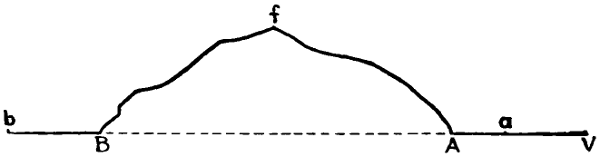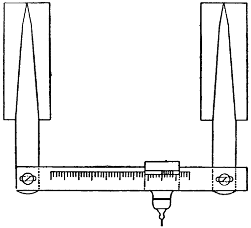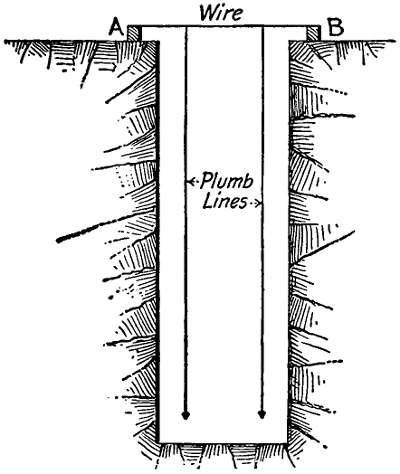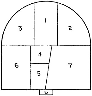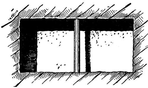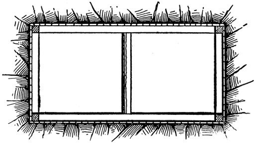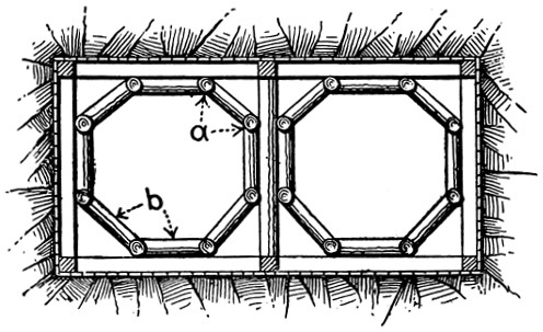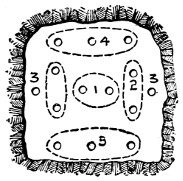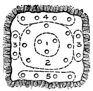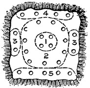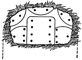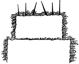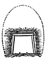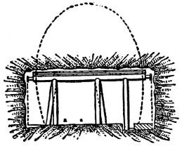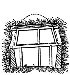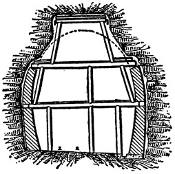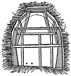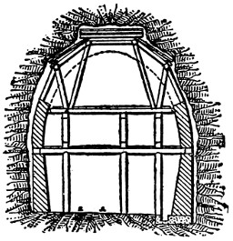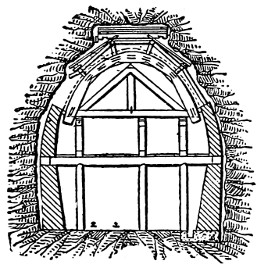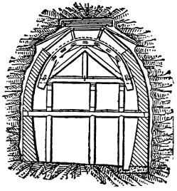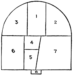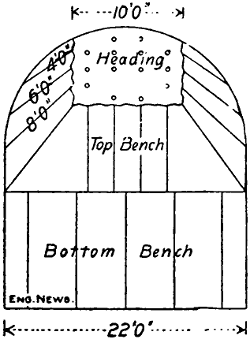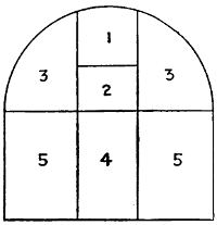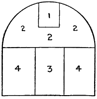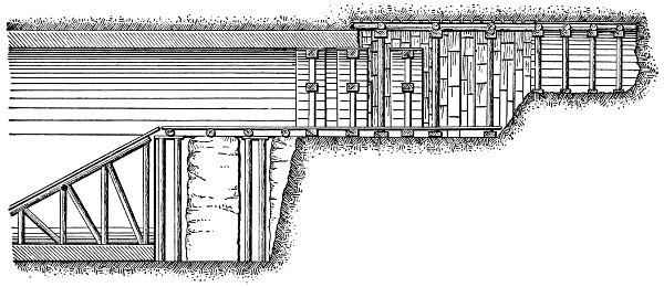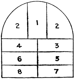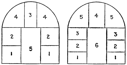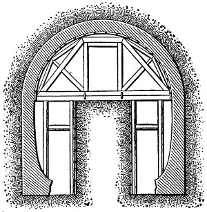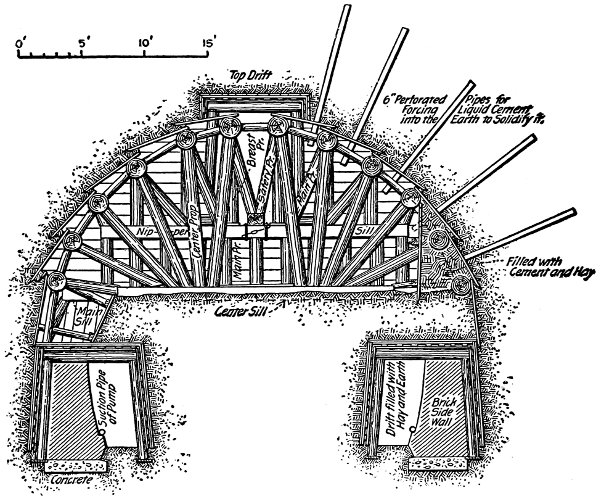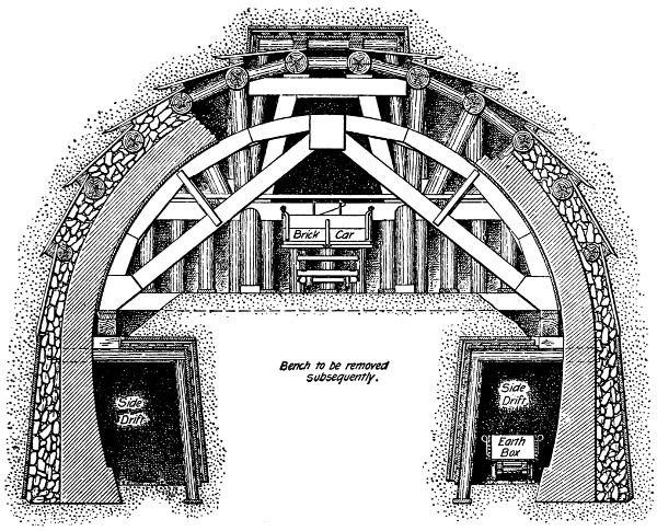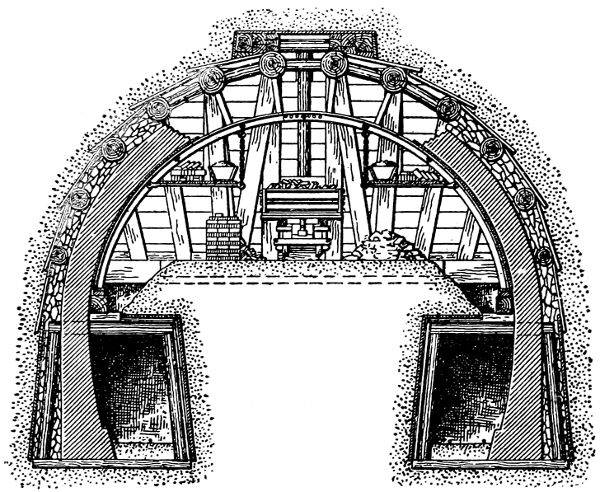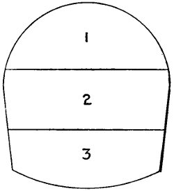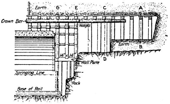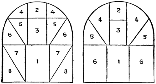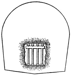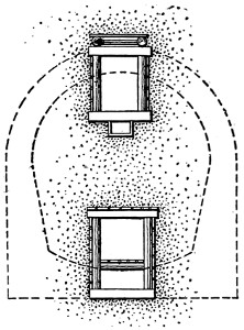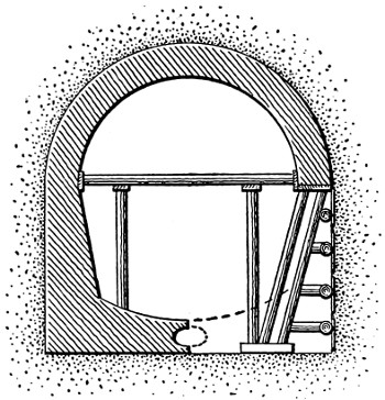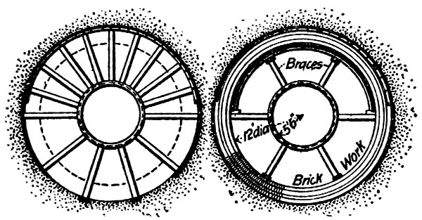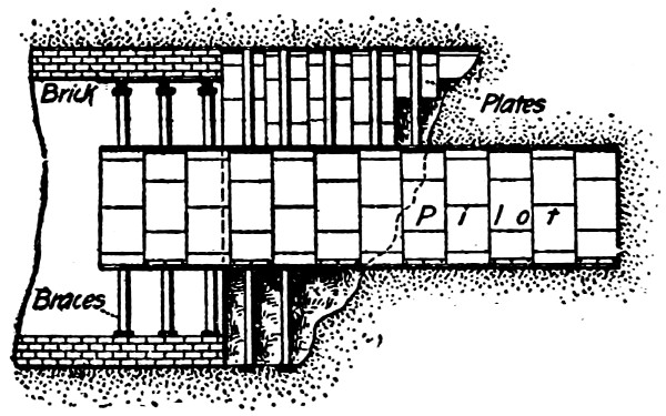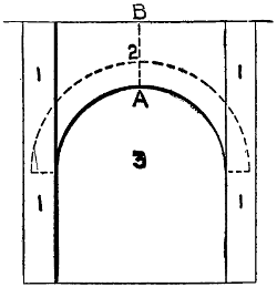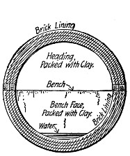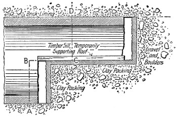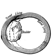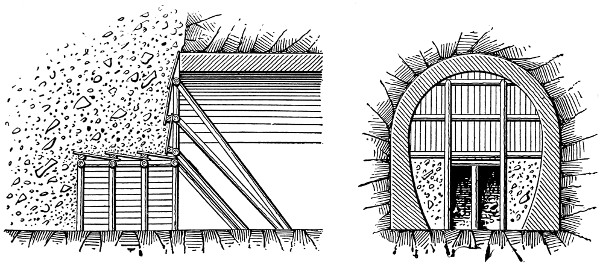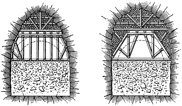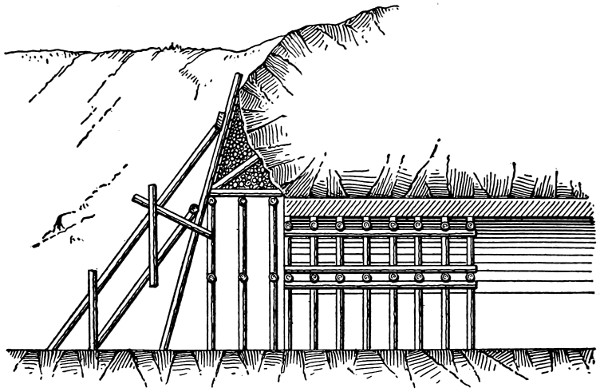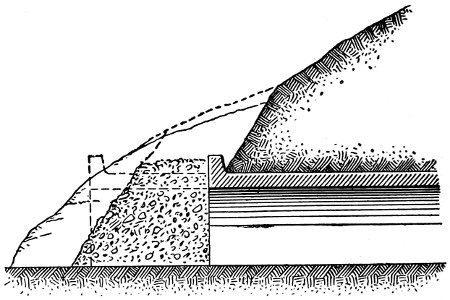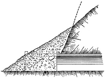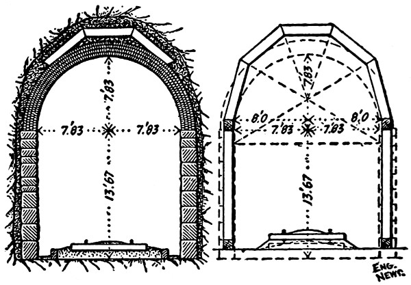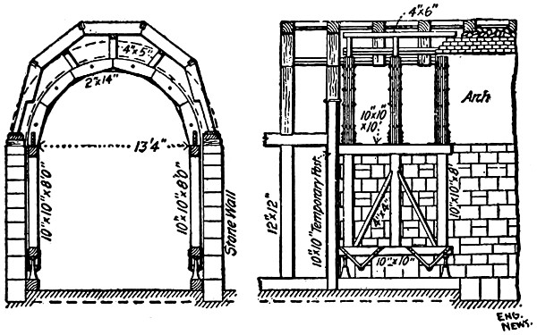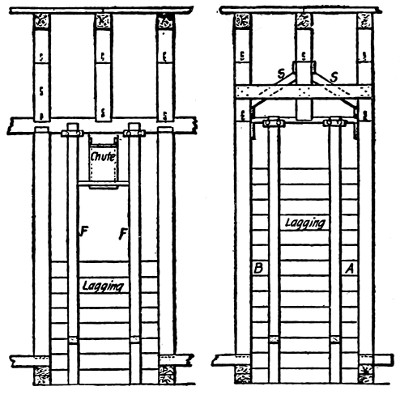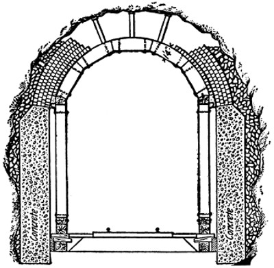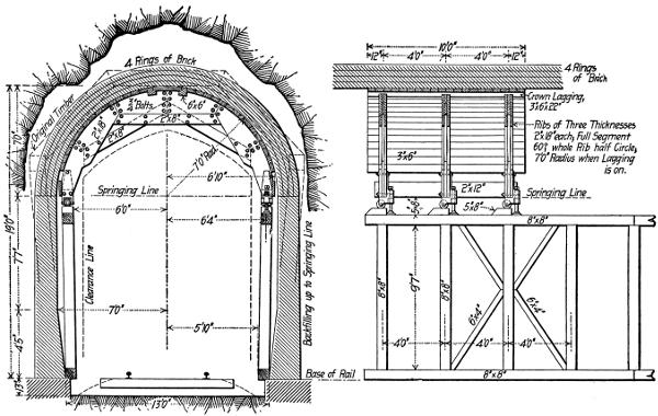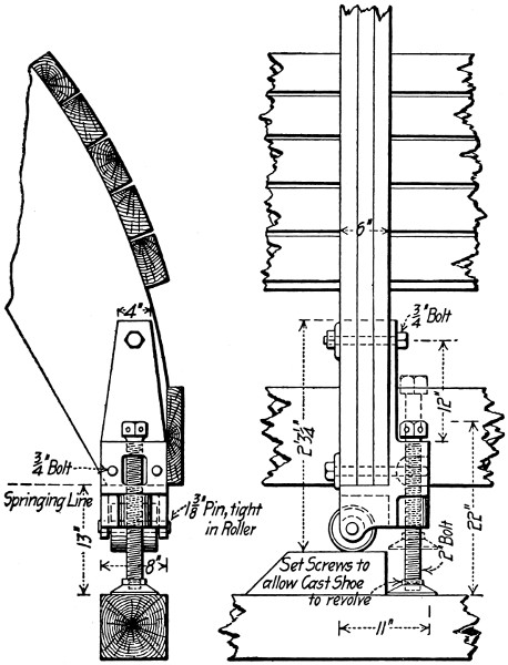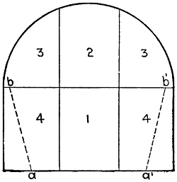
Fig. 55.—Diagram Showing Sequence
of Excavations in Drift
Method of Tunneling Rock.
—The method of tunneling through hard
rock by drifts is preferred by European engineers. All the great
Alpine tunnels, from the Mont Cenis tunnel to the Simplon,
are examples of tunneling by drifts. In this method the sequence
of excavation is shown diagrammatically by Fig. 55.
The work begins by excavating a
drift close to the floor of the proposed
tunnel (as shown in the center
of the figure) and far in advance of
the excavation of any other part.
The section marked 2 is next removed
and still later the portions
marked 3. Then with the removal
of the parts marked 4 the whole
section of the tunnel will be open.
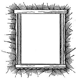
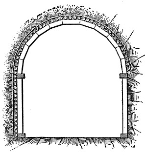
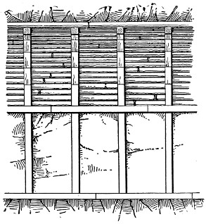
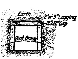
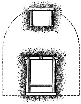
The drift is usually strutted by
means of side posts carrying a cap-piece
placed at intervals, and having
a ceiling of longitudinal planks resting on the successive caps.
In hard rock the roof of the section does not, as a rule, require
regular strutting, occasional supports being placed at intervals
to prevent the fall of isolated fragments: When the rock is disintegrated
or full of seams, a regular strutting may be necessary,
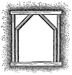
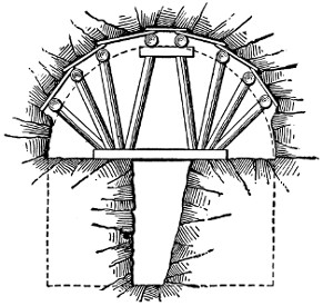
and this may be either longitudinal or polygonal in type. When
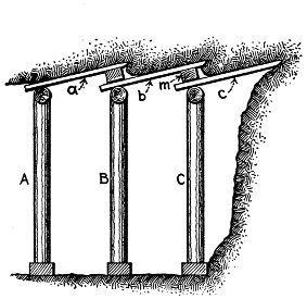
longitudinal strutting is employed, a sill is laid across the roof of
the drift, and upon this are set up two struts converging toward
the top and supporting a cap-piece close to the roof. On this
cap-piece are placed the first longitudinal crown bars carrying
transverse poling-boards. Additional props standing on the sill
and radiating outward are inserted as parts No. 3 are excavated.
These radial props carry longitudinal bars which in turn support
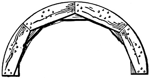
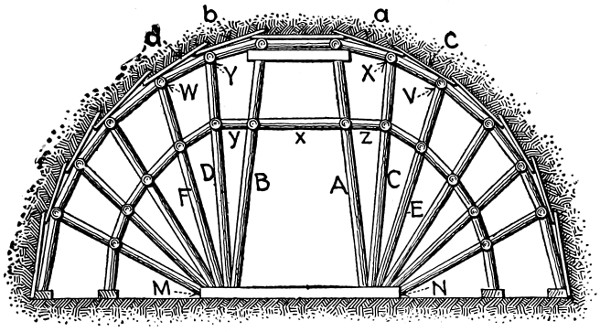
transverse poling-boards. When polygonal strutting is used,
it may take the form of three or five segment arches of heavy
timbers.
In hard rock tunnels, as a rule, there is no danger of caving in
because of heavy pressures, and the whole section is left open
for some time before it is lined. The lining may be of concrete
masonry, but in many long tunnels, excavated through hard
rock, the side walls are lined with rubble masonry and the arch
with brick, and, in some instances, even the arch has been lined
with rubble masonry. With skilful laborers at hand the rubble
masonry lining has proved most efficient and economical, because
the rock is utilized as it is excavated without any further
operation. Concrete, however, is more extensively employed
for lining tunnels than any other material.
Tunnels excavated by drifts enable simple means of hauling
to be employed, and this is one of the reasons why the method
finds so much favor with European engineers. The tracks
are laid along the floor of the drift, and carry all the spoil from
parts Nos. 2, 3, and 4, as well as from the front of the drift
itself. As fast as the full section is completed, this single track
in the drift is replaced by two tracks running close to the sides
of the tunnel, or by a broad-gauge track with a third rail.
Before entering upon a description of the constructive details
of this, the longest railway tunnel in the world, it may be
well to give a general idea of the undertaking. Many schemes
for the connection of Italy and Switzerland by a railway near
the Simplon Road Pass have been devised, including one involving
no great length of underground work, the line mounting
by steep gradients and sharp curves. The present scheme,
put forward in 1881 by the Jura-Simplon Ry. Co., consists
broadly of piercing the Alps between Brigue, the present railway
terminus in the Rhone Valley, and Iselle, in the gorge of
the Diveria, on the Italian side, from which village the railway
will descend to the existing southern terminus at Domo d’Ossola,
a distance of about 11 miles.
In conjunction with this scheme a second tunnel is proposed,
to pierce the Bernese Alps under the Lötschen Pass
from Mittholz to a point near Turtman in the Rhone Valley;
and thus, instead of the long détour by Lausanne and the Lake
of Geneva, there will be an almost direct line from Berne to
Milan via Thun, Brigue, and Domo d’Ossola.
Starting from Brigue, the new line, running gently up the
valley for 11⁄4 miles, will, on account of the proximity of the
Rhone, which has already been slightly diverted, enter the
tunnels on a curve to the right of 1050 ft. radius. At a distance
of 153 yards from the entrance, the straight portion
of the tunnel commences, and extends for 12 miles. The line
then curves to the left with a radius of 1311 ft. before emerging
on the left bank of the Diveria. Commencing at the northern
entrance, a gradient of 1 in 500 (the minimum for efficient
drainage) rises for a length of 51⁄2 miles to a level length of 550
yards in the center, and then a gradient of 1 in 143 descends
to the Italian side. On the way to Domo d’Ossola one helical
tunnel will be necessary, as has been carried out on the St.
Gothard. There will be eventually two parallel tunnels having
their centers 56 ft. apart, each carrying one line of way; but
at the present time only one heading, that known as No. 1,
is being excavated to full size, No. 2 being left, masonry lined
where necessary, for future developments. By means of cross
headings every 220 yds. the problems of transport and ventilation
are greatly facilitated, as will be seen later. As both
entrances are on curves, a small “gallery of direction” is necessary,
to allow corrections of alinement to be made direct from
the two observatories on the axis of the tunnel.
The outside installations are as nearly in duplicate as circumstances
will allow, and consist of the necessary offices,
workshops, engine-sheds, power-houses, smithies, and the numerous
buildings entailed by an important engineering scheme.
Great care is taken that the miners and men working in the
tunnel shall not suffer from the sudden change from the warm
headings to the cold Alpine air outside; and for this purpose
a large building is in course of erection, where they will be
able to take off their damp working clothes, have a hot and
cold douche, put on a warm dry suit, and obtain refreshments
at a moderate cost before returning to their homes. Instead
of each man having a locker in which to stow his clothes, a
perfect forest of cords hangs down from the wooden ceiling,
25 ft. above floor-level, each cord passing over its own pulleys
and down the wall to a numbered belaying-pin. Each cord
supports three hooks and a soap-dish, which, when loaded with
their owner’s property, are hauled up to the ceiling out of the
way. There are 2000 of these cords, spaced 1 ft. 6 ins. apart,
one to each man. The engineers and foremen are more privileged,
being provided with dressing-rooms and baths, partitioned
off from the two main halls. An extensive clothes washing
and drying plant has been laid down, and also a large restaurant
and canteen. At Iselle, a magazine holding 2200 lbs. of
dynamite is surrounded and divided into two separate parts by
earth-banks, 16 ft. high. The two wooden houses, in which
the explosive is stored, are warmed by hot-water pipes to a
temperature between 61° F. and 77° F., and are watched by
a military patrol; but at Brigue a dynamite manufactory,
started by an enterprising company at the time of the commencement
of the works, supplies this commodity at frequent
intervals, thereby avoiding the necessity of storing in such
large quantities. This dynamite factory has been largely increased,
and supplies dynamite to nearly all the mining and
tunneling enterprises in Switzerland.
—Before the Simplon tunnel was authorized,
expert evidence was taken as to the feasibility of
the project. The forecasts of the three engineers chosen, in
reference to the rock to be encountered and its probable temperature,
have, as far as the galleries have gone (an aggregate
distance of nearly 21⁄2 miles), generally been found correct.
At the north end, a dark argillaceous schist veined with quartz
was met with, and from time to time beds of gypsum and dolomite
have been traversed, the dip of the strata being on the whole
favorable to progress, though timbering is resorted to at dangerous
places. Water was plentiful at the commencement; in fact,
one inrush has not been stopped, and is still flowing down the
heading. The total quantity of water flowing from the tunnel
mouth is 16 gallons per second, of which 2 gallons per second
are accounted for by the drilling machines. At Iselle, however,
a very hard antigorio gneiss obtains, and is likely to
extend for 4 miles. Very dry and very compact, it requires
no timbering, and represents no great difficulty to the powerful
Brandt rock-drills, which work under a head of 3280 ft. of
water.
The temperature of the rock depends not only on the depth
from the surface, but largely upon the general form of that surface
combined with the conductivity of the rock. Taking
these points into consideration with the experience gained from
the construction of the St. Gothard tunnel, 95° F. was estimated
as the probable maximum temperature, owing to the
height of Monte Leone (11,660 ft.), which lies almost directly
over the tunnel axis.
—After having determined upon the general position
of the tunnels, taking into consideration the necessary gradients,
the temperature of the rock, and a large bed of troublesome
gypsum on the north side, two fixed points on the proposed
center line were taken, one at each entrance of tunnel
No. 1, and the bearings of these two points, with reference to
a triangulation survey made in 1876, were calculated sufficiently
accurately to determine, for the time being, the direction of
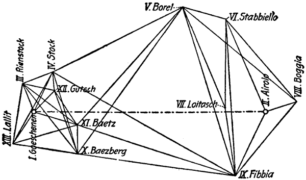
the tunnel. In 1898, a new triangulation survey was made,
taking in eleven summits, Monte Leone holding the central
position. This survey was tied into that of the Wasenhorn
and Faulhorn, made by the Swiss Government, and the accuracy
was such that the probable error in the meeting of the two
headings is only 6 cms. or 21⁄2 ins.
On the top of each summit is placed a signal, consisting of
a small pillar of masonry founded on rock, and capped with a
sharp pointed cone of zinc, 1 ft. 6 ins. high. An observatory
was built at each end of the tunnel in such a position that three
of the summits could be seen, a condition very difficult to fulfill
on the south side owing to the depth of the gorge, the mountains
on either side being over 7000 ft. high. Having taken
the angles to and from each visible signal, and therefrom having
calculated the direction of the tunnel, it was necessary to fix,
with extreme accuracy, sighting-points on the axis of the tunnel,
in order to avoid sighting on to the surrounding peaks for each
subsequent correction of the alinement of the galleries. To
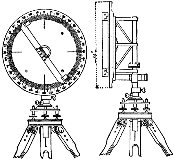
do this, a theodolite 24 ins. long and 23⁄8 ins. in diameter, with
a magnifying power of 40 times, was set up in the observatory,
and about 100 readings were taken of the angles between the
surrounding signals and the required sighting-points. In this
manner the error likely to occur was diminished to less than 1′.
Thus at the north end two points were found about 550 yds.
before and behind the observatory, while on the south side,
owing to the narrowness of the gorge, the points could only be
placed at 82 yds. and 126 yds. in front. One of these sighting-points
consists of a fine scratch ruled on a piece of glass fixed
in an iron frame, behind which is placed an acetylene lamp,—corrections
of alinement are always done by night,—the whole
being rigidly fixed into a niche cut in the rock and protected
from climatic and other disturbing agencies by an iron
plate.
—The direction of heading
No. 1 is checked by experts from the Government Survey Department
at Lausanne about three times a year, and for this
purpose a transit instrument is set up in the observatory. A
number of three-legged iron tables are placed at intervals of
1 mile or 2 miles along the axis of tunnel No. 1, and upon each
of these is placed a horizontal plane, movable by means of
an adjusting screw, in a direction at right angles to the axis,
along a graduated scale. On this plane are small sockets, into
which the legs of an acetylene lamp and screen, or of the transit
instrument, can be quickly and accurately placed. The screen
has a vertical slit, 3 ins. in height, and variable between 13⁄16 in.
and 3⁄16 in. in breadth, according to the state of the atmosphere,
and at a distance shows a fine thread of light. The instrument,
having first been sighted on to the illuminated scratch of the
sighting-point, is directed up the tunnel, where a thread of
light is shown from the first table. With the aid of a telephone
this light is adjusted so that its image is exactly coincident
with the cross hairs, and the reading on the graduated scale is
noted. This is done four or five times, the average of these
readings being taken as correct, and the plane is clamped to
that average. The instrument is then taken to the first table
and is placed quickly and accurately over the point just found
(by means of the sockets), and the lamp is carried to the observatory.
After first sighting back, a second point is given on the
second table, and so on. These points are marked either temporarily
in the roof of the heading by a short piece of cord hanging
down, or permanently by a brass point held by a small steel
cylinder, 8 ins. long and 3 ins. in diameter, embedded in concrete
in the rock floor, and protected by a circular casting, also sunk
in cement concrete, holding an iron cover resembling that of
a small manhole. From time to time the alinement is checked
from these points by the engineers, and after each blast the
general direction is given by the hand from the temporary
points. To check the results of the triangulation survey, astronomical
observations have been taken simultaneously at each
end. With regard to the levels, those given on the excellent
Government surveys have been taken as correct, but they have
also been checked over the pass.
—In cross-section, tunnel No. 1 is 13 ft.
7 ins. wide at formation level, increasing to 16 ft. 5 ins., with
a total height of 18 ft. above rail-level, and a cross-sectional
area of about 250 sq. ft. This large section will allow of small
repairs being executed in the roof without interruption of the
traffic, and will also allow of strengthening the walls by additional
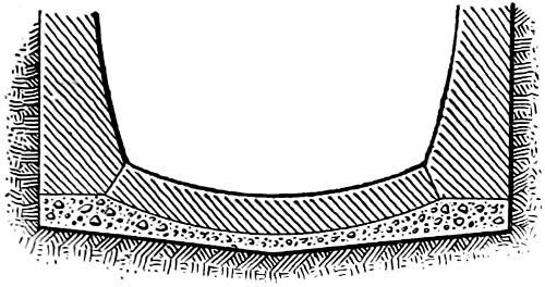
masonry on the inside. The thickness of the lining,
never wholly absent, and the material of which it is composed,
depend upon the pressure to be resisted, and only in the worst
case is an invert resorted to. The side drain, to which the rock
floor is made to slope, will be composed of half-pipes of
7 to 1 cement concrete. The roof is constructed of radial
stones.
Tunnel No. 2, being left as a heading, is driven on that side
nearest to No. 1, to minimize the length of the cross-headings,
and measures 10 ft. 2 ins. wide by 6 ft. 7 ins. high. Masonry
is used only where necessary, and in that case is so built as to
form part of the lining of the tunnel when eventually completed.
Concrete is put in to form a foundation for the side
wall, and a water channel. The cross-headings, connecting the
two parallel headings, occur every 220 yds., and are placed at
an angle of 56° to the axis of the tunnel, to avoid sharp curves
in the contractors’ railway lines. They will eventually be used
as much as possible for refuges, chambers for storing the tools
and equipment of the platelayers, and signal-cabins. The refuges,
6 ft. 7 ins. wide by 6 ft. 7 ins. high and 3 ft. 3 ins. deep,
occur every 110 yards, every tenth being enlarged to 9 ft. 10
ins. wide by 9 ft. 10 ins. deep and 10 ft. 2 ins. high, still larger
chambers being constructed at greater intervals.
—The work at each end of the tunnel
is carried on quite independently, consequently, though similar
in principle, the methods vary in detail, apart from the fact that
different geological strata require different treatment. Broadly
speaking, the two parallel headings, each 59 sq. ft. in section,
are first driven by means of drilling-machines and the use of
dynamite, this work being carried on day and night, seven days
in the week; No. 1 heading is then enlarged to full size by hand-drilling
and dynamite. On the Italian side, where the rock
is hard and compact, breakups are made at intervals of 50 yds.,
and a top gallery is driven in both directions, but, for ventilation
reasons, is never allowed to get more than 4 yds. ahead
of the break-up, which is gradually lengthened and widened
to the required section. No timbering is required, except to
facilitate the excavation and the construction of the side walls.
Steel centers are employed for the arch; they entail fewer supports,
give more room, and are capable of being used over again
more frequently without damage. They consist of two I-beams
bent to a template and riveted together at the crown, resting
at either side on scaffolding at intervals of 6 ft.; longitudinals
12 ft. by 4 ins. by 4 ins. support the roof. Hand rock-drilling
is carried out in the ordinary way, one man holding the tool and
a second striking; measurements of excavation are taken every
2 or 3 yds., a plumb-line is suspended from the center of the
roof, and at every half-meter (20 ins.) of height horizontal
measurements are taken to each side.
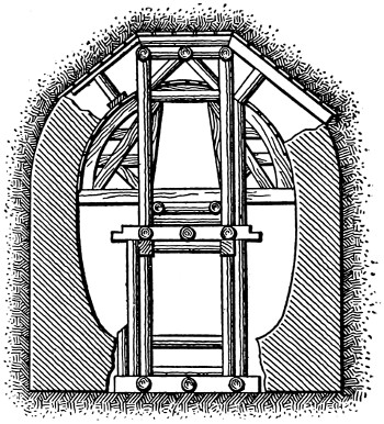
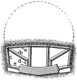
At the Brigue end a softer rock is encountered, necessitating
at times heavy timbering in the heading, and especially in
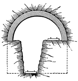
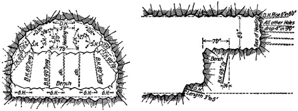
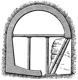
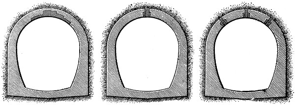
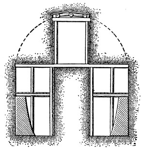
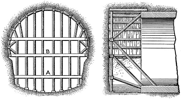
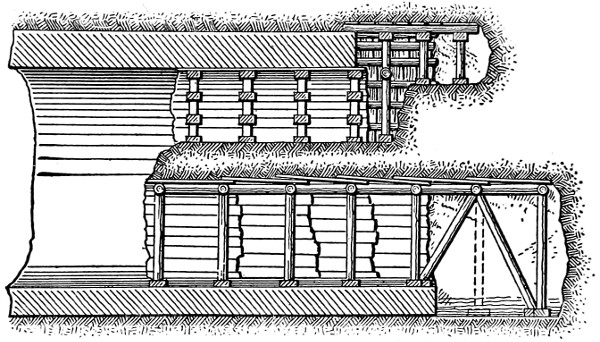
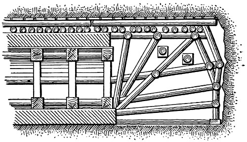
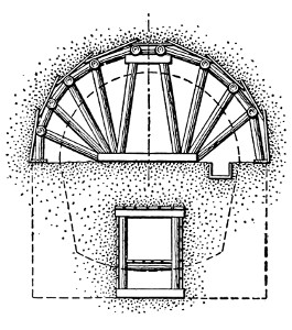
the final excavation to full size, Fig. 56. The bottom heading,
6 ft. 6 in. high, is driven in the center, and the heading is then
widened to the full extent and timbered; the concrete forming
the water channel and the foundation for one side wall is put
in; the side walls are built to a height of 6 ft. 6 ins., and the tunnel
is fully excavated to a further height of 6 ft. 6 ins. from the
first staging. The side walls are then continued up for the
second 6 ft. 6 ins., and
from the second floor
a third height of 6 ft.
6 ins. is excavated and
timbered. Finally the
crown is cleared out,
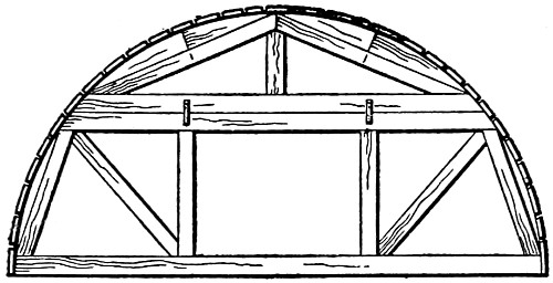
heavy wooden centers
are put in, the arch is
turned and all timbers
are withdrawn
except the top poling-boards,
supporting
the loose rock.
Fig. 56.—Sketches Showing Sequence of Work in
Excavating and Lining the Simplon Tunnel.
The masonry for
the side walls is obtained
either from the
tunnel itself or from
a neighboring quarry,
and varies in character
according to the
pressure; but the face
of the arch is always
of cut or artificial
stones, the latter being
7 to 1 cement
concrete. Where the
alinement heading, or
the “gallery of direction,”
joins the curving
portion of tunnel
No. 1, the section is
very much greater, and necessitates special timbering.
—A small line of railway, 2 ft. 71⁄2
ins. gauge, with 40-lb. rails, enters all three portals; but since
the construction of a wooden bridge over the Diveria, the route
through the “gallery of direction,” across heading No. 2, to
tunnel No. 1, is used exclusively; this railway leads to the face
in both headings, and, where convenient, from one heading to
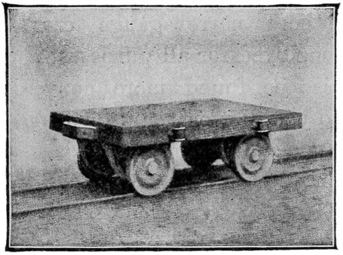
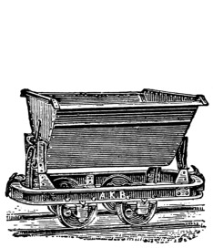
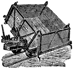
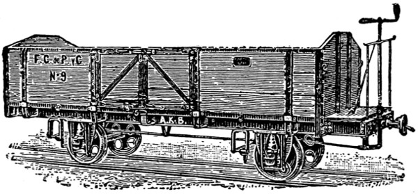
the other by the cross-galleries. Different types of wagons are
in use; but in general they are four-wheeled, non-tipping box
wagons, supplied with brakes and holding 2 cu. yds. of débris.
A special type of locomotive is used, designed to pass round
curves of 50 ft. radius, and supplied with a specially large boiler
to avoid firing in the tunnel.
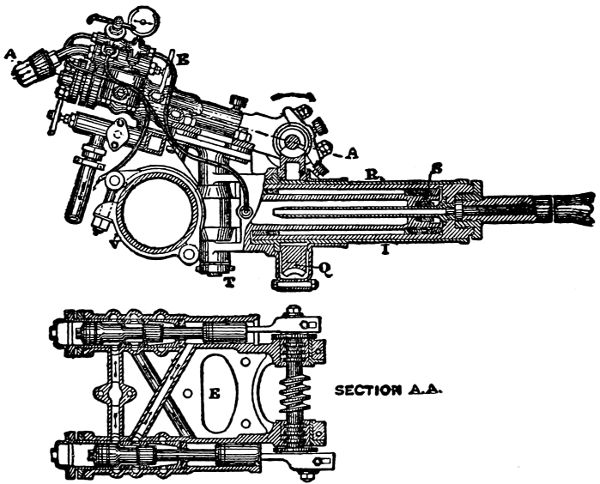
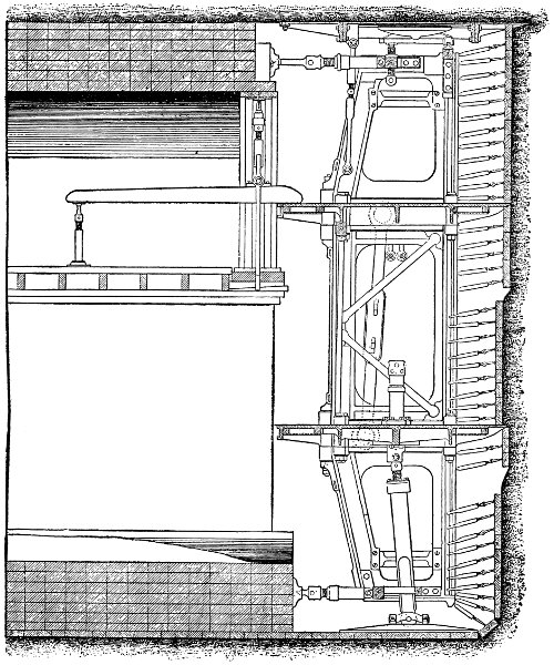
Fig. 57.—General Details of the Brandt Rotary Drills Employed at the Simplon Tunnel.
Larger illustration
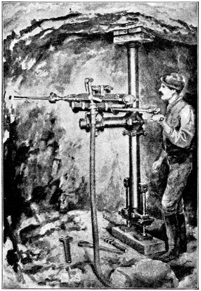
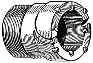
—The drilling-machines employed are of
the Brandt type, Fig. 57, and are mounted in the following
manner: A small four-wheeled carriage supports at its center
a beam, the shorter arm of which carries the boring mechanism
and the longer a counterpoise; near its center is the distributor.
In the short arm is a clamp holding the rack-bar or butting
column, which is a wrought-iron cylinder with a plunger constituting
a ram, and is jammed by hydraulic pressure between
the walls of the heading, thus forming a rigid support for the
boring-machine, and an efficient abutment against the reaction
of the drill. This rack-bar can be rotated on its clamp in a
plane parallel to the axis of the beam. Three or four separate
boring-machines can be mounted on the rack-bar, and can be
adjusted in any reasonable position.
The boring-machine performs the double function of continually
pressing the drill into the rock by means of a hollow
ram (I) and of imparting to the drill and ram a uniform rotary
motion. This rotary motion is given by a twin cylinder single-acting
hydraulic motor (E), the two pistons, of 27⁄8 ins. stroke,
acting reciprocally as valves. The cranks are fixed at an angle
of 90° to each other on the shaft, which carries a worm, gearing
with a worm-wheel (Q) mounted upon the shell (R) of the
hollow ram (I), and this shell in turn engages the ram by a
long feather, leaving it free to slide axially to or from the face
of the rock. The average speed of the motor is 150 revolutions
to 200 revolutions per minute, the maximum speed being 300
revolutions per minute. The loss of power between the worm
and worm-wheel is only 15% at the most; the worm being of
hardened steel and the wheel of gun-metal, the two surfaces in
contact acquire a high degree of polish, resulting in little wearing
or heating. Taking into consideration all other sources of
loss, 70% of the total power is utilized. The pressure on the
drill is exerted by a cylinder and hollow ram (I), which revolves
about the differential piston (S), which is fixed to the envelope
holding the shell (R). This envelope is rigidly connected to
the bed-plate of the motor, and, by means of the vertical hinge
and pin (T), is held by the clamp (V) embracing the rack-bar.
When water is admitted to the space in front of the differential
piston the ram carrying the drilling-tool is thrust forward, and
when admitted to the annular space behind the piston, the ram
recedes, withdrawing the tool from the blast-hole. The drill
proper is a hollow tube of tough steel 23⁄4 ins. in external diameter,
armed with three or four sharp and hardened teeth, and
makes from five to ten revolutions per minute, according to the
nature of the rock. When the ram has reached the end of its
stroke of 2 ft. 21⁄2 ins., the tool
is quickly withdrawn from the
hole and unscrewed from the ram; an extension rod is then
screwed into the tool and into the ram, and the boring is continued,
additional lengths being added as the tool grinds forward;
each change of tool or rod takes about 15 secs. to 25
secs. to perform. The extension rods are forged steel tubes,
fitted with four-threaded screws, and having the same external
diameter as the drill. They are made in standard lengths of
2 ft. 8 ins., 1 ft. 10 ins., and 113⁄4 ins. The total weight of the
drilling-machine is 264 lbs., and that of the rack-bar when full
of water is 308 lbs. The exhaust water from the two motor
cylinders escapes through a tube in the center of the ram and
along the bore of the extension rods and drill, thereby scouring
away the débris and keeping the drill cool; any superfluous
water finds an exit through a hose below the motors and thence
away down the heading. The distributor, already mentioned,
supplies each boring-machine and the rack-bar with hydraulic
pressure from the mains, with which connection is effected by
means of flexible or articulated pipe connections, allowing freedom
in all directions. The area of the piston for advancing
the tool is 151⁄2 sq. ins., which, under a pressure of 1470 lbs. per
sq. in., gives a pressure of over 10 tons on the tool, while for
withdrawing the tool 21⁄2 tons is available. In the rock found at
Iselle, namely, antigorio gneiss, a hole 23⁄4 ins. in diameter and
3 ft. 3 ins. in length is drilled, normally, in 12 mins. to 25 mins.;
a daily rate of advance of 18 ft. to 19 ft. 6 ins. is made in a heading
having a minimum cross-section of 59 sq. ft.; the time taken
to drill ten to twelve holes, 4 ft. 7 ins. deep, is 21⁄2 hrs.
When the débris resulting from one operation has been sufficiently
cleared away, a steel flooring, which is provided near
the face to enable shoveling to be more easily done, and to
give an even floor for the wheels of the drilling-carriage, is
laid bare at the head of the line of rails, and the drilling-machines
are brought up on their carriage by eight or ten men. When
advanced sufficiently close to the face, the rack-bar is slewed
round across the gallery and is wedged up against the rock
sides; connection is made between the distributor and the
hydraulic main, by means of the flexible pipe, and pressure
is supplied by a small copper tube to the rack-bar ram, thereby
rigidly holding the machine. Next, connections are made between
the three drilling-machines and the distributor, and in
20 mins. from the time the machine was brought up all three
drills are hard at work, water pouring from the holes.
The noise of the motors and grinding-tools is sufficient to
drown all but shouts; and where the extension rods do not fit
tightly, small jets of water play in all directions, necessitating
the wearing of tarpaulins by the men directing the tools. Lighting
is done wholly by small oil-lamps, provided with a hook
to facilitate fixing in any crack in the rock; electricity will
probably be used to light that portion of the tunnel which is
completed.
Two men are allotted to each drill, one to drive the motor,
the other to direct and replenish the tool, one foreman and two
men in reserve completing the gang. A small hammer is freely
used to loosen the screw joints of the extension rods and drill.
A hole is usually commenced by a two-edged flat-pointed tool,
until a sufficient depth is reached to prevent the circular tool
from wandering over the face of the rock, but in many instances
the hole is commenced with a circular tool. The exhaust
water during this period flows away by the hose underneath
the motor. In the antigorio gneiss, ten to twelve holes are
drilled for each attack, three to four in the center to a depth of
3 ft. 3 ins., the remainder, disposed round the outside of the
face, having a depth of 4 ft. 7 ins. The average time taken to
complete the holes is 13⁄4 hr. to 21⁄2 hrs. Instead of pulverizing
the rock, as do the diamond drills, it is found that the rock is
crushed, and that headway is gained somewhat in the manner
of a circular saw through wood. The core of rock inside the
tool breaks up into small pieces, and can be taken out if necessary
when the drill requires lengthening.
The lowest holes, inclined downwards, are full of water;
consequently two detonators and two fuses are inserted, but
apart from this, water has little effect on the charge. The
fuses of the central holes are brought together and cut off shorter
than those of the outer holes, in order that they may explode
first to increase the effect of the outer charges. All portable
objects, such as drills, pipe connections, tools, etc., have meanwhile
been carried back; the steel flooring is covered over with
a layer of débris to prevent injury from falling rock, and to
the end of the hydraulic main is screwed a brass plug pierced
by five holes; and immediately the explosions occur a valve is
opened in the tunnel, and five jets of water play upon the rock,
laying the dust and clearing the air. The necessity for this
was shown on one occasion when this nozzle was broken by the
explosion and the water had to be turned off immediately to
avoid useless waste; on reaching the face, the atmosphere was
found to be so highly charged with dust and smoke that it was
impossible to distinguish the stones at the feet, although a lamp
had been placed on the ground; and despite the fact that the
air tube was in full blast, the men experienced great difficulty
in breathing. A truck is now brought up, and four men clear
a passage in front, through the heap of débris, two with picks
and two with shovels, while on either side and behind are as many
men as space will permit. The stone is thrown either to the sides
of the heading or into the wagon, shoveling being greatly aided
by the steel flooring, which, before the explosion, had been laid
over the rails for nearly 10 yds. down the tunnel to receive the
falling rock. These steel plates are taken up when cleared, and
the wagon is pushed forward until the drilling-machine can be
brought up again, leaving the remaining débris at the sides to be
handled at leisure during the next attack. The roof and side
walls are, of course, carefully examined with the pick, to discover
and detach any loose or hanging rock. The times taken for each
portion of the attack in this particular antigorio gneiss are as
follows: Bringing up and adjustment of drills, 20 mins.; drilling,
between 13⁄4 hr. and 21⁄2
hrs.; charging and firing, 15 mins.;
clearing away débris, 2 hrs.; or for one whole attack, between
41⁄2 hrs. and 51⁄2 hrs., resulting in an advance of 3 ft. 9 in., or a
daily advance of nearly 18 ft.
From this it appears that the time spent in clearing away
the débris equals that taken up in drilling, and it is in this clearing
that a saving of time is likely to be effected rather than in
the process of drilling. Many schemes have been tried, such as
a mechanical plow for making a passage; at Brigue, “marinage,”
or clearing by means of powerful high-pressure water-jets,
directed down the tunnel, was tried, but the idea is not yet
sufficiently developed.
Another series of experiments has been tried at Brigue with
regard to the utilization of liquid air as an explosive agent
instead of dynamite; and for this purpose a plant has been
laid down, consisting of one ammonia-compressor, two air-compressors,
and two refrigerators, furnishing 1⁄10 gallon of liquid
air per hour at an expenditure of 17 H. P. The system used is
that of Professor Linde, who himself directs the experiments.
The great difficulty experienced is that of shortening the interval
of time that must elapse between the manufacture of the cartridge
and its explosion. The liquid oxygen, with which the
cartridge, containing kieselguhr (silicious earth) and paraffin, is
saturated, evaporates very readily, losing power every moment;
hence the effect of each cartridge cannot be guaranteed, and
though it is an exceedingly powerful explosive when used immediately
after manufacture, no practical result has yet been
obtained.
—Water is abundant at either end, and therefore
hydraulic power is the motive force employed. On the
Italian side, a dam 5 ft. high has been thrown across the Diveria
at a point near the Swiss frontier, about 3 miles above the site
of the installations. A portion of the water thus held back
enters, through regulating doors and gratings, a masonry channel
leading to two parallel settling tanks, each 111 ft. by 16 ft.,
whence, after dropping all its sand and solid matter, the now
pure water passes into the water-house, and, after flowing over
a dam, through a grating and past the admission doors, enters
a metallic conduit of 3-ft. pipes. Each of the settling tanks
and the approach canal are provided with doors at the lower
end leading direct to the river, through which all the sand and
solid matter deposited can be scoured naturally by allowing
the river-water to rush freely through. For this purpose the
floor of the basins is on an average gradient of 1 in 30. For
a similar reason the river-bed just outside the entrance to the
approach canal is lined with wooden planks, from which the
stones collecting behind the dam can be scoured by allowing
an iron flap, hinged at the bottom, to change its position from
the vertical to the horizontal in a gap left purposely in the
dam, so causing a rushing torrent to sweep it clean.
The chief levels are:
| Level |
of water at dam |
794.00 |
meters |
above |
sea |
level. |
| „ |
in water-house |
793.70 |
„ |
„ |
„ |
„ |
| „ |
at turbines |
618.50 |
„ |
„ |
„ |
„ |
giving a total fall of 175.20 ms. or 570 ft., and a pressure of
17.52 atmospheres.
The quantity of water capable of being taken from the Diveria
in winter, when the rivers which are dependent upon the mountain
snows for their supply are at their lowest, is calculated
to be 352 gallons per second. Thus, taking the fall to be
diminished by friction, etc., to 440 ft., and the useful effect at
70%, there is obtained 2000 H. P. on the turbine shaft.
The metallic conduit varies in material according to the
pressure; thus cast-iron pipes 3 ft. in diameter and 13⁄16 in. thick
are used up to a pressure of 2 atmospheres, from which point
they are of wrought-iron. The cast-iron portion has of late
caused a good deal of trouble, owing to settlement of the piers
causing occasional bursts, consequently a masonry pier has
been placed under each joint of this portion. The following
table gives the thicknesses and diameters, varying with the
pressure:
Water
Pressure. |
Thickness. |
Diameter. |
Weight
per Yard. |
Head
in Feet. |
Milli-
meters. |
Inch. |
Feet. |
Inches. |
Lbs. |
| 246 |
6 |
1⁄4 |
3 |
0 |
|
326 |
| 311 |
7 |
... |
3 |
0 |
|
383 |
| 360 |
8 |
... |
3 |
0 |
|
431 |
| 393 |
9 |
... |
3 |
0 |
|
483 |
| 426 |
10 |
... |
3 |
0 |
|
556 |
| 476 |
12 |
... |
3 |
0 |
|
651 |
| 590 |
16 |
5⁄8 |
3 |
3 |
1⁄3 |
977 |
This pipe is supported every 30 ft. on small masonry piers,
on the top of which is placed a block of wood hollowed out to
receive the pipe, thus allowing any movement due to the contraction
and expansion of the conduit. However, to prevent
this movement becoming excessive, the pipe is passed at intervals
of 300 yds. to 500 yds. through a cubical block of masonry of
13 ft. side, strengthened by longitudinal tie-bars. Five bands
of angle-bar riveted round the pipe, with their flanges embedded
in the masonry, constitute a rigid fixed point. Straw mats are
thrown over the pipe where it is exposed to the sun. The temperature
of the conduit is not, however, found to vary greatly,
since the pipe is kept full of water. To supply the rock-drills
with water at a maximum pressure of 100 atmospheres, or
1470 lbs. per sq. in., a plant of four pairs of high-pressure pumps
has been laid down, and a still larger addition is in course of
erection. At present, two Pelton turbines of 250 H.P. each,
running at 170 revolutions per minute, drive the pumps, by means
of toothed gearing, at 63 revolutions per minute. These pumps
are of very simple but strong construction, single suction and
double delivery, entailing one suction and one delivery-valve,
both heavy and both of small lift. The larger portion of the
plunger has exactly double the cross-sectional area of the smaller
portion, so that in the forward stroke half of the water taken in
at the last admission is pumped into the high-pressure mains, and
at the same time a fresh supply of water is sucked in. During the
backward stroke half of this new supply is pumped into the
mains, and the remainder enters the second chamber, to be
pumped during the next forward stroke. Thus the work done
in the two strokes is practically the same. The pumps are in
pairs, and are set at an angle of 90°, to insure uniform pressure
and uniform delivery in the mains. Their size varies; but at
Iselle there are three pairs, with a stroke of 2 ft. 21⁄2 ins., and the
plungers of 211⁄16 in. and 17⁄8 ins. (approximately) in diameter,
supplying 1.32 gallons per second.
To avoid injury to the valves, the water to be pumped is
taken from a stream up the mountain side, and is passed through
filter screens. The high-pressure water, after passing an accumulator,
enters the tunnel in solid drawn wrought-iron tubes,
31⁄8 ins. in internal diameter, 3⁄16 in. thick, and in lengths of 26 ft.
The diameter of these mains varies with their length, so as to
avoid loss of pressure. With the 1250 yds. of tunnel now driven
10 atmospheres are lost.
At Brigue the installations are, as far as possible, identical.
The Rhone water, however, before reaching the water-house,
is carried from the filter basins, a distance of 2 miles, in an
armored canal built upon the Hennebique system,[9] the walls
and supporting beams, of cement concrete, being strengthened
by internal tie-bars of steel. The concrete struts, resembling
balks of timber at a distance, are occasionally 35 ft. high and
1 ft. 71⁄2 ins. square. The metallic conduit is 5 ft. in diameter,
with a minimum flow of 176 cu. ft. per second and a total fall
of 185 ft. In case water-power should be unavailable, three
semi-portable steam engines, two of 80 H.P. and one of 60 H.P.,
are always kept in readiness at each end of the tunnel, and are
geared by belts to the turbine shaft.
—In tunneling, one of the most important problems
to be solved is that of ventilation, and it is for this reason
that the Simplon tunnel consists of two parallel headings with
cross cuts at intervals of 220 yds. At Brigue, a shaft 164 ft.
deep was sunk through the overlying rock until the “gallery
of direction” was encountered. Up this chimney the foul air
is drawn by wood fires, the fresh air—a volume of 19,000,000
cu. ft. per day, or 13,200 cu. ft. per minute—entering by heading
No. 2, penetrating up to the last cross gallery, and returning
by tunnel No. 1. The entrances of No. 1 and the “gallery
of direction,” besides those of all the intermediate cross galleries,
are closed by doors. By this arrangement, however, fresh
air does not reach the working faces; therefore a pipe, 8 ins.
in diameter, is led from the fresh air in No. 2 to within 15 yds.
of the face of each heading, and up this pipe a draft of air is
induced by means of a jet of water, the volume to each face
being 800 cu. ft. per minute. One single jet of water from the
high-pressure mains, with a diameter of 1⁄16 in., is capable of
supplying over 1000 cu. ft. of air per minute at the end of
160 yds. of pipe, and during the attack the men at the drills
are in a constant breeze with the thermometer standing at
70° F. At Iselle, air is blown into the entrance of heading
No. 2 at the rate of 14,100 cu. ft. per minute by two fans driven
from the turbine shaft. This air travels from the fans along
a pipe 18 ins. in diameter, till a point 15 yds. up the tunnel is
reached, where beyond a door the pipe narrows to form a nozzle
10 ins. in diameter. This door is kept open to allow the outside
air to be induced up the tunnel, as the headings are at present
only 2500 yds. long, giving a resistance of not quite sufficient
power to cause the air to return. The fresh air then travels up
No. 2, crossing over the top of the “gallery of direction,” from
which it is shut off by doors, to the last cross gallery, returning
by No. 1, and finally leaving either by the “gallery of direction”
or by No. 1. A system of cooling the air and driving it on by
means of a large number of water-jets will be installed in No. 2
where that heading crosses over the “gallery of direction,” but
at present there is no need for it.
The average temperature at the face is 73° F. during the
drilling operation, 76° F. after firing the charges, and a maximum
of 80° F., lately attaining to 86° F. on the south side,
with 80° F. and 85° F. before and after firing. The temperature
of the rock is taken at every 110 yds. in holes 5 ft. deep,
and shows a gradual increase according to the depth of over-laying
rock, to the conductivity of the rock, and to the form of
the mountain surface. The maximum hitherto reached on the
north side is 68° F., while on the south side, although a smaller
distance has been traversed, it attains to 79° F., due to the
more rapid increase in depth. Moreover, the temperature of
the rock is observed at the permanent stations, 550 yds. from
the entrances, in its relation to that of the tunnel and outside
air, and though on the north side that of the rock varies almost
as quickly as that of the tunnel air, on the south it is influenced
very much less.
A few statistics may be of interest with regard to the progress
of the last three months (taken from the trimestrial report
of January, 1900). At Brigue, where there are three drilling-machines
in No. 1 and two in the parallel heading, the total
length excavated was 995 yds. or 6409 cu. yds. in 89 working
days, the average cross-sectional area being 57 sq. ft. This required
507 attacks and 3066 holes, which had a total depth of
26,600 ft. and 14,700 re-sharpenings of the drilling-tool, with
44,000 lbs. of dynamite.
The average time occupied in drilling was 2 hrs. 45 mins.,
while charging, firing, and clearing away the débris took 6 hrs.,
35 mins. At Brigue 648 men and 29 horses were employed at
one time in the tunnel. At Iselle the numbers were 496 men
and 16 horses, working in shifts of 8 hrs. Outside the tunnel,
in the shops, forges, etc., the men work 8 hrs. to 11 hrs. per
day, the total being 541 men at Brigue and 346 men at Iselle.
On the Italian side, where the rock is very much harder, there
were three drilling-machines in each heading; the total length
excavated, with a cross-sectional area of 62 sq. ft., was 960 yds.
or 6700 cu. yds. in 91 working days. This required 61,293
re-sharpened tools, 758 attacks, 7940 holes with a total depth
of 33,000 ft., and 56,000 lbs. of dynamite. The average time
spent in drilling was 2 hrs. 55 mins., and in charging and clearing
2 hrs. 36 mins. Thus, in the hard gneiss, to excavate 1 cu.
yd. of rock required 81⁄2 lbs. of dynamite, and each tool pierced
61⁄2 ins. of rock before it required re-sharpening.
The drift method of excavating tunnels was followed in
Section IV of the New York Subway, under Park Avenue
between 33rd and 41st Streets. At this point the four tracks
of the subway pass under a rocky elevation, known as Murray
Hill, in two double track parallel tunnels, 43 ft. apart, center to
center. Here already existed a double track tunnel which was
built many years ago by the New York Central and Hudson
River R.R., and is now used by the Madison Avenue surface
cars. The two subway tunnels were driven close below the
existing tunnel and also very near the foundations of expensive
residences along Park Avenue, particularly on Murray Hill, one
of the best residential sections of the city.
—The material penetrated by the excavation
consisted chiefly of a surface outcrop of the mica-schist
rock which underlies Manhattan Island. The rock was for the
most part in compact strata, dipping at about 45° from East
to West, but at intervals an unstable stratum was encountered
which when free slid on the underlying stratum. Troubles
from such slides were experienced during the construction of
the tunnel.
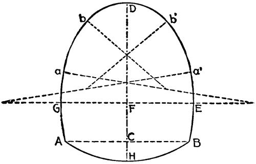
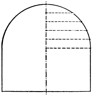
—The cross-section selected for the tunnels
had vertical side walls and a three-centered roof arch with the
flattest curve at the crown. The interior dimensions were
25 ft. wide and 16 ft. high. The selected cross-section was not
the best suited for a tunnel to be driven through rock, where
the sharpest curve should be at the top, but in this case the
flattened curve was chosen because of local conditions; chiefly,
the presence of the existing tunnel and the consequent necessity
of leaving a certain thickness of rock between it and the
new tunnel, without depressing very much the grade of the
subway.

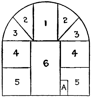
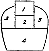
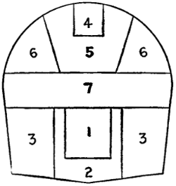
Fig. 58.—Sequence of Excavation in
the Murray Hill Tunnel.
—The two parallel tunnels were driven exclusively
from the ends reached by shafts; thus the tunnels were
attacked at four parts. It was in these tunnels that a comparative
test was made of the different methods of driving tunnels
through rock. The contractor applied the heading and drift
method at the southern ends of the tunnels, the eastern tunnel
being driven by means of a drift while in the western tunnel
the usual heading method was followed. This latter method
is illustrated in the chapter following and the eastern tunnel at
33rd Street, excavated by means of a drift, is here considered.
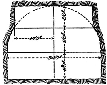
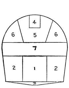
Fig. 58 shows the sequence of
cuts adopted for this tunnel. It
was begun by a bottom drift, about
10 ft. high, 8 ft. wide and 7 ft. deep,
which was located at one side of
the axis of the tunnel, as indicated
in the figure. This drift was immediately
widened by removing the
portions marked 2. About 50 ft.
in the rear the part marked 3 was
taken away, thus clearing the entire lower portion of the tunnel.
Section 4, about 50 ft. to the rear of section 3, was then
broken down and removed.
The methods of drilling and blasting were as follows: In
taking out the original drift, a wedge-shaped center cut was made
and then enlarged to the full size of the drift by drilling parallel
holes. The succeeding sections, 2 and 3, were removed by
driving parallel holes, while the top section, 4, was taken away
by a center cut and parallel holes. The drills were mounted
on columns, two drills to a column, and the holes were usually
drilled about 7 ft. deep, starting with a diameter of 23⁄4 in. and
ending with a diameter of 13⁄4 in. They were blasted with 40%
dynamite in light charges, only a few holes being fired at a time,
usually not more than three or four.
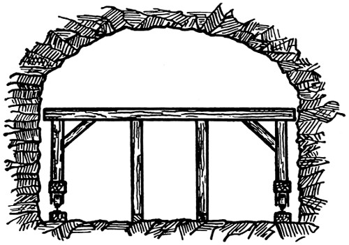
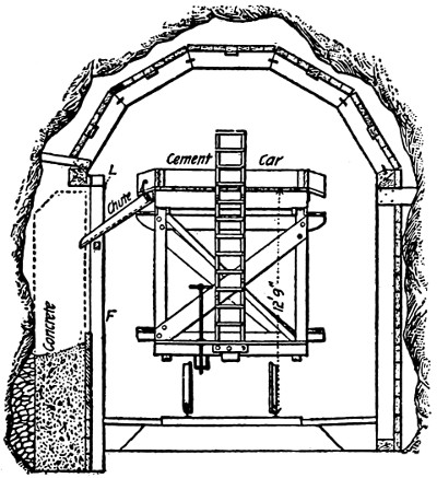
Fig. 59.—Traveling Platform for the Excavation of
the Upper Side of the Murray Hill Tunnel.
To remove section 4, a traveling platform 101⁄2 ft. long and
25 ft. wide was used. This platform, as shown in Fig. 59, consisted
of two longitudinal
beams mounted on four
double flanged wheels
which were running on
tracks laid 23 ft. apart.
Resting on top of these
beams were four 12 in. ×
12 in. uprights braced in
every direction against the
framework of the platform.
This frame was built of
12 in. × 12 in. beams laid
longitudinally, the transverse beams being 12 in. × 14 ins. The
platform proper was made of 3 in. planks, and was set 9 ft. above
the tunnel floor. The columns supporting the drills for the excavation
of the upper section 4, were set up above the platform
which was then reinforced by other vertical props, as indicated
by the dotted lines in the figure. These props, however, were
placed so as to leave a clearance beneath the platform for the
cars to carry away the débris from the front. During the
blasting the platform was moved back so that the blasted rock
fell to the floor of the tunnel, whence it was loaded into boxes
on the cars.
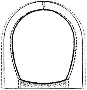
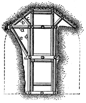
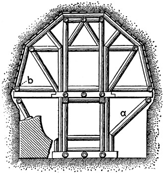
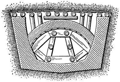
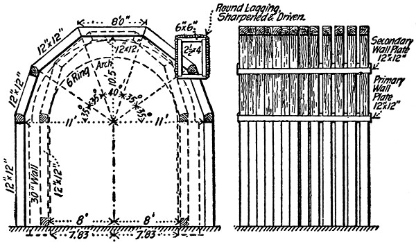
—When the rock was seamy and full of fissures,
running in every direction, it was necessary to support the
roof of the excavation. This was done in the following manner:
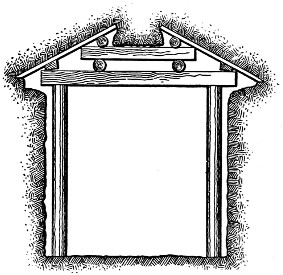
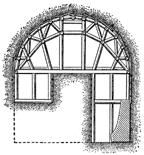
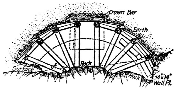
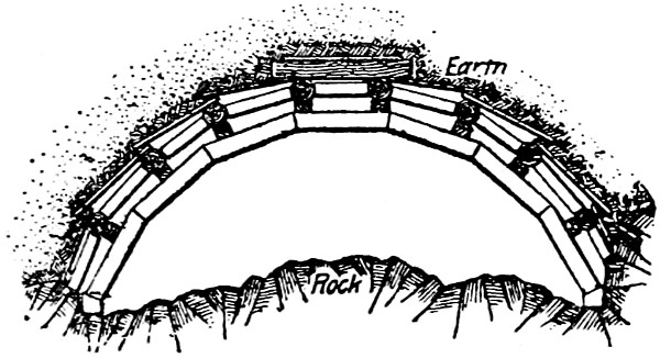
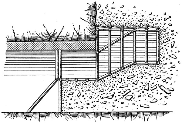
After part 4 was removed the timbers supporting the roof of
the excavation were set up. In this case, the polygonal strutting
was used. This consisted of heavy timber frames placed transversely
to the axis of the tunnel and supporting the planks or
poling-boards which ran longitudinally against the roof of the
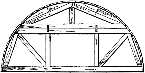
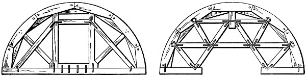
excavation. The seven-segment arch frame was used in the
Murray Hill tunnel. At the bottom of part 4 were placed
longitudinally 12 × 16 in. beams and upon them rested the
inclined segments which, with a horizontal one, formed the
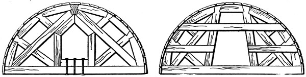
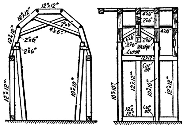
arch frame as shown in Fig. 60.
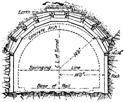
When the pressures were too
heavy the crown segment was
reinforced by a 6 × 12 in. beam,
kept in place by two 12 × 12 in.
inclined props which rested on
the templates. As the tunnel
was lined with concrete, the timbering
was left in place and it
was built outside the line of the
extrados of the concrete lining.
Timbering was only used for a short distance but it necessitated
a larger amount of rock excavation when it was required.
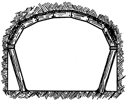
Fig. 60.—Timbering Used in the Murray
Hill Tunnel.
—Great efficiency was shown in the method of
hauling away the excavated materials. Three narrow-gauge
parallel tracks were laid on the floor of the tunnel and extended
to the faces of the advance drifts. Small flat cars were run on
these tracks. They carried steel boxes, 5 ft. square and 15 ins.
deep, fitted with three lifting rings and chains. When filled,
the cars were run to the bottom of the shaft, the boxes were
hoisted by a stiff-legged derrick placed at the shaft head, and
the débris was dumped into storage bins of 300 cu. yds. capacity.
These bins were elevated 8 ft. above the street so that the
wagons could be driven under it to take loads of spoil by
means of chutes. The broken rock was loaded into the boxes
by hand.
—The tunnel was lined with concrete which
was manufactured by a quite elaborate plant. A stone crushing
plant, consisting of bins for raw and crushed stone, was erected
at the shaft head and a mixing plant was suspended from the
shaft. On the platform of the shaft head were two bins side
by side, one for crushed stone, the other for sand; both of which
communicated, by means of trap doors, with a hopper chute.
The materials from the hopper were delivered into a measuring
box where cement was laid on top of the other ingredients by
hand. They were then conveyed through a canvas chute into
a cubical mixer operated by an engine. The mixer discharged
its contents into skips set on cars at the bottom of the
shaft and the concrete was hauled inside the tunnel ready for
use.
The construction of the lining was accomplished by means of
traveling platforms. The footing courses were laid first. Because
these projected inward about 18 ins. from the faces of the
finished sidewalks it was possible to lay a track rail on their top
inner edges on each side of the tunnel. These track rails carried
the traveling platforms. There were three of these platforms;
the forward one was used for building the side walls; the center
one, for carrying a derrick; the last one, for building the roof
arch. The side wall platform was mounted on six wheels. On
each side there was mounted an adjustable lagging which was
curved to conform to the inside profile of the side wall. In
operation this platform was run to the point where the side walls
were to be constructed and the lagging was adjusted to position
and fastened. Skips of concrete were then hoisted on its top,
their contents were shoveled into the space between the lagging
and the wall of the excavation and were there rammed into place
until the finished concrete had reached the top of the lagging.
When the concrete had set, the wedges holding the lagging in
place were loosened and the platform was moved ahead and
adjusted for building a new section of wall. The derrick platform
was 231⁄2 ft. wide and 18 ft. long. Transversely, it had
three bays, two of which were floored over and one was left
without flooring to allow passage for the concrete skips to and
from the cars, on the tunnel floor beneath. At the center of
the floored area was mounted a derrick to handle the skips. In
operation, the derrick platform came between the side wall
platform ahead and the roof platform behind. The construction
of the roof platform was practically the same as the side wall
platform with the addition of roof arch centers at each bent
on which lagging could be placed. The mode of procedure was
to erect the form for a small space between the side walls already
built and the haunches of the center, to shovel concrete from the
skips and to run it into place. Then the roof lagging, a part at
a time, was placed upward from the haunches and the concrete
was filled and rammed behind it. The lining was built from the
haunches upward until the two sides approached within a distance
of about 5 ft. from each other at the crown. This 5 ft. crown
strip or key was built by working from the rear toward the front
end of the platform.
—The plant used by the contractors for Section IV.
of the subway comprised a central power plant located about
4000 ft. from the work. This was on 42nd Street near the East
River and furnished power for the work on both Sections IV.
and V. The buildings consisted of an engine room 63 × 30 ft.
and a boiler room, 42 × 28 ft. In the former room was located
one Rand-Corliss air compressor, 22 × 40 × 48 ins., having a
capacity of 5000 cu. ft. of free air per minute; in the latter room
there were two 200 H.P. water tube boilers. There were also
the necessary equipment of feed water pump, air condenser
pump, etc. The compressors discharged into a 20 × 51⁄2 ft.
receiver of riveted steel through a 7 in. pipe. The air from the
receiver was carried by a 10 in. pipe 3.277 ft. to the corner of
Park Avenue and 41st Street, and was thence run south along
Park Avenue in an 8 in. pipe, from which 3 in. branches led to
the four headings of the work.
—The ventilation of the tunnel caused very
little trouble. In cool weather the natural draft of the shafts
and the air discharged from the drills served to keep the atmosphere
wholesome. In warm weather, artificial means were
necessary to clear the workings of foul air, particularly after
blasting. They comprised at each end a 4 ft. American exhaust
fan drawing air from a 12 in. riveted galvanized iron pipe, which
extended to the working faces.
—The tunnel was lighted by electric lamps which
extended even to the working face. During the blasting, however,
all the lamps and wires within 100 ft. from the front were
removed and gasoline torches were used; they were also employed
before the electric lamps and wires could be replaced, to
light the tunnel during the operation of clearing the débris.