HEAT TREATMENT OF STEEL
Heat treatment consists in heating and cooling metal at definite
rates in order to change its physical condition. Many objects may
be attained by correct heat treatment, but nothing much can be
expected unless the man who directs the operations knows what is
the essential difference in a piece of steel at room temperature
and at a red heat, other than the obvious fact that it is hot. The
science of metallography has been developed in the past 25 years,
and aided by precise methods of measuring temperature, has done
much to systematize the information which we possess on metallic
alloys, and steel in particular.
One of the most important means of investigating the properties of
pure metals and their alloys is by an examination of their heating
and cooling curves. Such curves are constructed by taking a small
piece and observing and recording the temperature of the mass at
uniform intervals of time during a uniform heating or cooling.
These observations, when plotted in the form of a curve will show
whether the temperature of the mass rises or falls uniformly.
The heat which a body absorbs serves either to raise the temperature
of the mass or change its physical condition. That portion of the
heat which results in an increase in temperature of the body is
called "sensible heat," inasmuch as such a gain in heat is apparent
to the physical senses of the observer. If heat were supplied to the
body at a uniform rate, the temperature would rise continuously,
and if the temperature were plotted against time, a smooth rising
curve would result. Or, if sensible heat were abstracted from the
body at a uniform rate, a time-temperature curve would again be a
smooth falling curve. Such a curve is called a "cooling curve."
However, we find that when a body is melting, vaporizing, or otherwise
suffering an abrupt change in physical properties, a quantity of
heat is absorbed which disappears without changing the temperature
of the body. This heat absorbed during a change of state is called
"latent heat," because it is transformed Page 106 into the work necessary to change
the configuration and disposition of the molecules in the body;
but it is again liberated in equal amount when the reverse change
takes place.
From these considerations it would seem that should the cooling
curve be continuous and smooth, following closely a regular course,
all the heat abstracted during cooling is furnished at the expense
of a fall in temperature of the body; that is to say, it disappears
as "sensible heat." These curves, however, frequently show horizontal
portions or "arrests" which denote that at that temperature all
of the heat constantly radiating is being supplied by internal
changes in the alloy itself; that is, it is being supplied by the
evolution of a certain amount of "latent heat."
In addition to the large amount of heat liberated when a metal
solidifies, there are other changes indicated by the thermal analysis
of many alloys which occur after the body has become entirely
solidified. These so-called transformation points or ranges may
be caused by chemical reactions taking place within the solid,
substances being precipitated from a "solid solution," or a sudden
change in some physical property of the components, such as in
magnetism, hardness, or specific gravity.
It may be difficult to comprehend that such changes can occur in
a body after it has become entirely solidified, owing to the usual
conception that the particles are then rigidly fixed. However, this
rigidity is only comparative. The molecules in the solid state
have not the large mobility they possess as a liquid, but even so,
they are still moving in circumscribed orbits, and have the power,
under proper conditions, to rearrange their position or internal
configuration. In general, such rearrangement is accompanied by a
sudden change in some physical property and in the total energy
of the molecule, which is evidenced by a spontaneous evolution or
absorption of latent heat.
Cooling curves of the purest iron show at least two well-defined
discontinuities at temperatures more than 1,000°F., below its
freezing-point. It seems that the soft, magnetic metal so familiar
as wrought iron, and called "alpha iron" or "ferrite" by the
metallurgist, becomes unstable at about 1,400°F. and changes
into the so-called "beta" modification, becoming suddenly harder,
and losing its magnetism. This state in turn persists no higher
than 1,706°C., when a softer, non-magnetic "gamma" iron is the
stable modification up to the actual melting-point of the metal.
These various changes occur in electrolytic Page 107 iron, and therefore cannot be
attributed to any chemical reaction or solution; they are entirely
due to the existence of "allotropic modifications" of the iron
in its solid state.
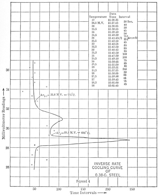
FIG. 45.—Inverse Rate Cooling Curve of 0.38 C Steel.
Steels, or iron containing a certain amount of carbon, develop
somewhat different cooling curves from those produced by pure iron.
Figure 45 shows, for instance, some data observed on a cooling piece
of 0.38 per cent carbon steel, and the curve constructed therefrom.
It will be noted that the time was noted when the needle on the
pyrometer passed each dial marking. If the metal were not changing
in its physical condition, the time between Page 108 each reading would be nearly constant;
in fact for a time it required about 50 sec. to cool each unit.
When the dial read about 32.5 (corresponding in this instrument
to a temperature of 775°C. or 1,427°F.) the cooling rate
shortened materially, 55 sec. then 65, then 100, then 100; showing
that some change inside the metal was furnishing some of the steadily
radiating heat. This temperature is the so-called "upper critical"
for this steel. Further down, the "lower critical" is shown by a
large heat evolution at 695°C. or 1,283°F.
Just the reverse effects take place upon heating, except that the
temperatures shown are somewhat higher—there seems to be a
lag in the reactions taking place in the steel. This is an important
point to remember, because if it was desired to anneal a piece of
0.38 carbon steel, it is necessary to heat it up to and beyond
1,476° F. (1,427°F. plus this lag, which may be
as much as 50°).
It may be said immediately that above the upper critical the carbon
exists in the iron as a "solid solution," called "austenite" by
metallographers. That is to say, it is uniformly distributed as atoms
throughout the iron; the atoms of carbon are not present in any fixed
combination, in fact any amount of carbon from zero to 1.7 per cent
can enter into solid solution above the upper critical. However,
upon cooling this steel, the carbon again enters into combination
with a definite proportion of iron (the carbide "cementite,"
Fe3C), and accumulates into small crystals which can be
seen under a good microscope. Formation of all the cementite has been
completed by the time the temperature has fallen to the lower critical,
and below that temperature the steel exists as a complex substance
of pure iron and the iron carbide.
It is important to note that the critical points or critical range
of a plain steel varies with its carbon content. The following
table gives some average figures:
| Carbon Content. |
Upper Critical. |
Lower Critical. |
|---|
| 0.00 | 1,706°F. |
1,330°F. |
| 0.20 | 1,600°F. |
1,330°F. |
| 0.40 | 1,480°F. |
1,330°F. |
| 0.60 | 1,400°F. |
1,330°F. |
| 0.80 | 1,350°F. |
1,330°F. |
| 0.90 |
1,330°F. |
1,330°F. |
| 1.00 | 1,470°F. |
1,330°F. |
| 1.20 | 1,650°F. |
1,330°F. |
| 1.40 | 1,830°F. |
1,330°F. |
| 1.60 | 2,000°F. |
1,330°F. |
Page 109 It is
immediately noted that the critical range narrows with increasing
carbon content until all the heat seems to be liberated at one
temperature in a steel of 0.90 per cent carbon. Beyond that composition
the critical range widens rapidly. Note also that the lower critical
is constant in plain carbon steels containing no alloying elements.
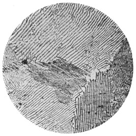
FIG. 46.—Microphotograph of steel used in S. K. F. bearings,
polished and etched with nitric acid and magnified 1,000 times. Made
by H. O. Walp.
This steel of 0.90 carbon content is an important one. It is called
"eutectoid" steel. Under the microscope a properly polished and
etched sample shows the structure to consist of thin sheets of
two different substances (Fig. 46). One of these is pure iron,
and the other is pure cementite. This structure of thin sheets
has received the name "pearlite," because of its pearly appearance
under sunlight. Pearlite is a constituent found in all annealed
carbon steels. Pure iron, having no carbon, naturally would show no
pearlite when examined under a microscope; only abutting granules
of iron are delicately traced. The metallographist calls this pure
iron "ferrite." As soon as a little carbon enters the alloy and a
soft steel is formed, small angular areas of pearlite appear at the
boundaries of the ferrite crystals (Fig. 47). With increasing carbon
in the steel the volume of iron crystals becomes less and less, and
the relative amount of pearlite increases, until arriving at 0.90
per cent carbon, the large ferrite crystals have been suppressed and
the structure is all pearlite. Higher carbon steels show films of
cementite outlining grains of pearlite (Fig. 48).
This represents the structure of annealed, slowly cooled steels.
It is possible to change the relative sizes of the ferrite and
cementite crystals by heat treatment. Large grains are associated
with brittleness. Consequently one must avoid heat treatments which
produce coarse grains.
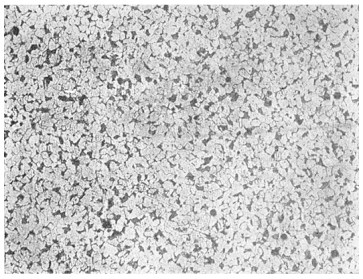
FIG. 47.—Structure of low carbon steel, polished, etched and
viewed under 100 magnifications. Tiny white granules of pure iron
(ferrite) have small accumulations of dark-etching pearlite
interspersed between them. Photograph by H. S. Rawdon.
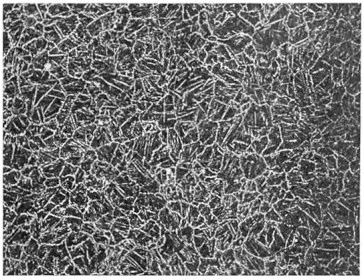
FIG. 48.—Slowly cooled high-carbon steel, polished, etched and
viewed at 100 magnifications. The dark grains are pearlite, separated
by white films of iron carbide (cementite). Photograph by H. S. Rawdon.
In general it may be said that the previous crystalline structure
of a steel is entirely obliterated when it passes just through the
critical range. At that moment, in fact, the ferrite, cementite or
Page 110 pearlite
which previously existed has lost its identity by everything going
into the solid solution called austenite. If sufficient time is
given, the chemical elements comprising a good steel distribute
themselves uniformly through the mass. If the steel be then cooled,
the austenite breaks up into new crystals of ferrite, cementite
and pearlite; and in general if the temperature has not Page 111 gone far
above the critical, and cooling is not excessively slow, a very
fine texture will result. This is called "refining" the grain;
or in shop parlance "closing" the grain. However, if the heating
has gone above the critical very far, the austenite crystals start
to grow; a very short time at an extreme temperature will cause
a large grain growth. Subsequent cooling gives a coarse texture,
or an arrangement of ferrite, cementite and pearlite grains which
is greatly coarsened, reflecting the condition of the austenite
crystals from which they were born.
It maybe noted in passing that the coarse crystals of cast metal
cannot generally be refined by heat treatment unless some forging
or rolling has been done in the meantime. Heat treatment alone does
not seem to be able to break up the crystals of an ingot structure.
Steel is hardened by quenching from above the upper critical. Apparently
the quick cooling prevents the normal change back to definite and
sizeable crystals of ferrite and cementite. Hardness is associated
with this suppressed change. If the change is allowed to continue
by a moderate reheating, like a tempering, the hardness decreases.
If a piece of steel could be cooled instantly, doubtless austenite
could be preserved and examined. In the ordinary practice of hardening
steels, the quenching is not so drastic, and the transformation of
austenite back to ferrite and cementite is more or less completely
effected, giving rise to certain transitory forms which are known
as "martensite," "troostite," "sorbite," and finally, pearlite.
Austenite has been defined as a solid solution of cementite
(Fe3C) in gamma iron. It is stable at various temperatures
dependent upon its carbon content, which may be any amount up to the
saturated solution containing 1.7 per cent. Austenite is not nearly
as hard as martensite, owing to its content of the soft gamma iron.
Fig. 49 shows austenite to possess the typical appearance of any
pure, crystallized substance.
In the most quickly quenched high carbon steels, austenite commonly
forms the ground mass which is interspersed with martensite, a large
field of which is illustrated in Fig. 50. Martensite is usually
considered to be a solid solution of cementite in beta iron. It
represents an unstable condition in which the metal Page 112 is caught
during rapid cooling. It is very hard, and is the chief constituent
of hardened high-carbon steels, and of medium-carbon nickel-steel
and manganese-steel.
Troostite is of doubtful composition, but possibly is an unstable
mixture of untransformed martensite with sorbite. It contains more
or less untransformed material, as it is too hard to be composed
entirely of the soft alpha modification, and it can also be tempered
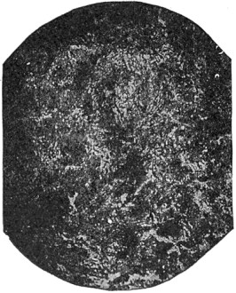
more or less without changing in appearance. Its normal appearance as
rounded grains is given in Fig. 51; larger patches show practically
no relief in their structure, and a photograph merely shows a dark,
structureless area.
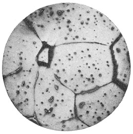
FIG. 49.—Coarse-grained martensite, polished and etched with
nitric acid and magnified 50 times. Made by Prof. Chas. Y. Clayton.
Sorbite is believed to be an early stage in the formation of pearlite,
when the iron and iron carbide originally constituting the solid
solution (austenite) have had an opportunity to separate from each
other, and the iron has entirely passed into the alpha modification,
but the particles are yet too small to be distinguishable under
the microscope. It also, possibly, contains some incompletely
transformed matter. Sorbite is softer and tougher than troostite,
and is habitually associated with pearlite. Its components are
tending to coagulate into pearlite, and will do so in a fairly
short time at temperatures near the lower critical, which heat will
furnish the necessary molecular freedom. The normal appearance,
however, is the cloudy mass shown in Fig. 52.
Pearlite is a definite conglomerate of ferrite and cementite containing
about six parts of the former to one of the latter. When pure, it
has a carbon content of about 0.95 per cent. It represents the
complete transformation of the eutectoid austenite accomplished by
slow-cooling of an iron-carbon alloy through the transformation
range. (See Fig. 46.)
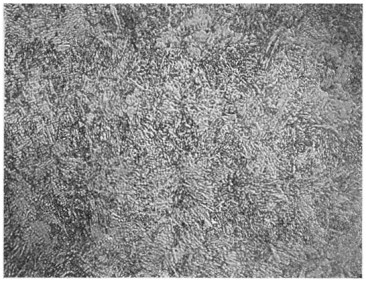
FIG. 50.—Quenched high-carbon steel, polished, etched and viewed
at 100 magnifications. This structure is called martensite and is
desired when maximum hardness is essential. Photograph by H. S. Rawdon.
|
|
|
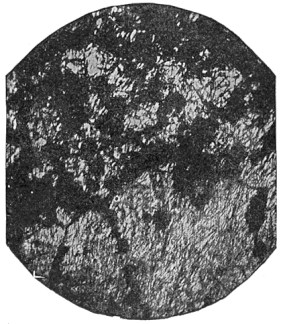
FIG. 51.—Martensite (light needles) passing into troosite
(dark patches). 130 X. From a piece of eutectoid steel electrically
welded. |
FIG. 52.—Sorbite (dark patches) passing into pearlite (wavy
striations). Light Areas are Patches of Ferrite. 220 X. From a piece
of hypo-eutectoid steel electrically welded. |
These observations are competent to explain annealing and toughening
practice. A quickly quenched carbon steel is mostly martensitic
which, as noted, is a solid solution of beta iron and Page 113 cementite,
hard and brittle. Moderate reheating or annealing changes this
structure largely into troostite, which is a partly transformed
martensite, possessing much of the hardness of martensite, but with
a largely increased toughness and shock resistance. This toughness
is the chief characteristic of the next Page 114 material in the transformation
series, sorbite, which is merely martensite wholly transformed
into a mixture of ultramicroscopic crystals of ferrite (alpha iron)
and cementite (Fe3C).
"Tempering" or "drawing" should be restricted to mean moderate
reheating, up to about 350° C., forming troostitic steel.
"Toughening" represents the practice of reheating hardened carbon
steels from 350° C. up to just below the lower critical, and
forms sorbitic steel; while "annealing" refers to a heating for
grain size at or above the transformation ranges, followed by a slow
cooling. Any of these operations not only allows the transformations
from austenite to pearlite to proceed, but also relieves internal
stresses in the steel.
Normalizing is a heating like annealing, followed by a moderately
rapid quench.
While the use of a pyrometer is of course the only way to have
accurate knowledge as to the heat being used in either forging or
hardening steels, a color chart will be of considerable assistance
if carefully studied. These have been prepared by several of the
steel companies as a guide, but it must be remembered that the colors
and temperatures given are only approximate, and can be nothing
else.
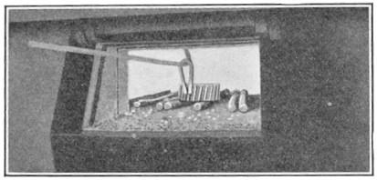
FIG. 53.—Finding hardening heats with a magnet.
The Magnet Test.—The critical point can also be determined
by an ordinary horse-shoe magnet. Touch the steel with a magnet
during the heating and when it reaches the temperature at which
steel fails to attract the magnet, or in other words, loses its
magnetism, the critical point has been reached.
Figures 53 and 54 show how these are used in practice.
Page 115 The first
(Fig. 53) shows the use of a permanent horse-shoe magnet and the
second (Fig. 54) an electro-magnet consisting of an iron rod with
a coil or spool magnet at the outer end. In either case the magnet
should not be allowed to become heated but should be applied quickly.
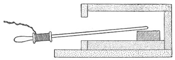
FIG. 54.—Using electro-magnet to determine heat.
The work is heated up slowly in the furnace and the magnet applied
from time to time. The steel being heated will attract the magnet
until the heat reaches the critical point. The magnet is applied
frequently and when the magnet is no longer attracted, the piece
is at the lowest temperature at which it can be hardened properly.
Quenching slightly above this point will give a tool of satisfactory
hardness. The method applies only to carbon steels and will not
work for modern high-speed steels.
This section is based on a paper read before the American Gear
Manufacturers' Association at White Sulphur Springs, W. Va., Apr.
18, 1918.
Great advancement has been made in the heat treating and hardening of
gears. In this advancement the chemical and metallurgical laboratory
have played no small part. During this time, however, the condition
of the blanks as they come to the machine shop to be machined has
not received its share of attention.
There are two distinct types of gears, both types having their
champions, namely, carburized and heat-treated. The difference
between the two in the matter of steel composition is entirely in
the carbon content, the carbon never running higher than 25-point
in the carburizing type, while in the heat-treated gears the carbon
is seldom lower than 35-point. The difference in the final gear
is the hardness. The carburized gear is file hard on the surface,
with a soft, tough and ductile core to withstand shock, while the
heat-treated gear has a surface that can be touched by a file with
a core of the same hardness as the outer surface.
Page 116 Annealing
Work.—With the exception of several of the higher types of
alloy steels, where the percentages of special elements run quite
high, which causes a slight air-hardening action, the carburizing
steels are soft enough for machining when air cooled from any
temperature, including the finishing temperature at the hammer.
This condition has led many drop-forge and manufacturing concerns
to consider annealing as an unnecessary operation and expense.
In many cases the drop forging has only been heated to a low
temperature, often just until the piece showed color, to relieve
the so-called hammer strains. While this has been only a compromise
it has been better than no reheating at all, although it has not
properly refined the grain, which is necessary for good machining
conditions.
Annealing is heating to a temperature slightly above the highest
critical point and cooling slowly either in the air or in the furnace.
Annealing is done to accomplish two purposes: (1) to relieve mechanical
strains and (2) to soften and produce a maximum refinement of grain.
Process of Carburizing.—Carburizing imparts a shell
of high-carbon content to a low-carbon steel. This produces what
might be termed a "dual" steel, allowing for an outer shell which
when hardened would withstand wear, and a soft ductile core to
produce ductility and withstand shock. The operation is carried
out by packing the work to be carburized in boxes with a material
rich in carbon and maintaining the box so charged at a temperature
in excess of the highest critical point for a length of time to
produce the desired depth of carburized zone. Generally maintaining
the temperature at 1,650 to 1,700° F. for 7 hr. will produce
a carburized zone 1/32 in. deep.
Heating to a temperature slightly above the highest critical point
and cooling suddenly in some quenching medium, such as water or oil
hardens the steel. This treatment produces a maximum refinement
with the maximum strength.
Drawing to a temperature below the highest critical point (the
temperature being governed by the results required) relieves the
hardening strains set up by quenching, as well as the reducing
of the hardness and brittleness of hardened steel.
Effect of Proper Annealing.—Proper annealing of low-carbon
steels causes a complete solution or combination to take place
between the ferrite and pearlite, producing a homogeneous mass of
small grains of each, the grains of the pearlite being surrounded
Page 117 by grains
of ferrite. A steel of this refinement will machine to good advantage,
due to the fact that the cutting tool will at all times be in contact
with metal of uniform composition.
While the alternate bands of ferrite and pearlite are microscopically
sized, it has been found that with a Gleason or Fellows gear-cutting
machine that rough cutting can be traced to poorly annealed steels,
having either a pronounced banded structure or a coarse granular
structure.
Temperature for Annealing.—Theoretically, annealing
should be accomplished at a temperature at just slightly above the
critical point. However, in practice the temperature is raised to
a higher point in order to allow for the solution of the carbon and
iron to be produced more rapidly, as the time required to produce
complete solution is reduced as the temperature increases past the
critical point.
For annealing the simpler types of low-carbon steels the following
temperatures have been found to produce uniform machining conditions
on account of producing uniform fine-grain pearlite structure:
0.15 to 0.25 per cent carbon, straight carbon steel.—Heat to
1,650°F. Hold at this temperature until the work is uniformly
heated; pull from the furnace and cool in air.
0.15 to 0.25 per cent carbon, 1½ per cent nickel, 1/2 per cent
chromium steel.—Heat to 1,600°F. Hold at this temperature
until the work is uniformly heated; pull from the furnace and cool
in air.
0.15 to 0.25 per cent carbon, 3½ per cent nickel steel.—Heat
to 1,575°F. Hold at this temperature until the work is uniformly
heated; pull from the furnace and cool in air.
Care in Annealing.—Not only will benefits in machining
be found by careful annealing of forgings but the subsequent troubles
in the hardening plant will be greatly reduced. The advantages in
the hardening start with the carburizing operation, as a steel of
uniform and fine grain size will carburize more uniformly, producing
a more even hardness and less chances for soft spots. The holes in
the gears will also "close in more uniformly," not causing some
gears to require excessive grinding and others with just enough
stock. Also all strains will have been removed from the forging,
eliminating to a great extent distortion and the noisy gears which
are the result.
With the steels used, for the heat-treated gears, always of a Page 118 higher carbon
content, treatment after forging is necessary for machining, as it
would be impossible to get the required production from untreated
forgings, especially in the alloy steels. The treatment is more
delicate, due to the higher percentage of carbon and the natural
increase in cementite together with complex carbides which are
present in some of the higher types of alloys.
Where poor machining conditions in heat-treated steels are present
they are generally due to incomplete solution of cementite rather
than bands of free ferrite, as in the case of case-hardening steels.
This segregation of carbon, as it is sometimes referred to, causes
hard spots which, in the forming of the tooth, cause the cutter
to ride over the hard metal, producing high spots on the face of
the tooth, which are as detrimental to satisfactory gear cutting
as the drops or low spots produced on the face of the teeth when
the pearlite is coarse-grained or in a banded condition.
In the simpler carburized steels it is not necessary to test the
forgings for hardness after annealing, but with the high percentages
of alloys in the carburizing steels and the heat-treated steels
a hardness test is essential.
To obtain the best results in machining, the microstructure of the
metal should be determined and a hardness range set that covers
the variations in structure that produce good machining results.
By careful control of the heat-treating operation and with the aid
of the Brinell hardness tester and the microscope it is possible
to continually give forgings that will machine uniformly and be
soft enough to give desired production. The following gives a few
of the hardness numerals on steel used in gear manufacture that
produce good machining qualities:
0.20 per cent carbon, 3 per cent nickel, 1¼; per cent
chromium—Brinell 156 to 170.
0.50 per cent carbon, 3 per cent nickel, 1 per cent
chromium—Brinell 179 to 187.
0.50 per cent carbon chrome-vanadium—Brinell 170 to 179.
The size of the piece influences the physical properties obtained in
steel by heat treatment. This has been worked out by E. J. Janitzky,
metallurgical engineer of the Illinois Steel Company, as follows:
Page 119
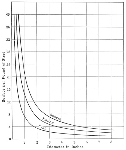
FIG. 55.—Effect of size on heating.
"With an increase in the mass of steel there is a corresponding
decrease in both the minimum surface hardness and depth hardness,
when quenched from the same temperature, under identical conditions
of the quenching medium. In other words, the physical properties
obtained are a function of the surface of the metal quenched for
a given mass of steel. Keeping this primary assumption in mind, it
is possible to predict what physical properties may be developed in
heat treating by calculating the surface per unit mass for different
shapes and sizes. It may be pointed out that the figures and chart
that follow are not results of actual tests, but are derived by
calculation. They indicate the mathematical relation, which, based
on the fact that the physical properties of steel are determined
not alone by the rate which heat is lost per unit of surface, but
by the rate which heat is lost per unit of weight in relation to
the surface exposed for that unit. The unit of weight has for the
different shaped bodies and their sizes a certain surface which
determines their physical properties.
"For example, the surface corresponding to 1 lb. of steel has been
computed for spheres, rounds and flats. For the sphere with a unit
weight of 1 lb. the portion is a cone with the apex at the center
of the Page 120
sphere and the base the curved surface of the sphere (surface exposed
to quenching). For rounds, a unit weight of 1 lb. may be taken as
a disk or cylinder, the base and top surfaces naturally do not
enter into calculation. For a flat, a prismatic or cylindrical
volume may be taken to represent the unit weight. The surfaces
that are considered in this instance are the top and base of the
section, as these surfaces are the ones exposed to cooling."
The results of the calculations are as follows:
TABLE 20.—SPHERE
Diameter
of sphere |
Surface per
pound of steel |
|---|
| X | Y |
|---|
| 8 in. |
2.648 sq. in. |
| 6 in. |
3.531 sq. in. |
| 4 in. |
5.294 sq. in. |
| 3 in. |
7.062 sq. in. |
| 2 in. |
10.61 sq. in. |
| XY = 21.185. |
TABLE 21.—ROUND
Diameter
of round |
Surface per
pound of steel |
|---|
| X | Y |
|---|
| 8.0 in. |
1.765 sq. in. |
| 6.0 in. |
2.354 sq. in. |
| 5.0 in. |
2.829 sq. in. |
| 4.0 in. |
3.531 sq. in. |
| 3.0 in. |
4.708 sq. in. |
| 2.0 in. |
7.062 sq. in. |
| 1.0 in. |
14.125 sq. in. |
| 0.5 in. |
28.25 sq. in. |
| 0.25 in. |
56.5 sq. in. |
| XY = 14.124. |
TABLE 22.—FLAT
Diameter
of flat |
Surface per
pound of steel |
|---|
| X | Y |
|---|
| 8.0 in. |
0.8828 sq. in. |
| 6.0 in. |
1.177 sq. in. |
| 5.0 in. |
1.412 sq. in. |
| 4.0 in. |
1.765 sq. in. |
| 3.0 in. |
2.345 sq. in. |
| 2.0 in. |
3.531 sq. in. |
| 1.0 in. |
7.062 sq. in. |
| 0.5 in. |
14.124 sq. in. |
| 0.25 in. |
28.248 sq. in. |
| XY = 7.062. |
Page 121 Having
once determined the physical qualities of a certain specimen, and
found its position on the curve we have the means to predict the
decrease of physical qualities on larger specimens which receive
the same heat treatment.
When the surfaces of the unit weight as outlined in the foregoing
tables are plotted as ordinates and the corresponding diameters
as abscissæ, the resulting curve is a hyperbola and follows
the law XY = C. In making these calculations the radii or
one-half of the thickness need only to be taken into consideration
as the heat is conducted from the center of the body to the surface,
following the shortest path.
The equations for the different shapes are as follows:
| For flats | XY = 7.062 |
| For rounds | XY = 14.124 |
| For spheres | XY = 21.185 |
It will be noted that the constants increase in a ratio of 1, 2,
and 3, and the three bodies in question will increase in hardness
on being quenched in the same ratio, it being understood that the
diameter of the sphere and round and thickness of the flat are
equal.
Relative to shape, it is interesting to note that rounds, squares,
octagons and other three axial bodies, with two of their axes equal,
have the same surface for the unit weight.
For example:
| Size | Length | Surface | Weight |
Surface for 1 lb. |
|---|
| 2 in. Sq. | 12 in. |
96.0 sq. in. |
13.60 lb. |
7.06 sq. in. |
| 2 in. Round | 12 in. |
75.4 sq. in. |
10.68 lb. |
7.06 sq. in. |
Although this discussion is at present based upon mathematical
analysis, it is hoped that it will open up a new field of investigation
in which but little work has been done, and may assist in settling
the as yet unsolved question of the effect of size and shape in
the heat treatment of steel.
The heat-treating department of the Brown-Lipe-Chapin Company,
Syracuse, N. Y., runs day and night, and besides handling all the
hardening of tools, parts of jigs, fixtures, special machines and
appliances, carburizes and heat-treats every month between 150,000
and 200,000 gears, pinions, crosses and other components entering
into the construction of differentials for automobiles.
The treatment of the steel really begins in the mill, where the
steel is made to conform to a specific formula. On the arrival
of the rough forgings at the Brown-Lipe-Chapin factory, the first
of a long series of inspections begins.
Page 122 Annealing
Method.—Forgings which are too hard to machine are put
in pots with a little charcoal to cause a reducing atmosphere and
to prevent scale. The covers are then luted on and the pots placed
in the furnace. Carbon steel from 15 to 25 points is annealed at
1,600°F. Nickel steel of the same carbon and containing in
addition 3½ per cent nickel is annealed at 1,450°F. When the
pots are heated through, they are rolled to the yard and allowed
to cool. This method of annealing gives the best hardness for quick
machining.
The requirements in the machine operations are very rigid and, in
spite of great care and probably the finest equipment of special
machines in the world, a small percentage of the product fails
to pass inspection during or at the completion of the machine
operations. These pieces, however, are not a loss, for they play
an important part in the hardening process, indicating as they do
the exact depth of penetration of the carburizing material and
the condition of both case and core.
Heat-treating Department.—The heat-treating department
occupies an L-shaped building. The design is very practical, with
the furnace and the floor on the same level so that there is no
lifting of heavy pots. Fuel oil is used in all the furnaces and
gives highly satisfactory results. The consumption of fuel oil
is about 2 gal. per hour per furnace.
The work is packed in the pots in a room at the entrance to the
heat-treatment building. Before packing, each gear is stamped with
a number which is a key to the records of the analysis and complete
heat treatment of that particular gear. Should a question at any time
arise regarding the treatment of a certain gear, all the necessary
information is available if the number on the gear is legible. For
instance, date of treatment, furnace, carburizing material, position
of the pot in the furnace, position of gear in pot, temperature of
furnace and duration of treatment are all tabulated and filed for
reference.
After marking, all holes and parts which are to remain uncarburized
are plugged or luted with a mixture of kaolin and Mellville gravel
clay, and the gear is packed in the carburizing material. Bohnite,
a commercial carburizing compound is used exclusively at this plant.
This does excellent work and is economical. Broadly speaking, the
economy of a carburizing compound depends on its lightness. The
space not occupied by work must be filled with compound; therefore)
other things being Page
123 equal, a compound weighing 25 lb. would be worth
more than twice as much as one weighing 60 lb. per cubic foot.
It has been claimed that certain compounds can be used over and
over again, but this is only true in a limited way, if good work
is required. There is, of course, some carbon in the compound after
the first use, but for first-class work, new compound must be used
each time.
The Packing Department.—In Fig. 56 is shown the packing
pots where the work is packed. These are of malleable cast iron,
with an internal vertical flange around the hole A. This
fits in a bell on the end of the cast-iron pipe B, which
is luted in position with fireclay before the packing begins. At
C is shown a pot ready for packing. The crown gears average
10 to 12 in. in diameter and weigh about 11 lb. each. When placed
in the pots, they surround the central tube, which allows the heat
to circulate. Each pot contains five gears. Two complete scrap
gears are in each furnace (i.e., gears which fail to pass
machining inspection), and at the top of front pot are two or more
short segments of scrap gear, used as test pieces to gage depth
of case.
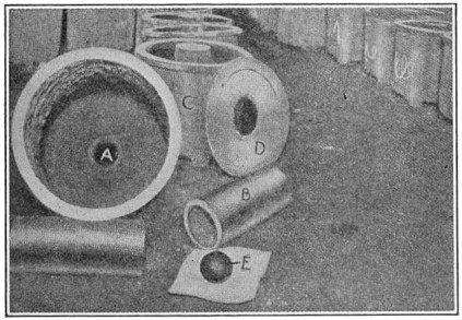
FIG. 56.—Packing department and special pots.
After filling to the top with compound, the lid D is luted
on. Ten pots are then placed in a furnace. It will be noted that the
pots to the right are numbered 1, 2, 3, 4, indicating the position
they are to occupy in the furnace.
The cast-iron ball shown at E is small enough to drop through
the pipe B, but will not pass through the hole A
in the bottom of Page
124 the pot. It is used as a valve to plug the bottom of
the pot to prevent the carburizing compound from dropping through
when removing the carburized gears to the quenching bath.
Without detracting from the high quality of the work, the metallurgist
in this plant has succeeded in cutting out one entire operation
and reducing the time in the hardening room by about 24 hr.
Formerly, the work was carburized at about 1,700°F. for 9 hr.
The pots were then run out into the yard and allowed to cool slowly.
When cool, the work was taken out of the pots, reheated and quenched
at 1,600°F. to refine the core. It was again reheated to
1,425°F. and quenched to refine the case. Finally, it was drawn
to the proper temper.
Short Method of Treatment.—In the new method, the
packed pots are run into the case-hardening furnaces, which are
heated to 1,600°F. On the insertion of the cold pots, the
temperature naturally falls. The amount of this fall is dependent
upon a number of variables, but it averages nearly 500°F. as
shown in the pyrometer chart, Fig. 61. The work and furnace must
be brought to 1,600°F. Within 2½ hr.; otherwise, a longer
time will be necessary to obtain the desired depth of case. On
this work, the depth of case required is designated in thousandths,
and on crown gears, the depth in 0.028 in. Having brought the work
to a temperature of 1,600°F. the depth of case mentioned can
be obtained in about 5½ hr. by maintaining this temperature.
As stated before, at the top of each pot are several test pieces
consisting of a whole scrap gear and several sections. After the
pots have been heated at 1,600°F. for about 5¼ hr., they
are removed, and a scrap-section test-piece is quenched direct
from the pot in mineral oil at not more than 100°F.
The end of a tooth of this is then ground and etched to ascertain
the depth of case. As these test pieces are of exactly the same
cross-section as the gears themselves, the carburizing action is
similar. When the depth of case has been found from the etched
test pieces to be satisfactory, the pots are removed. The iron ball
then is dropped into the tube to seal the hole in the bottom of
the pot; the cover and the tube are removed, and the gears quenched
direct from the pot in mineral oil, which is kept at a temperature
not higher than 100°F.
The Effect.—The heating at 1,600°F. gives the
first heat treatment which refines the core, which under the former
high heat Page 125
(1,700°F.) was rendered coarsely crystalline. All the gears,
including the scrap gears, are quenched direct from the pot in
this manner.
The gears then go to the reheating furnaces, situated in front of
a battery of Gleason quenching machines. These furnaces accommodate
from 12 to 16 crown gears. The carbon-steel gears are heated in a
reducing atmosphere to about 1,425°F. (depending on the carbon
content) placed in the dies in the Gleason quenching machine, and
quenched between dies in mineral oil at less than 100°F. The
test gear receives exactly the same treatment as the others and
is then broken, giving a record of the condition of both case and
core.
Affinity of Nickel Steel for Carbon.—The carbon- and
nickel-steel gears are carburized separately owing to the difference
in time necessary for their carburization. Practically all printed
information on the subject is to the effect that nickel steel takes
longer to carburize than plain carbon steel. This is directly opposed
to the conditions found at this plant. For the same depth of case,
other conditions being equal, a nickel-steel gear would require
from 20 to 30 min. less than a low carbon-steel gear.
From the quenching machines, the gears go to the sand-blasting
machines, situated in the wing of the heat-treating building, where
they are cleaned. From here they are taken to the testing department.
The tests are simple and at the same time most thorough.
Testing and Inspection of Heat Treatment.—The hard
parts of the gear must be so hard that a new mill file does not
bite in the least. Having passed this file test at several points,
the gears go to the center-punch test. The inspector is equipped
with a wooden trough secured to the top of the bench to support the
gear, a number of center punches (made of ¾-in. hex-steel having
points sharpened to an angle of 120 deg.) and a hammer weighing
about 4 oz. With these simple tools, supplemented by his skill, the
inspector can feel the depth and quality of the case and
the condition of the core. The gears are each tested in this way at
several points on the teeth and elsewhere, the scrap gear being also
subjected to the test. Finally, the scrap gear is securely clamped in
the straightening press shown in Fig. 57. With a 3½-lb. hammer
and a suitable hollow-ended drift manipulated by one of Sandow's
understudies, teeth are broken out of the scrap gear at various
points. These give a record confirming Page 126 the center-punch tests, which, if
the angle of the center punch is kept at 120 deg. and the weight
of the hammer and blow are uniform, is very accurate.
After passing the center-punch test the ends of the teeth are peened
lightly with a hammer. If they are too hard, small particles fly
off. Such gears are drawn in oil at a temperature of from 300 to
350°F., depending on their hardness. Some builders prefer to
have the extreme outer ends of the teeth drawn somewhat lower than
the rest. This drawing is done on gas-heated red-hot plates, as
shown at A in Fig. 58.
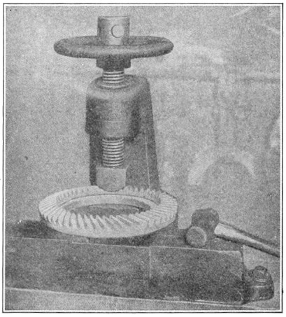
FIG. 57.—Press for holding test gears for breaking.
Nickel steel, in addition to all the tests given to carbon steel,
is subjected to a Brinell test. For each steel, the temperature
and the period of treatment are specific. For some unknown reason,
apparently like material with like treatment will, in isolated
cases, not produce like results. It then remains for the treatment
to be repeated or modified, but the results obtained during inspection
form a valuable aid to the metallurgist in determining further
treatment.
Page 127 Temperature
Recording and Regulation.—Each furnace is equipped with
pyrometers, but the reading and recording of all temperatures are
in the hands of one man, who occupies a room with an opening into
the end of the hardening department. The opening is about 15 ft.
above the floor level. On each side of it, easily legible from
all of the furnaces, is a board with the numbers of the various
furnaces, as shown in Figs. 59 and 60. Opposite each furnace number
is a series of hooks whereon are hung metal numbers representing the
pyrometer readings of the temperature in that particular furnace.
Within the room, as shown in Fig. 60, the indicating instrument
is to the right, and to the left is a switchboard to connect it
with the thermo-couples in the various furnaces. The boards shown
to the right and the left swing into the room, which enables the
attendant easily to change the numbers to conform to the pyrometer
readings. Readings of the temperatures of the carburizing furnaces
are taken and tabulated every ten minutes. These, numbered 1 to
10, are shown on the board to the right in Fig. 59. The card shown
in Fig. 61 gives such a record. These records are filed away for
possible future reference.
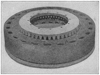
FIG. 58.—Gas heated drawing plate for tooth ends.
The temperatures of the reheating furnaces, numbered from 1 to
26 and shown on the board to the left in Fig. 59, are taken every
5 min.
Each furnace has a large metal sign on which is marked the temperature
at which the furnace regulator is required to keep Page 129 his heat.
As soon as any variation from this is posted on the board outside
the pyrometer room, the attendant sees it and adjusts the burners
to compensate.
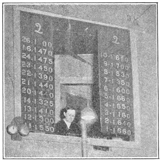
FIG. 59.—Pyrometer recording room.
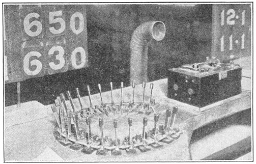
FIG. 60.—Inside of Pyrometer switch room.
Dies for Gleason Tempering Machines.—In Fig. 62 is shown
a set of dies for the Gleason tempering machine. These accurately
made dies fit and hold the gear true during quenching, thus preventing
distortion.
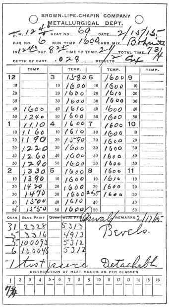
FIG. 61.—Carburizing furnace record.
Referring to Fig. 62, the die A has a surface B which
fits the face of the teeth of the gear C. This surface is
perforated by a large number of holes which permit the quenching
oil to circulate freely. The die A is set in the upper end of
the plunger Page 130
A of the tempering machine, shown in Fig. 63, a few inches
above the surface of the quenching oil in the tank N. Inside
the die A are the centering jaws D, Fig. 62, which are
an easy fit for the bore of the gear C. The inner surface
of the centering jaws is in the shape of a female cone. The upper
die is shown at E. In the center (separate from it, but a
snug sliding fit in it) is the expander G, which, during
quenching, enters the taper in the centering jaws D, expanding
them against the bore of the gear C. The faces F of
the upper die E fit two angles at the back of the gear and
are grooved for the passage of the quenching oil. The upper die
E is secured to the die carrier B, shown in Fig.
9, and inside the die is the expander G, which is backed
up by compression springs.
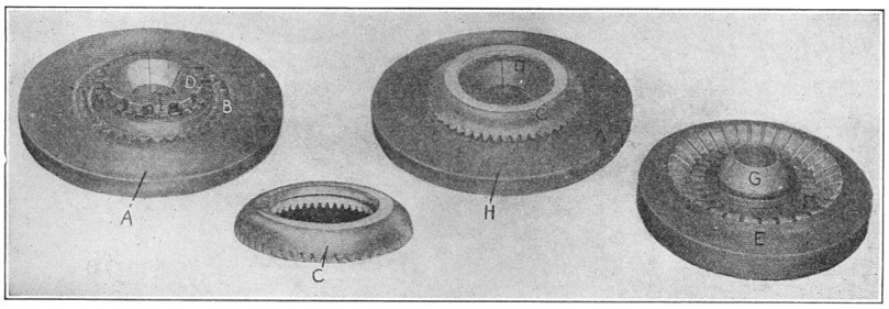
FIG. 62.—Dies for Gleason gear-hardening machine.
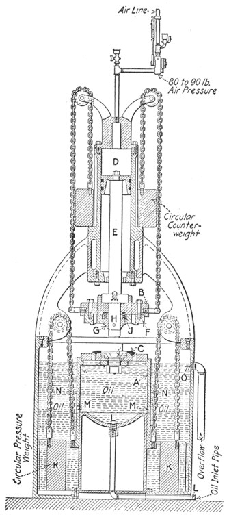
FIG. 63.—Gleason tempering machine.
Hardening Operation.—Hardening a gear is accomplished
as follows: The gear is taken from the furnace by the furnaceman
and placed in the lower die, surrounding the centering jaws, as
shown at H in Fig. 62 and C in Fig. 63. Air is then
turned into the cylinder D, and the piston rod E,
the die carrier B, the top die F and the expander
G descend. The pilot H enters a hole in the center
of Page 131 the
lower die, and the expander G enters the centering jaws
I, causing them to expand and center the gear C in
the lower die. On further advance of the piston rod E, the
expander G is forced upward against the pressure of the
springs J and the upper die F comes in contact with
the upper surface of the gear. Further downward movement of the
dies, which now clamp the work securely, overcomes the resistance
of the pressure weight K (which normally keeps up the plunger
A), and the gear is submerged in the oil. The quenching oil
is circulated through a cooling system outside the building and
enters the tempering machine through the inlet pipe L. When
the machine is in the position shown, the oil passes out through
the ports M in the lower plunger to the outer reservoir
N, passing to the cooling system by way of the overflow
O. When the lower plunger A is forced downward, the
ports M are automatically closed and the cool quenching oil
from the inlet pipe L, having no other means of escape,
passes through the holes in the lower die and the grooves in the
upper, circulating in contact with the surfaces of the gear and
passes to Page 132
the overflow. When the air pressure is released, the counterweights
return the parts to the positions shown in Fig. 63, and the operator
removes the gear.
The gear comes out uniformly hard all over and of the same degree of
hardness as when tempered in an open tank. The output of the machine
depends on the amount of metal to be cooled, but will average from
8 to 16 per hour. Each machine is served by one man, two furnaces
being required to heat the work. A slight excess of oil is used
in the firing of the furnaces to give a reducing atmosphere and
to avoid scale.
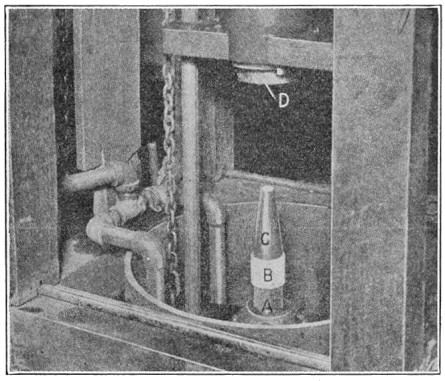
FIG. 64.—Hardening and shrinking sleeves.
Carburizing Low-carbon Sleeves.—Low-carbon sleeves
are carburized and pushed on malleable-iron differential-case hubs.
Formerly, these sleeves were given two treatments after carburization
in order to refine the case and the core, and then sent to the
grinding department, where they were ground to a push fit for the
hubs. After this they were pushed on the hubs. By the method now
employed, the first treatment refines the core, and on the second
treatment, the sleeves are pushed on the hub and at the same time
hardened. This method cuts out the internal grinding time, pressing
on hubs, and haulage from one department to another. Also, less
work is lost through splitting of the sleeves.
Page 133 The machine
for pushing the sleeves on is shown in Fig. 64. At A is
the stem on which the hot sleeve B is to be pushed. The
carburized sleeves are heated in an automatic furnace, which takes
them cold at the back and feeds them through to the front, by which
time they are at the correct temperature. The loose mandrel C
is provided with a spigot on the lower end, which fits the hole
in the differential-case hub. The upper end is tapered as shown
and acts as a pilot for the ram D. The action of pushing
on and quenching is similar to the action of the Gleason tempering
machine, with the exception that water instead of oil is used as
a quenching medium. The speed of operation depends on a number of
variables, but from 350 to 500 can be heated and pressed on in
11 hr.
Cyanide Bath for Tool Steels.—All high-carbon tool
steels are heated in a cyanide bath. With this bath, the heat can
be controlled within 3 deg. The steel is evenly heated without
exposure to the air, resulting in work which is not warped and
on which there is no scale. The cyanide bath is, of course, not
available for high-speed steel because of the very high temperatures
necessary.
The kind of steel used in the die of course influences the heat
treatment it is to receive, but this also depends on the kind of
work the die is to perform. If the die is for a forging which is
machined all over and does not have to be especially close to size,
where a variation of 1/16 in. is not considered excessive, a low
grade steel will be perfectly satisfactory.
In cases of fine work, however, where the variation cannot be over
0.005 to 0.01 in. we must use a fine steel and prevent its going
out of shape in the heating and quenching. A high quality crucible
steel is suggested with about the following analysis: Carbon 0.75
per cent, manganese 0.25 per cent, silicon 0.15 per cent, sulphur
0.015 per cent, and phosphorus 0.015 per cent. Such a steel will
have a decalescent point in the neighborhood of 1,355°F. and
for the size used, probably in a die of approximately 8 in., it
will harden around 1,450°F.
To secure best results care must be taken at every step. The block
should be heated slowly to about 1,400°F., the furnace closed
tight and allowed to cool slowly in the furnace itself. It should
not soak at the high temperature.
Page 134 After
machining, and before it is put in the furnace for hardening, it
should be slowly preheated to 800 or 900°F. This can be done
in several ways, some putting the die block in front of the open
door of a hardening furnace and keeping the furnace at about
1,000°F. The main thing is to heat the die block very slowly
and evenly.
The hardening heat should be very slow, 7 hr. being none too long
for such a block, bringing the die up gradually to the quenching
temperature of 1,450°. This should be held for 1/2 hr. or even
a little more, when the die can be taken out and quenched. There
should be no guess work about the heating, a good pyrometer being
the only safe way of knowing the correct temperature.
The quenching tank should be of good size and have a spray or stream
of water coming up near the surface. Dip the die block about 3 in.
deep and let the stream of water get at the face so as to play
on the forms. By leaving the rest of the die out of the water,
moving the die up and down a trifle to prevent a crack at the line
of immersion, the back of the block is left tough while the face
is very hard. To overcome the tendency to warp the face it is a
good plan to pour a little water on the back of the die as this
tends to even up the cooling. The depth to which the die is dipped
can be easily regulated by placing bars across the tank at the
proper depth.
After the scleroscope shows the die to be properly hardened, which
means from 98 to 101, the temper should be drawn as soon as convenient.
A lead pot in which the back of the die can be suspended so as
to heat the back side, makes a good method. Or the die block can
be placed back to the open door of a furnace. On a die of this
size it may take several hours to draw it to the desired temper.
This can be tested while warm by the scleroscope method, bearing
in mind that the reading will not be the same as when cold. If
the test shows from 76 to 78 while warm, the hardness when cold
will be about 83, which is about right for this work.
The Society of Automotive Engineers have adopted certain heat treatments
to suit different steels and varying conditions. These have already
been referred to on pages 39 to 41 in connection with the different
steels used in automobile practice. These treatments are designated
by letter and correspond with the designations in the table.
Heat Treatment A
After forging or machining:
- Carbonize at a temperature between 1,600°F. and 1,750°F.
(1,650-1,700°F. desired.)
- Cool slowly or quench.
- Reheat to 1,450-1,500°F. and quench.
Heat Treatment B
After forging or machining:
- Carbonize between 1,600°F. and 1,750°F. (1,650-1,700°F.
Desired.)
- Cool slowly in the carbonizing mixture.
- Reheat to 1,550-1,625°F.
- Quench.
- Reheat to 1,400-1,450°F.
- Quench.
- Draw in hot oil at 300 to 450°F., depending upon the degree of
hardness desired.
Heat Treatment D
After forging or machining:
- Heat to 1,500-1,600°F.
- Quench.
- Reheat to 1,450-1,500°F.
- Quench.
- Reheat to 600-1,200°F. and cool slowly.
Heat Treatment E
After forging or machining:
- Heat to 1,500-1,550°F.
- Cool slowly.
- Reheat to 1,450-1,500°F.
- Quench.
- Reheat to 600-1,200°F. and cool slowly.
Heat Treatment F
After shaping or coiling:
- Heat to 1,425-1,475°F.
- Quench in oil.
- Reheat to 400-900°F., in accordance with temper desired
and cool slowly.
Heat Treatment G
After forging or machining:
- Carbonize at a temperature between 1,600°F. and 1,750°F.
(1,650-1,700°F. desired).
- Cool slowly in the carbonizing mixture.
- Reheat to 1,500-1,550°F.
- Quench.
- Reheat to 1,300-1,400°F.
- Quench.
- Reheat to 250-500°F. (in accordance with the necessities of the case)
and cool slowly.
Heat Treatment H
After forging or machining:
- Heat to 1,500-1,600°F.
- Quench.
- Reheat to 600-1,200°F. and cool slowly.
Page 136 Heat
Treatment K
After forging or machining:
- Heat to 1,500-1,550°F.
- Quench.
- Reheat to 1,300-1,400°F.
- Quench.
- Reheat to 600-1,200°F. and cool slowly.
Heat Treatment L
After forging or machining:
- Carbonize between 1,600°F. and 1,750°F. (1,650-1,700°F.
desired).
- Cool slowly in the carbonizing mixture.
- Reheat to 1,400-1,500°F.
- Quench.
- Reheat to 1,300-1,400°F.
- Quench.
- Reheat to 250-500°F. and cool slowly.
Heat Treatment M
After forging or machining:
- Heat to 1,450-1,500°F.
- Quench.
- Reheat to 500-1.250°F. and cool slowly.
Heat Treatment P
After forging or machining:
- Heat to 1,450-1,500°F.
- Quench.
- Reheat to 1,375-1,450°F. slowly.
- Quench.
- Reheat to 500-1,250°F. and cool slowly.
Heat Treatment Q
After forging:
- Heat to 1,475-1,525°F. (Hold at this temperature one-half hour,
to insure thorough heating.)
- Cool slowly.
- Machine.
- Reheat to 1,375-1,425°F.
- Quench.
- Reheat to 250-550°F. and cool slowly.
Heat Treatment R
After forging:
- Heat to 1,500-1,550°F.
- Quench in oil.
- Reheat to 1,200-1,300°F. (Hold at this temperature three
hours.)
- Cool slowly.
- Machine.
- Reheat to 1,350-1,450°F.
- Quench in oil.
- Reheat to 250-500°F. and cool slowly.
Heat Treatment S
After forging or machining:
- Carbonize at a temperature between 1,600 and 1,750°F.
(1,650-1,700°F. Desired.)
- Cool slowly in the carbonizing mixture.
- Reheat to 1,650-1,750°F.
- Quench.
- Reheat to 1,475-1,550°F.
- Quench.
- Reheat to 250-550°F. and cool slowly.
Heat Treatment T
After forging or machining:
- Heat to 1,650-1,750°F.
- Quench.
- Reheat to 500-1,300°F. and cool slowly.
Page 137 Heat
Treatment U
After forging:
- Heat to 1,525-1,600°F. (Hold for about one-half hour.)
- Cool slowly.
- Machine.
- Reheat to 1,650-1,700°F.
- Quench.
- Reheat to 350-550°F. and cool slowly.
Heat Treatment V
After forging or machining:
- Heat to 1,650-1,750°F.
- Quench.
- Reheat to 400-1,200°F. and cool slowly.
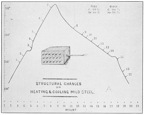
FIG. 65.—Chart of changes due to heating and cooling.
The effect of heat treatment on overheated steel is shown graphically
in Fig. 65 to the series of illustrations on pages 137 to 144. This
was prepared by Thos. Firth & Sons, Ltd., Sheffield, England.
Page 138
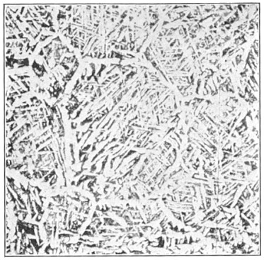
FIG. 66.—The structure of overheated mild steel from which all
the pegs were made (magnified 25 diameters). The pegs withdrawn at
720°C., or earlier, had this structure and were quite soft.
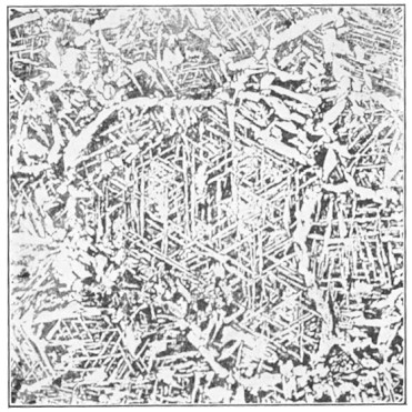
FIG. 67.—Peg withdrawn at 750°C. (magnified 25 diameters).
The structure is apparently unaltered, but the peg was hard and,
unlike the earlier ones, would not bend double.
Page 139
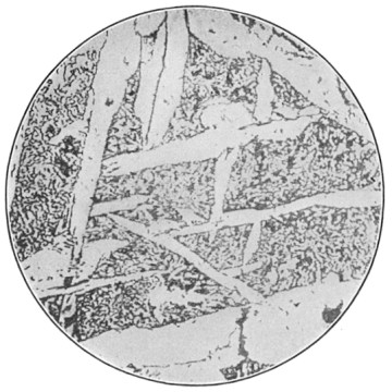
FIG. 68.—A portion of 66 magnified 200 diameters to show that
the dark (pearlite) areas are laminated.
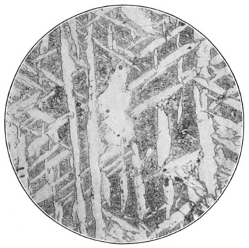
FIG. 69.—A portion of 67 magnified 200 diameters,
showing that pearlite areas are no longer laminated and providing
reason for observed hardness
Page 140
FIG. 70.—Peg withdrawn at 780°C. (magnified 25 diameters),
showing inter-diffusion of transformed pearlite and ferrite areas.
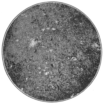
FIG. 71.—Peg withdrawn at 800°C. (magnified
25 diameters), showing inter-diffusion so far advanced that the
original outline of the crystals is now only faintly suggested.
Page 141
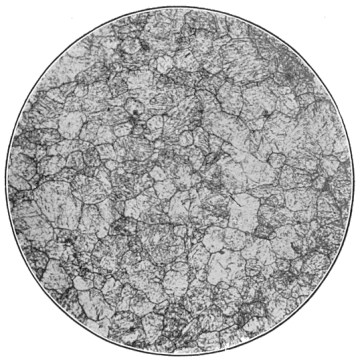
FIG. 72.—Peg withdrawn at 850°C. (magnified 100 diameters)
after inter-diffusion was completed. Note the regular outlines and
the small size of the crystals as compared with 67.
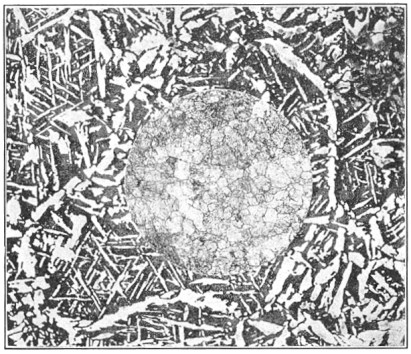
FIG. 73.—To facilitate comparison 67 was enlarged to the same
magnification as 62, and the one superimposed on the other. The
single large crystal occupied as much space as 8,000 of the smaller
ones.
Page 142
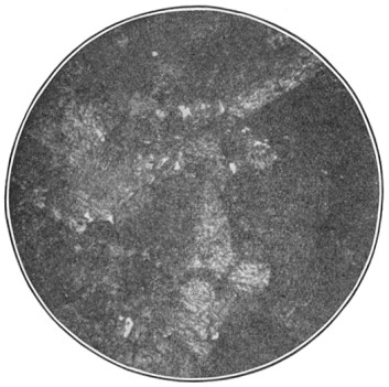
FIG. 74.—The peg withdrawn on cooling at 800°C. (magnified
100 diameters) shows the first reappearance of free ferrite. All pegs
withdrawn at higher temperatures were like Fig. 72.
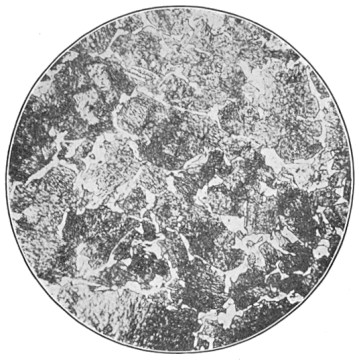
FIG. 75.—Peg withdrawn after cooling to 760°C.
The increased amount of free ferrite arranges itself about the
crystals as envelopes.
Page 143
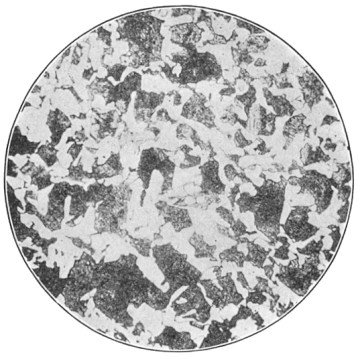
FIG. 76.-Peg withdrawn after cooling to 740°C.
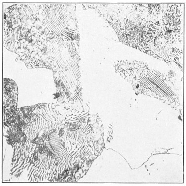
FIG. 77.—Peg withdrawn after cooling to 670°C. (magnified
800 diameters). Just at this moment the lamination of pearlite,
which now occupied its original area, was taking place. In some
parts the lamination was perfect, in other parts the iron and
iron-carbide were still dissolved in each other.
The center piece Fig. 65 represents a block of steel weighing about
25 lb. The central hole accommodated a thermo-couple which was
attached to an autographic recorder. The curve is a copy of the
temperature record during heating and cooling. Into the holes in the
side of the block small pegs of overheated mild steel were inserted.
One peg was withdrawn and quenched at Page 144 each of the temperatures indicated
by the numbered arrows, and after suitable preparation these pegs
were photographed in order to show the changes in structure taking
place during heating and cooling operations. The illustrations here
reproduced are selected from those photographs with the object
of presenting pictorially the changes involved in the refining of
overheated steel or steel castings. Figures 66 to 79 with their
captions show much that is of value to steel users.
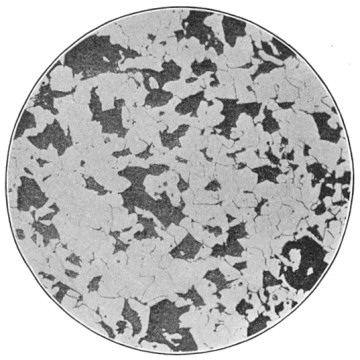
FIG. 78.—Any peg withdrawn after 670°C. on cooling
(magnified 100 diameters).
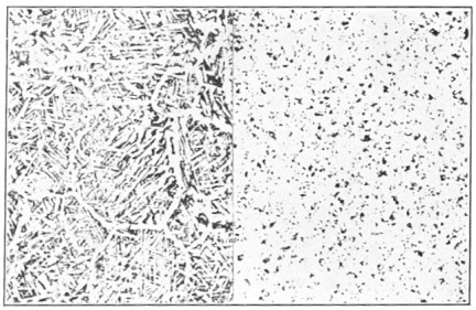
FIG. 79.—Structure of overheated steel before (left) and after
refining (right).
Page 145 CHAPTER IX — CARBON IN TOOL STEEL — CARBON STEELS FOR DIFFERENT TOOLS — USES OF THE VARIOUS TEMPERS OF CARBON TOOL STEEL — Page 151 STEEL FOR CHISELS AND PUNCHES — CHISELS-SHAPES AND HEAT TREATMENT[1] — PREVENTING DECARBONIZATION OF TOOL STEEL — ANNEALING TO RELIEVE INTERNAL STRESSES — DOUBLE ANNEALING — Page 156 QUENCHING TOOL STEEL — HINTS FOR TOOL STEEL USERS — PREVENTING CRACKS IN HARDENING — SHRINKING AND ENLARGING WORK — TEMPERING ROUND DIES — THE EFFECT OF TEMPERING ON WATER-QUENCHED GAGES — Page 163 TEMPERING COLORS ON CARBON STEELS
HARDENING CARBON STEEL FOR TOOLS
For years the toolmaker had full sway in regard to make of steel
wanted for shop tools, he generally made his own designs, hardened,
tempered, ground and usually set up the machine where it was to
be used and tested it.
Most of us remember the toolmaker during the sewing machine period
when interchangeable tools were beginning to find their way; rather
cautiously at first. The bicycle era was the real beginning of
tool making from a manufacturing standpoint, when interchangeable
tools for rapid production were called for and toolmakers were in
great demand. Even then, jigs, and fixtures were of the toolmaker's
own design, who practically built every part of it from start to
finish.
The old way, however, had to be changed. Instead of the toolmaker
starting his work from cutting off the stock in the old hack saw,
a place for cutting off stock was provided. If, for instance, a
forming tool was wanted, the toolmaker was given the master tool
to make while an apprentice roughed out the cutter. The toolmaker,
however, reserved the hardening process for himself. That was one
of the particular operations that the old toolmaker refused to
give up. It seemed preposterous to think for a minute that any
one else could possibly do that particular job without spoiling
the tools, or at least warp it out of shape (most of us did not
grind holes in cutters 15 to 20 years ago); or a hundred or more
things might happen unless the toolmaker did his own hardening
and tempering.
That so many remarkably good tools were made at that time is still
a wonder to many, when we consider that the large shop had from 30
to 40 different men, all using their own secret compounds, heating
to suit eyesight, no matter if the day was bright or dark, and then
tempering to color. But the day of the old toolmaker has changed.
Now a tool is designed by a tool designer, O.K.'d, and then a print
goes to the foreman of the tool department, who specifies the size
and gets the steel from the cutting-off department. After finishing
the machine work Page
146 it goes to the hardening room, and this is the problem
we shall now take up in detail.
The Modern Hardening Room.—A hardening room of today
means a very different place from the dirty, dark smithshop in
the corner with the open coal forge. There, when we wanted to be
somewhat particular, we sometimes shoveled the coal cinders to
one side and piled a great pile of charcoal on the forge. We now
have a complete equipment; a gas- or oil-heating furnace, good
running water, several sizes of lead pots, and an oil tank large
enough to hold a barrel of oil. By running water, we mean a large
tank with overflow pipes giving a constant supply. The ordinary
hardening room equipment should consist of:
Gas or oil muffle furnace for hardening.
Gas or oil forge furnace.
A good size gas or oil furnace for annealing and case-hardening.
A gas or oil furnace to hold lead pots.
Oil tempering tank, gas- or oil-heated.
Pressure blower.
Large oil tank to hold at least a barrel of oil.
Big water tank with screen trays connected with large pipe from bottom
with overflow.
Straightening press.
The furnace should be connected with pyrometers and tempering tank with
a thermometer.
Beside all this you need a good man. It does not make much difference
how completely the hardening department is fitted up, if you expect
good work, a small percentage of loss and to be able to tackle anything
that comes along, you must have a good man, one who understands
the difference between low- and high-carbon steel, who knows when
particular care must be exercised on particular work. In other
words, a man who knows how his work should be done, and has the
intelligence to follow directions on treatments of steel on which
he has had no experience.
Jewelers' tools, especially for silversmith's work, probably have
to stand the greatest punishment of any all-steel tools and to
make a spoon die so hard that it will not sink under a blow from
an 1,800-lb. hammer with a 4-ft. drop, and still not crack, demands
careful treatment.
To harden such dies, first cover the impression on the die with
paste made from bone dust or lampblack and oil. Place face down
in an iron box partly filled with crushed charcoal, leaving back
of die uncovered so that the heat can be seen at all times. Page 147 Heat slowly
in furnace to a good cherry red. The heat depends on the quality
and the analysis of steel and the recommended actions of the steel
maker should be carefully followed. When withdrawn from the fire
the die should be quenched as shown in Fig. 80 with the face of
die down and the back a short distance out of the water. When the
back is black, immerse all over.
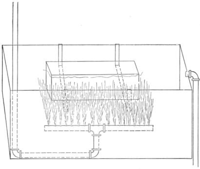
FIG. 80.—Quenching a die, face down.
If such a tank is not at hand, it would pay to rig one up at once,
although a barrel of brine may be used, or the back of the die
may be first immersed to a depth of about 1/2 in. When the piece
is immersed, hold die on an angle as in Fig. 81.
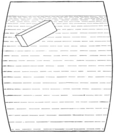
FIG. 81.—Hold die at angle to quench.
This is for the purpose of expelling all steam bubbles as they
form in contact with hot steel. We are aware of the fact that a
great many toolmakers in jewelry shops still cling to the overhead
bath, as in Fig. 82, but more broken pieces and more dies with soft
spots are due to this method than to all the others combined, as the
water strikes one spot in force, contracting Page 148 the surface so much faster than
the rest of the die that the results are the same as if an uneven
heating had been given the steel.
Take Time for Hardening.—Uneven heating and poor quenching
has caused loss of many very valuable dies, and it certainly seems
that when a firm spends from $75 to $450 in cutting a die that
a few hours could be spared for proper hardening. But the usual
feeling is that a tool must be hurried as soon as the hardener
gets it, and if a burst die is the result from either uneven or
overheated steel and quenching same without judgment, the steel
gets the blame.
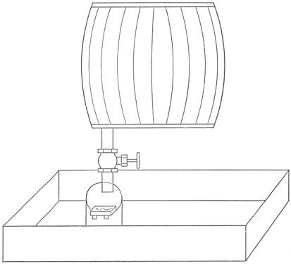
FIG. 82.—An obsolete method.
Give the steel a chance to heat properly, mix a little common sense
with "your 30 years experience on the other fellows steel." Remember
that high-carbon steel hardens at a lower heat than low-carbon
steel, and quench when at the right heat in the two above ways,
and 99 per cent of the trouble will vanish.
When a die flies to pieces in quenching, don't rush to the
superintendent with a "poor-steel" story, but find out first why it
broke so that the salesman who sold it will not be able to harden
piece after piece from the same bar satisfactorily. If you find
a "cold short," commonly called "a pipe," you can lay the blame
on the steelmaker. If it is a case of overheating and quenching
Page 149 when
too hot, you will find a coarse grain with many bright spots like
crystals to the hardening depth. If uneven heating is the cause,
you will find a wider margin of hardening depth on one side than
on the other, or find the coarse grain from over-heating on one
side while on the other you will find a close grain, which may be
just right. If you find any other faults than a "pipe," or are not
able to harden deep enough, then take the blame like a man and send
for information. The different steel salesmen are good fellows and
most of them know a thing or two about their own business.
For much work a cooling bath at from 50 to 75°F. is very good
both for small hobs, dies, cutter plates or plungers. Some work
will harden best in a barrel of brine, but in running cold water,
splendid results will be obtained. Cutter plates should always be
dipped corner first and if any have stripper holes, they should
first be plugged with asbestos or fire clay cement.
In general it may be said that the best hardening temperature for
carbon steel is the lowest temperature at which it will harden
properly.
Carbon tool steel, or "tool steel" as it is commonly called, usually
contains from 80 to 125 points (or from 0.80 to 1.25 per cent)
of carbon, and none of the alloys which go to make up the high
speed steels. This was formerly known also as crucible or "cast"
steel, or crucible cast steel, from the way in which it was made.
This was before the days of steel castings. The advent of these
caused so much confusion that the term was soon dropped. When we
say "tool steel," we nearly always refer to carbon-tool steel,
high-speed steel being usually designated by that name.
For many purposes carbon-steel cutters are still found best, although
where a large amount of material is to be removed at a rapid rate,
it has given way to high-speed steels.
All users of tool steels should carefully study the different qualities
of the steels they handle. Different uses requires different kinds of
steel for best results, and for the purpose of designating different
steels some makers have adopted the two terms "temper," and "quality,"
to distinguish between them.
In this case temper refers to the amount of carbon which Page 150 is combined
with the iron to make the metal into a steel. The quality means
the absence of phosphorous, sulphur and other impurities, these
depending on the ores and the methods of treatment.
Steel makers have various ways of designating carbon steels for
different purposes. Some of these systems involve the use of numbers,
that of the Latrobe Steel Company being given herewith. It will
be noted that the numbers are based on 20 points of carbon per
unit. The names given the different tempers are also of interest.
Other makers use different numbers.
The temper list follows:
LATROBE TEMPER LIST OF CARBON TOOL STEELS
| No. 3 | temper 0.60 to 0.69 per cent carbon |
| No. 3½ |
temper 0.70 to 0.79 per cent carbon |
| No. 4 | temper 0.80 to 0.89 per cent carbon |
| No. 4½ |
temper 0.90 to 0.99 pet cent carbon |
| No. 5 | temper 1.00 to 1.09 per cent carbon |
| No. 5½ |
temper 1.10 to 1.19 per cent carbon |
| No. 6 | temper 1.20 to 1.29 per cent carbon |
| No. 6½ |
temper 1.30 to 1.39 per cent carbon |
| No. 7 | temper 1.40 to 1.49 per cent carbon |
Die Temper.—No. 3: All kinds of dies for deep stamping,
pressing and drop forgings. Mining drills to harden only. Easily
weldable.
Smiths' Tool Temper.—No. 3½: Large punches, minting
and rivet dies, nailmakers' tools, hammers, hot and cold sets,
snaps and boilermakers' tools, various smiths' tools, large shear
blades, double-handed chisels, caulking tools, heading dies, masons'
tools and tools for general welding purposes.
Shear Blade Temper.—No. 4: Punches, large taps, screwing
dies, shear blades, table cutlery, circular and long saws, heading
dies. Weldable.
General Purpose Temper.—No. 4½: Taps, small punches,
screwing dies, sawwebs, needles, etc., and for all general purposes.
Weldable.
Axe Temper.—No. 5: Axes, chisels, small taps, miners'
drills and jumpers to harden and temper, plane irons. Weldable
with care.
Cutlery Temper.—No. 5½: Large milling cutters,
reamers, pocket cutlery, wood tools, short saws, granite drills,
paper and tobacco knives. Weldable with very great care.
Tool Temper.—No. 6: Turning, planing, slotting, and
shaping tools, twist drills, mill picks, scythes, circular cutters,
engravers' tools, surgical cutlery, circular saws for cutting metals,
bevel and other sections for turret lathes. Not weldable.
Hard Tool Temper.—No. 6½: Small twist drills, razors,
small and intricate engravers' tools, surgical instruments, knives.
Not weldable.
Razor Temper.—No. 7: Razors, barrel boring bits, special
lathe tools for turning chilled rolls. Not weldable.
The highest grades of carbon or tempering steels are to be recommended
for tools which have to withstand shocks, such as for cold chisels
or punches. These steels are, however, particularly useful where
it is necessary to cut tempered or heat-treated steel which is
more than ordinarily hard, for cutting chilled iron, etc. They are
useful for boring, for rifle-barrel drilling, for fine finishing
cuts, for drawing dies for brass and copper, for blanking dies for
hard materials, for formed cutters on automatic screw machines
and for roll-turning tools.
Steel of this kind, being very dense in structure, should be given
more time in heating for forging and for hardening, than carbon
steels of a lower grade. For forging it should be heated slowly
and uniformly to a bright red and only light blows used as the
heat dies out. Do not hammer at all at a black heat. Reheat slowly
to a dark red for hardening and quench in warm water. Grind on a
wet grindstone.
Where tools have to withstand shocks and vibration, as in pneumatic
hammer work, in severe punching duty, hot or cold upsetting or
similar work, tool steels containing vanadium or chrome-vanadium
give excellent results. These are made particularly for work of
this kind.
In the chief mechanical engineer's department of the Midland Ry.,
after considerable experimenting, it was decided to order chisel
steel to the following specifications: carbon, 0.75 to 0.85 per
cent, the other constituents being normal. This gives a complete
analysis as follows: carbon, 0.75 to 0.85; manganese, 0.30; silicon,
0.10; sulphur, 0.025; phosphorus, 0.025.
The analysis of a chisel which had given excellent service was as
follows: carbon, 0.75; manganese, 0.38; silicon, 0.16; sulphur,
0.028; phosphorus, 0.026. The heat treatment is unknown.
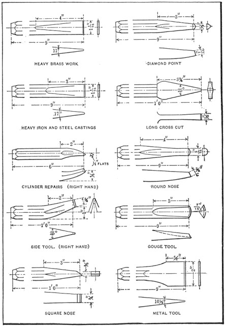
FIG. 83.—Forms of chisels standardized for the locomotive
shops of the Midland Ry., England.
At the same time that chisel steel was standardized, the form of
the chisels themselves was revised, and a standard chart of these as
used in the locomotive shops was drawn up. Figure 83 shows the most
important forms, which are made to stock orders Page 152 in the smithy and forwarded to the
heat-treatment room where the hardening and tempering is carried
out on batches of fifty. A standard system of treatment is employed,
which to a very large extent does away with the personal element.
Since the chemical composition is more or less constant, the chief
variant is the section which causes the temperatures to be varied
slightly. The chisels are carefully heated in a gas-fired furnace to
a temperature of from 730 to 740°C. (1,340 to 1,364°F.)
according to section. In practice, the first chisel, is heated
to 730°C.; and Page
153 the second to 735°C. (1,355°F.); and a 1 in.
half round chisel to 740°C., because of their varying increasing
thickness of section at the points. Upon attaining this steady
temperature, the chisels are quenched to a depth of 3/8 to 1/2
in. from the point in water, and then the whole chisel is immersed
and cooled off in a tank containing linseed oil.
The oil-tank is cooled by being immersed in a cold-water tank through
which water is constantly circulated. After this treatment, the
chisels have a dead hard point and a tough or sorbitic shaft. They
are then tempered or the point "let down." This is done by immersing
them in another oil-bath which has been raised to about 215°C.
(419°F). The first result is, of course, to drop the temperature
of the oil, which is gradually raised to its initial point. On
approaching this temperature the chisels are taken out about every
2°C. rise and tested with a file, and at a point between 215 and
220°C. (428°F.), when it is found that the desired temper
has been reached, the chisels are removed, cleaned in sawdust, and
allowed to cool in an iron tray.
No comparative tests of these chisels with those bought and treated
by the old rule-of-thumb methods have been made, as no exact method
of carrying out such tests mechanically, other than trying the
hardness by the Brinell or scleroscope method, are known; any ordinary
test depends so largely upon the dexterity of the operator. The
universal opinion of foremen and those using the chisels as to the
advantages of the ones receiving the standard treatment described
is that a substantial improvement has been made. The chisels were
not "normalized." Tests of chisels normalized at about 900°C.
(1,652°F.) showed that they possessed no advantage.
Tools or pieces which have holes or deep depressions should be
filled before heating unless it is necessary to have the holes
hard on the inside. In that case the filling would keep the water
away from the surface and no hardening would take place. Where
filling is to be done, various materials are used by different
hardeners. Fireclay and common putty seem to be favored by many.
Every mechanic who has had anything to do with the hardening of
tools knows how necessary it is to take a cut from the surface of
the bar that is to be hardened. The reason is that in the process
of making the steel its outer surface has become decarbonized. This
change makes it low-carbon steel, which will of Page 154 course not harden. It is necessary
to remove from 1/16 to ¼ in. of diameter on bars ranging from
1/2 to 4 in.
This same decarbonization occurs if the steel is placed in the
forge in such a way that unburned oxygen from the blast can get at
it. The carbon is oxidized, or burned out, converting the outside
of the steel into low-carbon steel. The way to avoid this is to use
a deep fire. Lack of this precaution is the cause of much spoiled
work, not only because of decarbonization of the outer surface
of the metal, but because the cold blast striking the hot steel
acts like boiling hot water poured into an ice-cold glass tumbler.
The contraction sets up stresses that result in cracks when the
piece is quenched.
It is especially important to prevent decarbonization in such tools
as taps and form cutters, which must keep their shape after hardening
and which cannot be ground away on the profile. For this reason
it is well to put taps, reamers and the like into pieces of pipe
in heating them. The pipe need be closed on one end only, as the
air will not circulate readily unless there is an opening at both
ends.
Even if used in connection with a blacksmith's forge the lead bath
has an advantage for heating tools of complicated shapes, since
it is easier to heat them uniformly and they are submerged and
away from the air. The lead must be stirred frequently or the heat
is not uniform in all parts of the lead bath. Covering the lead
with powdered charcoal will largely prevent oxidization and waste
of lead.
Such a bath is good for temperatures between 620 and 1,150°F.
At higher temperatures there is much waste of lead.
Work quenched from a high temperature and not afterward tempered
will, if complex in shape, contain many internal stresses which may
later cause it to break. They may be eased off by slight heating
without materially lessening the hardness of the piece. One way to do
this is to hold the piece over a fire and test it with a moistened
finger. Another way is to dip the piece in boiling water after it
has first been quenched in a cold bath. Page 155 Such steps are not necessary with
articles which will afterward be tempered and in which the strains
are thus reduced.
In annealing steels the operation is similar to hardening, as far
as heating is concerned. The critical temperatures are the proper
ones for annealing as well as hardening. From this point on there
is a difference, for annealing consists in cooling as slowly as
possible. The slower the cooling the softer will be the steel.
Annealing may be done in the open air, in furnaces, in hot ashes
or lime, in powdered charcoal, in burnt bone, in charred leather
and in water. Open-air annealing will do as a crude measure in
cases where it is desired to take the internal stresses out of
a piece. Care must be taken in using this method that the piece
is not exposed to drafts or placed on some cold substance that
will chill it. Furnace annealing is much better and consists in
heating the piece in a furnace to the critical temperature and
then allowing the work and the furnace to cool together.
When lime or ashes are used as materials to keep air away from
the steel and retain the heat, they should be first heated to make
sure that they are dry. Powdered charcoal is used for high-grade
annealing, the piece being packed in this substance in an iron box
and both the work and the box raised to the critical temperature
and then allowed to cool slowly. Machinery steel may be annealed
in spent ground-bone that has been used in casehardening; but
tool steel must never be annealed in this way, as it will be
injured by the phosphorus contained in the bone. Charred leather
is the best annealing material for high-carbon steel, because it
prevents decarbonizing taking place.
Water annealing consists in heating the piece, allowing it to cool
in air until it loses its red heat and becomes black and then
immediately quenching it in water. This plan works well for very
low-carbon steel; but for high-carbon steel what is known as the
"double annealing treatment" must be given, provided results are
wanted quickly. The process consists in heating the steel quickly
to 200° or more above the upper critical, cooling in air down
through the recalescence point, then reheating it to just above the
critical point and again cooling slowly through the recalescence, then
quenching in oil. This process retains in the steel a fine-grained
structure combined with softness.
To secure proper hardness, the cooling of quenching of steel is
as important as its heating. Quenching baths vary in nature, there
being a large number of ways to cool a piece of steel in contrast
to the comparatively few ways of heating it.
Plain water, brine and oil are the three most common quenching
materials. Of these three the brine will give the most hardness,
and plain water and oil come next. The colder that any of these
baths is when the piece is put into it the harder will be the steel;
but this does not mean that it is a good plan to dip the heated
steel into a tank of ice water, for the shock would be so great
that the bar would probably fly to pieces. In fact, the quenching
bath must be sometimes heated a bit to take off the edge of the
shock.
Brine solutions will work uniformly, or give the same degree of
hardness, until they reach a temperature of 150°F. above which
their grip relaxes and the metals quenched in them become softer.
Plain water holds its grip up to a temperature of approximately
100°F.; but oil baths, which are used to secure a slower rate
of cooling, may be used up to 500° or more. A compromise is
sometimes effected by using a bath consisting of an inch or two
of oil floating on the surface of water. As the hot steel passes
through the oil, the shock is not as severe as if it were to be
thrust directly into the water; and in addition, oil adheres to
the tool and keeps the water from direct contact with the metal.
The old idea that mercury will harden steel more than any other
quenching material has been exploded. A bath consisting of melted
cyanide of potassium is useful for heating fine engraved dies and
other articles that are required to come out free from scale. One
must always be careful to provide a hood or exhaust system to get
rid of the deadly fumes coming from the cyanide pot.
The one main thing to remember in hardening tool steel is to quench
on a rising heat. This does not mean a rapid heating as a slow
increase in temperature is much better in every way.
The Theory of Tempering.—Steel that has been hardened
is generally harder and more brittle than is necessary, and in
order to bring it to the condition that meets our requirements a
treatment called tempering is used. This increases the toughness
of the steel, i.e., decrease the brittleness at the expense
of a slight decrease in hardness.
Page 157 There
are several theories to explain this reaction, but generally it is
only necessary to remember that in hardening we quench steel from
the austenite phase, and, due to this rapid cooling, the normal
change from austenite to the eutectoid composition does not have
time to take place, and as a consequence the steel exists in a
partially transformed, unstable and very hard condition at atmospheric
temperatures. But owing to the internal rigidity which exists in
cold metal the steel is unable to change into its more stable phase
until atoms can rearrange themselves by the application of heat.
The higher the heat, the greater the transformation into the softer
phases. As the transformation takes place, a certain amount of heat
of reaction, which under slow cooling would have been released in
the critical range, is now released and helps to cause a further
slight reaction.
If a piece of steel is heated to a certain temperature and held
there, the tempering color, instead of remaining unchanged at this
temperature, will advance in the tempering-color scale as it would
with increasing temperature. This means that the tempering colors
do not absolutely correspond to the temperatures of steels, but the
variations are so slight that we can use them in actual practice.
(See Table 23, page 158.)
Temperatures to Use.—As soon as the temperature of the
steel reaches 100°C. (212°F.) the transformation begins,
increasing in intensity as the temperature is raised, until finally
when the lower critical range is reached, the steel has been all
changed into the ordinary constituents of unhardened steels.
If a piece of polished steel is heated in an ordinary furnace, a
thin film of oxides will form on its surface. The colors of this
film change with temperature, and so, in tempering, they are generally
used as an indication of the temperature of the steel. The steel
should have at least one polished face so that this film of oxides
may be seen.
An alternative method to the determination of temper by color is
to temper by heating in an oil or salt bath. Oil baths can be used
up to temperatures of 500°F.; above this, fused-salt baths
are required. The article to be tempered is put into the bath,
brought up to and held at the required temperature for a certain
length of time, and then cooled, either rapidly or slowly. This takes
longer than the color method, but with low temperatures the results
are more satisfactory, because the temperature of the bath can be
controlled with a pyrometer. The tempering Page 158 temperatures given in the following
table are taken from a handbook issued by the Midvale Steel Company.
TABLE 23.—TEMPERING TEMPERATURES FOR STEELS
Temperature
for 1 hr. |
Color |
Temperature
for 8 min. |
Uses |
|---|
| Deg. F. |
Deg. C. |
Deg. F. |
Deg. C. |
|---|
| 370 |
188 |
Faint yellow |
460 |
238 |
Scrapers, brass-turning tools, reamers, taps, milling cutters,
saw teeth. |
| 390 |
199 |
Light straw |
510 |
265 |
Twist drills, lathe tools, planer tools, finishing
tools |
| 410 |
210 |
Dark straw |
560 |
293 |
Stone tools, hammer faces, chisels for hard work, boring
cutters. |
| 430 |
221 |
Brown |
610 |
321 |
Trephining tools, stamps. |
| 450 |
232 |
Purple |
640 |
337 |
Cold chisels for ordinary work, carpenters' tools, picks, cold
punches, shear blades, slicing tools, slotter tools. |
| 490 |
254 |
Dark blue |
660 |
343 |
Hot chisels, tools for hot work, springs. |
| 510 |
265 |
Light blue |
710 |
376 |
Springs, screw drivers. |
It will be noted that two sets of temperatures are shown, one being
specified for a time interval of 8 min. and the other for 1 hr. For
the finest work the longer time is preferable, while for ordinary
rough work 8 min. is sufficient, after the steel has reached the
specified temperature.
The rate of cooling after tempering seems to be immaterial, and
the piece can be cooled at any rate, providing that in large pieces
it is sufficiently slow to prevent strains.
Knowing What Takes Place.—How are we to know if we
have given a piece of steel the very best possible treatment?
The best method is by microscopic examination of polished and etched
sections, but this requires a certain expense for laboratory equipment
and upkeep, which may prevent an ordinary commercial plant from
attempting such a refinement. It is highly recommended that any
firm that has any large amount of heat treatment to do, install
such an equipment, which can be purchased Page 159 for from $250 to $500. Its intelligent
use will save its cost in a very short time.
The other method is by examination of fractures of small test bars.
Steel heated to its correct temperatures will show the finest possible
grain, whereas underheated steel has not had its grain structure
refined sufficiently, and so will not be at its best. On the other
hand, overheated steel will have a coarser structure, depending
on the extent of overheating.
To determine the proper quenching temperature of any particular
grade of steel it is only necessary to heat pieces to various
temperatures not more than 20°C. (36°F.) apart, quench
in water, break them, and examine the fractures. The temperature
producing the finest grain should be used for annealing and hardening.
Similarly, to determine tempering temperatures, several pieces
should be hardened, then tempered to various degrees, and cooled in
air. Samples, say six, reheated to temperatures varying by 100°
from 300 to 800°C. will show a considerable range of properties,
and the drawing temperature of the piece giving the desired results
can be used.
For drawing tempers up to 500°F. oil baths of fresh cotton seed
oil can be safely and satisfactorily used. For higher temperature
a bath of some kind of fused salt is recommended.
Do not hesitate to ask for information from the maker as to the
best steel to use for a given purpose, mentioning in as much detail
as possible the use for which it is intended.
Do not heat the steel to a higher degree than that fixed in the
description of each class. Never heat the steel to more than a
cherry red without forging it or giving it a definite heat treatment.
Heating steel at even moderate temperature is liable to coarsen the
grain which can only be restored by forging or by heat treating.
Let the forging begin as soon as the steel is hot enough and never
let tool steel soak in the fire. Continue the hammering vigorously
and constantly, using lighter blows as it cools off, and stopping
when the heat becomes a very dull red or a faint brown.
Should welding be necessary care should be taken not to overheat
in order to make an easy weld. Keep it below the sparkling point
as this indicates that the steel is burnt.
Begin to forge as soon as the welds are put together, taking Page 160 care to
use gentle strokes at first increasing them as the higher heat
falls, but not overdoing the hammering when the steel cools. The
hammering should be extended beyond the welding point and should
continue until the dull red or brown heat is reached.
The blacksmith in the small shop, where equipment is usually very
limited, often consisting of a forge, a small open hard-coal furnace,
a barrel of water and a can of oil must have skill and experience.
With this equipment the smith is expected to, and usually can,
produce good results if proper care is taken.
In hardening carbon tool steel in water, too much cannot be said in
favor of slow, careful heating, nor against overheating if cracks
are to be avoided.
It is not wise to take the work from the hardening bath and leave
it exposed to the air if there is any heat left in it, because
it is more liable to crack than if left in the bath until cold.
In heating, plenty of time is taken for the work to heat evenly
clear through, thus avoiding strains caused by quick and improper
heating, In quenching in water, contraction is much more rapid
than was the expansion while heating, and strains begin the moment
the work touches the water. If the piece has any considerable size
and is taken from the bath before it is cold and allowed to come to
the air, expansion starts again from the inside so rapidly that the
chilled hardened surface cracks before the strains can be relieved.
Many are most successful with the hardening bath about blood warm.
When the work that is being hardened is nearly cold, it is taken
from the water and instantly put into a can of oil, where it is
allowed to finish cooling. The heat in the body of the tool will
come to the surface more slowly, thus relieving the strain and
overcoming much of the danger of cracking.
Some contend that the temper should be drawn as soon as possible
after hardening: but that if this cannot be done for some hours, the
work should be left in the oil until the tempering can be done. It
is claimed that forming dies and punch-press dies that are difficult
to harden will seldom crack if treated in this way.
Small tools or pieces that are very troublesome because of peculiar
shape should be made of steel which has been thoroughly annealed. It
is often well to mill or turn off the outer skin of the bar, to remove
metal which has been cold-worked. Then heat Page 161 slowly just through the critical
range and cool in the furnace, in order to produce a very fine
grain. Tools machined from such stock, and hardened with the utmost
care, will have the best chance to survive without warping, growth
or cracking.
Steel can be shrunk or enlarged by proper heating and cooling.
Pins for forced fits can be enlarged several thousandths of an
inch by rapid heating to a dull red and quenching in water. The
theory is that the metal is expanded in heating and that the sudden
cooling sets the outer portion before the core can contract. In
dipping the piece is not held under water till cold but is dipped,
held a moment and removed. Then dipped again and again until cold.
Rings and drawing dies are also shrunk in a similar way. The rings
are slowly heated to a cherry red, slipped on a rod and rolled
in a shallow pan of water which cools only the outer edge. This
holds the outside while the inner heated portion is forced inward,
reducing the hole. This operation can be repeated a number of times
with considerable success.
A number of circular dies of carbon tool steel for use in tool
holders of turret lathes were required. No proper tempering oven
was available, so the following method was adopted and proved quite
successful.
After the dies had been hardened dead hard in water, they were
cleaned up bright. A pair of ordinary smiths' tongs was made with
jaws of heavy material and to fit nicely all around the outside of
the die, leaving a 3/32-in. space when the jaws were closed around
the die. The dies being all ready, the tongs were heated red hot, and
the dies were picked up and held by the tongs. This tempered them
from the outside in, left the teeth the temper required and the
outside slightly softer. The dies held up the work successfully
and were better than when tempered in the same bath.
The following information has been supplied by Automatic and Electric
Furnaces, Ltd., 6, Queenstreet, London, S. W.:
Two gages of ¾ in. diameter, 12 threads per inch, were heated
in a Wild-Barfield furnace, using the pyroscopic detector, and
Page 162 were
quenched in cold water. They were subsequently tempered in a salt
bath at various increasing temperatures, the effective diameter of
each thread and the scleroscope hardness being measured at each
stage. The figures are in 10,000ths of an inch, and indicate the
change + or - with reference to the original effective diameter
of the gages. The results for the two gages have been averaged.
TABLE 24.—CHANGES DUE TO QUENCHING
| Thread |
After
quenching |
Tempering temperature, degrees
Centigrade |
|---|
| 220 |
260 |
300 |
340 |
380 |
420 |
|---|
| 1 |
+25 |
+19 |
+17 |
+15 |
+13 |
+11 |
+11 |
| 2 |
+18 |
+12 |
+11 |
+ 9 |
+ 6 |
+ 5 |
+ 5 |
| 3 |
+12 |
+ 6 |
+ 5 |
+ 3 |
0 |
0 |
0 |
| 4 |
+10 |
+ 4 |
+ 4 |
+ 2 |
... |
0 |
- 1 |
| 5 |
+ 9 |
+ 4 |
+ 4 |
+ 2 |
0 |
0 |
0
|
| 6 |
+ 9 |
+ 4 |
+ 3 |
+ 2 |
0 |
0 |
0 |
| 7 |
+10 |
+ 5 |
+ 5 |
+ 3 |
+ 2 |
+ 1 |
+2 |
| 8 |
+ 8 |
+ 4 |
+ 3 |
+ 2 |
0 |
0 |
+ 1 |
| 9 |
+ 9 |
+ 4 |
+ 3 |
+ 2 |
+ 1 |
+ 1 |
+ 1 |
| 10 |
+ 9 |
+ 5 |
+ 5 |
+ 3 |
+ 2 |
+ 2 |
+ 2 |
| 11 |
+ 7 |
+ 4 |
+ 4 |
+ 2 |
+ 1 |
+ 1 |
+ 1 |
| 12 |
+ 9 |
+ 5 |
+ 5 |
+ 5 |
+ 4 |
+ 4 |
+ 3 |
| | |
| |
| |
|
| Scleroscope |
80 |
70 |
70 |
62 |
56 |
53 |
52 |
Had these gages been formed with a plain cylindrical end projecting
in front of the screw, the first two threads would have been prevented
from increasing more than the rest. The gages would then have been
fairly easily corrected by lapping after tempering at 220°C.
Practically no lapping would be required if they were tempered at
340°C. There seems to be no advantage in going to a higher
temperature than this. The same degree of hardness could have been
obtained with considerably less distortion by quenching directly
in fused salt. It is interesting to note that when the swelling
after water quenching does not exceed 0.0012 in., practically the
whole of it may be recovered by tempering at a sufficiently high
temperature, but when the swelling exceeds this amount the steel
assumes a permanently strained condition, and at the most only
0.0014 in. can be recovered by tempering.
Opinions differ as to the temperature which is indicated by the
various colors, or oxides, which appear on steel in tempering.
The figures shown are from five different sources and while the
variations are not great, it is safer to take the average temperature
shown in the last column.
TABLE 25.—COLORS, TEMPERATURES, DEGREES
FAHRENHEIT
| |
A |
B |
C |
D |
E |
Average |
|---|
| Faint yellow |
430 |
430 |
430 |
430 |
430 |
430 |
| Light straw |
475 |
460 |
450 |
... |
450 |
458 |
| Dark straw |
500 |
500 |
470 |
450 |
470 |
478 |
| Purple (reddish) |
525 |
530 |
520 |
530 |
510 |
523 |
| Purple (bluish) |
... |
555 |
550 |
550 |
550 |
551 |
| Blue |
575 |
585 |
560 |
580 |
560 |
572 |
| Gray blue |
... |
600 |
... |
600 |
610 |
603 |
| Greenish blue |
... |
625 |
... |
... |
630 |
627 |
TABLE 26.—ANOTHER COLOR TABLE
Degrees
Fahrenheit |
High temperatures judged by
color |
|---|
| 430 | Very pale yellow |
Visible in full daylight |
| 460 | Straw-yellow |
| 480 | Dark yellow |
| 500 | Brown-yellow |
| 520 | Brown-purple |
| 540 | Full purple |
| 560 | Full blue |
| 600 | Very dark blue |
| 752 |
Red heat, visible in the dark |
| 885 |
Red heat, visible in the twilight |
| 975 |
Red heat, visible in the daylight |
| 1,292 |
Dark red |
| 1,652 |
Cherry-red |
| 1,832 |
Bright cherry-red |
| 2,012 |
Orange-red |
| 2,192 |
Orange-yellow |
| 2,372 |
Yellow-white |
| 2,552 |
White welding heat |
| 2,732 |
Brilliant white |
| 2,912 |
Dazzling white (bluish-white) |
Page 164 These
differences might easily be due to the difference in the light
at the time the colors were observed. It must also be remembered
that even a thin coating of oil will make quite a difference and
cause confusion. It is these possible sources of error, coupled
with the ever present chance of human error, that makes it advisable
to draw the temper of tools in an oil bath heated to the proper
temperature as shown by an accurate high-temperature thermometer.
Another table, by Gilbert and Barker, runs to much higher temperatures.
Beyond 2,200°, however, the eye is very uncertain.
TABLE 26.—COLORS FOR TEMPERING TOOLS
Approximate
color
and
temperature |
Kind of tool |
|---|
Yellow
430 to 450°F. |
Thread chasers, hollow mills (solid type) twist drills
centering tools, forming tools, cut-off tools, profile
cutters, milling cutters, reamers, dies, etc. |
Straw-yellow
460°F. |
Thread rolling dies, counterbores, countersinks. Shear
blades, boring tools, engraving tools, etc. |
Brown-yellow
500°F. |
Taps, Thread dies, cutters, reamers, etc. |
Light purple
530°F. |
Taps, dies, rock drills, knives, punches, gages,
etc. |
Dark purple
550°F. |
Circular saws for metal, augers, dental and surgical
instruments, cold chisels, axes. |
Pale blue
580°F. |
Bone saws, chisels, needles, cutters, etc. |
Blue
600°F. |
Hack saws, wood saws, springs, etc. |
Page 165 CHAPTER X — STANDARD ANALYSIS — QUALITY AND STRUCTURE — HARDENING HIGH-SPEED STEELS — CUTTING-OFF STEEL FROM BAR — LATHE AND PLANER TOOLS — Page 174 FOR MILLING CUTTERS AND FORMED TOOLS — INSTRUCTIONS FOR WORKING HIGH-SPEED STEEL — LATHE AND PLANER TOOLS — HEAT TREATMENT OF LATHE, PLANER AND SIMILAR TOOLS — HEAT TREATMENT OF MILLING CUTTERS, DRILLS, REAMERS, ETC. — HEAT TREATMENT OF PUNCHES AND DIES, SHEARS, TAPS, ETC. — A CHROMIUM-COBALT STEEL — SUGGESTIONS FOR HANDLING HIGH-SPEED STEELS — HARDENING HIGH-SPEED STEEL
HIGH-SPEED STEEL
For centuries the secret art of making tool steel was handed down
from father to son. The manufacture of tool steel is still an art
which, by the aid of science, has lost much of its secrecy; yet
tool steel is today made by practical men skilled as melters,
hammer-men, and rollers, each knowing his art. These practical
men willingly accept guidance from the chemist and metallurgists.
A knowledge of conditions existing today in the manufacture of
high-speed steel is essential to steel treaters. It is well for
the manufacturer to have steel treaters understand some of his
troubles and difficulties, so that they will better comprehend the
necessity of certain trade customs and practices, and, realizing
the manufacturer's desire to cooperate with them, will reciprocate.
The manufacturer of high-speed steel knows and appreciates the
troubles and difficulties that may sometimes arise in the heat-treating
of his product. His aim is to make a uniform steel that will best
meet the requirements of the average machine shop on general work,
and at the same time allow the widest variation in heat treatment
to give desired results.
High speed steel is one of the most complex alloys known. A
representative steel contains approximately 24 per cent of alloying
metals, namely, tungsten, chromium, vanadium, silicon, manganese,
and in addition there is often found cobalt, molybdenum, uranium,
nickel, tin, copper and arsenic.
The selection of a standard analysis by the manufacturer is the
result of a series of compromises between various properties imparted
to the steel by the addition of different elements and there is a
wide range of chemical analyses of various brands. The steel, to be
within the range of generally accepted analysis, should contain over
16 per cent and under 20 per cent tungsten; Page 166 if of lower tungsten content it
should carry proportionately more chromium and vanadium.
The combined action of tungsten and chromium in steel gives to it the
remarkable property of maintaining its cutting edge at relatively high
temperature. This property is commonly spoken of as "red-hardness."
The percentages of tungsten and chromium present should bear a
definite relationship to each other. Chromium imparts to steel
a hardening property similar to that given by carbon, although
to a less degree. The hardness imparted to steel by chromium is
accompanied by brittleness. The chromium content should be between
3.5 and 5 per cent.
Vanadium was first introduced in high-speed steel as a "scavenger,"
thereby producing a more homogeneous product, of greater density
and physical strength. It soon became evident that vanadium used
in larger quantities than necessary as a scavenger imparted to
the steel a much greater cutting efficiency. Recently, no less an
authority than Prof. J. O. Arnold, of the University of Sheffield,
England, stated that "high-speed steels containing vanadium have
a mean efficiency of 108.9, as against a mean efficiency of 61.9
obtained from those without vanadium content." A wide range of
vanadium content in steel, from 0.5 to 1.5 per cent, is permissible.
An ideal analysis for high-speed steel containing 18 per cent tungsten
is a chromium content of approximately 3.85 per cent; vanadium, 0.85
to 1.10 per cent, and carbon, between 0.62 and 0.77 per cent.
Detrimental Elements.—Sulphur and phosphorus are two
elements known to be detrimental to all steels. Sulphur causes
"red-shortness" and phosphorus causes "cold-shortness." The detrimental
effects of these two elements counteract each other to some extent
but the content should be not over 0.02 sulphur and 0.025 phosphorus.
The serious detrimental effect of small quantities of sulphur and
phosphorus is due to their not being uniformly distributed, owing
to their tendency to segregate.
The manganese and silicon contents are relatively unimportant in
the percentages usually found in high-speed steel.
The detrimental effects of tin, copper and arsenic are not generally
realized by the trade. Small quantities of these impurities are
exceedingly harmful. These elements are very seldom determined
in customers' chemical laboratories and it is somewhat difficult
for public chemists to analyze for them.
Page 167 In justice
to the manufacturer, attention should be called to the variations
in chemical analyses among the best of laboratories. Generally
speaking, a steel works' laboratory will obtain results more nearly
true and accurate than is possible with a customer's laboratory,
or by a public chemist. This can reasonably be expected, for the
steel works' chemist is a specialist, analyzing the same material
for the same elements day in and day out.
The importance of the chemical laboratory to a tool-steel plant
cannot be over-estimated. Every heat of steel is analyzed for each
element, and check analyses obtained; also, every substance used
in the mix is analyzed for all impurities. The importance of using
pure base materials is known to all manufacturers despite chemical
evidence that certain detrimental elements are removed in the process
of manufacture.
The manufacture of high-speed steel represents the highest art
in the making of steel by tool-steel practice. Some may say, on
account of our increased knowledge of chemistry and metallurgy,
that the making of such steel has ceased to be an art, but has
become a science. It is, in fact an art; aided by science. The
human element in its manufacture is a decided factor, as will be
brought in the following remarks:
The heat treatment of steel in its broad aspect may be said to
commence with the melting furnace and end with the hardening and
tempering of the finished product. High-speed steel is melted by
two general types of furnace, known as crucible and electric. Steel
treaters, however, are more vitally interested in the changes that
take place in the steel during the various processes of manufacture
rather than a detailed description of those processes, which are
more or less familiar to all.
In order that good high-speed steel may be furnished in finished
bars, it must be of correct chemical analysis, properly melted and
cast into solid ingots, free from blow-holes and surface defects.
Sudden changes of temperature are to be guarded against at every
stage of its manufacture and subsequent treatment. The ingots are
relatively weak, and the tendency to crack due to cooling strains
is great. For this reason the hot ingots are not allowed to cool
quickly, but are placed in furnaces which are of about the same
temperature and are allowed to cool gradually before being placed
in stock. Good steel can be made only from good ingots.
Steel treaters should be more vitally interested in the important
Page 168 changes
which take place in high-speed steel during the hammering operations
than that of any other working the steel receives in the course
of its manufacture.
The quality of high-speed steel is dependent to a very great extent
upon its structure. The making of the structure begins under the
hammer, and the beneficial effects produced in this stage persist
through the subsequent operations, provided they are properly carried
out. The massive carbides and tungstides present in the ingot are
broken down and uniformly distributed throughout the billet.
To accomplish this the reduction in area must be sufficient and the
hammer blows should be heavy, so as to carry the compression into
the center of the billet; otherwise, undesirable characteristics
such as coarse structure and carbide envelopes will exist and cause
the steel treater much trouble. Surface defects invisible in the
ingot may be opened up under the hammering operation, in which
event they are chipped from the hot billet.
Ingots are first hammered into billets. These billets are carefully
inspected and all surface defects ground or chipped. The hammered
billets are again slowly heated and receive a second hammering,
known as "cogging." The billet resulting therefrom is known as
a "cogged" billet and is of the proper size for the rolling mill
or for the finishing hammer.
Although it is not considered good mill practice, some manufacturers
who have a large rolling mill perform the very important cogging
operation in the rolling mill instead of under the hammer. Cogging
in a rolling mill does not break up and distribute the carbides and
tungstides as efficiently as cogging under the hammer; another objection
to cogging in the rolling mill is that there is no opportunity to
chip surface defects developed as they can be under the trained eye
of a hammer-man, thereby eliminating such defects in the finished
billet.
The rolling of high-speed steel is an art known to very few. The
various factors governing the proper rolling are so numerous that
it is necessary for each individual rolling mill to work out a
practice that gives the best results upon the particular analysis
of steel it makes. Important elements entering into the rolling
Page 169 are the
heating and finishing temperatures, draft, and speed of the mill.
In all of these the element of time must be considered.
High-speed steel should be delivered from the rolling mill to the
annealing department free from scale, for scale promotes the formation
of a decarbonized surface. In preparation of bars for annealing,
they are packed in tubes with a mixture of charcoal, lime, and other
material. The tubes are sealed and placed in the annealing furnace
and the temperature is gradually raised to about 1,650°F., and
held there for a sufficient length of time, depending upon the
size of the bars. After very slow cooling the bars are removed
from the tubes. They should then show a Brinnell number of between
235 and 275.
The inspection department ranks with the chemical and metallurgical
departments in safeguarding the quality of the product. It inspects
all finished material from the standpoint of surface defects, hardness,
size and fracture. It rejects such steel as is judged not to meet
the manufacturer's standard. The inspection and metallurgical
departments work hand in hand, and if any department is not functioning
properly it will soon become evident to the inspectors, enabling
the management to remedy the trouble.
The successful manufacture of high-speed steel can only be obtained
by those companies who have become specialists. The art and skill
necessary in the successful working of such steel can be attained
only by a man of natural ability in his chosen trade, and trained
under the supervision of experts. To become an expert operator
in any department of its manufacture, it is necessary that the
operator work almost exclusively in the production of such steel.
As to the heat treatment, it is customary for the manufacturer
to recommend to the user a procedure that will give to his steel
a high degree of cutting efficiency. The recommendations of the
manufacturer should be conservative, embracing fairly wide limits,
as the tendency of the user is to adhere very closely to the
manufacturer's recommendations. Unless one of the manufacturer's
expert service men has made a detailed study of the customer's
problem, the manufacturer is not justified in laying down set rules,
for if the customer does a little experimenting he can probably
modify the practice so as to produce results that are particularly
well adapted to his line of work.
The purpose of heat-treating is to produce a tool that will Page 170 cut so as to
give maximum productive efficiency. This cutting efficiency depends
upon the thermal stability of the complex hardenites existing in the
hardened and tempered steel. The writer finds it extremely difficult
to convey the meaning of the word "hardenite" to those that do not
have a clear conception of the term. The complex hardenites in
high-speed steel may be described as that form of solid solution
which gives to it its cutting efficiency. The complex hardenites are
produced by heating the steel to a very high temperature, near the
melting point, which throws into solution carbides and tungstides,
provided they have been properly broken up in the hammering process
and uniformly distributed throughout the steel. By quenching the
steel at correct temperature this solid solution is retained at
atmospheric temperature.
It is not the intention to make any definite recommendations as to
heat-treating of high-speed steel by the users. It is recognized
that such steel can be heat-treated to give satisfactory results
by different methods. It is, however, believed that the American
practice of hardening and tempering is becoming more uniform. This
is due largely to the exchange of opinions in meetings and elsewhere.
The trend of American practice for hardening is toward the following:
First, slowly and carefully preheat the tool to a temperature
of approximately 1,500°F., taking care to prevent the formation
of excessive scale.
Second, transfer to a furnace, the temperature of which is
approximately 2,250 to 2,400°F., and allow to remain in the
furnace until the tool is heated uniformly to the above temperature.
Third, cool rapidly in oil, dry air blast, or lead
bath.
Fourth, draw back to a temperature to meet the physical
requirements of the tool, and allow to cool in air.
It was not very long ago that the desirability of drawing hardened
high-speed steel to a temperature of 1,100° was pointed out, and
it is indeed encouraging to learn that comparatively few treaters
have failed to make use of this fact. Many treaters at first contended
that the steel would be soft after drawing to this temperature and
it is only recently, since numerous actual tests have demonstrated
its value, that the old prejudice has been eliminated.
High-speed steel should be delivered only in the annealed Page 171 condition
because annealing relieves the internal strains inevitable in the
manufacture and puts it in vastly improved physical condition. The
manufacturer's inspection after annealing also discloses defects
not visible in the unannealed state.
The only true test for a brand of high-speed steel is the service that
it gives by continued performance month in and month out under actual
shop conditions. The average buyer is not justified in conducting a
test, but can well continue to purchase his requirements from a
reputable manufacturer of a brand that is nationally known. The
manufacturer is always willing to cooperate with the trade in the
conducting of a test and is much interested in the information
received from a well conducted test. A test, to be valuable, should be
conducted in a manner as nearly approaching actual working conditions
in the plant in which the test is made as is practical. In conducting
a test a few reputable brands should be allowed to enter. All tools
entered should be of exactly the same size and shape. There is much
difference of opinion as to the best practical method of conducting
a test, and the decision as to how the test should be conducted
should be left to the customer, who should cooperate with the
manufacturers in devising a test which would give the best basis
for conclusions as to how the particular brands would perform under
actual shop conditions.
The value of the file test depends upon the quality of the file and
the intelligence and experience of the person using it. The file
test is not reliable, but in the hands of an experienced operator,
gives some valuable information. Almost every steel treater knows
of numerous instances where a lathe tool which could be touched
with a file has shown wonderful results as to cutting efficiency.
Modern tool-steel practice has changed from that of the past, not
by the use of labor-saving machinery, but by the use of scientific
devices which aid and guide the skilled craftsman in producing a
steel of higher quality and greater uniformity. It is upon the
intelligence, experience, and skill of the individual that quality
of tool steel depends.
We will now take up the matter of hardening high-speed steels.
The most ordinary tools used are for lathes and planers. The Page 172 forging
should be done at carbon-steel heat. Rough-grind while still hot
and preheat to about carbon-steel hardening heat, then heat quickly
in high-speed furnace to white heat, and quench in oil. If a very
hard substance is to be cut, the point of tool may be quenched in
kerosene or water and when nearly black, finish cooling in oil.
Tempering must be done to suit the material to be cut. For cutting
cast iron, brass castings, or hard steel, tempering should be done
merely to take strains out of steel.
On ordinary machinery steel or nickel steel the temper can be drawn
to a dark blue or up to 900°F. If the tool is of a special
form or character, the risk of melting or scaling the point cannot
be taken. In these cases the tool should be packed, but if there
is no packing equipment, a tool can be heated to as high heat as
is safe without risk to cutting edges, and cyanide or prussiate
of potash can be sprinkled over the face and then quenched in oil.
Some very adverse criticism may be heard on this point, but experience
has proved that such tools will stand up very nicely and be perfectly
free from scales or pipes. Where packing cannot be done, milling
cutters, and tools to be hardened all over, can be placed in muffled
furnace, brought to 2,220° and quenched in oil. All such tools,
however, must be preheated slowly to 1,400 to 1,500° then placed
in a high-speed furnace and brought up quickly. Do not soak high-speed
steel at high heats. Quench in oil.
We must bear in mind that the heating furnace is likely to expand
tools, therefore provision must be made to leave extra stock to
take care of such expansion. Tools with shanks such as counter
bores, taps, reamers, drills, etc., should be heated no further
than they are wanted hard, and quench in oil. If a forge is not
at hand and heating must be done, use a muffle furnace and cover
small shanks with a paste from fire clay or ground asbestos. Hollow
mills, spring threading dies, and large cutting tools with small
shanks should have the holes thoroughly packed or covered with
asbestos cement as far as they are wanted soft.
To cut a piece from an annealed bar, cut off with a hack saw, milling
cutter or circular saw. Cut clear through the bar; do not nick or
break. To cut a piece from an unannealed bar, cut right off with
an abrasive saw; do not nick or break. If of large cross-section,
Page 173 cut off
hot with a chisel by first slowly and uniformly heating the bar,
at the point to be cut, to a good lemon heat, 1,800 to 1,850°F.
and cut right off while hot; do not nick or break. Allow the tool
length and bar to cool before reheating for forging.
Forging.—Gently warm the steel to remove any chill, is
particularly desirable in the winter, then heat slowly and carefully
to a scaling heat, that is a lemon heat (1,800 to 2,000°F.), and
forge uniformly. Reheat the tool for further forging directly the
steel begins to stiffen under the hammer. Under no circumstances
forge the steel when the temperature falls below a dark lemon to
an orange color about 1,700°F. Reheat as often as is necessary
to finish forging the tool to shape. Allow the tool to cool after
forging by burying the tool in dry ashes or lime. Do not place
on the damp ground or in a draught of air.
The heating for forging should be done preferably in a pipe or
muffle furnace but if this is not convenient use a good clean fire
with plenty of fuel between the blast pipe and the tool. Never
allow the tool to soak after the desired forging heat has been
reached. Do not heat the tool further back than is necessary to
shape the tool, but give the tool sufficient heat. See that the
back of the tool is flatly dressed to provide proper support under
the nose of the tool.
Hardening High-speed Steel.—Slowly reheat the cutting
edge of the tool to a cherry red, 1,400°F., then force the
blast so as to raise the temperature quickly to a full white heat,
2,200 to 2,250°F., that is, until the tool starts to sweat at
the cutting face. Cool the point of the tool in a dry air blast
or preferably in oil, further cool in oil keeping the tool moving
until the tool has become black hot.
To remove hardening strains reheat the tool to from 500 to 1,100°F.
Cool in oil or atmosphere. This second heat treatment adds to the
toughness of the tool and therefore to its life.
Grinding Tools.—Grind tools to remove all scale. Use
a quick-cutting, dry, abrasive wheel. If using a wet wheel, be sure
to use plenty of water. Do not under any circumstances force the
tool against the wheel so as to draw the color, as this is likely
to set up checks on the surface of the tool to its detriment.
Forging—Forge as
before.—Annealing.—Place the steel in a pipe,
box or muffle. Arrange the steel so as to allow at least 1 in.
of packing, consisting of dry powder ashes, powdered charcoal,
mica, etc., between the pieces and the walls of the box or pipe.
If using a pipe close the ends. Heat slowly and uniformly to a
cherry red, 1,375 to 1,450°F. according to size. Hold the steel
at this temperature until the heat has thoroughly saturated through
the metal, then allow the muffle box and tools to cool very slowly
in a dying furnace or remove the muffle with its charge and bury
in hot ashes or lime. The slower the cooling the softer the steel.
The heating requires from 2 to 10 hr. depending upon the size of
the piece.
Hardening and Tempering.—It is preferable to use two
furnaces when hardening milling cutters and special shape tools.
One furnace should be maintained at a uniform temperature from
1,375 to 1,450°F. while the other should be maintained at about
2,250°F. Keep the tool to be hardened in the low temperature
furnace until the tool has attained the full heat of this furnace.
A short time should be allowed so as to be assured that the center
of the tool is as hot as the outside. Then quickly remove the tool
from this preheating furnace to the full heat furnace. Keep the
tool in this furnace only as long as is necessary for the tool to
attain the full temperature of this furnace. Then quickly remove
and quench in oil or in a dry air blast. Remove before the tool
is entirely cold and draw the temper in an oil bath by raising
the temperature of the oil to from 500 to 750°F. and allow
this tool to remain, at this temperature, in the bath for at least
30 min., insuring uniformity of temper; then cool in the bath,
atmosphere or oil.
If higher drawing temperatures are desired than those possible
with oil, a salt bath can be used. A very excellent bath is made
by mixing two parts by weight of crude potassium nitrate and three
parts crude sodium nitrate. These will melt at about 450°F.
and can be used up to 1,000°F. Before heating the steel in
the salt bath, slowly preheat, preferably in oil. Reheating the
hardened high-speed steel to 1,000°F. will materially increase
the life of lathe tools, but milling and form cutters, taps, dies,
etc., should not be reheated higher than 500 to 650°F., unless
extreme Page 175
hardness is required, when 1,100 to 1,000°F., will give the
hardest edge.
Owing to the wide variations in the composition of high-speed steels
by various makers, it is always advisable to follow the directions
of each when using his brand of steel. In the absence of specific
directions the following general suggestions from several makers
will be found helpful.
The Ludlum Steel Company recommend the following:
Cutting-off.—To cut a piece from an annealed bar, cut
off with a hack saw, milling cutter or circular saw. Cut clear through
the bar; do not nick or break. To cut a piece from an unannealed
bar, cut right off with an abrasive saw; do not nick or break. If
of large cross-section, cut off hot with a chisel by first slowly
and uniformly heating the bar, at the point to be cut, to a good
lemon heat, 1,800°-1,850°F. and cut right off while hot;
do not nick or break. Allow the tool length and bar to cool before
reheating for forging.
To Forge.—Gently warm the steel to remove any chill is
particularly desirable in the winter. Then heat slowly and carefully
to a scaling heat, that is a lemon heat (1,800°-2,000°F.),
and forge uniformly. Reheat the tool for further forging directly
the steel begins to stiffen under the hammer. Under no circumstances
forge the steel when the temperature falls below a dark lemon to an
orange color: about 1,700°F. Reheat as often as is necessary
to finish forging the tool to shape. Allow the tool to cool after
forging by burying the tool in dry ashes or lime. Do not place
on the damp ground or in a draught of air.
The heating for forging should be done preferably in a pipe or
muffle furnace, but if this is not convenient use a good clean
fire with plenty of fuel between the blast pipe and the tool. Never
allow the tool to soak after the desired forging heat has been
reached. Do not heat the tool further back than is necessary to
shape the tool, but give the tool sufficient heat. See that the
back of the tool is flatly dressed to provide proper support under
the nose of the tool.
Page 176
Hardening.—Slowly reheat the cutting edge of the tool
to a cherry red, 1,400°F., then force the blast so as to raise
the temperature quickly to a full white heat, 2,200°-2,250°F.,
that is, until the tool starts to sweat at the cutting face. Cool
the point of the tool in a dry air blast or preferably in oil;
further cool in oil, keeping the tool moving until the tool has
become black hot.
To remove hardening strains reheat the tool to from 500° to
1,100°F. Cool in oil or atmosphere. This second heat treatment
adds to the toughness of the tool and therefore to its life.
Grinding.—Grind tools to remove all scale. Use a quick
cutting, dry, abrasive wheel. If using a wet wheel, be sure to use
plenty of water. Do not under any circumstances force the tool
against the wheel so as to draw the color, as this is likely to
set up checks on the surface of the tool to its detriment.
The Firth-Sterling Steel Company say:
Instead of printing any rules on the hardening and tempering
of Firth-Sterling Steels we wish to say to our customers: Trust
the steel to the skill and the judgement of your Toolsmith and
Tool Temperer.
The steel workers of today know by personal experience and by
inheritance all the standard rules and theories on forging, hardening
and tempering of all fine tool steels. They know the importance of
slow, uniform heating, and the danger of overheating some steels,
and underheating others.
The tempering of tools and dies is a science taught by heat, muscle
and brains.
The tool temperer is the man to hold responsible for results. The
tempering of tools has been his life work. He may find suggestions
on the following pages interesting, but we are always ready to
trust the treatment of our steels to the experienced man at the
fire.
Fire.—For these tools a good fire is one made of hard
foundry coke, broken in small pieces, in an ordinary blacksmith
forge with a few bricks laid over the top to form a hollow fire.
The bricks should be thoroughly heated before tools are heated.
Hard coal may be used very successfully in place of hard coke and
will give a higher heat. It is very easy to give Blue Chip the
proper heat if care is used in making up the fire.
Forging.—Heat slowly and uniformly to a good forging
heat. Do not hammer the steel after it cools below a bright red.
Avoid as much as Page
177 possible heating the body of the tool, so as to retain
the natural toughness in the neck of the tool.
Hardening.—Heat the point of the tool to an extreme
white heat (about 2,200°F.) until the flux runs. This heat
should be the highest possible short of melting the point. Care
should be taken to confine the heat as near to the point as possible
so as to leave the annealing and consequent toughness in the neck
of the tool and where the tool is held in the tool post.
Cool in an air blast, the open air or in oil, depending upon
the tools or the work they are to do.
For roughing tools temper need not be drawn except for work where
the edge tends to crumble on account of being too hard.
For finishing tools draw the temper to suit the purpose for which
they are to be used.
Grind thoroughly on dry wheel (or wet wheel if care is used
to prevent checking).
The Fire.—Gas and electric furnaces designed for high
heats are now made for treating high-speed steels. We recommend
them for treating all kinds of Blue Chip tools and particularly
the above class. After tools reach a yellow heat in the forge fire
they must not be allowed to touch the fuel or come in contact with
the blast or surrounding air.
Heating.—Tools of this kind should be heated to a
mellow white heat, or as hot as possible without injuring the cutting
edges (2,000 to 2,200°F.). For most work the higher the heat the
better the tool. Where furnaces are used, we recommend preheating
the tools to a red heat in one furnace before putting them in a
white hot furnace.
Cooling.—We recommend quenching all of the above tools
in oil when taken from the fire. We have found fish oil, cottonseed
oil, Houghton's No. 2 soluble oil and linseed oil satisfactory.
The high heat is the important thing in hardening Blue Chip tools.
If a white hot tool is allowed to cool in the open air it will
be hard, but the air scales the tool.
Drawing the Temper.—Tools of this class should be
drawn considerably more than water-hardening steel for the same
purpose.
Heating.—The degree to which tools of the above classes
should be heated depends upon the shape, size and use for which
they are intended. Generally, they should not be heated to quite as
high a heat Page 178
as lathe tools or milling cutters. They should have a high heat,
but not enough to make the flux run on the steel (by pyrometer
1,900 to 2,100°F.).
Cooling.—Depending on the tools, some should be dipped
in oil all over, some only part way, and others allowed to cool
down in the air naturally, or under air blast. In cooling, the
toughness is retained by allowing some parts to cool slowly and
quenching parts that should be hard.
Drawing the Temper.—As in cooling, some parts of these
tools will require more drawing than others, but, on the whole,
they must be drawn more than water hardening tools for the same
purpose or to about 500°F. all over, so that a good file will
just "touch" the cutting or working parts.
Barium Chloride Process.—This is a process developed
for treating certain classes of tools, such as taps, forming tools,
etc. It is being successfully used in many large plants. Briefly
the treatment is as follows:
In this treatment the tools are first preheated to a red heat, but
small tools may be immersed without preheating. The barium chloride
bath is kept at a temperature of from 2,000 to 2,100°F., and
tools are held in it long enough to reach the same temperature.
They are then dipped in oil. The barium chloride which adheres
to the tools is brushed off, leaving the tools as dean as before
heating.
The Latrobe Steel Company make a high-speed steel without tungsten,
its red-hardness properties depending on chromium and cobalt instead
of tungsten. It is known as P. R. K-33 steel. It does not require
the high temperature of the tungsten steels, hardening at 1,830
to 1,850°F. instead of 2,200° or even higher, as with the
tungsten.
This steel is forged at 1,900 to 2,000°F. and must not be worked
at a lower temperature than 1,600°F. It requires soaking in
the fire more than the tungsten steels. It can be normalized by
heating slowly and thoroughly to 1,475°F., holding this for
from 10 to 20 min. according to the size of the piece and cooling
in the open air, protected from drafts.
A peculiarity of this steel is that it becomes non-magnetic at
or above 1,960°F. and the magnetic quality is not restored
by cooling. Normalizing as above, however, restores the magnetic
qualities. This enables the user to detect any tools which have
been overheated, with a horseshoe magnet.
Page 179 It is
sometimes advantageous to dip tools, before heating for hardening,
in ordinary fuel or quenching oil. The oil leaves a thin film of
carbon which tends to prevent decarbonization, giving a very hard
surface.
For other makes of high-speed steel used in lathe and planer tools
the makers recommend that the tools be cut from the bar with a
hack saw or else heated and cut with a chisel. The heating should
be very slow until the steel reaches a red after which it can be
heated more rapidly and should only be forged at a high heat. It
can be forged at very high heats but care should be taken not to
forge at a low heat. The heating should be uniform and penetrate
clear to the center of the bar before forging is begun. Reheat
as often as necessary to forge at the proper heat.
After forging cool in lime before attempting to harden. Do not
attempt to harden with the forging heat as was sometimes done with
the carbon tools.
For hardening forged tools, heat slowly up to a bright red and
then rapidly until the point of the tool is almost at a melting
heat. Cool in a blast of cold, dry air. For large sizes of steel,
cool in linseed oil or in fish oil as is most convenient. If the
tools are to be used for finishing cuts heat to a bright yellow
and quench in oil. Grind for use on a sand wheel or grindstone
in preference to an emery or an artificial abrasive wheel.
For hardening milling and similar cutters, preheat to a bright
red, place the cutter on a round bar of suitable size, and revolve
it quickly over a very hot fire. Heat as high as possible without
melting the points of the teeth and cool in a cold blast of dry
air or in fish oil.
Light fragile cutters, twist drills, taps and formed cutters may
be heated almost white and then dipped in fish oil for hardening.
Where possible it is better to give an even higher heat and cool
in the blast of cold, dry air as previously recommended.
The following suggestions for handling high-speed steels are given
by a maker whose steel is probably typical of a number of different
makes, so that they will be found useful in other cases as well.
These include hints as to forging as well as hardening, together
with a list of "dont's" which are often Page 180 very useful. This applies to forging,
hardening of lathe, slotting, planing and all similar tools.

FIG. 84.—All-steel, 5/8 in. square, 1/2 × 1 in., and larger
is usually mild finished, and can be cut in a hack saw. If cut off
hot, be sure to heat the butt end slowly and thoroughly in a clean
fire. Rapid and insufficient heating invariably cracks the steel.
If you want to stamp the end with the name of the steel, it is
necessary that this is done at a good high orange color heat, as
it is otherwise apt to split the steel. (Take your time, do not
hurry.)
In forging use coke for fuel in the forge. Heat steel slowly and
thoroughly to a lemon heat. Do not forge at a lower heat. Do not
let the steel cool below a bright cherry red while forging. After
the tool is dressed, reheat to forging heat to remove the forging
strain, and lay on the floor until cold. Then have the tool rough
ground on a dry emery wheel.
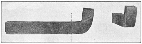
FIG. 85.—Be sure to have a full yellow heat at the dotted
line. Remember this is a boring mill tool and will stand out in
the tool-post, and if you do not have a high thorough lemon heat,
your tool will snap off at the dotted line. (Ninety-five per cent
of all tools which break, have been forged at too low a heat or
at a heat not thorough to the center.)
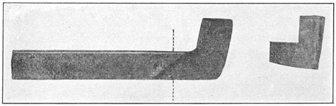
FIG. 86.—Keep your high lemon forging heat up. If you forge
under a steam hammer, take light blows. Do not jam your tool into
shape. Put frequently back into the fire. Never let the high lemon
color go down and beyond the dotted line.
Page 181 For built-up
and bent tools special care should be taken that the forging heat does
not go below a bright cherry. For tools ¾ by 1½ or larger
where there is a big strain in forging, such as bending at angles
of about 45 deg. and building the tools up, they should be heated
to at least 1,700°F. Slowly and without much blast. For a ¾
by 1½ tool it should take about 10 min. with the correct blast
in a coke fire. Larger tools in proportion. They can then be bent
readily, but no attempt should be made to forge the steel further
without reheating to maintain the bright cherry red. This is essential,
as otherwise the tools crack in hardening or while in use.
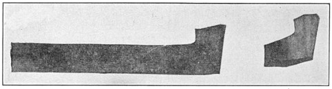
FIG. 87.—Be sure that the tool is absolutely straight at the
bottom, so as to lie flat in the tool-post.
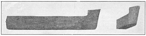
FIG. 88.—This is the finished forged tool, and let this grow
cold by itself, the slower the better. It is well to cool the tool
slowly in hot ashes, to remove all forging strain. You can now
grind the tool dry on a sharp emery wheel. The more you now finish
the tool in grinding, the less there is to come off after hardening.
In hardening place the tool in a coke fire (hollow fire if possible)
with a slow blast and heat gradually up to a white welding heat
on the nose of the tool. Then dip the white hot part only into
thin oil or hold in a strong cold air blast. When hardening in
oil do not hold the tool in one place but keep it moving so that
it cools as quickly as possible. It is not necessary to draw the
temper after hardening these tools.
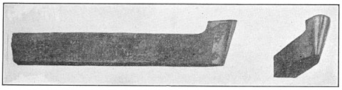
FIG. 89.—This tool is ground, ready for hardening. Never
harden from the forging heat.
Page 182
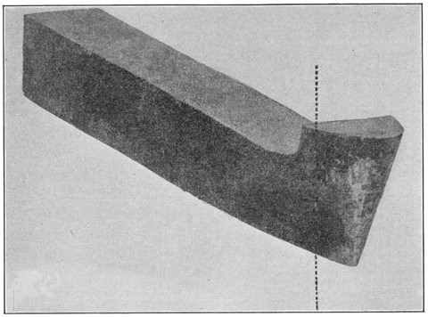
FIG. 90.—Heat the nose of the tool only up to dotted line,
very slowly and thoroughly to an absolutely white welding heat, so
that it shows a trifle fused around the edges, and be very sure that
this fusing has gone thoroughly through the nose, otherwise the
fusing effect will be taken off after the second grinding. Note
the difference of the nose between this and Fig. 86.
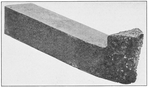
FIG. 91.—Shows unnecessary roasting and drossing. Such
hardening requires a great amount of grinding and is not good.
After hardening grind carefully on a wet emery wheel, and be sure
that the wheel is sharp with a plentiful supply of water. Do not
force the grinding, otherwise the cold water striking the steel
heated up by friction, will crack the nose. Be sure that the grinding
wheel is sharp.
In grinding all tools should be ground as lightly as possible on a
soft wet Page 183
sandstone or on a wet emery wheel, and care should be taken not
to create any surface cracks, which are invariably the result of
grinding too forcibly. The foregoing illustrations, Figs. 84 to
91, with their captions, will be found helpful.
Special points of caution to be observed when hardening high-speed
steel.
Don't use a green coal fire; use coke, or build a hollow
fire.
Don't have the bed of the fire free from coal.
Don't hurry the heating for forging. The heating has to be
done very slowly and the forging heat has to be kept very high (a
full lemon color) heat and the tool has to be continually brought
back into the fire to keep the high heat up. When customers complain
about seams and cracks, in 9 cases out of 10, this has been caused
by too low a forging heat, and when the blacksmith complains about
tools cracking, it is necessary to read this paragraph to him.
Don't try to jam the tool into shape under a steam hammer
with one or two blows; take easy blows and keep the heat high.
Don't have the tool curved at the bottom; it must lie perfectly
flat in the tool post.
Don't harden from your forging heat; let the tool grow cold
or fairly cold. After forging you can rough grind the tool dry,
but not too forcibly.
Don't, for hardening, get more than the nose white hot.
Don't get the white heat on the surface only.
Don't hurry your heating for hardening; let the heat soak
thoroughly through the nose of the tool.
Don't melt the nose of the tool.
Don't, as a rule, dip the nose into water; this should be
done only for extremely hard material. It is dangerous to put the
nose into water for fear of cracking and when you do put the nose
into water put just 1/2 in. only of the extreme white hot part
into the water and don't keep it too long in the water; just a few
seconds, and then harden in oil. We do not recommend water hardening.
Don't grind too forcibly.
Don't grind dry after hardening.
Don't discolor the steel in grinding.
Don't give too much clearance on tools for cutting cast iron.
Don't start on cast iron with a razor edge on the tool.
Take an oil stone and wipe three or four times over the razor edge.
Don't use tool holder steel from bars without hardening the
nose of each individual tool bit.
Air-hardening Steels.—These steels are recommended
for boring, turning and planing where the cost of high-speed seems
excessive. They are also recommended for hard wood knives, for
roughing and finishing bronze and brass, and for hot bolt forging
dies. This steel cannot be cut or punched cold but can be shaped
and ground on abrasive wheels of various kinds.
It should be heated slowly and evenly for forging and kept Page 184 as evenly
heated at a bright red as possible. It should not be forged after
it cools to a dark red.
After the tool is made, heat it again to a bright red and lay it
down to cool in a dry place or it can be cooled in a cold, dry
air blast. Water must be kept away from it while it is hot.
Page 185 CHAPTER XI — PROTECTIVE SCREENS FOR FURNACES — FURNACE DATA
FURNACES
There are so many standard furnaces now on the market that it is
not necessary to go into details of their design and construction
and only a few will be illustrated. Oil, gas and coal or coke are
most common but there is a steady growth of the use of electric
furnaces.
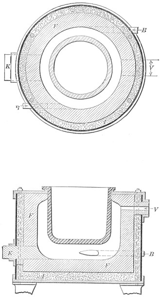
FIG. 92.—Standard lead pot furnace.
Page 186 Typical
Oil-fired Furnaces.—Several types of standard oil-fired
furnaces are shown herewith. Figure 92 is a lead pot furnace, Fig.
93 is a vertical furnace with a center column. This column reduces
the cubical contents to be heated and also supports the cover.
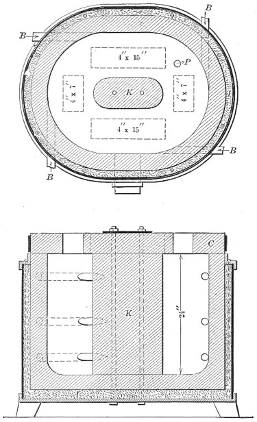
FIG. 93.—Furnace with center column.
A small tool furnace is shown in Fig. 94, which gives the construction
and heat circulation. A larger furnace for high-speed steel is
given in Fig. 95. The steel is supported above the heat, the lower
flame passing beneath the support.
For hardening broaches and long reamers and taps, the furnace shown
in Fig. 96 is used. Twelve jets are used, these coming in radially
to produce a whirling motion.
Page 187
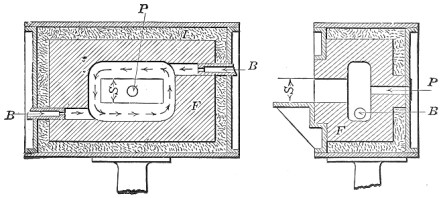
FIG. 94.—Furnace for cutting tools.
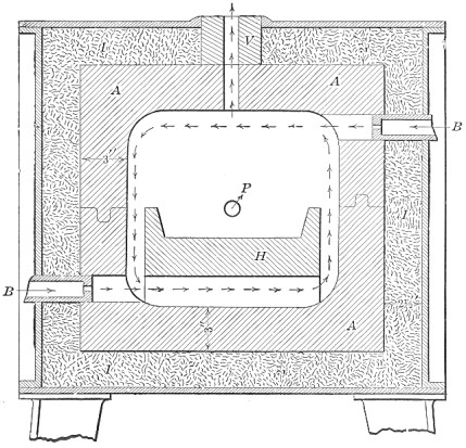
FIG. 95.—High-speed steel furnace.
Oil and gas furnaces may be divided into three types: the open
heating chamber in which combustion takes place in the chamber
and directly over the stock; the semimuffle heating chamber in
which combustion takes place beneath the floor of the chamber from
which the hot gases pass into the chamber through suitable openings;
and the muffle heating chamber in which the heat entirely surrounds
the chamber but does not enter it. The open furnace is used for
forging, tool dressing and welding. The muffle furnace is used for
hardening dies, taps, cutters and similar Page 188 tools of either carbon or high-speed
steel. The muffle furnace is for spring hardening, enameling, assaying
and work where the gases of combustion may have an injurious effect
on the material.
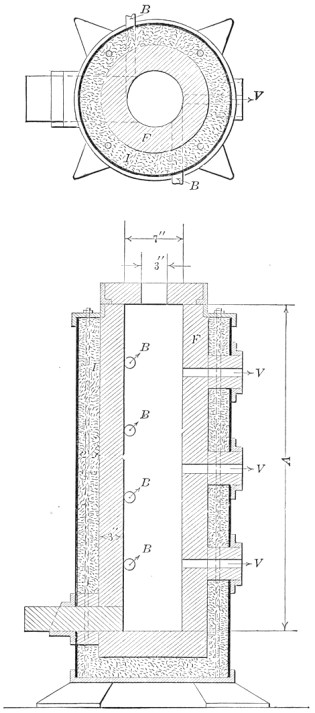
FIG. 96.—Furnace for hardening broaches.
Page 189
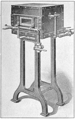
FIG. 97.—Forging and welding furnace.
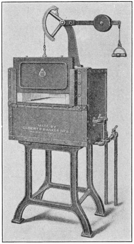
FIG. 98.—Semi-muffle furnace.
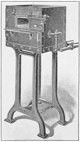
FIG. 99.—Muffle furnace.
Furnaces of these types of oil-burning furnaces are shown in Figs.
97, 98, and 99; these being made by the Gilbert & Barker
Manufacturing Company. The first has an air curtain formed Page 190 by jets
from the large pipe just below the opening, to protect the operator
from heat.
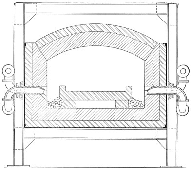
FIG. 100.—Gas fired furnace.
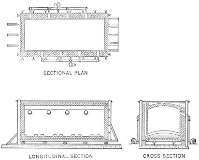
FIG. 101.—Car door type of annealing furnace.
Oil furnaces are also made for both high- and low-pressure air,
each having its advocates. The same people also make gas-fired
furnaces.
Several types of furnaces for various purposes are illustrated
Page 191 in Fig.
100 and 101. The first is a gas-fired hardening furnace of the
surface-combustion type.
A large gas-fired annealing furnace of the Maxon system is shown
in Fig. 101. This is large enough for a flat car to be run into
as can be seen. It shows the arrangement of the burners, the track
for the car and the way in which it fits into the furnace. These
are from the designs of the Industrial Furnace Corporation.
Before deciding upon the use of gas or oil, all sides of the problem
should be considered. Gas is perhaps the nearest ideal but is as a
rule more expensive. The tables compiled by the Gilbert & Barker
Manufacturing Company and shown herewith, may help in deciding the
question.
TABLE 27.—SHOWING COMPARISON OF OIL FUEL WITH VARIOUS
GASEOUS FUELS
| | Heat units
per thousand
cubic
feet
1,000,000 |
|---|
| Natural gas | 1,000,000
|
| Air gas (gas machine) 20 cp |
815,500 |
| Public illuminating gas, average |
650,000 |
| Water gas (from bituminous coal) |
377,000 |
| Water and producer gas, mixed |
175,000 |
| Producer gas | 150,000 |
Since a gallon of fuel oil (7 lb.) contains 133,000 heat units, the
following comparisons may evidently be made. At 5 cts. a gallon,
the equivalent heat units in oil would equal:
| | Heat units
per
thousand
cubic feet
at $0.375 |
|---|
| Natural gas |
at $0.375 |
| Air gas, 20 cp |
at 0.307 |
| Public illuminating gas, average |
at 0.244 |
| Water gas (from bituminous coal) |
at 0.142 |
| Water and producer gas, mixed |
at 0.065 |
| Producer gas |
at 0.057 |
Comparing oil and coal is not always simple as it depends on the
work to be done and the construction of the furnaces. The variation
rises from 75 to 200 gal. of oil to a ton of coal. For forging
and similar work it is probably safe to consider 100 gal. of oil
as equivalent to a ton of coal.
Then there is the saving of labor in handling both coal and ashes,
the waiting for fires to come up, the banking of fires and the dirt
and nuisance generally. The continuous operation possible with
oil adds to the output.
Page 192 When
comparing oil and gas it is generally considered that 4½ gal.
of fuel oil will give heat equivalent to 1,000 cu. ft. of coal
gas.
The pressure of oil and air used varies with the system installed.
The low-pressure system maintains a pressure of about 8 oz. on the
oil and draws in free air for combustion. Others use a pressure
of several pounds, while gas burners use an average of perhaps
1½ lb. of air to give best results.
The weights and volumes of solid fuels are: Anthracite coal, 55 to
65 lb. per cubic foot or 34 to 41 cubic feet per ton; bituminous
coal, 50 to 55 lb. per cubic foot or 41 to 45 cubic feet per ton;
coke, 28 lb. per cubic foot or 80 cubic feet per ton—the
ton being calculated as 2,240 lb. in each case.
A novel carburizing furnace that is being used by a number of people,
is built after the plan of a fireless cooker. The walls of the
furnace are extra heavy, and the ports and flues are so arranged
that when the load in the furnace and the furnace is thoroughly
heated, the burners are shut off and all openings are tightly sealed.
The carburization then goes on for several hours before the furnace
is cooled below the effective carburizing range, securing an ideal
diffusion of carbon between the case and the core of the steel
being carburized. This is particularly adaptable where simple steel
is used.
Workmen needlessly exposed to the flames, heat and glare from furnaces
where high temperatures are maintained suffer in health as well as
in bodily discomfort. This shows several types of shields designed
for the maximum protection of the furnace worker.
Bad conditions are not necessary; in almost every case means of relief
can be found by one earnestly seeking them. The larger forge shops
have adopted flame shields for the majority of their furnaces. Years
ago the industrial furnaces (particularly of the oil-burning variety)
were without shields, but the later models are all shield-equipped.
These shields are adapted to all of the more modern, heat-treating
furnaces, as well as to those furnaces in use for working forges;
and attention should be paid to their use on the former type since
the heat-treating furnaces are constantly becoming more numerous
as manufacturers find need of them in the many phases of munitions
making or similar work.
The heat that the worker about these furnaces must face may be
divided in general into two classes: there is first that heat due
to the flame and hot gases that the blast in the furnaces forces
out onto a man's body and face. In the majority of furnaces Page 193 this is by
far the most discomforting, and care must be taken to fend it and
turn it behind a suitable shield. The second class is the radiant
heat, discharged as light from the glowing interior of the furnace.
This is the lesser of the two evils so far as general forging furnaces
are concerned, but it becomes the predominating feature in furnaces
of large door area such as in the usual case-hardening furnaces. Here
the amount of heat discharged is often almost unbearable even for a
moment. This heat can be taken care of by interposing suitable, opaque
shields that will temporarily absorb it without being destroyed by
it, or becoming incandescent. Should such shields be so constructed
as to close off all of the heat, it might be impossible to work
around the furnace for the removal of its contents, but they can be
made movable, and in such a manner as to shield the major portion
of the worker's body.
First taking up the question of flame shields, the illustration,
Fig. 102, is a typical installation that shows the main features
for application to a forging machine or drop-hammer, oil-burning
furnace, or for an arched-over, coal furnace where the flame blows
out the front. This shield consists of a frame covered with sheet
metal and held by brackets about 6 in. in front of the furnace.
It will be noted that slotted holes make this frame adjustable
for height, and it should be lowered as far as possible when in
use, so that the work may just pass under it and into the furnace
openings.
Immediately below the furnace openings, and close to the furnace
frame will be noted a blast pipe carrying air from the forge-shop
fan. This has a row of small holes drilled in its upper side for
the entire length, and these direct a curtain of cold air vertically
across the furnace openings, forcing all of the flame, or a greater
portion of it, to rise behind the shield. Since the shield extends
above the furnace top there is no escape for this flame until it has
passed high enough to be of no further discomfort to the workman.
In this case fan-blast air is used for cooling, and this is cheaper
and more satisfactory because a great volume may be used. However,
where high-pressure air is used for atomizing the oil at the burner, and
nothing else is available, this may be employed—though naturally
a comparatively small pipe will be needed, in which minute holes are
drilled, else the volume of air used will Page 195 be too great for the compressor
economically to supply. Steam may also be employed for like service.
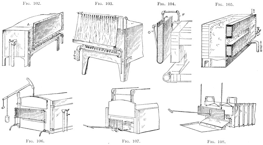
FIGS. 102 to 108.—Protective devices for furnace fronts.
The latest shields of this type are all made double, as illustrated,
with an inner sheet of metal an inch or two inside of the front. In
the illustration, A, Fig. 102, this inner sheet is smaller,
but some are now built the same size as the front and bolted to
it with pipe spacers between. The advantage of the double sheet
is that the inner one bears the brunt of the flame, and, if needs
be, burns up before the outer; while, if due to a heavy fire it
should be heated red at any point, the outer sheet will still be
much cooler and act as an additional shield to the furnace man.
Heavy Forging Practice.—In heavy forging practice
where the metal is being worked at a welding heat, the amount of
flame that will issue from an open-front furnace is so great that a
plain, sheet-steel front will neither afford sufficient protection
nor stand up in service. For such a place a water-cooled front is
often used. The general type of this front is illustrated in Fig.
103, and appears to have found considerable favor, for numbers of
its kind are scattered throughout the country.
In this case the shield is placed at a slight angle from the vertical,
and along the top edge is a water pipe with a row of small holes
through which sprays of water are thrown against it. This water runs
down in a thin sheet over the shield, cooling it, and is collected
in a trough connected with a run-off pipe at the bottom. The lower
blast-pipe arrangement is similar to the one first described.
There are several serious objections to this form of shield that
should lead to its replacement by a better type; the first is that
with a very hot fire, portions in the center may become so rapidly
heated that the steam generated will part the sheet of water and
cause it to flow from that point in an inverted V, and that section
will then quickly become red hot. Another feature is that after
the water and fire are shut down for the night the heat of the
furnace can be great enough to cause serious warping of the surface
of the shield so that the water will no longer cover it in a thin,
uniform sheet.
After rigging up a big furnace with a shield of this type several
years ago, its most serious object was found in the increase of
the water bill of the plant. This was already of large proportions,
but it had suddenly jumped to the extent of several hundred Page 196 dollars.
Investigation soon disclosed the fact that this water shield was one
of the main causes of the added cost of water. A little estimating
of the amount of water that can flow through a 1/2-in. pipe under
30-lb. pressure, in the course of a day, will show that this amount
at 10 cts. per 1,000 gal., can count up rather rapidly.
Figure 103 is a section through a portion of the furnace front and
shield showing all of the principal parts. This shield consists
essentially of a very thin tank, about 2½ in. between walls,
and filled with water. Like other shields it is fitted with an
adjustment, that it may be raised and lowered as the work demands.
The tank having an open top, the water as it absorbs heat from
the flame will simply boil away in steam; and only a small amount
will have to be added to make up for that which has evaporated.
The water-feed pipe shown at F ends a short distance above
the top of the tank so that just how much water is running in may
readily be seen.
An overflow pipe is provided at O which aids in maintaining
the water at the proper height, as a sufficient quantity can always
be permitted to run in, to avoid any possibility of the shield ever
boiling dry; at the same time the small excess can run off without
danger of an overflow. The shield illustrated in Fig. 104 has been
in constant use for over two years, giving greater satisfaction
than any other of which the writer has known. It might also be
noted that this shield was made with riveted joints, the shop not
having a gas-welding outfit. To flange over the edges and then
weld them with an acetylene torch would be a far more economical
procedure, and would also insure a tight and permanent joint.
The water-cooled front shown in Fig. 105 is an absurd effort to
accomplish the design of a furnace that will provide cool working
conditions. This front was on a bolt-heating furnace using hard
coal for fuel; and it may be seen that it takes the place of all
of the brickwork that should be on that side. Had this been nothing
more than a very narrow water-cooled frame, with brickwork below
and supporting bricks above, put in like the tuyeres in a foundry
cupola, the case would have been somewhat different, for then it
would have absorbed a smaller proportion of the heat.
A blacksmith who knows how a piece of cold iron laid in a small
welding furnace momentarily lowers the temperature, will appreciate
the enormous amount of extra heat that must be maintained in the
central portion of this furnace to make up Page 197 for the constant chilling effect
of the cold wall. Moreover, since there would have been serious
trouble had steam generated in this front, a steady stream of water
had to be run through it constantly to insure against an approach
to the boiling point. This is illustrated because of its absurdity,
and as a warning of something to avoid.
Water-cooled, tuyere openings, as mentioned above, which support
brick side-walls of the furnace, have proved successful for coal
furnaces used for forging machine and drop-hammer heating, since
they permit a great amount of work to be handled through their
openings without wearing away as would a brick arch. Great care
should be exercised properly to design them so that a minimum amount
of the cold tuyere will be in contact with the interior of the
furnace, and all interior portions possible should be covered by
the bricks. However, a discussion of these points will hardly come
in the flame-shield class, although they can be made to do a great
deal toward relieving the excessive heat to be borne by the furnace
worker.
Flange Shields for Furnaces.—Such portable flame shields
as the one illustrated in Fig. 106 may prove serviceable before
furnaces required for plate work, where the doors are often only
opened for a moment at a time. This shield can be placed far enough
in front of the furnace, that it will be possible to work under
it or around it, in removing bulky work from the furnace, and yet
it will afford the furnace tender some relief from the excessive
glare that will come out the wide-opened door. To have this shield
of light weight so that it may be readily pushed aside when not
wanted, the frame may be made up of pipe and fittings, and a piece
of thin sheet steel fastened in the panel by rings about the frame.
About the most disagreeable task in a heat-treating shop is the
removal of the pots from the case-hardening furnaces; these must
be handled at a bright red heat in order that their contents may be
dumped into the quenching tank with a minimum-time contact with the
air, and before they have cooled sufficiently to require reheating.
Facing the heat before the large open doors of the majority of
these furnaces, in a man-killing task even when the weather is
moderately cool. The boxes soon become more or less distorted,
and then even the best of lifting devices will not remove a hot
pot without several minutes labor in front of the doors.
In Fig. 107 is shown a method of arranging a shield on one Page 198 type of
charging and removing truck. This shield cannot afford more than
a partial protection to the body of the furnace tender, because
he must be able to see around it, and in some cases even push it
partly through the door of the furnace, but even small as it is it
may still afford some welcome protection. The great advantage in
this case of having the shield on the truck instead of stationary
in front of the furnace, is that it still affords protection as
long as the hot pot is being handled through the shop on its way
to the quenching tank.
It might be interesting to many engaged in the heat-treating or
case hardening of steel parts, to make a special note of the design
of the truck that is illustrated in connection with the shield;
the general form is shown although the actual details for the
construction of such a truck are lacking; these being simple, may be
readily worked out by anyone wishing to build one. This is considered
to be one of the quickest and easiest operated devices for the
removal of this class of work from the furnace. To be sure it may
only be used where the floor of the furnace has been built level
with the floor of the room, but many of the modern furnaces of
this class are so designed.
The pack-hardening pots are cast with legs, from two to three inches
high, to permit the circulation of the hot gases, and so heat more
quickly. Between these legs and under the body of the pot, the two
forward prongs of the truck are pushed, tilting the outer handle
to make these prongs as low as possible. The handle is then lowered
and, as it has a good leverage, the pot is easily raised from the
floor, and the truck and its load rolled out.
Heating of Manganese Steel.—Another form of heat-treating
furnace is that which is used for the heating of manganese and
other alloy steels, which after having been brought to the proper
heat are drawn from the furnace into an immediate quenching tank.
With manganese steel in particular, the parts are so fragile and
easily damaged while hot that it is frequent practice to have a
sloping platform immediately in front of the furnace door down
which the castings may slide into a tank below the floor level.
Such a furnace with a quenching tank in front of its door is shown
in Fig. 108.
These tanks are covered with plates while charging the furnace and
the cold castings are placed in a moderately cool furnace. Since some
of these steels must not be charged into a furnace where the heat is
extreme but should be brought up to their Page 199 final heat gradually, there is
little discomfort during the charging process. When quenching,
however, from a temperature of 1,800° to 1,900°, it is
extremely unpleasant in front of the doors. The swinging shield
is here adapted to give protection for this work. As will be noted
it is hung a sufficient distance in front of the doors, that it may
not interfere with the castings as they come from the furnace,
and slide down into the tank.
To facilitate the work, and avoid the necessity of working with
the bars outside the edges of the shield, the slot-like hole is
cut in the center of the shield, and through this the bars or rakes
for dragging out the castings are easily inserted and manipulated.
The advantage of such a swinging shield is that it may be readily
moved from side to side, or forward and back as occasion requires.
In order to give definite information concerning furnaces, fuels
etc., the following data is quoted from a paper by Seth A. Moulton
and W. H. Lyman before the Steel Heat Treaters Society in September,
1920.
This considers a factory producing 30,000 lb. of automobile gears
per 24 hr. The transmission gears will be of high-carbon steel and
the differential of low-carbon steel, carburized. The heat-treating
equipment required is:
| 1. Annealing furnaces |
1,400 to |
1,600°F. |
| 2. Carburizing furnaces |
1,700 to |
1,800°F. |
| 3. Hardening furnaces |
1,450 to |
1,550°F. |
| 4. Drawing furnaces |
350 to |
950°F. |
All of the forging blanks are annealed before machining, about
three-quarters of the machined gears and parts are carburized,
all the carburized gears are given a double treatment for core and
case, all gears and parts are hardened and all parts are drawn.
The possible sources of heat supply and their values are as
follows:—
| 1. Oil | 140,000 |
B.t.u. per gallon |
| 2. Natural gas | 1,100 |
B.t.u. per cubic foot |
| 3. City gas | 650 |
B.t.u. per cubic foot |
| 4. Water gas | 300 |
B.t.u. per cubic foot |
| 5. Producer gas | 170 |
B.t.u. per cubic foot |
| 6. Coal | 12,000 |
B.t.u. per pound |
| 7. Electric current | 3,412 |
B.t.u. per kilowatt-hour |
Page 200 For the
heat treatment specified only comparatively low temperatures are
required. No difficulty will be experienced in attaining the desired
maximum temperature of 1,800°F. with any of the heating medium
above enumerated; but it should be noted that the producer gas with
a B.t.u. content of 170 per cubic foot and the electric current
would require specially designed furnaces to obtain higher
temperatures than 1800°F.
TABLE 28.—COMPARATTVE OPERATING COSTS
| Assuming |
| Cost of oil- and gas-fired furnaces
installed as |
$100.00 per square foot of hearth |
| Cost of coal-fired furnace installed
as |
150.00 per square foot of hearth |
| Cost of electric furnace 100 kw.
capacity installed as |
90.00 per kilowatt |
| Cost of electric furnace 150 kw.
capacity installed as |
70.00 per kilowatt |
Output 3,000 lb. charge, 8 hr. heat carburizing, 2 hr. heating
only. Annual service 7,200 hr. Fixed charges including interest,
depreciation, taxes, insurance and maintenance 15 per cent. Extra
operating labor for coal-fired furnace 60 cts. per hour, one man
four furnaces.
COST OF VARIOUS TYPES OF FURNACES
| |
Class fuel |
Fuel per charge |
Unit fuel cost |
Installation cost |
Efficiency per cent |
Fixed charges |
Cost per charge |
|---|
| |
1 |
2 |
3 |
4 |
5 |
6 |
7 |
|---|
| Carburizing |
| 1 |
Oil |
52.0 gal. |
$0.15 gal. |
$2,400.00 |
12.6 |
$.40 |
$8.20 |
| 2 |
Natural gas |
4.4 M |
0.50 M |
2,400.00 |
18.8 |
0.40 |
2.60 |
| 3 |
City gas |
8.3 M |
0.80 M |
2,400.00 |
17.0 |
0.40 |
7.04 |
| 4 |
Water gas |
18.7 M |
0.40 |
2,400.00 |
16.4 |
0.40 |
7.88 |
| 5 |
Producer gas |
37.3 M |
0.10 M |
2,400.00 |
14.5 |
0.40 |
4.13 |
| 6 |
Coal |
814.0 lb. |
6.00 ton |
3,600.00 |
9.4 |
0.60 |
3.98 |
| 7 |
Electricity |
500.0 kw-hr. |
0.015 kw. |
9,000.00 |
53.0 |
1.50 |
9.00 |
| Heating |
| 1 |
Oil |
30.8 gal. |
0.15 gal. |
2,400.00 |
21.4 |
0.10 |
4.72 |
| 2 |
Natural gas |
2.61 M |
0.50 M |
2,400.00 |
32.0 |
0.10 |
1.40 |
| 3 |
City gas |
4.9 M |
0.80 M |
2,400.00 |
28.8 |
0.10 |
4.02 |
| 4 |
Water gas |
11.1 M |
0.40 M |
2,400.00 |
27.6 |
0.10 |
4.54 |
| 5 |
Producer gas |
22.1 M |
0.10 M |
2,400.00 |
24.6 |
0.10 |
2.31 |
| 6 |
Coal |
348.0 lb. |
6.00 ton |
3,600.00 |
22.0 |
0.15 |
1.38 |
| 7 |
Electricity |
329.0 kw-hr. |
0.015 kw. |
10,500.00 |
81.75 |
0.44 |
5.38 |
This shows but two of the operations and for a single furnace.
The total costs for all operations on the 30,000 lb. of gears per
24 hr. is shown in Table 29.
TABLE 29.—COMPARATIVE ANNUAL PRODUCTION COSTS FOR
30,000 POUNDS OUTPUT IN 24 HOURS
Page 201
| No. |
Equipment |
Installation cost |
Annual operating expenses |
Total |
Cost per lb. metal, cents |
|---|
| Fixed charges |
Heat |
Labor |
|---|
| | |
| |
| |
| |
| 1 | 2 |
3 | 4 |
5 | 6 |
7 | 8 |
| | |
| |
| |
| |
| I |
Oil |
$179,000.00 |
$26,850.00 |
$156,000.00 |
$105,000.00 |
$287,850.00 |
$3.19 |
| II |
Oil and electric |
213,000.00 |
31,950.00 |
142,770.00 |
97,000.00 |
271,720.00 |
3.02 |
| III |
Natural gas |
117,000.00 |
17,550.00 |
44,250.00 |
97,000.00 |
158,800.00 |
1.78 |
| IV |
(A) Natural gas containing furnaces |
120,000.00 |
18,000.00 |
41,000.00 |
94,000.00 |
153,000.00 |
1.70 |
| V |
Natural gas and electric |
181,000.00 |
27,150.00 |
73,820.00 |
90,000.00 |
190,970.00 |
2.13 |
| VI |
City gas |
122,000.00 |
18,300.00 |
123,200.00 |
94,000.00 |
235,500.00 |
2.62 |
| VII |
City gas and electric |
182,000.00 |
27,300.00 |
128,820.00 |
90,000.00 |
246,020.00 |
2.74 |
| VIII |
Water gas |
214,000.00 |
18,600.00 |
104,000.00 |
94,000.00 |
216,600.00 |
2.41 |
| IX |
Water gas and electric |
238,000.00 |
27,450.00 |
117,420.00 |
90,000.00 |
234,870.00 |
2.62 |
| X |
Producer gas |
246,000.00 |
18,900.00 |
69,300.00 |
90,000.00 |
178,200.00 |
1.98 |
| XI |
Producer gas and electric |
255,000.00 |
27,750.00 |
92,520.00 |
90,000.00 |
210,270.00 |
2.34 |
| XII |
Coal and electric |
194,000.00 |
29,100.00 |
87,220.00 |
90,000.00 |
206,320.00 |
2.30 |
| XIII |
Electric |
257,000.00 |
38,550.00 |
135,000.00 |
84,000.00 |
257,550.00 |
2.86 |
NOTE.—Producer plant fixed charges are included in the cost
of gas and are charged as "heat" in column 5, so they are omitted
from column 4.
Page 202 CHAPTER XII — PYROMETERS — THE THERMO-COUPLE — THE PYROMETER AND ITS USE — CALIBRATION OF PYROMETER WITH COMMON SALT — THE LEEDS AND NORTHRUP POTENTIOMETER SYSTEM — PLACING THE THERMO-COUPLES — LEEDS AND NORTHRUP OPTICAL PYROMETER — CORRECTION FOR COLD-JUNCTION ERRORS — BROWN AUTOMATIC SIGNALING PYROMETER — AN AUTOMATIC TEMPERATURE CONTROL PYROMETER — PYROMETERS FOR MOLTEN METAL — PROTECTORS FOR THERMO-COUPLES
PYROMETRY AND PYROMETERS
A knowledge of the fundamental principles of pyrometry, or the
measurement of temperatures, is quite necessary for one engaged
in the heat treatment of steel. It is only by careful measurement
and control of the heating of steel that the full benefit of a
heat-treating operation is secured.
Before the advent of the thermo-couple, methods of temperature
measurement were very crude. The blacksmith depended on his eyes
to tell him when the proper temperature was reached, and of course
the "color" appeared different on light or dark days. "Cherry"
to one man was "orange" to another, and it was therefore almost
impossible to formulate any treatment which could be applied by
several men to secure the same results.
One of the early methods of measuring temperatures was the "iron
ball" method. In this method, an iron ball, to which a wire was
attached, was placed in the furnace and when it had reached the
temperature of the furnace, it was quickly removed by means of
the wire, and suspended in a can containing a known quantity of
water; the volume of water being such that the heat would not cause
it to boil. The rise in temperature of the water was measured by a
thermometer, and, knowing the heat capacity of the iron ball and
that of the water, the temperature of the ball, and therefore the
furnace, could be calculated. Usually a set of tables was prepared
to simplify the calculations. The iron ball, however, scaled, and
changed in weight with repeated use, making the determinations
less and less accurate. A copper ball was often used to decrease
this change, but even that was subject to error. This method is
still sometimes used, but for uniform results, a platinum ball,
which will not scale or change in weight, is necessary, and the
cost of this ball, together with the slowness of the method, have
rendered the practice obsolete, especially in view of modern
developments in accurate pyrometry.
Armor plate makers sometimes use the copper ball or Siemens' water
pyrometer because they can place a number of the balls or Page 203 weights on
the plate in locations where it is difficult to use other pyrometers.
One of these pyrometers is shown in section in Fig. 109.
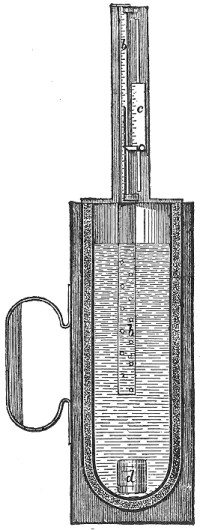
FIG. 109.—Siemens' copper-ball pyrometer.
Siemens' Water Pyrometer.—It consists of a cylindrical
copper vessel provided with a handle and containing a second smaller
copper vessel with double walls. An air space a separates
the two vessels, and a layer of felt the two walls of the inner
one, in order to retard the exchange of temperature with the
surroundings. The capacity of the inner vessel is a little more
than one pint. A mercury thermometer b is fixed close to
the wall of the inner vessel, its lower part being protected by a
perforated brass tube, whilst the upper projects above the vessel
and is divided as usual on the stem into degrees, Fahrenheit or
Centigrade, as desired. At the side of the thermometer there is
a small brass scale c, which slides up and down, and on
which the high temperatures are marked in the same degrees as those
in which the mercury thermometer is divided; on a level with the
zero division of the brass scale a small pointer is fixed, which
traverses the scale of the thermometer.
Short cylinders d, of either copper, iron or platinum, are
supplied with the pyrometer, which are so adjusted that their heat
capacity at ordinary temperature is equal to one-fiftieth of that
of the copper vessel filled with one pint of water. As, however, the
specific heat of metals increases with the temperature, allowance
is made on the brass sliding scales, which are divided according
to the metal used for the pyrometer cylinder d. It will
therefore be understood that a different sliding scale is required
for the particular kind of metal of which a cylinder is composed.
In order to obtain accurate measurements, each sliding scale must
be used only in conjunction with its own thermometer, and in case
the latter breaks a new scale must be made and graduated for the
new thermometer.
The water pyrometer is used as follows:
Page 204 Exactly
one pint (0.568 liter) of clean water, perfectly distilled or rain
water, is poured into the copper vessel, and the pyrometer is left
for a few minutes to allow the thermometer to attain the temperature
of the water.
The brass scale c is then set with its pointer opposite the
temperature of the water as shown by the thermometer. Meanwhile
one of the metal cylinders has been exposed to the high temperature
which is to be measured, and after allowing sufficient time for
it to acquire that temperature, it is rapidly removed and dropped
into the pyrometer vessel without splashing any of the water out.
The temperature of the water will rise until, after a little while,
the mercury of the thermometer has become stationary. When this is
observed the degrees of the thermometer are read off, as well as
those on the brass scale c opposite the top of the mercury.
The sum of these two values together gives the temperature of the
flue, furnace or other heated space in which the metal cylinder
had been placed. With cylinders of copper and iron, temperatures up
to 1,800°F. (1,000°C.) can be measured, but with platinum
cylinders the limit is 2,700°F. (1,500°C.).
For ordinary furnace work either copper or wrought-iron cylinders
may be used. Iron cylinders possess a higher melting point and have
less tendency to scale than those of copper, but the latter are
much less affected by the corrosive action of the furnace gases;
platinum is, of course, not subject to any of these disadvantages.
The weight to which the different metal cylinders are adjusted is
as follows:
| Copper | 137.0 grams |
| Wrought-iron | 112.0 grams |
| Platinum | 402.6 grams |
In course of time the cylinders lose weight by scaling; but tables
are provided giving multipliers for the diminished weights, by
which the reading on the brass scale should be multiplied.
With the application of the thermo-couple, the measurement of
temperatures, between, say, 700 and 2,500°F., was made more
simple and precise. The theory of the thermo-couple is simple;
it is that if two bars, rods, or wires of different metals are
joined Page 205
together at their ends, when heated so that one junction is hotter
than the other, an electromotive force is set up through the metals,
which will increase with the increase of the difference of
temperature between the two junctions. This electromotive force,
or voltage, may be measured, and, from a chart previously prepared,
the temperature determined. In most pyrometers, of course, the
temperatures are inscribed directly on the voltmeter, but the fact
remains that it is the voltage of a small electric current, and
not heat, that is actually measured.
There are two common types of thermo-couples, the first making use
of common, inexpensive metals, such as iron wire and nichrome wire.
This is the so-called "base metal" couple. The other is composed of
expensive metals such as platinum wire, and a wire of an alloy of
platinum with 10 per cent of rhodium or iridium. This is called
the "rare metal" couple, and because its component metals are less
affected by heat, it lasts longer, and varies less than the base
metal couple.
The cold junction of a thermo-couple may be connected by means
of copper wires to the voltmeter, although in some installations
of base metal couples, the wires forming the couple are themselves
extended to the voltmeter, making copper connections unnecessary.
From the foregoing, it may be seen that accurately to measure the
temperature of the hot end of a thermo-couple, we must know the
temperature of the cold end, as it is the difference
in the temperatures that determines the voltmeter readings. This
is absolutely essential for precision, and its importance cannot
be over-emphasized.
When pyrometers are used in daily operation, they should be checked
or calibrated two or three times a month, or even every week. Where
there are many in use, it is good practice to have a master pyrometer
of a rare metal couple, which is used only for checking up the
others. The master pyrometer, after calibrating against the melting
points of various substances, will have a calibration chart which
should be used in the checking operation.
It is customary now to send a rare metal couple to the Bureau of
Standards at Washington, where it is very carefully calibrated
for a nominal charge, and returned with the voltmeter readings
of a series of temperatures covering practically the whole range
of the couple. This couple is then used only for checking those
in daily use.
Pyrometer couples are more or less expensive, and should be Page 206 cared far
when in use. The wires of the couple should be insulated from each
other by fireclay leads or tubes, and it is well to encase them
in a fireclay, porcelain, or quartz tube to keep out the furnace
gases, which in time destroy the hot junction. This tube of fireclay,
or porcelain, etc., should be protected against breakage by an
iron or nichrome tube, plugged or welded at the hot end. These
simple precautions will prolong the life of a couple and maintain
its precision longer.
Sometimes erroneous temperatures are recorded because the "cold
end" of the couple is too near the furnace and gets hot. This always
causes a temperature reading lower than the actual, and should be
guarded against. It is well to keep the cold end cool with water,
a wet cloth, or by placing it where coal air will circulate around
it. Best of all, is to have the cold junction in a box, together
with a thermometer, so that its temperature may definitely be known.
If this temperature should rise 20°F. on a hot day, a correction
of 20°F. should be added to the pyrometer reading, and so on. In
the most up-to-date installations, this cold junction compensation
is taken care of automatically, a fact which indicates its importance.
Optical pyrometers are often used where it is impracticable to
use the thermo-couple, either because the temperature is so high
that it would destroy the couple, or the heat to be measured is
inaccessible to the couple of ordinary length. The temperatures of
slag or metal in furnaces or running through tap-holes or troughs
are often measured with optical pyrometers.
In one type of optical pyrometer, the observer focuses it on the
metal or slag and moves an adjustable dial or gage so as to get
an exact comparison between the color of the heat measured with
the calor of a lamp or screen in the pyrometer itself. This, of
course, requires practice, and judgment, and brings in the personal
equation. With care, however, very reliable temperature measurements
may be made. The temperatures of rails, as they leave the finishing
pass of a rolling mill, are measured in this way.
Another type of optical pyrometer is focused on the body, the
temperature of which is to be measured. The rays converge in the
telescope on metal cells, heating them, and thereby generating a
small electric current, the voltage of which is read an a calibrated
voltmeter similar to that used with the thermo-couple. The best
precision is obtained when an optical pyrometer is used each time
under similar conditions of light and the same observer.
Page 207 Where it
is impracticable to use either thermo-couples or optical pyrometers,
"sentinels" may be used. There are small cones or cylinders made
of salts or other substances of known melting points and covering
a wide range of temperatures.
If six of these "sentinels," melting respectively at 1,300°,
1,350°, 1,400°, 1,450°, 1,500°, and 1,550°F.,
were placed in a row in a furnace, together with a piece of steel
to be treated, and the whole heated up uniformly, the sentinels
would melt one by one and the observer, by watching them through
an opening in the furnace, could tell when his furnace is at say
1,500° or between 1,500° and 1,550°, and regulate the
heat accordingly.
A very accurate type of pyrometer, but one not so commonly used as
those previously described, is the resistance pyrometer. In this
type, the temperature is determined by measuring the resistance to an
electric current of a wire which is at the heat to be measured. This
wire is usually of platinum, wound around a quartz tube, the whole
being placed in the furnace. When the wire is at the temperature of
the furnace, it is connected by wires with a Wheatstone Bridge, a
delicate device for measuring electrical resistance, and an electric
current is passed through the wire. This current is balanced by
switching in resistances in the Wheatstone Bridge, until a delicate
electrical device shows that no current is flowing. The resistance
of the platinum wire at the heat to be measured is thus determined
on the "Bridge," and the temperature read off on a calibration
chart, which shows the resistance at various temperatures.
These are the common methods used to-day for measuring temperatures,
but whatever method is used, the observer should bear in mind that
the greatest precision is obtained, and hence the highest efficiency,
by keeping the apparatus in good working order, making sure that
conditions are the same each time, and calibrating or checking
against a standard at regular intervals.
In the heat treatment of steel, it has become absolutely necessary
that a measuring instrument be used which will give the operator an
exact reading of heat in furnace. There are a number of instruments
and devices manufactured for this purpose but any instrument that
will not give a direct reading without any guess work should have
no place in the heat-treating department.
A pyrometer installation is very simple and any of the leading Page 208 makers will
furnish diagrams for the correct wiring and give detailed information
as to the proper care of, and how best to use their particular
instrument. There are certain general principles, however, that
must be observed by the operators and it cannot be too strongly
impressed upon them that the human factor involved is always the
deciding factor in the heat treatment of steel.
A pyrometer is merely an aid in the performance of doing good work,
and when carefully observed will help in giving a uniformity of
product and act as a check on careless operators. The operator
must bear in mind that although the reading on the pyrometer scale
gives a measure of the temperature where the junction of the two
metals is located, it will not give the temperature at the center
of work in the furnace, unless by previous tests, the heat for
penetrating a certain bulk of material has been decided on, and
the time necessary for such penetration is known.
Each analysis of plain carbon or alloy steel is a problem in itself.
Its critical temperatures will be located at slightly different
heats than for a steel which has a different proportion of alloying
elements. Furthermore, it takes time for metal to acquire the heat
of the furnace. Even the outer surface lags behind the temperature
of the furnace somewhat, and the center of the piece of steel lags
still further. It is apparent, therefore, that temperature, although
important, does not tell the whole story in heat treatment. Time
is also a factor.
Time at temperature is also of great importance because it takes
time, after the temperature has been reached, for the various internal
changes to take place. Hence the necessity for "soaking," when
annealing or normalizing. Therefore, a clock is as necessary to
the proper pyrometer equipment as the pyrometer itself.
For the purpose of general work where a wide range of steels or
a variable treatment is called for, it becomes necessary to have
the pyrometer calibrated constantly, and when no master instrument
is kept for this purpose the following method can be used to give
the desired results:
An easy and convenient method for standardization and one which
does not necessitate the use of an expensive laboratory equipment is
that based upon determining the melting point of common table salt
(sodium chloride). While theoretically salt Page 209 that is chemically pure should
be used (and this is neither expensive nor difficult to procure),
commercial accuracy may be obtained by using common table salt
such as is sold by every grocer. The salt is melted in a clean
crucible of fireclay, iron or nickel, either in a furnace or over
a forge-fire, and then further heated until a temperature of about
1,600 to 1,650°F. is attained. It is essential that this crucible
be clean because a slight admixture of a foreign substance might
noticeably change the melting point.
The thermo-couple to be calibrated is then removed from its protecting
tube and its hot end is immersed in the salt bath. When this end
has reached the temperature of the bath, the crucible is removed
from the source of heat and allowed to cool, and cooling readings
are then taken every 10 sec. on the milli-voltmeter or pyrometer.
A curve is then plotted by using time and temperature as
coördinates, and the temperature of the freezing point of
salt, as indicated by this particular thermocouple, is noted,
i.e., at the point where the temperature of the bath remains
temporarily constant while the salt is freezing. The length of
time during which the temperature is stationary depends on the
size of the bath and the rate of cooling, and is not a factor in
the calibration. The melting point of salt is 1,472°F., and
the needed correction for the instrument under observation can
be readily applied.
It should not be understood from the above, however, that the salt-bath
calibration cannot be made without plotting a curve; in actual
practice at least a hundred tests are made without plotting any curve
to one in which it is done. The observer, if awake, may reasonably
be expected to have sufficient appreciation of the lapse of time
definitely to observe the temperature at which the falling pointer
of the instrument halts. The gradual dropping of the pointer before
freezing, unless there is a large mass of salt, takes place rapidly
enough for one to be sure that the temperature is constantly falling,
and the long period of rest during freezing is quite definite.
The procedure of detecting the solidification point of the salt
by the hesitation of the pointer without plotting any curve is
suggested because of its simplicity.
Complete Calibration of Pyrometers.—For the complete
calibration of a thermo-couple of unknown electromotive force, the
new couple may be checked against a standard instrument, placing
the two bare couples side by side in a suitable tube and taking
frequent readings over the range of temperatures desired.
Page 210 If only
one instrument, such as a millivoltmeter, is available, and there
is no standard couple at hand, the new couple may be calibrated over
a wide range of temperatures by the use of the following standards:
| Water, boiling point |
212°F. |
| Tin, under charcoal, freezing point |
450°F. |
| Lead, under charcoal, freezing point |
621°F. |
| Zinc, under charcoal, freezing point |
786°F. |
| Sulphur, boiling point |
832°F. |
| Aluminum, under charcoal, freezing point |
1,216°F. |
| Sodium chloride (salt), freezing point |
1,474°F. |
| Potassium sulphate, freezing point |
1,958°F. |
A good practice is to make one pyrometer a standard; calibrate it
frequently by the melting-point-of-salt method, and each morning
check up every pyrometer in the works with the standard, making the
necessary corrections to be used for the day's work. By pursuing
this course systematically, the improved quality of the product
will much more than compensate for the extra work.
The purity of the substance affects its freezing or melting point.
The melting point of common salt is given in one widely used handbook
at 1,421°F., although chemically pure sodium chloride melts at
1,474°F. as shown above. A sufficient quantity for an extended
period should be secured. Test the melting point with a pyrometer
of known accuracy. Knowing this temperature it will be easy to
calibrate other pyrometers.
Placing of Pyrometers.—When installing a pyrometer,
care should be taken that it reaches directly to the point desired
to be measured, that the cold junction is kept cold, and that the
wires leading to the recording instrument are kept in good shape.
The length of these lead wires have an effect; the longer they
are, the lower the apparent temperature.
When pyrometers placed in a number of furnaces are connected up
in series, and a multiple switch is used for control, it becomes
apparent that pyrometers could not be interchanged between furnaces
near and far from the instrument without affecting the uniformity
of product from each furnace.
Calibration can best be done without disturbing the working pyrometer,
by inserting the master instrument into each furnace separately, place
it alongside the hot junction of the working pyrometer, and compare
the reading given on the indicator connected with the multiple
switch.
Page 211 Protection
tubes should be replaced when cracked, as it is important that
no foreign substance is allowed to freeze in the tube, so that
the enclosed junction becomes a part of a solid mass joined in
electrical contact with the outside protecting tube. Wires over
the furnaces must be carefully inspected from time to time, as no
true reading can be had on an instrument, if insulation is burned
off and short circuits result.
If the standard calibrating instrument used contains a dry battery,
it should be examined from time to time to be sure it is in good
condition.
The potentiometer pyrometer system is both flexible and substantial
in that it is not affected by the jar and vibration of the factory
or the forge shop. Large or small couples, long or short leads
can be used without adjustment. The recording instrument may be
placed where it is most convenient, without regard to the distance
from the furnace.
Its Fundamental Principle.—The potentiometer is the
electrical equivalent of the chemical balance, or balance arm scales.
Measurements are made with balance scales by varying known weights
until they equal the unknown weight. When the two are equal the
scales stand at zero, that is, in the position which they occupy
when there is no weight on either pan; the scales are then said to
be balanced. Measurements are made with the potentiometer by varying
a known electromotive force until it equals the unknown; when the two
are equal the index of the potentiometer, the galvanometer needle,
stands motionless as it is alternately connected and disconnected.
The variable known weights are units separate from the scales, but
the potentiometer provides its own variable known electromotive
force.
The potentiometer provides, first, a means of securing a known
variable electromotive force and, second, suitable electrical
connections for bringing that electromotive force to a point where
it may be balanced against the unknown electromotive force of the
couple. The two are connected with opposite polarity, or so that
the two e.m.f.s oppose one another. So long as one is stronger
than the other a current will flow through the couple; when the
two are equal no current will flow.
Figure 107 shows the wiring of the potentiometer in its simplest
Page 212 form.
The thermo-couple is at H, with its polarity as shown by
the symbols + and -. It is connected with the main circuit of the
potentiometer at the fixed point D and the point G.
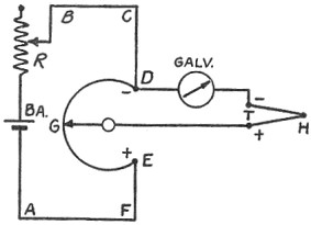
FIG. 110.—Simple potentiometer.
A current from the dry cell Ba is constantly flowing through
the main, or so-called potentiometer circuit, ABCDGEF. The
section DGE of this circuit is a slide wire, uniform in
resistance throughout its length. The scale is fixed on this slide
wire. The current from the cell Ba as it flows through
DGE, undergoes a fall in potential, setting up a difference
in voltage, that is, an electromotive force, between D and
E. There will also be electromotive force between D
and all other points on the slide wire. The polarity of this is in
opposition to the polarity of the thermo-couple which connects into
the potentiometer at D and at G. By moving G
along the slide wire a point is found where the voltage between
D and G in the slide wire is just equal to the voltage
between D and G generated by the thermo-couple. A
galvanometer in the thermo-couple circuit indicates when the Page 213 balance
point is reached, since at this point the galvanometer needle will
stand motionless when its circuit is opened and closed.
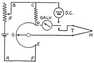
FIG. 111.—Standard cell potentiometer.
The voltage in the slide wire will vary with the current flowing
through it from the cell Ba and a means of standardizing
this is provided. SC, Fig. 111, is a cadmium cell whose
voltage is constant. It is connected at two points C and
D to the potentiometer circuit whenever the potentiometer
current is to be standardized. At this time the galvanometer is
thrown in series with SC. The variable rheostat R is
then adjusted until the current flowing is such that as it flows
through the standard resistance CD, the fall in potential
between C and D is just equal to the voltage of the
standard cell SC. At this time the galvanometer will indicate
a balance in the same way as when it was used with a thermo-couple.
By this operation the current in the slide wire DGE has
been standardized.
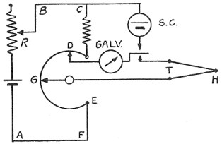
FIG. 112.—Hand adjusted cold-end compensator.
Development of the Wiring Scheme of the Cold-end
Compensator.—The net voltage generated by a thermo-couple
depends upon the temperature of the hot end and the temperature of
the cold end. Therefore, any method adopted for reading temperature
by means of thermo-couples must in some way provide a means of
correcting for the temperature of the cold end. The potentiometer
may have either of two very simple devices for this purpose. In
one form the operator is required to set a small index to a point
on a scale corresponding to the known cold junction temperature.
In the other form an even more simple automatic compensator is
employed. The principle of each is described in the succeeding
paragraphs, in which the assumption is made that the reader already
understands the potentiometer principle as described above.
Page 214 As previously
explained the voltage of the thermo-couple is measured by balancing
it against the voltage drop DG in the potentiometer.
As shown in Fig. 111, the magnitude of the balancing voltage is
controlled by the position of G. Make D movable as
shown in Fig. 112 and the magnitude of the voltage DG may
be varied either from the point D or the point G.
This gives a means of compensating for cold end changes by setting
the slider D. As the cold end temperature rises the net
voltage generated by the couple decreases, assuming the hot end
temperature to be constant. To balance this decreased voltage the
slider D is moved along its scale to a new point nearer
G. In other words, the slider D is moved along its
scale until it corresponds to the known temperature of the cold
end and then the potentiometer is balanced by moving the slider
G. The readings of G will then be direct.
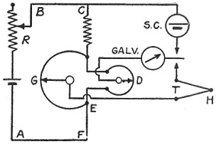
FIG. 113.—Another type of compensator.
The same results will be obtained if a slide wire upon which D
bears is in parallel with the slide wire of G, as shown in
Fig. 113.
Automatic Compensator.—It should be noted that the
effect of moving the contact D, Fig. 113, is to vary the
ratio of the resistances on the two sides of the point D in
the secondary slide wire. In the recording pyrometers, an automatic
compensator is employed. This automatic compensator varies the ratio
on the two sides of the point D in the following manner:
The point D, Fig. 114, is mechanically fixed; on one side
of D is the constant resistance coil M, on the other
the nickel coil N. N is placed at or near the cold
end of the thermo-couple (or couples). Nickel has a high temperature
coefficient and the electrical proportions of M and N
are such that the resistance Page
215 change of N, as it varies with the temperature
of the cold end, has the same effect upon the balancing voltage
between D and G that the movement of the point D,
Fig. 114, has in the hand-operated compensator.
Instruments embodying these principles are shown in Figs. 115 to
117. The captions making their uses clear.
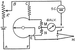
FIG. 114.—Automatic cold-end compensator.

FIG. 115.—Potentiometer ready for use.
The following illustrations from the Taylor Instrument Company show
different applications of the thermo-couples to furnaces of various
kinds. Figure 118 shows an oil-fired furnace with a simple vertical
installation. Figure 119 shows a method Page 216 of imbedding the thermo-couple
in the floor of a furnace so as to require no space in the heating
chamber.
Various methods of applying a pyrometer to common heat-treatment
furnaces are shown in Figs. 120 to 122.
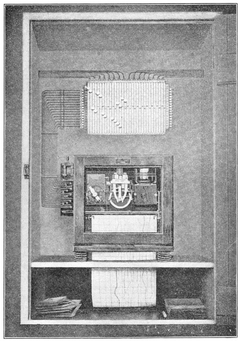
FIG. 116.—Eight-point recording pyrometer-Carpenter Steel Co.
The principles of this very popular method of measuring temperature
are sketched in Fig. 123.
Page 217
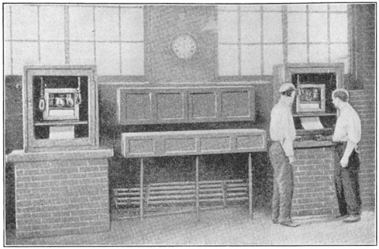
FIG. 117.—Multiple-point thermocouple recorder—Bethlehem
Steel Co.
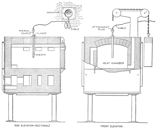
FIG. 118.—Tycos pyrometer in oil-fired furnace.
The instrument is light and portable, and can be sighted as Page 218 easily as
an opera glass. The telescope, which is held in the hand, weighs
only 25 oz.; and the case containing the battery, rheostat and
milliammeter, which is slung from the shoulder, only 10 lb.
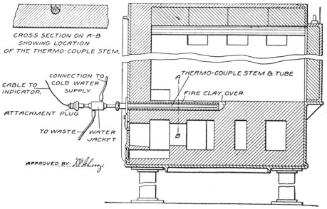
FIG. 119.—Thermocouple in floor of furnace.
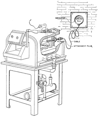
FIG. 120.—Pyrometer in gas furnace.
A large surface to sight at is not required. So long as the image
formed by the objective is broader than the lamp filament, the
temperature can be measured accurately.
Page 219
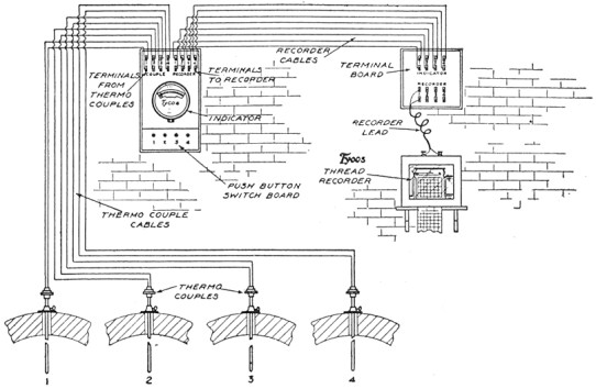
FIG. 121.—Tycos multiple indicating pyrometer and recorder.
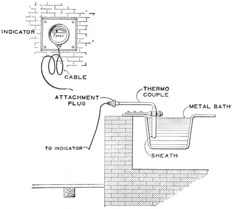
FIG. 122.—Pyrometer in galvanizing tank.
Page 220 Distance
does not matter, as the brightness of the image formed by the lens
is practically constant, regardless of the distance of the instrument
from the hot object.
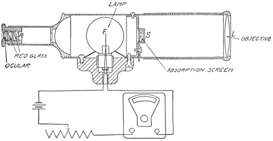
FIG. 123.—Leeds & Northrup optical pyrometer.
The manipulation is simple and rapid, consisting merely in the turning
of a knurled knob. The setting is made with great precision, due to
the rapid change in light intensity with change in temperature and
to the sensitiveness of the eye to differences of light intensity.
In the region of temperatures used for hardening steel, for example,
different observers using the instrument will agree within 3°C.
Only brightness, not color, of light is matched, as light of only
one color reaches the eye. Color blindness, therefore, is no hindrance
to the use of this method. The use of the instrument is shown in
Fig. 127.
Optical System and Electrical Circuit of the Leeds & Northrup
Optical Pyrometer.—For extremely high temperature, the
optical pyrometer is largely used. This is a comparative method.
By means of the rheostat the current through the lamp is adjusted
Page 221 until
the brightness of the filament is just equal to the brightness of
the image produced by the lens L, Fig. 123, whereupon the
filament blends with or becomes indistinguishable in the background
formed by the image of the hot object. This adjustment can be made
with great accuracy and certainty, as the effect of radiation upon
the eye varies some twenty times faster than does the temperature
at 1,600°F., and some fourteen times faster at 3,400°F.
When a balance has been obtained, the observer notes the reading
of the milliammeter. The temperature corresponding to the current
is then read from a calibration curve supplied with the instrument.
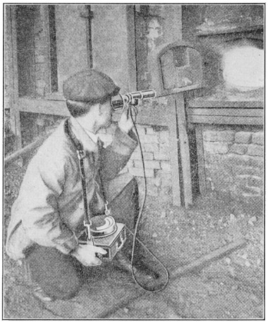
FIG. 127.—Using the optical pyrometer.
As the intensity of the light emitted at the higher temperatures
becomes dazzling, it is found desirable to introduce a piece of red
glass in the eye piece at R. This also eliminates any question
of matching colors, or of the observer's ability to distinguish
colors. It is further of value in dealing with bodies which do not
radiate light of the same composition as that emitted by a black
body, since nevertheless the intensity of radiation of any one
color from Page 222
such bodies increases progressively in a definite manner as the
temperature rises. The intensity of this one color can therefore be
used as a measure of temperature for the body in question. Figures
124 to 126 show the way it is read.
The voltage generated by a thermo-couple of an electric pyrometer is
dependent on the difference in temperature between its hot junction,
inside the furnace, and the cold junction, or opposite end of the
thermo-couple to which the copper wires are connected. If the
temperature or this cold junction rises and falls, the indications
of the instrument will vary, although the hot junction in the furnace
may be at a constant temperature.
A cold-junction temperature of 75°F., or 25°C., is usually
adopted in commercial pyrometers, and the pointer on the pyrometer
should stand at this point on the scale when the hot junction is
not heated. If the cold-junction temperature rises about 75°F.,
where base metal thermo-couples are used, the pyrometer will read
approximately 1° low for every 1° rise in temperature above
75°F. For example, if the instrument is adjusted for a cold-junction
temperature of 75°, and the actual cold-junction temperature
is 90°F., the pyrometer will read 15° low. If, however,
the cold-junction temperature falls below 75°F., the pyrometer
will read high instead of low, approximately 1° for every 1°
drop in temperature below 75°F.
With platinum thermo-couples, the error is approximately 1/2°
for 1° change in temperature.
Correction by Zero Adjustment.—Many pyrometers are
supplied with a zero adjuster, by means of which the pointer can be
set to any actual cold-junction temperature. If the cold junction
of the thermo-couple is in a temperature of 100°F., the pointer
can be set to this point on the scale, and the readings of the
instrument will be correct.
Compensating Leads.—By the use of compensating leads,
formed of the same material as the thermo-couple, the cold junction
can be removed from the head of the thermo-couple to a point 10,
20 or 50 ft. distant from the furnace, where the temperature is
reasonably constant. Where greater accuracy is desired, a common
method is to drive a 2-in. pipe, with a pointed closed end, some
10 to 20 ft. into the ground, as shown Page 223 in Fig. 128. The compensating
leads are joined to the copper leads, and the junction forced down
to the bottom of the pipe. The cold junction is now in the ground,
beneath the building, at a depth at which the temperature is very
constant, about 70°F., throughout the year. This method will
usually control the cold-junction temperature within 5°F.
Where the greatest accuracy is desired a compensating box will
overcome cold-junction errors entirely. It consists of a case enclosing
a lamp and thermostat, which can be adjusted to maintain any desired
temperature, from 50 to 150°F. The compensating leads enter
the box and copper leads run from the compensating box to the
instrument, so that the cold junction is within the box. Figure
129 shows a Brown compensating box.
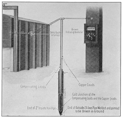
FIG. 128.—Correcting cold-junction error.
If it is desired to maintain the cold junction at 100°: the
thermostat is set at this point, and the lamp, being wired to the
110- or 220-volt lighting circuit, will light and heat the box
until 100° is reached, when the thermostat will open the circuit
and Page 224 the
light is extinguished. The box will now cool down to 98°, when
the circuit is again closed, the lamp lights, the box heats up,
and the operation is repeated.
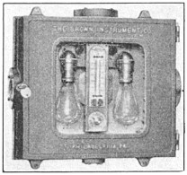
FIG. 129.—Compensating box.
In large heat-treating plants it has been customary to maintain an
operator at a central pyrometer, and by colored electric lights at
the furnaces, signal whether the temperatures are correct or not. It
is common practice to locate three lights above each furnace-red, white
and green. The red light burns when the temperature is too low, the
white light when the temperature is within certain limits—for
example, 20°F. of the correct temperature—and the green
light when the temperature is too high.
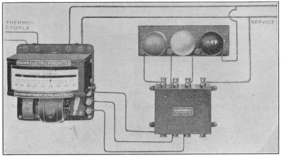
FIG. 130.—Brown automatic signaling pyrometer.
Instruments to operate the lights automatically have been Page 225 devised and
one made by Brown is shown in Fig. 130. The same form of instrument
is used for this purpose to automatically control furnace temperatures,
and the pointer is depressed at intervals of every 10 sec. on contacts
corresponding to the red, white and green lights.
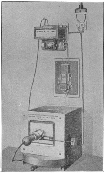
FIG. 131.—Automatic temperature control.
Automatic temperature control instruments are similar to the Brown
indicating high resistance pyrometer with the exception that the
pointer is depressed at intervals of every 10 sec. upon contact-making
devices. No current passes through the pointer which simply depresses
the upper contact device tipped with platinum, which in turn comes
in contact with the lower contact device, platinum-tipped, and
the circuit is completed through these two contacts. The current
is very small, about Page
226 1/10 amp., as it is only necessary to operate the
relay which in turn operates the switch or valve. A small motor is
used to depress the pointer at regular intervals. The contact-making
device is adjustable throughout the scale range of the instrument, and
an index pointer indicates the point on the instrument at which the
temperature is being controlled. The space between the two contacts
on the high and low side, separated by insulating material, is
equivalent to 1 per cent of the scale range. A control of temperature
is therefore possible within 1 per cent of the total scale range.
Figure 131 shows this attached to a small furnace.
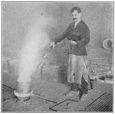
FIG. 132.—Portable thermocouple testing molten brass.
Pyrometers for molten metal are connected to portable thermocouples
as in Fig. 132. Usually the pyrometer is portable, as shown in
this case, which is a Brown. Other methods of mounting for this
kind of work arc shown in Figs. 133 and 134. The bent mountings
are designed for molten metal, such as brass or copper and are
supplied with either clay, graphite or carborundum tubes. Fifteen
feet of connecting wire is usually supplied.
The angle mountings, Fig. 134, are recommended for baths such as lead
or cyanide. The horizontal arm is usually about 14 in. long, and the
whole mounting is easily taken apart making Page 227 replacements very easy. Details of
the thermo-couple shown in Fig. 132 are given in Fig. 135. This is
a straight rod with a protector for the hand of the operator. The
lag in such couples is less than one minute. These are Englehard
mountings.
Thermo-couples must be protected from the danger of mechanical
injury. For this purpose tubes of various refractory materials
are made to act as protectors. These in turn are usually protected
by outside metal tubes. Pure wrought iron is largely used for this
purpose as it scales and oxidizes very slowly. These tubes are
usually made from 2 to 4 in. shorter than the inner tubes. In lead
baths the iron tubes often have one end welded closed and are used
in connection with an angle form of mounting.
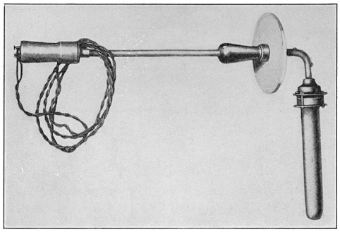
FIG. 133.—Bent handle thermocouple with protector.
Where it is necessary for protecting tubes to project a considerable
distance into the furnace a tube made of nichrome is frequently used.
This is a comparatively new alloy which stands high temperatures
without bending. It is more costly than iron but also much more
durable.
When used in portable work and for high temperatures, pure nickel
tubes are sometimes used. There is also a special metal tube made
for use in cyanide. This metal withstands the intense penetrating
characteristics of cyanide. It lasts from six to ten months as
against a few days for the iron tube.
Page 228 The inner
tubes of refractory materials, also vary according to the purposes
for which they are to be used. They are as follows:
Marquardt mass tubes for temperatures up to 3,000°F.,
but they will not stand sudden changes in temperature, such as in
contact with intermittent flames, without an extra outer covering
of chamotte, fireclay or carborundum.
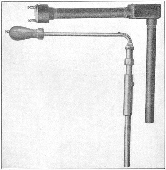
FIG. 134.—Other styles of bent mounting.
Fused silica tubes for continuous temperatures up to 1,800°F.
and intermittently up to 2,400°F. The expansion at various
temperatures is very small, which makes them of value for portable
work. They also resist most acids.
Chamotte tubes are useful up to 2,800°F. and are mechanically
strong. They have a small expansion and resist temperature Page 229 changes
well, which makes them good as outside protectors for more fragile
tubes. They cannot be used in molten metals, or baths of any kind
nor in gases of an alkaline nature. They are used mainly to protect
a Marquardt mass or silica tube.
Carborundum tubes are also used as outside protection to
other tubes. They stand sudden changes of temperature well and
resist all gases except chlorine, above 1,750°F. Especially
useful in protecting other tubes against molten aluminum, brass,
copper and similar metals.
Clay tubes are sometimes used in large annealing furnaces
where they are cemented into place, forming a sort of well for the
insertion of the thermo-couple. They are also used with portable
thermo-couples for obtaining the temperatures of molten iron and
steel in ladles. Used in this way they are naturally short-lived,
but seem the best for this purpose.
FIG. 135.—Straight thermocouple and guard.
Corundite tubes are used as an outer protection for both
the Marquardt mass and the silica tubes for kilns and for glass
furnaces. Graphite tubes are also used in some cases for outer
protections.
Calorized tubes are wrought-iron pipe treated with aluminum
vapor which often doubles or even triples the life of the tube
at high temperature.
These tubes come in different sizes and lengths depending on the
uses for which they are intended. Heavy protecting outer tubes
may be only 1 in. in inside diameter and as much as 3 in. outside
diameter, while the inner tubes, such as the Marquardt mass and
silica tubes are usually about ¾ in. outside and 3/8 in. inside
diameter. The length varies from 12 to 48 in. in most cases.
Special terminal heads are provided, with brass binding posts for
electrical connections, and with provisions for water cooling when
necessary.
Page 238 AUTHORITES QUOTED
A
ADDIS, W H., 102
AMERICAN MACHINISTS' HANDBOOK, 69
AMERICAN STEEL TREARERS' SOCIETY,
119
AMERICAN GEAR MFRS. ASSO., 115
AUTOMATIC AND ELECTRIC FURNACES LTD.,
161
ARNOLD, PROF. J. O., 167
B
BURLEIGH, R. W.
BORDEN, B.
BOKER, HERMAN & Co.
BROWN INSTRUMENT Co., 224
BROWN-LIPE-CHAPLIN Co., 121
C
CAMPBELL, H. H.
CARHART, H. A., 42
CLAYTON, C. Y., 112
CURTIS AIRPLANE Co.
E
ENGLEHARD, CHARLES, 227
ENSAW, HOWARD, 79,
95
F
FIRTH-STERLING STEEL Co., 176
FIRTH, THOMAS & SONS, 137
FOWLER, HENRY, 151
G
GILBERT & BARKER, 164,
188
H
HAYWAHD, C. R., 35
HOWE, DR. H. M., 8,
108
HOOVER STEEL BALL CO., 61
HEATHCOTE, H. L., 85
HARRIS, MATTHEW, 94
HUNTER, J. V., 192
J
JANITZKY, E. J., 119
JOHNSTON, A. B., 35
JUTHE, K. A., 1,
24, 65,
75, 79,
105, 145
L
LATROBE STEEL CO., 150,
178
LUDLUM STEEL CO., 175
LEEDS & NORTHRUP CO.,
211
LYMAN, W. H., 199
M
MANSFIELD, C. A.
MIDVALE STEEL Co.
McKENNA, ROY C., 164
MOULTON, SETH A., 199
N
NILES, BEMENT, POND, 67
P
PARKER, S. W.
POOLE, C. R.
R
RAWDON, H. S., 110,
113
S
S. A. E. (SOCIETY AUTOMOTIVE ENGINEERS),
39, 46,
49, 134
SAUVEUR, ALBERT, 105,
232
SPRINGFIELD ARMORY, 78
SELLACK, T. G.
SMITH, A. J., 101
SHIRLEY, ALFRED J.
T
TAYLOR INSTRUMENT Co., 215
THUM, E. E., 12-23;
105-121.
TIEMANN, H. P., 11
U
U. S. BALL BEARING Co.
UNITED STEEL Co.
UNDERWOOD, CHARLES N.
V
VAN DE VENTER, JOHN H., 86
W
WALP, H. O., 109
WOOD, HAROLD F., 46
WHEELOCK, LOVEJOY & Co., 69
Page 239 INDEX
A
ABC of iron and steel, ix
Absorption of carbon, rate of, 83
Air hardening steels, 183
Analysis of high speed steel, 165
Allotropic modifications, 107
Alloy steel, annealing, 76
properties of, 34
Alloys and their effect, 16,
24
in high speed steel, 166
in steel, value of, 16,
24
upon steel, 24
Alpha iron, 106
Annealing, 113,
115
care in, 154,
155
furnace, 190
high-chromium steel, 36
high speed tools, 174
in bone, 77
methods, 122
proper, 117
rifle components, 78
rust-proof steel, 36
steels, 75
temperature, 119
Arrests, 106
Austentite, 108, 111
Automotive industry, application of Liberty engine materials to,
46
temperature control, 225
Axles, heat treatment of, 61
B
Balls, making steel, 61
Barium chloride process, 178
Baths for tempering, 157
Bessemer converter, 2
Beta iron, 106
Blending compounds, 103
Blister steel, 81
Blue brittleness, 56
Bone, annealing in, 77
Boxes for case hardening or carburizing, 80
Breaking test gears, 126
Brinell hardness, 22
Broach hardening furnace, 188
Brown automatic pyrometer, 224
Burning, 65
C
Calorized tubes, 229
Carbon, 13
content at various temperatures, 84
content of case hardened work, 81
in cast iron, ix
in tool steel, 149-150
introduction of, 96
penetration of, 95
steel, 11
steel forgings, Liberty engine, 48
steel tools, 145
steels, S. A. E., 10, 39
steels, temper colors, 163
strengthens iron, 13
tool steel, forging, 65
Carbonizing, see Carburizing
Carborundum tubes, 229
Carburization, preventing, 93
Carburizing by gas, 88,
93
boxes, 80
compounds, 88,
102
gas consumption by, 101
local, 94
material, 85
nickel steel, 125
or case hardening, 79
pots for, 123
Page 240
Carburizing, process of, ix,
83, 116
short method, 124
sleeves, 132
with charcoal, 81,
88
See Case hardening
Car door type of furnace, 190
Case, depth of, 86
Case hardening boxes, 80
cast iron, 89
local, 94
or surface carburizing, 79
treatments for various steels, 92
see Carburizing
Cast iron, carbon in, ix
case hardening, 89
Cementite, ix, 14
Center column furnace, 186
Centigrade table, 232-234
Chamotte tubes, 228
Chart of carbon penetration, 97
heat treatment, 151
shape, 151
Chrome steel, 26-27
Chrome-nickel steel, 27-28
steel, forging, 66
Chrome-vanadium steel, 28
Chromium, 26-27
steels, S. A. E., 41
Chromium-cobalt steel, 178
Chromium-vanadium steel, S. A. E., 41
Classification of steel, 10
Clay tubes, 229
Cold end compensator, 213
junction errors, 222
shortness, 15,
166
worked steel, 65
Color in tempering, 157
Colors on carbon steels, 163
Combination tank, 90
Comparison of fuels, 191
Compensating leads, 222
Compensator for cold ends, 214
automatic, 214
Composition of steel, 13
Compound, blending, 103
separating from work, 102
Compounds for carburizing, 102
Connecting rods, Liberty motor, 42,
52
Continuous heating furnace, 71
Converter, Bessemer, 2
Cooling curves, 106,
107
Cooling quenching oil, roof system, 74
rate of, for gear-forgings, 51
Copper, effect of, in medium carbon steel, 35
Copper-plating to prevent carburizing, 93
Corrosion of high-chromium steel, 38
of rust-proof steel, 38
Corundite tubes, 229
Cost of operating furnaces, 200
Cracks in hardening, preventing, 106
Crankshaft, Liberty motor, 54
Critical point, 105
Crucible or tool steel, x,
4
Cutting off high speed steel, 172
Cyanide bath for tool steel, 133
D
Decarbonizing of outer surface, 153
preventing, 154
Depth of case, 86
Detrimental elements in steel, 166
Dies, drop forging, 133
quenching, 147
soft spots in, 147
tempering round, 161
Drawing, 114
ends of gear teeth, 127
Drop forging dies, 133
Ductility, 13, 18
E
Effect of alloys, 24
of different carburizing material,
87
of size of piece, 89,
119
of copper in medium carbon steel,
35
Elastic limit, 18
Electric process of steel making, 5
Electrode, 5
Elements, chemical, 12
Elongation, 18
Page 241
Endurance limit, 20
Energizer, 81, 88
Enlarging steel, 161
Equipment for heat treating, 121
Eutectoid, 109
F
Fahrenheit temperature table, 232
Fatigue test, 19
Ferrite, 106
File test, 16, 17
Flame shields, 193
Flange shields for furnaces, 197
Forging furnace, 189
high speed tools, 174
improper, 66
of steel, 64
practice, heavy, 195
rifle barrels, 69
Forgings, carbon steel Liberty engine,
48
Formed tools, high speed, 174
Fractures, examining by, 16,
159
Furnace, continuous heating, 71
crucible, 4
data, 199
electric, 5
Heroult, 6
open hearth, 3
records, 129
Furnaces, 185
annealing, 190
broach hardening, 188
car door type, 190
center column, 186
cost of operating, 200
data on, 199
forging, heavy, 195
fuels for, 199
gas fired, 190
high speed steel, 187
lead pot, 185
manganese steel, 198
muffle, 189
oil fired, 186
operating costs, 200
screens for, 192
tool, 187
Furnaces, water cooled fronts, 197
Fuels, comparison of, 191
for furnaces, 199
G
Gages, changes due to quenching, 162
tempering, 161
Gamma iron, 106
Gas, carburizing by, 93
consumption for carburizing,
101
fired furnace, 190
illuminating, for carburizing,
97
Gear blanks, heat treatment of, 115
forgings, rate of cooling for Liberty engine,
51
hardening machine, 130
steel, transmission, 59
teeth, drawing ends of, 127
Gears, Liberty engine, 50
Gleason tempering machine, 129
Grade of steel, 10
Grain, refining, 91,
110
size, 16
Graphitic carbon, ix
Grinding high speed steel, 176
H
Hair lines in forgings, 56
Hardening, 111
carbon steel for tools, 145
cracks, preventing, 160
dies, 146
gears, 130
high speed steel, 171
high speed tools, 177
of high-chromium steel, 37
of rust-proof steel, 37
room, modern, 146
Hardness tests, 20
Heating, effect of size, 119
for forging, 64
Heat, judging by color, 114
treating departments, 122
equipment, 121
forgings, 44
inspection of,
125
Liberty motor,
44
Page 242
Heat treating, of axles, 61
of chisels, 151
of gears, 131
of high speed steel, 170
of steel, 105
S. A. E., 134-137
Heat treatment, 105
Heroult furnace, 6
High-chromium steel, 36
annealing of, 36
corrosion of, 38
hardening of, 37
Highly stressed parts of Liberty engine,
49
High speed steel, analysis of, 166
annealing, 75
cutting off, 172
forging, 65
furnace, 187
hardening, 171
heat treatment of, 170
instructions for, 175,
180
manufacture, 166,
169
pack hardening, 172
structure of, 168
Hints for steel users, 159
I
Illuminating gas for carburizing, 97
Impact test, 19
Improper forging, 66
Influence of size on heating, 119
Inspection of heat treatment, 125
Internal stresses, relieving, 154
Introduction of carbon, 96
J
Jewelers' tools, 146
Judging heat of steel by color, 114
L
Latent heat, 105
Lathe and planer tools, 176
tools, high speed, 173
Latrobe temper list, 150
Lead bath, 154
pot furnace, 185
Leeds & Northrup potentiometer 211
optical pyrometer, 220
Liberty engine, highly stressed parts of, 49
Liberty engine materials, application to automotive industry,
46
motor connecting rods, 42,
52
motor, crankshaft, 54
motor piston pin, 57
Local case hardening, 94
Luting mixture, 100
M
Machineability of steel, 72
Machinery steel, annealing, 77
Magnet test, 114
Making steel in electric furnace, 6
Manganese, 16, 33,
107
steel, 29-30
furnace,
198
Manufacture of high speed steel, 169
Marquardt mass tubes, 228
Martensite, 111
Medium carbon steel, effect of copper on,
35
Metallography, 105
Microphotographs, 109 e. s.
Microscopic examination, 158
Milling cutters, high speed, 174
Mixture for luting, 100
Modern hardening room, 146
Molten metal pyrometers, 226
Molybdenum, 32
Muffle furnace, 189
N
Nickel, 24
Nickel-chromium steel, 27-28
steels, S. A. E., 40
Nickel, influence of, on steel, 25
steel, 24-26
affinity for carbon,
125
steels, S. A. E., 39
Non-homogeneous melting, 24
Non-shrinking steels, 35
Normalizing, 114
Page 243
O
Oil bath for tempering, 157
cooling on roof, 74
fired furnace, 186
hardening steel, forging,
66
steels, 35
temperature of quenching,
124
Open hearth furnace, 3
Operating costs of furnaces, 200
Outer surface decarbonizer, 153
Over-heated steel, restoring, 137
Overheating, 65
dies, 148
P
Pack-hardening, 87
high speed steel, 173
Packing work for carburizing, 123
Paste for hardening dies, 146
Pearlite, 109,
112
Penetration of carbon, 95
carbon, chart of, 97
in case hardening, 83
Phosphorus, 15, 33
Pickling Liberty motor forgings, 44
Pig iron, ix
Piston pin, Liberty motor, 57
Placing pyrometers, 210
Planer tools, high speed, 173
"Points" of carbon in steel, 9
Potentiometer, Leeds & Northrup,
211
Pots for carburizing, 123
Press for testing gears, 126
Preventing carburization, 93
cracks in hardening, 160
Properties of alloy steels, 34
of alloy steels, table, 34
of steel, 12
Protective screens for furnaces, 192
Puddled iron, ix
Punches and chisels, steels for, 151
Pyrometers, 202
calibration, 208
copper ball, 202
indicating, 219
inspection, 208
iron ball, 202
molten metal, 226
optical, 206,
220
placing, 210
recording, 216
Siemens, 202
testing, 209
water, 203
Q
Quality and structure of high speed steel,
168
of steel, 149
Quenching,
after carburizing, 86-88
dies in tank, 147
obsolete method, 148
oil, temperature of, 124
tank, 89
tool steel, 156
R
Rate of absorption of carbon, 83
Recording temperatures, 127
Red shortness, 14,
166
Refining the grain, 91,
111
Regenerative open hearth furnace, 3
Restoring overheated steel, 137
Rifle barrels, forging, 69
components, annealing, 78
Roof system of cooling oil, 74
Rust-proof steel, 36
annealing of, 36
corrosion of, 38
hardening of, 37
S
S. A. E. carbon steels, 10,
39
chromium steels, 41
chromium-vanadium, 41
heat treatments, 134-137
nickel-chromium steels, 40
nickel steels, 39
screw stock, 39
silico-manganese steel, 41
standard steels, 39
Page 244
Salt bath for tempering, 157
Scleroscope test, 21
Scratch hardness, 20
Screens for furnaces, 192
Screw stock, S. A. E., 14,
39
Sensible heat, 105
Sentinels, melting of, 207
Separating work from compound, 102
Shields for furnace doors, 193
Shore Scleroscope, 21
Short method of carburizing, 124
Shrinking steel, 161
Silica tubes, 228
Silico-manganese steels, S. A. E., 41
Silicon, 15, 33,
107
Silversmiths' tools, 146
Size of piece, effect of, 89,
119
Slags, 7
Sleeves, carburizing, 132
hardening and shrinking,
132
shrinking, 132
Solid solution, 106
Sorbite, 112
Specimens, test, 17
Standard S. A. E. steels, 39
Steel,
balls, stock for, 62
bolts, making, 61
composition of, 12
deoxidation, 15
for chisels and punches,
151
forging of, 64
give it a chance, 148
heat treatment of, 105
high speed, 165
making, 1,
6, 15
Bessemer process, 1
crucible process, 4
electric furnace process,
5
open hearth, 1
tools, carbon, in, 149
users' hints, 159
Structure of high speed steel, 168
Sulphur, 14, 33
T
Tables, air, oil and water hardened steel,
38
alloy steels, properties of,
34
carbon content, 84
carbon steels, 39
case hardening, 97
changes due to quenching,
162
chromium steels, 41
chromium-vanadium steels,
41
colors and temperature,
163
composition of steels,
51, 52
cost of furnaces, 200
effect of size, 119
fuels, comparison of,
191
high-chromium steel,
37
nickel-chromium steels,
40
nickel steels, 39
operating cost of furnaces,
200
production cost of furnaces,
201
S. A. E. steels, 49
screw stock, 39
silico-manganese steels,
41
stock for balls,
62
temperature conversion,
232-234
tempering temperatures,
158
weight of steel,
235-237
Tank for quenching, 89
dies, 147
Taylor instruments, 215
Temper, colors of, 157
list, Latrobe, 150
of steel, 10,
149
Temperature recorders, 127
tables, 232-234
Temperatures for tempering, 158
Tempering colors on carbon steels,
163
gages, 161
high speed tools, 177
machine, Gleason, 129
round dies, 161
temperatures, 158
theory of, 114,
156
Tempers of carbon steel, 10,
150
Tensile test, 17
Testing heat treatment, 125
Tests of steel, 16
Test specimens, 17
Theory of tempering, 114,
150
Thermocouple, 204
base metal, 205
Page 245
cold end, 206
placing, 218
protectors, 227
rare metal, 205
Time for hardening, 148
Tool furnace, small, 187
Tool or crucible steel, annealing, 76
Tool steel, cyanide bath for, 133
quenching, 150
Tools, carbon in different, 149
carbon steel, 145
of high speed steel, 173
sulphur in, 14
tempers of various, 150
transformation points,
106
Transmission gear steel, 59
Treatments for various steels, 92
Troosite, 112
Tubes, calorized, 229
carborundum, 229
Chamotte, 228
clay, 229
Marquardt mass, 228
silica, 228
Tungsten steel, 30
U
Ultimate strength, 17
Users of steel, hints for, 159
V
Vanadium steel, 28
W
Water annealing, 155
cooled furnace fronts,
197
Weight of steel bars, 235-237
Working instructions for high speed steel,
175
Wrought iron, ix
Y
Yield Point, 19
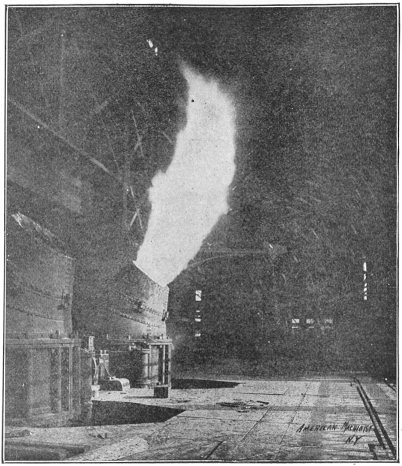 FIG. 1.—A typical Bessemer converter.
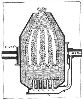 FIG. 2.—Action of Bessemer converter.
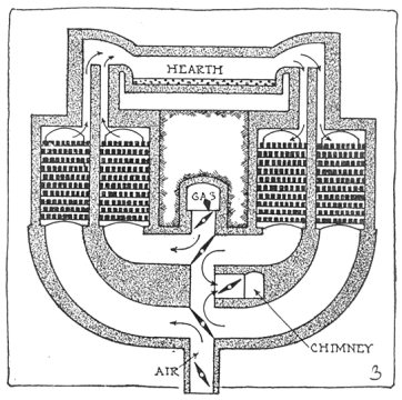 FIG. 3.—Regenerative open hearth furnace.
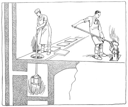 FIG. 4.—Typical crucible furnace.
 FIG. 5.—"Slagging off" an electric furnace.
 FIG. 6.—Pouring the ingots.
 FIG. 7.—Ludlum electric furnace.
 FIG. 8.—The furnace tilted for pouring.
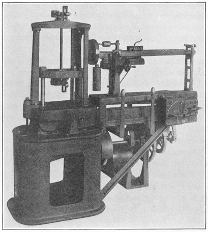 FIG. 9.—Olsen testing machine.
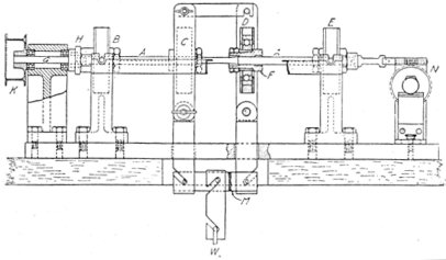 FIG. 10.—Sketch of rotating beam machine for measuring endurance
of metal.
FIG. 10.—Sketch of rotating beam machine for measuring endurance
of metal.
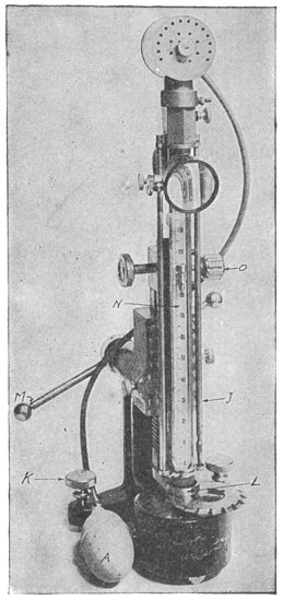 FIG. 11.—Shore scleroscope.
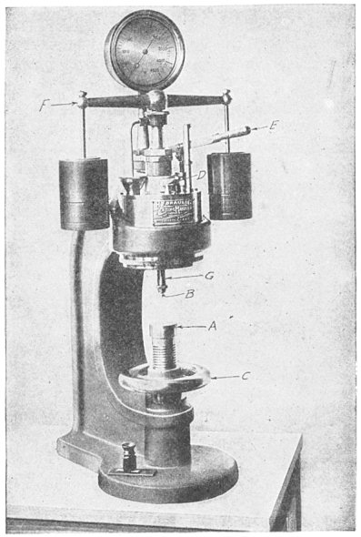 FIG. 12.—Hydraulic testing machine. (Brinell principle.)
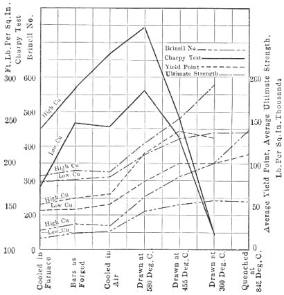 FIG. 13.—Effect of copper in steel.
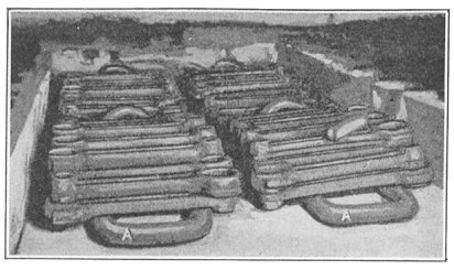 Fig. 14.—Rack for holding rods.
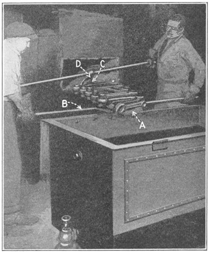 Fig. 15.—Sliding rods into tank.
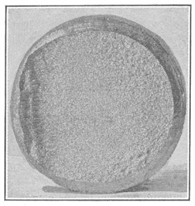 FIG. 16.—A sound forging.
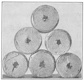 FIG. 17.—Burst from improper forging.
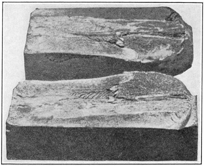 FIG. 18.—Burst from a piped center.
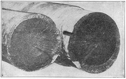 FIG. 19.—Result of using too light a hammer.
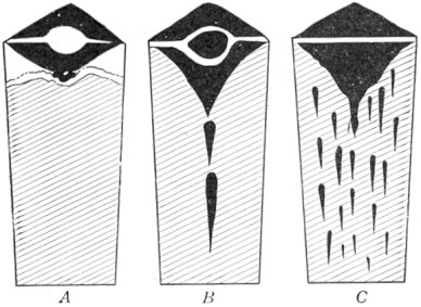 FIG. 20.—Good and bad ingots.
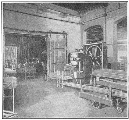 FIG. 21.—Cutting up barrels.
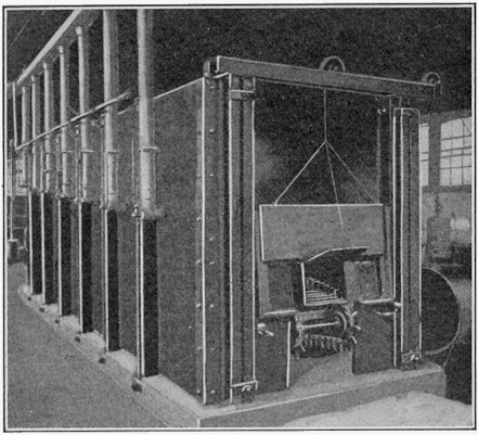 FIG. 23.—Continuous heating furnace.
 FIG. 24.
 FIG. 25.
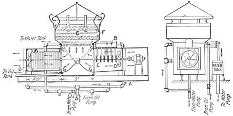 FIG. 26.—Details of the cooler.
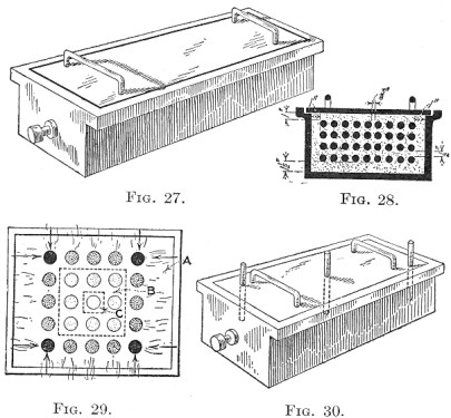 FIGS. 27 to 30.—Case-hardening or carburizing boxes.
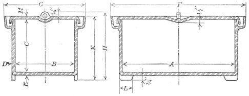 FIG. 31.—A lid that is easily luted.
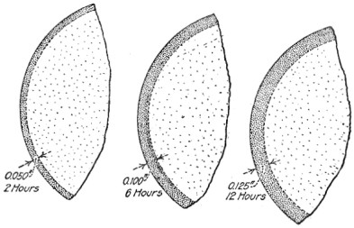 FIG. 32.—Case-hardening depths.
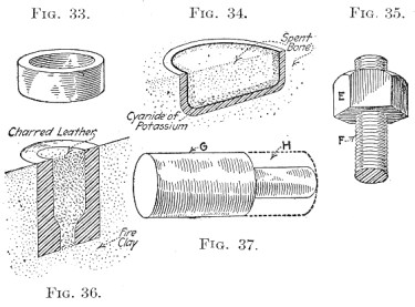 FIGS. 33 to 37.
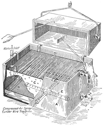 FIG. 38.—Combination cooling tank for case-hardening.
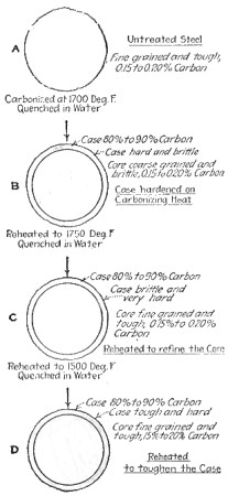 FIG. 39.—Why heat treatment of case-hardened work is necessary.
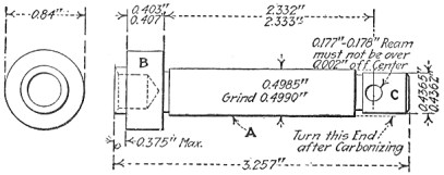 FIG. 40.—Shaft to be coated with paraffin.
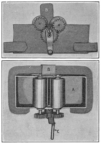 FIG. 41.—Device for coating the shaft.
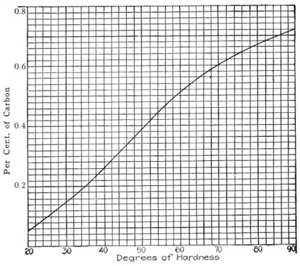 FIG. 42.—Chart showing penetration of carbon.
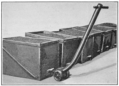 FIG. 43.—The cooling carts.
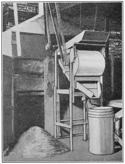 FIG. 44.—Machine for blending the mixture.