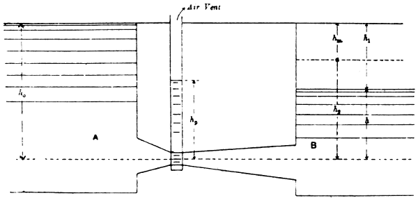
—In the design of head works no very
precise rules can be laid down. Some general ideas can
however be given as to the chief points to be attended
to and some general and approximate rules stated. In
every case a large scale plan of the river is of course
required and also a close examination of it and study of
its character. An attempt to forecast its action is then
possible. Gauge readings for several years and calculations
of discharges are of course necessary. If the bed
of the river, in course of time, rises upstream of the
weir or scours downstream of it, a large amount of protection
to the bed and banks will become necessary.
Some description of headworks and weirs, with a plan
of the headworks of the Sirhind Canal, India, has been
given in River and Canal Engineering, Chapters IV. and
X. Remarks regarding the collection of information
for such works are given in Chapter II. of the same
work. It is also explained how, by keeping the gates
of the under-sluices closed, a “pond” is formed between
the divide wall and the canal head so that heavy sand
deposits in the pond and does not enter the canal. By
closing the canal and opening the under-sluices the
deposit is scoured away.
The best site for the headworks of a canal depends on
the stability and general character of the bed of the
river but in deciding between any two proposed sites,
the question of the additional cost of the canal, if the
upper site is adopted, has to be taken into account.
Such cost may, in rugged country, be considerable.
In the case of Indian perennial canals, the head is
often close to the hills where the river bed is of boulders
and shingle and fairly stable, but it is often at a distance
from the hills and in such cases a gradual rise in
the bed of the river, even in the absence of a weir, is
more probable than scour. Such a rise may necessitate
a raising of the crest of the weir and of the bed of the
canal.
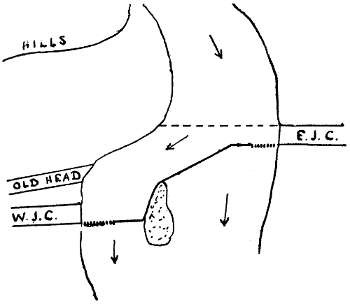
Fig. 5.
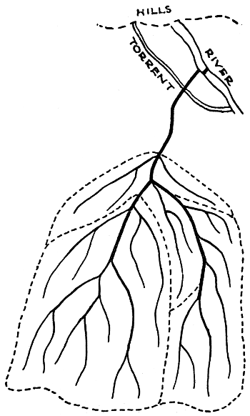
In the general arrangement of a headworks a great
deal depends on local conditions. Sometimes the river
runs in a fairly straight and defined channel and the
weir can then be run straight across it. Sometimes, as
in the case of the Ganges Canal, there is a succession of
islands and various short weirs are required in the
different channels. At the heads of the Eastern and
Western Jumna Canals, the river, on issuing from the
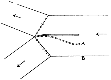
hills, widens out (Fig. 5.) and the weir is built obliquely
and not in a straight line. Its crest is higher at the east
than at the west side. There are under-sluices at both
sides. The upstream end and west side of the island
are revetted. The old head of the Western Jumna
Canal, as shown in the figure, existed long before the
advent of the British, and a temporary weir, made of
gabions filled with stones, was constructed across the
river every year during the low water period and swept
away during the floods. To have carried the weir along
the line shown dotted, the head of the Western Jumna
Canal being of course brought up to it, would apparently
have been feasible and cheaper, but the off-take would
have been in shallow water because of the curve in the
river, and there would have been no current along the
face of the head regulator of the canal.
The level of the floor of the under-sluices is generally
about the same as that of the bed of the canal. The
sill—made to exclude shingle and sand as far as
possible—of the canal head regulator may be 3 feet
higher and the crest of the weir 6 to 9 feet higher. The
top of the weir shutters is 1 to 2·5 feet above the F.S. level
of the canal which may be 5 feet or more above the bed
of the canal. If the weir is provided with falling
shutters the width of the waterway of the under-sluices
may be about ¹⁄₁₂th of the width of the waterway of the
weir alone, otherwise about ¹⁄₈th.
In nearly all cases the weir has a flat top and flat
slopes both upstream and downstream. In a case where
the river bed is of sand, the depth of water on the crest
of the weir in floods may be 15 feet and the velocity 14
or 15 feet per second. The downstream slope of the
weir may be about 1 in 15, and the upstream slope 1
in 6. Where the river bed is of boulders the velocity
may be still higher. The faces of the weir are usually of
hammer-dressed stone. A lock for the passage of rafts
is added if necessary.
Unless the banks of the river are high, it is necessary
to construct embankments to prevent the river water,
when headed up by the weir during the floods, from
spilling over the country with possible damage to the
canal. If the river has side channels they have to be
closed. The stream may also have to be trained, by
means of guide banks or spurs, so as to remain in one
channel and flow past the canal head and not form
shoals against it. Where the river is unstable, it may
shift its course so as to strike the weir obliquely and
this may cause excessive heading up at one side of the
weir. In such cases it is usual to divide the weir into
bays or sections, each about 500 feet long, by “divide
walls” running at right angles to the weir.
The free-board or height of the masonry walls and
tops of embankments above H.F. Level is about 5 feet.
The span of each opening in the under-sluices is
generally 20 to 35 feet. The piers may be 5 feet thick.
It is usual to make each alternate pier project upstream
further than the others so that long logs coming down
the river during floods, broadside on, may be swung
round and not be caught and held against the piers.
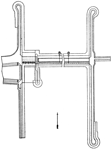
Fig. 6.

Fig. 6A.
Figs. 6 and 6A show the headworks of the Upper Chenab
Canal now under construction (Chapter IV.) The site
is in a low flat plain, but no better site could be found.
The weir consists of 8 bays of 500 feet each. The
crest is 10 feet above the river bed and the falling
shutters 6 feet high. The slopes are 1 in 6 and 1 in 15.
The bulk of the work is rubble masonry in lime. The
lower layer upstream of the crest is of puddle; upstream
of the second line of wells it is rubble masonry in half
sand and half lime; upstream of the lower line of wells
it is of dry stone and there is an intermediate layer of
rubble masonry in lime with the stones laid flat. Below
the crest there is a wall of masonry 9 feet thick and on
the crest there are two strips of ashlar between which
the shutters lie when down. The extreme upstream
and downstream portions of the bed protection are of
dry stone and 4 feet thick while next to the weir are
concrete blocks 2 feet thick resting on dry stone. The
width of the crest is 14 feet, of the weir 140 feet, of the
protection 70 feet upstream and 110 feet downstream.
The guide banks have tops 40 feet wide and 18 and 14
feet above the crest of the weir in the upstream and
downstream lengths respectively, the side slopes being
2 to 1 and the water slope being covered, up to H.W.
level, by dry stone pitching 4 feet thick. The left guide
bank runs upstream for 3,250 feet from the centre line
of the canal and the right 2000 feet from the line of
crest shutters. The under-sluices have 8 bays of 35 feet
each and the canal head regulator 36 openings of 6·5
feet each, the large openings shown in the figure being
sub-divided. The crest of the weir is no less than 10
feet above the river bed and the shutters add 6 feet to
this. The floor of the under-sluices is 4 feet higher
than the river bed. There is thus ample allowance for
a possible rise in the river bed.
—The contour map, besides
showing the contours of the country to be irrigated and
of a strip of country, even if not to be irrigated, which
will be traversed by the main line, should show all its
main features, namely:—streams, drainages, railways,
roads, embankments, reservoirs, towns, villages, habitations,
and the boundaries of woods and cultivated lands.
It should also show the highest water levels in all
streams or existing canals. A map showing as many
as possible of the above features should be obtained and
lines of levels run for the contours. In doing this, the
points where the lines of levels cut or pass near to any
of the above features or boundary lines, should be noted.
It may be necessary to correct inaccuracies in the plan
or to supply defects in it. The greater the trouble
taken to do this the less will be the trouble experienced
later on.
The heights of the contour lines will, in very flat
country, have eventually to be only 1 foot apart. This
will necessitate running lines of levels half-a-mile apart
at the most, and preferably 2000 feet apart, the pegs in
each line being about 500 feet apart. In less flat
country the heights of the contour lines can be further
apart than 1 foot. Whatever distance apart is decided
on for them, the survey should be done once for all.
On one of the Indian canals in flat country, the lines
of levels were at first taken 5 miles apart, the branches
roughly aligned and then further surveys made. This
led to great expense and delay and the procedure has
not been repeated.
In making a contour survey, a base line, as centrally
situated and as long as possible, should be laid down,
with side lines parallel to it near the boundaries of the
tract. The cross lines at half-mile or other intervals
should then be laid down. Some of them may run out
beyond the side lines. Circuits of levels should be run
along the base line, the side lines and the two extreme
cross lines and be carefully checked. The remaining cross
lines should then be levelled. All the levels having
been shown on the map the contours should be sketched
in. The scale of the map for a large project may be two
inches to a mile. If it is likely that the survey will have
to be extended, it will be easier to do this by prolonging
the base line and running more cross lines, than by
prolonging each of the cross lines already surveyed.
This can be borne in mind when selecting the base line.
—On the contour
map the proposed alignments of the canal, branches,
distributaries, and escapes, determined after careful
consideration of all matters affecting them, are shown.
The tracts to be irrigated by each branch and each
distributary are now marked off, the “irrigation
boundaries” following approximately the valleys and
lines of drainage. Any large tracts of land which cannot
be irrigated are of course shown and are excluded.
Forests or other lands which are not to be irrigated
should be similarly dealt with, otherwise confusion is
likely to arise later. The commanded area dependent
on each distributary is now ascertained from the map.
A certain percentage being deducted for scattered
unculturable areas the culturable commanded areas are
obtained. The proportion to be irrigated (in India in the
kharif) having previously been decided, the number of
acres to be actually irrigated by each distributary is
arrived at.
The next step is to ascertain the discharges.[9] A
general duty for the whole canal having been estimated
by considering the actual figures for other canals the
full supply of the canal at its head is arrived at.
(Chapter I, Art. 6). In Northern India it will be the
kharif duty and kharif full supply. Since some water
is lost by absorption in the channels, the duty of the
water on a branch is higher than that of the whole
canal based on its head discharge, and the duty on a
distributary is higher still. In designing a canal, an
attempt has to be made to estimate the losses of water
in the main canal and branches, so that the duties of
the branches and distributaries may be estimated and
the channels designed accordingly. On the Western
Jumna Canal the figures were estimated to be as
follows:—
| |
Kharif. |
Rabi. |
| Average discharge at canal head (c. ft. per sec.) |
3536 |
2755 |
| Duty based on the discharge (acres) |
98 |
138 |
| Estimated loss of water in canal and branches (c. ft. per sec.) |
400 |
300 |
| Average discharge at distributary head (c. ft. per sec.) |
3136 |
2455 |
| Duty based on the discharge (acres) |
111 |
154 |
The question of duty is one which if not carefully
considered, may cause some confusion. A canal and
branches, having been designed with certain assumed
duties and with discharges based on certain values of
N in Kutter’s co-efficient, have, let it be supposed, been
constructed to a greater or less extent. When the
time comes for constructing the distributaries, the
engineers concerned may have different ideas, based on
later experience, as regards the probable duty and the
most suitable value of N. If they design the distributaries
with a higher duty and a lower value of N, it is
obvious that they can provide more distributaries than
at first designed, or can increase their lengths. In either
case they would provide for an increased commanded
area. If they do not do this, they ought to adhere to
the values at first proposed, thus making the channels
larger than, according to their ideas, would be
necessary. These larger channels will be able to do
more irrigation, by an increase, not in the commanded
area, but in the proportion of it which is irrigated. Any
other course would result in the canal carrying more
water than could presumably be used by the distributaries.
Again, the question how the assumed duty was
arrived at may need consideration. It may have been
arrived at by taking the duty figures of some existing
canal, based on discharge figures which were the result,
not of observed but of calculated discharges, and if the
calculations were based on a value of N which experience
has proved to be wrong, a correction is obviously
needed. Many mistakes of the kinds indicated above
have been made, not perhaps in the case of a project
which has been recently got up and is then quickly
carried out in its entirety, but in one which is carried
out slowly or after a long period has elapsed or in one
which consists of extensions of an existing system. So
great, however, is the elasticity of a channel—by which
is meant its capacity for adapting itself to varied discharges,
a small change in the depth of water causing
a great change in the discharge—and so considerable
has been the uncertainty as to the real duty to be
expected, that any mistakes made have not usually
resulted in any serious trouble.
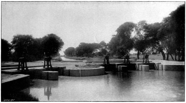
BIFURCATION AT TAIL OF CANAL.
The Distributaries have Gates and Winches.
To face p. 41.
It has been stated (Chapter I, Art. 2) that it is not
desirable to let one channel tail into another. In old
canals a distributary used sometimes, after running
parallel to a canal, to be brought back towards it and
tail into it. The advantage of this was that the
distributary had not to be made very small towards the
tail and that, if the demand abruptly ceased, the distributary
was not likely to breach. The principle was,
however, essentially bad. The lower part of the
distributary was obviously too near the canal and not
centrally situated as regards the irrigated strip. The
portion at the extreme tail was superfluous. Again,
whatever volume of water was carried through the
distributary and back into the canal, was needlessly
detached instead of being kept in bulk. Moreover the
duty of water on such a distributary cannot be ascertained
without a tail gauge and the observation of
discharges at the tail. There are similar objections to
one distributary tailing into another. Each should be
separate and distinct.
A major distributary is one whose discharge is more
than 40 c. ft. per second. It may be as much as 250
c. ft. per second. A branch, as soon as it reaches a point
where its discharge becomes only 250 c. ft. per second
should be considered as a major distributary. A minor
distributary is one whose discharge is from 8 to 40 c. ft.
per second. A minor distributary is nearly always a
branch of a major distributary. There are instances of
“direct minors,” i.e., minors taking off from canals or
branches. Such a minor, unless its discharge is a large
fraction of that of the canal which supplies it—and this
can seldom be the case—is objectionable because the
petty native official who has to see to the regulation of
supplies can manipulate the supply easily and without
detection, and the number of persons irrigating from it
being small, he can make private arrangements with
them. On the Sidhnai Canal there are some half-dozen
distributaries each of which had one or two minors
which took off close to the head of the distributary.
The people who irrigated from the minors managed to
get the heads shifted and taken off direct from the canal,
on the ground that, the water level in the canal being
higher than in the distributary, there would be better
command and less silt deposit. The irrigation on all
these minors ran up to a figure far in excess of what
had been intended, to the detriment of lands further
down the canal. The minor heads have all been retransferred
to the distributaries, the difficulty as to
command being got over, as it should have been at first,
by constructing weirs in the distributaries. The fall in
the water surface at the distributary head, i.e., the
difference between the water level in the canal and that
in the distributary downstream of its head but upstream
of the weir, is quite trifling or even inappreciable.
In some of the older Indian canals it was the custom
to place the heads of distributaries, not just above a
fall but several hundred feet above it, the idea being
that the distributary then received less silt. This
practice has now been discontinued. There is no valid
reason for following it.
The question whether, when a channel crosses a road
on the skew, a skew bridge should be constructed or
curves introduced into the road or channel, is one which
requires some consideration. As far as possible the lines
of channels should be fixed so as to cross important[10]
roads on the square or with a small angle of skew. In
the case of main canals or branches, the introduction of
special curves is generally out of the question, but if
the road is not straight something can be done by
shifting the line one way or the other. In the case of
“major” distributaries, curves can to some extent be
introduced. In the case of “minor” distributaries it is
often possible to curve the channel, with a radius of say
500 feet, so that it will cross the road at right angles.
There is very little objection to a skew bridge if the
angle of skew is not great. The angle of crossing having
been made as near to 90° as possible, the bridge can be
made skew though not necessarily so much askew as
the road. Slight curves can be introduced into the
road. When the road is made askew, a bridge on the
square involves at least three considerable curves (Fig. 7)
and the taking up of extra land. It also causes, in
perpetuity most likely, a more or less inconvenient and
unsightly arrangement and one which, in most countries,
would not be tolerated. When the angle of skew is not
great, it is best to introduce no curve at all into the
road. In the case of a “village” road, which may be
more or less undefined and liable to be shifted, the
difficulty about land may not be great, but even in this
case the angle of crossing should, if possible, be kept
near to 90°, especially in the case of minors, and where
curves have to be introduced into the road they should
be suitable ones. Abrupt angles are not only unsightly
but are unfair to the cart drivers. The crossings of
village roads by the minors of a certain great modern
canal have been stigmatised as “hideous.” Indian
canals can afford to do work properly.
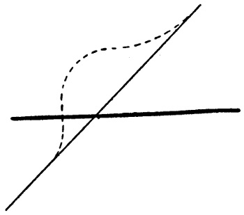
Fig. 7.
—Before a canal
system can be properly designed, it is necessary to
determine certain points in connection with the
working of the distributaries. A distributary is intended
to irrigate a certain kharif area. Its average kharif
supply is determined from the assumed kharif duty.
It generally runs full in the kharif but not always.
In a very dry tract such as the Montgomery district of
the Punjab, the demand is so great and so steady that a
distributary practically runs full through the greater
part of the kharif. In such a case the canal or branch
must be so designed that it can keep all distributaries
full at the same time. Its F.S. discharge will be the
sum of all the F.S. discharges of the distributaries plus
the losses of water by absorption.
But in other cases, especially if the rainfall is
considerable, a distributary does not require its full
supply, either all through the kharif or for long at a
time. An estimate must then be made of what it will
require. It may be estimated that its requirements
will be met if, during the period of greatest demand, it
is closed for two days out of a fortnight and receives
full supply for the remaining twelve days. In this
case, since the various distributaries need not all be
closed on the same days, the canal or branch can be so
designed that it will carry a full supply equal (after
deducting losses) to ⁶⁄₇ths of the aggregate full supplies
of the distributaries. In other cases the fraction may
be ³⁄₄ths. It is likely to be lower the greater the rainfall
of the district. Even in the case when the distributaries
run full through nearly the whole of the kharif, there
will be periods when they only run with about ³⁄₄ths full
supply. If full supply were run at such times, many of
the outlets would discharge more water than was
required, the cultivators would partly close them, and
breaches in the banks of the distributary might result.
Thus the water level of a distributary must always be
so arranged that it will have a good “command” when
it is running with about three-fourths of the full supply
discharge. The water level with ³⁄₄ths full supply is
generally ·5 to ·75 feet below the full supply level but it
should be calculated in each case. Generally it will be
correct to make the water level, when ³⁄₄ full supply is
run, about 1 foot above the high ground traversed by
the distributary, excluding any exceptionally high
portions of small area. A more exact method is given
in Art. 9. The greater the proportion of the culturable
area which is to be irrigated, the less should be the
area of any high land which is excluded. The F.S.
levels of the distributaries at their off-takes must be
settled in accordance with the foregoing remarks, and
these F.S. levels must be entered on the plan. Neglect
to thus fix the F.S. levels of distributaries before
designing the canals has frequently led to trouble.
The head needed at a bifurcation in order to get the
supply into a branch or distributary is always small
unless the velocity is high. For a velocity of 3 feet per
second the head required is only about ·16 ft., for 2 ft.
per second ·1 ft.
On an Inundation Canal which has no weir across
the river, the mean supply downstream of the regulator
(which is built a few miles down the canal lest it should
be damaged by the shifting of the river) is, as has been
mentioned, about half the full supply. The command
in such canals is not generally very good. A distributary
can often obtain only mean supply and it should be
designed so as to command the country when it is
carrying mean supply. A detailed description of
Inundation Canals in Northern India, is given in
Punjab Rivers and Works.
Let M, F, m, f, be the mean and full supply discharges
at the heads of a canal and of an average distributary
on it and let the number of distributaries be n. It has
been seen (Chap. I. Art. 6.) that M = ·8F about. Let k
be the proportion of the supply lost by absorption in
canal and branches. Then n m = (1 - k) M = ·8 (1 - k) F.
If the distributaries all run with full supplies—at the
time of greatest demand—for 4 days out of 5, then,
n f = 1·25 (1 - k) F
fm =
1·25·8 = 1·56
Since k depends on the wetted area, it is not
likely to be so great for F as for M, but the
above gives a general idea of the ratio of the
full kharif discharge to the mean kharif discharge.
On a large canal the circumstances of the distributaries
will not all be similar. Some will run full for a greater
proportion of their time than others. They can be
divided into groups and the ratio of the full to the
mean supply calculated for each group. The mean
supply is, as above stated, obtained from the area to be
irrigated, and the duty as estimated at the distributary
head.
At one time a system was introduced of making
distributaries of large size with the idea of running
them for short periods. One reason given for abandoning
this arrangement, was that there was a tendency to
run such a distributary for too long. This reason is
not very intelligible. It would be applicable to any
distributary which was not intended to be run without
cessation. The result would be that some other
distributary would be kept short of water and this would
imply extremely bad management. The chief reason
against such a distributary is the greater cost of its
construction. It would effect a saving of water. The
ratio of the discharge to the wetted area would be high,
though this would be to some extent neutralized by the
greater frequency of closures, since, when water is
admitted to a dry channel, the absorption is at first
great. There would also be some difficulty in the
distribution of the water because of the short period for
which it would remain open. It will be seen (Chapter
III. Art. 5), that it is desirable to open and close
always at the same hour of the day. An ordinary
distributary might run for 11 days out of 14. One of
double the size could not conveniently be run for
5¹⁄₂ days. A distributary can always be enlarged if
necessary, but if made too large it is extremely difficult
to make it smaller.
It was also, at one time, usual to make minors, when
there were several on a distributary, of large capacities
so that they ran in turns. The preceding remarks apply
to this case. The system has been abandoned.
—The apportioning
of discharges to the various channels having been
effected as described in Art. 2, the designing of the
canal and branches is proceeded with. Rough longitudinal
sections of all the lines are prepared by means
of the contour map, the ground levels being shown at
intervals of one foot—or whatever the vertical distance
between the contours may be—and the horizontal
distances obtained from the map by scaling.
On these longitudinal sections the lines proposed for
the bed and F.S. levels are shown reach by reach and
also the mean velocities and discharges.
The laws of silting and scouring and the principles
on which channels should be designed are fully gone
into in River and Canal Engineering. It is there
explained that, for a channel of depth D, there is a
certain critical velocity, V₀, which just prevents the
deposit of the silt, consisting of heavy clay and fine
sand, found in Indian rivers—this silt enters the canal
in such immense quantities that the canal silt clearances
would be impossible if much of it was deposited in
the channels—that sand of grades heavier than ·1 may
deposit in the head of a canal and well nigh threaten
its existence, that the clear water entering the canal
in winter may pick up and carry on some of the sand
but that proper steps for preventing the deposit in the
canal can be taken at the headworks. This last
question has been referred to in Art. 1. The following
additional rules for designing canals in Northern
India are chiefly taken from those given by Kennedy in
the explanatory notes to his Hydraulic Diagrams,
which are in use in the Irrigation Branch in Northern
India.
- (1) Near the hills where the bed is of shingle the
velocity may exceed V₀. A few other soils will
stand 1·1 V₀.
- (2) In ordinary channels any excess over V₀ will give
much trouble lower down.
- (3) In the first four or five miles of a distributary, V₀
should be allowed and gradually be reduced to
·85 V₀ at the tail, the gradient being reduced if
convenient, while a minor or branch distributary
should have less than V₀ at its off-take and still
less at the tail. The sand is drawn off by the
outlets and in the lower part of a distributary it
is often non-existent.
- (4) If there is efficient silt trapping at the head of
the canal any figures arrived at by the preceding
rules should be multiplied by ·9.
- (5) In the case of a canal having its head far from
the hills, the sand is finer and any figures arrived
at as above may be multiplied by, perhaps, about
·75, but further experience is needed to decide
this.
- (6) If the soil is very poor, especially if the depth of
water is more than 6 or 7 feet, the velocity
should be less than V₀—say ·9 V₀—so as not to
cause falling in of the banks. Depths of more
than 9 or 9·5 feet should, as far as possible, be
avoided for the same reason.
- (7) At a bifurcation, one branch channel may have
no raised sill, and, owing to its smaller depth, it
may draw off no surface water and get an
undue share of rolling sand. Its velocity should
be greater than V₀ and that of the other branch
be less than V₀.
- (8) At such a bifurcation it may be necessary, during
times of low supply, to head up the water in the
main channel and some silt may temporarily be
deposited in it. When the heading up ceases,
the silt is scoured away but it mostly goes into
the branch whose bed level is the lower. It is
best to design such bifurcations so that the sill
levels of the two branches are equal and, if
possible, so that their bed levels are equal.[11]
Otherwise the channel which is likely to get
most silt should have the steeper gradient.
- (9) Any existing well established régime should not
be tampered with.
Experience shows that in designing Irrigation
Channels in the plains of India in accordance with
Kennedy’s figures, the maximum ratio of bed width to
depth of water is as follows:—
Discharge,
c. ft. per second |
10 |
25 |
100 |
200 |
500 |
1,000 |
| Ratio |
3·5 |
4 |
4·5 |
5 |
6 |
6 |
The actual gradients of the canals generally range
from about 1 in 8,000 for a main canal to 1 in 2,000 for
the tail of a distributary, but near the head of a canal
where the bed is of boulders and shingle, the gradient
may be as steep as 1 in 1,000.[12] The velocity in this
last case may be 5 feet per second but generally it is
not more than 3 or 4 feet per second in canals and
branches, and 1 to 2 feet per second in distributaries.
In designing the channels, N, in Kutter’s co-efficient,
may be taken as ·0225 or ·020, according to judgment.
For new and smooth channels ·020 is generally correct.
A channel generally becomes rougher by use but sometimes
it becomes smoother. Cases have occurred in
which N has been found to be ·016. This question is
discussed in Hydraulics, Chap. VI.
The bed width of a canal is reduced, where a
distributary takes off, in such a way that when the
canal and distributary are both running full, the depth
of water in the canal continues to be uniform and the
flow to be uniform. When the distributary is closed
there is heading up in the canal upstream of the off-take,
but not enough to make any appreciable difference
unless the capacity of the distributary is a large fraction
of that of the canal and even then no harm is likely
to result.
The preceding rules and principles being taken into
consideration, the channels are designed. The bed levels,
gradients and depths are so arranged as to give the
velocities suited to the soil and to maintain the proper
relation of depth to velocity. The bed width is arranged
so as to give the proper discharge. The full supply
level of the canal and branches has also to be so
arranged that it shall be higher, at each distributary
off-take, than the full supply level of the distributary.
It is desirable to be able to give a distributary its full
supply even when the canal is low. Generally the slope
of the country along any line is greater than would be
suitable for the bed, and “falls” are introduced. The
off-take of a distributary is generally just above a fall
and there is generally an ample margin between its
F.S. level and that of the canal. The discharge of the
canal during the greater part of the rabi may be only
about half the full supply. This discharge should
be estimated and the water level corresponding
to it calculated and shown on the longitudinal section.
If possible the levels should be so arranged that even
with its least supply the water level in the canal will
enable full supply to be given to a distributary. If this
cannot otherwise be managed it may be necessary to
construct a regulator in the canal below the head of the
distributary so that, during low supplies, the water can
be headed up. It has been stated in River and Canal
Engineering, Chapter IV., that such heading up, if
temporary, is not at all likely to cause silt deposit in
the canal. The designing of the distributaries is not
proceeded with at this stage.
Since no irrigation is usually done directly from the
canal and branches, they are designed without any
particular connection between the level of the water
and that of the country traversed. Dangerously high
embankments are of course avoided as far as possible.
The bed is designed at such a level that the excavation
and embankment at any place will be, as nearly as
possible, equal. Land in India is cheap. When the
excavation exceeds the embankment the balance is
made into a spoil bank. When the excavation is less
than the embankment the balance is got from borrow-pits.
The side slopes of channels in excavation are generally
1 to 1, in embankment 1¹⁄₂ to 1. The sides of channels
of small or moderate size usually become about ¹⁄₂ to 1,
or even vertical, by the deposit of silt on the slopes.
This reduction of area is allowed for in the design i.e.
the bed width is so designed that the channel will carry
the required discharge, not with the side slopes as
executed, but when they have become ¹⁄₂ to 1. In large
canals however the sides do not always silt up but
rather tend to fall in. When this is expected to occur
the allowance above described is not made. Berms are
left so that if any part of the sides fall in, the bank will
not also fall in. The berms also allow of the channel
being widened if that ever becomes necessary. Type
sections are given in Figs. 8 and 9.
—Figs. 8 and 9 show the banks
and spoil.

Fig. 8.

Fig. 9.
The scale is 6 feet to an inch. The depth of water, in
this particular case, is 7 feet, and the bank, excluding
the small raised bank, 2 feet above the water. The
inside edge of the bank, where the small raised bank is
shown, is kept parallel to the canal for a considerable
distance. Its position is got by drawing a line, shown
dotted, at, generally, 1¹⁄₂ to 1. The embanked part of
the slope is actually made at 1¹⁄₂ to 1, but the
excavation is at 1 to 1, so that a berm is left. The
width of this berm of course varies as the depth of
digging varies. If there is likely to be much falling in
of the sides the berm can be made wider, the dotted
line starting, not from the edge of the bed, but from a
point further in. On an inundation canal in sandy soil
the berm may be 20 feet wide. In figure 8, the inside
slope above the berm is supposed to have silted up to
a slope of 1 to 1. In cases where it is expected the
whole inside slope will silt to ¹⁄₂ to 1 the dotted line, to
give the edge of the bank, can be shifted towards the
channel so that the berm at the ground level when
the channel is excavated will be very small for the
minimum depth of digging. There is no need for the
inner edge of the bank to run parallel to the canal for
great distances. Its position can be shifted whenever
suitable and the width of the berm at ground level
varied. This prevents the occupation of a needlessly
great width of land. It used at one time to be not
unusual to make a bank with a berm on the land side,
similar to that formed by the spoil in Fig. 8, but at
about the level of full supply in the canal. The principle
is not a good one. Salient angles are liable to be
worn away. If earth has to be added to a bank to
strengthen it, the whole can be widened or the rear slope
flattened. The roadway is shown 18 feet wide, which is
nearly the maximum. For the drainage of rain water it
has a transverse slope, away from the canal, of about 1 in
50. The small raised bank on the canal side is to give
safety to wheeled vehicles. It is provided on the patrol
bank[13] on main lines and places where there is much
traffic or where there is plenty of width of bank to spare.
When the ground level is, for a considerable distance,
above the proper bank level—which is at a fixed height
above the F.S. Level—so that the road and its side-drain
have to be cut out, much earthwork can be saved
by allowing them to be at a higher level and, in the case
at least of the non-patrol road, giving the road a reduced
width.

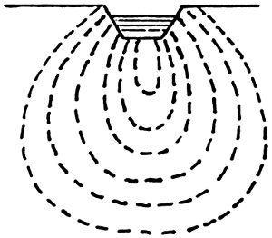
Fig. 10.
In shallow digging, the plan of setting back the banks
(Fig. 10) and letting silt deposit as shown by the dotted
lines, is one which should be followed much oftener than
it is. It not only gives eventually a very strong bank,
but it enables the borrow pits, from which the earth for
the banks is got, to be dug inside the banks. Outside
borrow pits, besides being a source of expense, owing to
compensation having to be paid to those in whose land
they are dug, cause great areas of hollows which are not
only unsightly, but are often full of stagnant water and
are thus a fruitful source of mosquitoes and malaria.
Insufficient attention has hitherto been paid to this
matter.
In designing each reach of a canal or branch, type
cross sections should be drawn out for several different
depths of digging, e.g., one for very shallow digging, i.e.,
where the bed is little, if at all, above the ground level,
one for deep digging where the ground is higher than
the water level, and one for the “balancing depth,”
where the area of the channel excavation is equal to the
earth required for the banks. In calculating the earthwork
the sectional area of the digging or of the embankment
is taken, whichever is the greater.
The proper width and height of bank for any channel
depends partly on the maximum depth of water in the
channel, and partly on the discharge. Given a depth of
water of say 8 feet, a breach will obviously be more
disastrous with a great volume of water than with a
small volume. The following statement gives some
figures suitable to the rather light and friable soils of
Northern India, but the question is largely one of
judgment. Generally a low and rather wide bank is
preferable to a higher and narrower one. If a road,
with or without the small raised bank next the canal, is
required, special widths can, of course, be arranged for.
A 14-foot bank is required for a driving road.
Top Width
of Bank. |
Height
of Bank
above F. S. |
Greatest
Admissible
Discharge. |
Greatest
Admissible
Depth
of Water. |
| Feet. |
Feet. |
C. ft.
per sec. |
Feet. |
| 20 |
2 |
|
12,000 |
12 |
|
| 18 |
2 |
|
8,000 |
12 |
|
| 16 |
2 |
|
5,000 |
11 |
|
| 14 |
2 |
|
3,000 |
10 |
|
| 16 |
1 |
·5 |
2,000 |
9 |
|
| 14 |
1 |
·5 |
1,500 |
9 |
|
| 12 |
1 |
·5 |
1,200 |
8 |
|
| 10 |
1 |
·5 |
1,000 |
7 |
|
| 9 |
1 |
·5 |
700 |
6 |
|
| 8 |
1 |
·5 |
500 |
5 |
·5 |
| 7 |
1 |
·5 |
400 |
5 |
|
| 6 |
1 |
|
300 |
4 |
·5 |
| 5 |
1 |
|
200 |
4 |
|
| 4 |
1 |
|
100 |
3 |
·5 |
| 3 |
1 |
|
50 |
3 |
|
The spoil in Fig. 8 is shown at a different level from
the bank proper, as it should be to give a neat straight
edge to the bank. The width of the spoil may vary
every chain. In Fig. 9 the spoil is raised to avoid
taking up too much land. The spoil presents the best
appearance when its height is kept uniform for as long
a length as possible, the width varying according to
necessity, When the height has to be altered, the
change should be made by means of a short ramp.
When the spoil is higher than the road, gaps in it are
left at intervals so that rain water can pass away.
When the spoil is heavy for a very short length it can,
in order to avoid a short and unsightly heap, which
would result from the adoption of the section shown in
Fig. 9, be placed as in
Fig. 8, some of it being led askew.
The small channel shown outside the bank in Fig. 8
is a watercourse for enabling trees to be grown. It has,
of course, to be graded, and it may be in cutting or in
embankment. If any silt clearances of the canal are
likely to be necessary, the watercourse must be set back
to allow room for the spoil. Such spoil, if sandy, is to
a large extent washed down or blown away and does
not accumulate to anything like the extent that would
be expected.[14] Moreover the spoil can extend onto the
watercourse when the trees have grown big, and no
longer need watering. Outside the watercourse is
shown the boundary road and the land boundary pillar.
The small channel in Fig. 9 is a drain for rain water.
It can be used as a plantation watercourse if the water
is lifted.
Where there is no spoil, some extra land, perhaps
20 feet on either bank, is usually taken up for getting
earth from for repairs.
—The proposed lines of channel, determined
as explained in Art. 5 should next be laid down
on the ground. A line should consist of a number of
straight portions. The curves should not be put in.
Trial pits should be dug at intervals. Some defects in
the line may at once become apparent because the contour
map, owing chiefly to the lines of levels having been
taken a considerable distance apart, is not perfect. A
line may pass through a patch of very high or very low
ground or too near to some building or other object
with which it is desirable not to interfere. Alteration
may be desirable at a drainage crossing or at the off-take
of a branch. The lines should be corrected where
necessary. Sometimes the corrections may be very considerable.
Allowance can be made for the alterations
which will occur when the curves are laid out. Where
there is doubt as to which line is the best, trial pits may
be dug to obtain further information regarding the soil.
The line should now be levelled, careful checks being
made, a longitudinal section of it prepared and the proposed
bed, bank and F.S. level shown. The ground
levels ascertained by levelling the line, are certain to disagree,
to some extent, with the contour lines. The
latter were got only by inference from the levels of
points in the survey lines, and they should be corrected
in accordance with the fresh levels now available. If
the line does not seem to be the best that can be got, a
fresh line can be marked on the plan and the above
procedure repeated.
—As soon as the best line
seems to have been found, a large scale plan of the
country along its course should be made by taking bearings
or off-sets from points in it to the various objects
and noting where the line cuts them. On this plan will be
shown the exact alignment, the curves being put in and
the straight portions slightly shifted where necessary
so that the line may pass at a proper distance from any
buildings or other objects. But before this procedure is
carried out, or while it is being carried out, the
estimate for the work can be prepared from the longitudinal
section already taken. Such a section is of
course amply sufficient for a “project estimate,” in
which only approximate figures are given, and it is quite
near enough for any estimate. In the case of small
works which have often to be executed with great
promptitude, lamentable delays have occurred owing to
the engineer deferring the preparation of his estimate
till he had got the line exactly fixed. Moreover there
is a chance of the labour being thrown away in case the
sanctioning authority directs any change in the alignment
to be made.
In the case of a large scheme, a project estimate is
prepared. In this the earthwork and the area of land
to be occupied are calculated pretty accurately. Designs
and estimates are also prepared for the headworks and
for the chief regulators. For works of which there are
to be many of one type—bridges, falls, distributary
heads and small drainage syphons—the cost is arrived
at from lump sum figures, one drawing of each kind
being submitted as a type. The distributaries are
approximately estimated at mileage rates. In the case
of a small scheme everything is estimated in detail
except perhaps the distributaries or some of them.
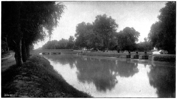
CANAL WITH BRIDGE AND DISTRIBUTARY HEAD.
The Head has Gates and Winches.
To face p. 61.
—A distributary is a
canal in miniature and, like a canal, it may have
branches. It has masonry bridges, falls and drainage
syphons. It has, as already mentioned, a masonry
regulator at its head. At the off-take of any branch or
distributary there is a regulator in the head of the
branch. If the branch takes off a large proportion of
the water there is a double regulator. A distributary
gives off watercourses as a canal gives off distributaries.
The watercourses belong to the people and not to
Government and they are cleared and maintained by
the people. Each watercourse has a masonry head
known as an “outlet” (Fig. 11). The outlet is the
point where the water passes from the hands of Government
officials to those of the cultivators. The outlet
is of masonry and its opening is not adjustable but is
fixed in such a way that its discharge, when the distributary
is full, bears, as nearly as can be arranged, the
same ratio to the F.S. discharge of the distributary as
the area intended to be irrigated by the watercourse
bears to that intended to be irrigated by the distributary.
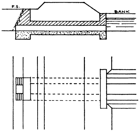
Fig. 11.
The floor of the outlet is level with the bed of the
distributary. It thus draws off rolling sand which
might otherwise accumulate in the distributary. Small
outlets are made of earthenware pipes, about ·4 feet in
diameter, laid in concrete. Two pipes, or three, may
be laid side by side. If more than three would be required,
a masonry opening is adopted. The discharge
through an outlet, is generally 2 to 5 c. feet per
second per square foot of outlet area, and the head ·1
to ·5 feet.
For the tract of country allotted to any distributary,
a contour map is prepared on a fairly large scale, say 4
inches to a mile. On the map the line is laid down
and a rough longitudinal section, showing the ground
level, is prepared as in the case of a canal.
It has already been stated (Art. 4) that a distributary
is so designed that its water level, when three-fourths
of the full supply is run, shall be well above the level
of most of the ground along its course. In other words
it should have a good command. A good rule is to
allow a fall of ·5 feet from the level of the water in the
distributary to that in the watercourse, a slope of 1 in
4,000 for the water flowing along the watercourse, and
a fall of ·3 feet for the water at the tail of the watercourse
to the level of the ground. This last level is,
like the other ground levels, taken from the contour
map. This procedure, in short, consists in making the
water level of the watercourse at its head govern that
of the distributary, just as the water level in the distributary
at its head was made to govern that in the
canal.
The enlarged contour map of the distributary area
shows, among other things, the boundaries of the lands
belonging to each village. Generally a watercourse
supplies water to only one village. When, however, a
village is far from the distributary, its watercourse has
to pass for a long distance through other villages and
it would be wasteful of water to have two separate
watercourses. In such cases one watercourse may serve
two villages or more. When a village is near to the
distributary and its land extends for a long distance
parallel to the distributary, it may have several watercourses
for itself alone. A watercourse can generally
be most conveniently dug along the boundary line of
two villages, or there may be some other line which the
people particularly desire.[15] Subject to, or modified by,
these considerations a watercourse is designed to run on
high ground like a distributary.
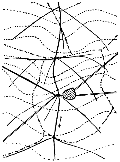
Contour Map (part) and Line of Distributary.
The scale is 1 inch to 2 miles. The contour lines at 1 foot intervals
are shown dotted, the roads by double lines. The line of the distributary,
in order to follow the ridge of the country, would have
gone more to the left of the plan near the village. The shifting of
the line to the right brings it nearer to the centre of the irrigated
tract—supposed to be the whole area shown—and enables a single
bridge to be built at the bifurcation of the two roads. Suitable lines
for main watercourses are shown in thin firm lines. It is assumed
that the command is sufficient to enable the watercourses to run off
at the considerable angles shown.
To face page 63
The great object is to reduce the total length of
channels, i.e., minors and watercourses. No watercourse
can be allowed to run alongside of or near to
another. It may run alongside a canal or distributary
when really necessary to gain command but not otherwise.
The longer the watercourse the larger the chak.
The discharge of an outlet may be anything up to 4 or
5 c. feet per second. This limits the size of a chak. If
a chak is too big it can be split up or a minor can be
designed. Very small chaks are to be avoided, but it
is difficult to fix a minimum size. The irrigation
boundary of the distributary, as fixed in the project, is
shown on the map but in practice it will not be exactly
followed. For various reasons the boundaries of a
chak may run somewhat outside it or stop short of it.
Where a distributary gives off a minor and there is a
double regulator, watercourses should, as far as possible,
be taken off from one or other of the branch channels
and not from upstream of the double regulator. Otherwise,
irregularities are likely to occur, both of the
regulators being partially closed at the same time—a
thing which is never necessary in legitimate distribution
of the supply—in order to head up the water and
increase the discharges of the outlets.
A watercourse nearly always gives off branches and
generally a system of turns is arranged by the farmers
among themselves, each branch in turn taking the whole
discharge of the watercourse for a day or part of a day,
the other branches being closed by small dams of earth.
To irrigate a field alongside the watercourse a gap is cut
in its bank. For fields further away, smaller channels
run off from the watercourses at numerous points.
Several gaps and several field channels may be in flow
at one time, and there is a dam in the watercourse below
the lowest one.
Occasionally, on an old canal, one watercourse crosses
another, the lands irrigated being at different levels, but
such crossings do not often occur in systems of watercourses
laid out according to modern methods. They
are, however, quite legitimate.
The lines of the main watercourses are sketched on
the map, their irrigation boundaries shown on it, and
F.S. discharges allotted to them according to the areas
which are to be dependent on them. In order that this
may conveniently be done the “full supply duty” or
“full supply factor” for the distributary is obtained. It
bears the same ratio to the ordinary duty that the mean
supply bears to the full supply. The total of the F.S.
discharges of all the watercourses should, with an allowance
for loss by absorption in the distributary, be the
same as the F.S. discharge of the distributary. If the
results are very discrepant it shows that the sizes of the
outlets need revision. Possibly they may all be too
large.
In “colonization” schemes where a canal is constructed
to irrigate waste lands—which are the property
of Government and which are divided into square blocks
and given out to colonists—Government has complete
control of the watercourse system, and can arrange it
exactly as desired, but in other cases landowners often
strenuously oppose the passage of watercourses through
their lands. Compulsory procedure according to legal
methods is tedious, but the practical rule is not to let
anyone have water until any watercourses which are to
pass through his land have been not only agreed to but
constructed.
In ordinary cases Government possesses no power as
to the precise line on which a watercourse is dug. It
fixes the site of the outlet and assigns certain land to it,
and sketches out the line of the watercourse. If the
people choose to alter the line they can do so, but great
alterations in the main watercourses are not generally
feasible.
The positions of the outlets[16] having been settled after
discussion with the cultivators, a table is prepared
showing the chainage of the outlets, the probable head
or difference between the F.S. level of the distributary
and of the watercourse, and the F.S. discharge. From
this the sizes of the outlets are calculated and shown in
another column. If the length of the outlet barrel is not
more than 5 or 6 times the diameter—in the case of a
barrel whose cross section is not round or square, the
mean diameter—the discharge can be calculated as for
a “short tube,” but if longer the formula for flow in pipes
should be used, allowance being, of course, made for the
head lost at the entrance. The outlets generally consist
at first of wooden “shoots” or long tubes, rectangular in
cross section. This is because, after they have been tested
by a year or two years’ working, the sizes nearly always
require adjustment and the cultivators often wish to
have the site shifted.
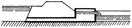
Fig. 11.
The uncertainty as to the proper size of an outlet is
due to several causes. If the command is very good
there may be a clear fall from the outlet into the
watercourse. In this case the discharge depends only
on the depth of water in the distributary, and is known
pretty accurately. But ordinarily the outlet is submerged,
and its discharge depends on the difference
between the water levels in the distributary and in the
watercourse. The latter level is not fixed. The cultivators
can lower it, to an extent which depends chiefly
on the distance of the fields from the distributary, by
deepening or widening the watercourse. In this way
the discharge of the watercourse is increased except
when a dam is temporarily made in it for the purpose of
irrigating any comparatively high land. This uncertainty
as to the discharge can in some cases be got over by
building a cistern (Fig. 11). This has the same effect
as raising the level of the barrel, the real outlet being
no longer submerged, and the discharge depending on
the depth of the crest of the overfall below the water in
the distributary. But such cisterns add greatly to the
cost of an outlet, and they can only be adopted when
there is good command. A great cause of uncertainty
as to the proper size of an outlet is the variability of the
duty of the water on the watercourse. The soil may be
clayey or sandy, the watercourse may be short or long,
the crops grown may be ordinary ones or may be chiefly
rice, which requires three or four times as much water
as most other crops, and the cultivators may be careful
or the opposite. Again, the people may, if the outlet
gives a plentiful supply, often keep it closed, but there
is no record of such closures nor would the people admit
that they occur. These causes may all operate in one
direction—on a whole distributary this cannot happen
to the same extent—and thus enormous differences in
duty may occur. There is no way of arriving at the
proper size for an outlet except trial. Observations of
the discharges of the outlets are of very limited use. The
discharge may vary according to the particular fields
being irrigated. Observations of discharges will be
useful in cases where the people complain, or when the
discharge is obviously much greater or much less than
intended and will in such cases enable temporary
adjustments to be made, but by placing a dam in a
watercourse and turning the water on to a high field
near its head the people can make it appear that the
discharge is only a fraction of what it should be.
On any distributary there are generally some watercourses
which have a poor command, the head at the
outlet being, say, ·1 ft. or even less. Probably the
irrigation is a good deal less than it should be. In
such cases the rules may be set aside and a liberal size
of outlet given. The size may be 2 or 3 times the
calculated size. There is no harm in this. The irrigation
cannot increase much. Similar cases frequently
occur on inundation canals especially near the heads of
canals or distributaries.
The construction of masonry outlets on a distributary
is not usually a final settlement of the matter. Further
adjustments become necessary. This matter will be
dealt with in Chapter III.
On the older canals little or insufficient attention
was given to the question of the sizes of outlets. The
sizes were far too great and, as long as all the outlets
in a distributary remained open, water could not reach
the tail. The distributary used to be divided into two
or three reaches and the outlets in the upstream reaches
used to be closed periodically. The closures had to be
effected through the agency of native subordinates and
the system gave rise to corruption on a colossal scale.
The tail villages never obtained anything like their
proper share of water. The upper villages were over-watered
and the soil was often water-logged and
damaged. Moreover, even if all concerned had the
best intentions, it was impossible to stop all leakage in
the closed outlets, except by making earthen dams in
the watercourses, and great waste of water resulted
from this.
The water level of the distributary with ³⁄₄ full supply,
designed so as to be at least ·5 ft. above the water level
in the watercourse heads—or to be 1 foot above high
ground if this simpler plan is adopted—is drawn on the
rough longitudinal section and also the line of F.S.,
falls being introduced where desirable and the gradients,
F.S. depths of water and widths of channels being
arranged, just as in the case of a canal, so as to give
the required discharges, velocities suited to the soil and
a suitable ratio of depth to velocity. The bed width of
a distributary decreases in whole numbers of feet. The
decrease occurs at outlets but not at every outlet. As
the channel becomes smaller its velocity becomes less
and this necessitates, according to the laws of silting
and scour, a reduced depth of water. The height and
width of the banks in the tail portion of a distributary
should be made rather greater than elsewhere—regard
being had to the depth and volume of the water—so
that breaches may not occur when the demand abruptly
slackens. The longitudinal section of a distributary
should have horizontal lines for showing the following:
| 1. |
Datum |
5. |
Draw-off |
9. |
Bank width |
13. |
Depth of digging |
| 2. |
Bed gradient |
6. |
F.S. discharge |
10. |
Height of bank |
14. |
Bed level |
| 3. |
Village |
7. |
Velocity |
11. |
F.S. depth |
15. |
Ground level[17] |
| 4. |
Land width |
8. |
V₀ |
12. |
Bed width |
16. |
Chainage[18] |
A specimen of a longitudinal section is shown in
Fig. 12. It shows only a few of the above items. In
practice all would be shown, large sheets of paper being
used with all the lines and titles printed on them.
When a distributary is constructed the side slopes
are made 1 to 1 in excavation and 1¹⁄₂ to 1 in embankment.
The sides usually silt up till they are ¹⁄₂ to 1 or
even vertical. The silting up to ¹⁄₂ to 1 is, as in the
case of a canal, allowed for in the designing. The
berms are left so that, if any part of the side falls in,
the bank will not also fall in. They also allow of
widening of the channel. The remarks made in Art. 6
regarding the design of banks, apply to distributaries,
especially large ones.
On a distributary there is seldom much spoil. Where
there is no spoil, a strip of land, outside the bank and
10 feet wide, can be taken up on either bank from
which to obtain earth for repairs. On a minor the
width of the strip is sometimes only 5 feet.
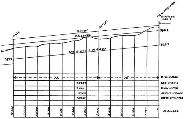
Fig. 12.
Larger illustration (82 kB)
When a distributary passes through land which is
irrigated from wells, it frequently cuts through the
small watercourses which run from the well to the
fields. In such cases, either a syphon or a supplementary
well is provided at Government cost. If several
watercourses, all from the same well, are cut through, it
is generally possible to combine them for the purpose of
the crossing. The wishes of the cultivators in this
matter are met as far as possible.
The procedure as regards laying out the line on the
ground, digging trial pits, correcting the line and preparing
the estimate are the same as for the case of a
canal.
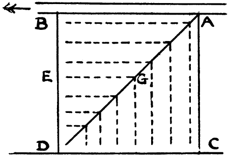
Fig. 13.
—Let AB (Fig. 13)
represent a portion of a distributary, the irrigation boundary
CD being two miles from AB. In order to irrigate
a rectangular plot ACDB, the main and branch watercourses
would be arranged somewhat as shown by the
full and dotted lines respectively. Generally, the whole
supply of the main watercourse would be sent in turn
down each branch, the other branches being then dry.
The average length open is AGE. The ends of the
branches lie on a line drawn say 200 feet from the lines
BD and DC, since it is not necessary for the watercourses
to extend to the outside edges of the fields.
Within the field there are small field watercourses which
extend to every part of it. By describing three rectangles
on AC, making AB greater than, equal to and
less than AC, it can be seen that the average length of
watercourse open is least—relatively to the area of
the block—when AB is equal to AC, i.e., when
the block served by the watercourse is square as in
the figure. If AB is 4 times AC, the average length
of watercourse open is increased—relatively to the area
of the block—in about the ratio of 3 to 2. Moderate
deviations from a square are of little consequence.
Suppose two parallel distributaries to be 4 miles
apart, each of them being an average Indian one, say
sixteen miles long with a gradient of one in 4,000, and
side slopes of ¹⁄₂ to 1, the bed width and depth of water
at the head being respectively 13·5 feet and 2·9 feet, and
at the tail 3 feet and 1 foot. The discharge of the
distributary, with N = ·0225, will be 72 c. ft. per second.
The discharge available for the 2 mile strip along one
bank will be 36 c. ft. per second. If the duty is 300
acres per c. ft. the area irrigated in this strip will be
10,800 acres, or 1,350 acres for each of the eight squares
like ACDB. Each main watercourse would then have
to discharge 4·5 c. ft. per second. Supposing its gradient
to be 1 in 4,000 and its side slopes ¹⁄₂ to 1 and N to be
·0225, its bed width would be 3 feet and depth of water
1·45 feet. Its wet border would be 6·3 feet, and its
average length 5280√2 + 5280 - 200 or 12,546 feet. Its
wetted area would be 79,040 square feet, and the total
wetted area of the 16 watercourses—on the two sides of
the distributary—would be 1,264,640 square feet. The
wetted border of the distributary itself is 19·5 feet at
the head and 5 feet at the tail, average 12·25 feet, and
its wetted area is 5,280 × 16 × 12·25 or 1,034,880 square
feet.
If the distributaries were two miles apart, there would
be twice the number of distributaries, and each square
would be one square mile instead of four. Each watercourse
would have to discharge 1·125 c. ft. per second.
It would have a bed width of 2 ft., depth of water ·8 ft.,
wet border 3·8 feet, length 6,173 feet, and wetted area
23,457 feet. The total wetted area of the 64 water
courses would be 1,501,248 square feet, or 18 per cent.
more than before. Each distributary would discharge
36 c. ft. per second, the bed width and depth at the
head being 10 feet and 2·24 feet, and at the tail 2 feet
and ·75 feet. The wet border at the head and tail would
be 14·5 and 3·5 feet, mean 9 feet, and the wetted area of
the two distributaries would be 1,520,640 square feet or
50 per cent. more than before. Supposing that, in the
case of the larger distributary considered above, the
2-mile square was considered too large, and that rectangles
1 mile wide were adopted, so that the watercourses
were a mile apart, their number would be doubled
and their length and size reduced. Their total wetted
area would not be greatly affected, but the difference in
the wetted areas of the two small distributaries as compared
with the one large one, would be the same as
before. In practice, of course, distributaries are not
always parallel, nor are the blocks of irrigation all
squares, and frequently, owing to peculiarities in the
levels of the ground or the features of the country, or
the boundaries of villages, it is necessary to align the
watercourses in a particular manner, or to construct
more than one watercourse where one would otherwise
have sufficed, but the above calculations show in a
general way the advantages of large watercourses and of
not placing the distributaries too near together.
It is commonly said that a watercourse discharging
more than 4 or 5 c. ft. per second is objectionable
because the cultivators, if there are too many of them
on one watercourse, cannot organize themselves in order
to work it and keep it in order. This matter is much
exaggerated. On the inundation canals of the Punjab
a watercourse often discharges 10 c. ft. per second, and
is several miles long and requires heavy clearances, but
the people have no particular difficulty in managing it.
Kennedy, a great authority on questions of irrigation,
states that the length of a watercourse may be three
miles. This, if the angle made by a watercourse with
the distributary is 45°, gives rather more than two miles
as the width of the strip to be irrigated.
Suppose that a distributary instead of being two miles
from each side of the irrigated strip, ran along one side
of it, and was four miles from the other side. If the
block were square, as before, the side of a square would
be 4 miles, and each watercourse would have to discharge
18 c. ft. per second, which is far too much. The blocks
would have to be rectangles, each being only one mile
wide measured parallel to the distributary. It has been
already seen that the length of watercourse in this case
is greater than when the block is square and each side
is two miles. Thus centrality in the alignment of the
distributary is an advantage.
A minor distributary has been defined (Chapter II.,
Art. 3) as being one discharging not more than 40 c. ft.
per second, but the term has come to be used to designate
a branch of a major distributary, and in that sense
it will be used in this article. When the shape of the
area commanded by a distributary is such that watercourses
exceeding 2 miles in length would otherwise be
required, one or more minors are often added. Frequently
it is a question whether to let some of the
watercourses be more than two miles long, or to
construct a minor and thus shorten the watercourses to
perhaps only one mile. Which method is best has not
been definitely settled. It is known that the loss of
water in watercourses is heavy, but if a minor is added
the loss in it has to be considered. The loss must be
high in any channel in which the ratio of wet border to
sectional area is small. The minor also costs money in
construction and in maintenance. On the whole the
matter, as far as concerns cost and loss of water, is,
perhaps, almost evenly balanced, but as regards distribution
of the supply a system without minors is preferable.
The off-take of a minor is generally far from the
canal, i.e., in a more or less out-of-the-way place, and it
is impossible to see that the regulation is properly carried
out. Irregularities and corruption are sure to arise.
Even if the supply is fairly distributed as between the
minor and the distributary it is almost certain that the
regulator, if a double one, will be manipulated for the
illegal benefit of outlets in the distributary upstream of
the bifurcation. There are sure to be some such outlets
not very far distant. In any case each minor adds one,
if not two, to the already very large number of gauges
which have to be entered daily in the sub-divisional
officer’s register (Chapter III., Art. 3), and adds
also to the mileage of channel to be inspected and maintained.
These considerations should, in many cases,
though of course not in all, turn the scale against the
construction of a minor. At one time it became usual
to construct minors even when watercourses more than
two miles long would not otherwise have resulted. This
custom was condemned some years ago, and is not
likely to be re-established. Most of the difficulties just
mentioned can, in the case of a minor which is not too
large, either absolutely or relatively to the main distributary
downstream of the off-take, be got over by making
the minor head like a watercourse outlet, building it up
to the proper size, removing the regulating apparatus
and abolishing the reading of the gauge, but in this case
the minor is not likely to be bigger than a large watercourse.
Such minors should not be constructed, and
any existing ones should, after the head has been treated
as above, be made over to the people and considered as
watercourses.
—The top of the head and tail walls of
an outlet are level with the F.S. levels in the distributary
and watercourse respectively. The steps in the
head wall enable the cultivators to go down either to
stop up the outlet or to remove any obstruction. The
stepping is arranged so as to fall inside the side slope
ultimately proposed. It is usual, in some places, to
have the entrance to the “barrel” of the outlet made
of cast iron. The cast iron pieces are made of various
standard sizes. This to some extent prevents the
“barrel” being built to a wrong size. A discrepancy
between the size of the masonry barrel and that of the
iron would be noticed, but if the masonry barrel is built
too large the iron head does not always restrict the discharge.
The action is the same as in a “diverging
tube” well known in hydraulics.
For sizes up to about 50 or 60 square inches the
barrel should be nearly square. For larger sizes the
height should exceed the width. Up to about 100 or
120 square inches the width can be kept down to 7 or 8
inches so that an ordinary brick can be laid across to
form the roof. For larger outlets the height can be
from 1·5 to 3 times the width, and the roof can be made
of large bricks, concrete blocks or slabs of stone or of a
flat arch of brickwork or by corbelling, but in this last
case there should be two complete courses above the
top of the outlet. The less the width the cheaper the
roof, the easier the adjustment of size and the less the
tendency to silt deposit during low supplies. If pipes
are used they should be laid in concrete. If cast iron
head pieces are to be used there should be several sizes
of one width and the widths of the masonry outlets
should be made to suit these widths.
A masonry outlet is not generally built till the watercourse
has been sometime in use. The exact position
of the outlet should then be so fixed that the watercourse
shall run out straight or with a curve and should
not be crooked.
The width between parapets should be, for a driving
road or one to be made into such, 10 ft. (if the bank is
wider, it should be narrowed just at the outlet site) and
for a non-driving road, 8 feet to 3 feet according to the
ultimate width of the bank. Earth backing should be
most carefully put in and rammed, otherwise a breach
may occur and the outlet be destroyed.
Various attempts have been made to provide gates
or shutters for outlets. The chief result has been
trouble and increased cost. If grooves are made and
shutters provided, the shutters are soon broken or lost
by the people. Hinged flap shutters are objectionable
because they are often closed by boys or by malicious
persons or by neighbours who wish to increase the
supply in their own outlet. The cultivator, when he
wishes to reduce the supply or to close the outlet, can
easily do this by obstructing the orifice with a piece of
wood or an earthenware vessel or a bundle of brushwood
or grass.
As regards temporary outlets, wooden outlets if large
(unless made of seasoned wood and therefore costly) are
liable to give great trouble. Water escapes round the
outside or through the joints. Pipes may do well if laid
in puddle but are brittle and costly if of large size. The
irrigators may interfere both with wooden outlets and
pipes and they are liable to be displaced or broken. A
temporary outlet, if small, can be made of bricks laid in
mud. The joints can be pointed with lime mortar.
When the outlet is made permanent the same bricks
are used again. But all kinds of temporary outlets are
liable to give trouble especially in light or sandy soil.
There is much to be said in favour of building masonry
outlets at the first, making a barrel only, i.e., omitting
the head and tail walls and taking the chance of having
to alter the size. The alteration is not very expensive.
The head and tail walls are built when the size has
been finally settled. The adjustment can be made by
raising or lowering the roof. This should be done over
the whole length of the outlet but lowering can be done
temporarily over a length of 3 feet at the tail end of the
outlet. This can be done even when the distributary
is in flow. A reduction over a short length at the upstream
end of a barrel does not, as already remarked,
necessarily reduce the discharge much.
On inundation canals the rules regarding outlets have
to be modified. Great numbers of watercourses take
off directly from the canals. In such cases, especially
near the head of a canal, the ground to be watered is
often 5 to 8 feet above the canal bed and it is wholly
unsuitable to place the outlet at bed level. The cost of
the tail wall would be excessive. The floor level in such
cases must be at about the lowest probable cleared bed
level of the watercourse, say, in order to be safe, a foot
or half a foot below the usual cleared bed of the
watercourse, so that water need never be prevented
from entering the watercourse. The irrigators should
be consulted as to the floor level and their wishes
be attended to as far as possible. For lift outlets
the floor should be at the bed level of the canal
or distributary. If this bed is to be raised in the course
of remodelling, the floor should be at the old bed level
until the bed has actually been raised, unless there is a
weir which raises the water. It is necessary that lift
outlets should work however small the canal supply
may be. In a distributary or small canal, the head
wall should be built up to F.S. level but in a canal with
deep water the head wall should reach up to just above
the roof of the outlet and be submerged in high supplies.
The stepping of the head wall should be set back if the
channel is to be widened and should project into the
channel if the channel is to be narrowed. The centre
line of the channel near the outlet site must always be
laid down and the outlet built at right angles to it and
also at the correct distance from it.
Occasionally there is a wide berm, say 20 ft. or even
50 ft., between a channel and its bank. In such a case
the outlet should be built to suit the bank. The long
open cut is however objectionable because the people
clear it and heap the spoil in Government land. Sometimes
the bank, especially if it is crooked, can be shifted
so as to come close to the channel at the outlet site.
Sometimes the outlets on inundation canals are large.
For outlets of more than 2·5 square feet in area, grooves
should be provided so that the cultivators can use a
gate if necessary.
—The positions and descriptions
of all the masonry works of a proposed canal or distributary
are of course shown on the longitudinal section
of the channel and from this the discharges and water
levels are obtained. The principles of design to be
followed[19] for bridges, weirs, falls, regulators and
syphons, are discussed in River and Canal Engineering.
It is mentioned that there is no special reason for making
the waterway of a regulator exactly the same as
that of the stream, and that the waterway may be such
as to give the maximum velocity considered desirable,
and that the foundations of a bridge should be made so
deep that it will be possible to add a floor, at a lower
level than the bed of the stream—with the upstream
and downstream pitching sloping up to the bed—so as
to increase the waterway and so save pulling down the
bridge in case the discharge of the channel is increased.
It remains to consider certain points affecting Irrigation
Canals.
The span of a bridge, where there are no piers, is
generally made as shown by the dotted lines in Figure
14, so that the mean width of waterway is the same as
that of the channel. The arches, in Northern India,
used at one time to be 60° as shown by the upper
curved line, but in recent years arches of 90° as shown
by the lower curved line, have frequently been adopted,
the springing of the arch being below the F.S. level, so
that the stream is somewhat contracted. The 90° arch
gives a reduced thickness and height of abutment. It
causes increased disturbance of the water, and this may
necessitate more downstream protection. An advantage
of having the springing not lower than the F.S. level is
that this admits of a raising of the F.S. level in case
the channel is remodelled, and this arrangement is still
common on distributaries.
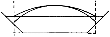
Fig. 14.
When a fall and bridge are combined, the bridge is
placed below the fall as this gives a lower level for the
roadway. The side walls of the fall are produced downstream
to form those of the bridge.
The roads in India are generally unfenced and the
banks of canals close to bridges, on both sides of the
canal and both above and below the bridge, are generally
more or less worn down by cattle, which, when being
driven home in the evening and out to graze in the
morning, go down to the stream to drink. In order to
prevent this damage the banks are sometimes pitched,
above the bridge as well as below it, but the cattle
generally make a fresh “ghát” further away. The best
plan is to allow a “ghát” on one bank either above or
below the bridge and to protect the other three places.
In the Punjab the widths of roadways between the
kerbs and parapets of bridges respectively have been
fixed as follows:—
| Kind of Road. |
Near Towns.[20] |
In the Country.[21] |
| |
Kerbs. |
Parapets. |
Kerbs. |
Parapets. |
| Provincial |
22 |
|
23 |
·5 |
16 |
|
17 |
·5 |
| District |
18 |
|
19 |
·5 |
14 |
|
15 |
·5 |
| Village |
14 |
|
15 |
·5 |
8 |
·5 |
10 |
|
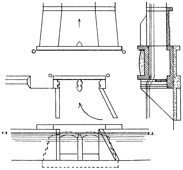
Fig. 15.
Fig. 15 shows a head regulator for a distributary.
The scale is 10 feet to an inch. It has a double set of
grooves for the insertion of the planks with which the
regulation is effected. Only one set of grooves is ordinarily
used, but when the distributary has to be closed
for silt clearance and all leakage stopped, both sets of
grooves can be used and earth rammed in between the
two sets of planks. The floor is shown a foot lower
than the bed of the distributary. This reduces the
action of the water on the floor, and enables the bed of
the distributary to be lowered if ever the occasion for this
should arise. This is a good rule—in spite of the fact
that in re-modellings the tendency is for the beds to be
raised—for all regulators or bridges, a raised sill being
added (in regulators) to reduce the length of the needles
or the number of the planks. Such sill should, where
needles are to be used, be fairly wide, especially if
regulation is to be done while the masonry is somewhat
new. The distributary shown has a bed width of 10 ft.
The span of the two openings in the head might have
been four feet each, but are actually five feet, and this
enables the distributary to be increased in size at any
time. The pitched portion of the channel tapers.
Unless needles are used, instead of horizontal planks,
spans are not usually greater than 5 or 6 feet. Longer
spans would give rise to difficulties in manipulating the
planks. Sometimes distributary heads are built skew,
but there is seldom or never any good reason for this.
A curve can always be introduced below the head to give
the alignment the desired direction.[22] The small circles
shown on the plan are “bumping posts.” On the left
is shown a portion of the small raised bank at the edge
of the road.
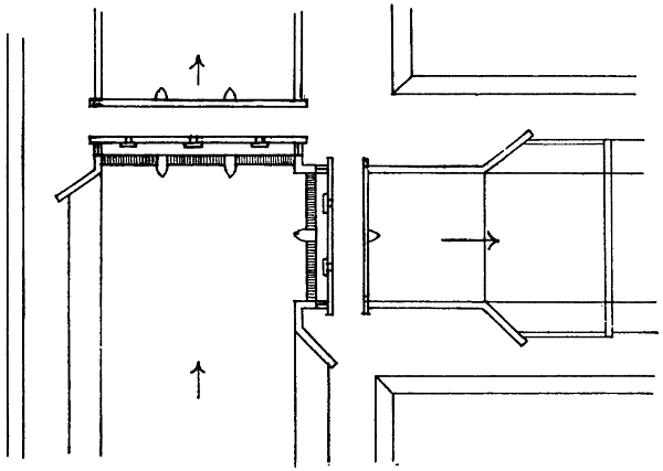
Fig. 16.
Figure 16 is a double regulator with needles. The
scale is 30 feet to an inch. The spans are 15 feet. The
roadway is on arches, but the regulating platform on
steel beams. The needles are seen at the upstream
sides of the regulators. They are worked from the
platforms to which access is obtained through the gaps
in the upstream parapets. The regulating platform
should generally be only just clear of the F.S. level, and
therefore lower than the roadway.
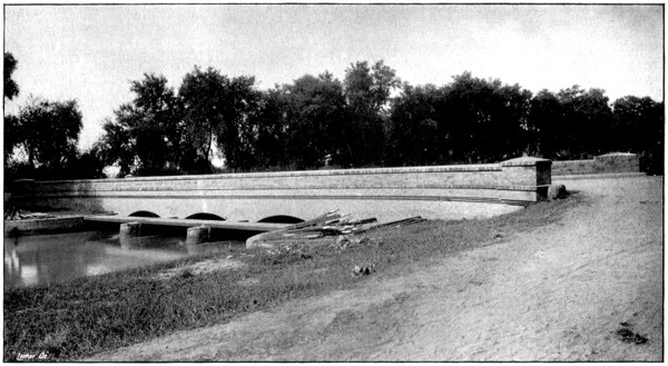
NEEDLE REGULATOR AND BRIDGE.
Needles lying on Bank.
To face p. 85.
Frequently the roadway of a bridge or small regulator
is carried, not on arches, but on steel beams. The
railings may be of wood or of gas pipe with the ends
plugged, running through angle iron posts. In the case
of such a regulator the roadway is sometimes so light
that camels are not allowed to cross over. This causes
unnecessary hardship. Bridges are not too numerous.
If the regulation is done by gates, both road and platform
are carried on arches.
The regulators on inundation canals, and some on
perennial canals, are not strong enough to admit of the
flow of water being entirely stopped, so that the depth
of water would be perhaps 10 feet upstream and nil
downstream. This might cause the overturning of the
piers, or the formation of streams under the floor. In
such cases a maximum permissible heading up is decided
on. Such orders are, in India, liable to be lost sight of
in course of time, and they are, at least on inundation
canals, where sudden emergencies often occur, hardly
reasonable. An engine driver is not told that he must
never entirely close his throttle valve. Regulators
should be so designed that the water can be completely
shut off.
The following remarks show the chief points in favour
of needles and horizontal planks respectively.
Advantages of Needles. Needles can be placed or
removed by one man.
Needles do not require hooks, etc., which are liable
to be broken or lost.
A needle regulator requires few piers, and is
therefore cheap.
Water falling over planks throws a strain on the
floor.
Regulation with needles is easy and rapid. A
jammed plank, especially if low down and not horizontal,
may give great trouble.
Advantages of Planks. Floating rubbish is not
liable to collect above the Regulator because the
water flows over the planks.
By means of double grooves and earth filling,
leakage can be quite stopped.
For large works the advantages are generally with
needles, but for small works, e.g. distributary heads and
shallow water, with planks. Needles 14 feet long are
not too long for trained men. Planks are more likely
than needles to arrest rolling sand, and this can be
taken into consideration in designing double regulators.
See number 8 of Kennedy’s rules, Article 5. When
planks are used there should be two sets of grooves.
Planks are very suitable for escape heads which have
only occasionally to be opened, earth being filled in
between the two sets of planks.
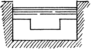
Fig. 16A
Regarding notched falls, in the case of small distributaries
the notches are so narrow that they are
extremely liable to be obstructed either accidentally by
floating rubbish or wilfully by persons whose outlets are
upstream of them. Weirs are not open to this objection,
and are frequently adopted. There is not the least
chance of their causing any silting worth mentioning.
A simple weir if made of the proper height for the F.S.
discharge, will cause a slight heading up with ³⁄₄ths of
the F.S. discharge, and this unfairly benefits any outlets
for a considerable distance upstream of the weir. This
difficulty can be got over by making the weir as in
Fig. 16A.
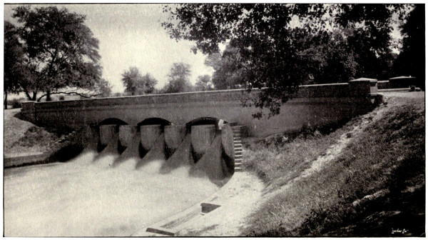
BRIDGE AND NOTCH FALL.
In this case the usual practice of placing the bridge downstream of the fall has not been followed.
The gauge well is seen on the left bank.
To face p. 87.
For cisterns below falls the usual rule for the depth is
K = H + ∛H √D
where H is the depth of water in the upstream reach,
and D is the difference between the upstream and downstream
water levels. Another rule for distributaries is
K = H + D3
the length of the cistern being 3 H and its width the
bed width of the channel.
At “incomplete” falls, i.e., where the tail water level
is above the crest, it is not unusual to construct a low-level
arch, which forms a syphon. The object is to
allay the surging of the surface water.
The question of skew bridges has been dealt with in
Art. 3. Another question is that of the heights of
bridges. Irrigation channels, especially the smaller
ones, are very frequently at a high level, and bridges
have ramps which are expensive to make and to
maintain, and are inconvenient. The lowering of distributary
bridges in such cases, so that they become
syphons, or nearly so, has often been advocated and is
frequently desirable. The bed should slope down to the
floor and up again. The heading up can be reduced by
giving ample waterway, but it will not be necessary to
do this if there is head to spare. The fall in the water
surface can be recognised and shown on the longitudinal
section. The structure becomes one of the incomplete
falls above described. The crown of the arch can, if
desirable, be kept above F.S. level, so that floating
rubbish will not accumulate.
The width between the parapets of a regulator can be
10 feet in the case of a driving road. It may be less,
according to the width of the bank, in other cases.
The upper layer of the floor of a bridge or regulator is
of brick on edge. Below this there is a layer of brick
laid flat, and below this, concrete of a thickness ranging
from ·5 feet to 3 feet. The thicknesses of piers range
from 1·5 to 3 feet.
The bricks used for canal work in Northern India are
10 inches long, 4⁷⁄₈ inches wide, and 2³⁄₄ inches thick.
The thicknesses of walls are about ·83, 1·25, 1·7, 2·1,
2·5 feet, and so on.
The slopes of ramps should be about 3 in 100 for
district roads, and 5 in 100 for village roads.
Railings should be provided along the tops of high
walls and top of pitching near to public roads or canal
patrol roads. Bumping posts should be provided for all
parapets, and should not be so placed as to seriously
obstruct the roadway.
The quarters for the regulating staff should, when
convenient, be in the fork between the two principal
branches. They may be on the bank—with foundations
on pillars carried down to ground level—but not in such
a position as to obstruct the road or any road likely to
be made. Rests consisting of two parallel timbers bolted
to blocks of masonry reaching up a foot from the ground,
should be provided for the needles or planks. The bolt
head should be countersunk so as not to damage the
needles and planks when they are hurriedly laid down.
When two or more works are close together they
should be made to conform, and the whole site should
be considered with reference to a neat and suitable
arrangement of works, ramps and roadways. If an
outlet is near to a minor or distributary head the
parapets of the two should be in line. If two masonry
works of any kind are near together it is often suitable
to pitch the intervening space. If there are outlets or
distributaries on opposite banks they should be exactly
opposite each other. Where a road crosses a bridge or
regulator, the bank should be at the same level as the
road, the bank being gradually ramped back to its
original level. The space in front of any quarters should
have a slight slope for drainage, but otherwise be at one
level and be connected with the road or bank by proper
ramps. The berm or bank should be made at the exact
level of the top of any pitching or side wall which
adjoins it. Wing walls are frequently made too short,
so that the earth at their ends forms a steep slope and
is worn away, and the bank or roadway is cut into.
The walls should extend to such a point that the earth
at their ends cannot assume a slope steeper than the
slope of the bank.
It is obvious that for every masonry work there should
be a large scale site plan[23] showing all roads, ramps, and
adjoining works, both existing and proposed roads being
shown for some little distance from the work.
For each kind of masonry work there is usually a type
design. A few of its dimensions, which are fixed, are
marked on it. The other dimensions are variable. It
would be a great advantage to add to the design a
tabular statement to show how these dimensions should
vary under different circumstances.
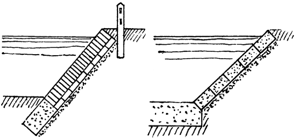
The object of pitching upstream of
bridges or regulators or downstream of bridges where
there may be little or no scouring action, may be partly
to protect the bank from damage by cattle or wear, or to
prevent sandy sides from falling in. In such cases there
may be pitching of the sides only, and it may be of brick
on edge laid dry and under this one brick flat resting on
rammed ballast (Fig. 17). Downstream of regulators or
weirs and downstream of bridges if contracted or having
piers which cause a rush of water, especially if the soil is
soft, the side pitching may be as above, but with the
bricks over one-sixth of the area placed on end and
projecting for half their length. This “roughened
pitching” tends somewhat to reduce the eddying. The
bed protection should be solid concrete or blocks of
concrete or masonry. Immediately downstream of
regulators or weirs where there is great disturbance,
both side and bed pitching may consist of solid concrete
or of concrete or masonry blocks (Fig. 18).
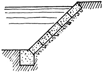
Fig. 19.
Three kinds of toe walls are shown in Figures 17,
19 and 20. The kind shown in Fig. 19 contains, for a
given depth below the bed, far more masonry than the
one shown in Fig. 17. It is also liable to be displaced
and broken if scour occurs.
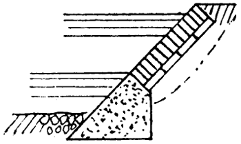
Fig. 20.
The earth should in all cases be carefully cut
to the proper slope, so that no made earth has
to be added. If the slope has already fallen in too
much, well rammed earth should be added. The flat
brick and rammed ballast can be varied as the work
proceeds, more being used in soft places and less in
hard.
In some parts of the Punjab, large bricks, the length,
breadth, and thickness being about twice the corresponding
dimensions of an ordinary brick, are made,
and are extremely useful and cheap for pitching. Where
the soil is sandy such bricks can be burned without
cracking.
Sometimes the curtain wall which runs across the bed
at the downstream end of the pitching is carried into the
banks and built up so as to form a profile wall (Fig. 21).
This is not very suitable, because the pitching of the
sides is apt to settle and leave the profile wall standing
out. It is better to lay a row of blocks on the slope. If
a hole tends to form in the bed downstream of the
curtain wall, blocks of masonry or concrete can be laid
and left to take up their own positions (Fig. 22).
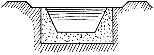
Fig. 21.
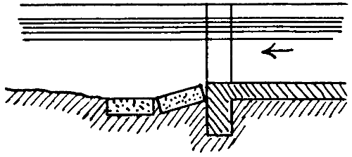
Fig. 22.
When scour of the bed or sides occurs downstream of
pitching, it is sometimes said that any extension of the
pitching downstream is followed by extension of the
scour. This may happen if the cross section of the
stream downstream of the pitched section has become
greater than the pitched section. In this case there is
eddying, due to abrupt enlargement of the stream where
the pitching ends. The increased width and lowered
bed level (not counting mere local hollows) of the stream
should be adhered to in the pitching. Where the
masonry of the regulator ends and the pitching begins,
there will be an abrupt or tapered enlargement, but the
eddies—at very low supplies there may be a fall—cannot
do harm.
This principle of enlarging the pitched cross section
can be followed, even in a new channel, if the soil is
light and scour is feared, and for this reason the matter
is mentioned in the present Chapter instead of in
Chapter III. It was once the custom to splay out the
sides of a channel, downstream of a regulator or weir,
so as to form a sort of pool in which the eddies exhausted
themselves, but this gives curved banks and requires
extra land and is not a very convenient or neat
arrangement. Where scour of the sides is likely to
occur, or has occurred, immediately downstream of the
pitching the latter may be turned in as shown in
Fig. 23.
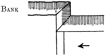
Fig. 23.
Pitching has constantly to be replaced or extended
owing, generally, to failure to pitch a sufficient length
or to ram well the earth under the pitching, or to use
properly rammed ballast or flat brick, or to give proper
bed protection, or to the use of dry brick pitching when
a stronger kind is needed.
The side slopes of pitching should be 1 to 1. They
can be ¹⁄₂ to 1 in rare cases, e.g., when there is no room
for 1 to 1, or in continuation of existing ¹⁄₂ to 1 pitching.
No absolute rule can be laid down as to the length to be
pitched, but in a Punjab distributary it is often about
5 times the bed width.
On Indian canals the
chainage[24]
is marked at every thousand feet. Five
thousand feet is called a “canal mile.” The distance
marks are often cast iron slabs, fixed in a cylindrical
block of brickwork about 2·1 feet in diameter and 1·5
feet high, the upper edge being rounded to a radius of
·4 feet. The wedge-shaped bricks for these blocks are
specially moulded. The iron slab should project about
eight inches and have about a foot embedded in the
brickwork.
On a canal having a wide bank the distance mark is
put at the outer edge of the patrol bank, earth being
added, if necessary, to increase the width. On a
distributary with a narrow bank the mark should be
on the opposite bank not the patrol bank. To enable
the miles to be easily distinguished the masonry block
can be sunk only ·5 foot in the ground, the others being
sunk a foot. In all cases the masonry block rests on a
pillar, 1·7 feet square, of bricks laid in mud, carried
down to the ground level.
Profile walls (Fig. 21, page 92) used occasionally
to be built at frequent intervals along a distributary.
They will not prevent scour occurring, if the stream is
tending to scour, unless very close together. Such
walls are of some use as showing whether the channel
is altering, but they are expensive and have to be
altered if, as often happens, the channel is remodelled.
It is a much better plan to lay down blocks—about 1¹⁄₄
foot cubes—of masonry or concrete, along the centre
line at every 500 feet, with their upper faces level with
the bed. If the bed scours they may be displaced but
otherwise they are useful not only for showing what
silt, if any, has deposited, but for showing the centre
line of the channel. Without them the centre line is
liable to be altered in silt clearances or berm cuttings.
To enable a block to be readily found and to be replaced
in proper position if displaced, there should be two
small concrete pillars exactly opposite to it and
equidistant from it, one on either bank of the channel.
Such blocks and pillars may with advantage be placed
at quite short intervals on curves.
The rest houses for the use of officials on tour are
generally at intervals of about 8 to 14 miles. There is
generally a rest house near to a large regulator and
frequently there is one near to a small regulator. This
facilitates inspection work and discharge observations
and it saves money, because the house can be looked
after by one of the regulating staff. Not infrequently
the house is placed just too far away from the regulator.
Similarly if a rest house is near a railway station it
should be within a quarter of a mile of it—always
provided that this does not bring it too near to villages
or huts—and not a mile or more away as is sometimes
the case. It is also a mistake to place a rest house off
the line of channel unless perhaps when it is on a
district road which crosses the channel.