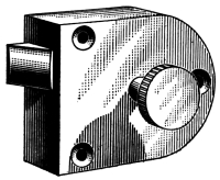
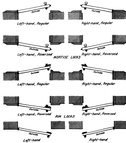
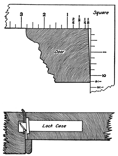
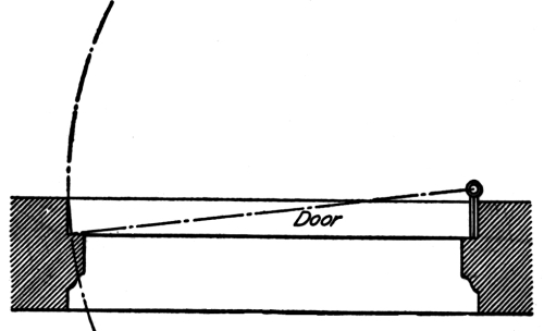
DIRECTOR, SCHOOLS OF ARCHITECTURE
AND BUILDING CONSTRUCTION INTERNATIONAL CORRESPONDENCE SCHOOLS
BUILDERS’ HARDWARE ESTIMATING AND CALCULATING
QUANTITIES MILL DESIGN
Published by
INTERNATIONAL TEXTBOOK COMPANY SCRANTON, PA. 1925
Builders’ Hardware: Copyright, 1908,
by International Textbook Company.
Entered at Stationers’ Hall, London.
Estimating and Calculating Quantities, Part 1:
Copyright, 1899, by The Colliery Engineer Company.
Copyright, 1908, by International Textbook Company.
Entered at Stationers’ Hall, London.
Estimating and Calculating Quantities, Part 2:
Copyright, 1899, by The Colliery Engineer Company.
Copyright, 1909, by International Textbook Company.
Entered at Stationers’ Hall, London.
Mill Design: Copyright, 1907,
by International Textbook Company.
Entered at Stationers’ Hall, London.
All rights reserved Printed in U. S. A.
Press of International Textbook Company Scranton, Pa.
PREFACE
The volumes of the International Library of Technology are made up
of Instruction Papers, or Sections, comprising the various courses
of instruction for students of the International Correspondence
Schools. The original manuscripts are prepared by persons thoroughly
qualified both technically and by experience to write with authority,
and in many cases they are regularly employed elsewhere in practical
work as experts. The manuscripts are then carefully edited to make
them suitable for correspondence instruction. The Instruction Papers
are written clearly and in the simplest language possible, so as to
make them readily understood by all students. Necessary technical
expressions are clearly explained when introduced.
The great majority of our students wish to prepare themselves for
advancement in their vocations or to qualify for more congenial
occupations. Usually they are employed and able to devote only a few
hours a day to study. Therefore every effort must be made to give
them practical and accurate information in clear and concise form and
to make this information include all of the essentials but none of
the non-essentials. To make the text clear, illustrations are used
freely. These illustrations are especially made by our own Illustrating
Department in order to adapt them fully to the requirements of the text.
In the table of contents that immediately follows are given the titles
of the Sections included in this volume, and under each title are
listed the main topics discussed. At the end of the volume will be
found a complete index, so that any subject treated can be quickly found.
BUILDERS’ HARDWARE — STAPLE HARDWARE — CUT AND WIRE NAILS — WOOD SCREWS, EXPANSION AND SPECIAL BOLTS — SASH WEIGHTS — FINISHING HARDWARE — METALS AND THEIR MANIPULATION — HINGES, HINGE BUTTS, AND SPECIAL HINGES — LOCKS AND THEIR APPURTENANCES
INTRODUCTION
1. The hardware used in building construction may be classified
as staple and finished. Staple hardware may be
considered as including such materials as nails and spikes, bolts and
screws, sash weights, and other materials of this character, while
finished hardware may include such devices and appliances as
locks and latches, hinges, door and window trimmings, and the various
metallic fixtures used in equipping the different classes of buildings.
To this last classification the term builders’ hardware is
frequently applied.
Strictly speaking, glass cannot be considered as hardware;
nevertheless, it is frequently supplied to the builder through hardware
supply houses, and it is so closely allied to the hardware of building
construction that the subject of glass, its trade terms, and other
information relating to its characteristics, will not be out of order
in this Section.
While little consideration is given to the hardware on the average
building, there is no more important part of the construction, nor
one to which greater attention should be given. On the quality and
the selection of proper hardware depends the avoidance of the petty
annoyances often found in buildings where this subject has not received
proper consideration.
The architect should be well informed regarding this subject, and
should be in a position to know the kind and quality of hardware
that, when specified, will give the best results. He will find that a
thorough knowledge of builders’ hardware will assist him materially
in writing comprehensive specifications for this portion of the work.
Consequently, the writing of the hardware specifications will receive
attention in this Section, and the proper manner of estimating, or
“taking off,” hardware will also be considered.
2. Cut Nails.—The primitive nail was made or forged by hand,
and this mode of manufacture still exists in certain sections of
Europe. These hand-made nails sold at exorbitant prices compared with
the machine-made nails of today.
The manufacture of cut nails is less automatic and requires more manual
labor than is necessary in the making of wire nails. The iron or steel
is first rolled into sheets, the thickness of which is equal to the
thickness of the nail; it is then cut into strips as wide as the nail
is long. This strip of metal is fed into the nail machine and sheared
off in tapering strips having the form of the nail, when it is seized
by clamps that hold it just long enough for the heading hammer to
strike the blow that forms the head.
The nail manufactured in this manner is known as the cut nail,
and is much superior to the wire nail, which is of more recent
production. Not only has the cut nail greater holding power, but it is
more durable, especially when used in damp places.
3. Nearly all cut nails used at the present time are made from
sheet steel, a small percentage only being manufactured of iron, for
which the makers charge a slightly higher price. The steel nail is
undoubtedly the best for use in hardwoods, but the iron nail will
outlast it where dampness exists, as, for instance, in shingling, etc.
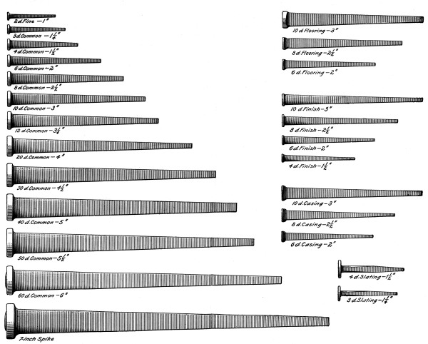
As shown in Fig. 1, cut nails are made in
many styles and sizes, and for various purposes. They are also known by
the same trade term for the various styles. Cut nails are heavier than
wire nails, and as they count fewer to the pound, are more expensive
at equivalent prices. All nails are sold at base prices per keg of 100
pounds, the “extras” for smaller and special nails being added to the
base price. For special work, certain types of nails can be obtained in
copper and brass.
4. Size and Gauge of Nails.—Both cut and wire nails
are designated by the trade term penny. The term penny as applied
to nails is a relic of medieval England. This designation was due, it is
said, to the fact that it defined the cost per hundred nails,
so that tenpenny nails would mean that 100 of such nails cost
ten pence. A more likely interpretation of the term is that it
implied the weight and not the cost, and that the term
penny is a corruption of the Old English word pun’ (for pound),
so that tenpunny or tenpenny implied that 1,000 of such
nails weighed 10 pounds. The smallest standard size of nail is known as
twopenny or threepenny, while the largest is designated
as sixtypenny. These sizes range in length from 1 to 6 inches.
In designating the size of the nail in list prices, the symbol “d” (for
penny) is used, so that a nail about 2 inches long is designated as 6d.
The thickness, or diameter, is indicated by the gauge number, the gauge
of cut nails being an indication of the thickness of plate from which
they are cut, while the gauge of wire nails is the size of the wire
from which the nails are formed. The different wire gauges and their
decimal equivalents of an inch are given in Table I.
The special wire gauge commonly used to indicate the size of the nail
is the Birmingham. In Table II is given a list
of the stock sizes of standard, common, cut nails. This table, besides
giving the thickness of the nail and its length, gives the number of
nails to the pound.
TABLE I
STANDARD WIRE GAUGES AND THEIR
DECIMAL EQUIVALENTS OF AN INCH
Number of Wire Gauge
American, or, Brown & Sharpe
Birming- ham
Washburn & Moen Manufacturing Company
Trenton Iron Company
United States Standard
Old English From Brass Manufacturers’ Lists
000000
.4600
.46857
00000
.4300
.4500
.43750
0000
.460000
.454
.3930
.4000
.40625
000
.409640
.425
.3620
.3600
.37500
00
.364800
.380
.3310
.3300
.34375
0
.324950
.340
.3070
.3050
.31250
1
.289300
.300
.2830
.2850
.28125
2
.257630
.284
.2630
.2650
.26563
3
.229420
.259
.2440
.2450
.25000
4
.204310
.238
.2250
.2250
.23438
5
.181940
.220
.2070
.2050
.21875
6
.162020
.203
.1920
.1900
.20313
7
.144280
.180
.1770
.1750
.18750
8
.128490
.165
.1620
.1600
.17188
9
.114430
.148
.1480
.1450
.15625
10
.101890
.134
.1350
.1300
.14063
11
.090742
.120
.1200
.1175
.12500
12
.080808
.109
.1050
.1050
.10938
13
.071961
.095
.0920
.0925
.09375
14
.064084
.083
.0800
.0800
.07813
.08300
15
.057068
.072
.0720
.0700
.07031
.07200
16
.050820
.065
.0630
.0610
.06250
.06500
17
.045257
.058
.0540
.0525
.05625
.05800
18
.040303
.049
.0470
.0450
.05000
.04900
19
.035390
.042
.0410
.0390
.04375
.04000
20
.031961
.035
.0350
.0340
.03750
.03500
21
.028462
.032
.0320
.0300
.03438
.03150
22
.025347
.028
.0280
.0270
.03125
.02950
23
.022571
.025
.0250
.0240
.02813
.02700
24
.020100
.022
.0230
.0215
.02500
.02500
25
.017900
.020
.0200
.0190
.02188
.02300
26
.015940
.018
.0180
.0180
.01875
.02150
27
.014195
.016
.0170
.0170
.01719
.01875
28
.012641
.014
.0160
.0160
.01563
.01650
29
.011257
.013
.0150
.0150
.01406
.01550
30
.010025
.012
.0140
.0140
.01250
.01375
31
.008928
.010
.0135
.0130
.01094
.01225
32
.007950
.009
.0130
.0120
.01016
.01125
33
.007080
.008
.0110
.0110
.00938
.01025
34
.006304
.007
.0100
.0100
.00853
.00950
35
.005614
.005
.0095
.0090
.00781
.00900
TABLE II
SIZE AND NUMBER TO THE POUND OF COMMON CUT NAILS
Trade Term
Length Inches
Gauge
Number to Pound
3d fine
1⅛
16
720
3d flat
1¼
15 full
430
4d flat
1½
14 full
275
5d flat
1¾
13 regular
215
6d common
2
12 regular
150
7d common
2¼
11 light
120
8d common
2½
11 regular
96
9d common
2¾
10 light
72
10d common
3
10 regular
64
12d common
3¼
9 regular
44
16d common
3½
8 regular
32
20d common
4
7 regular
28
30d common
4½
6 regular
18
40d common
5
5 regular
14
50d common
5½
4 regular
12
60d common
6
3 regular
10
Fig. 1
5. Wire Nails.—The term wire nail is applied to nails
made from drawn wire, or wire rods. Since their introduction some years
ago, wire nails have become decidedly popular, and in some localities
are used in preference to the old-style cut nails, owing to the fact
that there are a greater number to the pound, which makes them cheaper
than cut nails at the same price per keg. The size and number of common
wire nails to the pound are given in Table III.
By comparing the columns in Tables II and
III giving the number of nails to the pound for
both cut and wire nails, it can be readily seen that the wire nails are
greater in number for a given weight than cut nails of the same size.
For this reason, the wire nails are used by contractors on cheap work.
Wire nails are more liable to rust than cut or wrought nails, and are
consequently not so durable in damp situations; they also have less
holding power and more must be used to obtain the same strength.
TABLE III
SIZE AND NUMBER TO THE POUND OF COMMON WIRE NAILS
Size
Length Inches
Gauge Number
Approximate Number to the Pound
Advance Over Base Price per 100 Pounds
2d
1
15
876
$0.70
3d
1¼
14
568
.45
4d
1½
12½
316
.30
5d
1¾
12½
271
.30
6d
2
11½
181
.20
7d
2¼
11½
161
.20
8d
2½
10¼
106
.10
9d
2¾
10¼
96
.10
10d
3
9
69
.05
12d
3¼
9
63
.05
16d
3½
8
49
.05
20d
4
6
31
Base
30d
4½
5
24
Base
40d
5
4
18
Base
50d
5½
3
14
Base
60d
6
2
11
Base
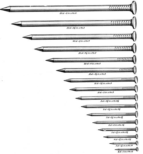
Fig. 2
Common wire nails in sizes from twentypenny to sixtypenny are sold at
base price, say $2 per keg, the smaller sizes costing an advance over
the base price. Thus, an eightpenny common nail would cost 10 cents
additional, or $2.10 per hundred pounds, while a twopenny nail would
cost $2.70 per hundred pounds, etc. The present advance above the base
price on 100-pound kegs for the several sizes is also given in this
table. All wire nails can be procured “barbed” at an additional advance
of 15 cents above base and extra prices.
The relative sizes of the common wire nail are best learned from
samples of the same, but Fig. 2, which shows
these nails full size, from sixtypenny to twopenny, clearly indicates
their proportions.
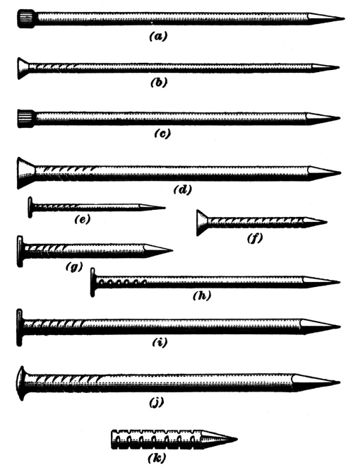
Fig. 3
6. Wire Nails for Special Purposes.—Wire nails as well as
wrought or cut nails are made in a variety of forms especially suitable
for the specific purpose for which they are intended. The several kinds
of wire nails in common use are illustrated in Fig. 3.
A nail used about buildings for putting the trim, or finishing work,
together is illustrated at (a), and from its use is known as a
finishing nail. These nails are used almost exclusively for this
purpose and are very light. They have a small head, so that when they
are set into the wood with a nail set, a very small opening is left for
puttying.
Another nail having practically the same use as the one just described
is designated as a casing nail, and is shown at (b). This
nail is a trifle lighter in gauge than the finishing nail, and from the
fact that it is countersunk under the head, it draws better than the
finishing nail. The fivepenny and sixpenny sizes are used for putting
on siding.
The common wire brad, shown at (c), is used for
practically the same purposes as the regular finishing nail, but it is
from two to four gauges heavier. This wire brad is useful when a heavy
nail with a small head is required, particularly in hardwood, where a
light finishing nail will not penetrate without bending.
The flooring brad, shown at (d), is a nail used almost
exclusively for flooring. This nail is made of heavier gauge wire than
other nails of this type, and drives easily, even in hard, maple floor.
The construction of the head of this type of nail allows for severe
“drawing” without splitting the tongue of the flooring boards.
The fine-wire nail, shown at (e), commonly called a
lath nail, is made in four sizes and is used for nailing lath
to studding. Owing to its smoothness, cleanliness, and easy-driving
qualities, this type of nail is extensively used.
A short, heavy nail, the whole length of which is barbed to increase
its holding qualities, is shown at (f). This nail is known as a
barbed roofing nail, and is generally used for nailing tin roofs
and ready, or prepared, roofing of every description. It is also used
with tin roofing caps.
At (g) is shown a slating nail. This type of nail is
formed from heavy gauge wire, and has a flat head that is large in
proportion to its length. This nail is used only for slating, but is
not so durable as the cut nail made for this purpose. Nails of this
kind are made in only five sizes.
A type of nail used for attaching wooden shingles, and known as the
shingle nail, is shown at (h). This nail is seldom
carried in stock, however, as threepenny and fourpenny common nails
answer the purpose. These shingle nails are clean and easily driven,
but are not so durable as cut nails.
A very heavy nail of the same character as the common wire nail, but
made much heavier, in order to increase the holding qualities and to
provide greater durability, is known as the fence nail. This
nail is made as shown at (i).
At (j) is shown a clinch nail that is manufactured from
soft wire or annealed hard wire. This nail answers the same purpose
as the old-style wrought, or clinch-cut, nail commonly used in the
construction of batten doors, etc. The metal being very soft at the
end of the nail, allows the point to be bent and driven back into the
wood to form the clinch. These nails do not differ from the common wire
nail, except in the form of the head and the material from which they
are made, as will be seen from Fig. 3 (j)
and Fig. 2.
There is a form of headless wire nail, known as a barbed
dowel-pin, which is made as shown in Fig. 3 (k).
This type of nail, or dowel, is used for doweling through the mortises and
tenons of sash, blinds, and frames of every description. In the mill, it has
displaced the wooden dowel used in former times. The length of pin to
be employed is regulated by the thickness of the wood to be secured, as
the pins are used ¼ inch shorter than the thickness of the woodwork.
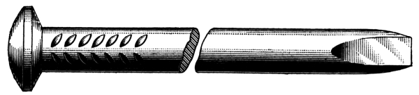
Fig. 4
An exceptionally heavy nail, or spike, is made from heavy wire or round
bar. These spikes are used for heavy construction work, such as splined
flooring, for slow-burning mill construction, and for bridge flooring.
They are made with both chisel points, as shown in Fig. 4,
and diamond points, and in ordering them, the kind of point, as well as the
style of head wanted should be specified. Spikes of this kind are made in all
sizes from tenpenny, which is of No. 6 gauge and 3 inches long, to
spikes ⅜ inch in diameter and 12 inches long.
7. Galvanized Nails and Spikes.—Nails and spikes, either cut
or wire, that have been dipped into molten zinc and become coated with
this metal are termed galvanized. By this process they are
rendered practically rust-proof. Cut or wire galvanized nails can be
obtained in the same sizes and types as ordinary nails, and if dealers
do not regularly carry them in stock, they will as a rule have them
galvanized to order. In order to secure durability, it is advisable
to use galvanized nails in places that are exposed to dampness, as in
shingling, in slating, in fence building, or in structures erected near
the seashore, as it has been proved by numerous tests that ordinary
nails rust through in such places in a few years. The galvanized nails
cost from $1.50 to $3 more per keg than the plain cut or wire nails.
The cheaper grades of galvanized nails are frequently coated only with
lead, and will not withstand the government test; that is, dipping them
into vitriol. A simple way to test the coating of a galvanized nail is
to rub the nail on a piece of white paper. A lead-coated nail will mark
the paper the same as a lead pencil and should be rejected, as it is
only a sham and has no redeeming qualities.
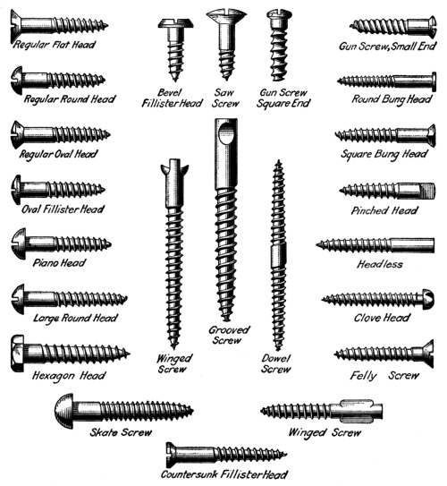
8. Wood Screws.—The ordinary wood screw, which is one of
the staple articles of hardware, is very necessary in the application
of all builders’ hardware about the building. Except in some lines of
cheap or rough, unfinished goods, hardware manufacturers now pack with
all hardware, screws that match the finish of the goods. The various
types of screws now on the market are illustrated in Fig. 5,
and the common types, such as flat-, round-, oval-, and fillister-headed screws
are easily procured.
Iron screws are made with either flat, round, or oval heads and the
following finishes: Bright, blued, japanned, tinned, galvanized,
bronze-plated, brass-plated, coppered, silvered, and nickel-plated.
Brass and bronze metal screws can also be procured with flat, round, or
oval heads, in either natural color or, on special order, finished to
match the hardware. Special screws are also manufactured for various
purposes, which are sufficiently explained by the illustration,
Fig. 5.
Fig. 5
Screws are always measured for length from the point to the top of the
head. The sizes in which screws can be obtained are given in Table IV.
The diameter of screws is always measured directly under the head, and
is always given in numbers of the screw makers’ gauge. The numbers vary
from 0 to 30, going consecutively without skip from 0 to 18
and from then on using only the even numbers. In Table IV
are also given the numbers of the screw makers’ gauge and
their equivalents in decimals of an inch.
TABLE IV
SIZE OF WOOD SCREWS
Length Inches
Diameter in Screw Makers’ Gauge
¼
From
0 to 4 inclusive
⅜
From
0 to 9 inclusive
½
From
1 to 12 inclusive
⅝
From
1 to 14 inclusive
¾
From
2 to 16 inclusive
⅞
From
2 to 16 inclusive
1
From
3 to 20 inclusive
1¼
From
3 to 24 inclusive
1½
From
3 to 24 inclusive
1¾
From
5 to 24 inclusive
2
From
5 to 24 inclusive
2¼
From
5 to 24 inclusive
2½
From
5 to 24 inclusive
2¾
From
6 to 24 inclusive
3
From
6 to 26 inclusive
3½
From
8 to 26 inclusive
4
From
8 to 30 inclusive
4½
From
12 to 30 inclusive
5
From
12 to 30 inclusive
6
From
12 to 30 inclusive
Screw Makers’ Gauge
Number of Screw Gauge
Equivalent in Decimals of an Inch
0
.05784
1
.07100
2
.08416
3
.09732
4
.11048
5
.12364
6
.13680
7
.14996
8
.16312
9
.17628
10
.18944
11
.20260
12
.21576
13
.22892
14
.24208
15
.25524
16
.26840
17
.28156
18
.29472
20
.32104
22
.34736
24
.37368
26
.40000
28
.42632
30
.45264
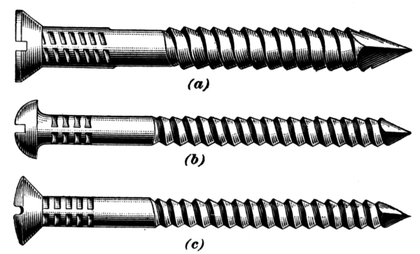
9. Drive Screws.—A screw known as the drive screw is
used mostly in the manufacture of various articles where cost is the
controlling factor. These screws, shown in Fig. 6,
are made somewhat on the order of the wood screw, but without the
deep-cut thread and gimlet point. Screws of this type are driven into
the wood with a hammer and have slotted heads so that they may be
withdrawn by means of a screwdriver. The thread is so constructed that
the wood may be penetrated without breaking down its fiber when the
screws are driven, and is shaped so as to engage with the wood while
resisting a pulling stress. These screws are made with flat, round,
or oval heads, as illustrated respectively at (a), (b),
and (c), and may be had in sizes from ½ inch to 4 inches in length.
Fig. 6
10. Expansion Bolts.—The expansion bolt is a device that
has proved extremely valuable in the building trades, as it provides a
means of bolting to stone, brick, concrete, slate, or other materials
of this nature. Expansion bolts are used principally in places where
it is not desirable or practicable to drill through the material to
which the fastenings are to be made. This type of bolt has also a great
advantage over other fastenings in that it can be removed with as much
ease and facility as it is applied, and also without injury either to
the article fastened or the material to which it is fixed, the bolt
likewise sustaining no injury.
Many styles of expansion bolts are now manufactured under various
patents, and these may be procured in all sizes and made of iron,
steel, or brass.
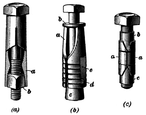
In Fig. 7 are shown several makes of
expansion bolts. The McCabe expansion bolt, shown at (a),
is constructed of a malleable, cylindrical-shaped, slotted case, or
shell, a, the aperture of which reduces in size and engages with
a bevel-shaped hexagon nut b. By turning the bolt, the nut is
drawn toward the head and thus expands the outer case in its passage;
this in turn binds against the sides of the hole in the masonry into
which the bolt is inserted. The shell, as the outside case a is
called, can be procured in any length or diameter, and can be used with
any machine bolt having a standard thread. The McCabe bolt is suitable
for bolting any thickness of material, provided the proper length of
bolt is employed.
The Brohard expansion bolt shown at (b), performs the
same functions as the bolt illustrated at (a). The case, or
shell, a, is composed of two or more parts riveted to a wrought
circular plate, near the head, as at b. These several parts are
expanded by means of the beveled nut, which approaches the head as the
bolt is turned. The principal feature of the Brohard expansion bolt is
that the beveled nut c cannot be forced from the case on account
of the lug d, which is attached to the nut and travels in the
slot e when the bolt is turned.
Fig. 7
The Steward and Romaine double-expansion bolt is shown at
(c). The shell of this bolt is composed of two semicylindrical
parts, as at a, a, that are somewhat longer in diameter
than the wedge-shaped nut and the sleeve at b and c,
respectively. Each half of the shell is held in place by light rubber
bands. The wedge-shaped parts are caused to approach each other by the
turning of the bolt, and thereby expand the split case at both ends
simultaneously. From the fact that this bolt is expanded at both ends,
it is called a double-expansion bolt, although it may be made
single-expansion by omitting the wedge-shaped sleeve at the head.
Fig. 8
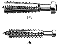
The Star expansion bolt, shown in Fig. 8 (a),
performs exactly the same duty as other expansion bolts, but its construction
is radically different. This bolt consists of only two parts, called
shields. Each shield is semicircular in form and interlocks at
the joints. The exterior of these shields has four rows of corrugated
ridges, or star-shaped projections, that prevent the shields from
turning in the hole. The interior of the shell is threaded and
decreases in size toward the farther end. Thus, by inserting a lag,
or coach, screw of any length, so as to engage with the thread, the
shields are spread apart at the farther end while the screw is entering
the aperture.
The Diamond expansion bolt shown at (b) is practically
the same as the one just described, as will be observed from the figure.
Expansion bolts are also made with all the parts entirely of brass or
bronze, with either plain, capped, or fancy heads, or nuts, and in any
finish desired.
11. Screw Anchors.—The device known as a screw anchor
can be used in place of an expansion bolt for securing light materials.
Several kinds of screw anchors are in the market at present. The
star anchor, which is made in one piece of composition metal
that is slotted about seven-eighths of its length, may be obtained
in various diameters and lengths. The exterior has two star-like
projections, to prevent the anchor from turning, while the interior is
constructed of ridges projecting from the tube, with the hole reduced
toward the slotted end. This internal construction permits the star
anchor to be used in combination with trade wood or machine screws of
any length. The screw used engages with the ridges in the interior,
cutting its own thread and expanding the anchor in its passage. These
composition anchors are very cheap, the price ranging from 1 to 3
cents, according to the size. They are made in different lengths, from
½ inch to 1½ inches, and for Nos. 6, 10, 14, and 18 wood screws.
Fig. 9
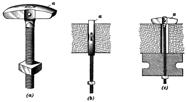
12. Special Bolts.—In Fig. 9 is shown
a toggle bolt. This device is a recent production for fastening
materials to surfaces having a hollow interior that will not admit
the use of expansion or tap bolts because of its frail character, as,
for instance, sheet metal, hollow fireproofing, etc. The toggle bolt
shown in the figure is constructed with long, fine-pitch threads cut
nearly to the head, so as to allow for securing thin materials. The
T-shaped head a is constructed either hollow, as shown
in the figure, or of flat strip metal, and is riveted loosely to the
end of the bolt, allowing the head to pivot and fold over the bolt,
and thus permitting the head to pass through a small opening. The head
is then tipped into its proper position, when the bolt is ready for
securing in place the work to be fastened. The construction of the
bolt is shown in Fig. 9 (a), while the
process of affixing it is illustrated at (b) and (c). These
toggle bolts are generally made with ³/₁₆-, ¼-, and ⁵/₁₆-inch bolts,
from 2½ to 6 inches long, and of either iron, steel, or brass.
13. Cast-Iron Weights.—The term sash weight is applied
to a counterweight used for balancing double-hung, or sliding, sash.
These weights are generally very rough, being made from either the
poorest iron or waste iron. The stock sizes are usually long and
cylindrical in form—from 1⅜ to 2¼ inches in diameter—have an eye
cast in the upper end, as shown in Fig. 10,
and weigh from 2 to 30 pounds, the weight determining the length of the
sash weight. In Table V are given the weight,
diameter, and length of sash weights as they are generally furnished to
the trade, although it is almost impossible to give this data with any
degree of accuracy, as the different manufacturers vary the diameters
of the weights slightly, and this changes the length measurement.
Square weights or special weights can be easily procured at small
additional cost.
Fig. 10
Fig. 11
14. Lead Weights.—The weight of lead is about 80 per cent.
greater than that of cast-iron; hence, lead sash weights must
be resorted to where the construction of the pockets is too narrow to
permit the use of iron weights, or where heavy plate glass is used.
They are also used in cases where the sash are very wide and low, as
here a short weight must be used in order to obtain the necessary
travel for the sash.
Lead weights can be procured in either round or square shapes, and of
any diameter or measurement to suit existing conditions, but they are
generally made to special order. A wrought- or malleable-iron eye, or
fastening, for applying the cord or chain is usually inserted at the
top. The cost of lead weights, however, is generally five times as great
as that of iron weights.
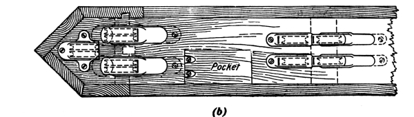
15. Sectional Sash Weights.—There is a form of sash weight
in the market known as the Walda sectional weight, which is
illustrated in Fig. 11. This weight, as
will be observed, is so arranged that units or sections may be
detached or added, as desired, to diminish or to increase the weight.
Such a weight can be nicely adjusted to counterbalance any sash,
and has the advantage over the cast-iron weight in that each part
is interchangeable and no mistake can be made in ordering, as the
necessary weight for any sash can be made up on the site.
TABLE V
WEIGHT, DIAMETER, AND LENGTH OF SASH WEIGHTS
Weight Pounds
Diameter Inches
Length Inches
Weight Pounds
Diameter Inches
Length Inches
3
1⅜
8½
12
1¾
20
3½
1⅜
9¾
13
1¾
21½
4
1⅜
11
14
2
18
4½
1⅜
12¼
15
2
19
5
1½
12
16
2
20¼
5½
1½
12½
17
2
21½
6
1½
14
18
2
22½
6½
1½
15
19
2
23½
7
1½
16
20
2
24½
7½
1½
17
21
2⅛
25
8
1½
18
22
2¼
23
8½
1⅝
16½
23
2¼
24
9
1⅝
17½
24
2¼
25
9½
1⅝
18½
25
2¼
25½
10
1⅝
19½
26
2¼
26
10½
1⅝
20½
27
2¼
27
11
1⅝
21½
28
2¼
28
11½
1¾
19
29
2¼
28½
16. Historical.—From the days of Tubal-Cain, “an instructor of
every artificer in brass and iron,” to the present time, no element in
the world’s composition has rendered greater service in advancing man’s
development than has the uninviting metal known as iron.
Recent discoveries show the very ancient existence of iron in Assyria,
and also in Egypt under the Pharaohs. It was found in considerable
quantities in Syria, in Canaanite times, and many tools and implements
of warfare were made from it. The Chalybes, located near the Black Sea,
were in Biblical times considered famous workers in “northern iron,”
while Damascus steel, for ages, has been justly celebrated.
Copper was well known to the Israelites and Egyptians before
the Exodus, and for many years previous to that event the Egyptians
obtained it from Arabia. It was also a native product of Palestine, and
was very largely exported from Cyprus, whence its name.
Tin was early known in the Orient, being one of the imports of
Egypt from Spain, through the Phoenician merchants, who also obtained
it from Britain. It was one of the principal commodities in the marts
of Tyre, and was used as an alloy with other metals.
Gold and silver, the precious metals, are mentioned in
the earliest times and were highly esteemed; they were utilized in the
manufacture of articles for domestic use, for personal adornment, and
for ceremonial accessories. These metals were obtained by the Hebrews
from Arabia, Ethiopia, Egypt, and Spain. Gold was used as a medium of
exchange, like money, as early as the time of Abraham, but was then
weighed, not counted. Silver was profusely used at that time in the
East, and seems to have been very abundant in the time of Solomon. An
alloy of gold and silver, called electrum, was also used.
Zinc was discovered in 1520 by Paracelsus, an alchemist and
astrologer of Europe, and was immediately adopted as a valuable alloy.
Bronze, a composition of copper and tin, seems to have been much
used in Europe before the adoption of iron for the same purposes, as
Roman remains testify; this was probably due to its greater ease in
working.
Brass, a composition of copper and zinc, soon became popular,
owing to its being more easily worked than bronze.
Burnished brass is mentioned in Ezekiel, but is considered to
have been an alloy of copper, there being a white metal, greatly used
for ornaments in the East, called white copper.
Locks and contrivances to secure protection and privacy were originally
made of wood, and a wooden lock (the oldest yet discovered) was
actually found in the ruins of Nineveh. This lock appears to have been
used on a gate of an apartment in one of the palaces of Khorsabad. The
ancient Egyptians constructed locks and keys from brass and iron, thus
showing their creative mechanical skill, while the ornaments discovered
in the royal tombs display the high order of their art.
The Greeks and Romans were skilled workers in the metals, and many
beautiful examples remain to attest their ability and ingenuity.
During the dark ages, following the conflict waged between the
barbarians of Northern Europe and the Romans, and resulting in the
fall of the Roman Empire in the 5th century, the art of working the
metals nearly disappeared. Not until the Revival of Learning in the
13th century did the art again receive the attention to which it was
entitled. As late as the reign of Edward III, of England, in the 14th
century, the iron pots and pans of the royal kitchen were listed among
the “jewels of His Majesty.” During the 15th and 16th centuries, great
progress was made among all civilized nations by skilled artificers.
Much of their work is still extant, and their “cunning of hand” and
“keenness of intellect,” as displayed in their products, serve, like
torches, to light the way to higher endeavor. From that time to the
present, great progress has been made. During the latter half of the
17th, the 18th, and the beginning of the 19th centuries, especially,
art work received a great impetus, and much of the present-day
adaptations are modeled from the schools of ornament then produced.
17. Metals Used in Hardware Manufacture.—The metals chiefly
used in manufacturing the products of the smiths’ art are iron and
steel and the copper alloys known as brass and bronze. Iron remains
as the chief material of construction for all the cheaper grades
of hardware, while brass and bronze are more generally used for
“destructible,” or wearing, parts and the finer and more elaborate
decorative work. These alloys also adapt themselves admirably to the
great variety of finishes that are now in vogue. Iron is also used
considerably for elaborate decorations in wrought and cast designs, and
is very desirable in the “rustless-iron” finish, technically known as
“Bower-Barff,” which derives its name from its two inventors.
White metal has been recently introduced, but will probably not be so
universally adopted as brass or bronze, owing to the great number and
variety of items used in hardware fittings, which would necessitate
stores carrying a full line of white-metal goods. At present, white
metal is used principally for hospital buildings and bathrooms.
18. Commercial and Stock Designs.—In recent years,
manufacturers have made rapid strides in producing beautiful and
elaborate trim in the several schools of ornament, and the most
exacting critic can now procure artistic designs. The finishes are made
to harmonize or contrast with any color treatment.
The principal hardware manufacturers can provide from stock, locks,
hinges, and escutcheons finished in any manner and designed in any of
the following schools of architectural ornament. They will also provide
hardware in special designs from sketches furnished by the architect,
including armorial or emblematic designs, if required. These several
schools of ornament are here arranged in alphabetical order.
Byzantine
Gothic, French
Colonial
Gothic, German
Elizabethan
Gothic, Italian
Empire
Greek
English Renaissance
Henry II
Flemish
Indian
Francis I
Italian Renaissance
French Renaissance
Japanese
German Renaissance
L’Art Nouveau
Gothic, English
19. Finishes.—The basic metals upon which are applied the
variety of finishes now obtainable, are iron, steel, brass, bronze, and
white metal, of which the three latter, even in their highly polished
natural state, are the most durable. These metals will not rust or
corrode when exposed as will iron or steel, and when tarnished can be
readily cleaned and polished.
Nearly all the fancy finishes are obtained by electroplating and acid
treatment on the natural metals, the finish being then lacquered to
preserve it. Some of these finishes are very attractive and desirable,
but where exposed to constant usage, have not the durability of the
natural metals, as they cannot be polished or cleaned without the
finish being injured or destroyed.
Many architects or owners purposely select applied finishes with the
object in view that they will need little attention. When selections
are being made for exterior purposes or where there is likely to
be excessive handling, it is best to select the darker shades with
sanded surfaces. For interior purposes, the more delicate finishes are
desirable for the decorative effect; they also wear reasonably well.
The variety of colors and shades of finishes is exceedingly large, and
the choice of color, like that of texture, depends on the character of
the design and on the personal taste of the one making the selection.
The standard finishes that can be had are numerous. Many of them may
be obtained in various shades of oxidation and in from one to four
different textures of surface. The most popular finishes are as follows:
Pompeian bronze
Copper
Sage-green bronze
Nickel
Royal copper bronze
Silver
Ormolu metal
Gold
Boston finish
Bower-Barff
Enameled
White enamel
Japanned
Gun-metal brown
White metal
Verde antique
Brass
Statuary bronze
Bronze
Olive bronze
20. Strap Hinges.—The common wrought hinges used to apply on
the surface, for hanging doors, etc., and generally used in connection
with rough work, such as bins, sheds, barns, etc., where a strong,
serviceable hinge that may be easily applied is required, are known as
strap hinges. They are constructed of wrought metal of various
weights, according to the size of the hinge, and are stamped or cut
from sheet metal, with knuckles, or sockets for the pins, formed
on the strap; the pins passing through the knuckles are well riveted.
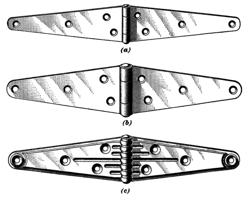
There are two kinds of strap hinges; namely, light-strap and
heavy-strap hinges.
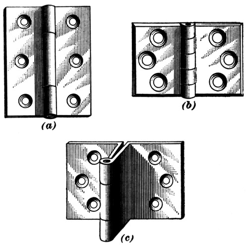
The light-strap hinge, which is shown in Fig. 12 (a),
is so termed because of its light construction and narrow joint. This
hinge is made in inch sizes, varying from 3 to 16 inches in length.
By inch size is meant the longest dimension when the hinge is closed;
thus, a 6-inch strap hinge is 12 inches long from end to end when
opened. They are listed and sold by the pair.
Fig. 12
The heavy-strap hinge, which is shown at (b), is similar
to the light hinge, but is made from heavier metal and has large
dimensions at the joints, or knuckles. This type of hinge is used where
a strong, substantial hinge is required. The heavy-strap hinge is made
in inch sizes, from 4 to 16 inches in length. The 4- and 5-inch sizes
are listed and sold by the pair, the 6-inch and larger sizes being
listed and sold by the pound; the larger the hinge the lower the price
per pound.
As shown at (c), the heavy-strap hinges are also made with
corrugated knuckles, which give additional strength where the
construction is weakest. These are termed corrugated-strap hinges.
All of the hinges described are also made in plain steel, japanned or
galvanized, and may have brass pins or rivets.
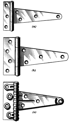
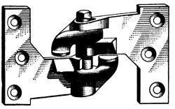
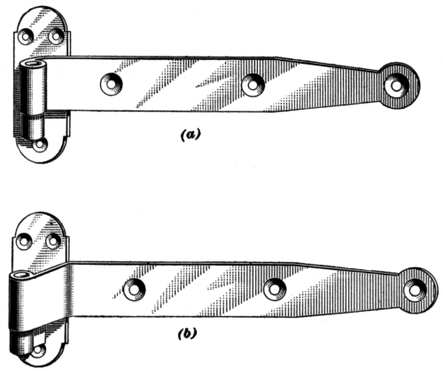
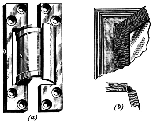
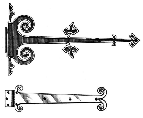
21. T Hinges.—As will be seen from Fig. 13,
T hinges are so called to distinguish them from the strap hinge, as well
as because of their construction, which is in the form of the letter T. The
T hinge is used for practically the same purpose as the strap
hinge, but is superior to it in strength, from the fact that its
knuckle is wider than that of the strap hinge. T hinges are made
in light, heavy, and extra-heavy grades, the former and latter types
being shown in Fig. 13 (a) and (b).
In arranging the sizes of T hinges, the measurements are given
for the length of the strap only; the leaf of the hinge forming the
T with the strap is not considered. Thus, a 6-inch T
hinge measures 6 inches from the pin to the end of the strap
leaf. T hinges may also be obtained in stamped metal, with
corrugations, as shown at (c). These hinges can be had in all
finishes. The light and heavy grades, as well as the 4- and 5-inch
extra-heavy grades, are sold by the pair, while the larger sizes of
extra heavy are sold by weight.
Fig. 13
22. Hinge Butts.—In the selection of hardware for building
purposes, no other article deserves more consideration, and probably
receives less, than the hinge butt. This type of hinge is used
for the purpose of hanging all of the exterior and interior doors of
buildings, and is usually secured to the edge of the door and to the
hanging stile of the frame with screws, the greater part of the
appliance being thus unobtrusive and partly hidden from view. The
hinge butt supports the entire weight of the door, and, ordinarily,
is constantly in use, so that it is subjected to excessive strain and
considerable wear. It is evident, therefore, that great care should be
exercised in selecting hinge butts, so that proper sizes and qualities
suitable for the purpose intended may be obtained.
Fig. 14
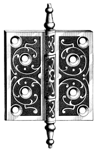
23. Cast-Iron Hinge Butts.—Hinge butts made of cast-iron
are used extensively in the cheaper class of buildings built for
speculative purposes, in which cost is usually the controlling factor.
An ornamental type of the cast-iron hinge butt is shown in Fig. 14.
Butts of this type are not extensively used at present, but may
be obtained in various finishes to imitate bronze or brass, and may
likewise be obtained without ornamentation. As the genuine Bower-Barff
finishes are produced with equal facility on iron or steel, a large
number of the better grade of cast butts are finished in this manner.
While the cast-iron hinge butt is not so durable as the steel butt,
being more easily broken when subjected to excessive stresses, it wears
somewhat better at the joints, or knuckles, than the ordinary steel
butt. Therefore, the extra-heavy types of cast-iron are becoming more
popular for entrance doors, etc., where a good wearing butt is
required, and where economy is the essential feature. The heavier
grades of cast-iron butts can be procured with steel bushings inserted
into the joints.
Fig. 15
Fig. 16
Fig. 17
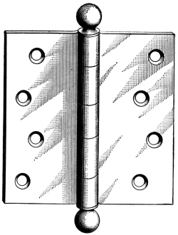
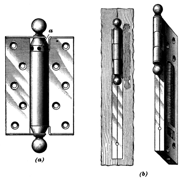
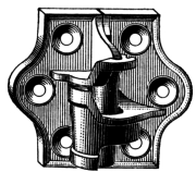
24. Steel Hinge Butts.—In recent years, the steel hinge
butt, which is shown in Fig. 15, has been substituted
for the cheaper cast-iron butts. The better grades are made with ball tips, as
indicated in the figure, and these are now almost universally used for
medium-class work and for the better class of interior work. Owing to
the fact that they are made up with smooth surfaces, the steel hinge
butts are adapted to the various buildings and finishings without
grinding or buffing. These butts are stamped and formed by machinery,
so that their cost is reduced to a minimum; they can be sold for less
than cast-iron butts, and also possess the advantage over the latter in
that they are practically unbreakable. The ordinary grades are not
suitable for large and heavy entrance doors that are constantly in
use, for they are made of soft steel and wear readily at the joints.
Thus, in time, they will allow the door to sag and thereby necessitate
readjustment, or the planing of the door at the sill. For such class
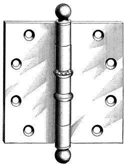
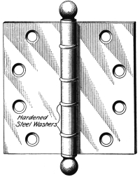
of work, steel hinge butts should be used that are provided with ball
bearings, as shown in Fig. 16, or with hardened-steel
washers inserted at the joints, as shown in Fig. 17.
These steel butts are also made in smaller sizes, and for bookcases,
cupboard doors, and light work of this kind in ordinary building
operations, they are used almost exclusively, having practically forced
the small cast butts for this class of work out of the market.
Fig. 18
25. Cast-Bronze and Brass Butts.—All types of brass
and bronze butts are made in several grades and qualities, and
it is difficult to determine the grade after they have been placed
in position. It is therefore advisable for the architect or building
superintendent to make a careful inspection of this hardware, to
determine whether it is furnished according to specification. Brass and
bronze butts are made in light, or commercial, heavy, and extra-heavy
grades, and in all cases should be steel-bushed, self-lubricating, and
provided with five knuckles. The high-grade butts are now manufactured
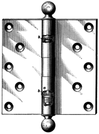
with ball bearings at the wearing joints. The construction of a solid
bronze, ball-bearing hinge butt is shown in Fig. 18. In this figure, the
hardened-steel balls are shown at a, and the cones, which are
also of hardened steel, at b. Bronze hinges constructed in this
manner can be obtained at a slight additional cost above the ordinary
steel-bushed hinge.
Where hinge butts are exposed to the weather, as when used for exterior
doors, bronze or brass butts should always be employed; and for
extra-heavy doors that are in constant use, only the extra-heavy types
should be used if permanency and durability are desired. There are a
number of cheap grades of bronze, steel-bushed hinges on the market
that are made of wrought or sheet metal. This kind of hinge has no
merit, and should not be used on work of any quality.
26. Sizes of Hinge Butts.—The standard hinge butts are always
square, but they may be procured in irregular sizes, at additional
cost. In indicating the size of irregular hinge butts—that is, the
butts that are not square, and that are consequently not standard—two
dimensions must always be given. The first dimension stated should
indicate the height of the butt, and the second the width of the butt
when it is open. Thus, a 6" × 5" butt is 6 inches high and 5 inches
wide when opened. This rule for indicating the size of hinge butts is
easy to remember, from the fact that it is the reverse of that
ordinarily employed by builders when indicating the sizes of doors and
windows, for here it is customary to give the horizontal dimension
first and the height of the opening last.
Fig. 19
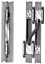
27. Single-Acting Hinges, or Butts.—There is a large butt,
or hinge, in the market that has a coil spring either between the
knuckles, or enclosed between the leaves. This device is known as
the single-acting hinge, and is illustrated in Fig. 19.
At (a) is shown the Bommer single-acting hinge, which has a
spiral spring enclosed within the casing formed by one of the knuckles.
The tension on this spring can be increased by operating the collar at
a with a pin, or bar. At (b) is shown a single-acting
spring hinge known as the Chicago single-acting spring butt.
This hinge butt has a spiral spring that is encased between two leaves.
In operating, this spring always tends to throw the door back to its
closed position. These two kinds of single-acting hinges are used more
than any other hinge of the same nature now in the market, but for
doors of large size the liquid door check is preferred, although it is
more costly. Single-acting hinge butts are used principally for hanging
water-closet slat doors; and they are also used for light doors that
do not reach the full height of the opening, and which have no jambs.
The Bommer hinge, as shown in Fig. 19 (a),
has an advantage on account of the simple means provided for adjusting
the tension of the coil, or spring, by which the momentum of the door
in swinging to and fro can be reduced to a minimum, thus shutting the
door with little noise as it strikes the stop.
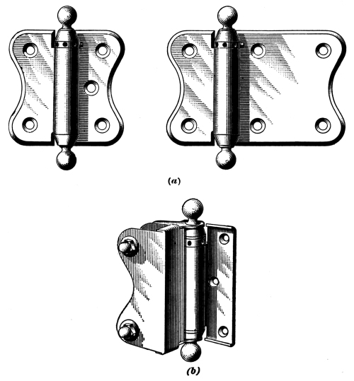
Fig. 20
Two other types of the Bommer single-acting spring hinge are shown in
Fig. 20. At (a) are shown two types of
single-acting, surface, spring hinges that are used for lavatory doors,
while at (b) is shown a similar single-acting spring hinge
arranged for securing to a marble or slate stile or partition. These
hinges are commonly supplied in highly polished nickel plate, brass, or
bronze. The clamp hinge illustrated at (b) is made to secure to
slabs of marble or slate from 1 to 2 inches in thickness, advancing by
quarter inches. This type of hinge is also adjustable ⅛ inch over and
under the stated sizes.
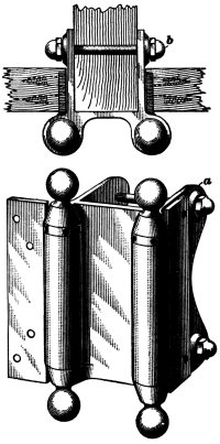
Fig. 21
The Bommer yoke-spring hinge is also made as illustrated in Fig. 21.
This yoke hinge consists of two single-acting hinges hung right
and left of the same partition on one box flange, the yoke or box
flange being constructed as shown at a. As the box flange of
this spring is not adjustable, the exact thickness of the marble, or
partition, and the door must always be stated in ordering these hinges.
The single-acting spring hinges with clamps, as just described, are
fastened to the marble partitions separating water-closet compartments
by means of bolts having capnuts, as shown at b, Fig. 21,
and are thus secured firmly in position. Special single-acting hinges may
be obtained with a reverse spring that can be regulated to hold the
door partly open, instead of in a closed position.
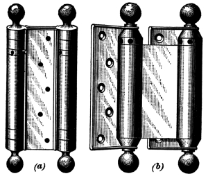
28. Double-Acting Hinges.—The double-acting hinge is
similar in construction to a single-acting hinge, except that it is
arranged so that the door can swing both ways. These hinges are
combined in one piece of hardware, as illustrated in Fig. 22.
Such hinges are much heavier and more costly than the single-acting hinge,
and they are generally used for entrance doors of hotels and public
buildings, and for doors between kitchen and pantry or dining room
in private residences, where a door that will swing both ways and
return to a closed position is desirable. The double-acting hinge is
usually subjected to excessive wear and strain. Care should therefore
be exercised in selecting this type of hinge; also, in determining the
size, it is better to have a hinge slightly larger than required rather
than one that is too small. While double-acting spring hinges made
of cast-iron may be obtained, those of the latest manufacture are of
steel. They may also be procured in brass or bronze, and of any desired
finish to match the fixtures and other hardware.
Fig. 22
Fig. 23
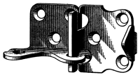
In Fig. 23 is shown another type of
double-acting spring hinge that is not so compact as those illustrated
in Fig. 22. This hinge, as shown, is operated
by a coil spring that fits into a rabbet formed in the two leaves of
the spring; thus, the coil is invisible when the door is closed, or in
its normal position. This hinge obtains a good purchase on the door and jamb.
29. Floor Hinges.—A device is made for hanging single- and
double-acting doors by means of pivots, or trunnions, placed at the top
or the bottom. The top pivot is usually inactive; that is, it has no
spring or other device, and is simply a trunnion, or pivot, with the
necessary plate to engage it fastened to the edge of the door trim. The
bottom piece of hardware, on the other hand, is arranged with a pivot
and a coil spring, and has various mechanisms for operating the door
positively and silently.
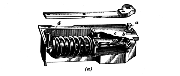
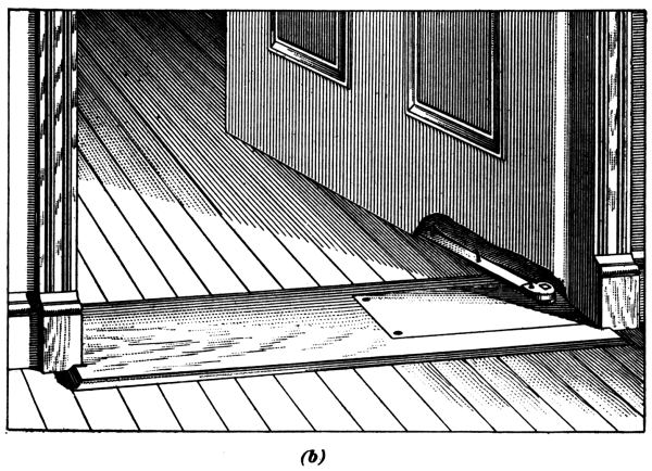
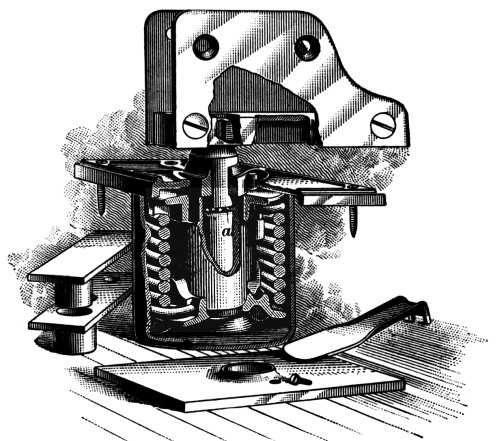
In Fig. 24 is illustrated a
single-acting, checking-spring hinge. This spring hinge is known
as the Bardsley, and its mechanism, which is enclosed in a
cast-iron box, is shown at (a). This box, or case, is set into
the floor, the top plate being made flush with the top of the floor, as
shown at (b). The operating bar, or pivot, of the hinge has a
square end, as shown at a, that engages with the plate secured
to the bottom edge of the door, and is connected to the mechanism by
means of a crank and connecting link, as at b. After being set
into the floor, the cast-iron box, or case, containing the spring,
piston cylinder, etc. is filled with oil or other non-freezing liquid,
and sealed by means of the top plate c. The action of the
door in opening compresses the spring and operates the piston in the
cylinder. The spring operating to close the door also moves the piston
and forces the oil in the cylinder out through a by-pass, the flow
being regulated by the adjusting screws d, which are on a level
with the top plate. In this manner, the door is closed surely but
gently, from which the hinge derives its name of checking-spring hinge.
Hinges of this type can be used without any modification of the door or
frame, but are not extensively used on account of their high price and
the cost of application.
Fig. 24
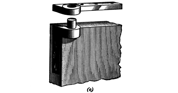
For pivoting the door at the top, there is provided a top pivot and
plate, as illustrated at (c). This pivot is applied to the edge
of the door stile. Both the top pivot and bottom hinge plates on the
door are offset.
Fig. 25
Double-acting floor hinges are rapidly displacing double-acting
spring hinges. This is due to the fact that when the former hinges
are employed the door is pivoted at the top and bottom and the weight
of the door is not carried by the coils of the spring, as in the
double-acting spring hinge. The floor type of double-acting hinge
carries the weight of the door on a ball bearing in the box, or case,
let into the floor, as shown at a, Fig. 25,
the coil performing only the function of closing the door. The
hinge illustrated is not only a double-acting hinge, but is also a
checking hinge, and for this reason is known as a double-acting,
checking-spring hinge. In operating, this spring hinge not only
closes the door, but prevents it, when closing, from oscillating after
the door has reached its neutral, or closed, position.
There are numerous double-acting floor hinges in the market that
are not of the checking type. Some of these are the Atlas
and Simplex, made by Bardsley, the Bommer, made by
Bommer Brothers, together with the Chicago, New Idea,
Matchless, Chief, and Columbia, made by various
manufacturers. All of these hinges embody practically the same
principle, but differ somewhat in mechanism.
30. Outside Blind and Shutter Hinges.—The outside shutter, or
blind, is still much used in the construction of dwelling houses, and
a great variety of hardware is made to use in conjunction with hanging
these devices. Only the most common of the many available types of this
kind of hardware, however, will be treated here.
The hinge illustrated in Fig. 26 may be
classed among the oldest types of shutter hinge. This hinge is made
of cast-iron and is formed with a gravity-locking device intended to
hold the shutter in position when opened against the building. It is
known as the Lull and Porter hinge, and is made in various sizes
that are designed to throw the shutter from 1½ to 6½ inches away from
the casing, so as to clear all obstructions consequent to the various
constructions. A sill catch must be used in conjunction with this
hinge, in order to hold the shutter in place when closed and to prevent
it from blowing open.
Fig. 26
Fig. 27
A similar type of hinge, known as the Clark hinge, is
illustrated in Fig. 27. This hinge is made of cast-iron,
and in three sizes, which are arranged to throw the blind 1¼, 3¼, or 4¼ inches
from the casing. The hinge with the largest throw is used on brick
buildings. With this hinge, as with the one just described, a sill
catch must be used to keep the shutter closed.
Fig. 28
In specifying cast-iron hinges of the types just considered, it is well
to mention that they shall be extra heavy, from the fact that there are
so many in the market of such light construction as to be practically
worthless.
A type of the gravity-locking hinge, which is better than the
cast-iron hinge, is illustrated in Fig. 28.
This hinge is made entirely of steel, and is known as the Stanley
gravity blind hinge. There is only one size of this hinge
manufactured, and it is used for frame buildings. All of the parts of
this hinge are interchangeable and reversible, so that it may be used
for either right- or left-hand blinds.
There is a wrought-steel hinge, known as the Stanley blind
hinge, which has not the gravity-locking device, but which obtains
a greater purchase on the shutter. This hinge is illustrated in Fig. 29;
the hinge shown at (a) is for frame buildings, while that
shown at (b) is arranged for brick walls.
Fig. 29
Another type of hinge made entirely of wrought steel, and known as the
New York blind hinge, is shown in Fig. 30.
This type of hinge has a long strap that extends on the top and the bottom rail of the
shutter and thus tends to prevent the blind from drooping. This strap
also strengthens the shutter by relieving the mortise and tenon of the
rail and stile from the strain. The New York blind hinges are made
in two styles. The hinge shown at (a) is intended for frame
buildings, while that at (b) is made with an offset to throw the
shutter clear of a brick jamb. These hinges are ordinarily used with
blind adjusters, or fasteners, and for very high blinds, a center, or
auxiliary, hinge is used.
Fig. 30
Fig. 31
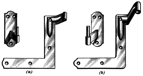
There is another type of strap hinge similar to those just described,
the butt of which consists of a pin and staple, as shown in Fig. 31.
This staple is secured by driving it into wooden blocking in the brick
joints. Hinges of this type are used extensively in localities where
brick buildings are numerous.
31. Inside Blind, or Shutter, Hinges.—The use of inside blinds,
or shutters, is general with the better class of domestic buildings,
and for hanging these shutters, three kinds of hinges are used,
depending on the number of folds in the shutter and the manner in which
they fold back on each other. Usually, the butt and the back
flap, as shown in Fig. 32 (a) and (b),
are used. Where the shutter has three folds, however, a knuckle butt, as
shown at (c), is employed. The purpose of the knuckle butt is to
cause the folds to take such relative positions as will enable them,
when open, to close properly into a pocket, or recess, formed in the
window frame.
Fig. 32.
Fig. 33
Fig. 34
Fig. 35
32. Invisible Butts, or Hinges.—A secret, or
invisible, hinge, known as the Soss hinge, has recently
been placed on the market. This hinge, which is illustrated in Fig. 33
(a), consists of a semicircular plate, which is attached rigidly
to the door section, and a movable semicircular plate on the jamb leaf,
which telescopes the section on the door in closing. These hinges are
invisible when the door is closed. The disadvantage in the use of
these hinges is due to the fact that they have only one wearing joint;
they are also somewhat complicated and expensive. As shown in Fig. 33
(b), they have no throw, or offset, and consequently the door
does not clear the baseboard, or trim, in opening. The larger size of
hinge has a throw of 1 inch, which is not ordinarily sufficient for
doors. These hinges, however, have their use for such mill work as
seats, secret jambs, drop, or folding, leaves, etc., and for this class
of work are the best in the market.
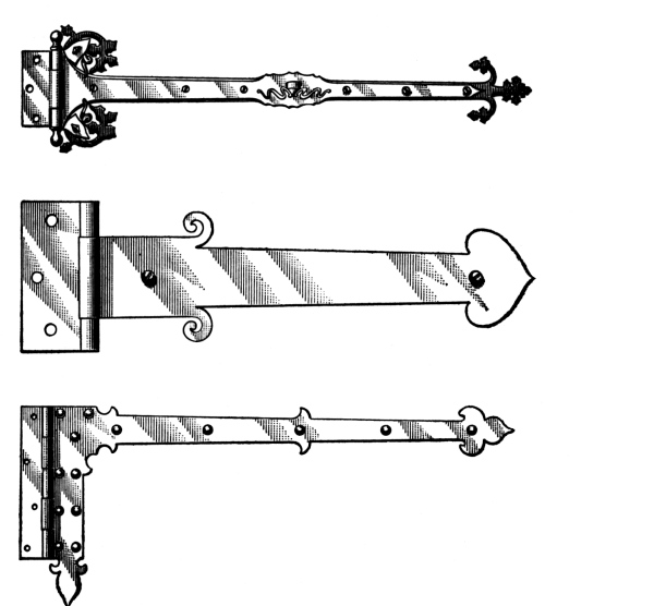
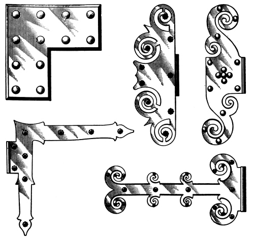
33. Strap and Corner Hinge Plates.—Medieval hardware was the
product of the blacksmith and the whitesmith, the former working with
forge and hammer, and the latter with chisel and file, the material
being wrought iron. The butt hinge was unknown, while the strap, or
surface, hinge was in universal use; and, as this was wholly in sight,
it naturally became the subject of decoration, chiefly in outline,
but occasionally in surface ornament also. With the adoption of the
butt hinge for general use, the opportunity of utilizing the hinge
to decorate the surface of the door disappeared, but with the modern
revival of decorative art the use of constructive metal work as a
feature of surface decoration for important doors was restored. This
was accomplished by combining with the modern butt a surface plate that
represents the strap hinge. Obviously, the width of the butt of a hinge
plate should correspond with the height of the butt hinge with which
it is to be used, and both should be of the same metal and finish. The
other dimensions are governed by the size of the door and by taste,
as is true also in the case of corner plates. A varied and artistic
selection of typical strap hinges and corner plates is given in the
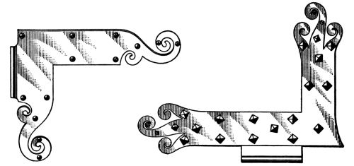
groups of designs shown in Figs. 34 and
35.
34. Locks in General.—In no other line of hardware is there
such a variety of grades and types as there is in door locks. In
general, locks may be designated as surface and mortise
locks, the former being secured to the surface of the door and
entirely exposed to view, while the latter are let into a mortise cut
in the edge of the stile. Besides these two general kinds of locks,
there are several special locks, which will be fully explained.
As to quality, locks may be classified in three grades; namely,
common, medium, and high grade.
Fig. 36
Fig. 37
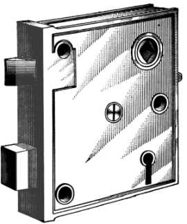
35. Common-Grade Rim and Mortise Locks. The rim lock,
as illustrated in Fig. 36, is generally used for buildings
of the cheapest class, such as tenements and small houses. As cheapness is
the controlling factor in such goods, especially the goods made for
speculative building purposes, the quality diminishes with the price.
For cheap work, rim locks are used on account of their low cost and
because they are easily applied. They also require no trim, such as
escutcheon plates, etc., and are complete when the spindle and the knob
are furnished with them. Rim locks are made in various sizes and either
square or rectangular in shape, the long dimension being placed either
horizontal or upright. They may also be obtained with either iron or
brass bolts, and are furnished with iron, tinned, or nickel-plated
keys. The cheapest grades of rim locks are made with two bolts and one
tumbler, while the better grades have an additional stop and a slide
bolt with three tumblers.
Rim locks are generally constructed of cast-iron, and in selecting
them, a careful inspection should be made of the internal mechanism,
choosing only those rim locks in which the bolts and the tumblers are
constructed of steel or brass. Rim locks, however, are also made of all
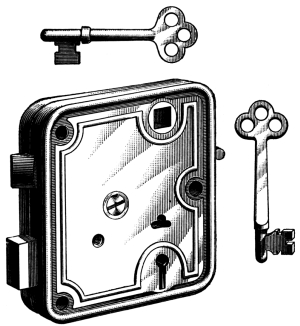
steel, and these are coming into general use. They present a somewhat
better appearance than cast-iron locks, as may be seen from Fig. 37.
The cast-iron rim lock may also be obtained with an ornamental case.
These cast-iron cases, as a rule, are finished in imitation of bronze.
Such rim locks, however, are not in general use on account of their
somewhat higher cost, and from the fact that their appearance is not
greatly improved by the ornamentation.
Fig. 38
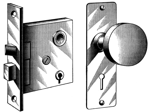
Cheap mortise locks, or sets, are also largely used
for the more common grades of work. They are sold in sets, that is,
with escutcheon plates, etc. of steel or cast-iron, both in plain and
ornamental designs, as illustrated in Fig. 38.
The cheapest lock sets are fitted with pottery knobs, and the better
grade, with metal knobs. All of these locks described are of poor
construction, as quality is a secondary consideration.
Fig. 39
36. Medium-Grade Mortise Locks.—The locks grouped under the
term “medium-grade” hardware have been greatly improved in recent years
and are adapted to a large range of uses, but they are especially made
for residence work. In dwellings of the better class, the best types of
rim locks are used for doors in attics and basements, and for closet
doors, but for all other doors, the medium-grade mortise locks
are used. These locks are provided with cast- or wrought-bronze lock
fronts, are made with from one to three lever tumblers, and have
drop-forge steel cases. The locks are constructed with easy springs,
which allow the latch bolt to retreat within the case on one light
spring when the door is closed, and when the knob is turned, to operate
the latch, both springs act jointly in order to overcome the friction
of the knob and to throw the bolt back to central position. The
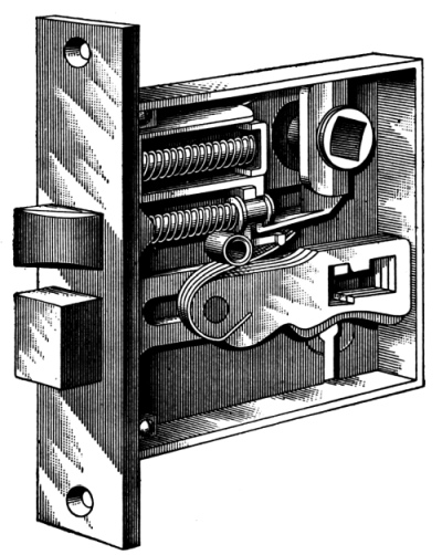
mechanism of an easy-spring, mortise knob lock is illustrated in Fig. 39.
Fig. 40
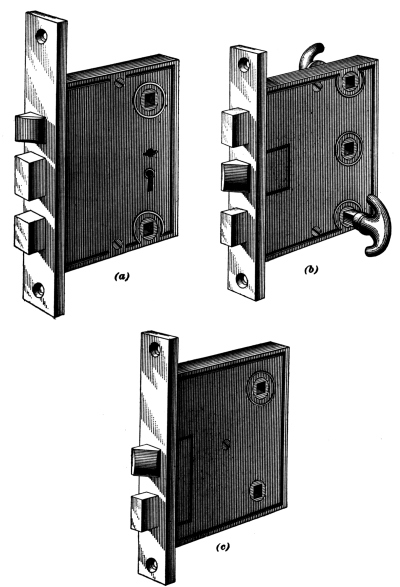
In the group of locks embodying those of medium quality are included
the three-bolt locks used for chamber and exterior doors, locks for
communicating doors between chambers, and twin, or two-bolt, locks
for twin bathroom or toilet-room doors, these being respectively
illustrated in Fig. 40 (a), (b), and (c).
All of these locks should be used with wrought- or cast-bronze trim, either
plain or in design, and in finishes to suit. Locks for exterior doors,
where security is important, should be selected with this object in
view, and three-tumbler, or three-bolt, locks should be used.
37. High-Grade Locks.—There are a number of high-grade door
locks and latches in the market for the equipment of first-class
buildings, and frequently these locks are especially constructed to
meet particular requirements. Among such locks are included, besides
high-grade, three-tumbler locks, those that embody the cylinder
principle and those that are equipped as master-key locks.
Fig. 41
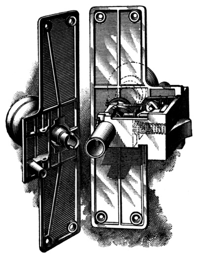
The unit-cylinder lock, illustrated in Fig. 41,
is made by P. & F. Corbin. This hardware specialty is a new departure in lock making.
The mechanism of the lock is contracted into the smallest possible
space, occupying only about 1½ in. × 3¼ in. Instead of being mortised
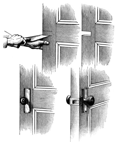
into the stile of the door, as is usual with the mortise lock, a piece
is cut entirely from the stile, as illustrated in Fig. 42.
In order to prevent this operation from weakening the stile of the door, the
unit-cylinder lock is provided with heavy escutcheon plates that are
strongly ribbed on the back, so that when these plates are secured to
the stile at the top and bottom, they supply the rigidity necessary to
make up for the notching. As the name implies, these locks are made in
a unit, and the keyhole to the cylinder lock is located in the knob.
The unit-cylinder lock is made in two styles—with dead-locking latch
bolt and with additional dead bolt.
Fig. 42
38. High-Grade Interior Door Locks.—In Fig. 43
is shown a type of high-grade, mortise-locking latch for interior doors.
These locks are of the heaviest construction, and are fitted with
either brass or bronze fronts. The bolts are operated with two or more
tumblers constructed on an improved pattern, and are of fine
workmanship. The trim for a lock of this character should be of the
very best grade, with knobs of the screwless-spindle type, which will
be explained later.
The escutcheons should be of the high-collar or the bracket-bearing
type, and should conform to the character of the locks in quality
and finish. On the most important work, it is always expedient and
usually feasible to obtain expert advice from manufacturers or from
dealers representing the manufacturer, whose intimate knowledge of
the product will be of great assistance to the architect or owner in
making suitable selections. The use of high-grade hardware requires
a considerable expenditure, and the necessity for expert advice consequently
becomes more imperative if the best results are to be obtained.
Fig. 43
39. Master-Key Locks.—The type of lock known as the
master-key lock is generally used for public or office
buildings, hotels, and occasionally in the better class of residence
work. These locks can be grouped into two classes; namely, the
Yale, or cylinder, and the lever-tumbler types,
the class first mentioned being the most desirable.
In the lever-tumbler type, illustrated in Fig. 39,
the tumblers, or wards, are so arranged that each lock can be operated only by
its particular key, the keys for all rooms being different and
non-changeable; all of the locks, however, can be operated by a key
made for the purpose, termed a master key. Each lock of this
type has two sets of tumblers; one set is operated by its individual
key, and the other, being uniform in all locks of the series, is acted
on by the master key. Such locks may be obtained either in the cheaper
kind, with one tumbler and twelve changes, or in the most intricate
styles of hotel locks, with five tumblers and 48,000 changes in one
set, and all operated by one master key. The cylinder lock
of this type is illustrated in Fig. 44,
which shows a Yale & Towne, mortise, front-door lock.
Fig. 44
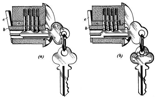
40. Details of the Yale Type of Master-Key Locks. The
Yale type of cylinder lock, which is illustrated in Fig. 45
(a) and (b), is much preferred, on account of the great
security it gives and the small key required by it. This lock is made
in three systems; namely, the regular, the concentric,
and the paracentric, or duplex.
In the regular system, one regular cylinder is controlled by
the change and master keys, the pin tumblers being cut in two places,
so that the change key brings one set of the abutting planes of the
tumbler in alinement with the surface of the cylindrical plug. This
plug is arranged so that a separate key is required to operate each
lock, the other line of cleavage through the blocks being the same with
all locks throughout the series, so that they may be opened with the
same key.
Fig. 45
Fig. 46
The concentric cylindrical arrangement of this type of lock is
shown in Fig. 46 (a) and (b). Here,
there is a larger cylinder encircling the key plug. This is known
as the master-ring, or larger, plug, and is indicated at a.
When the change key is inserted in the key plug b, the lower
series of breaks in the pins comes into alinement with the outer edge
of the plug, as shown at (a), and allows it to revolve in the
master ring, the cam on the inner side at c actuating the lock.
When the master key is inserted, the upper series of breaks comes
into alinement with the outer edge of the master ring, as shown at
(b), allowing the plug and the ring to rotate together with the
turning of the key, and thus to produce the same result as that caused
by the operation of the change key.
Fig. 47
The paracentric system, sometimes called the duplex
system, consists in having two separate cylinders to each lock, as
illustrated in Fig. 47. One of these cylinders, generally
the upper one, is operated by the change key, and the lower one, by the master
key. The interior construction of the lock is so devised that each
key performs the necessary function of operating the same bolt, so
that the individual lock may always be opened by the change key, and
all locks of the series by the master key. This latter system of lock
construction is more expensive than the one-cylinder type, but it
possesses an advantage in that it provides greater security when a
limited number of locks are grouped in one series.
41. Owners or officials of large office buildings and industrial
works now avail themselves of the master-key system just explained.
They are able to obtain mortise locks, rim locks, and padlocks,
all arranged to operate with a master key, in one series. In fine
residence work, this system is also adopted. Such a system of locking
is easily recognized as convenient, especially where subordinates
are held responsible for certain rooms or departments to which they,
individually, have access, as all of the rooms or departments may be
entered by the manager or superintendent by the aid of the master key.
A series of master-key locks may also be “submaster-keyed” by dividing
it into subordinate groups. In such a case, each group is operated by a
master key of its own, and all the subordinate groups are controlled by
a grand master key. For example, a six-story office building could be
furnished throughout with locks having non-changeable keys; the doors
of each floor could be operated separately by a master key; and the
doors of the entire building could be operated by a grand master key.
The convenience of such a system is readily apparent in large buildings
where each janitor is responsible for a certain floor, and where the
head janitor, manager, or owner, has control of all the locks through
the grand master key.
In some instances, for additional security and for special work,
the corrugations in the keyway are changed in shape so that the
manufacturers’ regular type of key will not enter the keyway, or plug,
thus allowing no chance for the regular type of key to operate the lock.
42. Locks for Residence Use.—The front-door lock is
distinctly a lock having two bolts; namely, a dead bolt and
a latch bolt. The latter is operated by the knob, and is so
arranged that, by means of stop-work in the lock front, the outer knob
may, at will, be set so as not to operate the latch, the latch bolt
being operated only from the outside by a key.
Fig. 48
The cylinder type of front-door lock illustrated in Fig. 44
is the best lock for this purpose, as it provides the greatest
security. This lock is operated by a convenient key of the Yale type,
which throws both latch and dead bolt with one insertion into the cylinder.
Three-tumbler, front-door locks and latches are to be had at a low
cost, and are used in the cheaper class of dwellings. When the
residence has an inner, or vestibule, door, a similar lock is used
without the dead bolt; this lock is termed a vestibule latch.
In all cases the vestibule lock should “key-lock” with the front-door
lock, so that one key will operate both. The other exterior doors of
a residence should have either Yale locks master-keyed to the front
door, for the better class of work, or locks of the 5-inch, three-bolt
variety, that are furnished with an extra bolt in addition to the dead
bolt, the third bolt being operated by a thumb knob on the inside. When
a cheaper trim is wanted, a 4-inch, two-bolt lock, supplemented by a
separate mortise or rim bolt, may be used.
For the first- or parlor-floor folding doors, 4- or 4½-inch,
two-bolt, mortise locks are ordinarily employed. Where the doors are
sliding, a 5½-inch, sliding-door lock with dead bolt and pull, or
handle, is provided. The pull, or handle, is operated, or thrown out,
when needed by pushing a button, or stop, in the lock. This special
type of sliding-door lock is illustrated in Fig. 48.
For bedroom doors, a lock similar to that used on the minor exterior
doors is usually employed. The lock for these doors may be either a
5-inch, three-bolt lock, or a 4-inch, two-bolt lock supplemented with a
mortise bolt. For communicating doors, it is best to use a three-bolt,
knob lock, the latch bolt of which is operated by the knob from either
side. Arranged above or below this latch bolt are two dead bolts, each
being operated by its respective thumb piece on opposite sides of the
door. Locks of this character are made for both swinging and sliding-doors.
43. Locks for Twin-Closet and Other Interior Doors.—Twin, or
double, doors are sometimes used between rooms in residences to deaden
sound or to increase privacy. Such doors should be fitted with the same
type of lock as other communicating doors, except that the lock should
be provided with two bolts, the same as the lock used for bathroom
doors. These locks are arranged with special trim on the abutting face
of each door, this trim having only a slight projection, and knobs
or lever handles projecting as little as possible, in order to avoid
interference on account of the limited space between the doors.
Bathroom doors are best fitted with a thumb bolt, either combined with
a lock or separate.
In fitting closet doors, it is best to use a two-bolt lock about 4
inches in size, with trim on both sides, so that the door may be
operated from inside in case it is accidentally closed on a person in
the closet. The possibility of this happening is slight, and usually a
saving is effected by using a knob latch without a dead bolt and a pair
of knobs with roses.
For basement or attic doors, a cheap type of mortise lock is
appropriate, or a rim lock may be used, if cost is a consideration.
Where care is exercised in the selection of locks in any one building,
great convenience will result from having all the different class
of locks about the building of the same grade, so that they may be
master-keyed in one set and thus give the owner control, with one key,
of all the locks. Each lock, however, will have its own individual, or
change, key, and should be selected and ordered with this object in
view. Another convenience may be had by ordering each room and closet
door keyed alike throughout the house, or alike throughout each floor,
so that the loss of a key will cause little or no inconvenience.
44. Hotel and Office Locks.—The purpose and use of master-keyed
locks has already been explained, but the employment of such locks
in large groups, as in the equipment of hotels and office buildings,
requires further discussion. The term corridor door designates
the entrance from a corridor or a hallway to a bedroom or an office,
while communicating doors are those between adjoining rooms.
Frequently, these doors are double, and are then known as twin doors,
while the term closet doors is self-explanatory. Each of
these doors requires a knob lock; that is, a lock having the
latch bolt operated by the knob and the dead bolt operated by a key.
Sometimes, in the case of locks on closet doors, the dead bolt on
communicating-door locks is omitted, and a thumb bolt substituted.
While all of the locks thus far enumerated are used in hotels, and
most of them in office buildings, technically speaking, a hotel
lock is a master-keyed knob lock for doors from the corridor to
bedrooms, while an office lock is an inverted lock; that is, a
lock with the keyhole above the knob. These latter locks are usually
master-keyed, especially for the doors from the corridor to the
office. Such locks as these may be master-keyed on any of the systems,
as previously explained. For office work, a small key is desirable,
so that cylinder locks are ordinarily employed, as the key for the
operation of such locks may be conveniently carried. For hotels,
however, a high-grade lever-tumbler lock with round, substantial keys
is desirable, because the keys are liable to hard usage, and should not
be convenient to carry in the pocket.
Hotel keys vary widely in arrangement, as well as in size, quality, and
price. The kind of action, or mechanism, to be adopted in a hotel lock
is frequently determined by the preference and experience of the hotel
manager, and it is desirable that he should be consulted in advance;
but the location and use of each door should be considered in the
selection of the locks for this character of building. It will thus be
seen that the subject of hardware for a hotel is one that requires the
most careful consideration of the architect.
The grouping of locks in a hotel should be studied, and, usually,
the best plan in large hotels is to group all of the locks on each
floor under one master key and to provide a different master key for
each floor, care being taken to limit the issue of master keys to the
smallest possible number of responsible persons. In some cases, a grand
master key is also provided that will open all the locks on every
floor. This arrangement of the locks entails an additional expense,
and also has the disadvantage that, in case the grand master key is
lost, all of the locks controlled by it should at once be set to a new
combination, in order to prevent access by the person into whose hands
the key has fallen. This procedure is both troublesome and expensive.
Fig. 49
The foregoing remarks relating to hotel locks apply equally to office
locks, especially as to the arrangement for the operation with the
master key. In other respects, however, the locks for an office
building differ considerably from those used in hotels, for a hotel
lock must secure the door both when the room is occupied and when it
is not, whereas an office lock is used chiefly to secure it when not
occupied. In consequence of this, certain differences in action are
employed. All office locks have a latch bolt that is operated by the
knob from both sides and yet permits free ingress and egress. Various
methods, however, are employed to lock the door against ingress except
by means of a key. Sometimes this is accomplished by means of a
separate dead bolt operated by a master key from either side; in other
cases it is accomplished by a latch bolt only, by providing the latter
with a stop-work like a front-door lock. By this arrangement, the outer
knob may be stopped so that the latch bolt cannot be operated from the
exterior except by the key; and, again, the latch bolt may be
dead-locked from the outside by the key. The choice of these
arrangements is a matter of personal preference.
45. Store-Door Trim.—The technical term store-door lock
originally designated a heavy rim or mortise dead lock, but is now
applied to a combined lock and latch, the former being operated by a
key from either side, and the latter by a thumb piece located above
the pull handle. Such locks are made in a large variety of sizes and
styles, the best being of the cylinder type, as shown in Fig. 49.
In this lock, the latch is operated by the thumb piece during the day,
while the dead latch secures the door at night.
Plates and handles for the combined store-door lock and latch are also
made in many sizes and styles, from the plain rectangular type to the
most ornamental forms. Such trim offers good opportunity for effective
decoration, and no embellishment is so effective for a store’s entrance
door as a pair of handsome plates and handles of appropriate design.
For such trim, it is not uncommon to provide an outlay of from $25
to $30 per door. Some of the more elaborate store-door handles are
illustrated in Figs. 50 and 51.
The trim illustrated in these plates is very carefully selected by the
architect to match the style of architecture in which the building is
designed, and the finish is selected with as much care.
46. Padlocks.—While padlocks are not ordinarily included
in builders’ hardware, they are extensively used for factories,
stables, and other buildings of this character; thus some care should
be taken in their selection. Padlocks are made in a great variety of
sizes, styles, and qualities, and retail at prices ranging from 10
cents, or less, to $5. Where these locks are exposed to moisture or
to the weather, they should be of bronze or of brass, with all of the
interior construction of the same material. If required for great
security, that is, for places where they are likely to be subjected
to violence, they should be very heavy, and preferably provided with
steel shackles. Padlocks constructed on the cylinder-lock principle
may be obtained, and should always be used where a series of locks
that are operated by separate keys and controlled by a master key is
employed. Ordinarily, a selection of padlocks should be made only after
an inspection of the actual samples, and not according to catalog
representations.
Fig. 50
Fig. 51
47. Cabinet Locks.—The locks used in cabinetwork are
distinct from builders’ locks, though they are occasionally used
in the construction of the finer classes of interior finish, and,
consequently, are of interest to the architect. Cabinet locks
are made chiefly of wrought metal, and in a vast variety of kinds,
sizes, and grades, so that care should be exercised in their selection.
The leading kind of cabinet locks are drawer, or till, locks; wardrobe,
or cupboard, locks; and chest, box, and desk locks. Special locks are
also manufactured for many other purposes. For the best work, the Yale,
or pin-tumbler, type is desirable where great security is required,
but for ordinary uses, other types, with either flat or round keys are
available. Many of the cabinet locks admit of being master-keyed, and
such locks are employed on lockers in club rooms, armories, etc.
Fig. 52
48. Asylum and Prison Locks.—For the doors of cells in insane
asylums, hospitals, and prisons, locks of special construction are
required. For this reason, a distinct class of hardware is manufactured
to meet the peculiar conditions that prevail. These locks, which are
designed primarily to prevent escape from the rooms, or cells, are
exceptionally exposed to attempts at tampering, and are especially
constructed to meet these conditions. There is an extensive line
of locks for these uses on the market. This line includes both the
Yale type and the lever-tumbler type of lock, and these locks are
constructed with both solid and barrel keys, thus affording a wide
range of selection. All such locks must be made so as to be controlled
by master keys.
In Fig. 52 are illustrated types of prison
or asylum locks. The lock shown at (a) is embedded, or built,
in the jamb, while that at (b) is secured to the door and the
keeper is fastened in the jamb.
Fig. 53
There are numerous other patterns of asylum and prison locks, such as
those illustrated in Fig. 53. The lock shown
at (a) is arranged to operate with a double-bitted key, while
the one at (b) is operated by means of a Yale key.
Nearly all modern locks for this purpose are operated with either
double-bitted or Yale keys, and those in common use are cylinder locks.
Information regarding these types of locks should be obtained in
advance, so that in preparing the plans and specifications, the type
selected may be clearly indicated and the arrangements made for any
special construction necessary to receive them. As the approved forms
of asylum or prison locks are built in the masonry during construction, they
must be delivered during the early stages of the erection of the building.
49. Bank and Safe Locks.—Locks for the doors of burglar-proof
and fireproof safes and vaults constitute a group distinct from
all others. These locks embody the most complicated mechanism, and
represent the highest art of modern lock making. The architect
in preparing plans of buildings for banks and trust companies is
frequently called on to approve or to specify the fastenings for
vault and safe doors. While the owners of such buildings will
probably predetermine the kind of lock to be employed, nevertheless
they will be guided by the advice of the architect in the selection
of some particular make. The locks used on such vaults and safes
comprise time, or chronometer, locks; dial, or
combination, locks; and safe-deposit and subtreasury
locks. There is also a device known as a bolt-motor, or
automatic lock, which is an allied product. In the manufacture
of these special locks, the skill of numerous experts and specialists
is required, and as their knowledge is at the disposal of the architect
or the engineer, they should be consulted in the selection of such
important pieces of mechanism.
Fig. 54
The time lock is illustrated in Fig. 54,
and is a locking device actuated by clockwork. This type of lock is
used in connection with the heavy boltwork of a safe door, to prevent
it from unlocking except during certain hours determined beforehand.
This lock is now recognized as an essential part of the equipment
of all first-class, burglar-proof vaults and safes. In its standard
form, the time lock has three chronometer movements of the finest
construction, each of which is competent to actuate the lock, so that,
in this way, almost absolute reliability is insured.
Fig. 55
A dial, or combination, lock is shown in Fig. 55.
The combination commonly called the dial lock has completely
superseded the key lock for use on safe and vault doors. Essentially,
the dial lock consists of a bolting mechanism guarded by a set of
changeable tumblers, or wheels. These tumblers are actuated by a
spindle passing through the door, this spindle being provided on
the outer end with a graduated dial. By rotating the dial in a
certain manner, the dial can be set and the lock operated. Dial, or
combination, locks are made in two grades, or varieties, designed
respectively for burglar-proof and for fireproof safes. The lock
intended for burglar-proof purposes is heavy and made to resist
violence, while the other locks are smaller, simpler, and cheaper,
intended only to secure the door against ordinary intrusion. Both of
these locks should be absolutely “non-pickable.”
In connection with the time lock, an automatic bolt-operating device is
now used on burglar-proof safes. The bolt-motor is a mechanism
containing heavy springs and is attached to the inside of a safe door.
These springs are set, or braced, while the door is closed, and when
released by the action of the time lock are capable of automatically
retracting the heavy boltwork of the door. This construction obviates
the necessity of any spindle through the door, and leaves the surface
absolutely unbroken, without any communication between the interior and
exterior.
Fig. 56
A form of safe-deposit lock is illustrated in Fig. 56.
This lock is of a new type, and is intended expressly for individual
safes, or boxes, rented by the safe-deposit companies. Such locks
are nearly always provided with a guard key, which is in charge of a
custodian and common to all the locks in the series. Each lock has
its own individual, or change, key, however, which differs from every
other key in the series. Before a change key can be inserted into its
lock, the guard mechanism must be unlocked by the guard key in charge
of the custodian. This makes the presence of the latter a necessary
preliminary to the unlocking of the box by the renter or his authorized
agent. Many styles and sizes of safe-deposit locks are made to meet
varying conditions, the lock probably most used being the Yale, or
pin-tumbler, variety, in which additional security is obtained by using
keys of special proprietary forms. For safe-deposit boxes of large
size, the dial lock is often used.
Subtreasury locks are intended for use on the small safety
chests, or “subtreasuries,” often placed within a fireproof safe.
These locks, which are illustrated in Fig. 57,
are of various types and sizes, and are suitable for use on metal doors
of all kinds.
Fig. 57
50. Care and Maintenance of Locks.—Locks, like other pieces
of mechanism, need reasonable care and attention to keep them in the
best condition. As they contain moving parts, they are subjected to
frictional wear and need occasional lubrication. Most of the friction,
and consequently the wear, occurs in the beveled latch bolt, which
may be readily lubricated. If the latch bolt is troublesome, its face
and back should be cleaned with a cloth moistened with naphtha or
kerosene, to remove any dirt. These surfaces should then be wiped with
another cloth saturated with machine oil or, better, with vaseline. Any
person can perform this simple work, and if it is done once or twice
a year, it will keep the bolts in such condition that each door will
close easily and quietly at all times. Another cause of trouble is the
tendency of the old-fashioned knob screw to become loose, thus allowing
the knob to pull from the spindle. Where such spindles are used, it
is a good plan to inspect them occasionally and to tighten any loose
screws. The best results from lock hardware, however, can be obtained by
having all locks and hardware inspected by a lock expert about once a year.
51. Pottery Knobs.—Door knobs, which are important
appurtenances to locks and latches, are made of many kinds of
materials, and are fastened to the spindle in several ways. It is
necessary, in order to make the proper selection of knobs for doors,
to be thoroughly conversant with the various types on the market.
The cheapest type of door knob is molded from several kinds of clay.
These pottery knobs are secured to iron or bronze shanks by
leading; that is, by setting them in molten lead, which, in
hardening, secures the knob to the shank.
Fig. 58
Pottery knobs are made in three styles, namely, mineral,
jet, and porcelain. Mineral knobs are dark brown in
color, while jet and porcelain knobs are, respectively, jet black and
pure white. All of these knobs are highly glazed, and are used only
with the cheapest grades of locks. Ordinarily, they are furnished with
japanned mountings, or shank and rose; occasionally, however, they may
be had with bronze-plated, real bronze, or brass mountings. The several
styles of porcelain knobs are illustrated in Fig. 58.
At (a) is shown the mineral knob, while at (b) and (c)
are shown the porcelain and jet kinds.
52. Wooden Knobs.—Knobs made of wood are quite generally used.
They are always turned from some hardwood, and are either stained
or finished naturally. The wooden knob is usually forced on the shank
by hydraulic pressure, and when securely fastened in this way makes
a desirable and cheap knob. Many of the cheaper wooden knobs on the
market are only glued or cemented to the shank, and, consequently, are
not durable, as they pull off; they are therefore entirely undesirable.
The mountings for the better knobs are made of iron, brass, or bronze,
though they may be had with wooden roses. Mountings of wood, however,
should not be used, as any severe side strain on the knob will split
the rose with the grain of the wood. In Fig. 59
are shown two wooden knobs, the one at (a) having a metal rose,
and the one at (b) a wooden rose.
53. Cast-Iron Knobs. Cheap locks are usually provided with knobs
made of cast-iron, and, although they are strong and serviceable, they
are seldom attractive. For finishing knobs of this kind, a bronze
metal plating is usually employed. Cast-iron knobs are frequently made
ornamental instead of plain. A typical cast-iron knob and rose are
shown in Fig. 60.
Fig. 59
Fig. 60
54. Stamped and Spun-Metal Knobs.—Knobs made of sheet metal
have lately come into extensive use, and they may be obtained in a
large variety of designs and forms. Plain and ornamental steel knobs
are illustrated in Fig. 61. Knobs ornamented
in any style of design are in the market, and are artistic and usually
well modeled.
Fig. 61
55. Bronze or Brass Knobs.—Knobs of bronze or brass are always
used in buildings of the better class, and all ornamental knobs of the
higher grade are made of these materials. The best knobs are usually
solid; that is, cast in one piece, with the exception that the shank
is inserted. Others are made in composite form, consisting of a steel
interior shell, or frame, over which is tightly drawn an external
section, or covering, of wrought-bronze or brass of substantial
thickness. The completed knob, if properly made in this manner, is
practically as strong as the hollow-cast knob and resists bruising or
other injury.
56. Glass Knobs.—The most expensive knobs made are those of cut
glass with metal mountings. Several knobs of this kind are illustrated
in Fig. 62. Cut-glass or crystal-glass knobs
are very costly, the price depending on the style and the amount of
cutting required and on the grade of glass used. The new method of
mounting glass knobs allows for adjusting the knobs to doors of varying
thicknesses, and also gives the knobs a handsome appearance, making
them both durable and reliable.
57. Styles and Sizes of Knobs.—The pottery knobs, such as the
mineral, jet, and porcelain knobs, are made only in spheroidal and oval
shapes. The spheroidal knobs are 2¼ inches in diameter, and the oval
knobs 2½ in. × 1¾ in.
Cast-iron and stamped-steel knobs are made spheroidal and of the box
pattern, with plain and molded edges, both styles of knobs being about
2¼ inches in diameter.
Bronze and brass knobs are usually spheroidal or ball-shaped, and are
2¼ and 2½ inches in diameter. They are also made oval and egg-shaped,
these latter styles being provided in two sizes, namely, 3 in. × 2 in.
and 2½ in. × 1¾ in. The same general dimensions obtain for wooden and
glass knobs.
Fig. 62
58. Lock Spindles.—In supplying a pair of knobs, there is
always included with them the spindle, which connects them and
passes through the hub of the lock. The type of spindle generally used
is the common, or side-screw, spindle, which is
shown in Fig. 63. In this spindle, the knobs
are secured by means of a knob screw passing through a hole in the knob
and engaging with one of the threaded holes in the spindle. There are
several holes in the spindle, so that the distance the knobs are apart
may be adjusted properly. Should further adjustment be required, it is
accomplished by placing thin washers at the end of the knob shank. This
type of spindle is generally used with the cheap grades of trim, and
should not be used in high-grade work.
Fig. 63
There is a modern type of lock spindle, known as the “screwless”
spindle, that permits the proper adjustment of the knobs without
the use of washers and with less screws. These spindles overcome the
general looseness and rattle found in the common type. A “screwless”
spindle, known as the Triplex, is illustrated in Fig. 64.
This spindle is a first-class device, and is constructed, as shown, of three
parallel parts, triangular in section, which, together, form a square
bar. To fasten the knob on this spindle, a setscrew in the knob bears
on the center bar, and owing to their wedge form, the two side bars are
forced apart and into frictional engagement with the spindle of the
knob. The spindle itself is screwless, and there is nothing tending to
loosen the setscrew, so that when once properly tightened, the knob
will remain firm and in position on the spindle under all conditions
of use. In some instances, this style of spindle has been condemned by
owners and architects. This has been due largely to the fact that the
mechanic did not set the screw tight against the spindle, thus allowing
the knob to be easily pulled off. This is often caused by not using a
screwdriver that exactly fits the head of the screw. When the knobs
are put in place as they should be, this device always gives entire
satisfaction.
Fig. 64
Fig. 65
There is another, though somewhat costly, type in the market, known as
the wrench spindle. This spindle is illustrated in Fig. 65.
As shown, the mechanism consists of a chuck, or vise-like arrangement,
formed on the knob shank. When the nut a is screwed on the jaws
b, the tendency is to grip the spindle securely, the latter
being solid and without screw holes. This type of spindle allows
perfect adjustment.
Another type of knob spindle is the swivel spindle. This is
used with front, vestibule, and other door locks that have stop-work,
whereby the outside knob may be made operative or not, as desired. In
order to accomplish this, the spindle is divided longitudinally, so
that one end may rotate independently of the other.
The standard sizes of spindles for door locks, etc. are ₅/₁₆ and ⅜ inch
square. Occasionally, spindles as large as ½ inch square are used for
large knobs or handles, such as would be used with massive lock trim.
For thumb knobs and locks and latches of this character, spindles ¼
inch square are employed.
59. Key Tags for Hotel Use.—Considerable confusion is
frequently created by hotel guests taking with them on departure
the key to their rooms. Formerly, hotel managers sought to prevent
this practice by attaching to each key a large tag of iron or
brass, generally serrated on the edges and made so cumbersome as to
practically preclude its being carried in the pocket. Subsequently,
tags made of red fiber of large size became popular. The usual forms
of these large tags, whether of brass or fiber, are illustrated in
Fig. 66. The use of key tags, however, is
gradually being superseded by having the name of the hotel and number
of the room stamped plainly on the key bow, the stamped name of the
house serving for its quick identification and return by mail. The
latest and best development in this detail consists in attaching to
the key bow, by means of a short chain, either an ornamental disk
bearing the name of the hotel and the number of the room, or a small
ball, the name and key number still being retained on the key bow. In
either case, the short pendant serves for convenience in the use of the
key, diminishes the danger of misplacing it, and, if well designed,
contributes to its appearance.
Fig. 66
WINDOW SASH HARDWARE — SASH TRIM FOR DOUBLE-HUNG WINDOWS — TRIMMINGS FOR PIVOTED AND CASEMENT SASH
60. Sash Pulleys.—The pulleys for the counterbalancing of
double-hung, or sliding, windows, while apparently unimportant pieces
of hardware, are worthy of much consideration in their selection, and
in the preparation of the specifications care should be exercised to
provide the best pulley consistent with the character of the work. It
is good practice to furnish the millmen with a sample of the pulleys
that are to be used, so that the frame will be properly mortised to
receive them when the sash are hung. By this method, the necessity of
exposing the case to
the weather during the erection of the structure
is obviated.
Fig. 67
The common grades of sash pulleys are rough and cheap, and may be used
for unimportant work and light sashes. For heavier sashes and important
work, however, a better grade of larger and heavier construction should
be used. It is important in specifying sash pulleys to stipulate the
size of the pulley and to specify the diameter of the axle; also to
state whether brass or bronze wheels and bronze faces are desired.
Pulleys are supplied in 1¾-, 2-, 2¼-, 2½-, and 3-inch diameters. The
required diameter of the pulley is determined by the thickness of the pulley
stile and the diameter of the sash weight required to balance the sash.
Fig. 68
Fig. 69
The cases in which the pulleys are mounted in the cheaper grades
are made of cast-iron, while in the better grades they are made of
stamped metal. High-grade pulleys constructed of stamped metal are
also provided; these are put together either by riveting the two
faces of the pulley or by electrically welding them. The construction
of a built-up steel pulley is illustrated in Fig. 67.
The cases enclosing the pulleys are made of cast-iron, as illustrated in
Fig. 68 (a), or they are constructed of stamped metal,
as shown at (b). The ends of the facing of the case are made square,
rounded, or auger-shaped, and are finished either rough, polished, or
lacquered, or are faced with brass or bronze of any finish desired. The
pulleys illustrated in Fig. 69 (a) are so constructed
that the mortise in the frame may be readily formed by a special boring machine
carrying three or four bits. This machine bores holes of a size to fit
the several cylindrical portions of the stamped-metal case, as at a,
a, a diagram of the mortising in the frame being illustrated at
(b).
Fig. 70
The better grades of pulleys may be procured with semi-steel, brass,
or bronze wheels, and with plain axles or with ball or roller bearings.
In the cheaper grades of sash pulleys, the axles are formed of common
wire, while in the better grades they are made of either steel or gun
metal ⅜ inch in diameter. In the best pulleys, the wheels are turned, to
insure smoothness of motion, and are made with grooves for cord,
ribbon, or chain. All steel pulleys built up as illustrated in Fig. 67
are of recent invention; they run smoothly, and are very easily
applied. These pulleys are also made with ball or roller bearings, and
may be obtained at a reasonable price.
Fig. 71
There is a special type of sash pulleys that may be used for twin
and triple windows, where it is necessary to form a narrow mullion
between the windows. This pulley is known as the Grant overhead sash
pulley, and is used as illustrated in Fig. 70.
At (a) is a twin-window arrangement, showing the sash on the
two sides double-hung, each sash being counterbalanced by means of
one counterweight. By this means, the frame mullion between the two
sashes can be made as narrow as 2 inches, which is an advantage where
the maximum amount of daylight opening is desired. Frequently, in
triple windows, the center sash, as well as the two side sashes, is
made double-hung. In such a case, the arrangement of the overhead
pulleys would be as shown in Fig. 70 (b).
These pulleys provide a convenient means for arranging double-hung
windows of this type, but sufficient room must be left in the head of
the window to allow for the insertion of this pulley and the travel
of the sash counterweights. The construction of this type of overhead
pulley with roller bearings is shown in Fig. 71.
61. Determination of Size of Sash or Frame Pulleys.—The
architect’s specifications should stipulate the diameter of the
sash pulleys to be used in the work, and this item requires careful
consideration. Where care is not exercised in this regard, either the
pulleys will be so small that the weight will rub against the pulley
stile, or they will be so large that the weight will rub the jamb
casing on the opposite side of the pocket. Standard sash pulleys are
made in sizes from 1¾ to 3 inches in diameter, varying by quarter
inches. In determining the diameter of the pulley required for a
particular window frame, a good rule is to multiply the thickness of
the pulley stile by 2.25; thus, a ⅞-inch stile would require a 2-inch
pulley; a 1⅛-inch stile, a 2½-inch pulley; and a 1⅜-inch stile, a
3-inch pulley. It is best to specify that pulleys for metallic frames
shall be of the larger size, namely, 3 inches in diameter; and also
that these pulleys shall have ⅜-inch axles.
62. Sash Cords and Chains.—The sash cords by which the
sashes are attached to the counterweights in double-hung windows are
usually furnished by the carpenter, and are so specified. However, they
may be specified under hardware. The specification for the sash cord
should state both the size and the maker’s name, and for good standard
work Sansom Spot or Silver Lake sash cords are the best
that can be procured. Table VI will be found convenient
in determining the diameter of the cord and the consequent size by number,
as well as the size of the sash pulley.
TABLE VI
STANDARD SIZE OF SASH CORD FOR PULLEYS
Size No.
Diameter of Cord Inch
Average Weight per Dozen Hanks Pounds
Average Number of Feet per Pound
Heaviest Weight to Be Used Pounds
Smallest Pulley to Be Used Inches
6
³/₁₆
18
66
5
1½
7
⁷/₃₂
22
55
15
1¾
8
¼
27
44
25
2
9
⁹/₃₂
33
36
35
2¼
10
⁵/₁₆
44
27
45
2½
12
⅜
60
20
55
3
Sash chains are made in the form illustrated in Fig. 72,
and may be had either in steel, red metal, or bronze. The sash chains in
the market are usually made in four sizes, being numbered from 0 to 3.
The makers, however, have no agreement regarding these standards, so
that the numbering is not uniform; one manufacturer’s No. 0 chain may
be his heaviest make, while a chain of the same number furnished by
another maker may be the lightest chain that he manufactures. In order
to provide against this discrepancy when specifying, it is well to name
the maker of the chain. The lightest sash chain will support sashes
weighing from 40 to 75 pounds, while the heaviest will carry sashes
that weigh from 150 to 250 pounds.
Fig. 72
Fig. 73
63. Sash Balances.—By the use of sash balances, one of
which is shown in Fig. 73, there is no necessity for weight
boxes, counterweights, etc. The contrivance illustrated has been manufactured
for many years, and the original intention was to have it displace
the sash pulley, cord, and weight for double-hung windows. Installing
spring sash pulleys costs more than the older method of hanging by
means of counterweights. They are constructed with a long, spiral
spring enclosed by a drum, on which the tape a, Fig. 73,
winds and thus raises the sash. The coil spring in this balance is made of
either light or heavy material, according to the weight of the sash it
is intended to counterbalance. They are seldom used, however, except
where there is insufficient room for sash weights. The steel tape is
liable to be twisted and broken by jarring in operating the sash, and
for general use it has been found that the most positive action is
secured by pulleys and weights.
64. Weight of Sash and Glass.—In estimating the weight of
window sash, in order that the size of the counterweights or of the
spring counterbalance may be determined, the weight of the glass
per square foot may be taken as follows: Plate glass, 3½ pounds;
double-thick glass, 1½ pounds; and single-thick glass, 1 pound. To find
the weight of the wooden sash, add together the height and the width of
the sash, in feet, and multiply by 2.1 for 2¼-inch sash, by 1.67 for
1¾-inch sash, and by 1.33 for 1⅜-inch sash. The several sizes of sash
given indicate the thickness of the sash frame. While these data for
determining the weight of sash are not exact, they are sufficiently
accurate to fix the size of the sash cords and pulleys and to estimate
the weight required to counterbalance them. The best practice in
counterbalance sashes, however, is to weigh the sash after it has been
glazed; in this manner the exact weight and size of the counterweights
required can be determined. The approximate weights of ordinary glazed
sash are usually given in the catalogs of manufacturers of sash
weights, pulleys, etc., and will be found convenient in determining the
approximate weight of sash weights without making the calculations just
described when estimating.
65. Sash Locks, or Fasts.—There are many different makes of
sash locks for double-hung sash in the market. In Fig. 74
are shown several of the older type of sash locks that have been
used extensively. The lock shown at (a) is known as the
Champion; that at (b), as the Ives, and that
at (c), as the Boston. This type of sash lock, the
construction of which is apparent from the illustration, has given
satisfaction for a number of years.
Fig. 74
Fig. 75
Fig. 76
A newer type of sash lock is that illustrated in Figs. 75
and 76. In Fig. 75
is shown a sash lock known as the Fitch. This lock is
made by several manufacturers, and can be procured in all finishes of
iron for the cheaper class of buildings, and also in bronze metal for
high-class work. It is composed of a helical cam, which is fastened
to the top of the meeting rail of the lower sash and engages with a
hook, or lug, that is secured to the bottom of the upper sash. The
operation of this fastener is rapid, and the rotary movement draws the
two sashes together horizontally and forces them in opposite directions
vertically. In this way, it holds the sash fast and prevents rattling
and air leaks. It also has an advantage in that it cannot be moved
by inserting a knife blade between the sashes from the outside. The
Yale screw sash fast illustrated in Fig. 76 is an
excellent piece of hardware. It accomplishes the same results as the Fitch lock;
namely, drawing the sash together by the tightening of a thumb nut on
a fine-pitched screw. This nut operates against a semicircular-shaped
upright hook, or lug, on the lower sash, thus developing great pressure
in the desired direction. While this sash fastener takes somewhat
longer to operate than the Fitch, it repays by providing greater security.
66. Sash Lifts.—While sash lifts are not required for
the cheapest work, as the window can be raised by pushing against the
parting rail or against the mullions, nevertheless they are made to
sell at such reasonable prices that it would seem advisable to place
them on the lower sash of all buildings, no matter how unimportant.
Fig. 77
Fig. 78
Fig. 79
The common type of sash lift illustrated in Fig. 77
is known as the hook sash lift. This lift is extensively used, and can be
procured in any grade or weight, in either cast-iron, steel, or bronze
metal, and in any finish desired.
The flush sash lift, the general type of which is shown in Fig. 78,
makes a better appearance than the hook lift, and is considerably
stronger, from the fact that the casing forming the grip is let into
the lower rail of the sash, and the strain is taken by this, rather
than by the screws. These lifts are made in either steel or bronze, and
in all finishes; they can also be had ornamented to correspond with the
lock trim.
For heavy sashes, such as those in public and commercial buildings, the
bar sash lift illustrated in Fig. 79
is the best. This type of lift should always be used for heavy sash. A
sash lift similar to the type shown at (a) is sometimes fastened
to the under side of the meeting rail of the upper sash for the purpose
of lowering the sash.
Fig. 80
Fig. 81
67. Sash Sockets and Pole Hooks.—In buildings having high
ceilings, where the top sash is some distance from the floor, as
is likely to occur in institutions, schools, and factories, it is
necessary to provide “pull-down” poles for the purpose of raising and
lowering the upper sash. The hooks used on the ends of such poles,
which are made of some tough wood, are as illustrated in Fig. 80.
Unless the upper sash is furnished with metal plates that have a hole,
or aperture, the pole will be used against the mullion or upper rail
of the window sash and thus mar the woodwork. The plates, or metal
sockets, to engage the sash and pull-down poles, are illustrated in
Fig. 81. They may be had in all metals and finishes and in several sizes.
Fig. 82
68. Stop-Screws.—The stop-bead screws, or
washers, or, as they are more commonly known, the
window-stop, or bead, adjusters, types of which are
illustrated in Figs. 82 and 83,
are necessary hardware adjuncts to the window trim for buildings of the
better class. In ordinary work, these stops are secured to the frame
by nailing, but when they are fastened in this manner, the stop-beads
are disfigured if it is necessary to remove them. A cheap and good way
of fastening these stop-beads is to use ordinary round-headed screws.
While these adjusters answer the purpose very well, they do not allow
for the adjustment of the stop-bead sidewise, so as to take up any
shrinkage that might occur in the sash and prevent it from rattling, as
well as making it air-tight.
Fig. 83
To overcome this deficiency, a surface washer, as illustrated in
Fig. 82, was originated. The surface washer
was ordinarily made about ⅝ inch in diameter, and was provided with one
large hole about ⅜ inch in diameter or with two smaller holes placed
side by side horizontally across the stop. By this means, the proper
adjusting of the stop-bead was provided for, the washer covering the
opening, or hole, through the stop. However, the defect in this method
consisted in the marring of the finished stop when adjustment was
required, for the washer left its imprint on the woodwork, and, when
shifted, this would show.
The best form of stop-bead washer is illustrated in Fig. 83,
and is known as the Taplin adjusting screw and countersunk cup
washer. This device is composed of a sunken, or cup, washer with a
slotted or horizontal hole in its base frame, so as to allow about a
³/₁₆-inch adjustment. This adjustment, as can be clearly seen from the
figure, is made without marring, or disfiguring, the stop-bead in any
way. These countersunk washers may be had in bronze or steel, those
made of steel being finished to match the hardware, as desired.
Fig. 84
69. Sash Centers.—When a transom sash is hung at the top or the
bottom, regular hinge butts may be used; but where a sash is pivoted
at the center, either on the sides or at the top and bottom, a pivoted
arrangement, termed a sash center, is needed. For large sash or
heavy transoms, and especially for those that are exterior sash, the
rabbeted center should be used. This type of center is illustrated in
Fig. 84; its construction gives great strength
and completely closes the joint against light and water.
An excellent type of center, known as the Howarth sash center,
is illustrated in Fig. 85, the method by which it is
attached to the frame and sash being clearly indicated. By this arrangement,
the two parts of the center fold, or butt, against each other and form a tight
joint, the stop-bead for the sash at the top and bottom being arranged
as indicated at a a.
Fig. 85
There is a sash center, known as the Tabor, that is constructed
as shown in Fig. 86. This center is used for very large
sash that are vertically pivoted; that is, arranged with a center at the top and
bottom. Such sash as these are used extensively in office buildings,
because, by their use, the entire window may be thrown open at one
time. The Tabor device consists of a special sub-sill, which engages
with a ribbed joint strip placed on the bottom of the sash. By this
means, a weather-tight joint is secured, and the sash is firmly
locked in a closed position. By throwing a lever, the sash is raised
above the astragal, or sub-sill, and can then be operated. The top
rail is supplied with a filling strip having an irregular joint at
the intersection with the sash, and is held firmly by a coil spring
encircling the top pivot.
In Fig. 87 are shown several sash centers of the common
type. These possess no particular merit, but are much used for common work.
Fig. 86
Fig. 87
70. Transom Lifts.—The transom lift illustrated in Fig. 88
is distinctly an American device for operating and fastening the
transom lights over doors. This device is used extensively in hotel and
office buildings. It is made in various styles and sizes necessary to
meet the several requirements. The transom lift consists of a vertical
sliding rod that is placed on the door jambs, as at a, with an
arm at the top connecting it with the sash, as at b. Near the
bottom is a clamp, or grip, that holds the bar a in any desired
position. By a vertical movement of the rod, the sash is caused to
swing. Transom lifts may be had for transom sashes that are pivoted at
the center or for those which are hinged at the top or the bottom. At
(a) and (b) in Fig. 88 are shown the types
of transom lifts for center-pivoted sash; the former arranged so that the sash
pitches outwards, while in the latter the sash pitches inwards. At
(c), the device is shown where the sash is hinged at the top,
while at (d) the sash is hinged at the bottom. The several kinds
of transom lifts made by the various manufacturers are practically
alike, except for variations in the form of the grip, or clamp. The
range of sizes and quality of transom lifts is large. The commercial
article may be obtained in steel, copper or bronze plated, or in bronze
or brass. They are made in ¼-, ⁵/₁₆-, ⅜-, and ½-inch sizes, the size
being determined by the weight of the sash and the degree of rigidity
and solidity desired to be obtained and expressed. For good work, the
⅜" and ½" diameters are used. The rods may be obtained in lengths of
from 3 to 12 feet. In specifying or ordering transom lifts, the rod
should always be sufficiently long to reach within 5 feet of the floor.
Fig. 88
Fig. 89
71. Transom Catches.—In Fig. 89 are illustrated
types of transom spring catches, or bolts. These devices are
provided in the several forms shown to meet various conditions. Those
shown at (a), (b), and (c) have a ring, or eye, in
the handle, to which an operating cord may be suspended, or into which
a pull-down hook may be inserted, to operate the sash. The transom
catch at (d) is made expressly for operation by means of a
pull-down hook. In very wide windows, for the purpose of limiting the
opening of the sash, these catches should be used in conjunction with
chains instead of with transom lifts.
72. Transom Chains.—In Fig. 90 are illustrated
several types of transom chains. The chains shown at (a) and (b)
are suitable for sashes weighing not more than 25 pounds, while that at
(c) is sufficiently strong for sashes weighing over 25 pounds.
These chains are fastened to cleats furnished with countersunk screw
holes for securing readily to the frame and sash. When the sash is
hinged at the bottom, these chains are used to limit the opening of the
sash. They are sometimes employed as an additional guard, to prevent
the sash from falling in case the sash lifter becomes broken. The
ordinary lengths of sash chains range from 8 to 24 inches, the latter
length being sufficient for the opening of the largest sash.
Fig. 90
73. Casement Trim.—The term casement applies properly to
any hinged sash. It is, however, usually limited to windows that have a
sill set some distance above the floor. Where the casement sash extends
to the floor, the term French window is generally applied,
although frequently the terms are confused. In designing casement
windows, the details of the hardware should be such that the casements
can be made weather-tight; and in laying out the full-sized details for
the mill work for a casement sash and frame, the available hardware
should be studied, so that the woodwork may be arranged to conform to it.
74. Casement Bolts and Fasts.—Casement sash may be provided
with any good form of top and bottom bolts or hinged sash fasteners,
but these should be supplemented by a good latch or cupboard catch
at the center. Special turnbuckles, or casement fasts,
constructed as shown in Fig. 91, are on the
market. All of the catches shown will securely fasten the sash, but the
types shown at (a) and (d), Fig. 91,
will draw the sash tightly against the frame when the buckle, or fast,
is drawn in place. In countries where casement sash are in general
use, the necessary fastenings, including the top and bottom bolts, are
embodied in one structure, as described in the following article.
Fig. 91
75. Cremorne Bolts.—In the best work, the Cremorne bolt
is used for casement windows. This device consists of a vertical
rod divided at or about the middle of its length, thus making two
pieces, and is operated by a knob, or handle, at that point. Types of
ornamental Cremorne bolts are illustrated in Fig. 92.
As shown, the upper and lower ends of the rods, or bolts, slide vertically and in
opposite directions, being operated by the turning of the knob, or
handle. These bolts are furnished with suitable strikes, either of the
plate or the box form, which are attached to the window at the top or
the bottom. Since the ends of the bolts are beveled, they press the two
sashes tightly together and against the sash frame when they are thrown
in. A single movement of the knob, or lever handle, is sufficient to
release both bolts.
Fig. 92
76. Espagnolette Bolts.—In Fig. 93 is shown the
Espagnolette bolt, which is similar in construction to the Cremorne bolt.
This bolt consists of a vertical rod, but instead of being in two pieces, as
in the Cremorne bolt, it is in one piece. This rod has hooks at each
end, and, by a rotary motion, engages pins, or plates, in the window
frame and thus draws the sashes together and against the frame. These
bolts are usually operated by a pendant handle, which, when lifted to
a horizontal position, will release the rod so that it may be rotated
to fasten or to release the sash. For very high sash, a supplemental
design may be used by providing a tapered hook on the opposite sash for
the pendant. The Espagnolette bolt is usually heavier than the Cremorne
and exerts more power in forcing the sashes against the frame; it
is also more expensive. Both bolts, however, are available for use
on doors as well as on windows, and lend themselves admirably to
decorative treatment, as shown in the illustrations.
Fig. 93
The same care should be exercised in the selection of these bolts
as for other hardware, and when ordering them, full-sized details
should accompany the order, showing sections through the top rail and
head-jamb, the bottom rail, the sill, and the lock stile. The exact
measurement of the height and the width of the openings should also be
given, and the information should state whether the sash swings inwards
or outwards. The hand of the active leaf, as well as the height of
the handle from the floor, should also be given. In Fig. 94
are shown sections through a casement sash, illustrating the conditions requiring
the use of Espagnolette bolts, and, as just stated, sections similar to
these should be furnished the dealer, or manufacturer, so that these
bolts will fit the construction when they are delivered.
Fig. 94
Fig. 95
Fig. 96
77. Casement Adjusters.—In order to hold pivoted or hinged sash
in a partly open position, it is necessary to use casement-sash
adjusters. These adjusters, and the method of applying them, are
illustrated in Fig. 95. In this figure is shown the adjuster
applied to a sash pivoted at the top and the bottom, but the device can as well be
applied to a casement sash hinged at the sides.
There are many forms of casement-sash adjusters, the common types being
illustrated in Fig. 96. They are arranged for sash that
open either inwards or outwards, and may be applied to either pivoted or hinged
sash. Most casement-sash adjusters usually consist of a rod or a bar
attached to the sash by a hinged or pivoted joint. The rod passes
through a clamp on the frame, or sill, and this rod, when the clamp is
tightened, holds the sash firmly in any desired position.
78. Window and Shutter Operating Devices.—The sash-operating
device is provided for the purpose of controlling a number of sash
in a line by one piece of mechanism. Frequently, divided sashes are
arranged side by side in skylights, clearstories, and monitors. These
windows are usually some distance from the floor, and the operating
device must be so arranged that it can be worked conveniently. The
device illustrated in Fig. 97 is known as the Lovell
window and shutter operating device, and consists of two longitudinal sections
of pipe shafting a connected to cog racks b at the end.
These cog racks in turn engage with a cog, or wheel, shaft c, as
indicated in the figure. Connecting arms d, with swivel joints
at each end, are arranged between the pipe shafts and the sash. The
ends connected to the sash are secured to the same by means of plates
and wood screws, and the swivel joint at the other end is provided
with a sleeve, or socket, that is secured to the pipe shafts with a
setscrew. The commendable feature of this device is that it is operated
by a straight push or pull of the arm, instead of a twist, as in some
other devices on the market. When the chain, or rope, around the large
chain wheel is pulled, the cog is turned, and as it engages the racks,
it thrusts one pipe horizontally in one direction and the other in an
opposite direction. By this means, the connecting arms to the sash
approach one another and lengthen the distance between the shafting and
the sash, which movement tends to push the sash open, the sash being
closed by the opposite operation. By this device as much as 500 feet of
sash may be operated by one wheel, or “power,” as it is called. This
chain wheel, or power, may be located either in the center or at the
terminals, and by careful adjustment will simultaneously close all the
sashes tight against the frame.
Fig. 97
DOOR HARDWARE AND ITS APPLICATION — SHUTTER HARDWARE — CABINET TRIM — DESIGN AND SPECIFICATION OF HARDWARE FOR BUILDINGS — HARDWARE OF SPECIAL DESIGN — HARDWARE SPECIFICATIONS — SELECTION, ESTIMATION, AND APPLICATION OF HARDWARE — SCHEDULES AND DRAWINGS FOR THE HARDWARE CONTRACTOR — GLASS AND GLAZING
79. Door Pulls.—In Fig. 98 are illustrated two
well-known types of door pulls. The pull shown at (a) consists of a
handle that is usually mounted on a plate and attached to either storm
or single-acting doors, although, occasionally, this type is used on
double-acting doors with the word “push” or “pull” inscribed on the
plate. When used on double-acting doors, the door pull has a tendency
to obviate the habit of persons placing their hands on the moldings
near the glass when operating the door, but is subject to the objection
of inviting a pull to open the door even with the word “push” inscribed
on the plate.
Fig. 98
Door pulls are made in various metals, both in plain and ornamental
design, some of the latter being very elaborate, as will be observed
from Fig. 99.
80. Kick Plates.—A kick plate is a modern device that
may be applied to the bottom of doors to protect the woodwork from
injury and wear, being used chiefly for double-acting doors and doors
of public buildings. These plates are frequently made of sheet metal,
but are much handsomer when made of cast metal and ornamented to
harmonize with other metal work of the door.
Fig. 99
Kick plates should completely cover the bottom rail of the door, but if
cost is the controlling factor, they may be cut down in height so that
a margin of wood the same width as the side, or lock, stile shows above
the plate. For instance, if the bottom rail is 12 inches in height and
the stile is 5 inches wide, the kick plate should be 7 inches high.
In all cases, kick plates should extend the full width of the door,
allowing enough margin, when used on double-acting-doors, for the
rounding of the edges. When used on single-acting doors having rabbeted
jambs, the rabbet of both jambs should be deducted from the length of
the kick plate. A typical kick plate of plain pattern is shown in Fig. 100.
Such plates are generally sold at a square-inch price.
Fig. 100
Fig. 101
81. Push Plates.—On double-acting or single-acting doors, such
as storm and duplex doors, push plates are used to protect the
woodwork against soiling and wear from handling. These plates are made
in various sizes, and are either plain or ornamented to harmonize with
the other hardware. To obtain good results, push plates should be as
wide as the lock stile, where possible, and from 12 to 30 inches long,
according to conditions and use. Plates 20 inches or less in length
should be placed on the door so that the distance from the floor to
the center of the plate is about 4 feet 6 inches; for larger plates
the distance from the floor to the top of the plate should be 5 feet.
If used in connection with a cylinder dead lock, the plate should be
cut or drilled, preferably near the bottom, to allow the cylinder of
the lock to pass through the plate. The plain type of push plate is
illustrated in Fig. 101 (a), while
one of more ornamental design is shown at (b).
82. Sign Plates.—Although metallic plates with lettering
are not usually included in the hardware specifications, they find
extensive use in hotels, banks, and other public buildings. The
inscriptions available cover every possible demand, including titles
of officers, names of rooms, etc. Sign plates of various sizes can
be procured in the following finishes: Bronze, brass, or nickel with
either sunken or raised black letters; bronze or brass with black
background or matte; white porcelain plate with blue, red, or gilt
letters; and blue porcelain with white letters. Two typical sign plates
are shown in Fig. 102.
Fig. 102
83. Door Stops and Holders.—Since door checks and double-acting
doors have come into more extensive use, the necessity of holding doors
open has created a demand for door stops and holders. The
door stop is a device for limiting the backward swing of a door.
This device may also be constructed so as to perform the additional
function of holding the door in an open position; it is then known as a
door holder.
Fig. 103
The ordinary door stop is simply a wooden knob with rubber tip, or
ring, that may be fastened to the floor or a baseboard, and is usually
made up in the forms shown in Fig. 103.
Better grades made of iron or bronze are also available. These come in
various shapes, as shown in Fig. 104.
Frequently, as shown at a, a hook for fastening the door in an
open position is combined with the door stop.
Fig. 104
Fig. 105
The door stop with the hook holdback is not always convenient to use,
so that the automatic holdback, or door holder shown in Fig. 105
is sometimes employed. This holder can be disengaged by a pull
on the handle of the door and automatically catches the door in an
entire open position.
Where it is desired to hold a door in any position or to release it
quickly, the rubber-tipped holder shown in Fig. 106
should be used; this device is easily operated and controlled by the foot.
Fig. 106
Fig. 107
84. Chain Door Fastener.—The type of chain fastener
illustrated in Fig. 107 is generally used on exterior
residence doors. This device allows the occupants to open the door partly without
permitting entrance. It consists of a heavy chain, one end of which
is attached to a plate, which in turn is fastened to the jamb with
screws. The other end of the chain carries a ball or a hook that may be
inserted in the slot of the long plate, which is attached to the door.
By this means, the door may be opened only slightly, until the ball of
the chain is released from the slot.
Fig. 108
Fig. 109
85. Door Bolts.—A large variety of door bolts is now on
the market. These bolts are made in all sizes, in wrought steel, cast
iron, brass, and bronze, and may be procured in any finish desired.
The several types of bolts used in common practice are illustrated in
Figs. 108 and 109.
In Fig. 108 (a) is shown a type of barrel bolt; at
(b) is shown what is known as a cased bolt; and at
(c) is shown a necked bolt. Fig. 109 (a)
shows a spring bolt, (b) a spring-necked bolt, and
(c) a type of shutter bolt. Various types of mortise
bolts are illustrated in Fig. 110.
Fig. 110
Fig. 111
Fig. 112
Fig. 113
Fig. 114
86. Chain Bolts and Foot-Bolts.—A type of rim bolt
used chiefly to secure the standing leaf of double doors is
shown in Fig. 111. These bolts are made in
various sizes, finishes, and grades, and in both plain and ornamental
design. In the figure, the chain bolt is shown at (a),
while the foot-bolt is illustrated at (b).
87. Flush Bolts.—Bolts that are intended to perform the same
function as chain bolts and foot-bolts, but are sunk into the stile
of the door flush with its surface or edge, are known as flush
bolts. These bolts, which are illustrated in Figs.
112 and 113, are
made in various styles, grades, and finishes, from the smaller kinds
for cabinet purposes to the large, double-mortise extension bolt. A
flush bolt with a knob is shown in Fig. 114,
while a heavy, T-handle extension bolt is shown in
Fig. 115.
Fig. 115
88. Door Springs and Checks.—During recent years considerable
improvement has been noticeable in the construction of the devices
known as door springs and checks. Formerly, the common
torsion rod and coil springs, which are illustrated in
Fig. 116, at (a) and (b),
respectively, were the only articles of this kind available. These
devices have been in extensive use for many years, and have performed
the work of closing the door, but not without the unnecessary bang
and slam made by the door when striking the jambs. This was overcome
to some extent, however, by the introduction of the air-check,
which depends on the use of an air cushion to resist the force of the
spring. In effect, each check is a small air pump.
Prominent among the older type of air-checks is the Eclipse made
by Sargent & Co. This check is clearly illustrated in Fig. 117.
At (a) and (b) are shown two methods of applying the
Eclipse air-checks. In (a), the spring-check that closes
the door is shown at a attached to the door, while its lever-arm
is fastened to the door casing. The cylinder b is also secured
to the door, and the piston c, operating in the cylinder, is
applied to the door casing. At (b), the parts are differently
arranged. The spring-check occupies the same relative position as shown
in (a), its lever-arm being shown at a, while the piston
c is fastened to the door and the cylinder b affixed to
the head-jamb of the door frame. Either method is adapted for inside
doors, but that shown at (b) is preferable for doors opening
outwards, on account of fewer parts being exposed; the spring-check
and its lever-arms, in this case, being the only parts exposed to the
weather. In construction these checks consist of a cylinder b
with a polished interior, in which works the piston c. On the
end of the piston there is provided a cup made of leather that has
previously been soaked in oil. By the insertion of the piston into the
cylinder as the door closes, there is a tendency to compress the air in
the cylinder, thus forming an air cushion with air outlet at the caps.
These outlets can be regulated by turning, or screwing, the cap to the
right or the left, as the case may require.
Fig. 116
Fig. 117
Devices of this kind, however, did not prove satisfactory until the
introduction of the Yale-Blount, or hydraulic, combinedspring and check, which is shown in Fig. 118.
In this device, the coil spring a, shown in (b), is enclosed in
the vertical portion of the check, the regulating of the tension being
accomplished by turning the ratchet sleeve b with a wrench made
for that purpose. The check enclosed in the horizontal part consists of
a metallic piston c, without packing, that moves in a tightly
sealed metallic cylinder containing a lubricating and non-freezing
liquid. The movement of the door in closing depends on the escape
of the liquid through a by-pass from one end of the cylinder to the
center, this by-pass being controlled by a small valve that may be
readily adjusted to produce any desired action of the door and thus
permit the door to be closed silently, with a smooth, steady motion,
and without rebound. Since the introduction of the Yale-Blount
type of check and spring combined, other manufacturers are making
similar styles, the most prominent being the Bardsley, the
Corbin, the Sargent, and the Ogden.
Fig. 118
89. Sliding-Door Hangers and Track.—The first sliding-doors
were usually carried on sheaves, or rollers, located at the bottom of
a door, these rollers traveling on a metal track, which was either
inserted in the floor or placed on its surface. This system, however,
has been displaced by the more modern sliding-door hanger, which
suspends the door from the top. The carriers containing the rollers,
or wheels, run on an overhead track placed in a recess formed for that
purpose above the soffit of the doorway.
The use of the overhead hanger requires a special construction of the
head-jamb, not only to provide space for the overhead track, but also
to furnish proper support for the brackets securing the same. It is
therefore a good plan to determine in advance the type of hanger to be
used, in order that the framing and other details of the doorway may be
made to conform to it. The most important features to be considered in
the selection of sliding-door hangers are the strength and stiffness of
track, the provision for adjusting and reducing friction and noise, the
strength and quality of the several parts, and the facility with which
these parts can be fitted in place and adjusted when in use.
In order to overcome noise, the original overhead hanger was made with
wooden track, which was placed on each side of the recess. On this
track rolled the wheels in pairs, being generally riveted to an axle
and having a space between them. The frame of the hanger traveled
on the axle from end to end, to overcome friction, the adjustment
being only in the hanger frame. Of this type of door hanger, the
Prindle, the Stearns, the Warner, the Ives,
and the Richards were the most widely used. The Ives improved
wooden-track, house-door hanger is illustrated in Fig. 119.
Fig. 119
Another form of sliding-door hanger, which is considered an improvement
over the type just described, consists of the single or side
steel-track hanger of the Lane or the Richards make. These sliding-door
hangers are constructed entirely of steel, and the hanger proper has
frictionless bearings, on the principle of the wooden-track hangers,
but with one wheel to each hanger, running on a steel track fastened to
one side of the recess. This combination is quite an improvement over
the old-style hanger, and can be placed in position more readily. The
wheels of these hangers, as shown in Fig. 120, are constructed of two
plates of steel, between which is placed a fiber wheel that is held
in position by through rivets. The fiber portion of the wheel comes
in contact with the track, while the plates act only as flanges, thus
tending to reduce the noise caused by the operation of the door.
Fig. 120
Fig. 121
The hangers most extensively used at present are the trolley
type, of which the Coburn is the original and the best of
the various kinds. The track, a typical section of which is shown in
Fig. 121, is made of sheet steel, which is bent or folded into various
forms, depending on the particular make. The carrier is contained in
the interior of the track. The several features of this type of track
and hanger are illustrated in Figs. 122,
123, and 124, which likewise
show the method of attachment and the detail construction of the door
head, or soffit, necessary to receive these tracks and hangers.
This type of sliding-door trolley track is also sometimes lined with
wood placed in the steel trough, or track, as shown in Fig. 125.
This makes the device absolutely noiseless, although the regular types
operate with very little noise. Besides the Coburn trolley and track,
there are the Richard and the McCabe. Both of these makes
possess merit. The trolleys, or carriers, are constructed with both
fiber and iron wheels, with ball bearings, running on a wooden or metal
track, according to the type.
Fig. 122
Fig. 123
Fig. 124
Fig. 125
Fig. 126
This type of hanger and track is made in all sizes, from the smallest,
for hanging small bookcase doors, up to the very largest, for warehouse
doors. As shown in Fig. 126, trolley hangers
are made for doors of special design, such as accordion and parallel
doors used to close up large openings. They are also made for elevator
doors, freight-car doors, barn doors, and automatic fire-doors, with
special construction to suit the various purposes.
Fig. 127
In factory and similar buildings, it frequently happens that one
portion must be separated from another by brick fire-walls and that
the openings in these walls have to be closed with tin-covered doors
as required by the National Board of Fire Underwriters, the object
being to reduce the fire hazard. Wherever possible, these doors are
made sliding and arranged so as to close automatically, being hung
on a slanting track with an incline of ¾ inch to the foot, and also
counterbalanced with weights so that the door will stand at any point,
as shown in Fig. 127. The cord or rope attached to the
weights passes over a pulley and is attached to the door with a fusible link,
as at a, which, in case of fire gives way and allows the door to close
automatically.
The doors are usually constructed of seasoned white pine or similar
non-resinous wood, using three thicknesses of ⅞-inch matched boards,
the outside layers to be vertical and inner layers horizontal and
thoroughly fastened together with wrought-iron clinch nails, driven in
flush and well clinched. The doors are then covered with 14" × 20" IC
bright charcoal tin plates of not less than 107 pounds to a box of 112
sheets. All joints are locked ½ inch, without soldering, and nailed
under the seams.
The track for these doors is best made of round-edge bar iron or tire
steel, ⅜ in. × 3½ in., being bolted to the wall with through bolts
having nut and flanged washer on the opposite side, and held from the
wall by cast-iron track brackets. The hangers are of wrought iron, ⅜
in. × 3½ in., provided with roller-bearing wheels and are attached to
the door with at least two bolts. The binders are of wrought metal, ⅜
in. × 3½ in., with angle flange at back end to notch in the wall and so
arranged as to grip and force the door against the wall when closed. In
connection with this, a wedge is placed at the end of the lower chafing
strip, and, when the door is closed, engages with the stay roll so
that the door will be held close to the wall on the opposite side. Two
chafing strips of ¾-inch, half-oval metal are placed on back of door
with 1" × ⅛" flat strips of same length in front and bolted through the
door. Bumper shoes are also used to prevent the binders from mutilating
or damaging the tin covering at the points that strike the binders.
90. Door Knockers.—Although the medieval door knockers
have been replaced by the modern door and electric bell, they are still
used occasionally for decorative purposes, and, when required, they
should be selected and specified with the finishing hardware. Door
knockers are made in various styles, sizes, and finishes—in iron,
brass, or bronze—to match the several designs expressed in hardware.
The elaborateness of the designs of this somewhat ornamental piece of
hardware is shown in Fig. 128.
Fig. 128
Fig. 129
91. Water-Closet Door Trim.—The construction of water closets
in public buildings has brought forth special hardware to meet the
various conditions of convenience, simplicity, and hard usage. In
ordinary work, the doors of water-closet compartments are secured
with a hook or a barrel bolt, while in the better class of work, as
in hotels and public places of this character, mortised thumb or knob
bolts or, better, indicator bolts are used.
Indicator bolts, as shown in Fig. 129, made both
mortise and rim, are available for water-closet doors. In either case, the
bolts are mortised into or placed on the inside of the door with the
indicator case on the outside. The indicator dial has a spindle on the
back, and this engages with the knob that operates the bolt. When the
bolt is thrown, the indicator shows the word “Engaged,” and when turned
back, the word “Open” appears.
Fig. 130
A simple form of fastening for water-closet doors is shown in Fig. 130,
which illustrates the flush, or half-mortise, knob bolt at (a),
and the water-closet rim latch at (b). The rim slide bolt is
also used for securing water-closet doors. All of these bolts are
available for wooden partitions, and may be had for marble or slate
work, when special strikes and bolts for fastening will be required.
Jamb door stops are seldom required for water-closet doors hung to
wooden partitions, but when needed there is to be had a simple stop
with a rubber tip that will answer all purposes. Where stops are
required for doors hung to marble partitions the type shown in Fig. 131
may be used. This stop has a clamp device that is attached to the
marble slab by bolts and it will be observed forms a combination stop
and strike for the latch or bolt.
Fig. 131
Fig. 132
Other water-closet specialties, which are not illustrated here but
which are sometimes specified under hardware, are: Coat-and-hat hooks,
cigar holders, cigar and paper holders combined, and toilet-paper
holders. Each can be procured to secure to either wood or marble, as
required.
92. Screen-Door Latches.—There is a light latch manufactured,
either rim or mortise, for use on screen doors. It consists of a knob
latch similar to a mortise latch or cupboard turn, but in addition to
a hub, as in the former, it is furnished with a spindle and a pair of
knobs, or lever handles. Latches for screen doors are also constructed
with “stop-work,” so that they cannot be operated from the outside
except by the means of a key. This latter latch is generally of the
mortise type, having escutcheons on both sides.
93. Elevator Latches.—Locks or latches for use on doors of
elevator shafts are usually operated by a key from the outside and by
a flush lever handle from the inside. The latch illustrated in Fig. 132
consists of a pivoted arm with a hook at its end to engage with a
strike on the jamb. This type of latch is the one generally employed.
Fig. 133
94. Secret Gate Latch.—In Fig. 133 is shown a
secret gate latch, which is used for office gates. Latches of this kind may
be had in either the rim or the mortise type. They usually consist of
a spring bolt that cannot be operated except by a concealed button or
similar device. In the type of latch shown in the figure, the concealed
button that controls the latch is located on the lower edge. The knob
shown is fixed and does not operate the latch.
95. Ornamental Nails and Studs.—Although the constructive
necessity for ornamental studs and nail heads has
disappeared under modern methods of wooden construction, they are
still used for purposes of decoration, and a great variety may be
had. Several stock designs are illustrated in Fig. 134.
These nails and studs are made of various metals and in many finishes, having a
projecting spur on the back that, when driven into the wood, firmly
attaches the ornamental head in place. They contribute effectively
to the decoration of important doors, especially extension doors of
churches and public buildings.
96. Hand and Bevel of Doors.—Many locks and butts used at the
present time are made reversible; that is, they can be used for
either right- or left-hand doors. Others are not, and must therefore
be specified as right hand or left hand. In this latter
class are included loose-joint butts and most locks, the operation
of which is different on one side than on the other. All locks with
beveled fronts are not reversible, and their use should be avoided
where no real need of them exists.
A reversible lock is one having a beveled latch bolt that can be
turned over, or reversed, at will, to make its bevel face the opposite
direction. This is usually accomplished by removing the cap of the lock
and turning over the latch bolt.
Fig. 134
In order that hardware may be ordered intelligently, the hand
and bevel of the door should be given where the hardware is not
interchangeable, or reversible. Rules to determine the hand of doors
have, therefore, been established by the manufacturers of hardware, so
that the information may be founded on a uniform basis. Reference to
Fig. 135 will materially assist in the
interpretation of these rules.
CUPBOARD AND CELL LOCKS
Fig. 135
1. The hand of a door is always determined from the outside.
2. The outside is the street side of an entrance door, the
corridor side of a room door, and the room side of a closet door. The
outside of a communicating door, from room to room, is the side from
which, when the door is closed, the butts are not visible. The outside
of a pair of twin doors is the space between them. This rule applies to
sliding-doors as well as hinged doors.
3. If, on standing outside of a door, the butts are on the right, it is
a right-hand door; if on the left, it is a left-hand door.
4. If, on standing outside, the door opens from you, or inwards, it
takes a lock with regular bevel bolt; if it opens outwards, it
takes a lock with reverse bevel bolt.
5. A door is beveled when its edge is not at a right angle with
its surface, and in this case the front of a mortise lock must be
beveled to correspond. This bevel is expressed by stating the thickness
of door and the distance that one edge drops back of the other. The
standard bevel is ⅛ inch in 2¼ inches, as shown in Fig. 136.
Fig. 136
6. The bevel of a lock is a term used both with mortise and rim
locks to indicate the direction in which the bevel of the latch bolt
is inclined. If inclined outwards, as for doors opening inwards, it is
a regular bevel bolt; if inclined inwards, as for doors opening
outwards, it is a reverse bevel bolt (except as to cabinet
locks, which, being commonly used on doors opening outwards, are
regularly made with reverse bevel bolts, unless otherwise specified).
Mortise locks used with double doors having either rabbeted or astragal
joints, must have fronts of corresponding sectional form. To avoid the
extra cost of special patterns, the edges, or joints, of such doors
should conform to established lock standards. The standard rabbet, or
step, in the edge of doors is ½ inch, and the standard astragal joint
has a ¾-inch bead.
The proper bevel of a door, if any is needed, is determined by the size
of butt and the width of the door, as shown in Fig. 137.
The inner corner of the door travels on a radius with the center at the center
of the pin of the butt, and must have a clearance to swing free of the
jamb casing. This may be obtained by beveling the edge of the door, or,
if its edge is left square, by leaving sufficient clearance between
the door and its jamb. If the door is of fair width and the butt does
not need to be very wide to clear the trim, it will be found that a
square edge may be used without resorting to an unduly open joint, thus
permitting the use of locks with regular front; that is, not beveled.
Fig. 137
97. Shutter Fasteners, or Adjusters.—The most convenient
fastener for shutters, or blinds, is the Zimmerman, or
Walling, type, as shown in Fig. 138.
These fasteners or adjusters secure the shutter in the closed, the
open, and several intermediate positions, and are made both japanned
and galvanized. They can be used with all styles of hinges, although
they are generally combined with regular butts or with the New York
blind hinge.
Fig. 138
Fig. 139
98. Shutter Rings.—In Fig. 139 is shown a
shutter ring. Rings should always be used on solid shutters to close them;
the shutter being solid, furnishes in itself no edge which can be clasped
in closing, which is not the case with slatted blinds. These shutter
rings are tinned or galvanized to prevent rusting, although they may
also be obtained japanned. A better type of shutter ring is that having
an eye riveted to a plate, which in turn is attached to the shutter
with several screws.
99. Shutter Bolts.—Bolts are used for securing both slatted
and solid shutters, but are chiefly intended for the solid shutter,
which is used for protection. Shutter bolts are made of wrought
steel in various sizes, from 6 to 16 inches long, and are to be had
either japanned or galvanized. While the same shutter bolts are used
on slatted blinds for keeping the blinds in a closed position, they
afford little protection, as they can usually be operated through the
slats. Common types of shutter bolts are illustrated in Fig. 140.
At (a) is shown the ordinary wrought-steel shutter bolt, while
the one shown at (b) is practically the same bolt with a lock
attachment at a.
100. Shutter Workers.—The shutter worker known as the
Mallory is an exceptionally good article for hanging shutters.
The lower hinge is made in box form, enclosing the gear necessary to
operate the blind; a square shaft connects this with a lever handle, or
crank, fastened to the casing inside the building, thus allowing the
user to operate the shutter from the inside without opening the sash or
screen. The cog gearing in the lower hinge will hold the shutter in the
closed, the open, or any desired intermediate position without the use
of any other device.
Fig. 140
101. Turnbuckles.—The device shown in Fig. 141
is known as a turnbuckle; it is employed for fastening shutters in an open
position against a building. Turnbuckles are made of cast-iron or of
wrought steel, and for use on either frame or brick buildings. They
may be used in connection with all styles of hinges, and are generally
employed on buildings that are exposed to exceedingly strong winds.
Fig. 141
102. Hinge Butts and Hinges.—For cabinetwork, small, light
hinge butts are used. These may be obtained in either bronze or steel,
with or without ball tips, and in various sizes. The steel butts of
this type are more commonly used, as they can be procured in all
finishes, but for high-grade work, bronze metal is always employed.
The usual type of cabinet hinge butt is illustrated in Fig. 142.
Fig. 142
Fig. 143
A surface hinge is sometimes used in place of a butt, in order to eliminate
the fitting to the woodwork that is necessary where butts are used.
103. Cupboard Latches.—A convenient fastening for cupboard
doors, consisting of a pivoted latch actuated by a projecting knob, is
shown in Fig. 143. This type of latch is
furnished with two forms of strikes, one for application on the edge
and the other for application on the surface of the jamb or door.
This figure shows a stock sample of this type of latch, but the student
should carefully note that whenever possible such garish or gaudy
ornament should always be avoided in all classes of hardware. Good
taste is always better satisfied with simple and direct treatment as
shown in Fig. 144; but where ornate styles
are adopted, the character of the ornament should be artistically
expressed as exemplified in Figs. 128,
134, 153,
155, 157, etc.
Fig. 144
104. Cupboard Catches.—The cupboard catch differs from
the cupboard latch just described, although it is intended for the
same purpose. The usual cupboard catch consists of a spring bolt that
is operated by a slide knob. It is made in various designs, sizes, and
shapes, in both the rim and flush varieties. Figs. 144
and 145 show
several types of cupboard catches.
Fig. 145
105. Cupboard Turn.—There is a piece of hardware intended
for the same purpose as the cupboard catch, known as the cupboard
turn. It is operated by a rotating knob instead of the slide, and
is considered the best rim article used for this purpose.
106. Cupboard Buttons.—The cupboard button is an old
device, but is little used at the present time, except for the cheapest
work. Various types of these buttons are illustrated in Fig. 146.
They are made with or without plates, as shown, and may be had in either
iron or brass.
Fig. 146
107. Elbow Catches.—A convenient fastening that is in quite
general use for the standing leaf of double doors is illustrated in
Fig. 147, from which the operation may readily be understood.
This device, which is commonly known as an elbow catch, fastens the
doors automatically; it is easily operated in opening the doors, and
thus does away with the old-style hook and eye. The strike of the catch
should be placed beneath the shelf where possible, using the catch inverted.
Fig. 147
Fig. 148
108. Bookcase Bolt.—The bookcase bolt, shown in
Fig. 148, is an automatic fastening device that is mortised
into the soffit of cabinets or bookcases having double doors. It is
arranged in such a position as to engage with the top of one door, and
is operated by the act of closing the other door, which carries the
lock, so that both doors are fastened or released by a single action.
Fig. 149
109. Lever Cupboard Catches.—Another piece of hardware used
for securing light doors, or leaves, such as are used in cupboards,
bookcases, and wardrobes, is illustrated in Fig. 149.
This fastening is very simple and convenient. It consists of a bar that is pivoted
to a plate and extends through the door, its inner end being hooked to
engage with a strike.
Fig. 150
Fig. 151
110. Drawer Pulls.—The drawer pull is a familiar article
of cupboard hardware, the usual type being illustrated in Fig. 150.
This article can be obtained in iron, steel, brass, or bronze, in
various styles and shapes, and in all finishes. Drawer pulls with
label plates are extensively used. A type of this drawer pull is
shown in Fig. 151.
111. Drop Drawer Pulls.—For cabinetwork, the drop drawer
pull, as illustrated in Fig. 152 (a), is used almost
entirely. The drop pull is made both plain and ornamented, examples of
each style being shown in Figs. 152 (a)
and (b) and 153.
Fig. 152
Fig. 153
Fig. 154
112. Cabinet Locks.—The type of lock illustrated in Fig. 154
is used on cabinetwork of every description, and can be procured for
all classes of construction. These locks are made in rim, flush, and
mortise styles, with keys having either plain or ornamental bows.
113. Cabinet Escutcheons.—In order to form a finish and
protect the woodwork near the keyhole, the cabinet escutcheon
plate is used. These plates are made in various sizes and styles of
ornamentation, some designs of which are illustrated in Fig. 155.
Fig. 155
114. Card Frames, or Label Plates.—An article known as the
card frame, or label plate, is used extensively to
placard drawers or cupboards to designate their contents. These plates
are made in various sizes, and may be procured in bronze and iron and
in the usual patterns shown in Fig. 156.
Fig. 156
115. Hinge and Corner Plates.—The hinge and corner
plate is an article used solely for decorative purposes on
cabinetwork. The variety of designs and sizes now available is such that
special patterns are rarely necessary. These plates may be obtained from
the hardware dealer in all of the usual metals and in all finishes.
116. Proprietary Hardware.—The manufacturers of hardware have
assembled an extensive collection of standard designs in the various
styles of ornament, from which fitting selections can be made for
almost every use without danger of repetition and without fear that the
design selected may become hackneyed by too general use. Therefore,
before incurring the great expense entailed by the adoption of special
designs, it is advisable that a careful examination of catalog designs
be made. Where, however, it is decided to adopt some special design,
the facilities of the manufacturer can be effectively utilized to
secure the best results at the least cost and with the minimum amount
of trouble to the architect or the owner.
Of all of the subordinate elements of interior decoration, there is
none that offers a larger opportunity for effective results and for
the exercise of personal taste than the metal work of the hardware
for doors and windows, whether elaborate and costly, or simple and
inexpensive. The knobs, plates, and hinges of a door compel attention
by the prominence of their position. If they are inappropriate and
unpleasing, they obtrude, while if artistic and in harmony with their
surroundings, they attract and provide a finish unobtainable in other ways.
The impress of individuality marks all of the important work of the
successful architect, and may be extended properly to the subordinate
details of decoration, especially where it is essential that these
harmonize with the general scheme. Hence, in some cases, the architect
furnishes the designs for the hardware to correspond with the
architectural treatment of the building. As, in the case of emblematic
hardware, these individual designs involve the additional expense of
special drawings, models, and patterns, the plan is seldom resorted to,
except where the question of cost is subordinate to that of perfection
of result.
117. For many years hardware has been generally regarded as
an indifferent detail that could be safely left to the carpenter
contractor to select and supply. Even when specified, it has been
usually described in a very loose and vague manner, doubtless owing
to the technical character of the information required and the
difficulty entailed on a busy architect in obtaining and formulating
it for use. Where, therefore, the conditions are such that an exact
and carefully detailed hardware specification cannot be prepared, the
only satisfactory plan is to exclude the finishing hardware from the
specifications prepared for the building and reserve it for selection
by the architect and the owner.
118. Emblematic Hardware.—Occasionally, it is found desirable
to indicate the character or use of a building by introducing one or
more appropriate emblems in the design or ornament of the hardware.
This is especially true of structures for lodges, clubs, societies,
and other organizations, in which case the emblems of regalia, badges,
etc. are available for the motif of the design. In municipal, state,
or government buildings, the coat of arms or public seal may be
introduced in decorating the hardware, and in buildings for railroad
companies, banks, etc., the monogram, seal, or name of the corporation
is frequently reproduced.
Fig. 157
In all instances, the device selected is usually introduced as the
central ornament of the door knob. This ornament is also repeated on
escutcheon and push plates, and generally on the larger pieces of metal
work; and while it may constitute the sole feature of decoration, it
usually has associated with it a border or other ornament.
Fig. 158
The use of emblematic hardware involves the use of special designs and
patterns, and thus entails a considerably greater cost than the use of
standard patterns. In Fig. 157 are shown several standard ornamental
designs, while in Fig. 158 are shown pieces of lock trim ornamented
with heraldic, or emblematic, designs.
119. The methods of specifying builders’ hardware differ
considerably. Some architects generalize and use the same form of
specification for buildings of all classes, while others are more
specific, and itemize all the hardware for the entire operation,
giving, besides the description, the catalog number and finish.
The first method is not considered good practice, and, though it
involves little work on the part of the architect, it rarely produces
the best results. Thus, wherever possible, the specification should
be complete and comprehensive, giving a full description of all the
hardware in the building.
120. Formerly, builders’ hardware could only be obtained in
a few styles, and there was not much choice regarding its physical
construction and mechanical operation, so that its selection could be
left to the contractor or builder. Specification, therefore, usually
included little more than a mere statement that the necessary hardware
should be furnished and that it should be of good quality.
In recent years, however, the revolution accomplished in the designing
and making of builders’ hardware has elevated it to an important
place in decorative art, and, simultaneously, the creating of new and
higher mechanical grades has radically changed the requirements in
specifications relating to this subject.
121. A few standard forms of hardware specifications that
should secure good results will now be considered. For convenience of
reference, these several forms are marked I, II, and III. The first two
forms are probably as good general forms of hardware specifications as
can be written, but, while they answer the purpose in some instances,
they should not be used where it is intended to have the general
contract include all the hardware, or where it is possible to prepare
an itemized specification such as that given in Form III. The numbering
of the paragraphs in these forms is continuous with this Section, but
in practice they generally start with 1.
FORM I
(See General Conditions)
Note.—Under the
head of General Conditions preceding all specifications furnished
to contractors by the architect, a series of binding requirements,
reservations, and stipulations are specifically stated, and it is
most essential that the contractor carefully peruse them, as he is
bound by them as well as by the clauses under the heading of Hardware
Specifications.
122. Rough Hardware.—Provide all the rough hardware, such as
nails, screws, sash weights, pulleys, chain or cord, anchors, screw
bolts, and all other material in this line necessary for the completion
of the operation.
123. Finishing, or Builders’, Hardware.—All fastenings and
metal trimmings used on doors, windows, transoms, closets, cabinets,
pantries, etc. will be furnished by the owner and delivered at the
building in the quantities and at the times reasonably needed by
the contractor, he to apply the same under the direction and to the
satisfaction of the architect.
The contractor is to be responsible for all hardware after delivery and
until the completion of the building. He shall hang all doors, properly
fit all locks, etc., and return them to their original packages until
after completion of the painting or finishing, when he shall place them
permanently. All knobs shall be covered with Canton flannel, to protect
them from injury, and all keys are to be cared for until the building
is delivered to the owner. The contractor shall place all keys in their
locks or deliver them to the architect with tags attached, indicating
where they belong.
The contractor shall furnish the manufacturer or dealer furnishing the
hardware with details of woodwork or information that may be necessary
in order to understand the requirements and to harmonize the hardware
with the cabinetwork, and, where interferences are discovered, to have
them adjusted before the hardware is delivered.
FORM II
(See General Conditions)
124. Rough Hardware.—Same as in Form I.
125. Finishing, or Builders’, Hardware.—The contractor shall
include in his estimate the sum of _____ dollars ($____) for the
purchase of the finishing hardware, which is to be selected by the
architect or owner and charged to the contractor. If the hardware costs
less than the stipulated amount, the difference shall be deducted from
his contract price; if it costs more than herein contemplated, the
owner will pay to the contractor the additional amount.
The above hardware is to include all fastenings and metal trimmings
used on doors, windows, transoms, closets, cabinets, pantries, etc.,
and will be delivered at the building in the quantities and at the
times reasonably required by the contractor, he to apply the same under
the direction and to the satisfaction of the architect.
FORM III
(See General Conditions)
126. Front-Entrance Doors.—Provide for the front-entrance
doors, cylinder, mortise, front-door lock and three 5" × 5" loose-pin,
ball-tip butts for each door; also flush extension bolts 12 inches and
24 inches long.
127. Vestibule Doors.—Provide for the vestibule doors,
cylinder, vestibule latch, keyed similar to the front door, and three
5" × 5" loose-pin, ball-tip butts; also flush bolts, the same as
specified for entrance doors.
128. Side-Entrance and Rear Doors.—Provide for the
side-entrance and rear doors, locks and butts the same as specified for
the front-entrance doors. Exterior basement and kitchen doors to have
5-inch, three-bolt or 4¼-inch, three-tumbler lock and mortise bolt;
also three 4½" × 4½" butts for each door.
129. Sliding-Doors.—Provide for all sliding-doors, Coburn
trolley hangers; double doors to have locks with astragal fronts, and
single doors to have flat-front locks.
130. Double-Acting Doors.—Provide for the doors where indicated
double-acting in the plans, Bommer spring hinges or floor pivots of
suitable size; also push plates, door holders, dead lock, and kick
plates.
131. Miscellaneous Doors.—Provide for all other doors on first
floor, 4¼-inch mortise lock with metal knobs and combined escutcheons;
also three 4" × 4" loose-pin, ball-tipped butts for each door.
132. Doors on Second Floor.—Provide for all the doors on the
second floor, 4¼-inch mortise locks with metal knobs and combined
escutcheons; chamber-entrance and bathroom doors to have in addition a
mortise bolt. Also provide for these doors, three 4" × 4" loose-pin,
ball-tipped butts for each door.
133. Doors in Attic and Basement.—Provide for the doors
in attic and basement, 3½-inch mortise locks, pottery knobs, and
escutcheons; also two 3½" × 3½" butts for each door.
134. Transoms.—All transoms throughout are to be hinged at the
top or the bottom or pivoted (as indicated in the plans), and are to
have ⁵/₁₆-inch transom lifts to extend to within 5 feet of the floor.
135. Double-Hung Windows.—The double-hung windows on the first
floor are to have approved sash locks and two flush lifts; those on the
second floor, in the attic, and in the basement are to have approved
sash locks and two flush or hook lifts to each sash. All window stops
are to be secured with flush adjusting stop-screws placed not more than
14 inches apart.
136. Casement Windows and Hinged Sash.—Provide for the casement
in the lavatory and on the second floor, 3" × 3" tight-joint butts and
suitable casement fasteners and adjusters. The basement sash are to be
hinged at the top with wrought butts and are to have bolts and hooks
and eyes to hold them open.
137. French Windows.—Provide for the French windows in the
dining room, 4" × 4" butts, three to each window sash. Also provide for
these windows, flush bolts, 12 inches and 24 inches on standing leaf,
and mortise turnbuckles.[1]
138. Bookcases and China Closets.—Provide for the doors of the
bookcases and china closets, 3" × 3" ball-tip butts, two to each door;
also locks and keyplates or mortise latches and knobs, and bolts for
double doors. All drawers to have drop drawer pulls, two to each drawer
over 20 inches wide.
139. Pantries, Dressers, and Linen Closets.—The doors of the
pantries, dressers, and linen closets are to be provided with 3" × 3"
butts, together with elbow catches or surface bolts for double doors.
Also provide rim cupboard catches or mortise latches with knobs. All
drawers over 20 inches wide are to have two drawer pulls. Flour bins
are to be hinged at the side or at the bottom, so as to tilt, and are
to be supplied with 3" × 3" wrought butts and bar pull or with large
T-handled cupboard turn. Place in each closet one (or two)
rows of brass-plated wire coat-and-hat hooks (or, bronze-plated cast
coat-and-hat hooks) to extend around all sides; these hooks are to
be placed not over 12 inches nor closer than 8 inches apart. Furnish
rubber-tipped, wooden-base knobs for all doors.
140. Quality and Finish.—All of the above hardware is to be of
Blank & Co.’s manufacture, except butts for interior doors, which are
to be the Stanley Work product. All the hardware on the first floor,
except kitchen and service portion, is to be plain, cast-bronze metal
of the design known as ____, and ____ finish. The hardware of the
second floor is to be of steel, in plain design and ____ finish. The
hardware of the bathroom is to be of plain bronze metal, nickel-plated,
while the basement, kitchen, and attic hardware is to be plain steel in
____ finish.
141. Miscellaneous Hardware.—The contractor shall furnish
and apply all hardware necessary to complete the building, under the
direction and subject to the approval of the architect.
142. The preceding specification is intended to meet the
requirements of a residence, but may be changed so as to apply to other
buildings by adding to the several items or by omitting some of them.
In following the specifications just given, the specification writer
should exercise great care in selecting the hardware required, using
the best that can be obtained with the money to be expended. In all
instances, the name, design, quality, and finish desired should be
stipulated.
143. No other material entering into the construction of a
building will pay a larger return in satisfaction, comfort, and
permanent economy for the time and care devoted to its selection than
the finishing hardware. The range of choice and quality has become too
great for the selection to be left to the general contractor under an
omnibus specification, and the practice of according to it the benefit
of careful and discriminating selection by the architect or client, or
both in consultation, is rapidly becoming general. Hardware has become
a factor of utmost importance in the interior decorative scheme of the
modern building, and its selection demands at least the care accorded
to other elements of interior decoration.
The method that should be employed in the selection and purchase of
hardware depends primarily on the existing conditions. If the building
is intended for the purpose of sale or renting, or if cheapness is
the dominating factor, then a competitive method may be expedient;
but if the client intends it for personal occupancy or for permanent
ownership, then competitive bidding is sometimes not productive of the
best results.
In all cases, a preliminary examination should be made of the makes
and grades of the commercial hardware available, and the amount that
it is desired to expend on this item should be decided on. The process
of selection is greatly facilitated by the elimination of articles
outside of the grades selected. When the maker’s grade of goods has
been decided on, the next step is to select in detail the articles,
designs, and finishes to be used in each room, floor, or division of
the building, making such notes of the decisions so reached as will be
convenient in framing the hardware specification, or schedule.
144. Allowance for Finishing Hardware.—Architects are
constantly called on to prepare preliminary estimates on proposed
buildings, to assist clients to determine whether they can afford
to build. For this purpose, the architect possesses an approximate
knowledge of the cost of excavation, masonry, woodwork, etc., so
that the necessary expenditure may be computed with a fair degree
of accuracy. Builders’ hardware, however, does not readily admit of
accurate preliminary estimating, and in many cases the architect merely
specifies the sum to be expended for finishing hardware, stating that
selections are to be made by himself or his client later, as the work
progresses. This system is found in many instances to be satisfactory
to all—architect, client, and builder.
The cost of the hardware usually bears a fairly constant ratio to
the total cost of various types of buildings. The following figures,
which are based on experience, indicate the range in this ratio under
ordinary conditions. This schedule gives the ratio of cost of finishing
hardware to the total cost of the building, land excluded.
Type of Building
Per Cent.
Hotels, large
1.00 to 1.5
Hotels, small
1.50 to 2.0
Apartment houses
1.50 to 2.0
Office buildings
1.00 to 2.0
Office buildings, fireproof
.50 to 1.5
Public buildings
1.50 to 2.0
Libraries
.75 to 1.5
Hospitals
.50 to 1.0
Residences, city
1.50 to 3.0
Residences, country
2.00 to 4.0
145. Taking Off Hardware.—The compilation of the estimate
schedule of finishing hardware for a building must be made from the
architect’s plans and specifications. Therefore, where possible, this
work should be done by a hardware expert or salesman, or by some person
who has the ability to read drawings easily and accurately and who
is capable of exercising thoroughness in every detail of the work.
The first step should be to study the specifications relating to the
general work, and especially that portion relating to hardware and
carpenter work, to see whether the latter embodies facts that affect
the hardware. If such is the case, notes should be made of the fact,
and in many cases, by following this rule, miscellaneous information
can be gathered that will be invaluable to the contractor and will
prevent much doubt as to requirements. The drawings should then be
examined, to gain familiarity with the building, the arrangement
of the interior, and other details. Having thus acquired a general
understanding of the whole subject, the compilation of the quantities
may begin.
146. The list of hardware should be compiled in a systematic
manner, beginning at a definite point in the building and progressing
through the several rooms and floors in a definite order. This will
insure the inclusion of every part of the building and the careful
consideration of every opening or other place where hardware is
required. For example, in the case of a residence, it is customary to
commence at the front entrance, including the front and vestibule
doors, passing thence to the hall, taking each room on the first floor
in due order, passing to the second floor and taking each room on it
in like order, and so on until each floor is covered. The attic and
basement are usually left until last, because they require a simpler
class of goods. The same general system can be followed in the case of
hotels, office buildings, apartment houses, etc., the essential point
being that an orderly method be followed. The rooms should always
be taken in natural sequence, and all openings of similar character
totaled and again counted on the drawing, so that the chances of
omission are minimized.
147. In the case of doors, it is necessary to make note of the
size and thickness, the hand, and the bevel, or rabbet, as required,
using in all cases three butts on all exterior doors, and also three
butts on all interior doors 7 feet or more high. The size of the butts
should in all instances be sufficient to cause the door to clear the
trim. The width of stiles and the general construction of the doors
should be noted, paying particular attention to the front-entrance
doors, as architects sometimes design these regardless of the hardware
that is to be used on them. Frequently, a careful scaling and
scrutinizing of elaborately designed doors will show a shelf effect
returning back to the lock stile, covering nearly half its width, just
about where the lock should be placed. Such defects can be remedied easily,
if observed in time, by directing the architect’s attention to them.
In the case of sliding-doors, it should be noted whether they are
single or double, what is to be the character of the hanger, or
rail, and the length of the run, and whether the door has a flat or
a half-round astragal. The width of the stile and the size of the
friction strip should also be noted, so that the hardware will not
conflict with the woodwork, molding, etc., as, where necessary, special
backsets can be procured on sliding-door locks to overcome this trouble.
Where double-acting doors are shown, always take note of the thickness,
width, and height, also of the width of the lock stile and the height
of the bottom rail, so that, if push plates or kick plates are
required, the suitable dimensions for them can readily be estimated.
The dead locks for these doors should be ordered with oval fronts for
single doors and oval fronts and strikes for double doors, to allow
for neat fitting to the rounded edge of the doors. Where kick plates
are required for double doors of this character, flush bolts should be
mortised into the edge of the door, so that the lower bolt will not
interfere with the kick plates.
148. In stating the information for windows, full details are
needed as to whether they are single- or double-hung, French casement,
stationary, or ordinary casement. Double-hung windows 20 inches or
less in width require only one sash lift. Extra-wide windows, such as
those over 36 inches, should have either bar lifts or two extra-heavy
hook sash lifts. The window stops should be studied in detail, so as to
estimate the number of screws that will be required for each window.
In the case of French windows, it is well to determine the height,
the width of the stile, whether the joints are rabbeted, beveled,
or flat, the hand, and whether the windows swing in or out; detail
cross-sections through head-jambs, casing, and lock stiles should
also be procured if possible. In casement sash, the pivoting should
be noted, so as to determine whether it is vertical or horizontal;
the swing should also be observed, and if the sash are to be hinged,
determine whether the hinges should be placed at the top, the bottom,
or the sides. As in the consideration of doors, the thicknesses and
sizes of all casements should always be noted. Sections through the
jambs, trim, and stiles should be taken at the points where the
hardware is to be applied.
149. In order to determine the kind and length of the lifters
to be used on the transoms, it is necessary to note the distance from
the floor to the center of each transom, also whether they are to be
pivoted or hinged from the bottom or the top, and how they are to
swing. The cross-section through side jambs and casings should always
be ascertained, in order to see that the hardware will be suitable to
meet the conditions of the trim.
150. It is necessary to learn all details of the pantry,
including the thickness and height of doors, whether they are double
or single, and the number of each kind. Note all drawers; those under
20 inches in width require only one pull. The details of the flour
bins should be examined to determine whether they are to be hinged at
the bottom and are to tilt, or whether they are to be curved on plan
and are to be hinged at the side, as each condition requires different
hardware.
151. Where unavoidable interferences are discovered, or where
the plans and specifications are obscure or defective, a note of the
facts should be made, and when all such matters have been collected,
they should be submitted to the architect for his decision as a basis
for final determination.
152. Application of Hardware.—Owing to the fact that hardware
has become more intricate in its manufacture and therefore more
complicated in its construction, it is found that the proper amount of
intelligence is not always exercised in its application. Frequently it
is applied so carelessly that the hardware practically loses its most
essential features. In the case of mortise-lock sets, all of the better
grades are made with easy springs, so that the door will close gently
and surely. However, this one feature alone is sometimes obliterated
by careless application. The trouble in this direction is principally
caused by the carpenter fitting the lock into the door untrue, and then
screwing the escutcheons to the doors out of plumb and alinement. This
causes the knob shanks, when rotated, to bind, or stick, in the sleeve,
or collar, of the escutcheon, thereby holding back the latch bolt after
the latch is withdrawn into the lock case. It is also found that proper
adjustment is seldom given to the knobs and spindles passing through
the escutcheons. In many cases when the hardware is applied carelessly,
the owner, not knowing the real cause of the trouble, condemns the best
hardware as being cheap and unsatisfactory.
In the application of cylinder locks for either front doors or office
doors, it is found that a great amount of inexperience is shown by
the average mechanic. In some cases, the locks are inverted, with
the cylinder below the knobs, when it is designed to be above; also,
sometimes, in reversing a front-door lock with night work, good
judgment is not always used.
153. Such troubles as those just described can be easily
overcome, and if the methods of applying hardware that follow are
strictly adhered to, satisfactory operation will be assured.
Reversing the ordinary mortise, or rim, lock requires no special
ability on the part of the workman, as the operation consists of merely
taking off the cap and turning over the latch bolt. Where, however, a
mortise lock is to be applied, care must be exercised so that it will
work properly. First fit the lock into the door at the proper height
from the floor, making the mortise large enough for the lock to enter
easily. Bore the holes for the knob and the key, and insert the screws
in the lock face and drive them home. Now take the escutcheons, or
roses, and knobs and apply them to the door, carefully adjusting the
knobs and spindles so that there is only slight play in the length.
Then true up both escutcheons, by holding one with the thumb and the
other with the fingers. When this much is accomplished, turn the knobs
right and left to see whether they work properly; if they bind in the
collar, adjust the escutcheons a trifle, vertically or horizontally,
until the knobs rotate back to the original position in both directions
without binding. By using a scratch awl and punch carefully, the exact
center of each screw hole may be located, and by holding the awl
perfectly true the screws will be started true. The escutcheons may now
be released and the screws driven home. If this method is carefully
followed, workmen will find that the latch bolt will work properly
in almost every case. Always try the knob, when the application is
completed, by rotating both to the right and to the left, and if found
to bind, always make the proper adjustment before leaving the work.
154. In fitting strikes to the jambs, it is suggested that
the workman locate them as low as possible, to conform to the locks,
leaving the margin in the strike below the lock bolts. Doors in new
buildings are liable to sag slightly, and if proper allowance is not
made, the strikes may have to be readjusted, sometimes even before the
contract is completed.
It is also necessary for the carpenter or superintendent to caution
the painters not to paint or varnish any hardware, especially the lock
faces, as this will also retard the operation of the latch bolt. As
previously stated, the hardware should be fitted to the work and then
replaced in the original packages, so as to protect it from abuse and
damage, applying it permanently only after the painting is completed.
155. In applying cylinder, or front-door, locks, the conditions
are still more difficult to overcome. When reversing cylinder locks
that have swivel spindles, unscrew the cap and reverse the latch
bolt; also, reverse the hubs, that is, the parts of the lock through
which the spindles pass. Cylinder locks should always be mortised
into the door at the proper height from the floor, and the holes
for the cylinders and knob spindles then made. Insert the lock
into the mortise, but do not put screws into the face; then apply
the escutcheons and adjust the knob, taking care that the swivel
of the spindle centers at the joint in the split hub. Now proceed
to screw in the cylinder to its full extent, so that the cylinder
collar is held rigidly between the cylinder and the escutcheon, and
the cylinder is perfectly vertical. Then set the cylinder adjusting
screw, and insert the wooden screws in lock face and drive them home
with the screwdriver. Hold and adjust the escutcheon so that the knob
will rotate back and forth automatically without friction, starting
the screw holes with an awl. If the doors are made of hardwood, an
automatic drill will have to be used to bore the screw holes. In such a
case, follow the directions just given regarding escutcheons; then start
the holes with a scratch awl while still holding the escutcheons, and
enlarge the holes with the drill. Screws that are off center, when
driven home into the countersinking, will surely draw the escutcheon so
that the knobs will bind and thus destroy the most desirable feature of
the lock.
156. Mechanics will find that the better the grade of the
hardware, the more care must be taken in its application. Hardware for
fine buildings is generally furnished with high, or bracket-bearing,
collars on escutcheons and screwless knobs for adjustment without
washers. These are fitted and turned carefully, so that there is very
little play between knob shanks and collars, and for this reason they
bind more readily when improperly applied. The mechanic should try the
lock in every possible way before leaving the work. He should set the
stop in the lock face, to be sure that swivel spindles are adjusted
properly, and also insert the key in the cylinder, to see whether it
operates smoothly while operating both bolts.
157. Hardware Schedules.—The contractor for the hardware
usually takes off his own bill of material from the general drawings
and the specifications furnished by the architect. However, the
architect will sometimes supply the hardware schedule and obtain prices
for the same direct from the dealer, thus saving the owner the general
contractor’s profit and insuring bids based on material of uniform
character and quality. It is well, therefore, to give some thought to
the preparation of the schedule, so as to insure a good classification
and to avoid omissions.
In drafting a schedule of hardware required for a building, it must be
compiled from a copy of the hardware specifications and a list of all
openings, cabinets, etc. that has been taken from the drawings. The
schedule should be subdivided primarily into building sections, such
as first floor, second floor, etc. as headings. Under
these headings, each opening or group of openings in each room or
division should be listed. Under the name of each opening or series of
openings should be grouped all the hardware required, itemizing each
and every article necessary and stating the quantity, numbers, sizes,
or dimensions, design, and finish.
Schedules thus prepared are readily priced for estimating, and such
classification eliminates the possibilities of omissions. Besides, the
order can be executed by the manufacturer in exact conformity with
the instructions, the hardware for each opening can be combined in a
separate package, and each package clearly labeled to indicate its
contents and the room or opening to which it belongs. The following
shows a typical form of schedule:
First Floor
One Pair of Entrance Doors, 2' 8" × 7' 6" × 2¼" Rt.-Hd. rabbeted.
Ten Doors, 2' 8" × 7" × 1¾", 6 R. H., 4 L. H. transom, top-hung.
10 inside lock sets, No._____.
Plain bronze metal.
15 pair of butts, No. ______, 4½" × 4½".
Plain bronze plated.
10 pair of butts, No._____, 3" × 2½".
Plain bronze plated.
10 transom lifts, No.______, ⁵/₁₆" × 4".
Plain bronze plated.
10 wooden-base knobs, 2½" diameter.
Double-Hung Windows
10 sash fasts, No. ____.
Plain bronze metal.
20 sash lifts, No. ____.
Plain bronze metal.
10 sash sockets, No. ____.
Plain bronze metal.
4 sash hooks, No. ____.
Plain bronze metal.
10 dozen adjusting screws and washers.
Plain bronze metal.
The foregoing schedule is merely intended as an example of a
classified, brief, and at the same time comprehensive hardware
schedule. A schedule of this kind shows, almost at a glance, the nature
of the hardware to be supplied, and if prepared by the architect,
should tend to procure bids based on uniform requirements.
158. Detail Drawings for the Hardware Contractor.—In some
architects’ offices, it is the practice to provide, on a single detail
sheet, cross-sections of every type of door stile in the building.
The time required to make such a drawing is slight, while the results
accomplished are most useful. Copies of this drawing are furnished to
the contractors for the cabinet trim and to the hardware contractor,
so that each of them will have identical information and that the work
will assemble properly when the hardware is put in place.
Such drawings should show the dimensions of the transverse sections of
the vertical stile, or lock stile for each door, also the overlapping,
if any, of panel moldings, together with the shape of bevels, rabbets,
astragals, and any other details affecting the size and location of
locks, hinges, butts, etc. The hand of the doors is usually, and
better, indicated on the floor plans. A further argument is that the
character and dimensions are liable to be overlooked when arranging
the paneling of doors; whereas, both should be considered. The use
of narrow stiles, special rabbets, and astragals, shelf effects,
friction strips, etc. is resorted to without sufficiently considering
the disadvantages that result from the contracted space in which the
lock and its trim must be placed. Where the items just mentioned are
proposed, the architect should ascertain what locks are available and
should provide space for those selected. Special locks are always
expensive, while a cramped space precludes the best construction.
159. Single- and Double-Thick Common Glass.—In the manufacture
of the ordinary window glass used in building construction, the glass
is first blown in cylindrical form and then cut and flattened, after
which it is reduced to salable sizes for shipment. Owing to this method
of manufacture, the percentage of first-quality glass is small, the
larger proportion of the product being second or third quality. All
glass of this kind is wavy or uneven and also has a slight bow, or
curve, to its length that is impossible to overcome when making. The
only difference in the qualities of common glass is in the amount of
the imperfections that it contains. These imperfections consist of
bull’s-eyes, blisters, scratches, and streaks that distort objects seen
through the glass.
The better grade of common glass is manufactured in what are called
continuous tanks, which are heated by natural gas. This glass is put
up in boxes containing 50 square feet. Single-thick glass runs
from thirteen to fifteen lights to 1 inch of thickness, and double
thick from eight to ten lights to the inch. Single-thick glass
above 20 in. × 24 in. in size should not be used except for work of a
speculative nature. The ability to distinguish single and double thick
and the various qualities of glass can only be acquired by observation.
In judging glass, it is well to remember that small lights free from
defects or uneven surfaces may be obtained much more easily than large ones.
160. Ground, or Sand-Blast Glass.—Common or plate glass, the
surface of which is made obscure by the process of grinding, is called
ground glass. This treatment, however, does not injure the
diffusing qualities of the glass.
The sand-blast process of treating glass produces results
similar to grinding. As the name implies, sand is blown against the
glass under high pressure and thus makes numerous small cuttings on its
surface, producing the appearance of ground glass.
Fig. 159
161. Chipped Glass.—The glass illustrated in Fig. 159
is called chipped glass, and is manufactured in the following manner: The
glass is first given a coat of glue and is then placed in a heated
receptacle; this process tends to contract and curl the glue, so that
when it dislodges itself from the glass, the cohesion will draw or
chip off particles of glass, leaving the surface uneven and showing a
design similar to that on a frosted window light. Chipped glass can be
procured in either the single or the double process (i. e., with a
single or a double chipping); and these processes are adaptable to
either sheet or plate glass, white or colored.
Fig. 160
162. Figured Rolled Glass.—Glass known generally as figured
rolled glass is manufactured for use in offices, public buildings,
and private residences where a glass is required to intercept the
vision and still diffuse the light. This glass has practically
supplanted the varicolored cathedral glass previously used, because
of its obscurity without reducing the quantity of light. Figured
rolled glass is made in various artistic designs, several of which are
illustrated in Fig. 160, and is ⅛ and ³/₁₆
inch in thickness. This glass is inexpensive; the prices range from 15
to 25 cents per square foot.
163. Plate Glass.—The process of manufacturing plate
glass is radically different from that of common sheet glass.
The latter is blown, while the former is cast in large sheets and
placed in annealing ovens to cool. When taken from the ovens the
glass is rough and opaque, but it is afterwards ground and polished
to make it transparent, the polishing being the most delicate process
in its manufacture. Plate glass glistens like a mirror and reflects
like one; objects seen through it are sharp and clean-cut; it has no
imperfections or wavy effects, and does not distort and deform objects
as does sheet glass.
164. Beveled Plate Glass.—The term beveled plate is
applied to plate glass the edges of which are ground and polished to
form a bevel, or border, around the glass. Plate glass finished in this
manner is much used for glazing entrance doors and for ornamental work.
The additional cost for beveling is slight compared with the effect
resulting therefrom.
165. Floor and Skylight Glass.—Floor glass is made only
from rough rolled or hammered glass in ½-, ¾-, and 1-inch thicknesses.
The prices range from 30 cents to $1 per foot, according to the
thickness.
Skylight glass is similar to floor glass, but can be procured
in ⅛-, ³/₁₆-, ¼-, and ⅜-inch thicknesses, and in either ribbed or
roughened surfaces. This glass is inexpensive, the prices ranging from
8 to 15 cents per square foot. Large quantities of skylight glass are
used for mills, skylights, and various other purposes, but it is not
used as a fire-retardant, as wire glass has entirely superseded it for
this purpose.
166. Wire Glass.—Glass with wire embedded therein, as
illustrated in Fig. 161, is made either ribbed, rough-rolled,
“maze” design, or clear, polished plate. The wire netting is embedded in its
center during the process of manufacture, thus producing a very strong
glass that is a good fire-retardant. The temperature at which the wire
is embedded in the molten glass insures cohesion between the metallic
netting and the glass, and the two materials become as one; thus, if
the glass is broken by shock, by intense heat, or from some other
cause, it remains practically intact. Wire glass combines the strength
of the wire netting and the glass plate, and the wire is so thoroughly
covered as to obviate the possibility of rust or corrosion. This glass
possesses extraordinary strength; a piece ¼ inch thick is as strong as
ordinary glass of twice that thickness. When wire glass is broken, it
will not scatter like plate or skylight glass; consequently, it finds
extensive use for overhead work, where falling glass due to accidental
breakage would be a source of danger.
Fig. 161
Wire glass is made ¼, ⅜, and ½ inch thick, and up to 40 inches wide and
100 inches long. This glass is sold at from 30 to 40 cents per square
foot for rough, ribbed, or maze pattern, according to the thickness,
while polished wire glass costs either 60 cents, 95 cents, or $1.25 per
square foot, according to the dimension of the light. Wire glass is
practically burglar-proof and missile-proof, and when set in approved
metallic frames forms a most efficient fire-retardant window. In its
use as a fire-stop, it possesses advantage in that it does not hide the
incipient blaze like steel-plate or tin-lined shutters. Windows glazed
with wire glass require no shutters for protection, but an opening may
be made in it by a blow from a fire-ax. Wire glass as a fire-retardant
is approved by the various boards of fire underwriters, and it may be
used for windows, skylights, and other exterior openings exposed to
fire hazard.
Fig. 162
167. Prisms, or Prismatic Glass.—When a ray of light passes
from air to glass, it undergoes the change in direction called
refraction. The knowledge of this property of light is utilized
in the design of prismatic glass, an example of which is
illustrated in Fig. 162. Prisms are made of
clear crystal glass, with the outer side usually plain. The inner side,
however, is formed into prisms of a great variety of angles made to
suit the several conditions under which the lights may be used. Prism
plates are made in two styles: Pressed prism plates, which are
composed of 4- or 5-inch pressed lenses that are glazed together with a
drawn zinc or copper bar, the several bars forming a frame being brazed
together electrically, and rolled, or sheet, prisms,
which are first rolled in large sheets and then cut to size.
Under average conditions, the direct light from the sky entering a room
through sheet or plate glass strikes the floor within a few feet of the
window and is mostly absorbed. For this reason, the rear part of the
room is dark. By the installation of prisms at the window openings,
however, the direction of the entering light is changed and projected
horizontally into the room. Prisms do not create light; they simply
distribute and diffuse the excess light at the window. Under certain
conditions the effective light in a room may be increased fifty times
by the installation of prisms. In Fig. 163, the arrows a show
the direction of the lowest rays from the sky over the cornice of the
opposite building, striking the prism plate at the floors. These arrows
also indicate vertical rays, striking canopies and skylights, while the
arrows b show the directions of the rays just mentioned after
passing through the prism plate; also, the manner in which the light
rays are projected into the building.
Fig. 163
168. Vault Lights for Basement, or Cellar, Lighting.—Where the
sidewalk and the basement ceiling are nearly on a level, basement rooms
can be successfully lighted by the installation of vault lights,
or glass pavement tile. The ordinary method is to use plain,
round, or square lenses, which are set in iron or concrete in iron
frames, as illustrated in Figs. 164
and 165, though vault lights are
now made with the supporting material of reinforced concrete. Where
the ceiling is low or the room at all deep, the system in which plain
lenses are used is unsatisfactory, as the direct light from the sky in
passing through the lens strikes the floor immediately underneath.
Fig. 164
Fig. 165
Fig. 166
Fig. 167
The more modern method is to use prism tile set in the necessary
frames. The prism receives the direct light from the sky on the upper
face and turns, or refracts, it back into the basement, as illustrated
in Fig. 166. Where the head-beam or other
obstructions interfere with the deflection of light direct from the
prism, it becomes necessary to use in connection with the skylight or
canopy just described an independent vertical frame of window prisms
of varying angles. These prisms intercept the light from the pavement
tiles and project it into the basement, thus utilizing the light to the
maximum advantage.
169. Glazier’s Points.—A necessary adjunct in glazing with
putty is the sheet-zinc, triangular glazier’s points, as
illustrated in Fig. 167. These points are
made in six sizes, which range from No. 000, the largest, to No. 3,
the smallest. They are also made in somewhat similar shape, called
sharps, but this type is not so popular as the triangle
point.
170. Grades of Putty.—Putty is usually graded as follows:
Commercial, a very cheap grade; pure, a medium grade;
and strictly pure, the best grade, which is made of pure
whiting ground in linseed oil. The cheaper grades are made in the same
manner, but with an amount of adulteration, either in oils or whiting,
commensurate with the cost. Therefore, the cheaper the putty, the more
it is adulterated, and none but strictly pure should be used when good
results are desired.
White-lead putty is in a class by itself, and costs about twice
as much as strictly pure whiting putty; but where permanent glazing is
required, its use will show handsome returns on the investment.
ESTIMATING AND CALCULATING QUANTITIES (PART 1) — INTRODUCTION
1. Scope of Subject.—The art of estimating is very important
both to the architect and to the builder; to the latter, in that he
must employ some systematic method of estimating in order to carry on
his business successfully, and to the former for the reason that he
should at all times be able to estimate the cost of the buildings that
he designs.
The science—for such it is—of fixing prices on a piece of work in any
branch of the building trades must be based on an extended experience.
With a little practice, any one can learn to take off the quantities
of materials, but when it comes to determining the rates, only persons
having extensive and varied knowledge of building and costs of various
details can accurately estimate the time and labor required to
complete the work. In order, then, that the duties and requirements
of a practical estimator may be thoroughly understood, a number of
detailed estimates will be given in this Section as guides. It should
be remembered, however, that as the prices of materials and labor vary
from those assumed, so will the estimates vary. The information given
in detail should be considered only as a general guide in analyzing the
elements that enter into the constructive problems in each department
of the building trades. In this way it will be possible to determine
intelligently the various unit costs. The estimates given are, in
general, net figures, and do not include any contractor’s profit.
2. Qualifications of the Estimator.—In the United States, there
are no standard or definite rules on estimating that hold good in every
section. The builders of each locality have their own ideas and customs
regarding the subject. This fact, together with the difference in the
cost of labor in various parts of the country and the fluctuations
in the market price of materials, requires, as before remarked, that
a competent estimator be a man of long and varied experience in the
business. There are, however, certain practical rules and suggestions
that will materially assist in taking off the quantities and in valuing
the labor required for any building operation. These points will
therefore be taken up and considered in detail in this Section.
3. Important Factors.—The prime considerations in making an
estimate are accuracy and time. To these ends the estimator must
systematize his efforts, and endeavor to do a maximum amount of work
in a minimum amount of time. This, however, should not be done at the
expense of accuracy, for accuracy is the most important factor and is
only insured when the figures are carefully checked. The estimator,
therefore, while avoiding too great refinements in calculation, should
aim at correctness rather than at speed in doing the work. Very
frequently do the effects of haste and inaccuracy in estimating the
cost of a structure become evident when it is too late to remedy the
errors, resulting sometimes in the financial ruin of the builder that
trusts too implicitly in the estimator’s figures.
A record should be kept of all estimates made, as this kind of
information is most valuable and establishes a precedent on which to
base subsequent estimates, as well as a check on the work at hand.
APPROXIMATE ESTIMATING — ACCURATE ESTIMATING SCHEDULE — EXCAVATION — ACTUAL COST OF EXCAVATION — CONTRACTOR’S METHOD OF FIGURING EXCAVATION — DITCH WORK — CALCULATING THE VOLUME OF AN EXCAVATION — CONCRETE WORK — DATA ON REINFORCED-CONCRETE BUILDING — CEMENT CELLAR FLOORS — CONCRETE BUILDING BLOCKS — MASONRY — DATA ON RUBBLE MASONRY — DATA ON FLAGSTONES AND CURBING — DATA ON ASHLAR AND CUT STONE — ADDITIONAL METHOD OF ESTIMATING ASHLAR — BRICKWORK — DATA ON BRICKWORK — ESTIMATING BRICKWORK — TERRA-COTTA WORK — TILING — MACKITE — CARPENTRY — ROOFING — ROOF MENSURATION — PLASTERING — LATHING — JOINERY — JOINERY DATA AND EXAMPLES OF ESTIMATING COSTS — STRUCTURAL STEEL — HEATING AND VENTILATING SYSTEM — PLUMBING AND GAS-FITTING — PLUMBING — GAS-FITTING — PAINTING AND PAPERING — PAINTING — DATA ON PAINTING — PAPERING — GLAZING
PRINCIPLES OF ESTIMATING
4. In order to make a preliminary estimate, before the plans of
a structure are drawn, but after the general dimensions of the proposed
building have been determined, architects and builders sometimes
employ a method of approximate estimating, by which the cost is
figured at so much per cubic foot of the building, the rate varying
according to its character and the finish required. The method is
also considerably used by insurance companies in fixing the amount to
be placed on a building. It should be borne in mind that this method
gives the approximate cost only, and should never be used in figuring
the contract price of a building. This estimate, however, may be used
to advantage in checking the accurate estimate, with which it will
frequently be found to agree remarkably well.
TABLE I
COST OF BUILDINGS PER CUBIC FOOT
Class of Building
Cost per Cubic Foot
Small frame buildings, costing from $800 to $1,500
10 to 12
Frame houses, 8 to 12 rooms, costing from $1,500 to $10,000
12 to 15
Reinforced-concrete mill buildings
10 to 14
Brick houses, 8 to 10 rooms
15 to 18
Highly finished city dwellings, brick or stone
20 to 25
Schoolhouses, brick
12 to 20
Churches, stone
20 to 40
Office buildings, well finished
35 to 50
Hospitals, libraries, and hotels
35 to 50
Table I shows the approximate cost per cubic foot of
various kinds of structures. In computing the contents of a building, there
is no uniformity in practice, but no great error will be made in figuring the
solid contents from floor of cellar to ridge of roof.
OUTLINE OF THE WORK
5. The drawings and specifications of a structure are the
guides that the estimator must follow in making his computations. All
measurements necessary for calculating the quantity of the materials
required are obtained from the drawings; and all information in regard
to the character of the workmanship and the quality of the materials to
be used is furnished by the specifications.
In compiling a schedule, there are three stages to the operation: (1)
Taking the dimensions for each of the various classes of work; (2)
computing and collecting the quantities; and (3) estimating the cost.
In carrying out the first of these steps, each of its subdivisions
should be considered in the order in which the work will be executed in
the building. This order is about as follows:
1.
Excavation
8.
Joinery
2.
Concrete work
9.
Hardware and ironwork
3.
Stonework
10.
Heating and ventilation
4.
Brickwork
11.
Plumbing and gas-fitting
5.
Carpentry
12.
Painting and papering
6.
Roofing
13.
Glazing
7.
Plastering
The third step, estimating the cost, may be subdivided into cost of
labor and cost of material. The latter can be definitely fixed by an
examination of lists giving current prices of materials; while the
former must be based on a fixed rate of wages per day for the various
classes of workmen.
The second and third branches of the work, being closely connected with
the first, will be partly considered in connection with it, and, later,
in detail in the complete example on estimating.
6. There are so many items to be considered in a careful
estimate, that the estimator should have a list of those coming under
each of the main headings already given, and in compiling a schedule
he should follow this order. The following list, which is arranged to
assist in making an estimate on a dwelling house, will serve as an
example of the general method that should be adopted:
EXCAVATION
Cellar
Wells
Areas
Pipe trenches
Piers
Fence trenches
Privy vaults
Grading
Footings
Filling
Cesspool
Labor
Catch basins
CONCRETE WORK
Cement
Wells
Sand
Area walls
Broken stone
Chimneys
Form lumber
Footings
Foundation walls
Floors
Partition walls
Columns
Piers
Pavements
Exterior walls
Fences
Concrete blocks
Hearths
Concrete cornices
Steel reinforcement
Core walls
Anchor bolts
Backing
Nails and spikes
Cesspools
Labor
Tanks
STONEWORK
Lime
Wells
Cement
Chimneys
Sand
Footings
Mortar
Cut or dressed stonework
Foundation walls
Carved stonework
Exterior walls
Pavements
Partition walls
Stone fences
Piers
Stone hearths
Area walls
Anchors and bolts
Cesspools
Labor
BRICKWORK
Lime
Cesspools
Cement
Wells
Sand
Range setting
Mortar
Furnace setting
Foundation walls
Footings
Exterior walls
Chimneys
Partition walls
Trimmer arches
Piers
Brick hearths
Area walls
Pavements
Terra-cotta work
Fences
Tiling
Labor
CARPENTRY
Framing
Girders in cellar
Joists, first story
Sills
Joists, second story
Cross-sills
Joists, third story
Posts
Joists, attic story
Beams
Ceiling beams
Girts
Headers
Studs
Trimmers
Plates
Common rafters
Deck plates
Hip rafters
Tower plates
Valley rafters
Braces
Purlins
Joists, basement
Furring
Ridge pole
Carrying beams
Collar beams
Ironwork
Lintels
Rods and bolts
Framing piers
Nails and spikes
Outlookers
Labor
Covering
Sheathing lumber
Flooring
Sheathing paper
Corner boards
Base
Casings
Siding
Cornice
Shingles
Labor
Roofing
Tin
Gutter linings
Shingle
Solder
Slate
Cresting
Tile
Finials
Paper or felt
Conductor hooks and fastenings,
Hanging gutters
nails and hooks
Conductor pipes
Cast shoes or boots
Conductor heads
Labor
Flashings
Plastering
Lath
Three-coat work
Lime
Plaster board
Sand
Patent plaster
Hair
Tiling, marble, etc.
Plaster of Paris
Stucco cornices
Plastering mortar
Stucco arches
Deafening
Stucco centers
Back plastering
Nails
One-coat work
Labor
Two-coat work
JOINERY
Inside and Outside Finish
Window frames
Doors
Door frames
Base
Sashes
Architraves
Corner and plinth blocks
Posts
Outside and inside blinds
Columns
Brackets
Balusters
Wainscoting
Hand railing
Moldings
Nails and screws
Planed lumber
Labor
Stairs
Rough lumber
Hand railing
Treads and risers
Balusters
Strings
Brackets
Spandrels
Bolts
Moldings
Nails and screws
Newels
Labor
Hardware
Mortise locks
Sash lifts
Rim locks
Sash cord
Padlocks
Transom lifters
Butts (various sizes)
Cupboard catches
Wrought butts
Hooks and eyes
Strap hinges
Drawer pulls
Blind hinges
Mortise bolts
Sash fasteners
Door stops
Sash weights
Door hangers
Shutter bars
Axle pulleys
HEATING AND VENTILATING SYSTEM
Hot-Air Heating
Furnace
Registers
Cold-air ducts and slide dampers
Sheet-tin and asbestos fire protection
Hot-air pipes, elbows, and dampers
Smoke pipe
Register boxes
Labor
Steam Heating
Boiler
Smoke pipe
Regulating and safety
Steam pipes
appliances
Return pipes
Fittings
Galvanized sheet-iron casings
Hangers
for indirect stacks
Indirect, direct-indirect,
Sheet-iron indirect flues, screens,
and direct radiators
and dampers
Valves
Indirect registers and boxes
Air vents
Japanning and bronzing
Floor and ceiling plates
Pipe coverings
Labor
Hot-Water Heating
Heater
Radiators, pipes, fittings, etc.,
Automatic damper regulator
same as for steam heating
Smoke pipe
Labor
Expansion tanks
PLUMBING AND GAS-FITTING
Plumbing Fixtures
Kitchen range with water-back
Kitchen sinks
Plunge baths
Pantry sinks
Shower baths
Slop sinks
Foot baths
Laundry tubs
Sitz baths
Safes
Wash basins
Hot- and cold-water faucets
Water closets
for fixtures
Urinals
Labor
Water Supply
City Supply
Pumps
Permits
Supply tanks
Corporation connections
Outside piping
Excavation
Lawn and garden hydrants
Extra-heavy lead, iron or
Fittings, etc.
brass service pipe
Wrought-iron pipe fittings
Curb cock and box
Brass pipe fittings
Stop and waste
Lead pipe fittings
Well Supply
Solder nipples
Storage cisterns
Stop-cocks
Cistern filters
Pipe straps
Metal tacks
Wiping solder
Kitchen boiler and stand
Labor
House Drainage
Permits
Lead soil, waste,
Sewer connections
and vent pipes
Excavations
Lead traps
Vitrified sewer pipe
Brass traps
and fittings
Fixture connections (brass)
Earthenware traps
Wrought-iron, galvanized, or
Portland cement
asphalt-coated drain, soil,
Unglazed drain pipe
and vent pipes and fittings
Cast-iron soil pipe and
Fresh-air inlets, vent caps
fittings
Vent-pipe flashings
Lead and oakum
Wall hooks, straps, bands,
Cast-iron traps
and hangers
Handholes and cleanouts
Wiping solder
Lead bends, brass ferrules
Labor
Gas-Fitting
Permit
Chandeliers
Tapping main
Pendants
Excavation
Wall brackets
Meters
Pillar lights
Stop-cocks
Globes, shades, and fireguards
Drip cups
Gas stoves and ranges
Piping
Gas-heater connections
Straps and hangers
Labor
Fittings
Pressure regulators
PAINTING AND PAPERING
Painting
Body of house
Floors
Trimmings
Ceilings
Blinds
Walls
Roof
Sash
Porches
Shelving
Inside work
Mantels
Oiling
Fences
Polishing
Outbuildings
Varnishing
Labor
Papering
Paper
Lining paper
Borders
Labor
Glazing
Sheet glass
Ribbed glass
(single or double thick)
Frosted glass
Plate glass
Glaziers’ points
Leaded glass
Putty
(stained or clear)
Labor
7. Excavation is generally measured by the cubic yard, although,
in a few localities, measurement by the perch is still in use. If the
latter method is adopted, it should be stated just what is meant by a
perch, as this varies considerably in different parts of the country.
Before fixing the price for excavation, it is advisable to investigate
the character of the soil by making boring tests. Where there is rock
to be blasted in making the excavation, a special price should be given
in the estimate. If the ground is wet, rendering pumping necessary,
provision should be made for the cost of the extra labor needed.
The disposition to be made of the excavated material should also be
considered; if it must be hauled a long distance, the cost will be
much greater than if the soil can be wasted near by. To aid in
estimating the actual cost, it is convenient and approximately correct
to consider 1 cubic yard of ordinary earth as a load for an ordinary
two-horse wagon.
In making calculations of the amount of material to be removed, care
should be taken to note the existing levels of the ground and those
required by the drawings. The excavation should be figured (and made)
at least 1 foot greater than the size of the foundation, so as to
provide room for setting the masonry, pointing, etc.
Excavation for pipes, drains, etc. should be at least 9 inches wider
than the diameter of the pipe to be laid therein. If the soil in which
the excavation is to be made is of a loose and sandy nature that is
liable to crumble and slide, a slope, say of 3 inches horizontal to 1
foot vertical, should be allowed on both sides of the trenches. If the
latter are of considerable depth, it is sometimes necessary to curb or
shore up the sides, in which case an allowance should be made in the
estimate for the lumber required. If piles are required, they should be
figured at so much per linear foot, driven.
8. In order that an idea may be formed of the actual cost of
excavating various kinds of soils, figures based on work actually
performed are here given. On this work, for a day of 8 hours, a laborer
was paid $2, and a driver with a two-horse team, $4.
As a rule, one laborer can excavate about 7 cubic yards of sandy
soil in 8 hours. Thus, at the rate of 25 cents per hour, the cost
of excavating this kind of soil is about 28½ cents per cubic yard,
provided the material is wasted around the building. To this figure,
however, must be added 4 or 5 cents to cover the foreman’s wages, the
exact amount depending on the number of men under the foreman. This
brings the total cost per cubic yard to about 33 cents.
When the material has to be carted away, the cost is further increased.
A team with a driver can haul away about 20 cubic yards of soil in a
day if the haul is only about ½ mile. In order to do this, however,
an extra wagon must be at hand so that the laborers can be loading
one wagon while the team is hauling away the other. Thus, the cost of
hauling 1 cubic yard of excavated material ½ mile is 20 cents. The
total cost, therefore, of excavating 1 cubic yard of sandy soil and
hauling it ½ mile is 33 + 20 = 53 cents.
9. If the soil is compact gravel, the cost of excavating,
including the foreman’s time, will be from 34 to 65 cents per cubic
yard, depending on its hardness. It costs about the same to haul
compact gravel as it does to haul sandy soil.
The exact cost of excavating wet soil cannot be given, as the
conditions encountered may vary in each case. In a stated time, a
laborer will excavate nearly as much wet material as dry material, but
the conditions of sheet piling and pumping out water makes the price
uncertain.
Such excavation is usually carried on at a cost of from 75 cents to
$1.25 per cubic yard.
In excavating rock, three men—one rockman and two laborers—usually
work together. For a day of 8 hours, the rockman receives $3 and each
laborer gets $2. Together, therefore, the wages of the three amounts to
$7 a day. These men will excavate about 6 cubic yards of rock in 1 day,
making the rock excavation cost $1.17 per cubic yard. To this must be
added the cost of explosives, which is about 10 cents per cubic yard,
and the wear on tools. This latter expense can hardly be estimated,
but may also be considered as 10 cents per cubic yard, thus bringing
the total cost of rock excavation up to $1.37 per cubic yard for rock
wasted at the building.
10. To sum up, excavation in sandy soil wasted around the
building costs 33 cents per cubic yard; if hauled ½ mile, it costs
53 cents per cubic yard. If the soil is compact gravel and is wasted
around the building, excavation costs from 34 to 65 cents per cubic
yard; if hauled ½ mile, from 54 to 85 cents per cubic yard. Wet
excavation with no piling or pumping costs about the same as dry; with
piling and pumping, it costs from 75 cents to $1.25 per cubic yard.
Rock work costs $1.37 per cubic yard if wasted around the building.
These figures do not include the contractor’s profit.
11. Besides the actual cost of excavation, the contractor, in
estimating, must include such items as office expenses, builder’s
profits, etc. The following method of figuring, which is employed by
the estimator of a large contracting firm in the eastern part of the
United States, will therefore be found useful. As in the preceding
case, the prices will be found to vary in different localities; therefore,
the figures given should only be used as a guide in estimating.
The prices are based on labor at $2 per day of 8 hours and a two-horse
team and driver at $5 per day of 8 hours. The excavation is assumed
to be made in ground varying from made ground to a moderately stiff
clay. The prices do not include the cost of shoring or pumping, and
are based on the assumption that there is no frost of any account
while operations are being carried out. Four classes of excavation are
recognized:
1. Excavation in trenches up to 5 feet deep, excavated material spread
on site about trenches, including back filling around walls, costs from
40 to 50 cents per cubic yard.
2. Trenches from 5 to 10 feet deep, excavated material spread on site
adjacent to trenches, including back filling around walls, costs from
65 to 75 cents per cubic yard.
3. For cellars, or similar digging, up to 6 feet deep and having an
area large enough to use a plow for loosening the earth (say areas
50 ft. × 20 ft. and over), excavated material being spread on site
adjacent to work, costs from 33 to 38 cents per cubic yard if a scoop
can be used, and from 40 to 45 cents per cubic yard if the material
must be loaded on a wagon to haul it out of the excavation.
4. When the conditions are the same as those just given, except that
the excavation is from 6 to 10 feet deep, the price is about 45 cents
per cubic yard.
The prices just given do not include hauling, except short hauls
immediately in the vicinity of the operations. The cost of hauling will
depend on the distance to the place where the material is to be dumped.
12. To obtain the cost of any of the classes of excavation just
given, including hauling, divide the hire of the team per day by the
number of cubic yards that can be removed to the dumping place per day,
and increase the preceding prices by that amount.
To figure the cost of sheet piling, measure the area to be sheet-piled
and allow for such stringers and braces as judgment may suggest. Since
the lumber may be used for other purposes after serving as piling,
its value should be estimated at 75 per cent. of the market price. It
usually costs about $7 per thousand feet to put the piling in place. As
a rule, 3" × 10" planks are used for this purpose.
The foregoing prices cover the general run of building work. For large
office buildings and other structures of a similar nature, where it is
necessary to excavate to a depth of about 25 feet and where several
varieties of ground are likely to be encountered, an average price for
digging (exclusive of pumping or shoring, but including a haul not
exceeding 1 mile) is $1.25 per cubic yard. If large boulders are likely
to be encountered in excavating, the price should be at least $1.50 per
cubic yard.
13. In estimating the cost of ditch work, there are
several factors that influence the price. A narrow ditch costs more to
dig per cubic yard than a wide one; likewise, a deep ditch costs more
than a shallow one. Following are given prices for laying agricultural
drain tiling. While these figures do not include builder’s profit, they
are based on the actual cost of work, the wages for a day of 8 hours
being $2 for laborers, $2.50 for the foreman, and $4 for a horse and
driver. In sections of the country where higher wages are paid, it will
be necessary to increase the figures at a proportional rate when making
estimates.
For trenches 3 feet deep and 18 inches wide, in very hard, clay soil
with about 10 inches of loam on top, the cost of excavating is about 12
cents per linear foot, or 72 cents per cubic yard. For filling in the
trench with the aid of a team and a scraper, it costs ¾ cent per
linear foot. For laying a 4-inch tile, including distributing along the
trench, the cost is ¾ cent per linear foot. For picking stones
off of the ground and placing them over the pipe to a depth of about 8
inches, it costs 2¼ cents per linear foot. Each outlet built of
field stones laid in cement costs from $5 to $8.
Fig. 1
14. The ordinary rules of mensuration are all that are needed to
compute the volume of any excavation. The work is very simple
when the area to be removed is regular; but when the outlines are very
irregular and broken, the easiest method to employ in calculating the
excavation is to divide the plan into geometrical figures that are easy
to compute, and then calculate the area of each one separately. Adding
these areas and multiplying their sum by the depth of the cellar will
give the volume of the excavation.
This method will be made clear by referring to Fig. 1,
which represents the plan of an irregular foundation. To compute the area of the
excavation, the plan is divided into the rectangles a d c b,
l k b m, j i h g, g f e c, and the polygons n q p o, t u r
s, and a x w v. By scaling on the drawing the dimensions
of these figures, the area of each may then be readily determined by
calculation.
Fig. 2
15. It is sometimes necessary to find the volume of an
excavation, the surface of which is very irregular, as in Fig. 2.
In such a case, the following method may be used: Divide the surface of
the excavation into a number of squares, or rectangles, as at d e f
c; these represent the ends of prisms, the other ends of which are
the bottom of the excavation, as at a h g b. Then calculate the
volume of each prism by ascertaining the height of the four corners
above the bottom; add these measurements together, divide the sum by 4
(the number of corners), and multiply the result by the end area, as
a h g b; the product will be the volume of the prism. The sum of
these partial volumes will be an accurate estimate of the contents of
the excavation.
16. Plain concrete work is usually paid for by the cubic
yard. The contractor furnishes all material, including the lumber,
to make the forms; he also erects the forms and removes them after
the concrete has been placed. There is no fixed practice regarding
openings in walls. Usually, small openings under, say, 100 square feet
in superficial area are considered as solid. All larger openings are
deducted from the work when measuring for payment. In some localities,
the actual volume of the concrete work is taken by the contractor
as a basis of the cost. In either case, it is of prime importance
that the architect and the contractor make some distinct agreement
beforehand as to exactly how the concrete work is to be measured
and paid for.
Reinforced-concrete work is also often measured by the cubic
yard, although sometimes it is contracted for as a finished building.
The steel reinforcement is sometimes included in the price. Often,
patented steel reinforcement is bought separately and delivered to the
contractor; at other times, the contractor buys the patented steel
or else makes it and pays a royalty to the holder of the patent.
Reinforced-concrete floors are sometimes measured by the cubic yard and
sometimes by the square yard, according to agreement. Pavements are
usually measured by the square foot or by the square yard.
In Table II are given the costs of stone
concrete and gravel concrete. These figures do not include builder’s
profit, cost of superintendence, or cost of forms. They are based on
the following costs: Labor, 25 cents per hour; cement, $2 per barrel;
sand, $1.50 per cubic yard; crushed stone, $1.65 per cubic yard;
gravel, $1 per cubic yard.
To the values given in the table, the price of the wooden forms,
both for material and erection, must be added. This of course varies
considerably, according to whether the work is straight or has a number
of corners and openings in it.
TABLE II
COST OF PLAIN STONE CONCRETE
Mixture
Quantity
Cost
Cement Parts
Sand Parts
Broken Stone Parts
Cement Barrels
Sand Cubic> Yards
Broken Stone Cubic Yards
Cement
Sand
Broken Stone
Labor
Total
1
2
4
1.5
.45
.90
$3.00
$.68
$1.49
$.75
$5.92
1
3
5
1.1
.50
.85
2.20
.75
1.40
.75
5.10
1
3
6
1.0
.45
.90
2.00
.68
1.49
.75
4.92
COST OF PLAIN GRAVEL CONCRETE
Mixture
Quantity
Cost
Cement Parts
Sand Parts
Gravel Parts
Cement Barrels
Sand Cubic> Yards
Gravel Cubic Yards
Cement
Sand
Gravel
Labor
Total
1
2
4
1.3
.4
.80
$2.60
$.60
$.80
$.75
$4.75
1
3
5
1.0
.5
.80
2.00
.75
.80
.75
4.30
1
3
6
.9
.4
.85
1.80
.60
.85
.75
4.00
The price of forms, including both material and erection, may be
said to vary from 50 cents for ordinary cellar work to $2 for heavy
retaining walls per cubic yard of concrete placed.
17. The cost of reinforced-concrete buildings varies
with the market price of cement and the steel bars or metal used
for reinforcing. At present, reinforced-concrete buildings of the
factory type constructed of common, hard, stretcher-brick walls and
reinforced-concrete floors, roof, and columns with foundations may be
built for from $1.35 to $1.65 per square foot of floor area. Usually,
the height of ceilings in factory buildings is about 14 feet from floor
to floor, thus making the cost of this type of building approximately
from 10 to 12 cents per cubic foot. For buildings of a better
commercial type, with face-brick walls and terra-cotta trimmings, the
cost per square foot of floor area will range from $1.65 to $1.90,
making the cost per cubic foot from 12 to 14 cents.
Reinforced-concrete buildings, as a rule, exceed the cost of buildings
of slow-burning construction of the same size by an amount about equal
to the cost of the metallic reinforcement. In other words, a building
of reinforced concrete costs from 10 to 25 per cent. more than the same
building of slow-burning construction.
The price of reinforced concrete per cubic yard varies within wide
limits, depending on the mass of concrete employed and the intricacies
of the forms. In building construction, reinforced concrete, including
the price of the forms, can usually be placed for from $12 to $18 per
cubic yard, the cost of the steel reinforcement being added.
Where the building is of considerable height, the same forms used in
the three lower stories may be used in constructing the balance of
the building. In such a case, the cost of the forms will probably not
exceed $6 for each cubic yard of concrete placed. If the building is
only two or three stories in height, and the work is rushed by using new
centering in each floor, the cost of the forms will range from $7 to $9
per cubic yard of concrete.
The cost of form work for floor construction will range from 10 to 12
cents per square foot. Column forms will cost in the neighborhood of
20 or 25 cents per running foot. The forms used for fine concrete-wall
construction require considerable time and bracing, and generally must
be executed with great care where finished work is required. Such forms
will cost from 8 to 10 cents per square foot of form on both sides
of the wall, but will greatly exceed this price if molded courses or
paneled spandrels are to be formed and lettering is to be cut in the work.
18. In estimating the cost of reinforced-concrete slabs,
the cost of the centering, the concrete, and the steel reinforcements
must be considered. The cost of centering for slab work varies from
5 to 7 cents per square foot, the latter figure probably being
more nearly correct for usual conditions. The concrete for plain
reinforced-concrete slab construction on steel beams can be placed for
about $5.60 per cubic yard, or 1¾ cents for a square foot 1 inch in
thickness. At present market values, the steel for reinforcing slabs
can usually be considered as costing about 3 cents a pound, the pound
price increasing as the rods decrease in size.
Table III gives the approximate cost,
in cents per square foot, of constructing different thicknesses of
reinforced-concrete slabs on steel-beam construction with the different
sizes of reinforcing bars usually employed. The prices include cost of
centering, concrete, and steel reinforcement.
19.Table III cannot be used for estimating the
cost of a reinforced-concrete floor with reinforced-concrete beams and girders.
In the construction of such a floor, the centering is much more costly
than where steel beams are used for the support of the floor slab. On
an average, the centering for the reinforced-concrete floor systems,
including the studding and shoring, will cost from 20 to 22 cents per
square foot, the sides of the beam and girder forms being included in
the square-foot estimate. This cost is materially reduced where the
centering is used over and over again for the construction of upper
floors, so that where the building is six or eight stories in height,
the average cost of the centering will not exceed 10 or 12 cents
per square foot, including shoring, as just mentioned. Owing to the
difficulty encountered in placing the concrete in the beams, the
tamping required with slice bars, etc., and the expense of placing
the reinforcement, the concrete for such construction will cost about
$7.50 or $8 per cubic yard. The steel for the entire construction
will usually average from 3 to 4 cents a pound, depending on whether
plain rods or deformed bars are used, or whether the system is made
up of loose rods or fabricated frames. In estimating the cost of
such a floor system, the centering should be figured by a carefully
itemized estimate, or roughly from the preceding figures. The amount of
concrete in both the slab beams and columns should be estimated, and
the total number of cubic yards required for the entire work should be
determined; then the unit price for providing and placing the concrete
should be carefully considered with reference to local conditions of
labor and cost of material.
TABLE III
COST IN CENTS PER SQUARE FOOT OF
REINFORCED-CONCRETE FLOOR SLABS SUPPORTED ON STEEL BEAMS
Thickness of Slab Inches
⁵/₁₆-Inch Diameter Rods at 6-Inch Centers
⅜-Inch Diameter Rods at 6-Inch Centers
⁷/₁₆-Inch Diameter Rods at 6-Inch Centers
½-Inch Diameter Rods at 6-Inch Centers
⅝-Inch Diameter Rods at 6-Inch Centers
3½
14.87
15.58
4
15.75
16.46
17.24
4½
16.62
17.33
18.11
18.87
5
17.50
18.21
19.00
19.75
20.87
5½
18.37
19.08
19.87
20.62
22.62
6
19.25
19.96
20.75
21.50
23.50
20. In determining the cost of cement cellar floors,
the concrete proper and the top coat should be considered separately.
The concrete proper is usually reckoned by the cubic yard. About 1
hour more is required to lay a cubic yard of floor than is necessary
for plain concrete work. Therefore, in estimating, 25 cents per cubic
yard, or the wages of a laborer for 1 hour, must be added to the
figures given in Table II. A 1-3-6 mixture is generally
used. For stone concrete, then, the cost of the concrete proper for a cement
cellar floor would be $5.17 per cubic yard, exclusive of the cost of
supervision and the builder’s profit.
An analysis of the cost per square yard of top coat 1 inch thick for a
cement cellar floor is as follows:
Cost Cents
¼
hour, plasterer’s time, at 45 cents per hour
11¼
¼
hour, laborer’s time, at 25 cents per hour
6¼
¹/₁₅
barrel of cement, at $2 per barrel
13⅓
⅛
barrel of white sand, at 75 cents per barrel
9⅜
Approximate cost per square yard
40
To the foregoing should be added the cost of supervision
and builder’s profit.
21. Concrete building blocks usually present about 2 square feet
of surface in the wall and are generally 8 inches thick, thus making a
volume of 1⅓ cubic feet. Since one-third of this volume as a rule is
air space, the actual volume of concrete is a little less than 1 cubic
foot. The materials in a block of this kind, if used in a 1-4 mixture,
will cost about 18 cents. If the block is 12 inches thick instead of 8
inches, the materials will cost about half again as much, or 27 cents.
The cost of labor to manufacture these blocks depends on whether they
are made in great quantities, and the wages paid the workmen, etc., and
varies from 6 to 10½ cents for each block. To lay a block in the wall
costs from 5 to 10 cents, 7 cents being about the average price. This
price includes the mortar used in laying. For teaming and haulage, an
allowance of 5 cents per block is usually sufficient. The cost per
block, 8 inches thick, set in the wall is then as follows:
Maximum Cost Cents
Minimum Cost Cents
Materials
18
18
Labor
10½
6
Placing
10
5
Haulage
5
none
Total
43½
29
These results divided by 2 will give the cost of the wall per square
foot, since each block is supposed to have a surface of 2 square feet.
If the wall is 12 inches thick instead of 8 inches, one-half as much
again should be added to the price.
22. Stone masonry is generally measured by the perch; in some
sections of the United States, however, measurement by the cord is
preferred, but the best method (as being invariable) is by the cubic
yard. In estimating by the perch, it is necessary to state how much
the perch is taken at, whether 24¾ or 25 cubic feet. Note should also
be made in regard to corners and deduction for openings. In most
localities it is not customary to deduct openings under a certain size,
and corners are usually measured twice.
23. Rough stone from the quarry is generally sold under two
classifications; namely, rubble and dimension stone.
Rubble consists of pieces of irregular size, such as are most
easily obtained from the quarry, up to 12 inches in thickness by 24
inches in length. Stone ordered of a certain size, or to square over
24 inches each way and to be of a particular thickness, is called
dimension stone.
Rubble masonry and stone backing are generally figured by the perch or
cubic yard. Dimension-stone footings are measured by the square foot
unless they are built of large, irregular stone, in which case they
are measured the same as rubble. Ashlar work is always figured by the
superficial foot; openings are usually deducted, and the jambs are
measured in with the face work. Flagging and slabs of all kinds, such
as hearths, treads for steps, etc., are measured by the square foot;
sills, lintels, molding, belt courses, and cornices, by the linear
foot; and irregular pieces, by the cubic foot. All carved work is done
at an agreed price by the piece.
24. The following proportions and cost of materials and amount
of labor required to lay 1 perch of rubble masonry are reasonably
accurate, and will serve to give an idea of how to estimate such work.
A perch of rubble masonry requires, approximately, 2,500 pounds of stone.
Cost of Rubble Masonry
Using 1-to-3 Lime Mortar
1
perch of stone (25 cubic ft.) delivered at work
$1.25
1
bushel of lime
.25
⅙
cubic yard of sand, at $1.50 per cubic yard
.25
½
day, mason’s labor, at $3.20 per day
1.60
¼
day, helper’s labor, at $2 per day
.50
Total
$3.85
Using 1-to-3 Portland-Cement Mortar
1
perch of stone
$1.25
¾
barrel of Portland cement, at $2 per barrel
1.50
¼
cubic yard of sand, at $1.50 per cubic yard
.38
½
day, mason’s labor, at $3.20 per day
1.60
¼
day, helper’s labor, at $2 per day
.50
Total
$5.23
To the preceding amounts should be added the cost of scaffolding and
the builder’s profit. If the walls are over two stories in height, 60
cents per perch extra for hoisting should be added.
25. Flagstones for sidewalks, ordinary stock, natural surface, 3
inches thick, with joints pitched to line, in lengths (along walk) from
3 to 5 feet, will cost, for a 3-foot walk, about 11 cents per square
foot (if 2 inches thick, 10½ cents); for a 4-foot walk, 12 cents; and
for a 5-foot walk, 16 cents. The cost of laying all sizes will average
about 3 cents per square foot. These figures do not include cost of
hauling.
Curbing, 4 in. × 24 in., granite, will cost from 40 to 50 cents per
linear foot at the quarry; digging and setting will cost from 10 to
12 cents additional; and the cost of freight and hauling must also be
added.
26. The following figures are average prices for ashlar
facing when the transportation charges are not excessive, and are
not given as fixed values, but more to show the relative costs. They
include nothing but plain ashlar, and in estimating, the extra cost of
sills, lintels, water-tables, belt courses, coping, etc. must be added.
These prices are based on quarrymen’s wages of $2.50 per day, and
stone-cutters’ wages of $4 per day.
Good rock-face bluestone ashlar, with from 6- to 10-inch beds, dressed
about 3 inches from face, will cost, ready for laying, from 30 to 40
cents per square foot, face measure; while a higher grade of work will
cost from 40 to 55 cents per square foot. Regular course bluestone
ashlar, from 12 to 18 inches high and with from 8- to 12-inch beds,
will cost about 50 cents per square foot. To this (and the previous
figures) must be added the cost of hauling, which, on an average, will
be about 3 cents per square foot.
To the preceding figures must also be added the cost of setting the
ashlar. In estimating the cost of ashlar walls backed with brick, the
wall is considered as solid brick, the cost of setting the ashlar being
offset by the saving in cost of the brick and mortar and the labor
resulting from making part of the thickness of the wall of stone. The
cost of raking out the joints and pointing, which amounts to about 10
cents per square foot, must also be added.
27. The following figures show the approximate cost of cut
bluestone for various uses:
Flagstone, 5-inch, size 8' × 10', edges and top
bush-hammered, per sq. ft., face measure
$ .75
Flagstone, 4-inch, size 5' × 5', select stock,
edges clean cut, natural top, per sq. ft.
.45
Door sills,
8" × 12", clean cut, per lin. ft.
1.35
Window sills,
5" × 12", clean cut, per lin. ft.
.80
Window sills,
4" × 8", clean cut, per lin. ft.
.45
Window sills,
5" × 8", clean cut, per lin. ft.
.60
Lintels,
4" × 10", clean cut, per lin. ft.
.65
Lintels,
8" × 12", clean cut, per lin. ft.
1.25
Steps, sawed stock,
7" × 14", per lin. ft.
1.10
Water-table,
8" × 12", clean cut, per lin. ft.
1.25
Coping,
4" × 21", clean cut, per lin. ft.
1.20
Coping,
4" × 21", rock-face edges and top,
per lin. ft.
.50
Coping,
3" × 15", rock-face edges and top,
per lin. ft.
.35
Coping,
3" × 18", rock-face edges and top,
per lin. ft.
.40
Platform,
6 inches thick, per sq. ft.
.50
To the preceding prices of cut stone must be added the cost of setting,
which for water-tables, steps, etc. will be about 10 cents per linear
foot; and for window sills, etc., about 5 cents per linear foot. In
addition, about 10 cents per cubic foot for fitting, and about 5 cents
per cubic foot for trimming the joints after the pieces are set in
place, should be allowed.
28. In a day of 8 hours, a stone cutter can cut about 4 square
feet of granite, about 6 square feet of bluestone, or about 8 square
feet of Ohio sandstone or limestone. These figures are for 6-cut,
patent-hammered work. For rock-face ashlar (beds worked about 3 inches
from face, the rest pitched), a workman can dress from 15 to 25 square
feet of random ashlar per day; and from 18 to 20 square feet of coursed
ashlar. In dressing laminated stone, from two to three times more work
can be done in a day on the natural surface than on the edge of layers.
In figuring cut stone, ample allowance should be made for waste, which,
on an average, will be 15 per cent.
29. The following method of estimating the cost of cut stone
is employed by many practical stone men. It is based on the fact
that most ashlar walls have about the same number of sills, belt
courses, lintels, water-tables, etc. in proportion to their volume,
and therefore all the stonework, both the ashlar proper and the other
cut stone, may be lumped together at one price per cubic foot. For
estimating purposes, stone may be divided into two classes: soft
stone, such as the sandstones, and hard stone, such as the
granites.
30. Soft Stone.—Indiana limestone may be taken as an example
of soft stone. In the Eastern Pennsylvania district, where the stone
cutters’ wage rate is 50 cents per hour, the cost of this kind of stone
is about as follows:
Rough blocks, per cubic foot
$ .75
Sawing, jointing, cutting, rubbing, waste in stock
1.50
Total
$2.25
If the work is tooled, which is preferable for this material, 20 cents
per cubic foot should be added. Thus the value in the yard, but ready
to set, for an ashlar front, including water-table, sills, lintels,
belt courses, all ordinary moldings, and plain cornices, is $2.45 per
cubic foot.
Consoles, dentils, panelings, and similar ornamental work, mantels,
and interior work have no fixed prices, but must be governed by the
estimator’s knowledge of time required to cut any particular kind,
sometimes reaching $5 per cubic foot. If moldings are deeply undercut,
an extra price will have to be charged.
In heavy work, where the amount of stock is large compared with the
amount of dressing, deductions may be made that sometimes amount to as
much as 20 per cent. Rock-face work is somewhat more expensive than
plain, dressed work because the projecting rock surface requires more
stock; therefore, about 10 per cent. should be added.
It is customary to leave stone roughly cut to shape for carving in
the wall, and therefore the sculptor determines the value from the
drawings and includes the cost of models, which must be approved by the
architect before the work is cut. Circular work, if plain, costs about
the same as square work, but if fluted or reeded, as in the case of
columns, it may cost as much as 50 per cent. additional.
31. Compared with limestone, the prices of other soft stones are
as follows:
Cost of Stock
For Cutting Per Cent.
Connecticut brownstone
$1.25
20
Long Meadow brownstone
1.25
30
Portage red stone
1.05
30
Vermont or Georgia white marble
2.15
50
Pennsylvania blue marble
2.00
50
Bluestone
.80
30
No definite price can be given for marble, as it comes in different
grades and varieties.
The prices of stock just given are for stones of common size. If
extra-large or extra-long stones are required, their price per cubic
foot will be greater.
The cost of transportation from the quarries also influences the price
of stone. This cost will vary according to the distance of the quarry
from the location where the stone is to be used. The cost of hauling
stone from the yard and setting it in the wall runs from 40 to 50 cents
per cubic foot.
32. Granite.—Final estimates of cut granite by the cubic foot
are seldom made, although approximate estimates are often made in that
way by comparing a proposed piece of work with a similar one already
completed. The reason for not making final estimates is that every
additional molding or break in granite work affects the cost
considerably, differing greatly in this respect from soft stone.
The first note to be made by the estimator is in regard to the cost
of material. Good granite, in dimension sizes, can be obtained from
southern quarries by rail for 65 cents per cubic foot, delivered. The
same expenditure will buy very good eastern granite where through
water transportation is available. If, however, the granite specified
is such that it must be obtained from eastern quarries having only
rail facilities for shipment, an addition of 40 or 50 cents per cubic
foot will be required. There are also some special grades of granite
that cost $1.50 or more per foot. In shipping granite, the railroads
usually allow 8 cubic yards to the car. Granite for monumental purposes
costs from $1.25 to $5 per foot, according to the size and quality.
At wholesale, the price first mentioned, namely, 65 cents per cubic
foot, will buy as good, substantial, and handsome material as will
generally be required.
33. Machinery is used extensively for cutting plain faces in
granite, and also to some extent for moldings and carved work. Every
line in granite is costly to cut and must be computed separately. For
instance, a plain face 12 inches wide, if cut by machinery, will cost
45 cents per square foot, while if cut by hand, where the machine
cannot be applied, it will cost 60 cents. A 2-inch bevel, as shown at
a, Fig. 3, will cost 50 cents per linear foot
additional. A scotia, as shown at b, or other molding, as at c,
will cost 60 cents per linear foot additional for each member.
Fig. 3
All returns, no matter how small, must be counted as not less than 1
foot. Circular work costs from 50 to 100 per cent. more than straight
work. Flutes or reeds in columns are very expensive, and must be
calculated in each case according to the width and depth. All beads and
joints should be counted at say 30 cents per square foot. All notches
or rabbets are counted separately, according to shape and size.
The preceding prices are based on what is called patent-hammered,
six-cut work. Eight-cut work will cost 15 per cent. more, and ten-cut
work, which is seldom used in ordinary building work, brings $1 per
square foot. Rock-face work in granite is cheaper than hammered work.
A good, clean rock face should be counted at 20 cents per square foot.
Axed, or peen-hammered, work is between rock face and six cut.
Polishing plain surfaces costs $1 per square foot in addition to the
cost of cutting, surfaces having widths of 4 inches and under counting
as 6 inches, and those over 6 inches up to 12 inches counting as 1 foot.
34. Brickwork is generally estimated by the thousand bricks
laid in the wall, but measurements by the cubic yard and the perch
are also used. The following data will be useful in calculating the
number of bricks in a wall. For each superficial, or square, foot of
wall 4 inches (the width of one brick) in thickness, allow 7½ bricks;
for a 9-inch (the width of two bricks) wall, count 15 bricks; for a
13-inch (the width of three bricks) wall, allow 22½ bricks; and so on,
estimating 7½ bricks for each additional 4 inches in thickness of the
wall. The preceding figures are for bricks about 8½ in. × 4 in. × 2¼
in. in size. If smaller bricks are used, the thickness of the walls
will be decreased proportionately.
If brickwork is estimated by the cubic yard, allow 500 bricks to a
yard. This figure is based on the use of bricks of the size just given
and mortar joints not over ⅜ inch thick. If the joints are ⅛ inch
thick, as in face brickwork, 1 cubic yard will require about 575
bricks. In making calculations of the number of bricks required, an
allowance of, say, 5 per cent. should be made for waste in breakage, etc.
The practice in regard to deductions for openings is not uniform
throughout the United States, but, usually, small openings are counted
solid, as the cost of the extra labor and the waste in working around
these places balances that of the brickwork saved. All large openings,
100 square feet or over in area, should be deducted. When openings are
measured solid, it is not customary to allow extra compensation for
arches, pilasters, corbels, etc.
Rubbed and ornamental brickwork should be measured separately, and
charged for at a special rate.
35. The following estimates on the cost of brickwork are very
carefully compiled, and will be found trustworthy. It should be
understood that the prices will vary with the cost of materials and
labor; the proportions, however, will be constant. The figures are
based on kiln, or actual, count; that is, with deductions for
openings. When the work is measured with no deductions for openings,
the cost per thousand may be assumed as about 15 per cent. less than
the prices given, which are exclusive of scaffolding, hoisting, and
builder’s profit. The scaffolding will cost, according to conditions of
the structure and site, from 5 to 7 per cent. of the prices given.
Cost of Common Brickwork
per Thousand Bricks
Using 1-to-3 Lime Mortar
1,000 bricks
$8.00
2 bushels of lime, at 25 cents per bushel
.50
½ cubic yard of sand, at $1.50 per cubic yard
.75
Bricklayer, 8 hours, at 55 cents per hour
4.40
Laborer, 8 hours, at 25 cents per hour
2.00
Total
$15.65
Using 1-to-3 Portland-Cement Mortar
1,000 bricks
$8.00
1 barrel of Portland cement
2.00
½ cubic yard of sand
.75
Bricklayer, 8 hours, at 55 cents per hour
4.40
Laborer, 8 hours, at 25 cents per hour
2.00
Total
$17.15
Using 1-to-4 Lime-and-Cement Mortar
1,000 bricks
$8.00
¾ bushel of lime, at 25 cents per bushel
.19
½ cubic yard of sand
.75
⅔ barrel of cement, at $2 per barrel
1.34
Bricklayer, 8 hours, at 55 cents per hour
4.40
Laborer, 8 hours, at 25 cents per hour
2.00
Total
$16.68
Cost of Straight, Pressed Brickwork,
per Thousand Bricks
Using Lime-Putty Mortar
1,000 pressed bricks, cost from $20 to $40 (average)
$30.00
1½ bushels of lime
.38
¼ cubic yard of fine sand
.38
Bricklayer, 27 hours, at 60 cents per hour
16.20
Laborer, 27 hours, at 25 cents per hour
6.75
Total
$53.71
36. The following figures and method of estimating brickwork
were supplied by an estimator of a large eastern contractor. The prices
given include office expense and builder’s profit. The wages per hour
on which these figures are based are: Bricklayers, 65 cents; hod
carriers, 25 cents; and common laborers, 18 cents.
Following are mentioned four distinct classes of brick buildings,
and in Table IV are given the labor prices per
thousand brick for the various stories of buildings of these classes.
1. Absolutely plain factory buildings.
2. Factory or office buildings broken up with a
few pilasters and other projections; stretcher-brick facing, neatly
cleaned down and pointed.
3. Office buildings of fairly ornamental
type, well broken up with pilasters, projecting courses, etc., with
pressed-brick facing.
4. Highly ornamental brick buildings, molded
cornices, pilasters, raised quoins, sunk molded panels, and numerous
flat and segmental arches.
TABLE IV
LABOR PRICES PER THOUSAND BRICK FOR
FOUR CLASSES OF BRICK BUILDINGS
Part of Building
Class 1
Class 2
Class 3
Class 4
Basement
$ 7.50
$ 7.50
$ 8.50
$ 9.50
First floor
8.00
9.00
10.50
13.50
Second floor
8.50
10.00
11.00
14.00
Third floor
9.00
10.50
11.50
14.50
Fourth floor
9.50
11.00
12.00
15.00
Fifth floor
10.00
11.50
12.50
15.50
Sixth floor
11.00
12.00
13.00
16.00
The prices in the table include the cost of mortar. If the cost of
brick at building is added, the result will be the total cost of
brickwork exclusive of scaffolding. The average price of total brick
labor in buildings of class 1 is $8.50; of class 2, $9.50; of class 3,
$11.50; and of class 4, $14.
37. The following miscellaneous brick prices, including labor
and mortar, but not brick, are from the same source as the prices given
in the preceding article, and are based on the same condition, the
prices being in bricks per thousand:
For heavy basement walls and similar masses
of brickwork
$ 7.00
For 18-inch brick walls not over two or three
stories high, in hard brick with struck joints
8.00
Same as above, but for 13-inch walls
9.00
For 18-inch brick walls, as above, but faced
on one side with pressed brick
12.00
For 18-inch brick walls, as above, but faced on
both sides with pressed brick
16.50
For 13-inch brick walls, as above, but faced
one side with pressed brick
14.00
For 13-inch brick walls, as above, but faced
both sides with pressed brick
14.00
Add to above, if of English or Flemish
bond, on entire cost of wall
.50
If work is broken up into light piers, requiring
a lot of plumbing, add to cost of wall as above
1.50
If a large number of segmental arches must
be turned, add to total cost of wall
1.00
In addition to the preceding schedule two useful rules to remember are:
For pressed-brick segmental arches, add for labor 1½ times the cost of
bricks; for pressed-brick arches requiring radial brick, add for labor
twice the cost of straight, pressed brick. As radial brick are shipped
to the building in barrels and have to be unpacked and laid out on the
full-sized diagram on the floor, it will be found that the rate given
is not excessive.
For brick vault arches, the cost of labor, exclusive of mortar, will be
about $5 per thousand brick. If pointed underneath, 7 cents per square
foot will have to be added. If the centers are left in place until the
mortar has set, it will be necessary to rake out the joints and wet
them before pointing. This will cost about 10 cents per square foot.
38. Terra-Cotta Floor Arches.—The cost of terra-cotta floor
arches varies somewhat with the span and with the difficulties
encountered in putting up and removing the centering. If the building
consists of a number of stories, the centering that is used on one
floor may be reused on a floor several stories higher up, in this
way decreasing the outlay for centerings. For ordinary spans, the
following analysis of the cost of a 12-inch arch, exclusive of the cost
of the terra cotta itself, will be found quite accurate, provided the
centering is put up by experienced laborers. The price given is per
square foot of arch.
Cents
Centering
3
Hoisting and laying
3½
Mortar
½
Total
7
This price is for work showing a flat ceiling. If the ceiling is much
broken up by girders, the price, exclusive of the terra cotta itself,
will be about 8 cents per square foot.
As a price per square foot, including the cost of terra cotta, setting,
and mortar, the following figures may be taken. These, however, do not
include the cost of plastering, or of any concrete fill above the terra
cotta.
Cents
10-inch arches
23
12-inch arches
25
15-inch arches
29
39. Terra-Cotta Partitions.—In office buildings, terra-cotta
partitions are usually erected on top of a floor in order to divide
the space into such rooms as will suit the tenants. This work is
generally done after the building is otherwise completed. An analysis
of the cost of such partitions is given in Table V.
TABLE V
COST OF TERRA-COTTA PARTITIONS
Thickness
Inches
Cost of Setting per Square Foot, Including Mortar Cents
Cost of Terra Cotta per Square Foot Cents
Total Cost per Square Foot Cents
3
5
9
14
4
5
10
15
6
6
12
18
10
8
16
24
The cost of placing 8-inch, terra-cotta backing to brickwork is 6
cents per square foot.
40. Although not always of a brick or terra-cotta nature, it
will be found more convenient to consider all tiling together
and at the same time that the cost of brickwork is taken up.
Only very general figures can be given on the cost of tiling, as this
cost depends considerably on the design to be carried out. The cost per
square foot of various styles of tile laid in place is as follows:
Moravian tile floors
$1.50
Interlocking, rubber tile floors
1.50
Columbia marble tile, 12" × 12", with colored border,
tile laid straight on floor
.50
Columbia marble tile, 12" × 12", with colored border,
tile laid diagonally on floor
.60
Italian marble tile, 12" × 12", with colored border,
tile laid straight on floor
.70
Italian marble tile, 12" × 12", with colored border,
tile laid diagonally on floor
.80
Terrazzo and marble mosaic border
.38 to .40
Common, white tile in vertical locations,
as lining for elevator shafts, etc.
.40
Marble mosaic ceiling work
3.00
Marble and glass mosaic ceiling work
8.00
2-inch book tile (laying only)
.04
3-inch book tile (laying only)
.04
Shoe tile (laying only)
.06
41. Mackite is a fireproofing material used for partitions in
very much the same way as terra cotta. As this material is put in place
by bricklayers, its cost will be taken up here.
Where there are many openings, two bricklayers and one laborer can set
240 square feet of mackite in 8 hours; in a straight wall, without
openings, these same men can set about 400 square feet. The market
price for 2" × 12" × 30" blocks is 6 cents per square foot; for blocks
3 inches thick, it is 8 cents per square foot. The average price for
both material and labor for 2-inch mackite is 10 cents per square foot;
for 3-inch material it is about 12 cents per square foot.
42. Carpentry should include general framing, roofs, floor
joists, partitions, sheathing, flooring, furring, and plastering grounds.
43. Board Measure.—The rough lumber used in framing is measured
by the board foot, which means a piece 12 inches square and
1 inch thick. Lumber is always sold on a basis of a thousand feet
board measure. The customary abbreviation for the latter term
is B. M.; that for thousand is M. Thus, 500 feet board measure,
costing $27 per thousand, would be written: 500 ft. B. M., at $27 per M.
To obtain the number of board feet in any piece of timber, the length,
in inches, should be multiplied by the end area, in square inches, and
the result divided by 144. For example, the number of feet B. M. in a
floor joist 20 feet long, 3 inches thick, and 10 inches deep is 240
inches (=20 feet × 12) multiplied by 30 square inches (the end area)
divided by 144, or 50.
The following rule is used by most contractors and lumber dealers:
Multiply the length in feet by the thickness and width in inches,
and divide the product by 12. Thus, a scantling 26 feet long, 2
inches thick, and 6 inches wide contains
26 × 2 × 6
= 26 feet B. M.
12
This rule, expressed in a slightly different manner, is more convenient
for mental computation: Divide the product of the width and
thickness in inches by 12, and multiply the quotient by the length in
feet. Thus, a 2" × 10" plank, 18 feet long, contains
2 × 10
× 18 = 30 feet B. M.
12
44. Prices of Lumber.—Owing to the continual variation in the
prices and grades of lumber, it is impossible to give prices here
that will not vary from day to day. The architect before starting to
estimate should first be sure that he has the latest lumber prices
obtainable. These prices can always be secured from the local lumber
dealer.
45. Studs.—To calculate the number of studs—set on
16-inch centers—the following rule may be used: From the length
of the partition, in feet, deduct one-fourth, and to this result add
1. Count the number of returns, or corners, on the plan, where double
studding is required, and add 2 studs for each such return. (The
reason for adding 1 is to include the stud at the end, which would
otherwise be omitted.) The sills, plates, and double studs must be
measured separately.
Fig. 4
For example, the number of studs required for partitions only, shown on
the plan, Fig. 4, is computed in the following manner.
30 ft. 6 in.
10 ft. 6 in.
9 ft. 6 in.
5 ft. 0 in.
4 ft. 6 in.
60 ft. 0 in.
Deducting one-quarter from 60 feet, the remainder is 45 feet; adding
1 stud, the result is 46 feet. As there are 4 returns, with 2 studs for
each, as shown at a a, the total number is 46 + (4 × 2) = 54
studs.
As a general rule, when (as is customary) the studs are set at
16-inch centers, 1 stud for each foot in length of
partition will be a sufficient allowance to include sills, plates, and
double studs. Thus, if the total length of partitions is 75 feet, 75
studs will be sufficient for sills, double studs, etc. If the studs are
set at 12-inch centers, the number required will be equal to the
number of feet in length of partition plus one-fourth. Thus, if
the length of partitions is 72 feet, 72 + 18, or 90, studs will include
those required for sills, plates, etc.
The same rules may be used for calculating the number of joists,
rafters, tie-beams, etc.
A good way to estimate bridging is to allow 3 cents apiece, or 6 cents
per pair; this will be sufficient to furnish and set a pair made of 2"
× 3" spruce or hemlock stuff.
46. Sheathing.—To calculate sheathing or rough
flooring (not matched), find the number of feet B. M. required to
cover the surface, making no deductions for door or window openings,
because what is gained in openings is lost in waste. If the sheathing
is laid horizontally, only the actual measurement is necessary; but if
it is laid diagonally, add 8 or 10 per cent. to the actual area.
47. Flooring.—In estimating matched flooring, a square
foot of ⅞-inch stuff is considered to be 1 foot B. M. If the flooring
is 3 inches or more in width, add one-quarter to the actual number
of board feet, to allow for waste of material in forming the tongue
and groove; if less than 3 inches wide, add one-third. Flooring of
1⅛-inch finished thickness is considered to be 1¼ inches thick, and for
calculating it the following rule may be used: Increase the surface
measure 50 per cent. (This consists of 25 per cent. for extra
thickness over I inch, and 25 per cent. for waste in tonguing and
grooving.) To this amount add 5 per cent. for waste in handling and
fitting.
In figuring the area of floors, openings for stairs, fireplaces, etc.
should be deducted.
48. Weather Boarding, or Siding.—In measuring weather
boarding, or siding, the superficial, or square, foot is
usually employed. No deduction should be made for ordinary window
or door openings, as these usually balance the waste in cutting and
fitting. Careful attention must be given to the allowance for lap. If
6-inch, nominal width (actual width, 5⅝ inches), siding, laid with
1-inch lap, is used, add one-quarter to the actual area of the space
to be covered, in order to obtain the number of square feet of siding
required. If 4-inch stuff is used, add one-third to the actual area.
When, as previously noted, no allowance is made for openings, the
corner and baseboards need not be figured separately.
49. Cornices.—As a general rule, cornices are measured by the
running foot, the molded and plain members being taken separately. A
good method of figuring cornices is as follows: Measure the girth,
or outline, and allow 1½ cents for each inch of girth, per linear
foot. This price will pay for material and for setting, the cost of
the mill work being estimated at 50 per cent.
50. Cost per Square Foot.—For all classes of materials that
enter into the general framing and covering of a building, a close
estimate may be made by analyzing the cost per square foot of surface;
that is, the cost of labor and materials—studs and sheathing in
walls, joists and flooring in floors, etc.—required for a definite
area should be closely determined, and this cost divided by the area
considered, will give the price per square foot. If the corresponding
whole area is multiplied by the figure thus obtained, the result will,
of course, be the cost of that portion of the work. While the usual
custom is to adopt a uniform rate for the various grades of work, a
careful analysis will show that roof sheathing, where the roof is much
cut up, costs more in place than wall sheathing, owing to its position;
also that the studs in walls and partitions cost more than floor
joists, as they are lighter and require more handling.
The following example shows how to determine the cost per square foot
of flooring and indicates the general method to be pursued in similar
cases. The area used in the calculation is a square, or 100 square
feet. The cost of labor is estimated at 40 per cent. of that of the
materials, as it has been shown by experience that this allowance is a
very close approximation to the actual cost of general carpenter work.
Cost of Finished Floor per Square
Joists, hemlock, 8 pieces, 3" × 10" × 10',
200 feet B. M., at $27 per M.
$ 5.40
Bridging, hemlock, 7 sets, 2" × 3" × 1' 4",
9 feet B. M., at $27 per M.
.24
Rough flooring, hemlock, ⅛ inch thick, laid
diagonally,
100 ft. + 25 ft. + 10 ft.,
135 feet B. M., at $25 per M.
3.38
Finished flooring, No. 2, white pine, ⅞ inch thick,
125 feet B. M., at $45 per M.
5.63
Nails, eightpenny (about) 3 pounds,
at $2.50 per 100 pounds
.08
Labor, 40 per cent. of cost of materials
5.89
Total cost for 100 square feet
$20.62
A similar method may be followed in estimating the cost of interior
finish, paneling, doors, etc.
51. Work of a Carpenter per Day.—The quantity of material that
a workman can put in place in a day is very uncertain, as it depends on
the skill of the man and the ease or difficulty of the work, both being
somewhat modified by circumstances. The figures given in Table VI,
while founded on information gained by many years of experience, are
only intended to give an idea of the relative quantities and are not a
standard to be adhered to in all cases. The estimates are based on an
8-hour day and wages at $3.20 per day. If the hours or pay are less or
greater in various localities than the prices given, the results will
be correspondingly diminished or increased.
TABLE VI
QUANTITIES OF MATERIAL PUT IN PLACE PER DAY BY ONE MAN
Class of Material
Number of Feet B. M., or Number
Remarks
Studding 2" × 4", or 2" × 6"
400
Wall or partition.
Rafters
400
Rafter ridge and bracing
250
Plate, 6" × 8", halved at corners
350
Floor joists, 2" × 10", or 3" × 12"
500
Ceiling joists, 2" × 6"
450
Sheathing, unmatched
500
Laid horizontally.
Sheathing, unmatched
400
Laid diagonally.
Sheathing, matched
400
Laid horizontally.
Sheathing, matched
300
Laid diagonally.
Sheathing, roof
750
Plain gable roof.
Sheathing, roof
300
Much cut up by hips,
valleys, dormers, etc.,
Ceiling lined with paper
200
Siding, 4 inches wide
200
Includes fitting
and setting
Siding, 6 inches wide
300
corner boards,
base, trim, and
scaffolding.
Posts and beams over cellars
200-250
Includes scarfing
and doweling.
Plaster grounds, linear feet
250
For base and wainscot,
straightened in
good shape.
Bridging, number of pairs per hour
10
Includes cutting and setting.
False jambs around openings, per hour
1
52. Cost of Laying Flooring.—The figures on flooring given in
Table VII will be found useful in calculating as they are
based on a square, which, as previously stated, is equal to 100 square feet. The
same carpenters’ wages and number of working hours as in the preceding
article are used here.
TABLE VII
LABOR COST OF LAYING WOODEN FLOORS, ETC.
Class of Material, Etc.
Number of Squares per Man per Day of 8 Hours
Cost per Square at 40 Cents per Hour
Rough matched hemlock floor, 6 inches wide
3
$ 1.07
3-inch spruce floors laid at right angles
3½
.91
to the beams
Yellow pine floor, with struck joints
1½
2.13
Cypress porch floor, finished with
1
3.20
white-lead joints
⅞-inch maple floor laid on a plank floor,
2
1.60
with paper between; also, struck joints
Laying straight-oak floor
1
3.20
Scraping oak floors
⅓
9.60
Finishing and waxing oak floors
⅔
4.80
Parquet floor in 2-inch strips of blocks ,
¼
12.80
12" × 6" or 16" × 8"
Scraping parquet floor
¼
12.80
Finishing and waxing parquet floor
⅔
4.80
to good finish
Sleepers, laying and setting, per linear foot
.02
53. Miscellaneous Carpentry Items.—In Table VIII
is given the cost of several items of carpentry, such as setting window and door
frames, furring brick walls, etc. The prices are based on the same
wages and hours as in the two preceding articles.
54. Nails.—To calculate the quantity of nails required in
executing any portion of the work, Table IX,
which is based on the use of cut nails, will be found useful.
TABLE IX
QUANTITY OF NAILS REQUIRED FOR VARIOUS PURPOSES
Material
Pounds Required
Kind of Nails and Size in Pennies
1,000 shingles
5
4
1,000 laths, 4 nails to a lath
7
3
, fine
1,000 laths, 6 nails to a lath
9
3
, fine
1,000 sq. ft. beveled siding
18
6
1,000 sq. ft. sheathing
20
8
1,000 sq. ft. sheathing
25
10
1,000 sq. ft. flooring, rough
30
8
1,000 sq. ft. flooring, rough
40
10
1,000 sq. ft. studding
15
10
5
20
1,000 sq. ft. furring, 1" × 2"
10
10
1,000 sq. ft. ⅞" finished flooring
20
8 to 10
, finish
1,000 sq. ft. 1⅛" finished flooring
30
10
, finish
55. Kinds of Roof Covering.—The roof coverings most
generally used are shingles, slate, tin, tile, and tarred paper and
gravel (known as gravel roofing). While there are slight variations in
the methods of measuring the different kinds, they are all based on the
square of 100 square feet.
56. Shingles.—In measuring shingle roofing, it is
necessary to know the exposed length of a shingle. This is found by
deducting 3 inches (the usual cover over the head of the lowest shingle
in the four overlapping courses) from the length and dividing the
remainder by 3. Thus, in Fig. 5, the distance b that
one shingle is overlapped by the third above it is usually made equal to 3 inches,
and the remaining length of the lowest shingle may be divided into
three equal portions, each equal to a. The lowest of these three
portions is the part exposed to the weather. Multiplying the length
exposed to the weather by the average width of a shingle will give the
exposed area. Dividing 14,400, the number of square inches in a square,
by the exposed area of 1 shingle, in square inches, will give the
number of shingles required to cover 100 square feet of roof. For
example, it is required to compute the number of shingles 18 in. × 4
in. needed to cover 100 square feet of roof. With a shingle of this
length, the exposure will be
18 - 3
= 5 inches;
3
then, the exposed area of 1 shingle is 4 in. ×
5 in., or 20 square inches, and 1 square requires
14,400 ÷ 20 = 720 shingles.
Fig. 5
An allowance should always be made for waste in estimating the number
of shingles required.
Table X is arranged for shingles from 15 to
27 inches in length, 4 and 6 inches in width, and for various lengths
of exposure.
57. Shingles are classed as shaved, or breasted,
and sawed shingles.
Shaved shingles have fallen almost into disuse, owing to the
difficulty of manufacturing them. These shingles vary from 18 to 30
inches in length, and are about ½ inch thick at the butt and ¹/₁₆ inch
at the top.
Sawed shingles are usually from 14 to 18 inches long and of
various thicknesses. In the case of 18-inch shingles, five shingles, at
their butts, will make 2¼ inches; that is, the thickness of one shingle
at the butt is 2¼ ÷ 5 = .45, or about ⁷/₁₆ inch. At the top, each
shingle is ¹/₁₆ inch thick. With 16-inch shingles, however, five of
them make only 2 inches. Therefore, the thickness of a 16-inch shingle
at the butt is 2 ÷ 5 = .4, or about ⅜, inch.
TABLE X
DATA FOR ESTIMATING SHINGLES
Exposure to Weather Inches
Number of Square Feet of Roof Covered by 1,000 Shingles
Number of Shingles Required for 100 Square Feet of Roof
4 Inches Wide
6 Inches Wide
4 Inches Wide
6 Inches Wide
4
111
167
900
600
5
139
208
720
480
6
167
250
600
400
7
194
291
514
343
8
222
333
450
300
White-pine and white-cedar shingles are graded alike. The shingles made
of No. 1, or clear, stock are designated XXXX. Those made of No. 2
stock, with 6-inch clear butt, are given the brand XX, while those made
of mill cull, with sound butt, are called X.
Red-cedar shingles are graded differently. Their grade depends on their
length. Thus, 18-inch, No. 1 shingles are termed “Perfection,” while
18-inch, thin butt are termed “Eureka.” Red-cedar shingles 16 inches
long, if made of No. 1, or clear, stock, are designated “Extra * A *.”
If they are 16-inch, thin butt, they are termed simply “* A *.”
Sawed shingles are made up into bundles of 250, and are sold on a basis
of 4 inches width for each shingle. Shingles cost from $4 to $6.75 per
thousand, according to material and grade. Dimension shingles—those
cut to a uniform width—if of prime cedar, shaved, ½ inch thick at the
butt and ¹/₁₆ inch at the top, will cost about $7.75 per thousand, but
since such shingles are usually 6 inches wide, less will be required
per square.
A fairly good workman will lay about 1,000 shingles per day of 8 hours,
on straight, plain work; while in working around hips and valleys, the
average will be about 700 per day.
58. Slating.—In measuring slating, the method of
determining the number of slates required per square is similar to that
given for shingling; but in slating, each course overlaps only two of
the courses below, instead of three, as in shingling. The usual lap,
or cover, of the lowest course of slate by the uppermost of the two
overlapping courses, is 3 inches; hence, to find the exposed length,
deduct the lap from the length of the slate, and divide the remainder
by 2. The exposed area is the width of the slate multiplied by this
exposed length, and the number of slates required per square is found
by dividing 14,400 by the exposed area of 1 slate in square inches.
Thus, if 14" × 20" slates are to be used, the exposed length will be
20 - 3
= 8½ inches;
2
the exposed area will be 14 × 8½ = 119 square
inches; and the number per square will be 14,400 ÷ 119 = 121 slates.
The following points should be observed in measuring slating: Eaves,
hips, valleys, and cuttings against walls are measured extra, 1
foot wide by their whole length, the extra charge being made for
waste of material and the increased labor required in cutting and
fitting. Openings less than 3 square feet are not deducted, and all
cuttings around them are measured extra. Extra charges are also made
for borders, figures, and any change in color of the work; and for
steeples, towers, and perpendicular surfaces.
Table XI, which is based on a lap of 3
inches, gives the sizes of the American slates and the number of pieces
required per square. The cost of slating varies from 9 to 15 cents per
square foot, depending on the class of work.
The thickness of stock slate varies from five to 1 inch to ⅜ inch
and special thicknesses up to 1 inch are made to order. For ordinary
dwellings, the usual thickness used is five to 1 inch, which gives a
thickness of a little more than ³/₁₆ inch, and the size used for this
class of work is generally 8 in. × 12 in. or 9 in. × 18 in., the price
being the same.
TABLE XI
NUMBER OF SLATES PER SQUARE
Size Inches
Number of Pieces
Size Inches
Number of Pieces
Size Inches
Number of Pieces
6 × 12
533
9 × 16
246
14 × 20
121
7 × 12
457
10 × 16
221
11 × 22
138
8 × 12
400
9 × 18
213
12 × 22
126
9 × 12
355
10 × 18
192
13 × 22
116
7 × 14
374
11 × 18
174
14 × 22
108
8 × 14
327
12 × 18
160
12 × 24
114
9 × 14
291
10 × 20
169
13 × 24
105
10 × 14
261
11 × 20
154
14 × 24
98
8 × 16
277
12 × 20
141
16 × 24
86
In Table XII is given a list of the
different colors of slate used in the Eastern and Middle States, the
quarries from which they are obtained, and the cost of slate, labor,
etc. per square, pertaining to each variety. The prices in the table
are based on the 8 in. × 12 in. or 9 in. × 18 in. sizes, thickness five
to 1 inch, and for quantities of not less than 50 squares. The cost
of labor, etc. being based on current prices in the aforementioned
territory.
Slate ¼ inch thick cost about 20 per cent. more than the five to 1 inch
for the material, and about 5 per cent. more for laying and freight.
Slate ⅜ inch thick cost about 45 per cent. more than the five to 1 inch
for the material, and about 15 per cent. more for laying and freight.
When copper nails are specified obtain current prices.
TABLE XII
APPROXIMATE COST OF SLATING, PER SQUARE
Classification
Cost of Slate F. O. B. Quarries
Cost of Laying, Including Roofing Felt, and Freight
Total Cost, Exclusive of Builder’s Profit
Black Slate
Brownville, Maine
$8.00
$5.00
$13.00
Monson, Maine
7.00
5.00
12.00
Peach Bottom, Pennsylvania
5.50
4.00
9.50
Chapman (Hard Vein), Pennsylvania
4.50
3.50
8.00
Bangor, Pennsylvania
4.50
3.50
8.00
Lehigh, Pennsylvania
4.00
3.50
7.50
Buckingham, Virginia
3.75
4.00
7.75
Red Slate
Vermont
12.00
4.25
16.25
Green Slate
Vermont
5.50
4.25
9.75
Purple Slate
Vermont
5.00
4.25
9.25
Mottled Slate
Vermont (Purple and Green)
4.00
4.25
8.25
59. Sheet-Metal Roofs.—In estimating sheet-metal roofs, the
hips and valleys are measured extra their entire length by 1 foot
in width, to compensate for increased labor and waste of material
in cutting and laying. Gutters and conductor pipes, or leaders, are
measured by the linear foot, 1 foot extra being added for each angle.
All flashings and crestings are measured by the linear foot. No
deductions are made for openings (chimneys, skylights, ventilators,
or dormer-windows) if they are less than 50 square feet in area; if
between 50 and 100 square feet, one-half the area is deducted; if over
100 square feet, the whole opening is deducted. An extra charge is made
for labor and waste of material to flash around openings.
60. There are two regular sizes of roofing plates, namely, 20
in. × 28 in. and 14 in. × 20 in. The larger size is generally used on
common work, owing to the fact that it requires fewer seams on the roof
and consequently cheapens the cost of laying. A third size, namely,
10 in. × 20 in., is also supplied, and is used generally for gutters
and leader pipes. Sheets 10 in. X 14 in. are sometimes used for laying
roofs, as they can be cleated better than the larger sizes. Such small
sheets, however, cost more to lay.
Two thicknesses of roofing plates are commonly recognized. One is the
IC, or No. 29 gauge, and weighs 8 ounces to the square foot; the other
is the IX, or No. 27 gauge, and weighs 10 ounces to the square foot.
Sometimes, a still heavier plate is called for, and it is therefore
kept in stock by the best manufacturers. This plate is known as IXX, or
No. 26 gauge, and is used for especially heavy work.
Formerly, the standard net weight per box of IC, 14" × 20" roofing tin
was 112 pounds, or 1 pound per sheet, making 112 sheets to the box;
but now this weight is reduced to 108 pounds. The old standard for IX
plates was 140 pounds, but very few brands now weigh more than 135
pounds per box. The most reliable manufacturers guarantee the weights
for the different boxes of tin, and if the material does not come up
to the guaranteed weight, it can be returned. The best sheets in the
market today are stamped with the mark of the brand and the designation
IC or IX of the thickness.
61. Using standing joints, a 14" × 20" sheet of roofing tin will
cover about 235 square inches of surface, or one box of such tin will
cover about 182 square feet. With a flat, lock seam, a sheet will cover
255 square inches, allowing ⅜ inch all around for joints; or a box
will lay 198 square feet. These figures make no allowance for waste.
Two good workmen can put on from 250 to 300 square feet of tin roofing
per day of 8 hours; this also includes painting the outside of the tin.
Tin roofing will cost from 8 to 10 cents per square foot, depending on
the quality of material and workmanship.
62. Tile Roofs.—Since tile roofs are constructed of so
many styles of tile, no general rules of measurement can be given.
Every piece of work must be estimated according to the particular kind
of tile used and the number of sizes and patterns. Information on all
these points is to be found in the catalogs of tile manufacturers.
TABLE XIII
APPROXIMATE COST OF ROOF TILING, PER SQUARE
Classification
Cost of Tile Delivered
Cost of Laying, Including Ashphalt Felt
Total Cost, Exclusive of Builder’s Profit
Shingle tile (rectangular), 6" × 12"
$13.00
$ 7.50
$20.50
Shingle tile (rectangular), 8" × 12"
14.00
6.50
20.50
Shingle tile (geometric shapes)
12.00
7.00
19.00
Conosera (interlocking), 8" × 12"
14.00
5.50
19.50
Conosera (interlocking), 10" × 15"
12.00
5.00
17.00
Conosera, combination 8" × 12" and 2" × 12"
16.50
8.00
24.50
French A (interlocking), size 10" × 15"
12.00
5.00
17.00
Spanish, 8" × 12"
13.00
6.50
19.50
Old Spanish, semicircular, channels
22.50
10.00
32.50
laid alternately, concave and convex
Roman, pan and semicircular roll,
17.00
8.00
25.00
laid 7½ in. center to center of rolls
Greek, pan and semihexagonal cap,
17.00
8.00
25.00
laid 7½ in. center to center of caps
Promenade for flat roofs, laid on 5 layers
7.00
13.00
20.00
of asphalt felt in asphalt pitch
In Table XIII is given a list of the prevailing styles
of roof tiling, the cost of tiling, labor, etc. per square, pertaining to each variety.
The prices in the table are based on the natural red color of the clay
when burnt; extra prices are asked for glazed-surface finish which can
be obtained in different colors. The prices in the table are based on
quantities of not less than 30 squares, as less than a minimum carload
means increased freight rates. The prices given cover railroad delivery
to points in the Eastern and Middle States. Labor, etc. being based on
current prices.
The above prices are figured on the tile being laid on wooden
sheathing; if laid on book tile or cement add 20 per cent.
If copper nails are used, care must be taken in figuring the number
of nails, as well as their length and gauge, for the special forms of
tile specified. Fluctuating values of copper make this an item of much
importance.
Ridges, hip rolls, barge tile, and finials are charged as extras and
due allowance must be made for cutting at valleys and hips.
63. Gravel Roofs.—In gravel roofing, the cost per square
depends on the number of thicknesses of tarred felt and the quantity
of pitch used per square. A value of 4 cents per square foot for four
thicknesses may be considered an average.
64. While a knowledge of how to apply the ordinary principles
of mensuration is all that is necessary to calculate any roof area,
yet the modern house, with its numerous gables and irregular surfaces,
introduces complications that render some further explanation of
roof measurement desirable. The most common error made in figuring
roofs—and one that should be carefully guarded against—is that of
using the apparent length of slopes, as shown by the plan or side
elevations, instead of the true length, as obtained from the end
elevations.
Fig. 6
65. The area of a plain gable roof, as shown in end and side
elevations in Fig. 6, is found by multiplying the length
g j by the slope length b d, and further multiplying by 2, for both
sides. The area of each gable is found by multiplying the width of the
gable a d by the altitude c b, and dividing by 2.
Fig. 7
Fig. 8
Fig. 9
66. In Fig. 7 is shown the plan and elevation of
a hip roof, having a deck z. The pitch of the roof being the same on each
side, the line c d shows the true length of the common rafter
l m.
In Fig. 8 is shown the method of developing the true
lengths of the hips and the true size of one side of the roof. Let a b c d
represent the same lines as the corresponding ones in Fig. 7.
From the line a d, Fig. 8, through b and c,
draw perpendiculars, as g h and e f; lay off from g and
e on these lines, the length of the common rafter c d,
Fig. 7, and draw the lines a h and d f,
Fig. 8; then the figure a h f d will
represent the true shape and size of the side of the roof shown in the
elevation in Fig. 7. The area of the triangle d e f
is equal to the area of the triangle a g h or a similar triangle a i
h. Hence, the portion of the roof a h f d is equal in area
to the rectangle a i f e, the length of which is half the sum of
the eave and deck lengths, while its breadth is the length of a common
rafter.
67. A method of obtaining the lengths of valley rafters,
applicable also to hip rafters, is shown in Fig. 9, which
is the plan of a hip-and-gable roof. To ascertain the length of the valley rafter
a b, draw the line a c perpendicular to a b and
equal in length to the altitude of the gable; then draw the line c b,
which will represent the true length of the valley rafter a b.
68. As an example of roof mensuration, the number of square feet
of surface on the roof shown in Fig. 10 will be calculated.
Fig. 10
The area of the triangular portion a c b is equal to the slope
length of d c (found by laying off c′ c equal to the
height of the ridge above the eaves and drawing c′ d) multiplied
by the length of the eaves line a b and divided
by 2. Multiplying the dimensions 13.5 feet and 23 feet,
respectively, and dividing by 2, the area is found to be
155.3 square feet.
The area of the trapezoid g f i h is half the sum of f i
and g h (shown in their true length on the plan) multiplied by
the true length of h i. The latter is found by marking the
height of the gable i i′ on the ridge line, and drawing the
line i′ h, which measures 10.6 feet. Performing these operations,
there results
5 + 14
× 10.6 = 100.7 square feet
2
for each side, or 201.4 square feet for both. As
each of the side gables is the same size, the area of the two roofs is
201.4 × 2 = 402.8 square feet.
The area of the polygon q p n k is equal to the triangle q
p w minus the triangle k n w, the area covered by the
intersecting gable roof. The former is equal to the triangle a c
b, the area of which is 155.3 square feet. The area of k n w
is equal to half of n w, or 6.5 feet, multiplied by the true
length of k s or the altitude of the triangle; the latter is
obtained by laying off k k′ equal to the height of the gable,
5.5 feet, at right angles to k s, and drawing s k′, which
is the required altitude and which measures almost 7.4 feet. Then k
n w = 6.5 × 7.4 = 48.1 square feet; whence q p n k equals
155.3 - 48.1 = 107.2 square feet.
The area of a p q c is
a p + q c
2
multiplied by the true slope length of t v, or t v′,
which measures 15.2 feet. Substituting dimensions, the area is found to be
6 + 24
× 15.2 = 228 square feet.
2
From this deduct the area of y z u, which is the portion covered
by the intersecting gable roof. The true length of t u along the
slope is t u′, measuring 12 feet; hence, the area of y z u is
14 × 12
= 84 square feet.
2
The net area of a p q c is therefore 228 - 84 = 144 square feet;
b c q w being equal to a p q c, its area is the same,
making the area of both sides 288 square feet.
The area of k n m l is
m n + l k
× m l′,
2
the slope length of m l. Substituting dimensions,
the area is
11 + 16
× 8.5 = 114.8 square feet.
2
As k l x w is equal to k n m l, the area of both is 229.6
square feet.
Adding the partial areas thus obtained, the sum is 155.3 + 402.8 +
107.2 + 288 + 229.6 = 1,182.9 square feet, or approximately 11.9
squares.
69. Plastering on plain surfaces, such as walls and ceilings,
is always measured by the square yard. In determining the cost of
plastering walls and ceilings, measure the surface actually plastered,
making no deduction for grounds or for openings less than 7 superficial
yards. For surfaces of domes or groined ceilings, beams, coves,
paneling, etc., a unit price is fixed by the linear or the superficial
foot, according to the character and disposition of the work. Round
corners and arrises should be measured by the linear foot.
On interior work, increase the price 5 per cent. for each 12 feet above
the floor after the first. For outside work, add 1 per cent. for each
foot above the lower 20 feet. All repairing and patching should be done
at agreed prices.
70. Stucco Work.—In estimating stucco work, cornices
composed of plain members and panel work are measured by the square
foot. Enriched cornices with carved moldings are measured by the
linear foot. When moldings are less than 12 inches in circumference,
measurement is taken by the linear foot; when over 12 inches,
superficial measurement is used. For internal angles or miters, add
1 foot to the length of cornice, and for exterior angles add 2 feet
to the length. Sections of cornice less than 12 inches measure as 12
inches. Add one-half for raking cornices.
For cornices or moldings abutted against a wall or plain surface, add 1
foot to the length of cornice; if against the soffit of stairs or other
inclined or covered surface, add 2 feet to the length of cornice.
Octagonal, hexagonal, and similar cornices, less than 10 feet in single
stretches, take one and one-half times the length.
For circular or elliptical work, charge double price; for domes and
groins, three prices. Enrichments of all kinds should be estimated at
an agreed price.
71. Cost of Plastering.—The following analysis of the cost of
plastering for 100 square yards, for both three-coat and two-coat work,
will be of assistance in making estimates. These costs are exclusive of
the lathing, which will be taken up later.
Cost of 100 Square Yards of
Three-Coat Plastering
Scratch Coat
6 bushels of lime, at 25 cents per bushel
$ 1.50
9 pounds of hair, at 4 cents per pound
.36
¾ cubic yard of sand, at $1.50 per cubic yard
1.13
5 hours, plasterer’s time, at 50 cents per hour
2.50
5 hours, laborer’s time, at 25 cents per hour
1.25
Total
$ 6.74
Brown Coat
6 bushels of lime, at 25 cents per bushel
$ 1.50
3 pounds of hair, at 4 cents per pound
.12
1 cubic yard of sand, at $1.50 per cubic yard
1.50
13 hours, plasterer’s time, at 50 cents per hour
6.50
6½ hours, laborer’s time, at 25 cents per hour
1.63
Total
$11.25
Finishing Coat
3½ bushels of finishing lime, at 35 cents per bushel
$ 1.23
½ barrel of plaster of Paris, at $1.75 per barrel
.88
⅜ bushel of white sand, at 27 cents per bushel
.10
18 hours, plasterer’s time, at 50 cents per hour
9.00
4½ hours, laborer’s time, at 25 cents per hour
1.13
Total
$12.34
The total cost of 100 square yards of three-coat plaster,
then, is $30.33, or about 31 cents per yard.
Cost of 100 Square Yards of
Two-Coat Plastering
Brown Coat
8 bushels of lime, at 25 cents per bushel
$ 2.00
16 pounds of hair, at 4 cents per pound
.64
1¼ cubic yards of sand, at $1.50 per cubic yard
1.88
8 hours, plasterer’s time, at 50 cents per hour
4.00
8 hours, laborer’s time, at 25 cents per hour
2.00
Total
$10.52
Finishing Coat
Same as given for three-coat work
$12.34
The total cost of 100 square yards of two-coat plaster is
therefore $22.86, or about 23 cents per square yard.
72. Lathing is measured by the superficial, or square, yard, no
openings under 7 superficial yards being deducted.
Plastering laths are about 1¾ inches wide, ¼ inch thick, and usually
4 feet long, the studding being generally placed 12 or 16 inches on
centers, so that the ends of the laths may be nailed to them. The laths
are usually set from ¼ to ⅜ inch apart, requiring about 1½, 1⁷/₁₆, or
1⅜ four-foot laths, respectively, to cover 1 square foot.
For a fair grade of work, a man will lay on an average about 15
bundles, or 1,500 laths, per day. The price usually paid for laying
laths is 25 cents a bundle.
In the following analysis is given the cost of lathing 100 square yards
of surface:
Cost of Lathing 100 Square Yards
14⁴/₁₀
bundles of laths, at 55 cents per bundle
$ 7.92
9
pounds of threepenny nails, at $3.65 per hundred pounds
.33
Putting on 14⁴/₁₀ bundles, at 25 cents per bundle
3.60
Total
$11.85
The total cost of lathing 100 square yards is therefore $11.85, or
about 12 cents per square yard.
73. Joinery includes all the interior and exterior finish put in
place after the framing and covering are completed; as, for example,
door and window frames, doors, baseboards, paneling, wainscoting,
stairs, etc. Most of these materials are worked at the mill and are
brought to the building ready to set in place.
74. Frames.—In taking off door and window frames,
describe and state sizes. Measure architraves by the running foot,
giving width and thickness, whether molded or plain, and state the
number of plinth and corner blocks.
75. Sash.—For sash, state dimensions (giving the width
first); thickness of the material, molded or plain; style of check-rail
and sill finish; thickness of sash bar; whether plain, single or
double-hung; and sizes (giving dimensions in inches) and number of
lights. Use standard sizes as much as possible.
76. Doors.—In taking off doors, describe and state
the sizes and thicknesses, whether the framing is stuck-molded,
raised-molded, or plain; and number of panels, whether plain or raised.
Use stock sizes wherever possible and suitable. For special work, where
doors are to be veneered, state thickness of veneer, how cores are to
be built, and the kind of wood to be used.
77. Blinds.—Describe size and thickness of blinds;
whether paneled or slatted (fixed or movable), and whether molded or
plain.
78. Baseboard and Beam Casings.—Measure the baseboard
and beam casings by the running foot, stating width and
thickness of stuff, and whether molded or plain. When a shoe is
used for the base, so state; also, if a surbase is required, give
particulars.
79. Wainscoting.—Measure wainscoting by the superficial
foot. State kind of finish, whether paneled or plain, and style of
molding and panels. Wainscoting cap and base, measure by the running
foot.
80. Stairways.—Often stairways are taken by the
contractor at so much per step, complete according to specifications.
In measuring stairways, take off the amount of rough material in
carriage timbers, and the planed lumber in treads, etc. Measure
balustrades by the linear foot. Give description of newels. Measure
spandrel and stairway paneling the same as wainscoting.
81. Inside Fixtures.—Kitchen dressers may be taken at a
fixed price complete; or at a fixed rate per square foot; or as dressed
lumber, drawers and doors being taken separately. Wardrobes,
bookcases, mantels, and china closets should be
treated separately, and a fixed price stated.
82. Porches, Etc.—Porches, exterior balustrades,
balconies, porte cochèrs, etc. may be taken at a price
per linear foot, or the actual quantity of material may be measured.
83. Molding.—Molded work that goes through the mill is usually
charged for by the square inch of section per foot in length. Thus,
if the price is 1 cent per square inch of section per foot in length,
a molding ⅞ in. × 4¾ in. and 12 feet long will cost 60 cents,
because the section in the rough is 1 in. × 5 in., or 5 square inches.
Therefore, 1 foot of this molding will cost 5 cents, and 12 feet will
cost 60 cents. This method of charging for molding, however, is not
altogether satisfactory, because it requires as much time to put a
narrow piece of molding through the molding machine as it does a wide
piece, and a wide piece, since it will have a larger sectional area,
will bring a higher price.
A molding machine operates at different speeds, being run at a slow
speed when cutting hard woods and at a high speed when cutting soft
woods. A machine will turn out from 900 to 4,800 linear feet of molding
of any width per hour, the 900 feet representing the amount of very hard
wood run through the machine, and the 4,800 feet the amount of soft
wood run through when the machine is speeded up to its full capacity.
The average output of a machine, however, is about 3,000 feet per hour.
The cost of the machine with a man to operate it may be considered
as 70 cents an hour on an average, the man getting 30 cents per hour
and the machine being charged for at the rate of 40 cents per hour.
Therefore, according to these figures, the cost of machining per linear
foot is only ⁷⁰₃3₀₀₀, or .023 of 1 cent. It will thus be seen that the
actual cost of putting molding through the machine, especially in large
quantities, does not amount to much.
For this reason, especially in the eastern cities, it is cheaper to
buy molding direct from the lumber mill than to buy the rough material
and then run it through the mill at its destination. In nearly every
instance the saving effected in putting the rough material through the
machine at its destination is more than counterbalanced by the extra
cost of freight rates due to the extra weight. For the same reason, in
the eastern market today planed boards are really as cheap as rough
ones, because the planed boards are lighter and thus cost less freight.
The cost of molding is governed almost entirely by the cost of the
raw material, and is always reckoned from a base price of 1 cent per
square inch of section 1 foot long. On this price a discount is given,
depending on the kind of wood and the finish desired. At present an
average discount for soft woods, such as white pine, spruce, cypress,
etc., is about 35 per cent. Thus, the actual cost of pine molding 1
foot long and 1 square inch in cross-section is
1 -
35
=
65
of 1 cent.
100
100
No discount is given on hard woods in many of the
large eastern cities at present—oak, birch, and the like being figured
net. For walnut, mahogany, and other high-priced woods, a special price
is set, depending on the market and the local prices.
84. Cost of Window Frames and Windows.—The following is
approximately the cost of a window frame with two 28" × 28" lights,
where all mill work is priced at ₆₅/₁₀₀ cent per square inch per foot:
Cost of Window Frame
Jambs at head, ⁵/₄" × 5" × 16'
$ .65
Sill, 2" × 5" × 4' 0"
.26
Sub-sill, ⁵/₄" × 6" × 2' 9"
.14
Blind stop, 1" × 2" × 16' 0"
.21
Parting stop, ½" × 1" × 16' 0"
.11
Outside casing, ⁵/₄" × 5" × 12' 0"
.49
Head casing, ⁵/₄" × 7" × 4' 0"
.23
Rabbeted cap, ⁵/₄" × 4" × 4' 0"
.13
Molding under cap, 1" × 3½" × 4' 6"
.11
Sill nosing, ⁵/₄" × 4" × 4' 0"
.13
Inside casing, including apron, 1" × 5" × 20' 0"
.65
Back band, ⁵/₄" × ⁵/₄" × 16' 0"
.17
Inside stops, ½" × 2" × 14' 0"
.10
Four sash pulleys, at 3 cents per pulley
.12
Making frame, 1 hour, at 40 cents per hour
.40
Total
$3.90
The cost of setting and casing such a window frame is about 70 cents.
The total cost of the frame set in place is therefore $3.90 + .70 =
$4.60.
The cost of the frame per square foot of light is therefore
$4.60 × 144
= 43 cents
2 × 28 × 28
85. The cost of an ordinary window with two 28" × 28" lights may
be estimated as follows:
Cost of Sash in Place
Cost of two sash, ⁶/₄, double-hung, glazed
with single-thick American glass
$2.10
Sash weights, 30 pounds, at 2 cents per pound
.60
Cord, 22½ feet, at 1 cent per foot
.23
Two sash lifts, at 5 cents each
.10
Sash lock
.15
Setting and hanging sash
.35
Total
$3.53
If double American instead of single American glass is used, the cost
just given should be increased by $1.
If the sash is glazed with single American glass, the cost per square
foot of light will be
$3.53 × 144
= 33 cents.
2 × 28 × 28
Therefore, the total cost of window and frame in place is 43 + 33 =
76 cents per square foot. If the sash is glazed with double American
glass, the cost per square foot of light will be
$4.53 × 144
= 42 cents.
2 × 28 × 28
Therefore, in this case the total cost of window and frame will be 43 +
42 = 85 cents per square foot.
For curved sash in curved walls, the cost is about twice as much as
that of straight work.
86. Cost of Door Frames and Doors.—The following estimate
represents the cost of an ordinary door frame. All molded work is put
in the estimate at 1 cent per square inch of section per foot of length
less 35-per-cent. discount, which is the same thing as ⁶⁵/₁₀₀ cent per
square inch of section per foot.
Cost of a 2' 8" × 6' 8" Door Frame in Place
17 linear feet of ⁵/₄" × 6" rabbeted jambs
$ .83
36 linear feet of 1" × 5" casing
1.17
36 linear feet of 1" × 2" back band
.47
Dadoing and smoothing jambs and casing,
1 hour, at 40 cents per hour
.40
Nails
.05
Setting up jambs and casing,,
3 hours at 40 cents per hour
1.20
Total
$4.12
The area of the door is 2 ft. 8 in. × 6 ft. 8 in. = 17.78 square feet.
Therefore, the cost of the preceding door frame per square foot of door
is $4.12 ÷ 17.78 = 23 cents.
87. The following estimate gives the cost of a door of moderate
price. The size of this door is 2 ft. 8 in. × 6 ft. 8 in. × ⁶/₄ in. It
has four panels, is made of No. 1 pine, and is finished with solid ogee molding.
Cost of Door in Place
Price of door
$2.75
Setting door, putting on hinges and lock,
2 hours, at 40 cents per hour
.80
1 pair of 4" × 4" japanned-steel butts
.16
1 mortise lock, brass-face knobs and escutcheons
.70
Total
$4.41
If the door is provided with stuck molding instead of solid molding, it
will cost about 50 cents more.
The area of the door is 2 ft. 8 in. × 6 ft. 8 in. = 17.78 square feet.
The cost per square foot is therefore $4.41 ÷ 17.78 = 25 cents. The
total cost of door and frame per square foot of door is therefore 25 +
23 = 48 cents.
88. The door just described has no transom. A transom 2 ft. 8
in. × 16 in., complete, will cost about $1. The area of such a transom
is 2 ft. 8 in. × 16 in. = 3⁵/₉ square feet. The cost per square foot is
therefore $1 ÷ 3⁵/₉ = 28 cents.
The prices just given are for solid pine doors. Veneered hardwood doors
are usually made to order. When the contractor bids on a house, the
architect as a rule has not yet detailed the veneered doors; therefore,
the contractor is more or less uncertain as to what will be required
and usually puts in a price that he thinks will cover the cost. In the
eastern part of the United States, for a veneered door, with ¼-inch
veneers built of staved-up cores, a price of from 35 to 50 cents per
square foot will be found adequate. This price does not of course
include the frame.
89. There is now on the market a ready-made, veneered birch door
known as the Korelock door. In using these doors, it is always
cheaper to make the door frame of the correct size to take stock-size
doors. The price of these doors is quite reasonable. For a 2' 8" × 6'
8" × ⁶/₄" door, with six cross-panels, the price is $2.80 for ⅛-inch
veneer; if the door is ⁷/₄ instead of ⁶/₄ inch, the price is $3.25.
This price of course includes no hardware or frame. A 2' 8" × 6' 8" × ⁶/₄"
two-panel door costs $3.30, and if ⁷/₄ inch, it costs $3.75. A 2'
8" × 6' 8" × 1⅜", half-glass door, with plain glass, costs $5.55; with
art or lace glass, the price is $6.20. This price includes the glass.
If the door is 1¾ inches thick instead of 1⅜ inches, 65 cents should be
added to the two prices just stated.
A fair workman can hang, trim, and put hardware, including mortise
lock, on about four ordinary doors per day. For veneered doors, or
those requiring extra care, not more than two can be put in place in a
day by one man.
90. Cost of Baseboards, Rails, and Moldings.—The cost of
material and fitting in place of baseboards may be estimated at 1³/₁₀
cents per square inch of section per linear foot. This price is for
pine; if hardwood is used, the price will be 2 cents. The same rule
also applies to chair rails, cap rails, and natural-finish picture
moldings.
91. Cost of Paneling and Wainscoting.—Paneling may be estimated
at 20 cents per square foot for ⅞-inch pine; if over ⅞ inch, add simply
for extra material. If the paneling is of hardwood and veneered, add 50
per cent. to the price of pine.
Plain wainscoting may be estimated at 9 cents per square foot, the cap
being figured separately by the linear foot.
92. Cost of Stairs.—The cost per step for an ordinary stairway,
constructed according to the following specifications, is about $3.55.
For a better class of work, about one-quarter should be added to this
price. Length of steps, 3 feet; tread, Georgia pine; riser, white pine;
open string, white pine; nosing and cove; dovetail balusters, square
or turned; rail 2½ in. × 3 in.; 6-inch start newel, cherry; two 4-inch
square angle newels, with trimmed caps and pendants; simple easements,
furred underneath for plastering; treads and risers tongued together,
housed into wall strings, wedged, glued, and blocked.
The material of such a stairway will cost about $1.84 per step. This
rate includes landing fascia and balustrade to finish on upper floor.
The labor on the same, mill work and setting in place, is about $1.71
per step. For example, for a stairs having 17 steps and landing
balustrade (including return, about 14 feet), the entire cost will be
17 × $3.55 = $60.35, of which $31.28 will represent the cost of dressed
lumber, including turned balusters and newels and worked rail, and
$29.07 will represent the cost of labor in housing strings, cutting,
mitering, and dovetailing steps, working easements, fitting and bolting
rail, and erecting stairway in building.
93. Cost of Verandas.—For small dwellings, it has been
found by experience that a veranda built according to the following
specifications will cost about $3.75 per linear foot: Width, 5 feet;
posts, turned, set 6 or 8 feet on centers; floor timbers, 2 in. × 6
in.; flooring, ⅞-inch white pine, sound grade; rafters, 2 in. × 4 in.,
dressed; purlins, 2 in. × 4 in., set 2 feet on centers; roof sheathing,
⅞-inch white pine; box frieze and angle mold; angle and face brackets;
steps; no balustrade.
To include balustrade with 2-inch turned balusters, add about 60 cents
per linear foot.
For a veranda built according to the following specifications, the cost
will be about $6.75 per linear foot: Width, 8 feet; columns, 9-inch,
turned; box pedestals; box cornice and gutter; level ceiling; roof
timbers, 2 in. × 6 in.; roof covered with matched boards; tin, a good
grade; floor timbers, 2 in. × 8 in.; floor, 1¼-inch white pine, second
grade, with white-lead joints; no balustrade.
Including balustrade, with 2½-inch turned balusters, rail, and base to
suit, add 80 cents per linear foot.
Where a portion of the veranda is segmental or semicircular, a close
approximation to the cost will be had if the circumference of the
circular part is measured, and a rate fixed at twice that for straight
work of the same length. This applies to veranda framing, roofing,
casing, and balustrades.
94. The price of structural steel varies continually as
the steel market fluctuates. The cost of erecting steel also varies
continually and depends on the difficulties to be overcome. Heavy steel
work costs less per pound than light roof trusses and domes, because
less shop work is required in proportion to the weight. For average
prices in the eastern part of the United States, heavy steel may be
taken at 3³/₁₀ cents per pound. Roof trusses, due to extra framing,
will cost about 3⁸/₁₀ cents per pound, and light, complicated dome work
will cost 6½ cents per pound. These prices are for steel delivered and
painted. To erect steel costs anywhere from ½ to 2 cents per pound,
depending on local conditions.
95. Heating and ventilating work should be estimated as
indicated in the following paragraphs:
Estimate all pipes and fittings the same as for plumbing. Sum up all
standard radiators, and the price per square foot of radiation. Figure
special radiators separately.
Itemize all valves, air vents, hangers, etc.
Estimate on pipe coverings by linear foot.
Estimate sheet-metal, indirect-radiator casings in pounds.
Estimate sheet-metal flues and smoke pipes by the linear foot; but
estimate elbows and dampers separately.
Estimate register boxes, registers, and borders separately.
Make separate items of expansion tanks, hot-water damper regulators,
and furnace regulators.
Figure heaters, steam boilers, and furnaces from manufacturers’
catalogs.
In estimating on heating by furnace, the average cost of labor is about
one-third that of materials. For steam and hot-water heating, the ratio
is about one-fifth.
The cost of a hot-air installation is approximately 6 per cent. of the
cost of the building; for steam heating, 8 per cent.; and for hot-water
heating, 10 per cent.
96. An approximate figure for the cost of plumbing
is 10 per cent. of the cost of the building. This figure is for
good materials and labor, and of course is subject to considerable
variation. The cost of labor alone will average about one-fourth the
cost of the materials.
97. Drainage System.—In making estimates for the drainage
system, measure all horizontal pipes from the plans and all
vertical pipes from the sectional drawings.
Commence at the sewer outlet and measure the main-sewer line forwards
into the building; then measure the horizontal branches.
Measure the vertical, soil, waste, and vent stacks to their
terminations above the roof, and waste-pipe branches to the fixtures on
the several floors.
Itemize the several pipes in the different kinds and classes.
Estimate all earthen pipe by the linear foot, allowing for Portland
cement in the joints.
Estimate all cast-iron pipe by the linear foot, allowing for each joint
¾ pound of lead for every inch in diameter of the pipe.
Estimate wrought pipe by the linear foot, inclusive of couplings.
Estimate brass, copper, and lead pipe by the pound.
Estimate all traps, bends, branches, increasers, reducers, and other
fittings separately, except such special brass fixtures, traps, and
connections as are included in the cost of the fixtures. Do not figure
lead bends that are smaller than 2 inches.
Estimate on brass ferrule connections at all points where lead pipe
joins iron pipe.
Estimate on all solder joints (wiped), allowing 1 pound of solder for
every inch inside diameter of the pipe.
98. Water-Supply System.—For water supplied from street mains,
allow for permits, corporation tapping, and curb box.
Measure the service pipe from street main to cellar, and allow for a
stop and waste cock inside the cellar wall.
Measure all horizontal distributing pipes from the plan views of
the building and all vertical distributing pipes from the sectional
drawings.
Measure all branches for the several fixtures on the different floors,
to the lawn hydrants, etc.
Itemize the different kinds and classes of pipes.
Estimate lead, brass, and copper water pipes by the pound, and wrought
water pipe by the linear foot.
Itemize all stop-cocks, pipe supports, straps, hangers, etc. separately.
Estimate all water-pipe fittings less than 1½ inches by the pound.
Figure on brass solder-nipple connections in all places where lead
pipes join iron pipes.
Estimate on kitchen boiler, sediment cock, and range connections; also
on faucets for all fixtures other than those which are included in the
costs of the fixtures.
Estimate on garden hydrants and lawn sprinklers, and allow a stop and
waste cock in cellar for each.
99. Well Supply.—For water supplied from a well, figure on
double-action force pump in kitchen or laundry if the well is not
deeper than 26 feet below the pump; for a deep well, estimate on a
pumping engine or a windmill.
Measure lead tank linings in square feet, and estimate by the pound,
allowing 1 pound of solder for every 2 feet of seams.
Allow 2 feet of lead pipe to connect iron pipes to house tank, and for
stop-cocks close to tank.
Provide for telltale and overflow pipes for tank.
Estimate copper tanks in square feet and by the pound.
If there are iron, slate, glass, or cedar tanks, figure them separately.
100. Fixtures.—Estimate each fixture separately, and
include traps, faucets, waste, vent, and water connections to walls or
floors. When the sewer is long and has but little fall, figure on using
a grease trap for the kitchen sink.
101. Cost.—The cost of the gas-fitting may be
approximately figured as about 3 per cent. of the cost of the building.
The cost of labor alone varies from about one-fourth to one-seventh of
the cost of materials. The better the grade of fixtures, the lower will
be the ratio, provided there is no excessive ornamentation requiring
much time to put in place, as the cost of the labor is about the same
for cheap fixtures as for more costly ones.
102. Estimate piping the same as for plumbing.
Allow for meter, permits, tapping gas main, etc.
Figure each gas fixture separately set up in place. The owner usually
makes a selection of fixtures from the manufacturer’s catalog. Allow
for shields, fireguards, etc. in places where there is danger of fire.
Figure gas grates, gas stoves, gas heaters, etc. separately. Where the
gas pressure is very high or unsteady, allow for a pressure regulator.
103. Painting is measured by the superficial yard, girting every
part of the work that is covered by paint, and allowing additions to
the actual surface to compensate for the difficulty of covering deep
quirks of moldings, for carved and enriched surfaces, etc. Ordinary
door and window openings are usually measured solid, to compensate for
the extra time taken in working around them, “cutting in” the window
sash, etc. Porch and stair balustrades, iron railings, and work having
numerous thin strips, are also counted solid, for a similar reason.
Allowance is frequently made for the distance from the ground that the
work is to be done, as in cornices, balconies, dormers, etc., and also
for the difficulty of access.
Charges are usually made for each coat of paint put on, at a certain
price per superficial yard and per coat.
Graining and marbling (imitations of wood and stone) and varnishing are
rated at different prices from plain work.
Capitals and columns and other ornamental work that is difficult to
measure should be enumerated, and a clear description of the amount of
work on them should be given.
104. Quantities.—One pound of pure lead-and-oil paint will
cover from 2¾ to 3¼ square yards of wood for the first coat, and from
4½ to 6 square yards for each additional coat; on brickwork, it will
cover about 1½ and 2 square yards, respectively. Colored paint will
cover about one-third more surface than white paint.
Using prepared or ready-mixed paint, 1 gallon will cover from 250 to
300 square feet of wooden surface, two coats; for covering metallic
surfaces, 1 gallon will be sufficient for from 300 to 400 square
feet, one coat. The weight per gallon of pure mixed paints varies
considerably, but, on an average, may be taken at about 16 pounds.
Prepared shingle stains will cover about 200 square feet of surface per
gallon if applied with a brush; or, this quantity will be sufficient
for dipping about 500 shingles. Rough-sawed shingles will require about
50 per cent. more stain than smooth ones.
One pound of cold-water paint, for the first coat, will cover from 50
to 75 square feet of wood, according to the surface condition, and
about 40 square feet of brick and stone.
One gallon of liquid pigment filler, hard-oil finish, or varnish will
generally cover from 350 to 450 square feet of surface for the first
coat, according to the nature of the wood and the finish, and from 450
to 550 square feet for the second and subsequent coats. One pound of
paste wooden filler will cover about 40 square feet.
One gallon of varnish weighs from 8 to 9 pounds; turpentine, about 7
pounds; and boiled or raw linseed oil, about 7¾ pounds.
For puttying, about 5 pounds of putty will be sufficient for 100 square
yards of interior and exterior work.
For sizing, about ½ pound of glue is used to 1 gallon of water.
For mixing paints, the figures given in Table XIV
represent the average proportions of materials required for each 100
pounds of lead.
TABLE XIV
QUANTITIES OF MATERIALS
Coat
Lead Pounds
Raw Oil Gallons
Japan Drier Gallon
Turpentine Gallons
Priming
100
7
½
—
Second
100
4
—
2
Third
100
6½-7
—
½
The drier is omitted in the second and succeeding coats, unless the
work is to be dried very rapidly, as it is considered to be injurious
to the durability of the paint.
On outside work, boiled oil is generally used in about the proportion
of 1 gallon to 2 gallons of raw oil.
105. Care in Painting.—In painting woodwork, putty should
not be used until after the first coat of paint or varnish has been
applied. There are two reasons for this. In the first place, if putty
is used on dry wood, the wood is liable to absorb the oil from the
putty and leave it in a dry and crumbly condition. Then, also, the oil
from the putty soaking into the wood will stain the wood dark, and this
stain may be seen through varnish. For this latter reason, putty should
be put in cracks and holes with a putty knife and not with the fingers,
as otherwise the oil from the putty will get over the fingers and thus
be transferred to the woodwork, where it will show as a dark stain if
the wood is varnished.
Due care should also be taken in painting woodwork that has knots in
it, as otherwise the turpentine in the knot will be sure to discolor
the paint in course of time. To avoid this, the knots should be coated,
or killed, with a coat of shellac before the first coat of
paint is applied. The shellac prevents the turpentine in the knot from
soaking through and discoloring the paint.
106. Cost of Painting.—The cost of applying paint on general
interior and exterior work will average about twice the cost of the
materials, while for very plain work, done in one color, the cost may
be taken at about 1½ times that of the materials. For stippling, the
cost will be about the same as for two coats of paint. For varnishing,
the cost of labor will be about 1½ times the price of the varnish.
The following figures represent fair average prices, for various
classes of work, and have been adopted by the Builders’ Exchange of a
large eastern city:
Cost Per Square Yard Cents
Interior Work
1 coat of paint, including shellacking knots
10
2 coats of paint, including puttying
20
3 coats of paint, including puttying
25 to 30
1 coat of shellac
15
Walls, 1 coat of size, 2 coats of paint
20
Walls, 1 coat of size, 3 coats of paint, stippled
30
Hardwood Finish
1 coat of paste filler, 1 coat of varnish
25
1 coat of paste filler, 2 coats of varnish
40
1 coat of paste filler, 3 coats of varnish
50
1 coat of paste filler, 3 coats of varnish,
rubbed down to dull finish
60 to 75
Finish on Soft Woods
1 coat of liquid filler, 1 coat of varnish
20
1 coat of liquid filler, 2 coats of varnish
30
1 coat of liquid filler, 3 coats of varnish, rubbed
50
Floors: filling, shellacking, varnishing,
or waxing, 2 coats (or 4 coats in all)
40
Tinting Walls (Cold-Water Paint)
Tinting, 50 yards or less, including sizing
12
Tinting, 50 yards or more, including sizing
10
107. In staining hardwoods with open grain, such as oak,
chestnut, ash, etc., it is customary, when a varnished surface is
required, to stain the paste filler with oil colors so as to secure the
desired tint and then finish with three or four coats of varnish. The
staining adds about 5 cents per square yard to the cost of varnishing.
When it is desired to color the silver grain, or medullary rays,
revealed in quarter-sawed material, the usual plan is first to stain
the material with an oil or an aniline stain that permanently affects
only the silver grain. Afterwards, the paste filler colored to the
desired tint is applied, and this, on entering and closing the open
grain, buries the first stain, but does not cover that over the
medullary rays. This, as in the previous method of staining, adds about
5 cents a square yard to the cost of varnishing.
Another method of treating oak, chestnut, and ash is to stain the wood
to the desired shade with an oil stain of the proper tint. This stain
is applied with cheesecloth to an even surface, and, after puttying,
one coat of flat varnish is applied. This process costs about 25 cents
per square yard.
For silver-gray effects, the addition of aluminum bronze to the oil stain
will give a pleasing effect. This costs about 28 cents per square yard.
When it is desired to have the open grain show a white effect, the
usual method is to use a paste filler with zinc white added and then a
coat of flat varnish. This costs about 30 cents per square yard.
Oak, chestnut, and ash maybe colored by fuming (to give the effect of
age) with the vapors of ammonia released in a closed box. This effect
is also produced by several patented processes. It costs about 30 cents
per square yard.
Exterior Painting
Cost Per Square Yard Cents
Woodwork
1 coat of paint
10
2 coats of paint, including puttying
18
3 coats of paint, including puttying
25 to 30
Common and Pressed Brickwork
1 coat of paint
15
2 coats of paint
25
3 coats of paint
35
Penciling and lining joints on painted brickwork
05
Penciling joints on pressed, unpainted brickwork
10
Sanding
2 coats of paint, 1 coat of sand
28
3 coats of paint, 1 coat of sand
35
Miscellaneous
Cost
Dipping shingles, per 1,000
$3.00
Additional coat, per 1,000 shingles
.50
Brush-coating shingles, per square yard
.15
Blinds, per square foot, 1 coat, painted on both sides
.04
Additional coat for blinds, per square foot
.04
Iron fence, per square foot, 1 coat, painted on both sides
.04
Tin roof, per square yard, 1 coat
.05
Additional coat for tin roof, per square yard
.04
Note.—For painting sand-lime bricks,
double the prices given for common and pressed brickwork.
108. Papering is usually figured per roll, put on the wall. The
paper is generally 18 inches wide, and is in 8-yard rolls; double rolls
are 16 yards. On account of waste in matching, etc., it is difficult to
estimate very closely the number of rolls required, but an approximate
result may be obtained as follows: Divide the perimeter of the room
by 1½ (the width of paper in feet); the result will be the number of
strips. Find the number of strips that can be cut from a roll, and
divide the first result by the second; the quotient will be the number
of rolls required. No openings less than 20 square feet in area should
be deducted, in order to compensate for cutting and fitting at such
places. About 15 per cent. should be added to the area to allow for
waste. The border, whether wide or narrow, is generally figured as one
roll of paper.
The cost of paper is extremely variable, ranging from 15 cents to $6
per roll; the average cost is probably 25 to 50 cents per roll, for
ordinary houses. Paper hanging costs from 10 cents to $1 per roll,
according to quality, with strips butted.
109.Glazing was formerly included in the painter’s
contract, but as it is now customary and more convenient to oil or
paint and glaze the sash at the mill when they are made, the glazing
is included in the joinery specifications, and is not considered as a
separate subdivision of estimating work.
In measuring glass, take the dimensions between rabbets each way when
the panes are rectangular; if irregular or circular in form, take
the extreme dimensions, and consider the panes rectangular. It costs
about 1½ cents per square foot of light to glaze a window. This price
includes the cost of putty.
Polished plate glass is used extensively for store-front windows and
also for glazing window sash in fine work. There are three qualities:
French plate, and two grades of American plate, which may be obtained
in various sizes up to 8 feet wide and 14 feet long. The cost of plate
glass is estimated by the aid of a price list that gives the cost of
the various sizes. This list is furnished by dealers and remains the
same from year to year; it is known as the standard list.
The fluctuations are provided for by means of a discount,
which is the same for all sizes of glass.
TABLE XV
PANES OF WINDOW GLASS PER BOX
Size Inches
Panes in Box
Size Inches
Panes in Box
Size Inches
Panes in Box
Size Inches
Panes in Box
6 × 8
150
16 × 22
21
22 × 28
12
26 × 58
5
7 × 9
115
16 × 24
15
22 × 30
11
28 × 28
9
8 × 10
90
16 × 34
13
22 × 32
10
28 × 30
9
8 × 12
75
16 × 38
12
22 × 34
10
28 × 42
6
9 × 11
73
16 × 44
10
22 × 36
9
28 × 52
5
9 × 12
67
18 × 20
20
22 × 38
9
30 × 30
8
9 × 13
62
18 × 22
18
22 × 48
7
30 × 40
6
10 × 12
60
18 × 24
17
22 × 52
6
30 × 50
5
10 × 14
52
18 × 26
16
24 × 24
12
30 × 54
4
10 × 16
45
18 × 32
13
24 × 26
12
32 × 32
7
10 × 18
40
18 × 36
11
24 × 28
11
32 × 36
6
12 × 14
43
18 × 42
10
24 × 30
10
32 × 48
5
12 × 16
38
18 × 52
8
24 × 32
10
32 × 52
4
12 × 18
34
20 × 20
18
24 × 34
9
32 × 58
4
12 × 20
30
20 × 22
16
24 × 36
9
32 × 62
4
12 × 22
27
20 × 24
15
24 × 38
8
34 × 34
6
12 × 24
25
20 × 26
14
24 × 40
8
34 × 36
6
14 × 16
32
20 × 28
13
24 × 42
7
34 × 46
5
14 × 18
29
20 × 30
12
24 × 44
7
34 × 50
4
14 × 20
26
20 × 34
11
24 × 46
7
34 × 56
4
14 × 22
24
20 × 36
10
24 × 52
6
36 × 36
6
14 × 24
22
20 × 38
10
24 × 60
5
36 × 44
5
14 × 26
20
20 × 40
9
26 × 26
11
36 × 48
4
14 × 36
14
20 × 52
7
26 × 28
10
36 × 54
4
14 × 40
13
22 × 22
15
26 × 32
9
36 × 58
3
16 × 18
25
22 × 24
14
26 × 44
6
36 × 64
3
16 × 20
23
22 × 26
13
26 × 52
5
40 × 60
3
When stained or art glass is used, the specifications generally limit
the cost, as the glass is made according to the architect’s designs
or to approved designs submitted by manufacturers. The price depends
more on the amount of lead or copper used than on the cost of the glass
itself, and therefore no very close estimate can be made. The following
figures are only approximate:
Cost Per Square Foot
Clear glass
$1 to $3
Opalescent glass
$1 to $3
Plate glass
$2 to $4
Cathedral glass
$3 to $5
Favrille glass
About $8
Ordinary window, or sheet, glass is sold by the box, which contains, as
nearly as possible, 50 square feet, whatever the size of the glass may
be. There are two qualities of ordinary glass, known as single
and double thick, the former being about ¹/₁₆ inch thick, and
the latter nearly ⅛ inch. Single-thick glass should never be used in
panes over 24 in. × 24 in. in size. Table XV
gives the number of panes of window glass in one box of 50 square feet.
ESTIMATING AND CALCULATING QUANTITIES (PART 2) — EXAMPLE IN ESTIMATING — EXCAVATION — Cellar Excavation — Excavation for Wall Footings [4] — Miscellaneous Excavations [5] — Filling — STONEWORK — Rubble Masonry — Ashlar [9] — Cut Stone — Concrete Footings and Floor — BRICKWORK — Pressed Brick — Common Brick — CARPENTRY — Floor Framing, First Story — Floor Framing, Second Story — Floor Framing, Attic — Floor Framing, Front Porch — Floor Framing, Back Porches — Bridging — Main-Roof Framing [11] — Porch-Roof Framing — Wall Studding — Partition Studding — Miscellaneous — Sheathing — Shingles — Flooring — ROOFING — Slating — Miscellaneous Items [16] — LATHING AND PLASTERING — Three-Coat Work — Two-Coat Work — Cornices — JOINERY — Door Frames, First Floor — Door Frames, Second Floor — Door Frames, Attic — Doors, First Story [17] — Doors, Second Floor — Doors, Attic — Window Frames, Cellar — Window Frames, First Story — Window Frames, Second Story — Window Frames, Attic — Window Sash, Cellar — Window Sash, First Story — Window Sash, Second Story — Window Sash, Attic — Screen Frames for Porch — Cellar Stairs — Back Stairs — Main Stairs — Miscellaneous Interior Joinery — Miscellaneous Exterior Work — HARDWARE — Locks — Hinges — Miscellaneous Hardware — HEATING AND VENTILATING SYSTEM — Furnace — Warm-Air and Smoke Pipes — Registers — Tin Register Boxes — Miscellaneous — PLUMBING — Fixtures — Water Supply — Drainage — GAS-FITTING — Fixtures — Pipe and Fittings — WIRING — PAINTING — Exterior Work — Interior Work — Summary of Cost of Building
1. Following the rules and suggestions already given in
Estimating and Calculating Quantities, Part 1, the estimate for
a house will be made as a practical example, the drawings on which
it is based being shown in the accompanying plates. In making the
estimate, the various portions of the work are taken in the order in
which they naturally occur in the erection of the building, following,
as closely as possible, the estimating schedule heretofore given.
As far as possible, the figures given in the example should be checked
up by taking off quantities and performing all the indicated work.
It is only by actually making the calculations that any practical
benefit from the work will be derived. No two estimators, working
separately, will arrive at exactly the same results; therefore, in
following the calculations in this example, some discrepancies between
the figures of the person performing the estimating and the ones given
will no doubt be found. These discrepancies should not be important
ones, however, and by carefully studying the methods followed, results
substantially the same as those computed here should be obtained.
2. In calculating the cubic yards of earth excavated for the
cellar, all measurements are taken from the foundation plan and the
sections. The plan is blocked out as shown in the accompanying Cellar
Plan, and the area of each block found; then, by multiplying the sum of
these partial areas by the depth of the cellar, the cubic contents is
determined. The trenches for the foundation walls of porches and for
the footings of cellar walls are calculated separately, as also are the
excavations for piers, drains, cesspools, area, etc.
Square Feet
Cubic Feet
Quantities
Block A, 23' 4" × 16' 4"
381.0
Block B, 14' 6" × 20' 10"
302.0
Deduct 4" × 3' 0"
1.0
Add for projection of wall, (13' 6" + 7') ÷ 2 × 3' =
30.8
331.8
Block C, 27' 6" × 17' 5"
479.0
Deduct for breaks in wall, 1' 7" × 6' 8" and 2' 6" × 3'
18.0
461.0
Block D, 26' 6" × 10' 5½"
277.2
Block E, 16' 8" × 11' 6½"
192.4
Deduct for breaks in wall, 6' 6" × 1' 11" and 3' × 5"
Trench for drain pipes from junction to dry cesspool,
20' × 3' × 18"
90.0
Total
2,449.3
Grand total of excavation
14,296.2
Cubic Feet
Quantities
Around foundation walls, 181' 2" × 6" × 6' 6"
588.8
Around foundation of porches, etc., 142' 3" × 6" × 3'
213.4
Total filling
802.2
Cost
The cost of excavation in sandy soil, taken from Estimating and
Calculating Quantities, Part 1, is 53 cents per cubic yard. The
cost of filling, including tamping, may be taken as about one-third
that of excavation, or, say, 18 cents per cubic yard.
Summary
Excavation, 14,296.2 cu. ft. = 529.5 cu. yd.,
at 53 cents per cubic yard
$280.64
Filling, 802.2 cu. ft. = 29.7 cu. yd.,
at 18 cents per cubic yard
5.35
Total cost of excavation and filling
$285.99
3. The foundation walls are built of rubble masonry to the
sill at the grade line, and from this sill to the water-table they
are built of ashlar with rubble backing, except those portions behind
porches and steps, which are wholly rubble. The estimate for stonework
also includes the concrete for footings and cellar floor; the number
of cubic feet of concrete required for the footings will be found by
referring to the item Excavation for Wall Footings.
The cost of the rubble masonry based on the analysis given in
Estimating and Calculating Quantities, Part 1, using 1-3
Portland cement mortar, is $5.23 per perch.
Summary
From the foregoing calculation, the quantity of rubble masonry is
3,209.2 cu. ft. Taking 25 cu. ft. to 1 perch, 3,209.2 ÷ 25 = 128.4
perches, which at $5.23 per perch makes the total cost of rubble
masonry $671.53.
Square Feet
Quantities
Facing for cellar walls, 79' 10" × 2' 2"
173.0
Porch piers, 29' 6" × 1' 6"
43.9
Total ashlar
216.9
Cost
The estimated cost of ashlar is based on the following analysis of the
cost of 1 square foot of ashlar:
Cost of stone, bluestone facing
$.40
Hauling stone
.03
Mortar
.01
Labor, estimating 64 square feet per day of 8 hours,
for two masons and one laborer:
Two masons, at $3.20 per day
.10
One laborer at $2 per day
.03
Cost per square foot
$.57
Summary
From the foregoing quantities, the ashlar amounts to
216.9 square feet, which, at 57 cents per square foot, will
make the total cost of ashlar $123.63.
Cost Per Foot
Total Cost
Quantities and Cost
Base, or ground sill, extending around
porches (except under stone steps) and
along exposed main walls, 172 ft., 5" × 11"
and 5" × 13" dressed and chamfered sandstone
$1.00
$172.00
Water-table, extending around main walls, 181 ft. 2 in.,
6" × 10" dressed and chamfered sandstone
.85
153.99
Lintel course, extending over brick walls,
125 ft., 6" × 10" dressed sandstone
.85
106.25
Twelve dressed sandstone window sills, cut
with lug and drip, 55¾ ft., 5" × 8"
.65
36.24
Cut-stone jambs and lintel for main door,
21½ ft., 10" × 12", sandstone
1.75
37.63
One front door sill, 5¾ ft., 6" × 10", sandstone
1.10
6.33
Coping on area walls, 9 ft., 3" × 16", sandstone
.60
5.40
Front and side porch steps, 59 ft., 8" × 12",
8" × 12", dressed sandstone
1.25
73.75
Eight bluestone steps for cellar,
outside entrance, 4' × 12" × 2"
.35
11.20
Bluestone lintel for kitchen fireplace, 6' × 12" × 6"
1.20
7.20
Cut stone for main chimney
25.00
Cost to set cut stone, 20 per cent.
127.00
Total cost of cut stone
$761.99
Quantities
Cubic Yard
Footings, as per Excavation for Wall Footings,
535.9 cu. ft. ÷ 27
19.8
Square Feet
Square Yard
Concrete floor:
Area of cellar excavation
1,740.0
Deduct area of footings
643.3
1,096.7
Add for 6-inch strip over inner projection
of wall footings, 165' × 6"
82.5
Add for projection on both sides of interior
walls, 126' × 6"
63.0
Add for projection over chimney footing,
33' × 6"
16.5
Total area of concrete floor
1,258.7
= 139.9
Cost
The estimate for concrete footings is based on the analyses of costs
given in Estimating and Calculating Quantities, Part 1, and is
$5.10 per cubic yard for a 1-3-5 mixture.
The estimate for the concrete floor is arrived at as follows:
The concrete will be a 1-3-6 mixture. According
to Estimating and Calculating Quantities, Part 1, this mixture
costs $4.92 per cubic yard. According to the same section, 25 cents
must be added to this cost for extra labor, bringing the total up to
$5.17 per cubic yard. If the concrete floor is 4 inches thick, the cost
per square yard will be ⁴/₃₆ × 5.17 = 57 cents, approximately. The top
coat, according to Estimating and Calculating Quantities, Part
1, is 40 cents. Therefore, the total cost of the concrete floor per
square yard is 57 + 40 = 97 cents.
Summary
Footing concrete, as per foregoing figures,
19.8 cu. yd. at $5.10 per cubic yard
$100.98
Concrete floor, 139.9 sq. yd.
at 97 cents per square yard
135.70
Total cost of concrete
$236.68
Recapitulation of Cost of Stonework
Rubble masonry
$ 671.53
Ashlar masonry
123.63
Cut stone
761.99
Concrete footings and floor
236.68
Total cost of stonework
$1,793.83
4. In estimating the brickwork, openings have been deducted,
thus practically giving “kiln count,” so that the analyses of prices
given heretofore will apply. If openings had not been deducted, the
prices would be 15 per cent. lower.
Quantities
No. Brick
Facing exterior walls, same length as stone
lintel course, 125' × 8' = 1,000 sq. ft. at
7½ bricks per square foot
7,500
Deduct for Openings:
Square Feet
No. Brick
Nine windows, total width 32' X 6' 6" high
208.0
Two casement windows, total width
7' 4" × 8' high
58.7
One lavatory window, total width
2' X 6" × 5' 6"
13.8
Main door, 5' 5" × 8' 9"
47.4
Total deductions
327.9
327.9 × 7½ =
2,459
Number of brick
5,041
Add 5 per cent. for waste
252
Total pressed brick
5,293
Cost
The cost of pressed brickwork is based on the analysis given in
Estimating and Calculating Quantities, Part 1, and is $53.71 per thousand.
Summary
From the preceding estimate of quantities, the
number of pressed brick laid is 5,041, which,
at $53.71 per M, will cost
$270.75
Pressed brick, not laid, 252, at $30 per M
7.56
Total cost of pressed brickwork
$278.31
Quantities
No. Brick
Backing exterior pressed-brick walls, 8½ in. thick,
Chimney, principal (flues figured solid), approximately
920 cu. ft., at 22½ brick per cubic foot
20,700
Chimney, rear, approximately 245 cu. ft.,
at 22½ brick per cubic foot
5,513
Trap pits, 46 sq. ft., at 7½ brick per square foot
345
46,303
Add 5 per cent. for waste
2,315
Total common brick
48,618
Cost
The cost of the common brickwork is based on the analysis given in
Estimating and Calculating Quantities, Part 1, and is $16.68 per
thousand for lime-cement mortar.
Summary
According to the estimate of quantities,
the number of common brick laid is 46,303,
which, at $16.68, will cost
$ 772.33
Common bricks, not laid, 2,315, at $8
18.52
Molded brick and terra-cotta cap for rear chimney
10.00
Total cost of common brickwork
$ 800.85
Recapitulation of Cost of Brickwork
Pressed brickwork
$ 278.31
Common brickwork
800.85
Total cost of brickwork
$1,079.16
5. In estimating carpentry work, it is advisable to make a
tabulated list of the various sizes of joists, rafters, etc., giving
the number and dimensions of each size. In this way, any error in
calculation or change in price can be corrected with little difficulty.
As house-framing timbers and boards are sold at the yards in even
lengths, as 10 feet, 12 feet, 14 feet, etc., uneven, or odd,
measurements must be figured in even lengths from which they can be
cut. Thus, if a stick 14 feet 7 inches in length is required, a 16-foot
stick must be ordered.
Usually, the price per thousand feet, board measure, increases as
longer sticks are used, although the practice varies in different
localities. For example, in most localities hemlock timber in 10-, 12-,
or 14-foot lengths is all one price per thousand, but a thousand feet,
board measure, of 16-foot lengths costs more, and 18-foot lengths is
still more expensive. The price of yellow pine, spruce, fir, etc. is
usually constant up to 20-foot lengths, but from that length on the
prices increase. The price of white-pine boards in most localities
increases with their width. The hardwoods can be usually obtained in
any reasonable length, the price increasing with the quality of the
lumber more than with the length of the stick.
It can thus be seen that in house framing it is usually cheaper to use
short sticks than long ones. However, for long members, a long stick is
cheaper, because the extra cost that would be incurred in splicing two
short sticks would more than offset the cheapness of the material. Of
course, when very long sticks are required, say sticks 30 feet or more
in length, a splice is cheaper, owing to the difficulty of obtaining
them and their very excessive price.
No set rules can be laid down as to what size timber should be ordered,
and every architect and builder should be governed by the prices in the
locality where the house is to be put up.
The amount of material, as previously estimated, is 18,578 ft. B. M.,
which, at $40.67 per M, will make the total cost of framing $755.57.
Quantities
Feet B. M.
Main roof, 2,200 sq. ft. × 1 in
2,200
Tower roof, 370 sq. ft. × 1 in
370
Porch roof, 637 sq. ft. × 1 in
637
Outside walls, laid diagonally,
2,417 sq. ft. + 10 per cent.
2,659
Total sheathing
5,866
Quantities
Area to be covered (see wall sheathing),
2,417 sq. ft.= 24.2 squares
Shingles, 4 in. wide, and 5 in. exposure,
number per square
720
Number of shingles required, 24.2 × 720
17,424
Add 5 per cent. for waste
871
Total shingles
18,295
Cost
The cost of sheathing in place is assumed to be the same as that for
hemlock lumber, $40.67 per M. The total sheathing is 5,866 square feet,
which, at $40.67 per M, will make the cost of sheathing $238.57.
The cost of shingles is based on the following analysis of the cost of
1,000 shingles in place:
1,000 shingles XXXX
$ 5.50
[14]Labor:
one man can lay about 700 shingles per day;
wages being $3.20, 1,000 will cost
4.57
Nails (about)
.25
Cost per thousand
$10.32
From the preceding estimate, the number of shingles
required is 18,295, which, at $10.32 per 1,000, will make the
cost of shingles in place $188.80.
Summary
Sheathing
$238.57
Shingles
188.80
Total cost of sheathing and shingles
$427.37
Quantities
Square Feet
First floor, area (net)
1,312
Second floor, area (net)
1,312
Attic floor, area (net)
1,071
Porch floors, area (net)
523
Hemlock Underflooring
Unmatched underflooring is used under the first and second floor. Its
quantity is 1,312 × 2 = 2,624 feet B. M.
Rift-Sawed Yellow-Pine Finish Flooring
The total area of the first, second, and third floors is 3,695 square
feet. Adding 25 per cent. for waste, the quantity of ⅞-inch flooring is
3,695 square feet + (3,695 × .25) = 4,619 feet B. M.
Yellow-Pine Porch Flooring
Increasing the net area of the porch floor by 25 per cent., the
flooring required is 523 square feet + (523 × .25) = 654 feet B. M.
Cost
The estimated cost of flooring may be analyzed as follows:
Rift-sawed yellow pine, 4,619 ft. B. M., at $71.67 per M
331.04
Yellow pine, 654 ft. B. M., at $62.17 per M
40.66
Total cost of flooring
$470.55
Porch Ceiling, Yellow Pine
Quantities
Feet B. M.
Porch ceiling, same as porch flooring
654
Cost
The cost of yellow-pine ceiling is $45 per thousand feet B. M. Since
there is no white lead to be used and the joints are not struck, $11
will pay for laying it. The nails will cost 67 cents, which will bring
the cost per thousand feet B. M., up to $56.67. Therefore, 654 feet B.
M., yellow-pine ceiling, at $56.67 per thousand, will cost $37.06.
6. Roof framing and sheathing are included in the estimate
for carpentry. Following are given the estimates for slating and
miscellaneous roof items:
Quantities
Squares
Main and dormer roofs
22.0
Porch roof
6.4
Tower roof
3.7
32.1
Cost
The price of slating per square is given in Table XII,
Estimating and Calculating Quantities, Part 1. Bangor slating costs $8 per
square. On account of the curved tower and the number of hips and
valleys, and because the measurement just given is actual measurement,
the price will be put at $10 per square. Thus, the cost of 32.1 squares
at $10 will be $321.
Quantities and Cost
Tin roof on bay window, 38 sq. ft. at 20 cents per square foot
$ 7.60
Tin for valleys, 191 sq. ft., at 18 cents per square foot
34.38
Flashing around chimneys and dormers, 90 sq. ft.,
at 10 cents per square foot
9.00
Gutters, 100 lin. ft., 26 in. wide, at 28 cents per foot
Terra-cotta ridge tiles, 70 lin. ft., at $1 per linear foot
70.00
3 terra-cotta finials, 2 ft. high, at $8 each
24.00
Tower finial, copper
30.00
Total
$232.18
Recapitulation of Cost of Roofing
Slating
$321.00
Miscellaneous
232.18
Total cost of roofing
$553.18
7. Plastering varies in price according to its position and
quality. It is therefore necessary to make a separate schedule of each
class of work, so that any increase or decrease in quantity may be
easily added to or deducted from the estimate.
Quantities
Square Feet
Square Yards
First-story walls, 542' × 9' 9⅜"
5,284.5
First-story ceiling (take measurement of flooring)
1,312.0
Second-story walls, 609' × 9'
5,481.0
Second-story ceiling
1,312.0
Attic walls, 190' × 8' + 156' × 6'
2,456.0
Attic ceiling
831.0
Total of three-coat plastering
16,676.5
1,853
Quantities
Square Feet
Square Yards
Cellar ceiling, use same measurements
as for concrete cellar floor
139.9
Quantities
Linear Feet
Cornice, 147' of 2' girth
147
Cornice, 493' of 1' girth
493
Cost
The cost of three-coat plastering is given in Estimating and
Calculating Quantities, Part 1, as 31 cents per square yard, and
two-coat work, as 23 cents per square yard. According to the same
section, lathing costs 12 cents per square yard. Therefore, lathing and
plastering for three-coat work cost 43 cents per square yard, and for
two-coat work, 35 cents per square yard.
The assumed cost of plain, run stucco cornice per linear foot of 2-foot
girth is 31½ cents, and the cost per linear foot of that having a
1-foot girth is 27 cents.
Summary
From the preceding estimates of quantities and costs, the following
figures are obtained:
1,853 sq. yd. of three-coat work,
at 43 cents per square yard
$ 796.79
139.9 sq. yd. of two-coat work,
at 35 cents per square yard
48.97
147 ft. of cornice at 31½ cents
46.31
493 ft. of cornice at 27 cents
133.11
Total cost of plastering
$1,025.18
8. As there are so many different sizes in the joinery work, no
attempt has been made to make detailed estimates of the cost of each;
but the general method of obtaining the costs is that given in the
articles on Joinery, in Estimating and Calculating Quantities,
Part 1. Since the quality of the work varies in different parts of the
building it will be found that one unit price will not be sufficient,
but experience is needed to fix the unit price for different classes of work.
Paneled partition under stairs, chestnut, 17 sq. ft.,
at 35 cents per square foot
5.95
String molding, 46' of 1½" × 3", chestnut, at 3½ cents
1.61
Skirt molding, 46' of 1½" × ¾", chestnut, 1¼ cents
.58
Soffit molding, 38' of ⅝" × 2", chestnut, 1½ cents
.57
Labor: 35 risers, at $2 each
70.00
Total
$203.48
Summary
Cellar stairs
$ 6.03
Back stairs
10.60
Main stairs
203.48
Total cost of stairs
$220.11
Baseboard
First story:
Chestnut, ⅞" × 6", with molding worked on face,
tongued into surbase, 1⅛" × 6", 139 ft.,
at 30 cents per linear foot
$ 41.70
White pine, ⅞" × 9", plain, 90 ft.,
at 33 cents per linear foot
29.70
Second story:
White pine, ⅞" × 9", molded, 300 ft.,
at 33 cents per linear foot
99.00
Attic:
White pine, ⅞" × 6", molded, 290 ft., at 24 cents
69.60
Total
$240.00
Wainscoting
First story:
Chestnut, ⅞" × 2½", beaded and matched boards,
4 ft. high, 33 ft. long, 132 sq. ft.,
at 8 cents per square foot, dining room
$ 10.56
Molded cap, 1½" × 1½", 33 ft., at 3 cents per foot
.99
Chestnut, paneled, 67' × 4' high = 268 sq. ft.,
at 35 cents per square foot
93.80
Molded cap, 1¼" × 4", 67 ft., at 10 cents per foot
6.70
Second story (bathroom):
White pine, ⅞" × 2½", matched boards, 4 ft. high,
128 sq. ft., at 8 cents per square foot
10.24
Molded cap, 1½" × 1½", 32 ft., at 3 cents per foot
.96
Total
$123.25
Picture Molding
Chestnut, 3" × 1½", 231 ft., at 9 cents
$ 20.79
China Closet
Chestnut, dressed, 97 ft. B. M., at 10 cents per foot
$ 9.70
Crown molding, 1" × 3", 8 ft., at 8 cents per foot
.64
Labor: 1 man, 2 days, at $3.20
6.40
Total
$ 16.74
Shelving
No. 2 white pine, 50 ft. B. M., at 4½ cents per foot
$ 2.25
Labor: 1 man, 1 day, at $3.20
3.20
Total
$ 5.45
Summary
Baseboard
$240.00
Wainscoting
123.25
Picture molding
20.79
China closet
16.74
Shelving
5.45
Total cost of miscellaneous interior joinery
$406.23
Moldings
356 ft. crown molding, 1" × 4", at 5½ cents
$ 19.58
356 ft. bed molding, 1" × 3", at 4 cents
14.24
356 ft. bed molding, 1" × 1½", at 3 cents
10.68
74 ft. bed molding, 1" × 2", at 3 cents
2.22
356 ft. bed molding, ½" × ⅞", at 1½ cents
5.34
64 ft. neck molding, at 1 cent
.64
36 ft. cove molding, ⅞" × 1⅛", at 3 cents
1.08
White pine:
35 ft. triglyphs, at 10 cents
3.50
207 turned balusters, 2" × 1' 6", for porches, at 10 cents
20.70
92 ft. molded hand rail, 5" × 3", at 11 cents
10.12
92 ft. bottom rail, 5" × 3", at 11 cents
10.12
200 dentils, 2" × 2" × 3", at 1½ cents
3.00
137 ft. window cap, 3" × 1½", at 3 cents
4.11
23 ft. B. M., for balustrade posts, at 4½ cents
1.04
Casing for circular window
1.00
Semicircular head-casing over outside door in dormer
2.00
Total cost of exterior work
$109.37
Recapitulation of Cost of Joinery
Door frames
$158.67
Doors
224.93
Window frames
254.32
Window sash
317.27
Stairs
220.11
Miscellaneous interior joinery
406.23
Miscellaneous exterior work
109.37
Total cost of joinery
$1,690.90
9. The prices given in the following list are based on the use
of the best quality of hardware in the market. Should inferior quality
be used, these prices would probably be 50 per cent. less. The cost of
labor is assumed to be one-fifth the cost of the hardware.
Quantities and Cost
One 5⅜-inch mortise front-door lock,
with bronze furniture complete
$6.00
One 4½-inch mortise vestibule-door lock,
with bronze furniture complete
5.50
One 5½-inch flush pull mortise lock for double sliding-door
3.00
Two 5½-inch flush pull mortise locks for single sliding-door,
at $2.25
4.50
Eighteen 4½-inch mortise knob locks, at $2.20
39.60
Ten 4-inch cupboard lock sets, at $1.85
18.50
Six 2⅜-inch mortise knob locks, at $1.50
9.00
One 2-inch steel spring padlock
.50
Total
$86.60
Quantities and Cost
1 pair double-acting checking spring hinges
with bronze push plates, for double-acting door
$10.50
2 pair 5" × 5" bronze loose pin butts, at $2.50
5.00
33 pair 4" × 4" bronze loose pin butts, at $1.90
62.70
2 pair 3" × 3" bronze loose pin butts, at $1.35
2.70
Total
$80.90
Quantities and Cost
Thirty-two 1⅛" × 2⅝" bronze sash fasts, at 40 cents
$12.80
Five 2" × 2¼" bronze cupboard turns, at 40 cents
2.00
Four 6" × 1¼" bronze flush bolts, at $1.25
5.00
3 doz. 3-inch japanned-iron coat hooks, at 25 cents
.75
One galvanized-iron hasp and staple
.20
One McCabe patent door hanger, double
3.50
Two McCabe patent door hangers, single, at $2
4.00
Four 2¼-inch bronze draw pulls, at 10 cents
.40
Total
$28.65
Summary
Locks
$86.60
Butts
80.90
Miscellaneous
28.65
Total cost of hardware
$196.15
10. A house as large as the one under consideration should be
heated either by steam or by hot water. However, a furnace is used in
this case, not because it is the best practice, but because it gives
practice in estimating on a furnace, which is more important than
estimating on either steam or hot water. In taking off quantities for
the heating and ventilating contract, attention should be given to
the fact that the furnace and pipes, registers and borders, and the
fireplace furniture are usually supplied by different manufacturers.
Quantities and Cost
One 53-inch cast-iron portable furnace set up in place
$125.00
Quantities and Cost
12 ft. of 4" × 8" tin W. A. pipe, at 12½ cents
$ 1.50
12 ft. of 3" × 12" tin W. A. pipe, at 15 cents
1.80
13 ft. of 4" × 10" tin W. A. pipe, at 15 cents
1.95
61 ft. of 10-inch round tin W. A. pipe, at 16 cents
9.76
12½ ft. of 8-inch round tin W. A. pipe, at 12½ cents
1.56
4 ft. of 8-inch galvanized-iron smoke pipe, at 15 cents
.60
17 ft. of 10-inch round, fireclay flue lining, at 25 cents
4.25
2½ ft. of 8-inch round, fireclay flue lining, at 20 cents
.50
Labor, one-half of cost of materials
10.96
Total
$ 32.88
Quantities and Cost
Three 14" × 16" japanned floor registers and borders,
at $3.85
$ 11.55
One 7" × 10" japanned floor register and border
.85
One 12" × 15" japanned floor register and border
2.25
Two 7" × 9" japanned floor registers and borders,
at 85 cents
1.70
One 10" × 12" japanned floor register and border
1.26
Two 12" × 15" japanned wall registers and borders,
at $2.25
4.50
One 10" × 12" japanned wall register and border
1.26
Labor, one-third of cost of materials
7.79
Total
$ 31.16
Quantities and Cost
Three 14" × 16" × 4", at 80 cents
$ 2.40
One 7" × 10" × 4"
.57
Two 10" × 12" × 4", at 75 cents
1.50
Two 15" × 12" × 4", at 75 cents
1.50
Two 7" × 9" × 4", at 57 cents
1.14
Labor, one-third of cost of materials
2.37
Total
$ 9.48
Quantities and Cost
Fifteen elbows, 10 in. in diameter, at 35 cents
$ 5.25
Two elbows, 8 in. in diameter, at 25 cents
.50
Ten sheets of "IC" tin, 20" × 28", at 20 cents
2.00
Two cold-air boxes, each 24 ft. long, of 20-inch earthen
pipe, with two slide dampers and screens
38.40
Labor: one-third of cost of materials
15.38
Total
$61.53
Summary
Furnace
$125.00
Warm-air and smoke pipes
32.88
Registers and borders
31.16
Register boxes
9.48
Miscellaneous
61.53
Total cost of heating and ventilating system
$260.05
11. A complete list of the plumbing fixtures, together with the
sizes, lengths, and materials of all pipes, should be tabulated so
that any item can be easily referred to in case of alteration in the
schedule.
Quantities and Cost
One double-oven brick-set kitchen range with water-back;
to be selected by the owner; complete
$50.00
One Class A, white-glazed earthenware sink, 30" × 20" × 7";
with porcelain back 15 in. high, and with porcelain
legs; 2-inch cast brass, nickel-plated; S-trap with
waste pipe to floor; and improved Fuller faucets;
telescopic ash drain board; complete
45.00
One Class A, 20" × 30" porcelain recess pantry sink,
white enameled inside, with nickel-plated standing
waste overflow; with nickel-plated 1½-inch brass
trap and pipe to floor; nickel-plated supply pipes
to floor; nickel-plated 2-inch supporting stand,
and heavy nickel-plated Fuller faucets, marked
hot and cold; complete
40.00
One 5' 6" porcelain-lined, roll rim, Roman pattern,
cast-iron bath, with cast-iron feet, painted one
coat outside, with nickel-plated combination
standing waste, compression star handle supply
valves at foot, with hot and cold
name plates; complete
40.00
One improved porcelain siphon-jet water closet,
with quartered-oak seat and cover, quartered-oak
siphon cistern, with nickel-plated brass brackets,
Attic rooms, 5 stiff brackets, 1 burner, each at $.75
3.75
Total
$316.75
Quantities and Cost
54 ft. 1½-inch pipe, at 10 cents
$ 5.40
30 ft. ¾-inch pipe, at 6 cents
1.80
30 ft. ½-inch pipe, at 4 cents
1.20
205 ft. ⅜-inch pipe, at 3 cents
6.15
Fittings
4.00
Total
$ 18.55
Labor
Labor, assumed to be one-seventh the cost of materials
(fixtures, pipes, etc.) = $335.30 ÷ 7 =
$ 47.90
Summary
Fixtures
$316.75
Pipe and fittings
18.55
Labor
47.90
Total cost of gas-fitting
$383.20
13. At the present time, most houses that are as large as the
one under consideration are equipped with electric door bells, and
probably with electric bells from some of the living rooms to the
kitchen. Such an equipment would cost, say, $25.
In most houses of this size, where available, both electricity and gas
are used for lighting purposes. The cost of wiring this house complete
for electric lights, including six wall switches, besides two three-way
switches for the hall light, so that it can be operated either from the
upper or lower floor, is about $325 if iron-armored conduit is used. If
electric lights are used, the lighting fixtures must be combination
fixtures, that is, fixtures that can be used for both gas and
electricity. This will add about 40 per cent. to the cost of the gas
fixtures, or 40 per cent. of $316.75, which amounts to $126.70.
The total cost of wiring is therefore as follows:
Electric bells
$ 25.00
Light wiring
325.00
Extra cost of fixtures
126.70
Total
$476.70
14. In taking off quantities for painting, it is customary to
estimate the cost by assuming a price per square yard for each class of
work, instead of estimating the material and labor separately.
Quantities
Three coats of pure linseed oil and white lead in four colors:
Square
Yards
Shingles (see item in Carpentry estimate)
269
Main cornice
130
Porch cornice
22
Porch posts
32
Spandrels
40
Porch skirting
14
Balustrade
52
Sash
64
Window sills
16
Porch floors and steps
72
Total
711
Square
Yards
One coat orange shellac and one of varnish:
Porch ceiling (see item in Carpentry estimate)
58
Quantities
Chestnut finish, parlor, library, dining room,
hall, stair hall, lavatory, and stairway. One coat of wood paste
filler, one coat of white shellac, and three coats of varnish, rubbed
down with pumice stone and water:
Square
Yards
Architrave
32
Base
16
Wainscoting
30
Sash
17
Doors
54
Jamb casings
7
Stairway
50
Balustrade of stairway
20
Total
226
White pine, natural finish, all of house not
finished in chestnut. One coat of spirit shellac and two coats of varnish:
Square
Yards
Architrave
73
Base
60
Wainscoting
29
Sash
40
Dresser
9
Doors
131
Jamb casings
31
Back stairs
34
Total
407
Cost
Exterior work, 711 sq. yd., at 30 cents per square yard
$213.30
Porch ceiling, 58 sq. yd., at 20 cents per square yard
11.60
Chestnut finish, 226 sq. yd., at 75 cents per square yard
169.50
White pine, natural finish, 407 sq. yd.,
at 25 cents per square yard
101.75
Total cost of painting
$496.15
15. Having estimated the cost of work required of each trade,
a summary of the whole will express the total estimated cost of the
building.
Excavation and filling
$ 285.99
Stonework
1,793.83
Brickwork
1,079.16
Carpentry
2,001.57
Roofing
553.18
Plastering
1,025.18
Joinery
1,690.90
Hardware
196.15
Heating and ventilation
260.05
Plumbing
730.19
Gas-fitting
383.20
Electric wiring
476.70
Painting
496.15
Total cost
$10,972.25
This total cost does not include any extras or builder’s profits.
MILL DESIGN — SITE AND ARRANGEMENT PRELIMINARY CONSIDERATIONS — INTRODUCTION — CLASSIFICATION OF FACTORY BUILDINGS — FACTORY PLANNING — ARRANGEMENT OF STAIR TOWERS — ELEVATOR SHAFTS — TOILET ROOMS — TYPES OF MILL CONSTRUCTION GIRDER AND PLANK-ON-EDGE CONSTRUCTION — STANDARD SLOW-BURNING CONSTRUCTION — FACTORY BUILDINGS OF REINFORCED CONCRETE — STEEL-FRAME MILL BUILDINGS
1. The requirements of the modern factory building are many, and
demand the careful attention of the architect in their planning and
construction. There are probably more rules and regulations imposed
by the state and local governments and by the Insurance Underwriters,
regulating the construction of this class of buildings, than for
buildings of any other character.
The laws imposed by the governments under whose jurisdiction the
building is to be erected, are framed manifestly for the protection of
the health and safety of the occupants of the building, and so as not
to jeopardize their lives in case of fire or panic, or the lives of
those engaged in the attempt to save the structure and prevent damage
to the adjoining property.
The Underwriters, or the Association of Insurance Companies, have
compiled numerous rules and regulations of which the architect planning
the building must take cognizance if he desires to secure a reasonable
rate of insurance on the building and its contents for the owner. Not
only do these rules and regulations deal with the structural design of
the building, but they consider the apparatus for protection in case of
fire, and such installations as the electric wiring. The architect must
be familiar with all these requirements in order to intelligently and
practically design industrial plants.
There are, also, many factors essential to the utilitarian and economic
operation of the building entering into the design of the modern
factory, to which the architect must devote careful study. Among
the most important of these are the economic receiving, shipping,
elevation, and transportation of merchandise; the proper and adequate
lighting of the building; the location and planning of the power
plant for the building, together with the engineering problems of
construction, which include the design of the floor, columns, and walls
for the loads to which they are subjected.
2. Classified according to their construction, factory
buildings may be divided into three types, which, for convenience, may
be designated as first-, second-, and third-class
buildings. A similar division to this is also frequently made by
the state or municipal laws for the regulation of the construction of
factory buildings.
3. First-Class Buildings.—Buildings of the first class are
those in which the walls, floors, columns, girders, beams, partitions,
and roofs are of stone, brick, terra cotta, concrete, steel, iron, and
such other fireproof materials as have been proven to be efficient.
Buildings of this class may be considered as constituting an entirely
fireproof building, which means that while the contents of the building
may burn, the building itself will remain intact, unless subjected to
the severe action of a prolonged conflagration.
4. Second-Class Buildings.—Buildings of the second class are
considered to include what is known as slow-burning, or the typical
factory-construction, type, in which all posts or girders must be of
heavy and massive timber, and the floor construction at least 3 inches
in thickness, and of solid planking. In buildings of the second class,
while it is permissible to use combustible materials, they must be of
such sizes and of such slow combustion that the security of the
building will be insured for a reasonable time after the conflagration
has commenced. It is usual, therefore, in this class of building, to
limit the size of the wooden posts to not less than 8 inches square,
though their strength may be greatly in excess of the load they are
required to support, and girders and beams are used whose least
dimension is 6 inches or more. In buildings of this character, it
is frequently necessary to use steel beams and columns in order to
obtain the strength for the great floor loads to which these members
are liable to be subjected. When such steel or iron columns are
used, however, they must be fireproofed, because even though made of
incombustible material, they would not have the same endurance in a
fire as have heavy wooden girders or posts, and their failure would
precipitate the fall of the floor. Wooden girders and posts, even
when charred part way through, have still sufficient strength for the
support of the load for which they were designed.
5. Third-Class Buildings.—Buildings of the third class are not
particularly recommended for the construction of factory buildings, for
the floors of these may be of the ordinary joist and finished floor
construction. Such buildings are readily ignitible and burn rapidly,
not only because the timber work in them is light, but because of the
numerous air spaces that exist between joists and in the furring of the
walls. No building with air space surrounded by combustible materials
can be considered as slow burning.
6. Considerations in Planning.—The outline of the building
is determined by the site, and owing to irregularities in the site
generally purchased for manufactory purposes, it is frequently
difficult to properly design buildings of this character. The factors
that probably influence the design mostly, after the location of the
column supports, and consequently the spacing of the windows has been
determined upon, are the stairways and elevators.
In many cases, these are the only subdivisions of the main-floor plans,
and in order to comply with the rules and regulations of the local or
state governments, and of the Underwriters’ Association, they demand
primary consideration. The stairways must as well be easy of access,
while the elevators must be conveniently located for the delivery and
receipt of goods from the first floor of the building.
Another factor that is likely to enter into consideration of the design
is the toilet rooms, which must be placed against an outside wall, and
convenient to any part of the floor.
Fig. 1
7. The Enclosed Stairway.—The important consideration in the
planning of factory stairways is to provide a quick, easy, and safe
egress for the occupants in case of fire. While it is necessary to have
good liberal stairways for communication between the floors, this is
not such an important feature in factory design, from the fact that
there is little travel of employes between the floors, in a modern
factory, as each individual’s work is usually apportioned to him and
confined to a particular location, and therefore does not require him
to be on different floors during the day.
The common type of factory stairway is that designated in Fig. 1.
This shows a brick-enclosed stairway with the doors entering it direct from
the factory. Such a stairway enclosure as this should have tin-lined
doors as at a, which fireproof the opening. Even then the
security of a stairway of this character is not certain, from the fact
that these doors may be left open, and are open to the stairway
during the egress of the occupants. With a severe fire, therefore,
on any floor, such a stairway is likely to be filled with smoke to
suffocation, and liable to ignition from the door openings. It can
therefore only be regarded as a makeshift for a fire-escape, or
fire-tower. It is also well, in the design of such a stairway, to
observe that the doors always open outwards, and not only this, but
that they open with the tide of people coming down the stairs. For
instance, in the figure the door a is opened correctly, but if
the flights of steps marked down and up were transposed,
then people coming down the flight c would press against the
door at a and prevent the people in the room d from
getting out to the stairs and hence to safety.
Fig. 2
8. Enclosed Fire-Escape, or Stair Towers.—Various designs for
brick-enclosed stairways of factory buildings have been recommended at
different times by the insurance companies. Two of these designs are
designated in Fig. 2 and show the elevator included,
as well as the stairway, in the tower.
A study of these plans will show that there is no direct communication
from the building to the stair tower, and that the only way by which
the stair tower may be entered is through an open balcony, which
communicates with a door in the side walls of the building, at each
floor. The brick-enclosed stair tower is shown in the figure at
a, the open galleries at b, and the door of egress from
the factory at c. By means of this arrangement, the occupants of
each floor can, in case of fire, go through the door in the side wall,
on to the open balcony, and into the fire-tower, thence down stairs or
elevator to the ground floor and safety. Because of the openness of the
balcony, which is surrounded with a strong rail, and partially covered
by the gallery above, the fire could hardly be sufficiently great
on any floor to make it untenantable, and no smoke or flames could
communicate with the fire-tower.
Fig. 3
9. Vestibule Fire-Tower Stairway.—While the arrangement just
described is rational, the fire-tower is of such dimensions as would
ordinarily preclude its use in the modern building where ground space
is valuable and every inch of surface must be economized.
The best possible design, therefore, for a fire-tower is that
indicated in Fig. 3. This construction is known as the
vestibule fire-tower, and from the plan it is seen that this combines safety
and utility in a small amount of space. The opening marked a
in the plan is always open to the weather, and the floor of the
vestibule is usually concreted and graded to a drain that connects with
the rain conductor of the roof at b. By this arrangement, a
well-protected line of travel is obtained between the stairway and the
buildings on each floor, the occupants of the building being protected
by the parapet wall and iron railing, as indicated at c c. To
this vestibule from the factory a tin-lined, or fireproof, door must be
provided, so that after the people have left one floor it can be cut
off from the vestibule.
In the construction of all fire-towers, their walls must be carried by
means of parapet walls at least 3 feet above the roof of the building,
and the roof over them must be constructed of fireproof material.
When it is required, fireproof windows may be used in the walls of
brick-enclosed fire-towers. These windows may be constructed of sheet
metal and glazed with wire glass. If it is not possible to use such
windows, a skylight may be built over the top of the tower, but this
skylight must be constructed of sheet metal, or other non-combustible
material, and glazed with wire glass.
10. Number of Fire-Towers.—The number of tower fire-escapes
required for factory buildings of either the first, second, or third
class, may be established according to the number of stories in height
of the building, and the floor area, in square feet, for each floor;
that is, for buildings of the first class, three or four stories in
height, having one tower, the floor area of any floor may be as much
as 20,000 square feet, while if the height of the building of the same
construction is made twelve stories, the floor area should only be
6,500 square feet.
Where two tower fire-escapes are incorporated in the plan, a building
three or four stories in height may contain as many as 25,000 square
feet in the area of one floor, but if the building were increased to
twelve stories, the floor area of each floor should not exceed 15,000
square feet.
In buildings of the second and third classes, a greater number of tower
fire-escapes should be provided, and it is good practice to supply one
tower fire-escape in a three-story building of these classes for a
floor area not exceeding 10,000 square feet, or two tower fire-escapes
should the floor area not exceed 15,000 square feet. In buildings of
this construction, of from four to six stories in height, the floor
area should not exceed, for one tower fire-escape, from 6,000 to
3,500 square feet of floor area in each floor, while with two tower
fire-escapes the maximum floor area is from 12,000 to 8,000 square feet.
11. Location of the Fire-Tower.—Where two tower fire-escapes
are used in a building, they must not be located near to each other,
the purpose always being to provide a second egress in case of one
being cut off by smoke or flame.
In small buildings of considerable height, it is sometimes difficult
to so arrange the plan as to provide two stairways at extreme ends
or corners of the building. In a case like this, it is frequently
necessary to extend balconies along the side of the building, entering
the fire-tower at some more distant point.
12. Location of Shaft.—In all factories of two or more stories,
an elevator is a necessity for the economic transmission of goods from
one floor to another. While in some instances the elevator is run
through hatch openings in the floor, without being enclosed in brick
walls, it is not good practice, for the openings through the floors
make possible the rapid communication of flames and smoke in case of
fire, even when provided with an automatic closing hatch. Elevators are
therefore generally built in an elevator shaft, the walls of which are
constructed of good hard brick and made from 12 inches to 18 inches in
thickness.
13. Elevator Doors and Openings.—In building elevator shafts,
it is necessary to provide door openings at each floor, the openings
being protected with tin-lined fireproof doors. These doors may be
either folding or sliding-doors, it usually being considered best to
provide a sliding-door that will automatically close when a certain
temperature has been reached in the building. It is not always
possible, however, to provide sliding-doors, from the fact that where
the elevator shaft projects out into the room and the door opening is
wide, there is no wall space on which to fasten the track. Customarily,
in each door opening, there is also provided a heavy stone or cast-iron
sill. As in many states the law requires some automatic, or folding,
lift gates for elevator openings, it is the practice to project this
sill inside of the shaft at least 4 inches, in order to provide a
bearing and protection for such gates.
14. Construction of Openings.—The openings in the brick walls
of an elevator shaft are constructed ordinarily with rowlock brick
arches, and from the fact that the openings are usually wide, and
little jamb is left on each side of the opening, it is necessary to
build 1-inch round iron rods in the arch above the opening, these
tie-rods being furnished with washer plates at each end.
The jambs of all openings in the elevator shafts should be protected
with cast-iron fenders made of about ½-inch metal, and so constructed
as to return about 4 inches on each face. These jambs are provided with
heavy wrought-iron anchors, which are built into the brickwork in the
process of construction.
(a)
(b)
Fig. 4
15. Freight Elevators.—Freight elevators are either
corner-guided or side-guided, the preference being for the latter,
as they are more easily constructed and adjusted, and during the
construction of the elevator shaft it is usual to build into the
brickwork blocks of wood about the thickness of a brick and of
sufficient length for the attachment of the guides. These are cut
wedge-shaped on the ends, so as to hold more firmly in the brickwork.
A diagrammatic plan of a side-guided and corner-guided elevator is
illustrated in Fig. 4 (a) and
(b), respectively.
Owing to the fact that it is necessary to have considerable hoisting
mechanism, at the head of the elevator shaft, the shaft is extended
above the roof, sometimes as much as 5 or 6 feet, for the minimum
height from the elevator platform at the top floor level to the under
side of the beams carrying the mechanism is about 16 feet, and the
sheaves carrying the rope and other mechanism at the top of the shaft
require several more feet.
16. Elevator-Shaft Windows.—Frequently, elevator shafts are
lighted with windows. Where such windows open into the building, they
must be constructed with metallic frame and wire glass; but where they
open outside of the building it is not necessary to do this. Where
elevator shafts are lighted from the top, metallic skylights glazed
with heavy glass should be provided. It is not considered such good
practice to use wired glass for this glazing, the idea being that in
case of fire, as each floor is cut off from the elevator shaft with
fireproof doors, vent may be had from the skylight at the top of the
shaft when the glass is broken, and some of the municipal and state
laws stipulate that the skylight at the top of an elevator shaft shall
not be less than two-thirds the area of the shaft.
As there is some mechanism on the bottom of the elevator platform and
at the foot of the shaft, it is necessary to sink the shaft at least 3
feet below the basement floor level, provided that the elevator runs to
the basement floor.
17. Location of Toilet Rooms.—In designing factory buildings
where a great many people are employed, the question of toilet
accommodations is a very necessary consideration.
After the location of the toilet room has been decided on, and it
should be placed as centrally as possible to the floor area, the
number of closets should be determined. It is usually found sufficient
accommodation if one closet is allowed for twenty people. In planning
the toilet room, it is essential, and generally required by law, that
the room shall be located on the outside wall, so that windows will
open directly into it. If the partitions between the compartments
only extend part way toward the ceiling, it is not necessary that
each compartment of the toilet room containing a closet should have
a window. For instance, referring to Fig. 5,
which is a typical arrangement of factory toilets, it is necessary only
to provide the window opening into the outside space surrounding the
enclosures around the closets.
Fig. 5
18. Material Used for Partitions.—The partitions of both the
compartments and the toilet room are, in factory construction, usually
built of 1⅛-inch, yellow-pine, tongued-and-grooved, beaded ceiling,
the corners of the partition being braced with 4" × 4" stop-chamfered
yellow-pine posts rabbeted to receive the ceiling. In no instance
should the partitions be constructed with an enclosed space or
concealed work. For hygienic reasons, it is always advisable to provide
toilet rooms with waterproof floors, and the brick walls that may
partially surround the enclosure should be waterproofed for a distance
of at least 1 foot from the floor. The waterproofing commonly employed
for the floors is asphalt or asbestolin, the latter being a
composition that is placed directly on the finished floor and forms a
permanent covering about ¼ inch in thickness, and of the nature of the
best cork linoleum.
In waterproofing the walls, about the only practical method to employ
is to give them several coats of an approved waterproof paint.
Fig. 6
Fig. 6 illustrates a reasonably cheap and
still excellent construction for toilet-room enclosures, the several
details of the construction being sufficiently clear without further
explanation.
19. Toilet-Room Fixtures.—In selecting fixtures for the toilet
rooms of a factory building, only the most serviceable kinds should be
used. In standard work, iron-porcelain siphon-jet closets with overhead
copper-lined flushing tanks are employed. The flushing is controlled
automatically by the action of the seat, which is always raised by
being provided with counterweights. Lids to the closets are never used
in factory installation, from the fact that they are readily broken and
generally out of order.
20. In Fig. 7 is designated an economical type of mill
construction, which is much in use. This construction is slow burning
in every respect, and is exceedingly simple, withal being substantial
and presenting a good appearance on the interior of the building. It
will be observed that the column supports of the floor consist of
yellow-pine posts, varying from 20 inches square to 8 or 10 inches
square, the latter being used for the support of the roof. The drawing
shows columns and wall construction suitable for a six- or seven-story
factory building, and the size of post indicated in the basement is
about the maximum.
The girders consist of 6" × 20" yellow-pine pieces bolted together
with ¾-inch bolts, though it is suggested that ⅞-inch bolts would be
preferable. The purpose in bolting up a girder in this way is that the
thinner planks are much more readily obtainable, they are more likely
to be thoroughly seasoned, and a girder built up in this manner is
usually stronger than a solid beam, from the fact that there is less
likelihood of hidden defects existing in the timber and much better
stock can generally be obtained.
21. Post Caps and Base Plates.—These girders just described
are supported on cast-iron post caps, similar to the Goetz-Mitchell
construction. These post caps, where they support girders in one
direction only, are usually known as two-way caps. If they support
girders in two directions—that is, transverse and longitudinal—they
are known as four-way caps. These caps are generally cast of ¾-inch
metal, and the girders bear on them at least 4 inches.
For the basement columns, it is usual to provide a cast-iron base
plate, as indicated at a. The timber column is sized into the
socket of the base plate, and it is best to carry the top edge of the
cap well above the floor, so that any moisture from leakage or in
washing the floor will not be allowed to penetrate to the wood. Owing
to the fact that this base plate must transmit the entire load on
the column to the brick, it must be heavily webbed on the sides and
corners, as indicated in the plan at b.
22. Concrete Footings.—It is usual in designing the foundations
for mill buildings to use concrete footings, as indicated in the plan.
It will be noticed in this particular instance, and it is the usual
practice, that the concrete footings are 12 inches in thickness. When
the footings are stepped, as indicated, under the wall of the building,
each footing is made about 12 inches in thickness, with a projection of
not more than 6 or 7 inches.
Section of finish flooring
Fig. 8
23. Floor Construction.—The floor construction of the building
consists of 3" × 6" yellow-pine pieces, set on edge and spiked
together. Such a construction as this is available for spans between
girders of from 10 to 15 feet, and does away with all secondary
girders, or beams. It also has an advantage in that it presents a neat
ceiling beneath when the edges of the planks forming the rough flooring
are beveled. On the top of this rough flooring, which is designed for
carrying the floor load, and which is so constructed that the joints
in the different pieces are broken, a 1-inch or 1¼-inch maple flooring
is laid. Maple is used for finished floors in factories principally
on account of its hardness and the excellent wearing surface that it
affords. The maple flooring available in the market runs in lengths of
from 3 to 16 feet, but the cost of the floor is greatly increased if
a minimum length of 6 or 8 feet is specified. Usually the flooring is
tongued and grooved and hollowed on the back, as indicated in Fig. 8.
The hollow back prevents the flooring from curling. In a better class
of finished flooring, the pieces are end-joined, or provided with a
tongue and groove on the end. This prevents the end of the flooring
from turning up and interfering with the smoothness of the floor and
the operation of trucks over it.
Fig. 9
24. Waterproofing and Dust Proofing.—For the purpose of
deadening sound, and sometimes for the sake of waterproofing, sheathing
paper or felt is inserted between the finished flooring and the rough
plank. By the introduction of paper between the maple and the rough
flooring, dust and dirt are prevented from falling through the crevices
due to the shrinkage of the flooring boards above.
It is usual in finishing a floor around the edge to use about 2-inch
quarter-round molding, as indicated at c, Fig. 7.
This molding is also used around the wooden columns, or posts.
In order to prevent the posts from splintering at the corner, and
so that there is less likelihood of the occupants being hurt, a
stop-chamfer, or arris, is formed on the corner.
25. Splice Pieces.—There is one feature which must not be
overlooked in mill construction, such as occurs in this figure, and
that is that since the girders butt against the columns on top of
the post caps, usually flush, there is nothing to carry the boards
at d, therefore yellow-pine pieces or steel angles must be
provided, as indicated at e. These splice pieces answer two
purposes, namely, to form a bearing for the ends of the planks f, f,
f, and also to tie the girders rigidly together longitudinally, and
thus increase the rigidity of the floor construction.
For a similar reason, it is necessary to form a ledge, either by
reducing the size of the pier above, or by corbeling out, at the window
openings, as shown at g, for the support of the floor planks at
h h. On the top of the corbel so formed, usually a 3" × 8"
yellow-pine piece is securely anchored to the wall, to provide a
bearing for the ends of the rough floor planking.
26. Reference to i and j, Fig. 7,
shows that there is very little room between the head of the window and the
bottom of the floor construction. By this means, the maximum amount of
light near the ceiling is obtained, and, besides, the ventilation is
greatly facilitated. This is one of the important features in factory
designing, as well as in school-house architecture.
27. Foundation Walls and Piers.—From the section of the
wall shown at k k, Fig. 7, it will be observed that the entire
building is practically supported on heavy piers, and that the 13-inch
walls below the window sills are only spandrel fillings. In some
instances, 9-inch walls can be used in these places, but it is not
considered advisable from the fact that beating rain will readily drive
through a 9-inch wall, and, besides, there is hardly sufficient sill
for a heavy window frame.
Attention is particularly called to the construction of the window sill
at l. In the better class of construction, heavy bluestone sills
5½ in. × 7½ in. would be used; but for cheap work, it is customary to
use a light 3" × 5" bluestone sill.
Where spandrel fillings more than 13 inches in thickness are used, or
where the thickness of the wall is much greater than the frame, as
indicated at m in the basement, beveled bricks on edge are used
for forming the sloping wall inside. The purpose of the sloping sill is
to prevent the corners from being broken and damaged, and employes from
occupying them.
28. Terra-Cotta Window Heads.—In factory construction, the use
of terra-cotta window heads is not unusual, and the construction of
such a window head is indicated at n, Fig. 7.
Where terra-cotta window heads are used in this manner, some means of support must
be had for the brickwork above the window head, as terra cotta in itself is of
little use as an arch, or lintel. It is not uncommon to use angle irons
back to back, as indicated on the section of window head n. This
construction, of course, can only be used where the wall runs parallel
with the supporting floor, for if the head of the window receives beams
or girders it must necessarily be more strongly and rigidly constructed
with heavy channel irons, or I beams.
Where the windows of the basement, as shown at m, are brought down
close to the pavement, it is absolutely necessary that the pavement be
sloped away from these windows with considerable pitch, not less-than
1 inch in 1 foot, as otherwise the water is likely to lay against the
window sill or run under it, causing it to rapidly decay, the capillary
attraction of the window frame drawing up the water.
Fig. 10
29. Window Openings.—Referring to Fig. 9, which
shows the face view of a bay of the wall illustrated in section in Fig. 7,
the details of the several window openings in the walls may be studied.
The basement windows are independent frames with double-hung sash, a
rowlock brick arch supporting the brickwork over the window head. In
the practice and design of window heads for mill buildings, it is usual
to make the radius of the window head equal to the width of the reveal.
In this instance, the distance across the opening is 4 feet 3 inches,
and the radius of the arched head is the same dimension.
The windows throughout the balance of the building are twin windows,
double hung, and the construction of the window frame and sash is shown
in the drawing. This frame is what is known as a reveal frame,
and is built in as the brickwork progresses. Sometimes the frame is
slipped in from the back, as shown in Fig. 10,
and when this is the case the work can be carried along without waiting
for the window frames.
Fig. 11
As distinguishable from the reveal frame, there is the plank-frame
construction, which is not built into the brickwork, but is built
up as shown in Fig. 11. When it is desirable
to have the central mullion a, Fig. 9,
as narrow as possible, the box construction indicated on the drawing is
done away with and the window is hung by means of overhead pulleys, the
weights operating in the boxes at the sides.
30. A type of factory construction more usual than that
previously described is illustrated in Fig. 12.
In this illustration, it will be noticed that the main girders bear on
wall pilasters, and the spandrel filling between the pilasters is kept
as thin as possible. The usual reveal window frame is used, as shown
at a, and the soffit of the arch over the window openings is
checked at the head of the opening to provide a wind and water stop
as at b. In this construction, which is probably the best,
though it does not possess the advantage of giving the maximum amount
of window space, and, consequently, light in the building, a rowlock
or bonded brick arch is used over the window frames. By means of this
construction, either the window frame may be built in place, or the
windows may be slipped in from the back against a rabbet formed in the
brickwork. The arch over the window head is indicated at c.
Fig. 12
Fig. 13
31. Floor Construction.—The floor construction consists
of heavy timber girders, no dimension of which may be less than 6
inches, as otherwise it would not comply with the requirements of
slow-burning construction. The floor planking consists of 3- or 4-inch
tongued-and-grooved spruce, or yellow-pine planking, planed on the
under side, and thoroughly spiked to the girder. Planking of the former
thickness may be used for clear spans as great as 8 feet, while the
latter thickness may be used for up to 10-foot or even 12-foot spans,
if the loads are light. The girders are indicated at d, and
the floor planking at e. Usually the girders, in order to
obtain the requisite strength, are made of long-leaf yellow pine.
On the top of the spruce planking is placed a finished maple floor.
This floor is made from either 1-inch maple, which finishes as ⅞
inch, or 1¼-inch maple, which finishes as 1⅛ inches, in thickness.
Neponsett sheathing paper, or deadening felt, is placed between the
spruce planking and the finished maple flooring for the purpose of
preventing dust from percolating through. This sheathing paper or felt
is sometimes made waterproof to prevent leakage due to water used for
fire-extinguishing purposes.
Frequently, the brickwork is corbeled out, as indicated at f,
in order to form a fire-stop between floors, or at least to prevent
an open joint at this place. Where the walls are offsetted, as shown
in Fig. 13, there is no need of corbeling out,
for the offset in the brickwork can be made to form the fire or dust stop.
32. Where heavy yellow-pine girders bear on brick walls, it is
usual to obtain the requisite bearing area by the use of cast-iron
bearing plates, as indicated in Fig. 14 (a), (b),
and (c). In (a) is shown an ordinary flat plate that has an
area figured so that the load on the brickwork will not exceed its
ultimate stress, which for brickwork laid in lime-and-cement mortar is
about 150 pounds per square inch, while for brickwork laid in cement
mortar, it is in the neighborhood of 200 pounds per square inch. This
plate is usually cast with a lug on the back, as at a, to be
built in the brickwork, and dowel-pins, or a lip, as at b, over
which the girder is fitted, or notched. By this means, a tie to the
wall is obtained. There is difficulty, however, in using such a
connection, for the carpenters on the job frequently miscut their
beams, so that the notchings or borings at b do not come where
they should, and to remedy the defect, the notchings, or borings, are
cut or gouged out, so that frequently the pin or lip at b is not
brought to bear against the timber.
(a)
(b)
(c)
Fig. 14
A more practicable bearing plate is illustrated in Fig. 14 (b).
Here, instead of providing dowels, or a lip, to set into the girder,
the top of the plate is cast with teeth, as indicated at c.
While these teeth tend to destroy fibers at the bottom of the beam,
they nevertheless sink into the timber, creating great friction, and
thus accomplish a tie to the wall fully as efficient as a dowel-pin, or
lip, let into the timber would be.
Probably the most common form of bearing plate is that illustrated in
Fig. 14 (c), which is known as the Goetz-Mitchell
bearing box. This is usually built flared, as indicated in the illustration, so that
when built into the brickwork it will have a hold in it, and the timber
acts as a tie by being notched over the lip, as at d in this
figure. These Goetz-Mitchell boxes are generally provided with a plate
that sets on top of them, on which the brickwork may be built, and not
infrequently the sides of the boxes are grooved so that the ends of the
girders are ventilated.
Fig. 15
33. Window Heads.—In Fig. 12 was shown
a form of window head that is the best for strength, but possesses the
disadvantage of lowering the top of the window, thus cutting off light
to the room, which is a serious objection where the room is wide, or
where it depends on the windows in one side for lighting the entire
floor area. In order to keep the window head up near the under side
of the floor construction, an I beam, lintel, or some similar
form of support for the brickwork over the head that takes up little
room, must be employed. A construction using shallow I beams is
illustrated in Fig. 15. Here the window head is
directly beneath the rough flooring; and while the outside face of the
window is formed with an arch, the brickwork above the window head is
supported on shallow I beams. This figure illustrates a section
through the wall extending parallel with the main girders, a bearing
being obtained for the floor planking by bolting to the I beams
a bearing strap a.
This construction would not be permitted in some of the larger cities,
as the building laws require that all steel beams supporting brickwork
must be fireproofed. Consequently, a steel lintel of this construction
would have to be surrounded with concrete, and the window head dropped
somewhat to allow a bearing for the floor planking, or some other form
of construction adopted.
Fig. 16
34. Within the last few years, the cost of the best Portland
cement has been so materially reduced that concrete has become an
available material for the construction of factories. Unless used in
great masses, however, it has not the strength to support the necessary
floor loads without the use of steel reinforcement. As explained in
Design of Beams, the fibers on the bottom of all beams
subjected to transverse stress are in tension, and while concrete has
considerable resistance to compression, it offers comparatively little
to tensile stress. It is therefore necessary to reinforce the lower
portion of all beams and floor slabs as indicated at a,
Fig. 16.
35. Advantages of Reinforced Concrete.—In Fig. 16,
the details of a typical reinforced-concrete factory building are illustrated,
and a building of this character may be constructed for a cost of from
10 to 15 per cent. greater than the ordinary slow-burning type of
building. Besides, this construction possesses the advantage of being
practicable for long spans and heavy loads, whereas in buildings of
the slow-burning type, owing to the fact that the size of the wooden
beams is limited to the available commercial timber, it is frequently
impossible to design floors with girders of large spans for floor
loads of over 250 pounds per square foot. While this is a heavy load,
it is too light for some classes of work, such as occur in printing
houses and lithographing establishments where heavy stones are used and
stored. The floor loads in such buildings sometimes amount to as much
as 300 or 400 pounds per square foot, while it is not unusual to find
the load on floors in warehouses amounting to as much as 500 pounds per
square foot.
Fig. 17
36. Strength of Concrete Columns With Steel Cores.—In the
building shown in Fig. 17, it will be noticed
that the columns are reduced in size in the lower floors, increased in the
middle portion of the building, and reduced toward the roof. The reduction
in the columns a and b is due to the fact that these columns
are reinforced with a steel core composed of structural shapes
riveted together, angles usually being employed for this purpose.
In proportioning such columns, it is good practice to figure on the
ultimate safe unit compressive stress of the steel without considering
the reduction made by the usual column formula, but to neglect, in the
consideration of the strength of the column, the resistance of the
concrete surrounding the steel core. To illustrate, if the sectional
area of the steel reinforcements in these columns equals 20 square
inches, and a safe unit fiber stress of 16,000 pounds is assumed, the
safe strength of the column will be 320,000 pounds.
Above the second floor, the columns are made much larger, for here
there is less steel reinforcement, and it is necessary to figure on the
safe bearing strength of the concrete.
37. Strength of Reinforced-Concrete Columns.—In proportioning
reinforced-concrete columns, it is customary among conservative
engineers to figure the safe strength of the concrete-column section
at 500 pounds per square inch of section; that is, if the column is 20
inches square, its area is 400 square inches, and its safe strength at
500 pounds per square inch will be 200,000 pounds. In the top floor, it
is seldom advisable to use concrete columns less than 10 inches square,
though at this dimension they generally possess several times the
requisite amount of resistance.
All columns in reinforced construction generally have embedded in them
3¾-inch to 1-inch round steel rods, tied together with round iron
binders, or bar-iron straps as indicated in Fig. 16 (b).
38. Floor and Roof Construction.—In considering the floor and
roof construction of buildings built of reinforced concrete, it will be
noted from Fig. 16 that the roof slab is made
3 inches in thickness. Such a slab made of good concrete, reinforced
with ⅜-inch steel rods, spaced 6 inches from center to center, will
carry the usual roof loads for spans up to 7 feet in the clear.
In forming the gutter for such roofs, as indicated at b, the
gusset is made by filling in with cinder concrete. Usually cast-iron
eave boxes are embedded in the concrete, and these in turn connected
with inside rain conductors.
The beams supporting the roof, when the span is from 12 to 14 feet, are
made about 12 inches deep and 8 inches wide, while the girders, also
constructed of reinforced concrete, are usually made about 3 inches
deeper and 11 inches in width.
In order to make the roof impervious to moisture, a covering of felt
and slag is commonly employed. This slag joins the parapet wall with
the usual tin flashing and counter flashing, as at c, though
copper is recommended for best work.
In the floor construction of reinforced-concrete factory buildings,
the slabs forming the floor panels are made not less than 4 inches
in thickness, and seldom over 5 inches, with a 1-inch finish coat of
cement besides, if this character of finish is desired. Such a floor
slab is shown in the construction at d, Fig. 16,
while the wooden floor construction is shown in Fig. 16 (c).
Here the structural feature of the floor is a 4-inch concrete slab upon the top
of which is placed 2" × 3" beveled hemlock sleepers, the space between
these sleepers being filled with cinder concrete, and the floor finish
obtained by laying 1-inch tongued-and-grooved maple floorings.
39. Reinforced-Concrete Beams and Girders.—The depth of the
beams and girders in reinforced-concrete construction varies, of
course, with the span and loads to be supported. Their width enters
little into the strength, and they may be made as narrow as possible in
order to cover the reinforcing steel. It is the best practice to make
beams and girders of the same width, for then the process of forming
the molds is greatly simplified and the cost reduced.
In placing the reinforcement in the concrete, it should always be at
least 2 inches from the outside surface, for a distance less than this
is considered inadequate fireproofing. In order that the reinforcing
metal e, Fig. 16, may enter over the top of the
reinforcing metal at f, it is usual to make the secondary girders, or beams,
3 inches less in depth than the main girders. To stiffen the building,
brackets are customarily introduced between the column and girders, as
illustrated at g. These brackets tend to greatly increase the
rigidity of the connection and shorten the span of the girder somewhat.
Fig. 18
40. Construction at Window Heads.—Where it is necessary to
have the window head near the top of the ceiling, reinforced-concrete
construction lends itself readily to the requirements of this
condition, for even where girders are supported over the window head,
the construction may be followed out, as indicated at h, Fig. 16.
Where it is desired to have the window head raised still higher,
a construction similar to that shown in Fig. 18 may be used.
In this case, however, care must be taken to have the girders bear on the piers
between the windows, and to have no intermediate beams.
(a)
(b)
Fig. 19
41. Column Footings.—With factory buildings of more than five
or six stories in height, great pressure is transmitted to the soil
from the base of the bottom column, and as it is necessary with soils
of even fairly good bearing capacity to have footings beneath the piers
supporting columns of from 6 to 10 feet square, adequate means of
providing these footings must be obtained. In Fig. 19 (a)
and (b) are shown two types of footings for concrete
columns. In (a) is indicated a reinforced-concrete column with a steel core.
In such an instance, all the load is transmitted by the steel core
through its angle plates and webbing at the foot to grillage beams.
These grillage beams are, however, not made sufficiently large to
transmit the load to the soil, but merely to distribute the load on the
bed of concrete. The spread portion of the footing is reinforced with
steel rods a, a crossed each way, and longitudinal shear
is taken up in the footing by means of stirrups b b. This is the
usual type of footing construction under reinforced-concrete factory columns.
Where, however, the column is not reinforced with a steel core, but
is merely a pier, footings may be designed as illustrated in Fig. 19
(b). Here the base of the column is enlarged in order to better
distribute the load on the several steps of the footing, and where the
bottom step has a considerable overhang, it is reinforced with steel
rods and stirrups, as indicated.
42. Detail of Slab and Girder Reinforcement.—In the previous
article, the general construction of the floors and column supports of
a factory building was explained. By referring to Fig. 20,
it will be shown how the girders and beams are reinforced with the steel bars.
In this figure, a plan is indicated at (a) and an elevation at
(b). The rod reinforcement of the slab is shown in the plan at
a, a. It will be noticed that over every other beam these
rod reinforcements lap, or break joints, and that some additional tie
or reinforcement is placed over the girders, as indicated by b,
b. These latter rods tend to tie in the floor slabs still more
rigidly than can be accomplished with their individual reinforcement.
Referring to the elevation (b), it will be noticed that all
the reinforcement of the beams is not usually carried along the lower
portion of the girder for its entire distance, but that some of the
reinforcement is bent up at a point about one-quarter of the span from
the abutment, in the form of a camber rod. By arranging the
reinforcing rods in this manner, an additional stirrup action, or
tie, to the girder supports is provided, and the oblique section made
by a horizontal line passing through these rods tends to provide
additional resistance to the horizontal shear in the beams and also
provide for negative bending moment produced in the beams near the
support. To further provide for this, shear stirrups are placed closer
together, toward the abutments, as indicated at c, c.
These stirrups are ordinarily light pieces of bar iron bent in a
U-shape, and sometimes bent around the rod reinforcement, a
detail of this stirrup being shown in Fig. 20 (c).
Fig. 20
43. There is a type of building which, while not distinctly mill
construction as usually understood, is frequently used for one-story
buildings, such as rolling mills, cement works, machine shops,
foundries, rail yards, and buildings of this class.
The essential feature of these buildings is a steel-roof truss
supported on steel columns, the columns being braced both to the truss
and longitudinally of the building. It is usually the purpose in the
design of such buildings to neglect everything but the necessary
stability and the first cost. The steelwork, consequently, is of the
lightest possible construction, usually designed for a unit fiber
stress of from 18,000 to 20,000 pounds, and the covering of the sides
of the building, together with window details, etc., is made only
sufficiently good to keep out the weather.
44. Material for Roof Covering.—The roof covering of this class
of building is either of slag on 2-inch spruce plank, spiked to nailing
strips bolted on to steel purlins from beneath, with lagscrews, or of
slate laid on 1-inch or 2-inch sheathing boards. Even galvanized iron
is used for the roofing of some of the cheapest class of buildings,
especially those which, owing to the process of manufacture, are
subjected to a high temperature.
45. Construction of Sides of Building.—The sides of these
buildings may be covered with either expanded-metal lath on metallic
furring strips, plastered inside and out with cement mortar so as to
form a fireproof and rigid screen wall about 2 inches in thickness;
or, the walls may be 9-inch or 13-inch brick walls built part way up
the height of the columns and leaving the columns exposed on the face;
or, corrugated galvanized iron lapped 6 inches and secured either by
riveting to metallic supports or nailed to wooden studding secured to
the steel frames. Of these constructions, probably the first is the
most expensive and also the most satisfactory.
Fig. 21
46. Partially Supported Steel-Frame Building.— In Fig. 21,
there is designated a type of construction that may be built for about
$1 per square foot of the area covered. This consists of steel I
beams, or angle-and-plate columns, used for column supports carrying
the usual angle iron steel-roof truss. The roof is sheathed with 2-inch
spruce tongued-and-grooved planking, covered with a good quality of
roofing felt and slag, with a stop-gutter a at the edge. Owing
to the fact that the steel columns are supported in a direction of
their minimum radius of gyration by means of the brick walls, they can
be made very light. The building illustrated has what is known as a
saw-tooth roof. By this means, light is obtained on the side
next to an adjacent and higher building by means of a sash b.
This sash is usually made hinged or pivoted, to provide the necessary
ventilation.
47. In Fig. 22, there is
illustrated, diagrammatically, the framework of a one-story
skeleton-construction building. In the design of all such buildings,
where there are no end gable walls, the several columns and trusses
must be braced diagonally, as indicated at a, a,
and frequently it is necessary to introduce a secondary system of
horizontal bracing from one panel point on the lower chord to another,
as indicated at b, b.
Fig. 22
In placing galvanized ironwork on the sides of steel-mill buildings,
it
is best to construct the necessary framework between the main
supporting members of the building of light angles, or tees. These
should be furnished punched with ⅜-inch or ⁵/₁₆-inch holes, to
which the galvanized iron may be riveted, it being best to mark the
galvanized iron in the field and punch it there. This may be done
without much difficulty with the usual light gauge used for this
purpose. It is sometimes necessary with this construction to flash
around the window and door heads with IX tin.
DETAILS OF MILL CONSTRUCTION AND DESIGN — BEAM CONNECTION TO GIRDERS — TRAVELING-CRANE LOADS
STRUCTURAL FEATURES
48. In factory construction, the headroom is seldom available
to support beams on the girders, as indicated in Fig. 23 (a).
It is usually necessary, in order to cheapen the construction of mill
buildings, to keep the distance between the clear headroom and the
finished floor level to the very minimum, and consequently the tops of
the beams are most always brought flush, or nearly so, with the top of
the girder.
A common construction is to use some of the various forms of
wrought-iron hangers, as shown in Fig. 23 (b).
The type of hanger shown is a single stirrup, and is probably the best of any
on the market; where beams enter the girder on both sides, the hanger is
designed double. While it is popularly supposed that this hanger would
readily fail by the bending of the metal at a, it is usually
proportioned to safely carry any reaction imposed under ordinary floor
loads. This hanger is obtained stamped out of steel plate or formed
from bar iron.
(a)
(b)
(c)
Fig. 23
49. Where it is not desirable to use wrought-iron or steel
hangers, a simple and inexpensive form of construction may be adopted
as that shown in Fig. 23 (c). Here the beam
a is supported on a wooden strip b, which extends the full length
of the girder, and is bolted near the bottom with through bolts. Such
a construction provides sufficient strength for the support of the
average factory floor, but its strength is difficult to figure with any
degree of certainty, and some surer form of connection is generally
considered preferable. In all instances, it is good practice to tie
together the opposite floor-beams butting on a girder by means of an
iron dog, or tie-plate, c.
50. In Fig. 24 (a), (b), (c), and
(d) are indicated other methods of supporting the secondary
floor-beams on main girders in the construction of factories. In
Fig. 24 (a) is shown an I-beam girder supporting
heavy timbers of a floor of slow-burning construction. It is always necessary
in this construction to bring the top edge of the timbers above the
upper flange of the I beam, and to span the space a thus
created with a piece of timber for a tie and for the support of the
floor planking. By providing this space between the ironwork and the
wooden tie, any shrinkage that may occur in the secondary timbers will
not cause the floor to ride on the top of the steel beam and thus
make a ridge evident in the finished floor at this place. The timbers
forming the secondary girders may either be supported on angle-iron
brackets, or on angle irons extending the entire length of the girder.
The latter method is only pursued when it is necessary to keep the end
of the timber a few inches away from the steel beam, and the angle,
consequently, being subjected to a greater bending moment, must have
more resistance by increasing the width of the section of the bracket.
Fig. 24
Sometimes, the secondary beams are supported on double stirrup hangers,
as shown in Fig. 24 (b). When it is not desired
to use steel beams, resort is frequently had to flitch-plate girders. They are,
however, held in some disfavor by the building departments of the
several cities, who do not consider that the combined strength of the
timber and metal can be taken, and will only permit the strength of
either the timber or metal to be used.
51. The building departments of several of the large cities
stipulate that buildings of the second class, which includes factory
construction, shall not have steel girders that are not fireproofed
supporting brick walls or floors. When this construction is required,
the secondaries must be supported as in Fig. 24 (c).
In this view is two angle brackets riveted or bolted to the steel beam, and
extending through the concrete for the support of the wooden beams.
While there is some danger of heat being transmitted to the beams
through the projecting ends of these brackets, nevertheless it is
considered better construction than that shown in Fig. 24 (d),
where stirrups are used over the concrete fireproofing. In this latter
construction, there is a liability of the stirrup bending at a,
a, and crushing the concrete beneath. Where the reaction from
the end of the girder is great, this undoubtedly is likely to occur,
and such stirrups should be provided with a bearing plate on top of the
concrete, so that their bearing at the edge will be distributed over a
considerable area.
Fig. 25
52. Planning for Traveling Cranes.—In designing factories
or mill buildings in which traveling cranes are to be installed, it
is important to observe that the track of the crane can be properly
supported, and also that there is sufficient headroom under the floor
or roof construction to permit the trolley of the crane and the
traveling mechanism of the crane girder to move underneath.
In Fig. 25, there is shown the upper portion of a
steel-mill building. The columns a support the girder carrying the runway
of the crane. A convenient means of supporting the roof is to splice to this
column a similar column b, which is incorporated in the design
of the roof truss and rigidly braced with the truss by means of a
knee brace at c. In the design of such a building, it is very
important to determine the distances x and y required by
the makers of the traveling crane. These distances x, y depend
on the size of the crane, that is, whether it is designed to carry 5,
10, 15, or more tons. Usually from 9 to 12 inches is sufficient for the
measurement x, while the measurement y varies from 5 to 8 feet.
53. Cranes Supported on Reinforced-Concrete Walls.—Frequently,
in the latest types of construction, the runway for the crane is
supported on reinforced-concrete walls, which construction is shown in
Fig. 26 (a). It will be observed that the pilasters
supporting the crane are strongly reinforced in all directions from which stresses
are likely to be created from the eccentric load imposed by the crane track.
Where cranes are supported on reinforced-concrete columns, as in
Fig. 26 (b), it would be good practice to put
additional rods in the far side of the column as at a, in order to supply
a greater resistance to bending, and thus counteract the effect of
the eccentric load produced by the reaction from the crane track.
Where cranes handle heavy rails or cumbersome material that might, by
swinging, impose a blow on the reinforced-concrete columns, it is good
construction to protect the edge of the columns with an angle iron as
indicated at b. This angle iron may be fastened in the forms and
anchored by means of pronged anchors back into the concrete when it is tamped.
Fig. 26
Fig. 27
54. Detail of Track Construction.—Many crane failures have
been due to the spreading of the track between supports. It is
better, therefore, to supply considerable lateral rigidity to the
beam supporting the track or traveling crane. Where loads are heavy
and plate girders are used for the runway tracks, the flanges of the
girder are sufficient for this purpose. Where I beams are used,
however, for the support of the crane track, it is good practice to
place on the top of them and rivet with countersunk rivets, spaced
about 18 inches apart on each flange, channel irons as indicated at
a, Fig. 27. By means of these channel irons, which
are drilled with open holes b b, the rail c may be readily clamped in
place by means of wrought-iron clips and bolts, and the rails nicely
aligned and adjusted by wedging between these clips and the track.
55. Maximum Stress on Track Girders.—The principal calculation
for the construction of the runway of cranes exists in determining the
maximum bending moment. The maximum bending moment on a runway girder
occurs when the wheels of the traveling crane are in the position
indicated in Fig. 28. It will be noticed that the center
of the girder is midway between the center of the near wheel and the center of the
crane trolley, that is, the distance a is one-half the distance
b. The following formula will give the maximum bending moment on
a crane girder when the load is in the position indicated in Fig. 28:
In order to illustrate the application of this formula, assume that the
wheel load w equals 10,000 pounds; that the distance from center
to center of supports of the runway girder is 15 feet, or 180 inches;
and that the distance a is 12 inches. By substitution,
M =
10,000 × (180-12)²
= 784,000 inch-pounds
2 × 180
From this bending moment may be found, by the methods given in
Design of Beams, the proper size girder to use.
THE POWER PLANT
BOILER ROOM
56. Locating the Boiler Room.—The ideal location for the
boilers of a factory or an industrial plant is in a separate building,
which may be denominated as the power house, and which may
include as well, the installation of the engines, dynamos, and other
machinery necessary for the generation of power and its transmission.
More frequently, however, the ground is not available for the erection
of a separate building for the power plant, and it becomes necessary
to install the boilers and engines in the factory itself. The location
usually selected for these vital features of the mill is the basement,
and the arrangement of the boilers and engines must be carefully
considered in the designing of this portion of the building.
57. In laying off the space to be occupied by the boilers, the
probable growth of the manufactory must be provided for by arranging
ample space for the installation of additional boilers.
It is best in arranging the boilers, to face them toward the available
coal supply, which is usually a coal bunker, vault, or bin, but in no
instance must the front of the boiler be nearer to a wall than the
length of the boiler tubes, unless special arrangements are made, for
this distance must be allowed in order to draw any defective or damaged
tubes and replace them with new ones. Also, by arranging the boilers
thus, the fireman has a minimum amount of carriage for the coal.
58. Coal Storage.—In designing the coal vaults, or coal
storage, their contents should be figured to allow for 1 or 2 weeks’
coal supply, and as much more as is possible, to carry the plant over
periods of existing coal shortage due to strikes or interrupted traffic
from bad weather or other cause. In calculating the amount of space
required for coal storage, it is sufficient to multiply the number of
horsepower generated by the boilers by 4, which is the approximate
number of pounds of coal per hour for the generation of 1 horsepower.
This result, again multiplied by the number of hours for which the
boilers are run at their capacity, will give the quantity of coal
needed per day, in pounds. The weight per cubic foot of coal varies
from 80 pounds for soft coal to 90 pounds for hard coal, so that by
dividing the number of pounds by these quantities the cubic feet of
coal required per day is obtained. The bins may then be proportioned
for the number of days’ supply which the judgment of the designer may
assume as being necessary.
59. Ash Disposal.—Besides the consideration of the coal
supply, some disposition must be made of the ashes from the boilers.
Frequently, a bin is constructed of masonry, alongside of the coal
supply, into which the ashes are dumped by means of barrows. In
large plants, this bin can be emptied by means of an ash conveyor, or
elevator, which will carry the ashes to the level of the street or
railroad track and thence into a cart or car.
60. Planning the Boiler Room.—In locating the boilers in the
boiler room, which should be done in the plans of the building, for
it is not customary to cement the floor space covered by the boilers,
and the cost of the building is thus reduced, a passageway not under
3 feet, and better 4 feet, should be left back of the boilers. This
passageway is required in order to have access to the clean-out doors
and the blow-off cocks. The ordinary horizontal return-tubular boiler,
and some water-tube boilers, can be constructed in a battery, with as
many boilers as may be desired in a row, especially when the passageway
is left back of the boilers. When setting other types of water-tube
boilers, space should be left between each battery of two, for in
these boilers, cast-iron doors are provided in the side walls for
blowing the soot from the tubes, and access must be had through the
side walls of the boiler for this purpose. It is therefore necessary in
laying out the boiler space for boilers of this character to provide
a passageway on one side of each boiler. In Fig. 29,
a battery of return-tubular boilers is indicated, showing the clean-out doors
for taking away the accumulation of soot and ashes that might be back of
the bridge wall, through a passageway at the rear of the boilers. Some
water-tube boilers are set in batteries of two, as the Babcock & Wilcox
water-tube, land-type boiler, which is provided with the necessary
clean-out doors, and doors for blowing the soot off the tubes in the
side wall.
Front of Boilers
Fig. 29
It is therefore necessary in laying out the boiler room of a
manufacturing plant to consider carefully the character of the steam
generator and study its requirements, so that it may be successfully
operated and the proper spaces allotted.
Fig. 30
61. Doorway to Engine and Boiler Room.—In the hasty design of
buildings, it is frequently found that the size of the doorways is not
sufficient to admit the boilers and machinery. This is a serious defect
in the planning of a manufacturing plant, as it requires either the
installation of the boilers and engines before the walls are entirely
built, or else the tearing out of brickwork and jambs in order to
accommodate them afterwards. An expedient for the enlargement of the
headroom of doorways and openings into the boiler and engine rooms
that are in the basement, is shown in Fig. 30.
Here, if the lintel of the doorway a is kept below the floor level,
where it would ordinarily exist, the headroom of the doorway will be materially
reduced, and considerable difficulty will be encountered in taking any
large piece of machinery, or a boiler or steam drum, down the steps
b. The doorway is consequently increased in height by the
introduction of the bulkhead at c; while by this means the floor
space above is slightly reduced, yet use can frequently be found for
the ledge or platform frame at the top of the bulkhead, as at d.
62. Floors Above Boilers.—It is important in designing boiler
rooms in factories to have the floor construction over the top of the
boiler of incombustible material, and it is customary in the better
class of buildings to provide a section of fireproof floor over the
top of the boiler room. This floor construction may either be a brick
arch supported on steel beams, or hollow-tile construction, though
reinforced concrete is now finding favor in this purpose.
63. It is not altogether necessary that the boilers in a
building shall be placed in the basement, though as this is usually
the least valuable of the floor space it is the practice to so locate
them. In some electric-light stations, and in large factories, boilers
have been located on the first floor, and even in several instances
on the fifth and sixth floors. The exigencies that demand the latter
installation, however, must be great, for it can be readily seen that
much power must be expended in lifting the coal, etc. to the boiler room.
CHIMNEYS
64. Dimensions and Capacity of Chimneys. Nearly all the
factory buildings combine in their structure a power plant, not the
least important feature of which is the chimney. There are
two things to consider in the design of a power chimney—first, its
capacity for providing the necessary draft and the conduction of the
requisite volume of gases from the furnace or boiler, and second, its
stability. The first requirement regulates its diameter and height, and
these dimensions, together with its construction, determine also its stability.
TABLE I
Diam- eter In.
Height of Chimneys and Commercial Horsepower Capacity
Side of Square Inches
Effective Area Square Ft.
Actual Area Square Ft.
50 Ft.
60 Ft.
70 Ft.
80 Ft.
90 Ft.
100 Ft.
110 Ft.
125 Ft.
150 Ft.
175 Ft.
200 Ft.
18
23
25
27
16
.97
1.77
21
35
38
41
19
1.47
2.41
24
49
54
58
62
22
2.08
3.14
27
65
72
78
83
87
24
2.78
3.98
30
84
92
100
107
113
119
27
3.58
4.91
33
105
115
125
133
141
149
30
4.48
5.94
36
128
141
152
163
173
182
191
32
5.47
7.07
39
154
168
183
196
208
219
229
35
6.57
8.30
42
182
200
216
231
245
258
271
288
38
7.76
9.62
48
269
290
311
330
348
365
389
43
10.44
12.57
54
348
376
402
427
449
472
503
551
48
13.51
15.90
60
436
471
503
536
565
593
632
692
748
54
16.98
19.64
66
579
620
658
694
728
776
849
918
981
59
20.83
23.76
72
698
746
792
835
876
934
1,023
1,105
1,181
64
25.08
28.27
78
885
949
990
1,038
1,107
1,212
1,310
1,400
70
29.73
33.18
84
1,035
1,098
1,157
1,214
1,294
1,418
1,531
1,637
75
34.76
38.48
90
1,269
1,338
1,403
1,496
1,639
1,770
1,893
80
40.19
44.18
96
1,532
1,606
1,712
1,876
2,027
2,167
86
46.01
50.27
100
1,760
1,865
2,043
2,197
2,359
89
50.11
54.54
104
1,899
2,024
2,218
2,395
2,560
93
54.39
59.00
108
2,051
2,190
2,399
2,591
2,770
96
58.83
63.62
112
2,323
2,588
2,795
2,983
100
63.46
68.42
118
2,632
2,883
3,114
3,339
105
70.71
75.94
120
2,725
2,986
3,225
3,447
107
73.22
78.54
124
2,915
3,193
3,449
3,687
110
78.31
83.86
130
3,165
3,467
3,745
4,004
116
85.04
90.76
136
3,868
4,178
4,466
121
94.85
100.88
142
4,305
4,567
4,886
126
103.69
109.98
150
4,719
5,097
5,448
133
115.72
122.72
Considering the first requirement, a circular flue is considered more
efficient than a square one, because its inside surface offers less
resistance to the passage of the gases, and there is not the likelihood
of eddies being formed. There is much difference of opinion among
engineers as to whether a stack should be narrower toward the top or
increased in size. The practice is to taper a stack toward the top,
this being done more on account of the necessity for increasing its
stability than because of the draft. Some stacks have been built,
however, with a larger inside diameter at the top than at the bottom,
with the idea of providing a greater sectional area for the passage of
the gases as their velocity is decreased. The capacity of the stack
for carrying off the products of combustion depends on the temperature
of the inside gases as compared with the temperature of the outside
air. The average temperature in stacks for power purposes ranges from
450° to 600° F., and, therefore, as there is little difference in the
travel of gases in flues between these temperatures, Table I
can safely be used in determining the diameter and height of stack for
a given capacity of power plant.
In Table I, it will be observed that the
capacity of the stack is given in horsepower, and in calculating this
table it was considered that 5 pounds of coal were burned to develop
1 horsepower, this being a high figure with the present economical
systems of power generation. Allowance has also been made, in this
table, for the friction of the gases against the side walls of the
stack, it being considered that a 2-inch layer of dead air exists
between the stack lining and the gases.
Fig. 31
65. Stability of Brick Chimneys.—In considering the stability
of brick stacks, the overturning moment due to the wind must not exceed
the resisting moment of the stack to overturning about the base. For
instance, referring to Fig. 31, the pressure p due
to the wind acts with the lever arm x about the base of the stack, tending
to overturn it. The stack, or chimney, resists this overturning moment
with its weight w, acting through a lever arm y; if these
two moments are equal, the stack can be considered safe under the
conditions considered, though it is better to have some factor of
safety, 2 usually being sufficient. An easy formula by which to
determine whether a stack is stable or not, is as follows:
w = (h² × dc)/b
in which w = weight of stack, in pounds; h = height of stack, in feet; d = mean diameter of stack, in feet; c = constant; b = width of base.
The constant c varies with the shape of the stack. For a square
stack, when the wind is blowing at hurricane violence, 56 is used; for
an octagonal stack, 35; and for a round stack, 28.
To demonstrate this formula, consider a square chimney having an
average breadth of 8 feet and a width at base of 10 feet, the stack
being 100 feet high. The problem is, therefore, to find what the weight
of the stack must be in order to resist the greatest wind pressure
likely to occur. By substitution, in the formula,
w =
100 × 100 × 8 × 56
= 448,000 pounds
10
With brickwork weighing about 120 pounds per cubic foot, the chimney in
question must therefore have an average thickness of somewhat more than
13 inches.
Fig. 32
66. A good rule to follow in designing brick stacks is to make
the base at least one-tenth of the height. For stacks under 5 feet in
diameter, the walls for the first 25 feet from the top may be 8 inches,
increased 4½ inches for each additional 25 feet from the top. If the
stack is more than 5 feet in diameter, the thickness at the top should
be 1½ bricks, or 12 inches, with a 4½-inch increase for each 25 feet.
If the stack is less than 3 feet in diameter, the brickwork for
the first 10 feet from the top may be as little as 4½ inches; this
thickness, however, is not recommended, as the weather is likely to
penetrate such a thin wall, and sooner or later, together with the
exposure to the gases, destroy the brickwork.
67. Construction of Brick Chimneys.—All brick stacks must be
provided with a cast-iron or stone coping at the top, and it is usually
well to tie them in toward the base with good heavy stone band courses.
In constructing brick stacks, the brickwork should be laid up in
lime-and-cement mortar, and the bricks well covered and slid in place,
not just tapped or hit with the handle of a trowel.
All chimneys should also be provided, for a distance of at least
one-third of their height from the base, with a fire-brick lining, laid
up in fireclay, and at the bottom of this lining, where the flues from
the boiler enter the stack, cast-iron cleaning doors and frame should
be provided for removing soot that will accumulate and drop down. A
good example of a brick stack is given in Fig. 32;
this stack has a capacity of 500 horsepower, and is sufficiently stable
to resist any wind pressure.
FIRE-PROTECTION OF MILL BUILDINGS
SPRINKLER SYSTEM
68. Sprinkler Tanks.—In the large cities, where fire risks
are great, and where nearly all the buildings and their contents are
protected by insurance, the owners of the buildings are subjected
to the rules and regulations of the Underwriters, or Associations
of Insurance Companies. These Underwriters from time to time pass
regulations insisting on certain further precautions and protection
against fire, such as the installation of sprinkler systems, stand
pipes for hose attachment for each floor, etc.
As the available city pressure or water supply of the municipality may
be limited, or uncertain, or the pressure too low for a high building,
it is sometimes necessary to place water tanks of from 10,000 to 30,000
gallons capacity in towers on the roofs of factories, and in the design
of new factories provision is usually made for three tanks.
In designing a building, these tanks are located at such a point that
their support is insured by the walls beneath, and the most convenient
place is found to be over the stair tower or adjacent to it. As 1
gallon of water, together with the tank containing it, has a unit
weight of 8 pounds, a 30,000-gallon tank complete will weigh in the
neighborhood of 240,000 pounds, which must be supported on the walls
and by means of iron beams.
The architect, besides providing adequate support for these tanks,
must so design the tanks as to secure them against bursting, which
would lead to serious consequences. For durability, sprinkler or
fire-protection tanks are made of either cypress or cedar from 2 to 3
inches in thickness. They are usually in the shape of a truncated cone,
and the bottom of the tank is required to be at least 20 feet above the
highest point of the top story.
The important feature in the design of such tanks is to see that they
are properly braced with hoops, and it is usual to specify that no hoop
shall be subjected to a unit stress of more than 12,000 pounds for
iron and 16,000 pounds for steel. These hoops are made from ¾-inch to
1-inch round iron, not less than the former, and the required strength
is obtained by spacing them closer together at the bottom and farther
apart toward the top. They are held together with adjustable clamps,
as indicated in Fig. 33, and by the use of such
clamps they may be readily tightened. The bottom hoops of the tank
are subjected to great stress, and it is good practice for these
hoops to bear against a flat iron hoop, as indicated in Fig. 34.
By this construction much greater bearing is provided on the wood, and
the round iron is prevented from cutting into the staves of the tank.
In some instances flat iron hoops are used altogether, but it is
considered better to use round iron hoops, from the fact that they are
not likely to corrode through as rapidly as the thin flat iron.
Fig. 33
Fig. 34
69. Proportioning the Hoops.—The principal element of
engineering entering into the design of large wooden water tanks
consists in the proportioning of the hoops, and Table II
will be found convenient in determining the hoops required for any size of tank.
70. In order to determine the number of hoops of a certain size
required for any span of 12 inches at a point any distance from the
water-line, the following formula may be used:
N =
5.16 dH
8
in which N = number of hoops required in 1 foot of height of tank; d = diameter of tank, in inches; H = height of water-line from center of space under consideration, in feet; S = actual safe strength, in pounds, of hoops assumed to be used.
71. To illustrate the foregoing, assume that it is desired to
find what will be the spacing of ⅞-inch steel hoops at the bottom of a
tank 12 feet in diameter, in which the water-line is 16 feet from the
middle of the section under consideration. Applying the formula in Art.
70, using in conjunction therewith Table II,
it is found that
N =
5.16 × 144 × 16
= 1.77.
6,720
This result, 1.77, is the number of hoops required in 12 inches of
height from the bottom of the tank, and would indicate that the hoops
should be spaced about 7 inches from center to center, for 12 inches
divided by 1.77 gives approximately 7 inches, the pitch of the hoops.
This process should be repeated for different points throughout the
height of the tank, and from the results the tank may be designed.
72. In the installation of sprinkler tanks, it must be observed
that they are placed some distance above the highest point of the top
floor, the distance usually required by the Underwriters being 20 feet,
if it is possible of attainment. The tank should always be roofed,
have a ladder from the roof of the building to its top, and a steam
pipe inside to prevent the water from freezing in winter. This pipe
is furnished with a check-valve to prevent the water in the tank from
siphoning.
EXAMPLE FOR PRACTICE
What should be the spacing of the ¾-inch round wrought-iron
hoops on a tank 10 feet in diameter and 12 feet high at a
distance of 6 feet from the water-line?
Ans. 12 in.
73. Automatic Sprinkler System.—The sprinkler system as now
installed for protection against fire in the interior of a building
consists essentially of piping connected to a gravity tank and
extending over the entire ceiling by means of mains and branches. There
is located on the ends of the branches automatic valves or stops,
which are collapsed or opened by the melting of a fuse or solder at a
temperature more than is likely to exist in the room at any time and
still below that which would be created by an incipient fire.
74. The underlying principles of automatic sprinkler systems as
stated by the Underwriters are as follows:
1. Buildings must be open in construction, free from concealed spaces,
or places where water thrown from sprinklers cannot penetrate.
2. Sprinklers to be so located that their distribution will cover all
parts of the premises.
3. Sprinkler piping to be of sufficient capacity and to have water
under pressure in same at all times, except in case of a system where
freezing is likely to occur, where an air lock is used.
4. An automatic supply of water of sufficient quantity and pressure
available at all times.
5. Systematic, thorough, and intelligent care and inspection of the
system.
75. Fireproof Windows.—It is frequently necessary, and in many
cases required by law, and especially recommended by the Underwriters,
to provide fireproof window frames and sash in walls exposed to great
fire risk, or where it is necessary to admit light into elevator shafts
or fire-towers. To meet this demand, several forms of metallic window
frames and sashes have been evolved, and these sashes when intended as
a fire-retarder are always glazed with wired glass.
76. Wired Glass.—The wire glass now in common use consists
of heavy glass plate with wire mesh embedded in it. This glass is
obtainable in polished, ribbed, prism, or mazed form, as shown in Fig.
35 (a), (b), (c), and (d), respectively.
The plain glass, Fig. 35 (a), is used where
the light is ample, and where it is desired for the occupants to see
through the windows. The ribbed is employed usually in factories, and
the ribs are generally run in a horizontal direction, so as to throw
the light toward the ceiling and floor, thus diffusing it throughout
the building. The prism glass is also employed in order to secure a
greater diffusion of the light than is possible with the plain or
factory ribbed glass, while the mazed glass finds favor where it is
necessary to employ an obscured sash, which will still admit plenty of
light and present a good appearance but yet cannot be seen through.
The glass used in metallic frames should not be less than ½ inch, or,
if polished, ⁵/₁₆-inch, and the embedded wire should not have a mesh
larger than 1 inch and should not be less in size than No. 22 Brown &
Sharpe wire gauge, which is the standard used in America.
Fig. 35
Fig. 36
77. Design of Sash.—In designing a sash for fire-retarder
frames, it is necessary, in order to comply with the Underwriters rules
and regulations, to observe that no single light exceeds 24 in. × 30
in. The metallic frames are generally constructed of No. 22 galvanized
steel, while the sash are made of a lighter weight, generally No. 24.
In unusual localities, where the frames are likely to be subjected to
the influence of gases, with known affinity for iron or galvanizing, it
is permissible to make the metallic frames of 18-ounce copper, though
such frames are not considered the equivalent of an iron frame as a
fire-retarder, and such frames should never be used in elevator, vent
shafts, or fire-retarder partitions that are liable to intense internal fires.
In order to better explain the construction of the commercial frames,
Fig. 36 is given, which illustrates one of the best frames
in the market. In the figure, a vertical cross-section through the window-head
sill and parting rail is illustrated. It will be observed that
these frames can be neatly framed with architrave mold and stop, as
designated at a and b. It will also be observed that the
head for the top sash is beveled, as indicated at c, so that
a tight joint is insured by the edge of the sash coming in contact
with the bevel, and thus compelling a close connection. The parting
rails are also constructed with a straight piece entering on a bevel
d, so that at this point a tight joint is also secured. By the
several offsets in the sill, wind and rain stops are provided, as
indicated at e. Sashes constructed in this manner can be made to
slide freely, noiselessly, and be made tight against weather and wind,
as well as being secured against annoying clattering, or rattling.
The sills of metallic frames are generally filled with cement, and
sometimes the heads are similarly made solid. Any unusually large
surfaces, like that which would occur between twin or triple windows,
in the mullion, are securely braced inside with galvanized sheet iron
or bar iron.
78. In the construction of metallic sash, solder is never
used for holding the parts together, for all parts must be either
lock-seamed or riveted, the lock seams being illustrated at g,
Fig. 36. Soldering may be used only to fill up the
joints. The objection to a joint that is only soldered and not lock-seamed is
that in a severe fire when the window is subjected to an intense heat, the
joint is apt to open by the solder melting out. When the joint opens,
flames may go through and the fire-stop will thus be soon destroyed.
In designing the frames, they should have at least a 4-inch lap on
the brick reveal on the sides and head, and it is not uncommon to
wind-stop the sill by extending upwards a piece of galvanized sheet
iron. While such windows as those described will act as a fire-retarder
and prevent flames from reaching apartments that they protect, even
in cases of severe conflagrations, nevertheless the glass radiates
considerable heat, and inflammable goods should not be stored too close
to such windows. Neither is it particularly desirable to have window
shades secured to the frames of metallic windows. Where the goods in a
building are particularly inflammable, the liability to pile them too
close to the sash should be entirely eliminated by using window guards,
which would maintain such merchandise at a distance of 3 or 4 feet from
the window.
79. Fire-Doors and Frames.—There is no more important feature
in the design of a mill building than the tin-lined fire-doors and
their attachment to the jambs. Every fault in their construction, as
viewed by the Underwriters, is likely to cost the owner additional insurance.
Fig. 37
Fig. 38
All tin-lined doors, when one door is used, should be made of three
thicknesses of tongued-and-grooved planking, laid up and down and
horizontally, and clinched-nailed, as illustrated in Fig. 37.
The tin lining on these doors must be of IC tin, put together with locked
seams, secretly nailed, and presenting the appearance designated in Fig. 38.
80. The sills of openings covered with tin-lined doors must
always project under the door, so that there is no danger of burning
through the floor and thus communicating to the space protected by this
entrance. The several constructions of sills most commonly used are
illustrated in Fig. 39.
Fig. 39
81. Sliding-doors should be hung with anti-friction adjustable
hangers. That is, the wheel of the hanger should have roller bearings
for the axle, and there should be some means of adjusting the height
of the door above the threshold by means of the hanger. The track for
sliding-doors should be placed on a slant toward the opening, so that
the door will automatically close. Where it is desired to have the
door open, it may be held back by means of a chord, fusible link, and
counterweight.
82. All folding doors should be heavily strap-hinged, and
secured to the jambs with iron-hanging stiles and hinge eyes with
through bolts, as shown at a, Fig. 40.
Fig. 40
Care must always be taken that any through bolts that go through brick
walls near door openings, as the bolts shown at a, Fig. 40,
be far enough away from the jambs so that there will be no danger of
the bolts pulling through when put under strain. It is always better
to build these bolts in the wall as the work progresses than to drill
holes and put them in afterwards.
INDEX
Note.—In this
volume, each Section is complete in itself and has a number. This
number is printed at the top of every page of the Section in the
headline opposite the page number, and to distinguish the Section
number from the page number, the Section number is preceded by a
section mark (§). In order to find a reference, glance along
the inside edges of the headlines until the desired Section number is
found, then along the page numbers of that Section until the desired
page is found. Thus, to find the reference “Anchors, Screw, §55, p16,”
turn to the Section marked §55, and then to page 16 of that Section.
[1]
In place of the mortise turnbuckle any of the following hardware can be
used: Casement fasts or locks; Cremorne bolts, locking top, bottom, and
center; or, Espagnolette bars, either rim or mortise.
[2]
The block F is taken as a triangle. The block G is a
semicircle, and its area is found, as will be noticed, by finding the
area of a circle and dividing it by 2.
[3]
The block F is taken as a triangle. The block G is a
semicircle, and its area is found, as will be noticed, by finding the
area of a circle and dividing it by 2.
[6]
External measurements with no deduction for openings.
[7]
Although these are made continuous, to carry the base, or ground sill,
independent piers, under the porch columns might be substituted, at a
somewhat less cost.
[8]
Although these are made continuous, to carry the base, or ground sill,
independent piers, under the porch columns might be substituted, at a
somewhat less cost.
[9]
The walls between the base sill and the water-table are faced with
ashlar, which extends around the main walls to the porches, and all
porch piers are built of ashlar.
[10]
One joist will be left over here, but this cannot easily
be helped.
[11]
In the attic plan, which shows the lines of the roof, the lines of the
dormers are omitted so as to make the important hips and valleys more prominent.
[12]
Where studs over 20 feet are required, it is sometimes more economical
to use two short studs, inserting a plate over the first-story studs
and resting the feet of the second-story studs thereon.
[13]
This value would appear high if compared with Table VI,
Estimating and Calculating Quantities, Part 1, but this table
represents ideal conditions, where there are no delays, mistakes,
legitimate office expenses, nor foreman's time included.
[14]
Usually a man can lay more than 700 shingles per day, but
the roof under consideration is very much cut up.
[15]
The cost of this hemlock is $1 cheaper per thousand than that
used in the framing, since shorter lengths may be employed.