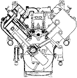
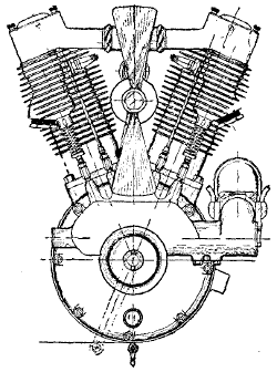
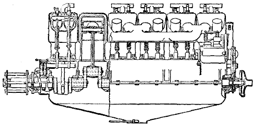
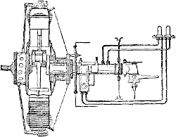
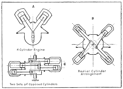
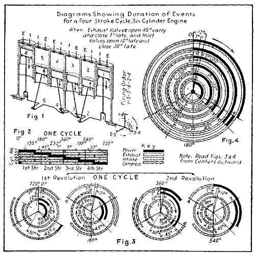
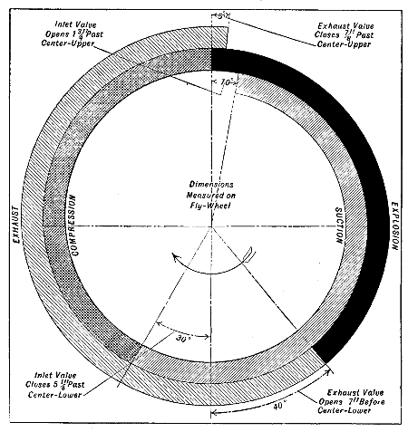
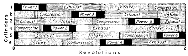
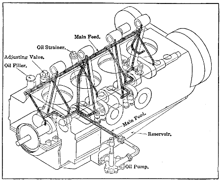
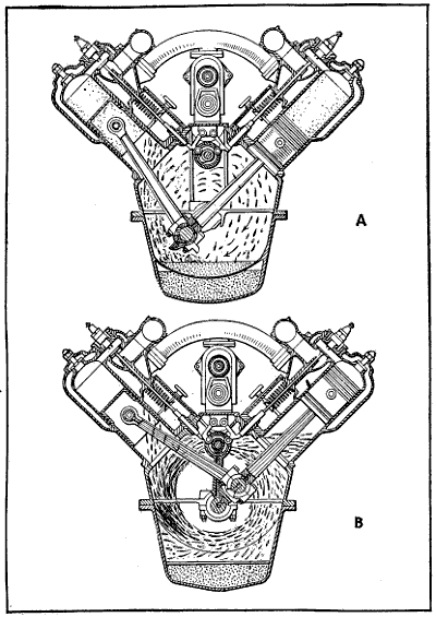
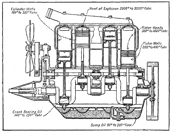
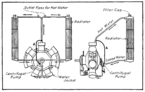
Inasmuch as numerous forms of airplane engines have
been devised, it would require a volume of considerable
size to describe even the most important developments
of recent years. As considerable explanatory matter has
been given in preceding chapters and the principles involved
in internal combustion engine operation considered
in detail, a relatively brief review of the features
of some of the most successful airplane motors should
suffice to give the reader a complete enough understanding
of the art so all types of engines can be readily
recognized and the advantages and disadvantages of each
type understood, as well as defining the constructional
features enough so the methods of locating and repairing
the common engine and auxiliary system troubles
will be fully grasped.
Aviation engines can be divided into three main
classes. One of the earliest attempts to devise distinctive
power plant designs for aircraft involved the construction
of engines utilizing a radial arrangement of the
cylinders or a star-wise disposition. Among the engines
of this class may be mentioned the Anzani, R. E. P. and
the Salmson or Canton and Unné forms. The two former
are air-cooled, the latter design is water-cooled. Engines
of this type have been built in cylinder numbers ranging
from three to twenty. While the simple forms were
popular in the early days of aviation engine development,
they have been succeeded by the more conventional
arrangements which now form the largest class. The
reason for the adoption of a star-wise arrangement of
cylinders has been previously considered. Smoothness
of running can only be obtained by using a considerable
number of cylinders. The fundamental reason for the
adoption of the star-wise disposition is that a better distribution
of stress is obtained by having all of the pistons
acting on the same crank-pin so that the crank-throw and
pin are continuously under maximum stress. Some difficulty
has been experienced in lubricating the lower cylinders
in some forms of six cylinder, rotary crank, radial
engines but these have been largely overcome so they are
not as serious in practice as a theoretical consideration
would indicate.
Another class of engines developed to meet aviation
requirements is a complete departure from the preceding
class, though when the engines are at rest, it is difficult
to differentiate between them. This class includes engines
having a star-wise disposition of the cylinders but
the cylinders themselves and the crank-case rotate and
the crank-shaft remains stationary. The important rotary
engines are the Gnome, the Le Rhone and the Clerget.
By far the most important classification is that including
engines which retain the approved design of the
types of power plants that have been so widely utilized
in automobiles and which have but slight modifications
to increase reliability and mechanical strength and produce
a reduction in weight. This class includes the
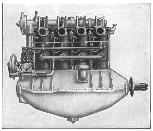
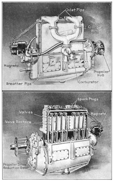
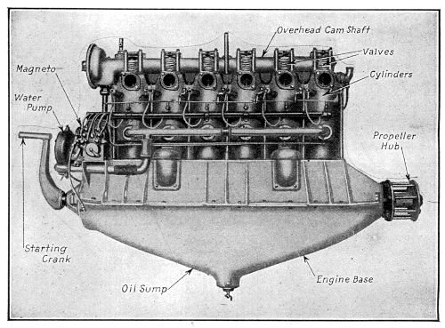
vertical engines such as the Duesenberg and Hall-Scott
four-cylinder; the Wisconsin, Aeromarine, Mercedes,
Benz, and Hall-Scott six-cylinder vertical engines and
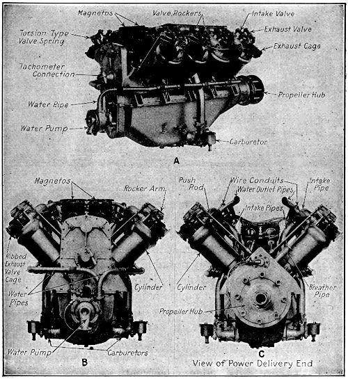
the numerous eight- and twelve-cylinder Vee designs such
as the Curtiss, Renault, Thomas-Morse, Sturtevant, Sunbeam,
and others.
[459]
The attention of the mechanical world was first directed
to the great possibilities of mechanical flight when
Bleriot crossed the English Channel in July, 1909, in a
monoplane of his own design and construction, having
the power furnished by a small three-cylinder air-cooled
engine rated at about 24 horse-power and having cylinders
4.13 inches bore and 5.12 inches stroke, stated to
develop the power at about 1600 R.P.M. and weighing 145
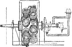
pounds. The arrangement of this early Anzani engine is
shown at Fig. 190, and it will be apparent that in the
main, the lines worked out in motorcycle practice were
followed to a large extent. The crank-case was of the
usual vertically divided pattern, the cylinders and heads
being cast in one piece and held to the crank-case by
stud bolts passing through substantial flanges at the
cylinder base. In order to utilize but a single crank-pin
for the three cylinders it was necessary to use two forked
rods and one rod of the conventional type. The arrangement
shown at Fig. 190, called for the use of counter-balanced
flywheels which were built up in connection
with shafts and a crank-pin to form what corresponds to
the usual crank-shaft assembly.
[460]
Large
image
(90 kB).
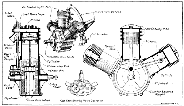
Fig. 190.—Views Outlining Construction of Three-Cylinder Anzani Aviation Motor.
[461]
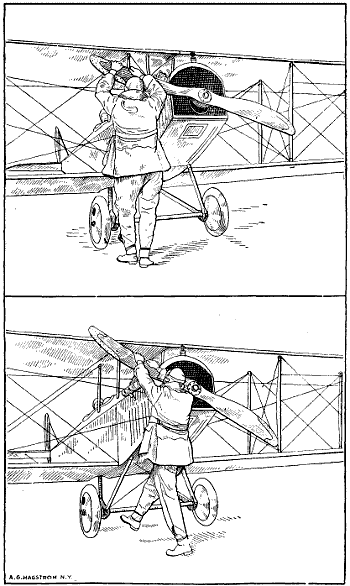
Fig. 190a.—Illustrations Depicting Wrong and Right Methods of “Swinging
the Stick” to Start Airplane Engine. At Top, Poor Position to
Get Full Throw and Get Out of the Way. Below, Correct Position
to Get Quick Turn Over of Crank-Shaft and Spring Away from
Propeller.
The inlet valves were of the automatic type so that a
very simple valve mechanism consisting only of the exhaust
valve push rods was provided. One of the difficulties
of this arrangement of cylinders was that the
impulses are not evenly spaced. For instance, in the
forms where the cylinders were placed 60 degrees apart
the space between the firing of the first cylinder and that
next in order was 120 degrees crank-shaft rotation, after
which there was an interval of 300 degrees before the
last cylinder to fire delivered its power stroke. In order
to increase the power given by the simple three-cylinder
air-cooled engine a six-cylinder water-cooled type, as
shown at Figs. 191 and 192, was devised. This was practically
the same in action as the three-cylinder except
that a double throw crank-shaft was used and while the
explosions were not evenly spaced the number of explosions
obtained resulted in fairly uniform application of
power.
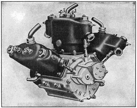
Fig. 191.—The Anzani Six-Cylinder Water-Cooled Aviation Engine.
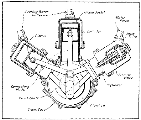
Fig. 192.—Sectional View of Anzani Six-Cylinder Water-Cooled Aviation
Engine.
The latest design of three-cylinder Anzani engine,
which is used to some extent for school machines, is
shown at Fig. 193. In this, the three-cylinders are symmetrically
arranged about the crank-case or 120 degrees
apart. The balance is greatly improved by this arrangement
and the power strokes occur at equal intervals of
240 degrees of crank-shaft rotation. This method of construction
is known as the Y design. By grouping two of
these engines together, as outlined at Fig. 194, which
gives an internal view, and at Fig. 195, which shows the
sectional view, and using the ordinary form of double
throw crank-shaft with crank-pins separated by 180 degrees,
a six-cylinder radial engine is produced which runs
very quietly and furnishes a steady output of power.
The peculiarity of the construction of this engine is in
the method of grouping the connecting rod about the
common crank-pin without using forked rods or the
“Mother rod” system employed in the Gnome engines.
In the Anzani the method followed is to provide each
connecting rod big end with a shoe which consists of a
portion of a hollow cylinder held against the crank-pin
by split clamping rings. The dimensions of these shoes
are so proportioned that the two adjacent connecting rods
of a group of three will not come into contact even when
the connecting rods are at the minimum relative angle.
The three shoes of each group rest upon a bronze sleeve
which is in halves and which surrounds the crank-pin
and rotates relatively to it once in each crank-shaft revolution.
The collars, which are of tough bronze, resist the
inertia forces while the direct pressure of the explosions
is transmitted directly to the crank-pin bushing by the
shoes at the big end of the connecting rod. The same
method of construction, modified to some extent, is used
in the Le Rhone rotary cylinder engine.
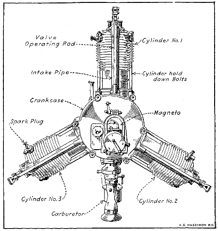
Fig. 193.—Three-Cylinder Anzani Air-Cooled Y-Form Engine.
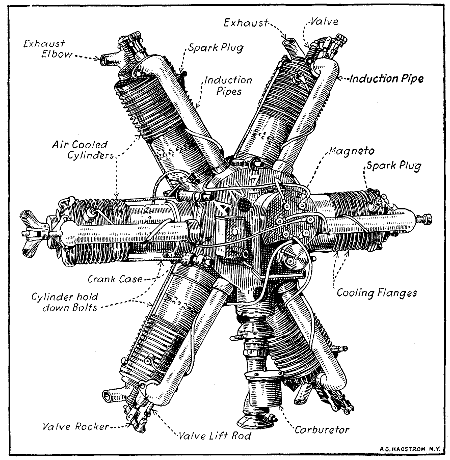
Fig. 194.—Anzani Fixed Crank-Case Engine of the Six-Cylinder Form
Utilizes Air Cooling Successfully.
Both cylinders and pistons of the Anzani engines are
of cast iron, the cylinders being provided with a liberal
number of cooling flanges which are cast integrally. A
series of auxiliary exhaust ports is drilled near the base
of each cylinder so that a portion of the exhaust gases
will flow out of the cylinder when the piston reaches the
end of its power stroke. This reduces the temperature
of the gases passing around the exhaust valves and prevents
warping of these members. Another distinctive
feature of this engine design is the method of attaching
the Zenith carburetor to an annular chamber surrounding
the rear portion of the crank-case from which the intake
pipes leading to the intake valves radiate. The magneto
is the usual six-cylinder form having the armature geared
to revolve at one and one-half times crank-shaft speed.
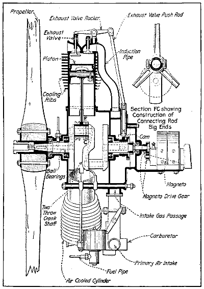
Fig. 195.—Sectional View Showing Internal Parts of Six-Cylinder Anzani
Engine, with Starwise Disposition of Cylinders.
[467]
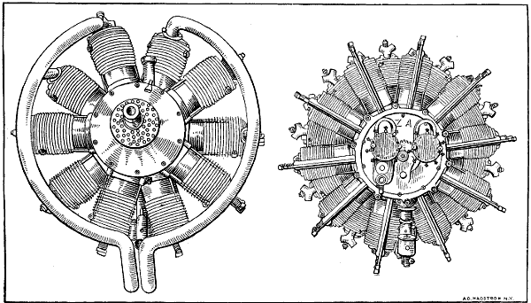
Fig. 196.—The Anzani Ten-Cylinder Aviation Engine at the Left, and the Twenty-Cylinder Fixed Type
at the Right.
The Anzani aviation engines are also made in ten- and
twenty-cylinder forms as shown at Fig. 196. It
will
be apparent that in the ten-cylinder form explosions will
occur every 72 degrees of crank-shaft rotation, while in
the twenty-cylinder, 200 horse-power engine at any instant
five of the cylinders are always working and explosions
are occurring every 36 degrees of crank-shaft
rotation. On the twenty-cylinder engine, two carburetors
are used and two magnetos, which are driven at two and
one-half times crank-shaft speed. The general cylinder
and valve construction is practically the same, as in the
simpler engines.
This engine, which has been devised specially for
aviation service, is generally known as the “Salmson”
and is manufactured in both France and Great Britain.
It is a nine-cylinder water-cooled radial engine, the nine
cylinders being symmetrically disposed around the crank-shaft
while the nine connecting rods all operate on a
common crank-pin in somewhat the same manner as the
rods in the Gnome motor. The crank-shaft of the Salmson
engine is not a fixed one and inasmuch as the cylinders
do not rotate about the crank-shaft it is necessary
for that member to revolve as in the conventional engine.
The stout hollow steel crank-shaft is in two pieces and
has a single throw. The crank-shaft is built up somewhat
the same as that of the Gnome engine. Ball bearings
are used throughout this engine as will be evident
by inspecting the sectional view given at Fig. 199. The
nine steel connecting rods are machined all over and are
fitted at each end with bronze bushings, the distance
between the bearing centers being about 3.25 times crank
length. The method of connecting up the rods to the
crank-pin is one of the characteristic features of this
design. No “mother” rod as supplied in the Gnome
engine is used in this type inasmuch as the steel cage or
connecting rod carrier is fitted with symmetrically disposed
big end retaining pins. Inasmuch as the carrier
is mounted on ball bearings some means must be provided
of regulating the motion of the carrier as if no
means were provided the resulting motion of the pistons
would be irregular.
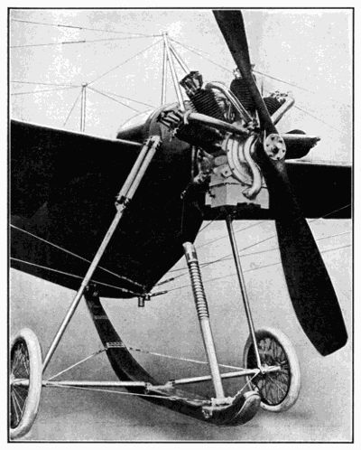
Fig. 197.—Application of R. E. P. Five-Cylinder Fan-Shape Air-Cooled
Motor to Early Monoplane.
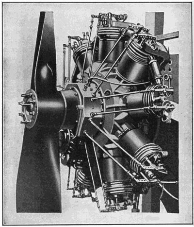
Fig. 198.—The Canton and Unné Nine-Cylinder Water-Cooled Radial
Engine.
The method by which the piston strokes are made to
occur at precise intervals involves a somewhat lengthy
and detailed technical explanation. It is sufficient to say
that an epicyclic train of gears, one of which is rigidly
attached to the crank-case so it cannot rotate is used,
while other gears make a connection between the fixed
gear and with another gear which is exactly the same
size as the fixed gear attached to the crank-case and which
is formed integrally with the connecting rod carrier. The
action of the gearing is such that the cage carrying the
big end retaining pins does not rotate independently of
the crank-shaft, though, of course, the crank-shaft or
rather crank-pin bearings must turn inside of the big
end carrier cage.
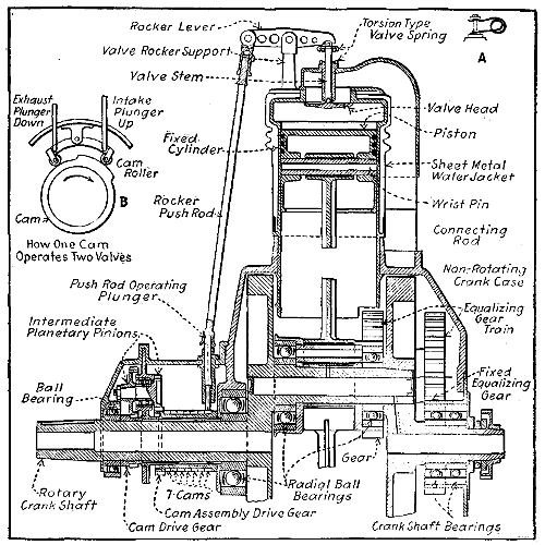
Fig. 199.—Sectional View Showing Construction of Canton and Unné
Water-Cooled Radial Cylinder Engine.
Cylinders of this engine are of nickel steel machined
all over and carry water-jackets of spun copper which
are attached to the cylinders by brazing. The water
jackets are corrugated to permit the cylinder to expand
freely. The ignition is similar to that of the fixed crank
rotating cylinder engine. An ordinary magneto of the
two spark type driven at 13⁄4 times crank-shaft speed is
sufficient to ignite the seven-cylinder form, while in the
nine-cylinder engines the ignition magneto is of the
“shield” type giving four sparks per revolution. The
magneto is driven at 11⁄9 times crank-shaft speed. Nickel
steel valves are used and are carried in castings or cages
which screw into bosses in the cylinder head. Each
valve is cam operated through a tappet, push rod and
rocker arm, seven cams being used on a seven-cylinder
engine and nine cams on the nine-cylinder. One cam
serves to open both valves as in its rotation it lifts the
tappets in succession and so operates the exhaust and
inlet valves respectively. This method of operation involves
the same period of intake and exhaust. In normal
engine practice the inlet valve opens 12 degrees
late and closes 20 degrees late. The exhaust opens
45 degrees early and closes 6 degrees late. This means
about 188 degrees in the case of inlet valve and 231 degrees
crank-shaft travel for exhaust valves. In the
Salmson engine, the exhaust closes and the inlet opens at
the outer dead center and the exhaust opens and the inlet
closes at about the inner dead center. This engine is
also made in a fourteen-cylinder 200 B. H. P. design
which is composed of two groups of seven-cylinders, and
it has been made in an eighteen-cylinder design of 600
horse-power. The nine-cylinder 130 horse-power has a
cylinder bore of 4.73 inches and a stroke of 5.52 inches.
Its normal speed of rotation is 1250 R. P. M. Owing to
the radial arrangement of the cylinders, the weight is but
41⁄4 pounds per B. H. P.
It cannot be denied that for a time one of the most
widely used of aeroplane motors was the seven-cylinder
revolving air-cooled Gnome, made in France. For a total
weight of 167 pounds this motor developed 45 to 47 horsepower
at 1,000 revolutions, being equal to 3.35 pounds
per horse-power, and has proved its reliability by securing
many long-distance and endurance records. The same
engineers have produced a nine-cylinder and by combining
two single engines a fourteen-cylinder revolving
Gnome, having a nominal rating of 100 horse-power, with
which world’s speed records were broken. A still more
powerful engine has been made with eighteen-cylinders.
The nine-cylinder “monosoupape” delivers 100 horse-power
at 1200 R. P. M., the engine of double that number
of cylinders is rated at about 180 horse-power.
Large
image
(89 kB).
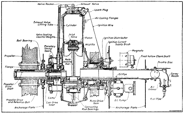
Fig. 200.—Sectional View Outlining Construction of Early Type Gnome Valve-in-Piston Type Motor.
Except in the number of cylinders and a few mechanical
details the fourteen-cylinder motor is identical with
the seven-cylinder one; fully three-quarters of the parts
used by the assemblers would do just as well for one
motor as for the other. Owing to the greater power demands
of the modern airplane the smaller sizes of Gnome
engines are not used as much as they were except for
school machines. There is very little in this motor that
is common to the standard type of vertical motorcar
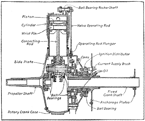
engine. The cylinders are mounted radially round a circular
crank-case; the crank-shaft is fixed, and the entire
mass of cylinders and crank-case revolves around it as
outlined at Fig. 200. The explosive mixture and the
lubricating oil are admitted through the fixed hollow
crank-shaft, passed into the explosion chamber through
an automatic intake valve in the piston head in the early
pattern, and the spent gases exhausted through a mechanically
operated valve in the cylinder head. The
course of the gases is practically a radial one. A peculiarity
of the construction of the motor is that nickel steel
is used throughout. Aluminum is employed for the two
oil pump housings; the single compression ring known
as the “obdurator” for each piston is made of brass;
there are three or four brass bushes; gun metal is employed
for certain pins—the rest is machined out of
chrome nickel steel. The crank-case is practically a steel
hoop, the depth depending on whether it has to receive
seven-or fourteen-cylinders; it has seven or fourteen
holes bored as illustrated on its circumference. When
fourteen or eighteen cylinders are used the holes are
bored in two distinct planes, and offset in relation one to
the other.
The cylinders of the small engine which have a bore
of 43⁄10 inches and a stroke of 47⁄10 inches, are machined
out of the solid bar of steel until the thickness of the walls
is only 1.5 millimeters—.05905 inch, or practically 1⁄16 inch.
Each one has twenty-two fins which gradually taper down
as the region of greatest pressure is departed from. In
addition to carrying away heat, the fins assist in strengthening
the walls of the cylinder. The barrel of the cylinder
is slipped into the hole bored for it on the circumference
of the crank-case and secured by a locking member
in the nature of a stout compression ring, sprung onto a
groove on the base of the cylinder within the crank chamber.
On each lateral face of the crank chamber are seven
holes, drilled right through the chamber parallel with the
crank-shaft. Each one of these holes receives a stout
locking-pin of such a diameter that it presses against
the split rings of two adjacent cylinders; in addition
each cylinder is fitted with a key-way. This construction
is not always followed, some of the early Gnome engines
using the same system of cylinder retention as used on
the latest “monosoupape” pattern.
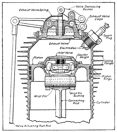
Fig. 201.—Sectional View of Early Type Gnome Cylinder and Piston
Showing Construction and Application of Inlet and Exhaust Valves.
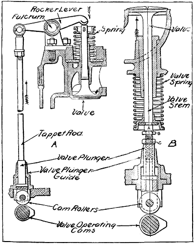
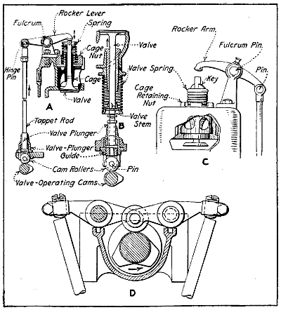
The exhaust valve is mounted in the cylinder head,
Fig. 201, its seating being screwed in by means of a
special box spanner. On the fourteen-cylinder model the
valve is operated directly by an overhead rocker arm
with a gun metal rocker at its extremity coming in contact
with the extremity of the valve stem. As in standard
motor car practice, the valve is opened under the lift of
the vertical push rod, actuated by the cam. The distinctive
feature is the use of a four-blade leaf spring with
a forked end encircling the valve stems and pressing
against a collar on its extremity. On the seven-cylinder
model the movement is reversed, the valve being opened
on the downward pull of the push rod, this lifting the
outer extremity of the main rocker arm, which tips a
secondary and smaller rocker arm in direct contact with
the extremity of the valve stem. The springs are the
same in each case. The two types are compared at A
and B, Fig. 202.
[477]
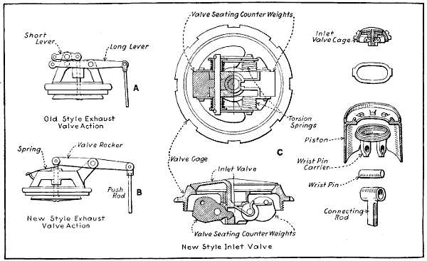
Fig. 202.—Details of Old Style Gnome Motor Inlet and Exhaust Valve Construction and Operation.
The pistons, like the cylinders, are machined out of
the solid bar of nickel steel, and have a portion of their
wall cut away, so that the two adjacent ones will not
come together at the extremity of their stroke. The head
of the piston is slightly reduced in diameter and is provided
with a groove into which is fitted a very light
L-section brass split ring; back of this ring and carried
within the groove is sprung a light steel compression
ring, serving to keep the brass ring in expansion. As
already mentioned, the intake valves are automatic, and
are mounted in the head of the piston as outlined at Fig.
202, C. The valve seating is in halves, the lower portion
being made to receive the wrist-pin and connecting rod,
and the upper portion, carrying the valve, being screwed
into it. The spring is composed of four flat blades, with
the hollowed stem of the automatic valve passing through
their center and their two extremities attached to small
levers calculated to give balance against centrifugal force.
The springs are naturally within the piston, and are lubricated
by splash from the crank chamber. They are of
a delicate construction, for it is necessary that they shall
be accurately balanced so as to have no tendency to fly
open under the action of centrifugal force. The intake
valve is withdrawn by the use of special tools through the
cylinder head, the exhaust valve being first dismounted.
[479]
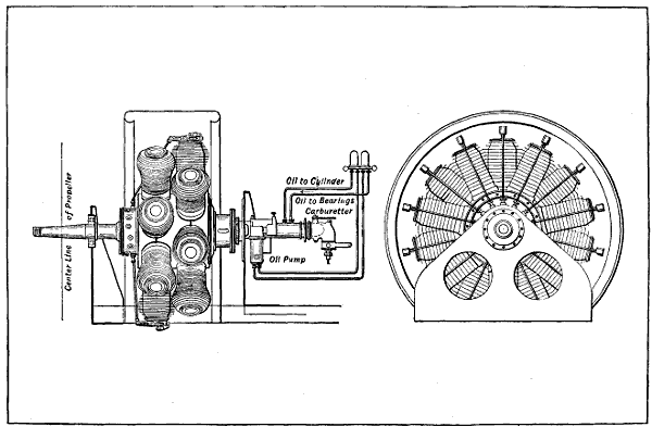
Fig. 203.—The Gnome Fourteen-Cylinder 100 Horse-Power Aviation Engine.
The fourteen-cylinder motor shown at Fig. 203, has a
two-throw crank-shaft with the throws placed at 180 degrees,
each one receiving seven connecting rods. The
parts are the same as for the seven-cylinder motor, the
larger one consisting of two groups placed side by side.
For each group of seven-cylinders there is one main connecting
rod, together with six auxiliary rods. The main
connecting rod, which, like the others, is of H section, has
machined with it two L-section rings bored with six holes—511⁄2
degrees apart to take the six other connecting
rods. The cage of the main connecting rod carries two
ball races, one on either side, fitting onto the crank-pin
and receiving the thrust of the seven connecting rods.
The auxiliary connecting rods are secured in position in
each case by a hollow steel pin passing through the two
rings. It is evident that there is a slightly greater angularity
for the six shorter rods, known as auxiliary connecting
rods, than for the longer main rods; this does not
appear to have any influence on the running of the motor.
Coming to the manner in which the earliest design exhaust
valves are operated on the old style motor, this at
first sight appears to be one of the most complicated
parts of the motor, probably because it is one in which
standard practice is most widely departed from. Within
the cylindrical casing bolted to the rear face of the crank-case
are seven, thin flat-faced steel rings, forming female
cams. Across a diameter of each ring is a pair of projecting
rods fitting in brass guides and having their
extremities terminating in a knuckle eye receiving the
adjustable push rods operating the overhead rocker arms
of the exhaust valve. The guides are not all in the same
plane, the difference being equal to the thickness of the
steel rings, the total thickness being practically 2 inches.
Within the female cams is a group of seven male cams
of the same total thickness as the former and rotating
within them. As the boss of the male cam comes into
contact with the flattened portion of the ring forming
the female cam, the arm is pushed outward and the exhaust
valve opened through the medium of the push-rod
and overhead rocker. This construction was afterwards
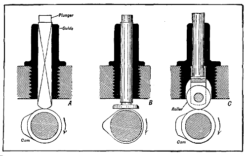
changed to seven male cams and simple valve operating
plunger and roller cam followers as shown at Fig. 204.
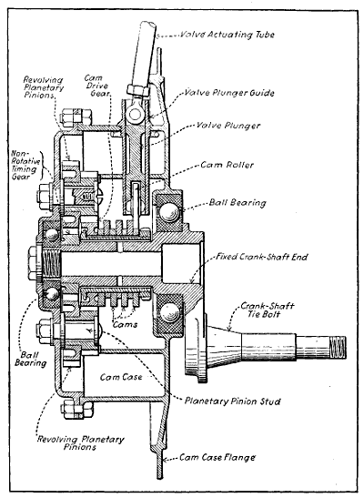
Fig. 204.—Cam and Cam-Gear Case of the Gnome Seven-Cylinder
Revolving Engine.
On the face of the crank-case of the fourteen-cylinder
motor opposite to the valve mechanism is a bolted-on end
plate, carrying a pinion for driving the two magnetos
and the two oil pumps, and having bolted to it the distributor
for the high-tension current. Each group of
seven-cylinders has its own magneto and lubricating
pump. The two magnetos and the two pumps are mounted
on the fixed platform carrying the stationary crank-shaft,
being driven by the pinion on the revolving crank chamber.
The magnetos are geared up in the proportion of
4 to 7. Mounted on the end plate back of the driving
pinion are the two high-tension distributor plates, each
one with seven brass segments let into it and connection
made to the plugs by means of plain brass wire. The
wire passes through a hole in the plug and is then
wrapped round itself, giving a loose connection.
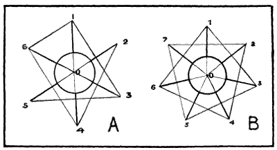
Fig. 205.—Diagrams Showing Why An Odd Number of Cylinders is Best
for Rotary Cylinder Motors.
A good many people doubtless wonder why rotary engines
are usually provided with an odd number of cylinders
in preference to an even number. It is a matter of
even torque, as can easily be understood from the accompanying
diagram. Fig. 205, A, represents a six-cylinder
rotary engine, the radial lines indicating the cylinders.
It is possible to fire the charges in two ways, firstly, in
rotation, 1, 2, 3, 4, 5, 6, thus having six impulses in one
revolution and none in the next; or alternately, 1, 3, 5, 2,
4, 6, in which case the engine will have turned through
an equal number of degrees between impulses 1 and 3,
and 3 and 5, but a greater number between 5 and 2, even
again between 2 and 4, 4 and 6, and a less number between
6 and 1, as will be clearly seen on reference to the
diagram. Turning to Fig. 205, B, which represents a
seven-cylinder engine. If the cylinders fire alternately
it is obvious that the engine turns through an equal
number of degrees between each impulse, thus, 1, 3, 5, 7,
2, 4, 6, 1, 3, etc. Thus supposing the engine to be revolving,
the explosion takes place as each alternate cylinder
passes, for instance, the point 1 on the diagram, and the
ignition is actually operated in this way by a single
contact.
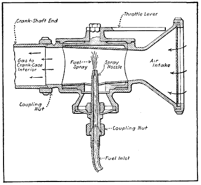
Fig. 206.—Simple Carburetor Used On Early Gnome Engines Attached
to Fixed Crank-Shaft End.
The crank-shaft of the Gnome, as already explained,
is fixed and hollow. For the seven- and nine-cylinder
motors it has a single throw, and for the fourteen- and
eighteen-cylinder models has two throws at 180 degrees.
It is of the built-up type, this being necessary on account
of the distinctive mounting of the connecting rods. The
carburetor shown at Fig. 206 is mounted at one end of
the stationary crank-shaft, and the mixture is drawn in
through a valve in the piston as already explained. There
is neither float chamber nor jet. In many of the tests
made at the factory it is said the motor will run with the
extremity of the gasoline pipe pushed into the hollow
crank-shaft, speed being regulated entirely by increasing
or decreasing the flow through the shut-off valve in the
base of the tank. Even under these conditions the motor
has been throttled down to run at 350 revolutions without
misfiring. Its normal speed is 1,000 to 1,200 revolutions
a minute. Castor oil is used for lubricating the
engine, the oil being injected into the hollow crank-shaft
through slight-feed fittings by a mechanically operated
pump which is clearly shown in sectional diagrams at
Fig. 207.
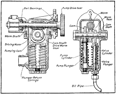
Fig. 207.—Sectional Views of the Gnome Oil Pump.
The Gnome is a considerable consumer of lubricant,
the makers’ estimate being 7 pints an hour for the 100
horse-power motor; but in practice this is largely exceeded.
The gasoline consumption is given as 300 to 350
grammes per horse-power. The total weight of the fourteen-cylinder
motor is 220 pounds without fuel or lubricating
oil. Its full power is developed at 1,200 revolutions,
and at this speed about 9 horse-power is lost in
overcoming air resistance to cylinder rotation.
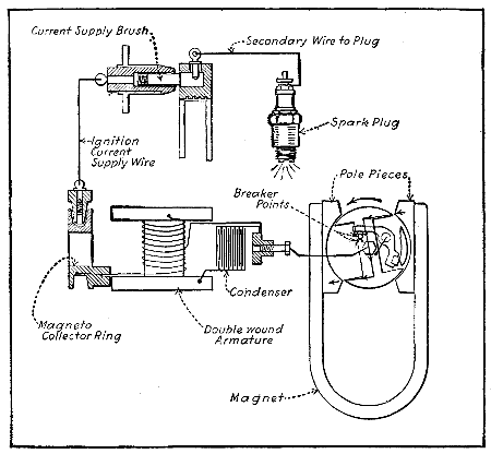
Fig. 208.—Simplified Diagram Showing Gnome Motor Magneto Ignition
System.
While the Gnome engine has many advantages, on the
other hand, the head resistance offered by a motor of this
type is considerable; there is a large waste of lubricating
oil due to the centrifugal force which tends to throw the
oil away from the cylinders; the gyroscopic effect of
the rotary motor is detrimental to the best working of the
aeroplane, and moreover it requires about seven per cent.
of the total power developed by the motor to drive the
revolving cylinders around the shaft. Of necessity, the
compression of this type of motor is rather low, and an
additional disadvantage manifests itself in the fact that
there is as yet no satisfactory way of muffling the rotary
type of motor.
The latest type of Gnome engine is known as the
“monosoupape” type because but one valve is used in
the cylinder head, the inlet valve in the piston being dispensed
with on account of the trouble caused by that
member on earlier engines. The construction of this
latest type follows the lines established in the earlier
designs to some extent and it differs only in the method
of charging. The very rich mixture of gas and air is
forced into the crank-case through the jet inside the
crank-shaft, and enters the cylinder when the piston is
at its lowest position, through the half-round openings
in the guiding flange and the small holes or ports machined
in the cylinder and clearly shown at Fig. 210.
The returning piston covers the port, and the gas is compressed
and fired in the usual way. The exhaust is
through a large single valve in the cylinder head, which
gives rise to the name “monosoupape,” or single-valve
motor, and this valve also remains open a portion of the
intake stroke to admit air into the cylinder and dilute
the rich gas forced in from the crank-case interior.
Aviators who have used the early form of Gnome say
that the inlet valve in the piston type was prone to catch
on fire if any valve defect materialized, but the “monosoupape”
pattern is said to be nearly free of this danger.
The bore of the 100 horse-power nine-cylinder engine is
110 mm., the piston stroke 150 mm. Extremely careful
machine work and fitting is necessary. In many parts,
tolerances of less than .0004′′ (four ten thousandths of
an inch) are all that are allowed. This is about one-sixth
the thickness of the average human hair, and in
other parts the size must be absolutely standard, no
appreciable variation being allowable. The manufacture
of this engine establishes new mechanical standards of
engine production in this country. Much machine work
is needed in producing the finished components from the
bar and forging.
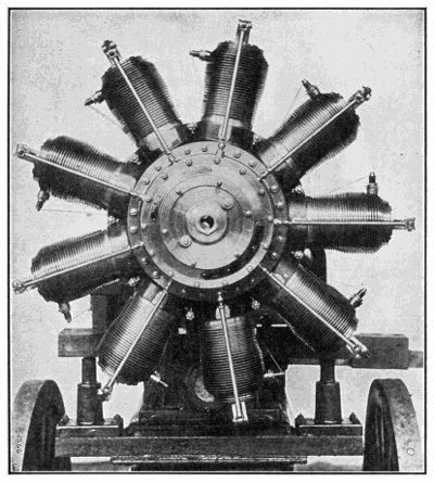
Fig. 209.—The G. V. Gnome “Monosoupape” Nine-Cylinder Rotary Engine
Mounted on Testing Stand.
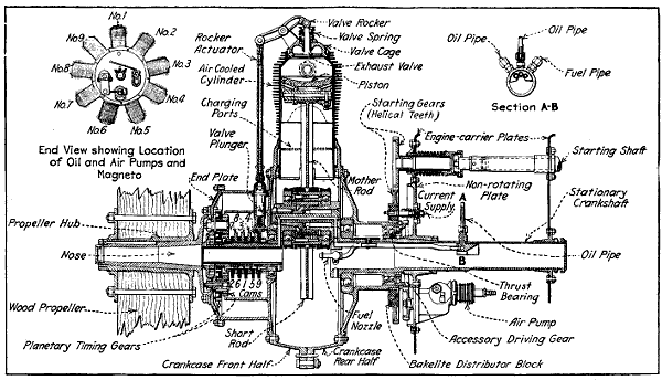
Fig. 210.—Sectional View Showing Construction of General Vehicle Co. “Monosoupape” Gnome
Engine.
The cylinders, for example, are machined from 6 inch
solid steel bars, which are sawed into blanks 11 inches
in length and weighing about 97 pounds. The first operation
is to drill a 21⁄16 inch hole through the center of the
block. A heavy-duty drilling machine performs this
work, then the block goes to the lathe for further operations.
Fig. 211 shows six stages of the progress of a
cylinder, a few of the intermediate steps being omitted.
These give, however, a good idea of the work done. The
turning of the gills, or cooling flanges, is a difficult proposition,
owing to the depth of the cut and the thin metal
that forms the gills. This operation requires the utmost
care of tools and the use of a good lubricant to prevent
the metal from tearing as the tools approach their full
depth. These gills are only 0.6 mm., or 0.0237 in., thick
at the top, tapering to a thickness of 1.4 mm. (0.0553 in.)
at the base, and are 16 mm. (0.632 in.) deep. When the
machine work is completed the cylinder weighs but 51⁄2
pounds.
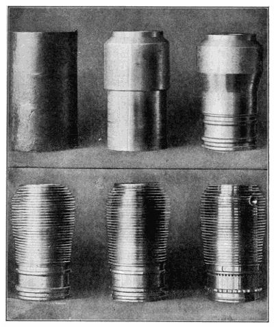
Fig. 211.—How a Gnome Cylinder is Reduced from Solid Chunk of Steel
Weighing 97 Pounds to Finished Cylinder Weighing 51⁄2 Pounds.
The following description of the fuel supply, ignition
and oiling of the “monosoupape,” or single valve Gnome,
is taken from “The Automobile.”
Gasoline is fed to the engine by means of air pressure
at 5 pounds per sq. in., which is produced by the air
pump on the engine clearly shown at Fig. 210. A pressure
gauge convenient to the operator indicates this pressure,
and a valve enables the operator to control it. No
carburetor is used. The gasoline flows from the tank
through a shut-off valve near the operator and through
a tube leading through the hollow crank-shaft to a spray
nozzle located in the crank-case. There is no throttle
valve, and as each cylinder always receives the same
amount of air as long as the atmospheric pressure is the
same, the output cannot be varied by reducing the fuel
supply, except within narrow limits. A fuel capacity of
65 gallons is provided. The fuel consumption is at the
rate of 12 U. S. gallons per hour.
The high-tension magnetos, with double cam or two
break per revolution interrupter, is located on the thrust
plate in an inverted position, and is driven at such a
speed as to produce nine sparks for every two revolutions;
that is, at 21⁄4 times engine speed. A Splitdorf
magneto is fitted. There is no distributor on the magneto.
The high-tension collector brush of the magneto
is connected to a distributor brush holder carried in the
bearer plate of the engine. The brush in this brush
holder is pressed against a distributor ring of insulating
material molded in position in the web of a gear wheel
keyed to the thrust plate, which gear serves also for
starting the engine by hand. Molded in this ring of insulating
material are nine brass contact sectors, connecting
with contact screws at the back side of the gear,
from which bare wires connect to the spark-plugs. The
distributor revolves at engine speed, instead of at half
engine speed as on ordinary engines, and the distributor
brush is brought into electrical connection with each
spark-plug every time the piston in the cylinder in which
this spark-plug is located approaches the outer dead
center. However, on the exhaust stroke no spark is being
generated in the magneto, hence none is produced at the
spark-plug.
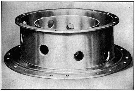
Fig. 212.—The Gnome Engine Cam-Gear Case, a Fine Example of Accurate
Machine Work.
Ordinarily the engine is started by turning on the
propeller, but for emergency purposes as in seaplanes or
for a quick “get away” if landing inadvertently in
enemy territory, a hand starting crank is provided. This
is supported in bearings secured to the pressed steel
carriers of the engine and is provided with a universal
joint between the two supports so as to prevent binding
of the crank in the bearings due to possible distortion
of the supports. The gear on this starting crank and the
one on the thrust plate with which it meshes are cut
with helical teeth of such hand that the starting pinion
is thrown out of mesh as soon as the engine picks up its
cycle. A coiled spring surrounds part of the shaft of the
starting crank and holds it out of gear when not in use.
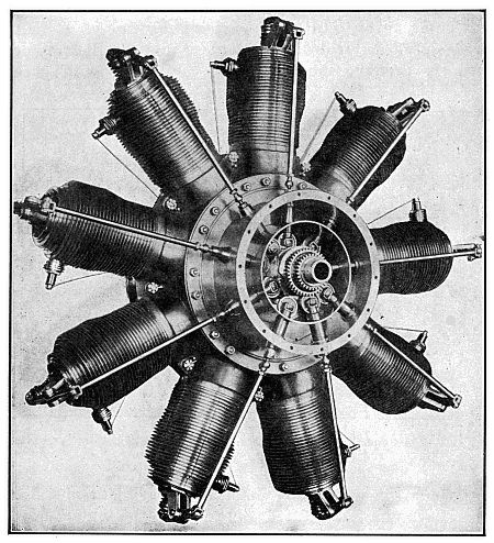
Fig. 213.—G. V. Gnome “Monosoupape,” with Cam-Case Cover Removed to
Show Cams and Valve-Operating Plungers with Roller Cam Followers.
Lubricating oil is carried in a tank of 25 gallon capacity,
and if this tank has to be placed in a low position
it is connected with the air-pressure line, so that the
suction of the oil pump is not depended upon to get the
oil to the pump. From the bottom of the oil tank a pipe
leads to the pump inlet. There are two outlets from the
pump, each entering the hollow crank-shaft, and there is
a branch from each outlet pipe to a circulation indicator
convenient to the operator. One of the oil leads feeds
to the housing in the thrust plate containing the two rear
ball bearings, and the other lead feeds through the crank-pin
to the cams, as already explained.
Owing to the effect of centrifugal force and the fact
that the oil is not used over again, the oil consumption
of a revolving cylinder engine is considerably higher than
that of a stationary cylinder engine. Fuel consumption
is also somewhat higher, and for this reason the revolving
cylinder engine is not so well suited for types of airplanes
designed for long trips, as the increased weight
of supplies required for such trips, as compared with
stationary cylinder type motors, more than offsets the
high weight efficiency of the engine itself. But for short
trips, and especially where high speed is required, as in
single seated scout and battle planes or “avions de
chasse,” as the French say, the revolving cylinder engine
has the advantage. The oil consumption of the Gnome
engine is as high as 2.4 gallon per hour. Castor oil is
used for lubrication because it is not cut by the gasoline
mist present in the engine interior as an oil of mineral
derivation would be.
A German adaptation of the Gnome design is shown
at Fig. 214. This is known as the Bayerischen Motoren
Gesellschaft engine and the type shown is an early design
rated at 50 horse-power. The bore is 110 mm., the stroke
is 120 mm., and it is designed to run at a speed of 1,200
R. P. M. It is somewhat similar in design to the early
Gnome “valve-in-piston” design except that two valves
are carried in the piston top instead of one. The valve
operating arrangement is different also, as a single four
point cam is used to operate the seven exhaust valves.
It is driven by epicyclic gearing, the cam being driven by
an internal gear machined integrally with it, the cam
being turned at 7⁄8 times the engine speed. Another
feature is the method of holding the cylinders on the
crank-case. The cylinder is provided with a flange that
registers with a corresponding member of the same diameter
on the crank-case. A U section, split clamping ring
is bolted in place as shown, this holding both flanges
firmly together and keeping the cylinder firmly seated
against the crank-case flange. The “monosoupape” type
has also been copied and has received some application
in Germany, but the most successful German airplanes
are powered with six-cylinder vertical engines such as
the Benz and Mercedes.
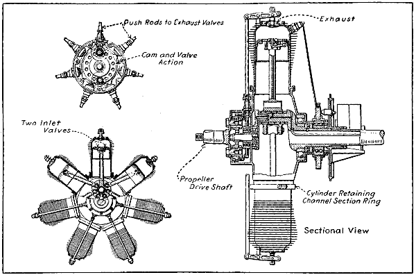
Fig. 214.—The 50 Horse-Power Rotary Bayerischen Motoren Gesellschaft Engine, a German Adaptation of the Early
Gnome Design.
The Le Rhone motor is a radial revolving cylinder
engine that has many of the principles which are incorporated
in the Gnome but which are considered to be an
improvement by many foreign aviators. Instead of having
but one valve in the cylinder head, as the latest type
“monosoupape” Gnome has, the Le Rhone has two valves,
one for intake and one for exhaust in each cylinder. By
an ingenious rocker arm and tappet rod arrangement
it is possible to operate both valves with a single push
rod. Inlet pipes communicate with the crank-case at one
end and direct the fresh gas to the inlet valve cage at the
other. Another peculiarity in the design is the method
of holding the cylinders in place. Instead of having a
vertically divided crank-case as the Gnome engine has
and clamping both halves of the case around the cylinders,
the crank-case of the Le Rhone engine is in the
form of a cylinder having nine bosses provided with
threaded openings into which the cylinders are screwed.
A thread is provided at the base of each cylinder and
when the cylinder has been screwed down the proper
amount it is prevented from further rotation about its
own axis by a substantial lock nut which screws down
against the threaded boss on the crank-case. The external
appearance of the Le Rhone type motor is clearly
shown at Fig. 215, while the general features of construction
are clearly outlined in the sectional views given
at Figs. 216 and 217.
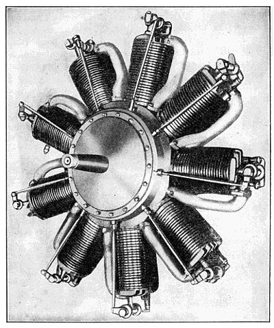
Fig. 215.—Nine-Cylinder Revolving Le Rhone Type Aviation Engine.
[497]
Large
image
(96 kB).
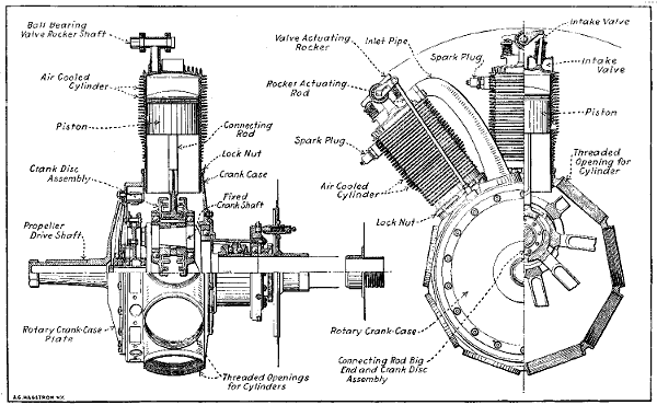
Fig. 216.—Part Sectional Views of Le Rhone Rotary Cylinder Engine, Showing Method of Cylinder Retention,
Valve Operation and Novel Crank Disc Assembly.
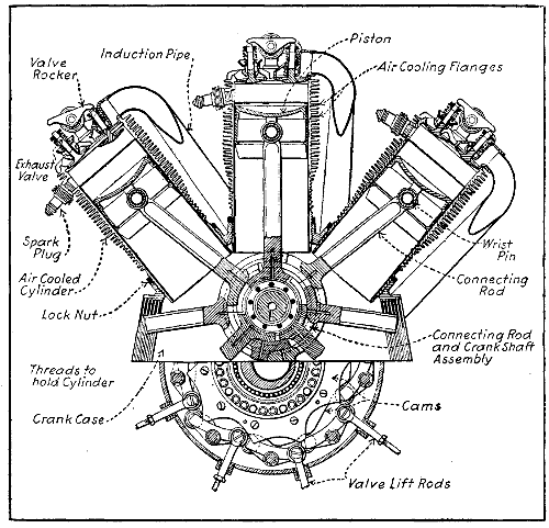
Fig. 218.—View Showing Le Rhone Valve Action and Connecting Rod
Big End Arrangement.
The two main peculiarities of this motor are the
method of valve actuation by two large cams and the
distinctive crank-shaft and connecting rod big end construction.
The connecting rods are provided with “feet”
or shoes on the end which fit into grooves lined with
bearing metal which are machined into crank discs
revolving on ball bearings and which are held together so
that the connecting rod big ends are sandwiched between
them by clamping screws. This construction is a modification
of that used on the Anzani six-cylinder radial
engine. There are three grooves machined in each crank
disc and three connecting rod big ends run in each pair
of grooves. The details of this construction can be readily
ascertained by reference to explanatory diagrams at
Figs. 218 and 219, A.
Three of the rods which work
in the groove nearest the crank-pin are provided with
short shoes as shown at Fig. 219, B. The short shoes
are used on the rods employed in cylinders number 1,
4, and 7. The set of connecting rods that work in the
central grooves are provided with medium-length shoes
and actuate the pistons in cylinders numbers 3, 6, and 9.
The three rods that work in the outside grooves have still
longer shoes and are employed in cylinders numbers 2,
5, and 8. The peculiar profile of the inlet and exhaust
cam plates are shown at C, Fig. 219, while the construction
of the wrist-pin, wrist-pin bushing and piston are
clearly outlined at the sectional view at E. The method
of valve actuation is clearly outlined at Fig. 220, which
shows an end section through the cam case and also
a partial side elevation showing one of the valve operating
levers which is fulcrumed at a central point and which
has a roller at one end bearing on one cam while the
roller or cam follower at the other end bears on the other
cam. The valve rocker arm actuating rod is, of course,
operated by this simple lever and is attached to it in
such a way that it can be pulled down to depress the
inlet valve and pushed up to open the exhaust valve.
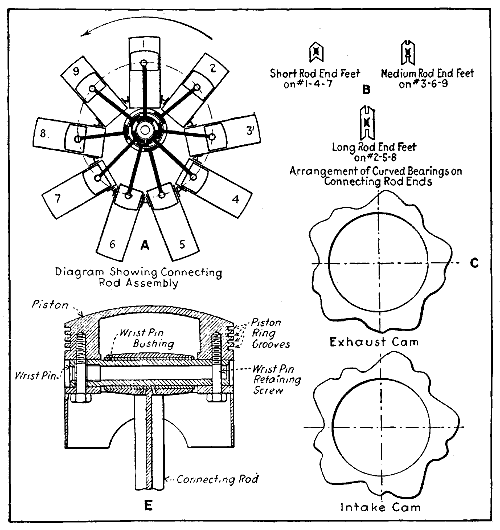
Fig. 219.—Diagrams Showing Important Components of Le Rhone Motor.
Large
image
(95 kB).
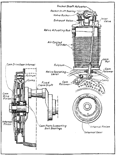
Fig. 220.—How the Cams of the Le Rhone Motor Can Operate Two Valves
with a Single Push Rod.
A carburetor of peculiar construction is employed in
the Le Rhone engine, this being a very simple type as
outlined at Fig. 221. It is attached to the threaded end
of the hollow crank-shaft by a right and left coupling.
The fuel is pumped to the spray nozzle, the opening in
which is controlled by a fuel regulating needle having
a long taper which is lifted out of the jet opening when
the air-regulating slide is moved. The amount of fuel
supplied the carburetor is controlled by a special needle
valve fitting which combines a filter screen and which is
shown at B. In regulating the speed of the Le Rhone
engine, there are two possible means of controlling the
mixture, one by altering the position of the air-regulating
slide, which also works the metering needle in the jet, and
the other by controlling the amount of fuel supplied to
the spray nozzle through the special fitting provided for
that purpose.
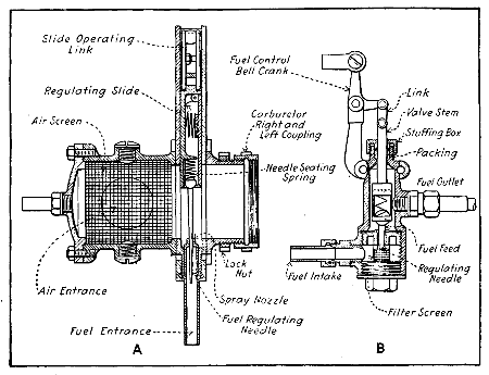
Fig. 221.—The Le Rhone Carburetor at A and Fuel Supply Regulating
Device at B.
In considering the action of this engine one can refer
to Fig. 222. The crank O. M. is fixed, while the cylinders
can turn about the crank-shaft center O and the piston
turns around the crank-pin M, because of the eccentricity
of the centers of rotation the piston will reciprocate in
the cylinders. This distance is at its maximum when
the cylinder is above O and at a minimum when it is
above M, and the difference between these two positions
is equal to the stroke, which is twice the distance of the
crank-throw O, M. The explosion pressure resolves itself
into the force F exerted along the line of the connecting
rod A, M, and also into a force N, which tends to make
the cylinders rotate around point O in the direction of
the arrow. An odd number of cylinders acting on one
crank-pin is desirable to secure equally spaced explosions,
as the basic action is the same as the Gnome engine.
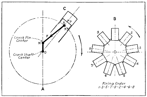
Fig. 222.—Diagrams Showing Le Rhone Motor Action and Firing Order.
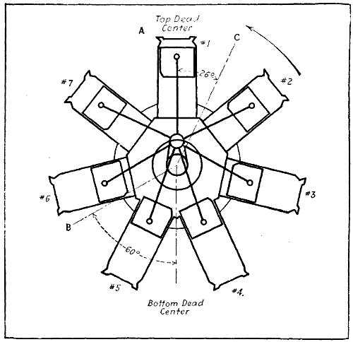
Fig. 223.—Diagram Showing Positions of Piston in Le Rhone Rotary
Cylinder Motor.
The magneto is driven by a gear having 36 teeth attached
to crank-case which meshes with 16-tooth pinion
on armature. The magneto turns at 2.25 times crank-case
speed. Two cams, one for inlet, one for exhaust,
are mounted on a carrying member and act on nine
rocker arms which are capable of giving a push-and-pull
motion to the valve-actuating rocker-operating rods. A
gear driven by the crank-case meshes with a larger member
having internal teeth carried by the cam carrier.
Each cam has five profiles and is mounted in staggered
relation to the other. These give the nine fulcrumed
levers the proper motion to open the inlet and exhaust
valves at the proper time. The cams are driven at
45⁄50 or 9⁄10 of the motor speed. The cylinder dimensions
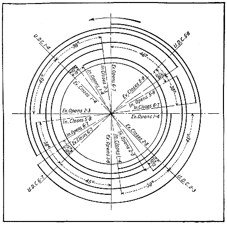
and timing follows; the weight can be approximated by
figuring 3 pounds per horse-power.
[505]
| 80 |
H.P. |
105 |
M/M bore |
4.20′′ |
bore. |
| |
140 |
M/M stroke |
5.60′′ |
stroke. |
| 110 |
H.P. |
112 |
M/M bore |
4.48′′ |
bore. |
| |
170 |
M/M stroke |
6.80′′ |
stroke. |
| Timing— |
Intake valve opening, lag |
18° |
⎫ |
110 H.P. |
18° |
⎫ |
80 H.P. |
| |
Intake valve closing, lag |
35° |
⎮ |
35° |
⎮ |
| |
Exhaust valve opening, lead |
55° |
⎬ |
45° |
⎬ |
| |
Exhaust valve closing, lag |
5° |
⎮ |
5° |
⎮ |
| |
Ignition time advance |
26° |
⎭ |
26° |
⎭ |
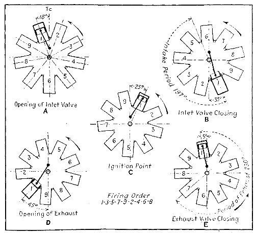
Fig. 224.—Diagrams Showing Valve Timing of Le Rhone Aviation Engine.
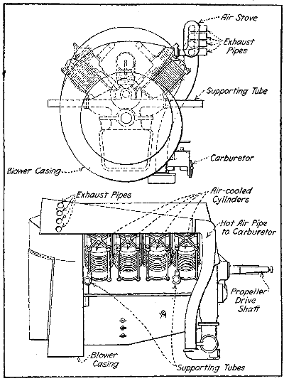
Fig. 225.—Diagrams Showing How Cylinder Cooling is Effected in
Renault Vee Engines.
Air-cooled stationary engines are rarely used in airplanes,
but the Renault Frères of France have for several
years manufactured a complete series of such engines of
the general design shown at Fig. 225, ranging from
a
low-powered one developed eight or nine years ago and
rated at 40 and 50 horse-power, to later eight-cylinder
models rated at 70 horse-power and a twelve-cylinder, or
twin six, rated at 90 horse-power. The cylinders are of
cast iron and are furnished with numerous cooling ribs
which are cast integrally. The cylinder heads are separate
castings and are attached to the cylinder as in early
motorcycle engine practice, and serve to hold the cylinder
in place on the aluminum alloy crank-case by a cruciform
yoke and four long hold-down bolts (Fig. 226). The
pistons are of cast steel and utilize piston rings of cast
iron. The valves are situated on the inner side of the
cylinder head, the arrangement being unconventional in
that the exhaust valves are placed above the inlet. The
inlet valves seat in an extension of the combustion head
and are actuated by direct push rod and cam in the usual
manner while an overhead gear in which rockers are operated
by push rods is needed to actuate the exhaust valves.
The valve action is clearly shown in Figs. 226 and 227.
The air stream by which the cylinders are cooled is produced
by a centrifugal or blower type fan of relatively
large diameter which is mounted on the end of a crank-shaft
and the air blast is delivered from this blower into
an enclosed space between the cylinder from which it
escapes only after passing over the cooling fins. In
spite of the fact that considerable prejudice exists against
air-cooling fixed cylinder engines, the Renault has given
very good service in both England and France.
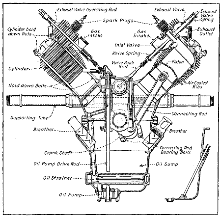
Fig. 226.—End Sectional View of Renault Air-Cooled Aviation Engine.
[509]
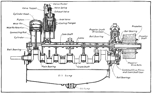
Fig. 227.—Side Sectional View of Renault Twelve-Cylinder Air-Cooled Aviation Engine Crank-Case, Showing Use
of Plain and Ball Bearings for Crank-Shaft Support.
As will be seen by the sectional view at Fig. 227, the
steel crank-shaft is carried in a combination of plain
bearings inside the crank-case and by ball bearings at the
ends. Owing to air cooling, special precautions are taken
with the lubrication system, though the lubrication is not
forced or under high pressure. An oil pump of the gear-wheel
type delivers oil from the sump at the bottom of the
crank-case to a chamber above, from which the oil flows
by gravity along suitable channels to the various main
bearings. It flows from the bearings into hollow rings
fastened to the crank-webs, and the oil thrown from the
whirling connecting rod big ends bathes the internal
parts in an oil mist. In the eight-cylinder designs ignition
is effected by a magneto giving four sparks per revolution
and is accordingly driven at engine speed. In the
twelve-cylinder machine two magnetos of the ordinary
revolving armature or two-spark type, each supplying
six cylinders, are fitted as outlined at Fig. 228. The
carburetor is a float feed form. Warm air is supplied
for Winter and damp weather by air pipes surrounding
the exhaust pipes. The normal speed of the Renault
engine is 1,800 R. P. M., but as the propeller is mounted
upon an extension of the cam-shaft the normal propeller
speed is but half that of the engine, which makes it possible
to use a propeller of large diameter and high efficiency.
Owing to the air cooling, but low compression
may be used, this being about 60 pounds per square inch,
which, of course, lowers the mean effective pressure and
makes the engine less efficient than water-cooled forms
where it is possible to use compression pressure of 100
or more pounds per square inch. The 70 horse-power
engine has cylinders with a bore of 3.78 inches and a
stroke of 5.52 inches. Its weight is given as 396 pounds,
when in running order, which figures 5.7 pounds per
horse-power. The same cylinder size is used on the
twelve-cylinder 100 horse-power and the stroke is the
same. This engine in running order weighs 638 pounds,
which figures approximately 6.4 pounds per B. H. P.
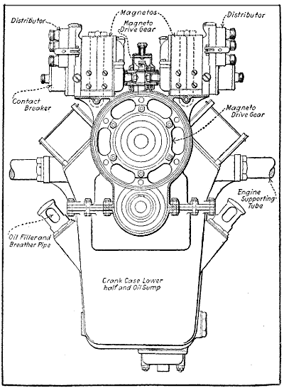
Fig. 228.—End View of Renault Twelve-Cylinder Engine Crank-Case,
Showing Magneto Mounting.
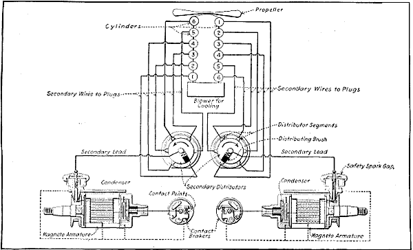
Fig. 229.—Diagram Outlining Renault Twelve-Cylinder Engine Ignition System.
The Model A is of the water-cooled four-cycle Vee
type, with eight cylinders, 4.7245 inch bore by 5.1182 inch
stroke, piston displacement 718 cubic inches. At sea-level
it develops 150 horse-power at 1,450 R. P. M. It can
be run successfully at much higher speeds, depending
on propeller design and gearing, developing proportionately
increased power. The weight, including carburetor,
two magnetos, propeller hub, starting magneto and crank,
but without radiator, water or oil or exhaust pipes, is
445 pounds. Average fuel consumption is .5 pound per
horse-power hour and the oil consumption at 1,450 R. P. M.
is three quarts per hour. The external appearance is
shown at Fig. 230.
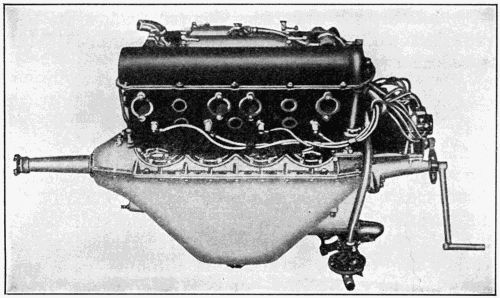
Fig. 230.—The Simplex Model A Hispano-Suiza Aviation Engine, a Very
Successful Form.
Four cylinders are contained in each block, which is
of built-up construction; the water jackets and valve
ports are cast aluminum and the individual cylinders
heat-treated steel forgings threaded into the bored holes
of the aluminum castings. Each block after assembly is
given a number of protective coats of enamel, both inside
and out, baked on. Coats on the inside are applied
under pressure. The pistons are aluminum castings,
ribbed. Connecting rods are tubular, of the forked type.
One rod bears directly on the crank-pin; the other rod
has a bearing on the outside of the one first mentioned.
The crank-shaft is of the five-bearing type, very short,
stiff in design, bored for lightness and for the oiling
system. The crank-shaft extension is tapered for the
French standard propeller hub, which is keyed and
locked to the shaft. This makes possible instant change
of propellers. The case is in two halves divided on the
center line of the crank-shaft, the bearings being fitted
between the upper and lower sections. The lower half
is deep, providing a large oil reservoir and stiffening
the engine. The upper half is simple and provides magneto
supports on extension ledges of the two main faces.
The valves are of large diameter with hollow stems,
working in cast iron bushings. They are directly operated
by a single hollow cam-shaft located over the valves. The
cam-shafts are driven from the crank-shaft by vertical
shafts and bevel gears. The cam-shafts, cams and heads
of the valve stems are all enclosed in oil-tight removable
housings of cast aluminum.
Oiling is by a positive pressure system. The oil is
taken through a filter and steel tubes cast in the case
to main bearings, through crank-shaft to crank-pins.
The fourth main bearing is also provided with an oil
lead from the system and through tubes running up the
end of each cylinder block, oil is provided for the cam-shafts,
cams and bearings. The surplus oil escapes
through the end of the cam-shaft where the driving gears
are mounted, and with the oil that has gathered in the
top casing, descends through the drive shaft and gears
to the sump.
Ignition is by two eight-cylinder magnetos firing two
spark-plugs per cylinder. The magnetos are driven
from each of the two vertical shafts by small bevel
pinions meshing in bevel gears. The carburetor is
mounted between the two cylinder blocks and feeds the
two blocks through aluminum manifolds which are partly
water-jacketed. The engine can be equipped with a
geared hand crank-starting device.
These motors are of the eight-cylinder “V” type, four-stroke
cycle, water-cooled, having a bore of 4 inches and
a stroke of 51⁄2 inches, equivalent to 102 mm. × 140 mm.
The normal operating speed of the crank-shaft is 2,000
R. P. M. The propeller shaft is driven through reducing
gears which can be furnished in different gear ratios.
The standard ratio is 5:3, allowing a propeller speed of
1,200 R. P. M.
The construction of the motor is such as to permit
of the application of a direct drive. The change from the
direct drive to gear drive, or vice versa, can be accomplished
in approximately one hour.
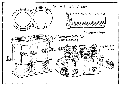
The cylinders are cast in pairs from an aluminum
alloy and are provided with steel sleeves, carefully fitted
into each cylinder. A perfect contact is secured between
cylinder and sleeve; at the same time a sleeve can be
replaced without injury to the cylinder proper. No difficulties
due to expansion occur on account of the rapid
transmission of heat and the fact that the sleeve is always
at higher temperature than the cylinder. A moulded
copper asbestos gasket is placed between the cylinder
and the head, permitting the cooling water to circulate
freely and at the same time insuring a tight joint. The
cylinder heads are cast in pairs from an aluminum alloy
and contain ample water passages for circulation of
cooling water over the entire head. Trouble due to hot
valves is thereby eliminated, a most important consideration
in the operation of an aeroplane motor. The
water jacket of the head corresponds to the water jacket
of the cylinders and large openings in both allow the
unobstructed circulation of the cooling water. The cylinder
heads and cylinders are both held to the base by six
long bolts. The valves are located in the cylinder heads
and are mechanically operated. The valves and valve
springs are especially accessible and of such size as to
permit high volumetric efficiency. The valves are constructed
of hardened tungsten steel, the heads and stems
being made from one piece. The valve rocker arms
located on the top of the cylinder are provided with
adjusting screws. A check nut enables the adjusting
screw to be securely locked in position, once the correct
clearance has been determined. The rocker arm bearings
are adequately lubricated by a compression grease cup.
Cam-rollers are interposed between the cams and the
push rods in order to reduce the side thrust on the push
rods.
A system of double springs is employed which greatly
reduces the stress on each spring and insures utmost
reliability. A spring of extremely large diameter returns
the valve; a second spring located at the cylinder base
handles the push rod linkage. These springs, which
operate under low stress, are made from the best of steel
and are given a special double heat treatment. The
pistons are made from a special aluminum alloy; are
deeply ribbed in the head for cooling and strength and
provided with two piston rings. These pistons are exceedingly
light weight in order to minimize vibration and
prevent wear on the bearings. The piston pin is made of
chrome nickel steel, bored hollow and hardened. It is
allowed to turn, both in piston and connecting rod. The
piston rings are of special design, developed after years
of experimenting in aeronautical engines.
The connecting rods are of “H” section, machined
all over from forgings of a special air-hardening chrome
nickel steel which, after being heat treated has a tensile
strength of 280,000 pounds per square inch. They are
consequently very strong and yet unusually light, and
being machined all over are of absolutely uniform section,
which gives as nearly perfect balance as can be obtained.
The big ends are lined with white metal and the small
ends are bushed with phosphor bronze. The connecting
rods are all alike and take their bearings side by side on
the crank-pin, the cylinders being offset to permit of
this arrangement. The crank-shaft is machined from
the highest grade chrome nickel steel, heat treated in
order to obtain the best properties of this material.
It is 21⁄4 inches in diameter (57 mm.) and bored hollow
throughout, insuring maximum strength with minimum
weight. It is carried in three large, bronze-backed white
metal bearings. A new method of producing these bearings
insures a perfect bond between the two metals and
eliminates breakage.
The base is cast from an aluminum alloy. Great
strength and rigidity is combined with light weight. The
sides extend considerably below the center line of the
crank-shaft, providing an extremely deep section. At
all highly stressed points, deep ribs are provided to distribute
the load evenly and eliminate bending. The lower
half of the base is of cast aluminum alloy of extreme
lightness. This collects the lubricating oil and acts as
a small reservoir for same. An oil-filtering screen of
large area covers the entire surface of the sump. The
propeller shaft is carried on two large annular ball bearings
driven from the crank-shaft by hardened chrome
nickel steel spur gears. These gears are contained within
an oil-tight casing integral with the base on the opposite
end from the timing gears. A ball-thrust bearing
is provided on the propeller shaft to take the thrust of
a propeller or tractor, as the case may be. In case of the
direct drive a stub shaft is fastened direct to the crank-shaft
and is fitted with a double thrust bearing.
The cam-shaft is contained within the upper half of
the base between the two groups of cylinders, and is
supported in six bronze bearings. It is bored hollow
throughout and the cams are formed integral with the
shaft and ground to the proper shape and finish. An
important development in the shape of cams has resulted
in a maintained increase of power at high speeds. The
gears operating the cam-shaft, magneto, oil and water
pumps are contained within an oil-tight casing and operate
in a bath of oil.
Lubrication is of the complete forced circulating system,
the oil being supplied to every bearing under high
pressure by a rotary pump of large capacity. This is
operated by gears from the crank-shaft. The oil passages
from the pump to the main bearings are cast integral
with the base, the hollow crank-shaft forming a passage
through the connecting rod bearings and the hollow cam-shaft
distributing the oil to the cam-shaft bearings. The
entire surface of the lower half of the base is covered
with a fine mesh screen through which the oil passes
before reaching the pump. Approximately one gallon of
oil is contained within the base and this is continually
circulated through an external tank by a secondary pump
operated by an eccentric on the cam-shaft. This also
draws fresh oil from the external tank which can be made
of any desired capacity.
- Horse-power rating, 140 at 2,000 R. P. M.
- Bore, 4 inches = 102 mm.
- Stroke, 51⁄2 inches = 140 mm.
- Number of cylinders, 8.
- Arrangement of cylinders, “V.”
- Cooling, water. Circulation by centrifugal pump.
- Cycle, four stroke.
- Ignition (double), 2 Bosch or Splitdorf magnetos.
- Carburetor, Zenith duplex. Water jacket manifold.
- Oiling system, complete forced. Circulating gear pump.
- Normal crank-shaft speed, 2,000 R. P. M.
- Propeller shaft, 3⁄5 crank-shaft speed at normal, 1,200 R. P. M.
- Stated power at 30′′ barometer, 140 B. H. P.
- Stated weight with all accessories but without water, gasoline or oil, 514 pounds = 234 kilos.
- Weight per B. H. P., 3.7 pounds = 1.68 kilos.
- Stated weight with all accessories with water, 550 pounds = 250 kilos.
- Weight per B. H. P. with water, 3.95 pounds = 1.79 kilos.
The Curtiss OX motor has eight cylinders, 4-inch
bore, 5-inch stroke, delivers 90 horse-power at 1,400 turns,
and the weight turns out at 4.17 pounds per horse-power.
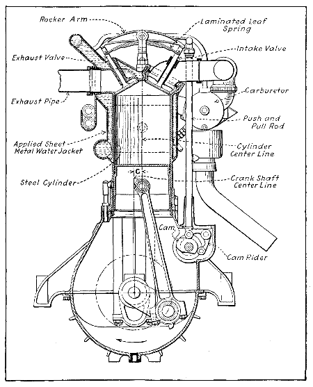
This motor has cast iron cylinders with monel metal
jackets, overhead inclined valves operated by means of
two rocker arms, push-and-pull rods from the central
cam-shaft located in the crank-case. The cam and push
rod design is extremely ingenious and the whole valve
construction turns out very light. This motor is an
evolution from the early Curtiss type motor which was
used by Glenn Curtiss when he won the Gordon Bennett
Cup at Rheims. A slightly larger edition of this type
motor is the OXX-5, as shown at Figs. 231 and 232,
which has cylinders 41⁄4 inches by 5 inches, delivers 100
horse-power at 1,400 turns and has the same fuel and
oil consumption as the OX type motor, namely, .60 pound
of fuel per brake horse-power hour and .03 pound of
lubricating oil per brake horse-power hour.
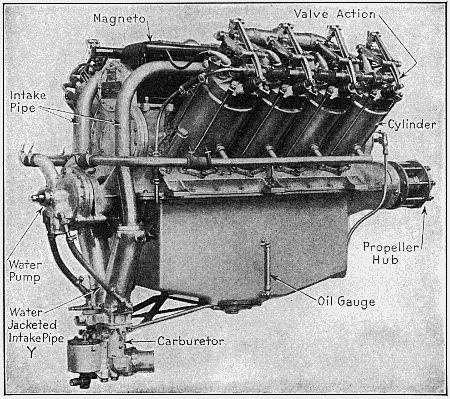
Fig. 231.—The Curtiss OXX-5 Aviation Engine is an Eight-Cylinder Type
Largely Used on Training Machines.
The Curtiss Company have developed in the last
two years a larger-sized motor now known as the V-2,
which was originally rated at 160 horse-power and which
has since been refined and improved so that the motor
gives 220 horse-power at 1,400 turns, with a fuel consumption
of 52⁄100 of a pound per brake horse-power hour
and an oil consumption of .02 of a pound per brake
horse-power hour. This larger motor has a weight of 3.45
pounds per horse-power and is now said to be giving
very satisfactory service. The V-2 motor has drawn
steel cylinders, with a bore of 5 inches and a stroke of
7 inches, with a steel water jacket top and a monel metal
cylindrical jacket, both of which are brazed on to the
cylinder barrel itself. Both these motors use side by
side connecting rods and fully forced lubrication. The
cam-shafts act as a gallery from which the oil is distributed
to the cam-shaft bearings, the main crank-shaft
bearings, and the gearing. Here again we find extremely
short rods, which, as before mentioned, enables the height
and the consequent weight of construction to be very
much reduced. For ordinary flying at altitudes of 5,000
to 6,000 feet, the motors are sent out with an aluminum
liner, bolted between the cylinder and the crank-case in
order to give a compression ratio which does not result
in pre-ignition at a low altitude. For high flying, however,
these aluminum liners are taken out and the compression
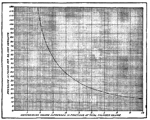
volume is decreased to about 18.6 per cent. of
the total volume.
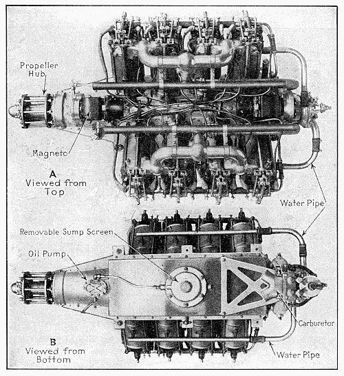
Fig. 232.—Top and Bottom Views of the Curtiss OXX-5 100 Horse-Power
Aviation Engine.
The Curtiss Aeroplane Company announces that it has
recently built, and is offering, a twelve-cylinder 5′′
× 7′′
motor, which was designed for aeronautical uses primarily.
This engine is rated at 250 horse-power, but it is
claimed to develop 300 at 1,400 R. P. M. Weights—Motor,
1,125 pounds; radiator, 120 pounds; cooling water, 100
pounds; propeller, 95 pounds.
Gasoline Consumption per Horse-power Hour, 6⁄10
pounds.
Oil Consumption per Hour at Maximum Speed—2
pints.
Installation Dimensions—Overall length, 845⁄8 inches;
overall width, 341⁄8 inches; overall depth, 40 inches;
width at bed, 301⁄2 inches; height from bed, 211⁄8 inches;
depth from bed, 181⁄2 inches.
The Thomas-Morse Aircraft Corporation of Ithaca,
N. Y., has produced a new engine, Model 88, bearing a
close resemblance to the earlier model. The main features
of that model have been retained; in fact, many parts
are interchangeable in the two engines. Supported by
the great development in the wide use of aluminum, the
Thomas engineers have adopted this material for cylinder
construction, which adoption forms the main departure
from previous accepted design.
The marked tendency to-day toward a higher speed
of rotation has been conclusively justified, in the opinion
of the Thomas engineers, by the continued reliable performance
of engines with crank-shafts operating at speeds
near 2,000 revolutions per minute, driving the propeller
through suitable gearing at the most efficient speed.
High speed demands that the closest attention be paid
to the design of reciprocating and rotating parts and
their adjacent units. Steel of the highest obtainable
tensile strength must be used for connecting rods and
piston pins, that they may be light and yet retain a
sufficient factor of safety. Piston design is likewise
subjected to the same strict scrutiny. At the present
day, aluminum alloy pistons operate so satisfactorily
that they may be said to have come to stay.
The statement often made in the past, that the gearing
down of an engine costs more in the weight of reduction
gears and propeller shaft than is warranted by
the increase in horse-power, is seldom heard to-day.
The mean effective pressure remaining the same, the
brake horse-power of any engine increases as the speed.
That is, an engine delivering 100 brake horse-power at
1,500 revolutions per minute will show 133 brake horse-power
at 2,000 revolutions per minute, an increase of 33
brake horse-power. To utilize this increase in horse-power,
a matter of some fifteen pounds must be spent
in gearing and another fifteen perhaps on larger valves,
bearings, etc. Two per cent. may be assumed lost in
the gears. In other words, the increase in horse-power
due to increasing the speed has been attained at the
expense of about one pound per brake horse-power.
The advantages of the eight-cylinder engine over the
six and twelve, briefly stated, are: lower weight per horse-power,
shorter length, simpler and stiffer crank-shaft,
cam-shaft and crank-case, and simpler and more direct
manifold arrangement. As to torque, the eight is superior
to the six, and yet in practice not enough inferior
to the twelve to warrant the addition of four more
cylinders. It must, however, be recognized that the
eight is subject to the action of inherent unbalanced
inertia couples, which set up horizontal vibrations, impossible
of total elimination. These vibrations are functions
of the reciprocating weights, which, as already
mentioned, are cut down to the minimum. Vibrations
due to the elasticity of crank-case, crank-shaft, etc., can
be and are reduced in the Thomas engine to minor
quantities by ample webbing of the crank-case and judicious
use of metal elsewhere. All things considered,
there is actually so little difference to be discerned between
the balance of a properly designed eight-cylinder
engine and that of a six or twelve as to make a discussion
of the pros and cons more one of theory than
of practice.
The main criticisms of the L head cylinder engine are
that it is less efficient and heavier. This is granted, as it
relates to cylinders alone. More thorough investigation,
however, based on the main desideratum, weight-power
ratio, leads us to other conclusions, particularly with
reference to high speed engines. The valve gear must
not be forgotten. A cylinder cannot be taken completely
away from its component parts and judged, as to its
weight value, by itself alone. A part away from the whole
becomes an item unimportant in comparison with the
whole. The valve gear of a high speed engine is a too
often overlooked feature. The stamp of approval has
been made by high speed automobile practice upon the
overhead cam-shaft drive, with valves in the cylinder
head operated direct from the cam-shaft or by means of
valve lifters or short rockers.
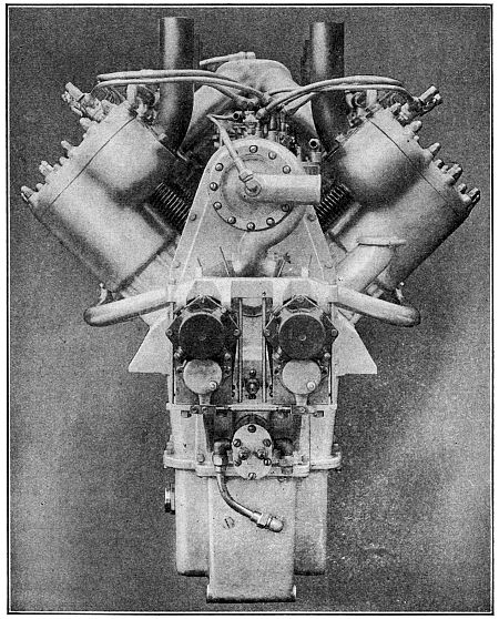
Fig. 233.—End View of Thomas-Morse 150 Horse-Power Aluminum Cylinder
Aviation Motor Having Detachable Cylinder Heads.
The overhead cam-shaft mechanism applied to an
eight-cylinder engine calls for two separate cam-shafts
carried above and supported by the cylinders in an oil-tight
housing, and driven by a series of spur gears or
bevels from the crank-shaft. It is patent that this valve
gearing is heavy and complicated in comparison with
the simple moving valve units of the L head engine,
which are operated from one single cam-shaft, housed
rigidly in the crank-case. The inherently lower volumetric
efficiency of the L head engine is largely overcome
by the use of a properly designed head, large valves and
ample gas passages. Again, the customary use of a dual
ignition system gives to the L head a relatively better
opportunity for the advantageous placing of spark-plugs,
in order that better flame propagation and complete
combustion may be secured.
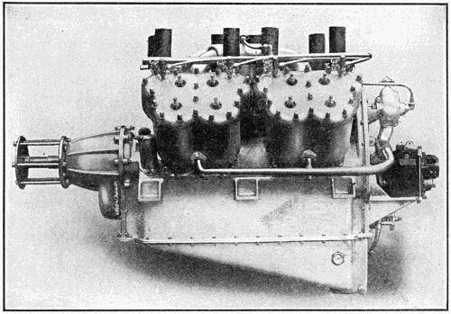
Fig. 234.—Side View of Thomas-Morse High Speed 150 Horse-Power
Aviation Motor with Geared Down Propeller Drive.
The
Thomas Model 88 engine is 41⁄8 inch bore and
51⁄2 inch stroke. The cylinders and cylinder heads are
of aluminum, and as steel liners are used in the cylinders
the pistons are also made of aluminum. This engine is
actually lighter than the earlier model of less power.
It weighs but 525 pounds, with self-starter. The general
features of design can be readily ascertained by study
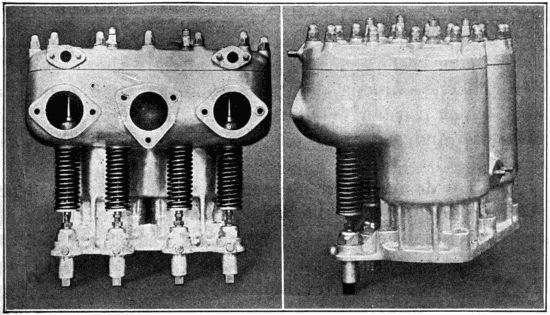
of the illustrations: Fig. 233, which shows an end view;
Fig. 234, which is a side view, and Fig. 235, which outlines
the reduction gear-case and the propeller shaft
supporting bearings.
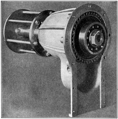
Fig. 235.—The Reduction Gear-Case of Thomas-Morse 150 Horse-Power
Aviation Motor, Showing Ball Bearing and Propeller Drive Shaft Gear.
This engine is a four-cylinder, 43⁄4′′
× 7′′, 125 horse-power
at 2,100 R. P. M. of the crank-shaft and 1,210
R. P. M. of the propeller. Motors are sold on above
rating; actual power tests prove this motor capable of
developing 140 horse-power at 2,100 R. P. M. of the
motor. The exact weight with magneto, carburetor, gear
reduction and propeller hub, as illustrated, 509 pounds;
without gear reduction, 436 pounds. This motor has
been produced as a power plant weighing 3.5 pounds per
horse-power, yet nothing has been sacrificed in rigidity
and strength. At its normal speed it develops 1 horse-power
for every 3.5 cubic inches piston displacement.
Cylinders are semi-steel, with aluminum plates enclosing
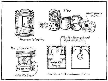
water jackets. Pistons specially ribbed and made of
Magnalite aluminum compound. Piston rings are special
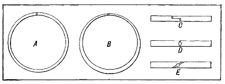
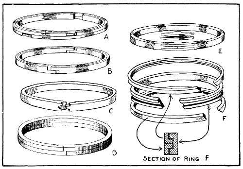
Duesenberg design, being three-piece rings. Valves are
tungsten steel, 115⁄16′′
inlets and 2′′ exhausts, two of each
to each cylinder. Arranged horizontally in the head,
allowing very thorough water-jacketing. Inlet valves in
cages. Exhaust valves, seating directly in the cylinder
head, are removable through the inlet valve holes. Valve
stems lubricated by splash in the valve action covers.
Valve rocker arms forged with cap screw and nut at
upper end to adjust clearance. Entirely enclosed by
aluminum housing, as is entire valve mechanism. Connecting
rods are tubular, chrome nickel steel, light and
strong. Crank-shaft is one-piece forging, hollow bored,
21⁄2-inch diameter at main bearings. Connecting rod
bearings, 21⁄4-inch diameter, 3 inches long. Front main
bearing, 31⁄2 inches long; intermediate main bearing,
31⁄2 inches long; rear main bearing, 4 inches long. Crank-case
of aluminum, barrel type, oil pan on bottom removable.
Hand hole plates on both sides. Strongly webbed.
The oiling system of this sixteen-valve Duesenberg
motor is one of its vital features. An oil pump located
in the base and submerged in oil forces oil through cored
passages to the three main bearings, then through tubes
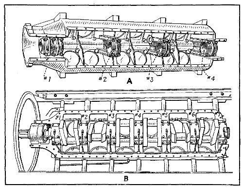
under each connecting rod into which the rod dips. The
oil is thrown off from these and lubricates every part of
the motor. This constitutes the main oiling system; it is
supplemented by a splash system, there being a trough
under each connecting rod into which the rod slips. The
oil is returned to the main supply sump by gravity,
where it is strained and re-used. Either system is in
itself sufficient to operate the motor. A pressure gauge
is mounted for observation on a convenient part of the
system. A pressure of approximately 25 pounds is
maintained by the pressure system, which insures efficient
lubrication at all speeds of the motor. The troughs
under the connecting rods are so constructed that no
matter what the angle of flight may be, oil is retained
in each individual trough so that each connecting rod
can dip up its supply of oil at each revolution.
These motors are four-stroke cycle, six-cylinder vertical
type, with cylinder 45⁄16′′ bore by 51⁄8′′ stroke. The
general appearance of this motor is shown in illustration
at Fig. 236. This engine is rated at 85-90 horse-power.
All reciprocating and revolving parts of this
motor are made of the highest grades of steel obtainable
as are the studs, nuts and bolts. The upper and lower
parts of crank-case are made of composition aluminum
casting. Lower crank-case is made of high grade aluminum
composition casting and is bolted directly to the
upper half. The oil reservoir in this lower half casting
provides sufficient oil capacity for five hours’ continuous
running at full power. Increased capacity can be provided
if needed to meet greater endurance requirements.
Oil is forced under pressure to all bearings by means of
high-pressured duplex-geared pumps. One side of this
pump delivers oil under pressure to all the bearings,
while the other side draws the oil from the splash case
and delivers it to the main sump. The oil reservoir is
entirely separate from the crank-case chamber. Under
no circumstances will oil flood the cylinder, and the oiling
system is not affected in any way by any angle of flight
or position of motor. An oil pressure gauge is placed
on instrument board of machine, which gives at all times
the pressure in oil system, and a sight glass at lower
half of case indicates the amount of oil contained. The
oil pump is external on magneto end of motor, and is
very accessible. An external oil strainer is provided,
which is removable in a few minutes’ time without the
loss of any oil. All oil from reservoir to the motor passes
through this strainer. Pressure gauge feed is also attached
and can be piped to any part of machine desired.
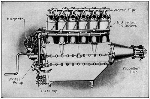
Fig. 236.—The Six-Cylinder Aeromarine Engine.
The cylinders are made of high-grade castings and
are machined and ground accurately to size. Cylinders
are bolted to crank-case with chrome nickel steel studs
and nuts which securely lock cylinder to upper half of
crank-case. The main retaining cylinder studs go
through crank-case and support crank-shaft bearings so
that crank-shaft and cylinders are tied together as one
unit. Water jackets are of copper, 1⁄16′′ thick, electrically
deposited. This makes a non-corrosive metal. Cooling
is furnished by a centrifugal pump, which delivers 25
gallons per minute at 1,400 R. P. M. Pistons are made
cast iron, accurately machined and ground to exact dimensions,
which are carefully balanced. Piston rings are
semi-steel rings of Aeromarine special design.
Connecting rods are of chrome nickel steel, H-section.
Crank-shaft is made of chrome nickel steel, machined all
over, and cut from solid billet, and is accurately balanced
through the medium of balance weights being
forged integral with crank. It is drilled for lightness and
plugged for force feed lubrication. There are seven
main bearings to crank-shaft. All bearings are of high-grade
babbitt, die cast, and are interchangeable and easily
replaced. The main bearings of the crank-shaft are
provided with a single groove to take oil under pressure
from pressure tube which is cast integral with case.
Connecting rod bearings are of the same type. The
gudgeon pin is hardened, ground and secured in connecting
rod, and is allowed to work in piston. Cam-shaft
is of steel, with cams forged integral, drilled for lightness
and forced-feed lubrication, and is case-hardened.
The bearings of cam-shaft are of bronze. Magneto, two
high-tension Bosch D. U. 6. The intake manifold for
carburetors are aluminum castings and are so designed
that each carburetor feeds three cylinders, thereby insuring
easy flow of vapor at all speeds. Weight, 420 pounds.
The new six-cylinder Wisconsin aviation engines, one
of which is shown at Fig. 237, are of the vertical type,
with cylinders in pairs and valves in the head. Dimensioned
drawings of the six-cylinder vertical type are
given at Figs. 238 and 239. The cylinders are made of
aluminum alloy castings, are bored and machined and
then fitted with hardened steel sleeves about 1⁄16 inch in
thickness. After these sleeves have been shrunk into
the cylinders, they are finished by grinding in place.
Gray iron valve seats are cast into the cylinders. The
valve seats and cylinders, as well as the valve ports, are
entirely surrounded by water jackets. The valves set
in the heads at an angle of 25° from the vertical, are
made of tungsten steel and are provided with double
springs, the outer or main spring and the inner or auxiliary
spring, which is used as a precautionary measure
to prevent a valve falling into the cylinder in remote
case of a main spring breaking. The cam-shaft is made
of one solid forging, case-hardened. It is carried in an
aluminum housing bolted to the top of the cylinders.
This housing is split horizontally, the upper half carrying
the chrome vanadium steel rocker levers. The lower half
has an oil return trough cast integral, into which the
excess oil overflows and then drains back to the crank-case.
Small inspection plates are fitted over the cams
and inner ends of the cam rocker levers. The cam-shaft
runs in bronze bearings and the drive is through vertical
shaft and bevel gears.
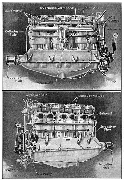
Fig. 237.—The Wisconsin Aviation Engine, at Top, as Viewed from
Carburetor Side. Below, the Exhaust Side.
The crank-case is made of aluminum, the upper half
carrying the bearings for the crank-shaft. The lower
half carries the oil sump in which all of the oil except
that circulating through the system at the time is carried.
The crank-shaft is made of chrome vanadium steel of
an elastic limit of 115,000 pounds. The crank-pins and
ends of the shaft are drilled for lightness and the cheeks
are also drilled for oil circulation. The crank-shaft runs
in bronze-backed, Fahrig metal-lined bearings, four in
number. A double thrust bearing is also provided, so
that the motor may be used either in a tractor or pusher
type of machine. Outside of the thrust bearing an annular
ball bearing is used to take the radial load of the
propeller. The propeller is mounted on a taper. At the
opposite end of the shaft a bevel gear is fitted which
drives the cam-shaft, through a vertical shaft, and also
drives the water and oil pumps and magnetos. All gears
are made of chrome vanadium steel, heat-treated.
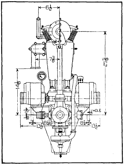
Fig. 238.—Dimensioned End Elevation of Wisconsin Six Motor.
The connecting rods are tubular and machined from
chrome vanadium steel forgings. Oil tubes are fitted to
the rods which carry the oil up to the wrist-pins and
pistons. The rods complete with bushings weigh 51⁄2
pounds each. The pistons are made of aluminum alloy
and are very light and strong, weighing only 2 pounds
2 ounces each. Two leak-proof rings are fitted to each
piston. The wrist-pins are hollow, of hardened steel,
and are free to turn either in the piston or the rod. A
bronze bushing is fitted in the upper end of the rod, but
no bushing is fitted in the pistons, the hardened steel
wrist-pins making an excellent bearing in the aluminum
alloy.
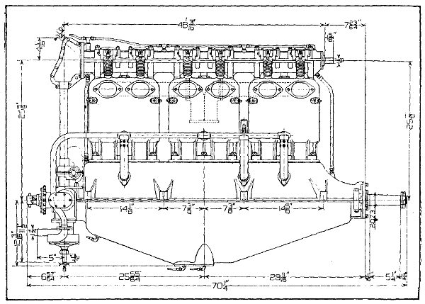
Fig. 239.—Dimensioned Side Elevation of Wisconsin Six Motor.
The water circulation is by centrifugal pump, which
is mounted at the lower end of the vertical shaft. The
water is pumped through brass pipes to the lower end
of the cylinder water jackets and leaves the upper end
of the jackets just above the exhaust valves. The lubricating
system is one of the main features of the engines,
being designed to work with the motor at any angle.
The oil is carried in the sump, from where it is taken
by the oil circulating pump through a strainer and forced
through a header, extending the full length of the crank-case,
and distributed to the main bearings. From the
main bearings it is forced through the hollow crank-shaft
to the connecting rod big ends and then through
tubes on the rods to wrist-pins and pistons. Another
lead takes oil from the main header to the cam-shaft
bearings. The oil forced out of the ends of the cam-shaft
bearings fills pockets under the cams and in the
cam rocker levers. The excess flows back through pipes
and through the train of gears to the crank-case. A
strainer is fitted at each end of the crank-case, through
which the oil is drawn by separate pumps and returned
to the sump. Either one of these pumps is large enough
to take care of all of the return oil, so that the operation
is perfect whether the motor is inclined up or down. No
splash is used in the crank-case, the system being a
full force feed. An oil level indicator is provided, showing
the amount of oil in the sump at all times. The oil
pressure in these motors is carried at ten pounds, a
relief valve being fitted to hold the pressure constant.
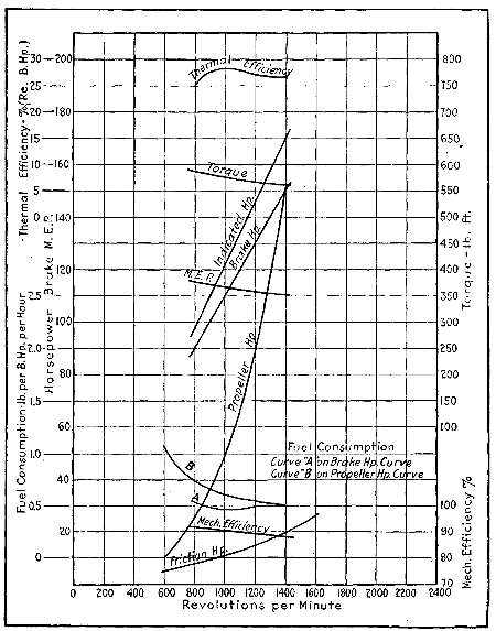
Fig. 240.—Power, Torque and Efficiency Curves of Wisconsin Aviation
Motor.
Ignition is by two Bosch magnetos, each on a separate
set of plugs fired simultaneously on opposite sides of the
cylinders. Should one magneto fail, the other would still
run the engine at only a slight loss in power. The Zenith
double carburetor is used, three cylinders being supplied
by each carburetor. This insures a higher volumetric
efficiency, which means more power, as there is no overlapping
of inlet valves whatever by this arrangement.
All parts of these motors are very accessible. The water
and oil pumps, carburetors, magnetos, oil strainer or
other parts can be removed without disturbing other
parts. The lower crank-case can be removed for inspection
or adjustment of bearings, as the crank-shaft and
bearing caps are carried by the upper half. The motor
supporting lugs are also part of the upper crank-case.
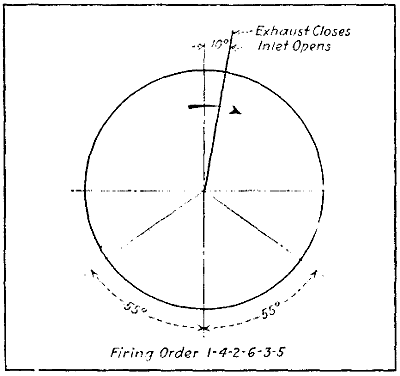
Fig. 241.—Timing Diagram, Wisconsin Aviation Engine.
The six-cylinder motor, without carburetors or magnetos,
weighs 547 pounds. With carburetor and magnetos,
the weight is 600 pounds. The weight of cooling
water in the motor is 38 pounds. The sump will carry
4 gallons of oil, or about 28 pounds. A radiator can be
furnished suitable for the motor, weighing 50 pounds.
This radiator will hold 3 gallons of water or about 25
pounds. The motor will drive a two-blade, 8 feet diameter
by 6.25 feet pitch Paragon propeller 1400 revolutions
per minute, developing 148 horse-power. The weight of
this propeller is 42 pounds. This makes a total weight
of motor, complete with propeller, radiator filled with
water, but without lubricating oil, 755 pounds, or about
5.1 pounds per horse-power for complete power plant.
The fuel consumption is .5 pound per horse-power per
hour. The lubricating oil consumption is .0175 pound
per horse-power per hour, or a total of 2.6 pounds per
hour at 1400 revolutions per minute. This would make
the weight of fuel and oil, per hour’s run at full power
at 1400 revolutions per minute, 76.6 pounds.
Following are the principal dimensions of the six-cylinder
motor:
- Bore 5 inches.
- Stroke 61⁄2 inches.
- Crank-shaft diameter throughout 2 inches.
- Length of crank-pin and main bearings 31⁄2 inches.
- Diameter of valves 3
inches (23⁄4 inches clear).
- Lift of valves 1⁄2 inch.
- Volume of compression space 22 per cent. of total.
- Diameter of wrist-pins 13⁄16 inches.
- Firing order 1-4-2-6-3-5.
The horse-power developed at 1200 revolutions per
minute is 130, at 1300 revolutions per minute 140, at
1400 revolutions per minute 148. 1400 is the maximum
speed at which it is recommended to run these motors.
A twelve-cylinder V-type engine illustrated, is also
being built by this company, similar in dimensions of
cylinders to the six. The principal differences being in
the drive to cam-shaft, which is through spur gears instead
of bevel. A hinged type of connecting rod is used
which does not increase the length of the motor and, at
the same time, this construction provides for ample bearings.
A double centrifugal water pump is provided for
this motor, so as to distribute the water uniformly to
both sets of cylinders. Four magnetos are used, two for
each set of six cylinders. The magnetos are very accessibly
located on a bracket on the spur gear cover. The
carburetors are located on the outside of the motors,
where they are very accessible, while the exhaust is in the
center of the valley. The crank-shaft on the twelve is
21⁄2 inches in diameter and the shaft is bored to reduce
weight. Dimensioned drawings of the twelve-cylinder
engine are given at Figs. 242 and 243 and should prove
useful for purposes of comparison with other motors.
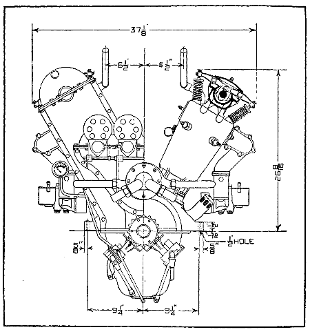
Fig. 242.—Dimensioned End View of Wisconsin Twelve-Cylinder Airplane
Motor.
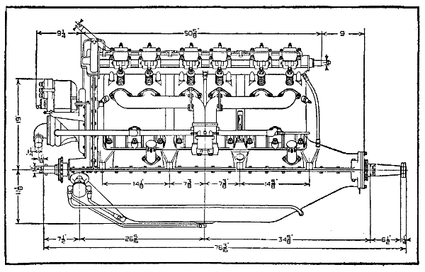
Fig. 243.—Dimensioned Side Elevation of Wisconsin Twelve-Cylinder Airplane
Motor.
The following specifications of the Hall-Scott “Big
Four” engines apply just as well to the six-cylinder
vertical types which are practically the same in construction
except for the structural changes necessary to accommodate
the two extra cylinders. Cylinders are cast
separately from a special mixture of semi-steel, having
cylinder head with valve seats integral. Special attention
has been given to the design of the water jacket around
the valves and head, there being two inches of water
space above same. The cylinder is annealed, rough
machined, then the inner cylinder wall and valve seats
ground to mirror finish. This adds to the durability of
the cylinder, and diminishes a great deal of the excess
friction.
Great care is taken in the casting and machining of
these cylinders, to have the bore and walls concentric
with each other. Small ribs are cast between outer and
inner walls to assist cooling as well as to transfer stresses
direct from the explosion to hold-down bolts which run
from steel main bearing caps to top of cylinders. The
cylinders are machined upon the sides so that when
assembled on the crank-case with grooved hold-down
washers tightened, they form a solid block, greatly assisting
the rigidity of crank-case.
The connecting rods are very light, being of the I
beam type, milled from a solid Chrome nickel die forging.
The caps are held on by two 1⁄2′′-20 thread Chrome nickel
through bolts. The rods are first roughed out, then annealed.
Holes are drilled, after which the rods are hardened
and holes ground parallel with each other. The
piston end is fitted with a gun metal bushing, while the
crank-pin end carries two bronze serrated shells, which
are tinned and babbitted hot, being broached to harden
the babbitt. Between the cap and rod proper are placed
laminated shims for adjustment. Crank-cases are cast of
the best aluminum alloy, hand scraped and sand blasted
inside and out. The lower oil case can be removed without
breaking any connections, so that the connecting rods
and other working parts can readily be inspected. An
extremely large strainer and dirt trap is located in the
center and lowest point of the case, which is easily removed
from the outside without disturbing the oil pump
or any working parts. A Zenith carburetor is provided.
Automatic valves and springs are absent, making the
adjustment simple and efficient. This carburetor is not
affected by altitude to any appreciable extent. A Hall-Scott
device, covered by U. S. Patent No. 1,078,919, allows
the oil to be taken direct from the crank-case and run
around the carburetor manifold, which assists carburetion
as well as reduces crank-case heat. Two waterproof four-cylinder
Splitdorf “Dixie” magnetos are provided. Both
magneto interruptors are connected to a rock shaft integral
with the motor, making outside connections unnecessary.
It is worthy of note that with this independent
double magneto system, one complete magneto can become
inoperative, and still the motor will run and continue to
give good power.
The pistons as provided in the A-7 engines are cast
from a mixture of steel and gray iron. These are extremely
light, yet provided with six deep ribs under the
arch head, greatly aiding the cooling of the piston as well
as strengthening it. The piston pin bosses are located
very low in order to keep the heat from the piston head
away from the upper end of the connecting rod, as well
as to arrange them at the point where the piston fits the
cylinder best. Three 1⁄4′′ rings are carried. The pistons
as provided in the A-7a engines are cast from aluminum
alloy. Four 1⁄4′′ rings are carried. In both piston types
a large diameter, heat treated, Chrome nickel steel wrist-pin
is provided, assembled in such a way as to assist the
circular rib between the wrist-pin bosses to keep the
piston from being distorted from the explosions.
The oiling system is known as the high pressure type,
oil being forced to the under side of the main bearings
with from 5 to 30 points pressure. This system is not
affected by extreme angles obtained in flying, or whether
the motor is used for push or pull machines. A large
gear pump is located in the lowest point of the oil sump,
and being submerged at all times with oil, does away
with troublesome stuffing boxes and check valves. The
oil is first drawn from the strainer in oil sump to the long
jacket around the intake manifold, then forced to the
main distributor pipe in crank-case, which leads to all
main bearings. A bi-pass, located at one end of the
distributor pipe, can be regulated to provide any pressure
required, the surplus oil being returned to the case.
A special feature of this system is the dirt, water and
sediment trap, located at the bottom of the oil sump.
This can be removed without disturbing or dismantling
the oil pump or any oil pipes. A small oil pressure gauge
is provided, which can be run to the aviator’s instrument
board. This registers the oil pressure, and also determines
its circulation.
The cooling of this motor is accomplished by the oil
as well as the water, this being covered by patent No.
1,078,919. This is accomplished by circulating the oil
around a long intake manifold jacket; the carburetion
of gasoline cools this regardless of weather conditions.
Crank-case heat is therefore kept at a minimum. The
uniform temperature of the cylinders is maintained by
the use of ingenious internal outlet pipes, running through
the head of each of the six-cylinders, rubber hose connections
being used so that any one of the cylinders may
be removed without disturbing the others. Slots are cut
in these pipes so that cooler water is drawn directly
around the exhaust valves. Extra large water jackets
are provided upon the cylinders, two inches of water
space is left above the valves and cylinder head. The
water is circulated by a large centrifugal pump insuring
ample circulation at all speeds.
The crank-shaft is of the five bearing type, being
machined from a special heat treated drop forging of the
highest grade nickel steel. The forging is first drilled,
then roughed out. After this the shaft is straightened,
turned down to a grinding size, then ground accurately
to size. The bearing surfaces are of extremely large
size, over-size, considering general practice in the building
of high speed engines of similar bore and stroke.
The crank-shaft bearings are 2′′ in diameter
by 115⁄16′′
long, excepting the rear main bearing, which is 43⁄8′′
long, and front main bearing, which is 23⁄16′′ long. Steel
oil scuppers are pinned and sweated onto the webs of
the shaft, which allows of properly oiling the connecting
rod bearings. Two thrust bearings are installed on the
propeller end of the shaft, one for pull and the other for
push. The propeller is driven by the crank-shaft flange,
which is securely held in place upon the shaft by six
keys. These drive an outside propeller flange, the propeller
being clamped between them by six through bolts.
The flange is fitted to a long taper on crank-shaft. This
enables the propeller to be removed without disturbing
the bolts. Timing gears and starting ratchets are bolted
to a flange turned integral with shaft.
The cam-shaft is of the one piece type, air pump
eccentric, and gear flange being integral. It is made
from a low carbon specially heat treated nickel forging,
is first roughed out and drilled entire length; the cams
are then formed, after which it is case hardened and
ground to size. The cam-shaft bearings are extra long,
made from Parson’s White Brass. A small clutch is
milled in gear end of shaft to drive revolution indicator.
The cam-shaft is enclosed in an aluminum housing bolted
directly on top of all six cylinders, being driven by a
vertical shaft in connection with bevel gears. This shaft,
in conjunction with rocker arms, rollers and other working
parts, are oiled by forcing the oil into end of shaft,
using same as a distributor, allowing the surplus supply
to flow back into the crank-case through hollow vertical
tube. This supply oils the magneto and pump gears.
Extremely large Tungsten valves, being one-half the cylinder
diameter, are seated in the cylinder heads. Large
diameter oil tempered springs held in tool steel cups,
locked with a key, are provided. The ports are very
large and short, being designed to allow the gases to enter
and exhaust with the least possible resistance. These
valves are operated by overhead one piece cam-shaft in
connection with short Chrome nickel rocker arms. These
arms have hardened tool steel rollers on cam end with
hardened tool steel adjusting screws opposite. This construction
allows accurate valve timing at all speeds with
least possible weight.
CENSORED
In a paper on “Aviation Motors,” presented by E. H.
Sherbondy before the Cleveland section of the S. A. E.
in June, 1917, the Mercedes and Benz airplane motor is
discussed in some detail and portions of the description
follow.
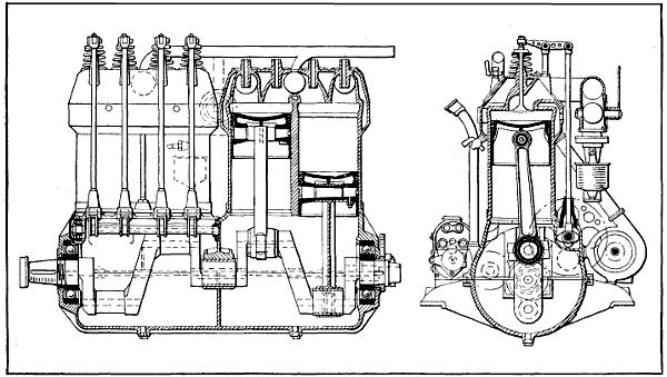
Fig. 244.—Side and End Sectional Views of Four-Cylinder Argus Engine, a German 100 Horse-Power Design Having
Bore and Stroke of 140 mm., or 5.60 inches, and Developing Its Power at 1,368 R.P.M. Weight, 350 Pounds.
The 150 horse-power six-cylinder Mercedes motor is
140 millimeters bore and 160 millimeters stroke. The
Mercedes company started with smaller-sized cylinders,
namely 100 millimeters bore and 140 millimeters stroke,
six-cylinders. The principal features of the design are
forged steel cylinders with forged steel elbows for gas
passages, pressed steel water jackets, which when welded
together forms the cylinder assembly, the use of inclined
overhead valves operated by means of an overhead cam-shaft
through rocker arms which multiply with the motion
of the cam. By the use of steel cylinders, not only
is the weight greatly reduced, but certain freedom from
distortion through unequal sections, leaks and cracks are
entirely avoided. The construction is necessarily very
expensive. It is certainly a sound job. In the details
of this construction there are a number of important
things, such as finished gas passages, water-cooled valve
guides and a very small mass of metal, which is water-cooled,
surrounding the spark-plug. Of course, it is necessary
to use very high compression in aviation motors
in order to secure high power and economy and owing to
the fact that aviation motors are worked at nearly their
maximum, the heat flow through the cylinder, piston, and
valves is many times higher than that encountered in
automobile motors. It has been found necessary to develop
special types of pistons to carry the heat from the
center of the head in order to prevent pre-ignition. In
the Mercedes motor the pistons have a drop forged steel
head which includes the piston boss and this head is
screwed into a cast iron skirt which has been machined
inside to secure uniform wall thickness.
[544]
CENSORED
[546]
Maker’s Name
and Model |
Num-
ber
of
Cyl. |
Bore
(In.) |
Stroke
(In.) |
Piston
Displace-
ment
(Cubic
In.) |
H.P. |
R.P.M. |
Weight of
Engine with
Carburetor
and Ignition |
Gas
Consump-
tion |
| Aeromarine |
6 |
4 |
1⁄2 |
5 |
1⁄8 |
449 |
|
85 |
1400 |
440 |
... |
Aeromarine
D-12 |
12 |
4 |
5⁄16 |
5 |
1⁄8 |
... |
... |
... |
750 |
... |
| Curtiss OX |
8 |
4 |
|
5 |
|
502 |
.6 |
90 |
1400 |
375 |
... |
| Curtiss OXX-2 |
8 |
4 |
1⁄4 |
5 |
|
567 |
.5 |
100 |
1400 |
423 |
... |
| Curtiss V-2 |
8 |
5 |
|
7 |
|
1100 |
|
200 |
1400 |
690 |
... |
| CENSORED |
General Vehicle
Gnome Mono |
9 |
4 |
.33 |
5 |
.9 |
848 |
|
100 |
1200 |
272 |
12 gals/hour
at rated H.P. |
Gyro K Rotary,
Le Rhone Type |
7 |
4 |
1⁄2 |
6 |
|
... |
90 |
1250 |
215 |
8 gals/hour
at rated H.P. |
Gyro L Rotary,
Le Rhone Type |
9 |
4 |
1⁄2 |
6 |
|
859 |
|
100 |
1200 |
285 |
10 gals/hour
at rated H.P. |
| Hall-Scott A-7 |
4 |
5 |
|
7 |
|
550 |
|
90-
100 |
1400 |
410 |
... |
| Hall-Scott A-5 |
6 |
5 |
|
7 |
|
825 |
|
125 |
1300 |
592 |
... |
| Hispano-Suiza |
8 |
4 |
5⁄8 |
5 |
|
672 |
|
154 |
1500 |
455 |
... |
Knox Motors
Co. |
12 |
4 |
3⁄4 |
7 |
|
1555 |
|
300 |
1800 |
1425 |
31.5 gals/hour |
| Maximotor A-6 |
6 |
4 |
1⁄2 |
5 |
|
477 |
|
85 |
1600 |
340 |
... |
| Maximotor B-6 |
6 |
5 |
|
6 |
|
706 |
.8 |
115 |
1600 |
385 |
... |
| Maximotor A-8 |
8 |
4 |
1⁄2 |
5 |
|
636 |
|
115 |
1600 |
420 |
... |
| Packard 12 |
12 |
4 |
|
6 |
|
903 |
|
225 |
2100 |
800 |
... |
| Sturtevant 5 |
8 |
4 |
|
5 |
1⁄2 |
552 |
.9 |
140 |
2000 |
580 |
... |
| Sturtevant 5-A |
8 |
4 |
|
5 |
1⁄2 |
... |
140 |
2000 |
514 |
13.75 gals/hour |
| Thomas 8 |
8 |
4 |
|
5 |
1⁄2 |
552 |
.9 |
135 |
2000 |
630 lbs. with
self-starter |
... |
| Thomas 88 |
8 |
4 |
1⁄8 |
5 |
1⁄2 |
552 |
.9 |
150 |
2100 |
525 lbs. with
self-starter |
... |
| Wisconsin |
6 |
5 |
|
6 |
1⁄2 |
765 |
.7 |
140 |
1380 |
637 |
... |
| Wisconsin |
12 |
5 |
|
6 |
1⁄2 |
1531 |
.4 |
250 |
1200 |
... |
... |
The carburetor used on this 150 horse-power Mercedes
motor is precisely of the same type used on the
Twin Six motor. It has two venturi throats, in the center
of which is placed the gasoline spray nozzle of conventional
type, fixed size orifices, immediately above which
are placed two panel type throttles with side outlets.
An idling or primary nozzle is arranged to discharge
above the top of the venturi throat. The carburetor
body is of cast aluminum and is water jacketed. It is
bolted directly to air passage passing through the top
and bottom half of the crank-case which passes down
through the oil reservoir. The air before reaching the
carburetor proper to some extent has cooled the oil in
the crank chamber and has itself been heated to assist
in the vaporization. The inlet pipes themselves are copper.
All the passages between the venturi throat and
the inlet valve have been carefully finished and polished.
The only abnormal thing in the design of this motor is
the short connecting rod which is considerably less than
twice the stroke and would be considered very bad practice
in motor car engines. A short connecting rod, however,
possesses two very real virtues in that it cuts down height
of the motor and the piston passes over the bottom dead
center much more slowly than with a long rod.
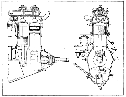
Fig. 245.—Part Sectional View of 90 Horse-Power Mercedes Engine,
Which is Typical of the Design of Larger Sizes.
Other features of the design are a very stiff crank-case,
both halves of which are bolted together by means
of long through bolts, the crank-shaft main bearings are
seated in the lower half of the case instead of in the
usual caps and no provision is made for taking up the
main bearings. The Mercedes company uses a plunger
type of pump having mechanically operated piston valves
and it is driven by means of worm gearing.
The overhead cam-shaft construction is extremely
light. The cam-shaft is mounted in a nearly cylindrical
cast bronze case and is driven by means of bevel gears
from the crank-shaft. The vertical bevel gear shaft
through which the drive is taken from the crank-shaft to
the cam-shaft operates at one and one-half times the
crank-shaft speeds and the reduction to the half-time
cam-shaft is secured through a pair of bevels. On this
vertical shaft there is mounted the water pump and a
bevel gear for driving two magnetos. The water pump
mounted on this shaft tends to steady the drive and avoid
vibration in the gearing.
The cylinder sizes of six-cylinder aviation motors
which have been built by Mercedes are
| Bore |
Stroke |
Horse-power |
| 105 mm. |
140 mm. |
100 |
| 120 mm. |
140 mm. |
135 |
| 140 mm. |
150 mm. |
150 |
| 140 mm. |
160 mm. |
160 |
The largest of these motors has recently had its horsepower
increased to 176 at 1450 R. P. M. This general
design of motor has been the foundation for a great many
other aviation motor designs, some of which have proved
very successful but none of which is equal to the original.
Among the motors which follow more or less closely
the scheme of design and arrangement are the Hall-Scott,
the Wisconsin motor, the Renault water-cooled, the Packard,
the Christofferson and the Rolls-Royce. Each of
these motors show considerable variation in detail. The
Rolls-Royce and Renault are the only ones who have used
the steel cylinder with the steel jacket. The Wisconsin
motor uses an aluminum cylinder with a hardened steel
liner and cast-iron valve seats. The Christofferson has
somewhat similar design to the Wisconsin with the exception
that the valve seats are threaded into the aluminum
jacket and the cylinder head has a blank end which
is secured to the aluminum casting by means of the valve
seat pieces. The Rolls-Royce motors show small differences
in details of design in cylinder head and cam-shaft
housing from the Mercedes on which it has taken out
patents, not only abroad but in this country.
In the Kaiser prize contest for aviation motors a four-cylinder
Benz motor of 130 by 180 mm. won first prize,
developing 103 B. H. P. at 1290 R. P. M. The fuel consumption
was 210 grams per horse-power hour. Total
weight of the motor was 153 kilograms. The oil consumption
was .02 of a kilogram per horse-power hour.
This motor was afterward expanded into a six-cylinder
design and three different sizes were built.
The accompanying table gives some of the details of
weight, horse-power, etc.
| Motor type |
B |
FD |
FF |
| Rated horse-power |
85 |
|
100 |
|
150 |
|
| Horse-power at 1250 r.p.m |
88 |
|
108 |
|
150 |
|
| Horse-power at 1350 r.p.m |
95 |
|
115 |
|
160 |
|
| Bore in millimeters |
106 |
|
116 |
|
130 |
|
| Stroke in millimeters |
150 |
|
160 |
|
180 |
|
| Offset of the cylinders in millimeters |
18 |
|
20 |
|
20 |
|
| Rate of gasoline consumption in grams |
240 |
|
230 |
|
225 |
|
| Oil consumption in grams per b.h.p. hour |
10 |
|
10 |
|
10 |
|
| Oil capacity in kilograms |
36 |
|
4 |
|
4 |
1⁄2 |
| Water capacity in litres |
5 |
1⁄2 |
7 |
1⁄2 |
9 |
1⁄2 |
| The weight with water and oil but with two magnetos, fuel feeder and air pump in kilograms |
170 |
|
200 |
|
245 |
|
| The weight of motors, including the water pump, two magnetos, double ignition, etc. |
160 |
|
190 |
|
230 |
|
| The weight of the exhaust pipe, complete in kilograms |
4 |
|
4 |
.8 |
5 |
1⁄2 |
| The weight of the propeller hub in kilograms. |
3 |
1⁄2 |
4 |
|
4 |
|
The Benz cylinder is a simple, straightforward design
and a very reliable construction and not particularly difficult
to manufacture. The cylinder is cast of iron without
a water jacket but including 45 degrees angle elbows to
the valve ports. The cylinders are machined wherever
possible and at other points have been hand filed and
scraped, after which a jacket, which is pressed in two
halves, is gas welded by means of short pipes welded on
to the jacket. The bottom and the top of the cylinders
become water galleries, and by this means separate water
pipes with their attendant weight and complication are
eliminated. Rubber rings held in aluminum clamps serve
to connect the cylinders together. The whole construction
turns out very neat and light. The cylinder walls
are 4 mm. or 3⁄16′′ thick and the combustion chamber is of
cylindrical pancake form and is 140 mm. or 5.60 inch in
diameter. The valve seats are 68 mm. in diameter and
the valve port is 62 mm. in diameter.
The passage joining the port is 57 mm. in diameter.
In order to insert the valves into the cylinder the valve
stem is made with two diameters and the valve has to
be cocked to insert it in the guide, which has a bronze
bushing at its upper end to compensate for the smaller
valve stem diameter. The valve stem is 14 mm. or 9⁄16′′
in diameter and is reduced at its upper portion to 91⁄2 mm.
The valves are operated through a push rod and rocker
arm construction, which is 7⁄16′′ and exceedingly light.
Rocker arm supports are steel studs with enlarged heads
to take a double row ball bearing. A roller is mounted
at one end of the rocker arm to impinge on the end of
the valve stem, and the rocker arm has an adjustable
globe stud at the other end. The push rods are light steel
tubes with a wall thickness of 0.75 mm. and have a hardened
steel cup at their upper end to engage the rocker
arm globe stud and a hardened steel globe at their lower
end to socket in the roller plunger.
The Benz cam-shaft has a diameter of 26 mm. and is
bored straight through 18 mm. and there is a spiral gear
made integrally with the shaft in about the center of its
length for driving the oil pump gear. The cam faces are
10 mm. wide. There is also, in addition to the intake
and exhaust cams, a set of half compression cams. The
shaft is moved longitudinally in its bearings by means of
an eccentric to put these cams into action. At the fore
end of the shaft is a driving gear flange which is very
small in diameter and very thin. The flange is 68 mm.
in diameter and 4 mm. thick and is tapped to take 6 mm.
bolts. The total length of cam-shaft is 1038 mm., and it
becomes a regular gun boring job to drill a hole of this
length.
The cam-shaft gear is 140 mm. or 51⁄2 inches outside
diameter. It has fifty-four teeth and the gear face is 15
mm. or 19⁄32′′. The flange and web have an average thickness
of 4 mm. or 5⁄32′′ and the web is drilled full of holes
interposed between the spur gear mounted on the cam-shaft
and the cam-shaft gear. There is a gear which
serves to drive the magnetos and tachometer, also the
air pump. The shaft is made integrally with this gear
and has an eccentric portion against which the air pump
roll plunger impinges.
The seven-bearing crank-shaft is finished all over in
a beautiful manner, and the shaft out of the particular
motor we have shows no signs of wear whatever. The
crank-pins are 55 mm. in diameter and 69 mm. long.
Through both the crank-pin and main bearings there is
drilled a 28 mm. hole, and the crank cheeks are plugged
with solder. The crank cheeks are also built to convey
the lubricant to the crank-pins. At the fore end of the
crank cheek there is pressed on a spur driving gear.
There is screwed on to the front end of the shaft a piece
which forms a bevel water pump driving gear and the
starting dog. At the rear end of the shaft very close to
the propeller hub mounting there is a double thrust bearing
to take the propeller thrust.
Long, shouldered studs are screwed into the top half
of the crank-case portion of the case and pass clean
through the bottom half of the case. The case is very
stiff and well ribbed. The three center bearing diaphragms
have double walls. The center one serves as a
duct through which water pipe passes, and those on either
side of the center form the carburetor intake air passages
and are enlarged in section at one side to take the carburetor
barrel throttle.
The pistons are of cast iron and carry three concentric
rings 1⁄4 inch wide on their upper end, which are pinned
at the joint. The top of the piston forms the frustum
of the cone and the pistons are 110 mm. in length. The
lower portion of the skirt is machined inside and has a
wall thickness of 1 mm. Riveted to the piston head is
a conical diaphragm which contacts with the piston pin
when in place and serves to carry the heat off the center
of the piston.
The oil pump assembly comprises a pair of plunger
pumps which draw oil from a separate outside pump, and
constructed integrally with it is a gear pump which delivers
the oil under about 60 pound pressure through a
set of copper pipes in the base to the main bearings. The
plunger oil pump shows great refinement of detail. A
worm wheel and two eccentrics are machined up out of
one piece and serve to operate the plungers.
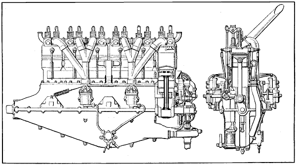
Fig. 246.—Part Sectional Side View and Sectional End View of Benz 160 Horse-Power Aviation Engine.
Some interesting details of the 160 horse-power Benz
motor, which is shown at Fig. 246, are reproduced from
the “Aerial Age Weekly,” and show how carefully the
design has been considered.
- Maximum horse-power, 167.5 B. H. P.
- Speed at maximum horse-power, 1,500 R. P. M.
- Piston speed at maximum horse-power, 1,770 ft. per minute.
- Normal horse-power, 160 B. H. P.
- Speed at normal horse-power, 1,400 R. P. M.
- Piston speed at normal horse-power, 1,656 ft. per minute.
- Brake mean pressure at maximum horse-power, 101.2 pound per square inch.
- Brake mean pressure at normal horse-power, 103.4 pound per square inch.
- Specific power cubic inch swept volume per B. H. P.,
5.46 cubic inch; 160 B. H. P.
- Weight of piston, complete with gudgeon pin, rings,
etc., 5.0 pound.
- Weight of connecting rod, complete with bearings,
4.99 pound; 1.8 pound reciprocating.
- Weight of reciprocating parts per cylinder, 6.8 pound.
- Weight of reciprocating parts per square inch of
piston area, 0.33 pound.
- Outside diameter of inlet valve, 68 mm.; 2.68 inches.
- Diameter of inlet valve port (d), 61.5 mm.; 2.42 inches.
- Maximum lift of inlet valve (h), 11 mm.; 0.443 inch.
- Area of inlet valve opening (π d h), 21.25 square cm.;
3.29 square inches.
- Inlet valve opens, degrees on crank, top dead center.
- Inlet valve closes, degrees on crank, 60° late; 35 mm.
late.
- Outside diameter of exhaust valve, 68 mm.; 2.68 inches.
- Diameter of exhaust valve port (d), 61.5 mm.; 2.42
inches.
- Maximum lift of exhaust valve (h) 11 mm.; 0.433
inch.
- Area of exhaust valve opening (π d h), 21.25 square
cm.; 3.29 square inches.
- Exhaust valve opens, degrees on crank, 60° early;
35 mm. early.
- Exhaust valve closes, degrees on crank, 161⁄2° late;
5 mm. late.
- Length of connecting rod between centers, 314 mm.;
12.36 inches.
- Ratio connecting rod to crank throw, 3.49:1.
- Diameter of crank-shaft, 55 mm. outside, 2.165 inches;
28 mm. inside, 1.102 inches.
- Diameter of crank-pin, 55 mm. outside, 2.165 inches;
28 mm. inside, 1.102 inches.
- Diameter of gudgeon pin, 30 mm. outside, 1.181 inches;
19 mm. inside, 0.708 inch.
- Diameter of cam-shaft, 26 mm. outside, 1.023 inches;
18 mm. inside, 0.708 inch.
- Number of crank-shaft bearings, 7.
- Projected area of crank-pin bearings, 36.85 square
cm.; 5.72 square inches.
- Projected area of gudgeon pin bearings, 22.20 square
cm.; 3.44 square inches.
- Firing sequence, 1, 5, 3, 6, 2, 4.
- Type of magnetos, ZH6 Bosch.
- Direction of rotation of magneto from driving end,
one clock, one anti-clock.
- Magneto timing, full advance, 30° early (16 mm.
early).
- Type of carburetors (2) Benz design.
- Fuel consumption per hour, normal horse-power, 0.57
pint.
- Normal speed of propeller, engine speed, 1,400 R. P. M.
One of the first very successful European flying engines
which was developed in Europe is the Austro-Daimler,
which is shown in end section in a preceding chapter. The
first of these motors had four-cylinders, 120 by 140 millimeters,
bore and stroke, with cast iron cylinders, overhead
valves operated by means of a single rocker arm,
controlled by two cams and the valves were closed by a
single leaf spring which oscillates with the rocker arm.
The cylinders are cast singly and have either copper or
steel jackets applied to them. The four-cylinder design
was afterwards expanded to the six-cylinder design and
still later a six-cylinder motor of 130 by 175 millimeters
was developed. This motor uses an offset crank-shaft,
as does the Benz motor, and the effect of offset has been
discussed earlier on in this treatise. The Benz motor also
uses an offset cam-shaft which improves the valve operation
and changes the valve lift diagram. The lubrication
also is different than any other aviation motor, since
individual high pressure metering pumps are used to
deliver fresh oil only to the bearings and cylinders, as
was the custom in automobile practice some ten years ago.
These very successful engines have been developed by
Louis Coatalen. At the opening of the war the largest
sized Coatalen motor was 225 horse-power and was of the
L-head type having a single cam-shaft for operating
valves and was an evolution from the twelve-cylinder
racing car which the Sunbeam Company had previously
built. Since 1914 the Sunbeam Company have produced
engines of six-, eight-, twelve- and eighteen-cylinders from
150 to 500 horse-power with both iron and aluminum
cylinders. For the last two years all the motors have had
overhead cam-shafts with a separate shaft for operating
the intake and exhaust valves. Cam-shafts are connected
through to the crank-shaft by means of a train of spur
gears, all of which are mounted on two double row ball
bearings. In the twin six, 350 horse-power engine, operating
at 2100 R. P. M., requires about 4 horse-power
to operate the cam-shafts. This motor gives 362 horsepower
at 2100 revolutions and has a fuel consumption of
51⁄100 of a pint per brake horse-power hour. The cylinders
are 110 by 160 millimeters. The same design has been
expanded into an eighteen-cylinder which gives 525 horsepower
at 2100 turns. There has also been developed a
very successful eight-cylinder motor rated at 2220 horsepower
which has a bore and stroke of 120 by 130 millimeters,
weight 450 pounds. This motor is an aluminum
block construction with steel sleeves inserted. Three
valves are operated, one for the inlet and two for the
exhaust. One cam-shaft operates the three valves.
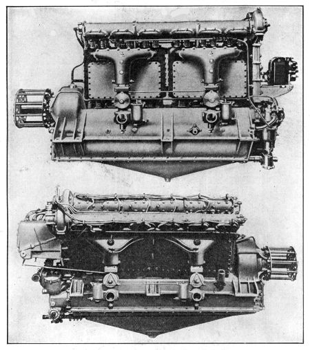
Fig. 247.—At Top, the Sunbeam Overhead Valve 170 Horse-Power Six-Cylinder
Engine. Below, Side View of Sunbeam 350 Horse-Power
Twelve-Cylinder Vee Engine.
The modern Sunbeam engines operate with a mean
effective pressure of 135 pounds with a compression ratio
of 6 to 1 sea level. The connecting rods are of the articulated
type as in the Renault motor and are very short.
The weight of these motors turns out at 2.6 pounds per
brake horse-power, and they are able to go through a
100 hour test without any trouble of any kind. The lubricating
system comprises a dry base and oil pump for
drawing the oil off from the base, whence it is delivered
to the filter and cooling system. It then is pumped by a
separate high pressure gear pump through the entire
motor. In these larger European motors, castor-oil is
used largely for lubrication. It is said that without the
use of castor-oil it is impossible to hold full power for
five hours. Coatalen favors aluminum cylinders rather
than cast iron. The series of views in Figs. 247 to 250
inclusive, illustrates the vertical, narrow type of engine;
the V-form; and the broad arrow type wherein three
rows, each of six-cylinders, are set on a common crank-case.
In this water-cooled series the gasoline and oil
consumption are notably low, as is the weight per horse-power.
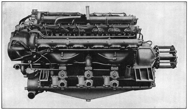
Fig. 248.—Side View of Eighteen-Cylinder Sunbeam Coatalen Aircraft Engine Rated at 475 B.H.P.
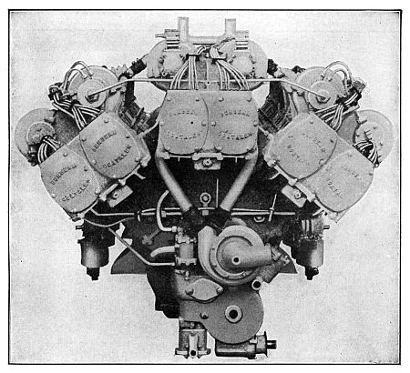
Fig. 249.—Sunbeam Eighteen-Cylinder Motor, Viewed from Pump and
Magneto End.
In the eighteen-cylinder overhead valve Sunbeam-Coatalen
aircraft engine of 475 brake horse-power, there
are no fewer than half a dozen magnetos. Each magneto
is inclosed. Two sparks are furnished to each cylinder
from independent magnetos. On this engine there are
also no fewer than six carburetors. Shortness of crank-shaft,
and therefore of engine length, and absence of
vibration are achieved by the linking of the connecting-rods.
Those concerned with three-cylinders in the broad
arrow formation work on one crank-pin, the outer rods
being linked to the central master one. In consequence
of this arrangement, the piston travel in the case of the
central row of cylinders is 160 mm., while the stroke of
the pistons of the cylinders set on either side is in each
case 168 mm. Inasmuch as each set of six-cylinders is
completely balanced in itself, this difference in stroke
does not affect the balance of the engine as a whole. The
duplicate ignition scheme also applies to the twelve-cylinder
350 brake horse-power Sunbeam-Coatalen overhead
valve aircraft engine type. It is distinguishable,
incidentally, by the passage formed through the center of
each induction pipe for the sparking plug in the center
cylinder of each block of three. In this, as in the eighteen-cylinder
and the six-cylinder types, there are two cam-shafts
for each set of cylinders. These cam-shafts are
lubricated by low pressure and are operated through a
train of inclosed spur wheels at the magneto end of the
machine. The six-cylinder, 170 brake horse-power vertical
type employs the same general principles, including the
detail that each carburetor serves gas to a group of three-cylinders
only. It will be observed that this engine presents
notably little head resistance, being suitable for
multi-engined aircraft.
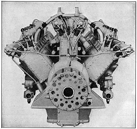
Fig. 250.—Propeller End of Sunbeam Eighteen-Cylinder 475 B.H.P.
Aviation Engine.
[564]
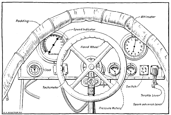
Fig. 251.—View of Airplane Cowl Board, Showing the Various Navigating and Indicating Instruments to Aid the
Aviator in Flight.
The proper functioning of the power plant and the
various groups comprising it may be readily ascertained
at any time by the pilot because various indicating meters
and pressure gauges are provided which are located on a
dash or cowl board in front of the aviator, as shown at
Fig. 251. The speed indicator corresponds to the speedometer
of an automobile and gives an indication of the speed
the airplane is making, which taken in conjunction with the
clock will make it possible to determine the distance covered
at a flight. The altimeter, which is an aneroid
barometer, outlines with fair accuracy the height above
the ground at which a plane is flying. These instruments
are furnished to enable the aviator to navigate the airplane
when in the air, and if the machine is to be used
for cross-country flying, they may be supplemented by a
compass and a drift set. It will be evident that these
are purely navigating instruments and only indicate the
motor condition in an indirect manner. The best way of
keeping track of the motor action is to watch the tachometer
or revolution counter which is driven from the
engine by a flexible shaft. This indicates directly the
number of revolutions the engine is making per minute
and, of course, any slowing up of the engine in normal
flights indicates that something is not functioning as it
should. The tachometer operates on the same principle
as the speed indicating device or speedometer used in
automobiles except that the dial is calibrated to show
revolutions per minute instead of miles per hour. At the
extreme right of the dash at Fig. 251 the spark advance
and throttle control levers are placed. These, of course,
regulate the motor speed just as they do in an automobile.
Next to the engine speed regulating levers is placed a
push button cut-out switch to cut out the ignition and
stop the motor. Three pressure gauges are placed in a
line. The one at the extreme right indicates the pressure
of air on the fuel when a pressure feed system is used.
The middle one shows oil pressure, while that nearest
the center of the dash board is employed to show the air
pressure available in the air starting system. It will be
evident that the character of the indicating instruments
will vary with the design of the airplane. If it was provided
with an electrical starter instead of an air system
electrical indicating instruments would have to be provided.
Two forms of air-starting systems are in general use,
one in which the crank-shaft is turned by means of an
air motor, the other class where compressed air is admitted
to the cylinders proper and the motor turned over
because of the air pressure acting on the engine pistons.
A system known as the “Never-Miss” utilizes a small
double-cylinder air pump is driven from the engine by
means of suitable gearing and supplies air to a substantial
container located at some convenient point in the
fuselage. The air is piped from the container to a dash-control
valve and from this member to a peculiar form
of air motor mounted near the crank-shaft. The air
motor consists of a piston to which a rack is fastened
which engages a gear mounted on the crank shaft provided
with some form of ratchet clutch to permit it to
revolve only in one direction, and then only when the
gear is turning faster than the engine crank-shaft.
The method of operation is extremely simple, the
dash-control valve admitting air from the supply tank
to the top of the pump cylinder. When in the position
shown in cut the air pressure will force the piston and
rack down and set the engine in motion. A variety of
air motors are used and in some the pump and motor may
be the same device, means being provided to change the
pump to an air motor when the engine is to be turned over.
The “Christensen” air starting system is shown at
Figs. 252 and 253. An air pump is driven by the engine,
and this supplies air to an air reservoir or container
attached to the fuselage. This container communicates
with the top of an air distributor when a suitable control
valve is open. An air pressure gauge is provided to
enable one to ascertain the air pressure available. The
top of each cylinder is provided with a check valve,
through which air can flow only in one direction, i.e., from
the tank to the interior of the cylinder. Under explosive
pressure these check valves close. The function of the
distributor is practically the same as that of an ignition
timer, its purpose being to distribute the air to the cylinders
of the engine only in the proper firing order. All
the while that the engine is running and the car is in
motion the air pump is functioning, unless thrown out of
action by an easily manipulated automatic control. When
it is desired to start the engine a starting valve is opened
which permits the air to flow to the top of the distributor,
and then through a pipe to the check valve on top of the
cylinder about to explode. As the air is going through
under considerable pressure it will move the piston down
just as the explosion would, and start the engine rotating.
The inside of the distributor rotates and directs a charge
of air to the cylinder next to fire. In this way the engine
is given a number of revolutions, and finally a charge of
gas will be ignited and the engine start off on its cycle of
operation. To make starting positive and easier some
gasoline is injected in with the air so an inflammable mixture
is present in the cylinders instead of air only. This
ignites easily and the engine starts off sooner than would
otherwise be the case. The air pressure required varies
from 125 to 250 pounds per square inch, depending upon
the size and type of the engine to be set in motion.
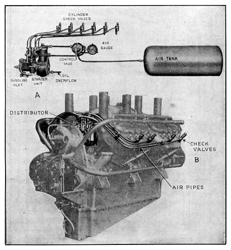
Fig. 252.—Parts of Christensen Air Starting System Shown at A, and
Application of Piping and Check Valves to Cylinders of Thomas-Morse
Aeromotor Outlined at B.
[568]
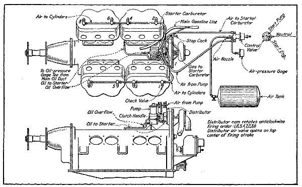
Fig. 253.—Diagrams Showing Installation of Air Starting System on Thomas-Morse Aviation Motor.
[569]
Starters utilizing electric motors to turn over the
engine have been recently developed, and when properly
made and maintained in an efficient condition they answer
all the requirements of an ideal starting device.
The capacity is very high, as the motor may draw current
from a storage battery and keep the engine turning
over for considerable time on a charge. The objection
against their use is that it requires considerable complicated
and costly apparatus which is difficult to understand
and which requires the services of an expert electrician
to repair should it get out of order, though if battery
ignition is used the generator takes the place of the
usual ignition magneto.
In the Delco system the electric current is generated
by a combined motor-generator permanently geared to
the engine. When the motor is running it turns the
armature and the motor generator is acting as a dynamo,
only supplying current to a storage battery. On account
of the varying speeds of the generator, which are due to
the fluctuation in engine speed, some form of automatic
switch which will disconnect the generator from the battery
at such times that the motor speed is not sufficiently
high to generate a current stronger than that delivered
by the battery is needed. These automatic switches are
the only delicate part of the entire apparatus, and while
they require very delicate adjustment they seem to perform
very satisfactorily in practice.
When it is desired to start the engine an electrical
connection is established between the storage battery and
the motor-generator unit, and this acts as a motor and
turns the engine over by suitable gearing which engages
the gear teeth cut into a special gear or disc attached to
the engine crank-shaft. When the motor-generator furnishes
current for ignition as well as for starting the
motor, the fact that the current can be used for this work
as well as starting justifies to a certain extent the rather
complicated mechanism which forms a complete starting
and ignition system, and which may also be used for lighting
if necessary in night flying.
An electric generator and motor do not complete a
self-starting system, because some reservoir or container
for electric current must be provided. The current from
the generator is usually stored in a storage battery from
which it can be made to return to the motor or to the
same armature that produced it. The fundamental units
of a self-starting system, therefore, are a generator to
produce the electricity, a storage battery to serve as a
reservoir, and an electric motor to rotate the motor crank-shaft.
Generators are usually driven by enclosed gearing,
though silent chains are used where the center distance
between the motor shaft and generator shaft is too
great for the gears. An electric starter may be directly
connected to the gasoline engine, as is the case where the
combined motor-generator replaces the fly-wheel in an
automobile engine. The motor may also drive the engine
by means of a silent chain or by direct gear reduction.
Every electric starter must use a switch of some kind
for starting purposes and most systems include an output
regulator and a reverse current cut-out. The output
regulator is a simple device that regulates the strength
of the generator current that is supplied the storage battery.
A reverse current cut-out is a form of check
valve that prevents the storage battery from discharging
through the generator. Brief mention is made of electric
starting because such systems will undoubtedly be incorporated
in some future airplane designs. Battery ignition
is already being experimented with.
A battery ignition system in its simplest form consists
of a current producer, usually a set of dry cells or a
storage battery, an induction coil to transform the low
tension current to one having sufficient strength to jump
the air gap at the spark-plug, an igniter member placed
in the combustion chamber and a timer or mechanical
switch operated by the engine so that the circuit will be
closed only when it is desired to have a spark take place
in the cylinders. Battery ignition systems may be of two
forms, those in which the battery current is stepped up
or intensified to enable it to jump an air gap between the
points of the spark plug, these being called “high tension”
systems and the low tension form (never used on
airplane motors) in which the battery current is not intensified
to a great degree and a spark produced in the cylinder
by the action of a mechanical circuit breaker in the
combustion chamber. The low tension system is the simplest
electrically but the more complex mechanically.
The high tension system has the fewest moving parts but
numerous electrical devices. At the present time all airplane
engines use high tension ignition systems, the magneto
being the most popular at the present time. The
current distribution and timing devices used with modern
battery systems are practically the same as similar parts
of a magneto.
[573]