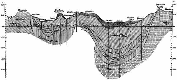
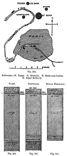
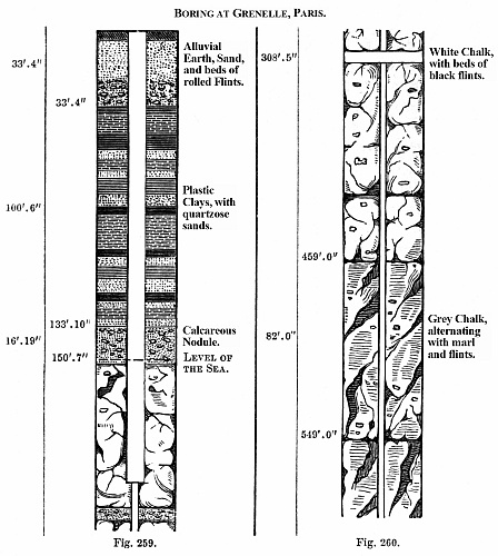
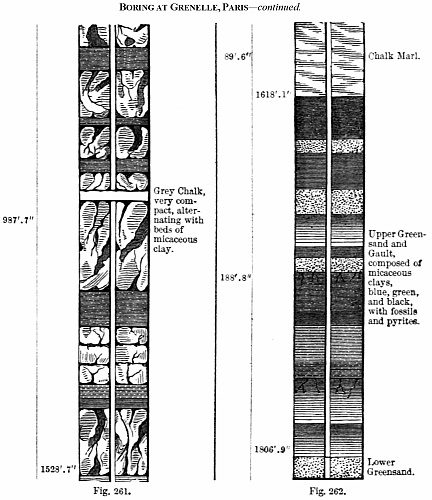
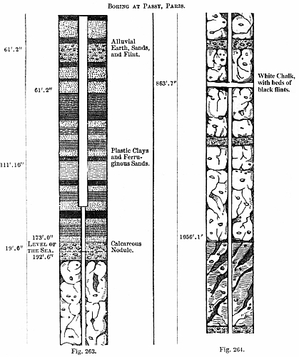
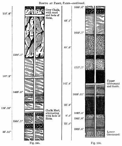
The first well that was executed of great depth, and which gave rise
to the adoption of tools which directed public attention to the art of
well boring, was that for the city of Paris by Mulot, at the Abattoir
of Grenelle. This was commenced in the year 1832; and after more than
eight years’ incessant labour, water rose, on the 26th of February,
1842, from the total depth of 1798 feet. Subsequent to this, many
wells have been sunk on the Continent, with the hope of attaining
the brine springs so often met with in the Rhine provinces, or the
springs destined for the supply of towns, and which are even deeper
than the well of Grenelle, reaching in some cases to the extraordinary
depth of 2800 feet; but all of them, like the Grenelle well, of
small diameter. In their construction, however, the German engineers
introduced some important modifications of the tools employed; and,
amongst other inventions, Euyenhausen imparted a sliding movement to
the striking part of the tool used for comminuting the rock, so as to
fall always through a certain distance; and thus, while he produced a
uniform action upon the rock at the bottom, he avoided the jar of the
tools. Kind also began to apply his system to the working of the large
excavations for the purpose of winning coal. Whilst the art was in
this state, and when he had already executed some very important works
in Germany, Belgium, the North of France, Creuzot, and Seraing, the
Municipal Council of Paris determined to entrust him with the execution
of a new well they were about to sink at Passy.
In sinking the well of Passy, the weight of the trepan for comminuting
the rock was about 1 ton 16 cwt., 1800 kilog.: the height through which
it fell was about 60 centimètres; and its diameter was 3 feet 37⁄16
inches, 1 mètre. The rods were of oak, about 8 inches on the side,
and the dimensions of the cutting tool were limited to 3 feet 37⁄16
inches because it worked the whole time in water; but generally the
class of borings Kind undertook were of such a description as justified
resorting to tools of great dimensions. When sinking the shafts for
winning coal, his operations required to be carried on with the full
diameters of 10 feet or 14 feet; and he then drove a boring of 3 feet 4
inches diameter in the first instance, and subsequently enlarged this
excavation. There can be no objection to executing Artesian borings
of this diameter, other than the probable exhaustion of the supply;
particularly as it is now known that the yield of water by these
methods is proportionate to the diameter of the column; though, strange
as it may appear, the first opposition to Kind’s plan of sinking the
well of Passy was founded upon the assumption that he would not meet
with a larger supply of water from the subcretaceous formations than
had been met with at Grenelle, where the diameter of the boring was
at the bottom not more than 8 inches. It is now, however, proved that
there is a direct gain in adopting the larger borings, not only as
regards the quantity of water to be derived from them, but also in
their execution, arising from the fact that the tools can be made
more secure against the effects of torsion or of concussion against
the sides of the excavation, which is the cause of the most serious
accidents met with in well sinking.
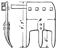
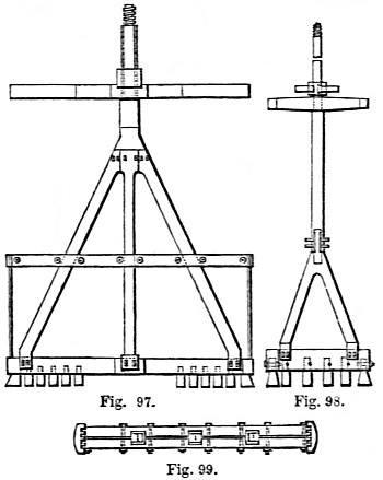
The trepan of M. Kind contains some peculiar details, which are shown
in Figs. 97, 98. The trepan is composed of two principal pieces, the
frame and the arms, both of wrought-iron, with the exception of the
teeth of the cutting part, which are of cast steel. The frame has at
the bottom a series of holes, slightly conical, into which the teeth
are inserted, and tightly wedged up, Fig. 99. These teeth are placed
with their cutting edges on the longitudinal axis of the frame that
receives them; and at the extremity of the frame there are formed two
heads, forged out of the same piece with the body of the tool, which
also carries two teeth, placed in the same direction as the others,
but double their width, in order to render this part of the tool more
powerful. By increasing the dimensions of these end teeth, the diameter
of the boring can be augmented, so as to compensate for the diminution
of the clear space caused by the tubing, necessarily introduced for
security in traversing strata disposed to fall in, or for the purpose
of allowing the water from below to escape at an intermediate level.
Figs. 97-99.
Above the lower part of the frame of the trepan is a second piece
composed of two parts bolted together, and made to support the lower
portion of the frame. This part of the machinery also carries two teeth
at its extremities, which serve to guide the tool in its descent, and
to work off the asperities left by the lower portion of the trepan.
Above this, again, are the guides of the machinery, properly speaking,
consisting of two pieces of wrought-iron, arranged in the form of
a cross, with the ends turned up, so as to preserve the machinery
perfectly vertical in its movements, by pressing against the sides
of the boring already executed. These pieces are independent of the
blades of the trepan, and may be moved closer to it or farther away
from it, as may be desired. The stem and the arms are terminated by a
single piece of wrought-iron, which is joined to the frame with a kind
of saddle-joint, and is kept in its place by means of keys and wedges.
The whole of the trepan is finally jointed to the great rods that
communicate the motion from the surface, by means of a screw-coupling,
formed below the part of the tool which bears the joint; this
arrangement permits the free fall of the cutting part, and unites the
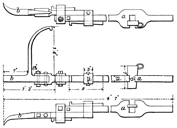
top of the arms and frame, and the rod, Fig. 100. It has been proposed
to substitute for this screw-coupling a keyed joint, in order to avoid
the inconvenience frequently found to attend the rusting of the screw,
which often interposes great difficulties in cases where it becomes
necessary to withdraw the trepan.

Fig. 100.
The sliding joint is the part of Euyenhausen’s invention most
unhesitatingly adopted by Kind, and it is one of the peculiarities of
his system as contrasted with the processes formerly in use. So long as
his operations were confined to the small dimensions usually adopted
for Artesian borings, he contented himself with making a description of
joint with a free fall; a simple movement of disengagement regulating
the height fixed by the machinery itself, like the fall of the monkey
in a pile-driving machine; but it was found that this system did not
answer when applied to large borings, and it also presented certain
dangers. Kind then, for the larger class of borings, availed himself
of sliding guides, so contrived as to be equally thrown out of gear
when the machinery had come to the end of the stroke, and maintained
in their respective positions by being made in two pieces, of which
the inner one worked upon slides, moving freely in the piece that
communicated the motion to the striking part of the machinery. The two
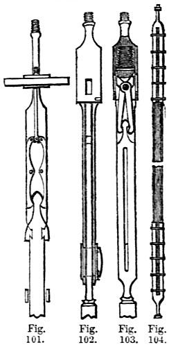
parts of the tool were connected with pins, and with a sliding joint,
which, in the Passy well, was thrown out of gear by the reaction of
the column of water above the tool unloosing the click that upheld
the lower part of the trepan, Figs. 101 to 103. The changes thus made
in the usual way of releasing the tool, and in guiding it in its fall
were, however, matters of detail; they involved no new principle in
the manner of well boring: and the modern authorities upon the subject
consider that there was something deficient in Kind’s system of making
the column of water act upon a disc by which the click was set in
motion. This system, in fact, required the presence of a column of
water not always to be commanded, especially when the borings had to be
executed in the carboniferous strata.
Figs. 101-104.
The rods used for the suspension of the trepan, and for the
transmission of the blows to it, were of oak; and this alone would
constitute one of the most characteristic differences between the
system of tools introduced by Kind and those made by the majority of
well-borers, but which, like the disengagement of the tool intended
to comminute the rock, depended for its success upon the boring
being filled with water. The resistance that the wood offers, by its
elasticity, to the effects of any sudden jar, is also to be taken
into account in the comparison of the latter with iron, for the iron
is liable to change its form under the influence of this cause. The
resistance to an effort of torsion need not, however, be much dwelt
on, for the turn given to the trepan is always made when the tool
is lifted up from its bed. For the purpose of making the rods, Kind
recommended that straight-grown trees, of the requisite diameter,
should be selected, rather than they should be made of cut-timber, as
there is less danger of the wood warping, and the character of the wood
is more homogeneous. He generally used these trees in lengths of about
50 feet, and he connected them at the ends with wrought-iron joints,
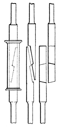
fitting one into the other, Fig. 104. The ironwork of the joints is
made with a shoulder underneath the screw-coupling, to allow the rods
to be suspended by the ordinary crow’s foot during the operation of
raising or lowering them. In the works executed at Passy there was a
kind of frame erected over the centre of the boring, of sufficient
height to allow of the rods being withdrawn in two lengths at a time,
thus producing a considerable economy of time and labour.
Figs. 105, 106.
Nearly all the processes yet introduced for removing the products of
the excavation must be considered to be, more or less,
defective, because all are established on the supposition that the
comminuting tool must be withdrawn, in order that the shell, or other
tool intended to remove the products of the working of the comminutor,
may be inserted. This remark applies to Kind’s operations at Passy
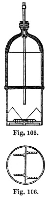
and elsewhere, as he removed the rock detached from the bottom of the
excavation by a shell, Figs. 105, 106, which was a modification of the
tool he invariably employs for this purpose. It consisted of a cylinder
of wrought-iron, suspended from the rods by a frame, and fastened to
it, a little below the centre of gravity, so that the operation of
upsetting it, when loaded, could be easily performed. This cylinder
was lowered to the level of the last workings of the trepan, and the
materials already detached by that instrument were forced into the
tool, by the gradual movement of the latter in a vertical direction.
Some other implements, employed by Kind for the purpose of removing
the products of the excavation in the shafts for the coal-mines of
the North of France, were ingenious, and well adapted to the large
dimensions of the shafts; but they were all, in some degree, exposed to
the danger of becoming fixed, if used in the small borings of Artesian
wells, by the minute particles of rocks falling down between their
sides and the excavation from above. Their use was therefore abandoned,
and the well of Passy was cleared out with the shell, the bottom of
which was made to open upwards, with a hinged flap, which admitted
the finer materials detached by the trepan. There were also several
tools for the purpose of withdrawing the broken parts of the machinery
from the excavation, or whatever substances might fall in from above;
and all were marked by a great degree of simplicity, but they did not
differ enough from those generally used for the same purpose to merit
further remarks. In fact, the accidents intended to be guarded against
or remedied are so precisely alike in all cases, that there can be
little variety in the manufacture of these instruments. But there is no
doubt that Kind deprived himself of a valuable appliance in not using
the ball-clack, la soupape à boulet, that other well-borers employ,
Fig. 107.
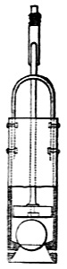
Fig. 107.
At Passy great strength was given to the head of the striking tool, and
to the part of the machinery applied to turn the trepan, because the
great weight of the latter superinduced the danger of its breaking off
under the influence of the shock, and because the solidity of this part
of the machinery necessarily regulated the whole working of the tool.
The head of the boring arrangement was connected with the balance-beam
of the steam-engine by a straight link-chain, with a screw-coupling,
admitting of being lengthened as the trepan descended, Figs. 108, 109.
The balance-beam, in order to increase its elastic force in the upward
stroke, is in Kind’s works made of wood, in two pieces; the upper one
being of fir and the lower one of beech. The whole of the machinery
is put in motion by steam, which is admitted to the upper part of
the cylinder, and presses it down, and thus raises the tool at the
other end of the beam to that part in connection with the cylinder.
The counterpoise to the weight of the tools is also placed upon the
cylinder-end of the beam. The cylinder receives the steam through ports
that are opened and closed by hand, like those of a steam-hammer;
so that the number of the strokes of the piston may be increased or
diminished, and the length of the strokes may be increased, as occasion
may require.
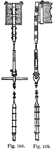
Figs. 108, 109.
The balance-beam is continued beyond the point where the piston is
connected with it, and it goes to meet the blocks placed to check the
force of the blow given by the descent of the tool. The guides of the
piston-head are attached to the part of the machinery that acts in this
manner; but at Passy, Kind made the balance-beam work upon two free
plummer-blocks, or blocks having no permanent cover, that they might
be more easily moved whenever it was necessary to displace the beam,
for the purpose of taking up or letting down the rods, or for changing
the tools; for the balance-beam was always immediately over the centre
of the tools, and it therefore had to be displaced every time that the
latter were required to be changed. This was effected by allowing the
beam to slide horizontally, so as to leave the mouth of the pit open.
The counter-check, above mentioned, likewise prevented the piston
from striking the cylinder cover with too great a force, when it was
brought back by the weight of the tools to its original position. The
operation of raising and lowering the rods, or of changing the tools,
was performed at Passy by a separate steam-engine, and the shell was
discharged into a special truck, moving upon a railway expressly laid
for this purpose in the great tower erected over the excavation. All
these arrangements were in fact made with the extreme attention to
the details of the various parts of the work which characterizes the
proceedings of foreign engineers, and conduces so much to their success.
The beating, or comminution of the rock, was usually effected at Passy
at the rate of from fifteen strokes to twenty strokes a minute. The
rate of descent, of course, differed in a marked manner, according to
the nature of the rock operated upon; but, generally speaking, the
trepan was worked for the space of about eight hours at a time, after
which it was withdrawn, and the shell let down in order to remove the
débris. The average number of men employed in the gang, besides the
foreman, or the superintendent of the well, was about fourteen: they
consisted of a smith and hammerman, whose duty it was to keep the
tools in order; and two shifts of men entrusted with the excavation,
namely, an engine-driver and stoker, a chief workman, or sub-foreman,
and three assistants. The total time employed in sinking the shafts
executed upon this system in the North of France, where it has been
applied without meeting with the accidents encountered in the Passy
well, was found to be susceptible of being divided in the following
manner: from 25 per cent. to 56 per cent. was employed in manœuvring
the trepan; from 11 per cent. to 141⁄2 per cent. in raising and
lowering the tools; from 19 per cent. to 21 per cent. in removing the
materials detached from the rocks, and cleaning out the bottom of the
excavation; and from 8 per cent. to 101⁄2 per cent. was lost, owing to
the stoppage of the engines, or to the accidents from broken tools, or
to other causes always attending these operations. In the well of Passy
there was, of course, a considerable difference in the proportions of
the time employed in the various details of the work; and the long
period occupied in obviating the effects of the slips which took place
in the clays, both in the basement beds of the Paris basin and in
the subcretaceous strata, would render any comparison derived from
that well of little value; but it would appear that, until the great
accident occurred, the various operations went on precisely as Kind had
calculated upon.
In the year 1872 Emerson Bainbridge, C.E., drew attention to the
Kind-Chaudron system of sinking mine shafts through water-bearing
strata, without the use of pumping machinery, in a paper read before
the Institute of Civil Engineers. As the operation is almost identical
with that which would have to be carried through in the case of a
well sunk through an upper series of water-bearing strata, of minor
importance or of impure quality, past rock and into the lower water
strata, as for instance through tertiaries and chalk into the lower
greensand, the following extract from Bainbridge’s paper may be read
with interest.
In the first place, it may be desirable to describe briefly the system
of sinking hitherto pursued in passing through strata yielding large
quantities of water. The most important sinkings of this character
have been carried out in the county of Durham, to the east of the
point at which the Permian overlie the carboniferous rocks. In this
district there is a thin bed of sand between the Permian rock and the
coal measures. Towards this bed the feeders of water are generally
found to increase, and in the sand there is usually a large reservoir
of water. The mode of sinking will be understood by reference to Fig. 110.
Whilst sinking in hard rock, it has ordinarily been the custom
to place iron curbs, or cribs, wherever a bed of stone appeared to
form a natural barrier between two distinct feeders of water. Thus
it has frequently happened that important feeders have been tubbed
back, rendering much less pumping power necessary than would have been
required had all the feeders been allowed to accumulate in the shaft.
As will be seen by Fig. 110, the number of wedging cribs employed is
no less than thirteen in 250 feet. The cribs forming the foundation of
each set of tubbing are generally much more massive and costly than the
segments of tubbing.
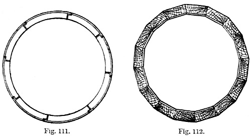
Figs. 111, 112.
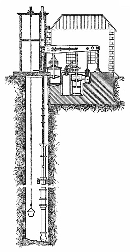
Fig. 113.
The process of fixing the crib is as follows;—The diameter of the
shaft is made about 30 inches larger than that of the inside of the
tubbing. When a bed of rock, which may be considered sufficiently
hard and close to separate the feeders above and below it, is reached,
the shaft is contracted to the diameter of the tubbing, and a smooth
horizontal face is made on which to place the wedging crib. The wedging
crib, which usually consists of segments about 4 feet long by 6 inches
high by 14 inches wide, is then placed on the bed. To give the crib a
firm and secure position, it is tightly wedged with wood, both behind
and between the joints; the tubbing is then built upon it to the next
wedging crib, which rests upon a bell-shaped section of rock. When the
tubbing nearly reaches this crib, the rock is removed piece by piece,
and the top ring of tubbing is placed close up against the crib. It
will thus be seen that the fixing of each crib is a costly process,
often causing considerable delay.
In some cases, where it has been difficult to find suitable foundations
for intermediate wedging cribs, the whole of the water-bearing
rocks have been sunk through without attempting to stop the feeders
separately, and no tubbing has been placed in the shaft till the
wedging crib could be fixed below the lowest feeder. This process is
more expeditious where there are small quantities of water; but where
the water is excessive greater delay is caused by contending with it
than from putting in numerous sets of tubbing to stop the feeders
separately. The tubbing used in England has almost invariably been of
cast-iron; on the Continent, till recently, tubbing of wood has chiefly
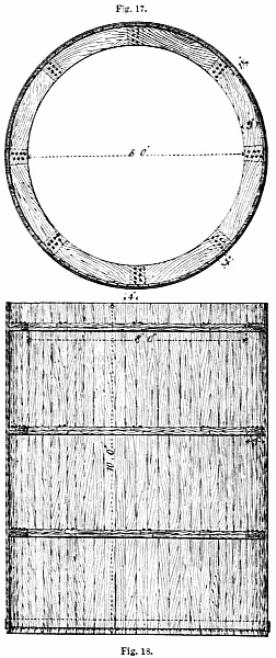
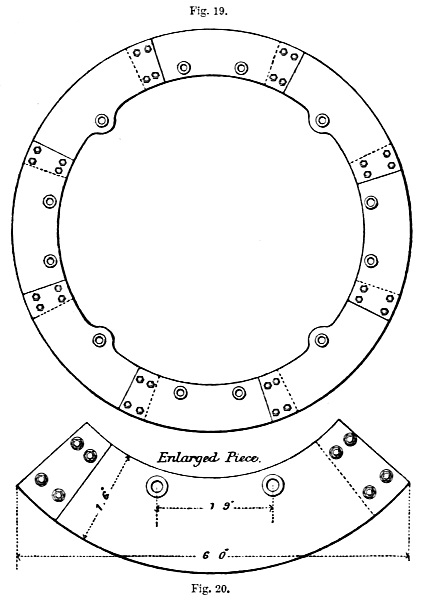
been used. Illustrations of both descriptions are shown by Figs. 111
and 112.
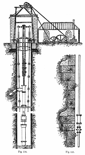
Figs. 114, 115.
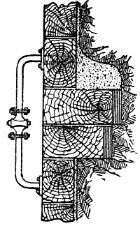
Fig. 116.
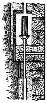
Fig. 118.
Figs. 113, 114, show, in elevation, the plant and the arrangements
generally in use at extensive sinkings. Where the water is in large
quantities it is usually pumped by an engine erected for the purpose,
assisted by the engine or engines intended to be employed to raise the
coal. A small capstan engine is used for passing the men and material
up and down the pit during the sinking, such engine being provided
also with a drum on slow motion, which is used for heavy weights. The
continual pumping, the placing of cribs, and the fixing of the tubbing
are proceeded with till the lowest feeder is reached, when a hard bed
is sought for on which to fix the lowest wedging crib. In all cases the
water has to be pumped out before the wedging crib, which forms the
foundation of each set of tubbing, can be placed.
From this description it will be understood that the sinkers, who
number from ten to twelve at one time, working four hours at a shift in
a pit, say, 14 feet in diameter, are compelled to work in water until
all the tubbing is fixed. This causes a serious obstacle to blasting,
and in other ways delays the progress of the work.
The tubbing used for damming back the water is generally in segments
from 1 foot to 3 feet high, and about 4 feet in length, the thickness
varying from half an inch to 33⁄4 inches. It is kept in position by
packing with wood behind the joints; and is made water-tight by placing
between the segments pieces of wood sheeting about half an inch thick,
which are wedged when all the tubbing is fixed, usually twice with
wood, and sometimes once with iron wedges.
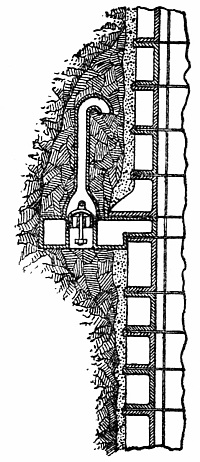
Fig. 117.
To equalize the pressure of water and gas behind the different sets of
tubbing, pass pipes, Figs. 115 and 116, are sometimes used. Another
expedient to effect this is to have a valve, working upwards, placed in
the wedging crib, Fig. 117. A ball is also sometimes used, Fig. 118.
The various modes of piercing beds of
quicksand are;—By hanging tubbing to that already fixed, and adding
fresh rings as the sand is removed. This is only practicable when the
quantity of sand is inconsiderable. By heavily weighting a cylinder of
iron of the same size as the shaft, and thus forcing it down through
the sand. By keeping back the sand by the use of piles—a resource that
can only be recommended when the bed of sand is not of great thickness.
When the water is excessive, by using pneumatic agency. As these
operations are apart from our immediate subject we need not further
discuss them.
M. Chaudron’s system, which is a modification of Kind’s, is divisible
into the following distinct processes, which consist of;—
The erection of the necessary machinery on the surface, and the opening
of the mine.
The boring of the pits to the lowest part of the water-bearing strata.
The placing of the tubbing.
The introduction of cement behind the tubbing to complete its solidity.
The extraction of the water from the pits, and the placing of the
wedging cribs, or “faux cuvelage,” below the moss box.
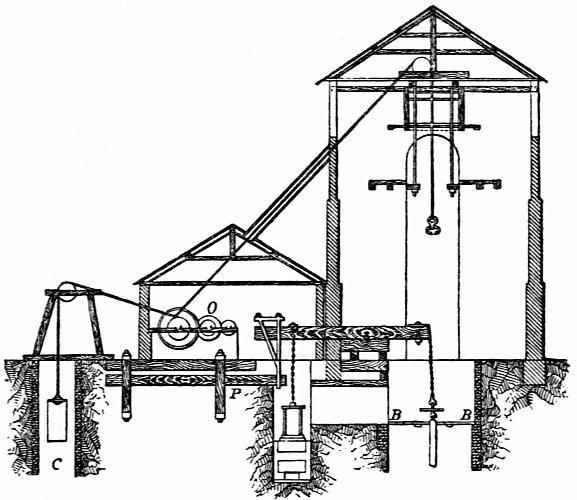
Fig. 119.
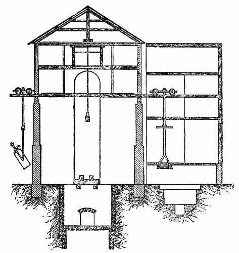
Fig. 120.
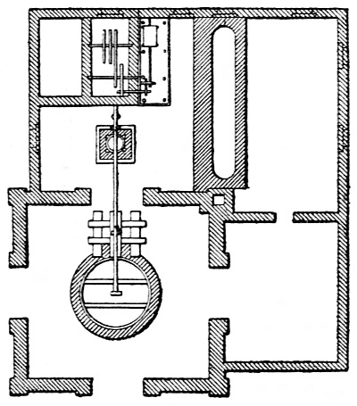
Fig. 121.
Figs. 119 to 121 show in elevations and in plan the plant usually
employed on the surface. O is a small capstan engine, having a cylinder
20 inches in diameter and a stroke of 32 inches, working on the third
motion. Attached to this engine, and working in the small pit C, is a
counterbalance weight. This engine is used for raising and lowering
boring tools, and for lifting the débris resulting from the boring.
As far as the platform, which is about 10 feet from the surface, the
pit has a diameter of 19 feet, or 4 feet more than the diameter of the
pit below. A at level of about 38 feet above this platform there is
a tramway on which small trucks run, carrying the débris cylinder
on one side, and the boring tools on the other. At a level of 48 feet
above the platform are placed supports for the wooden spears to which
the boring tools are attached. The machinery for boring is worked by
a cylinder, which has a diameter of 391⁄3 inches, and a full stroke
of 391⁄3 inches, the usual stroke varying from 2 feet to 3 feet. A
massive beam of wood transmits motion from this cylinder to the boring
apparatus, the connection between the beam and the piston-rod and the
beam and the boring tools being made by a chain. The engine-man sits
close to the engine, and applies the steam above the piston only. The
down stroke of the boring tools is caused by the sudden opening of
the exhaust, and a frame then prevents the shock of the boring rods
from being too severe. The engines work at speeds varying from 12 to
18 strokes a minute, according to the character of the strata passed
through.
Figs. 122-127.
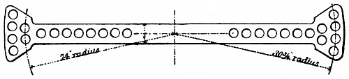
Fig. 130.
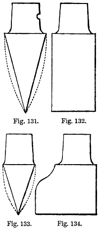
Figs. 131-134.
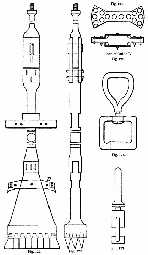
After the working platform is fixed, the first boring tool applied
is the small trepan, Figs. 122 to 125. This tool is attached to the
wooden beam by the same arrangement shown by Fig. 109. The boring
tools can be lowered at pleasure by means of an adjusting screw. Next
in order comes the handle for boring. This is worked by four men on
the platform, and is turned by the aid of a swivel. Attached to the
handle-piece are wooden rods, made from Riga pitch pine. These rods
are 59 feet in length and 73⁄4 inches square. A swivelled ring, Figs.
126, 127, is attached to the rope when raising and lowering the boring
rods. The small trepan cuts a hole 4 feet 83⁄4 inches in diameter, and
has fourteen teeth, fitted in cylindrical holes and secured by pins
entering through circular slots. The teeth are steeled. At a distance
of 4 feet 4 inches above the main teeth of the trepan there is an arm,
with a tooth at each end. This piece answers the purpose of a guide,
and at the same time removes irregularities from the sides of the hole.
At a distance of 13 feet 6 inches above the main teeth are the actual
guides, consisting of two strong arms of iron fixed on the tool, and
placed at right-angles to each other. The hole made by the small trepan
is not kept at any fixed distance in advance of the full-sized pit,
but the distance generally varies from 10 to 30 yards. With the small
trepan, which weighs 8 tons, the progress varies from 6 to 10 feet a
day.
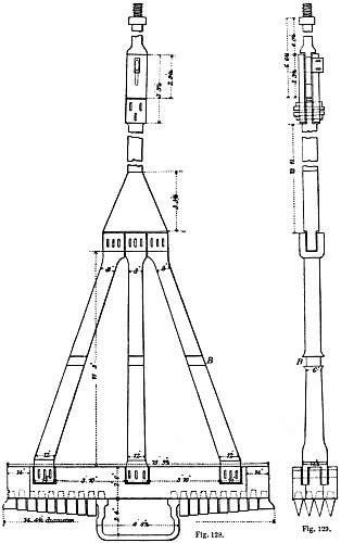
The large trepan, Figs. 128 to 130, weighs 161⁄2 tons, is forged in
one solid piece, and has twenty-eight teeth. A projection of iron forms
the centre of this trepan, and fits loosely into the hole made by the
small trepan, acting as a guide for the tool. At a distance of 7 feet 6
inches above the teeth, a guide is sometimes fixed on the frame, but is
not furnished with teeth. At a distance of 13 feet
3 inches from the teeth are two other guides at right-angles to each
other. These guides are let down the pit with the boring tool, the
hinged part of the guides being raised whilst passing through the
beams at the top of the pit, which are only 6 feet 7 inches apart.
When the tool is ready to work, the two arms are let down against the
side of the pit, and are hung in the shaft by ropes, thus acting as
a guide for the trepan, which moves through them. To provide against
a shock to the spears when the trepan strikes the rock on the down
stroke, at the upper part of the frame a slot motion is arranged, the
play of which amounts to about half an inch. The teeth of the large
trepan are not horizontal, but are deeper towards the inside of the
pit, the face of the inside tooth being 33⁄4 inches lower than the
outside. The object of this is to cause the débris to drop at once
into the small hole, by the face of the rock at the bottom of the
pit being somewhat inclined. The teeth used, Figs. 131 to 134, are
the same both for the large and the small trepan, and weigh about 72
lb. each. As a rule, only one set of teeth is kept in use, this set
working for twelve hours, the alternate twelve hours being employed
in raising the débris. This time is divided in about the following
proportions;—Boring, twelve hours; drawing the rods, one hour to
five hours, according to depth; raising the débris, two hours; and
lowering the rods one hour to five hours. The maximum speed of the
larger trepan may be taken at about 3 feet a day. The ordinary distance
sunk is not more than 2 feet a day, and in flint and other hard rocks
the boring has proceeded as slowly as 3 inches a day.
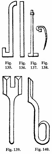
Figs. 135-140.
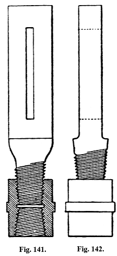
Figs. 141, 142.
The débris in the small bore-hole contains pieces of a maximum size
of about 8 cubic inches. In the large boring, pieces of rock measuring
32 cubic inches have been found. As a rule, however, the material
is beaten very fine, having much the appearance of mud or sand. In
both the large and the small borings the débris is raised by a
shell, similar to Figs. 105, 106, and in this system consisting of a
wrought-iron cylinder, 3 feet 3 inches in diameter by 6 feet 9 inches
long, and containing two flap-valves at the bottom, through which the
excavated material enters. This apparatus is passed down the shaft by
the bore-rods, and it is moved up and down through a distance varying
from 6 to 8 inches, for about a quarter of an hour, and is then drawn
up and emptied. In some cases where the rock is hard, three sizes of
trepan are used consecutively, the sizes being 5 feet, 8 feet, and 13
feet.
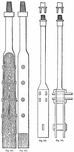
Figs. 143-146.
The several other tools and appliances used during the boring
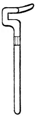
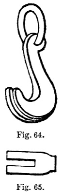
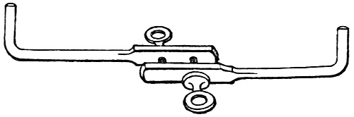
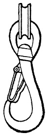
operations are shown, Figs. 135 to 140, including the key, Figs. 139,
140, used at the surface to disconnect the rods, the hook on which each
rod is hung after being raised to the high platform and there detached,
the bar upon which the hooks are moved,
and the fork for suspending the rods or tools from the rollers when it
is desired to move the rods or tools from above the shaft.
Figs. 141 to 146 are of the connections to the trepan and spears or
rods.
Should broken tools fall into the shaft, several varieties of apparatus
are used for their recovery. In case of broken rods of any kind having
a protuberance that can be clutched, a hook or crow, Figs. 137, 138,
of an epicycloidal form, enables the object to be taken hold of very
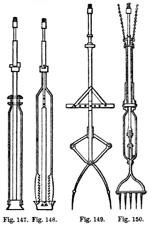
readily. Where the broken part has no shoulder which can be held, but
is simply a bar, the apparatus shown by Figs. 147, 148, is employed.
This is composed of two parts. The rods, the bottom of which have teeth
inside, are prevented from diverging by the cone and slide on the main
rods. When passed over a rod or pipe, they clutch it by means of the
teeth, and draw it up. Chaudron has, by this tool, raised a column
of pipes 295 feet in length and 8 inches in diameter. An instrument,
called a “grapin,” Figs. 149, 150, is used for raising broken teeth or
other small objects which may have fallen into the bottom of the shaft.
This tool also has one part sliding in the other, and is lowered with
the claws closed. The parts are moved by two ropes worked from the
surface. By weighting the cross-bar, which is attached to the moving
parts, the pressure desired can be exerted on the claws. The weight
is then lifted, the claws are opened, and are made to close upon the
substance to be raised. This instrument is now seldom required.
Figs. 147-150.
In boring shafts in the manner described, without being able to prove
in the usual way the perpendicularity of the shaft, it might be feared
that the system would be open to objection on this account. It appears,
however, that in all cases where Chaudron has sunk shafts by this
system he has succeeded in making them perfectly vertical. This is
ensured by the natural effect of the treble guide, which the chisels
and the two sets of arms attached to the boring tools afford, and by
the fact that if the least divergence from a plumb-line is made by the
boring tool, the friction of the tool upon one side of the shaft is so
great as to cause the borers to be unable to turn the instrument.
Boring alternately with the large and the small instrument, the shaft
is at length sunk to the point at which the lowest feeder of water
is encountered. In a new district this has to be taken, to some
extent, at hazard; but where pits have been sunk previously, it is not
difficult to tell, by observing the strata, almost the exact point at
which the bottom of the tubbing may be safely fixed. This point being
ascertained, the third process is arrived at.
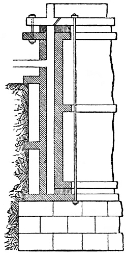
Fig. 151.
As the object of placing tubbing in a shaft is effectually to shut off
the feeders, which for water supply may have some bad qualities, and to
secure a water-tight joint at the base, it is important that the bed
on which the moss box has to rest should be quite level and smooth.
This is attained by the use of a tool, termed a “scraper,” attached to
the bore-rods, the blades being made to move round the face of the bed
intended for the moss box. The tubbing employed is cast in complete
cylinders. At Maurage each ring has an internal diameter of 12 feet and
is 4 feet 9 inches high. Each ring has an inside flange at the top and
bottom, and also a rib in the middle, the top and bottom of the ring
being turned and faced. The rings of tubbing are attached to each other
by twenty-eight bolts 1·1 inch in diameter, passed through holes bored
in the flanges. The tubbing is suspended in the pit by means of six
rods, which are let down by capstans placed at a distance of 30 feet
above the top of the pit. These machines work upon long screws. When a
new ring of tubbing is added, the rods are detached at a lower level,
and are hung upon chains, thus leaving an open space for passing it
forward. Before each ring is put into the pit it is tested by hydraulic
apparatus, Fig. 151. The tubbing is usually proved to one-half more
pressure than it is expected to be subjected to. At Maurage, where a
length of 550 feet of tubbing has to be put in, the chief particulars
respecting it are;—
| |
Length. |
Thickness |
Pressure
expected. |
Pressure
at which
Tubbing is
proved. |
| |
feet. |
inches. |
lbs. a
square inch. |
lbs. a
square inch. |
| Top |
130 |
1·17 |
30 |
45 |
| |
60 |
1·31 |
60 |
90 |
| |
60 |
1·57 |
90 |
135 |
| |
60 |
1·76 |
120 |
180 |
| |
60 |
1·96 |
150 |
225 |
| |
60 |
2·16 |
180 |
270 |
| |
60 |
2·35 |
210 |
315 |
| Bottom |
60 |
2·55 |
240 |
360 |
The joints between the rings of tubbing are made with sheet lead
one-eighth of an inch thick, coated with red-lead. The lead is allowed
to obtrude from the joint one-third of an inch, and is wedged up by
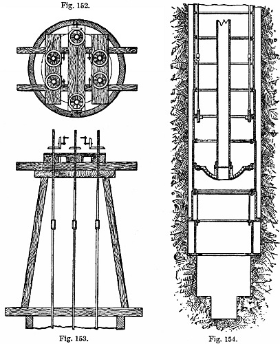
a tool which has a face one-twelfth of an inch thick. The mode of
suspending the tubbing to the rods will be understood by referring
to Figs. 152 to 154. The rods are attached to a ring by the bolts
connecting one ring of tubbing with another. The bottom ring of tubbing
and the ring carrying the moss box have their top flange turned
inwards, but their bottom flange outwards. A strong web of iron,
forming the base of a tube 161⁄2 inches in diameter, is attached
to the tubbing. The object of this tube is to cause the water in the
shaft to ease the suspension rods, by bearing part of the weight of the
tubbing. Cocks to admit water are placed at intervals up the tube, by
which means the weight upon the rods can be easily regulated, so that
not more than one-tenth to one-twentieth of the weight of the tubbing
is suspended by the rods at one time. The ring holding the moss box is
hung from the bottom joint in the tubbing by sliding rods.
Figs. 152-154.
The arrangement of the moss box which forms the base of the tubbing is
one of the most important points requiring attention in this system of
sinking. Ordinary peat moss is used. It is enclosed in a net, which,
with the aid of springs, keeps it in its place during the descent of
the tubbing. When the moss box, which hangs on short rods fixed to
the tubbing, reaches the face of rock, it is dropped gently upon it,
and the whole weight of the tubbing is allowed to rest upon the bed.
This compresses the moss, the capacity of the chamber holding it is
diminished, and the moss is forced against the sides of the shaft,
thus forming a water-tight joint, past which no water can escape. This
completes the third process.
It may be noted that up to this point the following important
differences between this and the ordinary system of placing tubbing are
to be observed;—The tubbing, on reaching its bed, bears the aggregate
pressure of all the feeders of water which have been met with in the
shaft. The tubbing, having been passed down the shaft in the manner
described, no wedging behind, or other modes of consolidating it in
the shaft, have been carried out. The connection between each ring of
tubbing is so carefully made, that the repeated wedging of the joints,
as in the ordinary system, is rendered unnecessary. The pit is still
full of water up to the ordinary level.
Under these conditions the next process is;—The introduction of cement
behind the tubbing to complete its solidity.
Figs. 155, 156.
Before the water is removed, the annular space between the tubbing and
the sides of the shaft is filled with hydraulic cement, to render the
tubbing impermeable, by a process of consolidation, less liable to the
effect of any pressure of water or gas which may be exerted towards the
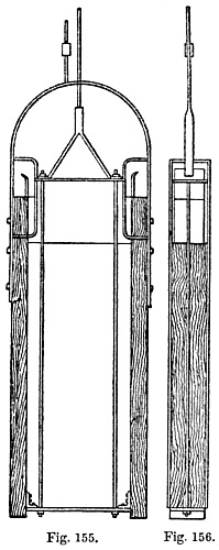
centre of the shaft. The cement is inserted behind the tubbing by close
ladles, Figs. 155, 156, capable of holding 44 gallons, and consisting
of two iron plates, one-eighth of an inch thick, fixed on two wooden
uprights 31⁄8 inches square. This apparatus is curved to suit the
mean circumference of the space to be concreted. A piston is placed
at the top of the ladle, and to this piston is attached a rod, which
can be moved from the surface; a door is also attached to the piston.
The ladle containing the concrete is passed down behind the tubbing by
means of a windlass at the surface, and when it reaches the lowest
point, the piston is pushed down and the cement allowed to escape from
the chamber. The weight of the cement and the ladle is sufficient with
a little ballast to enable it to descend easily.
A number of experiments have been made to discover a cement which will
not harden too quickly, and which, when hardened, will form a perfectly
compact and solid mass. A composition having the following proportions
has been found the best;—Hydraulic lime, from the lias near Metz,
slaked by sprinkling, 1 part; picked sand, from the Vosges sandstone,
1 part; trass, from Andernacht on the Rhine, 1 part; cement from Ropp
(Haute Saone), 1⁄4 part.
Six men are employed in putting in the cement;—two at the windlass
for letting down the ladle, two for working the rods attached to the
piston, and two on the working platform. The rods referred to have been
found such an inconvenience, that lately a rope on another windlass has
been used, and an appliance arranged for dropping the piston by moving
the rope.
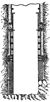
Fig. 157.
When a sufficient time has elapsed for the cement to harden, the
water within the tubbing, now effectually separated from the feeders,
is drawn out by a bucket worked by the crab engine,—an operation
which occupies from one to three weeks, according to circumstances.
When concluded, the joint between the moss box and the rock bed can
be examined. In some cases this joint is considered sufficient; but
it is generally thought desirable to form a base to the tubbing by
building a few feet of brickwork in cement on a ring or crib of wood,
as in Fig. 157. Another wooden crib is then placed on the top of this
brickwork, and above this, two cast-iron segmental wedging cribs with
a broad bed also wedged perfectly tight. On the base so prepared, four
or more rings of tubbing in segments are fixed, the top ring coming
close against the bottom of the moss box. This being done the work is
completed, and the sinking of the shaft is continued in the ordinary
way.
The application of the boring trepan is not to be recommended in the
sinking of the dry part of the shaft. The use of the tool would cause
the sinking to extend over a longer period, since the breaking of the
rock passed through into such minute particles would lead to loss of
time.
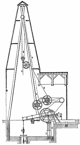
Fig. 158.
The system applied by Dru is worthy of attention, not so much on
account of the novelty of the invention, or of any new principle
involved in it, as on account of the contrivances it contains for the
application of the tool, “à chute libre,” or the free-falling tool,
to Artesian wells of large diameters. It has been already explained
that under Kind’s arrangements the trepan was thrown out of gear by
the reaction of the water which was allowed to find its way into
the column of the excavation; but that it is not always possible to
command the supply of the quantity necessary for that purpose; and
even when possible, the clutch Kind adopted was so shaped as to be
subject to much and rapid wear. Dru, with a view to obviate both these
inconveniences, made his first trepan similar to that shown in Fig.
101, in which it will be seen that the tool was gradually raised until
it came in contact with the fixed part of the upper machinery, when
it was thrown out of gear. The bearings of the clutch were parallel
to the horizontal line, and were found in practice to be more evenly
worn, so that this instrument could be worked sometimes from eight days
to fourteen days without intermission; whereas, on Kind’s system, the
trepan was frequently withdrawn after two days’ or three days’ service.
We take the following complete account of the system from a paper read
by M. Dru at the Conservatoire des Arts et Métiers, Paris, 6th June,
1867.
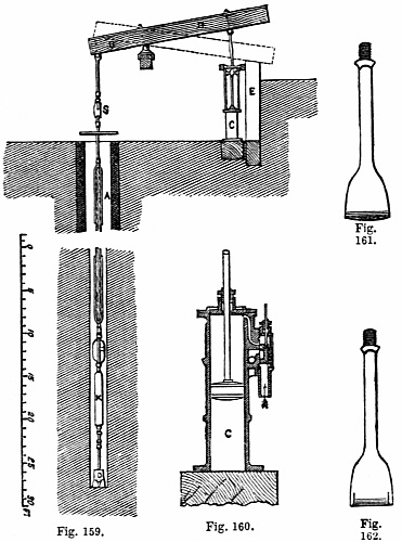
It will be seen from Figs. 158, 159, that the boring rod A is suspended
from the outer end of the working beam B, which is made of timber
hooped with iron, working upon a middle bearing, and is connected at
the inner end to the vertical steam cylinder C, of 10 inches diameter
and 39 inches stroke. The stroke of the boring rod is reduced to
22 inches, by the inner end of the beam being made longer than the
outer end, serving as a partial counterbalance for the weight of the
boring rod. The steam cylinder is shown enlarged in Fig. 160, and is
single-acting, being used only to lift the boring rod at each stroke,
and the rod is lowered again by releasing the steam from the top side
of the piston; the stroke is limited by timber stops both below and
above the end of the working beam B.
The boring tool is the part of most importance in the apparatus, and
the one that has involved most difficulty in maturing its construction.
The points to be aimed at in this are,—simplicity of construction and
repairs; the greatest force of blow possible for each unit of striking
surface; and freedom from liability to get turned aside and choked.
Figs. 159-162.
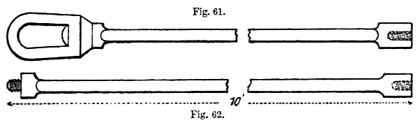
The tool used in small borings is a single chisel, as shown in Figs.
161, 162; but for the large borings it is found best to divide the
tool-face into separate chisels, each of convenient size and weight for
forging. All the chisels, however, are kept in a straight line, whereby
the extent of striking surface is reduced; and the tool is rendered
less liable to be turned aside by meeting a hard portion of flint on a
single point of the striking edge, which would diminish the effect of
the blow.
Figs. 163-167.
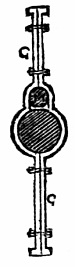
Fig. 168.
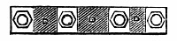
Fig. 169.
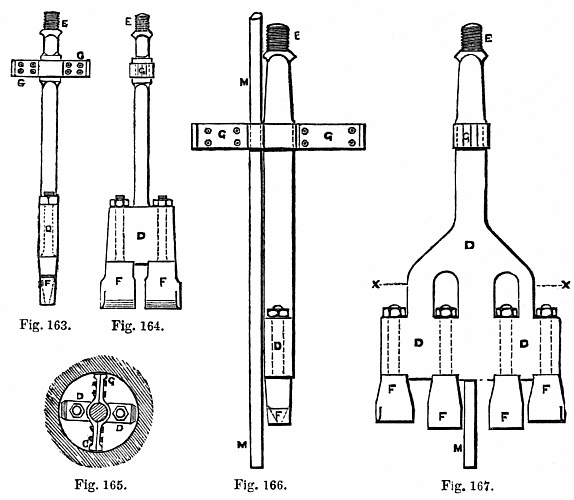
The tool is shown in Figs. 163 to 169, and is composed of a
wrought-iron body D, connected by a screwed end E to the boring rod,
and carrying the chisels F F, fixed in separate sockets and secured
by nuts above; two or four chisels are used, or sometimes even a
greater number, according to the size of the hole to be bored. This
construction allows of any broken chisel being easily replaced; and
also, by changing the breadth of the two outer chisels, the diameter of
the hole bored can be regulated exactly as may be desired. When four
chisels are used, the two centre ones are made a little longer than the
others, as shown in Fig. 167, to form a leading hole as a guide to the
boring rod. A cross-bar G, of the same width as the tool, guides it in
the hole in the direction at right-angles to the tool; and in the case
of the larger and longer tools a second cross-bar higher up, at right-angles
to the first and parallel to the striking edge of the tool, is
also added.
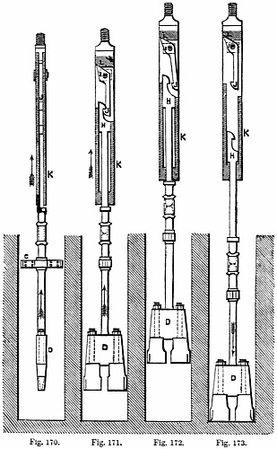
Figs. 170-173.
If the whole length of the boring rod were allowed to fall suddenly to
the bottom of a large bore-hole at each stroke,
frequent breakages would occur; it is therefore found requisite to
arrange for the tool to be detached from the boring rod at a fixed
point in each stroke, and this has led to the general adoption of
free-falling tools. M. Dru’s plan of self-acting free-falling tool,
liberated by reaction, is shown in side and front view in Figs. 170 to
173. The hook H, attached to the head of the boring tool D, slides
vertically in the box K, which is screwed to the lower extremity of
the boring rod; and the hook engages with the catch J, centred in
the sides of the box K, whereby the tool is lifted as the boring rod
rises. The tail of the catch J bears against an inclined plane L, at
the top of the box K; and the two holes carrying the centre-pin I of
the catch, are made oval in the vertical direction, so as to allow a
slight vertical movement of the catch. When the boring rod reaches the
top of the stroke, it is stopped suddenly by the tail end of the beam
B, Fig. 159, striking upon the wood buffer-block E; and the shock thus
occasioned causes a slight jump of the catch J in the box K; the tail
of the catch is thereby thrown outwards by the incline L, as shown in
Fig. 172, liberating the hook H, and the tool then falls freely to the
bottom of the bore-hole, as shown in Fig. 173. When the boring rod
descends again after the tool, the catch J again engages with the hook
H, enabling the tool to be raised for the next blow, as in Fig. 171.
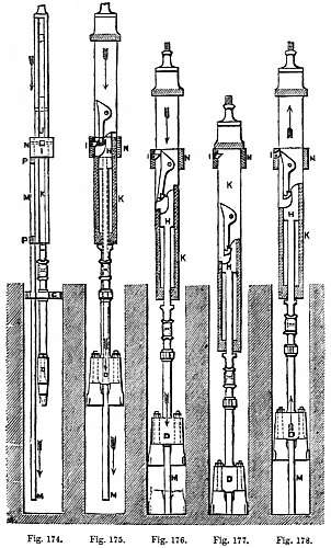
Figs. 174-178.
Another construction of self-acting free-falling tool, liberated by a
separate disengaging rod, is shown in side and front view in Figs. 174
to 178. This tool consists of four principal pieces, the hook H, the
catch J, the pawl I, and the disengaging rod M. The hook H, carrying
the boring tool D, slides between the two vertical sides of the box
K, which is screwed to the bottom of the boring rod; and the catch J
works in the same space upon a centre-pin fixed in the box, so that the
tool is carried by the rod, when hooked on the catch, as shown in Fig.
175. At the same time the pawl I, at the back of the catch J, secures
it from getting unhooked from the tool; but this pawl is centred in
a separate sliding hoop N, forming the top of the disengaging rod M,
which slides freely up and down within a fixed distance upon the box
K; and in its lowest position the hoop N rests upon the upper of the
two guides P P, Fig. 174, through which the disengaging rod M slides
outside the box K. In lowering the boring rod, the disengaging rod
M reaches the bottom of the bore-hole first, as shown in Figs. 174,
175, and being then stopped it prevents the pawl I from descending
any lower; and the inclined back of the catch J sliding down past the
pawl, the latter forces the catch out of the hook H, as shown in Fig.
176, thus allowing the tool D to fall freely and strike its blow. The
height of fall of the tool is always the same, being determined only
by the length of the disengaging rod M.
The blow having been struck, and the boring rod continuing to be
lowered to the bottom of the hole, the catch J falls back into its
original position, and engages again with the hook H, as shown in Fig.
177, ready for lifting the tool in the next stroke. As the boring rod
rises, the tail of the catch J trips up the pawl I in passing, as shown
in Fig. 176, allowing the catch to pass freely; and the pawl before it
begins to be lifted returns to the original position, shown in Fig.
177, where it locks the catch J, and prevents any risk of its becoming
unhooked either in raising or lowering the tool in the well.
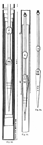
The boring tool shown in Figs. 163, 164, which was employed for boring
a well of 19 inches diameter, weighs 3⁄4 ton, and is liberated by
reaction, by the arrangement shown in Figs. 170 to 173; and the same
mode of liberation was applied in the first instance to the larger
tool, shown in Figs. 166 to 169, employed in sinking a well of 47 in.
diameter at Butte-aux-Cailles. The great weight of the latter tool,
however, amounting to as much as 31⁄2 tons, necessitated so violent
a shock for the purpose of liberating the tool by reaction, that the
boring rods and the rest of the apparatus would have been damaged by a
continuance of that mode of working; and M. Dru was therefore led to
design the arrangement of the disengaging rod for releasing the tool,
as shown in Figs. 174, 175. In this case the cross-guide G fixed upon
the tool is made with an eye for the disengaging rod M to work through
freely. For borings of small diameter, however, the disengaging rod
cannot supersede the reaction system of liberation, as the latter alone
is able to work in borings as small as 31⁄4 inches diameter; and a
bore-hole no larger than this diameter has been successfully completed
by M. Dru with the reaction tool to a depth of 750 feet.
The boring rods employed are of two kinds, wrought-iron and wood.
The wood rods seen in Figs. 159, 179, are used for borings of large
diameter, as they possess the advantage of having a larger section for
stiffness without increasing the weight; and also when immersed in
water the greater portion of their weight is floated. The wood for
the rods requires to be carefully selected, and care has to be taken
to choose the timber from the thick part of the tree, and not the
toppings. In France, Lorraine, or Vosges, deals are preferred.
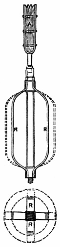
Fig. 179.
Figs. 180-182.
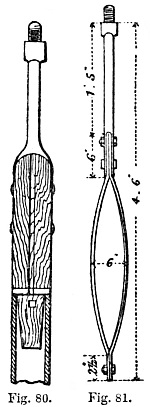
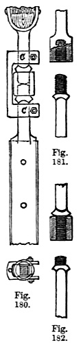
The boring rods, whether of wood or iron, are screwed together either
by solid sockets, as in Fig. 181, or with separate collars, as in
Figs. 180, 182. The separate collars are preferred for the purpose, on
account of being easy to forge; and also because, as only one half of
the collar works in coupling and uncoupling the rods, while the other
half is fixed, the screw-thread becomes worn only at one end, and by
changing the collar, end for end, a new thread is obtained when one is
worn out, the worn end being then jammed fast as the fixed end of the
collar.
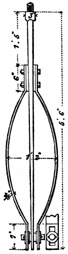
The boring rod is guided in the lower part of the hole by a lantern R,
Fig. 159, shown to a larger scale in Fig. 179, which consists of four
vertical iron bars curved in at both ends, where they are secured by
movable sockets upon the boring rod, and fixed by a nut at the top. By
changing the bars, the size of the lantern is readily adjusted to any
required diameter of bore-hole, as indicated by the dotted lines. In
raising up or letting down the boring rod, two lengths of about 30 feet
each are detached or added at once, and a few shorter rods of different
lengths are used to make up the exact length required. The coupling
screw S, Fig. 158, by which the boring rod is connected to the working
beam B, serves to complete the adjustment of length; this is turned by
a cross-bar, and then secured by a cross-pin through the screw.
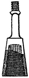
Fig. 183.
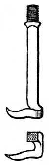
Fig. 184.
In ordinary work, breakages of the boring rod generally take place in
the iron, and more particularly at the part screwed, as that is the
weakest part. In the case of breakages, the tools usually employed for
picking up the broken ends are a conical screwed socket, shown in Fig.
183, and a crow’s foot, shown in Fig. 184; the socket being made with
an ordinary V-thread for cases where the breakage occurs in the iron;
but having a sharper thread, like a wood screw, when used where the
breakage is in one of the wood rods. In order to ascertain the shape of
the fractured end left in the bore-hole, and its position relatively to
the centre line of the hole, a similar conical socket is first lowered,
having its under surface filled up level with wax, so as to take an
impression of the broken end, and show what size of screwed socket
should be employed for getting it up. Tools with nippers are sometimes
used in large borings, as it is not advisable to subject the rods to a
twist.
When the boring tool has detached a sufficient quantity of material,
the boring rod and tool are drawn up by means of the rope O, Fig. 158,
winding upon the drum Q, which is driven by straps and gearing from
the steam-engine T. A shell is then lowered into the bore-hole by the
wire-rope U, from the other drum V, and is afterwards drawn up again
with the excavated material. A friction break is applied to the drum
Q, for regulating the rate of lowering the boring rod down the well.
The shell shown in Figs. 186, 187, consists of a riveted iron cylinder,
with a handle at the top, which can either be screwed to the boring
rod or attached to the wire-rope; and the bottom is closed by a large
valve, opening inwards. Two different forms of valve are used, either
a pair of flap-valves, as shown in Fig. 186, or a single-cone valve,
Fig. 187; and the bottom ring of the cylinder, forming the seating of
the valve, is forged solid, and steeled on the lower edge. On lowering
this cylinder to the bottom of the bore-hole, the valve opens, and the
loose material enters the cylinder, where it is retained by the closing
of the valve, whilst the shell is drawn up again to the surface. In
boring through chalk, as in the case of the deep wells in the Paris
basin, the hole is first made of about half the final diameter for 60
to 90 feet depth, and it is then enlarged to the full diameter by using
a larger tool. This is done for convenience of working; for if the
whole area were acted upon at once, it would involve crushing all the
flints in the chalk; but, by putting a shell in the advanced hole, the
flints that are detached during the working of the second larger tool
are received in the shell and removed by it, without getting broken by
the tool.
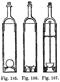
Figs. 185-187.
The resistance experienced in boring through different strata is
various; and some rocks passed through are so hard, that with 12,000
blows a day of a boring tool weighing nearly 10 cwt., with 19 inches
height of fall, the bore-hole was advanced only 3 to 4 inches a day.
As the opposite case, strata of running sand have been met with so
wet, that a slight movement of the rod at the bottom of the hole was
sufficient to make the sand rise 30 to 40 feet in the bore-hole. In
these cases Dru has adopted the Chinese method of effecting a speedy
clearance, by means of a shell closed by a large ball-clack at the
bottom, as shown in Fig. 186, and suspended by a rope, to which a
vertical movement is given; each time the shell falls upon the sand a
portion of this is forced up into the cylinder, and retained there by
the ball-valve.
Borings of large diameter, for mines or other shafts, are also sunk
by means of the same description of boring tools, only considerably
increased in size, extending up to as much as 14 feet diameter. The
well is then lined with cast-iron or wrought-iron tubing, for the
purpose of making it water-tight; and a special contrivance, invented
by Kind, and alluded to at p. 110, has been adopted for making a
water-tight joint between the tubing and the bottom of the well, or
with another portion of tubing previously lowered down. This is done
by a stuffing-box, shown in Fig. 188, which contains a packing of
moss at A A. The upper portion of the tubing is drawn down to the
lower portion by the tightening screws B B, so as to compress the
moss-packing when the weight is not sufficient for the purpose. A space
C is left between the tubing and the side of the well, to admit of the
passage of the stuffing-box flange, and also for running in concrete
for the completion of the operation. The moss-packing rests upon the
bottom flange D; but this flange is sometimes omitted. The joint is
thus simply made by pressing out the moss-packing against the sides of
the well; and this material, being easily compressible and not liable
to decay under water, is found to make a very satisfactory and durable
joint.
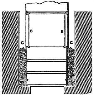
Fig. 188.
M. Dru states that the reaction tool has been successfully employed
for borings up to as large as about 4 feet diameter, witness the case
of the well at Butte-aux-Cailles of 47 inches diameter; but beyond
that size he considers the shock requisite to liberate the larger and
heavier tool would probably be so excessive, as to be injurious to the
boring rods and the rest of the attachments; and he therefore designed
the arrangement of the disengaging rod for liberating the tool in
borings of large diameter, whereby all shock upon the boring rods was
avoided and the tool was liberated with complete certainty.
In practice it is necessary, as with the common chisel, to turn the
boring tool partly round between each stroke, so as to prevent it from
falling every time in the same position at the bottom of the well; and
this was effected in the well at Butte-aux-Cailles by manual power at
the top of the well, by means of a long hand-lever fixed to the boring
rod by a clip bolted on, which was turned round by a couple of men
through part of a revolution during the time that the tool was being
lifted. The turning was ordinarily done in the right-hand direction
only, so as to avoid the risk of unscrewing any of the screwed
couplings of the boring rods; and care was taken to give the boring
rod half a turn when the tool was at the bottom, so as to tighten the
screw-couplings, which otherwise might shake loose. In the event of a
fracture, however, leaving a considerable length of boring rod in the
hole, it was sometimes necessary to have the means of unscrewing the
couplings of the portion left in the hole, so as to raise it in parts
instead of all at once. In that case a locking clip was added at each
screwed joint above, and secured by bolts, as shown at C in Fig. 180,
at the time of putting the rods together for lowering them down the
well to recover the broken portion; and by this means the ends of the
rods were prevented from becoming unscrewed in the coupling sockets,
when the rods were turned round backwards for unscrewing the joints in
the broken length at the bottom of the bore-hole.
When running sands are met with, the plan adopted is to use the Chinese
ball-scoop, or shell, Fig. 186, described for clearing the bottom of
the bore-hole; and where there is too much sand for it to be got rid of
in this way, a tube has to be sent down from the surface to shut off
the sand. This, of course, necessitates diminishing the diameter of
the hole in passing through the sand; but on reaching the solid rock
below the running sand, an expanding tool is used for continuing the
bore-hole below the tubing with the same diameter as above it, so as to
allow the tubing to go down with the hole.
In the case of meeting with a surface of very hard rock at a
considerable inclination to the bore-hole, M. Dru employs a tool, the
cutters of which are fixed in a circle all round the edge of the tool,
instead of in a single diameter line; the length of the tool is also
considerably increased in such cases, as compared with the tools used
for ordinary work, so that it is guided for a length of as much as 20
feet. He uses this tool in all cases where from any cause the hole is
found to be going crooked, and has even succeeded by this means in
straightening a hole that had previously been bored crooked.
The cutting action of this tool is all round its edge; and therefore in
meeting with an inclined hard surface, as there is nothing to cut on
the lower side, the force of the blow is brought to bear on the upper
side alone, until an entrance is effected into the hard rock in a true
straight line with the upper part of the hole.
Although as regards diameter, depth, and flow of water in favourable
localities, some extraordinary results have been obtained with this
system of boring by rods worked by steam power, yet, as Dru himself
observes, “in some instances his own experience of boring had been,
that owing to the difficulties attending the operation, the occurrence
of delays from accidents was the rule, while the regular working of
the machinery was the exception.” A further disadvantage to be noticed
is that, owing to the time and labour involved in raising and lowering
heavy rods in borings of 10 inches diameter and upwards, there is a
strong inducement to keep the boring tool at work for a much longer
period than is actually necessary for breaking-up fresh material at
each stroke. The fact is that after from 100 to 200 blows have been
given, the boring tool merely falls into the accumulated débris and
pounds this into dust, without again touching the surface of the solid
rock. It may therefore be easily understood how much time is totally
lost out of the periods of five to eight hours during which with the
rod system the tool is allowed to continue working.
In the most recent method of boring adopted in England, the rope
employed in the Chinese system has been reverted to, in place of
the iron or wood rods used on the Continent. A flexible rope admits
of being handled with greater facility than iron rods, but wants
the advantage of rigidity: in the Chinese method it admitted of
withdrawing the chisel or bucket very rapidly, but gave no certainty
to the operation of the chisel at the bottom of the hole. The rods
on the other hand enable a very effective blow to be given, with a
definite turning or screwing motion between the blows according to
the requirements of the strata; but the time and trouble of raising
heavy rods from great depths on each occasion of changing from boring
to clearing out the hole form a serious drawback, which makes the
stoppages occupy really a longer time than the actual working of the
machinery.
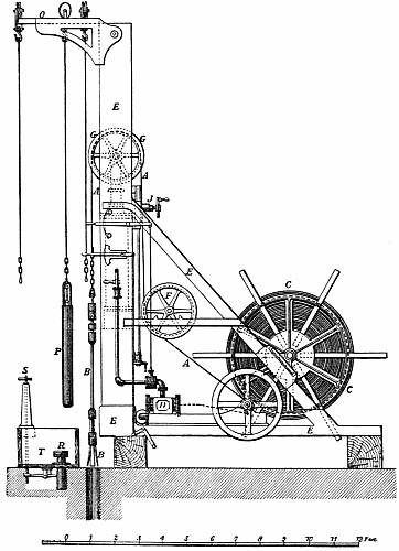
Fig. 189.
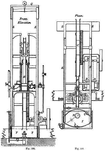
Figs. 190, 191.
The method invented by Colin Mather, and manufactured by Mather and
Platt, of Oldham, employed largely in England for deep boring, seems
to combine the advantages of the systems hitherto used, and to be
free from many of their disadvantages. The distinctive features
of this plan, which is shown in Figs. 189 to 195, are the mode of
giving the percussive action to the boring tool, and the construction
of the tool or boring-head, and of the shell-pump
for clearing out the hole after the action
of the boring-head. Instead of these implements being attached to rods,
they are suspended by a flat hemp-rope, about 1⁄2 inch thick and 41⁄2
inches broad, such as is commonly used at collieries; and the boring
tool and shell-pump are raised and lowered as quickly in the bore-hole
as the bucket and cages in a colliery shaft.
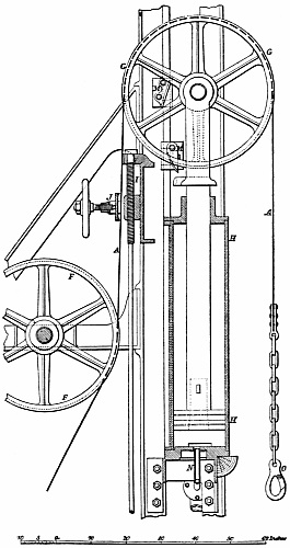
Fig. 192.
LARGE BORING MACHINE.
Longitudinal Section.
The flat rope A A, Fig. 189, from which the boring-head B is suspended,
is wound upon a large drum C driven by a steam-engine D with a
reversing motion, so that one man can regulate the operation with the
greatest ease. All the working parts are fitted into a wood or iron
framing E E, rendering the whole a compact and complete machine. On
leaving the drum C the rope passes under a guide pulley F, and then
over a large pulley G carried in a fork at the top of the piston-rod of
a vertical single-acting steam cylinder.
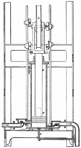
Fig. 193.
Large Boring Machine.
Transverse Section.
This cylinder, by which the percussive action of the boring-head is
produced, is shown to a larger scale in the vertical sections, Figs.
192, 193; and in the larger size of machine here shown, the cylinder is
fitted with a piston of 15 inches diameter, having a heavy cast-iron
rod 7 inches square, which is made with a fork at the top carrying the
flanged pulley G of about 3 feet diameter and of sufficient breadth for
the flat rope A to pass over it. The boring-head having been lowered
by the winding drum to the bottom of the bore-hole, the rope is fixed
secure at that length by the clamp J; steam is then admitted underneath
the piston in the cylinder H by the steam valve K, and the boring tool
is lifted by the ascent of the piston-rod and pulley G; and on arriving
at the top of the stroke the exhaust valve L is opened for the steam
to escape, allowing the piston-rod and carrying pulley to fall freely
with the boring tool, which falls with its full weight to the bottom
of the bore-hole. The exhaust port is 6 inches above the bottom of the
cylinder, while the steam port is situated at the bottom; and there is
thus always an elastic cushion of steam retained in the cylinder of
that thickness for the piston to fall upon, preventing the piston from
striking the bottom of the cylinder. The steam and exhaust valves are
worked with a self-acting motion by the
tappets M M, which are actuated by the
movement of the piston-rod; and a rapid succession of blows is thus
given by the boring tool on the bottom of the bore-hole. As it is
necessary that motion should be given to the piston before the valves
can be acted upon, a small jet of steam N is allowed to be constantly
blowing into the bottom of the cylinder; this causes the piston to move
slowly at first, so as to take up the slack of the rope and allow it
to receive the weight of the boring-head gradually and without a jerk.
An arm attached to the piston-rod then comes in contact with a tappet
which opens the steam valve K, and the piston rises quickly to the top
of the stroke; another tappet worked by the same arm then shuts off the
steam, and the exhaust valve L is opened by a corresponding arrangement
on the opposite side of the piston-rod, as shown in Fig. 193. By
shifting these tappets the length of stroke of the piston can be varied
from 1 to 8 feet in the large machine, according to the material to be
bored through; and the height of fall of the boring-head at the bottom
of the bore-hole is double the length of stroke of the piston. The fall
of the boring-head and piston can also be regulated by a weighted valve
on the exhaust pipe, checking the escape of the steam, so as to cause
the descent to take place slowly or quickly, as may be desired.
The boring-head B, Fig. 189, is shown to a larger scale in Figs. 194,
195, and consists of a wrought-iron bar about 4 inches diameter and 8
feet long, to the bottom of which a cast-iron cylindrical block C is
secured. This block has numerous square holes through it, into which
the chisels or cutters D D are inserted with taper shanks, as shown in
Fig. 195, so as to be very firm when working, but to be readily taken
out for repairing and sharpening. Two different arrangements of the
cutters are shown in the elevation, Fig. 194, and the plan, Fig. 196.
A little above the block C another cylindrical casting E is fixed upon
the bar B, which acts simply as a guide to keep the bar perpendicular.
Higher still is fixed a second guide F, but on the circumference of
this are secured cast-iron plates made with ribs of a saw-tooth or
ratchet shape, catching only in one direction; these ribs are placed at
an inclination like segments
of a screw-thread of very long pitch, so that as the guide bears
against the rough sides of the bore-hole when the bar is raised or
lowered they assist in turning it, for causing the cutters to strike in
a fresh place at each stroke. Each alternate plate has the projecting
ribs inclined in the opposite direction, so that one half of the ribs
are acting to turn the bar round in rising, and the other half to turn
it in the same direction in falling. These projecting spiral ribs
simply assist in turning the bar, and immediately above the upper guide
F is the arrangement by which the definite rotation is secured. To
effect this object two cast-iron collars, G and H, are cottered fast
to the top of the bar B, and placed about 12 inches apart; the upper
face of the lower collar G is formed with deep ratchet-teeth of about
2 inches pitch, and the under face of the top collar H is formed with
similar ratchet-teeth, set exactly in line with those on the lower
collar. Between these collars and sliding freely on the neck of the
boring bar B is a deep bush J, which is also formed with corresponding
ratchet-teeth on both its upper and lower faces; but the teeth on the
upper face are set half a tooth in advance of those on the lower face,
so that the perpendicular side of each tooth on the upper face of the
bush is directly above the centre of the inclined side of a tooth on
the lower face. To this bush is attached the wrought-iron bow K, by
which the whole boring bar is suspended with a hook and shackle O, Fig.
192, from the end of the flat rope A. The rotary motion of the bar is
obtained as follows: when the boring tool falls and strikes the blow,
the lifting bush J, which during the lifting has been engaged with
the ratchet-teeth of the top collar H, falls upon those of the bottom
collar G, and thereby receives a twist backwards through the space
of half a tooth; and on commencing to lift again, the bush rising up
against the ratchet-teeth of the top collar H receives a further twist
backwards through half a tooth. The flat rope is thus twisted backwards
to the extent of one tooth of the ratchet; and during the lifting
of the tool it untwists itself again, thereby rotating the boring
tool forwards through that extent of twist between each successive
blow of the tool. The amount of the rotation may be varied by making
the ratchet-teeth of coarser or finer pitch. The motion is entirely
self-acting, and the rotary movement of the boring tool is ensured with
mechanical accuracy. This simple and most effective action taking place
at every blow of the tool produces a constant change in the position of
the cutters, thus increasing their effect in breaking the rock.
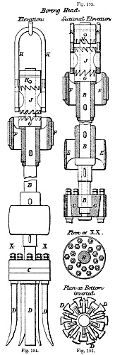
Boring Head.
Figs. 194-196.
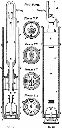
Figs. 197, 198.
The shell-pump, for raising the material broken up by the boring-head,
is shown in Figs. 197, 198, and consists of a cylindrical shell or
barrel P of cast-iron, about 8 feet long and a little smaller in
diameter than the size of the bore-hole. At the bottom is a clack A
opening upwards, somewhat similar to that in ordinary pumps; but its
seating, instead of being fastened to the cylinder P, is in an annular
frame C, which is held up against the bottom of the cylinder by a rod D
passing up to a wrought-iron bridge E at the top, where it is secured
by a cotter F. Inside the cylinder works a bucket
B, similar to that of a common lift-pump, having an indiarubber disc
valve on the top side; and the rod D of the bottom clack passes freely
through the bucket. The rod G of the bucket itself is formed like a
long link in a chain, and by this link the pump is suspended from
the shackle O, Fig. 192, at the end of the flat rope, the bridge E,
Fig. 197, preventing the bucket from being drawn out of the cylinder.
The bottom clack A is made with an indiarubber disc, which opens
sufficiently to allow the water and smaller particles of stone to enter
the cylinder; and in order to enable the pieces of broken rock to be
brought up as large as possible, the entire clack is free to rise
bodily about 6 inches from the annular frame C, as shown in Fig. 197,
thereby affording ample space for large pieces of rock to enter the
cylinder, when drawn in by the up stroke of the bucket.
The general working of the boring machine is as follows. The winding
drum C, Fig. 189, is 10 feet diameter in the large machine, and is
capable of holding 3000 feet length of rope 41⁄2 inches broad and
1⁄2 inch thick. When the boring-head B is hooked on the shackle at
the end of the rope A, its weight pulls round the drum and winding
engine, and by means of a break it is lowered steadily to the bottom
of the bore-hole; the rope is then secured at that length by screwing
up tight the clamp J. The small steam jet N, Figs. 192, 193, is next
turned on, for starting the working of the percussion cylinder H; and
the boring-head is then kept continuously at work until it has broken
up a sufficient quantity of material at the bottom of the bore-hole.
The clamp J which grips the rope is made with a slide and screw I, Fig.
192, whereby more rope can be gradually given out as the boring-head
penetrates deeper in the hole. In order to increase the lift of the
boring-head, or to compensate for the elastic stretching of the rope,
which is found to amount to 1 inch in each 100 feet length, it is
simply necessary to raise the top pair of tappets on the tappet rods
whilst the percussive motion is in operation. When the boring-head
has been kept at work long enough, the steam is shut off from the
percussion cylinder, the rope unclamped, the winding engine put in
motion, and the boring-head wound up to the surface, where it is then
slung from an overhead suspension bar Q, Fig. 189, by means of a hook
mounted on a roller for running the boring-head away to one side, clear
of the bore-hole.
The shell-pump is next lowered down the bore-hole by the rope, and the
débris pumped into it by lowering and raising the bucket about three
times at the bottom of the hole, which is readily effected by means of
the reversing motion of the winding engine. The pump is then brought up
to the surface, and emptied by the following very simple arrangement:
it is slung by a traversing hook from the overhead suspension bar Q,
Fig. 189, and is brought perpendicularly over a small table E in the
waste tank T; and the table is raised by the screw S until it receives
the weight of the pump. The cotter F, Fig. 197, which holds up the
clack seating C at the bottom of the pump, is then knocked out; and the
table being lowered by the screw, the whole clack seating C descends
with it, as shown in Fig. 198, and the contents of the pump are washed
out by the rush of water contained in the pump cylinder. The table is
then raised again by the screw, replacing the clack seating in its
proper position, in which it is secured by driving the cotter F into
the slot at the top; and the pump is again ready to be lowered down
the bore-hole as before. It is sometimes necessary for the pump to be
emptied and lowered three or four times in order to remove all the
material that has been broken up by the boring-head at one operation.
The rapidity with which these operations may be carried on is found
in the experience of the working of the machine to be as follows. The
boring-head is lowered at the rate of 500 feet a minute. The percussive
motion gives twenty-four blows a minute; this rate of working continued
for about ten minutes in red sandstone and similar strata is sufficient
for enabling the cutters to penetrate about 6 inches depth, when the
boring-head is wound up again at the rate of 300 feet a minute. The
shell-pump is lowered and raised at the same speeds, but only remains
down about two minutes; and the emptying of the pump when drawn up
occupies about two or three minutes.
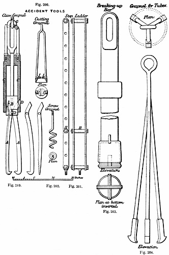
Figs. 199-204.
In the construction of this machine it will be seen that the great
desideratum of all earth boring has been well kept in view; namely,
to bore-holes of large diameter to great depths with rapidity and
safety. The object is to keep either the boring-head or the shell-pump
constantly at work at the bottom of the bore-hole, where the actual
work has to be done; to lose as little time as possible in raising,
lowering, and changing the tools; to expedite all the operations at the
surface; and to economize manual labour in every particular. With this
machine, one man standing on a platform at the side of the percussion
cylinder performs all the operations of raising and lowering by the
winding engine, changing the boring-head and shell-pump, regulating the
percussive action, and clamping or unclamping the rope: all the handles
for the various steam valves are close to his hand, and the break for
lowering is worked by his foot. Two labourers attend to changing the
cutters and clearing the pump. Duplicate boring-heads and pumps are
slung to the overhead suspension bar Q, Fig. 189, ready for use, thus
avoiding all delay when any change is requisite.
As is well known by those who have charge of such operations, in
well boring innumerable accidents and stoppages occur from causes
which cannot be prevented, with however much vigilance and skill
the operations may be conducted. Hard and soft strata intermingled,
highly-inclined rocks, running sands, and fissures and dislocations
are fruitful sources of annoyance and delay, and sometimes of complete
failure; and it will therefore be interesting to notice a few of the
ordinary difficulties arising out of these circumstances. In all the
bore-holes yet executed by this system, the various special instruments
used under any circumstances of accident or complicated strata are
fully shown in Figs. 199 to 207.
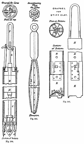
Figs. 205-207.
The boring-head while at work may suddenly be jammed fast, either by
breaking into a fissure, or in consequence of broken rock falling upon
it from loose strata above. All the strain possible is then put upon
the rope, either by the percussion cylinder or by the winding engine;
and if the rope is an old one or rotten it breaks, leaving perhaps a
long length in the
hole. The claw grapnel, shown in Fig. 199, is then attached to the
rope remaining on the winding drum, and is lowered until it rests
upon the slack broken rope in the bore-hole. The grapnel is made
with three claws A A centred in a cylindrical block B, which slides
vertically within the casing C, the tail ends of the claws fitting into
inclined slots D in the casing. During the lowering of the grapnel,
the claws are kept open, in consequence of the trigger E being held up
in the position shown in Fig. 199, by the long link F, which suspends
the grapnel from the top rope. But as soon as the grapnel rests upon
the broken rope below, the suspending link F continuing to descend
allows the trigger E to fall out of it; and then in hauling up again,
the grapnel is lifted only by the bow G of the internal block B, and
the entire weight of the external casing C bears upon the inclined
tail ends of the claws A, causing them to close in tight upon the
broken rope and lay hold of it securely. The claws are made either
hooked at the extremity or serrated. The grapnel is then hauled up
sufficiently to pull the broken rope tight, and wrought-iron rods 1
inch square with hooks attached at the bottom are let down to catch the
bow of the boring-head, which is readily accomplished. Two powerful
screw-jacks are applied to the rods at the surface, by means of the
step-ladder shown in Fig. 201, in which the cross-pin H is inserted at
any pair of the holes, so as to suit the height of the screw-jacks.
If the boring-head does not yield quickly to these efforts, the
attempt to recover it is abandoned, and it is got out of the way by
being broken up into pieces. For this purpose the broken rope in the
bore-hole has first to be removed, and it is therefore caught hold
of with a sharp hook and pulled tight in the hole, while the cutting
grapnel, shown in Fig. 200, is slipped over it and lowered by the rods
to the bottom. This tool is made with a pair of sharp cutting jaws or
knives I I opening upwards, which in lowering pass down freely over the
rope; but when the rods are pulled up with considerable force, the jaws
nipping the rope between them cut it through, and it is thus removed
altogether from the bore-hole. The solid wrought-iron breaking-up bar,
Fig. 203, which weighs about a ton, is then lowered, and by means of
the percussion cylinder it is made to pound away at the boring-head,
until the latter is either driven out of the way into one side of the
bore-hole, or broken up into such fragments as that, partly by the
shell-pump and partly by the grapnels, the whole obstacle is removed.
The boring is then proceeded with again, the same as before the
accident.
The same mishap may occur with the shell-pump getting jammed fast
in the bore-hole, as illustrated in Fig. 208; and the same means of
removing the obstacle are then adopted. Experience has shown the
danger of putting any greater strain upon the rope than the percussion
cylinder can exert; and it is therefore usual to lower the grapnel rods
at once, if the boring-head or pump gets fast, thus avoiding the risk
of breaking the rope.
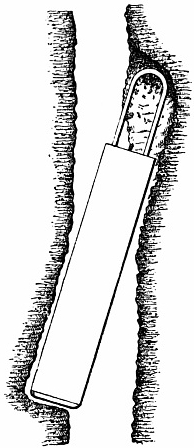
Fig. 208.
Shell-pump
Jammed in Bore-hole.
The breaking of a cutter in the boring-head is not an uncommon
occurrence. If, however, the bucket grapnel, or the small screw
grapnel, Fig. 202, be employed for its recovery, the hole is readily
cleared without any important delay. The screw grapnel, Fig. 202, is
applied by means of the iron grappling rods, so that by turning the
rods the screw works itself round the cutter or other similar article
in the bore-hole, and securely holds it while the rods are drawn up
again to the surface. The bucket grapnel, Fig. 206, is also employed
for raising clay, as well as for the purpose of bringing up cores
out of the bore-hole, where these are not raised by the boring-head
itself in the manner already described. The action of this grapnel is
nearly similar to that of the claw grapnel, Fig. 199; the three jaws A
A, hinged to the bottom of the cylindrical casing C, and attached by
connecting rods to the internal block B sliding within the casing C,
are kept open during the lowering of the tool, the trigger E being held
up in the position shown in Fig. 206, by the long suspending link F. On
reaching the bottom, the trigger is liberated by the further descent
of the link F, which, in hauling up again, lifts only the bow G of the
internal block B; so that the jaws A are made to close inwards upon the
core, which is thus grasped firmly between them and brought up within
the grapnel. Where there is clay or similar material at the bottom of
the bore-hole, the weight of the heavy block B in the grapnel causes
the sharp edges of the pointed jaws to penetrate to some depth into
the material, a quantity of which is thus enclosed within them and
brought up.
Another grapnel that is also used where a bore-hole passes through
a bed of very stiff clay is shown in Fig. 207, and consists of a
long cast-iron cylinder H fitted with a sheet-iron mouthpiece K at
the bottom, in which are hinged three conical steel jaws J J opening
upwards. The weight of the tool forces it down into the clay with
the jaws open; and then on raising it the jaws, having a tendency
to fall, cut into the clay and enclose a quantity of it inside the
mouthpiece, which on being brought up to the surface is detached from
the cylinder H and cleaned out. A second mouthpiece is put on and sent
down for working in the bore-hole while the first is being emptied, the
attachment of the mouthpiece to the cylinder being made by a common
bayonet-joint L, so as to admit of readily connecting and disconnecting
it.
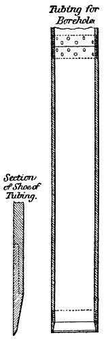
Fig. 209.
A running sand in soft clay is, however, the most serious difficulty
met with in well boring. Under such circumstances the bore-hole has to
be tubed from top to bottom, which greatly increases the expense of the
undertaking, not only by the cost of the tubes, but also by the time
and labour expended in inserting them. When a permanent water supply
is the main object of the boring, the additional expense of tubing
the bore-hole is not of much consequence, as the tubed hole is more
durable, and the surface water is thereby excluded; but in exploring
for mineral it is a serious matter, as the final result of the
bore-hole is then by no means certain. The mode of inserting tubes has
become a question of great importance in connection with this system of
boring, and much time and thought having been spent in perfecting the
method now adopted, its value has been proved by the repeated success
with which it has been carried out.
The tubes used by Mather and Platt are of cast-iron, varying in
thickness from 5⁄8 to 1 inch according to their diameter, and are all
9 feet in length. The successive lengths are connected together by
means of wrought-iron covering hoops 9 inches long, made of the same
outside diameter as the tube, so as to be flush with it. These hoops
are from 1⁄4 to 3⁄8 inch thick, and the ends of each tube are reduced
in diameter by turning down for 41⁄2 inches from the end, to fit
inside the hoops, as shown in Fig. 209. A hoop is shrunk fast on one
end of each tube, leaving 41⁄2 inches of socket projecting to receive
the end of the next tube to be connected. Four or six rows of screws
with countersunk heads, placed at equal distances round the hoop, are
screwed through into the tubes to couple the two lengths securely
together. Thus a flush joint is obtained both inside and outside the
tubes. The lowest tube is provided at the bottom with a steel shoe,
having a sharp edge for penetrating the ground more readily.
In small borings, from 6 to 12 inches diameter, the tubes are
inserted into the bore-hole by means of screw-jacks, by the simple
and inexpensive method shown in Figs. 210, 211. The boring machine
foundation A A, which is of timber, is weighted at B B by stones, pig
iron, or any available material; and two screw-jacks C C, each of
about 10 tons power, are secured with the screws downwards, underneath
the beams D D crossing the shallow well E, which is always excavated
at the top of the bore-hole. A tube F having been lowered into the
mouth of the bore-hole by the winding engine, a pair of deep clamps G
are screwed tightly round it, and the screw-jacks acting upon these
clamps force the tube down into the ground. The boring is then resumed,
and as it proceeds the jacks are occasionally worked, so as to force
the tube if possible even ahead of the boring tool. The clamps are
then slackened and shifted up the tubes, to suit the length of the
screws of the jacks; two men work the jacks, and couple the lengths of
tubes as they are successively added. The actual boring is carried on
simultaneously within the tubes, and is not in the least impeded by
their insertion, which simply involves the labour of an additional man
or two.
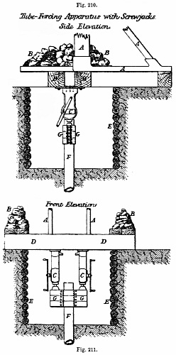
Figs. 210, 211.
A more perfect and powerful tube-forcing apparatus is adopted where
tubes of from 18 to 24 inches diameter have to be inserted to a great
depth, an illustration of which is afforded by an extensive piece of
work at the Horse Fort, standing in the channel at Gosport. This fort
is a huge round tower, as shown in Fig. 212; and to supply the garrison
with fresh water, a bore-hole is sunk into the chalk. A cast-iron well
A, consisting of cylinders 6 feet diameter and 5 feet long, has been
sunk 90 feet into the bed of the channel in the centre of the fort, and
from the bottom of this well an 18-inch bore-hole B is now in progress.
The present depth is 400 feet, and the bore-hole is tubed the whole
distance with cast-iron tubes 1 inch thick, coupled as before described.
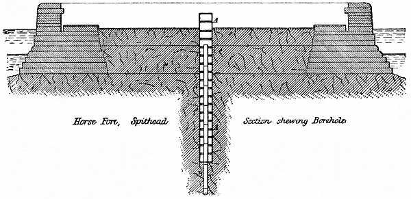
Fig. 212.
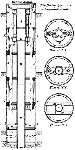
Fig. 213.
The method of inserting these tubes is shown in Fig. 213. Two
wrought-iron columns C C, 6 inches diameter, are firmly secured in the
position shown, by castings bolted to the flanges of the cylinders A
A forming the well, so that the two columns are perfectly rigid and
parallel to each other. A casting D, carrying on its under side two
5-inch hydraulic rams I I of 4 feet length, is formed so as to slide
freely between the columns, which act as guides; the hole in the centre
of this casting is large enough to pass a bore-tube freely through it,
and by means of cotters passed through the slots in the columns the
casting is securely fixed at any height. A second casting E, exactly
the same shape as the top one, is placed upon the top of the tubes B B
to be forced down, a loose wrought-iron hoop being first put upon the
shoulder at the top of the tube, large enough to prevent the casting E
from sliding down the outside of the tubes; this casting or crosshead
rests unsecured on the top of the tube and is free to move with it. The
hydraulic cylinders I, with their rams pushed home, are lowered upon
the crosshead E, and the top casting D to which they are attached is
then secured firmly to the columns C by cottering through the slots.
A small pipe F, having a long telescope joint, connects the hydraulic
cylinders I with the pumps at the surface which supply the hydraulic
pressure. By this arrangement a force of 3 tons on the square inch, or
about 120 tons total upon the two rams, has frequently been exerted to
force down the tubes at the Horse Fort. After the rams have made their
full stroke of about 3 feet 6 inches, the pressure is let off, and
the hydraulic cylinders I with the top casting D slide down the rams
resting on the crosshead E, until the rams are again pushed home. The
top casting D is then fixed in its new position upon the columns C, by
cottering fast as before, and the hydraulic pressure is again applied;
and this is repeated until the length of two tubes, making 18 feet,
has been forced down. The whole hydraulic apparatus is then drawn up
again to the top, another 18 feet of tubing added, and the operation of
forcing down resumed. The tubes are steadied by guides at G and H, Fig.
213, shown also in the plans.
The boring operations are carried on uninterruptedly during the process
of tubing, excepting only for a few minutes when fresh tubes are being
added. It will be seen that the cast-iron well is in this case the
ultimate abutment against which the pressure is exerted in forcing the
tubes down, instead of the weight of the boring machine with stones and
pig iron added, as in the case where the screw-jacks are used; the
hydraulic method was designed specially for the work at Gosport, and
has acted most perfectly. Both the cast-iron well and the bore-hole
are entirely shut off from all percolation of sea-water, by first
filling up the well 30 feet with clay round the tubes, and making the
tubes themselves water-tight at the joints at the time of putting them
together.
In the event of any accident occurring to the tubes while they are
being forced down the bore-hole, such as requires them to be drawn up
again out of the hole, the prong grapnel, Fig. 204, is employed for the
purpose, having three expanding hooked prongs, which slide down readily
inside the tube, and spring open on reaching the bottom; the hooks
then project underneath the edge of the tube, which is thus raised on
hauling up the grapnel. In case the tubes get disjointed and become
crooked during the process of tubing, the long straightening plug, Fig.
205, consisting of a stout piece of timber faced with wrought-iron
strips, is lowered down inside them; above this is a heavy cast-iron
block, the weight of which forces the plug past the part where the
tubes have got displaced, and thereby straightens them again.
Although there are few localities where the geological formation is
not favourable to the yield of pure water if a boring be carried deep
enough, yet it rarely happens that free-flowing wells such as those
in Paris and Hull are the result. Generally after the water-bearing
strata have been pierced, the level to which the water will rise is
at some depth below the surface of the ground; and only by the aid
of pumps can the desired supply be brought to the surface. Various
pumping arrangements have therefore been adopted to suit the different
conditions that are met with.
It is not the object of the present work to treat of the forms and
fittings of pumps, and the following details are only given as
completing Mather and Platt’s system.
It is always desirable to sink a cast-iron well, such as that at the
Horse Fort, as nearly as possible down to the level at which the water
stands in the bore-hole. The sinking of such a well is rendered an
easy and rapid operation, with the aid of the boring machine in winding
out the material from the bottom, and keeping the sinkers dry by the
use of the dip-bucket, shown in Figs. 214 to 216, which will lift
from 50 to 100 gallons of water a minute, for taking off the surface
drainage. A well having thus been made down to the level of the water
in the bore-hole, the permanent pumps are then applied to the bore-hole
as follows, the size of the pumps varying according to the diameter of
the bore-hole. Taking the case of a 15-inch bore-hole, a pump barrel
consisting of a plain cast-iron cylinder, say 12 inches diameter and 12
feet long, as shown in section in Fig. 219, is attached at the bottom
of cast-iron or copper pipes, which are 1⁄4 inch larger in diameter
than the pump barrel, and are coupled together in lengths by flanges,
Fig. 217. By adding the requisite number of lengths of pipe at the top,
the pump barrel is lowered to any desired depth down the bore-hole: the
nearer to the depth of the water-bearing strata the better. The topmost
length of pipe has a broad flange at its upper end, which rests upon a
preparation made to receive it on the cast-iron bottom of the well, as
at C in Fig. 219.
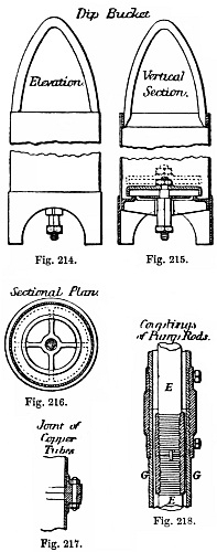
Figs. 214-218.
A pump bucket D, Fig. 219, with a water passage through it and a clack
on the top side, is then lowered into the barrel, being suspended by a
solid wrought-iron pump-rod E, which is made up of lengths of 30 feet
coupled together by right-and-left-hand screw-couplings, as in Fig.
218. A second bucket F
of similar form is also lowered into the pump barrel, above the first
bucket, and is suspended by hollow rods G coupled together in the
manner just described; the inside diameter of the hollow rods G being
such that the couplings of the solid rods E may pass freely through.
The pump-rods are carried up the well A to the surface, where the
hollow rod of the top bucket is attached to the horizontal arm of a
bell-crank lever H, Fig. 219; and the solid rod of the bottom bucket,
passing up through the hollow rod of the top bucket, is suspended from
the horizontal arm of a second reversed bell-crank lever K, facing the
first lever H. As the extremities of the horizontal arms of the levers
meet over the centre of the well, one of them is made with a forked end
to admit of the other passing it. The vertical arms of the two levers
are coupled by a connecting rod L, and a reciprocating motion is given
to them by means of an oscillating steam cylinder M, the piston-rod
of which is attached direct to the extremity of one of the vertical
arms; a crank and flywheel N are also connected to the levers, for
controlling the motion at the ends of the stroke. With the proportion
shown in the Figure of 3 to 4 between the horizontal and vertical arms
of the bell-crank levers, the stroke of 5 feet 4 inches of the steam
piston gives 4 feet stroke of the pump. The reciprocating motion of
the reversed bell-crank levers causes the two buckets to move always
in opposite directions, so that they meet and separate at each stroke
of the engine. A continuous flow of water is the result, for when the
top bucket is descending, the bottom bucket is rising and delivering
its water through the top bucket; and when the top bucket rises, it
lifts the water above it while the bottom bucket is descending, and
water rises through the descending bottom bucket to fill the space left
between the two buckets. In this way the effect of a double-acting pump
is produced.
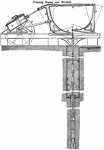
Fig. 219.
Although a continuous delivery of water is thus obtained of equal
amount in each stroke, it is found in practice that a heavy shock
is occasioned at each end of the stroke, in consequence of both the
buckets starting and stopping simultaneously, causing the whole column
of water to be stopped and put into motion again at each stroke. As an
air-vessel for keeping up the motion of the water is inapplicable in
such a situation, a modified arrangement of the two bell-crank levers
has been adopted, which answers the purpose, causing each bucket at the
commencement of its up stroke to take the lift off the other, before
the up stroke of the latter is completed. By this means all shock is
avoided, as the first bucket gently and gradually relieves the second,
before the return stroke of the second commences.
In this improved pumping motion, which is shown in Figs. 220, 221, the
two bell-crank levers H and K, working the pump buckets, are centred
one above the other, the upper one being inverted; the vertical arms
are slotted, and are both actuated by the same crank-pin working in the
slots, the revolution of the crank thus giving an oscillating movement
to the two levers
through the extent of the arcs shown by the
dotted lines in Fig. 220. The solid pump-rod E suspending the bottom
bucket D is attached to the upper bell-crank lever K, and the hollow
rod G of the top bucket is suspended from the lower lever H; the
crank-shaft J working the levers is made to revolve in the direction
shown by the arrow in Fig. 220, by means of gearing driven by the
horizontal steam-engine P.
The result of this arrangement is, that in the revolution of the crank
the dead point of one of the levers is passed before that of the other
is reached; so that the bucket which first comes to rest at the end of
its stroke is started into motion again before the second bucket comes
to rest. Thus in the lifting stroke of the bottom bucket worked by the
upper lever K, the bucket in ascending has only reached the position
shown at D in Fig. 220, at the moment when the top bucket worked by
the lower lever H arrives at the bottom extremity of its stroke, and
the bottom bucket D, which is still rising, continues to lift until it
reaches its highest position, by which time the top bucket has got well
into motion in its up stroke, and is in its turn lifting the water.