In this treatise we do not propose to go into the history of this
escapement and give a long dissertation on its origin and evolution, but
shall confine ourselves strictly to the designing and construction as
employed in our best watches. By designing, we mean giving full
instructions for drawing an escapement of this kind to the best
proportions. The workman will need but few drawing instruments, and a
drawing-board about 15" by 18" will be quite large enough. The necessary
drawing-instruments are a T-square with 15" blade; a scale of inches
divided into decimal parts; two pairs dividers with pen and pencil
points—one pair of these dividers to be 5" and the other 6"; one ruling
pen. Other instruments can be added as the workman finds he needs them.
Those enumerated above, however, will be all that are absolutely
necessary.
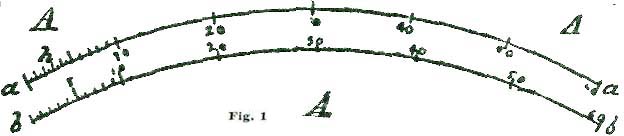
We shall, in addition, need an arc of degrees, which we can best make
for ourselves. To construct one, we procure a piece of No. 24 brass,
about 5-1/2" long by 1-1/4" wide. We show such a piece of brass at A,
Fig. 1. On this piece of brass we sweep two arcs with a pair of dividers
set at precisely 5", as shown (reduced) at a a and b b. On these
arcs we set off the space held in our dividers—that is 5"—as shown at
the short radial lines at each end of the two arcs. Now it is a
well-known fact that the space embraced by our dividers contains exactly
sixty degrees of the arcs a a and b b, or one-sixth of the entire
circle; consequently, we divide the arcs a a and b b into sixty
equal parts, to represent degrees, and at one end of these arcs we
halve five spaces so we can get at half degrees.
Before we take up the details of drawing an escapement we will say a few
words about "degrees," as this seems to be something difficult to
understand by most pupils in horology when learning to draw parts of
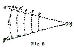
watches to scale. At Fig. 2 we show several short arcs of fifteen
degrees, all having the common center g. Most learners seem to have an
idea that a degree must be a specific space, like an inch or a foot. Now
the first thing in learning to draw an escapement is to fix in our minds
the fact that the extent of a degree depends entirely on the radius of
the arc we employ. To aid in this explanation we refer to Fig. 2. Here
the arcs c, d, e and f are all fifteen degrees, although the
linear extent of the degree on the arc c is twice that of the degree
on the arc f. When we speak of a degree in connection with a circle we
mean the one-three-hundred-and-sixtieth part of the periphery of such a
circle. In dividing the arcs a a and b b we first divide them into
six spaces, as shown, and each of these spaces into ten minor spaces, as
is also shown. We halve five of the degree spaces, as shown at h. We
should be very careful about making the degree arcs shown at Fig. 1, as
the accuracy of our drawings depends a great deal on the perfection of
the division on the scale A. In connection with such a fixed scale of
degrees as is shown at Fig. 1, a pair of small dividers, constantly set
to a degree space, is very convenient.
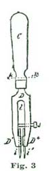
To make such a pair of small dividers, take a piece of hard sheet brass
about 1/20" thick, 1/4" wide, 1-1/2" long, and shape it as shown at Fig.
3. It should be explained, the part cut from the sheet brass is shown
below the dotted line k, the portion above (C) being a round handle
turned from hard wood or ivory. The slot l is sawn in, and two holes
drilled in the end to insert the needle points i i. In making the slot
l we arrange to have the needle points come a little too close
together to agree with the degree spaces on the arcs a a and b b. We
then put the small screw j through one of the legs D'', and by
turning j, set the needle points i i to exactly agree with the
degree spaces. As soon as the points i i are set correctly, j should
be soft soldered fast.
The degree spaces on A are set off with these dividers and the spaces
on A very carefully marked. The upper and outer arc a a should have
the spaces cut with a graver line, while the lower one, b b is best
permanently marked with a carefully-made prick punch. After the arc a
a is divided, the brass plate A is cut back to this arc so the
divisions we have just made are on the edge. The object of having two
arcs on the plate A is, if we desire to get at the number of degrees
contained in any arc of a 5" radius we lay the scale A so the edge
agrees with the arc a a, and read off the number of degrees from the
scale. In setting dividers we employ the dotted spaces on the arc b b.
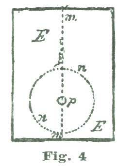
We will now proceed to delineate an escape wheel for a detached lever.
We place a piece of good drawing-paper on our drawing-board and provide
ourselves with a very hard (HHH) drawing-pencil and a bottle of liquid
India ink. After placing our paper on the board, we draw, with the aid
of our T-square, a line through the center of the paper, as shown at m
m, Fig. 4. At 5-1/2" from the lower margin of the paper we establish
the point p and sweep the circle n n with a radius of 5". We have
said nothing about stretching our paper on the drawing-board; still,
carefully-stretched paper is an important part of nice and correct
drawing. We shall subsequently give directions for properly stretching
paper, but for the present we will suppose the paper we are using is
nicely tacked to the face of the drawing-board with the smallest tacks
we can procure. The paper should not come quite to the edge of the
drawing-board, so as to interfere with the head of the T-square. We are
now ready to commence delineating our escape wheel and a set of pallets
to match.
The simplest form of the detached lever escapement in use is the one
known as the "ratchet-tooth lever escapement," and generally found in
English lever watches. This form of escapement gives excellent results
when well made; and we can only account for it not being in more general
use from the fact that the escape-wheel teeth are not so strong and
capable of resisting careless usage as the club-tooth escape wheel.
It will be our aim to convey broad ideas and inculcate general
principles, rather than to give specific instructions for doing "one
thing one way." The ratchet-tooth lever escapements of later dates have
almost invariably been constructed on the ten-degree
lever-and-pallet-action plan; that is, the fork and pallets were
intended to act through this arc. Some of the other specimens of this
escapement have larger arcs—some as high as twelve degrees.
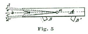
We illustrate at Fig. 5 what we mean by ten degrees of pallet-and-fork
action. If we draw a line through the center of the pallet staff, and
also through the center of the fork slot, as shown at a b, Fig. 5, and
allow the fork to vibrate five degrees each side of said lines a b, to
the lines a c and a c', the fork has what we term ten-degree pallet
action. If the fork and pallets vibrate six degrees on each side of the
line a b—that is, to the lines a d and a d'—we have twelve
degrees pallet action. If we cut the arc down so the oscillation is only
four and one-quarter degrees on each side of a b, as indicated by the
lines a s and a s', we have a pallet-and-fork action of eight and
one-half degrees; which, by the way, is a very desirable arc for a
carefully-constructed escapement.
The controlling idea which would seem to rule in constructing a detached
lever escapement, would be to make it so the balance is free of the
fork; that is, detached, during as much of the arc of the vibration of
the balance as possible, and yet have the action thoroughly sound and
secure. Where a ratchet-tooth escapement is thoroughly well-made of
eight and one-half degrees of pallet-and-fork action, ten and one-half
degrees of escape-wheel action can be utilized, as will be explained
later on.
We will now resume the drawing of our escape wheel, as illustrated at
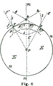
Fig. 4. In the drawing at Fig. 6 we show the circle n n, which
represents the periphery of our escape wheel; and in the drawing we are
supposed to be drawing it ten inches in diameter.
We produce the vertical line m passing through the center p of the
circle n. From the intersection of the circle n with the line m
at i we lay off thirty degrees on each side, and establish the points
e f; and from the center p, through these points, draw the radial
lines p e' and p f'. The points f e, Fig. 6, are, of course, just
sixty degrees apart and represent the extent of two and one-half teeth
of the escape wheel. There are two systems on which pallets for lever
escapements are made, viz., equidistant lockings and circular pallets.
The advantages claimed for each system will be discussed subsequently.
For the first and present illustration we will assume we are to employ
circular pallets and one of the teeth of the escape wheel resting on the
pallet at the point f; and the escape wheel turning in the direction
of the arrow j. If we imagine a tooth as indicated at the dotted
outline at D, Fig. 6, pressing against a surface which coincides with
the radial line p f, the action would be in the direction of the line
f h and at right angles to p f. If we reason on the action of the
tooth D, as it presses against a pallet placed at f, we see the
action is neutral.
With a fifteen-tooth escape wheel each tooth occupies twenty-four
degrees, and from the point f to e would be two and one-half
tooth-spaces. We show the dotted points of four teeth at D D' D''
D'''. To establish the center of the pallet staff we draw a line at
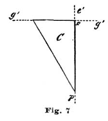
right angles to the line p e' from the point e so it intersects the
line f h at k. For drawing a line at right angles to another line,
as we have just done, a hard-rubber triangle, shaped as shown at C,
Fig. 7, can be employed. To use such a triangle, we place it so the
right, or ninety-degrees angle, rests at e, as shown at the dotted
triangle C, Fig. 6, and the long side coincides with the radial line
p e'. If the short side of the hard-rubber triangle is too short, as
indicated, we place a short ruler so it rests against the edge, as shown
at the dotted line g e, Fig. 7, and while holding it securely down on
the drawing we remove the triangle, and with a fine-pointed pencil draw
the line e g, Fig. 6, by the short rule. Let us imagine a flat surface
placed at e so its face was at right angles to the line g e, which
would arrest the tooth D'' after the tooth D resting on f had been
released and passed through an arc of twelve degrees. A tooth resting on
a flat surface, as imagined above, would also rest dead. As stated
previously, the pallets we are considering have equidistant locking
faces and correspond to the arc l l, Fig. 6.
In order to realize any power from our escape-wheel tooth, we must
provide an impulse face to the pallets faced at f e; and the problem
before us is to delineate these pallets so that the lever will be
propelled through an arc of eight and one-half degrees, while the escape
wheel is moving through an arc of ten and one-half degrees. We make the
arc of fork action eight and one-half degrees for two reasons—(1)
because most text-books have selected ten degrees of fork-and-pallet
action; (2) because most of the finer lever escapements of recent
construction have a lever action of less than ten degrees.
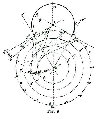
To "lay out" or delineate our escape-wheel teeth, we continue our
drawing shown at Fig. 6, and reproduce this cut very nearly at Fig. 8.
With our dividers set at five inches, we sweep the short arc a a' from
f as a center. It is to be borne in mind that at the point f is
located the extreme point of an escape-wheel tooth. On the arc a a we
lay off from p twenty-four degrees, and establish the point b; at
twelve degrees beyond b we establish the point c. From f we draw
the lines f b and f c; these lines establishing the form and
thickness of the tooth D. To get the length of the tooth, we take in
our dividers one-half a tooth space, and on the radial line p f
establish the point d and draw circle d' d'.
To facilitate the drawing of the other teeth, we draw the circles d'
c', to which the lines f b and f c are tangent, as shown. We divide
the circle n n, representing the periphery of our escape wheel, into
fifteen spaces, to represent teeth, commencing at f and continued as
shown at o o until the entire wheel is divided. We only show four
teeth complete, but the same methods as produced these will produce them
all. To briefly recapitulate the instructions for drawing the teeth for
the ratchet-tooth lever escapement: We draw the face of the teeth at an
angle of twenty-four degrees to a radial line; the back of the tooth at
an angle of thirty-six degrees to the same radial line; and make teeth
half a tooth-space deep or long.
We now come to the consideration of the pallets and how to delineate
them. To this we shall add a careful analysis of their action. Let us,
before proceeding further, "think a little" over some of the factors
involved. To aid in this thinking or reasoning on the matter, let us
draw the heavy arc l extending from a little inside of the circle n
at f to the circle n at e. If now we imagine our escape wheel to
be pressed forward in the direction of the arrow j, the tooth D
would press on the arc l and be held. If, however, we should revolve
the arc l on the center k in the direction of the arrow i, the
tooth D would escape from the edge of l and the tooth D'' would
pass through an arc (reckoning from the center p) of twelve degrees,
and be arrested by the inside of the arc l at e. If we now should
reverse the motion and turn the arc l backward, the tooth at e
would, in turn, be released and the tooth following after D (but not
shown) would engage l at f. By supplying motive to revolve the
escape wheel (E) represented by the circle n, and causing the arc
l to oscillate back and forth in exact intervals of time, we should
have, in effect, a perfect escapement. To accomplish automatically such
oscillations is the problem we have now on hand.
In clocks, the back-and-forth movement, or oscillating motion, is
obtained by employing a pendulum; in a movable timepiece we make use of
an equally-poised wheel of some weight on a pivoted axle, which device
we term a balance; the vibrations or oscillations being obtained by
applying a coiled spring, which was first called a "pendulum spring,"
then a "balance spring," and finally, from its diminutive size and coil
form, a "hairspring." We are all aware that for the motive power for
keeping up the oscillations of the escaping circle l we must contrive
to employ power derived from the teeth D of the escape wheel. About
the most available means of conveying power from the escape wheel to the
oscillating arc l is to provide the lip of said arc with an inclined
plane, along which the tooth which is disengaged from l at f to
slide and move said arc l through—in the present instance an arc of
eight and one-half degrees, during the time the tooth D is passing
through ten and one-half degrees. This angular motion of the arc l is
represented by the radial lines k f' and k r, Fig. 8. We desire to
impress on the reader's mind the idea that each of these angular motions
is not only required to be made, but the motion of one mobile must
convey power to another mobile.
In this case the power conveyed from the mainspring to the escape wheel
is to be conveyed to the lever, and by the lever transmitted to the
balance. We know it is the usual plan adopted by text-books to lay down
a certain formula for drawing an escapement, leaving the pupil to work
and reason out the principles involved in the action. In the plan we
have adopted we propose to induct the reader into the why and how, and
point out to him the rules and methods of analysis of the problem, so
that he can, if required, calculate mathematically exactly how many
grains of force the fork exerts on the jewel pin, and also how much (or,
rather, what percentage) of the motive power is lost in various "power
leaks," like "drop" and lost motion. In the present case the mechanical
result we desire to obtain is to cause our lever pivoted at k to
vibrate back and forth through an arc of eight and one-half degrees;
this lever not only to vibrate back and forth, but also to lock and hold
the escape wheel during a certain period of time; that is, through the
period of time the balance is performing its excursion and the jewel pin
free and detached from the fork.
We have spoken of paper being employed for drawings, but for very
accurate delineations we would recommend the horological student to make
drawings on a flat metal plate, after perfectly smoothing the surface
and blackening it by oxidizing.
By adopting eight and one-half degrees pallet-and-fork action we can
utilize ten and one-half degrees of escape-wheel action. We show at A
A', Fig. 9, two teeth of a ratchet-tooth escape wheel reduced one-half;
that is, the original drawing was made for an escape wheel ten inches in
diameter. We shall make a radical departure from the usual practice in
making cuts on an enlarged scale, for only such parts as we are talking
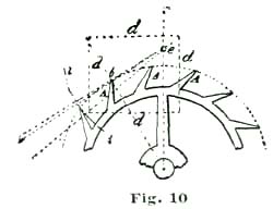
about. To explain, we show at Fig. 10 about one-half of an escape wheel
one eighth the size of our large drawing; and when we wish to show some
portion of such drawing on a larger scale we will designate such
enlargement by saying one-fourth, one-half or full size.
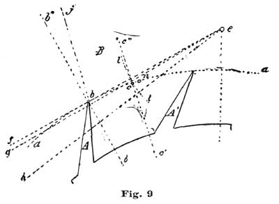
At Fig. 9 we show at half size that portion of our escapement embraced
by the dotted lines d, Fig. 10. This plan enables us to show very
minutely such parts as we have under consideration, and yet occupy but
little space. The arc a, Fig. 9, represents the periphery of the
escape wheel. On this line, ten and one-half degrees from the point of
the tooth A, we establish the point c and draw the radial line c
c'. It is to be borne in mind that the arc embraced between the points
b and c represents the duration of contact between the tooth A and
the entrance pallet of the lever. The space or short arc c n
represents the "drop" of the tooth.
This arc of one and one-half degrees of escape-wheel movement is a
complete loss of six and one-fourth per cent. of the entire power of the
mainspring, as brought down to the escapement; still, up to the present
time, no remedy has been devised to overcome it. All the other
escapements, including the chronometer, duplex and cylinder, are quite
as wasteful of power, if not more so. It is usual to construct
ratchet-tooth pallets so as to utilize but ten degrees of escape-wheel
action; but we shall show that half a degree more can be utilized by
adopting the eight and one-half degree fork action and employing a
double-roller safety action to prevent over-banking.
From the point e, which represents the center of the pallet staff, we
draw through b the line e f. At one degree below e f we draw the
line e g, and seven and one-half degrees below the line e g we draw
the line e h. For delineating the lines e g, etc., correctly, we
employ a degree-arc; that is, on the large drawing we are making we
first draw the line e b f, Fig. 10, and then, with our dividers set at
five inches, sweep the short arc i, and on this lay off first one
degree from the intersection of f e with the arc i, and through this
point draw the line e g.
From the intersection of the line f e with the arc i we lay off
eight and one-half degrees, and through this point draw the line e h.
Bear in mind that we are drawing the pallet at B to represent one with
eight and one-half degrees fork-and-pallet action, and with equidistant
lockings. If we reason on the matter under consideration, we will see
the tooth A and the pallet B, against which it acts, part or
separate when the tooth arrives at the point c; that is, after the
escape wheel has moved through ten and one-half degrees of angular
motion, the tooth drops from the impulse face of the pallet and falls
through one and one-half degrees of arc, when the tooth A'', Fig. 10,
is arrested by the exit pallet.
To locate the position of the inner angle of the pallet B, sweep the
short arc l by setting the dividers so one point or leg rests at the
center e and the other at the point c. Somewhere on this arc l is
to be located the inner angle of our pallet. In delineating this angle,
Moritz Grossman, in his "Prize Essay on the Detached Lever Escapement,"
makes an error, in Plate III of large English edition, of more than his
entire lock, or about two degrees. We make no apologies for calling
attention to this mistake on the part of an authority holding so high a
position on such matters as Mr. Grossman, because a mistake is a
mistake, no matter who makes it.
We will say no more of this error at present, but will farther on show
drawings of Mr. Grossman's faulty method, and also the correct method of
drawing such a pallet. To delineate the locking face of our pallet, from
the point formed by the intersection of the lines e g b b', Fig. 9, as
a center, we draw the line j at an angle of twelve degrees to b b''.
In doing this we employ the same method of establishing the angle as we
made use of in drawing the lines e g and e h, Fig. 10. The line j
establishes the locking face of the pallet B. Setting the locking face
of the pallet at twelve degrees has been found in practice to give a
safe "draw" to the pallet and keep the lever secure against the bank. It
will be remembered the face of the escape-wheel tooth was drawn at
twenty-four degrees to a radial line of the escape wheel, which, in this
instance, is the line b b', Fig. 9. It will now be seen that the angle
of the pallet just halves this angle, and consequently the tooth A
only rests with its point on the locking face of the pallet. We do not
show the outlines of the pallet B, because we have not so far pointed
out the correct method of delineating it.
Perhaps we cannot do our readers a greater favor than to digress from
the study of the detached lever escapement long enough to say a few
words about drawing instruments and tablets or surfaces on which to
delineate, with due precision, mechanical designs or drawings. Ordinary
drawing instruments, even of the higher grades, and costing a good deal
of money, are far from being satisfactory to a man who has the proper
idea of accuracy to be rated as a first-class mechanic. Ordinary
compasses are obstinate when we try to set them to the hundredth of an
inch; usually the points are dull and ill-shapen; if they make a
puncture in the paper it is unsightly.
Watchmakers have one advantage, however, because they can very easily
work over a cheap set of drawing instruments and make them even superior
to anything they can buy at the art stores. To illustrate, let us take a
cheap pair of brass or German-silver five-inch dividers and make them
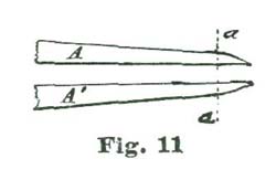
over into needle points and "spring set." To do this the points are cut
off at the line a a, Fig 11, and a steel tube is gold-soldered on each
leg. The steel tube is made by taking a piece of steel wire which will
fit a No. 16 chuck of a Whitcomb lathe, and drilling a hole in the end
about one-fourth of an inch deep and about the size of a No. 3 sewing
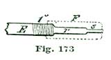
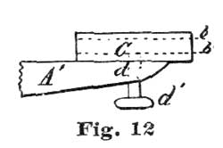
needle. We Show at Fig. 12 a view of the point A', Fig. 11, enlarged,
and the steel tube we have just drilled out attached at C. About the
best way to attach C is to solder. After the tube C is attached a
hole is drilled through A' at d, and the thumb-screw d inserted.
This thumb-screw should be of steel, and hardened and tempered. The use
of this screw is to clamp the needle point. With such a device as the
tube C and set-screw d, a No. 3 needle is used for a point; but for
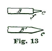
drawings on paper a turned point, as shown at Fig 13, is to be
preferred. Such points can be made from a No. 3 needle after softening
enough to be turned so as to form the point c. This point at the
shoulder f should be about 12/1000 of an inch, or the size of a
fourth-wheel pivot to an eighteen size movement.
The idea is, when drawing on paper the point c enters the paper. For
drawing on metal the form of the point is changed to a simple cone, as
shown at B' c, Fig. 13. such cones can be turned carefully, then
hardened and tempered to a straw color; and when they become dull, can
be ground by placing the points in a wire chuck and dressing them up
with an emery buff or an Arkansas slip. The opposite leg of the dividers
is the one to which is attached the spring for close setting of the
points.
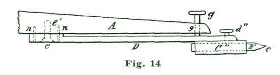
In making this spring, we take a piece of steel about two and
one-fourth inches long and of the same width as the leg of the divider,
and attach it to the inside of the leg as shown at Fig. 14, where D
represents the spring and A the leg of the dividers. The spring D
has a short steel tube C'' and set-screw d'' for a fine point like
B or B'. In the lower end of the leg A, Fig. 14, is placed the
milled-head screw g, which serves to adjust the two points of the
dividers to very close distances. The spring D is, of course, set so
it would press close to the leg A if the screw g did not force it
away.
It will be seen that we can apply a spring D and adjusting screw
opposite to the leg which carries the pen or pencil point of all our
dividers if we choose to do so; but it is for metal drawing that such
points are of the greatest advantage, as we can secure an accuracy very
gratifying to a workman who believes in precision. For drawing circles
on metal, "bar compasses" are much the best, as they are almost entirely
free from spring, which attends the jointed compass. To make (because
they cannot be bought) such an instrument, take a piece of flat steel,
one-eighth by three-eighths of an inch and seven inches long, and after
turning and smoothing it carefully, make a slide half an inch wide, as
shown at Fig. 15, with a set-screw h on top to secure it at any point
on the bar E. In the lower part of the slide F is placed a steel
tube like C, shown in Figs. 12 and 14, with set-screw for holding
points like B B', Fig. 13. At the opposite end of the bar E is
placed a looped spring G, which carries a steel tube and point like
the spring D, Fig. 14. Above this tube and point, shown at j, Fig.
15, is placed an adjustment screw k for fine adjustment. The inner end
of the screw k rests against the end of the bar E. The tendency of
the spring G is to close upon the end of E; consequently if we make
use of the screw k to force away the lower end of G, we can set the
fine point in j to the greatest exactness.
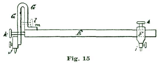
The spring G is made of a piece of steel one-eighth of an inch
square, and secured to the bar E with a screw and steady pins at m.
A pen and pencil point attachment can be added to the spring G; but in
case this is done it would be better to make another spring like G
without the point j, and with the adjusting screw placed at l. In
fitting pen and pencil points to a spring like G it would probably be
economical to make them outright; that is, make the blades and screw for
the ruling pen and a spring or clamping tube for the pencil point.
We will now, with our improved drawing instruments, resume the
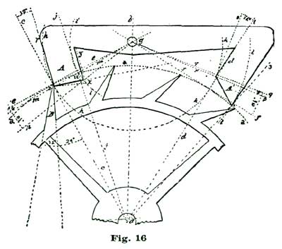
consideration of the ratchet-tooth lever escapement. We reproduce at
Fig. 16 a portion of diagram III, from Moritz Grossmann's "Prize Essay
on the Detached Lever Escapement," in order to point out the error in
delineating the entrance pallet to which we previously called attention.
The cut, as we give it, is not quite one-half the size of Mr.
Grossmann's original plate.
In the cut we give the letters of reference employed the same as on the
original engraving, except where we use others in explanation. The
angular motion of the lever and pallet action as shown in the cut is ten
degrees; but in our drawing, where we only use eight and one-half
degrees, the same mistake would give proportionate error if we did not
take the means to correct it. The error to which we refer lies in
drawing the impulse face of the entrance pallet. The impulse face of
this pallet as drawn by Mr. Grossmann would not, from the action of the
engaging tooth, carry this pallet through more than eight degrees of
angular motion; consequently, the tooth which should lock on the exit
pallet would fail to do so, and strike the impulse face.
We would here beg to add that nothing will so much instruct a person
desiring to acquire sound ideas on escapements as making a large model.
The writer calls to mind a wood model of a lever escapement made by one
of the "boys" in the Elgin factory about a year or two after Mr.
Grossmann's prize essay was published. It went from hand to hand and did
much toward establishing sound ideas as regards the correct action of
the lever escapement in that notable concern.
If a horological student should construct a large model on the lines
laid down in Mr. Grossmann's work, the entrance pallet would be faulty
in form and would not properly perform its functions. Why? perhaps says
our reader. In reply let us analyze the action of the tooth B as it
rests on the pallet A. Now, if we move this pallet through an angular
motion of one and one-half degrees on the center g (which also
represents the center of the pallet staff), the tooth B is disengaged
from the locking face and commences to slide along the impulse face of
the pallet and "drops," that is, falls from the pallet, when the inner
angle of the pallet is reached.
This inner angle, as located by Mr. Grossmann, is at the intersection of
the short arc i with the line g n, which limits the ten-degree
angular motion of the pallets. If we carefully study the drawing, we
will see the pallet has only to move through eight degrees of angular
motion of the pallet staff for the tooth to escape, because the tooth
certainly must be disengaged when the inner angle of the pallet reaches
the peripheral line a. The true way to locate the position of the inner
angle of the pallet, is to measure down on the arc i ten degrees from
its intersection with the peripheral line a and locate a point to
which a line is drawn from the intersection of the line g m with the
radial line a c, thus defining the inner angle of the entrance pallet.
We will name this point the point x.
It may not be amiss to say the arc i is swept from the center g
through the point u, said point being located ten degrees from the
intersection of the radial a c with the peripheral line a. It will
be noticed that the inner angle of the entrance pallet A seems to
extend inward, beyond the radial line a j, that is, toward the pallet
center g, and gives the appearance of being much thicker than the exit
pallet A'; but we will see on examination that the extreme angle x
of the entrance pallet must move on the arc i and, consequently, cross
the peripheral line a at the point u. If we measure the impulse
faces of the two pallets A A', we will find them nearly alike in
linear extent.
Mr. Grossmann, in delineating his exit pallet, brings the extreme angle
(shown at 4) down to the periphery of the escape, as shown in the
drawing, where it extends beyond the intersection of the line g f with
the radial line a 3. The correct form for the entrance pallet should
be to the dotted line z x y.
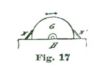
We have spoken of engaging and disengaging frictions; we do not know how
we can better explain this term than by illustrating the idea with a
grindstone. Suppose two men are grinding on the same stone; each has,
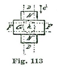
say, a cold chisel to grind, as shown at Fig. 17, where G represents
the grindstone and N N' the cold chisels. The grindstone is supposed
to be revolving in the direction of the arrow. The chisels N and N'
are both being ground, but the chisel N' is being cut much the more
rapidly, as each particle of grit of the stone as it catches on the
steel causes the chisel to hug the stone and bite in deeper and deeper;
while the chisel shown at N is thrust away by the action of the grit.
Now, friction of any kind is only a sort of grinding operation, and the
same principles hold good.
It is to be hoped the reader who intends to profit by this treatise has
fitted up such a pair of dividers as those we have described, because it
is only with accurate instruments he can hope to produce drawings on
which any reliance can be placed. The drawing of a ratchet-tooth lever
escapement of eight and one-half degrees pallet action will now be
resumed. In the drawing at Fig. 18 is shown a complete delineation of
such an escapement with eight and one-half degrees of pallet action and
equidistant locking faces. It is, of course, understood the escape wheel
is to be drawn ten inches in diameter, and that the degree arcs shown in
Fig. 1 will be used.
We commence by carefully placing on the drawing-board a sheet of paper
about fifteen inches square, and then vertically through the center
draw the line a' a''. At some convenient position on this line is
established the point a, which represents the center of the escape
wheel. In this drawing it is not important that the entire escape wheel
be shown, inasmuch as we have really to do with but a little over sixty
degrees of the periphery of the escape wheel. With the dividers
carefully set at five inches, from a, as a center, we sweep the arc n
n, and from the intersection of the perpendicular line a' a'' with
the arc n we lay off on each side thirty degrees from the brass degree
arc, and through the points thus established are drawn the radial lines
a b' and a d'.
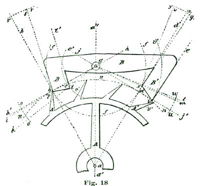
The point on the arc n where it intersects with the line b' is
termed the point b. At the intersection of the radial line a d' is
established the point d. We take ten and one-half degrees in the
dividers, and from the point b establish the point c, which embraces
the arc of the escape wheel which is utilized by the pallet action.
Through the point b the line h' h is drawn at right angles to the
line a b'. The line j j' is also drawn at right angles to the line
a d' through the point d. We now have an intersection of the lines
just drawn in common with the line a a' at the point g, said point
indicating the center of the pallet action.
The dividers are now set to embrace the space between the points b and
g on the line h' h, and the arc f f is swept; which, in proof of
the accuracy of the work, intersects the arc n at the point d. This
arc coincides with the locking faces of both pallets. To lay out the
entrance pallet, the dividers are set to five inches, and from g as a
center the short arc o o is swept. On this arc one degree is laid off
below the line h' h, and the line g i drawn. The space embraced
between the lines h and i on the arc f represents the locking face
of the entrance pallet, and the point formed at the intersection of the
line g i with the arc f is called the point p. To give the proper
lock to the face of the pallet, from the point p as a center is swept
the short arc r r, and from its intersection with the line a b'
twelve degrees are laid off and the line b s drawn, which defines the
locking face of the entrance pallet. From g as a center is swept the
arc c' c', intersecting the arc n n at c. On this arc (c) is
located the inner angle of the entrance pallet. The dividers are set to
embrace the space on the arc c' between the lines g h' and g k.
With this space in the dividers one leg is set at the point c,
measuring down on the arc c' and establishing the point t. The
points p and t are then connected, and thus the impulse face of the
entrance pallet B is defined. From the point t is drawn the line t
t', parallel to the line b s, thus defining the inner face of the
entrance pallet.
To delineate the exit pallet, sweep the short arc u u (from g as a
center) with the dividers set at five inches, and from the intersection
of this arc with the line g j' set off eight and one-half degrees and
draw the line g l. At one degree below this line is drawn the line g
m. The space on the arc f between these lines defines the locking
face of the exit pallet. The point where the line g m intersects the
arc f is named the point x. From the point x is erected the line
x w, perpendicular to the line g m. From x as a center, and with
the dividers set at five inches, the short arc y y is swept, and on
this arc are laid off twelve degrees, and the line x z is drawn, which
line defines the locking face of the exit pallet.
Next is taken ten and one-half degrees from the brass degree-scale, and
from the point d on the arc n the space named is laid off, and thus
is established the point v; and from g as a center is swept the arc
v' v' through the point v. It will be evident on a little thought,
that if the tooth A' impelled the exit pallet to the position shown,
the outer angle of the pallet must extend down to the point v, on the
arc v' v'; consequently, we define the impulse face of this pallet by
drawing a line from point x to v. To define the outer face of the
exit pallet, we draw the line v e parallel to the line x z.
There are no set rules for drawing the general form of the pallet arms,
only to be governed by and conforming to about what we would deem
appropriate, and to accord with a sense of proportion and mechanical
elegance. Ratchet-tooth pallets are usually made in what is termed
"close pallets"; that is, the pallet jewel is set in a slot sawed in the
steel pallet arm, which is undoubtedly the strongest and most
serviceable form of pallet made. We shall next consider the
ratchet-tooth lever escapement with circular pallets and ten degrees of
pallet action.
To delineate "circular pallets" for a ratchet-tooth lever escapement, we
proceed very much as in the former drawing, by locating the point A,
which represents the center of the escape wheel, at some convenient
point, and with the dividers set at five inches, sweep the arc m, to
represent the periphery of the escape wheel, and then draw the vertical
line A B', Fig. 19. We (as before) lay off thirty degrees on the arc
m each side of the intersection of said arc with the line A B', and
thus establish on the arc m the points a b, and from A as a center
draw through the points so established the radial lines A a' and A
b'.
We erect from the point a a perpendicular to the line A a, and, as
previously explained, establish the pallet center at B. Inasmuch as we
are to employ circular pallets, we lay off to the left on the arc m,
from the point a, five degrees, said five degrees being half of the
angular motion of the escape wheel utilized in the present drawing, and
thus establish the point c, and from A as a center draw through this
point the radial line A c'. To the right of the point a we lay off
five degrees and establish the point d. To illustrate the underlying
principle of our circular pallets: with one leg of the dividers set at
B we sweep through the points c a d the arcs c'' a'' d''.
From B as a center, we continue the line B a to f, and with the
dividers set at five inches, sweep the short arc e e. From the
intersection of this arc with the line B f we lay off one and a half
degrees and draw the line B g, which establishes the extent of the
lock on the entrance pallet. It will be noticed the linear extent of
the locking face of the entrance pallet is greater than that of the
exit, although both represent an angle of one and a half degrees.
Really, in practice, this discrepancy is of little importance, as the
same side-shake in banking would secure safety in either case.
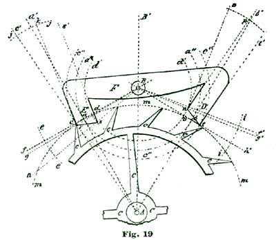
The fault we previously pointed out, of the generally accepted method of
delineating a detached lever escapement, is not as conspicuous here as
it is where the pallets are drawn with equidistant locking faces; that
is, the inner angle of the entrance pallet (shown at s) does not have
to be carried down on the arc d' as far to insure a continuous pallet
action of ten degrees, as with the pallets with equidistant locking
faces. Still, even here we have carried the angle s down about half a
degree on the arc d', to secure a safe lock on the exit pallet.
If we study the large drawing, where we delineate the escape wheel ten
inches in diameter, it will readily be seen that although we claim one
and a half degrees lock, we really have only about one degree, inasmuch
as the curve of the peripheral line m diverges from the line B f,
and, as a consequence, the absolute lock of the tooth C on the locking
face of the entrance pallet E is but about one degree. Under these
conditions, if we did not extend the outer angle of the exit pallet at
t down to the peripheral line m, we would scarcely secure one-half a
degree of lock. This is true of both pallets. We must carry the pallet
angles at r s n t down on the circles c'' d' if we would secure the
lock and impulse we claim; that is, one and a half degrees lock and
eight and a half degrees impulse.
Now, while the writer is willing to admit that a one-degree lock in a
sound, well-made escapement is ample, still he is not willing to allow
of a looseness of drawing to incorporate to the extent of one degree in
any mechanical matter demanding such extreme accuracy as the parts of a
watch. It has been claimed that such defects can, to a great extent, be
remedied by setting the escapement closer; that is, by bringing the
centers of the pallet staff and escape wheel nearer together. We hold
that such a course is not mechanical and, further, that there is not the
slightest necessity for such a policy.
By making the drawings large, as we have already suggested and insisted
upon, we can secure an accuracy closely approximating perfection. As,
for instance, if we wish to get a lock of one and a half degrees on the
locking face of the entrance pallet E, we measure down on the arc
c'' from its intersection with the peripheral line m one and a half
degrees, and establish the point r and thus locate the outer angle of
the entrance pallet E, so there will really be one and a half degrees
of lock; and by measuring down on the arc d' ten degrees from its
intersection with the peripheral line m, we locate the point s,
which determines the position of the inner angle of the entrance pallet,
and we know for a certainty that when this inner angle is freed from the
tooth it will be after the pallet (and, of course, the lever) has passed
through exactly ten degrees of angular motion.
For locating the inner angle of the exit pallet, we measure on the arc
d', from its intersection with the peripheral line m, eight and a
half degrees, and establish the point n, which locates the position of
this inner angle; and, of course, one and a half degrees added on the
arc d' indicates the extent of the lock on this pallet. Such drawings
not only enable us to theorize to extreme exactness, but also give us
proportionate measurements, which can be carried into actual
construction.
We will now take up the club-tooth form of the lever escapement. This
form of tooth has in the United States and in Switzerland almost
entirely superceded the ratchet tooth. The principal reason for its
finding so much favor is, we think, chiefly owing to the fact that this
form of tooth is better able to stand the manipulations of the
able-bodied watchmaker, who possesses more strength than skill. We will
not pause now, however, to consider the comparative merits of the
ratchet and club-tooth forms of the lever escapement, but leave this
part of the theme for discussion after we have given full instructions
for delineating both forms.
With the ratchet-tooth lever escapement all of the impulse must be
derived from the pallets, but in the club-tooth escapement we can divide
the impulse planes between the pallets and the teeth to suit our fancy;
or perhaps it would be better to say carry out theories, because we have
it in our power, in this form of the lever escapement, to indulge
ourselves in many changes of the relations of the several parts. With
the ratchet tooth the principal changes we could make would be from
pallets with equidistant lockings to circular pallets. The club-tooth
escape wheel not only allows of circular pallets and equidistant
lockings, but we can divide the impulse between the pallets and the
teeth in such a way as will carry out many theoretical advantages which,
after a full knowledge of the escapement action is acquired, will
naturally suggest themselves. In the escapement shown at Fig. 20 we have
selected, as a very excellent example of this form of tooth, circular
pallets of ten degrees fork action and ten and a half degrees of
escape-wheel action.
It will be noticed that the pallets here are comparatively thin to those
in general use; this condition is accomplished by deriving the principal
part of the impulse from driving planes placed on the teeth. As relates
to the escape-wheel action of the ten and one-half degrees, which gives
impulse to the escapement, five and one-half degrees are utilized by the
driving planes on the teeth and five by the impulse face of the pallet.
Of the ten degrees of fork action, four and a half degrees relate to the
impulse face of the teeth, one and a half degrees to lock, and four
degrees to the driving plane of the pallets.
In delineating such a club-tooth escapement, we commence, as in former
examples, by first assuming the center of the escape wheel at A, and
with the dividers set at five inches sweeping the arc a a. Through A
we draw the vertical line A B'. On the arc a a, and each side of its
intersection with the line A B', we lay off thirty degrees, as in
former drawings, and through the points so established on the arc a a
we draw the radial lines A b and A c. From the intersection of the
radial line A b with the arc a we draw the line h h at right
angles to A b. Where the line h intersects the radial lines A B'
is located the center of the pallet staff, as shown at B. Inasmuch as
we decided to let the pallet utilize five degrees of escape-wheel
action, we take a space of two and a half degrees in the dividers, and
on the arc a a lay off the said two and a half degrees to the left of
this intersection, and through the point so established draw the radial
line A g. From B as a center we sweep the arc d d so it passes
through the point of intersection of the arc a with the line A g.
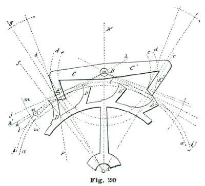
We again lay off two and a half degrees from the intersection of the
line A b with the arc a, but this time to the right of said
intersection, and through the point so established, and from B as a
center, we sweep the arc e. From the intersection of the radial line
A g with the arc a we lay off to the left five and a half degrees on
said arc, and through the point so established draw the radial line A
f. With the dividers set at five inches we sweep the short arc m from
B as a center. From the intersection of the line h B h' with the
arc m we lay off on said arc and above the line h' four and a half
degrees, and through the point so established draw the line B j.
We next set the dividers so they embrace the space on the radial line A
b between its intersection with the line B j and the center A, and
from A as a center sweep the arc i, said arc defining the addendum
of the escape-wheel teeth. We draw a line from the intersection of the
radial line A f with the arc i to the intersection of the radial
line A g with the arc a, and thus define the impulse face of the
escape-wheel tooth D. For defining the locking face of the tooth we
draw a line at an angle of twenty-four degrees to the line A g, as
previously described. The back of the tooth is defined with a curve
swept from some point on the addendum circle i, such as our judgment
will dictate.
In the drawing shown at Fig. 20 the radius of this curve was obtained by
taking eleven and a half degrees from the degree arc of 5" radius in the
dividers, and setting one leg at the intersection of the radial line A
f with the arc i, and placing the other on the line i, and allowing
the point so established to serve as a center, the arc was swept for the
back of the tooth, the small circle at n denoting one of the centers
just described. The length for the face of the tooth was obtained by
taking eleven degrees from the degree arc just referred to and laying
that space off on the line p, which defined the face of the tooth. The
line B k is laid off one and a half degrees below B h on the arc
m. The extent of this arc on the arc d defines the locking face of
the entrance pallet. We set off four degrees on the arc m below the
line B k, and through the point so established draw the line B l. We
draw a line from the intersection of the line A g with the line c h
to the intersection of the arc e with the line c l, and define the
impulse face of the entrance pallet.
Before we proceed to delineate the exit pallet of our escapement, let us
reason on the relations of the several parts.
The club-tooth lever escapement is really the most complicated
escapement made. We mean by this that there are more factors involved in
the problem of designing it correctly than in any other known
escapement. Most—we had better say all, for there are no exceptions
which occur to us—writers on the lever escapement lay down certain
empirical rules for delineating the several parts, without giving
reasons for this or that course. For illustration, it is an established
practice among escapement makers to employ tangential lockings, as we
explained and illustrated in Fig. 16.
Now, when we adopt circular pallets and carry the locking face of the
entrance pallet around to the left two and a half degrees, the true
center for the pallet staff, if we employ tangent lockings, would be
located on a line drawn tangent to the circle a a from its
intersection with the radial line A k, Fig. 21. Such a tangent is
depicted at the line s l'. If we reason on the situation, we will see
that the line A k is not at right angles to the line s l; and,
consequently, the locking face of the entrance pallet E has not really
the twelve-degree lock we are taught to believe it has.
We will not discuss these minor points further at present, but leave
them for subsequent consideration. We will say, however, that we could
locate the center of the pallet action at the small circle B' above
the center B, which we have selected as our fork-and-pallet action,
and secure a perfectly sound escapement, with several claimed
advantages.
Let us now take up the delineation of the exit pallet. It is very easy
to locate the outer angle of this pallet, as this must be situated at
the intersection of the addendum circle i and the arc g, and located
at o. It is also self-evident that the inner or locking angle must be
situated at some point on the arc h. To determine this location we
draw the line B c from B (the pallet center) through the
intersection of the arc h with the pitch circle a.
Again, it follows as a self-evident fact, if the pallet we are dealing
with was locked, that is, engaged with the tooth D'', the inner angle
n of the exit pallet would be one and a half degrees inside the pitch
circle a. With the dividers set at 5", we sweep the short arc b b,
and from the intersection of this arc with the line B c we lay off ten
degrees, and through the point so established, from B, we draw the
line B d. Below the point of intersection of the line B d with the
short arc b b we lay off one and a half degrees, and through the point
thus established we draw the line B e.
The intersection of the line B e with the arc h, which we will term
the point n, represents the location of the inner angle of the exit
pallet. We have already explained how we located the position of the
outer angle at o. We draw the line n o and define the impulse face
of the exit pallet. If we mentally analyze the problem in hand, we will
see that as the exit pallet vibrates through its ten degrees of arc the
line B d and B c change places, and the tooth D'' locks one and a
half degrees. To delineate the locking face of the exit pallet, we erect
a perpendicular to the line B e from the point n, as shown by the
line n p.
From n as a center we sweep the short arc t t, and from its
intersection with the line n p we lay off twelve degrees, and through
the point so established we draw the line n u, which defines the
locking face of the exit pallet. We draw the line o o' parallel with
n u and define the outer face of said pallet. In Fig. 21 we have not
made any attempt to show the full outline of the pallets, as they are
delineated in precisely the same manner as those previously shown.
We shall next describe the delineation of a club-tooth escapement with
pallets having equidistant locking faces; and in Fig. 22 we shall show
pallets with much wider arms, because, in this instance, we shall derive
more of the impulse from the pallets than from the teeth. We do this to
show the horological student the facility with which the club-tooth
lever escapement can be manipulated. We wish also to impress on his mind
the facts that the employment of thick pallet arms and thin pallet arms
depends on the teeth of the escape wheel for its efficiency, and that
he must have knowledge enough of the principles of action to tell at a
glance on what lines the escapement was constructed.
Suppose, for illustration, we get hold of a watch which has thin pallet
arms, or stones, if they are exposed pallets, and the escape was
designed for pallets with thick arms. There is no sort of tinkering we
can do to give such a watch a good motion, except to change either the
escape wheel or the pallets. If we know enough of the lever escapement
to set about it with skill and judgment, the matter is soon put to
rights; but otherwise we can look and squint, open and close the
bankings, and tinker about till doomsday, and the watch be none the
better.
In drawing a club-tooth lever escapement with equidistant locking, we
commence, as on former occasions, by producing the vertical line A k,
Fig. 22, and establishing the center of the escape wheel at A, and
with the dividers set at 5" sweep the pitch circle a. On each side of
the intersection of the vertical line A k with the arc a we set off
thirty degrees on said arc, and through the points so established draw
the radial lines A b and A c.
From the intersection of the radial line A b with the arc a lay off
three and a half degrees to the left of said intersection on the arc
a, and through the point so established draw the radial line A e.
From the intersection of the radial line A b with the arc a erect
the perpendicular line f, and at the crossing or intersection of said
line with the vertical line A k establish the center of the pallet
staff, as indicated by the small circle B. From B as a center sweep
the short arc l with a 5" radius; and from the intersection of the
radial line A b with the arc a continue the line f until it
crosses the short arc l, as shown at f'. Lay off one and a half
degrees on the arc l below its intersection with the line f', and
from B as a center draw the line B i through said intersection.
From B as a center, through the intersection of the radial line A b
and the arc a, sweep the arc g.
The space between the lines B f' and B i on the arc g defines the
extent of the locking face of the entrance pallet C. The intersection
of the line B f' with the arc g we denominate the point o, and
from this point as a center sweep the short arc p with a 5" radius;
and on this arc, from its intersection with the radial line A b, lay
off twelve degrees, and through the point so established, from o as a
center, draw the radial line o m, said line defining the locking face
of the entrance pallet C.
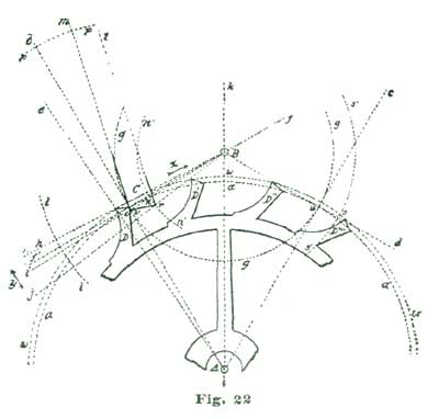
It will be seen that this gives a positive "draw" of twelve degrees to
the entrance pallet; that is, counting to the line B f'. In this
escapement as delineated there is perfect tangential locking. If the
locking face of the entrance-pallet stone at C was made to conform to
the radial line A b, the lock of the tooth D at o would be "dead";
that is, absolutely neutral. The tooth D would press the pallet C in
the direction of the arrow x, toward the center of the pallet staff
B, with no tendency on the part of the pallet to turn on its axis B.
Theoretically, the pallet with the locking face cut to coincide with the
line A b would resist movement on the center B in either direction
indicated by the double-headed arrow y.
A pallet at C with a circular locking face made to conform to the arc
g, would permit movement in the direction of the double-headed arrow
y with only mechanical effort enough to overcome friction. But it is
evident on inspection that a locking face on the line A b would cause
a retrograde motion of the escape wheel, and consequent resistance, if
said pallet was moved in either direction indicated by the double-headed
arrow y. Precisely the same conditions obtain at the point u, which
holds the same relations to the exit pallet as the point o does to the
entrance pallet C.
The arc (three and a half degrees) of the circle a embraced between
the radial lines A b and A e determines the angular motion of the
escape wheel utilized by the escape-wheel tooth. To establish and define
the extent of angular motion of the escape wheel utilized by the pallet,
we lay off seven degrees on the arc a from the point o and establish
the point n, and through the point n, from B as a center, we sweep
the short arc n'. Now somewhere on this arc n' will be located the
inner angle of the entrance pallet. With a carefully-made drawing,
having the escape wheel 10" in diameter, it will be seen that the arc
a separates considerably from the line, B f' where it crosses the
arc n'.
It will be remembered that when drawing the ratchet-tooth lever
escapement a measurement of eight and a half degrees was made on the arc
n' down from its intersection with the pitch circle, and thus the
inner angle of the pallet was located. In the present instance the
addendum line w becomes the controlling arc, and it will be further
noticed on the large drawing that the line B h at its intersection
with the arc n' approaches nearer to the arc w than does the line B
f' to the pitch circle a; consequently, the inner angle of the pallet
should not in this instance be carried down on the arc n' so far to
correct the error as in the ratchet tooth.
Reason tells us that if we measure ten degrees down on the arc n' from
its intersection with the addendum circle w we must define the
position of the inner angle of the entrance pallet. We name the point so
established the point r. The outer angle of this pallet is located at
the intersection of the radial line A b with the line B i; said
intersection we name the point v. Draw a line from the point v to
the point r, and we define the impulse face of the entrance pallet;
and the angular motion obtained from it as relates to the pallet staff
embraces six degrees.
Measured on the arc l, the entire ten degrees of angular motion is as
follows: Two and a half degrees from the impulse face of the tooth, and
indicated between the lines B h and B f; one and a half degrees lock
between the lines B f' and B i; six degrees impulse from pallet
face, entrance between the lines B i and B j.
Grossmann and Britten, in all their delineations of the club-tooth
escapement, show the exit pallet as disengaged. To vary from this
beaten track we will draw our exit pallet as locked. There are other
reasons which prompt us to do this, one of which is, pupils are apt to
fall into a rut and only learn to do things a certain way, and that way
just as they are instructed.
To illustrate, the writer has met several students of the lever
escapement who could make drawings of either club or ratchet-tooth
escapement with the lock on the entrance pallet; but when required to
draw a pallet as illustrated at Fig. 23, could not do it correctly.
Occasionally one could do it, but the instances were rare. A still
greater poser was to request them to delineate a pallet and tooth when
the action of escaping was one-half or one-third performed; and it is
easy to understand that only by such studies the master workman can
thoroughly comprehend the complications involved in the club-tooth lever
escapement.
As an illustration: Two draughtsmen, employed by two competing watch
factories, each designs a club-tooth escapement. We will further suppose
the trains and mainspring power used by each concern to be precisely
alike. But in practice the escapement of the watches made by one factory
would "set," that is, if you stopped the balance dead still, with the
pin in the fork, the watch would not start of itself; while the
escapement designed by the other draughtsman would not "set"—stop the
balance dead as often as you choose, the watch would start of itself.
Yet even to experienced workmen the escape wheels and pallets looked
exactly alike. Of course, there was a difference, and still none of the
text-books make mention of it.
For the present we will go on with delineating our exit pallet. The
preliminaries are the same as with former drawings, the instructions for
which we need not repeat. Previous to drawing the exit pallet, let us
reason on the matter. The point r in Fig. 23 is located at the
intersection of pitch circle a and the radial line A c; and this
will also be the point at which the tooth C will engage the locking
face of the exit pallet.
This point likewise represents the advance angle of the engaging tooth.
Now if we measure on the arc k (which represents the locking faces of
both pallets) downward one and a half degrees, we establish the lock of
the pallet E. To get this one and a half degrees defined on the arc
k, we set the dividers at 5", and from B as a center sweep the
short arc i, and from the intersection of the arc i with the line B
e we lay off on said arc i one and a half degrees, and through the
point so established draw the line B f.
Now the space on the arc k between the lines B e and B f defines
the angular extent of the locking face. With the dividers set at 5" and
one leg resting at the point r, we sweep the short arc t, and from
the intersection of said arc with the line A c we draw the line n p;
but in doing so we extend it (the line) so that it intersects the line
B f, and at said intersection is located the inner angle of the exit
pallet. This intersection we will name the point n.
From the intersection of the line B e with the arc i we lay off two
and a half degrees on said arc, and through the point so established we
draw the line B g. The intersection of this line with the arc k we
name the point z. With one leg of our dividers set at A we sweep the
arc l so it passes through the point z. This last arc defines the
addendum of the escape-wheel teeth. From the point r on the arc a we
lay off three and a half degrees, and through the point so established
draw the line A j.
The intersection of this line with the addendum arc l locates the
outer angle of the impulse planes of the teeth, and we name it the point
x. From the point r we lay off on the arc a seven degrees and
establish the point v, which defines the extent of the angular motion
of the escape wheel utilized by pallet. Through the point v, from B
as a center, we sweep the short arc m. It will be evident on a
moment's reflection that this arc m must represent the path of
movement of the outer angle of the exit pallet, and if we measure down
ten degrees from the intersection of the arc l with the arc m, the
point so established (which we name the point s) must be the exact
position of the outer angle of the pallet during locking. We have a
measure of ten degrees on the arc m, between the lines B g and B
h, and by taking this space in the dividers and setting one leg at the
intersection of the arc l with the arc m, and measuring down on m,
we establish the point s. Drawing a line from point n to point s
we define the impulse face of the pallet.
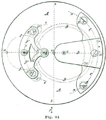
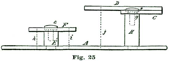
It is next proposed we apply the theories we have been considering and
make an enlarged model of an escapement, as shown at Figs. 24 and 25.
This model is supposed to have an escape wheel one-fifth the size of the
10" one we have been drawing. In the accompanying cuts are shown only
the main plate and bridges in full lines, while the positions of the
escape wheel and balance are indicated by the dotted circles I B. The
cuts are to no precise scale, but were reduced from a full-size drawing
for convenience in printing. We shall give exact dimensions, however, so
there will be no difficulty in carrying out our instructions in
construction.
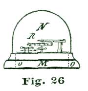
Perhaps it would be as well to give a general description of the model
before taking up the details. A reduced side view of the complete model
is given at Fig. 26. In this cut the escapement model shown at Figs. 24
and 25 is sketched in a rough way at R, while N shows a glass cover,
and M a wooden base of polished oak or walnut. This base is recessed
on the lower side to receive an eight-day spring clock movement, which
supplies the motive power for the model. This base is recessed on top to
receive the main plate A, Fig. 24, and also to hold the glass shade
N in position. The base M is 2½" high and 8" diameter. The glass
cover N can have either a high and spherical top, as shown, or, as
most people prefer, a flattened oval.
The main plate A is of hard spring brass, 1/10" thick and 6" in
diameter; in fact, a simple disk of the size named, with slightly
rounded edges. The top plate, shown at C, Figs. 24 and 25, is 1/8"
thick and shaped as shown. This plate (C) is supported on two pillars
1/2" in diameter and 1-1/4" high. Fig. 25 is a side view of Fig. 24 seen
in the direction of the arrow p. The cock D is also of 1/8" spring
brass shaped as shown, and attached by the screw f and steady pins s
s to the top plate C. The bridge F G carries the top pivots of
escape wheel and pallet staff, and is shaped as shown at the full
outline. This bridge is supported on two pillars 1/2" high and 1/2" in
diameter, one of which is shown at E, Fig. 25, and both at the dotted
circles E E', Fig. 24.
To lay out the lower plate we draw the line a a so it passes through
the center of A at m. At 1.3" from one edge of A we establish on
the line a the point d, which locates the center of the escape
wheel. On the same line a at 1.15" from d we establish the point
b, which represents the center of the pallet staff. At the distance of
1.16" from b we establish the point c, which represents the center
of the balance staff. To locate the pillars H, which support the top
plate C, we set the dividers at 2.58", and from the center m sweep
the arc n.
From the intersection of this arc with the line a (at r) we lay off
on said arc n 2.1" and establish the points g g', which locate the
center of the pillars H H. With the dividers set so one leg rests at
the center m and the other leg at the point d, we sweep the arc t.
With the dividers set at 1.33" we establish on the arc t, from the
point d, the points e e', which locate the position of the pillars
E E'. The outside diameter of the balance B is 3-5/8" with the rim
3/16" wide and 5/16" deep, with screws in the rim in imitation of the
ordinary compensation balance.
Speaking of a balance of this kind suggests to the writer the trouble he
experienced in procuring material for a model of this kind—for the
balance, a pattern had to be made, then a casting made, then a machinist
turned the casting up, as it was too large for an American lathe. A
hairspring had to be specially made, inasmuch as a mainspring was too
short, the coils too open and, more particularly, did not look well.
Pallet jewels had to be made, and lapidists have usually poor ideas of
close measurements. Present-day conditions, however, will, no doubt,
enable the workman to follow our instructions much more readily.
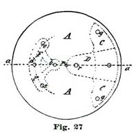
In case the reader makes the bridges C and F, as shown in Fig. 27,
he should locate small circles on them to indicate the position of the
screws for securing these bridges to the pillars which support them, and
also other small circles to indicate the position of the pivot holes d
b for the escape wheel and pallet staff. In practice it will be well to
draw the line a a through the center of the main plate A, as
previously directed, and also establish the point d as therein
directed.
The pivot hole d' for the escape wheel, and also the holes at e e
and b, are now drilled in the bridge F. These holes should be about
1/16" in diameter. The same sized hole is also drilled in the main plate
A at d. We now place a nicely-fitting steel pin in the hole d' in
the bridge F and let it extend into the hole d in the main plate. We
clamp the bridge F to A so the hole b comes central on the line
a, and using the holes e e in F as guides, drill or mark the
corresponding holes e' e' and b in the main plate for the pillars E
E' and the pallet staff.
This plan will insure the escape wheel and pallet staff being perfectly
upright. The same course pursued with the plate C will insure the
balance being upright. The pillars which support the bridges are shaped
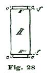
as shown at Fig. 28, which shows a side view of one of the pillars which
support the top plate or bridge C. The ends are turned to 1/4" in
diameter and extend half through the plate, where they are held by
screws, the same as in American movements.
The pillars (like H) can be riveted in the lower plate A, but we
think most workmen will find it more satisfactory to employ screws, as
shown at Fig. 29. The heads of such screws should be about 3/8" in
diameter and nicely rounded, polished and blued. We would not advise
jeweling the pivot holes, because there is but slight friction, except
to the foot of the balance pivot, which should be jeweled with a
plano-convex garnet.
The top pivots to the escape wheel should be capped with imitation
rubies for appearance sake only, letting the cap settings be red gold,
or brass red gilded. If real twelve-karat gold is employed the cost will
not be much, as the settings are only about 3/8" across and can be
turned very thin, so they will really contain but very little gold. The
reason why we recommend imitation ruby cap jewels for the upper holes,
is that such jewels are much more brilliant than any real stone we can
get for a moderate cost. Besides, there is no wear on them.
The pallet jewels are also best made of glass, as garnet or any red
stone will look almost black in such large pieces. Red carnelian has a
sort of brick-red color, which has a cheap appearance. There is a new
phosphorus glass used by optical instrument makers which is intensely
hard, and if colored ruby-red makes a beautiful pallet jewel, which will
afford as much service as if real stones were used; they are no cheaper
than carnelian pallets, but much richer looking. The prettiest cap for
the balance is one of those foilback stones in imitation of a rose-cut
diamond.
In turning the staffs it is the best plan to use double centers, but a
piece of Stubs steel wire that will go into a No. 40 wire chuck, will
answer; in case such wire is used, a brass collet must be provided. This
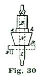
will be understood by inspecting Fig. 30, where L represents the Stubs
wire and B N the brass collet, with the balance seat shown at k. The
escape-wheel arbor and pallet staff can be made in the same way. The
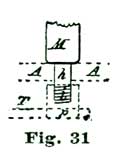
lower end of the escape wheel pivot is made about 1/4" long, so that a
short piece of brass wire can be screwed upon it, as shown in Fig. 31,
where h represents the pivot, A the lower plate, and the dotted line
at p the brass piece screwed on the end of the pivot. This piece p
is simply a short bit of brass wire with a female screw tapped into the
end, which screws on to the pivot. An arm is attached to p, as shown
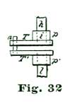
at T. The idea is, the pieces T p act like a lathe dog to convey the
power from one of the pivots of an old eight-day spring clock movement,
which is secured by screws to the lower side of the main plate A. The
plan is illustrated at Fig. 32, where l represents pivot of the
eight-day clock employed to run the model. Counting the escape-wheel
pivot of the clock as one, we take the third pivot from this in the
clock train, placing the movement so this point comes opposite the
escape-wheel pivot of the model, and screw the clock movement fast to
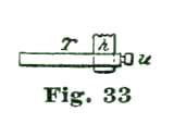
the lower side of the plate A. The parts T, Fig. 33, are alike on
both pivots.
To fully appreciate such a large escapement model as we have been
describing, a person must see it with its great balance, nearly 4"
across, flashing and sparkling in the show window in the evening, and
the brilliant imitation ruby pallets dipping in and out of the escape
wheel. A model of this kind is far more attractive than if the entire
train were shown, the mystery of "What makes it go?" being one of the
attractions. Such a model is, further, of great value in explaining to a
customer what you mean when you say the escapement of his watch is out
of order. Any practical workman can easily make an even $100 extra in a
year by making use of such a model.
For explaining to customers an extra balance cock can be used to show
how the jewels (hole and cap) are arranged. Where the parts are as large
as they are in the model, the customer can see and understand for
himself what is necessary to be done.
It is not to be understood that our advice to purchase the jewels for an
extra balance cock conflicts with our recommending the reader not to
jewel the holes of his model. The extra cock is to be shown, not for
use, and is employed solely for explaining to a customer what is
required when a pivot or jewel is found to be broken.
The screws which hold the plates in place should have heads about 3/8"
in diameter, to be in proportion to the scale on which the balance and
escape wheel are gotten up. There is much in the manner in which the
screw heads are finished as regards the elegance of such a model. A
perfectly flat head, no matter how highly polished, does not look well,
neither does a flattened conehead, like Fig. 35. The best head for this
purpose is a cupped head with chamfered edges, as shown at Fig. 34 in
vertical section. The center b is ground and polished into a perfect
concave by means of a metal ball. The face, between the lines a a, is
polished dead flat, and the chamfered edge a c finished a trifle
convex. The flat surface at a is bright, but the concave b and
chamfer at c are beautifully blued. For a gilt-edged, double extra
head, the chamfer at c can be "snailed," that is, ground with a
suitable lap before bluing, like the stem-wind wheels on some watches.
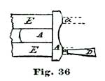
There are two easy methods of removing the blue from the flat part of
the screwhead at a. (1) Make a special holder for the screw in the end
of a cement brass, as shown at E, Fig. 36, and while it is slowly
revolving in the lathe touch the flat surface a with a sharpened
pegwood wet with muriatic acid, which dissolves the blue coating of
oxide of iron. (2) The surface of the screwhead is coated with a very
thin coating of shellac dissolved in alcohol and thoroughly dried, or a
thin coating of collodion, which is also dried. The screw is placed in
the ordinary polishing triangle and the flat face at a polished on a
tin lap with diamantine and oil. In polishing such surfaces the thinnest
possible coating of diamantine and oil is smeared on the lap—in fact,
only enough to dim the surface of the tin. It is, of course, understood
that it is necessary to move only next to nothing of the material to
restore the polish of the steel. The polishing of the other steel parts
is done precisely like any other steel work.
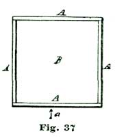
The regulator is of the Howard pattern. The hairspring stud is set in
the cock like the Elgin three-quarter-plate movement. The richest finish
for such a model is frosted plates and bridges. The frosting should not
be a fine mat, like a watch movement, but coarse-grained—in fact, the
grain of the frosting should be proportionate to the size of the
movement. The edges of the bridges and balance cock can be left smooth.
The best process for frosting is by acid. Details for doing the work
will now be given.
To do this frosting by acid nicely, make a sieve by tacking and gluing
four pieces of thin wood together, to make a rectangular box without a
bottom. Four pieces of cigar-box wood, 8" long by 1-1/2" wide, answer
first rate. We show at A A A A, Fig. 37, such a box as if seen from
above; with a side view, as if seen in the direction of the arrow a,
at Fig. 38. A piece of India muslin is glued across the bottom, as shown
at the dotted lines b b. By turning up the edges on the outside of the
box, the muslin bottom can be drawn as tight as a drum head.
To do acid frosting, we procure two ounces of gum mastic and place in
the square sieve, shown at Fig. 37. Usually more than half the weight of
gum mastic is in fine dust, and if not, that is, if the gum is in the
shape of small round pellets called "mastic tears," crush these into
dust and place the dust in A. Let us next suppose we wish to frost
the cock on the balance, shown at Fig. 39. Before we commence to frost,
the cock should be perfectly finished, with all the holes made, the
regulator cap in position, the screw hole made for the Howard regulator
and the index arc engraved with the letters S and F.
It is not necessary the brass should be polished, but every file mark
and scratch should be stoned out with a Scotch stone; in fact, be in the
condition known as "in the gray." It is not necessary to frost any
portion of the cock C, except the upper surface. To protect the
portion of the cock not to be frosted, like the edges and the back, we
"stop out" by painting over with shellac dissolved in alcohol, to which
a little lampblack is added. It is not necessary the coating of shellac
should be very thick, but it is important it should be well dried.
For illustration, let us suppose the back and edges of the cock at Fig.
39 are coated with shellac and it is laid flat on a piece of paper about
a foot square to catch the excess of mastic. Holes should be made in
this paper and also in the board on which the paper rests to receive the
steady pins of the cock. We hold the sieve containing the mastic over
the cock and, gently tapping the box A with a piece of wood like a
medium-sized file handle, shake down a little snowstorm of mastic dust
over the face of the cock C.
Exactly how much mastic dust is required to produce a nice frosting is
only to be determined by practice. The way to obtain the knack is to
frost a few scraps to "get your hand in." Nitric acid of full strength
is used, dipping the piece into a shallow dish for a few seconds. A
good-sized soup plate would answer very nicely for frosting the bottom
plate, which, it will be remembered, is 6" in diameter.
After the mastic is sifted on, the cock should be heated up to about
250° F., to cause the particles of mastic to adhere to the surface. The
philosophy of the process is, the nitric acid eats or dissolves the
brass, leaving a little brass island the size of the particle of mastic
which was attached to the surface. After heating to attach the particles
of mastic, the dipping in nitric acid is done as just described. Common
commercial nitric acid is used, it not being necessary to employ
chemically pure acid. For that matter, for such purposes the commercial
acid is the best.
After the acid has acted for fifteen or twenty seconds the brass is
rinsed in pure water to remove the acid, and dried by patting with an
old soft towel, and further dried by waving through the air. A little
turpentine on a rag will remove the mastic, but turpentine will not
touch the shellac coating. The surface of the brass will be found
irregularly acted upon, producing a sort of mottled look. To obtain a
nice frosting the process of applying the mastic and etching must be
repeated three or four times, when a beautiful coarse-grain mat or
frosting will be produced.
The shellac protection will not need much patching up during the three
or four bitings of acid, as the turpentine used to wash off the mastic
does not much affect the shellac coating. All the screw holes like s s
and d, also the steady pins on the back, are protected by varnishing
with shellac. The edges of the cocks and bridges should be polished by
rubbing lengthwise with willow charcoal or a bit of chamois skin
saturated with oil and a little hard rouge scattered upon it. The
frosting needs thorough scratch-brushing.
At Fig. 40 we show the balance cock of our model with modified form of
Howard regulator. The regulator bar A and spring B should be ground
smooth on one side and deeply outlined to perfect form. The regulator
cap C is cut out to the correct size. These parts are of decarbonized
cast steel, annealed until almost as soft as sheet brass. It is not so
much work to finish these parts as one might imagine. Let us take the
regulator bar for an example and carry it through the process of making.
The strip of soft sheet steel on which the regulator bar is outlined is
represented by the dotted outline b, Fig. 41.
To cut out sheet steel rapidly we take a piece of smooth clock
mainspring about 3/4" and 10" long and double it together, softening the
bending point with the lamp until the piece of mainspring assumes the
form shown at Fig. 42, where c represents the piece of spring and H
H the bench-vise jaws. The piece of soft steel is placed between the
limbs of c c' of the old mainspring up to the line a, Fig. 41, and
clamped in the vise jaws. The superfluous steel is cut away with a sharp
and rather thin cold chisel.
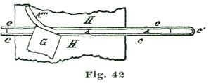
The chisel is presented as shown at G, Fig. 43 (which is an end view
of the vise jaws H H and regulator bar), and held to cut obliquely and
with a sort of shearing action, as illustrated in Fig. 42, where A''
represents the soft steel and G the cold chisel. We might add that
Fig. 42 is a view of Fig. 43 seen in the direction of the arrow f. It
is well to cut in from the edge b on the line d, Fig. 41, with a
saw, in order to readily break out the surplus steel and not bend the
regulator bar. By setting the pieces of steel obliquely in the vise, or
so the line e comes even with the vise jaws, we can cut to more nearly
conform to the circular loop A'' of the regulator A.
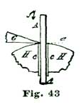
The smooth steel surface of the bent mainspring c prevents the vise
jaws from marking the soft steel of the regulator bar. A person who has
not tried this method of cutting out soft steel would not believe with
what facility pieces can be shaped. Any workman who has a universal face
plate to his lathe can turn out the center of the regulator bar to
receive the disk C, and also turn out the center of the regulator
spring B. What we have said about the regulator bar applies also to
the regulator spring B. This spring is attached to the cock D by
means of two small screws at n.
The micrometer screw F is tapped through B'' as in the ordinary
Howard regulator, and the screw should be about No. 6 of a Swiss
screw-plate. The wire from which such screw is made should be 1/10" in
diameter. The steel cap C is fitted like the finer forms of Swiss
watches. The hairspring stud E is of steel, shaped as shown, and comes
outlined with the other parts.
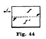
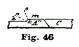
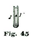
The regulator bar should be hardened by being placed in a folded piece
of sheet iron and heated red hot, and thrown into cold water. The
regulator bar A A' is about 3" long; and for holding it for
hardening, cut a piece of thin sheet iron 2-1/2" by 3-1/4" and fold it
through the middle lengthwise, as indicated by the dotted line g, Fig.
44. The sheet iron when folded will appear as shown at Fig. 45. A piece
of flat sheet metal of the same thickness as the regulator bar should be
placed between the iron leaves I I, and the leaves beaten down with a
hammer, that the iron may serve as a support for the regulator during
heating and hardening. A paste made of castile soap and water applied to
the regulator bar in the iron envelope will protect it from oxidizing
much during the heating. The portions of the regulator bar marked h
are intended to be rounded, while the parts marked m are intended to
be dead flat. The rounding is carefully done, first with a file and
finished with emery paper. The outer edge of the loop A'' is a little
rounded, also the inner edge next the cap C. This will be understood
by inspecting Fig. 46, where we show a magnified vertical section of the
regulator on line l, Fig. 40. The curvature should embrace that
portion of A'' between the radial lines o o', and should, on the
model, not measure more than 1/40". It will be seen that the curved
surface of the regulator is sunk so it meets only the vertical edge of
the loop A''. For the average workman, polishing the flat parts m is
the most difficult to do, and for this reason we will give entire
details. It is to be expected that the regulator bar will spring a
little in hardening, but if only a little we need pay no attention to
it.
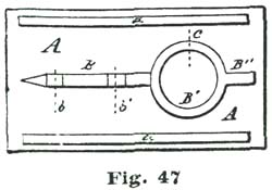
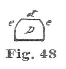
Polishing a regulator bar for a large model, such as we are building, is
only a heavy job of flat steel work, a little larger but no more
difficult than to polish a regulator for a sixteen-size watch. We would
ask permission here to say that really nice flat steel work is something
which only a comparatively few workmen can do, and, still, the process
is quite simple and the accessories few and inexpensive. First,
ground-glass slab 6" by 6" by 1/4"; second, flat zinc piece 3-1/4" by
3-1/4" by 1/4"; third, a piece of thick sheet brass 3" by 2" by 1/8";
and a bottle of Vienna lime. The glass slab is only a piece of plate
glass cut to the size given above. The zinc slab is pure zinc planed
dead flat, and the glass ground to a dead surface with another piece of
plate glass and some medium fine emery and water, the whole surface
being gone over with emery and water until completely depolished. The
regulator bar, after careful filing and dressing up on the edges with an
oilstone slip or a narrow emery buff, is finished as previously
described. We would add to the details already given a few words on
polishing the edges.
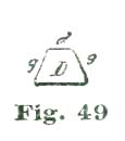
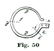
It is not necessary that the edges of steelwork, like the regulator bar
B, Fig. 47, should be polished to a flat surface; indeed, they look
better to be nicely rounded. Perhaps we can convey the idea better by
referring to certain parts: say, spring to the regulator, shown at D,
Fig. 40, and also the hairspring stud E. The edges of these parts look
best beveled in a rounded manner.
It is a little difficult to convey in words what is meant by "rounded"
manner. To aid in understanding our meaning, we refer to Figs. 48 and
49, which are transverse sections of D, Fig. 50, on the line f. The
edges of D, in Fig. 48, are simply rounded. There are no rules for
such rounding—only good judgment and an eye for what looks well. The
edges of D as shown in Fig. 49 are more on the beveled order. In
smoothing and polishing such edges, an ordinary jeweler's steel burnish
can be used.
The idea in smoothing and polishing such edges is to get a fair gloss
without much attention to perfect form, inasmuch as it is the flat
surface d on top which produces the impression of fine finish. If this
is flat and brilliant, the rounded edges, like g c can really have
quite an inferior polish and still look well. For producing the flat
polish on the upper surface of the regulator bar B and spring D, the
flat surface d, Figs. 48, 49, 51 and 52, we must attach the regulator
bar to a plate of heavy brass, as shown at Fig. 47, where A represents
the brass plate, and B the regulator bar, arranged for grinding and
polishing flat.
For attaching the regulator bar B to the brass plate A, a good plan
is to cement it fast with lathe wax; but a better plan is to make the
plate A of heavy sheet iron, something about 1/8" thick, and secure
the two together with three or four little catches of soft solder. It is
to be understood the edges of the regulator bar or the regulator spring
are polished, and all that remains to be done is to grind and polish the
flat face.
Two pieces a a of the same thickness as the regulator bar are placed
as shown and attached to A to prevent rocking. After B is securely
attached to A, the regulator should be coated with shellac dissolved
in alcohol and well dried. The object of this shellac coating is to keep
the angles formed at the meeting of the face and side clean in the
process of grinding with oilstone dust and oil. The face of the
regulator is now placed on the ground glass after smearing it with oil
and oilstone dust. It requires but a very slight coating to do the work.
The grinding is continued until the required surface is dead flat, after
which the work is washed with soap and water and the shellac dissolved
away with alcohol. The final polish is obtained on the zinc lap with
Vienna lime and alcohol. Where lathe cement is used for securing the
regulator to the plate A, the alcohol used with the Vienna lime
dissolves the cement and smears the steel. Diamantine and oil are the
best materials for polishing when the regulator bar is cemented to the
plate A.
The knowledge most important for a practical working watchmaker to
possess is how to get the watches he has to repair in a shape to give
satisfaction to his customers. No one will dispute the truth of the
above italicised statement. It is only when we seek to have limits set,
and define what such knowledge should consist of, that disagreement
occurs.
One workman who has read Grossmann or Saunier, or both, would insist on
all watches being made to a certain standard, and, according to their
ideas, all such lever watches as we are now dealing with should have
club-tooth escapements with equidistant lockings, ten degrees lever and
pallet action, with one and one-half degrees lock and one and one-half
degrees drop. Another workman would insist on circular pallets, his
judgment being based chiefly on what he had read as stated by some
author. Now the facts of the situation are that lever escapements vary
as made by different manufacturers, one concern using circular pallets
and another using pallets with equidistant lockings.
One escapement maker will divide the impulse equally between the tooth
and pallet; another will give an excess to the tooth. Now while these
matters demand our attention in the highest degree in a theoretical
sense, still, for such "know hows" as count in a workshop, they are of
but trivial importance in practice.
We propose to deal in detail with the theoretical consideration of
"thick" and "thin" pallets, and dwell exhaustively on circular pallets
and those with equidistant locking faces; but before we do so we wish to
impress on our readers the importance of being able to free themselves
of the idea that all lever escapements should conform to the rigid rules
of any dictum.
For illustration: It would be easy to design a lever escapement that
would have locking faces which were based on the idea of employing
neither system, but a compromise between the two, and still give a good,
sound action. All workmen should learn to estimate accurately the extent
of angular motion, so as to be able to judge correctly of escapement
actions. It is not only necessary to know that a club-tooth escapement
should have one and one-half degrees drop, but the eye should be
educated, so to speak, as to be able to judge of angular as well as
linear extent.
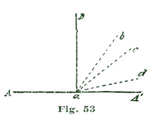
Most mechanics will estimate the size of any object measured in inches
or parts of inches very closely; but as regards angular extent, except
in a few instances, we will find mechanics but indifferent judges. To
illustrate, let us refer to Fig. 53. Here we have the base line A A'
and the perpendicular line a B. Now almost any person would be able to
see if the angle A a B was equal to B a A'; but not five in one
hundred practical mechanics would be able to estimate with even
tolerable accuracy the measure the angles made to the base by the lines
b c d; and still watchmakers are required in the daily practice of
their craft to work to angular motions and movements almost as important
as to results as diameters.
What is the use of our knowing that in theory an escape-wheel tooth
should have one and one-half degrees drop, when in reality it has three
degrees? It is only by educating the eye from carefully-made drawings;
or, what is better, constructing a model on a large scale, that we can
learn to judge of proper proportion and relation of parts, especially as
we have no convenient tool for measuring the angular motion of the fork
or escape wheel. Nor is it important that we should have, if the workman
is thoroughly "booked up" in the principles involved.
As we explained early in this treatise, there is no imperative necessity
compelling us to have the pallets and fork move through ten degrees any
more than nine and one-half degrees, except that experience has proven
that ten degrees is about the right thing for good results. In this day,
when such a large percentage of lever escapements have exposed pallets,
we can very readily manipulate the pallets to match the fork and roller
action. For that matter, in many instances, with a faulty lever
escapement, the best way to go about putting it to rights is to first
set the fork and roller so they act correctly, and then bring the
pallets to conform to the angular motion of the fork so adjusted.
Although we could say a good deal more about pallets and pallet action,
still we think it advisable to drop for the present this particular part
of the lever escapement and take up fork and roller action, because, as
we have stated, frequently the fork and roller are principally at fault.
In considering the action and relation of the parts of the fork and
roller, we will first define what is considered necessary to constitute
a good, sound construction where the fork vibrates through ten degrees
of angular motion and is supposed to be engaged with the roller by means
of the jewel pin for thirty degrees of angular motion of the balance.
There is no special reason why thirty degrees of roller action should be
employed, except that experience in practical construction has come to
admit this as about the right arc for watches of ordinary good, sound
construction. Manufacturers have made departures from this standard, but
in almost every instance have finally come back to pretty near these
proportions. In deciding on the length of fork and size of roller, we
first decide on the distance apart at which to place the center of the
balance and the center of the pallet staff. These two points
established, we have the length of the fork and diameter of the roller
defined at once.
To illustrate, let us imagine the small circles A B, Fig. 54, to
represent the center of a pallet staff and balance staff in the order
named. We divide this space into four equal parts, as shown, and the
third space will represent the point at which the pitch circles of the
fork and roller will intersect, as shown by the arc a and circle b.
Now if the length of the radii of these circles stand to each other as
three to one, and the fork vibrates through an arc of ten degrees, the
jewel pin engaging such fork must remain in contact with said fork for
thirty degrees of angular motion of the balance.
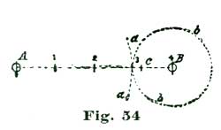
Or, in other words, the ratio of angular motion of two mobiles acting
on each must be in the same ratio as the length of their radii at the
point of contact. If we desire to give the jewel pin, or, in ordinary
horological phraseology, have a greater arc of roller action, we would
extend the length of fork (say) to the point c, which would be
one-fifth of the space between A and B, and the ratio of fork to
roller action would be four to one, and ten degrees of fork action would
give forty degrees of angular motion to the roller—and such escapements
have been constructed.
Now we have two sound reasons why we should not extend the arc of
vibration of the balance: (a) If there is an advantage to be derived
from a detached escapement, it would surely be policy to have the arc of
contact, that is, for the jewel pin to engage the fork, as short an arc
as is compatible with a sound action. (b) It will be evident to any
thinking mechanic that the acting force of a fork which would carry the
jewel pin against the force exerted by the balance spring through an arc
of fifteen degrees, or half of an arc of thirty degrees, would fail to
do so through an arc of twenty degrees, which is the condition imposed
when we adopt forty degrees of roller action.
For the present we will accept thirty degrees of roller action as the
standard. Before we proceed to delineate our fork and roller we will
devote a brief consideration to the size and shape of a jewel pin to
perform well. In this matter there has been a broad field gone over,
both theoretically and in practical construction. Wide jewel pins, round
jewel pins, oval jewel pins have been employed, but practical
construction has now pretty well settled on a round jewel pin with about
two-fifths cut away. And as regards size, if we adopt the linear extent
of four degrees of fork or twelve degrees of roller action, we will find
it about right.
As previously stated, frequently the true place to begin to set a lever
escapement right is with the roller and fork. But to do this properly we
should know when such fork and roller action is right and safe in all
respects. We will see on analysis of the actions involved that there are
three important actions in the fork and roller functions: (a) The fork
imparting perfect impulse through the jewel pin to the balance. (b)
Proper unlocking action. (c) Safety action. The last function is in
most instances sadly neglected and, we regret to add, by a large
majority of even practical workmen it is very imperfectly understood. In
most American watches we have ample opportunity afforded to inspect the
pallet action, but the fork and roller action is placed so that rigid
inspection is next to impossible.
The Vacheron concern of Swiss manufacturers were acute enough to see the
importance of such inspection, and proceeded to cut a circular opening
in the lower plate, which permitted, on the removal of the dial, a
careful scrutiny of the action of the roller and fork. While writing on
this topic we would suggest the importance not only of knowing how to
draw a correct fork and roller action, but letting the workman who
desires to be au fait in escapements delineate and study the action of
a faulty fork and roller action—say one in which the fork, although of
the proper form, is too short, or what at first glance would appear to
amount to the same thing, a roller too small.
Drawings help wonderfully in reasoning out not only correct actions, but
also faulty ones, and our readers are earnestly advised to make such
faulty drawings in several stages of action. By this course they will
educate the eye to discriminate not only as to correct actions, but also
to detect those which are imperfect, and we believe most watchmakers
will admit that in many instances it takes much longer to locate a fault
than to remedy it after it has been found.
Let us now proceed to delineate a fork and roller. It is not imperative
that we should draw the parts to any scale, but it is a rule among
English makers to let the distance between the center of the pallet
staff and the center of the balance staff equal in length the chord of
ninety-six degrees of the pitch circle of the escape wheel, which, in
case we employ a pitch circle of 5" radius, would make the distance
between A and B, Fig. 55, approximately 7-1/2", which is a very fair
scale for study drawings.
To arrive at the proper proportions of the several parts, we divide the
space A B into four equal parts, as previously directed, and draw the
circle a and short arc b. With our dividers set at 5", from B as a
center we sweep the short arc c. From our arc of sixty degrees, with a
5" radius, we take five degrees, and from the intersection of the right
line A B with the arc c we lay off on each side five degrees and
establish the points d e; and from B as a center, through these
points draw the lines B d' and B e'. Now the arc embraced between
these lines represents the angular extent of our fork action.
From A as a center and with our dividers set at 5", we sweep the arc
f. From the scale of degrees we just used we lay off fifteen degrees
on each side of the line A B on the arc f, and establish the points
g h. From A as a center, through the points just established we draw
the radial lines A g' and A h'. The angular extent between these
lines defines the limit of our roller action.
Now if we lay off on the arc f six degrees each side of its
intersection with the line A B, we define the extent of the jewel pin;
that is, on the arc f we establish the points l m at six degrees
from the line A B, and through the points l m draw, from A as a
center, the radial lines A l' and A m'. The extent of the space
between the lines A l' and A m' on the circle a defines the size
of our jewel pin.
To make the situation better understood, we make an enlarged drawing of
the lines defining the jewel pin at Fig. 56. At the intersection of the
line A B with the arc a we locate the point k, and from it as a
center we sweep the circle i so it passes through the intersection of
the lines A l' and A m' with the arc a. We divide the radius of
the circle i on the line A B into five equal parts, as shown by the
vertical lines j. Of these five spaces we assume three as the extent
of the jewel pin, cutting away that portion to the right of the heavy
vertical line at k.
We will now proceed to delineate a fork and roller as the parts are
related on first contact of jewel pin with fork and initial with the
commencing of the act of unlocking a pallet. The position and relations
are also the same as at the close of the act of impulse. We commence the
drawing at Fig. 57, as before, by drawing the line A B and the arcs
a and b to represent the pitch circles. We also sweep the arc f to
enable us to delineate the line A g'. Next in order we draw our jewel
pin as shown at D. In drawing the jewel pin we proceed as at Fig. 56,
except we let the line A g', Fig. 57, assume the same relations to the
jewel pin as A B in Fig. 56; that is, we delineate the jewel pin as if
extending on the arc a six degrees on each side of the line A g',
Fig. 57.
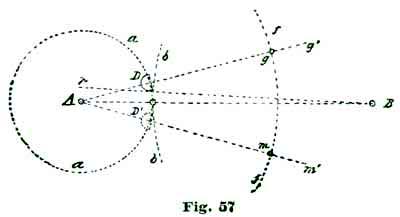
To aid us in reasoning, we establish the point m, as in Fig. 55, at
m, Fig. 57, and proceed to delineate another and imaginary jewel pin
at D' (as we show in dotted outline). A brief reasoning will show that
in allowing thirty degrees of contact of the fork with the jewel pin,
the center of the jewel pin will pass through an arc of thirty degrees,
as shown on the arcs a and f. Now here is an excellent opportunity
to impress on our minds the true value of angular motion, inasmuch as
thirty degrees on the arc f is of more than twice the linear extent as
on the arc a.
Before we commence to draw the horn of the fork engaging the jewel pin
D, shown at full line in Fig. 57, we will come to perfectly understand
what mechanical relations are required. As previously stated, we assume
the jewel pin, as shown at D, Fig. 57, is in the act of encountering
the inner face of the horn of the fork for the end or purpose of
unlocking the engaged pallet. Now if the inner face of the horn of the
fork was on a radial line, such radial line would be p B, Fig. 57. We
repeat this line at p, Fig. 56, where the parts are drawn on a larger
scale.
To delineate a fork at the instant the last effort of impulse has been
imparted to the jewel pin, and said jewel pin is in the act of
separating from the inner face of the prong of the fork—we would also
call attention to the fact that relations of parts are precisely the
same as if the jewel pin had just returned from an excursion of
vibration and was in the act of encountering the inner face of the prong
of the fork in the act of unlocking the escapement.
We mentioned this matter previously, but venture on the repetition to
make everything clear and easily understood. We commence by drawing the
line A B and dividing it in four equal parts, as on previous
occasions, and from A and B as centers draw the pitch circles c d.
By methods previously described, we draw the lines A a and A a',
also B b and B b' to represent the angular motion of the two
mobiles, viz., fork and roller action. As already shown, the roller
occupies twelve degrees of angular extent. To get at this conveniently,
we lay off on the arc by which we located the lines A a and A a' six
degrees above the line A a and draw the line A h.
Now the angular extent on the arc c between the lines A a and A h
represents the radius of the circle defining the jewel pin. From the
intersection of the line A a with the arc c as a center, and with
the radius just named, we sweep the small circle D, Fig. 58, which
represents our jewel pin; we afterward cut away two-fifths and draw the
full line D, as shown. We show at Fig. 59 a portion of Fig. 58,
enlarged four times, to show certain portions of our delineations more
distinctly. If we give the subject a moment's consideration we will see
that the length of the prong E of the lever fork is limited to such a
length as will allow the jewel pin D to pass it.
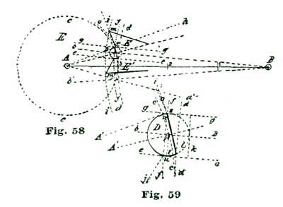
To delineate this length, from B as a center we sweep the short arc
f so it passes through the outer angle n, Fig. 59, of the jewel pin.
This arc, carried across the jewel pin D, limits the length of the
opposite prong of the fork. The outer face of the prong of the fork can
be drawn as a line tangent to a circle drawn from A as a center
through the angle n of the jewel pin. Such a circle or arc is shown at
o, Figs. 58 and 59. There has been a good deal said as to whether the
outer edge of the prong of a fork should be straight or curved.
To the writer's mind, a straight-faced prong, like from s to m, is
what is required for a fork with a single roller, while a fork with a
curved prong will be best adapted for a double roller. This subject will
be taken up again when we consider double-roller action. The extent or
length of the outer face of the prong is also an open subject, but as
there is but one factor of the problem of lever escapement construction
depending on it, when we name this and see this requirement satisfied we
have made an end of this question. The function performed by the outer
face of the prong of a fork is to prevent the engaged pallet from
unlocking while the guard pin is opposite to the passing hollow.
The inner angle s of the horn of the fork must be so shaped and
located that the jewel pin will just clear it as it passes out of the
fork, or when it passes into the fork in the act of unlocking the
escapement. In escapements with solid bankings a trifle is allowed, that
is, the fork is made enough shorter than the absolute theoretical length
to allow for safety in this respect.
We will now see how long a lever must be to perform its functions
perfectly. Now let us determine at what point on the inner face of the
prong E' the jewel pin parts from the fork, or engages on its return.
To do this we draw a line from the center r (Fig. 59) of the jewel
pin, so as to meet the line e at right angles, and the point t so
established on the line e is where contact will take place between the
jewel pin and fork.
It will be seen this point (t) of contact is some distance back of the
angle u which terminates the inner face of the prong E';
consequently, it will be seen the prongs E E' of the fork can with
safety be shortened enough to afford a safe ingress or egress to the
jewel pin to the slot in the fork. As regards the length of the outer
face of the prong of the fork, a good rule is to make it one and a half
times the diameter of the jewel pin. The depth of the slot need be no
more than to free the jewel in its passage across the ten degrees of
fork action. A convenient rule as to the depth of the slot in a fork is
to draw the line k, which, it will be seen, coincides with the circle
which defines the jewel pin.
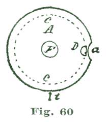
We will next consider a safety action of the single roller type. The
active or necessary parts of such safety action consist of a roller or
disk of metal, usually steel, shaped as shown in plan at A, Fig. 60.
In the edge of this disk is cut in front of the jewel pin a circular
recess shown at a called the passing hollow. The remaining part of the
safety action is the guard pin shown at N Figs. 61 and 62, which is
placed in the lever. Now it is to be understood that the sole function
performed by the guard pin is to strike the edge of the roller A at
any time when the fork starts to unlock the engaged pallet, except when
the jewel pin is in the slot of the fork. To avoid extreme care in
fitting up the passing hollow, the horns of the fork are arranged to
strike the jewel pin and prevent unlocking in case the passing hollow is
made too wide. To delineate the safety action we first draw the fork and
jewel pin as previously directed and as shown at Fig. 63. The position
of the guard pin should be as close to the bottom of the slot of the
fork as possible and be safe. As to the size of the guard pin, it is
usual to make it about one-third or half the diameter of the jewel pin.
The size and position of the guard pin decided on and the small circle
N drawn, to define the size and position of the roller we set our
dividers so that a circle drawn from the center A will just touch the
edge of the small circle N, and thus define the outer boundary of our
roller, or roller table, as it is frequently called.
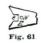
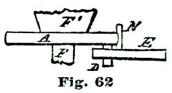
For deciding the angular extent of the passing hollow we have no fixed
rule, but if we make it to occupy about half more angular extent on the
circle y than will coincide with the angular extent of the jewel pin,
it will be perfectly safe and effectual. We previously stated that the
jewel pin should occupy about twelve degrees of angular extent on the
circle c, and if we make the passing hollow occupy eighteen degrees
(which is one and a half the angular extent of the jewel pin) it will do
nicely. But if we should extend the width of the passing hollow to
twenty-four degrees it would do no harm, as the jewel pin would be well
inside the horn of the fork before the guard pin could enter the passing
hollow.
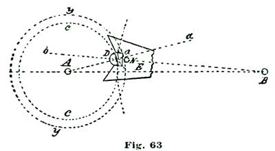
We show in Fig. 61 the fork as separated from the roller, but in Fig.
62, which is a side view, we show the fork and jewel pin as engaged.
When drawing a fork and roller action it is safe to show the guard pin
as if in actual contact with the roller. Then in actual construction, if
the parts are made to measure and agree with the drawing in the gray,
that is, before polishing, the process of polishing will reduce the
convex edge of the roller enough to free it.
It is evident if thought is given to the matter, that if the guard pin
is entirely free and does not touch the roller in any position, a
condition and relation of parts exist which is all we can desire. We are
aware that it is usual to give a considerable latitude in this respect
even by makers, and allow a good bit of side shake to the lever, but our
judgment would condemn the practice, especially in high-grade watches.
Grossmann, in his essay on the detached lever escapement, adopts one and
a half degrees lock. Now, we think that one degree is ample; and we are
sure that every workman experienced in the construction of the finer
watches will agree with us in the assertion that we should in all
instances seek to reduce the extent of all frictional surfaces, no
matter how well jeweled. Acting under such advice, if we can reduce the
surface friction on the lock from one and a half degrees to one degree
or, better, to three-fourths of a degree, it is surely wise policy to do
so. And as regards the extent of angular motion of the lever, if we
reduce this to six degrees, exclusive of the lock, we would undoubtedly
obtain better results in timing.
We shall next consider the effects of opening the bankings too wide, and
follow with various conditions which are sure to come in the experience
of the practical watch repairer. It is to be supposed in this problem
that the fork and roller action is all right. The reader may say to
this, why not close the banking? In reply we would offer the supposition
that some workman had bent the guard pin forward or set a pallet stone
too far out.
We have now instructed our readers how to draw and construct a lever
escapement complete, of the correct proportions, and will next take up
defective construction and consider faults existing to a lesser or
greater degree in almost every watch. Faults may also be those arising
from repairs by some workman not fully posted in the correct form and
relation of the several parts which go to make up a lever escapement. It
makes no difference to the artisan called upon to put a watch in
perfect order as to whom he is to attribute the imperfection, maker or
former repairer; all the workman having the job in hand has to do is to
know positively that such a fault actually exists, and that it devolves
upon him to correct it properly.
Hence the importance of the workman being perfectly posted on such
matters and, knowing that he is right, can go ahead and make the watch
as it should be. The writer had an experience of this kind years ago in
Chicago. A Jules Jurgensen watch had been in the hands of several good
workmen in that city, but it would stop. It was then brought to him with
a statement of facts given above. He knew there must be a fault
somewhere and searched for it, and found it in the exit pallet—a
certain tooth of the escape wheel under the right conditions would
sometimes not escape. It might go through a great many thousand times
and yet it might, and did sometimes, hold enough to stop the watch.
Now probably most of my fellow-workmen in this instance would have been
afraid to alter a "Jurgensen," or even hint to the owner that such a
thing could exist as a fault in construction in a watch of this
justly-celebrated maker. The writer removed the stone, ground a little
from the base of the offending pallet stone, replaced it, and all
trouble ended—no stops from that on.
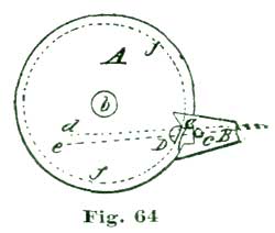
Now let us suppose a case, and imagine a full-plate American movement in
which the ingress or entrance pallet extends out too far, and in order
to have it escape, the banking on that side is opened too wide. We show
at Fig. 64 a drawing of the parts in their proper relations under the
conditions named. It will be seen by careful inspection that the jewel
pin D will not enter the fork, which is absolutely necessary. This
condition very frequently exists in watches where a new pallet stone has
been put in by an inexperienced workman. Now this is one of the
instances in which workmen complain of hearing a "scraping" sound when
the watch is placed to the ear. The remedy, of course, lies in warming
up the pallet arms and pushing the stone in a trifle, "But how much?"
say some of our readers. There is no definite rule, but we will tell
such querists how they can test the matter.
Remove the hairspring, and after putting the train in place and securing
the plates together, give the winding arbor a turn or two to put power
on the train; close the bankings well in so the watch cannot escape on
either pallet. Put the balance in place and screw down the cock.
Carefully turn back the banking on one side so the jewel pin will just
pass out of the slot in the fork. Repeat this process with the opposite
banking; the jewel pin will now pass out on each side. Be sure the guard
pin does not interfere with the fork action in any way. The fork is now
in position to conform to the conditions required.
If the escapement is all right, the teeth will have one and a half
degrees lock and escape correctly; but in the instance we are
considering, the stone will not permit the teeth to pass, and must be
pushed in until they will. It is not a very difficult matter after we
have placed the parts together so we can see exactly how much the pallet
protrudes beyond what is necessary, to judge how far to push it back
when we have it out and heated. There is still an "if" in the problem we
are considering, which lies in the fact that the fork we are
experimenting with may be too short for the jewel pin to engage it for
ten degrees of angular motion.
This condition a man of large experience will be able to judge of very
closely, but the better plan for the workman is to make for himself a
test gage for the angular movement of the fork. Of course it will be
understood that with a fork which engages the roller for eight degrees
of fork action, such fork will not give good results with pallets ground
for ten degrees of pallet action; still, in many instances, a compromise
can be effected which will give results that will satisfy the owner of a
watch of moderate cost, and from a financial point of view it stands the
repairer in hand to do no more work than is absolutely necessary to keep
him well pleased.
We have just made mention of a device for testing the angular motion of
the lever. Before we take up this matter, however, we will devote a
little time and attention to the subject of jewel pins and how to set
them. We have heretofore only considered jewel pins of one form, that
is, a round jewel pin with two-fifths cut away. We assumed this form
from the fact that experience has demonstrated that it is the most
practicable and efficient form so far devised or applied. Subsequently
we shall take up the subject of jewel pins of different shapes.
Many workmen have a mortal terror of setting a jewel pin and seem to
fancy that they must have a specially-devised instrument for
accomplishing this end. Most American watches have the hole for the
jewel pin "a world too wide" for it, and we have heard repeated
complaints from this cause. Probably the original object of this
accommodating sort of hole was to favor or obviate faults of pallet
action. Let us suppose, for illustration, that we have a roller with the
usual style of hole for a jewel pin which will take almost anything from
the size of a No. 12 sewing needle up to a round French clock pallet.
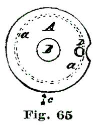
We are restricted as regards the proper size of jewel pin by the width
of the slot in the fork. Selecting a jewel which just fits the fork, we
can set it as regards its relation to the staff so it will cause the
pitch circle of the jewel pin to coincide with either of dotted circles
a or a', Fig. 65. This will perhaps be better understood by
referring to Fig. 66, which is a view of Fig. 65 seen in the direction
of the arrow c. Here we see the roller jewel at D, and if we bring
it forward as far as the hole in the roller will permit, it will occupy
the position indicated at the dotted lines; and if we set it in (toward
the staff) as far as the hole will allow, it will occupy the position
indicated by the full outline.
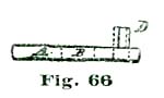
Now such other condition might very easily exist, that bringing the
jewel pin forward to the position indicated by the dotted lines at D,
Fig. 66, would remedy the defect described and illustrated at Fig. 64
without any other change being necessary. We do not assert, understand,
that a hole too large for the jewel pin is either necessary or
desirable—what we wish to convey to the reader is the necessary
knowledge so that he can profit by such a state if necessary. A hole
which just fits the jewel pin so the merest film of cement will hold it
in place is the way it should be; but we think it will be some time
before such rollers are made, inasmuch as economy appears to be a chief
consideration.
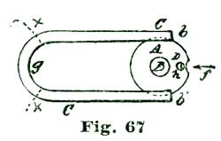
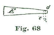
To make a jewel-pin setter which will set a jewel pin straight is easy
enough, but to devise any such instrument which will set a jewel so as
to perfectly accord with the fork action is probably not practicable.
What the workman needs is to know from examination when the jewel pin is
in the proper position to perform its functions correctly, and he can
only arrive at this knowledge by careful study and thought on the
matter. If we make up our minds on examining a watch that a jewel pin is
"set too wide," that is, so it carries the fork over too far and
increases the lock to an undue degree, take out the balance, remove the
hairspring, warm the roller with a small alcohol lamp, and then with the
tweezers move the jewel pin in toward the staff.
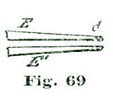
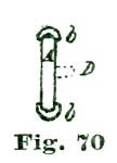
No attempt should be made to move a jewel pin unless the cement which
holds the jewel is soft, so that when the parts cool off the jewel is as
rigid as ever. A very little practice will enable any workman who has
the necessary delicacy of touch requisite to ever become a good
watchmaker, to manipulate a jewel pin to his entire satisfaction with no
other setter than a pair of tweezers and his eye, with a proper
knowledge of what he wants to accomplish. To properly heat a roller for
truing up the jewel pin, leave it on the staff, and after removing the
hairspring hold the balance by the rim in a pair of tweezers, "flashing
it" back and forth through the flame of a rather small alcohol lamp
until the rim of the balance is so hot it can just be held between the
thumb and finger, and while at this temperature the jewel pin can be
pressed forward or backward, as illustrated in Fig. 66, and then a touch
or two will set the pin straight or parallel with the staff. Figs. 68
and 69 are self-explanatory. For cementing in a jewel pin a very
convenient tool is shown at Figs. 67 and 70. It is made of a piece of
copper wire about 1/16" in diameter, bent to the form shown at Fig. 67.
The ends b b of the copper wire are flattened a little and recessed on
their inner faces, as shown in Fig. 70, to grasp the edges of the roller
A. The heat of an alcohol lamp is applied to the loop of the wire at
g until the small bit of shellac placed in the hole h melts. The
necessary small pieces of shellac are made by warming a bit of the gum
to near the melting point and then drawing the softened gum into a
filament the size of horse hair. A bit of this broken off and placed in
the hole h supplies the cement necessary to fasten the jewel pin.
Figs. 68 and 69 will, no doubt, assist in a clear understanding of the
matter.
We will now resume the consideration of the device for measuring the
extent of the angular motion of the fork and pallets. Now, before we
take this matter up in detail we wish to say, or rather repeat what we
have said before, which is to the effect that ten degrees of fork and
lever action is not imperative, as we can get just as sound an action
and precisely as good results with nine and a half or even nine degrees
as with ten, if other acting parts are in unison with such an arc of
angular motion. The chief use of such an angle-measuring device is to
aid in comparing the relative action of the several parts with a known
standard.
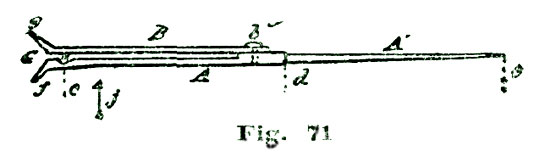
For use with full-plate movements about the best plan is a spring clip
or clasp to embrace the pallet staff below the pallets. We show at Fig.
71 such a device. To make it, take a rather large size of sewing
needle—the kind known as a milliner's needle is about the best. The
diameter of the needle should be about No. 2, so that at b we can
drill and put in a small screw. It is important that the whole affair
should be very light. The length of the needle should be about 1-5/8",
in order that from the notch a to the end of the needle A' should be
1-1/2". The needle should be annealed and flattened a little, to give a
pretty good grasp to the notch a on the pallet staff.
Good judgment is important in making this clamp, as it is nearly
impossible to give exact measurements. About 1/40" in width when seen in
the direction of the arrow j will be found to be about the right
width. The spring B can be made of a bit of mainspring, annealed and
filed down to agree in width with the part A. In connection with the
device shown at Fig. 71 we need a movement-holder to hold the movement
as nearly a constant height as possible above the bench. The idea is,
when the clamp A B is slipped on the pallet staff the index hand A'
will extend outward, as shown in Fig. 72, where the circle C is
supposed to represent the top plate of a watch, and A' the index hand.
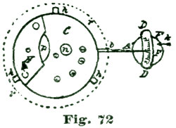
Fig. 72 is supposed to be seen from above. It is evident that if we
remove the balance from the movement shown at C, leaving power on the
train, and with an oiling tool or hair broach move the lever back and
forth, the index hand A' will show in a magnified manner the angular
motion of the lever. Now if we provide an index arc, as shown at D, we
can measure the extent of such motion from bank to bank.
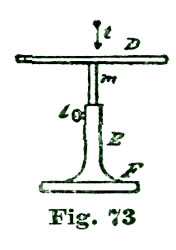
To get up such an index arc we first make a stand as shown at E F,
Fig. 73. The arc D is made to 1-1/2" radius, to agree with the index
hand A', and is divided into twelve degree spaces, six each side of a
zero, as shown at Fig. 74, which is an enlarged view of the index D in
Fig. 72. The index arc is attached to a short bit of wire extending down
into the support E, and made adjustable as to height by the set-screw
l. Let us suppose the index arc is adjusted to the index hand A',
and we move the fork as suggested; you see the hand would show exactly
the arc passed through from bank to bank, and by moving the stand E F
we can arrange so the zero mark on the scale stands in the center of
such arc. This, of course, gives the angular motion from bank to bank.
As an experiment, let us close the bankings so they arrest the fork at
the instant the tooth drops from each pallet. If this arc is ten
degrees, the pallet action is as it should be with the majority of
modern watches.
Let us try another experiment: We carefully move the fork away from the
bank, and if after the index hand has passed through one and a half
degrees the fork flies over, we know the lock is right. We repeat the
experiment from the opposite bank, and in the same manner determine if
the lock is right on the other pallets. You see we have now the means
of measuring not only the angular motion of the lever, but the angular
extent of the lock. At first glance one would say that if now we bring
the roller and fork action to coincide and act in unison with the pallet
action, we would be all right; and so we would, but frequently this
bringing of the roller and fork to agree is not so easily accomplished.
It is chiefly toward this end the Waltham fork is made adjustable, so it
can be moved to or from the roller, and also that we can allow the
pallet arms to be moved, as we will try and explain. As we set the
bankings the pallets are all right; but to test matters, let us remove
the hairspring and put the balance in place. Now, if the jewel pin
passes in and out of the fork, it is to be supposed the fork and roller
action is all right. To test the fork and roller action we close the
banking a little on one side. If the fork and jewel pin are related to
each other as they should be, the jewel pin will not pass out of the
fork, nor will the engaged tooth drop from that pallet. This condition
should obtain on both pallets, that is, if the jewel pin will not pass
out of the fork on a given bank the tooth engaged on its pallet should
not drop.
We have now come to the most intricate and important problems which
relate to the lever escapement. However, we promise our readers that if
they will take the pains to follow closely our elucidations, to make
these puzzles plain. But we warn them that they are no easy problems to
solve, but require good, hard thinking. The readiest way to master this
matter is by means of such a model escapement as we have described. With
such a model, and the pallets made to clamp with small set-screws, and
roller constructed so the jewel pin could be set to or from the staff,
this matter can be reduced to object lessons. But study of the due
relation of the parts in good drawings will also master the situation.
In using the little instrument for determining angular motion that we
have just described, care must be taken that the spring clamp which
embraces the pallet staff does not slip. In order to thoroughly
understand the methods of using this angle-measuring device, let us take
a further lesson or two.
We considered measuring the amount of lock on each pallet, and advised
the removal of the balance, because if we left the balance in we could
not readily tell exactly when the tooth passed on to the impulse plane;
but if we touch the fork lightly with an oiling tool or a hair broach,
moving it (the fork) carefully away from the bank and watching the arc
indicated by the hand A, Fig. 72, we can determine with great
exactness the angular extent of lock. The diagram at Fig. 75 illustrates
how this experiment is conducted. We apply the hair broach to the end of
the fork M, as shown at L, and gently move the fork in the direction
of the arrow i, watching the hand A and note the number of degrees,
or parts of degrees, indicated by the hand as passed over before the
tooth is unlocked and passes on to the impulse plane and the fork flies
forward to the opposite bank. Now, the quick movement of the pallet and
fork may make the hand mark more or less of an arc on the index than one
of ten degrees, as the grasp may slip on the pallet staff; but the arc
indicated by the slow movement in unlocking will be correct.
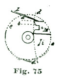
By taking a piece of sharpened pegwood and placing the point in the slot
of the fork, we can test the fork to see if the drop takes place much
before the lever rests against the opposite bank. As we have previously
stated, the drop from the pallet should not take place until the lever
almost rests on the banking pin. What the reader should impress on his
mind is that the lever should pass through about one and a half degrees
arc to unlock, and the remainder (eight and a half degrees) of the ten
degrees are to be devoted to impulse. But, understand, if the impulse
angle is only seven and a half degrees, and the jewel pin acts in
accordance with the rules previously given, do not alter the pallet
until you know for certain you will gain by it. An observant workman
will, after a little practice, be able to determine this matter.
We will next take up the double roller and fork action, and also
consider in many ways the effect of less angles of action than ten
degrees. This matter now seems of more importance, from the fact that we
are desirous to impress on our readers that there is no valid reason
for adopting ten degrees of fork and roller action with the table
roller, except that about this number of degrees of action are required
to secure a reliable safety action. With the double roller, as low as
six degrees fork and pallet action can be safely employed. In fork and
pallet actions below six degrees of angular motion, side-shake in pivot
holes becomes a dangerous factor, as will be explained further on. It is
perfectly comprehending the action of the lever escapement and then
being able to remedy defects, that constitute the master workman.
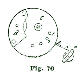
We can also make use of our angle-testing device for measuring our
escape-wheel action, by letting the clasp embrace the arbor of the
escape wheel, instead of the pallet staff. We set the index arc as in
our former experiments, except we place the movable index D, Fig. 76,
so that when the engaged tooth rests on the locking face of a pallet,
the index hand stands at the extreme end of our arc of twelve degrees.
We next, with our pointed pegwood, start to move the fork away from the
bank, as before, we look sharp and see the index hand move backward a
little, indicating the "draw" on the locking face. As soon as the pallet
reaches the impulse face, the hand A moves rapidly forward, and if the
escapement is of the club-tooth order and closely matched, the hand A
will pass over ten and a half degrees of angular motion before the drop
takes place.
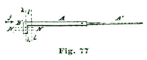
We will warn our readers in advance, that if they make such a testing
device they will be astonished at the inaccuracy which they will find in
the escapements of so-called fine watches. The lock, in many instances,
instead of being one and a half degrees, will oftener be found to be
from two to four degrees, and the impulse derived from the escape wheel,
as illustrated at Fig. 76, will often fall below eight degrees. Such
watches will have a poor motion and tick loud enough to keep a policeman
awake. Trials with actual watches, with such a device as we have just
described, in conjunction with a careful study of the acting parts,
especially if aided by a large model, such as we have described, will
soon bring the student to a degree of skill unknown to the old-style
workman, who, if a poor escapement bothered him, would bend back the
banking pins or widen the slot in the fork.
We hold that educating our repair workmen up to a high knowledge of what
is required to constitute a high-grade escapement, will have a
beneficial effect on manufacturers. When we wish to apply our device to
the measurement of the escapement of three-quarter-plate watches, we
will require another index hand, with the grasping end bent downward, as
shown at Fig. 77. The idea with this form of index hand is, the
bent-down jaws B', Fig. 77, grasp the fork as close to the pallet
staff as possible, making an allowance for the acting center by so
placing the index arc that the hand A will read correctly on the index
D. Suppose, for instance, we place the jaws B' inside the pallet
staff, we then place the index arc so the hand reads to the arc
indicated by the dotted arc m, Fig. 78, and if set outside of the
pallet staff, read by the arc o.
We think a majority of the fine lever escapements made abroad in this
day have what is termed double-roller safety action. The chief gains to
be derived from this form of safety action are: (1) Reducing the arc of
fork and roller action; (2) reducing the friction of the guard point to
a minimum. While it is entirely practicable to use a table roller for
holding the jewel pin with a double-roller action, still a departure
from that form is desirable, both for looks and because as much of the
aggregate weight of a balance should be kept as far from the axis of
rotation as possible.
We might as well consider here as elsewhere, the relation the balance
bears to the train as a controlling power. Strictly speaking, the
balance and hairspring are the time measurers, the train serving only
two purposes: (a) To keep the balance in motion; (b) to classify and
record the number of vibrations of the balance. Hence, it is of
paramount importance that the vibrations of the balance should be as
untrammeled as possible; this is why we urge reducing the arc of
connection between the balance and fork to one as brief as is consistent
with sound results. With a double-roller safety action we can easily
reduce the fork action to eight degrees and the roller action to
twenty-four degrees.
Inasmuch as satisfactory results in adjustment depend very much on the
perfection of construction, we shall now dwell to some extent on the
necessity of the several parts being made on correct principles. For
instance, by reducing the arc of engagement between the fork and roller,
we lessen the duration of any disturbing influence of escapement action.
To resume the explanation of why it is desirable to make the staff and
all parts near the axis of the balance as light as possible, we would
say it is the moving portion of the balance which controls the
regularity of the intervals of vibration. To illustrate, suppose we have
a balance only 3/8" in diameter, but of the same weight as one in an
ordinary eighteen-size movement. We can readily see that such a balance
would require but a very light hairspring to cause it to give the usual
18,000 vibrations to the hour. We can also understand, after a little
thought, that such a balance would exert as much breaking force on its
pivots as a balance of the same weight, but 3/4" in diameter acting
against a very much stronger hairspring. There is another factor in the
balance problem which deserves our attention, which factor is
atmospheric resistance. This increases rapidly in proportion to the
velocity.
The most careful investigators in horological mechanics have decided
that a balance much above 75/100" in diameter, making 18,000 vibrations
per hour, is not desirable, because of the varying atmospheric
disturbances as indicated by barometric pressure. A balance with all of
its weight as near the periphery as is consistent with strength, is what
is to be desired for best results. It is the moving matter composing the
balance, pitted against the elastic force of the hairspring, which we
have to depend upon for the regularity of the timekeeping of a watch,
and if we can take two grains' weight of matter from our roller table
and place them in the rim or screws of the balance, so as to act to
better advantage against the hairspring, we have disposed of these two
grains so as to increase the efficiency of the controlling power and not
increase the stress on the pivots.
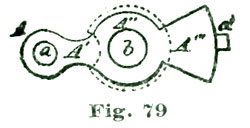
We have deduced from the facts set forth, two axioms: (a) That we
should keep the weight of our balance as much in the periphery as
possible, consistent with due strength; (b) avoid excessive size from
the disturbing effect of the air. We show at A, Fig. 79, the shape of
the piece which carries the jewel pin. As shown, it consists of three
parts: (1) The socket A, which receives the jewel pin a; (2) the
part A'' and hole b, which goes on the balance staff; (3) the
counterpoise A''', which makes up for the weight of the jewel socket
A, neck A' and jewel pin. This counterpoise also makes up for the
passing hollow C in the guard roller B, Fig. 80. As the piece A
is always in the same relation to the roller B, the poise of the
balance must always remain the same, no matter how the roller action is
placed on the staff. We once saw a double roller of nearly the shape
shown at Fig. 79, which had a small gold screw placed at d, evidently
for the purpose of poising the double rollers; but, to our thinking, it
was a sort of hairsplitting hardly worth the extra trouble. Rollers for
very fine watches should be poised on the staff before the balance is
placed upon it.
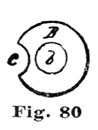
We shall next give detailed instructions for drawing such a double
roller as will be adapted for the large model previously described,
which, as the reader will remember, was for ten degrees of roller
action. We will also point out the necessary changes required to make it
adapted for eight degrees of fork action. We would beg to urge again the
advantages to be derived from constructing such a model, even for
workmen who have had a long experience in escapements, our word for it
they will discover a great many new wrinkles they never dreamed of
previously.
It is important that every practical watchmaker should thoroughly master
the theory of the lever escapement and be able to comprehend and
understand at sight the faults and errors in such escapements, which, in
the every-day practice of his profession, come to his notice. In no
place is such knowledge more required than in fork and roller action. We
are led to say the above chiefly for the benefit of a class of workmen
who think there is a certain set of rules which, if they could be
obtained, would enable them to set to rights any and all escapements. It
is well to understand that no such system exists and that, practically,
we must make one error balance another; and it is the "know how" to make
such faults and errors counteract each other that enables one workman to
earn more for himself or his employer in two days than another workman,
who can file and drill as well as he can, will earn in a week.
The proportion in size between the two rollers in a double-roller
escapement is an open question, or, at least, makers seldom agree on it.
Grossmann shows, in his work on the lever escapement, two sizes: (1)
Half the diameter of the acting roller; (2) two-thirds of the size of
the acting roller. The chief fault urged against a smaller safety roller
is, that it necessitates longer horns to the fork to carry out the
safety action. Longer horns mean more metal in the lever, and it is the
conceded policy of all recent makers to have the fork and pallets as
light as possible. Another fault pertaining to long horns is, when the
horn does have to act as safety action, a greater friction ensues.
In all soundly-constructed lever escapements the safety action is only
called into use in exceptional cases, and if the watch was lying still
would theoretically never be required. Where fork and pallets are poised
on their arbor, pocket motion (except torsional) should but very little
affect the fork and pallet action of a watch, and torsional motion is
something seldom brought to act on a watch to an extent to make it
worthy of much consideration. In the double-roller action which we shall
consider, we shall adopt three-fifths of the pitch diameter of the
jewel-pin action as the proper size. Not but what the proportions given
by Grossmann will do good service; but we adopt the proportions named
because it enables us to use a light fork, and still the friction of the
guard point on the roller is but little more than where a guard roller
of half the diameter of the acting roller is employed.
The fork action we shall consider at present is ten degrees, but
subsequently we shall consider a double-roller action in which the fork
and pallet action is reduced to eight degrees. We shall conceive the
play between the guard point and the safety roller as one degree, which
will leave half a degree of lock remaining in action on the engaged
pallet.
In the drawing at Fig. 81 we show a diagram of the action of the
double-roller escapement. The small circle at A represents the center
of the pallet staff, and the one at B the center of the balance staff.
The radial lines A d and A d' represent the arc of angular motion of
fork action. The circle b b represents the pitch circle of the jewel
pin, and the circle at c c the periphery of the guard or safety
roller. The points established on the circle c c by intersection of
the radial lines A d and A d' we will denominate the points h and
h'. It is at these points the end of the guard point of the fork will
terminate. In construction, or in delineating for construction, we show
the guard enough short of the points h h' to allow the fork an angular
motion of one degree, from A as a center, before said point would come
in contact with the safety roller.
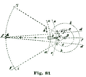
We draw through the points h h', from B as a center, the radial
lines B g and B g'. We measure this angle by sweeping the short arc
i with any of the radii we have used for arc measurement in former
delineations, and find it to be a trifle over sixty degrees. To give
ourselves a practical object lesson, let us imagine that a real guard
point rests on the circle c at h. Suppose we make a notch in the
guard roller represented by the circle c, to admit such imaginary
guard point, and then commence to revolve the circle c in the
direction of the arrow j, letting the guard point rest constantly in
such notch. When the notch n in c has been carried through thirty
degrees of arc, counting from B as a center, the guard point, as
relates to A as a center, would only have passed through an arc of
five degrees. We show such a guard point and notch at o n. In fact, if
a jewel pin was set to engage the fork on the pitch circle b a, the
escapement would lock. To obviate such lock we widen the notch n to
the extent indicated by the dotted lines n', allowing the guard point
to fall back, so to speak, into the notch n, which really represents
the passing hollow. It is not to be understood that the extended notch
at n is correctly drawn as regards position, because when the guard
point was on the line A f the point o would be in the center of the
extended notch, or passing hollow. We shall next give the details of
drawing the double roller, but before doing so we deemed it important to
explain the action of such guard points more fully than has been done
heretofore.
We have already given very desirable forms for the parts of a
double-roller escapement, consequently we shall now deal chiefly with
acting principles as regards the rollers, but will give, at Fig. 82, a
very well proportioned and practical form of fork. The pitch circle of
the jewel pin is indicated by the dotted circle a, and the jewel pin
of the usual cylindrical form, with two-fifths cut away. The safety
roller is three-fifths of the diameter of the pitch diameter of the
jewel-pin action, as indicated by the dotted circle a.
The safety roller is shown in full outline at B', and the passing
hollow at E. It will be seen that the arc of intersection embraced
between the radial lines B c and B d is about sixty-one and a half
degrees for the roller, but the angular extent of the passing hollow is
only a little over thirty-two degrees. The passing hollow E is located
and defined by drawing the radial line B c from the center B through
the intersection of radial line A i with the dotted arc b, which
represents the pitch circle of the safety roller. We will name this
intersection the point l. Now the end of the guard point C
terminates at the point l, and the passing hollow E extends on b
sixteen degrees on each side of the radial line B c.
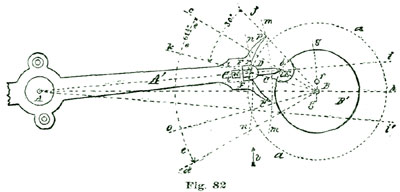
The roller action is supposed to continue through thirty degrees of
angular motion of the balance staff, and is embraced on the circle a
between the radial line B k and B o. To delineate the inner face of
the horn p of the fork F we draw the short arc g, from A as a
center, and on said arc locate at two degrees from the center at B the
point f. We will designate the upper angle of the outer face of the
jewel pin D as the point s and, from A as a center, sweep through
this point s the short arc n n. Parallel with the line A i and at
the distance of half the diameter of the jewel pin D, we draw the
short lines t t', which define the inner faces of the fork.
The intersection of the short line t with the arc n we will
designate the point r. With our dividers set to embrace the space
between the point r and the point f, we sweep the arc which defines
the inner face of the prong of the fork. The space we just made use of
is practically the same as the radius of the circle a, and
consequently of the same curvature. Practically, the length of the guard
point C' is made as long as will, with certainty, clear the safety
roller B in all positions. While we set the point f at two degrees
from the center B, still, in a well-constructed escapement, one and a
half degrees should be sufficient, but the extra half degree will do no
harm. If the roller B' is accurately made and the guard point C'
properly fitted, the fork will not have half a degree of play.
The reader will remember that in the escapement model we described we
cut down the drop to one degree, being less by half a degree than
advised by Grossmann and Saunier. We also advised only one degree of
lock. In the perfected lever escapement, which we shall describe and
give working drawings for the construction of, we shall describe a
detached lever escapement with only eight degrees fork and pallet
action, with only three-fourths of a degree drop and three-fourths of a
degree lock, which we can assure our readers is easily within the limits
of practical construction by modern machinery.
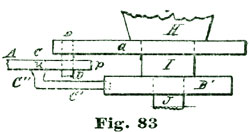
The guard point C', as shown at Fig. 82, is of extremely simple
construction. Back of the slot of the fork, which is three-fifths of the
diameter of the jewel pin in depth, is made a square hole, as shown at
u, and the back end of the guard point C is fitted to this hole so
that it is rigid in position. This manner of fastening the guard point
is equally efficient as that of attaching it with a screw, and much
lighter—a matter of the highest importance in escapement construction,
as we have already urged. About the best material for such guard points
is either aluminum or phosphor bronze, as such material is lighter than
gold and very rigid and strong. At Fig. 83 we show a side view of the
essential parts depicted in Fig. 82, as if seen in the direction of the
arrow v, but we have added the piece which holds the jewel pin D. A
careful study of the cut shown at Fig. 82 will soon give the horological
student an excellent idea of the double-roller action.
We will now take up and consider at length why Saunier draws his
entrance pallet with fifteen degrees draw and his exit pallet with only
twelve degrees draw. To make ourselves more conversant with Saunier's
method of delineating the lever escapement, we reproduce the essential
features of his drawing, Fig. 1, plate VIII, of his "Modern Horology,"
in which he makes the draw of the locking face of the entrance pallet
fifteen degrees and his exit pallet twelve degrees. In the cut shown at
Fig. 84 we use the same letters of reference as he employs. We do not
quote his description or directions for delineation because he refers to
so much matter which he has previously given in the book just referred
to. Besides we cannot entirely endorse his methods of delineations for
many reasons, one of which appears in the drawing at Fig. 84.
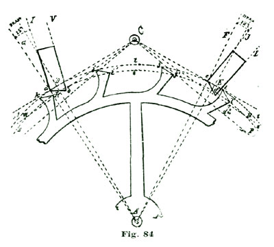
Most writers endorse the idea of tangential lockings, and Saunier speaks
of the escapement as shown at Fig. 84 as having such tangential
lockings, which is not the case. He defines the position of the pallet
staff from the circle t, which represents the extreme length of the
teeth; drawing the radial lines A D and A E to embrace an arc of
sixty degrees, and establishing the center of his pallet staff C at
the intersection of the lines D C and E C, which are drawn at right
angles to the radial lines A D and A E, and tangential to the circle
t.
Here is an error; the lines defining the center of the pallet staff
should have been drawn tangent to the circle s, which represents the
locking angle of the teeth. This would have placed the center of the
pallet staff farther in, or closer to the wheel. Any person can see at a
glance that the pallets as delineated are not tangential in a true
sense.
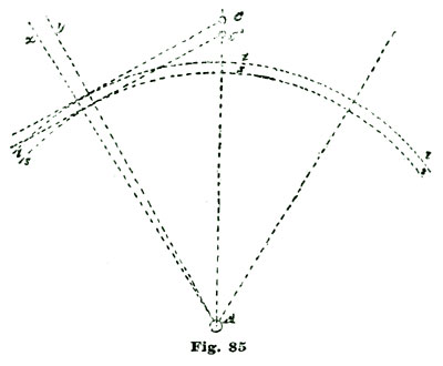
We have previously considered engaging friction and also repeatedly have
spoken of tangential lockings, but will repeat the idea of tangential
lockings at Fig. 85. A tangential locking is neutral, or nearly so, as
regards engaging friction. For illustration we refer to Fig. 85, where
A represents the center of an escape wheel. We draw the radial lines
A y and A z so that they embrace sixty degrees of the arcs s or
t, which correspond to similar circles in Fig. 84, and represent the
extreme extent of the teeth and likewise the locking angle of such
teeth. In fact, with the club-tooth escapement all that part of a tooth
which extends beyond the line s should be considered the same as the
addendum in gear wheels. Consequently, a tangential locking made to
coincide with the center of the impulse plane, as recommended by
Saunier, would require the pallet staff to be located at C' instead of
C, as he draws it. If the angle k' of the tooth k in Fig. 84 was
extended outward from the center A so it would engage or rest on the
locking face of the entrance pallet as shown at Fig. 84, then the draw
of the locking angle would not be quite fifteen degrees; but it is
evident no lock can take place until the angle a of the entrance
pallet has passed inside the circle s. We would say here that we have
added the letters s and t to the original drawings, as we have
frequently to refer to these circles, and without letters had no means
of designation. Before the locking angle k' of the tooth can engage
the pallet, as shown in Fig. 84, the pallet must turn on the center C
through an angular movement of at least four degrees. We show the
situation in the diagram at Fig. 86, using the same letters of reference
for similar parts as in Fig. 84.
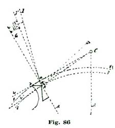
As drawn in Fig. 84 the angle of draft G a I is equal to fifteen
degrees, but when brought in a position to act as shown at G a' I',
Fig. 86, the draw is less even than twelve degrees. The angle C a I
remains constant, as shown at C a' I', but the relation to the radial
A G changes when the pallet moves through the angle w C w', as it
must when locked. A tangential locking in the true sense of the meaning
of the phrase is a locking set so that a pallet with its face coinciding
with a radial line like A G would be neutral, and the thrust of the
tooth would be tangent to the circle described by the locking angle of
the tooth. Thus the center C, Fig. 86, is placed on the line w'
which is tangent to the circle s; said line w' also being at right
angles to the radial line A G.
The facts are, the problems relating to the club-tooth lever escapement
are very intricate and require very careful analysis, and without such
care the horological student can very readily be misled. Faulty
drawings, when studying such problems, lead to no end of errors, and
practical men who make imperfect drawings lead to the popular phrase,
"Oh, such a matter may be all right in theory, but will not work in
practice." We should always bear in mind that theory, if right, must
lead practice.
If we delineate our entrance pallet to have a draw of twelve degrees
when in actual contact with the tooth, and then construct in exact
conformity with such drawings, we will find our lever to "hug the banks"
in every instance. It is inattention to such details which produces the
errors of makers complained of by Saunier in section 696 of his "Modern
Horology," and which he attempts to correct by drawing the locking face
at fifteen degrees draw.
We shall show that neither C nor C', Fig. 85, is the theoretically
correct position for the pallet center for a tangential locking.
We will now take up the consideration of a club-tooth lever escapement
with circular pallets and tangential lockings; but previous to making
the drawings we must decide several points, among which are the
thickness of the pallet arms, which establishes the angular motion of
the escape wheel utilized by such pallet arms, and also the angular
motion imparted to the pallets by the impulse faces of the teeth. We
will, for the present, accept the thickness of the arms as being
equivalent to five degrees of angular extent of the pitch circle of the
escape wheel.
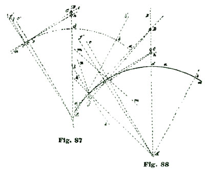
In making our drawings we commence, as on former occasions, by
establishing the center of our escape wheel at A, Fig. 87, and
sweeping the arc a a to represent the pitch circle of such wheel.
Through the center A we draw the vertical line A B, which is
supposed to also pass through the center of the pallet staff. The
intersection of the line A B with the arc a we term the point d,
and from this point we lay off on said arc a thirty degrees each side
of said intersection, and thus establish the points c b. From A,
through the point c, we draw the line A c c'. On the arc a a and
two and a half degrees to the left of the point c we establish the
point f, which space represents half of the thickness of the entrance
pallet. From A we draw through the point f the line A f f'. From
f, and at right angles to said line A f, we draw the line f e
until it crosses the line A B.
Now this line f e is tangent to the arc a from the point f, and
consequently a locking placed at the point f is a true tangential
locking; and if the resting or locking face of a pallet was made to
coincide with the line A f', such locking face would be strictly
"dead" or neutral. The intersection of the line f e with the line A
B we call the point C, and locate at this point the center of our
pallet staff. According to the method of delineating the lever
escapement by Moritz Grossmann the tangent line for locating the center
of the pallet staff is drawn from the point c, which would locate the
center of the pallet staff at the point h on the line A B.
Grossmann, in delineating his locking face for the draw, shows such face
at an angle of twelve degrees to the radial line A f', when he should
have drawn it twelve degrees to an imaginary line shown at f i, which
is at right angles to the line f h. To the writer's mind this is not
just as it should be, and may lead to misunderstanding and bad
construction. We should always bear in mind the fact that the basis of a
locking face is a neutral plane placed at right angles to the line of
thrust, and the "draw" comes from a locking face placed at an angle to
such neutral plane. A careful study of the diagram at Fig. 88 will give
the reader correct ideas. If a tooth locks at the point c, the
tangential thrust would be on the line c h', and a neutral locking
face would be on the line A c.
To aid in explanation, let us remove the pallet center to D; then the
line of thrust would be c D and a neutral locking face would coincide
with the line m m, which is at right angles to the line c D. If we
should now make a locking face with a "draw" and at an angle to the line
c D, say, for illustration, to correspond to the line c c' (leaving
the pallet center at D), we would have a strong draw and also a cruel
engaging friction.
If, however, we removed the engaging tooth, which we have just conceived
to be at c, to the point k on the arc a' a', Fig. 88, the pallet
center D would then represent a tangential locking, and a neutral
pallet face would coincide with the radial line A k'; and a locking
face with twelve degrees draw would coincide nearly with the line l.
Let us next analyze what the effect would be if we changed the pallet
center to h', Fig. 88, leaving the engaging tooth still at k. In
this instance the line l l would then coincide with a neutral locking
face, and to obtain the proper draw we should delineate the locking face
to correspond to the line k n, which we assume to be twelve degrees
from k l.
It is not to be understood that we insist on precisely twelve degrees
draw from a neutral plane for locking faces for lever pallets. What we
do insist upon, however, is a "safe and sure draw" for a lever pallet
which will hold a fork to the banks and will also return it to such
banks if by accident the fork is moved away. We are well aware that it
takes lots of patient, hard study to master the complications of the
club-tooth lever escapement, but it is every watchmaker's duty to
conquer the problem. The definition of "lock," in the detached lever
escapement, is the stoppage or arrest of the escape wheel of a watch
while the balance is left free or detached to perform the greater
portion of its arc of vibration. "Draw" is a function of the locking
parts to preserve the fork in the proper position to receive and act on
the jewel pin of the balance.
It should be borne in mind in connection with "lock" and "draw," that
the line of thrust as projected from the locked tooth of the escape
wheel should be as near tangential as practicable. This maxim applies
particularly to the entrance pallet. We would beg to add that
practically it will make but little odds whether we plant the center of
our pallet staff at C or h, Fig. 87, provided we modify the locking
and impulse angles of our pallets to conform to such pallet center. But
it will not do to arrange the parts for one center and then change to
another.
Apparently there seems to be a belief with very many watchmakers that
there is a set of shorthand rules for setting an escapement, especially
in American watches, which, if once acquired, conquers all
imperfections. Now we wish to disabuse the minds of our readers of any
such notions. Although the lever escapement, as adopted by our American
factories, is constructed on certain "lines," still these lines are
subject to modifications, such as may be demanded for certain defects of
construction. If we could duplicate every part of a watch movement
perfectly, then we could have certain rules to go by, and fixed
templets could be used for setting pallet stones and correcting other
escapement faults.
Let us now make an analysis of the action of a lever escapement. We show
at Fig. 89 an ordinary eighteen-size full-plate lever with fork and
pallets. The dotted lines a b are supposed to represent an angular
movement of ten degrees. Now, it is the function of the fork to carry
the power of the train to the balance. How well the fork performs its
office we will consider subsequently; for the present we are dealing
with the power as conveyed to the fork by the pallets as shown at Fig.
89.
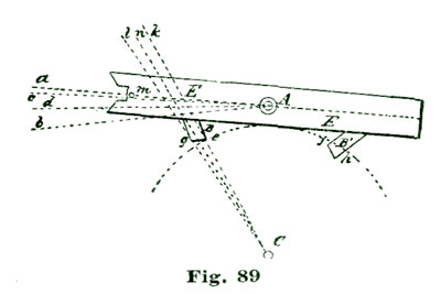
The angular motion between the lines a c (which represents the lock)
is not only absolutely lost—wasted—but during this movement the train
has to retrograde; that is, the dynamic force stored in the momentum of
the balance has to actually turn the train backward and against the
force of the mainspring. True, it is only through a very short arc, but
the necessary force to effect this has to be discounted from the power
stored in the balance from a former impulse. For this reason we should
make the angular motion of unlocking as brief as possible. Grossmann, in
his essay, endorses one and a half degrees as the proper lock.
In the description which we employed in describing the large model for
illustrating the action of the detached lever escapement, we cut the
lock to one degree, and in the description of the up-to-date lever
escapement, which we shall hereafter give, we shall cut the lock down to
three-quarters of a degree, a perfection easily to be attained by modern
tools and appliances. We shall also cut the drop down to three-quarters
of a degree. By these two economies we more than make up for the power
lost in unlocking. With highly polished ruby or sapphire pallets ten
degrees of draw is ample. But such draw must positively be ten degrees
from a neutral locking face, not an escapement drawn on paper and
called ten degrees, but when actually measured would only show eight and
a half or nine degrees.
With ten degrees angular motion of the lever and one and a half degrees
lock, we should have eight and a half degrees impulse. The pith of the
problem, as regards pallet action, for the practical workman can be
embodied in the following question: What proportion of the power derived
from the twelve degrees of angular motion of the escape wheel is really
conveyed to the fork? The great leak of power as transmitted by the
lever escapement to the balance is to be found in the pallet action, and
we shall devote special attention to finding and stopping such leaks.
If we use a ratchet-tooth escape wheel we must allow at least one and a
half degrees drop to free the back of the tooth; but with a club-tooth
escape wheel made as can be constructed by proper skill and care, the
drop can be cut down to three-quarters of a degree, or one-half of the
loss with the ratchet tooth. We do not wish our readers to imagine that
such a condition exists in most of the so-called fine watches, because
if we take the trouble to measure the actual drop with one of the little
instruments we have described, it will be found that the drop is seldom
less than two, or even three degrees.
If we measure the angular movement of the fork while locked, it will
seldom be found less than two or three degrees. Now, we can all
understand that the friction of the locking surface has to be counted as
well as the recoil of the draw. Locking friction is seldom looked after
as carefully as the situation demands. Our factories make the impulse
face of the pallets rounded, but leave the locking face flat. We are
aware this condition is, in a degree, necessary from the use of exposed
pallets. In many of the English lever watches with ratchet teeth, the
locking faces are made cylindrical, but with such watches the pallet
stones, as far as the writer has seen, are set "close"; that is, with
steel pallet arms extending above and below the stone.
There is another feature of the club-tooth lever escapement that next
demands our attention which we have never seen discussed. We refer to
arranging and disposing of the impulse of the escape wheel to meet the
resistance of the hairspring. Let us imagine the dotted line A d, Fig.
89, to represent the center of action of the fork. We can readily see
that the fork in a state of rest would stand half way between the two
banks from the action of the hairspring, and in the pallet action the
force of the escape wheel, one tooth of which rests on the impulse face
of a pallet, would be exerted against the elastic force of the
hairspring. If the force of the mainspring, as represented by the
escape-wheel tooth, is superior to the power of the hairspring, the
watch starts itself. The phases of this important part of the detached
lever escapement will be fully discussed.
We will now take up a study of the detached lever escapement as relates
to pallet action, with the point specially in view of constructing an
escapement which cannot "set" in the pocket, or, in other words, an
escapement which will start after winding (if run down) without shaking
or any force other than that supplied by the train as impelled by the
mainspring. In the drawing at Fig. 90 we propose to utilize eleven
degrees of escape-wheel action, against ten and a half, as laid down by
Grossmann. Of this eleven degrees we propose to divide the impulse arc
of the escape wheel in six and five degrees, six to be derived from the
impulse face of the club tooth and five from the impulse plane of the
pallet.
The pallet action we divide into five and four, with one degree of lock.
Five degrees of pallet action is derived from the impulse face of the
tooth and four from the impulse face of the pallet. The reader will
please bear in mind that we do not give these proportions as imperative,
because we propose to give the fullest evidence into the reader's hands
and enable him to judge for himself, as we do not believe in laying down
imperious laws that the reader must accept on our assertion as being
correct. Our idea is rather to furnish the proper facts and put him in a
situation to know for himself.
The reader is urged to make the drawings for himself on a large scale,
say, an escape wheel 10" pitch diameter. Such drawings will enable him
to realize small errors which have been tolerated too much in drawings
of this kind. The drawings, as they appear in the cut, are one-fourth
the size recommended, and many of the lines fail to show points we
desire to call attention to. As for instance, the pallet center at B
is tangential to the pitch circle a from the point of tooth contact at
f. To establish this point we draw the radial lines A c and A d
from the escape-wheel center A, as shown, by laying off thirty degrees
on each side of the intersection of the vertical line i (passing
through the centers A B) with the arc a, and then laying off two and
a half degrees on a and establishing the point f, and through f
from the center A draw the radial line A f'. Through the point f
we draw the tangent line b' b b'', and at the intersection of the line
b with i we establish the center of our pallet staff at B. At two
and a half degrees from the point c we lay off two and a half degrees
to the right of said point and establish the point n, and draw the
radial line A n n', which establishes the extent of the arc of angular
motion of the escape wheel utilized by the pallet arm.
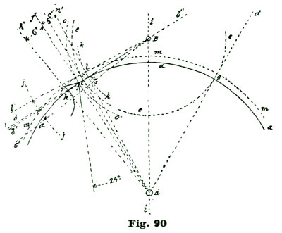
We have now come to the point where we must exercise our reasoning
powers a little. We know the locking angle of the escape-wheel tooth
passes on the arc a, and if we utilize the impulse face of the tooth
for five degrees of pallet or lever motion we must shape it to this end.
We draw the short arc k through the point n, knowing that the inner
angle of the pallet stone must rest on this arc wherever it is situated.
As, for instance, when the locking face of the pallet is engaged, the
inner angle of the pallet stone must rest somewhere on this arc (k)
inside of a, and the extreme outer angle of the impulse face of the
tooth must part with the pallet on this arc k.
With the parts related to each other as shown in the cut, to establish
where the inner angle of the pallet stone is located in the drawing, we
measure down on the arc k five degrees from its intersection with a,
and establish the point s. The line B b, Fig. 90, as the reader will
see, does not coincide with the intersection of the arcs a and k,
and to conveniently get at the proper location for the inner angle of
our pallet stone, we draw the line B b', which passes through the
point n located at the intersection of the arc a with the arc k.
From B as a center we sweep the short arc j with any convenient
radius of which we have a sixty-degree scale, and from the intersection
of B b' with j we lay off five degrees and draw the line B s',
which establishes the point s on the arc k. As stated above, we
allow one degree for lock, which we establish on the arc o by laying
off one degree on the arc j below its intersection with the line B
b. We do not show this line in the drawing, from the fact that it comes
so near to B b' that it would confuse the reader. Above the arc a on
the arc k at five degrees from the point n we establish the point
l, by laying off five degrees on the arc j above the intersection of
the line B b with j.
The point l, Fig. 90, establishes where the outer angle of the tooth
will pass the arc k to give five degrees of angular motion to the
lever. From A as a center we sweep the arc m, passing through the
point l. The intersection of the arc m with the line A h we call
the point r, and by drawing the right line r f we delineate the
impulse face of the tooth. On the arc o and one degree below its
intersection with the line B b we establish the point t, and by
drawing a right line from t to s we delineate the impulse face of
our entrance pallet.
One great fault with most of our text books on horology lies in the fact
that when dealing with the detached lever escapement the drawings show
only the position of the pallets when locked, and many of the conditions
assumed are arrived at by mental processes, without making the proper
drawings to show the actual relation of the parts at the time such
conditions exist. For illustration, it is often urged that there is a
time in the action of the club-tooth lever escapement action when the
incline on the tooth and the incline on the pallet present parallel
surfaces, and consequently endure excessive friction, especially if the
oil is a little thickened.
We propose to make drawings to show the exact position and relation of
the entrance pallet and tooth at three intervals viz: (1) Locked; (2)
the position of the parts when the lever has performed one-half of its
angular motion; (3) when half of the impulse face of the tooth has
passed the pallet. The position of the entrance pallet when locked is
sufficiently well shown in Fig. 90 to give a correct idea of the
relations with the entrance pallet; and to conform to statement (2), as
above. We will now delineate the entrance pallet, not in actual contact,
however, with the pallet, because if we did so the lines we employed
would become confused. The methods we use are such that we can
delineate with absolute correctness either a pallet or tooth at any
point in its angular motion.
We have previously given instructions for drawing the pallet locked; and
to delineate the pallet after five degrees of angular motion, we have
only to conceive that we substitute the line s' for the line b'. All
angular motions and measurements for pallet actions are from the center
of the pallet staff at B. As we desire to now delineate the entrance
pallet, it has passed through five degrees of angular motion and the
inner angle s now lies on the pitch circle of the escape wheel, the
angular space between the lines b' s' being five degrees, the line
b''[**note: check this against the diagram-most other lines nave a
two-letter identification] reducing the impulse face to four degrees.
To delineate our locking face we draw a line at right angles to the line
B b'' from the point t, said point being located at the intersection
of the arc o with the line B b''. To draw a line perpendicular to B
b'' from the point t, we take a convenient space in our dividers and
establish on the line B b'' the points x x' at equal distances from
the point t. We open the dividers a little (no special distance) and
sweep the short arcs x'' x''', as shown at Fig. 91. Through the
intersection of the short arcs x'' x''' and to the point t we draw
the line t y. The reader will see from our former explanations that
the line t y represents the neutral plane of the locking face, and
that to have the proper draw we must delineate the locking face of our
pallet at twelve degrees. To do this we draw the line t x' at twelve
degrees to the line t y, and proceed to outline our pallet faces as
shown. We can now understand, after a moment's thought, that we can
delineate the impulse face of a tooth at any point or place we choose by
laying off six degrees on the arc m, and drawing radial lines from A
to embrace such arc. To illustrate, suppose we draw the radial lines w'
w'' to embrace six degrees on the arc a. We make these lines
contiguous to the entrance pallet C for convenience only. To delineate
the impulse face of the tooth, we draw a line extending from the
intersection of the radial line A' w' with the arc m to the
intersection of the arc a with the radial line A w''.
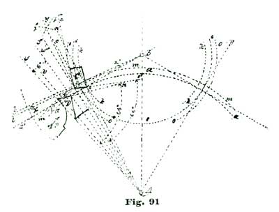
We next desire to know where contact will take place between the
wheel-tooth D and pallet C. To determine this we sweep, with our
dividers set so one leg rests at the escape-wheel center A and the
other at the outer angle t of the entrance pallet, the short arc t'
w. Where this arc intersects the line w (which represents the impulse
face of the tooth) is where the outer angle t of the entrance pallet
C will touch the impulse face of the tooth. To prove this we draw the
radial line A v through the point where the short arc t t' passes
through the impulse face w of the tooth D. Then we continue the line
w to n, to represent the impulse face of the tooth, and then measure
the angle A w n between the lines w n and v A, and find it to be
approximately sixty-four degrees. We then, by a similar process, measure
the angle A t s' and find it to be approximately sixty-six degrees.
When contact ensues between the tooth D and pallet C the tooth D
will attack the pallet at the point where the radial line A v crosses
the tooth face. We have now explained how we can delineate a tooth or
pallet at any point of its angular motion, and will next explain how to
apply this knowledge in actual practice.
To delineate our entrance pallet after one-half of the engaged tooth has
passed the inner angle of the entrance pallet, we proceed, as in former
illustrations, to establish the escape-wheel center at A, and from it
sweep the arc b, to represent the pitch circle. We next sweep the
short arcs p s, to represent the arcs through which the inner and
outer angles of the entrance pallet move. Now, to comply with our
statement as above, we must draw the tooth as if half of it has passed
the arc s.
To do this we draw from A as a center the radial line A j, passing
through the point s, said point s being located at the intersection
of the arcs s and b. The tooth D is to be shown as if one half of
it has passed the point s; and, consequently, if we lay off three
degrees on each side of the point s and establish the points d m, we
have located on the arc b the angular extent of the tooth to be drawn.
To aid in our delineations we draw from the center A the radial lines
A d' and A m', passing through the points d m. The arc a is next
drawn as in former instructions and establishes the length of the
addendum of the escape-wheel teeth, the outer angle of our escape-wheel
tooth being located at the intersection of the arc a with the radial
line A d'.
As shown in Fig. 92, the impulse planes of the tooth D and pallet C
are in contact and, consequently, in parallel planes, as mentioned on
page 91. It is not an easy matter to determine at exactly what degree of
angular motion of the escape wheel such condition takes place; because
to determine such relation mathematically requires a knowledge of higher
mathematics, which would require more study than most practical men
would care to bestow, especially as they would have but very little use
for such knowledge except for this problem and a few others in dealing
with epicycloidal curves for the teeth of wheels.
For all practical purposes it will make no difference whether such
parallelism takes place after eight or nine degrees of angular motion of
the escape wheel subsequent to the locking action. The great point, as
far as practical results go, is to determine if it takes place at or
near the time the escape wheel meets the greatest resistance from the
hairspring. We find by analysis of our drawing that parallelism takes
place about the time when the tooth has three degrees of angular motion
to make, and the pallet lacks about two degrees of angular movement for
the tooth to escape. It is thus evident that the relations, as shown in
our drawing, are in favor of the train or mainspring power over
hairspring resistance as three is to two, while the average is only as
eleven to ten; that is, the escape wheel in its entire effort passes
through eleven degrees of angular motion, while the pallets and fork
move through ten degrees. The student will thus see we have arranged to
give the train-power an advantage where it is most needed to overcome
the opposing influence of the hairspring.
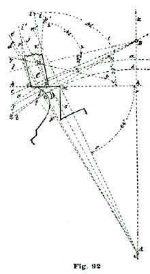
As regards the exalted adhesion of the parallel surfaces, we fancy there
is more harm feared than really exists, because, to take the worst view
of the situation, such parallelism only exists for the briefest
duration, in a practical sense, because theoretically these surfaces
never slide on each other as parallel planes. Mathematically
considered, the theoretical plane represented by the impulse face of
the tooth approaches parallelism with the plane represented by the
impulse face of the pallet, arrives at parallelism and instantly passes
away from such parallelism.
As delineated in Fig. 92, the impulse planes of the tooth and pallet are
in contact; but we have it in our power to delineate the pallet at any
point we choose between the arcs p s. To describe and illustrate the
above remark, we say the lines B e and B f embrace five degrees of
angular motion of the pallet. Now, the impulse plane of the pallet
occupies four of these five degrees. We do not draw a radial line from
B inside of the line B e to show where the outer angle of the
impulse plane commences, but the reader will see that the impulse plane
is drawn one degree on the arc p below the line B e. We continue the
line h h to represent the impulse face of the tooth, and measure the
angle B n h and find it to be twenty-seven degrees. Now suppose we
wish to delineate the entrance pallet as if not in contact with the
escape-wheel tooth—for illustration, say, we wish the inner angle of
the pallet to be at the point v on the arc s. We draw the radial
line B l through v; and if we draw another line so it passes through
the point v at an angle of twenty-seven degrees to B l, and continue
said line so it crosses the arc p, we delineate the impulse face of
our pallet.
We measure the angle i n B, Fig. 92, and find it to be seventy-four
degrees; we draw the line v t to the same angle with v B, and we
define the inner face of our pallet in the new position. We draw a line
parallel with v t from the intersection of the line v y with the arc
p, and we define our locking face. If now we revolve the lines we have
just drawn on the center B until the line l B coincides with the
line f B, we will find the line y y to coincide with h h, and the
line v v' with n i.
We have now instructed the reader how to delineate either tooth or
pallet in any conceivable position in which they can be related to each
other. Probably nothing has afforded more efficient aid to practical
mechanics than has been afforded by the graphic solution of abstruce
mathematical problems; and if we add to this the means of correction by
mathematical calculations which do not involve the highest mathematical
acquirements, we have approached pretty close to the actual requirements
of the practical watchmaker.
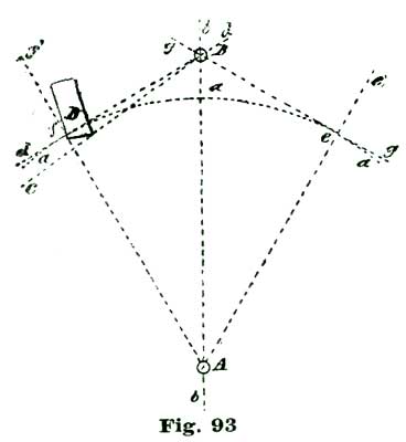
To better explain what we mean, we refer the reader to Fig. 93, where we
show preliminary drawings for delineating a lever escapement. We wish to
ascertain by the graphic method the distance between the centers of
action of the escape wheel and the pallet staff. We make our drawing
very carefully to a given scale, as, for instance, the radius of the arc
a is 5". After the drawing is in the condition shown at Fig. 93 we
measure the distance on the line b between the points (centers) A B,
and we thus by graphic means obtain a measure of the distance between A
B. Now, by the use of trigonometry, we have the length of the line A
f (radius of the arc a) and all the angles given, to find the length
of f B, or A B, or both f B and A B. By adopting this policy we
can verify the measurements taken from our drawings. Suppose we find by
the graphic method that the distance between the points A B is 5.78",
and by trigonometrical computation find the distance to be 5.7762". We
know from this that there is .0038" to be accounted for somewhere; but
for all practical purposes either measurement should be satisfactory,
because our drawing is about thirty-eight times the actual size of the
escape wheel of an eighteen-size movement.
Let us further suppose the diameter of our actual escape wheel to be
.26", and we were constructing a watch after the lines of our drawing.
By "lines," in this case, we mean in the same general form and ratio of
parts; as, for illustration, if the distance from the intersection of
the arc a with the line b to the point B was one-fifteenth of the
diameter of the escape wheel, this ratio would hold good in the actual
watch, that is, it would be the one-fifteenth part of .26". Again,
suppose the diameter of the escape wheel in the large drawing is 10" and
the distance between the centers A B is 5.78"; to obtain the actual
distance for the watch with the escape wheel .26" diameter, we make a
statement in proportion, thus: 10 : 5.78 :: .26 to the actual distance
between the pivot holes of the watch. By computation we find the
distance to be .15". These proportions will hold good in every part of
actual construction.
All parts—thickness of the pallet stones, length of pallet arms,
etc.—bear the same ratio of proportion. We measure the thickness of the
entrance pallet stone on the large drawing and find it to be .47"; we
make a similar statement to the one above, thus: 10 : .47 :: .26 to the
actual thickness of the real pallet stone. By computation we find it to
be .0122". All angular relations are alike, whether in the large drawing
or the small pallets to match the actual escape wheel .26" in diameter.
Thus, in the pallet D, Fig. 93, the impulse face, as reckoned from B
as a center, would occupy four degrees.
Reason would suggest the idea of having the theoretical keep pace and
touch with the practical. It has been a grave fault with many writers on
horological matters that they did not make and measure the abstractions
which they delineated on paper. We do not mean by this to endorse the
cavil we so often hear—"Oh, that is all right in theory, but it will
not work in practice." If theory is right, practice must conform to it.
The trouble with many theories is, they do not contain all the elements
or factors of the problem.
Near the beginning of this treatise we advised our readers to make a
large model, and described in detail the complete parts for such a
model. What we propose now is to make adjustable the pallets and fork to
such a model, in order that we can set them both right and wrong, and
thus practically demonstrate a perfect action and also the various
faults to which the lever escapement is subject. The pallet arms are
shaped as shown at A, Fig. 94. The pallets B B' can be made of steel
or stone, and for all practical purposes those made of steel answer
quite as well, and have the advantage of being cheaper. A plate of sheet
brass should be obtained, shaped as shown at C, Fig. 95. This plate is
of thin brass, about No. 18, and on it are outlined the pallet arms
shown at Fig. 94.
To make the pallets adjustable, they are set in thick disks of sheet
brass, as shown at D, Figs. 95, 96 and 97. At the center of the plate
C is placed a brass disk E, Fig. 98, which serves to support the
lever shown at Fig. 99. This disk E is permanently attached to the
plate C. The lever shown at Fig. 99 is attached to the disk E by two
screws, which pass through the holes h h. If we now place the brass
pieces D D' on the plate C in such a way that the pallets set in
them correspond exactly to the pallets as outlined on the plate C, we
will find the action of the pallets to be precisely the same as if the
pallet arms A A', Fig. 94, were employed.
To enable us to practically experiment with and to fully demonstrate all
the problems of lock, draw, drop, etc., we make quite a large hole in
C where the screws b come. To explain, if the screws b b were
tapped directly into C, as they are shown at Fig. 95, we could only
turn the disk D on the screw b; but if we enlarge the screw hole in
C to three or four times the natural diameter, and then place the nut
e under C to receive the screw b, we can then set the disks D D'
and pallets B B' in almost any relation we choose to the escape wheel,
and clamp the pallets fast and try the action. We show at Fig. 97 a view
of the pallet B', disk D' and plate C (seen in the direction of
the arrow c) as shown in Fig. 95.
It will be noticed in Fig. 99 that the hole g for the pallet staff in
the lever is oblong; this is to allow the lever to be shifted back and
forth as relates to roller and fork action. We will not bother about
this now, and only call attention to the capabilities of such
adjustments when required. At the outset we will conceive the fork F
attached to the piece E by two screws passing through the holes h h,
Fig. 99. Such an arrangement will insure the fork and roller action
keeping right if they are put right at first. Fig. 100 will do much to
aid in conveying a clear impression to the reader.
The idea of the adjustable features of our escapement model is to show
the effects of setting the pallets wrong or having them of bad form. For
illustration, we make use of a pallet with the angle too acute, as shown
at B''', Fig. 101. The problem in hand is to find out by mechanical
experiments and tests the consequences of such a change. It is evident
that the angular motion of the pallet staff will be increased, and that
we shall have to open one of the banking pins to allow the engaging
tooth to escape. To trace out all the consequences of this one little
change would require a considerable amount of study, and many drawings
would have to be made to illustrate the effects which would naturally
follow only one such slight change.
Suppose, for illustration, we should make such a change in the pallet
stone of the entrance pallet; we have increased the angle between the
lines k l by (say) one and a half degrees; by so doing we would
increase the lock on the exit pallet to three degrees, provided we were
working on a basis of one and a half degrees lock; and if we pushed back
the exit pallet so as to have the proper degree of lock (one and a half)
on it, the tooth which would next engage the entrance pallet would not
lock at all, but would strike the pallet on the impulse instead of on
the locking face. Again, such a change might cause the jewel pin to
strike the horn of the fork, as indicated at the dotted line m, Fig.
99.
Dealing with such and similar abstractions by mental process requires
the closest kind of reasoning; and if we attempt to delineate all the
complications which follow even such a small change, we will find the
job a lengthy one. But with a large model having adjustable parts we
provide ourselves with the means for the very best practical solution,
and the workman who makes and manipulates such a model will soon master
the lever escapement.
Some years ago a young watchmaker friend of the writer made, at his
suggestion, a model of the lever escapement similar to the one
described, which he used to "play with," as he termed it—that is, he
would set the fork and pallets (which were adjustable) in all sorts of
ways, right ways and wrong ways, so he could watch the results. A
favorite pastime was to set every part for the best results, which was
determined by the arc of vibration of the balance. By this sort of
training he soon reached that degree of proficiency where one could no
more puzzle him with a bad lever escapement than you could spoil a meal
for him by disarranging his knife, fork and spoon.
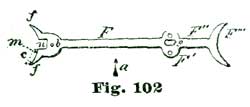
Let us, as a practical example, take up the consideration of a short
fork. To represent this in our model we take a lever as shown at Fig.
99, with the elongated slot for the pallet staff at g. To facilitate
the description we reproduce at Fig. 102 the figure just mentioned, and
also employ the same letters of reference. We fancy everybody who has
any knowledge of the lever escapement has an idea of exactly what a
"short fork" is, and at the same time it would perhaps puzzle them a
good deal to explain the difference between a short fork and a roller
too small.
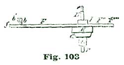
In our practical problems, as solved on a large escapement model, say we
first fit our fork of the proper length, and then by the slot g move
the lever back a little, leaving the bankings precisely as they were.
What are the consequences of this slight change? One of the first
results which would display itself would be discovered by the guard pin
failing to perform its proper functions. For instance, the guard pin
pushed inward against the roller would cause the engaged tooth to pass
off the locking face of the pallet, and the fork, instead of returning
against the banking, would cause the guard pin to "ride the roller"
during the entire excursion of the jewel pin. This fault produces a
scraping sound in a watch. Suppose we attempt to remedy the fault by
bending forward the guard pin b, as indicated by the dotted outline
b' in Fig. 103, said figure being a side view of Fig. 102 seen in the
direction of the arrow a. This policy would prevent the engaged pallet
from passing off of the locking face of the pallet, but would be
followed by the jewel pin not passing fully into the fork, but striking
the inside face of the prong of the fork at about the point indicated by
the dotted line m. We can see that if the prong of the fork was
extended to about the length indicated by the outline at c, the action
would be as it should be.
To practically investigate this matter to the best advantage, we need
some arrangement by which we can determine the angular motion of the
lever and also of the roller and escape wheel. To do this, we provide
ourselves with a device which has already been described, but of smaller
size, for measuring fork and pallet action. The device to which we
allude is shown at Figs. 104, 105 and 106. Fig. 104 shows only the index
hand, which is made of steel about 1/20" thick and shaped as shown. The
jaws B'' are intended to grasp the pallet staff by the notches e,
and hold by friction. The prongs l l are only to guard the staff so it
will readily enter the notch e. The circle d is only to enable us to
better hold the hand B flat.
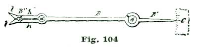
From the center of the notches e to the tip of the index hand B' the
length is 2". This distance is also the radius of the index arc C.
This index arc is divided into thirty degrees, with three or four
supplementary degrees on each side, as shown. For measuring pallet
action we only require ten degrees, and for roller action thirty
degrees. The arc C, Fig. 105, can be made of brass and is about 1-1/2"
long by 1/4" wide; said arc is mounted on a brass wire about 1/8"
diameter, as shown at k, Fig. 106, which is a view of Fig. 105 seen in
the direction of the arrow i. This wire k enters a base shown at D
E, Fig. 106, which is provided with a set-screw at j for holding the
index arc at the proper height to coincide with the hand B.
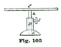
A good way to get up the parts shown in Fig. 106 is to take a disk of
thick sheet brass about 1" in diameter and insert in it a piece of brass
wire about 1/4" diameter and 3/8" long, through which drill axially a
hole to receive the wire k. After the jaws B'' are clamped on the
pallet staff, we set the index arc C so the hand B' will indicate
the angular motion of the pallet staff. By placing the index hand B
on the balance staff we can get at the exact angular duration of the
engagement of the jewel pin in the fork.
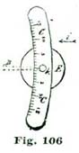
Of course, it is understood that this instrument will also measure the
angles of impulse and lock. Thus, suppose the entire angular motion of
the lever from bank to bank is ten degrees; to determine how much of
this is lock and how much impulse, we set the index arc C so that the
hand B' marks ten degrees for the entire motion of the fork, and when
the escapement is locked we move the fork from its bank and notice by
the arc C how many degrees the hand indicated before it passed of its
own accord to the opposite bank. If we have more than one and a half
degrees of lock we have too much and should seek to remedy it. How? It
is just the answers to such questions we propose to give by the aid of
our big model.
"Be sure you are right, then go ahead," was the advice of the celebrated
Davie Crockett. The only trouble in applying this motto to watchmaking
is to know when you are right. We have also often heard the remark that
there was only one right way, but any number of wrong ways. Now we are
inclined to think that most of the people who hold to but one right way
are chiefly those who believe all ways but their own ways are wrong.
Iron-bound rules are seldom sound even in ethics, and are utterly
impracticable in mechanics.
We have seen many workmen who had learned to draw a lever escapement of
a given type, and lived firm in the belief that all lever escapements
were wrong which were not made so as to conform to this certain method.
One workman believes in equidistant lockings, another in circular
pallets; each strong in the idea that their particular and peculiar
method of designing a lever escapement was the only one to be tolerated.
The writer is free to confess that he has seen lever escapements of both
types, that is, circular pallets and equidistant lockings, which gave
excellent results.
Another mooted point in the lever escapement is, to decide between the
merits of the ratchet and the club-tooth escape wheel. English makers,
as a rule, hold to the ratchet tooth, while Continental and American
manufacturers favor the club tooth. The chief arguments in favor of the
ratchet tooth are: (a) It will run without oiling the pallets; (b)
in case the escape wheel is lost or broken it is more readily replaced,
as all ratchet-tooth escape wheels are alike, either for circular
pallets or equidistant lockings. The objections urged against it are:
(a) Excessive drop; (b) the escape wheel, being frail, is liable to
be injured by incompetent persons handling it; (c) this escapement in
many instances does require to have the pallets oiled.
(a) That a ratchet-tooth escape wheel requires more drop than a club
tooth must be admitted without argument, as this form of tooth requires
from one-half to three-fourths of a degree more drop than a club tooth;
(b) as regards the frailty of the teeth we hold this as of small
import, as any workman who is competent to repair watches would never
injure the delicate teeth of an escape wheel; (c) ratchet-tooth lever
escapements will occasionally need to have the pallets oiled. The writer
is inclined to think that this defect could be remedied by proper care
in selecting the stone (ruby or sapphire) and grinding the pallets in
such a way that the escape-wheel teeth will not act against the
foliations with which all crystalline stones are built up.
All workmen who have had an extended experience in repair work are well
aware that there are some lever escapements in which the pallets
absolutely require oil; others will seem to get along very nicely
without. This applies also to American brass club-tooth escapements;
hence, we have so much contention about oiling pallets. The writer does
not claim to know positively that the pallet stones are at fault because
some escapements need oiling, but the fact must admit of explanation
some way, and is this not at least a rational solution? All persons who
have paid attention to crystallography are aware that crystals are built
up, and have lines of cleavage. In the manufacture of hole jewels, care
must be taken to work with the axis of crystallization, or a smooth hole
cannot be obtained.
The advantages claimed for the club-tooth escapement are many; among
them may be cited (a) the fact that it utilizes a greater arc of
impulse of the escape wheel; (b) the impulse being divided between the
tooth and the pallet, permits greater power to be utilized at the close
of the impulse. This feature we have already explained. It is no doubt
true that it is more difficult to match a set of pallets with an escape
wheel of the club-tooth order than with a ratchet tooth; still the
writer thinks that this objection is of but little consequence where a
workman knows exactly what to do and how to do it; in other words, is
sure he is right, and can then go ahead intelligently.
It is claimed by some that all American escape wheels of a given grade
are exact duplicates; but, as we have previously stated, this is not
exactly the case, as they vary a trifle. So do the pallet jewels vary a
little in thickness and in the angles. Suppose we put in a new escape
wheel and find we have on the entrance pallet too much drop, that is,
the tooth which engaged this pallet made a decided movement forward
before the tooth which engaged the exit pallet encountered the locking
face of said pallet. If we thoroughly understand the lever escapement we
can see in an instant if putting in a thicker pallet stone for entrance
pallet will remedy the defect. Here again we can study the effects of a
change in our large model better than in an escapement no larger than is
in an ordinary watch.
There have been many devices brought forward to aid the workman in
adjusting the pallet stones to lever watches. Before going into the
details of any such device we should thoroughly understand exactly what
we desire to accomplish. In setting pallet stones we must take into
consideration the relation of the roller and fork action. As has already
been explained, the first thing to do is to set the roller and fork
action as it should be, without regard in a great degree to pallet
action.
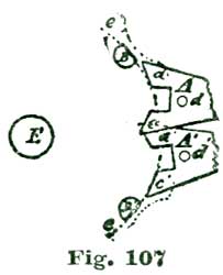
To explain, suppose we have a pallet stone to set in a full-plate
movement. The first thing to do is to close the bankings so that the
jewel pin will not pass out of the slot in the fork on either side; then
gradually open the bankings until the jewel pin will pass out. This will
be understood by inspecting Fig. 107, where A A' shows a lever fork as
if in contact with both banks, and the jewel pin, represented at B
B'', just passes the angle a c' of the fork. The circle described by
the jewel pin B is indicated by the arc e. It is well to put a
slight friction under the balance rim, in order that we can try the
freedom of the guard pin. As a rule, all the guard pin needs is to be
free and not touch the roller. The entire point, as far as setting the
fork and bankings is concerned, is to have the fork and roller action
sound. For all ordinary lever escapements the angular motion of the
lever banked in as just described should be about ten degrees. As
explained in former examples, if the fork action is entirely sound and
the lever only vibrates through an arc of nine degrees, it is quite as
well to make the pallets conform to this arc as to make the jewel pin
carry the fork through full ten degrees. Again, if the lever vibrates
through eleven degrees, it is as well to make the pallets conform to
this arc.
The writer is well aware that many readers will cavil at this idea and
insist that the workman should bring all the parts right on the basis of
ten degrees fork and lever action. In reply we would say that no
escapement is perfect, and it is the duty of the workman to get the best
results he can for the money he gets for the job. In the instance given
above, of the escapement with nine degrees of lever action, when the
fork worked all right, if we undertook to give the fork the ten degrees
demanded by the stickler for accuracy we would have to set out the jewel
pin or lengthen the fork, and to do either would require more time than
it would to bring the pallets to conform to the fork and roller action.
It is just this knowing how and the decision to act that makes the
difference in the workman who is worth to his employer twelve or
twenty-five dollars per week.
We have described instruments for measuring the angle of fork and pallet
action, but after one has had experience he can judge pretty nearly and
then it is seldom necessary to measure the angle of fork action as long
as it is near the proper thing, and then bring the pallets to match the
escape wheel after the fork and roller action is as it should be—that
is, the jewel pin and fork work free, the guard pin has proper freedom,
and the fork vibrates through an arc of about ten degrees.
Usually the workman can manipulate the pallets to match the escape wheel
so that the teeth will have the proper lock and drop at the right
instant, and again have the correct lock on the next succeeding pallet.
The tooth should fall but a slight distance before the tooth next in
action locks it, because all the angular motion the escape wheel makes
except when in contact with the pallets is just so much lost power,
which should go toward giving motion to the balance.
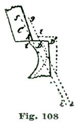
There seems to be a little confusion in the use of the word "drop" in
horological phrase, as it is used to express the act of parting of the
tooth with the pallet. The idea will be seen by inspecting Fig. 108,
where we show the tooth D and pallet C as about parting or dropping.
When we speak of "banking up to the drop" we mean we set the banking
screws so that the teeth will just escape from each pallet. By the term
"fall" we mean the arc the tooth passes through before the next pallet
is engaged. This action is also illustrated at Fig. 108, where the tooth
D, after dropping from the pallet C, is arrested at the position
shown by the dotted outline. We designate this arc by the term "fall,"
and we measure this motion by its angular extent, as shown by the dotted
radial lines i f and i g. As we have explained, this fall should
only extend through an arc of one and a half degrees, but by close
escapement matching this arc can be reduced to one degree, or even a
trifle less.
We shall next describe an instrument for holding the escape wheel and
pallets while adjusting them. As shown at Fig. 107, the fork A' is
banked a little close and the jewel pin as shown would, in some
portions, rub on C', making a scraping sound.
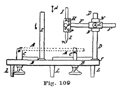
A point has now been reached where we can use an escapement matcher to
advantage. There are several good ones on the market, but we can make
one very cheaply and also add our own improvements. In making one, the
first thing to be provided is a movement holder. Any of the three-jaw
types of such holders will answer, provided the jaws hold a movement
plate perfectly parallel with the bed of the holder. This will be better
understood by inspecting Fig. 109, which is a side view of a device of
this kind seen edgewise in elevation. In this B represents the bed
plate, which supports three swing jaws, shown at C, Figs. 109 and 110.
The watch plate is indicated by the parallel dotted lines A, Fig. 109.
The seat a of the swing jaws C must hold the watch plate A exactly
parallel with the bed plate B. In the cheap movement holders these
seats (a) are apt to be of irregular heights, and must be corrected
for our purpose. We will take it for granted that all the seats a are
of precisely the same height, measured from B, and that a watch plate
placed in the jaws C will be held exactly parallel with the said bed
B. We must next provide two pillars, shown at D E, Figs. 109 and
111. These pillars furnish support for sliding centers which hold the
top pivots of the escape wheel and pallet staff while we are testing the
depths and adjusting the pallet stones. It will be understood that these
pillars D E are at right angles to the plane of the bed B, in order
that the slides like G N on the pillars D E move exactly vertical.
In fact, all the parts moving up and down should be accurately made, so
as not to destroy the depths taken from the watch plate A. Suppose, to
illustrate, that we place the plate A in position as shown, and insert
the cone point n, Figs. 109 and 112, in the pivot hole for the pallet
staff, adjusting the slide G N so that the cone point rests accurately
in said pivot hole. It is further demanded that the parts I H F G N D
be so constructed and adjusted that the sliding center I moves truly
vertical, and that we can change ends with said center I and place the
hollow cone end m, Fig. 112, so it will receive the top pivot of the
pallet staff and hold it exactly upright.
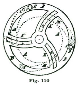
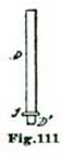
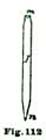
The idea of the sliding center I is to perfectly supply the place of
the opposite plate of the watch and give us exactly the same practical
depths as if the parts were in their place between the plates of the
movement. The foot of the pillar D has a flange attached, as shown at
f, which aids in holding it perfectly upright. It is well to cut a
screw on D at D', and screw the flange f on such screw and then
turn the lower face of f flat to aid in having the pillar D
perfectly upright.
It is well to fit the screw D' loosely, so that the flange f will
come perfectly flat with the upper surface of the base plate B. The
slide G N on the pillar D can be made of two pieces of small brass
tube, one fitting the pillar D and the other the bar F. The slide G
N is held in position by the set screw g, and the rod F by the set
screw h.
The piece H can be permanently attached to the rod F. We show
separate at Figs. 113 and 114 the slide G N on an enlarged scale from
Fig. 109. Fig. 114 is a view of Fig. 113 seen in the direction of the
arrow e. All joints and movable parts should work free, in order that
the center I may be readily and accurately set. The parts H F are
shown separate and enlarged at Figs. 115 and 116. The piece H can be
made of thick sheet brass securely attached to F in such a way as to
bring the V-shaped groove at right angles to the axis of the rod F. It
is well to make the rod F about 1/8" in diameter, while the sliding
center I need not be more than 1/16" in diameter. The cone point n
should be hardened to a spring temper and turned to a true cone in an
accurately running wire chuck.
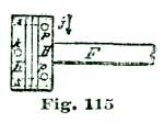
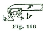
The hollow cone end m of I should also be hardened, but this is best
done after the hollow cone is turned in. The hardening of both ends
should only be at the tips. The sliding center I can be held in the
V-shaped groove by two light friction springs, as indicated at the
dotted lines s s, Fig. 115, or a flat plate of No. 24 or 25 sheet
brass of the size of H can be employed, as shown at Figs. 116 and 117,
where o represents the plate of No. 24 brass, p p the small screws
attaching the plate o to H, and k a clamping screw to fasten I
in position. It will be found that the two light springs s s, Fig. 115
will be the most satisfactory. The wire legs, shown at L, will aid in
making the device set steady. The pillar E is provided with the same
slides and other parts as described and illustrated as attached to D.
The position of the pillars D and E are indicated at Fig. 110.
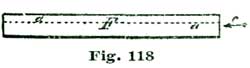
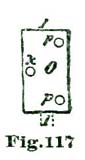

We will next tell how to flatten F to keep H exactly vertical. To
aid in explanation, we will show (enlarged) at Fig. 118 the bar F
shown in Fig. 109. In flattening such pieces to prevent turning, we
should cut away about two-fifths, as shown at Fig. 119, which is an end
view of Fig. 118 seen in the direction of the arrow c. In such
flattening we should not only cut away two-fifths at one end, but we
must preserve this proportion from end to end. To aid in this operation
we make a fixed gage of sheet metal, shaped as shown at I, Fig. 120.

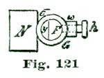
In practical construction we first file away about two-fifths of F and
then grind the flat side on a glass slab to a flat, even surface and, of
course, equal thickness from end to end. We reproduce the sleeve G as
shown at Fig. 113 as if seen from the left and in the direction of the
axis of the bar F. To prevent the bar F turning on its axis, we
insert in the sleeve G a piece of wire of the same size as F but
with three-fifths cut away, as shown at y, Fig. 121. This piece y is
soldered in the sleeve G so its flat face stands vertical. To give
service and efficiency to the screw h, we thicken the side of the
sleeve F by adding the stud w, through which the screw h works. A
soft metal plug goes between the screw h and the bar F, to prevent
F being cut up and marred. It will be seen that we can place the top
plate of a full-plate movement in the device shown at Fig. 109 and set
the vertical centers I so the cone points n will rest in the pivot
holes of the escape wheel and pallets. It is to be understood that the
lower side of the top plate is placed uppermost in the movement holder.
If we now reverse the ends of the centers I and let the pivots of the
escape wheel and pallet staff rest in the hollow cones of these centers
I, we have the escape wheel and pallets in precisely the same position
and relation to each other as if the lower plate was in position. It is
further to be supposed that the balance is in place and the cock screwed
down, although the presence of the balance is not absolutely necessary
if the banking screws are set as directed, that is, so the jewel pin
will just freely pass in and out of the fork.
We have now come to setting or manipulating the pallet stones so they
will act in exact conjunction with the fork and roller. To do this we
need to have the shellac which holds the pallet stones heated enough to
make it plastic. The usual way is to heat a piece of metal and place it
in close proximity to the pallets, or to heat a pair of pliers and clamp
the pallet arms to soften the cement.
Of course, it is understood that the movement holder cannot be moved
about while the stones are being manipulated. The better way is to set
the movement holder on a rather heavy plate of glass or metal, so that
the holder will not jostle about; then set the lamp so it will do its
duty, and after a little practice the setting of a pair of pallet stones
to perfectly perform their functions will take but a few minutes. In
fact, if the stones will answer at all, three to five minutes is as much
time as one could well devote to the adjustment. The reader will see
that if the lever is properly banked all he has to do is to set the
stones so the lock, draw and drop are right, when the entire escapement
is as it should be, and will need no further trial or manipulating.