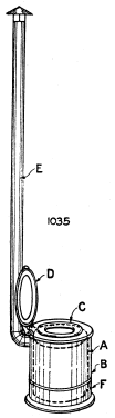
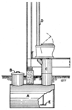
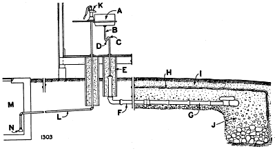
A tight, underground septic tank with shallow distribution of the
effluent in porous soil generally is the safest and least troublesome
method of treating sewage upon the farm, while at the same time
more or less of the irrigating and manurial value of the sewage may
be realized.
The late Professor Kinnicutt used to say that a septic tank is
"simply a cesspool, regulated and controlled." The reactions described
under the captions "How sewage decomposes" and "Cesspools"
take place in septic tanks.
In all sewage tanks, whatever their size and shape, a portion of
the solid matter, especially if the sewage contains much grease, floats
as scum on the liquid, the heavier solids settle to form sludge, while
finely divided solids and matter in a state of emulsion are held in
suspension. If the sludge is retained in the bottom of the tank and
converted or partly converted into liquids and gases, the tank is called
a septic tank and the process is known as septicization. The process
is sometimes spoken of as one of digestion or rotting.
History.—Prototypes of the septic tank were known in Europe
nearly 50 years ago. Between 1876 and 1393 a number of closed
tanks with submerged inlets and outlets embodying the principle of
storage of sewage and liquefaction of the solids were built in the
United States and Canada. It was later seen that many of the early
claims for the septic process were extravagant. In recent years
septic tanks have been used mainly in small installations, or, where
employed in large installations, the form has been modified to secure
digestion of the sludge in a separate compartment, thus in a measure
obviating disadvantages that exist where septicization takes place in
the presence of the entering fresh sewage.
Purposes.—The purposes of a septic tank are to receive all the farm
sewage, as defined on page 1, hold it in a quiet state for a time, thus
causing partial settlement of the solids, and by nature's processes
of decomposition insure, as fully as may be, the destruction of the
organic matter.
Limitations.—That a septic tank is a complete method of sewage
treatment is a widespread but wrong impression. A septic tank
does not eliminate odor and does not destroy all organic solids. On
the contrary, foul odors developed, and of all the suspended matter in
the sewage about one-third escapes with the effluent, about one-third
remains in the tank, and about one-third only is destroyed or reduced
to liquids and gases. The effluent is foul and dangerous. It may
contain even more bacteria than the raw sewage, since the process
involves intensive growths. As to the effects upon the growth and
virulence of disease germs little is known definitely. It is not believed
that such germs multiply under the conditions prevailing in a
septic tank. If disease germs are present, many of their number
along with other bacteria may pass through with the flow or may be
enmeshed in the settling solids and there survive a long time. Hence
the farmer should safeguard wells and springs from the seepage or
discharges from a septic tank as carefully as from those of cesspools.
Further treatment of effluents.—The effluent of a septic tank or any
other form of sewage tank is foul and dangerous. Whether or not
the solids are removed by screening, by short periods of rest, as in
plain or modified forms of settling tanks, or by longer quiescence,
as in septic tanks, the effluent generally requires further treatment
to reduce the number of harmful organisms and the liability of
nuisance. This further treatment usually consists of some mode of
filtration. In the earliest example of such treatment the sewage
was used to irrigate land by either broad flooding or furrow irrigation.
By another method the sewage is distributed underground by
means of drain tile laid with open joints, as illustrated in Figures
27 and 30.
Artificial sewage filters are composed of coarse sand, screened
gravel, broken stone, coke, or other material, and the sewage is
applied in numerous ways. Since, filtration is essentially an oxidizing
process requiring air, the sewage is applied intermittently in
doses.[9]
If properly designed and operated, filters of sand, coke, or stone
are capable of excellent results. Under the most favorable conditions
it is unwise to discharge the effluent of a sewage filter in the
near vicinity of a source of water supply. Under farm conditions
filters are usually neglected or the sewage is improperly applied,
resulting in the clogging and befouling of sand filters and the discharge
from stone filters of an effluent which is practically as dangerous
and even more offensive than raw sewage. Moreover unless the
filters are covered there are likely to be annoying odors, and there
is always the possibility of disease germs being carried by flies where
sewage is exposed in the vicinity of dwellings. Hence it seems more
practical for the farmer, avoiding the expense of earth embankments
or masonry sides and bottom for a filter bed, to waste the tank
effluent beneath the surface of such area of land as is most suitable
and available. This method of applying sewage to the soil or subsoil
is often spoken of as subirrigation, but subsoil distribution of
sewage is different in principle and practice from subirrigation for
the increase of crop yields. Subirrigation is rarely successful unless
the land is nearly level, the topsoil porous and underlaid with an
impervious stratum to hold the water within reach of plant roots,
and unless a relatively large quantity of water is used and the work
is skillfully done. On the other hand, the quantity of sewage on
farms being small, it may be wasted in hilly ground, which should be
as porous, deeply drained, and dry as possible.
Parts of a system.—The four parts of a septic-tank installation with
subsurface distribution of the effluent are outlined in Figure 17: (1)
The house sewer from house to tank; (2) the sewage tank consisting
of one or more chambers; (3) the sewer from tank to distribution
field; (4) the distribution field, where the sewage is distributed and
wasted, sometimes called the absorption field. These parts will be
discussed in the order named, although the last should have the first
consideration.
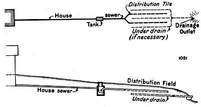
Fig. 17.—Parts of a septic-tank installation
House sewer.—The length will vary with the slope of the ground
and position of buildings, well, and distribution field. Fifty to 100
feet is a fair length; a greater is still more sanitary. Wherever possible
the house sewer should be laid straight in line and grade. Figure 18
shows how this work may be done. Suppose the distance from
A to E be 100 feet; that grade boards be set 25 feet apart crosswise
of the trench at A, B, C, D, and E; that the ground at A be 4 feet
lower than at E; that the top of the sewer be 2½ feet below the
surface of the ground at A and 4½ feet below the surface of the
ground at E; the fall of the sewer between A and E is 2 feet
(4 + 2½ - 4½ = 2). If the fall in 100 feet be 2 feet, in 25 feet it is
one-fourth as much, or 6 inches. Hence, grade board B is 6 inches
higher than grade board A, C is 6 inches higher than B, and so on
to E. The top edges when all the boards are set with a carpenter's
level and fastened in position should be in line. The grade thus
established may be any convenient height above the top of the proposed
sewer, and the measuring stick used to grade the pipe is cut
accordingly. This height is usually a certain number of whole feet.
Fixing the line of the sewer is a mere matter of setting nails in the
top edges of boards A and E directly over the center of the proposed
sewer and tightly stretching a fish line or grade cord; nails should
be set where the cord crosses boards B, C, and D.
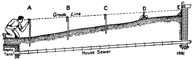
Fig. 18.—Setting line and grade for house sewer. To the observer at A the top edges of
the grade boards appear as one; the half-driven nails are set to line
If the cellar or basement contains plumbing fixtures, the house
sewer should enter 1 to 2 feet below the cellar floor. If all plumbing
fixtures are on the floors above, the sewer may enter at no greater
depth than necessary to insure protection from frost outside the cellar
wall. Digging the trench and laying the pipe should begin at the
tank or lower end. The large end of the pipes, called the hub, should
face uphill, and the barrel of each pipe should have even bearing
throughout its length. Sufficient earth should be removed from beneath
the hubs to permit the joints to be made in a workmanlike
manner.
The house sewer may be vitrified salt-glazed sewer pipe, concrete
pipe, or cast-iron soil pipe. The latter, with poured and calked lead
joints makes a permanently water-tight and root-proof sewer, which
always should be used where the vicinity of a well must be passed;
4, 5, or 6-inch pipe may be used, depending mainly on the fall and in
less degree on the quantity of sewage discharge. As a measure of
economy the 4-inch size is favored for iron pipe. If vitrified pipe is
used, either the 5 or 6-inch size is preferable, as these sizes are made
straighter than the 4-inch size and are less liable to obstruction. Of
the two the 5-inch size is preferable. The fall in 100 feet should
never be less than 2 feet for 4-inch size, 1½ feet for 5-inch size, 1
foot for 6-inch size.
Figure 19 shows methods of making good joints. A, B, C, D, E,
F, and G are ordinary sewer pipe joints; H, cast-iron soil pipe.
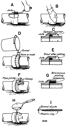
Fig. 19.—How to make good joints. See text for directions
and specifications
A shows the use of a yarning iron to pack a small strand of jute into the
joint space, thus centering the pipes and preventing the joint filler running
inside. The joint surfaces should be free of dirt and oil. The jute is cut in
lengths to go around the pipe; a small strand is soaked in neat Portland cement
grout, then twisted and wrapped around the small end of the pipe to be pushed
into the hub of the last pipe laid. After the pipe is pushed home the jute is
packed evenly to a depth of not over ½ inch, leaving about 1½ inches for the
joint filler. Old hemp rope or oakum dipped in liquid cement or paper may be
used, in place of jute, and the packing may be done with a thin file or piece
of wood.
B shows the use of a rubber mitten or glove to force Portland cement mortar
into the joint space. The mortar should be thoroughly and freshly mixed in the
proportion of one volume of cement to one volume of clean sand and should be
pressed and tamped to fill the joint completely.
C shows a section of finished joint. The fresh mortar should not be loosened
or disturbed when laying the next pipe.
D shows method of pouring a joint with grout, which is quicker, cheaper, and
better than using a rubber mitten. A flexible sheet-metal form or mold, oiled
to prevent the grout sticking, is clamped tightly around the joint and is completely
filled with grout consisting of equal parts of Portland cement and clean
sand mixed dry, to which water is added to produce a creamy consistency. The
pipes should not be disturbed and the form should not be removed for 24 hours.
E shows a section of grouted joint, well rounded out, strong, and tight.
F shows the use of a pipe jointer for pouring a hot filler. The pipe jointer
may be an asbestos or rubber runner or collar or a piece of garden hose clamped
around the pipe leaving a small triangular opening at the top. The jointer is
pressed firmly against the hub, and any small openings between the jointer and
pipe are smeared with plastic clay to prevent leakage of the filler. A clay dike
or funnel about 3 inches high built around the triangular opening greatly aids
rapid and complete filling of the joint space. The filler may be a commercially
prepared bituminous compound or molten sulphur and fine sand. The former
makes a slightly elastic joint; the latter a hard unyielding joint. With good
workmanship both kinds of joint are practically water-tight and root-proof,
and cost about the same as cement mortar joints. The filler is heated in an iron
kettle over a wood, coke, or coal fire. It should be well stirred, and when at a
free running consistency should be poured with a ladle large enough to fill the
joint completely at one operation. As soon as the compound cools the jointer
is removed. Sulphur-sand filler is made by mixing together dry and melting
equal volumes of ordinary powdered sulphur and very fine clean sand, preferably
the finest quicksand. A 5-inch sewer pipe joint requires from three-tenths
to nine-tenths of a pound (according to the kind of pipe) of sulphur,
worth 3 to 5 cents per pound, and a like quantity of sand. From ½ to 1½
pounds of bituminous filler are required for a 5-inch pipe joint.
G shows section of finished joint.
H shows the use of a pouring ladle in making lead joints in cast-iron soil pipe.
This pipe is in lengths to lay 5 feet, and the metal of the barrel is ¼ inch thick.
The joint is yarned with dry jute or oakum, as described above, and is poured
full with molten, soft, pig lead to be afterwards driven tightly with hammer and
calking tools. About ¾ pound of lead for each inch in diameter of pipe is
required. Prepared cements of varying composition have proved effective and,
as they require no calking, are economical. Among the best is a finely ground,
thoroughly mixed compound of iron, sulphur, slag, and salt.
I is a homemade pipe jointer or clay roll for use in pouring molten lead. A
strand of jute long enough to encircle the pipe and the ends to fold back, leaving
an opening at the top, is covered with clay moistened, rolled and worked to form
a plastic rope about 1 inch in diameter. The jointer gives the very best results
but must be frequently moistened and worked to keep the clay soft and pliable.
The jointer shown in F is frequently used for pouring lead joints.
Obstructions in house sewers are frequent. Among the causes
are broken pipes, grade insufficient to give cleansing velocities, newspaper,
rags, garbage, or other solids in the sewage, congealing of
grease in pipes and main running traps (house sewer traps), and
poor joint construction whereby rootlets grow into the sewer and
choke it. Good grade and good construction with particular care
given to the joints, will avert or lessen these troubles. The sewer
should be perfectly straight, with the interior of the joints scraped
or swabbed smooth. When the joint-filling material has set, the
hollows beneath the hubs should be filled with good earth free of
stones, well tamped or puddled in place. It is important that like
material be used at the sides of the pipe and above it for at least
1 foot. The back filling may be completed with scraper or plow.
No running trap should be placed on the house sewer, because it
is liable to become obstructed and it prevents free movement of air
through the sewer and soil stack. Conductors or drains for rain
or other clean water should never connect with the house sewer,
but should discharge into a watercourse or other outlet.
Where obstruction of a house sewer occurs, use of some of the
simple tools shown in Figure 20 may remedy the trouble. It is not
likely that farmers will have these appliances, except possibly some
of the augers; but some of them can be made at home or by a blacksmith,
and most of them should be obtainable for temporary use from
a well-organized town or city sewer department. The purpose of
the several tools shown is indicated in the notation.
The tank.—The septic tank should be in an isolated location at least
50 to 100 feet from any dwelling. This is not always possible,
because of flat ground, but in many such instances reasonable distance
and fall may be secured by raising both the house sewer and
tank and embanking them with earth. Cases are known where tanks
adjoin cellar or basement walls and the top of the tank is used as a
doorstep; in other cases tanks have been constructed within buildings.
Such practices are bad. It is difficult to construct an absolutely
water-tight masonry tank, and still more difficult to make it proof
against the passage of sewer odors.
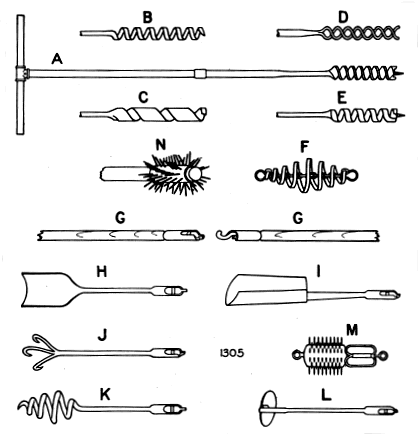
Fig. 20.—Sewer-cleaning tools—how to use them. A, Ordinary 1½ or 2 inch auger
welded to a piece 1¾-inch extra strong wrought pipe about 5 feet long: the stem
is lengthened by adding other pieces of pipe with screw couplings, and is fitted
with a pipe handle; all cleaning work should proceed upstream; B, twist or open
earth auger; C, ribbon or closed earth auger; D, spiral or coal auger; E, ship
auger; F, root cutter; G, sewer rods, with hook coupling, usually of hickory or
ash 1 or 1¼ inches in diameter and 3 or 4 feet long; H, gouge for cutting obstructions;
I, scoop for removing sand or similar material; J, claw, and K, screw, for
removing paper and rags; L, scraper; M, wire brush for removing grease, drawn
back and forth with a wire or rope; N, homemade wire brush (for a 5-inch sewer
use a 1½-inch wooden pole to which is securely tacked a piece of heavy rubber,
canvas, or leather belting or harness leather 5½ by 8 inches, spirally studded, as
shown, with ordinary wire nails 1½ inches in length)
In Northern States, particularly in exposed situations, it is desirable
to have the top of the tank 1 to 2 feet underground, thus promoting
warmth and uniformity of temperature in the sewage. In
Southern States this feature is less important, and the top of the
tank may be flush with the ground. Every tank should be tightly
covered, for the reasons above stated and to guard against the spread
of odors, the transmission of disease germs by flies, and accidents to
children.
Considerable latitude is allowable in the design and construction
of septic tanks. No particular shape or exact dimensions can be
presented for a given number of people. One family of 5 persons
may use as much water as another family of 10 persons; hence the
quantity of sewage rather than the number of persons is the better
basis of design. Exact dimensions are not requisite, for settlement
and septicization proceed whether the sewage is held a few hours
more or a few hours less. As to materials of construction, some form
of masonry, either brick, building tile, rubble, concrete, or cement
block, is employed generally. Vitrified pipe, steel, and wood have
been used occasionally.
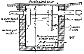
Fig. 21.—One-chamber septic tank—does nothing more
than a tight cesspool. Brick construction, heavily
plastered inside; size suitable for 180 to 280 gallons
of sewage daily (nominally 4 to 7 persons)
A plant for use all year round should have two chambers, one to
secure settlement and septicization of the solids and the other to
secure periodic discharge
of the effluent
by the use of an automatic
sewage siphon.
The first chamber is
known as the settling
chamber, the second as
the siphon or dosing
chamber. The siphon
chamber is often omitted
and the effluent is
allowed to dribble away
through subsurface tile,
as illustrated in Figure
16. The latter procedure
is not generally
advised, but may be
permissible where the
land slopes sharply or has long periods of rest, as at summer houses
and camps.
The septic tanks shown in this bulletin are designed to satisfy the
following conditions:
1. Water consumption of 40 gallons per person per day of 24
hours.
2. A detention period of about 24 hours; that is, the capacity of the
settling chamber below the flow line is approximately equal to the
quantity of sewage discharged from the house in 24 hours.
3. Where a siphon chamber is provided, its size is such that the
dose of sewage shall be approximately equal to 20 gallons per person;
that is, the capacity of the siphon chamber between the discharge
and low-water lines is roughly equal to the quantity of sewage discharged
in 12 hours.
A simple one-chamber brick tank suitable for a household discharging
180 to 280 gallons of sewage daily is shown in Figure 21. A
small two-chamber tank constructed of 24-inch vitrified pipe, suitable
for a household discharging about 125 gallons of sewage daily, is
shown in Figure 22. A typical two-chamber concrete tank is shown
in Figure 23. Excepting the submerged outlet, all pipes within the
tank and built into the masonry are cast-iron soil pipe with cast-iron
fittings. Vitrified or concrete sewer pipe and specials are generally
used, as they are frequently more readily obtainable and a slight
saving in first cost may be effected. Cast iron is less liable to be
broken in handling or after being set rigidly in masonry, and the
joints are more easily made water-tight. The submerged outlet is
midway of the depth of liquid in the settling chamber. The inside
depth of the siphon chamber is the drawing depth of the siphon
plus 1 foot 5 inches.
The following table gives the principal dimensions with quantities
of materials for four sizes of tank as illustrated in Figure 23:
Dimensions and quantities for septic tanks.
| Number of persons. |
Quantity of sewage in 24 hours. |
Settling chamber. |
| Capacity below flow line. |
Length. |
Depth. |
Width. |
W. |
X. |
Y. |
Z. |
|
Galls. |
Galls. |
Ft. |
In. |
Ft. |
In. |
Ft. |
In. |
In. |
Ft. |
In. |
In. |
In. |
| 5 |
180-280 |
240 |
4 |
0 |
5 |
0 |
2 |
0 |
6 |
2 |
0 |
4 |
6 |
| 10 |
320-480 |
420 |
5 |
0 |
5 |
6 |
2 |
6 |
6 |
2 |
3 |
4 |
6 |
| 15 |
520-680 |
620 |
5 |
6 |
6 |
0 |
3 |
0 |
8 |
2 |
6 |
5 |
8 |
| 20 |
720-960 |
860 |
6 |
0 |
6 |
6 |
3 |
6 |
8 |
2 |
9 |
5 |
8 |
| Number of persons. |
Quantity of sewage in 24 hours. |
Siphon chamber. |
Concrete. |
Cement. |
Sand. |
Stone. |
Reinforcement in top slab (strip of heavy stock fencing). |
| Length. |
Depth. |
Width. |
A. |
B. |
C. |
D. |
Length. |
Width. |
|
Galls. |
Ft. |
In. |
Ft. |
In. |
Ft. |
In. |
In. |
In. |
In. |
In. |
Cu. Yd. |
Bbls. |
Cu. Yd. |
Cu. Yd. |
Ft. |
In. |
| 5 |
180-280 |
5 |
0 |
2 |
8 |
2 |
0 |
3 |
4 |
15 |
18¼ |
3 |
4½ |
1⅓ |
2⅔ |
10 |
32 |
| 10 |
320-480 |
8 |
0 |
2 |
8 |
2 |
6 |
3 |
4 |
15 |
20¼ |
4¼ |
6¼ |
2 |
3¾ |
14 |
39 |
| 15 |
520-680 |
8 |
8 |
2 |
10 |
3 |
0 |
4 |
4 |
17 |
20¼ |
6⅔ |
9¾ |
3 |
6 |
15⅔ |
47 |
| 20 |
720-960 |
10 |
0 |
2 |
10 |
3 |
6 |
4 |
4 |
17 |
20¼ |
8 |
12 |
3½ |
7 |
17½ |
56 |
Siphons.—Reference has already been made to the vital importance
of air in sewage filtration. If the spaces within a filter or soil are
constantly filled with water, air is excluded, and the action of the
filtering material is merely that of a mechanical strainer with its
clogging tendency. The purpose of a siphon is twofold: (1) To secure
intermittent discharge, thus allowing a considerable period of
time for one dose to work off in the soil and for air to enter the soil
spaces before another flush is received; (2) to secure distribution
over a larger area and in a more even manner than where the sewage
is allowed to dribble and produce the conditions of the old-fashioned
sink drain—namely, a small area of water-logged ground.
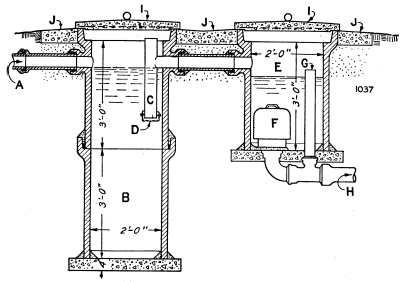
Fig. 22.—Two-chamber septic tank, simple and inexpensive, constructed of 24-inch
vitrified sewer pipe, size suitable for 125 gallons of sewage daily (nominally 3
persons). A, House sewer; B, settling chamber, made of double T branch and
one length of straight pipe, each 3 feet long and 2 feet in diameter, supported by 4
inches of concrete, all joints made water-tight; C, submerged outlet, consisting of a
metal T slipped into the sewer-pipe branch; D, wire screen ¼-inch mesh; E, siphon
chamber made of one T branch 3 feet long and 2 feet in diameter; F, siphon;
G, 3-inch overflow; H, sewer to distribution field; I, tight cover with lifting ring;
J, concrete protection around sewer-pipe hubs
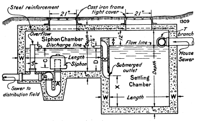
Fig. 23.—Typical two-chamber concrete septic tank. (See table for dimensions and
quantities for different sizes)
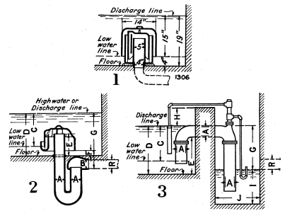
Three types of sewage siphon are shown in Figure 24. In all, the
essential principle is the same: A column of air is entrapped between
two columns of water; when the water in the chamber rises to a
predetermined height, called the discharge line, the pressure forces
out the confined air, destroying the balance and causing a rush of
water through the siphon to the sewer. The entire operation is automatic
and very simple. The siphons shown are commercial products
made of cast-iron; they have few parts and none that move, and the
whole construction is simple and durable. The table (fig. 24) lists
stock sizes adapted to farm use. Manufacturers furnish full information
for setting their siphons and putting them in operation. For
example, take type 2, Figure 24: (1) Set siphon trap (U-shaped
pipe) plumb, making E (height from floor to top of long leg) as
specified; (2) fill siphon trap with water till it begins to run out at
B; (3) place bell in position on top of long leg, and the siphon is
ready for service. Do not fill vent pipe on side of bell.
|
Type 2
INCHES |
| Diameter of siphon |
A |
3 |
3 |
4 |
4 |
| Diameter of outlet |
B |
4 |
4 |
4 |
4 |
| Drawing depth |
C |
13 |
15 |
14 |
17 |
| Depth to floor |
D |
16¼ |
18¼ |
17¼ |
20¼ |
| Height above floor |
E |
7¼ |
9¼ |
8¾ |
11¾ |
| Clearance under bell |
F |
2 |
2 |
2 |
2 |
| Inside bottom of outlet, to discharge line |
G |
20½ |
22½ |
22¾ |
25¾ |
| Discharge line, to top of wall |
H |
|
|
|
|
| Depth of outlet sump |
I |
|
|
|
|
| Length and width of outlet sump |
J |
|
|
|
|
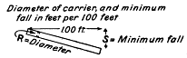
Diameter of carrier (R),
and minimum fall (S)
in feet per 100 feet
|
R |
4 |
4 |
4 |
4 |
| S |
2 ft. |
2 ft. |
7 ft. |
8 ft. |
| R |
5 |
5 |
5 |
5 |
| S |
1½ ft. |
1½ ft. |
2 ft. |
2½ ft. |
| R |
6 |
6 |
6 |
6 |
| S |
1 ft. |
1 ft. |
1 ft. |
1 ft. |
|
Type 3
INCHES |
|
Type 1
INCHES |
| Diameter of siphon |
A |
3 |
3 |
4 |
4 |
|
4 |
| Diameter of outlet |
B |
|
|
|
|
|
|
| Drawing depth |
C |
13 |
15 |
14 |
17 |
|
5 |
| Depth to floor |
D |
17 |
17 |
19 |
22 |
|
15 |
| Height above floor |
E |
13 |
13 |
15 |
18 |
|
19 |
| Clearance under bell |
F |
|
|
|
|
|
|
| Inside bottom of outlet, to discharge line |
G |
19 |
21 |
20 |
25 |
|
|
| Discharge line, to top of wall |
H |
6 |
6 |
8 |
8 |
|
|
| Depth of outlet sump |
I |
13 |
13 |
11 |
12 |
|
|
| Length and width of outlet sump |
J |
18 |
19 |
19 |
18 |
|
|
[Transcriber Note: The data for Type 1 Siphon has been added to the table.]
Fig. 24.—Three types of sewage siphon. The table gives dimensions for setting standard
3 and 4 inch siphons; also the appropriate size and grade of the sewer to carry
the siphon discharge
The overhead siphon, type 3, Figure 24, may be installed readily in
a tank already built by addition of an outlet sump. If properly set
are handled, sewage siphons require very little attention and flush
with certainty. Like all plumbing fixtures they are liable to stoppage
if rags, newspaper, and similar solids get into the sewage. If
fouling of the sniffing hole or vent prevents the entrance of sufficient
air into the bell to lock the siphon properly, allowing sewage to
dribble through, the remedy is to clean the siphon. Siphons are for
handling liquid; sludge if allowed to accumulate will choke them.
Submerged outlet.—The purpose of a submerged outlet is to take
the outflow from a point between the sludge at the bottom and the
floating solids or scum. The outlet in Figure 23 may be readily made
of sheet metal by a tinsmith. Wrought iron or steel pipe with elbows
or light lead pipe may be used, the pipe being set in the concrete and
left in place. Sometimes a galvanized wire screen (¼-inch mesh) is
fitted over the inner end to prevent large solids leaving the settling
chamber and possibly clogging the siphon or distribution tile. If a
screen is used it should be easily removable for cleaning.
Manhole frame and cover.—The frame and cover shown in Figure 23
are stock patterns made of cast-iron and weighing about 250 pounds
per set. The cover is 21 inches in diameter; it is tight and, on account
of its weight, is unlikely to be disturbed by small children.
The frame or rim is about 7 inches high and 31 inches in longest
diameter. If desired, light cast-iron cistern or cesspool covers obtainable
from plumbing supply houses, homemade slabs of reinforced
concrete (see Figure 25), or wooden covers (see Figure 21) may be used.
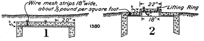
Fig. 25.—Homemade reinforced concrete covers. (1) Slabs placed crosswise permit uncovering
the whole tank for cleaning, but as inspection is somewhat difficult, cleaning is the
more likely to be neglected; (2) manhole, 18 inches square; cover, 22 by 22 by 3 inches
thick, easy to make and to slide or lift from the opening
Overflow.—The purpose of an overflow is to pass sewage to the distribution
field should the siphon stop working. The overflow (fig.
23) is a 3-inch riser pipe with top 3 inches above the discharge line
and the bottom calked or cemented into the side outlet of a T branch.
The run of the T branch should correspond with the size of the sewer
from the tank to the distribution field. If this sewer is 4-inch pipe,
a 4 by 3 inch T branch is used, the 4-inch spigot end of the siphon
being calked or cemented into the branch, as shown in Figure 23; if
the sewer is 5-inch, a 5 by 3 inch T branch is used and connected to
the siphon with a 5-inch to 4-inch reducer (in vitrified specials the
equivalent is a 4-inch to 5-inch increaser); if the sewer is 6-inch, a
6 by 3 inch T branch is used and connected to the siphon with a 6-inch
to 4-inch reducer.
Concrete work.—Before excavation for the tank is begun, two
wooden forms should be built for shaping the inside of the settling
and siphon chambers. In most instances the ground is fairly firm,
so that the lines of excavation may conform to the outside dimensions
of the tank, the back of the walls being built against the earth.
The forms may be made of square-edged boards, braced and lightly
nailed, as shown in Figure 26. The forms should have no bottom.
If it is desired to lay the sides and covering slab in one operation,
the top of the forms must be boarded over. All pipe and manhole
openings should be accurately placed and cut. The faces of the
forms may be covered with paper or smeared with soap or grease to
facilitate removal later.
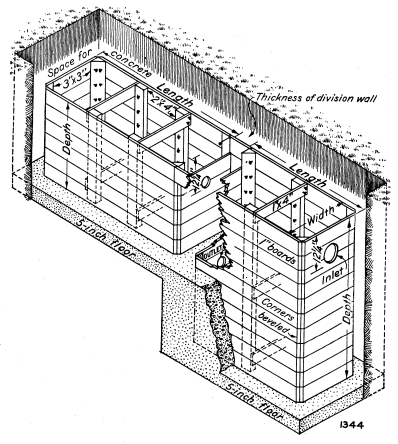
Fig. 26.—Forms for concrete work—how to use them
Click on image to view larger size.
1 Make the forms as shown and to the dimensions required by Figure 23
and the table on p. 29; nails to be driven from the inside and left
projecting for drawing with a claw hammer.
2. Excavate to lines 6 or 8 inches, as may be required, outside of the
forms and to the depths required for both chambers.
3. Pour settling chamber floor and place form thereon.
4 Pour settling chamber walls to level of siphon chamber excavation,
inserting submerged outlet pipe at the proper height. 5. Block siphon
and short pipes to correct line and grade, and fill with concrete
around the trap.
6. Pour siphon chamber floor, and place the form
thereon.
7 Continue pouring all walls to their full height, inserting the inlet
pipe when the concrete reaches that elevation.
8. Do not remove forms till the concrete is hard; with favorable
weather, forms for walls only may be removed in 1 to 2 days; forms
supporting a cover slab should remain 1 to 2 weeks.
The ground should next be excavated to the proper depth for
placing the floors in both chambers. The settling chamber floor,
being the lower, should be placed first. Effort should be made to
secure water-tight work, a feature of especial importance where
leakage might endanger a well or spring. A concrete mixture of
1:2:4 is generally preferred (1 volume cement, 2 volumes sand, 4
volumes stone). The ingredients should be of best quality and thoroughly
mixed. The concrete should be poured promptly and worked
with a spade or flat shovel to make the face smooth and eliminate
pockets or voids within the mass.[10] Before the settling chamber floor
has hardened the form should be set upon the floor and the concrete
work continued up the sides. The pipe form for the submerged
outlet should be set. When the side walls of the settling chamber
have reached the bottom of the excavation for the siphon chamber,
the siphon trap with its connecting branch and short piece of pipe
should be set to proper line and grade and blocked in position. The
floor of the siphon chamber should now be poured and the form for
that chamber placed thereon, leaving a 6-inch or 8-inch space (according
to the thickness of the division wall) between the ends of
the two forms. Pouring of all side walls and the top slab should
continue without stop, making the entire structure a monolith.
Steel reinforcement.—To stiffen the cover slab and guard against
cracking, a little steel should be embedded in the concrete about 1
inch above the inside top. For this purpose a strip of heavy stock
fencing is convenient and inexpensive. The line wires should be not
less than No. 10 gauge (about ⅛ inch) and the stay wires not less
than No. 11 gauge. The reinforcement should be cut at manholes and
fastened around manhole openings. If desired a standard wire-mesh
reinforcement weighing about one-third of a pound per square foot
may be used. Another alternative is to use 14-inch round rods,
spacing the crosswise rods 6 inches apart and the lengthwise rods
12 inches apart. Poultry netting should not be used, because of
its lightness.
Sewer from tank to distribution field.—The length of this sewer
depends on the situation of the field and the fall to it. The size of
the sewer depends on the fall that can be obtained and the size of
siphon. The table in Figure 24 shows the minimum fall at which
4-inch, 5-inch, and 6-inch sewers should be laid to take the discharge
of the 3-inch and 4-inch siphons specified. The line and grade
should be set in the same manner as for the house sewer (see fig. 18)
and the construction should be as specified under that caption.
Distribution field.—The distribution field or area is a sewage filter,
and its selection and the manner of preparing it largely determine
the success of subsoil disposal of sewage. As a rule farm land is
not the best filtering material. It is too fine grained and fertile.
Its tendency is to hold water too long, to admit insufficient air, to
clog when even small quantities of sewage are applied. Hence the
distribution area should be of liberal size—on the average 500 square
feet for each person served. It should be dry, porous, and well
drained—qualities that characterize sandy, gravelly, and light loam
soils. It should be devoid of trees and shrubbery, thus giving sunlight
and air free access. It should be located at least 300 feet downhill
from a well or spring used for domestic water supply. Preferably
it should slope gently, but sharp slopes are not prohibitive.
Subsoiling the area is always desirable.
Clay and other compact, impervious soils require special treatment.
Less sewage can be applied to them, and hence it is well to
have the area larger than 500 square feet per person. Clay should
be subsoiled as deep as possible with a subsoil plow. In some instances
dynamite has been of service in opening up the ground to
still greater depth. Drainage and aeration should be further promoted
by laying tile underdrains, as outlined in Figure 17 and shown
in more detail in Figure 29.
After the construction work the distribution areas should be raked
and seeded with thick-growing grass. Grass is a safe crop; its water
requirement is high, and it affords considerable protection from frost.
Suitable grasses are redtop, white clover, blue grass, and Bermuda
grass. The area may be pastured or kept as grass land.
Distribution system.—Poor distribution of the sewage and failure to
protect the joints of the distribution tile account for most of the
failures. Each flush of the siphon should be so controlled that every
part of the field will receive its due proportion. The distribution
tile must be so laid that loose dirt will not fall or wash into the open
joints.
Different methods of dividing the flush and laying out the distribution
tile are shown in Figures 27 and 30. Layouts 1, 2, and 3,
Figure 27, are suitable for flat or gently sloping areas and are
planned for the shallow siphon chambers tabulated on page 29.
Layout 4, Figure 27, is suitable for steep slopes. In all four layouts
use is made of one or more V branches (not Y branches) to divide
the flow equally among the several lines. V branches, sometimes
called breeches, should be leveled with a carpenter's level crosswise
the ends of the legs, thus insuring equal division of the flow.
The size and length of distribution tile and the spacing of the lines
or runs admit of considerable variation in different soils. Water
sinks rapidly in gravels and sands, and hence larger tile and shorter
length are permissible than in close soils. Lateral movement is slow
in all soils, but extends farther in gravels and sands than in close
soils. In average soils the effect on vegetation 5 feet away from the
line is practically nil.
From these considerations, with the siphon dose 20 gallons per
person, it is usually a safe rule to provide 50 feet of 3-inch tile for
each person served and to lay the lines 10 feet apart. Such provision
gives a capacity within the bore of the tile lines about equal
to the siphon dose, and as some sewage is wasted at each joint a
reasonable factor of safety is provided. A spacing of 10 feet will,
it is believed, permanently prevent the extension of lateral absorption
from line to line, provided the area is fairly well drained. As between
3-inch and 4-inch tile the smaller size costs less and is better
calculated to taper the dose to small proportions. Four-inch tile is
less likely to get out of alignment or to become clogged; a length
of 28 feet has the same capacity in the bore as 50 feet of 3-inch.
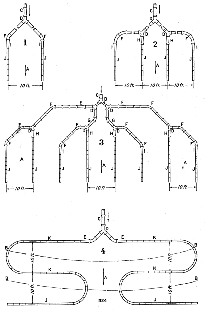
Fig. 27.—Methods of laying distribution system: Methods 1, 2, and 3 for
flat or gently sloping land; method 4 for steep slopes (see also
Figure 30);
A, direction of slope;
B, contour of field;
C, sewer from tank,
preferably size 5 inch, though 4 or 6 inch may be used, depending on
the fall and the size of the siphon (see table,
fig. 24);
D,
V-branch
set to divide the flow exactly;
E, reducer, to 4 inches;
F, ⅛ bend,
4-inch;
G, increaser, from 4 inches;
H, increaser, 3 to 4 inches;
I,
reducer, 4 to 3 inches;
J, distribution tile, 3-inch;
K, distribution
tile, 4-inch
Good-quality drain tile in 1-foot lengths or second-quality sewer
pipe in 2-foot lengths may be used. The lines are generally laid in
parallel runs, but may be varied according to the topography. Layouts
1, 2, and 3, Figure 27, for flat or gently sloping land, run with
the slope; layout 4, for steep slopes, runs back and forth along the
contour in a series of long flat sweeps and short steep curves. The
grade of the runs and sweeps should be gentle, rarely more than
10 or 12 inches in 100 feet. In layouts 1, 2, and 3, Figure 27 especially,
it is desirable that the last 20 feet of each run should be laid
level or given a slight upward slope, thus guarding against undue
flow of sewage to the lowest ends of the system.
The runs should be laid no deeper than necessary to give clearance
when plowing and prevent injury from frost. Ten inches of earth
above the top of the tile is sufficient generally throughout the southern
half of the United States and 18 inches generally in the North,
but if the field is exposed or lacks a thick heavy growth of grass, the
cover should be increased to 3 to 6 feet near the Canadian line.
Where frost goes down 5 to 7 feet, it is better to lay the tile at
moderate depth and cover the runs with hay, straw, or leaves
weighted down, removing the covering in the spring.
Making the joints of the distribution tile demands especial attention.
For a short distance on the upper end of each run the tile
should be laid with ends abutting; the joint opening should be increased
gradually to one-eighth inch and this increased to one-fourth
in the last 20 feet of the run. All joints should be protected against
the entrance of loose dirt. Four methods are shown in Figure 28.
The lower end of each run should be closed with a brick or flat
stone; or, what is better, an elbow or T branch may be placed on the
end and vented above the surface of the ground, improving the flow
of sewage, the ventilation of pipes, and the aeration of the soil.
If the distribution tile must be laid in clay or other close, poorly
drained soil, special treatment is necessary. A common method is
to subsoil and underdrain the area thoroughly, as shown in Figure 29.
It is not always possible to run the underdrain in lines between the
distribution lines as shown in Figures 17 and 29, but it is a desirable
thing to do, as the sewage must then receive some filtration through
natural soil.
In some instances it is sufficient to lay the distribution tile on a continuous
bed, 8 to 12 inches thick, of coarse gravel, broken stone, or
brick, slag, coke, or cinders and complete the refill as shown in Figure
16 or 29.
Figure 30 shows two other methods of controlling the flow on steep
slopes and diverting proper proportions to the several lateral distributors
laid along the contour of the field. This work can not be
effected properly with T or Y branches; the flow tends to shoot
straight ahead, comparatively little escaping laterally. To overcome
this difficulty recourse is had to diverting boxes, of which two types
are shown in Figure 30. These boxes involve expense, but permit
inspection and division of the flow according to the needs. They may
be built of brick, stone, concrete, or even wood.
Type 1 consists of a single box, into which all the lateral distributors
head. It will be noted that the laterals enter at slightly different
elevations, the two opposite the inlet sewer being the highest,
the next two slightly lower, and the next two the lowest. This staggering
of the outlets, in a measure, offsets the tendency of the flow
to shoot across and escape by the most direct route.
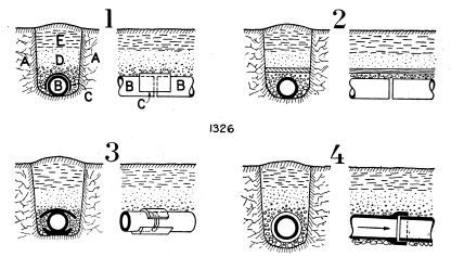
Fig. 28.—Four methods of protecting open joints in distribution lines—an all-important
work. Sketches show cross-section and longitudinal views; the depth from the surface
of the ground to the top of the tile is about 10 inches
1. A, Subsoiled ground; B, 3 or 4 inch drain tile; C, strip of tarred paper about 6
inches wide and extending three-fourths the distance around the tile, allowing sewage
to escape at the bottom; D, coarse sand, gravel, broken stone or brick, slag, cinders, or
coke, the coarsest material placed around the tile (where the ground is naturally very
porous and well drained, special filling in the trench may be omitted); E, natural soil.
2. Drain tile covered with a board laid flat, leaving the entire joint open.
3. Drain tile laid in stoneware gutter pieces and the joint covered with stoneware caps;
gutter and cap pieces are inexpensive commercial products; their radius is longer than
that of the outside of the tile, thus leaving open most of the joint space; the gutter aids
in keeping the tile in line.
4. Vitrified sewer pipe with hubs facing downhill; the spigot end should be centered in
the hub with a few small chinks or wedges.
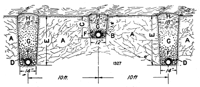
Fig. 29.—-Close soils should be deeply subsoiled and underdrained. Porous, well-drained,
air-filled soil is absolutely necessary. A, Subsoiled ground; B, 3 or 4 inch distribution
tile; C, depth variable with the climate, 1¼ to 3½ feet; D, 4-inch underdrain; E, depth
such as would prepare land for good crop production, generally 3½ to 4 feet; F, stone
or other coarse material; G, gravel grading upward to coarse sand; H, loose soil
Type 2 calls for one or more diverting boxes, according to the number
of lateral distributors, and readily permits of wasting sewage at
widely separated elevations and distances. The outlet pipes enter
the box at slightly different elevations, for the reason already stated.
With either type, should the outlets not be set at the right elevations,
partial plugging of the holes and a little experimenting will enable
one to equalize or proportion the discharges.
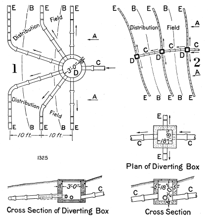
Fig. 30.—Two systems of distribution on steep slopes—use of diverting box. A, Direction
of slope; B, contour of field; C, 4, 5, or 6 inch sewer from tank; D, diverting
box; E, 3-inch or 4-inch distribution tile
Sewage switch.—The clogging of filters and soils after long-continued
application of sewage has been previously referred to. It
is, therefore, desirable to arrange the distribution system in two units
with a switch between them, so that one area may drain and become
aerated while the other is in use. This procedure is especially desirable
where the soil is close and the installation of considerable
size. It adds to the life and effectiveness of the distribution area and
permits use of a plant in case it is necessary to repair, extend, or
relay the tile in either unit.
Arrangement in two units does not necessarily mean doubling the
amount of tile and the area required in a single field. However desirable
that may be, expense or lack of suitable ground will often
prevent. With open sands and gravels and the assumed siphon dose
of 20 gallons per person, 15 to 20 feet of 4-inch tile in each unit for
each person will usually suffice. With more compact soil it is advisable
to more nearly double the requirements previously described.
Two simple types of switch are shown in Figure 31. The switch
should be turned frequently, certainly as often as is necessary to prevent
saturation or bogginess of either area.
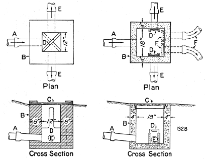
Fig. 31.—Two simple types of sewage switch. A, Sewer from tank; B, switch box;
C, cover; D, blade or stop board (in the left-hand box the direction of flow is controlled
by placing the blade in alternate diagonal position; in the right-hand box the stop
works in iron guides cast integral with a short piece of light-weight pipe set in the
masonry; if desired the guides may be wood, fastened to the masonry with expansion
bolts); E, sewer to distribution area; F (right-hand box), alternate position of outlets
or additional outlets if required
A complete installation.—The general layout and working plans of
a complete installation built in 1915-16 are shown in Figure 32.
The plant is larger than those heretofore considered, and involves
several additional features. The settling chamber below the flow line
has a capacity of 1,000 gallons, and on a basis of 40 gallons per
person per day would serve 25 people.
For many years sewage had been discharged through two 4-inch
sewers to a cesspool in the rear of the house. The proximity of the
well made it unsafe, and the overflow of the cesspool dribbled over
the low portion of the garden and barnyard, cheating nuisance.
The first step was to make borings with a soil auger in the pasture
400 or 500 feet from the house. The borings showed a heavy clay
soil to a depth of about 4 feet, underlaid with a sandy stratum only
a few inches in thickness. It was decided to locate the distribution
area in the pasture and to aid the seepage of sewage by digging
numerous filter wells through the clay to the sandy stratum. Levels
were taken and a contour plan prepared to serve for laying out the
plant and establishing the grades.
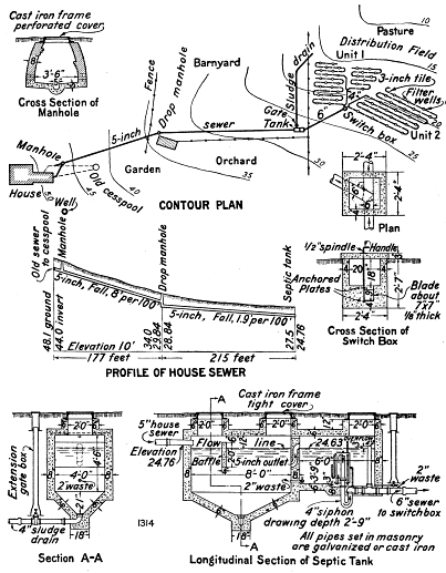
Fig. 32.—A complete installation for a large rural home. General layout on a contour
plan and construction drawings. Note abandonment of old cesspool near the well and
garden and removal of sewage to a lower and safer location in the pasture, where the
treatment is subsurface distribution, aided by numerous filter wells about 4 feet deep
filled with coarse gravel. Note that sludge is removed from the bottom of the settling
chamber by opening the gate on the sludge drain
Click on image to view larger size
The septic tank is built in one corner of the barnyard, and a 5-inch
sewer connects it with the old 4-inch sewers to the cesspool. All
sewer-pipe joints were poured with a flexible jointing compound.
The settling chamber is of hopper shape at the bottom, and a 4-inch
sludge drain with gate provides for the gravity removal of sludge.
The lower end of the sludge drain is above the surface of the ground
and 9 feet below the flow line. The end is protected by a small retaining
wall, and the sludge is readily caught in barrels and hauled
out on the land for burial. The outlet is low enough to drain the
settling chamber completely. If it is desired merely to force out the
sludge, the drain may be brought to the surface under a head of 3 to
5 feet, discharging the sludge into a trench or drying bed, to be applied
later to the land. A 2-inch waste pipe about mid-depth of the
settling chamber permits drawing off the cleared portion of the sewage
to the siphon chamber and from thence through another 2-inch
waste pipe into the 6-inch sewer leading to the distribution field.
The 4-inch siphon has a drawing depth of 33 inches, and as the
siphon chamber is 4 feet wide by 6 feet long the dose is about 500
gallons. The siphon cost $35. The 6-inch sewer to the switch box
falls about 6 inches in 50 feet. The distribution field was thoroughly
subsoiled, and about 800 feet of 3-inch tile was laid in each unit. At
intervals of 25 feet along the distribution trenches 6-inch holes were
dug through the clay stratum with a posthole digger. These holes
were filled with stone and constitute the filter wells previously mentioned.
All tile lines are surrounded with stone and coarse gravel,
and the ground has been trimmed to give a uniform cover of 12
inches. All work was done by day labor in a thorough manner. As
the men were doing other work at the same time the actual cost is not
known, but it is believed the installation cost about $700.
Cost data.—Reliable cost figures are difficult to estimate. Labor,
materials, freight, haulage, and other items vary greatly in different
localities. The septic tank shown in Figure 21 contains about 1,000
bricks and is estimated to cost $60 complete. The septic tank shown
in Figure 23 for 5 persons is estimated to cost $135; for 10 persons,
$170; for 15 persons, $240; for 20 persons, $280. In Maryland, in
1916, the cost of installing a septic tank similar to that shown in
Figure 23 (for 5 people), including 86 feet of 5-inch house sewer
(55 feet of cast-iron pipe passing a well, and 31 feet of vitrified pipe)
and 214 feet of second-quality 4-inch sewer pipe in the distribution
area, was as follows:
| Excavation, labor |
$7.50 |
| Materials delivered |
46.60 |
| Three-inch siphon, including freight |
15.75 |
| Construction, labor |
28.00 |
| Supervision |
5.00 |
| Total |
102.85 |
The quotations in the following table will be found useful in
making estimates of cost:
Cost per foot of pipe and drain tile
(Approximate retail prices, Washington, D. C., February, 1928)
| Kind of pipe. |
Size, in inches. |
| 3 |
4 |
5 |
6 |
Extra heavy cast-iron soil pipe |
$0.23 |
$0.31 |
$0.40 |
$0.48 |
| Vitrified salt-glazed sewer pipe |
.15 |
.15 |
.22½ |
.22½ |
| Clay or shale drain tile |
.06 |
.07 |
.10 |
.13 |
The cost of cast-iron fittings may be roughly estimated as follows;
Bends, one and one-half times the price of straight pipe; T-branches,
two times the price of straight pipe; reducers, average of the prices
of straight pipe at each end. The cost of clay bends, T-branches,
reducers, and increasers may be roughly estimated at four times the
price of straight pipe.
Operation.—Attention must be given to every plant to insure success.
Unusual or excessive foulness should be investigated. No
chemicals should be used in a septic tank; garbage, rags, newspaper,
and other solids not readily soluble in water should be kept out of
sewers and tanks. The plant should be inspected often, noting particularly
if the siphon is operating satisfactorily. If scum forms
in the settling chamber it should be removed, and the sludge should
be bailed or pumped out yearly. Frequently tanks are not cleaned
out for three or four years, resulting in large quantities of solid
matter going through to the distribution system and clogging it.
Clogging may occur in the tile or in the adjacent soil. In either
case the tile should be dug up, cleaned, and relaid. In some cases
it has been found advantageous to relay the tile between the former
lines. When sewage is applied to fairly porous land at the slow
rate here recommended and the plant is well handled the tile lines
should operate satisfactorily for many years. Liming heavy soils
tends to loosen and keep them sweet.
Field data.—As a basis for outlining or designing a suitable installation
the following data should be known:
1. State, town, and whether in or near an incorporated municipality.
2. Usual number of persons to be served.
3. Average daily consumption of water in gallons.
4. Kind and depth of well, depth to water surface.
5. Character of soil, whether sandy, gravelly, loamy, clay, or muck.
6. Condition of soil as to drainage.
7. Character of subsoil.
8. Character of underlying rock and, if known, its depth below the
surface.
9. Depth to ground water at both house and field where sewage is to
be distributed.
10. Minimum winter temperature and approximate depth to which frost
goes.
11. Number and kind of buildings to be connected with the sewer.
12. Number and kind of plumbing fixtures in each building.
13. Whether plumbing fixtures are to be put in the basement.
14. Depth of basement floor below ground.
A plan to scale or a sketch with dimensions showing property lines,
buildings, wells, springs, and drainage outlets should be furnished.
The direction of surface drainage should be indicated by arrows.
The slope of the land (vertical fall in a stated horizontal distance)
should be given or if possible a contour plan (showing lines of
constant elevation) should be furnished.