"Take it all in all, a ship of the line is the most honourable thing
that man, as a gregarious animal, has ever produced.... Into
that he has put as much of his human patience, common sense,
forethought, experimental philosophy, self-control, habits of order
and obedience, thoroughly wrought hand-work, defiance of brute
elements, careless courage, careful patriotism, and calm expectation
of the judgment of God, as can well be put into a space of
300 feet long by 80 feet broad."—Ruskin.
LONDON:
OFFICES OF "ENGINEERING," 35 AND 36, BEDFORD STREET, W.C.
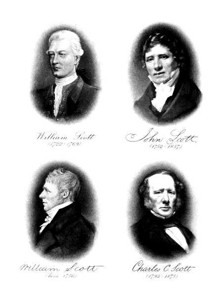
Portraits of William Scott (born 1722, died 1769); John Scott
(born 1752, died 1837); William Scott, his Brother (born 1765);
and Charles Cuningham Scott (born 1794, died 1875) (Plate II.)
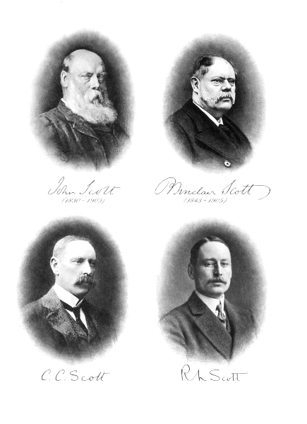
John Scott, C.B. (born 1830, died 1903); Robert Sinclair
Scott (born 1843, died 1905); Charles Cuningham Scott (the
present Chairman); Robert Lyons Scott (Plate III.)
John Scott (I) founded the firm in 1711, and engaged
in the building of herring busses and small craft. There
is, unfortunately, no engraving of him extant, so that our
series of portraits on Plates II. and III. adjoining page 1,
is to this extent incomplete.
William Scott, his son, born 1722, died 1769, succeeded
him, and, with his brother, extended the business alike as
regards the extent of the works, and the types of vessels
built. His first square-rigged ship—of 1765—was the first
vessel built on the Clyde for owners out of Scotland.
John Scott (II), born 1752, died 1837, son of William,
greatly developed the works and built the dry dock and
basin now included, with the original Yard, in the establishment
of Messrs. Caird and Co., Limited. Under his
régime many ocean-going sailing ships were constructed, ship-work
for the Navy was undertaken, the manufacture of steam
machinery commenced in 1825, and Admiralty orders undertaken
for engines for dockyard—as well as Greenock-built
frigates. He built the Custom House Quay in 1791,
bought Halkshill, the family seat, in 1815, was a partner
in the Greenock Bank, and otherwise promoted the industries
of the town.
His brother, William Scott (II), born 1756, migrated
to Barnstaple, where he carried on an extensive shipbuilding
industry, obtaining engines for the most of his
steamships from the Greenock Works.
Charles Cuningham Scott, born 1794, died 1875, son
of John Scott (II), along with his elder brother, John
Scott (III), born 1785, died 1874, carried on the business as
"John Scott and Sons," developing still further the progressive
policy of his father, who had been responsible for the
works for about half a century. The Cartsdyke Yard
was commenced in 1850 by Charles Cuningham Scott, and
his son John, under the style of "Scott and Co.," and
this firm is the one which has maintained the continuity
of the Scotts' association with shipbuilding.
John Scott (IV), born 1830, died 1903,[1] and Robert
Sinclair Scott, born 1843, died 1905, sons of Charles
Cuningham Scott, were responsible for the progress for
nearly forty years, and the former was created a Companion
of the Bath (C.B.) in 1887. During their régime the firm
took a large part in the introduction of the steamship for
over-sea voyages; in the development of high steam pressures
and of the multiple-expansion engine, which greatly improved
the economy of the steam engine; and in naval work,
with its incidental advancement. They completely reconstructed
the Cartsdyke Works, and greatly improved what
is now known as the Cartsburn Dockyard, modernising
the equipment. The co-partnery was, for family reasons,
registered in 1900 under the Limited Liability Company
Law.
Charles Cuningham Scott, son of John Scott, C.B.,
is now the head of the concern and Chairman of the
Company (Scotts' Shipbuilding and Engineering Company,
Limited), and with him on the directorate are his brother
Robert Lyons Scott, C. Mumme, and James Brown.
THE maintenance of an industry for two
hundred years by one family, in the
direct line of succession and in one
locality, is almost unique in the history
of western manufactures. Such a record
proves that the successive generations
have displayed diligence, prudence, and
enterprise; otherwise it would not have been possible for
them to have held continuously a foremost place in the
face of incessant competition consequent upon the general
advance in science, the introduction of superior constructional
materials, and the invention of new machinery.
It indicates also the maintenance of a high standard of
workmanship as well as integrity and business capacity;
because time is the most important factor in proving
efficiency and in establishing credit for durability of work,
without which no reputation can be retained for such a
long period.
The Scotts began the building of ships in Greenock
in 1711. To-day, their descendants of the sixth generation
worthily maintain the high traditions which have accumulated
during the intervening two hundred years. It is
impossible to form an adequate conception of the service
rendered by this one firm to the science of marine construction
and to Britain, the leading maritime nation of the
world. We should require to review in detail the successive
steps: firstly, in the perfection of the sailing ship, from
the sloops and brigantines of the eighteenth century, to
such beautiful clippers as Scotts' Lord of the Isles, which
in 1856 made the record voyage from China, and did much
to wrest from the Americans the "blue ribbon" of the
ocean; and, secondly, in the development of the steamship
from its inception early in the nineteenth century to the
leviathans of to-day. In successive epochs in the history
of naval architecture the Scotts have played a creditable
part, and to some of the more important improvements
initiated or advanced by the firm reference will be made
in our brief survey of the work done during the past two
centuries. Unfortunately, some years ago, most of the
old-time records were destroyed by a fire at the shipyard,
so that our review of the early work is largely from contemporary
publications, and is unavoidably incomplete.
The beginnings were small, for Scotland had not yet
attained to industrial importance, and had little oversea
commerce. The first trans-Atlantic voyage made by a
Clyde ship was in 1686, when a Greenock-built vessel
was employed on a special mission to carry twenty-two
persons transported to Carolina for attending conventicles
and "being disaffected to Government."[2] American ships
were most numerous on the western seas, and the East
India Company had a monopoly of the eastern seas, so
far as Britain was concerned, and preferred to build their
ships in India, although many were constructed on the south
coast of England. This monopoly checked progress. There
was little or no incentive to improvement in merchant ships,
and the naval authorities were too busy fighting Continental
nations to risk extensive experimental work. We have it
on the authority of Sir Nathaniel Barnaby, K.C.B.,[3] that
neither Government nor private builders made much progress
in improving methods of construction. The first letters
patent granted for improvements relating to ships bear the
date January 17th, 1618, but the result of a thorough
investigation of all patents between 1618 and 1810 discloses
no improvement worth recording, except in the manufacture
of sheathing and the construction of pumps.
The Scotts, like a few other shipbuilders on the Clyde,
were concerned for the greater part of the eighteenth
century in the building of fishing and coasting boats. There
belonged to Greenock, in 1728, as many as nine hundred of
such fishing boats, locally built, each carrying from twenty
to twenty-four nets and manned by a crew of four men.
For many years the business of the firm consisted almost
entirely in the building of herring busses and small craft
employed in the fishing trade, the first establishment being
at the mouth of the West Burn, on land leased from the
Shaw family. The shipbuilding industry was carried on
intermittently, and the Scotts were the first to give it
stability and continuity. In 1752, the Greenland whale
fisheries were engaged in, and this led to a development
in the size of craft. The first square-rigged vessel built in
the port was a brig, named Greenock, constructed in 1760,
for the West Indian trade. In 1765, William Scott, who
had succeeded the original founder—his father, John Scott—built
a large square-rigged ship for some merchants of the
town of Hull, the timber for which came from the Ducal
woods at Hamilton. This ship is notable as being probably
the first ship built on the Clyde for owners out of Scotland.[4]
To take a fairly representative year (1776), eighteen vessels,
ranging up to 77 tons, and of a total of 1073 tons burden,
were constructed in Greenock, and of the number six
were built by the Scotts.[5] Although the work could be
more cheaply done on the Clyde than at London or Bristol,
there was for a long time a strong prejudice against English
owners ordering vessels from the north, and against Scotch
vessels taking any part in the oversea trade.
The Jacobite risings had also affected the industry,
but the War of Independence in America had far-reaching
beneficial results. It is true that prior to this the rich
fields of the English colonial possessions, as well as the
English markets, had been opened to the commerce of
Scotland, and that the merchants of Glasgow had developed
extensive commercial operations with the West Indies and
British North America; but, although there was thus a
considerable oversea trade between the Clyde and the
Western hemisphere, all the large vessels trading to the
Clyde were built in America.[6] The shipbuilding industry
in the States was thus a very extensive one; and, in 1769,
there were launched, in the North American Colonies, three
hundred and eighty-nine vessels of 20,000 tons burden,
which was far in excess of the annual British output.[7] This
was largely owing to the limitless supply of timber in
America, and to the import duties on constructional material
imposed in this country to suit the English growers of oak,
the price of which advanced in the eighteenth century from
£2 15s. to £7 7s. per load.[8]
The Brunswick, of 600 tons, carpenters' measurement,
to carry 1000 tons real burden, built by the Scotts in 1791
for the Nova Scotia trade; and the Caledonia, of 650 tons,
built by the Scotts in 1794, for the carriage of timber for
the Navy yards—each the largest ship in Scotland of its
respective year—signalised the beginning of a period of
greater activity, especially in respect of large ocean ships.
Some years before—1767—the Scotts had feued ground for
a building yard on the shore east of the West Burn. They
added a graving dock of considerable size, and the inaugural
proceedings included a dinner held on the floor of the dock.
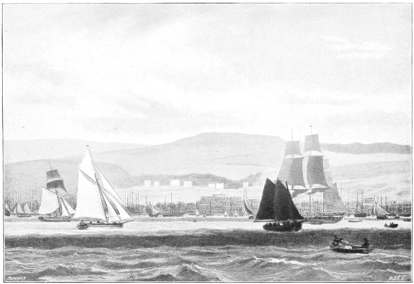
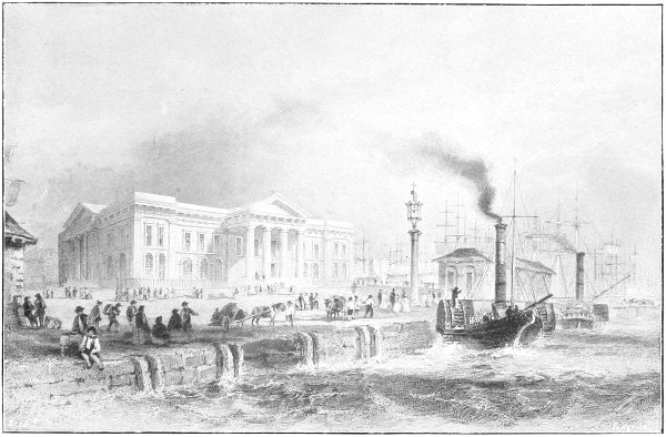
Plate V.
From an Old Engraving.
GREENOCK AND SCOTTS' YARD IN THE EIGHTEENTH CENTURY.
Other developments contributed to the prosperity of the
port of Greenock, the chief of the establishment being John
Scott of the third generation, who was born in 1752, and
died in 1837. His brother, William Scott, also the second
of that name, migrated to Bristol, where he carried on an
extensive trade as a shipbuilder. The latter was the father
of James M. Scott, who is still remembered by some old
inhabitants as the founder, about 1847, of penny banks in
Greenock and of the Artisans' Club. John Scott, after his
brother's departure, carried on the business under the name
of John Scott and Sons, and did great service not only for
the town, but also for the advancement of the business. In
three successive years, 1787, 1788, and 1789, he bought
three large plots from the ninth Lord Cathcart, for the
extension of the works.[9] These then extended almost from
the West Quay to the West Burn. He also, in 1791,
constructed the old steamboat or custom-house quay,[10] and
played a large part in developing the banking facilities of
the town. He bought, in 1815, Halkshill, near Largs,
which has continued the residence of the family. In view
of the association of the firm with the town, it may be
worth interpolating here a statement of the growth of the
population of Greenock, with the sources from which the
figures have been taken.
Year.
Population.
Source.
1700
1,328
Campbell's History, page 23.
1801
17,458
Weir's History, page 120.
1901
68,142
Census Returns, vol. i., page 212.
Shipbuilding work, however, was still in craft which
to-day would be considered insignificant. The increase of
the mercantile fleet of England throughout the eighteenth
century was only fivefold in respect of numbers, and sixfold
in tonnage; the average size shows an augmentation
from 80 tons to only 100 tons, and there was no improvement
in labour-economising appliances for the working of the
ship, as the ratio of men to tonnage was at the beginning
of the century practically one to every 10 tons, and at
the close one to 13 tons.[11]
In the nineteenth century, the tonnage increased eightfold,
but in view of the adoption of steam the actual carrying
capacity was augmented nearly thirtyfold; the average
size of ship increased to 760 tons. Practically, every ship
in the eighteenth century carried guns, the average being
two per vessel. It was not until 1853 that there was
omitted from the mail contracts the clause which provided
that each mail vessel must be built to carry guns of the
largest calibre in use.
The nineteenth century brought every incentive to
the development of shipbuilding. Nelson taught the lesson,
never to be forgotten, that sea-power is essential to the
commercial expansion—even to the existence—of our island
kingdom, with its corollary, that the merchant fleet is as
necessary to this mastery of the sea as fighting squadrons.
The sea became our home; there arose a renewed love
of exploration, and an ambition for colonisation. Success
brought the chastening influence of responsibility, with a
higher appreciation of the advantage of a conciliatory policy
towards foreign nations. Contemporaneously with the growth
of this conception of empire there arose a war of retaliation
in shipping with the newly-formed United States of
America, which continued for half a century. Although
not without its regrettable incidents, it stimulated a rivalry
in the shipping and shipbuilding industries which was
ultimately as beneficial as it had been pronounced. The
monopoly of the East India Company in the Eastern
shipping trade terminated, so far as India was concerned,
in 1814, and as regards China in 1834. This removed an
influence which had hitherto retarded enterprise in naval
construction—especially on the Clyde—due to the Company's
preference for building their ships in India, and in the
south of England ports. Private owners, too, entered more
vigorously into competition with American clippers which
had first commenced trade with China in 1788.
With the widening of the maritime interests and
the intensification of competition there was awakened a
general desire to increase the strength of ships. In this
respect, as in others, there had been little advance either
in the Navy or in the mercantile marine. It was exceptional
for a ship of the eighteenth century to continue in service
for more than twelve or fifteen years. This was due
partly to defective constructional details, and partly to
the ineffective methods of preserving timber.
Ships were then built up[12] of a series of transverse ribs,
connected together by the outside planking and by the
ceiling. There was no filling between the ribs. The
ship's structure thus suffered severely from hogging and
sagging stresses. The French tried to improve this by
introducing oblique iron riders across the ceiling, or by
laying the ceiling and the outside planking diagonally,
while in other instances the whole was strengthened with
vertical or diagonal riders; but none of these systems gave
complete satisfaction. The Sepping system was introduced
about 1810, and was early adopted by the Scotts. The
bottom of the ship was formed into a solid mass of
timber. The beams were connected with the side of the
ship by thick longitudinal timbers below the knees, and
by other stiffening members. A trussed frame was laid
on the inside of the transverse frame in the hold of the
ship, and the decks were laid diagonally. These members
bound the ship in all directions, so as to resist the stresses
due to the ship working in a seaway.
The method of preserving the timber adopted at the
beginning of the eighteenth century was to char the inner
surface of the log, while the outer surface was kept wet;
but this was superseded early in the century by the stoving
system, which consisted in placing timber in wet sand, and
subjecting it to the action of heat, for such time as was
necessary to extract the residue of the sap and bring the
timber to a condition of suppleness. This process continued
until 1736, after which the timber itself was steamed.
Copper sheathing was first employed on warships in 1761;
prior to this lead had been used, but only occasionally.
American shipbuilders held an important position, even
in the British trade, for some time after the Declaration
of Independence; but there was then developed a pronounced
spirit of emulation amongst the British firms,
which had a marked effect on competition in western seas.
At the beginning of the nineteenth century much of the
oversea work done by the Scotts was for the West Indian
trade. The vessels were not often of more than 600 tons,
but the firm continued steadily to develop their business.
Between 1773 and 1829, the period of expansion under
the second John Scott, to which we have already referred,
the output was 16,800 tons.[13] This output included a succession
of fine ships for the West India trade, to the order of
some of the old Glasgow companies, amongst the number
being Stirling, Gordon and Company; J. Campbell and
Company; James Young and Company; and Muir and
Fairlie. We may mention as typical ships, the Grenada, of
650 tons burden, and the John Campbell, of 446 tons, built
in 1806, the first ships launched on the Clyde with all
rigging in position.
Thus early, too, the Scotts had entered upon the construction
of that long series of yachts, sailing and steam,
which has brought them considerable repute, and even
more pleasure, since they were in successive generations
noted yachtsmen. In 1803 they launched the 45-1/2-ton
cutter for Colonel Campbell, of the Yorkshire Militia, which
was pronounced one of the completest of the kind ever built
in Scotland up to that time. It may be incidentally mentioned,
that the Scotts also showed thus early their practical
sympathy with the auxiliary forces of the Crown by being
at the head of the volunteer Sea Fencibles formed on the
Clyde in the stormy years of the Napoleonic wars.
As soon as the monopoly of the East India Company
was removed in 1814, private shipowners entered the lists,
and the Scotts were early occupied in the construction of
Indo-China clippers. In 1818 they built the Christian, and
in 1820 the Bellfield, the latter, of 478 tons register, for
the London and Calcutta trade. She was one of the first
of a long series. The Kirkman Finlay, of 430 tons, built
in 1834, suggests the name of a firm long and honourably
associated with the development of trade in our great
Eastern dependency. The effect of competition was a
reduction in the average rate of freight per ton from India
to Britain from £32 10s. about 1773 to £10 in 1830.
The East India Company about the year 1813 paid
£40 per ton for their ships, as against about £25 per ton
by other traders; the latter sum was about the same as
that paid in America. The East Indiaman had a crew in the
ratio of one to 10 or 12 tons, while one to 25 tons sufficed
for the West Indiaman. The speed of the western ship
was greater, largely by reason of the difference in proportions
and lines. The clipper built on the Clyde and
in America had a length equal to five or six times the
beam, against four times the beam in the case of the East
India Company's ships. In the design of these clippers
the Scotts took an important part. Charles Cuningham
Scott was then at the head of the concern. An ingenious
method of making model experiments in the graving dock
at the works was evolved in the 'forties, whereby the firm
were able to arrive at the most satisfactory form of hull to
give the minimum of resistance, and at the same time a large
capacity for cargo per registered ton. In this latter respect
they were more successful than the designers of the East
Indiamen, notwithstanding the bluff form of the latter.
As rapidity in answering the helm was a most important
element in tacking, and therefore in speed, the firm about
this time prepared full-rigged models, about 5 ft. long,
for experimental trials as to the ship's form and rudder,
on Loch Thom, on the hill above Greenock, in an exposed
place where the conditions of wind were analogous to those
at sea. The results proved satisfactory. In fact, in these
years, when the Minerva, Acbar, and other noted clippers
were built, the care used in design and construction was
almost as great as that now devoted in the case of racing
yachts.
The Scotts, in the first half of the nineteenth century,
continued to produce a long series of successful sailing
ships, while at the same time taking a creditable part
in the evolution of the steamship. Steam, however, was
not possible in long-distance voyages until pressures had
been increased, and coal consumption reduced to moderate
limits; and thus it came that, although the steam engine
was used in the early years of the nineteenth century in
river, and later in coasting, craft, the sailing ship continued
supreme almost until the middle of the century. We do
not propose, however, to refer to all of the later sailing
ships built by the Scotts, but it may be interesting to
give some details of the construction.
American rock elm was largely used. The frames
were in three sections with scarfed joints, bolted together,
the scantlings being reduced towards the top, so as to lower
the centre of gravity. Inside the frames there were at
various heights longitudinal timbers, to add to the fore-and-aft
strength. The top sides were of greenheart, the beams
of oak or greenheart, with wrought-iron knees; the height
between the beams was made to admit of two hogsheads
of sugar being placed in the hold. There were side-stringers,
sometimes 10 in. thick, between the floor and the beams,
which were half-checked into the stringers. On the top
of the beams there were deck-stringers. There was a
most effective transverse and longitudinal binding, brass
bolts being extended right through the knee, stringer,
frame, and skin of the ship. The decks were of yellow
or Dantzig white pine. An 800 or 1000-ton West Indiaman
occupied about nine months in construction. The last
wooden ship built in Greenock was the Canadian, completed
by the Scotts in 1859.[14]
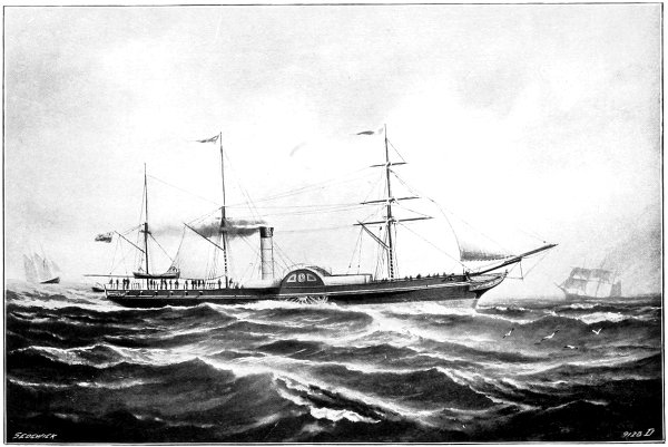
The highest conception of the iron sailing ship, as
built by the firm, was probably embodied in the Lord of the
Isles, completed in 1856. She had a length between perpendiculars
of 185 ft., a breadth of 29 ft.—the proportion
being thus 6.4 of length to 1 of beam—with a depth of hold
of 18 ft. Her registered tonnage was 691 tons, and her
builders' measurement 770 tons. Although a fine-ended
ship she carried a large cargo on board, and made her
first trip to Sydney in seventy days, which had not then
been surpassed.[15] She made the passage from Shanghai to
London in eighty-seven days, with 1030 tons of tea on board.
In one trip she averaged 320 nautical miles for five consecutive
days. When engaged in the celebrated race
for the delivery of the season's teas from Foo-chow-foo to
London, in 1856, the Lord of the Isles beat two of the
fastest American clippers, of almost twice her tonnage.
She "delivered her cargo without one spot of damage,
and thus British ships regained their ascendency in the
trade which their American rivals had far too long
monopolised."[16] From that time the British sailing ships
gradually gained a complete superiority over the American
vessels, and carried all before them, until they in turn
were supplanted by the British steamship. From time to
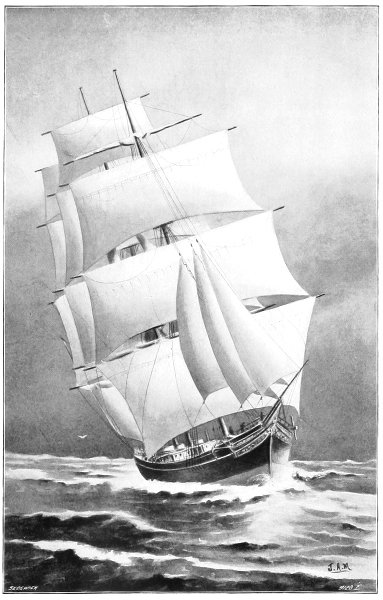
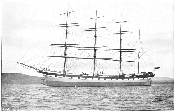
time an occasional sailing ship was constructed of steel;
the latest, the Archibald Russell, is illustrated. Built for
Messrs. John Hardie and Company, this vessel has a length,
between perpendiculars, of 278 ft., a beam of 43 ft., and a
depth, moulded, of 26 ft., and carries 3930 tons of deadweight
cargo on a draught of 21 ft. 7-1/2 in. But less than
1 per cent. of ships now constructed depend upon the
unbought but uncertain winds, and then only for special
trades. On regular routes the steamer is now almost
paramount, and it was, therefore, appropriate in the highest
degree that the first vessels to steam regularly to China,
viâ the Cape, should, like the Lord of the Isles, be built
by the Scotts; but that belongs to another story.
The Development of the Steamship.
A CLOSE association existed between the
Scotts and the family of James Watt,
the inventor of the steam engine: the
founder of the Scotts' shipbuilding firm
and the father of Watt were identified
with several schemes for the improvement
of Greenock; and the signature
of John Scott, of the third generation, whose portrait is the
second reproduced on Plate II., is taken from a document
in connection with some intromissions of town's funds, to
which also is adhibited the signature of Watt's father.
It is not surprising, therefore, that the Scotts were
early close students of Watt's inventive work, and among
the first to enter upon the building of steamships; while
at the same time, as we have shown in the preceding
pages, building many of the fine sailing ships which
established British shipping supremacy in the early half
of the nineteenth century, and raised Greenock by 1829 to
a port having trade with every part of the world.
Miller and Taylor commenced their experiments at
Dalswinton in 1788, with a steam engine driving paddle-wheels
in boats[17].
Symington's steam tug, Charlotte Dundas,
by its success in 1802 on the Forth and Clyde Canal[18],
removed any remaining doubt; but it was not until 1812 that
Henry Bell, with his Comet, proved the commercial utility
of the steam system, although without profit to the
promoter.[19]
The building of steamships, evolved by experiments
by various workers in Britain—and in America
also—was readily adopted on the Clyde. Within four
years of the completion of the Comet, it was not unusual
for five hundred or six hundred passengers to enjoy in the
course of one day water excursions on the river.[20] The
fares were practically five times those prevailing to-day.
Among the earliest of the Clyde steamers were the Active,
of 59 tons, and Despatch, of 58 tons, built by the Scotts.
In calculating the tonnage in those early days, an average
allowance of one-third was deducted for the machinery.
In 1816 the firm built the Shannon, of a length between
perpendiculars of 77 ft. 7 in., of a beam of 15 ft. 3 in.,
and of a depth moulded of 9 ft. 1 in. She had fore-and-aft
cabins. Her engines were of 14 horse-power nominal.
She plied on the Shannon between Limerick and Kilrush.
By 1818—six years after the completion of the Comet—thirty-two
steamers were running on the Clyde, and some
of these were sent ultimately for traffic on the coast and
on other rivers.[21] The largest of these was of 112 tons,
with engines of 40 nominal horse-power.
The Scotts had built many sailing craft for the Clyde
and Belfast trade, for the Glasgow and Liverpool service,
and for the Liverpool and Drogheda, and other coasting
routes; and it was natural when steam was introduced
that the same firm should supply the side-paddle boats.
In three successive years—from 1819 to 1821—the
largest steamer in the kingdom came from Scotts'
Works. The record was marked in 1819 by the Waterloo,
of over 200 tons, with engines of 60 nominal horse-power;
in 1820, by the Superb of 240 tons register, with engines
of 72 nominal horse-power, which cost about £37 per ton,
and steamed 9 miles per hour, using 1670 lb. of Scotch
coal per hour; and in 1821, by the Majestic, of 345 tons
register, with engines of 100 horse-power, which cost over
£40 per ton, and steamed 10 miles per hour for a consumption
of 2240 lb. of Scotch coal. Although the modern
steamer is fifty times the size of these pioneers, with a cost
per ton of less than one-fourth, and a fuel consumption per
unit of work done of not more than a seventh, the records
of these and other early ships are worthy of full reference.
The advantage of steam navigation for channel service
was at once recognised. A Parliamentary return issued
in 1815 showed that for the space of nine days in the
previous year only one mail packet could sail between
Holyhead and Dublin owing to adverse winds, and even
then the average passage was twenty-four hours. Lord
Kelvin, in his memorable Address as Chancellor of the
University of Glasgow, in 1905, recalled the fact that
early in the century his father often took three or four
days to cross from Belfast to Greenock in a smack, as
she was frequently becalmed. With favourable winds,
rapid passages were made, a revenue cutter occasionally
doing the Belfast and Greenock run in ten hours.
The Greenock and Belfast route was among the first
around the coast to come under the influence of the
mechanical system of propulsion. The Rob Roy, which
was the outcome, so far as form of hull was concerned,
of probably the first model experiments ever made—undertaken
by David Napier in the Canal at Camlachie[22]—was
in 1818 the pioneer in the Glasgow and Belfast steam
service, and later in the Dover and Calais steam service.
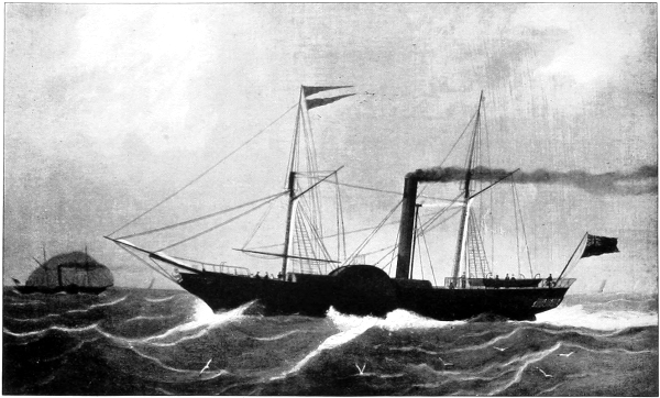
There followed in 1819 three notable vessels from
Scotts' Works: the Waterloo,[23] the Robert Bruce, and the
Sir William Wallace. The particulars and performances of
these vessels, taken from contemporary records, principally
the "Greenock Advertiser," which faithfully reported each
incident in the development of the steamship, are especially
interesting as illustrative of early work.
The Waterloo, which, as we have already said, was the
largest steamer of her year (1819), had a beam equal to
one-fifth of her length, the measurement between perpendiculars
being 98 ft. 8 in. In addition to a large number of
passengers, she carried under ordinary conditions a cargo
of 100 tons, on a draught of 8 ft. 6 in. against 7 ft. 3 in.
without cargo. Three months were required, between the
launch of the ship and her trials, for the fitting on board
of engines each of 30 nominal horse-power, which gave her
a speed of between 8 and 9 miles per hour. Sails, however,
were still carried to assist in driving the ship, and this
vessel was of schooner rig. She inaugurated the steam
service between Belfast and Liverpool.
The Robert Bruce was the first steamer to trade
between the Clyde and Liverpool.[24]
She was followed by
the Sir William Wallace. Both were built by the Scotts,
and had engines of 60 nominal horse-power. They began
service in the summer of 1819; and the record of the
maiden voyage of the former, in August, 1819, showed that
two and a-half hours were occupied in the run from Glasgow
to Greenock, about 22 miles; and within 26 hours thereafter
the vessel took on her pilot at the north-west lightship
outside the Mersey Bar. The return voyage was equally
satisfactory. To quote again from contemporary records,
"the passengers, both out and home, were so highly gratified
with the performance of this vessel and their treatment on
board that they unanimously expressed their entire satisfaction
with Captain Paterson's exertions to render them
comfortable and happy, their conviction of the seaworthiness
of the vessel, and their admiration of the powers of the
engines, capable of propelling so large a body at the rate
of 7 knots per hour, in the face of a strong north-northwest
wind and high sea for at least two-thirds of the way
from Liverpool, her rate thither being nearly 9 knots."[25]
In 1820, the Superb, of 240 tons and 72 horse-power,
followed the Sir William Wallace, and marked a still
further improvement. She had a copper boiler, and in the
three cabins sleeping accommodation was provided for sixty-two
passengers. She was "the finest, largest, and most
powerful steam vessel in Great Britain.[26] The average
duration of the passage from the Clyde to Liverpool did
not exceed 30 hours."
The Majestic, also for the Clyde and Liverpool service,
was built in 1821, and was 134 ft. 11 in. long between
perpendiculars, 22 ft. 8 in. beam, and 14 ft. 5 in. depth,
moulded. Her draught, 10 ft. 6 in. forward and 12 ft. aft,
was too great for the upper reaches of the Clyde, and
passengers were brought from Glasgow to Greenock in a
tender. In her four cabins there was greatly-increased
accommodation for the passengers. She was probably the
first steamer with a sleeping apartment exclusively for
ladies. The copper boiler worked at a pressure of 4 lb.
per square inch, and the engines ran at 56 revolutions.
The fares[27] to Liverpool in those days were £2 15s., as
compared with 11s. to-day; of course, very much better
accommodation is now provided.
The City of Glasgow was built in 1822 for the Liverpool
service. This vessel, which cost £15,000, had a speed of
over 10 knots, and was reputed the fastest afloat. Her
length was 110 ft. 4 in., beam 22 ft. 4 in., and depth,
moulded, 13 ft. She was arranged like the Majestic, and
the two were long the most important vessels in the Clyde
and Liverpool trade. She was subsequently bought by
McIver, and inaugurated the competition with the Burns
line, commenced in 1829.[28] The McIver and Burns lines
were subsequently combined.
The Scotts rendered similar service in the development
of the mail route between Holyhead and Dublin. The
first vessel built by them for this service was the Ivanhoe,
constructed in 1820. The steam service had been opened
between these two ports in 1819 by the Talbot, the first
steamer fitted with feathering floats.[29] The Ivanhoe,[30]
a larger steamer than the Talbot, was of 170 tons
burden, her length between perpendiculars being 97 ft. 4 in.,
beam 19 ft., and depth, moulded, 14 ft. 6 in. She had
various improvements in her machinery, which was of 60
nominal horse-power. She left Scotts' yard in May, 1820,
and made the voyage to Howth (200 miles), in 26-1/2 hours.
Thus the Scotts continued to improve on each successive
ship, and to widen the area of their influence. The Clyde
continued to largely monopolise the industry of steam
shipbuilding, and it was not until the summer of 1822
that a steamer—not built in Scotland—appeared on the
Clyde. This was the Saint George, from Liverpool, and
the City of Glasgow, already referred to, her competitor
in the Liverpool trade, raced her and greatly excelled.
One of the first steamers to trade in the Mediterranean
was the Superb, sent thither in 1824, and the Trinacria,
also built by the Scotts, followed in 1825. These ran
between Naples and Palermo. The last-named vessel was
135 ft. long over-all, and 113 ft. 6 in. between perpendiculars,
39 ft. 6 in. broad over the paddle-box, and 21 ft. 10 in.
net beam, 14 ft. deep (moulded), and of 300 tons burden.
The vessel was especially well-equipped, and cost £15,000.
The engines, the first manufactured by the Scotts at their
Greenock foundry, were of 80 nominal horse-power, and the
boilers, which were of copper, weighed 40 tons. The speed
was 10 miles per hour. Later this steamer became the
Hylton Joliffe, and was employed by the General Steam
Navigation Company on their London and Hamburg
service.
As to the yard in which these several vessels were
built, suggestion is afforded of the state of efficiency by
the following quotation from a history published in 1829.[31]
"The building yard of Messrs. Scott and Sons is allowed
to be the most complete in Britain, excepting those which
belong to the Crown. It has a fine extent of front from
the West Quay to the termination of the West Burn, and
has a large dry dock, which was altered lately to the
plan of the new dock. All the stores and lofts are entirely
walled in, and, independently of the building premises,
they have an extensive manufactory of chain cables."
The majority of the engines for these early steamers
of the Scotts were constructed by Napier or Cook, and
were of the side-lever or beam type. In 1825, however,
John Scott, who had done so much for the progress of the
firm, decided to commence building machinery, and acquired
for £5000 the works which have since been developed into
the well-known Greenock Foundry. This establishment was
begun, although on a very small scale, about 1790,[32] and in
its equipment, which was considered thoroughly efficient,
there was included a large cupola. Some idea is given
of the extent of the establishment by reference to Weir's
"History of Greenock" (1829), page 94, where it is stated
that in the few years that had elapsed since the taking
over of the works by the Scotts "they have manufactured
some splendid engines, and—what is more to be looked for
than the appearance—they have wrought well. They have
in hand the largest engine ever made, which is of a size
of 200 horse-power, and is intended for a vessel building
at Bristol. The number of men employed amount to about
two hundred and twenty, while the weekly distribution of
wages is £180." As a contrast, it may be said here that
there are now four thousand men in the works, earning
per week over £5500 in wages, and that the Scotts are
engaged on the largest set of engines yet constructed by
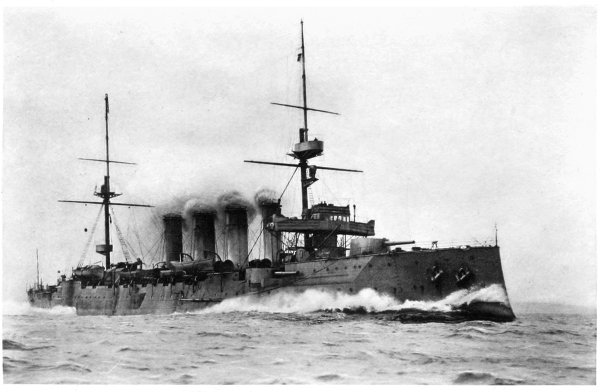
them—for H.M.S. Defence. They are of 27,000 indicated
horse-power, to give the immense armoured cruiser named,
of 14,600 tons displacement, a speed of 23 knots.
Since 1825, the Scotts have continued to do very
satisfactory engine work, much of it of an original character,
not only for vessels built for themselves, but for ships constructed
on the Thames and other English rivers, and also
for the series of warships built for the British Navy at
their works, and for others constructed at the Royal Dockyards.
This naval engine work began with H.M. ships
Hecla and Hecate, engined in 1838-9, and the first warships
built in the dockyards to be sent to Scottish works to
receive machinery.[33] And here it may be noted, too, that
the first warship built by the Scotts was the Prince of
Wales, in 1803, and also that the firm had the credit
of building the first steam frigate constructed at Clyde
works for the British Navy, H.M.S. Greenock, launched
in 1839. They also built the first compound engines fitted
to a French warship. With these naval ships and engines
we deal in our next Chapter, and may therefore continue
our narrative regarding merchant steamers.
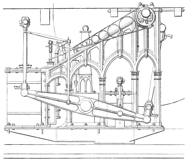
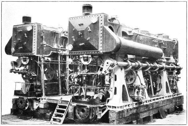
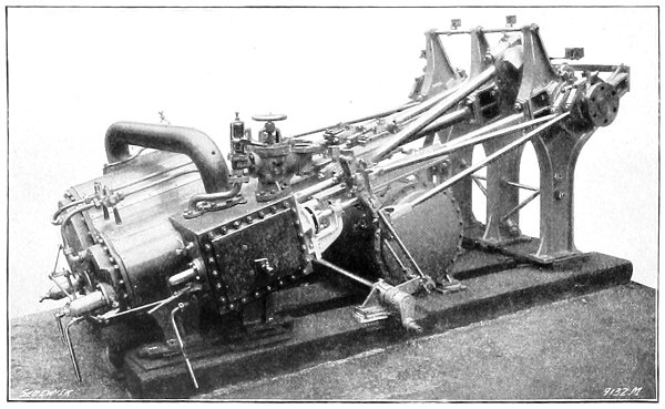
We reproduce on the preceding page a drawing
illustrating an early type of engine built by the firm.
This is an engine constructed in 1831. The steam cylinder
is 52-1/4 in. in diameter, and the crank-shaft is actuated,
through connecting-rods, from the ends of the levers
operated by the piston-rod, while the air-pump is placed
at the opposite ends of the levers.
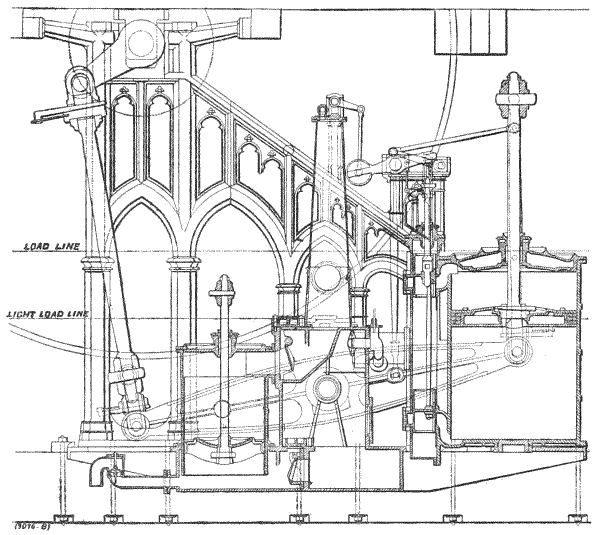
A different type of engine, constructed in the following
year (1832), is illustrated on the facing page. In this
case the cylinder operates the opposite end of the levers
to that connected with the crank-shaft. In both engines
the lever-gudgeon passes through the jet-condenser.
The records we have given are historically interesting,
because they tell of the beginnings of a great epoch in
British shipping. We do not propose to follow in such
detail subsequent steamships, built for other services,
between London and Aberdeen, the Clyde and Dublin,
etc. The City of Aberdeen, built in 1835 for the first-named,
marked noteworthy progress. She measured 187 ft.
over the figure-head, and was of 1800 tons, including the
space for the machinery. Her poop was 60 ft. long and
45 ft. broad. According to contemporary testimony, she
was, in her day, the strongest steamer built, having solid
frames from gunwale to gunwale. She had additional
bracing with African oak stringers; oak and iron trussings
alternately bolted to the stringers formed a complete
system of diagonal fastenings and bindings from stem to
stern. The whole of the cabins, saloons and state rooms,
were on one deck, and there was the important innovation
of hot and cold baths. The speed was 12 miles per hour.[34]
The Jupiter, of 439 tons and 210 horse-power, built
in 1836 for the Clyde and Dublin trade, cost £20,000, and
established a record in speed, making the voyage in sixteen
hours six minutes, at the rate of 13 miles per hour;
formerly the voyage took twenty-four hours.
In the late 'thirties and the early 'forties there was
a great development in oversea trading steamers, the Clyde
taking, then as now, the foremost place. Several epoch-marking
voyages had been made with the steam engine
used intermittently. The Savannah had thus crossed the
Atlantic from the United States in 1819, and the Royal
William from Quebec in 1833.
The barque Falcon,[35] 84 ft. in length, and of 175 tons,
had, on the voyage to India in 1835 utilised engines
which, however, were removed on her arrival in our
Eastern dependency. Later in the same year the Enterprise,
of 470 tons and 120 horse-power, also rounded
the Cape of Good Hope to India. In all these cases,
however, sails were utilised whenever possible, and there was
still great hesitancy in accepting the steam engine even as
an alternative on occasions to the use of the "unbought
wind." The advantage, however, of a rate of speed which,
while low, would be constant, soon asserted itself, and there
followed within a few years regular mail steamship services
on the North and South Atlantic Oceans, in the Mediterranean
Sea, in the Indian Ocean, and the China Seas. In
the beginning and development of these services the Scotts
took a prominent part.
One of the first notable steamship lines to be organised
for oversea service was that which ultimately became the
Peninsular and Oriental Company. It had its origin[36] in
steamship service from Falmouth to Oporto, Lisbon, Cadiz,
and Gibraltar. Four steamers were built in 1836-37:
the Tagus, Don Juan, Braganza, and Iberia. The first-named
was built by the Scotts, and the third was engined
by them. These ultimately carried the mails as far as
Alexandria, whence they were conveyed overland to Suez,
and from thence by the East India Company's vessels
to Bombay. This service developed into the Peninsular
and Oriental service, when, in 1840, the Company took
over the mail service on the Indian Ocean; in 1847
they extended their operations to China. The overland
service continued until the Suez Canal was opened in
1869, and many of the vessels for the Mediterranean
service, as well as for the eastern route, were built by the
Scotts.
The Tagus,[37] which was thus amongst the first of the
P. and O. steamers, was built in 1837. She had a length of
182.1 ft., a beam of 26 ft., and a depth of 17 ft. 4 in., the
burden tonnage being 709 tons. When carrying 265 tons of
coal in her bunkers and 300 tons of cargo, the draught was
14 ft. 6 in. The side-lever engines which were fitted to her
had a cylinder 62 in. in diameter, with a 5-ft. 9-in. stroke,
developed 286 horse-power, and operated paddle-wheels
23 ft. 6 in. in diameter. Two of the other early steamers, the
Jupiter and the Montrose, were also constructed by the Scotts.
The conveyance of cargo and passengers across the
Isthmus of Suez not only involved inconvenience and
expense, but was a cause of great delay. There was still,
however, a strong prejudice against steamships being utilised
for long sea voyages, partly because of vested interests in
sailing ships. Sir John Ross, C.B., who, in 1818 and in 1829
to 1833, made Arctic explorations, was one of the strongest
advocates for a service to India by way of the Cape of Good
Hope; and, in order to establish the feasibility of the
undertaking, made experiments with the City of Glasgow,
built by the Scotts in 1821. This vessel, of 283 tons, had
in the interval been fitted with new boilers, with special safety
appliances, and they worked at 4-lb. pressure; they gave the
high evaporation in those days of 9 lb. of water per pound
of coal.[38]
This vessel made the trip from London Bridge to the
lightship off Spithead (246 miles) in thirty-one hours five
minutes, on a consumption of 6 lb. of fuel per indicated horse-power
per hour. These facts were utilised by Sir John Ross
in his advocacy of the route, and a new company was formed,
under his chairmanship, in 1837.
The first vessel of the fleet, named the India, was
built and engined by the Scotts, and was a few years later
transferred to the Peninsular and Oriental Company. The
India, launched in 1839, was the largest steamer built on the
Clyde up to that date, being 206 ft. 6 in. long, 30 ft. 9 in. beam,
or 48 ft. wide over the paddle-boxes. The gross tonnage
was 1206 tons. Accommodation was provided for eighty
cabin passengers, and provision made for 400 tons of cargo.
A feature of her construction was the provision of two
strong bulkheads of iron across the engine-room, in order
to avoid accidental outbreak of fire, and also to prevent
water from a leak in one part spreading to another.[39] This
was probably the beginning—nearly seventy years ago—of
the system of division by watertight bulkheads, now
universal. Its compulsory adoption was advocated by the
Institution of Naval Architects in 1866, and enforced by
Lloyds in 1882, and by the Board of Trade in 1890. The
machinery was of 320 horse-power, and had surface-condensers.
The India was launched on the anniversary
of the birth of James Watt, and a salute of twenty-one
guns was fired as the vessel left the ways.
Five other steamers were built for the service, and
the voyage took from fifty-five to sixty days, as compared
with the one hundred and thirteen days occupied by the
Enterprise. A monthly service was thus rendered possible.
At the same time the Scotts built steam vessels for the
coasting trade of India and of South Africa.
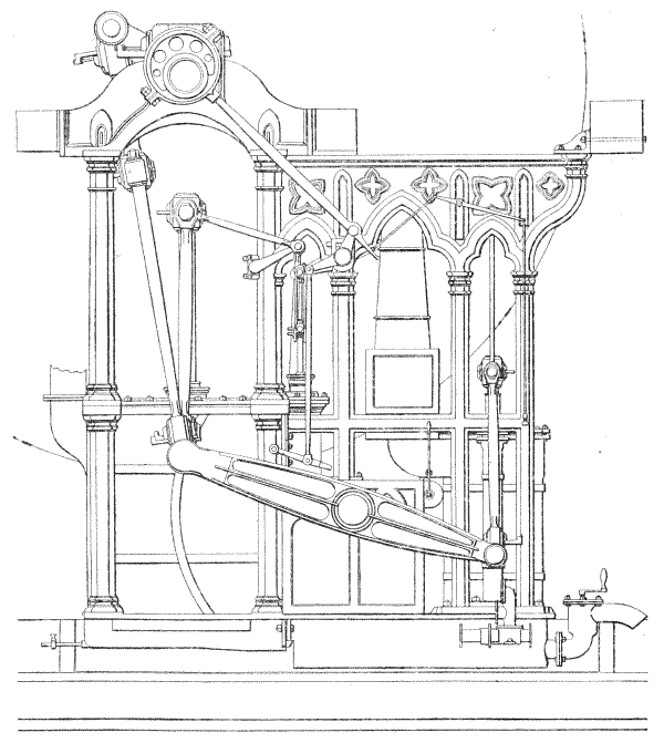
The type of machinery in use at this period is illustrated
on the opposite page. This particular engine was constructed
in 1838. The piston was connected to one end of the
side-levers, while the crank was operated from the other.
The paddle-wheel of this engine was 25 ft. 0-1/2 in. in diameter,
with seventeen floats. For about thirty years this was the
standard type of marine engine for paddle steamers.
The Gothic architectural design for the main framing
was gradually abandoned for something less ornamental
and perhaps more mechanical.
The Royal West India Mail Company's Service, still
one of the best known of British lines, was commenced
in 1841. Some of the steamers were purchased, but
amongst those built originally for the service was the
Dee by the Scotts. She was 213 ft. 9 in. long, 30 ft. 4 in.
beam, and 30 ft. in depth, the burden tonnage being 1848
tons. On a draught of 17 ft. 6 in. she carried 700 tons of
cargo; and, as with most of the oversea liners of the period,
the average speed was only about 8 knots. The voyage
of 13,650 miles occupied then one hundred and nine days,
including stoppages; and the consumption of fuel was
25-1/2 tons per day. The engines, which had cylinders
73 in. in diameter with a stroke of 7 ft., were of 450 horse-power,
driving side paddle-wheels 28 ft. 6 in. in diameter.[40]
In the thirty years from the first commercial British
steamer, the Comet, there had not been much advance in
the steam engine, excepting in size, power, and, perhaps,
reliability. Wood had continued to be the constructive
material for all but the smallest ships. The size of vessels
had grown steadily to the 1848 tons of the West Indian
mail liner, which started regular steamship service almost
contemporaneously with the inauguration of the Atlantic
mail line by the Cunard Company in 1840. Speeds on
service, even on the shortest routes, were seldom over
13 knots, and on the long routes under 8 knots. But
this was in excess of the average attained by all but
exceptionally fast clippers. The Table on the opposite
page shows the progress made in thirty years.
Table I.—Epoch-Marking Steamers Built By The Scotts, 1819 To 1841.
Largest constructed on Clyde, 1837, and an early P. and O. liner.
1839
India
1206
320
10
First steamer to India viâ the Cape and the first Indian liner.
1841
Dee
1848
450
10
First Royal West India Mail liner.
We enter now upon the period when iron took the
place of timber as a constructional material. It was first
used in part in the construction, on the banks of the
Monkland Canal as far back as 1818, of a canal barge
named the Vulcan, a vessel which continued at work for
over sixty years.[41] But the first vessel built entirely of iron
was a small craft constructed in 1821 in England. It was
not, however, until 1832 that the first sea-going vessel
was built of this metal. Progress in the adoption of iron
was slow, largely because timber had proved so serviceable,
and, with lessened restriction upon its importation, had
become much cheaper. It was not until the higher
strength and greater ductility of steel were demonstrated
in the 'eighties that timber was finally superseded. The
last wooden ship built by the Scotts was completed in
1859.
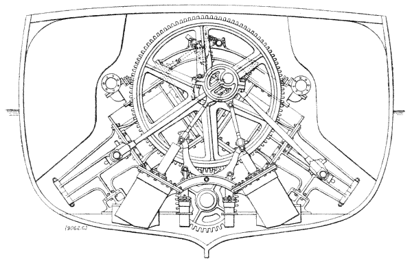
The firm built several of the early Atlantic liners,
and we reproduce on page 32, as a further step in the
development of the steam engine, a drawing showing the
double-gear engines constructed early in the 'fifties for an
iron screw steamer of 1190 tons, built for the Glasgow
and New York service. This engine was pronounced at
the time "the most compact specimen of its type then in
existence,"[42] for although the power developed was 250 horse-power,
and the ship was 260 ft. in length, only 12 ft. 6 in.
of the fore-and-aft length was taken up by the machinery.
"Every weight was well balanced, the working parts were
clear and open, and the combined whole was stable, firm,
and well bound together." The cylinders were 52 in. in
diameter, were arranged diagonally, and worked at right
angles to each other, with a stroke of 3 ft. 9 in. The
piston-rods projected through the lower covers, to allow
of long return connecting-rods. Each cylinder had two
piston-rods, for greater steadiness, their outer ends in each
case being keyed into a crosshead, fitted at each end with
slide-blocks, working in a pair of inclined open guide-frames,
bolted to the bottom cylinder cover, and supported
beneath by projecting bracket-pieces, recessed and bolted
down upon pedestal pieces on the engine sole-plate. From
each end of this crosshead, immediately outside the guide-frame,
a plain straight connecting-rod of round section
passed up to actuate the main first-motion shaft. The
upper ends of the connecting-rods were jointed to side-studs,
or crank-pins, fixed in two opposite arms of a pair
of large spur-wheels, which gave motion to the screw-shaft
by means of a pair of corresponding spur-pinions, fixed
on the shaft.
The main spur-wheels were 11 ft. 5-1/2 in. in diameter,
and the pinions on the screw-shaft 4 ft. 6 in.; so that the
screw propeller made 2-1/2 revolutions to each rotation of the
engine. The arrangement ensured that each piston was
directly coupled to both of the large wheels, and the
increased length of the crossheads, which the plan involved,
was counterbalanced by the effect of the double piston-rods,
for by this division of the pressure the cross-strain
leverage was proportionately diminished.
The use of steam expansively in multiple-cylinder
engines was, however, the most important factor in the
development of the steamship during the latter half of
the nineteenth century.[43] With low steam pressures and
simple engines the coal consumption, even for moderate-sized
ships, was a serious item in a long sea voyage; and,
early in the 'fifties, engineers, recognising the economy
which would result from a successful compounding of
steam, tackled the problems of steam-generation plant to
enable the necessary high initial pressure to be developed
with safety. John Elder had fitted several ships, but was,
for a long time, content with an initial pressure of from
50 lb. to 60 lb. per square inch.
The late John Scott, C.B., was so convinced of the
economy of steam at higher pressures in the compound
system that he decided to build, largely at his own expense,
a vessel which would enable him to put the system to
a thorough test. This steamer, constructed of iron in 1858,
was the Thetis, which was, undoubtedly, an epoch-marking
ship, as her machinery was operated at an initial pressure
of 115 lb. to the square inch—exceptionally high for those
days.
For the first time, surface condensers were used in
association with the compound marine engine. There were,
as shown on Plate XI., facing page 36, six cylinders,
arranged in two groups, each with one high- and two
low-pressure cylinders. The three pistons of each group
worked one crosshead, connecting-rod, and crank. Each
group had two slide-valves, one for the high-pressure
and one for the low-pressure cylinders, and both were
attached to one valve spindle and one reversing link.[44]
The engines worked up to 51 revolutions per minute—equal
to a piston speed of 255 ft. per minute—and the
maximum indicated horse-power was 256. The engines were
tried by the late Professor Macquorn Rankine, F.R.S., who
certified that the coal consumption on trial was 1.018 lb.
per indicated horse-power per hour: an extraordinary result,
even in the light of modern improvements.[45]
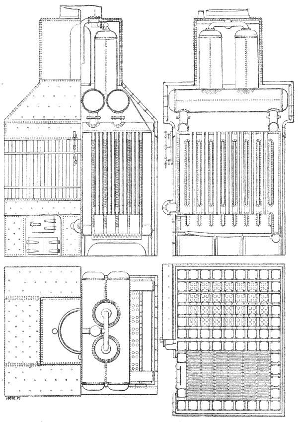
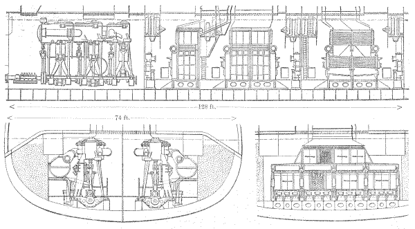
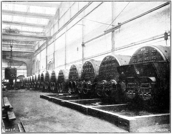
A large part of this efficiency was due to the boilers,
which were of the Rowan water-tube type, and are illustrated
on the opposite page. They had square vertical
water-tubes, and through each of these there passed four
hot-gas tubes. They evaporated 11 lb. of water per pound
of coal, which was 30 per cent. higher than was attained
with the best marine boilers of those days. The coal
consumption at sea was about 1.86 lb. per indicated horse-power
per hour.
Unfortunately, there soon developed small holes in the
boiler-tubes, owing to erosion of the external surface, probably
the consequence of the chemical action set up by the
steam for cleaning the tubes mixing with the soot and other
deposit.[46] Although for this reason this early water-tube
boiler did not succeed, there is no doubt that the performances
suggested improvements which have since brought
complete success to this system of boiler. At the same
time, the efficiency of high steam pressures was completely
established and resulted in very considerable progress in
the size and power of steamships.
Another innovation which suggested future developments
was the fitting at the base of the funnel in the
Thetis of a series of water-tubes for the purpose of utilising
the waste heat from the boilers to evaporate water for
subsequent condensation to make up the boiler feed. The
time was not ripe for such a utilisation of the waste gases—the
heat was insufficient to generate the required steam—but
now various schemes are applied for absorbing the waste
heat in the uptake to heat air for furnace draught and
to superheat steam.
A number of water-tube boilers were made, and
a set was fitted into a corvette built for the French
Navy. This vessel, completed in the early 'sixties, was
the first ship in the French fleet to be driven by
compound engines, and will fall to be described with
other vessels in our next Chapter, dealing with the work
of a century for the Navy.
Perhaps the most significant indication of the success
of the Scott compound engine is found in the results of
its application to the early Holt steamers. Alfred Holt
commenced trading with the West Indies in 1855, while
his brother, George Holt, became associated with Lamport
in the River Plate trade in 1865. Both lines continue
among the most successful in British shipping.
The Holt steam line to China was commenced in
1865, and was the only one viâ the Cape of Good
Hope which proved at once successful. Built and engined
by the Scotts, the early Holt liners, starting from Liverpool,
never stopped till they reached Mauritius, a distance
of 8500 miles, being under steam the whole way, a
feat until then considered impossible.[47] Thence the vessels
proceeded to Penang, Singapore, Hong Kong, and Shanghai.
Unaided by any Government grants, they performed this
long voyage with great regularity.
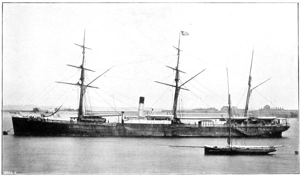
The three vessels which inaugurated the very successful
Holt line were named Agamemnon, Ajax, and Achilles,
and were built of iron by the Scotts in 1865-6. They
were each 309 ft. in length between perpendiculars, 38 ft. 6 in.
beam, and 29 ft. 8 in. in depth, with a gross tonnage of
2347 tons—dimensions which were then deemed too great
for the China trade, but which experience soon proved to
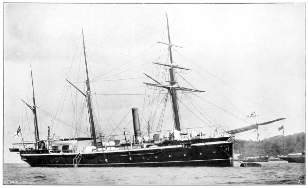
be most satisfactory. Sails were fitted to the vessels, as
shown in the engraving on the Plate facing page 40.
Alfred Holt was the first to apply the compound
engine to long voyages, and his vessels were the earliest of
the type built for the merchant service by the Scotts. It
is true the Pacific Company had compound engines fitted
to one or two ships prior to this, but these were only
used in the coasting trade. The engines of these Holt liners
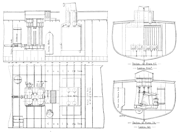
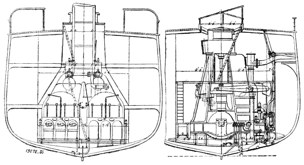
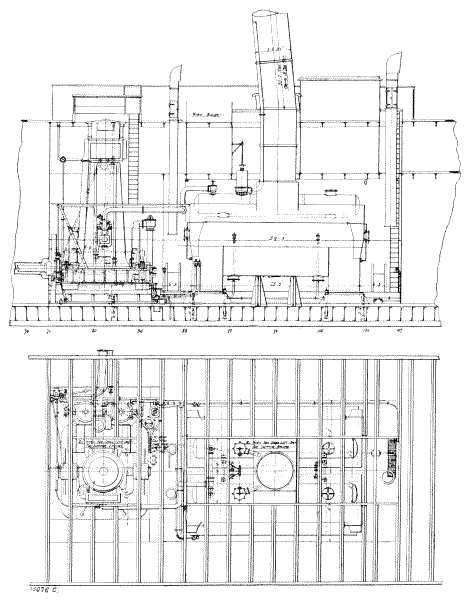
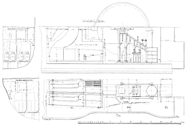
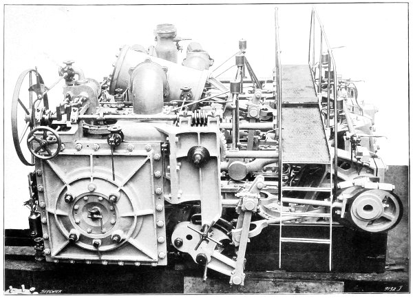
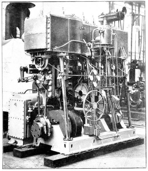
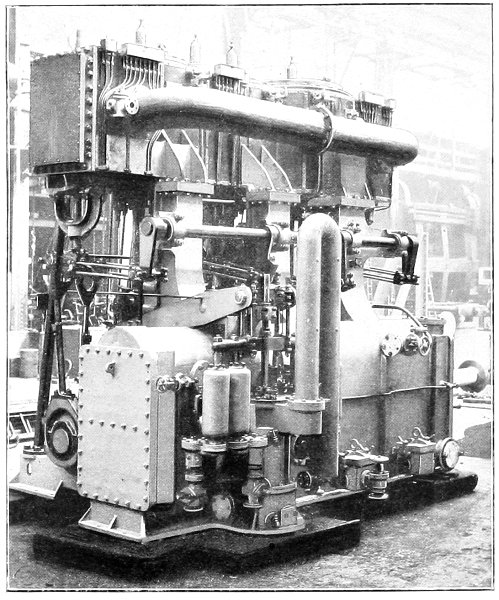
are therefore of historical interest, and general drawings
are reproduced on the next page and on Plate XII. A
feature in these liners was that the propeller was abaft the
rudder, which worked in an aperture in the deadwood corresponding
to that for the propeller in single-screw modern ships.
A detailed description from the specification of the
machinery may be reproduced, as it indicates the practice
of the Scotts for a considerable time. Indeed, this type
of compound engine, with slight modifications, was the
standard engine for Holt liners until the advent of the
triple-expansion engine. The details follow:—
The cylinders were: high-pressure, 30 in. in diameter; low-pressure, 62 in.
in diameter, with 4 ft. 4 in. stroke, arranged vertically in tandem fashion, with
the low-pressure cylinder on the top. There were two connecting-rods, but
a common crosshead for the tandem cylinders, and a common crankpin.
The crankshaft was 13-1/2 in. in diameter, with a bearing 30 in. long at
the aft end of the bedplate, which took the propeller thrust. The propeller
was three-bladed, 17 ft. in diameter, with 26 ft. 6 in. pitch; with 46 revolutions
per minute the piston speed was 400 ft. per minute. To ensure smooth
working with the single crank, a heavy flywheel was fitted, and the pump
levers carried a massive weight to help to balance the weight of pistons
and rods.
The condenser had 420 tubes 1-1/2 in. in diameter, giving a cooling
surface of 1375 square feet. The tubes were arranged in three nests, the
water circulating through the top one first and the bottom one last. The
circulating pump, instead of forcing water through the tubes, as was usual in
such case, sucked from the condenser and discharged directly overboard. There
were: one air pump, 24 in. in diameter; one circulating pump, 24 in. in
diameter; two feed pumps, 4-3/4 in. in diameter; and one bilge pump 7 in.
in diameter: all the pumps were single-acting, with 17 in. stroke. The
diameters of the principal pipes were: main steam, 7-1/2 in.; to low-pressure
cylinder, 12 in.; circulating inlet, 10 in.; discharge, 12 in.; air-pump discharge,
10 in.; main feed, 3-3/4 in.; and waste steam, two at 6 in. in diameter.
The two boilers were double-ended, of the locomotive type, with wet-bottomed
furnaces. The centre was cylindrical, but the ends were rectangular
with semi-cylindrical tops, the total weight, without water, being 78 tons.
Each boiler had a long receiver passing through the uptake to dry the steam.
On the receiver was a deadweight safety-valve 6-1/4 in. in diameter, to
suit a working pressure of 60 lb. per square inch. The grate surface was
112 square feet, and the total heating surface 4506 square feet, there being
328 iron tubes 4 in. in diameter.
Plate XII.
GENERAL ARRANGEMENT OF THE MACHINERY OF THE
"ACHILLES."
The three pioneer ships of the Holt line—the
Agamemnon, Ajax, and Achilles—proved most economical.
The Achilles came home from China in fifty-seven days
eighteen hours, net steaming time, or, including the stoppages
at ports, sixty-one days three hours. She travelled
during this period a distance of 12,352 miles, on a consumption
of coal which did not exceed 20 tons per day
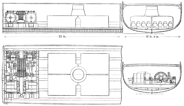
for all purposes,[48] equal to 2-1/4 lb. per unit of power per hour,
which for those early days, with comparatively low steam
pressures, must be regarded as a highly satisfactory result.
The non-stop voyage between Liverpool and Mauritius
was made as early as 1866 in thirty-seven days, equal to
10 knots, with a number of passengers and a fair cargo.
The higher economy established for the compound engine
on long voyages resulted in the ultimate supersession of
the sailing ship.[49] Thus the Scotts, while still enjoying
the credit of the splendid performance of the Lord of the
Isles in the early 'sixties, produced at their foundry the Holt
compound engine, which sounded the death-knell of the
clipper. The compound system had at once an influence on
the size of ships. Up till 1862 no ship of over 4000 tons
had been constructed, with the exception of the Great
Eastern; by 1870 there were fifteen; by 1880, thirty-seven.[50]
The Scotts, aided by Holt, continued their research
towards higher economy, and a large fleet of steamers was
built, with engines having flywheels which, it was found by
experience, considerably improved the economy up to a
certain stage, although with increased pressure the proportion
of saving was not commensurate with the weight
of the wheel, and the three-cylinder three-crank engine was
ultimately adopted.
The Scotts throughout the century continued to have
a close association with the China trade, constructing a long
series of successful steamers for the Holt company and for
other lines, with services from Britain to the Far East, and
carried out very extensive work in the building up of the
coasting trade of Asia and Oceania. For the Holt line
alone there have been constructed by the Scotts forty-eight
steamers, aggregating 148,353 tons; while the
propelling machinery of these represents 19,500 nominal
horse-power. For the India and China services there
have, in the past fifty years, been completed over one
hundred and thirty steamers.
The China Navigation Company, Limited, was formed
in 1873 by Messrs. John Swire and Sons, of London,
for trading in China, and the first steamers built for
them by the Scotts were two vessels of 1200 tons gross,
completed in 1876.
Since then the Scotts' yard has practically never been
without a vessel for one or other branch of the Eastern
trade, and particularly for the China Navigation Company,
which runs steamers from China as far south as Australia,
as far west as the Straits, and as far north as Vladivostock
and the Amur river. They also have ships trading up the
Yangtsze Kiang to Ichang, 1000 miles from the sea, where
the rapids prevent navigation farther into the interior.
For this service the twin-screw steamer was adopted in
1878, much earlier than in many other trades, largely owing
to the strong advocacy of the late John Scott, C.B. Up to
that time most of the Yangtsze steamers were propelled
by paddle-wheels driven by walking-beam engines. The first
of the twin-screw steamers was built in 1878—a vessel of
3051 tons gross—and there has been constructed since
then a long succession of very serviceable steamers. For
this line alone, sixty-four vessels have been constructed by
the Scotts, the aggregate tonnage being 115,600 tons,
while the nominal horse-power of the propelling machinery
fitted to these vessels is 15,000 horse-power.
But having in our brief historical sketch come to
times within the recollection of the reader, it may be
more satisfactory to depart from the purely chronological
review of the company's operations, and to offer rather an
analysis of the progress made, deferring a description of
typical modern steamers for a separate Chapter.
The direct-acting vertical engine, with inverted cylinders,
almost as we know it to-day, and as illustrated in connection
with the work of the twentieth century, was
introduced in the late 'fifties. The compound engine, introduced
in 1854, was developed into the triple-expansion
system in 1882, and later into the quadruple-expansion type;
but this latter has not been much adopted, only some 3 per
cent. of the vessels registered at Lloyds being so fitted.
This is in a large measure due to the satisfactory economy
attained with triple-expansion engines. As to the progress
made, Table II., giving average results at different periods,
is instructive.[51]
Table II.—Progress in the Economy of the Marine Engine,
1872 to 1901.
1872.
1881.
1890.
1901.
Boiler pressure in pounds per square inch
52.4
77.4
158.5
197
Coal consumption in pounds per indicated horse-power per hour
2.11
1.83
1.52
1.48
Consumption on prolonged sea voyages in pounds per indicated horse-power per hour
- - -
2
1.75
1.55
Piston speed in feet per minute
376
467
529
654
The advance of the century may be popularly expressed
by stating that, whereas in the first coasting steamships
built by the Scotts the fuel consumed in carrying 1 ton
of cargo for 100 miles was 224 lb., the expenditure to-day
is from 4 lb. to 5 lb. The economy of the steam engine has
accounted, as is shown in the Table, for a considerable
part of this improvement. But, at the same time, the
growth in the size of ships has enabled the normal speed
of 10 knots to be realised, with an addition to engine
power of much less ratio than the increase in the
capacity of the steamer. As to speed, recent progress
has been most marked in the Navy, and it is therefore fitting
that here we should direct our attention to Naval work.
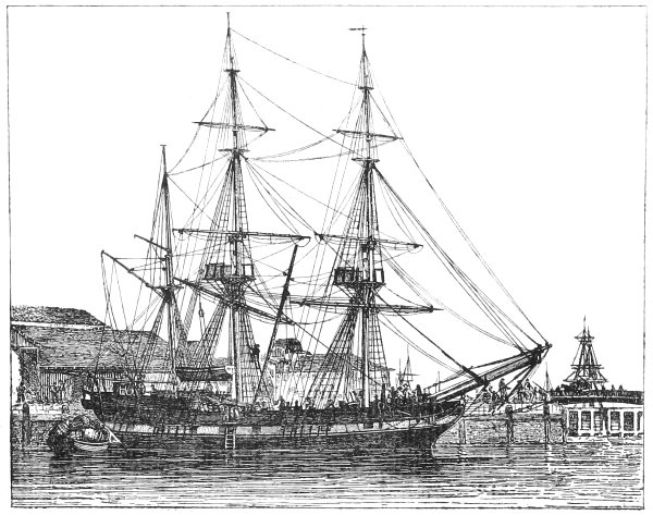
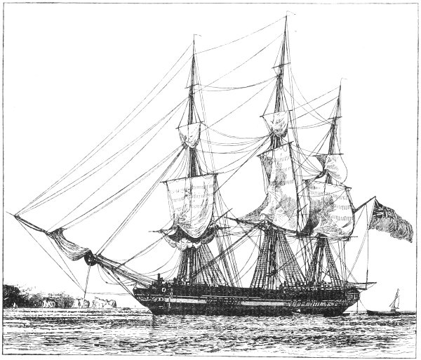
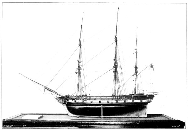
THE work for the Navy by the Scotts
began with the building, in 1803, of a
sloop-of-war named The Prince of Wales;
a photograph from the model of this
vessel is reproduced on Plate XIV.
Since the construction of this ship the
firm have carried out several important
Admiralty contracts, including the first machinery manufactured
in Scotland for a dockyard-built ship, the first
steam frigate built in the North, and several later ships,
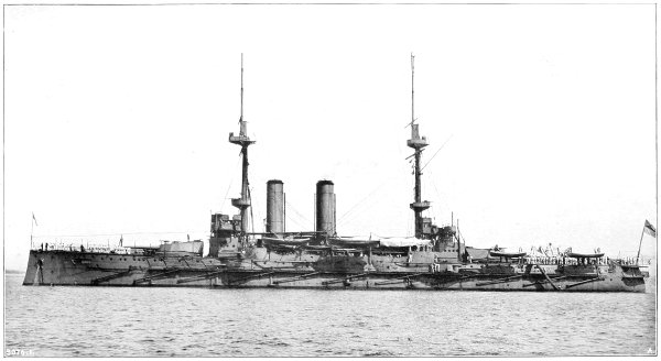
with their engines; the most recent order being for the
machinery of the armoured cruiser Defence, of 14,600 tons
displacement, and 27,000 indicated horse-power, to give a
speed of 23 knots.
The progress demonstrated by a contrast between the
small sloop-of-war and this latest powerfully-armed and
well-protected high-speed cruiser, is a record of research
and invention, not only on the part of the naval architect,
but also of the chemist, the metallurgist, and the engineer;
the triumph is greater than that reviewed in the case of
the Merchant Marine. Great speed has been achieved,
notwithstanding that the problems to be solved in its attainment
have been intensified by the limitations in the size
of the ship in order to minimise the target presented to the
enemy's fire, and by the necessity of providing for heavy
armour, armament, and ammunition in the displacement
weight.
When a comparison is made of the Navy ships at
the beginning of the nineteenth century with those of a
hundred years earlier, it is found that little progress had
been made, either in design or in gun-power. The largest
vessel in 1700 was of 1809 tons burden, with a hundred
guns. A century later, the size had increased only to
2600 tons, with a hundred and twenty guns.[52] But even
this was an exceptionally large vessel. The British ships
were, as a rule, smaller, and perhaps slower, than the
French ships; but then—as now and always—skill in
strategy, courage in combat, and devotion to duty were
the most powerful factors in action. No fault in these
respects could be found with the work of our Navy in the
various engagements which terminated in the epoch-marking
victory in Trafalgar Bay.
The peace following the Napoleonic wars was not conducive
to advancement, as there was little incentive to
pursue the sciences which contributed to the development
of destructive weapons. Steam as a motive power and
iron as a constructive material were not so readily adopted
in the Navy ship as in the Merchant Marine. Progress in
the utilisation of iron was not continuous. The first
application of steam was belated, and its popularity was
not unalloyed.
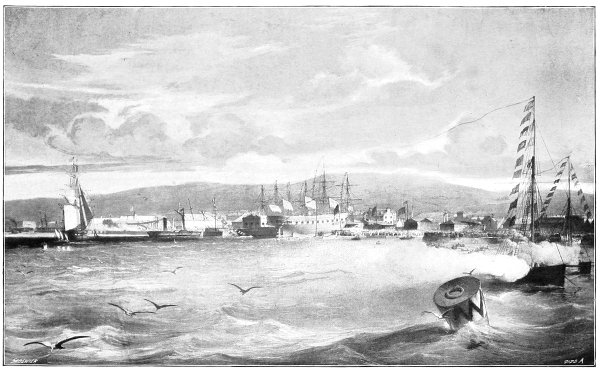
Plate XV.
From an Old Engraving.
THE LAUNCH OF THE FIRST CLYDE-BUILT STEAM FRIGATE "GREENOCK," 1849.
The Admiralty ordered their first ship of iron in
1839—a small, non-fighting boat for the Dover station—and
there followed other vessels for the exploration of
the River Niger. But the first iron fighting ship was
not built until 1843. In 1848-9 the Scotts constructed
the iron steam frigate Greenock, the largest iron warship
of her day, and the first steam frigate built on
the Clyde. The over-all length of this vessel was 213 ft.,
the beam 37 ft. 4 in., and the depth of hold 23 ft. She
was of 1413 tons burden, and carried ten 32-pounder smooth-bore
muzzle-loading guns. The illustration on Plate XV. is
a reproduction from an old engraving of the launch of the
vessel. It is a noteworthy feature that the figure-head
was a bust of John Scott, the second of that name. This
compliment by the Naval authorities of the time was well
merited, as he did much not only for the advance of naval
architecture, but also for the development of Greenock.
As a writer of the day put it, this vessel was the
experimentum crucis of the principle of constructing fighting
ships of iron.[53] By 1850 there were six large iron
vessels, ranging downwards from the 1980 tons of the
eighteen-gun ship Simoon, with eleven smaller vessels; but
they were all condemned, because it was found by experiment[54]
that the 32-pounder gun at short range could
perforate the side of the iron ship, and that the projectile
carried its "cloud of langrage" with great velocity into
the interior of the ship, so that men could not stand
against it. Tests were also made with sixteen wrought-iron
plates superposed, to give a total thickness of 6 in.,
but these also were perforated by the 32-pounder projectiles
at 400 yards range; so that the adoption of iron on the
main structure of the ship was practically delayed until
armour-plates were first rolled in 1859.
The obstacle to the adoption of steam was the unsuitability
of paddle-wheel machinery for fighting ships. The
wheel was exposed to gun-fire, and the whole of the
machinery could not be located below the water line.
Moreover, the side wheel limited the number of guns
which could be utilised for broadside fire. The first steam
craft ordered by the Admiralty was a small vessel of 210 tons
and 80 nominal horse-power, built in London in 1820.[55]
Several other non-fighting steamships followed. By 1837,
the largest steam vessel in the fleet was a sloop of
1111 tons and 320 horse-power.[56] In 1839 five steam vessels
were built, and two of them—the Hecate and Hecla—were
engined by the Scotts. These wooden steamers were
the first Naval vessels sent to Scotland to have their
machinery fitted on board. They were of 817 tons and
250 horse-power. The paddle-wheels had a diameter of
25 ft. 1/2 in., and there were seventeen floats. The main
engines, illustrated on page 29, represent the type adopted,
not only in the Naval, but in the Merchant service of this
time. The steam pressure was then about 3 lb. per square
inch.
On Plate XVI. we illustrate the general arrangement of
the machinery in the Hecate and Hecla. There were four
boilers of the rectangular type, each with two wet-bottomed
furnaces at one end and large return flues at
the other end. The uptakes passed up inside the boilers
through the steam space, uniting in one funnel.
Smith's screw-propeller was tried experimentally in
1837, and Ericsson's about the same time. The comparative
trials of the Archimedes fitted with Smith's screw
against existing paddle-steamers did much to prove the
efficiency of the new system.[57] The screw-ship excelled
the performance of paddle-steamers on the service, and the
screw-propeller was adopted by the Admiralty in 1845;
twin-screws followed twenty-five years later.
The Greenock, built in 1848, was the first war vessel by
the Scotts fitted with the screw-propeller. We have already
referred to her construction in iron, and to her launch. She
had a displacement of 1835 tons, and her engines were of
719 indicated horse-power. The speed realised on the trial was
9.6 knots. The Greenock's machinery, which is illustrated
on the next page, is specially interesting, as it represents
one of the earliest attempts to drive the screw-propeller
by gearing. Two horizontal cylinders were fitted, each
71 in. in diameter, with a stroke of piston of 4 ft. The
gearing consisted of four sets of massive spur-wheels and
pinions, in the ratio of 2.35 to 1, so that 42 revolutions per
minute of the engines give 98.7 revolutions to the propeller-shaft.
The propeller was 14 ft. in diameter, and was so
fitted that it could be detached and raised to the deck.
There were four rectangular brass-tube boilers, each with
four wet-bottomed furnaces, and all the internal uptakes
united in one funnel, which was telescopic, so that when
it was lowered and the propeller raised out of the water,
the vessel had the appearance, as well as the facility, of a
sailing frigate.
As will be seen from the drawings, both the engines
and boilers were arranged very low in the hull, to be safe
from the enemy's fire. The engine and boiler compartment
occupied 72 ft. of the length of the ship—about one-third
of the total length—and the seating for the machinery
was specially constructed, with a very close pitch of frames
which were only 1 ft. apart. For comparison with the
drawings of the machinery in the Greenock, we give on
page 49 a similar drawing of the machinery of the
Canopus, of 12,956 tons displacement, seven times that
of the Greenock. To double the speed, the power of
machinery had to be multiplied twenty times, and yet
the space occupied is only about trebled.
In 1850 the largest of the steam vessels in the Navy[58]
had a displacement of 3090 tons, but the most noted was
the Dauntless, of 2350 tons displacement, with engines of
1347 indicated horse-power to give a speed of 10 knots.
It is true that there were three smaller vessels of greater
speed, one of 196 tons steaming 11.9 knots; but this
was the highest rate reached in the Navy service. By
this time some of the fast mail steamers made 13-1/2 knots.
These latter were suited for war service, but we have
already dealt with them.
Following the adoption of the screw-propeller in warships
came the abandonment of gearing for the engines.
For many years various forms of horizontal engine were
used; first with return-connecting rods, and subsequently
with direct-acting rods. Steam pressures steadily increased,
largely owing to stronger materials being available. It
was, however, not until the 'seventies that the cylindrical
boiler, the compound engine, and the surface condenser
admitted of an increase to 60 lb. per square inch[59]—several
years after these improvements had been introduced in the
Merchant Marine.
The Scotts had worked steadily at the solution of
the problem from their trials with the Thetis in 1858
(see page 34ante). In 1860 the late John Scott, C.B.,
laid before the Admiralty a system of water-tube boilers
and compound engines, but objection was raised to the
system. The French Naval authorities, with whom the
Scotts then had close business connection, took up the
scheme, largely because of the favour with which it
was viewed by M. Dupuy de Lôme, the head of the
Department. The first ship fitted was a corvette of
650 tons displacement; the boilers worked at a pressure
of 140 lb., while the initial pressure at the compound
three-cylinder engines was 120 lb. These were the first
engines of the compound type in the French Navy.
The Scotts were at the time building engines for four
corvettes under construction at the Woolwich and Deptford
yards for the British Navy; and the Admiralty agreed
to have fitted in one of them water-tube boilers and engines
similar to those built for the French boats. The boilers
may be said to have belonged to the same general
type as the Thornycroft and Normand water-tube steam
generators. It was subsequently found impossible, however,
to ensure that the top of the boilers should be at least 1 ft.
under the load-line—a condition then enforced in steam
vessels for the Navy—and the adoption of the water-tube
boiler was deferred, the ordinary machinery of the period
being fitted to work at 25-lb. pressure instead of 120-lb.[60]
This was unfortunate, as it removed the incentive to
continued research needed to make the water-tube boiler
a really satisfactory steam generator. The Scotts, however,
continued to work for the successful application of high
pressures, and it was this that brought them into contact
with the late Mr. Samson Fox, with whom they were closely
identified for many years in connection with the development
of the corrugated flue and the cylindrical steam boiler.
Opinion being adverse to the water-tube boiler, notwithstanding
its acceptance by many foreign Navies, there
was a strong agitation fostered by engineers to induce the
societies for the registry of shipping, and also the Board
of Trade, to increase the ratio of the working to the test,
pressure in boilers. The British Admiralty allowed the
boiler to be worked up to within 90 lb. of the test pressure,
whereas in the Merchant Service the working pressure
was limited to one-half of the test pressure. In 1888
the Scotts, being convinced that the Admiralty system
afforded quite a satisfactory factor of safety, undertook the
experiment of submitting a warship boiler, then being built
by them to Admiralty specification, to the highest possible
pressure, even up to bursting-point. The boiler ultimately
leaked to such an extent, after the pressure had been
maintained for a long period at 620 lb. per square inch,
that it was not considered necessary to proceed further.
The stresses at this stage worked out to 48,130 lb. per
square inch; and the result proved that there was some
justification for a reduction in the minimum scantlings of
the shells of marine boilers to, at least, the scale adopted
by the Admiralty.[61]
These suggestive experiments were carried out in
connection with the boilers constructed in 1888-9 for two
war vessels built by the Scotts. These vessels were the
Sparrow and the Thrush. At the same time, the Scotts
engined two other vessels of the same type, constructed at
the Royal Dockyards. A view is given on Plate XVII. of
the Thrush, which was commanded by H.R.H. the Prince
of Wales on the North American and West Indian stations
in 1891. She was a vessel of composite build, of 805 tons
displacement, with machinery of 1200 horse-power, to give
a speed of 13 knots; but, as is shown by the illustration,
she was fitted as a three-masted schooner, and utilised
her sails when the wind was favourable. In this respect,
she marks the transition stage between the days of the
sailing craft and the modern ship, depending entirely on
steam for propulsion. Indication is afforded of the progress
towards this transformation by Table III. on the opposite
page, which shows the improvement in economy in the
machinery of warships at various stages in their development.
The figures in the Table are average results rather
than highest attainments during the periods. For 1890-95
we have taken the Barfleur, the engines of which were
constructed by the Scotts in 1894; whilst the particulars
for 1895-1900 refer to the Canopus, engined by them in
1900. In 1902 they also supplied the machinery for the
battleship Prince of Wales, and commenced the construction
of the armoured cruiser Argyll. But before referring in
detail to these latter ships, we may briefly review the
advances in applied mechanics, metallurgy and chemistry,
which have contributed largely to the perfection of these
modern fighting ships in respect of offensive and defensive
qualities.
TABLE III.
PROGRESSIVE TYPES OF WARSHIP MACHINERY, AND THEIR ECONOMY, 1840 to 1905.
Coal consumption per indicated horse-power per hour
7 lb.
4 lb. to 5 lb.
2-1/2 lb.
2 lb.
1.8 lb.
1.8 lb.
Type of engine ... ...
Geared screw
Simple horizontal surface condensing
Three-cylinder compound
Three-cylinder triple-expansion
Three-cylinder triple-expansion
Four-cylinder triple-expansion
Piston speed in feet per minute
220
500 to 600
750
840
918
1000
Weight of machinery per indicated horse-power
10 cwt.
3 cwt. to 5 cwt.
3 cwt.
2-3/4 cwt.
2 cwt.
1.6 cwt.
Speed of ship ... ...
8 to 9 knots
14 knots
16 knots
18 knots
18.25 knots
23 knots
The gun most in favour at the close of the eighteenth,
and at the opening of the nineteenth, centuries was the
cast-iron, smooth-bored, muzzle-loader: first the 32-pounder
and later the 68-pounder. Carronades were used for
"smashing" rather than for penetrating the skin or structure
of ships. Although the 68-pounders were improved by a
lining of wrought iron being inserted in the bore, whereby
the energy at 1000-yards range was increased from 290
to 600 foot-tons, little progress was made until after the
Crimean War, when chemists undertook the investigation
of the action of explosives and metallurgists sought to
produce stronger metals.
The general idea as regards the powder used as a
propellant was that the ignition was instantaneous, and
that the more violent the explosion the greater would be
the velocity of the projectile. Under such conditions short
weapons naturally found favour; and indeed, with a light,
spherical, ill-fitting projectile, there was very little advantage
to be gained by lengthening the bore. But with the
introduction of rifled cannon, much heavier and better-fitting
shot became possible, and a rapid-burning powder
gave rise to dangerous pressures in the gun. It was then
realised that it was not an explosion that was wanted,
but a continuous pressure acting on the base of a shot
for a relatively considerable period. This needed a slow-burning
explosive, and led to the manufacture of powder
as pebbles or prisms; the enlargement in the late 'seventies
of the chamber of the gun, and the provision of air spaces
for the expansion of the powder, greatly added to the
velocity with which the shot left the gun, and therefore
augmented its carrying power.[62]
Gun-makers had meanwhile improved the strength of
the weapon by a recognition of the fact that wrought
iron was twice as strong in the direction of the fibre as
across it; and thus in the 'sixties they began to coil the
central tube, surrounding it by hoops, welded or shrunk
on. The full advantages of fibre were thus secured for
resisting circumferential strain. The bore was rifled to
give the shot that rotatory motion which prevents irregularity
in flight and conduces to accuracy of fire at long
range. The smooth-bore gun was effective up to only
1000 yards range, as compared with the 6000 yards and
7000 yards for the modern weapon. Breechloading was first
introduced into the Navy in the 'sixties, but discarded
because the details for closing the breech end proved
unsatisfactory. Finally, it was reintroduced in 1878, a
satisfactory mechanism having been devised.
These various improvements gradually increased the
power of the gun. The length and weight had enormously
grown, as is shown by the particulars of successive large
Naval guns, shown in Table IV. on the next page; but
the increase in energy up till the 'eighties was not commensurate
with the augmentation of the weights of the
projectile and charge.
The advance from the 38-ton gun of 1870 to the
110-1/2-ton gun in 1887 involved the multiplying by five of
the charge of powder, which quadrupled the energy of the
gun, but the carrying power of the shot was still deficient.
The velocity had increased in twenty years from 1600 to
2000 ft. per second, slower-burning powder having been
introduced.
Table IV.
Particulars of the Successive Large Naval Guns, 1800 to 1905.
Year.
Type.
Weight.
Length.
Calibre.
Weight of Projectile.
Weight of Charge.
Muzzle Energy.
Penetration of Wrought Iron at 1000 Yards Range.
tons
cwt.
in.
in.
lb.
lb.
ft.-tns.
in.
1800
Cast-iron smooth-bore
2
12
114
6.4
32
10
400
1842
Ditto
4
15
...
8.12
68
16
700
1865
Woolwich wrought-iron
4
10
...
7
115
22
1400
7
1870
Built-up muzzle-loader
38
0
200
12.50
810
200
13,900
17
1880
Ditto
80
0
321
16
1700
450
27,960
22-1/2
1887
Built-up breech-loader
110
10
524
16.25
1800
960
54,390
32
1895
Wire-wound breech-loader
46
0
445.5
12
850
...
33,940
34.6
1900
Ditto
51
0
496.5
12
850
210
36,290
35.4
1905
Ditto
58
0
540
12
850
...
49,560
42
Attention was further directed to the improvement
of explosives; and ultimately, instead of gunpowder having
a potential energy of 480 foot-tons per pound, modified
gun-cotton was introduced, with an energy of 716 foot-tons
per pound, and still later there were evolved explosive compounds
of which the potential energy per unit of weight
was fourfold greater than in the case of gunpowder, namely,
1139 foot-tons per pound. Finally, the explosive has taken
the form of cordite, which ensures slow burning, great
expansion, and, consequently, augmented propelling power
behind the projectile, without material addition to the
maximum strain upon the weapon. But in any case the
constructional strength of the modern gun is enormously
superior to the earlier built-up weapons, as around the
inner tubes there is coiled something like 120 miles of
wire, which itself has a breaking-strain of between 90 and
110 tons per square inch, and is put on under a tension
of from 54 tons per square inch on the inner wires to
32 tons per square inch on the outer wires,[63] so that the
ultimate resistance to strain consequent upon the firing of
the gun is enormously increased. Velocities of 2600 ft.
per second are thus realised, and even more is quite
feasible, so that penetration of wrought iron at 1000
yards range has now been increased to 42 in.
If we compare the 12-in. gun to-day with the weapon
of the same calibre of twenty years ago, when there was no
widened chamber for the explosive, when prismatic powder
of low expansive power was used, it is found, as shown in
the Table opposite, that the penetration at 1000 yards
has been doubled, and the possible effective range multiplied
fivefold. There has also been an enormous gain in quicker
fire by improved breech mechanism and efficient hydraulic
and electric mountings, whereby the gun and all its loading,
elevating, and training machinery is rotated.
The metallurgist has also been successfully occupied,
and it is probable that the armour plate of to-day is still
invulnerable. The earlier wrought-iron plates were increased
from 4-1/2 in. in thickness on the Warrior of 1861, to the
24 in. on the Inflexible of 1881; the area protected being
almost proportionately reduced. The artillerist with
improved projectiles ultimately defeated this heavy cleading
on the ships; but compound armour, first made in 1879,
enabled the maximum thickness on the broadside to be
reduced to 18 in., permitting a greater area to be covered
for the same weight. At first the 80-ton gun failed in
its attack, but heavier weapons, with improved projectiles,
prevailed. The next step was the introduction of all-steel
armour in 1890. Two years later there was introduced
the super-carburising and subsequent chilling of the face
of plates made of an alloy of nickel steel. In 1897 the
process of hardening was still further developed, and now
the 9-in. plate on the modern battleship is equal in resistance
to a 26-in. wrought-iron plate of the 'sixties, or a 20-in.
compound-plate of the 'eighties, or a 13-in. plate of the
early-hardened type. For the present, therefore, the armour
seems to have secured the victory, as at 5000 yards range
9-in. armour can scarcely be defeated by even the 12-in. gun.
With the increased resistance of armour and the consequent
reduction in its thickness, the naval designer can
spread his protecting plates over a much wider area, so
that the whole broadside of ships like the Prince of Wales,
or the cruisers Argyll and Defence, is clad with armour of
satisfactory resisting power. At the same time the gun-power
and speed of ships have been greatly increased without
making the displacement inordinately high. On the opposite
page a Table gives the main features of representative
ships at different epochs, which will show this at a glance.
The growth in the size of battleships has been steady,
with the exception of the class represented by the Barfleur
and Canopus, both of which were engined by the Scotts.
These vessels are embodiments of a desire to check the
advance in the size and cost of the battleship. The deficiency
in the number and calibre of their guns was partly compensated
by the introduction, for the first time in battleships,
of quick-firing weapons of large calibre. The Barfleur had
four 12 in. breechloaders and ten 4.7 in. quick-firers; while
the Canopus had four 10 in. breechloaders and ten 6 in.
quick-firers. But opinion has again strongly grown in
favour of having in each British ship the best that can
be achieved; and thus the Prince of Wales has a displacement
greater than any previous ship, while in the King
Edward and the Lord Nelson classes there has been a further
growth in every element of power. The probabilities, too,
are that we have not yet by any means seen the end of
this advance.
SIZE AND FIGHTING QUALITIES OF BRITISH BATTLESHIPS OF DIFFERENT PERIODS.
Name.
Date of Completion.
Displacement.
Side Armour.
Speed.
Total Weight of Shot in One Round.
Collective Energy at Muzzle of One Round.
tons
in.
knots
lb.
foot-tons
Warrior
1861
9,210
4-1/2-in. wrought iron
14-1/2
3800
61,476
Hercules
1868
8,680
9-in. to 6-in. wrought iron
14
5400
70,200
Alexandra
1877
9,490
12-in. to 6-in. wrought iron
15
5426
71,400
Inflexible
1881
11,880
24-in. to 16-in. wrought iron
13
6936
123,120
Benbow
1888
10,600
18-in. compound
16.75
4600
135,560
Royal Sovereign
1892
14,150
18-in. and 5-in. compound
17.5
5800
159,610
Barfleur
1894
10,500
12-in. compound
18.5
2450
67,670
Canopus
1900
12,950
6-in. hardened steel
18.25
4600
178,720
Prince of Wales
1902
15,000
9-in. super-hardened steel
18.25
4600
194,400
King Edward VII.
1904
16,350
9-in. super-hardened steel
18.50
5920
270,040
Lord Nelson
1905
16,500
10-in. super-hardened steel
18.50
7960
413,900
As to the machinery made by the Scotts for these
battleships, the Barfleur had three-cylinder, triple-expansion
twin-screw engines, to run at 108 revolutions, and to develop
13,000 indicated horse-power. On her trials the power was
13,163 indicated horse-power. There are eight single-ended,
return-tube, cylindrical boilers, working at 155 lb. pressure.
Other details are given in the Table on page 53.
The engines of the Canopus are illustrated on page 49
by a drawing taken from a Paper read at the Institution
of Civil Engineers, by Sir John Durston and Admiral
H. J. Oram.[64] This was the first type of British battleship
fitted with water-tube boilers. She was followed soon after
by the Prince of Wales.[65]
The Argyll, which was built and engined by the
Scotts, and the Defence, which is being built in one of the
Royal Dockyards, and is having its machinery constructed
by the Scotts, signalise progress in cruiser design. The
hardening of armour, increasing its resistance, permits of a
reduction in weight for a given measure of protection, so that
it has been possible to effectively defend the modern cruiser,
while at the same time giving an enormously increased gun-power
and a speed far in excess of that possible ten years ago.
The Argyll is a vessel of 10,850 tons displacement, being
450 ft. long, 68 ft. 6 in. beam, and having a draught of
25 ft.; while the Defence is a vessel of 14,600 tons displacement,
having a length of 490 ft., a beam of 74 ft. 6 in.,
and a draught of 26 ft. In both ships the greater part
of the broadside, from 5 ft. below the water-line to the
upper deck, is armoured, and a very large proportion of
the area thus clad has 6-in. hardened plates.
In the late 'nineties it was assumed that quick-firing
artillery was best suited to the work of a cruiser, and
thus the 6-in. gun was exclusively adopted. But since
then Naval strategists have developed their ideas as to
the function of armoured cruisers, and now anticipate
their use in the line of battle; so that not only has the
defensive quality been improved, but the offensive power
has been materially increased. In the Defence, and the
other ships of the class, the 6-in. gun has been entirely
discarded in favour of an installation of 9.2-in. and 7.5-in.
weapons. Owing to the perfection of the hydraulic and
electric mountings, little has been forfeited in respect of
rapidity of fire, while much has been gained in the
striking energy at a given range of each projectile. Thus,
while the 6-in. gun five years ago had an energy equal
to penetrating 6 in. of wrought iron at 3000 yards' range,
the 7.5-in. weapon now may perforate 6-3/4 in., and the 9.2-in.
gun 9 in. of the hardest armour at corresponding range.
The total weight of projectiles fired from the present-day
cruiser in a minute is double, and the muzzle energy
quadruple, the results attained by the cruisers designed
at the close of the nineteenth century.[66]
The modern cruisers steam at 23 knots, the power of
the machinery in the Argyll being 21,000 indicated horse-power,
and in the Defence 27,000 indicated horse-power. The
machinery of the Argyll, which is typical, consists of four
sets of triple-expansion engines, arranged in separate watertight
compartments. The diameters of the cylinders are:
high-pressure, 41-1/2 in.; intermediate-pressure, 65-1/2 in.; and
the two low-pressure, each 73-1/2 in., all having a stroke of
42 in. At full power, developed with 138 revolutions, the
piston speed is 966 ft. per minute. The cylinders are fitted
with liners, and are steam-jacketed; forged steel is used
for the liners of the high- and intermediate-pressure
cylinders, and cast-iron for those of the low-pressure cylinders.
The cylinder covers and pistons are of cast steel, the latter
being of conical form. The high- and intermediate-pressure
cylinders have piston valves, and the low-pressure cylinders
flat valves. The cylinders are supported at the front by
eight forged-steel columns, and at the rear by four cast-iron
columns formed with guide-faces, and one forged steel
column. The crankshaft is in four pieces, the high- and
intermediate-pressure parts being interchangeable with each
other, and the two low-pressure parts with one another.
The shafts are hollow, and three-bladed propellers of
manganese bronze are fitted to each. The condensers are
entirely separate, and independent air pumps are fitted.
The Argyll had a combination of six cylindrical and
sixteen water-tube boilers, but in the later ships, including
the Defence, the boilers are entirely of the water-tube type.
The working pressure of the boiler is 275 lb., reduced
at the engines to 250 lb. The trials of the Argyll were
carried through most satisfactorily,[67] and the vessel, under
the new Admiralty conditions, was completed for commission
by the builders. The fact that this armoured cruiser was
so completed at the builder's yard is of itself evidence of
the capacity and efficiency of the plant.
YACHT designers and builders, when
votaries of the sport, produce much
better results, and in this truism we
have some explanation of the success
of the Scotts in the long series of
yachts built during the past century.
There are a few misty memories and
time-worn traditions to the effect that yachting of a kind
was indulged in on the Clyde in the closing years of
the eighteenth century; but there are no authentic
records antecedent to the nineteenth century. From 1803
onwards the Scotts have been closely identified with the
pastime, and with the production in the early years of
sailing yachts; and, later, of steam craft.
The first notable Clyde racing yacht, of which there is
any record, was launched by the Scotts in 1803, as already
referred to on page 11 ante. She was a 45-1/2-ton cutter
for Colonel Campbell, an Argyllshire soldier, and the
launching ceremony, the honours of which were done by
Lady Charlotte Campbell, was attended with military
honours. For the twenty years immediately following
the launch of this cutter, yachting made most pleasing
progress, and in 1824 the Royal Northern Yacht Club
was formed for the better organisation and encouragement
of the pastime. The club had its origin in the North
of Ireland, and had jurisdiction over that district, as well
as over the West of Scotland up till 1838, when the
Irish section was disbanded. The Royal Northern gave
regattas throughout the season, at almost every suitable
port, from Helensburgh on the Clyde to Oban. Amongst
the leaders of the Clyde Division was John Scott, the
second of the name, and a large number of the racing
craft owned by the members were built by him. Indeed,
one of the most experienced writers on Yachting in
Scotland, Mr. J. D. Bell, says that "among the old
yachting families of the West of Scotland, the Scotts and
the Steeles filled the foremost place."
Among the best remembered of the yachts built by
John Scott were the cutters Hawk and Hope, constructed
for himself, and the Clarence, built for his son-in-law,
the late Robert Sinclair. The Hawk was a boat
of about 30 tons, the Hope was rather smaller, and was
used for cruising rather than for racing; and the Clarence
was about 18 tons.
The Hawk was a successful racer, and secured many
cherished prizes, but the Clarence was her superior, and
was the first of a long line of prize-winners which have
brought renown to the Clyde. Indeed, in all she won
over thirty challenge trophies, and in her best season
never suffered defeat. Robert Sinclair, the owner, was
himself a keen and accomplished yachtsman.
In the races held in 1833-34—most prominent years—John
Scott, with the Hawk, won the Anglesey
Cup at Dublin, and the Oban and Helensburgh Cups;
while Robert Sinclair, with the Clarence, won the
Ladies' Cup at Oban, the Kintyre Cup at Campbeltown,
the Dublin, Adelaide, and Booth Cups at Dublin, the
Stewart Cup at Greenock, the Largs Cup and the
Dunoon Cup. These two yachts were indeed close rivals,
although the principal honours rested with the Clarence.
On one occasion, however, the Hawk unexpectedly defeated
the Clarence in an important race at Dublin, and the
owners were anxious to have the cup in Greenock as
soon as possible for a special reason. Recognising that the
Clarence was really the faster boat, they handed over the
trophy to her crew to take to the Clyde port; but the
luck which enabled the Hawk to win the cup stood by her
on the passage home, and she made the port a considerable
time before her rival.
The Clarence became a pilot boat, and was unfortunately
run down off Garroch Head, while the Hawk was transferred
to the fishing trade. In later years John Scott, C.B., had
the laudable desire to secure as a relic the vessel his grandfather
had owned, but the negotiations failed; and the boat
is probably still at work among the islands of Scotland.
The Royal Northern Club's fleet in the 'thirties
numbered about fifty, but there were no steam vessels on
the list until 1855. Among the principal boats in the
club were the Duke of Portland's ketch, the Clown, of
156 tons; the Duke of Buccleuch's cutter, the Flower of
Yarrow, of 145 tons; Mr. John Scott's cutter, the Lufra,
of 81 tons; Mr. Robert Meiklem's schooner, Crusader,
of 126 tons; and Mr. Lewis Upton's cutter, Briton, of
91 tons. The membership was about one hundred and
fifty, the aggregate tonnage of the fleet about 2000 tons,
and its cost, at a fairly generous estimate, about £20,000.
What a contrast is suggested by a review of the
fleet of yachts owned to-day by Clyde yachtsmen! There
are now eight clubs in the Firth recognised by the Yacht
Racing Association, and one of the largest of these—the
Royal Clyde—alone has over a thousand members, with a
fleet of over three hundred and seventy yachts, of a collective
tonnage of 26,000 tons, and of a first cost of a million
sterling. The club-house at Hunter's Quay, which cost
about £20,000, is representative of the best of its kind.
Many of the yachts—sailing and steam—are of considerable
size, and have international repute for their excellence,
either as racers, or as comfortable seaworthy cruisers.
The origin of the Royal Clyde Club in itself affords
interesting suggestion of the development of the pastime
on the Clyde. Owing to a rule enforced by the Royal
Northern Club during the earlier period of its existence,
boats smaller than 8 tons could not be enrolled; many
enthusiastic owners of small craft were thus debarred from
membership, and in 1856 they decided to form a new
club. This, first named the Clyde Model Yacht Club,
became, a year later, the Clyde Yacht Club; and, having
grown immensely in influence, obtained, in 1872, Queen
Victoria's sanction to the appellation of "Royal." To-day
the Royal Clyde Yacht Club is one of the most important
in the Kingdom.
John Scott (1752-1837) was long a prominent member
of the Royal Northern Club. His son, Charles Cuningham
Scott, was an original member, but did not take the same
active part in the pastime, the claims of a quickly-developing
industry being probably the reason. But the records of
the family were again revived by his sons—John Scott, C.B.,
Robert Sinclair Scott, and Colin William Scott. They
displayed a preference for steam craft, although the first-named
owned several cutters, beginning with the Zingara;
later several beautiful yachts, each successive ship being
named the Greta, were built for him. The first of
these, of 1876, and the last, of 1895, are illustrated on
the Plate facing this page. He was elected Commodore
of the Royal Clyde Club in 1895 in acknowledgment of
his services to the club and to yachting generally, and
he occupied the post until his death in 1904.
These were exciting times in Clyde yachting. It was
then that Lord Dunraven and Sir Thomas Lipton made
their gallant but unsuccessful efforts to recover the America
cup with Clyde-built boats, while the performances of the
Britannia, owned by the then Prince of Wales, now
His Majesty the King, and of the Meteor, belonging to
the German Emperor, gave a distinction to the sport which
it had never enjoyed before.
The Mudhook Yacht Club was formed in 1873 by a
few skilled yacht designers and yachtsmen, and included
Robert Sinclair Scott, Colin William Scott, and James
Reid. The membership was limited to forty, and the aim
of the founders was to "encourage amateur yacht sailing."
There were many inspirations connected with the founding
of the club; there is a tradition that when a "Mudhooker"
was being initiated, he was usually confronted with a coil
of rope, a small marlinspike, a chart and dividers, a forecastle
bucket and other implements; and, before the hand
of fellowship was extended to him, he was exercised, with
more or less of solemnity, as to their uses. From the
foundation of the Club until his death in 1905, Robert
Sinclair Scott was Admiral of the Club. For twenty-nine
years from the same period his brother, Colin
William Scott, acted as Honorary Secretary, and his great
services were recognised on the club attaining its majority
in 1894, by the presentation by the members of a set of
old candelabra and fruit dishes. The present Honorary
Secretary is R. L. Scott, son of John Scott, C.B.
Although, as we have said, the Scotts never owned
racing yachts, they have built for themselves and for
others a long succession of beautiful steam yachts, as
recorded in the Table on page 69. In all, seven yachts have
been built in succession for the Scotts themselves. Each
was named the Greta, after a small stream which runs
through the Halkshill Estate, excepting the last, which
was called the Grianaig, the Gaelic for Greenock.
The last Greta is exactly double the length of the first,
while the yacht tonnage is practically eightfold. The
successive steps are marked. The Greta of 1876 was
76 ft. long, and of 53 tons, and she was at once purchased
by a Kilmarnock lady, Miss Finnie. The vessel built for
John Scott, C.B., in the following year was slightly larger,
and she also was coveted and secured. In 1878 a
still larger ship was built, and for many years this craft
continued in the possession of its original owner, but
in 1892 was displaced by a vessel of greater size, of
135 ft. 6 in. in length, and of 230 tons yacht displacement.
Other vessels followed at periods of three years,
and the Greta of 1898 was 154 ft. long, and of 393 tons.
Many other notable vessels were constructed in the
same period for other owners; and while it is not
possible to refer to all of them, mention may be made of
the Tuscarora, built in 1897, for William Clark, Esq., of
Paisley. This vessel, which is illustrated on Plate XXIV.,
is 170 ft. long, and of 775 tons. She had a bridge and promenade
deck 104 ft. long; and there were ten state-rooms
and large saloons for the owner and his guests. Built for
oversea cruising, she had a very complete installation of
refrigerating machinery. The triple-expansion engines with
which she was fitted developed 1030 horse-power when
running at 150 revolutions, equal to a piston speed of
675 ft. per minute. Steam was supplied by a single-ended
boiler.
A much larger vessel—indeed, the largest of the type
constructed by the firm—was the Margarita, constructed
for A. J. Drexel, Esq., of Philadelphia, to the designs of the
late Mr. G. L. Watson, who did so much for the advance
of the science of naval architecture as applied to sailing
and steam yachts. This vessel is of 272 ft. in length,
with a displacement of 2522 tons. For the owner and
his guests there are thirteen large state-rooms, and the
general saloons include dining, drawing, and smoking
rooms, a boudoir, and a children's nursery. The yacht
is equipped with all the accessories of the modern liner,
including refrigerating appliances. It is propelled at a
speed of over 17 knots by twin-screws, operated by two
independent sets of triple-expansion, four-cylinder engines,
balanced to obviate vibration.
TABLE VI.—GENERAL PARTICULARS OF PRINCIPAL STEAM YACHTS BUILT BY SCOTTS' SHIPBUILDING
AND ENGINEERING COMPANY, LIMITED, GREENOCK.
Name.
Date of Construction.
Length.
Breadth.
Depth.
Displacement in Tons.
Speed.
Type of Engines.
Indicated Horse-power.
Boiler Pressure.
Owner.
ft. in.
ft. in.
ft. in.
knots.
lb.
Greta
1876
76 0
12 0
9 3
53
7.5
Compound
58
74
John Scott, Esq., C.B.
Greta
1877
84 0
12 6
9 6
73
8.25
"
76
78
John Scott, Esq., C.B.
Greta
1878
90 0
14 0
9 6
86
9.33
Compound tandem
105
78
John Scott, Esq., C.B.
Ulva
1879
162 0
21 0
15 6
350
11.08
"
277
70
F. A. Hankey, Esq.
Griffin
1879
120 0
16 6
11 0
152
9.8
"
130
78
C. E. Dashwood, Esq.
Eagle
1879
84 0
12 6
9 6
77
7.7
Compound
74
75
Count Stackleberg, St. Petersburg.
Retriever
1884
123 0
17 0
12 0
144
11
"
215
90
O. Randall, Esq.
Alca
1887
80 6
14 0
10 0
93
10
Triple-expansion
110
160
Colonel Malcolm, Poltalloch.
Santanna
1887
180 0
24 0
15 6
495
13.6
"
780
150
M. Louis Prat, Marseilles.
Foros
1891
236 0
30 6
20 6
1170
12.5
"
960
160
M. Kousenzoff, Moscow.
Greta
1892
135 6
18 6
12 0
230
11
"
280
160
John Scott, Esq., C.B.
Kittiwake
1893
113 0
21 0
13 6
210
9.55
"
185
160
Lord Carnegie.
Lutra
1894
117 0
18 0
12 0
200
10.75
"
250
160
Colonel Malcolm.
Greta
1895
145 0
22 0
13 5
338
11
"
340
170
John Scott, Esq., C.B.
Erin
1896
252 0
31 6
20 6
1330
15.6
Triple-expansion, 4 cyl.
2500
180
Sir Thomas Lipton, Bart.
Tuscarora
1897
170 0
26 6
15 7
775
12.5
"
1030
170
Wm. Clark, Esq., Paisley.
Greta
1898
154 0
22 9
13 6
393
12.25
"
480
170
John Scott, Esq., C.B.
Lutra
1899
140 0
21 0
13 0
348
11.65
"
480
170
Lord Malcolm of Poltalloch.
Margarita
1900
272 0
36 6
28 0
2522
17.1
{Twin-screw, triple expansion, four cylinders in each engine}
5200
200
A. J. Drexel, Esq., Philadelphia, U.S.A.
Waihi
1900
82 0
14 6
10 0
102
10.3
Triple-expansion
130
170
J. Bulloch, Esq.
Saevuna
1901
76 4
14 6
9 3
95
8.4
Compound
75
130
Maurice Bernard Byles, Esq.
Grianaig
1904
160 0
23 9
14 0
435
12.6
Triple-expansion
740
190
R. Sinclair Scott, Esq.
Beryl
1904
160 0
25 0
14 6
500
13.3
"
910
200
Baron Inverclyde.
The Erin, now owned by Sir Thomas Lipton, Bart.,
was designed and built in 1896 for a Sicilian nobleman and
was purchased later by the popular baronet and sporting
yachtsman. One of the largest vessels of her time, she was
250 ft. long, and of 1330 tons displacement. The four-cylinder,
carefully-balanced engines, of 2500 horse-power,
gave her a sea speed of 15-1/2 knots. A view of this
well-known yacht is given on Plate XXI., facing page 63.
Much might be written about the decoration of these
yachts; but it may suffice to give illustrations of the
dining- and drawing-rooms in the steam yacht Beryl, owned
by the Right Hon. Baron Inverclyde. The saloons are
in the Old-English style, and are treated with decorative
freedom, but with strict simplicity. The walls in both cases
are framed in solid figured white Austrian wainscot oak,
highly finished and polished. The drawing-room has silk
tapestry panels, relieved with chaste carving on the window
canopies, dado rail and mantelpiece, and divided with
bevelled and carved pilasters, with carved Corinthian capitals.
In the dining-room, on the other hand, there is no tapestry,
the whole being of oak, suitably carved. In the ports
there are large plate-glass windows, fitted with Greenwood
springs. In each room there is a large cupola skylight,
which, with its rich stained glass, gives a fine decorative
effect. The drawing-room cupola is fitted with a brass
mushroom ventilator. The ceiling in each case is of
yellow pine, moulded, ribbed, and beamed in the Tudor
style, and painted flat white, picked out with gold.
THE STEAM YACHT "BERYL," OWNED BY LORD INVERCLYDE.
The drawing-room has a slow-combustion grate having
brass mounts, with richly-carved oak mantelpiece, marble
jambs, tiled hearth, and fire-brasses and fender. The dining-room
has a steam radiator enclosed in a cabinet with
Numidian marble top and brass-grilled front.
The Beryl is a vessel of 160 ft. in length, with a displacement
of 500 tons at slightly less than 12-ft. draught.
She steams at 13.3 knots with the engines indicating 910
horse-power, steam being supplied from a large single-ended
boiler with three furnaces.
As typical of the engines adopted in the yachts built
by the Scotts, we give an illustration on Plate XXVI.,
facing page 72, of the engines of the Grianaig. In the
thirty years that have elapsed since the first Greta was
built, the ratio of horse-power to tonnage has increased from
1 to 1 to 2 to 1, the steam pressure from 74 lb. to 200 lb.;
and the piston speed from about 300 ft. to 675 ft. per
minute. The aim has been to ensure reliability by a
steady- and easy-running engine.
An effective appearance has always been aimed at, and
the result has invariably been a highly-finish design.
Yachts' engines are invariably balanced, whether so specified
or not, as the gain in comfort to all on board, owing to
the absence of vibration, is so marked as to more than
compensate for the extra cost involved. Forced lubrication
has also been applied, although the engines may be
of the ordinary open type: the main bearings, crank-pins,
cross-heads, eccentrics, valve gear, pump gear, etc., are all
included in the system, which has given every satisfaction.
The Grianaig's engines developed on trial 740 indicated
horse-power at 148 revolutions per minute, with a boiler
pressure of 190 lb. per square foot, and a condenser vacuum
of 26.5 in. Some of the details, being typical of the
practice of the firm in respect of yacht machinery, are
quoted from the specification on the next page.
The arrangement of cylinders is as follows: H.P. 14 in. in diameter,
I.P. 22 in. in diameter, L.P. 35 in. in diameter, Stroke 24 in. The
piston and connecting-rods are of steel; the guide-shoes for the crossheads
are of cast iron, the ahead face having white metal, and the astern face
being left plain. The back columns are of the usual cast-iron box type, the
front columns, being steel, are turned. The high-pressure cylinder has a
piston valve, and the intermediate- and low-pressure cylinders flat slide-valves.
None of the cylinders is provided with liners. A single-stroke
reversing engine is situated at the back of the main engine, but is operated
from the starting platform. The condenser is of the surface type with a
circular cast-iron shell; the total cooling surface is 1300 square feet.
Steam is supplied to the main engine by one single-ended cylindrical
boiler 13 ft. 9 in. in diameter by 10 ft. long, working at a pressure of 190 lb.
per square inch. There are three furnaces, the mean internal diameter being
3 ft. 5-3/4 in. and the length 6 ft. 10 in. The grates are 6 ft. long, giving
an aggregate area of 61.5 square feet. The boiler tubes are 3-1/4 in. in
diameter and 6 ft. 10-3/4 in. long, the total heating surface being 1899 square
feet.
PROPHECY has its allurements even in
the domain of applied mechanics; and
having reviewed progress during the
past two centuries in naval architecture,
as embodied in sailing ships, merchant
steamers, warships, and yachts, there
is a temptation to speculate on the
prospects of the future. The possibilities of the steam
turbine, for manufacturing which the Scotts are laying
down a special plant; the potentialities of the producer-gas
engine as applied to the propulsion of ships; and even the
solution of the problems which stand in the way of the
application of the universally-desired oil turbine, are all
topics which would prove interesting, even although no
conclusion could be arrived at. It is enough, however, to
say here, that each is having careful consideration by the
firm.
The historian is not, however, concerned with the future,
and the only justification for the title given above is the
intention here to briefly review the state of marine construction,
as represented at the beginning of this new
century by typical vessels built or being built by the
Scotts. It is difficult, where so many ships of distinctive
design and equipment have been constructed, to select a
few representative types. Amongst the countries which
have had new ships in recent years are France, Russia,
Italy, Denmark, Holland, Portugal, Greece, India, the
Straits Settlements, China, Australia, New Zealand, Brazil
and other South American Republics, and the United
States of America. This list of foreign cliéntele, however, is
being diminished, owing to the influence of subsidies paid
by foreign Governments to shipowners or shipbuilders.
Taking account only of large vessels built during the
past fifty years, there are one hundred and five of Scotts'
steamers now trading in China seas, twenty-six in the
Indian Ocean, ten on the North Atlantic, nine in the
South African seas, thirty in South American waters,
eighteen in the Colonial service, and ninety-seven on the
European coast; while in home waters there are many more.
One of the gratifying features in connection with the
commercial relationship of the Scotts, too, is the continuance
of confidence over a long period of years of several of
our large steamship companies. This is, perhaps, the best
indication of the satisfactory character of the work done.
The Holt Line have had built for them within forty years,
by the Scotts, forty-eight vessels of 148,353 tons. The
China Navigation Company have had a greater number of
ships, namely, sixty-four, but as the size is smaller the
total tonnage is less, namely, 115,600 tons. An important
Continental firm has had twenty-one vessels; while for
a Portuguese Company five large vessels were built, and
for the French Trans-Atlantic Company eleven fast liners.
Other cases might be mentioned, but these suffice.
As regards fast steamers, the recent warships built
and described in a previous chapter may be accepted
as typical in so far as the problems of marine engineering
are concerned. In each of these cases the design of the
machinery has been prepared by the firm, and the difficulties
were more complicated than in the case of merchant
work. Moreover, it must be remembered, that the maritime
predominance of Britain is due as much to that enormous
fleet of moderate-speed intermediate and cargo ships, which
maintain exceptionally long voyages with regularity and
economy, as to the fast ships engaged on comparatively
short routes. Of the nine thousand odd British ships
included in Lloyds' Register, less than 2-1/2 per cent. have a
speed of over 16 knots: a fact which in itself proves that
economy, rather than speed, is the primary consideration.[68]
The new Donaldson liner, now being constructed by
the firm, may be accepted as representative of one of the
most useful types of steamer in the British fleet. An
illustration of this vessel is given on Plate XXVIII., facing
page 74. While primarily intended for the Atlantic passenger
trade, she is of such moderate dimensions as to
suit almost any service, having a length of 455 ft. between
perpendiculars, a breadth of 53 ft., and a depth, moulded,
of 32 ft.; the draught will not be more than 26 ft. with a
displacement of 13,500 tons. While designed to carry 8000
tons of deadweight cargo in the four holds, the vessel has
accommodation for a large number of passengers, who are
afforded more room than on the larger and faster liners, with
the same luxury and comfort. This latter fact accounts
in large measure for the growing preference of a great
proportion of the travelling public for the intermediate
ship.
The machinery has been designed with the view of
attaining the highest economy. For driving the twin screws
there are two separate three-cylinder triple-expansion
engines, which are to indicate together 5500 horse-power
when running at the moderate piston speed of 680 ft. per
minute. The cylinders are respectively 26 in., 42 in., and
70 in. in diameter, the stroke being 48 in. There is a very
complete installation of auxiliary machinery. In all, there
are fifty-seven steam cylinders in the ship, each having its
special function.
Steam for all of these is supplied at a pressure of
180 lb. per square inch, by two double-ended boilers 20 ft.
long, and two single-ended boilers 11 ft. 6 in. long, the
diameter in all cases being 15 ft. 9 in. The total heating
surface is about 15,000 square feet, and the grate area
435 square feet. In the design and construction of the
engines and boilers every consideration has been given
to strength in order to ensure reliability.
In dealing with the development of the steamship we
had occasion to refer to the Holt liners, which inaugurated
the first regular steamship service to the Far East, viâ the
Cape of Good Hope. That was in 1865, and since then a
long series of most successful steamships has been constructed
by the Scotts for the China trade of the Ocean
Steamship Company. As representative of the modern
ship for this service we take four vessels just completed,
three of them taking the names of the pioneer ships of
the line—the Achilles, Agamemnon, and Ajax, while the
fourth is named Deucalion; one of these is illustrated
on Plate XXIX., facing this page.
Throughout the forty years that have elapsed since
the first vessels were built, each successive steamer of the
forty-eight built by the Scotts has marked an increase in
size, and an improvement in economy. In the former
respect the advance is not perhaps so striking as in
some other trades; but it must always be remembered
that a ship which is to steam for 12,000 or 13,000 miles
without many opportunities of coaling cannot be of high
speed; otherwise the bunker capacity would be so great as to
seriously reduce the available cargo space; while the running
expenses would be so heavy as to materially decrease
the utility of the vessel as an aid to the development
of commerce. There is ever the happy mean, which has
here been realised with characteristic prudence and enterprise.
The forty years' progress in the case of the Holt
liners has brought about an increase of 50 per cent. in
the dimensions of the ship, the later Scotts' vessels being
441 ft. between perpendiculars, 52 ft. 6 in. in breadth, and
35 ft. in depth moulded, with a gross register of 7043 tons.
In respect of deadweight capacity, however, there has
been considerable development, due to the adoption of
mild steel having permitted a reduction in the weight of
boilers and engines, and in the scantlings of the hull.
The new vessels, with a draught of 26 ft. 6 in., carry
8750 tons of deadweight cargo—two and a-half times the
weight carried by the earliest Holt liners.
In forty years the steam pressure in the Holt liners has
increased from 60 lb. to 180 lb.; and the piston speed from
400 ft. to 720 ft. per minute. The heating surface in the
boilers has decreased from 6 square feet to 3 square feet
per unit of power; and the condenser surface from 1.83
square feet to 1.3 square feet per unit of power. On the
other hand, each square foot of grate gives now 14 horse-power,
as compared with 6.6 horse-power formerly.
As a result of increased steam pressures and greater
efficiency of propulsion, it may be taken that, notwithstanding
the increase in dimensions and capacity of the
ship, and the consequent advance in engine power, the
coal required for a voyage half way round the world
has been reduced to one half that of 1865.
Another notable feature in the economy of the ship
is that twenty-five derricks have been fitted for dealing
rapidly with the cargo, and one of these has a lifting
capacity of 35 tons, to take such heavy units of cargo
as locomotive boilers and tenders. In addition, there are
eighteen steam winches. The reduction in the time spent
in port, because of the facilities thus provided, is another
element in the economy of the modern ship.
The largest oil steamer yet constructed, the Narragansett,
was completed by the Scotts in 1903. This vessel,
built for the Anglo-American Oil Company, carries in her
sixteen separate compartments, 10,500 tons of oil, at a speed
of 11 knots, for a fuel consumption of 4.9 lb. of coal per
100 tons of cargo per mile. This result is deduced from
steaming, in ordinary service, over nearly 24,000 miles,
and is consequently as reliable as it is interesting.
The Narragansett, which is illustrated on Plate XXX.,
facing this page, has a length between perpendiculars of
512 ft. and overall of 531 ft.; the beam is 63 ft. 3 in.,
and the depth, moulded, 42 ft. The deadweight carrying
capacity on a draught of 27 ft. is 12,000 tons. The
engines are of the triple-expansion type. Interest in the
machinery is associated principally with that fitted for the
pumping of the oil cargo. There are two pump-rooms,
one located conveniently for the oil in the eight compartments
forward of the machinery space; the other in a
corresponding situation for the same number of tanks
abaft the propelling engines. The 10,500 tons of cargo
can be loaded or discharged in less than twelve hours.
While primarily for the Atlantic trade, the vessel was
designed to undertake, if required, the much longer voyage
of the Eastern service.
Plate XXX.
THE LARGEST OIL-CARRYING STEAMER AFLOAT, THE "NARRAGANSETT."
Because of the uniformly good results with ordinary
coal, we give the details as received from the superintending
engineer of the owners:—
Table VII.—Records of Coal Consumption of Steamship
"Narragansett."
Voyage No.
Coal, Indicated Horse-Power per Hour.
Total Coal on Voyage.
Coal for Boilers only.
Sea Miles on Voyage.
Cargo Carried.
Average Speed.
Horse-Power On Voyage.
lb.
tons
tons
miles
tons
knots
I.H.P.
15
1.60
918
822
3,447
10,298
10.85
3,713
1.58
3,900
16
1.59
923
834
3,403
10,289
10.80
3,951
1.64
3,775
1.63
3,668
17
1.50
924
836
3,469
10,499
10.40
3,949
1.53
3,796
18
1.50
847
775
3,441
10,563
11.10
3,937
1.50
3,720
19
1.44
837
760
3,423
10,570
10.85
3,909
1.43
3,813
20
1.50
780
707
3,312
10,641
11.50
4,107
1.32
3,817
21
1.56
846
766
3,330
10,651
10.60
3,909
1.44
3,870
1.46
3,746
Totals
6075
5500
23,825
73,511
Averages
1.51
868
786
3,404
10,501
10.87
3,848
The China Navigation Company of London, for whom
the Scotts began building in 1875, have had in the thirty
years sixty-four vessels, which have been an important
factor not only in the development of trade in China,
but also in the advancement of British interests in the
Far East.
In an earlier Chapter we referred to the extent of
the service conducted by these vessels, and also to the
Company's continuous progressive spirit, which, for instance,
induced them, on the suggestion of the Scotts, to adopt
twin-screws. The launch of one of these ships is illustrated
on Plate XXXI., facing this page, while the next Plate,
XXXII., illustrates the Fengtien, which was built in 1905
in an exceptionally short period of time. The contract
was made in the closing week of 1904, the first keel-plate
was laid on the 15th January, 1905, the vessel was
launched on the 20th April, and arrived in Shanghai on
the 14th July—less than twenty-six weeks from the date
when the building was commenced. This performance
indicates not only the satisfactory character of the
organisation, but also of the equipment of the shipyard
and marine engineering works.
The Fengtien has a length between perpendiculars of
267 ft., a beam of 40 ft., and a depth, moulded, of 18 ft.,
with a deck-house having accommodation for thirty-three
European first-class passengers; while on the top of this
house there is, as shown in the engraving, a promenade for
passengers. The accommodation provided for first-class
passengers is exceptionally satisfactory, both in respect of
state-rooms and of public saloons. Fifty-six first-class
Chinese passengers are also carried, as well as seventy
steerage native passengers. In addition to this considerable
source of revenue, the ship carries 1720 tons of deadweight
cargo on a draught of 14 ft.
The Fengtien on her trial, when developing 2146 horse-power,
attained a speed of 13-1/4 knots, which was considered
highly satisfactory, in view of the unusual dimensions. The
engines are of the triple-expansion, three-cylinder type,
fitted with every accessory which experience has shown
to ensure regularity of working, with the minimum of
expense in respect of upkeep and working cost. Steam
at 190-lb. pressure is supplied by two boilers, 15 ft. in
diameter and 11 ft. 6 in. long, having 5184 square feet of
heating surface, and 121 square feet of grate area.
We have referred generally to the passenger accommodation
in the ships built by the firm, and it may be
interesting to refer here to the character of the work done
and illustrated on Plate XXVII., facing page 73. The
first view shows the dining-room of one of four Portuguese
steamers. This room is designed in the Jacobean style.
The walls are framed and panelled in solid walnut, and
all the mouldings, cornices, architraves, pilasters, columns,
pediments, and also the furniture, are beautifully carved.
The floor is laid in mosaic tiles, in geometrical patterns,
with Brussels carpet runners in the passage-ways. The
ceiling is of yellow pine, moulded, ribbed, and broken up
with carved panels, painted a flat white and relieved with
gold. The dome skylight is in teak, with richly-carved
beams and mouldings; and glazed with embossed plate glass,
while the side windows are fitted with jalousie blinds,
stout double-line teak shutters, and glass bull's-eyes in
brass frames. The upholstery is in crimson Utrecht velvet,
and seating accommodation is provided for sixty-eight
saloon passengers.
The other view on Plate XXVII. illustrates the
drawing-room of the steam yacht Foros, built for M. Kousenzoff,
of Moscow. It is in the Elizabethan style. The walls
are framed in solid East Indian satinwood, highly finished
and French polished, with figured silk tapestry panels of
a shade that harmonises and blends with the wood-work.
Neat and delicate carving in low relief is introduced where
most effective. The ceiling, of yellow pine, has square
panels of Tynecastle tapestry, relieved with rich carving
in cornices and beams. The room is lighted and ventilated
by eight large round lights in the ship's side, each enclosed
in a recess with a sliding screen of beautifully-stained and
leaded glass. The large circular skylight in the centre of
the room, finished to suit the ceiling, has large opening
sashes, glazed with stained glass. The floor is laid with
oak parquetry, with a Parisian mat in the centre. The room
is heated by a slow-combustion grate with rich brass
mounts, tiled hearth, fire-brasses and fender. The mantelpiece
and overmantel, in satinwood, is a beautiful piece
of work—carved and relieved with colonnades and pilasters.
This room is fitted with a complete installation of electric
bells and lights, with two graceful electric candelabra, one
on each side of the fireplace. The stained glazing is
illumined at nights by electric lights on the outside. The
drawing-room is completely and artistically furnished with
high mirrors, fitments, writing-tables, card and occasional
tables, and with a variety of beautifully upholstered chairs
and sofas. All the metal-work is of ormolu.
The British India Steam Navigation Company is
another of the old clients of the Scotts. This Company,
originally formed in 1856, under the title of the Calcutta
and Burmah Steam Navigation Company, which was changed
in 1862 to the title now known in all maritime countries,
had its first steamship built by the Scotts, and it is therefore
interesting to illustrate the one recently built at the same
Works—the Bharata. This vessel is of the intermediate
type, carrying a large number of British and native
passengers, and nearly 4000 tons of cargo. The length
between perpendiculars is 373 ft., the beam 45 ft., and
the depth, moulded, 29 ft. 6 in. The cargo carried on a
draught of 24 ft. is 3940 tons, and this is handled by
eight hydraulic cranes, some of them of high power. The
passenger accommodation, in the centre part of the ship,
includes state rooms and saloons for forty-two first-class
and thirty-six second-class European travellers, while in
the 'tween decks a large number of native passengers are
accommodated.
The machinery of the Bharata gives a speed of
16 knots, when the displacement is 5560 tons. The
engines are of the triple-expansion type, and develop
6000 indicated horse-power. Five single-ended boilers
supply steam at 180 lb. pressure. This vessel in service
carries her cargo of about 4000 tons and her passengers
at a speed of 16 knots, for a consumption of ordinary
coal of about 50 tons per day.
In our historical Chapters it has been clearly shown
that the Scotts took a prominent part in the evolution
of Channel steamers, and reference may be made to the
latest vessels of this class now being built at the Company's
works—two steamers for the old and successful firm of
G. and J. Burns, Limited. These vessels, the dimensions
of which are:—Length 233 ft., breadth 33 ft., depth 24 ft.,
are to have a speed of 13 knots. They are to be employed
on the service between Glasgow and Manchester, and are
fitted for steerage passengers, and also for conveying cattle,
horses and sheep. The machinery consists of three-cylinder
triple-expansion engines of 1750 indicated horse-power,
having cylinders 23 in., 36 in., and 58 in. in diameter
respectively, with a stroke of 42 in. The boilers, of which
there are two in each ship, are 14 ft. in diameter and
12 ft. 6 in. in length, with a heating surface of 4000
square feet, and a grate area of 120 square feet. They
work under natural draught at a pressure of 175 lb. per
square inch.
We might continue almost indefinitely describing
different types of ships, but will content ourselves with a
reference to the fleet of Thames passenger steamers built
in 1905 for the London County Council. Of the thirty
vessels constructed for the Council, twenty had their
boilers and engines from the Scotts' Works. Ten of the
steamers, in which this machinery was fitted, were built
on the Clyde by Messrs. Napier and Miller; six at
Southampton, by Messrs. John I. Thornycroft and Company;
and four at Greenwich, by Messrs. G. Rennie and
Company. These vessels are 130 ft. long, and of very
light draught—2 ft. 10 in. when loaded. An idea of their
proportions is given by the engraving on Plate XXXIV.,
facing this page, showing one of the Clyde-built vessels
ready to steam from Greenock to London.
The engines for all of these vessels are of the compound,
diagonal, surface-condensing type, the two cylinders being
16 in. and 31 in. in diameter, with a stroke of 3 ft.
One set of engines is illustrated on Plate XXXV.,
adjoining page 85. They have forged steel guide columns,
to bind the cylinders to the three entablature frames. The
crank-shaft is a solid steel forging, 6-5/8 in. in diameter,
coupled to the steel paddle-shafts by flexible couplings.
The surface-condenser, cylindrical in form and constructed
of light brass sheets, is placed below the guide bars close
to the cylinders. The water-ends are of cast brass, arranged
for double circulation of the water. The air-pump, of the
trunk type, is driven by bell-crank levers off the low-pressure
connecting-rod. Two independent feed-pumps are
driven off the same crosshead.
The auxiliary machinery includes a circulating pump
with auxiliary air-pump attached, a direct-acting feed and
bilge pump, a fan and engine for the forced draught, and
an electric engine and dynamo.
Each steamer has one cylindrical steam boiler, 9 ft. in
diameter by 9 ft. 3 in. long. The working steam pressure is
110 lb. The boilers are also illustrated on Plate XXXV.
The twenty sets of engines and boilers were completed
in a remarkably short space of time.
These steamers were designed for a service speed of
12 statute miles per hour, and a trial speed of 13 miles
per hour, or 11.285 knots. The best trial performances
were attained by the FitzAilwin and the Turner, both
built on the Clyde; they attained a speed of 14.1 miles
per hour, or 12-1/4 knots, with the engines making 69.8
revolutions per minute, and indicating 360 horse-power.
This is nearly 1 sea mile per hour more than was required
by the contract.
Plate XXXIV.
ONE OF TWENTY THAMES STEAMERS ENGINED BY THE SCOTTS.
We illustrate on Plate XXXVI., facing page 86,
a typical set of triple-expansion engines. The practice
in respect of the design of engines and boilers is
necessarily very varied. From the designs for a small
steam launch to those for a first-class cruiser or battleship
there is a wide range, and all classes of work, with not
a few of special interest, come between those extremes.
In connection with the three-crank triple-expansion engine,
now generally adopted for merchant work, an arrangement
well favoured for sizes up to about 1000 indicated horse-power
is that in which the high-pressure cylinder is in
the centre with a piston valve, the intermediate-pressure
cylinder being forward, and the low-pressure cylinder aft,
each with a slide valve at the extreme ends. This has
been found to give a handy arrangement of gear, and to
be easily accessible. With twin-screw engines of this power
it is customary, and has been found very convenient, to lead
all the hand-gear for both engines to a pedestal placed
midway between the engines and ahead of the forward
cylinders.
A description of the types of engines built by the
Scotts for the China Navigation Company during the past
thirty years would be practically a history of the progress
of marine engineering during that period. The customary
sequence of cylinders has in the main been adhered to in
the design of these engines—viz., high-pressure cylinder
forward and low-pressure cylinder aft in the case of
compound engines: the intermediate-pressure cylinder, in
the case of triple-expansion machinery, is placed
between the high- and low-pressure cylinders. Indeed, this
latter is the arrangement invariably adopted by the firm
in the design of all large-size ordinary cargo steamer
engines. The valve gear is forward of its cylinder in each
case. This has also been the design adopted in the case
of recent high-class passenger and mail steamers with
three cylinders, and in the case also of steamers for special
trades. Twin-screw engines present little deviation from
the above, and such as there is mainly affects pipe connections.
All engines of whatever type up to about 1000 indicated
horse-power are usually arranged with forged columns
in front. The condenser is ordinarily designed to form
part of the engine structure, having the columns cast on,
and supporting the cylinders; but not infrequently it is
entirely separate from the main engines, and is carried
either on the back of the columns, or fitted in the wing
of the ship.
Of engines for the Navy nothing need be said beyond
stating that they form quite a class by themselves, and
all present the special features of design so characteristic
of Admiralty work referred to in an earlier Chapter. The
latest types of large-size engines for the Admiralty are
being fitted with a system of forced lubrication to main
bearings and crank-pins.
The Scotts' practice with respect to paddle engines
has been no less varied than that in the case of screw
machinery, ranging as it does from the ponderous side-lever
engine of past years to the stern-wheel engine of the
shallow-draught steamers of the present day. Oscillating
and diagonal engines, both compound and triple-expansion,
are also within the experience of the Company, the
three-stage expansion being the type now usually adopted.
With respect to auxiliary machinery, the Scotts invariably
fit a separate centrifugal pump for circulating
the water through the condenser for all classes of engines,
excepting only those for the ordinary tramp steamer. The
air, bilge, and sanitary pumps are usually worked from
the main engine by levers. The feed pumps are generally
independent. Frequently, especially in yachts, all the
pumps are entirely independent of the main engines. The
Scotts in some cases make all auxiliary machinery for their
own engines: such as centrifugal pumps, fans, feed-heaters,
auxiliary condensers, duplex feed and ballast pumps, etc.
Many varieties and types of boilers have been made.
The old practice of having two or three rings in the
length of the shell in ordinary cylindrical boilers has long
since given place to one plate in the length. The boiler ends
are seldom made in more than two plates; up to diameters
of 11 ft. only one plate is used. The number of riveted
seams is thereby reduced to a minimum, and the liability of
the boiler to leak is minimised. The Scotts also have a
system of forced draught for supplying either cold or heated
air to the furnaces, which is fitted largely to their ships,
and gives every satisfaction. Large installations of Belleville
and Yarrow water-tube boilers for working under forced
draught have also been made and fitted in H.M. ships,
but they need no description here. A large installation
for burning oil fuel has recently been completed and
applied by the firm to the Babcock and Wilcox water-tube,
and the cylindrical, boilers of H.M.S. Argyll.
Efficiency: Design: Administration.
HAVING reviewed the history of the
firm, and dealt briefly with the results
obtained by some of the modern steamers
constructed by them, we propose now
to describe the Works in order to indicate
the measures adopted to secure efficiency
in design and construction of all types
of ships and machinery. Organisation and administration
are as important factors towards this end as the mechanical
methods and appliances adopted, and it may be well,
therefore, to deal first with these.
The firm have been responsible for the design of almost
every merchant ship constructed by them. Success has
been rendered more certain by the possession of carefully-collated
records, the product of an organised system of
working up all data, of tackling new problems, of making
calculations regarding any scientific question, and of studying
contemporaneous work as described in the technical
press and in papers read at technical institutions. This
continuous investigation produces a wealth of suggestion,
which enables the chiefs of the respective departments to
determine how far practice may be improved; and thus there
is steady progress not only in design but in constructional
methods. A well-selected technical library, from which the
staff can borrow books, also contributes to the same end.
Admiralty and merchant work is initiated in separate
drawing-offices. The "Printed Instructions to Draughtsmen"
throws light on the general principles which influence
design, and one or two quotations may be made:—"Every
machine or structure is designed with a certain object in
view; therefore, in designing, keep that object always to
the front. Go straight to the point, and let the object
be attained in as simple a manner as possible. Avoid
all curves and indirect lines, except those conceived to
give uniform strength or stiffness, or required for some
definite purpose. There should be a reason for the contour
and shape of every detail. It should be remembered that
designs made in this way, requiring least material for the
work to be done, usually look best. Besides keeping
the object clearly to the front, it is necessary in designing
to remember that certain facilities must be attended to
for moulding, machining, and erecting. It is also necessary
to keep in view the circumstances in which the structure
or machine is to be used. Every little detail should be
definitely attended to on the drawings, and not left to the
judgment of the men in the shops; remember that it is
usually the unexpected which happens, and that even
the want of a split pin may cause a breakdown. In
making drawings or sketches for ordering material or for
the shops, assume that those who have to interpret the
instructions have no knowledge of, or information concerning,
the work in question, except what is contained in the drawing
or order you are making out. This will ensure that all
information issuing from the drawing-office is complete, and
that no work is done in the shops without drawing-office
instructions."
The draughtsman, in designing work, must so arrange
details as to fully utilise, as far as is compatible with
progress, the special machine tools available, the system
of gauges, templates, and jigs extensively applied in the
shops, and existing patterns. Bonuses are paid for improvements
in design whereby economy may be effected in
machine operations, etc.
There is a large estimating department, where records
of costs, rates, wages, etc., are of the most complete
description. The card system adopted is admirably suited
for enabling references to be made at any time as to the
cost of units in any contract. Here also it is possible, by
the simple process of comparison, to effectually check the
economy of design and manufacture, without which a high
premium is placed against efficiency.
The staff in these departments is largely recruited
from the shops, and thus there is an incentive to the
willing apprentice to excel. The great majority of the
vacancies in the technical staff are filled by apprentices who
have spent three and a-half years in the shops, and who
are chosen as a result of examination and of a satisfactory
record in the shops. Financial facilities are afforded to
boys and to progressive workmen to attend special classes,
not only in Greenock but in Glasgow. Competitions are
instituted at intervals to encourage expertness in some
branch of work—for instance, in the use of the slide-rule, etc.
Thus in many ways the growth of an active esprit de
corps is encouraged, apart altogether from the influence
which the historical and present-day success of the firm
engenders.
The same broad policy is pursued in the shops.
Payment by merit to the tradesman is adopted as far as
possible. In the engine works the bonus system—first
adopted in 1902—is extensively applied. The arrangement
is satisfactory from the point of view of tradesman,
employer, and client.
Long experience has enabled the firm to set equitable
standard times for many operations, and there was from
the beginning the guarantee that this standard would not
be altered unless entirely new machines were introduced to
greatly influence the rate of production. Now if a workman
requires the full time, or more than the time set as a standard
for a job, he is still paid his full-time wage as under the
old conditions: but should he complete the work in less
than the standard time, his rate of wage per hour is
increased in direct proportion to the saving in time; the
shorter the time taken, the greater the rate of bonus.
The bonuses earned range as a rule from 20 to 30 per
cent. over the time-rate wage. To quote actual cases, a
workman who saves 26 hours on a job for which the
standard time is 134 hours, increases his wage for the
fortnight by 14s., while the money saved to the employer
is only 2s. 9d. He who saves 30 per cent. on the time
adds 21s. to his fortnight's wage.
Such reduction in the time taken is not attained at
the expense of efficiency; the premium job is carefully
inspected, and unless it is of the highest standard the
bonus is forfeited; so that the workman is continuously
careful to avoid any risk which will result in the loss
of the reward for his extra work. The reduction in time
taken is, in a large measure, due to the exercise of foresight
and ingenuity on the part of the workman. He is
ever on the alert to ensure that he will not be kept
waiting for material to enable work to progress. The
machine-man makes certain that before one unit is out of his
machine the casting, forging, or bar for the next is alongside.
This is further facilitated by a man in each shop whose only
duty is to see that there is a supply of work for every
tool. Encouragement is always accorded to those who
suggest modifications to increase the output from any
machine. Again, in the erecting of engines, considerable
economy has been attained, owing to similar foresight being
exercised to ensure that each unit is machined before it
is wanted by the erector.
To the employer also there is gain in the increased
production, from a given number of machines and men, for
a constant establishment expenditure—rent, rates, taxes,
etc. While the wage paid to the men is increased, there
is a reduction in the cost of production, which of itself
encourages capital expenditure on improved methods and
appliances. Concurrently with the adoption of the bonus
system there has been a great increase in the cutting
speed of tools, which has also augmented the rate of production.
This "speeding-up" is partly due to the fitting
of new machines, to the substitution of forged steel machine-cut
gear for cast spur-wheels, to the strengthening of
lathe headstocks, to wider belts, to the application of
reversible motors to some machines, and to quicker return
speeds.
Some indication may be given of the increased economy
resulting from the bonus system and from the "speeding-up"
of tools, as compared with the former system, with
slower speeds and piece-work rates. A typical job, which
had formerly occupied eighty hours, was, after experience,
given a standard time of sixty hours. When first carried
out under the bonus system the time actually taken
was forty-five hours, the labour cost being reduced from
£2 13s. 4d. at piece-work rate to £1 17s. 6d. under the bonus
system, while the wage of the worker was increased by
2d. per hour. Subsequently, a repeat of this job was
machined by the same man, who, having confidence that
the time allowed would not be reduced, finished the work
in thirty-nine hours, saving twenty-one hours on the
standard time, reducing the cost to £1 15s. 0d., and increasing
his rate of pay by 2.8d. per hour. Other comparisons
might be given to show the advantage over the piece-work.
In successive fortnights after the introduction of the
system, the percentage of time saved on the time taken
on piece-work in one department steadily advanced from
16 per cent. to 47 per cent., and ultimately the pay of
the men per hour was increased 75 per cent., while the
saving to the employer was 50 per cent.
The client profits, as the contract price is reduced
without any diminution in the satisfactory character of
the work done; indeed it is probable that this is improved
because of the special inspection to ascertain if the bonus
has been conscientiously earned. A lower contract price,
therefore, is possible; and this places the firm, both directly
and indirectly, in a better position in competition in shipbuilding.
There is more work obtainable, more constant
employment for the workmen, with the additional inducement
of higher wages to capable and diligent men.
The Shipbuilding Yard.
Covering an area of 40 acres, the
Works have ten berths for the construction
of ships of all sizes, with
departments for producing all the
accessories and machinery—engine and
boiler works, steam-turbine factory,
foundries, brass, copper, and sheet-iron
shops, saw-mill and extensive wood-working department—and
these give employment to four thousand workmen. The
equipment has been greatly extended and modernised during
the past few years. The building of the China Steam
Navigation Company's steamer Fengtien in nineteen weeks,
from the laying of the keel to the trials, is one of several
instances of rapid construction which might be enumerated.
The plans of ships prepared in the designing department
and drawing offices, to which reference has been made in the
previous Chapter, are passed to the moulding loft, where the
work of construction is commenced. This loft is situated in
a substantial four-storey building, accommodating practically
all the wood-finishing departments. Each floor has an area
of 12,500 square feet; the ground and first floors are given
up to the joiners and cabinet-makers, with their numerous
machine tools, while the top floor is at present utilised for
storing completed joiner work, etc. The moulding loft
monopolises the third floor, and as the length is 240 ft. and
the width 52 ft., there is ample space, as is shown on the
engraving in Plate XL., facing page 94, for laying down
full size deck-plating, stringers, margin plates, deck girders,
etc., so that moulds or templates may be prepared for the
iron workers. Armour-plates for warship belts, barbettes,
and casemates are similarly prepared in template, to assist
the makers to form them to the required curvature and size.
The ironworkers' department is extensive and important.
When the material is delivered into the yard, it is discharged
from the railway wagons by a 5-ton electric overhead
travelling high-speed crane, which stacks the plates and bars
in such a way that any piece can be readily removed by the
same crane for conveyance to the furnaces.
There are six furnaces suitable for heating shell plates of
the largest size, and angles and bars for frames, etc., up to 60 ft.
in length. Adjacent to the furnaces are the screeve boards
and the frame-bending blocks. The channel, bulb angle, or
Z bars, used so extensively now for framing in large ships, are
bevelled as they pass from the furnace to the bending blocks.
This is done in a special machine made by Messrs. Davis and
Primrose, Leith, and illustrated on Plate XLI., adjoining
this page. The bars, as delivered from the rolling mills,
have flanges at an angle of 90 deg., which is not suitable for
taking the skin plating of ships. One angle has therefore
to be altered, so that while the inner flange may lie at right
angles to the keel-plate, that to the outside will fit closely to
the shell plating throughout the entire length of the frame
from keel to shear stroke, which may be 50 ft. or 60 ft.
As the bar passes through the machine, the web is
carried on an ordinary flat roller, while bevelling rolls, set
to the desired angle, work on each side of one of the flanges
to give it the desired set. There are several of these
machines in use, and they run on rails laid across the front
of the furnace, so that the angles, Z sections, or channels
may be bevelled while passing out of the furnace on to the
bending blocks. The manipulation of the plates from the
furnace is by means of steam and electric winches.
Formerly, the turning of the frames to the required
curvature against the pins on the bending blocks was carried
out by hand. To suit the heavier scantlings of the larger
ships of the present day, a portable hydraulic machine is now
utilised. It is fixed at its base by pins, which fit into the
ordinary holes in the blocks, and hydraulic pressure is
supplied through a flexible pipe to work the ram-head
against the angles, forcing them to take the desired form.
The machine is a great labour economiser, as it ensures work
on the heaviest of bulb angles being carried out in the
minimum of time, and therefore at top heat.
The bars are usually cut to length by a guillotine, but it
was considered that this tended to twist the metal, and
perhaps unduly fatigue it; and as a consequence the firm
have fitted John's shearing and notching machine, as constructed
by Messrs. Henry Pels and Co., of Berlin. This
new machine is illustrated on Plate XLI., adjoining page 95.
The tool is shown in the act of cutting through a channel
section. The cutting tool is seen immediately in front of
the operator, and is actuated by gearing accommodated
within the standards of the machine. When the cutting
tool is brought down on the angle or beam to be sheared,
and the shaft at the rear started, the rotation of an eccentric
actuated by the shaft causes the point of the tool to slide
idly a short distance to-and-fro on the bar. The hand
lever on the right hand side of the machine is depressed,
forcing the tool downwards, and the continued rotation of
the eccentric causes the tool to pierce through the bar
with a downward and inward motion. Where there is
a deep web with flanges, the beam is reversed on the anvil,
to enable the other flange to be cut. The cutting of any
bar in this machine is a matter of only a few seconds.
Of the platers' shed, where the plates, angles, bulbs,
bars, etc., are machined, two views are given on Plates XLII.
and XLIII., facing pages 96 and 98 respectively. It may be
said generally that the machines are designed to deal with
plates up to 50 ft. in length, and with angles up to 60 ft. in
length, and of corresponding sections. It follows that the
straightening and bending rolls, edge-planers, and punching
and shearing machines, are of great power. It is scarcely
necessary to make detailed references to all of the tools for
these and other purposes.
All the tools are electrically driven. The plate-flattening
rolls, which have 15 and 20 horse-power reversible motors,
take plates 8 ft. wide, and the rolls are from 21-1/2 in. to 19 in.
in diameter. The bending rolls are driven by a 20 horse-power
motor. The plate-edge planers, shown to the left in
the view, Plate XLII., facing page 96, are operated by
16 horse-power motors, and the plate is held on the table by
means of hydraulic rams as well as screw-jacks. For drilling
and countersinking plates there are several modern tools,
each actuated by an independent electric motor. One of these
is a three-standard drill, to deal with plates of the largest
size. The spindles have a rise and fall of 10 in., and are
fitted with self-acting, as well as hand, feed, and with
the usual rack arrangement for the traverse of the head.
Several radial countersinking machines, with 11-ft. jibs and
spindles 2-1/2 in. in diameter, are driven by 10 horse-power
motors. There are many heavy punching and shearing
machines, nearly all of them having 42-in. gaps, so that
they can punch holes at any part of the widest plates.
As a rule, they are arranged to punch 1-1/2-in. holes through
1-1/2-in. plates at the rate of thirty holes per minute. The
shears are of corresponding power.
For dealing with angles and bars there are several
interesting tools, in addition to shears and punches. Some
of the shears cut 8-in. by 4-in. angles, and are driven by
10 horse-power motors. There are channel-angle shearing
machines, taking work 16 in. by 6 in., and operated by
hydraulic pressure. These machines are made with revolving
gear to suit almost any angle of flange.
There is also an hydraulic stamping press for bending
angles and tees to form knee-bars and other stiffening pieces,
the cylinders being 14 in. in diameter, working at a
pressure of 800 lb. per square inch, with a stroke of 18 in.
The machine, which has been constructed by Sir William
Arrol and Company, Limited, consists of an hydraulic cylinder
mounted horizontally on a massive table. On the ram-head
there are former blocks, while on the table in front there
are corresponding dies. The bar is placed on the table
between the blocks and dies, and as these are forced together
by hydraulic pressure, the bar between them is squeezed
into the exact shape required. Not only is the operation
expeditiously executed, but there is no uncertainty. The
whole of the metal within the bar is retained inside the
knee, which becomes thicker and broader, materially adding
to its strength. As the moulds or dies can be made to
suit any form, the machine can be utilised in the preparation
of various details of structures, provided they are designed
with a view to their production by aid of dies. The great
economy resulting from the use of special machines is only
realised when the designing staff remember that they must
be kept employed.
A specially powerful tool is provided for bending
channel irons and beams, and for drilling horizontal holes
in them. Hydraulic manhole-punching and flanging machines
are employed, each having a ram of 27 in. in diameter, and
capable of punching a hole 42 in. by 16 in. through a
plate 3/4 in. thick. There are provided dies for forming
flanges 4 ft. 6 in. deep in the widest of plates.
The modern practice of joggling and of scarfing the laps
and edges of plates is applied in many instances, and
special hydraulic tools are provided to carry out this work.
The firm were also early in adopting the practice of
joggling frames, deck beams, etc. The frames and beams
are joggled when cold, to suit each alternate inner strake
of plating, in a special design of hydraulic press, of which
there are several in the works. This tool, illustrated on
Plate XLI., adjoining page 95, carries dies on the ram-head
and on the anvil, to form between them the obverse and
reverse sides of the dent or joggle desired. Movable
centre-pieces on the ram-head and anvil are traversed in all
directions by screw thread to suit the position and width of
the joggled part, and a gauge shows variations of 0.1 in. in
the position of the joggled part of the frame. A 2 ft.
length of angle can be joggled at each stroke. The machines
are by Messrs. Hugh Smith and Co., Limited, Glasgow.
The same machine joggles the lap or edge of a shell,
inner bottom, or deckplate in a similar way. The whole
length of the frame or plate can thus be worked in a very
short time. A powerful jib crane, of 16 ft. radius, assists
materially in the rapidity of the work turned out by these
tools. The only slips required are at the ends of the
vessel, where the bevel of the frames precludes the use of
joggling. A special electrically-driven hammer is used for
forming these taper slips.
The angles, etc., to form the frames are assembled at
the head of the building-berth, and when lying on skids
are riveted to form the double bottom, frames and margin
plates. Hydraulic riveters are used wherever possible.
There are about a score of these at work in the shipbuilding
yard, with cylinders from 8 in. to 10-1/2 in. in
diameter, a stroke of 7-1/2 in., and a gap of 55 in., so that
heavy work can be done. Some of them are specially
designed for keel work, for closing rivets in beams, and
for difficult parts.
The frames thus riveted are conveyed down the berth
by a simple and ingenious cableway, known in the Works as
the "switchback," from its resemblance to the well-known
amusement railway. A derrick-post stands at the head
of the berth adjacent to the skids on which the frames
are riveted. The cable stretches from a small derrick at
the foot of the shipbuilding berth over a pulley at the
top of the large derrick-post, and thence, through a similar
block at its base, to an electric winch. The frame or unit
of the ship's structure is suspended on a running block on
the cable, which is then made taut, partly by the working of
the winch and partly by the large derrick post being inclined
backwards. The running block with its load travels down
the taut cable by gravity, under the guidance of the squad
of fitters. The gradient of the cableway is only sufficient
to enable the load to move slowly to its position in the
shipbuilding berth.
The double-bottom frames and margin plates are
united with the keel-plate, and subsequently there are successively
worked into the structure the tank top plates, side
frames, the skin plates, beams, bulk-heads, and other units,
portable hydraulic punches and riveters being largely used.
Pneumatic tools are also extensively employed for boring,
drilling, riveting, chipping, caulking, etc. There are from
130 to 140 of these tools in use on vessels in course of
construction.
There are ten building berths ranging in length up
to 700 ft.; but slight alterations would enable the firm
to build vessels of still greater size. Several of these are
shown on the engraving on Plate XXXVII., facing page 88.
The launching ground is probably the finest in the river,
the channel being here of great depth and very wide, as is
shown on the engraving opposite. Indeed, ordinary merchant
vessels with full lines are launched without any check
chains; the fine-ended ships—mail steamers and cruisers—are,
as a precautionary measure, checked by drags in the
usual way. The engraving on Plate XXXVIII., facing
page 90, shows the launch of H.M.S. Argyll.
The ships launched are completed in the fitting-out
dock, constructed about two years ago, and illustrated on
Plate XLIV. The engraving shows H.M.S. Argyll under
the big jib-crane. This dock has a length of 560 ft. and
a width of 172 ft., and opens directly into the channel of
the Clyde. The depth of water is never less than 28 ft., so
that warships are afloat at all states of the tide. A
prominent feature in the view is the crane, which was
supplied by Messrs. George Russell and Co., Limited, of
Motherwell, and lifts 120 tons at a radius of 70 ft. It is
carried on concrete foundations and piers, which rise 20 ft.
above the level of the quay. In addition to the pier for
carrying the mast of the crane, there are similar supports
for each of the back legs through which the crane is
anchored.
One advantage of the derrick type is that the crane
may be placed close to the edge of the quay; in this
case the centre is only 7 ft. from the front of the
wharf, so that the full load of 120 tons can be dealt with
at an effective outreach of 63 ft. from the quay. The
maximum radius of the heavy purchase with a load of
over 60 tons is 90 ft., and of the light purchase gear,
with a load of 10 tons, 98 ft. The minimum radius of
the crane is 25 ft. There are four sets of gear: for lifting
heavy loads, for raising light weights, for derricking the
jib, and for slewing; a separate controller of the enclosed
tramway type is provided for each. The main hoisting
and derricking motors are of 50 horse-power, and the others
of 35 horse-power. The speed of hoisting 120 tons is
5 ft. per minute, while a 10-ton load is raised at the rate of
40 ft. per minute. Automatic brakes are fitted for the
slewing motion, and powerful hand-brakes for the hoisting
and derricking gears. All motions are controlled by one
man in the steelhouse fixed to the mast of the crane
56 ft. above the quay level.
There is on the opposite wharf of the dock a 20-ton
travelling electric crane, and throughout the Works there
are many portable and hydraulic cranes, in addition to the
hydraulic and other cranes commanding the machine tools.
Reference may here be made to the Company's graving
dock, illustrated on Plate XLV., adjoining page 101. The
length is 360 ft., and it is largely used for docking ships
for repair, as well as for cleaning ships preparatory to trial.
Our view shows a torpedo-boat destroyer in the dock. The
pumps for the emptying of the dock are electrically driven.
We may return now to our narrative of the construction
of a ship, and deal with the supplementary departments,
including those of joiners, smiths, plumbers, sheet-iron,
and other workers.
Wood-work forms a large and important item in most
of Scotts' ships, as many of them are for passenger service.
We illustrate on Plate XLVI. one of the saw-mills. It
is self-contained, having its own power plant, including a
compound engine, having cylinders 15-1/4 in. and 27-1/2 in. in
diameter by 44-in. stroke. There are four vertical saw
frames, the largest having a 36-in. frame, six rollers, and
two bogies to take in the heaviest logs. In addition, there
are circular saws, ranging up to 6 ft. in diameter, a swing
cross-cut saw, special planing, moulding, and turning
machines to do heavy work, and saw-sharpeners, grindstones,
punching machines and anvils to carry out all repairs
and fettling of the blades, etc. There are also large steam-heated
drying stoves, and a timber-drying yard of about
three acres in extent. The overhead travelling cranes
range up to 5 tons capacity, and the rails on which they
run are extended on columns across the yard. The saw-mill
is the largest and best-equipped in the district, and does
the sawing and planing of timber for three of the largest
shipbuilding yards, as well as the general work for two
other firms.
The joiners' and cabinet-makers' shop, as we have
already indicated, occupies two floors of a building 240 ft.
long and 52 ft. wide; while the fourth floor is utilised for the
French polishing work, as well as for storing the completed
wood-work until the vessel is ready to receive it. Provision
is also made in the same building for the model-making
department, in which replicas of nearly all ships are produced,
and, being works of art, because of their completeness,
accuracy, and beauty, have earned high awards at many
Exhibitions.
In the joiners' shops, illustrated by two engravings on
Plate XLVII., adjoining this page, there is a complete
equipment of wood-working machines for sawing, turning,
planing, moulding, sand-papering, mortising, boring, tenoning,
dovetailing, dowelling and joining. These are electrically
driven, and are grouped at three places in the length of
the shop on each floor, with benches around them, so that
the joiners do not require to carry their jobs any distance
in order to have them machined. There is also in use in
connection with the department a portable electric circular
saw, which is specially useful for carpenters and joiners,
etc., on board the ship in the dock. An electric deck-planer,
of the lawnmower form, has proved serviceable in
reducing enormously the most laborious task experienced
by carpenters and joiners.
There are two large smithies convenient to the shipbuilding
berths, and in both cases the finishing department
adjoins. In one case there are fifty-four fires and eight
hammers; in the other, forty fires, with five hammers,
ranging up to 15 cwt. The fires are operated by mechanical
blowers, and the smoke and waste gases are carried off by
overhead ventilating pipes. Extensive work is carried out
by the smiths. Die-stamping is largely adopted in connection
with the making of eye-plates, cleats, stanchions,
clips, etc. In each finishing shop there are band saws, radial
and other drills, screwing machines, and grindstones. Smiths'
stores are arranged above the finishing shops.
The plumbers' shop is fitted with a special machine for
bending pipes when cold, as well as screwing and tapping
machines, drills, saws, grinders, and fires.
The sheet-iron department is equally well equipped,
having straightening rolls, shearing, punching, chipping,
drilling, and other tools, with various hammers; and here
work is done in connection with ventilating and other light
ironwork.
In view of the warship contracts undertaken, the
mechanics' shop, for work peculiar to the ship as distinct
from the propeller machinery, etc., is extensive. The four
lathes here range up to 27 ft. in length over all, with a
14-in. headstock and a 22-ft. bed. There is a useful shaping
machine, a fair-sized planer, and several drills, all adequate
for the work required, which is remarkable more, perhaps, for
its great variety than for size.
All the machinery in the yard, and in several departments
in the engine and boiler works, is run from one central
station, of which two views are given on Plate XLVIII.,
opposite. The electric generators occupy one side of the
power station, and the air compressors and hydraulic pumps
the other. Steam at 200 lb. pressure is supplied by one
marine cylindrical, and four Babcock and Wilcox water-tube,
boilers, with superheater, coal conveyors, and mechanical
stokers.
There are three electric generating sets, with a total
capacity of 1200 kilowatts, the voltage being 240. They
are illustrated on Plate XLVIII., facing this page. The
engines are of the high-speed, enclosed, forced lubrication,
condensing type. The current is distributed from a switchboard
in the power station by overhead mains, with three-way
distributing panels in the various departments. The
motors, of which there are about 130 in the shipbuilding
department alone, are of the two- and four-pole type, partly
or entirely enclosed, and mostly of 10 to 20 electric horse-power.
Arc lamps are used for lighting, but the shops
and offices are also illumined by 16 and 32 candle-power
incandescent lamps. Plugs are arranged at various points
throughout the yard for portable lights, and for connecting
mains for lighting the various ships while being completed in
the docks.
Hydraulic power at 800 lb. pressure is generated by two
high-pressure pumps, with steam cylinders 15 in. in diameter,
and rams 4 in. in diameter. There are separate accumulators
for each. The pressure pipes are led underground
throughout the Works to the various hydraulic tools already
referred to.
There are two air compressors for supplying power for
the pneumatic tools. The combined capacity is 1800 cubic
feet of free air per minute. Each has two steam cylinders
6 in. in diameter, working respectively high- and low-pressure
air cylinders 15-1/4 in. and 21-1/4 in. in diameter, the stroke
being 18 in. The hydraulic pumps and the air compressors
are illustrated on Plate XLVIII., facing page 104.
As we have already stated, part of the power generated
in this station is utilised at the engine works, to which we
may now turn our attention.
The Engine and Boiler Works. — FOOTNOTES:
RAPIDITY of construction has been
characteristic of the engine and boiler
works of the Scotts to at least as
great an extent as in the shipbuilding
yard. Several instances might be noted,
beginning with six blockade-runners,
built in a very short period, in 1864,
and fitted with engines to give a speed of 12 knots at sea
and 13-1/2 knots on trial. A recent and striking instance is
the construction of boilers and engines for twenty of the
passenger steamers built for traffic on the Thames, to the
order of the London County Council, and described on
pages 83 and 84, ante. The contract for this work was signed
towards the end of November, 1904, and work was commenced
about the beginning of December. The various
parts of the engines were being machined and finished
during the month of January and the beginning of February,
1905; and all of the twenty sets of engines and boilers
were completed by the end of May. Another noteworthy
case is the construction of the machinery for the steamship
Fengtien, described on page 80, ante. Work was commenced
on the machinery in the middle of January, and finished
about the end of April. The machinery was fitted in the
ship and ready for the trials on the 29th May. The total
time taken from the beginning of work was well under five
months.[69]
The pattern shop, where all work originates, is fitted
with the usual pattern-making machinery, including a core-making
machine.
The iron foundry, which was begun in 1790,[70] and around
which the large engineering establishment has since been
raised step by step, continues to do sound work. There are
four cupolas, of a combined capacity of about 20 tons, and
cylinders up to 120 in. in diameter are cast. These facts
suggest the satisfactory character of the equipment.
The brass foundry is an equally important department,
where first-class work is done. There are fifty-two crucible
pots in use, varying in size up to 150 lb., and of a collective
capacity of about 2 tons; also an air furnace capable of
producing at one heat 12 tons of metal, for such heavy
castings as are required for preparing shaft liners, large sea
chests for naval ships, etc. The strength of Admiralty
gun metal made in this foundry is up to 18 tons per square
inch, with 30 per cent. of elongation in a 2-in. length. The
foundry is served by an electrically-operated jib crane.
In the forge and smiths' shops a large amount of detail
work is done, in units ranging up to 3 tons in weight. The
hammers vary up to 15 cwt. power. A considerable
amount of die-stamping is done in connection with auxiliary
engine forgings, etc. All paddle-wheels are made in this
department. The blast for the fires is got from an electrically-driven
fan.
The machine shop, which was one of the first constructed
with a completely glazed roof, occupies a site on a steep
slope, one side being formed by a heavy retaining wall, as
shown in the engraving on Plate XLIX., facing page 106.
At the level of the top of the wall, which is 25 ft. high,
there is the light machine shop, while at the end of the bay
and over the annexe situated to the left of the engraving,
is the brass-finishing shop. There is a 2-ton hoist between
the erecting-shop floor and the galleries, so that no inconvenience,
so far as transport is concerned, is involved by
this arrangement.
Originally a stream ran down the hill and over the site
on which the Works are located, and its waters have for
many years been utilised as a source of power. A special
24-in. inward-flow turbine works in the conduit which conveys
the water across the site, and this turbine develops
continuously 80 horse-power. This serves to drive some of
the machines in the boiler works. The turbine runs in
parallel with a compound vertical engine, which drives the
shafts actuating the groups of small machines in the engine
shop. Many of the larger tools, however, are electrically-driven
by separate motors, the current being transmitted
from the central station already described.
The engravings on Plates XXXIX. and XLIX., facing
pages 92 and 106 respectively, illustrate the main machine
shop, which has a width of 60 ft., and, with the adjoining bay,
accommodates some of the finest marine engineering tools
made. Perhaps the best indication of their efficiency is
the fact that three weeks suffice for the machining of
the parts of a complete set of engines to develop 2000
horse-power. The shops are traversed by five overhead
electric cranes, ranging up to 40 tons lifting capacity.
The leading dimensions and the principal work done
by the more important tools afford an idea of the extent
of the equipment. There are several planing and slotting
machines, one of which is shown in the engraving on
Plate L., facing this page. There are two combined
machines, to plane 21 ft. and to slot 18 ft., used in
connection with the condensers, cylinders, large bearing
frames and sole-plates of engines, while two other smaller
tools are devoted to finishing the castings for bed-plates
and columns. For machining eccentric-rod ends, etc., there
is a 24-in. slotter with a circular table. There are two
high-speed planers with two tool-boxes on the cross-slide,
which take in pieces 10 ft. by 5 ft. by 5 ft., and one to
take work 12 ft. by 3 ft. by 3 ft.
In the driving of some of the heavier tools very good
results have been attained by the application of a reversible
motor, which in one case has dispensed with four
belts, a pair of bevel wheels, and two countershafts, reducing
enormously the frictional waste, and enabling higher speeds
and quicker return strokes to be attained.[71]
For drilling work there are several large tools. Recently
there has just been fitted a multiple machine which, while
primarily intended for drilling the tube-holes in drums and
water-pockets of Yarrow water-tube boilers, is also utilised
in connection with ordinary machine work. This tool, of
which an engraving is given on Plate L., facing page 108,
was manufactured by Messrs. Campbells and Hunter, Limited,
Leeds. It has a massive cross-slide carrying four saddles,
movable by a powerful screw, driven by spur-gearing and
friction-clutch, controlled from one of the saddles. The
steel spindles are balanced, and have a special self-acting,
variable, rack-feed motion, as well as a quick vertical motion
by hand for rapidly adjusting the drill through the jig.
Each spindle can be operated independently. The table
has a sliding motion, directed by two straight screws
coupled to the cross shaft and vertical shaft, and is carried
by a straight bed with three bearing surfaces. This
machine, which weighs 20 tons, is driven by a 30 brake-horse-power
electric motor.
There are two vertical boring mills used for cylinder
work, one being capable of boring up to 120 in. in diameter,
and the other to 94 in. in diameter. A combined boring
and facing machine, with a table 4 ft. square, is usefully
employed on propeller bosses, valve-chests, small cylinders,
and built-up bed-plates, machine bearings, etc.
The installation of high-speed lathes is specially noteworthy.
In one, the face-plate can take in 12 ft. in diameter,
and, as the length of bed is 30 ft., it is useful for large
surfacing work, as well as for turning crankshafts of the
larger sizes. There are two 12-in. double-geared lathes for
surfacing and screw cutting. These are self-acting, and the
lengths of bed are 19 ft. and 12 ft. respectively. For
turning piston and connecting rods, two screw-cutting lathes
of 16-1/4-in. centres are in use, the length of the bed being
22-1/2 ft. These have each a triple-gear headstock, and a
chuck 48 in. in diameter; with rack motion and slide-rest
feeds. A 20-in. centre lathe, with a bed 28 ft. 6 in. long,
is fitted with two saddles and four slide-rests for shaft
liners, etc. Amongst others, there is a 27-in. centre lathe
for shafting, the bed being 36 ft. long.
One of the lathes is illustrated on Plate LI., adjoining
page 109. This is a 48-in. surfacing and boring lathe, by
Messrs. John Lang and Sons, Limited, Johnstone. The two
new features introduced are the variable speed drive and
automatic speed-changing mechanism. The headstocks can
be used for single or triple gear, and are so arranged that,
even when running at the greatest speed, there is a reduction
by gearing. With this arrangement the lathes have greater
power when turning small diameters than when the belt is
used driving direct to the main spindle. The spindles, which
are hollow, with hexagonal turrets, are of crucible cast steel,
and run in gun-metal bearings. By means of the speed-changing
mechanism, the cutting speed of the tool is kept
practically constant when surfacing. This means that any
surface can be finished off in about one-half of the time taken
by a lathe having the ordinary step-cone drive, where the
workman will not change the position of the belt while
surfacing. The self-acting feed-motions are positive.
Milling is adopted in many instances in preference to
planing or slotting, and this is especially so in connection
with valve quadrants, columns, faces, etc. For the first-named
there is a large vertical miller, and for the latter
a horizontal tool with a vertical milling apparatus. For
grinding bolts, etc., a machine having a separate head for
grinding taps is used, the emery wheel being 18 in. in
diameter and 1-1/2 in. broad.
A shop, now in course of construction, is to be specially
laid out for the manufacture of turbine machinery of the
greatest power. It is to be 285 ft. long, with a span of
60 ft. Heavy lifts will be taken by a 100-ton overhead
crane, and ordinary work will be handled by a 40-ton
electric crane. The heavy machine tools, while specially
chosen for turbine work, are also adaptable for use in the
manufacture of the heaviest reciprocating machinery. The
principal tools are large lathes suitable for turbine rotors
and crank-shafts; vertical boring machines which may be
utilised for work on cylinders as well as on turbine casings;
and a heavy planer, 10 ft. by 10 ft. by 25 ft. stroke. The
necessary small machine tools for turbine work will be put
down in this department, whence also some of the large
tools will be removed from the existing shops, so that it
will be fully equipped for the purpose intended.
The brass-finishing shop, which is illustrated on
Plate LII., facing page 110, serves both for ship and
engine work. It has only recently been laid out anew. The
machines, according to the latest practice, are arranged
down each side of the shop, and the benches occupy the
centre. Each alternate bench is utilised for the material
to be operated upon, so that the working bench is not
littered in a confused way, as is too often the case. There
are representative types of the best makes of automatic
tools, turret lathes, brass-finishers' lathes, and grinding
machines with specially large discs.
A considerable amount of work is done to limit gauge
in all the shops which we have described. This practice has
been considerably developed recently, and a specially equipped
department has been organised, where gauges, templates, and
cutting tools are made. This department is illustrated on
Plate LIII., facing this page. A word may first be said as
to the significance of this new department. Where three
or four ships have engines of the same type, a set of jigs and
templates for the most important parts are at once made,
so that a unit from an engine in one ship may be fitted to an
engine in another. This simplifies the ordering of new parts,
and greatly reduces the number of spare items which have
to be kept in store by the owners, in order that repairs or
refits may be effected at short notice.
For some time the Scotts have adopted this system, so
that it was a simple matter to enforce it in connection with
the machinery of the twenty Thames Steamers, and in recent
naval work, where the practice is being applied in an
extended form. In the recent Admiralty work every part
of an engine is made interchangeable and identical with the
corresponding parts of other engines for the same type of
ship, although built in different parts of the country; and
this fact alone will indicate the extent and intricacy as
well as the care and degree of accuracy necessary. This
standardisation to ensure interchangeability has reached its
highest exemplification in the case of the machinery for
the armoured cruiser Defence, of 27,000 indicated horse-power,
to be completed in twenty-one months from the
placing of the order by the Admiralty.
Then, as regards the tool-making and fettling—the
other branch of work carried out in the tool room—it has
been recognised that, to make the cutting tools efficient, it
is necessary to utilise the most suitable steel for the tools
working on various metals and alloys; and the selection of
the tool steel for each metal has been systematised by the
careful collation of data of actual work. In the manufacture
of the tools special appliances are used and will be referred
to presently. The workmen are encouraged to use only tools
in sound condition. Each machine-man in the shops has ten
checks, and may borrow from the store a corresponding
number of tools, but these must be returned as soon as
possible for overhaul and re-grinding. The bonus system
further induces the men to ensure that their tools are in
good condition.
The tool department is separate from the main structure,
and in it all jigs, templates, and gauges, as well as tools, are
constructed. Standard gauges, as well as limit gauges, are
used, and both are marked in metrical and English dimensions.
The tool room is not only carefully maintained at a
regular temperature, in order to prevent the templates and
jigs from varying in the course of their manufacture, but the
appliances adopted have been selected so as to get the most
precise results. In connection with the manufacture of large
boiler taps, drill gauges, milling cutters, etc., a specially
designed gas furnace has been built, with a number of compartments
which can be used separately or collectively,
according to the size of the tool being made. The toolsmith's
forge is on the down-draught principle, so that, in
addition to carrying off all smoke and dust, it tends to keep
the atmosphere pure.
Amongst the principal machines used in this tool-manufacturing
department is an 8-in. Whitworth self-acting,
sliding-surfacing, and screw-cutting lathe, with a
backing-off and taper-turning attachment. The milling,
drilling, and grinding machines are all by the best makers.
A 10-ft. machine is used for making the comparative
measurements from existing standards. This machine, also
of Whitworth make, has a measuring screw in a fast
headstock with a large dividing wheel, one division of the
latter representing 0.0001-in. in the end movement of the
spindle. All transverse and tensile testing of bars is done
in this department.
A check system is used in connection with the distribution
of templates, tools, drawings, etc., and a separate store
in the centre of the works is arranged for this purpose.
As to the boiler works, the fact that in 1905 the
production was practically one boiler per week is, of itself,
testimony to the nature of the plant adopted. The main
boiler shop, together with its yard, has an area of 7000
square yards, and a height of 45 ft. to the crane rail, and
is served by five overhead electric cranes, ranging in lifting
power up to 100 tons, with numerous jib and other cranes
associated with the various machine tools.
The machine tools fitted in the boiler works are all
of a very powerful character; but only a few of these
need here be referred to. There is a 13-ft. gap hydraulic
plate-bending machine, which is entirely automatic in its
action, and can be set to any radius to bend plates up to
2 in. thick when cold. The flanging for the front and
back plates of boilers is done in an hydraulic machine,
exerting a pressure of over 160 tons. This machine has
four rams, two of which act downwards, one upwards, and
the other horizontally. It is served by a special hydraulic
jib-crane, capable of lifting the heaviest plates. There are
also plate-edge planers and triple boring mills of corresponding
power, while the vertical rolls take in plates up
to 10-ft. wide.
For the riveting of the boilers there is a 13-ft. gap
hydraulic riveting machine, capable of exerting a load on
each rivet of 200 tons. The weight of this riveting
machine alone is about 60 tons, and it is served by an
independent hydraulic jib-crane. All the valves in connection
with the crane and riveter are led to a common
platform, so that one man is able to manipulate the whole
of the work.
There is also a large installation of special plant for
the manufacture of water-tube boilers, but it is scarcely
necessary to describe this in detail.
A large part of the boiler work, especially for warships,
is galvanised, and a special department has been organised
for this purpose. The tubes, in the first place, are thoroughly
cleaned, then placed in a zinc bath, and coated by electrolysis
to the desired extent; the object being to expose defects, as
well as to protect the tubes from corrosion during manufacture.
The amount of work done is, perhaps, the best
indication of the equipment of this department, as well as
of the water-tube department; and this will be realised when
it is stated that over 24,000 tubes are required for the
boilers of one cruiser, and that six months suffices for their
construction.
It would be possible to give other indications of the
splendid equipment of the Works, but enough has been said
to show that there is directed towards the realisation of the
best work in all departments—firstly, the advantages of
accumulated experience, carefully collated throughout two
hundred years; secondly, the benefits which the psychologists
claim for hereditary influence—applicable here not only
through the proprietors, but also through many of the
workmen; and, thirdly, a sound progressive spirit,
which recognises the necessity for continual improvement
in administration and design, and in machine tools and
methods of manufacture.
PRINTED AT THE BEDFORD PRESS, 20 AND 21, BEDFORDBURY, STRAND, LONDON, W.C.
[1] This date is incorrectly given as 1904 at the end of the third paragraph
on page 66.
[2] Campbell's "Historical Sketches of the Town and Harbour of
Greenock," vol. i., page 18.
[3] Sir Nathaniel Barnaby's "Naval Development in the Century," page 23.
[10] Campbell's "Historical Sketches of the Town and Harbour of Greenock,"
page 68.
[11] The following figures are taken for 1701 from "Chambers' Estimates,"
pages 68, 69, and 90; for 1793 from Lindsay's "History of Merchant
Shipping"; for 1803 from "Porter's Progress of the Nation," page 626;
and for 1901 from the "Statistical Abstract for the United Kingdom."
1701.
1793.
1803.
1901.
Number of ships
3,281
16,079
20,893
20,258
Tonnage
261,222
1,540,145
2,167,863
15,357,052
Seamen
27,196
118,286
—
247,973
The Scottish fleet, which is not included for 1701 and 1793, was much smaller,
alike in the size of units and aggregate tonnage.
[12] Holmes's "Ancient and Modern Ships," page 130.
[A] It is difficult to determine in all cases the basis on which horse-power
was computed. The figures given represent nominal horse-power, and in
Sennett and Oram's "Marine Steam Engine" (page 3), the indicated horse-power
is, for this early period, recorded as 1.8 times the nominal horse-power.
[42] "Practical Mechanic's Journal," vol. i., 1853.
[43] The number of steam vessels belonging to the United Kingdom in
1849 was only 1142, of 158,729 tons; Sweden, which was second among
the nations of the world, had only about one-tenth of this tonnage.—Porter's
"Progress of the Nation," page 626.
[68] From Lloyds' Register we classify, according to speed, the numbers of
British and Foreign, and of Oversea and Channel, Steamers, of over 16 knots.
Speed.
British.
Foreign.
Oversea.
Channel.
Over 20 knots
42
26
17
51
19 to 20 knots
23
11
7
27
18 " 19 "
38
14
15
37
17 " 18 "
53
49
67
35
16 " 17 "
70
56
77
49
226
156
183
199
[69] For further references to the rate of construction, see Engineering,
vol. lx., page 813, where it is noted that ten vessels, aggregating 26,000 tons,
were built for the China Navigation Company in nine months.