CHAPTER I TRACTOR PRINCIPLES
While tractors and automobiles are the same in general principles,
there is a wide difference between them in design, construction, and
handling, due to the differences in the work that they do and in the
conditions under which they do it.
An automobile is required to move only itself and the load that it
carries. While it can run over rough roads, these must be hard enough
to support it; on soft ground it will sink in and be unable to get
itself out. It can make great speed over smooth, level roads; but only
rarely do road and police conditions permit it to run its fastest for
more than a few minutes at a time. For the greater part of its life it
develops only a portion of the power of which it is capable.
A tractor, on the other hand, is intended not to carry, but to haul.
It must run and do its work on rough hillsides, soft bottoms, or any
other land where it is required to go. Instead of developing speed it
develops pulling power, and must be able to develop its full power
continuously.
Appearance and comfort count for a great deal in an automobile, and
much attention is devoted to making it noiseless and simple to manage.
These things do not apply in a tractor, which is a labor-saving and
money-making machine, valuable only for the work that it can do. There
is no question of upholstery or nickel-plating; all that is wanted is a
machine that will do the required work with the least possible cost of
operation.
As is the case with any kind of machine that is purchased as a
money-maker, its cost should be as low as is consistent with its
ability to do its work. Any extra cost for accessories, or finish, or
other detail, is wasted unless it permits the machine to do more work,
or, by making the operator more comfortable, allows him to run the
machine for a longer stretch of time or with greater efficiency.
It may be taken for granted that any tractor will run and will do its
work with satisfaction, provided it is sensibly handled and cared for.
Far more troubles and breakdowns come from careless handling and from
neglect than from faulty design and material. A tractor that is running
and doing its work is earning a return on the money invested in it;
when it is laid up for repairs there is not only a loss of interest on
the investment, but a loss of the value of the work that it might be doing.
To keep a tractor running is a matter only of understanding and of
common sense; common sense to realize that any piece of machinery needs
some degree of care and attention, and understanding of where the care
and attention should be applied. The more thoroughly a tractor operator
understands his machine, the more work he will be able to get out of
it, and the more continuously it will run. This is only another way of
saying that understanding and knowledge pay a direct return in work
done and money earned.
In the early days of the automobile there were as many types of cars
as there were manufacturers. As time has gone on, the unsatisfactory
ideas have been weeded out, and automobiles have approached what may be
called a standard design.
At the present time, tractor designs are varied, and it is hardly
possible to speak of any type as standard. The reason for this lies in
the fact that many manufacturers start with a design for one special
part, and build the tractor around it.
For example, a manufacturer may develop a method of driving the wheels
that he feels is especially good for tractor work. In applying it he
may find that the engine must be so placed on the frame that when the
power pulley is in position the belt will interfere with the front
wheels unless they are small; he therefore uses small front wheels, and
advocates them for tractors.
Another manufacturer with a patent steering gear may be able to place
the power pulley so that there is ample clearance for the belt; he
finds that by using high front wheels he can get a better support for
the frame, and therefore claims that high front wheels are an advantage.
Other designs may be based on having three wheels, or two; advantages
are claimed for each type, and each type undoubtedly has them.
The selection of a tractor is based on one’s own experience or on
that of neighbors, or on the ability of the salesman to bring out the
advantages of the make that he sells; but when the tractor is bought
and delivered, its ability to do the work promised for it depends solely
on the care with which it is handled and looked after.
Whatever the design of a tractor may be, there are certain parts that
it must have in order to do the work required of it. These parts, or
groups of parts, are as follows:
Engine.—This furnishes the
power by which the tractor operates.
Clutch.—By means of a
clutch the engine may be connected with the mechanism, so that the
tractor moves, or it may be disconnected, so that it may run without
moving the tractor.
Change Speed Gear.—As
will be explained in later chapters, an engine, in order to work
most efficiently, should run at a fixed speed; the tractor should be
able to run fast or slow, according to conditions. A change speed
gear is therefore provided, by which the speed of the tractor may be
changed, although there is no change in the speed of the engine.
Drive.—The drive is the
mechanism that applies the power of the engine to the wheels, and makes
them turn.
Differential.—When a
tractor makes a turn, the outside wheels cover a larger circle than the
inside wheels, and therefore must run faster in order to get around in
the same time. It is usually the case that the power of the engine is
applied to both driving wheels; if both were solid on the axle, like
the wheels of a railroad car, one would be forced to slip when making a
turn, which would waste power. By applying a differential, the engine
can drive both wheels, but the wheels may run at different speeds when
conditions require it.
The clutch, change speed gear, drive and differential form the
transmission.
Steering gear.—By means
of the steering gear the direction in which the tractor moves may be
changed.
Supports.—A tractor moves
on broad-tired wheels, or on crawlers, which are so formed that they
grip the ground and do not slip.
They give so broad a support that even on soft ground the
weight of the tractor will not pack the soil sufficiently to injure it
as a seed bed.
Frame.—The frame is the
foundation of the tractor, and holds the parts in the proper relation
to each other. It is usually made of channel steel, the parts being
bolted to it; in some tractors, however, the parts are so attached to
each other that they form their own support, and no other frame is needed.
Tractor manufacturers make these parts in different ways; all
accomplish the same result, but do it by different methods. The main
principles are much the same, and should be known and understood. They
are described and explained in the succeeding chapters.
CHAPTER II ENGINE PRINCIPLES
The working part of a tractor is the engine; it is this that furnishes
the power that makes the machine go.
The engine gets its power from the burning of a mixture of fuel vapor
and air. When this mixture burns, it becomes heated, and, as is usual
with hot things, it tries to expand, or to occupy more room.
The mixture is placed in a cylinder, between the closed end and the
piston; it is then heated by being burned, and, in struggling to
expand, it forces the piston to slide down the cylinder. This movement
of the piston makes the crank shaft revolve, which in turn drives the tractor.
The first step in making the engine run is to put a charge of mixture
into the cylinder, and it is clear that if the burning of the charge is
to move the piston, the piston must be in such a position that it is
able to move. When the mixture is burned, the piston must therefore be
at the closed end of the cylinder.
After the charge of mixture has been burned, the cylinder must be
cleared of the dead and useless gases that remain, in order to make
room for a fresh charge.
The charge of mixture is drawn into the cylinder just as a pump sucks
in water. At a time when the piston is at the closed end of the
cylinder, a valve is opened connecting the space above the piston with
the device that forms the mixture; then by moving the piston outward,
mixture is sucked into the space above it. When the piston reaches the
end of its stroke the cylinder has been filled with mixture, and the
valve then closes.
It would be useless to set fire to the mixture at that time, for the
piston is as far down the cylinder as it can be, and pressure could not
move it any farther. To get the piston into such a position that the
expanding mixture can move it, it is forced back to the closed end of
the cylinder. This squeezes or compresses, the cylinderful of
mixture into the small space, called the combustion chamber,
between the piston and the cylinder head.
If the mixture is now burned, the piston can move the length of the
cylinder, and in so doing it develops power.
The cylinder is cleared of the burned and useless gases by opening a
valve and pushing them out by moving the piston back to the inner end
of the cylinder. When this has been done, the valve is closed, and, by
opening the inlet valve and moving the piston outward, a fresh charge
is sucked in, and the several steps of the gas engine cycle are
repeated.
The name cycle is given to any series of steps or events that
must be gone through in order that a thing may happen. Thus the empty
shell must be taken out of a gun and a fresh cartridge put in before
the gun can be fired again, and that series of steps might be called
the gun cycle.
The gas engine cycle requires the piston to make four strokes. An
outward stroke sucks in a charge of mixture, and an inward stroke
returns the piston to the firing position and compresses the charge.
Then comes the outward stroke when the piston moves under power, followed
by the inward stroke that clears the cylinder of the burned gases.
For every stroke of the piston the crank shaft makes a half-revolution;
the crank shaft therefore makes two revolutions to four strokes of the
piston and to each repetition of the gas engine cycle.
Of these four strokes of the piston only one produces power. The other
three strokes, called the dead strokes, are required to prepare
for another power stroke.
A gas engine cylinder thus produces power for only one quarter of the
time that it runs. This is one of the striking differences between the
gas engine and the steam engine, for the piston of a steam engine moves
under power all of the time that the engine runs.
A one-cylinder gas engine must have something to make the piston go
through the dead strokes, for otherwise the piston would stop at
the end of the power stroke; the piston is kept in motion by heavy
flywheels attached to the crank shaft. These, like any object, try to
continue in motion when once they are started; a power stroke starts
the crank shaft revolving and its flywheels keep it going.
Thus, the piston drives the crank shaft during the power stroke, and
the crank shaft drives the piston during the dead strokes.
To start an engine, the crank shaft is revolved to make the piston suck
in a charge of mixture and compress it; then the charge is burned, the
power stroke takes place, and the engine runs.
A clear idea of what goes on inside of the cylinder is quite necessary
in order to take proper care of an engine and to get the best work
out of it. The following description applies to any cylinder, for the
action in all cylinders of an engine is the same.
Inlet Stroke.—During the
inlet stroke (No. 1, Fig. 1), the piston moves outward; the
inlet valve is open, and the exhaust valve is closed. This movement of the piston
creates suction, and if there are leaks in the cylinder, air will be
sucked in and will spoil the proportions of the charge. This will prevent
the proper burning of the mixture, and the engine will lose power.
The piston moves at such high speed that the mixture cannot enter fast
enough to keep up with it; mixture is still flowing in when the piston
reaches the end of its stroke, and even when it begins to move inward
on the next stroke. The more mixture there is in the cylinder, the more
powerfully the engine will run; the inlet valve is therefore held open
for as long a time as the mixture continues to enter.
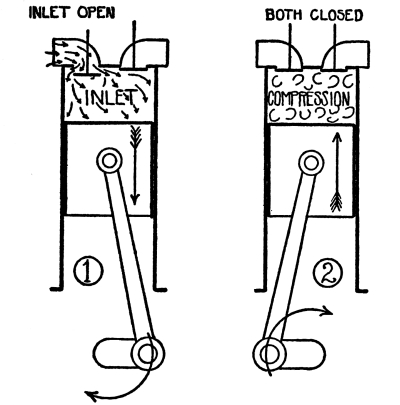
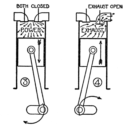
Fig. 1.—The Gas Engine Cycle
In slow-speed 1-cylinder and 2-cylinder engines the valve closes when
the piston reaches the end of its stroke; on high-speed engines the
valve does not close until the piston has moved ¼ inch or ½ inch on the
compression stroke.
Compression Stroke.—During
the compression stroke (No. 2, Fig. 1) the piston moves inward,
and both valves are closed. This movement places the piston in position
to move outward on the power stroke. As the outlets to the cylinder
are closed, the charge of mixture cannot escape, and is therefore
compressed into the space between the piston and the cylinder head when
the piston is at the inner end of its stroke. This space is usually
about one quarter the volume of the cylinder; the charge is therefore
compressed to about one quarter of its original volume.
This compression of the charge is very important in the operation of
the gas engine, and any interference with it will make the engine run poorly.
In the first place, it improves the quality of the charge, and makes it
burn very much better. When the charge enters the cylinder, the fuel
vapor and air are not thoroughly mixed; much of the fuel is not turned
into vapor. By compressing the charge it becomes heated; this vaporizes
the fuel, and vapor and air become thoroughly mixed.
Compression also increases the power. Suppose that the cylinder
contains a quart of mixture which, when heated, will expand to a
gallon. If this quart of mixture is compressed to a half pint, it
will not lose its ability to expand to a gallon, and will exert more
pressure in expanding from a half pint to a gallon than from a quart to
a gallon.
A leaky cylinder will cause a further loss of power because some of the
charge will escape during the compression stroke, which will leave less
to be burned and to develop power.
Ignition.—Setting fire to the
charge of mixture is called the ignition of the charge, and it
takes place close to the end of the compression stroke. To get the
greatest power, all of the mixture should be on fire and heated most
intensely as the piston begins the power stroke.
When the mixture is set on fire, it does not explode like gunpowder,
but burns comparatively slowly; the charge is ignited by an electric
spark, and the flame spreads from that point until it is all on
fire. In order to give the flame time to spread, the spark passes
sufficiently before the end of the compression stroke to have the
entire charge on fire as the power stroke begins. This is called the
advance of the ignition.
The flame takes the same time to spread through the charge when the
engine is running fast as when it is running slow. Therefore if the
engine is speeded up, the spark must be advanced, for otherwise the
piston would be on the power stroke before the flame would have time to
spread all through the mixture.
When the engine is slowed down, the spark must have less advance, or
must be retarded, for, if it were not, the charge would all be
in flame, and exerting its full pressure, before the piston reached the
end of its compression stroke.
The subject of ignition, which is of great importance, is covered more
fully in Chapter VI.
Power Stroke.—During
the power stroke (No. 3, Fig. 1) the piston moves outward,
and both valves are closed. As it begins, the mixture is all on fire, and great
pressure is exerted against the piston.
As the piston moves outward the combustion space becomes larger, and
the gases obtain the room for expansion that they seek. As they expand,
the pressure that they exert becomes less. By the time the piston
is three quarters the way down the power stroke, the pressure is so
reduced that it has little or no effect; the gases are still trying to
expand, however, so the exhaust valve is opened at that point, and they
begin to escape.
Exhaust Stroke.—During the
exhaust stroke (No. 4, Fig. 1) the piston moves inward and the
exhaust valve is open. This movement of the piston pushes the burned gases out
of the cylinder, and it is clear that the more thoroughly the cylinder
is emptied of them, the more room there will be for a fresh charge.
In high-speed engines the gases cannot escape as fast as the piston
moves; they are still flowing out when the end of the stroke is
reached. Therefore the valve is closed, not at the end of the stroke,
but when the piston has moved about ⅛ inch outward on the inlet stroke.
The inlet valve opens as the exhaust valve closes.
It can be seen that through the inlet and compression strokes a leak
will reduce the charge and so interfere with the production of full
power. The piston must make a tight fit in the cylinder, the valves
must seat tightly, and gaskets and other parts must be in proper condition.
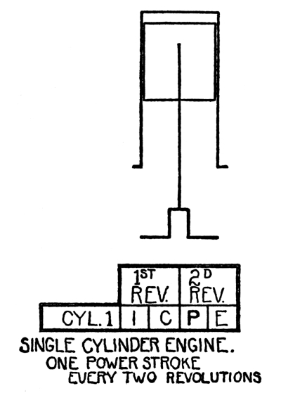
Fig. 2.—1-Cylinder Power Diagram
Figure 2 shows a power diagram for a 1-cylinder engine,
in which the crank shaft moves under power during one stroke out of every four.
An engine with two cylinders can be built so that first one cylinder
applies power and then the other, in which case the crank shaft moves
under power during two strokes out of every four.
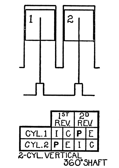
Fig. 3.—2-Cylinder Power Diagram
Figure 3 is a power diagram of an engine of this sort. If
piston 1 is moving down under power, piston 2 is also moving down, but on the inlet
stroke. The following stroke is exhaust in cylinder 1 and compression
in cylinder 2, and cylinder 2 will then deliver a power stroke while
cylinder 1 is on inlet. Thus the crank shaft will receive a power
stroke, followed by a dead stroke; then another power stroke and
another dead stroke, and so on.
There will be the disadvantage, however, that the pistons, moving up
and down together, will cause vibration, which in the course of time
will be likely to give trouble. To overcome this, a 2-cylinder engine
can be built as indicated in Figure 4.
In this engine the cranks project on opposite sides of the crank shaft
instead of on the same side, as in Figure 3; the pistons thus
move in opposite directions, and produce no vibration. Power will be unevenly
applied, however, for both power strokes occur in one revolution, with
two dead strokes in the succeeding revolution.
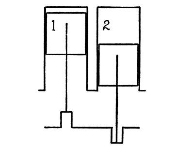
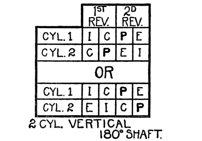
Fig. 4.—2-Cylinder Power Diagram, 180 Shaft
With piston 1 moving down on power, piston 2, moving upward, can only
be performing compression or exhaust. If it is on compression, its power
stroke will follow the power stroke of piston 1, while if it is on
exhaust its power stroke will have occurred immediately before the
power stroke of piston 1. In either case one power stroke follows the
other, taking place in one revolution of the crank shaft, while in the
following revolution both pistons will be performing dead strokes.
While there is no vibration from the movement of the pistons in this
engine, the uneven production of power will produce vibration of
another kind.
These two types may be built with the cylinders standing up or
lying down; that is, they may be either vertical engines or
horizontal engines. The double opposed engine, which is
built only in horizontal form, is free from either kind of vibration,
but has the disadvantage of occupying more room than the others. The
cylinders, instead of being side by side, and on the same side of the
crank shaft, are placed end to end, with the crank shaft between them,
as shown in Figure 5.
The pistons make their inward and outward strokes together, but in so
doing they move in opposite directions. Thus every power stroke is
followed by a dead stroke, as in the engine shown in Figure 3,
while the movement of one piston balances that of the other, as is the case
with the engine shown in Figure 4.
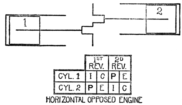
Fig. 5.—H. D. O. Power Diagram
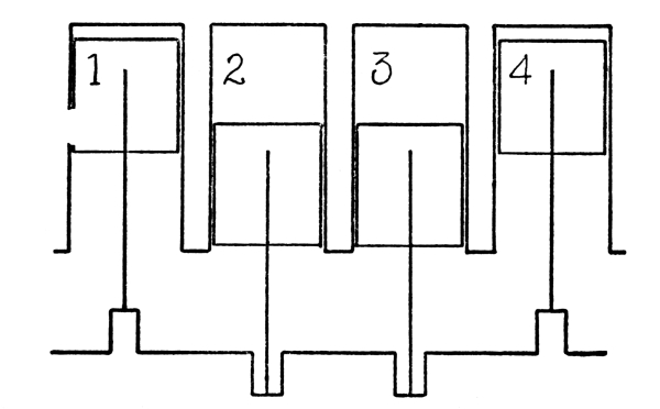
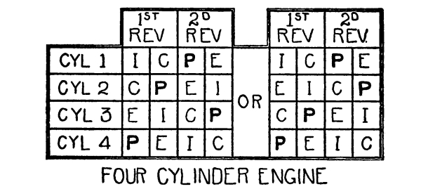
Fig. 6.—4-Cylinder Power Diagram
In a 4-cylinder engine one power stroke follows another without any
dead stroke intervals, which, of course, makes the crank shaft revolve
more smoothly and with a steadier application of power. The power
diagram is shown in Figure 6; in studying this it should be
remembered that if two pistons move in opposite directions, as in Figure 4,
one power stroke follows another, while if they move in the same direction,
as in Figure 3, there is an interval of one stroke between
their power strokes.
The crank shaft of a 4-cylinder engine is so made that the middle
pistons move in the same direction, and opposite to the end pistons.
This construction has been found to make a smoother running engine than
if pistons 1 and 3 moved one way while pistons 2 and 4 moved the other.
If piston 1 is on the power stroke, either piston 2 or piston 3 can
follow, for they are moving in the opposite direction. If we say that
piston 2 is the next, then piston 4 must be the third to give a power
stroke, for it is the only one left that is moving in the opposite
direction to piston 2. Piston 3 is thus the fourth to move under power,
and it is followed by another power stroke by piston 1; the firing
order is then said to be 1, 2, 4, 3.
If it is piston 3 that follows piston 1, piston 4 will again be the
third to produce power, and piston 2 will be the fourth. The firing
order will then be 1, 3, 4, 2. There is no other order in which a
4-cylinder engine can produce power, and there is no choice between them.
The firing order of an engine is established by the manufacturer, and
depends on the order in which the valves are operated.
CHAPTER III ENGINE PARTS
The foundation of an engine is the base, which supports the
bearings in which the crank shaft revolves, and to which the
cylinders are attached. The cylinders of tractor engines are made
of cast-iron, and the cylinder heads, which close the upper ends of
the cylinders, are usually in a separate piece, bolted on. The joint
between the cylinders and the cylinder head is made tight by placing
between them a gasket of asbestos and thin sheet metal.
The crank shaft has as many cranks, or throws, as the engine
has cylinders. Crank shafts for 2-cylinder engines are shown in Figure 7;
the upper one is for an engine of the type shown in Figure 3, with
pistons moving in the same direction. With both cranks projecting from
one side the shaft is out of balance, so balance weights are
attached to the opposite side.
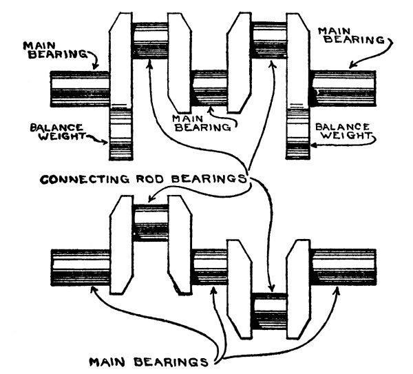
Fig. 7.—2-Cylinder Crank Shaft
The other shaft shown in Figure 7 does not need balance weights,
for one crank balances the other. A four-cylinder crank shaft, Figure 8,
is also in balance.
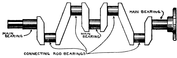
Fig. 8.—4-Cylinder Crank Shaft
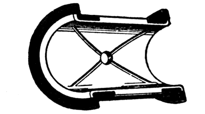
Fig. 9.—Half of a Plain Bearing
Crank shafts revolve in main bearings, which are set in
the engine base. In tractor engines these are usually plain
bearings, a half of such a bearing being shown in Figure 9.
This is a bronze shell lined with a softer metal, making an exact fit on
the shaft; with the two halves in place, the shaft should turn freely,
but without looseness or side play. The grooves shown are to admit
lubricating oil.
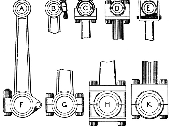
Fig. 10.—Connecting Rod Bearings
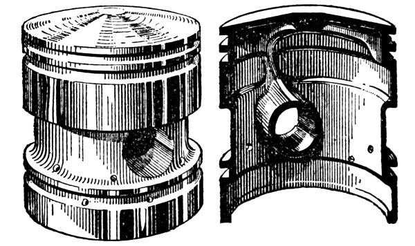
Fig. 11.—Piston Complete and in Section
The piston is attached to the crank shaft by a connecting
rod, which is illustrated in Figure 10. Pistons are
shown in Figures 11 and 12;
they are made as light as is consistent with the pressure that they must bear,
and are hollow, and open at the lower end.
The piston is attached to the connecting rod by a wrist pin, or
piston pin, which is a shaft passing through it from side to
side, and also through the bearing in the upper end of the connecting
rod. The connecting rod swings on the wrist pin in following the
rotation of the crank shaft, and its attachment to the wrist pin must
permit this without being loose.
The bearings at the two ends of a connecting rod are usually
adjustable, so that wear can be taken up; some of the methods of
doing this are illustrated in Figure 10. In A, the wrist pin
bearing is a plain tube, ground to an exact fit; when it is worn it must be
replaced. In B, the bearing is split, and the ends are drawn together
by a bolt to the correct fit. The bearing in C is in two parts, held
together by a U-shaped bolt, while in D the two parts are held together
by a cap bolted to the end of the connecting rod. In E, the end of the
connecting rod is a square loop enclosing the two parts of the bearing;
the parts are held in the proper position by a wedge adjusted by screws.
The crank shaft bearing of the connecting rod shown in F is in two parts
which are hinged together. G, H, and K show the forms usually used in
tractor engines, which consist of two parts bolted together.
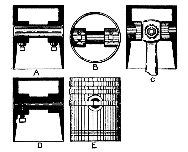
Fig. 12.—Wrist Pin Fastenings
The wrist pin is usually firmly attached to the piston, so that the
connecting rod swings on it; methods of securing the wrist pin are
shown in Figure 12, the wrist pin being held in supports cast in the
piston. In A, the wrist pin is held by two set screws, and in B, by
pins passing through it. The wrist pin shown in D is hollow, as is very
common, and a bolt passes through part of the piston and into the wrist pin.
In the construction shown in C the wrist pin is secured to the
connecting rod and moves in bearings in the piston. In E, a ring
fitting in a groove around the piston prevents the wrist pin from
moving endways.
The engine must usually be taken to pieces in order to get at the wrist
pin; lock nuts, lock washers or cotter pins are always used to prevent
the trouble that would be caused if the wrist pin worked loose.
A leak-proof joint between the piston and the cylinder is made by means
of piston rings that fit in grooves around the piston, as shown
in E, Figure 12. Piston ring grooves are shown in
Figure 11. Piston
rings are not solid, but are split so that they are elastic; they fit
snugly in their grooves, and tend to spring open to a greater size than
the cylinder. This causes them to maintain a close fit against the
cylinder, and the gases are prevented from leaking past.
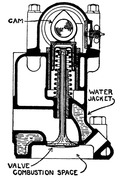
Fig. 13.—Valve
Each cylinder is provided with two valves: the inlet valve that
admits fresh mixture and the exhaust valve through which the
burned gases escape. These valves are metal disks with funnel-shaped
edges fitting into funnel holes. A valve and its stem are shown in
Figure 13 and also in Figure 15.
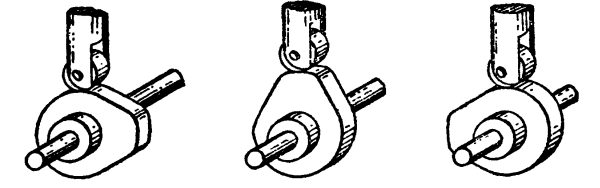
Fig. 14.—Action of a Cam
A valve is opened at the proper time by a cam, and closed by a
spring. A cam is a wheel with a bulge on one side, so that its rim is
eccentric to its shaft, as illustrated in Figure 14, which
shows a cam in three positions of a revolution. A rod resting on the rim of the
cam is moved endways as the bulge passes under it, and the valve is
operated by connecting it with the rod.
A valve is opened once during two revolutions of the crank shaft;
therefore the cam cannot be placed on the crank shaft, for, if it were,
the valve would be opened every revolution. The cam is placed on a
separate shaft which is driven by the crank shaft at half its speed.
This is usually done with gears, a gear on the crank shaft meshing with
a gear on the cam shaft having twice as many teeth; the crank shaft
gear must make two revolutions in turning the cam shaft gear once.
The valve in Figure 13 is held on its seat by a spring. The
cam bears against the end of the valve stem, and as it revolves its bulge forces the
valve stem and valve to move endways and thus to uncover the valve opening.
As the movement of the piston depends on the crank shaft, the valve can
be made to open at the right time by a proper setting of the gears that
drive the cam shaft.
The length of time that the cam will hold the valve open depends on
the shape of the bulge of the cam. It can be seen that the pointed cam
of Figure 13 will not hold the valve open for as
long a time as the flat-end cam of Figure 14.
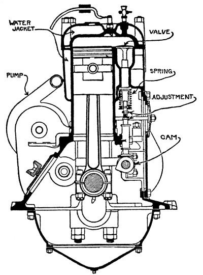
Fig. 15.—“Twin City” Tractor Engine
In the design shown in Figure 13 the cam bears directly
against the end of the valve stem, the cam shaft in this case lying along the
cylinder head. In the construction shown in Figure 15 the
valves are not placed in the cylinder head, but are in an extension or valve
pocket projecting from the combustion chamber; this cam shaft is
near the crank shaft. It would not be practicable to make the valve
stem long enough to reach down to the cam, so a length of rod, called
a push rod, or tappet, is placed between them; the cam
moves the push rod and the push rod in turn moves the valve. This is a
construction frequently used for automobile engines.
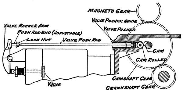
Fig. 16.—“Hart-Parr” Valve Mechanism
In tractor engines the cam shaft is usually placed near the crank
shaft, as in Figure 15, and the valves are in the head, so
that a valve moves in the opposite direction to the movement of the push rod. This
requires still another part to be used, called the rocker arm.
It is shown in Figure 16. It is a short bar, pivoted at or
near the center, with one end at the push rod and the other at the valve stem.
When it is moved by the push rod it in turn moves the valve.
Valves operated by push rods and rocker arms are also shown in
Figures 17, 18 and
19; Figure 18 is a single-cylinder horizontal engine, while
Figure 19 is a horizontal double opposed engine, in which one cam
operates a valve in each cylinder. Figure 20 shows the valve mechanism
of a vertical engine in which all parts, including the rocker arm, are
enclosed to protect them from dust, and so they can run in oil.
A small space is always left somewhere between the cam and the valve
stem, to give the valve stem room to lengthen, which it will do when it
gets hot. If this space were not left, the valve stem, in lengthening
as it became hot, would strike the part next to it, and the valve would
be lifted from its seat. This would cause the engine to lose power.
This space must be kept properly adjusted, and instructions for this
will be found in Chapter XII.
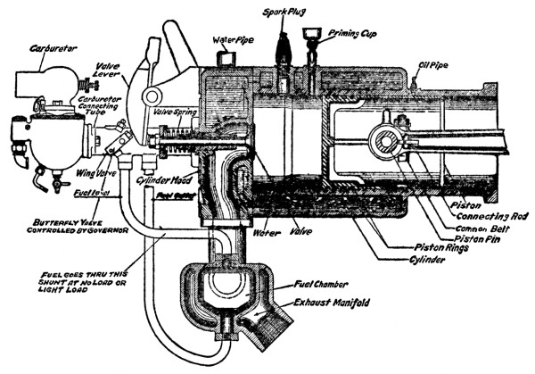
Fig. 17.—“Hart-Parr” Engine
A valve is held against its seat by a spring, which must be compressed
when the valve is opened. If this spring is too weak, it will not hold
the valve tightly on its seat, while if it is too stiff, the cam shaft
and other parts will be needlessly strained in compressing it.
Friction between the cam and the end of the valve stem or push rod
would cause rapid wear if these parts were not of hardened steel, and
kept well oiled. Still further to reduce wear, there is usually a
roller on the end of the push rod, as shown in Figure 16
and some of the other illustrations. Figure 15 shows a
construction in which the end of the push rod is a flat disk, which rotates
as the cam comes into contact with it.
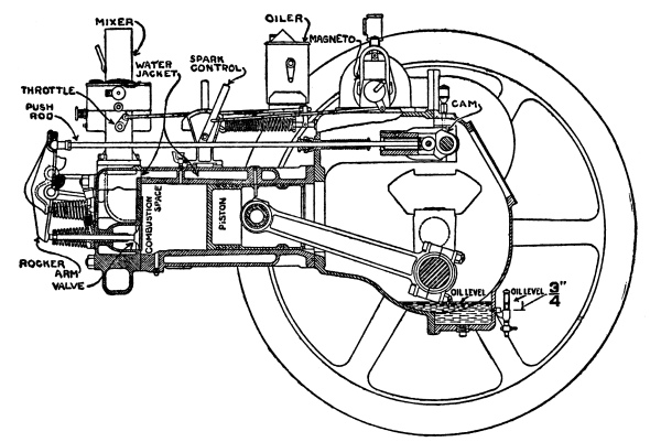
Fig. 18.—“Oil-Pull” Engine
When the mixture burns, the top of the piston, the cylinder head, and
the walls of the combustion chamber become heated, and if it is not
prevented they will get so hot that they will expand sufficiently to
cause the piston to stick, or seize. The upper part of the
cylinder is, therefore, provided with a cooling system that keeps
these parts from getting overheated. Channels are provided through
which water is circulated; the water takes the heat from the metal
parts, becoming heated itself, and then passes to a cooler, or
radiator, where it gives up the heat to currents of air.
In addition to the channels, or water jackets, around the
cylinder, a cooling system includes the radiator, the connections, and
usually a pump that keeps the water in motion.
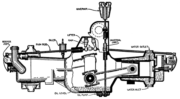
Fig. 19.—Horizontal Double Opposed Engine
In some tractors, notably the Fordson, no pump is used; the water
circulates because it is heated. This is called a thermo-syphon
system. When the engine runs, the water in the cylinder jackets becomes
heated; as hot water is lighter than cold water, it rises and flows out
of the jackets to the radiator, its place being taken by cool water
from the bottom of the radiator. This circulation continues as long as
the water in one part of the system is hotter than the water in some
other part of the system.
The lubrication of an engine is described and explained in Chapter X.
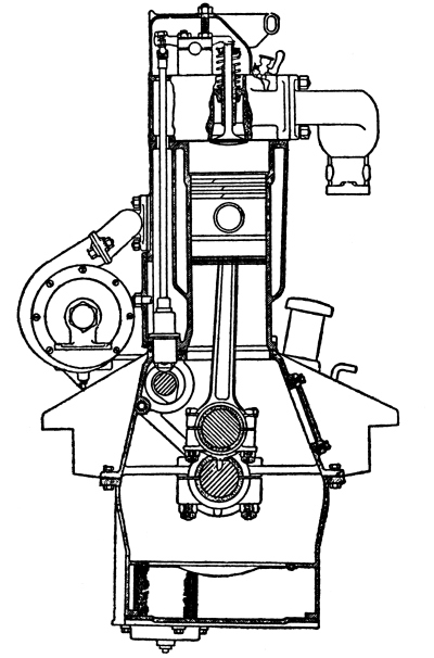
Fig. 20.—“Monarch” Engine
CHAPTER IV FUELS AND CARBURETION
In order that a thing may burn, it must be provided with oxygen. Oxygen
is found in air, so it is usual to say that air is necessary in order
that anything may burn.
To prove this, light a candle and place an empty bottle over it, upside
down; in a very short time the oxygen in the bottle will be used up,
and the flame will flicker and get smoky, and finally die out. If a
card is laid on the chimney of a coal-oil lamp so that it covers the
opening, that flame also will flicker, get smoky and go out.
In order to deaden the fire in a stove, the dampers are closed to
prevent air from entering; the fire is kept alight by the very small
quantity of air that leaks in below the fire-box. When the drafts are
opened the fire will burn up brightly because a plentiful volume of air
can then enter.
In a similar way, air must be used in a gas engine in order that the
fuel may burn. It is not possible to mix air with a liquid; the first
step in making a gas that will burn is, therefore, to turn the fuel,
whether it is gasoline, kerosene, distillate, or other oil, into a
vapor; this vapor is then mixed with air.
For good results it is very necessary that the vapor and air be in
proper proportions. In the experiment with the candle and the bottle it
was seen that as the air was used up, the candle flame became yellow
and smoky: this is the effect of insufficient air. If there is not
enough air in the mixture, part of the vapor will not be able to burn,
and will only smoke.
If, on the other hand, there is too much air, the mixture, if it will burn
at all, will burn slowly, and the extra volume of air will reduce the heat.
In a mixture of the proper proportions of air and fuel vapor, the
burning, or combustion, will be very rapid, resulting in the
sudden production of the greatest possible amount of heat. This, of
course, is what is necessary if the engine is to produce its fullest
power. With such a mixture, combustion will be complete before the
piston has done more than start outward on the power stroke, and the
greatest possible, or maximum, pressure will then be produced.
When a mixture burns slowly, the piston will have gone through much
of the power stroke before combustion is complete, in which case a
considerable part of the pressure that should have been applied at the
beginning of the stroke will be wasted.
A mixture that is not correct will burn unevenly; it may burn better
during one power stroke than during another, which will make the engine
run unsteadily.
If the mixture has too much air in proportion to the amount of vapor,
it is known as a thin mixture, or a lean or poor
mixture. It burns so slowly that it is quite possible for the mixture
that started burning before the beginning of the power stroke to
continue burning through the exhaust stroke, and for enough flame to
remain in the cylinder to set fire to the fresh charge that enters
during the next inlet stroke. This will produce what is known as a
backfire; that is, the mixture entering the cylinder will catch
fire, and in burning will blow back through the open inlet valve. This
is a dangerous condition, for the flame might spread to fuel dripping
from the carburetor, or to the fuel tank.
A mixture that has not enough air is called a rich mixture; the
air that is present will burn part of the vapor, while the rest will go
out of the exhaust unburned, or will work past the piston into the oil
in the crank case. This is wasteful of fuel.
The most serious result of a rich mixture, however, is in the
production of carbon, and the carbonization of the
engine. The flame of a rich mixture is smoky; the smoke of this flame,
as is the case with smoke from all other sources, is composed of fine
particles of carbon, or soot. These particles of carbon will deposit
on all parts of the combustion space: on the top of the piston, on the
valves, on the spark plugs, and on the inner wall of the cylinder head.
At first it is gummy, but it rapidly hardens and forms a crust that
must be scraped off with a steel tool.
Carbon in an engine will reduce the power through causing
preignition, or, in other words, by setting fire to the
fresh charge before the proper point in the stroke. The heat of the
combustion will cause the carbon deposit to become so heated that it
will glow, these glowing particles being sufficient to ignite the
incoming fresh charge. The remedy for this condition is to remove the
carbon, which is usually done by taking off the cylinder head and
scraping away the deposit.
It may be added that carbon is also formed by the use of too much
lubricating oil, as will be explained in the chapter on lubrication.
Thus it is seen that if the engine is to run properly, and is to be
kept in good condition, the proportions of the mixture must be very
carefully maintained.
The mixture is formed in a carburetor, or mixer. This
is, roughly, in the form of a tube through which air is sucked during
the inlet stroke; projecting into it is a fine tube called a spray
nozzle through which the fuel enters. In action it is somewhat
similar to the atomizer that is used for spraying the nose and throat.
By forcing the fuel to flow rapidly through this small tube it comes
out in the form of spray, and the tiny drops are picked up by the
current of air and are carried into the cylinder.
It is much easier to form a mixture of gasoline than of kerosene
or distillate, because gasoline vaporizes more readily at ordinary
temperatures. If saucers of gasoline and kerosene are placed in the
sun, the gasoline will evaporate rapidly and completely, leaving only
a faint oily deposit. The kerosene, on the other hand, will evaporate
slowly, and much of it will not evaporate at all.
To make kerosene and distillate evaporate completely, they must be
heated, just as water must be heated to make it evaporate.
In the case of a carburetor for gasoline, the current of air needs
only to be warmed; the spray of gasoline will evaporate on coming into
contact with the warmed air, and much of it will enter the cylinder as
vapor. In order to evaporate kerosene and distillate much more heat
must be provided, and it is usually considered necessary to heat not
only the current of air, but the liquid fuel as well. Methods of doing
this will be explained in the next chapter.
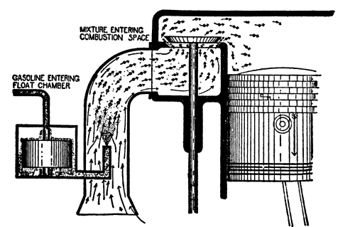
Fig. 21.—Principle of Carburetor
When kerosene or distillate is used, there are conditions that make
it necessary to add water vapor to the mixture, which prevents the
overheating of the cylinder and reduces the deposit of carbon. The
difficulty of making a complete vapor of kerosene and distillate
results in a tendency on the part of these fuels to carbonize the
cylinders; the use of water aids in keeping the cylinders clean.
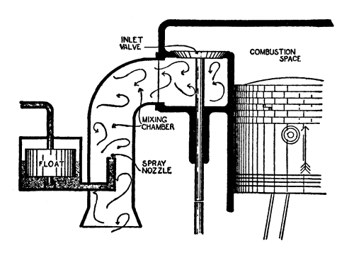
The general principle of a carburetor is shown in Figure 21,
one drawing illustrating conditions when the inlet valve is closed and the
other when it is open. It shows an engine cylinder connected with an
inlet pipe or mixing chamber, through which there is a swift
flow of air during an inlet stroke.
Projecting into the intake pipe is the spray nozzle, which is
connected with a small chamber containing fuel; inside of this chamber
is a float, usually made of cork, although it is sometimes a
light metal box. The fuel is intended to fill the chamber to a certain
height, at which the valve will be closed by the float rising on the
fuel. This level is such that the fuel does not quite reach the tip of
the spray nozzle.
During the compression, power, and exhaust strokes, the fuel stands at
this level, for it cannot run out of the spray nozzle, and the float
holds the valve closed. As soon as the inlet valve opens, air rushes
through the intake pipe and sucks fuel out of the spray nozzle. This,
of course, takes fuel out of the float chamber; the float in sinking
opens the valve, and enough fuel enters to restore the level.
The fuel comes out of the nozzle in the form of fine spray; it is in
such small drops that it evaporates quickly, and the resulting mixture
of fuel vapor and air passes into the cylinder. By using a spray nozzle
of the proper size, any desired proportion of fuel and air may be obtained.
If an engine runs at a single speed, a carburetor as simple as this one
would be satisfactory, for if the suction is always the same, there will be
little or no change in the proportions of the mixture that is formed.
To get the best results, the proportions of fuel vapor and air should
be the same for all running speeds of the engine. The proportions of
the mixture, however, depend on the violence of the suction, which
changes as the engine speed changes, becoming greater as the speed
increases. The simple carburetor illustrated in Figure 21
can be adjusted to give a correct mixture for any particular speed, but will
be out of adjustment for any other speed.
The speed of a 1-cylinder engine does not change very greatly; it is
built to run at practically a constant speed, and a simple carburetor
is satisfactory for it. The speed of engines with a greater number of
cylinders may be greatly changed, and the carburetor must be so made
that it will give the same proportions of vapor and air at low speed as
at high.
In the simple carburetor described, the speeding-up of the engine will
result in a greater rush of air through the intake pipe, which in turn
will suck out a much greater quantity of fuel. If the carburetor is
adjusted to give the proper quantity of fuel for the air that passes
at low speed, at high speed it will give far more fuel than will be
required by the quantity of air that then passes. Thus at high speed
the mixture will be too rich.
If, on the other hand, this carburetor is adjusted to give a proper
mixture at high speed, too little fuel will be sucked out when the
engine runs slowly, and the mixture will be too lean.
A carburetor must thus have an additional device that will keep the
mixture correct, regardless of the speed at which the engine runs.
This is sometimes done by changing the size of the spray nozzle so
that a greater or less quantity of fuel flows out, but more usually
by permitting an extra quantity of air to enter the carburetor as the
engine speeds up. This is done with an extra air intake, the
principle of which is illustrated in Figure 22.
As will be seen, this carburetor has two openings for air, one being
the main air inlet and the other the extra air inlet. The latter is an
opening provided with a valve which is held on its seat by a spring.
The suction created by an inlet stroke is exerted in the carburetor,
but at low speed is not sufficient to suck the extra air valve from its
seat. Air then enters only through the main air inlet, and the spray
nozzle is adjusted to give the proper proportion of fuel.
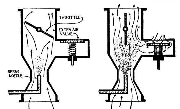
Fig. 22.—Principle
of Extra Air Inlet
As the engine speed increases the mixture becomes richer; but there
is also an increase in suction, which becomes strong enough to pull
the extra air valve from its seat. This provides another opening into
the carburetor, through which enough air enters to keep the mixture
in proper proportion. The higher the speed of the engine the more the
valve will open, and the greater will be the quantity of air admitted.
In order to get the fullest power from an engine, the carburetor is
built to give its most perfect mixture at the usual working speed.
This will be the speed at which the engine will run under ordinary
conditions. As the engine will run at this speed most of the time, the
carburetor should then deliver its best mixture on the least possible
quantity of fuel.
As an engine is run at low speed so little of the time, it is not
necessary that the mixture should then be so perfect or that the fuel
should be used so economically.
The design of a carburetor is a complicated matter, because the
production of mixture is due to the flow of air, which is a very
changeable thing. On a cold, damp day, the air will be heavier and
denser than on a day that is hot and dry, and different quantities of
fuel will be necessary for the formation of the mixture. The carburetor
manufacturer cannot make a commercial carburetor that will take care
of such a difference as this; he strikes an average that gives good
general results, and expects the user to change the adjustments when
weather and temperature make it necessary.
The formation of the mixture is affected by the condition of the
engine. When all of the parts of the engine are tight, the suction in
the carburetor is more violent than when there is a leakage of air past
the piston rings, or through a leaky valve or spark plug.
On a dry, hot day the fuel evaporates much more readily than on a day
that is cold and damp; more of the fuel that flows out of the spray
nozzle will be vaporized and the formation of the mixture will be
easier. On a cold, damp day the fuel will not vaporize in the
carburetor to any extent, and much of it will pass to the cylinder in
drops that even there will not vaporize in time to form a mixture.
In order to assure the vaporization of enough fuel to form a mixture under
such conditions, the fuel and the air must be heated to a greater degree.
As the engine becomes heated up, more and more of the fuel will
vaporize, and the amount flowing out of the spray nozzle may therefore
be cut down.
With fuels like kerosene and distillate, which do not vaporize as
readily as gasoline, it is not unusual to have them condense on
the walls of the inlet pipe, which produces a condition known as
loading. This condensation is similar to the sweating of an
ice-water pitcher on a hot day. If an engine is running at a constant
speed, loading does not make much difference, because the carburetor is
so adjusted that it gives a proper mixture. If the engine is suddenly
speeded up, however, the greater rush of air will pick up the condensed
fuel, and the mixture will instantly become too rich, continuing so
until this extra supply of fuel is used up. The result will be to choke
the engine and make it lose power just at the time when extra power is
needed.
Loading can be prevented by heating the inlet pipe to such an extent
that the fuel will not condense on it.
The speed of a tractor engine is practically always controlled by a
throttle, which is a valve set in the passage of the carburetor.
It operates exactly the same as a damper in a stovepipe; when it is
closed, it shuts the passage and prevents the flow of mixture to the
engine. As it is opened, it permits a greater quantity of mixture to
flow, and it follows, of course, that as the charges of mixture become
larger, the engine runs with more power. A tractor carburetor usually
has two throttles, one being operated by hand and the other by the governor.
It is usual for a carburetor to be fitted with a strangler, or
choke, which makes it easier to form a mixture at slow starting
speed. When an engine is cold, the fuel evaporates slowly; and,
furthermore, when an engine is cranked by hand its speed is so low that
the suction in the carburetor is not sufficient to draw out enough fuel
to form a mixture. The strangler is a valve similar in every way to the
throttle, but placed between the main air inlet and the spray nozzle.
When it is closed and the engine is cranked, very little air can enter
the carburetor; the suction is therefore very great. Far more fuel
than usual is then sucked out of the spray nozzle, and of this greater
amount enough reaches the cylinder to form a combustible mixture. The
engine will start, but as soon as it does so, the strangler must be
opened so that the normal amount of air enters. If this is not done,
the excessive suction will draw so much fuel out of the spray nozzle
that the mixture formed will be too rich to burn.
CHAPTER V CARBURETORS
The apparatus that forms the mixture is in two parts, one being the
carburetor that proportions the fuel to the quantity of air drawn
into the cylinder, and the other the mixing chamber, or
manifold, that connects the carburetor with the valve chamber.
The mixing chamber has no adjustments; it is a passage, often a pipe,
that is shaped to fit the conditions, and according to the ideas of
the manufacturer. When kerosene and distillate are used, the mixing
chamber must be heated, so it is frequently built into the exhaust
manifold, which is the pipe that conducts the burned gases away
from the engine. In some cases it gets heat from the water jacket of
the engine, a water jacket formed around it being connected with the
cooling system.
The carburetor, on the other hand, has adjustments that must be
understood in order to run the engine economically. The understanding
of these adjustments is simplified if it is remembered that the object
of the carburetor is to maintain a correct proportion of fuel to the
volume of air that passes through it.
All tractor carburetors operate on the same principles, and the
principles are applied in much the same way. If these principles are
understood, and there is an understanding of what the parts of a
carburetor are for and what they do, there should be no difficulty in
adjusting and caring for any kind of a carburetor that may be offered.
The main body of the carburetor is the tube through which the air
passes. This is a casting, and cannot be adjusted or altered. Into this
passage projects the spray nozzle, which is usually provided with an
adjustment to control the amount of liquid that may flow out of it.
When no adjustment is provided, the spray nozzle is made removable, so
that a nozzle with an opening of any desired size may be inserted.
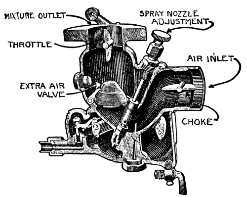
Fig. 23.—“Kingston”
Carburetor, Model L
On some carburetors the extra air valve is set by the manufacturers,
while on others it is adjustable by controlling the strength of the
spring that holds it against its seat.
The carburetor shown in Figure 23 has a spray nozzle adjustment of
a very usual type. A rod is so arranged that its pointed end projects
into the opening of the spray nozzle; by screwing it up or down the
opening may be made larger or smaller, so that more or less fuel may
flow out. The extra air valve is a flap valve that closes the air
passage until the suction is great enough to lift it from its seat.
Around the spray nozzle is a tube that connects the passage below the
extra air valve with the passage above it; when the suction is too low
to lift the extra air valve from its seat, any air flowing through the
carburetor passes through this tube. The tube is so small that even a
little air passing through it is enough to suck fuel out of the spray
nozzle, and the spray nozzle is so adjusted that enough fuel comes out
to make a proper mixture with that volume of air.
This is the low-speed adjustment, which gives a mixture on which
the engine will start and will run at its lowest or idling
speed. At this speed the engine produces just enough power to keep
itself going.
When the engine speeds up, and suction increases, the extra air valve
is lifted off its seat, and a greater volume of air flows through the
carburetor. The increased suction also draws more fuel out of the spray
nozzle. If the greater amount of fuel were in proportion to the greater
volume of air, there would be no change in the mixture, but this is not
the case. As suction increases, the proportion of fuel drawn out of the
spray nozzle becomes too great for the air, and the mixture becomes too
rich. To overcome this, the extra air valve permits a still greater volume
of air to pass, so that the proportions of fuel and air do not change.
The chamber below the air passage in Figure 22 is the fuel
cup, into which fuel flows from the tank. Inside the fuel cup is a ring of cork
attached to a pivoted lever, on the other end of which is a needle
valve that can close the opening through which the fuel enters the cup.
As the cup fills, the cork floats on it, and in rising it moves the
lever on its pivot. When the fuel reaches such a level that it is near
the tip of the spray nozzle, the valve closes the opening and prevents
more fuel from entering.
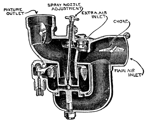
Fig. 24.—“Kingston”
Carburetor, Model E
In the carburetor shown in Figure 24, the principal air
passage is past the spray nozzle, and all air goes by this passage when the engine is
running at low speed. The extra air inlet consists of a number of holes
through which air can pass without going past the spray nozzle. On each
of these holes is a ball; when the suction is low the balls completely
close the holes. When speed increases, the suction becomes great enough
to lift the balls off the holes, and the extra volume of air that is
necessary is permitted to enter. By making the balls of different
weights, it can be seen that the volume of air admitted for any speed
is under good control.
Like the carburetor shown in Figure 23, this carburetor
is of the float feed type; that is, the flow of fuel to it is controlled
by a valve that is operated by a float.
Either of these two carburetors may be adjusted for gasoline or for
kerosene, but the adjustment that is right for one is wrong for the
other. Thus, if an engine is started on gasoline, with the intention of
running on kerosene, the carburetor must be readjusted when the change
is made. This is unsatisfactory, so a double carburetor is sometimes
used, as shown in Figure 25. This consists of two carburetors of the
kind shown in Figure 24, having a single mixture outlet, one being
adjusted for gasoline and the other for kerosene. Either of them can be
connected with the mixture outlet by means of a switch valve.
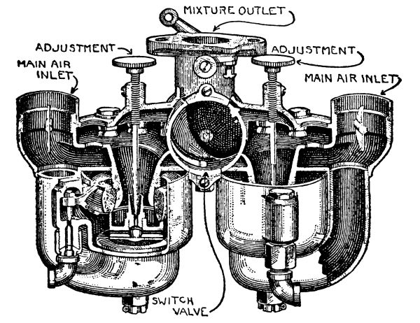
Fig. 25.—“Kingston”
Carburetor, Dual Model
In order to run on kerosene or distillate it is necessary to apply heat
for the reason that these oils do not evaporate readily at ordinary
temperatures. Gasoline, on the other hand, evaporates readily, and a
cold engine can be started on it. Tractors that run on kerosene or
distillate are therefore started on gasoline and run on it until they
are hot enough to vaporize the heavier oil.
A carburetor that will run on either gasoline or kerosene is shown in
Figure 26. The main air inlet is at E, which leads the air
around the spray nozzle and into the chamber G. The mixture flows to the cylinder
by the passage B. The control of the fuel at working speeds is by the
high-speed adjustment, which is a needle valve screwing into the spray
nozzle. Above this is another needle valve that adjusts the flow of
fuel for slow speed.
Extra air enters through the opening A, which is closed at slow speed
by a valve held against it by a spring. This valve bears against one
end of a pivoted lever, the other end of which is attached to the
slow-speed needle valve; when the extra air valve opens it moves the
lever and the slow-speed needle valve is lifted to permit the flow of a
greater volume of fuel from the spray nozzle.
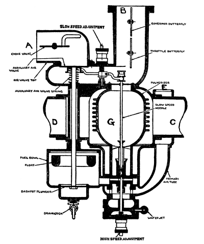
Fig. 26.—“E-B” Carburetor
This carburetor is started on gasoline. When the engine is hot, a
switch valve is operated to permit the burned gases from the engine to
flow through the carburetor; they pass through the pipe C, D, and as
the chamber G is directly in their path it becomes intensely heated.
The carburetor can then be switched to kerosene. A side view of this
carburetor is shown in Figure 27.
These carburetors are all of the float feed type, and are used on
engines of which the speed is variable. A carburetor that is fed by a
pump is shown in Figure 28. This is a simple tube with a fuel
cup cast on one side of it. Fuel is pumped to the bowl, and the proper level is
maintained by an overflow through which excess fuel passes back to the tank.
This carburetor is intended for an engine of which the speed does not
change greatly. Its only adjustment is the spray nozzle, and this is
altered to correspond with changes in engine speed.
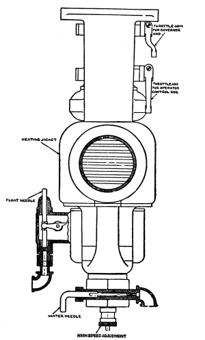
Fig. 27.—“E-B” Carburetor,
Side View
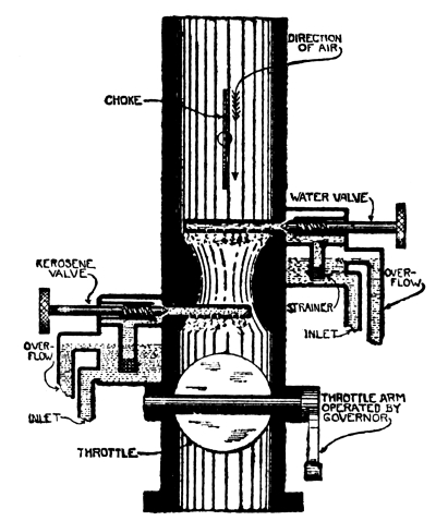
Fig. 28.—Pump-fed Carburetor
If an engine is clean and in good condition, it will run as well on
kerosene as on gasoline, although the heating effect of kerosene is
greater. When an engine is carbonized, as is usually the case, a
condition known as preignition will occur unless it is
prevented. Carbon from unburned fuel or from lubricating oil will
deposit on the piston head and the parts of the combustion chamber, and
particles will become heated to the glowing point, when they will set
fire to the fresh mixture during the compression stroke and before the
proper time. The effect is to make the engine lose power, and it also
gives rise to a sharp metallic knocking. By reducing the temperature
in the cylinder during the compression stroke this condition can be
prevented. This can be done by adding water vapor to the mixture, and
kerosene carburetors are therefore built with a water attachment. As
can be seen in Figure 28, this is a water cup and spray nozzle
like those for the fuel. When the engine knocks, and shows that preignition
is occurring, water is turned on, and, being carried into the cylinder,
keeps the mixture from being heated to the point of ignition before the
proper time.
Figure 29 shows the attachment of this carburetor to an
engine which, in this case, is horizontal. To start the engine, gasoline is injected
into the carburetor, as shown; this will give a sufficiently good
mixture for the purpose, and enough heat for running on kerosene is
thus obtained.
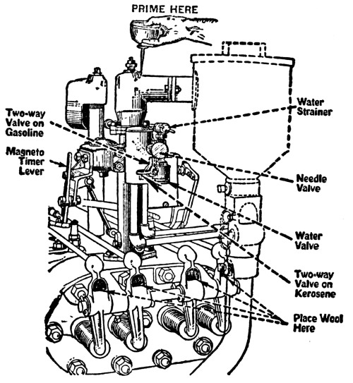
Fig. 29.—“Titan” Carburetor
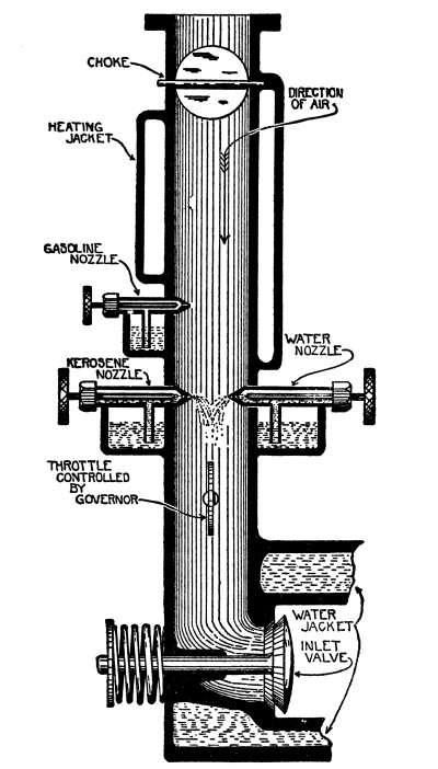
Fig. 30.—Pump-fed Carburetor
With Two Fuel Nozzles
The carburetor shown in Figure 30 is similar, but has a bowl
and spray nozzle for gasoline, to use in starting. It is also provided with a
heating jacket through which hot water or hot gases may circulate.
In many cases the fuel is heated before reaching the carburetor. This
is done by coiling the feed pipe around the exhaust pipe or putting it
in a jacket through which hot water circulates.
Another device sends the mixture through a chamber heated by the
exhaust, as shown in Figure 31. Figure 32
shows an arrangement in which the mixture passes through a jacket
around one branch of the exhaust pipe. By means of a switch valve, A,
more or less of the exhaust gases may be permitted to flow through this
branch, so that the mixture may be heated to any desired degree.
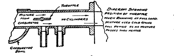
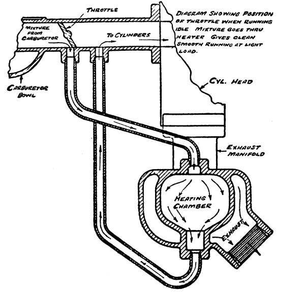
Fig. 31.—“Hart-Parr” Mixture Heater
All of these heating devices are so arranged that the heat is under the
control of the driver, which permits him to heat the mixture as much as
he judges to be necessary. Enough heat must be used to prevent the fuel
from condensing; but too much heat will cut down the efficiency of the
engine because it will cause so much expansion of the mixture that a
cylinderful of it will not produce the maximum power.
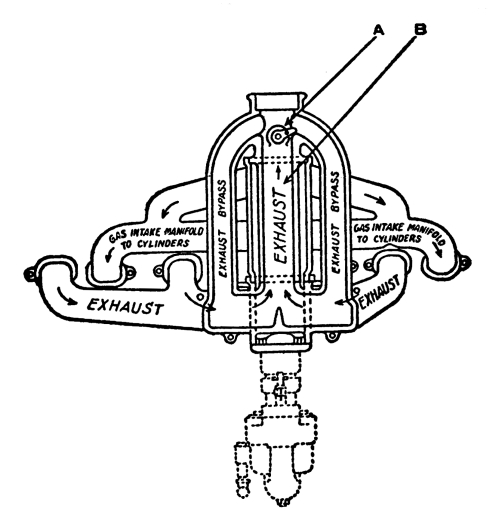
Fig. 32.—“Twin City” Manifold
Figure 33 shows the pump that is used in a force feed carburetor of the
type shown in Figure 28. Its plunger is forced through an inward stroke
by a cam, and makes an outward stroke as its spring returns it to
position. The inlet and outlet openings of the cylinder are closed by
ball check valves, the inlet check being open on the outward strokes,
and the outlet check being open on the inward strokes. A pump of this
sort requires no attention beyond seeing that the check valves work
properly, and that there are no leaks.
Figure 34 shows the connections between the fuel tank
and the carburetor. Under the tank, 1, is a chamber containing a fine wire
strainer, 4, through which the fuel must pass to reach the carburetor;
any dirt that may be present is strained out, and collects in the cup,
2. Water in the fuel also settles here, and the cup is cleaned out by
unscrewing the plug, 3. 5 is the shut-off cock; it should always be
closed when the tractor is not working.
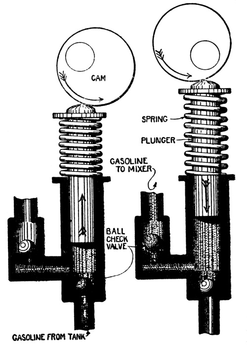
Fig. 33.—Fuel Pump
A complete fuel system is illustrated in Figure 35,
showing the connections of the tanks, pumps, and carburetor.
As dirt is injurious to an engine, the air that forms the mixture
must be clean, so when a tractor works in a dusty field, it should be
equipped with an air cleaner, of which there are three kinds. In one
of these the air is required to pass through water, which washes it.
A cleaner of this type is shown in Figure 36. The dusty air
enters the central passage, and is forced to pass through the water in order
to reach the outlet. Passage through the water and through the baffle
plates frees the air of all its dust.
In the cleaner shown in Figure 37, the air is passed
through loose wool, which filters out the dust. Another type of cleaner works on
the same principle as a cream separator; the air is given a whirling
motion, which throws the dirt out at the sides, and it is collected in
a glass jar.
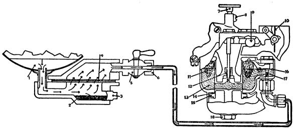
Fig. 34.—“Avery” Fuel Connections
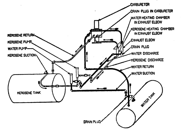
Fig. 35.—“Oil-Pull” Fuel System
These air cleaners must be emptied frequently, for if they are not kept
clean it cannot be expected that they will do their work.
A tractor engine is built to develop its maximum power at a certain
speed; if it runs at greater speed, it will not operate efficiently,
and there will be unnecessary wear of its parts. These engines are
therefore usually fitted with governors which hold them at their
most efficient speed. A governor operates by centrifugal force.
Anything in motion tries to move in a straight line; if it is forced to
move in a circle, it will exert force in trying to move away from its
center. It is this that is called centrifugal force. It is centrifugal
force that holds water in a pail that is being swung around the head,
and that makes the pail fly off if it is released.
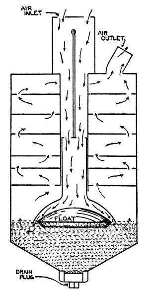
Fig. 36.—Air Washer
In applying this principle to a governor, weights are attached to a
plate and made to revolve; springs hold them together, but in spite
of this, centrifugal force throws them outward. In moving, they act
on a rod that operates the throttle; as the speed increases, the move
outward more and more, and it is a simple matter of adjustment to cause
them to close the throttle when the speed reaches a desired point.
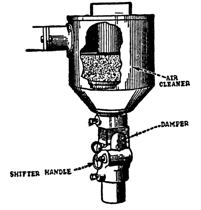
Fig. 37.—Air Strainer
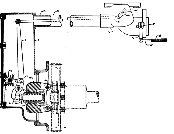
Fig. 38.—“E-B” Governor
A governor and its connections are shown in Figure 38. The
weights, R, are L-shaped, and pivoted at the angle to a plate driven by the engine.
The shaft that drives the plate also supports a collar, P, that is
loose on it and can slide endways; the collar rests against the short
bar of the L-shaped weights. The other end of the collar touches the
lever, E, which is moved when the collar moves. As the lever is
connected with the throttle, a movement of the collar will control the
position of the throttle.
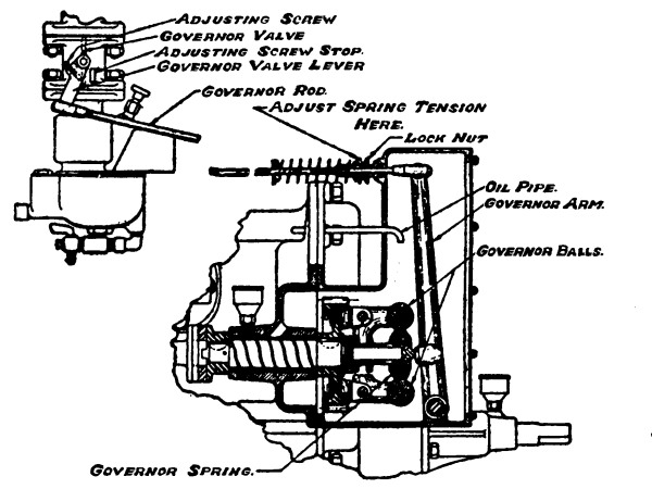
Fig. 39.—“Case” Governor
When the shaft revolves, the long arms of the L-shaped weights tend
to fly outward; this moves them on their pivots, and the short arms
thereupon force the collar to slide on the shaft, which moves the lever
and operates the throttle. The speed at which the throttle will begin
to close is determined by the setting of the spring that holds the
weights in.
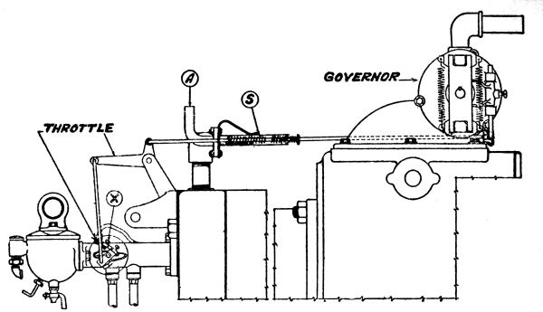
Fig. 40.—“Hart-Parr” Governor
Governors and governor connections are shown in Figures 39
and 40.
The governor shown in Figure 41 is enclosed in a housing that can
be locked or sealed. This prevents the unauthorized changing of the adjustment.
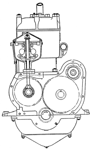
Fig. 41.—Vertical Governor
CHAPTER VI IGNITION
In order that a gas engine may run properly, the mixture must be set on
fire, or ignited, at exactly the right time; if ignition occurs
too early or too late, there will be a loss of power.
The greatest pressure will be obtained at the instant when all of the
mixture is burning, and this should take place just as the piston
begins to move outward on the power stroke. A little time is required
for the mixture to burn; there is a brief interval between the instant
when it is set on fire and the instant when it is all in flame. Thus it
is clear that if the mixture is all to be burning as the piston starts
the power stroke, it must be set on fire before that time, or, in other
words, toward the end of the compression stroke.
The point at which ignition should occur depends on the speed of the
engine and should change when the speed changes. The time required
for the flame to spread throughout the mixture does not change; let
us say that, with the engine running at 1200 revolutions a minute,
the mixture can be ignited when the piston is ¼ inch from the end
of the compression stroke, and will all be in flame by the time the
piston starts on the power stroke. If the engine is slowed down to
600 revolutions a minute and no change is made in the ignition, the
mixture will all be in flame before the piston reaches the end of the
compression stroke; pressure will then be produced before the piston is
in position to perform the power stroke. The pressure will try to make
the engine run backwards; it will sometimes be sufficient to make the
engine stop. If the momentum of the flywheel is sufficient to force the
piston to the end of the stroke against the pressure, this condition
will cause a loss of power. This is called preignition, or
ignition that occurs too soon. One effect of it is to produce a hard,
metallic knocking, due to the oil being squeezed out of the bearings by
the great pressure, which permits the bearing and shaft to strike. The
remedy is to make ignition occur later in the stroke.
If the engine is speeded up above 1200 revolutions, the piston will
have had time to move some distance on the power stroke before the
mixture is all in flame; the combustion space will then be too large to
permit the mixture to produce its greatest pressure, and again there
will be a loss of power. The remedy in this case is to make ignition
occur earlier in the compression stroke.
When ignition is made to occur early in the compression stroke, it
is said to be advanced; when it is made to occur late in the
stroke, it is said to be retarded.
To get the best results, the engine should be run with ignition
advanced as far as is possible without causing knocking.
The charge of mixture is always set on fire by an electric spark,
and the parts that produce and control this spark are called the
ignition system.
An ignition system consists of: First, the apparatus that produces
the electric current, which is usually a magneto; second, a
timer, which controls the instant at which the spark occurs;
third, the spark plugs, which project into the cylinders, and
at which the sparks take place; fourth, a switch, by which the
sparking current can be turned on or off, and fifth, the wires, or
cables, by which the parts are connected.
The electric current that gives the spark is always produced by
magnetism. In a magneto, magnetism is obtained from the heavy steel
magnets that are part of it; there is a constant flow of magnetism from
one end of these to the other. To obtain an electric current, a coil of
wire is placed in the magnetism, and the strength of the magnetism is
made to change; it alternately becomes weak and strong. Whenever a
change in strength takes place, an electric current flows in the wire,
and it continues to flow as long as the magnetism continues to change
in strength. When the change in strength is very great, that is, when
the magnetism changes from very weak to very strong, or from very
strong to very weak, the electric current is more powerful than when
there is only a little change in strength. A more powerful current is
also produced by a change that takes place suddenly than by a change
that takes place slowly.
The electrical principle that produces a current in this manner
is called induction; the current produced is known as an
induced current.
A magneto has two or more magnets, and between their ends,
or poles, there revolves a piece of iron called the
armature. A piece of iron placed between the poles of a magnet
becomes a magnet itself; the armature is so shaped that, as it
revolves, its magnetism continually changes in strength, and it is the
changes in the strength of the magnetism of the armature that produce
the sparking current.
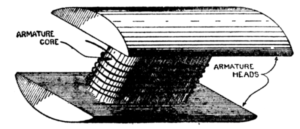
Fig. 42.—Armature
The iron armature of the Bosch magneto, which is the best known type,
is shown in Figure 42. It has a central bar with two heads,
the wire being wound around the central bar, or core. The shafts on which
it revolves are attached to the ends of the heads.
Figure 43 shows different positions of the armature
between the poles of the magnet, and illustrates the changes in the magnetism of the
central bar. There is a continual flow of magnetism from one pole of a
magnet to the other; if a piece of iron lies between them the magnetism
will use it as a bridge, but often its easiest path will be through the
air. In A, Figure 43, the armature lies crossways, and its
central bar or core forms a perfect bridge for the magnetism. Practically all of
the magnetism flows through it, and it then becomes a powerful magnet
itself. It sets up its own flow of magnetism, which flows through the core
to one head, through the air to the other head, and so back to the core.
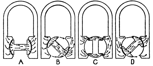
Fig. 43.—Flow of
Magnetism Through Armature Core
In B, the armature has revolved a little. Most of the magnetism is
still flowing through the core, but some of it is finding an easier
path by flowing through the heads and across the air space to the other
pole. The magnetism of the core is, therefore, a little weaker than it
is in A.
In C, the heads alone form bridges between the poles, and none of the
magnetism flows by the core because that no longer forms a path. The
core is no longer producing magnetism; in moving from A to C there has
thus been a complete change in the strength of the magnetism of the
core, for from full strength it has died away to nothing.
By a further movement, as in D, the core again acts as a bridge, and
another change in strength occurs, this time from nothing to full
strength again. In moving from D to B, there are slight changes in
strength, but not enough to produce a sparking current; it is only in
passing from B to D that a sparking current can be produced.
In this type of magneto the space between the heads is wound full of
wire, which of course revolves with the armature; the more turns of
wire there are, the more intense will be the current, so very fine wire
is used to get the greatest possible number of turns.
In the Bosch magneto the first few layers are of coarse wire, and are
the primary winding. The remainder, called the secondary
winding, is very fine wire, and the two are connected so that one
forms an extension of the other.
It has been explained that it is most important to have the spark occur
at exactly the right instant in the stroke. On a magneto the instant of
sparking is controlled by a timer, or circuit breaker,
which is a switch that is automatically operated at the time when the
magneto is producing a current sufficiently intense to form a spark.
Figure 44 illustrates one complete revolution of the armature,
and it will be seen that it passes twice from position B to position D. This
shows that it gives a sparking current twice during each revolution.
The circuit breaker must therefore operate twice during each revolution.
It is placed at the end of the magneto; in some makes it revolves with
the armature and is operated by stationary cams, while in others it is
stationary, and is operated by a cam on the armature shaft. In either
case the effect is the same.
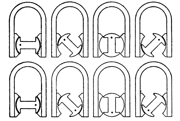
Fig. 44.—One
Complete Revolution of the Armature
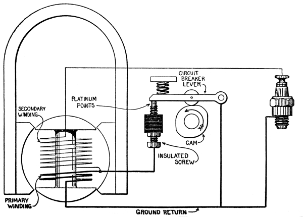
Fig. 45.—Connections
of Bosch Magneto
Figure 45 shows the way in which the winding on the armature
of a Bosch magneto is connected with the circuit breaker and with the armature.
The circuit breaker shown is not the kind used on the Bosch, and serves
only to illustrate the principle. It consists of a lever pivoted at one
end, with the other end resting against the tip of a screw. A cam bears
against the lever and can move it to break the contact with the screw.
The cam is so set that it moves the lever at the time when the current
is most intense.
The coarse wire, or primary winding, on the armature is connected with
the lever and with the screw of the circuit breaker; when the lever is
touching the screw, any current produced in the primary winding has a
complete path, or circuit, in which to flow.
The fine wire, or secondary winding, is wound on top of the primary,
and its inmost end is connected to the outmost end of the primary
so that one forms a continuation of the other. The outmost end of
the secondary leads to the spark plug; any current produced in the
secondary winding flows to the spark plug, and, if intense enough, will
jump across the small gap in the plug, and return to the secondary by
way of the primary.
Referring to Figure 43, a weak current is produced in the
primary while the armature revolves from D to B; at that time the circuit breaker is
closed, so the current can flow in the path thus provided for it. A
current also tries to flow in the secondary, but is too weak to jump
across the gap in the spark plug. As the armature comes closer to the
point C, Figure 43, the primary current becomes more intense,
and the electricity in the secondary increases its endeavor to jump the gap in
the spark plug, but is still unable to do so.
As the armature passes over the point C, the circuit breaker opens.
The primary current, which is then most intense, finds its path taken
away from it, and it seeks another, which it finds by flowing into the
secondary winding. This flow of primary current, added to the pressure
already existing in the secondary, forms a current sufficiently intense
to jump across the gap in the spark plug, and in so jumping it produces
the ignition spark.
As the armature passes to position D, Figure 43,
the circuit breaker closes, and the action is repeated.
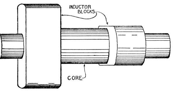
Fig. 46.—“K-W” Inductor
A magneto of this type is thus seen to give two sparks to every
revolution of the armature.
K-W and Dixie magnetos operate on the same general principle as the
Bosch, with the difference that the wire windings are separate from the
armature, and do not revolve. The revolving part, which is called an
inductor, consists of blocks of iron, so shaped that, as they
revolve, they alternately lead the magnetism to the core of the winding
and then away from it. The result is that the core gains magnetism and
then loses it, and these continual changes in strength produce sparking
currents in the winding.
The inductor of a K-W magneto is shown in Figure 46.
It consists of a shaft on which are mounted two blocks of iron at right angles.
The section of shaft that joins them is the core of the winding; the wire
is wound on it just as thread is wound on a spool, but with a space
between, so that the shaft may revolve inside of the coil.
Figure 47 shows the inductor in three positions of its
revolution between the poles of the magnet. When it is in the first position,
magnetism can flow from one pole of the magnet to the other by going
into one end, A, of one block, through the core, and out of one end, C,
of the other block. This makes a magnet of the core and it forms
magnetism of its own. When the inductor turns to the second position
magnetism can get across without flowing through the core, for the
blocks now give it a path. As the flow through the core ceases, the
core’s magnetism dies away, which gives the change in strength that is
needed to produce a sparking current.
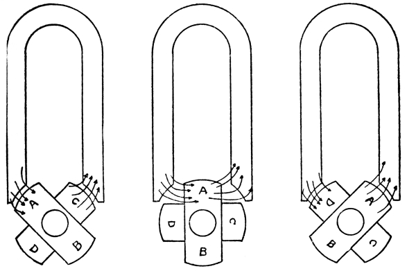
Fig. 47.—“K-W”
Inductor in Three Positions
When the inductor is in the third position, the core again becomes the
path for the magnetism and is magnetized; these changes continue as
long as the inductor turns.
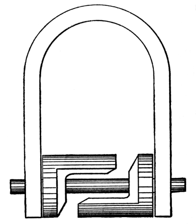
Fig. 48.—“Dixie” Inductor
While an armature type of magneto, like the Bosch, produces two sparks
to every revolution, the K-W produces four, for there are four periods
during every revolution when there is sufficient change in the strength
of the magnetism of the core to produce a sparking current.
In these magnetos the revolving shaft is parallel to the ends of the
magnets, but in the Dixie magneto it is at a right angle, as shown
in Figure 48. The shaft is of some metal, such as brass or
bronze, through which magnetism will not flow; otherwise the shaft would form a
continuous path. The inductor blocks are mounted on the shaft, and act
as extensions of the poles of the magnet. The core on which the wire is
wound is a separate piece, placed under the arch of the magnets, with
ends that extend down and form a tunnel in which the inductor revolves.
Figure 49 shows an end view of the inductor, the magnets
being cut away so that the core may be seen. As inductor block A is an extension
of one pole of the magnet, magnetism tries to flow from it to block
B, which is an extension of the other pole of the magnet. When the
inductor is in position 1, Figure 49, magnetism can flow
from block A through the core to block B, the core then being magnetized. In
position 2, magnetism can flow from one block to the other by going
through the ends of the core instead of through the core itself; the
core then loses its magnetism, but regains it when the inductor moves
to position 3.
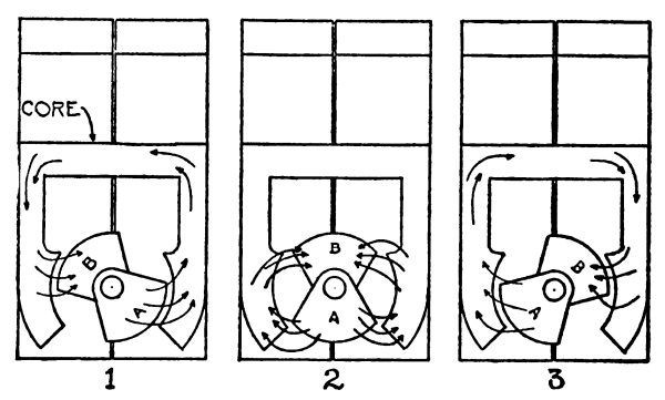
Fig. 49.—Three
Positions of “Dixie” Inductor
In practically all makes of magnetos the circuit breaker is at the end
of the armature or inductor shaft, and is operated by it. The Bosch
circuit breaker is illustrated in Figure 50, the parts being
mounted on a plate attached to the shaft and revolving with it. The lever
is L-shaped, pivoted at the angle, with one end resting on the tip
of a screw. When the shaft revolves, the other end of the lever is
dragged over a block of metal that acts as a cam; this makes it move
on its pivot and separates it from the screw. By turning the screw the
distance of separation may be adjusted.
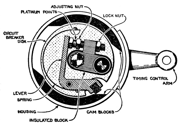
Fig. 50.—“Bosch”
Circuit Breaker
In the circuit breaker of the K-W magneto it is the cam that revolves,
while the lever is stationary, as shown in Figure 51.
It will be noticed that the cam will move the lever only twice during each
revolution; the magneto can produce four sparks during a revolution,
but with this arrangement of the cam only two of them are used.
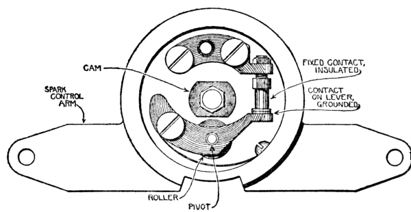
Fig. 51.—“K-W”
Circuit Breaker
It has been said that an intense sparking current is produced when
there is a great change in the strength of the magnetism, and when the
change in strength occurs suddenly. There cannot be any alteration in
the change in strength, for the greatest magnetic strength of the core
is what is given it by the magnet, and changing from this to nothing
is the greatest change possible. The suddenness with which the change
takes place, however, depends on the speed at which the magneto runs.
A 4-cylinder engine requires two sparks to each revolution of the crank
shaft; the armature of a Bosch magneto for this engine will therefore
run at the same speed as the crank shaft.
The K-W magneto, giving four sparks to the revolution, could run
at half of the speed of the crank shaft, but then the change in the
strength of the magnetism would take place slowly, and the sparking
current would not be sufficiently intense. By using only two of the
sparks the magneto is run at the same speed as the crank shaft; the
change in strength then takes place more suddenly, and a more intense
sparking current is produced.
The circuit breaker of a magneto for a 1-cylinder engine has only one
cam, so that a single spark is produced during each revolution of the
armature; the armature makes one revolution to every two revolutions of
the crank shaft.
However many cylinders an engine may have, the magneto must be revolved
from one point of sparking to the next in the interval between ignition
in one cylinder and ignition in the next cylinder to fire. A magneto
is driven by the crank shaft through gears or by a chain, which are so
proportioned and set that the magneto is at a point of sparking at the
instant when a piston is in position for ignition.
A magneto for an engine with more than one cylinder is provided
with a distributor, which passes the sparking current to the
particular cylinder that is ready for ignition. A distributor is a
revolving switch built into the magneto, with as many points, or
contacts, as the engine has cylinders. At the instant when the
magneto produces a sparking current, the revolving distributor arm is
in position to pass the current to one of the contacts, and the current
flows to the spark plug with which it is connected.
An electric current must have a complete path, or circuit, in order
to be able to flow. In a magneto ignition system this path is partly
of wire and partly of the metal of the engine. The diagram in Figure 45
indicates that the current returns to the magneto from the circuit
breaker lever and the spark plug by wire, but in actual construction
it returns by the metal of the engine. This is called a ground
return; the circuit is said to be grounded.
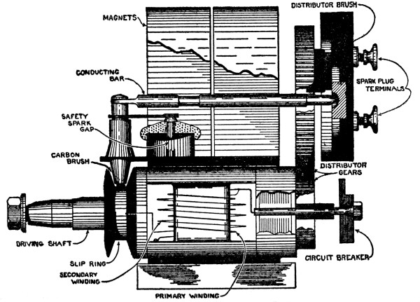
Fig. 52.—“Bosch”
Magneto in Section
Figure 52 is a side view of a Bosch magneto, partly broken
away to show the interior. As can be seen, one end of the primary winding is
screwed to the armature, and is thereby connected with the metal of the
magneto; as the magneto is attached to the engine the primary winding
is thus in contact with that also. The other end of the primary winding
leads to the insulated block of the circuit breaker, Figure 50.
This block is insulated from the disk; that is, while it is attached
to the disk, it is kept from touching it by means of pieces of hard
rubber or mica. Through these an electric current cannot pass.
The lever is grounded; that is, it is in contact with the metal of
the magneto. When the lever touches the screw of the insulated block,
current can flow; when they are separated, the circuit is broken.
One end of the secondary winding, Figure 52, is attached
to the outer end of the primary. The other end leads to the slip ring, which
is a metal rim on a hard rubber wheel attached to the armature and
revolving with it. Sparking current flowing to the slip ring is led off
by a carbon brush and passed to the distributor.
Should a spark plug wire fall off while the engine is running, the
current would lose its path and would seek another; it is quite powerful
enough to make a path for itself by breaking through the windings. As
this would injure the magneto, such a thing is prevented by providing a
safety spark gap, which acts like a safety valve in giving the
current a path when the regular path is interrupted. It consists of
two points of metal, one attached to the metal of the magneto and the
other connected with the slip ring brush; it is a more difficult path
than the one through the spark plug, but easier than breaking down the
windings.
Figure 53 is a section of the K-W magneto. As the coil
does not revolve, no slip ring is necessary; the sparking current flows directly
to the distributor.
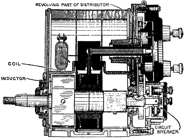
Fig. 53.—“K-W”
Magneto in Section
To start an engine, the crank shaft must be turned at sufficient
speed to drive the magneto fast enough to produce a spark. With large
engines this is often a difficult matter, so it is very usual to
equip a magneto with an impulse starter. One part of this is
attached to the magneto shaft and the other to the engine shaft that
drives the magneto; the two are connected by a spring. When starting,
a catch holds the armature and prevents it from turning. The drive
shaft turns, however, and in so doing winds up the spring. At a certain
point the catch is automatically released, and the spring then throws
the armature over at a speed that gives a good spark. A spark is thus
assured, even though the engine is being cranked very slowly.
CHAPTER VII BATTERY IGNITION SYSTEMS
While the greater number of tractor engines use magneto ignition, many
use battery and coil systems, which are the same in general principle
as magneto systems, but produce magnetism in a different manner.
Copper is a nonmagnetic metal; that is, magnetism will not
flow through it, nor can it be magnetized. If a pile of iron filings
is stirred with a copper wire there will be no effect, as might be
expected; but if a current of electricity flows through the wire, the
iron filings will cling to it, as shown in Figure 54,
as if it were a real magnet.
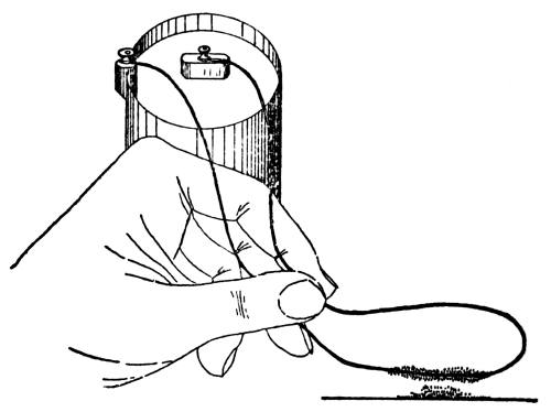
Fig. 54.—Magnetism
in a Copper Wire
It is one of the principles of electricity that when a current flows
through a wire, the wire is surrounded by magnetism, which continues
as long as the current flows; when the circuit is broken and the
current stops flowing, the magnetism dies away. The magnetism produced
is feeble and can be very greatly increased by winding the wire around
an iron bar. The magnetism produced by the current then flows into the
bar, and that, like the core of the winding of a magneto, throws out
magnetism of its own. This is indicated in Figure 55.
By changing the intensity of the electric current, or by cutting it off, the strength
of the magnetism can be made to change, and this change of strength can
produce a sparking current.
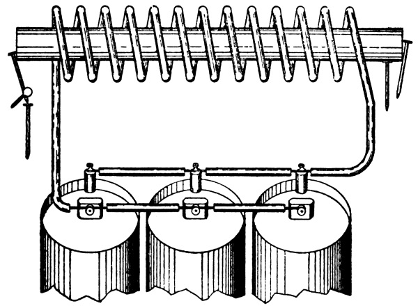
Fig. 55.—Magnetism
from Electricity
The principle employed is illustrated in Figure 56. A is
a coil of wire wound around one end of an iron bar and connected with a battery;
B is an entirely separate coil of wire wound around the other end of
the bar, with its ends separated by a short distance. By closing the
battery switch the current will be permitted to flow in coil A, and the
bar will become magnetized; the magnetism that it throws out will be
felt by coil B. When the switch is opened the current stops flowing
and the magnetism dies out of the bar; these changes in strength will
create an electric current in coil B, which will form a spark as it
passes across the space between the ends.
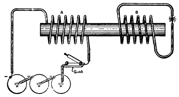
Fig. 56.—Principle
of Spark Coil
In ignition coils, coil B is wound on top of coil A. Coil A, called
the primary winding, consists of a few layers of coarse wire.
The more turns of wire there are in coil B, called the secondary
winding, the more intense will be the current that it produces, and
the intensity is also increased by keeping the windings close to the
iron core. The secondary winding is, therefore, made of exceedingly
fine wire, and has a very great number of turns.
To obtain a spark, a current is permitted to flow through the primary
winding to create magnetism, and the flow is then stopped to cause
the magnetism to die away. The secondary winding is affected by each
of these changes in magnetic strength. The bar loses magnetism more
rapidly than it gains it, however; it is therefore the dying out of the
magnetism that has the greater effect on the secondary winding, and
that causes it to produce a sparking current.
To use this principle for ignition, the engine is fitted with a
revolving switch, which closes the circuit as a piston is on the
compression stroke, and then breaks the circuit at the instant when a
spark is desired. Combined with the revolving switch, or timer,
is a distributor like the distributor of a magneto, which passes the
sparking current to the cylinder that is ready to receive it.
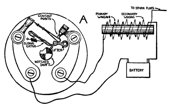
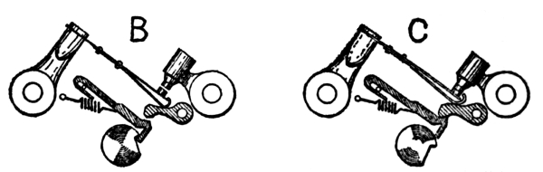
Fig. 57.—“Atwater-Kent”
Ignition System
To produce an intense sparking current, it is necessary to break the
circuit as abruptly as possible, in order to cause the magnetism to die
away suddenly. Figure 57 shows how this is done in the Atwater-Kent system.
The parts of the circuit breaker are carried on a plate, in the center
of which revolves a shaft with a notch in it. Against the side of this
shaft rests the hooked end of the sliding catch; as the notch comes
under this hooked end, the sliding catch is drawn forward, only to be
snapped back by its spring as the notch moves from under it. The lifter
is a bit of metal, pivoted at one end, with its free end lying between
the sliding catch and the flat steel spring that carries one of the
contact points.
A, Figure 57, is a diagram of the system. B shows the
position of the parts as the notch carries the sliding catch forward, and C shows
their positions as the spring snaps the sliding catch back to its
place. It will be seen that in thus moving back it strikes the lifter,
which in turn moves the contact spring, and so closes the circuit; but
the circuit is instantly broken as the parts spring back to position.
The movement of the parts is so rapid that to the eye they seem to be
standing still. The circuit is closed only for an instant, but that
is sufficient to magnetize and demagnetize the coil, and to produce a
sparking current.
The operation of this system depends on the very great swiftness with
which the circuit is made and broken; there is not sufficient time
for the core to get thoroughly magnetized, but such magnetism as is
produced changes strength so quickly that it gives a sufficiently
intense current to create an ignition spark.
In other battery systems of like principle, the circuit is closed for
a long enough time to allow the core to become fully magnetized, the
circuit then being suddenly broken. In some of these systems the timer
breaks the circuit, while in others it is broken by the magnetism,
through a vibrator.
A vibrator coil system is illustrated in Figure 58.
The timer is a ring made of some kind of insulating material, with a plate of
metal set in it and forming one of the timer contacts. The other
contact is the revolving brush, driven by the engine; the circuit is
closed when the brush touches the metal plate.
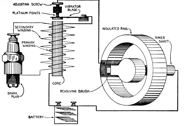
Fig. 58.—Vibrator
Coil Ignition System
Opposite the end of the core is a flat steel spring, or vibrator
blade, resting against the tip of a screw; when the core is
magnetized it draws the end of the blade to it, and separates it from
the screw. The battery current flows from the timer contact to the
screw, then to the vibrator blade and to the primary winding of the
coil. The core then becomes magnetized, and draws the blade away from
the screw, which breaks the circuit; this causes the magnetism to die
away, and a sparking current is produced in the secondary winding of
the coil. The vibrator blade, no longer held down by the magnetism,
springs back against the screw; the circuit is again made, and the
action is repeated. The movement of the vibrator blade is very rapid,
being some hundreds of vibrations a second.
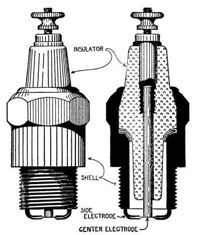
Fig. 59.—Spark Plug
A spark plug is illustrated in Figure 59. It consists of
a metal shell screwed into the cylinder, enclosing an insulator of porcelain,
mica, or some similar material. Through the insulator passes the center
electrode, which is a rod of metal, with its lower end separated by a
short distance from the shell or from a wire attached to the shell.
This separation is the gap across which the sparking current passes,
and at which the spark occurs.
Spark plugs receive the pressure of the power stroke, and must be
strongly made in order to withstand it. A leaky spark plug will cut
down the power of the engine, just as a leaky valve will.
CHAPTER VIII TRANSMISSION
The parts of a tractor by which the power of the engine is applied to
the driving wheels are called the transmission, and include the
clutch, the change speed gear, the differential
and the drive.
It has been shown that a gas engine delivers power only when it is
running at speed; it cannot run until some outside power drives it
through the inlet and compression strokes.
The tractor cannot move until the engine is running and delivering
power, and it follows, therefore, that it must be possible to
disconnect the engine from the driving mechanism in order that it may
run independently. This is done by means of a clutch, which is a
device that connects two shafts, or disconnects them.
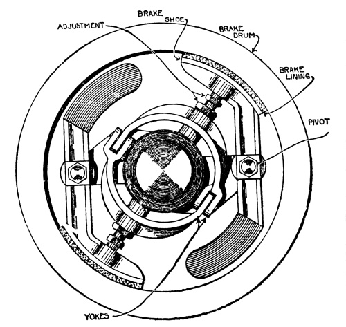
Fig. 60.—Internal
Clutch
A clutch must be so made that when it is engaged it takes hold, not
suddenly, but gradually. If it took hold suddenly, the tractor would be
required to jump at once into full motion; this would cause a severe
straining of the parts and probable breakage. The alternative would be
the abrupt stopping of the engine, and this would also strain things.
By making the clutch in such a way that it slips, and takes hold little
by little, the tractor starts slowly, and gradually comes up to speed;
the slipping of the clutch then ceases, and it takes hold firmly.
All clutches operate by the friction of one surface against another;
in some, the surfaces are curved and in others flat, while in still
others the clutch is a band around a wheel, or drum. A clutch is
operated by a hand lever or by a foot pedal.
Figure 60 shows a type of clutch that operates inside a
drum, which is often the overhanging rim of the flywheel. The shaft in the center is
independent of the flywheel, and it is the purpose of the clutch, which
is attached to the shaft, to lock the shaft and flywheel together when
the tractor is to be started.
The brake shoes, which bear against the drum, form the ends of pivoted
levers, and are lined with an asbestos material that resists the heat
caused by the friction against the drum.
A cone-shaped block of steel slides lengthways on the shaft; when it is
pushed into position, it forces out the yokes, and thus presses the
brake shoes against the drum.
A plate clutch, or disk clutch, is shown in Figure 61.
The principle of a plate clutch may be illustrated by placing a
half-dollar between two quarters and pinching them with the thumb and
forefinger. If they are held loosely, the half-dollar may be turned
between the quarters, but if they are pinched tightly, the friction
between the coins will be so great that one cannot be turned without
turning the others.
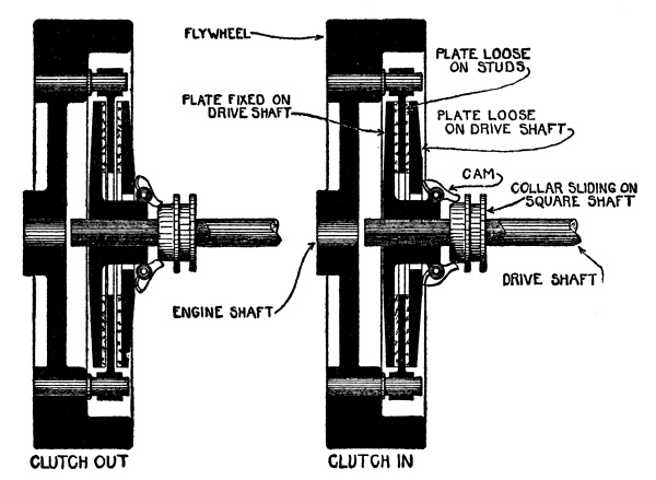
Fig. 61.—Plate Clutch
Attached to the flywheel are studs, which support a disk, or plate;
this plate revolves with the flywheel, and is practically a part of it.
On either side of this plate are other plates that are supported on the
drive shaft; they revolve with it, but can slide along it. The end of
the shaft is square and fits a square hole in a collar, so that while
the collar may slide along the shaft, the two must turn together. Cams
are mounted on the hub of one of the plates in such a position that
they can press the outside plates together and pinch the flywheel plate
between. The cams are operated by pressing the collar against them.
The first drawing shows the clutch out, or released; the flywheel may
then turn without turning the shaft, for the plates are not in contact.
The second drawing shows the clutch in, or engaged. The collar is
pressed against the cams, and the plates in turn are drawn together,
pinching the flywheel plate between them. The flywheel and the drive
shaft then revolve together.
Plate clutches are often made with more than three plates; some makes
run in a bath of oil, and some are intended to work dry.
In a cone clutch, the overhanging rim of the flywheel is funnel-shaped,
and into it fits a cone-shaped disk carried on the end of the drive
shaft. To engage the clutch, the disk is slid along the shaft against
the flywheel, the friction between the two being sufficient to drive
the shaft.
When a clutch is thrown in it should take hold gradually, slipping at
first, but finally having a firm grip. When it is thrown out, it should
release instantly and completely.
The power delivered by an engine depends on the bore and
stroke of the cylinder, and on the speed. The greater the bore,
or diameter of the cylinder, and the greater the stroke, or distance
the piston moves in a half-revolution of the crank shaft, the larger
will be the combustion space, and the larger will be the charge of
mixture that it can take in; the larger the charge, the greater will be
the power produced when the charge burns.
Each cylinder produces power once during every two revolutions of the
crank shaft; if the engine runs at 1,000 revolutions per minute there
will be twice as many power strokes as there would be if it ran at 500
revolutions per minute, and during that minute it will produce twice as
much power.
A traction engine is intended to run at a certain speed, at which it
will produce its greatest power without overstraining its parts. This
normal speed for any particular engine depends on the number of
cylinders, their size and design, and other details established by the
manufacturer. To get the best from the engine, this is the speed at
which it should always be run.
The power required to move the tractor depends on various things;
the hardness and smoothness of the ground, the grade, the load it is
pulling, and so on. The tractor might be running on level ground,
pulling so great a load that the engine is called on for all of the
power that it can deliver.
On coming to a hill, still more power will be required, for now the
tractor and its load must be lifted as well as moved forward. The
engine, already working at its limit, cannot deliver the extra power
needed, and will slow down and stop unless something is done to aid
it. In such a case, the change speed gear is used to give the engine
a greater leverage on its work, just as a block and tackle gives a
greater leverage or purchase to a man who must lift a heavy weight.
Let us say that the normal speed of the engine is 1,000 revolutions per
minute, and that it is so connected that it makes 40 revolutions while
the driving wheels make 1, the speed of the tractor being 3 miles per
hour. If it is a 4-cylinder engine there will thus be 80 power strokes
to every revolution of the driving wheels. The engine is delivering its
full power and cannot do more should the tractor be called on for an
extra exertion, such as climbing a hill or crossing rough ground.
By changing the connections between the engine and the driving wheels,
the engine can be made to run twice as many revolutions to one turn of
the driving wheels, which will give double the number of power strokes;
the wheels will thus be turned with twice the force. As no change is
made in the speed of the engine, the wheels will now turn at half their
former speed, and the tractor will run at 1½ miles per hour. It will,
however, have twice the ability to overcome obstacles.
This change in the connections between the engine and the drive is
performed by the change speed gear, which is driven by the
engine and which in turn drives the wheels.
There are many varieties of change speed gears, but the main principle
in them all is the same, for they depend on the action of cog-wheels,
or gears.
When two gears running together, or in mesh, have the same
number of teeth, they will revolve at the same speed. If one has half
as many teeth as the other—10 teeth and 20, let us say—the 10-tooth
gear will make two revolutions while the 20-tooth gear is making one.
There are two shafts in a change speed gear, one driven by the engine
and the other driving the wheels; each carries gears that mesh with
gears on the other shaft. These pairs of gears are of different sizes,
and any pair may be used; the shaft driven by the engine runs as the
engine runs, while the speed of the other shaft depends on the pair of
gears that is being used.
By changing from one pair of gears to another, the driven shaft, and,
consequently, the wheels, may be run at a greater or less number of
revolutions, while the speed of the engine and the driving shaft do not
change. The number of power strokes that occur during one revolution of
the wheels is thus changed, and they turn with more force or with less.
High speed, or high gear, means the combination of gears
that gives the greatest speed to the wheels, but the fewest power
strokes to each revolution. The combination that gives the slowest
speed to the wheels, but the greatest number of power strokes, is
called low speed, or low gear.
Many tractors have but two speeds, a low and a high; but others have an
intermediate combination for conditions too severe for running on high
gear but too easy for low.
The change speed gear mechanism also provides for reversing or backing
the tractor. Two gears running together turn in opposite directions,
while in a train of three gears the outside gears turn in the same
direction. The usual combination in a change speed gear uses two gears
for going ahead; to run the driven shaft the other way, which will make
the tractor back, a third gear is meshed between the two.
The differences between various makes of change speed gears are in the
methods used to put into action the desired pair of gears.
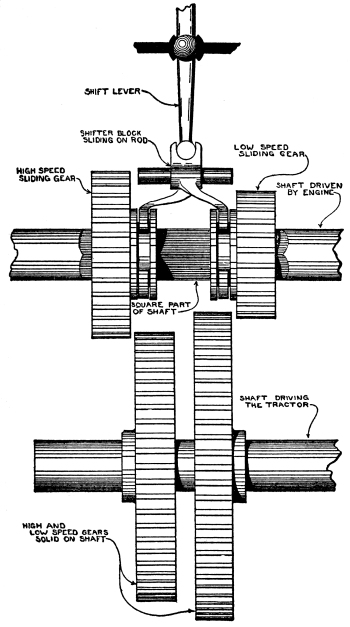
Fig. 62.—Principle
of Sliding Gear
Two general plans are used. In one of them, a gear of each pair can
slide endways on its shaft, but must revolve with it; thus it can be
slid into mesh or out. In the other, the gears of a pair are always in
mesh, but one of them is loose on its shaft, so that shaft and gear can
revolve independently. To make the pair of gears operate, the loose
gear is locked to its shaft.
Figure 62 shows the principle of the sliding gear
type. One part of the shaft driven by the engine is square, and fits into square
holes in its gears, which may thus slide along it, but must revolve with it.
Each sliding gear is moved by a shifter block, which is operated by
a shift lever. There is a shifter block for each gear, and the shift
lever may be moved sideways to operate either one of them.
Figure 63 shows the jaw clutch type of change speed
gear, in which the gears are in mesh all of the time, but run loose on their
shaft when they are not working. The drawing shows bevel gears,
which are used when the driving and driven shafts are at a right angle.
The same principle is used for spur gears on shafts that are
parallel, as in Figure 62.
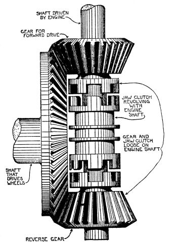
Fig. 63.—Principle
of Jaw Clutch Change Speed Gear
The center of the shaft is square, and fits a block that can slide
endways, but that must revolve with it. The ends of the block have
heavy teeth that can mesh with teeth on the hubs of the loose gears;
meshing the block with one of the gears forces that gear to revolve
with the shaft.
The drawing shows only one speed forward; the reverse is obtained by a
second gear on the same shaft, which is placed on the opposite side of
the center of the driven gear, and turns it in the opposite direction.
When a tractor turns, the outside wheel makes a larger circle than the
inside wheel, and has a longer path to travel. Both wheels travel their
paths in the same time, so it follows that the outside wheel must move
faster than the inside wheel, although both are being driven by the
engine. This is allowed for by the differential, which is driven
by the change speed gear, and which in turn drives the wheels; it
operates automatically by the difference in the resistance to the
rolling of the wheels.
The action of the differential is illustrated by an experiment that
requires a pair of wheels on an axle, like buggy wheels, and a stick
long enough to reach from one to the other. With the wheels on smooth
ground, put the ends of the stick through the wheels at the top, each
end pressing against a spoke. Hold the stick at its center and push it
forward; the stick will transmit the pressure to the spokes, and the
wheels will turn. The wheels being on smooth ground, there is equal
resistance to their movement, and they will run straight forward.
Now repeat the experiment with the wheels so placed that one is on
a smooth roadway and the other on sand; as the wheel on the smooth
surface meets with less resistance than the other does, it moves
faster, and the pair of wheels circles, although the stick applies
equal pressure to both.
The power developed by the engine is transmitted by the differential
to both rear wheels; when the wheels meet with equal resistance, they
turn equally, but when one wheel meets with greater resistance than the
other, it slows down, while the other speeds up to correspond.
A tractor with two driving wheels must use a differential in order to
make turns easily. Without a differential, the wheels would run always
at equal speed, and in making a turn one would be obliged to slip.
The use of a differential has a disadvantage, however. If one wheel
is in a mudhole and the other is on hard ground, the wheel in the mud
meets with little resistance, and all of the power of the engine goes
to it; it spins without moving the tractor, while the other wheel
remains stationary. In such a case all of the power should be applied
to the wheel that has traction in order to move the tractor, but this
the differential fails to allow.
In some tractors the differential is so made that the parts may be
locked together. This lock is used when one wheel is in a mud hole, and
as by its use power is transmitted equally to both wheels, the tractor moves.
Great care must be taken to unlock the differential as soon as the need
for the lock has passed, for otherwise the wheels would slip on a turn,
and the parts of the transmission might be strained or broken.
A differential is usually made with two bevel gears placed face to
face; between them is a frame holding three or more small bevel gears
that are in mesh with them both. The engine revolves the frame with its
small gears; each of the large bevel gears revolves a driving wheel.
When the tractor moves straight ahead the differential turns as
if it were one solid piece. When there is less resistance to one
driving wheel than to the other, the small bevel gears, in addition to
revolving with the frame that carries them, turn on their shafts. This
transmits the power of the engine to one wheel more than the other,
according to the resistance of the wheels.
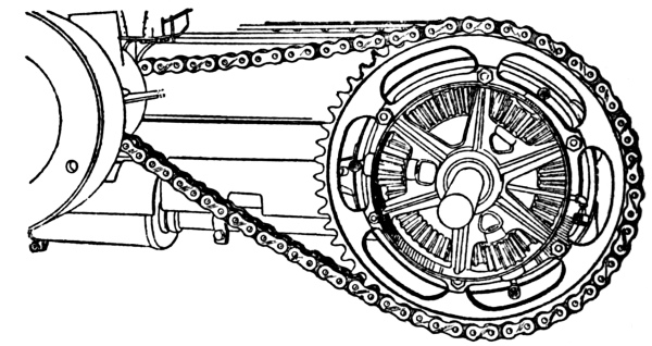
Fig. 64.—“I. H. C.” Chain
Drive, Showing the Differential
Figure 64 shows one of the large bevel gears of a differential,
with the three small gears, the other large bevel gear being removed. A
differential in section is shown in Figure 65.
A tractor with only one driving wheel has no differential. Such
tractors usually have two wheels, but one of them runs loose on the
axle, and serves only to support the tractor. The rear axle construction
of a tractor with a 1-wheel drive is shown in Figure 66,
which should be compared with the 2-wheel rear construction shown in
Figure 65.
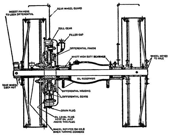
Fig. 65.—“Case” Rear Axle
There are a number of methods used for transmitting power to the
driving wheels. In Figure 64 a chain is used; there are
tractors with but one chain, and others with a chain for each driving wheel.
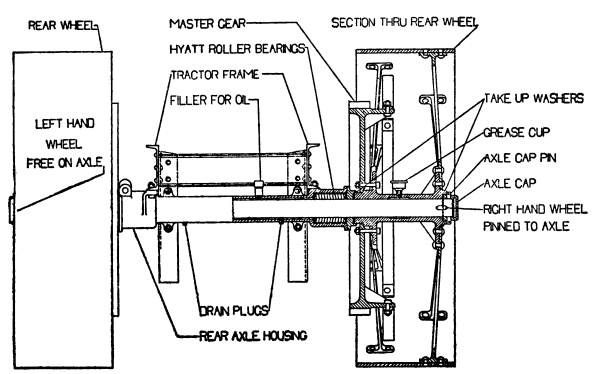
Fig. 66.—“Oil-Pull”
Rear Axle
The most usual method is by a master gear, or bull gear,
which is a large and heavy gear attached to the driving wheel, as shown
in Figures 65 and 66.
In some tractors this gear is nearly the size of the wheel, and is
fully exposed; in others it is smaller, and enclosed in an oil-tight
housing.
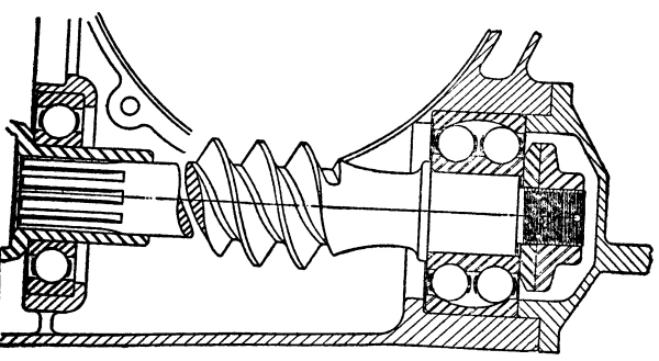
Fig. 67.—Driving Worm
The small gears that drive the bull gears are on the ends of the cross
shaft, called the jack shaft, that carries the differential.
In the Fordson tractor the differential is built into the axle, as it
is in an automobile, and power is applied by a worm. The worm is
driven by the change speed gear, and is a screw meshing with a gear on
the differential, whose teeth are cut at the proper angle to make them
fit the threads of the worm. A worm, which is shown in Figure 67,
is always enclosed, and runs in oil.
CHAPTER IX TRACTOR ARRANGEMENT
The uneven ground over which tractors must work requires the weight to
be kept low, to prevent capsizing, and they are also built wide, for
the narrower they are the more easily they tip over. They cannot be
broad in front, however, for if they are the steering wheels cannot
be swung enough to permit them to turn in the small circle that is
desirable.
To give a small turning circle some tractors are built with the front
of the frame raised enough to permit the wheels to cut under. Others
use small steering wheels, but this is not desirable because small
wheels will not run over rough ground as readily as large ones, and
steering is difficult.
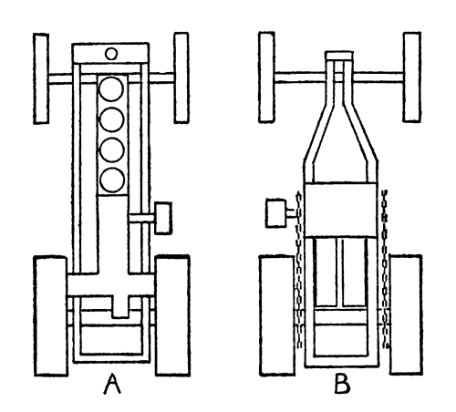
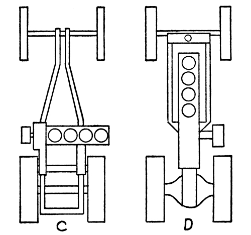
Fig. 68.—Tractor
Arrangement
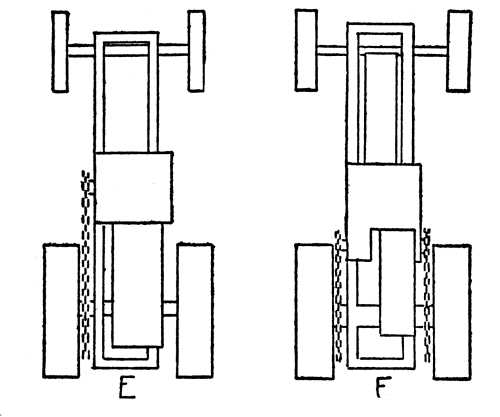
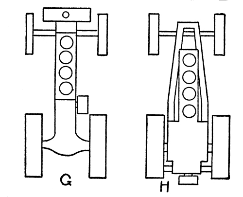
Fig. 69.—Tractor
Arrangement
Types of tractors are indicated in Figures 68
and 69. A has a 4-cylinder vertical engine in
front, driving both wheels by bull gears, while B is a 2-cylinder
horizontal engine in the center, driving both wheels by chains. C has a
4-cylinder vertical engine set across the frame. These three types have
riveted steel frames, to which the parts are attached.
In D, the drive is entirely enclosed within the rear axle housing,
and the rear part of the frame is formed by the axle housing and the
housing of the change speed gear.
E has a 1-cylinder horizontal engine with a single chain drive, while F
has a similar engine but drives to both wheels.
G has no frame, its place being taken by the crank case of the engine
and the housings of the parts of the transmission. G and H have
4-cylinder vertical engines, G driving through an enclosed rear axle
and H through bull gears.
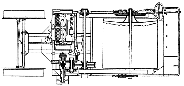
Fig. 70.—“Gray” Tractor
Figure 70 has one broad wheel instead of two narrower
ones, this being placed inside of the frame instead of outside. It has a
4-cylinder vertical engine placed across the frame, and drives through two chains.
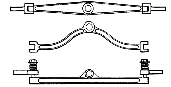
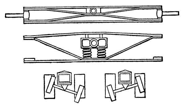
Fig. 71.—Types
of Front Axles
The front axle of a tractor is almost always attached to the frame by
a pivot, so that the wheels will follow uneven ground. Some of the
forms of front axles are shown in Figure 71.
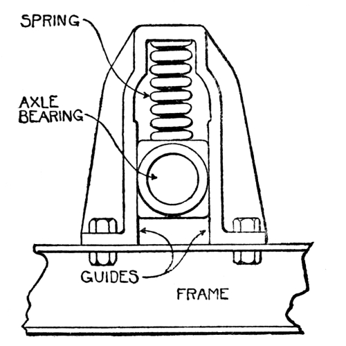
Fig. 72.—Spring Support
The first is a plain bar, while the second is arched to raise the front
of the frame in order to permit the steering wheels to cut under. In
the third the wheel axles are mounted on springs, which take up some of
the vibration and act as shock absorbers.
The fourth axle shown is built of steel bars riveted together to form
a truss, and the fifth is similar, with the frame pivot carried on
springs. The sketches at the bottom indicate the extent to which the
pivoted front axle may swing.
Figure 72 shows a spring support for the
axles, front and rear. The axle bearing is in a block sliding in
guides, the weight being supported by a heavy spring.
CHAPTER X LUBRICATION
The most important thing in the care of a tractor is to oil it; every
moving part should be lubricated, and the greatest care should be taken
to assure a never-failing supply of oil and grease.
Carelessness in lubrication is the principal cause of tractor trouble.
There is nothing complicated or difficult about keeping a tractor
properly oiled; yet more tractors break down from careless lubrication
than from any other cause. Every tractor-maker issues an oiling diagram
and oiling instructions, and there is no excuse for an operator whose
machine does not get the right kind of lubricant in the right quantity
at each place where lubrication is necessary.
The cause of wear is friction; oil reduces friction and so reduces
wear. No matter how smooth and highly polished two pieces of steel may
be, there will be friction between them if they are rubbed together,
and they will wear each other. If they are oiled, the particles of oil
will keep the pieces from touching each other, and there will be no wear.
Other substances than oil can be used; there are some kinds of
machinery that are lubricated with water, for instance. For general
use, however, oil and grease are the best, and are practically always used.
The object of a lubricant is to keep two pieces of metal from
touching; it must therefore be able to get between them, and must stay
there. If the pieces are large and heavy, there will be much greater
pressure on the oil than if they are small and light, and the oil must
be able to withstand this pressure and resist being squeezed out. The
oil that would keep the small, light pieces apart might not be able to
stand the pressure of a greater weight, and might be squeezed out from
between two heavy pieces.
Oil has a tendency to cling to whatever it touches, and thick oil
or grease has more of this tendency than a thin, or “runny” oil. If
a thick oil or grease is used on light machinery, such as a sewing
machine, this clinging tendency would make the machine run hard, and
might even prevent its operation.
When oil is heated, it becomes thinner, or more “runny.” Through
this, an oil used in a hot place might get so thin that it would not
lubricate; and on the other hand, an oil that works all right in the
heat of summer might get so thick on a cold winter day as to be useless.
A slow-moving part of a machine uses a thick oil or a grease; a thin
oil must be used for a part that moves at high speed.
Some of the parts of a tractor move slowly and some at high speed;
some are cool and some are hot. Different kinds of lubricants are
therefore required, and it is a grave mistake to use a lubricant that
is not suitable to the work that it is required to do.
The engine is the most difficult part of a tractor to lubricate, and
the part that suffers most if the supply fails or if the wrong kind
of lubricant is used. In the first place, it is so hot that any oil
will burn, being turned to carbon; the best that can be expected of
an oil is that it will resist burning until it has done its work of
lubricating the piston and cylinder.
A tractor engine is more difficult to oil than an automobile or
truck engine for the reason that it works harder and more steadily.
An automobile engine is rarely driven to the limit of its power; it
has frequent opportunities to cool when running down hill. A tractor
engine, on the other hand, works at its full power all day long with
no opportunities to cool off. An oil that gives good satisfaction on
an automobile might ruin a tractor engine through its inability to
withstand the greater heat.
The makers of tractors understand the importance of using proper oils,
and recommend certain brands and grades; these recommendations should
be followed in order to get the best possible results. All makers
specify at least two kinds of lubricants, and most of them three; one
specifies six, which range from a light sewing machine oil to a grease
so thick that it is nearly solid. Whatever the recommendations may be,
they should be followed.
In general, lubricants are classified according to their thickness, and
they range from the light oil used for typewriters and sewing machines
to grease so thick that it may be cut like butter. The thinnest oil
is used for the circuit breaker pivot; this part is usually moved in
one direction by a cam and in the other by a light spring. A thick oil
would gum the bearing to such an extent that the spring might not be
able to move the lever.
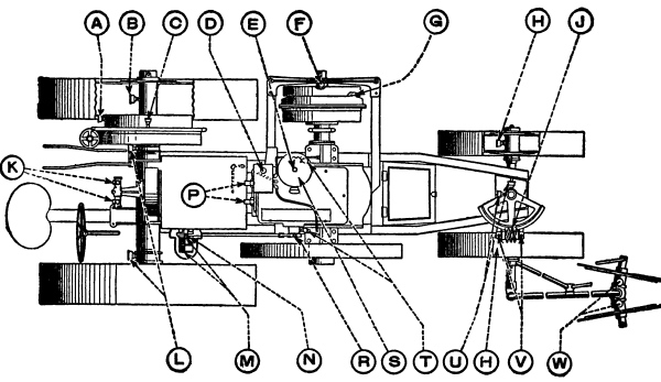
Fig. 73.—“Mogul”
Oiling Diagram
| |
| KEY |
DESCRIPTION |
QUANTITY |
LUBRICATION |
| ONCE EVERY HOUR |
| L |
Rear axle bearing |
Two complete turns |
Cup Grease |
| ONCE EVERY TWO HOURS |
| A |
Differential hub |
One complete turn |
Cup Grease |
| B |
Rear wheel hub |
One complete turn |
Cup Grease |
| C |
Differential pinion |
One complete turn |
Cup Grease |
| H |
Front wheel hub |
Two complete turns |
Cup Grease |
| T |
Governor and cam shaft bearing |
Two complete turns |
Cup Grease |
| TWICE EVERY DAY |
| E |
Governor |
Oil |
Cylinder oil |
| F |
Outboard bearing grease cups |
Two complete turns when plowing |
Cup Grease |
| G |
Transmission |
One pint |
See note below |
| N |
Magneto trip |
Grease every 5 hours |
Cup Grease |
| Magneto roller and slide |
Oil every 5 hours |
Oil |
| J |
Steering worm |
Keep covered |
Cup Grease |
| W |
Steering hub grease cup |
One complete turn |
Cup Grease |
| V |
Steering worm shaft |
Oil every 5 hours |
|
| R |
Lubricator eccentric |
Oil every 5 hours |
|
| |
|
(keep wool in pocket) |
|
| P |
Cam roller slide |
Oil every 5 hours |
|
| K |
Valve levers |
Fill with oil every 5 hours |
|
| |
|
(keep wool in pocket) |
|
| ONCE EVERY DAY TRACTOR IS IN USE |
| U |
Steering sector shaft |
One complete turn |
Cup Grease |
| D |
MECHANICAL LUBRICATOR |
|
| |
Fill with a good grade of heavy gas engine cylinder oil.
Turn the crank on the mechanical oiler 40 to 50 times when
starting the engine. |
|
| D |
IMPORTANT |
|
| |
In cool or cold weather the oil in lubricator tank must be
warmed as it will not flow readily unless of the right temperature. |
|
| G |
TRANSMISSION |
|
| |
In warm weather, use heavy oil such as “600” transmission or
Polarine transmission oil; in cold weather, use a good light oil. |
|
| S |
GOVERNOR |
|
| |
Cylinder oil in governor should cover shoe. |
|
| M |
MAGNETO |
|
| |
Oil magneto bearings once a week with sewing machine or
cream separator oil. |
|
| |
The oil used in an engine is thicker, and has a high burning
point and high viscosity; that is, it should be able to
resist burning, and should not get so thin when it is heated that it
will be squeezed out of the bearings. The same kind of oil that is used
in the engine can be used in many other parts of the tractor.
Grease is usually used for the gears of the transmission and drive.
There is very great pressure between the teeth of two meshing gears,
and only thick oil and grease have sufficient viscosity to resist being
squeezed out.
The thickest grease is used on the tracks of caterpillar-type tractors.
Before operating a tractor, the lubrication chart supplied by the
manufacturer should be studied with great care, and all of its
requirements should be observed. This chart is usually in the form of
a diagram accompanied by a table, as shown in Figure 73,
which is the lubrication chart of one of the International Harvester tractors.
This figure illustrates the constant attention that is demanded by this most
important part of tractor operation.
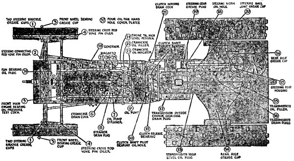
Fig. 74.—“Illinois”
Oiling Diagram
The table calls for four lubricants, these being sewing machine oil,
which is very thin and liquid; gas engine cylinder oil; transmission
oil, which is as thick as molasses; and cup grease, which is like butter.
The engine is oiled automatically, the only requirements being to keep
the oil tank filled, and to be sure that the oiler is working. The
other parts of the tractor are oiled or greased by hand.
Figure 74 is the oiling chart of the Illinois tractor.
There are three systems used for engine lubrication: splash,
force feed, and by a mechanical oiler. In the splash system,
a pool of oil is maintained in the crank case, of such a depth that
the ends of the connecting rods just dip into it. They strike it with
sufficient force to splash it to all parts of the crank case, the oil
that strikes the pistons being carried up into the cylinders and
lubricating the walls.
The end of the connecting rod is often fitted with a dipper, as shown
in Figure 75, to strike into the oil, as well as an oil
catcher, shown in the same drawing, which is a little trough that catches the
splashing oil and guides it to the connecting rod bearing.
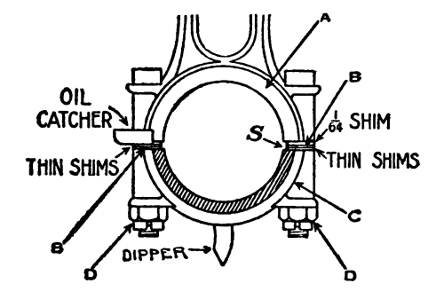
Fig. 75.—End of
“Twin City” Connecting Rod
To oil the wrist pin bearing there is an oil groove around the piston
that collects oil from the cylinder walls; a hole connects this groove
with the hollow wrist pin, from which other oil holes lead to the
bearing. This is shown in Figure 76.
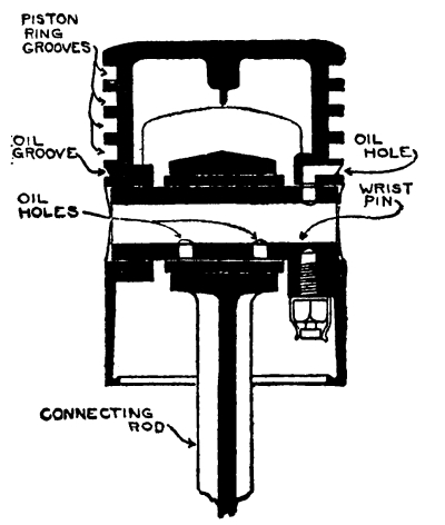
Fig. 76.—Wrist
Pin Lubrication
In the force feed system a pump driven by the engine forces oil through
pipes and channels to all of the bearing surfaces. Oil collects in a
pocket in the crank case, called the sump, and is drawn from it
by the pump. The sump is usually provided with a wire mesh strainer
that separates out any dirt.
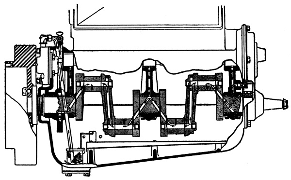
Fig. 77.—Force Feed
Oiling System of “Gray” Engine
From the oil pump the oil is forced to the bearings by pipes and by
holes drilled in the crank shaft and other parts, as shown in
Figure 77.
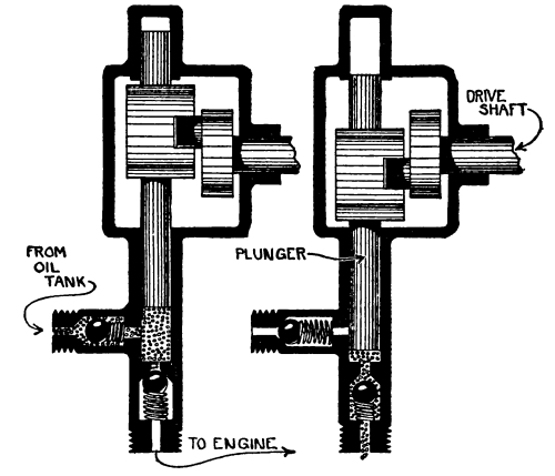
Fig. 78.—Oil Pump
An oil pump is illustrated in Figure 78. It consists
of a plunger driven by the engine, working in a cylinder provided with two ball
check valves, one for inlet and the other for outlet. On an upward
stroke of the plunger the cylinder fills with oil, which is forced to
the engine bearings by the following inward stroke.
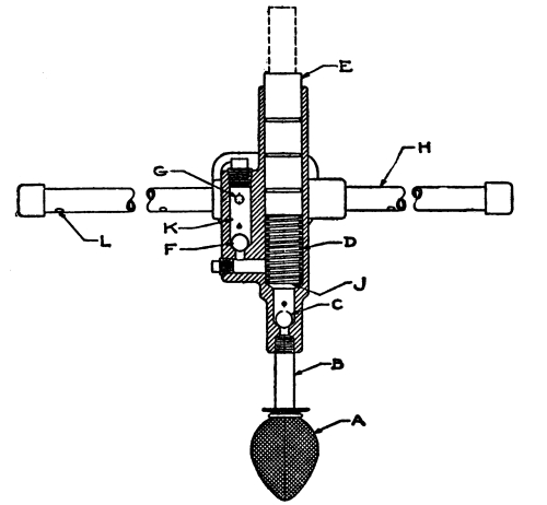
Fig. 79.—“E.B.”
Oil Pump
Figure 79 shows a similar pump with a strainer over the
intake, the outlet being through the holes L in the pipe H. In the pump illustrated
in Figure 80 the plunger is hollow, and fills with oil during an inward
stroke; the oil is forced out to a passage around the plunger, and
passes to the bearings by the holes H.
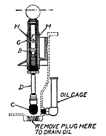
Fig. 80.—Oil Pump
with Hollow Plunger
Figure 81 shows two methods of preventing oil from leaking
out around the plunger. In the first of these, a channel is formed in the upper
part of the pump cylinder, leading to the crank case; any oil that
leaks past the plunger flows to the crank case by this drain pipe
and is not wasted. In the second method a packing of soft material,
such as cotton or asbestos, is placed around the plunger, and is
pressed against it by a gland, which is like a thick washer.
A packing nut screws against the gland, and thus squeezes the
packing against the plunger.
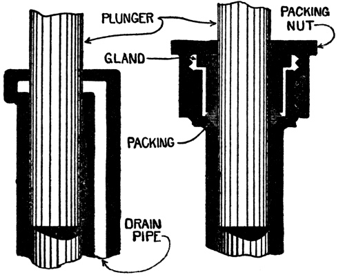
Fig. 81.—Methods
of Preventing Oil Leaks
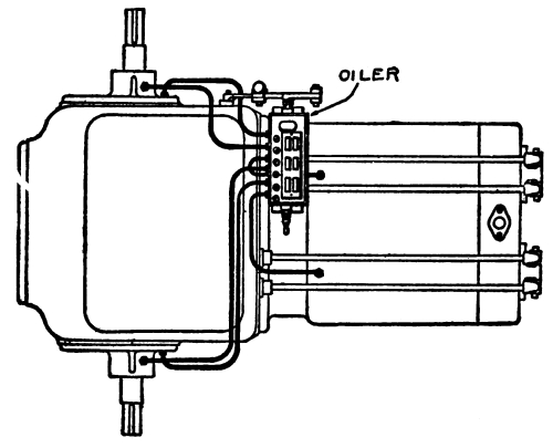
Fig. 82.—“Titan” Lubricator
A mechanical lubricator, or oiler, consists of several
small oil pumps placed in an oil tank, each pump feeding one special
bearing, and all driven by the engine. Figure 82 is a top
view of a 2-cylinder horizontal engine oiled by a six-feed oiler. The bearings
that it oils are the two ends of the crank shaft, the two ends of the
cam shaft, and the two cylinders; the gears and other bearings are
oiled by splash. An oiler is adjustable, so that it will feed any
desired quantity of oil.
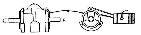
Fig. 83.—“I.H.C.”
Method of Oiling Crank Pins
Figure 83 shows a side view and an end view of the crank
shaft of a 2-cylinder horizontal engine. To each end of the crank is attached a
ring, B, formed into a channel; oil splashing into this ring is thrown
into the channel by centrifugal force, and flows by holes, A, to the
crank pin bearings.
The oil forced to the cylinders from the oiler, Figure 82,
reaches the wrist pin by grooves and holes, A, Figure 83.
A 6-feed oiler is also shown in Figure 84.
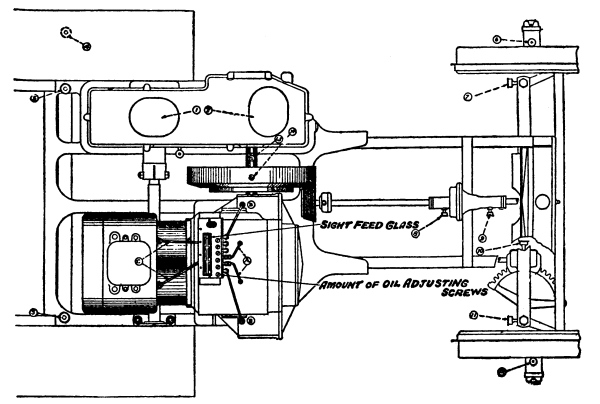
Fig. 84.—“Hart-Parr”
Oiling System
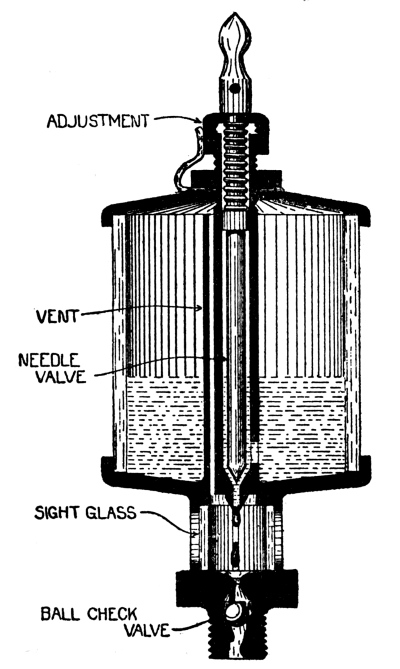
Fig. 85.—Oil Cup
Figure 85 is an oil cup, which is used to feed an
individual bearing. It is a glass cup holding oil with an opening at the bottom
into which fits a needle valve. When the engine is at rest, the needle
valve handle at the top is turned down, which allows a spring to close
the needle valve; on starting the engine the needle valve is raised,
and the oil flows out by gravity. The dripping oil may be seen through
a sight glass at the bottom.
In the force feed and oiler systems the oil feeds only when the engine
is running, but with an oil cup the oil feeds all of the time that the
needle valve is raised. Care must therefore be taken to turn on the oil
cup when starting the engine, and to turn it off when the engine is stopped.
Change speed gears and differentials are usually enclosed in oil-tight
housings that contain a supply of oil or grease. The only attention
that is required is to see that they have the necessary amount, and
that the lubricant is of the right kind.
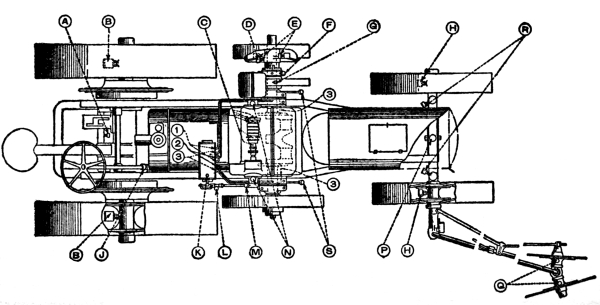
Fig. 87.—“Titan”
10-20 Oiling Diagram
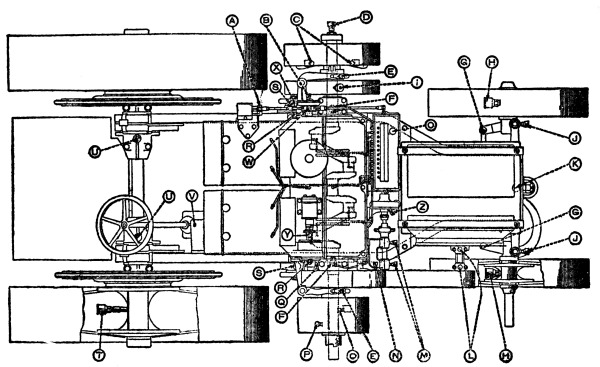
Fig. 88.—“International”
Oiling Diagram
The bearings of wheels and of many other parts of a tractor are
lubricated with grease fed by grease cups; a grease cup has a
cover that, when screwed down, forces the grease out of a hole in the
bottom of the cup. In using a grease cup it is not sufficient simply to
give the cover a turn or two; the cover should be screwed down enough
to force an ample supply of grease to the bearing. This is illustrated
in Figure 86.
Figures 87 and 88 are oiling
diagrams. They show the many points at which a tractor must be
lubricated, and it should be remembered that the failure to maintain a
plentiful supply of lubricant at any one of these points will mean the
wear and breakdown of that particular part.
CHAPTER XI TRACTOR OPERATION
Before running a new tractor it should be given a careful examination
to make sure that all nuts and bolts are tight, and not secured only
by paint; that all grease cups are in position and filled; that all
parts of the mechanism are properly lubricated; that oil holes are free
from grit, and that nothing is cracked, broken or missing. It should be
cleaned of cinders and mud that may have collected in shipment, and in
general it should be seen to be in proper condition.
A tractor, like any other piece of machinery, requires breaking in, and
for the first few days it should be run slowly and with light loads.
All parts should be plentifully oiled, for there will be rough and
uneven places on the bearings that must be worn smooth, and without oil
these would heat and be injured.
A continual watch should be kept for loose nuts and bolts, which should
be tightened without delay. Readjustments of the clutch and brake will
be found necessary, for their linings when new may be lumpy; as these
lumps wear down through use the clutch or brake will begin to slip and
must be tightened. When the linings are worn in, this trouble will
disappear, and readjustments will be necessary only at considerable
intervals.
Special care should be taken to keep the filler caps of the fuel and
oil tanks clean and free from dirt. If these are dirty, the dirt will
be carried into the tank when filling, and will sooner or later cause
trouble.
The vent holes in the filler caps should be kept clear. If they are
plugged with dirt, air cannot enter the tank to take the place of the
fuel that flows out, and the feed of fuel will stop.
Beginning when the tractor is new, a system of daily inspection should
be started, and should be continued for the working season. Big trouble
starts with small trouble, and if small trouble is cured without delay,
big trouble will be avoided. Trouble usually begins with looseness,
which may be due to a slack nut or bolt, or may come with wear. If the
loose part is not tightened, it will begin to shift its position; it
will wear, and will rapidly lead to a breakdown.
Every day, without fail, all parts of the tractor should be inspected
for loose nuts, bolts, pipe and electrical connections, petcocks, drain
plugs, steering connections, etc. This is also the time for wiping off
the working parts, and cleaning mud and grit from rods, shafts, joints,
and other places at which dirt could make its way into bearings.
The change speed gears of a tractor should not be shifted while in
motion, this being one of the differences between a tractor and an
automobile. In the sliding gear type of change speed mechanism, the
gears slide into mesh sideways, a tooth of one being opposite a space
between two teeth of the other. If the gears are not in the right
position for this, one tooth will strike another, and the gears cannot
be meshed. In such a case the clutch is let in for a slight touch to
move one gear, not for a dozen or twenty revolutions, but enough to
bring a space between two teeth of one gear opposite a tooth of the other.
If an attempt is made to shift the gears while they are in motion, the
result will be that one will grind against the other, and there will be
rapid wear and probable breakage. It is because gears cannot be shifted
while they are moving that manufacturers instruct users not to attempt
to shift on a hill without first blocking the wheels. The reason for
this is that the brakes may not hold the tractor, and if the gears are
pulled out of mesh, the machine may start to run down hill; as another
speed cannot then be engaged because the gears are moving, there will
be no control over the tractor.
Never coast down hill; always run with one of the speeds engaged. By
switching off the ignition the motion of the tractor will drive the
engine, and this provides the best possible brake. On low gear, the
engine will turn in the neighborhood of eighty revolutions to one turn
of the driving wheels, and the work required to do this will check the
tractor on the steepest of practicable grades.
A tractor is not built for as accurate and delicate steering as an
automobile and should always be slowed in making a turn; this is
especially true when hauling plows or other loads in the field. It is
difficult to control the tractor if a turn is made at high speed, and
the machine is liable to tip over.
In steering and in engaging the clutch, the action should not be jerky
and abrupt, but gradual and smooth. Letting in the clutch suddenly will
start the tractor with a jerk that will strain it from end to end, and
an abrupt swing of the steering wheel will have the same effect. Making
these motions smoothly and steadily will cause the tractor to change
its direction or pace with the least possible strain and effort. This,
of course, increases the tractor’s life.
In much of the work done by the tractor, the varying conditions of
field and soil make a continual change in the load, and the tractor
must be handled accordingly. The change from an uphill to a downhill
haul, and from sand or light loam to gumbo, will require the gears
to be shifted in order that the engine may neither labor nor race in
keeping the outfit at its work.
There should be no hesitation in coming down to low speed when the
engine shows by its laboring that the effort of working on high gear is
becoming too great. The engine cannot deliver its full power unless its
speed is maintained, and low gear is provided for those times when the
load is too great to be handled on high. Use high speed whenever it is
possible, but trying to force the tractor to run on high with too great
a load will lead to a breakdown.
High speed should be used for light work or for moving from place
to place, but the engine should never be run at a greater number of
revolutions than that specified by the manufacturers. It is very poor
policy to run the tractor fast over rough roads, as the pounding will
inevitably injure it.
Cold weather changes conditions in the handling and operation of a
tractor; there is difficulty in starting, lubrication is likely to be
faulty, and there is danger of breakage in engine, radiator, and air
washer through freezing.
Difficulty in starting comes from the use of the usual medium grade of
gasoline, which is satisfactory in mild weather, but will not vaporize
at low temperatures. Cold gasoline will not vaporize in a cold engine;
to form a mixture it is necessary to use high test gasoline, which will
vaporize at low temperatures, or to warm the engine to a temperature at
which medium grade gasoline will vaporize.
It is advisable to keep on hand a few gallons of high test gasoline to
use in starting, or even a mixture of high test gasoline and ether,
half-and-half, for extreme cold weather.
The engine may be warmed by pouring a bucket of hot water into the
cooling system, cranking the engine to get it into the water jackets of
the cylinders. Another plan is to wrap cloth around the intake manifold
and carburetor, soaking it with hot water, being careful not to get
water into the air intake.
A drop of liquid gasoline on the points of the spark plug will
short-circuit them and prevent the formation of a spark; the points
should be dry, and it is an advantage to heat the plugs, screwing them
hot into the engine at the last moment before trying to start.
Kerosene is thicker when cold than when warm; it will not flow so
freely, and the needle valve of the carburetor must be opened more in
winter than in summer to obtain a proper mixture.
Lubricating oil also thickens in cold weather, and flows much more
sluggishly. The lubrication adjustments that are correct for summer
will therefore be incorrect for winter. This may be provided for to
a great extent by using a thinner oil in winter than the oil used in
summer. A cold snap is likely to result in burned bearings if the
change in lubrication that it brings is not allowed for.
Grease thickens in cold weather more than oil does, and some kinds
freeze solid. In winter a light, soft grease should be used, and the
grease cups should be turned down several more turns than is usual when
the weather is warm.
While antifreezing compounds can be used in the cooling systems of
automobiles, they are not suitable for tractors because the greater and
more continuous heat quickly evaporates them. The danger of freezing is
very great, and must be avoided; the water in the radiator and jackets
is in thin sheets, and will freeze when a bucket of water standing in
the open will not show any signs of ice.
The only real protection against freezing is to drain out all the
water whenever the tractor is to stand idle for a sufficient time for
it to cool off. Petcocks are provided for this at the lowest points
of the system, and also in the pump when forced circulation is used.
The freezing of even a small pocket of water will be enough to crack a
cast-iron water jacket wall, and the best assurance that the system is
thoroughly drained is to open the drain cocks while the engine is still
running, shutting down as the flow stops.
When putting up a tractor for the winter it should be thoroughly
protected from rust and corrosion. The last time that the tanks are
filled a quart of light oil should be added for every five gallons of
gasoline or kerosene; as the tank empties this will leave a coating of
oil on the inside walls.
Fuel tanks and water system should be drained, and particular care
should be taken that all the water is out; the drain cocks should be
left open. A mechanical oiler should be filled full, to protect the
steel parts of the pumps from rust.
A half pint of thick oil should be put into each cylinder, and spread
to the cylinder and piston walls by cranking for a few turns. Oil
should be run between the valves and their seats.
All exterior parts should be protected by a coat of thick oil or
by paint. The governor rod, push rods, and similar parts should be
especially looked after. It is advisable to take off the magneto and
store it in a safe, dry place; spark plugs should be left in position.
The tractor should be covered with a tarpaulin and stored in a tight shed.
When going over a tractor preparatory to laying it up, a list should
be made of all parts that need renewal. These parts should be procured
at once; they are more readily obtained during the winter than in the
operating season, and will be on hand for the spring overhaul.
CHAPTER XII ENGINE MAINTENANCE — FUEL SYSTEM AND CARBURETOR — MAGNETO AND IGNITION SYSTEM — COMPRESSION — VALVE TIMING — CARBON
The operation of a carburetor depends on so many things that no exact
instructions for its adjustment can be given. The best that can be done
is to give a general idea of the requirements, and to outline a plan by
which the adjustment can be arrived at.
The many makes and designs of carburetors and vaporizers that are
used on tractors have different kinds of adjustments; on most of them
the only adjustment is the needle valve that controls the fuel, but
some also have adjustable air valves. In any case, the manufacturer’s
instruction book should be studied for the understanding of the
particular carburetor in question.
The first step in adjusting a carburetor is to get the engine
running. The needle valve should be closed, and then opened enough to
give a mixture on which the engine will start; on many carburetors
this will be about one and one half turns. The engine should then
be primed; that is, a little gasoline should be put in the
cylinder, which may be done with a squirt can.
When the engine is running, and is well heated, the needle valve should
be gradually closed until the engine begins to miss, and to send jets
of flame out of the carburetor, or little explosions occur in the
carburetor. These are signs of a thin mixture, and the needle valve
should be gradually opened to make the mixture richer. The engine will
run more steadily, and will pick up speed until the mixture becomes too
rich, when it will choke and black smoke will come out of the exhaust.
The positions of the needle valve for a mixture that is too thin and
one that is too rich have thus been found, and it remains to set it at
that point between at which the engine runs most steadily and at the
best speed.
With adjustable air valves it is usual to adjust for idling, that is,
the slowest speed at which the engine will run steadily without load,
and then to make any necessary additional adjustment for full speed and
power.
If a carburetor cannot be adjusted by following the usual methods,
trouble may be looked for, and this may be in the carburetor itself,
in the fuel supply, or in the intake manifold, taking for granted, of
course, that the engine is in proper condition and that the ignition
system is operating correctly.
Dirt under the float valve will prevent the valve from seating, and the
level in the float chamber will be too high, so that the mixture is too
rich. Lifting the valve from its seat will let fuel rush through, and
loose particles will thus be washed away. If dirt is ground into the
valve and seat, or if these parts are worn, the valve must be reseated,
which is done by turning the valve against its seat with light
pressure, the end of the valve being gently tapped with a light hammer.
Under no conditions use a grinding compound, for the particles would
become imbedded in the soft metal and would ruin the valve.
Other causes of flooding are a bent valve, the sticking of the float
pivot, and the soaking of fuel into the cork float, which is thereby
made too heavy to float properly. The remedy is to dry it, and then to
give it three coats of shellac.
A frequent cause of trouble is dirt in the pipe from the tank to the
carburetor. While there may not be enough dirt to prevent the engine
from running slowly, it is sufficient to prevent the flow of sufficient
fuel for full power. A strainer is always provided, and this should be drained
every day; if this is not done frequently, dirt will work its way through.
A grain of sand in the spray nozzle will choke it, and every precaution
should be taken to keep this from happening, as well as the other
troubles that dirt brings. The best precaution is to strain the fuel
through chamois leather, or, if this is not obtainable, through a very
fine metal wire screen.
In fuel systems that use a pump, the sticking of the check valves, and
the leaking of the pump through poor packing, will cut down the supply of fuel.
If air can leak into the carburetor or intake manifold, the proportions
of the mixture will be altered. To test for leaks, run the engine, and
with a squirt can squirt gasoline on the joints or other places that
are suspected of leaking air. If there is a leak, the gasoline can be
seen being sucked in.
Air must enter the tank to take the place of the fuel that flows out,
and this is provided for by a small hole drilled in the tank-filling
cap. If this hole becomes stopped up, the fuel will not flow, and the
engine will come to a stop. There is a similar hole in the top of the
float bowl of most carburetors, and this also must be kept open.
An engine is always started on gasoline, for that will form a mixture
when it is cold. Before switching to kerosene the engine must be hot,
and this will take several minutes of running on gasoline.
With a double carburetor, which has a separate fuel bowl and spray
nozzle for each fuel, nothing more is required than the switching
of one or the other into action; when the two parts have once been
adjusted, they require no further adjustment. Carburetors that use
the same spray nozzle for both gasoline and kerosene will require a
readjustment when the switch is made, for, as kerosene is thicker than
gasoline, it will require a larger opening for a sufficient quantity
to pass. This readjustment is a slight opening of the needle valve on
switching to kerosene, and an equal closing when gasoline is again used.
A few minutes before the engine is stopped the carburetor should be
switched from kerosene to gasoline, so that when it is shut down the
fuel bowl will contain gasoline and the cylinders gasoline mixture.
This is done to make it possible to start the engine. If the engine is
stopped on kerosene, it cannot be started if it has had time to cool.
In such a case the fuel bowl must be drained of kerosene and filled
with gasoline, and the engine must be cranked until the cylinders
receive a clean gasoline mixture.
When an engine is working at full power on kerosene, it gets much
hotter than would be the case with a gasoline mixture. Carbon particles
in the cylinder, and projecting bits of metal, such as thin spark plug
points or the edge of a screw thread, become so hot that they glow,
with the result that they ignite the incoming fresh charge and cause
preignition. The effect of this is to cause a pounding or knocking
that is very noticeable. It is then necessary to use water, which is
provided for in the carburetor.
Water has the effect of cooling the intensely heated parts, and only
enough should be used to prevent preignition. When the knocking is
heard, water should gradually be turned on, using no more than is
necessary to stop the noise. Too much water will cause the engine to
miss by collecting on the spark plug points, thereby preventing the
passing of the ignition spark.
Hard water should not be used, for it will form scale, which will
interfere with the action of the carburetor. Only soft water should be
used, and preferably rain water.
Whenever the engine is stopped, the fuel valve at the tank should be
closed to shut off the carburetor supply. If this is not done, the
float valve will be the only thing that prevents the fuel from running
out, and should the float valve leak, the fuel will be wasted.
A magneto that is kept clean and properly oiled rarely gives trouble,
and it is a mistake to blame it whenever the engine runs irregularly or
will not start. Its adjustments should be changed only when the other
parts of the engine have been proved to be in good condition.
The working parts of a magneto are enclosed, and practically proof
against dust. It should be wiped off frequently, and dust and grit
should not be allowed to collect around the oil holes, for otherwise it
will work into the bearings and damage them.
Dust and dirt are especially injurious to the circuit breaker, which
should be frequently inspected and cleaned. Very little oil should be
used on it, and this should be the light oil used for typewriters and
sewing machines. A thicker oil will become gummy, and will prevent the
free action of the lever.
If there is much sparking at the platinum points, so that they become
corroded and rough, it is an indication that the condenser of the
magneto is not operating as it should, for the object of the condenser
is to prevent such sparking. The only remedy is to renew the condenser.
Rough points will spark more than smooth ones; should they get into
this condition, they should be lightly filed with a file of the cut
known as “dead smooth.” If this file cannot be obtained, pinch a strip
of the finest sand paper—not emery paper—between the points, and draw
it gently back and forth, smoothing down first one point and then the
other. In smoothing platinum points the greatest care should be taken
to make them flat and true to each other.
After smoothing the points they should be readjusted so that when they
are separated by the cam they are from ¹/₃₂ to ¹/₆₄ inch apart.
A distributor made with a carbon brush that slides across the contacts
will require wiping off at least once a month. Carbon dust will rub off
the brush and collect on the face of the distributor; in the course of
time this will cause a short-circuit. The distributor is always made so
that it can easily be cleaned.
A magneto is timed to an engine so that when the spark control is fully
retarded, the circuit breaker points are just separating as a piston
goes over top center. The engine is cranked until one of the pistons
is at top center; the magneto should be in position, but its coupling
should be loose, so that the armature can be revolved. The spark
control is retarded; that is, it is moved as far as possible in the
direction in which the armature turns. The armature is then revolved
in the direction in which it will be driven by the engine until it is
seen that the contact points are beginning to separate; holding the
armature, the coupling is then made fast.
It will now be found that the distributor brush is touching one of the
contacts; that contact is to be connected with the spark plug of the
cylinder that is at top center of the compression stroke. The following
distributor contacts are connected to the remaining spark plugs in the
order in which their cylinders fire.
Should the magneto be suspected of being out of order, the first test
is to disconnect a wire from its spark plug, and support the tip ⅛ inch
from the metal of the engine while the engine is cranked briskly; if a
spark appears, it is evidence that the magneto is operating and that
the trouble is elsewhere.
If there is no spark, repeat the test with the switch wire disconnected
from the magneto. This wire and the switch form a circuit from the
metal of the engine to the insulated part of the circuit breaker;
when the switch is closed, or in the “off” position, this circuit is
completed, and as the magneto current flows over it instead of over
the regular sparking circuit, no spark is produced at the plug. It
sometimes happens that the switch or wire is defective, and allows
the current to take that circuit even when the switch is in the open
or “run” position. If this is the case it will be shown by a spark on
cranking the engine with the switch wire disconnected at the magneto,
and no spark when it is connected.
If the switch and wire are all right, examine the circuit breaker to
see whether the contact points are clean, and that they touch when the
cam allows them to; touch the circuit breaker lever to see that it is
free to move and that its spring is not broken. In some tractors the
magneto is in such a position that the circuit breaker cannot easily
be seen; in such a case hold a small mirror in front of the circuit
breaker and examine the reflection.
If the circuit breaker is in good condition, examine the distributor to
see whether it is dirty, or the brush broken; if these parts are all
right, the trouble is of such a character as requires the magneto to be
returned for repair.
Ignition trouble is usually in the spark plugs. The insulator cracks
easily in many makes, which will permit the current to leak across
without forming a spark; it is frequently the case that the crack does
not show, and the best test is to replace the suspected plug with a
plug that is known to be good. If the cylinder fires with one plug and
not with the other, there is no question as to the cause of the trouble.
The insulator of the plug must be kept clean, for a deposit of carbon
on it will form a path by which the current can pass without forming
a spark. A dirty plug can best be cleaned by brushing it with a stiff
toothbrush dipped in gasoline. A carbon deposit can be softened by
soaking the plug in gasoline for a few hours, and can then be brushed
off more easily.
The spark gap of a plug should be from ¹/₃₂ to ¹/₆₄ inch. After
considerable use the points will be burned off, and the gap will become
too wide; the points should then be bent to form a proper gap.
Oil and grease will rot rubber, and the ignition wires should therefore
be wiped clean. Oil-soaked cables will give trouble, and should be
replaced with new ones.
It is frequently difficult to locate a leakage of current. If the
engine is misfiring and losing power, and a leakage of current through
poor insulation is suspected, the easiest way to detect it is to run
the engine in the dark. Leaks will show themselves by sparks, which are
then easily seen.
In order to deliver its full power a gas engine must have good
compression, and compression should frequently be tested by cranking
the engine slowly and steadily with the ignition switched off. If
compression is good, there will be a springy, elastic resistance
that becomes greater as a piston approaches the end of a compression
stroke, and that throws the piston outward as dead center is passed.
Compression should be the same for all cylinders.
If there is a leakage of compression, the only resistance will be from
the bearings, and it will be the same for all parts of the stroke.
A compression leak often makes a hissing noise that can be distinctly
heard, and by which it can be located, but more often it makes no
sound, and its location must be found by testing. The leak may be at
any of the openings into the combustion space; at the valves, around
the spark plugs or piston rings, or at the cylinder head gasket.
To discover whether the gasket leaks, run gasoline along the line of
the gasket joint with a squirt can while the engine is being cranked
briskly; at a leaky place it will be sucked in or blown out. The same
test should be made around the spark plug.
The remedy is to reset the cylinder head, using a new gasket, and being
sure that the surfaces are clean and free from grit.
Piston ring leaks are usually caused by the rings sticking in their
grooves through the formation of carbon. To test for piston ring leaks,
pour a half pint of cylinder oil into each cylinder, and crank the
engine slowly. The oil will form a seal around the pistons, and if
compression is then improved, the rings are shown to be at fault.
To free the rings, pour a few tablespoonfuls of kerosene into each
cylinder, and spread it by giving the engine a few turns; after
standing for an hour or so the carbon should be sufficiently softened
to free the rings.
If the leakage of compression is due to the rings being worn and loose
in their grooves, they must be replaced.
The most usual cause of compression loss is leaking valves. With its
continual pounding against its seat, and the heat to which it is
exposed, a valve and its seat will become rough and pitted, and will
leak; when in this condition the valve must be ground.
A valve is ground by spreading grinding compound on the seat, and
turning the valve against it. This requires the valve spring to be taken
off; the exact method of doing this depends on how these parts are made.
If the valves are in a removable cylinder head, valve grinding is most
easily done by taking the cylinder head to a bench. In many designs the
valve seats are part of the cylinder casting, and the job is done on
the tractor.
In grinding a valve the valve is not turned around in one direction
only, for this would cut grooves in the valve and seat. To obtain
smooth surfaces the valve should be given part of a turn in one
direction, and then turned equally in the other direction; after every
few turns the valve should be lifted and dropped to another position on
the seat. In this way the grinding is made even all around.
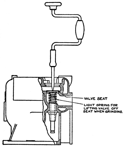
Fig. 89.—Grinding
Valve in Engine with Fixed Head
The best tool for valve grinding is a carpenter’s brace with a screw
driver blade fitting the slot in the valve, as shown in Figure 89.
This drawing illustrates a cylinder with a fixed head; the valve is
reached by unscrewing the plug from the opening directly above it. When
grinding valves in an engine of this design the opening between the
valve pocket and the combustion space should be plugged with a rag or
waste to prevent the grinding compound from getting into the cylinder.
With the valve grinding tool in position, swing the handle back and
forth ten or twelve times; then lift the valve, place it in a new
position, and repeat. The valve is lifted most easily by a light spring
placed under the valve disk, as shown in Figure 89.
From time to time the valve disk and seat should be cleaned off and
examined to see whether they are smooth and free from pits and scores.
If they appear to be, make marks around the valve disk with a lead
pencil, replace the valve, and give it a complete turn. If this wipes
off the pencil marks all around the valve, the grinding is complete,
and the valve may be replaced with its spring and spring retainer. It
is not necessary to grind until the entire thickness of the valve disk
and seat are smooth; a narrow band all around will make the valve tight.
After grinding, and before replacing the valve, all traces of the
grinding compound should be wiped off, and great care taken that none
of it gets into the cylinder, valve stem guide, or other working part.
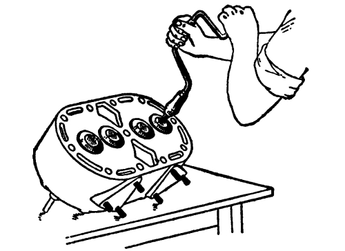
Fig. 90.—Grinding
Valve in Detachable Head
On an engine with a removable head containing the valves, the head
may be taken to a work bench, which makes grinding easier. This is
illustrated in Figure 90. On an engine in which the valve
and its seat may be taken out, the seat may be clamped in a vise, as shown in
Figure 91. With valves of either of these types, the grinding
may be tested by turning the head or the seat so that the disk is down, and pouring in
gasoline. If the valve is not tight, the gasoline will leak through,
and grinding must be continued.
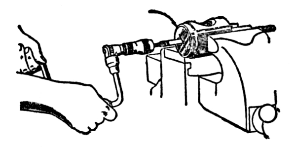
Fig. 91.—Grinding
Valve in Detachable Seat
When a valve seat is very badly worn it must be redressed, which is
done with a cutting tool to be obtained from the maker of the tractor,
and illustrated in Figure 92. This has a stem fitting the
valve stem guide which centers the tool and assures a true cut. If a seat is so
worn as to need redressing, the valve will be in such bad condition
that it must be discarded and a new one used. This must be ground in
before the engine is run.
Grinding a valve lowers it in its seat, and usually makes it necessary
to readjust the push rod. When an engine is cold there is a space of
about ¹/₃₂ inch somewhere between the cam and the valve stem; in Figure 93,
this space is shown to be between the valve stem and the rocker arm.
As the engine heats up the valve stem lengthens, and this space permits
it to do so.
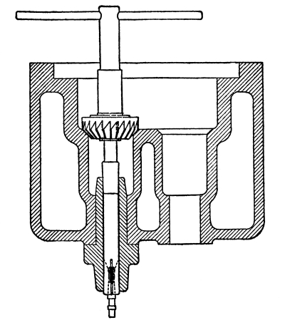
Fig. 92.—Valve Seat Cutter
If the space is too small, the stem will come against the rocker arm
or the push rod, and the valve will be held off its seat, causing
a compression leak. If the space is too great, the valve will open
too late and close too early. The space must therefore be carefully
adjusted, and this is arranged for on practically all makes of tractor engines.
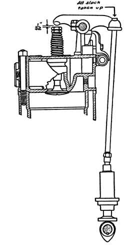
Fig. 93.—“Holt”
Valve Arrangement
One-thirty-second of an inch is the thickness of a 10-cent piece; it
should just be possible to slip a slightly worn dime into the space
when the engine is cold.
By timing the valves is meant the setting of the cam shaft in
such a position that the valves are opened at the correct point in the
stroke. It is necessary to time the valves only when the cam shaft has
been taken out and must be replaced. The principle of valve timing
should be understood, however, in order to be able to tell whether an
engine is timed correctly.
It will usually be found that the face of the flywheel bears letters
and figures that are indicators of the timing of the valves. This
arrangement on the E-B engines is shown in Figure 94.
Two lines are cut in the face of the flywheel, one marked ex. cl. 1-4, which
means exhaust valve closes, cylinders 1 and 4, and the other marked
center 1-4, to indicate that the pistons in
those cylinders are on center. A straight-edge is held against the
finished surface of the housing and the crank shaft is turned to bring
one of the marks in line with it; at that point the valves or pistons
are as indicated by the lettering.
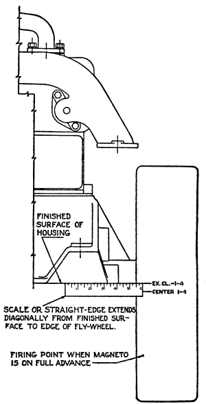
Fig. 94.—Valve
Timing, Using Marks on Flywheel
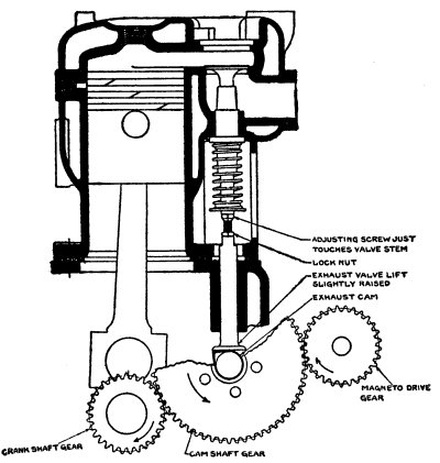
Fig. 95.—Valve Timing
The flywheel is also marked with a dot to indicate the firing point.
When the dot is in line with the straight-edge, ignition should occur
with the spark control fully advanced.
Figure 95 shows the valve arrangement of the same engine,
with the exhaust valve just closing; the point of the cam has passed under the
lifter or push rod, and has permitted the valve to come to its seat,
but is still holding the lifter against the valve stem.
To check the valve setting, hold a slip of tissue paper, such as a
cigarette paper, in the space between the lifter and the valve stem,
while the engine is cranked slowly. While the cam is holding the valve
off its seat the paper will be pinched between the lifter and the valve
stem and held firmly. At the instant when the paper is freed and can
be moved, the valve is seated and the point of the cam is just passing
from under; the proper mark on the flywheel should then be in line with
the straight-edge.
As the cams for all valves are in one piece with the cam shaft, setting
one valve sets them all and checking the setting of one checks the
setting of all.
Before taking out a cam shaft, two adjoining teeth of its gear should
be marked with a prick punch or a small cold chisel, and a similar mark
should be made on the tooth of the crank shaft gear that comes between
them. In replacing the cam shaft it is then necessary only to return
the teeth to the same position. Timing gears are usually marked in this
way by the manufacturers.
A kerosene lamp that is turned too high gives a dense black smoke that
is composed of fine particles of carbon. A piece of paper held in the
smoke is quickly covered with a deposit of carbon, commonly called
soot, or lamp-black.
All fuel oils and lubricating oils contain carbon. When these oils burn
in the cylinder, they produce carbon, much of which passes out of the
exhaust, while the rest deposits on the valves and on all parts of the
combustion space. This deposit hardens, and eventually makes trouble
through causing preignition.
The deposit is rough, and the heat in the cylinder is sufficient to
make the outstanding particles glow; they ignite the incoming charge,
and cause preignition. The sign of carbon trouble is a sharp knocking
in the cylinder, especially when the engine is under a heavy load. The
sound is the same as that caused by too great an advance of the spark.
Carbon deposit can be greatly reduced by pouring a few tablespoonfuls
of kerosene into each cylinder and cranking for a few turns to spread
it to all parts of the combustion space. This will soften the carbon
and much of it will be blown out when the engine is next started. Best
results will be obtained if the kerosene is poured in after a run, when
the engine is hot.
If the carbon deposit is too hard to be softened by kerosene, it can
be removed by scraping. This requires the cylinder head to be taken
off, when the deposit can be scraped and chipped with a screwdriver.
Care should be taken to keep the carbon crumbs from getting into the
cylinders, valve stem guides, or other places where it would cause wear.
In taking off the cylinder head the gasket should be handled carefully,
and protected from denting and bending. A battered or bent gasket is a
sure cause of compression leaks. In replacing a metal gasket, give it a
coat of cylinder oil on both sides to improve its seating.
When replacing the cylinder head, set all of the bolts up a little at
a time, instead of screwing some of them tight while others are loose.
One bolt drawn tight may tilt the cylinder head slightly, and there
will be a distortion when another bolt is tightened. This is avoided by
setting up all of the bolts a little at a time.
Running on too rich a mixture, giving the engine too much oil, and not
using an air cleaner in dusty work will carbonize an engine rapidly.
Blue smoke at the exhaust is a sign that too much lubricating oil is
being used; black smoke indicates too rich a mixture. Carbonizing
can be greatly reduced by careful adjustment of the lubricator and carburetor.
CHAPTER XIII LOCATING TROUBLE — ENGINE WILL NOT START — ENGINE LOSES POWER — ENGINE STOPS — ENGINE MISSES — ENGINE STARTS; BUT STOPS — ENGINE OVERHEATS — ENGINE SMOKES
There are many ways in which an engine can give trouble, but these are
not serious to an operator who understands the action of an engine,
and who works with his brain as well as with his hands. Each of these
troubles has a distinct cause; proper care will avoid them, but if they
come the reasons for them can be determined by simple tests.
In order to develop full power, an engine must be in good mechanical
condition; that is, the bearings must be free without being loose,
the gears must run well, the pistons and their rings must not bind or
be too free, and so on. It must be properly lubricated and cooled,
compression must be correct, it must get a good mixture, and ignition
must take place at the right time. If an engine gives trouble, it is
because one of these systems is not working properly, and it is not at
all difficult to locate the cause and to correct it.
If an engine gets a good mixture, which is ignited properly, it will
run; if it will not give any explosions it is because one or the other
of these systems is not working properly. An inspection or a simple
test will show which one is at fault.
If an engine will not start after being cranked a dozen or twenty
times, it is useless to continue to crank it. It is not getting either
a proper mixture or an ignition spark, and it saves time and energy to
find out where the trouble is, rather than to keep on cranking in the
hope that something may happen.
When a tractor engine refuses to start, the trouble is usually with the
mixture, and, more often than not, this is due to carelessness or to
forgetfulness. The tank may be empty, or the fuel valve may be closed,
so that the carburetor is dry; see if there is fuel in the carburetor
bowl. The engine may have been shut down while running on kerosene,
instead of having been switched to gasoline for the last few minutes of
its run, so that the carburetor, intake manifold and cylinders contain
kerosene, which will not vaporize without heat, instead of gasoline,
which will. In this case the engine must be primed with gasoline.
If too much gasoline has been used for priming, the cylinders may
contain a mixture that is too rich to ignite; the engine should then be
cranked briskly with the fuel shut off and the compression relief cocks
open, to clear out the rich mixture and fill the cylinders with air.
Water in the fuel will make starting difficult or impossible. It is
easy to forget to shut off the water valve of the carburetor when
stopping the engine, and when starting, water from this valve will
prevent the forming of a mixture and will also interfere with the
ignition.
If the mixture is apparently all right, the fault may be in the
ignition. A drop of liquid fuel or of water, for instance, may be on
the spark plug points; this will short-circuit them and no spark will
be formed, although the sparking current is passing.
If there is a suspicion that the ignition system is at fault, and that
the magneto is not producing a sparking current, it should be tested,
as explained in Chapter XII.
Starting in cold weather is always more difficult than starting when it
is warm. Helps in cold weather starting are given in Chapter XI.
A leaky inlet manifold will admit an extra amount of air that will
completely alter the proportions of a mixture. Thus the mixture will be
wrong, although the carburetor adjustment seems to be correct. Manifold
leaks are usually at the joints, but occasionally a manifold is found
with a hole in it due to poor casting or material, or a crack may develop.
Difficulty in starting due to poor compression caused by stuck valves
or rings will show its cause by the ease with which the engine can be
cranked.
If an engine is free enough to turn over, poor lubrication or cooling
will not interfere with starting it. Faults in these systems show
themselves only when an engine is running.
An engine will lose power through a defect of compression, carburetion,
ignition, cooling or lubrication, or because of a mechanical fault.
If the trouble comes from cooling or lubrication, the engine will
overheat and thus make the cause known. A bearing that binds will
become very hot, while if the cooling system fails, the engine will
be hot all over. When the engine is excessively hot, the pistons will
expand, and much of the power of the engine will be used up in forcing
them to move.
An engine that is not hotter than usual, and is having regular and even
explosions, probably loses power through a loss of compression. This is
the most usual cause of this trouble, and it is located and remedied as
explained in Chapter XII.
If compression is good, the loss of power may be due to a clogged
muffler or exhaust pipe, which will not permit the free escape of the
burned gases. This condition will prevent full charges of fresh mixture
from entering the cylinders, and the engine then cannot be expected to
deliver full power.
Another possible cause of a loss of power with the engine apparently in
proper condition is the sticking or poor adjustment of the governor.
The factory adjustment of the governor should not be changed, however,
until it is definitely proved that that is where the trouble lies.
If the engine misses fire, or runs irregularly, the loss of power
will be due to faulty carburetion or ignition. The mixture may be
too rich or too lean; in either case the trouble will be remedied by
readjusting the carburetor. A mixture that is very much too lean will
make itself known by backfiring; there will be little explosions
at the carburetor. This should be remedied at once, for the danger of
fire from it is very great. Black smoke at the exhaust is a sign of a
mixture that is too rich.
An engine will not deliver full power if it is run on a retarded
spark. A loss of power from this cause will be accompanied by general
overheating of the engine.
The manner in which an engine stops will indicate the reason for it.
A failure of the ignition system that stops the formation of current,
like the sticking of the circuit breaker lever, will cut off all
explosions instantly; the engine will stop abruptly. An engine will not
stop abruptly from any fault with the mixture; with mixture trouble the
explosions will become weaker and weaker until they cease.
If an engine stops through a failure of the lubrication or cooling
systems it will be intensely hot, which will not be the case if the
fault is with carburetion or ignition.
A running engine will not be brought to a stop by a loss of compression.
A steady or irregular miss in one cylinder is usually due to the spark
plug’s being cracked or dirty. Carburetor trouble will affect all the
cylinders; it cannot affect one cylinder only, and missing in one
cylinder may be put down as ignition trouble. In this case ignition
trouble does not mean magneto trouble, for if the magneto produces
sparking current for one cylinder it will produce it for all. Therefore
ignition trouble in only one cylinder is in those parts of the ignition
system supplying that cylinder; that is, in the spark plug or in the
spark plug cable.
A less likely cause for missing in one cylinder only is poor
compression. It is usually the case that if compression is poor in one
cylinder it is poor in them all, but a broken valve or piston ring or a
weak valve spring will weaken compression in one and not in the others.
A cylinder that misses is cooler than the others, and can be located by
feeling. It can also be located by short-circuiting the spark plugs one
at a time; this will make no difference in the dead cylinder, but when
the spark plug of an active cylinder is short-circuited the speed of
the engine will drop.
To short-circuit a spark plug, take a wooden-handled screwdriver or
other tool and rest the blade on the engine near the spark plug; then
tilt until its shank is close to the spark plug terminal. The spark
current will then pass to the metal of the engine by way of the tool
instead of by the spark plug points. This is also a test of ignition,
for a spark will pass between the terminal and the tool.
Irregular missing in all cylinders may be due to a fault at one of
the parts of the ignition system that supplies them all; a dirty
distributor, for instance, or a sticking circuit breaker lever, or
rough platinum points. It may also be due to a clogged fuel line, which
prevents the carburetor from getting a regular and sufficient flow.
Irregular missing will also be caused by loose ignition connections,
and by loose switch parts.
When an engine starts readily but quickly slows down and stops, the
reason is almost always an insufficient supply of fuel. An obstruction
in the pipe may prevent the fuel from flowing fast enough to keep the
carburetor bowl filled when the engine is running; when the engine
starts, the fuel is sucked out of the spray nozzle faster than it comes
in through the float valve, so the carburetor is soon drained and the
engine stops. The bowl then fills, only to be sucked dry again when the
engine is next started.
This difficulty is caused by dirt in the fuel, which collects in the
strainer or the fuel pipe. The strainer is so arranged that it may be
easily drained and cleaned; to clear out the pipe, shut off the fuel at
the tank, disconnect the pipe at both ends, and blow through it.
The strainer should be drained every day; it is sufficient to open the
strainer drain cock for two or three seconds.
Most of the troubles due to dirt in the fuel will be avoided if the
fuel is strained when filling the tank.
Another thing that will bring an engine to a stop is the clogging of
the vent holes in the tank filler cap and in the top of the carburetor
bowl. These holes should be clear, so that air can enter to replace the
fuel that is used; if air cannot enter the fuel will not flow, and the
tank is then said to be air-bound.
An engine may overheat either because it produces more heat than the
cooling system can take care of, or because the cooling system is not
taking off all of the heat that it should.
Running an engine with the spark retarded will cause it to overheat; so
will a failure of the lubrication and an obstruction to the passage of
the exhaust gases.
If an engine has been taken down and overheats when it is reassembled,
it may be that the magneto has been wrongly timed, and produces its
spark too late. If an engine has been running properly but begins to
overheat, the ignition cause will be the faulty setting of the spark
control, or the slipping of the spark control rod.
When an engine is run on kerosene, the oil in the crankcase must be
frequently drained off and replaced with fresh oil. The reason for
this is that part of the kerosene that goes to the cylinders does not
vaporize and burn, but works its way past the pistons and into the
crankcase, where it thins the lubricating oil. As the oil thins, it
loses its ability to lubricate, and the engine begins to overheat.
Anything that produces extra friction will cause overheating, as, for
example, a wrist pin that works endways and rubs against the cylinder
wall, or a tight bearing.
For a cooling system to work properly it must contain a full supply of
water, the passages must be clear, sufficient air must pass through the
radiator, and the pump must be in proper condition.
Hose connections will rot, and a strip of rubber may peel off the
inside and be drawn across the passage; or if dirty water is used, the
dirt may choke the fine radiator passages or other channels. If the
radiator is covered with mud, air cannot get at the tubes to take the
heat from the water that they contain.
A very usual cause of overheating is a slipping fan belt; an adjustment
is provided by which the belt can be tightened when it works loose.
Black smoke indicates that the mixture is too rich; blue smoke is a
sign of too plentiful lubrication. Oil that is too thin, or that is
of a poor grade, will cause smoking; good quality oil of the grade
recommended by the manufacturer should always be used.
Broken piston rings, or rings stuck in their grooves, will be the cause
of smoking because they will permit an excess of oil to pass by them.