Besides the tools mentioned in Part I, viz., bench-hook, hammer,
saw, file, bradawl, pincers, the following additional tools will be
found of service, though some of these are luxuries, and generally
it is best to use as few as possible:
1. A larger saw, for sawing rougher and larger wood than stripwood,
e.g. a Tenon Saw, length 8 to 16 inches; 10 to 16 points
to an inch, price about one and ninepence.
2. An Archimedean Drill. This is useful for making small
holes when there is danger of the wood splitting, however when
once this drill is used, the worker never again feels inclined to
use a bradawl or any other kind of boring tool. A quite useful
and efficient drill can be bought for sixpence. Care must be
taken that the drill bits or drill points do not break, for being
quite slender and made of tempered steel they are rather fragile.
A set of twelve drill points in assorted sizes in a metal case may
be bought for sixpence. (For hints on the use of drill, see under
fret-saw.)
3. The Cramp or clamp is a contrivance used for holding
boards together. An adjustable G cramp is a handy article for
small work. There are several models of G cramps; that shown
in the plate costs twopence.
4. A Rasp or rough file for removing from boxes either paper
or the names that are sometimes stamped on them.
5. Brace and Bit. The smallest-sized brace, which has a
sweep of 5 inches, is the most convenient for children. Bits are
of many patterns. The most common form is the Centre-bit
which will cut holes from 3/8 inch to 1½ inches in diameter.
The Pin-bit or shell-bit of the smallest bore is used to make
small-sized holes for screws, etc., but more especially when making
preparation for using the centre-bit.
A Centre-bit 1¾ inches in diameter costs ninepence; a brace
and bit (¾ inch diameter) together costs one and threepence; this
latter bit is useful for boring holes in wheels for axles, etc.
However the brace and bit is somewhat of a luxury and can
be done without, for holes made with the Archimedean drill can
always be enlarged to the required size, by means of round files
and patience.
6. The Mitre-block is a piece of beech-wood carefully squared
and rebated so as to present throughout its length a rectangular
step-like recess in which the wood to be mitred is placed in order
to be cut at the necessary angle.
In the raised part are three saw kerfs, two at an angle of
45° with the sides of the mitre-block and one half-way between
these at right angles to the sides. The inclination of the saw-cuts
at an angle of 45° is to the right and left respectively, so that
when these angles are brought together in the mitred joint they
may form a perfect right angle (90°). The mitre-block is a luxury,
but it is useful in squaring off the ends of the wood, making picture
frames, making the crane (Chapter V), etc., price sixpence.
A Compass, Protractor, Ruler, Try-square and well-sharpened
Pencil will be found useful in making nearly every toy.
A Plane is not necessary for any of the toys described in the
following chapters, but is mentioned here in case anyone should
require one for reducing the thickness of wood or straightening
a surface. The most economical one is a Jack-plane fitted
with a smoothing-plane iron. The Jack-plane thus equipped
may be used for reducing thicknesses of material (this is the real
function of the Jack-plane) as well as for planing up surfaces true
and smooth (the purpose of the smoothing-plane).
The Jack-plane iron has its cutting edge slightly rounded
in order to gouge out the wood and thus reduce thickness
quickly, the smoothing-plane iron is ground to a straight
edge.
If both these irons are bought, the plane becomes both a
Jack-and a smoothing-plane.
The Stanley Bailey adjustable iron plane is a good one. No. 5
size, 14 inches long, is recommended.
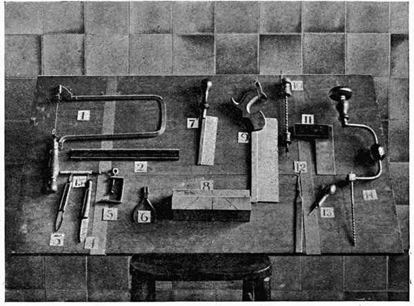
Plate X USEFUL TOOLS
1. Fret-saw
2. 'Non-slip' safety ruler
3. Card knife (London pattern)
4. Craft knife
5. G cramp
6. Round-nose pliers
7. Brass back metal saw
8. Mitre block
9. Tenon saw
10. Archimedean drill
11. Try square
12. File
13. Bradawl
14. Brace and bit
15. Carton knife
However, as we have said before, it can be done without. The
first four tools are the really necessary ones.
The Preservation of Tools. Keep tools in a dry atmosphere
in a wooden box. Have them instantly dried after grinding and
whenever they have been in contact with wet. Iron or steel parts
should be frequently rubbed over with a piece of oily rag (if
grease is used it must be free from salt). A speck of rust must be
removed at once with fine emery-paper and oil.
A generous coating of oil or vaseline should be given when
tools are laid aside for some time.
The Sharpening of Tools. Chisels, planes and knives are
sharpened on oilstones. The Lily-white and the Rosy-red
Washita oilstones are perhaps the best natural stones on the
market. With regard to the oil used, machine, engine, neat's
foot and sweet oils are all suitable. Clean the stone after use.
Knives are sharpened at an angle on both sides, and will
therefore have one side rubbed on the stone a few times and will
then be turned over to rub the other side.
Pen-knives can be sharpened on the ordinary kitchen
knifeboard.
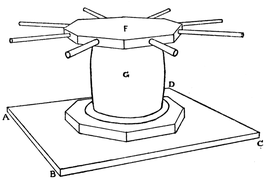
Fig. 280
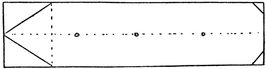
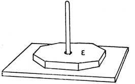
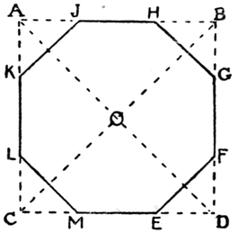
Saw a square piece of wood, side 4-1/3 inches, A B C D (Fig. 280).
Cut two others, sides 2½ inches. Saw the corners of these and
make them octagons.[1] Drill a hole through the centre of E (Fig.
281). Into this hole glue a wooden meat skewer or round rod
that will pass through the hole of a large reel. Glue and nail
E to A B C D. Round the sides of F (Fig. 280) drill eight holes
about ¼ inch deep. Make levers of
wood to fit these holes as in Fig. 280.
Match sticks could be used. Now
glue F to the top of the reel, G, taking
care that the centre of F is over
the centre of the reel. Place the reel
over the axle, round which it can
be turned. The capstan can be used
for dragging along a toy boat by means of a string tied to the
boat and wound round the reel.
A Dreadnought. The bottom of the boat is made from a piece
of wood 9¾ inches by 2½ inches. Shape the bow as in Fig. 283. To
this glue another piece of wood, A B C, shaped to fit over the first,
and about 6 inches in length. The two pieces can also be nailed
together.
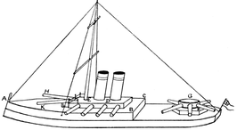
Fig. 283
Cut a piece of wood, D, 2¾ inches by 1½ inches, and glue and
nail it to A B C. When these pieces are secure drill a hole through
them at E for the mast. To carry the guns at the stern, shape
two pieces of wood, G and F, in the form of circles or octagons,
and glue and nail them in their place. The mast has holes
drilled through it to hold pieces of cane.
Nail ¼ inch nails round one end of D and tie black thread round
them.
The guns are made of small rolls of brown paper, narrower
at one end and painted black or grey. They are glued in position.
The guns H and K, are fastened to a small piece of wood, L, to raise
them above the level of the deck.
The funnels are made of pieces of round wood or rolls of
paper. The whole boat is painted grey, and rigged with black
thread.
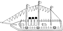
A Liner (Fig. 284). The foundation of the boat is a piece
of wood 10½ inches by 1½ inches, and about ¼ inch in thickness,
or thicker if possible. Shape the bow as in the figure. Round
the stern.
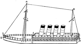
Fig. 284
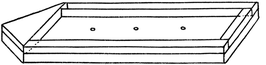
Cut two pieces of cardboard 7½ inches by 1½ inches. These are
for the decks (Fig. 286), and their stern ends must be shaped to
correspond to the stern of the boat. Place them together on
the foundation and make holes right through along their edges
about ½ inch apart.

Fig. 285
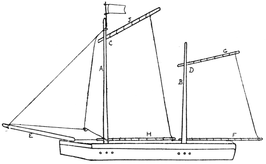
Cut two pieces of stripwood ½" × ¼" × 6½". Place them one
over the other and drill a hole (¼ inch in diameter) at P, about
1¾ inches from
one end; this
hole is to receive
the mast, B.
Along each piece
of stripwood mark little doors and windows or port-holes.
Glue each piece of stripwood along the middle of each
cardboard deck, as in Fig. 285, having made holes in the cardboard
corresponding to the holes P drilled in the stripwood. Now
glue the stripwood of one piece to the middle of the cardboard
of the other piece, taking care that the holes in each piece of cardboard
are over each other (Fig. 286). While these pieces are
drying, drill a hole about 2 inches from the bow for the mast A;
drill holes along the edge of the bow (C D E), 1/3 an inch apart.
Cut pieces of cane 7/8 inch to fit through the holes in the cardboard,
and pieces about 3/8 inch in length for railings round the
bow. Now glue the stripwood, G, to the boat so that ends H and
K correspond with
the edge of the
stern. While this
is drying prepare
the masts. The
mainmast is about
4 inches in length; this length allows it to stand 3 inches above
the upper cardboard deck; the foremast is about 5 inches.
Round the foremast glue a circular piece of cardboard, M, resting
on a nail passing through the mast. Hammer a nail through
at L for a spar, and put a piece of cane through a hole at N.
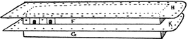
Fig. 286
Glue the masts into position. Put in a nail at O in the stern,
and a piece of cane, D, at the bow. Hammer in three nails in
side D C and three on the other side for rigging. Insert the strips
of cane through the holes in the cardboard; put a little glue into
the holes in the wooden deck, and tap the cane in very gently;
put the smaller pieces of cane into the holes round the bow.
Tie cotton round the pieces of cane as in Fig. 284; tie cotton to
masts, etc.
The funnels are made of rolls of paper. If the liner is a
Cunarder, the funnels should be red with black bands round the
top and two black lines lower down. The wooden sides of the
boat are painted dark brown.
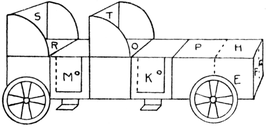
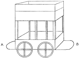
A piece of flat wood 2½ inches by 5½ inches forms the bottom of the
car. Two pieces of wood, 5½ inches by 1 inch, are marked out and
sawn as in Fig. 287. If it is found too difficult to saw out the
corner pieces E F G and H K L, piece A E C M can be cut right off,
by sawing along a line E M; G M H N can be cut off by sawing
along lines G M and H N, the same with L N B D.
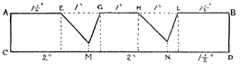
Fig. 287
The corners E, F, G, H, K, L should be rounded with a file, as
shown in the plate. The two side-pieces are then glued at each
side of the bottom. Front and back pieces are then cut, and
fitted between the bottom and sides; also a top to fit over A E,
and seats to fit over G H and L B.
These seats are then provided with backs and arms as shown
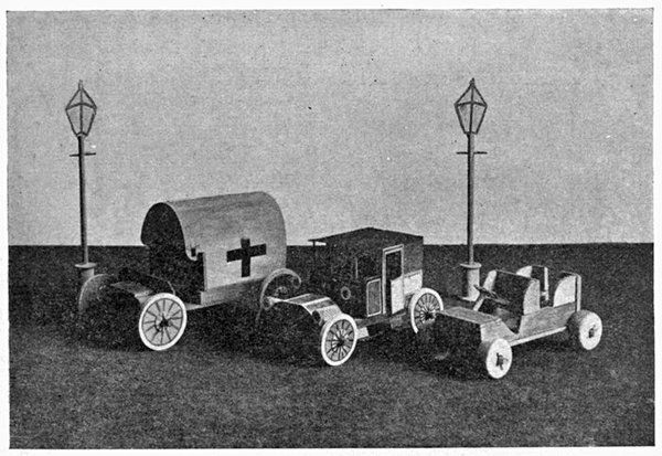
in the plate. Axles and wheels should be made and put on as
described in Part I, Chapter XIII. The wheels should be ½ an
inch thick and have the edges rounded to represent the tyre.
Lastly the steering pillar, with cardboard wheel attached, is fixed
into bottom.
A drawback to this toy is that it is made of so many separate
pieces of wood, but children delight in it and can make it most
successfully. Children from nine to twelve have turned out
most effective motor-cars.
A Swinging Cradle (Fig. 288). The cradle is a wooden box,
5 inches by 2¾ inches, and 2 inches deep. Before nailing this
together, holes must be drilled in the two short sides, large enough
to take a wooden axle about ¼ inch in diameter.
A and B are two pieces of stripwood ¼" × ½" × 5"; their tops
are rounded and holes similar to those in the cradle are drilled
in them about 1½ inches from the top.
A is fastened to E, which is 4 inches in length, by means of
triangular pieces of wood, C and D, which are glued and nailed to
A and E.
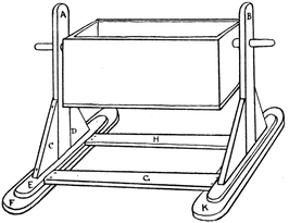
Fig. 288
F and K are wider pieces of wood, 5 inches by 1 inch. E is glued
and nailed to F; a wider space must be left on one side of E so
that the supports, H and G, can be fastened securely to F.
G and H are 5½" × ½" × ¼".
For the axles on which the cradle swings two pieces of stripwood,
¼" × ¼" × 1¼" must be cut and rounded, passed through holes
in A and B, and glued securely to the holes in the sides of the
cradle.
A Deck-chair (Fig. 289). Two pieces of stripwood, ¼" × ¼" × 6",
A B, C D, are taken. These are nailed and glued to E and F,
each 2¼ inches. E and F should not be placed too near the ends
of A B and C D, as the wood may split when the nails are
driven in. E and F may be rounded. For the smaller frame of
the chair, cut two pieces of stripwood, 5 inches in length. To get
the measurements for the bars, M and L, place G H and J K inside
A B C D as in Fig. 289, and measure distances G J and H K. This
must be done very accurately. Before nailing G H and J K together,
notches must be cut in them as in Fig. 290. The wood
is partly sawn through
at N and O, and the
notch is then filed out,
the safe edge of the
file being turned towards
N and O. To
make the support, two
pieces of wood are
cut 2 inches in length,
Q R and U V in Fig.
291, which shows how
the length of the piece
of wood S, which
fastens Q R and U V
together, is obtained.
Frame G K is now
nailed to frame A D (Fig. 289). Fix the point for the nail at
T about 2 inches from H and B. When hammering the nail
in at T, the bars A B and G H should rest upon the edge of the
bench or table.
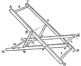
Fig. 289
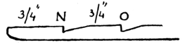
Fig. 290
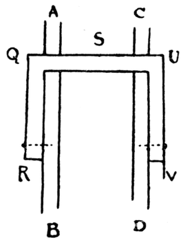
Fig. 291
From A and C measure distances of 2½ inches to R and V
respectively. To these points nail the arms of the support,
Q R and U V.
A piece of coloured print or casement cloth is fastened to
E and L.
Other toys which can be made in a similar manner are a
camp-stool, a clothes-horse, a screen.
This toy is made of wood, cardboard and paper (cartridge).
A piece of wood, E F G H (Fig. 292), 8½ inches by 2¼ inches
is required for the bottom of the car, and two pieces, A B C D,
5 inches by 1½ inches, for the sides.
The supports (1, 2, 3, 4, 5, 6) are pieces of stripwood
¼" × ¼" × 3½".
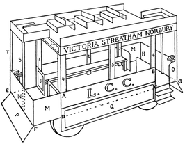
Fig. 292
Glue three of these to one of the sides as in Fig. 293, allowing
A B C D to project beyond them for a space equal to the thickness
of the wooden bottom of the car, E F G H. This forms one side
of the car; make the other in the same way.
Fig. 294 shows how the sides and seats are fastened to the
bottom of the car.
The seat is a piece of stripwood ¼" × ½" × 5".
The top of the car is made of thick cardboard cut as in Fig. 295
to the given measurements. Before the top is fastened on strips
of cartridge paper are gummed round its sides. These strips are
about an inch wide, and are doubled
in half; one half is gummed to the
cardboard as in Fig. 296. The other
half bends downward and the names
of places to which the car runs are
printed on it. Similar pieces are
gummed to the top and bent upward
to form the railings round the
top (Fig. 297.)
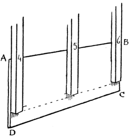
Fig. 293
These pieces are painted yellow
and edged with dark brown. Fig. 298
shows the entrance to the interior of
car. J and K are pieces of cardboard, coloured yellow, and glued
into position; L is a similarly coloured piece of cardboard or
paper glued to supports 1 and 4. The other entrance is finished
off in the same way.
Cut two pieces of cardboard, 4½ inches by 1½ inches, as in Fig. 299.
Make half-cuts along the dotted lines. These pieces are bent round
and glued to the ends of the bottom of the car (M, N, O in Fig. 292).
These are also coloured yellow and their edges are dark brown.
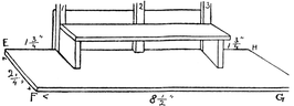
Fig. 294
The wheels are put on as the wheels of the engine (Part I,
Chapter XIII).
Cut two pieces of cartridge paper (P in Fig. 292), colour as
described before, and gum under each end of car.
Part Q is a piece of cardboard one inch wide, coloured like
M N O, and gummed along the side, so that it covers at least
half the wheels.
The top can now be glued on. Thin strips of wood or pieces
of cane (S and T
in Fig. 292 and
296) are gummed
in position.
The steps into
the car are made
of cartridge paper
coloured black.
Fig. 300 shows
the simplest way
of making the
stairs leading to
the top of the
car.
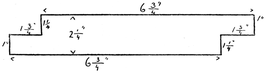
Fig. 295
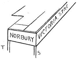
Fig. 296
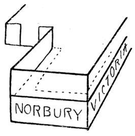
Fig. 297
W Y is a piece of cardboard, 1 inch wide, to which pieces of stiff
paper are gummed as in diagram. X is a flap of paper which
fastens the steps to the top of the car.
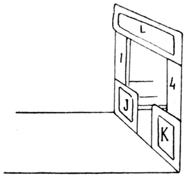
Fig. 298
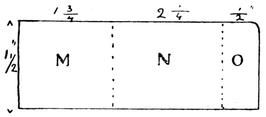
Fig. 299
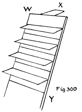
Fig. 300
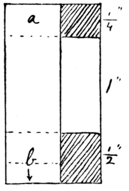
Fig. 301
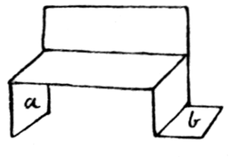
Fig. 302
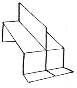
Fig. 303
Seats for the Top. Pieces of cartridge paper are cut out,
1¾ inches by ¾ inch, and coloured yellow. These are folded and
cut as in Figs. 301 and 302. Part a is gummed to the side
of the car, flap b is gummed to the floor. The second seat is
gummed back to back to the first seat (Fig. 303). The top of
the car will hold about six of these double seats. Single seats
can be gummed in the corners.
Steering-wheels are made as in Fig. 292. The top is of cardboard,
cut or marked as in the figure and coloured black. This
is gummed to a round rod, about 1¾ inches in length, which is
fastened to the end of the car (N in Fig. 292). A similar steering-wheel
is fastened to the other end.
A Crane. Foundation, Arm, Pulley. Cut a piece of wood about
5½ inches by 4½ inches (H in Fig. 304). Cut a second piece
a square, A, side 2½ inches. Cut off the corners. This forms a
stand on which the crane, etc., is fastened.
Cut a piece of stripwood, ¼" x ½" x 8". This is the arm of
the crane, C, and is usually inclined at an angle of 45° to 60°.
To support this arm cut B with sides about ¾ inch, angles 45°
or 60° and 30°.
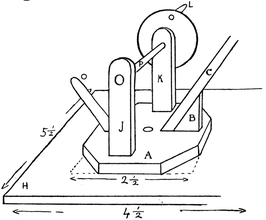
Fig. 304
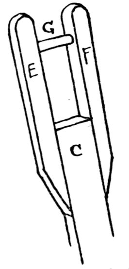
Fig. 305
Cut two pieces of stripwood ¼ inch by ¼ inch, each 2 inches
in length; shape like E and F in Fig. 305. These can now be
glued and nailed to the arm C, projecting an inch beyond.
A wheel for the pulley is cut from a round rod about ¾ inch in
diameter.
If a groove is to be made round the circumference, the wheel
should be about ¼ to 3/8 inch thick. The groove is made with a
file. A simple way to make the groove is to cut two cardboard
discs a little larger in diameter than the wheel and glue them to
each side of the wheel, in which case the latter need not be quite
so thick. A hole is drilled through the wheel and enlarged by a
round file to ¼ inch in diameter.
A piece of wood is now rounded for an axle, so that the wheel
turns on it easily. This must fit tightly between E and F. Pass
it through the wheel and glue it in position (G in Fig. 305).
Winding Gear. Cut two pieces of stripwood, ¼" x ½" x 2",
J and K in Fig. 304. Round their tops, drill and enlarge holes in
them.
A hole must now be made through the centre of A, to enable
this part to rotate on the foundation H, so that the crane may
swing round in any direction. One of the simplest ways of doing
this is to use a rivet, but if such is not procurable a screw may be
used; the hole in A is made large enough for A to turn easily on
the pivot which can be screwed into H. Before this is done,
pieces J and K are fastened to A about one inch apart. To do this,
drive nails right through A in correct positions, glue the ends of
J and K and hammer them on to the nails. The head of the nail
should rest on a piece of metal when the wood is being hammered
down on its point.
The support B should now be glued and nailed to A. When B
is firmly fixed the arm C is fastened to it. The hole in the centre
of A must be left clear.
A is now riveted or screwed to H. A wooden axle, P, is made
to pass through holes in J and K, and to the ends of this axle wheels
are glued. (The figure shows one only.) The wheels can be
made from reels, or several discs of cardboard gummed together.
Before glueing on the wheels, wooden handles, L, are fastened
to them. A wooden handle O is fastened to A. This is used for
turning the crane. A piece of stout thread is tied to and wound
round P and passed over the pulley. To the end of this a hook
is fastened, made from wire or a bent pin. Bags can be made
and filled with sawdust, etc.
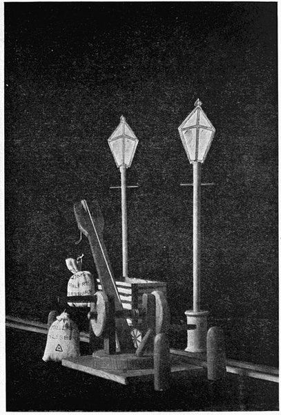
Plate XI A CRANE
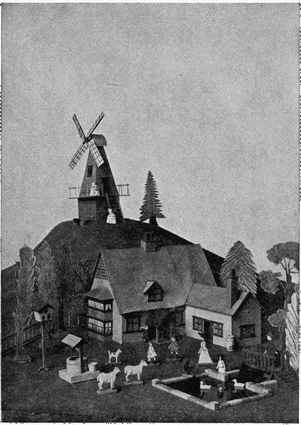
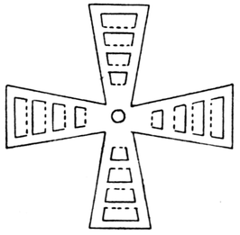
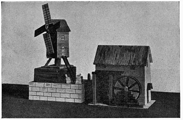
Windmill (Plate XII). Cut a square of wood, side 5 inches.
This is the stand A in Fig. 306. To the centre of this glue a
large reel, B.
Next cut two 4-inch squares of wood and drill through their
centres holes of about ¼ inch in diameter. Glue one to the top
of the reel so that the holes coincide. Next cut and glue into
position the supports, C. For these stripwood ½ inch by ½ inch
can be used.
Cut two pieces of wood, 4 inches by 6 inches. These form two
sides of the windmill; glue and nail them to the other 4-inch
square, which forms the bottom of the windmill.
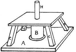
Fig. 306
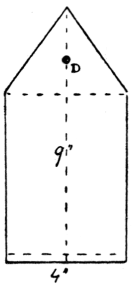
Fig. 307
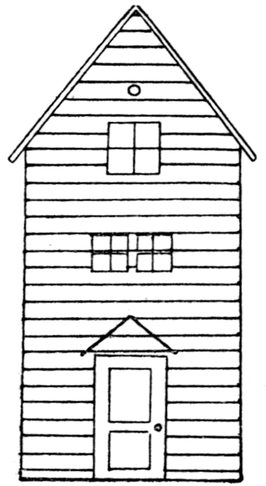
Fig. 308
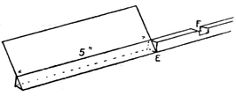
Fig. 309
Next cut two pieces of wood as in Fig. 307, for the other
sides of the windmill. Drill a small hole in each at D about
1½ inches from the top.
On one of these sides mark and paint a door and windows as
in Fig. 308, and over the door make a small roof, like the roof
over the porch of the signal-box (Chapter XII). The windows
and door may be cut out with a fret-saw and the door hinged on
by means of a strip of strong linen. Glue and nail these sides in
position. Make and fix the roof.
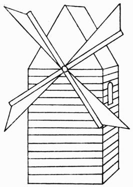
The Sails. For these, two strips of wood, ¼ inch square and
12 inches long, are necessary.
In the centre of each of these, cut a slot half-way through
the wood so that one may fit tightly into the other (F in Fig. 309).
The sails are made of cardboard, and are rectangular in shape,
measuring 5 inches by 2 inches. They are coloured light brown,
with dark markings on them, as shown in the plate. Shape each
end of the arms of the sails as in Fig. 309. This is easily done
by filing, if the wood is fairly soft. Saw half-way through the
wood at E, and file, or cut off the wood with a pen-knife. To
this flat surface the sails are glued, so that they may be inclined
to the wind. Now glue the two arms together, and when they
are firm make a hole through the middle, F, where the arms
cross. Take a short steel knitting needle, about 6¾ inches;
fix one end into this hole with glue; then glue a small piece
of cardboard or wood over it, and a cork washer behind, to keep
the sails from touching the walls of the windmill; pass the
needle through the holes in the sides of the windmill and glue
a little knob of wood to the other end to prevent the needle
slipping back. If a needle cannot be obtained, an old bicycle
spoke, or even a wooden meat skewer, will do, but in the latter
case the holes in the walls must be made larger, and the sails
fixed to the end of the skewer by a small nail.
Now glue a piece of round rod into the reel (H in Fig. 306) so
that it projects about an inch. Place the mill on this stand, so
that the rod passes through the hole in the bottom of the mill.
The mill can be turned round in any direction so that the sails
may catch the wind. Make a small ladder to reach the door.
A very pretty but somewhat more difficult windmill is shown
in Fig. 310. It is made of cardboard. The foundation, platform
and railings can be made as described in the case of the lighthouse
(Chapter XIII).
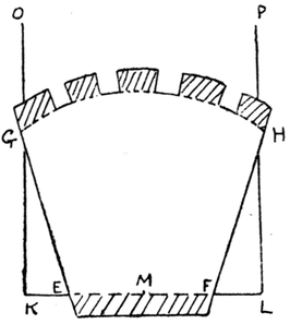
The truncated hexagonal pyramid forming the body of the
windmill is made as follows. With centre O (Fig. 311), and a
radius of about 10 inches, describe an arc, A B.
From any point on this arc mark off six spaces, each 2 inches.
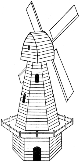
Fig. 310
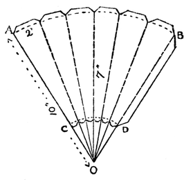
Fig. 311
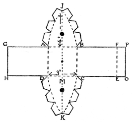
Fig. 312
Join the several points to each other and to O. With radius
about 3 inches make arc C D. Join points where C D cuts radii,
by dotted lines. Draw the flanges; make half cuts along the
dotted lines, cut out along the dark lines, and fold into shape.
Fasten together with seccotine; turn in the flanges at the bottom,
and fasten them to the platform.
The Top of the Windmill can be cut from one piece of cardboard.
Draw square, A B C D (Fig. 312), large enough to project
beyond top of hexagonal pyramid (side of square should be about
3 inches). On the middle of D C draw M K = 4 inches, and draw
a similar line on A B. Join A J, J B, K D and K C, by curved lines.
Produce A B and D C both ways. Make B F, C E, D H, A G, equal in
length to arc B J. Draw the flange E F P O. Make holes in the
middle of A J B and D K C through which the knitting-needle (on
which the sail is fastened) may pass. Draw flanges on B J, J A, etc.
Make half cuts along the dotted lines, and cut along the dark lines.
Before fastening the top together, put a very small paper-clip
through the middle of square, A B C D, and fasten it to a square of
cardboard of the same size, so that it turns freely on it. This
second square will be gummed to the top of the hexagonal
pyramid, so that the top of the windmill may be turned in any
direction. Bend up A J B and D K C at right angles to square,
A B C D. Bend up B C E F and A D H G and gum them to the
flanges of A J B and D K C; gum flange F O to A D H G. The
sails are made as already described.
A Water-wheel (Plate XII). The Wheel. Cut two discs
of cardboard, 4 inches in diameter. Make holes in the centre,
glue them to a small reel (about an inch high), and pass a round
rod through for an axle. This wheel is an overshot water-wheel—that
is, one that receives the water shot over the top, and must
be fitted with 'buckets.' These receive the water at the top
of the wheel and retain it until they reach the lowest point (see
Fig. 313).
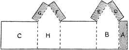
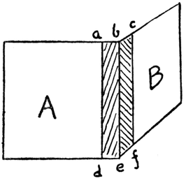
The 'buckets' may be made of stiff paper or thin cardboard.
Cut pieces 1 inch in width, and in length the distance
of the two wheels apart plus ½ an inch. Mark these out as in
Fig. 314, where a b is the distance between the wheels, and
c, d, e, f are flanges for fastening the bucket to the wheels. Fold
as in Fig. 315. Make at least twelve of these buckets; divide
the wheel into twelve parts, and fasten the buckets between the
wheels.
WINDMILL AND WATERMILL
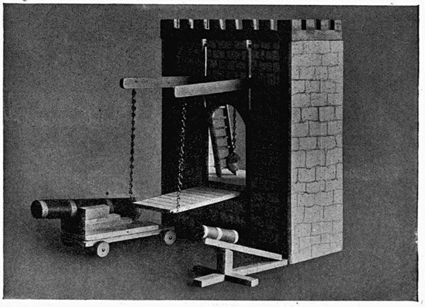
Plate XII DRAWBRIDGE
(Chapter VII)
To make the toy technically correct, the buckets should rest
against a solid wheel contained within the two outer ones, as in
Fig. 313, so that no water can run down toward the centre of the
wheel. This can be easily managed, if desired, in the following
manner:
Before fastening the wheels to the reel, cut a long strip of paper,
with flanges, as in Fig. 316, in which a b is the distance between
the two outer wheels. Describe a smaller circle on one of the
wheels, about 3 inches in diameter; glue the reel in position, then
bend down the flanges of this strip of paper (Fig. 316), and gum
these round the smaller circle of the wheel. Now gum the other
wheel to the reel and to the flanges of the paper.
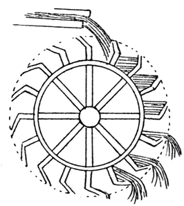
Fig. 313
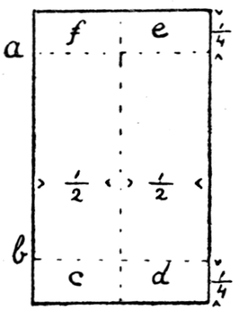
Fig. 314
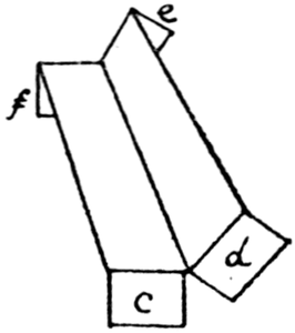
Fig. 315
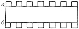
Fig. 316
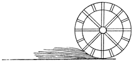
Fig. 317
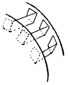
Fig. 318
The wheel should be painted brown, with spokes marked in
darker colour. The plate shows the wheel and the mill-house.
A hole is made in the side of the house, into which the axle of the
wheel is inserted; the other end is held by the upright standard
shown in the plate. The shoot may be made of cardboard; it
should slope a little and should come just over the top of the
wheel, which revolves freely beneath it.
A chimney may be made of a cork, one end being cut on the
slant, so that it stands upright on the roof, which is made of
cardboard. The whole should be suitably coloured.
An Undershot Wheel. This wheel is very simple to make.
It has a number of float-boards arranged round it and is turned
by a stream of water moving against the float-boards at its lowest
point (Fig. 317).
Fig. 318 shows how the float-boards, which are made of cardboard,
are fastened between the wheels. With this undershot
wheel, the shoot represented in the plate is not required.
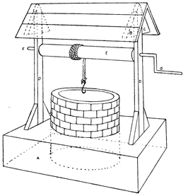
Fig. 319
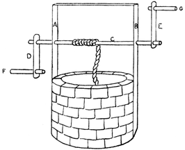
A Well (Fig. 319). The round part of the well is made from
a mantle-box or other round box. A is a fairly deep box turned
upside down, with a circle cut out into which the mantle-box
fits closely. This gives a fair depth. Cover the well with paper
coloured to represent bricks; colour the box, A, green. The
cardboard roof is glued to posts, D, and to triangular pieces
of wood, B and C, glued to each side of D.
Holes are drilled through the posts to take the roller, E, which
is a round rod about ½ an inch in diameter. Drill small holes in it
at each end. Push a pin from the end F through the side post
into the roller. Bind a piece of wire to form a handle, G, and
push one end of this into the roller. Bend a piece of wire or pin
to form a hook, tie this to a piece of string, wind it round the
roller and fasten the other end of the string to roller with seccotine.
If a small chain is used this can be fastened by one of
its links to the roller with a staple, and should be so fastened
before the roller is put in position.
A Drawbridge (Plate XII). Two pieces of wood for the front,
H and I (Fig. 320), must first be sawn 11 inches by 2½ inches.
The white wood of chocolate boxes, etc., is the best.
Next two strips of wood, 7" × ¼" × ¼" are cut (satin walnut
stripwood will do)—D E and F G in Fig. 321.
The bridge is made of a piece of white wood, 2-5/8 inches by
5¼ inches. The posts, D E and F G, are nailed to the bridge so that
the bridge turns on the nails. (Note that the bridge is nailed
about 3¼ inches from bottom of post.)
Next two lengths of stripwood, R S, are sawn 10" × ½" × ¼",
these are nailed to pieces H and I (nails are about 8½ inches
from bottom), so
that the portions
R T project about
5½ inches. The
strips R S turn
freely on their
nails.
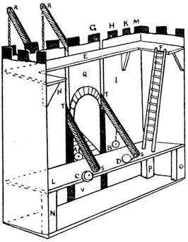
Fig. 320
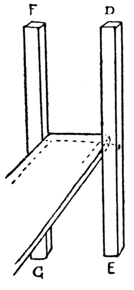
Fig. 321
Before nailing
them in position,
their ends should
be rounded as in
the figure. The
posts G F and
D E (which hold
the bridge) are
then glued to H
and I. A piece
of wood, V, about 8 inches by 2-1/3 inches, is glued to the lower
parts of H and I, and joins them together.
Next the piece of wood Q is cut; its width will be the distance
of post F G from D E (about 2½ inches)—this distance should
be carefully measured so that the piece fits well; its length will
be about 5 inches. The arch is cut with a fret-saw. Piece Q is
kept in position by having the ends of the arch glued to posts
F G and D E, and by a length of stripwood (½ inch by ¼ inch) glued
along the top as shown in the plate. Lengths of stripwood (½ inch
by ¼ inch) may also be glued down the sides. Holes must be
drilled in the ends, R, for wire loops, care being taken that these
holes are over the bridge; wire loops must be placed on the
bridge exactly underneath, and these loops are joined by chains,
which can be made of wire or else bought from an ironmonger.
Fig. 320 shows the inside of the drawbridge; A, B, C and D
are the lead weights for raising and lowering the beams. These
weights can be cut from a piece of sheet lead or may be lead
buttons. They are attached to the beams by chains and wire
hooks. E F is a ledge for the defenders of the bridge to stand on.
Sides have been added and a platform, L. The battlements,
G, H, K, etc., are made of pieces of stripwood ½" × ½" × ¼", glued
round the top.
The ladder is made of matches as described in Chapter IX.
A Movable Siege Tower (Plate XIII). Two pieces of wood
(A and B in Fig. 322) are sawn to the shape and measurements of
Fig. 323. To the broader ends of these, pieces of stripwood
½ inch by ½ inch are glued and nailed (C in Fig. 323), and other
pieces, D, ¼ inch by ¼ inch (about three on each side), are
fastened at equal distances apart. D3 and the corresponding
piece on the other side must not extend to edge of B, but a space
must be left of ½ inch for the posts of the drawbridge.
Next the wood is cut for the foundation and the platforms,
J, H, etc.
A stands about 6 inches from B, so this must be the width
of all the platforms, except the foundation, F, which is wider and
projects about ¾ inch on each side of A and B, and the platform K,
which rests on A and B.
The other dimensions of the platforms will be the same as
those of the pieces of stripwood on which they rest. The platform
K must be about ¼ inch narrower than tops of A and B,
to leave room for posts L and M. A and B are now glued and nailed
to the base by means of the pieces of stripwood, C, at their ends,
and the platforms are glued in position.
Two pieces of stripwood ¼ inch by ½ inch, S and T in Fig. 324, are
now cut equal in length to distance of K from H, for the supports
of bridge. Place these in position between K and H, and measure
distance between them; this gives width of drawbridge; its
length is 6¼ inches. This can now be sawn. Fix in position as
explained for previous toy.
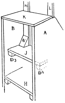
Fig. 322
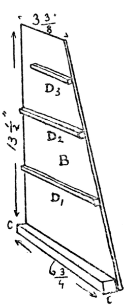
Fig. 323
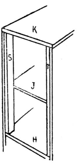
Fig. 324
Next cut two pieces of stripwood ½" × ¼" × 10½", L and M.
At the ends of these drill holes, ¼ inch in diameter, through which
passes the chain of the drawbridge. Fix these in position by
triangular wedges glued to sides and to platform J.
On top, K, add struts to support M and L, as shown in the
plate. The chains of the drawbridge are looped over nails
driven into A and B, just above platform J.
The base may be mounted on small wheels and strengthened
with projecting beams by which the tower may be pushed into
position. (These are not shown in plate.) Ladders to reach
the top can also be made (see Chapter IX), and a battering
ram may be swung from platform H, as shown in the plate. A
tower of this kind was used by the Crusaders in the siege of
Jerusalem (1099).
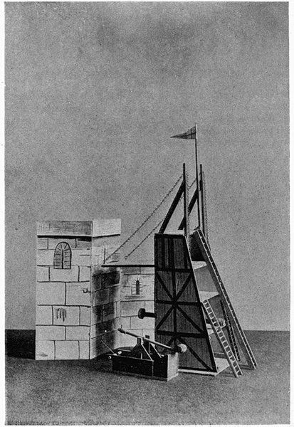
Plate XIII MEDIÆVAL SIEGE TOWER
TRAPGET
A War Engine (Plate XIII). This piece of artillery was used at
the time of the crusade of Richard I. It is a simple and interesting
model to make. The sides (A B C D in Fig. 325) are built up
of pieces of stripwood ¼ inch by ¼ inch, length about 3 inches, or the
sides may be pieces of cigar-box. If made of stripwood, grooves
can be filed in the two bottom pieces to make holes, E, when these
pieces are glued together. A round rod passes through these
holes to form a windlass. Two posts, F and G, ¼" × ½" × 3¼", are
glued to the sides about 1½ inches from end, A C, as in figure; these
must either have holes drilled through them for a rod of wood (or
thick wire) or have circular grooves filed in the tops into which
a rod can be glued.
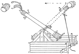
Fig. 325
The sides a b c d and A B C D should be about 2½ inches apart,
and are kept together by pieces of stripwood glued across
the bottom. Make struts as in the figure to support posts F
and G.
The beam H K may be made from a piece of stripwood,
½ × ½ × 5", filed to a round shape. Two pieces of wire, L L, are bent
to form a fork and two hooks, M and N are bound firmly to one
end with thread. The other end, K, has a small screw-eye screwed
into it through which passes a wooden bolt to keep the rings of
lead, O, from slipping off. These rings of lead are easily made from
strips cut from a piece of sheet lead and bent round the beam.
(A pair of old scissors should be kept for cutting lead, or a knife
and hammer may be used.)
Now the beam H K must be fastened to rod P Q. This may be
done in different ways. The simplest but least effective way is
to bind the beam firmly in the middle to the rod with thread or
elastic.
A second way is to drill a hole through the beam, through
which the thread or elastic that binds it to the rod can pass. The
best way perhaps is to make the hole in the beam large enough
for rod P Q to pass through, and then bind it to the rod with elastic
or thread or, if a large model is being made, catgut. (A jeweller
is generally ready to give away a small quantity of this.) A
barrel, R, can be filed or cut from a small piece of wood or cork, or
it may be a small reel.
To work the machine pull the beam down by means
of a piece of thread looped on to the hook M and wound
around the windlass. When the beam head is down, place the
barrel on the fork and keep it in position by rope, S. When
the beam head is released, it flies up and the barrel is shot
forward.
This trapget or war engine was used for casting Greek fire,
with which the barrel was filled. It may interest the maker of
this toy to know its composition. In the words of an old writer:
"You make Greek fire thus: Take quick-sulphur, dregs of wine,
Persian gum, 'baked salt,' pitch, petroleum, and common oil.
Boil these together. Then whatever is placed therein and lighted,
whether wood or iron, cannot be extinguished except with vinegar
or salt."
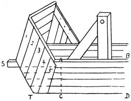
Fig. 326
Generally this engine had a kind of wooden hood in front to
protect those working the machine (Fig. 326). This hood is
easily made of stripwood or an
old cigar-box. Notice that the
stripwood that forms the sides,
A B C D, must be longer (extended
in diagram to S T), so that strips
of wood, 1, 2, 3, 4, 5, can be nailed
and glued as in diagram.
The Mangonel, Fig. 327 (an
instrument for casting great stones
to beat down walls and to slay the
enemy), makes an interesting toy.
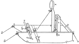
Fig. 327

Fig. 328
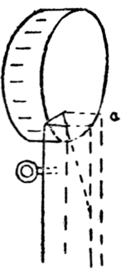
Fig. 329
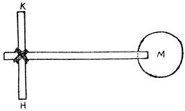
Fig. 330
First cut two pieces of wood, 10¼ inches by 1¾ inches (the sides
of a wooden chocolate box will do when sawn the right size and
filed), and shape them as in Fig. 328. Saw slits in both pieces at
G, ¼ inch wide and ½ inch deep. If two saw-cuts are made for
each slit the wood between can be cut away with a pen-knife.
These slits must be about 2¾ inches from end, b d.
With a round file make semicircles at c and e to hold the
rollers on which the engine is moved into position.
With a bradawl and round file make holes, F, in both pieces
about 3½ inches from end, A (diameter of hole about 3/8 inch, or
larger if a larger windlass is required).
Put these two pieces aside, and next saw a length of stripwood,
½" × ½" × 5"; saw a slit about ¼ inch from one end and
hammer it on the metal top of a bottle of Le Page's liquid glue
as in Fig. 329. The corner a should be cut or filed off. A small
screw-eye is screwed into the wood just below the metal top. Saw
a piece of stripwood, ½" × ¼" × 3½", tie this firmly with elastic
to the other end of the first piece of stripwood as in Fig. 330.
This elastic constitutes the propulsive force. The ancients used
catgut, which formed a thick coil, stretched from H to K, the lever
passing through the middle of the coil. The pulling down of the
lever gave additional twist to the coil, which reacted strongly
on release. Now fasten the sides a b c d and A B C D together by
nailing and glueing them to two pieces of stripwood, ½" × ½" × 2¼".
Then glue H K securely into the slots G so that the beam with the
stone-holder M is upright. Push a round stick through the holes
F, for a windlass; this can have holes drilled in the portions that
project, to hold sticks for turning the rod. A piece of thread is
tied to the screw-eye Q, and wound round the windlass F; when
this thread is tightened the beam is pulled down, then when let
go it flies up, causing anything placed in the tin, M, to be shot
some distance. The safest 'stones' to put in this pan are pieces
of cork or small pieces of wood. The following additions can be
made to the model:
(1) RR are pieces of stripwood, ½" × ¼" × 4", glued to the sides
and carrying a strip, T. This strip T in the olden days was
covered with leather and was so placed that the beam
carrying the stone-holder would abut against it. Notice
the struts W for supporting the posts R.
(2) N O is a rod (about ¼ inch in diameter) passing through
two small screw-eyes fixed in a piece of stripwood, S,
½" × ¼" × 3¼". A piece of strong wire, P, passes through
hole in rod N O; it is bent so that it cannot work out,
and the other end is bent to just catch the holder, M, when
it is pulled down. A releasing handle is fastened to the
rod, N O at O. The beam S is glued into slots in A B C D
and a b c d, so that when the beam is pulled down the catch
P clutches M.
(3) Small screw-eyes may be screwed in at A, a, B, b, for holding
ropes to fasten the machine to pegs in the ground. Rollers
may also be made to fit under C and E.
This toy is an attractive one, because it really works successfully.
It must be strongly put together, for the beam when pulled
down flies up with considerable force.
Stone-throwers like this were used at the siege of Acre. Very
often these engines had special names given to them. For example
Philip of France had a very good engine of war called 'The Bad
Neighbour,' and inside Acre the Turks had one called 'The Bad
Kinsman.'
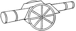
Cannons of the Fourteenth Century. These are very easily
made. Figs. 331 and 332 show two that can be copied.
In Fig. 331 a piece of wood is cut to the shape of A B; a groove
is then filed in it, into which the cannon C is glued. The cannon
may be made of a roll of brown paper (two pieces may be pasted
together for greater strength) with four bands of cartridge paper
painted yellow and gummed round it, or it may be a piece of
wood filed to shape and circled with bands of lead.
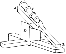
Fig. 331
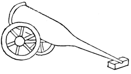
Fig. 332
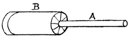
Fig. 333
The cannon in Fig. 332 consists of two cardboard wheels on
an axle of stripwood, ¼ inch by ¼ inch, and the cannon is glued to
a groove in the axle. It may be made of wood with a lead rim,
or of two rolls of brown paper as in Fig. 333, where the flanges
of the smaller roll A are gummed to flanges of B.
Cannon of the Fifteenth Century. This may be made of a
short mantle-box (with lids on), cardboard wheels and pieces of
stripwood, ¼ inch by ¼ inch. Fig. 334 shows the finished cannon.
The stripwood cart which the cannon rests on must be made to fit
the mantle-box; the shafts a may be straight or curved. Round
holes may be cut at b. This same cannon may be fitted with
axles, and swing between two posts. The wheels should be
painted black, and the mantle-box covered with black paper,
with bands of yellow paper at 1, 2 and 3.
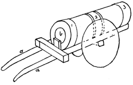
Fig. 334
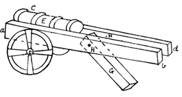
Fig. 335
Toward the end of the fifteenth century artillery was much
improved.
Fig. 335 shows a gun that is interesting to make.
The carriage consists of two pieces of stripwood, ½" × ¼" × 8"
(a b and c d in Fig. 335). A cannon, E, is made out of a roll of brown
paper, length 3½ inches, diameter about ¾ inch, and glued between
a b and c d, or it may simply rest on cross-pieces of wood
joining a b and c d. G is a piece of wood, ¼" × ¾" × 3½", turning
on a pin or piece of wire, H, which passes through a b and c d.
a b and c d are glued to a piece of stripwood F (¼ inch by ¼ inch)
which has its projecting ends rounded to receive two cardboard
wheels. The great fault of these earlier cannons was that though
they were often of immense bore and weight, throwing balls of
from one to five hundredweights, they were for the most part
without carriages, and therefore very difficult to move about and
very slow in their operations.
The Scots were the first to anticipate the modern gun-carriage
by what they called 'carts of war,' which carried two
guns. Many of the guns of the English required fifty horses to
drag them!
'Mons Meg' (a fifteenth-century cannon still to be seen at
Edinburgh Castle) is an easy model to make.
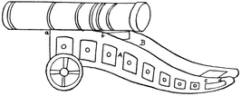
Fig. 336
Parts A and B (Fig. 336) are drawn on cardboard, cut out and
coloured (brown and black). They are joined together by strips
of cardboard at a b and c d. To the cardboard at a b the cannon
is gummed. The wheels are of cardboard, the axle of stripwood
(¼ inch by ¼ inch). Mons Meg fired a granite ball weighing 300 lb.
A Tudor Cannon (Fig. 337). The sides A A may be cut out
of cardboard or, better still, of three-ply wood with the fret-saw.
The wheels are solid discs
and may also be cut out
with the fret-saw, holes being
drilled in the centre for
the axle. The cannon itself
can be shaped out of wood
with pen-knife and file, or a
cardboard roll (such as is used
for transmitting music or
pictures) can be used, the thicker parts are then made by gumming
additional pieces of cardboard round it, or glueing strips of lead.
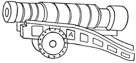
Fig. 337
It is difficult to discover when gunpowder was first used. Probably
its use was learnt from the Saracens in the fourteenth century.
Roger Bacon (? 1214-1294) suggested that it might be used in
warfare.
In a Florentine document of 1326 mention is made of the use
of gunpowder in Europe. The first use of the cannon recorded
in English history is in 1327, when Edward III was at war with
Scotland.
In making the guns described in this chapter it is necessary to
distinguish between breech-loading cannons and muzzle-loading.
The breech-loader is loaded from the breech or rear end of the
barrel and not at the muzzle. Figs. 334, 335 and 337 are examples
of this kind and therefore must have a hole at each end.
Figs. 331 and 332 are examples of muzzle-loading cannons and
therefore have holes only at one end.
During the sixteenth century breech-loading was gradually
abandoned for muzzle-loading owing to the large escape of gas
and air at the breech. It was not until 1860 that it was reverted
to with great improvements.
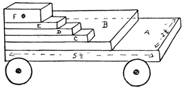
Fig. 338
A Ship Cannon. A piece of wood (about ¼ inch thick, the side
of a wooden chocolate-box or any other light box will do) is first
sawn out 5½ inches by 2 inches
(A in Fig. 338). Another piece
of wood, B, 4½ inches by 2 inches,
is cut and glued on the first
piece. Three pieces of stripwood
¼ inch by ½ inch, C, D, E,
are cut to lengths 3½ inches,
2¾ inches, 2 inches respectively.
These are glued on one side
as in the figure, and similar strips are cut and glued to the
other side. Two pieces of stripwood, F, ½" × ½" × 1½", have holes
drilled half way through them, to receive the
pivots of the gun, but must not be glued on to
E until the gun is in position.
The cannon is made of a roll of brown paper
6 inches long; one end should be narrower than
the other (the widest end say 1 inch in diameter,
the narrowest end ½ inch to ¾ inch).
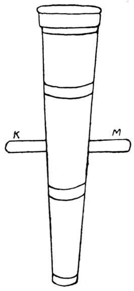
Fig. 339
The roll must be securely fastened together
by seccotine, two layers of brown paper make
a strong cannon; black paper is then pasted
over it and bands of brown paper as in
Fig. 339. A hole is pierced through the cannon
about half-way along it, and a round stick, K M,
passed through; this pivot should be just long
enough to fit into blocks F when these are fixed and glued
in position.
Before this is done, the wheels should be made and fastened on.
This is an easy matter. Two lengths of stripwood (¼ inch by ½ inch)
are cut 2¼ inches long. The little wheels (¾ inch in diameter) are
cut from any round rod available, or if no rod can be obtained
they may be cut out of cardboard. Holes are drilled in the wheels
and nails with large heads passed through and driven into the
stripwood. The axles are either glued or nailed to the bottom
of A. Finally the pivot, K M, is fitted into its blocks, and these are
glued into position. A wedge can be made to slip in under the
cannon to raise and lower it. The wedge should be just wide
enough to slip in between the two layers of stripwood.
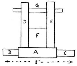
Fig. 340
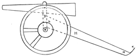
Fig. 341
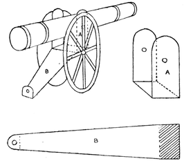
A Modern Breech-loading Field Gun (Fig. 341). This is a
simple toy to make. A piece of stripwood, A, ¼" × ¼" × 2", must first
be cut, and the ends, B and C, rounded for about ½ inch (Fig. 340).
Next two pieces of stripwood, D and E, ¼" × ¼" × 1¼", are cut.
These must have their tops rounded as in Fig. 341, and have
holes drilled through them to receive a rounded match, G. F is
a piece of wood ½" × ¼" × 5/8". Pieces F, D and E are glued or nailed
to A. Before the pivot G is put in position the cannon must be
made. This is a roll of black paper, 3¾ inches long, ½ inch in
diameter at widest end, and ¼ inch at the narrowest. Holes
are made through it to receive the pivot. The ends of the
match sticks that project beyond D and E can be cut off. Next
the wheels are cut. These may be cardboard discs of diameter
1-3/8 inches.
A piece of wood, H, is next cut, ½" × ½" × 4½", and worked to
the shape shown in Fig. 341. The end L must be sawn at an angle,
so that when H is glued on, D is perpendicular. The end L is
glued to the piece of wood, F. K is a piece of cardboard with a
hole through it for pulling the cannon along; it is glued to end M.
The wheels, etc., should be painted black or grey. The cannon
itself may be made of white paper and painted grey or yellow, or
else made of yellow or light brown paper.
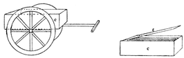
A Cart must next be made to carry ammunition for the cannon.
The shells for the cannon described would be about 2¼ inches long,
so the cart must be 2½ inches long, and 1¾ inches wide (Fig. 342).
It can be made of wood or cardboard. Notice the end to which
the lid is attached.
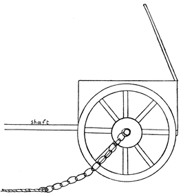
Fig. 342
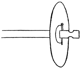
Fig. 343
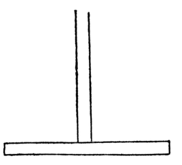
Fig. 344
The wheels must be the same size as those used for the cannon
and can be made and attached in the same way to an axle, but
this axle must project some distance beyond the wheel, as in
Fig. 343, and have a groove filed round it, so that short chains
may be fastened on each side; ropes are attached to these chains
to allow the cart to be pulled along by hand.
Fig. 344 shows the shaft. It is 1½ times the length of the cart.
It can be made of strips of cardboard or wood. Matches painted
black make good shells.
To make this toy, plenty of used matches are required, and
some strips of light wood (that obtained from a soap-box or
chocolate-box will do) and liquid glue.
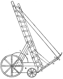
Two lengths of wood, Q R and S T, are cut 12½" × ½" × ¼", and one
long edge of each is rounded. These pieces are sand-papered if
they are rough or uneven.
Twenty-three pencil dots half an inch apart are marked down
the middle of the widest side of one piece. The two pieces are then
clamped together (the piece with the 23 marks on top), and holes
drilled through them both together with an Archimedean drill.
Next seventeen matches are taken, and cut exactly to the
length 1¾ inches; the ends are tapered so that they will fit in the
holes drilled. Beginning from one end of one long strip, hammer
these matches in the first seventeen holes, place the second long
strip of wood on top of these matches, so that the first seventeen
holes are exactly over the seventeen matches and hammer it on.
(Be careful to hammer in between the holes, a file makes a good
hammer.) Hammer first one strip, and then the other until the
matches are driven firmly in the holes, as far as they will go;
file away all projecting ends of matches. Through the eighteenth
hole of Q R and S T, a long piece of wood, A B, must pass to project
1-1/3 inches on each side of the ladder (Fig. 345).
Two pieces of wood, 3½" × ½" × ¼" (C D and E F), are cut, and have
six holes drilled in them; these six holes must be marked off from
the six remaining holes in the main ladder, so that they will
come exactly opposite them; these pieces are secured to the
main ladder by matches, and by the cross-piece, A B. The whole
ladder is then glued to a strip of wood, G H, ½ inch by ¼ inch of
a length equal to the total width of the ladder. This can be
put aside for a time.
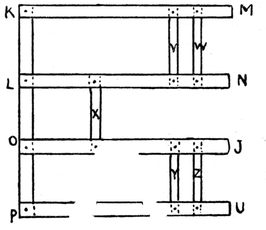
Next the shaft in Fig. 346 is made. K P is the same length as
G H in Fig. 345 and about ¼ inch by ¼ inch; K M, L N, O J, P U
are each 4¼ inches long, they are the same distances apart as
C G, Q R, S T and E H in Fig. 345. They are held together by strips,
V, W, X, Y, Z. These strips may be matches; in this case they must
be inserted first, and then the whole of K M P U is glued to K P.
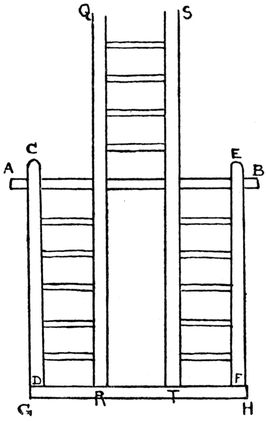
Fig. 345
Figs. 346 and 347
This shaft is fastened to the main ladder in Fig. 345 midway
between A B and G H, so that when the shaft is horizontal the main
ladder makes an angle of 72° with it.
Fig. 347 shows the shaft M K, P U, attached to the main ladder;
it is supported in its place by four struts, two on each side (a and b
in Fig. 347). Care must be taken to saw off the ends M, N, J, U
(Fig. 346) so that they rest exactly against C D, R Q, S T, E F
(Fig. 345), at about an angle of 72°. The ends of the struts must
also be carefully bevelled to fit; the main ladder can then be glued
to the shaft and the struts to the main ladder and shaft.
Small wheels of cardboard or wood are nailed (as for ship's
cannon) at each end of G H.
An axle for the larger wheels must be made to be glued on K P
(Fig. 347). Care must be taken in deciding on the size of the large
wheels, the diameter must be such a length that the shaft, K M P U,
is parallel to the ground.
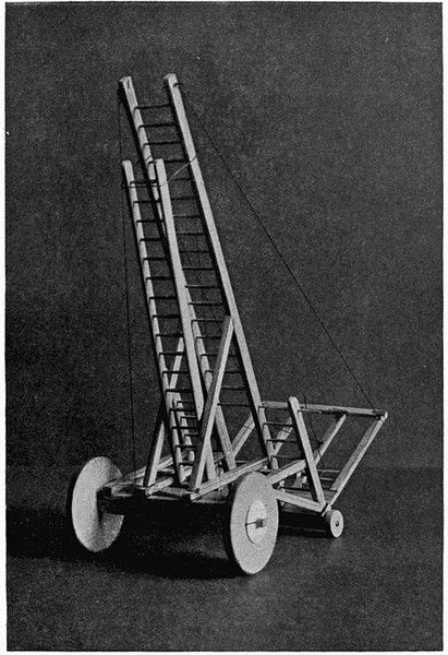
Plate XIV
FIRE-ESCAPE
Next the back portion shown on the plate is made similarly
to the shaft shown in Fig. 346. It is glued to G H so as to be at
right angles to the main ladder. Pieces of wire bent and pushed
into holes in C D and E F form railings. Pieces of stout thread are
attached to strengthen the whole, as shown in the plate. An
extra ladder (necessarily narrower) can be made to rest on the
bar, X, and lean inside a piece of bent wire as shown. The wheels
can be made of cardboard or sawn from any of the materials
suggested in Part I, Chapter XIII.
Note.—In making the fire-escape it will be a help to cut out
two cardboard angles of 72°, these help to keep the shaft K M P U
in the right position while the glue is drying.
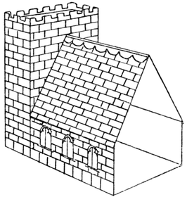
A Castle (Plate XV). Fig. 348 is an example of a mediæval
castle and is somewhat similar to the Castle of Chaluz, which was
besieged by Richard I. It is made of cardboard of medium thickness.
First make the four towers, A, B, C, D Fig. 349. Cut a
piece of cardboard 10 inches by 8¼ inches.
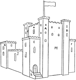
Fig. 348
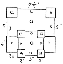
Fig. 349
Divide this as in Fig. 350, and make half cuts along the dotted
lines. Cut out the windows. Fold and gum together. Make
the other towers in the same way.
To make overhanging battlements, cut pieces of stripwood
½ inch by ¼ inch the correct length, and glue them round the tops
of the towers (Fig. 351). Then cut out pieces of cardboard as in
Fig. 352, and gum these to the wood. It is best to cut a strip of
cardboard long enough for two sides only, and to make a half cut
at the bend; then to cut another strip for the other two sides.
Small pieces can be cut off a length of stripwood, ¼ inch by
¼ inch, and glued underneath, as a, b, c, in Fig. 351.
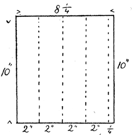
Fig. 350
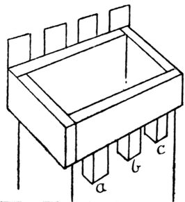
Fig. 351
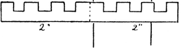
Fig. 352
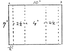
Fig. 353
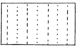
Fig. 354
Next make the sides, M, N, O, P; these are about 3 inches
in width, but a ½ inch must be allowed on each side for flanges
for fastening them to the towers; in height they just reach the
battlements of the towers. Make battlements as described, cut
out the windows and fasten these sides to the four towers. Colour
this part suitably. To make a flat roof for Q (Fig. 349), cut eight
lengths of stripwood ¼ inch by ¼ inch just long enough to come
about ½ inch below the battlements of the sides, M, N, O, P, and glue
these into the eight corners of Q. Cut a piece of cardboard to fit
over Q, cut doors in this for access to the roof, and glue it to
the tops of the pieces of stripwood.
To make towers E and F. Cut a piece of cardboard, 7 inches
by 10 inches. Mark it out as in Fig. 353, and make half cuts
along the dotted lines; the narrow strips at each end are flanges
for fastening the tower E, to A and C. Make battlements round
the top, colour, mark the windows and door, and gum to A and
C; make F in the same way. G and H are similar towers 2½ inches
square and 7 inches high. The four towers, E, F, G, H, can be
covered with roofs in the way already described. G and H are
fastened to E and F respectively, by pieces of cardboard 5 inches
long and about 4½ inches high. G is fastened to H by L, which
is about 7½ inches long and 4½ inches high. A door can be made
in L, leading into the courtyard, Q.
Cut a piece of cardboard, R in Fig. 348, about 2-1/3 inches high,
and gum it to the side of E to form a wall; between the latter
and tower a fit a flight of steps. These are marked out as in
Fig. 354.
Make half cuts along the lines marked——; turn the cardboard
over and make half cuts on the other side along the dotted
lines; bend in alternate directions. Flanges may be added to
each step.
A Tournament (Plate XV). Fig. 355 shows a royal tent at
a tournament. The platform inside may be made of 12 match-boxes
(A, B, C, D, E, F show the six foremost ones) or of any
suitable cardboard box. Pieces of cardboard, G H K L and M N O P,
are gummed on each side. a b c d is a piece of cardboard gummed
to a match-box and placed in front of the opening between H L
and M O. Paper steps may be made to lead from the ground to
the top of the match-box, and thence to the top of the platform.
The roof, S, is a piece of paper, bent along T V, to fit the triangular
tops of the cardboard sides, Q and R, to which it is fastened
by paper hinges. A piece of cardboard is gummed at the back.
Flags, etc., may be added.
X and Z show stands at the back for the more ordinary spectators.
They are simply strips of cardboard, suitably painted
and gummed for support to match-boxes or strips of wood.
The railings shown in the plate are made of cardboard or stripwood,
and placed in suitable positions to represent the lists.
If the railings are made of cardboard they should be fitted into a
groove in a piece of wood to enable them to stand.
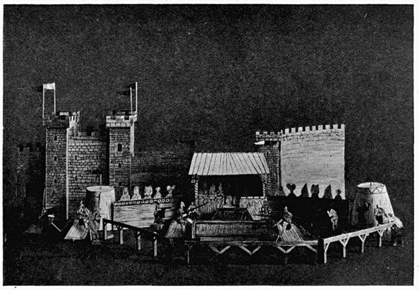
CASTLE AND TOURNAMENT
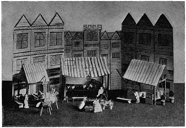
Plate XV
MEDIÆVAL FAIR
Across the enclosed space, and parallel to the royal tent, a
partition is placed to separate the combatant knights. It may
be made of cardboard or wood (see Fig. 356).
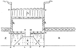
Fig. 355
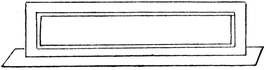
Fig. 356
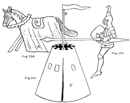
Two circular tents made of cardboard and paper stand at
each side; in these the knights put on their armour.
In Fig. 357 A is a cardboard disc to which the paper covering
C is gummed by a flange; B is a post which is glued into a hole
in the middle of the cardboard disc and rests on the ground
inside the tent.
The horses are made of corks and matches as described in
previous chapters. A piece of coloured paper (A in Fig. 358)
is gummed over the horse's back. The saddle, B, is a piece of
coloured paper, gummed to A. The bridle is cut out of paper.
Knights may be cut out of paper as in Fig. 359. Two pieces of
paper should be cut out, of the same shape except that one arm
bears a lance, the other a shield; gum the head and upper part
of the body together; the knight can be fastened to the horse by
gumming his legs to the trappings, A.
Heralds, a king and queen to sit in the royal box (for which
a bench must be made), spectators, etc., may be drawn and cut
out, or suitable figures can sometimes be cut from old history books
or advertisements. The background may consist of trees or of
a castle. In a similar way, with cork horses, etc., a procession
of the Canterbury pilgrims can be made.
Figs. 357, 358 and 359
A Fair in the Days of Henry VIII (Plate XV). The plate
shows the background of the fair. It is a piece of cardboard, with
houses drawn upon it and coloured; behind it are fastened two
cardboard supports which enable it to stand upright. This piece
of cardboard should be as long as possible, to give plenty of room
for many booths to be placed in front of it. Fig. 360 shows a
booth at which cloth and woollen materials are sold.
The covering of the booth is made of paper. The tables may
be of different shapes in different stalls. In the cloth merchant's
stall, rolls of coloured paper are piled up to represent bales of
cloth. To the pole is tied a sheep cut out of cardboard. An
apothecary's booth with its red and white pole can be made.
Shelves of cardboard, supported on little pieces of wood glued
to the posts of the tent, may be fastened round three sides of the
booth; cardboard bottles are cut out, painted and fastened to the
shelves by paper hinges, or bottles can be made of plasticine.
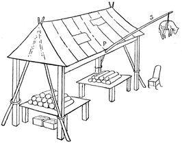
Fig. 360
Other booths may be added, one for 'ribbons of all the colours
of the rainbow,' others for books, leather, ironmongery, pewter
and silver articles for the table, etc.
Fig. 361 shows a quaint swinging chariot of the eleventh century;
it can be made of stout cartridge paper, cardboard and stripwood
(¼ inch by ¼ inch).
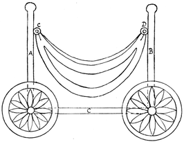
Fig. 361
First draw on cartridge paper two arcs of a circle (about
3-inch radius), a b c and d e f in Fig. 362; join them by
straight lines a d and c f. This is for the floor of the chariot.
To make the sides, draw arc G H K (Fig. 363) with same radius,
but portions G L and M K project about 1 inch beyond the arc
a b c in Fig. 362. Join G and K by the curved line, G N K. Draw
the flange O P. Colour the side yellow and brown, cut out.
Bend the flange O L M P and gum it to a b c in Fig. 362. Draw
and cut out the other side in a similar manner and gum it on;
the chariot will then appear as in Fig. 361. Two seats of paper
can be gummed inside.
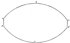
Fig. 362
Two pieces of stripwood (¼ inch by ¼ inch), A and B in Fig. 361,
are then cut; their height must be determined by the size of the
car. Two small screw-eyes are screwed in at C and D (Fig. 361),
from which the car is slung by pieces of thread or wire. The
posts, A and B, are glued and nailed to the middle of the axles,
which must be flat, the ends only being rounded for the wheels.
Pieces of stripwood (¼ inch by ¼ inch) or strips of cardboard, C,
connect the axles on each side.
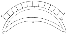
Fig. 363
The wheels are cardboard discs, with a pattern drawn on them
as in the figure, and painted yellow and brown.
Fig. 364 shows a pretty chair for a doll's house. It is a copy
of a carved oak chair of the fourteenth century. It is made of
wood or cardboard. If made of cardboard, a small square box
may be used for the seat, A, to which the sides and back are
gummed. The sides and back should be cut in one, with half-cuts
down A B and C D, where the cardboard is bent and gummed to
the box. The chair should be painted a very light brown with
dark brown markings. It looks well if made out of the wood of
a cigar-box.
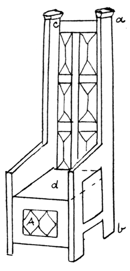
Fig. 364
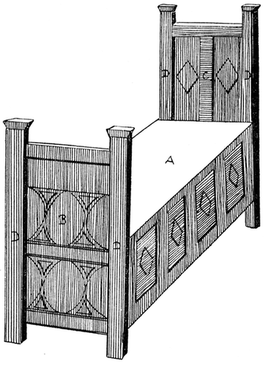
Fig. 365
Fig. 365 gives a pattern of a fourteenth-century bed that goes
with the chair, A can be an oblong box, covered with paper
suitably coloured (light brown with panels of dark brown).
B and C are pieces of cardboard (painted as indicated) gummed
to each end of the box; four pieces of stripwood, D (¼ inch by
¼ inch), are glued on to the cardboard.
This bed is easily made of wood. A may be a cigar-box, or
the bed can be made of separate pieces of wood carefully glued
and nailed together.
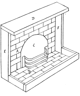
Fig. 366
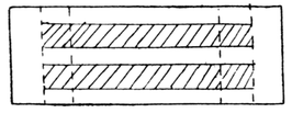
Fig. 367
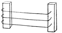
Fig. 368
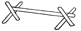
Fig. 369
A Fire-place (Fig. 366). This toy is made of wood and cardboard.
Its size will depend upon the doll's house for which it is
made. The mantelpiece, D, is a piece of wood glued and nailed
to two wooden supports, E and F. To the back of these a piece
of cardboard, A, is glued. This is coloured to look like tiles,
and space C is painted black. The grate is made of cardboard
(Fig. 367). The shaded portions are cut out and half cuts are
made along the dotted lines. It is coloured black, bent as in
Fig. 366 and gummed to the cardboard back. The fender is of
wood, and is glued to E and F and to a cardboard bottom, B,
which is coloured to represent tiles.
The grate may also be made of pieces of wire bent to shape
and passed through holes in two pieces of wood (Fig. 368), which
are then gummed to A.
Fire-dogs can be made from matches glued together as in
Fig. 369. A poker and shovel can be cut from cardboard. The
most convenient sizes of stripwood from which to make this
toy are lengths of ½ inch by ¼ inch for supports E and F,
lengths of ¼ inch by ¼ inch for the fender, and 1 inch by ¼ inch
for the mantelpiece.
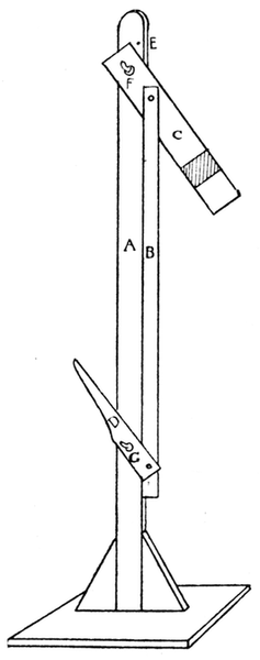
Fig. 370
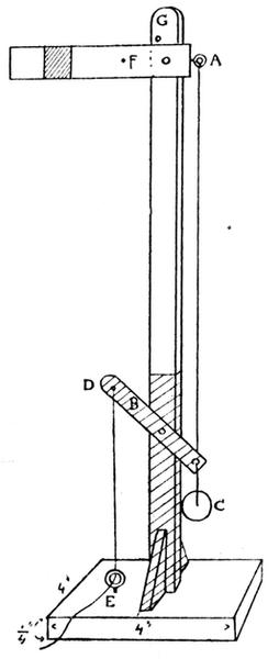
Fig. 371
A Railway Signal. Fig. 370 shows a simple method of making
this toy. A is a piece of stripwood about 11" × ½" × ¼", fastened to a
wooden stand. Holes are bored in A at F about ½ inch from the top
and at G about 2½ inches from the ground. The arm, C, is a piece
of cardboard 3 inches by ½ inch with a red band painted across it.
The lever, D, is a smaller piece of cardboard. C and D are fastened
to A by pieces of wire or by rivets so that they move freely up
and down. B is a narrow strip of stiff cardboard fastened by
small paper-clips to C and D. When the lever, D, is pulled down,
the arm, C, is pushed up. A small nail is put in at E to keep the
arm from rising too high.
Fig. 371 shows a railway signal which can be worked by a
lever placed at any distance away.
In this model the arm, F, is a piece of wood about 4" × ½" × ¼".
Into one end is fixed a screw-eye, A. About ½ inch from this end
bore a hole. Nail the arm through this hole to the post about
¾ inches from the top, so that it moves freely on the nail. B is
a piece of wood, 2" × ½" × ¼". Make three holes in it. Nail it
through the middle hole to the post, 3 inches from the ground,
so that it turns freely on the nail. Take a piece of fairly strong
wire, fasten one end to A and the other to B. A weight (a lead
button) is needed to keep the arm of the signal up. Attach this
weight, C, by a piece of thread to B, as in the figure. Tie a piece
of thread to D, pass it through a small screw-eye, E, fixed on the
stand. When this string is pulled the arm is lowered.
This toy may be worked entirely with thread. Tie a piece of
thread from A to C, taking care to keep the lever B in the position
shown in the figure; then tie another piece from a small nail
at F to D. A small nail should be put in at G to prevent the arm
from rising too high.
The stand and the shaded part of the signal post should be
painted black, the rest of the post is white, the arm is white with
a red band.
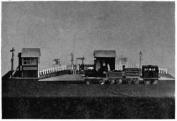
A Signal-box (Plate VIII). For the foundation of the signal-box,
take a piece of wood 9 inches by 4 inches, A B C D (Fig.
372). Cut two pieces of wood, 4½ inches by 4 inches. Glue and
nail these to A B C D (E and F in Fig. 372). Next cut four pieces
of wood, G H J K, ¼" × ¼" × 6½". Glue these to E and F. Measure
and cut two pieces of wood, M and L, to fit in between K and J,
and G and H. Glue these in position. Next measure and cut
out a piece of cardboard, N (Fig. 374), that will fit in between the
posts, G H J K, and rest on the sides, E and F, and the ends,
L and M. This forms the floor of the signal-box.
Measure and cut two pieces of cardboard that will fit across
the space between the posts G and K. Mark and cut out windows
in these as shown in the plate, and glue them on each side to the
posts. Next cut out two pieces of cardboard, 9 inches by 4 inches
(Fig. 375). Measure along the sides the distances C J and K B; find
the middle, O, of top, join O K and O J, and cut off the shaded
portions. Make half cuts along the dotted lines and bend back
the flanges to which the roof is fastened. In one piece make a
door, the bottom of which must be on a level with the floor. A
window may be cut out in the door, or simply drawn in with
pencil and painted; on the other side, mark and cut out a window
similar to the window in the sides. Glue these pieces in position.
Make the roof of cardboard as described in the case of the Noah's
Ark, and glue it to the flanges.
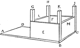
Fig. 372
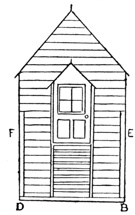
Fig. 373
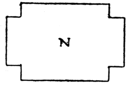
Fig. 374
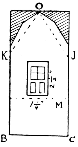
Fig. 375
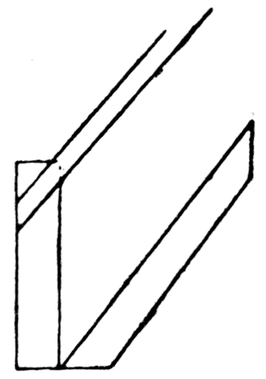
Fig. 376
The Porch. For the platform of the porch cut a piece of wood
1¾ inches by 1¼ inches. Cut two sides, 2¾ inches by 1¼ inches.
Glue and nail these to the platform. Cut two supports as shown
in the plate, and glue these to the ends just underneath the
door, so that when the porch rests on them, and the door is
open, the floor of the porch is level with the floor of the
signal-box. Next cut the two outer posts, glue them into position as
shown in the plate, and glue the platform of the porch on the
four posts. The roof of the porch is cut from cardboard, with
flanges to be glued to the end of the signal-box. The slope of
the roof should be parallel to that of the roof of the signal-box.
Make a ladder as described in Chapter IX. Bevel the ends
of the ladder as in Fig. 376 so that it can be glued into position.
Glue two small posts on each side and glue two strips of cardboard
to these and to the sides of the porch for railings.
Windows may be painted in the wooden sides, the rest is
coloured to represent bricks; the window sashes are dark green
or brown, and the roof grey.
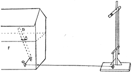
Fig. 377
From this signal-box the signal shown in Fig. 371 can be worked
in a very simple manner. Fig. 377 shows the arrangement.
Through a hole, A, in the floor fits a wooden lever, B C. Pass the
thread belonging to the signal through a small hole in the side of
the box, then through a small screw-eye at O, and tie it to the end
of the rod. When the lever, B, is pushed over the signal arm is
lowered.
A small nail is put through the lever just above A, to act as a
fulcrum. The side F (Fig. 377) may have large windows which
open to enable the child to insert his hand and push the lever.
If the signal-post is set up some distance away from the signal-box,
it may be found necessary to add another weight.
A Lighthouse (Plate XVI). This lighthouse is similar to one
called the Gull Island Light in Newfoundland. It is a hexagonal
column and is therefore somewhat easier to make than a circular
structure.
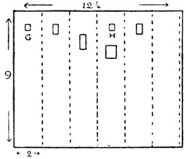
Fig. 378
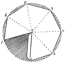
Fig. 379
The main column is 9 inches high, and each of the six faces is
2 inches. Cut out a piece of cardboard, of medium thickness,
9 inches by 12¼ inches (Fig. 378).
Divide it into six parts 2 inches
in width, leaving a flange ¼ inch
wide at the end for fastening the
column together. Make half cuts
along the dotted lines. Cut out a
door and windows, and two holes,
G and H, ¼ inch square. Fold
and gum together. The hexagonal
column above the first platform is
2½ inches high, sides 2 inches;
that above the second platform
is 2 inches high, sides 1½ inches.
Before folding and gumming
the top column, or lantern, together,
windows must be cut out.
It is easier to cut the windows
out completely and gum the bars
behind the openings. A door is
cut just above the first platform
as shown in the plate. The
top of the lantern is a hexagonal
pyramid 1½ inches high, edges 2 inches. To make this, the length
of one of the sloping edges (as a' d' in Fig. 380) must be found.
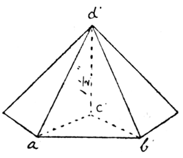
Fig. 380
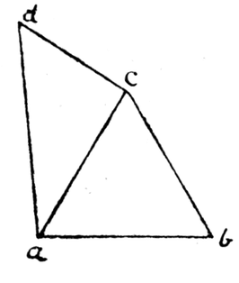
Fig. 381
Draw a line a b (Fig. 381) 2 inches long. This is one edge of
the hexagonal base. On it make an equilateral triangle a c b.
This is the same as triangle a' c' b' in Fig.
380. At c (Fig. 381) draw c d at right
angles to a c; make c d equal to the
height of the pyramid—namely, 1½ inches;
join a d; this is the length of one of the
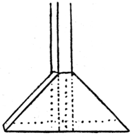
sloping edges (a' d' in Fig. 380). With
radius a d describe a circle (Fig. 379).
Mark along its circumference the distance
a b, six times; join a to b, b to c, etc., and
join each point to the centre. Cut off the
shaded portions, leaving a flange for fastening,
and make half-cuts along the dotted
lines. Bend and gum together.
The first platform shown in the plate
is a circle of cardboard or wood, radius 3 inches. Holes are
made round the edge.
To this the upper column is fastened by paper hinges, unless
the columns have been provided with flanges at top and bottom.
Glue match sticks or pieces of cane, about 1 inch in length, into
the holes in the platform for railings, round which black thread
may be tied. Now fasten the whole to the main column so that
the sides coincide.
In the same way the lantern is fastened to the upper platform
and the latter to the upper column, after similar railings have been
made round the upper platform. Lastly the pyramidal top is fixed
on the lantern, by either paper hinges or flanges. Now cut a
piece of stripwood, ¼ inch by ¼ inch, of the right length, so that it
passes through the holes G and H in the lower column and projects
about 1/8 inch over the doorway; into this projecting end
screw a small screw-eye, pass a piece of string through it and bring
the ends inside the door. This is the pulley by means of which
goods are hauled up from the boat into the lighthouse. A ladder
can be made of matches (as described in Chapter IX); two
wire hooks are inserted at the ends, and it is hung to the
doorway.
The lighthouse can be coloured grey and fastened to a piece
of cardboard painted blue.
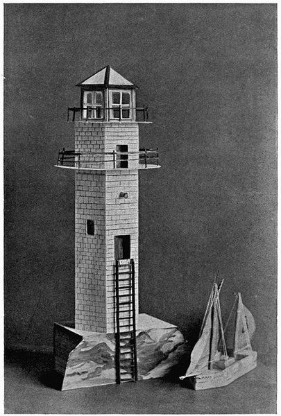
Plate XVI A LIGHTHOUSE
A Transporter Bridge. The supports for this bridge, A and B
(Fig. 382), are two small wooden Bovril boxes (those containing
one dozen one-ounce tins); their bottoms have been knocked out
and they are mounted on wooden supports or on two smaller
boxes of about the same width.
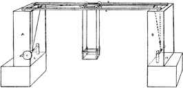
Fig. 382
Take two lengths of stripwood, C, D, 2' × ½" × ¼"; on to each
of these glue and nail a similar length of stripwood, ¼ inch by ¼ inch
(Fig. 383). Next the overhead trolley should be made (Fig. 384).
The axles G and H are about 3½" × ¼" × ¼". The wheels are made
of wood and can be cut from an old broom handle. Before these
are put on, the two pieces E and F, which are 3½" × ¼" × ¼", are
glued to G and H. C and D are placed so that the trolley runs
easily along their ledges, the distance between them is measured
and two pieces of stripwood (J in Fig. 383) are cut, by means of
which C and D are fastened together. This frame can rest on
A and B. There is no need to fasten it permanently.
To each end of H and G, very small screw-eyes are screwed,
K in Fig. 383, to which the strings or chains which support
the car are attached—also two screw-eyes are screwed in at
H and G.
Fig. 385 shows part of the car and gives the necessary measurements.
Side R is made of stripwood, ¼ inch by ¼ inch. The gates
at each end are made of strips of cardboard. Four screw-eyes
are placed in the corner posts for hanging the car to trolley (see
Fig. 382). Pieces of thread are tied to the screw-eyes at H and G,
and pass through screw-eyes in the supports (T and U in Fig. 382).
Two windlasses can be made to stand on M and L, similar to the
winding gear described in making the crane (Chapter V), by
means of which the car can be drawn backward and forward. The
bridge may stand across a piece of cardboard painted to represent
a river.
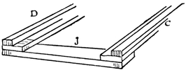
Fig. 383
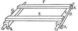
Fig. 384
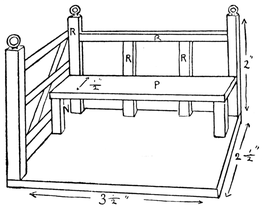
Fig. 385
For the toys described hitherto, the chisel has hardly been required,
but to carve boats from a solid block of wood it becomes
somewhat of a necessity, the pen-knife being but a poor substitute.
The use of the chisel has been postponed owing to the dangers
which attend its use. However, when children have become
accustomed to handle tools properly and to respect them, they
are no more likely to cut their hands with a chisel than with a
knife when sharpening pencils or peeling potatoes.
The following tools will be found useful in making exact
models of boats, hollowing them out, etc.:
(1) A ½-inch or ¾-inch chisel. This is a good one to start with.
(2) A smaller chisel about ¼ inch wide.
(3) A gouge. A 3/8 inch and a 5/8 inch gouge answer most purposes.
This is an indispensable tool when hollowing out a boat.
(4) A spoke-shave. This is used to smooth a curved surface
after it has been roughly cut with a chisel or knife. It is not really
necessary, as its work may be done with sand-paper or a file.
However it is not expensive, and it leaves the wood with a 'clean'
surface much superior to that obtained with sand-paper.
(5) A vice.
The best wood for making the following boats is yellow deal
or American white-wood. This, though not expensive, must be
bought. One does not often find a piece of waste wood suitable
for boat-making.
A very simple boat can be made in the following way. Procure
a block of wood about 7" × 1½" × 2". On the top surface of the block
draw a plan of the boat as in Fig. 387; on the bottom surface
draw the plan shown in Fig. 388. Take care not to make the keel
too narrow, especially in first attempts at boat-making. The keel
of this boat may be quite ¼ inch thick. See that it is really in the
middle.
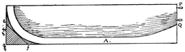
Fig. 386
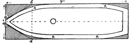
Fig. 387
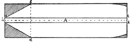
Fig. 388
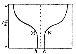
Fig. 389
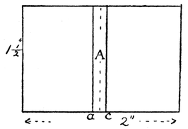
Fig. 390
Mark on both sides of the boat the lines shown in
elevation, Fig. 386. Mark lines showing the stern elevation
as in Fig. 389, at the other end the stern, as in Fig. 390.
Now saw away as much surplus wood as possible. It is well
to begin by sawing along lines a b and c d in Fig. 387, to roughly
shape out bow. If a very curved bow is desired, saw off the corner
e f g (Fig. 386). To make the keel, saw along lines a h and c k,
about ¼ inch deep (Fig. 388), at the stern end saw down to M and N.
Now carefully round and model the sides and keel with gouge,
chisel, spoke-shave and file, or simply with chisel and file.
Before finishing off with sand-paper or spoke-shave, the boat
should be tried in the water, it will probably lean to one side;
cut off a little wood from this side and try again. (Be careful
to dry your tools if they get wet.) When the boat is properly
balanced, nail a strip of lead along the keel.
A hole may be bored on the deck for a mast.
To make the Rudder. Saw a piece of wood out about
1 inch by 2¼ inches (wood should be about ¼ inch thick). Draw
a rudder on it as in Fig. 391, cut out this shape
with saw and file. Round the top as at C for the
handle. Make holes with a fine bradawl and insert
two pieces of bent wire at a and b. To put them
in it is best to hold them with a pair of pincers.
Ordinary pins with their heads cut off do just as
well as wire. Make two wire loops and fix them
in the stern of the boat (P and Q in Fig. 386), that
the rudder may hook on to these, care must be
taken that the eyes are exactly opposite the hooks.
To make the tiller, drill a hole in a piece of
wood, as in Fig. 392, and file it large enough to fit
tightly round the top of the rudder, then work the
tiller to shape.
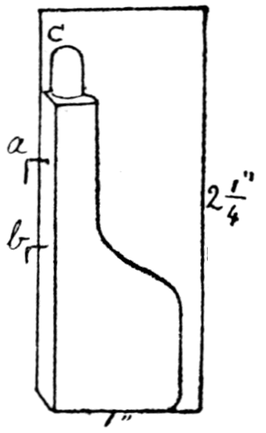
Fig. 391
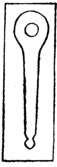
Fig. 392
This boat can be hollowed out with the gouge.
First draw line R R R R round the boat (Fig. 387)
to give the thickness of side. Before starting on the actual
boat, it is as well for the amateur to practise cutting a
few hollows. With satin walnut, pine, American white-wood,
gouging is not a difficult matter. When the boat is being
gouged out it should if possible be placed in a vice. (Always
put a piece of thin wood between the jaws of the vice and
the article you wish to hold to prevent marks.) Another way
of hollowing the boat is to begin boring centre-bit holes as
close together as possible, being careful not to bore too deep,
then gouge out as much wood as you safely can, finish with file and
sand-paper. When the boat is hollowed out, seats can be made for
it. These should be cut the exact length of middle of boat, bevelled
at the ends, and fitted into the boat by forcing them into position.
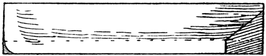
Fig. 393
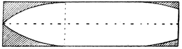
Fig. 394
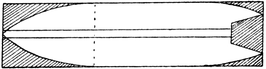
Fig. 395
Figs. 393, 394, 395 show elevation and plans of a common
type of boat. Saw off triangular
pieces of wood to
form the bow, cut out the
stern with the tenon saw and
chisel. Model the sides and
keel with gouge, chisel and
file as before. To put a
rudder on this boat, notice
that a hole must be bored
through the deck for the
rudder to pass through.
There is no need in a boat
like this, or indeed in any
boat (when practice has
been attained), to saw out the keel, the gouge and chisel are
sufficient, but the sawing sometimes helps the beginner.
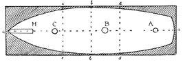
Fig. 396
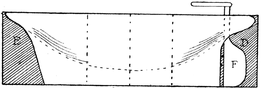
Fig. 397
A Schooner (Plate IV). On a suitable piece of wood (a square
prism, length 3½½ times width) draw a line a a (Fig. 396) on the
surface through the middle from end to end. Then draw a line
across the middle b b, and divide the surface in three by lines c c
and d d. Pencil out the deck as in Fig. 396. Now here is a piece
of advice that it is well to follow in all boat-making. To mark off
the deck make a cardboard template the shape and size of one
half, taken from the middle line, a a. Lay the template on one half
of the piece of wood and pencil round the edge. Then turn the
template over on the other side and pencil round the edge again.
In this way the shape of the deck is more accurate and both sides
are symmetrical, which is very important if the boat is to float
upright in the water. Now on the sides draw the elevation as in
Fig. 397.
Cardboard templates will also be found useful in getting the
cross-sections correct.
Now saw and file away the stern, D, and the bow, E, and chisel
away the sides and keel as described before. Fig. 398 shows the
appearance of the stern.
Having chiselled and filed the outside of the hull to correct
shape and exactly equal on both sides, gouge out the inside as
described before. Next make the deck from deal about 1/8 inch
thick, cutting it the exact size of the outline in Fig. 396. Before
fastening the deck, bore a hole at A for the rudder (a corresponding
hole being bored in the hull), and holes at B and C for masts
(with corresponding holes, not more than ¼ inch deep, in the hull).
If need be (in large models) the under part of the deck where holes
come can be strengthened by pieces of wood nailed across. With
a hard pencil draw lines along the deck to give the appearance
of boards.
A hole for a hatch-way may be cut out with a fret-saw. The
hatch-way itself for a large boat can be made of pieces of wood
nailed together.
Now fix the deck on to the top of the hull with small nails.
Another way of fixing the deck is to make it just large enough
to fit inside the hull, leaving an edge or bulwark all round,
¼ inch to ½ inch in depth.
The longer mast goes into hole B. The total length of the
schooner is about 1¼ times the height of the mast above the deck.
The shorter mast goes into hole C and is very little longer than
half the boat. The masts must fit firmly into the holes in the
deck and hull.
To ballast the boat, nail a piece of lead along the keel. If too
large a piece is used at first, it can easily be reduced.
The rudder F is cut out and fixed as already described.
H in Fig. 396 shows where the end of the bowsprit comes.
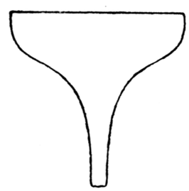
Fig. 398
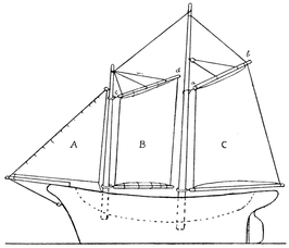
Fig. 399
A. Stay foresail. B. Gaff foresail. C. Mainsail.
Fig. 399 shows a drawing of the masts and sails for a schooner.
The gaffs, a b and c d, and the corresponding booms, are fastened
to the masts by wire loops. Lawn or Indian muslin make good
sails. It is well to wash the material before using it.
The Fret-saw is a delightful tool, and very useful to the toy-maker.
It can be used for making wheels and the various jointed and
mechanical toys described in the following chapters.
In dealing with the fret-saw we have to consider (1) the saw-blades
and (2) the frame in which they are held. The saw-blades
are about five inches in length and are made of delicate steel wire
with correspondingly fine teeth. They are very cheap, being
commonly sold at about three halfpence to threepence a dozen,
and even less when purchased by the gross. They are supplied
in ten different grades, numbered from 00 to 8, proceeding from
fine to coarse. For the toys described in this book, Nos. 1, 2 and 3
will be found most suitable. To preserve the saw-blades from
rust, keep them in a wood or metal case. Upon the proper
tension of the saw-blade depends its action. To keep it taut, a
number of frames have been designed, the most practical being
one made of steel and varying in size from 12 inches to 18 inches
measuring from the saw-blade to the back of the frame. The
handle is of wood. The 12-inch size is the most suitable for
children.
Cheap frames can be obtained for sixpence halfpenny (smaller
ones even for fourpence). In the cheaper kinds the necessary
tension is obtained by drawing the arms slightly towards each
other when clamping the blade. The spring of the steel will then
keep the blade sufficiently taut. In the better-class frames (price
from two shillings upward) the tension is secured by the action
of a lever. Notice that the saws must be inserted with the teeth
pointing downward.
Holding and managing the Saw-frame. The hand saw-frame
requires all the steadiness possible; the bend of the frame should
rest along the forearm, and against the shoulder if the frame be
a long one, or under the shoulder if a short one. This prevents
the frame from swinging round.
The saw-blade will describe the arc of a circle as it passes
through the wood, and this dip is reduced to the minimum by
making short strokes instead of long ones. This is important
to remember. The amateur is sure to break a few saw-blades
at first, they are so fragile, indeed even in the hands
of an expert they have a precarious hold on life and can
only be expected to last a certain time. Fortunately they are
cheap.
The saw-blade must not be pressed on into the wood too
quickly; the wood is held to the table with the fingers, and every
part of the line to be cut is moved in due succession against the
cutting edge of the blade. Excessive energy will often cause the
blade to stick fast in the wood; in this case the blade must be
eased by gently working it up and down so that it does not cut
but frees itself. This method can be adopted when turning a sharp
corner; work the saw up and down (without cutting) until the
blade points in the right direction.
Very often the locking of the blade in the wood is due to
gummy or heavy wood, or to a twist in the saw-blade; this latter
cause can be prevented by the exercise of care in fixing the saw
in the frame.
Children should have the cheaper frames to practise with;
however they soon learn to manage them and in due course find
out that a saw-blade is really not so delicate as it looks. In
cutting out animals, etc., leave a piece of surplus wood round
the frailer parts as long as possible so that one has something to
hold without fear of breakage.
When an interior space has to be cut out (e.g. when cutting
away interior portions of wheels to make the spokes) a hole must be
made by means of the Archimedean drill to admit the saw; the
upper end of the saw is released from its clamp, passed through
the hole, and again fixed in position. The hole in all cases should
be bored as near as possible to a corner or point, as these are
convenient starting-places. A medium-sized drill point rather
than fine points should be used wherever space permits. Fine
points are apt to break. The drill stock must be held quite vertical
and revolved both when the point is entering the wood and when
it is being withdrawn. No pressure is required on the drill beyond
its own weight.
In making the various jointed animals, etc., in the following
chapters bifurcated nickel rivets are used, small-gauge. The
following are useful sizes:—
Sizes No. 14 6/16, 8/16, 10/16. (These are useful for jointed animals.)
Sizes No. 11 12/16, 14/16, 16/16. (These are used for the crane, etc.)
These rivets can be bought in boxes of assorted sizes.
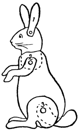
Fig. 400
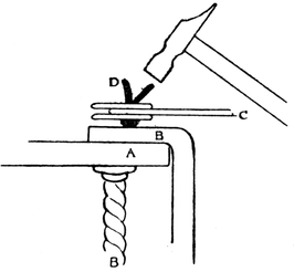
Fig. 401
Figs. 400 and 401 show how a jointed animal is riveted
together. When hammering the rivet open, its head should be
placed on a piece of metal (the clamp will do). Fig. 401 shows the
method of opening the rivet. A represents the table, B the clamp,
C the head of the rabbit and its ears, D, the rivet.
Little Gymnast. First the little gymnast must be drawn and
cut out. He can be made of cardboard of medium thickness and
paper-fasteners (Size 00) or better of three-ply wood and bifurcated
nickel rivets (Size No. 14-8/16).
First draw the body, A, Fig. 402,
2½ inches long. (The measurements
given are important, for unless the
limbs are in proportion the figure
will not work properly.) Make two
holes with the drill, if wood is being
used, as in Fig. 402.
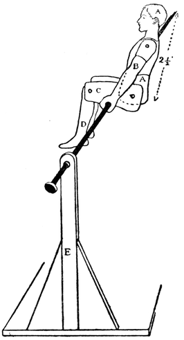
Fig. 402
The arms, B, are 2¼ inches long,
the hands must be large enough
to contain holes to carry a wooden
knitting needle (1/8 inch in diameter).
The upper part of leg, C,
is 1½ inches in length; the lower
part, D, 1½ inches. Make holes in
these parts as in the figure. Take
care that the holes are large enough
to hold the rivet or paper-fasteners
loosely, so that the limbs swing
about easily.
Now fasten all these parts
together. (For directions how to
hammer the rivets see the previous
chapter.)
Paint the figure in water colours if it is made of cardboard, if it
is made of wood it may be left unpainted, or painted in oil colours.
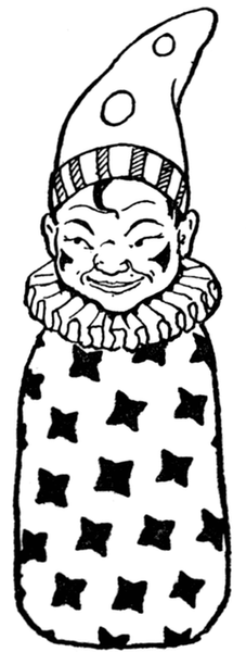
Fig. 403
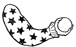
Fig. 404
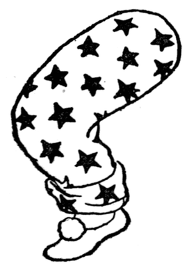
Fig. 405
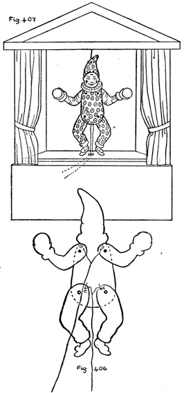
Fig. 406
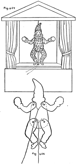
Fig. 407
Push a wooden knitting needle (about 1/8 inch in diameter)
through the holes in the hands, see that it fits tightly, add a little
glue if there is any danger of the needle slipping round inside the
holes.
Two pieces of stripwood, E, are next sawn about 11" × ¼" × ½".
These posts must have holes drilled in them near the top for the
knitting needle to pass through, and revolve freely. The posts
are nailed and glued to a base, the size of which will depend upon
the length of the bar which the gymnast turns upon.
Two or three gymnasts look well swinging together, or a
gymnast, a monkey and a clown. In this case 12" × 6" × ¼" makes
a good stand. The posts are supported by triangular supports.
On turning the knitting needle the little figure will revolve in a
life-like manner, and perform many of the professional exercises
of the horizontal bar. The actions are made more realistic if
the man's head is weighted with a piece of lead, so as to make his
head more nearly the same weight as his body.
The Dancing Clown. Draw on cardboard or three-ply wood
and cut out the head and body of the clown as in Fig. 403. Colour
it, and cut out another piece exactly the same to represent the
back of the clown. Draw and cut out two arms as in Fig. 404,
two legs as in Fig. 405. Cut out two small discs of lead, and glue
them behind the balls in his hands; glue little pieces of lead behind
his boots. His arms and legs are fastened together by thread,
as in Fig. 406. The back part of the body hides the strings.
This clown can be hung inside a box, and the strings passed
through a hole (directly underneath the clown) in another box
upon which he can then be made to dance, as in Fig. 407. The
figure works best if properly balanced; see that the arms and legs
are equal in size and weight.
Rocking Horses and Elephants. The simplest way of making
a rocking horse is shown in Fig. 408. Two rockers, A B C, are cut
out of cardboard (medium thickness). Next two horses, D, are
drawn on cartridge paper, the distance between the fore and hind
feet corresponding to the distance A C in the rockers. The
horses are coloured and cut out, and their heads and tails gummed
together. The four legs are then fastened with paper-fasteners
(or with gum) to the ends of the two rockers. A wooden rocking
horse is made in the following way. The two rockers, A B and C D,
are cut out of three-ply wood with a fret-saw. The arc of a circle
of 4 inches to 4½ inches radius is a good size; width of rocker,
H K (Fig. 409), ¾ inch.
Three pieces of stripwood ¼ inch by ¼ inch are sawn, length
3¼ inches, E, F and G. Pencil-marks must be made on the two
rockers to show where these strips are to go, one in the middle,
the other two at the ends. Before fastening them on, a slit is
sawn in the middle of each end-piece, as at E and G.
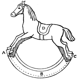
Fig. 408
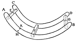
Fig. 409
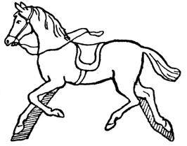
Fig. 410
Strips E, F and G are glued and nailed to one rocker, then this
rocker can be laid on its side, and the second rocker glued to the
upstanding strips. There is no need to nail the second rocker;
indeed, if the ends of the strips are very evenly cut, there is no
need for nailing at all. The horse (Fig. 410) can be cut out of
cardboard and have one front leg and one back leg fitted into the
slits. Cardboard of medium thickness will just fit a saw-cut and
no gluing is needed. If the horse is cut out of fret-wood or three-ply
wood (1/8 inch thick) the saw-cuts must be enlarged with a
file and the feet glued in.
Instead of horses, donkeys, tigers, lions, etc., can be fixed on
rockers as just described.
The rockers in Fig. 409 can also be built up of cardboard.
A Rocking Elephant. On a piece of cardboard draw a circle
1¼ inches in radius; on this draw an elephant as in Fig. 411.
Colour the ball red and the elephant grey (both sides must be
coloured) and cut out. Cut out a piece of cartridge paper (Fig. 412),
length equal to half the circumference of the circle in Fig. 411,
width, 1½ inches. Fold in half along D E, cut out D B C E, as in
diagram, the shaded portions being cut away. Gum B D C E to
disc H as in Fig. 411, so that D F E G forms a rocker; make a
similar rocker for the other side. Two pieces of lead (A in Fig.
411) are cut out and glued on each side of the disc at the bottom,
as in the figure. The lead must have paper suitably coloured pasted
over it. The elephant will swing up and down at the slightest
touch. Instead of an elephant a clown can be drawn on the ball.
Fig. 413 shows an elephant rolling on his back. This toy can
be made in the same way as the first elephant. A circle (1¼ inches
radius) is drawn first, and the elephant drawn in the circle.
These elephants can be cut with the fret-saw from satin walnut
(¼ inch thick). In this case the lead on each side must almost
reach the diameter, as shown in Fig. 413. Another disc of wood
(1¼ inch radius) must be fret-sawed out of the satin walnut, sawn
in two, and the halves glued one on each side of the lead, to make
a base wide enough for the toy to rock upon without upsetting.
No lead will then show, and it will look like a wooden toy. If
these toys are cut out of thin wood, 1/8 inch thick, they still require
at least twice as much lead as the cardboard toy.
The elephant may also be drawn balancing a ball instead of a
clown.
Children will delight in making these toys from cardboard,
paper and lead for a toy circus.
Fig. 414 shows a swan drawn in a circle; the shaded part
represents the paper rocker on one side. This model requires
no lead. A duck can be made in the same way.
Fig. 415 shows a design for elephants on a see-saw. The
elephants must be the same size as far as possible.
Fig. 411
Fig. 412
Fig. 413
Fig. 414
Fig. 415
Fig. 416, "The Washing Day," shows a pattern that will please
little English toy-makers. It can be cut from wood with the
fret-saw, or with scissors from cardboard of medium thickness.
Fig. 416
Fig. 417
To make the Design. First cut two lengths of three-ply wood
or cardboard, ½ inch by 8 inches, A B and C D.
Next draw on wood or cardboard, and cut out, the two little
washer-women (they are about 4½ inches high). They look more
effective if painted.
These are fastened to the strips of cardboard by means of
paper-fasteners (Size 000; one gross sixpence); the holes for the
fasteners are about 1¼ inches from the ends. The holes in the
little washer-women are exactly one above the other, so that
when the paper-fasteners are in and A B is exactly above C D, the
figures are upright.
A washing tub, E, is cut out of cartridge paper (top of tub,
3 inches, bottom 1¾ inches); this can be painted brown or green
and have a white rim round the top to represent soap-suds. This
tub is gummed to C D, exactly between the two little washers.
If the part of A B that comes behind the tub is cut away as in
diagram the figures will work better.
When the strips of cardboard are moved backward and
forward the figures put their clothes in the tub and take them
out again. The toy works best if a little space is left between
A B and C D, as in Fig. 417. If it is cut out of fret-wood the figures
are fastened by rivets, as explained in Chapter XV.
Fig. 417 shows two ducks eating out of the same bucket;
strips of cardboard, A B and C D, are the same size as those in
Fig. 416. The bucket is cut out of cardboard and gummed
to C D.
The sailors in Fig. 418 are made in the same way, holes are
made in their hands, through which yarn is passed (the thicker
the yarn the more like rope it is) or oars can be cut out of cardboard
and fitted in the holes in their hands, when they will appear
to row.
Fig. 419 shows a man driving a donkey. It is made of cardboard,
except the whip, A, which is thread tied into a hole in the
cardboard at C. The whip will work better if a little piece of
lead or something heavy is tied at the end of the thread. The
reins, B, are of thread or yarn, and pass through holes in the
donkey's mouth and in the man's hand.
Two fishermen can be made in the same way, the whip easily
becomes a fishing-rod and a lead fish can be attached to the end
of the line.
In the case of the donkey-driver and the fishermen the strips
of cardboard should be longer than shown in the figure, to leave
room for holding. The strip for the donkey-driver should be
about 9 inches, the fishermen require at least 12 inches if their
lines are not to get entangled.
Fig. 418
Fig. 419
Children will readily think of other designs for this simple
but interesting toy.
A Monkey-up-a-stick is a very easy toy to make. First cut out
a cardboard or wooden monkey as in Fig. 420. See that the legs
and arms turn freely on paper-fasteners, A and B. Paint the
monkey grey or brown. With a pin make holes, C and D, in
the feet and hands. Next saw two lengths of stripwood, one
1´ × ¼" × ¼", the other almost twice as long. Drill a hole near
one end of each of these sticks. Pass a pin or piece of wire through
the holes in the monkey's feet and the hole in the shorter stick;
bend down the pin on each side to keep the feet from slipping off.
(The point of the pin should be cut off with pliers.) In the same
way fasten the monkey's hands to the longer stick. See that the
limbs (note that they come one on each side of the stick) revolve
freely on the pins or wire. The two sticks may be kept together
by pieces of elastic; this however rather prevents the one stick
from moving freely up and down the other. It is better first to
file the sticks (or one of the sticks) round or to use dowel rods.
These round rods can then be kept together by cardboard or
wooden discs. The disc must have a hole in the middle large
enough for the rod to move freely up and down in it. The
thicker the piece of wood or cardboard the better. The hole must
be made in the wood with a brace and bit (a bradawl will make
the hole in cardboard, and it can be filed to the right size with a
round file). The longer rod, A, Fig. 421, goes through the hole;
the bottom of the shorter rod, B, is glued and nailed to the disc.
By moving the disc C up and down the monkey performs its
usual antics at the top of the stick.
The monkey, or a clown if preferred, looks very effective cut
out of three-ply wood and riveted together.
For a small model wooden meat skewers may be used as sticks.
Other suggestions for C in Fig. 421 are: a reel (though rod B
when glued to a reel tends to break off); half a cork.
Fig. 420
Fig. 421
Fig. 422
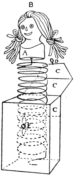
Fig. 423
More interesting than the "monkey-up-a-stick" is the
monkey that climbs a rope, though this little animal has sometimes
an irritating manner of swinging about on the rope, and
going no higher. If he is carefully made according to the following
directions he ought to climb. The monkey is cut out of cardboard
in the same way as the first monkey, except that his two
arms are gummed firmly on in the position shown in Fig. 422,
his legs only being free to move. Pins or pieces of wire are passed
through the holes at A, B, C, D. In the case of pins, the point is
cut off with cutting pliers and the rest doubled back to prevent
its coming out on one side, the head of the pin prevents it coming
out on the other. Tie a piece of thin elastic round the pins,
A and B, so that it is only just on the stretch when the legs are
drawn up parallel with the arms, as in the figure. A piece of wire
is passed through at E and is bent over out-wards, drawing the
hands fairly tightly together. A piece of thread is passed through
the eye so formed, down and under the pin, C, then over the pin, D
By alternately slackening and tightening the line the monkey will
climb up the thread in a very life-like manner.
Care must be taken to nip the wire well together at the hands
to get enough friction to hold the thread firmly while the elastic
pulls the legs up, on the other hand the thread must be just loose
enough to pass through E.
A Jack-in-the-box. The simplest way of making a Jack-in-the-box
is the following. Get some ordinary wire (quite thin
wire will do) about 4 feet long or longer if a bigger jump is
required. Wind this tightly round a broom handle, keeping the
rings of wire close together. Slip it off. Take a cork, cut it so
that it is about 1¼ inches high. File it round in the shape of a
head as in Fig. 423. Mark the eyes and nose in ink, the mouth
with red paint; or two beads can be glued in for the eyes. To
make the hair, cut several short pieces of black wool, tie them
in the middle at B, and glue or pin them to the middle of the head;
tie back the side ends with yellow or red wool as in the figure.
Fasten one end of the wire spring in the centre of bottom of cork,
as at A. A piece of muslin is then gummed round the cork to hide
the spring, so that it is loose and folds easily.
Next make a box, 2¾ inches high, or take the cardboard box
that contains a bottle of Le Page's liquid glue, and cut off about
one-third. Cut off the cover and glue it on to one side (C in the
figure). Make loop of wire at D, and insert a paper-fastener at
E to catch the wire loop. Fasten the end of the spring to the
bottom of the box, by passing it through the hole in one bottom
flap, bending it over and gluing over it the other flaps that form
the bottom. Coloured paper or scraps may be gummed to the
sides and top of the box. This is a suitable toy to be hung on a
small Christmas tree.
A larger and stronger Jack-in-the-box can be made from a
wooden box about 5½ inches square. For this a piece of No. 12
gauge wire about 10 feet long is required; it is wound around a
rolling-pin. This spring is then nailed by means of staples to a
piece of wood made to fit the inside of the box. Fasten a round
piece of cardboard to the top of the spring, and either sew on to it
a small doll's head, or make a doll's head of part of a stocking
stuffed with wool and having eyes, mouth, etc., sewn on. A cap
(a fool's cap looks best) is made to fit the head, and a loose jacket
is sewn on to hide the spiral body.
Fig. 424 shows the principle on which this toy is made; the
shaded portion represents the inside of a box. A good size for a
box to make this toy is 9" × 4½" × 2¼". Slits should be cut in the
long side of the box at a b, c d, e f, g h. These slits may be made
with a pen-knife, and a fret-saw file will make them wide enough
for a piece of cardboard to slip up and down in.
Slits are then made in the short side exactly under the
long slits, as p n in Fig. 425. Widen these slits also with a
file.
Next cut out the cardboard figures. Draw head, body and
one leg to be cut out in one piece; about 3 inches of cardboard
should be left below the foot (M and N in Fig. 424), the total length
of figure being about 8 inches. Cut out another figure like this.
Make holes just below the foot as at D in Fig. 424.
Next draw and cut out legs, F and H. Notice that they do not
project so far inside the box, their length being about 3½ inches.
Fasten these to the figures by paper-fasteners. Next cut out a
long strip of cardboard, A B, ½ inch by 14 inches. Pass this through
the slits (p n in Fig. 425) in the short sides of the box. See that
it slides easily up and down in these slits.
The portions marked M and N turn on pivots h k and m l.
These pivots pass through holes, D and E, in the figures and through
holes made at each side of the box exactly opposite the short
slits. Steel knitting needles make good pivots, or pieces of cane.
When the top is quite complete these pivots may be glued into
the holes in the box for greater security. Fasten pieces of lead
at the bottom of M and N so that the figures swing easily on the
pivots.
When it is found that the pivots are in the right place, pass
the strip of cardboard A B through the slits, and fasten the legs,
F and H, to it by paper-fasteners, as at X and Y. See that the
needles are in the right holes and fasten up the box.
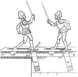
Fig. 424
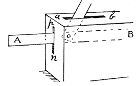
Fig. 425
(It is a convenience in making this toy to let the cover form
one side, the cover being left off until all the inside arrangements
are complete; the pivots can then be put into their holes in the
cover, and the cover put on.)
Now if the projecting ends of A B are pushed backward and
forward the figures fight in a very realistic manner. Notice that
A B has two movements: one backward and forward, the other
up and down. The lead weights in M and N keep A B up. Generally
speaking, the longer the slits are the better the figure works.
This, however, does not apply to slits c d and g h. The slits need
not be so close together as in the figure if it is desired that the
swordsmen should fight at a greater distance.
The arms are cut out of cardboard and fastened by paper-fasteners
on each side of the figure; the swords may be cut out
with the arms, or made separately and gummed on after-wards,
pieces of cane making effective swords. A more difficult but more
satisfactory way of putting on the arms is this: pass a very short
piece of cane through the hole in the body, where the arms are
to be fastened; see that it turns very easily in the hole; next
seccotine the pieces of cane that project at each side into holes in
the arms; see that one arm is up, the other down. To make the
arms balance well, it may be necessary to fasten a small piece of
lead to one hand.
This toy is most amusing if carefully made. The following
hints may be useful:
(1) Draw and paint the little swordsmen as carefully as
possible.
(2) See that the slits are perfectly straight and wide enough
for the cardboard to pass through.
(3) See that the arms, legs and feet turn easily on their pivots,
whether these pivots be paper-fasteners, cane or knitting needles.
(4) See that sufficient lead is attached.
(5) Cover the box neatly with paper, but not the slits. A piece
of green paper looks well for the top.
This toy may also be cut out of wood with a fret-saw. Many
other amusing toys can be made on the same principle.
Fig. 426
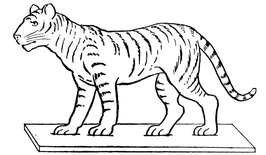
Fig. 427
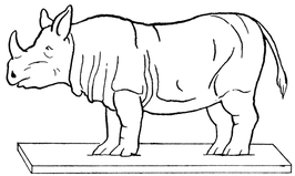
Fig. 428
Besides the numerous models already described that can be made
with the fret-saw, endless further toys might be made, among
others the following.
1. A Zoo or Wild-Beast Show. The animals for this may be
jointed models like the elephant and giraffe (Part I, Chapter XX);
in this case they will stand quite well; or they may be cut in one
piece and glued to an oblong strip of wood for a stand, as the lion
and other beasts in Figs. 426 to 430. Three-ply wood or satin
walnut 1/8 inch thick is suitable for these animals, which however
may also be cut out of cardboard and glued into slits cut in a
wooden stand.
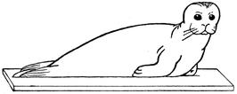
Fig. 429
2. Forest, Jungle or Desert Scenes, etc. (Figs. 431 to 437).
These trees, which have very characteristic shapes, can easily be
cut out with the fret-saw. Where the branches are slender and
there is danger of their breaking, use three-ply wood. They
should be painted green, with the markings indicated in the
drawings put in with sepia or dark green.
3. A Farmyard, with trees, ducks, cows, etc. Figs. 438 to
443 are patterns of farmyard animals. There is considerable
educational value in the drawing and cutting out of the simple
outlines necessary in fret-wood trees or animals. It will help
children to think in lines, as it were, and to draw boldly.
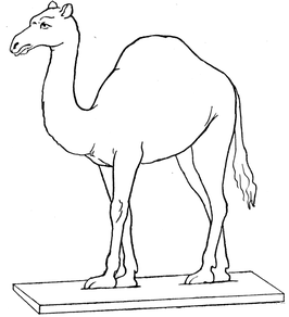
Fig. 430
Teachers will find sets of fret-wood animals and trees of use in
the Nature Study and Geography lessons.
4. Soldiers, Sailors, Boy Scouts, etc. Figs. 444 to 447 may
be cut out and glued on stands in the same way.
The small files used for fret-wood are useful to finish and
'clean up' these toys.
Fig. 431 The Walnut
Fig. 432 The Palm (Cocoa-nut)
Fig. 433 The Palm Oil Tree
Fig. 434
The Elm
Fig. 435
The Spruce Fir
Fig. 436
The Lombardy
Poplar
Fig. 437
The Scots Pine
Fig. 438
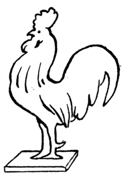
Fig. 439
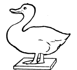
Fig. 440
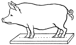
Fig. 441
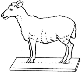
Fig. 442
Fig. 443
Fig. 444
Fig. 445
Fig. 446
Fig. 447
For these toys a wooden box is required, A B C D (Fig. 448), about
a foot or more square and 5 inches deep. L is a wheel made like
the overshot water-wheel in Chapter VI. Another way of making
the buckets is shown in Figs. 449, 450, and 451. These are glued
close together between two circles of cardboard as shown in
Fig. 451. This method is somewhat easier if small wheels are
required. The wheel should have ten or more buckets; the
greater the number of buckets, the faster the wheel works.
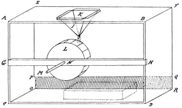
Fig. 448
Fig. 452 shows the construction of the reservoir, J, through
which the sand runs. The size of it will depend upon the toy
made.
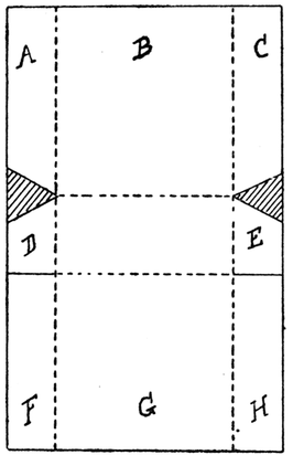
Fig. 449
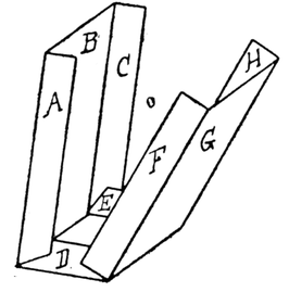
Fig. 450
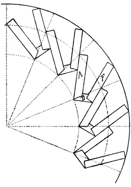
Fig. 451
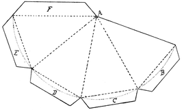
Fig. 452
F is the flange for fastening it together, and E, D, C, B are
flanges for fastening it to roof A B E F (Fig. 448). A round hole
is filed out at A, after the reservoir is fastened together, through
which the sand runs. The wooden side of box, A B E F, is taken off
and a piece of cardboard is nailed to the box instead. This can
have a hole cut in it, K in Fig. 448, and the reservoir glued under
it. G H is a bar of stripwood nailed across the front of the box,
through which a hole, N, is bored. The axle of the wheel passes
through this and through a corresponding hole in the back of the
box. As the sand runs out of the reservoir, it falls into the boxes
and so turns the wheel; hence the sails of a windmill, the hands
of a clock, etc., fastened to axle, L M, can be made to turn. Notice
carefully that the hole at the bottom of the reservoir should be
over the centre of the boxes of the sand-wheel and a little to one
side of the wheel, as in Fig. 448. Part of the back of the box,
P Q R O, should be cut out to allow a tray to go in to receive the
sand.
Fig. 453
To make a Bicyclist (Fig. 453). Cut two circles of cardboard,
radius 1¼ inches. Mark on them the spokes of a bicycle.
Make two sand-wheels the same size as the bicycle wheels;
their width should be about ½ inch to ¾ inch. Take a piece of stripwood
½ inch by ¼ inch and the length of the box. Make holes
in it, 3 inches, 4½ inches and 6 inches from one end. Nail the bar
across the box 3 inches from ground; make holes in the back of
the box exactly opposite the holes in the bar. Make wooden axles
to pass right through these holes so that they turn freely in them.
The sand-wheels should be glued to two of these axles. Now cut
out a piece of cardboard to fit over the front of the box; bore
holes in it corresponding to those in the bar, G H. Paint on it
a suitable background, as in Fig. 453. Nail small pieces of stripwood,
½ inch by ¼ inch, to the corners of the box (as at A and B in
Fig. 453), to which the cardboard can be fastened by drawing-pins
or glue. Pass the axles of the sand-wheels through the first
and third holes from the end of bar G H, and let them project
about 1 inch beyond the cardboard. To these ends the bicycle
wheels must be glued. In making this toy it is better not to
fasten pieces together too quickly, until all the various parts
are ready.
The figure of the cyclist should be cut out to the measurements
given for the little gymnast in Chapter XVI. The body
and head could be cut out of thin three-ply wood, and the arms
and legs of cardboard.
The best
method of joining
limbs to the body
so that there is
the least possible
friction is as
follows. Cut off
a small piece of
a pin, including
the head, pass it
through the holes,
and apply to the
cut end a tiny
drop of sealing
wax. Make holes
in the cyclist's
feet at G (Fig. 454). Cut a small cardboard wheel, F, about
½ inch in diameter: make a hole in its centre and one near the
circumference.
Fig. 454
Glue a piece of match stick into the hole near the circumference,
the other end of this match stick must turn freely in the hole in
cyclist's left foot. Pass the axle already made through this
wheel, to which it must be glued, and through the cyclist's right
foot and through middle hole in the bar.
Make two small pulley wheels (e.g. slices of reels with cardboard
flanges), one twice the size of the other. Fig. 455 shows
how the toy is put together and how it works. A and B are the
sand-wheels; axles, F G and F M, are glued into them and into the
two bicycle wheels. K H is the axle passing through centre of
pedal wheel. N O are pulley wheels glued to axles, F G and H K,
respectively, and connected by an elastic band, E. When sand-wheel,
A, turns round, wheel, N, turns and turns pedal wheel, F,
in Fig. 456, and as O is twice as big as wheel N, the pedal will
revolve twice as slowly as the bicycle wheels.
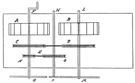
Fig. 455
Pulleys of equal size, C and D, might be added with advantage
to connect the two sand-wheels, and a handle at F to start the
wheels.
Fig. 456 shows how the leg is fastened to the pedal wheel.
To keep the cyclist's body steady cut a piece of stripwood
1" × ¼" × ¼". Glue one end to middle of cyclist's body and the
other to the cardboard background.
B (Fig. 454) is a thin piece of wood, passing over the projecting
end of axle of wheel, E, its other end being glued to the bottom
of the cyclist's body. A similar strip, A, is cut. This is fastened
between his hands by a little piece of pin, and passes over the axle
of wheel, D. C is a thin strip of wood or cardboard which passes
over the axle of E and can be glued to the cyclist's right leg and
pass behind wheel, F.
Fig. 456
Make a platform as in Fig. 453 to support the cyclist. Make
two reservoirs as already described. Cut a piece of cardboard
to fit over the top of box and make holes in it, L and M in Fig. 453.
Glue the reservoirs under these. Make a cardboard tray to fit
under the wheels for the sand to fall in. Another wheel might
be added to work the sails of the windmill in the distance. Very
fine sand must be used for working these toys, the best is silver
sand and it should be kept as dry as possible.
Fig. 457 shows another modification of this toy. B is a box
turned upside down and placed in front of that containing the
sand-wheel. A is the cardboard background, suitably coloured.
The sailor's legs are cut in one piece and glued into a slit in the
box. The body is fastened to them at F by a small paper-clip so
that it moves very freely. The arm is fastened on at G. A small
match stick passes through the hole in the hand and is glued in
the hole in circumference of wheel E.
The axle, M N, to which this wheel is glued passes through the
cardboard or wooden standard, D, through a hole in the background,
A, and through the centre of the sand-wheel. D is fixed
to the box. The arm of the crane, C, made of cardboard or three-ply,
is glued to D. A hole is made at G and a corresponding hole
in A opposite G. Pass a small stick of wood or cane, K, through
these holes and glue it in. The crane should be about 1 inch from
the background. K keeps the arm of the crane steady. Tie a
piece of cotton to the axle of wheel E, pass it over K or over a
small pulley wheel revolving on K G; tie to it a thin wire hook to
which a paper box or barrel can be fastened.
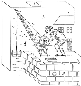
Fig. 457
In the same way a sailor can be made to work a windlass and
drag a paper boat up a sloping beach, a man can draw water from
a well or turn a barrel organ, or a paper mouse gummed to a cardboard
base can be drawn along until it disappears into its hole.
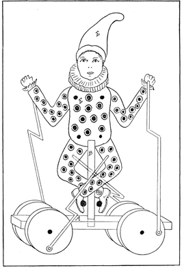
Fig. 458
Fig. 458 shows how a clown can be mounted on a cart so that
when the cart is drawn along he dances and waves his arms. In
toys of this kind, the wheels should be quite half-an-inch in thickness.
They are glued on to round axles which turn freely in
small screw-eyes or in holes in wooden blocks fastened under the
car or cart. If any part of the axle projects beyond the wheel
it gets in the way of the wires. The clown is made of cardboard
or three-ply, according to design given in Chapter XVI. It is
then fastened securely to rod B, and the latter glued into a hole
in the middle of the cart. Fairly strong wire is fastened to the
wheel by a nail with a broad head so that when the wire is looped
round the nail it turns freely on the nail but does not come off.
The wire is bent at right angles twice to bring it close to the figure,
as shown at A. It must fit accurately into the holes in the figure.
Notice that one leg passes on each side of the post.
The clown works best when cut out of wood. In this case the
body E and post B may be cut out in one piece, one leg and one
arm are then attached to the front of the body, and one leg and
one arm behind.
Fig. 459 shows a soldier on the march. He is made of three
pieces of wood. Head, body, arms and stand A are cut out in one
piece, the legs are cut out separately and riveted loosely to the
body; only two pieces of wire are needed, one on each side, to
work the legs. The gun may be a piece of wire or wood fixed
on after-ward. The wheels are ½ inch in thickness.
Other similar toys worked by wheels can be made by cutting
a hole in the bottom of the cart. One axle of the cart must run
exactly under this hole, it must be made of wire and bent as B C
in Fig. 460.
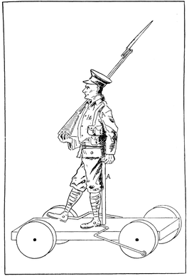
Fig. 459
D and E are pieces of tin nailed to the cart, through holes in
which axle B C freely turns; or wooden blocks may be nailed on
for the axle to turn in, if tin cannot be obtained. The ends of the
axle are securely fastened into solid wooden wheels. As the
wheels revolve they will push up and down a piece of wire or
wooden rod, F, which is fastened to the bent part of the axle.
Now F can be
used to work
a number of
simple toys, if
its free end is
fastened to the
part which it
is desired to
move. For example
by this
means an animal's
mouth may be made to open and shut as it is wheeled
along, or its head to wag; a blacksmith may be made to strike
his anvil, the drummer to beat his drum. The ingenious child
will be able to adapt this simple piece of mechanism to many
a toy.
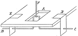
Fig. 460
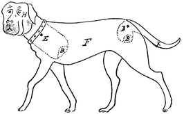
Fig. 461
A Lively Dog. Cut out with a fret-saw two pieces of wood as
F in Fig. 461, which represents the body and legs of a dog in one
piece. Now cut out the head H (notice length of neck behind
body) and the tail K from wood ¼ inch thick.
Now glue the two bodies to a piece of stripwood A (½ inch by
½ inch) placed along the tops of bodies inside (Fig. 462), and
bevelled so that the legs of the dog will be further apart than
the upper portion. The legs are joined by
pieces of stripwood, M, ¼ inch by ¼ inch,
about 1½ inches long. Notice that the ends
of these strips are bevelled. Now make
hole, E, in the head-piece; notice that there
is the same length of wood above E as below
it. Make corresponding holes E in sides F.
Pass a piece of wire through the hole in the
dog's head and see how it
hangs; the head portion
will be the heavier and
sink. Now take the head
off, saw out a piece of
wood at B, insert a piece
of lead and try again. It
is an easy matter if too
much lead has been added
to cut off a little. When
the head is correctly
balanced, as in Fig. 461,
bend over the wire so that
it cannot come off. The
tail, K, is attached in the
same way.
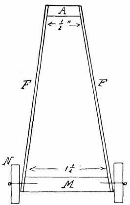
Fig. 462

Fig. 463
Fig. 464
Small wheels, N, cut
from some convenient
round rod are then nailed to M. The dog should be suitably
coloured. When drawn along he wags his tail and bends his head.
The legs look rather better if cut out separately and glued
to the sides.
The Tumbling Clown or Monkey. Cut out cardboard or
wooden animals similar to those in Part I, Chapter XX, but use
no lead. Now, instead of swinging them on a perch, make a hole
at B where they stand; take a piece of copper wire, about 1/8 inch
thick and 6 inches long.
Bend it slightly as in Fig. 463. Pass the wire through the
hole in the animal, so that the animal fits tightly on it exactly
in the middle of wire.
The animals are best cut out of thick cardboard. Fig. 464
shows a suitable animal, and the following from Chapter XX—Figs.
256, 257, 259, 263 and 264—can be adapted. As no lead
can be used for the purpose to which we are now going to put
them, animals that balance without lead, as in Fig. 464, are the
most suitable. Therefore in designing them, one must take
care that the hole B is exactly at the centre of gravity,
and the bend of body, D (that is widest part of body), just
below B.
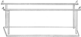
Fig. 465
To make the Monkey tumble. Cut a piece of wood 12 inches
by 2½ inches, and fix parallel bars to this as in Fig. 465. File or
cut notches in the ends at A, to keep the monkey from tumbling
off in his zeal. Now put the wire with the monkey in the middle
across one end of the rails. Push the monkey head over heels
and he will go on solemnly turning over and over, however long
the rails are, until he lands in safety in the notches at the other
end. It is the bend in the wire and carefully balanced body of
the monkey that makes him behave so delightfully.
The longer the stand is the better, for then two or three clowns,
monkeys and cockatoos can follow each other rapidly.
Fig. 466
The bars must be high enough to allow the monkey to turn
without touching the ground—4½ inches high will just do if length
of monkey from B to C (Fig. 464) is 4½ inches.
Fig. 466 shows two clowns swinging together; a variety of
funny figures can be made to follow each other along the bars.
Kites. Perhaps one of the easiest kites to make is one which
the children of Annam and Tonking delight to play with. To
make it, three light bamboo canes are required—about 2 feet in
length—those used for flower-sticks will do quite well. Tie them
strongly together as in Fig. 467.
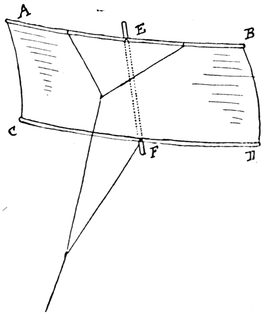
Fig. 467
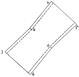
Fig. 468
The backbone E F should be quite rigid, but the cross-pieces
A B and C D are better if they are slightly curved. A sheet of
light paper must now be pasted from A B to C D underneath E F
in such a way that it is quite tight under E F, but rather loose
between A C and B D.
Fig. 468 shows how the paper should be cut. G H is the exact
distance between E and F; J K and L M are wider than distances
between A C and B D in Fig. 467, so that when the flaps on the
paper are pasted over the cross-bits the paper is loose between
A and C and between B and D (Fig. 467). The secret of the
balance is to have the flutter at the edges quite equal. Fig. 467
shows how the string is fastened.
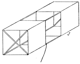
Fig. 469
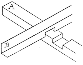
Fig. 470(a)
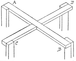
Fig. 470(b)
Fig. 471
Fig. 472
Fig. 473
A Box Kite. This is a very common form of kite and quite
easy to make. Take four laths from 27 to 30 inches in length
and four pieces about 13 inches in length. The smaller pieces
are fastened together with nails and glue, as in Fig. 470 (a) and (b).
To the ends of these the long pieces are nailed and glued, as in
Fig. 470 (b). Mark off the long pieces into thirds and over the two
end thirds sew strips of light material. Tie on the string as shown
in Fig. 469. This kite is said to be an American invention.
A similar kite may be made triangular in form.
Fig. 471 shows another form of the box kite. Here the
material covers a little less than ¼ of the strip A B. Cross-bars
E F and C D are tied across the middle and to the four sides, and
wings are sewn on to them.
Figs. 472 and 473 are modifications of the triangular form of
kite. In both these kites the long strips of wood are from
2½ to 3 feet in length.
Notice that in Fig. 472, A B is the same length as D E, F G = D H;
E H = about ¼ of E D.
Fig. 474
In Fig. 473 A B = C D. C E = about ¼ of C D. F G equal about
1/3 of A B. F C = C E. A H and
J K are light frames of stripwood
covered with calico. The diagrams
show how these kites are
put together.
A Chinese Kite. The kites
used in China are very light and
flimsy compared to our kites, as
they are made of tissue paper
and bamboo.
In making one it is better to
use somewhat stronger paper.
The paper is cut out as in Fig.
474, the two upper sides being
slightly shorter than the two lower. Leave two rectangular
pieces A, A, at each end of the shorter sides. A piece of split
bamboo, slightly flattened, is glued firmly to the paper from B to C.
A second piece of bamboo tapering at the ends is used as a cross-piece
D. This is bent as in the figure so that where it crosses the
backbone, B C, it is only a few inches from the apex, B. It is tied
to B C at D. Its tapering ends are pasted down to the paper by
means of the two flaps, A, A. Bamboo B C should not be more
than 1/3 inch in width, piece D, ¼ inch. To prevent the paper
getting torn in a good breeze, tie fine cotton round the border of
the kite—i.e. from B to A, to C, to A, and to B again. Paste a thin
margin of paper over the cotton, enclosing it, and to the kite.
This must be done so that the face of the kite is perfectly flat;
it must not bag in any way.
To fly the Kite. Much depends on the way in which the
'belly-band' is tied on. Its upper string is tied to D, and the
lower to the backbone, B C, almost anywhere below a line from
A to A. If the two strings are very near together, the kite behaves
in a more lively manner, darting about in all directions.
The kite must be coaxed into the air by a series of jerks and
pulls when the apex of the kite is facing upwards. It is inclined
to turn round at first and some patience is required to learn when
to pull and when to jerk. If one pulls at the wrong time it will
dart down and then unless sufficient string is quickly let out, it
will fall to the ground.
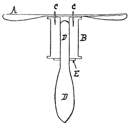
Fig. 475
When once the kite is up, it does not keep stationary like an
English kite, but is always darting
about; a skilful flyer can make a
kite dart down and almost touch
the roof of a house at a great
distance off, and then dart up
again almost overhead.
It is not an easy kite to manage,
but when once the art of flying it
is mastered it is never forgotten.
Gliders. The earliest type of
toy flying-machine consisted of a
two-bladed tin propeller spun on
a frame by unwinding string, as
with a top, and suddenly let go. It is easily made, as shown in
Fig. 475, where A is a tin propeller nailed by nails C and C to a
large reel B. In making this toy the nails must be driven into the
reel first, their heads are then cut off and they are tightly fitted
into holes in propeller A. D is the axle on which the reel spins and
the handle for holding it; E is a washer. This flying-machine is
worked by smartly pulling a length of string wound around the reel.
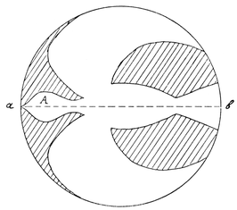
Fig. 476
Modern aeroplanes are far more difficult to make than this;
they need patience, skill and experiment, and besides a knowledge
of how to twist and bend wood by steaming it; plenty
of cane and whalebone wire, tissue paper or fine Japanese silk,
and catapult elastic, which is generally the motive power used
in working model aeroplanes. (Messrs Gamage, Holborn, W.C.,
stock skeins of specially prepared elastic.)
In this chapter only the simple and well-known types will be
very briefly described, the boy who is interested must get special
books on this subject from his library. In the first place the
beginner must know what the three types of machines used in
designing models generally are—viz. (1) the glider or motorless
model, a glider being a winged structure, which when released
from a height does not fall directly to the ground, but descends
gracefully at a gentle slope; (2) the monoplane, which is constructed
more or less on the lines of a bird; and (3) the biplane
or double-winged aeroplane.
Gliders may be either of the monoplane or biplane type.
Experiments with gliders will enable boys to find out some of the
principles on which aeroplanes are built, and will prepare them to
undertake the construction of more difficult forms.
In making one's first glider one cannot do better than copy
a bird. On a piece of paper draw a circle, fold it in half, draw a
bird on one half, as in Fig. 476, cut it out, when the paper is
opened it will appear as in the figure. If this bird is thrown head
first toward the ground, it will probably fall. If two little bits of
cardboard are gummed on each side of his head, he will make a
better flight and land on the ground after making a gentle curve.
A still better bird may be cut from cardboard, a half cut is then
made along a b to bend it, and the head is weighted with sealing-wax.
How well this bird flies depends on the weight, and to some
extent on the shape of the bird. Birds of various shapes and with
different amounts of sealing-wax should be tried, until one is
made that glides to the ground in a long, graceful curve.
In making bird gliders the following points should be
remembered:
(1) Draw the bird in a circle as already explained, this ensures
that the wings will be exactly balanced.
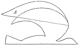
Fig. 477
(2) If the head in Fig. 476 is not long enough for a graceful
flight, a longer
head cut from
cardboard can be
pasted on.
(3) If the bird
dives quickly
down head first,
you know that
the head is too
heavy, or the neck
too long.
(4) If the bird
rises and then falls the head is too light and probably not long
enough.
(5) The wings can be made larger if necessary by the addition
of tissue-paper wings gummed on as A in Fig. 477.
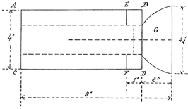
Fig. 478
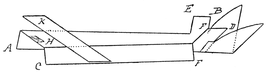
Fig. 479
Another Glider. Cut out a piece of paper 8 inches by 4 inches,
A B C D in Fig. 478. Mark B E and D F each 1 inch; make cuts
along the dark lines at E and F to the depth of 1 inch. Draw the
broken lines along the paper, dividing it into four equal strips.
Bend sides A E and C F downward along dotted lines. Bend E B
and F D upward along middle dotted lines, and press side C F
toward side A E, part way along this line, but leaving the part
near the ends A C flat; to this end plane K will be gummed
(Fig. 479). K is 6 inches by 1 inch. Cut tail, G, and gum on as in
diagrams. It can be weighted at H by gumming several strips
of cardboard across or by affixing sealing-wax. Although this
is not a very graceful-looking glider it works most successfully,
and will describe quite a graceful curve toward the ground.
The child will find it interesting to make a number of these
gliders and then go one day to a window or high place and let them
glide to the ground and thus find out the bird that has the longest
flight. Or a number of children can have glider races and see
who can make a glider that alights on the ground farthest from
them. Other forms of gliders can be made, but they are all on
the same principle, a somewhat long body, wings and weight
adjusted to keep them from falling.
Fig. 480 shows a glider made from a dowel rod, with slits in
it at each end through which two cardboard planes are passed and
fastened. The cardboard must be of light weight and yet stiff
enough not to flap. The size of the planes must be found by
experiment, for their size will depend naturally upon the weight
of the material used. The bigger plane should be in length about
twice the smaller one. It is best to fasten the large plane on first
and then adjust the smaller one to give a long, graceful flight.
If a split pole can be found it is an easy matter to fasten the
planes in. Canes (bamboo) split readily and can be used as centre
pole.
This glider can fairly easily be made into an aeroplane and
worked with a propeller. It may be mentioned here that model
aeroplanes are generally worked with the propeller in front and
not in the rear.
To make Propellers. These can be made of tin or wood.
A tin propeller can be cut from any old tin with a pair of shears
or strong scissors kept for the purpose. Cut two blades to the
shape shown in Fig. 481.
Next cut an oblong block of wood (Fig. 482); notice that
width a b in Fig. 482 must equal a b in Fig. 481, therefore width
of a b must be a little less than a b in Fig. 481. Slit each end
diagonally as in Fig. 482 for about ½ inch to hold the blades.
Drill a hole through centre of block for the wire axle d c. Insert
the blades in the slots, bend the ends over slightly and nail them
in the wood to keep them firm. Fix the wire shaft firmly in the
block as in Fig. 482. The propeller is now ready to be attached
to the glider.
Before this is done, however, we shall consider the making of
a wooden propeller. This is rather more difficult to make.
Cut a piece of wood to the shape shown in Fig. 483 with a sharp
pen-knife. The propeller must then be given the correct twist
by means of the steaming kettle. Take hold of the extreme ends
of the propeller and hold it over the jet of steam so that steam
plays upon the blades at each side of the thick central portion.
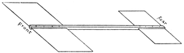
Fig. 480
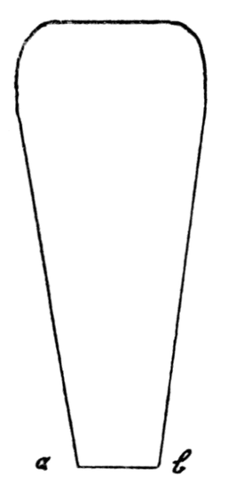
Fig. 481
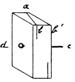
Fig. 482

Fig. 483
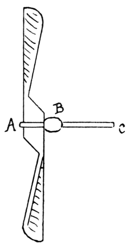
Fig. 484
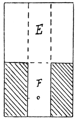
Fig. 485
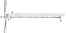
Fig. 486
When the wood is supple, twist it as in Fig. 484. This sounds
easier to do than it really is, the difficulty being to get the twist
on one side exactly equal to the twist on the other. For this
reason the tin propellers are more satisfactory to make. However
suppose the correct twist has been given, the next thing to do
is to sand-paper the wooden propeller carefully and file a groove
around the middle at A; now wrap a piece of wire, A C, tightly
around the propeller in this central groove, and put on the head,
B. The propeller is now ready to be fastened to the glider shown
in Fig. 480.
To fasten Propeller to Glider. Cut a piece of tin to the pattern
shown in Fig. 485, bend along the dotted line; make a hole at
F for axle, B C, to go through. Bend portion E round the front end
of the glider, keep it in its place by bending it with thread coated
with glue; portion F with the hole is bent down at right angles as
shown in Fig. 486. Now pass axle, A C, through hole F, bend end
C into a hook. Put screw-eye D in the rod about one-third of
length of rod from the other end (see Fig. 486). Fasten strands
of elastic from hook C to D. It is best really to have a hook at
D so that the elastic can be slipped over. The strands should be
just loose enough to remain taut when unwound. When the
propeller is in position the planes will probably have to be readjusted.
The tin propeller can be attached in a similar way.
These propellers will do for almost any simple design of aeroplanes.
When the motor is wound up for flight, the number of turns
to give to the propeller will depend upon the strength and number
of the elastic strands used. About a hundred turns is a usual
number. Throw the motor forward in a slightly downward direction;
because it is a glider it will tend to follow a gentle curve
to the ground at first, but the whirling propeller will tend to carry
it forward and upward. The first attempts may be failures, but
these models are well worth many trials.
The Hawk Aeroplane (Fig. 487) is a common flying toy
worked as the above by elastic. Cut two blocks of wood, A, A´;
make holes in them as shown. Into the square holes fix and glue
two square rods C. Through A´ bore a hole for the piece of cane,
B B´, to pass through. F is a wire spindle with a hook at one end
for elastic; it passes through the hole in block A´, through two
beads, and through a piece of cork, F, into which it must be fixed.
K is a piece of cane bent as in diagram, passing through a hole in
cork, H. The bend is more permanent if the cane is held to the
spout of a boiling kettle; the ends of K should be slightly warped
in opposite directions. Into block A another wire hook is fixed
and bands of elastic are passed over this hook and the opposite
one, as in the diagram; the more bands the better.
The cane B B´ is bent round at each end and fastened to the
wooden rods, C C, by thread. The cane, K K, is fastened by thread
as in the diagram; the thread can pass through a hole in the cork.
Spaces T, T, T, T are covered with thin tissue paper gummed to
thread and cane by means of overlapping edges. The model is
wound up and set going like the previous one. Care must be
taken to have it properly balanced, and it must be made as light
as possible; the blocks A, A´ may very well be cut from cork.
Light bamboo cane can be used for posts, C C. At its best, however,
the Hawk Aeroplane is not so good a flyer as the first
model described.
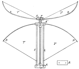
Fig. 487
An ambitious and clever boy who has once grasped the
principles on which flying-machines are made can think out many
models for himself and copy some of the more elaborate ones.
The biplane makes a very effective toy, but is omitted here
because it is somewhat difficult to construct.
Jacob's Ladder. This is a very old and ingenious puzzle and
an amusing toy. It is very simply made. A number of blocks
of wood must be made, 4" × 2½" × 3/8". Any number may be used,
but not less than seven; twelve is a very good number.
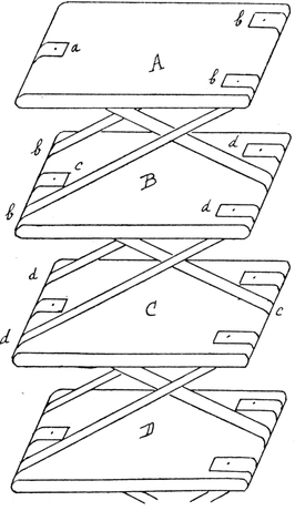
Fig. 488
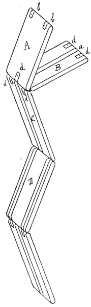
Fig. 489
Round the edges of the blocks and make them smooth with
sand-paper, as in Fig. 488. Cut strips of tape about ¼ inch wide
and long enough to go over the rounded ends of the blocks,
a, b, b, etc., in Fig. 488. There are three tapes to each block.
Nail and glue tape a to the centre of upper end of block A; it is
then brought over and downward under the middle of the lower
end of block B and fastened.
Tapes b b are now fastened to the opposite end of A about
¼ inch from the end on either side, and are then brought round the
opposite end of B, as shown in the diagram. The centre tape c
is fastened to B and then brought down underneath to centre of
the opposite end of C. The tapes must be arranged like this
throughout the whole set of blocks.
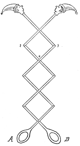
Fig. 490
Fig. 489 shows how the blocks are held when they are all
complete. Top block A must be
turned so as to bring the second
block to the same level. The top
of this block then falls, and it
appears to pass rapidly down
first on one side and then on the
other, until it reaches the bottom.
This is only what seems to
happen. What really happens
is that the second block becomes
reversed and falls back again, in
its former position. This makes
it come level with the third block,
which at once falls over on the
fourth, and so on to the end of the
ladder. A very illusive effect is
thus produced. The blocks might
be coloured with some bright
enamel paint, contrasting colours
on opposite sides.
The Trellis Toy (Fig. 490).
The strips of wood for this toy
should be as thin as possible.
They are fastened together at
points 1, 2, 3, 4, etc., by small pieces of wire, or by rivets bent
down to prevent their slipping off, but not too tightly, so that
the toy works easily. Heads can be cut out of cardboard painted
and glued to the wood. Strips A and B should be wider at one
end and have holes made in them for handles.
A Running Mouse. This toy is made of fret-wood, two
ordinary reels and elastic.
Choose two reels of about 1½ inches in length, diameter about
1 inch.
Cut out a piece of wood, A, to measurements given (Fig. 491).
With a fret-saw cut out the head (Fig. 492); slit B is a little wider
than the thickness of the wood, so that the head wags about very
easily when wired to the body (Fig. 494). Cut out four legs as in
Fig. 493. The reels work behind these so that the shape of the
leg partly hides them. Nail the back legs to the body as shown
in Fig. 494. Make a round axle to fit one of the reels so that it
turns easily on it; cut it the exact length of the distance between
the two back legs, pass it through the reel and glue its ends, C,
to the legs so that the reel comes slightly below the legs and can
run along easily. Now make holes, D, in the front legs, and nail
them to the body so that holes D are on a level with the axle C.
Make a hole through the body A, midway between the front legs,
through which the string, E, will pass. Make holes in the other
reel and insert wire staples at each end as in Fig. 495. Fasten to
and wind round the reel about a yard of string. Pass rubber
bands through each staple (F in Fig. 495) and through the holes
D in the front legs and knot on the outside. Pass the string
through the hole in A (Fig. 496).
To fasten Head on. Make two holes in the head exactly over
each other, G and H in Fig. 492. Slip the head on to the body and
make a hole through the body, between holes G and H, as shown in
Fig. 497. Bend a piece of wire as in Fig. 498, distance between bent
ends being equal to distance between holes G and H; slip the wire
through the hole in the body, pass the ends of the wire through
holes G and H, then bend the ends over to the position shown by the
dotted lines in Fig. 498; the mouse's head will then swing from
side to side. Make a hole in end at L (Fig. 494) and insert a tail of
thick string. A piece of wood, M, shaped as in Fig. 494, may be
glued along part of the body, A, a little to one side so as not to
interfere with string, E. The whole may be suitably coloured.
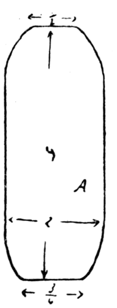
Fig. 491
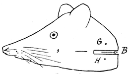
Fig. 492
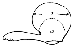
Fig. 493
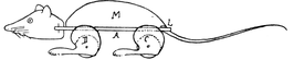
Fig. 494
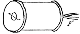
Fig. 495
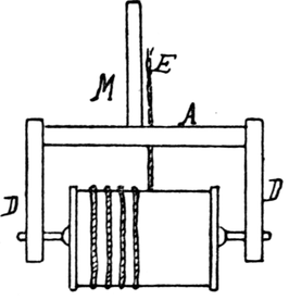
Fig. 496
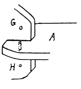
Fig. 497
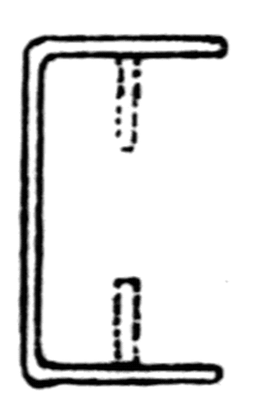
Fig. 498
Fig. 499
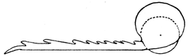
Fig. 500
The toy works in this way. If it is placed on the floor
and the string held, the weight of the toy will make the
twine unwind, thus causing the elastic which supports the
reel to twist. When the string is slackened, the elastic will
untwist again, making the reel revolve and the toy run along
the ground.
Figs. 499 and 500 show a black beetle that can be made in the
same way; the antennæ may be made of wire. Other suitable
animals are a lizard and a crocodile.
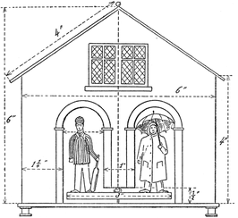
Fig. 501
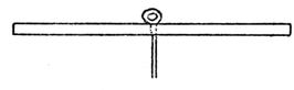
Fig. 502

Fig. 503
A Hygroscope. The cottage is made of thin wood about
1/8 inch to 3/8 inch in thickness, according to measurements
given in Fig. 501. The sides are about 3½ inches. The platform
or floor on which it stands, 6½ inches by 4 inches. The
sides of the roof are 4 inches by 4 inches, so that it projects
slightly.
The doors in front are 1¼ inches wide and 3 inches high, and are
cut out with the fret-saw; about half-an-inch of the partition
between the doors is cut away to allow the disc on which the
figures stand to swing round. Cut with fret-saw a circular disc of
wood 1/8 inch thick, diameter 3 inches. Drill a hole through the
centre and fit into it quite tightly a piece of wire bent into a loop
as shown in Fig. 502. Drill a hole in the floor of the cottage,
about an inch from the middle of the partition. The wire axle
should fit into this so that it turns easily, but not too loosely,
otherwise the disc on which the figures stand will wobble. Just
over this hole there must be another hole in the roof. This can
be made by filing, with round fret-saw file, a little hollow
(Fig. 503) in each of the top sides of the roof, so that when
they come together a hole is formed. The back, sides, floor
and roof may now be nailed and glued together. Next cut
out from three-ply wood with the fret-saw two little figures
as in Fig. 501; they should be about 2 inches to 2¼ inches,
and should be suitably coloured. These are glued to the
wooden disc.
The disc is hung from the roof by a piece of catgut; a knot
is made at the end to prevent it slipping through, the other end
being tied to the wire loop; the wire passes through the hole in
the floor. The catgut must be long enough to allow the disc to
turn round completely on its axis. Four pieces of wood or four
small reels are glued to the corners of the floor to prevent the wire
axle from touching the ground. The front must not be put on
until the model is found to work correctly. To do this, hang the
disc so that it is parallel to the ground, and so that both figures
are looking out of their respective doors; then tie the knot at the
top and wait for a change of weather.
Supposing on a damp day the cricketer comes forward and the
boy in mackintosh and sou'wester retires indoors, this is because
the catgut is twisting the wrong way, therefore the end that is
fastened to the roof must be fastened to the wire loop, and vice
versa. Now the front can be glued on. It can be suitably painted,
showing door-posts, windows, bricks, etc.
Why the Hygroscope works. Catgut has the peculiar property
of absorbing moisture from the air and twisting up and becoming
shorter; when the air is dry it untwists to its original length;
the damper the air the greater is the amount of the twist. Hence
in the model, as the catgut twists and untwists according to the
state of the atmosphere, the little figures swing in and out of the
cottage doors.
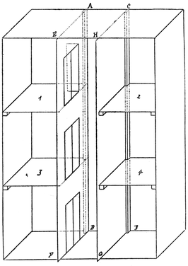
Fig. 504
A Lift. There are a variety of ways of making a lift. One of
the simplest is shown in this chapter. The first essential is a
wooden box, oblong if possible, so that there can be many floors.
The measurements given in this chapter are for quite a small model
made from a shallow oblong box, 9½ inches by 14¾ inches, and
about 2½ inches in depth.
Sand-paper the inside and cover it with some pretty paper.
Mark off distances A C and B D (Fig. 504) equal to 2½ inches; rule
lines A B and C D along the bottom of the box; glue pieces of stripwood
¼ inch by ½ inch (A B and C D in Fig. 504) along the bottom
of the box for the lift to run up and down between.
The lift is made next. Cut two pieces of wood 2½ inches
by 2¼ inches; nail to the corners of one piece four pieces of
stripwood, ¼" × ¼" × 3". Fasten the other piece of wood to these
four posts by means of screw-eyes. Now leave the lift for a
while.
Cut two pieces of cardboard, A B E F and C D H G, to divide
the box into three long divisions, as in Fig. 504. See that they
project ¼ inch beyond the box. Divide these strips into three
parts and draw and cut out doors as in the diagram; the line for
the floors must, of course, be well above the top of the lift, while
the height of the doors must correspond to that of the lift. Now
glue these strips of cardboard to the pieces of stripwood A B and
C D as in diagram; see that the doors open into the rooms on each
side, and not into the lift.
See that the lift runs easily up and down between the cardboard
strips; sand-paper it if it does not.
Make four holes in the top of the box, a, b, c, d in Fig. 505.
Tie thread or black yarn to the screw-eyes, cross it and pass it
through the holes as in the figure, then pass the four cables through
screw-eye K. When the lift is on the ground, pull the strings taut
and tie a knot below the screw-eye. The lift can be raised by
means of winding gear attached to the side as described in
Chapter V, on the crane; the weight of the lift will pull it down
again, or if this is not enough it can be weighted with lead.
Fig. 505 shows another way of working the model. Screw-eyes
can be fastened to the bottom of the lift and thread tied to them
as before; these threads must pass through four holes in the
bottom of the box, through a hole in the support L M and through
screw-eye Q; the bottom strings are then knotted to the top strings
at R, and the lift can be lowered and raised by moving knot R
up and down.
The supports N P and L M are made of pieces of stripwood
½ inch by ¼ inch.
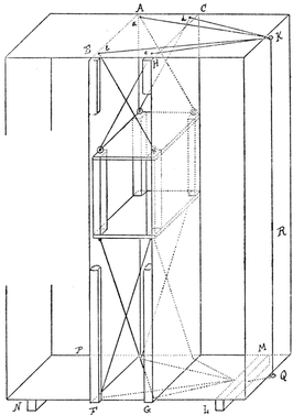
Fig. 505
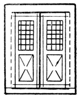
Fig. 506
Cut a door out of cardboard as shown in Fig. 506 and glue it
over the front of the lift. (In Fig. 506 the dotted lines are half
cuts, the black lines are cut.)
Nail strips of wood ¼ inch by ¼ inch, E F and H G, in front of
the lift and glue the pieces of cardboard to them. They keep the
lift from falling forward. If the lift is moved up and down, as
shown in Fig. 505, it is best for it to fit fairly tightly so that it
stays into whatever position it is pulled.
Cardboard floors, 1, 2, 3, 4 (Fig. 504), are added, and kept in
position by pieces of stripwood.
The rooms on each side can be furnished according to taste
and according to their size. The lift itself may be finished off
with advertisements, directions to travellers, etc., according
as it is intended for use in a railway station, a hotel, a store,
etc.
This toy, although so simply made, is very effective.
Pont Roulant at Saint-Malo. This is a pretty model to make.
First glue four pieces of stripwood, 3/8" × 1/8" × 4½", together (A A A A
in Fig. 507). Nail and glue to the corners of this framework four
round rods, 10¼ inches long and ¼ inch in diameter. Dowel rods
such as these are somewhat difficult to nail on; however, should
the wood of the little frame split, or the hole in the dowel rod be
made too large for the nail, and so make the structure unsteady,
the discs of cork (C in Fig. 507), which have a hole filed in the middle
of them and are glued to the rods and the framework, help to consolidate
the whole. Similar discs of cork are placed round the
middle of rods, B, and at the tops of the rods. These serve to hold
the black yarn which rigs the structure. The pieces of cork at
the top have the additional advantage of making a steadier base
for the platform to rest on. If the poles are not all cut exactly
the same length, the discs of cork can be raised above the shorter
poles and the platform on top made perfectly horizontal. These
cork discs also give a larger surface to glue the platform to.
Instead of dowel rods, iron wire 1/8 inch in diameter can be used.
These wire rods must have cork discs on them like the wooden
rods, but they must be glued into holes in the lower framework
and in the platform.
Having fixed the rods in position, thread is tied underneath
a bottom piece of cork (C5 in diagram), passed over the top of rod
B3 and kept there by the cork disc at the top, round the bottom
of post B4 and under the bottom cork, over the next post and so on,
so that the threads cross each other as in the diagram. Thread is
also tied round the middle of the rods just above corks C1, C2, C3,
and C4. Thread is also tied from C2 to C3, and C1 to C4.
Pieces of stripwood, 3/8" × 1/8" × 4½", are glued across the frame
A A A A. Next the platform has to be made; this is a piece of
wood 8½ inches square and 1/8 inch in thickness. Before gluing
it on to the four posts it is best to make and fasten to it the cabin,
railings, etc.
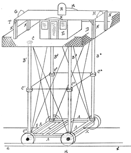
Fig. 507
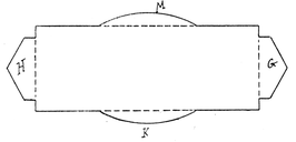
Fig. 508
The cabin, E, in the middle is 3 inches square and 2 inches high;
it is cut out of cardboard. Flanges must be left for gluing it
to platform, and for gluing the roof to it. Doors and windows
are drawn round it or cut out. The cabin is then glued in the
middle of platform D.
The roof is a piece of cardboard 3¼ inches by 8½ inches. Fig.
508 shows how it is cut out, half cuts are made along the dotted
lines, and G, K, H, M are bent up to form the ornaments G, K, H, M
in Fig. 507.
The roof is glued to the top of cabin, E, and to the tops of posts,
N, which are pieces of stripwood ¼" × ¼" × 2".
Triangular pieces of cardboard are glued in the corners, as P
in Fig. 507.
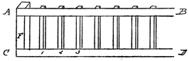
Fig. 509
The railings are 1 inch high; they can either be made of strips
of cardboard 1 inch by 8½ inches supported at the corners and in
the middle by pieces of
stripwood ¼" × ¼" × 1",
with criss-cross lines
drawn on them, or be
made as in Fig. 509,
where A B and C D are
strips of cardboard ¼
inch wide, F is stripwood ¼ inch by ¼ inch, and 1, 2, 3, etc., are
parts of match sticks glued to the cardboard strips. Seats can
be placed round the railings, and round the cabin where there
are no doors.
A piece of stripwood, R, ½" × ½" × 1½", is cut and filed as in
Fig. 507 and glued to the middle of the roof.
The platform is then glued to the tops of the posts with their
surrounding corks. The frame, A A A A, is mounted on wheels
1-1/8 inches in diameter and ¼ inch in width. The axles are pieces
of stripwood ¼ inch by ¼ inch, to which the frame A A is glued.
The rails on which it runs (a b in Fig. 507) are made in a similar
manner to those described in Chapter XIII, for the transporter
bridge. It is pulled along by thread tied to screw-eyes X and Y,
and wound up by winding gear similar to that described in
Chapter XIII.
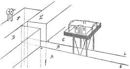
Fig. 510
Fig. 510 shows how high tide can be represented by means of
boxes and cardboard; D, E, F are boxes which form a quay into
which the car runs. A, B, C are pieces of cardboard resting on
pieces of stripwood glued to boxes D, E, F, and similar boxes on
the other side, or the cardboard can rest on boxes. If boxes cannot
be found big enough for D, E and F, several boxes can be built
up. Slots a b and c d must be left wide enough for the supports
to pass freely, and the threads must be omitted at front and
back. The rails must lie exactly under slots a b and c d. The
pieces of cardboard A, B and C should be coloured blue. The
thread from the car underneath the "water" can pass into
box F and up through a hole in the top, where the winding gear
can be placed, but, of course, it can be worked from below. Sheets
of cardboard A and C can be surrounded by boxes or fastened in a
large box, or have cardboard walls built around it.
Tower Bridge. A very simple and effective model of Tower
Bridge can be made, which will prove a delightful plaything.
The measurements given in this chapter need not be followed,
but the bridge can be made larger or smaller according to
taste. The whole structure can be of wood or of wood and
cardboard.
Two small boxes are required, made of wood ¼ inch thick, about
4 inches in length, breadth and height. (If such small boxes
cannot be found they must be made.)
Take off one side of box, A B C D in Fig. 511, which shows the
mechanism of the toy. Into the edges D F and C E screw two small
screw-eyes, G and H, about ¼ inch from the top.
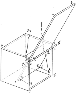
Fig. 511
Now cut a piece of wood 8¼ inches long for the bridge. The
width of bridge a b must be equal to width of interior of box. For
the present model it will be 3½ inches.
The wood used for the bridge should be about 1/8 inch
thick.
Now rule a line 5¾ inches from end a b. On this line screw in
two small screw-eyes, K and L, of the same size as screw-eyes G
and H. The axle, M N, may be either iron wire (in which case the
bridge may work rather loosely) or, what is better, a wooden rod
that just fits the screw-eyes. Whichever axle is chosen cork discs
should be placed at each end to prevent it slipping out. Before the
bridge is fastened on, screw-eyes O and P are screwed in it near the
end c d. Screw-eye P must be far enough from the edge b d to
clear screw-eye R when the bridge is upright. The same with
screw-eye O.
A piece of strong thread is tied to screw-eye P, passed through
screw-eye R, and through a hole in the drawbridge above screw-eye
R, but clear of axle, M N. A similar piece of thread is tied to
screw-eye O, passed through Q, and through a hole in the bridge.
Now cover up top, A B C D, with a piece of cardboard, but do
not bring this quite up to B C, in order not to interfere with the
working of the bridge. Make holes in the cardboard for the
strings to pass through. Then cover up the front portion, D C F E,
below the bridge with cardboard.
The tower (Fig. 512) must next be made. This is formed of
one piece of cardboard: height, a b, 9 inches; width, c d, 3¼ inches.
In the sides facing the bridge large openings, E, are cut about
2½ inches high.
Small openings, F and G, about 1½ inches high and ¾ inch broad,
are cut for the overhead foot bridges. These are made of long
pieces of cardboard 2 inches broad, bent in three divisions to form
the path and sides. The latter are marked to represent railings.
They should be long enough to pass well inside the tower through
openings F and G, and through the corresponding openings in the
opposite tower. They can be glued into position by pieces of
stripwood or left movable.
A door, A, should be made in the top of the tower and a platform
put in to make a compartment for working the bridge. The
pieces of thread are brought up through holes in this platform and
fastened to rod B, which passes through holes in sides of tower,
and is kept from slipping out by cork discs. When this rod is
turned the bridge will rise or fall.
If a large model is being made a proper little windlass with a
handle can be constructed inside the upper room of the tower.
The threads pass up on each side of the tower so as not to interfere
with the "traffic" passing under the arch of the bridge. The
tower is fastened up with flanges and glued to the wooden box
with the help of small blocks of wood. A square pyramid is
placed on the top of the tower, and the whole is suitably coloured.
A picture of the real Tower Bridge is a great help when finishing
off the model.
A similar bridge and tower are made for the other side.
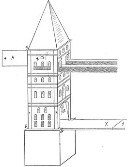
Fig. 512
To keep the wooden boxes the right distance apart (that is, so
that bridge X just touches bridge Y) nail or glue them to a long
strip of wood painted blue. There is, however, no need to fasten
them permanently.
The ingenious toy-maker will find a hundred ways of improving
this toy. There are many additions that can be made if a picture
of the Tower Bridge is consulted; cardboard paths can lead to
bridge X, round the outside of the tower; railings can be added to
bridges X and Y (but see that they are not in the way when the
bridge goes up!), and so on. The method of raising and lowering
the bridges is capable of a number of modifications. It should be
the pleasant business of the maker to improve this model, and not
be content with too slavishly following the directions given.
Bridges are among the most interesting things in the world,
and there are countless happy hours in front of the little toy-maker
who sets to work to collect pictures and written accounts
of bridges, and who tries to imitate these.
Soldering. A knowledge of soldering makes many more toys
possible, besides being a useful acquirement in itself. The
following are the materials needed:
1. A soldering iron (Fig. 513). This can be bought for sixpence
at any ironmonger's. It is best to get one not too long in the stem,
as otherwise it is difficult to hold it steady.
2. A strip of soft solder, price about three-halfpence.
3. Soldering fluid or flux. This can be made at home from a
pennyworth of spirits of salt (from an oil shop). Put a little of the
spirits into a separate bottle and drop a few scraps of zinc into it.
When it has stopped "fizzing" it is ready for use.
4. A pennyworth of resin.
5. A piece of sheet tin.
Soldering is not nearly so difficult as people think. There
is one thing really essential for its success, and that is unlimited
patience in cleaning the metal surfaces to be joined together.
Solder will not adhere to dirty metal. The surfaces must be
thoroughly scraped and cleaned with an old knife, then filed,
rubbed with emery-cloth and protected by a coating of flux.
The flux required for use should be kept in a shallow dish (e.g. a
meat-paste jar), to prevent it being upset; it can be put on with
a small brush.
The copper bit of the soldering iron must be covered with a
thin film of solder before any soldering is done; this is to ensure
that it is perfectly free from dirt or dust. This process is called
"tinning the bit." It is quite simple. Heat the iron to a dull red
heat, not quite red hot, as the solder would otherwise be destroyed.
Then quickly file the four faces of the point to remove any dirt or
oxide that may have got on it and which would prevent the solder
from sticking to the bit. Next dip the bit for a second or two in
the soldering fluid and melt off a drop of solder on to the piece of
sheet tin on which is put a little piece of resin. Turn the point
of the bit round and round in the melted solder until it is completely
coated. It is very important that the soldering iron should
at no time be overheated, as this tinning would be burnt off; nor
can it be repeated too often that the surfaces to be joined must be
thoroughly cleaned; failure to do this is in most cases the cause
of unsuccessful soldering.

Fig. 513
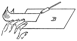
Fig. 514
To solder handle A to B (Fig. 514). Thoroughly clean that part
of B to which A is to be fastened,
and handle A, rubbing the edges
of A with emery-cloth. Place
A on B and rub a little flux
with a brush along the join.
Dip the bit into the flux and
drop a spot or two of solder
on the edges by applying the
heated iron to the end of the
strip of solder. Apply the bit
to the solder and trail the
solder with the point of the hot iron round the join so
that it is filled up.
A little practice will soon enable this to be done successfully,
and the skill thus acquired makes the following toy possible.
A Steamer with a Screw Propeller. Fig. 515 shows the
size and shape of the steamer. It should be about 4 inches wide
amidships, 3½ inches deep, and hollowed out as thin as possible,
according to directions given in Chapter XIV. Fig. 516 shows the
measurements for the stern. The bows should be sharp.
This boat must be fairly large to take the tube which runs
through it. Fasten a strip of lead 1/8 inch thick to the bottom of
the keel. Paint the boat a suitable colour. When it is dry place
it in the water and mark on the stern-post, A B (Fig. 516), the
height to which the water comes, for the propeller must come just
below this. Midway between this point and the end of the keel
bore a hole, C, in the stern-post, through the boat in the direction
of the top of the bow. This hole should be 3/8 inch wide and can be
made with a red-hot wire.
A brass tube must now be bought from a gasfitter's, 3/8 inch
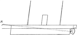
Fig. 515
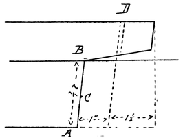
Fig. 516
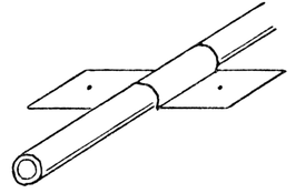
Fig. 517
Fig. 518
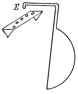
Fig. 519
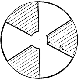
Fig. 520
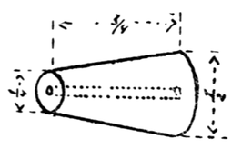
Fig. 521
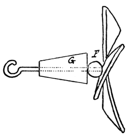
Fig. 522
Fig. 523
outside measurement, and long enough to reach from C to about
3½ inches beyond the end of the bow. Now cut a piece of tin
¾ inch wide and 2 inches long. Bend the middle of it round the
tube and the ends outward (Fig. 517). Punch holes in each end.
Solder this strip round the tube about 4½ inches from one end.
At this end file four teeth, about 1/8 inch deep, as in Fig. 518. Now
push the end that is not filed through the hole in the stern from
the inside of the boat, so that it is flush with the wood, and fasten
the other end to the stem of the boat by driving small nails through
the holes in the strip of tin into the boat. To prevent water
entering the boat put some putty round the tube where it passes
through the wood. Before fastening the tube in the boat, round
out the end of the bow slightly so that the tube will rest securely
on it without projecting too much above the gunwale. Make the
deck and fix it as described in Chapter XIV. Bore a hole, D, in
Fig. 516, near the stern right through the deck so that it comes
out under the counter about 1 inch from the stern-post. It
should be large enough for a piece of stout wire to pass through.
This is for the rudder.
To make the Rudder. Cut a piece of brass wire about 1/16 inch
thick, 6¼ inches long. Cut the rudder out of tin and shape as in
Fig. 519. Solder it on to the wire so that the end of the rudder is
flush with the end of the wire. Pass the wire through the hole, D,
and bend as in Fig. 519. Cut a strip of tin about 1/3 inch in width,
punch holes in it, point the ends, bend them over and fasten them
into the deck so that the strip is under the bend, E, of the tiller.
Press the tiller over and into one of these holes; thus the rudder
can be held firm in its required position for steering.
In the middle of the deck cut a hole about ¾ inch in diameter
for the funnel, which is a tube of tin about 4 inches long.
The Propeller. Cut a circle of tin 2 inches in diameter and
inscribe a hexagon; cut as in Fig. 520, the shaded portions being
cut away.
Punch a hole in the centre and into this fix, by soldering, a piece
of brass wire (1/16 inch thick), 2 inches long, to form an axle. Warp
the fans of the propeller out of the plane of the circle about ¼ inch.
Make two pieces of wood shaped as in Fig. 521. Bore a hole
through each and by filing with a small round fret-saw file enlarge
it to 1/16 inch.
Put a glass bead, F (Fig. 522), on wire of propeller, and put the
wire through one of the pieces of wood, bend the end into a small
hook. Take another piece of wire, pass it through the second piece
of wood and bend it as in Fig. 523. Now take a piece of strong
elastic, ¼ inch wide and about 3½ feet long; tie the ends together.
This must be passed through the tube in the boat. To do this,
tie a piece of string to the elastic, and drop the string through the
tube from the stern end, and by means of the string pull the elastic
through, first hooking one end of it to the hook on the propeller
wire, Fig. 522. Then push the piece of wood, G, into the tube, so
that the screw clears the rudder. Now hook wire, H (Fig. 523),
into the elastic, and push wood, K, into tube. The wood must be
cut away so that the handle, M, can catch in the teeth of the tube.
To make the boat work, hold the propeller steady with one
hand and wind up the elastic by the handle, M; put the handle
in one of the teeth to keep the elastic twisted; set the rudder, put
the boat into the water, let go the propeller and the boat will go
on until the elastic is unwound. Instead of one band of elastic,
several thinner bands may be used, and more motive power can
thus be obtained.
Toys worked by the Wind. Cut out of fret-wood (1/8 inch
thick), or three-ply wood, a man reading a paper with one foot
raised and resting on a box.
The man should be about 5¾ inches and his raised foot 1 inch
from the ground, as in Fig. 524. The shoeblack is cut out in three
pieces. First the kneeling portion, A (Fig. 525), is cut 2 inches high
and a hole made at b; then the head with part of the arm to the
elbow attached, as H in Fig. 526, about 1¾ inches high, and with
holes at d and e; then the hand (with long shoe-brush) and arm
to elbow, as K in Fig. 527; make a hole at f. Length of K
2¼ inches.
Now join K to H by wire or a rivet through holes f and e, so that
it swings loosely, then join H to A by a wire through holes d and b.
Colour these two figures suitably.
The base on which the figures rest is a piece of wood about
12 inches by 3 inches. The next thing to be made is the mechanism
that works the figures. First cut a piece of stripwood
¼" × ¼" × 7", A in Fig. 524. The fan or propeller, B, is made by
cutting a small circular piece of wood or cork about 1 inch in
diameter and securely fixing round it five wind flaps as shown.
These flaps are best made of tin.
Fig. 524
Fig. 525
Fig. 526
Fig. 527

Fig. 528
Now get a piece of stout copper wire (about 1/16 inch thick),
D in Fig. 524, and bend it as in diagram. The best way to effect
this bend is first to make a sort of elongated [**Symbol: U], as in Fig. 528;
this can be done with pincers. Then put part A in a vice and bend
B C and D E out at right angles. Cut it the right length so that the
bend will come on a level with the shoeblack's brush and one end
will come above post, A. The wire, D, should be pointed or well
smoothed with a file at the lower end, so that it will turn easily on
a piece of glass glued to the base.
Wire D is supported by two wire hoops or screw-eyes placed in
post A. The holes through which it passes must not be too large
or it will wobble and not turn smoothly. Now all the parts are
ready for putting together. Glue the shoeblack on first, then
opposite to him the man. See that the brush passes over the shoe.
If for any reason this does not happen, a larger brush can be cut
from wood or cardboard and pasted over the shoeblack's hand.
Now fasten post A behind the man so that the bend of the wire, D,
will be in the right position; pass wire, D, through the wire loops
or hooks (these are best made of copper wire); glue the top of it
into the hole in the propeller. Glue a piece of glass, E, under the
other end. Connect by a thin piece of wire the shoeblack's brush
with bend in D. The figure will now work well in the wind.
The shoeblack is the toy one most often sees worked in this way.
A man sawing wood is another favourite model, and can be made
in exactly the same way.
Two knights fighting can also be made; this involves, however,
two propellers.
Toys worked by Convection Currents. These are less interesting
toys because they do not admit of much variety. The toy
is worked over a gas burner, where it acts as a ceiling protector.
As the power available from convection currents is very slight,
every care must be taken that the figure will work smoothly.
As the toy is exposed to heat, the soldering must be well done.
Fig. 529 shows how the toy is made.
The little sailor is cut out of sheet metal (tinned plate); his
limbs are fixed by means of rivets or eyelets (the latter are obtainable
at a boot repairer's). Take care that they move freely.
They will do so if the holes are very smooth. The wire used is steel
wire about 1/16 inch; this is fairly easy to bend.
Wire A B is bent as already described in the shoeblack. It
passes through loops in the wire at A and D. It is kept from
slipping through at A by a ring of wire soldered on the top.
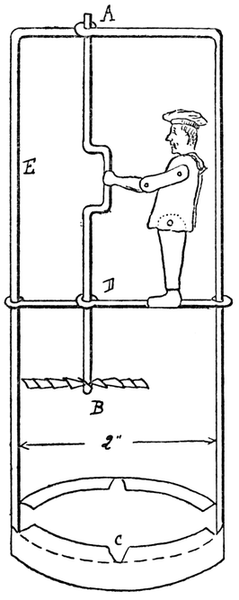
Fig. 529
The propeller at B is simply a tin disc
with radial cuts, each sector being twisted
at an angle by a pair of pliers. The
propeller is held by a turn in the wire and
by a touch of solder. Notice that the feet
of the figure are turned round the wire on
which it stands. They can be soldered for
greater security. The hand is also curled
round the crank pin, but it must be free to
turn on it.
The wire framework, E, is soldered to
a circle of tin, C, which fits on the top of
the lamp. As the figure has to be small
it should be as long as possible.
A pair of scissors should be kept for
cutting tin, or tinman's snips can be used;
cutting pliers and centre punches will
also be needed. Holes, however, can be
punched in tin with strong round nails
and a hammer. Round files are needed
for making holes smooth.
Empty tin canisters form a supply of
tin plate.
Adjustable cycle spanners are useful
for bending wire at right angles; a hide mallet is a great
convenience.
Before making a toy like one of those described it is well to
practise bending wire with vice, hammer and mallet.
In the last toy, if tinned plate and tinned steel wire are used,
the soldering is a fairly easy matter, because the tinning has already
been done.
A Farmhouse. Young children, having cut out of cardboard
or fret-wood the animals and trees described in Chapter XX,
having constructed a bridge, a well, a dove-cot, and other small
models scattered through this volume, take considerable pleasure
in arranging their toys into pretty groups and attractive combinations.
At this stage the lack is often felt of some object of
central interest, of something to 'pull the composition together,'
as an art critic would put it: the farm scene requires a farm, the
domestic scene a villa, the Eastern animals and trees an Indian
temple, or some such building, to complete the picture.
With regard to home scenes, children may be advised at this
stage to make for themselves any house or building that suits their
fancy. The basis of the toy will always be the four walls plus a
roof described in the Noah's Ark (Part I, Chapter X); more complicated
cardboard work has already been studied in the castle
(Part II, Chapter X), so children who are ambitious to achieve
something more picturesque than the Noah's Ark may be advised
to go out into the suburbs or the country, and sketch any simple
building, or set of buildings, which they would like to reproduce.
Such work, once attempted, becomes extremely fascinating, and
leads to very picturesque and delightful results. To do really good
work, however, children must accustom themselves to plan very
carefully what they propose to do, and to convert their sketches
into a set of drawings to scale, which, in the case of a building,
should include at least a ground plan and a couple of elevations.
Figs. 530 and 531 show how to lay down the plan and elevations
of a simple building of the 'Noah's Ark' type, to which
have been added a front and a back door, with porches, bay and
storm windows, chimney-stacks, and an outhouse at the back.
Fig. 532 is the front elevation to half scale.
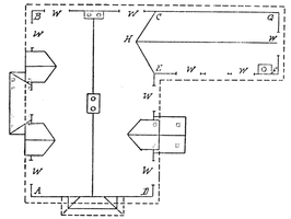
Fig. 530
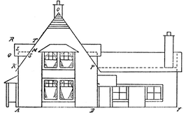
Fig. 531
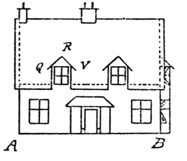
Fig. 532
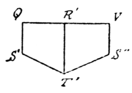
Fig. 533
The addition of another entirely detached outhouse with wide
door at one end, for a cowshed, to face the back of the main building
and form the third side of a square, will give the nucleus of
quite an attractive farm.
When once the plans have been drawn, a scale is plotted below
to suit any size to which it is intended to build; all the dimensions
shown in plan and elevation are then taken as required with
dividers, read off on the scale, taken anew on a foot-rule, and
transferred to the wood or cardboard.
The scale given on the figure is for quite a large house, the
ground plan of the main building measuring 15 inches by 10 inches,
and that of the outhouse 10 inches by 5 inches. These two buildings
had best be constructed on separate bases, and need not be
permanently joined; the roof of the outhouse can be carried rather
further into that of the main building than is indicated by the line
C H E, and the main roof alone cut carefully to the line C H E.
If the main roof is made detachable, building A B C D will form a
receptacle for the outhouses and the whole farm stock. The
broken line surrounding A B C D and C E F G indicates the dimensions.
A house of this size is best built with a base and walls of wood
obtained from some grocers' boxes.[2] If the scale be marked so
that points 0, 10, 20 read 0, 7½, 15, giving a reduction to three
quarters, the main building will measure 11¼ inches by 7½ inches,
and may be built entirely of cardboard. If the scale be marked
so that points 0, 10, 20 read 0, 5, 10, A B and A D measuring respectively
7½ inches and 5 inches, we shall have a small model that can
be built of very light materials, such as stout cartridge paper on
a cardboard base.
The bay window will, of course, be made separately, and
gummed into position by means of flanges. The porches may be
detachable, like the outhouse; the front-door porch is built of
eight pillars of stripwood, nailed and glued to a wood or cardboard
base and to cross-beams above; between the pillars may be fixed
a couple of seats, one on each side of the door. The back-door
porch is supported by four pillars. The roofs are of cardboard.
The ground-floor windows, indicated at W, may be either painted
or cut out; in the latter case they may be made to open or may be
fitted with celluloid window-panes; these you can beg from any
amateur photographer of your acquaintance; he is sure to have
plenty of 'waster' films. The doors should, of course, be made
to open.
The storm windows are easily made; the sides, K L M, are cut
with angle L K M = half the angle K O P, the latter being in the
present instance 72°. The shape of the window roofs can be
arrived at by experimenting with a paper template, but more
accurately by plotting them out to scale.
Thus: draw Q' R' V' = Q R V, R' T' = R T, Q' S' and V' S" = Q S;
join S' T' and S" T'; then Q' V' S" T' S' (Fig. 533) is the exact
shape (leaving the flanges out of account) to which the storm-window
roofs should be cut. The roofs over the front porch and
the bay window, the chimney stacks, etc., are thought out and
plotted in the same manner, the solving of these little problems
being excellent practice, which may be turned to good account in
after life.
The village church, the village inn, if it is old and picturesque,
should form good subjects for study and reproduction on the lines
indicated above. For young people who have exhausted the
possibilities of their immediate surroundings we give a few models
from lands more remote.
The Taj Mahal, Agra. This is one of the most famous buildings
in India, and was erected by the Emperor Shah Jehan over
the body of his favourite wife. A very pretty model which closely
resembles it can be made as follows:—
In Fig. 534 the dome, A, is a plain india-rubber ball, circumference
about 11 inches. Four india-rubber balls, circumference
about 6 inches, are needed as B B, and four, circumference about
4½ inches, for the four columns (C in Fig. 534) which surround the
temple. Cut a piece of fairly thick cardboard, 7 inches square, for
the roof of the temple. Cut off the corners as in Fig. 535. In the
centre describe a circle with radius 1-3/8 inches, and round it four
smaller circles of radius 7/8 inch.
Cut a strip of thin cardboard 9 inches by 2 inches. Cut as in
Fig. 536, leaving flanges of ½ inch. Roll round and fasten together
with seccotine and two small paper-clips, size 00. This forms the
part of the temple marked D in Fig. 534. It is glued to the roof
by the flanges, etc., and ball, A, is glued into it.
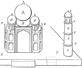
Fig. 534
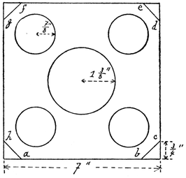
Fig. 535
Fig. 540
Fig. 541
Fig. 542
Fig. 543
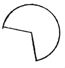
Fig. 544
Before fastening it together, mark on it in ink the pattern
indicated in Fig. 536.
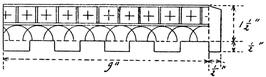
Fig. 536
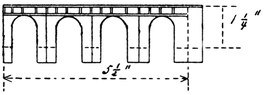
Fig. 537

Fig. 538
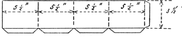
Fig. 539
Cut four strips of thin cardboard 5½ inches by 1¼ inches; mark
off ¼ inch for flanges; cut each as in Fig. 537; bend them round
and fasten together; glue the smaller balls, B, B, into them and
glue them on the roof just over the smaller circles.
Cut four strips of cardboard 5 inches by 1 inch; cut and mark
as in Fig. 537, and glue this round the smallest balls, C. Measure
distances ha, ab, bc, cd, etc. (Fig. 535), on a piece of cardboard,
and mark out as in Fig. 538. Make half cuts along the dotted lines
and leave flanges as shown. Distance ak = ah and lb = bc = cm = nd.
Make and cut out the windows and arch.
Cut another piece of cardboard similar to this. These two
bent round and joined together form the sides of the temple.
Now cut a piece of cardboard as in Fig. 539, leaving flanges all
round.
Bend it round and gum it together. This is gummed underneath
the roof, before fastening on the outer walls, and serves a
double purpose; it helps to support the roof on which the domes
rest, and prevents the temple from looking too hollow when the
windows are cut out.
To make Tower, C E (Fig. 534). It consists of three rolls of
thin cardboard, E F G, each about 2 inches high, circumference
4½ inches.
Circular pieces of cardboard, big enough to project about
¼ inch beyond the columns, form the platforms, H, J, K. Underneath
each platform triangular pieces of cardboard are glued, as
in Fig. 540. Four of these columns stand round the central
building.
It is a great improvement if rings of cardboard, ¼ inch wide, are
made and glued round all the smaller domes, as shown in Fig. 541.
Round the sides of the building strips of paper, L, M, N, O
(Fig. 534), are gummed, rising about ½ inch from the roof, with
patterns drawn on them as in Fig. 543. Little cardboard turrets
(Fig. 542) are cut out and gummed in each corner, P and Q (Fig. 534).
Little cones of paper, made by rolling together a circle cut as in
Fig. 544, may be glued to the tops of the domes.
The whole should be mounted on a platform made of a piece
of stout cardboard, X Y, about a foot square or a little larger,
supported on match-boxes placed two together. A row of these
across the middle will prevent the platform from sagging. Trees
can be cut out as in Chapter XX, Figs. 431 and 436, to stand
round the temple.
A Pagoda, or memorial tower, in the province of Quei Chow
in China (Fig. 545). This is made of nine hexagonal prisms.
The bottom one is 2 inches high, the sides being also two inches;
the dimensions of the next are 1/8 inch less, the next another 1/8 inch
less, and so on. The last prism has side ¾ inch, height ¾ inch.
An ornament for the top can be filed from a cork or piece of
round wood. The platforms project about ¼ inch beyond the
prisms; the supports may be cardboard or pieces of thin wood.
The prisms are fastened together as described in the case of the
lighthouse (Chapter XIII). The whole should be painted to
represent stones, and doors marked on as in Fig. 545.
Fig. 545
Fig. 546
Fig. 546 shows a Mosque in an oasis in the Sahara Desert.
Here the dome, A, an india-rubber ball, is let into a circular hole in
the roof. The towers or minarets are prisms of cardboard on top
of each other, surmounted by a piece of dowel rod, one end being
rounded to a point. Trees can be cut out as in the figure to form
a background.
Fig. 547 shows a Japanese Pagoda. This is built up in a similar
manner to the Chinese pagoda. Parts A B C D are square prisms
about 1 inch high; E F G are truncated square prisms. They are
made like the reservoir described in the models worked by sand
(Chapter XXI), but the upper parts have been cut off; they are
glued to the squares of cardboard which rest upon the tops of
A, B, C and D.
A piece of cardboard is glued over the top of E so that B can
rest upon it, and so on with the others; pieces of paper cut out as
at H J are gummed round the edges. There are many interesting
models that can be made in this way. Almost any good illustrated
geography book will provide plenty of material from which pretty
and interesting foreign scenes can be built up.
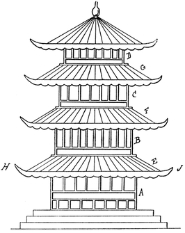
Fig. 547
This is a toy that will provide hours of happy play.
There are many effective ways of making a toy theatre, and
the planning and designing of one is a pleasant piece of work.
This chapter gives a few suggestions to future theatre builders, who
must adopt those that appeal most to them. A large stage is the
most necessary part, so that there is plenty of room to set up the
scenes and room for the actors. A small stage limits the choice
of plays considerably.
A pretty and useful theatre can be made thus. Get a wooden
box 8¾ inches wide, about 1 foot long and 2¼ inches deep. (The
theatre described in this chapter was made from a wooden box
containing Fry's Nut Milk Chocolate—this box is exactly the right
size.) This box forms the basis of the platform; stand it bottom
upward, nail to the back of it a piece of wood, G H C D, which is
1 foot square (see Fig. 548). The platform, A B L M, is a piece
of stiff cardboard or wood, A B is length of box, L M is 2 feet.
This makes a fine large platform for arranging scenes.
Pieces of stripwood ¼ inch by ½ inch are glued across the platform,
A L B M, each strip a little over a ¼ inch from the other (the
¼ inch side is glued to platform). About eleven strips can be
thus glued across; their ends should project about ¼ inch beyond
the platform.
The grooves thus formed are for running the actors up and
down in.
A piece of wood, a b c d, is now cut 2 feet by 3¼ inches.
Holes are drilled along the top of it about ¼ inch in diameter,
and red paper gummed at the back of them for the footlights.
Panels or a pretty design of some kind should be painted on it, or
it may have coloured paper pasted on it. This piece of wood is
glued to K J E F so that its ends project equally on each side.
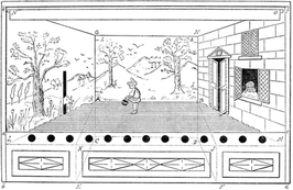
Fig. 548
Now cut two pieces of stripwood ½" × ¼" × 16¼" (e b and f d in
Fig. 548). Bevel the top ends to hold up cardboard roof e f G H
(the measurements for which can be easily found). The roof is
secured by a flap glued behind A G H B, the roof is also glued to
the tops of the strips eb and fd. These posts are glued to sides of
abcd. Before they are glued on, however, they must have holes
drilled near their upper ends for pole, N O, to pass through. The
curtain must be made of fairly thin stuff glued to pole, N O. It can
be pulled up and down by means of pulley wheels attached on
each side. (For making pulley see Part I, Chapter XIV.) Pieces
of lead can be sewn in the corners to make the curtain run down
more easily.
Saw cuts are made across the strips of wood that cover the
platform along lines B M and A L. Into these slits the side scenes
fit. These side scenes are cut out of cardboard and have drawings
and painting on them according to the story that is being acted.
They must have slits cut in them (corresponding to the grooves in
the platform), the number of slits depending on the number of
actors. For example in Fig. 548 side scene H f B M has an open door
through which Red Riding Hood can be pushed. She is cut out
of either cardboard or wood, and glued to the end of a piece of
stripwood, ¼ inch by ¼ inch, by means of which she is pushed from
the side along the groove in the stage and so off through the corresponding
slit in scene G e L A. (In Fig. 548 the Wolf is looking
through this slot.) The window in scene H f B M can be made to
open and show the Grandmother inside. The cardboard scene,
G H A B, is kept in its place by pieces of wire (h, h, h, h) fastened
at the back and bent over.
Almost any story can be acted in this theatre. All the actors
are fastened to lengths of stripwood by means of which they are
passed in and out. Sometimes two, three or more may be fastened
to one length. The number of openings in the side scenes will,
of course, depend on the story being acted.
Trees, etc., can also be cut out as described in Chapter XX
(Part II), and stood about.
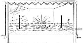
Fig. 549
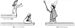
Fig. 550
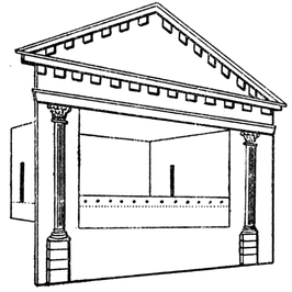
Fig. 551
A sea scene looks very effective. Waves can be cut out of
cardboard and placed in every groove, as in Fig. 549, and a ship
drawn across. A shipwreck forms an exciting scene. Indeed,
there is no end to the scenes—soldiers marching past, stories and
scenes from history and literature, etc., etc. The ingenious
owner of the theatre will think of many, and add many improvements.
It must not be forgotten that the stage is large enough to
hold small objects—trees, etc.—to make the scenes look more
realistic. Also holes or slits can be made in the roof if it is necessary
to pull anything up or hang anything. Fig. 549 shows how
a fringe of paper, A, can be fastened to the roof and bent over to
hide the pole on which the curtain is wound.
Fig. 550 shows how the scenes are worked; as the Witch is
pushed on from one side, the weeping Cinderella is pushed off;
when she has quite gone and only the Witch remains, a radiant
Cinderella comes on, followed by a coach, etc.
Lastly, Fig. 551 shows a proscenium, which may be built up of
either cardboard or wood, and fixed to the front of the theatre.
The sides should project sufficiently to hide the working of the
strips by means of which the actors are moved on the stage.
Here, for the present, we take leave of the reader, having given
him or her some insight into a subject both pleasant and profitable.
The preceding pages are no more than an introduction to the art
of making toys, and of making the most of simple tools and simple
materials, and their real purpose is to encourage our young people
not only to copy but also to create, or at any rate to copy not only
from our book but from the world around them.
Dolls' houses and furniture, railways, boats and other vehicles
offer endless possibilities of original and attractive design, and
mechanical toys, whether driven by wind, water, elastic or the
works of an old clock, offer an equally wide field for invention.
At a later age girls will no doubt be ambitious to devise useful
articles for the home, while boys may become interested in engineering
and electrical models, optical toys, etc.; the deftness of
hand, acquaintance with elementary principles, and self-confidence
acquired through the simple work which we have described, should
stand them in good stead.
Self-reliance and ingenuity are valuable assets with which to
start upon the more serious tasks of life, and if our hints on toy-making
contribute in any way to the development of these qualities
this book will not have been written in vain.
Transcriber's Note:
Punctuation and spelling were made consistent when a
predominant preference was found in this book; otherwise they
were not changed.
Simple typographical and spelling errors were corrected.
P. 99 added "or" between "bridges," & "picture". Seemed to make more sense than "and" which could also have been used.
P. 182 Figs 346 and 347 are so intertwined that it would be not only difficult to separate them but also would leave unsightly gaps.
P. 188 Figs 357, 358, and 359 are so intertwined that it would be not only difficult to separate them but also would leave unsightly gaps.