CLOSING the Electric Circuit.—In connection with the system of
coast defence by means of electrical submarine mines, there are two
distinct methods of effecting the closing of the electric circuit, and
consequently, the firing battery being connected, the explosion of the
mine or mines, which methods may be used separately, or in combination,
and are as follows:—
- 1.—The self-acting method.
- 2.—The firing by judgment, or observation method.
During the early days of submarine defensive warfare, the latter
method alone was used, owing to the absence of anything like a
practicable form of self-acting apparatus; but within the last few
years, the former has almost entirely superseded the latter method,
except in very exceptional cases; this revolution being due to the vast
improvements that have been, and still are being effected in the
system of firing electrical submarine mines automatically.
Use of Circuit Closers.—Electrical submarine mines may by means
of an apparatus, termed a circuit closer, be rendered self-acting; that is
to say, by the action of a vessel coming in contact with such an
apparatus, which may be either within the mine itself, or within a
buoy attached to the mine, the electric circuit is closed, and the mine
in connection with the circuit closer so struck, exploded. The essential
feature of such a mode of closing the electric circuit is, that electrical
submarine mines may be rendered either active or harmless, at the
will of the operator, which is effected by the putting in, or taking out
of a plug, by which means the firing current is either thrown in, or out
of the circuit.
Circuit closers.—Many different forms of circuit closers have been
devised, among which the following seem the most suitable and are
those generally used:—
- 1.—Mathieson's inertia circuit closer.
- 2.—Mathieson's spiral spring circuit closer.
- 3.—Austrian self-acting circuit closer.
- 4.—McEvoy's mercury circuit closer.
- 5.—McEvoy's weight magneto circuit closer.
Mathieson's Circuit Closer.—This form of circuit closer has been
adopted by the English government in connection with their system
of defence by electrical submarine mines.
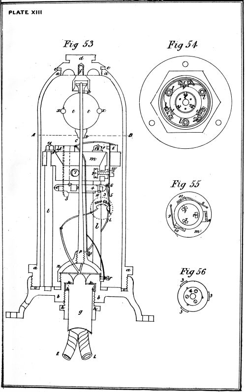
The details of this apparatus are shown at Pl. xiii.
Fig. 53, a is a gun-metal dome screwed on to a metal base b, its
foot resting on a gutta percha washer c, so as to exclude any water;
d is a cap screwed on to the top of the dome, and made watertight
by the leather washer e; f is a guard cap screwed into the cap d, this
is to keep the spindle of the circuit closer steady during transport, and
would be removed when the apparatus is prepared for service; g is the
ebonite base plug through which pass the insulated wires E and L;
h is an hexagonal collar, working in the metal base plate b, by means
of which, and the brass collar i, and the leather washer k, the base plug
is secured, and water is excluded from the interior of the circuit closer;
l, l, l are brass columns supporting a circular ebonite piece m; n is a
metal bridge screwed on to the base plate b, into which is screwed the
spindle p, both of which are prevented from moving after being
screwed up by the set screws r and s.
The spindle p carries a leaden ball t, which is supported upon the
rest v, and is secured in position by the screw nut w; x is an india
rubber ring, the object of which is to prevent any damage being done
to the spindle should the ball when set in action by a heavy blow from
a passing vessel be brought into contact with the dome; 2 is a brass
disc attached to the spindle carrying an ebonite disc 4, connected to it
by screws; 6 is a brass contact ring also fixed to the ebonite disc 4, provided
with a screw 8, for the attachment of one of the base plug wires,
and with platinised projections 3, 3, 3, Fig. 56. The contact ring 6
is completely insulated from the spindle and brass disc 2. Three contact
springs 5, are attached to the circular ebonite piece m, and the faces
opposite to the platinised projections of the disc 2 are also platinised.
7 shows the contact screws of the connecting pieces, which serve also
as adjusting screws to regulate the sensitiveness of the apparatus, the
points of which as well as their bearings on the springs are platinised.
The springs are connected together by means of the wires 9,
Fig. 55, one end of which is secured to the connecting piece by the
screw 10, and the other passes through to the top of the ebonite piece,
and is attached to the top of the spring next in succession to that to
which it is fixed below.
One terminal of a coil of 1000 ohms resistance (which is used for
testing purposes) is attached to the line L, terminal of the ebonite
base plug, which latter is also connected to the screw 8, on the circumference
of the contact ring 6; the other terminal of the resistance
coil is connected to the earth, E terminal of the base plug.
A bare copper wire of No. 16 B. W. G. connects the top of the last
contact spring with the set screw s; a piece of similar wire jointed to
it is passed round one of the brass collars and connected to the screw r.
As a precaution against bad contact, the contact springs are connected
together by bare wires A, B, C. This completes the connections for the
signalling circuit, the earth being formed by the body of the instrument;
D is a hole left in the metal base for the passage of the insulating
wire which connects the earth plate to the earth E terminal of the
base plug.
Testing Current.—For testing purposes the current from the test
battery arrives by the line wire L, and passes thence through the
resistance coil to earth by means of the wire E, which is attached to a
zinc earth plate placed in a recess in the jacket of the circuit closer.
Action of the Circuit.—The action of the apparatus is as follows:—
Closer.—On the circuit closer being struck, the weight of the lead
ball t causes the steel rod p to be deflected and brings the brass ring 6
in contact with one of the springs 5; the signalling current which up
to this moment has been passing through the 1000 ohms coil to earth,
then passes to the contact ring 6 (avoiding the resistance coil) thence
to the spring which is in contact with it, and from there by means of
the wire connections to the set screws s and r, and so to earth through
the metal body of the apparatus; the effect of the resistance coil
being thus eliminated, is to strengthen the signalling current, and
thus enable it to work the shutter apparatus, by which means the firing
current is thrown into circuit and the mine exploded.
MATHIESON'S CIRCUIT CLOSER.
Circuit Breaker.—By altering the mode of connecting the wires, the
above apparatus may be used as a circuit breaker, that is to say, the
signal may be given, and the mine exploded by the cessation of a
passing current, instead of by the closing of the electric circuit. This
system was specially designed for use with platinum wire fuzes, but is
rarely used.
Circuit Closer of Electro Contact Mines.—When the inertia circuit
closer is employed in connection with electro contact mines, the
circular ebonite piece m is replaced by a similar shaped piece of brass,
and which is in metallic connection through the brass pillars l, l, l
with the mass of the metal of the apparatus which forms the earth
plate.
The insulated wire of the base plug is connected to one pole of a
platinum wire fuze, the other pole of which is connected by another
wire to the outer metal rim of the disc of the spindle. As long as the
circuit closer remains undisturbed, a break will remain in the circuit,
which is due to the ebonite insulation between the spindle and the
outer metal rim of the disc; but the moment the apparatus is struck,
which causes the spindle to vibrate, the outer metal rim will come in
contact with one of the springs completing the circuit, through the
circular metal portion and the pillars of the circuit closer to earth.
Adjustment of Circuit Closer.—The sensitiveness of Mathieson's inertia
circuit closer is determined by the distance between the disc 4 and
the springs 5, 5, 5, which is regulated by means of the adjusting screws
7, 7, 7, which press against the inner faces of the springs. Owing to
the great weight of the leaden ball, when by any cause the circuit
closer is inclined for a length of time, a permanent set is given to the
spindle, thereby destroying the adjustment of the instrument.
Improvements in the Inertia Circuit Closer.—To remedy this very
serious defect, a cylinder of india rubber is substituted for the leaden
ball; a circuit closer so fitted is also less affected by the action of
counter mines, which is a very important advantage.
Mathieson's Spiral Spring Circuit Closer.—A sectional elevation of
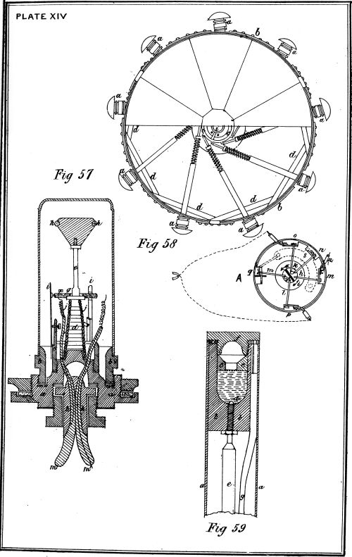
this form of circuit closer is shown at Fig. 57. It consists of a brass
base a, provided with a grooved flange for carrying a gutta percha
washer, and it has also an hexagonal projection for the purpose of
screwing the circuit closer into the gun-metal mouth of its air-tight
cylinder, or buoy; b is a brass dome enclosing the apparatus for the
purpose of protecting it from injury, and also by means of india rubber
washers to prevent an ingress of water, should the circuit closer case
become injured, and leak; c is a brass collar to which the brass contact
springs i, i are attached, and which are regulated by the set screws
j, j; a brass spiral spring d carries a metal rod e, which supports a
brass ball f, surrounded by an india rubber band h. A contact disc g
is secured to the base of the spindle e, but insulated from it by an
ebonite boss; k is an ebonite base plug with two channels in it,
through which the wires m, m1 pass.
An Improvement on the Inertia Circuit Closer.—This instrument is a
vast improvement on the inertia apparatus previously described, being
more simple and more certain in its action, a desideratum in all
circuit closers; but notwithstanding, up to the present time Mathieson's
inertia apparatus has been used by our government, to the exclusion
of all other instruments of a similar nature, some of which were proved
to be far superior when subjected to the crucial test of actual practice.
Austrian Self-acting Circuit Closer.—This form of circuit closing
apparatus, which is purely a self-acting one, that is to say, a mine so
fitted cannot be fired at will, is shown at Fig. 58.
It consists of several buffers a, a, a, which by means of strong
springs are held in position, their heads projecting outside the torpedo
case b; on being pressed in by the contact of a passing vessel, the
ends of these buffers would be forced against a ratchet wheel c, which
is also kept in position by means of a spring. Several strong pieces
of wood d, d within the case keep the buffers and their attached arms
in the proper direction, and also afford rigidity to the torpedo case.
The brass ratchet wheel c being put in motion carries round with it a
central arrangement e, the lower part of which is shown at Fig. 58, A.
This portion consists of a cylinder of brass f divided into two parts
insulated one from the other by a piece of ebonite g; on one side of
this cylinder there are three arms of brass, h, i, and k, and on the other
there are two arms, l and m, all of which are insulated from each other.
AUSTRIAN CIRCUIT CLOSER, MERCURY CIRCUIT CLOSER.
The arm h is close to, but insulated from a metal plate n, which
latter is permanently connected with the conducting wire leading
from the firing battery, and thus while in a state of rest is electrically
charged; beyond the arm i is a spring o, which is connected with
the earth, and in such a position that when the central portion is
moved round, this spring o comes in contact with the arm i, and
the plate n with the arm h simultaneously, and the circuit is thus
completed through earth to the battery, but the current of electricity
does not pass through the fuze. The arms k, l on the opposite sides
of the cylinder, and consequently insulated one from the other, are
connected with the fuze, and the arm m is connected with the earth.
On a further pressure of the vessel on the buffer, the arm i is
pushed beyond the spring, and in contact therewith, and consequently
the circuit by earth to the battery is broken, while the contact of the
arm h and plate n is still retained, and the current is passed by the
arm k through the fuze to the arm l, and then to earth through the
arm m, thus completing the electric circuit of the firing battery
through the fuze, and to exploding the mine.
The spring acts as a circuit breaker, and by means of an intensity
coil in connection with the firing battery, the current is only passed
through the fuze when at the point of greatest intensity.
By detaching the firing battery, the channel defended by such
submarine mines may be rendered safe.
Fuze only in Circuit at Moment of Firing it.—One of the principal
objects to be gained by the employment of such an arrangement for
the closing of the electric circuit in connection with submarine mines,
is the prevention of premature explosion from induction which might
be caused by the proximity of any atmospheric electricity, the fuze
in this system being entirely cut out of circuit until the moment
when it is necessary to fire it.
The Austrians employed this form of circuit closing instrument
during the war of 1866, and still continue to use it in connection with
their coast defence by submarine mines.
McEvoy's Mercury Circuit Closer.—At Fig. 59 is represented a
longitudinal section of a circuit closer of this construction.
It is placed in the mine in such a manner that when undisturbed
it maintains an approximately upright position.
It consists of a metal tube a into which the cup b of vulcanite, or
other insulating material is fixed. The cup is contracted at some
distance from the top by the perforated plug c, which is also of
insulating material; d is a metal pin fixed into the bottom of the
cup b, it is connected with the wire e, which is insulated and passes
to the battery; f is a metal plug closing the tube a and the cup b at
the top; g is a wire attached to the plug f, and passing from it to an
earth connection. The cup b is filled with mercury up to the level of
the plug c. By the contact of a passing vessel the instrument would
be tilted sufficiently to cause the mercury to flow into contact with
the metal plug f, thus completing the electric circuit and exploding
the mine.
This form of circuit closer, though not generally adopted, would, on
account of its being less liable to derangement by the motion of the
waves, or by the explosion of an adjacent or counter mine, seem to fulfil
the many requirements of a circuit closer for general service.
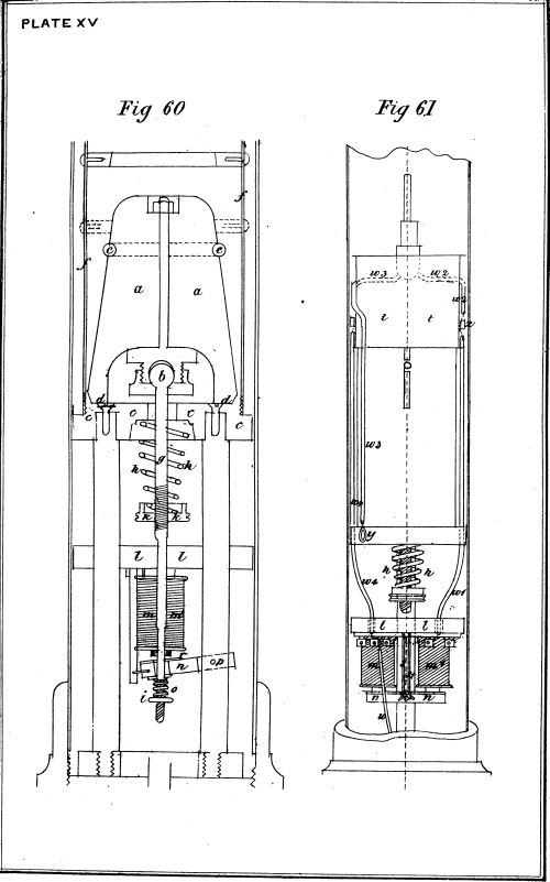
McEvoy's Weight Magneto Circuit Closer.—This form of circuit closer,
which is shown in section and plan at Fig. 60 and 61, is one of the
most important improvements that has ever been effected in such
apparatus, and bids fair to become universally adopted.
A heavy metal conical shaped weight a (Fig. 60), hollowed out in
its base and working in a ball and socket joint b, rests on a solid brass
base c, and is so arranged that on the apparatus being struck, the
weight a will fall over, pivoting on one of its supports d, d; e is a band
of india rubber, encircling the weight a, for the purpose of preventing
a jar on its falling against the sides of the brass cylinder f, which
contains the weight a and joint b. A brass rod g, connected to the ball
and socket joint, passes through the base c, through a strong spiral
spring h (which latter rests on an adjusting screw k), through a piece
of ebonite l, which supports the bobbins and core m, m1; then between
these bobbins m, m1 through an armature n, which is pivoted at p;
and lastly through a slight spiral spring o, which is kept in position by
the adjusting screw i.
The armature n is fitted with a small piece of brass r, so arranged
that when it (the armature) is in the position shown in Fig. 60, this
piece of brass r does not make contact with the two strips of metal, s, s,
between which it, r, works; but when the armature n is in contact
with the cores of the bobbins m, m1, then the piece of brass r makes
contact with the metal strips s s, and so makes a short circuit for the
electric current. An ordinary telephone t, Fig. 61, in which some
small shot, bells, &c., are placed, is fixed to the top of the brass
cylinder f.
Action of Circuit Closer.—The action of this apparatus is as follows:—
On the mine carrying this form of circuit closer being struck by a
passing vessel, the weight a is caused to fall over towards the side of the
brass cylinder f, thus allowing the strong spiral spring h to act on the
brass rod g in an upward direction, by which means the armature n is
brought into contact with the soft iron cores of the bobbins m, m1.
Mc.EVOY'S MAGNETO ELECTRO CIRCUIT CLOSER.
The connections of the wires are made as follows:—
The line wire w is led through the base of the apparatus and
connected to a piece of brass under the ebonite support l, in connection
with one of the wires of the bobbin m, the other wire of which is
attached to the metal strip s; the wires of the bobbin m1 are connected,
the one to the metal strip s1, the other to a piece of brass under the
ebonite support l; from this latter piece of brass a wire w1 is led to
the brass screw x. The wires w2, w3, from the fuzes are led, the one to
the brass screw x, the other to a screw y, which forms through the metal
of the apparatus the earth plate. One of the wires of the telephone t
is connected to the brass screw x, the other w4 is connected to the
piece of brass to which the line wire w is also attached. While the
circuit closer remains in a state of rest, the current from the signalling
battery flows along the line wire w, up the telephone wire w4, through
the telephone which has a high resistance, then by the wire w2 through
the fuzes, and to earth by the wire w3.
On the circuit closer being struck, by which cause the armature n
is brought up to the cores of the bobbins m, m1, and the piece of brass r
in contact with the metal strips s, s1, the signalling current, instead of
circulating through the high resistance of the telephone t, passes round
the bobbin m, down the metal strip s, across the brass piece r, up the
metal strip s1, round the bobbin m1 (thus forming an electro magnet of
m, m1), and by the wire w, direct through the fuzes to earth, and so
explodes the torpedo. The effect of the telephone resistance being cut
out, is to strengthen the signalling current, and enable it to work the
shutter apparatus and so throw the firing battery in circuit and
explode the mine.
The advantages of this circuit closing apparatus are:—
1.—Simplicity.
2.—Compactness.
3.—Increased certainty of action, due to the sustained contact of
the armature n, on the apparatus being struck.
4.—Additional means of testing a system of electrical submarine
mines, which is afforded by the telephone:—
When this form of circuit closer is put in action by a friendly vessel
coming in contact with it, or when experiments are being made, the
signalling current must be reversed, so that no doubt may exist as to
the armature n having dropped, on the apparatus coming to rest.
The telephone test indicates whether the circuit closer is in position
or not, the shot, &c., within the telephone being shaken about by the
movement of the buoyant circuit closer, the noise so created is readily
distinguished by the receiving telephone at the station.
Another form of submarine mine is that known as the "Electro
Mechanical" mine. The difference between this form and an ordinary
mechanical mine is, that the exploding agent is electricity, and that
it may be converted into an electro contact mine if desirable.
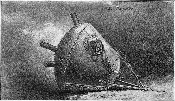
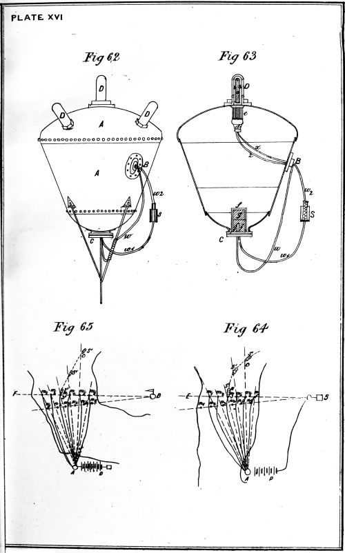
Description of a Russian Electro.—The electro mechanical mine, used
by the Russians during the late Turco-Russian war, is shown in
elevation and section at Fig. 62 and 63.
Mechanical Submarine Mine, used by them during the late Turco-Russian
War.—A is the conical shaped case; B the loading hole; C the base
plug; D, D, &c., are five horns, screwed into the head of the case A;
these are composed of a glass tube A, containing a chlorate of potash
mixture, enclosed in a lead tube B, over which is screwed a brass
safety cylinder C; when ready for action this latter tube C is removed;
directly beneath each of the horns A, on the inside of the case, as at
E, is a thin brass cylinder, closed at one end by a piece of wood d,
and containing several pieces of zinc and carbon, arranged in the form
of a battery, the zinc and carbon wires z and x being led through the
piece of wood d; F is a copper cylinder containing the priming charge
of gun-cotton g, and detonating fuse f; the terminals of the fuze are
connected to two insulated wires, w and w1, the former of which is led
direct to the loading hole B, and attached on the inside to the five zinc
connecting wires z, &c.; the latter is attached to one end of a safety
arrangement S, the other end of which is connected to the wire w2,
which is attached on the inside to the carbon wires x, &c.; the safety
arrangement S consists of an ebonite cylinder, containing a brass
spiral spring fixed to one end of it, and pressing against a brass plate
at the other, thus preserving a metallic connection between the wires w1,
and w2; the mine is rendered inactive by pressing the spring down,
and inserting a piece of ebonite between it and the plate.
Its Action.—The action of this form of electro mechanical submarine
mine is very simple; the brass safety cylinders c, c, &c., being
removed on a vessel striking either of the horns, D, D, &c., the lead
tube b is bent, causing the glass tube a to be broken, and the mixture
contained therein to flow into the cylinder E, instantly generating
a current of electricity in the zinc carbon battery, and exploding
the mine.
Mode of Converting into an Electro Contact or Observation Mine.—To
convert this mine into an electro contact one, it is only necessary
to connect the wires w1 and w2 to other wires leading from the shore;
also by replacing the horns D, D by solid brass screw plugs, the mine
may be converted into an ordinary observation one. In this case the two
wires w and w1 attached to the fuze f, terminals would have to be
connected to the observation instruments on shore.
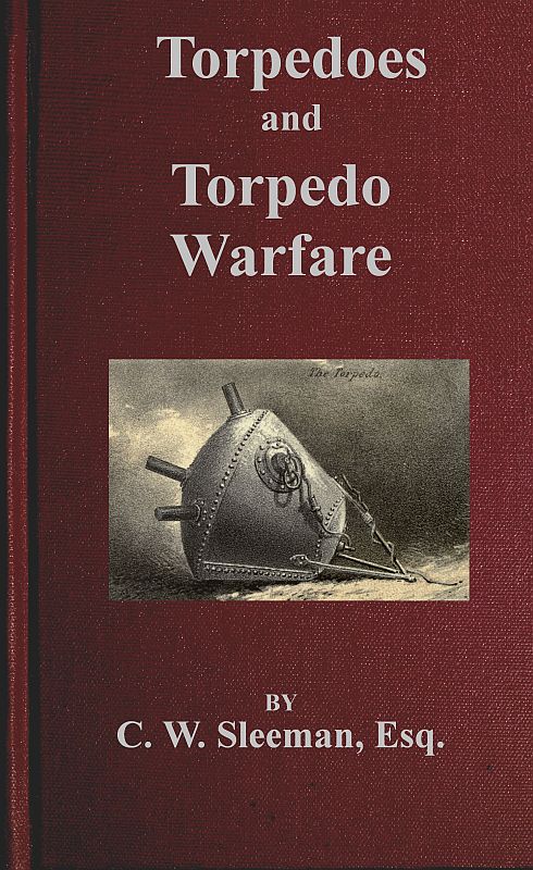
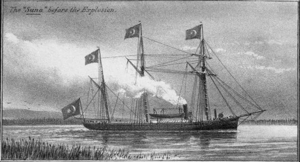
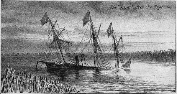
Turkish Vessel sunk.—It was by means of one of these electro
mechanical mines, that the Turkish gunboat Suna was sunk at Soulina.
Firing by observation, that is to say, effecting the ignition of an
electrical submarine mine at the precise moment of a hostile vessel
being vertically over it, through the agency of one or two observers
stationed at a very considerable distance from the mine, should, with
the very perfect self-acting circuit closers that exist at the present
time, be resorted to only in very exceptional cases, or in connection
with the self-acting system.
There are two defects, which are common to all methods of firing
submarine mines by observation, and these are:—
1.—At night time, or in foggy weather, it cannot be employed.
2.—It is necessary to employ at least two observers, at a
considerable distance apart, who to effect a proper action at
the right moment, must work in perfect unison. These
defects alone are sufficient to explain the preference
given to a self-acting method of closing the electric circuit
at the precise moment of a vessel being in position over
a mine by those governments who have adopted electrical
submarine mines as a means of coast defence.
Methods of Firing by Observation.—There are several methods of firing
by observation, of which the following are the ones principally used:—
- 1.—By pickets or range stakes.
- 2.—By cross bearings.
- 3.—By intersectional arcs fitted with telescopes.
- 4.—The Prussian system.
Intersection by Pickets or Range Stakes.—In narrow channels and at
short distances, this system of ascertaining the relative position of a
hostile vessel and a submarine mine may be used, provided that skilled
and careful men are employed to work it. Two or more pickets or
stakes are arranged in front of the firing station in such a manner that
a vessel passing up the channel on the prolongation of these stakes
will be over a mine. This arrangement should of course always be
considered as an extempore one; it was used on several occasions by
the Confederates during the American civil war.
Firing by Cross Bearings.—The simplest method of so determining
the relative position of a vessel and a submarine mine, and exploding
it at the right moment, is that in which observers are placed on the
prolongation of the mines. This mode is shown at Fig. 64, where
m1, m2, m3, &c., and n1, n2, n3, &c., are the mines; A and B, the points in
prolongation of the mines where the observers are stationed; D the
firing battery, and s, and s1 two hostile vessels.
At the stations A and B firing keys are placed, at the former one
for each separate mine, perfectly distinct and insulated from each other,
at the latter a single key. The pivot points of the series of keys at A
are connected by separate wires to one pole of the firing battery D, the
other pole of which is connected by a single cored insulated cable to
the pivot point of the key at B; the contact points of the series of
keys at A are connected by separate line wires as A m1, A m2, A m3, &c.,
to the different mines, while the contact point of the key at B is put
to earth. Thus it will be seen that, in the case of the row of mines, m1,
m2, &c., unless the key at B, and the key at A, of either of those mines
are both pressed down at the same instant, no current can pass, and
therefore none of those mines can be exploded.
In the case of the vessel S, though at C, she is on the prolongation
of the line A m5, C, and therefore the key of the mine m5, is pressed
down at A, yet not being on the prolongation of the line B, E, the key
at B is not pressed down, therefore the firing battery is not thrown in
circuit, or the mine m5 exploded, but when the vessel s reaches the
position N, that is over the mine m3, she being on the prolongation of
the lines A m3, and B E, the key (m3) at A, and the key at B
would both be pressed down, and therefore the mine m3 exploded, and
the ship destroyed. In the case of a vessel passing through an
interval between any two mines at such a distance as to be out of the
radius of destructive effect of either of the mines belonging to the first
row (which is shown at s1,) only the key at B would be pressed down,
and thus the vessel enabled to pass safely through, but only to come
to grief at the second or third row of mines, provided they have been
properly placed, and separate though similar arrangements as in the
case of the line of mines, m1, m2, &c. have been made.
Firing by a Preconcerted Signal.—At Fig. 65 is represented a somewhat
similar, though a much simpler plan of the foregoing system, by
employing a preconcerted signal at the station B in the place of the
firing key and insulated cable, as in the former case. The only
material difference in the arrangement of these two methods, is that in
the latter case the pole of the firing battery at A, which in the former
case was connected to the firing key at B, is put direct to earth. As
will be readily understood, this latter system requires great coolness
and nerve on the part of the operator at A, who has not only to watch
the vessel passing across his intersections, but also to be on the alert
to receive the signal from the observer at B. Should it ever be
necessary to adopt this latter system, it will be found advisable to
employ two men at station A, one to watch station B, the other to
attend to the firing key and intersections. A separate signal-flag for
each line of mines, and also a separate firing arrangement, would be
required. As in many cases it would not be practicable to have a
station in such an advanced position as at B, in Fig. 64 and 65, on
account of the danger of its being cut off by an enemy, another combination
becomes necessary. In this instance the station B is placed
on the opposite side of the river, &c., to that on which the station A is
placed, and a series of firing keys, instead of a single one, is here used,
necessitating a multiple cable between the stations A and B, in the
place of single cored cable; the manner of manipulating this method
is very similar to that previously described.
Firing by Intersectional Arcs fitted with Telescopes.—The foregoing
methods of firing by cross bearings are replete with many serious
defects, to remedy which, to a considerable extent, special arrangements
have been devised, that is, the employment of intersectional arcs
fitted with telescopes at the stations A and B.
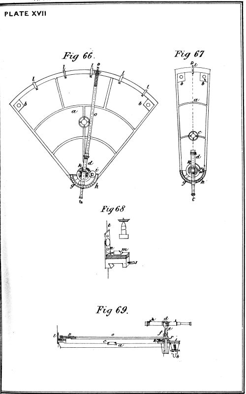
Fig. 66 and 67 show the arrangements of these arcs, the former
being the one used at the firing station A, the latter at the converging
station B. At each station one arc is provided for each row of mines
placed in position. The firing arc Fig. 66 consists of a cast iron frame
a, with three feet b, b, b, these being provided with levelling screws.
To ascertain when this frame is level, a circular spirit level is attached
thereto, a telescope d provided with one horizontal and three vertical
cross wires, supported on Y's, admitting of vertical motion and attached
to an upright e. A mill-headed screw f enables the telescope d to be
raised or lowered; the telescope, which is rigidly connected to a
vernier g, traversing over a graduated arc h, can be moved rapidly in a
lateral direction by means of a rack and pinion arrangement i, and it
can be clamped in any position by means of the screw h. Sights are
fixed on the telescope in a vertical plane passing through its axis. To
the outer rim of the frame of the arc, which is smooth, are secured the
sights l l (shown on a large scale at Fig. 68), to give the direction of
the mines. These sights are provided each with a brass point of V
form, m, and a binding screw, n, in metallic connection with each
other, but insulated by means of an ebonite plate from the rest of the
metal of the sight. One end of a short piece of insulated wire is
attached to the binding screw n, and the other passes through a hole
in the base of the sight and projects below it; o is a brass tube rigidly
connected to and moving with the upright carrying the telescope d,
and projecting in front of this latter. A brass spring p (see Fig. 69)
is attached to, but insulated from the outer extremity of this tube, and
is so arranged as to make contact with the V point m on the sight, by
means of a corresponding projection fitted to its under side. An insulated
wire passing the tube o, the outer end of which is connected to
a screw on the spring p, forms a metallic connection between this
projection and the firing key.
At Fig. 68 is shown an enlarged view of the front of the sight; in
addition to the V projection m, and binding screw n, it is fitted with a
capstan-headed screw to bear against the inner rim of the frame, and a
thin wire upright t for giving the alignment of the mine, to which a
disc is attached, on which the number of the mine is affixed.
When the distance between the station and the mine is only about
one mile, an ordinary eyepiece is used in the place of the telescope d.
At Fig. 67 is represented the arc employed at the converging
station, which with the exception of there being no tube o, and only
one sight, is precisely similar in construction to the one used at the
firing station, and which has been described.
APPARATUS FOR FIRING BY OBSERVATION.
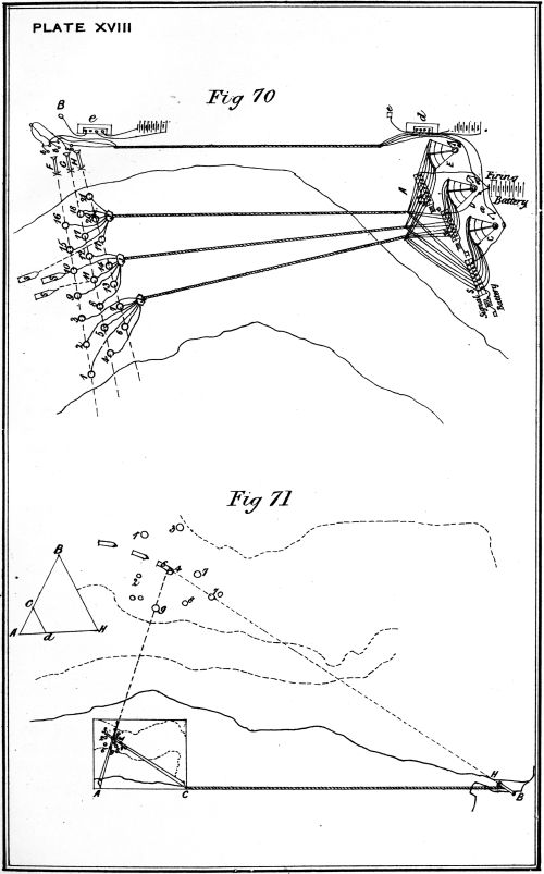
Application of the Intersectional Arc Method.—The application of the
method of firing by observation, by means of intersectional arcs fitted
with telescopes, is shown at Fig. 70. C, D, and E are three of the
larger kind of arcs, one being used for each row of mines at the firing
station A. At the converging station B, one of the smaller arcs is used
for each row of mines, as shown at F, G, and H. S, S1, S2, are the
signalling apparatus, the F terminals of which are connected to the
sights l, l, l, Fig. 69, of arcs C, D, E. Firing keys a, a, a at station A
are connected to each arc, and to three of the cores of the cable connecting
the two stations A and B, respectively. At the converging
station B, three firing keys b, b, b are connected to earth and to
three cores of the connecting cable respectively. The remaining core
of this cable is connected to the recording instruments d, e. The
action of the arcs, &c., will be readily understood from the diagram
at Fig. 70.
This arrangement does not interfere with the action of the circuit
closer, as all that is effected by the observing arc circuit is to put the
signalling battery current at the converging station B to earth instead
of at the circuit closer.
Prussian System of Firing by Observation.—The principle on which
this system is based, depends upon the proposition that if c d, in the
triangle shown in Fig. 71, be always kept parallel to H B, then A c, c d,
d A bear exactly the same proportion to each other as A B, B H, H A do
to one another; so that by means of the small triangle A d c, the
lengths of the sides of the large triangle A B H can be obtained, and
hence the position of the point H, the base A B being of course known.
In Fig. 71 at A there is a slate table representing the roadstead, and
upon it the exact position of every torpedo is laid down, corresponding
to their position in the roadstead. At A and B, 500 yards apart,
telescopes having cross wires are placed; at A a long narrow straight-edged
strip of glass A d is arranged to move in unison with the
telescope at A; and by the application of dynamo electricity, a similarly
constructed piece of glass c d moves in exact unison with the telescope
at B, and having its pivot at C; that is to say, C d keeps parallel with
B H, the line of sight of the observer at B.
Then if the observers at A and B have got a ship in their telescopes,
the point of intersection d of the two pieces of glass A d and C d
gives the position of the ship on the slate table at A, and when this
point d comes over the position of any one mine on the slate, it is known
that the ship is over that particular mine in the harbour, and she may
be destroyed accordingly, by throwing the firing battery into circuit.
By the employment of electricity and a mirror, the great defect of
this method, viz., the necessity of employing four people to manipulate
it, would be remedied. The foregoing is a modification of Siemens's
method of ascertaining distances at sea, &c.
Rules observed in Planting Mines.—In placing a system of submarine
mines in position, the following are some of the chief points to be
attended to, this work depending in a great measure on local circumstances,
and on the method that is to be adopted in exploding and
mooring them:—
1.—The plan of defence must be carefully laid down on a chart, on
a scale of not less than six inches to the mile, and on this
plan are to be marked the sites of the observing stations,
the positions of each mine, circuit closer, and junction box,
with their corresponding numbers, and also of the electric
cables.
2.—The position of each mine having been determined, should be
marked off by buoys.
3.—The utmost care should be taken to lay the electric cables, so
that they shall be as far as possible away from the mines
in the vicinity of which it may be necessary to take them,
so as to lessen the liability of injury to them, by the
explosion of the latter.
4.—The electric cables should be laid parallel, and never be
allowed to cross directly over each other, otherwise the
operation of underrunning them will be much complicated,
also a certain amount of slack should be allowed to
facilitate in picking the cables up for repair, &c.
5.—Every manner of device is to be used to conceal the electric
cables, such as laying dummies, making detours inland, &c.
6.—All marks indicating position of the mines to be removed, after
the mines have been placed in position.
7.—The identity of each cable and mine to be very carefully
preserved throughout, by means of a number.
8.—A number of electro contact mines should be placed in advance
of the leading line of mines, at irregular intervals, to
prevent the enemy, having once ascertained the position of
one mine of a line, from knowing within limits the position
of the others of that line.
SYSTEMS OF DEFENCE BY SUBMARINE MINES.
In connection with a system of defence by electrical submarine
mines, the following batteries are required:—
- 1.—Firing battery.
- 2.—Signalling, or shutter battery.
- 3.—Testing battery.
- 4.—Telegraph battery.
Firing Battery.—The firing battery should be suited to the nature
of the fuze employed, and should possess considerable excess of power
to enable it to overcome accidental defects, such as increased resistance
in the various connections, or defective insulation in the line wire, &c.
As platinum wire or low tension fuzes are now universally adopted
as the mode of ignition for submarine mines, it will be only necessary
to describe those electrical batteries which are most suitable as an
exploding agent in connection with such fuzes; these are as follows:—
- 1.—Siemens's dynamo low tension machine.
- 2.—Von Ebner's Voltaic battery.
- 3.—Chromic acid or Bichromate Voltaic battery.
- 4.—Leclanché's Voltaic battery.
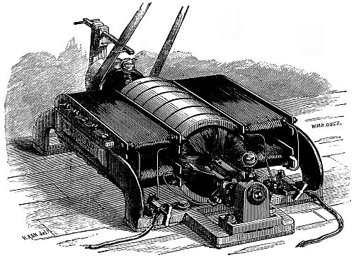
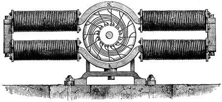
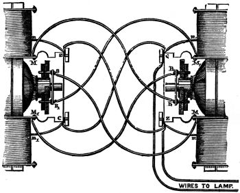
Siemens's Low Tension Dynamo Electrical Machine.—This instrument
consists of an electro magnet and an ordinary Siemens armature,
which, by the turning of a handle, is caused to revolve between the poles
of the electro magnet. The coils of the electro magnet are in circuit
with the wire of the revolving armature, and during rotation the residual
magnetism of the soft iron electro magnet cores at first excites weak
currents which pass into the electro magnet coils, increasing the
magnetism of the core, thus inducing still stronger currents in the
armature wire. This accumulation by mutual action goes on until the
limit of magnetic saturation of the iron cores of the electro magnets is
reached.
By the automatic action of the machine, the powerful current so
produced is sent into the leading wire or cable to the fuze to be
exploded.
In this apparatus the electric current passes continuously through
the line wire until a sufficiently powerful current is generated to heat
or fuze the bridge of the fuze, and so ignite the gun-cotton priming.
The coils of the armature and electro magnets are wound with wire of
large diameter, to a total resistance of 8 to 10 Siemens units, or 7·6 to
9·5 ohms, in about 2,000 windings.
With a platinum wire weighing 1·65 grains per yard, 6-1/2 inches
can be fuzed on short circuit, and 14 inches can be heated to redness.
The total weight of this machine, which is manufactured by
Messrs. Siemens Brothers, is about 60 lbs.
Advantages of Siemens's Dynamo Electrical Machine.—The advantages
of such a machine over Voltaic apparatus are:—
1.—The absence of chemical agents.
2.—There is less liability to get out of order.
3.—No special knowledge is required to work them, or to keep
them in order.
4.—Greater durability.
The great defect of this and all similar machines is that the electric
force has to be developed by turning a handle for a certain time before
it is possible to generate a current sufficiently powerful to ignite a
fuze, which defect, in connection with a system of defence by self-acting
submarine mines, particularly at night, renders them inferior to
Voltaic batteries, as under such circumstances, an apparatus is required
that will cause an electric current to flow at any moment when the
circuit is completed.
The application of steam power would to a certain extent remedy
the above-mentioned defect, but the cost of such a method, compared
to that of a Voltaic arrangement, would be far too great to allow of its
superseding the latter arrangement.
Von Ebner's Voltaic Battery.—This form of Voltaic battery, which
may be considered as a modification of that known as Smee's, was
designed by Baron von Ebner, colonel of the Austrian imperial corps
of engineers, for use in connection with the Austrian system of submarine
defence, by self-acting electrical mines.
A section of one of these cells is shown at Fig. 72. It consists of
a glass vessel a, to contain the diluted sulphuric acid, within which
is suspended a plate b of platinised lead, which is bent round into a
cylindrical form to fit close around the inner surface of the glass
vessel. In the centre of this latter is hung a porcelain perforated cup
c, containing some cut-up zinc and mercury to keep it (the zinc)
amalgamated. The top of each cell is furnished with a porcelain cover,
through which the wires attached to the positive and negative poles of
the cell project.
Due to the large quantity of liquid contained in the cell, the
tendency to alter its internal resistance is retarded; also by the
arrangement of the porcelain cup, above detailed, the consumption
of zinc and mercury, which in an ordinary Voltaic battery is very
considerable, is materially diminished.
Chromic Acid or Bichromate Battery.—This form of battery is very
similar to Grove's, the difference being that, in the place of the nitric
acid as the exciting liquid, either chromic acid, or a solution of bichromate
of potash, sulphuric acid and water is substituted.
A form of this battery, as designed by Dr. Hertz, is used in connection
with the German system of torpedo defence.
Leclanché Voltaic Battery.—This form of Voltaic battery was invented
by M. Leclanché, some twelve years ago. At Fig. 73 is shown
a cell of this battery in its original form. The positive pole a consists
of a plate of graphite in a porous pot b, and surrounded by a mixture
of peroxide of manganese and graphite. The negative pole c is a rod
or pencil of amalgamated zinc. The whole is enclosed in an outer
vessel of glass d containing a solution of sal ammoniac.
A modified form of the Leclanché cell as used in a firing battery
is shown at Fig. 74. It consists of an ebonite trough or outer vessel a
about 16" long, 9" deep, and 2-3/4" wide. The negative pole or zinc
plate b is of similar shape to the trough a, but with its base removed,
and does not fit the trough exactly, the space between it and the
trough being left to ensure the former being completely surrounded
by the sal ammoniac solution; the positive pole, or carbon element,
consists of four gas carbon plates c attached together at their head by
means of lead, and enclosed in a flannel bag, in which they are firmly
embedded in the peroxide of manganese mixture; the positive element
is of such a shape that it fits loosely between the sides, and is nearly
of the same height as the zinc plate.
The object of such a form of cell was to obtain an electric current
of large quantity, with as few cells as possible, by which means the loss
of power which might occur from the employment of a great number
of small cells is avoided.
Advantages of a Leclanché Firing Battery.—The advantages of the
Leclanché firing battery are:—
1.—The absence of chemical action when the battery circuit is not
complete, and consequently there is no waste of material.
2.—Requires little or no looking after.
3.—It may be kept ready for action in store without in any way
deteriorating.
4.—It is comparatively very cheap.
These advantages combine to make a Leclanché battery the most
suitable of any other form of electrical battery for use as the exploding
agent for electrical submarine mines, and it is now universally used
for such purposes.
Signalling Battery.—The signalling battery should be so constituted
as to be capable of working the electro magnet of the shutter apparatus
effectually when the circuit is closed direct to earth, and yet
not so powerful as by the continuous passage of the current generated
by it to fire the fuze in the mine. In the case of a platinum wire
fuze being in the circuit, plenty of power may be given to the battery
without fear of a premature explosion from this cause, but in the case
of a high tension fuze it is necessary to be very careful in order to
guard against such a contingency.
As in the case of a signalling or shutter battery, the electric
current will be continually flowing, it is necessary to employ a constant
battery, or one that requires least trouble and expense to maintain it
in working order, and it is for this reason that a modified form of
Daniell battery has been adopted to work the shutter apparatus.
Daniell Signalling Battery.—At Fig. 75 is shown the manner of
arranging a Daniell cell. A glass or porcelain vessel a contains a
saturated solution of sulphate of copper, in which is immersed a copper
cylinder b open at both ends and perforated by holes; at the upper
part of this cylinder there is an annular shelf d, also perforated by
holes, and below the level of the liquid; this is for the purpose of
supporting crystals of sulphate of copper for the replacing of that
decomposed as the electrical action proceeds. Inside the cylinder b
is a thin porous vessel c of unglazed earthenware; this contains either
water, or a solution of common salt, or dilute sulphuric acid, in which
is placed the cylinder of amalgamated zinc e. Two strips of copper
p and n, fixed by binding screws to the copper and to the zinc, serve
for connecting the elements in series, or otherwise.
For the purposes of testing, either the Leclanché or Daniell battery
specially arranged, or the Menotti battery, which is really a modification
of the Daniell, may be used.
FIRING BATTERIES, TESTING BATTERIES.
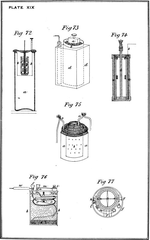
Description of a Menotti Cell.—A Menotti cell, shown at Fig. 76,
consists of a copper cup containing some crystals of sulphate of copper
and covered with a fearnought diaphragm a, placed at the bottom
of an ebonite cell b; over this cup is put some sawdust, and resting
on top of this is a disc of zinc c on another piece of fearnought. The
upper portion of the zinc and its connection with the insulated wire
are carefully insulated. Fresh water poured on the sawdust renders
the battery active.
Description of a Menotti Test Battery.—Fig. 77 represents a plan
of the top of such a test battery with a 20-ohm galvanometer attached
thereto. The connections are made as follows:—
One of the wires w of the object to be tested is attached to the
terminal f, which is also connected by an insulated wire to the copper
cup a; the other main wire w1 is attached to the terminal g of the
galvanometer; h, the other terminal of the galvanometer, is connected
by a short piece of wire k to the terminal l of the contact key m;
and the contact point n is in connection with the zinc plate c; thus
the current from the battery flows along the wire w through the
object to be tested, back along the wire w1, through the coils of the
galvanometer, along the wire k to the contact key m, and if this is
pressed down to the zinc plate c, so completing the circuit.
To steady the needle of the galvanometer a bar magnet is used,
which is inserted in the space r. The whole of the apparatus is
enclosed in a leathern case fitted with a cover and strap.
This is a very compact and simple form of test battery, and will
be found extremely useful in boats, &c., when placing mines in
position.
Telegraph Battery.—For the purposes of telegraphing between
torpedo stations, &c., a form of Leclanché battery, known as No. 3
commercial pattern, is generally used.
Voltaic Batteries.—The following points in connection with the
use of voltaic batteries, which are taken from Beechey's 'Electro
Telegraphy,' should be carefully observed:—
1.—Each cell of a battery should be carefully insulated.
2.—The floors and tables in the battery room should be kept
scrupulously clean and dry, so as to prevent the least
leakage or escape of the current.
3.—The plates of a battery should be clean.
4.—Porous cells should be examined, and cracked ones replaced.
5.—No sulphate of zinc or dirt should be allowed to collect at the
lips of the cells.
In the case of a Daniell battery—
1.—The solutions should be inspected daily, and crystals of
sulphate of copper added as required.
2.—The zinc plate must not touch the porous cell, or copper will
be deposited on it (the zinc).
3.—The battery should be charged with sulphate of zinc from the
first.
4.—The copper solution must be watched and prevented from
rising over the edge of the porous jar, the tendency of
such solutions being to mix with each other by an action
termed osmosis.
These being in addition to foregoing general directions for Voltaic
batteries.
Defects in a Voltaic Battery on its Current becoming Deficient.—On
the electric current of a Voltaic battery becoming deficient, the following
defects should be looked for:—
1.—Solutions exhausted; for instance, sulphate of copper in a
Daniell's entirely or nearly gone, leaving a colourless
solution.
2.—Terminals or connections between the cells corroded, so that
instead of metallic contact there are oxides of almost
insulating resistance intervening in the circuit.
3.—Cells empty, or nearly so.
4.—Filaments of deposited metals stretching from electrode (pole)
to electrode (pole).
Also intermittent currents are sometimes produced by loose wires
or a broken electrode, which alternately makes and breaks contact
when shaken. Inconstant currents are also sometimes produced when
batteries are shaken. The motion shakes the gases off the electrodes,
thus increasing temporarily the electro-motive force of the battery.
Firing Keys and Shutter Apparatus.—The following is a description
of the various firing keys and shutter signalling apparatus, which is used
in connection with a system of electrical submarine mines. By means
of the former the firing or other batteries may be thrown into circuit
at will, whilst by means of the latter the firing battery is thrown
in circuit without the aid of an operator, and a signal at the same
instant given, indicating that a certain mine of the system has been
struck.
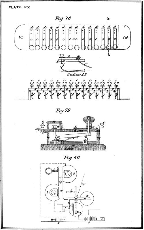
Description of a Series of Firing Keys.—At Fig. 78 is shown a plan
and section of a series of firing keys as arranged for firing several
mines by observation.
It consists of a strong wooden frame a, of a convenient form for
the purpose of attaching it to the firing table by screws through the
holes b, b. On this frame a series of keys c, c, c are fixed at convenient
intervals. These consist of a strong brass spring firmly
screwed to a series of brass plates d, d, d on the front of the wooden
box a. From these latter short copper wires pass through the woodwork,
and of such a length that, when required, the mine wires may
be easily attached by means of binding screws, as shown at f. The
inner end of each key is fitted with an ebonite knob (which is shown at
c in the section) to insulate the hand of the operator when using the
key. On the frame, and directly under each of the ebonite knobs,
are arranged a series of metallic points g, g, g, so placed that on
either of the keys c being pressed down, a perfect contact is made
between it and its respective metallic point; h, h, h are copper wires
leading from the metallic points g, g, g through the box, and of such
a length that binding screws f, f, f can be easily attached to them
when necessary.
A single firing key of an improved form is shown at Fig. 79. It
consists of a strong wooden box a a, weighted at the bottom with lead
in order to steady the key on the table, &c., on which it may be placed;
on the inside of the bottom of the box is fixed a piece of ebonite, by
which means the metallic point b, and the terminal of the firing key c,
are insulated from each other; d d' are two terminals at the end of the
box, to which the circuit wires are attached, one of these terminals is
connected in metallic circuit to the firing key at c, the other one to
the metallic point b; a wooden cover h, fitted with a catch k, protects
the connections of the wires; by means of a plate, and catch e e,
the key can be rendered inactive, thus preventing the danger of a
premature closing of the electric circuit; by means of a spring s a
break is always established between the key and the metallic point.
It is immaterial to which of the two terminals d d' either wire is
connected.
The Morse Firing Key.—This form of key is so well known in
connection with the Morse telegraph, that it is not necessary to
describe it.
It is usually employed in torpedo work in connection with a
testing and firing table.
The Shutter Apparatus.—The shutter signalling and firing apparatus
was devised to enable the firing battery current to be thrown
in circuit without the aid of a personal operator, the signalling
current (which is always kept in circuit) at the same instant ringing
a bell, by which is known the particular mine that has been
struck.
At Fig. 80 is represented a diagram of such an apparatus. a is an
armature working on a pivot between the two horns of an electro
magnet b b, and held in position by a spiral spring c; the latter is in
connection with a regulating screw, by which more or less pressure
may be brought to bear in an opposite direction to that of the
attractive action of the electro magnet. A stud i regulates the
distance to which the armature may be drawn back; d is a shutter on
which a reference number for each mine should be indicated, attached
to a lever pivoted at the point e, the inner arm of which is just long
enough to catch under the point of the armature a; when a current
of sufficient strength is passed through the coils b b of the electro
magnet, the armature a is attracted, releasing the lever attached to
the shutter d, which by its own weight falls into the position shown
by the dotted lines. f and g are two mercury cups, the former being
in connection with the signalling current, and the latter with the
firing current. When the lever is horizontal and the shutter drawn
up and ready for action, the circuit of the signalling battery s is
completed through the mercury cup f, along an arm h of the lever to
the pivot e, and thence to the mine by the line wire w. When the
circuit closer is struck by a passing vessel, and consequently the
shutter thrown into the position shown by the dotted lines, another
arm k, a prolongation of the lever, falls into the mercury cup g, which
latter is in connection with the firing battery F. The armature a is
prevented from coming into actual contact with the horns of the
electro magnet by two small studs. The object of this is to prevent
any effect of residual magnetism which might otherwise interfere with
the rapidity of action of the armature when released and drawn back
by the spring c.
FIRING KEYS, SHUTTER APPARATUS.
The object of employing Mercury Cups.—Mercury cups were devised
in the place of the springs used in connection with the original
design of a shutter apparatus, for the reason that electrical circuits
dependent on the pressure of springs are always liable to interruption
from dirt or oxide intervening between the points of contact.
Shutter Apparatus used with a Circuit Breaker.—When the circuit
breaking system is used with the shutter signalling apparatus, the
action of the armature in releasing the lever must be reversed; that
is to say, that when the current is passing and the armature a attracted
to the electro magnet b b, the shutter d must be held up, and when
the current ceases, and the armature a drawn back by the spring c, the
lever must be released, and the shutter allowed to fall. This is
effected by altering the end of the lever, so that it hooks into, instead
of abutting against the armature a.
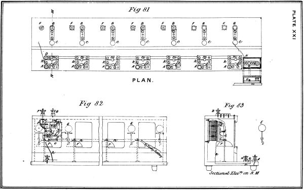
To each shutter apparatus an electric bell is fitted, by which notice
is given when a circuit closer has been struck. For general service,
a box containing seven such shutter signalling and firing apparatus has
been adopted, a plan of which is represented at Figs. 81, 82 and 83.
The connections of the different circuits are as follows:—
The insulated wire of the upper bobbin of the electro magnet is
connected to the spring of the armature; the pivot of the lever is
connected with the right-hand terminal B, or main line connection on
the top of the box; the insulated wire from the lower bobbin is connected
to the middle brass plate k in the front ledge of the apparatus,
the circuit from B to k being thus completed. The front adjoining
brass plate A, provided with a terminal, is connected with the negative
pole of the signalling battery, the positive pole being put to earth.
On a brass plug being put in the hole l, the signalling current will
flow to the plate k, thence through the lower and upper bobbin to
the spring of the armature, along the latter to the shutter lever, and
from the pivot through the main line wire to the mine. The innermost
brass plates H H are all connected in the same metallic circuit,
and to them are attached by means of the binding screw D the test
battery and galvanometer. Thus on the brass plug being removed
from l, and placed in m, the signalling battery is cut out of circuit,
and the test battery thrown in. In this way the condition of each
individual mine may be ascertained while the connections of the
remaining mines are left undisturbed. The positive pole of the firing
battery (the negative being to earth) is connected to the terminal S at
the right-hand corner of the lower ledge of the box; the plate to
which the terminal S is fixed is divided at G, the left-hand portion
being connected to a bar which runs horizontally the whole length of
the box, and in metallic connection with each mercury cup g, Fig. 80.
A brass plug is placed in the hole G, and when from any cause the
lever drops, the firing battery will be thrown into circuit, and the
mine to which the lever that has fallen is attached will be exploded.
Shutter Instrument and Observing Telescope.—Each mine is given a
number, which is put on the disc of the shutter instrument connected
to it, and also on the corresponding tablet C. From the brass plate in
connection with the spring c, Fig. 80, a wire is taken to the terminal f,
Fig. 81, on top of the box. From this terminal a wire is led to the
connections of the observing telescope, and thus the mines can be fired
by judgment if required, without the aid of the circuit closer.
The signal battery current is always circulating, even when the
system is in a state of rest, but in consequence of the resistance placed
in this circuit, which may be either a resistance coil in the circuit,
added to the resistance of the fuzes, when high tension fuzes are used,
or only the former resistance in the case of low tension fuzes, this
current is too feeble to form an electro magnet; directly, however,
a circuit closer is struck, this resistance is cut out, and thus the signal
battery current becomes sufficiently powerful to work the electro magnet
of that particular mine.
The circuit of the signal battery, and that to the observing telescope,
are broken the instant the lever commences to fall.
To enable the apparatus to be used on the circuit breaking system,
a spare lever E is provided for that purpose with each box.
The object to be gained by a system of testing is to ascertain the
condition of the electrical submarine mines placed in the defence of a
harbour, &c., and should there exist any fault, not only to detect its
exact position and cause, but also its magnitude, so that it may be at
once determined whether it is necessary to remedy the fault, or
whether the electrical apparatus is sufficiently powerful to overcome
the defect.
Tests.—There are two distinct kinds of tests, viz.:—
- 1.—Mechanical tests.
- 2.—Electrical tests.
Mechanical tests are applied to ascertain that the mechanical
arrangements of the shutter apparatus, circuit closers, and all similar
appliances work efficiently and easily; that the several parts of the
mine case when put together for service are thoroughly watertight;
that the chains, wire cables, and ropes in connection with the mooring
apparatus are of sufficient strength to perform the work required of
them; that the weights of the anchors, or sinkers, are such as to keep
the mines in position after submersion; and that the case of the
mine be sufficiently strong to enable it to bear the external pressure
due to the depth at which it may be submerged for a considerable
time without any leakage.
The foregoing tests of the mine case and moorings would of course
be performed during the process of manufacture, but to prevent any
chance of failure they should be repeated before being employed on
actual service.
Electrical Tests.—Electrical tests are those which are applied to the
several component parts of the system, to ascertain that the electrical
conditions necessary to a successful result exist.
The importance of being able to carry out the above in its entirety
is understood when it is remembered that a submarine mine becomes
practically valueless unless it acts efficiently at the single instant of
time that it would be required so to do.
List of Instruments used in Testing.—The following are some of the
instruments that are employed in connection with a system of electrical
tests:—
- 1.—Thomson's electrometer.
- 2.—Thomson's reflecting galvanometer.
- 3.—Astatic galvanometer.
- 4.—Differential galvanometer.
- 5.—Detector galvanometer.
- 6.—Three coil galvanometer.
- 7.—Thermo galvanometer.
- 8.—Siemens's universal galvanometer.
- 9.—A shunt.
- 10.—Commutator.
- 11.—Rheostat.
- 12.—Resistance coils.
- 13.—Wheatstone's balance.
Electrometers indicate the presence of a statical charge of electricity,
by showing the force of attraction or repulsion between two conducting
bodies placed near together. This force depending in the first place
on the quantity of electricity with which the conducting bodies are
charged, ultimately depends on the difference of potential between
them; an electrometer is therefore strictly an instrument for measuring
difference of potential.[J]
Sir William Thomson's quadrant electrometer is the most perfect
form of electrometer yet constructed, and the one usually employed in
cable testing. It consists of a very thin flat aluminium needle spread
out into two wings, and hung by a wire from an insulated stem inside
a Leyden jar, which contains a cupful of strong sulphuric acid, the
outer surface of which forms the inner coating of the Leyden jar. A
wire stretched by a weight connects the aforesaid needle with this
inner coating. A mirror, rigidly attached to this needle by a rod,
serves to indicate the deflection of the needle by reflecting the image
of a flame on to a scale. The needle hangs inside four quadrants,
which are insulated by glass stems: each pair of opposite quadrants
are in electrical connection. Above and below the quadrants two tubes,
at the same potential as the needle, serve to screen it and the wires in
connection with it from all induction except that produced by the four
quadrants. Suppose the needle charged to a high negative potential
(-), then if the quadrants are symmetrically placed, it will deflect
neither to the right nor to the left, so long as the near quadrants are
at the same potential. If one of these be positive relatively to the
other, the end of the needle under them will be repelled from the
negative quadrant to the positive one, and at the same time the other
end of the needle will be repelled from in the opposite direction. This
motion will be indicated by the motion of the spot of light reflected
by the mirror, and the number of divisions which the spot of light
traverses on the scale measures in an arbitrary unit the difference of
potential between the + and - quadrants.
The reflecting electrometer being a very delicate instrument,
requires careful handling, and should only be used by a practised
electrician. Its use would therefore be restricted to important stations,
and special tests of a delicate nature.
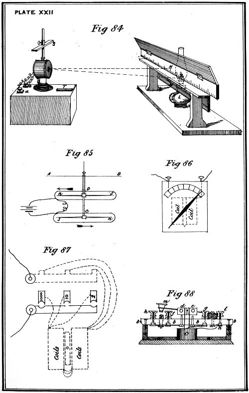
Thomson's Reflecting Galvanometer.—A galvanometer is an instrument
intended to detect the presence of a current and measure its
magnitude.
The most sensitive galvanometer as yet constructed is the reflecting
galvanometer of Sir William Thomson, a diagram of which is shown at
Fig. 84.
A small piece of magnetised steel watch spring, 3/8ths of an inch
long, is fastened with shellac on the back of a little round concave
mirror, and of about the size of a fourpenny piece. This is suspended
by a piece of unspun silk thread in the centre of a coil of many
hundred turns of fine copper wire insulated with silk, and well protected
between the turns with varnish. The two ends of the coils are
soldered to terminal screws a, b, so that any conducting wire can be
joined up to it as required. The little mirror hangs in the middle of
its coil, with the magnet lying horizontally. By means of a lamp L
placed behind the screen, the light of which passes through a slit M,
and is thrown on the face of the mirror, a spot of light is reflected on
the scale N.
When a current passes through the coil, the little magnet is deflected,
and since the magnet is attached to the mirror, which is very
light, both are deflected as forming one body, and the spot of light
moves accordingly along the scale N.
A powerful steel magnet S is placed above the coil, and can be
moved up or down, whereby the directive force of the earth may be
increased or weakened. This magnet S is used to steady the spot of
light, which otherwise would shake about, and there would be no
certainty about the measurement. A second magnet T is placed perpendicular
to the magnetic meridian, to adjust the zero of the instrument,
i.e., to bring back the spot of light to a fiducial mark at the centre
of the scale when no current is passing.
This instrument should only be used at important stations, and
when special tests of a delicate nature are required to be applied.
Astatic Galvanometer.—An astatic galvanometer is that in connection
with which an astatic needle is employed, by the use of which the
sensitiveness of a galvanometer is greatly increased.
An astatic needle is a combination of magnetised needles with their
poles turned opposite ways.
At Fig. 85 a diagram of such an instrument is shown. Two
magnets D and C are joined, with the north pole of one over the south
pole of the other, forming one suspended system. In the ordinary form
of astatic galvanometer the needles D and C are about two inches long,
and are each covered by a coil, these latter being so joined that the
current must circulate in opposite directions round the two so as to
deflect both magnets similarly. The deflection of the needles D and C
is observed by means of a pointer or glass needle A, B, rigidly connected
with the astatic system by a prolongation of the brass rod
connecting the needles D and C. The coils are flat and of the shape
indicated in Fig. 85, and are also made in two halves, placed side
by side with just sufficient space between them to allow the rod to
hang freely.
This form of galvanometer, though less delicate than the preceding
one, is still a very sensitive one, and should only be applied in the case
of fine and delicate tests.
Differential Galvanometer.—A differential galvanometer consists of
a magnetic needle surrounded by two separate coils of equal length
and material carefully insulated from each other and wound in opposite
directions. In using it one circuit acts against the other. If a current
of equal strength were passing through each there would be no deflection
of the needle, because the influence in both directions is equal. If
one current were stronger than the other, the needle would be deflected
by the stronger.
This form of galvanometer will be found extremely useful in connection
with a system of electrical tests.
Latimer Clark's double shunt differential galvanometer is the
instrument best adapted for submarine mine tests.
Detector Galvanometer.—A detector galvanometer is usually made
with a vertical needle, and is employed to detect and roughly estimate
the strength of a current where no particular accuracy is
required.
It consists of a magnetic needle pivoted in the centre of a coil of
insulated wire, and having an index needle attached to move with it,
the latter appearing on a dial, divided into 360 equal arcs or portions:
a diagram of such an instrument is shown at Fig. 86.
This instrument should be of small size and portable form, and as
sensitive as it is possible to make it, under such conditions.
Three Coil Galvanometer.—The three coil galvanometer is provided
with a vertical needle, and is in other respects very similar in appearance
to the detector galvanometer before described. It is formed with
three coils of 2, 10, and 1000 ohms resistance; each coil is connected
with a brass plate on the top of the box which encloses the whole, and
may be switched into circuit by means of a plug at will. The object
of the three resistances is to suit the different resistances that may
occur, with a perfect, or imperfect state of the electrical combination in
connection with each mine. A diagram of this instrument is shown at
Fig. 87, the dotted portions are inside the case.
Thermo Galvanometer.—A thermo galvanometer is an instrument
used to ascertain the power of a firing battery which is employed to
ignite platinum wire or low tension fuzes.
The form of thermo galvanometer generally used in connection
with a test table, is arranged as follows:—
Two ebonite studs, fitted with brass connecting screws, are fixed to
the lid of a box containing some resistance coils, and placed in circuit
with them; these studs, placed about ·3 of an inch apart, are arranged
to receive a piece of platinum wire which is stretched from one stud to
the other; the firing battery being placed in circuit with the platinum
wire, and the resistance coils, its working power would then be tested
by the fusion of the wire through a given electrical resistance, as
indicated by the resistance coils put in circuit.
Another form of thermo galvanometer, which is very compact and
portable, is shown at Fig. 88. It consists of a wooden box a, with a
cover of ebonite b, within the box is placed a resistance coil c; d and e
are two ebonite standards ·3" apart, the former of which is connected
by a copper wire with the terminal f, the latter to the terminal g; the
terminal h is similarly connected to the contact piece k, and the
terminal l to the firing key m, at n; the resistance coil c is connected
to the terminal g and to the copper wire n; the platinum wire (of
which several lengths are used, according to the resistance of the coil
c) is placed between the standards d and e. To test a battery, it is only
necessary to connect it to the terminals f and h, when by pressing
down the key m the power of the battery, according as to its fusing or
not the platinum wires, will be ascertained; the use of the terminals g
and l is to cut out the resistance, which is effected by connecting
them by means of a copper wire.
Siemens's Universal Galvanometer.—Siemens's universal galvanometer
is an instrument combining in itself all the arrangements
necessary for the following operations:—
- 1.—For measuring electrical resistances.
- 2.—For comparing electromotive forces.
- 3.—For measuring the intensity of a current.
The instrument which is shown in elevation and plan at Pl. xxiii.,
Fig. 1 and 2 respectively, consists of a sensitive galvanometer which
can be turned in a horizontal plane, combined with a resistance bridge
(the wire of which bridge instead of being straight is stretched round
part of a circle). The galvanometer has an astatic needle, suspended
by a cocoon fibre, and a flat bobbin frame wound with fine wire. The
needle swings above a cardboard dial divided in degrees; as however,
when using the instrument the deflection of the needle is never read
off, but the needle instead always brought to zero, two ivory limiting
pins are placed at about 20 degrees on each side of zero.
The galvanometer is fixed on a graduated slate disc, round which
the platinum wire is stretched. Underneath the slate disc three
resistance coils of the value of 10, 100, and 1000 Siemens' units are
wound on a hollow wooden block, which protrudes at one side, and on
the projection carries the terminals for the reception of the leading
wires from the battery and unknown resistance. The adoption of three
different resistance coils enables the measuring of large as well as
small resistances with sufficient accuracy.
GALVANOMETERS FOR TESTING.
The whole instrument is mounted on a wooden disc, which is
supported by three levelling screws, so that it may be turned round its
axle. On the same axle a lever is placed which bears at its end an
upright arm, carrying a contact roller. This roller is pressed against
the platinum wire round the edge of the slate disc by means of a
spring acting on the upright arm, and forms the junction between
the A and B resistances of a Wheatstone's bridge, which resistances
are formed by the platinum wire on either side of the contact roller,
one of the three resistance coils forming the third resistance of the
bridge. G is the galvanometer, k a milled head from which the
needles are suspended, and by turning k they can be raised or lowered,
m is the head of a screw which arrests or frees the needle when in
motion. h1, h2, h3, h4, are the terminals of the respective ends of the
three resistance coils, viz., 10, 100, and 1000 units, which are wound on
the wooden block C; these terminals may be connected to each other
by means of stoppers, and therefore one or more of the resistances may
be brought into circuit as desired, and to the ends of these terminals
the wires of the artificial resistances are connected as shown on
diagrams Pl. xxiv., Figs. 1, 2, 3a and 3b; f is the graduated slate disc,
round which the platinum wire is stretched in a slight groove at the
edge of the disc, and is inserted in such manner that about half its
diameter protrudes beyond the slate. The ends of the platinum wire
are soldered to two brass terminals l and l1, which are placed at the
angles formed by the sides of the gap in the slate disc, and which
form the junctures, as in the ordinary resistance bridge, between A,
n, and the galvanometer on one side, and B, X, and the galvanometer
on the other side, of the parallelogram. The terminal l is permanently
connected by a thick copper wire or metal strip to terminal
h_{1}, and the other terminal l1 is connected in a similar manner to
terminal III.
Slate is adopted for the material of which to make the disc f,
because it is found by experience to be the material which is the least
sensitive to variations in the weather or temperature.
The slate disc is graduated on its upper edge through an arc of 300
degrees, zero being in the centre, and the graduations figured up to
150 on each side at the terminals l and l1 of the bridge wire.
In the centre of the circular plate E of polished wood, supported
upon three levelling screws b, b, b, a metal boss is inserted, in which
turns the vertical pin a which carries the instrument. This pin, being
well fitted to the boss, supports the instrument firmly, but at the same
time allows it to be turned freely round its vertical axis without losing
its horizontal position when once obtained.
On the arm D D, which turns on the pin a, and somewhat behind
the handle g, there is a small upright brass arm d turning between two
screw points r, and carrying in a gap at its upper end a small platinum
jockey pulley e turning on a vertical axis. This pulley forms the
movable contact point along the bridge wire, against which it is
kept firmly pressed by means of a spring acting on the arm d. The
arm D D, which is insulated from the other parts of the apparatus, is
permanently connected with the terminal I. On the top of d a pointer
Z or a vernier is fixed, which laps over the upper edge of the slate disc
and points to the graduations.
To the pin a is attached a circular disc of polished wood C, about
one inch thick, and having a groove turned in its edge for the reception
of the insulated wires composing the resistances. The disc C has a
projection c, which carries the five insulated terminals marked I., II.,
III., IV., V., as shown on Fig. 1 and 2, Pl. xxiii. Terminals III.
and IV. can be connected by a plug, II. and V. by the contact key K.
Terminal I. is in connection with the lever D D.
Fig. 3 and 4, Pl. xxiii. show the shunt box supplied with the
galvanometer if specially desired; the copper connecting arms a, a are
screwed to the terminals II. and IV. By inserting a plug at c (Fig. 4,
Pl. xxiii.), the galvanometer is put out of circuit altogether, whilst
by plugging either of the other holes shunts of the value of 1/9, 1/99, or
1/999, are introduced into the circuit, and the effect upon the galvanometer
is reduced to 1/10, 1/100, 1/1000, respectively of what it would
have been without the insertion of the shunt.
Fig. 5 and 6, Pl. xxiii., show a battery commutator allowing to
bring into the circuit four different amounts of battery power. It is
placed in the battery circuit whenever consecutive tests with different
batteries are desired to be made, it being only necessary to change the
place of the stopper in the battery commutator, the terminal screw a
of the battery commutator being connected to terminal V. of the
galvanometer, and the screws b, b, b, b to various sections of the battery:
see diagram of connections, Fig. 4, Pl. xxiv.
The application of the universal galvanometer will be clear from
the diagrams on Pl ii.; instructions, however, for its practical use
are added further on, and also tables for use when measuring conducting
resistances.
As will be seen from diagram, Fig. 1, Pl. xxiv., the proportion
between the unknown resistance X, and the artificial resistance n is,
when the deflection is read off on the side of the slate disc marked A:
| |
X |
: n |
= |
150 + a |
: 150 - a |
| or, |
X |
= |
150 + a |
· n. |
| |
150 - a |
but if read off on the B side of the disc—
The values of these two fractions, for every half degree, will
be found in the columns headed A and B of the table in the
Appendix.
SIEMEN'S UNIVERSAL GALVANOMETER.
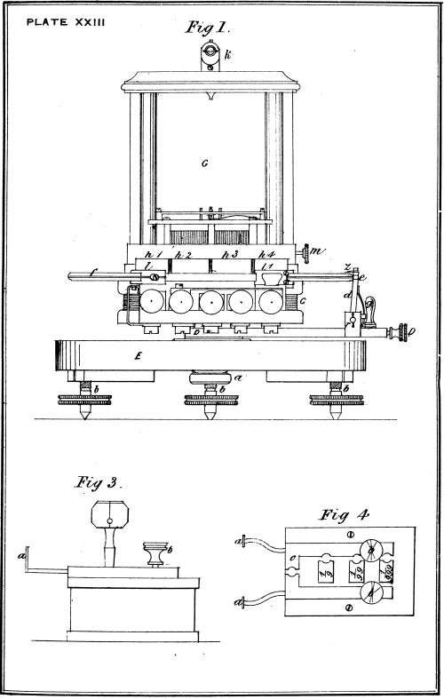
SIEMEN'S UNIVERSAL GALVANOMETER.
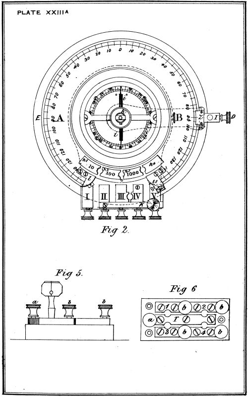
SIEMEN'S UNIVERSAL GALVANOMETER.
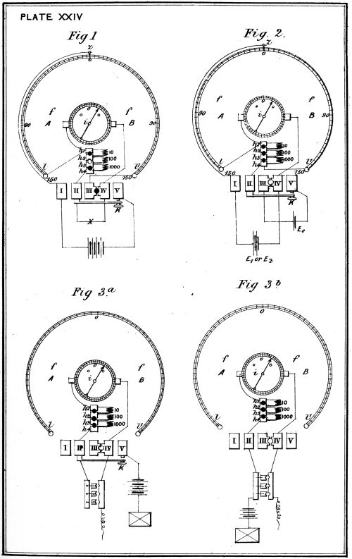
SIEMEN'S UNIVERSAL GALVANOMETER
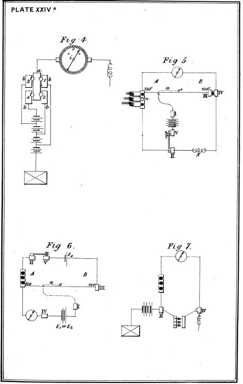
Measuring Electrical Resistances.—For this purpose the instrument
is arranged as a Wheatstone's balance. The connections are made as
shown at Pl. xxiv., Fig. 1 and 5, where X is the unknown resistance.
a.—The needle i is to be brought to the zero point of the small
cardboard scale by turning the galvanometer G round its
vertical axis, taking care that the needle moves with
perfect freedom.
b.—The pointer or vernier Z is to be brought, by means of the
handle g, to the zero point of the large scale on the slate
disc.
c.—A plug is to be inserted between the terminals marked III. and
IV.
d.—The holes 10, 100, and 1000 are, two of them, to be plugged,
and one left open, according to the extent of the unknown
resistance to be measured; either 10 or 100 must be left
open if the resistance is small, and 1000 if it is large.
e.—The two ends of the unknown resistance are to be connected to
terminals II. and IV.
f.—The two poles of some galvanic battery are to be connected to
terminals I. and V.
When the above-mentioned connections have been made, and on
depressing the key K, the battery current is sent into the combination
and deflects the needle, say, to the right-hand or B side of the instrument,
the pointer or vernier Z must then be pushed, by means of the
handle g, to the B side of the instrument. If this is found to increase
the deflection of the needle i, the pointer Z should be pushed to the
other or A side of the instrument beyond the zero point of the large
scale until the needle remains stationary when the key K is depressed.
The number indicated by the vernier Z should be read off carefully,
and notice taken whether it is on the A or B side of the large scale.
This number must then be referred to the galvanometer table,[K] when
the figure opposite to the number, multiplied by the resistance unplugged,
is the resistance of X. The value of the resistance to be
determined will be thus found by a single operation.
Supposing the reading to be 50 on the A side of the large scale,
the resistance n unplugged having been 100 units, we get according to
the before-mentioned law of resistance bridge the following proportion
(see Fig. 5, Pl. xxiiiA.):—
| X : |
100 |
= |
150 + 50 |
: 150 - 50 |
| X |
|
150 + 50 |
× 100 |
| 150 - 50 |
| X |
= |
200 units. |
For measuring very small resistances a single cell will be found
sufficient; but for large resistances more should be used, say, 15 to 20.
If very accurate measurements of small resistances are to be taken, the
screw at the end of the moving arm D D should receive one battery
wire, terminal V. receiving the other.
Comparing Electromotive Forces.—For this purpose Professor E. du
Bois-Reymond's modification of Poggendorff's compensation method
is used.
The connections are made as shown at Pl. xxiiiA., Fig. 2 and 6.
For comparing two electromotive forces E1 and E2, a third electromotor
of higher electromotive force E0 is used, and two separate
tests taken.
The manipulations a and b are to be the same as before.
c.—The hole between III. and IV. to be left unplugged.
d.—Plugs to be inserted in 10, 100 and 1000.
e.—The two poles of the electromotor of an electromotive force E0
are to be connected to the terminals III. and V.
f.—The poles of the battery whose electromotive force E1 is to
be compared are connected to terminals I. and IV. in such
a manner that the similar poles of the two electromotors
are joined to terminals I. and III., and to IV. and V. respectively.
When depressing the key K the galvanometer needle will be deflected
and can be brought back to zero by turning the pointer Z either
to the right or to the left. Should for instance the pointer have to be
brought to 30° on the A side we have the following equation—
| E1 = E 0 |
150 - 30 |
. . . . . . . . (1), |
| 300 + n |
where n is the resistance of the battery E0.
The electromotor E2 is now to be inserted in the place of E1, and
the galvanometer needle, when it deflects, again brought back to zero
by moving the pointer Z. If for instance the pointer has to be pushed
to 40° on the B side to obtain equilibrium we have—
| E2 = E0 | 150 - 40 |
. . . . . . . . (2). |
| 300 + n |
By eliminating n from equations 1 and 2 we have
E1 : E2 = (150 - 30) : (150 + 40) = 12 : 19 . . . . . . . . (3).
The two electromotive forces are in the same proportion as the two
observed distances of the pointer Z from 150° on the A side of the
instrument.
For measuring the Intensity of a Current.—For this purpose the
instrument is simply used as a sine galvanometer. The connectionsare made as shown at Pl. xxiv., Figs. 3a and 7.
The manipulations a, b, c, and d same as in the second case.
e.—Connect one pole of a battery to terminal II. and put the other
pole to earth.
f.—Connect the line to terminal IV.
The galvanometer is then to be turned in the same direction as
the needle is deflected until the needle coincides with the zero point.
Whilst this is being done the large scale on the slate disc will move
under the pointer Z, which must be left stationary; the sine of the
angle indicated by Z will thus give the value proportionate to the
strength of the current. Should the shunt box be required, it has to
be connected with terminals II. and IV.
Fig. 4 shows the same connections as Fig. 7, but without the shunt
box, and with the battery commutator. Fig. 3a shows diagram of the
same connections but with the key K, and Fig. 3b the same without
the key.
A Shunt.—A "Shunt" is a second path offered to a current traversing
a given circuit, or portion of a circuit, so as to diminish the amount
of the current flowing through that portion of the circuit. In the
diagram shown at Fig. 89 the shunt diminishes the amount of the
current flowing along the circuit between A and B.
If only 1/Nth of the current is to pass along the circuit between
A and B (of resistance R) then the resistance of the shunt must
equal R/(N - 1).
By the aid of shunts it is quite possible to make use of very
sensitive instruments to measure powerful currents.
Commutators or Switch Plates.—A commutator or switch plate is an
apparatus by which the direction of currents may be changed at will,
or by which they may be opened or closed. Bertin's commutator,
which is represented at Fig. 90, consists of a small base of hard wood
on which is an ebonite plate, this by means of the handle m is turned
about a central axis between two stops c and c'. On the disc are
fixed two copper plates, one of which o is always positive, being
connected by the axis and by a plate (+) with the binding screw P,
which receives the positive electrode of the battery; the other copper
plate i, e, bent in the form of a horse-shoe, is connected by friction
below the disc with a plate (-), which plate is connected with the
negative electrode N. On the opposite side of the board are two
binding screws b, and b', to which are attached two elastic metal plates
r, and r'.
On the disc being turned as shown in the figure, the current
coming by the binding screw P passes into the piece o, the plate r,
and finally the binding screw b, which by means of a copper wire leads
the current to the apparatus in connection with b; then returning to
the binding screw b', the current reaches the plate r', the piece i, e,
and so to the battery by the binding screw N.
If the disc is turned so that the handle m is half way between c
and c', the pieces o and i, e, being no longer in contact with the plates
r and r', the current will not pass. If m is turned as far as c, the
plate o will then touch r', and the current pass to b', and return by b,
thus reversing its direction.
"Peg" switches are also often used; they are arranged so that
the removal or insertion of a brass peg or plug cuts out, or completes
a circuit.
Rheostat.—A rheostat is an instrument used for the comparison of
resistances.
SHUNT, COMMUTATOR, RHEOSTAT.
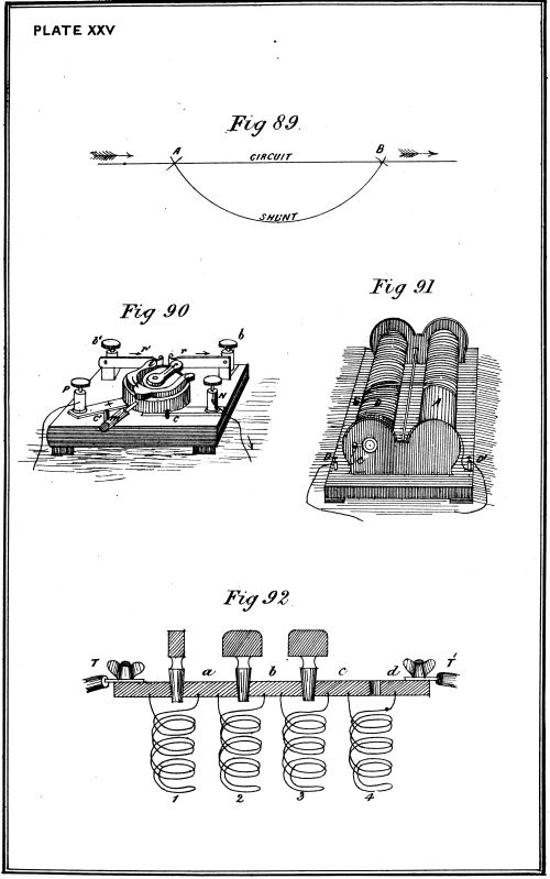
Wheatstone's rheostat, which is shown in elevation at Fig. 91,
consists of two cylinders A and B, one of brass and the other of
non-conducting material, so arranged that a copper wire can be
wound off the one on to the other by turning a handle C. The
surface of the non-conducting cylinder B has a screw thread cut in
it for its whole length, in which the turns of the copper wire lie,
so that its successive convolutions are well insulated from each other.
Two binding screws D, D' connected with the ends of the copper
wire are provided, to which the circuit wires are connected. A scale
is attached at E, by means of which the number of convolutions on B
can be read off; and parts of a revolution are indicated on a circle at
one end. The handle C can be shifted from one cylinder to the other.
Supposing the rheostat introduced into a circuit, and the whole of
the copper wire wrapped on the metal cylinder A, then, on account
of the large section of this metal cylinder, its resistance may be
entirely neglected, but for every convolution of the wire on the
non-conducting cylinder B, a specific resistance is introduced into
the circuit. The amount of resistance can thus be varied as gradually
as desired by winding on and off the cylinder B. This instrument is
often used in connection with the thermo galvanometer.
Resistance Box.—The general arrangement of a resistance box is
shown in the diagram Fig. 92.
Between two terminal binding screws T and T1 secured on a
vulcanite slab are fixed a series of brass junction pieces a, b, c, d; each
of these is connected by a resistance coil to its neighbour, as shown
at 1, 2, 3, and 4. A number of brass conical plugs with insulating
handles of vulcanite are provided, which can be inserted between any
two successive junction pieces, as between T and a, or a and b.
With all the plugs inserted, the electrical current will flow direct
from T to T1, the large metallic junction pieces directly connected by
the plugs would offer no sensible resistance; but if all the plugs were
removed, then the current would flow through each of the coils 1, 2,
3, and 4, and the resistance in the circuit would be the sum of the
resistances of those four coils. With the plugs arranged as in the
figure, the current would flow through coil 4 only, and the resistance
in the circuit would be equal to the resistance of that coil.
Wheatstone's Balance.—The electrical conductivity of a body is
determined by ascertaining the ratio between the resistance of a
certain length of the conductor in question, having a given section,
to that of a known length of a known section of some substance taken
as a standard.
For this purpose Wheatstone's bridge in connection with a box of
resistance coils is the most convenient method.
At Fig. 94 is shown Wheatstone's balance (Post-office pattern),
and at Fig. 93 the apparatus is reduced into the form of a parallelogram,
which is the usual diagram of Wheatstone's bridge. The
theory of the bridge is as follows:
Four conductors A B, B C, A D, and D C are joined at A and C
to the poles of a battery Z; the resistance between A and B is R;
that between A and D is r; that between D and C is R1; and that
between B and C is x, the unknown resistance to be measured. A
convenient constant ratio is chosen for R1 and r, such as equality
1 to 10, 1 to 100, or 1 to 1000; and then R1 is adjusted until no
current flows through the galvanometer G; when this is the case we
have R : r=R1 : x, or x = (r/R) × R1; so that if r = R/100, x will be equal
to R1/100.
Two keys a and b are inserted; the current is wholly cut off the
four conductors until contact is made at a; and then after the
currents in the four conductors have come to their permanent
condition, contact is made at b to test whether any current flows
through the galvanometer. The three resistances R, R1 and r and
the resistance of the galvanometer should be small if x is small, and
great if x is great.
The conductors A B and A D of the bridge are each formed of
three resistance coils having a resistance of 10, 100, and 1000 ohms
respectively, inserted between the terminals B and D of the balance,
Fig. 94.
The conductor D C is formed of a set of resistance coils from 1 up
to 4000 ohms, amounting altogether to 11,110 ohms, inserted between
the terminals D and C of the balance; in the balance, a brass plug
being inserted between the terminals D and D1, they may be considered
as one terminal D. The conductor B C is the wire to be
tested, and is connected to the terminals B and C of the balance.
Measurement of Resistances.—When a resistance is to be measured
that is within the range of the coils in R1, R and r are made equal.
The needle of the galvanometer will move in a different direction,
either to the right or to the left, according as the resistance in R1 is
greater or less than the line wire x. The needle remains at zero
only when the resistance in R1 is equal to that in x. For r : R :: R1 : x.
WHEATSTONE'S BRIDGE.
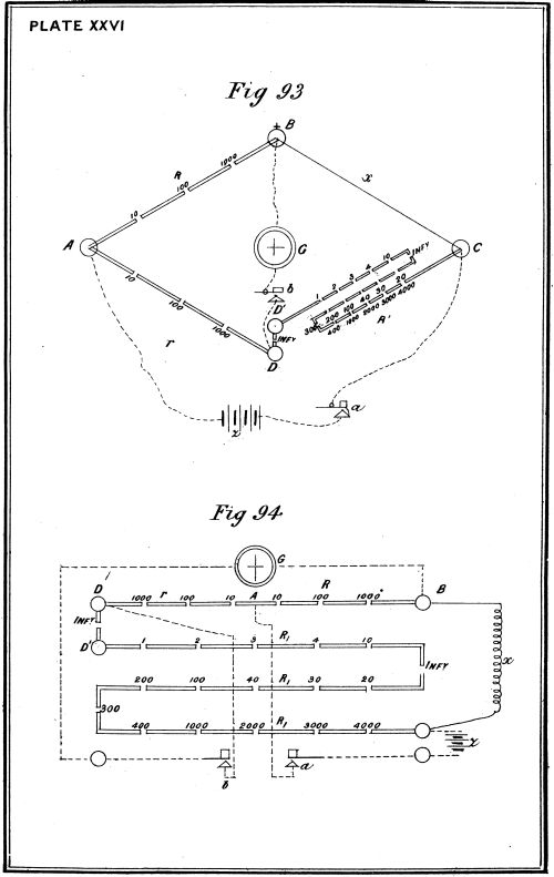
When the resistance of x is greater than that of R1, as in an
insulation test, the resistance in r is made less than that in R, in order
that r and R may have such a proportion one to the other as will
enable the coils in R1 to balance a resistance in x, greater than their
own, that is to say, greater than 11,100 ohms; thus r : R :: R1 : x,
or 10 : 1000 :: 10,000 : 1,000,000, the resistance in the line to be
tested would be 1,000,000 ohms, supposing the values of r, R and R1
to be respectively 10, 1000, and 10,000 ohms.
When the resistance to be tested is less than that of the least coil
in R1 (1 ohm), then the resistance in r is made greater than in R.
Thus r : R :: R1 : x, or 100 : 10 :: 2 : 0·2; the resistance of the line
to be tested would in this case be 1/20 of an ohm.
Manipulation.—In all cases the key in connection with the battery
should first be depressed, then the galvanometer key, making very
short contacts by the latter, just sufficient to show the direction of
the deflection, until the coils in R1 are nearly adjusted, otherwise
considerable time will be lost in making a series of tests, owing to
the swing given to the needle, which will take some little time before
it again remains steady at zero. When once the coils in R1 are
adjusted, and a balance obtained, it should be ascertained whether the
needle will remain steady when contact is made and broken.
Test Tables.—In connection with a system of testing electrical submarine
mines, for the sake of convenience and simplicity it is necessary
to use a table (termed a "Test Table"), on which all the apparatus used
for the purpose of testing are fixed. Several forms of tables have been
designed for such a purpose. At Fig. 95 is shown the method of
arranging such a table.[L]
A is an astatic galvanometer placed between two switch plates,
B and C; ten other similar switch plates, 1, 2, 3, 4, D, 5, 6, 7, E, and
8, are arranged in front of the galvanometer A; F, G, and H are
three terminal plates; K is a box of resistance coils used in connection
with the thermo galvanometer M; L is a firing key, and N a battery
commutator; O is a three-coil galvanometer; R is a Wheatstone
balance (Post-office pattern).
The ten switch plates, 1, 2, 3, 4, D, &c., are used for the connection
of any particular line to be tested, as well as for the earth connections
and instruments employed in that operation.
"Sea Cell" Tests.—The arrangement shown in the figure is that
required in connection with the sea cell test, and Mr. Brown's method
of keeping certain earth plates in a bucket instead of in the sea.
If two plates of suitable metal to form a Voltaic battery are placed
in salt water and connected by a metallic conductor, a battery is
at once formed capable of producing considerable deflection on a
moderately delicate galvanometer. Testing by this arrangement has
been termed the "sea cell" test.
Arranging Earth Plates.—Mr. Brown's, Assistant-Chemist to the
War Department, method of arranging the earth plates is as follows:—
A series of earth plates, such as copper, carbon, tin, zinc, &c., are
placed in a bucket filled with sea water, and which is placed in the
testing room. The water in the bucket is put in connection with the
water of the sea by means of a conducting wire, terminating at one
end with a zinc plate in the bucket, and at the other with a zinc
plate in the sea. By this means the tests made with the different
earth plates in the bucket are identical with those made with corresponding
earths placed absolutely in the sea, and therefore these
latter may be done away with, the sea cell tests being entirely carried
out by means of the bucket earth plates.
In addition to the bucket earth plates there will be several other
earth plates in connection with the testing room, these being placed in
the sea, such as the zinc earth for the firing battery, the zinc earth
for the signalling battery, &c.
Connections of Switch Plates.—The switch plate D is used for the
connection of any particular mine cable which it may be required to
test. The switch plate E is connected with a zinc earth plate used
for testing the firing battery. This must always be in the sea. The
switch plate 1 is in connection with a zinc earth in the bucket; 2 is
attached to a copper earth plate in the bucket; 3 is attached to a
carbon earth plate in the bucket; 4 to a tin earth plate in the bucket;
5 is used for connection with the zinc signalling earth connection in
the sea; 6 is attached to a copper earth plate used for the sea cell
test, or any other purpose required, in the sea; 7 is attached to a
zinc earth plate in the sea; and 8 is a common zinc earth in the sea.
The terminal plates G and H are used for the connection, for
testing purposes of the negative and positive poles, of the firing
battery, and F is connected with a zinc earth in the sea, for a similar
purpose. These plates are in connection with the resistance coils K
and the thermo galvanometer M, employed for testing the firing battery,
the circuit being closed by the firing key L. Other ways of using
these plates may of course be adopted if desired. The resistance coils
K range from 0·5 to 100 ohms, and are composed of wire adapted for
the passage of a quantity current. A reversing key is generally used
in connection with a testing battery and the three-coil galvanometer
O. This reversing key would consist of two bridges completely insulated
from each other, the upper one attached to the negative, the
lower one to the positive pole of the test battery. In their normal
position both keys press against the upper bridge, and until one or
other of the keys is pressed down no current will pass, the direction
of the current being altered by pressing down a different key. The
point of each key is provided with a terminal and connected, the
one to a zinc earth through the switch plate 8, the other to one
terminal of the three-coil galvanometer when the tests are to be
applied.
The Wheatstone balance R is used in finding the resistances of
electrical cables, balancing fuzes, &c. By means of a commutator,
N, the necessary number of cells for any particular test may be
thrown in circuit when required.
Test of Platinum Wire Fuze for Conductivity.—The platinum wire
fuze may be tested electrically as follows:—
If placed in circuit with a few cells of a Daniell or Leclanché
battery and a detector galvanometer, before the platinum wire bridge
of the fuze is fixed, there should be no deflection of the needle, for
no metallic circuit exists; if it did, such would be fatal to the
efficiency of the fuze. If similarly placed in circuit after the bridge
has been fixed, a considerable deflection of the needle should result,
such deflection being due to the current passing through the metallic
bridge, which to be efficient ought to be the sole medium through
which the circuit is completed.
Test of Resistance of Platinum Wire Fuze.—The electrical resistance
of a platinum wire fuze is ascertained by means of the Wheatstone's
balance R and galvanometer A, Fig. 95. The terminals of the fuze
are connected to the binding screws of the balance, the commutator
N and galvanometer A being connected up in circuit. The
resistance of the coils is then adjusted by taking out plugs until the
needle of the galvanometer A is brought to zero, when the sum of the
resistances indicated by the unplugged coils will be equal to that of
the fuze. The resistance of a platinum wire fuze might also be
ascertained by means of a differential galvanometer instead of a
Wheatstone balance.
The electrical resistance of 3/10" of fine platinum wire, weighing
1·9 grains to the yard, is 3/10 of an ohm nearly (Schaw).
Testing High Tension Fuzes.—High tension fuzes require very
delicate and careful management in testing them, due to the high
electrical resistance of such fuzes, which ranges from 1500 to 2000
ohms, combined with the danger of premature explosion when testing
even with a small number of battery cells. Very sensitive galvanometers,
such as the reflecting galvanometer, should if possible be
used, otherwise the mode of making the tests for conductivity and
resistance of a high-tension fuze is similar to that already given for
a platinum wire fuze.
Detonating fuzes should always be placed in an iron case during
the process of testing.
Insulation Test for Electrical Cables.—To test an electrical cable for
insulation, it should first be put in a tank of water, or in the sea, and
allowed to soak for at least forty-eight hours. The object of this is to
allow the water to penetrate the outer protection of hemp and iron
wires, &c., and to search out and get into any weak places there may be
in the insulation under the armouring. At Fig. 96 is shown the
method of performing this test. A is a tank holding the electrical
cable, which has been in soak for forty-eight hours; B is an astatic
galvanometer; C, Z a Leclanché or Daniell battery of great power;
and C is an ordinary firing key. One end of the electric cable D is
connected to the galvanometer B through the firing key C; the other
end of the cable is very carefully insulated; one pole of the battery
is connected to the galvanometer B, the other is put to earth in the
tank at F; should the insulation be perfect, no deflection of the
needle should follow on the key being pressed down. A very slight
deflection might be observed on a moderately sensitive galvanometer,
due to the current passing through the insulation; its whole length
being immersed, the surface through which such a current would pass
would be large, and the sum of the infinitesimally small quantities
escaping over the whole length, would in the aggregate be sufficient to
deflect the needle to a small extent in completing the circuit of the
battery. Should any considerable deflection occur, it would indicate
a defect or leak in the insulation of the cable, the extent of which
would be roughly measured by the amount of such deflection.
By using a reflecting galvanometer a very much more delicate test
would be obtained, but for the comparatively short lengths of electric
cables used in connection with submarine mines, such accuracy is
hardly necessary.
To test an electric cable for conductivity, it would be only necessary
to expose the metallic conductor G, and put it in the water of the tank.
If the conductivity were good, then the whole of the current would
pass through the cable and the needle of the galvanometer would be
violently deflected. If the continuity were broken, no deflection would
be observed.
Defects observed in the Conductivity of the Cable.—To ascertain the
position of a defect in the insulation of a cable, as indicated by the
tests above described, it would be only necessary to keep a continuous
current flowing through the cable, and gradually take it out of the
tank. If the fault existed at a single point, the deflection of the needle
would be suddenly reduced at the moment of that point of the cable
being lifted out of the water, and therefore its position would be
determined with considerable accuracy. Should several defects exist
as each was lifted out, a sudden reduction of the deflection would occur.
Discharge Test.—The conductor of an electrical cable may be broken
without destroying the insulation, and on applying the foregoing tests,
good insulation would be indicated, but no conductivity, and no
information would be given as to the position of the fault. Under
such circumstances the following test must be applied:—
Put one pole of a very powerful battery to earth, and charge one
end of the defective cable, then immediately discharge it through a
reflecting galvanometer, and note the extreme limit of the swing of the
needle, then, charge the other end of the cable in a similar manner,
and discharge it through the same galvanometer, noting as before the
swing of the needle. This should be done three or four times, and the
average of the deflections taken. Then the position of the fault would
be indicated by the proportion between the average deflections in each
case, and the cable might safely be cut at that point. Should the precise
position of the fault not be discovered in thus cutting the cable, each
section should be tested again for conductivity, and that in which a
fault was still found to exist should be again tested by the discharge
as before.
Test of Electrical Resistance of Cable.—This is effected by balancing
it against the Wheatstone balance, in a similar manner to that
explained for a fuze. The electrical resistance of the conductor of
a cable affords a very correct indication of the quality of the metal
of which it is composed. For a very delicate test the reflecting
galvanometer should be used.
Electrical Test of Insulated Joints.—Insulated joints and connections,
whether of a permanent or temporary nature, should be tested electrically,
in a precisely similar manner to that explained for electric cables.
They should be soaked for forty-eight hours, and then tested for
insulation, conductivity, and electrical resistance.
In testing permanent joints special tests are carried out, which are
described by Mr. Culley in his 'Handbook of Practical Telegraphy.'
Voltaic batteries should be subjected to the following tests:—
- 1.—For potential.
- 2.—For internal resistance.
- 3.—For electromotive force.
For the purpose of testing the potential of a battery, one pole
should be put to earth, and with the other one pair of the quadrants of
a Thomson's reflecting galvanometer should be charged; when this is
done, a certain deflection of the spot of light will occur, and the amount
of such deflection, as compared with that produced by a standard cell
applied to the instrument in a similar manner, would give the relative
value of the potential of the battery.
The following method of determining the internal resistance of a
battery is that recommended by Mr. Latimer Clark in his book on
electrical measurements.
The instrument employed is a double shunt differential galvanometer,
a diagram of which is shown at Fig. 97. Connect the battery
and a set of resistance coils in circuit between the terminals A and D,
and insert plugs in the resistance coils so that they give no resistance;
insert plugs at A and C, and also both the shunt plugs at A and D.
The current will now flow through one half of the galvanometer circuit
only, being, however, reduced to 1/100 of its amount by the shunt D; the
deflection of the needle must be carefully read. The plug A must now
be removed to B, which causes the battery current to flow through both
halves of the galvanometer (each being shunted). The circuit will
now be as shown in the figure, and the needle will of course be
deflected somewhat more than before. Now unplug the resistance coils
which are in circuit with the battery until the deflection of the needle
is reduced to its original amount, and the resistances unplugged will be
equal to the internal resistance of the battery.
The following is another method of ascertaining the internal resistance
of a battery cell.
A circuit is formed, consisting of the battery cell, a rheostat, and a
galvanometer, and the strength C is noted on the galvanometer. A
second cell is then joined with the first, so as to form one of double the
size, and therefore half the resistance, and then by adding a length l
of the rheostat, the strength is brought to what it originally was, C.
Then if E is the electromotive force, and R the resistance of cell, r
the resistance of the galvanometer, and other parts of the circuit, the
strength C in the one case is C = E / (R + r), and in the other = E / ((1/2)R + r + l),
and since the strength in both cases is the same, R = 2l, i.e., the internal
resistance of the cell is equal to twice the resistance corresponding to
the length l of the rheostat wire.
The comparative electromotive force of a battery may be determined
by means of a double shunt differential galvanometer in the following
method, as recommended by Mr. Latimer Clark.
"This can only be done relatively in terms of some other standard
battery. First determine the resistance of the standard and of the
other cells to be measured; then insert the shunt plugs at A and D,
Fig. 97, and also at C and B, and join up the standard cell in circuit
with a resistance coil to the terminals A and D, and unplug the
resistance coils until a convenient deflection is obtained, say 15°; note
the sum of the resistances in circuit, including that of the battery
galvanometer, resistance coil and connecting wires; now change the
battery for another, and by unplugging the resistance coils bring the
needle again to the same deflection, 15°; having again found the total
resistance in the circuit, the relative electromotive force will be
directly proportional to these resistances."
The electromotive force of a battery may also be measured statically
by means of Thomson's quadrant electrometer, the poles of the battery
being connected with the two chief electrodes of the instrument, in
which arrangement no current will pass, and the electromotive force
will be directly indicated by the difference of potential observed.
In the case of a quantity battery, that is, a battery capable of fusing
a fine platinum wire, its electromotive force and internal resistance
may be determined by means of the resistance coils K, and thermo
galvanometer M, shown at Fig. 95.
Tests after Submersion.—After an electrical submarine mine has
been placed in position, it should be immediately tested to ascertain
that all is right, and similar tests should be applied at intervals to
ascertain that the charge remains dry; that the insulation and conductivity
of the electric cable remains the same; and that its electrical
resistance indicates a state of efficiency.
The nature of the tests applied to determine these points will
depend upon the nature of the combination in which the mine is
arranged.
The manner of applying the "sea cell" test, by which is ascertained
the condition of a system of electrical submarine mines, will be readily
understood from the following examples.
The arrangements for testing to ascertain whether a charge is dry,
or wet, is shown at Fig. 98.
z is a plate of zinc introduced in the circuit within the charge, and
between the fuze and the shore; another earth plate of carbon x is
connected with the electric cable beyond the fuze, forming the ordinary
earth connection of the system at that point; and at home a copper
earth plate c is used.
First, in the case of a dry charge with the insulation and conductivity
of the cable, good; under these circumstances there would be
formed a sea cell between the earth plates x, and c, which would
produce a certain deflection of the needle of a galvanometer g, which
is placed in the circuit, and in a certain direction.
Secondly, in the case of a charge becoming wet, through leakage,
with the insulation and conductivity of the cable, good; under these
circumstances, a sea cell would be formed between the plates c and z,
causing a different deflection of the needle in amount and in direction,
by which it would be at once indicated that the charge had become wet.
TEST TABLE, DIFFERENTIAL GALVANOMETER.
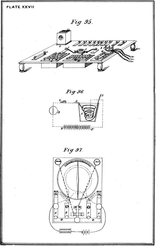
"Sea cell" Test for Insulation.—Again, in the case of the insulation
of the electric cable being damaged to such an extent as to expose the
copper conductor. Under these circumstances there would be formed
a sea cell between the copper earth plate c, and the exposed copper
conductor of the cable, by which a certain definite deflection of the
galvanometer would be observed, which deflection would differ in
character from that produced by the copper carbon sea cell, when the
insulation of the cable was good, and the system in working order, and
therefore it would indicate that some change in the electrical conditions
of the system had occurred. The fact that a leak existed in the
insulation would be proved by changing the earth plate at home from
copper to zinc, carbon, tin, &c.
In the case of no deflection being produced on the galvanometer, on
applying the sea cell test, a want of continuity, or inefficient connections
would be indicated.
The foregoing afford examples of the vast utility of the "sea cell"
in connection with a system of electrical tests for submarine mines,
numerous variations of which may be effected by employing a series
of earth plates, of different metals, at the home end of the circuit, in
connection with a carbon and zinc earth plate at the other end. And
the mode of manipulating these tests may, by means of numerous
switch plates, as shown at Fig. 95, be made extremely simple and
efficient.
Armstrong's System of Electrical Testing.—A very simple method
of testing electrical submarine mines, with which low tension fuzes are
used, has been devised by Captain Armstrong, R.E., and is shown at
Fig. 99. a is the electric cable leading from the shore; b the cable
attached to a polarised relay c, and connecting the charge through
the fuze f to the earth; b' the cable, attached to another polarised
relay c', and connecting the mine with the circuit closer; the polarised
relay c, in the mine, is arranged to be worked by a positive current,
that is to say, the wire surrounding the core is so wound as to increase
the polarity of the electro magnet, near the armature d, when a
positive current is passed through it, and to diminish the polarity
when a negative current is passed through the wire surrounding the
core; the polarised relay c' within the circuit closer is arranged to be
worked by a negative current, the coil being so wound as to produce
an influence exactly the reverse of c.
Then, a positive current passing along the line wire a, the armature
d in the charge will be attracted, while d' will remain unaffected;
again, if a negative current be circulated, the armature d' within the
circuit closer will be attracted, while the armature d will remain
unaffected. Two insulated wires forked together are wound round
each electro magnet, one a thin wire (g and g') having a considerable
resistance, about 1000 ohms, being connected direct to the earth
plates e and e', and the other a thick wire (h and h') offering a very
small resistance, and so arranged that when the armature is attracted,
they may be in contact with and complete the circuit through the
armature to earth.
The thin wire coils are so arranged that a certain number of
Leclanché cells (ten or twelve, as may be desired) will make the
electro magnets act, while with fewer cells the current would be too
weak, and would therefore pass through them to earth without affecting
the armature.
By means of the three-coil galvanometer, a table of the deflections,
obtained by the foregoing system of testing, should be carefully recorded,
when the circuit is known to be in good working order, so that
any defect in the circuit would be at once indicated on the application
of the various tests, by the results so obtained differing from those
originally recorded. When a system of submarine mines is placed in
position for the purposes of practice and experiment, every trouble
should be taken to endeavour to fix the exact position of any defect
that may exist, also to ascertain its magnitude, &c., but in time of war,
should a defect exist in the system, no time must be lost in such
operations, but the mine at once lifted, and the fault repaired, or a
fresh one laid in its place, unless the presence of an enemy or other
imperative cause should prevent such work being done.
Austrian Testing Table.—The following is a description of the
Austrian testing table, and their mode of making electrical tests with it,
in connection with their system of self-acting electrical submarine mines.
METHODS OF TESTING.—ARMSTRONG,—AUSTRIAN.
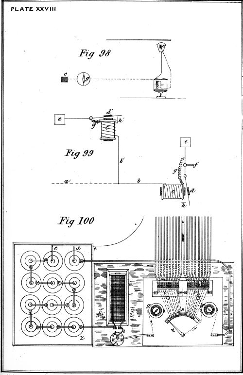
Its design is shown at Fig. 100; c z represents the battery with
one pole to earth at e, and the other in connection with an intensity
coil a, through which the current passes to the contact plate b. When
it is desired to put the system of mines in connection with the table,
in a state of preparation to be fired by the contact of a vessel, a plug
is inserted between the contact plates b and f, and the current passes
through the galvanometer g, and electrically charges the conducting
wires connecting the mines with the battery, through the several
binding screws on the contact plates, numbering 1, 2, 3, &c. The
fact that the charge has been fired is also at once indicated on the
galvanometer g.
Test to discover an Exploded Charge.—It then becomes necessary
to ascertain which particular mine of the system has been exploded;
for this purpose a separate circuit in connection with a single cell d is
employed. This cell is in connection through a galvanometer g' (a
more sensitive instrument than the galvanometer g) with the pivot of
the key h, and rheotome R, which latter is connected, as shown by
the dotted lines, with each individual mine of the system attached to
the contact plates numbered 1, 2, 3, &c. The handle of the rheotome
is moved round, to each number in succession and directly it is placed
in contact with that corresponding to the exploding mine, the
electrical circuit is completed through the exposed end of the
fractured wire, and this is indicated by the galvanometer g'. During
the testing process the firing battery c z must be disconnected; this is
done by raising one of the bridges i i with which each group of ten
mines is provided.
Insulation Test.—The rheotome and testing galvanometer g' are
also used to test the insulation of the electric cables connecting the
mines to the testing table. This is done in precisely the same
manner as testing for an exploded mine: the handle of the rheotome
is turned round, and each cable connected in succession with the
testing circuit as before; should the galvanometer g' remain stationary,
the insulation is good; but should a defect of insulation exist, the
current passing through it would act on and deflect the galvanometer,
indicating the particular line in which it exists, and, roughly, its
extent in proportion to the deflection shown; should the fault be
considerable, the defective cable should be at once detached, as the
current lost through it might so diminish the working power of the
firing battery, as to prevent it exploding any of the fuzes attached to
the group in connection with it. By the above arrangement, the
insulation of each line can be tested at any moment required.
In making the delicate test for insulation, which should invariably
be done at leisure, and, if possible, when an enemy's vessels are not in
the vicinity of the mines, a large number of Daniell's or other cells of
suitable form should always be used. To do this, it would only be
necessary to connect such a battery in place of a single cell permanently
arranged, as described, in the testing circuit, and to
proceed with the details of the operation as before. As the cable
would, in actual work, always be charged with the full power of a
firing battery, the value of its insulation to resist an electrical charge
at such a high potential would be an important point to determine.
The fuzes being entirely out of the circuit till the moment of the
action arrives, no danger of a premature explosion need be apprehended;
if a fuze were in such a position as to be fired prematurely,
it would be exploded, in connection with the firing circuit, independently
of the operation of testing the insulation of the cables.
To render a Channel Safe.—In order to render the channel safe
for a friendly vessel, it is only necessary to remove the plug from
between the contact plates b and f; this disconnects the firing battery
from the circuit.
Defence of Harbours by Booms, &c.—Booms or cables supported by
rafts may also be employed in the defence of harbours, or rivers, either
by themselves, or in combination with submarine mines; in the latter
case, the booms, &c., may be moored either in advance of the mines, or
in rear of the front row, this last method of mooring them being the
most effective one.
There are a great variety of forms in which a boom may be constructed.
The qualities essential for a good and practicable boom are:—
- 1.—Great strength.
- 2.—Great power of resistance.
- 3.—Convenience in handling.
- 4.—Easy to manipulate.
- 5.—Its materials easily procurable.
Construction of a Boom.—The general construction of a boom consists
of a main cable, buoyed up at intervals by floats. The main cable
may be either wire, chain, or rope, the former being very much superior
for this purpose to chain or rope. The floats consist of balks of timber
built round the main cable and bound together by means of iron hoops
&c. A space is left between each float, by which a certain amount
of flexibility in the boom is obtained, without which it would be of
comparatively little use, as it might be easily overrun.
It must be borne in mind, in constructing all such booms, that the
smaller the proportion of timber used in forming the floats to the
cable, consistent with buoyancy, the stronger will be the structure.
A very important feature in connection with such a mode of defence
is the manner of mooring it; for if it be moored so as to be
unyielding, then its sole power of resisting a vessel charging it is
the actual strength of the materials composing the structure, but if it
be moored so that it is capable of yielding to a sudden blow, this force
will be to some extent absorbed, and resistance of the defence greatly
increased.
The raft employed to support the main cable should be moored by
means of very heavy chains (without anchors) in the direction of the
attack, and with ordinary anchors and cables on the other side.
As a rule, the booms should be moored obliquely to the direction of
the current, where there is any, as the tendency of the current to overrun
the boom when so placed will be less, and also a ship ramming it
must place herself athwart the current to attack the boom at right
angles.
Clearing a Passage through the Torpedo Defences of an Enemy.—The
subject of clearing a passage through the torpedo defences of an enemy
is one fraught with innumerable difficulties, on account of the varied
nature and impracticability of obtaining accurate and certain information
of such defences, and thus it is impossible to lay down any fixed
rule or plan for carrying out such an operation.
In fact, it will be only under the most favourable circumstances that
such a service will be successfully accomplished, that is to say, in the
case of a harbour or river defended by submarine mines but unsupported
by guns, or guard boats, or where the electric light is used.
Numerous methods have been devised from time to time to effect
the destruction of an enemy's submarine defences, among which are
the following:—
- 1.—Projecting frames, &c., from the bows of a vessel.
- 2.—Creeping and sweeping by boats.
- 3.—Countermining.
Projecting Frames, &c., from the Bows of a Vessel.—This method was
adopted by the Federals during the American civil war of 1861-5,
and in many instances it was the means of saving their ships when
proceeding up rivers which had been torpedoed by the Confederates,
though notwithstanding this precaution several vessels were sunk.
The submarine mines against which this mode of defence was used,
were in nine cases out of ten mechanical ones, and therefore the framework
defence afforded a better means of protection then, than would be
the case now that electrical ground mines and circuit closers are used,
as the framework would catch the circuit closer only, and the vessel
would probably be over the mine when the explosion took place. The
Americans moor their circuit closers in rear of their mines, so that a
vessel fitted with a bow frame or not, coming in contact with the
former must be right over the charge at the instant of explosion.
Against ground electrical mines fired at will, the bow net, &c., is no
protection whatever, still under certain circumstances it would be found
extremely useful.
Sweeping for Submarine Mines.—This method of clearing a channel
of submarine mines could not possibly be carried out under artillery
fire, but in waters not so defended it would prove of some value.
Where only buoyant mines, or ground mines with circuit closers are
to be cleared away, two or more boats dragging a hawser between them
would be sufficient to discover them, and so lead to their destruction;
but where dummy mines and inverted creepers are moored in addition,
another method of sweeping must be resorted to, viz., that of bringing
an explosive charge of gun-cotton to act on the obstruction grappled,
and thus destroy it. This is effected by lashing a charge to each end
of the sweep, so that whatever is grappled may slide along it, until
caught by hooks, which are attached for this purpose to the centre of
the charge. On grappling an obstruction, the two boats drop their
anchors, one hauling in, the other veering out the sweep, until the
charge is hooked by the obstruction; this being effected, the boats
move out of range, and the charge is fired.
Creeping for Electrical Cables, &c.—Creeping is the method employed
for picking up the electric cables of the enemy's submarine mines, and
is effected by boats towing an ordinary grappling iron, or specially
prepared creeper on the ground.
In both sweeping and creeping it would be found necessary to
employ a diver, who would ascertain the nature of the grappled
obstructions which could not be easily raised by the boats.
The Lay torpedo boat, which is fully described in the chapter
on offensive torpedoes, is capable of being used for the foregoing
purposes.
Countermining.—Countermining, that is, the destruction of submarine
mines by the explosion of other mines dropped close to them,
will under certain conditions prove of great use in clearing harbours of
mines. This method could not be operated in waters properly guarded
and swept by artillery fire.
There are two distinct methods of laying out countermines, viz.:—
1.—In a boat, which may be either towed, or hauled out to its
destination, or may be steered, and controlled by electricity.
2.—By attaching them to buoys so that they are suspended at
the proper depths, and then hauled out by means of a
warp to an anchor which has been previously placed in
position.
Both of the foregoing methods have been successfully manipulated
in practice, the first method, where the boat carrying the countermines
is towed either by a pulling or steam boat being the most practicable
one. A large amount of material would be required for clearing a
channel by means of countermines: for example, if the mines to
be attacked require 500-lb. gun-cotton charges to be used, 7-1/2 tons
of the explosive, besides cables, buoys, &c., would be required to clear
a passage about one mile in length and 200 feet in width.
A ship's launch will carry about twelve of these 500-lb. countermines,
with all the gear attached thereto.
Experiments to ascertain the effect of countermining have been
carried out in England and Europe for the last five years, some of
which are given at length in the chapter on "Torpedo Experiments."
During the Turco-Russian war, a portion of the Danube was swept in
the ordinary and most simple manner by the Turks, and five Russian
electro contact buoyant mines were picked up; one other exploded
during the process of dragging it to the surface, but no injury occurred
to those at work.
Destruction of Passive Obstructions.—To clear away booms, or other
passive obstructions, if not possible to cut them away, they may be
destroyed by outrigger boats exploding their torpedoes underneath,
and in contact, or by attaching charges of gun-cotton at intervals, and
then exploding them simultaneously. When a chain is horizontal,
and therefore somewhat taut, a charge of 3-1/2 lbs. of gun-cotton (this
explosive, being the most effective and convenient for such purposes,
should always be used) will be found sufficient to destroy it, no matter
what size, and whether the chain is in or out of the water, the charge
being of course placed in contact with it. Great uncertainty must
always attend the supposed clearance of a channel, or passage of
submarine mines, as was exemplified during the American civil war,
when most of the Northerners' vessels were destroyed while moving
over ground which had been previously carefully dragged, and buoyed,
and this fact, coupled with the tediousness and danger of performing
such a service, proves the enormous value of a system of defence by
submarine mines.