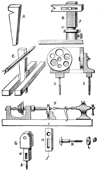
The very first mechanical work of difficulty, but of
pre-eminent importance, in making an engine,
is boring the cylinder, that is, if the same is a
casting, and not a piece of tube ready made and
smooth on the inside. This is, properly speaking, lathe
work, yet may be done in a different way. Suppose you
have bought your entire set of castings, which is the best
way, and that the cylinder is half an inch diameter inside,
which is a manageable size to work upon. Get a half-inch
rosebit, which is very like the countersinks sold with the
carpenter’s brace and bits. Mount it in the lathe in a
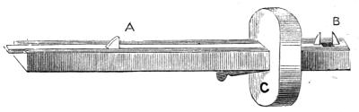
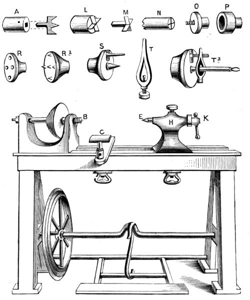
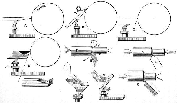
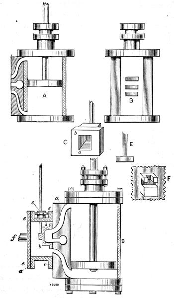
chuck, A, Fig. 65. Unscrew the point of the back poppit,
and slip over the spindle a boring-flange, B, which is
merely a flat plate like a surface chuck, only the socket is
not screwed but bored out, generally large enough to slip
over the spindle. Sometimes there is, however, a screw at
the back, to screw into the spindle, the same as the points
or centres. On the face of this lay a piece of board of equal
thickness, but it is as well if not planed, as its object is
partly to prevent the cylinder from slipping about during
the operation, as it is sometimes inclined to do upon the
smooth metal flange, and partly to prevent the borer or
rosebit from coming in contact with the flange when it
has passed through the cylinder. Grasp the latter in the
left hand, and you can easily prevent it from revolving with
the drill, which will go through rapidly, and leave the hole
beautifully finished and quite true from end to end,—indeed,
I have bored iron also, rapidly and with great ease,
with this tool.
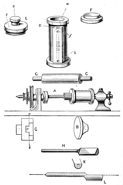
Fig. 65.
It is absolutely necessary, remember, that this hole bored
in the cylinder should be at right angles to the ends of the
same, and to secure this you must now make use of it to
mount the cylinder in the lathe to turn these ends or
flanges. I will show you a simple and easy way to do this.
C is a bar of iron or steel, preferably of the latter, about 6
inches long, and three-eighths diameter, filed into six sides.
It is a good plan to have three or four sizes of such bars,
with centre holes drilled carefully into each end, so that
you can mount them with a carrier-chuck, as you would if
you were going to turn them. Taking one of about the
size named, mount upon it a piece of wood, and turn this
down until your cylinder will just go tightly upon it.
Being a six-sided bar, it is easy to mount the wood upon it
by boring the latter with a gimlet and then driving the bar
into it. It will hold tightly, and not turn round upon the
metal. The cylinder being fixed in this way, you must
turn the two flanges with a graver if the cylinder is of iron,
but with a flat tool or the four-sided brass tool if of the
latter metal; and also turn the edges of the flanges. The
rest of the cylinder will be left in the rough, and may be
painted green or black. I should advise you always to bore
the cylinder first when possible, and then to mount it as
described and turn it on the ends, which are thus sure to
be correctly at right angles to the bore. Some cylinders,
however, especially short ones, may be squared up first, and
then mounted on a face-plate and bored. Unless, however,
you have either a grip-chuck, which is self-centring, or
some clamps properly constructed for this particular work,
you will find the first method the easiest, especially for
small light work.
You should now make the ports for steam and exhaust.
Mark them upon the flat part of the casting, after you
have filed this as level as you can, and do not mark them
so long as not to leave you room beyond the ends of the
ports for the steam-box or case which has to be placed here.
The upper and lower ports are to be the same size, but the
middle one may be a trifle larger with advantage. In
larger engines these are cast in the metal, and have only
to be trimmed and faced; but in the small models you have
to drill them out in the boss cast on the cylinder. Drill
down from the top, as shown at D by the dotted lines, but
take great care not to go farther than the outer ports, which
are to be therefore first made, so that you can tell when the
drill has gone far enough. If you pierce the middle port
from either end, the cylinder is spoiled. To cut the middle
one, you merely drill a hole straight in towards the cylinder,
and meet it by another drilled from the side, into which the
pipe for the exhaust is to be screwed. You also drill
straight through into the cylinder at a b, and you then
plug the end of f, and that at the other end of the cylinder.
Your port faces, however, are generally oblong, and not
round. Make a row of holes with the drill, and then, with
a little narrow steel chisel and light hammer, chip out
the superfluous metal, and finish with a small file. You
can always make narrow channels with squared sides by
thus drilling two or more holes, and throwing them into
one with a file; but in reality, for these small engines, it is
very little matter whether the ports are round in section or
square.
The bottom and top of the cylinder demand our next
attention. E and F show these. They are easily and instantly
mounted in a self-centring chuck, but can be held
very well in one of wood carefully bored with a recess of the
right size and depth. You must here, nevertheless, be very
particular, else you will get your work untrue at this point,
and then your piston-rod will stand awry, and all your
subsequent fitting will be badly done. I therefore give you
at G a section of the chuck bored to take the cover truly.
Recess the part down to the line a b, to fit the cover exactly,
taking care to level very carefully the bottom of the recess.
Below this cut a deeper hole, to allow the flange in which
the stuffing-box will be to go into it. It need not, however,
fit the flange. The rough casting will hold very well
in a chuck like this, even if it is of iron. You now carefully
face the bottom of the cover, and turn the slight
flange exactly to fit into the cylinder; then reverse it in the
chuck, so as to get the stuffing-box outside; and in doing
so, take the greatest care that it beds flat upon the bottom
of the chuck. Turn off level the top of the flange first at x
of fig. E, and then place a drill with its point against the
middle of this, and its other end (with a little hole
punched in it to keep it steady) against the back poppit
centre, and carefully drill a hole down to the level of c,
large enough to admit the gland of the stuffing-box or nearly
so; but remember that you must not go too far, because
the rest of the hole must only just allow the piston-rod to
go through it. Therefore, after you have drilled about
three-fourths of the distance, replace this drill by a smaller
one, and with it bore quite through. The advantage of beginning
in this way is, that you can now bring up the back
centre of your lathe to steady the cylinder cover while you
finish turning it; and as you will have to make a chuck
only to take hold of the flange b, while you turn the edge,
you will need probably some extra support of this kind. I
have, nevertheless, turned an iron cylinder cover 2½ inches
diameter without any such support; the actual strain not
being very severe, provided you understand how a tool
should be made and held.
The above directions apply equally to the cylinder bottom,
the great secret in this and all similar work being to take
care to bed the work well and truly against the bottom of
the recess, turned in the chuck; this being neglected, will
result in the two faces not being parallel, which will terribly
throw out of truth the rest of your work. Indeed, in all
fitting of this kind, it is absolutely necessary to be exact
in the squaring and truing of each several piece that has
to be turned or filed; otherwise no planning or clumsy
arrangement will make your mechanism work as it ought
to do. Take a week, if necessary, over any part, and don’t
be content until it is well done.
Your cylinder ought now to have a finished appearance
when the cover and bottom are placed in position, but the
latter have to be permanently attached by small screws,
and these I strongly advise you to buy. They cost about
50 cents a dozen, including a tap with which to make a
thread in the holes made to receive them; or, if you prefer
it, you can buy miniature bolts and nuts at almost as
cheap a rate, which would cost you much time and trouble
to make for yourself, if, indeed, you succeeded at all. You
will want four of these for the top, and the same for the
bottom, the holes for which you will make with a small
archimedean or other drill.
The mention I have made of this reminds me that I am
gradually adding considerably to your list of tools, and it
is necessary to do so if you take up model-making. Set
down, at any rate, the following:—
- Archimedean Drill-Stock and 6 Drills.
- Table-Vice.
- Hand-Vice or Pin-Vice.
- Small Brass-Back Saws for Metal.
- Pair of Small Pliers.
And for use in the lathe, either two or three sizes of rose-bits,
or engineer’s half-round boring bits, of which I shall
have to speak presently; and, unless you buy all screws
and nuts, you will want screw-plate and taps, or small
stock and dies. Files of square, round, and oblong section
are matters of course. Remember, too, that after a file
has been used on iron and steel, it is useless for brass; so
use new ones on the latter metal first, and after such use
they will answer for cast iron and then for wrought iron.
You will find the cost of files rather heavy unless you
attend to this. Have neat handles to all your smaller files,
with ferules to prevent splitting.
When you purchase the castings of the engine, you will
find a valve-box to enclose the slide and become a steam-chest,
as explained. It is like a box with neither top nor
bottom, but with a flange, or turned-out edge all round, for
the screws by which it is to be attached to the valve-facings
of the cylinder. This box must have its flanges filed up
bright on their flat sides and edges—the rest may be painted.
It will exercise your skill to get the two faces flat and true,
to fit upon the cylinder; and at last you will find it expedient
to put a brown paper rim or washer between the
surfaces, or a bit of very thin sheet lead, to make a steam-tight
joint. Do not solder it, if it is possible to use screws,
because this is nearly certain to get melted off; and, if not,
it is not nearly so neat and workmanlike a way of uniting
the parts. You should, indeed, in all models, put them
together in such a way as to be able at any time to
separate the different pieces again, either for the purpose
of cleaning or repair; and, if you solder, you cannot easily
do this.
The valve-casing and its back are generally put on
together; four screws at the corners passing through the
back and both flanges into the flat side of the cylinder.
This depends, however, upon the exact shape of these
different pieces; and I can give you no special directions
for a particular case unless I could see the castings which
you have to fit together. The stuffing-box you will make
quite separate, both its outer and inner part, and screw or
solder the former into place. It is seldom cast upon the
valve-casing, because of the difficulty of chucking a cubical
object safely so as to turn any part of it.
You are not to screw or solder the valve-box to the
cylinder until you have carefully filed up the valve itself to
slide upon the port face, without the possibility of any escape
of steam taking place. This needs the greatest possible
care; and probably, after doing what you can with a flat
file, you will have to put a little emery and oil between
the surfaces, and grind them to a perfect fit, by rubbing
them together. This grinding with emery is an operation
frequently required in mechanical engineering. Lathe-mandrels
are fitted in this way into the collars; the
cylinder is also ground into the back poppit-head. It is
not a very long or difficult operation, but whenever you
have had to use it, take care to wipe off the emery, or it
will keep on grinding. It is indeed very difficult to do
this perfectly; and for very fine work, such as fitting the
mandrel of a screw-cutting lathe (i.e., a traversing mandrel),
oilstone powder and crocus are used, in place of emery.
These, however, cut very slowly, making the operation of
grinding exceedingly tedious; and in the present instance,
emery will answer quite well enough. In very small
engines, a stroke or two of a file is all that is needed to fit
the valve, which is so small as hardly to be worthy of the
name; but in an engine with cylinder of 1 or 2-inch bore,
it will be impossible to do with file alone, as well as you
can with grinding.
The piston and piston-rod should be turned at the same
time, as already suggested in treating of the atmospheric
engine of Newcomen. By this, you will avoid getting the
piston “out of square” with its rod, as if you had bored
the hole for the latter askew—a not unusual occurrence.
I do not mean to say that it is absolutely necessary for
you to turn the piston-rod at all, for, in models, it is generally
of round iron or steel-wire, which is as cylindrical as
you can possibly make it. Knitting-needles are in general
use for this, as being well finished and equalised from end
to end. But these are rather hard, being tempered only to
about the degree of steel-springs; therefore you must never
attempt to cut a screw on them until you have first heated
the end to be screwed red-hot, and allowed it to cool again
very slowly. If you do this, a screw-plate will put a sufficiently
good thread to allow you to attach either the piston,
or the small piece of brass necessary to form the hinge,
upon the other end of the rod—that is to say, the piece
marked H in Fig. 64. Leave this for the present, however,
not attempting at present to cut either the piston-rod
or valve-rod to its intended length. You cannot do this
until you have laid down the exact plan of the engine, and
marked on the bed-plate the position of all the parts.
I shall now suppose that you have finished the cylinder,
with its slide-valve, casing, stuffing-boxes, and piston, so
that you have these in exactly the state in which you might
buy them at Bateman’s and elsewhere, if you preferred, to
spare yourself the trouble of boring the cylinder and fitting
it. You can buy them just in this condition, with the rest
of the castings in the rough; but I rather hope you may
prefer to try and do for yourself the not very heavy or difficult
work which I have described.
I suppose you, indeed, to have bought the forked connecting-rod,
either arranged for brasses, or with holes
drilled (or to be drilled) in the ends, which would probably
be the case for a model of the size named, and also the
various bearings, guides, and so forth required—some of
which would have to be turned, and some filed, but which
ought now to present little difficulty to our young
mechanic.
Try to keep sharp edges to all your filed work, unless evidently
intending to round them; for surfaces pretending to
be flat, but partaking of a curved sectional form, characterise
the workman as undeniably a bad hand with the file,
and not worth his wages. Still I may tell you at once that
nothing is so difficult as to use a file well. It has a knack
of rounding off edges, which always get more than their
proper share of its work. But this being the case, you will
know what to try and avoid. Therefore, always endeavour
in filing a flat surface to make it slightly hollow in the
middle, which it is scarcely possible, however, for you to
do; but the endeavour to effect this by filing the middle
more than the edges will help you wonderfully in keeping
the latter sharp. Those, for instance, on the fork of the
connecting-rod, especially the inside ones, should be as
straight and sharp as possible; and if you round the outside
edge, take care to do it so that it shall be evident you
intended it; and so with all edges, whether turned or
filed.
The disc of the eccentric can only be turned by letting it
into a chuck to something less than half its thickness, and
levelling one side and half the edge, and then reversing it;
unless you prefer to drill and mount it on a spindle upon
its centre. If you do this, you will of course eventually
have two holes in it; because this first one is not that by
which it will be mounted when in place. This second hole
is not, however, of the least importance, and may be left
without plugging, and, if preferred, may become in part
ornamented by drilling additional holes, and filing them
into some pattern; or if it is desired to conceal the one it
was turned upon, this can be plugged and faced off, and
will then not be the least apparent. If the outer ring, or
strap, as it is called, is to be made in two pieces, with projecting
lugs, it is evident the outside edge cannot well be
turned; and, unless you have that most useful addition to
the lathe, a grip or jaw-chuck, you will have some little
difficulty in letting the ring into a wooden chuck, so as to
turn the inside. The solid ring is, therefore, preferable (if
you use the first, however, you turn it up as a single ring,
and then saw it across through the lugs), which can be let
into a common chuck, with a place chiselled out to allow
the boss to project, into which the eccentric rod has to be
screwed. This boss also has to be drilled and turned on
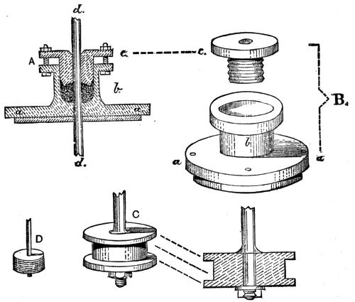
the outside. There are several modes of chucking it which
can be applied, but the simplest is to use the carrier-chuck,
and to let the ring become its own carrier by coming against
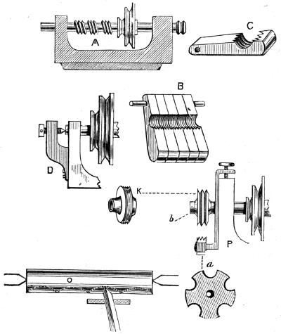
the pin, as shown in Fig. 66, A.
When the ring is very small, I should first drill the hole
for the wire rod, and then screw and mount it upon a little
wire spindle, as in fig. B, aiding this, if necessary, by the
back centre. But the smallest models require to be put
into a watchmaker’s lathe or throw, and, except as curiosities,
are scarcely worth making.
I have already told you never to undertake engine-making
without first laying down a full-sized plan on paper,
with centre lines through the principal parts, from which
to take all measurements, and to mark these upon the base-plate,
as a guide to the perfect adjustment of the various
parts. Some of these are capable of a little extra adjustment
after being put in place: the eccentric rod, for
instance, can be lengthened or shortened by screwing into
or out of the eccentric ring; and the piston-rod, too, may
be similarly lengthened or shortened slightly; but try to
work as near as you can to precise measure without such
adjustment.
To turn the fly-wheel, which is the last operation (including
the crank-axle), it is better carefully to drill the
boss, if not already done, marking the centre on each side,
and working half through from each, so as to insure the
squareness of the hole with the side of the wheel, which is
very important. Then mount it at once upon its axle, previously
turned slightly conical, where the wheel is to be
placed, and run both together in the lathe. This will
insure the wheel running true when the engine is put
together.
In the horizontal engine which I have sketched, the
crank is quite separate from the axle; and this is the easiest
way to make it. The crank itself is filed up, like C of fig.
66, and drilled for the axle and the pin upon which the
brasses on the connecting-rod work. Turn down the end
of the crank-shaft very slightly conical, until the crank
will almost go over it. Then heat the crank, which will
expand it and enable you to slip it on the shaft. Dip it in
cold water, and it will be as firm as if made in one piece
with the axle. This is called shrinking it on, and the
operation will often stand you in good stead, and save the
trouble of filing key-ways and making the small wedges
called keys. The pin D can in this case be turned
up separately, and screwed in, which will complete the
work.
The eccentric must evidently be placed in position before
the crank is added, and this, too, might be shrunk on, were
it not that it cannot easily be fixed in a model until the
engine is set up. The best way, therefore, is, in this case,
to turn the eccentric with a little projecting boss to take
a set screw, E, Fig. 66.
Where the axle has to pass through bearings, it must be
turned down at these parts, so that the whole will be like F.
First on the right is the journal, e, then the place for the
fly-wheel, d, very slightly conical—the smallest part being
towards e—then the second journal, and then another
slightly conical part, the smallest end towards a, to take
the eccentric and crank. The fly-wheel you will key on shaft,
thus:—G represents the boss or centre of the wheel bored
for the axle, and a key-way or slot filed on one side at a.
There is a flat place filed on the axle, and the wheel is
turned round to bring this opposite to the key-way. A
wedge or key, b, is then driven in, which keeps the wheel
secure, and prevents it from turning round or working
loose on the axle. If inconvenient to turn a boss and add
a set-screw to the eccentric, this also may be keyed in its
place after its position has been found; but, for the latter
purpose, it should fit rather tightly on the axle, so that it
can be just moved round with the finger stiffly until its
position with respect to the crank is ascertained.
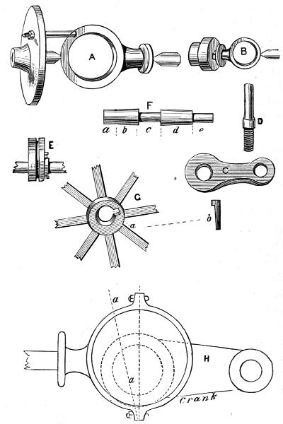
Fig. 66.
This position I shall now endeavour to explain, using a
diagram from an American work, in which this generally
supposed difficult point is thus ably and satisfactorily explained.
First, put your engine together as if for work,
and having cut the eccentric rod to about the length you
seem to require, judging from your plan drawn upon the
bed-plate, turn round the eccentric, with your fingers upon
the crank-shaft, and, having removed the cover of the
valve-box, so that you can see the action on the valve,
watch the motion of the latter. Doubtless, the result will
be that one of the steam-ports will be opened clear to the
exhaust-port, while the other is nearly or entirely shut.
The rod is then too long or too short. If in a horizontal
engine the port nearest to the crank is wide open and the
other shut, the rod is too long, and must be shortened half
the difference only (you will do this by screwing it farther
into the eccentric hoop). When the valve “runs square,”
or opens and shuts the ports correctly, set the eccentric as
in the diagram, H, in respect to the crank, i.e., with its
widest part at right angles to it. By running square is
meant that when the eccentric is turned round as described,
the valve opens the ports equally, and does not affect one
more than the other. The line a of the diagram shows
that the position of the eccentric may advantageously be a
little beyond the right angle to the crank, to give what is
called “lead,” i.e., to open the valve a little before the
piston commences its return-stroke.
The boilers of model engines are made of tin, sheet-brass,
or copper; seldom of the latter, which is, nevertheless, by
far the best material, and one that you can braze, rivet, or
solder satisfactorily, or bend into any shape with a hammer
or wooden mallet. When polished, too, its rich red colour
is very handsome. Brass is chiefly used from the facility
of obtaining tubes of it ready brazed or soldered, from
which any desired length can be cut. A brazed copper
boiler will stand a great deal of pressure; will tear, and
not fly into pieces when it bursts; and may be heated after
the water has boiled away without suffering any injury. It
would certainly not be worth while to make one for a model
engine with a half-inch cylinder, but for one of 1 inch diameter
and 2½ stroke; and for larger sizes, it will amply repay
the trouble; and I will show you how to make one, with a
tube or flue inside to add to the heating surface.
I shall endeavour presently to give the proper dimensions
of boilers to work cylinders of given diameters, but the
general directions here subjoined apply to all boilers of
models, whether large or small. The main body of the
boiler is generally cylindrical, and is, in fact, a tube of
sheet-metal, with riveted, brazed, or soldered seams, the
last greatly predominating in the toy engines; the result of
which is, that the first time the water gets too low, out
drops the bottom, or, at the least, divers leaky places appear,
and the boiler is obliged to go to the tinman’s for repair,
its beauty being ever after a thing of the past. It is difficult
to braze in an ordinary fire; because even if, by blowing
it with a pair of bellows, you get sufficient heat, you cannot
always manage to apply your work in a good position, as
you can over the hot coals of a forge fire, where there are
no bars, hobs, or other parts of the grate standing in the
way. Moreover, you often want both hands free just as the
solder commences to “run,” and forge-bellows will keep up
the blast for a few seconds after your hand is taken from
the staff or handle of them. Still, if you have no forge,
which is probable, you should make a fire of cinders or coke
(the latter if possible); and if you can contrive a grate by
putting together a few bricks in some out-house, with a
bar or two of hoop-iron below for the coke to rest upon, you
will have a far more convenient fire to work at than can
possibly be obtained in any ordinary household grate or
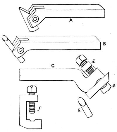
stove. You will require a pair of light tongs, which ought
to be something like A, Fig. 67; but it is quite possible to
do without these if you can hold your work in any other
way; as, for instance, with a loop of iron wire twisted
round it and left long enough to form a handle.
The first thing to do is to cut a strip of copper large
enough to make the required tube. A piece 6 inches wide
will roll up into a cylinder of about 2 inches diameter (the
circumference of a circle being nearly equal in all cases to
three times its diameter, or measure through the centre).
If, therefore, you want one 6 inches across, which is the
smallest size that can be advantageously fitted with a flue
or internal tube, you must cut it out 18 inches wide, and if
it is 8 in length to the bottom of the steam dome, it will
be a large and serviceable boiler, fit to work an engine with
a cylinder of 1½ bore by 2½ or 3 inch stroke, which would
drive a small lathe. But observe that if you really have
pluck and skill enough to try your hand upon an engine
that will give you real power, you must take care to remember
that “the strength of anything is the strength of its
weakest part.” So don’t make the very common mistake
of having a good boiler and ample cylinder, and then fit
the engine with piston-rod, valve-rod, and such like, too
small to bear the strain which you propose to put upon the
engine. Remember that every screw and nut and pin upon
which strain is liable to fall, must be of sufficient size and
strength to bear it safely: if not, your engine will not only
come to grief in the heavy trial, but it is quite possible that
you also may become subjected to a bad scald or other
disagreeable consequence of your error.
Whatever sized strips of copper you use for a boiler, the
edges have to come together to form what is called a butt-joint;
i.e., they do not overlap like the ordinary joints you
see made in tin. Before you coil up the strip into a tubular
shape, you have to cut out holes for any boiler fittings you may
wish to add, such as safety-valve, steam-dome, and gauges
to ascertain the level of the water. These, however, do
not all come into the cylindrical part of our present boiler;
the gauge-taps and glass water-gauge alone having to be
provided for. The man-hole, too, which is added to all
large boilers, may be dispensed with, its object being to
enable one to get at the inside, which will scarcely be
necessary if our work is well done at first. A boiler of the
proposed size should be heated with charcoal, as it would
require a very large lamp; but where gas can be obtained,
it may be preferably used, a ring gas-burner being placed
below within the furnace. The object of a steam-dome,
which, in a horizontal boiler, would have to be placed
somewhere on the tube itself, is to prevent what is called
priming, i.e., the carrying into the cylinder water as well
as steam, which arises from the spurting caused by the
violent boiling of the water. The dome merely provides
a chamber for dry steam above the general level of the
boiler, the steam-pipe passing from it direct to the cylinders.
Our present boiler will be vertical like the last, but
with a flue up the middle, and a grate fitted below. It
is shown complete in Fig. 67, B, with all the fittings
usually attached.
Having coiled up the tube by hammering it over a
cylinder of wood turned for the purpose, a little smaller
than the intended size of the boiler (the edges having been
previously filed up bright, and a width of a quarter of an
inch of the upper being similarly cleaned on the inside all
along the seam), a few loops of iron wire are tied round
it, at intervals of 1 inch or 1½ inches; there being a short
piece put round, and twisted together at the ends by a
pair of pliers. The object of these is to prevent the seam
from opening on the application of heat, which it is otherwise
certain to do by the expansion of the metal. Some
borax, pounded in a mortar, and heated to drive off the
water of crystallisation, is next mixed with a little water
to form a creamy paste, and smeared along the inside of
the tube, upon the brightened part, the full length of the
seam. It is generally better to heat this salt first sufficiently
to dry it (or rather fuse it), because it swells
prodigiously by the first application of heat, and if the
spelter is laid on it, it often carries it off; after once
fusing, it only melts quietly.
Before applying the little lumps of spelter, turn over
the tube to heat the part opposite to the seam, so as to
equalise the expansion. Then hold it in a pair of light
tongs, lay the spelter all along upon the borax, and expose it
without actually touching the coals to the heat of the fire,
urged by a strong blast. Continue this until a blue flame
arises, which shows that the spelter has melted; this blue
flame being, in fact, that caused by the burning of the
zinc in the solder—spelter being copper and zinc fused
together, or, if required softer, brass, tin, and zinc. The
former is generally used, however, on copper. When the
blue flame arises, the solder runs into the joint, and the
work is done. With the hardest of these spelters, a red
heat will not seriously affect the joint, and, therefore, if at
any time the water should get below the line of this seam,
so that it becomes exposed to the heat, no harm will be
done. Nevertheless, this ought never to occur, as a gauge
should be attached to every boiler to show the exact
position of the water at any given time.
The inside tube of this boiler will be seen, from the
section, to be conical up to the level of the lower part of
the chimney. This is of copper, brazed like the cylindrical
part, and is 2 inches wide below, and 1 inch above; consequently,
the strips to make it must be 6 inches wide at
one end, and taper to 3 inches at the other. If the dome
rises 2 inches from the level of the top of the cylinder, it
will be sufficient; and as this is a difficult piece of work
for a boy to manage, a coppersmith should be asked to
hammer the dome into the required form, as he will know
from experience the best size of circular disc to use for the
purpose. This part is so far removed from the action of
the fire that it may safely be soldered, but it is, nevertheless,
as well to rivet it, turning out both the edge of the
cylinder and that of the dome. Use copper rivets, and
make the holes half an inch apart. If you find any
leakage, you can run a little solder into the joint on the
inside. The bottom of the boiler may be quite flat and
brazed, a few rivets being first put in to hold the parts
accurately together. The same may be said of the tube
which passes through both this and the dome. There is
nothing equal to riveting and brazing for this kind of
work.
I may as well state however here, that as such a boiler
as I have now described is worth very good work, it would
be a great pity to spoil it; and it will be better to content
yourself with smaller boilers and engines soldered, where
necessary, until you have had some practice in brazing.
This indeed is not difficult in reality, but, at the same time,
requires great care, because sometimes the solder and the
work melt at so nearly the same temperature, that, like a
bad tinker, you will sometimes make two holes instead of
mending one. The brass, for instance, used for beer-taps
is very soft, and contains lead, and to a certainty would
itself melt before ordinary spelter, and could not therefore
be brazed; but the best Bristol brass, or yellow metal,
will braze easily. A blacksmith, brazing a key or other
iron article, will braze it in a different way, using brass
wire, with which he will envelop the parts thickly which
are to be united, after securing their position with iron
binding-wire. He then sprinkles with borax, and heats
the work until the wire runs into the joint; after which he
files and cleans off level. This makes a very good medium.
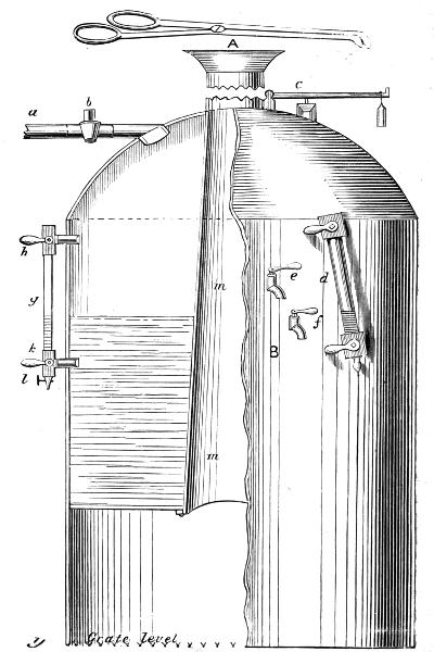
Fig. 67.
I have spoken of riveting in this place. There is no
difficulty in this work. You can buy copper rivets of all
sizes, and have only to punch holes, put a rivet in place,
and hammer it so as to spread the metal to form a second
head. If the rivets are heated before being applied, they
will draw the parts closer together, because they shrink
in cooling. All large boilers are made in this way, but
smaller ones of iron are often welded, where such a mode of
junction is possible. When you can rivet boilers water
and steam tight, you will find no difficulty in constructing
them, for you can make riveted joints where brazing
would be difficult or impossible.
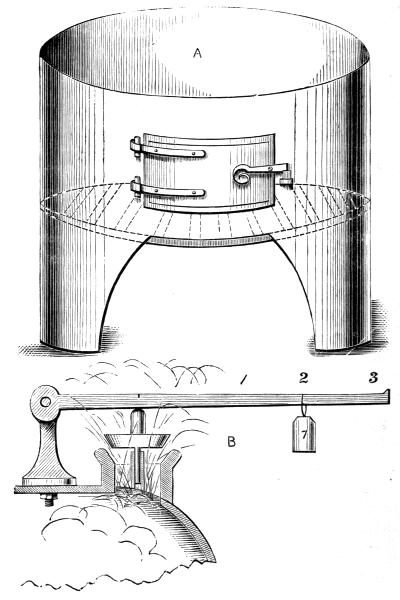
Fig. 68.
Fig. 67, B, is a half-section of such a boiler as I have
just described. Fig. 68, A, is the lower part, which is
separate, and forms the furnace in which the boiler stands,
fitting it closely. This is drawn to scale, and is half the
real size. a is the steam-pipe, fitted high up in the dome,
the tap, b, serving to turn on or off the supply of steam for
the cylinder; c is the safety-valve shown in section, and
care must be always taken to make the conical part short
and of a large angle, or it may stick fast, and cause an
explosion; d is the glass gauge, to show the exact height
of the water in the boiler. Its construction will be understood
from the other which is attached, where the boiler is
seen in section. There is no need to have two, and this is
added solely to explain the nature of glass-gauges. The
top and bottom are of brass, being tubes screwing into the
boiler, or fastened by a nut inside; a tube, g, of thick
glass, connects these two, so as to form a continuous tube,
one end of which opens into that part of the boiler which
is full of steam, the other opening below the water-level.
Thus the tube forms practically part of the boiler, and the
level of the water is clearly seen. The lower tap is used
for blowing off water, to insure the communication being
kept open, as it might get stopped up with sediment.
Gauge-cocks, e, f, are generally added, even where the
glass water-gauge is used. One of these should always
give steam, the other water,—the level of the latter being
between the two. If the upper one gives water, the boiler
is too full; if both give steam, the boiler needs to have
water added. With these fittings, even a soldered boiler
ought never to get burnt, and will last a long time with
care.
The lower part, Fig. 67, is made like that before described,
except that, being intended for charcoal, a circular grate
is used, which simply rests upon little brackets fixed by
rivets for this purpose. The flame and heat play upon the
bottom of the boiler, and also pass up the central tube—the
latter adding greatly to the quantity of steam produced.
This furnace, when lighted, may be fed with bits of coke as
well as charcoal, about the size of filberts, and will give
plenty of heat. If the draught, however, is deficient, turn
the waste steam into the tube, so as to form a jet at each
stroke, and it will greatly increase it. It is in this way
that the locomotive engines are always fitted, George
Stephenson having first suggested the arrangement. Previously
to this a fan had been fitted below the grate, which
was put in rapid motion by the engine, and thus a sufficient
draught was obtained.
To find out what pressure is exerted by the safety-valve,
it must be clearly understood upon what principle it acts.
I have in a previous chapter told you that the atmospheric
pressure equals 15 lbs. on each square inch, so that if the
surface of the valve which is exposed to the air is 1 inch
in area or surface, it is pressed down with a force of 15 lbs.
The steam, therefore, inside the boiler will not raise it until
its elasticity exceeds this atmospheric pressure. If, therefore,
we desire to have only just 15 lbs. per square inch
pressing against the inside of the boiler (i.e., a pressure of
“one atmosphere,” as it is called), we have only to load
the valve so that, inclusive of its own weight, it shall
equal 15 lbs. But it is plain that we must not load it at
all in reality; for a flat plate, 1 inch square, of no weight,
is all that is needed, the atmosphere itself being the load.
Suppose, then, that we do load it with 15 lbs. in addition to
the 15 lbs. with which nature has loaded it, we shall not
find the steam escape until it presses with a force of 30 lbs.
on the square inch, or two atmospheres (which, however,
is not 30 lbs. of useful pressure upon one side of the piston,
if the cylinder is open as in an atmospheric engine, but
only 15 lbs.) This is not the strain which the boiler has
to stand, because the atmosphere is pressing upon it and
counteracting it up to the 15 lbs., so that this strain tending
to burst it is but 15 lbs. The number of pounds, therefore,
which is straining the boiler can readily be seen; being
always that with which the safety-valve is loaded, and this
is also the useful pressure for doing any required work. Unfortunately,
however, even in the best constructed engines,
a pressure of 15 lbs. upon the boiler by no means represents
that in the cylinder. Now it would be inconvenient to
place weights upon the safety-valve itself, and therefore a
lever is added, as seen in the sketch, with a weight hung
at one end of it. This is shown at B, Fig. 68, where a
section of the valve is given with its stem passing through
a guide to insure the correct motion of the valve. The
lever is hinged at one end; and the rule of the pressure or
weight which is brought to bear upon the valve is, that it
is multiplied by the distance at which the weight hangs
from the valve, compared with its distance from the hinge
or fulcrum. If a weight of 7 lbs. is hung at 1, i.e., at a
distance as far on that side of the valve as the fulcrum is
on the other side of it, 7 lbs. will be the actual power
exerted; at 2, where it is twice the distance, it will be
doubled, and, as shown in the drawing, a pressure of 14 lbs.
will be brought to bear upon the valve; while, if the weight
is hung at 3, it will exercise a force of 21 lbs. This is very
easy to understand and to remember. Sometimes (always
in locomotives) the weight is removed and a spring balance
is attached at the long end. Upon this is marked the
actual pressure exerted; there being a nut to screw down,
and thus bring any desired strain upon the spring. Mind,
however, in case you should try this in any of your models,
that the scale marked on the balance when you buy it must
be multiplied, as before, according to the length of your
lever. Thus, if I attach such a balance at 3 of the drawing,
a real weight of 5 lbs. shown by the balance will be
3 × 5, or 15 lbs. upon the valve, and a balance made for
such engine would be marked 15 lbs., to prevent the possibility
of dangerous error.
Having been led on from the atmospheric engine to that
of Watt’s, and to slide-valve engines generally, I am now
going backward a little to a class easier to make, because
they have no slide-valves, nor even four-way cocks; and
then I shall have done with engines. But I dare say some
of my readers will wonder why I have said so little about
condensers and condensing engines. I am sure they will
wonder at it if they understood what I explained of the
advantage of a vacuum under the piston; so that 15 lbs.
pressure upon the piston means 15 lbs. of useful work, instead
of 30 lbs. being required for that purpose. But condensing
engines are utterly beyond a boy’s power. They
require not only a vessel into which the steam is injected
at each stroke, but there must be a pump to raise and
inject cold water to condense the steam, and a pump to
extract from the vessel again this water, after it has been
used, and a cistern, and cold and hot wells; and all this is
difficult to make so as to act; and I am sure no boy cares for
a steam engine that will not work. Moreover, I have given
you difficult work as it is—work that many of my readers
will no doubt be afraid to try—yet I did it on purpose;
because if small boys are unequal to some of it, their big
brothers are not, or ought not to be; and mechanical boys
must look at difficulties as a trained hunter looks at a
hedge—viz., with a strong desire to go over it, or through
it, or any how and some how to get to the other side of it.
Indeed, you must ride your mechanical hobby very boldly
and with great pluck, or you won’t half enjoy the ride.
However, I am quite aware that I have led you into several
difficulties, and therefore now I propose to set before you
some easy work as a kind of holiday task which will send
you with fresh vigour to what is not so easy.
The engines without slide-valves have also no eccentrics
and no connecting-rods. There is just a boiler, a cylinder,
piston, piston-rod, and crank, and you have the sum total,
save and except the fly-wheel. These are direct-action
engines, the cylinders of which oscillate like a pendulum,
and the piston-rod itself is connected to the crank, doing
away with the necessity for guides.
Fig. 69, A, shows one of these engines, and you see that
the cylinder leans to the left when the crank is turned to
that side; and if you turn the wheel to the right, the crank
will presently cause it to lean the other way; and thus, as it
turns on a pin, or “trunnion,” as it is called, it keeps
on swinging from side to side as the wheel goes round.
Now, when it is in its first position, the piston is at the
bottom of the cylinder, and it then needs to have the steam
admitted below it to drive up the piston; but when this
has passed its highest position, and the cylinder is turned
a little to the right, the piston must be allowed to descend,
and, therefore, we must let out the steam below it. We
ought, at the same time, to admit steam above the piston
to force it down; but, in the simplest models, which are
called single-action engines, this is not done. The fly-wheel,
having been set in motion, keeps on revolving, and,
by its impetus, sends down the piston quite powerfully
enough to overcome the slight resistance which is offered
by the friction of the parts.
Now, you can, I daresay,
easily understand that it is possible
to make this to-and-fro
motion of the oscillating cylinder
open first a steam-port to
allow steam to raise the piston,
and then an exhaust-port to let
it blow off into the air. This
is exactly what is done in practice,
and it is managed in the
following manner:—
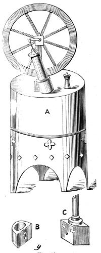
Fig. 69.
B, of Fig. 69, shows the
bottom of the cylinder, which
is a solid piece of brass filed
quite flat on one side, and
turned out to receive the end
of the brass tube, which, generally
speaking, is screwed into
it to form the cylinder, this
being the easiest way to make
it. In the middle of the upper
part of the flat side you see a
white steam-port, and below it
a round white spot, which is the position of the pin, or
trunnion, on which it oscillates. Fig. 69, C, is a similar
piece of brass, which is fixed to the top of the boiler. In
this, on the left of the upper part, is also a port, which is
connected with the boiler by a hole drilled below it to
admit steam. On the right is also a port, which is merely
cut like a notch, or it may go a little way into the boss,
and then be met by a hole drilled to meet it, so as to form
the escape or exhaust port. Between and below these is
the hole for the trunnion.
Now, you can, I think, see that if the cylinder stands
upright against this block, as it does when the crank is
vertical (or upright) and on its dead points, the port at the
bottom of the cylinder would fall between the two on this
block of brass, and, as they are both flat and fit closely, no
steam from the boiler can enter the cylinder. Nor do we
want it to do so, because, if the crank is on a dead point,
no amount of steam can make the piston rise so as to move
it. But now, if we move the cylinder to the left, which we
can do by turning the wheel, we shall presently get the
crank at right angles to its former position, and, also, we
shall bring the steam-ports in the cylinder and block
together, so that steam will enter below the piston. But,
practically to get as long a stroke as possible, steam is not
allowed to enter fully until the crank is further on than in
a horizontal position, that is, approaching its lower dead
point; and this is the position in which to put it to start
the engine. By altering the shape or the position of the
port a little, we can so arrange matters as to let steam
enter at any required moment.
Steam having entered, the piston will rise rapidly, forcing
up the piston, and presently, by the consequent revolution
of the fly-wheel, the cylinder will be found leaning to the
left, and at this moment the piston must evidently begin
to descend. At this very time the steam-ports will have
ceased to correspond, but the port in the cylinder will come
opposite the exhaust-port in the brass block, and this port
is made of such size and shape that the two shall continue
to be together all the time the piston is descending; but,
the moment it has reached the end of its downward stroke,
they cease to correspond in position, and the steam-port
begins again to admit a fresh supply of steam.
The pillar attached to the brass boss has nothing to do
with it, but is one of the supports of the axle of the fly-wheel,
as you will understand by inspection of A of this
same drawing.
Such is the single-action model engine, of no power, but
a very interesting toy and real steam engine.
The double-action engine is very superior to the foregoing,
which, I may remark, has no stuffing-box, and of which the
piston is never packed. I may also add, that the crank is
formed generally by merely bending the wire that forms the
axle of the wheel, and putting the bent end through the hole
of a little boss or knob of brass, screwed to the end of
the piston-rod. Here you have no boring of cylinders
to accomplish, but the cylinder cover, piston, and wheel
(often of lead or tin) require the lathe to make them neatly.
Many an engine, however, has been made without a lathe,
and I have seen one with a bit of gun-barrel for a cylinder,
and a four-way cock of very rough construction, that was
used to turn a coffee-mill, and did its work very well too.
But I must go at once to the double-action oscillating
cylinder, in which, although a similar mode of admitting
steam is used, it is arranged to admit it alternately above
and below the piston, the exhaust also acting in a similar
manner.
After the explanation I have given you, however, of the
single-action engine, you will, some of you, I think, jump
at a conclusion almost directly, and perhaps be able to plan
for yourselves a very easy arrangement to accomplish the
desired end. All boys, however, are not “wax to receive,
and adamant to retain” an impression; for I have known
some who need an idea to be driven into their brains with a
good deal of hard hammering. Stupid?—No. Dull?—No,
only slow in getting hold, and none the worse for that generally,
if the master will but have a little patience; for when
they do get hold, they are very like bulldogs, they won’t
let go in a hurry, but store up in most retentive minds
what they learned with such deliberation.
The cylinder of the double-action engine is of necessity
made with ports very similar to those of the horizontal
engine already described. There is a solid piece attached
to the cylinder as before, which is drilled down to the upper
and lower part respectively of a central boss, turned very flat
upon the face, and which has to work against a similar flat
surface as in the last engine. But the ports in the latter
are four instead of two, and in an engine with upright
cylinder would be cut as follows, and as shown in Fig.
70, C.
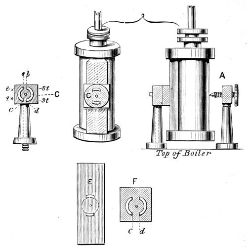
Fig. 70.
Those on the right marked st are steam-ports, which, being
drilled into one behind, are connected with the boiler. The
other two marked ex, are similarly exhaust-ports opening into
the air. The spaces between a b and c d of fig. C must be
wide enough to close the steam-ports in the cylinder, when
the latter is perpendicular and the engine at rest. When
the cylinder leans to the left, oscillating on the central pin
between the ports in the middle of the circle, the lower port
of it will evidently be in connection with the steam-port in
C, while the upper port of the cylinder will be opposite to
the exhaust. As the cylinder is carried over towards the
right, the upper steam-ports will come into action in a
similar way, while the lower exhaust-port is also carrying
off in turn the waste steam. The impetus, therefore, of the
fly-wheel has here only to carry the ports over the spaces
a b, c d, and to prevent the crank stopping on the two dead
points. This, therefore, is a genuine double-action engine,
and will answer, even on a large scale, very satisfactorily.
If you do not quite understand the action of these ports, cut
out two pieces of card, E F. Let E represent the cylinder.
Draw circles, and cut two ports. Cut another piece of card
to represent the brass block, with ports, c d; pin them
together through the centres of the circles, and they will
easily turn on the pin. Mark the ports, so that you will
see at a glance which are steam and which exhaust. Now
cut out the ports with a penknife, and as you work the two
cards together, swaying that which represents the cylinder
to and fro upon the other, you will see when the ports in
each card agree with one another, and which are opposite to
which. This will teach you far better than any further
written explanation. You will also see that, instead of
making the steam and exhaust ports respectively with a
division between, the two steam-ports may be in one curve
united, and likewise the two exhausts; but take care not to
unite the exhaust with the steam-ports. There is no way
so easy as this of reversing the action of the steam; it is, in
fact, a circular slide-valve, but wonderfully easy to make,
because you have no steam-case to make, nor any attachments
whatever.
The faces of the valve are kept in close contact in one of
two ways—either the centre-pin is fixed into the cylinder
face, and after passing through the brass boss with the
ports, is screwed up with a nut at the back; or else there is
fixed a small pillar or upright on the opposite side of the
cylinder, and a little pointed screw passing through this
presses against the cylinder, and makes a point of resistance,
against which it centres, and on which it turns. This
is shown at fig. A. A small indentation is made where the
point comes in contact with the cylinder.
In a locomotive engine there are two such cylinders,
working against opposite faces of the same brass block
containing the ports. The cranks are also two, on the
shaft of the driving-wheels, and are at right angles to each
other; so that when one piston is at the middle of its
stroke, the other is nearly or quite at the end of it. Thus,
between the two there is always some force being exerted
by the steam; and the dead points of one crank agree with
the greatest leverage of the other. In locomotives, too, the
cylinders generally are made as in the present drawing,
viz., to oscillate on a point at the middle of their length;
but it is just as easy to have the two ports meet at the
bottom instead, so that the point of oscillation may be low
down, like the single-acting cylinders of the last sketch,
and this is generally done when the cylinder is to stand
upright.
There is no occasion for me to draw an engine with
double-acting oscillating cylinders, because in appearance
it would be like the single-acting one; but whereas the
latter is of absolutely no use, seeing that the greater part
of its motion depends on the impetus of the fly-wheel, the
former can be made to do real work, and is the form to be
used for marine and locomotive engines. For the former,
oscillating cylinders with slide-valves are used in practice;
but for real locomotives fixed cylinders are always used.
Of course either will answer in models, and it will be good
practice to try both.
I have now given sufficient explanation of how engines
work, and how they may be made, to enable my young
mechanic to try his hand at such work. The double-action
oscillating engines especially are well worthy of his attention,
as he may with these fit up working models of steam-boats
and railway trains, which are far more difficult to
construct with fixed cylinders and slide-valves. I shall
therefore close this part of my work with a description of
one or two useful appliances to help him in the manipulative
portion of his labour,—for here, as in most other
matters, head and hand and heart must work together.
The heart desires, the head plans, the hands execute. I
think, indeed, I might without irreverence bring forward
a quotation, written a very long time ago by a very clever
and scientific man, in a very Holy Book: “Whatsoever thy
hand findeth to do, do it with all thy might.” Depend
upon it, success in life depends mainly upon carrying into
practice this excellent advice. If you take up one piece of
work, and carelessly and listlessly play at doing it, and
then lay it down to begin with equal indifference something
else, you will never become either a good mechanic or a
useful man. If you read of those who have been great men—lights
in their generation—you will find generally that
they became such simply by their observance of that ancient
precept of the wise man. They were not so marvellously
clever—they seldom had any unusual worldly advantages;
but they worked “with all their might,” and success
crowned their efforts, as it will crown yours if you do the
same.
Chapter XV. — HARDENING AND TEMPERING TOOLS. — HOW TO TEMPER TOOLS.
I promised in a previous page to describe a little
stove for heating soldering-irons, and doing
other light work. It is made as follows, and
will be found very useful.
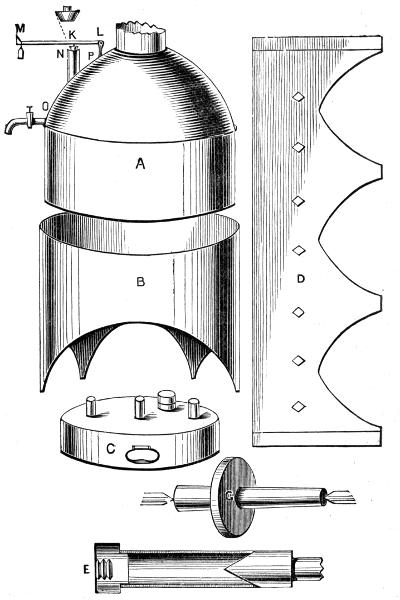
Fig. 71, A, is a tube of sheet-iron, which forms the body
of the little stove. Four light iron rods stand out from it,
which form handles, but these are forked at the ends, and
thus become rests for the handles of soldering-irons, or any
light bars that are to be heated at the ends. Below is a
tray, also of sheet-iron, upon short legs to keep it off the
table—for this is a little table-stove. C is the cast-iron
grate. You can buy this for a few pence first of all, and
then you fit your sheet-metal to it. It will rest on three
or four little studs or projections riveted to the stove inside;
or you can cut three or four little places like D, not
cutting them at the bottom line, a b, but only on three
sides, and then bend in the little piece so as to make a
shelf. If the stove is about 4 inches high above the grate,
and 2 or 3 inches below it, and 6 inches diameter, it will
be sufficiently large for many small operations; but that
the fuel may keep falling downwards as it burns, the lower
part should be larger than the upper, and, to admit plenty
of air, should be cut into legs as shown. Round the top
are cut semicircular hollows, in which the irons rest. To
increase the heat, a chimney or blower, B, is fitted, which
has also openings cut out to match those of the lower part,
so that the soldering-irons can be inserted when this
chimney is put on. If, however, this is not required, but
only a strong draught, by turning the chimney a little, all
the openings will be closed. A still longer chimney can
be added at pleasure. A hole should be made at the level
of the grate to admit the nozzle of an ordinary pair of bellows.
This stove you would find of great service, and it
may be fed with coke and charcoal in small lumps. Now
you may make the above far more useful. It will make a
regular little furnace, and not burn through, if you can line
it with fireclay. In London and large towns you can
obtain this; and it only needs to be mixed up with water,
like mortar, when you can plaster your stove inside an inch
thick or more, making it so much larger on purpose.
There is no need to do this below the level of the grate;
but if you cannot get fireclay, you may do almost as well
by getting a blacklead-meltingpot from any ironfoundry,
and boring a few holes round the bottom for air, and fitting
it inside your little iron stove. In this you can obtain
heat enough to melt brass, and it will last a great deal
longer than the iron alone, which will burn through if you
blow the fire much; but for general soldering, tempering
small tools, and so forth, you need not blow the fire, as
the hood and chimney will sufficiently increase the heat.
There is no danger in the use of this little fireplace, but
of course you would not stand it near a heap of shavings,
unless you are yourself a very careless young “shaver.”
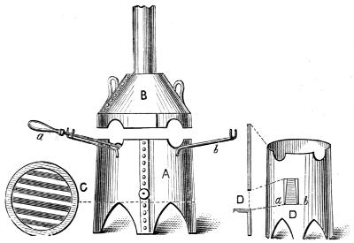
Fig. 71.
There is no reason why the young mechanic should not
be told how to make his own tools, and how to harden and
temper them, because he ought to be a sort of jack-of-all-trades;
and perhaps he may break a drill or other small
tool just in the middle of some special bit of work, or his
drill may be just a little too small or too large, and there
he will be stuck fast as a pig in a gate, and unable to set
himself right again any more than the noisy squeaker
aforesaid. But to a workman a broken drill means just
five minutes’ delay, and all goes on again as merrily as
before; and as we wish to make our young readers workmen
and not bunglers, we will teach them this useful art
at once.
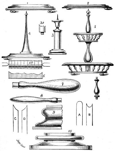
Drills are made of steel wire or rods of various sizes.
In old times they were made square at one end, to fit lathe-chucks
or braces, but now, for lathe-work, they are generally
made of round steel, and fastened into the chuck with
a set screw on one side. In this way they can be more
easily made to run true. But there are so many kinds of
drills that I suppose I had better go into the matter a
little—only I have not room to say much more.
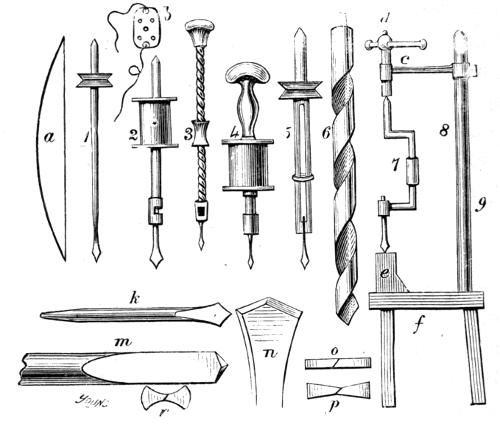
Fig. 72.
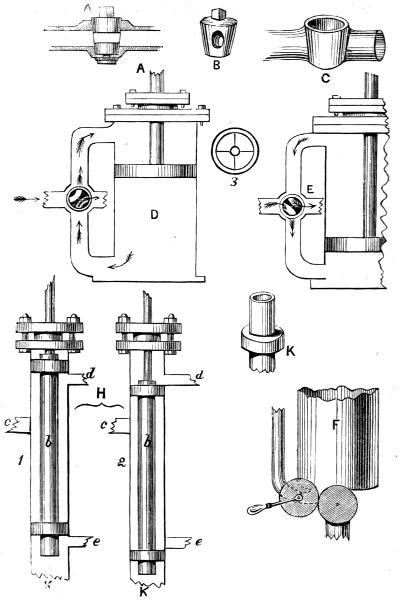
Look at Fig. 72, and you will see some of the more usual
forms of drills used, but these are by no means all. You
will not indeed require such a collection; and yet, if you
should grow from a young mechanic into an old one, I daresay
you will find yourself in possession of several of them.
The first, labelled 1, is the little watchmaker’s drill, of
which, nevertheless, this would be considered a very large
size. It is merely a bit of steel wire, with a brass pulley
upon it, formed into a point at the largest end, and into a
drill at the other. The way it is worked is this: At the
side of the table-vice—that is, at the end of its jaws or
chops or chaps—are drilled a few little shallow holes, in
which the watchmaker places the point at the thickest end;
the drill-point rests against the work, which he holds in
his left hand. A bow of whalebone, a, has a string of
fine gut such as is used for fishing, or, if the drill is very
small, a horse-hair; and this is given one turn round the
brass pulley before the drill is placed in position. The
bow is then moved to and fro, causing the drill to revolve
first in one direction and then in the other. The general
work is in thin brass, and therefore these little tools are
sufficiently strong for the purpose. Some of the drills and
broaches (four or five, or even six sided wires of steel) are
so fine that they will bend about like a hair, and yet are
so beautifully made and tempered as to cut steel.
No. 2 is a larger drill, even now much used. In principle
it is exactly similar to the last, but the pulley is
replaced by a bobbin or reel of wood, made to revolve by a
steel bow with a gut string, or a strong wooden bow. The
drills, too, are separate, and fit into a socket at the bottom
of the drill-stock. The large end is pointed, as in the last,
and is made to rest in one of the holes in a steel breast-plate,
b, which is tied to the chest of the operator, who, by
leaning against it, keeps the drill to its work, while both
hands are free to hold the latter steady. There is a modification
of this tool, invented by a Mr Freeman, intended
to do away with the bow. The bobbin or reel is turned
without raised ends, and is worked by a flat strip of
wood covered with india-rubber, and turned at one end to
form a convenient handle. The having to twist the bow-string
round the drill, which is always a bother, is thus
done away with.
No. 4 is a drill-stock similar to the last, but in place of
the breast-plate a revolving head or handle is put to the
top, in which the point works. This is held in one hand,
while the drill-bow is worked by the other. This is also
generally held against the chest, as the hand alone does
not give sufficient pressure. Heavy work, however, cannot
well be done by these breast-drills, and they are liable
to cause spitting of blood from the constant pressure in
the region of the heart and lungs.
No. 3 is the Archimedean drill-stock, now very common,
but originally invented by a workman of Messrs Holtzappffel’s,
the eminent lathemakers of London. It now
comes to us as an American drill-stock. It is a long
screw of two or more threads, with a ferule or nut working
upon it. The upper end revolves within the head, which is
of wood; the lower end is formed into a socket to receive
the drills, which revolve by sliding the ferule up and down.
Some are 14 inches long, and others not more than 5.
The first are used with the pressure of the chest, the latter
with that of the left hand. For light work these are very
useful, and you will seldom need any other in the models
of small engines, &c.
No. 5 is another watchmaker’s drill, but serves also as a
pin-vice to hold small pieces of wire while being turned or
filed in the little lathes which are used in that trade, and
which are worked by a bow with one hand, while the tool
is held in the other. This is by no means a useless tool,
even without the pulley. It is made by taking a round
(or better, an octagon, or five or six sided) piece of steel,
drilling the end a little distance, and then sawing the
whole up the middle. The slit thus made is then filed
away to widen it, and leave two jaws at the end, which
grasp the pin or drill; a ring slips over, and keeps the
jaws together.
We now come to fig. 6, which represents the best of all
drills for metal. It is really American this time, and does
our Transatlantic cousins great credit, as does the machinery
generally invented or made by them (the Wheeler and
Wilson sewing-machines for instance). The steel of which
this drill is made is accurately turned in a lathe, and the
spiral groove is cut by machinery. This groove acts in two
ways—first, as allowing the shavings (not powdery chips) to
escape as the tool penetrates, but as forming the cutting
edges where they (for there are two) meet at the point.
These, however, require a lathe with a self-centring chuck
made on purpose. They are sold in sets upon a stand,
chuck and all complete, and each is one-thirty-second of
an inch larger than the other. Some are as small as a
darning-needle, or less, and they run up to an inch or so in
diameter. There are large and small sets.
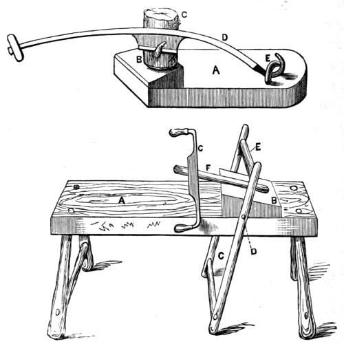
We now pass to the old-fashioned smith’s brace, fig. 7,
shown in position, drilling the piece e. Pressure is kept
up either by a weighted lever, or by a screw, as shown
here. The brace is moved round by the hand of the workman.
Very often this tool is arranged on the vice-bench,
so that the work can be retained in the jaws of the vice
while being drilled. Sometimes it is mounted on a separate
stand, having a stool below, and a special kind of vice
or clamp is added. Well made, this is not so bad a tool as
it looks, but those used ordinarily in smiths’ shops are very
clumsy, and do not even run true, and the drills are badly
made, although by sheer force they are driven through the
work.
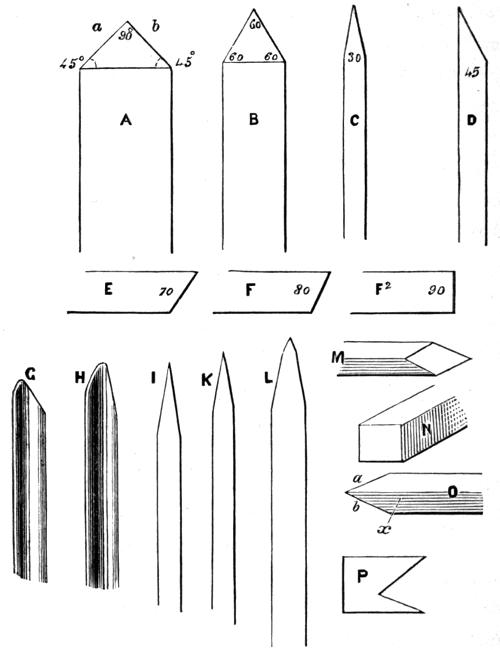
Whatever form of drill-stock is used, the main thing is
to have the drills properly formed. You will recognise k
and n as common forms, than which m is considerably
better. For cast-iron n would not be a bad point, because
the angle is great, much greater, you see, than k; and the
bevels which form the cutting edges of a drill should also
not be too sharp, as they are generally made, for, as they
only scrape away the metal, their edges go directly.
The common way to make a drill is this: A piece of steel
wire of the required size is heated until red hot (never to
a white heat, or it would be spoiled). The end is then
flattened out with a hammer, and the point trimmed with
a file. It is then again heated red hot, and dipped into
cold water for a second. Then held where the changes of
colour, which ensue as it cools, can be seen plainly; and as
soon as a deep yellow or first tinge of purple becomes
visible, it is entirely cooled in water. It is then finished,
except as regards fitting it to the drill-stock, which may be
done before or after it is hardened, because care is taken
only to dip the extreme point. To get proper cutting
edges the drill is taken to the grindstone, and each side of
the point is slightly bevelled, but in opposite directions, so
as to make it cut both ways. It is not, however, left of
equal width, like o, but the flattened sides are ground away,
so as to make more of a point, like p and n.
Now, this is all right enough as regards forging and
hardening, and tempering, and for the smallest drills this
is the only way to make them. (Only watchmakers heat
them in the candle till red, and then cool and temper by
running them into the tallow.) But if you want a good
drill that will cut well and truly, you should file away the
sides of a round bar like m, only spreading the point very
slightly indeed, just to prevent the drill sticking fast in the
work. Another drill, indeed, is spoken of very highly,
which is also carefully made like m, but the places which
are here flat are hollowed out or grooved lengthwise, the
section of the point—i.e., the appearance of the end of the
drill—becomes rather curious, like r. I am assured by those
who have used them, that these cut quite as well as the
twist drills which I have described already. These which
I am now speaking of are also American; and I don’t know
how it is, that somehow America is a far better place for
improvements in tools and machines than our own Old
England. And if I had a wonderful invention—a new
birch-rod-making and flogging-machine for very troublesome
boys, for instance—I am afraid I should go to America
to patent it; but I daresay English boys would not object
to that.
To teach an idle boy to read,
His mind be sure to jog;
But if he’s very bad indeed,
You’ll be obliged to flog.
Yet if you flog him day by day,
He’ll never learn to read;
For boys require a lot of play
To make them work with speed.
But young mechanics, if they err
Or join the lazy team,
Would all, as I suppose, prefer
To be well flogged by steam.
If not, they had better not let me patent my flogging-machine.
Luckily it is not invented yet.
The cutting edges of drills come under the same rules as
other cutting edges. You might, for instance, hold a large
drill flat on the rest, and use either edge as a turning-tool.
You will see at once that these edges will not cut if
made in the usual way, but only scrape. The bevel wants
to be ground only to 3°, as before explained, to give
the proper clearance, and the cutting edge requires to be
then made by grinding back the upper surface, which is
just the same in effect as is produced by twisting the metal
or cutting a spiral groove, which hollows out this upper
surface and gives it cutting power. It is no use grinding a
sharper-looking bevel, or making more of a point—you
only weaken the edge; m or n is quite pointed enough,
though the first is a right angle and the second greater;
and, for cast-iron, a rounded point, showing no angle at all,
will do just as well, or better, when once it has begun to
penetrate. Do not be deceived, therefore, by making drills
look pointed and keen, for, I repeat, they are scraping tools
only, unless you file an edge by bevelling back the upper
face of each side of the point. If you were to make a very
thick, strong drill, you might begin by grinding back the
two sides to 3°, to form the accidental front line of the point
or section angle, and then grind back, at 45° from this line,
the upper face, by which you would do just what you did to
give the graver cutting edges of 60°—only a drill thus
formed must have a point of 90°. It would cut in two
directions, like one for a drill stock and bow.
I hope my bigger boys will not pass over the remarks on
cutting edges interspersed in this book, for, once understood,
they will be found to be most valuable. Indeed, they
cannot work intelligently until they understand exactly
the nature and principles of the tools which they have to
use. In drilling iron, use water or oil, or soap and water,
or soda-water—either will do; but the holes are drilled in
the ships’ armour-plating with soap and water to cool the
drill; and very well it answers, for these plates are several
inches thick, but the holes are soon made. When working
in brass and gun-metal, use no water, but work the drill
quite dry. The same rules, in short, apply to drilling as
to turning or planing metal; and if you could see the
action of a well-made American twist-drill, you would recognise
this similarity, for you would see the metal come
forth in long, bright curls, as pretty and shining as those
of your favourite young lady or loving sister—one of which
you have, I daresay.
To give you some idea of what a straight course a drill
will take, if rightly made and skilfully used, I may tell you
that a twist-drill has been run through a lucifer-match
from end to end without splitting it; and as to the fineness
possible, I have seen a human hair with an eye drilled
through it, by which, needle-like, it was threaded with the
other end of itself.
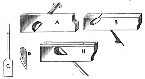
I told you how to bore a cylinder, which is but drilling
on a larger scale, and in Fig. 65 I sketched the method of
doing this in the lathe with a rosebit. But I did not explain
another tool used just in the same way, but which will
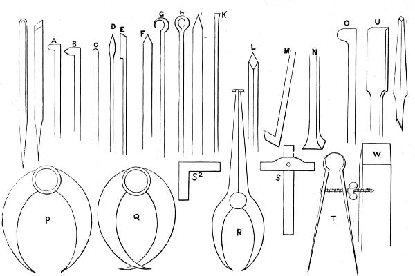
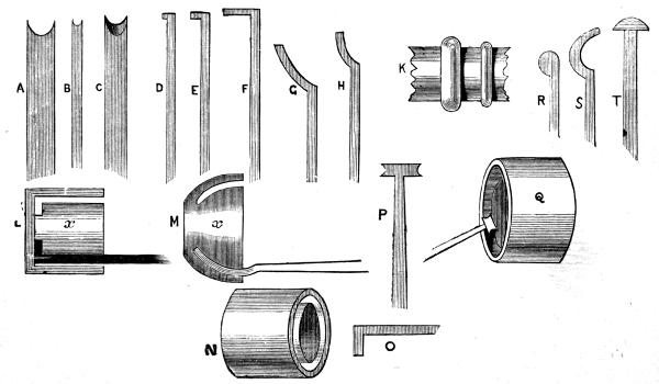
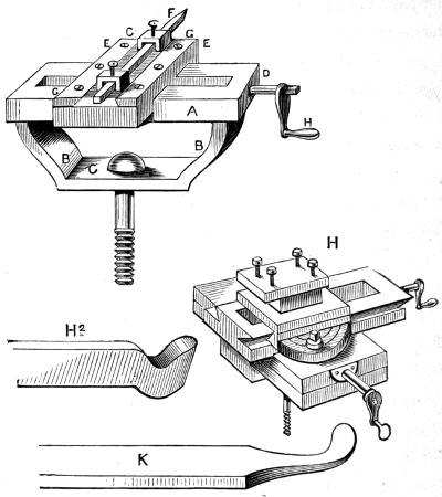
bore holes in solid iron wonderfully. Fig. 65, L, H, K, is
one of these. This is an engineer’s boring-bit, and is made
of all sizes, from that required to bore the stem of a tobacco-pipe—(don’t
smoke, boys, it will dry up your brains)—to
that which would bore a cannon. A rod of steel is forged
with a boss or larger part at one end. This is centred in the
lathe, and the centre-marks are well drilled, and not merely
punched, especially that at the small end. The boss is then
turned quite cylindrical, after which it is filed[4] away exactly
to the diametrical line, as you will see by inspection of L.
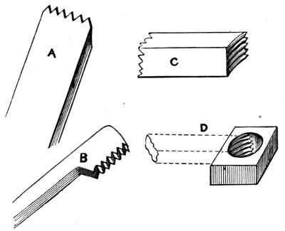
The end is then ground off a little slanting, to give, as
before, about 3° of clearance. The cutting edge thus obtained,
and the end in which the centre hole still remains,
are carefully hardened. You thus have a tool which will
bore splendidly, but you must give it entrance by turning
a recess first of all in the work, or drilling, with a drill of
equal size, a little way into the material. Used like the
rosebit, this tool will run beautifully straight, so that you
can bore very deep, long holes with it, and cylinders can
be most beautifully bored with it. I think you would be
able to make these tools with a little care; but, when you
harden them, only heat and dip the extremities, or it is
ten to one your steel rod will bend and warp in cooling,
and you will not be able to rectify it. If the ends are quite
hard, it is as well that the rest should be soft, as the tool
will not then be so liable to get broken.
There are many other tools used for boring iron and steel,
but you need not trouble yourself at present to learn anything
of them—they are no use to you now.
I have headed this chapter “Hardening and Tempering”
tools, but as yet I have only partially explained the process,
which is a very curious one; and though the result is highly
necessary in many cases, it is by no means well understood
what really takes place in the process, or why this effect
should occur in steel, but not in iron, or brass, or other
metals.
If you heat a piece of bright steel over a clear gas jet or
fire which will not smoke it, you will see several colours
arise as the metal gets hotter and hotter, until finally it
becomes red. These are due to oxidation, which is so long
a word that I am not sure I can stop to explain it thoroughly.
Let us see, however, what we can make of it. The air we
breathe contains two gases, oxygen and nitrogen, with a
small proportion of a third called carbonic acid. Neither of
these alone will support life, or keep the fire burning, or
enable vegetables to live and grow, but it is the first which
is in this the chief support. The second is only used by
Nature as we use water to brandy, viz., to dilute it and
render it less strong. If we breathed oxygen alone, we
should live too fast, and wear out our bodies in a few hours.
If we breathed nitrogen only, we should die, and so of carbonic
acid. Now this oxygen seizes upon everything in a
wonderful and sometimes provoking manner. If you leave
a bright tool out of doors to get damp, down comes our
friend oxygen and rusts it. It combines with the iron and
makes oxide of iron, which is what we call rust. I suppose,
however, this oxygen comes more from the water than the
air, because water is made also of two gases, hydrogen and
this same oxygen. It is certain that oxygen in this case
always finds any bright tools that we leave about in the wet,
and coats them with a red jacket very speedily. Then if
you look at a blacksmith at work, you will see scales fall
from the hot iron as he hammers it. These are black, but
our old friend has been at work, and united with the red-hot
metal and formed another oxide of iron, called black
oxide. We can understand this. If a man eats a good
deal, or drinks a good deal, he gets red in the face; if he eats
till he chokes himself, he gets black in the face, and I suppose
it is much the same when oxygen eats too much iron.
Well, when we begin to heat the steel, down comes oxygen
and begins his work; and first he looks very pale; then he
gets more bilious and yellower; then he gets hotter and
shows a tinge of red with the yellow forming orange; then
he begins to get purple, then blue, then deeper blue; and
finally black before he gets absolutely red and white hot.
Now to temper steel, we first heat it red-hot, not minding
these colours, and then we cool it suddenly in cold water.
This renders it very hard indeed. No file will cut it, or
drill penetrate it; but if we strike it, behold it breaks like
glass! This is too hard for general work, for the edge will
break and chip if it meets with any hard spot in the metal,
or chances to bite in too deep. Its teeth are too brittle, and
so get broken off. For this reason we have to “let down,”
or temper, the tool, and we proceed as follows: The part
to be tempered is ground quite bright. It is then laid upon
a bar of iron heated red-hot, or if small, it is held over a
gas jet or in a candle; heated, in short, in any way most
suitable and convenient. And now, first, our friend oxygen
puts on a pale yellow face as before. This will do for turning
steel and iron, but is still too hard for general work.
Then comes the orange, and this presently tends slightly to
blue; at which point, if the tool is instantly cooled in water,
it will be found to bear a good edge, hard, but sufficiently
tough for work. Most tools for metal and drills are let
down to something between the yellow and blue, and we
know that the more they approach blue, the softer they will
be. Thus we can easily manage our tools;—some to bear
hard blows, like axes, which are tempered to a blue colour;
some like files, which a blow will break, but which are
famous for their own special work—these are let down only
to a pale yellow; others, like springs and saws, are let
down to a more thorough blue, because they are required
to be elastic and tough, but are not needed to be so particularly
hard. Then tools like turnscrews, and bradawls,
and gimblets are left even softer, sometimes not tempered
or hardened at all, but just forged and ground to the required
shape.
Now, I fancy some of my sharp boys will say that the
first description I gave of the mode of hardening and tempering
was not exactly like this; nor was it, yet in
principle it is the same. For instance, if you give a
drill to a smith to make, he will do as I then said. He
will heat the extreme point red-hot, then dip the point in
water, give a rub on the stone or bricks of the forge, and
watch the colours. This can be done when the tool is of
sufficient substance to retain heat enough after the edge
has been dipped to re-heat that edge sufficiently. In this
case there is no need to chill the whole tool and then heat
it again. But in the case of small drills and tools, pen-knife-blades,
and other articles of this nature, there will
not be sufficient heat retained, after dipping, to bring up
to the surface the desired colours; for oxygen likes a
hot dinner as well as you do, and if the iron is not hot
enough he will have nothing to do with it.
One great difficulty you would find if you had much
tempering to do, viz., that the articles bend under the
operation, some more than others. Try this: Take a thin
knitting-needle when the owner is not looking, and run off
with it;—it is all in the cause of science! Heat it red-hot,
and with a pair of pliers take it up and drop it sidewise in
a basin of water. It will bend like a bow. Heat again,
straighten it, re-heat, and this time pop it in lengthwise—endwise,
point first—I mean (don’t you see that a round
needle has no sides, and puts me into a perfect quagmire
of difficulty). However, you will understand this, and
will find the needle not bent nearly so much as before, but
still it is not straight. As I explain most things as I go
on, I may as well explain why this bending occurs before
I tell you how to straighten your work again. All metals
expand with heat, and contract with cold. I am sure I
contract terribly in the winter until I have had plenty of
hot soup, and hot roast-beef, and plum-pudding; and I
know my temper improves, too, when I get expanded and
warm. Well now, when you dropped your sister’s knitting-needle
all hot on its side into the water, that side
contracted before the other, and consequently the needle
bent; but when you put it in the water, end on, it was
cooled all round at once, and if you could but cool a piece of
metal equally all over, inside and out, at once, all parts would
shrink equally fast, and the article would remain straight.
But there is, unfortunately, another cause of this bending,
which is, that all articles are not of such form that
the same quantity of metal is on all sides of the axial
line. Take a half-round file, for instance; one side is flat,
the other curved, so that taking these two surfaces into
consideration, one contains a great deal more metal than
the other, and will not cool at the same rate. These
articles are far more liable to bend than those whose sides
are parallel. Another result of the hot mass being cooled
most quickly on the outside is, that cracks are produced in
the latter, because, so to speak, the skin is contracted, and
can no longer contain all the expanded metal within it.
Hence, to make a mandrel for a lathe, it is common to bore
it out first, before hardening, to remove this mass of metal,
and to allow the water to touch it inside as well as out.
Such mandrels seldom crack or bend.
The only way to straighten articles which have warped
by hardening, is by what is called hacking or hack-hammering,
which is nothing more than hammering the concave
or hollow side with the edge of the steel pane of a
hammer. This spreads the metal upon the hammered side,
and, by expanding it, straightens the tool, for the hollow
side, remember, is that which was too much shrunk or contracted.
This is not an operation you will have to do,
especially if you only harden the extreme points of the
drills and little tools you make.
There is another way of hardening, not steel, but iron,
called “case hardening,” because it puts a case of steel
over the surface of the metal. Obtain a salt called prussiate
of potash. It is yellow, like barley-sugar, but is
poison. Heat the iron red-hot, and well rub it upon this
salt, and then cool it in water. You will find that now a
file will not touch it, its surface being as hard as glass. It
is carbonised on its exterior, and made into hard steel.
This can be done in another way, as gun-locks, snuffers,
and many other things are case hardened. They are enclosed
in an iron box, with cuttings of leather and bone-dust,
and the box is luted about with clay and put in the
fire. All the pieces get red-hot, and the leather chars and
blackens, and some of it combines as before with the hot
iron, and makes it into steel. And our friend oxygen is
considerably at a loss in this case to find his way in, or he
would make black scales again and spoil the work; or combine
with the carbon (or charcoal) and make it into gas.
Probably, however, as we shut up a little oxygen with the
contents of the box, this change DOES take place, but just as
the gas rises the iron seizes it, and holds it fast.
And now, boys, I find it necessary to lay down the pen,
which I see has almost run away with me, and written a
good many more pages than I at first intended. Since I
began to write I have visited the workshops at King’s
College, and seen a sight to gladden my eyes. Boys carpentering,
boys turning, boys filing; engines of real use,
with single and double cylinders, finished, and in course of
construction, and all these the work of schoolboys, whose
hands and brains are alike engaged in this delightful
branch of industry. Let no one, therefore, pretend that
boys are not capable of executing good work of this kind in
a masterly manner, or that what they do is always child’s-play,
or I shall take up the cudgels in their behalf. I
have also seen, in the Working-Men’s Exhibition, a very
neat little engine, made by a boy only twelve years of age,
which makes me hope and believe that the few hints upon
wood and metal work which I have here thrown together
will neither be unacceptable nor useless to those whom I
address in these pages. In this hope I take my leave, and
sign myself, with gratification and pride—
The boy mechanic’s faithful friend,
THE AUTHOR.
FOOTNOTES
Heroes of the Nations.
EDITED BY
EVELYN ABBOTT, M.A., Fellow of Balliol College, Oxford.
A series of biographical studies of the lives and work
of a number of representative historical characters about
whom have gathered the great traditions of the Nations
to which they belonged, and who have been accepted, in
many instances, as types of the several National ideals.
With the life of each typical character will be presented
a picture of the National conditions surrounding him
during his career.
The narratives are the work of writers who are recognized
authorities on their several subjects, and, while
thoroughly trustworthy as history, will present picturesque
and dramatic “stories” of the Men and of the events connected
with them.
To the Life of each “Hero” will be given one duodecimo
volume, handsomely printed in large type, provided
with maps and adequately illustrated according to
the special requirements of the several subjects. The
volumes will be sold separately as follows:
| Cloth extra |
$1 50 |
| Half morocco, uncut edges, gilt top |
1 75 |
| Large paper, limited to 250 numbered copies for
subscribers to the series. These may be obtained
in sheets folded, or in cloth, uncut edges |
3 50 |
The first group of the Series will comprise twelve
volumes, as follows:
Nelson, and the Naval Supremacy of England. By W. Clark
Russell, author of “The Wreck of the Grosvenor,” etc.
Gustavus Adolphus, and the Struggle of Protestantism for Existence.
By C. R. L. Fletcher, M.A., late Fellow of All Souls College,
Oxford.
Pericles, and the Golden Age of Athens. By Evelyn Abbott, M.A.,
Fellow of Balliol College, Oxford.
Theodoric the Goth, the Barbarian Champion of Civilization. By
Thomas Hodgkin, author of “Italy and Her Invaders,” etc.
Sir Philip Sidney, and the Chivalry of England. By H. R. Fox-Bourne,
author of “The Life of John Locke,” etc.
Julius Cæsar, and the Organization of the Roman Empire. By
W. Warde Fowler, M.A., Fellow of Lincoln College, Oxford.
John Wyclif, Last of the Schoolmen and First of the English Reformers.
By Lewis Sargeant, author of “New Greece,” etc.
Napoleon, Warrior and Ruler, and the Military Supremacy of
Revolutionary France. By W. O’Connor Morris, sometime
Scholar of Oriel College, Oxford.
Henry of Navarre, and the Huguenots in France. By P. F. Willert,
M.A., Fellow of Exeter College, Oxford.
Alexander the Great, and the Extension of Greek Rule and of
Greek Ideas. By Prof. Benjamin I. Wheeler, Cornell University.
Charlemagne, the Reorganizer of Europe. By Prof. George L. Burr,
Cornell University.
Louis XIV., and the Zenith of the French Monarchy. By Arthur
Hassall, M.A., Senior Student of Christ Church College, Oxford.
To be followed by:
Cicero, and the Fall of the Roman Republic. By J. L. Strachan
Davidson, M.A., Fellow of Balliol College, Oxford.
Sir Walter Raleigh, and the Adventurers of England. By A. L.
Smith, M.A., Fellow of Balliol College, Oxford.
Bismarck. The New German Empire: How It Arose; What It
Replaced; and What It Stands For. By James Sime, author of
“A Life of Lessing,” etc.
William of Orange, the Founder of the Dutch Republic. By Ruth
Putnam.
Hannibal, and the Struggle between Carthage and Rome. By
E. A. Freeman, D.C.L., LL.D., Regius Prof. of History in the
University of Oxford.
Alfred the Great, and the First Kingdom in England. By F. York
Powell, M.A., Senior Student of Christ Church College, Oxford.
Charles the Bold, and the Attempt to Found a Middle Kingdom.
By R. Lodge, M.A., Fellow of Brasenose College, Oxford.
John Calvin, the Hero of the French Protestants. By Owen H.
Edwards, Fellow of Lincoln College, Oxford.
Oliver Cromwell, and the Rule of the Puritans in England. By
Charles Firth, Balliol College, Oxford.
Marlborough, and England as a Military Power. By C. W. V.
Oman, A.M., Fellow of All Souls College, Oxford.
G. P. PUTNAM’S SONS
NEW YORK
27 WEST TWENTY-THIRD ST.
LONDON
24 BEDFORD ST., STRAND