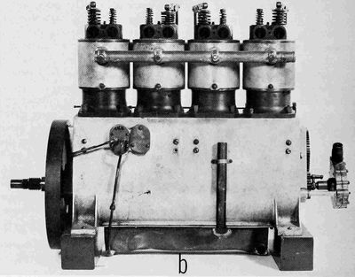
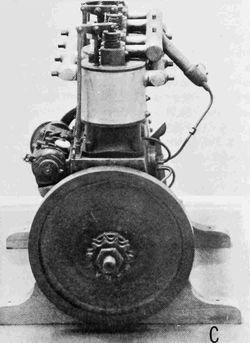
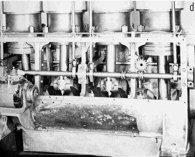
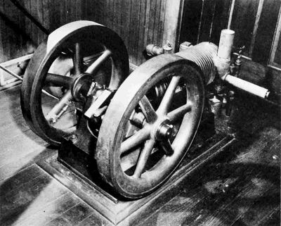
In commencing the design of the first engine, the first important
decision arrived at was that of the number and size of the cylinders
to be employed and the form in which they would be combined, although
it is unlikely that this presented any serious problem. In a similar
situation Manly, when he was working on the engine for the Langley
Aerodrome,[9] was somewhat perturbed because he did not have access to
the most advanced technical knowledge, since the automobile people who
were at that time the leaders in the development of the internal
combustion engine, tended for competitive reasons to be rather
secretive about their latest advancements and designs. But although
the standard textbooks may not have been very helpful to him, there
were available such volumes as W. Worby Beaumont's Motor Vehicles and
Motors which contained in considerable detail descriptions and
illustrations of the best of the current automobile engines. The
situations of Manly and the Wrights differed, however, in that whereas
the Wrights' objective was certainly a technical performance
considerably above the existing average, Manly's goal was that of
something so far beyond this average as to have been considered by
many impossible. Importantly, the Wrights had their own experience
with their shop engine and a good basic general knowledge of the size
of engine that would be necessary to meet their requirements.
Engine roughness was of primary concern to them. In the 1902
description of the engine they sent to various manufacturers, they had
stated: "... and the engine would be free from vibration." Even
though their requirement for a smooth engine was much more urgent than
merely to avoid the effect of roughness on the airplane frame, they
were faced, before they made their first powered flight, with the
basic problem with which the airplane has had to contend for over
three-quarters of its present life span: that is, it was necessary to
utilize an explosion engine in a structure which, because of weight
limitations, had to be made the lightest and hence frailest that could
possibly be devised and yet serve its primary purpose. However
great the difficulty may have appeared, in the long view, the
fault was certainly a relatively minor one in the overall development
of the internal combustion engine—that wonderful invention without
which their life work would probably never have been so completely
successful while they lived, and which, even aside from its
partnership with the airplane, has so profoundly affected the nature
of the world in which we live.
It seems quite obvious that to the Wrights vibration, or roughness,
was predominantly if not entirely caused by the explosion forces, and
they were either not completely aware of the effects of the other
vibratory forces or they chose to neglect them. Although crankshaft
counterweights had been in use as far back as the middle 1800s, the
Wrights never incorporated them in any of their engines; and despite
the inherent shaking force in the 4-inline arrangement, they continued
to use it for many years.
The choice of four cylinders was obviously made in order to get, for
smoothness, what in that day was "a lot of small cylinders"; and this
was sound judgment. Furthermore, although the majority of automobiles
at that time had engines with fewer than four cylinders, for those
that did the inline form was standard and well proven, and, in fact,
Daimler was then operating engines of this general design at powers
several times the minimum the Wrights had determined necessary for
their purpose.
What fixed the exact cylinder size, that is, the "square" 4×4-in.
form, is not recorded, nor is it obvious by supposition. Baker says it
was for high displacement and low weight, but these qualities are also
greatly affected by many other factors. The total displacement of just
over 200 cu in. was on the generous side, given the horsepower they
had determined was necessary, but here again the Wrights were
undoubtedly making the conservative allowances afterwards proven
habitual, to be justified later by greatly increased power
requirements and corresponding outputs. The Mean Effective Pressure
(MEP), based on their indicated goal of 8 hp, would be a very modest
36 psi at the speed of 870 rpm at which they first tested the engine,
and only 31 psi at the reasonably conservative speed of 1000 rpm. The
4×4-in. dimension would provide a cylinder large enough so that the
engine was not penalized in the matter of weight and yet small enough
to essentially guarantee its successful operation, as cylinders of
considerably larger bore were being utilized in automobiles. That
their original choice was an excellent one is rather well supported by
the fact that in all the different models and sizes of engines they
eventually designed and built, they never found it necessary to go to
cylinders very much larger than this.
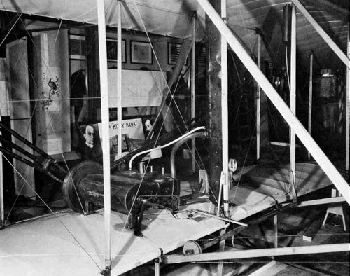
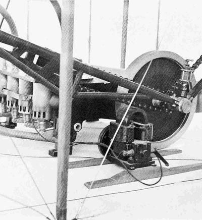
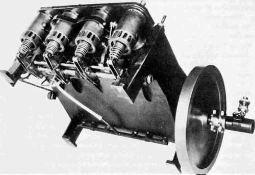
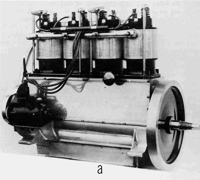
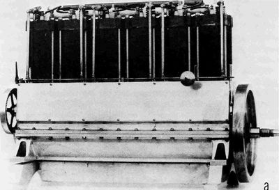
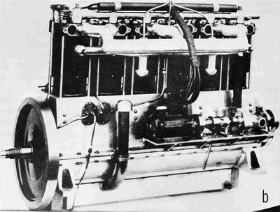
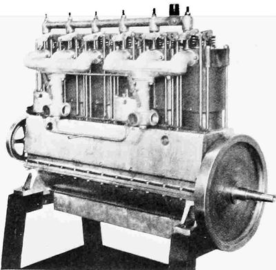
Figure 3.—First flight engine, 1903, installed in
the Kitty Hawk airplane, as exhibited in the Science Museum. (Photo
courtesy the Science Museum, London.)
A second basic determination which was made either concurrently or
even possibly in advance of that of the general form and size was in
the matter of the type of cylinder cooling to adopt. Based on current
practice that had proven practical, there were three
possibilities, all of which were in use in automobiles: air, water, or
a combination of the two. It is an interesting commentary that Fernand
Forest's[10] proposed 32-cylinder aircraft engine of 1888 was to be
air-cooled, that Santos-Dumont utilized an air-cooled Clement engine
in his dirigible flights of 1903, and that the Wrights had chosen air
cooling for their shop engine. With the promise of simplicity and
elimination of the radiator, water and piping, it would seem, offhand,
that this would be the Wrights' choice for their airplane; but they
were probably governed by the fact that not only was the water-cooled
type predominant in automobile practice, but that the units giving the
best and highest performance in general service were all water cooled.
In their subsequent practice they never departed from this original
decision, although Wilbur Wright's notebook of 1904-1907
contains an undated weight estimate by detailed parts for an
8-cylinder air-cooled engine. Unfortunately, the proposed power output
is not recorded, so their conception of the relative weight of the
air-cooled form is not disclosed.
One of the most important decisions relating to the powerplant—one
which was probably made long before they became committed to the
design itself—was a determination of the method of transmission of
power to the propeller, or propellers. A lingering impression exists
that the utilization of a chain drive for this purpose was a natural
inheritance from their bicycle background. No doubt this experience
greatly simplified the task of adaptation but a merely cursory
examination shows that even if they had never had any connection with
bicycles, the chain drive was a logical solution, considering every
important element of the problem. The vast majority of automobiles of
the time were chain driven, and chains and sprockets capable of
handling a wide range of power were completely developed and
available. Further, at that time they had no accurate knowledge of
desirable or limiting propeller and engine speeds. The chain drive
offered a very simple and inexpensive method of providing for a
completely flexible range of speed ratios. The other two possibilities
were both undesirable: the first, a simple direct-driven single
propeller connected to the crankshaft, provided essentially no
flexibility whatsoever in experimentally varying engine or propeller
speed ratios, it added an out-of-balance engine torque force to the
problem of airplane control, and, finally, it dictated that the pilot
would be in the propeller slipstream or the airflow to it; the second,
drive shafts and gearing for dual propellers, would have been very
heavy and expensive, and most probably would have required a long-time
development, with every experimental change in speed ratios requiring
a complete change in gears. Again, their original choice was so
correct that it lasted them through essentially all their active
flying years.
The very substantial advantages of the chain drive were not, however,
obtained at no cost. Torque variations in the engine would tend to
cause a whipping action in the chain, so that it was vulnerable to
rough running caused by misfiring cylinders and, with the right timing
and magnitude of normal regular variations, the action could result in
destructive forces in the transmission system. This was the basic
reason for the Wrights' great fear of "engine vibration," which
confined them to the use of small cylinders and made a fairly heavy
flywheel necessary on all their engines. When they were requested to
install an Austro-Daimler engine in one of their airplanes, they
designed a flexible coupling which was interposed between the engine
and the propeller drive and this was considered so successful that it
was applied to the flywheel of some engines of their last
model, the 6-70, "which had been giving trouble in this regard."[11]
Although flat, angled, and vertical engines had all been operated
successfully, the best and most modern automotive engines of the time
were vertical, so their choice of a horizontal position was probably
dictated either by considerations of drag or their desire to provide a
sizable mounting base for the engine, or both. There is no record of
their ever having investigated the matter of the drag of the engine,
either alone or in combination with the wing. The merit of a vertical
versus a horizontal position of the engine was not analogous to that
of the pilot, which they had studied, and where the prone position
undoubtedly reduced the resistance.
Having decided on the general makeup of their engine, the next major
decision was that of just what form the principal parts should take,
the most important of these being the cylinders and crankcase. Even at
this fairly early date in the history of the internal combustion
engine various successful arrangements and combinations were in
existence. Individual cylinder construction was by far the most used,
quite probably due to its case of manufacture and adaptability to
change. Since 4-cylinder engines were just coming into general use (a
few production engines of this type had been utilized as early as
1898), there were few examples of en-bloc or one-piece construction.
The original German Daimler Company undoubtedly was at this time the
leader in the development of high-output internal-combustion engines,
and in 1902, as an example of what was possible, had placed in service
one that possibly approximated 40 hp, which was an MEP of 70 psi.
(Almost without exception, quoted power figures of this period were
not demonstrated quantities but were based on a formula, of which the
only two factors were displacement and rpm.) The cylinders of this
Daimler engine were cast iron, the cylinder barrel, head, and water
jacket being cast in one piece. The upper part of the barrel and the
cylinder head were jacketed, but, surprisingly, the bottom 60 percent
of the barrel had no cooling. The cylinders were cast in pairs and
bolted to a two-piece aluminum case split at the line of the
crankshaft. Ignition was make-and-break and the inlet valves were
mechanically actuated. Displacement was 413 cu in. and the rpm was
1050.
Although a few examples of integral crankcase and water jacket
combinations were in use, the Wrights were being somewhat radical when
they decided to incorporate all four cylinders in the one-piece
construction, particularly since they also proposed to include the
entire crankcase and not just one part of it. It was undoubtedly the
most important decision that they were required to make on all the
various construction details, and probably the one given the
most study and investigation. Many factors were involved, but
fundamentally everything went back to their three basic requirements:
suitability, time, and cost. There was no obvious reason why the
construction would not work, and it eliminated a very large number of
individual parts and the required time for procuring, machining, and
joining them. Probably one very strong argument was the advanced state
of the casting art, one of the oldest of the mechanical arts in
existence and one the Wrights used in many places, even though other
processes were available. What no doubt weighed heavily was that
Dayton had some first-class foundries. The casting, though intricate
and not machinable in their own shop, could be easily handled in one
that was well outfitted. The pattern was fairly complex but apparently
not enough to delay the project or cause excessive cost.
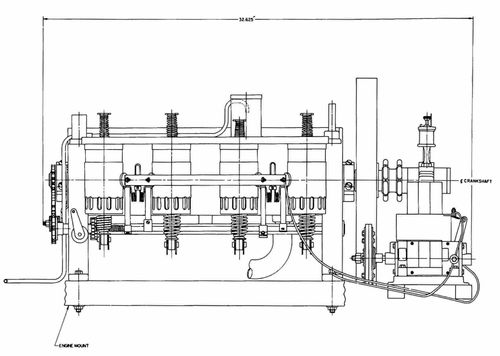
Figure 4.—First flight engine, 1903, left side and
rear views, with dimensions. (Drawing courtesy Howell Cheney Technical
School.)
LEFT SIDE VIEW.
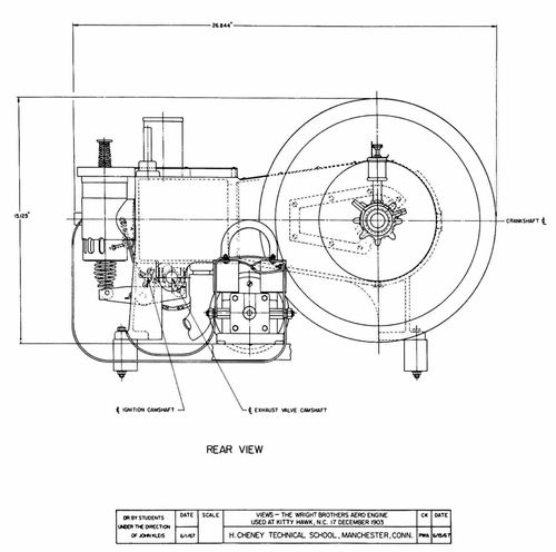
REAR VIEW
The selection of aluminum for the material was an integral
part of the basic design decision. Despite the excellence and accuracy
of the castings that could be obtained, there was nevertheless a
minimum dimension beyond which wall thickness could not be reduced;
and the use of either one of the two other proven materials, cast iron
or bronze, would have made the body, as they called it, prohibitively
heavy. The use of aluminum was not entirely novel at this time, as it
had been utilized in many automobile engine parts, particularly
crankcases; but its incorporation in this rather uncommon combination
represented a bold step. There was no choice in the matter of the
alloy to be used, the only proven one available was an 8 percent
copper 92 percent aluminum combination.
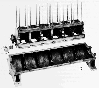
By means of the proper webs, brackets and bosses, the crankcase would
also carry the crankshaft, the rocker arms and bearings, and the
intake manifold. The open section of the case at the top was
covered with a screw-fastened thin sheet of cold-rolled steel. The
main bearing bosses were split at a 45° angle for ease of assembly.
The engine support and fastening were provided by four feet, or lugs,
cast integral on the bottom corners of the case, and by accompanying
bolts (Figure 2). Although the crankcase continued to be pretty much
the "body" of the internal combustion aircraft engine throughout its
life, the Wrights managed to incorporate in this original part a major
portion of the overall engine, and certainly far more than had ever
previously been included.
The design of the cylinder barrel presented fairly simple problems
involving not much more than those of keeping the sections as thin as
possible and devising means of fastening it and of keeping the water
jacket tight. They saved considerable weight by making the barrel
quite short, so that in operation a large part of the piston extended
below the bottom of it; but this could be accepted, as there were no
rings below the piston pin (Figure 6). The barrel material, a good
grade of cast iron, was an almost automatic choice. In connection with
these seemingly predetermined decisions, however, it should be
remembered that their goal was an engine which would work without
long-time development, and that, with no previous experience in
lightweight construction to guide them they were nevertheless
compelled to meet a weight limit, so that the thickness of every wall
and flange and the length of every thread was important.
With the separate cylinder barrel they were now almost committed to a
three-piece cylinder. It would have been possible to combine the
barrel and head in a one-piece casting and then devise a method of
attachment, but this would have been more complex and certainly
heavier. For housing the valves, what was in effect a separate
cylindrical, or tubular, box was decided upon. This would lie across
the top of the cylinder proper at right angles to the cylinder axis,
and the two valves would be carried in the two ends of this box. The
cylinder barrel would be brought in at its head end to form a portion
of the cylinder head and then extended along its axis in the form of a
fairly large boss, a mating boss being provided on one side of the
valve box. The cylinder barrel would then be threaded into the valve
box and the whole tightened or fastened to the crankcase by means of
two sets of threads, one at each end of the barrel proper. This meant
that three joints had to be made tight with only two sets of threads.
This was accomplished by accurate machining and possibly even hand
fitting in combination with a rather thick gasket at the head end, one
flat of which bore against two different surfaces. This can be seen in
Figure 6, where the circular flange on the valve box contacts both the
crankcase and the cylinder barrel. Altogether it was a simple, light,
and ingenious solution to a rather complex problem.
At this point the question arises: Why was the engine layout
such that the exhaust took place close to the operator's ears? It
would have been possible, starting with the original design, to turn
the engine around so that the exhaust was on the other side. This
would have little effect on the location of the center of gravity, and
the two main drive chains would then have been of more equal length.
However, of the many factors involved, probably one of the principal
considerations in arriving at their final decision was the location of
the spark-advance control, which was in effect the only control they
had of engine output, except for complete shutoff. In their design
this was immediately adjacent to the operator; with a turned-around
engine, an extension control mechanism of some sort would have been
required. The noise of the exhaust apparently became of some concern
to them, as Orville's diary in early 1904 contains an entry with a
sketch labeled "Design for Muffler for Engine," but there is no
further comment.
The problem of keeping joints tight, and for that matter the entire
construction itself, were both greatly simplified by their decision to
water-jacket only a part of the cylinder head proper, and the valve
box not at all. This was undoubtedly the correct decision for their
immediate purpose, as again they were effecting savings in time, cost,
complexity, and weight. There is nothing in the record, however, to
show why they continued this practice long after they had advanced to
much greater power outputs and longer flight times. Their own
statements show that they were well aware of the effect of the very
hot cylinder head on power output and they must also have realized its
influence on exhaust-valve temperature.
The cylinder assembly was made somewhat more complicated by their
desire to oil the piston and cylinder by means of holes near the
crankshaft end in what was, with the engine in the horizontal
position, the upper side of the cylinder barrel. This complication was
no doubt taken care of by not drilling the holes until a tight
assembly had been made by screwing the barrel into place, and by
marking the desired location on the barrel. Since this position was
determined by a metal-to-metal jam fit of the crankcase and cylinder
barrel flange, the barrel would reassemble with the holes in very
nearly the same relative position after disassembly.
With the valve box, or housing, cylindrical, the task of locking and
fastening the intake and exhaust valve guides and seats in place was
easy. The guide was made integral with and in the center of one end of
a circular cage, the other end of which contained the valve seat (see
Figure 5). Four sections were cut out of the circular wall of the cage
so that in effect the seat and guide were joined by four narrow legs,
the spaces between which provided passages for the flow of the
cylinder gases. These cages were then dropped into the ends of the
valve boxes until they came up against machined shoulders and
were held in place by internal ring nuts screwed into the valve box.
The intake manifold or passage was placed over the intake valves so
that the intake charge flowed directly into and through the valve cage
around the open valve and into the cylinder. The exhaust gas, after
flowing through the passages in the valve cage, was discharged
directly to the atmosphere through a series of holes machined in one
side of the valve box.
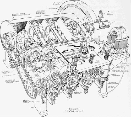
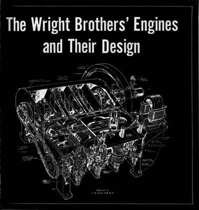
Figure 5.—First flight engine, 1903, assembly.
(Phantom cutaway by J. H. Clark, with key, courtesy Aeroplane.)
KEY
- 1 and 2. Bearing caps in one piece with plate 3.
- 3. Plated screwed over hole 4 in crankcase end.
- 4. Key-shaped hole as hole 5 in intermediate ribs.
- 6. Inter-bearings cap (white-metal lined) and screwed to
inter-rib halves 7.
- 8. Splash-drip feed to bearings.
- 9. Return to pump from each compartment of crankcase base
("sump") via gallery 10 and pipe to pump 11 underneath jacket.
- 12. Oil feed from pump via rubber tube 13.
- 13. Drip feeds to cylinders and pistons.
- 14. Gear drive to pump.
- 15. Big-end nuts, lock-strip, and shims.
- 16. Gudgeon-pin lock.
- 17. Piston-ring retainer pegs.
- 18. Cylinder liner screwing into jacket.
- 19. Open-ended "can" admits air.
- 20. Fuel supply.
- 21. (Hot) side of water jacket makes surface carburetter.
- 22. Sparking plug (comprising positive electrode 23 and
spark-producing make-and-break 24).
- 25. Lever attached to lever 26 via bearing 27 screwed into
chamber neck 28.
- 26. Levers with mainspring 29 and inter-spring 30, and rocked by
"cam" 31.
- 31. Cam with another alongside (for adjacent cylinder).
- 32. Positive busbar feed to all four cylinders.
- 33. Assembly retaining-rings.
- 34. Sealing disc.
- 35. Exhaust outlet ports.
- 36. Camshaft right along on underside of jacket and also driving
oil pump 11 via 14.
- 37. Spring-loaded sliding pinion drives make-and-break shaft 38
through peg in inclined slot 39.
- 40. Cam to push pinion 37 along and so alter its angular relation
with shaft 38 (to vary timing).
- 41. Exhaust-valve cams bear on rollers 42 mounted in end of
rocker-arms 43.
- 44. Generator floating coils.
- 45. Friction-drive off flywheel.
- 46. Sight-feed lubricator (on stationary sleeve).
- 47. Hardwood chain tensioner.
The intake and exhaust valves were identical and of two-piece
construction, with the stems screwed tightly into and through the
heads and the protruding ends then peened over. This construction was
not novel, having had much usage behind it, and it continued for a
long time in both automobile and aircraft practice. One-piece cast
and forged valves were available but here again it was a
choice of the quick, cheap, and proven answer.
The entire valve system, including guides and seats, was of cast iron,
a favorite material of the Wrights, except for the valve stems, which
were, at different times, of various carbon steels. Ordinary
cold-rolled apparently was used in those of the original engine, but
in later engines this was changed to a high-carbon steel.
The piston design presented no difficulty. In some measure this was
due to the remarkable similarity that seems to have existed among all
the different engines of the time in the construction of this
particular part, for, although there were some major variations, it
was, in fact, almost as if some standard had been adopted. Pistons all
were of cast iron and comparatively quite long (it was a number of
years before they evolved into the short ones of modern practice);
they were almost invariably equipped with three wide piston rings
between the piston pin and the head; and, although there were
in existence a few pistons with four rings, no oil wiper or other ring
seems to have been placed below the piston pin. The Wrights' piston
was typical of the time, with the rings pinned in the grooves to
prevent turning and the piston pin locked in the piston with a
setscrew. In designing this first engine they were, however,
apparently somewhat unsure about this latter feature, as they provided
the rod with a split little end and a clamping bolt (see Figure 6), so
that the pin could be held in the rod if desired; but no examples of
this use have been encountered.
The Wrights' selection of an "automatic" or suction-operated inlet
valve was entirely logical. Mechanically operated inlet valves were in
use and their history went back many years, but the great majority of
the engines of that time still had the automatic type, and with this
construction one complete set of valve-operating mechanisms was
eliminated. They were well aware of the loss of volumetric efficiency
inherent in this valve, and apparently went to some pains to obtain
from it the best performance possible. Speaking of the first engine,
Orville Wright wrote, "Since putting in heavier springs to actuate the
valves on our engine we have increased its power to nearly 16 hp and
at the same time reduced the amount of gasoline consumed per hour to
about one-half of what it was."[12]
Why they continued with this form on their later engines is a question
a little more difficult to answer, as they were then seeking more and
more power and were building larger engines. The advantages of
simplicity and a reduced number of parts still existed, but there also
was a sizable power increase to be had which possibly would have more
than balanced off the increased cost and weight. They did not utilize
mechanical operation until after a major redesign of their last engine
model. Very possibly the answer lies in the phenomenon of fuel
detonation. This was only beginning to be understood in the late
1920s, and it is quite evident from their writings that they had
little knowledge of what made a good fuel in this respect. It is
fairly certain, however, that they did know of the existence of
cylinder "knock," or detonation, and particularly that the compression
ratio had a major effect on it. The ratios they utilized on their
different engines varied considerably, ranging from what, for that
time, was medium to what was relatively high. The original flight
engine had a compression ratio of 4.4:1. The last of their service
engines had a compression ratio about twenty percent under that of the
previous series—a clear indication that they considered that they had
previously gone too high. Quite possibly they concluded that
increasing the amount of the cylinder charge seemed to bring on
detonation, and that the complication of the mechanical inlet valve
was therefore not warranted.
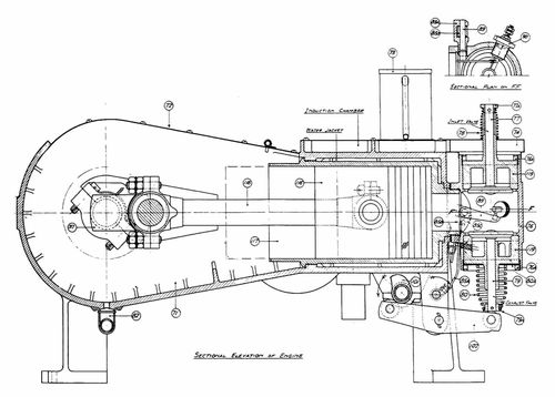
Figure 6.—First flight engine, 1903, cross section.
(Drawing courtesy Science Museum, London.)
The camshaft for the exhaust valves (101, Figure 6), was chain driven
from the crankshaft and was carried along the bottom of the crankcase
in three babbit-lined bearings in bearing boxes or lugs cast integral
with the case. Both the driving chain and the sprockets were standard
bicycle parts, and a number of bicycle thread standards and other
items of bicycle practice were incorporated in several places in the
engine, easing their construction task. The shaft itself, of mild
carbon steel, was hollow and on each side of an end bearing sweated-on
washers provided shoulders to locate it longitudinally. Its location
adjacent to the valves, with the cam operating directly on the rocker
arm, eliminated push rods and attendant parts, a major
economy. The cams were machined as separate parts and then sweated
onto the shaft. Their shape shows the principal concern in the design
to have been obtaining maximum valve capacity—that is, a quite rapid
opening with a long dwell. This apparent desire to get rid of the
exhaust gas quickly is manifested again in the alacrity with which
they adopted a piston-controlled exhaust port immediately they had
really mastered flight and were contemplating more powerful and more
durable engines. This maximum-capacity theory of valve operation, with
its neglect of acceleration forces and seating velocities, may well
have been at least partially if not largely the cause of their
exhaust-valve troubles and the seemingly disproportionate amount of
development they devoted to this part, as reported by Chenoweth,
although it is also true that the exhaust valve continued to present a
problem in the aircraft piston engine for a great many years after,
even with the most scientific of cam designs.
The rocker arm (102, Figure 6) is probably the best example of a small
part which met all of their many specific requirements with an extreme
of simplicity. It consisted of two identical side pieces, or walls, of
sheet steel shaped to the desired side contour of the assembly, in
which were drilled three holes, one in each end, to carry the roller
axles, and the third in the approximate middle for the rocker axle
shaft proper. This consisted of a piece of solid rod positioned by
cotter pins in each end outside the side walls (see Figure 5). The
assembly was made by riveting over the ends of the roller axles so
that the walls were held tightly against the shoulders on the axles,
thus providing the correct clearance for the rollers. The construction
was so light and serviceable that it was essentially carried over to
the last engine the Wrights ever built.
The basic intake manifold (see Figure 5) consisted of a very low flat
box of sheet steel which ran across the tops of the valve boxes and
was directly connected to the top of each of them so that the cages,
and thus the valves, were open to the interior of the manifold.
Through an opening in the side toward the engine the manifold was
connected to a flat induction chamber (21, Figure 5) which served to
vaporize the fuel and mix it with the incoming air. This chamber was
formed by screw-fastening a piece of sheet steel to vertical ribs cast
integral with the crankcase, the crankcase wall itself thus forming
the bottom of the chamber. A beaded sheet-steel cylinder resembling a
can (73, Figure 6) but open at both ends was fastened upright to the
top of this chamber. In the absence of anything else, this can could
be called the carburetor, as a fuel supply line entered the cylinder
near the top and discharged the fuel into the incoming air stream,
both the fuel and air then going directly into the mixing chamber. The
can was attached near one corner of the chamber, and vertical baffles,
also cast integral with the case, were so located that the incoming
mixture was forced to circulate over the entire area of
exposed crankcase inside the chamber before it reached the outlet to
the manifold proper, the hot surface vaporizing that part of the fuel
still liquid.
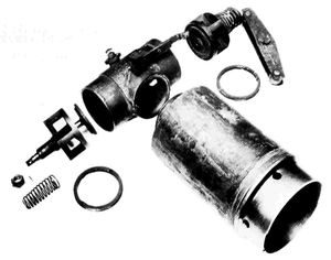
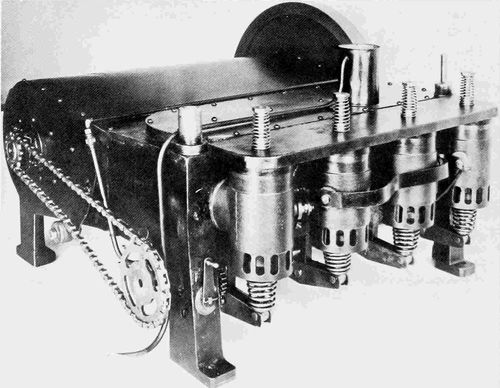
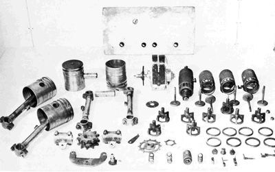
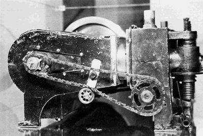
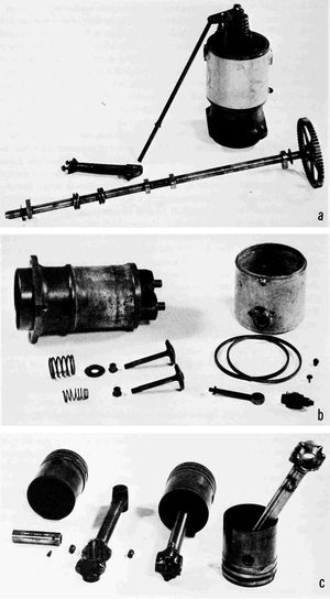
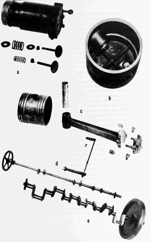
Figure 7.—First flight engine, 1903: cylinder, valve
box, and gear mechanism; below, miscellaneous parts. (Photos courtesy
Science Museum, London, and Louis P. Christman.)
Fuel was gravity fed to the can through copper and rubber tubing from
a tank fastened to a strut, several feet above the engine. Of the two
valves placed in the fuel line, one was a simple on-off shutoff cock
and the other a type whose opening could be regulated. The latter was
adjusted to supply the correct amount of fuel under the desired flight
operating condition; the shutoff cock was used for starting and
stopping. The rate of fuel supply to the engine would decrease as the
level in the fuel tank dropped, but as the head being utilized was a
matter of several feet and the height of the supply tank a matter of
inches, the fuel-air ratio was still maintained well within the range
that would ignite and burn properly in the contemplated one-power
condition of their flight operation.
This arrangement is one of the best of the many illustrations of how
by the use of foresight and ingenuity the Wrights met the challenge of
a complex requirement with a simple device, for while carburetors were
not in the perfected stage later attained, quite good ones that would
both control power output and supply a fairly constant fuel-air
mixture over a range of operating conditions were available, but they
were complex, heavy, and expensive. The arrangement, moreover, secured
at no cost a good vaporizer, or modern "hot spot." In their subsequent
engines they took the control of the fuel metering away from the
regulating valve and gravity tank combination and substituted an
engine-driven fuel pump which provided a fuel supply bearing a fairly
close relationship to engine speed.
The reasons behind selection of the type of ignition used, and the
considerations entering into the decision, are open to speculation, as
are those concerning many other elements that eventually made up the
engine. Both the high-tension spark plug and low-tension
make-and-break systems had been in wide use for many years, with the
latter constituting the majority in 1902. Both were serviceable and
therefore acceptable, and both required a "magneto". The art of the
spark plug was in a sense esoteric (to a certain extent it so remains
to this day), but the spark-plug system did involve a much simpler
combination of parts: in addition to the plug and magneto there would
be needed only a timer, or distributor, together with coils and
points, or some substitute arrangement. The make-and-break system, on
the other hand, required for each cylinder what was physically the
equivalent of a spark plug, that is, a moving arm and contact point
inside the cylinder, a spring-loaded snap mechanism to break the
contact outside the cylinder, and a camshaft and cams to actuate the
breaker mechanism at the proper time. Furthermore, as the Wrights
applied it, the system required dry cells and a coil for starting,
although these did not accompany the engine in flight. And finally
there was the problem of keeping tight the joint where the
oscillating shaft required to operate the moving point in the spark
plug entered the cylinder.
This is one of the few occasions, if not the only one, when the
Wrights chose the more complex solution in connection with a major
part—in this particular case, one with far more bits and pieces.
However, it did carry with it some quite major advantages. The common
spark plug, always subject to fouling or failure to function because
of a decreased gap, was not very reliable over a lengthy period, and
was undoubtedly much more so in those days when control of the amount
of oil inside the cylinder was not at all exact. Make-and-break
points, on the other hand, were unaffected by excess oil in the
cylinder. Because of this resistance to fouling, the system was
particularly suitable for use with the compression-release method of
power control which they later utilized, although they probably could
not have been looking that far ahead at the time they chose it.
High-tension current has always, and rightfully so, been thought of as
a troublemaker in service; in Beaumont's 1900 edition of Motor
Vehicles and Motors, which seems to have been technically the best
volume of its time, the editor predicted that low-tension
make-and-break ignition would ultimately supersede all other methods.
And finally, the large number of small parts required for the
make-and-break system could all be made in the Wright Brothers' shop
or easily procured, and in the end this was probably the factor, plus
reliability, that determined the decision which, all things
considered, was the correct one.
There was nothing exceptional about the exact form the Wrights
devised. It displayed the usual refined simplicity (the cams were made
of a single small piece of strip steel bent to shape and clamped to
the ignition camshaft with a simple self-locking screw), and
lightness. The ignition camshaft (38, Figure 5), a piece of
small-diameter bar stock, was located on the same side as the exhaust
valve camshaft, approximately midway between it and the valve boxes,
and was operated by the exhaust camshaft through spur gearing. That
the Wrights were thinking of something beyond mere hops or short
flights is shown by the fact that the ignition points were
platinum-faced, whereas even soft iron would have been satisfactory
for the duration of all their flying for many years.
The control of the spark timing was effected by advancing or retarding
the ignition camshaft in relation to the exhaust valve camshaft. The
spur gear (37, Figure 5) driving the ignition camshaft had its hub on
one side extended out to provide what was in effect a sleeve around
the camshaft integral with the gear. The gear and integral sleeve were
slidable on the shaft and the sleeve at one place (39, Figure 5) was
completely slotted through to the shaft at an angle of 45° to the
longitudinal axis of the shaft. The shaft was driven by a pin tightly
fitted in it and extending into the slot. The fore-and-aft position of
the sleeve on the shaft was determined by a lever-operated
cam (40, Figure 5) on one side and a spring on the other. The movement
of the sleeve along the shaft would cause the shaft to rotate in
relation to it because of the angle of the slot, thus providing the
desired variation in timing of the spark. The "magneto" was a
purchased item driven by means of a friction wheel contacting the
flywheel, and several different makes were used later, but the
original is indicated to have been a Miller-Knoblock (see Figure 5).
The connecting rod is another example of how, seemingly without
trouble, they were able to meet the basic requirements they had set
for themselves. It consisted of a piece of seamless steel tubing with
each end fastened into a phosphor-bronze casting, these castings
comprising the big and little ends, drilled through to make the
bearings (See Figures 5 and 6). It was strong, stiff and light.[13]
Forged rods were in rather wide use at the time and at least one
existing engine even had a forged I-beam section design that was
tapered down from big to little end. The Wrights' rod was obtained in
little more time than it took to make the simple patterns for the two
ends. The weight was easily controlled, no bearing liners were
necessary, and a very minimum of machining was required. Concerning
the big-end material, there exists a contradiction in the records:
Baker, whose data are generally most accurate, states that these were
babbited, but this must be in error, as the existing engine has
straight bronze castings without babbiting, and there is no record, or
drawing, or other indication of the bearings having been otherwise.
Different methods of assembling the rod were used. At one time the
tube ends were screwed into the bronze castings and pinned, and at
another the ends were pinned and soldered. There is an indication that
at one time soldering and threads were used in combination. One of the
many conflicts between the two primary sets of drawings exists at this
point. The Smithsonian drawings show the use at each end of adapters
between the rod and end castings, the adapters being first screwed
into the castings and pinned and then brazed to the inside of the
tube. The Science Museum drawings show the tube section threaded and
screwed into the castings. The direct screw assembly method called for
accurate machining and hand fitting in order to make the ends of the
tubing jam against the bottom of the threaded holes in the castings,
and at the same time have the end bearings properly lined up. The
weakness of the basic design patently lies in the joints. It
is an attempt to utilize what was probably in the beginning a
combination five-piece assembly and later three, in a very highly
stressed part where the load was reversing. It gave them considerable
trouble from time to time, particularly in the 4-cylinder vertical
engines, and was abandoned for a forged I-beam section type in their
last engine model; but it was nevertheless the ideal solution for
their first engine.
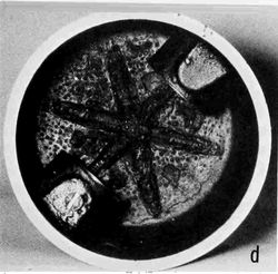
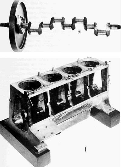
The crankshaft was made from a solid block of relatively high carbon
steel which, aside from its bulk and the major amount of machining
required, presented no special problems. It was heat-treated to a
machinable hardness before being worked on, but was not further
tempered. The design was an orthodox straight pin and cheek
combination and, as previously noted, there were no counterweights to
complicate the machining or assembly. A sizable bearing was provided
on each side of each crank of the shaft, which helped reduce the
stiffness requirement.
Their only serious design consideration was to maintain the desired
strength and still keep within weight limitations. A fundamental that
every professional designer knows is that it is with this particular
sort of part that weight gets out of control; even an additional 1/16
in., if added in a few places, can balloon the weight. With their
usual foresight and planning, the Wrights carefully checked and
recorded the weight of each part as it was finished, but even this
does not quite explain how these two individuals, inexperienced in
multicylinder engines—much less in extra-light construction—could,
in two months, bring through an engine which was both operable and
somewhat lighter than their specification.
In one matter it would seem that they were quite fortunate. The
records are not complete, but with one exception there is no
indication of any chronic or even occasional crankshaft failure. This
would seem to show that it apparently never happened that any of their
designs came out such that the frequency of a vibrating force of any
magnitude occurred at the natural frequency of the shaft. Much later,
when this type of vibration became understood, it was found virtually
impossible, with power outputs of any magnitude, to design an
undampened shaft, within the space and weight limitations existing in
an ordinary engine, strong enough to withstand the stress generated
when the frequency of the imposed vibration approximated the natural
frequency of the shaft. The vibratory forces were mostly relatively
small in their engines, so that forced vibration probably was not
encountered, and the operating speed range of the engines was so
limited that the natural frequency always fell outside this range.
The flywheel was about the least complex of any of their engine parts
and required little studied consideration, although they did have to
balance its weight against the magnitude of the explosion forces which
would reach the power transmission chains, with their complete lack of
rigidity, a problem about which they were particularly
concerned. The flywheel was made of cast iron and was both keyed to
and shrunk on the shaft.
Some doubt still exists about the exact method of lubricating the
first engine. The unit presently in the airplane has a gear-type oil
pump driven by the crankshaft through a worm gear and cross shaft, and
the Appendix to the Papers states that it was lubricated by a small
pump; nevertheless Baker says, after careful research, that despite
this evidence, it was not. Also, the drawings prepared by Christman
(they were commenced under the supervision of Orville Wright) do not
show the oil pump. In March 1905 Wilbur Wright wrote to Chanute,
"However we have added oiling and feeding devices to the engine ...";
but this could possibly have referred to something other than an oil
pump. But even if a pump was not included originally, its presence in
the present engine is easily explained. Breakage of the crankcase
casting caused the retirement of this engine, which was not rebuilt
until much later, and the pattern for this part had no doubt long
since been altered to incorporate a pump. It was therefore easier in
rebuilding to include than to omit the pump, even though this required
the addition of a cross shaft and worm gear combination. On later
engines, when the pump was used, oil was carried to a small pipe,
running along the inside of the case, which had four small drill holes
so located as to throw the oil in a jet on the higher, thrust-loaded
side of each cylinder. The rods had a sharp scupper on the outside of
the big end so placed as also to throw the oil on this same thrust
face. Some scuppers were drilled through to carry oil to the rod
bearing and some were not.
The first engine was finished and assembled in February 1903 and given
its first operating test on 22 February. The Wrights were quite
pleased with its operation, and particularly with its smoothness.
Their father, Bishop Wright, was the recorder of their satisfaction
over its initial performance, but what he noted was probably the
afterglow of the ineffable feeling of deep satisfaction that is the
reward that comes to every maker of a new engine when it first comes
to life and then throbs. They obtained 13 hp originally: later figures
went as high as almost 16, but as different engine speeds were
utilized it is rather difficult to settle on any single power figure.
The most realistic is probably that given in the Papers as having
been attained later, after an accurate check had been made of the
power required to turn a set of propellers at a given rpm. This came
out at approximately 12 hp, the design goal having been 8. Following
exactly the procedure that exists to this day, the engine went through
an extended development period, and it was the end of September 1903
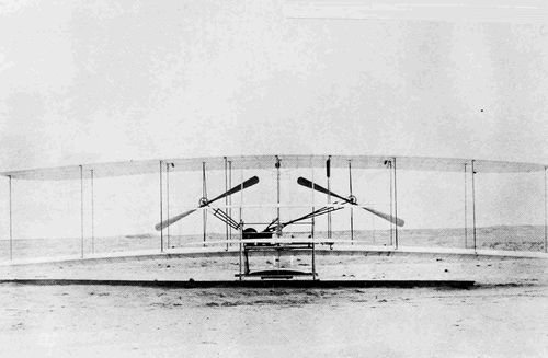
before it was taken, with the airplane, to Kitty Hawk where the
historic flights, which have had such a profound effect on the lives
of all men, were made on 17 December 1903.