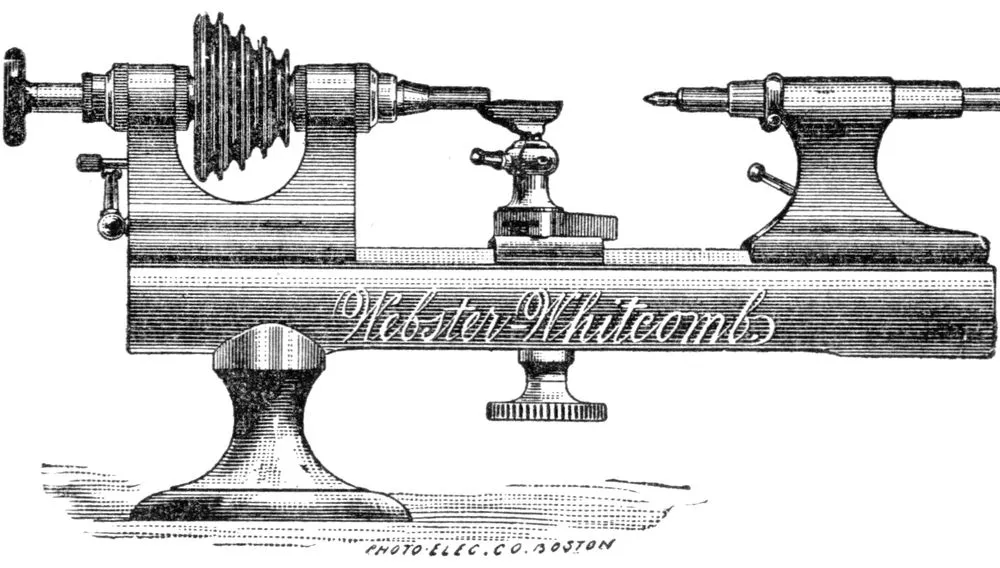
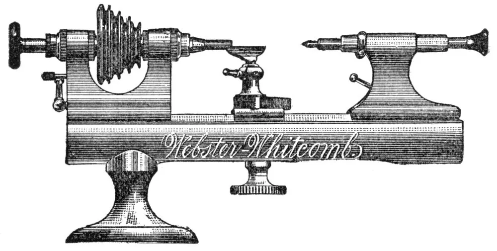
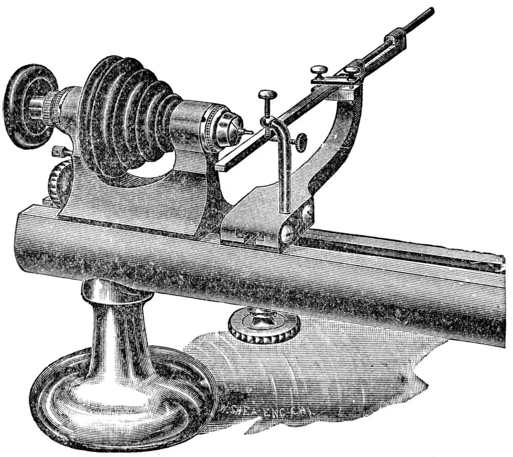
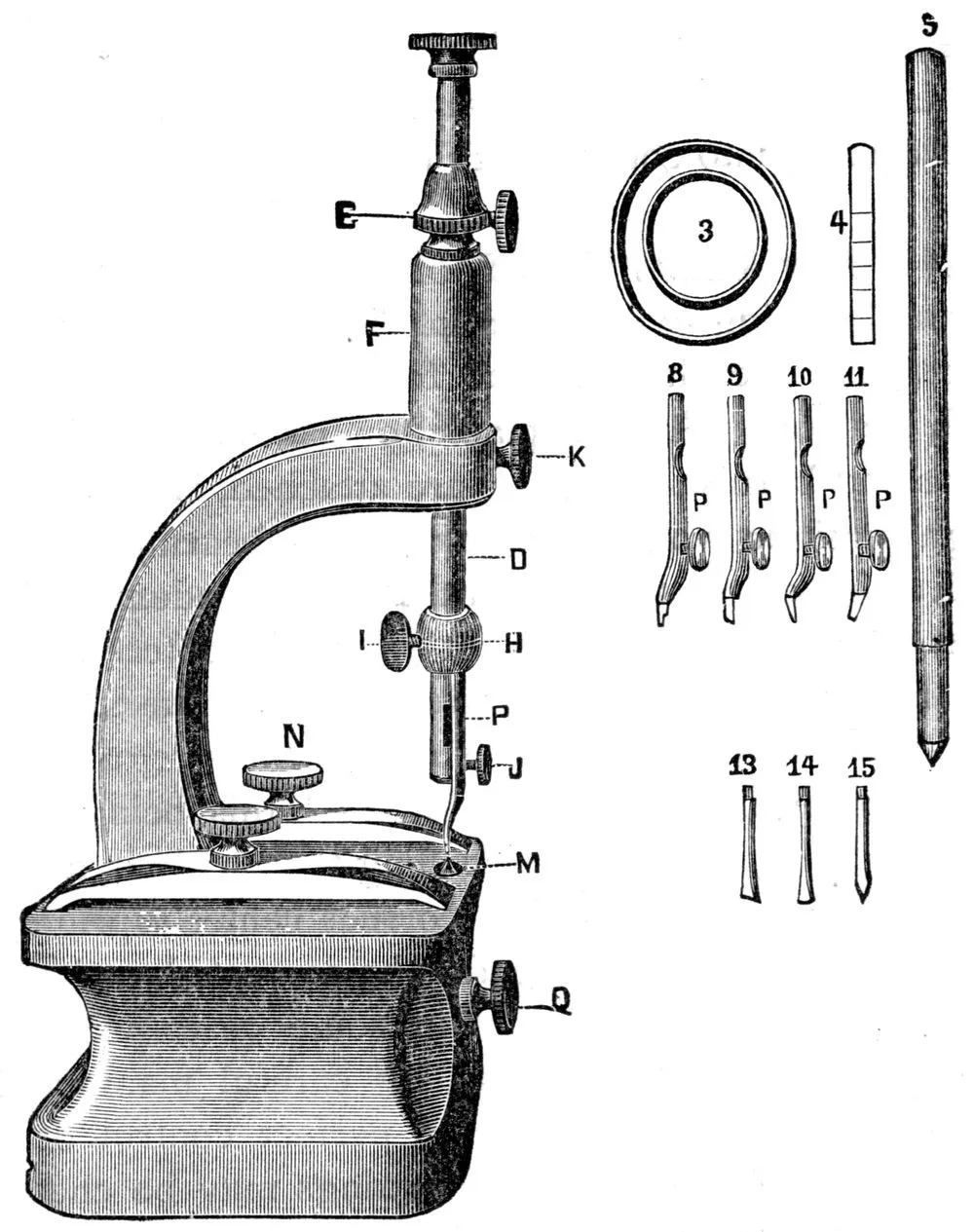
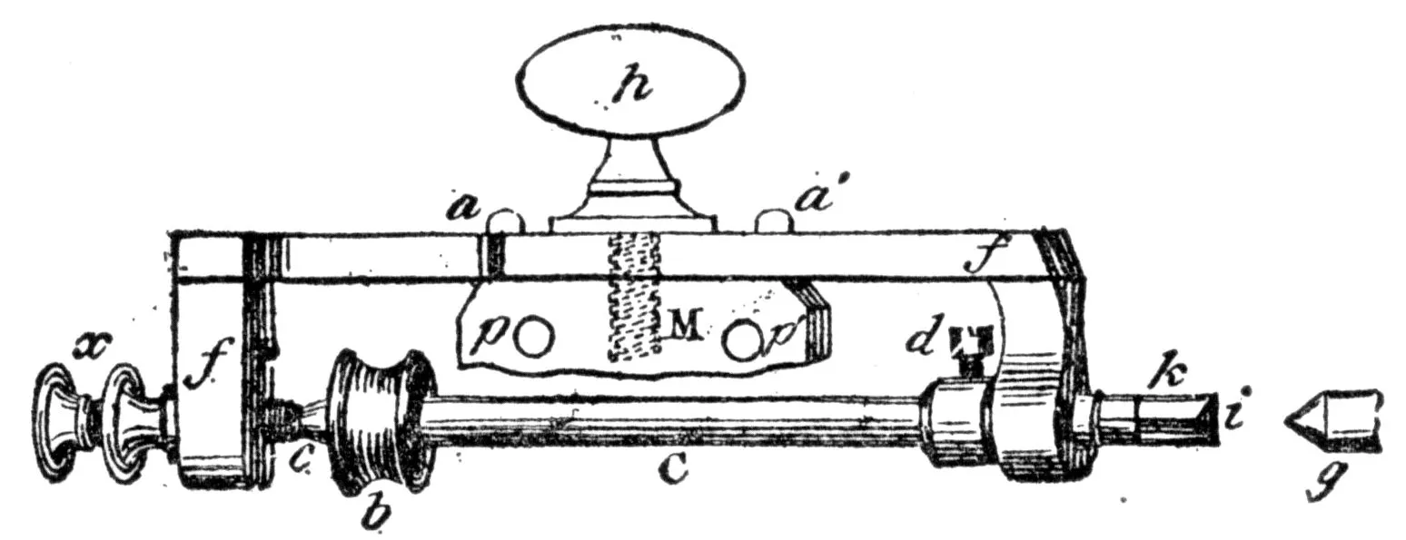
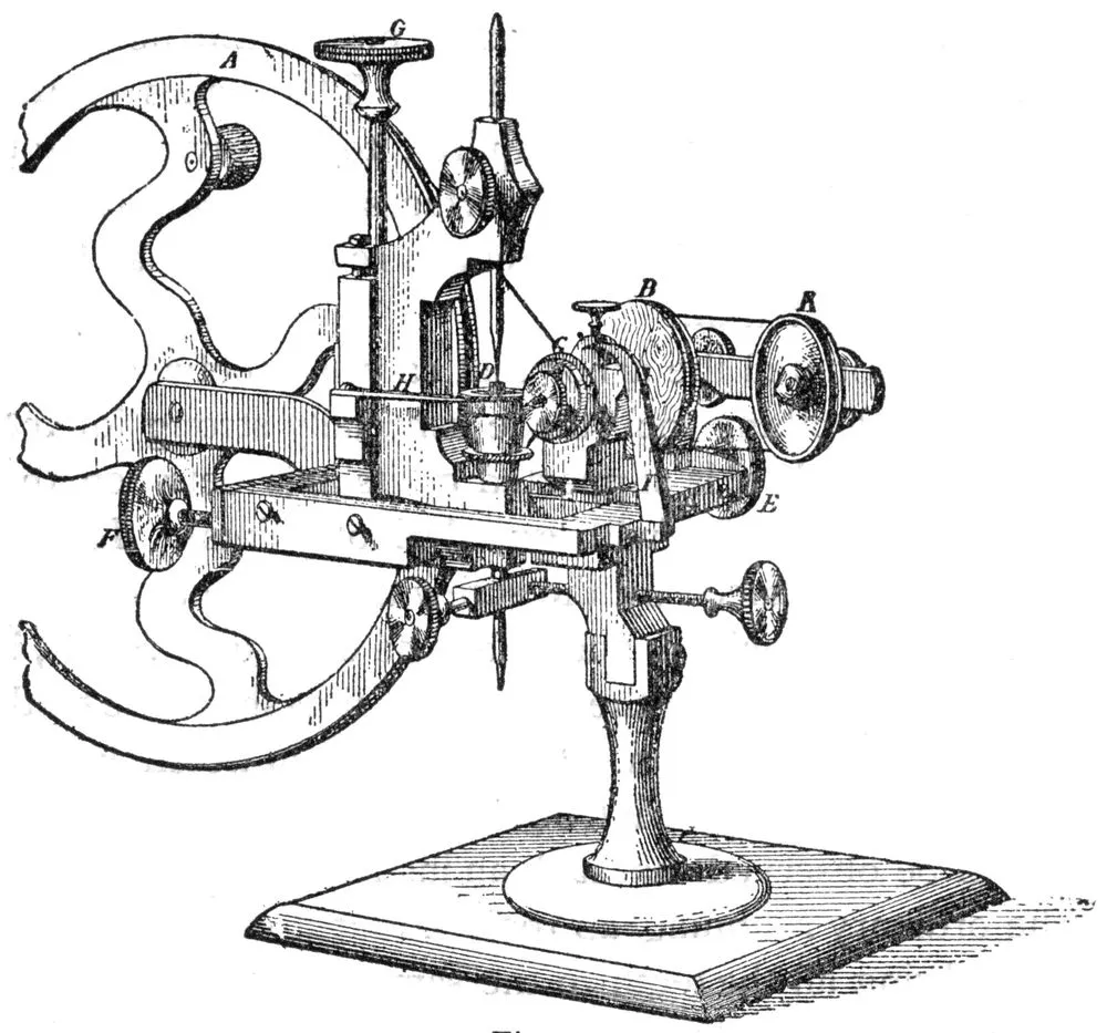
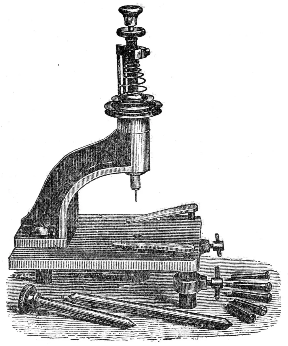
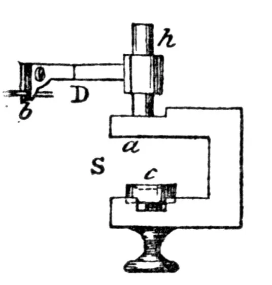
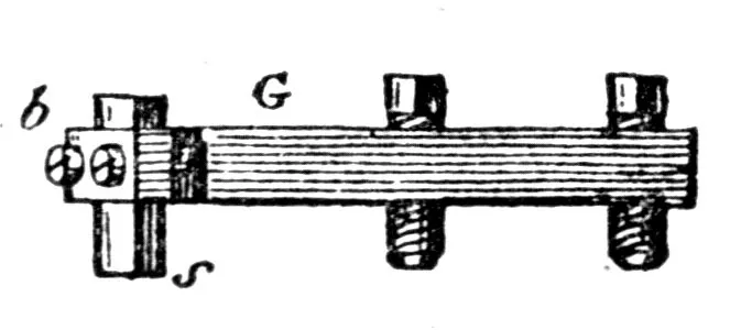
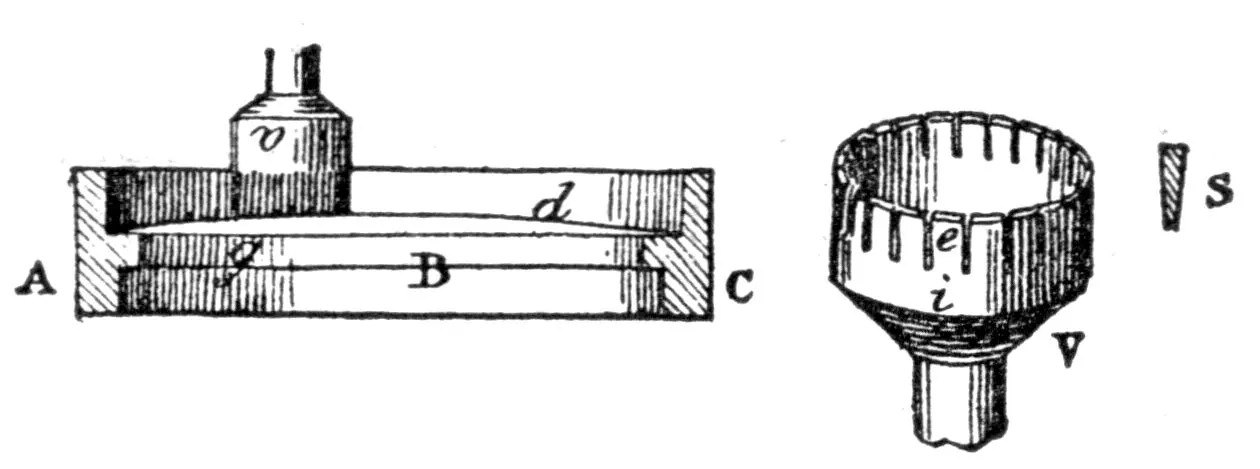
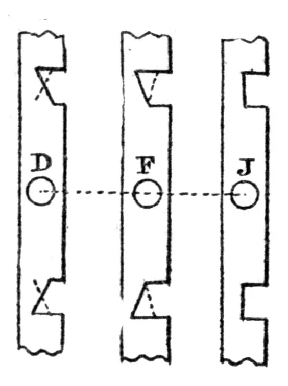
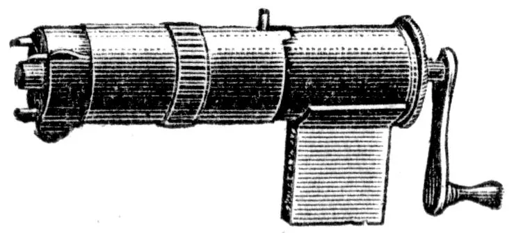
Do not be deceived by an “IMITATION” when you can get the
Genuine Webster-Whitcomb for $36.00.
By the introduction of special and costly tools we have
brought the price of Lathes down from $80.00 in 1876, to
$36.00 in 1894. Who has done more for the craft than we?
SEND for Price List and NOTE reductions.
Remember our full address.
Benj. Allen & Co.
141-143 STATE ST., CHICAGO, ILL.
Watch Materials, Tools and Jewelers’ Supplies.
THE MOST COMPLETE STOCK.
LOWEST PRICES. BEST GOODS.
“Diamond” Brand Pin Tongues, put up in neat box, partitioned off, each size
separate, warranted the best and stiffest Pins in the market, per gross - $1.00.
All Orders Filled Accurately and
Without Delay.
SEND FOR ILLUSTRATED CATALOGUE.
Watches, Clocks, Diamonds,
Jewelry and Silverware.
The Watchmakers’ Hand Book
INTENDED AS A WORKSHOP COMPANION FOR THOSE ENGAGED
IN WATCHMAKING AND ALLIED MECHANICAL ARTS
BY CLAUDIUS SAUNIER
ILLUSTRATED AMERICAN EDITION
REVISED AND ENLARGED BY
HENRY G. ABBOTT
WITH SPECIAL REFERENCE TO THE WANTS OF AMERICAN WORKMEN
CHICAGO:
GEO. K. HAZLITT & CO., Publishers.
1894.
COPYRIGHTED 1892, BY GEO. K. HAZLITT & CO.
PREFACE.
M. Saunier’s writings occupy an unique position in
Europe, as works of reference for all who are engaged
in watchmaking, and it may not be out of place to observe
that the American edition of his treatise promises to take
a similar place among English-speaking communities.
A glance at the index will show that the information
given is essentially practical in its character, and such as
will be of use to the watchmaker in his daily work. The
volume is thus in no sense an abridgment of the original
edition, but on the contrary, it contains much more matter
than the original work.
In recent years the work of the ordinary watch
repairer has undergone considerable change. The
apprenticeship he serves, if indeed it can be called a real
apprenticeship, is shorter than formerly. The immense
number of badly constructed watches that he is called
upon to put in going order for a trifling remuneration,
compels him to replace the older methods of procedure
by others, whenever by so doing time can be saved.
From this point of view, then, the value of the present
Hand Book can hardly be over-estimated, since it contains,
in a readily accessible form, many details as to the
working of metals, and descriptions of various practical
operations, new and improved forms of tools, etc.
But the volume will be found of daily use to a wider
circle of workers than those above referred to. We
believe that there is hardly a branch of the watchmaking
trade which may not benefit by the numerous practical
details that are given; indeed, although the work is
specially designed for the use of watchmakers, a great
portion of it will be seen to be no less applicable to other
mechanical arts.
M. Saunier’s original works, the Guide-Manuel de
l’Horloger, and Recueil des Procedes Pratiques, which
appeared as separate volumes, have been incorporated in
this American edition, a large amount of additional information
being at the same time added. As the second
contained many details that more properly belonged to
the first, and vice versa, it has been thought desirable to
remodel the whole, and, as will be seen from an examination,
the six parts that constitute the work are distinct
in their character.
With a view to further facilitate the use of this Hand
Book as a work of daily reference, an unusually full index
has been added, which the reader is recommended in all
cases to consult, and no effort has been spared to make
the cross references in the body of the work as complete
as possible.
It seems desirable here to give some explanation in
regard to several of the practical methods described.
Every watchmaker will at once recognize that recipes
are included which are of the nature of makeshifts, and
that it would in many cases be better to replace a piece
by a new one rather than to repair it in the manner indicated.
But, on the other hand, it has been felt that the
work will often be appealed to by those who, from various
circumstances, may be prevented from making or
procuring a new part that will suit the watch under
repair, while those who are not so situated will have no
difficulty in deciding for themselves as to which method
to adopt.
The original work of M. Saunier, and the English
edition, both had the illustrations in the back of the work,
which necessitated considerable inconvenience when consulting
them. In this edition we have ventured to insert
the illustrations in the text that describes them. The
antiquated tools, like the bow, bow-lathe, the turns and
mandril, have been omitted, and the modern foot-wheel,
lathe and accessories substituted.
Henry G. Abbott
INDEX.
NOTE—The references are in all cases to the pages, not to the paragraphs.
PART I . ARITHMETIC, GEOMETRY, DRAWING, ETC. — ARITHMETIC. — SOME SIGNS EMPLOYED IN CALCULATIONS. — POWERS AND ROOTS. — PROPORTION. — ELEMENTS OF PRACTICAL GEOMETRY. — GEOMETRICAL DRAWING. — DRAWING INSTRUMENTS. — GEOMETRICAL DRAWINGS. — THE MICROMETRICAL DIVIDING TABLE. — OTHER METHODS OF DIVIDING INTO EQUAL PARTS. — TO SUBDIVIDE A CIRCLE. — TIME. — FOOTNOTES:
THE Watchmakers’ Hand Book.
1. We often hear the theory advanced that in this
country, at the present day, it is not necessary to have a
knowledge of arithmetic, geometry, drawing, etc.,
because our interchangeable system of manufacturing
watches, makes all knowledge in these lines superfluous,
and that without any knowledge of arithmetic or geometry
a man may become a thorough master of watchmaking.
This is a mistake that too many of our young
men make. The fact that the leading watch factories of
the United States have adopted the interchangeable system,
of course lessens the number of parts which the
repairer will have to make and fit, but it by no means alters
the situation as regards the repairing of foreign-made
watches, nor even the changing of American watches
from key to stem-winders. Without a thorough knowledge
of arithmetic and, at least, an insight into the principles
of geometry, no young man can hope to become a
first-class watchmaker in the true sense of the word.
Without these accomplishments he will be deprived of
the pleasure of reading understandingly the best literature
of the day, the works of those who are best fitted
to impart knowledge to the members of the trade.
With a knowledge of geometry he will be able to comprehend
the works of the best authors, to ascertain the
dimensions of solid bodies, and be in a position to apply
the rules that form the basis of linear drawing. Every
watchmaker, worthy of the name, should be able to
make and understand the drawing of any machine, or of
any horological instrument. Many inventors, and even
ordinary workmen, would avoid a large amount of hard
work, often useless, and occupying much time, if, instead
of at once putting an idea into practice with brass and
steel, they were able as a preliminary, to make for themselves
a correct design drawn to scale.
2. It is taken for granted that the reader is familiar
with the rules of arithmetic at least, and we will touch upon
some points in algebra and geometry that it will be well
to mention. Should the reader have no knowledge of
arithmetic, algebra and geometry, we would advise him
to take up these studies during his leisure hours, using
some of the standard text books for that purpose.[1]
Besides possessing a knowledge of prime numbers, numbers
which have no divisors but unity and themselves,
the watchmaker should be able to determine the greatest
common measure of several numbers, a rule which is of
great importance in calculating a train of wheels that
is complicated.
We shall confine our attention to the methods of extracting
square roots and proportions, the rules for which may
have been forgotten, owing to their being less frequently
employed than the more common rules of arithmetic;
they are of frequent use in horology.
3. The sign of addition is an erect cross, +, called
plus, and when placed between two quantities it indicates
that the second is to be added to the first. Thus, 5 + 3
equals 8.
The sign of subtraction is a short horizontal line, -,
called minus, and when placed between two quantities it
indicates that the second is to be subtracted from the first.
Thus, 8 - 3 equals 5.
The double sign, ±, is sometimes written before a
quantity to indicate that in certain cases it is to be added
and in others it is to be subtracted. Thus 5 ± 3 is read
5 plus or minus 3.
The sign of multiplication, ×, when placed between
two quantities indicates that the first is to be multiplied
by the second. Thus, 3 × 5 equals 15.
The sign of division is a short horizontal line with a
point above and one below, ÷, and when placed between
two numbers or quantities it indicates that the first is to
be divided by the second. Thus, 6 ÷ 2 equals 3.
The sign of equality is two short, horizontal, parallel
lines, =, representing the words equal to. Thus,
6 ÷ 2 = 3.
Inequality is denoted by the angle >, the opening
always being toward the larger number or quantity; thus,
in 12 + 7 > 14, the sign >, indicates that the sum of 12
and 7 is greater than 14, and the whole expression is
read, 12 plus 7 is greater than 14. The expression
9 < 4 + 7 is read, 9 is less than 4 plus 7.
A parenthesis, (), denotes that the several numbers or
quantities included within it are to be considered together,
and subjected to the same operation. Thus, (10 + 4) × 3
indicates that both 10 and 4, or their sum, are to be multiplied
by 3.
A horizontal vinculum, ———, placed over the numbers
or quantities, is frequently used instead of the parenthesis.
Thus, 2 + 4 + 6 × 7 is
equivalent to (2 + 4 + 6) × 7.
Division is more usually indicated by a line between
the two figures, the dividend being written above and the
divisor below the line. Thus, ¹⁶⁄₈ indicates division, the
same as 16 ÷ 8.
Algebra is that branch of mathematics in which the
operations are indicated by signs or symbols, and the
quantities are represented by letters.
The sign of ratio consists of two points like the colon,
:, placed between the quantities compared. Thus, the
ratio of a to b is written a : b.
The sign of proportion consists of a combination of
the signs of ratio. Thus, : :: : . The first two and
last two dots are read is to, while the four in the middle
are read as. Thus, if a, b, c, and d, are four quantities
which are proportional to each other, we say a is to b as
c is to d, and this is expressed by writing them thus:
a : b :: c : d.
4. The power of a number is the product formed by
successive multiplication of the same number by itself.
Thus,
2 × 2 = 4, the second power or square of 2.
2 × 2 × 2 = 8, the third power or cube of 2.
2 × 2 × 2 × 2 = 16, the fourth power of 2, etc.
An exponent is a number written above a quantity, at
the right-hand, to indicate how many times the quantity
is to be taken as a factor, as 63 = 6 × 6 × 6.
The root of a quantity is a factor which, multiplied by
itself a certain number of times, will produce the given
quantity. Thus, in the above examples 2 is the square
root of 4 and the cube root of 8.
The radical sign, √, indicates that the root of the
quantity placed under it is to be taken, and the index of
the root is expressed by a little figure placed outside of
the bend. If a square root the index figure is usually
omitted.
√4 = 2 or
²√4 = 2 and
³√8 = 2.
5. Extracting the square root of whole numbers.[2]I. Point the given number off into periods of two
figures each, counting from the units place to the left.
For example, we wish to find the square root of 399424,
we point it off thus: 39,94,24.
II. Find the greatest perfect square in the left-hand
period, and write its root for the first figure in the required
root; subtract the square of this figure from the first
period, and to the remainder bring down the next period
for a dividend. Thus:
39,94,24(6 36 394
III. Double the root already found, and write the
result on the left for a divisor; find how many times this
divisor is contained in the dividend, exclusive of the right-hand
figure, and place the result in the root and at the
right of the divisor. Thus:
39,94,24(63 36
123 394
IV. Multiply the divisor thus completed by the last
figure of the root; subtract the product from the dividend,
and to the remainder bring down the next period
for a new dividend. Thus:
39,94,24(63 36
123 394 369 2524
V. Double the right-hand figure of the last complete
divisor for a new divisor, and continue the operation as
before. Thus:
39,94,24(632 36
123 394 369
12622524 2524
6. It is often convenient to express the relations of
qualities in the form of a proportion and from the proportion
derive an equation.
Ratio is the quotient of one number divided by another.
Thus the ratio of 30 to 6 is ³⁰⁄₆.
7. Proportion is the equality of ratios: Thus if
³⁰⁄₆ = 5 and ⁴⁰⁄₈ = 5 then we may state that ³⁰⁄₆ = ⁴⁰⁄₈
or the proportionality is usually expressed (3) thus:
30 : 6 :: 40 : 8
and this constitutes what is called a geometrical proportion,
and 30 and 8 are called the extremes and 6 and 40
the means.
8. The product of the extremes is always equal to
the product of the means. Thus: 30 × 8 = 6 × 40 = 240.
Hence it follows that if we only know three terms we
can always determine the fourth, or unknown term,
which is usually represented by the letter x. Thus in
the proportion
12 : 3 :: 16 : x
we find the product of the means, or 3 × 16 = 48; this
product divided by 12, the known extreme, gives us the
value of x, or the unknown extreme, as equalling 4.
9. If we know the two extremes and only one of the
means the same rule is applied. Thus in the proportion
20 : 5 :: x : 25,
we have: 20 × 25 = 500.
⁵⁰⁰⁄₅ = 100, the value of x.
10. The object of geometry is to measure the extent
of bodies. A body has three dimensions, length, breadth
and thickness, and one of these latter is sometimes termed
weight or depth.
Either dimension taken by itself is measured by a
straight line.
When the extent of a body is expressed by combining
any two dimensions, it is termed area or surface, and when
three are employed we obtain the solid measure or volume.
Plane geometry only takes cognizance of figures situated
in one plane or surface, and therefore only possessing
two dimensions; solid geometry, however, regards bodies
as having all three dimensions.
Two lines are parallel when their distance apart is
the same at all points. The same is also applicable to
parallel planes.
Two lines or planes meeting each other will form an
angle. The point at which they meet or intersect is
termed the apex or summit of the angle.
A straight line is perpendicular or at right angles to
another straight line, or to a plane, when all the angles
which it makes with that line or plane are equal.
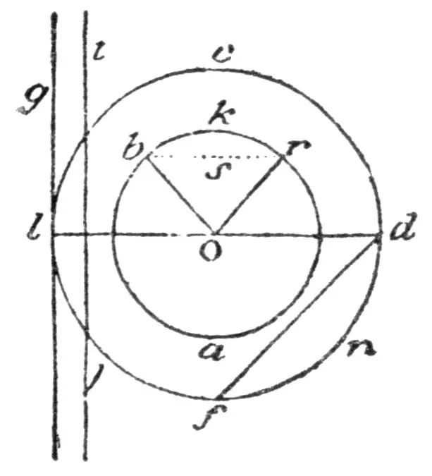
A circumference of a circle is a curved line l c d ffig. 1,) such that all its points are equally distant from an internal
point, o, termed the center. The circle is the space
enclosed by the circumference.
It will be noticed that in geometry these two words are
distinguished, although they are frequently referred to as
identical. Thus, the rim of a wheel or balance is generally
termed a circle.
Two circles (l c d f and b r a, fig. 1,) described from
the same center are said to be concentric. When their
centers do not coincide they are called excentric with regard
to one another.
Any portion of a circumference, such as f n d, is termed
an arc of the circumference, or, more commonly an arc
of a circle.
A chord is a straight line, f d, which unites the two extremities
of an arc. When the chord passes through the
center of a circle it is termed a diameter.
The radius of a circle or circumference is a straight
line drawn from the center to the circumference; and all
the radii that can be thus drawn are equal. A diameter
is, then, always double the radius, and, conversely, the
radius, is always half the diameter.
A tangent is a straight line that only touches a circumference
at one point, as g l (fig. 1); whereas a secant cuts
the circle, as i j.
A circumference is assumed to be divided into 360
equal parts, termed degrees. The degree is subdivided
into sixty equal parts, or minutes, and the minute into 60
seconds. These are respectively symbolized by the marks
° ′ ″ placed at the right-hand top corner of the figure.
Such an expression as 18° 30′ 15.5″ would, then, be
read 18 degrees, 30 minutes, and 15.5 seconds.
11.Ratio of the circumference to the diameter.
The diameter of a circle is to the circumference
as 7: 22; or, employing decimal
fractions, as 1: 3.14159 (a number which,
in algebra, is always represented by the
Greek letter π.)
Fig. 1.
Knowing a diameter (D), the circumference,
x, can be ascertained from the
proportion:—
1: 3.14159:: D: x.
Knowing a circumference (C), the diameter, x, can be
determined from the proportion:—
3.14159: 1:: C: x.
The latter proportion will also give the value of the
radius, which is half a diameter.
12. The superficial area of a circle is equal to the circumference
multiplied by half the radius, or to the square
of the radius multiplied by 3.14159.
A sector is the circle enclosed between an arc and two
radii bounding it, as bOr k (fig. 1.)
The area or surface of a sector can be ascertained by
multiplying the length of the arc by half the radius.
A segment of a circle is the portion intercepted between
an arc and its chord, as f d n (fig. 1.)
The surface of a segment, as b k r s, can be obtained
by subtracting from the area of the sector Ob k r, the
area of the triangle, b rO (15).
13.Ring. To determine the surface of a flat ring, the
area of the inner circle must be subtracted from that of
the outer circle; in other words, take the difference
between the areas of the two circles that fix the inner
and outer diameters of the ring.
The area of a flat ring can also be calculated by adding
together the internal and external diameters; then multiply
the number so obtained by their difference and by the
decimal fraction 0.7854 (that is, 3.1415/4). The product
will be the required area.
14.Angles and their measurement. When two lines
meet one another, they form an angle, as we have
already seen. If we take the apex as the center of a
circle, the number of degrees intercepted between the
two straight lines gives a measure of this angle.
The angle measured by a quarter of a circumference,
or 90°, is termed a right angle.
An obtuse angle is greater than a right angle, and an
angle that is less is termed an acute angle.
15.Triangles, squares, etc., and their measurement.
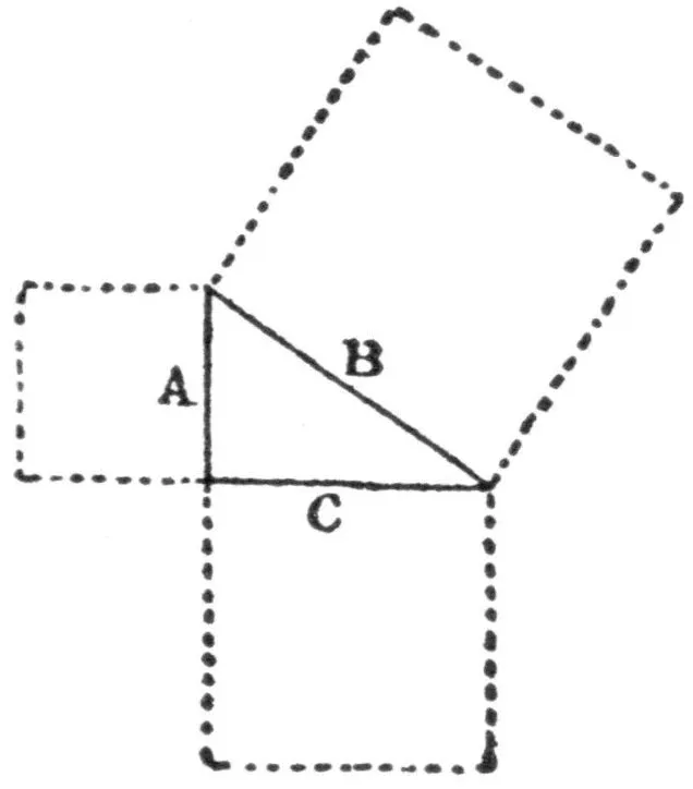
The triangle or plane area enclosed within three
straight lines joined two and two together (A,
B, C,
fig. 2,)
is said to be rectangular when one of its angles is a right
angle; it is equilateral when the three sides are equal,
under which circumstances the three angles are also equal;
and isosceles when only two sides are of equal length.
The sum of the three angles of a triangle is always
equal to two right angles. If only two of the angles are
known, it is thus easy to determine the third.
Similar triangles are characterized by the fact that
their homologous sides (that is, the sides opposite to
equal angles) are proportional.
Peculiarity of the right-angled triangle. The square
described on the longest side, termed the hypothenuse
(B, fig. 2,) is equal to the sum of the
squares described on the two other
sides. Hence, it follows that, if the
lengths of the two shorter sides are
known, that of the hypothenuse can be
ascertained by extracting the square
root of the number formed by adding
together the squares formed on these
two sides (5).
Fig. 2.
If the hypothenuse is known and one of the shorter
sides, the third can be determined by extracting the square
root of the number formed by subtracting the square
of the known side from the square of the hypothenuse.
The surface of a triangle is determined by multiplying
one of the sides by half the perpendicular height of the
angle opposite to this side.
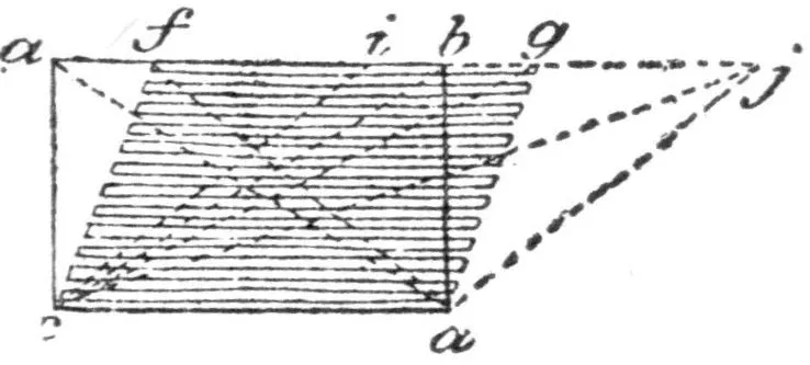
16. The surface of a square or of an oblong or rectangle
(a b c d, fig. 3) is equal to the product of the base multiplied
by the height.
The sum of the squares described on the four sides is
equal to twice the square described on a diagonal. This
diagonal divides the rectangle into two equal rectangular
triangles.
17. The surface of a parallelogram or lozenge, a plane
figure with four sides, opposite pairs
of which are parallel (c f g d and c
i j d, fig. 3,) is equal to the product
of one side multiplied by the perpendicular
height of the figure.
Fig. 3.
The sum of the squares described on the four sides
of a parallelogram is equal to the sum of the squares
described on the two diagonals.
18.Measures of various solid bodies. The volume
of a cube of parallelopiped (that is, a body bounded
by six four-sided figures, every opposite two of which
are parallel) is obtained by multiplying the surface of
the base by the height.
The volume of a straight cylinder is the product of
the surface of the circle which forms its base into the
height of the cylinder.
The area of the curved surface of a cylinder is obtained
by multiplying the circumference of the circle
forming its base by the height.
The volume of a tube or cylindrical ring of rectangular
section, such as the arbor-nut of a barrel, or the
rim of a circular balance, etc., is equal to the product
of the plane surface of its base (13) into its height.
The volume of a right cone or of a regular pyramid is
the product of the base into a third of the height.
The surface of a sphere may be determined by multiplying
the square of the diameter by 3.1416 (11).
The volume of a sphere is equal to this surface multiplied
by a third of the radius.
19. An elementary knowledge of the art of drawing,
an ability to represent the outlines of objects by simple
lines, is of the first importance to the watchmaker.
Such a design is obtained by projecting on to one plane
all the visible points of the object represented.
Projection on a vertical plane gives an elevation; the
object is looked at from one side.
Projection on to a
horizontal plane
produces a plan; the object is observed from above, thus giving
a bird’s-eye view.
The projection of a point on a vertical or horizontal
plane is the foot of the perpendicular, from the given point
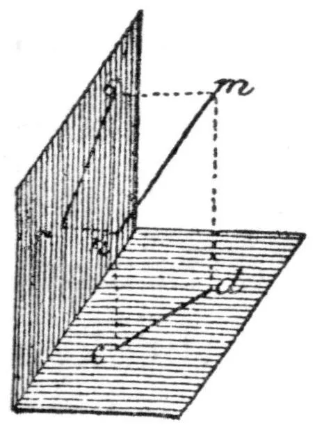
on to the plane. Assume the line n m (fig. 4), to be fixed
in space; its horizontal projection will give
c d, and its vertical projection, r s.
Fig. 4.
Miscellaneous details. When one portion
of the object to be represented is found to
pass behind other pieces so that it cannot be
seen, the continuation is frequently indicated
by dotted lines.
Surfaces that are situated in planes one behind the other
are shaded, the more deeply according as they are farther
back. This shading is produced by a number of
parallel lines which may be vertical or horizontal.
Parts that are in relief are indicated by projected
shadows, or by increasing the thickness of a line that
would cast a shadow.
In order to distinguish the several shadings or to emphasize
the lines by which they are separated, it is a very
usual, though not invariable practice to assume the light
to be coming from the left-hand upper corner.
When drawing a square in relief, such as a b c d (fig. 3),
the lines c d b d, will be made darkest; but if it is a recess,
the lines a b, a c should be brought into prominence by
means of dark lines.
Fig. 5.
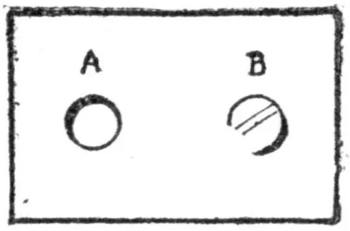
These several directions will be found useful when a
hole, any cavity, a pin, a round object etc.,
has to be depicted, as in fig. 5. As a
general rule, the thick lines should indicate
the position at which a shadow would
form, the light being assumed to fall on
the drawing in the manner indicated above.
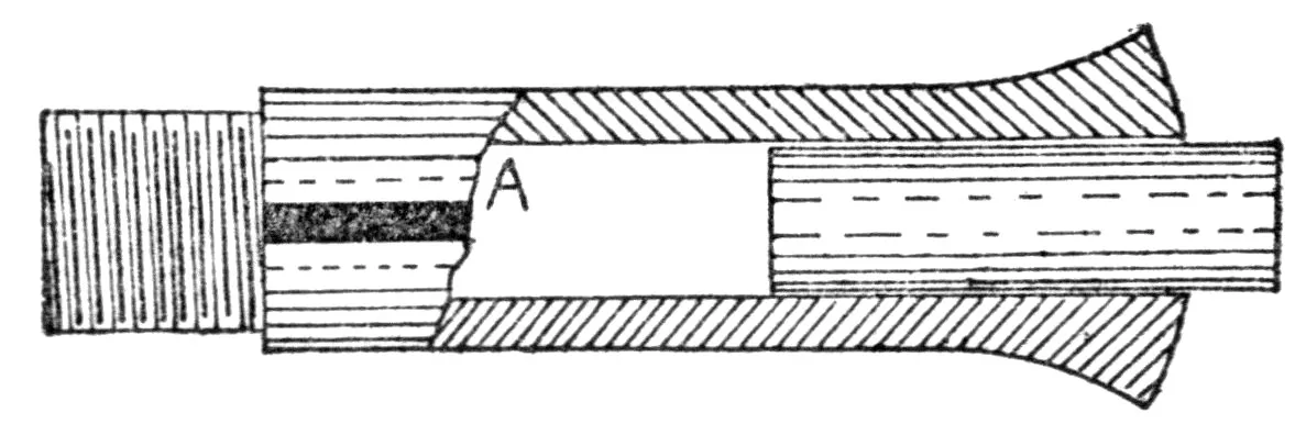
A section shows a body as it would appear if cut in
two, and one portion removed in order to expose the
interior, as in fig. 6. A section is indicated by a series of
parallel lines drawn close together and at an inclination of
about 45° to the vertical.
Fig. 6.
In order to leave more
room for important details,
or to show objects
that are situated behind,
a piece is often broken
off by an irregular line, as shown in that drawing.
Lines formed by a series of detached points sometimes
serve as a means of associating several figures representing
the same object looked as in different directions.
20.Tracing and transfering. These two operations
are resorted to when it is required to obtain one or more
copies of a picture or design already drawn.
Tracing consists in laying a piece of tissue or other
translucent paper over the drawing and copying it by
following over the lines that are visible with a pencil. Or
ordinary paper can be used for the purpose, providing it
is not too thick, if the picture be placed against the pane
of a window or, what is more convenient, on a sheet of
glass used as a desk and illuminated from below. When
either sheet of paper is too thick to allow sufficient light
to pass, one or other of the methods of transfering indicated
below must be resorted to.
21. This operation consists in reproducing a tracing on
a separate sheet of paper or on metal that is to be
engraved. Either of the following methods may be
adopted:
1. The picture to be transferred is fixed to a table or
drawing board if tracing paper is to be used, or to a
sheet of glass if only ordinary paper is available. The
lines are then traced with a black lead pencil that must
not be too hard. When this is finished it is laid, face
downwards, on a sheet of white paper, taking care that
both sheets are so fixed that they shall not slip. Apply
pressure to the upper surface by tapping with a small
pad made on purpose and, at the same time, gently
rubbing. Experience will very soon show how hard
the pad should be. Now remove the tracing, still
taking care to avoid any slipping, and a faint reproduction
of the design will be found on the lower sheet
of paper. It is only necessary to follow over the lines
with India ink. The figures will be reversed but a
transfer with it in the original direction may be
obtained by inverting the picture and laying it on glass
so as to make a reverse tracing.
2. Lay the picture on a desk or drawing board
and trace it with ink on a very transparent sheet of
paper. When the ink is dry, invert the tracing and
blacken the back with a No. 2 pencil. Now lay the
tracing, with the ink side uppermost, on a sheet of
clean paper, taking care to avoid slipping, and go over
the several lines with an agate or metal style, avoiding
excessive pressure on account of the risk of tearing
the paper. On removing the upper sheet an impression
will be found not reversed. Go over all the lines
with India ink and clean the paper with India-rubber
or stale bread.
Observations. The choice of paper and pencil is not a
matter of indifference. All kinds of paper do not
receive an impression equally well, neither do all pencils
transfer with equal facility. The Faber pencil No. 3,
will generally be found best suited to such work.
In preparing drawings which you desire to preserve,
as drawings of escapements, etc., a good quality of light
weight bristol board will be found more desirable than the
best drawing papers. White wedding bristol, about two-ply
in thickness, answers admirably, and India ink lines
drawn upon it will not spread as they often do on
drawing papers. The prepared liquid India inks now
on the market are superior to any you can prepare by
grinding the sticks.
22.To transfer an engraved design. This method
is available when it is desired to obtain an impression, for
example, of the engraved surface of a watch case.
Procure some of the inks used by copper-plate engravers,
or, in its absence, ordinary stencil ink may be used.
Taking a small quantity on the end of the finger, tap it
on the surface of a glass plate, in order that the ink may
be distributed, leaving only a small quantity evenly spread
over the finger: tap with the finger thus prepared over
the watch case long enough to make sure that all
the surface in relief has received some ink; take a piece
of writing paper and, after slightly moistening it,
spread it over this surface. Lay above this a piece of
paper folded in four and pass over it in all directions
any round body, such as a small tool handle, and with
some pressure; then raise the papers without allowing
them to slide.
If the operation has been carefully performed a very
clear impression will thus be obtained of the engraved
surface. The relief will be black and the hollows white,
but, of course, the figure is reversed like that in a looking-glass.
If required in the right direction it must be traced
through to the other side of the paper.
23. It is needless here to describe the rule, set-square,
T-square, bow-compass, etc., as every one knows them.
To verify the accuracy of a rule. On a perfectly flat
smooth surface carefully draw, with the rule in question, a
fine straight line. Then turn the rule over, hinging it as
it were on the line just drawn; if quite straight the edge
of the rule will exactly coincide with the line, in this new
position, throughout its entire length. Each edge should
be thus examined.
To verify the accuracy of a set-square. Having fixed an
accurate rule on a smooth surface, place one edge of the
set-square against it, and draw a line along the edge perpendicular
to the rule; then, having turned the set-square,
hinging it on the line just drawn, bring it against the rule
and along the line. If the square is true the edge and
line will coincide throughout their length.
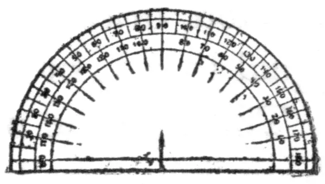
24.The Protractor.Fig. 7 represents a common
form of this instrument. It is made of horn, or, if of
metal, the inner portion is cut away,
leaving only a base and a semicircular
arc, which is divided into 180 equal
parts or degrees; a complete circle
would therefore consist of 360 such
degree. The point indicating the center of the arc,
should be very small in order to facilitate the exact setting
of it at the apex of an angle.
Fig. 7.
When an angle has to be drawn with accuracy, the
protractor is unsuitable; it will be better to adopt one of
the methods described at paragraph 37, or trigonometrical
methods.
25.Drawing scales. When an object is represented
by a drawing, if the dimensions are the same as those of
the object itself, or, rather, as they would project on to a
horizontal or vertical plane, the drawing is said to be full
size; but the object is generally represented either on an
increased or diminished scale, which is defined, the proportions
between all the parts being still, however, maintained
the same.
With a view to avoid the many calculations that such
a change would involve, it is usual to employ drawing
scales. The following notes will sufficiently explain their
construction and use.
Let it be required to reproduce a large drawing on a
small scale, in such a proportion that the dimensions are
reduced in the ratio of 10 to 1.
Fig. 8.
Take a straight line of indefinite length, a b, fig. 8, and
mark out on it spaces equal to a 1, which represents any
measurement taken on the original object; at c, the 10th
division, draw a perpendicular, and on it measure c g
equal to a 1, or one-tenth of a c and join a g.
Through the points indicating the divisions into tenths
draw lines parallel to c g, and you will thus have a series
of triangles, d a 1, d′ a 2, d″ a 3, etc., similar to the triangle
g a c. In virtue of a well-known property of such
triangles (15), d 1 will be one-tenth of a 1; d′ 2 one-tenth
of a 2; and so on.
Thus, if a measurement taken on the object, or on a
large drawing, is equal to a x, it will only be needful to
turn the compass on the point x as a center, and to observe
accurately the perpendicular height, x z, to ascertain
the corresponding measurement on the reduced scale.
Such a scale can be employed to measure meters and
decimeters, or feet and inches (but in this latter case, it
would have been necessary to mark off 12 instead of 10
divisions from a). Since a 1 might be made to represent
one metre; a 2, two meters, etc., in virtue of the principle
of the triangle already referred to, d 1 will be the tenth
of a 1, and will therefore represent a decimeter; d′ 2 will
represent 2 decimeters, etc. The length required to represent,
say 5.3 will be ascertained by taking the distance
a 5, to which the distance d″ 3 is added. Similarly 6 feet
2 inches would be given by a 6, to which d′ 2 is added
on a 12-division scale.
26. The following description of one of these decimal
scales, which is engraved on metal or ivory, and often
included in cases of drawing instruments, will suffice to
enable any one to construct a scale on this principle, that
goes to a still further degree of accuracy, measuring, for
example, meters, decimeters and millimeters, or yards,
feet and inches.
Fig. 9.
Let A B, fig. 9, be a flat rectangular rule, divided
throughout its length by parallel equidistant lines into ten
strips. At right angles to these are the lines o o′, a a′,
etc., separated from one another by a distance of one
centimeter (doubled in the drawing in order to make the
details more clear.) The first centimeter is subdivided
along the two edges, Ao, n′ o, into 10 equal parts or
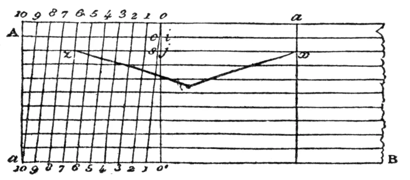
millimeters, and the division, o, on the upper edge is
joined by an oblique line with the 1 on the lower edge,
and the others by parallel oblique lines as shown in the
figure. Thus c i will be one-tenth of a millimeter, s j
two-tenths, and so on.
If the compass is opened so as to reach from x to z, it
will be seen that it covers a space of 16 millimeters and
2-10ths of a millimeter, for there are one large division
(or 10 mm.), 6 smaller divisions (or millimeters) plus a
fraction of a millimeter equal to s j or 2-10ths of a
millimeter.
27.Sector. When it is required to reduce the scale
of a drawing, subject to the condition that the dimensions
shall be all diminished in the ratio of two given lines, we
may state the problem thus:
The longer of the two given lines is to the shorter, as
any given dimensions of the old drawing is to x. The
value of x thus determined will be the
corresponding dimension of the new
figure.
Such a rule of three proposition would involve a considerable amount
of work, and the required result can be arrived at with greater facility by the geometrical methods which forms the
basis of the scale just described, or, better still, by using the
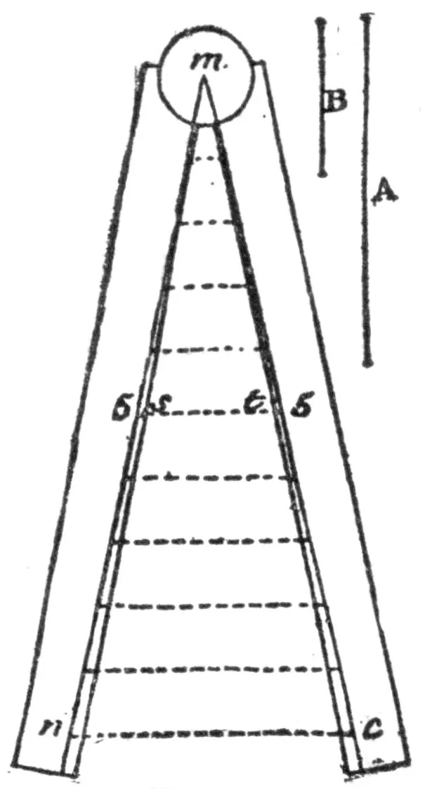
sector shown in fig. 10. It consists of two brass or ivory legs hinged
about a center m which is at the apex of the angle n m c
formed by two straight lines similarly divided into equal parts.
Fig. 10.
It is employed as follows: Let us assume that a drawing
has to be reduced in the ratio of the line A to the
line B; set off the length A along m n, and suppose its
extremity to be at s, where division number 5 occurs.
Open a compass to a distance equal to B, and placing one
point on s, open the two legs of the scale until the second
point coincides exactly with the corresponding division t,
that is, with the 5 on the other leg, m c. Maintaining the
scale open to this amount, it is only needful, after measuring
a distance on the original drawing or object, to
set it off along m n, and to measure the distance between
its extremity and the corresponding point on the
other leg; this distance will be the dimension on the
reduced scale.
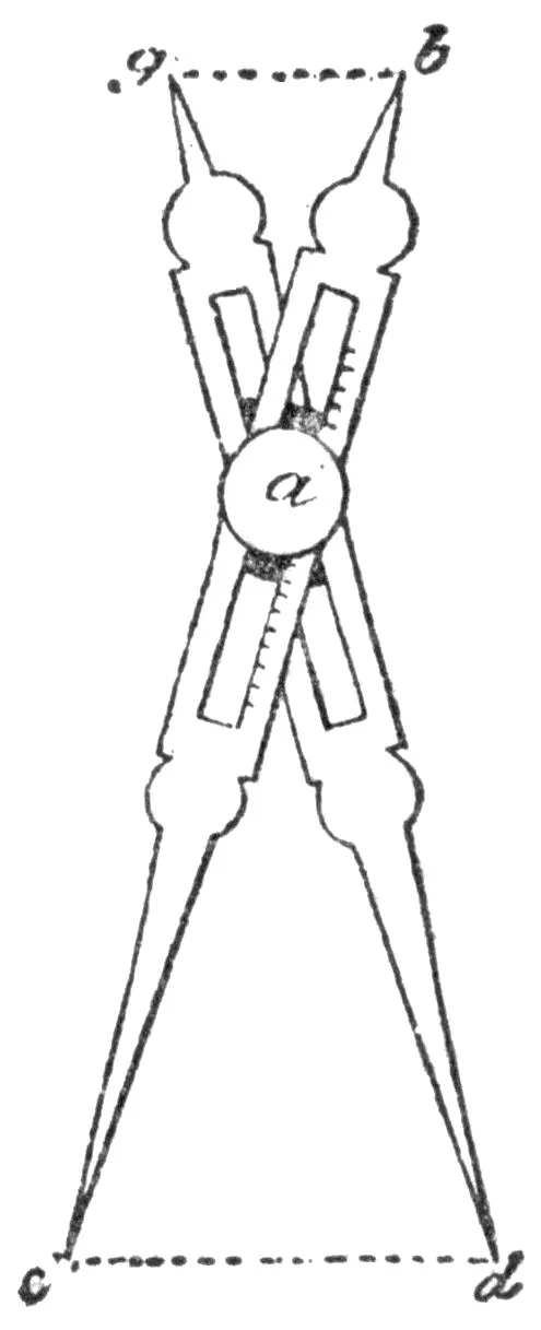
28.Proportional compass. This consists of two
equal stems terminating with points, fig. 11.
They are cut through for a portion of their
length, and provided with a slide forming a
hinge, that can be clamped by a screw a in
any position. Graduations on the two slots
and a mark on the slide indicate in what
position of the slide a, the length a b (equal
to a g) is equal to ½, ⅛, ¼, etc., of a d; and
thus show what is the ratio of g b to c d,
a ratio which is independent of the extent
to which the arms are opened.
Fig. 11.
29.The vernier. The vernier consists
of a small graduated slide which is adapted
to a graduated rule or circular arc with a view to ascertain
the value of small fractional parts of the divisions
marked on the rule or arc.
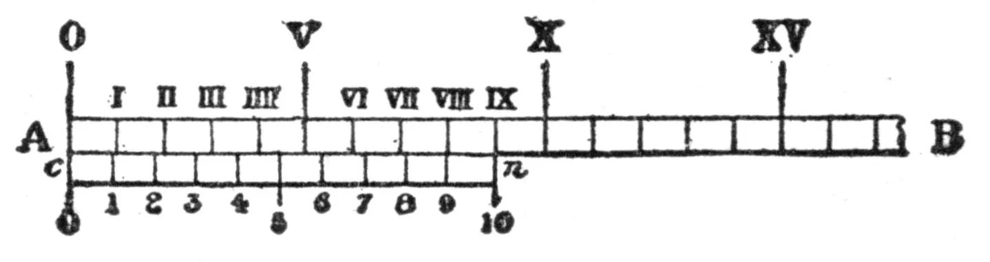
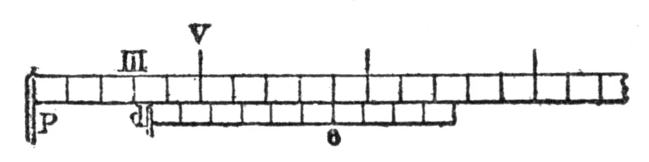
Let A B, in fig. 12, be a rule divided into millimeters
(the proportions are enlarged in the drawing so as to
avoid confusion among the lines), and let it be required
to determine a length to within the tenth of a millimeter.
As the measurement is required to the tenth, take ten
less one or nine of the divisions of the scale; they will
extend from O to IX, and this represents the acting length
of the vernier.
Subdivide the vernier into ten equal parts; it is
manifest that each graduation of the vernier differs from
the original subdivisions of the rule by 1-10th of a graduation
of the latter. In other words, unity on the vernier
is equal to 9-10ths of unity on the rule.
Fig. 12.
When the rule and vernier are placed as shown in
fig. 12, so that the o on both scales coincide, the successive
divisions on the rule (marked with Roman
numerals for distinction) will be progressively more and
more in advance of the corresponding divisions on the
vernier in the following proportion:—
The marks I and 1 are 1-10th apart; the marks II and
2, 2-10ths; III and 3, 3-10ths; and so on, the mark X
being 10-10ths, or one complete division in advance of
10, this division being a unit on the scale.
Thus if the vernier is caused to slide along the edge
of the rule, when 1 coincides with I the vernier has
advanced 1-10th; when 2 coincides with II, it has
advanced 2-10ths; and so on.
Let it be required to determine the distance Pd, fig. 13.
The division 6 on the vernier coincides with a division of
the scale; hence it follows that the extremity d of the
vernier is at a distance of 6-10ths millimeters from III,
the next division of the scale to the left. The distance
between P and d is thus 3.6 millimeters.
Fig. 13.
With a vernier showing tenths, if two consecutive
divisions of the vernier fall between two divisions on the
rule, and there does not appear to be a tendency
towards one side more than towards another, even when
observed with a strong glass, it is possible
to take an approximate reading to the
twentieth.
Fig. 14.
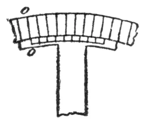
In measuring circular arcs a curved
vernier is used in place of a straight one,
and its graduations are made to correspond with those
on the circle as shown in fig. 14.
30.Micrometer screw. By employing a micrometer
screw it is possible to measure infinitesimal amounts,
but the screw must be perfectly accurate, and must work
without appreciable backlash or loss of time.
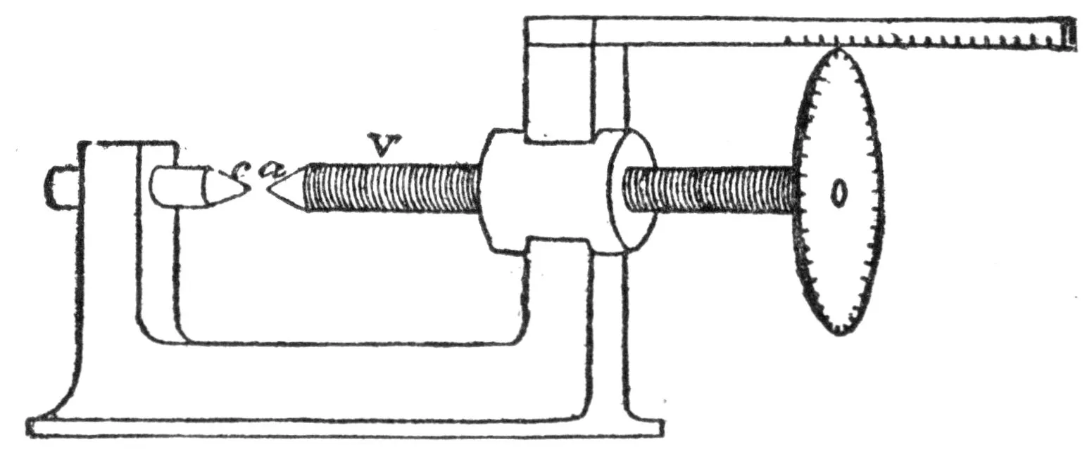
Fig. 15.
Assume V, fig. 15, to be such a screw, having a pitch
of 1 millimeter. It will advance by this amount with each
complete rotation.
To the head of the screw is attached a disc of such a
size that its rim can be divided into a number of equal
parts, say a hundred. These graduations may be marks
on the edge or notches cut in it when an index is
required to stop in them; but the index is less frequently
met with than a simple divided straight-edge almost in
contact with the disc. The divisions round the disc are
numbered in ascending order as the points c and a
separate, so that zero comes under the index or rule
when these points are in contact. Readings of the
numbers will thus afford a measure of the displacement
of the point of the screw.
When the disc is rotated the point a will move
towards or from c by 1-100th of a millimeter for each
division passing under the straight-edge, and one millimeter
for each complete rotation. It is thus possible to
obtain the dimensions of an object when it enters without
play between the two jaws to within an error of about
1-100th of a millimeter if the instrument is accurately
made.
If, instead of passing the object between the two jaws,
it is gripped by them, the measurement will be less exact,
as no account is taken of the pressure exerted and of the
elasticity. (44.)
31.Sketches. It is advisable from an early age to
accustom oneself to make rapid freehand sketches of
objects as they present themselves to the eye. Such a
sketch will help in the preparation of a more exact
drawing, which involves a knowledge of the several
geometrical methods given below.
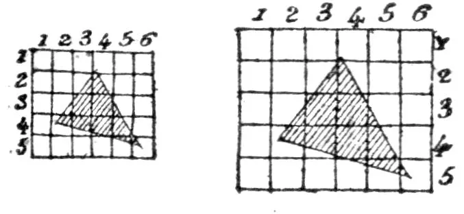
A drawing may be transferred, reduced or enlarged as
follows:
Draw across the original picture a number of equidistant
vertical and horizontal lines, forming perfect squares, and
number the two sets of lines in succession. Then draw
a similar series of lines on a clean sheet of paper, setting
the lines at an equal, less or greater distance apart, and
copy in succession the parts of the figure that are enclosed
within the several squares.
As it is not always possible to draw lines across a
figure, they may be replaced by a frame carrying fine
threads or wires stretched in the two directions. The
frame is laid over the original drawing, which can then
be copied, as above explained, on a sheet of paper divided
into squares (fig. 16).
Fig. 16.
The frame may, moreover, afford assistance in the
drawing of solid objects. Having placed it above or in
front of the object and in contact with
it, copy on to the sectional paper the
contents of each corresponding square,
taking care to look at the object perpendicularly.
With a little practice,
and by placing the eye in the correct position and always
at the same distance from the frame (a distance which
may be regulated by a glass), a sketch in fair proportion
may easily be obtained.
Fig. 17.
32.To erect a perpendicular on a straight line.
Either the compass or a set-square can be employed; the
use of the latter instrument is so simple that
no further reference need be made to it.
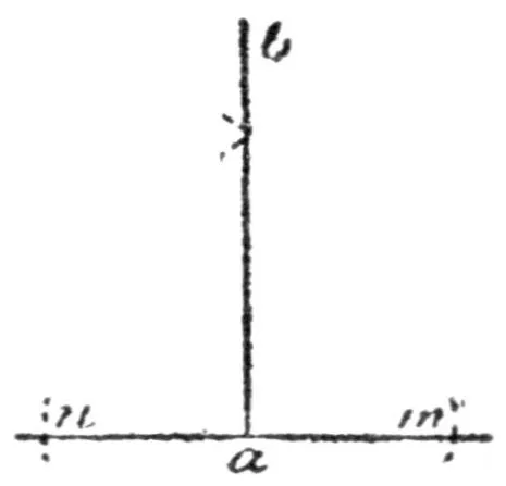
Assume a, fig. 17, to be the point in the line
n m at which a perpendicular is to be drawn.
On either side of a measure off equal
distances a n, a m; from n and m, with a radius about
equal to the distance n m, draw two circular arcs cutting
one another. If their point of intersection b be joined to
a, the line a b will be the required perpendicular.
Fig. 18.
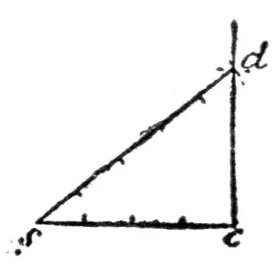
33.To erect a perpendicular at the extremity
of a line. From the extremity c, fig. 18,
mark off four equal parts towards s. From s,
with a radius equal to five such parts, describe
a circular arc, and from c, with a radius of
three such parts, describe another arc cutting
the first at d. The line joining c and d will be perpendicular
to s c.
For the square of 5 is 25, and this is equal to the
square of 4 or 16 plus the square of 3 or 9. Thus
the triangle s c d must be right-angled (15).
Fig. 19.
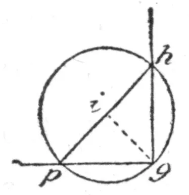
Or the following method may be adopted: With any
center i and radius i g (fig. 19), as large as possible,
describe a circumference passing through g.
From the point p, where the circle cuts the
line, draw the diameter p i h. If the point h
be joined to g, it is the required perpendicular;
for, by a property of the semicircle, the angle
h g p is a right angle.
Fig. 20.
34.To let fall a perpendicular on a straight
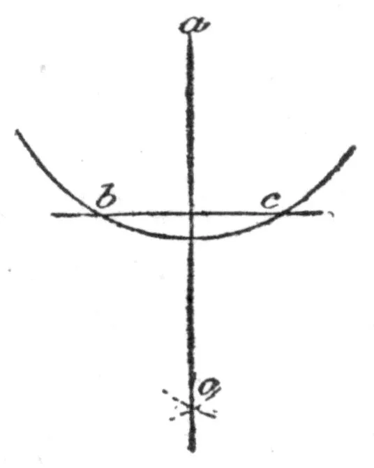
line. In order to let fall a perpendicular
from the point a on to the line b c (fig. 20),
describe from a as a center, a circular arc
sufficiently large, cutting the straight line
in two points, b and c. From these two
points, with the same opening of the compass,
draw on the under side of the line
two arcs that intersect. The point of intersection o
joined to a gives the required perpendicular.
Fig. 21.
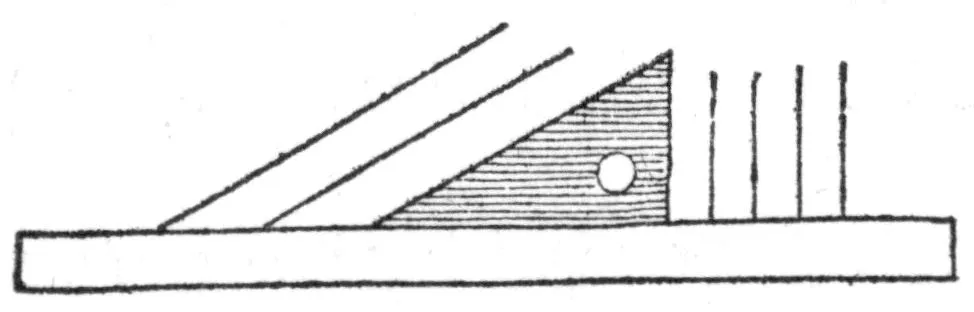
35.To draw parallel straight lines. Having fixed
a good straight-edge over the drawing, as many parallel
lines as are required may be
drawn with the aid of a set-square
which is caused to slide
along the rule. They will be
vertical, horizontal or inclined, according to the position
of the rule, which must be set exactly perpendicular to
the direction in which the parallel lines are to be drawn
(fig. 21).
Fig. 22.
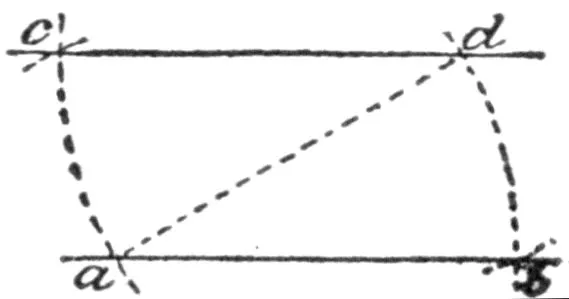
To draw, from a given point, a line parallel to a given
line. Let d be the given point, and a b the given line
(fig. 22). From d draw the circular arc a c, and from a
where it cuts a b, with the same radius
describe the arc d b. From a set off on
a c, a distance equal to d b. The line
joining d and c is the required parallel.
Fig. 23.
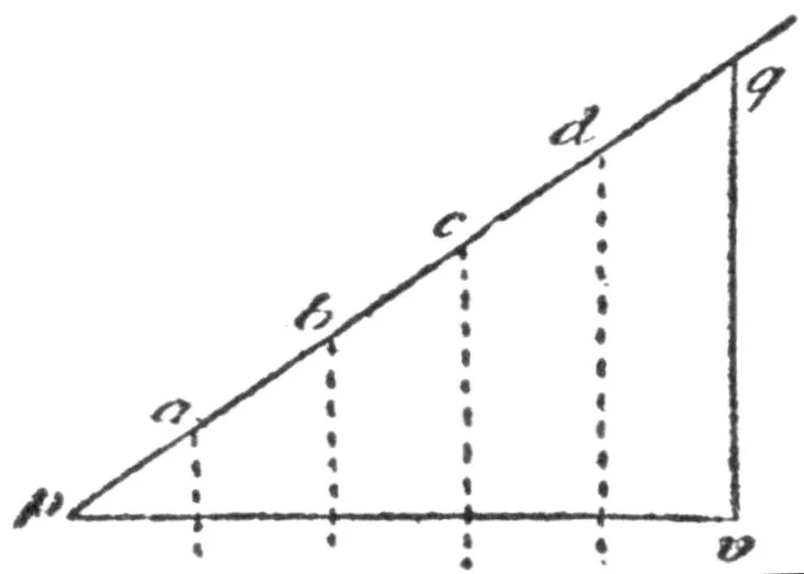
36.To subdivide a line into equal parts. Let it
be required to divide the line p v (fig. 23), into five equal
parts. Draw a line p q inclined at any angle, and mark
off on this line five equal parts of any length; join q, the
extremity of the five lengths, and v,
and through the points a, b, c, d, draw
lines parallel to q v. In virtue of a
property of similar triangles these
lines will divide p v into equal parts.
It is advisable that the lines p v and
p q should not differ very considerably in length, as,
otherwise the inclination of the parallel lines to p q will
render it difficult to observe the exact point of intersection.
Fig. 24.
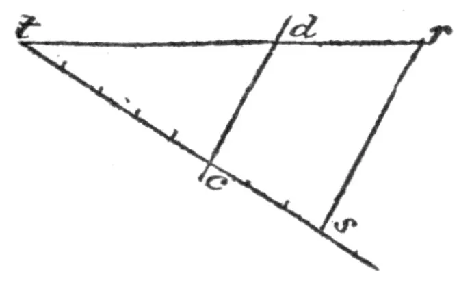
To divide a line into proportional parts. The proposition
can be solved in a similar manner. Let it be required
to divide a line t r (fig. 24), into two sections that are to
one another in the proportion of 5 to 3.
On t s mark off a series of equal parts
given by the addition of these numbers
together, that is 8; and join the last
point s to r. Then draw through c, the
fifth division, a line parallel to s r. This line c d will cut
t r into two parts, which are to one another in the proportion
of 5 to 3.
By an analogous construction a fourth proportional can
be graphically obtained, as already indicated in articles
25-27.
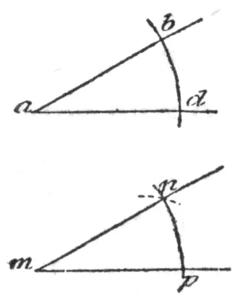
37.To construct an angle equal to a given angle.
The angle may be measured by means of the protractor
(24), which then enables us to draw a similar angle; but
greater accuracy is obtainable by using the compass.
Fig. 25.
Let it be required to construct at m on the line m p
(fig. 25), an angle equal to b a d. With as
large a radius as possible, draw from the
points a and m the arcs b d and n p. Measure
the distance d b and mark it off with the
compass from p on the arc p n. A line
drawn through m to the intersection of the
two arcs will give the required angle equal
to b a d.
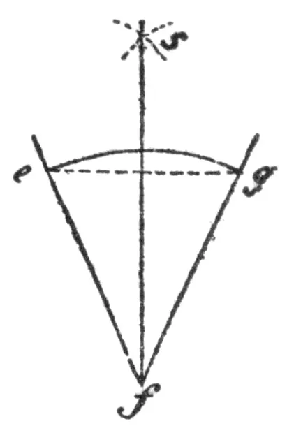
38.To subdivide an angle into 2, 4, or 8 equal
parts. In addition to the use of the protractor, the following
graphic method is often given in works on
geometry.
Fig. 26.
An angle e f g being given (fig. 26), from its apex f
as a center describe the arc e g, and from its
two points of intersection with the sides, with
a radius greater than half their distance apart,
draw two short arcs cutting each other at s.
A line drawn from f through the intersection
s will divide the angle into two equal parts.
If four divisions are needed, repeat the process
on the two angles s f e, s f g, and so on for a
further sub-division.
The line that divides the angle into two equal parts
will also bisect or divide into two equal parts the chord
and the arc e g.
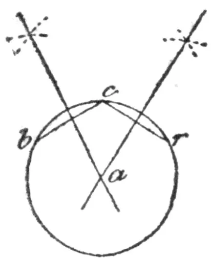
Fig. 27.
39.To find the center of a circle or of a circular
arc. Take on the circumference, or on the arc, three
points b c r (fig. 27). Join b to c and c to r. At the
middle point of each of these lines[3] erect a perpendicular.
The point of intersection of these perpendiculars
is the required center.
A similar method should be resorted to
when it is desired to describe a circle passing
through three given points.
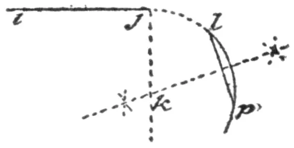
Fig. 28.
40.To connect up or associate lines. In order to
join up a straight line, such as i j (fig.
28), with the curve l p, erect a perpendicular
at j, and through the middle
point of a chord, l p, draw a second
perpendicular cutting the first in k. This point will be
the center from which the curve uniting the two lines
should be struck.
Fig. 29.
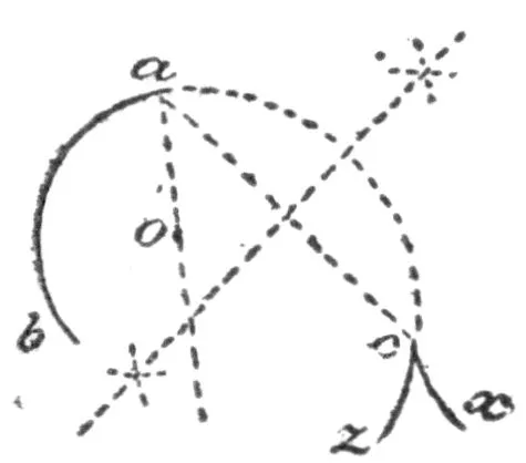
To unite a curve a b (fig. 29), with another curve, c x
or c z, at the point c, first find o, the center of the curve
a b, draw the line a o, continuing it beyond
the center; join a and c, and erect a perpendicular
at the middle point of this chord.
The intersection of this perpendicular with
a o, produced if necessary, should be taken
as the center for a curve uniting b a with c.
Fig. 30.
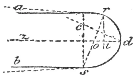
To join up two lines inclined to each other or parallel
lines of unequal length, such as a r, b s, fig.
30, draw midway between the two another
line, z d; join the two extremities r and s,
and from these points let fall perpendiculars
r i and s c; then from d draw a line perpendicular
to s r. The point o thus obtained will be the
center of the arc r d, and c will be the center for d s.
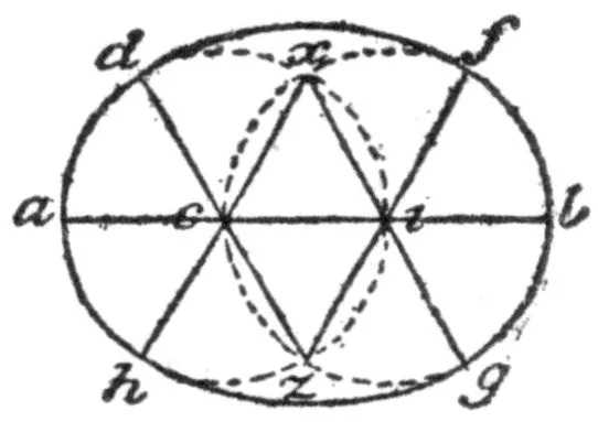
41.To describe an ellipse. Let a b (fig. 31), be
the major axis of the ellipse; divide it into three equal
parts, and from the two points, c and i, at which it is
divided, with a radius equal to i c, draw (in pencil) two
circles, intersecting in the points x and z. Through these
points draw the lines x i g, x c h, z i f, z c d.
With the center z describe the arc d f, and from x
draw h g; the ellipse will be completed by the two arcs,
f b g, d a h, of the primitive circles.
Fig. 31.
If it be required to describe an ellipse that shall have a
shorter minor axis, divide the major axis into four equal
parts, thus obtaining three points of sub-division. With
each point as a center and with a radius
equal to one of the spaces describe circles.
Those to the right and left will determine
the extremities of the ellipse, and the central
circle will intersect the minor axis in
two points which must be taken as centers for describing
the top and bottom portions of the figure.
Fig. 32.
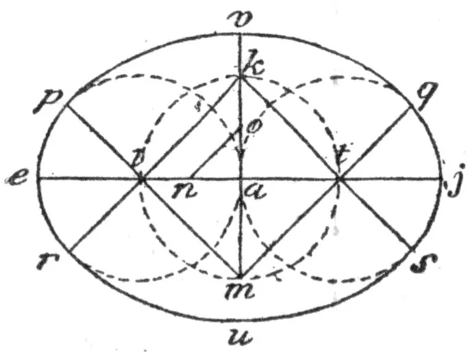
When the length of the long and short axes are given,
proceed as follows (fig. 32): From the center a, where
they intersect at right angles, mark off the distances a n,
a o, equal to the difference in the length
of two semi-axes. Join n o, and add
one half of n o to a o measured in the
direction of a v, thus obtaining the
point k; with the radius a k describe
a circle. On this circumference will
lie the four centers; k for the arc r u s, m for the arc p
v q, t and i for the short arcs q j s, p e r.
The figures obtained by the methods here given closely
resemble the ellipse, but are not of the strict mathematical
form. It is well to acquire some facility in drawing
ellipses, for the projection of a circle on a plane, when
the two are neither parallel nor perpendicular, is an
ellipse, and one often has occasion to describe it.
42. The following may be added as a mode of describing
an ellipse:
The major axis and the two foci (points in this axis)
being known, fix two pins in these foci. Then tie a piece
of string into a loop and place it over the pins; stretch it
with a pencil, the point of which is on the paper, and on
moving this around in a circular direction, the string being
maintained stretched, an ellipse will be described. When
the string is so stretched that it lies along the major axis,
the length should be such that the pencil is exactly at its end.
Fig. 33.
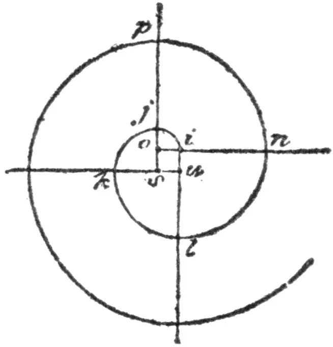
43.To draw a spiral curve. Draw four lines forming
a small square (fig. 33). The point o is taken as the
center of the first arc, i j; s is the
center of j k; u of k l; i of l n. Then,
to continue the curve, o is again taken
as the center for n p, and so on. This
method produces a volute in which the
coils are at a considerable distance
apart, such as has no special applicability
to horology.
Fig. 34.
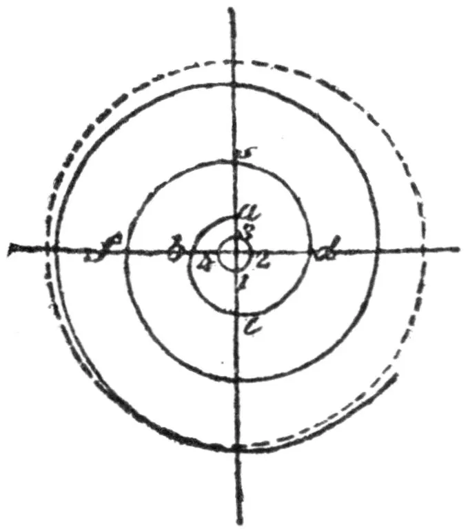
As the balance-spring of a watch is partially concealed
by other pieces, it is generally sufficient
to represent the parts that show themselves
by concentric circular arcs, or
arcs described from two centers. If
a more accurate representation be
required, the following method may be
resorted to: when working on a small
scale it involves the use of the eyeglass,
for the figure (fig. 34,) here given is exaggerated in order
to avoid confusion in the lines, numbers, letters, etc.
A small circle having been described, it is divided into
an even number of equal parts, say four; a less number
than this should never be adopted. From the same center
describe another circle as small as possible, which will be
cut by the two diameters drawn between opposite points
of division numbered 1, 2, 3, 4.
Assuming a to represent the starting-point of the curve,
from the center 1 with radius 1 a draw the arc a b; from
2 with radius 2 b draw the arc b c; from 3 with 3 c draw
c d; from 4 with 4 d draw d s; then recommencing with
1 and the radius 1 s draw s f, and so on.
The less the radius of the small circle and the greater
its number of divisions, the closer will the successive coils
be together. To secure accuracy when working on a
small scale, it is advisable that the center and the several
points be in a thin brass or horn plate, which is maintained
in position by steady pins.
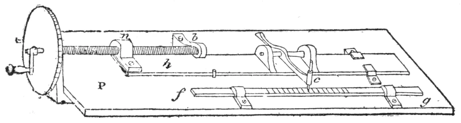
44. This instrument is no more than a simple application
of the screw to dividing straight lines, but it will
suffice to enable the reader to understand the principles
on which the more complicated instruments are based.
Fig. 35.
A plate, P, fig. 35, supports a bracket a, in which a
screw, similar to the one described in paragraph 30, is
engaged by means of a collet; it rotates, being supported
between this bracket and the small bearing b, that receives
the pivot at the end of the screw.
The screw is fitted carefully into a nut n, which is
rigidly attached to the small plate h; this carries a fine
marker, movable on an axis, and terminating with a chisel
edge or a fine diamond point, according as the instrument
is to be used for engraving metal or glass; or it may be
provided with a fine pencil if the object is merely to make
subdivisions on a drawing.
This being understood, it will be evident that, if a rule
or rod of any form be fixed by screws or otherwise
between f and g, it can be graduated by means of the
marker, the screw being made to advance; the millimeter
screw can be used for dividing into millimeters and fractions
direct, or, with a little calculation, into fractions of
an inch. Each complete rotation of the head means a
displacement of the marker by a millimeter; a half turn
will be half a millimeter, etc.
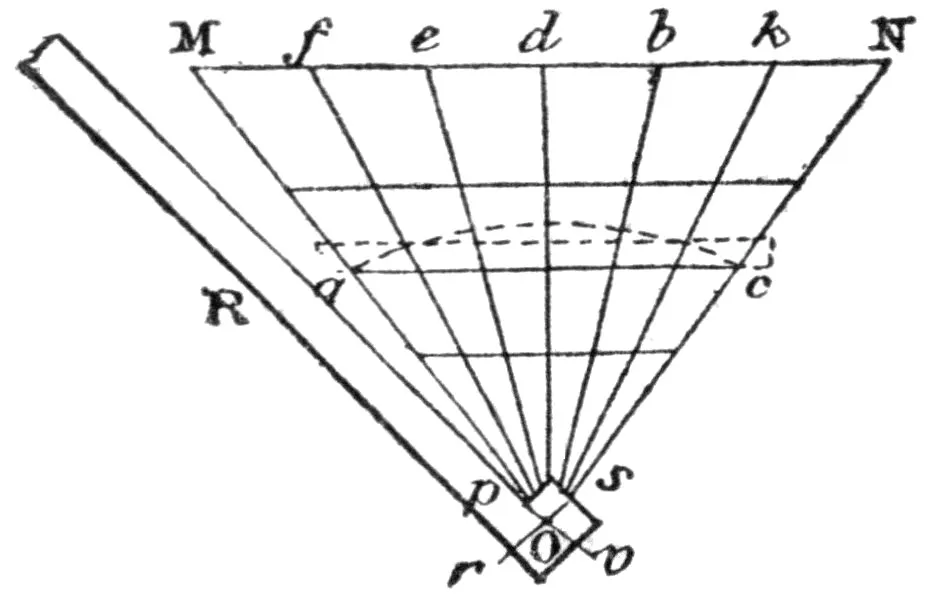
Fig. 36.
45.First method. Having fixed a sheet of drawing
paper on a smooth board, draw the line M N, fig. 36,
longer than the rule which is required to be divided.
Then, with a compass or graduated scale, mark off a
series of equidistant points, commencing at N, equal in
number to the required series on the rule, and let M be
the last division. With the center N and radius N M
describe the circular arc p v, and with M as a center and
the same radius, describe a second arc r s, intersecting
the first at O. Join O with M and N. Assume a c to be
the rule that is to be divided into equal parts; slide it on
the paper parallel to M N until the extremities, a and c,
coincide with the lines O M, O N, and are equidistant from
O. This position can be easily found by the aid of a
compass with one of its centers at O. Now fix the rule
in position with sealing-wax, or by some other means,
and, with a firm upright pin,
center the brass rule R at O, so
that it can rotate round this center
on the pin as a pivot. It now
only remains to trace a series
of lines Ok, Ob, Od, etc., with
the rule, to the division points of
the line M N. The line a c is thus divided into as many
equal parts as the line M N. The graduations will be all
the more exact according as the divisions of the line MN are longer.
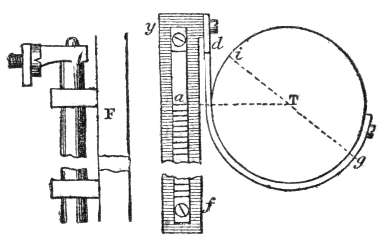
46.Second method. By the side of the chuck of a
wheel-cutting engine, arrange a horizontal slide y ffig.
37, that can travel easily in a direction perpendicular to
aT. A watch fusee-chain, or a very flexible spring, is
fixed by one end to the chuck, and by the other to the
slide at d. The chain or spring is kept stretched by a
weight which tends to draw the slide from f towards d.
Fig. 37.
The rule to be graduated, a, is now fixed on the slide, and an
initial division is marked on it with a pointed rotating cutter in the
position usually occupied by the wheel cutter, or else by striking a
small pointed or flat-edged chisel arranged for the purpose, in such a
manner as not to be liable to derangement.
Rotate the table through a definite distance; the rule a
will advance through the same distance; mark the second
division; then having moved the division-plate through a
distance equal to its first displacement, mark the third
graduation, and so on. Suppose, for example, that it be
required to make 30 divisions on the rule between f and
d; select on the plate the circle corresponding to twice or
thrice this amount, so that the radius of the chuck may
not be relatively too short, and that the chain or spring
may not act at a disadvantage; take the number 60 for
example:
The two marks at d and g on the spring indicate the
length that corresponds to the straight line to be divided.
The chuck is placed in the lathe and reduced in diameter
until the half circumference is exactly equal to the
distance between these two marks on the spring, which
thus fall on a diameter, i g, of the chuck.
The spring having been fixed by its two extremities,
the slide with the rule attached is placed in position, so
that the mark g is on the line aT; it will be evident from
the figure that each displacement of the division-plate
through one-sixtieth of its circumference will cause a to
advance through one-thirtieth of the space between f
and d.
Remarks.—Knowing the relation of a diameter to the
circumference (as 1 : 3.1416), we can determine the
diameter of the chuck at once by calculation.
Its form should be a true cylinder, and it is well to place
guides that will prevent the spring or chain from assuming
a helical position.
The side that carries the rule should be strictly perpendicular
to aT; and the portion of the spring that is
not coiled on the chuck should always be parallel to this
slide.
The chuck and spring must be quite clean and smooth,
and the latter should be very pliable. A greater weight will
be needed to keep the spring stretched than will suffice for
a chain, and it must be increased as the strength of springs
is greater.
The slide, y f, may simply travel over a horizontal
surface between pins planted in two parallel lines. But
it would be preferable to adopt some other method, for
instance, to make this piece (F, fig. 37), travel with a
little friction along a perfectly true cylindrical rod.
47.Third method. This is merely an application of
the arrangement mentioned in paragraph 44. The lathe
can be employed for marking off a series of equidistant
points in a straight line. Knowing the pitch of the slide-rest
screw, determine the distance apart in, say, millimetres,
of the required divisions, and fix the rule perfectly
flat on the face-plate, which must be rendered immovable
by any convenient means. Then mark the first point
with the drill-stock. Advance the screw by the amount
previously determined upon and mark the second point.
After withdrawing the drill, again advance by the same
amount and mark the third point, etc. Always be careful,
before making the first mark, that the screw has already
traveled some distance in the direction it will continue to
move, so as to avoid backlash, or loss of time.
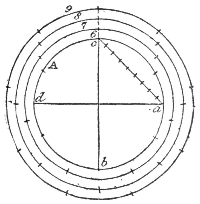
48.To divide the circumference into equal
parts. After having drawn the circle, A, fig. 38, draw
two diameters, d a, b c, at right angles to each other,
dividing the circle into four equal parts. Join the points,
c a, and divide the line, c a, accurately into nine equal
parts.
Draw a series of circles concentric with the first, at
distances apart equal to one of the divisions of c a, and
to the number of one, two, three, etc., according as it is
required to subdivide the circle, say for a pinion, into
seven, eight, nine, etc., equal parts.
Fig. 38.
With a fine-pointed compass,
measure off the radius of the
initial circle A. Placing one
point of the compass at c, the
other point will give the position
of the next leaf, and so on,
all around the circumference.
If the innermost circle A be
selected for sub-division, six
divisions will be obtained, and
there will be one more division for each larger circle.
The operation will be facilitated by selecting the first
circle, so that the line a c contains exactly nine divisions
equal to those of some scale that is accessible. Such a
circle can be easily found, by first drawing the two diameters,
laying the scale in the direction c a, and determining
by trial the radius for which the first and ninth divisions
correspond to a and c respectively.
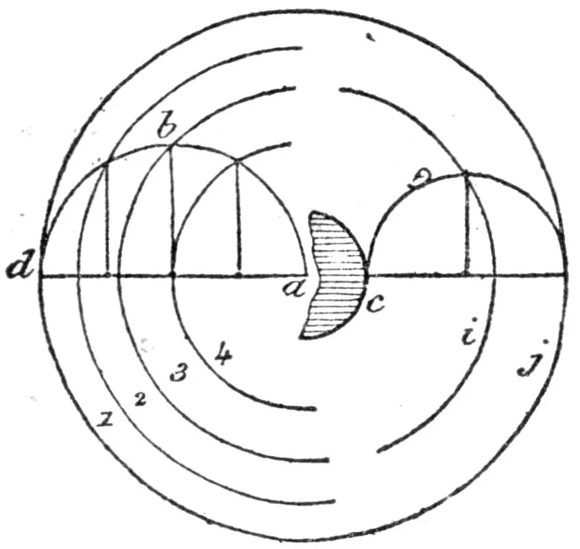
49.To divide a surface into rings of equal or
proportional superficial area. The following solution
is due to M. Brocot:
Let a d be the radius of a circle (fig. 39), that is required
to be subdivided into four rings of equal area by concentric
circles. Taking a d as a diameter, draw the semicircumference,
a b d; accurately divide a d into four equal
parts, and at each point so obtained, erect a perpendicular.
Through the intersections of these perpendiculars with
the semicircle, draw a series of concentric circles; they
will trace out rings, 1, 2, 3, 4, that have equal superficial
areas.
If it be required to divide the surface in a given proportion,
divide the line a d,
according to that proportion.
Fig. 39.
The right-hand side of fig.
39 gives a special application
of this method to the division
into two equal areas of the
interior of a barrel exclusive of
the space occupied by the
arbor-nut. If the mainspring
accurately covers i c when wound up, and i j when
unwound, it will give the greatest possible number of turns.
50. Solar time is taken from the revolutions of the
earth, and the watchmaker can easily get the exact solar
time of any point at which he may happen to be by a
little calculation from known standards. These standards
are: 1. The zenith. 2. The longitude of the point of
observation. 3. The difference between noon at the
point of observation and noon of a known meridian either
east or west of the point of observation. The zenith is
that point in the heavens where the rays of the sun are
in a plane exactly perpendicular to the surface of the
earth at the point of observation, and when the rays of
sunlight are in this plane it is noon at that point. The
circumference of the earth is divided into 360 degrees or
meridians of longitude, so that as the earth revolves once
every twenty-four hours, each of these meridians will
pass the zenith, or fixed point, in that time. In twenty-four
hours there are 24 × 60 = 1,440 minutes, so that the
interval between the passage of one meridian and the next
will be 1,440 ÷ 360 = 4 minutes. A degree of longitude
is divided like an hour, into minutes and seconds, so that
1 degree
of
longitude
equals
4 minutes
of
time.
1 minute
”
”
”
4 seconds
”
”
1 second
”
”
”
¹⁄₁₅ or .066 seconds
of
time.
51. Thus it happens that, at a town one degree east
of a given point the sun will be visible four minutes sooner,
and if to the west, four minutes later than at that point.
The “local,” or solar time, therefore, will be four minutes
earlier at the first town, and four minutes later at the
second town, than it is at the point of observation.
52. It will be readily seen that, having any two of the
three factors given above, the other can be readily found.
Thus having the time of a given meridian and the local
noon or meridian time, the longitude can be readily found;
or, having the longitude (which can be readily obtained
from a surveyor) and the time of a given meridian,
“noon,” can be calculated, etc. The first method is followed
in calculating distances at sea; the chronometer
keeping Greenwich time, and the local noon giving the
longitude.
When great accuracy is necessary, however, a fixed
star is used as a means of observing the exact time when
a revolution of the earth is completed, as the revolution
of the sun in its orbit causes a slight variation during the
year. For further information on this point the reader is
referred to works on astronomy.
To obviate the constantly varying time in running east
or west, the railroads use the time of a given meridian
over each fifteen degrees of longitude, and as each degree
of longitude equals four minutes of time, it follows that
only the hour is changed in changing from one standard
to another. In Europe the zero of longitude, or the time
of the meridian of Greenwich is used. In the United
States the time of the 75th degree, which passes through
Philadelphia, is used from the 67th to the 80th degree,
which comprises the territory from Princeton, Maine, to
a line drawn north and south, passing through Erie and
Pittsburg, Pa., and is called Eastern time. The time of
the 90th meridian is used from the 80th to the 102d
meridian, and is called Central time. The time of the
105th meridian is used from the 102d to the 114th
meridian, and is called Mountain time. The time of the
120th meridian is used from the 114th meridian to the
coast (which ends at about the 124th meridian) and is
called Pacific time. The time of the various standards
is telegraphed through their various territories at noon
each day, and furnishes an accurate standard of comparison
to all watchmakers.
53. In very many cities the actual or solar noon has
been discarded and the railway standard adopted, thus
making but one standard and removing the source of confusion
and annoyance to many people. In others, however,
the two standards are still used, and it becomes
necessary for the watchmaker to be able to calculate
both standards, in case of accident or irregularity in his
regulator. Hence he should calculate his longitude
within one second by means of the difference between
railroad and local noon, and have the nearest surveyor
correct his reckoning; then, by means of the accurate
longitude and the railroad time, correct the solar time;
then by means of the solar noon and the longitude calculate
the railroad time. When all these calculations check
each other perfectly, he possesses all the time data he
needs for that place, and can correct his standard or
regulator if at any time it should become irregular. The
calculations are very simple, and can be easily performed
from the data given above.
[3] Determined in the manner explained for erecting a perpendicular
in par. 32 except that intersecting arcs are described on both sides of the
line (n m, fig. 17); the perpendicular will be a line joining these points of
intersection.
PART II . MATERIALS EMPLOYED IN HOROLOGY. — IRON. — CAST IRON. — STEEL. — GENERAL OBSERVATIONS. — SPECIAL OBSERVATIONS. — DETERMINATION OF THE QUALITIES OF STEEL. — PREPARATIONS OF STEEL. — HARDENING. — TEMPERING. — TO WHITEN AND BLUE STEEL. — CASE-HARDENING. — INFLUENCE OF FOREIGN METALS AND METALLOIDS ON THE QUALITIES OF IRON AND STEEL. — COPPER. — ZINC. — BRASS. — HAMMER HARDENING OF BRASS. — TO ANNEAL BRASS. — CAST BRASS. — TIN. — BRONZE. — STERRO. — LEAD. — NICKEL. — GERMAN SILVER. — GOLD. — SILVER. — ALUMINIUM AND ALUMINIUM BRONZE. — MERCURY. — PLATINUM. — PALLADIUM. — CHARACTERISTIC PROPERTIES OF ALLOYS. — SOLDERING. — METHODS OF SOLDERING. — BRONZING. — GILDING. — ACIDS AND SALTS. — OIL. — ALCOHOL. — BENZINE, ETC. — POLISHING MATERIALS. — PREPARATION OF POLISHING MATERIALS. — SMOOTHING. — SMOOTHING OF BRASS. — SMOOTHING OF STEEL. — POLISHING. — TO POLISH STEEL. — CEMENT, WAX, RESIN, ETC. — ENAMEL. — PRECIOUS STONES. — WORKING IN PRECIOUS STONES. — FOOTNOTES:
54. Iron is an elementary body, that is to say it cannot
be decomposed. It is the most tenacious of the metals,
having a breaking strain of about 75 kilo. per sq. mm. (or
106,000 pounds per sq. inch) of section. Two pieces
can be perfectly welded together when raised to a white
heat.
In the smaller horological appliances, the metal is not
employed except after conversion into steel. In common
clocks it is used from motives of economy, for forming
pins, screws, etc. In turret clocks, however, considerable
use is made of it, many of the parts after they are formed
being cemented, that is to say, having their surface rendered
hard in a manner subsequently indicated (65).
Such a mode of manufacture is particularly applicable
to pieces that are subject to a constant succession of impacts;
their hardened, steelified surface resists wear, while
the iron core affords security against rupture.
It is important to carefully distinguish the cases in which
iron is preferable from those in which its substitution for
steel serves merely to augment the profits of the manufacturer.
The fracture of a good piece of iron is characterized
by long twisted fibres of a brilliant white color.
If heated frequently or carelessly, the quality of the
metal is impaired—it ceases to be fibrous and looses its
tenacity: in this condition it is said to be burnt.
It is better to work with a charcoal or gas fire, as coal
acts more rapidly in rendering the metal brittle. Cold
hammering, or “hammer-hardening,” also makes it brittle
and diminishes its tenacity, but this is again restored by
a suitable annealing.
Iron dissolves slowly in dilute nitric acid; if not diluted,
this acid rapidly oxidizes it. Dilute sulphuric acid dissolves
the metal easily, but if concentrated, it has no action
in the cold, whereas, on heating to ebullition, the iron is
dissolved with evolution of sulphurous acid gas. It is also
dissolved by hydrochloric acid, or aqua regia.
Iron is less magnetic than steel, especially hardened
steel, which, owing to its great coercive force, is magnetized
with greater difficulty, but retains its magnetism for
a longer period. Indeed, soft iron, if properly prepared,
can be magnetized and demagnetized instantaneously.
Some workmen can distinguish iron from steel by the
musical note emitted on striking. A more certain
method, however, consists in using dilute nitric, or sulphuric
acid. If the surface remains unaltered, or nearly
so, when touched with a drop of either acid, the metal is
iron, but, in the case of steel, a black mark will be left,
owing to the liberation of carbon.
55.To Remove Rust. The usual mode is to rub
the object with a piece of oiled rag, or emery paper. It
appears that more rapid and more satisfactory results are
secured by using very pure petroleum, and wiping with a
hempen or woolen rag.
56.To Prevent Rust. Dip iron or steel articles in
a mixture of equal parts of carbolic acid and olive oil,
rubbing the surface with a rag. Others rub the metal
with a mercurial ointment, leaving a thin layer over the
entire surface. It is stated that, if iron be dipped in a
solution of carbonate of potash or soda in water, the surface
will be protected against rust for a long time, and
objects can be protected for any period by burying in
quicklime. Rubbing the surface with plumbago has a
similar effect, and Barff has pointed out that, by exposing
iron to the action of steam, heated above the boiling point
of water, a coating of magnetic oxide of iron is formed,
which is equally serviceable.
57.To restore iron and steel that has been burnt,
or badly forged. When iron is burnt, or carelessly
forged, it becomes crystalline and brittle; in order to
restore it to its original condition, a fresh and very careful
forging is generally needed. This can be avoided by
having recourse to the following method, suggested by
Caron: it consists in treating the metal somewhat after
the manner adopted in hardening steel.
He experimented with a bar of good iron, which was
easily bent when cold, without breaking or showing any
cracks. It was then burnt and became brittle when cold,
the fractured surface showing brilliant shining facets.
Prepare a boiling saturated solution of sea-salt, heat
the piece of iron to a bright redness, and plunge it into
the bath until it is of the same temperature (about 110°
C. or 230° F.) After undergoing this operation, it is
found that the metal can be easily doubled in the
cold, exactly as it did before being burnt.
Perret states that steel which has been deteriorated by
frequent hardening can be restored as follows: Heat it
short of dull redness and quench in melted tallow, repeating
the operation, if necessary, when the steel may be
again hardened in the ordinary manner, and will be
nearly, if not quite, restored to its original condition.
58. This is only used in the manufacture of tools and
large clocks; the employment of cast iron wheels in
the striking train of such clocks has materially reduced
their price.
Like steel, it is a compound body, consisting mainly
of iron and carbon. Cast iron, however, differs from
steel in the quantity of carbon present, for, whereas its
proportion in cast iron varies from 2 per cent. upwards,
there is never, in steel, an amount exceeding 1.5 per cent.,
and even .5 per cent. renders an iron hard, converting it
into “mild” steel.
Cheapness is not the only argument in favor of the
use of cast iron. In virtue of its molecular structure,
this material offers a considerable resistance to a
crushing strain, so that the teeth of wheels, made of
carefully selected cast iron, will work for a long time
without sensible wear; moreover, the founder’s art has
made such important advances that there is no difficulty
in casting, to a constant pattern, a wheel, together with
the pinion that it carries, and any other projections, etc.,
that may be required; this economizes labor to a very
great extent.
The use of cast iron in the construction of certain
classes of wheels, and parts of tools, presents advantages
which we cannot afford to ignore; but it must be carefully
observed that this material is not suitable in cases
where great accuracy in the acting parts is required, as it
cannot, like brass and steel, be conveniently worked
by the turning tool or file. In recent years, however,
this difficulty has been overcome by the introduction
of what are termed “malleable castings,” produced
as follows:
59.Malleable Castings. The object is first made
of ordinary cast iron, and the invention consists in rendering
this malleable by the removal of the carbon that has
served the very important purpose of rendering the metal
fusible. In large cast iron pots, the castings are laid with
alternating layers of powdered red hæmatite, and the
whole is kept at a temperature of about 900° C. (1,650°
F.), or cherry-red heat, for 72 hours. On cooling, the
castings are found to consist of nearly pure iron, and to
be perfectly malleable, and, therefore, workable.
60. The treatment of steel involves some of the most
prolonged and delicate operations in the entire range of
horology. If the metal is badly selected and prepared,
the working of it will be laborious, difficult and unsatisfactory;
the resulting object will be distorted in the hardening,
and will not harden uniformly; in short, it will
occasion much toil and loss of time, with very little
success.
Let the young watchmaker accustom himself from
the first to study the steel that he uses, so that he
may be thoroughly cognizant of both its advantages
and defects; he will, in the practice of his art, be amply
repaid for the brief time spent in making such an examination.
61. Steel is not an elementary body; it is usually
regarded as a carbide of iron, that is to say a combination
of carbon and iron. Analysis, however, proves other substances
to be usually present in almost infinitesimal
quantities; their remarkable influence on the physical
properties of the metal has not yet been fully investigated,
but much attention is being devoted to them at the present
day.
The varieties of steel are very great. What are known
as puddled and natural steel are obtained by acting
directly on cast iron. Cementation is a very old method
of converting bars of malleable or pure iron into steel
by enclosing them in charcoal and heating the whole for
several days, until the carbon has worked itself into the
center of the bars in such quantity as to covert the iron
into steel.
The steel obtained by the above method is very heterogeneous;
in other words, the composition is not uniform
throughout a given block or bar. One part is highly
carbonized, whereas another part, especially towards the
center, will not be sufficiently so. The grain, although
very fine in one part, will be more coarse in another;
hard particles of pure cast iron, termed “pins,” are to be
met with that resist the action of the graver or the file
and give rise to cracks in the hardening, hammering, etc.,
and portions or sometimes even entire layers that have
taken up no carbon whatever. The differences in the
density, hardness, malleability, etc., that can be shown to
exist at different points in the same bar arise from this
cause.
Such faults can in part be corrected by shearing, an
operation which consists in binding together a number of
bars in a bundle, raising them to a red heat and beating
them with sledge or steam hammers so as to weld them
into one. The bar thus obtained is again heated, folded
several times on itself, again hammered, rolled, etc., when
it is termed shear steel. If these operations are performed
carefully and without a too great heat, the quality of the
steel is much improved; it is more homogeneous and can
be worked with greater facility.
62. The discovery of the earliest method of producing
cast steel, thoroughly homogeneous, was made by a
watchmaker, B. Huntsman, of York, and metal produced
by his method is very highly prized at the present day.
Many other methods have been since introduced, amongst
which may be mention the Bessemer and the Siemens-Martin
processes, and steel is now produced from iron of
very varying quality, so that the mark cast steel is now
far from being a guarantee of quality. The fusion of
shear or cement steel will only secure a marked superiority
in its quality under two principal conditions: (1)
The metal must be carefully selected, since certain qualities
do not intermingle thoroughly. (2) Very great care
and skill must be devoted to all the operations, the successive
heatings, forging, rolling, etc.
In short, in the case of steel it is exceptionally true that
we must never accept the metal merely on its own recommendation.
Whatever maker’s mark is selected, the
results obtained will never be satisfactory unless the
degree of hardness, the elasticity, cohesive force, etc., are
such as will suit the metal to the special purpose to
which it is to be applied as well as to the working it will
have to undergo. Experiment can alone make us fully
cognizant of the qualities of a steel.
63. All steels, if of good quality to begin with, will
deteriorate if subjected too often or too long (according
to the character of the metal) to the action of either the
fire or the hammer. They will become brittle and incapable
of hardening, in the end even reverting to the
condition of iron.
The quality of steel becomes worse as the number of
flaws, blackish filaments, more or less carbonaceous veins,
and occasional particles of pure iron in its substance are
greater; as its surface is cindery, that is to say spotted with
minute black marks which become more prominent after
polishing, etc.; as its fracture presents an uneven grain, etc.
Such a metal is found to vary considerably as regards
hardness, elasticity, etc.; not being uniformly affected in
the hardening, it becomes difficult to work with the file
and almost impossible to form into a perfect cylinder in
the lathe.
Other conditions being equal, these faults are characteristic
of natural steel rather than of the two other varieties.
At the same time, if well sheared, it becomes very
elastic, and has the great advantages of not being deteriorated
under the hammer and of being less ready than
the other varieties to be converted into iron.
Rolling, wire-drawing and hammering occasion a molecular
re-arrangement; it is necessary, therefore, to anneal
the metal from time to time, as otherwise it becomes
brittle or cracks.
There is a certain temperature, corresponding to each
variety of steel, which cannot be exceeded without the
metal being injuriously affected; this temperature must,
then, be previously determined.
The grain of a piece of steel that has been superheated
or burnt is characterized by brilliant diamond-like
particles; the mass loses its beautiful color, and resembles
iron more or less according to the degree of heat applied.
Some few workmen are enabled, by long experience
and a very delicate touch, to judge approximately of the
quality of a steel from its weight, feel, and resonance.
Metal that is of a good quality, homogeneous, and
very dense, they term full.
64.Natural Steel. In the case of natural steels of
low quality, the fracture is usually characterized by uneven
grains, a somewhat fibrous nature and a bluish tint.
The grain becomes finer and more even and the surface
presents more and more the appearance of a piece of
coke, as the quality of metal improves. In addition to
these distinctive features a natural steel of high quality
can be distinguished by the fact of its being more thoroughly
hardened and less liable to break when hard.
In hardening it must be raised to a higher temperature
than cement steel; in other words, steel of a low quality
must be heated somewhat above bright redness, while
the better qualities should be heated to an orange-red, or
nearly so (77).
65.Cement Steel. The cement steel ordinarily
met with has a lamellar fracture, the lamellæ varying in
form and color from the center towards the circumference.
The grain is usually finer and more uniform than
that of natural steel, there is seldom any appearance of
fibres, veins, or flaws. The color of the fracture is greyish,
tending towards blue in the ordinary qualities.
The better qualities are marked by a closer grain, a
more uniform, dull, greyish-white color, exhibiting neither
streaks or black spots after hardening, and by the further
fact that hardening can be effected at a lower temperature.
If of the very best quality, it should not require
heating beyond a clear cherry-red; often even a still
less degree of heat will suffice.
66.Cast Steel. Cast steel is the most homogeneous,
full, and beautiful of the three classes. Several varieties
exist. The fracture of cast steel, as compared with others,
is smooth, compact, and of a white-grey color, resembling
coke. The grain is fine and very even. The metal must
be hardened at a temperature much lower than can be
safely applied to other classes of steel, since it is rapidly
deteriorated by heat.
Cast steel is more fusible than ordinary steel, and will
fracture with ease under the hammer when heated to a
blue tint, so that great care is essential in hammering it.
The metal should never be heated beyond a dull or
cherry-red heat, lest it be burnt.
The tenacity will be increased by forging at a low temperature
or even by cold hammering.
The fineness in grain, together with its high density,
afford an indication that the metal can be rendered very
uniformly hard; that very fine cutting edges and the
most minute rods can be made of it; and that, after hardening,
it can be highly and uniformly polished; in other
words, that it does not exhibit spots or streaks differing
in color from the mass, as is always the case with natural
and cement steels. For most horological purposes (such
as making pinions, staffs, pivots, etc.) cast steel is preferable.
It is the only kind that can with certainty be
highly polished, turned perfectly round, and that does not
get distorted in the smoothing. Moreover, when wear
does occur it exhibits less irregularity.
Highly-carbonized shear steel exhibits a fine, close grain
that would make it easily mistaken for cast steel. They
can be best distinguished by the application of dilute
sulphuric acid. The side of the bar when acted on by
this means exhibits lines that indicate the junctions of the
several layers constituting shear steel.
67. It is unnecessary to observe that as we are writing
mainly for the use of practical watch and clockmakers,
we shall make no reference to those elaborate systems of
testing that form a remarkable feature of the engineering
of the present day, but shall confine ourselves to the tests
which workmen can apply for themselves.
When the grain is fine, close and homogeneous, the
fracture in even curved lines and the surface of a uniform
grey aspect, the metal is considered to be of good quality.
It is, nevertheless, unsafe to rely too much on such indications,
for a steel that has been hammered until cold will
exhibit a fine close grain, whereas the grain of the same
metal will be coarse and open if it was still red hot when
the hammering or rolling was concluded. The grain of
hardened steel, moreover, depends on the degree of heat
to which it has been subjected.
When of equal quality, even if from the same maker,
the grain will be finer in bars of small dimensions than in
those that are larger.
Cast steel even, especially in large pieces, is not always
perfectly homogeneous, as can be easily perceived on
applying the file, or still better, in the lathe; an object can
with difficulty be turned perfectly round, and loses its
shape in the smoothing. As a general rule it is impossible
to form a reliable opinion on a specimen of steel until
after it has been worked, filed, turned, and tested according
to the particular use to which it is to be applied; for a steel
that is excellent for making, say, a spring or a cutter, may
be quite unsuitable and give most unsatisfactory results if
used for making staffs or fine pivots, or the converse may
be equally true.
As a preliminary test, break a piece of the metal; after
having examined the fracture, form a cutting edge, harden
to what seems to be a convenient degree, then sharpen
and employ for cutting small pieces of iron. If the edge
is in no way damaged by the iron, this may be taken as
a good indication that the metal possesses body and
tenacity, and that it can be hardened as much as is
required for such purposes.
The following are methods of obtaining more complete
information as to the homogeneity, the character of grain,
the degree of hardness a given sample can attain, as well
as its malleability, body, elasticity, etc.
68.Homogeneity. Place drops of dilute sulphuric
acid equidistant along the surface of a bar. If the metal
is homogeneous all the drops will impart the same
color.
Cold hammer or hammer-harden, and then fire-harden
part of the bar. Break off the extremity in order to
study the fracture; if the result of this examination is
satisfactory, polish the hardened end carefully, and with
the aid of a glass again examine into the homogeneity of
the metal. The polish will be the better and more
uniform according as the steel is more homogeneous.
69.Grain, hardness and temperature of hardening.
All varieties of steel do not harden to the same
degree, and each requires to be heated to its own particular
temperature for hardening; moreover, the character
of the metal, its color, and the size of its grains vary
according to the degree of heat to which it is subjected.
It would be difficult to draw any exact conclusions as to
the character of grain and the hardness without the following
practical method, which we owe to Reaumur:
At a temperature not exceeding a dull redness, forge a
piece of the steel to be tested into the form of a razor-blade,
that is to say, leaving it thick on one edge and thin
on the other, in the direction of its length. Then heat
the blade, holding it by one end, and when the other end
has reached a bright red heat, plunge the whole into
water. Part of the steel will then be hard hardened.
Along the entire length of the thinner edge carefully
break off the metal with a hammer or otherwise, and
examine the character of grain at different points of the
exposed thicker edge thus left.
As the form, color, etc., of the grain depend on the
degree of heat to which each portion was subjected, it
follows that we shall observe four types of grains: (1)
Large, white, sparkling grains; (2) Grains that are
medium sized and intermixed, some being white and
sparkling, others white and dull; (3) Fine dull grains;
and (4) Grains that are medium sized, but dull and ill-defined.
According as the third class of grains is observed to
be more numerous than the second class, so is the fineness
of the steel greater, and conversely.
This method of testing possesses, moreover, the advantage
that the workman can experiment on his blade of
steel with a view to determine the temperature best
suited for hardening.
Grain No. 1 corresponds to a white-red heat for hardening.
Grain No. 2 corresponds to an orange-red heat for
hardening.
Grain No. 3 corresponds to some shade of cherry-red
heat for hardening.
Grain No. 4 corresponds to a dull red heat for hardening.
As there is some difficulty in remembering the exact
points at which these several temperatures are reached we
will complete this account of the mode of testing by the
following:
70. On a thick plate of metal, maintained at an orange-red
heat, place three fragments of the steel under examination,
previously marking them, so as to observe the
order in which they are immersed in water; and have
three vessels of water standing near. As soon as one of
the pieces reaches a dull cherry-red heat, allow it to slide
into one of the vessels; heat the second to a medium
cherry, and the third to a bright cherry-red, introducing
them in succession into the water-vessels. If these pieces
be examined as to the resistance they offer to breaking,
and the fracture of each be compared with the fracture
at different points of the razor-blade, the file being
used to test hardness, we shall have sufficient evidence as
to the most suitable temperature for the hardening of this
particular variety of steel.
71.Body. A steel that possesses body is not brittle.
This quality may be tested in the following manner:
Several bars of different kinds of steel, of equal dimensions
and hardened as uniformly as possible, are bent
until the breaking point is reached. If all the conditions
of the trial are identical, those bars that stand the greatest
angular deflection without breaking have the most body.
Steel that possesses body does not break as easily as
that which is wanting in body. Its fracture will be, as it
were, bevelled off like the mouth-piece of a whistle. If
soft and fibrous, it will be characterized by parts being
torn asunder.
72.Elasticity. The elasticity may be tested in a
similar manner. It is proportional to the curvature or to
the weight that a rod or blade of the metal under examination
can support without failing to return to its initial
position as soon as the weight or obstacle is removed. A
sample of steel that is distorted by a weight that another
specimen resists, is evidently inferior in elasticity.
73.Malleability, tenacity, ductility. A cold hammering,
if carefully managed, will suffice to indicate the
limits between which steel will support frequently
repeated percussion, without breaking, cracking or flying.
Forge a piece, introducing it a number of times into
the fire in order to ascertain whether it loses its distinctive
characteristics rapidly, and whether it can be successfully
forged.
It is more difficult to forge, according as it is harder
and more “steely.”
The degree of malleability is indicated by the manner
in which it supports hammering and rolling, and by the
smallness of the dimensions to which it can be brought
by such operations.
Passing the metal through a draw-plate with smooth
holes, or tapping it in a screw-plate will give useful indications
as to degree of ductility and tenacity.
A metal is said to be malleable when it can be easily
spread out under the hammer or in the laminating
rolls. It is called ductile when it can be reduced to very
thin wire by passing through the draw-plate.
It would seem that these two properties, ductility and
malleability, should always exist together, to the same
degree, in any given metal, but such is not the case. Iron
can be drawn into very fine wire, but cannot be reduced
to sheets of relatively equal thinness; tin and lead give
leaves of extreme thinness, but cannot be drawn out into
very fine wires; gold and silver are both very malleable
and ductile, and they rank highest as regards the possession
of these properties.
Steel is more fusible and malleable than iron, but less
ductile.
74.Observations. Formerly the makers of cylinder
escapements preferred forged steel, and their cylinders
often cracked after the hardening: modern makers employ
drawn steel, and it is much preferable. At the same time
they do not appear to recognize the principal reason for
the difference in the two varieties of steel. It seems to
us to be as follows: forged steel is malleable; drawn
steel, which has passed well through the draw-plate, is
ductile, and, therefore, tenacious. But tenacity in a metal
is nothing else than an exceptional resistance, opposed by
its particles to a fracture or separation; it follows, then
that drawn steel will crack with less facility than the
other.
75. When a variety of steel has been selected that
possesses the requisite properties: that is to say, fibre and
elasticity for springs; body and tenacity for circular cutters,
gravers, etc., it must be prepared; in other words,
it must be made so that it can be worked with ease, for
steel that is badly prepared will resist both the file, the
graver and the drill. It can never be turned perfectly
round, and will harden unevenly.
76.To anneal steel. The commonest, and at the
same time best, method consists in heating the metal to a
dull, red heat, burying it in hot ashes and allowing it to
cool slowly.
Steel raised to a red heat in contact with air loses a
portion of its carbon, so that it is better to place the metal
in a vessel of burnt clay; this is introduced into a fire
which must not be too bright at first, and when the vessel
has attained a red heat the fire is checked and left until
the whole is quite cold.
In order to soften steel by annealing with a view to
work it, engineers entirely cover the metal with dry powdered
wood charcoal or dry iron filings or turnings, in a
cast iron box or pot, or in a crucible, shutting up all the
openings so as to protect it from the direct action of the
fire and from the air. The vessel is then put in a dull
fire, the heat being gradually raised until the whole has
acquired the requisite temperature, which is known by
observing the color (see the following table); this degree
of heat is maintained for about ten minutes and the fire
quenched, after which it must be allowed to gradually die
out. Frequently the cooling is not complete for a day
or two, and even more when the crucible is of large
dimensions.
The metal will become softer, according as the cooling
is more slowly effected. It is generally heated to 800°
or 900° C. (1500° or 1600° F.), a cherry-red heat.
When the steel is associated with brass, as in the case of
a compensation balance, it is not safe to exceed 600° C.
(1000° F.)
77. It will be useful here to give the following table,
compiled by Pouillet, of the temperature, as indicated by
the air-thermometer, corresponding to various colors of a
heated body:
Incipient red
heat
corresponds
to
525° C. ( 980° F.)
Dull red
”
”
”
700° C. (1280° F.)
Incipient cherry-red
”
”
”
800° C. (1470° F.)
Cherry-red
”
”
”
900° C. (1650° F.)
Clear cherry-red
”
”
”
1000° C. (1830° F.)
Deep orange
”
”
”
1100° C. (2010° F.)
Clear orange
”
”
”
1200° C. (2190° F.)
White
”
”
”
1300° C. (2370° F.)
Bright white
”
”
”
1400° C. (2550° F.)
Dazzling white
”
”
”
1500-1600° C. (2730-2910° F.)
78.Annealing or softening in water. Instead of allowing
a piece of steel to cool slowly, it may be thrown into
water when heated to a temperature just below that at
which it would harden. In this case the metal will not
harden, but, on the contrary, become very soft. A single
operation suffices for certain varieties of steel, but with
others it must be repeated.
The only difficulty consists in fixing upon the precise
moment at which the metal has the requisite tint (a purplish
yellow or dull red), and this is more especially felt
when dealing with small pieces; experience can alone
guide the workman in this matter.
A skilful workman recommends the employment of
water containing one-fifth of its weight of gum arabic.
He also recommends that the metal be wiped over with
an oiled rag, then held in the fire, and, as soon as the oil
is converted into a thick smoke, and is on the point of
igniting, to immerse in water.
79.Hammering steel. Watchmakers who are
called upon to manipulate exceedingly small pieces of
steel, can somewhat increase the body and homogeneity
of the metal by a cold hammering. After annealing, the
object is hammered with light, uniform blows, again annealed,
and the same operation is repeated one or more
times, according to the degree of malleability already acquired
by the metal. Steel thus prepared has more body;
the particles composing it are more closely pressed together;
it files and turns well, can be heated more evenly,
and is not distorted or only very slightly in hardening,
providing the requisite precautions are taken.
80.The hammer and anvil. It is important that in
these operations the surfaces of the hammer and anvil
employed be perfectly smooth and even polished. If
they are rough or cracked, if they are uneven or have a
grained surface, a flaw will be produced in the body of
the steel or a crack on its surface.
81.To clean rough steel. The black coating
known as “scale,” which covers the surface of the metal
after it has been in the fire, will rapidly spoil gravers and
files, and, in addition to this, it leaves behind in them excessively
hard particles that will become imbedded in the
steel itself after a clean surface has been exposed. It is
then essential, in order to ensure good and rapid workmanship,
to previously remove this crust from the surface.
This can be done in two ways: by using a rapidly-revolving
grindstone, which instantaneously removes the
oxide, at the same time smoothing the surface of the
steel; or by leaving it for a sufficient length of time in
dilute acid, by which the superficial oxide is dissolved.
Sulphuric acid is usually preferred; in addition to the
cleaning, it is said to produce an effect somewhat similar
to annealing. On withdrawal from the acid, the steel
must be thoroughly washed with water and wiped dry
with care.
82.Ordinary mode of preparing steel. When
the metal has been annealed by one of the methods indicated
above, its preparation is completed by “pickling” in
acid, after which it is hammered cold between an anvil and
hammer (79, 80). When the metal has been worked, it
is heated to a bluish tint, and after cooling slowly is ready
for the hardening.
83.M. Covillot’s mode. This author adopts a method
whereby he obtains steel that is very soft to work and
perfectly free from hard grains or “pins” of cast iron, which
are so often to be met with in steel, causing it to crack in
consequence of their inability to spread under the hammer.
Take some garlic, the younger the better, mix it with
sufficient good walnut-oil to cover the garlic and form
into a paste; then place it in an earthenware pot on the
fire. When beginning to boil, heat the steel to dull redness
and plunge it into the boiling paste. Withdraw it with a
quantity of oil and garlic adhering; again heat to redness
and plunge into the paste. This operation may be repeated
two or three times. Then heat the steel, while
inclosed in an iron tube or box placed on the fire, and
allow the whole to cool. Finally, the steel may be
finished by setting it to cook (if we may use such an expression)
for ten or twelve hours in the composition of
garlic and nut-oil.
The last operation may be performed by setting the
boiling solution over an oil-lamp, after depressing the
wick in such a manner that the paste may be kept just
simmering.
M. Covillot employed the same mixture for hardening
the objects; but then, of course, it must be cold.
84. It is well known that by the operation of hardening,
which consists in heating a piece of steel to a red heat
and immediately chilling it, the hardness is very materially
increased.
Hardening increases the dimensions of the object. A
steel collar adjusted to fit a cylinder will slide on more
easily after hardening.
Rolled steel is more liable to be distorted in the
hardening than metal which has been forged or hammer-hardened.
As a general rule, when steel—especially
cast steel—has been carefully annealed, cold-hammered
and, after working, heated to a blue temper and slowly
cooled, it will not be distorted in the hardening, providing
the heating is skillfully conducted, and if, at the moment
of introducing the object vertically into the bath, the heat
is evenly distributed throughout. Some practical men
affirm that the mere presence of an oily layer on the surface
of the water will check the tendency to distortion.
A workman frequently pretends that he has some exceptionally
good solution for hardening, of which a great
mystery is often made; but it is very generally admitted
by those who are well-informed that these so-called
secrets are a delusion and in no sense superior to pure
water. There is a certain amount of truth on both sides,
and the former class are somewhat justified by experiments
with the various solutions enumerated below. We
may, however, lay down the three following conditions
as essential to the successful conduct of the operation of
hardening: (1) The steel must previously be carefully
prepared and worked; metal that has been skillfully hammered
cold or below a red heat, for instance, will harden
better than when not so treated; but if hammered too
much or carelessly, it will crack; (2) The method of
heating should be such that the heat is evenly distributed
throughout the object; if, on immersion, its temperature
is not uniform, the degree of hardness will vary; (3)
The skill of the workman must enable him to detect the
exact degree of heat the variety of steel can withstand,
and this must on no account be exceeded, for in that case
the steel will lose tenacity, will be more or less burnt,
&c. In the case of irregular shaped articles, considerable
skill is often needed to ensure that the several parts of
the mass shall be cooled at, approximately, the same rate.
85.Methods of hardening. The baths used for
hardening may be classed under three heads: Tough,
Hard, and Glass-hard. It must be understood, however,
that these classes may be made to merge more or less
into one another, by varying the degree of temper.
85a. The following receipts are drawn from various
sources, and the reader is recommended to select the one
which he finds on trial to be best adapted to his requirements,
for, as Prof. Akerman has pointed out, there are
very many conditions exceedingly difficult of calculation
that influence hardening, and hence it follows that a workman
accustomed to hardening often considers that only
one method, which he has been in the habit of employing,
can be used for a certain purpose, while another equally
skillful workman can only attain the same result by a
method essentially different.
I. Tough. Tallow; tepid water; oil; resin; sealing-wax;
lead; beeswax; a solution of 3 to 4 parts (by
weight) of gum arabic in 100 parts of water; 1 part of
soft soap in 100 parts of water; cold water with a layer of
oil over it, the thickness of which varies with the degree
of hardness required; 10 parts mutton suet, 5 parts resin,
2 parts sal-ammoniac, and 35 parts olive oil.
II. Hard. Cold water; water containing various salts,
such as sal-ammoniac and sea-salt; a solution of 5 parts
sea-salt and 1 part sal-ammoniac in 20 parts of water; 4
parts sulphuric acid, 50 parts sea-salt, 10 parts alcohol,
and 1,000 parts water (all by weight); 4 parts sulphuric
acid, 1 part nitric acid, 1 part pyroligneous acid in 1,000
parts water (to be used very cold).
III. Glass-hard.—Mercury; nitric acid; opium; any
cyanide.
86. As a rule it is well to employ tallow for the hardening
of small objects in which hardness without brittleness
is needed. Oil renders the surface harder than the
interior, and soapy water has the same effect. Saline
solutions generally give great hardness. Very minute
drills may be hardened by simply whisking them about
in the air after heating the blade to redness, and small
objects may be hardened by pressing between two cold
surfaces, as those of the hammer and anvil.
If hardened in nitric acid, opium, or mercury, the hardness
of steel is so great that it will easily cut glass. But
such steel is brittle and all the more delicate according
as the precise temperature necessary (which is not very
high) has been exceeded. For it must always be borne
in mind that steel which has been heated too highly has
deteriorated in quality and will remain brittle.
87.Precautions to be observed in hardening.
In the case of delicate pieces it is necessary to avoid the
use of the blow-pipe, as the current of air causes the surface
to scale, and, as is well known, the metal being unevenly
heated will be distorted in the hardening, and will
not be uniformly hardened.
It is better to enclose the article between two pieces of
ignited charcoal, or in a metal tube, or to bring it in contact
with a sufficiently hot piece of metal, etc. An excellent
plan is to heat the article in a bath of hot lead, or of
lead and tin in proportions dependent on the temperature
required. The heating is thus exceedingly uniform, and,
if operating in a dark room, the temperature can be accurately
judged.
When it is required to harden an object without discoloring
the surface or destroying the polish, it may be
placed in a tube, and completely surrounded with powdered
wood charcoal, or, preferably, animal charcoal.
The whole after being heated is plunged in water without
the steel being in any way exposed to the air. The
powder must be heaped up as a precaution against access
of air. On being taken from the water, the steel is at
once placed in alcohol, and if at all dull it will generally
be only necessary to rub the surface with a little rouge.
It is essential that the animal charcoal be previously
heated in order to expel moisture, as otherwise it would
adhere to the surface and produce marks and even irregularity
in the hardness.
As a rule the object must be immersed in the cooling
liquid vertically in the direction of its greatest length, and
if of unequal thickness, the stout portion should touch
the surface first, so that the metal may cool more uniformly.
In hardening large masses of steel, various devices
are resorted to in order to insure uniformity in the
cooling, but space prevents us from entering more fully
into this interesting question.
The vessel must be of such a depth that the object will
not reach the bottom until quite cold. It is liable to distortion
if introduced sideways, or if the vessel is too
shallow.
The method described above for protecting the surface
from the action of the fire should be adopted when hardening
delicate or complicated articles; but in the case of
drills, for instance, a simple coating of one of the following
preparations is sufficient.
When an object is hardened in a saline solution, it is well
to cover it with a paste composed of water, salt and flour
(some use yeast and salt for this purpose), or a thin clay. This
precaution prevents any blistering or oxidation of the surface.
If it be desired to avoid oxidation, and, at the same
time, to restore to the steel the carbon it has lost owing
to the action of the fire, it must be rolled, while still wet,
in another paste, containing powdered horn or leather, or
some such calcined animal matter. Delicate parts can
also be protected by a layer of beeswax and olive oil
made hot.
In hardening small drills, very good results are obtained
by enclosing the blade in a pellet formed of prussiate of
potash, lard and Castile soap, and cooling in beeswax,
or the surface may be protected by a layer of soft soap.
Steel as forged, that is with the thin scale on, is less liable
to break in hardening than if previously brightened, for
the scale causes it to cook, and, therefore, contract more
slowly. At the same time it should be borne in mind that
when the surface is bright the hardness will be somewhat
greater.
It will be well to warn the beginner that, if an object is
not entirely immersed in the cooling liquid, it should never
be held still, but rapidly moved up and down, as otherwise
there is a liability to crack at that part which was level
with the surface.
As a watchmaker only uses steels of the best quality, he
should, in hardening never exceed a cherry-red heat, and
cherry-red comprises three distinct tints (77); incipient
cherry-red, cherry-red, and clear cherry-red. The second
of these should not be exceeded in hardening cast steel,
and the third should be taken as an extreme limit in the
case of shear steel.
Ice-cold water should never be employed, but the extreme
chill should be first taken off. Indeed, it is found
that frosty weather interferes materially with the operation
of hardening.
Some workmen maintain that the hardening is done
better if the water has been long used for the purpose
without renewal.
88. Hardened steel is extremely fragile, but its tenacity
may be restored by tempering, that is to say, by heating
it to a degree dependent on the amount by which its
original softness has to be restored. The color of the
metallic surface will gradually change as the temperature
rises, each tint corresponding approximately to the
degree of heat given in the following table (Stodart):
1.
Very pale straw yellow 220° C. (430° F.)
}
Tools for metal.
2.
A shade darker yellow 235° C. (450° F.)
}
3.
Darker straw yellow 245° C. (470° F.)
}
Tools for wood and screws, taps, etc.
4.
Still darker straw yellow 255° C. (490° F.)
}
5.
Brown yellow 260° C. (500° C. 500° F.)
}
Hatchets, chipping chisels and other percussive tools, saws, etc.
6.
Yellow, tinged slightly with purple 270° C. (520° F.)
}
7.
Light purple 275° C. (530° F.)
}
8.
Dark purple 290° C. (550° F.)
}
Springs.
9.
Dark blue 300° C. (570° F.)
}
10.
Paler blue 310° C. (590° F.)
}
Too soft for the above purposes.
11.
Still paler blue 320° C. (610° F.)
}
12.
Still paler blue, with tinge of green 335° C. (630° F.)
}
89. It will facilitate the precise determination of these
points if it be remembered that
An alloy of
1 part lead and
1 part tin (by weight)
melts at
196° C. (385° F.)
Metallic tin
”
”
”
230° C. (446° F.)
An alloy of
2 parts lead and
1 part tin
”
240° C. (465° F.)
Metallic bismuth
”
”
”
270° C. (520° F.)
An alloy of
5 parts lead and
1 part tin
”
290° c. (550° F.)
Metallic cadmium
”
”
”
310° C. (590° F.)
Metallic lead
”
”
”
320° C. (608° F.)
90. Before proceeding to temper an object, at least
one of its faces must be smoothed with pumice-stone,
oilstone dust, or emery paper, and the surface must be
left perfectly clean, care being taken to avoid contact
with the fingers, as otherwise it will be difficult to ensure
the requisite tint being obtained.
Tempered to any shade between Nos. 1 and 6 the steel
will, if previously well hardened, be left too hard to be
worked by a file or graver; heated beyond No. 10, it
can no longer be much bent without distortion.
When the quality and the degree of hardness of steel
differ, the temper corresponding to a given tint will also
vary. As a rule, hardened cast steel, tempered to No. 8,
will be found as soft as natural steel which has been let
down to No. 9, or even to No. 10.
A piece of steel can be let down to the same tint several
times in succession without altering its properties.
If a good and uniform color is desired, the steel must be
highly polished, as the oxidation of rough parts will
render the tint irregular. The rouge employed must not
be too dry, and, if the burnisher is used, care should be
taken that it acts on the entire surface. Metal of a bad
quality, which will not take an even polish, can rarely be
nicely blued.
When the object is finely smoothed with a uniform white
surface, very good results may be obtained; but in such
cases the cleaning must be carefully conducted, as the
presence of minute greasy particles will always render
the color irregular, and may even entirely prevent its
appearance.
A uniform color can only be obtained by heating the
object in such a manner that its temperature is raised
evenly throughout.
The tempering may be performed by placing an object
on the bluing tray, a thin metallic plate, often covered
with a thick layer of fine brass filings, which should be
renewed for each operation; or on a thick piece of metal
previously heated to a sufficient degree; on ignited charcoal
covered with a layer of white ash; in a bath of
molten metal, the temperature of which corresponds to
the requisite degree of heat, or the object may be laid
on the surface of such a bath, etc. Some watchmakers
when letting down a piece of steel immerse it in water
to check the action; but by so doing they produce an
exactly contrary effect. If a piece of steel be cooled
suddenly in water as soon as it assumes any given color
it will be softer than if left to cool in the open air (78).
At one of the blue tints, steel possesses its maximum
elasticity. The exact shade varies with the different
qualities of steel.
If a hardened and tempered spring has lost its initial
elasticity, this may be restored or even improved upon by
gently hammer-hardening, and after whitening with
emery, again tempering to the proper blue tint.
91. A very convenient way of tempering a large
number of small articles at a time, heating them with
absolute uniformity, is to place them in a small vessel with
sufficient tallow or cold oil to cover them; the whole is
then heated to the requisite degree, which may be determined
by a thermometer or by observing the smoke.
When smoke is first seen to rise, the temper corresponds
to No. 2 in the table (article 88). Smoke more abundant
and darker corresponds to No. 5. Black smoke still
thicker, No. 7. Oil or tallow takes fire with lighted paper
presented to it, No. 9. After this the oil takes fire of
itself and continues to burn. If the whole of the oil is
allowed to burn away, the lowest temper in the table is
reached.
It is often convenient to simply smear an article with
oil or tallow, and hold it over a flame or piece of hot iron.
The temper can then be judged in the manner just
explained.
With a view to combine the two operations of hardening
and tempering, M. Caron suggested that the temperature
of the water used for hardening be heated to a pre-determined
degree. Thus the requisite temper may be
given to gun-lock springs by heating the water in which
they are hardened to 55° C. (130° F.).
92. Some makers of watch-hands and balance-springs,
when they are not satisfied with the color assumed
by an object in tempering, immerse it in an acid bath,
which whitens it, after which the bluing operation is
repeated.
We have seen watchmakers whiten small pieces of
steel with a piece of pith moistened with dilute sulphuric
acid, but the method cannot be recommended.
Others fix fine steel work, a watch-hand for example,
with wax on a plate, and whiten it by means of pith and
polishing rouge, or a small stiff brush charged with the
same material. It is then detached, by heating, and
cleaned in hot alcohol.
These methods, if judiciously employed, are of great
service, but it is important to remember always to
thoroughly wash after the use of acid, and then to allow
the object to remain for a few minutes in alcohol.
Sulphuric acid does not whiten well. It often leaves
dark shades on the surface. Hydrochloric acid gives
better results.
93.To blue steel uniformly. In order to secure a
uniform color in tempering or bluing, it is essential that
the smoothing and polishing should have been very
evenly done. The surface must be perfectly clean; for
otherwise parts that are greasy, or on which the rouge
has remained too long, or has been too dry, will not
exhibit the same tint as the rest. The heat must be
uniformly distributed. This is why, when bluing screws
in a perforated bluing pan, it is customary to lightly
strike the handle, for the vibration and the perpetual
change in the contacts ensures their receiving the heat
more evenly. A similar purpose is served by placing
the pieces in brass filings. Steel must not be tempered
while only in contact with bodies that are bad conductors
of heat, stone, either in powder or block, for example;
because, as we have already observed, the distribution
of heat would occur unevenly throughout the metal.
Watchmakers secure a uniform tint more easily by
using an iron or copper polisher than one of any other
metal.
94.To blue small pieces of steel evenly. If the foregoing
precautions are carefully observed, the following
methods will give satisfactory results:
First blue the object without any special regard to uniformity
of color. If it proves to be imperfect, take a piece
of dead wood that does not crumble too easily, or of clean
pith, and whiten the surface with rouge without letting it
be too dry. Small pieces thus prepared, if cleaned and
blued with care, will assume a very uniform tint.
A clever mechanic assures us that he easily obtains a
similar result by rubbing the surface, after it has been
well smoothed, with the end of a stick that has been
partly burnt in the fire.
95.To blue a clock hand or a spring. To blue a
piece of steel that is of some length, a clock hand for
example; clockmakers place it either on ignited charcoal,
with a hole in the center for the socket, and whitened over
its surface, as this indicates a degree of heat that is approximately
uniform, or on a curved bluing tray perforated
with holes large enough to admit the socket. The
center will become violet or blue sooner than the rest, and
as soon as it assumes the requisite tint, the hand must be
removed, holding it with tweezers by the socket, or by
the aid of a larged-sized arbor passed through it; the
lower side of the hand is then placed on the edge of the
charcoal or bluing tray, and removed by gradually sliding
it off towards the point, more or less slowly according to
the progress made with the coloring; with a little practice,
the workman will soon be enabled to secure a uniform
blue throughout the length, and even, if necessary, to
retouch parts that have not assumed a sufficiently deep
tint.
Instead of a bluing tray, a small mass of iron, with a
slightly rounded surface and heated to a suitable temperature,
can be employed; but the color must not form too
rapidly, and this is liable to occur if the temperature of
the mass is excessive. Nor should this temperature be
unevenly distributed.
A spring after being whitened can be blued in the same
way. Having fixed one end, it is stretched by a weight
attached to the other end, and the hot iron is then passed
along it at such a speed that a uniform color is secured.
Of course the hot iron might be fixed and the spring
passed over it. A lamp may be used, but its employment
involves more attention and dexterity.
96.Bluing as an indication of temper. This
subject has already been very fully considered in article
88 to 90. When the color assumed by a piece of steel
does not require to be preserved, and it is only necessary
to temper the object at a certain temperature, the means
best adapted to expedite the operation will naturally be
sought. Thus, in factories, large numbers are tempered
at once in a bath of tallow, oil, etc. The workman, in
judging temper by color (88), must have enough experience
to enable him to determine, for a given sample of
steel, what are the successive colors as well as the temperature
of the bath, etc. His success is certain; but it
depends on the experience, and, therefore, on the sense
of sight of the operator, and, we should again add, on
the knowledge he possesses of the qualities of the steel
he is using.
97. This process is often resorted to when a hard
surface is required on objects of wrought iron, for example
the face of an anvil. It is the exact converse of
the method already described in article 59 for obtaining
malleable castings, and consists in heating the object to a
red heat in contact with charcoal, or some substance containing
carbon; this enters into the surface iron, converting
it into steel. Or after heating to a bright redness
the object may be sprinkled over with prussiate of potash,
returned to the fire, and after a few minutes cooled
by immersion in water. When a greater thickness of
steel is needed, or when dealing with large articles, they
must be enclosed in wrought-iron boxes, and bedded in
such substances as fragments of horn, bones, leather cuttings,
etc; the box is then luted up and the whole maintained
at a red heat for twelve hours, after which the fire
is allowed to die out. Articles may sometimes be case-hardened
by coating with a paste of arsenious acid, powdered
leather, horn, or other nitrogenous body and hydrochloric
acid, and then heating them to bright redness in
a muffle or other suitable furnace.
98. It would be impossible to give a full account of
this subject in the space at our disposal, and the reader
must be referred to works on the metallurgy of iron and
steel for details in regard to the remarkable influence of
minute traces of phosphorus, tungsten, silicon, manganese,
arsenic, etc., on the mechanical and chemical properties
of those metals.
99. Copper is an elementary body of a reddish-brown
color, which must not be confounded with brass,
occasionally termed yellow copper. In tenacity it comes
next below iron, breaking with a strain of 34 kilo. per sq.
mm. of section (or 48,000 lbs. per sq. inch).
In horology, the only use made of the pure metal is for
the construction of compensation pendulums on the gridiron
principle, and as wire in electric clocks. It is also
employed, when rolled into thin sheets, for a base to
receive the enamel of watch dials, in consequence of its
expansion being about the same as that of the enamel,
which does not therefore crack in the cooling.
The copper of commerce is seldom pure, and this gives
rise to many of the imperfections met with in ordinary
brass.
100. This is an elementary metallic body of a bluish
white color. It is used in the form of rods, for compensation
pendulums.
It must be obtained of great purity, whether it is employed
by itself or to alloy with another metal. The
presence of foreign bodies in zinc, even in very small
quantities, has a marked influence on the physical properties
of an alloy into which it enters.
The purer the metal the more easily will it roll, and
this fact can be taken advantage of as a test of quality.
Although very brittle at 0° C. (32° F.) and 200°C. (400° F.),
it has a maximum malleability at about 100° C. (212° F.),
the boiling point of water; it should, then, be heated
to this degree before bending, rolling, hammering, etc.
It may be annealed in boiling water, or by heating to
such a temperature that water hisses when allowed to
drop on to it.
It melts at 420° C. (790° F.) and volatilizes if raised to
a red heat.
A sudden cooling, or the presence of arsenic or antimony,
will render zinc brittle. It must not be melted in
cast iron vessels, as the quality of zinc is deteriorated by
the small quantity of iron it takes up under such circumstances.
This metal possesses a great affinity for oxygen, and
therefore oxidizes very readily when fused.
It is usual, before pouring zinc that is intended for rolling,
to throw some pieces of the solid metal into the
molten mass, the object being to somewhat reduce the
temperature, and thus prevent a too rapid cooling, as, in
that case, zinc is very brittle.
101. Pure copper is difficult to work with the graver
or file, but such is not the case when this metal is alloyed
with zinc; we then obtain brass, or, as it is sometimes
termed, yellow copper.
Alloys containing copper, zinc, and tin are termed
bronzes.
If a small quantity of lead, about 1 per cent. of its
weight, be added to brass, it renders the metal less
fibrous, imparting to it a certain degree of brittleness so
that it is more easily worked with the graver, file, drill,
or the saw.
When the brass is required to be hammered, a portion
of the lead is replaced by tin; by this means the metal
becomes more malleable, or, in terms of the workshop, soft.
The color, tenacity, ductility, malleability, etc., vary
with the percentage composition of the alloy. It is, then,
of the utmost importance that a watchmaker be able to
test and select the brass before employing it in his work;
metal that is excellent for wire-drawing, for example,
would be utterly useless for making an escape wheel,
since it would become distorted in the cutting in consequence
of its ductility. It belongs, in fact, to the class of
metals that will extend under the hammer without
hardening (very soft brasses).
The following is given as an analysis of brass very
frequently employed in horology: copper, 66 per cent.,
zinc, 33 per cent.; and lead, 1 per cent. But it must not
be forgotten that this is only to be taken as a mean. Both
the proportions and the qualities vary with different
makers, doubtless also according to the degree of purity
of the metals employed in their manufacture.
102.To select brass. By following the directions
given below any watchmaker should be able to select the
brass best suited to his special requirements.
When the copper is in excess, zinc being proportionately
reduced, the brass is usually soft and of a
beautiful golden color. On the other hand, as the proportion
of zinc is increased, the brass becomes more
and more brittle, and at the same time, more fusible;
the color changes to a light yellow, ultimately becoming
greyish-white, and brass of this nature is said to be “hard.”
Very soft brass chokes the file, and spreads without
hardening under the hammer; very hard brass, on
the other hand, is fragile, liable to crack when hammered
cold, and breaks in passing through the draw-plate.
Metal of a good yellow shade, intermediate between
the golden and the pale yellow color, passes well
through the draw-plate, spreads out slowly under the
hammer, but without cracking, until of about half the
initial thickness, and then resists the further action of the
hammer, which rebounds from it; such brass is usually
found to be of good quality for watchwork.
A sheet of brass is rarely homogeneous. If, after
pouring, the metal has been allowed to cool slowly, the
interior will be crystalline, and there will be an uneven
fracture. This will cause the tenacity, etc., to vary
throughout the mass. Similar differences are occasionally
to be observed between the two faces of the same
plate, due to the phenomenon of liquation; that is to say,
to a tendency that characterizes certain metals when
melted together to separate from one another when the
cooling is not affected under proper conditions.
If the two surfaces of a plate be scraped clean at several
points, and drops, as nearly equal as possible, of very
pure watch oil, be placed on these clean surfaces, it may
be taken as a rough indication that the metals are
uniformly distributed if the successive shades of color of
the oil as time goes on are the same at all the points
experimented upon.
Some watchmakers heat the brass to a red heat (which
must never be exceeded), and plunge it into nitric acid
(equal parts acid and water). By this means the entire
surface is cleaned, and the above examination is facilitated.
103.Plates. The selection of the metal will depend
on the purpose for which it is intended, and the thickness
must be such that, when hammered till of sufficient hardness,
it will approximately equal one dimension of the
required object; for it is advisable to remove as little of
the surface metal as possible, a plate always hardening
much more at the surface than in the interior.
There is considerable difficulty in indicating clearly in
a book the exact mode of conducting the operation of
hammer-hardening, and the assistance of a competent
master is essential, at any rate for the first few trials. It
must suffice to point out that the anvil, with a slightly
convex surface, and the hammer, of sufficient weight,
must be in very good condition and, if possible, polished
on their faces; the head of the latter should be rather
convex, and the pene or chisel end somewhat broad and
gently rounded off in all directions, for it will be needed
as a means of bending the metal upwards; the curvature
being such that there is not a danger of starting a crack,
etc., by its means. We have already spoken of these
two tools (79, 80); it is only necessary to add that a thick
straw pad should be placed under the anvil or block.
When one is compelled to use brass that is too thick,
so that there is much work to be done with the hammer
to reduce the thickness to what is required, it is a good
plan to commence by elongating the metal in one direction,
striking with the pene of the hammer a series of
parallel blows in the direction of the required elongation;
when the thickness is two or three times that ultimately
needed, the surface is smoothed with the hammer-head
and annealed; then it is brought to the right thickness by
another hammering in the manner explained below, but
it should be again pointed out that, when possible, metal
of a suitable thickness ought to be taken in the first
instance, since too much hammering has a detrimental
effect.
Before hammer-hardening a plate, it must be dressed,
an operation which consists in rounding off the edges
very carefully in order to prevent their cracking, and in
rounding the bottom and sides of internal angles which,
without such a precaution would occasion a rupture.
After this is completed, proceed to the hardening, using
a rather heavy hammer, and giving sharp blows along
lines parallel to the sides of the plate; commence from
one of the corners in the case of a square plate; and
with a round plate let the blows be in circles. In the
latter case, work from the circumference towards the
center, at the same time gradually increasing the force
of the blows, since the metal opposes a greater resistance
towards the center. If the work is done evenly and
without hurrying, the surface will remain fairly flat, a
fact which should be verified from time to time by the
aid of a metal rule.
Round plates are sometimes hardened by commencing
to hammer in the center and working towards the circumference
along two radii in opposite directions; that is
along a diameter. This first diameter is then crossed by
another at right angles; the intervals are filled in with
other diameters that must not touch until the entire surface
is covered, always taking care to work from the
center towards the circumference.
When the metal is thin only the hammer-head is used,
but beyond a certain thickness the pene of the hammer
must be employed until about half the required thickness
is reached; the surface is planished and the hardening
finished with the face.
Blows that are irregular, too hard or roughly given,
will cause the metal to crack. Hurried working will
disturb the molecular grouping of the alloy; it will at the
same time be heated and therefore softened, thus losing
all the good qualities that are anticipated from hammer-hardening,
namely increased body and elasticity. It was
in order to avoid this heating that the old watchmakers
used to hammer the brass in cold water, an excellent
precaution which is too much neglected at the present
day.
Brass that is badly hammered, the blows being violent
or irregular, will spring out of shape on being cut and
occasionally crack when gilding.
If during the process of hammering, a crack is observed
to be commencing at the edge, it must be removed
with a rat-tail file, all sharp angles being rounded
off; and when cracks immediately reappear on continuing
the operation, it is an indication that the metal cannot
support any further hammering cold.
If brass is compact or well forged it may be relied
upon to preserve the oil at pivots, etc., better, as oil is
decomposed more rapidly in presence of a finely divided
metal.
104.Brass rods. Rods having a square section
must only be hammered on two opposite faces.
A rod of square section can be hammered on all four
faces but it must be first filed perfectly square; the hammering
must not be pushed too far, and the four angles
must be maintained right angles. If some are made
obtuse and others acute, a flaw will be produced in the
direction of a diagonal.
The three following methods are employed in the case
of round rods:
The first consists in hammering over the entire surface,
the rod being at the same time rotated on the anvil by
hand; but this operation must not be much prolonged, as
the metal is liable to crack lengthwise.
The second method consists in reducing the diameter
of an annealed brass rod to about one-half or two-thirds
its initial amount by causing it to pass in succession
through a number of holes of the draw-plate.
When the third method, which is due to Brocot, is
adopted, one extremity of the brass rod is gripped in the
bench vise and the other end in a hand vise, which is
then caused to rotate round the rod as an axis. If the
torsion be continued until the metal is on the point
of breaking, it will be found to be very effectually
hardened. This method is resorted to with advantage
for hardening pin-wire and the metal for making pillars.
105. When it is necessary to considerably reduce the
dimensions of a piece of brass, either with the hammer,
rolls or draw-plate, it must be annealed from time to
time.
The metal should not be heated to redness; it is supposed,
rightly or wrongly, that such a proceedings
especially if repeated, separates a portion of the zinc, or
at least changes the mode in which it is associated with
the copper. Brass should be heated slowly and uniformly,
in a moderate fire, until the temperature is such
that drops of water thrown onto the surface are rapidly
converted into vapour, or paper turns yellow and begins
to smoke. It is then withdrawn from the fire and
allowed to cool.
Brass is brittle when hot, so that it can only be worked
cold.
When brass is annealed, just as when steel is tempered,
the metal should not be allowed to rest on a bad
conductor of heat, such as wood or stone, because there
will be a tendency to uneven distribution of the heat
throughout the metal.
106. This is usually brittle, owing to the fact that the
copper employed in its manufacture consists, as a rule, of
all sorts of scrap, from good or bad metal; moreover,
from motives of economy, the proportion of zinc is generally
increased and, in pouring, the precautions essential
to avoid the effects of liquation (102), etc., are frequently
neglected. Such an alloy must never be used for small
objects, it must be entirely excluded from a watch, and
in a clock only such pivots as are called upon to perform
an insignificant amount of work should be allowed to
run in it.
In order to avoid injuring the file, or embedding in the
metal any particles of the hard coating of oxide that
always covers rough castings, it is usual to dip the object
in dilute nitric or sulphuric acid (155), by which the oxide
is dissolved.
107. This is an elementary body, almost as white as
silver and having a breaking strain of only 8 kilo. per
sq. mm. of section (or 11,300 lbs. per sq. inch.)
Watchmakers use it in making solder. It is also sometimes
used in the form of plates or rods for polishing
with rouge, and it is said to be much more efficient when
very pure.
If a strip of pure tin is bent, a crackling noise, termed
the “crying” of tin, is heard. After frequent bending,
the metal loses this property.
The degree of purity may be judged:
(1) By the loudness of the “cry,” which is found to
be greater as the tin is purer;
(2) By the relative lightness of two balls of equal size,
one of which is formed of very pure tin and used as a
standard;
(3) By pouring the metal, when just melted, in a mould
1 or 2 centimetres (about ¾ inch) in diameter. If tin is
pure, when cast into plates or ingots, the surface will be
perfectly smooth, without exhibiting any sign of crystallization
at the moment of solidification, whereas the presence
of small quantities of foreign metals causes it to be
covered with a network of needle-formed crystals, which
are the more numerous according as the metal is less pure.
The Banca tin is almost chemically pure; English tin
is also very pure; but others contain a small percentage
of copper, lead, iron, or arsenic.
108. Bronze is an alloy, in very variable proportions,
of copper and tin, to which may be added, according to circumstances,
a small percentage of lead or zinc, or even iron,
when it is desired to increase the hardness or tenacity.
As a rule, this alloy is tough and hard to work; it is
especially used for parts of large machines that are subjected
to considerable pressure.
The fusion and casting of bronze require special precautions,
for the proportion between the metals is liable
to vary through oxidation of the tin, which then goes to
form a dross, and the composition may vary throughout
the mass. It sometimes results from this that the bronze
bearings for the pivots in large clocks are not even as
good as ordinary brass, and wear away more rapidly than
the pivots.
Bronze is also used by watchmakers for making plates
or small rods for polishers, and for the bells of clocks.
Bell-metal contains about 78 per cent. of copper and 22
per cent. of tin; it has a beautiful fracture, and is very
fusible and sonorous. The addition of any other metal is
rather prejudicial than otherwise; this explains why so
many clock bells are wanting in sonorousness.
An impediment to the use of bronze is its want of
malleability; but Dronier has recently pointed out that
such alloys may be rendered perfectly ductile and malleable
by adding from ½ to 2 per cent. of mercury. These
alloys are said to be less oxidizable than ordinary bronzes,
and at the same time more hard, elastic, resisting and
sonorous.
109. This is an alloy containing 56 per cent copper,
41 zinc, 2 tin and 1 iron. It resembles a reddish-colored
brass, and has been much used in Vienna, where
it is considered superior to brass from the point of view
of ductility, tenacity and malleability.
An experienced horologist, M. Grossmann, made satisfactory
lever escape-wheels of it, and he considers it to
be superior to the best brass in regard to both density
and elasticity. At the same time he points out that it
clogs the cutter, and the color is inferior to that of good
hard brass.
110. A metal with a brilliant bluish grey lustre, which
rapidly becomes dull when exposed to the air. It is very
malleable and ductile. It breaks with a strain of 2.9
kilo. per sq. mm. section (4,000 lbs. per sq. inch), but possesses
extreme flexibility.
Lead is not used in horology, except as a constituent
of solders; in these, however, it plays a very important
part. It is occasionally used in the pure state as a lap
for applying polishing materials, but more frequently
alloyed with tin, by which hardness is imparted to the
metal, the alloy being known as “pewter.”
111. An elementary metallic body of a greyish-white
color, resembling that of platinum. With care it can be
forged when hot and formed into plates; its structure
in that case is fibrous. Its hardness is the same as
that of iron, and nickel will take a high polish. Next
to iron, it is the most powerfully magnetic of all
metals.
It can be caused to alloy with many other metals—notably
iron, cobalt, copper, zinc, tin, and antimony.
According to Stodart and Faraday, an alloy of 33 parts
iron and 1 part nickel is as malleable as the former metal,
but less liable to rust. Fleitmann has recently shown
that by the addition of about 1-10th per cent of magnesium,
nickel is rendered perfectly malleable and ductile,
capable of being drawn into wires or rolled into sheets,
and Garnier finds that 3-10ths per cent of phosphorus
has a similar effect.
Nickel is useful as a coating for objects that are not
subjected to friction, for preserving them from the action
of the air. It takes a beautiful polish, and is not tarnished
by being touched.
112. Although the proportion of copper in this alloy
is considerably greater than that of nickel, watchmakers
frequently apply the latter name to it, doubtless on account
of the beautiful polish of which the metal is capable and
the comparative inoxidizability which it derives from the
presence of nickel.
German silver is an alloy of copper, nickel and zinc,
with the occasional admixture of a small proportion of iron
or tin. When used in the construction of objects that
require soldering, 2 per cent. of lead is added.
The alloy usually employed in horology is very malleable;
it has a mean composition: copper, 60 per cent;
nickel, 20 per cent; and zinc, 20 per cent. That containing
58 per cent copper, 14 nickel, 25 zinc, and 3 iron,
is said to be highly elastic.
The following useful details with regard to the employment
of German silver for watchwork are due to M. C.
E. Jacot.
Watch movements have been made of this alloy for
the past thirty years; it was long thought that the taste
would die out, but, on the other hand, the demand for
“nickel” movements increases each year.
The alloy is better prepared at the present day; it has a
beautiful grayish-white colour, it is more malleable, and
better to work than formerly, but still not so easy as brass.
The latter alloy is less detrimental to the file, and can be
turned and drilled more rapidly.
German silver is only used for the plates, cocks and bars.
The barrels and wheels are of brass, and surfaces exposed
to friction, such as the center pivot-hole (all other holes
being jewelled) are bushed with the same metal, for it is
observed that in presence of nickel oil is rapidly blackened
and the pivots wear sooner than when working in good
brass.
The color remains unaltered for a long time if the surface
has been carefully smoothed in the first instance; and
if cleansed with soap and water, its original freshness can
be to a great extent restored. Some watchmakers prefer
to employ chemical preparations for cleaning the metal.
The following is recommended as very effective for
this purpose: Mix 50 parts alcohol, 1 part sulphuric, and
one part nitric acid. Allow the pieces to remain in this
liquid for 10 or 15 seconds, wash with cold water, and
subsequently with alcohol, dry with a soft rag or in boxwood
saw dust.
113. An elementary body, the most beautiful and the
most valuable of all the ordinary metals. In the unalloyed
state it has a pure yellow color, and when reduced to
extremely thin leaves, appears green by transmitted light.
It is the most malleable and ductile of all the metals, but
its tenacity is low.
Gold resembles platinum, silver, iron, etc., in being capable
of welding, that is to say, two pieces of the metal can
be united without previous fusion. Indeed, by the application
of great pressure it can be made to weld when cold.
It is insoluble except in aqua regia (a mixture of 1 part
nitric acid and 4 parts hydrochloric acid), alkaline persulphides
and selenic acid. Chlorine, phosphorus, and a few
other substances can be made to combine with it by the
acid of heat.
It is as a preservative, that is applied in layers termed
“gilding,” that gold is principally used in watchwork, and
some details will be found on this subject under “Gilding,”
(articles 142-153). Owing to its softness the metal is
not used in a pure state, but usually alloyed with copper.
The principal alloys in use in this country are:
22 parts (carats) gold, 2 parts (carats) copper, for coin
and wedding rings.
18 parts gold, 6 parts copper, for high-class jewelry
and watch-cases.
15 parts gold, 9 parts copper, for ordinary jewelry.
12 parts gold, 12 parts copper; and 9 parts gold, 15
parts copper, for common jewelry.
The alloys used for soldering gold will be described
under “Solders” (126).
Alloys of gold with silver and copper have been
employed for making watch wheels; they wear well, and
will take a beautiful polish, which is maintained for a
longer time than in the case of brass wheels.
Chronometer balance-springs and the suspension-springs
for astronomical clocks have also been made of
gold-copper or gold-silver alloys rolled and hardened
(591.) If carefully prepared, they maintain their elasticity
unimpaired for a long period, and there is no liability
to rust.
The dilatation for a given change of temperature is,
however, greater than that of steel, so that a greater compensating
effect becomes necessary, but this inconvenience
is partially compensated for by its inoxidizability
and the fact that it is not liable to become magnetic.
114. This metal in an unalloyed state is too soft for
use in horology; its principal use is for cases, and as a
constituent of solders.
Houriet made watch wheels of an alloy containing 2
parts silver to 1 part 18-carat gold, and he affirmed that
this alloy became polished at the acting surfaces of the
teeth. Jurgensen states that chronometer escape-wheels
made of this alloy, carefully hammered, do not require
oil at the points of their teeth.
Dumesnil proposed an alloy of 2 parts copper, 1 part
silver, and 1 part zinc, all perfectly pure. Lecocq made
chronometer balances in which the brass was replaced
by pure silver deposited on the surface of the steel by
electrolysis, thus avoiding the use of a fire. The compensation
is said to have been very efficient.
115. Aluminium is an extremely light elementary
body, having a density of only 2.56; with equal bulks,
therefore, it will weigh only about as quarter as much as
silver. As its capacity for heat is very great, this metal
is observed to heat or cool more slowly than other
metals.
Pure, or in a slightly alloyed state, it has not been used
in horology, except for pendulum rods and large hands
in regulator clocks; in short, it can be employed where
lightness is the principal quality in view.
It is extremely ductile. The presence of 1-100th part
of bismuth, however, renders the metal somewhat brittle,
and it develops cracks under the hammer. Traces of
iron also decrease its malleability.
An alloy of 5 parts silver and 95 aluminium can be as
easily worked as the pure metal, but is harder and takes
a better polish.
We would add a curious observation of M. Redier:
After passing a piece of aluminium several times through
the draw-plate, he observed that the elongation had only
occurred at the surface; for on cutting the wire at different
points, he noticed that, throughout a portion of the
length, the metal was hollow, a very fine capillary tube
being thus formed.
116.Aluminium Bronze is an alloy of aluminium with
copper. A alloy of 5 parts of the former to 95 of the
latter has a beautiful golden color, but if the proportion
is changed to 10 and 90 parts respectively, we obtain the
most serviceable and the most easily worked alloy.
This bronze can be forged at a cherry-red heat, and
even near its melting point; and its thickness can be
reduced to a very small amount under the hammer. It is
easily filed and turned, but does not possess any special
advantage over brass, which is less detrimental to the
file; the density is 7.7, very little below that of brass, 8.4.
It appears from a considerable number of experiments
that it might be used with advantage for the bearings of
axes that rotate with high velocities. It resists wear
better than any other metal. In the experiments made
by Foucault to demonstrate the rotation of the earth by
means of the pendulum, he found that an aluminum
bronze wire lasted for the longest period. Its tenacity is
equal to that of iron. It has been shown that slide-bars
of locomotives made of this bronze resist wear twice as
long as those formed of the ordinary bronze. There
would then be an advantage in using it for the bearings
of foot-lathes, etc.
Grossman asserts that lever escape-wheels of this metal
have proved satisfactory, and he makes the following
observation on the subject. If aluminium bronze be
reduced to three-fourths of its original thickness by
hammering, it will begin to crack. This can be prevented
by heating to a red heat and plunging into water; it can
then be again reduced by one-fourth of its thickness, and
again annealed, and so on. He reduced the thickness
from 2.5 millimeter to 0.2 millimeter, and the metal
resisted for a long period repeated flexures backwards
and forwards; and he observes that no other metal, after
being so much compressed, would possess the same
marvellous degree of tenacity.
In order to obtain aluminium bronze of the best quality,
the copper should be absolutely pure, and, in the manufacture,
the alloy must be melted and forged two or three
times in succession, as by this means the strength and
tenacity are increased, and the metal can be more easily
worked.
The beautiful golden color possessed by certain of
these bronzes when polished, has caused them to be used
for cheap watch-cases, but they always tarnish at those
parts that are not subject to daily wear.
117. This is the only metal liquid at the ordinary
temperature; it solidifies at -40° C. (-40° F.). It
possesses a high metallic lustre, resembling silver, but
with a slightly bluish tint, and does not oxidize at ordinary
temperatures.
Mercury alloys with many other metals, forming amalgams,
and as small a quantity as 1-40th per cent of lead
suffices to entirely alter its character. The presence of
such traces can be easily detected by the liquid wetting
glass or china, and therefore forming a tail when a vessel
containing it is tilted.
The commercial metal is rarely pure, but the greater
portion of the lead, tin, bismuth or copper, by which it is
contaminated, can be removed by distillation. The most
convenient method consists, however, in agitating the
metal with either dilute nitric acid, a solution of mercurous
nitrate, strong sulphuric acid, a solution of corrosive
sublimate or of perchloride of iron, and subsequent
washing with distilled water. When mercury is only
contaminated with mechanical impurities, they can be very
effectually removed by agitating with powdered loaf
sugar.
This metal has many uses in the arts, for the construction
of thermometers, barometers; for plating, etc.; in
horology it is used for compensation pendulums, and has
also been occasionally used for compensation balances.
118. This elementary body is almost as white as
silver, takes a brilliant polish, and is highly ductile and
malleable. It is the heaviest of the ordinary metals, the
least expansive when heated, and has a breaking strain
of 40 kilo. per sq. mm. section (56,500 lbs. per sq. inch.).
Platinum is infusible, except at the high temperatures
attainable with the oxy-hydrogen blow-pipe. At a white
heat, however, it softens, and can be forged and welded.
It is unacted upon by the air at any temperature, and is
insoluble in acids, except aqua regia (155), although acted
on by certain alkalies.
This metal is used in the construction of scientific
instruments, and for objects that are exposed to the air,
as, for example, sun dials. Alloyed with irridium, (a rare
metal of the same group) it possesses an excellent and
unalterable surface for fine engraving, as the scales of
astronomical instruments, etc. This alloy has also been
adopted for the construction of international standards of
length and weight.
Platinum is much employed for chemical apparatus, in
consequence of its being unacted on by acids, and its non-liability
to melt in ordinary furnaces. Both the pure
metal and its alloys with silver have been employed in
the form of wire for bushing the pivot-holes of watches,
and in sheets for cutting out cocks and wheels, but the
results obtained were not as good as with good brass.
As a rule, such wheels are found to occasion a rapid
wear of pinion leaves.
Attempts have also been made to construct balance-springs
of this metal, but we are informed that they were
not found to possess any sufficient advantages.
It is advisable to heat platinum in a spirit lamp or Bunsen
burner; the naked flame is objectionable, because,
being charged with a certain amount of carbon, it deteriorates
the metal.
119. This metal resembles silver rather than platinum,
and is almost as infusible as the latter metal. It has a
density of 12.5. When heated in contact with air it
becomes blue, owing to the formation of an oxide. It
possesses the remarkable power of absorbing (or occluding)
about 900 times its own volume of hydrogen, if
attached to the negative pole of a battery in acidulated
water; its bulk is increased slightly by this charge, and,
on expelling the gas by the aid of heat, the metal shrinks
to less than its initial dimensions. Palladium is useful for
the graduated scales of scientific instruments, since it is
not discolored by sulphurous acid. It forms alloys with
most of the metals and some of these can be hardened
like steel. If 100 parts of steel be alloyed with 1 part of
this metal, the resulting alloy is said to be excellent for
making scientific instruments, and an alloy of 24 parts
palladium, 44 silver, 72 gold, and 92 copper has been
recommended for use in horology.
M. Paillard, of Geneva, has introduced balance-springs
made of an alloy, whose composition is not given, possessing
the following advantages: they are non-magnetic,
their tenacity is considerable, are not tarnished by the air,
sulphurous acid, or sea water; nor are they distorted by
heating, and, on cooling, they recover their original elasticity,
which is equal to that of steel hardened and tempered
to a blue color. The co-efficient of expansion of
this alloy is rather less than that of steel.
120.Density. This is sometimes rather greater and
sometimes less than that deduced from the densities of
the constituent metals,[4] but no exact law has been discovered
in regard to this question.
Hardness, Ductility, Tenacity. Alloys are usually
harder, more brittle, and less ductile and tenacious than
the most ductile and tenacious constituent metal.
Elasticity. The co-efficient of elasticity of an alloy
generally approximates closely to the mean of the co-efficients
of its constituent metals.
Expansion. The co-efficient of linear expansion of an
alloy, that is to say, the number representing the proportional
part of its length by which it increases for each
degree rise of temperature, may be approximately estimated
as follows: multiply the linear co-efficient of each
constituent metal by the percentage of it present in the
alloy, and divide by its density. Add together the several
numbers thus obtained. Multiply this sum by the
density of the alloy (which must be experimentally
determined) and divide by 100. The resulting figure is
the required linear co-efficient (122).
Fusibility. Alloys are always more fusible than the
least fusible of their component metals, and often more so
than any one of them.
Oxidation. As a rule, the air acts with less energy on
alloys than on their constituent metals. There are, however,
cases in which the converse is the case.
Action of acids. This is generally similar to the action
on the predominating metal.
Observations. Alloys formed of metals that differ
materially in density are rarely homogeneous, especially
if they have been allowed to cool slowly. It is, then,
essential that they be thoroughly stirred and cooled rapidly.
It is for this reason that alloys are frequently poured
out on to a flagstone to cool, or that they are compressed
after pouring, whereby the formation of crystals is prevented.
121.Metals and alloys. The following table gives
the more important physical properties of the metals
and alloys generally met with, and will be found useful
for reference. The precise meaning of each number
may be gathered from the notes in paragraph 122.
122.Notes on the foregoing table. For a complete
explanation of the several properties of metals and
alloys that are enumerated in the above table, the reader
must be referred to works on mechanics and physics,
but the following explanatory notes are necessary.
The number in brackets after the name of each metal,
etc., refers to the article in which it is considered.
The specific gravity of a substance is the ratio of the
weight of a given bulk of that substance to the weight of
the same bulk of water at a definite temperature. The
numbers here given can only be regarded as approximations,
as the specific gravity varies greatly with the state
in which a body exists, the hammering it may have been
subjected to, etc.
Degree of hardness is ascertained by means of the following
standard series, observing which of them scratches
the body under examination and which it is capable
of scratching.
Linear expansion. These co-efficients represent the
extension in length that the several substances undergo
when heated: the first column for each degree Fahrenheit
and the second for each degree Centigrade. The extension
is given per unit of length; thus, 1 inch of copper at
32° F. will become 1 + 0.0000102, or 1.0000102 inch at
33° F.; and 1 + 30 × .0000102, or 1.000306 at 32 + 30 or
62° F.
Superficial expansion may be obtained by multiplying
the linear co-efficient by 2, and cubical expansion by
multiplying the same number by 3.
As in the case of specific gravity, these data, as well as
those in succeeding columns, can only be regarded as
approximations, depending on the condition of the metal
etc.
Specific heat is the amount of heat required to raise
the temperature of a substance one degree (the Centigrade
scale being here adopted), that required for the
same weight of water being taken as unity. The corresponding
numbers on the Fahrenheit scale can be
deduced from those here given by multiplying by 5 and
dividing by 9.
The melting points are given on Fahrenheit’s scale and
can only be regarded as approximate on account of the
difficulty experienced in determining these high temperatures.
Different observers often vary by two or three
hundred degrees in their estimates.
Conductivity for heat and electricity are given in
reference to that of silver, which is called 100. It surpasses
all other known metals in both these properties
when chemically pure, but a trace of impurity has a very
prejudicial influence on them.
It will be observed that in many cases the conductivities
have not been determined, a remark that applies to
other columns of the table.
123. It is well known that a solder is an alloy
employed to unite, by the aid of heat, two metallic bodies
that are placed in contact. A solder, then, must be much
more fusible than the metals it unites, otherwise these
latter would be damaged by the degree of heat applied.
Solder is all the less tenacious, and melts the more easily
according as the proportion of the most fusible metal
present is increased.
This fact is taken advantage of when several solderings
have to be performed on the same object. The alloy
last employed will require to be considerably more fusible
than the first, as otherwise the heat would be so great
that the earlier joints would melt. In an ordinary lead-tin
solder, the fusibility is increased by increasing the
proportion of the latter metal till the lead is to tin, as 6
is to 1. This alloy melts at 194° C. (380° F.), and the
melting point may be still further reduced by adding a
gradually increasing proportion of bismuth.
As the melting point of the solder approximates to
that of the metals to be united, the risk of damaging
these latter is of course increased, but, at the same time,
the joint will be all the stronger, as the metal will be
almost as strong there as at any other point, and it can be
forged, etc.
Solders are distinguished as hard or soft; the former
requires the application of a red heat, and can therefore
only be used for such metals as gold, silver, brass;
whereas the latter melt at very low temperature, and can
be employed for metals that have low melting points, or
when it is important not to exceed a moderate degree of
heat. The joint is, however, the more solid according as
the heat employed approximates to that at which the
metal will melt.
124.Composition of solders. The solders ordinarily
employed can be obtained from material dealers,
but it is advisable to give here the composition of some
of the more important, specifying the metal to which they
are applicable.
125.Aluminium solders. I. Zinc, 70 parts; copper,
15; aluminium, 15.
II. M. Mourey employes a series of aluminium-zinc
alloys, commencing with two per cent aluminium to 98
per cent zinc, and progressing to 20 per cent of the
former to 80 per cent of the latter metal.
II. Gold, 15 parts; silver, 2 parts; copper, 1 part.
III. Gold, 11.94 parts; silver, 54.74 parts; copper,
28.17 parts; zinc, 5.81 parts. The three first metals are
melted together in a crucible, and when they have somewhat
cooled, a rather greater proportion of zinc than is
here indicated (to allow for loss by volatilization) is added,
and the alloy constantly stirred.
II. (Harder, and known as “Plumbers’ Sealed” solder.)
Tin, 1 part; lead, 2 parts.
III. Many other proportions of tin and lead are
occasionally used, ranging from tin, 1 part; lead, 25 parts,
to tin, 6 parts; lead, 1 part.
IV. (Very fusible solder, melting in boiling water.)
Lead, 3 parts; tin, 5 parts; bismuth, 8 parts. The fusibility
is still further increased by adding mercury or
cadmium.
129.Spelter solders. (Used for brazing.) Copper
and zinc in varying proportions. It becomes more fusible
as the amount of zinc present is increased.
130. A thorough cleansing of the surfaces to be
united is always needful, but more especially so in the
case of soft soldering. It may be effected by means of
acids, or with a graver or scraper, etc.; the cleansed
surfaces must not be touched with the fingers, and the
soldering should be done at once. If acids are employed,
the objects should be thoroughly washed after soldering,
in order to avoid rust; and, after drying, they should be
rinsed with alcohol.
The parts to be soldered are held in position with
clamps, tweezers, pins, or iron wire. This latter, known
as binding wire, is used for delicate objects and should be
very pliable. When a high degree of heat is to be
applied, all risk of the iron uniting with gold may be
avoided by mixing a little sandiver with the borax
employed. (See article 153).
Before heating, if there are already parts united with
solder, they should be covered with borax to prevent
softening.
Only a moderate heat should at first be applied, so as
to melt the borax, or sal-ammoniac without displacing it.
The violent frothing up, which is very liable to displace
the parts or the fragments of solder, can thus in a great
part be avoided. If a naked lamp-flame is used, or if it
is directed on to the object with a blow-pipe, it should be,
so to speak, large and soft, and the jet should not be
directed to the point of juncture until the solder is
observed to have fused. In soldering brass to steel, it is
sometimes necessary to direct the flame against the brass
only, in order, as far as possible, to avoid softening the
steel. The hard solders for gold, silver, etc., require a
considerable degree of heat, so that the objects must be
heated to redness.
131.To solder gold and platinum to each other
or to themselves. On a hard wetted surface, marble, for
example, rub a piece of borax until a white liquid paste
is obtained (or the powdered borax sold by chemists can
be made into paste direct). Having prepared the borax,
the surfaces to be united are cleansed either by scraping
or with dilute nitric acid (155); the acid may be previously
heated to boiling, as it will then act more rapidly; and
the surfaces are subsequently scraped. They are now
covered with the borax with a paint brush, set in position,
and small pieces of solder placed on the junction. As
already observed, the heating must at first be gentle to
avoid displacing the solder by the frothing of the borax.
132.To solder silver. Also for uniting gold to
silver, or silver, brass, steel to each other or to themselves.
Proceed in the manner already explained for
gold and platinum, except that the borax paste must be
sensibly thicker.
133.To solder tin. Also for uniting gold, silver,
brass to each other, or to other metals, such as steel, iron,
etc. Clean the surface with a graver or scraper; sulphuric
or hydrochloric acid may be used, but in this case
the cleansing afterwards must not be forgotten.
The heating is effected as in soldering gold, unless a
soldering iron is used, when the directions subsequently
given should be followed.
134.To solder aluminium. M. Mourey recommends
the following method.
One of the series of aluminium solders, No. II. (art.
125), is employed and, as a flux, two-thirds of balsam of
copaiba, one-third very pure Venice turpentine, and a
few drops of the juice of a citron; these constituents are
pounded together in order to secure a perfect admixture.
The surfaces to be united are covered with solder
(employing a soldering iron of aluminium) just as in the
case of tinning (137), the flux just mentioned being used.
The two surfaces, thus prepared, are placed in contact
and maintained in the required position, and, after laying
on the joint particles of solder that are richer in aluminium
than the one used for preparing the surfaces, the
whole is placed over a charcoal fire or heated before the
blow-pipe, pressing gently on the pieces of solder, which
will soon melt and should be distributed by means of a
little tool of aluminium.
During this second stage of the process, it is necessary
to be very cautious in the application of the flux; the
pieces of solder should only be dipped in it before being
placed in position, for the flux is mainly for use in preparing
the surfaces; as soon as the solder has run well,
the temperature should be lowered in order not to dry
up and burn the solder, which would be apt to become
brittle.
In preparing the solders, the aluminium is first fused
and stirred with a small iron rod; then add the zinc and
stir again; add a little tallow and cast the solder into rods.
The zinc must not be too much heated, as it will volatilize,
leaving the alloy rich in aluminium and therefore
brittle.
135.Fluxes for soldering. Various substances
can be employed as fluxes for cleansing the surfaces to
be united:
Sal-ammoniac reduced to powder and made into a
paste with sweet oil, or merely dissolved in water. A
paste formed of sal-ammoniac and resin, reduced to powder,
with water or oil. Resin alone will suffice for the
soft soldering of copper or brass. Venice turpentine,
which has the advantage of not causing steel to rust,
although it makes the objects sticky so that they require
to be afterwards rinsed in alcohol or turpentine.
Various acid solutions are sold for the purpose and
experience will enable the watchmaker to select that
which is best adapted to his requirements.
Lastly, saturated chloride of zinc can be recommended.
It is prepared as follows:
Some dilute hydrochloric acid (which also goes by the
name of spirits of salts, or muriatic acid) is placed in a
glass flask and strips of zinc are added one by one; the
flask must be left uncorked and the zinc added a little at a
time, lest the effervescence that occurs should break the
vessel. When the zinc added is not acted on by the fluid
it may be concluded that the acid is saturated or “killed,”
and the fluid may then be transferred to a stoppered or
corked bottle for use. In using it, a small quantity is
spread over the surfaces that are to be united and the
solder will be found to run with great freedom. Some
authorities recommend the addition of sal-ammoniac to
the extent of one-fourth the weight of acid taken. It is
well again to warn the reader that the pieces must be
thoroughly washed after employing these liquids, for,
otherwise, they will cause tools with which they are
brought in contact to rust and will rust themselves if they
consist wholly or in part of iron or steel. The vessel
containing the fluid must be kept well away from the
work-bench.
The liquid can be used immediately after being prepared
as above explained; but all acid reaction may be
prevented by evaporating at a moderate temperature
until of the consistency of oil; it is then allowed to cool
and kept in a bottle.
136.The soldering iron with a head of copper,
such as is used by tin-plate workers, is well known; if
made on a small scale it may occasionally be of service
to the watchmaker. The tool may be T-shaped, one end
of the horizontal portion, the copper head, terminating in
a rather thin blade, and the other enlarged, so that, when
held in the flame of a lamp, it will store up a sufficient
amount of heat. The upright part of the T corresponds,
of course, to the handle. After the iron has been heated
just short of redness in the dark, the end of the blade is
moistened with soldering fluid and a small piece of solder
attached to it. The object to be united is gently heated
and also moistened with the fluid; the iron charged with
solder is presented to it, often with the enlarged extremity
of the head maintained in the flame of a lamp, and the
solder will, as a rule, run without again heating the object,
although this might be done while the iron is still in
contact. It may be found convenient to fix the iron in a
suitable position with the lamp below the large end of
the head; the object will then be brought against the
iron after being moistened with the fluid.
137. It is often advisable to tin the surfaces to be
united previous to soldering them; in order to do this
they are moistened with soldering fluid, small pieces of
solder are then spread over, and these are fused by passing
the hot iron over the surface; or the solder can be
spread after fusion by means of a metallic rod charged
with the liquid.
138.Brazing. This operation consists in soldering
iron, steel, brass, or copper, with an easily fusible brass,
which is specially prepared in the form of coarse dust,
termed spelter solder, or cut in thin strips of convenient
shape (129). The method resembles, in all essential
particulars, the application of hard solders previously
referred to (131, etc.)
Heat is usually applied direct by the blow-pipe, borax
being used as a flux, and the precautions taken that are
mentioned in article 130: it is necessary to avoid a greater
degree of heat than would melt the brass, since the object
might in that case be fused. For fine work, it is better
to employ silver solder.
On an emergency, two pieces of steel can be united
by brazing and subsequently hardened, and we have successfully
practiced this method in such a case as the following:
A small portion having been broken off from
the quarter-piece of a repeater, we dovetailed into it
another piece of steel of the required form, but a trifle
too large at the upper side. When the brass had run
well into the joint, and the piece was still at a full cherry-red
heat, it was hardened, and afterwards cleaned and
tempered to a blue color. The upper surface was then
brought to shape with a good file, resting it on a wooden
block against a projection, and, after making sure that
it would act correctly, the whole was smoothed and
polished. It has since worked well and does not show
signs of wear.
139.To bronze copper. The following are two
methods recommended for bronzing objects of this metal,
for example, a medal.
Dissolve two parts of verdigris (acetate of copper)
and one part of sal-ammoniac in vinegar. Boil the
solution, skim it, and dilute with water until it no longer
possesses a feebly metallic smell, nor produces a whitish
precipitate on the addition of water. Then let it boil
again in an earthenware or porcelain vessel and transfer
it, while boiling, into another vessel containing the perfectly
clean medals, etc., and place the whole on the fire.
As soon as the medals assume the required color, remove
them, and wash carefully in clean water.
The objects must not be left too long in the acid
bath over the fire, because the layer of oxide would
become too thick, and would easily scale off the surface;
whereas, if the operation is properly conducted,
the coating adheres so firmly that it cannot be separated
even by scraping. Of course, it is only after a certain
number of trials, and with experience, that the exact
moment can be ascertained for removing the objects
from the bath. It is very necessary that the bath be not
too concentrated, as the superficial oxide becomes proportionately
less adherent: moreover, a whitish powder
is deposited on the medal, which turns green on exposure
to the air and spoils the appearance of the bronzing.
140.Chinese bronzing. The Chinese employ the
following mixture for bronzing copper, the several constituents
being powdered before being incorporated
together: 2 parts of verdigris, 2 parts of cinnabar, 5 of
sal-ammoniac, 5 of alum, and 2 parts of the beak and of
the liver of a duck. A paste having been made, with
vinegar, it is spread over the perfectly clean surface of
the copper, and the whole exposed for an instant to the
fire, then allowed to cool, washed, and the operation
repeated as often as may be needed in order to obtain
the desired tint.
By adding sulphate of copper to the mixture a browner
shade will be obtained, and it may be made yellower by
adding borax. Copper thus treated is said to present a
beautiful appearance, and to be so permanent that neither
air nor water has any influence against it.
141.To bronze brass. Dissolve copper turnings in
nitric acid until it is completely saturated. Immerse the
brass objects to be bronzed in this solution after they have
been cleaned, smoothed with water of Ayr stone, and
heated to such a temperature as the hand can just support;
on being placed over a charcoal fire they will
assume a green color; rub them over with rags, repeat
the immersion and heating over charcoal until the required
tint is obtained. The shade may be improved by oiling
the finished surfaces.
It is asserted that by immersing copper articles in
molten sulphur containing lampblack in suspension, they
assume the appearance of bronze; and that they may
even be polished without losing their color.
142.Gold gilding without the aid of mercury.
Prepare the gold in fine powder, as explained in the following
paragraph, or procure it from the dealers in
chemical products, who manufacture it of various tints.
Make a mixture of this powder with pure rock salt and
cream of tartar (bitartrate of potash), pulverized in the
same manner as described in speaking of silver-plating
and take the same precautions in its application.
The gold surface will present a dull appearance; acid
cannot be used to improve its color when operating, for
example, on a wheel with attached pinion, but the same
result may be attained by a very simple method. Rub
the object after plating with cream of tartar, mixed with
a large proportion of water; then immediately wash in an
abundance of warm water at not less than 40° C. (104°
F.); soap it thoroughly, so as to neutralize any acid that
may remain, and finally pass through alcohol to dissolve
any remaining soap.
The surface will be still further improved by rubbing
with a very hard piece of pith, such as is occasionally met
with.
M. Robert, in describing the above method, adds:
“In this manner I have gilded cocks, domes, compensation
balance weights, and even their brass rims. When,
skilfully and expeditiously performed, the pinion need not
be discolored; but, if it is at any time slightly marked,
it may be restored by at once rubbing the surface with a
soft stick and fine rouge.”
143.Preparation of the gold powder. As
already observed this can be obtained of any desired color
from the dealers in chemical products, but the following
method is given for the benefit of any one who desires to
prepare it for himself:
Place some gold in thin leaves in a dish, and add a little
honey, thoroughly intermixing the two by the aid of a
glass rod flattened at one end; then place the paste so
obtained in a glass of water containing a little alcohol,
washing it and allowing the powder to settle. Decant
the liquid and again wash the residue, repeating the operation
until a fine brilliant powder is obtained. This
powder is mixed as required with rock salt and powdered
cream of tartar in the manner already described.
144.Second method. Dissolve one part by weight
(say about ten grains) of pure gold, rolled very thin, in
aqua regia (155) contained in a porcelain dish, which may
be gently heated on a sand-bath, and evaporate the acid
until it assumes a blood-red color. Add about 30 parts,
by weight, of warm distilled water, in which 4 parts of
crystallized cyanide of potassium have been previously
dissolved; thoroughly stir the mixture with a glass rod,
and filter it through a glass funnel.
145.Third Method. Roseleur recommends the following
solution for gilding by simple immersion. Distilled
water, 17 pints; pyrophosphate of soda (in crystals)
28 ounces; hydrocyanic acid, 1-3 ounce; crystallized perchloride
of gold, 2-3 ounce. The pyrophosphate is added,
in small quantities at a time, to 16 pints of water, in a
porcelain vessel, stirring with a glass rod and applying
gentle heat; then filter and cool. The gold salt is dissolved
in a small amount of water; filter and add to the
cold solution of pyrophosphate; lastly, add the hydrocyanic
acid and the solution, heated to the boiling point,
is ready for use.
The articles to be dipped must be thoroughly cleansed
and passed through a very dilute solution of nitrate of
binoxide of mercury; they must be constantly agitated
while in the bath and the best coating is obtained by dipping
the articles in a nearly exhausted solution of the same
kind immediately after the mercury solution.
146.Electro Gilding. But the method most usually
adopted is that in which a battery is employed. It is,
however, impossible, within the limits of this work, to
explain the precautions that are necessary in conducting
the process, managing the battery, etc., and the reader must
be referred to works on electro-metallurgy for these details.
147.To prepare the pieces to be plated. After
the surface has been stoned, boil the object a few minutes
in a solution of soda or potash, and rinse in clean water.
Roseleur, in the articles already referred to, gives very
full instructions, of which the following is an outline. The
reader who desires to obtain more complete information
can consult his works.
Attach the pieces to a cork and brush with a clean brush
charged with water and pumice-stone powder and thoroughly
rinse. Place them in a solution consisting of: water,
2¼ gal.; nitrate of binoxide of mercury, 1-14 oz.; sulphuric
acid 1-7 oz. Then rinse again.
148.Graining. Mix thoroughly with the application
of moderate heat, silver powder, 1 ounce; pure common
salt, finely powdered, 13 ounces; cream of tartar 4 to 5
ounces. Make a thin paste of this mixture with water
and spread with a spatula on the pieces; having mounted
them on a cork to which a rotary motion is given, rub
them in all directions with a brush with close bristles, adding
fresh paste from time to time. When the desired grain
is obtained, wash and scratch-brush with revolving wire
brushes. Three of these are often used of varying degrees
of hardness and a decoction of liqorice, weak size or stale
beer is liberally applied to the surface.
149.Resist. This is a composition for covering steel
parts in order to protect them from the action of the acids,
etc., in the various processes of cleaning, graining and gilding.
It consists of yellow wax, 2 ounces; clear resin, 3⅓
ounces; very fine red sealing-wax, 1½ ounces; finest rouge,
1 ounce; Melt the resin and sealing-wax in a porcelain
dish, then add the yellow wax, and when the whole is
thoroughly liquid, gradually add the rouge, stirring with
a glass rod. The parts to be coated are slightly heated
and covered with the mixture.
To remove the resist after the gilding process is completed,
place the pieces in warm oil or turpentine, then in a
very hot soapy or alkaline solution and lastly in fresh water.
150. When prepared as above explained, the object
may be gilt by one of the preceding methods; of course a
hot solution cannot be resorted to when the resist has
been applied.
151.To clean objects that are of gold or gilt.
The following method is equally applicable to pieces that
are gilt, such as cocks, domes, etc., the frames and parts
of timepieces and to either gold or gilt jewelry.
To about a tumbler of water add 20 drops of strong
ammonia. Immerse the object several times in this mixture
and brush it with a soft brush; as soon as the operation
appears to be completed (which experience will soon
enable the workman to ascertain), wash in pure water,
then in alcohol, and dry with a fine linen rag. The original
brilliancy of the gilding will then be restored.
When the coating is thin and has been galvanically
deposited, only very soft brushes must be used.
Gilders, instead of dipping in alcohol and drying with a
linen rag, usually immerse the pieces in boxwood sawdust,
leaving them long enough to become thoroughly dry;
after this treatment they merely require to be shaken
and lightly rubbed with a fine brush.
The sawdust must be perfectly dry; indeed it is a good
plan to slightly warm it by placing the wooden box containing
it for a few minutes on a hot oven or stove in the
winter and exposing it to a hot sun in summer.
Instead of ammonia, alum (156) is sometimes boiled in
water and the objects dipped two or three times in this
solution, subsequently brushing as in the previous case.
152.To restore the dead surface of gold or gilt objects.
Place them for two or three minutes in chlorine water,
rinse them in clean water, soap them and finally dry
in sawdust. It is advisable that parts that are polished
be prevented from actual contact with the liquid as it
would produce a somewhat deadened surface.
153.To clean gold jewelry after soldering. Particles
of binding wire are often left adhering to the surface
of jewelry after soldering, and, on dipping the
object into the dipping liquid, a layer of oxide may be
formed. This can be removed without detriment to the
polished surface by plunging the object for a few seconds
in nitric acid (155).
154. The watchmaker has occasion to employ a few
acids and salts. He should never forget the advice
already given to keep them away from his work-bench
and always to well wash a piece of metal that has been
in contact with them.
155.Acids.Nitric Acid, either in a concentrated or
dilute form, will dissolve iron, steel, copper, lead, silver,
zinc, brass, nickel, mercury, German silver. It does not
dissolve tin, but reduces it to a white powder, known as
metastannic acid. Hence, if an attempt be made to dissolve
bronze which contains tin, this metal is deposited, and the
copper and zinc pass into solution.
Sulphuric acid will dissolve iron, steel, copper, tin,
silver, zinc, brass, nickel, mercury, German silver.
Hydrochloric acid will dissolve iron, steel, zinc and
nickel and has a slow action on copper, tin, brass and
German silver.
Aqua regia, a mixture of about 2 parts hydrochloric
and 1 part nitric acid, will dissolve all the above-named
metals, and in addition, gold and platinum, although separately
neither acid will attack these metals.
Hydrofluoric acid attacks and dissolves all metals,
except platinum, lead and silver with violent effervescence.
It is also used for etching on glass or enamel. It is
usually preserved in gutta-percha bottles, and is of such a
dangerous nature that no use should be made of it without
a good knowledge of its properties.
Acids are rarely employed pure by watchmakers; they
are diluted with water. Nitric acid of commerce has a
density of about 1.4 (38° on Baume’s hydrometer). If
this density is reduced by the addition of water to 1.16
(20° Baume), we obtain the acid most commonly employed.
For cleaning metallic surfaces prior to soldering etc.; for
giving a grained surface to brass, and for whitening blue
steel, special proportions are found most convenient, which
the reader can best determine experimentally for himself,
remembering that the action of the acid should neither be
too quick nor too slow. When once he has ascertained the
best proportion, he can always recover it by the aid of the
hydrometer.
156.Salts.Borax serves as a flux in soldering gold,
silver, platinum, etc., (131); also for the same purpose
in brazing (138); it is met with in crystals or as a
powder.
Sal-Ammoniac (also called Chloride of ammonium),
is used for soldering tin, either as a powder or made into
a paste, with sweet oil or with water, or mixed with resin.
Alum dissolved in water may occasionally be used in
place of nitric acid for cleaning surfaces that have been
soldered; it attacks iron or steel more energetically than
copper, zinc, or brass. This fact is often taken advantage
of for removing broken screws, etc., from brass plates.
All other steel parts are removed and the plate placed in
a solution of alum, when the steel screw is gradually eaten
away by being converted into rust.
In 100 parts of cold water, only 9 parts of alum will
dissolve, but if the water be boiled, it will take up 75 parts.
Its action will then be proportionately more energetic
when boiling.
157. The oil intended for use as a lubricant for watchwork,
etc., should be kept away from the light, as otherwise
it would be discolored; it is on this account that the
bottles containing such oil are frequently covered with
black paper. Only the quantity wanted for immediate
use should be placed in the oil-cup.
Two preliminary tests will afford some indication as to
the quality of an oil. A thick layer is placed on a small
portion of the surface of a glass plate, and side by side, a
similar layer of another oil used for comparison, and they
are exposed to the air for some time without being touched.
The one that is found to be sticky under the finger when
the other has dried up will, in all probability, be preferable.
The second preliminary test is made on a whetstone; it is
usually found that the oil that takes the longest time to
thicken is of better quality. Of course these tests will
only suffice to afford a rough approximation, and cannot
be accepted as conclusive.
The mode adopted for testing either the acidity or the
purity of oil will afford no evidence as to how long it
will maintain its fluidity; and very good results have at
times been secured by the use of oils that were slightly
acid, or from mixtures of oils of two or more qualities.
Many of the methods recommended for purifying oils
are to a great extent illusory, for they cannot impart to
the fluid characteristics that are wanting from the beginning.
Success depends largely on the skill of the manipulator;
and if he is not endowed with the power of judging,
mainly by the taste, whether oil satisfies certain
prescribed conditions, he can never be certain of the result.
Crops differ as regards degree of maturity, etc., from year
to year; and the animals from which oils are procured are
rarely in the same condition as regards health, age, nourishment,
etc.
Tests made on a whetstone, and on a window-pane, as
well as observations made on drops of oil placed in jewel
holes, or in oil-cups in a metal plate kept for the purpose—some
of the drops being exposed to the air, while others
are in closed boxes—will afford valuable indications; and
according to the observations of M. H. Robert, it is safe
to consider an oil bad if, at the end of six or eight days
after being placed on a plate of good brass, it shows a
marked green tinge—especially so if a clearly defined
fringe forms round the drop, or else if the brass itself is
discolored.
After all, the only evidence on which the watchmaker
can rely is that which he obtains by experimenting on
watches which he keeps to lend to his customers while
their own are undergoing repair, and these trials should
last for at least a year.
And there is great variety among the wearers of
watches. Some live in constantly varying temperatures,
often dusty; many ladies use perfumes; some persons perspire
more than others; all these causes influence the oil,
and make it alter or evaporate more rapidly in one watch
than in another.
158.To secure the maximum permanency in
oil. In the case of very many watchmakers who complain
bitterly of the oils they employ, the fault is their own
and not that of the oil; for they neglect the most simple
precautions, both in purchasing and in using it.
The following are a few points to which attention should
be given:
Do not buy, from motives of economy, bottles that have
lain for years in the shop.
Keep the oil away from the light, and only take in the
oil cup the amount required for immediate use, as stated
above.
Ascertain that the watch-cases close well. If they do
not, there will be air currents generated, and the oil will
suffer.
The oil in a cylinder escapement will always deteriorate
very rapidly; some watchmakers coat over the inside of
the dome-joint and recommend the owner not to open it.
By doing so, the oil can be maintained in good condition
at the escapement for a long time.
Lastly, when cleaning a watch, the work should be conscientiously
done. This point is very important.
When the parts are carelessly cleaned with soap, or
with impure benzine, they will, after a few months, assume
a dull colour, in consequence of a thin layer of the materials
used in cleaning having been left on the surface.
It has at times been noticed that steel work was preserved
from rust through the perspiration of the wearer, after
being cleaned by certain fluids. Evidently this was due
to a thin coating having been left on the surface of the
metal. The conclusion to be drawn is obvious: clean
carefully; push the pivots into rather hard pith; finish with
a soft brush in proper condition, and clear out all pivot-holes
with pegwood.
159.Mixed oils: camphorated oils. Good results
are frequently obtained by mixing together two different
kinds of oil. Thus, American watch oil, which is very
fluid and apt to evaporate at the temperature of the
pocket, is improved by the addition of a somewhat thicker
oil. A mixture of real American oil with the Rodanet
oil has been recommended as excellent.
There are some who advocate the addition of a small
quantity of camphor to an oil that is known to be satisfactory,
but we cannot answer for it from personal experience.
160.Sinks. In cleaning, it is important to avoid
removing the gilding in the oil sinks of watches, or the
superficial oxide in the sinks of clocks that have been going
for a considerable time. For if it be removed, there will
be a fresh coating formed in time, and this, too, at the
expense of the oil.
In new timepieces that are not gilt, it is well worth while
polishing the sinks over their entire surface. If not applied
too liberally, the oil will then be more likely to remain in
contact with the end of the pivot. Moreover, as the surface
is smoothed and hardened, and its pores are, as it
were, closed by the action of the polisher, the oil will
oxidize more slowly. This fact was first pointed out by
Robin.
161.Caution to be observed in applying oil. The precautions
to be observed in applying oil will be better considered
in Part V. of this work, where we shall describe
the method of cleaning and putting a watch together.
162.Retention of oil on acting surfaces. Since
oil is essential in order to diminish friction, and the movement
of the bodies to which it is applied tends to drive it
from the surfaces of contact, it is important, with a view
to its being constantly brought back and maintained in
proximity to these surfaces, that they be formed in
accordance with certain rules based on the laws of hydrostatics.
163. Only what is known as rectified alcohol should be
used in cleaning parts of watch work. The copper pan in
which it is made to boil should not be too thin. The
handle should be so arranged that it can be fixed in the
vise, and the lamp held under the pan.
When, in heating, the alcohol ignites, it is best not to
attempt its extinction by blowing; if the pan is held
against the under side of the bench, the flame will at once
be put out, or this can be effected by merely laying a
piece of sheet metal over the pan. A good plan for preventing
ignition is to make a lid of wire gauze, which is
placed over the pan during the application of heat.
The substance known as “methylated spirit” is a cheap
preparation of alcohol, and of use for burning in a spirit
lamp, and for other purposes where the alcohol is not
required to be pure.
164. This and other preparations of a similar nature,
such as Essence Lemoine, Essence Genevoise, etc., are
much used for dissolving clogged oil and other substances
of a greasy nature from parts of watches in cleaning.
165. The following account of the materials used for
polishing, is, for the most part, extracted from Holtzapffel’s
Turning and Mechanical Manipulation, to which the
reader is referred for fuller information in regard to them,
and to their mode of application:
Buff Leather glued to a flat surface, or to the edge
of a revolving disc, is used with emery, crocus, rottenstone
and other powders.
Charcoal is much used by steel and copper-plate
engravers. That made by burning elder without access of
air is considered the best, but willow and elm have also
been recommended.
Diamond, in the form of powder, is used by lapidaries,
seal engravers, and watch jewel makers. The
latter obtain the diamond bort that is rubbed off stones in
faceting, and they separate it into various degrees of fineness,
by decantation (168). The mode of applying it is
described in articles 207, 216.
Diamantine, Sapphirine, Rubitine, etc., are names
given to various chemical preparations for polishing, to be
obtained at the tool shops; they must not be assumed to
consist in any way of the jewels from which their names
are derived.
Emery. At the present day, oilstone dust is very frequently
replaced by emery with oil or water, especially in
clockwork. Any required degree of fineness can be obtained
by decantation. Emery dust is sometimes used in
place of rouge for polishing.
The solid emery wheels and sticks, that are now common
in the trade, work rapidly, but they have the disadvantage
of heating steel, and many of them soon become
pasty. The heating renders them less suitable for grinding
gravers, but they are very convenient for roughly
shaping steel work, or removing the hard surface caused
by the application of heat.
To make emery paper. If occasion requires it, this can
be done as follows: Fix a sheet of stout rope manila paper
on a board, glueing it round the edge. Having put emery
powder into a sifter, the mesh of which has the requisite
degree of fineness, and rapidly covered the surface of the
paper with thin hot glue, shake the sifter lightly over the
paper until it is evenly covered, and leave to cool. When
dry, detach the paper and shake it vigorously to detach
loose grains. Cloth may be used instead of paper, if
desired.
Hone slates. Under this heading are included a great
variety of stones used for smoothing and polishing.
Ayr stone, or water of Ayr stone, is much used for
smoothing brass work prior to gilding (142), etc. It
should be kept wet in order to prevent it from becoming
hard.
Blue polishing stone is much used by jewelers, clockmakers,
and others; it is recommended for use in spotting
(174) and for polishing wheels (176.)
Oilstone. This forms the quickest cutting whetstone
known. Oilstone slips are used by watchmakers after the
manner of files. Oilstone powder, or dust, is much used
in the earlier stages of polishing, and is preferable to
emery in that it does not leave particles embedded in the
surface of the metal. On pewter laps it may also be
employed for polishing steel work.
Oxides of iron. Under this head are included the several
materials known as crocus, rouge, red-stuff, colcothar
of vitriol, etc. It is advisable to remove gritty particles
from these materials by decantation (168) before using.
Pumice-Stone is extensively used for polishing cut glass,
and is applicable to brass and other metal work.
Putty Powder is oxide of tin, or, more commonly, of
tin and lead in varying proportions. The whitest kind,
provided it be heavy, is considered the best.
Rottenstone. This variety of tripoli is of the greatest
value for polishing brass work, as well as for silver, glass,
and even the hardest stones.
Tripoli is of a greyish yellow or red color, and consists
mainly of silica. Its principal use is in the polishing of
hard woods.
Whiting is common chalk, ground, washed to remove
sand, etc., and dried in lumps.
166.Polishing Stones. The following method is
described by M. Cadot for preparing these stones, which
are very useful for polishing a wheel that is not riveted
to its pinion (see article 185).
Carefully select a blue stone; after dressing its surface,
smooth it with emery paper of gradually increasing fineness.
Saturate the surface with oil, and rub it with a
common piece of rough sapphire, one face of which is flat
and partly smoothed, until the surface of the stone is
hardened.
Such a stone is used dry. The wheels must previously
have been carefully smoothed, since the stone does not
abrade the metal. If care is taken to avoid scratches, the
surface will last for a long time, although, of course, it is
only serviceable for gold, brass, nickel or metals of a similar
degree of hardness.
167. The several materials used for polishing must be
kept carefully packed (glass stoppered bottles are preferable),
as a few grains of dust, or of foreign bodies, will
suffice to prevent the operation of polishing from being
successful. Polishers should be filed very smooth, with a
perfectly clean file that is not quite new. Files that are
dirty or new will deposit small hard particles of dirt, or
cause pieces off the points of their teeth to become embedded
in the surface of the polisher.
168.Decantation. This consists in causing a material
in a fine state of sub-division to fall slowly through a liquid
with the view to separate coarse particles, or various degrees
of fineness, by taking advantage of their different
rates of descent.
The watchmaker should prepare all his smoothing and
polishing materials, etc., by decantation. He will by this
means obtain them in grains that are much more uniform
in size, of any required degree of fineness and free from
hard or large particles.
Fig. 40.
The operation is exceedingly simple. The material
having been pounded under the hammer or otherwise, is
thrown into a vessel more or less filled with a liquid, water,
oil, etc. After being thoroughly stirred, it is allowed to
partially settle, and the liquid is carefully poured into
another vessel. All the coarse heavy grains will be found
as a residue in the first vessel; they are collected and used
for coarse work. After again stirring and
leaving to settle for a longer period, the liquid
is again poured off, and the powder thus separated
will be the second degree of fineness,
so that it may be termed No. 2. By successive
operations, in which a gradually increasing
interval of time is allowed, Nos. 3, 4, etc., can
be obtained; that is to say, a series of powders
of the same material but presenting a greater
degree of uniformity in the size of grains and of
gradually increasing fineness. It may be observed
that when the powder of the requisite
degree of fineness is nearly attained the mass
should be left to settle until the following day, or, rather,
until the fluid is clear; then decant carefully so as not to
lose any of the deposit.
When treating a material that is soft and friable, it
should be crushed between the fingers, as by using a
hammer hard grains of foreign matter might be accidentally
intermixed. Oil may be used for decanting diamond
powder or oilstone dust for smoothing; water for rottenstone
or tripoli; alcohol for hartshorn, etc.
169.To prepare diamond powder. Select rough
diamonds of a blackish tint, of such a size that there are
four or five to a caret. These are crushed in a hard steel
mortar of the form indicated in fig. 40, the pestle being
provided with a small stuffing box that can be brought
down on to the mortar to prevent the escape of diamond-dust;
but it is well to first crush one stone, with a single
blow of the hammer on the pestle; remove all the fragments
and examine the end of the pestle; it will be found
that a number of particles have bedded themselves in it;
these should be examined to select pieces to serve as drills
and gravers. The larger fragments serve for gravers,
and particles should be sought that are as nearly as
possibly triangular prisms about ¹⁄₅₀ inch long for making
drills. The other stones may be treated in similar manner
till enough fragments are found. Now place all other
pieces in the mortar, and continue for two or three hours
striking the pestle with the hammer, turning it partly
round after each few blows to prevent the powder from
imbedding itself in the steel. When no “bite” is perceived
in rotating the pestle, the diamond is sufficiently
reduced; it is shaken out of the mortar into a watch-glass
containing the most limpid oil attainable, and if necessary
the fragments are released by a steel spatula, at the same
time striking the external surface of the mortar with the
hammer. Thoroughly mix the oil and the powder, subdividing
the latter as much as possible by rubbing against
the glass with a spatula; allow the mixture to rest for an
hour and pour off the liquid into a second glass, leaving
the larger particles behind. Leave the oil in the second
glass for four hours; then decant, into a third glass with
the same precautions; this is left for eight hours; the next
glass sixteen hours. When all the powder has settled
pour off the oil, and the several degrees are ready for use.
Some jewelers prefer to leave the powder for two or
three days in a mixture of equal nitric and sulphuric acid
in order to dissolve particles of steel. The acids are then
much diluted with water, left for some days and decanted.
Then wash the powder in two fluid ounces of pure
alcohol, leave for two days, decant and dry, and afterwards
treat with oil. The operation is long and hardly
necessary.
170. If a surface is smoothed well, the labor of polishing
will be diminished by at least one-half, and it is an essential
preliminary if a good gilding on brass is required.
The materials most frequently used are emery and
oilstone dust for steel, pumice and water of Ayr stone for
brass. The stones should not be traversed by veins, nor
exhibit hard grains. Powders should be freed from large
or hard grains by decantation, and it is advisable to
repeat this operation several times in order to have
several degrees of fineness.
171. Every watchmaker knows that after finishing the
object with a smooth file, it is smoothed, first with a blue
stone or rather coarse water of Ayr stone, and then with
one of finer grain. If the brass is to be gilt, the operation
is concluded with a series of circular strokes, so as
not to leave any striæ or bright spots; if the surface is to be
spotted or watered the final strokes should all be parallel.
A soft piece of charcoal applied with water may also
be used on objects intended for gilding; in other cases it
is used with oil.
172.Wavy or watered smoothing. This is done
with water of Ayr stone and oil carefully prepared, or
with a piece of wood charged with oilstone dust, etc.
The oiled corner of an emery buffstick can occasionally
be used.
To obtain wavy undulations on a smooth piece of
metal, the finger should first be placed at the point of
commencement of the undulations. Resting the wood or
stone against the finger, it is moved a little in a straight
line, and then in a series of semicircular waved lines,
from right to left or left to right. The finger is advanced
through a definite distance and the operation repeated,
and so on.
A very good watered surface can be produced with soft
charcoal. With a view to increasing the regularity in
the marks, a rule may be laid on the object, against
which the charcoal is brought.
Fig. 41.
Parallel watering is usually done
mechanically, but any watchmaker
can secure regularity by the following
simple device.
Fix a graduated rule t g across the
cork (fig. 41) and two pins A A, to
form stops for preventing the stick
or stone from traveling too far. A
division of the rule is made to correspond with the line
v v; and, when the first line has been traced, advance
the object by one, two or three graduations of t g,
according to the interval that is to be left between
successive undulations. Then trace the second wave,
and so on.
173.Wavy and curvilinear smoothing. These
are of two kinds; some are entire circles, which we shall
proceed to consider; others radiate in curves from the
circumference to some other point of the circle as, for
example, many of those that are met with on keyless
ratchet wheels. The latter will be discussed farther on,
when discussing the smoothing of steel, for the process
is identical for both steel and brass, except that with the
latter named metal and nickel the stick may be replaced
by a strip of zinc or tin, and coarse rouge is used.
174.Circular snailing or spotting. This is produced
on a special tool by which several motions can be
given to the object, but watchmakers, as a rule, so seldom
have occasion to trace this class of ornament, that it will
suffice to explain how it can be produced by the appliances
that everyone has at hand.
The universal mandrel may be employed for the purpose,
but, in that case, the operation is a very slow one,
whereas, with the ordinary lathe, it can be done both
rapidly and well.
Fig. 42.
Adjust a rest of the form shown at s (fig. 42), taking
care that the height of the center is sufficient; the small
rectangular bed a a has a projecting edge, divided by equidistant
graduations. To the headstock of the lathe is
attached, at b, a piece of bluestone or wood. Having set
the rest at a convenient height, and holding the object to
be spotted, P, on the rest, bring in it contact with b when
in rotation. When the mark is made, lean the object
from b, slide it along a a so that its edge coincides with
the next division and make another mark, and so on until
an entire row is completed. Then raise or lower the rest
and repeat the process for a second row, and so on.
Instead of applying oil to the acting face of b, which
would have to be renewed at each operation, it is usual
to cover the object P with oil, if b is a stone, or with oil
mixed with the substance used for smoothing, if b is
of wood. If this precaution is taken, the work will progress
much more rapidly.
When the object operated upon is of irregular shape it
must first be attached to a rectangular plate and then
proceed as already stated.
A still more simple method, but one that is, in certain
cases quite sufficient, consists in passing through the poppet-head
a center of the form f d (H,
fig. 42) which is
caused to rotate by the fingers or any other means.
Fig.
43.
To make spottings that, instead of being parallel, radiate from
the center to the circumference, the rest a a must carry
a disc that can rotate on a clamping screw, and is maintained in
position by a finger, with an even number of equidistant divisions
on the circumference of the disc. The object to be operated upon
is then fixed to the disc, and a stick used, the diameter of which
is equal to the distance between two radii that pass through a
pair of graduations on the disc; for example, the small circle
s (fig. 43). A series of circular
spots is then made by gradually rotating the disc. Now replace the
rod s by one of the diameter n; advance the support
until it corresponds with the position n, and make the
second range of circular
spots, and so on. The figure renders any further explanation unnecessary.
The watchmaker who has clearly followed what precedes
will be able, should occasion require it, to construct
a special tool acting with certainty; but it will be well to
remember that there is a great advantage in driving the
spotting stick by the foot, and bringing it down on the
object by a small hand lever, after the manner of the
drilling machines used in factories.
175. The smoothing of a steel object is commonly
done on a piece of cork, with a large iron polisher charged
with oilstone dust and oil. If a flat surface, it can be finished
with a copper polisher or on a sheet of glass. In
the case of staffs, arbors, etc., that are not intended to be
polished subsequently, a certain degree of brilliancy is
given to the surface by rubbing with wood, usually pegwood,
or with a stick covered with the finest emery paper
and oil.
A surface that will not be subjected to friction—as, for
example, the head of a screw—can be smoothed rapidly
and well with a dry emery buffstick if little metal has to
be removed, and the polishing can then be at once proceeded
with. Only one cleaning is in this case necessary,
for after the emery it will suffice to rub with pith and
pass a brush over the surface.
For ordinary work, smoothing a staff or head of a screw
with dry, fine emery and finishing by the friction of rather
hard pith backwards and forwards, will give a fairly
satisfactory surface.
176.White and dead smoothing. To produce a
graining, the piece of steel must be previously smoothed
in the ordinary way, perfectly flat and free from scratches.
The graining is produced by rubbing the object on a sheet
of ground glass with the finger, taking very small circular
strokes, especially towards the end of the operation. The
degree of success depends on the quality of the oilstone dust
employed. It must be very fine, and it will be a
prudent precaution to decant the powder in water, or
preferably in oil, and not to use the earlier deposits (168).
When the oilstone dust is not very good, it may be
washed in hydrochloric acid, which dissolves most of the
hard grains, but it will require to be thoroughly washed
in water afterwards, on account of the difficulty there is
in removing the last traces of the acid. Of course such
a method is only to be resorted to on an emergency.
Perhaps the most difficult piece to grain is a keyless
barrel ratchet, because if the operation is at all prolonged
the edge of the ratchet may become white before the
center and it may even polish. If this happens, the
ratchet should be held in the hand and rubbed with a
piece of pith cut to a blunt point with a flat end. By this
means it is easy to act on the center, avoiding the edges.
177.Dead white or frosted surface. After having
grained the steel in the manner above indicated, if it
is required to obtain a dead white frosted surface, employ
a mud formed of Arkansas stone dust, or the sticky
deposit on a whetstone, which is more easily obtained.
It should not be too yellow, as the result is all the better
according as a greater number of steel particles are mixed
with the oil; at least, so we are informed by some very
good workmen. A large piece of elder-pith having been
divided into two equal parts lengthwise, is smoothed with
a new, clean file; the mud is spread upon it, and the piece
of steel is moved over it with circular strokes as in
producing the graining. In this case the movement can
be rapid. If the operation be well done, and if the oilstone
dust used be of good quality, the object will, after being
cleaned, present a beautiful uniform white surface in
which the graining is still visible. Experience and knack
are everything in the proper conduct of such an operation,
especially in its concluding stage.
The surface may be cleaned in pure benzine mixed
with a little sulphuric acid, followed by a very clean buffstick,
which will impart a brilliancy to the metal.
M. Bean recommends fine Turkey oilstone powder
mixed with turpentine as the best preparation for rapidly
producing a dead smooth surface on steel work.
Workmen that are constantly engaged in graining
employ a foot-wheel for the purpose. The ground glass
is fixed so that, although not rotating, a small circular
motion is communicated to it. The steel is then simply
held against it; indeed, several pieces can be grained in
this manner at once.
To the methods above described we would add the following,
which is successfully practiced by several English
workmen:
They lightly fix the ratchet, for example, by its edge,
and finish the smoothing with a piece of pith, more or
less charged with pure charcoal powder and fine oilstone
dust. Here also knack is mainly instrumental in insuring
success.
178.Snailing. To produce the snailing on a fusee or
on keyless wheel-work, the device shown
in fig. 44 can
be used. The ratchet or fusee is mounted between one
pair of centers and driven by a cord from a foot or hand-wheel.
The copper or iron lap, having a diameter equal
to about three times that of the surface to be snailed, is
charged with fine emery powder and oil, or oilstone dust,
etc., and set in contact with the face of the steel, which
thus causes it also to rotate. The direction of the snailing
will be the same, whether the rotation is to the right
or left. If it be required to change the direction, the
relative positions of the two pieces must be reversed.
It has been already observed
that brass and nickel can be snailed
in the same way, employing a zinc
or tin lap and coarse rouge (173).
In some cases, hard wood laps can
be used for these softer metals.
In keyless steel wheels a beautiful snailing can be
obtained with Arkansas stone mud (or, in its absence, the
greasy mass from an oilstone) mixed with polishing rouge.
Fig. 44.
With reference to the little tool shown in fig.
44, it
may be observed that, if the axes of both the steel piece
and lap were driven by bow or otherwise, the surface
would be polished and not snailed.
In the absence of the tool here referred to, any one can
easily construct one for the purpose which will adapt to
the mandril or a foot-lathe: in order to help him in doing
so we will describe one designed by M. Cadot, of Paris.
179.Tool for snailing. This is shown in fig. 45, and
we would at the outset observe that it can be used
equally well for polishing. To a shoulder at the extremity,
A, of a piece of steel rod, B (which takes the place of
the slide-rest cutter) is riveted an L-shaped piece c c d,
and to the point d is firmly fixed by a screw or rivet, the
upright piece d h parallel to c c; this piece is enlarged at
h so as to give a bearing to a hardened steel screw, with
a hollow point, in the axis of B: the lap is supported
between this screw and a hole in the center of A. The
figure will suffice to indicate the form of this lap which is
dished internally as shown by the dotted line. It is made
of iron or copper if intended for use with hardened steel.
Fig. 45.
The piece to be snailed is fixed to a
chuck of the foot-lathe, and, having
fixed the rod B in place of the cutter,
the lap is brought, by means of the
slide-rest screws, in contact with the
steel, taking care not to set it up to
the center, as snailing that starts from
the center is not so good. Having
charged the lap with fine emery and
oil, the object is rotated and it sets the lap also in motion.
It was mentioned above that this tool can be employed
for polishing: for such a purpose use fine rouge, replace
the lap by one of bronze or bell-metal, fix a ferrule at i,
and, while the object turns in the lathe, rotate the lap
with a bow.
By fixing a rod at L instead of at B, the tool is at once
adapted to be used in an ordinary pair of turns, as it can
be fixed in place of the T-rest; but it is not so easy to
secure parallelism of the two surfaces.
180.To restore the watered surface in nickel
movements, etc. Although the following is employed
for nickel (or rather German silver) it may be well to
observe that it is equally applicable to all other metals.
As these nickel movements are not gilt subsequent to
being repaired, it frequently happens that the water marks
on the surfaces do not correspond. By the aid of the
following device watchmakers can correct this fault, but
we must warn them that, as in all operations involving
dexterity, they must first make experiments in order to
acquire the requisite manual skill.
Fig. 46.
On a small open frame C C, fig. 46, fix several parallel
bars f l, e d, etc., and on two of these adjust a slide p o n
m, with two strips glued underneath so that it can travel
up and down between a and b. On p o n m, fix a guide
of convenient form, as G; and, after cementing the piece,
say A, that is to be watered
on a board resting on the
bench, place the frame C C
above it and trace the figure
of the guide with a pegwood
stick charged with polishing
material. The same figure
can be reproduced in parallel
rows as the guide can
be moved up or down.
By varying the shape and position of the guides, the
water lines can take the form of waves, festoons, circles
or ovals. In the two latter cases the guide has apertures
of the requisite form, and the board that carries A, not
being more than half the size of the aperture, can be
moved about by hand or by a tool.
If preferred, one of the bars, as e d, can be graduated
and arrangements can be made for clamping the slide by
screws in any position.
These explanations will suffice to enable any intelligent
watchmaker, after a few trials, to imitate successfully any
of the beautiful watered surfaces that are, on a manufacturing
scale, produced by machinery.
As regards the material to be used, first mix medium
rouge and putty powder in equal proportions. It will be
possible to decide from the shade obtained whether more
putty powder should be added, because when there is too
much rouge, the surface does not acquire a good white
color.
181.To polish brass. When it is required that a
surface be maintained perfectly flat, first dress with somewhat
coarse water of Ayr with blue stone and then go
over with a softer stone. Next work with fine rottenstone
and oil on a felt or buffstick for objects of large
dimensions and on a piece of pegwood for smaller articles.
They are then soaped, washed and dried in sawdust
(151).
The work can be accomplished more rapidly, but without
maintaining a perfectly flat surface, by first employing
pumice-stone and oil spread over a large piece of
soft wood or felt. It is then cleaned and polished with
rottenstone.
When the form permits of it, a tin disc charged with
tripoli and rotating in a lathe can be employed.
Observations. Pumice-stone is powdered fine and then
sifted. In using rottenstone a piece an inch or two cube
is crushed between the fingers into a cup of water, and
this is decanted so as to give several degrees of fineness
(168). The polishing can best be effected by using old
wood from which the sap has dried up: French chalk
has but little action if the polisher with which it is applied
is from the animal kingdom, horn for example, etc.
182.To polish watch wheels. Although the
operation of polishing is extremely simple, it is very important
that a certain degree of manual skill be acquired by
practice, as otherwise the work is never of the best.
We will here enumerate several methods of procedure,
in order that, after trial, each can select the method with
which he finds himself most successful.
Smoothing. The smoothing should be done carefully
with very soft water of Ayr stone, free from veins and
hard grains and perfectly flat. The wheel must then be
well cleaned.
Polishing. In polishing, rods of walnut or boxwood,
of tin, bronze or zinc are used. A buffstick and burnisher
are also employed.
The materials applicable are rottenstone (with oil or
alcohol, being made very thin in the latter case) tripoli,
prepared chalk, polishing rouge, crocus, etc. These
materials have been sufficiently described in articles
165-7. Workmen sometimes prefer to make mixtures
of two or more substances, but it is more usual to employ
them separately.
183.First Method. After smoothing and cleaning
the wheel, it is polished while resting on a piece of cork,
where it is held between the fingers which cause it to rotate;
the best rottenstone is used and is applied by
smooth pieces of boxwood, about 8 inches long, which
are filed to a bevel edge. It is best to have the grain of
the wood crosswise and the polishers should be of sufficient
thickness to prevent their bending when in use.
The rottenstone can be replaced by tripoli and the boxwood
by walnut. Some wheel polishers prefer a triangular
stick of pure tin or zinc which is often planed to
ensure perfect flatness; rouge, rottenstone or tripoli can
be used with it.
The wheel, after being well washed in soap and hot
water, is thoroughly dried and finished with a fine buffstick
in good condition, while it rests on a cork covered
with smooth felt; this operation is with a view to prepare
the surface prior to using the burnisher.
Some polishers, instead of the dry buffstick, prefer one
charged with a little rouge, tripoli or rottenstone
moistened. But such preparations must be applied very
sparingly as they involve a risk of rounding the edges.
The burnisher is next rapidly passed over the surface
of the wheel, which rests on cork, covered with a linen
rag, or on a piece of wood, covered with smooth paper.
Some give long backward and forward strokes with the
tool; others give semicircular movements. It will be
found sufficient to give short strokes from half an inch to
an inch in length. A slight motion of the wrist is all that
is required and after a few trials the necessary skill will
be attained. We cannot say more. Practice must also
be relied on for determining the most suitable pressure.
The burnisher, about half an inch wide and four
inches long, is curved in the direction of its length. A
straight burnisher might be used, but it is less safe; the
angle of the burnisher set against the pinion should be
rounded off.
The burnisher is cleaned and restored by drawing
across a large flat piece of walnut charged with rouge of
very good quality and very pure. After being washed, a
little white wax is passed over it, and then it is again
rubbed vigorously with a piece of cloth or a buffstick;
finally with a soft linen rag. When a tendency to stick
shows itself this operation must be repeated.
184.Second process. By this method the surfaces
are somewhat rounded off at the edges. But, although
not so pleasing to the eye, this circumstance involves no
inconvenience except that, when burnishing, the burnisher
would not at once come in contact with the entire
surface; we need not, however, employ the burnisher.
Laying the wheel on a cork, some workmen smooth the
wheel by covering it with oil and fine tripoli and rubbing
with a walnut-wood stick. Others spread a layer of such
a mixture first on the stick and then rub the wheel.
When no more lines are observable across the surface of
the wheel it is cleaned, placed on a fresh cork that is
covered with a soft linen rag, and polished with a fresh
buff stick (or one that has already been used for a similar
purpose) and an abundant supply of rouge or even fine
rottenstone and oil may be used. The buffstick receives
a semicircular movement in all directions in order not to
needlessly round the corners, the edges of the teeth and
the crossings.
It is then washed in warm water, bathed in alcohol and
dried with a fine linen rag.
185.Third process. After smoothing with a very soft
stone, rub it with a piece of the root of boxwood cut
across the fibre, on which is a layer of the following composition:
Two-thirds rottenstone mixed with one-third castile
soap, worked into a paste with a few drops of water so
that, although not a liquid, it can be spread out at will.
Make the wheel move backwards and forwards between
the fingers while resting on a smooth, good cork,
without a linen rag, and, as the operation nears its completion,
a semicircular motion should be given to the
wood. Wash with soap, boil in alcohol and dry.
The wheel can be burnished on a cork without any
linen rag and the (curved) burnisher should be moved with
short circular strokes from the center towards the circumference,
gradually working up towards to the extremity
of the burnisher; the same portion of the burnisher
should not pass twice over the wheel (see also article
166). For common work, fairly satisfactory results may
be obtained by using French chalk and a piece of hard
wood.
Clock wheels are polished with a piece of felt and
rottenstone. They are subsequently soaped, washed and
dried in sawdust. (151)
186.To polish lever escape-wheel teeth. The
Lancashire escape-wheel makers employ a triangular
frame carrying at its corners, (1) a cutter to slit the teeth,
(2) a cutter to shape them, and (3) a revolving piece of
hard leather of a section corresponding to the form of the
space. This latter is charged with the finest glossing stuff,
used dry, and the sides of the teeth of six wheels at a
time are polished by revolving the disc in each of the
spaces in turn. It is hardly necessary to observe that
the operation is completed before the wheels are removed
from the cutting engine.
187.To polish sinks or oil-cups. A piece of
pegwood, rounded at the end, is used for this purpose,
rotating it in a lathe; the watch plate or cock should be
inclined in varying directions to the stick in order to
remove scratches. If a very high polish is required it
may be given by following with a stick, the end of which
is covered with wash-leather charged with rouge.
188. The polishing must always be preceded by a very
thorough smoothing, either with oilstone dust, fine emery,
or coarse rouge. If any lines are left to be erased by
means of fine rouge, the operation becomes tedious and
is rarely successful. The oilstone dust is applied on an
iron or copper polisher. When it is desired to preserve
the angles sharp, at a shoulder for example, the polisher
should be of steel.
When using diamantine an iron polisher, drawn out
and flattened with a hammer, answers very well.
With fine rouge, a bronze or bell-metal polisher is preferable
for shoulders; and, for flat surfaces, discs or
large zinc or tin polishers, although glass is preferable to
either of these.
After each operation with oilstone dust, coarse rouge,
etc., the polisher, cork, etc., must be changed, and the
object should be well cleaned—preferably by soaping;
perfect cleanliness is essential to success.
Fine rouge or diamantine should be made into a thick
paste with oil; a little is then taken on the polisher or
glass and worked until quite dry. As the object is thus
not smeared over, a black polish is more readily obtained,
and the process gets on better if the surface is cleaned
from time to time.
189.To get a good black polish. As just pointed
out, this is mainly secured by using very little polishing
material at once, in a very little liquid on either, the polisher
or glass plate and drying up quickly. If the surface does
not prove satisfactory at first, it will often be found that
a final rapid and light application of dry diamantine or
rouge on a piece of glass or pith will produce a brilliant
black polish.
If operating on an axis or staff, polish as well as possible,
first erasing the marks of the graver or file, and
then, hold the ferrule between the fingers, rotate it with
one hand and with the other rub the axis lengthwise with
a pegwood stick charged with rouge or diamantine.
A rod will show a black polish if it be rubbed lengthwise
with emery paper of gradually increasing fineness,
oil being applied with the finest quality.
To polish flat surfaces. Place the object on a sound
piece of cork covered with a clean rag and rub with, a
long strip of ground glass.
To polish a square shoulder. Fix a rod in place of the
T-rest of the turns, and set it in such a position that the
polisher rests on this vertical rod when lying flat against
the shoulder. Another and better method consists in
cementing or otherwise fixing in the plane of the shoulder
a brass disc of such dimensions that the polisher is constrained
to remain flat.
Observations. The corner of the polisher that is used
for polishing a shoulder should be neither right-angled
nor too acute. In the first case it would round off the
shoulder, and in the second it would become soon distorted
and leave dull radial marks on the surface.
Diamantine should not be used for polishing the acting
surfaces of pivots, the pallets of escapements, etc., since
this material, as well as emery, is liable to leave particles
embedded in the steel which occasion rapid wear.
190. The principal uses to which the watchmaker
applies cement is for fixing objects in the lathe, pallet-stones
in position, as well as locking and unlocking pallets,
ruby-pins, etc.
The selection of a cement or wax is not a matter of indifference;
fine sealing-wax causes objects to adhere
firmly together, but many of the best workmen prefer
refined shellac. Certain kinds of wax are too dry, the
consequence being that a false stroke of the graver will
often detach the piece; others are thick and soft, and are
apt to heat rapidly under the action of the burnisher or
polisher, so that the object is displaced. It is only by
making a series of trials that the efficiency of the material
can be ascertained. Some workers claim that a mixture
of sealing-wax and shellac gives good results.
191.Mode of applying cements. When employing
wax, resin, cement, etc., for uniting two objects, it is
important to note that the mode in which it is applied has
an important influence on its efficiency. The following
observations on this point are due to M. Sibon, and the
reader will be able to select those portions that have
reference to his work.
When two objects are united by a cement, this will lose
much of its value if unskillfully applied, and, in order to
use it to the best advantage, the following practical rules
should be observed.
1. The surfaces to be united must be quite clean.
2. The less cement, wax, etc., that is interposed between
them, the better they will adhere. This is
owing to the fact that with a thick layer the object has,
at the junction, no more rigidity than that of the cement
itself; as a rule this more fragile than the material it is
employed to unite.
3. There should be perfect contact between the cement
and the surfaces. With a view to securing this, the object
must be first heated to a point such that the wax or
cement cannot solidify without having first had time to
effect a perfect union.
This remark is especially applicable when using sealing-wax,
mixtures of resin, shellac, and similar materials. They
will not adhere firmly unless the surfaces have been heated
very nearly to the point of fusion of the cement. The
sealing of letters offers an example in proof of this assertion.
When the seal has been used several times in
succession or been left too long on the wax so as to become
hot, it will adhere and cause some inconvenience if
further employed.
With hot melted glue, adhesion is best secured by
friction or a moderate pressure.
Sealing-wax is excellent for uniting metal to glass or
stone, providing they are sufficiently heated to melt it;
for, if applied to cool surfaces, it will not adhere at all.
By heating two pieces of glass or stoneware sufficiently
to melt shellac, a small quantity will suffice to make them
adhere firmly together; notwithstanding that every one
has seen such joints, very few succeed in making them,
for the simple reason that they do not recognize the
necessity of heating a delicate piece of glass or china to
the point which is essential for securing a good result.
In conclusion, the principal obstacles to adhesion are
air and dirt. The first is always present; the second is
due to accident or carelessness. All surfaces are covered
with a thin layer of air that is very difficult to remove;
its influence prevents highly polished metal from being
moistened when immersed in water. So long as this
layer of air is not displaced, the cement cannot adhere to
the surface to which it is applied, because it cannot come
into direct contact. The most effective agent for displacing
this air is heat. Metals heated to about 75° C.
(170° F.) are immediately moistened on being plunged
into water, hence it follows that, as regards cements that
are applied in a fused state, heat is the best means of
bringing them into intimate contact with the surface.
We would add that, in addition to possessing this advantage,
the application of heat also renders the surfaces
more penetrable to the layer of cement, after the manner
of soldering, and makes the interlocking of the molecules
more perfect; this explains the greater degree of tenacity
of a well made joint with only a thin layer of cement.
192.To set in wax in the lathe. Trace a series
of concentric circles on the face of the chuck with a
graver point, after turning it true: this will increase the
adhesion of the cement. Then the flame of the spirit lamp
is held under the rotating chuck and, when this is
hot enough, its surface is covered with a layer of shellac
or sealing-wax, and the object is held against it. Holding
it in position with a piece of pegwood supported on
the T-rest, the lamp is removed and the lathe kept rotating
until the cement sets. The cooling can be hastened
by applying a small moist sponge, but it should not set
too suddenly.
If the object requires to be very exactly centered, its
position must be insured while the cement is still soft by
means of a long pegwood stick in its central hole. This
stick is held in position until the cement sets, steadying it
between two fingers close up to the chuck. The slightest
eccentricity will be indicated by a motion of the free end
of the stick.
If the object is round, and has no central hole, it must
be centered by its circumference, holding the pegwood
in front, or resting against a corner of a circular elevation
or depression, as, for example, the collet of a wheel, or
of a cylinder riveted to its balance, etc.
The beginner should make a number of trials; they
will enable him both to acquire lightness of touch, and to
recognize the proper degree of softness of the cement for
centering, as well as its tenacity.
When it is essential that the two faces of the object be
strictly parallel, a precaution is necessary; this consists in
leaving on the face of the chuck a slightly projecting
circular rim with a fine smooth edge, and of a diameter
rather less than that of the object. By moving this latter
backwards and forwards after applying it to the wax, and
pressing it into close contact while cooling, the requisite
parallelism will be secured.
193.To fix a pallet-stone, etc., in position. To
fix a pallet-stone or an end-stone by means of shellac it is
usual to place a small piece of the latter round the stone
when in position and apply heat. But very often the lac
spreads unevenly or swells up; and this, in addition to
being unsightly, is apt to displace the stone. The inconvenience
can be avoided as follows: The pallets are held
in long sliding tongs, and, taking a piece of shellac, heat
it and roll it into a cylinder between the fingers; again
heat the extremity and draw it out into a fine thread.
This thread will break off, leaving a point at the end of
the lac. Now heat the tongs at a little distance from the
pallets, testing the degree of heat by touching the tongs
with the shellac. When it melts easily, lightly touch the
two sides of the notch with it; a very thin layer can thus
be spread over them, and the pallet-stone can then be
placed in position and held until cold enough. The tongs
will not lose the heat suddenly, so that the stone can
easily be raised or lowered as required. The projecting
particles of cement can be removed by a brass wire, filed
to an angle and forming a scraper.
To fix an end-stone, the cap must be held by its edge
in the sliding tongs, and shellac carefully applied around
the edge of the hollow. It is advisable to hold the cap in
a small tool formed of two parallel blades, as when
reversed so as to press the stone on a flat surface, the
shellac will spread over the end-stone, from which it will
be removed with difficulty.
194. This name is applied to an opaque glass, with
which various metallic compounds, such as oxide of tin,
phosphate of lime, borax, etc., have been incorporated by
fusion. The color, of course, varies with the substance
so added.
Willis recommends the following as a good white
enamel for dials: silver sand, 14 parts; borax, 10 parts;
red lead, 18 parts; niter, 2 parts; oxide of tin, 12 parts;
flint glass, four parts; and binoxide of manganese, 1-50th
of a part. But a good deal of care is requisite, both in
selecting the materials and preparing the enamel, in order
to insure a pure color of any desired shade; it is, therefore,
often desirable to purchase the enamel ready prepared.
In applying enamel, regard must be had to the relative
dilatation of the metal to which it is applied, the two being
so combined as to expand and contract together; otherwise
there is danger of the enamel cracking, either at
once or shortly after it has set.
Enamel may be applied to gold or copper. Associated
with the latter, it forms the ordinary dials of watches and
timepieces, and, with the former, it serves for making
enameled gold dials or cases. The gold should be of 22
carat, the 2 carats of alloy consisting of equal parts of
silver and copper. If the gold is of a higher standard, it
will not adhere so well, and, if lower, there will be a further
danger of melting the metal before the enamel is
fused.
Silver is apt to cockle on the application of heat,
and enamel applied to it presents a bubbly appearance.
195.Application of enamel in the cold. We
are indebted for the following particulars to M. Fournier,
of Dieppe, a well-known enamel maker:
There are two kinds of false enamel for application,
when cold, to damaged dials.
The first, a mixture of white resin and white lead,
melts like sealing-wax, which it closely resembles. It is
advisable, when about to apply it, to gently heat the dial
and the blade of a knife, and, with this, to cut a piece of
enamel of the requisite size and lay it on the dial. The
new enamel must project somewhat above the old.
When cold, the surface is levelled by scraping, and a
shining surface is at once produced by holding at a little
distance from the flame of a spirit lamp. It is necessary
to be very careful in conducting this operation, as the
least excess of heat will burn the enamel and turn it
yellow; it is, however, preferable to the following,
although more difficult to apply, as it is harder and does
not become dirty so soon.
The second false enamel contains white lead mixed
with melted white wax. It is applied like a cement,
neatly filling up the space, and afterwards rubbing with
tissue paper to produce a shining surface; if rubbed with
a knife blade or other steel implement its surface will be
discolored.
196. The principal precious stones used in watches,
chronometers and regulator clocks, in their order of hardness,
are: diamond, ruby, sapphire, chrysolite.
A watchmaker, although he may not have had any
previous experience of jewels, can easily ascertain their
relative hardness by rubbing one against the other. The
softer will be scratched by those that are harder, and the
stone that can be marked by a file may be thrown aside
as useless.
197.Diamond. We shall make a very brief reference
to this stone, as it is not used except for the end-stones
for balances for chronometers and high-class
watches.
Splinters of diamond are employed for drilling
materials of a less degree of hardness, and fragments
fixed at the end of a rod are used for turning very hard
steel; diamond dust is the principal material used for
working precious stones, polishing, etc. (see articles 165
and 169).
198.Ruby. This jewel, of a rich, velvetty, red color,
exists in three principal varieties: oriental, spinel and
balas rubies, which differ as regards their chemical composition.
From a jeweler’s point of view, the value of a ruby is
enhanced by its rich color and transparency; but this is
not the case in regard to its application in horology, for
which hardness and capability of taking a high polish are
mainly necessary.
The specific gravity of the three varieties is: oriental,
4.2; spinel, 3.7; balas, 3.6.
The first of these is the best, since it is the hardest,
both taking a better polish in the first instance and retaining
it for a longer period.
In comparison with the other varieties, its specific gravity
is greater and it possesses a brighter color, but will
often be found to be less transparent.
Spinel and balas rubies are frequently met with that
are very beautiful to the eye, but their hardness is inferior
to that of the sapphire and even of the chrysolite. They
must be carefully excluded from all good work, for,
either in consequence of the inferior hardness or the mode
in which the oxide of iron, magnesia, etc., is combined,
or of other causes, oil rapidly deteriorates in contact with
them, and the moving parts, especially if they are of
steel, soon show signs of wear. The rubies themselves
also suffer, and it is by no means uncommon, especially in
the case of the duplex escapement, to meet with such
jewels quite rough and even pitted on their acting surfaces.
199.False ruby. In a certain class of watches, a variety
of stones pass for rubies that are known to jewelers
as rubicelle, rubace, rock ruby, Brazil, Siberian or
Bohemian ruby, rose ruby, etc., the hardness of which
is even less than that of rock crystal. Pivot-holes made
of these imitations of the real ruby are worth less than
plain brass settings.
200.Sapphire. The color of this stone, sometimes
even milky, passes through all the shades of blue. Like
the ruby, there are several varieties that differ appreciably
in regard to hardness. The hardness of oriental sapphire
is equal to that of oriental ruby; both consist of
nearly pure alumina, colored by a little oxide of iron;
their chemical composition thus being the same, they only
differ in regard to color. It is, then, a great mistake on
the part of watchmakers to prefer spinel or balas rubies
in place of oriental sapphires.
The sapphire is more brittle than the ruby.
The other kinds of sapphire, such as water sapphires,
are not true sapphires; they are soft and should never be
used in horology. The density of the oriental sapphire
is about 4.01, whereas that of other kinds is only 2.58.
201.Chrysolite. Under this name lapidaries include
a variety of stones of yellow-green, apple-green with
shades of yellow, and other colors.
That known as oriental chrysolite, which is the same
as the oriental topaz, has a beautiful pale yellow color
with shades of apple-green; it is the most highly esteemed.
This stone has a sufficiently high degree of hardness for
use in watchmaking, as it will scratch rock crystal. Its
density varies from 3.73 to 3.00.
The other varieties, ordinary chrysolites, come very
low in the scale of hardness. They can be scratched by
quartz, rock crystal and even by the file, and are thus of
no use for watches.
202.Agate, Carnelian, Topaz. Only the varieties
of the stones already considered that are termed oriental
can be used for the pivot-holes or the pallets of astronomical
regulators, but for the escapements of the ordinary
timepieces of commerce, such, for example, as the pallets
of Brocot escapements, the topaz, agate or carnelian may
be used. When of the hardest kind, and capable of
receiving a high polish, they will very efficiently resist
the friction of brass teeth. As to the softer kinds, they
are inferior to hardened polished steel for pallets.
203. The methods adopted for working in the precious
stones are in great parts kept secret by those who practise
them; it is, however, well known to watchmakers
that jewels are usually worked and polished with powdered
diamond, and the following details will afford all
the information necessary to enable the reader to make a
jewel of any required form. Where not otherwise stated,
the information is taken from a work published by N.
Dumontier.[5]
204.Tools for working jewels. These are all of
simple construction, and can be made by any watchmaker
if, indeed, he has not them
already to hand.
Fig. 47.
(1.) A small lathe arranged
to receive chucks, fixed to
the bench or in a vise, and
driven by a foot-wheel. Its
form resembles that shown in
fig. 47.
(2.) Two circular laps of
copper and one of tin about
2 inches in diameter and ⅛th
inch thick; these present a
flat face for grinding, smoothing and polishing the stones,
and are adapted to the nose of the lathe.
(3.) A small barrel (that also screws into the nose of
the lathe) with six brass covers, perforated at the center,
on which to cement the jewel-holes, when enlarging,
smoothing and polishing their holes.
Fig. 48.
(4.) A flat steel circular cutter half an inch in diameter,
for slitting stones. Also two
similar discs, one of copper and
the other of tin, of the same size,
and having sharp edges, are
occasionally useful.
(5.) Two small laps, one of
copper and one of tin, to smooth
and polish cylindrical stones.
These laps are mounted in place
of the T-rest, or in the slide-rest,
in such a manner that they can
be rotated in a horizontal plane
by a bow, in a manner sufficiently indicated by fig. 48.
(6.) Two chucks adapted to the lathe, on which to
cement the jewels for drilling, turning and polishing.
(7.) A number of small broaches, spindles with concave
and convex ends, etc., for smoothing and polishing
jewel-holes, convex and concave surfaces.
There may also be added a small steel plug mortar for
powdering the diamond (169), and a flat steel plate with
a block for working up the powder.
205.Selection of Stones. This is of the first importance.
By the aid of a powerful lens, or a microscope,
ascertain that they contain no cracks, air cavities or black
specks; avoid stones that are milky, preferring such as
are marbled, and in which the directions of crystalization
seem to cross one another, as they are the hardest. The
hardness may be tested by trying them one against the
other (122), but an experienced workman needs only to
note the amount of resistance it offers to the operation of
cutting on the lap. The density also affords a valuable
means of determining the nature of stones. (See above
notes on the several kinds.)
206.To find the axis of crystallization of a
stone. It is well known that jewels differ from glass, in
that they form crystals of certain definite forms; they are
therefore termed “crystalline,” whereas glass is “vitreous.”
If a jewel-hole is drilled in any direction other than the
axis round which the crystal may be assumed to have
been formed, there will be difficulty experienced in the
drilling and polishing; the edges of the hole will become
rough during the act of rounding them off, and the hardness
will appear to be irregular. This point seems, however,
to be ignored by the majority of jewel-hole makers,
although the determination of the most suitable direction
presents no difficulty.
Obtain, from any optician, two tourmaline plates cut
parallel to their axis of crystallization and with their faces
polished. Mount them in a light frame, parallel to each
other, so that each can rotate independently of the other
round the axis through their centers; it is convenient if a
light spring tends to bring the plates together so that a
stone can be held when placed between them. Or such
an arrangement can be bought ready made at most opticians:
it is known as a tourmaline polariscope. If this
instrument be held up between the eye and a light, and
one plate be rotated while the other remains stationary, it
will be seen that the light becomes gradually greater or
less according to the direction of rotation; and further, if
the plates be good ones, a point will exist at which there
is nearly total darkness.
To examine a stone, cut and polish on it two parallel
faces approximately at right angles to the axis of
crystallization; this can generally be roughly guessed at by
inspection. Place it between the plates (when set at their
darkest position), and not only will the light be in part
restored but beautiful colored rings will be formed. If
they are circular, the faces of the stone are at right angles
to its axis; if not, incline it till the rings become so, and
the axis will then coincide with that of the instrument.
In case the rings are not observed at all, the stone must
again be cut at right angles to the original direction, and
the experiment repeated. If they still do not appear, the
stone is unsuitable for drilling, but may be used for
pallets, locking-stones, ruby-pins, etc.
The stones to be examined in this manner must be
larger than those commonly met with, and if cylindrical
rubies can be obtained they are to be preferred,
as it is then only necessary to slice them across their
axis.
It should perhaps be observed that these precautions
can only be taken in making jewel-holes for the higher
class of clocks, chronometers and watches. The cheaper
class must of necessity be cut in such a manner as their
figure may suggest.
207.Making jewel-holes. Having selected 20 or 30
stones of about the same height, cement them to a smooth
brass or copper-plate, heated to melt the cement. Hold
this plate in contact with a revolving copper lap in which
the coarser quality of diamond powder (169) has been
embedded by means of a hard steel block; the lap is
moistened with water.
When one side of the stones is true, soften the cement
and, after washing, place them in a vessel containing
spirits of wine heated by a lamp. After doing the same
to the plate, again cement the stones to it with the trued
sides downwards, and grind the other faces until the
desired thickness is arrived at. Clean the stones and
smooth them on the brass lap charged in a similar manner
with a finer quality of powder.
The stones are now ready for drilling. This may be
done with diamond powder, or with the diamond drill,
both of which methods will be explained.
208.To drill with powder. In drilling with powder, the
stone is fixed with sealing-wax or shellac on a carrier
that is adapted to the tool-holder of the slide-rest, this
carrier being provided with a vertical slide, so that by the
screws in three directions the stone can be accurately
centered; it is, moreover, so arranged that the stone can
be advanced to or from the drill by pressing with the
finger axially. Drill a small hole in the center of the
chuck and, after fixing a piece of steel in it that has been
hardened and tempered to a greyish color, turn a point
on it about twice the length of a pivot, to serve as a drill.
This point must be slightly thinned backwards to prevent
it from choking in the hole and its end should be flat, so
as to retain the powder.
When the stone is exactly centered, place No. 2 diamond
powder on the end of the drill, and press the stone
gently against it, constantly releasing it from the drill for
an instant at a time. The hole will be perforated in
from 8 to 15 minutes, according to its depth, during which
interval the powder should be renewed two or three
times. Remove the stone and fix it on the barrel-chuck
cover so as to turn true in the lathe; then turn out the
oil-cup with a diamond graver of suitable form. See
again that the stone is central, and re-center it if this be
found necessary. This is done with the smooth conical
end of a soft round broach, or a pegwood, a lamp being
held under the chuck at the same time.
209.To use the diamond drill. Having centered the
stone on the chuck, as explained in the preceding paragraph,
set it in rotation and bring a sharp-pointed diamond
graver against its center, pressing lightly and resting
the handle on the T-rest; a minute central mark is
thus made in the stone for maintaining the drill axial.
Selecting a diamond drill of convenient diameter, moisten
it in the mouth and present it to the mark, applying a
gentle pressure, the amount of which can only be ascertained
by practice. It is to be observed that a number
of stones should, if possible, be drilled at the same time,
for the hand is apt to lose the requisite knack, if only
one or two are perforated at a time.
210.Smoothing and Polishing. When the hole
is made through, remove the stone and invert it on the
chuck. The diameter being less than that ultimately
required, pass a brass broach charged with No. 3 powder
through the hole, giving it a gentle axial motion while
the stone revolves, and taking care to avoid pushing it
so far forward as to lock in the stone, and holding it
very lightly between finger and thumb. When sufficiently
smooth, clean with rotten wood or soft bread,
and treat it in a similar manner with a copper broach
and No. 4 powder. Then again clean and use a tin
broach and powder No. 5. Next, taking a small bone
cone, smooth the angles of the holes; then use a copper
wire with rounded end for smoothing the oil-cup (with
powder No. 3); follow as explained for the hole with the
finer degrees. Using a finely pointed pegwood that
passes through the hole, marry or round off the internal
angle between the hole and oil-cup (the powder that
remains in the hole being sufficient for this purpose) and
do the same to the outer circumference of the cup with a
copper spindle of somewhat larger diameter.
Round off external angles with a diamond graver followed
by a copper polisher, the end of which is cup-shaped.
The flat face of the stone is polished with a
small copper disc and No. 4 powder, pressing it lightly
with the finger at the same time that a circular movement
is given to it; finish with No. 5 powder. Or the stone
may be detached and the flat face polished by working
on a ground glass plate, a pegwood point being passed
into the hole to form a handle.
Re-set the stone, inverting it, on the chuck, centering
it. The other side is then polished in the same manner,
using such tools as its form may require.
Having thus completed the stone, examine it carefully
with a powerful glass to ascertain that the hole is highly
polished and the angles rounded off, etc. It is then
ready for setting.
211.Setting Jewel-holes. Whether it be a plate,
cock or bushing in which the stone is to be set, the piece
must always be cemented to a chuck and the hole accurately
centered. Turn it out to a depth corresponding to
the thickness of stone, and make a circular groove round
the hole thus made with a round-pointed graver, only
leaving a very thin fillet of metal on the inside. The
stone should fit easily in the hole, but without play, and
should pass in to such a depth that its surface is slightly
below that of the plate, etc., when there is an end-stone; in
other cases it must, of course, often depend on the end-shake
to be obtained. At the same time it appears desirable
that it always should be slightly below.
Clean out the setting and place a small quantity of oil
in it to prevent the stone from flying out when made to
rotate; or it may be rendered still more safe by a pointed
pegwood held in the hand. The stone is fixed in
position with a small conical burnisher (as, for example,
the point of a round broach) very carefully polished, so as
to avoid all abrading action; if an excess of metal is
forced over the surface of the stone, it is removed with a
graver. The surface of the brass is finally smoothed
with pith or pegwood, and tripoli in oil, followed with
polishing rouge in spirits of wine.
English jewel-setters often do not turn the groove, but
leave a projecting edge round the hole, which is pressed
on to the stone with a burnisher.
212.To Make End-stones. The details already
given will enable any intelligent workman to make end-stones.
If one of diamond in a brass or steel setting is
required, take a small rose-cut stone, turn out a hole
in the chuck to receive it, and, after cementing in position,
turn off the corners with a diamond graver so as to be
able to set it.
For making end-stones of ruby, sapphire or chrysolite,
flatten a face, using the laps Nos. 1, 2, and 3 in succession,
or a plate of ground glass. Then cement with the
flat face towards the chuck, and turn to the requisite
form with a diamond graver. Polish with the cup-ended
brass and copper spindles, and set, if requisite, in the
same manner as a jewel-hole.
213.To make pallets, unlocking pallets, etc.
This may be done on the lap, or by using files of soft
steel, copper and tin. In the first case the stones are
roughed out while held by the hand, and the required
form is given them while holding them in a small carrier
that fits into the T-rest support, but the forms of such
stones are so various that no special details can be here
given. The diamond powder of different degrees of
fineness is used, as in making jewel-holes.
214.To make semi-cylindrical locking stones,
ruby-pins, etc. The stone must first be made approximately
cylindrical on the lap No. 1, so that it may be
turned with the diamond graver. Drill a hole in the
chuck, cement the stone in it and turn it in this manner.
When true and of the requisite length and diameter,
round off the outer end and smooth with a cup-ended
spindle, then polish with powders 3 and 4 successively.
Round off the sharp corner with a cup of rather greater
curvature. The cylindrical surface is polished by means
of a small lap carried on a vertical spindle in a frame fixed
in the T-rest support, and caused to rotate rapidly with a
bow, the lathe-head also revolving at the same time
(179). The lap-carriage should have a vertical screw
adjustment so that it may be brought just into contact
with the stone; it is supplied with the several degrees of
powder in turn. Now drill a hole in another chuck of
the diameter of this cylinder, fix it in position and finish
off the opposite end.
To form the flat face along the axis of the stone it is
cemented to a support in place of the T-rest and brought
against the revolving lap in the lathe; or the same result
may be attained by using a brass file.
215.To make a duplex roller. At the present
day this operation so rarely has to be done that only a
few words can be devoted to its consideration.
Very pure rubies must be selected, and the hole drilled
as explained in 209; if the drill is too short it must be
introduced at opposite ends, and the two holes made to
meet. After smoothing the surface, the notch is cut with
the thin steel cutter referred to in article 204, the roller
being cemented to a support that replaces the T-rest.
When the steel disc charged with powder No. 4 is revolving
very rapidly, advance the roller under it by a screw.
The notch is polished by a small copper file of suitable
form, and its corners rounded off by a tin one of square
section, one edge of which enters the notch.
216.To mount diamond drills and gravers.
Drill a hole or file a notch in the end of a piece of brass
wire to correspond with the fragment of diamond; heat
the end in a spirit lamp and lay on it a piece of good sealing-wax
or shellac. When this commences to melt, set
the diamond in position and leave the whole to cool.
Diamond drills are very commonly mounted at the end
of a pin that has had its point filed off; mark a point on
the end with a graver and drill the hole, which should be
very shallow. Holding the pin in a pin-vise with its
point projecting about 1-10th inch, heat the vise in a
lamp, and proceed as above explained.
[4] The theoretical density of an alloy, on the assumption that in alloying
the metals do not contract or expand, is obtained by dividing the
percentage proportion of each constituent metal by its density, adding
the products so obtained together, and dividing their sum into 100.
[5] L’art de travailler les Pierres precieuses a l’usage de l’Horlogerie et
de l’Optique. Paris. 1843.
PART III. HEALTH AND MANIPULATION. — PRESERVATION OF HEALTH. — THE SIGHT. — THE BODY IN GENERAL. — USE OF THE FILE AND GRAVER. — TO FILE FLAT AND SQUARE WITH BOTH HANDS AT ONCE. — TO FILE FLAT WITH ONE HAND. — TO TURN CYLINDRICAL PIVOTS, ETC., AND SQUARE SHOULDERS.
217. Some of the following directions may perhaps
be considered to be over-minute and too restrictive; but
they are not so. Good habits contracted in youth are
easily maintained, and, when the watchmaker has tried
them long enough to convince him of their influence on
his health, he will experience no difficulty in keeping
them up.
218. When working at any small mechanism, such as
a watch, it is necessary to use the glass, but this practice
is apt to produce inflammation of the conjunctiva or cornea
and a weakening of the eyesight; a too frequent and
prolonged use of the glass will have the same effect as
using spectacles that are too strong.
In order to preserve his eyesight, the watchmaker
should take the following precautions:
He should not retain the glass at his eye by a contraction
of the muscles for more than a brief interval of
time. The glass holder, which can be at once set in any
desired position, has therefore much to recommend it.
Drill a few holes in the frame of the glass to avoid or
at least diminish the inconvenience that arises from the
heating of the enclosed air, as well as from the deposition
of moisture on the surface of the glass.
Do not use glasses of too great magnifying power;
they needlessly fatigue the eye.
Only use glasses that are truly achromatic. If compelled
to use the ordinary simple glass, place a ring of
dead black paper inside the frame and against the lens,
which, by diminishing the field of view, will reduce the
inconvenience due to spherical aberration.
It is hardly necessary to advocate the use of a green
cardboard shade to the lamp, as they are so generally used
by watchmakers. It should be so arranged as to protect
the head and eyes from radiation, and cardboard is
preferable to metal as it radiates less heat.
Working at night and by artificial light, more especially
by the dazzling light of gas, fatigues the eyes much more
than with ordinary daylight, and the workman will find it
a relief, if obliged to work by artificial light on very minute
objects, to rest his eyes frequently on large stationary
bodies. If he can do so, it is a great comfort to bathe
the eyes in cold water.
It is good practice to habituate oneself to the use of
either eye with the glass.
By adopting these simple precautions, how many of
our fellow-workers who are now only able to see objects
indistinctly and suffer from incipient blindness would have
preserved their sight uninjured. And there is yet another
precaution that has been pointed out by Dr. Haltenhoff,
of Geneva. He has shown that by avoiding an excessive
indulgence in alcoholic drinks or tobacco, many old
watchmakers in that town have succeeded in preserving
their sight unimpaired, and it is impossible to
doubt the truth or over-estimate the importance of this
fact.
The same authority draws attention to the necessity of
taking care that, before adopting watchmaking as a trade,
youths should ascertain that they do not suffer from progressive
nearsightedness, which is often hereditary, as in
such a case they would most certainly be compelled to
abandon it in after life. Boys should not be set to work
on such small objects as the details of a watch too early
in life, before the membranes of the eye have assumed a
certain degree of rigidity.
Mr. Brudenell Carter, a well-known ophthalmist, is of
opinion that the habitual use of the glass by watchmakers
has the effect of actually developing and preserving the
power of the eye.
219. It is often found that an old, or even middle-aged
watchmaker is irritable, often tired and soured. This arises,
not so often from an over-excited uneasiness in regard to
his trade, an explanation that is usually urged, as from a
derangement of his digestive organs brought about by
the habit of life he is compelled to adopt. Prolonged
working at minute horological mechanism is perhaps more
wearying to the mind and body than any other trade or
occupation.
To avoid its ill effects the watchmaker should adopt
the following precautions as far as possible:
Do not use a stool with a stuffed seat, but prefer one
of cane or wood.
Take care that the relative heights of the board and
stool are such that an excessive compression of the muscles
of the chest, etc., is avoided during any long operation
that renders it necessary to maintain the body in a
constrained position.
A stool with adjusting screw similar to a music stool is
convenient from this point of view.
Change the position as much and as often as possible,
especially when working with the file or graver. With
this object in view many workmen have a second board
of such a height that they can work standing.
When using the lamp let it always be provided with a
cardboard shade as already recommended.
A screen to protect the head from the direct heat of
the flame is often found advantageous; in fact, the watchmaker
should adopt the advice of Boerhaave: “Keep the
head cool and the feet warm.”
Let him always remember that nothing does more
harm than sitting to the bench immediately after a meal.
He should allow an interval of half an hour to elapse and
with some temperaments, even this is not enough; during
this period he should only do work at which it is possible
to stand. A little exercise, such as a walk that is
not hurried, will be still better; it will stimulate the circulation
and stretch the muscles that have been maintained
in a constrained position for a long time through the
prolonged attention and slight motion that his labors
involve.
220. The first operations that a watchmaker ought to
learn are to file flat and square, to turn round, to forge,
to hammer-harden a piece of metal without deteriorating
it. These accomplishments are but too much neglected
in the modern training of an apprentice, an omission that is
partly owing to the want of good instructors and partly
to the shortness of the time he can afford to devote to
learning his trade.
221. It is a very common practice to place an old file
in the hands of an apprentice, to fix in the jaws of a vise
a piece of metal, either brass, iron or steel, and to set him
to work rubbing and filing the surfaces with great labor,
the only result being that they are utterly mis-shapen
and covered with brilliant spots.
This method is bad. The action of the file is mechanical
and the problem that has to be solved is the following:
To produce good work in the shortest possible
time, and with the least expenditure of force. It is therefore
only by very slow degrees that an apprentice can
hope to acquire the requisite ability, if he is set to work
trying to shape an object in some hard metal before he
knows how to maintain lines straight and surfaces flat.
Not knowing how to proportion his effort to the resistance
to be overcome, and allowing the file to travel
irregularly over the surface, he gets confirmed in the
tendency to give a rocking motion to the file, whereby
the surface is left round, and he will find it all the more
difficult to throw this habit aside.
It is far better to let him commence on round pieces
of common wood, filing with a rasp or coarse-cut file,
without removing too much at once. By this means he
may rely on learning to file flat and square by the eye
alone without the aid of a straight-edge.
When he works well in common wood, he can be set
to file harder woods, box for an example, roughing with
a rasp and finishing with a new bastard file. He should
not be allowed to have hard wood until able to file a surface
so well that, on placing a metal rule across it in any
direction, it is found to be flat.
222. Let him then advance to brass, which, if cast,
should be previously dipped in acid to remove the hard
surface, as this should not be filed off. The resistance
it offers would cause a jerky motion of the file that
would be apt to disturb the slight amount of decision the
hand has already acquired.
As brass opposes a considerable resistance, the pupil
should be carefully watched with a view to preventing
too rapid movement and an excessive pressure, involving
waste of power, while he fancies the work is being proportionately
advanced; the manner in which the file is
applied to the surface should also be observed, taking care
that little or no pressure is applied during the backward
stroke. The teacher should both explain and demonstrate
that the main secret of success consists in a perfect
equilibrium between the actions of the two hands; one
should increase as the other decreases with the horizontal
motion of the file, since the two levers in use, namely the
portions on either side of the point of contact, are continually
the one increasing and the other decreasing.
By filing steadily and attentively, the hands will gradually
acquire the requisite sensitiveness, or tact, that
enables each to adjust the pressure in proportion to the
other, as well as the knack that enables them to maintain
the surface flat. It is important to avoid short and jerky
movements.
Practical instruction from a competent teacher must be
relied on to complete the directions here given; no written
instructions can replace it.
It is advisable to use new, or nearly new files in the
above lessons; the wear will have brought them into good
condition for working iron or steel.
Proceed with these metals as already explained in
regard to brass, and special attention must still be given
in order to prevent hurry on the part of the pupil. The
files remove less metal at a time and a greater pressure
is necessary, so that he does not make such rapid progress
as with brass, and this gives rise to a tendency either
to use new files, which are soon spoilt, or to give the
stroke too suddenly, while applying considerable pressure,
especially during the return stroke. He thus heats
his file, breaks off the crests of the teeth, which become
embedded in the metal and do much to further damage
the file. Moreover, he will lose some of the sensitiveness
of touch that his hand has already acquired.
223. It would perhaps be well to subdivide the day
into three parts for as long as appears necessary; the first
to be devoted to filing, the second to turning, and the third
to forging and cold hammering.
By this means he will be quicker in acquiring the requisite
skill of hand and eye, and, when he has attained
to this ability, it will be time to practice himself in the
management of various tools. Feeling certain of himself
he will soon become quick in his work.
It is prejudicial to the true instruction of a pupil and a
false economy of both time and money, to let him commence
either a clock or watch before arriving at this
point. He will experience difficulty in making even the
simplest pieces, which, besides being very badly made,
will take up a long time; he will keep forgetting as he
goes on, because, owing to the slowness with which he
works, the construction of a machine occupies months, or
even years, whereas it would only have occupied a few
weeks, or months, if he had possessed sufficient manual
skill to enable him to handle properly the file and graver.
We insist specially on the need of this preliminary
training of the young horologist, because, with very rare
exceptions, if a pupil is set to delicate details before he is
master of his tools, he works with a want of decision, and,
therefore, with difficulty. He will, as a rule, make a
workman of but moderate ability, and will soon become
disgusted with his trade, from the mere fact that he cannot
work with ease and rapidity.
Time is an element of success; hence gratuitous apprenticeships
for short terms, that become a tax on the master
if he does not soon make use of his pupil’s services, will
very seldom produce good watchmakers.
224. When an object is to be held on a cork or
wood block fixed in the vise, with one hand, and filed with
the other hand, special care must be taken to lay the file
flat without any hesitation after each return stroke, and
the hand should be able to feel if the file is wrong in this
respect, and to at once bring it flat. After the pupil has
learned this, he will very soon be able to adjust the pressure
and the force exerted in moving the file horizontally,
so that it shall remove an equal amount from the entire
surface operated upon. It often happens that the object
can conveniently be rested upon a finger of the left-hand
while the right-hand holds the file. The maintenance of
the file flat is in that case much easier.
225.Mechanical device for filing flat. This (the
pradel) consists in placing behind the workman a horizontal
bar, on which rests one end of the file handle, prolonged
for the purpose to about a yard in length; thus the
file has two points of support: the bar, adjusted at a convenient
height, behind the workman, and the object to
be filed flat fixed in the vise in front.
This method, while convenient for amateurs, may be
utilized in teaching an apprentice, letting the supports be
hinged at one and press at the other end on a rather
strong spring index, which must be prolonged so as to
be brought under the eye of the pupil.
The displacement of the index will show him every false
movement of his hands, and will guide him in adjusting
them. It would be best if the prolongation of the handle
were as light as possible, but rigid and arranged so that
the file can be held naturally.
226. Just as in working with the file, advice and
demonstration by a good master are here indispensable.
The materials should be worked in the same order as
is explained in parts 221-4; that is: wood, brass, iron,
steel, hardened and tempered steel; no one sample being
set aside until the student can turn it perfectly round, flat
on shoulders, etc., and smooth throughout.
He should turn for a long time, whether it be by the
lathe or bow, exclusively with the point of a square, or
lozenge-shaped graver, the end of which is ground off on
a slope; this is the only possible method of learning to
turn true, and it enables the workman to acquire great
delicacy of touch.
Owing to carelessness, or to the fact that, when first
beginning, they were set to work on metal that was too
hard or rough, most learners turn with gravers that are
ground to very blunt points; as the graver bites less, they
are obliged to apply a proportionately increased pressure,
and only succeed in tearing the metal away, subjecting it
to a kind of rolling action, and rendering the hand heavy.
If a pupil will not practice turning with the graver point,
so as to preserve it intact for some time, dependent on the
nature of the metal, he will never be able to turn perfectly
true.
The bow should be used through its entire length, and
with a motion that is progressive, not jerky. The knack
of the turner with the bow consists mainly in keeping
the simultaneous actions of the two hands quite distinct;
one drawing the bow downwards, while the other depresses
the point of the graver supported on the T-rest,
and these two movements of the hands must be performed
at the same time, but quite independently.
Irregular and sudden depressing of the graver point, or
engaging it too deeply, causes its frequent rupture. This
also sometimes arises from the fact that the point is not
removed with sufficient rapidity, so that on raising the
bow the metal catches it while traveling in the reverse
direction; the graver is thus drawn slightly towards the
work, and its point will be found too close in when the
bow again descends.
As has been already observed, the bow, which must
not be too short, should be used to its full length with a
regular, but not rapid motion. Afterwards, when the
hand has learnt how to manage the graver, the speed can
be gradually augmented. There is always a danger of
losing time, teaching, and, therefore, money, if pupils are
too much hurried in their lessons. Before trying to work
quickly, they should, at any rate, know how to work
fairly well.
Short and sudden movements of the bow will make
the object turned jerk; it will be heated, and the sharp
angles of the graver will jamb in the metal; thus there is
less work done, although there is more noise, and this is
done badly.
227. When sufficient experience has been gained in
turning with the graver point, and a trial is made with
the cutting edge, do not attempt to remove much at a
time by pressing heavily, but take the metal sideways so
as to remove a continuous thread, using all the points of
the edge in succession and the entire length of the bow.
The metal will thus be removed as a thin ribbon or shaving.
When the hand has had some experience, it will be
found easy to remove long strips, and the work can be
done quickly, although there be no hurrying in the movement
of the bow. These remarks are equally applicable
to turning with a lathe.
228. Hardened steel that has been let down to a blue
temper requires certain precautions. If the graver is
found not to cut cleanly, it must at once be sharpened,
and no attempt should be made to remove more metal by
increasing the pressure of the hand, because the steel
will burnish and become hard under a point or edge that
is blunt, and the portions thus burnished are sometimes so
hard as to resist the best gravers. The only way of
attacking them is to begin at one side with a fine graver
point which must be sharpened for each stroke; at times
it becomes necessary to temper the metal afresh before it
will yield. It is asserted that by moistening the point of
the graver with petroleum it becomes more able to
attack hard substances, and that a mixture of two parts
petroleum and one part turpentine enables it to turn very
hard steel with comparative ease. Indeed, for all turning
it is a common practice to moisten the graver with oil,
water, turpentine, or simply by introduction into the mouth.
We have frequently seen apprentices, and even watchmakers,
themselves, careless as to the proper sharpening
of their gravers and thinking that they could hasten their
work by the application of considerable pressure; they
thus produced bright spots that required several hours
of work before they could be removed.
There is one essential condition for ensuring good
work with the lathe, and this consists in the perfect
roundness of the points or holes of the runners or centers,
and of the holes or points that are supported in them;
this perfect truth is nevertheless very rarely met with,
for it is noticeable that barely one watchmaker in ten
knows at the present day how to roll such a point. We
shall subsequently indicate the precautions to be observed
in order to secure this accuracy.
The diameter of ferrule is also to be considered; if it
is too small, the bow will slip and the object will only
rotate by jerks; if too large, it loads the object unnecessarily
and the velocity of rotation is reduced, since for the
same stroke of the bow the ferrule must make a less
number of turns. Moreover, if it is of large diameter,
only a light bow must be used, because otherwise the
force applied would be excessive.
Swiss workmen—at least the great majority of them—turn
with the right or left-hand indifferently. This
is a very useful accomplishment easily acquired when
young.
The working of various tools, such as the English or
Geneva mandrel, and any lathe driven by a treadle, will
be a great help in developing the sense of touch and in
making it more certain.
But it must not be forgotten that, in order to turn well,
the lathe must be well made and planned; without this,
no accurate work can be done. The lathe is the first
and most important of tools, and a great number of very
serviceable accessories can be added to it, which, unfortunately,
but few watchmakers know how to make
properly. As a rule they content themselves with a
simple pair of finishing turns on which but a comparatively
small amount of work can be done.
Without committing the mistake of having a too great
multiplicity of tools, let the pupil rest certain that a well-planned
set of tools in good condition both facilitates and
abridges his work and renders it more perfect.
PART IV. TOOLS AND APPLIANCES. — WORKSHOP FITTINGS. — THE LATHE. — THE FOOT WHEEL. — THE BENCH. — IDLERS. — CHUCKS. — THE SLIDE REST. — GRAVERS AND OTHER HAND-TURNING TOOLS. — DRILLS. — LATHE ATTACHMENTS. — MISCELLANEOUS SMALL TOOLS. — ACCESSORIES AND MISCELLANEOUS OPERATIONS TO BE PERFORMED IN THE UNIVERSAL HEAD. — TO CENTER AN OBJECT. — UPRIGHTING AND DRILLING. — PRODUCTION OF SCREW THREADS. SCREW PLATES AND TAPS. — TAPS. — METHODS OF TAPPING HOLES. — RAPID MODE OF MAKING A SCREW. — SCREW-HEAD TOOLS. — TOOLS FOR CUTTING AND ROUNDING-UP THE TEETH OF WHEELS. WHEEL-CUTTING ENGINE. — CUTTERS FOR FORMING THE TEETH OF BRASS WHEELS. — MILL CUTTERS FOR STEEL. — TOOL FOR MAKING CUTTERS. — TOOLS FOR CORRECTING THE FORM OF TEETH. — TO TEST THE ACCURACY OF CERTAIN TOOLS.
229. Before proceeding to describe the various forms
of lathes and the several small tools that the watchmaker
should make for himself as occasion offers, either during
his apprenticeship or immediately after, with a view to
increase his manual skill or to extend his experience, it
will be well that he take note of the principal conditions
that should be satisfied by the ordinary tools that he will
have to buy, as well as the precautions to be observed in
their use and some improvements of which they are
capable.
230.The bench or board. This should be fixed
in front of a large window that affords a good light.
The various hooks, recesses, etc., for holding files,
hammers, etc., as well as the drawers, should be well in
sight, not only in order that the hand can at once take
hold of whatever tool is required, but also to enable the
workman to restore them to their place immediately after
use. By doing so he will have no occasion to retain on
the bench any but those tools that are very frequently or
continuously used.
It is an excellent habit, conducive both to well-planned
and rapid work, and which can be easily acquired by a
little attention during an apprenticeship, to always place
the same tools in the same places, as the bench will then
never be encumbered. By this means loss of time in
turning over a number of objects in order to find one that
may be small is frequently avoided.
This observation is of minor importance to specialists
who require but a small number of tools; but it is of the
first importance to a workman that is engaged in the
repair of watches.
231.The stool. Those with cane seats are to be
preferred. The height of the bench and stool should be
so related that the muscles of the chest are not too much
cramped, especially if the workman is engaged on an
operation that occupies a long time and obliges him to
maintain a stooping position. The stool with a screw is
advantageous in this respect.
232.The lamp. Certain precautions in regard to
artificial light have already been indicated in article 218.
233.Oilstones. It is impossible to maintain the
points of gravers in good condition if care is not taken to
keep clean and flat the surface of the stone on which they
are set; if it has suffered irregular wear, the level may be
restored by rubbing the stone on a flat, smooth board,
covered with a thin paste of fine sand and water. Most
kinds of oil thicken on the surface rapidly, when the
graver will slide over without being ground down at all,
turning around in the hand and thus destroying the flat
face and wearing the softer parts of the stone, rendering
it uneven. A strong solution of potash or soda is very
effective for removing this gummy mass; benzine is also
recommended for the same purpose. Various substitutes
for common oil are used; such as the mineral lubricating
oils or petroleum. Dr. Latteux advocates the use of a
mixture of alcohol and glycerine, the proportion of the
latter decreasing as the extent of metallic surface in contact
with the stone at once increases. Thus, for example,
in setting a razor the stone will bite better if alcohol be
in excess; but for a graver, of which only a small surface
touches the stone, the amount of glycerine present should
be relatively much greater.
234.Circular oilstones. Circular oilstones will
be found very convenient for sharpening drills, gravers
and other cutting tools, where it is desirable to have exact
angles. An Arkansas or Turkey stone dressed down to
circular form, and say 1½ inches in diameter, when
mounted for the lathe will be found very useful. Apply
the lubricant to the stone the same as you would to a flat
one, and hold your graver or drill at the exact angle you
wish the cutting edges to be and turn at a moderate speed.
Truer angles and better work can be produced in this
manner than by any other. Emery or corundum wheels
can be mounted in a similar manner. Small circular
stones can be obtained from material dealers and dental
supply houses, in sizes varying from ½ × ⅛ to 3½ × ¾
inches. They can be mounted similar to Fig. 49, by
turning down a piece of No. 30 Stubb’s steel wire to the
size of the opening in your wheel and riveting the wheel
firmly upon it. The best sizes for watchmakers’ use are
½ inch, 1 inch and 1½ inch in diameter.
Fig. 49.
235.Small grindstones. When it is necessary to
remove a good deal from the face of a graver, the operation
will take too long on the oilstone, and there would
be considerable difficulty in maintaining the flat face;
recourse must then be had to the grindstone, but it should
be remembered that care is needful when using it. The
grindstone must always be thoroughly wet in order to
avoid heating the graver, as its cutting power would
then be destroyed. The emery wheels described in paragraph
165 can be used for this purpose, but they are,
for the most part, inconvenient on account of the rapid
increase they occasion in the temperature of the metal.
Some forms of emery wheel can, however, be moistened
just as the grindstone.
When the cylindrical surface is rendered irregular by
use, take a piece of sheet-iron, the tail of an old file or a
cold chisel, and hold it with one hand firmly on a support
against the edge of the stone, which is rotated by the
other hand. The surface can thus be made smooth and
true, providing it is only attacked gradually and the
handle is not turned too rapidly. An excessive velocity
will heat the iron, which is then less effective and is more
rapidly worn down; whereas, with a slow motion, the
iron will relatively wear little and the stone more. A
rough diamond mounted at the extremity of a steel rod,
affords an excellent means of trimming a grindstone, and
is at the present day generally used in factories.
236.Glasses. Some particulars have already been
given in regard to these simple microscopes in article
218.
237.Files. A new file should never be used for
steel; it is best to employ it for some time at first on
brass, taking care not to use it too roughly. If employed
to steel at once, or if sharp, quick strokes are applied,
the cutting edges of the file will chip off, and the hard
particles will be embedded in the metal operated upon;
the work will thus be bad, and the file itself deteriorated.
A file that has been carefully used, and has passed
gradually from brass to steel, will last four or five times
as long, and will always work well.
Watchmakers often fit files into handles by driving
them firmly into round holes in the handles; this practice
frequently leads to the handles being cracked, and the
following method is preferable: Take an old worn out
file or a piece of iron of the same form as the tail of the
file to be fitted; heat it several times to bright redness
and drive it, when so heated, into the handle, taking care
to maintain it perpendicular. A hole will thus be made
of the required form, in which the file will hold without
there being any occasion to apply excessive force in fixing
it in position.
When the surface of a file is choked with particles of
iron, copper, wood, etc., while the cutting edges are yet
good, it can be cleaned as follows: Place the file for a
few seconds in a hot lye of potash in water, and on withdrawal,
dry it before the fire and brush the surface with
a stiff brush.
238. To renew the cutting edges of files, either of
the following methods can be adopted: 1. First clean
the file with potash or soda dissolved in water, if
greasy or resinous substances have to be removed;
with hydrochloric acid if it is rusty; and by rubbing
with a metallic brush or piece of coke if particles of
iron, brass, lead, copper or tin have to be removed.
The file is now immersed in a mixture of 1 part nitric
acid, 3 parts sulphuric acid, and 7 parts water. As the
action of the acids become less energetic owing to the
combination with iron, the temperature of the mixture
must be raised, since rapidity is a condition of success.
The time during which the file should remain in this bath
varies from 10 seconds to 100 or more, the roughening
of fine-cut files being far more rapid than when they are
of a coarser cut. On removal from the bath, immerse in
lime wash, dry, and then cover them with a mixture of
oil and turpentine by means of a brush, after which they
are ready for use. 2. After being cleaned, as explained
above, the file is supported in a dish full of water, resting
on two cross wires, so that all its surface is in contact
with the liquid. Now add strong nitric acid in the proportion
of 1 part to 8 of the water, mix it thoroughly and
allow it to remain for 25 minutes. Remove the file, and,
after washing in water and rubbing with a hard brush,
place it again in the bath, to which a second eighth part
of acid is now added, and leave it for 50 minutes. Again
remove and brush the file, add a sixteenth part of concentrated
sulphuric acid, and replace the file in the bath.
Then wash successively in pure water and in lime wash
(to remove the last traces of acid), and dry. The file
will be found to possess both the qualities and the
appearance of a new one.
239.To cut an equaling file. It often happens that a
workman is called upon to modify the shape of, for
example, the bottom of a rectangular notch, and he is not
provided with a file of suitable shape. In such a case he
can adopt one of the following methods of extemporizing
a file:
Fig. 50.
1. Clamping the small steel strip, L, Fig. 50, in a vice,
cut the notches with a chisel, n, as follows: Holding n a
little inclined, cut the first notch, i. This will slightly
raise the metal, presenting a rounded face at the back.
To make the next cut, hold the chisel with its edge on
L and, after drawing it backward until arrested by the
back of i, incline it to the requisite amount
and give a second blow with the hammer,
then continue the operation till the whole
is finished. A few trials will enable any
workman to make a small file with sufficient accuracy
for his purpose.
2. Employ an arrangement similar to that of the
micrometer divider (44) only more rigid. A study of this
article and examination of the corresponding figure will
afford all the information that is necessary.
3. This is identical with the method of dividing a rule
described in 46, except that the divisions are closer
together and the tracer is replaced by a revolving cutter
with its axis a little inclined, to give the requisite slope to
the teeth of the file. This cutter is supported in a hinged
frame and provided with a washer of ivory or other such
substance, as seen at s, Fig. 50, to determine the depth
of cut.
240.Beaupuy files and burnishers. Most watchmakers
are acquainted with the files and burnishers that M.
Beaupuy has introduced for rapidly forming conical
pivots, the main characteristic of which is that the corner
presented to the pivot is rounded to the desired form and
roughed; they do their work rapidly and well, but some
skill is necessary in their management. To the instructions
which accompany them we would add the following:
They must never be used when quite new on a pivot
that is to be employed in a watch; it will be reduced too
rapidly. The freshness must be worn off the cutting
edges of the teeth by preliminary use.
The pressure must only be applied perpendicularly to
the surface of the staff as in making a square-shouldered
pivot; the file is held against the flat surface without
pressure. A lateral force will have the effect of straining
the pivot and causing it to break.
241.Pliers, tweezers, etc. It is advisable to have
a considerable number of these, as their strength should
always be proportional to the force that has to be applied
to them. For example, if a pair of sliding tongs is used
when a hand-vise is needed, the former will be strained
beyond its limit of elasticity and the tool becomes nearly
useless.
The same might occur with any other form of pliers or
tweezers. In the hands of a good workman they will
last for a long time, but if used unintelligently, without
proportioning the size of tool to the force that has to be
applied, taking up the first that comes to hand, all the
tools will soon become unsatisfactory and the work itself
will suffer. It is very desirable to have one or more pairs
of brass pliers and tweezers for handling metal work
without the risk of scratching.
242.Compasses, gauges, micrometers, etc. The
common compass for measuring thickness, the douzieme
gauge, is not always strictly accurate in its indications.
The douzieme proper, has a scale divided into twelfths,
though some patterns are now made that have a scale
divided into tenths and hundreds of an inch and again
there are others that measure the fractions of a millimeter.
The greater majority of these tools on the American
market are correctly divided, but we sometimes come
across those of foreign make that are divided incorrectly
and care should be used in selecting. In the inaccurate
tools the objection is that the opening of the jaws gives
a measure of a chord whereas the displacement of the
index measures the arc of a circle. It follows from this,
that, if the index is first arrested when pointing to 15, for
example, and again when at 30, the interval between the
jaws in the second case will not be exactly double the
first. Before purchasing, it is well to test the gauge for
accuracy in this regard by some reliable standard.
243.Caliper for mainspring height, depth of sink,
etc. A simple instrument for taking such measurements
is shown at G, Fig. 51.
Fig. 51.
The finger a travels over a graduated
arc whenever the rod c is pressed inwards;
b is a fixed stop, with its extremity in the
plane of n. Any movement of a below o
measures the space traversed by c within
the line b n.
Laying a coiled mainspring, for example, on a plane
surface, stand the base n of the caliper upon it, and the
end c pressing on the table will be forced upwards and
move the needle. To take the depth of a barrel, press
c on the bottom, allowing b to rest on the edge of the
cover recess.
It will be evident, from the figure, that a and c are connected
by a spring passing around drums at corresponding
axes. The smaller j is, the more sensitive will the instrument
become.
244.Figure 8 caliper. For ordinary work, the
calipers to be bought at material stores will suffice; but
when it is required to verify escape wheels, balances, etc.,
there is some risk of accidents in consequence of the variableness
of the friction at the joint. To remove this
source of danger, true the rubbing surfaces in the mandril
and replace the brass discs at the center by similar
discs of steel, then carefully re-make the rivet that forms
a hinge, after oiling all the acting surfaces. The arms
will now move with a uniform degree of stiffness, so that
there need be no danger of jerks.
245.Riveting stake and punch. The holes in a
riveting stake are made to increase downwards, so as to
avoid any accident occurring through the oscillation of
the axis. The riveting punches made of a plain steel
rod, with a hole drilled at one end in the direction of the
axis, are the best. Those that are perforated transversely
like the lanterns of screw-point tools, do not produce
such good riveting, since the parts of the end, from
behind which metal has been removed, are more or less
elastic.
246.Burnishers. Burnishers will not remain in
good condition unless their surfaces are prepared, from
time to time; in the case of those used for very fine
work, by passing over a buffstick charged with polishing
rouge or very fine emery, and other kinds on an emery
stick more or less fine, according to the degree of roughness
the burnisher is required to possess.
247.To re-face a burnisher. Pivot burnishers are
usually re-faced by a lapidary; a watchmaker can,
however, do it for himself very effectually in the following
manner: Prepare a dry, smooth piece of wood,
rather thick, and of a width equal to the length of the
burnisher. On this board carefully glue a piece of
emery paper, of a fineness corresponding to the degree
of cut required, stretching it as even as possible, and
turning the edges down towards the under side. Then
lay the board on a firm smooth surface, resting a weight
upon it, and allow it to dry.
In using this lap, it is fixed or allowed to rest against
the side of the bench; holding the burnisher with two
hands at its extremities, the workman places himself at
one end of the board, and draws the burnisher along it
towards him, maintaining the surface quite flat and applying
considerable pressure. On reaching the nearer end,
raise it, and after again placing it on the farther end, draw
towards the body, and so on.
By proceeding in this manner and always in the same
direction, placing the burnisher so that the acting edge is
farthest away from the operator, all risk of rounding
this angle will be avoided.
248.Broaches. Great care is needed in adapting
handles to broaches. Resting the point against a finger
of one hand and causing the handle to rotate by two
fingers of the other hand, the broach itself should be seen
to remain true.
It is a good precaution, suggested by M. H. Robert,
to gently draw a piece of iron, charged with rouge, along
the edges of pivot broaches in order to remove the thread
of metal from them. Minute particles of this thread
would otherwise remain in the holes, and occasion wear
of the pivots.
These fine broaches are not fixed in handles, but a
piece of sealing-wax is melted on to the upper end; then,
holding the broach between the fingers, with its stem
downwards, it is rotated while held to a flame, so that
the sealing-wax forms a regular, oblong handle.
249.Blow-pipes. In order that a long even flame
may be obtained, the hole should be of moderate size and
perfectly clean around the edge; otherwise the jet cannot
be straight and sharp. Difficulty will always be experienced
by anyone who has not learned to breathe without
interrupting the continuity of the blast. Where a supply
of gas is available, the gas blow-pipe
presents advantages from the
point of view of convenience.
Fig. 52.
Fig. 52 shows a gas blow-pipe
for jewelers, which is simple and
convenient. It consists of a blow-pipe
of the ordinary form, having
a gas pipe inserted in the lower
half, and a threaded hood or
sleeve at the lower end, which
changes the shape of the flame
by screwing in or out, so as to
vary the influence of the current
of air upon the flame. A ring adapted to
slip over the finger while working, is
soldered to the middle joint of the pipe,
and the quantity of gas is controlled by
the stop-cock and spring lever shown in
the cut, the gas being supplied to the
pipe by a rubber tube connecting it to
the nearest gas jet in the usual way.
Thus having the shape of the flame under
control and the quantity variable at will,
the workman is in position to accomplish
the desired end speedily and effectually.
To use to the best advantage, set the
jamb-nut so that with the valve lever in
its normal position, the flame at the end
of the pipe will just keep alight. The
blow-pipe can then be laid down temporarily
and again used without the
trouble of turning off the gas or relighting.
When used as a mouth blow-pipe, the most convenient
way to hold it is with the third finger through the ring.
For bellows work it is better to pass the ring over the
index finger. The ring also serves, with the valve-lever,
as a rest to hold the
flame-nozzle away
from the table when
the blow-pipe is laid
down temporarily.
To produce an
oxy-hydrogen flame,
connect the air-pipe
with a cylinder of nitrous oxide, opening the cylinder-valve
carefully, so as to permit the escape of only sufficient
nitrous oxide to produce with the illuminating gas
a very small flame. Regulate the illuminating gas flow
with the thumb-screw or with the finger on the lever of
the blow-pipe valve.
Fig. 53.
Fig. 53 shows an automatic hand blow-pipe for use
with a foot blower. One of the rubber tubes shown is
connected with the blower and the other to the gas
supply. It is self adjusting for both gas and air, requiring
only a slight motion of the lever, shown under the
thumb, to obtain instantly any flame, from the smallest
to the largest; so that these pipes have all the delicacy
of the best mouth blow-pipe, used with the utmost skill,
together with the power and advantages obtained with a
mechanical blower.
250.Small gas furnaces. The workman will frequently
have occasion to anneal pieces of steel or to raise
to a red heat objects that are too large for the blow-pipe;
an ordinary open fire aided by bellows is often resorted to
in such a case. A better plan, however, is to use any
small portable gas furnace, provided with a hood that
completely closes it at the top.
Fig. 54 shows a gas melting furnace, which is kept by
material and supply houses. It is powerful enough to
melt gold, silver, brass and copper, but is not recommended
for cast iron. It can be used for scorifying and
cupelling. The lid can be pushed sideways sufficiently
to give access to the interior of the furnace.
Fig. 54.
The following points in the management of a gas furnace
will be of service to all novices in their use. The
power and speed are practically without limit, depending
only on the gas and air supply, and are under perfect
control. Allowing five cubic feet of gas for heating up,
it requires about four feet of gas for every pound of cast
iron melted. For small work it is as cheap as a coke
furnace, and not one-quarter the trouble.
The quantity of air required depends upon the gas
supply. One must be equal to the other, so that perfect
combustion will take place, and that entirely within the
furnace. An excess of either gas or air renders a high
temperature an impossibility.
See that all gas taps have a large clear way through.
High temperatures and rapid working require a free
supply of gas.
To adjust a new furnace to its highest power, connect
both gas and air supply with the burner. Turn on the
full gas supply, light the gas, the air-way being full open,
work the foot blower and then put the gauze nozzle of
the burner tight against the hole in the casing, so that no
flame escapes around it. If the flame comes out of the
lid about two inches, the adjustment is right. If the flame
is longer, open the air check until the proper flame is
obtained, or reduce the gas supply. If smaller, or not
visible, close the air check until the flame appears.
The cap-nut, which will be found at the throat of the
horizontal “mixing tube,” where the air enters and mixes
with the gas, is used for changing the size of the orifice
from which the gas escapes. When the escape is from
a large orifice, a smoky, yellow, or “reducing” flame is
the result. By contracting the orifice by screwing the
cap-nut on to the gas delivery tube, a blue or oxidizing
flame will be obtained. Adjustment for the proper flame
should first be made by this nut, and the size of the flame
regulated afterwards by means of a cock at the gas main.
A slightly yellow flame gives the best results when a
high heat is desired. The arrangement above described
is clearly shown at the left-hand lower corner of the sectional
illustration above.
A chimney or stove-pipe 8 or 10 feet high may
be
used as a fixture, and the draft partially stopped by
the damper or slide when lower temperatures are
required, the gas being turned down in proportion; the
guide for the proper adjustment being that UNDER ALL
CIRCUMSTANCES THE FLAME MUST JUST COVER THE CRUCIBLE
OR MUFFLE, but not extend into the chimney so as
to make it red hot. When the flame covers the crucible
or muffle, the gas is doing its extreme duty under the
most favorable circumstances, without waste.
Keep all fluxes away from the furnace jacket, as they
are injurious to fire clay, and are liable to cause the lids,
etc., to stick to the furnace.
A thin layer of quick lime on the bottom of the furnace
will prevent the crucible adhering to it when very
hot.
When using a furnace for high temperatures, care
should be taken not to use a fire clay casing, as it melts
at a temperature a little above that of cast iron; plumbago
or asbestos only should be used when very high temperatures
are required.
Fig. 55.
Fig. 55 represents a small gas furnace, which is extremely
useful for small meltings, experimental work, etc.
It consists of a pot made of a mixture of fire clay and
asbestos, bound with rivetted iron hoops, and having a
hole in the side at which the flame enters. A lid pierced
by a central hole permits the escape of the products of
combustion, and the crucible is placed in the center so
that the flame surrounds it. It is worked with gas and a
foot blower. Gas from a ⅜-inch supply pipe will work
it efficiently. About ten cubic feet of gas per hour is sufficient
for most purposes.
The casing holds the heat so perfectly that the most
refractory substances can be fused with ease, using a
Fletcher foot blower. Half a pound of cast iron requires
from seven to twelve minutes for perfect fusion; the time
depending on the gas supply and pressure of air from the
foot blower. The crucible will hold about ten ounces of
gold.
The power which can be obtained is far beyond what
is required for most purposes, and is limited only by the
fusibility of the crucible and casing.
Fig. 56.
Fig. 56 represents a small apparatus, which, owing to
its speed and economy of operation, has a very extended
use in the jewelry and silversmithing trades. With this
apparatus a sound two-ounce ingot of gold or silver can
be moulded in two minutes. A crucible of moulded carbon
is supported by a sheet-iron slide, or plate, which is clamped
to an ingot mould by a clamp which swivels in the U-shaped
cast iron stand. The metal to be melted is placed in
the crucible, and the flame of the blow-pipe directed on
it until it is perfectly fused. The whole is then tilted over
by means of the upright handle at the back of the mould.
The waste heat serves to make the ingot mould hot. No
flux should be used with the carbon crucibles. For the
smaller operations, such as
making small quantities of
colored golds, for electroplating
solutions, testing ingots,
and the smaller operations
of the jeweler and
plater, it is invaluable.
Fig. 57.
The air pressure used in
operating gas furnaces varies
from one to four pounds
per square inch, though the latter is seldom required
except for the severest work in large furnaces; as a
general rule it is less than two pounds in the operations
of the gold and silversmith. The pressure must be
arranged so that the air supply equals that of the gas
used. This can be readily seen by the color of the
flame, as noted in instructions for handling the furnaces.
For small operations foot blowers are used. These consist
of a powerful bellows having a hemispherical pressure
chamber on one side, and adapted to work either by the
hand or foot; see Fig. 57.
Fig. 58.Fig. 59.
The perfect combustion of the gas is secured by mingling
equal quantities of gas and air in a mixing chamber,
and then igniting the mixture. In the larger furnaces
this is accomplished by a mixing chamber placed under
the furnace, so as to heat the mixture before ignition, and
no pressure supply of air is necessary. In the smaller
apparatus, this mixing is done in the burner, which consists
of an inner tube carrying an air supply, surrounded
by a gas tube, and the whole surmounted by a sliding
nozzle for changing the shape of the flame. The mixing
chamber being so small, the air and gas pass through it so
rapidly that considerable pressure of air must be provided
to prevent it from being excluded by the normal pressure
of the gas; hence the necessity for a blower when using
small burners.
When it is not desirable to use gas, for pecuniary, or
other reasons, melting may be carried on by means of a
gasoline gas flame, which is noisy, but otherwise little inferior
to coal gas. The furnaces for gasoline differ but
little in construction from the others, as will be seen by
Figs. 58 and 59. The only difference being that the
burners are applied from the side and no air pressure tubes
are needed, while the furnace is supported on legs to
insure safety from fire.
Fig. 60.
The burner for gasoline is radically different from that
for gas, being, in fact, a small gas machine, Fig. 60.
In Fig. 60P is an ordinary force pump, at the bottom
of which, at A, is a valve which closes automatically
upon releasing the pressure from the pump, C is a check
valve which closes the inlet to the tank T completely; F
is a filling screw for introducing gasoline. V is a vent
screw for letting off the pressure when through; His
a pipe leading from the tank to the burner D; E is the
burner regulator, terminating in a fine point, closing the
orifice of the burner; SS
are packing boxes. Upon
opening C and pumping a few strokes a pressure is created
in the tank and on top of the fluid, forcing it through the
tubes of the burner, which being previously heated, vaporizes
the gasoline. This issues from the orifice at the
end of E as a highly heated gas and burns as such in the
form of a powerful blast, Fig. 61. After being once
started the heat of the flame passing through the burner,
vaporizes the fluid in the tubes, and hence the apparatus
is automatic.
Fig. 61.
The air which is forced in is not consumed, so that to
keep up the blast it only requires a few strokes of the
pump occasionally to maintain the pressure lessened by
the consumption of the fluid.
To operate the blow-pipe: close E; unscrew F, and
introduce from two quarts to one gallon of gasoline of
76° according to the capacity of the tank. Replace F
and close V; open C one or two turns and give three or
four full strokes of pump P, and close C. Heat the
burner by burning some of the fluid in a suitable vessel
placed under the burner; when hot enough apply a
match and open E gradually, until the action is more or
less uniform. If no spray or liquid issues from the
orifice, the burner is hot enough; if not hot enough, burn
slowly until no liquid or spray issues. When sufficiently
heated the blast can be made of any intensity desired, by
the use of the pump as above. To stop its action, shut
the regulator E, or open
screw V, or both. When not
in use the vent V should invariably
be kept open. The
mouth of the burner D,
should be two or three inches
from the inlet of the furnace,
or there will not be perfect
combustion.
For very high temperatures
and muffle work, light
the burner as above and heat
the inside of the furnace to a
bright red; then place the
burner against the inlet of the
furnace; turn out the burner
by means of the cock E,
and immediately turn it on
again without lighting it,
when if the furnace is hot
enough, the gas will ignite
inside the furnace. The heat can be regulated as in the
first method of burning. When burning inside of the
furnace, there must be no flame in the burner tube; it
should all be inside the furnace, and the tube of the
burner must be close to the fire hole, or there will not be
enough heat in the tubes.
Use a drop or two of sperm oil on the piston of the
pump occasionally, also on leather washer at F, otherwise
the apparatus will be apt to leak, corrode and work
badly.
Fig. 62.
251.Muffle Furnace. This consists of a fire-clay
furnace, mounted upon a powerful gas burner and containing
an oven, also of fire-clay or plumbago, so placed
as to receive the full heat of the flame, without permitting
the direct action of the flame upon any object placed
within it. The objects are placed in and withdrawn from
the muffle, or oven, through the door shown in the cut.
This door is made of two pieces so that the upper one
may be removed to watch the progress of the work without
chilling the contents of the muffle by too great an
entrance of cold air. They are extensively used for
assaying, annealing, etc., and for many other purposes
where an exact temperature is required. The illustration
shown in Fig. 62, is of a gas muffle, but they are also
made to be used with the gasoline burner previously
described.
252. Of all the tools and machinery employed by the
watchmaker, the lathe is the most important. Very poor
work is often turned out by those possessing a first-class
lathe, but there are very few persons who can turn out
good, true work, from a poor, cheap lathe, and if it is
untrue it is utterly impossible to turn out good work.
Wonders can be accomplished by the ingenious mechanic
who thoroughly understands the capabilities of the lathe.
By patient skill of manipulation, the Chinese and Japanese
turn out some truly wonderful work; they succeed in
turning sphere after sphere, one inside the other, from a
solid piece of ivory, the opening from one to another
being comparatively small.
The earliest form of the lathe in the trade was the dead
center: that is, a lathe whose parts did not revolve, the
object to be operated on being placed between centers
and made to revolve by means of the bow. This form of
lathe was succeeded by the live spindle or live mandril
pattern, although there were many good points about it
that must be acknowledged. It contained one great element
that many modern appliances, termed lathes, lack,
i. e., the element of truth. No matter how coarsely or
crudely constructed, this truth was not eliminated, except
by the ignorance of the artisan, for the centers must
remain the same relatively, whatever may be their position
in relation to the lathe bed.
With the introduction of the live spindle lathe in this
country, the verge, Jacot and other lathes and tools of
that type were rapidly abandoned. In Europe, however,
the live spindle lathe did not meet with such a cordial
reception, and it has taken many years, in some localities,
to overcome the prejudice against them; in fact, there are
still many workmen there who cling to the dead center
patterns.
The all-important point in lathes of the live spindle
type is accuracy of fitting, and particularly in regard to
the spindle and its bearings, for unless a certain degree
of perfection is attainable in this particular, it is worse
than useless, as it not only does not do the work, but
leads the artisan astray. The workman, sometimes,
through motives of economy, purchases foreign made
lathes, that closely resemble the American in outline and
finish. These lathes, as a usual thing, are not accurate,
and in the greater majority of cases the chucks which
accompany them are worse than nothing, and yet these
lathes, in nearly all cases, are declared to be as good as
the American. There are some foreign lathes that are
very carefully made, and are quite as true as the best
American, but they are the exception and not the rule.
The workman who buys one of these lathes cannot, of
course, tell whether it is right or wrong until he has
placed it on his bench and tested it, and even then he cannot
be sure, for although when a certain chuck is placed
in the spindle and tested it may apparently show no
deviation from truth, there may still be untruth in the
spindle or chuck or both, as the errors in one may be
counteracting the errors in the other, and if the chuck be
turned or an absolutely true chuck placed in the spindle,
the error will be made quite apparent. If an American
lathe, by any possibility, is allowed to pass the inspector,
and finds its way upon the market, the maker is only too
glad to replace it with a perfect one, for his reputation is
at stake; but if one of the imitation pattern proves untrue
you will have to do the best you can.
Fig. 63.
There are American made lathes upon the market that
are as inferior in many respects as the imitations, and the
watchmaker will do well to do without a lathe until such
time as he can afford to purchase one of known reputation.
Among the first-class American lathes upon the
market may be mentioned the Webster-Whitcomb, shown
in Fig. 63; the Moseley, shown in Fig. 64; the Hopkins,
shown in Fig. 65, and the Rivett, shown in Fig. 66, and
others.
An excellent lathe for the heavier work of watchmakers
and jewelers, such as cannot be performed with satisfaction
on the watchmaker’s lathe, is the No. 4 Barnes,
which is shown in Fig. 67.
Fig. 64.
For screw-cutting, the manufacture of watchmaker’s
tools, fishing reels, repairs on tower clocks, in fact, all the
heavier work of the trade, it is admirably fitted.
253.Care of the Lathe. The American lathe of to-day
is a marvel of completeness in its parts, and how
many hours, yea months, of study and experiment have
been bestowed upon it by its projectors and makers to
acquire these points of utility and excellency? What a
vast amount of care has been exercised for the production
of a perfect lathe! Must this care cease at the moment
it passes into the hands of the watchmaker?
It is a very easy matter at any time to wipe off the dust
and oil that may accumulate, but does this alone constitute
due care? There may be a nice glass case to cover
it and keep off the dust, and a very good idea it is, if
faithfully used; but if a counter shaft is on the bench, or
much lathe work is to be done, it soon falls into blissful
desuetude, or finishes its usefulness by being broken.
Then, often, a cloth is wrapped about the lathe, which
soon gets soiled and looks badly, let alone the poor protection
it affords.
Fig. 65.
Dust is omnipresent, and the greatest enemy to all
active machinery; it insidiously makes its way into every
crease and crevice, and if not promptly removed will
cause untold damage. We cannot get rid of it and must
(like the industrious housewife) wage a constant warfare
against it.
The care necessary to be given to a fine lathe differs
from most other tools; it is not confined alone to the
removal of dust and keeping clean, but the fitting properly
of the several parts as used. There should be no
overstraining when tightening screws, chucks, etc., or
when fitting articles in both wire and wheel chucks, and
so on through the list.
Fig. 66.
The face of the lathe bed when it comes from the
makers is (or should be) perfectly true from end to end,
in order that head and tail stocks will meet on a direct
line of centers, even should they be changed end for end,
and a good lathe will meet those requirements. Now, it
is obvious to any thinking mind that if this face becomes
injured by neglect, whereby the nickeling is removed in
spots or portions, they will, in all probability, become
rusty; this rust will then eat away and throw off more,
and soon the face presents an uneven surface, which will
tend to destroy the line of centers between head and tail
stocks.
The head stock, usually occupying one position, causes
less wear at this point or place, while the hand-rest and
tail stock are constantly being shifted, so where there is
more motion or action there must be more wear, especially
if dust, chips, or grit be allowed to accumulate
beneath them, and though the wear is seemingly imperceptible,
it nevertheless is there, and will sooner or later
manifest itself, and this is a signal that the level of the
bed is becoming impaired, and, necessarily, the truth.
Thus too much care and attention cannot be exercised in
guarding against chips and dust when sliding hand-rest
back and forth on the bed.
Fig. 67.
At the end of the bed, where the tail stock takes position,
many watchmakers have the tail stock off, and this
portion is more exposed to atmospheric action, also receiving
perspiration from the hands when they come in contact.
Again, others let the tail stock remain in position,
only removing when it comes in the way. In the former
case, it is well to devise some means for the protection of
the bed; this is easily done by making a sheath of
chamois skin to slip tightly over the bed; it can be
removed and replaced readily, and when it becomes
soiled, can be washed.
This sheath should be fully two-thirds the length of
bed, or reaching from tail end up to hand-rest when it is
close to head stock. It preserves the bed from dampness,
which is considerable in some climates, also the perspiration
of the hand and flying chips and dust. In the
second case, if the tail stock is allowed to remain on the
lathe, or, if removed and placed on the bench, it is subjected
to all the evils the bed is in the former. Our opinion
is, the tail stock should be kept in its compartment in
a tight-fitting drawer, away from dust and accidental
knocks of other tools on the bench; the tail spindle not
being nickeled, is more liable to rust if left exposed, and
should be kept in a sheath of oiled paper. This may
seem superfluous and too much bother, yet it is taking
proper care which tells in the end.
The bottom of tail stock should always be brushed off
before placing in position, not only for its protection, but
for fear some particle of grit may be adhering, thereby
throwing it out of truth, and screwing it down tight only
adds injury to the lathe if allowed to remain.
The head stock demands close attention; the spindle
should run freely without end-shake, and about once a
week should be speeded, meanwhile administering oil
until it leaves the bearings clean, and then wiped off. A
little oil should be added every day. See that the mouth
of the spindle is kept bright and clean; thrust a piece of
cloth clear through spindle every now and then, that all
dust and dirt may be removed.
Wire and wheel chucks should often be washed in gasoline
to remove gummy dirt and oil which is constantly
adhering, and it is even well each time a chuck is used, to
wash off first, then wipe dry. A little dirt on the mouth
of spindle, or on the chuck, often throws it out of truth,
and consequently the article fastened therein also.
When fitting head or tail stocks, or in fact any attachment,
do so carefully. Do not bang it in place as if you
held a grudge against it, and when in position see that
they are tightly screwed in place.
Having too much end-shake on live spindle, especially
in soft lathes, causes uneven wear in its bearings, besides
not being reliable for true pivoting or any such work.
When the cost of a lathe is taken into consideration, it
goes to prove that it is not easily replaced. Where is
the jeweler with a stock of goods who would retire without
first seeing that his valuables were in the safe, but
how many are there that think of giving this protection
to their lathes? Some do, but the greater per cent do
not. It is a good plan to see that the head stock, the
tail stock, and attachments are in the safe and should a
fire break out that endangers the store, and no chance to
save it, the feeling of satisfaction is great to know the
lathe is safe, that is, the most expensive parts, for the bed
can be purchased at a nominal cost compared to the
attachments.
Fig. 68.
254. In the selection of a foot-wheel the workman
must be governed by his own experience and taste, for
the variety that exactly suits one person is very distasteful
to another. The swing treadle pattern shown in
Fig. 68 is a very popular one with American workmen.
These swing treadles are made in various ways by the
different manufacturers, but the methods of using them
are alike. There are workmen, however, who prefer the
heel and toe motion and
others that prefer the up and
down motion. This is all a
matter of taste and it matters
but little what form of lathe
wheel is used provided the
motion is steady and the exertion
is light. As a general
rule a heavy wheel, say forty
pounds in weight, will be
found, on the whole, much
better than a light one and
the motion will be more
uniform.
255.Driving Bands
and Belts. Most foot-wheels
are so constructed that either
a flat or round belt may be
used in transmitting the power to the countershaft or
lathe, as the case may be. Many watchmakers use a
flat belt between foot-wheel and countershaft and a
round leather belt, or cord, between countershaft and lathe.
If we may judge by appearances, this is the favorite
fitting. Others use round leather belts in both instances,
while others again use cotton or hemp cord or gut. All
things considered, the round leather belt seems to possess
advantages over all others. It does not slip as
easily as cotton cord, is more elastic than gut and throws
less strain on the bearings, absorbs less power and
works much smoother. The ends are fastened together
by means of an S hook and the cord may be readily
tightened by giving it an additional twist or two.
Fig. 69.
256.The Countershaft. The countershaft is indispensable
in using milling tools, wheel cutters and pivot
polishers. The pattern shown in Fig. 69 is but one of
many on the market.
In some of the patterns the uprights extend through
the top of the bench and are held securely in place by
means of thumb screws or wing nuts. The pattern
shown in the illustration is mounted on a solid metal base
which is intended to be fastened to the bench by means
of screws. The advantages of using a countershaft are
three fold: First, you are able to regulate your speed
perfectly without changing the motion of the foot from
fast to slow or vice versa; second, your belt is carried to
the back of the bench, where it is out of the way, instead
of coming down in front of the head; and third, you
obviate the necessity of having holes in your bench on
each side of the lathe, that small articles are liable to drop
through. Fig. 70 illustrates the favorite arrangement of
foot wheel, countershaft and belts.
Fig. 70.
257. As previously suggested (230) it is of the
utmost importance in doing good work, and doing it
rapidly, that your bench be kept orderly and clean at all
times, and that all your tools and devices be in their proper
places, exactly where you can put your hand on them
at a moment’s notice. An excellent arrangement for a
watchmaker’s bench is shown in Fig. 70. This bench
was designed by G. W. Laughlin, and is complete in
every detail. Benches can be purchased ready made
from material dealers, both with and without curtain tops,
but there are many watchmakers that prefer to make, or
have made for them, a bench varying from the usual pattern.
The bench illustrated is made of black walnut,
veneered with French walnut and bird’s eye maple. The
top is 21 inches wide by 41 long and is 33 inches from
the floor. The drawers on the right-hand side are 10
inches wide. In the center are two shallow drawers,
while the left-hand side is entirely boxed in.
Fig. 71.Fig. 72.Fig. 73.
258. Idlers are especially valuable for use on slide
rest tools, such as pivot polishers, milling attachments,
wheel cutters, etc., and with traverse spindle tailstocks,
traverse spindle drivers, etc., to give a vertical
direction to the belts. Idlers are constructed in various
forms, some of them being mounted on upright posts,
fastened to the bench just back of the lathe, as shown in
Fig. 71; others consist of steel rods terminating in a ball,
and socket joint, where it is fastened to the bench, as
shown in Fig. 72, while in other patterns the rod is fastened
by means of a wing nut to a brace running from one
to the other of the supports of the countershaft and may
be placed at any desired angle. The idler shown in Fig.
73 can be used in this way. Some watchmakers prefer
to place their idlers on an overhead
countershaft, which is usually fastened
just back of the bench and about two
and a half or three feet above it.
The idler shown in Fig. 72 can be
screwed to the bench or to the wall
above the bench, in the latter case it
will extend out horizontally over the
lathe and is out of the way of the
watchmaker when not in use. In
the forms shown in Fig. 71, 72 and
73 the belt passes from the countershaft
over the idler and one long belt
only is used. This style is sometimes
varied by using two separate
belts one from the countershaft to
the idler and another from the idler
down to the lathe. If in the latter
style, a cone pulley of rubber is used
on the countershaft and also for the corresponding pulley
on the idler and a plain pulley for the down belt. Of
course in this form the idler stand must be in the form
of a countershaft, as the pulley must be fast on the shaft
and the shaft itself must revolve. In the styles shown
above, the shaft is rigid and the pulleys revolve upon it.
The advantage of using the cone pulley style is that the
speed of the cutter or other attachment may be varied at
will without in any way increasing or decreasing the
speed of the wheel.
Fig. 74.Fig. 75.Fig. 76.Fig. 77.Fig. 78.Fig. 79.
259. True chucks are the most important adjuncts
to a watchmaker’s outfit. A true lathe with poor,
untrue chucks is almost useless. Chucks hold the
work truest that comes the nearest to fitting the holes in
them. If you try to hold work in a chuck that is too
large or too small, you will soon get the chucks out of
true and you will soon become dissatisfied with your
chucks, your work and your lathe. Care should always
be taken to select a chuck that will take the work without
straining it open and yet is not so large that undue
pressure will have to be used in holding it. The American
split chuck, when true, will hold almost any piece of
work with the greatest precision as regards truth; but the
split chuck is a delicate attachment and will not stand hard
knocks and rough treatment. After using them, you
should clean them in benzine to remove all dirt, rinsing
them in alcohol and drying with a soft linen rag, and see
that no small chips of metal are left in the openings that
may throw the work out of truth the next time they are
used. Fig. 74 illustrates the regular pattern split chucks
that accompany American lathes. Fig. 75 is a conoidal
wire chuck, so called because the shape of the mouth of
the chuck is conoidal in lieu of the shoulder usually left
on wire chucks for the bend in the spindle. Fig. 76 is
an arbor chuck. This is a solid chuck on the end of
which is a threaded arbor for the reception of saws, laps,
wheels, etc., which are held firmly in position by means
of the nut on the threaded arbor. Fig. 77 is a screw
chuck. This is a solid steel chuck having a threaded hole
in the end for the reception of cement brasses, etc. Fig.
78 is a shoulder chuck. It is a split chuck with a large
opening in the end with square shoulders for the work to
rest upon. Fig. 79 is a taper chuck, which is solid and
has a large opening for the reception of tapers, centers,
laps, etc. Fig. 80 is a step or wheel chuck, which usually
comes in sets of five, and as each chuck has nine steps, a
set of them will accommodate forty-five different sizes of
work. These chucks are useful for holding mainspring
barrels when fitting in the cap, should it become out of
true; for trueing up the barrel of English lever watches
that are damaged by the breaking of a mainspring and
for holding almost any wheel in a watch, such as the fitting
of a center wheel to a pinion, or in making sure that
hole in the wheel is in the center. These chucks will
the hold wheels from 5 to 2.25. The chucks mentioned
above are the most common ones in every day use and
usually accompany the American lathe in combination
sets. As intimated, these chucks are delicate and as a
usual thing they do not receive the care they should,
when their cost and the delicate exactitude demanded of
them is considered. The watchmaker who prides himself
on his good work and the orderly condition of his
tools, attachments and bench
generally will purchase or
make for himself a nice chuck
box with a glass or wooden
cover to exclude all dust and
flying chips. You cannot
expect to do good true work
with a chuck that is thrown
carelessly into a drawer containing an assortment of files,
a hammer, staking block, oilstone, screw driver, sliding
tongs, etc., and yet how many watchmakers take just
this kind of care of their chucks, and complain of their
untruth, and declare that a wax chuck is the only thing
that can be absolutely relied upon for truth. Fig. 81
illustrates a neatly arranged chuck box made by the
Faneuil Watch Tool Company. In it all the various
chucks may be arranged and the whole may be covered
with a glass shade to keep out all dirt. A wooden
cover might be used and perhaps would be preferable
to many as it is less liable to be broken
and occupies less space and therefore admits of
the box being placed in a drawer, leaving more
room on the bench for the necessary tools and
attachments.
Fig. 80.Fig. 81.
A chuck box should be well soaked in oil so
that the wood will absorb no moisture and thus
tend to rust the chucks. A small envelope made
of tissue paper and filled with quicklime will, if
placed in the chuck box, take up the moisture
in the air and prevent the chucks from rusting.
Fig. 82.
260. The chuck stepping device, invented and
patented by Mr. Moseley, is a valuable attachment
for the lathe. In this device, shown in Fig.
82, a rests in chuck slightly less than diameter of
work; b tightens in rear end of draw-in spindle,
and turning c regulates the depth of step. By
the use of this tool any wire chuck will accurately
serve as a step chuck. It is a device of great
service to the watchmaker when used and understood.
It enables him to make a step in any wire
chuck of any depth he may desire, and will push
out the work at any time when he so desires. It
is very useful many times for a stop for marking
or cutting off when you want a number of pieces of the
same length or kind. Many object to the stepped chuck
for general use.
Fig. 83.
261. In addition to the regular chucks which usually
accompany American lathe combinations may be mentioned
some others which from time to time
have been placed upon the market by manufacturers
of watchmakers’ tools. These
chucks were devised for holding work which
it was found in practice could not be held by
the ordinary chucks.
262. The bezel chuck, shown in Fig. 83,
was originally made with a view of holding bezels only,
but is now made so that it will hold watch plates, coins,
etc., and is adjustable to any size. It can be fitted to any
lathe and it requires but very little practice to use it, as it is
extremely simple and any one who uses a lathe can make
or repair bezels in a workmanlike manner. It holds the
work as in a vise, and no amount of turning or jarring
will loosen the jaws, while it may be opened or closed
instantly by simply turning the milled nut behind the face
plate, thus enabling the operator to turn and fit a bezel
perfectly, by trying on the case as many times as necessary.
It holds the bezel by either groove, so that the
recess may be turned out when too shallow or too small
for the glass, or the bezel may be inverted and turned
down when it rests too hard against the dial. It will be
found especially useful in turning out the inevitable lump
of solder from the recess of the bezel after soldering, and
in fitting to case, as the process of soldering generally
makes the bezel shorter, and consequently it will not fit
the case. It also renders the operation of polishing
bezels, after soldering, the work of but a few moments.
In turning out the recess for glass in bezels, especially
those of the heavy nickel variety, it will prove a friend
indeed. When, for instance, you look through your
stock of flat glasses and find none to fit, but have one that
is just too large. Any watchmaker knows that if the
groove in the bezel is imperfect, it is very apt to break
the glass. This chuck is also useful as a barrel closer,
holding work while engraving, and many other uses that
will present themselves to the watchmaker.
Fig. 84.
263. The Hopkins’ patent adjustable chuck, shown in
Fig. 84, is designed to grip and hold firmly and accurately
any size of work, from the smallest staff to the
largest pinion, watch wheels of all sizes, mainspring barrels
and other large work, and can be adjusted to any
make of lathe, by simply placing
it friction tight on a plug
chuck fitted properly to the
lathe. In using this chuck for
staffs, pinions, wire, etc., fasten
a V-piece, 7, of proper size, in
the hole of attachment 6, taking
care that both the V and the
seat in which it rests, are free
from chips, dirt, etc. Then lay your work in the V and
fasten it there by means of the sliding jaw above it. This
done, place the attachment on the face of the chuck body,
with the disc slipped under the heads of the two spring
bolts, and then spin the work to center the same as when
using wax. After centering thus, fasten the disc to place
by tightening the nuts on the back ends of the spring bolts.
For holding work by the web of the wheel, place the
wheel under the screw cap, on the face attachment 8, and
screw the cap down firmly on it, with the staff or pinion
projecting outward through the center hole. This done,
proceed the same as when using attachment 6. For
mainspring barrels and like work, use attachment 11, and
place a bit of broken mainspring between the work and
the ends of the three binding screws, and tighten the
screws down on this instead of directly on the work.
Fig. 85.Fig. 86.
264. The Spickerman patent cement chuck, shown
in Figs. 85 and 86, holds and centers accurately any
wheel in a watch while drilling, polishing or fitting new
staffs or pinions, and all danger of injuring the wheels is
obviated. It will fit all kinds of American or Swiss
lathes. The holder shown in Fig. 86 at a, is turned down
to nearly the size of the screw for the lathe, and the
screw is cut so the holder will set as close as possible to
the lathe. The face of the holder is then turned perfectly
true. Put the wheel to be centered in cap c, as near to
the center as convenient, and then screw on b. Then
place the cemented face of chuck b against the face of
holder a on the lathe, and with a lamp warm the cement
between the surfaces, holding the chuck by means of a
pegwood against the pivot of the wheel in the cap c, and
it will move to an exact center as soon as warmed sufficiently.
New cement should be added occasionally
between the surfaces, as the old cement hardens and
burns away, and does not center as well as when new.
Fig. 85 shows chuck with wheel inside ready for centering
and drilling.
Fig. 87.Fig. 88.
265. The gem patent pivoting chuck, shown in Figs.
87 and 88, is intended as a substitute for wax when performing
pivoting and like work. By the means of the
ball b, placed between the two sliding sockets c, c, with
the several other parts as represented in Fig. 87, a combination
of sliding and ball and socket movements, in connection
with a spring pump-center is obtained. A set of
ten or more supplementary chucks g, with different sizes
of center holes, and attachment n for all sizes of wheels,
are furnished with each chuck. The supplementary
chuck g, in the form of a small split chuck, is made to fit
into a hole with taper mouth, in the center of the ball b,
and is drawn into place and the work fastened firmly in
it by means of the binding nut m, which screws on to a
projection extending outward from the front of the ball.
To use this chuck, proceed as follows: Remove the nut
m, and give freedom to the working parts by loosening
the large back nut k. Then to bring the hole through
the ball b into line, spin the ball to center, first at the
base of the projecting screw and then at the mouth of the
hole through it, and in this position again fasten the parts,
by tightening the nut k. Then give freedom to the
pump-center by slightly loosening the set screw j. When
doing this, hold your finger against the front of the chuck,
to prevent the center rod from shooting out of its place
when freed. Then having placed a supplementary chuck
g, of proper size, in its place in the chuck, and your work
in it, with its back end resting properly in the countersink
in the end of the pump-center, fasten it there by
screwing the cap m down snugly over it, using a small
lever pin when necessary for the purpose, but not with
undue force. Then again loosen the nut k, and spin the
work to center at its outer end; and then tighten both the
nut k and set screw j. In tightening the set screw j,
make sure it is so tightened as to prevent the pump-center
from slipping from place when working. If from
tightening the screw j, it is found that the work has been
thrown in any degree away from true center, loosen the
nut k, leaving the pump-center fast, and again spin to
center and fasten as before. After a little practice this
can all be done in a few seconds, and the work brought
to absolute center.
In using attachment n, for wheels, the nut m and chuck
g are removed, and n is substituted therefor; the work
being held on the face of the attachment by flat-headed
screws that grip the arms of the wheel. For cylinder
escape wheels a special attachment n is furnished.
Fig. 89.Fig. 90.
266.Fig. 89 illustrates a crown chuck, which is used
for holding crowns while undergoing repairs. The Dale
chuck shown in Fig. 89 is made on the lines of the ordinary
split wire chuck, a large recess being turned in the
end for the reception of the crown. The Johanson chuck
is illustrated in Fig. 90, and is quite different in construction,
a ball-shaped cap with right
hand thread screwing down onto
the body of the chuck, thus holding
the crown from the outside,
while a screw-center with left
hand thread, holds it firmly from
the inside. This chuck is made
in two patterns, one for use in a No. 40 wire chuck,
as shown in Fig. 90, and the other is mounted on a
regular chuck and is ready to insert into the lathe-head
the same as an ordinary wire chuck.
Fig. 91.
267. The slide rest is an expensive but very useful
adjunct to the lathe. It is used so extensively in this
country, however, that a full description of it seems
superfluous. Fig. 91 is a fair example of a modern
slide rest for the American lathe. The tool-holder varies
with the different makers, but the rests proper are all
made on the same general principles, that of two sliding
beds working at right angles to each other, and carrying
a tool-holder, capable of being raised or lowered or set
at any desired angle.
268. Brass is easily turned with the slide-rest in an
ordinary lathe arranged for the purpose, but the turning
of steel demands more care in setting the cutter so as to
obtain the best cutting edge as well as in determining the
point of application of the tool. Preliminary trials must
be made, and the following remarks will be of service as
a guide.
Fig. 92.
269. Engineers use a hooked tool to a very great extent
for both planing and turning. Both experience and
reasoning point to the conclusion that a tool of the form b or
dFig. 92, possesses many recommendations, and numerous
designs of hooked tools more or less resembling these
figures are employed with advantage; the tool occupies
the best possible position in reference to the surface it is
required to cut, and the cutting edge
is both sharp and solid. It will be
evident that a certain relation exists
between the cutting angle and the point
of application of the tool to the cylindrical object that is
being turned, and this it is necessary to determine. With
a hooked tool, as with the ordinary slide-rest cutter, a
cutting angle which is too acute will wear away rapidly;
when too obtuse, the tool scrapes and will only act when
considerable pressure is applied.
In conclusion, it is clear that in forming or re-grinding
any tool for cutting a surface, it must be so arranged that
its edge makes the least possible angle with the surface
that is consistent with the securing of a sufficient degree
of resistance to the cohesion and the hardness of metal
operated upon; in other words, the end of the tool must
be almost tangential to the circumference of the object,
and the angle of the cutting edge must be obtained by
removing metal from the top face of the tool. These principles
are applicable to all tools for metals; to the blades
of drills as well as to the cutting edges of gravers, etc.
270. The angle of the cutting edge of the tool used
in the slide rest for steel should be less than that employed
for operating on brass. According to Holtzapffel, it
may vary in the former case from 60° to 80° and, in the
latter case, 70° to 90°, according as the tool is required
for rough turning or finishing. 60° and 80° may, however,
be taken as convenient angles in the cases respectively.
Simple methods of ensuring that the cutting edge
has any required angle are described in article 396.
The velocity with which the lathe revolves should also
be less when turning steel, and care must be taken that
both the tool and object are constantly moistened with oil.
It is sometimes desirable to arrange a small dropping-can
for the purpose of keeping up the supply; this may
be easily done by placing a can containing the fluid above
the level of the work and allowing a piece of lamp-wick,
previously moistened, to hang from it so as to almost
touch the work: a continuous series of drops will fall, owing
to the influence of capillarity.
Fig. 93.
271. When roughing out work it is best that the cutter
first travel perpendicular to the object, from a
towards b, Fig. 93, and then in the direction of
the arrow. The corner a should only be used
for finishing an internal angle or for roughing it
out, and, in this latter case, the cutter must
advance along a b and be withdrawn from the
metal in the direction of the arrow. The small face at
the end, a c, should be narrow.
Fig. 94.
272.Forms of slide-rest cutters. The usual
forms of cutters for use in the slide-rest are shown in
Figs. 94 and
95. A
and A′
are respectively the plan and
side view of the most common form. Two inclined
planes i n and d c are formed on the left-hand and under
sides. The point on which they terminate is cut off
square, a cutting edge, which is more or less acute
according to the metal to be operated
upon, being obtained by a third incline
c n. The width of the square cutting
edge, indicated at n in figure A, varies
according to the metal to be operated upon, as well as
this incline c n. It is advisable to be provided with at
least half-a-dozen cutters of this form, with edges of
varying width and inclination, and even
this number is often found insufficient;
cutters for steel should never be used
in turning brass.
Fig. 95.
A cutter may be sharpened in the
usual manner for ordinary work; but if
it is desired to produce very smooth
sinks, etc., one that has been carefully polished must be
used for the final cut.
The blade should cut with both its edges; the straight
edge will serve to form right-angled corners of sinks,
while the other edge will form bevels. It is hardly
necessary to add that, when a square corner formed by
the first of these edges requires to be beveled by the second,
the lathe must rotate in the opposite direction and
the cutter be passed over to the opposite side of the
center.
273.C, in the same figure, is a rounded cutter for
making circular grooves. F, Fig. 95, is for cutting the
groove that receives a barrel-cover. J and V are for
forming the “tallow-drop” shoulders of pivot-holes, etc.
It will doubtless be observed that these cutters would
form nipples that are dome-shaped and relatively somewhat
high, and, for small pivot-holes, the blade would require
to be narrower and of a shape that corresponds with
the nipple it is desired to produce. L is for rounding off
angles. S is a convenient shape for smoothing the bottom
of a barrel without damage to the hook. T has a
square point; it is used narrow for cutting, for example,
the passage under the escape-wheel cock in a cylinder
watch, and, when made wider, will serve to cut the settings
for jewels. In the latter case it may either be square
at the end or a little rounded at the corners.
In addition to the use indicated above, V can be employed
for raising the
edge of a jewel setting.
274.Sharpening slide-rest tools. A flat surface
turned in the lathe will never be even unless the cutting
face n in AFig. 94, is smooth, and indeed polished, and its
edge parallel to the face-plate. Some care is therefore
necessary in sharpening this face. The requisite parallelism
can be secured by the following method.
275. Sharpen the tool while it is held in the tool
represented in Fig. 96.
Fig. 96.
On a thick brass plate l and parallel to its
plane at one extremity b, a plate p is pivoted.
The inclination of p to l can be varied and
it is fixed in any required position by the
curved arc passing under the clamping
screw j.
A small bar c is fixed to l with its edge set accurately at
right angles to the line at b′ in which the two planes
intersect. An examination of the figure will suffice to
indicate the manner in which such a tool is used. Having
set p so that it makes with l the angle to be given to
the cutting face, the cutter b is held against the bar c,
where it may be fixed with a screw v, or in any convenient
manner, taking care to leave the portion of the
cutter that is to be removed projecting beyond the face of
p as shown at b′. Now pass a piece of smooth oilstone
or disc of steel charged with oilstone dust over the face
of p until the projecting portion is removed; if a polished
face is required, this must be succeeded by a bronze or
ground glass disc charged with rouge. If the plate p is
of sufficient dimensions, it will not be distorted, even
though only made of hammered brass; but it would of
course be better made of steel, hardened if possible.
276. If the watchmaker will make a rectangular
holder to fit in his tool post, with a square groove planed
in its upper side that will fit some particular size of tool
steel, say one-fourth or three-sixteenths of an inch, he can
then buy bar steel of that size and make his cutters by
simply cutting off a piece from the bar and grinding one
end to the desired shapes and angles, thus saving a vast
amount of time and labor in the preparation of his tools,
facilitating their rapid interchange in the tool post, when
working, and securing the greatest possible rigidity of
the tool, as the cutting edge projects from the holder
only far enough to allow the holder to clear the work.
277.Hooked gravers. It is needless to do more
than mention the gravers that some watchmakers are in
the habit of making of worn-out files, of various forms to
suit their special requirements; but we would remind
learners that care is essential in fixing the position of the
rest and the inclination that has to be given to the tool so
as to obtain a smooth surface, and at the same time a
rapid removal of metal.
The most usual forms of the hooked graver are shown
in Fig. 97. A will serve to hollow out a plate, barrel,
etc.; B for turning the bottom of a barrel without touching
the hook; C for forming a barrel-cover groove after
it has been roughed out with an ordinary graver. The
bottom of a barrel can also be turned with a graver of the
form D held on the T-rest at right angles to the bottom,
and a slide-rest cutter can be made of this form with
advantage.
Fig. 97.
Some workmen incline the end cutting face of A slightly
backwards from the perpendicular to d d, fearing lest, in
sharpening, it should accidentally be made to incline in
the other direction, and so make it difficult to form
internal square corners.
278.Gravers for turning square shoulders,
etc. Very few watchmakers are able to finish off a
square shoulder by using a graver with the usual point;
as a rule, when they are smoothing the surface of the
pivot they allow the point to cut a ring in the shoulder,
and if, instead of being sharp, the point is dull, a rough
groove is the result.
To avoid such a fault it is a common practice to employ
gravers with very short faces, but their inconvenience is
evident. It is much better to retain the long lozenge-shaped
face, but with the point modified, as indicated by
B or C, Fig. 98.
The ordinary point, shown at A, can be used for cutting
the back slope of a shoulder, B for forming the square-shouldered
pivot, and C for beveled shoulders. The
inclination of the face e d of B may vary, the angle e being
more or less acute, according as more or less use is
required to be made of the point. This form of graver
has the double advantage that a pivot can be turned and
smoothed at one operation, very little polishing being
needed. Moreover, the point is less fragile, and such a
graver combines the advantages of those with pointed
and square ends.
Fig. 98.
The length of this small face depends on the work
required of it, thus for making a cylinder pivot it may
be about a third the length of the pivot; this is found
convenient for ensuring that the pivot shall be of uniform
diameter. The direction to be given to the face is indicated
by the dotted line e d, and a lozenge-shaped graver
is preferable to one of square section for this purpose.
This direction e d is very important, and frequent trials
should be made so as to ensure its being always produced.
The form C for beveling off a shoulder does not call for
explanation.
Although of less importance than when turning with
the slide-rest, the cutting angle of the graver should correspond
with the nature of the metal operated on. In
reference to this question see article 270.
279.Spherical turning tool. A very simple and
convenient tool for forming a sphere of metal may
be made by taking a hardened steel tube whose
internal diameter is less than that of the sphere to be
produced. This is ground square and flat at one end, and
sharpened by rubbing this flat end on an oilstone. The
tool is moved about over the surface of the ball, previously
roughed out, and a perfect sphere will soon be
obtained, the metal being removed by the internal edge
of the tube. If a steel tube is not accessible it will be
enough to drill a hole in the end of a softened worn-out
file, subsequently hardening it.
Fig. 99.
280. The forms ordinarily adopted for the blades of
drills are shows at A and C, Fig. 99. The form C is best
suited for perforating brass and other metals having a
similar degree of hardness. The blade
must not be too thick, as, if it were, there
would not be a sufficient cutting edge.
As the hardness of the metal operated on
is greater, the thickness of the blade
must proportionately increase, or what
amounts to the same, the two slopes that give the cutting
edges must have a less degree of inclination. If this
condition of sufficient thickness be satisfied by a drill of
the form C, it will perforate steel very well, but its point
will rapidly wear. When operating on this metal, therefore,
the form A is preferable, especially when the steel
is at all hard. Such a drill with the corners rounded off
and sharpened will last for a long time, if the cutting
angles are not too acute. If the metal is not hard, more
rapid progress may be made by adopting a blade less
flattened than A, that is to say, something intermediate
between A and C.
A drill may be asserted to be good if it satisfies the following
conditions: the point must be in the middle of the
blade; it must be made of good steel that is carefully
hardened, without being heated beyond the proper temperature;
lastly, it must be quite true—in other words, in
rotating it must run with sufficient truth throughout
its entire length, so that it withstands the end pressure
required to cause it to bite, and does not bend.
281. It must not be forgotten that: (1) if a drill is
driven too rapidly it will heat, and thus become softened
as though too much tempered; it is with a view to prevent
this that, when operating upon iron or steel, many
workmen now and then dip the drill into a cold liquid
(turpentine is good for this purpose), dry it, and recommence
drilling, the hole being liberally supplied with oil;
(2) when the blade is left too hard, the cutting edge too
acute, or if a feather edge has been left by the oilstone,
small hard particles that are detached from the drill will
embed themselves in the hole, and this will be especially
the case if it is worked too rapidly or with jerks; such
particles render the operation of drilling very slow and
difficult.
282.To drill steel of a blue temper. At first
not much difficulty will be experienced; but when the
drill reaches a certain depth and the metal seems to oppose
a gradually increasing resistance, the operation must
at once be stopped. If the blade of the drill be now
examined with a glass, it will be easy to see which points
have ceased to cut, producing instead a series of bright
rings at the bottom of the hole that are very difficult to
remove. Exchange the drill for one of a different form
or, without reducing its width, change the form of the
blade; if it was arrow-headed for example, make it a semicircle,
or semi-oval, or chisel-shaped with sloping edges.
All that is essential is that the form be so changed that the
bright portions of the surface shall be gradually removed,
and that no attempt be made to act on the whole bright
surface at once. Until this hard portion is removed, the
blade will require frequent sharpening.
Some authorities recommend that the hole be moistened
from time to time with dilute nitric acid, which is then
washed off, and renewed when a shiny surface is produced.
Oil can with advantage be replaced by turpentine as a
lubricant for the drill blade.
The formation of hard shining surfaces is attributed to
three causes: (1) to the cutting edge being rounded,
rolling as it were and hardening the surface of the metal
against which it continues to move; (2) to the drill being
made of bad steel or imperfectly hardened, so that small
particles break off and are embedded in the metal operated
upon; and (3) to a deficiency in the supply of oil, or an
excessive velocity of rotation of the drill.
These difficulties may usually be avoided by observing
the following precautions:
Fig. 100.
283.Blade of the drill. This should be neither as
thin nor as acute as is used for
drilling brass. Its angle should
never be less than 100° and the
incline should be at about 45°.
The forms generally employed are shown in Fig. 100,
at A, B and C. At first the form A is used, and, as the
operation progresses, it is modified with an oilstone slip.
284.Drilling slowly with considerable pressure. If the
drill rotates too rapidly or there is not sufficient oil, the
surfaces of contact will be heated and shining rings will
form. It is well to practice slightly, varying the speed of
the wheel, in accordance with the pressure applied; the
speed should be more decided when the pressure is, for
the instant comparatively great. With continuous rotation,
considerable pressure should be applied with moderate
velocity. Constantly remove the drill to sharpen, clean
the hole and have an abundant supply of oil. Whatever
liquid is most effective in maintaining the drill cool will
probably be the best; turpentine is better than oil, since it
has the additional advantage of increasing the “bite” of
the drill.
285.The part against which the drill acts should be
very rigid. For example, if a hole is being made for a
pivot in a cylinder plug which is not provided with a shellac
backing, and is, therefore, flexible, the operation will
be more tedious than when the cylinder is filled with
shellac. The firmness is usually greater when the object
is centered about the point to which the drill is applied.
286.Making the drill. The very best steel should
be used, and the precautions indicated in article 87 should
be taken in the hardening. If the steel is burnt in this
process, no satisfactory results are to be expected of it.
To avoid such a danger it is often advisable to leave the
blade nearly round and thicker than is required, finishing
with a piece of oilstone. Although somewhat more tedious,
this method has the advantage of ensuring that, after
hardening, all the metal that is most liable to have been
burnt is removed.
The drill must be short, the blade being thick and not
much reduced at the shoulder, in order to stand pressure
when in use. A drill that has been several times hardened
is rarely good.
287.Finished drills. We would here draw the
attention of watchmakers to some beautifully made drills
that have been introduced and are known in the trade as
“finished” drills, in contra-distinction to the well known
pivot drills that are always sold in the rough. They
are of two forms, corresponding to A
and C, Fig. 99,
for steel and brass respectively; they are made of the
best steel, carefully hardened and tempered to the requisite
degree; and a principal recommendation consists in
the fact that, while being moderate in price, they are of
definite graduated sizes, extending from 0.1 mm. to 2.5
mm. (0.004 to 0.1 inch), a range which comprises 37
distinct sizes.
288.Semi-cylindrical drills. These drills give
excellent results when driven by a wheel, and, although
they have been long in use by engineers,
they are hardly known to watchmakers.
Fig. 101.
The simplest form is a cylindrical rod
rounded at its end and then filed down to
a trifle less than half its thickness, as seen
at b d and l i, Fig. 101.
The length of the point is greater or less according to
the nature of the metal to be operated upon, but under no
circumstances must the point itself be sharp. With the
form shown at b d, some of the rod that is left cylindrical
must be partially filed away; a better shape is indicated
by the dotted lines, all the metal being removed that is
outside the line i l. With such a drill the hole is smoothed
immediately after it is made by one or the other cutting
edge of the portion i l. It should be sharpened on the
round, not on the flat surface (or at any rate very slightly),
because the thickness would be rapidly reduced and the
blade made smaller. When such a drill does not turn
true the back of the blade can be reduced, starting from
the cutting edge, it being observed that, with the continuous
motion of the wheel, only one edge acts. After
a few trials it will be found easy to use this form of drill.
It possesses this very great advantage: when fixed in a
drill-chuck, it can be turned exactly round, of the required
diameter and finished; so that, whenever replaced in the
chuck, one can be certain beforehand that the hole drilled
will be of a definite diameter.
Fig. 102.
289.Fig. 102, shows, at C and D, another form of
semi-cylindrical drill; the first, C, is a front and the second
a side view. The angle a is formed by a sloping
semicircle and the stem of the drill is of
less diameter than the head, as indicated by
the shoulder j. The angle t s r and the one
between the face D and the plane b a must
not be too acute.
This drill works evenly, but two conditions
must be satisfied; it must be maintained
perfectly true by the chuck, and, in commencing,
both sides of the blade must engage against the sides of
a conical opening that forms the beginning of a hole
which has to be enlarged.
Fig. 103.
290. At F and
N M, Fig. 103, are seen front and side
views of another form of drill. While acting in a similar
manner to the others described above, it differs from them
in that the blade also cuts with its two sides; the edges,
p, i, i, o, are sloped off backwards to form cutting angles.
The shape is indicated to the right of M, this portion being
the exact inverse of the side N.
As with the drills previously considered, a few trials
must be made to decide upon the best slopes for the cutting
angles, etc., according to the metal
operated upon. They may be retained as
left by the lathe, or very slightly inclined,
on the faces p and i. All these forms of
drills require to be mounted so as to run
very true. The point o must be accurately
central. A hole that has been already
drilled small can be rapidly enlarged by such a drill as
this last, the pin o, having the same diameter as the one
originally drilled.
Fig. 104.
291.The Twist Drill. The Morse twist drill,
shown in Fig. 104, is rapidly coming into favor
with watchmakers for the heavier classes of work,
and is very desirable when drilling deeply, as this
form of drill heats slowly and the particles are
carried to the surface of the work. A large
range of sizes in these drills are now carried in stock by
the material dealers.
292.Tailstocks. Besides the regular tailstock
which accompanies the American lathe there are several
other varieties made for use on special kinds of work.
Fig. 105 illustrates the half open tailstock which is cut
away so that the spindles can be laid in, instead of being
passed through the holes. The fixture will be found
exceedingly convenient when several spindles are to be
used for drilling, counterboring and chamfering. Fig.
106 illustrates the screw tailstock, an attachment which is
very convenient for all kinds of heavy drilling, the spindle
being moved by a screw with hand-wheel attached. Fig.
107 illustrates the traverse spindle tailstock, which will
be found very convenient for straight drilling and
especially where the watchmaker has considerable drilling
to do.
Fig. 105.Fig. 106.Fig. 107.Fig. 108.
293.Jeweling Caliper Rest. Although this tool
was invented and manufactured for the purpose of cutting
jewel settings it may be used to great advantage in
countersinking for screw heads, opening wheels for
pinions or bushings, etc. The sliding jaws of the calipers
should be so adjusted that when the swinging part
is brought back snugly against them, the front cutting
edge of the cutter in the sliding spindle will exactly line
with the center of the lathe spindle. Then if the calipers
are at the right height, when a jewel or jewel setting is
placed in the jaws of the caliper it will move the edge of
the cutter outward
from the lathe center
just half the diameter
of the jewel then in
the caliper and the
cutting made at that
distance from the center
will exactly coincide
with the size of
the jewel to be set.
If however, when set
and worked as above,
it is found that the hole
cut is too large for the jewel, it will indicate that the calipers
are too low down and should be raised, provision for
which is made in the construction of the tool. Upon the
other hand, if the cutting is found too small to fit, it will
indicate the calipers should be lowered. The final cutting
for the jewel seat should be made by running the center
straight inward from the face of the plate; the adjustable
stop screw on the back end of the sliding spindle,
serving to gauge the depth of the cutting.
Fig. 109.Fig. 110.Fig. 111.Fig. 112.
294.Pivot Polishers. The pivot polisher
is used for grinding and polishing conical and straight pivots and
shoulders. It is also used for drilling, polishing or snailing steel
wheels, milling out odd places in plate or bridge, where only a part
of a circle is to be removed, etc. In the style shown in Fig.
109, the American Watch Tool Co.’s polisher, and
Fig. 110, the Moseley pattern, the circular base
is graduated to degrees and the fixture can be set at any angle. The
spindle has a taper hole for drill chucks, which makes the fixture very
useful for drilling either in the center or eccentric and by using the
graduations on the pulley of the headstock an accurately spaced circle
of holes may be drilled. Fig. 111 illustrates the
polisher made by the Faneuil Watch Tool Company, and is intended to be
mounted on the slide rest. Fig. 112 illustrates
the Johanson pivot polisher and in general principle is like the
others. This style is made both for use on the slide rest and also for
the hand rest. When
used in the latter, a stud, shown in Fig. 113,
is screwed into the base plate and supports the tool in the hand
rest, so as to be readily adjustable in any direction. When used in
the slide rest, this stud is removed and the plate clamped between
two hollow cylindrical supports by a stud which is slipped into the
groove of the slide rest and fasted by a nut at the top, the whole
forming a turret-like mount of great strength and upon which the
machine can be readily swiveled in any direction. In general, polishers
are used as follows: After the pivot is turned to
proper shape, put on your polisher, with the lap back of the pivot,
usually the cast iron lap first. A square-cornered lap for square
shoulders and a round-cornered lap for conical pivots. The laps for
conical pivots can be
readily cornered with a fine file, and cross-ground with fine oilstone
to remove any lines made by graver or files. Lines on the end can be
removed the same way, or by means of the fingers often rubbing them
on a piece of ground glass which has on it a paste of oilstone powder
and oil, well mixed. Oilstone powder and oil used on the lap, or No. 1
crocus will rough out the work well. When roughed out to your liking,
wipe off the oilstone powder or crocus and with a little oil touch
the pivot gently; repeat the second time. Then change lap for one of
boxwood or brass and use crocus No. 4, very fine, and ground down to a paste. Proceed as
with the first lap, being careful at all times to keep the lap properly
oiled and not pressed too hard against the work, particularly in the
last operation. Be sparing of your grinding and polishing material as
a little will accomplish as much work as a large quantity and do it
better. Bring the lap up carefully against the work until spread all
the way around, then proceed, bearing in mind that grinding is not
polishing, and that to polish nicely the work and lap must be very
nearly the same shape. Fig. 114 illustrates the
Hardinge pivot polisher, which is a hand polisher and much more simple
in construction and use than those mentioned above. It is attached to
the lathe bed the same as the T or hand rest. Polishing and grinding
slips are furnished with this attachment, as with the others.
Fig. 113.Fig. 114.
295.Centering Attachments or Back Rests.
These attachments are very useful in rapidly bringing
work to an accurate center, when pivoting, staffing, etc.,
and particularly where a large number of pieces have to
be centered successively. Fig. 115 illustrates the Potter
patent self-centering lathe attachment which is made to
fit any pattern of American lathe.
Fig. 115.
It consists principally of the slide bed pieces R and D,
the upright plate A and the reversible anti-friction sliding
jaws O U V X. The upright plate A is attached to the slide
D in such a way that it may be readily raised or lowered, or
adjusted in any other direction at pleasure; and may be
set with either side facing the lathe-head. The sliding
jaws are made of phosphor bronze anti-friction metal and
four sets, of three in a set, are furnished with each attachment,
as shown at O, U, V, X, the forms differing so
they may be adapted to the various kinds of watch work,
and they are operated in radial grooves in the upright
plate A by means of the rotating lever L, which moves
the three jaws in and out, to and from the center, or
opens and closes them in perfect unison. One set of jaws
may be withdrawn and another set substituted therefor in
a few moments. With each change of the jaws, however,
the plate A requires readjustment, but this too, may be
done in a few moments, as follows: Having previously
provided yourself with a
bit of straight wire or a
small steel rod, turned to
run perfectly true in your
lathe, and having fastened
this in your chuck in the
lathe, loosen the nuts C C,
so as to give freedom of
movement to the plate A;
then bring the attachment
to proper position on the
lathe bed and fasten it
there, after which move
the sliding jaws inward
until they bind tightly on
the piece of straight wire held in the chuck and in this
position again tighten the nuts CC. Once adjusted to
accurate center in this way, no further adjustment, whatever
the size of the work to be operated upon, is required,
until you make another change of jaws.
In use, the end of the work to be operated upon is
placed in an accurate split chuck in the lathe, and the
chuck tightened on it, just sufficiently to hold it in place
and to rotate it, the other end being supported in the
central bearing, formed by the sliding jaws. In this position
the jaws may be opened or closed as often as desired,
and each time they will bring the work to accurate center.
A similar attachment to the one above described is
extensively used by machinists and is known as the back
rest. In principle it is very similar, but is more simple
in construction, and ambitious workmen can make them
without difficulty. This attachment, which is shown in
Fig. 116, differs in its mode of fastening to the lathe bed
and the jaws cannot be opened and closed at one time as in
the Potter attachment.
Fig. 116.
The illustration shows the rest in position on the lathe
bed, looking from the right-hand end of bed; m shows
the base, looking from above, in direction of arrow k; d
shows bolt for binding it to the lathe bed. It does not
seem as though it needed much explanation, as it will be
readily seen that the head d of bolt, passes up through the
longitudinal slot in the lathe bed, through the round hole
in base of back rest and is slipped back into slot m, when
about half a turn of nut g binds it firmly to the bed. The
washer h, on the end of the binding screw, is riveted or
soldered in place and should be close enough to nut g to
allow only about half a turn to loosen the bolt, as that is
sufficient, and more space would occasion a loss of time in
running the nut back and forth to bind or loosen the rest.
It will be seen that when the nut g is slackened, it binds
against the washer h, and it will stay there, and be just
where you want it when you are ready to use it again.
The jaws are of hard brass; about three sets, with points
of different widths, will cover a large range of work.
Those shown in Fig. 116 are suitable for such work as
pivoting small French clock pinions, etc. It will be
observed that the jaws are so made that they may be
changed by slightly loosening the screws. The screw
heads should have thin steel washers under them.
Fig. 117.Fig. 118.
296.Universal Head. The universal head has
entirely superseded the clumsy universal mandrel in this
country. The example shown in Fig. 117 is more
accurate, less clumsy and complicated and will perform
all the work that can be performed on the universal mandrel.
The face-plate is 3½ inches in diameter, but by
the use of the two crescent-shaped slots it will hold anything
in size and shape of watch work. The pump center
is operated from the back by the rubber knob and can
be used either with or without a spring. The jaws, which
will pass the center, are held in position on face of plate
by springs and are fastened from the back. Peep holes
are provided in these heads in order that the workman
may examine the back of the work at all times. In the
Moseley head, shown in Fig. 117, these holes are of taper
form. Fig. 118 shows a universal face-plate to be used
in a chuck in the lathe. It is smaller and less expensive
than the universal head and answers very well for some
work, especially that of the lighter kind, but cannot be
recommended as highly as the universal head, as it is not
so accurate. The pump center is used to center, from the
back, any object confined in the
jaws, but it sometimes becomes
necessary to mount the object, by
means of wax, upon a plate, and
hold the plate in the jaws. In
such a case the work must necessarily
be centered from the front.
This can be done accurately by
means of a piece of pegwood, as
ordinarily done on the lathe, by
placing the point in the center hole and the pegwood
resting on the T-rest and observing if the free end of the
pegwood remains stationary.
297.Traverse Spindle Grinder. This tool will
be found very useful for grinding cutters, lathe centers,
pump centers, reamers, countersinks, squaring up barrel
arbors after hardening, or work on any hardened steel
tool. In the hands of an ingenious workman, it will be
found exceedingly useful, as by its aid a great variety of
work can be performed that cannot be accomplished without
it. Fig. 119 is intended to be attached to the slide
rest.
Fig. 119.Fig. 120.
298.Milling Fixture. This attachment, which is
shown in Fig. 120 is designed to be fitted to the slide rest
and holds the wire chuck vertically
under the center of the lathe, so that
articles held in the chucks can be
fed under mills or saws held in the
saw arbor in the lathe-head.
Fig. 121.
299.Wheel Cutters. The
wheel cutter is a valuable addition
to the lathe. Several different styles
of these attachments are made, each
possessing points of merit. They are designed for cutting
all kinds of wheels and pinions used in key and stem-wind
watches. When the cutter spindle is vertical the
belt runs directly to it from the countershaft, but when
horizontal, the belt passes over idler pulleys held above
the lathe. One style of wheel-cutting attachment is
shown in Fig. 121, while another style is shown in Fig. 71.
Fig. 122.
300.Rounding-up Attachment. The Webster
rounding up attachment, shown in Fig. 122, is a very
useful adjunct to the lathe. It is
attached to the top of the slide-rest.
To operate, a pointed
taper chuck is put in the lathe
spindle. The wheel to be
rounded up is put into the fixture
and the wheel adjusted
vertically so that the point of
the lathe center will be at the
center of the thickness of the wheel, after which the
lower spindle of the fixture should not be moved. Now
remove the wheel, also the taper chuck, and put the saw
arbor, with the rounding-up center, in the lathe spindle,
and adjust the longitudinal slide of the slide-rest so that
the rounding-up cutter will be back of and in line with
the center of the rounding-up fixture, after which the
longitudinal slide of the slide-rest should not be moved.
Now put the wheel and supporting collet in place, and
proceed with the rounding-up.
Fig. 123.
301.Screw Head Sink Cutter. This is usually
made in the form of an arbor terminating in a cutting
edge similar to the rose-cutter, but having a projecting
pin from its center. This tool will be found especially
useful in replacing broken end-stones. The jewel being
set in brass, is held by two screws, on opposite sides, the
screw heads being let in or sunk even with the surface,
half of the screw head projecting over on the end-stone.
The end-stones furnished by the watch companies are not
sunk for these screw heads, but are round and of the
proper diameter. These cutters will cut away from the
jewel setting the space to be occupied by the screw head
in a very few moments and in a very perfect manner.
All of the watch companies do not use the same diameter
of screw head in the cock and potance, consequently you
will be compelled to make separate tools for the different
makes of watches. With a set of five or six of these
cutters you can fit any American watch.
After you have completed your set, of say five
or six cutters, select a small brass plate and
bore five or six small holes in a row, in which
the guide pins of the cutters will enter, and
then cut with the tools a number of sinks,
numbering these holes in the plate and also
the arbors of the tools with corresponding numbers.
You will then have a plate similar to Fig. 123 which
can then be used as a gauge for measuring the heads of
screws.
Fig. 124.
These cutters are easily made as follows: cut off a
piece of wire of the required diameter, about one inch
long, and place it in a chuck that fits it snugly and turn
one end to a center, about 40°; now reverse the wire in
the chuck and be sure it is true; select a drill that will
pass through the screw hole in the cock or potance freely
and proceed to drill a hole in the center of the end of the
wire, about ¹⁄₁₆ of an inch deep. Remove from the lathe
and with a sharp file and graver, proceed to cut a series
of teeth as equal and even as possible. Use a good
strong glass while working and be sure you have every
tooth sharp and perfect, as upon this depends the quick
and nice work you expect from the tool. When this is
well done, proceed to temper fairly hard and polish up
the outside to make it look workmanlike. Now select
a piece of steel pivot wire, of a size that will almost fit in the
hole drilled in the end of the tool and polish down to the
proper size to drive in the hole tightly. Allow the wire
to project about ¹⁄₁₆ of an inch, taper the point and
polish. The tool is now complete and will resemble Fig.
124. Select an end-stone of a diameter to fit tightly in the
cock or potance, as maybe required; set the hole jewel in
place and then the end-stone pressed down tightly against
the hole jewel. Place your cutter in a chuck that fits it
true; select a smaller medium sized drill rest and place it in
the tail stock spindle. Hold the cock, or potance, with
the jewels in place, against the drill rest, level, and proceeding
to run the lathe at a fair speed, slowly feed the
cock or potance to the cutter, the projecting pivot in the
end of the cutter passing through the screw hole and acting
as a guide to keep the cutter in the center of the hole.
Caution must be exercised, or you will cut the recess for
the screw heads too deep, as these little cutters are very
deceiving and cut much faster than you would suppose.
In fitting an end-stone, select one that is more than flush
when the jewel hole and end-stone are in the proper position,
and after sinking the screw head as described, turn
off on the lathe almost flush or level. Make a small dot
on one side of the end-stone as a mark or guide in replacing
it. Remove the end-stone and proceed to polish
the top of the setting on a plate glass polisher.
302.Screw Extractors. The Bullock Screw
Extractor, shown in Fig. 125, is a simple yet very valuable
tool to the watchmaker who finds he has a plate in
which a screw has been broken off. To use this tool, first
fasten it in your vise, then bring one end of the broken
or rusted-in screw against screw center and the broken
screw head against screw driver; turn the washers so as
to hold the broken screw firmly in place; turn the plate
gently and the broken screw will follow the screw driver
point out of the plate. It may be necessary in some
instances to turn the screw driver point against the
broken head with a good deal of force in order to start
the screw. A little benzine or kerosene applied to the
screw will help to loosen it.
Fig. 125.
The ingenious workman can, with the expenditure of
a little time, make an attachment for removing broken
screws, somewhat similar to the above. Take two
common steel watch keys having hardened and tempered
pipes—size, four or five—having care that the squares in
each are of the same size and of good depth. Cut off the
pipes about half an inch from the end; file up one of these
for about one-half its length, on three equal sides, to fit
one of the large split chucks of the lathe. Drill a hole in
one of the brass centers of the lathe of sufficient size and
depth, into which insert the other key-pipe, and fasten
with a little solder. Soften a piece of Stubbs’ wire, to
work easily in the lathe, and turn down for an eighth of
an inch from the end to a size a little smaller than the
broken screw in the plate; finish with a conical shoulder,
for greater strength, and cross-file the end with a fine
slot or knife-edge file, that the tool may not slip on the
end of the broken screw; cut off the wire a half inch
from the end and file down to a square that will fit
closely in one of the key-pipes. Make a second point
like the first one and fit it to the other key-pipe; harden
in oil, polish, and temper to a dark straw color. Fit the
brass center into the tail stock. To use, put the tools in
place in the lathe, place the broken end of the screw
against the end of the point in the lathe-head; slide up the
back center and fasten the point firmly against the other
end of the screw, that it may not slip or turn; revolve the
plate slowly, and the broken screw, being held fast
between the two points will be quickly removed. To
remove a broken pillar screw, place the broken screw
against the point in the lathe-head, holding the plate
firmly with the right-hand, the pillar on a line with the
lathe center; turn the lathe-head slowly backward with
the left-hand, and the screw will be removed. Should
the tool slip on the broken screw, and fail to draw it out,
drill a hole in the lower or dial side of pillar, down to the
screw point (if the size of the pillar will admit of it), and
with the second point in the back center, remove the
screw in the same manner as in the first process. Five
or six sizes of these points will be found sufficient for the
majority of these breakages that may occur.
It sometimes happens that a screw gets broken off in a
watch plate in such a manner that it is impossible to
remove it with tools without marring the plate. In such
an event proceed as follows: Put enough rain water in
a glass tumbler to thoroughly cover the plate and add sulphuric
acid, until the water tastes a little sharp. Place
the plate in the solution and allow it to remain a few hours,
when the screw will partially dissolve and drop out.
Remove from the solution, wash thoroughly in clean
water, then in alcohol and dry in saw dust. The solution
will not injure the brass
plate or gilding in the
slightest, but care must be
taken to remove all other
screws or cemented jewels,
previous to immersion.
Fig. 126.
303.Roller Remover.
There are numerous designs
in the way of roller
removers upon the market,
some of them good but
many of them weak and
liable to bend where the roller is very tight on the staff.
All points being considered, the Hardinge remover,
shown in Fig. 126, is perhaps the strongest and best on
the market and is built on true mechanical principles.
The nose in the center and top of the illustration is
drilled up so as to receive a balance pivot without bearing
on its point, and can be moved towards or from the
two bent prongs by means of the thumb nut at the
bottom of the tool. The prongs can be spread apart or
drawn together, and are secured in place by means of
the binding screws at the sides. In using the remover
the feet of the two prongs are brought under the roller
and secured by the binding screws. The nose is now
advanced against the shoulder of the bottom pivot and
the staff can be driven out without damage to either
roller or staff.
Fig. 127.
304.Balance Protectors. These are of two kinds
and for entirely different operations. The Arrick protector,
shown in Fig. 127, is used for
protecting balances while working upon
the pivots while in the lathe. No
matter how careful a person may be,
accidents will happen, and the least
accident to a compensation balance
gives the workman considerable trouble.
The least slip of the graver, polisher
or hand rest and great damage is the result. The staff
is passed through the hole in the protector, and held in
a wire chuck, and the protector is secured to the arms of
the balance by two screws. The Bullock protector,
shown in Fig. 128, is designed to protect the balance and
other wheels from heat while drawing the temper from
staff or pinion for the purpose of pivoting.
Fig. 128.Fig. 129.
305.Beat Block. This simple device obviates the
necessity of marking the balance to see that it is in beat.
Before taking off the hair
spring lay it on the block,
shown in Fig. 129, turn
the balance so the roller
pin hits on the side the
arrow points, then turn the
table so that the line comes
under the stud. In replacing the balance put the stud
over the line and it will then beat the same as before.
By using this tool you also avoid getting the balance out
of true.
306.Female Centers. Centers are of two kinds,,
male and female. The ordinary centers that accompany
the lathe, which are male centers, are familiar to all watchmakers.
Female centers, however, are not so well
known among watchmakers, and they can be used to great
advantage in many operations where other and less simple
attachments and means are usually resorted to. You should
have at least six pairs of female centers, the largest being
one-fourth of an inch in diameter, which will accommodate
as large a piece as you will wish to handle on
your watch lathe, viz: winding arbors for clocks.
These female centers are made from steel tapers, the
same as male centers are made, but instead of turning
the end to a sharp point they are countersunk, Fig. 130.
First place the taper in a chuck and turn off the outside
and end true; drill a small hole in the center of the taper,
while the lathe is running, and deep enough so the countersink
will not reach the bottom of the hole, or one-eighth
of an inch deeper than the countersink. Harden
the end only, and after tempering polish off the bluing.
After you have made all the sizes you require, test all of
them in your lathe to make sure
they did not get out of true in
tempering.
Fig. 130.
These female centers are very useful for holding or
suspending any article in the lathe that is too large to be
held in the split chucks. Pivots of clocks can be turned
and polished very quickly and accurately in these centers.
Almost any kind of large work can be done on a
medium sized watchmaker’s lathe by fitting to it a face
plate one and three-fourths inches in diameter, with four
slots, and fitted to a chuck with a standard taper hole to
receive both male and female centers interchangeably.
With two styles of dogs, almost any kind of large clock
work can be readily handled.
These centers prove very useful for many odd jobs.
As an example: It is a very common occurrence to hear
an American clock beat irregularly, caused by the escape
wheel being out of round. Select a pair of female centers
that will admit the ends of the pivots of the escape wheel
snugly; place one center in the taper chuck and the other
in the tail stock spindle, and suspend the escape pinion in
these centers; fasten on a dog, run the lathe at a high
speed and hold a fine sharp file so it will touch the teeth
of the ’scape wheel slightly, and in a moment the wheel
will be perfectly round, after which sharpen up the teeth
that are too thick.
Fig. 131.
307.Drill Rest. In using the lathe for drilling, a
great saving in both time and drills can be effected by
using a drill rest similar to that shown in Fig. 131. It is
well to have a half dozen different sizes, starting at ¼
inch and increasing by ⅛ inch, for various classes of work.
These rests are not kept by material dealers, but can be
made by the watchmaker. Saw from a piece of rolled
sheet brass, say 1-16 inch
thick, the circles required,
leaving metal enough to
finish nicely. Place a steel
taper plug in the taper
chuck of your lathe and
turn down a recess, leaving
a shoulder on the taper. Drill a hole through the
brass plate to fit the steel taper tightly. Place the
end of the taper on a lead block and proceed to rivet the
brass plate, on the taper, making sure that it is true
replace the taper in the lathe chuck and proceed to
turn the face and edge of the brass plate perfectly true
and to the proper size. Those who have tried to drill a
straight hole through an object by holding it in the fingers
know just how difficult it is to do, but by placing one of
these drill rests in the spindle of the tail stock, placing the
article to be drilled against it and bringing it up against
the drill, you can drill the hole perfectly upright and
avoid all danger of breaking the drill.
Fig. 132.
308.Filing Fixture or Rest. These rests will be
found very convenient in squaring winding arbors, center
squares, etc. There are several makes of these tools, but
they are all built upon the same principle, that of two
hardened steel rollers on which the file rests, and Fig.
132 is a fair example. One pattern is made to fit in the
hand rest after the T is removed, while the other is
attached to the bed of the lathe in the same manner as
the slide rest. The piece to be squared is held in the
split or spring chuck in the lathe, and the
index on the pulley is used to divide the
square correctly. Any article can be filed
to a perfect square, hexagon or octagon
as may be desired. The arm carrying
the rollers can be raised or lowered as
required for adjustment to work of various sizes.
309.Filing Block. A contrivance made to take
the place of the filing rest, which was made of box wood
or bone. Ide’s filing fixture, shown in Fig. 133, consists
of a cylinder of hardened steel, riveted upon a staff which
in turn enters a split socket. The surface of the steel
cylinder is grooved with various sizes of grooves for the
different sizes of wire, or to suit any work.
Fig. 133.Fig. 134.
Fig. 134 illustrates Melotte’s revolving bench block,
which combines both anvil and filing block. No. 1 is a
steel anvil which may be instantly revolved and stopped
on quarters. No. 2 is a rubber block, held by friction on
its arm, and can readily be turned to any position. This
rubber, being slightly elastic, makes a very suitable filing
bed for small articles of any material and may be used
without risk of scratching or defacing polished surfaces.
No. 3 is a wooden block, held on to its arm by a spring
friction device, which also allows it to be turned around to
any desired position. The three-armed hub is revolved
by pulling out slightly and is automatically held perfectly
firm and solid in any of the three positions.
Fig. 135.
310.Micrometer Caliper.Fig. 135 is a full size
cut of the Brown & Sharp Mfg. Co.’s micrometer caliper.
It measures from one-thousandth of an inch to one-half
inch. It is graduated to read to thousandths of an inch,
but one-half and one-quarter thousandths are readily estimated.
This instrument is also graduated to the hundredths
of a millimeter, but when so graduated the table
of decimal equivalents is omitted. They are also made
to read to ten thousandths of an inch. The edges of the
measuring surfaces are not beveled, but are left square,
as it is more convenient for measuring certain classes of
work. It will gauge under a shoulder or measure a small
projection on a plain surface. Watchmakers will especially
appreciate micrometers of this form. This tool will be
found very useful for gauging mainsprings, pinions, etc.
In the caliper, shown by cut, the gauge or measuring
screw is cut on the concealed part of the spindle C, and
moves in the thread tapped in the hub A; the hollow
sleeve, or thimble D is attached to the spindle C and
covers and protects the gauge screw. By turning the
thimble, the screw is drawn back and the caliper opened.
The pitch of the screw is 40 to the inch. The graduation
of the hub A, in a line parallel to the axis of the
screw, is 40 to the inch, and is figured 0, 1, 2, etc., every
fourth division. As the graduation conforms to the pitch
of the screw, each division equals the longitudinal distance
traversed by the screw in one complete rotation, and
shows that the caliper has been opened 1-40th or .025 of
an inch. The beveled edge of the thimble D is graduated
into 25 equal parts, and figured every fifth division
0, 5, 10, 15, 20. Each division when passing the line of
graduation on hub A, indicates that the screw has made
1-25th of a turn, and the opening of the caliper increased
1-25th of 1-40th, or a thousandth of an inch.
Hence, to read the caliper, multiply the number of
divisions visible on the scale of the hub by 25, and add the
number of divisions on the scale of the thimble, from zero
to the line coincident with the line of graduation on hub.
For example: As the caliper is set in the cut, there are
three whole divisions visible on the hub. Multiply this
number by 25, and add the number of divisions registered
on the scale of the thimble, which is 0 in this case,
the result is seventy-five thousandths of an inch.
(3 × 25 = 75 0 = 75). These calculations are readily
made mentally.
Differences between Wire Gauges in Decimal Parts of an Inch.
311.Registering Gauge. The registering gauges
shown in the illustrations are two of the best examples of
this class of tools. They are manufactured by A. J.
Logan, Waltham, Mass., and are very accurate and nicely
finished. Fig. 136 is an upright and jaw gauge, and Fig.
137 is designed as a jaw and depth gauge. They are
both made to gauge one-thousandth of a centimeter
or one-thousandth of an inch. Fig. 137 shows the
piece of work marked A being gauged, while B represents
a sliding spindle to get the depth of a hole or
recess, or the thickness of any piece of work, which will
be indicated on the dial.
Fig. 137.Fig. 138.Fig. 139.
Another form of registering gauge is shown in Fig.
138. It is an English gauge and but little used in this
country. The principle of its construction, however, is
good, and any ingenious watchmaker can make it. The
back of the dial is recessed and arranged as in Fig. 139.
One limb is fixed; the other is pivoted, and has a few
rack teeth meshing into a center pinion. The pinion
carries the hand, which should make a revolution in
closing the calipers. The spiral spring attached to the
pinion is to keep it and the hand banked in one direction
for shake. The spring s is to keep the jaws open. The
milled headed screw and the clamp c are to fix the jaws
in case it is required to do so. A cover is snapped into
the recess, and takes the back pivot of the pinion.
Fig. 140.
312.Staff Gauge. The tool shown in Fig. 140 is
designed for measuring the height of the balance staff
from the balance seat to the end of the top pivot. The
illustration is enlarged to give
more distinctness.
E E′ is a piece of curved
steel about ¹⁄₂₀ of an inch
thick, and ¹⁄₂₅ of an inch wide.
On the lower side from E′
to the end, the arm is filed
down in width and thickness
to correspond to an ordinary
balance arm; C is a slot in
the upper arm E, which allows A, B, D, A′ to be moved
backward and forward. D D′ is a round brass post
drilled and tapped. The part D′ has a thread cut on
it, and the part shown in the slot C fits with easy friction.
B is a lock-nut, drilled and tapped to fit the thread on D′.
It is for the purpose of clamping D D′ against the arm E.
A A′ is a small steel screw with milled head, and is made
to fit the tapped hole in D D′.
Mr. Beeton describes his method of using this tool as
follows: Take your measurement of the distance the balance
seat is to be from the end of the top pivot, as follows:
remove the end-stone in balance-cock, and screw the cock
on the top of the top plate (18-size full plate movement);
then taking the plate in your left-hand, and tool (shown
in Fig. 139) in your right, place H in position, so that the
end of the screw A′ rests on the jewel in the balance
cock, and notice the position of the arm E′ which corresponds
to the balance arm, between the top plate and
under side of the balance-cock. If the distance between
the arm E′ and end of screw A′ is too great, the arm E′
will be too low and touch the plate; if not enough, it will
be too high and touch the regulator pins. Therefore, all
that is necessary to do is to move the screw A A′ up or
down as the case may be, sufficiently to ensure that the
arm E′ will assume the position the arm of the balance is
to have. Take an 18-size balance with oversprung hairspring,
the arm is at the bottom of the rim; in that case,
when measuring, the screw A′ is adjusted so as to bring
the arm E′ close to the plate, when A′ is resting on the
balance jewel; if the balance is old style with undersprung
hairspring, the balance arm is at top of rim, in which
case A′ is adjusted so that the arm E′ is close to the balance
cock; if the balance arm is in the center of the rim,
as in some English and Swiss balances, the screw A′ is
adjusted so that the arm E′ is midway between the plate
and cock.
The reason the part A, B, D, A′ are arranged to move
laterally in slot C is, because all balance shoulders are
not the same distance from the center, and where, in
some cases, the screw A′ would be in a line with the center
of the staff when the arm E′ was resting on the balance
seat, in other cases it would reach past the center,
of course, short of it; and, therefore, it is made adjustable
to suit all cases.
Fig. 141.
313.Staff or Cylinder Height Gauge. The
obvious advantage of this tool, which is shown at Fig.
141, is the automatic transfer of the
measurement so that it may be
readily applied to the work in hand.
The tool, as the illustration shows,
consists of a brass tube terminating
in a cone-shaped piece. To the
bottom of this cone is attached a
disc through which a needle plays.
Around the upper end of the tube is
a collar upon which is fixed a curved
steel index finger. A similar jaw,
which is free to move, works in a
slot in the tube. The movable jaw
is tapped and is propelled by a screw that terminates
in the needle point. This tool is very useful in making
the necessary measurements required in putting in a
staff. To use it in this work, set the pivots of the
gauge through the foot hole, and upon the end-stone
project the needle such a distance as you wish the
shoulder to be formed above the point of the pivot.
Next set the gauge in the foot hole as before, and elevate
the disc to a height that shall be right for the roller,
which is done by having the lever in place, the little disc
showing exactly where the roller should come. Finish
the staff up to that point; then take the next measurement
from the end-stone to where the shoulder should
be, for the balance to rest upon. This point being
marked, the staff can be reversed and measurements
commenced from the upper end-stone, by which to
finish the upper end of the staff. Distances between the
shoulders for pinions and arbors can be obtained with
the same facility, a little practice being the only requisite.
314.Vernier Caliper.Fig. 142 is an illustration
of the Vernier Caliper, a light, convenient and valuable
instrument for obtaining correct measurements. The
side represented in the illustration is graduated upon the
bar to inches and fiftieths of an inch, and by the aid of a
Vernier is read to the thousandths of an inch (see description
below). The opposite side is graduated to inches
and sixty-fourths of an inch. The outside of the jaws
are of suitable form for taking inside measurements, and
when the jaws are closed, measure two hundred and fifty
thousandths of an inch in diameter.
Fig. 142.
These instruments can be furnished with millimeters
(in the place of sixty-fourths of an inch), and provided
with a Vernier to read to one-fiftieth of a millimeter.
On the bar of the instrument is a line of inches numbered
1, 2, 3, each inch being divided into tenths, and
each tenth into five parts, making fifty divisions to one
inch. Upon the sliding jaw is a line of divisions (called a
Vernier, from the inventor’s name), of twenty parts, figured
0, 5, 10, 15, 20. These twenty divisions on the
Vernier correspond to extreme length with nineteen
parts, or nineteen-fiftieths on the bar, consequently each
division on the Vernier is smaller than each division on
the bar by one-thousandth of an inch. If the sliding jaw
of the caliper is pushed up to the other, so that the line 0
on the Vernier corresponds with 0 on the bar, then the
next two lines on the left will differ from each other one-thousandth
of an inch, and so the difference will continue
to increase one-thousandth of an inch for each division till
they again correspond on the twentieth line on the Vernier.
To read the distance the caliper may be open,
commence by noticing how many inches, tenths and parts
of tenths the zero point on the Vernier has been moved
from the zero point on the bar. Then count upon the
Vernier the number of divisions until one is found which
coincides with one on the bar, which will be the number
of thousandths to be added to the distance read off on the
bar. The best way of expressing the value of the divisions
on the bar is to call the tenths one hundred thousandths
(.100) and the fifths of tenths, or fiftieths, twenty
thousands (.020). Referring to the accompanying cut, it
will be seen that the jaws are open one-tenth of an inch,
which is equal to one hundred thousandths (.100). Suppose
now, the sliding jaw was moved to the left, so that
the first line on the Vernier would coincide with the next
line on the bar, this would then make twenty thousandths
(.020) more to be added to one hundred thousandths
(.100), making the jaws then open one hundred and
twenty thousandths (.120) of an inch. If but half the
last described movement was made, the tenth line on the
Vernier would coincide with a line on the bar, and would
then read, one hundred and ten thousandths (.110) of an
inch.
Fig. 143.
315.Hair Spring Stud Index.Fig. 143 illustrates
Johanson’s hair spring stud index. The engraving
shows the full size of the tool, which consists of a
steel plate mounted on feet, and pierced with a number
of holes for the reception of screws, when taking
down a watch. In the
center of the index is a
hole for the staff, and an
oblong slot for the reception
of the roller jewel.
To get any American
movement in beat, proceed
as follows: In front of
No. 100 is a small spring;
push same towards No. 10; then place the balance on
top of the stand, with staff in center and roller jewel in
the oblong hole; let the spring back gently; the balance
will then take its own position. Set degree hand in front
of the desired degree, as per direction on index table;
place hair spring stud in front of degree hand, and push
on the collet.
INDEX TABLE FOR HAIR SPRING STUDS.
Size.
Degree.
Columbus
18
Open Face Breguet
23
Columbus
6
Open Face Breguet
Elgin
18
Open Face Breguet
66
Elgin
16
Open Face Breguet
52
Elgin
16
Flat Hair Spring
52
Elgin
10
Flat Hair Spring
50
Elgin
6 and 8
Flat Hair Spring
50
Elgin
0
Flat Hair Spring
Illinois
18
Open Face Breguet
33
Illinois
18
Hunting
84
Illinois
18
Open Face Flat
89
Illinois
16
Illinois
6
Hunting
52
Illinois
4
Hampden
18
Dueber Hunting
80
Hampden
18
Open Face
75
Hampden
16
Hampden
6
Hunting
50
Howard
18
Old Model
5
Howard
18
New Model
23
Howard
16
Howard
6
Rockford
18
27
Rockford
6
Waltham
18
Key Flat Hair Spr’g
48
Waltham
18
O. F. Hair Spring
61
Waltham
18
Breguet
50
Waltham
14-16
42
Waltham
4-6
50
Waltham
1
42
Seth Thomas
18
Open Face
50
Seth Thomas
18
Hunting
52
316.Oil-cup Drills or Chamfering Tools. The
reservoirs that contain a supply of oil at the ends of pivot
holes are made in the lathe with a semi-cylindrical drill,
or by hand with a chamfering tool of the form shown at
B or C, Fig. 144. A drill gives a clean cut, but necessitates
a subsequent polishing of the hole; as to the chamfering
tool here referred to, some inconvenience will be
experienced in its use, owing to the point being apt to
jump out of the hole and make irregular scratches on the
brass, which are difficult to remove.
Fig. 144.Fig. 145.
The best shapes of drills for making, or at any rate for
re-forming or finishing oil-cups, are shown at D and F,
Fig. 144, and in Fig. 145.
D and F are two drill-blades that terminate in non-cutting
circular arcs. The flat curved end is more and more
inclined from the top towards the corner, from i towards
the side e; the angle at i becoming more acute, and at e
more obtuse towards the corners. The
drill will, of course, only cut when rotating
in one direction; in the other direction
the obtuse angles and the reverse sides of
the cutting angles will act as burnishers.
Thus if the angles on either side are well
formed and the blade has been polished,
the surface of the oil-cup will be clean cut
and polished. F is similar to D, but made
from a steel rod.
317.Observations on making the oil-cups. Reservoirs
that are made with a drill, or with a chamfering tool by
hand, will often be found to be eccentric, and, when a
pivot-hole is bushed and re-drilled, it proves to be struck
from a different center from the oil-cup. In such cases
watchmakers often give themselves endless trouble without
securing a cup of good form and well centered. This
difficulty can be avoided by using the tool in a lathe driven
by a wheel; then, holding the plate in one hand square
against a drill rest in tail stock, advance the tail stock
with the other hand so as to bring the plate in contact
with the drill.
When it is only required to correct the form of an oil-cup,
the drill may be replaced by a rod with file cuts on
its rounded extremity (H, Fig. 144). The reader will find
no difficulty in making such a cutter for himself, drawing
a file with both hands over the rounded end, but always
in the direction of the file-cuts. After covering the surface
with lines in this manner, rotate the cutter through
a right angle and form a number of cross cuts. Or
roughen the surface with a chisel of the form shown at
H; after making a few cuts parallel to each other, turn
the chisel through an angle and repeat the operation.
318.Chamfering Tool. As is well known, this is
used for removing the roughness that a drill leaves at the
edge of a hole, or to take off the cutting edge around a
screw head sink, etc., thus forming a bevel edge. The
tool commonly has a flat semicircular blade, the diameter
of which depends on size of hole to be made; this semicircle
is ground to a cutting edge like a drill, as shown at
A, Fig. 144. Chamfering tools are also made pyramidal,
with flat faces, as at B and C; the angle at the apex is
more or less acute, according to the depth of chamfer
required.
The oil-cup drills D and F are also used for chamfering
the edge of a hole.
A cone formed at the extremity of a piece of pinion
wire with a cutting edge on each leaf and hardened will
be found very useful for this purpose.
319. The two forms of chamfering tool first described
leave a series of undulations on the bevel edge, so that,
instead of being conical, it presents a number of small
facets. This inconvenience can be avoided by using the
tool shown at Z, Fig. 145.
A small disc of hardened steel is pivoted within a recess
formed at the end of a rod, the pin on which it rotates
being at right angles to the direction of the rod. As is
seen in the figure to right of Z, the section of this roller is
a rectangle, and the surface is carefully polished, the
edges being left sharp.
Clockmakers make use of a tool for forming oil-cups
that only differs from the one above described in two
particulars: (1) The disc is fixed on its axis; and (2) the
edge, instead of being square to the two faces, is inclined
as shown at j and at the same time is slightly rounded
crosswise.
A few trials will be found necessary before the most
convenient thickness and inclination of edge are arrived
at.
320.Hollow Chamfering Tools. These, as is
well known, are used for removing the angles at the
ends of cylindrical rods, of steady-pins, etc., or for rounding
them off. Three forms are shown at O, Q,
N, Fig.
146.
Fig. 146.
O is a round rod, the flat end of which has been filed
across with the corner of a triangular file. Four cutting
edges are thus produced which
will act on the end of any object
that rotates within them, or vice
versa. If it be required to form
a very acute angle, two slits
must be cut with a screw-head
file and the sides afterwards inclined to the required
extent with a flat file. This tool will serve a double purpose:
(1) to chamfer off the edge of a rod; and, (2) by
prolonging this operation to form a point at the end.
As a rule, when it is desired to round off, say, a pillar of
a clock after reducing its length or from any other cause,
a hollow chamfering tool of very open angle is used, a
rocking motion being imparted to it round the axis of the
spindle; it is better to use a tool of the shape shown at N
or Q. The latter, Q, is easily formed by strokes of a rat-tail
file at right angles across its end; the other, N, is cut
internally with a shaped chisel or with a small rotating
cutter to which different inclinations are given during the
cutting, as is also done when using the chisel.
321. The tool shown at O,
Fig. 146, has been modified
as follows by M. Roze. The two notches at right
angles are replaced by three equidistant notches of equal
depth. To make these in a piece of round steel it should
be divided on the circumference into six equal parts; then
cut the three notches as follows: Calling the points
marked on the circumference 1, 2, 3, 4, 5, 6, one notch
will lie parallel to the line joining 1, 3, and equidistant
between this line and the point 5; a second will be parallel
to 3, 5, and midway between that line and point 1, and
the third will be parallel to 5, 1, and midway between this
and the point 3.
In a hollow chamfering tool thus constructed it will be
found that only the three long sides 1, 3, 5, actually cut,
and at 2, 4 and 6 are short sides that are set back. But
when a file is laid on the face joining two of the former
sides, say 1, 3, the short faces 4, 6, will protect the cutting
edge 5 from contact with the file.
322.Tool for Centering Rods. These appliances
are well known to watchmakers, who often employ them
for marking the position of the hole in the brass wire
when making bushings. It is advisable to
have such a tool somewhat large, about a
third as large again as that shown at s r,
Fig. 147.
Fig. 147.
The head of the centering punch or drill
is filed flat on either side, and this flattened
portion passes into a notch in the spring r,
which maintains it in position and prevents
rotation when the triangular-pointed blade
is pressed against the end of this rod, this rod being
caused to rotate in the hollow cone of s. Instead of a
spring such as r, a helical spring is often used; but it
then becomes necessary to fix a pin in the drill that slides
in a groove in s, so as to prevent the drill from rotating.
323.Centering with a Set-Square. The set
square may be used for centering round rods, and the following
is a very simple mode of applying it:
Fig. 148.
On one arm of the square R, Fig. 148, a triangular
plate c d is screwed or riveted so that its edge
c d exactly bisects the right angle, that is,
divides it into two equal angles. The flat end
of a round rod is held within the angle and
against the plate, a line being traced on it along
c d; it is then turned through about a right angle and a
second line traced. The intersection of these two lines
gives the axis of the rod.
324.Tool for Roughing Out Points. This is
merely the inverted chamfering tool of which two forms
are described in paragraphs 320-21, one of them being
also shown at O, Fig. 146. It will be evident that when
the end of a rod is caused to rotate in this hollow cone it
will take its form.
In some cases it may be found convenient to place such
a tool in the tail stock of the lathe.
If the bottom of the cone at the end of O were prolonged
by continuing the cuts farther down with a thin
flat file, the point of the rod might be formed like a conical-headed
screw before it is tapped.
325.Balance-spring Collet Tool. This convenient
little tool for rotating the balance-spring collet is
commended almost as much by its simplicity and facility
of construction as by its usefulness.
Fig. 149.
A steel rod n, Fig. 149, is fixed in a handle T; it terminates
in a cone a and is drilled with a fine hole as
indicated by the dotted lines. A thin wing b, pointed at
its extremity, is also attached to the handle.
Holding the balance between the fingers of the left
hand and the tool in the right, the blade b is
introduced into the slit in the collet while a rests
on the balance staff shoulder, the pivot being
within the hole n. Now rotate to the right or
left until the stud is opposite to the mark on the
balance rim, and this may be done without danger,
providing the tool is held firmly and vertical.
Fig. 150.
326.Watch-hand Holder. A very convenient
form of tool, in which to clamp a hand while enlarging the
center hole is represented in Fig. 150. Two brass plates,
f and g, are hinged at m like a sector. A collar, a b,
surrounding the two is pivoted at a and has a clamping-screw
b by which the two plates can be
forced together. Several circular sinks of
different sizes and equally divided between
the two plates, are cut of a depth varying
from one-half to two-thirds that of the plates,
and they must be made to increase in diameter
as they get deeper, thus resembling
the internal groove that receives a barrel
cover. The plate a is cut away along the portion c d and
grooves are formed to leave passages open between this
surface and the bottom of the sinks in g and f.
When it is required to enlarge the hole of a watch-hand,
place it, inverted, in the hole of suitable size, as
shown at c of the figure, and tighten the screw b. Held
round the whole or greater part of its circumference, the
hand is thus firm and its center hole can be enlarged without
risk, either with a drill or broach; the hand will not
show marks due to the pressure with which it has been held.
327.Common Hand fitting Pliers. The sliding
tongs with large flat head, perforated with a number of
holes in which the head of a hand is clamped when the
opening requires to be enlarged, are often useful, but we
feel them to be less so than the holder just described. It
is desirable that the inner faces of their jaws, which are
usually left rough, be at least smoothed.
Fig. 151.
328.Another form of Watch-hand Holder.
M. Fiquemont has devised the simple little tool shown in
Fig. 151. It consists of a short brass rod R, perforated
lengthwise and having a thread cut
externally on the surface a b. It
should be reduced in thickness below
this tapped portion. The rod, shown
also in longitudinal section at P, is cut
into four quarters by two slits from
a to b, which are at right angles and
leave the points as indicated apart
at d. The elasticity of these four
quarters should make them take the
form of a reversed cone when holding a hand, so that the
ascent of the screw c shall tighten them.
Within the head a of the tool is formed a circular recess,
so that, if the reversed head of a watch-hand be placed
within it and the screw made to ascend, it will be held
very firmly by the circumference, as seen in the figure.
The hand will thus be perfectly free to adjust in any way
that is needed for fitting it while held at the end of the
tool, and without being removed before the work is complete.
Three or four sizes will suffice for all ordinary
watch-hands.
A tool may be made in a similar manner, except that
the screw is not divided by the longitudinal slits, and the
hand is held against the point by a lantern (similar to those
of a screw-point tool), which must be cut away in the
manner indicated in Fig. 150, explained above (326). An
assortment of three or four lanterns will render the tool
serviceable for all sizes of hands.
Fig. 152.
329.Clip for Holding Escapewheels while
Cleaning. A mere inspection of M, Fig. 152, will make
the arrangement of this little tool evident. The
fork is made of a piece of brass rod and its two
arms are elastic, a handle being screwed into the
lower extremity.
Two small steel jaws are fixed to the upper
ends inclined towards each other, and, in using
the tool, it is only necessary to press with two
fingers on the heads of the screws, when the
jaws will open. Having placed the escape wheel
pinion between them, the wheel will be firmly
held so that its teeth can be easily cleaned, etc.
Fig. 153.
330. The appliance shown in Fig. 153 can be used
for a similar purpose, and is further especially serviceable
for holding an escape-wheel that is not riveted to its
pinion. It consists of two
parts, a handle T, shown separate
at t, which is drilled
throughout its length and
tapped externally at the portion
t, and a collar or nut D,
the end of which is traversed by two cuts at right angles
that resemble the letter T in section. If the tool is intended
for holding escape-wheels that have three instead of four
arms, this cross must be replaced by three radiating grooves
of similar section. The position occupied by the wheel
is indicated by the dotted lines r r, and it will be evident
that, when the flat end of T is screwed up against
this wheel, after dropping it into the cross and slightly
turning round the axis as in a bayonet joint, it may be
firmly held. The safest mode of introducing the wheel is
by holding it on a broach, which is subsequently removed.
Fig. 154.
331.Tool for Testing the Truth of a Cylinder
Escapewheel. The small tool shown at D, Fig. 154, can
be advantageously used in place of the plain arbor commonly
employed for testing the equality of the spaces in
such a wheel. The plate D, which may
be mounted on three feet, is traversed at
its center by the smooth conical portion
f of the screw f v, tapped somewhat
tightly into a cock fixed to the other side
of the plate. There is a radial slot, a c,
cut in the plate large enough to allow an
escape-wheel pinion to move freely. An
inspection of the figure will make evident
the manner in which the tool is to be
used: a wheel being placed as shown, or
with reverse side upwards, is made to slide towards the
center, gradually raising the screw until the largest space
is found to admit f with contact at both sides. All the
smaller spaces are then carefully opened until they admit
the cone in the same manner as the largest.
332.Novel tool for the same purpose. When the
spaces are adjusted in the manner explained above, or if
the length of the teeth is measured in a narrow gauge
plate, there will nearly always remain a certain degree of
irregularity in the teeth. A more efficient means would
be for the gauge to embrace both a tooth and space, and
this condition is satisfied by the following appliance.
Fig. 155.
The slide k k, Fig. 155, is dovetailed into a plate, level
with its surface, so that k k can be moved in a vertical
direction by a screw; it is perforated with a series of holes
of gradually decreasing diameter. To the same plate
are also fixed: (1) a smooth tongue, b, with a foot and
screw; and (2) a second tongue, j, terminating in an index
x n, which is movable about a pivot, x, and held against
a pin in the plate by a light straight or spiral spring.
The extremity, n, traverses a graduated arc.
Having introduced the pinion of the wheel, or the arbor on which it
is held, into a hole of the slide that it fits without shake, and
brought this hole to the position indicated in the figure, apply a
slight pressure to the wheel in the direction of its rotation. With one
tooth resting against b the tongue j will be held by the
spring against the next and the reading of the index is to be noted
accurately. Withdraw the wheel slightly, and, placing the succeeding
tooth against b, take a second reading, and so on around the
entire circumference.
Of course, the delicacy of the instrument will be
increased by lengthening x n in comparison with x j.
Fig. 156.
333.Tool for Removing Studs.Fig. 156 represents
a small tool which may be employed for this purpose.
It consists of a thick strip of metal, C, spreading
out like the letter T at the end which is not shown, so as
to form two feet, the screw, j, being a third, so arranged
that the T rests horizontally. The disc, d (shown also
in plan), rotates on the screw, j, and is partially enclosed
in a horizontal slot. Around the circumference of d are
four rectangular notches of different sizes. The holes
indicated by black dots on the plan receive the point of
the screw, v, which clamps the disc when the notch corresponding
in size with the stud to be
removed has been brought under the
small cone projecting from the spring, b;
the other end of b is fixed to the T-shaped
piece, C. The mode of using
this little instrument will at once be
evident. Resting the right arm on the
bench, and, with the left-hand, bringing
the wing of the cock above the notch in
d, the other hand presses upon the milled button of b,
forcing the conical pin against the stud and thus removing
it from the cock. The screw, a, can be adjusted so as to
prevent too great force being applied.
Fig. 157.
334.Tweezers for Removing Studs. One form is
shown in Fig. 157. The upper arm, H, is bent downwards
as indicated at g. The lower arm is shorter and
carries a separate piece, n m, which slides under two
screws, s, and is pressed forward
by a spring, r. The action will be
easily understood; the extremity,
m, rests against the stud, and m n
is forced backwards until the point,
g, is exactly over the stud pin. A simple pressure of the
finger will then suffice to remove the stud.
A still more simple pair of tweezers for this purpose
may be made by filling a square notch in the end of one
prong of an ordinary pair with broad noses, and setting a
pin opposite to its center in the end of the other prong.
335.Staking Tool. The modern staking tool will
perform the same work as the last two tools described
and many other operations. It consists of a shifting
table, around which holes of various sizes are arranged
in a circle, so that any desired hole may be brought
under a suitable punch moving in a vertical holder.
Usually twenty-four tempered steel punches and four
stumps are provided, which will be found sufficient to
cover all the operations in the ordinary run of watch
repairs, and the ingenious workman can from time to
time add to these by making punches in his spare
moments, if he finds from experience that he is in need of
punches of a different shape. Fig. 158 illustrates the
Johanson combination staking tool, on the front end of
which a hairspring stud indicator is arranged.
Fig. 158.
336. The staking tool can be used as a cannon pinion
tightener by making a punch for it having a blunt chisel
edge. When a cannon pinion is placed on a stump which
is slightly dished in that portion of its face opposite to the
punch, and the punch gently struck with a hammer, it
will be sufficiently contracted to insure the requisite
adherence to the set-hands arbor. If fears are entertained
lest the pinion should be cracked with the blow, it
may be placed loosely on an arbor and held in position.
337. It may also be used to advantage for tightening
the set-hands arbor in the center or cannon pinion, but
care must be exercised or the arbor may be bent so that
the minute hand which it carries passes nearer the dial at
one place than another.
An arbor that is too loose is introduced into a suitable
stump and at the top and bottom of the slack portion two
punch marks are made opposite one another. The punch
having a conical or three-sided point, will occasion an
expansion of the metal round each mark; if a smooth file
be passed over the surface so as to remove the burr,
which would not offer any permanent resistance, sufficient
projecting metal will be left to secure a sound and lasting
friction when a little oil is applied.
If the arbor is well supported immediately beneath the
punch, it will not be distorted by any moderate impact.
It is advisable before operating on the metal to ascertain
its degree of hardness.
338. It may also be used as a pinion riveting tool.
The pinion, with its wheel in position, is placed on the
hardened steel stump, the end to be riveted being upwards.
The riveting is then struck with the polished end of a
hollow punch. If it be required to spread the riveting, a
punch must first be used that is rounded from within outwards,
to be followed with a perfectly flat punch. A
little practice will at once enable a workman to select the
best form of punch.
The stump should be very hard and polished, funnel-shaped
downwards and carefully fitted to the bed, so as
to be firm and central with the punch. If these precautions
are not taken the pinion will spring and the riveting
will be imperfect.
339. The staking tool may also be used for closing
up barrel holes, screw-holes, etc. In repairing watches
it is often found that the screws hold badly or not at all,
and the holes at times cannot be satisfactorily bushed. In
such cases it becomes necessary to close them, an operation
which any intelligent workman can perform very
well in the following manner: Make a stump rounded at
the top and provided with a pump-center. This can be
merely a pointed steel rod that passes through the
stump from below with slight friction, and is forced
upwards by a light spring fixed by a screw, so that, on
undoing the screw, the rod can be removed. The one
pump-center can be used for various stumps as the openings
are funnel-shaped downwards. Center the hole to
be closed by means of the pump-center, then bring down
the hollow punch and strike it as in riveting a pinion. A
small circular groove will be formed around the hole,
which, if the punch is in good order, will be perfectly
even. The form of the punch is very important; the
watchmaker must decide for himself by trial as to the
most convenient shape. The thickness of the ring of
metal may be modified; it is rounded off in a semicircle
by some, and curved inwards or outwards by others.
Instead of a pump-center below we have used punches
that were themselves provided with a pump center and
helical spring. Either form gives satisfactory results.
The holes of barrels can be closed with a punch that is
only depressed at its center enough to avoid the point of
the pump-center. When the face is more or less rounded
the hole will be closed by forming a cup as with a chamfering
tool. The tool may then be enlarged if requisite
with a round broach or an arbor covered with white wax.
It will thus be hardened, and the cup-shaped recess will
serve to retain the oil, while the somewhat thinner hole
will probably be in a condition to resist friction as long as
formerly.
When the hole is of moderate thickness, and it does
not require much reduction in diameter, this method will
be found satisfactory; barrels that have been thus treated
have been found to stand ten years without appreciable
wear. When the metal is thicker, however, the spreading
inwards is very slight, and there is some danger, in
using a round broach to do it, of straining the metal or
detaching the central ring of the barrel or its cover.
It should be observed that the methods explained above
are absolutely useless for closing pivot-holes, and should
only be resorted to for barrels, on an emergency.
340.Drifting Tool. This appliance, shown in Fig.
159, is very useful for making holes of round, oval or
square, or, indeed, any required form. It takes the place
of a punching machine for light work.
Fig. 159.
The punch, or “drift,” is screwed into the stock CC′.
A pin, p, fixed in CC′ prevents its rotation while allowing
an end motion along the slot mn. The end C′ is hollowed
out to receive the point of a screw, B, and a pin,
shown near C′, is received in a groove turned in B, thus
enabling it to draw the stock in the direction CC′. The
part H is gripped in the jaws of a vise, and a strong handle,
E, is used to advance the screw BB′. With a tool
about three times the size of the figure there is no difficulty
in punching the eyes of mainsprings, square holes
in stop fingers, etc., and it can be made by an apprentice.
Of course its strength depends on the pitch of the screw
and the radius of the handle E.
341. For heavier work it will be necessary to resort
to the punching machine. There are several constructions
in use, but the most usual is essentially the same as
that of the tool just described. The screw works vertically
in a strong bridge that is fixed to the bed in which
the counterpart of the punch is held. Great use is made
of this machine in factories at the present day, almost
every part of a watch being in the first instance roughly
shaped by its means. Indeed, thin metal is often left as
it comes from the punch, and very perfect crossings of
wheels, etc., are thus produced.
Steel does not cut well in the press unless it is soft and
homogeneous, and the final dimensions of the object can
be more nearly approached according as these conditions
are satisfied. Attempts have been made to cut levers,
etc., of the exact dimensions required, but it is better to
leave a slight excess of metal to be afterwards removed
by a mill cutter or other means. The crossings of steel
lever and cylinder escape-wheels are punched out, but
the metal used is of special excellence. Before introducing
a piece of steel into the press it is advisable to remove
any scale, etc., by pickling, or with a file.
342.Draw-Plate. Every watchmaker should possess
a plate for drawing round wire so as to be able to
obtain it of any required diameter. They are to be had
at all material houses. In bushing holes in a brass plate,
it not unfrequently happens that the brass used for the
bushing is not of the same color as the plate. To avoid
such a difference cut off a piece from a plate of the same
color and round it by hand, making one end to taper.
Fixing the draw-plate in the vise, pass this end through
one of its holes, and, gripping it in the hand-vise, pull the
brass through the plate. Continue this operation through
successive holes until the requisite thickness is attained.
No special precautions are necessary, further than
keeping the holes well greased and annealing the brass
from time to time so as to counteract the hardening
caused by the operation.
Such a plate can also be used for steel wire, and plates
with holes of special form, for example those for drawing
click and pinion wire, are well known in the trade.
Fig. 160.
343.The Grammaire, or Dividing Plate. This
tool is shown in Fig. 160. To mark out the crossings of
a wheel, etc., fix it by the conical-headed screw t to the
middle of the plate, on which are
traced a series of concentric circles
(not shown) divided into 6, 8, 10
and 12 equal parts. By laying the
little ruler rr over the wheel blank
and using these division marks as
a guide, 3, 4, 5 or 6 radii can be
drawn to serve as guides for cutting
out the arms.
If it is desired to indicate the width of the arms instead
of a mere central line, a series of holes must be drilled at
the division marks and screws with tapered points tapped
into them from below. Resting the ruler against these
cones, the arms can be drawn of any required width,
according to the distance to which the screws project.
No further explanation is necessary, for the figure shows:
(1) a grammaire adapted to mark out a four-armed
wheel, these arms being indicated by the dotted lines; and
(2) the small ruler rr cut away at the middle so as to
avoid coming into contact with the conical-headed screw.
Fig. 161.
344.Jewel-resetting Tools. Hopkins’ patent jeweling
and staking tool, shown in Fig. 161, is an ingenious
device, and one that will be found very useful to the
watch repairer. As the spindle, or handle, to which the
cutters and burnishers P P P are attached, is sustained in
upright position when in use, by the long bearings through
which it passes in the upright F, independently of the
lower center, the hole to be cut may be centered either
from above or below as preferred; and the depth to
which it is desired the cutter shall work is regulated by
adjustment of the sliding collar E, and this being a correct
uprighting, as well as jeweling tool, with it a pivot
hole, or a jewel setting, the correct center (upright) of
which has been lost, may readily be corrected, or its true
center again found, and, what in some cases would be
a very desirable consideration, by careful manipulation
with the cutter, which is under perfect control of the
operator, the position of jewel settings may be changed
so as to alter the depth of locking of the wheels to any
desired extent. To regulate the depth to which it is
desired a cutter shall work below the surface of a plate,
lower the spindle D until, when moved out sufficiently far,
the end of the cutter will rest down on the top of the
plate to be operated upon, and fasten it there by lightly
tightening the screw K; this done adjust and fasten the
collar E on the spindle D, to the same height above the
top of the upright F as it is desired the cutter shall work
below the surface of the plate on which it now rests.
This, when the spindle D has been again set free by
loosening the screw K, will of course allow the cutter to
sink into the hole to be operated upon to the exact distance
the collar E had been set above top of F. In
adjusting the collar, E, the graduated wedge No. 4, or
the jewel to be set, as preferred, may be used as a
gauge. The burnishers, No. 9, are used both for opening
and closing settings; the same burnisher, having
chosen one of proper size, is used for both purposes; the
side being used for opening the setting, and the beveled
and rounded end for burnishing it down again over the
jewel. The pieces 13 and 14 are made to fit in the lower
end of the spindle D (the cutter P having been removed),
same as an ordinary drill-stock, and are used for burnishing
the edges of a jewel setting down flat over the jewel,
countersinking screw heads, giving end-shake to wheels,
etc.; and being easily made, any one owning the tool can
make these for himself, of forms and sizes to suit the particular
work in hand. For uprighting purposes, withdraw
the spindle D and substitute No. 5, the rings, No.
3, being intended for laying the work on, on the tool bed.
For upright drilling through watch plates, mark the place
to be drilled (prick punch it slightly) with the cone point
of No. 5; which done turn the spindle No. 5 upside down
and rest the upper end of the drill in the countersink in
its end, the drill being operated with a fiddle bow acting
on a collet placed on its shank for the purpose. For cutting
off bushings level with a watch plate, either a cutter
of the No. 13 or 14 class, or one of the P cutters can be
used. For staking or riveting wheels upright on their
pinions, lay the stake No. 7 level on the tool bed (the center
M having been fastened down out of the way), and
with No. 5 center accurately the hole to be used in the
stake, and fasten it there by means of the clamps N;
then remove the cone end of No. 5, and place a punch
with a hole in its end of the required size, on the part
m, and proceed as in an ordinary upright staking tool.
345.Tool for Flat Polishing. A thick brass
plate is provided with three strong screws arranged in
triangular form (G, Fig. 162), and far enough apart to
ensure that, if the plate is reversed and rests on their
heads, it will remain flat when moved by hand over a polishing
surface.
Fig. 162.
The screws should fit tightly or be provided with lock-nuts.
We believe that every watchmaker must be acquainted
with this little tool. The object to be smoothed or polished
is fixed with shellac or sealing-wax to the middle
of the triangle formed by the screws;
the level is then adjusted so that, when
resting on a flat surface, the object to
be polished coincides exactly with it.
The polisher (for example, a sheet of ground glass) is
charged with oilstone dust or polishing rouge, and the
object is passed over it until perfectly flat and smooth.
346. For smoothing, it is best to use a large sheet of
iron or steel. For polishing, copper or bronze is preferred.
Ground glass may be employed for both operations;
it must be hard and perfectly flat.
A disc rotating in the lathe or mandril, etc., is often
used.
The tool may be inverted and rest firmly on a cork, the
polisher being then moved backwards and forwards by
hand, and always in contact with the three screws.
It is best to use pith for cleaning the polished surface; in
its absence use soap, then wash and dry with a soft linen
rag. The object is detached by heating the tool, and is
cleaned by boiling in alcohol; afterwards pass through
pure alcohol at the ordinary temperature and dry.
347. This tool can be employed for polishing small
surfaces, such as the end of a rod, of a barrel-arbor or a
screw-head, as well as for those of greater extent. But
it appears needless to enter into further detail.
Instead of three screws some workmen only use two, at
some distance apart. The object to be polished, being
placed at the third corner of the triangle, takes the place
of the remaining screw.
Lastly, if a band be fitted to one side of the brass plate,
as shown at b, Fig. 162, and held by two screws, it will
often be of service as a clamp for fixing the object, as at s.
348. Flat pieces can be polished on a revolving lap
worked by the foot, being simply held in the hand or in a
piece of soft leather; but a certain amount of practice is
needed in order to do this successfully.
349. With a view to simplify the work, we will here
give, in a collected form, a number of operations that may
be performed in the mandril, or universal head, among
which the practical watchmaker will easily be able to distinguish
those that can be done in the ordinary lathe; we
will also describe numerous accessories that the workman
should make for himself, if he is desirous of making his
mandril or universal head still more generally useful.
Fig. 163.
350. Prepare a number of chucks of the form shown
in Fig. 163. Some of these carry a small bar with screws,
by which an object may be
clamped firmly to the chuck, an
arrangement which is also
shown at A, Fig. 163; others
have a hole drilled through their
axis; others again have a projecting arbor, etc. They
may also be made with a flat face on which to cement
objects in the ordinary manner.
Fig. 164.
As it is often necessary to have a considerable surface
to cement, for example, a watch-plate, one or more may
be made of the form shown at T, Fig. 164.
The lower plate being clamped in the dogs,
the disc e will be free. If this disc be made
of bronze or steel it may be used as a lap; if of brass, it
may be turned true and used as a wax chuck, etc.
The chucks should, as far as possible, be well made, so
that they can be truly centered by means of the pump-center.
351. When there is a hole at the center on the side
towards the face-plate, in the universal head, as is usually
the case, it is only necessary to place this hole over the
point of the pump, pressing it inwards, and then to clamp
the object in the dogs; the pump is then drawn within
the body of the arbor. Very often, however, there is no
central hole, or there is only a mark on the face that is
towards the cutter; in such a case it becomes necessary
to center from the front or by the circumference.
352.To Center from the Front. If the object is
held by wax on a plate, it may be centered as in the
ordinary lathe while the plate is hot, by resting a piece of
pegwood on the T-rest with a point placed in the central
hole, and observing whether its free end remains
stationary.
After the plate has cooled, the accuracy of the centering
should be tested by means of a long piece of pegwood
which rests on the T-rest brought close up to the object.
The pegwood is held parallel to the lathe-bed, and, if the
centering is satisfactory, its outer end will not move.
The detection of any slight movement is greatly facilitated
by placing some fixed object close to the free end of the
pegwood. If a motion is still observed the centering is
imperfect, and must be corrected in the manner explained
below (354).
353.Perrelet’s method of Centering. In principle,
this is identical with the one just described; but the pegwood
index is replaced by the small apparatus shown in
Fig. 165.
Fig. 165.
A hollow cylinder, of which a c c a′ is a section, is firmly
held by friction by its portion a b b′ a′ in the tailstock.
In the front of this cylinder is fixed a steel ring that is
thick at the circumference and tapers inward, so that the
central hole has a cutting edge. The two black triangles
represent a section of
this ring. The rod rn passes without play
through this hole, and
carries a projecting ring at s to determine the distance
to which it enters the collar c c; there is also a small key
that corresponds with a nick in c c, and thus prevents
rotation.
An inspection of the figure will show that, when s rests
against c c, if the finger be placed on r and communicate
motion to it, the rod n r will be able to oscillate in any
direction, and to an extent limited by the diameter of the
hole in the cylinder.
The error in the centering at r will be multiplied at n
in the proportion of n s to s r; thus if n s is ten times s r,
the motion at n will be ten times as great as the actual
error at r.
354. The instrument is used as follows: The object
to be centered being placed between the jaws, having the
centering spindle in position in tailstock. Slide tailstock
towards the face-plate until the point r of the rod enters
the hole, or central mark of the object, and, setting the
T-rest close to the point n, rotate the face-plate. If the
centering is exact, the point n will remain stationary. If
n moves to and fro, give a gentle blow against the edge
of the object, which should not be held firmly in the dogs;
the blow must be on the side opposite to that at which n
shows the greatest deviation from the point of reference.
Repeat the process until the centering is perfect or sufficiently
accurate; then clamp the dogs firmly, taking care
not to disturb anything.
In centering from a jewel hole, an aluminium rod n s
may be employed on account of its lightness, and it may
be terminated in an ivory cone at r.
355. There is one precaution to be observed, as it
facilitates the use of this appliance; it is advisable that the
portion a b b′ a′ of the cylinder be somewhat long and
well made, in order that, while being in the first instance
inserted in tailstock up to the shoulder, the cylinder may
be partially withdrawn and still held firmly. The reason
for this is as follows: When the tailstock is pushed along,
a considerable amount of friction resists its motion, and,
as the hand cannot always control this motion, it may
happen that r comes up against the object with some
force. To avoid this, bring the point near the hole and
then rotate the collar in the tailstock so as to gently withdraw
it to the requisite amount. The cylinder may, if
desired, be fixed by a small screw after the point r has
been set in position.
Fig. 166.
356.Another Centering Device. The centering
indicator shown in Fig. 166 will also be found useful for
testing for exact center. The body of the indicator is
made of sheet brass, and should be about five inches long
by two inches in width at the larger end. The shank C is
made to fit in rest holder,
and is either riveted or
soldered to the body; R
is steel or copper wire
sharpened to a fine point,
and balances on a pivot
at 1; B is a clock hand
pivoted to the body at 1;
2 and 2 are pivot joints
only, and do not go through the body; C will perhaps
give a better idea of the end R. To center with this tool,
unscrew your rest and remove it, then place the shaft C
in rest holder and adjust it till the needle point R touches
the top of hole, as shown at A. The index hand will
then note the variations as the head revolves. If too
low, the hand will point above center, and if high, vice
versa.
357.To Center from the Circumference. Two
cases may occur: Either the entire rim of the object is
exposed, as when the teeth are to be cut in a wheel blank;
or the rim can only be used as a means of determining
the center, as when a barrel has been bushed with an
undrilled bushing.
358. The tool shown in Fig. 166 may also be used
for the test if the short end of arm R rests against the
under side of the object that it is desired to center.
359. When it is required to drill or merely to center
the hole in a wheel, barrel, etc., that does not run true,
clamp a piece of sheet brass in the dogs and turn out a
sink that will exactly receive the wheel, etc., but allowing
it to project slightly. Now unscrew one dog and
advance it a little, so as to grip the edge of the object as
well as the plate; move the other dogs inwards in succession,
and it will only remain to drill or true the hole
with a suitable drill.
360.When the Lathe is Provided with a Tailstock.
Let it be required to mark and drill a pivot-hole
in the cock when the plate-hole is accurately centered by
means of the pump-center. Place the tailstock in position
on the lathe-bed, and mark the position of the hole
with a center, as in an ordinary uprighting tool; then, if
the hole is to be very fine, make it with an ordinary pivot-drill.
If the hole to be drilled is somewhat large, it may be
drilled with the twist drill, the bed of the lathe being, as
usual, horizontal.
361.When the Lathe is not Provided with a
Tailstock. In such a case it is possible to upright and
drill by using fine drills, and making points so formed as
to take the place of the cutter. Or a stock may be made
to receive drills, points, etc.,
and it may be well here to
remark that stocks of the
same form are convenient for
receiving chamfering or sinking
tools.
Fig. 167.
This stock is shown in Fig. 167. An inspection
of Ec will suffice to show its
form, and it may be used for holding either a drill or a marking point,
or a small hollow center in which to support a pivot drill.
The following method should be adopted for securing
accuracy in the adjustment of these stocks:
There must be no shake of the stock in the tool-holder;
it is especially important to avoid any displacement during
the act of clamping. If there is any reason for doubt on
this point, drill a hole at the foot of the cutter in which an
index, y, can be temporarily inserted; any displacement
can be detected by its deviation from a fixed mark. As
a rule, however, there will be no occasion for doubt if the
plate that is screwed down upon the stock is parallel to
the bed of the tool-holder.
The cutter is then replaced by a stock of the form
shown at E′, in which a hole has been previously drilled
to receive the drill or other bit, but somewhat smaller
than it is required finally to be. The pump-center must
now be replaced by an accurately fitting piece B that
terminates in a short semi-cylindrical drill.
It will be evident that if the mandrel be revolved, and,
at the same time, the tool-holder advanced towards this
drill, the hole in the stock E′ will be enlarged and
smoothed, and its axis will accurately coincide with that
of B. Any drill, chamfering tool, etc., that has been
turned true, will, therefore, on being inserted in the stock,
prove to be strictly in the axis of the lathe.
Fig. 168.
362.To Drill a Series of Holes. Mount on a stock
similar to that just described, a small frame carrying a
drill-stock, as shown in Fig. 168. If this be fixed in the
slide-rest in place of the cutter, it can be used for drilling
a hole or a series of holes previously marked out, or, if
the pitch of the transverse screw of the slide-rest is
known, for a series of equidistant holes in a horizontal
line. When it is required to drill a series of holes in
a circle, as, for example, in the escape-wheel of the
pin-escapement, bring the point of the drill onto the
circumference and then proceed as when using the
ordinary wheel-cutting engine provided with a vertical
drill-holder, taking care to fix the face-plate by means
of an index.
This index should have a means of
slightly modifying its length, so that
the point of the drill may always be
brought into exact coincidence with
the points that have been previously
marked on the object.
It will be observed that, if the drill
were replaced by a round milling tool, the U’s of a
cylinder escape-wheel might be polished, or, indeed, cut,
the concave ends of the teeth of the star-wheel in a
Geneva stopwork could be corrected, etc. But it is unnecessary
further to insist upon the many uses to which
this form of tool can be applied.
363.To Cut the Teeth of a Ratchet, Minute-Wheel,
Etc. When the face-plate is divided on the circumference,
it is easy to cut the teeth of an ordinary
wheel of a timepiece, escape-wheel, barrel ratchet, to cut
or true a star-wheel for the stopwork, etc. After
mounting the wheel on a chuck and carefully centering
it, replace the cutter by a small revolving cutter-frame
after the model of that shown in Fig. 168.
The stock d, shown in both plan and elevation, carries
a piece c at right angles, which has a slot cut throughout
its length. In this slot a U-shaped support can be
clamped by a nut in any position. The U portion forms
a bearing for a cutter, such as is shown at f in the figure,
and the axis projects so as to receive a ferrule for rotating
the cutter.
It will be evident that, with such an arrangement, the
height of the cutter can be adjusted in accordance with
the teeth to be cut.
364.To Cut a Circular or Elliptic Groove. For
this purpose no special accessory is needed; an ordinary
cutter will suffice.
Fig. 169.
Let a b c d, Fig. 169, be the form of the required
groove. Mark a series of centers so that
circles struck from them will just overlap
one another, and at the same time nearly
reach the edge of the groove. Then turn
out all the circular sinks, indicated by
shaded lines, to the required depth.
Center the plate by the point o from which the arc a b
is struck; now bring the cutter to such a position that its
outer cutting edge coincides with the arc a b, and bring
it against the plate; set the face-plate in motion, not,
however, by using the treadle, but by the hand at its circumference,
and traverse the arc from b to a; then withdraw
the cutter. By this means the projecting angles,
left white in the figure, will be removed, and a clean edge
will be left to the groove.
As an operation of this description will not present
any difficulty, further explanation appears unnecessary;
for the information above given will enable
any watchmaker to make curved grooves of the kind
indicated.
If it is required to smooth the surface of the groove,
replace the cutter by a pegwood stick that can be rotated
with friction, and the end of which just fits into the
groove, charging it with pumice or other stone and oil.
One hand moves the face-plate backwards and forwards,
while the other rotates the stick.
Fig. 170.
365.To Cut the Cylinder Escape-Wheel Cock Passage.
As a rule the cock is cemented, inverted,
to a wax chuck, and the passage cut or
enlarged on the lathe. It is more expeditious
to use a plate provided with a clamping bridge,
as shown at Fig. 170. The face-plate should be made
to oscillate backwards and forwards by hand, and not
rotated by the wheel.
366.To Make a Straight Groove.First method.
The tool devised by M. Chopard, director of the school
of horology at Besançon, and shown in Fig. 171, is used
for this purpose. As will be seen, it consists of a small
lathe which is adapted to the slide-rest as follows:
Fig. 171.
Two pins, a a′, are planted in the top of the tool-holder,
the cutter together with the plate by which it is
clamped having been first removed. Holes drilled in the
frame f f fit accurately onto these pins, while a screw, h,
passing through an intermediate hole, affords a means of
firmly fixing the apparatus to the tool-holder M.
This tool should satisfy the following conditions: The
arbor C should fit into a recess that receives a cutter, but
without coming into contact with it; this arbor should be
parallel to the bed of the lathe; and, lastly, the axis of
C should be on a line with the lathe center.
367. Having set this little appliance in position, trace
on the watch-plate two lines indicating the directions of
the sides of the groove as well as lines fixing its length.
Now place the plate in the dogs, setting the point of the
pump-center anywhere on the line drawn along the
middle of the groove. Turn the plate so that this line is
horizontal, and fix it in any way that is convenient.
The arbor C carries a revolving cutter k, which can be
changed as desired, and is held in position by the clamping
screw d. Assume that the diameter of this cutter corresponds
exactly with that of the required groove;
advance it towards the plate, turning the wheel rapidly,
the cord being round the ferrule b; a circular sink will
thus be formed in the plate of the same diameter as k.
When this has been cut to a sufficient depth, the tool is
moved parallel to the face-plate, and the cutter k, continuing
its movement of rotation, will now cut, not with its
extremity i, but with its sides. It will thus form a straight
groove of any desired length.
368. The cutter is a three-sided prism, or it may have
four sides with four cutting edges on the sides, and only
one cutting edge at the extremity i. If it is preferred to
retain only the two acting edges that start from either
end of the cutting edge i, they may be made more acute,
and the other pair reduced by means of a file.
Fig. 172.
369.Second method. This is simpler than the one
just considered. At the end of a rod G, Fig. 172, which
takes the place of the cutter in the
slide-rest, a plate p is fixed. A line
is drawn across the face of this
plate in such a position that, when
G is clamped in the tool-holder, this
line is horizontal, and in the plane that contains the axis
of the pump-center.
Let it be required to cut a straight groove in the piece
of brass l. Wax it to the plate p so that the axis of the
required groove is over the line traced on the plate. Now
fix G in the tool-holder and replace the pump-center by a
rod D, the extremity of which is formed into a cutter of a
diameter equal to the width of the required groove; the
rod D should be fixed in the hollow arbor by a screw. It
is then only necessary to set the cutter in motion, forcing
the piece l against the revolving cutter, until the requisite
depth is attained. Then, by making the tool-holder
travel parallel to the face-plate, the groove will be elongated
until of the desired length.
370. The cutter may be of the form shown in Fig.
171, or it may be as shown at b in Fig. 172, since the
movement is always in the same direction. The cutting
edges are each formed by two small inclined faces, one
pair of which is shown at b; they occupy half the diameter
of the cutter. At the back of this pair the cutter presents
the appearance of the lower half shown in the
figure and vice versa.
It will be evident that the two sides of this cutter will
act while its motion is continuous in one direction.
Besides the numerous operations that can be performed
on the lathe as we have hitherto indicated, it may be
employed, if divided on the head stock, for tracing out
angles, marking the crossings of a wheel, a balance, etc.,
and for other purposes, many of which are referred to in
the course of this work.
371. The lathes employed in the manufacture of
screws are of two kinds; those intended for polishing and,
where necessary, modifying the form of screw-heads,
much used by watch examiners and repairers, and those
specially designed for cutting the threads, which are
mainly in use in factories.
Before discussing them, however, we will give some
account of the screw-plates and taps in ordinary use.
372.Common Hand Screw-plates. The use of
these is much facilitated by providing a second plate perforated
with holes of such sizes that a spindle which just
passes into a hole of any given number will be of the size
most convenient for forming a screw in the hole of the
same number in the screw-plate. For a long time we
have made use of two Latard screw-plates so made that
a rod which would enter one hole without
play was of the most convenient size for
forming a screw in the next smaller hole
but one (thus the plate perforated with plain
holes can be replaced by a second screw-plate,
or by using the successively larger holes on a
single plate as gauges).
Fig. 173.
In order to form a screw that is clean-cut and even,
with the least possible straining of the metal, the holes in
the screw-plate should have notches cut as shown at F,
Fig. 173; they should be carefully hardened and well polished
on each side of the notch, and this system is now
even applied in the case of the smallest jewel screws.
373.Screw Dies. The ordinary plate, in which
notches are not cut at the sides, squeezes up and strains
the metal. This effect is less marked when separate dies
are used, and disappears entirely if only a small quantity
of metal is removed at a time, and the cutting edges of the
dies are smooth and in good order. In addition to possessing
other advantages, this form of screw-plate enables us
to obtain at will screws of the same thread and different
diameters or of the same diameter and different threads.
The dies must be carefully fitted to the slides that receive
them. Dies cannot be employed for cutting very small
screws.
374.Fine-threaded Screw-plates. At the present
day these can always be obtained at the material
stores; but thirty years ago it was not so, and the watchmaker
was obliged to make them for himself. The following
method was adopted:
Take a screw formed with an ordinary plate, in which
the thread is broad as compared with the hollow. If the
screw does not satisfy this condition it must be modified
thus:
Having ascertained that it runs true, and that it is
larger than will be ultimately required, insert it in a chuck
in your lathe. The T-rest must carry a smooth horizontal
rod of hardened steel.
Rotating the screw, hold a slitting file in the hollow;
the file should fit into this hollow accurately, and should
be smoothed on its two sides, only cutting with one edge.
The bar of hardened steel will determine the depth to
which the file is allowed to cut. By this means a screw
is obtained that has a thread thick at the bottom. With
the graver remove the top of this thread, round off its
corners, and harden the screw, filing three facets along
its entire length, that make it taper.
The tap, having been thus prepared, is employed for
cutting a thread in a piece of steel, not too thick, that has
been previously annealed, and in which a hole is drilled of
the proper size. The thread of this internal screw will be
thin and the hollow proportionately broad.
The plate is now hammered cold with care until the
thickness is so far diminished that the thread and hollow
are as nearly as possible of equal thickness. Harden it
and chamfer the ends of the hole with a conical steel
point and oilstone dust. Then clean it and cut a thread
on a piece of soft steel which may be formed into a tap.
If the operation has been properly conducted, this tap
will satisfy the prescribed conditions, and, when hardened,
it is to be employed to cut a thread in a second
steel plate, which will be employed as a screw-plate; for
that first formed must, in consequence of the hammering
to which it was subjected, present irregularities in the
hole, and can only be used to cut one or two taps cautiously.
It is useless for making screws or tapping brass.
(See also 378.)
375.To Clear a Stopped Hole in a Screw-Plate.
Drill a hole through the center of the piece of metal that
fills up the hole, taking care to maintain it central, and to
employ a drill that is sufficiently small to avoid all risk of
contact with the screw threads. Pass a broach through
this hole and, after tightening it with a few gentle blows
with the hammer, turn it in such a direction that it tends
to unscrew the broken screw, which will in nearly every
case, be removed without difficulty by this means.
376. Screw-cutting comprises two distinct operations—the
formation of a spiral thread on the circumference
of a cylindrical spindle, and of a spiral groove within a
cylindrical hole to receive this thread.
Taps are made either by means of a screw-plate or in
the lathe; we shall presently refer to this second method.
Every watchmaker may be supposed to have received,
early in his career, instruction as to the cutting of a tap
with a screw-plate. Great caution is necessary in the
hardening, for if the tap is not true or the metal burnt it
will cut badly and be apt to break. Taps are cleaned
after hardening with a piece of wood in the lathe or
between two hard pieces of pith covered with oilstone
dust, and either three or four cutting facets may be made.
It is important to avoid the production of a burr in making
these facets; a good plan is to make them while the
metal is still soft, and to pass the tap through the plate
subsequently, as a sharp cutting edge is thereby produced.
The facets should be carefully smoothed, and the use of
coarse rouge is an advantage.
A tap with three facets gives the cleanest cut and leaves
the most space to receive the metal that is removed, but
with four facets the roundness of the hole is more certain
to be maintained.
Fig. 174.
We have seen taps formed as represented at M, Fig.
174, so that the object in which a
thread is being cut is loose at the
part o, when the direction of movement
of the tap is reversed. They
are also at times made semi-cylindrical,
as at G, and work well in the
lathe for tapping brass, but we have not tried this form
with steel.
377.To Cut a Tap when of Considerable
Length. The following precautions must be observed
in order to ensure that a long screw shall be both round
and true.
The steel must be of very goad quality, and loose dies
should be used in preference to a screw-plate. It is a
good practice to employ two pairs of dies (or even more);
one to rough out the screw, leaving the thread somewhat
larger than it will finally be, and the other to finish after
having trued it, and even sometimes lightly turned the
surface in places. Very little metal must be removed at
a time, the dies should have sharp cutting edges, and a
rather large number of threads.
A screw can be made in the ordinary manner in a
screw-plate rather larger than is required, then reduced
to the requisite diameter, and finished with a plate in
which the holes are of the form shown at F, Fig. 173, or
in a screw-cutting lathe; in either case, however, care
must be taken to avoid straining the metal in its passage
through the first plate, on account of the tendency which
it then possesses to become distorted in the hardening.
If a micrometer screw is required, that is, a screw of
absolutely uniform pitch, it is necessary to apply to makers
of astronomical and other similar instruments of precision.
Fig. 175.
378.To Cut a Screw of any Desired Pitch and
Diameter. Let it be required to cut a thread on the
stem B, Fig. 175, of any pre-determined pitch that already
exists in a screw-plate. Turn down the portion d to such
a diameter that a screw can be cut on it in this hole, and
fit two runners to the lathe of the form shown at G and H.
The end of H is drilled and tapped so that d turns freely
in it, and a hole is drilled in G to receive the stem B freely,
but without sensible play, and a fine notch is cut at a.
It will be obvious that if now the ferrule r is caused to
rotate, while a fine saw or file is inserted in the notch a,
a screw will be formed on B of the same pitch as that on
d, although there may at the same time be a very considerable
difference in their diameters. This method
may be adopted in place of that explained in article 374
for obtaining a fine-threaded screw.
379.Left-handed Screw Taps. The manner in
which these are made in the screw-cutting lathe will be
subsequently explained; in its absence the watchmaker
may adopt one of the following methods:
Fig. 176.
First method. If, when an internal screw has been cut
with a right-handed tap, B, Fig. 176, it be required to tap
a second hole in the reverse direction, the following plan
may be resorted to:
File the original tap B on two opposite sides, so as to
give it the flattened shape shown at A in the same figure.
Insert the end into the hole to be tapped and turn the tap
to the left with the application of considerable
pressure, so as to force the tap to bite. When
the tap has been passed in and withdrawn there
will be found to be a left-handed thread cut in
the hole. For, if the tap is turned towards
the right, the thread f passes into the groove
already formed by the thread a; but, if turned towards
the left, f will originate a groove into which b will pass,
traveling in an inverse direction to that previously given
to it.
The finer the thread of the screw, the better is the
chance of success, and with a wide thread it is often
necessary to recommence two or three times. If a plate
or pair of dies be cut in this manner and hardened, they
will serve to cut an even left-handed tap.
Fig. 177.
Second method. Attach a comb to one or two sides of
a cylinder, as indicated at F, Fig. 177. This can be used
to cut a thread in the piece of metal S, that is either right
or left-handed according to the direction of
rotation of F, sufficient pressure being at the
same time applied to force it into the plate.
The pitch of the thread will depend on the
amount of pressure applied. This plan is only
a modification of the one described above, and,
as in that case, success can only be guaranteed
when a means is adopted for securing a definite relative
amount of motion in F around its axis and S vertically.
Fig. 178.
Third method. A tap of unhardened steel is filed into
a triangular form, C, Fig. 178, and twisted so as
to bring the angles b, f, towards a, d, etc.; we
thus obtain a tap which will serve, throughout
a certain portion of its length, to cut a left-handed
thread, but the part that is not so adapted,
at the extremities, will require to be removed before
hardening.
Fig. 179.
380.To Make a Left-handed Tap by Means of a
Right-handed Tap. A portion of the right-handed tap
is filed off on three faces to the section shown at b, Fig.
179, and firmly set in the die d so as to be held in the
frame for screw-cutting dies. A second die, f made of
brass and having a semi-cylindrical recess opposite b is
fitted to the frame. The diameter of this semi-cylinder
should be the same as that of the rod on which a left-handed
thread is to be cut. Now grip this rod as shown
at a by means of the screw g, so that it is held between
the die f and the block b, and rotate the frame or the rod
a towards the left; a spiral groove will thus be cut by the
thread on b. It is sometimes an advantage to cut this
thread lengthwise in the manner indicated at b′.
Fig. 180.
This method enables us to cut a given thread on a rod
of any given diameter. From an examination of Figs.
179 and 180, it will be seen that a
simple comb of the form of C or D,
carefully made by hand and fixed
in the place of b, can be employed
to cut a right or left-handed thread
on any given rod; it is advisable,
however, that the teeth of the comb
be inclined to the axis of the screw, like the thread of an
ordinary tap, as otherwise the operation becomes more
difficult and success less certain.
Fig. 181.
The method may be simplified by taking a brass plate,
D, Fig. 181, of sufficient thickness, and firmly setting in
it the right-handed tap, v, having only filed away two
opposite faces before hardening. The rod to be tapped
is then introduced with considerable pressure into the hole
j, and, if rotated towards the left, it will receive a left-handed
thread of the same pitch. The notch shown at
b′, Fig. 179, will facilitate the operation, as a cutting
action will take the place of compression.
381. M. Gontard has suggested a modification of this
arrangement, which consists in forming the die f, Fig.
179, so that the original right-handed tap can be
embedded in a hole previously tapped in it and filed away
on the side towards b so as to expose a cutting edge; and
he points out that, by suitably inclining the frame with
reference to the axis of the rod to be tapped, the appliance
can be used to cut a double or even a triple-threaded
screw, right or left-handed. He further draws attention
to the fact that in a screw formed in this manner the sides
of the thread are smooth and polished, a condition which
cannot be secured when either a plate or dies are used.
382.To Increase the Diameter of a Tap. It
sometimes happens that a screw will not penetrate to a
sufficient depth, or fits too tightly into its hole, owing to
the tap employed being of a less diameter, either in consequence
of the hardening, polishing or wear, or through
having been formed in a different screw-plate. In such
a case the following expedient may be resorted to:
Fig. 182.
Make a fresh tap in soft steel and file away two opposite
sides so as to give it the section shown at A
or B, Fig.
182: after measuring the diameter at several
points in its length, hammer gently on the
flattened sides. With a little care and by using
a micrometer at intervals for testing the alteration in
diameter, it will be found that the required increase can
be obtained without much difficulty. The tap is then
hardened and polished, etc.; indeed, it is best to make
a fresh tap.
383. It is needless to refer to the method of tapping
by hand, as it is well known to all practical men.
384.Tapping in the Lathe. The plate of a watch
is gripped in the dogs of a face-plate, the hole to be
tapped being centered by means of the pump-center,
which is then withdrawn, and a tap held to the hole; the
face-plate is then caused to rotate either by the hand
resting on its circumference, a slight backward motion
being given after each advance, or the motion may be
continuous and be given by the wheel. In the latter
case, however, the tap must have a good cutting edge
and only be held in the hand with the degree of force
required to make it cut, so that it may rotate without
breaking in case the resistance opposed becomes too
great. The tap may be steadied on the T-rest.
385.To Tap with a Mainspring Winder. The
ordinary mainspring winder will, if the click work is
removed, be found very convenient for tapping holes, and
indeed, for forming the external thread on screws.
Having removed the winding arbor, replace it by a tap
carefully centered; then introduce its coned end into the
hole in the plate, which must be pressed forward while
the handle is turned, a short backward motion being
given to it at frequent intervals. When the tap is
engaged sufficiently in the hole it is merely necessary to
maintain the plate at right angles without applying
pressure.
386.To Tap with a Bow. Instead of the mainspring
winder, one of the small drill-stocks to be driven
by a bow, consisting of an arbor, with a coned hole at
one end and ferrule at the other, supported in a frame
that is clamped in the vise, may be used. They are to
be obtained at any tool-shop.
The bow being on the ferrule and the tap properly
centered in the arbor, the hole is held against the coned
end and the bow worked with an alternate forward and
backward movement; but if the tap has a good cutting
edge and the bow is strong (of steel or cane), a hole may
be tapped with a single stroke of the bow. After a few
trials the method will be found very easy and certain.
A regular and rather slow motion should be given to
the bow, which should be long and strong. It is well to
ascertain the number of revolutions of the ferrule that
correspond to a stroke of the bow, so as to ensure that
the tap is not introduced to a greater depth than is required.
If it is desired that the screw work easily in the hole,
the tap should be moved several times backwards and
forwards.
387. The little turns here referred to, some of
which are perforated throughout their entire length and
others only at one end, are very cheap and will often be
found useful; they can be adapted to receive drills,
broaches, taps, etc.
388.To Tap in an Ordinary Lathe. In factories
it is a common practice to tap the holes in plates, etc.,
and even to cut the threads of screws in a lathe specially
arranged for the purpose. The tools adapted for such
work are of two kinds: in some the tap enters to the
required depth, when it is immediately arrested, disconnected,
and then rotated in an opposite direction; in
others, the tap advances to a definite point, and is
immediately withdrawn. As a rule, however, the tap
remains stationary and the object is caused to rotate.
389.Beillard Lathe for Tapping Screws. The
axis F M, Fig. 183, is perforated throughout its length.
At F, the screw-plate G is dovetailed into it. The inner
end of the hole in this plate is slightly coned to facilitate
the insertion of the brass wire D, and it must be exactly
in the axis of F M. A guide B sliding on two rods c, c,
is traversed by the rod D which can be clamped in it by
the screw a.
By pushing D against the screw-plate at the same time
that the handle N is rotated, a thread will be traced on it
and it will emerge at k. When
B has advanced to the point m,
the screw a is released, B is
drawn back, and a again
clamped.
Fig. 183.
When a long screw, such as
Xx has to be tapped, the screw-plate is fixed at m, and
the guide B is fastened on to the portion X. Of course
the hole in the screw-plate must always be abundantly
provided with oil.
If the screw-plate F is replaced by a plate perforated
with a round or square hole, a drill, broach or tap may be
substituted for k, being clamped by the screw h, and the
tool is at once available for drilling, broaching or tapping
any given hole.
390. The methods ordinarily adopted by watchmakers
are too well known to need description; we will therefore
at once proceed to give a special plan recommended
by M. Vissiere.
An eccentric poppet-head with boring-plate, Fig. 185, is
fitted to the bed of the lathe, the eccentricity being such
that the axis of the centers is at the point a on the circumference
of the circle a y. The conical hole, having a center
at a, is cut away towards the rim of the plate to the
degree indicated in the figure, and its center is so placed
that the vertical line f and the radius d are inclined at
120°. The position of the T-rest is shown at s, and by
bringing it into actual contact with the disc the steadiness
of both is increased.
The fixed headstock of the lathe is provided with a
runner of the form B, Fig. 184, terminating in a point m
at one end and a hollow cone or funnel n at the other
end.
Having filed the ends of a rod T, of any required
diameter, square and fitted a ferrule, support it between
the two cones, a of the boring-plate and n of the runner.
Near the end a cut a hollow r sufficiently small to allow
the stem to pass through the notch in the hole a, Fig. 185.
After passing it through, the rod will be supported as
shown at H, Fig. 184, so that the rim e i rests against the
cone.
Fig. 184.Fig. 185.
Further explanation is hardly necessary; after removing
the portion c g with a graver, turn down to a point p.
When making a screw, turn out a second hollow o o′; it
then only remains to turn off the disc at the extremity,
and the screw will be roughed out of the form c p g v.
If it is preferred to work with a point at the left-hand
end of B, remove the rod after the point v has been
turned, replace mBn by a common runner, reverse B,
and recommence the operation.
It would be difficult to devise a method for roughing
out a screw and making a point that would be more
expeditious than the one here described.
391. These are of various kinds: some work by hand
and others by a bow. The jaws are brought together
sometimes by a sliding ring, and at others by a milled
head placed between them and rigidly attached to a pin
tapped with right and left-handed threads that engage in
the jaws. But neither of these plans is good; the screws
are not held firmly and they are rarely well centered;
owing to the slight displacements of the jaws.
Fig. 186.
A better plan is to arrange, either in the lathe or in the
jaws of the screw-head tool (when driven by a bow), a
series of chucks of the form shown at T, Fig. 186.
They are easily made and tapped, the hole i serving
to remove the metal from the inner end of the
hole that has to be tapped; such chucks occupy
very little space, and, if numbered to correspond
with the size of screw, any chuck required can
be found without trouble. If the hole becomes
too large owing to frequent use, a larger size of tap can
be passed through the hole and its number changed.
392. A set of such chucks is almost indispensable at
the present day to the watchmaker who wishes to repair
watches well; for he rarely makes his own screws, as
they are to be obtained well made and very cheap at the
material dealers, whereby a great saving of time is
effected. But their heads are seldom of the proper size
to fit the original sinks, and by being provided with such
a series of chucks the watchmaker can at once overcome
this difficulty, as he can turn the heads down with a
graver.
393.R, Fig.
187, is an arbor for a screw-head tool that is
driven by a bow, and is adapted to receive such chucks, or it can be used in an ordinary
lathe, d being supported on a pointed center, and g in a
boring-plate, Fig. 188, or in a cone-plate center.
394. In this form of screw-head tool the portion A is
sometimes perfectly cylindrical, so that the piece V can
slide on to it, being clamped by the screw b.
This tube V is cut away through about half its length
with a notch, as indicated in the figure;
bent pieces of hardened steel c and n
are screwed to either side of the notch.
Screws, h and f, provided with lock-nuts,
determine the distance between
these plates, and when V is in position
on A the ends of c, n, will rest on
the screw-head, leaving just sufficient
space between them for inserting the
file that cuts the slit.
Fig. 187.
Hard steel caps of the form shown at M may also be
fitted to A, a notch being cut in them to receive the
screw b. These will be
found useful as guides for
filing or polishing screw-heads,
or the ends of
arbors flat, reducing the
heads of several screws to the same height, etc.
Fig. 188.
395. The tool for forming the U-spaces in a cylinder
escape-wheel can be easily be converted into a screw-head
tool with laps. A glance at Fig. 189 will at once
make this evident. A number of chucks are adapted to
the arbor A, and in the tube c c either a T-rest or a
spindle carrying a lap is fixed.
It will also serve as a tool for drilling; a drill-chuck
with drill, f, being adapted to A, and the object to
be perforated at b resting against a plate that projects
at right angles from a slide d d, which may be advanced
by a screw g.
396. The modern watchmaker has so little call to
cut screws that it does not pay him to purchase a screw-cutting
lathe; for a very small sum he can have screws of
any thread or diameter cut by those who make a specialty
of such work, always provided that he cannot find what
is wanted in the material stores. The same thing also
applies to fuzees.
Fig. 189.
397. The machine for dividing the circumference of
a wheel, termed the wheel-cutting engine, and one form
of which is shown in Fig. 190, is well known to nearly all
workmen. The wheel is fixed to a chuck at B by wax or
screws, or by the pressure of a hollow cone or “sugar
loaf” of steel, to the apex of which pressure is applied by
the arm D, or in other ways. The wheel may be centered
either by a pump-center within the chuck or by an
appliance such as is shown in Fig. 191, except that the
arm b is curved and its index much longer. This little
addition may be fixed to the frame of the engine in any
convenient position.
Fig. 190.
The chuck B that carries the wheel is rigidly connected with
a large brass plate A A, on which are concentric circles
of divisions, and the whole can be maintained stationary by setting
the point of the index C C in any desired hole on the
division-plate. The cutter is carried on an arbor (shown separate at
L) between horizontal bearings in the frame J, and
is caused to revolve by means of the pulley K. The several
parts lettered E, F, G, H, are for
bringing the cutter against the wheel and modifying the direction in
which it moves, so that the machine can cut straight or inclined teeth,
bevel or crown wheels, etc. It should be added that the engine here
represented is more complex than those ordinarily used for cutting
watch wheels, although the principle on which it acts is the same.
The teeth may be cut by circular cutters of the nature
of files, by a small straight cutter, similar to those used in
a slide-rest projecting from a
rotating axis, or by several such
cutters mounted on a disc which
is caused to rotate. For the sake
of distinction it will be well to
refer to the first of these as file or
mill cutters, while the second and
third may be termed respectively
single and multiple blade or composite
cutters.
Fig. 191.
Watchmakers rarely possess a sufficiently large assortment
of file-cutters for making all the various forms of
teeth that are met with in horology; but this deficiency
can be supplied by making them for themselves to any
required pattern in the manner subsequently described.
398.Observations. The wheel-cutting engine in
which the plate is caused to rotate by means of a tangent
screw is usually the most accurate. If the pitch of the
screw is fine it will give all the subdivisions of a circle
that are required for ordinary work, but it is essential
that a good form of counter be attached to the screw, and
a certain amount of calculation is always needful.
The engine that has a division-plate with conical holes
arranged concentrically over its surface is simpler and
better adapted for rapid work. The larger this plate, the
greater is its chance of being correct and, at the same
time, it affords room for a larger number of divisions.
It is preferable that the cutter frame rise and fall in a
vertical dovetail, for when the arbor is carried in an H
shaped arm pivoted on two screws, the teeth are always
slightly dished. The entire apparatus should be somewhat
heavily constructed and supported on a solid bed;
so as to prevent the vibration of the cutter-arbor from
being distributed over the entire machine.
The highest numbers on the plate should be used whenever
it is possible, so as to diminish the error due to
irregularities in the sub-division. For example, in cutting
a wheel of 30 teeth, use the 90 or 120 circles, taking
every third or fourth hole.
These remarks will probably be sufficient to enable
any watchmaker who possesses a wheel-cutting engine
to employ it with success; we will, however, add the
description of a few appliances or processes that have a
bearing on this question.
399.To Divide a Wheel so that it has one
Tooth more or less than any given number on
the Division-plate. It is to be observed that neither
this nor the following method is mathematically exact, but
if it is practiced with care and the division-plate is of
sufficient diameter, the error may as a rule be neglected.
Fig. 192.
Let P, Fig. 192, be a division plate that has a 30 circle,
but not one of 29 or 31 divisions.
Divide the circumference of a disc
d, seen on edge, into a large
number of parts in the engine,
360 for example, and fix it to the
end of the index, at the same time
attaching a finger, i, to the support s. Now advance the
screw of the index through a distance corresponding to
the angle lPk included between the two successive
points of the 30-division circle. To measure this distance
a pointer should be previously fixed to the frame
to correspond with the middle point of a hole in the
circle under consideration, and the motion should be
arrested when it coincides with the next succeeding hole.
Assume that this amount of displacement has required
three complete turns of the screw; 1,080 divisions on the
disc have thus passed under the finger i. Dividing this
number by 31, we obtain 34.83.
After observing the division on d that coincides with
the pointer i, cut the first space of the wheel; then cause
34.83 divisions to pass under i, in such a direction that
the plate is drawn with the arrow, and transfer the index
to the next hole of the circle, rotating this time opposite
to the arrow; the second space can now be cut, and
so on.
With a view to diminish errors arising from the omission
of fractions, since 31 does not divide evenly into 360,
a number of multiples of the number 34.83 should be
determined. Thus 4 times 34.83 is 139.32, so that, when
the fourth space is cut, the pointer i must be at this
number of divisions from its initial position.
The index should be so situated that, when half the arc
l k has been traversed, as explained above, s a is at right
angles to the radius Pr of the division-plate. If it is
desired to move d in a reverse direction, it must be
moved backwards to a considerable distance and then
forward up to the required point so as to avoid error
due to backlash. The screw of the index should fit
the support s firmly and without any shake.
400.To Cut a Wheel with any Given Number
of Teeth. When the given number does not occur on
the division plate, proceed as follows: Take a strip of
metal, for example a pliant piece of soft steel, and cut
in it a series of equal and equidistant notches as shown
at B, Fig. 193. Cut the band to such a length that it
has the same number of pairs of teeth and spaces as
the wheel is required to have teeth. Now turn a lead
disc of a diameter that the strip of metal will exactly
enclose; fix this strip round the circumference
with pins, screws, or in
any convenient manner, as is shown
at C. We thus obtain a temporary
division plate which can replace the
permanent one or be attached to its upper or under surface,
and, when an index has been adapted to it, the
wheel can be divided into the requisite number of parts.
Fig. 193.
When employing an engine the division plate of which
is worked by a tangent screw, the above affords an easy
means of making the divided head for the screw with any
desired number of divisions.
401. With a view to insure accuracy, it is advisable
to employ a disc of large diameter as the errors of
division are thereby rendered less important and the
metallic blade can be made to lie closer to the rim.
The blade is subdivided by a saw to which a guide is
attached as indicated at H, Fig. 193, or the saw can with
advantage be replaced by a file that only
cuts on its edge and not on either face, or
by a pair of mills or revolving cutters
united together as shown at S. The
following plan, however, appears to be
more expeditious and to involve less trouble to ensure
accuracy.
Fig. 194.
A hole a, Fig. 194 is drilled in a metallic band by means
of a semi-cylindrical drill fixed in the chuck of a lathe
or in a wheel-cutting engine, etc. It will be convenient
if the drill can be set vertical. Beneath it is a brass
bed-plate in which are fixed two pins equal in diameter to
the hole a; this hole having been placed over one pin
b, the band is held firmly against the other, while the
second hole is drilled. This is then transferred to the pin,
and so on.
In the absence of a suitable tool, a well made measure
can be employed for marking a series of points with the aid
of an eyeglass; the holes are then drilled with the bow or in
any other manner.
402.To Cut a Wheel, Ratchet or Pinion on an
Ordinary Lathe. When only a moderate degree of
accuracy is required, the ordinary lathe can be adapted for
cutting the teeth of minute
wheels, ratchets, pinions, etc.,
by making the following
appliance:
The piece B, Fig. 195,
provided with a stud at p,
slides on two horizontal and
parallel cylindrical rods fixed
to the slide C, or it may move
in a dovetail. The cannon d,
carrying a ferrule k and a
file-cutter f, rotates on the
foot at p without shake; and
the cord of a wheel or bow
passes round k.
Fig. 195.
R, the wheel to be cut, is supported between the runners,
the divided plate V, which may even be an old wheel with
the required number of teeth, being fixed to the axis of R.
V is held stationary during the operation of cutting, by
the index l. The mode of action hardly requires explanation:
while f is rotating, advance B until it is arrested
by the stop t; then draw B back, advance l to the next
division on the plate, and so on.
403. We have said enough on this subject to enable
any watchmaker to make such a tool, modifying it or
completing it according to his requirements. We would
only remark that: (1) If a cannon of the form d is used,
the stud should be diminished in diameter at its middle
part for about three-quarters of its length, so that friction
occurs only at extremities; and (2) if a wheel is used to
rotate k, there should be an idle pulley at m supported on
a fixed arm independent of B, either attached to the lathe-bed
or bench, or fixed in the vise, so that the ferrule k
can move backwards or forwards without altering the
tension of the cord, in the manner indicated at Y.
404.Wheel-cutting Arbor-chucks. These appliances
are specially useful in making wheels that are
required to be rigorously true, such, for example, as
escape wheels. The form is represented in Fig. 196.
It is simply the arbor of an ordinary lathe, formed in
two pieces, b a and b c, the body b d being very accurately
fitted into the conical hole in the plate of
the wheel-cutting engine. If now a wheel is
fixed with wax on the extremity z and turned
in the lathe to the required form, it is only
necessary to unscrew b c and introduce b d into
the socket of the wheel-cutting engine; then
having cut the teeth, the piece b c is replaced,
and the whole is set in the lathe, if required to
test its truth, without the wheel having been displaced
from the chuck.
Fig. 196.
It will, of course, be evident that the two parts must
be accurately fitted together; the tapped hole and the
screw must be true with the axis. M. Millot, with whom
we have seen this form of arbor in use, has not been able
to detect any eccentricity, although he often employs
them.
405. They might be formed in one piece, as a d b,
with a point at p. A boxwood ferrule is then fitted onto
the portion b d, where it is clamped by two screws, and
these can be released when it is desired to insert the
chuck into the wheel-cutting engine. The points of these
screws should be received in recesses in order to avoid
the production of any roughness on the surface of b d.
Wheel-cutting engines have been made to receive these
arbor-chucks without removing the pulley. The point c
is placed in a hole and the upper end is enclosed in a collar,
which is tightened by means of a screw.
The arbor used by M. Millot had a lantern chuck, and
this is very convenient in making objects that require to
be measured during the progress of the work.
406.Modification of the Ordinary Arrangement
for Holding the Wheel While Cutting. In
the wheel-cutting engine as usually met with, the wheel
(when not mounted on an axis) is held against the chuck
by a hollow steel cone, on which presses an arm that
slides on a vertical pillar and can be clamped in
any position. The hole at the end of this arm
does not always, therefore, correspond with the
point of the cone, and, as a consequence, the
wheel often gets displaced during cutting. This
inconvenience can be avoided by adopting the following
device, which we have seen in use with several watchmakers.
Fig. 197.
The pillar with its sliding arm is replaced by an iron or
steel piece of the form G, Fig. 197. The point a is
received by the central hole at the lower end of the
division-plate axis, while the screw b presses on the point
of the cone, clamping it firmly. Further explanation seems
unnecessary; we would only add that the piece G must be
made strong and perfectly rigid.
407. For making the teeth of the wheels of a train, a
special form of cutter, set to revolve on an axis, is
employed, and it may be constructed on either of three
distinct systems.
Fig. 198. Fig. 199.
(1) A single cutter mounted on an arbor, as at A, B,
Figs. 198 and 199; this may be termed a single cutter.
(2) A circular cutter, formed of a series of such single
cutters, which will be termed a multiple blade or composite
cutter. Two specimens are shown at F, J, Fig. 200.
Fig. 200.
(3) The pinion, or steel wheel cutter or mill, formed of
a single piece of metal, as seen in Figs. 201, 202 and 203.
These may be described as mill or file cutters.
408.To Make a Single Cutter. The form shown
at A, Fig. 198, is roughed out to as nearly as possible the
required form in good steel. Some makers, possessed of
exceptional skill, make them entirely by hand, and they
make very beautiful teeth by this means; but as a rule
watchmakers cannot look for such success, so that it is
better to complete the formation of the cutter in a
specially arranged tool.
Fig. 201.Fig. 202.
The two sides may be made in the wheel-cutting
engine, with the same mill cutter,
which is inclined when used to
undercut the acting edge; but
this operation is not as easy as it
appears at first sight, and the
watchmaker will find it to his advantage to make the
following device:
Fig. 203.
A spindle, b d, Fig. 204, supported between the runners,
t, v, serves as an axis for the arm f g h, which is
bent at g so as to afford a support to a conical cutter a,
driven on the ferrule c. The descent of this arm is limited
by an adjustable stop, fixed to the bed of the turns.
Having removed the T-rest, replace it by the rod N, to
which the cutter is clamped by a screw k, after being
roughed out so as to reduce the work required of the
cutter.
Place N so that the conical cutter occupies the position
indicated at z, and, if a slight pressure be applied at h
while a is caused to revolve, both the straight and curved
portion of the side will be formed, and the side will, at the
same time, be bevelled to an angle corresponding with
that of the cone. The curved portion of the side will be
more or less undercut, according as the arm h is depressed
below the horizontal plane
passing through the axis of
the lathe. The opposite side
is formed by inverting the
piece f g h.
Fig. 204.
In smoothing or polishing
it is only requisite to replace
the cutter by a smooth conical
roller, and to work as before.
409. The cutter is sometimes fixed in the arbor as
shown in Fig. 198. The arbor itself is thick and perforated
with a round hole in which the tail of the cutter
accurately fits, a slight pressure applied by the screw m
being sufficient to make it steady.
For cutting the escape-wheels of clocks the arbor
should have a velocity of about 200 turns a second.
M. Peupin, a skilful watchmaker who adopts the practice
here given, having observed that with a sharp cutting
edge he did not obtain a sufficiently smooth surface,
succeeded in obviating the difficulty by drawing a polisher
with rouge along the cutting edge, maintaining it
at right angles to the plane of the cutter. This operation,
if carefully executed, will serve to remove the feather-edge,
to make the edge even and yet not dull, and to
secure a highly polished cut surface. The sides of the
teeth will present a proportionately better surface,
according as the portion c a
(M, Fig. 198,) approximates
towards the dotted line c d.
His escape-wheel teeth are cut in successive stages.
The last stroke of the cutter is given by advancing it
against the side of the wheel, so that the cutter axis
remains in the plane of the wheel.
410.Triangular Cutters. When a cylindrical or
conical mill is not available for finishing and sloping the
sides of a cutter, it may be replaced by a triangular cutter
(T or C, Fig. 205,) and when the
application of much force is required
there may be a pointed
bearing; but this is seldom necessary.
Fig. 205.
If carefully hardened and set,
such a cutter gives a clean cut; of course it will not
act for as long a period as the conical form above
described, but this is of comparatively little importance,
since the blank cutters are always roughed out previously
to nearly the requisite shape.
411.To Make Several Cutters at Once. By
adopting the following method, it is possible to make several
such cutters in one operation.
Turn a steel disc of the form of an ordinary mill cutter,
as shown at l p, Fig. 200. To finish it, giving the
same curvature to the two sides, take a piece of steel, C,
and shape the corner r to exactly correspond with the side
of the point or ogive of a tooth, bevelling it so as to give
a cutting edge at the upper surface; then harden and
smooth it with care. Having fixed it in position in the
tool that carries the arbor a and the roughed out disc
(whether this be the lathe, wheel or pinion-cutting engine,
or a special device) in the required position, one side of
the disc may be finished. The arbor a is then reversed
and the other side finished in the same manner, so that
both sides have the same curvature in opposite directions.
Of course the tool C may be advanced against l p,
either sideways from r towards l, or radially in the direction
l p, as is most convenient. Or the tool might remain
fixed and the disc advance against it radially or laterally.
The traverse slide in a lathe is usually provided with
a stop; it would then be very easy to form one side of
the disc in such a tool, afterwards reversing the arbor
and forming the other side.
If a very good cutting edge is desired, the sides should
be smoothed and, when the disc is completed, it may be
divided into pieces similar to B,
Fig. 199, each of which
will serve as a cutter. It will be noticed that the acting
edge is not undercut behind; it is thus necessary to slope
the cutter a little as shown at B, as otherwise the rim will
choke in the spaces of the wheel, straining it without cutting.
412.Composite Cutter Formed of a Succession
Of Single Cutters. By mounting a series of
identical single cutters round the circumference of a disc,
a circular cutter can be formed in the manner indicated
in Fig. 206. The upper
portion represents the
arrangement of the pieces
while they are being
turned, and the lower portion
shows their positions
when the cutter is ready to be used. M. A. Croutte, to
whom we are indebted for several of the details here
given, was much surprised that this form of cutter is not
better known, since it possesses certain special advantages;
we will summarize his remarks on the subject.
Fig. 206.
The separate cutters b, g, etc., Fig. 206, are not undercut
from the acting edge backward; they are merely
reversed, so that this acting edge is towards the front, in
other words it lies along the radius. These separate
pieces possess a special advantage in that they can be
used until the steel is quite worn out by the setting; in
this respect differing from the undercut cutters, for they
are not altered either in form or thickness by setting.
As a set-off against this important advantage, they are
characterized by the inconvenience of requiring that the
two sides of the blade be exactly in a plane at right
angles to the axis, and that the slide carrying the cutter-arbor
shall move in a direction parallel to this plane.
And even when this double condition is satisfied, there
will be friction of the two sides above the dotted line i j,
Fig. 199, against the sides of the teeth; and if the above
named conditions are not satisfied, the cutter, being
presented edgeways, will be choked with brass, and the
results will be unsatisfactory.
413. In order to ascertain whether such a fault exists,
it is only necessary to notice whether the cutter becomes
brass-colored on one side towards the point, and on the
other more inwards, and the sides of the teeth
exhibit striæ or scores in opposite directions,
as indicated at E, Fig. 207. The white strip,
1, 1, corresponds to the bottom of a space
between two teeth; 2, 2, and 3, 3, the two
sides of this space, spread out like an open book.
Fig. 207.
By examining the marks with care, and noticing the
direction in which they are inclined, it will be possible to
ascertain both whether the separate cutters are out of
place, and in which direction the arbor should be moved
in order to correct any error.
We must, then, repeat that all the cutters must satisfy
this condition, because if only one is wrong it will produce
the scores here referred to.
The necessity of these precautions in the use of such a
composite cutter, and the fact that the friction of the portion
above the line i j, Fig. 199, renders it difficult to
obtain a polished cut (which is essential for such delicate
depths as those of watches), have doubtless prevented its
use becoming general. For work that is somewhat
larger or rough, it will be found to give satisfactory
results and will last longer than a single cutter. A lubricant,
such as glycerine or oil, should be applied to it.
414.Composite Cutters with the Cutting Edges
Undercut. An old Paris clockmaker, Brisson, used a
cutter of the form F, Fig. 200, for the teeth of his wheels.
He undercut the two sides of the blades by means of a
small special tool. Strictly speaking, the operation can
be performed by hand.
In order to ensure that the curves that form the ogives
of teeth are alike on the two sides of a cutter, he made a
series of templates
or standards of the form C, Fig. 206,
in which were two holes, C and c, of equal diameter.
The upper one, which might be funnel-shaped so as to
give a cutting edge, was half cut away, and, after being
hardened and set, could be used to give a final stroke to
the circumference of two discs of equal diameter. These
two discs, or one cut through a diameter would suffice,
having been brought by a file to the form H, and joined
as shown at r s, can be mounted eccentrically so as to
present a cutting edge to the roughed out cutter A; the
two sides can thus be made even. The disc may then
be finished by cutting away the metal so as to give the
form shown at F, Fig. 200.
By the aid of the standards he could easily reproduce
the same forms of teeth when required.
Fig. 200 comprises, at J, a cutter for the teeth of watch
wheels of the form employed successfully by M. A.
Phillippe. The figure will explain itself.
We have known a Geneva wheel cutter who employed
these composite cutters with advantage in making duplex
wheels. The principal difficulty he experienced arose
from the distortion of the metal in hardening, because the
acting portion naturally lengthened a little. This form
of composite cutter certainly demands careful workmanship,
but, if the construction, hardening and polishing are
good, it will produce fine work and will last a long time.
415.General Observations on Cutting the
Teeth of Brass Wheels with a Single or Compound
Cutter. High-class English watches, the movements
for which are made at Prescot, in Lancashire, have
the wheel teeth made by a composite cutter after the
wheels are riveted to their pinions. We have remarked
that these watches make less noise when running down
than those in which the teeth have been formed with a
mill or continuous action cutter.
Success in forming teeth with cutters depends mainly
on the securing of a good form as regards the cutting
edge, and on its being maintained in good condition; on
the steadiness of the entire machine, so as to avoid vibration;
on the weight of the wheel, and on the velocity of
the cutter being sufficient. A cutter ought never to
assume a brassy color except when it requires setting; if
it does so, and this is not the case, it proves that the
metal is being strained or scraped with friction. The
velocity must be very considerable; greater with a single
cutter than with one that is composite. The velocity is
limited by that point at which the heat generated would
cause the oil to evaporate, soften the cutter, distort, and
sometimes even displace, the wheel operated on. The
engagement of the cutter with the metal must be very
slight, and should never be increased suddenly.
Attempts have been made to enclose the arbor bearings
in horn, but it is liable to be distorted by the heat.
Before dividing the disc into cutters it is essential that
the two edges be carefully smoothed, and this without
their being distorted. This can easily be done in an old
depthing tool, using an arrangement
like that shown in Fig. 208.
The lap must be of hard wood,
and its right-hand corner rounded
off so as to resemble the side of a
tooth; it is set to engage with one
side of the cutter. We say the right-hand corner, because
a lateral pressure can then be applied. It is important
that the surface as left by the graver be clean cut,
because if the smoothing is too much prolonged, it will
deform the cutter.
Fig. 208.
416. In some factories it is usual to use discs about
2½ inches in diameter, for cutting the teeth of brass
wheels in timepieces. The single cutters are arranged
round the circumference as follows: One forms a space
between two teeth; the one immediately preceding forms
the right-hand side of the ogive, and that which follows
forms the left-hand side. By adopting such an arrangement
of separate cutters, if their side that lies against the
disc is slightly inclined backwards it is no longer necessary
to bevel off the cutting edge.
417.Pinions, Keyless Wheels, Etc. The cutters
that last for the longest period when used for cutting
steel are those formed like a file; but a watchmaker is not
always in a position to make them himself; we will, therefore,
here only speak of those he can make, the description
of the first few being taken from a work by M. A.
Phillippe, of Geneva, Les montres sans clefs (keyless
watches).
418.Cutter for Forming the Inclined Teeth
of Winding Pinions.Fig. 201 shows at S a section
along the axis of such a cutter, and at P a side view.
When it is believed to be of the required form, rest a
piece of lead on the T-rest of the lathe and press it
against the rotating disc. The impression made in the
lead will afford a means of ascertaining both whether
the form is correct, and whether the surfaces are smooth
enough. This last point is important.
The cutting edges are formed by merely making a
number of notches around the circumference with a tool
for cutting ratchet teeth. Then advance this ratchet cutter
so that it may engage with the convex edge of the
cutter operated upon, and against the back of the teeth
of this cutter; the ratchet cutter is then in a position to
form a second face, o i, by which the teeth of the cutter
are undercut at the back, but in such a manner that a
small flat surface o a is left in order to retain the form.
When a cutter made in this way will no longer bite, it
may be set by passing a hard slip of whetstone over the
faces of the teeth.
The ratchet cutter employed for making this cutter
should never be pressed against it heavily.
419.Cutter for Ordinary Wheel Teeth. We
will now pass to the consideration of cutters for forming
teeth of the usual shape, of intermediate steel wheels,
set-hands wheels, pinions, etc. They may be made as
follows:
The rim is indented with small fine ratchet teeth, b d,
Fig. 202. Any burr produced on the sides is then carefully
removed, and the cutter is placed in the wheel-cutting
engine, and notches, c, c′, c′′, c′′′, etc., are formed
on either side with a flat square-edged cutter of such a
thickness that the circumference is about equally divided
into hollows and prominences. It is important to note
that the right side of the teeth must be but slightly
roughed, not more than is required in order to raise a
slight burr, all that is necessary to form the cutting edge
of this portion of the disc. In roughing these sides, at
least one out of every two of the small ratchet teeth on
the circumference should be left untouched, so as to
ensure the required thickness being maintained.
The cutter shown in section and elevation at S and P,
Fig. 201, might be cut on the side n in the manner here
explained, and the convex portion k might be indented
with a fine ratchet-toothed cutter, carried in the hinged
cutter-frame of the wheel-cutting engine. The degree of
penetration may be determined by fixing an ivory disc
against the cutter and concentric with it, the two differing
in diameter by the depth the cuts are to be made. The
teeth will be rather too square towards the circumference,
but their form can be carefully corrected by hand. It is
obvious that the very greatest caution is necessary in
hardening cutters.
420.Rose-Cutters or Forming Pinion Cutters.
As the edges of pinion cutters are rounded, they can be
made in the manner suggested by Thevenin. Supporting
the roughed out cutter in the cutter-frame of a wheel-cutting
engine, he fitted in the axis of the division-plate a
kind of rose-cutter, N, Fig. 205. Its extremity, n, instead
of being flat, is hollowed out as indicated by the dotted
line, and, by presenting the cutting edge thus obtained
endwise to the grooved edge of the cutter, the correct
form can be given to it. With a mushroom-headed piece
of steel and oilstone dust, the cutting edge of the rose-cutter
can be made more or less acute by modifying the
angle of this steel lap.
421.Other Forms of Pinion Cutter. When a
cutter is merely required for a special piece of work, and
not for continuous use, it will often be sufficient to make
it as shown at A, Fig. 203; this is made by grooving the
disc (c), or forming its edges as at d, after which a series
of teeth are cut on the periphery with a revolving cutter,
taking care to leave no more burr on one side than on the
other. Then pass a smooth worn file (or a worn flat
cutter) over the faces of the teeth, applying oil at the
same time, so as to produce a slight burr on the edges; if
the file is not allowed to bite too much and is well managed,
these minute ridges will be uniform. After hardening,
the cutter is ready for use.
If the faces were smoothed without subsequently applying
the file, the cutter would not bite; for its action
depends on the slight projection of metal that corresponds
to the file-cuts. The cutter is nothing more than a circular
file, with two cuts per tooth. If the corners are
turned over evenly by means of a very hard burnisher the
same effect will be produced; but this operation is delicate,
as the amount of metal turned over must be the
same in every case.
When a cutter does not bite, it must be softened and
restored to its initial condition.
422. Or the following method may be adopted when
it is required to make a cutter for a special purpose.
Proceed at first in the manner just described, but the
periphery is divided into a greater number of teeth with
a flat cutter, and to a rather greater depth, as at E, Fig.
203. Bend backward each tooth to a distance equal to
about half a space by any convenient method; for example,
by a lever resting at the bottom of each space and
pressing against the corner of the tooth, etc. Before
bending the first tooth introduce a piece of brass into the
space behind it, of a thickness equal to about half this
space, so as to avoid bending too far; for succeeding teeth
the thickness must be about equal to a space; thus E will
become E′. An inspection of Fig. 203 will suffice to
make the operation evident; it amounts to bending back
a series of separate cutters. The disc is then hardened,
and the faces of the teeth are smoothed when they do
not cut well; or merely smooth those that are the first to
become dull.
It is important to employ soft steel that has previously
been well annealed.
423.Cutter for Making Square Spaces. The
teeth of such a cutter can be easily formed with a file, as
shown at L, Fig. 209, the edge of the cutter, f, being
passed backwards and forwards in the direction
of the arrows, applying considerable
pressure and at the same time slowly rolling
f around. Or the cutter may be set up on
a short arbor between the centers of the
lathe; then pass the file backwards and forwards
across the edge until the cuts are formed,
slowly advancing the file in the meanwhile, so as
to form the cuts around the circumference without once
raising the file. The cutter must then, of course, be
hardened.
Fig. 209.
424.Forming Cutters with a Milling Tool.
The roughing of a round-edged, or even of a square cutter,
can also be effected with the aid of a milling or “nurling”
tool, proceeding in the same manner as when milling
the heads of screws, etc. The tool must be in good condition,
well provided with oil, and applied with considerable
pressure against very soft steel.
If necessary, the workman can make the mill for himself;
it is shown at M, Fig. 210. F shows the method of
applying it to the cutter, and by partly
turning the mill (of course carried in a
strong holder) around its point of contact
with the cutter, as indicated by the
dotted lines, the rim of F will be evenly
roughed all around.
Fig. 210.
With good steel fairly satisfactory
results are obtained in this manner, but it is needless to
observe that such cutters never bite as well as those
made in the usual manner.
425.General Observations. When cutters are
used with steel they must be driven at a less velocity than
when cutting brass, and, as M. A. Phillippe has observed,
it is best to make the cutters for steel of small diameter
(about half an inch). They are more easily made and are
less distorted in the hardening. The velocity should
diminish as the diameter increases; for too great a velocity,
especially when the diameter is great, will dull the
cutter and soften it, owing to the heat produced.
Cutters must be turned very true: it is advisable to
give them a last stroke with the graver after they are
fitted to the cutter-arbor that will subsequently carry them.
When operating on steel it is best that the cutter frame
of the wheel-cutting engine be advanced by a screw so as
to give it a slow and easy motion; the results obtained
are more satisfactory than when it is advanced by hand
or with a lever.
The following practice is not uncommon in factories
when it is desired to reproduce the exact form of a cutter.
A notch is made with the cutter in the edge of a piece of
steel, X, Fig. 211, or a series of notches o o′, etc., can be
made by several cutters in the circumference
of a disc Z (same figure). After
being hardened and sharpened at the
cutting edge, this disc is fixed at the
center of the division-plate of a wheel-cutting
engine, and can then be used to complete the
grooving of any cutter that is set in position on the cutter-arbor
before hardening. The positions opposite to which
the notches were cut should be marked on the chuck,
so that they may always be set-square to the cutter.
Fig. 211.
426. Besides the forms of cutter above described for
operating on steel, we may mention that circular cutters
may be used in which all the notches around the circumference
have been polished, thus removing the burr, and
preventing them from acting in the manner of a file. But
while, with the former kind, a somewhat rapid rotation is
necessary (although not so rapid as when cutting brass),
with this latter class the movement must be comparatively
slow, and produced by means of a hand-wheel; otherwise
they will not cut, since the action depends rather on
the application of pressure, and resembles that of a slide-rest
cutter. The distance apart and width of the teeth of
the cutter, as well as their inclination, are of importance;
if too far apart they occasion a waste of time; if too large
the machine will act in a jerky manner, and when too
narrow, an excessive pressure will be needed in order to
make the cutter bite the steel, which, it is to be observed,
must always be thoroughly annealed. The edge must be
well supplied with oil or soapy water when in action.
It is generally found best to advance the cutter against
the edge of the steel rather than across it.
Fig. 212.
427. The instruments usually employed for making
cutters for the teeth of wheels and pinions are complicated
and expensive, but the author has designed one for
his own use that is comparatively simple, and can be
made by any watchmaker. When the reader has grasped
the principle on which it acts he will be able, without difficulty,
to modify it so as to suit his requirements.
Fig. 213.
The frame B Bb, Figs. 212 and 213, consists of the
body of the tool, B B, and a bar b b, which is attached to
it by screws. Between the two the division-plate P
rotates on an axis E R. The end E of this axis is formed
as a chuck to receive the cutter f, which is clamped by a
screw t.
The support SsJ is held with friction in the lower part
of this frame, to carry the cutter-holder A L M. This
cutter-holder is hinged at n, so that it can receive a double
motion, revolving about a horizontal axis J, and about an
inclined axis n.
The portion A L of the cutter-holder carries a perforated
arbor a c, with a ferrule c that receives the tail of the
small rose-cutter, which will presently be described.
The end M rests against a guide G, held by a vane o z,
which is pivoted on a pillar z, and can be clamped in either
of the directions z y, z x, or by one of the screws o, o.
428. We will now consider the mode of action of the
machine. Having set the little arbor c a in rotation, rest
the end M of the arm against the guide, and gradually
advance the rose-cutter towards f; the edge of d will form
the first notch in the grooved rim of the cutter, and then
will be raised from contact with it, owing to the influence of
the guide G. After moving the tool-holder back to its
initial position, advance the wheel P by a tooth, repeat
the operation, and so on.
429. If the cutter f has to be notched on both sides,
it must be reversed on the chuck; turn the guide so as to
point in the direction z x, corresponding exactly to z y;
then having set the cutter-holder in the line z h, recommence
operations. The two grooves of the cutter will
then necessarily be of similar form.
Teeth can be cut on the rim of f by using a cutter of
the form F, Fig. 214, and holding M against a straight
vertical guide.
With a given divided wheel, P,
the teeth can be brought nearer together by reducing the diameter
of the cutter, and vice versa. It is well to have some change wheels, but a better plan
is to advance
the division plate by the aid of a tangent screw.
Fig. 214.
430.To Make the Several Accessories.Form
of the rose or star-cutter. The rose-cutter is formed of a
mushroom-headed piece of steel. Such a conical cutter is shown at
C and R,
Fig. 215, and at F,
Fig. 214.
F and C are
cut in the same way that conical cutters are always made, and R is a small triangular prism that only cuts by
its three corners, a, a, a. As it is necessarily
very small when employed in making the cutters for watch pinions,
it must, in such a case, be supported at the neck by a little fork.
Moreover, it must be brought gradually against the steel to be operated
upon, so as only to engage a very little at a time. With a view to
this, it is advisable that the cutter-holder be advanced by a screw.
Fig. 215.
The star-cutter, shown at E,
Fig. 216, is at times substituted
for the rose-cutter. It cuts with the corners e, e,
etc., whether it be going to the right or left indifferently.
Or a triangular cutter like T,
Fig. 216, can
be used in its place; but its angles are
fewer and less acute, so that they become
dull more rapidly.
A few trials will be needed in order to
determine the most convenient rate of
movement of the several parts; and the
edge of the cutter f must always be liberally supplied
with oil. A little can may be so arranged as
to allow oil to fall drop by drop on to the cutter d,
Fig. 213.
Fig. 216.
431.To make the guide. Having mounted a plate,
G, on the vane o z, trace out the approximate form of the
cutter with the point of M; then cut off the superfluous
metal, leaving a slight margin. This excess is necessary
because the curvature of the guide is not the same as that
of the cutter, for the indentations as they spread out from
the center (t) become gradually deeper. The guide
should be tested from time to time by operating on a
blank brass disc fixed in place of the cutter f and
the guide must be modified as experience shows to be
requisite. Its edge must be saddle-shaped so that the
middle may correspond exactly with the two dotted lines
z x, z y, Fig. 213.
The position of the disc on the chuck t must be brought
to correspond with the guide by carefully turned washers
placed behind it.
432.Driving attachment.Fig. 217 shows one system
that may be adopted for connecting the ferrule C
with a driving wheel. All that is required
is that the instrument be set in such a
position that this ferrule is placed as indicated
in the figure with reference to
the distributor.
Fig. 217.
433.Cutters of uneven thickness at the
circumference. It is well-known that the
edges of the cutters of rounding-up tools
(435) are made to taper off around the periphery. In
order to indent such a cutter, the guide must be mounted
on a slide, so that it may be gradually displaced while
the operation is in progress, by an amount previously
determined upon.
The desired result can be obtained with sufficient
accuracy by moving the guide backwards by successive
stages with a screw. The end k of the arm M, Fig. 213,
is slightly tapered, so that a gradual depression of M
occurs, and each cut is deeper than that which preceded
it.
Fig. 218.
434.Modification in the construction. This instrument
may be modified as follows: The disc to be operated
upon is fitted to the chuck of the division-plate D,
Fig. 218, which is vertical, and the
entire system is capable of a movement
of rotation round the axis of
the base P. Having set the disc
in the plane a b, as shown in the
figure, clamp P; then, by traversing
the cutter-holder, the teeth on the
side of the cutter towards a b are
made. This cutter frame having
now been removed, the base P is
turned until the cutter is in the plane c n, such that it is
equally inclined on the opposite side of the axis of the
cutter frame; the teeth on that side may then be made,
the star-cutter being rotated in an opposite direction.
It is unnecessary to prolong our explanations of the
instrument, as the details already given will suffice for
any intelligent workman.
435.Rounding-up Tools. In Europe it is the
practice, in making watch wheels, to first notch the circumference
by means of a flat circular cutter in a wheel
cutting engine, thus forming a number of square teeth.
They are subsequently rounded off to the usual form,
after the wheels are riveted to their pinions, in a special
tool.
The apparatus employed for this purpose is termed a
rounding up tool, and its principal feature is a mill cutter
F, Fig. 219, the portion a b of whose circumference is
cut away and replaced by a guide g f made of steel
spring, and so fixed as to coincide with the edge of the
cutter at f, and incline at g in order to compel the cutter
to pass, at each rotation, into consecutive spaces of the
wheel. Two screws are provided, the one f for setting
the guide opposite the edge of the cutter, and g for
placing the free end of the guide opposite to a space.
This tool acts with great rapidity, a fact which has
led to its being very extensively used in the factories of
France and Switzerland, although the ordinary system of
wheel cutting is preferred in England
for all the better class of work. For it
should be noted that the rounding up
tool does not correct any errors that
are due to bad dividing; for example, if
a wheel is found to have some of its
teeth larger than others, the tool can not be relied
upon to correct them; on the other hand, if a wheel is
exactly divided it is improbable that the employment of
this tool will occasion irregularity.
Fig. 219.
The instrument we are discussing is, however, not
much used by watch repairers, although they are frequently
called upon to touch up the teeth of wheels, or to
slightly reduce the diameters of their pitch circles, operations
which cannot be done by hand with much chance of
success. The limited use to which rounding-up tools have
been put is owing, in great part, to their high price, but
cheaper tools on this principle are now coming into use.
436. One of these is shown in Fig. 220. The wheel
to be operated upon is held against a small table at D
between two vertical runners with guard-pivot centers,
and a cutter of the form shown at Fig. 219, is fixed at C
to a suitable chuck of a small lathe-head B; this is caused
to revolve by the hand-wheel A, a supplementary pulley K
taking all strain off the axis. The three milled-headed
nuts seen at E, F, and G are for adjusting the instrument;
E for moving the lathe-head, so that the cutter is in the
same plane as the axis of the runners, a position which is
determined by the pointer I; F for advancing the wheel
against this cutter; and G for setting the plane of the
wheel to pass through the axis of the lathe-head as indicated
by the index H. The instrument is accompanied
by a number of cutters to suit the various sizes of teeth
ordinarily met with, as well as of tables to support wheels
of different dimensions.
Fig. 220.
437.Ingold Fraise or Cutter.Rounding-up
Cones. Either the cutters devised by M. Ingold, or the
rounding-up cones of M. Berlioz, may be used for correcting
the form of wheel teeth.
The Ingold fraise is a small steel cylinder perforated
through the axis so as to be mounted on an arbor, and
having a number of longitudinal notches on its circumference
which makes it resemble a pinion, the points of
whose leaves have been ground off. The spaces of the
fraise are of the exact form required to be given to the
teeth of the wheel, and their surfaces are covered with
fine file cuts so as to enable them to remove metal from
the wheel operated on.
Having mounted the arbor that carries it between two
centers of a depthing tool (made especially strong for the
purpose), the wheel is supported by its axis between the
second pair of centers (with guard-pivot points). If now
the fraise be advanced by the screw until its teeth engage
with those of the wheel, and either be caused to rotate, it
will drive the other, and the fraise will thus shape the teeth
to a pre-determined form, the faces of each notch acting
the part of a minute file introduced between the teeth.
It will be observed that such an instrument is preferable
to the ordinary rounding-up tool, in that it may be relied
upon to bring all the teeth to the same shape, but, on the
other hand, the latter tool has an advantage in being
available for slightly reducing the diameter of a wheel
when a depth is found to be too strong.
438. An objection has been urged against the Ingold
fraises on the ground of expense, as each dimension of
tooth evidently requires a cylinder specially adapted to it.
This fact has led to the introduction of “rounding-up
cones” the invention of M. Berlioz, which act on precisely
the same principle, but are conical instead of cylindrical,
so that each fraise evidently takes the place of a number
of Ingold fraises. The total number being proportionately
reduced. But great dexterity is required in their
use, so that they cannot be successfully employed until
after numerous trials.
439.Exact Rounding-up Tool. The author has
devised an instrument for giving to the teeth of wheels
the exact form determined upon by theory, but as it is of
too elaborate a nature to come into general use, we shall
not do more than here refer to it. It is rather of a
nature to be used for scientific work, but might be found
of considerable value for accurately forming the blades of
cutters that are used in grooving the circular cutters
employed for cutting the teeth of wheels.
440.To Round Up Teeth By Hand. We have
seen a country watchmaker proceed somewhat as follows:
His method was only effective, however, for ensuring the
verticality of the file, and did not maintain it straight, nor
could the curvature of all the teeth be relied upon to be
the same; these two conditions are satisfied by the system
here explained.
Formerly watchmakers possessed very considerable
skill in this kind of work, as the teeth were always formed
by hand; but at the present day, for want of practice,
there is not one to be found in a hundred competent to
round up a wheel properly by hand alone. Recourse
may be had to the following expedient in an emergency;
it necessitates the construction of a small special tool, but
this is so simple that it can be made in a few hours by an
apprentice.
441. Take a bar of metal or hard wood,
made smooth on its faces and square at the corners (R, Fig. 221), and adapt
to it a slide, c c, through the center of which a slot is cut to
receive a clamping screw; it slides between the four pins indicated in
the figure. An arbor a is supported by c c, parallel to
R, having a plate at its end on which a
wheel to be operated on can be fixed by three screws and a loose plate.
It is centered by the circumference before clamping these screws,
rotating a with a bow, and it may be well to place a piece of
tissue paper under and over the wheel in order to avoid scratches.
V is a tongue that can be introduced
into the space between two teeth in order to prevent the wheel from
moving.
Fig. 221.
Two arms, p p, screwed to the bar R R, support the
handle of the rounding-up file l, which consists of a large
cylinder t, t, that slides in the arms p, p. The
cylinder T must be exactly parallel to the arbor
a, and the longer it is the better. The file-holder
s, also shown detached at Y, Fig. 222,
is merely driven onto the rod t. The distance
between the center of the axis t and the face
of the file (b b′, Fig. 222) is equal to the radius
of the circle that embraces the external curves
of two or more teeth, as will be explained.
Fig. 222.
The several parts being arranged as shown in Fig. 221,
and the bar clamped in a vise at E, it will be obvious that,
if the wheel is held in two fingers of the left-hand so as
to prevent it from being displaced, while the rod T is
moved up and down, at the same time rotating it with the
right-hand, the curves of two teeth will be adjusted to
correspond with the arc o o o (Z, Fig. 223), and, by transferring
the tongue V to the next succeeding space, the
curve i i i can be struck.
Fig. 223.
442.Observations. The curvature of the point of a
tooth coincides very closely with a circular arc described
from a certain definite center, and comprising either two
or three teeth. In order to realize these conditions in
practice, the slide c c is so adjusted that the axis of T
passes just within the circle that passes through
o, o, o, etc. (Z, Fig. 223), at which the points
of the teeth commence; by making trials with
two or three file-holders that differ in regard
to the distance b b′ (Y, Fig. 223), it will be
easy to select the most suitable for producing
the required curve. After operating on all
the teeth in succession, advance the wheel by
means of the screw D, and again work around
the circumference, and so on. The progress of the work
should be frequently examined with the glass.
It is possible to dispense with the tongue V, and to
merely steady the wheel by hand; the work is thus done
more rapidly, but must be examined with very great care.
We would insist that the lengths of the two axes are an
element of success. In operating on watch wheels T
should not be less than six inches long.
By suppressing the tongue the motion of the two axes
may be co-ordinated so as to form any theoretical curve;
This is the case in the exact rounding-up tool already
referred to, but it of course renders the instrument more
complicated.
443.To Ease a Train of Wheels. In very many
of the cheaper watches and timepieces now met with in
commerce the teeth are rough and badly cut, and the
pinions but little polished, so that watchmakers are constantly
complaining of the difficulty of securing even a
moderately good depth. In such cases they have a simple
method to adopt in addition to those already referred to,
namely, to polish the teeth with a piece of charcoal.
A piece of smooth, even charcoal, with regular fibre, is
moistened with oil or water, and passed across the teeth
individually; first with the fibres lying in the direction of
motion, and afterwards with them at right angles to that
direction.
If the charcoal is carefully selected and lightly applied
for a sufficient length of time and no more, the ogives will
be found to be nicely smoothed, and the depth will run
far more easily than it did previously. It is dangerous to
use quick-cutting charcoal, as it is apt to deform the
teeth.
Smoothing with a brush charged with charcoal powder
cannot be regarded as anything more than cleaning; if
the action is too much prolonged the form of the teeth
will be spoilt.
444.Drilling Tool. First center the runner in the
lathe, and ascertain that it is straight, cylindrical, and
exactly centered; then fit a ring to it so as to slide with
friction to (temporarily) limit the descent of this runner
in the vertical stock of the tool.
After placing it in position, adapt to its lower end a
collar, provided with a long index of soft brass, which is
bent so as almost to touch the plate at its circumference.
Rotate the runner and it will be shown to be perpendicular
to the plate if the point of the index remains at the
same distance from the plate.
As a confirmatory test the runner may be drawn up in
the stock, and the trial repeated after bending the index
nearly to touch the plate.
445.Uprighting Tool. If the two stocks or tubes
that receive the runners are exactly in line, a runner
should move easily through the two at once.
Setting the points in contact in various positions in a
vertical line, observe whether they coincide, both when at
rest and when rotated together or independently.
First ascertain that the table is at right angles to the
axis in the manner already explained for the drilling tool,
making the necessary tests with the two runners independently.
Then support between their points a short
arbor carrying a soft brass index. The position of the
lower runner being maintained constant by means of a
collar as above explained, rotate the upper one by hand;
its friction will carry the index and arbor around, the point
of this latter being set close to the plate. Repeat the
operation by raising the pair of runners and bending the
index down to the same amount.
If in these various positions the point remains at the
same distance from the table, it affords evidence that the
tool is accurate.
An uprighting tool consists of two parts: the table
carrying the lower stock, and the bridge that forms the
upper stock. The base of this latter is a ring turned flat
and co-axial with the stock, and is fitted accurately into a
square groove surrounding the table, where it is fixed by
screws.
Any watchmaker understanding this mode of construction
will easily perceive when he has tested the tool in
the manner above indicated, both what are its faults and
how far he can correct them.
446. The English uprighting and drilling tools, and
some of foreign construction, are combined on the same
stand, and a good arrangement, made by Boley, is shown
in Fig. 224. It will be seen that the drill can be set in
motion by a hand or foot-wheel; the table is fixed in a
vise and provided with two dogs for clamping the object.
The drilling spindle is perforated throughout its length
so that the drill can be held by an American split chuck.
Fig. 224.
447.Depthing Tool. As the value of a depth
depends essentially on the overlapping of the teeth being
the exact amount required by theory, it is specially
important that the tool used for determining the distance
between the centers of the wheels and pinions should be
of the utmost attainable accuracy.
First ascertain that the spindle which serves as an axis
for the two halves of the tool does not change position
when they have been several times separated and brought
together. For, if this were to happen, and a runner were
uneven or the hinge not smoothed within, the parallelism
of the two pairs of runners would be impaired.
The runners must be of equal thickness throughout,
and should pass with ease from one head to that opposite.
Their points and center holes must be seen to be in good
condition, and, on placing them in their turns, they must
be found to be both true and cylindrical. Having restored
them to their places with the points together, move the
pair lengthwise from one head to the other, examining
the points in successive positions to ascertain that they
coincide accurately, both when the runners are loose and
when clamped. When the adjustment has been carelessly
done the runners will be found to bend under pressure,
causing the points to be displaced.
Having set two runners side by side and level, describe
with them circular arcs on a smooth piece of brass from
centers previously marked, first with the points just projecting
from the heads and then projecting more and
more. These tests may be made both within and without
the tool; so that there will be four sets of tests in all.
It is very important in making the last-named trials,
that the tool be maintained at right angles to the plate on
which the circular arcs are traced; this condition can
easily be satisfied by a special device, or by merely causing
the compass to slide along a set-square. It may be
added that the series of arcs should be drawn end to end,
in order that it may be easier to observe their agreement
or difference when examining with the glass.
448. When this series of tests has been gone through,
and the points have been examined so as to make sure
that there is no burr which bends over while tracing the
arcs, it is possible to determine the value of the tool; we
know whether it is perfect or not, and what corrections
are required. As a rule there are two points mainly at
fault; the holes in the heads are not exactly continuations
the one of the other, so that they need to be broached out
afresh and new runners have to be made. A careful and
intelligent workman who is provided with suitable tools
will be able, from the information given in this work, to
correct, or at least improve, a defective depthing tool;
but, as a rule, it will be better done by the maker.
PART V. REPAIRING AND EXAMINING WATCHES. — METHOD. — EXTERNAL EXAMINATION OF THE WATCH. — TO EXAMINE A GENEVA MOVEMENT. — ACCESSORIES FOR BEGINNERS. — CLEANING THE WATCH. — PUTTING THE WATCH TOGETHER. — TO EXAMINE ENGLISH OR AMERICAN MOVEMENTS. — TO RAPIDLY TIME A WATCH OR CLOCK. — TIMING IN POSITIONS. HORIZONTAL AND VERTICAL. — NOTE ON THE PROPORTIONS OF BALANCES. — DEMAGNETIZING. — FOOTNOTES:
449. Expedition and certainty in watchmaking and
repairing are primarily secured by proceeding on a definite
system, both in details of construction or repairing.
The best watchmakers, and practical men generally,
take their work in a certain order, from which any
departure is exceptional. By this means they avoid the
necessity of doing work twice over and of frequently taking
up the same piece; a circumstance that often occurs
with young watchmakers, owing to forgetfulness or to a
want of sequence in their ideas.
They should from the first exercise themselves in
working methodically on a definite system.
It must, however, be understood that no method can
be inflexible, nor can it be equally advantageous for different
individuals, because men differ in regard to manual
dexterity, goodness of eyesight and of memory,
power of associating their ideas, etc. A system that is
suitable to a person of unexcitable temperament will have
to be modified by one is oppositely disposed. Everyone
will be able to decide for himself as to the best system
to adopt and the order in which to take his daily
work.
These preliminary observations appear necessary
because the method explained below of examining a
Geneva watch has been regarded by some as too long
and minute. We would urge any young watchmaker
that hears such ideas advanced to assure himself that it is
a mistake, because the system here explained is only put
forward subject to the modifications that experience suggests;
and it is to be observed that many of the operations
given can be performed more rapidly than they are
described.
When a watchmaker experiences a great loss of time,
does it not usually arise from the fact that he is obliged
to take a watch to pieces, or nearly so, after its repairing
and examination were thought to have been completed;
or when a watch that has been repaired is brought back
to be examined before the ordinary period of cleaning
has elapsed?
Let him add together the numerous hours spent in this kind
of thankless work, let him sum up the worries experienced,
and the discredit, etc., to which he has been subjected,
and he will see that systematic work would have
saved him both loss of money and loss of credit.
450. In the following paragraphs, when the manner
in which a given fault manifests itself is not indicated at
once, it should be sought in the index of this volume,
either under the name of the operation or under that of
the object to which it relates. The reader will see for
himself which passages refer exclusively to the English
or American and which to the Geneva watch.
451.Case, Glass, Dial, Dome. Glance at the case
in order to ascertain that it has not received a blow or
been subjected to pressure; that the joints and fly springs
work well; and that the hands in rotating touch neither
the glass nor dial. By laying the nail on the surface of
the glass, it will be easy to see whether there is sufficient
freedom between the socket of the hand and the glass.
In case of doubt, place a small piece of paper on the
hand, close the bezel and tap the glass with the finger
while the watch is in an inclined position. If free, the
paper will be displaced.
The set-hands square should be rounded at the end
and a trifle below the level of any accidental bending of
the back of the watch, and the dome must not press on
the balance-cock wing or the central dust cap (if present).
The above remark also applies to the winding square of
a fusee watch.
There must also be sufficient freedom between the
going-barrel teeth and the banking-pin of the balance
on the one hand, and the internal rim of the case, the
fly-springs, and the joints on the other. Otherwise
there is danger of contacts when the case is closed
which occasion irregularity and stoppage often difficult
to detect.
452. The dome must be at a sufficient distance from
all parts of the movement, more especially the balance-cock.
If there is any occasion for doubt on this point
put a thin layer of rouge on the parts that are most
prominent. Close the case and holding it in one hand
to the ear, apply a pressure at all parts of the back
with a finger of the other hand, listening attentively in
order to ascertain whether the vibrations are interfered
with. If the interval is insufficient, a trace of rouge
will be found on the inside of the dome. In such a
case, if the dome cannot be raised nor hollowed slightly
in the lathe (when formed of metal), lower as far as
possible the index work and the balance-cock wing and
fix in the plate, close to the balance, one or two screws
with mushroom heads that will serve to raise the dome.
Ascertain that the hands stand sufficiently far apart;
that the hour hand does not rub against the hole in the
dial; and that the minute hand does not come nearer to
the dial in one place than in another, a fault which may
arise either from the dial not being flat or from the center-wheel
being badly planted.
Remove the movement from its case, after making
sure that it is held steadily by the locking screws; take
off the hands, and see that the hour wheel has the right
amount of play; this freedom may be diminished if required
by laying on the wheel small discs of tinsel cut
out with a punch. If the dial presses against any part of
the movement, or is not flat or comes so near to any of
the pivot-holes as to draw off the oil, it must be ground
away until a sufficient amount of freedom is obtained.
453. Although the following remarks refer in the
main to foreign watches with a Lepine movement, very
many are also applicable to the English and American
watches; further observations specially bearing on them
will be found in articles 477-80.
454.The Motion Work and Hands. Rotate the
wheels connecting the hour and minute-hands by the aid
of a key and a glance will suffice to show whether the
several depths, which should be light, are satisfactory.
The wheels should not rub against one another, the plate,
barrel, or stopwork. The barrel should have been previously
examined to ascertain that it is not inclined to one
side, as if it were, an error would probably be made in
estimating the degree of freedom.
The set-hands arbor (the square of which should be a
trifle smaller than that of the barrel-arbor) must turn
rather stiffly in the center pinion, and the cannon pinion
must be held on the arbor sufficiently tight to avoid all
chance of its rising and so becoming loose; for this
would alter the play of the hands and motion work. If
any fault is found in the adjustment correct it at once, so
as to avoid doing so after the movement has been cleaned.
If it has not been already done, slightly round the
lower end of cannon pinion and the steel shield, care
being taken to avoid forming a burr on the pinion leaves.
These two pieces ought to rest on the ends of the center
pinion pivots, and at the same time be some distance
removed from the plate and bar respectively.
455.Freedom and Endshake. Observe that
there is sufficient clearance between the plate and barrel;
the barrel and center-wheel; the several wheels in succession
both between themselves, their cocks, and sinks;
between the balance on the one hand and its cock, the
center-wheel, fourth wheel cock, the balance-spring coils
and stud on the other. The fourth wheel is frequently
found to pass too near to the jewel forming the lower
pivot-hole of the escape-wheel.
The end-shake of the wheels may be tested by taking
hold of an arm of each with tweezers and lifting it.
This may also be done in the case of the escape-wheel,
but, when the cock is slight, it will be sufficient to
press gently upon it with a pegwood stick, then releasing
it, and observing the apparent increase in the length
of pivot. At the same time ascertain that the width
and height of the passage in the cock is enough to allow
the teeth, when carrying oil, to pass with the requisite
freedom.
Holding the watch on a level with the eyes, lightly
raise the balance with a pegwood point several times,
each time allowing it to fall. The variation observed in
the space between the collet and cock will indicate the
end-shake of the balance-staff.
456.Action of the Escapement. The side play
of the balance pivots in their holes can be easily estimated
by touch, or this may be done by the eye, attentively
watching the upper pivot through the end-stone with a
powerful glass, while the watch lies flat and the lower
pivot in the same manner with the watch inverted. If
the end-stones are not clear enough, although such a case
is rare, remove first one end-stone and examine the pivot;
then replace it and remove the other.
It should be possible to rotate the balance until the
banking pin comes against its stop, without causing the
escape wheel to recoil at all, or allowing a tooth to catch
outside the cylinder behind the small lip. The banking-pin
sometimes passes too near to the fourth wheel staff.
The U-arms should rest nearly in the middle of the banking
slot of the cylinder: they should be as far from the
upper as from the under edge of this slot, so that the end-shakes
may have free play in all positions of the watch.
Ascertain that the balance-spring is flat; that it coils
and uncoils regularly without constraint; that it does not
touch the center wheel, the stud, or the inner curb-pin
(with its second coil). The rapid examination of the
escapement may now be regarded as completed if the
watch in hand is merely being cleaned after having previously
gone well.
But if engaged on a watch that has not gone well previously,
or if examining a new one, the action of the
escapement must be thoroughly tested.
457.Visible Depths. While the train is in motion
through the force of the mainspring or the pressure of a
finger against the barrel teeth, examine with a glass all
the depths that are visible. That of the escapement, for
example, can be easily seen through the jeweled pivot-hole
when this is flat, the watch being laid horizontal and
a powerful glass used. When the action cannot be seen
in this manner with sufficient distinctness, hold the watch
up against the light and look through it. Depths that
cannot be clearly seen, or about which any doubt exists,
must be subsequently verified by touch. (458.)
If examining a new watch, it may be found necessary
to form inclined notches at the edge of the cocks or near
the center hole of the plate so to see the action of the
depths. But it is important that the settings of the jewels
are not disturbed, and indeed that enough metal is left
around these holes to admit of their being re-bushed if
necessary.
458.Invisible and Doubtful Depths. These
must be tested by touch, and the requisite corrections
applied after having re-polished the pivots, etc., as may
be necessary. We would observe that holes a trifle large
are less inconvenient than those which afford too little
play; providing the depths are in good condition.
459.Length of Balance Pivots: Centering the
Balance-Spring. Remove the end-stone from the
chariot and see that the pivot projects enough beyond the
pivot-hole when the plate is inverted. Then remove the
cock and detach it from the balance. Take off the
balance-spring with its collet from this latter and place
it on the cock inverted, so as to see whether the collet
is central when the outer coil is midway between the
curb-pins. Remove the cock end-stone and end-stone cap,
place the top balance pivot in its hole and see that it projects
a little beyond the pivot-hole.
Place the balance in the figure-of-8 calliper to test its
truth, and, at the same time, to see that it is sufficiently
in poise; it must be remembered, however, that the
balance is sometimes put out of poise intentionally.
460.Play of Train-Wheel Pivots. Allow the
train to run down: if it does so noisily or by jerks, it may
be assumed that some of the depths are bad in consequence
either of the teeth being badly formed, or the
holes too large, etc. To test the latter point, cause the
wheels to revolve alternately in opposite directions by
applying a finger to the barrel or center-wheel teeth, at
the same time noting the movement of each pivot in turn
in its hole; a little practice, comparing several watches
together, will soon enable the workman to judge whether
the play is correct. The running down of the train will
also indicate whether any pivots are bent. Now remove
the barrel-bar with its several attachments.
461.Center-Wheel: Bad Uprighting. Remove
the third wheel, and, if necessary, test the uprighting of
the center-wheel by passing a round broach or taper
arbor through it, and setting the plate in rotation about
this axis, holding a card near the edge while doing so.
This will indicate at once whether the axis of the wheel
is at right angles to the plate.
When a marked deviation is detected, or the holes are
found to be too large, they must be re-bushed and
uprighted again. When, however, the error is but slight
the axes may be set vertical by bending the steady pins a
little, in doing which proceed as follows:
Set the bar in its place alone, the screw or screws
being a little unscrewed, and rest the side of the bar
opposite to that towards which it is to be bent against a
piece of brass held in the vise, and strike the farther edge
of the plate one or two sharp blows with a small wooden
mallet. Experience alone can teach the workman to proportion
the blow so as to obtain a given amount of deviation,
and must enable him to ascertain whether it is desirable
or not to pass a broach through the steady-pin holes
before operating as above explained. Some discretion is
essential in practising the method.
It is important that the center pivots project beyond
the holes in the plate and bar. A circular recess is
turned around the outer end of each of these holes
so as to form reservoirs for oil. Owing to the neglect
of these simple precautions, which are so easy to take,
many watches, especially those that are thin, come back
for repair with their center pivots in a bad state,
because the oil could not be applied in sufficient quantity,
and has been drawn away by the cannon pinion or
the steel shield.
If the watch has a seconds hand, ascertain by means of
the calliper that its wheel is upright. Finally, examine
each jewel to see that it is neither cracked nor rough at
the edges of the hole.
462.The Barrel: to Take Down and Repair.
The side spring, which must not be too strong, should
reach with certainty to the bottom of the spaces between
the teeth of the ratchet, and this latter should be held
steadily in position by the cap. It is a good plan after
making the extensive repairs here spoken of to again
test the barrel and center pinion depth, either by touch
of by drilling a hole for observation.
The screw of the star-wheel must not project within
the cover nor rub against the dial; it must be reduced if
either case presents itself. The action of the stopwork
must be well assured, especially when the actual stop
occurs. It is a good plan to, as it were, “round-up” the
star-wheel and finger-piece, with an emery stick, supporting
them on arbors. There must be no possibility of
friction between the finger and the bottom of its sink.
Fig. 225.
463.To Test the Stopwork. Take up the winding
square of an arbor, with the barrel, etc., in position,
in a pair of sliding tongs or a Birch key; hold the tongs
between the last three fingers and the palm of the left
hand, the first finger and thumb being applied to the circumference
of the barrel so as to rotate it, first in one
direction and then in the other. During this movement,
take a pegwood point in the right-hand, and try to turn
the star-wheel against the direction in which it would be
impelled by the finger; the position is indicated by B in
Fig. 225. The tooth that is just going to engage with
the finger will thus be caused to take up the worst possible
position for being turned, and thus, if the action
proves to be satisfactory for each tooth, we may rest
content as to the future; providing, of course, that the
engagement takes place square, and there is no tendency
to cause distortion of the metal. When the corner of C
is stopped against the convex tooth of the star-wheel, the
finger should be free in a space, and directed towards
the center of A. By holding the sliding tongs in a vise
both hands can be kept at liberty.
For details in regard to the examination and repair of
keyless mechanism, see article 481.
464. To facilitate the work by securing order in taking
to pieces and cleaning, preventing the screws from
being mixed, etc., it is a good practice to prepare beforehand
one or more boards, in which grooves and holes are
made in positions to correspond with those of the several
pieces on the plate of the watch, as indicated by Fig.
226.
Fig. 226.
The round holes receive the cock and bar screws,
which may be cleaned while the other parts are in the
benzine solution. (Two holes are shown side by side for
each bar and cock, so that the same plate will serve for
a large and small watch). The oval or circular hollows
at a and around m receive the cap screws, and m the
shield; c, c, c, hold the screws of the side spring and
star-wheel and the finger-piece pin; j is for the screws
of the top end-stone, and n for those of the bottom end-stone,
etc.
It may be well here to mention the very convenient
divided boxes for holding the several parts of a watch
when taken to pieces that are in general use by watchmakers.
They measure about six inches by four, and one
inch in depth, thus being large enough to contain all the
parts of any ordinary watch.
At first every young watchmaker will find the advantage
of noting on paper, bearing the number of the watch,
the successive operations that have to be done. He will
then merely have to strike them out one by one as the
work progresses. As he becomes more practiced he can
dispense with this auxiliary.
465. Whatever system of cleaning is adopted it is
essential that it be concluded by passing a pegwood point
into each of the holes.
Brilliancy is given to the surfaces of cleaned pieces by
passing a carefully kept fine brush over them. A brush
that is greasy can only be cleaned by soap and water, and
a new brush is prepared for use by passing an inclined
cutting edge over the ends of its bristles so as to taper
them off to fine points, and to remove knots due either to
hard parts or to bristles becoming united. This preliminary
treatment is completed by charging the brush with
French chalk, and rubbing it vigorously on a dry crust of
bread until the brush can be passed over a gilded surface
without scratching it. The bristles are maintained in
good condition by the same treatment. Billiard chalk is
also very effective for this purpose, and the greater
number of cavities there are in the crust the better it will
act. A burnt bone is an excellent substitute for the
crust, and has the advantage of causing the brush to
impart a very brilliant appearance to objects to which it
is applied.
466.To Clean with a Brush. This method is
less used now than formerly, as it can be adopted with
safety with the old-fashioned gilding, but is too severe for
the thin galvanic coats that are applied at the present day.
It may, however, be resorted to for getting up the surface
of polished brass wheels, for example.
Put some French chalk or powdered sal-ammoniac
(which can be bought at a chemist’s) in pure alcohol.
Shake the mixture, and with a fine paint brush coat the
object with a small quantity of it, subsequently brushing
the surface with a brush that is in very good condition.
Polished wheels may be made to present a very brilliant
appearance by this means, but their teeth and the leaves
of pinions must be afterwards carefully cleaned.
The French chalk and sal-ammoniac are all the more
effective according as they have remained a longer time
in the alcohol; doubtless owing to the fact that the hard
grains met with in them are then more completely dissolved.
467.Soaping. It is advisable to use a soap that
quickly produces a good lather; and the object is held in
the hand and cleaned by rubbing with a soft brush
charged with this lather; then immerse first in clean
water, and subsequently in alcohol, moving it about in
each: it may be left for a few seconds in this latter, and,
on being removed, is dried with a fine linen rag or soft
muslin. A stroke with a soft brush in good condition
will give brilliancy to the surface. As water sometimes
dissolves the soap very slowly, it is desirable that it be
employed warm. If about to soap polished wheels, the
surface must be first got up with a buffstick and rouge, or
by brushing with sal-ammoniac.
The balance spring may be cleaned by laying it on a
linen rag doubled, and tapping it gently with a brush
charged with lather; then dipping in water and alcohol
in succession.
The alcohol may be used hot or cold; its action is,
however, more rapid and effective in the former case.
But there is no occasion to use hot alcohol except when
dealing with substances such as wax, that resist its action.
468.Essences and Benzine. The employment of
essences in cleaning watches is becoming more general
every day. They are to be obtained at all material dealers,
together with full instructions in regard to their use.
A few observations may nevertheless not be out of place
here.
The objects are left in the solution for a few minutes
in order to allow all adhering matter to dissolve, but they
must not remain too long, as certain qualities of benzine,
etc., are apt to leave stains. Dry the pieces on removing
them, and finish by passing over a fine brush that has
been charged with chalk and subsequently been rubbed
on a hard crust or burnt bone; as has already been
observed, this will produce a brilliant surface on either
gilding or polished brass.
The following composition, the ingredients of which
can be obtained at any chemist’s, has been strongly
recommended to us by a clever watchmaker:
90
parts
by weight of
refined petroleum.
25
”
”
sulphuric ether.
The objects are immersed for several minutes; indeed,
they may remain for a longer period without danger, and
on removal from the bath are found to be clean and
bright. It must not be forgotten that many of these
essences are liable to ignite with the mere proximity of a
lamp.
469. The three following rules must be observed
in arranging a system of putting the watch together:
(1) avoid taking up the same piece two or more times;
(2) hold it lightly, as any pressure will produce a mark;
(3) keep it as short a time as possible in the fingers.
Any linen rags used must be free from fluff, but rags
of all kinds should as far as possible be replaced by
certain kinds of tissue paper. The best kind will be
that which, while securing a given degree of pliability,
will best prevent heat and moisture from passing
through. Blue-shaded tissue paper should be avoided,
as it is often found to encourage the formation of rust on
steel work.
470. The following order is adopted by some excellent
watchmakers in putting together the ordinary form
of Geneva watch; it may be adopted exactly or modified
as experience dictates.
Commence by putting the several parts of the barrel
together, attaching it to the bar and observing the directions
given farther on (474) in regard to the distribution
of oil. Owing to the position of the stop-finger, it is
sometimes found that the mainspring must be set up
either one-quarter or three-quarters of a turn. Very
often one-quarter is not sufficient, and in such cases it is
necessary, before putting together, to ascertain that the
spring admits of at least 5 or 5¼ turns in the barrel. If
it will not allow this amount, and yet has to be set up
three-quarters of a turn, too great a strain will come upon
the eye of the spring in winding. Fix the chariot with
its end-stone on the under side of the plate.
Replace the fourth wheel, making sure that it is free
and has no more than the requisite end-shake and is
upright. Then the escape-wheel, testing it in a similar
manner. See that the teeth have sufficient freedom on
both sides of the cock passage, then make the two wheels
run together with a pair of tweezers of pegwood, in all
positions of the plate, to make sure of everything being
free.
471. After attaching the index and end-stone to the
balance-cock and the balance-spring to the balance
(observing that the center of the stud is against the
dot on the balance rim), place some oil in both the
balance pivot-holes (476); adjust the balance to the
cock after placing a drop of oil in the cylinder (though
a much better plan is that given in article 476), and
set in position on the plate. Some workmen apply a
drop of oil to the top of the escape-wheel pivot-hole
before setting the balance-cock in its place, but others
prefer only to add the oil after the escapement has been
tested.
Placing a small piece of paper first between the balance
and cock, and then between the balance and plate, ascertain
whether the escape-wheel occupies its correct position
in reference to the cylinder, in order that the escapement
may act properly. This test is especially necessary
in dealing with very thin watches or those in which the
cylinder banking slot is exceptionally narrow. The barrel
bar is now fixed to the plate.
472. Set the third wheel in its place, and lastly the
center wheel, after putting a little oil on the shoulder of
its bottom pivot. Before putting the bar over it, apply
oil to the top pivot in a similar manner; then screw it
down. After this is done screw on the third wheel cock.
Now apply a small quantity of oil to the two center
pivots, and very lightly to the others that have not already
been oiled; give a turn to the key and listen to the tick
of the watch in all positions. This should always be
done before replacing it in the case.
After passing the slightly-oiled set-hands arbor through
the center pinion, and adapting the cannon pinion to its
end, reverse the watch, passing the end of the center
arbor through a hole in the riveting stake, so that the
watch is supported on the end of the cannon pinion; a
light blow of the hammer on the square end of this arbor
will then suffice to drive the cannon pinion home. Some
do this before replacing the movement in its case, and
some after.
Add a little oil to such pivots as have not already
received enough, and fix in their places the remaining
parts of the motion work, the dial and hands: the watch
then only requires to be timed.
473.Precautions to be Observed in Applying
Oil. The method of distributing and applying the oil is
of more importance than might be thought, and has a
very marked influence on both the time of going and the
rate.
Oil that is very fluid may be used for the escapement
and fine pivots, where only a small quantity is needed and
the pressure is slight; but it is not suitable in other places
on account of its tendency to spread, and thus leave the
rubbing surfaces.
If too much oil is applied the effect is the same as if
there had been too little; it runs away, and only a minute
quantity is left where it is wanted.
474.Barrel. It is not enough to apply oil to the
coils of the spring; some must also be placed on the bottom
of the barrel. Before putting on the cover, moisten
the shoulder of the arbor-nut that comes in contact with
it with oil; by doing so, when oil is applied to the pivot,
after the cover is in its place, this oil will be retained at
the center of the boss in the cover. Moreover, it will not
then be drawn away by the finger-piece, passing from
this to the star-wheel.
The oil applied to the upper surface of the ratchet to
reduce its friction against the cap must not be in such
quantity as to spread on to the winding square. It is a
good plan to round off the lower corner of this cover.
475.Center-wheel. The observation made above in
reference to the oil applied to the barrel-cover may be
repeated here. By proceeding as explained in article
472, and adopting the precautions mentioned at the end
of article 461, it is possible to make sure of the pivots
lasting for a long period.
476.Escapement pivots: Cylinder. When the drop
of oil is introduced into the oil-cup of the balance pivot-hole,
insert a very fine pegwood point, so as to cause the
descent of the oil; a small additional quantity may then
be applied. When this precaution is not taken, it frequently
happens that in inserting the balance pivot its
conical shoulder draws away some of the oil, and there is
a deficiency both in the hole and on the end-stone.
As has been already noticed (471), some workmen
place a single drop of oil within the cylinder, and when
the escape-wheel advances each tooth takes some up.
This method is unsatisfactory, because the earlier teeth
receive such a quantity of oil that it runs down the pillars,
where it is useless and merely tends to increase the
weight of the wheel. A much better plan is to put a
very small quantity in the cylinder, and on the flat of each
tooth or every second or third tooth. It will thus be
evenly distributed, and will not tend to flow away.
The escape-wheel pivots require but a small quantity
of oil. It often happens, however, that, owing to carelessness,
the workman applies too much, and it runs down
to the pinion. The leaves will thus become greasy and
stick, while the pivots are running dry.
477. As has been already observed in article 453,
many of the remarks made in speaking of the Geneva
movement are equally applicable to that of English or
American construction, and any intelligent watchmaker,
on reading articles 450-463, will be able to select for
himself whatever has a bearing on the English watch,
without difficulty. It will be well, however, to supplement
it by the special directions contained in the four following
articles:
478.Case, Glass, Dial, Cap, Dome. In addition
to the points specified in articles 451-452, the following
require attention. See that the position of dial is not
altered by closing down the bezel, that the fuzee dust cap
does not touch the dome or cap, and that the diamond
end-stone or other jeweling of the balance-cock is free of
the case. In ¾-plate watches the chain is occasionally
found to rub against the edge of the case, or the top-plate
to press against the bottom edge of the same, causing
the train to bind. See that the balance and chain and
the fuzee great wheel are free of the cap, where one
exists; the chain is especially liable to rub after the breaking
of a strong spring, which may cause the barrel to
bulge, when it may also rub against the potence. Ascertain
that none of the dial-plate feet or pins touch the
train, that the hour wheel is clear of the third and fourth
wheel bar, and the minute wheel out of contact with the
dial-plate and not pressed by the dial. See that the third
wheel is free in its hollow, and that the balance, more
especially in oversprung watches, is clear of the barrel.
479.Movement. The regulator or index must be
tested, especially in watches that are undersprung, at several
points between “fast” and “slow,” to see that it
nowhere approaches too near to the spring, is held with
sufficient firmness, and that it never comes near enough
to the guard pin for contact to occur. See that the
potence screw and steady-pins do not project, and that
the barrel does not touch the name-plate, balance-cock,
top-plate hollowing or great wheel.
Before taking off the top-plate, notice the position of
the detent in the steel wheel, and the amount of its end-shake;
the wear of the holes, and freedom of the train
wheels; the position of the third pinion with respect to
the center wheel, and that of the escape wheel to the
lever; see that the banking pins are not loose or bent;
that the guard pin, which protects the balance staff when
the chain breaks, is near enough to the barrel and the
potence. When the watch is taken to pieces, any loose
pillars or joints must be secured, pivots examined to see
whether worn or bent, and those working on end-stones
that they come through the holes. The fourth wheel
pinion must be free in the hollow of the pillar plate and
the center wheel in its hollow; a similar examination also
must be made of the collet and pin which secure the
great wheel to the fusee. If a chain is broken near the
barrel end, the stopwork is probably defective or the
spring too strong.
The following faults may be met with in the English
stopwork. The stop may come opposite the fusee snail
too soon or too late, allowing one turn too few or too
many of the fusee; or the back of the snail may butt
against the stop, and thus stop the watch after going for
a few hours. Overwinding sometimes occurs in consequence
of the stop-spring being locked between the
shoulder of the stop and its brass stud; and the blade of
the snail or the end of the stop may be worn or bent in
cleaning.
In ¾-plate fusee watches, see that the balance does not
come too near to the fusee, fourth wheel, center wheel,
and sometimes the escape-wheel. It is to be observed
that the breaking of a mainspring sometimes causes certain
teeth of the great wheel to be strained.
480.Escapement. It may be well to note the
few following particulars that should always be attended
to. See that ruby-pin and pallet stones are firmly
set, that neither pallets nor roller is loose on its staff,
and that the lever and pallets are rigidly fixed together.
The guard pin must be firm, the balance well riveted
to its collet, the spring collet sufficiently tight and the
curb pins firm. If there is a compensation balance,
ascertain that each screws tight. The precautions to
be observed in regard to the balance-spring are given
in article 456.
481.Keyless Work. So great a variety of arrangements
of the mechanism for winding watches at the
pendant is met with at the present day that it would
be impossible to give detailed directions in regard to
their examination; the following general remarks,
however, mainly taken from the work of M. A.
Philippe on Keyless Watches,[6] will be found of
value in directing attention to the points which most
require it, and will suffice for any intelligent workman.
Is should be observed at the outset, however,
that the adjustment of keyless work is almost
entirely a question of depths, and the workman
who has thoroughly mastered this subject will rarely
experience any difficulty in dealing with keyless
mechanism.
Carefully observe each depth, etc., in succession, to
make sure that no prejudicial friction occurs either
between teeth or by contiguous parts coming in contact.
All springs should act solely in the direction in
which pressure is required of them. Special attention
should be given to the intermediate steel wheel for
communicating motion to the cannon pinion, when
this exists, as it is permanently in gear with the train,
so that any unevenness of the depth will effect the
rate: if the minute wheel have too much end-shake
or play on its stud, it is apt to ride on the intermediate
steel wheel. The friction of the cannon pinion on
the set-hands arbor must not be excessive, since it
would involve too great a strain on the teeth of the
minute wheel, nor too slight, since the hands would
be liable to be displaced on releasing the set-hands
stud. If the intermediate wheel has too much end-shake,
limit this by an eccentric screw overlapping its
edge.
Test the spring of the set-hands stud, to see that it is
not too strong nor too weak and that it moves parallel
with the plate. Failure in this latter particular might
lead to its rising on to the rocking-bar or other pieces
on which its acts.
The winding pinion depth must be examined to see
that it is neither too deep nor shallow.
The set-hands stud-spring must be strong enough to
resist any accidental pressure on the stud, but, on the
other hand, the strength must not be excessive, as the
spring will then be all the more liable to break, besides
causing inconvenience when setting the hands. The
course of the spring should be banked at the point
which gives a good depth between the winding and
intermediate wheels. The minute-wheel stud must be
firm in the plate, as any accidental binding might
otherwise unscrew it, occasioning the breakage of the
dial. When the minute hand is carried by the set-hands
arbor, and not by the cannon pinion, care is
necessary in fitting this latter, for if too loose it will
rotate in setting the hands without carrying the minute
hand round, and the minute and hour hand will cease to
agree.
It is important that attention be paid to the application
of oil to keyless work, as, in its absence, rust rapidly
forms, and the mechanism becomes bound. Of course,
all bearing surfaces, such as the interior of the pendant,
intermediate and minute wheel studs, studs or screws of
the rocking bar or other surfaces on which wheels rotate,
must be lubricated; an equally important point is to liberally
oil the teeth of the winding pinion and the bevel or
crown wheel that engages with it. The application of a
little oil inside and outside the cannon pinion must not
be forgotten.
482. It seems desirable to supplement the information
here given by a few details, since we have observed that,
either from want of patience or method, many watchmakers
are not always successful in counting the vibrations.
483.To Practice Counting Vibrations. At the
outset it is to be observed that to each vibration to the
right there is a corresponding one to the left, so that it is
only necessary to observe those in one direction, or else
to count one for each two impacts of the escapement, in a
minute (or half-minute), in order to ascertain the number
of vibrations.
14,400 vibrations per hour correspond to 4 per second;
that is 240 per minute, or 120 per half-minute, and the
half of this number is 60.
Similarly, a 16,200 train would give 4½ vibrations per
second; or 270 in a minute, the half of which number is
135.
An 18,000 train giving 5 vibrations per second, or 150
per half-minute, would count 75 in this interval of time.
This being understood, the required number of vibrations
is to be ascertained as follows:
The movement is placed in such a position that the
light is reflected from an arm of the balance, so that, by
reference to some fixed point, (such as the side of the
balance-cock, the stud, etc.), each return of the balance
can be noted and counted. A very little practice will
remove any difficulty that may be experienced in doing
this. When the requisite skill has been acquired, one
can listen to the impacts of the escapement while continuing
to count, and in order to determine with greater
facility the correspondence of the position of the balance
with successive pairs of vibrations, close the eyes from
time to time while still counting. On opening them, the
accuracy of the coincidence can be at once tested by the
sight, and, with a little patience, it is possible to count the
double vibrations with certainty in this manner, both by
the eye and ear; it is only necessary when nearing the
end of the minute or half-minute to continue counting
aloud, while keeping the eye on the regulator: for the
ear will guide the voice, which will thus accurately reflect
the motions of the watch.
The above explanations will be sufficient to enable any
watchmaker of average intelligence to acquire the power
of counting vibrations, either in the manner here recommended,
or by modifying it in any manner that may suit
his temperament. This power, when once acquired, will
be of very great assistance in his daily work, for before
taking a watch to pieces that requires repair, he can in
one or two minutes ascertain the number of vibrations it
should make; he will thus be enabled to regulate the
watch almost instantaneously when the necessary repairs
have been completed. We would again observe that the
main point is to educate the ear to ignore each alternate
vibration, and thus to count only the intervals of the balance
being in the same position and the same phase of its
motion.
484.Vibration Counter. Leclerre’s Vibration
Counter is shown in Fig. 227. R is a ratchet wheel
with 30 teeth, mounted on a vertical plate, so that it
can rotate freely. A pawl, v, prevents its movement
except when forced forward one tooth at a time by
depressing the spring gathering-click, p, a finger
being applied to the button, o, each time the word
“ten” is uttered. The number of teeth advanced thus
affords a record of the vibrations without there being
any necessity to go into higher figures.
Fig. 227.
485.To Regulate a Watch. Place the movement
near to a regulator or watch indicating seconds, in such
a position that the eye can easily observe the periodical
return of an arm of the balance, as already explained,
and commence to count, always starting from the instant
at which the seconds hand points to zero. Then count
steadily 1, 2, 3, 4, etc., until this hand reaches 30 seconds.
Assume, as is very commonly the case, that the balance
should make 18,000 vibrations in an hour, or 150
in a half-minute, and that, on counting its vibrations, we
find 65 double vibrations, or 130 beats, whereas it should
give 150. It is thus 20 beats slow. Advance the index,
and repeat the operation; and so on till the regulation is
effected.
A greater degree of accuracy will be secured by counting
for a longer period, say one, two, or three minutes;
but when this is done, it is advisable, in order to avoid
confusion, to recommence at one after each 30 or 50
have been counted, because all that is required is the
final deviation.
Remarks. 1. All men are not equally quick of perception,
so that, in counting and uttering the word one, it
will be found to correspond with the end of the first beat
in the case of some observers, and its commencement
with others. By practicing on a well regulated watch,
a watchmaker can determine to which of these classes he
belongs. If to the second, he should double the one at
starting; in other words, he should count thus:
1, 1, 2, 3, 4, 5, etc.
2. Advantage may be taken of the principle of the
sounding-board by placing the watch on a sonorous body
which will make the vibrations louder, or by placing
between the plate of the watch and the ear a rod that is
a good conductor of sound. By either or both of these
means, the operation is rendered very easy, especially if
the vibration counter recording the tens is employed.
486.Another Method of Regulating a Watch.
When the movement is in going order, arrest the balance
and make a mark with rouge on one arm of the escape-wheel.
Release the balance when the seconds hand of
the regulator crosses 60. Observing the number of
revolutions that should be made by the escape-wheel in
a given time (it would be six turns per minute with an
ordinary 18,000 train), count its revolutions while the
fourth wheel makes one complete turn; indeed, even this
counting may be avoided by making a rouge mark on its
edge where it corresponds with the mark already made
on the escape-wheel. If after two or three minutes these
two marks are found to occupy similar positions at the
instant the seconds hand of the regulator crosses 60, the
watch is to time. If there is any difference it is easy to
ascertain whether this indicates a gain or a loss, and the
index is moved accordingly.
487.To Regulate a Clock. The timing of timepieces
by counting vibrations is much more easy than that
of watches.
Before removing the pendulum count the number of its
vibrations during two or three minutes. This time will
be sufficient to afford a guide in regulating the clock
after it has been repaired.
In most modern timepieces the escape wheel makes 120
revolutions in an hour, or two in a minute. Hence we
have two modes of timing.
(1). Having made a light mark on the circumference
of this wheel opposite to a fixed point, observe if the
coincidence is maintained after intervals of two or three.
(2). Multiply the number of the escape-wheel teeth
by 2, and the product by 120. This gives the number of
oscillations the pendulum should make in an hour.
Thence deduce the number it should make in two minutes,
or the number per minutes can be obtained by multiplying
the first product by 2, and it only remains to
count the number actually performed in any definite
interval.
488.Guilmet’s Synchrometer. When a clock
is to time, its pendulum makes a certain definite number
of oscillations per minute, dependent on the train. If,
therefore, before taking it to pieces a comparison pendulum
be set to make the same number of oscillations as
that of the clock, or if the former be set to make the number
which the train shows that the clock pendulum should
perform, it can be used as a term of comparison for setting
the clock to time after it has been cleaned. This is
the principle on which the synchrometer is based. A
pendulum is lightly supported on a frame, and has an
adjustable rod sliding in a tube, and graduated so that it
can be firmly set without difficulty to give the various
periods of oscillation commonly met with in timepieces.
The pendulum is hung freely without any train to drive
it, and continues to oscillate for two or three minutes,
quite long enough to ascertain whether agreement is
maintained between the two pendulums.
489.Other Methods of Regulating a Clock.
Various plans have been recently proposed for rapidly
timing a clock, all based upon one idea: namely, the
temporary addition of a seconds hand for purposes of
observation. That suggested by M. Jacomin is recommended
by its simplicity.
Having removed the pin and washer that maintain the
minute hand in position in an ordinary timepiece, replace
them by a light brass cap that can be fixed by a screw or
in any convenient manner, so that a fine steel pin projecting
from it shall be accurately in the axis of the minute
wheel. Part of a watch movement, comprising only the
center, third and fourth wheels with seconds hand
attached, is supported in front of the clock dial, so that
this pin can be inserted in place of the set-hands arbor,
and it is evident that, if the clock is to time, the seconds
hand should perform one revolution per minute as it will
form part of the clock train. The length of pendulum
must then be varied until this condition is found to be
satisfied.
490. To adjust a watch so that it has the same rate
when first placed in a horizontal and then in a vertical
position is a delicate and often difficult operation; thus it
is seldom found to be properly done in ordinary watches.
The rates in a vertical and horizontal position are made
identical or nearly so by equalizing the resistances that
interfere with the motion of the balance in the two cases,
and by taking advantage of the displacement of the center
of gravity of the balance spring.
Satisfactory results will be obtained in most cases by
employing the following methods, either separately, or
two or more together, according to the results of experiments
or the rates, the experience and the judgment of
the workman:
1. Flatten slightly the ends of the balance pivots so
as to increase their radii of friction; when the watch is
lying flat the friction will thus become greater.
2. Let the thickness of the jewel-holes be no more
than is absolutely necessary. It is sometimes thought
sufficient to chamfer the jewel hole so as to reduce the
surface on which friction occurs; but this does not quite
meet the case, since an appreciable column of oil is maintained
against the pivot.
3. Reduce the diameters of the pivots, of course
changing the jewel-holes. The resistance due to friction,
when the watch is vertical, increases rapidly with any
increase in the diameters of pivots.
4. Let the balance spring be accurately centered, or
it must usually be so placed that the lateral pull tends to
lift the balance when the watch is hanging vertical. In
this and the next succeeding case it would sometimes be
advantageous to be able to change the point at which it
is fixed; but this is seldom possible.
5. Replace the balance spring by one that is
longer or shorter but of the same strength; this is
with a view to increase or diminish the lateral pressure
in accordance with the explanation given in the last
paragraph.
6. Set the escapement so that the strongest impulse
corresponds with the greatest resistance of the balance.
7. Replace the balance. A balance that is much too
heavy renders the timing for position impossible.
8. Lastly, when these methods are inapplicable or
insufficient, there only remains the very common practice
of setting the balance “out of poise.”
If there is a gain in the vertical hanging position of the
watch, slightly reduce the lower side of the balance; the
oscillation will increase somewhat in extent, and there
will be a losing rate in this position.
The converse must be done in the opposite case.
When the vibration exceeds a whole turn, the changes
will be the reverse of those above indicated. This fact
must not be forgotten, especially in regard to the duplex
and lever escapements, which may at first make a vibration
of more than a turn, and subsequently less, according
to the state of the oil.
We would again observe that the timing of a watch for
position presents some difficulty, and it will only be after
making a number of trials that the watchmaker will be
able to accomplish it with certainty.
491. Two very important elements in the timing are
the weight and dimensions of the balance; it is, then,
necessary that a watchmaker should practice himself in
observing their relative values, and the effect of increasing
one at the expense of the other on timing, and more
especially on timing for positions.
The sensibility of a balance to variations in the motive
force, and the time that elapses between the initial short
vibration and the first that is of normal extent, a
time that is approximately constant will serve as
criteria. A balance that is very sensitive to variations
in the motive force is generally too small; and one
that attains to the normal arc of vibration almost
instantaneously is, as a rule, too light. The converse
effects would indicate that the size and weight were
excessive.
In order that he may be able to practically apply these
remarks, the workman should gain experience by making
observations on several watches whose rate is known
to be good, in the following manner.
In regard to weight: Stop the balance at the position
of rest of its spring, then release it and count the number
of vibrations up to the point at which the normal arc is
attained; the extent of this must have been previously
recorded on the plate with rouge marks.
Record the number thus obtained in a table opposite
to the dimensions of the balance, and, by comparing
these dimensions with those of another balance
of equal size, the weight can be ascertained and also
recorded.
In regard to size: Pass through the center pinion
a kind of short screw arbor carrying a large thin
ferrule, on which a cord supporting a weight is coiled.
Fixing the movement in a movement holder, set it in
a vertical plane and observe the extent of the vibrations
of the balance with different weights attached to
the cord.
These arcs should also be recorded in the table opposite
to the dimensions of the balance. With sufficient
practice the watchmaker will be enabled to judge
at a glance whether the weight and size are well proportioned.
492. The following method of removing the magnetism
from a watch that has been accidentally brought
under the influence of a powerful magnet is proposed by
Professor A. L. Mayer. We shall not here enter more
fully into the subject than is necessary to indicate the
manner in which a watchmaker may restore the steel
work to its original condition.
Take a delicately suspended magnetic needle, say a
mariner’s compass, the length of which is about equal to
the diameter of the watch, and lay it on a table. Now
place the watch to be operated on, which should not be
going, on the table close to the needle and on either the
east or west side of it, having previously turned the box
around until the needle points to zero. Taking care not
to vary the distance between the centers of the watch and
compass, observe the number of graduations to which the
north end of the needle is deflected with each figure on
the dial brought in succession nearest to the compass; it
is also necessary to note whether the deflection is towards
the east or west.
For example, assume that the watch is on the east side,
and that, with noon nearest to the compass, the north end
of the needle is turned 12° to the east, that is, towards
the watch. This shows that some point in the watch in
the neighborhood of the number XII on the dial possesses
what is known as “north polarity,” and if the deflection
had been to the west the polarity would have been
“south.”
493. To take an example. Let the results of a series
of trials with the several hours in succession towards the
compass be as given in the following table:
Hour nearest to the Compass
I
II
III
IV
V
VI
VII
VIII
IX
X
XI
XII
Angle of Deflection
5°
18°
72°
56°
22°
5°
17°
16°
16°
20°
24°
20°
Direction of Deflection
E
W
W
W
W
E
E
E
E
E
E
E
Hence Polarity is
N
S
S
S
S
N
N
N
N
N
N
N
Fig. 228.
It will be seen that the greatest deflection westward
corresponds to three o’clock, and, in the easterly direction,
to eleven o’clock. This shows that the strongest
south and north polarity are respectively in these directions.
The first thing to be done is, then, to eliminate
this particular magnetism. Placing a bar magnet in a
horizontal direction, approach the watch to its south-seeking
end in such a manner that a line X X′, Fig. 228,
through the axis of the magnet, will pass through the
center C of the watch, the figure XI, which marks the
point of extreme north polarity, being nearest to the bar
magnet. Now cause the watch to oscillate so that it
alternately takes up the two positions A and B, and, when
this has been several times repeated, bring III in a
similar manner near the north-seeking pole of the bar
magnet, oscillating the watch in the same way. Again
try the watch with the compass, repeating the above
operations if necessary until the readings are somewhat
as follows:
Hour nearest to the Compass
I
II
III
IV
V
VI
VII
VIII
IX
X
XI
XII
Angle of Deflection
5°
4°
0°
5°
8°
2°
4°
4°
2°
1°
0°
2°
Direction of Deflection
E
E
W
W
W
E
E
E
E
E
Hence Polarity is
N
N
S
S
S
N
N
N
N
N
These figures show that, in counteracting the polarity
at III and XI, the magnetic action of the watch in all
other positions has, as might indeed have been anticipated,
materially diminished. Such a condition of things
will, of course, not be attained at once, and it may even
happen that the polarity at the two points III and XI is
reversed; in such a case it is only necessary to oscillate
the III in front of the south-seeking pole instead of the
north.
The last table shows that a maximum south polarity is
now at V, and north at I. These points must therefore
be operated upon in the same manner, and, by proceeding
in this manner, and successively eliminating the worst
points, the magnetism may be effectually removed.
As proving the efficiency of the above method, Prof.
Mayer mentions a case in which a watch lost one hour in
six in consequence of magnetism, and yet after the above
treatment, it resumed its original rate of about a second
per day.
494.Another Method. A second method of procedure
has recently been described by H. S. Maxim.
He employs a specially arranged apparatus, based on the
principle that if a watch or other object be subjected to
rapid alterations of magnetism, while gradually withdrawing
it from the influence of the magnetic poles, the distance
ultimately becomes so great that the reversals are
inappreciable, when the watch is found to be demagnetized.
A bar magnet is arranged to revolve in a horizontal
plane around a vertical axis; the watch being placed
in a small pocket opposite to the magnet, is caused to
rotate in an ever-shifting vertical plane, while the frame
supporting it rotates in a horizontal plane. While these
movements continue the watch carrier is gradually moved
away from the magnet by the action of a long horizontal
screw, and it is stated that watches that have been completely
spoiled can be rendered perfectly free from magnetism
by such an apparatus.
PART VI. PRACTICAL RECIPES. — THE PLATE. — THE BARREL. INCLUDING ARBOR, STOPWORK, MAINSPRING, ETC. — THE MAINSPRING. — THE FUSEE. — CHAIN. — WHEELS. — PINIONS. — SET-HANDS SQUARE. — PIVOTS. — BUSHING PIVOT HOLES, ETC. — DEPTHS. — ON THE APPLICATION OF THE GEOMETRICAL LAWS OF DEPTHS TO PRACTICE. — PALLETS. — CYLINDER. — BALANCE SPRING. — DIAL PLATE. — METAL DIALS. — HANDS. — GLASSES. — BROACHING. — SOLID AND HOLLOW SQUARES. — TO STRAIGHTEN A ROD, PLATE OR WHEEL. — FOOTNOTES:
495. The practical operations of the watchmaker are
numerous and of a very varied character. Detailed
instructions in regard to the proper conduct of a large
number of them will be given in this part of the work,
and frequent references will be made to former parts of
this volume, whenever by so doing repetition can be
avoided.
The operations herein discussed are often of so dissimilar
a nature that it has been found impossible to
classify them in such a manner that will always ensure
the reader finding the information he requires without
waste of time; and any risk of this would seriously
impair the value of such a hand-book as the present. A
very full index has therefore been added, and when seeking
for details concerning any particular operation, this
should in all cases be first consulted.
496.To Make a Plate. The sheet of brass having
been prepared in the manner explained in article 103,
roughly rounded and smoothed on one face, is cemented
to the chuck of a lathe. Turn out the other face of the
plate very flat, and make the circumference square.
When using a lathe the face must first be roughed out,
and then the plate is to be cemented to a perforated
plate, so that it can be centered and finished. Smooth
the exposed face with a well-set cutter and turn the
inside and outside of the edge; then make sure that the
whole is concentric by a light cut with a cylindrical drill
in the center hole. After removing and cleaning the
plate it is set up in the dogs, and the face that has hitherto
been untouched is gently dressed with the graver.
There will thus be left a narrow ring at the edge that
is not touched by the graver: this may be levelled with a
smooth-cut file, and the whole surface then smoothed as
explained in article 171.
Fig. 229.
If a lathe is not available, the plate must be cemented
to an arbor of the form shown at Y, Fig. 229. The heel
of this is received in a runner of the turns,
while the point of the opposite runner is
received by the hole in the center of the
plate, which is thereby held in close contact
with the plate of Y, the revolution
being, of course, produced by a bow.
While the cement is still hot, a stick resting
on the T-rest will serve to ensure the
concentricity of the plate until it is set. This setting may
be rendered more rapid by the application of cold water.
Turn out the plate with a hooked graver made of a
worn out file, and, if the upper or under side does not
run true, turn the portion that projects beyond the chuck
with a graver, and, when the plate is removed, face the
surface, taking the flat ring produced by the graver as a
guide, and taking care to avoid altering any portion of it.
The smaller sinks can also be made in the same primitive
manner, to which we have only drawn attention for
the sake of watchmakers who are ill-provided with tools.
But we would at the same time point out that, at the
present day, there should not be a single one who does
not know how to extemporize a lathe-head.
497.Cocks and Bars. If it is required to make
all the cocks and bars of a watch, prepare a false plate,
the thickness of which is a trifle greater than that of the
highest cock or bar; then turn on the under side a series
of sinks to correspond with the thin portions of the cocks
and bars. Cut the several parts out of this plate with a
fine saw, and it only remains to shape their contours with
a file.
The same method may be adopted if a number of identical
cocks have to be made at a time.
498.To Make a Barrel. Having trued both faces
of the brass, and drilled a central hole rather less than
that finally required and exactly perpendicular to the
faces, turn away the brass from the inside (leaving a considerable
excess of metal at the center to form the shoulder),
and form the ring on which the teeth are to be cut,
if it is a going-barrel, in the ordinary lathe on a wax chuck.
Then fasten the plane surface, which must be
quite true, to a smooth plate that is of uniform thickness
and has a hole in the center to permit the passage of the
pump-center. Having fixed the plate by the mandrel dogs,
finish with well-set gravers: 1 the inside; 2 the external
cylindrical surface both of the barrel and of the ring left
for the teeth; 3 the barrel-cover groove; and 4 with a
fine-pointed cutter slightly enlarge the central hole. By
this means it is possible to ensure that the barrel will turn
true and in the flat. Smooth the inside, more especially
the groove, the corner of which must always be carefully
smoothed and polished.
The cutting of the recess in the barrel-cover (of a Swiss
or French watch) that gives freedom to the motion work,
as well as the recesses for the stopwork, will not present
any difficulty when the workman is provided with a lathe
with or without a slide-rest.
Fig. 230.
When there is no slide-rest, the tool shown at D, Fig.
230, can be used for making the groove. A strip of
metal of rectangular section has a small cutter clamped
in a slot in its surface at a slight
inclination. By releasing the
two screws of the clamp, this
cutter can be advanced to any
required extent, and in the strip
of metal are two or three slots having different degrees
of inclination, so that the one can be selected that corresponds
with the depth of the groove.
499.To Make the Star-Wheel Sink. This is
easy on the lathe, the requisite degree of eccentricity
being given to the barrel-cover by means of the pump-center.
500.The Cover: Form of the Groove. As in
making the barrel, a thick ring must be left
at the middle of the cover to be afterwards
removed.
Fig. 231.
Fig. 231 is an enlarged figure to show
the mode in which a cover is held in its
groove. The two are so formed that the
cover shall pass into the recess with the
least possible resistance, and yet be held
firmly without a risk of rotation. It is, nevertheless, a
good precaution to fix a pin in the rim so that it shall
prevent such an accident.
501.Barrel Hook. It is necessary to observe that
a certain amount of caution must be exercised in regard
to the barrel hook, for at least three-quarters of those
met with are badly made. A large hook, projecting far
into the barrel, as often occurs, occupies a needless
amount of space, and at times occasions the breaking of
the spring. One that is badly formed or does not project
sufficiently allows the spring to escape. A hook should
project rather beyond the thickness of the spring; if too
thick the spring will be weakened at its eye; if too thin,
it is liable to give when the pull of the mainspring is
exerted on it.
The circumference of the barrel must be drilled through
exactly midway between the bottom and the groove, in a
direction that is slightly inclined, so as to resist the pull of
the mainspring. A thread is cut in this hole with a conical
tap, arresting its advance just before the full threads
are reached, in order to make sure that the brass screw
to be subsequently inserted shall hold firmly. Then tap
the brass wire from which a hook is to be made. Allowing
a length to project beyond the screw-plate equal to
about one and a half times the thickness of the mainspring,
file the two sides flat, round off the
point, inclining it slightly backwards, and
form the hook with a fine screw-head slitting
or other suitable file; then remove the
wire from the screw-plate and hold it in a
pin vise.
Fig. 232.
The angle a (C′, Fig. 232) is now filed
down so as not to project within the barrel;
any burr that might interfere with its introduction
is also removed and the hook is then
screwed into its place. It will be easy to ascertain whether
the various heights, etc., are correct before screwing it
tight home. Then screw the hook into position so that
it requires the application of some force in doing so and
cut off the external portion level with the surface of
the barrel, employing a sharp cutting file. But if it
appears necessary to withdraw the hook to make any
alteration, this should be done before bringing it to the
final position.
Some watchmakers do not take such precautions; they
fit a piece of hard brass wire to the hole, beveling off the
end that is to form the hook, then cut off the wire nearly
flush with the outer surface of the drum and, resting the
back of the hook against a piece of steel, give a blow
with the hammer so as to bend the point of the hook.
But this method, although expeditious, is not the best and
it does not always succeed.
502.To Repair a Barrel. When the play or the
end shake of the pivots is considerable, bush the holes
with bushings turned on a smooth taper arbor. They
must not be riveted roughly, as there is a danger of distorting
the bushing or of causing the bottom of the barrel
to “cockle.”
If there is any fear that the bushing will be thus distorted
or that the barrel will not run true after the operation,
it will be well to employ large bushings in which
the hole is less than that ultimately required. Then
center from the circumference and enlarge the hole, at
the same time truing it.
Some practical watchmakers, if the bottom of the barrel
is thin, or if special solidity is requisite, fear that the
bushing may become loose; they, therefore, enlarge the
barrel-hole and make it square; then bush it with a piece
of plain brass, and having centered the barrel by its circumference
in the lathe, drill a central hole.
It is hardly necessary to observe that, when the holes
in both barrel and cover require to be operated upon, a
pin should be fixed so as to prevent the latter from rotating
in its groove; so that before finally removing the
barrel from the lathe, the cover can be put in position to
have its center accurately adjusted with a long pointed
graver.
503.A Barrel That Does Not Run True. The
remedy for this has just been indicated: enlarge the holes
and rivet in them bushings that are either plain or have
only very small holes. The two holes can then be accurately
centered with a slide-rest and cutter of the requisite
form.
Fig. 233.
It is a very simple process, and yet there are some
workmen who, either from not possessing a lathe or
ignorance as to how it should be used, set the barrel on a
screw arbor, and, after having topped the teeth, round
by hand those teeth which have
been touched. This method of
procedure is longer than the former
and gives results that are
worse; moreover, since the
screw-arbors are rarely themselves
true, especially in regard
to the cones, which will be found
to have a play on the axis, it
is far better to set the barrel in cement on an arbor of
the form C, Fig. 233, on the center pin of which the
barrel-hole fits without play; the middle of plate C must
not be too thickly coated with cement.
504.Barrel Out of Upright. Several methods
may be resorted to for adjusting a barrel that does not
turn flat on its axis. Assume that the holes are not too
large, for it has just been shown that by bushing the holes
and truing them on the lathe, it is always possible to
ensure that a barrel shall be true on its axis.
To true it without renewing the holes, first try turning
the cover round in its groove by successive short
stages, and test its truth each time; the arbor being
clamped in a pair of sliding tongs and a card held close
to the teeth. If, after the entire circumference has been
tested, no point is found that satisfies the requisite conditions,
the edge of the cover must be gently hammered
(a piece of silver paper being first laid on the anvil so
as to avoid marking the gilding) on the side at which
the teeth pass farthest from the card and the effect of
the operation must be tested. This hammering should
be done very carefully and little at a time, and if too
great a strain is put on the cover to force it into the
groove, some metal must be removed from the side
opposite to that at which the hammering occurred.
Hence, if the one side is too much extended in the
first instance, so that a large amount of metal has to
be removed from the opposite side, the operation is
liable to be unnecessarily long and difficult. It is
hardly necessary to observe that we are here referring
to the modern form of going-barrel, in which the
cover is on the opposite side to the teeth; in the older
form, where the reverse is the case, the opposite edge of
the cover must be hammered.
Sometimes a barrel that runs true on its arbor is
found to incline when mounted on the plate: such a
fault is due either to the barrel holes being too large
or to the sink that receives the ratchet not being
parallel to the plate. This sink must be trued in
the lathe while in position, screwed to the plate of the
watch.
Fig. 234.
505.To Adjust a Post or Curb in Position.
Make a small punch, a front and side elevation of which
are shown at p p, Fig. 234; harden it and let it down to
a yellow temper at the point. Now fix a flattened ball
of lead in the vise, the upper surface of which is so
formed that the portion of the barrel
that is to receive the hole for the
post may rest securely. There is no
necessity for the entire barrel to rest
on the lead. Place a small piece of
mainspring, q, within the barrel against the circumference,
where it will be maintained by the punch p, which will
also hold the barrel steady on the lead block. Then
give a moderate blow with a heavy hammer on the head
of the punch, forcing its point through the barrel.
A burr will be produced outside the barrel, while there
will be a corresponding depression within, especially in
front of the hole. To secure clean edges, pass a file
over the external projection, but only sufficiently to
remove its crest, and, resting the inside of the barrel on
a lead block, drive inwards the metal that projects; then
pass the punch through in a direction opposite to the first
and of course with less force. Remove the burrs and
repeat the operation first on one side and then on the
other with gentle blows of the hammer, removing the
punch by hand. Finish with a very fine file, which will
entirely remove any external burr round the hole, and
one cut with a slide-rest cutter in the inside, followed by
charcoal and oil.
A watchmaker that has never performed this operation
will do well to experiment with the punch on a small
plate of brass, or, still better, on a worn-out barrel.
To insert the post, coil up the mainspring in the winder
so as to be able to introduce a slightly conical piece of
steel or brass between the two last turns of the spring
and near to the hole. Place the post in position and hold
it and the spring while the wedge that keeps the coils
apart is removed. If the opening thus secured was found
to be insufficient, it might be increased by introducing a
screwdriver, which is held down until the post is inserted.
The making of this curb, shown at b, Fig. 234, will offer
no difficulty.
Fig. 235.
506.Stopwork. If the pitch circles of the finger-piece
and star-wheel of several Geneva stops be
measured, it will be seen that
three different proportions may
exist (Fig. 235), in which the
former is less than, equal to, and
greater than the latter respectively.
When the finger-piece has a greater diameter, as at d,
it will oppose an increased resistance to the hand in winding,
but the direction of its pressure against the stop will
be much below the center of rotation of the star-wheel,
because the finger is necessarily very short.
When the finger-piece is very small, as at a, there will
be less resistance opposed owing to any want of freedom
of the star-wheel, and the pressure against the stop will
be more nearly tangential, the finger being relatively
long; but more care will be required in the construction
and, for a given force applied to the key in winding,
there will be a proportionately increased pressure against
the star-wheel axis.
Inconveniences thus increase in proportion as either
piece is enlarged as compared with the other, and the
best proportion is secured by making the two diameters
equal, as shown at c b.
The stud on which the star-wheel rotates should be cut
square or, preferably, slightly conical downwards.
507.To True a Star-Wheel. The form of a star-wheel
can be adjusted on the lathe, on the tool shown in
Fig. 208, using a cylindrical mill-cutter and adding a
stop so that the branches of the tool are always brought
to the same distance apart.
Star-wheels can be bought of the material dealers,
but they are not always equally divided; indeed, some
exist that have been merely punched in the punching
press. Hence it follows that many of them are characterized
by at least one of the following faults: teeth
of unequal length, or with their concavities of unequal
form.
Fig. 236.
When the teeth are well formed and finished at their
ends, but of unequal length, this arises from the star-wheel
having been badly centered during the
operation of cutting; it must then be re-centered.
Take a small brass plate H, Fig. 236,
and drill a hole at its center, with a notch
at the edge, a, to receive the convex tooth
without shake. Now place the plate in the lathe and turn
out a sink to receive the star-wheel and hold it firmly.
The convex tooth will then drop into the notch and the
wheel should project a little above the face of the plate.
Now release one dog, and, having gripped with it one
tooth of the wheel, take a fine-pointed graver and true
the central hole and the sink that receives the screw head,
taking care only to remove a small quantity of
metal at a time.
If the workman has not considerable experience in
using the lathe and fears a derangement in releasing and
again tightening the dog, he had better remove the plate,
cement the star-wheel in position and replace it, when it
can be re-centered with the pump-center.
508.To Make a Finger-Piece. After having
drifted the square hole in the center of a steel disc of suitable
dimensions, and traced out a line to mark the circumference
of the disc and the end of the finger, drill two
holes a little beyond this line, leaving such a space
between them as to ensure that the base of the finger
shall possess sufficient strength; but these holes should
be drilled so far in towards the center of the disc that
freedom is left for the corners of the star-wheel teeth
during
its rotation. The head of the finger is at first left so as
to exactly fit the spaces of the wheel without play, this
being subsequently given with a fine file and in the
smoothing.
File the circumference all round so as just not to touch
the line traced out; then, putting the disc on an arbor,
hold a fine barrette file against the edge, and cause the
arbor to oscillate backwards and forwards, the file coming
in contact alternately with each side of the finger.
This smoothing of the rim will materially facilitate and
abridge the final work with the graver. The corner of
the rim on one side of the finger having been finished off
with the graver edge, reverse the arbor between its
centers to treat the other corner in a similar manner.
A finger-piece made as here explained will be found to
be very true.
Some watchmakers, when it is possible, finish the circumference
after it has been adjusted on the barrel-arbor
itself; but as a rule this is not necessary.
The slit that receives the pin may be cut as follows:
File a square piece of brass to fit the hole in the finger-piece,
cut a notch across the end with a screw-head file,
and insert it in the square hole. Having centered a flat
cutter, the thickness of which is equal to that of the slit
to be cut, on a taper arbor, place this in the lathe; resting
the brass horizontally on the T-rest (which had better
be at the back of the lathe, so that the progress of the
operation may be more easily observed) and present the
notch to the cutter.
509. It will be understood that the foregoing details
relate to the method to be adopted in making the
finger-piece by hand, but it is very easy to arrange
an addition to the ordinary lathe, with or without a
throw, for rounding or truing the circumference with
great rapidity.
Having mounted a circular mill-cutter on an arbor in a
chuck, as seen at R, Fig. 233, replace the T-rest by an
upright that has a shoulder, and is truly cylindrical, and
of a diameter to fit the support without shake; the finger-piece,
D, is fixed to its upper end by a cone and nut, as in
the screw-arbor, or by any other means. A lever l is
adapted to the vertical rod, so that it can be rotated
between two stops on the lathe-bed; such stops are,
however, not always needed, because by employing a
thick cutter that is smooth on the face there is no danger
of damage to the finger. At the same time, if there are
no stops, considerable care is requisite in the smoothing
and polishing to prevent the sides of the lap touching the
finger. This can be polished afterwards in a very short
time by using a lap that has been turned on the edge to
fit the notch. It is useless to enter into further particulars,
as the little appliance or one of an analogous description
can be easily made.
The apparatus shown in Fig. 195, and described in
article 402, could be employed for such a purpose.
510.To Make a Clock Barrel. A strip of soft
brass, thicker than the circumference of the drum is
intended to be, is coiled into a circle rather less in
diameter than the required barrel, on a cylinder of hard
wood, either by pressure between the jaws of a vise, or
with a mallet or hammer. The two edges, after being
carefully cleaned, are soldered with silver solder or
brazed, while they are held in position by a piece of
binding wire wound round the drum.
Placing this ring on the nose of a beak-iron, harden it
by gentle blows, so as not only to harden the brass, but
also to increase the diameter and make a true cylinder.
Chuck it on a cylinder of hard wood in order to turn
the two ends square, and form the edge that is received
in a groove cut in the bottom of the barrel; the bottom is
then soft soldered in position. In the older barrels that
contained very strong springs, it was often the practice to
leave tongues projecting round the drum that entered
holes in the bottom and were riveted on the other side.
The barrel may be cemented to a large wax chuck that
has as its center a short arbor tapped and provided with
a washer and nut, or it may be gripped by its base in the
universal head, and the surfaces, etc., finished.
Some of the details given in regard to a watch barrel
are applicable here.
The drum is now no longer made by bending a strip
of brass, except in country towns, because brass tubing is
always to be obtained in cities at metal warehouses, which
only needs to be cut into rings of the requisite length.
511.To Make a Barrel-Arbor. If the metal is in
the rough and has the scale on, it must be cleaned either
on the stone or with acid. The following method of procedure
has been proved in practice to be expeditious:
When the arbor has been turned to shape with the
graver, smoothed, and almost polished, it is placed in the
barrel and should rotate when in position, but with
considerable friction. Then make the two squares as
explained below (513); and, after smoothing that which
receives the finger-piece, set this latter in position on the
arbor and see that it does not descend quite to the
shoulder. Then replace it by a worn out finger-piece,
or by a copper disc that is cut so as to allow of the insertion
of the pin in exactly the same position as is required
by the finger-piece to be definitively used. It is then easy
to drill the pin-hole from either side of the square and to
smooth it with a fine broach. Each time that the arbor
has to be inserted in the barrel, great care must be taken
to remove any burr, as it might damage the barrel holes.
Before hardening the arbor, cut in it two grooves of
moderate depth at the points at which the ends must be
broken off. Such a practice has two advantages: 1.
The two waste points of the arbor can be removed and
each end partly formed without employing a file, an
arrangement whereby it is possible to maintain in the
arbor a maximum of hardness, at least at the winding
end. 2. If the arbor is distorted, it will not be in the body,
but from the points at which these cuts are made. If
any distortion occurs, the blow-pipe jet can be directed on
the points, which are then removed with a file before the
final polishing.
512. To harden the arbor, place it in an iron tube and
surround it with powdered charcoal which is pressed
down, having previously been well dried. When the
whole has been heated to the requisite temperature,
throw it into water, and, if the precautions already
explained under hardening are adopted, the arbor will be
found to be smooth and clean and without either scales or
blisters on its surface. Clean and polish it; this latter
operation will give the proper freedom to the pivots,
although it often happens that a touch with a broach is
required in the two holes.
Fig. 237.
The bevelled groove within the ratchet teeth is polished
by rotating the arbor while a small
steel plate, perforated at its center and of
the form shown in plan and section at Z,
Fig. 237, is held by the hand against the
groove. The shoulders can be easily and rapidly polished
in the tool represented in Fig. 44.
Fig. 238.
513.To Make the Squares. To Make Drifts. The tool shown
in Fig. 238 is used. On the plate P, which is at right angles
to the foot S, is fixed a frame that carries two hard steel
rollers, c and d, the edges of which are extended to
form a guide.
A bent finger b is hinged on a screw on the side of the plate,
and has a hole j drilled in it, which is continued for a short
distance into the plate P.
The following is the method of using the appliance:
Fix to the arbor a disc, indicated by dotted lines, in the
circumference of which are four equidistant notches to
receive the nose of the finger b. The rod S takes the
place of the T-rest and the arbor is placed between the
centers of the lathe. As S can be raised or lowered to
any position and the runners can be moved laterally, it is
easy to bring the point at which the square should
commence to correspond with the line n n. The finger
b having been inserted in one of the notches of the
division-plate, reduce the arbor with the file L. Move b
to the next notch, and repeat the operation, and so on
with the other two sides.
If there is any danger of the finger not maintaining a
sufficiently firm hold of the plate, a tight-fitting pin can be
inserted in the hole j.
At first the arbor should be filed away less than is
actually required, and the only adjustment necessary to
ensure this is the raising of S to a suitable height. No
difficulty need be experienced in this, but, if any doubt is
entertained, a screw may be supported from the bed of
the lathe, terminating in a rod that passes through the
plate P, as indicated at t for example, thus securing perfect
regularity in the upward and downward motion of
the system.
If a tapered square is required, it will be sufficient to
slightly incline the frame by means of two screws v i,
placed near its left-hand edge with their ends resting on
the plate P.
514.To Drill Exactly Through the Center of
the Arbor. Of course, if the old arbor-nut is available,
it will afford the best guide for performing this operation,
and, if the arbor is tapped, such a hole will not be
required. But when neither of these conditions is satisfied,
the workman will have two slight difficulties to overcome:
the drilling of the arbor and its nut exactly in the
center and parallel to the plane of the ratchet. By
adopting the following method, he can easily satisfy these
conditions:
Fig. 239.
515. Take a brass disc D, Fig. 239, turned smooth on
its two faces. Enlarge its central hole until the barrel-arbor enters
it to such a distance that a blow of a mallet will drive it up against
the ratchet where it should hold firmly. This disc is chucked on the
lathe and a groove is formed that passes exactly through the center.
Ascertain by means of a douzieme or a thickness gauge whether the
thickness of the disc, measuring from the bottom of the groove to the
under side, is equal to the space between the shoulder of the arbor
that corresponds to the outside edge of the barrel hole, and the point
at which the hole should be drilled. If the thickness is excessive,
diminish it from the under side; if, on the other hand, it is not
sufficient, fit some thin discs on the arbor, and then force the brass
disc to the position thus determined upon. It is hardly necessary to
add that when this is done, holes must be drilled to some depth on
either side of the arbor, using a drill that does not shake about in
the groove although quite free and inclining slightly downwards so
that the hole shall not be above the point determined upon, namely,
the bottom of the groove. Continue the drilling until the two holes
meet, the drill being maintained, during this part of the operation,
parallel to the face of the ratchet.
Fig. 240.
516. If the workman is not provided with a tool for
cutting the groove exactly in the axis of the disc, the
accuracy that is so essential
can be ensured as follows: A
brass rod G, Fig. 240, is divided
into four at the end as near the
center as possible by means of
a fine saw or a file that only cuts with its edge, which
will be used to form the groove. Set the rod G in the
lathe, a center of the form f being inserted at b where
the slits cross, and turn down the rod Gb, although only
a little metal should need to be removed, until it enters
the hole in the brass disc and projects a short distance on
the other side. It then only remains to insert in one of
the notches of Gb the cutting file or the saw previously
used, to form a groove on the surface of the disc that
passes exactly through its center; it is to be remembered
that the saw, etc., must only cut with its edge, and should
enter the notch with a very slight friction, sufficient to
indicate that it fits without play.
517.The Arbor-Nut. The usual practice is to
make the diameter of the nut equal to one-third that of
the inside of the barrel. With thick springs of but slight
flexibility it must be larger so as to avoid overstraining
the innermost coil, and, conversely, with a very thin
spring it is diminished, rendering the employment of a
longer spring possible. When the nut is too small the
spring must be made long, and, by setting up the stopwork,
a coil of the spring can be maintained always on
the nut.
518.To drill the nut along a diameter. By means
of the rod G, Fig. 240, draw a straight line to indicate a
diameter of the nut. This line will serve as a guide for
marking two points opposite to one another on the circumference,
round which a circle has previously been
traced with a graver. The points should be marked so
deeply as to ensure that the drill does not displace itself in
the initial stages of the drilling; with a little caution, and
using a glass, very little difficulty will be experienced in
ensuring that the points are in a right line. One of the two
following methods may be employed for drilling the nut:
Fig. 241.
1. Prepare a brass block of the form shown at f p f′,
Fig. 241, the space A being cut away, and the end p provided
with large-headed screws, shown at v, v, in the
plan. The two faces, f, f′, must be parallel to each
other, and at right angles with the face p, a condition
which can be easily satisfied by means of the lathe, the
face f′, for example, being turned towards the headstock,
and the dogs introduced into the space A; the
opposite face f is then trued with the slide rest. In the
vertical face a a make a round hole, through which a
pointed center passes, being pressed forward by a spiral
or other spring, and the point corresponding exactly with
the line a a traced on the face of the brass; of course the
axis of this center must be at right angles to the same
line. A small block may be inserted within the space A
to prevent any flexure of the arms.
An inspection of the figure will make clear the manner
in which this little tool is to be used. Having fixed the
nut on the face p by the screws v v, so that the two
points on its circumference coincide with the line a a, the
whole is placed in the drilling tool with the dogs pressing
either on the upper external face or in the space A.
After the block is fixed, ascertain by rotating the uprighting
spindle that its point coincides in all positions with the
top mark on the edge of the nut, and drill as usual.
Drill one side, invert the block, and proceed in a similar
manner to drill the other.
The little appliance above described might be simplified
by being made of the form shown at E, which would
require to be reversed when the second hole is about to
be drilled.
519.To Polish the Inclined Faces of Ratchet
Teeth. Set the ratchet in slow rotation by means of the
foot-wheel, and bring a strip of spring covered with coarse
rouge and oil against it from the side, resting the strip on
the T-rest. In a very short time the teeth will be
rounded and polished. This process is similar to that
adopted at the present day for polishing the inclines of
cylinder escape wheels in the lathe. The position of the
polishing spring and its inclination must be determined
upon by trial, so as to make sure that the entire surface
of the tooth is acted on.
Fig. 242.
520. Another method is to make a small boxwood
lap, and arrange it as shown at M, Fig. 242, so that, when
caused to revolve on its axis, which may be more or less
inclined, it is brought into contact with the ratchet wheel
with its axis, as indicated by
the figure. The teeth will
cut into the wood, and trace
out a helix, as seen at M′, and
the lap, passing successively
into the ratchet teeth, will
cause it to revolve rapidly.
When the groove is deep enough, apply some coarse
polishing rouge to the surface of the drum; after a few
rotations the faces will be found to be polished.
The arbor and lap may be arranged in either of two
ways.
Mount the lap between the centers that carry the cutter
in a wheel-cutting engine and support the barrel-arbor
opposite to it in a vertical direction between the chuck
and the bent arm or “gallows” used to fix a wheel while
cutting its teeth.
A watchmaker who is not provided with this tool must
chuck the lap in the lathe, then mount the barrel-arbor
in such a carrier as is shown at p p, Fig. 242, and, resting
its base on the T-rest, hold the ratchet against the
lap, determining the most suitable height and inclination
by trial; this, he will find, can be easily done.
521.To Polish the Circular Groove in the
Ratchet. It takes a long time to accomplish this by using
first, an iron polisher with oilstone dust, then one of copper
with rouge and oil. The operation can be performed
more expeditiously by using an
iron runner, as shown at B, Fig.
243. The end is rounded to correspond
with the groove; and the
hole, which is indicated by dotted
lines, should be large and funnel-shaped, so as to avoid
contact with the corners of the winding square when a
see-saw motion is given to B in the polishing.
Fig. 243.
The arbor being cemented to a chuck in a lathe, hold
the end o, charged with oilstone dust or rouge, in the
groove, and, while the arbor revolves, rotate the spindle
B in the hand, at the same time giving it a see-saw
motion as above mentioned. A very little practice will
be required to do this.
522.Repairing a Barrel-Arbor. Cement the
arbor a a, Fig. 244, to the lathe chuck, turn down the
ratchet, removing its teeth and thus diminishing its diameter
by about a third, as shown at n n; then reduce the
thickness to a half, turning it down on the side next to
the winding square, and continue this square down to the
flat disc that remains, taking care that no shoulder is left
at the angle between the two. The arbor is now in
a condition to receive the new ratchet which has to be
fitted.
Fig. 244.
Adjust a flat ratchet r r like those used on the barrel-arbor
of a fusee watch, which must be of the thickness
and diameter of the original ratchet, so
that it exactly fits the winding square;
turn a sink in it, as shown by the dotted
line, to receive the disc already
formed; and, if the hole fits the winding
square freely but without play, and
this square is carried down to the disc,
the dust cap c c will maintain the ratchet in its position as
effectually as though it formed one with the arbor.
By adopting the above method, which does not occupy
much time, it is often possible to avoid making a new
arbor when all but the ratchet is sound; and if this portion
should again wear out, the necessary repair is still
further simplified.
We are assured that arbors repaired in the above manner
showed no signs of wear after fifteen years, except
that the square in the ratchet was a trifle enlarged, though
not sufficiently to interfere in any way with the efficiency;
moreover, in modern watches, the winding square is generally
long, so that the ratchet can be left somewhat
thicker at the center and a corresponding sink cut in the
under side of the dust cap to receive it.
523.To True a Barrel-Arbor that is Coned
Inwards or too Large. Cement the arbor firmly to
a chuck as shown at C, Fig. 245. With care it will be
easy to make the part e run true. As a rule, but very
little metal requires to be removed to make e cylindrical
or conical in any desired direction, and it will generally be
sufficient to finish by polishing with an iron polisher and
oilstone dust or coarse rouge and oil. Use a narrow
polisher that only bears on the end of e,
giving it a double movement, straight forward
and in a half circle towards one side;
or else use a broader polisher, supporting it
on the T-rest. By inclining this, the iron
can be prevented from touching e, except near its
extremity. It is unnecessary to add that when the arbor
has been made cylindrical or coned in a given direction a
suitable polisher, bearing on the entire length of e, can be
used.
Fig. 245.
Either of the two following methods can be adopted
in the place of that above explained: Support the winding
square end of the barrel-arbor in an eccentric runner;
let the opposite end run in a small coned hole in the end
of a steel runner, which must be polished and hardened
so as to prevent the corners of the square that receives
the stop-finger from wearing it away; now apply coarse
rouge until the fault no longer exists and follow with fine
rouge to complete the polishing.
If not provided with an eccentric runner, it will be sufficient
to take a tight-fitting key, drive it on with a blow
of a hammer and file a point at the tapped end so as to
be in the axis of the barrel-arbor. Having attached a
ferrule to this key, place the whole between the runners
and proceed as explained above.
524.To Renew a Worn Winding Square.
The best plan is to make an entirely new arbor; but
when this cannot be done, as, for example, on the ground
of expense, the following method of repair may be
attempted: Direct the blow-pipe flame on to the square
while holding the body of the arbor in a pair of pliers,
so as to prevent its being over-heated; and round off the
corners of the square, leaving the diameter no greater
than is necessary for strength, and tap it with a screw-plate.
Now drill a hole at the end of a piece of round
steel of somewhat greater diameter than the original
square, and form an internal screw by means of a tap
made in the same hole of the screw-plate as was used
for the arbor; the end of the tap should be tapered and
with good cutting edges.
If the arbor is the full length allowed by the case,
reduce the length slightly and screw on the small steel
spindle, tapped to the right depth. It must not be
screwed quite down to the ratchet, although intended
ultimately to come into actual contact. After having
thus tested it, form the square, which will naturally be
rather larger than the original, and cut a deep groove
with the graver at the point where the square is to be
broken off, but, before breaking it, harden and let down
to a blue or violet temper; then smooth, polish, and screw
finally on to the arbor. If this last operation does not
result in the square breaking away, grip the spindle in a
vise, and, taking the square in a pair of long-nosed pliers,
break it with a sharp blow. It only remains to finish off
the end in a screw-head tool.
525. A free and uniform action of the mainspring is
one of the primary conditions that have to be satisfied
for ensuring a continuously good rate.
526.To make the eye in a Mainspring. Every watchmaker
knows that this is commonly done by means of a
mainspring punch; but in its absence a hole can be made
by hammering a pointed punch one or more times through
the end of the spring after it has been softened, and,
after filing away the projecting metal, the hole is broached
out or enlarged with the point of a graver and finished
with a rat-tail file, taking care that the corners are rounded
off so as to avoid the risk of cracks.
527.To reduce the height of a Mainspring. This
and the following method are only to be resorted to when
a new spring cannot be obtained.
Introduce the spring into a barrel of less height than
itself and wear the steel away by rubbing it on a hard
surface charged with oilstone dust, keeping it constantly
rotated between the fingers. When the reduction is sufficient
remove the spring and draw-file it, so as to round
off the two edges; then clean the entire surface.
528.Selecting a Mainspring: Adapting it to a
Fusee. The spring that is characterized by the most
uniform uncoiling and the least difference between the
force exerted when fully and only partially wound up
will generally secure the most constant rate. In selecting
one for a going-barrel watch, or in adapting to a
fusee, the adjusting rod, shown in Fig. 246, and described
in article 530, is used.
529. At the outset, we would state the three
characteristic
properties of a fusee that have led to its adoption
and retention in high-class watches and marine chronometers:
1, it equalizes the motive force; 2, it enables us
to use a tapered mainspring, in which the uncoiling takes
place in the most advantageous manner possible; and, 3,
it secures a longer period of going.
Fig. 246.
530.To Adjust a Fusee to Its Mainspring.
Set the barrel and fusee in position in the frame, with the
mainspring and chain carefully hooked in their places,
and the former set up about half a turn, and grip the
fusee square in the clamp, d n, of the adjusting rod,
shown in Fig. 246; then wind up the mainspring by
rotating this lever with the hand until arrested by the
stopwork. Now slide the weight m, which is held by
friction and a light spring, along the rod until a point is
reached at which the lever just neutralizes the force of
the mainspring, so that the whole rests in equilibrium
when left to itself. Rotate the rod backwards by half
turns at a time. If equilibrium is maintained to the end,
the fusee is well adjusted. But when this is not the case,
it will be found that the weight of the lever is too great
or too small; showing that the radius of the fusee is either
too small or too great. Adjust the lever so that it balances
with the radius of the fusee, which is thus shown
to be most deficient, and at all other points along the
thread of the fusee more metal must be removed to an
extent indicated by the experiment.
When not provided with a fusee engine, it is a common
practice to use the ordinary lathe, and an equaling
file smoothed on its two faces; or a templet might be
adapted to the T-rest of such lathe.
If the irregularity observed is but slight, it is advisable
not to touch the fusee; because, in the great majority of
cases, an equipoise can be arrived at by altering the
degree to which the spring is set up. Thus, if the weight
is too heavy for the lower coils of the spring, set it up
more, so as to increase its tension; in the converse case,
of course, it must be let down. By trying several springs,
especially if they are of different manufacture, it will very
often be found possible to secure a sufficient degree of
uniformity without there being any occasion to re-cut the
fusee.
531.To Ease a Chain. When the links are rusty
or not sufficiently supple, the chain should be placed in
oil and left there for some hours at least. Round off the
edge of a boxwood block, cut a groove across this edge,
and clamp the block in a vise; then place the chain like
a saddle in the groove, so that it hangs down on either
side. Applying oil liberally to the wood, take an end of
the chain in each hand, and pull it backwards and forwards
in the groove, renewing the supply of oil at intervals.
When perfectly flexible, the chain must be cleaned
with benzine, or, after soaping, wash it in water and leave
for some minutes in alcohol. After being dried, it is
dipped in fine oil and dried in a clean linen rag free from
fluff, pressing the rag against the edge. A chain treated
in this manner will be found to remain supple for a long
time, and it will not be liable to rust.
532.Riveting a Hook, Etc. When riveting either
a hook or link to a chain, it is very necessary that the
end of the rivet be cut or filed quite square; for, otherwise,
the blow of the hammer will bend the rivet, so that
the chain will not be square on the barrel, neither will the
riveting be firm.
533.To Rough Out a Wheel. The sheet brass
having been prepared in the manner indicated in article
103, one face is smoothed with a file, followed by oilstone
dust; the plate is then set up in the lathe, to true
the other face with the slide rest. On the smoothed face
trace out the rim and the crossings. These latter can
best be marked out on the dividing plate, or grammaire,
already explained in article 343.
Fig. 247.
After drilling the small holes, a, c, etc., Fig. 247, at
the corners, cement the wheel to a plate that is perforated
to permit the use of the pump center,
and remove the metal between the
crossings by first turning the sinks indicated
by the shaded disc s with the
slide rest, and subsequently cut the
groove i i. Now center the wheel in
the lathe, and trace the arcs a c with a
fine graver, moving the face-plate backwards and forwards
in the manner referred to in article 364.
Remove the wheel from the plate, and finish off
the spaces with a file. Two files will be needed for
forming the angles; one a flat barrette file, with the
corner beveled off and smoothed to nearly a right
angle, to go against the rim of the wheel; and the
other a taper file, with faces of the same curvature
as the inside of the rim, its two edges being inclined
at rather more than a right angle and smoothed carefully.
If these simple precautions are not taken, there
is a risk of cutting through the arms or making them
too narrow.
Many of the details in the following article, although
specially relating to a balance, will be found applicable to
the construction of other wheels.
534.To Make a Plain Balance. The round
plate of which the balance is to be made must be
hammered with the greatest possible care, and of a
thickness but little greater than that of the finished
balance (103). Smooth one face and cement it either
to a perforated plate through which the pump center
can reach the balance (if the universal head is to be
used), or on the chuck of an ordinary lathe, or on the
wax chuck C, Fig. 233. Hollow the middle portion
with the slide rest cutter or hook tool, according to
the kind of lathe used; but, whichever it be, it must
be very well set, and only remove a small portion at
a time. The application of an excessive pressure will
produce a kind of rolling action, which will induce a
tendency in the arms to bend. Remove the metal
between the rim and boss until its thickness is diminished
by about a third; smooth this surface carefully, finishing
with a piece of charcoal. The disc is now ready for
crossing out.
Place it on the dividing plate (see article 343) to
mark out the three arms, and remove the metal between
them, either in the lathe, as explained above, or by
drilling a series of holes parallel to the arms and rim.
These holes should be so arranged that they can be
enlarged with a fine-pointed graver (while the balance
rests on a flat wooden block or is cemented to it),
and a turn with a sharp edged broach, or the passage
of a thin rat-tail file should be sufficient to separate the
useless metal. As a rule, the series of holes is drilled
with the disc held against a wooden block, but the
burrs produced on the under side by the drill prevent
it from being maintained flat, unless they are removed
after each hole is drilled, and this might occasion a
distortion of the disc. It would, perhaps, be better to
cement the rough balance to a sheet of zinc; the color of
the shavings would suffice to indicate whether the hole
was through.
The arms and rim must be made smooth and even
with nicely formed crossing files, the edges of which are
smoothed to the most convenient angle, as already indicated.
In filing the crossings the balance should rest against
a small block in the vise, and they are rounded while
resting in a groove at the edge of a similar block,
specially shaped for the purpose. This block is also useful
as a support in finishing the angles between crossings
and rim.
The under face of the balance is smoothed with oilstone
dust; and the arms by drawing the polisher along
them while the balance rests on a flat block; it is then
cleaned and fitted on a very true arbor, as A, Fig. 233.
This should pass through the center hole of the balance
without play after a broach has slightly enlarged it, and
the balance is clamped by a cap and three screws, j. It
only remains to set the arbor in the lathe and polish the
rim, first turning it to a half oval if desired. In the latter
case the rim, after being smoothed, is polished first with
coarse rouge on hard pith, and subsequently with fine
rouge on softer pith.
535. If the arms of a balance are found to be too
long, so that they curve, the rim must be lengthened by
hammering with the greatest possible care; the inside
and outside of it must then be trued on an arbor of the
form A.
The boss at the center will be found thicker than is
desirable; its height can be reduced with the balance
merely adjusted on a smooth taper arbor, but it is
necessary to observe that the balance and arbor must not
be adjusted to each other by pressing or by rotating the
balance with the rim held in the fingers. It must be
pushed on or off the arbor by applying pressure at the
center of the boss on one side or the other with a piece
of hard wood resting firmly against the T-rest, while
you cause the arbor to rotate.
Instead of the form of arbor shown at A, a screw arbor
might be used, with its cone pressing against a cap, but
the balance must always be carefully adjusted on the
arbor, and this latter must run perfectly true.
536.To Make a Number of Identical Wheels.
If it is desired to make a number of brass wheels of the
same size and shape, the workman will find it much to
his advantage to employ the punching machine. By
adopting the following method he can make his own
punches and bed-plates.
Fig. 248.
With a view to secure same length in the matrices
that are used for forming the crossings, without augmenting
the difficulty of construction,
proceed thus: Each
of the pieces V, V, Fig. 248,
consists of two parts: 1. The
star-piece, a c b d, of three,
four, five or six arms, according
to the number of crossings
of the wheel. 2. The collar, V.
The star-piece is of the same
length as the collar, and is
made in the wheel-cutting engine in the same manner as
the leaves of a pinion. The punches, of which one is
shown at P, are fitted by hand to the recesses of the star-piece,
and then cemented in position; the whole is then
chucked in the lathe and turned as one piece, so that its
diameter is slightly greater than the interior of the collar.
Now harden the star-piece, and temper it to a blue color.
When cold harden the collar Vv, and temper it to the
same degree, but, while expanded by the heat in tempering,
introduce the cold star-piece and drive it home. By
proceeding in this manner, no subsequent hand fitting
will be required. Vn must not be hardened.
Tools for punching the crossings of wheels are sometimes
made on this system in which the disc of brass is
fixed to a support that can be made to revolve by quarters
of a revolution at a time, and a single punch serves to
remove the metal by four separate operations. But as a
rule it is better to use four punches together.
537.To Repair Wheels. When the teeth of a
wheel are damaged, the only possible remedy is to provide
a new one. If, however, a single tooth is broken,
the following method can be adopted, on an emergency,
for inserting a new one:
Fig. 249.
538.To insert a new tooth in a wheel. Cut a small
notch in the rim of the wheel, shown at a, Fig. 249,
which should be dovetailed if possible, and
the two sides spread out slightly from the
upper towards the under side, as indicated
at c c. Cut a small piece of well-hammered
brass, of the form B, so that the part d d fits
exactly into the notch in the rim. Now
invert the wheel and grip it near to a in a
pair of long-nosed pliers, which must be held in the vise.
Moisten the inner faces of the notch with soldering fluid
and, placing B in position, put particles of solder round its
edge; holding the lamp beneath the nose of the pliers,
the solder will presently melt, and a drop of the fluid
should be added to facilitate its running into the joint.
Cool the wheel and wash thoroughly, first with water
and subsequently with alcohol.
It only remains to file both faces smooth and level with
the rim of the wheel; then shape the tooth carefully.
By introducing B from the side opposite to that which
is visible in the watch, and sloping the faces d d, to a less
degree than a, the inverted wheel will present a recess
to receive the solder; so that, on looking at the upper
surface, at which the edges fit very closely, the joint will
be scarcely visible.
539.To true a wheel. When the teeth are found to
be in good condition, but the wheel does not run true, or
one or more of its arms are strained, the fault can be corrected,
in a case of absolute necessity, as follows:
Remove the pinion from its wheel. Enlarge the central
hole in the lathe and rivet or solder in it a brass ring
that is slightly thicker than the wheel, and perforated
with a smaller hole than that required for the riveting.
Now center the wheel from its circumference; increase
the central hole with the slide-rest cutter, and turn down
the two faces of the ring level with the wheel. Rivet
the pinion in its place, after testing the truth of its riveting
neck, when the wheel should be found to turn both
true and flat.
If the wheel under repair is likely to be subjected to
much force, at least two small notches should be left in
the enlarged hole in the wheel to receive corresponding
projections in the brass ring.
540. If the crossings of a wheel are broken and the
wheel cannot be replaced, it must be chucked in the lathe
and the arms turned out with a graver, the inner edge of
the rim being at the same time turned circular, and a
step turned on this edge where the metal is to be left of
half its original thickness.
Take another wheel of the same size and thickness, or
a plain disc, and turn it of the same diameter as the outer
ridge of the step; reduce its thickness at the edge by
one-half and a disc will thus be obtained with a ridge
round the edge corresponding exactly with that of the
wheel, and the one will fit in the other. They are, of
course, soldered in this position, care being taken to prevent
the solder from reaching the teeth, and the old
wheel will thus be provided with a new interior.
If the disc is made to fit closely on the upper side, a
wedge-shaped ring being left to receive the solder in the
manner explained in article 537, the joint will be scarcely
perceptible on the exposed face, even with a glass.
In repairing delicate wheels in any way it is a good
precaution to cement the rim to the edge of a hole in a
brass plate, so that only the arms or other part to be
operated upon is exposed.
541.To Make a Stem-Wind Wheel. We will
suppose that the old wheel is available as a pattern; if it
is not, the several dimensions must be
ascertained by calculation in accordance
with the laws of depths.
Fig. 250.
Prepare a thick plate, and drill a central
hole, fitting a steel pin into it as shown at
o d, Fig. 250. The diameter of d must be
exactly the same as that of the pump-center in the universal
head. Fit the wheel-blank R to the pin o without
play, and cement it to the plate. Remove the pump-center
and insert d in its place, clamping the plate P
firmly against the face-plate by the dogs. By using
well-sharpened gravers or cutters, the wheel may be
rapidly shaped.
The pin might be forced in from the under side to the
level of that face of the plate; and if it were perforated
as shown by the dotted lines, it might be centered by
means of the pump. Or the plate P might be made
circular and centered from its circumference.
542. To cut the teeth on the circumference the wheel
need only be fixed on the chuck of the wheel-cutting
engine as usual by means of the steel cone. The crown
teeth are cut while the wheel is firmly cemented to a pin-chuck
like that used in turning it.
Other keyless wheels can be made on the same principle,
and such modifications as may be necessary experience
will suggest. Sufficient information in regard to
wheel-cutting has already been given in 397 and following
articles.
543.To Make a Pinion. At the present day
pinions of all sizes can be obtained of the material dealers,
so that it is very seldom that a watchmaker is obliged to
make one for himself.
In an emergency, however, he can adopt the following
method for making one out of the ordinary drawn steel;
but it should be added that, in all probability, some practice
will be needed before success is arrived at. Cut a
length of steel wire of suitable diameter about two-thirds
as long as the files that are to be used for shaping the
teeth. Turn it down to form the axis, leaving a block
near each end equal in length to the required pinion, as if
three pinions were to be made on the same staff. Then
cut and round leaves on all, keeping the file always in
contact with a leaf of each pinion. By proceeding thus
the sides and roundings of the leaves will be maintained
parallel to the axis, and there will be no risk of the pinion
being barrel-shaped, as is nearly always the case when a
short pinion is held in the fingers or rested on a block in
the vise.
Proceed in the same manner in smoothing and polishing,
using pieces of some close-grained wood, such as
walnut.
It is much easier to make the pinion of the required
form by means of a revolving cutter in the lathe, if the
workman is not provided with a special tool for the purpose:
the arrangement of the lathe is described in article
402.
In some factories the leaves are cut in two operations: a
cutter with plain fine saw teeth divides the circumference
into the requisite number of equal parts, the leaves being
subsequently made of the correct shape by a special
cutter, the method of making which has already been
very fully explained in articles 417-435.
544.To Determine the Size of a Pinion. The
following table is usually employed for this purpose. See
also 562 and the following articles.
To give the approximate diameter of a pinion, the
pinion caliper should include:
For
16
leaves,
6 full teeth; that is to say, measuring the distance between the two external faces;
”
15
”
rather less than 6 teeth, or 5 teeth,
and just beyond the point of the sixth;
”
14
”
6 teeth, measuring at the points.
”
12
”
5 teeth, measuring at the points (or rather 4½ teeth); for a clock-wheel, 5 full teeth;
”
10
”
4 full teeth; for a clock-wheel, 4 squared teeth;
”
9
”
rather less than 4 full teeth, or 3 full teeth to the point of the fourth;
”
8
”
4 teeth, measured at the points, minus a quarter of a space;
”
7
”
rather less than 3 full teeth; for a clock-wheel, 3 full teeth, plus a quarter of a space;
”
6
”
3 teeth, measured at the points, or rather more; for a clock-wheel, 3 full teeth.
It is important to notice that these measures can only
be regarded as a first approximation, and it is only by
actual trial in a depth-tool that we can be certain that a
pinion is correctly sized. By taking the measures in a
micrometer, or other accurately divided gauge provided
with a vernier, the work of selecting will be much abridged;
but how long will it be before the generality of watchmakers
will make use of these convenient appliances?
The well-known wheel and pinion sector, although convenient,
is not equal to them in point of accuracy, and is
affected by an error in measuring a chord, not a true
diameter of the wheel or pinion.
545.To Increase or Decrease a Pinion. The
pitch circle of a pinion may be increased by reducing the
thickness of the leaves in such a manner that their flat
faces are continued further on to the rounding; conversely,
a pinion may be decreased by carrying this rounding
farther down towards the base of the leaf.
546.To Decrease a Pinion Without Removing
the Wheel. Some watchmakers recommend that the
wheel be removed from the pinion, and, after the necessary
reduction has been effected and the leaves re-polished,
again riveted on the pinion-neck. Very few workmen,
however, can do this well, so that after the operation the
wheel is seldom found to run true. If a new pinion cannot
be procured, the old one must be reduced.
When a pinion that is too large is replaced by one that
is smaller, it is necessary to take care that the hole in the
wheel is well centered and not too large; in either of
these cases it must be enlarged and bushed after being
centered by the circumference.
547.To Polish Pinion Leaves Mechanically.
It was formerly the custom to polish the leaves of a
pinion, holding it on a block or between two fingers and
traversing a strip of metal with oilstone dust backwards
and forwards in each space for the smoothing, and a
similar strip of walnut wood (with rouge) for polishing.
This method has long been abandoned in factories,
where all pinions are polished in a machine.
We will proceed to explain a simple arrangement for
polishing pinions in the ordinary lathe, but it is advisable
first to describe one form of tool that is actually in use
on the large scale for this purpose. The two only differ
in their dimensions.
548.Pinion-polishing Machine.
A frame B B, Fig.
251, supports at its upper end an H-shaped piece, of the
same form as the cutter-holder in an ordinary wheel-cutting
engine; but the arbor, instead of carrying a cutter,
is provided with a wooden drum R. On the base of
the frame is a plate P, which can be fixed by the screw
E, and carries a second plate p to serve as a bed for the
slide, which supports the pinion to be polished freely
between two brackets a, a. The plate p can be set a
little oblique and clamped by the screw v.
Fig. 251.
The machine acts as follows: Present a corner of a
pinion-leaf to the circumference of R (which is caused to
revolve by a cord passing round the pulley n n), the axis of
the pinion being not quite at right angles with that of the
drum, in order that the groove formed in the soft wood
may resemble the thread of a screw, and so cause the
pinion to revolve. When the groove is of sufficient
depth, apply rouge if operating on a small pinion, and
emery for a large one: after a few turns of R, the slide
carrying the pinion being at the same time moved backwards
and forwards, the pinion will be found to be polished.
A better surface can be obtained by using flour emery.
The steel wheels of keyless work can be polished in
the same manner.
549. The spindle of the screw E passes through a
rectangular slot in B in order that the slide and its support
can be moved parallel to the axis of R.
The grain of the wood must be at right angles to the
axis of rotation of the drum, and a wood that is non-fibrous
is preferable. It must evidently not be too hard,
and, if too soft, the thread formed on its circumference
will get rough, and often will suddenly change position.
When the entire surface has been worn it must be
re-turned smooth and cylindrical. The larger a roller is,
the quicker it will polish and the less it will wear. Moreover,
it will render a proportionately less amount of
motion of the slide necessary. The root of the walnut
tree is especially sought after, but, when this cannot be
obtained, other woods can be used.
In factories where clock pinions are made, thin discs
are employed in place of the drums. They are at least a
decimetre (4 inches) in diameter, and very narrow at the
edge, and can be re-turned with a graver when worn
without being removed from the tool, if a T-rest be fixed
in some convenient position.
The screw d is for limiting the descent of the drum,
but some workmen prefer to dispense with it, and, instead,
hold the frame C C in the hand, pressing it gently against
the pinion. They urge that the wood is never of the
same degree of hardness round its circumference, and
therefore must of necessity wear irregularly; by holding
C C in the hand the pressure on the pinion can be more
evenly adjusted, as it is possible to feel at once whether
the drum is polishing or scratching.
The inclination of the slide to a plane at right angles
to the axis of R is measured by the pitch of the screw
formed on the drum. But in practice no special precautions
are taken, and it is only necessary to incline the
slide slightly to the right or left, until the pinion is found
to revolve freely.
The drum may be from two to three
inches in diameter, and, in order to ensure
the same degree of hardness throughout
the entire circumference, it is a good plan
to make the drum of a series of wedges
cut so that the grain in all radiates from
the center. Beautiful polished surfaces
are obtained in this manner.
Fig. 252.
550.To polish a pinion in the ordinary
lathe. Various methods may be adopted,
but the following is one of the commonest:
Support the pinion between the two centers b, d, of the
pinion-carrier shown in Fig. 252, the form of which will
be evident without explanation. Rest this carrier by the
portion M against the T-rest, pressing it against the drum
at the same time with one finger. Rotating the drum
first by hand, make the pinion cut a groove varying the
inclination until it is found to be correct, and, when sufficiently
deep, charge with polishing material, and rotate
it with wheel, at the same time moving the pinion-carrier
backwards and forwards endwise. A little experience
will give the requisite skill.
If the pinion is not held at a sufficient inclination it will
scrape and will not revolve. If too much inclined, only
the roundings of the leaves will be polished, the sides
being left untouched. A well-formed groove will last for
a long time.
551.To Tighten a Cannon Pinion. If it is
simply slack it will be sufficient to increase the diameter of
the set-hands arbor as described in article 336. But if
the cannon pinion is in the habit of working off this arbor
when setting the hands, the arbor can be tapered a little
downwards; or proceed as follows:
Fig. 253.
Drill a hole in the square that receives the minute hand
in the position shown at a, Fig. 253, and also indicated
by dotted lines at c s; now turn a groove
round the arbor, also shown by dotted lines, at
the point n, to correspond with the hole a.
Insert a pin in this hole, filing it off smooth with
the surface at the side at which it enters, and
nearly level at the other side, to be hammered
over just sufficiently to prevent the pin from
working its way out. The cannon pinion will
now be found to turn with the requisite degree of friction,
and without any tendency to work up. It will last all the
longer if both the pin and the groove in which it works
are polished.
552.To Make a Set-Hands Nut. This is a
small square nut pinned to the pivot of a solid cannon pinion
that projects beyond the top-plate in some watches
after passing through a hollow center pinion. This
construction has been latterly discontinued, but it may be
well to explain the mode in which such a nut can be
renewed when necessary.
Fig. 254.
Take a rod of soft steel of a diameter half as large
again as that of the square to be made. Drill a hole
along its axis rather less in diameter than the set-hands
arbor and cut off the ends a little longer than the square
is required to be. Put this nut on an arbor and turn it
flat on each end (although still a little long) and truly
cylindrical. Having inserted a loose fitting coned brass
wire of oval section into the nut, hold it on its side on an
anvil. With a sharp blow of the hammer
cause the cylinder to assume an oval form,
so that the round hole is as seen at A, Fig.
254, this being the section of the end of the
set-hands arbor itself. If the work has
been carefully performed up to this point,
the steel nut should now pass a short distance
on to the arbor on applying a moderate
pressure, and it will suffice to slightly alter the form
of this latter in order to ensure a perfect fit. As there
should be no shake, it is advisable that this adjustment be
made after the nut is hardened.
File the two faces d and f parallel to each other and to
the axis of the oval, reducing the total thickness very
nearly to the amount ultimately required, then holding
the nut in the pincers by these two faces firmly, but without
scratching them (or it may be held by a rod fitted to
the oval hole), form the square, removing all the metal
that is beyond the two vertical lines in the figure. Then
set it on an oval arbor and turn the corners down to
the exact diameter required; pass the graver over the
two ends so as to adjust the length. It will then be
easy to finish off the square and round the lower end,
holding the nut on a steel rod in a pin-vise. Drill the
hole for a pin after marking its two ends on the nut
as explained in article 518, then, holding the nut so
that it rests on its lower face, form a recess with a
chamfering tool held in its axis; the form of this can be
modified if required with the rounded end of a rod and
oilstone dust.
Harden the square and temper it to a blue color; then
smooth its faces and ends, and fit the square to the set-hands
arbor. The hole for the pin must now be made
through this arbor, taking care not to allow the square to
rise out of its place during the operation. It only
remains to polish the recess formed in the nut with a rod
rounded at one end and rotated with a ferrule, and finish
off the corners with a burnisher and rouge; the lower
end is finished in the same manner as the head of a
screw.
553. We have here considered the case of a new
arbor, but, if fitting a nut to one that is already drilled,
proceed as follows: Make the nut rather longer than
necessary and drill a hole higher than the point at which
measurement shows it ought to be; then remove metal
from the lower face until the two holes coincide. The
work is simplified if the nut be made of the correct
height at once and, instead of drilling a hole, a slit be
formed as in the head of a screw, the bottom of which
must correspond with the lower edge of the hole in the
arbor.
554.To fit the Set-hands Arbor to the Center
or cannon pinion. We have pointed out in
article 364, the objections to hammering the set-hands
arbor so as to secure sufficient friction to make it hold in
either of the pinions through which it passes in the ordinary
form of watch. Tracing a spiral line on its surface
is not much better, as the metal thus caused to project
soon wears off. A better method is explained in article
337, but, when only a slight increase of diameter is
needed, the following will suffice:
Roll the arbor on a hard flat wood surface with a
file of medium cut, applying considerable pressure so
that the arbor is forced against the file. If the pressure
is sufficient and maintained long enough, a dead rough
surface will be formed on it which will increase its
diameter so that it will retain a small quantity of oil.
It is well to roughen the surface rather more than
necessary, subsequently passing a burnisher lightly over
it until the arbor fits the pinion with sufficient friction.
As to the making of a set-hands arbor, it will present
no difficulty to a watchmaker of even average skill in
turning and filing.
555.The Play Of Pivots. It may be accepted as
an approximate rule that the play of escapement pivots
in their holes should be as follows:
In the cylinder escapement, about one-sixth the diameter
of pivot.
In the duplex escapement, about one-tenth the diameter
of pivot.
In the lever escapement, about one-eighth the diameter
of pivot.
A large hole causes the pitching of the depths to vary
with position, and a deficient play renders the escapement
more sensitive to thickening of the oil.
The depth of a pivot-hole or the length of its cylindrical
acting surface may be taken to vary inversely with
its hardness. Thus a ruby hole is made less deep than
one of brass.
556.To Replace the Pivot of a Hollow Pinion.
It often happens that the pivot of a hollow center pinion
is so deeply cut that it cannot be re-polished, in consequence
of the careless manner in which too many examiners
finish the center holes (461). If the pinion itself is
found to be still in good condition, it can be made serviceable
as follows:
Cement the pinion, with its wheel attached, firmly to
the chuck of a lathe after having removed the two worn
pivots, and, when it is accurately centered, increase the
hole by means of a drill that is a trifle larger than the
original pivots (see article 282); in the hole thus enlarged
and carefully smoothed insert a close fitting steel tube
that has been hardened and tempered to a blue color,
which must be smoothed and run true. The portion of
this tube that projects on either side is then adjusted to
the proper length, and it only remains to polish the
pivots.
If only one pivot requires renewal, ascertain whether
there would be sufficient hold with the hole enlarged
through half its length, and proceed as already
explained.
We have assumed that the shoulders of the original
pivots can be made to serve again, but it often happens
that the shoulders do not possess sufficient substance, in
consequence of the hollows being cut too deep. In such
a case it is hardly necessary to observe that the hole
must be drilled larger, so that, after the tube has been
adjusted, new shoulders can be turned on it.
557.To Redress a Bent Pivot. For this purpose
some workmen merely use a pair of pliers or tweezers;
others place the pivot in a slot of the Jacot tool, and
press on it with a burnisher that has little or no cut, at
the same time causing the staff to rotate. Either of the
two following methods may be adopted:
Drill a number of straight holes in a plate exactly at
right angles to its surface. Now introduce the pivot into
a hole that it fits with very little play, and redress it
by causing the staff to rotate, at the same time holding
the plate in the hand. Caution is necessary since there
is some risk of bending the pivot too far.
558.Pivoting a Cylinder, etc. This operation
will not present any difficulty if the several heights are
properly taken. See also the articles on Beaupuy files
(240), and on compasses for measuring heights, etc. (243).
559.Polishing Pivots in the Lathe. Pivots are
as a rule polished by metal polishers provided with suitable
materials, and held in the
hand; in Fig. 255, however, is
given the design of a machine
by which this work can be accomplished
when the pivoting
is done in the chuck-lathe, the
pivot itself being free and unsupported
by a runner.
Fig. 255.
The bed P of the instrument
carries a wheel R which engages
with a pinion on the axis
of the polishing lap m. The
wheel R is mounted on a clock
stud passing through a slot and fixed by a nut, so that
the pitching of the two mobiles may be modified; motion
is communicated to the lap by simply placing the finger
against the teeth of R. The bed can move in a vertical
plane, being pivoted on two screws, v, v, and the block
that receives the points of these is riveted to the disc d d,
which can be made to rotate, with friction, on the second
disc n n. This latter is riveted to a plate e fixed at the
end of a cylindrical rod F.
It will be evident that if the rod F is inserted in
the T-rest support, the plate P extending towards the
back of the lathe, this plate can be raised or lowered,
and moved towards the right and left, so that the
flat face of the lap can always be brought in contact
with the pivot that is to be polished. This latter is
caused to rotate by a foot-wheel while one hand holds
the raised plate by the button a, and a finger of the
other hand is applied to the teeth of R, causing the lap
to rotate.
The upward motion of P may be limited by the
edge of the top s of the button s k, which is tapped
so as to rotate with stiff friction on the pillar H. The
stop l is to prevent the polisher from traveling too
far towards the left and thus removing too much
from the shoulder that is to be polished. The screw
x, giving motion to the slide y, is for securing parallelism
between the pivot and the surface of the lap,
according as the former is cylindrical or conical in
shape.
For fine pivots it is advisable to introduce an additional
wheel and pinion. The finger will then be better able to
appreciate the degree of resistance opposed, and, owing
to the increased velocity, it will be useless to use oilstone
dust, but rouge can be applied directly after the turning.
At e is a steady-pin for maintaining the position of the
instrument.
560. Every watchmaker knows how to proceed in
adjusting an ordinary perforated bushing or stopping.
We would make a few remarks on the subject of bushings
generally.
The tapped bushing is very firm, but, in order that it
may be well centered, it is essential that its thread fits
exactly the tube of the tool (322), and that the pointed
rod is exactly central. A turned bushing, especially
when a broach can be passed into it after it is in position,
is more easily made central (see article 342).
When bushing holes that are rather large with solid
bushings, after the hole has been marked with the pointer
it must be drilled with a small drill, a larger one being
subsequently passed through, so as to increase it. Otherwise
there is great danger of the hole turning to one
side.
If a hole, such as that of the center wheel, is bushed
with a perforated bushing, it will often be found to
incline towards the barrel or fusee, so that the hole is displaced.
Such an inconvenience may be avoided by using
a bushing with a hole smaller than is ultimately required,
afterwards enlarging it with the plate centered in the
lathe.
561.Riveting of Bushings. Some watchmakers
have found considerable advantage in replacing the sudden
and irregular impacts of a hammer by gradual pressure,
without shock, obtained by a small press worked by
hand on the principle of a punching machine. With a
well made bushing, the flat end of which is slightly
rounded, and the inside of the hole in the plate finished
with a rat-tail rather than with a cross file, it is found
that the riveting is always perfect. Others employ an
ordinary pair of sliding tongs, the noses of which are
drilled to receive two punches, one flat and the other
rounded, as in the mainspring punch. Three pairs of
punches suffice for all sizes of bushings, and the same
tool can be used for closing up screw-holes, etc.
Fig. 256.
562.Movable Bushings. These are for use in
regulator clocks and others of large dimensions, and a
few words must suffice for their description. They are
the invention of M. Alleaume, and will be understood
from Fig. 256. It is always desirable, with a view to
prevent wear, that when metal pivot-holes are used, the
pivot should bear on a length equal to about three times
its diameter; but for such a condition to be satisfied, it is
essential that the axes of both holes and pivots be
absolutely parallel. The figures will
at once show in what manner such parallelism
is secured. C C is the plate,
in section, in which a hole is made of
the form indicated by the lines that
bound the cross-hatchings. The movable
bushing A is held against a shoulder, and prevented
from rotating by a screw, the point of which
enters a small hole in the bushing. The pivot of B
passes into A, and this latter is capable of such slight
motion as will insure contact between the surfaces
throughout their length.
563.To Secure a Good Depth. The least skillful
of watchmakers can, without much difficulty, place a
wheel in the depthing tool in conjunction with a pinion,
and change this latter until the two are found to run
easily together. But there are comparatively few that
are sufficiently acquainted with the subject of depths to
be able to select a pinion whose proportions are such as
to satisfy the greatest number of the conditions to be fulfilled
by a good depth.
This unsatisfactory state of things is due in great
measure to the employment, without any correction, of
tables of the sizes of pinions (544), according to which
these sizes are determined by a measurement on the teeth
of the wheel, taken with a pinion caliper. This method,
although sufficient for ascertaining the size approximately,
and even for securing a depth that runs more or less
easily, cannot be accepted as an unvarying rule.
Far from resting on any mathematical law, as ignorant
men urge in their attempt to instruct others, it is only
true for a particular number and form of tooth in regard
to the wheel, and a definite thickness of leaf and shape of
the rounding in regard to the pinion. It ceases to be true
if applied to other numbers of teeth, or to pinions that
have their leaves thicker or thinner, or the roundings
different from those of the pinion first determined upon.
564.Theoretical and practical depths. The fundamental
principle of every depth is as follows: To determine
what curvature should be given to the teeth of the
wheel which drives, in order that the tooth that follows
(whether its side be straight or formed according to a
pre-determined curve) shall be driven in such a manner
as to secure the best transmission of force, a transmission
which is in part influenced by the uses to be made of the
machine.
565. Teeth formed like the involute of a circle have
very marked advantages, but they cannot be adopted in
practice, especially in the case of the leaves of pinions.
The epicycloid can be realized very approximately in the
teeth of wheels in horology, and such teeth can be used
in conjunction with pinion leaves having straight faces,
the construction of which does not present any difficulty.
This explains why the epicycloidal form has been adopted
by watchmakers; but, although it is more easily drawn
than the majority of other curves, there are still some
obstacles in the way of its general application, mainly
dependent on industrial requirements. The difficulty is
usually got over by forming the tooth according to a circular
arc, nearly identical with the epicycloidal curve,
see articles (440-42).
566. When two mobiles are of the same diameter, the
theoretical depth will be characterized by having teeth
and spaces of equal width; but, since in practice the friction
with such an arrangement would be excessive, owing
to its taking place on both sides of the tooth, the teeth of
the wheel that are driven are so far reduced in thickness
as to secure the necessary freedom.
567. When the two mobiles are very highly numbered,
the lead is short, so that the tooth of the wheel
may be a trifle broader or narrower than the space without
inconvenience.
But when using pinions of low number (from 6 to 10
leaves), this is not the case. In proportion as the width
of the wheel tooth is reduced, its ogive becomes shorter,
and the most advantageous portion of the lead (that
beyond the line of centers) becomes less. And, besides
this, account must be taken of the slipping towards the
end of the lead, and the reduction in the difference
between the geometrical and the total diameters of the
wheel.
568. To secure a good depth with low numbered
pinions, the leaves should not be more than half the thickness
of the space. If they are thicker than this, it may
be found necessary to reduce the width of the wheel teeth,
when the pitching is insufficient; but the most
serious objection lies in the fact that the pitch circle of the
pinion will be diminished in diameter. Let there be two
pinions with circular roundings and of the same total
diameter, but having leaves of different thicknesses—that
with the leaves thick will be found to be too small, etc.
569.To Calculate the Vibrations of a Pendulum
or Balance. Multiply together the numbers of
teeth of the wheels, starting with the one that carries
the minute hand (which therefore makes one revolution
in an hour), but exclude the escape-wheel.
Multiply together the numbers of leaves of the pinions,
commencing with the one that engages with the center-wheel.
If the first product be divided by the second, the number
obtained gives the number of revolutions of the escape-wheel
in an hour.
Multiply this figure by twice the number of teeth of the
escape-wheel, and the product is the number of single
vibrations performed by the balance or pendulum in one hour.
570. It has been urged that when the geometrical
forms of the leaves and teeth, as given in scientific
treatise, are accurately carried out in practice, the depths
are found to be unsatisfactory and liable to cause occasional
stoppage; and these facts are brought forward as
evidence that theory and practice are at variance.
On the contrary, theory and practice are in perfect
accord: the apparent disagreement arises from an error
in the application of the geometrical laws.
In copying the theoretical forms of the teeth of wheels
and leaves of pinions, it would be necessary to ascertain
that they were mathematically exact, and this is impracticable.
Two conditions must be borne in mind:
1. Theory shows that the mobile which drives should
be made a trifle larger than the geometrical size, so as to
counteract imperfections in the workmanship.
2. A pinion is never made of the exact mathematical
proportions, in consequence of the processes that have to
be adopted for cutting, polishing, centering, etc. If a
number of pinions be taken, and if the several dimensions
of each be determined by means of a micrometer
measuring to hundredths of a millimeter (or from two to
three-thousandths of an inch), differences that are, comparatively
speaking, large will be found in the diameters,
measuring between corresponding leaves; in the thickness
of leaves; in the diameters of the circles at which
the roundings join the straight faces, and the general
truth of the pinion will nearly always leave something to
be desired. It should be added that these faults will be
more marked according as the leaves have been more
quickly made.
The teeth of wheels will be found to be characterized
by similar faults, although they are less marked.
571. It follows from these facts that, in watches
and timepieces, the pinion is always a little smaller
than theory would require; thus the epicycloid should
be struck with a somewhat smaller generating circle,
and the ogive of the tooth will be proportionately
reduced.
The practical conclusion at which we arrive, then, is as
follows: As it is impossible to secure absolute perfection
in the teeth of small horological mechanisms, their
ogives must be slightly more rounded at the points than
the designs given in scientific treatises indicate, since
these latter are drawn exactly in accordance with the
geometrical laws.
These remarks are of the greatest possible importance
to the manufacturers of both watches and timepieces;
they point to the fact that not only the ogives
of all wheel teeth should be lower than theory indicates,
but also that, in commoner work, they must be
still lower, according as the pinions are of more inferior
quality.
572.To Alter a Stem Winding Pinion Depth.
The depth of the Stem Winding Wheel and Pinion often
occasions considerable inconvenience, and its adjustment
requires to be accurately made: when the depth is too
deep, its alteration is easy, as the roundings of the pinion
leaves can be reduced, or the stud or other piece that
carries the winding wheel can have its base a little
reduced on one side, so as to set the wheel a trifle out of
upright (but so slightly as not to be perceptible to the
eye, and taking care that the teeth remain on a level
with those of the barrel-arbor wheel). A shallow depth
is somewhat more difficult to correct. If a sufficient
change cannot be made by altering the support of the
winding wheel, one of the following methods must be
resorted to:
1. Reset the pendant of the case.
2. Make a new winding pinion of greater diameter,
increasing the number of its leaves by one, to correspond
to this change.
3. Alter the position of the movement in the case.
The two first methods are more especially applicable to
new work, while the third is more convenient for repairers,
although of course it can only be resorted to with
advantage when the pinion has a bearing in the pendant.
The requisite change in the position of the movement can
be produced by raising the rim of the case that supports
the plate, or by soldering two thin strips of metal on this
rim, producing a similar effect; one on either side of the
pendant will suffice, except when a considerable change
is necessary, in which case they should be set at intervals
around the rim to avoid an obvious inclination of the dial.
Or four holes can be drilled at equal distances apart
around the edge of the plate and in its plane, so that their
edges overlap the position occupied by the rim of the
case; pins are then set in these holes and filed away until
they produce the requisite amount of elevation. Or,
again, flat-headed screws may be fitted around the edge
with their axes at right angles to the plane of the plate
and their heads on the dial side.[7] The depth will
then be adjusted by screwing these screws more or less
into the plate.
It is advisable to ascertain that the dial is not forced too
near the glass, as such is occasionally found to be the case,
necessitating the bevelling of the edge of the former.
573.To Advance a (visible) Jewel in a Pallet.
Workmen that have had much experience of escapement
making do this without any difficulty by holding the pallet
arm in a pair of tweezers that have been slightly
warmed, but ordinary repairers will not succeed with
such a method: they can however, effect the required
change as follows.
Fig. 257.
Make a small brass plate, E, fig. 257, with a piece c
projecting upwards, which the screw v traverses with
stiff friction. A saddle b is fitted to the edge of the plate
by screws. A glance at the figure will suffice
to show the mode of using it; the pallet arm
whose jewel is to be adjusted is clamped under
b with the jewel just opposite the screw v.
Now turn this screw until it stands at the distance
from the impulse face of a through which
the jewel is to be advanced; taking the plate
in a pair of long-nosed pliers, hold them over
a small lamp flame, and press with a small
screwdriver lightly against the point a so as to advance
the stone by the requisite amount as soon as the shellac
is sufficiently soft. A particle of shellac is placed at a, if
any cavity forms during the process, and the plate is laid
on some cool body, avoiding contact with the pallet-staff.
If the stone projects below the lower surface of the
pallets, a small washer must be placed underneath before
clamping the screws of b, of such a thickness that the
stone is just on the level with the surface E.
574.To Alter the Form of a Pallet Face.
Workmen that possess the requisite skill and steadiness
of hand can alter the form of a pallet jewel, when it is
necessary to modify the height or form of the impulse
face, by simply using a copper polisher charged with
diamond powder. The polishing material employed is
always decanted in very pure oil, as otherwise it is apt to
scratch instead of polish. The coarser quality is first
used when a material change has to be effected, but if
only a very slight alteration is necessary, and the adjustment
has to be very exact, only the finest quality must
be used, as there is a danger of making scratches that
would be very difficult to erase. We would also add
that this operation requires some skill and patience.
Fig. 258.
575.To Measure the Lift and all other Angles,
etc. of the Lever Escapement. A very simple instrument
for measuring these angles was designed by Curzon,
one which any watchmaker can arrange for himself,
and is quite sufficient for all practical purposes. This is
shown in Fig. 258, and consists of an ordinary depth tool
to which a scale is added. A hand adapted to the pallet-staff
supported between one pair of runners of the depth
tool gives motion to a curved rack (shown by dotted
lines), and this causes a pinion carrying a second index
to rotate, the radii being so related that the movement
of the staff is magnified four times on a scale which can
be observed while the glass is at the eye examining the
pallets. The index which travels over the shorter scale
to the left (divided up to 10° on either side of zero) is
connected with the pallet-staff by a fork and a short arm
passing through the circular groove; it affords a convenient
means of moving the pallets while testing them, and
gives a measure, in degrees, of their motion. The
graduated arc shown at the top is for measuring
the
lever and roller.
576.Verge Pallets: to Measure their Opening.
The little instrument shown in Fig. 259 may be used for
this purpose; its mode of
action will be easily understood
from an inspection of
the figure.
Fig. 259.
One of the pallets being
held with its flat face against
the base of the graduated semicircle by the lever and
spring B, so that the axis of the verge is at right angles
to the plane of the instrument through the point n, an
index previously fixed to the other pallet will show by
the graduations the number of degrees of opening.
This index, shown at P, Fig. 160, must be very light.
It is formed in two parts, the body c d, and the small
spring z z. The pallet when held in the notch
c, must have its face held flat against c d by the
spring z z. The face c d of the index must be
quite smooth and straight, so as to avoid any
error in the reading of the scale.
Fig. 260.
The pressure-block C, Fig. 259 (shown in plan
and elevation at C, Fig. 260), is movable on its center, and
this center, which by an engraver’s error is represented
on the line n r, should be a little to the right of that line.
577.To Open or Close Verge Pallets. Some
workmen cut a notch at the end of a small rod in which
the verge is inserted, the two arms of the fork being
then drawn together by a screw; then, holding each
pallet in a pair of long-nosed pliers, one in each hand,
the rod is held in the flame of a lamp and, as soon as the
body of the verge becomes blue, it is gently twisted to
the right or left according as the pallets require to be
opened or closed.
This method is not always convenient, and the following
may be recommended:
Fig. 261.
Support the verge by its shoulders between two cone-plate
centers in a pair of finishing
turns, as seen in Fig. 261. A carrier
b is screwed to the upper pallet, and
prevents the verge from rotating;
c is a rod through which heat is conducted;
a, shown both in plan and
elevation, is another rod, which is
much longer than c, and has a notch
cut at the end, so that it can be forced on to the lower
pallet. The end d is free, and the T-rest shown dotted
at s, must be brought nearly into contact with it, the
distance between them corresponding to the angle to
which it is required to alter the opening of the pallets.
Now hold a lamp under the free end of c and, as soon as
the body of the verge changes color, d will descend by
its own weight until arrested by s, the opening will
thus be increased or diminished to the requisite extent.
The operation will be accomplished more quickly by
directing the blow-pipe flame against the verge body.
Of course when diminishing the opening, the verge
must be held in the reverse direction to that shown in the
figure.
578.To Polish the Cylinder Lips Mechanically.
The polishing of the lips of a cylinder is one of the most
delicate operations that can be undertaken by a watchmaker;
we have, therefore, endeavored to devise an
instrument by which this can be done mechanically, and
which should at the same time be so simple and so easily
made that any watchmaker should be able to construct it
for himself.
Fig. 262.
579. It consists of two distinct parts which take
their place in an ordinary pair of finishing turns. 1. The
plate P, Fig. 262, supported on a rod T, to take the place
of the T-rest. 2. The frame E, whose axis replaces one of
the runners. This much being clearly understood from
the figure, there will be but little difficulty in understanding
the following details.
Fig. 263.
On the plate P is mounted a bracket, b b b′, held by a
screw and washer. It has a slot cut lengthwise, so that
on loosening the screw it can be made to slide towards
the right or left. The vertical portion b′ supports a fork-shaped
piece, d c, a front view of which is given in Fig.
263, pivoted on a collet-screw, f, and this
may be fixed by a pin passing through its
end like a bolt. The upper end of the fork-piece
is provided with teeth for a purpose
that will be presently apparent.
The long spindle, g h, turns between the
two supports, k, l, fixed to the plate P, under
the action of the handle M. This axis carries
two eccentric cams, q and R. When it
rotates, the eccentric R causes the fork d c
to rise and fall, thus occasioning an oscillating movement
of the rack d, at the same time the other eccentric q
presses against the back of the slide i n, which moves
freely in the guide s, and is always held
against the cam by a helical spring j; the
slide thus has an oscillating motion in the
direction of its length.
Fig. 264.
All the details in regard to the slide and
its guide will be easily gathered from the
plan in Fig. 262, and the side elevation in
Fig. 264.
A small iron polisher is adapted to the
slide n i. Being pivoted on a pin at one
extremity, serving as an axis, its end u is
pressed downward by the light spring v
(Figs. 262 and 264), which might be replaced by a spiral
spring below the polisher if preferred.
580. This being understood, we will pass to the
frame E.
The rod that carries it is formed of thick drawn steel
pinion wire, the diameter of which is less than that
of the hole in the poppet-head of the turns. This spindle
is provided with brass collars at y and z of such an external
diameter as to be received in the poppet-head, in
which the rod can rotate freely. By adopting this
arrangement, not only is the frictional surface diminished,
without reducing the accuracy of the adjustment, but the
apparatus can be easily adapted to any pair of turns.
Fig. 265.
To the right-hand side
of the frame is fixed, by
two screws, the cylinder
carrier x shown at X, Fig.
265. It must be removed
in order to set the cylinder
in position by cementing
its balance to the surface;
care is necessary to make
sure that the back of the
cylinder shall be towards the side e of the frame when the
carrier is again screwed in position. After having thus
replaced it, set the rack d to engage with the pinion wire
z, in such a manner that, when the eccentric cam R
occupies the position indicated in Fig. 263, the small iron
polisher rests at the middle point of the cylinder lip.
Now finally clamp the screw that fixes the support T.
The mode of action of the machine will be easily
understood. If, after charging the polisher with polishing
rouge the handle M is rotated, the cam R will impart
an oscillating angular movement to the frame E through
its axis y z, and the cam q will, at the same time, cause
the polisher to move backwards and forwards, always in
contact with the surface of the lip during its movement.
581. The work will be performed more rapidly, and
the polish will be better if the iron have a slight lateral
motion as well as that in the direction of its length. It
is, however, more simple to communicate a longitudinal
oscillating movement to the cylinder, and this answers
the same purpose; it is only necessary to make two small
additions, the spiral spring o and the little cock a. The
latter is fixed to d in an inclined position (as indicated at
A), and this inclination can be varied by merely turning
the left-hand screw. It will be evident that when d is
ascending, the cock will push the spindle y z forward;
and when d descends, the spindle will be brought back to
its initial position by the pressure of the spring o, which
is simply placed over the end of the opposite runner.
This longitudinal movement must be but slight, and it
can be made as little as desired since it depends solely on
the inclination of a.
582.Observations. 1. The angular motion of the
frame E must be sufficient to enable the polisher to act on
the entire surface of the lip. The extent of this movement
is determined by the size and the degree of eccentricity
of the cam R. The greatest motion will occur
when the spindle passes through the hole 1 (Fig. 263),
and it will gradually become less as the holes 2, 3, etc.,
are used. The cam q should also have two or three
holes for varying its eccentricity. These cams may be
made of hard wood, ivory, etc.
2. The iron polisher may be replaced by a piece of
flexible spring fixed by a screw to the slide; but its
pressure is less uniform.
3. The bent arm w, Figs. 262 and 265, is clamped
to the plate P by a screw d,
and the long arm b, Fig. 265,
bears against the back of the poppet-head, and thus
ensures the steadiness of P. To insure steadiness by its
means, b is drawn back in the direction of the arrow,
then hooked behind the poppet-head and clamped by the
screw d. The firmer the support is the better.
4. The machine may be arranged so that the two
lips can be polished at the same time, but it then
becomes more complicated. In the tool here described,
as soon as one lip is polished the cylinder
carrier is unscrewed, turned around, and screwed
against the left arm of the frame E, in which are two
screw-holes opposite to those in the right-hand arm.
Unscrewing the slide b b, the T-rest carrier is moved
along the lathe bar until the polisher is over the lip;
b b having been set in position is clamped, and, after
seeing that w has a bearing, the second lip may be
polished.
5. The cylinder carrier shown at
X, Fig. 265, is used
when the balance is in position. For a plain cylinder
without its balance another form of carrier is employed
that has at the edge of its central hole a small but solid
projecting shell to which the cylinder is cemented.
583.Methods of Obtaining Continuous Motion. Rapid
work is not possible when a single handle, as shown at M,
is used for working the apparatus; recourse may, however,
be had to one of the following methods:
1. Mount a small pinion with a square hole at its center,
and make it engage with a large wheel driven by a
handle. This wheel, having a great number of teeth,
will proportionately increase the rate of motion.
2. Take a powerful clock movement and connect up
its center arbor with the axis g h; having wound up the
main spring, allow it to run down so long as it possesses
sufficient power to drive the mechanism.
3. Fix a ferule at h, and drive it by the aid of a foot-wheel.
584.To Select a Balance Spring. Various methods
are adopted for this purpose. The most common,
by which the strength is ascertained from the length of
cone formed by hanging the balance from the inner coil
of the spring while the outer is held in a pair of tweezers.
A more exact method, based on the same principle, is to
employ the small gauge shown in Fig. 266.
Fig 266.
A vertical pillar n n is fixed on a smooth plate B, and
the slide C is held by friction in any position on n n.
Place C so that the distance between c′ and B is equal to
the distance between the end of the lower balance-staff
pivot and the balance-spring collet. Having now fitted
the spring in this collet, raise the balance, by tweezers
holding the outer coil, until the lower pivot just rests on
B. The graduations on C will then afford a measure of
the extension of the spring, and this extension should
about equal the radius of the balance measured on the
same scale.
When the number of vibrations performed in an hour
is known, a spring may be selected by fitting it to the
balance and, while holding the outer coils in the tweezers,
supporting the lower pivot on a hard smooth surface; the
balance is then made to vibrate and the vibrations are
counted. The spring need not be pinned into the collet,
but may be attached by wax to the top pivot.
585.To Fix a Balance-Spring to its Collet. A
common way of doing this is to put the collet on a wire
or broach which is held in one hand while the other
presents the inner end of the spring, held in tweezers,
to the hole in the collet; subsequently fixing it with a
pin. The following is a more convenient method:
At the middle of a brass plate is a boss tapped through
a vertical hole in its center to receive a small screw with
flat head. When the collet is fixed by this screw passing
through it, the operation of setting the spring in position
and pinning it will be much facilitated, and the plate will
at the same time afford a means of testing its parallelism.
Two or three screws with heads of various sizes should
be provided, and, in order that they may be always available,
they should be screwed into holes at a corner of
the plate.
This tool might be made of further use by adding an
arrangement for holding the stud while drilling it, with a
view to ensure that the hole is at the proper height.
Fig. 267.
586.Balance-Spring Gauge. A back view and
side elevation of this are shown in Fig. 267; it can be
made without difficulty by any watchmaker.
Through the middle of the plate passes a staff a b
lightly pivoted between the cock p and the plate, and
projecting on the left-hand side as far as the point a.
Between the cock and plate it carries the collet of the
spiral spring s and the stop-finger d c, and at the point z
is a light finger y z that passes over the graduations on
the dial.
When the stop-finger d c is free it stands in the direction
of the dotted line i; on rotating the staff, by taking
hold of the pivot a, in the direction of the arrow i, the
extremity c of the finger will be brought round till it
presses against the inclined plane r, which it will force
back and, on coming against the stop near c, it will be
held fast in the notch of the small bent lever that terminates
at r. A spring maintains this lever always against
a pin set in the plate. The index finger y z will now
be standing over the zero of the scale, and will be maintained
in that position until the finger d c is released by a
momentary pressure of the hand on the push-piece n,
when it will fly back to the initial position corresponding
to the dotted line i.
587. The instrument is used as follows: The small
sliding holder H, which is shown in section at E, (both of
these figures being much enlarged since it is extremely
fine and light), has a hole through its center that fits on
to the axis at a. Having set a balance spring in the clip
as indicated at E, place H on the pivot a, tightening the
slide so that it can be used to rotate a b, and bring the
stop-finger round to the position d c. Holding the outer
coil of the spring in tweezers at v, its inner coil being
held in the clip, release the bent arm by means of the
push-piece n. The point on the dial at which the finger
y z is arrested will give a measure of the force of the
balance spring v.
It will be evident that a spring can now be easily
selected of the same strength as v, or stronger or weaker
within definite limits which will become well known
when some use has been made of the instrument.
The entire mechanism is enclosed within a box that is
covered by a glass, through the middle of which a hole
is made for the passage of a. The spring s is of about
the strength ordinarily used for 18-line watches.
Fig. 268.
588.To Set a Breguet Spring in Position. To
test the strength of a flat spiral spring that is to be formed
into a Breguet spring, it must first be
attached by its collet to the balance-staff.
As the outer coil cannot be held in the
stud owing to its being so near to the
pivot hole, it must be held in the clip b of
the little appliance shown at S, Fig. 268.
Holding the watch-plate between a and c,
the arm D can rise or fall on the rod h, and
b can be brought to such a position that it grips the
spring at a point just beyond the stud, so that, when the
spring is turned inward, the point held may be brought
up to the stud. The springing of the watch can thus be
proceeded with, and springs tried until one of the required
strength is obtained. It then only remains to give the
spring the double curvature, and to take care that the
end of the overcoil is brought sufficiently near to the
center.
Since the action of a Breguet spring is more free than
that of an ordinary flat spring, the watch may be found
to lose slightly; it is advisable therefore to time the
watch before making the bend, so as to show a gain.
A little experience will enable the watchmaker to avoid
being much out, and any trifling error that there may be
is corrected either by a displacement of bend or by
altering the central coil. If the latter method is to be
resorted to, it is better that the watch should lose rather
than gain a little.
589.To Flatten an Ordinary Balance Spring.
Remove the collet and stud, and clamp the spring by a
central screw between two plates, which are then placed
on a blueing tray and gently heated. A small piece of
whitened steel is laid on the plate in order to see that the
heat does not exceed what is needed to give a blue temper.
Allow the plates to cool and separate them.
Ordinary springs being made of rolled steel and subsequently
coiled, always open out on heating; it is therefore
necessary before resorting to the above method, to
coil up the spring, as otherwise the outer turn will be
found to have opened beyond the stud.
590.To Diminish the Strength of a Balance
Spring. Scraping the end or the entire length always
renders the spring defective. Dipping in acid is very
little better. It is preferable to embed the spring in cork
or soft pith, and work it over a ground glass plate
covered with oil stone dust that is fine and smooth. This
method might be resorted to for reducing the height of a
mainspring.
Fig. 269.
If the cork or pith is hard and only a little metal has to
be removed, the operation is successful; but it is apt to
result in more metal being removed from the edges than
from the center. When much has to be removed, the
spring must be cemented to the polishing plate (shown at
G, Fig. 269, and
described in article 345)
with fine wax,
thoroughly liquid, so that on pressing
the spring all its coils may come in
contact with the plate; it must be
held thus until cold. Now adjust the
leveling screws, so that the whole surface
bears flat on the glass; rub it as
long as is considered necessary, and detach the spring as
soon as the plate is sufficiently heated; boil in alcohol to
clean its surface.
591.To Harden Gold Springs. Gold detent,
thermometer, suspension and balance-springs can be
obtained of a high degree of elasticity. Rolling hardens
them, but renders them very brittle. They can be made
supple and elastic, not by hardening, as in the case of
steel, but by annealing, care being taken not to exceed a
certain degree of heat. The spring may be coiled on a
block and placed in a tube that has a smooth steel lid,
then heat the tube in the flame of a spirit lamp, and as
soon as the steel is of a blue temper, remove the flame
and allow the whole to cool.
Others anneal by keeping the spring in boiling oil for
a definite period.
The hardness of a gold spring increases with the proportions
of alloy it contains, and, if well annealed, it will
be very elastic and will break when bent too far, as in
the case of steel.
592.To Ease an Index on Its Endstone Cap.
It is a common but bad practice among watchmakers to
scrape the inside of the ring of the index or to cut it
through. A better method is as follows: Resting the
index on a cork, cover the inside of its ring with oil stone dust
and make the cap rotate in its seat by means of a
pinion calliper, the two points of which are inserted in
the screw-holes. The operation is repeated as often as
may be required.
593.To Cut the Large Hole in the Timepiece
Dial Plate. Some workmen cut the hole in the dial-plate
of a timepiece by means of a strong pair of compasses,
one leg of which terminates in a bullet-nose that
is supported in a central hole, while the other is provided
with a hardened cutting point that serves to scrape
out a groove.
Others use a rule that revolves on a conical point
and carries a slide with a tracing point which can be
replaced by a sharp-pointed cutter. Proceed in exactly
the same manner as when using the compass, but a
greater force can be applied, because, while one hand
steadies the center, the full force of the other is applied
to the cutter.
A third and still simpler plan is adopted by some
clockmakers. A rod of the diameter of the central hole,
and a cutter of which only the cutting point projects,
are gripped in a vise at a distance apart equal to the
radius of the hole to be made. Then passing the rod
through the central hole and holding the plate in both
hands, rotate it, at the same time applying pressure so as
to cause the cutter to form a groove. When a moderate
depth has been attained, invert the plate and cut one on
the opposite side. Care is necessary when the grooves
are on the point of uniting; on the removal of the center,
smooth the edge with a half round file. Some workmen
consider it more convenient to set the cutter and rod
in a thick piece of wood that is rounded at the top and
made flat on its two sides towards the bottom, so as to
be firmly held in the vise.
594.To Drill an Enamel Dial. Take a hard,
well-sharpened graver and moisten it with turpentine or
turpentine that contains camphor in solution, or in the
following mixture, which is still better:
Turpentine
62
parts
by weight.
Oxalate of potassium
4
”
”
Camphor
4
”
”
The two latter substances are reduced to powder and
dissolved in the turpentine, and two parts by weight of
sandal wood may be added.
The graver point is placed on the dial at the point at
which a hole is required and the graver is rotated backwards
and forwards between the fingers. Practice,
acquired by drilling a few holes in broken dials, will
soon indicate the degree of pressure that can be applied
without fear of accident. Some workmen prefer only
to apply the maximum pressure while the graver rotates
in one direction, reducing it during the opposite movement;
others hold the handle or tang in one hand and
rotate the graver with the other, always in the same
direction.
The operation is continued, frequently arresting it,
however, in order to set the graver and moisten it, until
the copper-plate and back enamel are perforated.
As soon as this point is reached, take an iron or steel
spindle, pointed at one end. The point must be more
obtuse than the hole already formed in the dial. Charge
this end with emery or oilstone dust, and place in the
chuck in your lathe; when the spindle is caused to
revolve the enamel on the contour of the hole will be
rapidly removed. When the copper disc is reached, a
fine-pointed and sharp graver must be used to remove
the metal that is exposed as well as that which is covered
with only a thin layer of enamel; then renew the operation
with the spindle, occasionally drawing a file along
the surface of the acting cone. Or the cones of solid
emery to be obtained at material stores can be used for
this purpose. A workman must be very careless or
unskilful to fail in rapidly drilling a hole in a dial by this
method without accident, and he may carry on the process
easily until the hole is large enough to permit the
introduction of a rat-tail file.
595.To Enlarge a Dial-Hole With a Rat-Tail
File. As an extra precaution the contour of the hole
on either side may be coned with a spindle as explained
above, so as to reduce the thickness of enamel to be
acted upon by the file; but a watchmaker that has had
any experience can dispense with such a preliminary,
which we would at the same time recommend.
The file must enter the hole freely. If only the point
can do this, the file must be held very short, so that the
finger may come in contact with the dial before the
larger diameter of the file locks in the hole, as this would
almost certainly crack the enamel. Some workmen
avoid such an accident by forcing on to the file a rather
long cork of small diameter.
With a view to avoid scratching the face of the dial in
case the file is drawn out of the hole in its backward
movement, it is well to round off and polish its point.
During the forward movement a slight circular motion
is given to the file, and in returning no pressure is to be
applied; the file must merely slide over the surface. It
is dipped from time to time in the liquid mentioned in
the last article. When the hole is large enough, a conical
spindle should be used to smooth its edges as in the
earlier stages of the process.
596.To Remove Enamel from the Back. To
remove portions of the enamel from the back when it
touches part of the motion work, etc., various methods
are adopted.
The little spindles of solid emery that may be obtained
at material stores may be used for the purpose.
Some watchmakers use a flattened lead ball perforated
at its center and carried on a taper arbor, forming a kind
of small grindstone, rounded across its rim. The arbor is
held in a chuck and the edge of the lead disc is moistened
with water, and emery powder sprinkled over it; when
set in rotation the surface to be removed is held against
the lead, the necessary pressure being applied by the
finger against the other face. Water must be frequently
sprinkled on the surface so as to avoid heating, and to
maintain the emery in its place, and the dial is washed
occasionally to examine the progress of the work.
In place of lead, some use emery formed into a solid
block with shellac or various kinds of cement; it is centered
on a large taper arbor, and should be at least a
quarter of an inch thick and rounded at its edge. Such
a disc is very hard when cold; it is used in the manner
explained in the last paragraph, but wears more rapidly
than the lead disc, if the latter is well made and supplied
with emery of the right degree of coarseness, in sufficient
abundance and evenly distributed.
597.Dials Fixed by Screws through the Edges.
The screw-holes at the edge are drilled in the manner
already explained in article 594, and the center hole is
enlarged as there described, if this is found to be necessary
in order to permit the free passage of the hour
wheel. The diameter of a dial may be reduced if it is
too large in the manner explained in article 600. When
it has been thus prepared, place it in position, the XII
being exactly opposite the pendant, with the movement
in the case, and close the bezel. If the dial is found to
shake under the bezel it should be fixed with three or
four small wedges of pegwood, care being taken that
they do not subject the dial to much pressure. The
accuracy of the position may be tested by holding a
stretched piece of cord over the dial, and observing
whether it passes at the same time through the middle of
the pendant, the center hole, the XII and the VI. When
the dial is thus found to be properly placed, mark one of
screw-holes on the watch-plate through a dial-hole.
Some care is necessary in doing this lest the hole is
marked eccentrically or the dial is displaced by pressure
against one side of the hole in it, which might result in
the dial being cracked by the screw. Now remove the
plate from its case and drill its screw hole in the drilling
tool; tap it and fit the screw. Replace the plate in the
case, and, after fixing the dial to it with the one screw
thus fitted, carefully mark the second hole, etc.
Some workmen expedite the operation by marking
and drilling the two holes at the same time; but if at
first they do not succeed in making them in the required
position they materially increase the time occupied, as
one hole at least requires to be bushed, etc.
598.Dials Held in Position by Feet. If the dial
has feet, and it is required to adapt them to the plate,
they must be first carefully bent straight; then take a
piece of stiff card board of moderate thickness, and
laying it on a piece of lead, punch out with a sharp-edged
punch, or other means, a round hole of the diameter of a
foot. Having inserted one foot in this hole, and placed
the card on a flat surface with the dial uppermost, apply
a slight pressure to this latter so as to mark the position
of the second foot. Then punch out a second similar
hole at the point thus indicated. If the operation has
been properly conducted the two feet will enter the
holes easily, but at the same time without constraint or
shake, and they should project on the opposite side.
It now only remains to cut out the cardboard to the
size of the plate, and, after making a central hole and a
mark to exactly correspond with noon, to place it in position
in the frame and under the bezel, as though it were
the actual dial. Then mark the two holes for the dial
feet, using a sharp-pointed chamferer that just fits the
hole, held vertical and rotated by one hand, while pressure
is applied by a finger of the other hand.
Some workmen merely prick holes in the card with
some sharp-pointed instrument, or even force the feet
through it at all risks;
hence it happens that
feet are often bent out
of the vertical, and, in
order to be able to
bend them into the required
position, it becomes
necessary to enlarge the holes in the plate and
bend the dial feet.
Fig. 270.
599.To Cut a Large Hole in a Dial. To set a
Seconds Dial. This operation is performed in the ordinary
lathe. The hole is cut by a ring of thin iron or
copper cut with saw-like teeth round its edge, as shown
at V, Fig. 270, kept in rotation and charged with fine
emery and oil or water or, what is better, turpentine.
The mixture described in article 594 will secure a still
more rapid action.
It is advisable that the thickness of the ring be made
to gradually diminish from e towards i, as indicated by
the section at S, so as to prevent it from choking and
probably cracking the dial.
The following arrangement may be adopted: Prepare
a strong ring with a projecting internal ridge, shown in
section at A B C; cement the dial, g d, to this ridge, or
fix it by any convenient means, and attach this supporting
ring to a chuck that rotates in a direction opposite to
that of the cutter, but much less rapidly. On reaching
the copper disc, reverse A B C and repeat the above process
on the back enamel. The copper is thus exposed
on the two sides. On filling the deeper groove with
dilute nitric acid the metal will gradually be eaten away,
and the acid should be renewed as often as may be
needed. It then only remains to smooth the edge, beveling
it on the front side, and to cement the seconds dial
in position.
The use of acid may be avoided and the cutter passed
through the copper, but greater care must be exercised,
because the work is more difficult when operating on
metal. It will, however, not be difficult after a few trials.
Willis recommends that the dial be cut straight
through, commencing at the back and using emery and
oil, the dial being cemented on a brass block immediately
below the cutter, and rather less in diameter than the
hole produced. He mounts the cutter on a stock that
is provided with a pump center, the point of which is
maintained throughout the operation in the small hole
or point that marks the center of the hole. The great
advantage of this method is that the taper of the hole
is in the required direction and no filing is necessary.
600.To Reduce the Diameter of a Dial. Resting
the dial in an inclined position against a block, file its
edge with a smooth or half-smooth file, which must
only be allowed to act while advancing, and is at the same
time displaced sideways and turned so as to follow the
contour of the dial. The file should be dipped occasionally
in turpentine, and when sufficient enamel has been
removed, pass a new emery stick over it to remove the
file marks.
601.To Remove a Figure or Name from a
Dial. Oil of spike lavender may be employed for
erasing a letter or number.
Enamel powder made into a paste with water, oil, or
turpentine, is also used for this purpose. It should be
previously decanted so as to obtain several degrees of
fineness. The powder used for re-polishing the surface
where an impression has been removed must be
extremely fine. It is applied on a piece of pegwood,
although some use ivory.
The last and best system is to use diamond powder.
Take a little of the powder, made into a paste with fine
oil, on the end of a copper polisher, the surface of which
has been freshly filed and slightly rounded. On rubbing
the marks they will be seen to rapidly disappear.
The surface is left a little dull; it may be rendered
bright by rubbing with the same powder mixed with
a greater quantity of oil and applied with a stick of
pegwood.
Watchmakers will do well to try several degrees of
fineness of the diamond powder on old dials.
602.To Restore a Silver Dial. We proceed to
describe several methods of doing this, but would at
once observe that when the earlier ones are adopted,
the hours, if they are painted, necessarily disappear;
whereas they can be retained by resorting to the last
method although great caution must in that case be taken;
moreover, it is much more difficult to accomplish than
the others.
603. First Method. This is the most expeditious
system, and at the same time the most certain of success.
If the hours are in enamel, there need be no fear; if
engraved and filled with black composition, this will disappear,
but it can be replaced without difficulty. There
remains the case of painted hours to be considered.
First make thin marks with a fine point along the
lines of all the figures, taking care not to pass beyond
their ends: and do the same for the dots and lines that
indicate the seconds. By using a glass and following the
instructions given in article 619, no difficulty will be
experienced in doing this, and the fine lines and dots
thus made will afford sufficient guide for re-marking
the hours.
Begin by cleaning the dial with a brush and fine pumice-stone
so as to remove spots and slight scratches.
604.To Frost the Surface. In order to frost the
surface of the dial, take a spirit lamp with large wick,
and direct a blow-pipe flame from it against the under
side of the dial, which is held by one hand with a hooked
support. If the flame is gently directed over the entire
surface of the back, a good dead surface is obtained that
resists a moderate degree of friction either in soaping with
a fine sponge, or washing in a large quantity of water,
or in applying soft bread and oil of spike lavender to
erase irregularities or marks made in painting the figures.
The application of the flame is several times repeated,
so as to obtain a decisive and even frosting; but it is
necessary, with a view to avoid buckling the thin metal,
to place an iron or copper washer behind the dial. The
flame oxidizes the surface of the metal; that is to say, it
causes the oxygen of the air to combine with the copper
which is alloyed with silver.
605.Pickling or Bleaching the Dial. Introduce sufficient
warm water into a suitable flat vessel to completely
cover the dial, and gently pour into it a few drops of sulphuric
acid (oil of vitriol), so that the two liquids are in
the proportion of about 1 to 10; then lay the dial in this
dilute acid for a period that varies from half to one or two
minutes. The frosting will first become yellow and then
of a beautiful white color. Wash it in a large quantity
of water, wipe with a fine linen rag, and apply the flame
momentarily to the back in order to prevent the formation
of spots on the surface.
When several dials have to be operated upon, the acid
is put in a porcelain dish and boiled by a lamp. Then
place each dial for a moment in it, wash in an abundant
suppl of water, and dry by tapping with a fine linen rag.
606. Second Method. For the benefit of such as
care to experiment with it, we add the following method:
Brush the dial with a coarse brush and pumice-stone
reduced to an impalpable powder until no scratches are
visible. Make it red-hot and allow to cool. Then dip
for two or three seconds in a porcelain vessel containing
dilute sulphuric acid; on removal it will be found to be
white, but rather dull. In order to produce a clear
frosted surface, place the dial in a mixture of
Allow the metal to remain in this acid until no more
globules are seen to form on its surface, then withdraw
it and immediately place in cold water. The dial will
be observed to be nearly black; it is then pickled as
above explained (605), washed well, heated red-hot
and, when cold, again pickled; the operation is concluded
by thoroughly washing its surface.
607.Third Method.[9] Cover the surface of the dial
with a thin layer of soap, and brush it over, taking care
to avoid touching the hours if these are not enamelled.
This can best be done with a fine brush and pumice
stone reduced to an impalpable powder. When the
dial has been made as clean as possible by this means,
wash it carefully with water and tartrate of potash
(cream of tartar), then plunge it immediately in the
hot solution of nitrate of silver (608) attaching it to
the silver wire which is fastened to the zinc and copper
discs 609; in two or three minutes the surface of
the metal will be perfectly frosted, and, if each operation
has been cautiously performed, the hours will
remain intact.
Each time the zinc and copper discs are used they
should be cleaned with nitric acid, and rubbed over with
pumice stone. As soon as the dial is clean, immerse it
in the solution; the least delay is apt to cause the surface
to become oxidized through contact with the air.
608.To Prepare the Silver Solution. Dissolve an
ounce[10] of solid nitrate of silver (lunar caustic) in a small
quantity of water; filter the solution and add twice its
volume of liquid ammonia. In a separate vessel dissolve
6 ounces of yellow prussiate of potash and 4 ounces of
crystallized carbonate of soda in 60 ounces of water, contained
in a vessel of enamelled iron, which must be placed
on the fire. When near the boiling point add the concentrated
solution of nitrate of silver, and allow the mixture
to boil for an hour, taking care to add hot water in
sufficient quantity to make up for that lost by evaporation;
then filter the resulting solution.
609.To Prepare the Discs and to Plate. In order to
use this solution for restoring a dial or plating any other
object, take two discs about the size of a half dollar, one
made of zinc and the other of copper, and, after making
a small hole in each, unite them with a copper wire, or,
preferably, with one of silver. After having attached
the dial or other object to this connecting wire, immerse
the entire system in a glass or earthenware vessel, and
pour over it a sufficient quantity of the solution, previously
made hot.
If the object operated upon is perfectly clean, bright
and free from all greasy or oily matter, its surface will
be found in two or three minutes to be covered with a
firmly adherent layer of silver. When only a small piece
is treated it will suffice to immerse it in the hot liquor,
and rub it with the finger; a bright silvered surface will
thus be obtained.
610.To Clean Metal Dials of Clocks. When
the hours are neither enamelled nor engraved, it is
necessary to first trace out the several lines and dots in a
manner similar to that explained in article 619.
611.Ordinary Mode of Cleaning the Dial. Very
often it is possible to make a silver or plated dial of either
watch or clock sufficiently clean by merely brushing with
powdered cream of tartar worked into a paste with
water, carefully rubbing around any painted figures with
a fine stiff brush. Then wash with clean water, dry by
gently tapping with a fine linen rag, and expose to a
slight heat. (This is in part the same method as is described
in article 607; the two may be combined). If the
dial is tarnished, it must be silvered as explained below.
612.To Plate a Brass Dial.Preparing the
Silver. Place in a glass flask from 100 to 150 grains of
pure silver made into thin strips by means of a hammer
or rolling mill. Add five or six times the weight of
dilute nitric acid so as to completely cover the silver, and
warm the vessel, taking care to avoid breathing the
fumes or admitting them to the workshop. The metal
will be dissolved, and, on continuing the application of
heat until all the liquid is evaporated, crystals will be
found at the bottom. When cool fill the flask with warm
water and, as soon as all the crystals are dissolved, pour
the solution into a porcelain dish, previously half filled
with water. Place in it a sheet of clean copper of about
the size of three fingers, and allow it to remain for the
night.
On the following day all the silver will be found
attached to the plate, and it can be collected by immersing
this in water. Carefully pour off the water from the
fine powder thus obtained, and wash it once or twice with
an abundant supply of pure water; then dry thoroughly
with the application of very moderate heat. If the silver
thus obtained is not required for immediate use, it should
be kept in a dark blue bottle to avoid the influence of
light and moisture.
613.To Prepare the Surface of the Dial. It must be
quite smooth, thoroughly washed and dried. M. Robert
recommends that the smoothing be accomplished by using
soft water of Ayr stone, rubbing in all directions, in order
remove scratches. Or pegwood charcoal can be used,
sloped at one end like a whistle, and applied with water.
Others employ pumice-stone powder and very fine emery
paper.
614.To Apply the Silver. Take equal parts of
rock-salt and cream of tartar, pound them together, and
when well mixed, take about 60 or 80 grains of the
mixture, and add to it 15 or 20 grains of silver, prepared
as above described, and add a few drops of water to form
a thick paste, which must be well mixed and worked
up on a ground glass plate by means of a horn spatula
to remove all grits. A glass pestle may be used for this
purpose.
The dial having been prepared, take up some of the
paste with a perfectly clean and rather stiff brush, and
spread it over the surface of the dial, rubbing quickly and
somewhat harshly. The brush should be worked about
in all directions, so as to avoid scratches, until the silver
is found to adhere firmly to the dial. According to M.
Robert, this rubbing is to be continued until the required
grain is obtained; but M. Fournier states that it should be
arrested when the surface possesses a lead-grey color;
the dial is then well washed, dried, and the operation
re-commenced exactly as before except that the brush
used is softer. A good surface will thus be formed, and
it will be whiter if the proportion of silver in the paste is
increased.
The result attained in great part depends on the skill of
the operator, and this can only be acquired by experience.
615.Observations. If the mixture contains too much
of the salt or too little silver, the latter will adhere with
difficulty, and will come off in lumps or scales; moreover,
it will not have so white a color.
As the proportion of silver is increased, the white
becomes gradually better; but, on the other hand, if
it is in excess the surface will be coarse and uneven.
Too much or too little water will have nearly the
same effect. The color is worse if the dial has been
imperfectly smoothed, and when several days or even
hours are allowed to elapse between the cleaning and
silvering.
It is essential that the rock-salt and the cream of
tartar be perfectly pure; if they contain any earthy matter
it will scratch the surface and impair its whiteness.
As soon as the operation is completed, the dial must
be washed in an abundant supply of pure water; any
neglect in this particular will cause it to blacken. This
washing may be performed with an ordinary watch-brush,
charged with cream of tartar. Then rinse the dial, and
dry, tapping gently with a fine linen rag, and finish by
slightly warming it.
616.Gold Dials. It will not be necessary to say
much on this subject. In order to restore the color to a
gold or gilt dial, it may be dipped for a few seconds in
the following mixture: Half an ounce of cyanide of
potassium is dissolved in a quart of hot water, and two
ounces of strong ammonia mixed with half an ounce of
spirits of wine and added to the solution. On removal
from this bath, the dial is immediately immersed in warm
water; then brush with soap, rinse, and dry in hot boxwood
dust. Or it may be simply immersed in dilute nitric
acid, but in that case any painted figures will be destroyed.
617.Another Receipt. The following is the method
ordinarily adopted for coloring gold dials; but it is to be
observed at the outset that, although apparently characterized
by extreme simplicity, a good deal of skill is
needed to ascertain when the mixture is of the right consistency,
and when the dial has been sufficiently exposed
to its action.
Make a mixture of 4 oz. saltpetre, 2 oz. alum and
2 oz. common salt (the purest attainable), with a
very little water. On placing this in a blacklead
crucible over the fire it will become limpid, and must
be allowed to boil until somewhat pasty and of a pale
yellow color, stirring all the while with a stick. Now
take two dials, back to back, that have been cleaned
and blackened by annealing, and pass a platinum wire
through their centers so that they hang horizontally,
resting on a loop at its end; immerse the dials in
the hot color crucible, and, after holding it for a short
time, withdraw them and immediately immerse in a
vessel of nearly boiling water standing close by. The
“color” will then be washed, and the progress of the
work can be observed. The dials are again dipped
in the crucible if necessary, and will probably require
about three minutes’ immersion in all. It is advisable
that the “color” be thick rather than thin, as in the
latter case the dials are apt to be clouded.
618.To Re-Paint the Hours on a Dial. The
following system has reference to metallic dials, but the
reader will be able to select without difficulty the parts
that are applicable to altering and retouching the figures
on an enamel dial.
We can answer from experience for its being successful,
but would at once observe that it cannot be practised
hastily, because some skill is essential in addition to
patience and care: with them, success is certain.
619.First Method. Before removing the hour figures
and the divisions for minutes, mark them with a fine
steel point, using a lens and proceeding with great caution.
These marks will remain, so that after the dial has
been colored or otherwise treated, it will only be necessary
to trace over them with a fine brush charged with
ink.
The short horizontal lines at the top and bottom of
each figure, termed serifs, as well as the two circles that
enclose the minute divisions, can be drawn with a sharpened
point of the screw-bar compass.
620.Second Method. Lay on the dial to be treated,
or on another of the same dimensions that has the hours
well marked, a piece of tracing paper, so that neither it
nor the dial can be displaced, and, using India ink and a
fine drawing pen, accurately trace the hour figures and
the minute divisions. When the ink is dry, invert the
paper and trace the figures, etc., thus obtained on the
other side of the paper, this time using a pencil instead of
ink. Laying the paper on the dial so that neither can
slip, pass with a rounded point of some soft metal over all
the figures and divisions. Now remove the paper without
permitting it to rub against the dial. If the pencil
has been selected of a suitable degree of hardness, and
the operation skilfully conducted, the marks showing the
hours and minutes will be clearly visible, although faint,
and, holding the glass to the eye, the several marks must
be traced over with a fine brush or pencil. If this operation
is performed carefully, the dial will present a very
good appearance.
621.Third Method. Place the dial within a kind of
large barrel that has at its center a thick
pivot projecting. The three rules, D, F,
J, Fig. 271, can be fitted on to this by
their central holes so as to rotate on it.
Being supported by the rim of the barrel,
they will pass very near to the surface
of the dial without rubbing against it.
From an inspection of the figures it will
be evident that D is used for forming the
bars of an X, F for those of a V, and J for
that of an I. Of course the serifs at either end of a
numeral are made with the compass.
Fig. 271.
It is unnecessary to observe that if the edge of the rim
be graduated, and the rules terminated by any convenient
arrangement for arresting their motion at the graduations,
the hours can be traced on a dial from which all marks
have been erased. It then only remains to paint them in
with ink.
622.Inks for Painting the Hours. Work up
some clean lampblack in oil of spike lavender. Then add
a small quantity of spirit varnish, and thoroughly mix the
whole. This is applied with a fine brush, and the success
of the operation depends very much on the selection of
this latter.
623.Another Recipe. Mix together ivory black,
pure wax, and turpentine; the more the turpentine is in
excess, the more will the ink be colored. It is best
adapted for filling in the figures engraved in dials, and a
gentle heat should be applied to impart a smooth surface.
Any irregularities in the painting may be erased by the
aid of oil of spike lavender and soft bread.
624.To Set a Watch-Hand in Position. The
most delicate part of this operation is the enlarging of the
center hole of a minute hand and the closing of the hour
hand socket when necessary.
Set the hand in cement on a brass plate that has a
hole passing through at the point corresponding to the
socket. The hole must then be enlarged with a semi-cylindrical
drill to a diameter such that it will only be
necessary to gently pass the broach through afterwards.
The drill must not be worked too rapidly,
and the plate may require to be immersed occasionally
in water, so as to avoid heating the cement and thus
loosening the hand.
When the hole in a watch-hand is too large, it may
generally be sufficiently reduced by means of the staking
tool.
625.To Redden Watch-Hands. Make into a
paste (while holding over a lamp) a mixture of two
parts carmine, two parts chloride of silver, and one
part Japan varnish. Having spread some of this
over the hands, lay them face upwards on a sheet
of copper, applying heat until the desired tint is
produced.
626.To Drill Glass. A hole can be rapidly made
in a piece of glass by using a steel spindle ground at the
extremity to a point with three or four faces, and hardened
in mercury. This spindle may be chucked in the
lathe, or rotated between the finger and thumb, the point
being moistened from time to time with turpentine or the
mixture mentioned in article 594. The glass operated
upon should be held against the blade with the thumb or
a pad immediately behind it, and should receive a gentle
rocking motion so as to prevent the drill from choking in
the hole formed; and as soon as the point appears on the
other side, the drilling should be re-commenced from that
side. It is a good precaution to mark the point at which
the hole is required with a diamond or the steel point
before commencing, and the pressure applied while drilling
must be but slight.
627.To Cut Glass. It is possible to cut a sheet of
glass roughly to any required shape with an ordinary pair
of scissors, if the operation is performed under water. Of
course a smooth edge cannot be obtained by such means,
but it will often be found sufficient.
A more exact method is to use a piece of ignited charcoal
or the pastile mentioned below, first making a scratch
as a starting-point and holding the heated substance a
little in advance of the crack: this will follow the direction
in which the hot body is moved. The method is
available for dividing glass tubes or other objects in irregular
shape.
What is known as the “Berzelius pastile” for cutting
glass is formed of the following mixture: Gum arabic, 6
parts; gum tragacanth, 2³⁄₁₀ parts; benzoin, 2³⁄₁₀ parts;
lampblack, 18 parts; and the requisite quantity of water.
Mix the gum tragacanth with water and leave it to swell
up for some hours; dissolve the gum arabic in a sufficiency
of water, and powder the benzoin finely. Mix the
three, forming a paste of such a consistency as to be
moulded, the lampblack and a little water being also
added. The pastiles are then formed by rolling between
two plates.
The diameter of a watch-glass can be reduced by
centering it in a lathe, chucking it between two pieces
of cork or a pair of cork arbors, and applying a moistened
piece of glass to the edge, or an emery stick. When the
desired diameter is attained, polish the edge with pumice-stone
followed by putty powder applied on a wet cork.
628.To Broach a Hole Vertically. A hole in a
plate, as for example, that in a barrel, is seldom maintained
at right angles to the surface by young watchmakers
when they have occasion to employ a broach.
By adopting the following very simple method, success
may be assured:
Take along cork of a diameter rather less than that of
the barrel or other object operated upon, and make a
hole in the length of the cork through which the broach
can be passed. When the cork has been turned quite
true on its end and edge, the broach is pushed through
and used to enlarge the hole; by pressing against the
back of the cork it is kept always against the barrel, and
the vertically of the broach is thus maintained.
629.To Broach and Maintain the Hole Round.
Many workmen either use bad broaches or work them in
a jerky manner so as to make striæ within the hole. To
avoid such distortion when uncertain of the hand, draw
the broach somewhat out of the hole and insert in the
space thus left one or two pieces of hard wood, forming
a kind of jacket, so that at least two cutting edges of the
broach may be prevented from acting; the broach forcing
its way into the pieces of wood, will carry them round
with it. A few trials will enable a workman to employ
this method.
Fig. 272.
When operating on holes that are rather large it is a good
practice to use broaches that are semi-cylindrical or triangular,
their sections being as shown at C,
A, or D,
Fig. 272. C and D are excellent for smoothing a hole, but
remove very little metal; A does more
work in a given time and, if well handled, will maintain the hole very
round. When operating on a large hole, these broaches can be rotated
in a brace; but, in the case of small or medium size holes, it is
much better to mount them in a drilling headstock like those used by
case-makers for the joint holes, and the tools can be revolved by the
aid of a hand or foot-wheel. Only one precaution need be noted, namely,
the necessity of avoiding the application of too much pressure, so that
the broach jams in the hole.
630.To File an Arbor or Drift Square by Hand.
The most expeditious mode of making a square, as, for
example, that of a barrel-arbor, is by using the tool
described in article 513, or one of analogous construction;
but in their absence the square must be made by
hand.
Soften the jaws of a hand-vise and make four flat
faces on them, forming an exact square, either by filing
or by attaching pieces by rivets. Having clamped the
steel on which a square is to be formed in the vise,
hold this in one hand and rest it in a recess in a wood
block; with the other hand hold the file, determining
its position by laying it on the upper face of the square
before applying it to the arbor. After giving one or
two strokes, test the truth of the face formed by again
laying the file on the upper face of the vise. Then
turn the vise through a quarter of a circle and proceed
in the same manner; and so on for the other two
faces. Before finishing the square and while there
still remains a slight excess of metal on each face,
ascertain, by examining the end and measuring the
lengths of the faces, whether the square is accurately
formed.
Fig. 273.
Put in the lathe and draw with flat file in the direction
of the axis along each face. If the square is
to be polished after hardening, proceed in the same
manner, using an iron polisher in place of the file, to
which longitudinal, transverse, and circular movements
may be given.
After hardening, the square may be tempered to some
shade between pale yellow and a deep blue, according to
the purpose for which it is intended.
631.Another Method. Let it be required to fit a
square to the hole in a keyless winding pinion, the diagonal
of which is a′ b′, Fig. 273. Turn the end c d of
the rod down until it exactly enters the square hole.
Measure with a tapered strip of brass whose edges are
filed sharp the diagonal a′ b′; this will give the diameter
a b of the larger portion of the rod, as will be gathered
from the figure a′ d b′ c.
Turn down the portions of the rod on which the square
is to be made and file four faces, each time arresting the
action of the file when it is on a level with the smaller
cylindrical portion, maintaining the angles equal by
observing that the four portions of the circumference
retain their equality while gradually diminishing. By a
little care and using the square-headed hand-vise
described above, success may be assured.
632.To Drift a Square Hole in Steel of Moderate
Thickness. The steel in which it is required to
make a square hole must be very soft and thoroughly
annealed, otherwise it is sure to crack under the action
of the drift or when hammered.
To make the hole in the center of a stop-finger, for
example, the hole must first be drilled of a diameter
less than the side of the final square: the drift is then
inserted, liberally supplied with oil. On removing the
drift, the square is enlarged by means of a fine square
file acting on each of its corners; then with slightly
larger drifts the hole is gradually increased to the
required size. They are driven with a rather heavy
hammer, care being taken to maintain them vertical
and with each change of drift a file should be passed
over the surface to remove the metal that collects at
the corners.
633.To Drift a Stem Winding Pinion. For
this purpose the methods explained above are insufficient,
on account of the great thickness of metal, which we
repeat, must always be very soft.
Nevertheless, by using drifts that are very slightly
conical, short, and roughed like a file in an inclined direction,
and by using a number that succeed one another of
gradually increasing diameter, steel of considerable thickness
can be treated in the above manner; but it is far less
expeditious than the method explained below.
The piece of steel with a hole drilled through it should
be from a third to half as large again in diameter as it is
finally required to be. After turning the surface true and the
two ends flat, the tube is driven on to a long drift of suitable
temper, well oiled and of nearly the diameter of the
hole to be made. Clamping this drift in a hand-vise or
sliding tongs, rest the steel tube on an anvil with its axis
and one face of the drift parallel to the surface, and forge
the tube with a medium size hammer. Turn the drift
through a quarter of a circle, again forge the tube, and
so on. Care should be taken that the drift is forced
further into the tube from time to time, oil being at the
same time applied.
A punching machine is also very serviceable for the
purpose of drifting. Sometimes the attempt is made to
forge the metal red-hot, but this is much more difficult
on account of the rapidity that is needed in threading the
hot steel, hammering and removing it. Moreover, the
steel has to be heated several times and is apt to be
burnt.
If the method above explained, in which the metal is
kept cold, is carefully performed, it succeeds very well,
but it must be observed that steel is often met with that
is irregular in composition and cracks.
634.A Steel Rod. When the rod is short use a
large pair of sliding tongs or a hand-vise, the jaws of
which have been softened in order to make a groove
in each parallel to their edge. Placing the rod in the
cylindrical recess thus formed between the jaws, fix
one side of the hand-vise in a bench vise, holding a
spirit lamp near the jaws and, as the steel changes its
color, tighten the slide or screw of the former. When
the metal assumes a blue color and the jaws are as tight
as possible, remove the lamp, allowing the whole to cool
slowly or by applying water.
The jaws should be formed so as to bend the rod
rather more than is ultimately required, because steel on
being released is apt to partially recover its initial
curvature.
When the rod is long grip its two ends in the frame of
a fret-saw, which should be somewhat strong. Then
hold a lamp under the rod, at the same time stretching
the rod more and more, and allow the steel to
remain stretched until quite cold. If it has been sufficiently
stretched the metal will be rendered perfectly
straight.
635.A Plate, Escape-Wheel or Stem Wind
Wheel. In the middle of a square plate that is moderately
thick, fit a strong screw with a large and long head;
this screw must pass freely through a disc that is perfectly
flat and fits easily into the upper side of the escape-wheel.
Now fix the plate between the jaws of a bench-vise,
and, placing the wheel between this plate and the
disc with a moderate pressure applied by the screw, hold
a lamp to the under side, gradually tightening the screw
as the steel changes color so as to obtain a maximum
pressure when a blue temper is reached. Leave the
whole to cool in position.
636.A Verge, Small Arbor or Pinion Staff.
When steel is sufficiently tempered, it may be laid flat on
a smooth piece of copper held in the vise and flattened
by hammering as in the case of an ordinary rod; but if
it is hard the blade of the hammer must be used. Every
watchmaker knows, for example, that a verge is straightened
by striking with the blade against its concave side,
while the convex side rests flat on a smooth anvil. By
the action of the hammer the side that is struck becomes
a little longer, thus straightening the staff, It is not
usually necessary to remove the marks left by the hammer,
but if this has to be done the operation should be
continued beyond what is necessary to straighten the
metal, then temper it to a blue color and allow it to cool.
A small smooth taper arbor or pinion staff, can be
straightened by resting it on a wood block, and rubbing
the concave side lengthwise with a worn file of medium
cut, applying considerable pressure, the arbor being firmly
supported below to avoid breakage. The result is the
same as with the blows of a hammer, but the marks left
are barely visible.
[7] It may be well to point out that the above details relate to the case
in which the stem-wind work is on the top plate. When it is under the
dial, of course the corrections here given for a deep and shallow depth
will be reversed.
[8] This contains about 1 part of pure acid and 2 parts of water.
[9] Taken from M. H. Robert’s Etudes sur
diverses questions d’horlogerie.
[10] If a greater or less quantity of the solution is required, all these quantities must, of
course, be increased or diminished proportionately.
CLOCK HAIRSPRINGS.
Repairers’ Assortment. Best Quality, Colletted, carefully arranged, box
containing 50, fifteen kinds, by mail,
$1.50
Same Assortment, box containing 100,
2.50
One Dozen for any make of clocks,
.50
One-Half Dozen for any make of clocks,
.30
Single Springs,
.10
If your jobber doesn’t keep them send and get them direct, postpaid.
F. N. MANROSS,
Manufacturer of every description of Clock and Gauge Hairsprings. FORESTVILLE, CONN.
The American Jeweler
CHICAGO, ILL.
A Monthly Journal for Watchmakers and Jewelers.
As an advertising medium it is unsurpassed. Advertising
Rates mailed on application. Has more paid subscribers
than any other journal in the trade.
If in search of a situation or if you want a watchmaker,
place your want ad. in The American Jeweler.
$1.00 per Year. Send for Sample Copy.
GEO. K. HAZLITT & CO. ...PUBLISHERS...
91 Plymouth Place, CHICAGO, ILL.
Patented May 25, 1886.
Eureka Mainspring Winder,
FOR WATCHMAKERS’ USE.
This instrument is always ready for use, and will
instantly wind any watch spring into coils to fit any
American or Swiss Barrel. It is simple and durable.
Price, Nickel Plated, $1.25.
The trade will find it to their advantage to send us their orders, as we have the
most experienced men, and all orders are filled with the best quality goods, the
same day as order is received, and at the lowest market prices.
GREEN BROS. Importers and Jobbers of Watchmakers, Jewelers and Engravers Fine Grade Tools, Materials and General Supplies.
11 Maiden Lane, NEW YORK.
THE HARTUNG COMPANY,
211 STATE ST., CHICAGO.
Watchmakers and Jewelers
FOR THE TRADE EXCLUSIVELY.
Fine Watch Repairing of all kinds our Specialty.
Demagnetizing. Changing key wind watches to stem
wind. Watch case and jewelry repairing.
All work promptly and carefully executed. Our reputation
is of a good and long standing. We will be pleased
to send price list and information on demand.
CRUCIBLE FURNACE
For Manufacturing
Jewelers....
No. 15. Patented May 18, 1880.
No. 15. Crucible Furnace.
This will take crucibles up to
4×3½ inches, holding about six
pounds when full, and with ½ inch
gas pipe, and a pressure of gas
supplying about 50 feet per hour,
will melt a crucible of gold, silver
or brass in about 30 minutes, and
the same quantity of cast iron in
about 60 minutes from the time
the gas is first lighted. It is made
in a very substantial manner, and
is recommended as a first-rate furnace for manufacturing
jewelers, reducing photo waste, etc.
The lid can be lifted away by a handle provided
for the purpose.
Prices on Application.
MANUFACTURED ONLY BY
BUFFALO DENTAL MFG. CO
587-589 Main Street,
BUFFALO, N. Y.
Watchmaking
If you want to become a thorough practical watchmaker, you
can do so at less expense and in less time at this school than any
other place. Students received at any time. Send for catalogue and
samples of engraving. Address:
Hutchinson’s Practical School for Watchmakers,
J. L. Hutchinson,
La Porte, Ind.
SUPERINTENDENT.
Anything and Everything in the shape of
Dials Made to Order from our own
Design or from Yours.
Dials with Portraits, Monograms, Landscapes, Yachting, Hunting,
Fishing, Polo, Base Ball, Tennis, Cricket, or in fact any design.
SOCIETY DESIGNS A SPECIALTY.
Complete Stock of Plain and Fancy Dials always on hand.
L H. KELLER & CO.
Watchmakers and Jewelers
Tools & and & Materials
OF EVERY DESCRIPTION.
64 Nassau StreetNEW YORK.
The Chicago Watchmakers’ Institute
A Modern Trade
School.
Best in America.
Scientific and
Practical
In all its Methods.
TEACHES
Watchmaking and Repairing,
Jewelry Work and Engraving,
and gives a Thorough Course in Optics.
Call and see our school and its work, or send for catalogue.
Or any of the tools you need daily; and when you want the best and
most practical tools, those that have been designed by practical workmen
and proved by them; when you want the latest, best and cheapest
tools; send for circulars and prices to
A. W. JOHANSON, Manufacturer of Watchmakers’ and Jewelers’ Tools,
326 Wells Street
CHICAGO, ILL.
PRACTICAL BOOKS
....FOR....
Watchmakers AND Jewelers.
FOR SALE BY
GEO. K. HAZLITT & Co.,
91 PLYMOUTH PLACE,
CHICAGO.
Staff Making and Pivoting. Practical directions for making new staffs
from raw material. By Eugene E. Hall. Chapter I. The raw material;
the gravers; the roughing out; the hardening and tempering. Chapter
II. Kinds of pivots; their shape; capillarity; the requirements of a
good pivot. Chapter III. The proper measurements and how
obtained. Chapter IV. The gauging of holes; the side shake; the
position of the graver. Chapter V. The grinding and polishing; the
reversal of the work; the wax chuck. Chapter VI. Another wax
chuck; the centering of the work. Chapter VII. The finishing of the
staff; pivoting; making pivot drills: hardening drills; the drilling
and fitting of new pivots. Illustrated with 24 engravings. 48 pages.
Paper covers $ 25
Watch Repairing. By N. B. Sherwood. Contents: The Bench and its
Accessories; The Vise and Oilstone; Lathe Appliances; The Jacot
Lathe; Depthing Tool; Expanding the Web of a Wheel; The Spreading
Tool and its Use; The Rounding-Up Tool; Stud Remover; Opening
the Regulator; Roller Remover; Replacing Broken Teeth; Graining
Polishing Blocks; Polishing Steel Work; Polishing Pivots;
Superiority of Conical Pivots; The Cutting Engine; To Cut ’Scape
Wheels; Replacing Broken Arbors: Hardening and Tempering. Illustrated.
Price 35
The Watchmakers’ and Jewelers’ Practical Hand Book. A guide to the student
and a workshop companion for the practical watchmaker.
Hundreds of valuable suggestions from private formulas and the best
authorities, together with hints on making certain repairs. An invaluable
book for the workman. The most valuable book for the money
ever offered to the trade. Fifth Edition, Revised and Enlarged.
Edited and compiled by Henry G. Abbott. Illustrated with 154 zinc
etchings. 118 Pages. Flexible muslin, 50 cents. Paper covers
35
Prize Essay on the Detached Lever Escapement for watches and timepieces.
A practical and theoretical treatise, by Moritz Grossman, to which the
first prize was awarded by adjudicators appointed by the British Horological
Institute, London. 118 pages, bound in paper covers, with
20 full page plates, bound in a separate volume. Two volumes, price,
1 50
Acme Record of Watches Bought and Sold. A complete record for
dealers in watches, by which they can at all times tell what watches
have been sold, by whom bought, price paid, profit made, etc., and
in case of the watch being imperfect, the dealer can readily ascertain
from whom he purchased it, or if stolen he has a full description of
them which should materially aid in their recovery. Books of 3,000
Entries, substantially bound
$1 00
The Acme Record of Watch Repairs. A simple and economical method of
recording watch repairs. Book of 1,000 entries, substantially bound
1 00
The Acme Record of Jewelry Repairs. A simple and economical method
of recording jewelry and miscellaneous repairs. Book of 1,000 entries,
substantially bound
1 00
The Acme Watch Guarantee Book. If you desire to increase your watch
repair business, purchase an Acme Guarantee Book, and advertise the
fact that you “give a written guarantee with all work turned out.”
These books are printed with a stub so that you may keep a record
of all guarantees made, with date, name of owner, description of
movement and case, repairs, etc. They are bound in heavy, substantial
covers printed on good paper and perforated all around so they
can be easily torn out.
Books of 200 Guarantees 1 00
Books of 300 Guarantees 1 50
Books of 500 Guarantees 2 52
Abbott’s Americas Watchmaker and Jeweler. By Henry G. Abbott. An
Encyclopedia for the Horologist, Jeweler, Gold and Silversmith. Containing
Hundreds of Private Receipts and Formulas, Compiled from
the Most Reliable Sources. Complete Directions for Using all the
Latest Tools, Attachments and Devices for Watchmakers and Jewelers.
Among other things contained in this volume
may be mentioned a thorough explanation of
adjustments, both to positions and isochronism;
directions for making all the alloys used by a
watchmaker, jeweler and metalworker; a review
of all the escapements, their action, construction
and proportion, together with diagrams of each
escapement; an exhaustive treatise on balances,
their expansion and contraction, auxiliaries, sizes
and weights and direction for poising; the balance
staff, and full and complete directions for making
and replacing new staffs, together with
the use of the graver in turning and the manipulation
of measuring instruments; directions for making twenty
different cements of great value to the watchmaker and jeweler,
including lathe wax; directions for cleansing, pickling and polishing
all kinds of metals: magnetism and the use of the various demagnetizers;
electroplating, bronzing and staining all metals; gauges of
all kinds, and directions for using; soldering and directions for making
all kinds of hard and soft solder and fluxes; steel, its treatment in
annealing, hardening, tempering, etc.; watch cleaning, repairing,
etc.: a treatise on wheels and pinions: directions for using all
modern tools and appliances; and hundreds of miscellaneous receipts,
formulas and hints on all kinds of work, of great value to every workman.
This edition contains forty-four pages more than former editions,
and each page contains one-third more matter than the pages of
former editions. An alphabetical list of over five hundred European
watchmakers who manufactured watches prior to 1800, with years in
which they carried on business, from which the watchmaker can easily
establish the age of any movement that a customer may desire to know
about; an alphabetical list of all books on horology published in the
English or French language prior to 1850; portraits and sketches
of all the celebrated watchmakers of the world from 1600 to 1894. 354
pages. Illustrated with 288 engravings. Paper covers, $1 25. Fine
muslin
$1 50
A Simple and Mechanically Perfect Watch. By Moritz Grossmann. A
Prize Essay on the Construction of a Simple
yet Perfect Watch. Written in a masterly manner
by one of the greatest of Horological Authors.
Illustrated with many engravings. From
the standpoint of the practical man at the bench
this is one of the most exhaustive essays ever
written on the subject and no practical workman
can fail to appreciate it. 96 pages 38
diagrams. Paper, 75c. Fine muslin
1 00
The Watchmakers’ Library. This book consists of
a collection of the best articles from the various
trade journals of this country and Europe,
among the authors being Moritz Grossmann, M.
Kessels, Chas. Spiro, Chas. Reiss, Herman
Horrman, P. M. Youlen, M. Sandoz, Herman Grosch, James U. Poole,
E. Sordet and Vincent Lauer. The papers are all of a practical nature
and of great value to the practical watchmaker, the whole forming
a volume of 290 pages and index. In Paper Covers
1 00
Prize Essay on the Balance Spring and its Technical Adjustments (Baroness
Burdett Coutt’s Prize). By M. Immisch. A description of the invention
of the balance spring, its effect upon the art of watchmaking;
the effects of inertia of the balance; resistance of the air; balance
adjustment by means of turning screws and washers; proportions of
spring and balance; nature of spirals; lengths of balance vibrations
and their effect upon the timing; pinning in equal and unequal coils;
the Breguet spring; making its curves, pinning; regulating isochronal
springs, etc. Fully illustrated with numerous engravings and diagrams.
Cloth. Price
1 00
Repairing Repeating Watches. By C. T. Etchells. A practical
treatise on the subject and the only one in print. Fully illustrated.
The most vexatious repairs that come to the watchmaker are those on
repeating watches—and yet they are the most profitable if you know just
how to make them. Not every watchmaker can make them, and that is just
why they are profitable. Do you know how? If not, why
not? You are never too old to learn. Paper covers
35
The Escapements. Their Action, Construction and Proportion. All
watch and clock escapements thoroughly illustrated and described
Illustrated with twenty diagrams. Paper Covers Price
$ 50
Same in cloth binding 75
Prize Essay on Watch Cleaning and Repairing. By F. C. Ries. This work
took the first prize, (offered by The American Jeweler) in competition
with thirty-six other writers. Contents: Examination of the Movement;
Taking Down; Fitting the Dial; Fitting Center Pivot and Bridge;
Bushing; Endshake; Worn Center Pinions; Truing the Barrel; Repairing
the Ratchet; Putting on Square on a Fusee; Examination of Mainspring;
Stemwind Mechanism; Examination of Train; Imitation
Gilding; Pivots; Making Balance Staff; The Hairspring; Jeweling;
Cleaning in General. Price
25
Watch and Chronometer Jeweling. By N. B. Sherwood. A complete treatise
on this subject and the only one in print. Contents: Peculiarities
of Gems used in Making Jewels; Requisite Tools and How to Use
Them; Shaping and Polishing the Jewel; Opening the Jewel; Setting
the Jewel; The Endshake Tool; General Hints to the Repairer. Illustrated.
Price
35
General Letter Engraving. By G. F. Whelpley, the acknowledged
authority on engraving. His latest and best work. Contents: General
Hints to Beginners; Lines and Curves; Originality; Practice
Material; Position of Graver; Treatment of Gravers; Correct Spacing;
Coffin Plate Engraving; Necessary Tools; Laying
out the Work Preparation of Plate; Use of
Gravers; Methods of Cutting; Slope and Height
of Letters; Inclination of Graver; Transfering;
Letters Appropriate for Long and Short Names;
Harmony in Laying Out; Touching Up; Difficult
Materials and their Treatment; Tools and
Materials; Sharpening Gravers; Choice of
Tools; Engraving in Rings; Gravers for Same:
Engraving Blocks and Stands: Ciphers, their
Formation and Ornamentation; Inscriptions;
Best Manner of Cutting; Ciphers as Compared
with Monograms; Monograms and their Treatment;
Figure Monograms or Cipheroids; Intertwining,
Complex Monograms; General Treatment. Copiously Illustrated.
112 pp. Paper $1.00. Cloth
1 25
The Watchmakers’ and Jewelers’ Practical Receipt Book. A workshop
companion, comprising full and practical formula and directions for
solders and soldering, cleaning, pickling, polishing, bronzing, coloring,
staining, cementing, etching, lacquering, varnishing, general
directions for finishing all metals, hundreds of miscellaneous receipts
and processes of great value to all practical watchmakers and jewelers.
This is the only book on the market to-day that gives full and complete
directions for etching names, portraits, etc., in the bowls of souvenir
spoons and silver articles in general. This so-called trade secret is
sold by certain persons at $5.00. Dozens of other “trade secrets” that
are advertised for sale in trade papers at from $1.00 to $5.00 can be
found in this book. Worth its weight in gold to any practical watchmaker
and jeweler. 132 pages, illustrated. Paper covers, $1.00.
Fine English muslin binding
1 25
Poising the Balance. An Essay of unusual merit. By J. L. Finn 25
Hairspringing. A complete treatise on the art of hairspringing. By
A. Z. Price
25
Adjustments to Positions, Isochronism and Compensation. The only work on
the subject in print. 50 pp. Illustrated. Price
25
Repairing Watch-Cases. A practical treatise on the subject. By W.
Schwanatus. Contents: Repairing the Pendant; Lining Pendant
Holes; Work at the Joints; Soldering the Bezel; The Closing of the
Case; Taking Out the Dents. 40 pp. Price.
25
Jewelers’ Practical Receipt Book. Contains a mass of most valuable
receipts, formulas and information, gathered from the best and most
reliable sources. Fifth edition, revised and enlarged. 48 pp. Price
15
Prize Essay on the Balance Staff and Cylinder. By P. W. Eigner. This
essay took the first prize offered by the American Horological Society.
Gives methods for turning, grinding and polishing, from staff to
pivots. Illustrated with numerous engravings. Paper covers
25
Compensating Pendulums and How to Make Them. A practical treatise on
the construction of mechanically perfect Pendulums, for the use of
watchmakers. By J. L. Finn and S. Riefler. Illustrated. Paper covers,
Price
35
TRANSCRIBER’S NOTE
Illustrations in this eBook have been
positioned between paragraphs. In versions of this eBook that support
hyperlinks, the references to illustrations lead to
the corresponding illustrations. Links to articles have been provided where they
are referenced in other sections.
The index was not checked for proper alphabetization or correct page
references.
Obvious typographical errors and punctuation errors have been
corrected after careful comparison with other occurrences within
the text and consultation of external sources.
Some hyphens in words have been silently removed, some added,
when a predominant preference was found in the original book.
Except for those changes noted below, all misspellings in the text,
and inconsistent or archaic usage, have been retained.