BY
TEACHER OF PERSPECTIVE AT THE ROYAL ACADEMY
‘QUÎ FIT?’
OXFORD
AT THE CLARENDON PRESS
1910
OXFORD
PRINTED AT THE CLARENDON PRESS
BY HORACE HART, M.A.
PRINTER TO THE UNIVERSITY
DEDICATED
TO
BARONET
PRESIDENT OF THE ROYAL ACADEMY
IN TOKEN OF FRIENDSHIP
AND REGARD
It is much easier to understand and
remember a thing when a reason is given for it, than when we are merely
shown how to do it without being told why it is so done; for in the
latter case, instead of being assisted by reason, our real help in all
study, we have to rely upon memory or our power of imitation, and to do
simply as we are told without thinking about it. The consequence is that
at the very first difficulty we are left to flounder about in the dark,
or to remain inactive till the master comes to our assistance.
Now in this book it is proposed to enlist the reasoning faculty from
the very first: to let one problem grow out of another and to be
dependent on the foregoing, as in geometry, and so to explain each thing
we do that there shall be no doubt in the mind as to the correctness of
the proceeding. The student will thus gain the power of finding out any
new problem for himself, and will therefore acquire a true knowledge of
perspective.
| BOOK I |
| |
page |
The Necessity of the Study of Perspective To Painters, Sculptors, and
Architects |
1 |
What Is Perspective? |
6 |
The Theory of Perspective: |
|
|
I. |
Definitions |
13 |
|
II. |
The Point of Sight, the Horizon, and the Point of Distance. |
15 |
|
III. |
Point of Distance |
16 |
|
IV. |
Perspective of a Point, Visual Rays, &c. |
20 |
|
V. |
Trace and Projection |
21 |
|
VI. |
Scientific Definition of Perspective |
22 |
|
Rules: |
| |
|
VII. |
The Rules and Conditions of Perspective |
24 |
|
VIII. |
A Table or Index of the Rules of Perspective |
40 |
| BOOK II |
The Practice of Perspective: |
|
|
IX. |
The Square in Parallel Perspective |
42 |
|
X. |
The Diagonal |
43 |
|
XI. |
The Square |
43 |
|
XII. |
Geometrical and Perspective Figures Contrasted |
46 |
|
XIII. |
Of Certain Terms made use of in Perspective |
48 |
|
XIV. |
How to Measure Vanishing or Receding Lines |
49 |
|
XV. |
How to Place Squares in Given Positions |
50 |
|
XVI. |
How to Draw Pavements, &c. |
51 |
|
XVII. |
Of Squares placed Vertically and at Different Heights, or the Cube in
Parallel Perspective |
53 |
|
XVIII. |
The Transposed Distance |
53 |
|
XIX. |
The Front View of the Square and of the Proportions of Figures at
Different Heights |
54 |
|
XX. |
Of Pictures that are Painted according to the Position they are to
Occupy |
59 |
|
XXI. |
Interiors |
62 |
|
XXII. |
The Square at an Angle of 45° |
64 |
|
XXIII. |
The Cube at an Angle of 45° |
65 |
|
XXIV. |
Pavements Drawn by Means of Squares at 45° |
66 |
|
XXV. |
The Perspective Vanishing Scale |
68 |
|
XXVI. |
The Vanishing Scale can be Drawn to any Point on the Horizon |
69 |
|
XXVII. |
Application of Vanishing Scales to Drawing Figures |
71 |
|
XXVIII. |
How to Determine the Heights of Figures on a Level Plane |
71 |
|
XXIX. |
The Horizon above the Figures |
72 |
|
XXX. |
Landscape Perspective |
74 |
|
XXXI. |
Figures of Different Heights. The Chessboard |
74 |
|
XXXII. |
Application of the Vanishing Scale to Drawing Figures at an Angle when
their Vanishing Points are Inaccessible or Outside the Picture |
77 |
|
XXXIII. |
The Reduced Distance. How to Proceed when the Point of Distance is
Inaccessible |
77 |
|
XXXIV. |
How to Draw a Long Passage or Cloister by Means of the Reduced
Distance |
78 |
|
XXXV. |
How to Form a Vanishing Scale that shall give the Height, Depth, and
Distance of any Object in the Picture |
79 |
|
XXXVI. |
Measuring Scale on Ground |
81 |
|
XXXVII. |
Application of the Reduced Distance and the Vanishing Scale to Drawing a
Lighthouse, &c. |
84 |
|
XXXVIII. |
How to Measure Long Distances such as a Mile or Upwards |
85 |
|
XXXIX. |
Further Illustration of Long Distances and Extended Views. |
87 |
|
XL. |
How to Ascertain the Relative Heights of Figures on an Inclined
Plane |
88 |
|
XLI. |
How to Find the Distance of a Given Figure or Point from the Base
Line |
89 |
|
XLII. |
How to Measure the Height of Figures on Uneven Ground |
90 |
|
XLIII. |
Further Illustration of the Size of Figures at Different Distances and
on Uneven Ground |
91 |
|
XLIV. |
Figures on a Descending Plane |
92 |
|
XLV. |
Further Illustration of the Descending Plane |
95 |
|
XLVI. |
Further Illustration of Uneven Ground |
95 |
|
XLVII. |
The Picture Standing on the Ground |
96 |
|
XLVIII. |
The Picture on a Height |
97 |
| BOOK III |
|
XLIX. |
Angular Perspective |
98 |
|
L. |
How to put a Given Point into Perspective |
99 |
|
LI. |
A Perspective Point being given, Find its Position on the Geometrical
Plane |
100 |
|
LII. |
How to put a Given Line into Perspective |
101 |
|
LIII. |
To Find the Length of a Given Perspective Line |
102 |
|
LIV. |
To Find these Points when the Distance-Point is Inaccessible |
103 |
|
LV. |
How to put a Given Triangle or other Rectilineal Figure into
Perspective |
104 |
|
LVI. |
How to put a Given Square into Angular Perspective |
105 |
|
LVII. |
Of Measuring Points |
106 |
|
LVIII. |
How to Divide any Given Straight Line into Equal or Proportionate
Parts |
107 |
|
LIX. |
How to Divide a Diagonal Vanishing Line into any Number of Equal or
Proportional Parts |
107 |
|
LX. |
Further Use of the Measuring Point O |
110 |
|
LXI. |
Further Use of the Measuring Point O |
110 |
|
LXII. |
Another Method of Angular Perspective, being that Adopted in our Art
Schools |
112 |
|
LXIII. |
Two Methods of Angular Perspective in one Figure |
115 |
|
LXIV. |
To Draw a Cube, the Points being Given |
115 |
|
LXV. |
Amplification of the Cube Applied to Drawing a Cottage |
116 |
|
LXVI. |
How to Draw an Interior at an Angle |
117 |
|
LXVII. |
How to Correct Distorted Perspective by Doubling the Line of
Distance |
118 |
|
LXVIII. |
How to Draw a Cube on a Given Square, using only One Vanishing
Point |
119 |
|
LXIX. |
A Courtyard or Cloister Drawn with One Vanishing Point |
120 |
|
LXX. |
How to Draw Lines which shall Meet at a Distant Point, by Means of
Diagonals |
121 |
|
LXXI. |
How to Divide a Square Placed at an Angle into a Given Number of Small
Squares |
122 |
|
LXXII. |
Further Example of how to Divide a Given Oblique Square into a Given
Number of Equal Squares, say Twenty-five |
122 |
|
LXXIII. |
Of Parallels and Diagonals |
124 |
|
LXXIV. |
The Square, the Oblong, and their Diagonals |
125 |
|
LXXV. |
Showing the Use of the Square and Diagonals in Drawing Doorways,
Windows, and other Architectural Features |
126 |
|
LXXVI. |
How to Measure Depths by Diagonals |
127 |
|
LXXVII. |
How to Measure Distances by the Square and Diagonal |
128 |
|
LXXVIII. |
How by Means of the Square and Diagonal we can Determine the Position of
Points in Space |
129 |
|
LXXIX. |
Perspective of a Point Placed in any Position within the Square |
131 |
|
LXXX. |
Perspective of a Square Placed at an Angle. New Method |
133 |
|
LXXXI. |
On a Given Line Placed at an Angle to the Base Draw a Square in Angular
Perspective, the Point of Sight, and Distance, being given |
134 |
|
LXXXII. |
How to Draw Solid Figures at any Angle by the New Method |
135 |
|
LXXXIII. |
Points in Space |
137 |
|
LXXXIV. |
The Square and Diagonal Applied to Cubes and Solids Drawn
Therein |
138 |
|
LXXXV. |
To Draw an Oblique Square in Another Oblique Square without Using
Vanishing-points |
139 |
|
LXXXVI. |
Showing how a Pedestal can be Drawn by the New Method |
141 |
|
LXXXVII. |
Scale on Each Side of the Picture |
143 |
|
LXXXVIII. |
The Circle |
145 |
|
LXXXIX. |
The Circle in Perspective a True Ellipse |
145 |
|
XC. |
Further Illustration of the Ellipse |
146 |
|
XCI. |
How to Draw a Circle in Perspective Without a Geometrical Plan |
148 |
|
XCII. |
How to Draw a Circle in Angular Perspective |
151 |
|
XCIII. |
How to Draw a Circle in Perspective more Correctly, by Using Sixteen
Guiding Points |
152 |
|
XCIV. |
How to Divide a Perspective Circle into any Number of Equal
Parts |
153 |
|
XCV. |
How to Draw Concentric Circles |
154 |
|
XCVI. |
The Angle of the Diameter of the Circle in Angular and Parallel
Perspective |
156 |
|
XCVII. |
How to Correct Disproportion in the Width of Columns |
157 |
|
XCVIII. |
How to Draw a Circle over a Circle or a Cylinder |
158 |
|
XCIX. |
To Draw a Circle Below a Given Circle |
159 |
|
C. |
Application of Previous Problem |
160 |
|
CI. |
Doric Columns |
161 |
|
CII. |
To Draw Semicircles Standing upon a Circle at any Angle |
162 |
|
CIII. |
A Dome Standing on a Cylinder |
163 |
|
CIV. |
Section of a Dome or Niche |
164 |
|
CV. |
A Dome |
167 |
|
CVI. |
How to Draw Columns Standing in a Circle |
169 |
|
CVII. |
Columns and Capitals |
170 |
|
CVIII. |
Method of Perspective Employed by Architects |
170 |
|
CIX. |
The Octagon |
172 |
|
CX. |
How to Draw the Octagon in Angular Perspective |
173 |
|
CXI. |
How to Draw an Octagonal Figure in Angular Perspective |
174 |
|
CXII. |
How to Draw Concentric Octagons, with Illustration of a Well |
174 |
|
CXIII. |
A Pavement Composed of Octagons and Small Squares |
176 |
|
CXIV. |
The Hexagon |
177 |
|
CXV. |
A Pavement Composed of Hexagonal Tiles |
178 |
|
CXVI. |
A Pavement of Hexagonal Tiles in Angular Perspective |
181 |
|
CXVII. |
Further Illustration of the Hexagon |
182 |
|
CXVIII. |
Another View of the Hexagon in Angular Perspective |
183 |
|
CXIX. |
Application of the Hexagon to Drawing a Kiosk |
185 |
|
CXX. |
The Pentagon |
186 |
|
CXXI. |
The Pyramid |
189 |
|
CXXII. |
The Great Pyramid |
191 |
|
CXXIII. |
The Pyramid in Angular Perspective |
193 |
|
CXXIV. |
To Divide the Sides of the Pyramid Horizontally |
193 |
|
CXXV. |
Of Roofs |
195 |
|
CXXVI. |
Of Arches, Arcades, Bridges, &c. |
198 |
|
CXXVII. |
Outline of an Arcade with Semicircular Arches |
200 |
|
CXXVIII. |
Semicircular Arches on a Retreating Plane |
201 |
|
CXXIX. |
An Arcade in Angular Perspective |
202 |
|
CXXX. |
A Vaulted Ceiling |
203 |
|
CXXXI. |
A Cloister, from a Photograph |
206 |
|
CXXXII. |
The Low or Elliptical Arch |
207 |
|
CXXXIII. |
Opening or Arched Window in a Vault |
208 |
|
CXXXIV. |
Stairs, Steps, &c. |
209 |
|
CXXXV. |
Steps, Front View |
210 |
|
CXXXVI. |
Square Steps |
211 |
|
CXXXVII. |
To Divide an Inclined Plane into Equal Parts—such as a Ladder
Placed against a Wall |
212 |
|
CXXXVIII. |
Steps and the Inclined Plane |
213 |
|
CXXXIX. |
Steps in Angular Perspective |
214 |
|
CXL. |
A Step Ladder at an Angle |
216 |
|
CXLI. |
Square Steps Placed over each other |
217 |
|
CXLII. |
Steps and a Double Cross Drawn by Means of Diagonals and one Vanishing
Point |
218 |
|
CXLIII. |
A Staircase Leading to a Gallery |
221 |
|
CXLIV. |
Winding Stairs in a Square Shaft |
222 |
|
CXLV. |
Winding Stairs in a Cylindrical Shaft |
225 |
|
CXLVI. |
Of the Cylindrical Picture or Diorama |
227 |
|
|
BOOK IV |
|
|
CXLVII. |
The Perspective of Cast Shadows |
229 |
|
CXLVIII. |
The Two Kinds of Shadows |
230 |
|
CXLIX. |
Shadows Cast by the Sun |
232 |
|
CL. |
The Sun in the Same Plane as the Picture |
233 |
|
CLI. |
The Sun Behind the Picture |
234 |
|
CLII. |
Sun Behind the Picture, Shadows Thrown on a Wall |
238 |
|
CLIII. |
Sun Behind the Picture Throwing Shadow on an Inclined Plane |
240 |
|
CLIV. |
The Sun in Front of the Picture |
241 |
|
CLV. |
The Shadow of an Inclined Plane |
244 |
|
CLVI. |
Shadow on a Roof or Inclined Plane |
245 |
|
CLVII. |
To Find the Shadow of a Projection or Balcony on a Wall |
246 |
|
CLVIII. |
Shadow on a Retreating Wall, Sun in Front |
247 |
|
CLIX. |
Shadow of an Arch, Sun in Front |
249 |
|
CLX. |
Shadow in a Niche or Recess |
250 |
|
CLXI. |
Shadow in an Arched Doorway |
251 |
|
CLXII. |
Shadows Produced by Artificial Light |
252 |
|
CLXIII. |
Some Observations on Real Light and Shade |
253 |
|
CLXIV. |
Reflection |
257 |
|
CLXV. |
Angles of Reflection |
259 |
|
CLXVI. |
Reflections of Objects at Different Distances |
260 |
|
CLXVII. |
Reflection in a Looking-glass |
262 |
|
CLXVIII. |
The Mirror at an Angle |
264 |
|
CLXIX. |
The Upright Mirror at an Angle of 45° to the Wall |
266 |
|
CLXX. |
Mental Perspective |
269 |
|
Index |
270 |
Leonardo da Vinci tells us in his
celebrated Treatise on Painting that the young artist should
first of all learn perspective, that is to say, he should first of all
learn that he has to depict on a flat surface objects which are in
relief or distant one from the other; for this is the simple art of
painting. Objects appear smaller at a distance than near to us, so by
drawing them thus we give depth to our canvas. The outline of a ball is
a mere flat circle, but with proper shading we make it appear round, and
this is the perspective of light and shade.
‘The next thing to be considered is the effect of the
atmosphere and light. If two figures are in the same coloured dress, and
are standing one behind the other, then they should be of slightly
different tone, so as to separate them. And in like manner, according to
the distance of the mountains in a landscape and the greater or less
density of the air, so do we depict space between them, not only making
them smaller in outline, but less distinct.’1
Sir Edwin Landseer used to say that in looking at a figure in a
picture he liked to feel that he could walk round it, and this exactly
expresses the impression that the true art of painting should make upon
the spectator.
There is another observation of Leonardo’s that it is well I
should here transcribe; he says: ‘Many are desirous of learning to
draw, and are very fond of it, who are notwithstanding void of a proper
disposition for it. This may be known by their want of perseverance;
like boys who draw everything in a hurry, never finishing or
shadowing.’ This shows they do not care for their work, and all
instruction is thrown away upon them. At the present time there is too
much of this ‘everything in a hurry’,
and beginning in this way leads only to failure and disappointment.
These observations apply equally to perspective as to drawing and
painting.
Unfortunately, this study is too often neglected by our painters,
some of them even complacently confessing their ignorance of it; while
the ordinary student either turns from it with distaste, or only endures
going through it with a view to passing an examination, little thinking
of what value it will be to him in working out his pictures. Whether the
manner of teaching perspective is the cause of this dislike for it,
I cannot say; but certainly most of our English books on the
subject are anything but attractive.
All the great masters of painting have also been masters of
perspective, for they knew that without it, it would be impossible to
carry out their grand compositions. In many cases they were even
inspired by it in choosing their subjects. When one looks at those sunny
interiors, those corridors and courtyards by De Hooghe, with their
figures far off and near, one feels that their charm consists greatly in
their perspective, as well as in their light and tone and colour. Or if
we study those Venetian masterpieces by Paul Veronese, Titian,
Tintoretto, and others, we become convinced that it was through their
knowledge of perspective that they gave such space and grandeur to their
canvases.
I need not name all the great artists who have shown their interest
and delight in this study, both by writing about it and practising it,
such as Albert Dürer and others, but I cannot leave out our own Turner,
who was one of the greatest masters in this respect that ever lived;
though in his case we can only judge of the results of his knowledge as
shown in his pictures, for although he was Professor of Perspective at
the Royal Academy in 1807—over a hundred years ago—and took
great pains with the diagrams he prepared to illustrate his lectures,
they seemed to the students to be full of confusion and obscurity; nor
am I aware that any record of them remains, although they must have
contained some valuable teaching, had their author possessed the art of
conveying it.
However, we are here chiefly concerned with the necessity of this
study, and of the necessity of starting our work with it.
Before undertaking a large composition of figures, such as the
‘Wedding-feast at Cana’, by Paul Veronese, or ‘The
School of Athens’, by Raphael, the artist should set out his
floors, his walls, his colonnades, his balconies, his steps, &c., so
that he may know where to place his personages, and to measure their
different sizes according to their distances; indeed, he must make his
stage and his scenery before he introduces his actors. He can then
proceed with his composition, arrange his groups and the accessories
with ease, and above all with correctness. But I have noticed that some
of our cleverest painters will arrange their figures to please the eye,
and when fairly advanced with their work will call in an expert, to (as
they call it) put in their perspective for them, but as it does not form
part of their original composition, it involves all sorts of
difficulties and vexatious alterings and rubbings out, and even then is
not always satisfactory. For the expert may not be an artist, nor in
sympathy with the picture, hence there will be a want of unity in it;
whereas the whole thing, to be in harmony, should be the conception of
one mind, and the perspective as much a part of the composition as the
figures.
If a ceiling has to be painted with figures floating or flying in the
air, or sitting high above us, then our perspective must take a
different form, and the point of sight will be above our heads instead
of on the horizon; nor can these difficulties be overcome without an
adequate knowledge of the science, which will enable us to work out for
ourselves any new problems of this kind that we may have to solve.
Then again, with a view to giving different effects or impressions in
this decorative work, we must know where to place the horizon and the
points of sight, for several of the latter are sometimes required when
dealing with large surfaces such as the painting of walls, or stage
scenery, or panoramas depicted on a cylindrical canvas and viewed from
the centre thereof, where a fresh point of sight is required at every
twelve or sixteen feet.
Without a true knowledge of perspective, none of these things can be
done. The artist should study them in the great compositions of the
masters, by analysing their pictures and seeing
how and for what reasons they applied their knowledge. Rubens put low
horizons to most of his large figure-subjects, as in ‘The Descent
from the Cross’, which not only gave grandeur to his designs, but,
seeing they were to be placed above the eye, gave a more natural
appearance to his figures. The Venetians often put the horizon almost on
a level with the base of the picture or edge of the frame, and sometimes
even below it; as in ‘The Family of Darius at the Feet of
Alexander’, by Paul Veronese, and ‘The Origin of the
“Via Lactea”’, by Tintoretto, both in our National
Gallery. But in order to do all these things, the artist in designing
his work must have the knowledge of perspective at his fingers' ends,
and only the details, which are often tedious, should he leave to an
assistant to work out for him.
We must remember that the line of the horizon should be as nearly as
possible on a level with the eye, as it is in nature; and yet one of the
commonest mistakes in our exhibitions is the bad placing of this line.
We see dozens of examples of it, where in full-length portraits and
other large pictures intended to be seen from below, the horizon is
placed high up in the canvas instead of low down; the consequence is
that compositions so treated not only lose in grandeur and truth, but
appear to be toppling over, or give the impression of smallness rather
than bigness. Indeed, they look like small pictures enlarged, which is a
very different thing from a large design. So that, in order to see them
properly, we should mount a ladder to get upon a level with their
horizon line (see Fig. 66, double-page
illustration).
We have here spoken in a general way of the importance of this study
to painters, but we shall see that it is of almost equal importance to
the sculptor and the architect.
A sculptor student at the Academy, who was making his drawings rather
carelessly, asked me of what use perspective was to a sculptor.
‘In the first place,’ I said, ‘to reason out
apparently difficult problems, and to find how easy they become, will
improve your mind; and in the second, if you have to do monumental work,
it will teach you the exact size to make your figures according to the
height they are to be placed, and also the boldness with which they
should be treated to give them their full effect.’
He at once acknowledged that I was right, proved himself an efficient
pupil, and took much interest in his work.
I cannot help thinking that the reason our public monuments so often
fail to impress us with any sense of grandeur is in a great measure
owing to the neglect of the scientific study of perspective. As an
illustration of what I mean, let the student look at a good engraving or
photograph of the Arch of Constantine at Rome, or the Tombs of the
Medici, by Michelangelo, in the sacristy of San Lorenzo at Florence. And
then, for an example of a mistake in the placing of a colossal figure,
let him turn to the Tomb of Julius II in San Pietro in Vinculis, Rome,
and he will see that the figure of Moses, so grand in itself, not only
loses much of its dignity by being placed on the ground instead of in
the niche above it, but throws all the other figures out of proportion
or harmony, and was quite contrary to Michelangelo’s intention.
Indeed, this tomb, which was to have been the finest thing of its kind
ever done, was really the tragedy of the great sculptor’s
life.
The same remarks apply in a great measure to the architect as to the
sculptor. The old builders knew the value of a knowledge of perspective,
and, as in the case of Serlio, Vignola, and others, prefaced their
treatises on architecture with chapters on geometry and perspective. For
it showed them how to give proper proportions to their buildings and the
details thereof; how to give height and importance both to the interior
and exterior; also to give the right sizes of windows, doorways,
columns, vaults, and other parts, and the various heights they should
make their towers, walls, arches, roofs, and so forth. One of the most
beautiful examples of the application of this knowledge to architecture
is the Campanile of the Cathedral, at Florence, built by Giotto and
Taddeo Gaddi, who were painters as well as architects. Here it will be
seen that the height of the windows is increased as they are placed
higher up in the building, and the top windows or openings into the
belfry are about six times the size of those in the lower story.
|
|
Fig. 1. |
Perspective is a subtle form of
geometry; it represents figures and objects not as they are but as we
see them in space, whereas geometry represents figures not as we see
them but as they are. When we have a front view of a figure such as a
square, its perspective and geometrical appearance is the same, and we
see it as it really is, that is, with all its sides equal and all its
angles right angles, the perspective only varying in size according to
the distance we are from it; but if we place that square flat on the
table and look at it sideways or at an angle, then we become conscious
of certain changes in its form—the side farthest from us appears
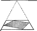
shorter than that near to us,
and all the angles are different. Thus A (Fig. 2) is a geometrical square and B is the same square seen in
perspective.

|

|
|
Fig. 2. |
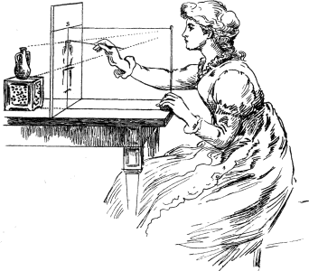
The science of perspective gives the dimensions of objects seen in
space as they appear to the eye of the spectator, just as a perfect
tracing of those objects on a sheet of glass placed vertically between
him and them would do; indeed its very name is derived from
perspicere, to see through. But as no tracing done by hand could
possibly be mathematically correct, the mathematician teaches us how by
certain points and measurements we may yet give a perfect image of them.
These images are called projections, but the artist calls them pictures.
In this sketch K is the vertical
transparent plane or picture, O is a
cube placed on one side of it. The young student is the spectator on the
other side of it, the dotted lines drawn from the corners of the cube to
the eye of the spectator are the visual rays, and the points on the
transparent picture plane where these visual rays pass through it
indicate the perspective position
of those points on the picture. To find these points is the main object
or duty of linear perspective.
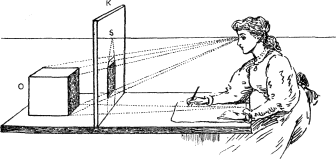
Fig. 3.
Perspective up to a certain point is a pure science, not depending
upon the accidents of vision, but upon the exact laws of reasoning. Nor
is it to be considered as only pertaining to the craft of the painter
and draughtsman. It has an intimate connexion with our mental
perceptions and with the ideas that are impressed upon the brain by the
appearance of all that surrounds us. If we saw everything as depicted by
plane geometry, that is, as a map, we should have no difference of view,
no variety of ideas, and we should live in a world of unbearable
monotony; but as we see everything in perspective, which is infinite in
its variety of aspect, our minds are subjected to countless phases of
thought, making the world around us constantly interesting, so it is
devised that we shall see the infinite wherever we turn, and marvel at
it, and delight in it, although perhaps in many cases unconsciously.
In perspective, as in geometry, we deal with parallels, squares,
triangles, cubes, circles, &c.; but in perspective the same figure
takes an endless variety of forms, whereas in geometry it has but one.
Here are three equal geometrical squares: they are all alike. Here are
three equal perspective squares, but all varied
in form; and the same figure changes in aspect as often as we view it
from a different position. A walk round the dining-room table will
exemplify this.
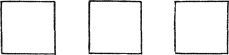
Fig. 4.
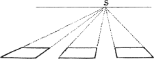
Fig. 5.
It is in proving that, notwithstanding this difference of appearance,
the figures do represent the same form, that much of our work consists;
and for those who care to exercise their reasoning powers it becomes not
only a sure means of knowledge, but a study of the greatest
interest.
Perspective is said to have been formed into a science about the
fifteenth century. Among the names mentioned by the unknown but pleasant
author of The Practice of Perspective, written by a Jesuit of
Paris in the eighteenth century, we find Albert Dürer, who has left us
some rules and principles in the fourth book of his Geometry;
Jean Cousin, who has an express treatise on the art wherein are many
valuable things; also Vignola, who altered the plans of St.
Peter’s left by Michelangelo; Serlio, whose treatise is one of the
best I have seen of these early writers; Du Cerceau, Serigati, Solomon
de Cause, Marolois, Vredemont; Guidus Ubaldus, who first introduced
foreshortening; the Sieur de Vaulizard, the Sieur Dufarges, Joshua
Kirby, for whose Method of Perspective made Easy (?) Hogarth drew
the well-known frontispiece; and lastly, the above-named Practice of
Perspective by a Jesuit of Paris, which is very clear and excellent
as far as it goes, and was the book used by Sir Joshua Reynolds.2 But nearly all
these authors treat chiefly of parallel perspective, which they do with
clearness and simplicity, and also mathematically, as shown in the short
treatise in Latin by Christian Wolff, but they scarcely touch upon the
more difficult problems of angular and oblique perspective. Of modern
books, those to which I am most indebted are the Traité Pratique de
Perspective of M. A. Cassagne (Paris, 1873), which is
thoroughly artistic, and full of pictorial examples admirably done; and
to M. Henriet’s Cours Rational de Dessin. There are
many other foreign books of excellence, notably M. Thibault's
Perspective, and some German and Swiss books, and yet,
notwithstanding this imposing array of authors, I venture to say
that many new features and original
problems are presented in this book, whilst the old ones are not
neglected. As, for instance, How to draw figures at an angle without
vanishing points (see p. 141, Fig. 162,
&c.), a new method of angular perspective which dispenses with
the cumbersome setting out usually adopted, and enables us to draw
figures at any angle without vanishing lines, &c., and is almost, if
not quite, as simple as parallel perspective (see p. 133, Fig. 150, &c.). How to measure distances by the square
and diagonal, and to draw interiors thereby (p. 128, Fig. 144). How to explain the theory of perspective by
ocular demonstration, using a vertical sheet of glass with strings,
placed on a drawing-board, which I have found of the greatest use (see
p. 29, Fig. 29). Then again, I show how
all our perspective can be done inside the picture; that we can measure
any distance into the picture from a foot to a mile or twenty miles (see
p. 86, Fig. 94); how we can draw the Great
Pyramid, which stands on thirteen acres of ground, by putting it 1,600
feet off (Fig. 224), &c., &c. And while
preserving the mathematical science, so that all our operations can be
proved to be correct, my chief aim has been to make it easy of
application to our work and consequently useful to the artist.
The Egyptians do not appear to have made any use of linear
perspective. Perhaps it was considered out of character with their
particular kind of decoration, which is to be looked upon as picture
writing rather than pictorial art; a table, for instance, would be
represented like a ground-plan and the objects upon it in elevation or
standing up. A row of chariots with their horses and drivers side
by side were placed one over the other, and although the Egyptians had
no doubt a reason for this kind of representation, for they were grand
artists, it seems to us very primitive; and indeed quite young beginners
who have never drawn from real objects have a tendency to do very much
the same thing as this ancient people did, or even to emulate the
mathematician and represent things not as they appear but as they are,
and will make the top of a table an almost upright square and the
objects upon it as if they would fall off.
No doubt the Greeks had correct notions of perspective, for the
paintings on vases, and at Pompeii and Herculaneum, which were either by
Greek artists or copied from Greek pictures,
show some knowledge, though not complete knowledge, of this science.
Indeed, it is difficult to conceive of any great artist making his
perspective very wrong, for if he can draw the human figure as the
Greeks did, surely he can draw an angle.
The Japanese, who are great observers of nature, seem to have got at
their perspective by copying what they saw, and, although they are not
quite correct in a few things, they convey the idea of distance and make
their horizontal planes look level, which are two important things in
perspective. Some of their landscapes are beautiful; their trees,
flowers, and foliage exquisitely drawn and arranged with the greatest
taste; whilst there is a character and go about their figures and birds,
&c., that can hardly be surpassed. All their pictures are lively and
intelligent and appear to be executed with ease, which shows their
authors to be complete masters of their craft.
The same may be said of the Chinese, although their perspective is
more decorative than true, and whilst their taste is exquisite their
whole art is much more conventional and traditional, and does not remind
us of nature like that of the Japanese.
We may see defects in the perspective of the ancients, in the
mediaeval painters, in the Japanese and Chinese, but are we always right
ourselves? Even in celebrated pictures by old and modern masters there
are occasionally errors that might easily have been avoided, if a ready
means of settling the difficulty were at hand. We should endeavour then
to make this study as simple, as easy, and as complete as possible, to
show clear evidence of its correctness (according to its conditions),
and at the same time to serve as a guide on any and all occasions that
we may require it.
To illustrate what is perspective, and as an experiment that any one
can make, whether artist or not, let us stand at a window that looks out
on to a courtyard or a street or a garden, &c., and trace with a
paint-brush charged with Indian ink or water-colour the outline of
whatever view there happens to be outside, being careful to keep the eye
always in the same place by means of a rest; when this is dry, place a
piece of drawing-paper over it and trace through with a pencil. Now we
will rub out the tracing on the glass, which is sure to be rather
clumsy, and, fixing
our paper down on a board, proceed to draw the scene before us, using
the main lines of our tracing as our guiding lines.
If we take pains over our work, we shall find that, without troubling
ourselves much about rules, we have produced a perfect perspective of
perhaps a very difficult subject. After practising for some little time
in this way we shall get accustomed to what are called perspective
deformations, and soon be able to dispense with the glass and the
tracing altogether and to sketch straight from nature, taking little
note of perspective beyond fixing the point of sight and the
horizontal-line; in fact, doing what every artist does when he goes out
sketching.
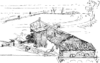
Fig. 6. This is a much reduced
reproduction of a drawing made on my studio window in this way some
twenty years ago, when the builder started covering the fields at the
back with rows and rows of houses.
Definitions
Fig. 7. In this figure, AKB
represents the picture or transparent vertical plane through which the
objects to be represented can be seen, or on which they can be traced,
such as the cube C.
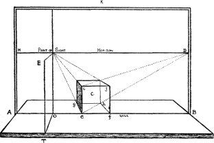
Fig. 7.
The line HD is the
Horizontal-line or Horizon, the chief line in perspective,
as upon it are placed the principal points to which our perspective
lines are drawn. First, the Point of Sight and next D, the Point of Distance. The chief vanishing
points and measuring points are also placed on this line.
Another important line is AB, the
Base or Ground line, as it is on this that we measure the
width of any object to be represented, such as ef, the base of
the square efgh, on which the cube C is raised. E is
the position of the eye of the spectator, being drawn in perspective,
and is called the Station-point.
Note that the perspective of the board, and the line SE, is not
the same as that of the cube in the picture AKB, and also that so much of the board which is
behind the picture plane partially represents the
Perspective-plane, supposed to be perfectly level and to extend
from the base line to the horizon. Of this we shall speak further on. In
nature it is not really level, but partakes in extended views of the
rotundity of the earth, though in small areas such as ponds the
roundness is infinitesimal.
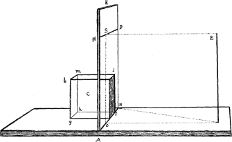
Fig. 8.
Fig. 8. This is a side view of the previous figure, the picture plane
K being represented edgeways, and the
line SE its full length. It also shows
the position of the eye in front of the point of sight S. The horizontal-line HD and the base or ground-line AB are represented as receding from us, and in that
case are called vanishing lines, a not quite satisfactory term.
It is to be noted that the cube C
is placed close to the transparent picture plane, indeed touches it, and
that the square fj faces the spectator E, and although here drawn in perspective it appears
to him as in the other figure. Also, it is at the same time a
perspective and a geometrical figure, and can therefore be measured with
the compasses. Or in other words, we can
touch the square fj, because it is on the surface of the picture,
but we cannot touch the square ghmb at the other end of the cube
and can only measure it by the rules of perspective.
The Point of Sight, the Horizon, and the Point
of Distance
There are three things to be considered and understood before we can
begin a perspective drawing. First, the position of the eye in front of
the picture, which is called the Station-point, and of course is
not in the picture itself, but its position is indicated by a point on
the picture which is exactly opposite the eye of the spectator, and is
called the Point of Sight, or Principal Point, or
Centre of Vision, but we will keep to the first of these.
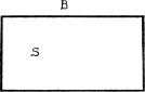
|
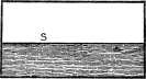
|
|
Fig. 9. |
Fig. 10. |
If our picture plane is a sheet of glass, and is so placed that we
can see the landscape behind it or a sea-view, we shall find that the
distant line of the horizon passes through that point of sight, and we
therefore draw a line on our picture which exactly corresponds with it,
and which we call the Horizontal-line or Horizon.3 The height of
the horizon then depends entirely upon the position of the eye of the
spectator: if he rises, so does the horizon; if he stoops or descends to
lower ground, so does the horizon follow his movements. You may sit in a
boat on a calm sea, and the horizon will be as low down as you are, or
you may go to the top of a high cliff, and still the horizon will be on
the same level as your eye.
This is an important line for the draughtsman to consider, for the
effect of his picture greatly depends upon the position of the horizon.
If you wish to give height and dignity to a mountain or a building, the
horizon should be low down, so that these things may appear to tower
above you. If you wish to show a wide expanse of landscape, then you
must survey it from a height. In a composition of figures, you select
your horizon according to the subject, and with a view to help the
grouping. Again, in portraits and decorative work to be placed high up,
a low horizon is desirable, but I have already spoken of this
subject in the chapter on the necessity of the study of perspective.
Point of Distance
|
|
Fig. 11. |
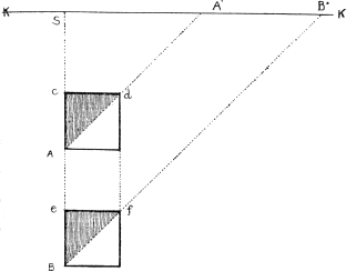
Fig. 11. The distance of the spectator from the picture is of great
importance; as the distortions and disproportions arising from too near
a view are to be avoided, the object of drawing being to make things
look natural; thus, the floor should look level, and not as if it were
running up hill—the top of a table flat, and not on a slant, as if
cups and what not, placed upon it, would fall off.
In this figure we have a geometrical or ground plan of two squares at
different distances from the picture, which is represented by the line
KK. The spectator is first at A, the corner of the near square Acd. If from A we draw a diagonal of that square and produce it
to the line KK (which may represent
the horizontal-line in the picture), where it intersects that line at
A· marks the distance that the
spectator is from the point of sight S. For it will be seen that line SA equals line SA·. In like manner, if the spectator is at B, his distance from the point S is also found on the horizon by means of the
diagonal BB´, so that all lines or
diagonals at 45° are drawn to the point of distance (see
Rule 6).
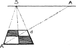
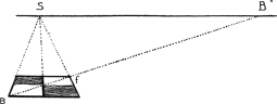
Figs. 12 and 13. In these two figures the difference is shown between
the effect of the short-distance point A· and the long-distance point B·; the first, Acd, does not appear to lie so flat on the
ground as the second square, Bef.
From this it will be seen how important it is to choose the
right point of distance: if we take it too near the point of sight, as
in Fig. 12, the square looks unnatural and distorted. This, I may
note, is a common fault with photographs taken with a wide-angle lens,
which throws everything out of proportion, and will make the east end of
a church or a cathedral appear higher than the steeple or tower; but as
soon as we make our
line of distance sufficiently long, as at Fig. 13, objects take their
right proportions and no distortion is noticeable.
|
|
|
Fig. 12. |
Fig. 13. |
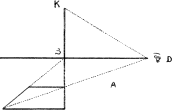
In some books on perspective we are told to make the angle of vision
60°, so that the distance SD (Fig. 14)
is to be rather less than the length or height of the picture, as at
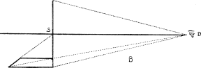
A. The French recommend an angle of
28°, and to make the distance about double the length of the picture, as
at B (Fig. 15), which is far more
agreeable. For we must remember that the distance-point is not only the
point from which we are supposed to make our tracing on the vertical
transparent plane, or a point transferred to the horizon to make our
measurements by, but it is also the point in front of the canvas that we
view the picture from, called the station-point. It is ridiculous, then,
to have it so close that we must almost touch the canvas with our noses
before we can see its perspective properly.
|
|
|
Fig. 14. |
Fig. 15. |
Now a picture should look right from whatever distance we
view it, even across the room or gallery, and of course in decorative
work and in scene-painting a long distance is necessary.
We need not, however, tie ourselves down to any hard and fast rule,
but should choose our distance according to the impression of space we
wish to convey: if we have to represent a domestic scene in a small
room, as in many Dutch pictures, we must not make our distance-point too
far off, as it would exaggerate the size of the room.
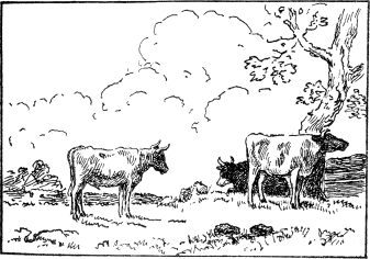
Fig. 16. Cattle. By Paul Potter.
The height of the horizon is also an important consideration in the
composition of a picture, and so also is the position of the point of
sight, as we shall see farther on.
In landscape and cattle pictures a low horizon often gives space and
air, as in this sketch from a picture by Paul Potter—where the
horizontal-line is placed at one quarter the height of the canvas.
Indeed, a judicious use of the laws of perspective is a great aid
to composition, and no picture ever looks right unless these laws are
attended to. At the present time too little attention is paid to them;
the consequence is that much of the art of the day reflects in a great
measure the monotony of the snap-shot camera, with its everyday and
wearisome commonplace.
Perspective of a Point, Visual Rays,
&c.
We perceive objects by means of the visual rays, which are imaginary
straight lines drawn from the eye to the various points of the thing we
are looking at. As those rays proceed from the pupil of the eye, which
is a circular opening, they form themselves into a cone called the
Optic Cone, the base of which increases in proportion to its
distance from the eye, so that the larger the view which we wish to take
in, the farther must we be removed from it. The diameter of the base of
this cone, with the visual rays drawn from each of its extremities to
the eye, form the angle of vision, which is wider or narrower according
to the distance of this diameter.
|
|
Fig. 17. |
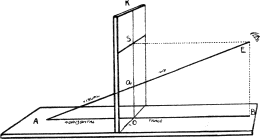
Now let us suppose a visual ray EA
to be directed to some small object on the floor, say the head of a
nail, A (Fig. 17). If we interpose
between this nail and our eye a sheet of glass, K, placed vertically on the floor, we continue to
see the nail through the glass, and it is easily understood that its
perspective appearance thereon is the point a, where the visual
ray passes through it. If now we trace on the floor a line AB from the nail to the spot B, just under the eye, and from the point o,
where this line passes through or under the glass, we raise a
perpendicular oS, that
perpendicular passes through the precise point that the visual ray
passes through. The line AB traced on
the floor is the horizontal trace of the visual ray, and it will be seen
that the point a is situated on the vertical raised from this
horizontal trace.
Trace and Projection
If from any line A or B or C (Fig. 18),
&c., we drop perpendiculars from different points of those lines on
to a horizontal plane, the intersections of those verticals with the
plane will be on a line called the horizontal trace or projection of the
original line. We may liken these projections to sun-shadows when the
sun is in the meridian, for it will be remarked that the trace does not
represent the length of the original line, but only so much of it as
would be embraced by the verticals dropped from each end of it, and
although line A is the same length as
line B its horizontal
trace is longer than that of the other; that the projection of a curve
(C) in this upright position is a
straight line, that of a horizontal line (D) is equal to it, and the projection of a
perpendicular or vertical (E) is a
point only. The projections of lines or points can likewise be shown on
a vertical plane, but in that case we draw lines parallel to the
horizontal plane, and by this means we can get the position of a point
in space; and by the assistance of perspective, as will be shown farther
on, we can carry out the most difficult propositions of descriptive
geometry and of the geometry of planes and solids.
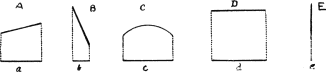
Fig. 18.
The position of a point in space is given by its projection on a
vertical and a horizontal plane—
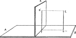
Fig. 19.
Thus e· is the projection of E on the vertical plane K, and e·· is the projection of E on the horizontal plane; fe·· is the
horizontal trace of the plane fE, and e·f is the trace of the same plane on
the vertical plane K.
Scientific Definition of Perspective
The projections of the extremities of a right line which passes
through a vertical plane being given, one on either side of it, to find
the intersection of that line with the vertical plane. AE (Fig. 20) is the right line. The projection of
its extremity A on the vertical plane
is a·, the projection of E, the
other extremity, is e·. AS is
the horizontal trace of AE, and
a·e· is its trace
on the vertical plane. At point f, where the horizontal trace
intersects the base Bc of the
vertical plane, raise perpendicular fP till it cuts a·e· at point P, which is the point required. For it is at the
same time on the given line AE and the
vertical plane K.
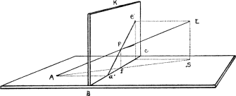
Fig. 20.
This figure is similar to the previous one, except that the extremity
A of the given line is raised from the
ground, but the same demonstration applies to it.
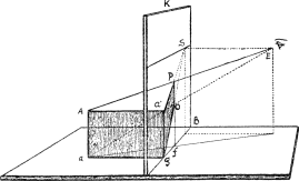
Fig. 21.
And now let us suppose the vertical plane K to be a sheet of glass, and the given line AE to be the visual ray passing from
the eye to the object A on the other
side of the glass. Then if E is the
eye of the spectator, its projection on the picture is S, the point of sight.
If I draw a dotted line from E to
little a, this represents another visual ray, and o, the
point where it passes through the picture, is the perspective of little
a. I now draw another line from g to S, and thus form the shaded figure ga·Po, which is the perspective of
aAa·g.
Let it be remarked that in the shaded perspective figure the lines
a·P and go are both
drawn towards S, the point of sight,
and that they represent parallel lines Aa· and ag, which are at right angles
to the picture plane. This is the most important fact in perspective,
and will be more fully explained farther on, when we speak of retreating
or so-called vanishing lines.
The Rules and Conditions of Perspective
The conditions of linear perspective are somewhat rigid. In the first
place, we are supposed to look at objects with one eye only; that is,
the visual rays are drawn from a single point, and not from two. Of this
we shall speak later on. Then again, the eye must be placed in a certain
position, as at E (Fig. 22), at a
given height from the ground, S·E, and
at a given distance from the picture, as SE. In the next place, the picture or picture plane
itself must be vertical and perpendicular to the ground or horizontal
plane, which plane is supposed to be as level as a billiard-table, and
to extend from the base line, ef, of the picture to the horizon,
that is, to infinity, for it does not partake of the rotundity of the
earth.
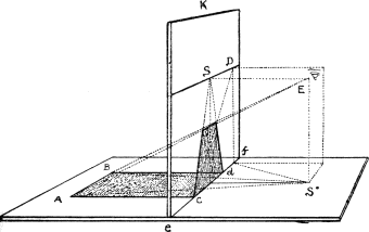
Fig. 22.
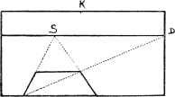
|
|
Fig. 23.
Front view of above figure. |
We can only work out our propositions and figures in space with
mathematical precision by adopting such conditions as the above. But
afterwards the artist or draughtsman may modify and suit them to a more
elastic view of things; that is, he can make his figures separate from
one another, instead of their outlines coming close together as they do
when we look at them
with only one eye. Also he will allow for the unevenness of the ground
and the roundness of our globe; he may even move his head and his eyes,
and use both of them, and in fact make himself quite at his ease when he
is out sketching, for Nature does all his perspective for him. At the
same time, a knowledge of this rigid perspective is the sure and
unerring basis of his freehand drawing.
All straight lines remain straight in their perspective appearance.4
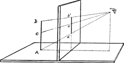
|
|
Fig. 24. |
Vertical lines remain vertical in perspective, and are divided in the
same proportion as AB (Fig. 24), the
original line, and a·b·, the perspective line, and if the one is
divided at O the other is divided at
o· in the same way.
It is not an uncommon error to suppose that the vertical lines of a
high building should converge towards the top; so they would if we stood
at the foot of that building and looked up, for then we should alter the
conditions of our perspective, and our point of sight, instead of being
on the horizon, would be up in the sky. But if we stood sufficiently far
away, so as to bring the whole of the building within our angle of
vision, and the point of sight down to the horizon, then these same
lines would appear perfectly parallel, and the different stories in
their true proportion.
|
|
Fig. 25. |
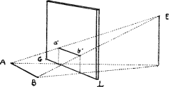
Horizontals parallel to the base of the picture are also parallel to
that base in the picture. Thus a·b· (Fig. 25) is parallel to
AB,
and to GL, the base of the picture.
Indeed, the same argument may be used with regard to horizontal lines as
with verticals. If we look at a straight wall in front of us, its top
and its rows of bricks, &c., are parallel and horizontal; but if we
look along it sideways, then we alter the conditions, and the parallel
lines converge to whichever point we direct the eye.
This rule is important, as we shall see when we come to the
consideration of the perspective vanishing scale. Its use may be
illustrated by this sketch, where the houses, walls, &c., are
parallel to the base of the picture. When that is the case, then objects
exactly facing us, such as windows, doors, rows of boards, or of bricks
or palings, &c., are drawn with their horizontal lines parallel to
the base; hence it is called parallel perspective.
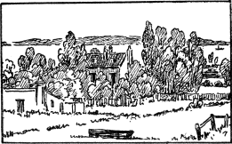
Fig. 26.
All lines situated in a plane that is parallel to the picture plane
diminish in proportion as they become more distant, but do not undergo
any perspective deformation; and remain in the same relation and
proportion each to each as the original lines. This is called the front
view.
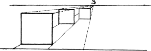
Fig. 27.
All horizontals which are at right angles to the picture plane are
drawn to the point of sight.
Thus the lines AB and CD (Fig. 28) are horizontal or parallel to the
ground plane, and are also at right angles to the picture plane K. It will be seen that the perspective
lines Ba·, Dc·, must, according to the laws of
projection, be drawn to the point of sight.
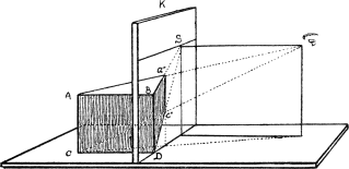
Fig. 28.
This is the most important rule in perspective (see Fig. 7 at beginning of Definitions).
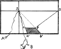
|
|
Fig. 29. |
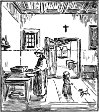
|
|
Fig. 30. |
An arrangement such as there indicated is the best means of
illustrating this rule. But instead of tracing the outline of the square
or cube on the glass, as there shown, I have a hole drilled through
at the point S (Fig. 29), which I
select for the point of sight, and through which I pass two loose
strings A and B, fixing their ends at S.
As SD represents the distance the
spectator is from the glass or picture, I make string SA equal in length to SD. Now if the pupil takes this string in one hand
and holds it at right angles to the glass, that is, exactly in front of
S, and then places one eye at the end
A (of course with the string
extended), he will be at the proper distance from the picture. Let him
then take the other string, SB, in the
other hand, and apply it to point b´ where the square touches the
glass, and he will find that it exactly tallies with the side b´f
of the square a·b´fe. If he applies the same string to a·,
the other corner of the square, his string will exactly tally or cover
the side a·e, and he will thus have ocular demonstration of this
important rule.
In this little picture (Fig. 30) in parallel perspective it will be
seen that the lines which retreat from us at right angles to the picture
plane are directed to the point of sight S.
All horizontals which are at 45°, or half a right angle to the
picture plane, are drawn to the point of distance.
We have already seen that the diagonal of the perspective square, if
produced to meet the horizon on the picture, will mark on that horizon
the distance that the spectator is from the point of sight (see definition, p. 16). This point of distance becomes
then the measuring point for all horizontals at right angles to the
picture plane.
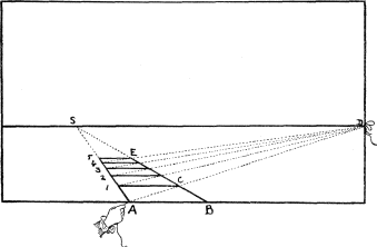
Fig. 31.
Thus in Fig. 31 lines AS and BS are drawn to the point of sight S, and are therefore at right angles to the
base AB. AD being drawn to D (the distance-point), is at an angle of 45° to the
base AB, and AC is therefore the diagonal of a square. The line
1C is made parallel to AB, consequently A1CB is a square
in perspective. The line BC,
therefore, being one side of that square, is equal to AB, another side of it. So that to measure a length
on a line drawn to the point of sight, such as BS, we set out the length required, say BA, on the base-line, then from A draw a line to the point of distance, and where it
cuts BS at C is the length required. This can be repeated any
number of times, say five, so that in this figure BE is five times the length of AB.
All horizontals forming any other angles but the above are drawn to
some other points on the horizontal line. If the angle is greater than
half a right angle (Fig. 32), as EBG,
the point is within the point of distance, as at V´. If it is less, as ABV´´, then
it is beyond the point of distance, and consequently farther from the
point of sight.
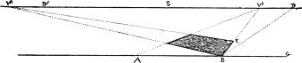
Fig. 32.
In Fig. 32, the dotted line BD,
drawn to the point of distance D, is
at an angle of 45° to the base AG. It
will be seen that the line BV´ is at a
greater angle to the base than BD; it
is therefore drawn to a point V´,
within the point of distance and nearer to the point of sight S. On the other hand, the line BV´´ is at a more acute angle, and is therefore
drawn to a point some way beyond the other distance point.
Note.—When this vanishing point is a long way outside
the picture, the architects make use of a centrolinead, and the painters
fix a long string at the required point, and get their perspective lines
by that means, which is very inconvenient. But I will show you later on
how you can dispense with this trouble by a very simple means, with
equally correct results.
Lines which incline upwards have their vanishing points above the
horizontal line, and those which incline downwards, below it. In both
cases they are on the vertical which passes through the vanishing point
(S) of their horizontal
projections.
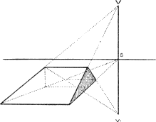
Fig. 33.
This rule is useful in drawing steps, or roads going uphill and
downhill.
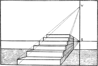
Fig. 34.
The farther a point is removed from the picture plane the nearer does
its perspective appearance approach the horizontal line so long as it is
viewed from the same position. On the contrary, if the spectator
retreats from the picture plane K
(which we suppose to be transparent), the point remaining at the same
place, the perspective appearance of this point will approach the
ground-line in proportion to the distance of the spectator.
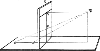
Fig. 35.
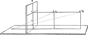
Fig. 36.
The spectator at two different distances from the
picture.
Therefore the position of a given point in perspective above the
ground-line or below the horizon is in proportion to the distance of the
spectator from the picture, or the picture from the point.
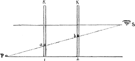
Fig. 37.
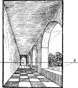
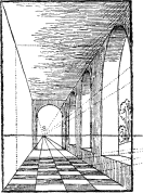
Figures 38 and 39 are two views of the same gallery from different
distances. In Fig. 38, where the distance is too short, there is a want
of proportion between the near and far objects, which is corrected in
Fig. 39 by taking a much longer distance.
|
The picture at two different distances from the point. |
|
|
|
Fig. 38. |
Fig. 39. |
Horizontals in the same plane which are drawn to the same point on
the horizon are parallel to each other.
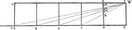
Fig. 40.
This is a very important rule, for all our perspective drawing
depends upon it. When we say that parallels are drawn to the same point
on the horizon it does not imply that they meet at that point, which
would be a contradiction; perspective parallels never reach that point,
although they appear to do so. Fig. 40 will explain this.
Suppose S to be the spectator,
AB a transparent vertical plane which
represents the picture seen edgeways, and HS and DC two
parallel lines, mark off spaces between these parallels equal to SC, the height of the eye of the spectator,
and raise verticals 2, 3, 4, 5, &c., forming so many squares.
Vertical line 2 viewed from S
will appear on AB but half its length,
vertical 3 will be only a third, vertical 4 a fourth, and so
on, and if we multiplied these spaces ad infinitum we must keep
on dividing the line AB by the same
number. So if we suppose AB to be a
yard high and the distance from one vertical to another to be also a
yard, then if one of these were a thousand yards away its representation
at AB would be the thousandth part of
a yard, or ten thousand yards away, its representation at AB would be the ten-thousandth part, and whatever
the distance it must always be something; and therefore HS and DC, however
far they may be produced
and however close they may appear to get, can never meet.
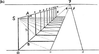
Fig. 41.
Fig. 41 is a perspective view of the same figure—but more
extended. It will be seen that a line drawn from the tenth upright K to S
cuts off a tenth of AB. We look then
upon these two lines SP, OP, as the
sides of a long parallelogram of which SK is the diagonal, as cefd, the figure on
the ground, is also a parallelogram.
The student can obtain for himself a further illustration of this
rule by placing a looking-glass on one of the walls of his studio and
then sketching himself and his surroundings as seen therein.
He will find that all the horizontals at right angles to the glass will
converge to his own eye. This rule applies equally to lines which are at
an angle to the picture plane as to those that are at right angles or
perpendicular to it, as in Rule 7. It also applies to those on an
inclined plane, as in Rule 8.
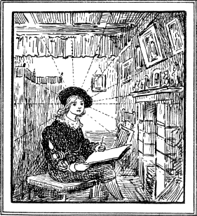
Fig. 42. Sketch of artist in
studio.
With the above rules and a clear notion of the definitions and
conditions of perspective, we should be able to work out any proposition
or any new figure that may present itself. At any rate, a thorough
understanding of these few pages will make the labour now before us
simple and easy. I hope, too, it may be found interesting. There is
always a certain pleasure in deceiving and being deceived by the senses,
and in optical and other illusions, such as making things appear far off
that are quite near, in making a picture of an object on a flat surface
to look as if it stood out and in relief by a kind of magic. But there
is, I think, a still greater pleasure than this, namely, in
invention and in overcoming difficulties—in finding out how to do
things for ourselves by our reasoning faculties, in originating or being
original, as it were. Let us now see how far we can go in this
respect.
A Table or Index of the Rules of
Perspective
The rules here set down have been fully explained in the previous
pages, and this table is simply for the student's ready reference.
Rule 1
All straight lines remain straight in their perspective
appearance.
Rule 2
Vertical lines remain vertical in perspective.
Rule 3
Horizontals parallel to the base of the picture are also parallel to
that base in the picture.
Rule 4
All lines situated in a plane that is parallel to the picture plane
diminish in proportion as they become more distant, but do not undergo
any perspective deformation. This is called the front view.
Rule 5
All horizontal lines which are at right angles to the picture plane
are drawn to the point of sight.
Rule 6
All horizontals which are at 45° to the picture plane are drawn to
the point of distance.
Rule 7
All horizontals forming any other angles but the above are drawn to
some other points on the horizontal line.
Rule 8
Lines which incline upwards have their vanishing points above the
horizon, and those which incline downwards, below it. In both cases they
are on the vertical which passes through the vanishing point of their
ground-plan or horizontal projections.
Rule 9
The farther a point is removed from the picture plane the nearer does
it appear to approach the horizon, so long as it is viewed from the same
position.
Rule 10
Horizontals in the same plane which are drawn to the same point on
the horizon are perspectively parallel to each other.
In the foregoing book we have explained the theory or science of
perspective; we now have to make use of our knowledge and to apply it to
the drawing of figures and the various objects that we wish to
depict.
The first of these will be a square with two of its sides parallel to
the picture plane and the other two at right angles to it, and which we
call
The Square in Parallel Perspective
From a given point on the base line of the picture draw a line at
right angles to that base. Let P be
the given point on the base line AB,
and S the point of sight. We simply
draw a line along the ground to the point of sight S, and this line will be at right angles to the
base, as explained in Rule 5, and consequently angle APS will be equal to angle SPB, although it does not look so here. This is our
first difficulty, but one that we shall soon get over.
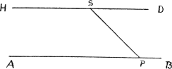
Fig. 43.
In like manner we can draw any number of lines at right angles to the
base, or we may suppose the point P to
be placed at so many different positions, our only difficulty being to
conceive these lines to be parallel to each other. See Rule 10.
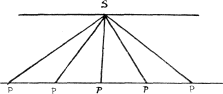
Fig. 44.
The Diagonal
|
|
Fig. 45. |
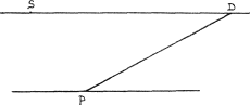
From a given point on the base line draw a line at 45°, or half a
right angle, to that base. Let P be
the given point. Draw a line from P to
the point of distance D and this line
PD will be at an angle of 45°, or at
the same angle as the diagonal of a square. See definitions.
The Square
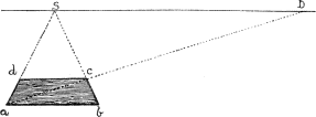
Draw a square in parallel perspective on a given length on the base
line. Let ab be the given length. From its two
extremities a and b draw aS and bS to
the point of sight S. These two lines
will be at right angles to the base (see Fig.
43). From a draw diagonal aD to point of distance D; this line will be 45° to base. At point c,
where it cuts bS, draw
dc parallel to ab and abcd is the square
required.
|
|
|
Fig. 46. |
Fig. 47. |
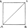
We have here proceeded in much the same way as in drawing a
geometrical square (Fig. 47), by drawing two lines AE and BC at right
angles to a given line, AB, and from
A, drawing the diagonal AC at 45° till it cuts BC at C, and then
through C drawing EC parallel to AB.
Let it be remarked that because the two perspective lines (Fig. 48)
AS and BS are at right angles to the base, they must
consequently be parallel to each other, and therefore are perspectively
equidistant, so that all lines parallel to AB and lying between them, such as ad,
cf, &c., must be equal.
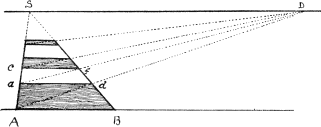
Fig. 48.
|
|
Fig. 49. |
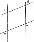
So likewise all diagonals drawn to the point of distance, which
are contained between these parallels, such as Ad, af, &c., must be equal. For
all straight lines which meet at any point on the horizon are
perspectively parallel to each other, just as two geometrical parallels
crossing two others at any angle, as at Fig. 49. Note also (Fig. 48)
that all squares formed between the two vanishing lines AS, BS, and by the
aid of these diagonals, are also equal, and further, that any number of
squares such as are shown in this figure (Fig. 50), formed in the same
way and having equal bases, are also equal; and the nine squares
contained in the square abcd being equal, they divide each side
of the larger square into three equal parts.
From this we learn how we can measure any number of given
lengths, either equal or unequal, on a vanishing or retreating line
which is at right angles to the base; and also how we can measure any
width or number of widths on a line such as dc, that is, parallel
to the base of the picture, however remote it may be from that base.
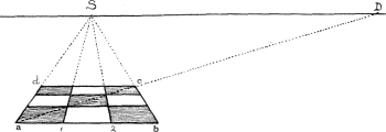
Fig. 50.
Geometrical and Perspective Figures
Contrasted
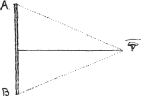
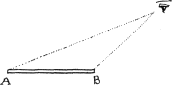
As at first there may be a little difficulty in realizing the
resemblance between geometrical and perspective figures, and also about
certain expressions we make use of, such as horizontals, perpendiculars,
parallels, &c., which look quite different in perspective,
I will here make a note of them and also place side by side the two
views of the same figures.
|
|
|
Fig. 51 A. The geometrical view. |
Fig. 51 B. The perspective view. |

|

|
|
Fig. 51 C. A geometrical square. |
Fig. 51 D. A perspective square. |

|
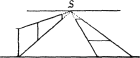
|
|
Fig. 51 E. Geometrical parallels. |
Fig. 51 F. Perspective parallels. |

|
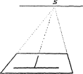
|
|
Fig. 51 G. Geometrical
perpendicular. |
Fig. 51 H. Perspective
perpendicular. |

|
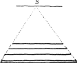
|
|
Fig. 51 I. Geometrical equal
lines. |
Fig. 51 J. Perspective equal
lines. |
|
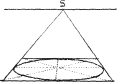
|
|
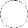
Fig. 51 K. A geometrical circle. |
Fig. 51 L. A perspective circle. |
Of Certain Terms made use of in Perspective
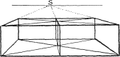
|
|
Fig. 52. Horizontals. |
Of course when we speak of Perpendiculars we do not mean
verticals only, but straight lines at right angles to other lines in any
position. Also in speaking of lines a right or straight
line is to be understood; or when we speak of horizontals we
mean all straight lines that are parallel to the perspective plane, such
as those on Fig. 52, no matter what direction they take so long as they
are level. They are not to be confused with the horizon or
horizontal-line.
There are one or two other terms used in perspective which are not
satisfactory because they are confusing, such as vanishing lines and
vanishing points. The French term, fuyante or lignes
fuyantes, or going-away lines, is more expressive; and point de
fuite, instead of vanishing point, is much better. I have
occasionally called the former retreating lines, but the simple meaning
is, lines that are not parallel to the picture plane; but a vanishing
line implies a line that disappears, and a vanishing point implies
a point that gradually goes out of sight. Still, it is difficult to
alter terms that custom has endorsed. All we can do is to use as few of
them as possible.
How to Measure Vanishing or Receding Lines
Divide a vanishing line which is at right angles to the picture plane
into any number of given measurements. Let SA be the given line. From A measure off on the base line the divisions
required, say five of 1 foot each; from each division draw
diagonals to point of distance D, and
where these intersect the line AC the
corresponding divisions will be found. Note that as lines AB and AC are two
sides of the same square they are necessarily equal, and so also are the
divisions on AC equal to those on
AB.
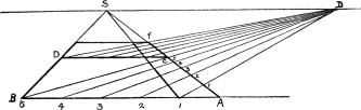
Fig. 53.
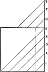
|
|
Fig. 54. |
The line AB being the base of the
picture, it is at the same time a perspective line and a geometrical
one, so that we can use it as a scale for measuring given lengths
thereon, but should there not be enough room on it to measure the
required number we draw a second line, DC, which we divide in the same proportion and
proceed to divide cf. This geometrical figure gives, as it were,
a bird's-eye view or ground-plan of the above.
How to Place Squares in Given Positions
Draw squares of given dimensions at given distances from the base
line to the right or left of the vertical line, which passes through the
point of sight.
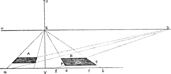
Fig. 55.
Let ab (Fig. 55) represent the base line of the picture
divided into a certain number of feet; HD the horizon, VO
the vertical. It is required to draw a square 3 feet wide,
2 feet to the right of the vertical, and 1 foot from the
base.
First measure from V, 2 feet
to e, which gives the distance from the vertical. Second, from
e measure 3 feet to b, which gives the width of the
square; from e and b draw eS, bS, to
point of sight. From either e or b measure 1 foot to
the left, to f or f·. Draw fD to point of distance, which intersects
eS at P, and gives the required distance from base. Draw
Pg and B parallel to the base, and we have the required
square.
Square A to the left of the
vertical is 2½ feet wide, 1 foot from the vertical and 2 feet
from the base, and is worked out in the same way.
Note.—It is necessary to know how to work to scale,
especially in architectural drawing, where it is indispensable, but in
working
out our propositions and figures it is not always desirable.
A given length indicated by a line is generally sufficient for our
requirements. To work out every problem to scale is not only tedious and
mechanical, but wastes time, and also takes the mind of the student away
from the reasoning out of the subject.
How To Draw Pavements, &c.
Divide a vanishing line into parts varying in length. Let BS· be the vanishing line: divide it into
4 long and 3 short spaces; then proceed as in the previous
figure. If we draw horizontals through the points thus obtained and from
these raise verticals, we form, as it were, the interior of a building
in which we can place pillars and other objects.
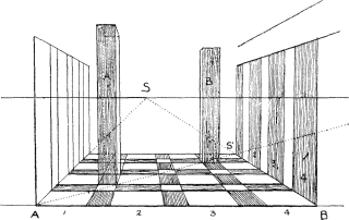
Fig. 56.
Or we can simply draw the plan of the pavement as in this figure.
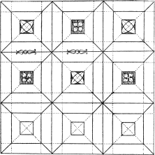
Fig. 57.
And then put it into perspective.
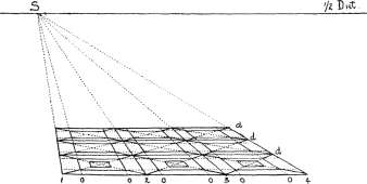
Fig. 58.
Of Squares placed Vertically and at Different
Heights, or the Cube in Parallel Perspective
On a given square raise a cube.
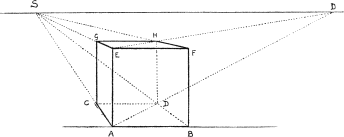
Fig. 59.
ABCD is the given square; from
A and B raise verticals AE, BF, equal to
AB; join EF. Draw ES, FS, to point of sight; from C and D raise
verticals CG, DH, till they meet vanishing lines ES, FS, in G and H,
and the cube is complete.
The Transposed Distance
The transposed distance is a point D· on the vertical VD·, at exactly the same distance from the point of
sight as is the point of distance on the horizontal line.
It will be seen by examining this figure that the diagonals of the
squares in a vertical position are drawn to this vertical
distance-point, thus saving the necessity of taking the measurements
first on the base line, as at CB,
which in the case of distant objects, such as the farthest window, would
be very inconvenient. Note that the windows at K are twice as high as they are wide.
Of course these or any other objects could be made of any
proportion.
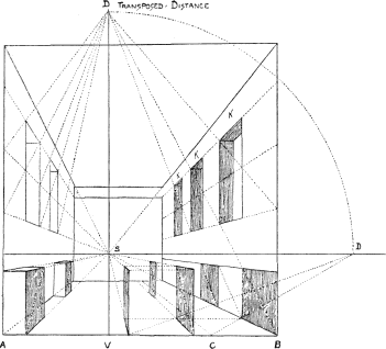
Fig. 60.
The Front View of the Square and of the
Proportions of Figures at Different Heights
According to Rule 4, all lines situated in a plane parallel to
the picture plane diminish in length as they become more distant, but
remain in the same proportions each to each as the original lines; as
squares or any other figures retain the same form. Take the two squares
ABCD, abcd (Fig. 61), one
inside the other; although moved back from square EFGH they retain the same form. So
in dealing with figures of different heights, such as statuary or
ornament in a building, if actually equal in size, so must we represent
them.
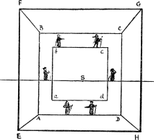
|
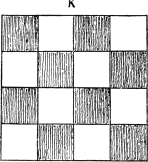
|
|
Fig. 61. |
Fig. 62. |
In this square K, with the checker
pattern, we should not think of making the top squares smaller than the
bottom ones; so it is with figures.
This subject requires careful study, for, as pointed out in our opening
chapter, there are certain conditions under which we have to modify and
greatly alter this rule in large decorative work.
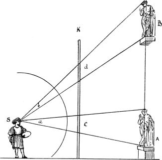
Fig. 63.
In Fig. 63 the two statues A and
B are the same size. So if traced
through a vertical sheet of glass, K,
as at c and d, they would also be equal; but as the angle
b at which the upper one is seen is smaller than angle a,
at which the lower figure or statue is seen, it will appear smaller to
the spectator (S) both in reality and
in the picture.
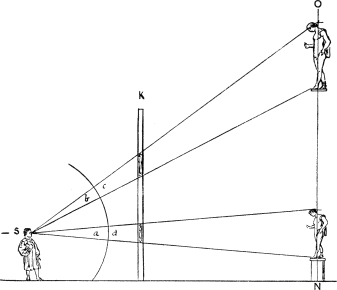
Fig. 64.
But if we wish them to appear the same size to the spectator who is
viewing them from below, we must make the angles a and b
(Fig. 64), at which they are viewed, both equal. Then draw lines through
equal arcs, as at c and d, till they cut the vertical
NO (representing the side of the
building where the figures are to be placed). We shall then obtain the
exact size of the figure at that height, which will make it look the
same size as the lower one, N. The
same rule applies to the picture K,
when it is of large proportions. As an example in painting, take
Michelangelo’s large altar-piece in the Sistine Chapel, ‘The
Last Judgement’; here the figures forming the upper group, with
our Lord in judgement surrounded by saints, are about four times the
size, that is, about twice the height, of those at the lower part of the
fresco. The
figures on the ceiling of the same chapel are studied not only according
to their height from the pavement, which is 60 ft., but to suit the
arched form of it. For instance, the head of the figure of Jonah at the
end over the altar is thrown back in the design, but owing to the
curvature in the architecture is actually more forward than the feet.
Then again, the prophets and sybils seated round the ceiling, which are
perhaps the grandest figures in the whole range of art, would be 18 ft.
high if they stood up; these, too, are not on a flat surface, so that it
required great knowledge to give them their right effect.
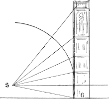
|
|
Fig. 65. |
Of course, much depends upon the distance we view these statues or
paintings from. In interiors, such as churches, halls, galleries,
&c., we can make a fair calculation, such as the length of the nave,
if the picture is an altar-piece—or say, half the length; so also
with statuary in niches, friezes, and other architectural ornaments. The
nearer we are to them, and the more we have to look up, the larger will
the upper figures have to be; but if these are on the outside of a
building that can be looked at from a long distance, then it is better
not to have too great a difference.
For the farther we recede the more equal are the angles at which we view
the objects at their different stages, so that in each case we may have
to deal with, we must consider the conditions attending it.
These remarks apply also to architecture in a great measure.
Buildings that can only be seen from the street below, as pictures in a
narrow gallery, require a different treatment from those out in the
open, that are to be looked at from a distance. In the former case the
same treatment as the Campanile at Florence is in some cases desirable,
but all must depend upon the taste and judgement of the architect in
such matters. All I venture to do here is to call attention to the
subject, which seems as a rule to be ignored, or not to be considered of
importance. Hence the many mistakes in our buildings, and the
unsatisfactory and mean look of some of our public monuments.
Of Pictures that are Painted according to the
Position they are to Occupy
In this double-page illustration of the wall of a picture-gallery,
I have, as it were, hung the pictures in accordance with the style
in which they are painted and the perspective adopted by their painters.
It will be seen that those placed on the line level with the eye have
their horizon lines fairly high up, and are not suited to be placed any
higher. The Giorgione in the centre, the Monna Lisa to the right, and
the Velasquez and Watteau to the left, are all pictures that fit that
position; whereas the grander compositions above them are so designed,
and are so large in conception, that we gain in looking up to them.
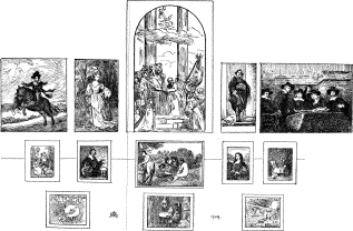
Fig. 66.
Larger View
Note how grandly the young prince on his pony, by Velasquez, tells
out against the sky, with its low horizon and strong contrast of light
and dark; nor does it lose a bit by being placed where it is, over the
smaller pictures.
The Rembrandt, on the opposite side, with its burgomasters in black
hats and coats and white collars, is evidently intended and painted for
a raised position, and to be looked up to, which is evident from the
perspective of the table. The grand Titian in
the centre, an altar-piece in one of the churches in Venice (here
reversed), is also painted to suit its elevated position, with low
horizon and figures telling boldly against the sky. Those placed low
down are modern French pictures, with the horizon high up and almost
above their frames, but placed on the ground they fit into the general
harmony of the arrangement.
It seems to me it is well, both for those who paint and for those who
hang pictures, that this subject should be taken into consideration. For
it must be seen by this illustration that a bigger style is adopted by
the artists who paint for high places in palaces or churches than by
those who produce smaller easel-pictures intended to be seen close.
Unfortunately, at our picture exhibitions, we see too often that nearly
all the works, whether on large or small canvases, are painted for the
line, and that those which happen to get high up look as if they were
toppling over, because they have such a high horizontal line; and
instead of the figures telling against the sky, as in this picture of
the ‘Infant’ by Velasquez, the Reynolds, and the fat man
treading on a flag, we have fields or sea or distant landscape almost to
the top of the frame, and all, so methinks, because the perspective is
not sufficiently considered.
Note.—Whilst on this subject, I may note that the
painter in his large decorative work often had difficulties to contend
with, which arose from the form of the building or the shape of the wall
on which he had to place his frescoes. Painting on the ceiling was no
easy task, and Michelangelo, in a humorous sonnet addressed to Giovanni
da Pistoya, gives a burlesque portrait of himself while he was painting
the Sistine Chapel:—
“I’ho già fatto un gozzo in questo
stento.”
Now have I such a goitre ’neath my chin
That I am like to some Lombardic cat,
My beard is in the air, my head i’ my back,
My chest like any harpy’s, and my face
Patched like a carpet by my dripping brush.
Nor can I see, nor can I budge a step;
My skin though loose in front is tight behind,
And I am even as a Syrian bow.
Alas! methinks a bent tube shoots not well;
So give me now thine aid, my Giovanni.
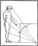
|
|
Fig. 67. |
|
‘Draw upon part of wall MN half
the figure you mean to represent, and the other half upon the cove above
(MR).’ Leonardo da Vinci’s
Treatise on Painting. |
At present that difficulty is got over by using large strong canvas, on
which the picture can be painted in the studio and afterwards placed on
the wall.
However, the other difficulty of form has to be got over also.
A great portion of the ceiling of the Sistine Chapel, and notably
the prophets and sibyls, are painted on a curved surface, in which case
a similar method to that explained by Leonardo da Vinci has to be
adopted.
In Chapter CCCI he shows us how to draw a figure twenty-four braccia
high upon a wall twelve braccia high. (The braccia is 1 ft.
10⅞ in.). He first draws the figure upright, then from the
various points draws lines to a point F on the floor of the building, marking their
intersections on the profile of the wall somewhat in the manner we have
indicated, which serve as guides in making the outline to be traced.
Interiors
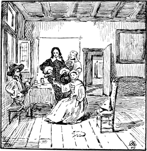
Fig. 68. Interior by de Hoogh.
To draw the interior of a cube we must suppose the side facing us to
be removed or transparent. Indeed, in all our figures which represent
solids we suppose that we can see through them,
and in most cases we mark the hidden portions with dotted lines. So also
with all those imaginary lines which conduct the eye to the various
vanishing points, and which the old writers called
‘occult’.
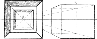
Fig. 69.
When the cube is placed below the horizon (as in Fig. 59), we see the top of it; when on the horizon, as in
the above (Fig. 69), if the side facing us is removed we see both top
and bottom of it, or if a room, we see floor and ceiling, but otherwise
we should see but one side (that facing us), or at most two sides. When
the cube is above the horizon we see underneath it.
We shall find this simple cube of great use to us in architectural
subjects, such as towers, houses, roofs, interiors of rooms, &c.
In this little picture by de Hoogh we have the application of the
perspective of the cube and other foregoing problems.
The Square at an Angle of 45°
When the square is at an angle of 45° to the base line, then its
sides are drawn respectively to the points of distance, DD, and one of its diagonals which is at right
angles to the base is drawn to the point of sight S, and the other ab, is parallel to that base
or ground line.
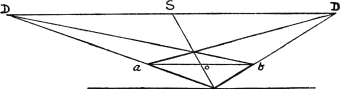
Fig. 70.
To draw a pavement with its squares at this angle is but an
amplification of the above figure. Mark off on base equal distances, 1,
2, 3, &c., representing the diagonals of required squares, and from
each of these points draw lines to points of distance DD´. These lines will intersect each other, and so
form the squares of the pavement; to ensure correctness, lines should
also be drawn from these points 1, 2, 3, to the point of sight S, and also horizontals parallel to the
base, as ab.
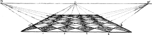
Fig. 71.
The Cube at an Angle of 45°
Having drawn the square at an angle of 45°, as shown in the previous
figure, we find the length of one of its sides, dh, by drawing a
line, SK, through h, one of its
extremities, till it cuts the base line at K. Then, with the other extremity d for
centre and dK for radius,
describe a quarter of a circle Km; the chord thereof mK will be the geometrical length of dh. At
d raise vertical dC
equal to mK, which gives us the
height of the cube, then raise verticals at a, h, &c.,
their height being found by drawing CD
and CD´ to the two points of distance,
and so completing the figure.
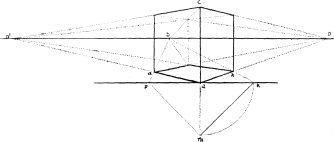
Fig. 72.
Pavements Drawn by Means of Squares at 45°
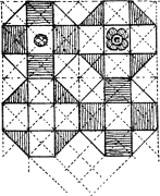
|
|
Fig. 75. |
The square at 45° will be found of great use in drawing pavements,
roofs, ceilings, &c. In Figs. 73, 74 it is shown how
having set out one square it can be divided into four or more equal
squares, and any figure or tile drawn therein. Begin by making a
geometrical or ground plan of the required design, as at Figs. 73 and 74,
where we have bricks placed at right angles to each other in rows,
a common arrangement in brick floors, or tiles of an octagonal form
as at Fig. 75.
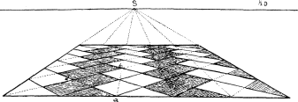
Fig. 73.
Fig. 74.
The Perspective Vanishing Scale
The vanishing scale, which we shall find of infinite use in our
perspective, is founded on the facts explained in Rule 10. We there find
that all horizontals in the same plane, which are drawn to the same
point on the horizon, are perspectively parallel to each other, so that
if we measure a certain height or width on the picture plane, and then
from each extremity draw lines to any convenient point on the horizon,
then all the perpendiculars drawn between these lines will be
perspectively equal, however much they may appear to vary in length.
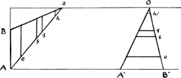
Fig. 76.
Let us suppose that in this figure (76) AB and A·B· each
represent 5 feet. Then in the first case all the verticals, as
e, f, g, h, drawn between AO and BO
represent 5 feet, and in the second case all the horizontals
e, f, g, h, drawn between A·O and B·O also
represent 5 feet each. So that by the aid of this scale we can give
the exact perspective height and width of any object in the picture,
however far it may be from the base line, for of course we can increase
or diminish our measurements at AB and
A·B· to whatever length we
require.
As it may not be quite evident at first that the points O may be
taken at random, the following figure will prove it.
The Vanishing Scale can be Drawn to any Point on
the Horizon
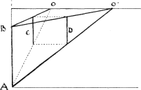
|
|
Fig. 77. |
From AB (Fig. 77) draw AO, BO, thus
forming the scale, raise vertical C.
Now form a second scale from AB by
drawing AO· BO·, and therein raise vertical D at an equal distance from the base. First, then,
vertical C equals AB, and secondly vertical D equals AB,
therefore C equals D, so that either of these scales will measure a
given height at a given distance.
(See axioms of geometry.)
Application of Vanishing Scales to Drawing
Figures
In this figure we have marked off on a level plain three or four
points a, b, c, d, to indicate the places
where we wish to stand our figures. AB
represents their average height, so we have made our scale AO, BO, accordingly. From each point marked we draw
a line parallel to the base till it reaches the scale. From the point
where it touches the line AO, raise
perpendicular as a, which gives the height required at that
distance, and must be referred back to the figure itself.
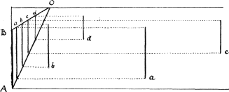
Fig. 78.
How to Determine the Heights of Figures on a
Level Plane
First Case.
This is but a repetition of the previous figure, excepting that we
have substituted these schoolgirls for the vertical lines. If we wish to
make some taller than the others, and some shorter, we can easily do so,
as must be evident (see Fig. 79).
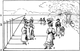
Fig. 79. Schoolgirls.
Note that in this first case the scale is below the horizon, so that
we see over the heads of the figures, those nearest to us being the
lowest down. That is to say, we are looking on this scene from a
slightly raised platform.
Second Case.
To draw figures at different distances when their heads are above the
horizon, or as they would appear to a person sitting on a low seat. The
height of the heads varies according to the distance of the figures
(Fig. 80).
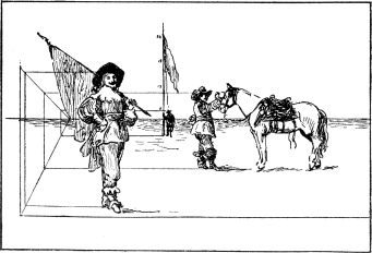
Fig. 80. Cavaliers.
Third Case.
How to draw figures when their heads are about the height of the
horizon, or as they appear to a person standing on the same level or
walking among them.
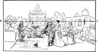
Fig. 81.
In this case the heads or the eyes are on a level with the horizon,
and we have little necessity for a scale at the side unless it is for
the purpose of ascertaining or marking their distances from the base
line, and their respective heights, which of course vary; so in all
cases allowance must be made for some being taller and some shorter than
the scale measurement.
The Horizon above the Figures
In this example from De Hoogh the doorway to the left is higher up
than the figure of the lady, and the effect seems to me
more pleasing and natural for this kind of domestic subject. This
delightful painter was not only a master of colour, of sunlight effect,
and perfect composition, but also of perspective, and thoroughly
understood the charm it gives to a picture, when cunningly introduced,
for he makes the spectator feel that he
can walk along his passages and courtyards. Note that he frequently puts
the point of sight quite at the side of his canvas, as at S, which gives
almost the effect of angular perspective whilst it preserves the
flatness and simplicity of parallel or horizontal perspective.
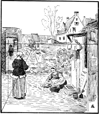
Fig. 82. Courtyard by De Hoogh.
Landscape Perspective
In an extended view or landscape seen from a height, we have to
consider the perspective plane as in a great measure lying above it,
reaching from the base of the picture to the horizon; but of course
pierced here and there by trees, mountains, buildings, &c. As a rule
in such cases, we copy our perspective from nature, and do not trouble
ourselves much about mathematical rules. It is as well, however, to know
them, so that we may feel sure we are right, as this gives certainty to
our touch and enables us to work with freedom. Nor must we, when
painting from nature, forget to take into account the effects of
atmosphere and the various tones of the different planes of distance,
for this makes much of the difference between a good picture and a bad
one; being a more subtle quality, it requires a keener artistic sense to
discover and depict it. (See Figs. 95 and 103.)
If the landscape painter wishes to test his knowledge of perspective,
let him dissect and work out one of Turner's pictures, or better still,
put his own sketch from nature to the same test.
Figures of Different Heights
The Chessboard
In this figure the same principle is applied as in the previous one,
but the chessmen being of different heights we have to arrange the scale
accordingly. First ascertain the exact height of each piece, as Q, K, B, which represent the queen, king,
bishop, &c. Refer these dimensions to the scale, as shown at QKB,
which will give us the perspective measurement of each piece according
to the square on which it is placed.
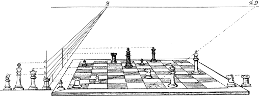
Fig. 83. Chessboard and Men.
This is shown in the above drawing (Fig. 83) in the case of the white
queen and the black queen, &c. The castle, the knight, and the pawn
being about the same height are measured from the fourth line of the
scale marked C.
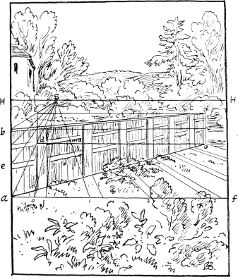
Fig. 84.
Application of the Vanishing Scale to Drawing
Figures at an Angle when their Vanishing Points are Inaccessible or
Outside the Picture
This is exemplified in the drawing of a fence (Fig. 84). Form scale
aS, bS, in accordance with the height of the fence or
wall to be depicted. Let ao represent the direction or angle at
which it is placed, draw od to meet the scale at d, at
d raise vertical dc, which gives the height of the fence
at oo·. Draw lines bo·, eo, ao, &c., and
it will be found that all these lines if produced will meet at the same
point on the horizon. To divide the fence into spaces, divide base line
af as required and proceed as already shown.
The Reduced Distance. How to Proceed when the
Point of Distance is Inaccessible
It has already been shown that too near a point of distance is
objectionable on account of the distortion and disproportion resulting
from it. At the same time, the long distance-point must be some way out
of the picture and therefore inconvenient. The object of the reduced
distance is to bring that point within the picture.
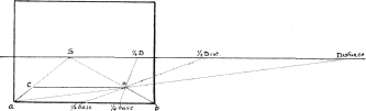
Fig. 85.
In Fig. 85 we have made the distance nearly twice the length of the
base of the picture, and consequently a long way out of it. Draw Sa, Sb, and from a draw aD to point of distance, which cuts Sb at o, and determines the
depth of the square acob. But
we can find that same point if we take half the base and draw a line
from ½ base to ½ distance. But even this ½ distance-point does not come
inside the picture, so we take a fourth of the base and a fourth of the
distance and draw a line from ¼ base to ¼ distance. We shall find that
it passes precisely through the same point o as the other lines
aD, &c. We are thus able to
find the required point o without going outside the picture.
Of course we could in the same way take an 8th or even a 16th
distance, but the great use of this reduced distance, in addition to the
above, is that it enables us to measure any depth into the picture with
the greatest ease.
It will be seen in the next figure that without having to extend the
base, as is usually done, we can multiply that base to any amount by
making use of these reduced distances on the horizontal line. This is
quite a new method of proceeding, and it will be seen is mathematically
correct.
How to Draw a Long Passage or Cloister by means
of the Reduced Distance
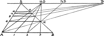
Fig. 86.
In Fig. 86 we have divided the base of the first square into four
equal parts, which may represent so many feet, so that A4 and Bd
being the retreating sides of the square each represents 4 feet.
But we found point ¼ D by drawing 3D
from ¼ base to ¼ distance, and by proceeding in the same way from each
division,
A, 1, 2, 3, we mark off on
SB four spaces each equal to
4 feet, in all 16 feet, so that by taking the whole base and the ¼
distance we find point O, which is
distant four times the length of the base AB. We can multiply this distance to any amount by
drawing other diagonals to 8th distance, &c. The same rule applies
to this corridor (Fig. 87 and Fig. 88).
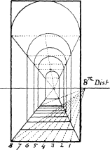
|
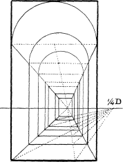
|
|
Fig. 87. |
Fig. 88. |
How to Form a Vanishing Scale that shall give
the Height, Depth, and Distance of any Object in the Picture
If we make our scale to vanish to the point of sight, as in Fig. 89,
we can make SB, the lower line
thereof, a measuring line for distances. Let us first of all divide
the base AB into eight parts, each
part representing 5 feet. From each division draw lines to 8th
distance; by their intersections with SB we obtain
measurements of 40, 80, 120, 160, &c., feet. Now divide the side of
the picture BE in the same manner as
the base, which gives us the height of 40 feet. From the side BE draw lines 5S, 15S, &c.,
to point of sight, and from each division on the base line also draw
lines 5S, 10S, 15S, &c.,
to point of sight, and from each division on SB, such as 40, 80, &c., draw horizontals
parallel to base. We thus obtain squares 40 feet wide, beginning at base
AB and reaching as far as required.
Note how the height of the flagstaff, which is 140 feet high and 280
feet distant, is obtained. So also any buildings or other objects can be
measured, such as those shown on the left of the picture.
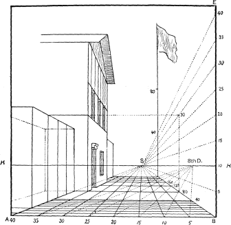
Fig. 89.
Measuring Scale on Ground
A simple and very old method of drawing buildings, &c., and
giving them their right width and height is by means of squares of a
given size, drawn on the ground.
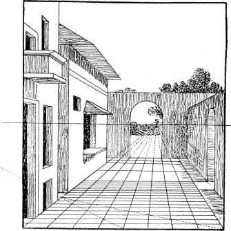
Fig. 90.
In the above sketch (Fig. 90) the squares on the ground
represent 3 feet each way, or one square yard. Taking this as our
standard measure, we find the door on the left is 10 feet high, that the
archway at the end is 21 feet high and 12 feet wide, and so on.
Fig. 91 is a sketch made at Sandwich, Kent, and shows a somewhat
similar subject to Fig. 84, but the
irregularity and freedom of the perspective gives it a charm far beyond
the rigid precision of the other, while it conforms to its main laws.
This sketch, however, is the real artist's perspective, or what we might
term natural perspective.
Fig. 91. Natural Perspective.
Application of the Reduced Distance and the
Vanishing Scale to Drawing a Lighthouse, &c.
In the drawing of Honfleur (Fig. 92) we divide the base AB as
in the previous figure, but the spaces measure 5 feet instead of
3 feet: so that taking the 8th distance, the divisions on the
vanishing line BS measure 40 feet
each, and at point O we have 400 feet
of distance, but we require 800. So we again reduce the distance to a
16th. We thus multiply the base by 16. Now let us take a base of 50 feet
at f and draw line fD to
16th distance; if we multiply 50 feet by 16 we obtain the 800 feet
required.
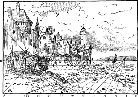
Fig. 92. Honfleur.
The height of the lighthouse is found by means of the vanishing
scale, which is 15 feet below and 15 feet above the horizon, or 30 feet
from the sea-level. At L we raise a
vertical LM, which shows the position
of the lighthouse. Then on that vertical measure the height required as
shown in the figure.
Perspective of a lighthouse 135 feet high at 800
feet distance.
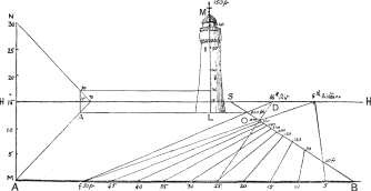
Fig. 93. Key to Fig. 92, Honfleur.
The 800 feet could be obtained at once by drawing line fD, or 50 feet, to 16th distance. The other
measurements obtained by 8th distance serve for nearer buildings.
How to Measure Long Distances such as a Mile or
Upwards
The wonderful effect of distance in Turner's pictures is not to be
achieved by mere measurement, and indeed can only be properly done by
studying Nature and drawing her perspective as she presents it to us. At
the same time it is useful to be able to test and to set out distances
in arranging a composition. This latter, if neglected, often leads to
great difficulties and sometimes to repainting.
To show the method of measuring very long distances we have to work
with a very small scale to the foot, and in Fig. 94 I have divided the
base AB into eleven parts, each part
representing 10 feet. First draw AS
and BS to point of sight.
From A draw AD to ¼ distance, and we obtain at 440 on line BS four times the length of AB, or 110 feet × 4 = 440 feet. Again, taking
the whole base and drawing a line from S to 8th distance we obtain eight
times 110 feet or 880 feet. If now we use the 16th distance we get
sixteen times 110 feet, or 1,760 feet, one-third of a mile; by repeating
this process, but by using the base at 1,760, which is the same length
in perspective as AB, we obtain 3,520
feet, and then again using the base at 3,520 and proceeding in the same
way we obtain 5,280 feet, or one mile to the archway. The flags show
their heights at their respective distances from the base. By the scale
at the side of the picture, BO, we can
measure any height above or any depth below the perspective plane.
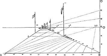
Fig. 94.
larger view
Note.—This figure (here much reduced) should be drawn
large by the student, so that the numbering, &c., may be made more
distinct. Indeed, many of the other figures should be copied large, and
worked out with care, as lessons in perspective.
Further Illustration of Long Distances and
Extended Views
An extended view is generally taken from an elevated position, so
that the principal part of the landscape lies beneath the perspective
plane, as already noted, and we shall presently treat of objects and
figures on uneven ground. In the previous figure is shown how we can
measure heights and depths to any extent. But when we turn to a drawing
by Turner, such as the ‘View from Richmond Hill’, we feel
that the only way to accomplish such perspective as this, is to go and
draw it from nature, and even then to use our judgement, as he did, as
to how much we may emphasize or even exaggerate certain features.
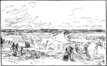
Fig. 95. Turner's View from Richmond
Hill.
Note in this view the foreground on which the principal figures stand
is on a level with the perspective plane, while the river and
surrounding park and woods are hundreds of feet below us
and stretch away for miles into the distance. The contrasts obtained by
this arrangement increase the illusion of space, and the figures in the
foreground give as it were a standard of measurement, and by their
contrast to the size of the trees show us how far away those trees
are.
How to Ascertain the Relative Heights of Figures
on an Inclined Plane
The three figures to the right marked f, g, b
(Fig. 96) are on level ground, and we measure them by the vanishing
scale aS, bS. Those to the left, which are repetitions of them,
are on an inclined plane, the vanishing point of which is S·; by the side of this plane we have placed another
vanishing scale a·S·,
b·S·, by which we measure the
figures on that incline in the same way as on the level plane. It will
be seen that if a horizontal line is drawn from the foot of one of these
figures, say G, to point O on the edge of the incline, then dropped
vertically to o·, then again carried on to o·· where the
other figure g is, we find it is the same height and also that
the other vanishing scale is the same width at that distance, so that we
can work from either one or the other. In the event of the rising ground
being uneven we can make use of the scale on the level plane.
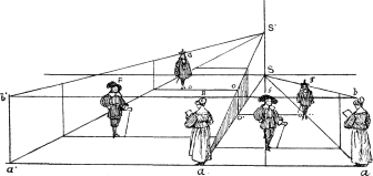
Fig. 96.
How to Find the Distance of a Given Figure or
Point from the Base Line
Let P be the given figure. Form
scale ACS, S being the point of sight and D the distance. Draw horizontal do through
P. From A draw diagonal AD
to distance point, cutting do in o, through o draw
SB to base, and we now have a square
AdoB on the perspective plane; and as figure P is standing on the far side of that square
it must be the distance AB, which is
one side of it, from the base line—or picture plane. For figures
very far away it might be necessary to make use of half-distance.
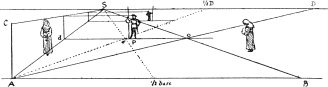
Fig. 97.
How to Measure the Height of Figures on Uneven
Ground
In previous problems we have drawn figures on level planes, which is
easy enough. We have now to represent some above and some below the
perspective plane.
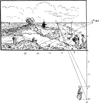
Fig. 98.
Form scale bS, cS; mark off distances 20 feet, 40 feet,
&c. Suppose figure K to be 60 feet
off. From point at his feet draw horizontal to meet vertical On, which is 60 feet distant. At the point
m where this line meets the vertical, measure height mn
equal to width of scale at that distance, transfer this to K, and you have the required height of the figure in
black.
For the figures under the cliff 20 feet below the perspective plane,
form scale FS, GS, making it the same width as the other, namely
5 feet, and proceed in the usual way to find the height of the
figures on the sands, which are here supposed to be nearly on a level
with the sea, of course making allowance for different heights and
various other things.
Further Illustration of the Size of Figures at
Different Distances and on Uneven Ground
Let ab be the height of a figure, say 6 feet. First form
scale aS, bS, the lower line of which, aS, is on a level with the base or on the perspective
plane. The figure marked C is close to
base, the group of three is farther off (24 feet), and 6 feet
higher up, so we measure the height on the vanishing scale and also
above it. The two girls carrying fish are still farther off, and about
12 feet below. To tell how far a figure is away, refer its measurements
to the vanishing scale (see Fig. 96).
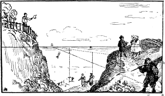
Fig. 99.
Figures on a Descending Plane
In this case (Fig. 100) the same rule applies as in the previous
problem, but as the road on the left is going down hill, the vanishing
point of the inclined plane is below the horizon at point S·; AS, BS is the vanishing scale on the level
plane; and A·S·, B·S·, that on the incline.
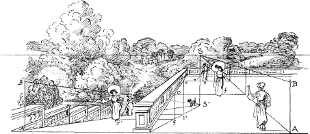
Fig. 100.
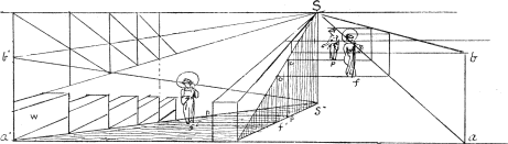
Fig. 101.
This is an outline of above figure to show the working more plainly.
Note the wall to the left marked W
and the manner in which it appears to drop at certain intervals, its
base corresponding with the inclined plane, but the upper lines of each
division being made level are drawn to the point of sight, or to their
vanishing point on the horizon; it is important to observe this, as it
aids greatly in drawing a road going down hill.
Further Illustration of the Descending
Plane
In the centre of this picture (Fig. 102) we suppose the road to be
descending till it reaches a tunnel which goes under a road or leads to
a river (like one leading out of the Strand near Somerset House). It is
drawn on the same principle as the foregoing figure. Of course to see
the road the spectator must get pretty near to it, otherwise it will be
out of sight. Also a level plane must be shown, as by its contrast to
the other we perceive that the latter is going down hill.
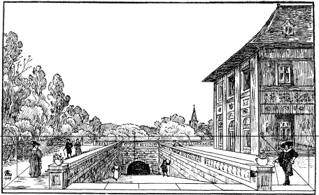
Fig. 102.
Further Illustration of Uneven Ground
An extended view drawn from a height of about 30 feet from a road
that descends about 45 feet.
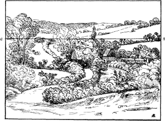
Fig. 103. Farningham.
In drawing a landscape such as Fig. 103 we have to bear in mind the
height of the horizon, which being exactly opposite the eye, shows us at
once which objects are below and which are above us, and to draw them
accordingly, especially roofs, buildings, walls, hedges, &c.; also
it is well to sketch in the different fields figures of men and cattle,
as from the size of these we can judge of the rest.
The Picture Standing on the Ground
Let K represent a frame placed
vertically and at a given distance in front of us. If stood on the
ground our foreground will touch
the base line of the picture, and we can fix up a standard of
measurement both on the base and on the side as in this sketch, taking
6 feet as about the height of the figures.
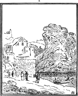
Fig. 104. Toledo.
The Picture on a Height
If we are looking at a scene from a height, that is from a terrace,
or a window, or a cliff, then the near foreground, unless it be the
terrace, window-sill, &c., would not come into the picture, and we
could not see the near figures at A,
and the nearest to come into view would be those at B, so that a view from a window, &c., would be
as it were without a foreground. Note that the figures at B would be (according to this sketch) 30 feet from
the picture plane and about 18 feet below the base line.
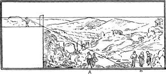
Fig. 105.
Angular Perspective
Hitherto we have spoken only of parallel perspective, which is
comparatively easy, and in our first figure we placed the cube with one
of its sides either touching or parallel to the transparent plane. We
now place it so that one angle only (ab), touches the
picture.
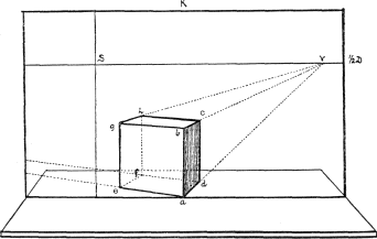
Fig. 106.
Its sides are no longer drawn to the point of sight as in Fig. 7, nor its diagonal to the point of distance, but
to some other points on the horizon, although the same rule holds good
as regards their parallelism; as for instance, in the case of bc
and ad, which, if produced, would meet at V, a point on the horizon called a
vanishing point. In this figure only one vanishing point is seen, which
is to the right of the point of sight S, whilst the other is some distance to the left,
and outside the picture. If the cube is correctly drawn, it will be
found that the lines ae, bg, &c., if produced, will
meet on the horizon at this other vanishing point. This far-away
vanishing point is one of the inconveniences of oblique or angular
perspective, and therefore it will be a considerable gain to the
draughtsman if we can dispense with it. This can be easily done, as in
the above figure, and here our geometry will come to our assistance, as
I shall show presently.
How to put a Given Point into Perspective
Let us place the given point P on a
geometrical plane, to show how far it is from the base line, and indeed
in the exact position we wish it to be in the picture. The geometrical
plane is supposed to face us, to hang down, as it were, from the base
line AB, like the side of a table, the
top of which represents the perspective plane. It is to that perspective
plane that we now have to transfer the point P.
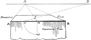
Fig. 107.
From P raise perpendicular Pm till it touches the base line at
m. With centre m and radius mP describe arc Pn so that mn is now the same length
as mP. As point P is opposite point m, so
must it be in the perspective, therefore we draw a line at right angles
to the base, that is to the point of sight, and somewhere on this line
will be found the required point P·.
We now have to find how far from m must that point be. It must be
the length of mn, which is the same as mP. We therefore from n draw nD to the point of distance, which being at
an angle of 45°, or half a right angle, makes mP· the perspective length of mn by its
intersection with mS, and thus
gives us the point P·, which is the
perspective of the original point.
A Perspective Point being given, Find its
Position on the Geometrical Plane
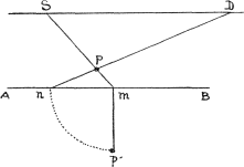
|
|
Fig. 108. |
To do this we simply reverse the foregoing problem. Thus let P be the given perspective point. From point
of sight S draw a line through P till it cuts AB at m. From distance D draw another line through P till it cuts the base at n. From m
drop perpendicular, and then with centre m and radius mn
describe arc, and where it cuts that perpendicular is the required point
P·. We often have to make use of this
problem.
How to put a Given Line into Perspective
This is simply a question of putting two points into perspective,
instead of one, or like doing the previous problem twice over, for the
two points represent the two extremities of the line. Thus we have to
find the perspective of A and B, namely a·b·. Join those points,
and we have the line required.
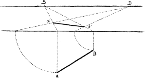
Fig. 109.
If one end touches the base, as at A (Fig. 110), then we have
but to find one point, namely b. We also find the perspective of
the angle mAB, namely the
shaded triangle mAb.
Note also that the perspective triangle equals the geometrical
triangle.
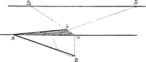
Fig. 110.
When the line required is parallel to the base line of the picture,
then the perspective of it is also parallel to that base (see
Rule 3).
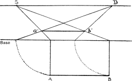
Fig. 111.
To Find the Length of a Given Perspective
Line
A perspective line AB being given,
find its actual length and the angle at which it is placed.
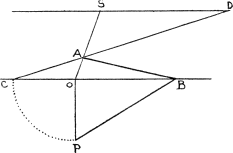
|
|
Fig. 112. |
This is simply the reverse of the previous problem. Let AB be the given line. From distance D through A draw
DC, and from S, point of sight, through A draw SO. Drop
OP at right angles to base, making it
equal to OC. Join PB, and line PB is
the actual length of AB.
This problem is useful in finding the position of any given line or
point on the perspective plane.
To Find these Points when the Distance-Point is
Inaccessible
If the distance-point is a long way out of the picture, then the same
result can be obtained by using the half distance and half base, as
already shown.
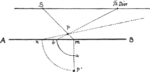
Fig. 113.
From a, half of mP·,
draw quadrant ab, from b (half base), draw line from
b to half Dist., which intersects Sm at P,
precisely the same point as would be obtained by using the whole
distance.
How to put a Given Triangle or other Rectilineal
Figure into Perspective
Here we simply put three points into perspective to obtain the given
triangle A, or five points to obtain
the five-sided figure at B. So can we
deal with any number of figures placed at any angle.
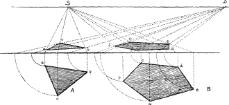
Fig. 114.
Both the above figures are placed in the same diagram, showing how
any number can be drawn by means of the same point of sight and the same
point of distance, which makes them belong to the same picture.
It is to be noted that the figures appear reversed in the
perspective. That is, in the geometrical triangle the base at ab
is uppermost, whereas in the perspective ab is lowermost, yet
both are nearest to the ground line.
How to put a Given Square into Angular
Perspective
Let ABCD (Fig. 115) be the given
square on the geometrical plane, where we can place it as near or as far
from the base and at any angle that we wish. We then proceed to find its
perspective on the picture by finding the perspective of the four points
ABCD as already shown. Note that the
two sides of the perspective square dc and ab being
produced, meet at point V on the
horizon, which is their vanishing point, but to find the point on the
horizon where sides bc and ad meet, we should have to go a
long way to the left of the figure, which by this method is not
necessary.
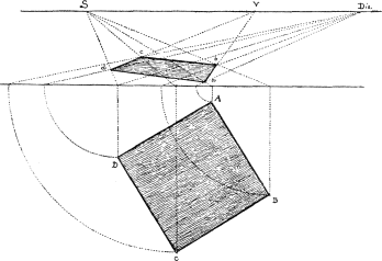
Fig. 115.
Of Measuring Points
We now have to find certain points by which to measure those
vanishing or retreating lines which are no longer at right angles to the
picture plane, as in parallel perspective, and have to be measured in a
different way, and here geometry comes to our assistance.
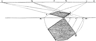
Fig. 116.
Note that the perspective square P
equals the geometrical square K, so
that side AB of the one equals side
ab of the other. With centre A
and radius AB describe arc Bm· till it cuts the base line at
m·. Now AB = Am·, and if we join bm· then triangle
BAm· is an isosceles triangle.
So likewise if we join m·b in the perspective figure will
m·Ab be the same
isosceles triangle in perspective. Continue line m·b till it cuts
the horizon in m, which point will be the measuring point for the
vanishing line AbV. For if in an isosceles triangle we draw lines
across it, parallel to its base from one side to the other, we divide
both sides in exactly the same quantities and proportions, so that if we
measure on the base line of the picture the spaces we require, such as
1, 2, 3, on the length Am·, and then from these divisions draw lines
to
the measuring point, these lines will intersect the vanishing line AbV
in the lengths and proportions required. To find a measuring point for
the lines that go to the other vanishing point, we proceed in the same
way. Of course great accuracy is necessary.
Note that the dotted lines 1,1, 2,2, &c., are parallel in the
perspective, as in the geometrical figure. In the former the lines are
drawn to the same point m on the horizon.
How to Divide any Given Straight Line into Equal
or Proportionate Parts
Let AB (Fig. 117) be the given
straight line that we wish to divide into five equal parts. Draw AC at any convenient angle, and measure off
five equal parts with the compasses thereon, as 1, 2, 3, 4, 5. From
5C draw line to 5B. Now from each division on AC draw lines 4, 4, 3, 3, &c.,
parallel to 5,5. Then AB will be
divided into the required number of equal parts.
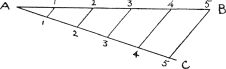
Fig. 117.
How to Divide a Diagonal Vanishing Line into any
Number of Equal or Proportional Parts
In a previous figure (Fig. 116) we have shown
how to find a measuring point when the exact measure of a vanishing line
is required, but if it suffices merely to divide a line into a given
number of equal parts, then the following simple method can be
adopted.
We wish to divide ab into five equal parts. From a,
measure off on the ground line the five equal spaces required.
From 5, the point to which these measures extend (as they are taken
at random), draw a line through b till it cuts the horizon at
O. Then proceed to draw lines from
each division on the base to point O,
and they will intersect and divide ab into the required number of
equal parts.
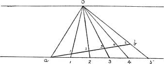
Fig. 118.
The same method applies to a given line to be divided into various
proportions, as shown in this lower figure.
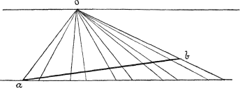
Fig. 119.
Further Use of the Measuring Point O
One square in oblique or angular perspective being given, draw any
number of other squares equal to it by means of this point O and the diagonals.
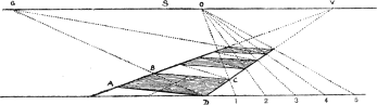
Fig. 120.
Let ABCD (Fig. 120) be the given
square; produce its sides AB, DC till they meet at point V. From D measure
off on base any number of equal spaces of any convenient length, as 1,
2, 3, &c.; from 1, through corner of square C, draw a line to meet the horizon at O, and from O draw
lines to the several divisions on base line. These lines will divide the
vanishing line DV into the required
number of parts equal to DC, the side
of the square. Produce the diagonal of the square DB till it cuts the horizon at G. From the divisions on line DV draw diagonals to point G: their intersections with the other vanishing line
AV will determine the direction of the
cross-lines which form the bases of other squares without the necessity
of drawing them to the other vanishing point, which in this case is some
distance to the left of the picture. If we produce these cross-lines to
the horizon we shall find that they all meet at the other vanishing
point, to which of course it is easy to draw them when that point is
accessible, as in Fig. 121; but if it is too far out of the picture,
then this method enables us to do without it.

Fig. 121.
Figure 121 corroborates the above by showing the two vanishing points
and additional squares. Note the working of the diagonals drawn to point
G , in
both figures.
Further Use of the Measuring Point O
Suppose we wish to divide the side of a building, as in Fig. 123, or
to draw a balcony, a series of windows, or columns, or what not,
or, in other words, any line above the horizon, as AB. Then from A we
draw AC parallel to the horizon, and
mark thereon
the required divisions 5, 10, 15, &c.: in this case twenty-five
(Fig. 122). From C draw a line through
B till it cuts the horizon at O. Then proceed to draw the other lines from
each division to O, and thus divide
the vanishing line AB as required.
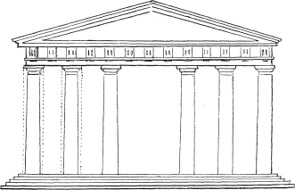
Fig. 122 is a
front view of the portico, Fig. 123.
In this portico there are thirteen triglyphs with twelve spaces between
them, making twenty-five divisions. The required number of parts to draw
the columns can be obtained in the same way.
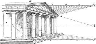
Fig. 123.
Another Method of Angular Perspective, being
that Adopted in our Art Schools
In the previous method we have drawn our squares by means of a
geometrical plan, putting each point into perspective as required, and
then by means of the perspective drawing thus obtained, finding our
vanishing and measuring points. In this method we proceed in exactly the
opposite way, setting out our points first, and drawing the square (or
other figure) afterwards.
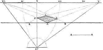
Fig. 124.
Having drawn the horizontal and base lines, and fixed upon the
position of the point of sight, we next mark the position of the
spectator by dropping a perpendicular, S ST, from that point of sight, making it the
same length as the distance we suppose the spectator to be from the
picture, and thus we make ST the
station-point.
To understand this figure we must first look upon it as a ground-plan or
bird’s-eye view, the line V2V1 or horizon line representing the
picture seen edgeways, because of course the station-point cannot be in
the picture itself, but a certain distance in front of it. The angle at
ST, that is the angle which decides
the positions of the two vanishing points V1, V2, is always a right angle, and the two
remaining angles on that side of the line, called the directing line,
are together equal to a right angle or 90°. So that in fixing upon the
angle at which the square or other figure is to be placed, we say
‘let it be 60° and 30°, or 70° and 20°’, &c. Having
decided upon the station-point and the angle at which the square is to
be placed, draw TV1 and
TV2, till they cut the
horizon at V1 and V2. These are the two vanishing
points to which the sides of the figure are respectively drawn. But we
still want the measuring points for these two vanishing lines. We
therefore take first, V1 as
centre and V1T as radius, and describe arc of circle till it cuts
the horizon in M1, which is
the measuring point for all lines drawn to V1. Then with radius V2T
describe arc from centre V2
till it cuts the horizon in M2, which is the measuring point for all
vanishing lines drawn to V2. We have now set out our points. Let
us proceed to draw the square Abcd. From A, the nearest angle (in this instance touching the
base line), measure on each side of it the equal lengths AB and AE, which
represent the width or side of the square. Draw EM2 and BM1 from the two measuring points, which
give us, by their intersections with the vanishing lines AV1 and AV2, the perspective lengths of the sides
of the square Abcd. Join
b and V1 and
dV2, which intersect
each other at C, then Adcb is the square required.
This method, which is easy when you know it, has certain drawbacks,
the chief one being that if we require a long-distance point, and a
small angle, such as 10° on one side, and 80° on the other, then the
size of the diagram becomes so large that it has to be carried out on
the floor of the studio with long strings, &c., which is a very
clumsy and unscientific way of setting to work. The architects in such
cases make use of the centrolinead, a clever mechanical contrivance
for getting over the difficulty of the far-off vanishing point, but by
the method I have shown you, and shall further illustrate, you will find
that you can dispense with
all this trouble, and do all your perspective either inside the picture
or on a very small margin outside it.
Perhaps another drawback to this method is that it is not
self-evident, as in the former one, and being rather difficult to
explain, the student is apt to take it on trust, and not to trouble
about the reasons for its construction: but to show that it is equally
correct, I will draw the two methods in one figure.
Two Methods of Angular Perspective in one
Figure
It matters little whether the station-point is placed above or below the
horizon, as the result is the same. In Fig. 125 it is placed above, as
the lower part of the figure is occupied with the geometrical plan of
the other method.
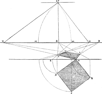
Fig. 125.
In each case we make the square K
the same size and at the same angle, its near corner being at A. It must be seen that by whichever method
we work out this perspective, the result is the same, so that both are
correct: the great advantage of the first or geometrical system being,
that we can place the square at any angle, as it is drawn without
reference to vanishing points.
We will, however, work out a few figures by the second method.
To Draw a Cube, the Points being Given
As in a previous figure (124) we found the
various working points of angular perspective, we need now merely
transfer them to the horizontal line in this figure, as in this case
they will answer our purpose perfectly well.
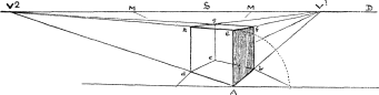
Fig. 126.
Let A be the nearest angle touching
the base. Draw AV1, AV2. From A, raise vertical Ae, the height of the cube. From e
draw eV1,
eV2, from the other
angles raise verticals bf, dh, cg, to meet
eV1, eV2, fV2, &c., and the cube is
complete.
Amplification of the Cube Applied to Drawing a
Cottage
Note that we have started this figure with the cube Adhefb. We have taken three times AB, its width, for the front of our house, and
twice AB for the side, and have made
it two cubes high, not counting the roof. Note also the use of the
measuring-points in connexion with the measurements on the base line,
and the upper measuring line TPK.
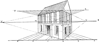
Fig. 127.
How to Draw an Interior at an Angle
Here we make use of the same points as in a previous figure, with the
addition of the point G, which is the
vanishing point of the diagonals of the squares on the floor.
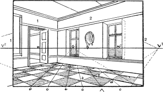
Fig. 128.
From A draw square Abcd, and produce its sides in all
directions; again from A, through the
opposite angle of the square C, draw a
diagonal till it cuts the horizon at G. From G draw
diagonals through b and d, cutting the base at o,
o, make spaces o, o, equal to Ao all along the base, and from them draw
diagonals to G; through the points
where these diagonals intersect the vanishing lines drawn in the
direction of Ab, dc and
Ad, bc, draw lines to
the other vanishing point V1, thus completing the squares, and so
cover the floor with them; they will then serve to measure width of
door, windows, &c. Of course horizontal lines on wall 1 are
drawn to V1, and those on
wall 2 to V2.
In order to see this drawing properly, the eye should be placed about
3 inches from it, and opposite the point of sight; it will then
stand out like a stereoscopic picture, and appear as actual space, but
otherwise the perspective seems deformed, and the
angles exaggerated. To make this drawing look right from a reasonable
distance, the point of distance should be at least twice as far off as
it is here, and this would mean altering all the other points and
sending them a long way out of the picture; this is why artists use
those long strings referred to above. I would however, advise them
to make their perspective drawing on a small scale, and then square it
up to the size of the canvas.
How to Correct Distorted Perspective by Doubling
the Line of Distance
Here we have the same interior as the foregoing, but drawn with
double the distance, so that the perspective is not so violent and the
objects are truer in proportion to each other.
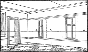
Fig. 129.
To redraw the whole figure double the size, including the
station-point, would require a very large diagram, that we could not get
into this book without a folding plate, but it comes to the same thing
if we double the distances between the various
points. Thus, if from S to G in the small diagram is 1 inch, in the
larger one make it 2 inches. If from S to M2
is 2 inches, in the larger make it 4, and so on.
Or this form may be used: make AB
twice the length of AC (Fig. 130), or
in any other proportion required. On AC mark the points as in the drawing you wish to
enlarge. Make AB the length that you
wish to enlarge to, draw CB, and then
from each division on AC draw lines
parallel to CB, and AB will be divided in the same proportions, as I
have already shown (Fig. 117).
Fig. 130.
There is no doubt that it is easier to work direct from the vanishing
points themselves, especially in complicated architectural work, but at
the same time I will now show you how we can dispense with, at all
events, one of them, and that the farthest away.
How to Draw a Cube on a Given Square, using only
One Vanishing Point
ABCD is the given square (Fig.
131). At A raise vertical Aa equal to side of square AB·, from a draw ab to the vanishing
point. Raise Bb. Produce VD to E to
touch the base line. From E raise
vertical EF, making it equal to Aa. From F draw FV. Raise
Dd and Cc, their heights being determined by the
line FV. Join da and the cube
is complete. It will be seen that the verticals raised at each corner of
the square are equal perspectively, as they are drawn between parallels
which start from equal heights, namely, from EF and Aa
to the same point V, the vanishing
point. Any other
line, such as OO·, can be directed to
the inaccessible vanishing point in the same way as ad,
&c.
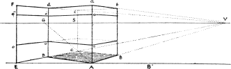
Fig. 131.
Note. This is only one of many original figures and problems
in this book which have been called up by the wish to facilitate the
work of the artist, and as it were by necessity.
A Courtyard or Cloister Drawn with one Vanishing
Point
In this figure I have first drawn the pavement by means of the
diagonals GA, Go, Go, &c., and the vanishing point V, the square at A being given. From A draw diagonal through opposite corner till it cuts
the horizon at G. From this same point
G draw
lines through the other corners of the square till they cut the ground
line at o, o. Take this measurement Ao and mark it along the base right and left
of A, and the lines drawn from these
points o to point G will give
the diagonals of all the squares on the pavement. Produce sides of
square A, and where these lines are
intersected by the diagonals Go
draw lines from the vanishing point V
to base. These will give us the outlines of the squares lying between
them and also guiding points that will enable us to draw as many more as
we please. These again will give us our measurements for the widths of
the arches, &c., or between the columns. Having fixed the height of
wall or dado, we make use of V point
to draw the sides of the building, and by means of proportionate
measurement complete the rest, as in Fig.
128.
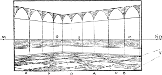
Fig. 132.
How to Draw Lines which shall Meet at a Distant
Point, by Means of Diagonals
This is in a great measure a repetition of the foregoing figure, and
therefore needs no further explanation.
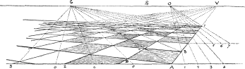
Fig. 133.
I must, however, point out the importance of the point G. In angular perspective it in a measure takes the
place of the point of distance in parallel perspective, since it is the
vanishing point of diagonals at 45° drawn between parallels such as
AV, DV, drawn to a vanishing point V. The method of dividing line AV into a number of parts equal to AB, the side of the square, is also shown in a
previous figure (Fig. 120).
How to Divide a Square Placed at an Angle into a
Given Number of Small Squares
ABCD is the given square, and only
one vanishing point is accessible. Let us divide it into sixteen small
squares. Produce side CD to base at
E. Divide EA into four equal parts. From each division draw
lines to vanishing point V. Draw
diagonals BD and AC, and produce the latter till it cuts the horizon
in G. Draw the three cross-lines
through the intersections made by the diagonals and the lines drawn to
V, and thus divide the square into
sixteen.
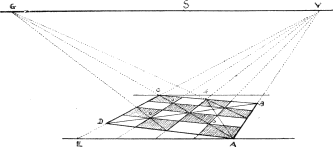
Fig. 134.
This is to some extent the reverse of the previous problem. It also
shows how the long vanishing point can be dispensed with, and the
perspective drawing brought within the picture.
Further Example of how to Divide a Given Oblique
Square into a Given Number of Equal Squares, say Twenty-five
Having drawn the square ABCD, which
is enclosed, as will be seen, in a dotted square in parallel
perspective, I divide the line
EA into five equal parts instead of
four (Fig. 135), and have made use of the device for that purpose by
measuring off the required number on line EF, &c. Fig. 136 is introduced here simply to
show that the square can be divided into any number of smaller squares.
Nor need the figure be necessarily a square; it is just as easy to make
it an oblong, as ABEF (Fig. 136); for
although we begin with a square we can extend it in any direction we
please, as here shown.
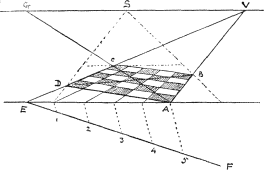
Fig. 135.
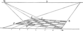
Fig. 136.
Of Parallels and Diagonals
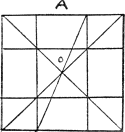
|
|
Fig. 137 A. |
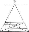
|
|
Fig. 137 B. |
To find the centre of a square or other rectangular figure we have
but to draw its two diagonals, and their intersection will give us the
centre of the figure (see 137 A). We
do the same with perspective figures, as at B. In Fig. C is
shown how a diagonal, drawn from one angle of a square B through the centre O of the opposite side of the square, will enable us
to find a second square lying between the same parallels, then a third,
a fourth, and so on. At figure K
lying on the ground, I have divided the farther side of the square
mn into ¼, ⅓, ½. If I draw
a diagonal from G (at the base)
through the half of this line I cut off on FS the lengths or sides of two squares; if through
the quarter I cut off the length of four squares on the vanishing line
FS, and so on. In Fig. 137 D is shown how easily any number of objects at any
equal distances apart, such as posts, trees, columns, &c., can be
drawn by means of diagonals between parallels, guided by a central line
GS.
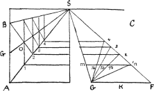
|
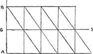
|
|
Fig. 137 C. |
Fig. 137 D. |
The Square, the Oblong, and their Diagonals
Having found the centre of a square or oblong, such as Figs. 138 and
139, if we draw a third line through that centre at a given angle and
then at each of its extremities draw perpendiculars AB, DC, we divide
that square or oblong into three parts, the two outer portions being
equal to each other, and the centre one either
larger or smaller as desired; as, for instance, in the triumphal arch we
make the centre portion larger than the two outer sides. When certain
architectural details and spaces are to be put into perspective,
a scale such as that in Fig. 123 will be found of great
convenience; but if only a ready division of the principal proportions
is required, then these diagonals will be found of the greatest use.
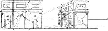
|
|
Fig. 138. |
Fig. 139. |
Showing the Use of the Square and Diagonals in
Drawing Doorways, Windows, and other Architectural Features
This example is from Serlio's Architecture (1663), showing
what excellent proportion can be obtained by the square and diagonals.
The width of the door is one-third of the base of square, the height
two-thirds. As a further illustration we have drawn the same figure in
perspective.
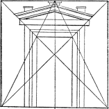
|
|
|
Fig. 140. |
Fig. 141. |
How to Measure Depths by Diagonals
If we take any length on the base of a square, say from A to g, and from g raise a
perpendicular till it cuts the diagonal AB in O, then from
O draw horizontal Og·, we form a square AgOg·, and thus measure on one side of the
square the distance or depth Ag·. So can we measure any other length, such
as fg, in like manner.
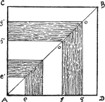
|
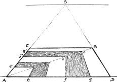
|
|
Fig. 142. |
Fig. 143. |
To do this in perspective we pursue precisely the same method, as
shown in this figure (143).
To measure a length Ag on the
side of square AC, we draw a line from
g to the point of sight S, and
where it crosses diagonal AB at O we draw horizontal Og, and thus find the required depth Ag in the picture.
How to Measure Distances by the Square and
Diagonal
It may sometimes be convenient to have a ready method by which to
measure the width and length of objects standing against the wall of a
gallery, without referring to distance-points, &c.
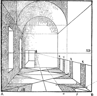
Fig. 144.
In Fig. 144 the floor is divided into two large squares with their
diagonals. Suppose we wish to draw a fireplace or a piece of furniture
K, we measure its base ef on
AB, as far from B as we wish it to be in the picture; draw eo
and fo to point of sight, and proceed as in the previous figure
by drawing parallels from Oo,
&c.
Let it be observed that the great advantage of this method is, that
we can use it to measure such distant objects as XY just as easily as those near to us.
There is, however, a still further advantage arising from it,
and that is that it introduces us to a new and simpler method of
perspective, to which I have already referred, and it will, I hope,
be found of infinite use to the artist.
Note.—As we have founded many of these figures on a
given square in angular perspective, it is as well to have a ready and
certain means of drawing that square without the elaborate setting out
of a geometrical plan, as in the first method, or the more cumbersome
and extended system of the second method. I shall therefore show
you another method equally correct, but much simpler than either, which
I have invented for our use, and which indeed forms one of the chief
features of this book.
How by Means of the Square and Diagonal we can
Determine the Position of Points in Space
Apart from the aid that perspective affords the draughtsman, there is
a further value in it, in that it teaches us almost a new science, which
we might call the mystery of aspect, and how it is that the objects
around us take so many different forms, or rather appearances, although
they themselves remain the same. And also that it enables us, with,
I think, great pleasure to ourselves, to fathom space, to work out
difficult problems by simple reasoning, and to exercise those inventive
and critical faculties which give strength and enjoyment to mental
life.
And now, after this brief excursion into philosophy, let us come down to
the simple question of the perspective of a point.
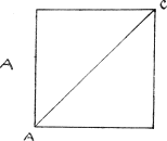
|
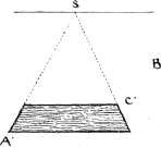
|
|
Fig. 145. |
Here, for instance, are two aspects of the same thing: the
geometrical square A, which is facing
us, and the perspective square B,
which we suppose to lie flat on the table, or rather on the perspective
plane. Line A·C· is the perspective of
line AC. On the geometrical square we
can make what measurements we please with the compasses, but on the
perspective square B· the only line we
can actually measure is the base line. In both figures this base line is
the same length. Suppose we want to find the
perspective of point P (Fig. 146), we
make use of the diagonal CA. From
P in the geometrical square draw PO to meet the diagonal in O; through O draw
perpendicular fe; transfer length fB, so found, to the base of the perspective square;
from f draw fS to point
of sight; where it cuts the diagonal in O, draw horizontal OP·, which gives us the point required. In the same
way we can find the perspective of any number of points on any side of
the square.
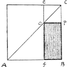
|
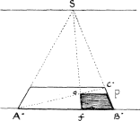
|
|
Fig. 146. |
Perspective of a Point Placed in any Position
within the Square
Let the point P be the one we wish
to put into perspective. We have but to repeat the process of the
previous problem, making use of our measurements on the base, the
diagonals, &c.
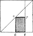
|
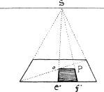
|
|
Fig. 147. |
Indeed these figures are so plain and evident that further
description of them is hardly necessary, so I will here give two
drawings of triangles which explain themselves. To put a triangle into
perspective we have but to find three points, such as fEP, Fig. 148 A, and then transfer these points to the perspective
square 148 B, as there shown, and form
the perspective triangle; but these figures explain themselves. Any
other triangle or rectilineal
figure can be worked out in the same way, which is not only the simplest
method, but it carries its mathematical proof with it.
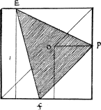
|
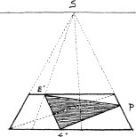
|
|
Fig. 148 A. |
Fig. 148 B. |
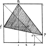
|
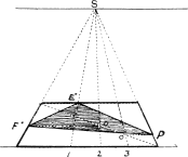
|
|
Fig. 149 A. |
Fig. 149 B. |
Perspective of a Square Placed at an Angle New
Method
As we have drawn a triangle in a square so can we draw an oblique
square in a parallel square. In Figure 150 A we have drawn the oblique square GEPn. We find the points on the base Am, as in the previous figures, which
enable us to construct the oblique perspective square n·G·E·P· in the parallel perspective square
Fig. 150 B. But it is not necessary to
construct the geometrical figure, as I will show presently. It is here
introduced to explain the method.
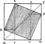
|
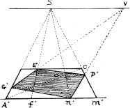
|
|
Fig. 150 A. |
Fig. 150 B. |
Fig. 150 B. To test the accuracy of
the above, produce sides G·E· and
n·P· of perspective square till
they touch the horizon, where they will meet at V, their vanishing point, and again produce the
other sides n·G· and P·E· till they meet on the horizon at the
other vanishing point, which they must do if the figure is correctly
drawn.
In any parallel square construct an oblique square from
a given point—given the parallel square at Fig. 150 B, and given point n· on base. Make A·f· equal to n·m·, draw
f·S and n·S to point of sight. Where these lines cut the
diagonal AC draw horizontals to P· and G·,
and so find the four points G·E·P·n· through which to draw the
square.
On a Given Line Placed at an Angle to the Base
Draw a Square in Angular Perspective, the Point of Sight, and Distance,
being given.
Let AB be the given line, S the point of sight, and D the distance (Fig. 151, 1). Through A draw SC
from point of sight to base (Fig. 151, 2 and 3). From C draw CD
to point of distance. Draw Ao
parallel to base till it cuts CD at
o, through o draw SP, from B mark
off BE equal to CP. From E draw
ES intersecting CD at K, from
K draw KM, thus completing the outer parallel square.
Through F, where PS intersects MK,
draw AV till it cuts the horizon in
V, its vanishing point. From V draw VB
cutting side KE of outer square in
G, and we have the four points
AFGB, which are the four angles of the
square required. Join FG, and the
figure is complete.
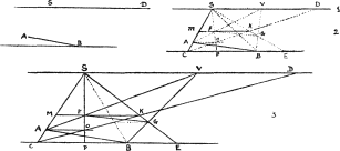
Fig. 151.
Any other side of the square might be given, such as AF. First through A and F draw SC, SP,
then draw Ao, then through
o draw CD. From C draw base of parallel square CE, and at M
through F draw MK cutting diagonal at K, which gives top of square. Now through K draw SE,
giving KE the remaining side thereof,
produce AF to V, from V draw
VB. Join FG, GB, and BA, and the square required is complete.
The student can try the remaining two sides, and he will find they
work out in a similar way.
How to Draw Solid Figures at any Angle by the
New Method
As we can draw planes by this method so can we draw solids, as shown
in these figures. The heights of the corners of the triangles are
obtained by means of the vanishing scales AS, OS, which have
already been explained.
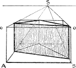
|
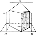
|
|
Fig. 152. |
Fig. 153. |
In the same manner we can draw a cubic figure (Fig. 154)—a box,
for instance—at any required angle. In this case, besides the
scale AS, OS, we have made use of the vanishing lines DV, BV,
to corroborate the scale, but they can be dispensed with in these simple
objects, or we can use a scale on each side of the figure as
a·o·S, should both vanishing
points be inaccessible. Let it be noted that in the scale AOS, AO is made
equal to BC, the height of the
box.
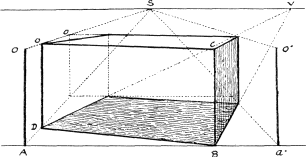
Fig. 154.
By a similar process we draw these two figures, one on the square,
the other on the circle.
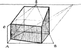
|
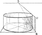
|
|
Fig. 155. |
Fig. 156. |
Points in Space
The chief use of these figures is to show how by means of diagonals,
horizontals, and perpendiculars almost any figure in space can be set
down. Lines at any slope and at any angle can be drawn by this
descriptive geometry.
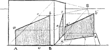
|
|
Fig. 157. |
The student can examine these figures for himself, and will
understand their working from what has gone before. Here (Fig. 157) in
the geometrical square we have a vertical plane AabB
standing on its base AB. We wish to
place a projection of this figure at a certain distance and at a given
angle in space. First of all we transfer it to the side of the cube,
where it is seen in perspective, whilst at its side is another
perspective square lying flat, on which we have to stand our figure. By
means of the diagonal of this flat square, horizontals from figure on
side of cube, and lines drawn from point of sight (as already
explained), we obtain the direction of base line AB, and also by means of lines aa· and
bb· we obtain the two points in space a·b·. Join Aa·, a·b· and Bb·, and we have the projection required, and
which may be said to possess the third dimension.
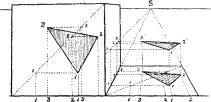
|
|
Fig. 158. |
In this other case (Fig. 158) we have a wedge-shaped figure standing
on a triangle placed on the ground, as in the previous figure, its three
corners being the same height. In the vertical geometrical square we
have a ground-plan of the figure, from which we draw lines to diagonal
and to base, and notify by numerals 1, 3,
2, 1, 3; these we transfer to base of the horizontal perspective
square, and then construct shaded triangle 1, 2, 3, and raise
to the height required as shown at 1·, 2·, 3·. Although we may
not want to make use of these special figures, they show us how we could
work out almost any form or object suspended in space.
The Square and Diagonal Applied to Cubes And
Solids Drawn Therein
As we have made use of the square and diagonal to draw figures at
various angles so can we make use of cubes either in parallel or angular
perspective to draw other solid figures within
them, as shown in these drawings, for this is simply an amplification of
that method. Indeed we might invent many more such things. But subjects
for perspective treatment will constantly present themselves to the
artist or draughtsman in the course of his experience, and while I
endeavour to show him how to grapple with any new difficulty or subject
that may arise, it is impossible to set down all of them in this
book.
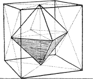
|
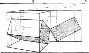
|
|
Fig. 159. |
Fig. 160. |
To Draw an Oblique Square in Another Oblique
Square without Using Vanishing Points
It is not often that both vanishing points are inaccessible, still it
is well to know how to proceed when this is the case. We first draw the
square ABCD inside the parallel
square, as in previous figures. To draw the smaller square K we simply draw a smaller parallel square h h h
h, and within that, guided by the intersections of the diagonals
therewith, we obtain the four points through which to draw square K. To raise a solid figure on these squares
we can make use of the vanishing scales as
shown on each side of the figure, thus obtaining the upper square
1 2 3 4, then by means of the diagonal 1 3 and 2 4
and verticals raised from each corner of square K to meet them we obtain the smaller upper square
corresponding to K.
It might be said that all this can be done by using the two vanishing
points in the usual way. In the first place, if they were as far off as
required for this figure we could not get them into a page unless it
were three or four times the width of this one, and to use shorter
distances results in distortion, so that the real use of this system is
that we can make our figures look quite natural and with much less
trouble than by the other method.
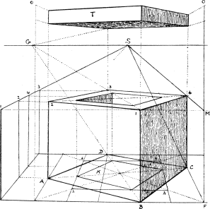
Fig. 161.
Showing How a Pedestal can be Drawn by the New
Method
This is a repetition of the previous problem, or rather the
application of it to architecture, although when there are many details
it may be more convenient to use vanishing points or the
centrolinead.
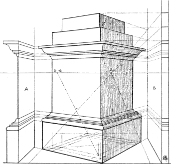
Fig. 162.
Scale on Each Side of the Picture
As one of my objects in writing this book is to facilitate the
working of our perspective, partly for the comfort of the artist, and
partly that he may have no excuse for neglecting it, I will here
show you how you may, by a very simple means, secure the general
correctness of your perspective when sketching or painting out of
doors.
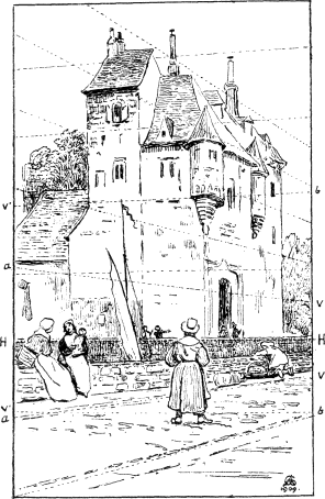
Fig. 163. Honfleur.
Let us take this example from a sketch made at Honfleur (Fig. 163),
and in which my eye was my only guide, but it stands the test of the
rule. First of all note that line HH,
drawn from one side of the picture to the other, is the horizontal line;
below that is a wall and a pavement marked aV, also going from one side of the picture to the
other, and being lower down at a than at V it runs up as it were to meet the horizon at some
distant point. In order to form our scale I take first the length of
Ha, and measure it above and
below the horizon, along the side to our left as many times as required,
in this case four or five. I now take the length HV on the right side of the picture and measure it
above and below the horizon, as in the other case; and then from these
divisions obtain dotted lines crossing the picture from one side to the
other which must all meet at some distant point on the horizon. These
act as guiding lines, and are sufficient to give us the direction of any
vanishing lines going to the same point. For those that go in the
opposite direction we proceed in the same way, as from b on the
right to V· on the left. They are here
put in faintly, so as not to interfere with the drawing. In the sketch
of Toledo (Fig. 164) the same thing is shown by double lines on each
side to separate the two sets of lines, and to make the principle more
evident.
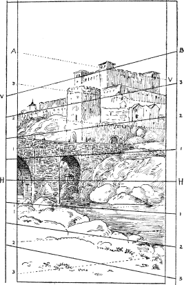
Fig. 164. Toledo.
The Circle
If we inscribe a circle in a square we find that it touches that
square at four points which are in the middle of each side, as at a b
c d. It will also intersect the two diagonals at the four points
o (Fig. 165). If, then, we put this square and its diagonals,
&c., into perspective we shall have eight guiding points through
which to trace the required circle, as shown in Fig. 166, which has the
same base as Fig. 165.
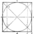
|
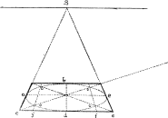
|
|
Fig. 165. |
Fig. 166. |
The Circle in Perspective a True Ellipse
Although the circle drawn through certain points must be a freehand
drawing, which requires a little practice to make it true, it is
sufficient for ordinary purposes and on a small scale, but to be
mathematically true it must be an ellipse. We will first draw an ellipse
(Fig. 167). Let ee be its long, or transverse, diameter, and
db its short or conjugate diameter. Now take half of the long
diameter eE, and from point
d with cE for radius
mark on ee the two points ff, which are the foci of the
ellipse. At each focus fix a pin, then make a loop of fine string that
does not stretch and of such a length that when drawn out the double
thread will reach from f to e. Now place this double
thread round the two pins at the foci ff· and distend it with the
pencil point until it forms triangle fdf·, then push the pencil
along and right round the two foci, which being guided by the thread
will draw the curve, which is a true ellipse, and will pass through the
eight points indicated in our first figure. This will be a sufficient
proof that the circle in perspective and the ellipse are identical
curves. We must also remember that the ellipse is an oblique projection
of a circle, or an oblique section of a cone. The difference between the
two figures consists in their centres not being in the same place, that
of the perspective circle being at c, higher up than e the
centre of the ellipse. The latter being a geometrical figure, its long
diameter is exactly in the centre of the figure, whereas the centre
c and the diameter of the perspective are at the intersection of
the diagonals of the perspective square in which it is inscribed.
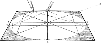
Fig. 167.
Further Illustration of the Ellipse
In order to show that the ellipse drawn by a loop as in the previous
figure is also a circle in perspective we must reconstruct around it the
square and its eight points by means of which it was drawn in the first
instance. We start with nothing but
the ellipse itself. We have to find the points of sight and distance,
the base, &c. Let us start with base AB, a horizontal tangent to the curve extending
beyond it on either side. From A and
B draw two other tangents so that they
shall touch the curve at points such as TT· a little above the transverse diameter and on a
level with each other. Produce these tangents till they meet at point
S, which will be the point of sight.
Through this point draw horizontal line H. Now draw tangent CD parallel to AB.
Draw diagonal AD till it cuts the
horizon at the point of distance, this will cut through diameter of
circle at its centre, and so proceed to find the eight points through
which the perspective circle passes, when it will be found that they all
lie on the ellipse we have drawn with the loop, showing that the two
curves are identical although their centres are distinct.
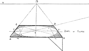
Fig. 168.
How To Draw a Circle in Perspective Without a
Geometrical Plan
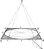
|
|
Fig. 169. |
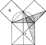
|
|
Fig. 170. |
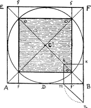
|
|
Fig. 171. |
Divide base AB into four equal
parts. At B drop perpendicular Bn, making Bn equal to Bm, or one-fourth of base. Join mn and
transfer this measurement to each side of d on base line; that
is, make df and df· equal to mn. Draw fS and f·S, and the intersections of these lines with the
diagonals of square will give us the four points o o
o o.
The reason of this is that ff· is the measurement on the base
AB of another square o o o o
which is exactly half of the outer square. For if we inscribe a circle
in a square and then inscribe a second square in that circle, this
second square will be exactly half the area of the larger one; for its
side will be equal to half the diagonal of the larger square, as can be
seen by studying
the following figures. In Fig. 170, for instance, the side of small
square K is half the diagonal of large
square o.
In Fig. 171, CB represents half of
diagonal EB of the outer square in
which the circle is inscribed. By taking a fourth
of the base mB and drawing
perpendicular mh we cut CB at
h in two equal parts, Ch, hB. It will be seen that hB is equal to mn, one-quarter of the
diagonal, so if we measure mn on each side of D we get ff· equal to CB, or half the diagonal. By drawing ff,
f·f passing through the diagonals we get the four points o o o
o through which to draw the smaller square. Without referring to
geometry we can see at a glance by Fig. 172, where we have simply turned
the square o o o o on its centre so that its angles touch the
sides of the outer square, that it is exactly half of square ABEF, since each quarter of it, such as EoCo, is bisected by its diagonal
oo.
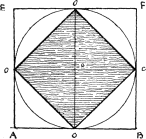
|
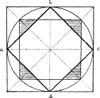
|
|
Fig. 172. |
Fig. 173. |
How to Draw a Circle in Angular Perspective
Let ABCD be the oblique square.
Produce VA till it cuts the base line
at G.
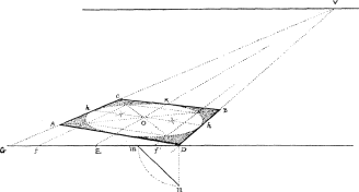
Fig. 174.
Take mD, the fourth of the
base. Find mn as in Fig. 171, measure it on each side of E, and so obtain Ef and Ef·, and proceed to draw fV, EV,
f·V and the diagonals, whose
intersections with these lines will give us the eight points through
which to draw the circle. In fact the process is the same as in parallel
perspective, only instead of making our divisions on the actual base
AD of the square, we make them on
GD, the base line.
To obtain the central line hh passing through O, we can make use of diagonals of the half squares;
that is, if the other vanishing point is inaccessible, as in this
case.
How to Draw a Circle in Perspective more
Correctly, by Using Sixteen Guiding Points
First draw square ABCD. From O, the middle of the base, draw semicircle
AKB, and divide it into eight equal
parts. From each division raise perpendiculars to the base, such as
2 O, 3 O, 5 O,
&c., and from divisions O, O, O draw
lines to point of sight, and where these lines cut the diagonals AC, DB,
draw horizontals parallel to base AB.
Then through the points thus obtained draw the circle as shown in this
figure, which also shows us how the circumference of a circle in
perspective may be divided into any number of equal parts.
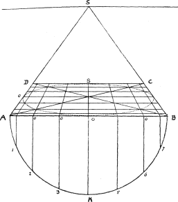
Fig. 175.
How to Divide a Perspective Circle into any
Number of Equal Parts
This is simply a repetition of the previous figure as far as its
construction is concerned, only in this case we have divided the
semicircle into twelve parts and the perspective into twenty-four.
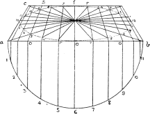
|
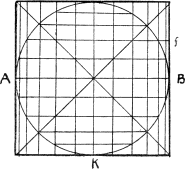
|
|
Fig. 176. |
Fig. 177. |
We have raised perpendiculars from the divisions on the semicircle, and
proceeded as before to draw lines to the point of sight, and have thus
by their intersections with the circumference already drawn in
perspective divided it into the required number of equal parts, to which
from the centre we have drawn the radii. This will show us how to draw
traceries in Gothic windows, columns in a circle, cart-wheels,
&c.
The geometrical figure (177) will explain the construction of the
perspective one by showing how the divisions are obtained on the line
AB, which represents base of square,
from the divisions on the semicircle AKB.
How to Draw Concentric Circles
First draw a square with its diagonals (Fig. 178), and from its
centre O inscribe a circle; in this
circle inscribe a square, and in this again inscribe a second circle,
and so on. Through their intersections with the diagonals draw lines to
base, and
number them 1, 2, 3, 4, &c.; transfer these measurements
to the base of the perspective square (Fig. 179), and proceed to
construct the circles as before, drawing lines from each point on the
base to the point of sight, and drawing the curves through the
inter-sections of these lines with the diagonals.
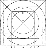
|
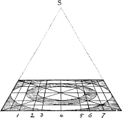
|
|
Fig. 178. |
Fig. 179. |
Should it be required to make the circles at equal distances, as for
steps for instance, then the geometrical plan should be made
accordingly.
Or we may adopt the method shown at Fig. 180, by taking quarter base
of both outer and inner square, and finding the measurement mn on
each side of C, &c.
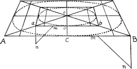
Fig. 180.
The Angle of the Diameter of the Circle in
Angular and Parallel Perspective
The circle, whether in angular or parallel perspective, is always an
ellipse. In angular perspective the angle of the circle's diameter
varies in accordance with the angle of the square in which it is placed,
as in Fig. 181, cc is the diameter of the circle and ee
the diameter of the ellipse. In parallel perspective the diameter of the
circle always remains horizontal, although the long diameter of the
ellipse varies in inclination according to the distance it is from the
point of sight, as shown in Fig. 182, in which the third circle is much
elongated and distorted, owing to its being outside the angle of
vision.
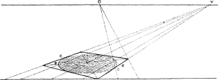
Fig. 181.
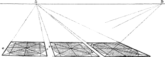
Fig. 182.
How to Correct Disproportion in the Width of
Columns
The disproportion in the width of columns in Fig. 183 arises from the
point of distance being too near the point of sight, or, in other words,
taking too wide an angle of vision. It will be seen that column 3
is much wider than column 1.
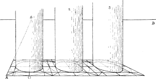
Fig. 183.
In our second figure (184) is shown how this defect is remedied, by
doubling the distance, or by counting the same distance as half, which
is easily effected by drawing the diagonal from O to ½-D, instead
of from A, as in the other figure,
O being at half base. Here the squares
lie much more level, and the columns are nearly the same width, showing
the advantage of a long distance.
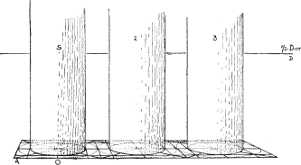
Fig. 184.
How to Draw a Circle over a Circle or a
Cylinder
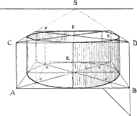
|
|
Fig. 185. |
First construct square and circle ABE, then draw square CDF with its diagonals. Then find the various points
O, and from these raise perpendiculars
to meet the diagonals of the upper square at points P, which, with the other points will be sufficient
guides to draw the circle required. This can be applied to towers,
columns, &c. The size of the circles can be varied so that the upper
portion of a cylinder or column shall be smaller than the lower.
To Draw a Circle Below a Given Circle
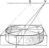
|
|
Fig. 186. |
Construct the upper square and circle as before, then by means of the
vanishing scale POV, which should be
made the depth required, drop perpendiculars from the various points
marked O, obtained by the diagonals,
making them the right depth by referring them to the vanishing scale, as
shown in this figure. This can be used for drawing garden fountains,
basins, and various architectural objects.
Application of Previous Problem
That is, to draw a circle above a circle. In Fig. 187 can be seen how
by means of the vanishing scale at the side we obtain the height of the
verticals 1, 2, 3, 4, &c., which determine the direction
of the upper circle; and in this second figure, how we resort to the
same means to draw circular steps.
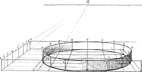
Fig. 187.
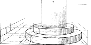
Fig. 188.
Doric Columns
It is as well for the art student to study the different orders of
architecture, whether architect or not, as he frequently has to
introduce them into his pictures, and at least must know their
proportions, and how columns diminish from base to capital, as shown in
this illustration.
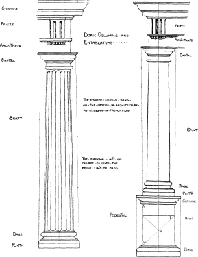
Fig. 189.
To Draw Semicircles Standing upon a Circle at
any Angle
Given the circle ACBH, on diagonal
AB draw semicircle AKB, and on the same line AB draw rectangle AEFB, its height being determined by radius OK of semicircle. From centre O draw OF to
corner of rectangle. Through f·, where that line intersects the
semicircle, draw mn parallel to AB. This will give intersection O· on the vertical OK, through which all such horizontals as
m·n·, level with mn, must pass. Now take any other
diameter, such as GH, and thereon
raise rectangle GghH, the same height as the other. The manner of
doing this is to produce diameter GH
to the horizon till it finds its vanishing point at V. From V through
K draw hg, and through O· draw n·m·. From O draw the two diagonals og and oh,
intersecting m·n· at O, O, and thus we have the five points GOKOH through which to draw the required
semicircle.
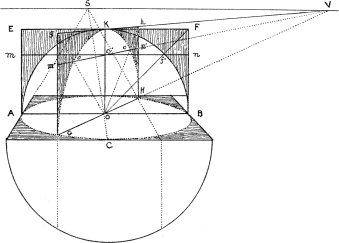
Fig. 190.
A Dome Standing on a Cylinder
This figure is a combination of the two preceding it. A cylinder
is first raised on the circle, and on the top of that we draw
semicircles from the different divisions on the circumference of the
upper circle. This, however, only represents a small half-globular
object. To draw the dome of a cathedral, or other building high above
us, is another matter. From outside, where we can get to a distance, it
is not difficult, but from within it will tax all our knowledge of
perspective to give it effect.
We shall go more into this subject when we come to archways and
vaulted roofs, &c.
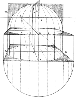
Fig. 191.
Section of a Dome or Niche
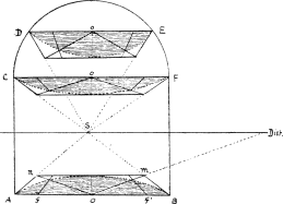
|
|
Fig. 192. |
First draw outline of the niche GFDBA (Fig. 193), then at its base draw square and
circle GOA, S being the point of sight, and divide the
circumference of the circle into the required number of parts. Then draw
semicircle FOB, and over that another
semicircle EOC. The manner of drawing
them is shown in Fig. 192. From the divisions on the circle GOA raise verticals to semicircle FOB, which will divide it in the same way. Divide
the smaller semicircle EOC into the
same number of parts as the others,
which divisions will serve as guiding points in drawing the curves of
the dome that are drawn towards D, but
the shading must assist greatly in giving the effect of the recess.
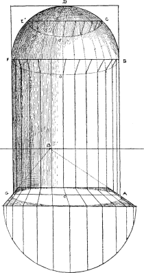
Fig. 193.
In Fig. 192 will be seen how to draw semicircles in perspective. We
first draw the half squares by drawing from centres O of their diameters diagonals to distance-point, as
OD, which cuts the vanishing line
BS at m, and gives us the depth
of the square, and in this we draw the semicircle in the usual way.
A Dome
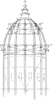
|
|
Fig. 194. A Dome. |
First draw a section of the dome ACEDB (Fig. 194) the shape required. Draw AB at its base and CD at some distance above it. Keeping these as
central lines, form squares thereon by drawing SA, SB, SC, SD,
&c., from point of sight, and determining their lengths by diagonals
fh, f·h· from point of distance, passing through O. Having formed the two squares, draw
perspective circles in each, and divide their circumferences into twelve
or whatever number of parts are needed. To complete the figure draw from
each division in the lower circle curves passing through the
corresponding divisions in the upper one, to the apex. But as these are
freehand lines, it requires some taste and knowledge to draw them
properly, and of course in a large drawing several more squares and
circles might be added to aid the draughtsman. The interior of the dome
can be drawn in the same way.
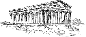
How to Draw Columns Standing in a Circle
In Fig. 195 are sixteen cylinders or columns standing in a circle.
First draw the circle on the ground, then divide it into sixteen equal
parts, and let each division be the centre of the circle on which to
raise the column. The question is how to make each one the right width
in accordance with its position, for it is evident that a near column
must appear wider than the opposite one. On the right of the figure is
the vertical scale A, which gives the
heights of the columns, and at its foot is a horizontal scale, or a
scale of widths B. Now, according to
the line on which the column stands, we find its apparent width marked
on the scale. Thus take the small square and circle at 15, without its
column, or the broken column at 16; and note that on each side of its
centre O I have measured oa,
ob, equal to spaces marked 3 on the same horizontal in the scale
B. Through these points a and
b I have drawn lines towards point of sight S. Through their intersections with diagonal
e, which is directed to point of distance, draw the farther and
nearer sides of the square in which to describe the circle and the
cylinder or column thereon. I have made all the squares thus
obtained in parallel perspective, but they do not represent the bases of
columns arranged in circles, which should converge towards the centre,
and I believe in some cases are modified in form to suit that
design.
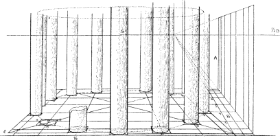
Fig. 195.
Columns and Capitals
This figure shows the application of the square and diagonal in
drawing and placing columns in angular perspective.
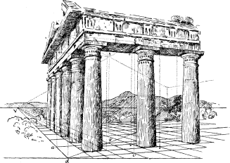
Fig. 196.
Method of Perspective Employed by
Architects
The architects first draw a plan and elevation of the building to be
put into perspective. Having placed the plan at the required angle to
the picture plane, they fix upon the point of sight, and the distance
from which the drawing is to be viewed. They then draw a line SP at right angles to the picture plane
VV·, which represents that distance so
that P is the station-point. The eye
is generally considered to be the station-point, but when lines are
drawn to that point from the ground-plan, the station-point
is placed on the ground, and is in fact the trace or projection exactly
under the point at which the eye is placed. From this station-point
P, draw lines PV and PV·
parallel to the two sides of the plan ba and ad (which
will be at right angles to each other), and produce them to the horizon,
which they will touch at points V and
V·. These points thus obtained will be
the two vanishing points.
The next operation is to draw lines from the principal points of the
plan to the station-point P, such as
bP, cP, dP,
&c., and where these lines intersect the picture plane (VV· here represents it as well as the horizon),
drop perpendiculars b·B,
aA, d·D, &c., to meet the vanishing lines AV, AV·, which
will determine the points A, B, C,
D, 1, 2, 3, &c., and also the
perspective lengths of the sides of the figure AB, AD, and the
divisions B, 1, 2, &c. Taking the
height of the figure AE from the
elevation, we measure it on Aa;
as in this instance A touches the
ground line, it may be used as a line of heights.
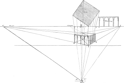
Fig. 197. A method of angular
Perspective employed by architects.
[To face p. 171]
Larger View
I have here placed the perspective drawing under the ground plan to
show the relation between the two, and how the perspective is worked
out, but the general practice is to find the required measurements as
here shown, to mark them on a straight edge of card or paper, and
transfer them to the paper on which the drawing is to be made.
This of course is the simplest form of a plan and elevation. It is
easy to see, however, that we could set out an elaborate building in the
same way as this figure, but in that case we should not place the
drawing underneath the ground-plan, but transfer the measurements to
another sheet of paper as mentioned above.
The Octagon
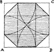
|
|
Fig. 198. |
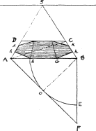
|
|
Fig. 199. |
To draw the geometrical figure of an octagon contained in a square,
take half of the diagonal of that square as radius, and from each corner
describe a quarter circle. At the eight points where they touch the
sides of the square, draw the eight sides of the octagon.
To put this into perspective take the base of the square AB and thereon form the perspective square ABCD. From either extremity of that base
(say B) drop perpendicular BF, draw diagonal AF, and then from B with radius BO,
half that diagonal, describe arc EOE.
This will give us the measurement AE.
Make GB equal to AE. Then draw lines from G and E towards
S, and by means of the diagonals find
the transverse lines KK, hh,
which will give us the eight points through which to draw the
octagon.
How to Draw the Octagon in Angular
Perspective
Form square ABCD (new method),
produce sides BC and AD to the horizon at V, and produce VA
to a· on base. Drop perpendicular from B to F the same
length as a·B, and proceed as
in the previous figure to find the eight points on the oblique square
through which to draw the octagon.
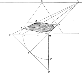
Fig. 200.
It will be seen that this operation is very much the same as in
parallel perspective, only we make our measurements on the base line
a·B as we cannot measure the
vanishing line BA otherwise.
How to Draw an Octagonal Figure in Angular
Perspective
In this figure in angular perspective we do precisely the same thing
as in the previous problem, taking our measurements on the base line
EB instead of on the vanishing line
BA. If we wish to raise a figure on
this octagon the height of EG we form
the vanishing scale EGO, and from the
eight points on the ground draw horizontals to EO and thus find all the points that give us the
perspective height of each angle of the octagonal figure.

Fig. 201.
How to Draw Concentric Octagons, with
Illustration of a Well
The geometrical figure 202 A shows
how by means of diagonals AC and BD and the radii 1 2 3, &c.,
we can obtain smaller octagons inside the larger ones. Note how these
are carried out in the second figure (202 B), and their application to this drawing of an
octagonal well on an octagonal base.
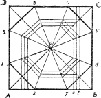
|
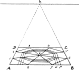
|
|
Fig. 202 A. |
Fig. 202 B. |
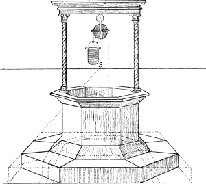
Fig. 203.
A Pavement Composed of Octagons and Small
Squares
To draw a pavement with octagonal tiles we will begin with an octagon
contained in a square abcd. Produce diagonal ac to V. This will be the vanishing point for the
sides of the small squares directed towards it. The other sides are
directed to an inaccessible point out of the picture, but their
directions are determined by the lines drawn from divisions on base to
V2 (see back, Fig. 133).
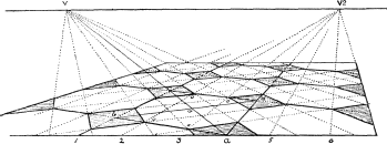
Fig. 204.
I have drawn the lower figure to show how the squares which contain
the octagons are obtained by means of the diagonals,
BD, AC, and the central line OV2. Given the square ABCD. From D draw
diagonal to G, then from C through centre o draw CE, and so on all the way up the floor until
sufficient are obtained. It is easy to see how other squares on each
side of these can be produced.
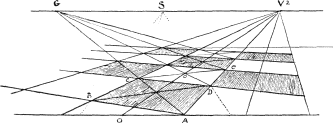
Fig. 205.
The Hexagon
The hexagon is a six-sided figure which, if inscribed in a circle,
will have each of its sides equal to the radius of that circle (Fig.
206). If inscribed in a rectangle ABCD, that rectangle will be equal in length to two
sides of the hexagon or two radii of the circle, as EF, and its width will be twice the height of an
equilateral triangle mon.
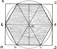
|
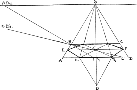
|
|
Fig. 206. |
Fig. 207. |
To put the hexagon into perspective, draw base of quadrilateral AD, divide it into four equal parts, and
from each division draw lines to point of sight. From h drop
perpendicular ho, and form equilateral triangle mno. Take
the height ho and measure it twice along the base from A to 2. From 2 draw line
to point of distance, or from 1 to ½ distance, and so find length
of side AB equal to A2. Draw BC, and
EF through centre o·, and
thus we have the six points through which to draw the hexagon.
A Pavement Composed of Hexagonal Tiles
In drawing pavements, except in the cases of square tiles, it is
necessary to make a plan of the required design, as in this figure
composed of hexagons. First set out the hexagon as at A, then draw parallels 1 1, 2 2, &c.,
to mark the horizontal ends of the tiles and the intermediate lines
oo. Divide the base into the required number of parts, each equal
to one side of the hexagon, as 1, 2, 3, 4, &c.; from these
draw perpendiculars as shown in the figure, and also the diagonals
passing through their intersections. Then mark with a strong line the
outlines of the hexagonals, shading some of them; but the figure
explains itself.
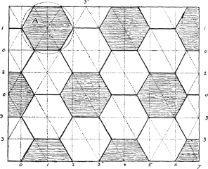
Fig. 208.
It is easy to put all these parallels, perpendiculars, and diagonals
into perspective, and then to draw the hexagons.
First draw the hexagon on AD as in
the previous figure, dividing
AD into four, &c., set off right
and left spaces equal to these fourths, and from each division draw
lines to point of sight. Produce sides me, nf till they
touch the horizon in points V, V·; these will be the two vanishing points
for all the sides of the tiles that are receding from us. From each
division on base draw lines to each of these vanishing points, then draw
parallels through their intersections as shown on the figure. Having all
these guiding lines it will not be difficult to draw as many hexagons as
you please.
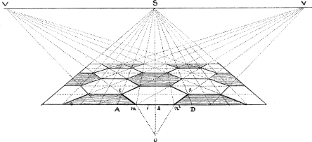
Fig. 209.
Note that the vanishing points should be at equal distances from
S, also that the parallelogram in
which each tile is contained is oblong, and not square, as already
pointed out.
We have also made use of the triangle omn to ascertain the
length and width of that oblong. Another thing to note is that we have
made use of the half distance, which enables us to make our pavement
look flat without spreading our lines outside the picture.
A Pavement of Hexagonal Tiles in Angular
Perspective
This is more difficult than the previous figure, as we only make use
of one vanishing point; but it shows how much can be done by diagonals,
as nearly all this pavement is drawn by their aid. First make a
geometrical plan A at the angle
required. Then draw its perspective K.
Divide line 4b into four equal parts, and continue these
measurements all along the base: from each division draw lines to V, and draw the hexagon K. Having this one to start with we produce its
sides right and left, but first to the left to find point G, the vanishing point of the
diagonals. Those to the right, if produced far enough, would meet at a
distant vanishing point not in the picture. But the student should study
this figure for himself, and refer back to Figs.
204 and 205.
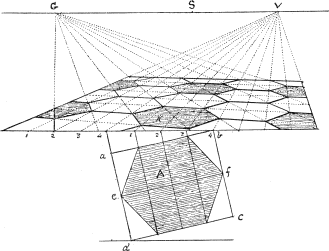
Fig. 210.
Further Illustration of the Hexagon
To draw the hexagon in perspective we must first find the rectangle
in which it is inscribed, according to the view we take of it. That at
A we have already drawn. We will now
work out that at B. Divide the base
AD into four equal parts and transfer
those measurements to the perspective figure C, as at AD,
measuring other equal spaces along the base. To find the depth An of the rectangle, make DK equal to base of square. Draw KO to distance-point, cutting DO at O, and thus
find line LO. Draw diagonal Dn, and through its intersections
with the
lines 1, 2, 3, 4 draw lines parallel to the base, and we shall
thus have the framework, as it were, by which to draw the pavement.
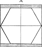
|
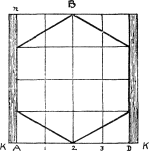
|
|
Fig. 211 A. |
Fig. 211 B. |
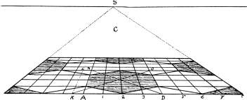
Fig. 212.
Another View of the Hexagon in Angular
Perspective
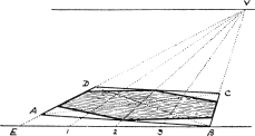
|
|
Fig. 213. |
Given the rectangle ABCD in angular
perspective, produce side DA to E on base line. Divide EB into four equal parts, and from each division
draw lines to vanishing point, then by means of diagonals, &c., draw
the hexagon.
In Fig. 214 we have first drawn a geometrical plan, G, for the sake of clearness, but the one above
shows that this is not necessary.
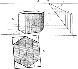
Fig. 214.
To raise the hexagonal figure K we
have made use of the vanishing scale O
and the vanishing point V. Another
method could be used by drawing two hexagons one over the other at the
required height.
Application of the Hexagon to Drawing a
Kiosk
This figure is built up from the hexagon standing on a rectangular
base, from which we have raised verticals, &c. Note how the jutting
portions of the roof are drawn from o·. But the figure explains
itself, so there is no necessity to repeat descriptions already given in
the foregoing problems.
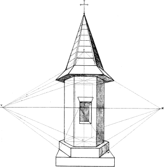
Fig. 215.
The Pentagon
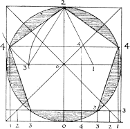
|
|
Fig. 216. |
The pentagon is a figure with five equal sides, and if inscribed in a
circle will touch its circumference at five equidistant points. With any
convenient radius describe circle. From half this radius, marked 1,
draw a line to apex, marked 2. Again, with 1 as centre and 1 2
as radius, describe arc 2 3. Now with 2 as centre and 2 3 as
radius describe arc 3 4, which will cut the circumference at
point 4. Then line 2 4 will be one of the sides of the
pentagon, which we can measure round the circle and so produce the
required figure.
To put this pentagon into parallel perspective inscribe the circle in
which it is drawn in a square, and from its five angles
4, 2, 4, &c., drop perpendiculars to base and number them
as in the figure. Then draw the perspective square (Fig. 217) and
transfer these measurements to its base. From these draw lines to point
of sight, then by their aid and the two diagonals proceed to construct
the pentagon in the same way that we did the triangles and other
figures. Should it be required to place this
pentagon in the opposite position, then we can transfer our measurements
to the far side of the square, as in Fig. 218.
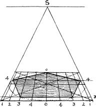
|
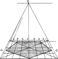
|
|
Fig. 217. |
Fig. 218. |
Or if we wish to put it into angular perspective we adopt the same
method as with the hexagon, as shown at Fig. 219.
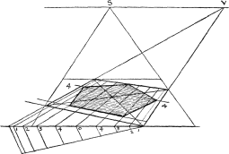
|
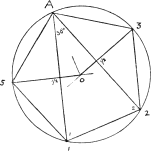
|
|
Fig. 219. |
Fig. 220. |
Another way of drawing a pentagon (Fig. 220) is to draw an isosceles
triangle with an angle of 36° at its apex, and from centre of each side
of the triangle draw perpendiculars to meet at o, which will be
the centre of the circle in which it is inscribed. From this centre and
with radius OA describe circle A 3 2, &c. Take base of
triangle 1 2, measure it round the circle, and so find the five
points through which to draw the pentagon. The angles at 1 2 will
each be 72°, double that at A, which
is 36°.
The Pyramid
Nothing can be more simple than to put a pyramid into perspective.
Given the base (abc), raise from its centre a perpendicular
(OP) of the required height, then draw
lines from the corners of that base to a point P on the vertical line, and the thing is done. These
pyramids can be used in drawing roofs, steeples, &c. The cone is
drawn in the same way, so also is any other figure, whether octagonal,
hexangular, triangular, &c.
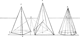
|
|
Fig. 221. |
Fig. 222. |
Fig. 223. |
The Great Pyramid
This enormous structure stands on a square base of over thirteen
acres, each side of which measures, or did measure, 764 feet. Its
original height was 480 feet, each side being an equilateral triangle.
Let us see how we can draw this gigantic mass on our little sheet of
paper.
In the first place, to take it all in at one view we must put it very
far back, and in the second the horizon must be so low down that we
cannot draw the square base of thirteen acres on the perspective plane,
that is on the ground, so we must draw it in the air, and also to a very
small scale.
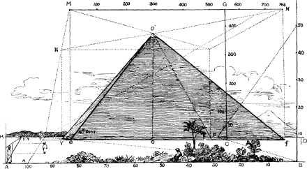
Fig. 224.
Divide the base AB into ten equal
parts, and suppose each of these parts to measure 10 feet, S, the point of sight, is placed on the left of the
picture near the side, in order that we may get a long line of distance,
S ½ D; but even this line is only half the distance we
require. Let us therefore take the 16th distance, as shown in our
previous illustration of the lighthouse (Fig. 92), which enables us to
measure sixteen times the length of base AB, or 1,600 feet. The base ef of the pyramid
is 1,600 feet from the base line of the picture, and is, according to
our 10-foot scale, 764 feet long.
The next thing to consider is the height of the pyramid. We make a
scale to the right of the picture measuring 50 feet from B to 50 at point where BP intersects base of pyramid, raise perpendicular
CG and thereon measure 480 feet. As we
cannot obtain a palpable square on the ground, let us draw one 480 feet
above the ground. From e and f raise verticals
eM and fN, making them equal to perpendicular G, and draw line MN, which will be the same length as base, or 764
feet. On this line form square MNK
parallel to the perspective plane, find its centre O· by means of diagonals, and O· will be the central height of the pyramid and
exactly over the centre of the base. From this point O· draw sloping lines O·f, O·e, O·y,
&c., and the figure is complete.
Note the way in which we find the measurements on base of pyramid and on
line MN. By drawing AS and BS to point
of sight we find Te, which
measures 100 feet at a distance of 1,600 feet. We mark off seven of
these lengths, and an additional 64 feet by the scale, and so obtain the
required length. The position of the third corner of the base is found
by dropping a perpendicular from K,
till it meets the line eS.
Another thing to note is that the side of the pyramid that faces us,
although an equilateral triangle, does not appear so, as its top angle
is 382 feet farther off than its base owing to its leaning position.
The Pyramid in Angular Perspective
In order to show the working of this proposition I have taken a much
higher horizon, which immediately detracts from the impression of the
bigness of the pyramid.
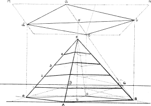
Fig. 225.
We proceed to make our ground-plan abcd high above the horizon
instead of below it, drawing first the parallel square and then the
oblique one. From all the principal points drop perpendiculars to the
ground and thus find the points through which to draw the base of the
pyramid. Find centres OO· and decide
upon the height OP. Draw the sloping
lines from P to the corners of the
base, and the figure is complete.
To Divide the Sides of the Pyramid
Horizontally
Having raised the pyramid on a given oblique square, divide the
vertical line OP into the required
number of parts. From
A through C draw AG to
horizon, which gives us G, the
vanishing point of all the diagonals of squares parallel to and at the
same angle as ABCD. From G draw lines through the divisions 2, 3,
&c., on OP cutting the lines PA and PC,
thus dividing them into the required parts. Through the points thus
found draw from V all those sides of
the squares that have V for their
vanishing point, as ab, cd, &c. Then join bd,
ac, and the rest, and thus make the horizontal divisions
required.
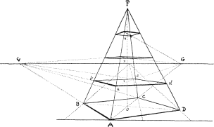
|
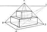
|
|
Fig. 226. |
Fig. 227. |
The same method will apply to drawing steps, square blocks, &c.,
as shown in Fig. 227, which is at the same angle as the above.
Of Roofs
The pyramidal roof (Fig. 228) is so simple that it explains itself.
The chief thing to be noted is the way in which the diagonals are
produced beyond the square of the walls, to give the width of the eaves,
according to their position.
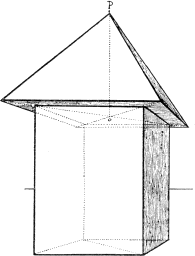
|
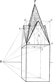
|
|
Fig. 228. |
Fig. 229. |
Another form of the pyramidal roof is here given (Fig. 229). First
draw the cube edcba at the required height, and on the side
facing us, adcb, draw triangle K, which represents the end of a gable roof. Then
draw similar triangles on the other sides of the cube (see Fig. 159, LXXXIV). Join the opposite triangles
at the apex, and thus form two gable roofs crossing each other at right
angles. From o, centre of base of cube, raise vertical OP, and then from P draw sloping lines to each corner of base
a, b, &c., and by means of central lines drawn from
P to half base, find the points where
the gable roofs intersect the central spire or pyramid. Any other
proportions can be obtained by adding to or altering the cube.
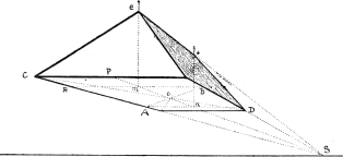
Fig. 230.
To draw a sloping or hip-roof which falls back at each end we must
first draw its base, CBDA (Fig. 230).
Having found the centre O and central
line SP, and how far the roof is to
fall back at each end, namely the distance Pm, draw horizontal line RB through m. Then from B through O draw
diagonal BA, and from
A draw horizontal AD, which gives us point n. From these two
points m and n raise perpendiculars the height required
for the roof, and from these draw sloping lines to the corners of the
base. Join ef, that is, draw the top line of the roof, which
completes it. Fig. 231 shows a plan or bird's-eye view of the roof and
the diagonal AB passing through centre
O. But there are so many varieties of
roofs they would take almost a book to themselves to illustrate them,
especially the cottages and farm-buildings, barns, &c., besides
churches, old mansions, and others. There is also such irregularity
about some of them that perspective rules, beyond those few here given,
are of very little use. So that the best thing for an artist to do is to
sketch them from the real whenever he has an opportunity.
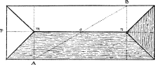
Fig. 231.
Of Arches, Arcades, Bridges, &c.
For an arcade or cloister (Fig. 232) first set up the outer frame ABCD according to the proportions required.
For round arches the height may be twice that of the base, varying to
one and a half. In Gothic arches the height may be about three times the
width, all of which proportions are chosen to suit the different
purposes and effects required. Divide the base AB into the desired number of parts,
8, 10, 12, &c., each part representing 1 foot. (In
this case the base is 10 feet and the horizon 5 feet.) Set out
floor by means of ¼ distance. Divide it into squares of
1 foot, so that there will be 8 feet between each column or
pilaster, supposing we make them to stand on a square foot. Draw the
first archway EKF facing us, and its
inner semicircle gh, with also its thickness or depth of
1 foot. Draw the span of the archway EF, then central line PO to point of sight. Proceed to raise as many other
arches as required at the given distances. The intersections of the
central line with the chords mn, &c., will give the centres
from which to describe the semicircles.
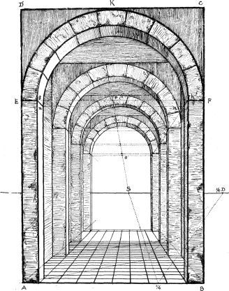
Fig. 232.
Outline of an Arcade with Semicircular
Arches
This is to show the method of drawing a long passage, corridor, or
cloister with arches and columns at equal distances, and is worked in
the same way as the previous figure, using ¼ distance and ¼ base. The
floor consists of five squares; the semicircles of the arches are
described from the numbered points on the central line OS, where it intersects the chords of the
arches.
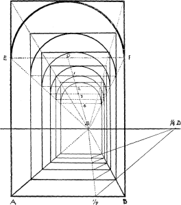
Fig. 233.
Semicircular Arches on a Retreating Plane
First draw perspective square abcd. Let ae· be the
height of the figure. Draw ae·f·b and proceed with the rest of
the outline. To draw the arches begin with the one facing us, Eo·F enclosed in the quadrangle Ee·f·F.
With centre O describe the semicircle
and across it draw the diagonals e·F, Ef·, and
through nn, where these lines intersect the semicircle, draw
horizontal KK and also KS to point of sight. It will be seen that the
half-squares at the side are the same size in perspective as the one
facing us, and we carry out in them much the same operation; that is, we
draw the diagonals, find the point O,
and the points nn, &c., through which to draw our arches. See
perspective of the circle (Fig. 165).
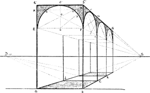
Fig. 234.
If more points are required an additional diagonal from O to
K may be used, as shown in the figure,
which perhaps explains itself. The method is very old and very simple,
and of course can be applied to any kind of arch, pointed or stunted, as
in this drawing of a pointed arch (Fig. 235).
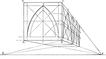
Fig. 235.
An Arcade in Angular Perspective
First draw the perspective square ABCD at the angle required, by new method. Produce
sides AD and BC to V. Draw
diagonal BD and produce to point G,
from whence we draw the other diagonals to cfh. Make spaces
1, 2, 3, &c., on base line equal to B 1 to obtain sides of squares. Raise vertical
BM the height required. Produce DA to O on
base line, and from O raise vertical
OP equal to BM. This line enables us
to dispense with the long vanishing point to the left; its working has
been explained at Fig. 131. From P
draw PRV to vanishing point V, which will intersect vertical AR at R. Join
MR, and this line, if produced, would
meet the horizon at the other vanishing point.
In like manner make O2 equal to B2·. From 2 draw line to V, and at 2, its intersection with AR, draw line 2 2, which will also meet the
horizon at the other vanishing point. By means of the quarter-circle
A we can obtain the points through
which to draw the semicircular arches in the same way as in the previous
figure.
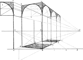
Fig. 236.
A Vaulted Ceiling
From the square ceiling ABCD we
have, as it were, suspended two arches from the two diagonals DB, AC,
which spring from the four corners of the square EFGH, just underneath it. The curves of these
arches, which are not semicircular but elongated, are obtained by means
of the vanishing scales mS,
nS. Take any two convenient
points P, R, on each side of the semicircle, and
raise verticals Pm, Rn to AB,
and on these verticals form the scales. Where mS and nS
cut the diagonal AC drop
perpendiculars to meet the lower line of the scale at points 1, 2.
On the other side, using the other scales, we have dropped
perpendiculars in the same way from the diagonal to 3, 4. These
points, together
with EOG, enable us to trace the curve
E 1 2 O 3 4 G. We draw the arch under the other diagonal in
precisely the same way.
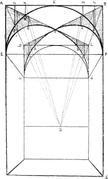
|
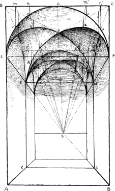
|
|
Fig. 237. |
Fig. 238. |
The reason for thus proceeding is that the cross arches, although
elongated, hang from their diagonals just as the semicircular arch EKF hangs from AB, and the lines mn, touching the circle at
PR, are represented by 1, 2,
hanging from the diagonal AC.
Figure 238, which is practically the same as the preceding only
differently shaded, is drawn in the following manner. Draw arch EGF facing us, and proceed with the rest of
the corridor, but first finding the flat ceiling above the square on the
ground ABcd. Draw diagonals
ac, bd, and the curves pending from them. But we no longer
see the clear arch as in the other drawing, for the spaces between the
curves are filled in and arched across.
A Cloister, from a Photograph
This drawing of a cloister from a photograph shows the correctness of
our perspective, and the manner of applying it to practical work.
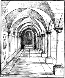
Fig. 239.
The Low or Elliptical Arch
Let AB be the span of the arch and
Oh its height. From centre
O, with OA, or half the span, for radius, describe outer
semicircle. From same centre and oh for radius describe the inner
semicircle. Divide outer circle into a convenient number of parts,
1, 2, 3, &c., to which draw radii from centre O. From each division drop perpendiculars. Where
the radii intersect the inner circle, as at gkmo, draw
horizontals op, mn, kj, &c., and
through their intersections with the perpendiculars f, j,
n, p, draw the curve of the flattened arch. Transfer this
to the lower figure, and proceed to draw the tunnel. Note how the
vanishing scale is formed on either side by horizontals ba,
fe, &c., which enable us to make the distant arches similar
to the near ones.
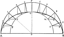
Fig. 240.
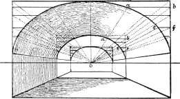
Fig. 241.
Opening or Arched Window in a Vault
First draw the vault AEB. To
introduce the window K, the upper part
of which follows the form of the vault, we first decide on its width,
which is mn, and its height from floor Ba. On line Ba at the side of the arch form scales
aa·S, bb·S, &c. Raise the semicircular arch K, shown by a dotted line. The scale at the side
will give the lengths aa·, bb·, &c., from different
parts of this dotted arch to corresponding points in the curved archway
or window required.
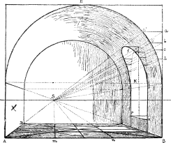
Fig. 242.
Note that to obtain the width of the window K we have used
the diagonals on the floor and width m n on base. This method of
measurement is explained at Fig. 144, and is of ready application in a
case of this kind.
Stairs, Steps, &c.
Having decided upon the incline or angle, such as CBA, at which the steps are to be placed, and the
height Bm of each step, draw
mn to CB, which will give the
width. Then measure along base AB this
width equal to DB, which will give
that for all the other steps. Obtain length BF of steps, and draw EF parallel to CB.
These lines will aid in securing the exactness of the figure.
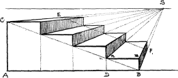
|
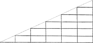
|
|
Fig. 243. |
Fig. 244. |
Steps, Front View
In this figure the height of each step is measured on the vertical
line AB (this line is sometimes called
the line of heights), and their depth is found by diagonals drawn to the
point of distance D. The rest of the
figure explains itself.
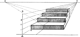
Fig. 245.
Square Steps
Draw first step ABEF and its two
diagonals. Raise vertical AH, and
measure thereon the required height of each step, and thus form scale.
Let the second step CD be less all
round than the first by Ao or
Bo. Draw oC till it cuts the diagonal, and proceed to draw the
second step, guided by the diagonals and taking its height from the
scale as shown. Draw the third step in the same way.
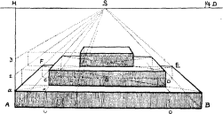
Fig. 246.
To Divide an Inclined Plane into Equal
Parts—such as a Ladder Placed against a Wall
Divide the vertical EC into the
required number of parts, and draw lines from point of sight S through these divisions 1, 2, 3,
&c., cutting the line AC at
1, 2, 3, &c. Draw parallels to AB, such as mn, from AC to BD, which
will represent the steps of the ladder.
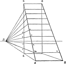
Fig. 247.
Steps and the Inclined Plane
In Fig. 248 we treat a flight of steps as if it were an inclined
plane. Draw the first and second steps as in Fig. 245. Then through
1, 2, draw 1V, AV to V, the
vanishing point on the vertical line SV. These two lines and the corresponding ones at
BV will form a kind of vanishing
scale, giving the height of each step as we ascend. It is especially
useful when we pass the horizontal line and we no longer see the upper
surface of the step, the scale on the right showing us how to proceed in
that case.
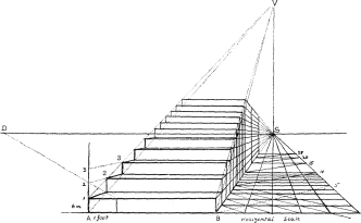
Fig. 248.
In Fig. 249 we have an example of steps ascending and descending. First
set out the ground-plan, and find its vanishing point S (point of sight). Through S draw vertical BA, and make SA
equal to SB. Set out the first step
CD. Draw EA, CA, DA, and GA, for the ascending guiding lines. Complete the
steps facing us, at central line OO.
Then draw guiding line FB for the
descending steps (see Rule 8).
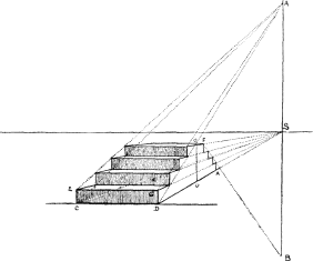
Fig. 249.
Steps in Angular Perspective
First draw the base ABCD (Fig. 251)
at the required angle by the new method (Fig. 250). Produce BC to the horizon, and thus find vanishing point
V. At this point raise vertical VV·. Construct
first step AB, refer its height at
B to line of heights hI on left, and thus obtain height of step at
A. Draw lines from A and F to V·. From n draw diagonal through
O to G. Raise vertical at O to represent the height of the next step, its
height being determined by the scale of heights at the side. From A and F
draw lines to V·, and also similar
lines from B, which will serve as
guiding lines to determine the height of the steps at either end as we
raise them to the required number.
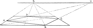
Fig. 250.
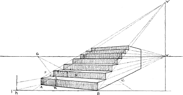
Fig. 251.
A Step Ladder at an Angle
First draw the ground-plan G at the
required angle, using vanishing and measuring points. Find the height
hH, and width at top HH·, and draw the sides HA and H·E. Note
that AE is wider than HH·, and also that the back legs are not at the same
angle as the front ones, and that they overlap them. From E raise vertical EF, and divide into as many parts as you require
rounds to the ladder. From these divisions draw lines 1 1,
2 2, &c., towards the other vanishing point (not in the
picture), but
having obtained their direction from the ground-plan in perspective at
line Ee, you may set up a
second vertical ef at any point on Ee and divide it into the same number of
parts, which will be in proportion to those on EF, and you will obtain the same result by drawing
lines from the divisions on EF to
those on ef as in drawing them to the vanishing point.
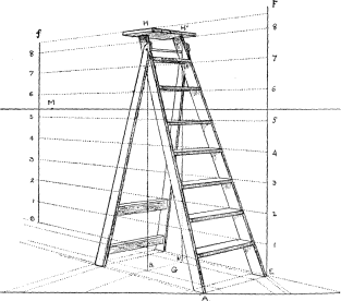
Fig. 252.
Square Steps Placed over each Other
This figure shows the other method of drawing steps, which is simple
enough if we have sufficient room for our vanishing points.

Fig. 253.
The manner of working it is shown at Fig.
124.
Steps and a Double Cross Drawn by Means of
Diagonals and one Vanishing Point
Although in this figure we have taken a longer distance-point than in
the previous one, we are able to draw it all within the page.
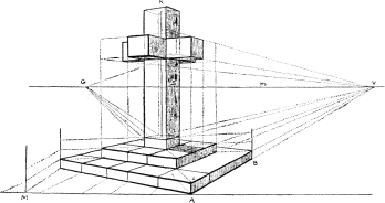
Fig. 254.
Begin by setting out the square base at the angle required. Find
point G by means of diagonals, and
produce AB to V, &c. Mark height of step Ao, and proceed to draw the steps as already
shown. Then by the diagonals and measurements on base draw the second
step and the square inside it on which to stand the foot of the cross.
To draw the cross, raise verticals from the four corners of its base,
and a line K from its centre. Through
any
point on this central line, if we draw a diagonal from point G we cut the two opposite verticals of the shaft
at mn (see Fig. 255), and by means of the vanishing point V we cut the other two verticals at the
opposite corners and thus obtain the four points through which to draw
the other sides of the square, which go to the distant or inaccessible
vanishing point. It will be seen by carefully examining the figure that
by this means we are enabled to draw the double cross standing on its
steps.
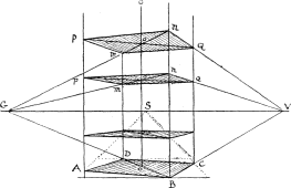
Fig. 255.
A Staircase Leading to a Gallery
In this figure we have made use of the devices already set forth in
the foregoing figures of steps, &c., such as the side scale on the
left of the figure to ascertain the height of the steps, the double
lines drawn to the high vanishing point of the inclined plane, and so
on; but the principal use of this diagram is to show on the perspective
plane, which as it were runs under the stairs, the trace or projection
of the flights of steps, the landings and positions of other objects,
which will be found very useful in placing figures in a composition of
this kind. It will be seen that these underneath measurements, so to
speak, are obtained by the half-distance.
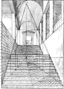
Fig. 256.
Winding Stairs in a Square Shaft
Draw square ABCD in parallel
perspective. Divide each side into four, and raise verticals from each
division. These verticals will mark the positions of the steps on each
wall, four in number. From centre O
raise vertical OP, around which the
steps are to wind. Let AF be the
height of each step. Form scale AB,
which will give the height of each step according to its position. Thus
at mn we find the height at the centre of the square, so if we
transfer this measurement to the central line OP and repeat it upwards, say to fourteen, then we
have the height of each step on the line where they all meet. Starting
then with the first on the right, draw the rectangle gD1f, the height of AF, then draw to the central line go,
f1, and 1 1, and thus complete the first step. On DE, measure heights equal to D 1. Draw 2 2 towards central line, and
2n towards point of sight till it meets the second vertical
nK. Then draw n2 to
centre, and so complete the second step. From 3 draw 3a to third
vertical, from 4 to fourth, and so on, thus obtaining the height of each
ascending step on the wall to the right, completing them in the same way
as numbers 1 and 2, when we come to the sixth step, the other end
of which is against the wall opposite to us. Steps 6, 7, 8, 9
are all on this wall, and are therefore equal in height all along, as
they are equally distant. Step 10 is turned towards us, and abuts on the
wall to our left; its measurement is taken on the scale AB just underneath it, and on the same line to which
it is drawn. Step 11 is just over the centre of base mo, and is
therefore parallel to it, and its height is mn. The widths of
steps 12 and 13 seem gradually to increase as they come towards us, and
as they rise above the horizon we begin to see underneath them. Steps
13, 14, 15, 16 are against the wall on this side of the picture, which
we may suppose has been removed to show the working of the drawing, or
they might be an open flight as we sometimes see in shops and galleries,
although in that case they are generally enclosed in a cylindrical
shaft.
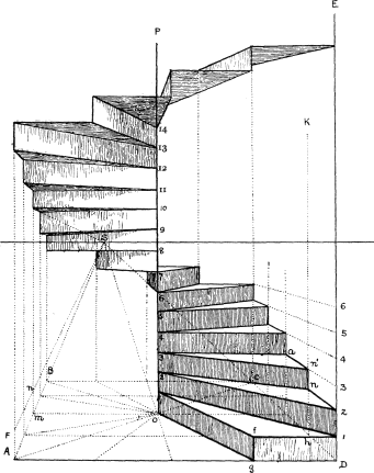
Fig. 257.
Winding Stairs in a Cylindrical Shaft
First draw the circular base CD.
Divide the circumference into equal parts, according to the number of
steps in a complete round, say twelve. Form scale ASF and the larger scale ASB, on which is shown the perspective measurements
of the steps according to their positions; raise verticals such as
ef, Gh, &c. From
divisions on circumference measure out the central line OP, as in the other figure, and find the heights of
the steps 1, 2, 3, 4, &c., by the corresponding numbers in
the large scale to the left; then proceed in much the same way as in the
previous figure. Note the central column OP cuts off a small portion of the steps at that
end.
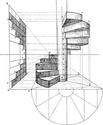
Fig. 258.
In ordinary cases only a small portion of a winding staircase is
actually seen, as in this sketch.
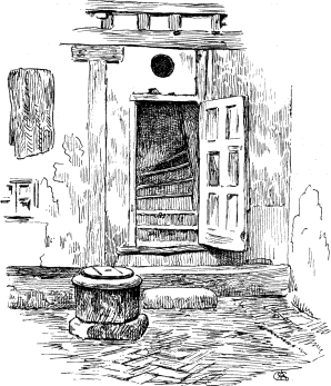
Fig. 259. Sketch of Courtyard in
Toledo.
Of the Cylindrical Picture or Diorama
Although illusion is by no means the highest form of art, there is no
picture painted on a flat surface that gives such a wonderful appearance
of truth as that painted on a cylindrical canvas, such as those
panoramas of ‘Paris during the Siege’, exhibited some years
ago; ‘The Battle of Trafalgar’, only lately shown at Earl's
Court; and many others. In these pictures the spectator is in the centre
of a cylinder, and although he turns round to look at the scene the
point of sight is always in front of him, or nearly so. I believe
on the canvas these points are from 12 to 16 feet apart.
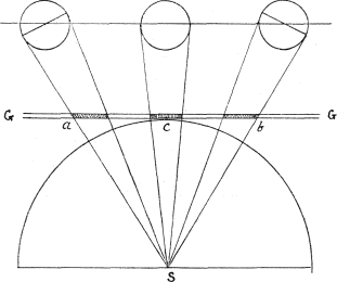
Fig. 260.
The reason of this look of truth may be explained thus. If we place
three globes of equal size in a straight line, and trace their apparent
widths on to a straight transparent plane, those at the sides, as
a and b, will appear much wider than the centre one at
c. Whereas, if we trace them on a semicircular glass they will
appear very nearly equal and, of the three, the central one c
will be rather the largest, as may be seen by this figure.
We must remember that, in the first case, when we are looking at a
globe or a circle, the visual rays form a cone, with a globe at its
base. If these three cones are intersected by a straight glass GG, and looked at from point S, the intersection of C will be a circle, as the cone is cut straight
across. The other two being intersected at an angle, will each be an
ellipse. At the same time, if we look at them from the station point,
with one eye only, then the three globes (or tracings of them) will
appear equal and perfectly round.
Of course the cylindrical canvas is necessary for panoramas; but we
have, as a rule, to paint our pictures and wall-decorations on flat
surfaces, and therefore must adapt our work to these conditions.
In all cases the artist must exercise his own judgement both in the
arrangement of his design and the execution of the work, for there is
perspective even in the touch—a painting to be looked at from a
distance requires a bold and broad handling; in small cabinet pictures
that we live with in our own rooms we look for the exquisite workmanship
of the best masters.
The Perspective of Cast Shadows
There is a pretty story of two lovers which is sometimes told as the
origin of art; at all events, I may tell it here as the origin of
sciagraphy. A young shepherd was in love with the daughter of a
potter, but it so happened that they had to part, and were passing their
last evening together, when the girl, seeing the shadow of her lover's
profile cast from a lamp on to some wet plaster or on the wall, took a
metal point, perhaps some sort of iron needle, and traced the outline of
the face she loved on to the plaster, following carefully the outline of
the features, being naturally anxious to make it as like as possible.
The old potter, the father of the girl, was so struck with it that he
began to ornament his wares by similar devices, which gave them
increased value by the novelty and beauty thus imparted to them.
Here then we have a very good illustration of our present subject and
its three elements. First, the light shining on the wall; second, the
wall or the plane of projection, or plane of shade; and third, the
intervening object, which receives as much light on itself as it
deprives the wall of. So that the dark portion thus caused on the plane
of shade is the cast shadow of the intervening object.
We have to consider two sorts of shadows: those cast by a luminary a
long way off, such as the sun; and those cast by artificial light, such
as a lamp or candle, which is more or less close to the object. In the
first case there is no perceptible divergence of rays, and the outlines
of the sides of the shadows of regular objects, as cubes, posts,
&c., will be parallel. In the second case, the rays diverge
according to the nearness of the light, and consequently the lines of
the shadows, instead of being parallel, are spread out.
The Two Kinds of Shadows
In Figs. 261 and 262 is seen the shadow cast by the sun by parallel
rays.
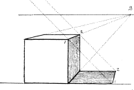
|
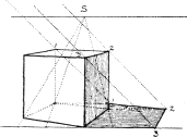
|
|
Fig. 261. |
Fig. 262. |
Fig. 263 shows the shadows cast by a candle or lamp, where the rays
diverge from the point of light to meet corresponding diverging lines
which start from the foot of the luminary on the ground.
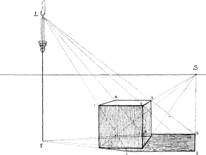
Fig. 263.
The simple principle of cast shadows is that the rays coming from the
point of light or luminary pass over the top of the intervening object
which casts the shadow on to the plane of shade to meet the horizontal
trace of those rays on that plane, or the
lines of light proceed from the point of light, and the lines of the
shadow are drawn from the foot or trace of the point of light.
Fig. 264 shows this in profile. Here the sun is on the same plane as
the picture, and the shadow is cast sideways.
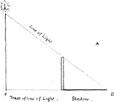
|
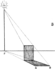
|
|
Fig. 264. |
Fig. 265. |
Fig. 265 shows the same thing, but the sun being behind the
object, casts its shadow forwards. Although the lines of light are
parallel, they are subject to the laws of perspective, and are therefore
drawn from their respective vanishing points.
Shadows Cast by the Sun
Owing to the great distance of the sun, we have to consider the rays
of light proceeding from it as parallel, and therefore subject to the
same laws as other parallel lines in perspective, as already noted. And
for the same reason we have to place the foot of the luminary on the
horizon. It is important to remember this, as these two things make the
difference between shadows cast by the sun and those cast by artificial
light.
The sun has three principal positions in relation to the picture. In
the first case it is supposed to be in the same plane either to the
right or to the left, and in that case the shadows will be
parallel with the base of the picture. In the second position it is on
the other side of it, or facing the spectator, when the shadows of
objects will be thrown forwards or towards him. In the third, the sun is
in front of the picture, and behind the spectator, so that the shadows
are thrown in the opposite direction, or towards the horizon, the
objects themselves being in full light.
The Sun in the Same Plane as the Picture
Besides being in the same plane, the sun in this figure is at an
angle of 45° to the horizon, consequently the shadows will be the same
length as the figures that cast them are high. Note that the shadow of
step No. 1 is cast upon step No. 2, and that of No. 2 on
No. 3, the top of each of these becoming a plane of shade.
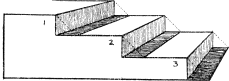
|
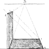
|
|
Fig. 266. |
Fig. 267. |
When the shadow of an object such as A, Fig. 268, which would fall upon the plane, is
interrupted by another object B, then
the
outline of the shadow is still drawn on the plane, but being interrupted
by the surface B at C, the shadow runs up that plane till it meets the
rays 1, 2, which define the shadow on plane B. This is an important point, but is quite
explained by the figure.
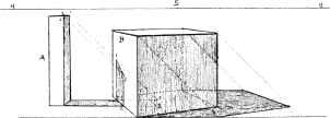
Fig. 268.
Although we have said that the rays pass over the top of the object
casting the shadow, in the case of an archway or similar figure they
pass underneath it; but the same principle holds good, that is, we draw
lines from the guiding points in the arch, 1, 2, 3, &c.,
at the same angle of 45° to meet the traces of those rays on the plane
of shade, and so get the shadow of the archway, as here shown.
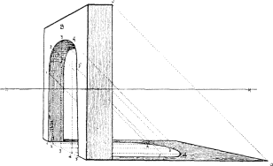
Fig. 269.
The Sun Behind the Picture
We have seen that when the sun's altitude is at an angle of 45° the
shadows on the horizontal plane are the same length as the height of the
objects that cast them. Here (Fig. 270), the sun still being at 45°
altitude, although behind the picture, and consequently throwing the
shadow of B forwards, that shadow must
be the same length as the height of cube B, which will be seen is the case, for the shadow
C is a square in perspective.
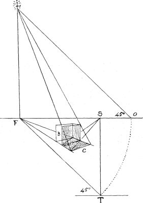
Fig. 270.
To find the angle of altitude and the angle of the sun to the picture,
we must first find the distance of the spectator from the foot of the
luminary.
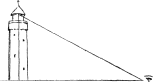
|
|
Fig. 271. |
From point of sight S (Fig. 270)
drop perpendicular to T, the
station-point. From T draw TF at 45° to meet horizon at F. With radius FT
make FO equal to it. Then O is the position of the spectator. From F raise vertical FL, and from O
draw a line at 45° to meet FL at L, which is the luminary at an altitude of
45°, and at an angle of 45° to the picture.
Fig. 272 is similar to the foregoing, only the angles of altitude and
of the sun to the picture are altered.
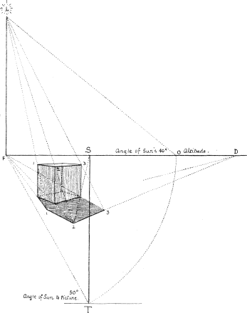
Fig. 272.
Note.—The sun being at 50° to the picture instead of
45°, is nearer the point of sight; at 90° it would be exactly opposite
the spectator, and so on. Again, the elevation being less (40° instead
of 45°) the shadow is longer. Owing to the changed position of the sun
two sides of the cube throw a shadow. Note also that the outlines of the
shadow, 1 2, 2 3, are drawn to the same vanishing points as
the cube itself.
It will not be necessary to mark the angles each time we make a
drawing, as it must be seen we can place the luminary in any position
that suits our convenience.
Sun Behind the Picture, Shadows Thrown on a
Wall
As here we change the conditions we must also change our procedure.
An upright wall now becomes the plane of shade, therefore as the
principle of shadows must always remain the same we have to change the
relative positions of the luminary and the foot thereof.
At S (point of sight) raise
vertical SF·, making it equal to
fL. F· becomes the foot of the luminary, whilst the
luminary itself still remains at L.
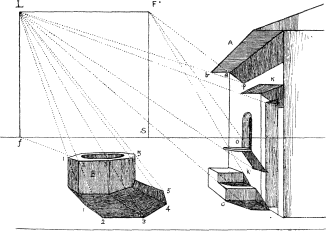
Fig. 273.
We have but to turn this page half round and look at it from the
right, and we shall see that SF·
becomes as it were the horizontal line. The luminary L is at the right side of point S instead of the left, and the foot thereof is, as
before, the trace of the luminary, as it is just underneath it. We shall
also see that by
proceeding as in previous figures we obtain the same results on the wall
as we did on the horizontal plane. Fig. B being on the horizontal plane is treated as
already shown. The steps have their shadows partly on the wall and
partly on the horizontal plane, so that the shadows on the wall are
outlined from F· and those on the
ground from f. Note shadow of roof A, and how the line drawn from F· through A is
met by the line drawn from the luminary L, at the point P,
and how the lower line of the shadow is directed to point of sight S.
Fig. 274 is a larger drawing of the steps, &c., in further
illustration of the above.
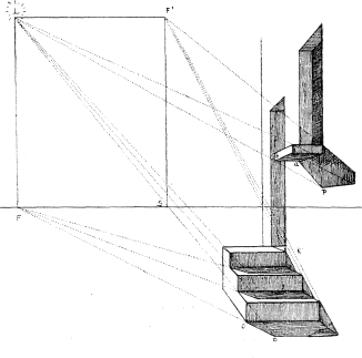
Fig. 274.
Sun Behind the Picture Throwing Shadow on an
Inclined Plane
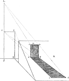
|
|
Fig. 275. |
The vanishing point of the shadows on an inclined plane is on a
vertical dropped from the luminary to a point (F) on a level with the vanishing point (P) of that inclined plane. Thus P is the vanishing point of the inclined plane K. Draw horizontal PF to meet fL (the line drawn from the luminary to the horizon).
Then F will be the vanishing point of
the shadows on the inclined plane. To find the shadow of M draw lines from F through the
base eg to cd. From luminary L draw lines through ab, also to cd,
where they will meet those drawn from F. Draw CD, which
determines the length of the shadow egcd.
The Sun in Front of the Picture
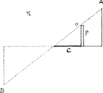
|
|
Fig. 277. |
When the sun is in front of the picture we have exactly the opposite
effect to that we have just been studying. The shadows, instead of
coming towards us, are retreating from us, and the objects throwing them
are in full light, consequently we have to reverse our treatment. Let us
suppose the sun to be placed
above the horizon at L·, on the right
of the picture and behind the spectator (Fig. 276). If we transport the
length L·f· to the opposite
side and draw the vertical downwards from the horizon, as at FL, we can then suppose point L to be exactly opposite the sun, and if we make
that the vanishing point for the sun's rays we shall find that we obtain
precisely the same result. As in Fig. 277, if we wish to find the length
of C, which we may suppose to be the
shadow of P, we can either draw a line
from A through O to B, or from
B through O to A, for the
result is the same. And as we cannot make use of a point that is behind
us and out of the picture, we have to resort to this very ingenious
device.
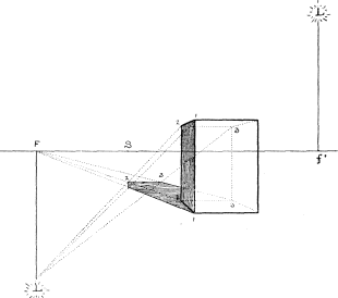
Fig. 276.
In Fig. 276 we draw lines L1, L2, L3
from the luminary to the top of the object to meet those drawn from the
foot F, namely F1, F2, F3, in the same way as in the figures we
have already drawn.
Fig. 278 gives further illustration of this problem.
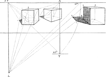
Fig. 278.
The Shadow of an Inclined Plane
The two portions of this inclined plane which cast the shadow are
first the side fbd, and second the farther end abcd. The
points we have to find are the shadows of a and b. From
luminary L draw La, Lb, and from F, the foot, draw Fc, Fd. The intersection of these lines will be
at a·b·. If we join fb· and db· we have the shadow
of the side fbd, and if we join ca· and a·b· we
have the shadow of abcd, which together form that of the
figure.
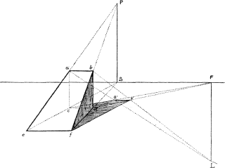
Fig. 279.
Shadow on a Roof or Inclined Plane
To draw the shadow of the figure M
on the inclined plane K (or a chimney
on a roof). First find the vanishing point P of the inclined plane and draw horizontal PF to meet vertical raised from L, the luminary. Then F will be the vanishing point of the shadow. From
L draw L1, L2, L3 to top of figure M, and from the base of M draw 1F, 2F, 3F to
F, the vanishing point of the shadow.
The intersections of these lines at 1, 2, 3 on K will determine the length and form of the
shadow.
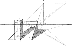
Fig. 280.
To Find the Shadow of a Projection or Balcony on
a Wall
To find the shadow of the object K
on the wall W, drop verticals OO till they meet the base line B·B· of the wall. Then from the point of sight
S draw lines through OO, also drop verticals Dd·, Cc·, to meet these lines in d·c·; draw
c·F and d·F to foot of luminary. From the points xx
where these lines cut the base B raise
perpendiculars xa·, xb·. From D, A, and B draw lines to the luminary L. These lines or rays intersecting the verticals
raised from xx at a·b· will give the respective points of
the shadow.
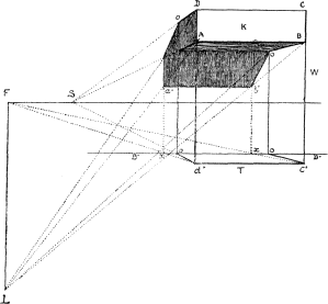
Fig. 281.
The shadow of the eave of a roof can be obtained in the same way.
Take any point thereon, mark its trace on the ground, and then proceed
as above.
Shadow on a Retreating Wall, Sun in Front
Let L be the luminary. Raise
vertical LF. F will be the vanishing point of the shadows on the
ground. Draw Lf· parallel to
FS. Drop Sf· from point of sight; f· (so found)
is the vanishing point of the shadows on the wall. For shadow of roof
draw LE and f·B, giving us e, the shadow of E. Join Be,
&c., and so draw shadow of eave of roof.
For shadow of K draw lines from
luminary L to meet those from
f· the foot, &c.
The shadow of D over the door is
found in a similar way to that of the roof.
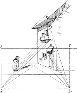
Fig. 282.
Figure 283 shows how the shadow of the old man in the preceding
drawing is found.
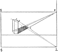
Fig. 283.
Shadow of an Arch, Sun in Front
Having drawn the arch, divide it into a certain number of parts, say
five. From these divisions drop perpendiculars to base line. From
divisions on AB draw lines to F the foot, and from those on the semicircle
draw lines to L the luminary. Their
intersections will give the points through which to draw the shadow of
the arch.
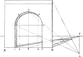
Fig. 284.
Shadow in a Niche or Recess
In this figure a similar method to that just explained is adopted.
Drop perpendiculars from the divisions of the arch 1 2 3 to
the base. From the foot of each draw 1S, 2S, 3S to foot of luminary S, and from the top of each, A 1 2 3 B, draw lines to L
as before. Where the former intersect the curve on the floor of the
niche raise verticals to meet the latter at P 1 2 B, &c. These points will indicate about the
position of the shadow; but the niche being semicircular and domed at
the top the shadow gradually loses itself in a gradated and somewhat
serpentine half-tone.
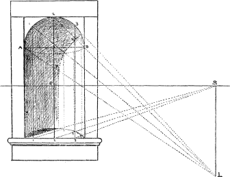
Fig. 285.
Shadow in an Arched Doorway
This is so similar to the last figure in many respects that I need not
repeat a description of the manner in which it is done. And surely an
artist after making a few sketches from the actual thing will hardly
require all this machinery to draw a simple shadow.
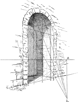
Fig. 286.
Shadows Produced by Artificial Light
Shadows thrown by artificial light, such as a candle or lamp, are
found by drawing lines from the seat of the luminary through the feet of
the objects to meet lines representing rays of light drawn from the
luminary itself over the tops or the corners of the objects; very much
as in the cases of sun-shadows, but with
this difference, that whereas the foot of the luminary in this latter
case is supposed to be on the horizon an infinite distance away, the
foot in the case of a lamp or candle may be on the floor or on a table
close to us. First draw the table and chair, &c. (Fig. 287), and let
L be the luminary. For objects on the
table such as K the foot will be at
f on the table. For the shadows on the floor, of the chair and
table itself, we must find the foot of the luminary on the floor. Draw
So, find trace of the edge of
the table, drop vertical oP,
draw PS to point of sight, drop
vertical from foot of candlestick to meet PS in F. Then
F is the foot of the luminary on the
floor. From this point draw lines through the feet or traces of objects
such as the corners of the table, &c., to meet other lines drawn
from the point of light, and so obtain the shadow.
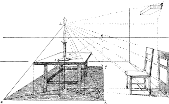
Fig. 287.
Some Observations on Real Light and Shade
Although the figures we have been drawing show the principles on
which sun-shadows are shaped, still there are so many more laws to be
considered in the great art of light and shade that it is better to
observe them in Nature herself or under the teaching of the real sun. In
the study of a kitchen and scullery in an old house in Toledo (Fig. 288)
we have an example of the many things to be considered besides the mere
shapes of shadows of regular forms. It will be seen that the light is
dispersed in all directions, and although there is a good deal of
half-shade there are scarcely any cast shadows except on the floor; but
the light on the white walls in the outside gallery is so reflected into
the cast shadows that they are extremely faint. The luminosity of this
part of the sketch is greatly enhanced by the contrast of the dark legs
of the bench and the shadows in the roof. The warm glow of all this
portion is contrasted by the grey door and its frame.
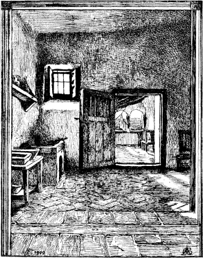
Fig. 288.
Note that the door itself is quite luminous, and lighted up by the
reflection of the sun from the tiled floor, so that the bars in the
upper part throw distinct shadows, besides the mystery of colour thus
introduced. The little window to the left, though not admitting much
direct sunlight, is evidence of the brilliant glare outside; for the
reflected light is very conspicuous on the
top and on the shutters on each side; indeed they cast distinct shadows
up and down, while some clear daylight from the blue sky is reflected on
the window-sill. As to the sink, the table, the wash-tubs, &c.,
although they seem in strong light and shade they really receive little
or no direct light from a single point; but from the strong reflected
light re-reflected into them from the wall of the doorway. There are
many other things in such effects as this which the artist will observe,
and which can only be studied from real light and shade. Such is the
character of reflected light, varying according to the angle and
intensity of the luminary and a hundred other things. When we come to
study light in the open air we get into another region, and have to deal
with it accordingly, and yet we shall find that our sciagraphy will be a
help to us even in this bewilderment; for it will explain in a manner
the innumerable shapes of sun-shadows that we observe out of doors among
hills and dales, showing up their forms and structure; its play in the
woods and gardens, and its value among buildings, showing all their
juttings and abuttings, recesses, doorways, and all the other
architectural details. Nor must we forget light's most glorious display
of all on the sea and in the clouds and in the sunrises and the sunsets
down to the still and lovely moonlight.
These sun-shadows are useful in showing us the principle of light and
shade, and so also are the shadows cast by artificial light; but they
are only the beginning of that beautiful study, that exquisite art of
tone or chiaro-oscuro, which is infinite in its variety, is full
of the deepest mystery, and is the true poetry of art. For this the
student must go to Nature herself, must study her in all her moods from
early dawn to sunset, in the twilight and when night sets in. No
mathematical rules can help him, but only the thoughtful contemplation,
the silent watching, and the mental notes that he can make and commit to
memory, combining them with the sentiments to which they in turn give
rise. The plein air, or broad daylight effects, are but one item
of the great range of this ever-changing and deepening
mystery—from the hard reality to the soft blending of evening when
form almost disappears, even to the merging of the whole landscape, nay,
the whole world, into a dream—which is felt
rather than seen, but possesses a charm that almost defies the pencil of
the painter, and can only be expressed by the deep and sweet notes of
the poet and the musician. For love and reverence are necessary to
appreciate and to present it.
There is also much to learn about artificial light. For here, again,
the study is endless: from the glare of a hundred lights—electric
and otherwise—to the single lamp or candle. Indeed a whole volume
could be filled with illustrations of its effects. To those who aim at
producing intense brilliancy, refusing to acknowledge any limitations to
their capacity, a hundred or a thousand lights commend themselves;
and even though wild splashes of paint may sometimes be the result,
still the effort is praiseworthy. But those who prefer the mysterious
lighting of a Rembrandt will find, if they sit contemplating in a room
lit with one lamp only, that an endless depth of mystery surrounds them,
full of dark recesses peopled by fancy and sweet thought, whilst the
most beautiful gradations soften the forms without distorting them; and
at the same time he can detect the laws of this science of light and
shade a thousand times repeated and endless in its variety.
Note.—Fig. 288 must be looked upon as a rough sketch
which only gives the general effect of the original drawing; to render
all the delicate tints, tones and reflections described in the text
would require a highly-finished reproduction in half-tone or in
colour.
As many of the figures in this book had to be re-drawn, not a light
task, I must here thank Miss Margaret L. Williams, one of our
Academy students, for kindly coming to my assistance and volunteering
her careful co-operation.
Reflection
Reflections in still water can best be illustrated by placing some
simple object, such as a cube, on a looking-glass laid horizontally on a
table, or by studying plants, stones, banks, trees, &c., reflected
in some quiet pond. It will then be seen that the reflection is the
counterpart of the object reversed, and having the same vanishing points
as the object itself.
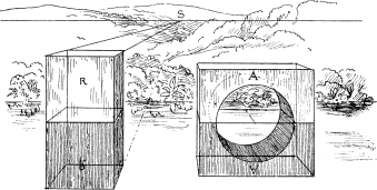
Fig. 289.
Let us suppose R (Fig. 289) to be
standing on the water or reflecting plane. To find its reflection make
square [R] equal to the original square R. Complete the reversed cube by drawing its other
sides, &c. It is evident that this lower cube is the reflection of
the one above it, although it differs in one respect, for whereas in
figure R the top of the cube is seen,
in its reflection [R] it is hidden,
&c. In figure A of a semicircular
arch we see the
underneath portion of the arch reflected in the water, but we do not see
it in the actual object. However, these things are obvious. Note that
the reflected line must be equal in length to the actual one, or the
reflection of a square would not be a square, nor that of a semicircle a
semicircle. The apparent lengthening of reflections in water is owing to
the surface being broken by wavelets, which, leaping up near to us,
catch some of the image of the tree, or whatever it is, that it is
reflected.
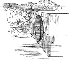
|
|
Fig. 290. |
In this view of an arch (Fig. 290) note that the reflection is
obtained by dropping perpendiculars from certain points on the arch,
1, 0, 2, &c., to the surface of the reflecting plane, and
then measuring the same lengths downwards to corresponding points,
1, 0, 2, &c., in the reflection.
Angles of Reflection
In Fig. 291 we take a side view of the reflected object in order to
show that at whatever angle the visual ray strikes the reflecting
surface it is reflected from it at the same angle.
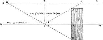
Fig. 291.
We have seen that the reflected line must be equal to the original
line, therefore mB must equal
Ma. They are also at right
angles to MN, the plane of reflection.
We will now draw the visual ray passing from E, the eye, to B,
which is the reflection of A; and just
underneath it passes through MN at
O, which is the point where the visual
ray strikes the reflecting surface. Draw OA. This line represents the ray reflected from it.
We have now two triangles, OAm
and OmB, which are right-angled triangles and equal,
therefore angle a equals angle b. But angle b
equals angle c. Therefore angle EcM equals
angle Aam, and the angle at
which the ray strikes the reflecting plane is equal to the angle at
which it is reflected from it.
Reflections of Objects at Different
Distances
In this sketch the four posts and other objects are represented
standing on a plane level or almost level with the water, in order to
show the working of our problem more clearly. It will be seen that the
post A is on the brink of the
reflecting plane, and therefore is entirely reflected; B and C being
farther back are only partially seen, whereas the reflection of D is not seen at all. I have made all
the posts the same height, but with regard to the houses, where the
length of the vertical lines varies, we obtain their reflections by
measuring from the points oo upwards and downwards as in the
previous figure.
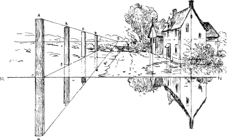
Fig. 292.
Of course these reflections vary according to the position they are
viewed from; the lower we are down, the more do we see of the
reflections of distant objects, and vice versa. When the figures are on
a higher plane than the water, that is, above the plane of reflection,
we have to find their perspective position,
and drop a perpendicular AO (Fig. 293)
till it comes in contact with the plane of reflection, which we suppose
to run under the ground, then measure the same length downwards, as in
this figure of a girl on the top of the steps. Point o marks the
point of contact with the plane, and by measuring downwards to a·
we get the length of her reflection, or as much as is seen of it. Note
the reflection of the steps and the sloping bank, and the application of
the inclined plane ascending and descending.
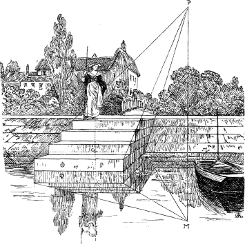
Fig. 293.
Reflection in a Looking-glass
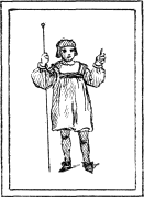
|
|
Fig. 294. |
I had noticed that some of the figures in Titian’s pictures
were only half life-size, and yet they looked natural; and one day,
thinking I would trace myself in an upright mirror, I stood at
arm’s length from it and with a brush and Chinese white,
I made a rough outline of my face and figure, and when I measured
it I found that my drawing was exactly half as long and half as wide as
nature. I went closer to the glass, but the same outline fitted me.
Then I retreated several paces, and still the same outline surrounded
me. Although a little surprising at first, the reason is obvious. The
image in the glass retreats or advances exactly in the same measure as
the spectator.
Suppose him to represent one end of a parallelogram e·s·, and
his image a·b· to represent the other. The mirror AB is a perpendicular half-way between them, the
diagonal e·b· is the visual ray
passing from the eye of the spectator to the foot of his image, and is
the diagonal of a rectangle, therefore it cuts AB in the centre o, and AO represents a·b· to the spectator. This is
an experiment that any one may try for himself. Perhaps the above fact
may have something to do with the remarks I made about Titian at the
beginning of this chapter.
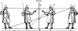
Fig. 295.
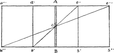
Fig. 296.
The Mirror at an Angle
If an object or line AB is inclined
at an angle of 45° to the mirror RR,
then the angle BAC will be a right
angle, and this angle is exactly divided in two by the reflecting plane
RR. And whatever the angle of the
object or line makes with its reflection that angle will also be exactly
divided.
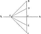
|
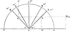
|
|
Fig. 297. |
Fig. 298. |
Now suppose our mirror to be standing on a horizontal plane and on a
pivot, so that it can be inclined either way. Whatever angle the mirror
is to the plane the reflection of that plane in the mirror will be at
the same angle on the other side of it, so that if the mirror OA (Fig. 298) is at 45° to the plane RR then the
reflection of that plane in the mirror will be 45° on the other side of
it, or at right angles, and the reflected plane will appear
perpendicular, as shown in Fig. 299, where we have a front view of a
mirror leaning forward at an angle of 45° and reflecting the square
aob with a cube standing upon it, only in the reflection the cube
appears to be projecting from an upright plane or wall.
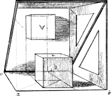
Fig. 299.
If we increase the angle from 45° to 60°, then the reflection of the
plane and cube will lean backwards as shown in Fig. 300. If we place it
on a level with the original plane, the cube will be standing upright
twice the distance away. If the mirror is still farther tilted till it
makes an angle of 135° as at E (Fig.
298), or 45° on the other side of the vertical Oc, then the plane and cube would disappear,
and objects exactly over that plane, such as the ceiling, would come
into view.
In Fig. 300 the mirror is at 60° to the plane mn, and the
plane itself at about 15° to the plane an (so that here we are
using angular perspective, V being the
accessible vanishing point). The reflection of the plane and cube is
seen leaning back at an
angle of 60°. Note the way the reflection of this cube is found by the
dotted lines on the plane, on the surface of the mirror, and also on the
reflection.
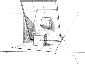
Fig. 300.
The Upright Mirror at an Angle of 45° to the
Wall
In Fig. 301 the mirror is vertical and at an angle of 45° to the wall
opposite the spectator, so that it reflects a portion of that wall as
though it were receding from us at right angles; and the wall with the
pictures upon it, which appears to be facing us, in reality is on our
left.
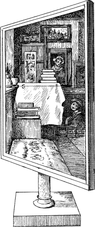
Fig. 301.
An endless number of complicated problems could be invented of the
inclined mirror, but they would be mere puzzles calculated rather to
deter the student than to instruct him. What we chiefly have to bear in
mind is the simple principle of reflections. When a mirror is vertical
and placed at the end or side of a room it reflects that room and gives
the impression that we are in one double the size. If two mirrors are
placed opposite to each other at each end of a room they reflect and
reflect, so that we see an endless number of rooms.
Again, if we are sitting in a gallery of pictures with a hand mirror,
we can so turn and twist that mirror about that we can bring any picture
in front of us, whether it is behind us, at the side, or even on the
ceiling. Indeed, when one goes to those old palaces and churches where
pictures are painted on the ceiling, as in the Sistine Chapel or the
Louvre, or the palaces at Venice, it is not a bad plan to take a hand
mirror with us, so that we can see those elevated works of art in
comfort.
There are also many uses for the mirror in the studio, well known to
the artist. One is to look at one's own picture reversed, when faults
become more evident; and another, when the model is required to be at a
longer distance than the dimensions of the studio will admit, by drawing
his reflection in the glass we double the distance he is
from us.
The reason the mirror shows the fault of a work to which the eye has
become accustomed is that it doubles it. Thus if a line that should be
vertical is leaning to one side, in the mirror it will lean to the
other; so that if it is out of the perpendicular to the left, its
reflection will be out of the perpendicular to the right, making a
double divergence from one to the other.
Mental Perspective
Before we part, I should like to say a word about mental
perspective, for we must remember that some see farther than others, and
some will endeavour to see even into the infinite. To see Nature in all
her vastness and magnificence, the thought must supplement and must
surpass the eye. It is this far-seeing that makes the great poet, the
great philosopher, and the great artist. Let the student bear this in
mind, for if he possesses this quality or even a share of it, it will
give immortality to his work.
To explain in detail the full meaning of this suggestion is beyond
the province of this book, but it may lead the student to think this
question out for himself in his solitary and imaginative moments, and
should, I think, give a charm and virtue to his work which he
should endeavour to make of value, not only to his own time but to the
generations that are to follow. Cultivate, therefore, this mental
perspective, without forgetting the solid foundation of the science I
have endeavoured to impart to you.
Index citations in the original book referred to page numbers. Where
possible, links will lead directly to a chapter header or illustration.
Note that the last two entries for Toledo are figure numbers rather than
pages; these have not been corrected.
A
Albert Dürer,
2,
9.
Angles of Reflection,
259.
Angular Perspective,
98-123,
133,
170.
Ang"lar
Persp"ctive, New Method,
133,
134,
135,
136.
Arches, Arcades, &c.,
198,
200-208.
Architect's Perspective,
170,
171.
Art Schools Perspective,
112-118,
217.
Atmosphere,
1,
74.
B
Balcony, Shadow of,
246.
Base or groundline,
89.
C
Campanile Florence,
5,
59.
Cast Shadows,
229-253.
Centre of Vision,
15.
Chessboard,
74.
Chinese Art,
11.
Circle,
145,
151-156,
159.
Columns,
157,
159,
161,
169,
170.
Conditions of Perspective,
24,
25.
Cottage in Angular Perspective,
116.
Cube,
53,
65,
115,
119.
Cylinder,
158,
159.
Cylindrical picture, 227.
D
De Hoogh,
2,
62,
73.
Depths, How to measure by diagonals,
127,
128.
Descending plane,
92-95.
Diagonals,
45,
124,
125,
126.
Disproportion, How to correct,
35,
118,
157.
Distance,
16,
77,
78,
85,
87,
103,
128.
Distorted perspective, How to correct,
118.
Dome,
163-167.
Double Cross,
218.
E
Ellipse,
145,
146,
147.
Elliptical Arch,
207.
F
Farningham,
95.
Figures on descending plane,
92,
93,
94,
95.
Fig"res
"n an inclined plane,
88.
Fig"res
"n a level plane,
70,
71,
72,
73,
74,
75.
Fig"res
"n uneven ground,
90,
91.
G
Geometrical and Perspective figures contrasted,
46-48.
Geom"trical plane,
99.
Giovanni da Pistoya, Sonnet to, by Michelangelo,
60.
Great Pyramid,
190.
H
Hexagon,
177,
183,
185.
Hogarth,
9.
Honfleur,
83,
142.
Horizon,
3,
4,
15,
20,
59,
60.
Horizontal line,
13,
15.
Horizontals,
30,
31,
36.
I
Inaccessible vanishing points,
77,
78,
136,
140-144.
Inclined plane,
33,
118,
213,
244,
245.
Interiors,
62,
117,
118,
128.
J
Japanese Art,
11.
Jesuit of Paris, Practice of Perspective by,
9.
K
Kiosk, Application of Hexagon,
185.
Kirby, Joshua, Perspective made Easy (?),
9.
L
Ladder, Step,
212,
216.
Landscape Perspective,
74.
Landseer, Sir Edwin,
1.
Leonardo da Vinci,
1,
61.
Light, Observations on,
253.
Light-house,
84.
Long distances,
85,
87.
M
Measure distances by square and diagonal,
89,
128,
129.
Mea"ure vanishing lines, How to,
49,
50.
Measuring points,
106,
113.
Meas"ring point O,
108,
109,
110.
Mental Perspective,
269.
Michelangelo,
5,
57,
58,
60.
N
Natural Perspective,
12,
82,
95,
142,
144.
New Method of Angular Perspective,
133,
134,
135,
141,
215,
219.
Niche,
164,
165,
250.
O
Oblique Square,
139.
Octagon,
172-175.
O, measuring point,
110.
Optic Cone,
20.
P
Parallels and Diagonals,
124-128.
Paul Potter, cattle,
19.
Paul Veronese,
4.
Pavements,
64,
66,
176,
178,
180,
181,
183.
Pedestal,
141,
161.
Pentagon,
186,
187,
188.
Perspective, Angular,
98-123.
Persp"ctive, Definitions,
13-23.
Persp"ctive, Necessity of,
1.
Persp"ctive, Parallel,
42-97.
Persp"ctive,
Rules and Conditions of,
24-41.
Persp"ctive,
Scientific definition of,
22.
Persp"ctive, Theory of,
13-24.
Persp"ctive, What is it?
6-12.
Pictures painted according to positions they are to occupy,
59.
Point of Distance,
16-21.
Po"nt
"f Sight,
12,
15.
Points in Space,
129,
137.
Portico,
111.
Projection,
21,
137.
Pyramid,
189,
190,
191,
193-196.
R
Raphael,
3.
Reduced distance,
77,
78,
79,
84.
Reflection,
257-268.
Rembrandt,
59,
256.
Reynolds, Sir Joshua,
9,
60.
Rubens,
4.
Rules of Perspective,
24-41.
S
Scale on each side of Picture,
141,
142-144.
Sc"le Vanishing,
69,
71,
81,
84.
Serlio,
5,
126.
Shadows cast by sun,
229-252.
Sha"ows
ca"st
"y artificial light,
252.
Sight, Point of,
12,
15.
Sistine Chapel,
60.
Solid figures,
135-140.
Square in Angular Perspective,
105,
106,
109,
112,
114,
121,
122,
123,
133,
134,
139.
Sq"are and diagonals,
125,
138,
139,
141.
Sq"are of the hypotenuse (fig. 170),
149.
Sq"are in Parallel Perspective,
42,
43,
50,
53,
54.
Sq"are at 45°,
64-66.
Staircase leading to a Gallery,
221.
Stairs, Winding,
222,
225.
Station Point,
13.
Steps,
209-218.
T
Taddeo Gaddi,
5.
Terms made use of,
48.
Tiles,
176,
178,
181.
Tintoretto,
4.
Titian,
59,
262.
Toledo,
96,
144,
259,
288.
Trace and projection,
21.
Transposed distance,
53.
Triangles,
104,
106,
132,
135,
138.
Turner,
2,
87.
U
Ubaldus, Guidus,
9.
V
Vanishing lines,
49.
Vani"hing point,
119.
Vani"hing
scale,
68-72,
74,
77,
79,
84.
Vaulted Ceiling,
203.
Velasquez,
59.
Vertical plane,
13.
Visual rays,
20.
W
Winding Stairs,
222-225.
Water, Reflections in,
257,
258,
260,
261.


