Section I.—Rubber Motors.
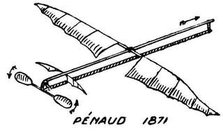
§ 1. Some forty years have elapsed since Pénaud first used
elastic (rubber) for model aeroplanes, and during that time
no better substitute (in spite of innumerable experiments)
has been found. Nor for the smaller and lighter class of
models is there any likelihood of rubber being displaced.
Such being the case, a brief account of some experiments on
this substance as a motive power for the same may not be
without interest. The word elastic (in science) denotes:
the tendency which a body has when distorted to return to its
original shape. Glass and ivory (within certain limits) are
two of the most elastic bodies known. But the limits
within which most bodies can be distorted (twisted or
stretched, or both) without either fracture or a Large permanent
alteration of shape is very small. Not so rubber—it
far surpasses in this respect even steel springs.
§ 2. Let us take a piece of elastic (rubber) cord, and
stretch it with known weights and observe carefully what
happens. We shall find that, first of all: the extension is
proportional to the weight suspended—but soon we have an
increasing increase of extension. In one experiment made
by the writer, when the weights were removed the rubber
cord remained 1/8 of an inch longer, and at the end of an
hour recovered itself to the extent of 1/16, remaining finally
permanently 1/16 of an
inch longer. Length of
elastic cord used in this
experiment 8-1/8 inches,
3/16 of an inch thick.
Suspended weights, 1 oz.
up to 64 oz. Extension
from ¼ inch up to 24-5/8
inches. Graph drawn in
Fig. 14, No. B abscissæ
extension in eighths of
an inch, ordinates
weights in ounces. So
long as the graph is a
straight line it shows
the extension is proportional
to the suspended
weight; afterwards in
excess.
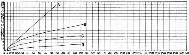 Fig. 14.—Weight and Extension.
B, rubber 3/16 in. thick; C, 2/16 in. thick; D, 1/16 in. thick. A, theoretical line if extension were
proportional to weight.
In this experiment
we have been able to
stretch (distort) a piece
of rubber to more than
three times its original
length, and afterwards it
finally returns to almost
its original length: not
only so, a piece of rubber
cord can be stretched to
eight or nine times its
original length without
fracture. Herein lies its
supreme advantage over
steel or other springs. Weight for weight more energy can
be got or more work be done by stretched (or twisted, or, to
speak more correctly, by stretched-twisted) rubber cord than
from any form of steel spring.[12] It is true it is stretched—twisted—far
beyond what is called the "elastic limit," and its
efficiency falls off, but with care not nearly so quickly as is
commonly supposed, but in spite of this and other drawbacks
its advantages far more than counterbalance these.
§ 3. Experimenting with cords of varying thickness we
find that: the extension is inversely proportional to the thickness.
If we leave a weight hanging on a piece of rubber
cord (stretched, of course, beyond its "elastic limit") we
find that: the cord continues to elongate as long as the weight
is left on. For example: a 1 lb. weight hung on a piece
of rubber cord, 8-1/8 inches long and 1/8 of an inch thick,
stretched it—at first—6¼ inches; after two minutes this had
increased to 6-5/8 (3/8 of an inch more). One hour later 1/8 of
an inch more, and sixteen hours later 1/8 of an inch more, i.e.
a sixteen hours' hang produced an additional extension of ¾ of
an inch. On a thinner cord (half the thickness) same weight
produced an additional extension (after 14 hours) of 10-3/8 in.
N.B.—An elastic cord or spring balance should never
have a weight left permanently on it—or be subjected to
a distorting force for a longer time than necessary, or it
will take a "permanent set," and not return to even approximately
its original length or form.
In a rubber cord the extension is directly proportional to
the length as well as inversely proportional to the thickness
and to the weight suspended—true only within the limits of
elasticity.
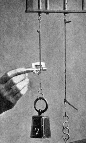 Fig. 15.—Extension and Increase in Volume.
§ 4. When a Rubber Cord is stretched there is
an Increase of Volume.—On stretching a piece of
rubber cord to twice its original (natural) length, we should
perhaps expect to find that the string would only be half as
thick, as would be the case if the volume remained the
same. Performing the experiment, and measuring the cord
as accurately as possible with a micrometer, measuring to the
one-thousandth of an inch, we at once perceive that this is
not the case, being about two-thirds of its former volume.
§ 5. In the case of rubber cord used for a motive power
on model aeroplanes, the rubber is both twisted and stretched,
but chiefly the latter.
Thirty-six strands of rubber, weight about 56 grammes,
at 150 turns give a torque of 4 oz. on a 5-in. arm, but an
end thrust, or end pull, of about 3½ lb. (Ball bearings, or
some such device, can be used to obviate this end thrust
when desirable.) A series of experiments undertaken by the
writer on the torque produced by twisted rubber strands,
varying in number, length, etc., and afterwards carefully
plotted out in graph form, have led to some very interesting
and instructive results. Ball bearings were used, and the
torque, measured in eighths of an ounce, was taken (in each
case) from an arm 5 in. in length.
The following are the principal results arrived at. For
graphs, see Fig. 16.
§ 6. A. Increasing the number of (rubber) strands by
one-half (length and thickness of rubber remaining constant)
increases the torque (unwinding tendency) twofold, i.e.,
doubles the motive power.
B. Doubling the number of strands increases the torque
more than three times—about 3-1/3 times, 3 times up to 100
turns, 3½ times from 100 to 250 turns.
C. Trebling the number of strands increases the
torque at least seven times.
The increased size of the coils, and thereby increased
extension, explains this result. As we increase the number
of strands, the number of twists or turns that can be given
it becomes less.
D. Doubling the number of strands (length, etc., remaining
constant) diminishes the number of turns by one-third
to one-half. (In few strands one-third, in 30 and over one-half.)
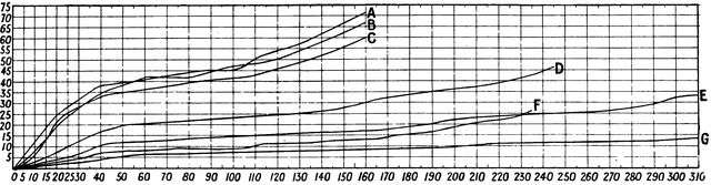
Fig. 16.—Torque Graphs of Rubber Motors.
| Abscissæ = Turns. | Ordinates = Torque measured in 1/16 of an oz. Length of arm, 5 in. |
| A. | 38 strands of new rubber, 2 ft. 6 in. long; 58 grammes weight. |
| B. | 36 strands, 2 ft. 6 in. long; end thrust at 150 turns, 3½ lb. |
| C. | 32 strands, 2 ft. 6 in. long. |
| D. | 24 "" " |
| E. | 18 " " " weight 28 grammes. |
| F. | 12 " 1 ft. 3 in. long |
| G. | 12 " 2 ft. 6 in. long. |
E. If we halve the length of the rubber strands, keeping
the number of strands the same, the torque is but slightly
increased for the first 100 turns; at 240 turns it is double.
But the greater number of turns—in ratio of about 2:1—that
can be given the longer strand much more than compensates
for this.
F. No arrangement of the strands, per se, gets more
energy (more motive power) out of them than any other,
but there are special reasons for making the strands—
G. As long and as few in number as possible.
1. More turns can be given it.
2. It gives a far more even torque. Twelve strands
2 ft. 6 in. long give practically a line of small constant
angle. Thirty-six strands same length a much steeper
angle, with considerable variations.
A very good result, which the writer has verified in
practice, paying due regard to both propeller and motor, is
to make—
H. The length of the rubber strands twice[13] in feet the
number of the strands in inches,[14] e.g., if the number of
strands is 12 their length should be 2 ft., if 18, 3 ft., and
so on.
§ 7. Experiments with 32 to 38 strands 2 ft. 6 in. long
give a torque curve almost precisely similar to that obtained
from experiments made with flat spiral steel springs, similar
to those used in watches and clocks; and, as we know, the
torque given by such springs is very uneven, and has to be
equalised by use of a fusee, or some such device. In
the case of such springs it must not be forgotten that the
turning moment (unwinding tendency) is NOT proportional
to the amount of winding up, this being true only in the
"balance" springs of watches, etc., where both ends of the
spring are rigidly fastened.
In the case of Spring Motors.[15]
I. The turning moment (unwinding tendency) is proportional
to the difference between the angle of winding and
yielding, proportional to the moment of inertia of its section,
i.e., to the breadth and the cube of its thickness, also proportional
to the modulus of elasticity of the substance used,
and inversely proportional to the length of the strip.
§ 8. Referring back to A, B, C, there are one or two
practical deductions which should be carefully noted.
Supposing we have a model with one propeller and
36 strands of elastic. If we decide to fit it with twin screws,
then, other reasons apart, we shall require two sets of
strands of more than 18 in number each to have the same
motive power (27 if the same torque be required).[16] This is
an important point, and one not to be lost sight of when
thinking of using two propellers.
Experiments on—
§9. The Number of Revolutions (turns) that can
be given to Rubber Motors led to interesting results,
e.g., the number of turns to produce a double knot in the cord
from end to end were, in the case of rubber, one yard long:—
| No. of Strands. | No. of Turns. | No. of Strands. | No. of Turns. |
| 4 | 440 | 16 | 200 |
| 8 | 310 | 28 | 170 |
| 12 | 250 | | |
It will be at once noticed that the greater the number
of rubber strands used in a given length, the fewer turns will
it stand in proportion. For instance, 8 strands double knot
at 310, and 4 at 440 (and not at 620), 16 at 200, and 8 at
310 (and not 400), and so on. The reason, of course, is the
more the strands the greater the distance they have to travel
round themselves.
§ 10. The Maximum Number of Turns.—As to
the maximum number of permissible turns, rubber has
rupture stress of 330 lb. per sq. in., but a very high permissible
stress, as much as 80 per cent. The resilience
(power of recovery after distortion) in tension of rubber is
in considerable excess of any other substance, silk being the
only other substance which at all approaches it in this
respect, the ratio being about 11 : 9. The resilience of
steel spiral spring is very slight in comparison.
A rubber motor in which the double knot is not exceeded
by more than 100 turns (rubber one yard in length)
should last a good time. When trying for a record flight,
using new elastic, as many as even 500 or 600 or even
more turns have been given in the case of 32-36 strands a
yard in length; but such a severe strain soon spoils the
rubber.
§ 11. On the Use of "Lubricants."—One of the
drawbacks to rubber is that if it be excessively strained it
soon begins to break up. One of the chief causes of this is
that the strands stick together—they should always be
carefully separated, if necessary, after a flight—and an
undue strain is thereby cast on certain parts. Apart also
from this the various strands are not subject to the same
tension. It has been suggested that if some means could
be devised to prevent this, and allow the strands to slip over
one another, a considerable increase of power might result. It
must, however, be carefully borne in mind that anything of
an oily or greasy nature has an injurious effect on the
rubber, and must be avoided at all costs. Benzol, petroleum,
ether, volatile oils, turpentine, chloroform, naphtha,
vaseline, soap, and all kinds of oil must be carefully avoided,
as they soften the rubber, and reduce it more or less to the
consistence of a sticky mass. The only oil which is said to
have no action on rubber, or practically none, is castor oil;
all the same, I do not advise its use as a lubricant.
There are three only which we need consider:—
- 1. Soda and water.
- 2. French chalk.
- 3. Pure redistilled glycerine.
The first is perfectly satisfactory when freshly applied,
but soon dries up and evaporates.
The second falls off; and unless the chalk be of the
softest kind, free from all grit and hard particles, it will
soon do more harm than good.
The third, glycerine, is for ordinary purposes by far the
best, and has a beneficial rather than a deleterious effect on
the rubber; but it must be pure. The redistilled kind,
free from all traces of arsenic, grease, etc., is the only kind
permissible. It does not evaporate, and a few drops, comparatively
speaking, will lubricate fifty or sixty yards of
rubber.
Being of a sticky or tacky nature it naturally gathers up
dust and particles of dirt in course of time. To prevent
these grinding into the rubber, wash it from time to time in
warm soda, and warm and apply fresh glycerine when
required.
Glycerine, unlike vaseline (a product of petroleum), is
not a grease; it is formed from fats by a process known as
saponification, or treatment of the oil with caustic alkali,
which decomposes the compound, forming an alkaline
stearate (soap), and liberating the glycerine which remains
in solution when the soap is separated by throwing in
common salt. In order to obtain pure glycerine, the fat
can be decomposed by lead oxide, the glycerine remaining
in solution, and the lead soap or plaster being precipitated.
By using glycerine as a lubricant the number of turns
that can be given a rubber motor is greatly increased, and
the coils slip over one another freely and easily, and prevent
the throwing of undue strain on some particular portion,
and absolutely prevent the strands from sticking together.
§ 12. The Action of Copper upon Rubber.—Copper,
whether in the form of the metal, the oxides, or the
soluble salts, has a marked injurious action upon rubber.
In the case of metallic copper this action has been
attributed to oxidation induced by the dissolved oxygen
in the copper. In working drawings for model aeroplanes I
have noticed designs in which the hooks on which the rubber
strands were to be stretched were made of copper. In no
case should the strands be placed upon bare metal. I
always cover mine with a piece of valve tubing, which can
easily be renewed from time to time.
§ 12A. The Action of Water, etc., on Rubber.—Rubber
is quite insoluble in water; but it must not be
forgotten that it will absorb about 25 per cent. into its pores
after soaking for some time.
Ether, chloroform, carbon-tetrachloride, turpentine,
carbon bi-sulphide, petroleum spirit, benzene and its homologues
found in coal-tar naphtha, dissolve rubber readily.
Alcohol is absorbed by rubber, but is not a solvent of it.
§ 12B. How to Preserve Rubber.—In the first
place, in order that it shall be possible to preserve and keep
rubber in the best condition of efficiency, it is absolutely
essential that the rubber shall be, when obtained, fresh and
of the best kind. Only the best Para rubber should be
bought; to obtain it fresh it should be got in as large
quantities as possible direct from a manufacturer or reliable
rubber shop. The composition of the best Para rubber is
as follows:—Carbon, 87·46 per cent.; hydrogen, 12·00 per
cent.; oxygen and ash, 0·54 per cent.
In order to increase its elasticity the pure rubber has to
be vulcanised before being made into the sheet some
sixty or eighty yards in length, from which the rubber
threads are cut; after vulcanization the substance consists of
rubber plus about 3 per cent. of sulphur. Now, unfortunately,
the presence of the sulphur makes the rubber more prone
to atmospheric oxidation. Vulcanized rubber, compared to
pure rubber, has then but a limited life. It is to this
process of oxidation that the more or less rapid deterioration
of rubber is due.
To preserve rubber it should be kept from the sun's
rays, or, indeed, any actinic rays, in a cool, airy place, and
subjected to as even a temperature as possible. Great extremes
of temperature have a very injurious effect on rubber, and
it should be washed from time to time in warm soda water.
It should be subjected to no tension or compression.
Deteriorated rubber is absolutely useless for model
aeroplanes.
§ 13. To Test Rubber.—Good elastic thread composed
of pure Para rubber and sulphur should, if properly
made, stretch to seven times its length, and then return to
its original length. It should also possess a stretching
limit at least ten times its original length.
As already stated, the threads or strands are cut from
sheets; these threads can now be cut fifty to the inch. For
rubber motors a very great deal so far as length of life
depends on the accuracy and skill with which the strands are
cut. When examined under a microscope (not too powerful)
the strands having the least ragged edge, i.e., the best cut,
are to be preferred.
§ 14. The Section—Strip or Ribbon versus
Square.—In section the square and not the ribbon or strip
should be used. The edge of the strip I have always found
more ragged under the microscope than the square. I have
also found it less efficient. Theoretically no doubt a round
section would be best, but none such (in small sizes) is
on the market. Models have been fitted with a tubular
section, but such should on no account be used.
§ 15. Size of the Section.—One-sixteenth or one-twelfth
is the best size for ordinary models; personally, I
prefer the thinner. If more than a certain number of
strands are required to provide the necessary power, a larger
size should be used. It is not easy to say what this number
is, but fifty may probably be taken as an outside limit.
Remember the size increases by area section; twice the
sectional height and breadth means four times the rubber.
§ 16. Geared Rubber Motors.—It is quite a mistake
to suppose that any advantage can be obtained by using a
four to one gearing, say; all that you do obtain is one-fourth
of the power minus the increased friction, minus the added
weight. This presumes, of course, you make no alteration in
your rubber strands.
Gearing such as this means short rubber strands, and
such are not to be desired; in any case, there is the difficulty
of increased friction and added weight to overcome.
It is true by splitting up your rubber motor into two sets of
strands instead of one you can obtain more turns, but, as we
have seen, you must increase the number of strands to get
the same thrust, and you have this to counteract any
advantage you gain as well as added weight and friction.
§ 17. The writer has tried endless experiments with all
kinds of geared rubber motors, and the only one worth a
moment's consideration is the following, viz., one in which
two gear wheels—same size, weight, and number of teeth—are
made use of, the propeller being attached to the axle of
one of them, and the same number of strands are used on
each axle. The success or non-success of this motor depends
entirely on the method used in its construction. At first
sight it may appear that no great skill is required in the
construction of such a simple piece of apparatus. No
greater mistake could be made. It is absolutely necessary
that the friction and weight be reduced to a minimum, and the
strength be a maximum. The torque of the rubber strands
on so short an arm is very great.
Ordinary light brass cogwheels will not stand the
strain.
A. The cogwheels should be of steel[17] and accurately cut
of diameter sufficient to separate the two strands the
requisite distance, but no more.
B. The weight must be a minimum. This is best
attained by using solid wheels, and lightening by drilling and
turning.
C. The friction must be a minimum. Use the lightest
ball bearings obtainable (these weigh only 0·3 gramme),
adjust the wheels so that they run with the greatest freedom,
but see that the teeth overlap sufficiently to stand the strain
and slight variations in direction without fear of slipping.
Shallow teeth are useless.
D. Use vaseline on the cogs to make them run as easily
as possible.
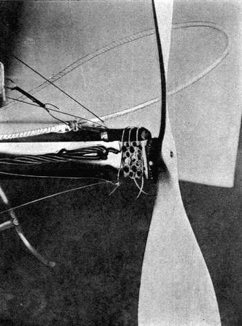 Fig. 17.—Geared Rubber Motor.
Designed and constructed by the writer. For description
of the model, etc., see Appendix.
E. The material of the containing framework must be of
maximum strength and minimum lightness. Construct it
of minimum size, box shaped, use the thinnest tin (really
tinned sheet-iron) procurable, and lighten by drilling holes,
not too large, all over it. Do not use aluminium or magnalium.
Steel, could it be procured thin enough, would be
better still.
F. Use steel pianoforte wire for the spindles, and hooks
for the rubber strands, using as thin wire as will stand the
strain.
Unless these directions are carefully carried out no
advantage will be gained—the writer speaks from experience.
The requisite number of rubber strands to give the
best result must be determined by experiment.
§ 18. One advantage in using such a motor as this is
that the two equal strands untwisting in opposite directions
have a decided steadying effect on the model, similar almost
to the case in which two propellers are used.
The "best" model flights that the writer has achieved
have been obtained with a motor of this description.[18]
In the case of twin screws two such gearings can be used,
and the rubber split up into four strands. The containing
framework in this case can be simply light pieces of tubing
let into the wooden framework, or very light iron pieces
fastened thereto.
Do not attempt to split up the rubber into more than two
strands to each propeller.
Section II.—Other Forms of Motors.
§ 18A. Spring Motors.—This question has already
been dealt with more or less whilst dealing with rubber
motors, and the superiority of the latter over the former
pointed out. Rubber has a much greater superiority over
steel or other springs, because in stretch-twisted rubber far
more energy can be stored up weight for weight. One
pound weight of elastic can be made to store up some
320 ft.-lb. of energy, and steel only some 65 lb. And in
addition to this there is the question of gearing, involving
extra weight and friction; that is, if flat steel springs similar
to those used in clockwork mechanism be made use of, as
is generally the case. The only instance in which such
springs are of use is for the purpose of studying the effects
of different distributions of weight on the model, and its
effect on the balance of the machine; but effects such as
this can be brought about without a change of motor.
§ 18B. A more efficient form of spring motor, doing away
with gearing troubles, is to use a long spiral spring (as long
as the rubber strands) made of medium-sized piano wire,
similar in principle to those used in some roller-blinds, but
longer and of thinner steel.
The writer has experimented with such, as well as scores
of other forms of spring motors, but none can compare with
rubber.
The long spiral form of steel spring is, however, much
the best.
§ 18C. Compressed Air Motors.—This is a very
fascinating form of motor, on paper, and appears at first sight
the ideal form. It is so easy to write: "Its weight is negligible,
and it can be provided free of cost; all that is necessary is
to work a bicycle pump for as many minutes as the motor
is desired to run. This stored-up energy can be contained in
a mere tube, of aluminium or magnalium, forming the central
rib of the machine, and the engine mechanism necessary for
conveying this stored-up energy to the revolving propeller
need weigh only a few ounces." Another writer recommends
"a pressure of 300 lb."
§ 18D. A pneumatic drill generally works at about 80 lb.
pressure, and when developing 1 horse-power, uses about
55 cubic ft. of free air per minute. Now if we apply this to
a model aeroplane of average size, taking a reservoir 3 ft.
long by 1½ in. internal diameter, made of magnalium, say—steel
would, of course, be much better—the weight of which
would certainly not be less than 4 oz., we find that at 80 lb.
pressure such a motor would use
55 / Horse Power (H.P.)
cub. ft. per minute.
Now 80 lb. is about 5½ atmospheres, and the cubical
contents of the above motor some 63 cub. in. The time
during which such a model would fly depends on the H.P.
necessary for flight; but a fair allowance gives a flight of from
10 to 30 sec. I take 80 lb. pressure as a fair practical limit.
§ 18E. The pressure in a motor-car tyre runs from 40 to
80 lb., usually about 70 lb. Now 260 strokes are required
with an ordinary inflator to obtain so low a pressure as
70 lb., and it is no easy job, as those who have done it know.
§ 19. Prior to 1893 Mr. Hargraves (of cellular kite fame)
studied the question of compressed-air motors for model
flying machines. His motor was described as a marvel
of simplicity and lightness, its cylinder was made like a
common tin can, the cylinder covers cut from sheet tin
and pressed to shape, the piston and junk rings of ebonite.
One of his receivers was 23-3/8 in. long, and 5·5 in.
diameter, of aluminium plate 0·2 in. thick, 3/8 in. by 1/8 in.
riveting strips were insufficient to make tight joints; it
weighed 26 oz., and at 80 lb. water pressure one of the ends
blew out, the fracture occurring at the bend of the flange,
and not along the line of rivets. The receiver which was
successful being apparently a tin-iron one; steel tubing was
not to be had at that date in Sydney. With a receiver of
this character, and the engine referred to above, a flight of
343 ft. was obtained, this flight being the best. (The
models constructed by him were not on the aeroplane, but
ornithoptere, or wing-flapping principle.) The time of flight
was 23 seconds, with 54½ double vibrations of the engines.
The efficiency of this motor was estimated to be 29 per cent.
§ 20. By using compressed air, and heating it in its
passage to the cylinder, far greater efficiency can be obtained.
Steel cylinders can be obtained containing air under the
enormous pressure of 120 atmospheres.[19] This is practically
liquid air. A 20-ft. cylinder weighs empty 23 lb. The
smaller the cylinder the less the proportionate pressure that
it will stand; and supposing a small steel cylinder, produced
of suitable form and weight, and capable of withstanding
with safety a pressure of from 300 to 600 lb. per sq. in., or
from 20 to 40 atmospheres. The most economical way of
working would be to admit the air from the reservoir directly
to the motor cylinders; but this would mean a very great
range in the initial working pressure, entailing not-to-be-thought-of
weight in the form of multi-cylinder compound
engines, variable expansion gear, etc.
§ 21. This means relinquishing the advantages of the
high initial pressure, and the passing of the air through a
reducing valve, whereby a constant pressure, say, of 90 to
150, according to circumstances, could be maintained. By
a variation in the ratio of expansion the air could be worked
down to, say, 30 lb.
The initial loss entailed by the use of a reducing valve
may be in a great measure restored by heating the air before
using it in the motor cylinders; by heating it to a temperature
of only 320°F., by means of a suitable burner, the
volume of air is increased by one half, the consumption
being reduced in the same proportion; the consumption of
air used in this way being 24 lb. per indicated horse-power
per hour. But this means extra weight in the form of fuel
and burners, and what we gain in one way we lose in
another. It is, of course, desirable that the motor should
work at as low a pressure as possible, since as the store of
air is used up the pressure in the reservoir falls, until it
reaches a limit below which it cannot usefully be employed.
The air then remaining is dead and useless, adding only to
the weight of the aeroplane.
§ 22. From calculations made by the writer the entire
weight of a compressed-air model motor plant would be at
least one-third the weight of the aeroplane, and on a small
scale probably one-half, and cannot therefore hold comparison
with the steam engine discussed in the next paragraph.
In concluding these remarks on compressed-air
motors, I do not wish to dissuade anyone from trying this
form of motor; but they must not embark on experiments
with the idea that anything useful or anything superior to
results obtained with infinitely less expense by means of
rubber can be brought to pass with a bicycle pump, a bit of
magnalium tube, and 60 lb. pressure.
§ 22A. In Tatin's air-compressed motor the reservoir
weighed 700 grammes, and had a capacity of 8 litres. It was
tested to withstand a pressure of 20 atmospheres, but was
worked only up to seven. The little engine attached thereto
weighed 300 grammes, and developed a motive power of
2 kilogram-metres per second (see ch. iii.).
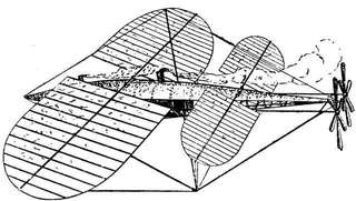
§ 23. Steam-Driven Motors.—Several successful
steam-engined model aeroplanes have been constructed, the
most famous being those of Professor Langley.
Having constructed over 30 modifications of rubber-driven
models, and experimented with compressed air,
carbonic-acid gas, electricity, and other methods of obtaining
energy, he finally settled upon the steam engine (the
petrol motor was not available at that time, 1893). After
many months' work it was found that the weight could not
be reduced below 40 lb., whilst the engine would only
develop ½ H.P., and finally the model was condemned. A
second apparatus to be worked by compressed air was tried,
but the power proved insufficient. Then came another with
a carbonic-acid gas engine. Then others with various
applications of electricity and gas, etc., but the steam engine
was found most suitable; yet it seemed to become more and
more doubtful whether it could ever be made sufficiently
light, and whether the desired end could be attained at all.
The chief obstacle proved not to be with the engines, which
were made surprisingly light after sufficient experiment.
The great difficulty was to make a boiler of almost no weight
which would give steam enough.
§ 24. At last a satisfactory boiler and engine were
produced.
The engine was of 1 to 1½ H.P., total weight (including
moving parts) 26 oz. The cylinders, two in number, had
each a diameter of 1¼ in., and piston stroke 2 in.
The boiler, with its firegrate, weighed a little over 5 lb.
It consisted of a continuous helix of copper tubing, 3/8 in.
external diameter, the diameter of the coil being 3 in.
altogether. Through the centre of this was driven the blast
from an "Ælopile," a modification of the naphtha blow-torch
used by plumbers, the flame of which is about 2000° F.[20]
The pressure of steam issuing into the engines varied from
100 to 150 lb. per sq. in.; 4 lb. weight of water and about
10 oz. of naphtha could be carried. The boiler evaporated
1 lb. of water per minute.
The twin propellers, 39 in. in diam., pitch 1¼, revolved
from 800 to 1000 a minute. The entire aeroplane was 15 ft.
in length, the aerofoils from tip to tip about 14 ft.,
and the total weight slightly less than 30 lb., of which
one-fourth was contained in the machinery. Its flight was a
little over half a mile in length, and of 1½ minutes' duration.
Another model flew for about three-quarters of a
mile, at a rate of about 30 miles an hour.
It will be noted that engine, generator, etc., work out at
about 7 lb. per H.P. Considerable advance has been made
in the construction of light and powerful model steam
engines since Langley's time, chiefly in connexion with
model hydroplanes, and a pressure of from 500 to 600 lb.
per sq. in. has been employed; the steam turbine has been
brought to a high state of perfection, and it is now possible
to make a model De Laval turbine of considerable power
weighing almost next to nothing,[21] the real trouble, in
fact the only one, being the steam generator. An economization
of weight means a waste of steam, of which models
can easily spend their only weight in five minutes.
§ 25. One way to economize without increased weight in
the shape of a condenser is to use spirit (methylated spirit,
for instance) for both fuel and boiler, and cause the exhaust
from the engines to be ejected on to the burning spirit,
where it itself serves as fuel. By using spirit, or some very
volatile hydrocarbon, instead of water, we have a further
advantage from the fact that such vaporize at a much
lower temperature than water.
§ 26. When experimenting with an engine of the turbine
type we must use a propeller of small diameter and pitch,
owing to the very high velocity at which such engines run.
Anyone, however, who is not an expert on such matters
would do well to leave such motors alone, as the very
highest technical skill, combined with many preliminary
disappointments and trials, are sure to be encountered before
success is attained.
§ 27. And the smaller the model the more difficult the
problem—halve your aeroplane, and your difficulties increase
anything from fourfold to tenfold.
The boiler would in any case be of the flash type of
either copper or steel tubing (the former for safety), with a
magnalium container for the spirit, and a working pressure
of from 150 to 200 lb. per sq. in. Anything less than this
would not be worth consideration.
§ 28. Some ten months after Professor Langley's successful
model flights (1896), experiments were made in
France at Carquenez, near Toulon. The total weight of
the model aeroplane in this case was 70 lb.; the engine
power a little more than 1 H.P. Twin screws were used—one
in front and one behind. The maximum velocity
obtained was 40 miles per hour; but the length of run only
154 yards, and duration of flight only a few seconds. This
result compares very poorly with Langley's distance (of best
flight), nearly one mile, duration 1 min. 45 sec. The
maximum velocity was greater—30 to 40 miles per hour.
The total breadth of this large model was rather more than
6 metres, and the surface a little more than 8 sq. metres.
§ 29. Petrol Motors.—Here it would appear at first
thought is the true solution of the problem of the model
aeroplane motor. Such a motor has solved the problem of
aerial locomotion, as the steam engine solved that of terrestrial
and marine travel, both full sized and model; and if
in the case of full sized machines, then why not models.
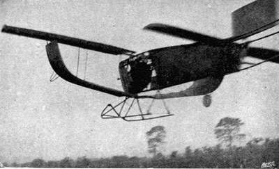 Fig. 18.—Mr. Stanger's Model in Full Flight.
 Fig. 19.—Mr. Stanger's Petrol-driven Model Aeroplane.
[Illustrations by permission from electros supplied by the "Aero."]
§ 30. The exact size of the smallest working model steam
engine that has been made I do not know,[22] but it is or could
be surprisingly small; not so the petrol motor—not one,
that is, that would work. The number of petrol motor-driven
model aeroplanes that have actually flown is very
small. Personally I only know of one, viz., Mr. D.
Stanger's, exhibited at the aero exhibition at the Agricultural
Hall in 1908.
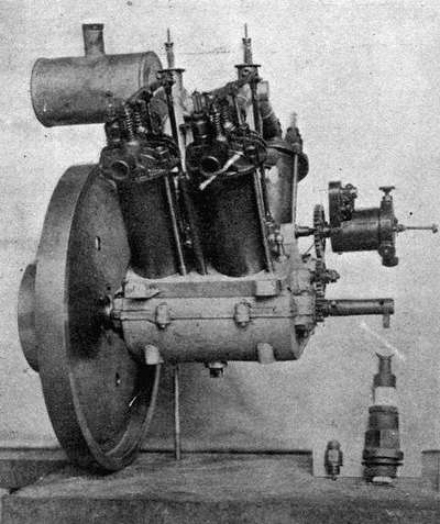 Fig. 20.—Mr. Stanger's Model Petrol Engine.

Fig. 21.—Mr. Stanger's Model Petrol Engine.
In Fig. 21 the motor is in position on the aeroplane.
Note small carburettor. In Fig. 20 an idea of the size
of engine may be gathered by comparing it with the
ordinary sparking-plug seen by the side, whilst to the
left of this is one of the special plugs used on this
motor.
(
Illustrations by permission from electros supplied by the "Aero.")
§ 31. The following are the chief particulars of this
interesting machine:—The engine is a four-cylinder one,
and weighs (complete with double carburetter and petrol tank)
5½ lb., and develops 1¼ H.P. at 1300 revolutions per minute.
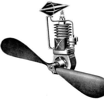 Fig. 22.—One-Cylinder Petrol Motor.
(Electro from Messrs. A.W. Gamage's Aviation Catalogue.)
The propeller, 29 in. in diam. and 36 in. in pitch, gives a
static thrust of about 7 lb. The machine has a spread of
8 ft. 2 in., and is 6 ft. 10 in. in length. Total weight 21 lb.
Rises from the ground when a speed of about 16 miles an
hour is attained. A clockwork arrangement automatically
stops the engine. The engine air-cooled. The cylinder of
steel, cast-iron heads, aluminium crank-case, double float
feed carburetter, ignition by single coil and distributor.
The aeroplane being 7 ft. 6 in. long, and having a span
8 ft.
§ 32. One-cylinder Petrol Motors.—So far as the
writer is aware no success has as yet attended the use of a
single-cylinder petrol motor on a model aeroplane. Undoubtedly
the vibration is excessive; but this should not be
an insuperable difficulty. It is true it is heavier in proportion
than a two-cylinder one, and not so efficient; and so
far has not proved successful. The question of vibration on
a model aeroplane is one of considerable importance. A
badly balanced propeller even will seriously interfere with
and often greatly curtail the length of flight.
§ 33. Electric Motors.—No attempt should on any
account be made to use electric motors for model aeroplanes.
They are altogether too heavy, apart even from the accumulator
or source of electric energy, for the power derivable
from them. To take an extreme case, and supposing we use
a 2-oz. electric motor capable of driving a propeller giving a
static thrust of 3 oz.,[23] on weighing one of the smallest
size accumulators without case, etc., I find its weight is
4½ oz. One would, of course, be of no use; at least three
would be required, and they would require practically short
circuiting to give sufficient amperage (running them down,
that is, in some 10 to 15 seconds). Total weight, 1 lb.
nearly. Now from a pound weight of rubber one could
obtain a thrust of pounds, not ounces. For scale models
not intended for actual flight, of course, electric motors have
their uses.
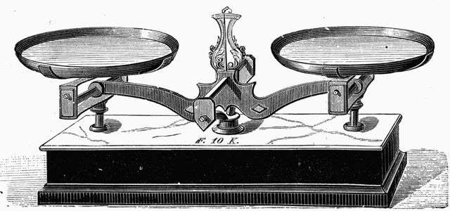 THE MOST IMPORTANT "TOOL" IN THE BUILDING OF MODEL AEROPLANES.