CHAPTER II. THE PNEUMATIC TRANSIT COMPANY AND THE FIRST PNEUMATIC TUBES FOR THE TRANSPORTATION OF UNITED STATES MAIL. — Organization. — Aim and Object of the Company. — The Clay-Lieb Patents. — Franchises and First Government Contract. — Search for Tubes. — Method of Manufacturing Tubes. — Laying and Opening the Tubes for Traffic. — Description of the Tubes, Method of Laying, etc. — Air-Compressor—Method of Circulating the Air. — Terminal Apparatus. — The Sender. — Sub-Post-Office Receiver. — Main Post-Office Receiver. — The Carrier. — Operation of the Tubes. — Benefits of the System.
—Early in the year 1892 several Philadelphia
gentlemen organized a corporation and obtained a charter in the State
of New Jersey to construct, lay, and operate pneumatic tubes for the
transmission of United States mail, packages, merchandise, messages,
etc., within the States of New Jersey and Pennsylvania. The corporation
was styled the Pneumatic Transit Company. Mr. William J. Kelly was
elected president, and the company is still under his management.
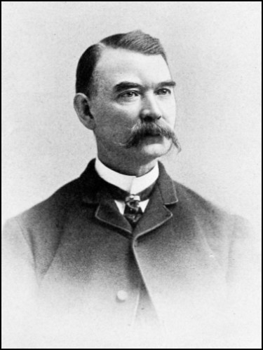
WM. J. KELLY,
President of the Pneumatic Transit Co.
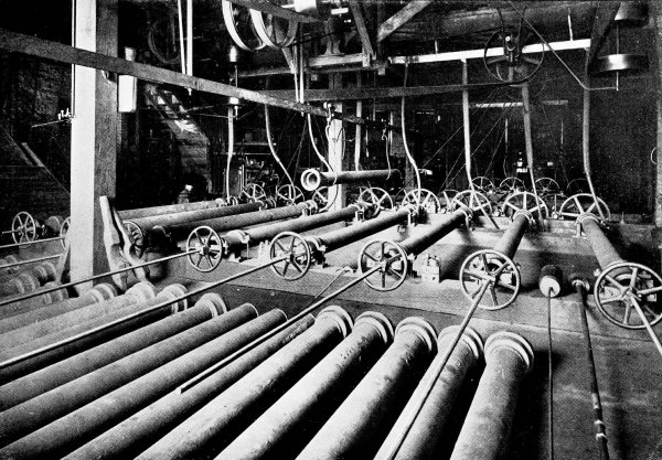
Fig. 4.
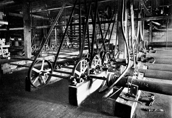
Fig. 5.
SIX-INCH PNEUMATIC TUBES IN PROCESS OF BORING AT THE SHOP OF A.
FALKENAU, PHILADELPHIA, PA.
—When the Pneumatic Transit
Company was formed, it was the aim and object of its promoters to
construct an extensive system of underground tubes in the City of
Philadelphia which would serve, first, for the rapid transmission of
mail, second, for the quick delivery of merchandise from the large
retail stores, third, for the transmission of telegrams or messages
within the city limits, and, fourth, to conduct a general local express
business with greater speed than can be done in any other manner. To
accomplish this result sub-stations were to be located six or eight
blocks apart throughout a large portion of the city, and a central
station was to be established in the centre of the business
section. Stations were also to be established in the more important
retail stores and large office buildings, and all of the stations were
to be connected by tubes forming one large system.
For the transmission of mail it was planned to connect the main
post-office with the sub-post-offices by tubes of a size large enough
to carry all of the first-class and most of the other classes of
mail matter. The sub-post-offices would be divided into groups, all
of the offices in one group being connected to the same line, which
would terminate at the main post-office. Most of the business would
be between the main and individual sub-offices; in addition to this
there would be some local mail sent between the sub-offices which, for
offices in the same group, could be despatched directly without passing
through the main office. The advantages to be gained by the use of
these tubes over the present wagon service are very apparent. It places
all the sub-post-offices in almost instant communication with the main
office and with each other.
It was a part of the general plan to lay tubes from the main
post-office to the railway stations, thereby hastening the despatch and
receipt of mails to and from the trains.
It was expected that the bulk of the business would consist in the
delivery of parcels from the retail stores to the private houses in the
residence sections of the city. Of course it would not be practicable
to lay a tube to each house, but with a station not more than four or
five blocks away, the parcels would be sent through the tube to the
nearest station, and then delivered by messengers to the houses with a
minimum loss of time. Ladies could do their shopping and find their
purchases at home when they returned.
The same tubes used for parcel delivery would also be used for a
district messenger service. With numerous public stations in convenient
locations, all the advantages of the European system would be realized
in the quick despatch of letters and telegrams. Every one knows how
much time is consumed by district messenger-boys in the delivery of
messages, especially when they have to go long distances, and no
argument is required to show that this time would be very much reduced
by the use of pneumatic tubes, besides prompt delivery would be made
much more certain.
The tubes of this system were to be six or eight inches in diameter,
with a few small tubes in localities where the message service is very
heavy.
Without going more into detail, such were in brief the plans of the
promoters of this new company; but before launching such an enterprise,
involving a large amount of capital, there were many engineering and
mechanical problems to be solved. It was not simply a question of
obtaining tubes and laying them in the streets, but ways and means
for operating them must be devised. Up to this time only small tubes
had been used for the transmission of telegrams, messages, cash, and
other light objects. Now it was proposed to transmit heavy and bulky
material. There was no experience for a guide.
—The Pneumatic Transit Company at
this time turned to the Electro-Pneumatic Transit Company, of New
Jersey, a national company that had been in existence since 1886,
and which claimed to own valuable patents, for the ways and means
to carry out its new enterprise. The patents were those of Henry
Clay and Charles A. Lieb, and the rights to use them in the State
of Pennsylvania were procured by the Pneumatic Transit Company,
under a contract entered into between the two companies. The patents
claimed to cover a practical working system by which a large number
of stations could be connected to a system of main and branch tubes,
with electrically-operated switches at the junctions of the branches
with the main lines. Any person who gives the subject a little thought
will at once see the advantages of such a system if it could be made
to operate. Up to the present time only single- or double-line tubes
have been used, without branches. In the European systems, frequently
several stations are located along a line, but the carriers must stop
at each station, be examined, and if they are destined for another
station, they must be redespatched. The cash systems used in many
of our large stores have independent tubes running from the central
cashier’s desk to each station about the store. It is plain to be seen
that, if several of these stations could be connected by branches to a
main tube, a large amount of tubing would be saved—a most desirable
result. The advantages of such a system would be still greater for long
lines of tube laid under the pavements, extending to stations located
in different parts of a large city. It was such a result that the
patents of Clay and Lieb aimed to accomplish.
In order to demonstrate the practicability of the system, the
Electro-Pneumatic Transit Company had constructed in the basement of
the Mills Building, on Broad Street, New York, a short line of small
brass tubing, about two or three inches in diameter, with one branch,
thus connecting three stations together. The tube was very short,
probably not more than two hundred feet in length. The air-pressure
required was very slight, probably not more than an ounce or two, being
supplied by a small blower run by an electric motor.
At the junction of the branch and the main tube was located a switch
that could be moved across the main tube and so deflect the approaching
carrier into the branch. This switch was moved by an electro-magnet,
or solenoid, that could be excited by pressing a button at the station
from which the carrier was sent. When the carrier passed into the
branch tube it set the switch back into its normal position, so that a
second carrier, following the first, would pass along the main tube,
unless the switch was again moved by pressing the button at the sending
station.
This tube in the Mills Building worked well, but it was of a size
only suited to the transmission of cash in a store or other similar
service. It could not be said, because this tube worked well, that
a larger and longer tube with numerous branches would work equally
well. In fact, there are several reasons why such a tube would not
operate satisfactorily. The method of operating the switches was
impracticable. Suppose the branch tube had been located two miles away
from the sending station and that it would take a carrier four minutes
to travel from the sending station to the junction of the branch tube.
Again, suppose that we have just despatched a carrier destined for a
station on the main line beyond the junction, and that we wish to
despatch the second carrier to be switched off into the branch tube,
we must wait at least four minutes, until the first carrier has passed
the junction, before we can press the button and set the switch for
the second carrier which may be on its way. How are we to know when
the first carrier has passed the junction, and when the second will
arrive there, in order that we may throw the switch at the proper time?
Must we hold our watch and time each carrier? It is plain that this is
not practical. I take this as an illustration of the impracticability
of the Clay-Lieb System as constructed in the Mills Building when
extended to practical dimensions. I will not describe the mechanism and
details of the system, which are ingenious, but will say in passing
that the automatic sluice-gates, which work very well in a three-inch
tube with carriers weighing an ounce or two and air-pressures of only
a few ounces per square inch, would be useless and could not be made
to operate in a six-inch tube with carriers weighing from eight to
twenty-five pounds and an air-pressure of from five to twenty-five
pounds per square inch. For further information the reader is referred
to the patents of Clay and Lieb.
—In the spring of
1892 an ordinance was passed by Common and Select Councils, and signed
by the Mayor of the City of Philadelphia, permitting the Pneumatic
Transit Company to lay pneumatic tubes in the streets of that city.
At the time this franchise was granted negotiations were in progress
with the post-office department, in Washington, for the construction
of a six-inch pneumatic tube, connecting the East Chestnut Street
sub-post-office, at Third and Chestnut Streets, with the main
post-office, at Ninth and Chestnut Streets, for the transmission of
mail. This sub-post-office was selected because more mail passes
through it daily than any other sub-office in the city, it being
located near the centre of the banking district. Negotiations were
delayed by various causes, so that the contract with the government was
not signed until October, 1892.
—It was at this time that the writer was
first employed by the Pneumatic Transit Company, as engineer, to
superintend the construction of this line. The company commenced at
once to carry out its contract with the United States government, both
the post-office department and the company being very desirous of
having the work completed before winter. The time was very short for
such an undertaking, but wrought-iron tubes had already been ordered
of a well-known firm who manufacture pipe and tubing of all kinds.
After waiting four or five weeks the first lot of tubes were finished,
but upon inspection it was found that they were not sufficiently
accurate and smooth on the interior to permit of their being used
for the purpose intended. The next thing that suggested itself was
seamless drawn brass tubes. While they would be very expensive, the
process of manufacture makes them eminently suited for the purpose,
but they could not be obtained in time. A city ordinance prohibits
the opening of the streets of Philadelphia during the winter months
except in extreme cases. Accurate tubes must be had, and had quickly.
It then occurred to the writer that it might be possible to bore a
sufficient quantity of ordinary cast-iron water-pipe and fit
the ends accurately together to answer our purpose. Inquiry was made
at nearly all the machine-shops in the city, to ascertain how many
boring-machines could be put upon this work of boring nearly six
thousand feet of six-inch pipe. It was found impossible to get the work
done in time, if it was to be done in the usual manner of boring with
a rigid bar. At last a man was found in Mr. A. Falkenau, engineer and
machinist, who was prepared to contract for the construction of twelve
special boring-machines and to bore all the tubing required. Suffice it
to say, that the machines were built, and about six thousand feet of
tubes were bored, between November 8 and December 31.
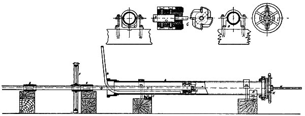
—The process of boring was novel
in some respects, and might be termed reaming rather than boring. Figs.
4 and 5 show the interior of the shop and the twelve machines. Fig. 6
is a drawing of one of the machines. A long flexible bar rotated the
cutter-head, which was pulled through the tube, in distinction from
being pushed. In order to give the feeding motion, a screw was attached
to the cutter-head and extended through the tube in advance of it. The
feed-screw was drawn forward by a nut attached to a hand-wheel located
at the opposite end of the tube from which the boring began. Since it
was not necessary that the tubes should be perfectly straight, a method
of this kind was permissible, in which the cutters could be allowed to
follow the cored axis of the tube. Air from a Sturtevant blower was
forced through the tubes during the process of boring, for the double
purpose of clearing the chips from the cutters and keeping them cool.
After the tubes were reamed, each piece had to be placed in a lathe,
have a counter-bore turned in the bottom of the bell, and have the
other end squared off and turned for a short distance on the outside to
fit the counter-bore of the next section.
—The first tubes were
laid about the middle of November, but December 1 came before the work
was completed and special permission had to be obtained from the city
to carry on the work after that date. All work was suspended during
the holidays in order not to interfere with the holiday trade of the
stores on Chestnut Street. Severe frosts prevailed at that season, so
that when the work was begun again, after the holidays, bonfires had
to be built in the streets to thaw out the ground in order to take up
the paving-stones and dig the trench for the tubes. Several times the
trench was filled with snow by unusually heavy storms. Notwithstanding
all these delays and annoyances, the work was pushed forward, when
a less determined company would have given it up, and was finally
completed. A formal opening took place on February 17, 1893, when Hon.
John Wanamaker, then Postmaster-General, sent through the tube the
first carrier, containing a Bible wrapped in the American flag.
It was certainly a credit to the Pneumatic Transit Company and its
managers that they were able to complete this first line of tubes so
quickly and successfully under such trying circumstances. The tubes
have been in successful operation from the opening until the present
time, a period of nearly four years, and the repairs that have been
made during that time have not required its stoppage for more than a
few hours.
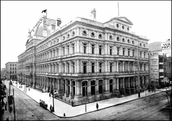
In the summer of 1895 the sub-post-office was removed from Chestnut
Street to the basement of the Bourse (see Fig. 7). This required the
abandonment of a few feet of tube on Chestnut Street and the laying of
a slightly greater amount on Fourth Street, thus increasing the total
length of the tubes a little. Wrought-iron tube, coated with some
alloy, probably composed largely of tin or zinc, was used for this
extension. The wrought-iron tube is not as good as the bored cast iron.
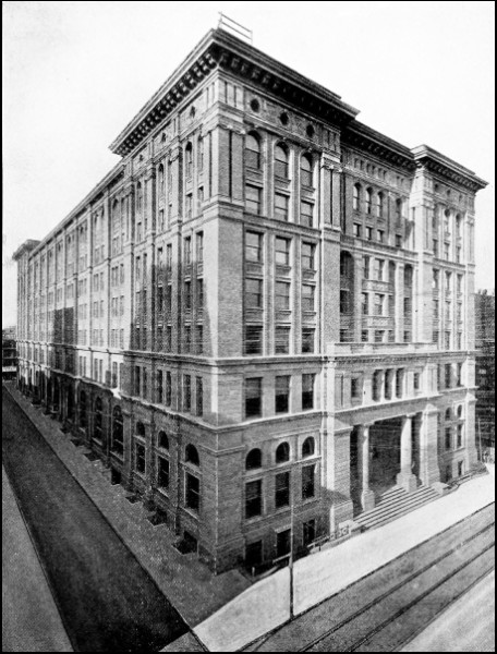
Fig. 7.
BOURSE BUILDING, PHILADELPHIA.
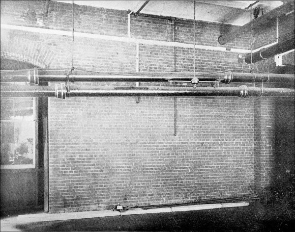
Fig. 8.
PNEUMATIC TUBES SUSPENDED IN THE BASEMENT OF THE MAIN POST-OFFICE.
—This Chestnut
Street line consists of two tubes, one for despatching carriers from
and the other to the main post-office. The distance between the two
stations is two thousand nine hundred and seventy-four feet, requiring
five thousand nine hundred and forty-eight feet of tube. The inside
diameter of the tube is six and one-eighth inches, and it was made in
sections each about eleven feet long, with “bells” cast upon one end,
in order to join the sections with lead and oakum, calked in the usual
manner of making joints in water- and gas-pipes, with this exception,
that at the bottom of the bell a counter-bore was turned to receive
the finished end of the next section. By thus machining the ends of
each section of tube and having them fit accurately together, male and
female, a practically continuous tube was formed with no shoulders
upon the interior to obstruct the smooth passage of the carriers.
Joints made in this way possess another great advantage over flanged
and bolted joints, in that they are slightly yielding without
leaking, and so allow for expansion and contraction due to changes of
temperature. Each joint takes care of the expansion and contraction of
its section, which is very slight, but if all were added together would
amount to a very large movement. Another advantage of the “bell” joint
is that it permits slight bends to be made in the line of tube without
requiring special bent sections. Where short bends had to be made, at
street corners, in entering buildings, and other similar places, brass
tubes were used, bent to a radius of not less than six feet, or about
twelve times the diameter of the tube. (One of the brass bends may be
seen in Fig. 10.) The bends were made of seamless tubing, bent to the
desired form and radius in a hydraulic machine. To prevent them from
being flattened in the process of bending, they were filled with resin,
which was afterwards melted out. Flanges were screwed and soldered
to the ends of the bent brass tubes, and they were bolted to special
flanged sections of the iron tube.
The tubes were laid in the trench and supported by having the ground
firmly tamped about them. Usually one tube was laid above the other,
with an iron bracket between, but frequently this arrangement had to
be departed from in order to avoid obstructions, such as gas- and
water-pipes, sewers, man-holes, etc. The depth of the tubes below the
pavement varied from two to six feet, and in one place, in order to
pass under a sewer, the extreme depth of thirteen feet was reached. At
the street crossings it was frequently difficult to find sufficient
space to lay the tubes. At the intersection of Fifth and Chestnut
Streets a six-inch water-main had to be cut and a bend put in. A
seven-strand electric cable, used for telephoning and signalling,
was laid upon the top of one of the tubes, protected by a strip of
“vulcanized wood,” grooved to fit over the cable. The cable and
protecting strip of wood were fastened to the tube by wrought-iron
straps and bolts.
The tubes enter the main post-office on the Chestnut Street side,
through one of the windows, and are suspended from the ceiling along
the corridor in the basement for a distance of nearly two hundred
feet. Fig. 8 shows the tubes thus suspended. They terminate upon the
ground floor about the centre of the building, and near the cancelling
machines.
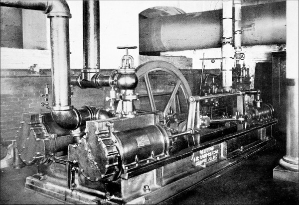
Fig. 9.
DUPLEX AIR-COMPRESSOR IN THE BASEMENT OF THE MAIN POST-OFFICE.
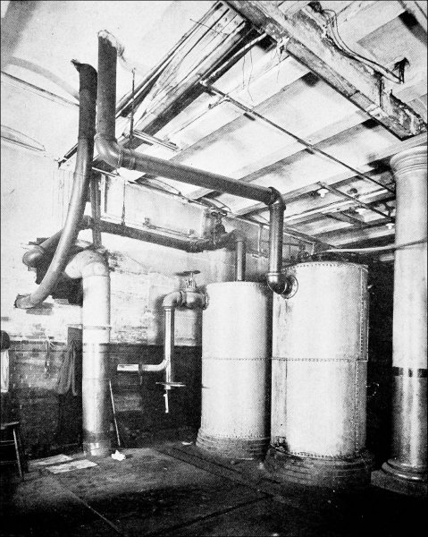
Fig. 10.
TANKS AND TUBE IN THE BASEMENT OF THE MAIN POST-OFFICE.
—The current of
air that operates the tubes is supplied by a duplex air-compressor
located in the basement of the main post-office. This machine is
shown in Fig. 9, and requires no detailed description, as it does not
differ materially from air-compressors used for other purposes. The
stroke is twenty-four inches, the diameter of the steam-cylinders
ten inches, and the air-cylinders eighteen inches. The air-cylinders
are double acting, with poppet-valves, and have a closed suction.
The speed of the machine varies slightly, being controlled by a
pressure-regulator that maintains a practically constant pressure
in the tank that feeds the tube. The engines develop a little over
thirty horse-power under normal conditions. The pressure of the air
as it leaves the compressor is usually six or seven pounds per square
inch. Compressing the air heats it to about 156° F., but this is not
sufficient to require water-jackets about the air-cylinders. From the
compressor the air flows to a tank, shown on the right in
Fig. 10, where any oil or dirt contained in the air is deposited. The
principal purpose of the tank is, however, to form a cushion to reduce
the pulsations in the air caused by the periodic discharge from the
cylinders of the compressors, and make the current in the tube more
steady. From this tank the air flows to the sending apparatus on the
ground floor of the post-office and thence through the outgoing tube to
the sub-post-office. At the sub-post-office, after flowing through the
receiving and sending apparatus, it enters the return tube and flows
back to the main office, passing through the receiving apparatus there
and then to a tank in the basement,—the left tank in Fig. 10. The
air-compressor draws its supply from this tank, so that the air is used
over and over again. This return tank has an opening to the atmosphere,
which allows air to enter and make up for any leakage or escape at the
sending and receiving apparatus, thereby maintaining the atmospheric
pressure in the discharge end of the tube and in the suction of the
compressor. The tank serves to catch any moisture and dirt that come
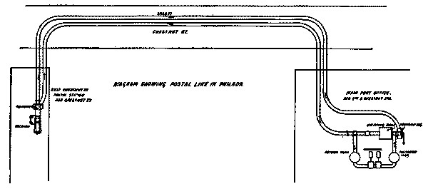
out of the tube. Fig. 11 is a diagram showing the direction and course
of the air-current. It will be noticed that both the out-going and
return tube are operated by pressure, in distinction from exhaust.
The air is forced around the circuit by the air-compressor. There is no
exhausting from the return tube. The pressure of the air when it enters
the tube at the main post-office is, say, seven pounds per square inch;
when it arrives at the sub-post-office the pressure is about three and
three-quarters pounds, and when it gets back to the main office and
enters the return tank, the pressure is zero or atmospheric. Thus it
will be seen that the pressure becomes less and less as the air flows
along the tube. This is not the pressure that moves the carriers, but
the pressure of the air in the tube, a pressure that exists when there
are no carriers in the tube. It is the pressure that would be indicated
if you should drill a hole into the tube and attach a gauge.
—When the construction of this line was
begun, it was the intention of the Pneumatic Transit Company to use the
apparatus of the Electro-Pneumatic Transit Company, at both stations,
for sending and receiving carriers, and so-called working-drawings
were obtained for this purpose. The sending apparatus was constructed
according to the designs furnished, but, upon examination of the
drawings of the receiving apparatus, it was so apparent that it would
not work as intended that it was never constructed.
The writer was asked to design an automatic receiver to stop the
carriers without shock upon their arrival at the stations, and to
deliver them upon a table without appreciable escape of air,—something
that would answer the requirements of the present plant.
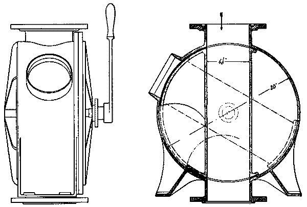
Fig. 12.
TRANSMITTER.—PHILA.
SENDING APPARATUS.
Larger image (143 kB)
—The sending apparatus is for the purpose of
enabling the operator to place a carrier in the tube without allowing
the air to escape. In other words, it is a means of despatching
carriers. The apparatus for this purpose, already referred to, is
simply a valve. A side view and section of it are shown in Fig. 12.
Fig. 15 is a view of the apparatus in the main post-office. The sending
apparatus is seen on the left. Fig. 13 is a view of the sub-post-office
apparatus, and here a man may be seen in the act of despatching a
carrier. Referring to the section, Fig. 12, it will be seen that the
sending apparatus consists of a short section of tube supported on
trunnions and enclosed in a circular box. Normally this short section
of tube stands in line with the main tube, and the air-current passes
directly through it. It is shown in this position in the figure. When a
carrier is to be despatched, this short section of tube is rotated by a
handle until one end comes into coincidence with an opening in the side
of the box. In this position the air flows through the box around the
movable tube. A carrier can then be placed in the short section of tube
and be rotated by the handle into line with the main tube. The carrier
will then be carried along with the current of air. A circular plate
covers the opening in the box where the carrier is inserted when the
sending apparatus is closed.
At the sub-post-office this sending apparatus is placed in a horizontal
position, but its operation is the same.
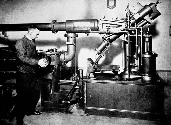
Fig. 13.
RECEIVING AND SENDING APPARATUS IN THE SUB-POST-OFFICE.
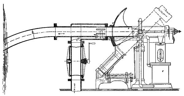
Fig. 14.
APPARATUS AT SUB-STATION—PHILA.
Larger image (151 kB)
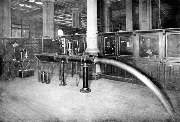
Fig. 15.
TERMINALS OF THE TUBE IN THE MAIN POST-OFFICE.
Larger image (397 kB)
—We have already explained that
the air-pressure in the tube at the sub-post-office is about three
and three-quarters pounds per square inch. With such a pressure we
cannot open the tube to allow the carriers to come out. They must
be received in a chamber that can be closed to the tube after the
arrival of a carrier and then opened to the atmosphere. Furthermore,
this chamber must act as an air-cushion to check the momentum of the
carriers. Fig. 13 shows the sub-post-office apparatus when a carrier
is being delivered from the receiving apparatus, or, as we will name
it for convenience, the receiver. Fig. 14 is a drawing of the same
apparatus, partly in section, that shows more clearly its method
of operation. This drawing shows the sending apparatus in a
different position from Fig. 13, but that is immaterial. The receiver
consists of a movable section of tube, about twice the length of a
carrier, closed at one end, supported upon trunnions, and normally
in a position to form a continuation of the main tube from which the
carriers are received. When a carrier arrives it runs directly into
the receiver, which being closed at the end forms an air-cushion
that stops the carrier without shock or injury. Just before reaching
the receiving chamber the current of air passes out through slots in
the walls of the tube into a jacket that conducts it to the sending
apparatus, as shown in Fig. 14. At the closed end of the receiving
chamber, or air-cushion, is a relief valve, normally held closed by
a spring. As the carrier compresses the air in front of it, this
valve opens and allows some of the air to escape, which prevents the
carrier from rebounding into the tube. Under the outer end of the
receiving chamber is a vertical cylinder, E, Fig. 14, supported upon
the base-plate containing a piston. The piston of this cylinder is
connected by a piston- and connecting-rod to the receiving chamber.
When air is admitted to the cylinder under the piston, the latter rises
and tilts the receiving chamber to an angle of about forty degrees,
which allows the carrier to slide out. The receiving chamber carries
a circular plate, C, that covers the end of the main tube when it is
tilted. A small piston slide-valve, F, located near the trunnion of
the receiving chamber, controls the admission and discharge of air to
and from the cylinder E, upon the arrival of a carrier. When a carrier
arrives and compresses the air in the air-cushion or receiving
chamber, a small portion of this compressed air is forced through pipe
G, to a small cylinder containing a piston and located just above the
piston slide-valve F. The increased pressure acting on the piston moves
it downward, and it in turn moves the slide-valve F. Thus it will be
seen that the stopping of the carrier causes the receiving chamber to
be tilted and the carrier slides out on to an inclined platform, K.
This platform is hinged at one end, and supported at the angle seen
in the figure by a counterweight. When a carrier rests upon it, the
weight of the carrier is sufficient to bear it down into a horizontal
position; in this position the carrier rolls off on to a table or
shelf. The platform, K, is connected by rods, bell-cranks, etc., to the
piston slide-valve, so that when it swings downward by the weight of
a carrier, the slide-valve is moved upward into its normal position,
and this causes the receiving chamber to tilt back into a horizontal
position ready to receive the next carrier. The time that elapses from
the arrival of a carrier until the receiving chamber has returned to
its horizontal position is not more than three or four seconds. Nothing
could operate in a more satisfactory manner.
—At the main post-office we have a
receiver of a different type. It will be remembered that the pressure
in the return tube at the main post-office is nearly down to zero or
atmospheric, so that we can open the tube to allow the carriers to pass
out without noise or an annoying blast of air. Figs. 15 and 16 show
the main-office apparatus, and Fig. 17 is a drawing of the same. Here
the receiver consists of a section of tube closed by a sluice-gate,
located at B, Fig. 17. The air-current passes out through slots in the
tube into a branch pipe leading to the return tank in the basement.
These slots are located about four feet back of the sluice-gate, so
that the portion of the tube between the slots and the sluice-gate
forms an air-cushion to check the momentum of the carriers. The
sluice-gate is raised and lowered by a piston moving in a cylinder
located just above the gate. The movement of this piston is controlled
by a piston slide-valve in a manner similar to the apparatus at the
sub-post-office. Air for operating the piston is conveyed through the
pipe D, Fig. 17, from the pipe leading from the air-compressor to the
sending apparatus. This air is at about seven pounds pressure per
square inch.
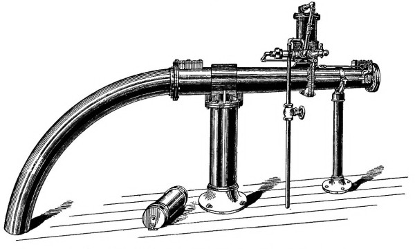
Fig. 16.
RECEIVING APPARATUS AT THE MAIN POST-OFFICE.
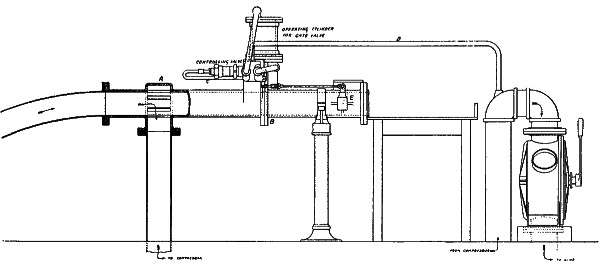
Fig. 17.
APPARATUS AT THE MAIN OFFICE—PHILA.
Larger image (83 kB)
When a carrier arrives, after passing the slots that allow the
air-current to flow into the branch pipe, it compresses the air in
front of it against the gate. This compression checks its momentum,
and it comes gradually to rest. The air compressed between the
carrier and the sluice-gate operates to move the piston slide-valve,
thereby admitting air to the gate cylinder under the piston, which
rises, carrying with it the sluice-gate. The tube is now open to the
atmosphere, and there is just sufficient pressure in the tube to push
the carrier out on to a table arranged to receive it. As the carrier
passes out of the tube it lifts a finger out of its path. This finger
is located at E, Fig. 17, and when it is lifted by the passing carrier
it moves the piston slide-valve, and the sluice-gate is closed. A valve
is located in the branch-pipe that conducts the air to the return tank
in the basement. If the pressure in the tube is not sufficient to
push the carrier out on to the table, this valve is partially closed,
thereby increasing the pressure to a desired amount.
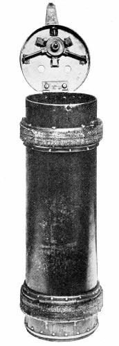
Fig. 18.
CARRIER.
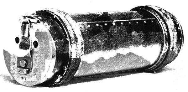
Fig. 19.
CARRIER.
—We have frequently spoken of the carrier, which
contains the mail and other parcels that are transported from one
office to the other. In Fig. 13, showing the sub-post-office apparatus,
we see one of these carriers being despatched by the attendant and
another being delivered from the tube. In Fig. 15 several carriers
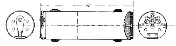
may be seen standing on the floor. Fig. 18 shows a carrier with the
lid open, ready to receive a charge of mail, and Fig. 19 shows the
same closed, ready for despatching. The construction of the carrier
is shown by the drawing, Fig. 20. The body of the carrier is steel,
about one-thirty-second of an inch in thickness. It is made from a
flat sheet, bent into a cylinder, riveted, and soldered. The
length outside is eighteen inches, and the inside diameter is five and
one-quarter inches. The front end is made of a convex disk of steel,
stamped in the desired form, and secured to the body of the carrier
by rivets, with the convex side inward. It is necessary to have a
buffer upon the front end of the carrier to protect it from blows
that it might receive, and this buffer is made by filling the concave
side of the front head with felt, held in place by a disk of leather
and a central bolt. The leather disk is made of two pieces, riveted
together, with a steel washer between. The steel washer is attached
to the head of the bolt. The carrier is supported in the tube on two
bearing-rings, located on the body of the carrier a short distance from
each end. The location of these rings is so chosen that it permits a
carrier of maximum length to pass through a bend in the tube of minimum
radius without becoming wedged. This is a very important feature in the
construction of carriers, but does not appear to have been utilized in
other systems.
The bearing-rings are made of fibrous woven material, especially
prepared, and held in place by being clamped between two metal rings,
one of which is riveted to the body of the carrier. Of course these
rings wear out and have to be replaced occasionally, but their usual
life is about one thousand miles. The rear end of the carrier is closed
by a hinged lid and secured by a special lock. The lock consists of
three radial bolts that pass through the body of the carrier and the
rim of the lid. These bolts are thrown by three cams, attached to a
short shaft that passes through the lid and has a handle or lever
attached to it upon the outside of the lid. This cam-shaft is located
out of the geometrical centre of the lid in such a position that when
the lever or handle is swung around in the unlocked position, it
projects beyond the periphery of the lid, and in this position the
carrier will not enter the tube. When the lid is closed and locked,
the lever lies across the lid in the position shown in Fig. 19, and
when the carrier is in the tube it cannot become unlocked, for the
lever cannot swing around without coming in contact with the wall of
the tube. This insures against the possibility of the carriers opening
during transit through the tube. The empty carriers weigh about nine
pounds, and when filled with mail, from twelve to fifteen pounds. They
have a capacity for two hundred ordinary letters, packed in the usual
manner.
—The tubes are kept in constant
operation during the day, and six days of the week. The air-compressor
is started at nine o’clock in the morning and runs until seven in the
evening, except during the noon hour, the air flowing in a constant
steady current through the tubes. When a carrier is placed in the
tube it is carried along in the current without appreciably affecting
the load on the compressor. Carriers may be despatched at six-second
intervals, and when they are despatched thus frequently at each office,
there will be eighteen carriers in the tube at the same time. If ten
carriers per minute are despatched from each office, and each carrier
contains two hundred letters, the tube has a carrying capacity of two
hundred and forty thousand letters per hour, which is far beyond the
requirements of this office. About five hundred carriers a day are
despatched from each office. This varies considerably on different
days and at different seasons of the year. Experience has taught that
a certain period of time should elapse between the despatching of
carriers, in order that they may not come in contact with each other,
and that the receivers may have time to act. With the present plant
this period is made about six seconds. In order to make it impossible
for carriers to be despatched more frequently than this, time-locks
are attached to the sending apparatus. One of these locks may be seen
in Fig. 13, connected to the handle of the sending apparatus. It is
so arranged that when a carrier is despatched a weight is raised and
allowed to fall, carrying with it a piston in a cylinder filled with
oil. While the weight is rising and falling the sending apparatus is
locked, but becomes unlocked when the weight is all the way down. A
by-pass in the cylinder permits the oil to flow from one side of the
piston to the other, and the size of this by-pass can be regulated,
thus determining the time that the weight shall take in descending.
This makes a simple and effective time-lock that does not get out of
order.
The time required for a carrier to travel from the main to the
sub-post-office is sixty seconds, and from the sub- to the main
post-office, fifty-five seconds. This difference of time in going and
returning is due to the expansion of the air in the tube, as will
be explained more fully in another place. The distance between the
offices being two thousand nine hundred and seventy-four feet, gives
an average speed of about fifty-two feet per second, or 35.27 miles
per hour. Of course the speed can be increased by increasing the
air-pressure, but this speed is found in practice to be ample for all
requirements. In order to give some idea of the energy possessed by
one of these carriers travelling at this speed, it may be said that
if the end of the tube were left open and turned upward, an emerging
carrier would rise about forty feet into the air. It is easy to imagine
how apparatus, depending for its operation upon impact with a moving
carrier, would be soon destroyed, as well as the carriers themselves.
This is why receiving apparatus used with small tubes and light
carriers cannot be applied to large tubes with heavy carriers.
No serious trouble has ever been experienced from carriers getting
wedged in any part of these tubes.
—The advantages to the post-office
department by the adoption of this system have been numerous, and the
post-office officials who are familiar with the operation of the tubes
frequently speak in high terms of their usefulness. Formerly the mail
was transported from one office to the other by a wagon making a trip
every half-hour. Considerable time has been saved by the greater speed
of transit, but even more time is gained by keeping the mail moving
instead of allowing it to accumulate and then despatching it in bulk.
With the pneumatic system a letter posted in the sub-post-office will
reach its destination just as quickly as if posted at the main office,
and sometimes more quickly. Let us take an example, first, with the old
wagon service. Suppose that you drop a letter in the sub-post-office;
it lies there, say, fifteen minutes waiting for the departure of the
next wagon; it is put into a pouch with hundreds of other letters, and
ten minutes are consumed in transporting it to the main office. When
it arrives there the pouch is thrown on the floor at the entrance of
the building; in a few minutes, more or less, a clerk takes the pouch,
throws it on a truck and wheels it around to the cancelling machines,
where it may lie for five or ten minutes more before being opened,
and then perhaps five minutes will elapse before your letter reaches
the cancelling machine. It would not be unusual for three-quarters
of an hour to elapse from the time you dropped your letter in the
office until it was cancelled. Now with the pneumatic tube service
forty minutes of this time will be saved; for immediately after you
drop your letter in the office it will be despatched through the tube
and delivered on the table in front of the cancelling machines. Soon
after the tubes were installed the postmaster’s attention was called
to an instance where letters from the sub-office were sent through
the tube and were despatched to New York City one train earlier than
they could have been had the old wagon service been in use. People
frequently post letters requesting that they be sent through the tube;
of course they would be sent in that way if the request was not made,
but it shows that the public recognize the better service. Formerly
mail was collected from the street boxes in the banking section of the
city and the collectors carried it to the main office. After the tubes
were installed this mail was carried to the sub-post-office to be sent
through the tube, and the time formerly occupied in walking to the main
office was then utilized in having the men face up the letters ready
for the cancelling machines,—a double saving in time besides making
their labor much lighter and enabling them to do more useful work.
Since the sub-office has been established in the Bourse, it has been
made a distributing as well as receiving office. At least two more
deliveries of mail are made each day in the Bourse building than in any
other office building in the city.
All letters mailed in the sub-office with a special delivery stamp are
despatched through the tube immediately.
It is now nearly four years since the system was put into operation.
During that time more than thirty-five million letters have been
transported, and all the repairs to the system have not required it
to be stopped for more than a few hours. During the first year the
Pneumatic Transit Company operated the tubes at their own expense,
agreeing at the end of that time to take them out if the government so
requested. Since the first year the government has paid the running
expenses.
Such is the history of the first United States pneumatic postal system.
Such is the history of the first pneumatic tubes of sufficient size to
carry all the first class and most of the lower classes of mail, in
this or any other country, so far as the writer knows.
CHAPTER III. THE SYSTEM AND APPARATUS OF THE BATCHELLER PNEUMATIC TUBE COMPANY. — General Arrangement and Adaptability of the System. — Size of Tubes. — System of Very Large Tubes. — General Arrangement of Apparatus in the Stations. Two-Station, Two-Compressor Line. — Two-Station, One-Compressor Line. — Three- to Eight-Station Line. — The Sending Apparatus. — Sending Time-Lock. — Intermediate Station Time-Lock. — The Electro-Pneumatic Circuit-Closer. — The Open Receiver. — The Closed Receiver. — The Intermediate Station Receiving and Transfer Apparatus. — Carriers. — Air Supply. — Fans. — Blowers. — Air-Compressors. — The Tube, Line Construction, etc. — CHAPTER IV. FACTS AND GENERAL INFORMATION RELATING TO PNEUMATIC TUBES. — Definitions. — Intermittent and Constant Air-Current. — Laws Governing the Flow of Air in Long Tubes. — Law of Pressure. — Uses of Pressure Curves. — Law of Velocity. — Characteristics of the Velocity Curve. — Use of Velocity Curves. — Quantity of Air Used. — Temperature of the Air. — Horse-Power. — Efficiency. — Pressure and Exhaust Systems. — Laws Expressed in Mathematical Formulæ. — Moisture in the Tubes. — Location of Obstructions in Tubes. — Transcriber’s Notes:
—The
experience gained in the construction and operation of the Philadelphia
post-office tubes has naturally suggested improvements that can be
made in future construction, and, furthermore, it has taught us what
the requirements will be of an extensive system of tubes laid in the
streets of our cities, both for the transmission of mail and for
a general commercial business. Since the Philadelphia post-office
tube was completed, we have been busily engaged in working out all
the details of a system of many stations so connected together that
carriers can be despatched in the most direct manner possible from
any station to any other. It is the purpose of the present chapter to
describe this system.
While the Pneumatic Transit Company has ample field in the State of
Pennsylvania to carry out the work which it has mapped out, a field
broad enough to yield a good profit for the capital invested, there
is no reason why the system should be limited to one State. So, in
order to obtain a broader charter, covering all places where pneumatic
service may be needed, a new corporation was formed and styled the
Batcheller Pneumatic Tube Company.
It is impossible to lay down a rigid system equally well adapted to
all places and purposes. We must accommodate ourselves somewhat to
circumstances. For example, the post-office department may require
one size of tube, arranged to operate in a particular way, while the
requirements of a parcel delivery business would be utterly different.
The geographical location of the stations will have much to do with the
general arrangement; also the condition of the streets. Some of the
streets of our large cities are so filled with water- and gas-pipes,
electrical conduits, sewers, steam-pipes, etc., etc., that it is almost
impossible to find space for pneumatic tubes, especially of large
diameter. Railway or water facilities have much to do with the location
of a central pumping station, on account of the coal supply. All of
these and many other things have to be taken into consideration in
planning a system for any locality.
We have an example of a peculiar location and conditions in a proposed
line of tubes over the New York and Brooklyn bridge connecting the main
post-offices of those cities. This would be in many respects a unique
plant. Two air-compressors would be used, one at each office.
In order to give a general idea how a large number of stations can be
connected into one system, the diagram Fig. 21 has been drawn.
We have already referred to the attempts of Clay and Lieb to devise
means whereby several stations could be located along a main line and
carriers be sent from any station to any other through the main line.
Their method was to use branch tubes leading off from the main line
with switches at the junctions. They deflected the air-current into
the branch by placing an automatic closed valve in the main line just
beyond the junction, returning the air from the branch to the main line
just beyond the valve. The carriers were to open and close this valve
automatically as they passed.
The branch and switch system has many attractions for the inventor,
and upon first thought it would seem the most feasible solution of
the problem. It has been the dream of more than one inventor, as the
records of the patent-office show, but no one has succeeded in working
it out. The current of air cannot be divided; carriers passing from the
branch into the main line must not collide with other carriers running
in the main line; a certain minimum distance must always be maintained
between the carriers in the same tube; when a carrier is despatched
it must go directly to the station for which it is intended without
further attention from the sender and it must not interfere with other
carriers; expense of manufacture prohibits the use of any but round
smooth tubes up to eight inches in diameter, hence projections cannot
be placed upon the carrier to give it an individuality and cause it to
operate a switch at any particular point along the line; the carrier is
free to rotate in a round tube about its longitudinal axis, therefore,
its individuality must be indicated by some symmetrical marking about
this axis, if it is to be automatic in its operation; the speed of
the carrier is so high that electrical contacts placed in distinctive
positions on the carriers cannot be used while it is in motion, for
mechanism having inertia could not be moved during the short time that
the electric circuit would be closed; only the simplest attachments
can be made to the carrier, for constructional reasons and because of
the rough usage that they receive. These and numerous other reasons
make the problem most difficult. We have not attempted to solve it by
the use of branch tubes and electrically operated switches, but have
adopted the simpler and equally effective method of carrying the main
line through each of the stations that it unites. In our system each
carrier has an individuality determining the station at which it will
be discharged from the tube. By a simple attachment to, the front end
of the carrier, consisting of a circular metal disk, the sender so
marks the carrier that it will pass all stations until it arrives at
the station for which it was destined and will there pass out of the
tube. In addition to this a method has been devised whereby carriers
can be inserted into the tube without the possibility of collision with
carriers already running in the tube.
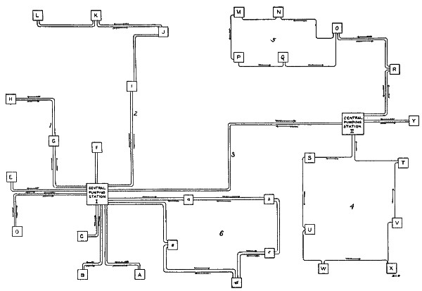
Fig. 21.
A DIAGRAM SHOWING VARIOUS METHODS OF CONNECTING THE STATIONS OF A LARGE
SYSTEM WITH PNEUMATIC TUBES.
Larger image (94 kB)
Referring now to the diagram, Fig. 21, we have here an imaginary system
which we will suppose to be located in some large city. The two large
squares I and II indicate central pumping stations, and the small
squares A, B, C, D, etc., indicate receiving and sending stations. Some
of the stations, such as A, B, C, D, E, F, and Y, which do a large
amount of business and may be supposed to be large retail stores, are
connected directly with the central station by double tubes, one for
sending and the other for receiving carriers. Two smaller stores, such
as G and H, may be located on the same line. At I, J, K, and L we have
four stations, all connected by the same double line of tubes. These
stations we will imagine to be located in the residence section of
the city. Carriers containing parcels of merchandise or other matter
destined for private residences would be sent from the stores A, B, C,
etc., to the central station I, where they would be transferred to the
line 2 and be adjusted to stop at the station nearest the residence to
which the parcels were addressed. From this station the parcels would
be delivered by messengers to the residences. If a carrier is to be
sent from the central station I to station K, it will be so adjusted
before it is put into the tube that it will pass stations I and J, but
be discharged automatically from the tube when it arrives at station
K. In a similar manner carriers can be despatched from station L to
station I or from station J to station L. In passing through the
central station the carriers are manually transferred from one line to
another.
In another part of the city we may have another central pumping
station, II; and the two central stations may be connected by a double
trunk line, 3. Again, we have lines radiating from this central
station, as shown by station Y. There will be some localities where it
will be an advantage to arrange the stations upon a loop, as shown in
circuit 4, where stations S, T, U, V, W, and X are connected together
in this way. Or we can combine the two arrangements of loop and direct
line, as shown in circuit 5. Stations O and R are on the double line,
but from O a loop is formed including stations N, M, P, and Q. Here it
is supposed that the stations O and R do a much larger business with
the central station II than the stations N, M, P, and Q, this being
the principal reason for placing them on the double line. All carriers
must be returned to the station from which they were sent, or others
to replace them, otherwise there will be an accumulation of carriers
at some of the stations. It is like a railway: there must be as many
trains despatched in one direction as the other, each day. Station O
can receive a carrier from the central station and return it directly,
but when station N receives one it must be returned via M, P, Q, O,
and R, a much longer route than that by which it was received. This
disadvantage is compensated, when stations N, M, P, and Q do only a
small amount of business, by the less cost of laying a single line.
If a carrier is to be sent from M to N, it must go via P, Q, and O,
being manually transferred at O from the “down” to the “up” line. P
can send directly to Q, but Q must send to P via O, N, and M. R can
send directly to O and O to R. Similarly in circuit 4 the carriers must
all travel around the loop in the same direction, shown by the arrows.
Station S can receive carriers directly from the central station, but
they must return via U, W, X, V, and T.
Again, we may have a double-loop line, as indicated in the diagram
by circuit 6. Here five stations, a, b, c, d, and e, are
connected by a loop consisting of two lines of tube, in which the air
circulates in one direction in one line and in the opposite direction
in the other. Here b can send directly to c, c directly to
b, and e to b via d and c, or via central and a. This
is an arrangement that would be used where there is a large amount
of business between the stations on the loop. As stated before, the
best arrangement for any particular locality depends entirely upon
circumstances.
—The pneumatic-tube system that we are describing
is not limited to any particular size of tube. The size is usually
determined by the number and size of packages to be transported.
A small tube, two or three inches in diameter, is best suited for
telegrams and messages; mail, parcels, etc., require a six- or
eight-inch tube, while mail pouches and bulky material, a thirty-six
inch or possibly larger tube. We divide tubes into three classes,
according to their size, naming them small, large, and very large
tubes. By small tubes we mean those not larger than three or possibly
four inches in diameter. Large tubes are those having a diameter more
than four inches and not more than eight inches. Very large tubes
include all that are more than eight inches. This classification is
for convenience, but it has a deeper significance. For example, in
the transportation of mail, it must either be handled in bulk, that
is, in pouches, or in broken-bulk, that is, loose or tied up in small
packages. There are many advantages in transporting it in broken-bulk,
in fact, there are very few places where it could be handled in any
other way. For this service six- or eight-inch tubes—not larger—are
best suited. The carriers are light enough to be easily handled; they
are not so large in capacity as to make it necessary to wait for an
accumulation of mail to fill them; they can be delivered from the tube
on to tables at any point in the building where the mail is wanted,
for cancelling, distribution, or pouching, thus rendering a very rapid
service; the mail is kept moving in an almost constant stream, keeping
the postal employees more uniformly employed; special carriers can be
despatched with “special delivery” letters. In other words, the most
rapid service can be rendered by this size of tube.
If a larger than eight-inch tube is to be used for mail service,
it should be not less than thirty-six inches. Carriers larger than
eight inches cannot be handled: they are too heavy. They are also too
heavy to slide through the tube, hence, must be mounted upon wheels.
It is not practical to make a carrier on wheels less than eighteen
or twenty-four inches, and the carrier must be at least twenty-four
inches to contain a large mail-pouch. Now, if we are going to despatch
mail-pouches through a pneumatic tube we must send more than one in a
carrier, otherwise the service will be too slow. Such large carriers
could not be despatched oftener than once or at most twice in a minute.
Suppose we were to transport the mail from a railway station to a main
post-office. A train arrives with, say, sixty pouches. If only one
pouch could be put into a carrier and the carriers could be despatched
at half-minute intervals, it would take thirty minutes to despatch
all the pouches. Now, suppose we make the tube thirty-six inches.
The carriers will be eight feet long and will contain from twelve to
fifteen pouches. Five carriers would contain the entire train-load of
mail, and they could be despatched in four or five minutes.
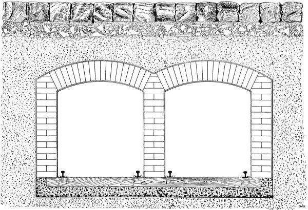
Fig. 22.
CROSS-SECTION OF A 36-INCH TUBE.
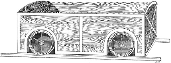
Fig. 23.
CARRIER FOR A 36-INCH TUBE.
—The cross-section of a
thirty-six-inch tube is shown in Fig. 22. It is built flat on the
bottom and sides, with an arched top. The floor is of concrete
containing creosoted ties; the side walls and top are of brick,
plastered with cement upon the interior. The two tubes may be built
one above the other or side by side, depending upon the condition
of the streets, but one common separating wall will serve for both.
The carriers, one of which is shown in Fig. 23, run on two rails laid
close to the sides of the tube. At curves a guard-rail is placed upon
the side wall, making it impossible for a carrier to leave the track.
The carriers are made of hard wood with an iron frame, and are as light
as consistent with the service required of them. They are open on top.
Their outside dimensions are thirty-four inches by thirty-four inches
by eight feet. The sending and receiving apparatus for these very large
tubes have to be specially designed for each particular station, so no
attempt will be made here to describe them. The air-pressure required
depends upon the length of the line. If it were not more than six or
eight ounces a fan would be used to maintain the air-current, but for
pressures above this, up to a pound or two per square inch, some form
of positive blower would be used.
At the stations considerable floor space or “yard room” would be
required for side tracks, switches, etc. Usually the basement of a
building would have to be utilized for the termination of such a tube.
There are but few places in our large cities where the streets are so
free from pipes, sewers, conduits, etc., that it would be practicable
to build a thirty-six-inch pneumatic tube. When the service can be
rendered by an eight-inch tube, the cost of installation favors its
adoption. Steep grades cannot be ascended by these very large tubes,
while the eight-inch tubes can be placed vertically. We do not say that
there is no use for eighteen- and twenty-four-inch tubes, but the
demand for them would be in special cases and we will not discuss them
here. For ordinary mail and parcel service we recommend the use of
six- and eight-inch tubes. An eight-inch carrier is twenty-four inches
long, about seven inches inside diameter, and will contain five hundred
ordinary letters. It weighs about thirteen pounds empty, and one can
be despatched every six to ten seconds. We estimate that eighty per
cent. of all the parcels delivered from a large retail department store
could be wrapped up to go into these carriers. The minimum radius of
curvature of an eight-inch tube is eight feet.
—We will now proceed to a description of
our system in detail. Figs. 24, 25, and 26 are diagrams showing how
the tubes, air-compressor, tanks, sending and receiving apparatus
are connected together at the stations. These diagrams are drawn to
represent an eight-inch tube, but essentially the same arrangement
would be used for smaller tubes.
Fig. 24 represents a line of two stations with an air-compressor at
each station. Such an arrangement is proposed for the line of postal
tubes over the New York and Brooklyn bridge, or for any two stations
located a very long distance apart, say six or eight miles.

Fig. 24.
DIAGRAM OF A TWO-STATION, TWO-COMPRESSOR LINE.
Larger image (83 kB)
Referring to the diagram, we have at station A an air-compressor, c,
which draws its supply of air from the tank e, and delivers it,
compressed to the necessary pressure, into the tank d. From the tank
d the air flows to the sending apparatus, a, and thence through
the tube f to the station B. Upon arrival at B it flows through the
receiving apparatus m, and then by the pipe l to the tank j. A
second air-compressor, o, is located at station B, and it draws its
supply of air from the tank j. The tank j has an opening to the
atmosphere, i, through which air can enter when the air-compressor
draws more than is supplied from the pipe l. The opening i in the
tank j serves as an escape for air when the air-compressor at station
A is started before that at station B. Stations A and B are similar in
their arrangements. At B the air-compressor o delivers its compressed
air to the tank k, from which it flows to the sending apparatus n,
and thence through the tube g back to station A. Upon its arrival at
A it passes through the receiving apparatus and enters the tank e,
which is open to the atmosphere at h. The tanks d and k serve
as separators to remove from the air any dirt and oil coming from the
compressors, and they form a cushion, deadening, to some extent, the
pulsations of the compressors and making the current of air in the
tubes more steady and uniform. The tanks e and j form traps to
catch any moisture, oil, or dirt coming out of the tubes.
Carriers are placed in the tubes and despatched by means of the sending
apparatus a and n. They are received from the tubes and delivered
on to tables by means of the receiving apparatus b and m. It will
be seen that the arrangement is such that the air flows through one
tube and returns through the other, the same air being used over and
over again. Any air that escapes at the sending and receiving apparatus
is replaced by an equal amount entering the tanks e and j from the
atmosphere. By thus keeping the same air circulating in the tubes we
prevent an accumulation of moisture in the tubes.
The air is at its maximum pressure in the tanks d and k. The
pressure falls gradually as it flows along the tubes and is down to
atmospheric when it enters the tanks e and j. The pressure at the
receivers, b and m, is just sufficient to push the carriers out on
to the tables. The construction of the sending and receiving apparatus
will be described in another place.

Fig. 25.
DIAGRAM OF A TWO-STATION, ONE-COMPRESSOR LINE.
Larger image (34 kB)
—Fig. 25 is a diagram showing
two stations, A and B, connected by a double line of tubes, both
operated by one air-compressor located at station A. This is the
arrangement used in the Philadelphia post-office line, and is the
arrangement that will ordinarily be used for all two-station lines
except where unusual conditions require something different. Station
A is arranged precisely like station A in Fig. 24, so it need not be
described again. The air flows from the sending apparatus a through
the tube f to the receiving apparatus p at station B. From the
receiver p it flows through the pipe l to the sending apparatus
n and thence through the tube g back to station A. The receiver
p at station B is what we will call a closed receiver,—i.e., it
delivers the carrier from the tube on to the table without opening
the tube to the atmosphere. The use of this form of receiver is made
necessary by the fact that the air-pressure in the tube at this station
is considerably above atmospheric. The air-pressure is at a maximum in
the tank d. It falls gradually along the tube f, and when the air
arrives at the receiver p, at station B, the pressure has fallen
nearly to one-half its maximum amount in the tank d. On its return
journey through the tube g the pressure continues falling until it
reaches the atmospheric pressure when the air enters the tank e at
station A.
The entire line of tube, going and returning, is operated by air at a
pressure above the atmospheric. There is no exhausting in the return
tube. It is distinctly a pressure system.
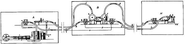
Fig. 26.
DIAGRAM OF A THREE- TO EIGHT-STATION LINE.
Larger image (98 kB)
—Thus far we have described only
two-station lines. In Fig. 26 we have a diagram of three stations
connected together by a double line of tubes, and the arrangement
would be similar if it were extended to four, five, six, seven, or
eight stations. The stations are called A, B, and H. Station A is
arranged exactly the same as stations A in Figs. 24 and 25, therefore,
needs no description. Station B, being an intermediate station, is
quite differently arranged from any of the preceding. From station
A the air flows through the tube f to station B, where it enters
the automatic receiving and transferring apparatus, s. From this
it flows through the tube f′ to the sending apparatus r, and
thence through the tube f″ to the next station, which may be
another intermediate station, C, or the terminal station H. Station H
is arranged like station B, Fig. 25. The air from the tube f″
enters the receiver p, and is then returned, through the pipe l, to
the sending apparatus n. From the sending apparatus n it continues
on its return journey through the tube g to the intermediate station
B, where it enters the receiver and transfer apparatus t, then passes
to the sending apparatus q, and through the tube g″ back to
the receiver b at station A. Thus we have followed the air-current
out through one tube and back through the other. The current is kept
circulating by the compressor located at station A. The pressure is
at a maximum in the tank d, and falls gradually as the air flows
along the tube until it returns to the tank e, when the pressure has
fallen to atmospheric. A carrier is despatched from station A, and
after passing through the tube f arrives at station B, where it stops
momentarily in the automatic receiver and transfer apparatus s. If
the carrier is intended for station B, and was properly adjusted when
it was despatched at A, it will be discharged from the apparatus s
on to the table u. But if it were intended for some other station
and were so adjusted, after the delay of two or three seconds in
the apparatus s, it will be automatically transferred to the tube
f′, pass through the sending apparatus r, and go on its journey
through tube f′ to the next station. If it is not discharged from
the tube at any of the intermediate stations, it will finally arrive
at the terminal station H and there stop. Just how the carriers are
adjusted and the details of the receiving and transfer apparatus will
be described hereafter. Carriers arrive at station B from H, or other
stations on the line, through tube g, in the apparatus t, which
either discharges them on to the table u or sends them on through
the tube g′ and g″ to station A. Carriers are despatched
from station B to station A by means of the sending apparatus q, and
from station B to other stations along the line, C, D, E, F, G, and
H, by means of the sending apparatus r. Thus, from B carriers can
be sent and received in either direction. In order to prevent the
possibility of a collision of carriers by attempting to despatch one
at station B at the instant another is passing through the sending
apparatus, an automatic lock is attached to each sending apparatus.
Just outside the station B, say three hundred feet on each side, are
located manholes, and in these manholes boxes are attached to the tube
containing an electric circuit-closing apparatus, so arranged that
when a carrier passes it will close an electric circuit leading to the
sending apparatus in the station. These manholes and circuit-closers
are shown and located on the diagram at v and w. Wires x and y
lead from them to the sending apparatus r and q. When a carrier
from station A passes the box v, it closes the electric circuit x,
which sets a time-lock on the sending apparatus r, holding this
apparatus locked, so that it is impossible to despatch a carrier for,
say, twelve seconds, a sufficient time for the carrier coming from the
station A to pass station B and get three hundred feet beyond it. After
the twelve seconds have elapsed the sending apparatus is unlocked and
a carrier can then be despatched. In a similar manner a carrier coming
from station H, in passing the box w, closes the electric circuit y
and locks the sending apparatus q for a sufficient length of time to
let the carrier pass the station. This resembles, in some respects,
the “block system” as used on railroads. A “block” about six hundred
feet in length, depending upon the speed of the carriers, is made at
each intermediate station with the station in the centre of the block.
Whenever a carrier enters this “block” the sending apparatus at the
station is locked, and a carrier cannot be inserted into the tube to
collide with the one which is passing. It will be noted that a carrier
in passing out of the “block” does not unlock the sending apparatus;
this is done automatically at a definite time after the carrier entered
the block. The unlocking is entirely independent of the carrier after
it has entered the block, and the reason it is so arranged is this:
suppose that a second carrier enters the “block” before the first one
leaves it; if the first carrier unlocked the apparatus when it left the
“block,” then it would be unlocked with the second carrier in the block
and a collision might occur, but by arranging it as we have done, if a
second carrier enters the “block” before the first has passed out, the
sending apparatus remains locked for a period of time beginning with
the arrival of the first carrier in the “block” and ending, say, twelve
seconds after the arrival of the last carrier, which is sufficient time
for the last carrier to pass out of the block. Of course, if a carrier
becomes wedged in the tube a collision may occur, but this very seldom
if ever happens. The details of the locking apparatus will be described
in another place.
If stations A, B, ... and H were arranged on a loop, as shown in
circuit 6, Fig. 21, then station H, Fig. 26, would be at the central,
or station A. If it were a single loop, like circuit 4, Fig. 21,
then there would be only one sending apparatus and one receiving and
transferring apparatus at the intermediate stations.
A telephone circuit will include all stations, in order to give orders
to the station attendants and to signal to the central station in case
of an accident, when it might be necessary to stop the air-compressor.
The telephone wires, in the form of a lead-covered cable, are laid in
the same trench with the tubes and fastened to them.
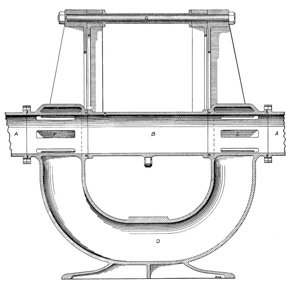
Fig. 28.
SENDING APPARATUS.—LONGITUDINAL SECTION.
Larger image (283 kB)
—We have, in the preceding pages,
frequently spoken of the sending apparatus, and have described it
as mechanism by which carriers are inserted into the tube. In the
Philadelphia postal line this apparatus consisted of a large valve,
operated by hand. For an eight-inch tube such a valve would be too
large and heavy to be manually operated. Furthermore, that type of
apparatus is not suited to an intermediate station, where carriers
have to pass through it. To meet all of these requirements we have
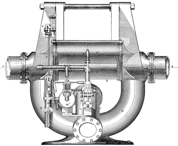
designed an apparatus, of which Fig. 27 is a side elevation, Fig. 28
a longitudinal section, and Fig. 29 a cross-section. Referring to the
longitudinal section, Fig. 28, the sending apparatus is shown inserted
into the line of a pneumatic tube, A, A. We have a movable section of
tube, B, that can be swung about the large bolt, G, at the top, into
and out of line with the main tube, A, A. When the section of tube B
is being swung to one side, the air-current has a by-pass through the
slots E and F and the U-shaped pipe D. The joints at the ends of the
movable section B are packed with specially-formed leathers. Referring
to the cross-section, Fig. 29, when the movable section of tube B is
swung out of line with the main tube, another and similar tube, C,
takes its place. The two movable tubes, B and C, are made in one piece,
so that they must always move together. They are connected together at
each end by plates, M, that serve not only as connecting-plates, but
covers for the ends of the main-line tube while the tubes B and C are
being moved. The tubes B and C swing between four plates or wings,
L, that extend out on each side of the apparatus. They serve as guards,
and, at certain positions of the swinging tubes, prevent the air from
escaping.
We will, for convenience, call the system of swinging tubes B and C,
with their supports, etc., the swing-frame or simply the frame. This
frame is moved or swung from one position to the other by means of a
cylinder and piston, H, placed in an inclined position under it. A lug,
N, is cast on the tube B, to which the connecting-rod, O, is attached.
The cross-head, P, slides upon an inclined guide, Q. On top of the
cylinder is placed a controlling valve, made in the form of a piston
slide-valve. The piston in the cylinder H is moved by the pressure of
the air taken from the main tube through the pipe I. The apparatus is
operated by a hand-lever, K. When this lever is pulled, it moves the
sliding-head R, and this, through the spring S, moves the controlling
valve, if the valve is not locked. If it is locked, pulling the lever
simply compresses the spring S. When the controlling valve is moved to
the right the air in the cylinder H escapes through the passage V and
the port J to the atmosphere, and compressed air from the main tube
flows through the pipe I, the passages T and U, to the cylinder H,
under the piston, causing the piston to move up the inclined cylinder
and swing the frame until the tube C is in line with the main tube.
Carriers are despatched by placing them in the tube C, then pulling
the lever K, and swinging the frame until the tube C is in line with
the main tube. The carrier is then taken up and carried along by the
current of air in the main tube.
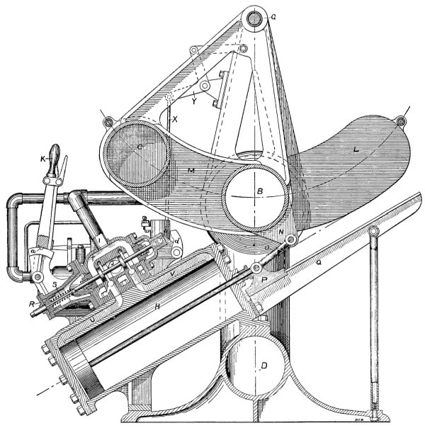
Fig. 29.
SENDING APPARATUS.—CROSS-SECTION.
Larger image (448 kB)
Replacing the hand-lever K in its original position returns the frame
to its normal position.
—In any system of large pneumatic tubes
a short time should elapse between the despatching of carriers, in
order that they may not collide in the tube, and to give the receiving
apparatus at the stations time to act. To insure the impossibility
of having carriers despatched too rapidly, we place on the sending
apparatus a time-lock that will automatically lock it for a determined
length of time after each carrier is despatched, the time-lock being
adjustable for any desired time. The time-lock, W, is shown attached
to the sending apparatus in Fig. 27. When the swing-frame is swung
to despatch a carrier, it pulls up the rod X by means of a link and
bell-crank, Y, thereby locking the controlling valve of the cylinder H
and starting the time-lock W, which will unlock the controlling valve
after the required time has elapsed. The details of this time-lock
are shown in Fig. 30. It consists of a long vertical cylinder, A,
containing a piston, B, and a spiral spring, C, that tends to force the
piston to the bottom of the cylinder. The cylinder is filled with oil,
and holes, D, in the piston allow the oil to pass freely through it
when it is moved upward in the cylinder. When the piston moves downward
an annular collar, E, forming a valve, closes the holes in the piston
and prevents the oil from passing through. Extending from one side of
the piston to the other is a by-pass, F, in the wall of the cylinder.
When the piston moves downward the displaced oil is forced to flow
through this by-pass. A small cock, G, is arranged in the by-pass to
throttle the stream of oil flowing through it. The opening in this
cock, or the amount of throttling, is indicated on the outside by
an index and dial, Z (see Fig. 27). When the piston B is raised and
allowed to descend by the force of the spring C, it forces the oil
through the by-pass F and the cock G. If the latter is wide open the
piston will descend quickly, but if it is nearly closed the piston
will descend very slowly. In other words, the time of descent can be
regulated by opening and closing the cock G. The reading on the dial Z
can be made seconds of time that elapse while the piston is descending.
Above the cylinder is a cross-head, H, that moves up and down between
vertical guides. This cross-head is moved by the rod X, also shown
in Fig. 27, that receives its motion from the swinging frame of the
sending apparatus. A piston rod, I, attached to the piston in the
cylinder, extends up through the travelling cross-head but is not
attached to it. On the piston-rod are two enlargements, J and K, one
made a solid part of it, the other formed by two nuts. The travelling
cross-head H carries a pawl, L, that engages under the shoulder formed
by the nuts K. This pawl is kept against the piston-rod by the spring
M. The enlargement, J, on the piston-rod forms a shoulder that bears
against the bell-crank, N, that connects with the bolt, O, which locks
the controlling valve. In the present down position of the piston and
piston-rod, the enlargement J, by pressing against the bell-crank N,
holds the bolt O in an unlocked position. When a carrier is despatched
the cross-head H is lifted by the rod X, and carries with it the piston
and piston-rod, compressing the spring C. This upward movement of the
piston-rod allows the bolt O to be thrown by a spring, not shown in the
figure, and so lock the controlling valve of the sending apparatus.
As the cross-head continues its upward movement, the pawl L comes in
contact with the end of the screw P and disengages the piston-rod. This
allows the piston to descend as rapidly as the oil can pass through the
by-pass and cock G. When the piston has reached nearly to the bottom of
the cylinder, the shoulder J, on the piston-rod, engages the bell-crank
N and withdraws the bolt O, thereby unlocking the controlling valve.
The time that the sending apparatus is locked depends upon the time
required for the piston to descend. While the sending apparatus is
locked against the sending of another carrier, it is not so locked
that the swing-frame cannot be returned to its normal position and
another carrier inserted ready to be sent as soon as the necessary time
expires. This time is usually not more than ten seconds. Not only may
the second carrier be placed in the tube C, Fig. 29, ready to be sent,
but the handle K may be pulled and fastened in the notch a, thereby
compressing the spring S, which, as soon as the controlling valve is
unlocked, will move the valve and automatically despatch the carrier.
The controlling valve is locked by the passage of a bolt through the
hole b, in a block carried on the end of the valve stem, when it
returns to the normal position shown in the figure. Usually little or
no time will be lost in thus locking the sending apparatus, for the
small amount of time that the apparatus is locked will be needed in
handling the carriers.
—We have another time-lock
attached to the sending apparatus that has been already referred
to in describing the “block system” used at intermediate stations;
a time-lock to prevent carriers being inserted into the tube at
intermediate stations while another carrier is passing that station.
This time-lock is shown in Fig. 27 at W´, and is shown in detail by a
sectional drawing, Fig. 31.
When a carrier closes an electric circuit in passing one of the boxes
located in a manhole about three hundred feet from an intermediate
station, it indicates its approach to the station by exciting the
electro-magnet A, Fig. 31. This magnet pulls down its armature B and
raises the small piston valve C, which admits compressed air to a small
chamber, D. The air is supplied to this chamber from the main tube
through the pipe E. In one end of this chamber is fitted a piston, F,
held to one end of its stroke by a spring, G. When compressed air is
admitted to the chamber D, this piston is moved to the left, and by
such movement throws the controlling valve of the sending apparatus
into its normal position (shown in Fig. 29) and holds it there. This
forms a positive lock, and, no matter in what position the sending
apparatus may be, it puts the tube B, Fig. 29, into line with the main
tube so that the approaching carrier can pass through the apparatus.
The piston-rod H, Fig. 31, is connected to the finger d, Fig. 29,
and by rocking this finger moves the controlling valve, or prevents it
being moved by the handle K.
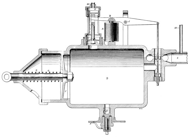
Fig. 31.
INTERMEDIATE STATION TIME-LOCK.
Larger image (199 kB)
Returning now to Fig. 31, we have on the top of the chamber D, in
addition to the electro-magnet A and its armature B, a differential
cylinder and piston, K, L, whose function is to close the valve C
when the chamber D is filled with air. The piston K is smaller than
the piston L, and sustains a constant air-pressure, supplied through
the small pipe M M, from the pipe E, which leads to the main tube.
When the chamber D becomes filled from the pipe E through the valve
C, the pressure in the chamber moves the piston L upward against the
pressure on the piston K, because of the greater area of the piston
L. This movement of the differential piston raises the lever I, which
passes through a slot in the stem of the differential piston, and thus
closes the valve C. The air in the chamber now gradually escapes to
the atmosphere through a small orifice Q; in fact it has been escaping
here all the time while the chamber was being filled, but the opening
through the valve C is so many times larger than the orifice Q that the
escape of air was not sufficient to prevent the chamber from filling.
Now, however, that all supply to the chamber is shut off, the air in
the chamber is gradually being discharged through the orifice. When
nearly all the air has escaped, the piston F will return to its normal
position, shown in the figure, and unlock the controlling valve.
The time required for the air to escape from the chamber, D, is the
time that the sending apparatus will be locked, and this time can be
regulated by varying the size of the orifice Q. The opening of the
orifice, or the time that the sending apparatus is locked, is indicated
by an index and dial, P.
This locking mechanism is secured to a bracket on the side of the
large cylinder H, Fig. 27, in a position where it can be easily
inspected. The moving parts of the electro-magnetic valve—for such is
the valve C, with the magnet A, Fig. 31—are made very light, in order
that they may respond easily and quickly to the closing of the electric
circuit.
It is a disadvantage to have stations too numerous upon the same line,
especially if they do a large amount of business, for each station
will delay the sending of carriers from the others more or less, and
the interference will be greatest during the busiest hours of the
day. This condition is inherent in any system of large tubes where
carriers have to be run a certain minimum distance apart, and cannot be
overcome by any mechanism. But the disadvantage is greatly overshadowed
by the advantage of being able to connect several stations by one
line, instead of having to run independent lines from each station to
the central, especially when the business of the individual stations
is not sufficient to occupy a separate tube all the time. It makes
it possible to have stations where otherwise the business would not
warrant the cost of installation and expense of operation. We recommend
the establishing of not more than eight stations on a line, and usually
a smaller number than this, depending, of course, upon the amount of
business to be done at each station.
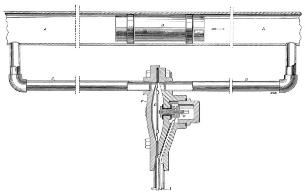
Fig. 32.
ELECTRO-PNEUMATIC CIRCUIT-CLOSER.
Larger image (153 kB)
—There is one piece
of mechanism used in connection with the sending apparatus that we
have yet to describe, and that is the circuit-closing device located
in the manholes in the street. Since the carriers travel at a high
rate of speed, they should not be made to operate any mechanism by
impact with fingers or levers protruding into the tube when it can be
avoided, even though the work to be done is so slight as the closing
of an electric circuit, for the repeated impacts cannot fail to work
injury to the carriers and the mechanism to be operated, no matter how
carefully they are designed. To avoid such impacts, we have designed
the electro-pneumatic circuit-closer, shown by the drawing in Fig. 32.
It is operated by a passing carrier, but pneumatically rather than
mechanically. In the figure we have a pneumatic tube, A, A, in which a
carrier, B, is moving in the direction indicated by the arrow. At two
points, about twenty or thirty feet apart, two small holes are tapped
into the tube and pipes, C and D, are screwed in. These pipes lead to
two chambers in a cast-iron box, F, separated by a diaphragm, E. This
diaphragm is insulated electrically from the box supporting it, and
is connected with the wire G. Just out of contact with the diaphragm
is an insulated screw, H, connected with the wire I. These wires lead
to the time-lock, already described, on the sending apparatus at the
station. When no carrier is passing, the air-pressure is the same on
both sides of the diaphragm, but when a carrier enters that part of the
tube between the two points where the pipes C and D are connected, the
equality of pressure on opposite sides of the diaphragm is destroyed.
There is always a slightly greater pressure in rear of the carrier than
in front of it, equal to the frictional resistance of the carrier in
the tube. It is this difference of pressure in front and in rear of
the carrier that moves it through the tube. When the carrier is in
the position shown in the figure, the same difference of pressure will
exist on opposite sides of the diaphragm, and it will be deflected into
contact with the screw H, thereby closing the electric circuit. When
the carrier has passed, equality of pressure on opposite sides of the
diaphragm is established and the diaphragm takes its normal position,
out of contact with the screw H. This apparatus is easily attached to
the tube, and it contains no mechanism to get out of order.
—Wherever the pressure in the tube is down
nearly to atmospheric, we can use an open receiver to discharge the
carriers from the tube. This is a receiver that opens the tube to
the atmosphere and allows the carrier to come out. Such a receiver
is used at the main post-office in the Philadelphia postal-line, and
was described in the last chapter. The present receiver is similar in
operation, but contains some improvements in details. Fig. 33 is a side
elevation of the apparatus, Fig. 34 is a longitudinal section, and
Fig. 35 is a cross-section through the cylinder and valve, showing the
sluice-gate.
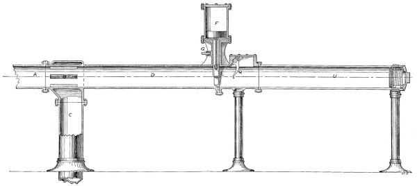
Fig. 34.
OPEN RECEIVER.—LONGITUDINAL SECTION.
Larger image (87 kB)
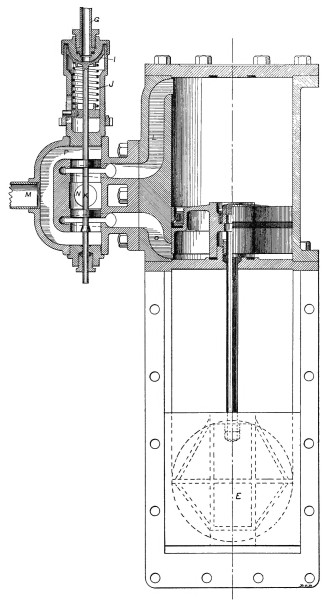
Fig. 35.
OPEN RECEIVER.—SLUICE-GATE MECHANISM.
Larger image (193 kB)
Referring to the longitudinal section, the apparatus is attached to
the end of a pneumatic tube, A. The current of air from the tube
A flows through the slots B into a pipe, C, that conducts it to a
tank near the air-compressor. About the centre of the apparatus is a
sluice-gate, E, that is raised and lowered by a piston in a vertical
cylinder, F, located just above the sluice-gate. This piston is moved
by air-pressure taken from some part of the system. When a carrier
arrives from the tube A, it passes over the slots B and runs into the
air-cushion D, where it comes gradually to rest. Checking the
momentum of the carrier compresses the air in front of it considerably,
and this excess of pressure is utilized to move a small slide-valve
that controls the movement of the piston in the cylinder F, so that as
soon as the carrier has come to rest the sluice-gate rises and allows
the carrier to be pushed out with a low velocity on to a table. The
small pipe G conducts a small portion of the air compressed in front
of the retarded carrier to the controlling valve, H, seen in Figs. 33
and 35. Referring now to the section of the valve and cylinder, Fig.
35, the pipe G enters the top of a small valve-cylinder containing a
hemispherical piston, I, that is held up by a spiral spring, J. This
spring has just sufficient tension to hold the piston I up against
the normal pressure of air in the tube. When a carrier arrives
and compresses the air in the air-cushion, the excess of pressure
forces the piston I down against the spring J, and moves the piston
slide-valve K. This change of position of the slide-valve allows the
air in the cylinder F to escape to the atmosphere through the passage
L, passage P, and pipe M, while compressed air from some part of the
main tube enters through the port N and passage O to the under side of
the piston in the cylinder F. This moves the piston up, carrying with
it the sluice-gate E.
There is just sufficient pressure in the tube in rear of the carrier
to push the carrier past the gate and on to the table. As the carrier
moves out it raises a finger, Q, Fig. 34, that projects into its
path. Raising this finger extends the spring R, Fig. 33, and rotates
the lever S, bringing the pawl T under the end of the controlling
valve-stem. When the carrier has passed out and the finger Q is free
to descend, the spring R rotates the lever S back to its original
position, and thereby raises the controlling slide-valve, which causes
the sluice-gate to close. By having the upward motion of the finger Q
simply extend the spring R, and the downward motion, by the force of
the spring, move the valve, we are enabled to have several carriers
pass out of the tube together without having the sluice-gate close
until the last carrier has passed out. If raising the finger Q moved
the valve, then when the first carrier passed out, the gate would close
down upon the second. Attached to the receiving apparatus and extending
beyond it is a tube, U, cut away upon one side so that the carriers can
roll out of it on to a table, and having in the end a buffer to stop
the carriers if by any accident they come out of the tube with too much
speed. This buffer consists of a piston covered with several layers
of leather and having a stiff spring behind it. The whole apparatus
is supported from the floor upon suitable standards, and, for an
eight-inch tube, occupies a floor-space twelve feet long by two feet
wide, not including the table.
This is the simplest form of receiving apparatus. Owing to conditions
of pressure already explained, its use is confined principally to the
pumping stations. The only care that it requires is an occasional
cleaning and oiling.
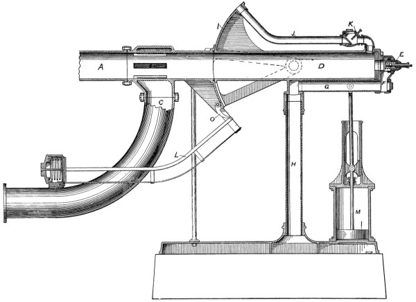
Fig. 37.
CLOSED RECEIVER.—LONGITUDINAL SECTION.
Larger image (196 kB)
—Next we will turn our attention to
the closed receiving apparatus used at all terminal stations where
the pressure in the tube is considerably above the pressure of the
atmosphere, so much so that the tube cannot be opened to allow the
carrier to pass out without an annoying blast of air and a high
velocity of the carrier. This apparatus is similar to the receiver used
in the sub-post-office of the Philadelphia postal line, but contains
several modifications and improvements tending towards simplification.
Fig. 36 shows it in elevation, and Fig. 37 in longitudinal section.
As in the open receiver just described, the air from the tube A is
deflected through slots B into a branch pipe, C, that conducts it from
the receiving apparatus to the sending apparatus and return tube. The
carriers arrive from the tube A, pass over the slots B, where the air
makes its exit, and run into an air-cushion, D. This air-cushion is
a tube about twice the length of the carrier, closed at one end, and
supported upon trunnions. When the carrier has been brought to rest,
this closed section of tube is tilted by the movement of a piston in
a cylinder to an angle that allows the carrier to slide out; the tube
then returns to its original position. If the end of the air-cushion
was closed perfectly tight the carrier, after coming to rest, would
rebound and might be caught in the joint between the stationary and
movable parts of the apparatus, when the air-cushion tube tilted. To
prevent the rebounding of the carrier a relief-valve, E, has been
placed in the head of the air-cushion tube. It is held closed against
the normal pressure in the tube by a spiral spring, but the excessive
pressure created by checking the momentum of the carrier opens the
valve and allows a little air to escape through the passage F and
pipe G, down the pedestal H, to the atmosphere. When the air-cushion
or receiving tube D is tilted to discharge a carrier, the circular
plate I covers the end of the main tube. In order to prevent carriers
sticking in the receiving tube when it is tilted, and to insure their
prompt discharge, the pipe J is provided. In the tilted position of
the receiving tube, the end of this pipe coincides with the end of the
main tube, from which it receives air to hasten the discharge of the
carrier. A check-valve, K, prevents the air from flowing backward in
this pipe when a carrier is being received in the air-cushion chamber.
The opening of this check-valve can be adjusted by a screw, thereby
regulating the speed of ejection of the carrier.
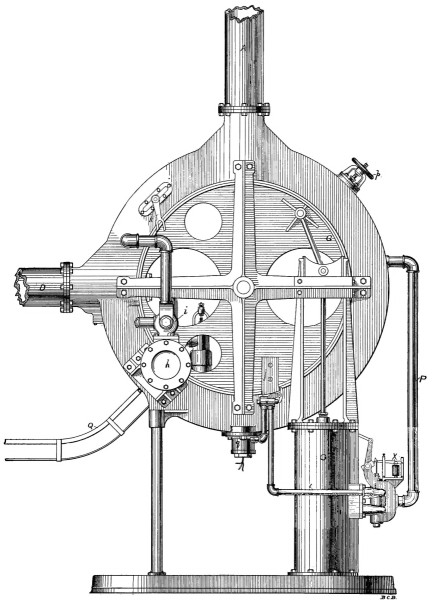
Fig. 38.
INTERMEDIATE STATION RECEIVING AND TRANSFER APPARATUS.
Larger image (292 kB)
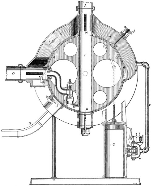
Fig. 39.
INTERMEDIATE STATION RECEIVING AND TRANSFER APPARATUS.—VERTICAL
SECTION.
Larger image (326 kB)
The carrier is discharged down a chute, L, which has a buffer at the
bottom, and from the chute it rolls off on to a table. The buffer is
made similar to the buffer in the open receiver already described.
The cylinder and piston M, that operate to tilt the receiving tube D,
are supported upon the base of the apparatus under the closed end of
the receiving tube. The cross-head of the piston- and connecting-rods
travels between guides that are made a part of the upper cylinder
head. The movement of the piston in the cylinder M is controlled by
a piston slide-valve exactly similar to the one shown in Fig. 35.
The slide-valve is moved, in the same manner, by the air compressed
ahead of the carrier when it is brought to rest in the air-cushion
D. The air is conducted from the air-cushion to the controlling
slide-valve through a small pipe, N, Fig. 36. This pipe leads to one
of the trunnions, where it has a joint to allow for the tilting of
the receiving tube. When the carrier is discharged from the receiving
tube, it raises a finger, O, Fig. 37, located just outside the tube.
Raising this finger pulls the rod P, Fig. 36, extends the spring
Q, turns the lever R, and catches the pawl S, under the end of the
controlling valve stem. When the carrier has passed down the chute and
allowed the finger O to drop down, the spring Q turns the lever R back
to its original position and moves the controlling valve. This causes
the receiving tube to return to a horizontal position, where it is
ready to receive the next carrier.
At first this apparatus may seem a little cumbersome, but nothing could
work better. It is certain in its action and almost noiseless. Carriers
are received, discharged, and the receiving tube returned to its normal
position in four seconds, and it can be done in less time if necessary.
—One
other form of receiving apparatus remains to be described, and this is
the apparatus used at intermediate stations to intercept all carriers
intended for that station and to send the others on through the tube
to the next station. A side elevation of the apparatus is shown in
Fig. 38 and a vertical section in Fig. 39. The tubes are led into an
intermediate station, carried upward, and then, with a bend of one
hundred and eighty degrees, are connected to the top of the receiving
and transfer apparatus, as shown in the diagram, Fig. 26. The object of
this arrangement will be seen as we describe the apparatus. Referring
to the sectional drawing, Fig. 39, the connection of the tube A is seen
at the top. As in the other receivers, the current of air arriving
from the tube A is deflected through slots, B, into a passage, C, made
in the frame of the apparatus. From this passage it enters the tube D
through the slots E. The tube D leads to the sending apparatus and
on to the next station, as seen in Fig. 26. The carriers are received
in a closed section of tube F, which forms an air-cushion, similar to
the closed receiver last described. This receiving tube F is made a
part of what we might term a wheel. This wheel fits accurately into a
circular casing and is supported by two trunnions or axles, upon which
it revolves. The wheel has a broad flat rim, G, that covers the end of
the tube at H when the wheel is revolved, and, in the normal position
in which it is shown in the figure, covers the interior openings I, J,
K, and L, in the casing. Leather packing is provided around each of the
openings to prevent the escape of air between the face of the wheel
and the interior face of the casing. From the bottom of the receiving
tube F a passage, M, leads past a check-valve, N, to the tube D. When
a carrier arrives from the tube A, it descends into the receiving tube
F, compressing the air in front of it. This compressed air begins to
escape through the passage M, but the high velocity of it closes the
check-valve N as much as possible. A stop on the stem of the valve
prevents it being closed entirely. The small opening past the valve
allows some of the air to pass, thereby preventing the carrier from
rebounding on the air-cushion. As soon as the carrier has come to rest,
the check-valve N, by its own weight, opens wide, and the carrier, by
its weight, settles gradually down to the bottom of the receiving tube.
The wheel containing the receiving tube and the carrier will then be
revolved by the cylinder and piston O, which is operated by compressed
air taken from the tube through the pipe P. If the carrier is for this
station, the wheel will rotate through an angle of forty-five degrees
and discharge the carrier through the opening J, down the chute Q, from
which it will roll on to a table arranged to receive it. If, however,
the carrier is intended for some other station, the wheel will rotate
through an angle of ninety degrees and discharge the carrier through
the opening K into the tube D, and it will go on its way to the next
station. This selection of carriers is brought about in a comparatively
simple manner. At the bottom of the receiving tube F there are two
vertical needles, R and S, shown upon a larger scale in Fig. 40. The
needles R and S are contained in tubes having an insulating lining
which keeps them out of electrical contact with the frame of the
apparatus. Wires a and b make connection with the needles through
metal plugs that form a guide for the needles, and through the springs
U and V. Directly below the needle R is an insulated spring clip, W,
held by two bolts and connected to the wire e.
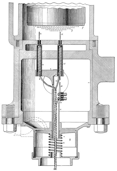
Fig. 40.
A DETAIL OF THE INTERMEDIATE STATION RECEIVING AND TRANSFER
APPARATUS.
Larger image (360 kB)
The end of a carrier is represented at T. As the carrier settles down
to the bottom of the receiving tube, it comes in contact with the
ends of the needles and presses them down, they being supported by
two springs U and V. As the needle R is moved down, it makes contact
with the spring clip W, located just below it, and closes an electric
circuit that includes the electro-magnet X, Figs. 38 and 39, on the
valve of the rotating cylinder O. When this electro-magnet is excited
it attracts its armature and moves the piston slide-valve Y, that
admits air to the top of the piston in the cylinder O, and allows the
air under the piston to escape to the atmosphere. The piston moves
downward and revolves the wheel by means of a connecting rod.
Upon the end of the carrier T is placed a thin circular metal disk,
f, which may be copper, brass, tin-plate or any metal that is not
easily oxidized. The diameter of this disk of metal determines the
station at which the carrier will be discharged from the tube. Disks of
various diameters, that may be attached to the carrier, are represented
by dashed lines, g, in Fig. 40. When the carrier comes in contact
with the two needles R and S, if the circular metal disk on the front
end of the carrier has a diameter sufficient to span the space between
the two needles, in the position in which it is held, then an electric
circuit, made by the wires a and b, will be closed through the
needles and the metal disk on the carrier. The metal disk makes a
short-circuit from one needle to the other. If the metal disk is not
large enough to span the distance between the two needles, then the
electric circuit remains broken.
Returning again to Fig. 39, we have the opening J, where the carriers
are discharged, closed by a sluice-gate. This gate is opened and
closed by a piston moving in a cylinder, h, shown in Fig. 38. A
piston slide-valve, i, similar in all respects to the valve on the
cylinder O, controls the movement of the piston in this cylinder and
the sluice-gate to which it is attached. The slide-valve is moved in
one direction, that opens the sluice-gate, by an electro-magnet in the
circuit of the wires a and b, Fig. 40.
When the electric circuit made by these wires is closed by a disk
on the front end of a carrier, short-circuiting the two needles,
the valve is moved by the electro-magnet in the circuit, and the
sluice-gate is opened. As the wheel, including the receiving tube and
carrier, revolves, a lug, j, Fig. 38, on the outside of the wheel
comes in contact with the open sluice-gate and the wheel can rotate
no farther. A blast of air through the valve L, Fig. 39, assisted by
gravity, pushes the carrier out of the receiving tube, through the
opening J and down the chute Q, on to the receiving table.
Had the disk on the front end of the carrier been too small to span
the distance between the two needles, the circuit would not have been
closed, the sluice-gate would not have been opened, no obstruction
would have been placed in the path of the lug j, on the wheel, and
the wheel would have continued its rotation through ninety degrees
until the receiving tube F came in line with the tube D. During the
latter part of the rotation, a pin on the wheel engages a lever, k,
Fig. 38, and turns a valve, l, Fig. 39, stopping the flow of air
through the passage C, compelling it to take another route through
the passage m, and the receiving tube F, taking with it the carrier
into the tube D. When the carrier leaves the receiving tube and passes
through either of the openings J or K, it engages one of the fingers,
n or o, that lie in its path. These fingers are connected by rods
and levers to the valves on the rotating and sluice-gate cylinders.
The ejected carrier pushes these fingers to one side, and after it has
passed the fingers return, by the force of a spring, to their former
position and move the valves, causing the sluice-gate to close and the
wheel to rotate backward into its normal position ready to receive
the next carrier. The connection between the fingers and the valves is
similar to the mechanism on the open and closed receivers, so need not
be described in detail here.
The speed with which the carriers are ejected from the receiving tube
through the opening J and down the chute Q is regulated by the valve
L, which can be opened or closed by a hand-wheel, p. Before the
wheel and receiving tube can be rotated, the needles must be withdrawn
from the receiving tube, and this is accomplished by a small cylinder
and piston, q, shown in Fig. 40. The needles and their encasement
are attached to a cross-head, r, on the end of a hollow piston-rod,
s. When air is admitted to the top of the piston in the rotating
cylinder O, Fig. 39, it is also admitted through the pipe t, Fig.
38, to the cylinder and upper side of the piston q, Fig. 40. This
moves the piston q down against the force of a spring, u, and
withdraws the needles from the receiving tube. This takes place after
the needles have served their purpose and before the wheel is rotated.
The piston q has much less inertia than the wheel, therefore it
moves much quicker. When the wheel begins to rotate it closes a valve,
v, in the pipe t, Fig. 38, confining the air in the cylinder q,
and preventing the needles from being raised by the spring u before
the wheel returns to its normal position. If by any accident the
needles should be raised, no serious harm would result, for their ends
would simply bear against the face of the wheel. If this took place
constantly, grooves might be worn in the face of the wheel; for this
reason the valve v is provided.
In order to facilitate the inspection of the needles and electric
contact springs W, they are contained in a cylindrical brass case,
w, that is held in place beneath the receiving tube by two bolts. By
removing the nuts from these bolts the entire mechanism can be removed,
examined, and cleaned. It also gives easy access to the receiving tube.
The receiving tube is long enough to receive two carriers, if it should
ever happen that two arrive at the same time.
Fig. 41.
DIAGRAM OF CONTACT-DISKS AND NEEDLES.
Larger image (101 kB)
To show how the apparatus at the various stations is arranged to
correspond with the disks of various sizes attached to the front of the
carriers, a diagram, Fig. 41, has been made, in which the needles at
the bottom of the receiving tubes of the apparatus at six intermediate
stations are represented at A, B, C, D, E, and F. Six disks of
different sizes are represented at a, b, c, d, e, and f.
The needles are placed farthest apart at station A and nearer together
at each succeeding station until we arrive at station F, where they
are nearest together. If we wish to send a carrier to station A from
the central, we place the largest disk, a, upon the front end of it.
When it arrives at station A, it closes the electric circuit between
the needles and is discharged from the tube. Should we wish to send a
carrier to station D, then we place the disk d upon the front end of
it. When the carrier arrives at the station A, the disk is not large
enough to span the needles; therefore the sluice-gate is not opened
and the carrier is sent on in the tube. When it arrives at stations
B and C, the same thing occurs again, but when it reaches station D,
the needles are sufficiently close together so that the disk makes an
electric circuit between them, and the carrier is discharged from the
tube, as was intended when despatched. Since the carriers always travel
in the same direction in a tube, the first station at which they arrive
where the needles are near enough together to have both touch the disk,
will be the station at which the carrier was intended to stop. Carriers
can be despatched from any station, but if we wish to send from say D
to A, they must either travel around a loop or be sent through a return
tube in which the needles are arranged in the reverse order. If no disk
is placed on the carrier, it will go to the last station on the line.
There are other attachments that might be made to the front end of
the carriers in order to have them stop at any desired station along
a line. We have worked out two other systems which are entirely
mechanical in their operation, not using electric circuits and
electro-magnets to move the valves. While such a mechanical system has
some advantages over the present combined mechanical and electrical
system, yet there is one great advantage in the latter, and that is the
simplicity of the attachment made to the carrier. A round flat disk of
tin-plate is attached to the front end; it is something that is not
in the way; it does not prevent standing the carriers on end in racks
to fill them; it is not easily injured, and only those who have had
experience can realize the rough usage that the carriers receive; it
is quickly and easily attached to the carrier, and it is so cheap that
when bent it can be thrown away.
—The carriers are similar in all respects to those
used in the Philadelphia postal-line, that have been described in the
preceding chapter and illustrated in Figs. 18, 19, and 20. When there
are intermediate stations upon the lines, means are provided for
attaching disks to the front end of the carriers. The disks have a
central stem that secures them to the bolt in the centre of the head,
and are so arranged that they can be quickly attached or removed.
Many experiments have been made to find the best material for
bearing-rings, but thus far nothing better than a specially-prepared
woven fabric has been found. These rings will run about a thousand
miles, when they become so reduced in diameter that they have to be
replaced by new ones.
The most essential elements of a carrier are strength, lightness, and
security of the contents. Aluminum has frequently been proposed as a
suitable material for the bodies of carriers, but for the same weight
steel is much stronger, especially in thin rolled sheets, and for this
reason it has been used.
One of the most perplexing problems that presented itself in working
out the details of the system was to design a secure and reliable lock
for the lids of the carriers. We believe that the one which has been
adopted fulfils all requirements in a satisfactory manner.
Some experiments have been made with carriers that open on the side,
but structurally they are weak and unsuited to stand the blows that
carriers frequently receive. They are not so easily and quickly filled
and emptied as those that open on the end. These remarks apply to
carriers for large tubes. In small tubes for the transportation of cash
in retail stores, carriers with side openings are found convenient.
When United States mail is sent through tubes not used exclusively for
postal service, carriers with special locks can be used, so that they
can be opened only by post-office employees.
—This completes the description of the special
apparatus used in this system, but we have yet to say something
regarding the machines that supply the air. In Paris the water from the
city mains has been used to compress or exhaust the air used in small
tubes, but to operate large tubes in most of our cities steam is the
only available power. Except in isolated cases, an independent steam
plant will be erected to supply the air for a system of tubes. This
plant should be designed with a view to obtaining the maximum economy
in coal consumption, labor, water, cartage, and incidental expenses.
We might say that the same general rules of economy which govern the
design and construction of electric-lighting plants should be applied
to the plans and construction of air-compressing plants.
Three types of blowing machines are used,—viz., centrifugal fans,
positive blowers, and air-compressors.
—Very large tubes of moderate length can be operated by
ordinary centrifugal fans. These fans are capable of supplying air
under a pressure not exceeding ten or twelve ounces per square inch
with very good efficiency. They are the simplest and most inexpensive
of all blowing-machines.
—When tubes have a length and diameter that require a
pressure from one to four pounds per square inch, some form of positive
blower of the Root type can be used with economy. Their construction
is familiar to nearly every one at all interested in machinery, so we
need give no space to their description here.
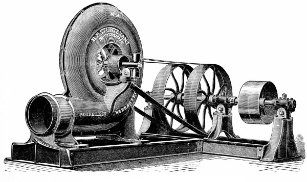
Fig. 42.
THE STURTEVANT STEEL PRESSURE BLOWER.
Larger image (324 kB)
Fig. 43.
ROOT’S POSITIVE PRESSURE BLOWER.
Fig. 44.
SECTION OF ROOT’S TRUE CIRCLE BLOWER.
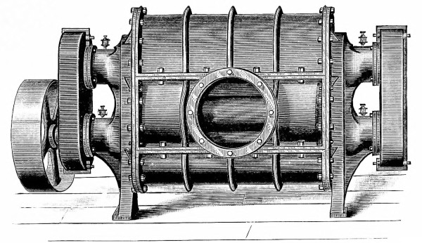
Fig. 45.
THE GREEN BLOWER.
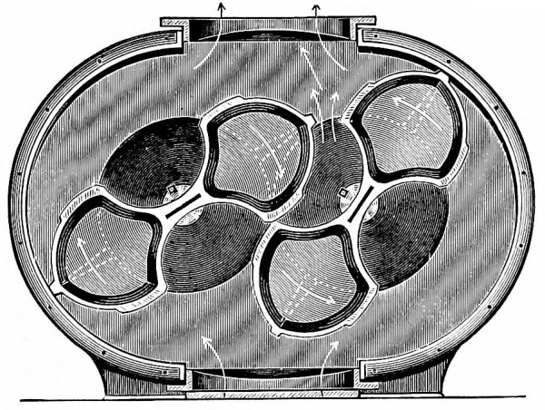
Fig. 46.
SECTION OF THE GREEN BLOWER.
—By far the greater number of our tubes require
an air-pressure of more than five pounds per square inch. For such
air supply we recommend some form of air-compressor, and usually this
is driven by a steam-engine, which forms a part of the compressor.
In making our selection we should bear in mind the conditions under
which the compressor will run. Usually it must be kept in constant
operation at least ten hours per day, and frequently for a much longer
period. This makes it important that the compressor be substantially
built and supported upon a solid and firm foundation. The bearings
should be broad, of good wearing material that has a low coefficient of
friction, and provided at all times with ample lubrication. If poppet
valves are used in the air-cylinders, and they are most common, the
speed in revolutions per minute should not be high. Duplex are better
than single cylinder compressors, because they deliver the air in a
more steady stream,—the pulsations are less. For constant running,
economy of steam is an important item; therefore some good type of
cut-off valve should be provided. The air-cylinders should not be
water-jacketed unless the pressure is above twenty-five pounds per
square inch. It is better to use the air as warm as possible, for it
will soon be cooled after entering the tube. A speed-governor should
be provided with compressors which are to run at constant speed, but
usually they will be run to maintain a constant pressure in the tank,
and to this end a good and reliable form of pressure-governor should
be provided, together with some reliable safety device to stop the
engine when the speed exceeds a safe limit. But most important of all
is to have the valves of the air-cylinders large in area; otherwise
the efficiency of the machine will be very low. With machines working
under eighty pounds pressure, a difference in pressure of one pound
on opposite sides of the valves has but little effect, but when
the machine is only compressing to five or ten pounds, one pound
is a very large proportion of the total pressure and reduces the
efficiency. Besides these few suggestions, only the requirements of
good engineering need be demanded. In Figs. 42, 43, 44, 45, 46, and
47 we show a fan, two blowers, and an air-compressor suited to the
requirements of pneumatic-tube service that can be found in the market,
and that are built by responsible concerns. We believe they are all
good of their kind, but do not recommend any particular make.
—Up to the present time
we have found no material better suited for the straight parts of
pneumatic tubes than cast iron, machined upon the interior. It gives a
smooth and accurate tube. It can be made in most convenient lengths. It
is strong and not easily deformed. The bell-joint, calked with lead and
oakum, having the tubes fitted together male and female at the bottom
of the bell, is the best joint yet devised for pneumatic tubes. It is
slightly yielding, accommodating itself to slight changes of length
of tube due to changes of temperature, and it allows slight bends
to be made at each joint. The joints are very accurate, presenting
no shoulders to obstruct the passage of carriers. The joints can be
made by men accustomed to laying water- and gas-pipe. The cast iron
is so stiff that it is not distorted in calking, as may be done with
wrought-iron tube. The principal objections to its use are the expense
of boring and the readiness with which it corrodes upon the interior.
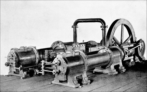
Fig. 47.
RAND COMPOUND COMPRESSOR OF MODERATE SIZE.
Larger image (570 kB)
We are always hoping that wrought-iron or steel tubes will be so much
improved in uniformity of dimensions and smoothness of interior that we
can use them, but our experiments thus far have been discouraging. It
may be that some of the new processes of making tubes will give us
what we want, but we have not yet found it.
Small tubes and the short bends of large tubes are made of brass, it
being the most suitable material. It would be very difficult to bend
iron tubes without involving great expense. The thickness of the bent
portion of an eight-inch tube is usually three-sixteenths of an inch
and never less than one-eighth of an inch.
Where the ground is firm, no other support is needed for the tubes
than to tamp the earth solidly about them. In order to economize space
in the streets, it is customary to lay the tubes one above the other;
and it is very convenient, although not necessary, to separate them by
cast-iron saddle brackets. Such an arrangement has to be frequently
departed from in order to overcome obstructions in the streets and to
get through narrow passages. At all low points in a tube line, traps
are provided to catch any moisture that may accumulate. These traps
are made accessible for frequent inspection by means of man-holes
or otherwise. The tube is usually laid about three feet below the
pavement. This distance has frequently to be varied, but it never
becomes so small as to render the tubes liable to injury from heavy
trucks passing over the pavement.
We will now discuss, in an elementary way, the theory of pneumatic
tubes, in order to understand more clearly their modus operandi and
the principles upon which they should be constructed. Let us begin with
the definition of a pneumatic tube.
—A pneumatic tube is a tube containing air. This
is perhaps the broadest and most comprehensive definition that can
be given, but we usually associate with the idea of a pneumatic tube
the use to which it is put. If we were to embody this idea in our
definition we might define a pneumatic tube as a tube through which
material is sent by means of a current of air. This is still a very
broad definition, including all kinds of material for transportation,
for every conceivable purpose. It places no limit upon the dimensions
of the tube nor the manner of its operation. This definition would
include the toy commonly known as a putty-blower, and the pneumatic gun.
These instruments are not usually pictured in our minds when we hear
or see the term pneumatic tube used. Instead of these, we think of
the brass tubes that we have seen in the large retail stores in some
of our cities for conveying cash from the various counters to the
centrally located cashier’s desk. Again narrowing our definition to
conform more nearly with the mental picture presented, we will define a
pneumatic tube as a long tube for the purpose of transporting material
in carriers by means of a current of air in the tube. This, like all
definitions, is not entirely satisfactory, if we examine it critically,
but it will answer our present purpose.
—Having thus defined
a pneumatic tube, there are two ways in which we may operate it to
transport our carriers containing mail, packages, or other matter. The
first method consists in storing our compressed air in a suitable tank,
or by exhausting the air from the tank; then, when we wish to despatch
a carrier we place it in the tube and connect the tube with the tank by
opening a valve. As soon as the carrier arrives at the distant end of
the tube the valve is closed and the air soon ceases to flow. When a
long interval of time elapses between the despatching of carriers, this
is the most economical method of operation, but usually carriers have
to be despatched so frequently that a great deal of time would be lost
if the air-current had to be started and stopped for each carrier.
The second and more usual method of operation consists in maintaining a
constant current of air in the tube and in having the carriers inserted
and ejected at the ends of the tube without stopping the current of air
for any appreciable length of time. It is analogous to launching boats
in a rapidly flowing stream, allowing them to float down stream and
then withdrawing them. When the boats are in the stream they present
little obstruction to the flow of water and check its speed but very
little. In order to compute the speed with which the boat will pass
from one point to another, we only have to know the speed of the stream
between those points when no boat is in it. The presence of the boat
does not change the speed appreciably. So it is with carriers in a
pneumatic tube: they are carried along with the current of air. The air
flows nearly as rapidly when a carrier is in the tube as when there
is none. The friction of the carrier against the inner surface of the
tube creates a slight drag, but it checks the speed of the air only a
little. Therefore, in order to know the speed with which a carrier will
be transported from one station to another through a pneumatic tube,
we need only to know the velocity with which the air flows through the
tube when no carrier is present. Of course there are special cases of
heavy carriers, or carriers having a large amount of friction from
their packing, or of tubes not laid horizontally, where the resistance
of the carrier must be taken into consideration, but for our present
purpose we will neglect all of these conditions.
—This leads us
to study the laws governing the flow of air in long tubes, omitting
for the present the presence of a carrier. Since tubes operated
intermittently have become obsolete, we will only consider the case
of a constant current of air, this being what we have to deal with in
practice.
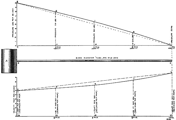
Fig. 48.
PRESSURE AND VELOCITY CURVES.
Larger image (152 kB)
In order to make our ideas and thoughts as clear as possible let us
represent them by a diagram, Fig. 48. We will suppose that a tank, A,
is kept constantly filled with compressed air at a pressure of ten
pounds per square inch, from some source of supply. We will suppose
that the pressure of the air in this tank never changes, air being
supplied as fast as it flows away. Next, let us assume that a tube
eight inches in diameter inside and one mile long (five thousand two
hundred and eighty feet) is connected to the tank at one end and left
open to the atmosphere at the other. The air will flow in a constant
stream from the tank into the atmosphere, for the reason that air is
being supplied to the tank as fast as it flows away.
—First, let us consider the pressure of the
air at various points in the tube. We will, for convenience, represent
the pressure in the tank by a vertical line, D E, ten units in length,
since the pressure is ten pounds per square inch. Now let us go to a
point on the tube one quarter of a mile (one thousand three hundred
and twenty feet) from the tank, drill a hole in the tube, attach a
pressure-gauge and measure the pressure of the air at this point.
We shall find it to be about 7.91 pounds per square inch; or, 2.09
pounds below the pressure in the tank. We will represent this on our
diagram by another vertical line, F G, having a length of 7.91 units.
Again let us measure the pressure in the tube at a point one-half a
mile (two thousand six hundred and forty feet) from the tank. Here we
find it to be about 5.61 pounds per square inch, and we represent it
by the vertical line, H I, having 5.61 units of length. We note that
the pressure is 4.39 pounds below the pressure in the tank. We are at
the middle point of the tube and the pressure has fallen to nearly,
but not quite, one-half the pressure in the tank. We will now go to
a point three-quarters of a mile (three thousand nine hundred and
sixty feet) from the tank, and here the pressure is about 3.01 pounds
per square inch. We represent it by the vertical line, J K. Lastly,
we measure the pressure very near the end of the tube, one mile from
the tank, and find it to be about zero, or the same as the pressure of
the atmosphere. All of our measurements have been in pounds above the
atmospheric pressure; to express them in absolute pressure, we should
add to each the pressure of the atmosphere, which is 14.69 pounds,
nearly.
Now we will draw a smooth curve through the tops of all our vertical
lines, and we have a curve, E, G, I, K, L, representing the pressure in
the tube at every point. It falls gradually from ten pounds to zero,
but it does not fall in exact proportion to the distance from the tank.
Such a fall of pressure would be represented by the straight dash-line,
E, L. The reason why the true pressure-curve is not a straight line,
and lies above a straight line, is because air is an elastic fluid and
expands, becoming larger in volume as the pressure diminishes. The
straight dash-line represents the fall of pressure of an inelastic
fluid, like water, when flowing in the tube.
The fall of pressure along the tube is analogous to the fall of level
along a flowing stream. In fact, we frequently speak of the descent of
a stream as the “head of water” when it is used for power purposes,
and we mean by this the pressure the water would exert if it were
confined in a pipe. The descent, or change of level, in the bed of a
stream is necessary to keep the water flowing against the friction of
the banks. The descent of the water imparts energy to overcome the
friction. In a similar manner, we must have a fall of pressure along
the pneumatic tube to overcome the friction of the air against the
interior surface of the tube. We find another analogue in the flow of
the electric current along a wire; here there is a fall of potential
necessary to overcome the resistance of the wire. Since power has to be
expended to compress the air and impart to it its pressure, when this
pressure disappears we know that the air must be losing its energy or
doing work, and we look to see what becomes of it. In the present case,
we find that most of this work is expended in overcoming the friction
between the air and the surface of the tube.
—The pressure curve teaches us many
things. Suppose we were to establish stations on this tube at the
quarter, half, three-quarter, and mile points; we see at once that
intermediate-station or closed receivers, described in the last
chapter, must be used at all of the stations except the mile point at
the end of the tube, because the pressure in the tube is so high above
the pressure of the atmosphere that we could not open the tube to let
the carriers come out, but at the end of the tube we could use the open
receiver. In designing our sending and receiving apparatus for each
station, we look to this pressure curve to tell us the pressure which
we shall have on the pistons in our cylinders, and are thereby enabled
to make them with proper proportions for the work that they have to do.
—Next let us see what the velocity of the air
is in the tube. Suppose that we have some convenient means of measuring
the velocity of the air at any point, in feet per second or miles
per hour, with some form of anemometer. We will have our measurements
taken at the five points where we measured the pressure,—viz., at
the tank, one-quarter, one-half, three-quarters and one mile from the
tank. We will represent the velocities by a diagram similar to the
one used for pressures. At the tank we find the air entering the tube
with a velocity of 59.5 feet per second (40.6 miles per hour). We draw
the vertical line M N, to represent this. At the quarter mile point
the velocity is sixty-five feet per second (44.4 miles per hour) an
increase in the first quarter of a mile of 5.5 feet per second. We
construct the vertical line O P. At the half-mile point the velocity is
72.4 feet per second (49.4 miles per hour); at the three-quarter mile
point it is eighty-three feet per second (56.8 miles per hour); and at
the end of the tube, one mile from the tank, the air comes out of the
tube with a velocity of 100.4 feet per second (68.5 miles per hour),
about 1.7 times faster than it entered the tube at the tank. Drawing
all the vertical lines to represent these velocities, and drawing a
smooth curve line through the tops of our vertical lines, we have the
curve of velocities, N, P, R, T, V, for all points along the tube. It
is an increasing velocity and increases more rapidly as we approach the
end of the tube. This is shown more clearly by drawing the straight
dashed line N V.
If the fluid flowing in the tube were inelastic, like water, then the
curve of velocities would be a straight horizontal line, for the water
would not come out of the tube any faster than it went in. But we are
dealing with air, which is an elastic fluid, and, as we stated before,
it expands as the pressure is reduced and becomes larger in volume.
It is this expansion that increases its velocity as it flows along the
tube. It must go faster and faster to make room to expand. Since the
same actual quantity of air in pounds must come out of the tube each
minute as enters the tube at the other end in the same time, to prevent
an accumulation of air in the tube, and since it increases in volume as
it flows through the tube, it follows that its velocity must increase.
—This velocity curve is
both interesting and surprising, if we have not given the subject any
previous thought. It might occur to us that the air expands in volume
in the tube, and we might reason from this fact that the velocity of
the air would increase as it flowed through the tube, but very few of
us would be able to see that the rate of increase of velocity also
increases. That is to say, it gains in velocity more rapidly as it
approaches the open end of the tube. If the velocity were represented
on the diagram by a straight horizontal line, we should know that it
was constant in all parts of the tube, which would be the case if water
were flowing instead of air. If it were represented by a straight
inclined line, like the dashed line N V, then we should know that
the velocity increased as the air flowed along the tube, but that it
increased at a uniform rate. The slope of the line would indicate the
rate of increase. Neither of these suppositions represent correctly
the velocity of the air at all points in the tube; this can only be
done by a curved line such as we have shown. The slope of the curve at
any point represents the rate of increase of velocity of the air at
that point. If the curve is nearly horizontal, then we know that the
velocity does not increase much; but if the curve is steep, then we
know that it is increasing rapidly, the actual velocity being indicated
by the vertical height of the curve above the horizontal line M U.
—Besides being interesting, a knowledge
of the velocity of the air at all points in a tube is of much practical
value. It gives us the time a carrier will take in going from one
station to another. Usually the first questions asked, when it is
proposed to lay a pneumatic tube from station A to station B, are,
How quickly can you send a carrier between these points? How much
time can be saved? These questions are answered by constructing a
velocity curve. Since the velocity changes at every point along a
tube, to get the time of transit between two points we must know the
average velocity of the air between those points. We can find this
approximately from our curve by measuring the height of the curve
above the horizontal line M U at a large number of points, and then
taking the average of all these heights; but there is a more exact
and easier method by means of a mathematical formula. As such formula
would be out of place here, we will not give it; suffice it to say,
that the average velocity of the air between the tank and the end of
the tube, in the case we have assumed, is about seventy-three feet per
second (49.7 miles per hour), a little less than one-half the sum of
the velocities at the two ends, and a little more than the velocity
at the half-mile point. Knowing the average velocity, we can tell
how long it takes for a particle of air, and it will be nearly the
same for a carrier, to travel from the tank to the end of the tube,
by dividing the distance in feet by the average velocity in feet per
second. This we find to be one minute 12.3 seconds. Since the air moves
more rapidly as it approaches the open end of the tube, a carrier will
consume a greater period of time in going from the tank to the quarter
mile point than in going from the three-quarter mile point to the open
end. The last quarter of a mile will be covered in a little more than
fourteen seconds, while the first quarter will require a little more
than twenty-one seconds. This difference is surprising, and it becomes
even more marked in very long tubes with high initial pressures. This
explains why the service between stations located near the end of the
tube is more rapid than between stations on other parts of the line.
This velocity curve shows us the velocity of the carriers at each
station along the line and enables us to regulate our time-locks
and to locate the man-holes and circuit-closers connected with each
intermediate station. It gives us the length of the “blocks” in our
“block system.” When we know the velocity and weight of our carriers,
we can compute the energy stored up in them, and from this the length
we need to make our air-cushions so as not to have the air too highly
compressed. It would be impossible to design our apparatus properly if
we did not know the laws that govern the flow of air in the tubes.
—The next important fact that we learn
from the velocity curve is the quantity of air that flows through
the tube each second or minute. If we multiply the velocity with
which the air escapes from the open end of the tube by the area of
the end of the tube in square feet, we have the number of cubic feet
of air at atmospheric pressure discharged from the tube per unit of
time. The same quantity of air must be supplied to the tank in order
to maintain a constant flow in the tube. In the present case that we
have assumed, the tube is eight inches in diameter; therefore the
cross-sectional area is 0.349 square foot. The velocity of the air as
it comes out of the end of the tube is 100.4 feet per second; therefore
about thirty-five cubic feet of air are discharged from the tube each
second, or two thousand one hundred cubic feet per minute. This same
amount must be supplied to the tank A in order to maintain the pressure
constant, but when it is compressed so that it exerts a pressure of
ten pounds per square inch, the two thousand one hundred cubic feet
will only occupy a space of one thousand two hundred and fifty cubic
feet, if its temperature does not change. This leads us to consider the
effect of temperature changes.
—If the air is allowed to become heated
by compression, as is the case in practice, we have a new set of
conditions. If the air in the tank A is hot,—that is, warmer than the
surrounding atmosphere,—it will by radiation cool somewhat before it
enters the tube, and it will be still further cooled when it expands
in the tube. Again, if its temperature falls below the temperature of
the ground in which the tube is laid, it will absorb heat from the
ground, and this will tend to keep up its temperature; so in practice
we have very complicated relations between the temperature, pressure,
and volume of the air. These relations cannot be exactly expressed by
mathematical formulæ, and we will make no attempt so to express them,
but will be content with saying that in practice we find that the
temperature of the air in the tubes is nearly constant after the first
few hundred feet, so that we can without appreciable error compute the
pressures and velocities as if it were constant. Now, if the air in the
tank A is hot, we must raise the pressure a little above ten pounds
per square inch to obtain the velocities given on our diagram. When
the air cools it contracts in volume, or, if the volume cannot change,
being fixed by the limits of the containing vessel, then the pressure
is reduced, so by raising the pressure in the tank A a little above ten
pounds, we compensate the loss of pressure.
—Having shown how the quantity of air can be
computed we are now in a position to estimate the horse-power of
the air-compressor necessary to operate the tube. I say estimate,
because we have to take into consideration the efficiency of the
air-compressor, and that is not an absolutely fixed quantity: it varies
with different types of machines and with their construction. When
working with pressures of less than ten pounds, the friction of the
machine is an important factor. The area and construction of the valves
in the air-cylinders is another very important factor. If the valves
are not large enough or do not open promptly, our cylinders will not
be filled with air at each stroke; this will reduce the efficiency of
the machine. In practice we go to a manufacturer of air-compressors and
tell him how much air must be compressed per minute, and the pressure
to which it must be compressed, with other conditions, and then he
tells us what size of machine we shall require and the horse-power of
the machine approximately. He is supposed to know the efficiency of his
own machines. We may endeavor to prove his estimate by computations of
our own. To give some idea of the horse-power required to supply the
air needed to operate our eight-inch tube one mile long, I will say
that the steam-engines of the air-compressor will have to develop in
the vicinity of one hundred and twenty-five actual horse-power. From
the horse-power of the steam-engine we can easily compute the coal that
will be consumed under boilers of the usual type.
—It will be noted that most of the power is not used
primarily in moving the carriers, but to move the air through the tube.
Very nearly as much power is used to keep the air flowing in the tube
when no carriers are in it as when carriers are being despatched. If we
should define the efficiency of a pneumatic tube as the ratio of the
power consumed in moving the carriers to the power consumed in moving
the carriers and the air, we should find this so-called efficiency to
be very low. It is analogous to pulling the carrier with a long rope
and dragging the rope on the ground. Much more power would be consumed
by the rope than by the carrier. But a business man would define the
efficiency of a pneumatic tube as the ratio of the cost of transporting
his letters, parcels, etc., to the cost of transporting them with equal
speed in any other way. Defined in this practical manner the efficiency
of a pneumatic tube is high. We do not care what becomes of the power
so long as it accomplishes our purpose.
—We have noticed that pneumatic
tubes have not always been operated by compression of the air, but
that some of the small tubes used in the telegraph service of European
cities have been operated by exhausting the air. The two systems are
sometimes distinguished by calling one a pressure system and the other
an exhaust system. These terms are very misleading, for an exhaust
system is a pressure system. The current of air is kept flowing in a
tube by maintaining a difference of pressure at the two ends, and the
result is the same whether we raise the pressure at one end above the
atmospheric or lower it at the other below the atmospheric. In either
case it is pressure that causes the air to flow. It happens that we
are living in an atmosphere of about fifteen pounds pressure per
square inch, and it is very convenient oftentimes in our computations
to take the pressure of the atmosphere as our zero, and reckon all
other pressures above and below this. If all our pressure scales read
from absolute zero, the pressure of a perfect vacuum, then all this
confusion would be avoided. We have not used the absolute zero in
our diagram, because all our gauges are graduated with their zero at
atmospheric pressure, and it is customary to speak of pressures above
and below the atmospheric.
It is very natural to ask the question, why are tubes sometimes
operated by compressing the air and at other times by exhausting it?
We answer by saying that it is usually a question of simplicity and
convenience that determines which system shall be used. Some of the
cash systems in the stores use compressed air in the out-going tubes
from the cashier’s desk and exhaust the air from the return tubes. Both
ends of the tubes are then left open at the counters, no sending or
receiving apparatus being required there. The carriers are so light,
their velocity so low, and the air-pressure varies so little from the
pressure of the atmosphere that the carriers can be allowed to drop
out of the tubes on to the counters, and they can be despatched by
simply placing them at the open end of the tube into which the air is
flowing. The currents of air entering and leaving the tubes are not
so strong as to cause any special annoyance. At the cashier’s desk
some simple receiving and sending apparatus has to be used, but it is
better to concentrate all of the apparatus at one point rather than
have it distributed about the store, as would be the case if the double
system were not used. In the London pneumatic telegraph both methods
of operation have been in use. Double lines were laid, and the engines
exhausted the air from one tube and forced it into the other. The
exhausted tube was therefore used to despatch in one direction, while
the other tube, operated by the compressed air, served for despatching
in the opposite direction. So far as I know, both work equally well.
In operating large tubes, that is to say, tubes six or eight inches
in diameter, there is an advantage in using compressed, rather than
exhausted air, in the construction of the sending and receiving
apparatus, especially when the tubes are very long. With an ample
supply of compressed air always at hand, the air-cushions can be made
shorter and more effective in bringing the carriers quickly to rest.
With exhausted air the cushions are ineffective, and consequently
must be made very long in order to stop the carrier before it strikes
the closed end of the tube. This does not apply to small tubes where
the carriers are so light that they can be stopped without injury by
allowing them to strike solid buffers. Again, when compressed air is
used, we have a larger difference in pressure between the pressure in
the tube and the atmosphere to operate our mechanism by cylinders and
pistons. With an exhaust system carriers are not so easily ejected
from the tubes of the receiving apparatus; we could not use the simple
form of open receiver. Again, if the tubes are laid in wet ground, and
a leak occurs in any of the joints, water will be drawn in if air is
being exhausted from the tube, while it will be kept out if compressed
air is used.
In regard to the question of relative economy of the two systems, we
will say that when long tubes are used, requiring high pressures, or,
more strictly speaking, a large difference of pressure, to maintain the
desired velocity of air-current, there seems to be some advantage in
using an exhaust system. The reason is this: the friction of the air in
the tube, which absorbs most of the power, increases as the air becomes
heavier and more dense. When the air is exhausted from the tube, we
are using a current of rarefied air, and this moves through the tube
with less friction and, consequently, a higher velocity, for the same
difference of pressure, than the more dense compressed air. But for
short tubes that require only a small difference of pressure, this
advantage becomes very small, and is overbalanced by other advantages
of a compressed air system. So, taking everything into consideration,
there is not so much to be said in favor of an exhaust system.
—While we have
heretofore purposely avoided all complicated mathematical formulæ, it
may not be out of place here to give a few of the more simple relations
that exist between the pressure, velocity, length and diameter of
the tubes, etc. In two tubes having the same diameter, with the same
pressures maintained at each end, but of different lengths, the mean
velocities of the air in the tubes will bear the inverse ratio to the
square roots of the lengths of the tubes. This is expressed by the
following proportion:
u : U :: √L : √l
u and U represent the mean velocities of the air in the
two tubes and l and L the respective lengths of tubes.
A similar but direct ratio exists between the mean velocities and the
diameters of the tubes, thus:
u : U :: √d : √D
This relation, however, is only approximately true for
tubes differing greatly in diameter.
The relation of the pressure to other factors is not so simply
expressed. For example, in two tubes of the same length and diameter,
the relation between the pressures at the ends and the mean velocity of
the air may be expressed as follows:
(p02 - p12)3/2(P02 - P12)3/2
u : U :: ———— : ————
(p03 - p13)(P03 - P13)
(p02 - p12)3/2(P02 - P12)3/2
u : U :: ———— : ————
(p03 - p13)(P03 - P13)
where u and U are the respective
mean velocities, p0 and P0 the respective pressures at the
initial ends of the tubes, and p1 and P1 the respective
pressures at the final ends of the tubes,—the pressures being measured
above absolute zero.
There are other relations that can be similarly expressed, but for them
we must refer the reader to a mathematical treatise on the subject.
—When pressures of more than five pounds
per square inch are used, it is not unusual to find some moisture on
the interior of the tube and upon the outside of the carriers when they
come out of the tube. It is seldom more than a slight dampness, or at
most a degree of wetness equal to that seen on the outside of a pitcher
of ice-water on a warm day. A slight amount of moisture in the tube is
not objectionable, for it serves as a lubricant to the carriers; but
when it is present in considerable quantity it becomes objectionable
and even annoying. This moisture is brought into the tube with the air,
and is deposited upon the walls of the tube when their temperature
is sufficiently below that of the atmosphere. The atmosphere always
contains more or less moisture in the state of vapor. The capacity of
air for water-vapor depends upon its temperature, being greater the
higher the temperature, but it is a fixed and definite quantity at any
given temperature. When the air contains all the water-vapor it can
hold at a certain temperature, it is said to be saturated. If it is
not saturated, we express the amount that it contains in per cent. of
the amount it would contain if it were saturated, and this is termed
the “relative humidity.” For example, if the air is three-fourths
saturated, we say the “relative humidity” is seventy-five; but if the
temperature changes, the “relative humidity” changes also. Suppose
the temperature to-day is seventy-five degrees Fahrenheit, and that
the “relative humidity” is eighty, a cubic foot of air then contains
0.00107 pound of water-vapor. Now suppose this air enters a pneumatic
tube and is cooled by expansion and contact with the colder walls of
the tube to sixty degrees. At this temperature a cubic foot of air can
contain only 0.00082 pound of water-vapor when it is saturated. Now,
each cubic foot of air brought into the tube brings with it 0.00107
pound of vapor, and after it is cooled down to sixty degrees it cannot
hold it all, consequently the difference, or 0.00025 pound, must be
deposited in the tube. Under these conditions one hundred thousand
cubic feet of air will deposit twenty-five pounds of water in the tube.
In the system of pneumatic tubes built and operated by the Batcheller
Pneumatic Tube Company, the presence of a large quantity of moisture
in the tube is prevented by using the same air over and over again. A
little moisture may be deposited when the tube starts into operation,
but the amount does not increase appreciably, as very little fresh air
is admitted after starting.
—In regard to the removal
of obstructions in the tubes, I have had little or no experience;
therefore under this heading I am satisfied to quote from the “Minutes
of the Proceedings of the Institution of Civil Engineers,” London,
Volume XLIII.
“Intimately connected with the working of the tubes is the removal of
obstructions which occur from time to time, causing not unfrequently
serious inconvenience and delay. The most general cause of obstruction
is a stoppage of the train arising from accident to the tube, to the
carriers or piston, or to the transmitting apparatus. In such cases the
delay is generally very brief, it being for the most part sufficient to
reverse the pressure on the train from the next station, and to drive
it back to the point it started from. If one or more of the carriers
break in the tube, reverse pressure is also generally sufficient to
remove the obstacle; but where this fails, the point of obstruction
must be ascertained. This is done by carefully observing the variations
of air pressure in the reservoir when placed in connection, first
with a line of known length, and then with the obstructed tube. By
this means the position of the obstruction can be ascertained within
one hundred feet. Or the tube may be probed with a long rod up to a
length of two hundred feet. A very ingenious apparatus, by M. Ch.
Bontemps, is shown in Figs. 49 and 50, and is employed to ascertain
the exact position of the obstruction. It acts by the reflection of
sound-waves on a rubber diaphragm. A small metal disk is cemented to
the rubber, and above this is a pointed screw, D. An electric circuit
is closed where the points C and D are brought in contact. To locate an
obstruction a pistol is fired into the tube as shown, and the resulting
wave, traversing the tube at the rate of three hundred and thirty
metres a second, strikes the obstruction and is then reflected against
the diaphragm, which in its turn reflects it to the obstacle, whence it
returns to the diaphragm. By this means indications are marked on the
recording cylinder, and if the interval of time between the first and
second indications be recorded, the distance of the obstacle from the
membrane is easily ascertained. The chronograph employed is provided
with three points; the first of these is placed in a circuit, which
is closed by the successive vibrations of the diaphragm; the second
corresponds to an electric regulator, marking seconds on the cylinder;
and the third subdivides the seconds there marked. Fig. 50 indicates a
record thus made. In this case the obstacle is situated at a distance
of sixty-two metres, and the vibration marks thirty-three oscillations
per second. The interval occupied by two successive marks from the
diaphragm on the paper corresponds to twelve oscillations, and the
distance of the obstruction is then calculated by the following formula:
D = 0.5 × 330 × 12⁄33 = 60 metres;
so that the distance of the obstacle is recorded within two
metres.
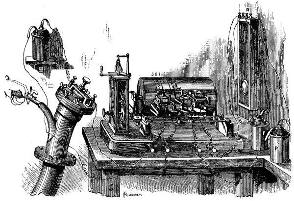
Fig. 49.
OBSTRUCTION-RECORDING APPARATUS.
Larger image (359 kB)
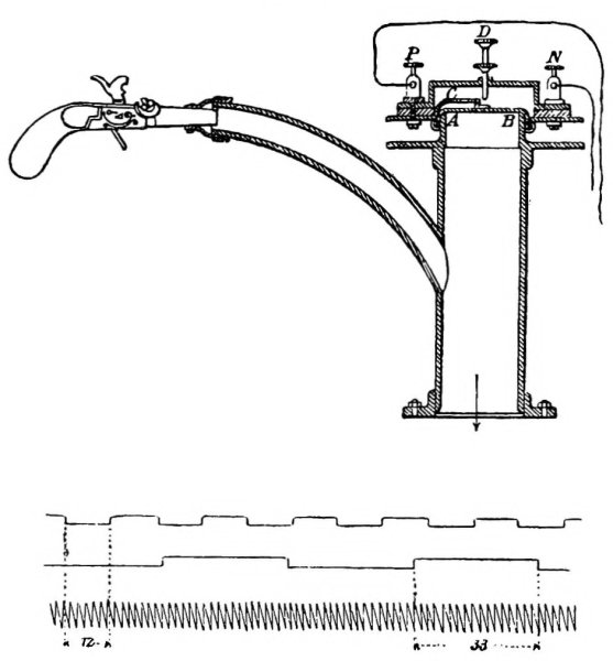
Fig. 50.
OBSTRUCTION-RECORDING APPARATUS.
“Amongst the special causes of accident may be mentioned the accidental
absence of a piston to the train, breaking of the piston, the freezing
up of a piston in the tube, and even forgetting the presence of a
train, which has caused the entire service to be one train late
throughout the day. Finally, the tubes themselves are sometimes broken
or disturbed during street repairs, resulting of course in a complete
cessation of traffic in the system till the damage is made good.”
The spelling, punctuation and hyphenation are as the original, with the exception of apparent typographical errors which have been corrected.