The River Tunnel work, from some points of view, has the most
interest. It is interesting because it is the first main line crossing of
the formidable obstacle of the Hudson River, and also by reason of
the long and anxiously discussed point as to whether, in view of the
preceding experiences and failures to construct tunnels under that
river, foundations were needed under these tunnels to keep them from
changing in elevation under the action of heavy traffic.
The River Tunnels here described start on the east side of the
shield chambers on the New York side and end at the east side of the
shield chambers on the New Jersey side. They thus include the New
York and exclude the New Jersey shield chambers, the reason for such
discrimination being that the New York shield chambers are lined
with cast iron while those on the New Jersey side are of the typical
rock section type, as already described. The design of the tunnels and
their accessories will be first described, then will come the construction
of the tunnels as far as the completion of the metal lining, followed
by a description of the concrete lining and completion of the work.
New York Shield Chambers.—The shield chambers may be seen on
Plate XXXII, previously referred to, which shows the junction of
the iron-lined tunnels and the shield chambers. They consist of two
iron-lined pieces of tunnel placed side by side, with semi-circular
arches and straight side-walls. The segments of the arch are made to
break joint with one another by making the side-wall or column castings
of two different heights, as shown in Fig. 9. The length of each
ring is 18 in.
The reason for the adoption of this type of construction was the
necessity for keeping the width of the permanent structure within the
60-ft. width of the street. The length of this twin structure is
28.5 ft., and the weight of the metal in it is as follows:
| 19 long-column arch rings at 22,802 lb. |
433,238 |
lb. |
| 19 short-column arch rings at 23,028 lb. |
437,532 |
" |
|
--------- |
|
| Total weight |
870,770 |
lb. |
General Type of River Tunnel Lining.—The main ruling type
adopted for the tunnels under the Hudson River, and in the soft water-bearing
ground for some distance on the shoreward side of the river
lines, consists of two parallel metal-lined tunnels, circular in cross-section,
each tunnel being 23 ft. outside diameter, and the two tunnels
37 ft. apart from center to center, as shown on Fig. 10. The metal
lining is of cast iron (except for a few short lengths of cast steel) and
of the usual segmental type, consisting of "Rings" of iron, each ring
being 2 ft. 6 in. in length, and divided by radial joints into eleven
segments, or "Plates," with one "Key," or closing segment, having
joints not radial but narrower at the outside circumference of the
metal lining than at the inside. The whole structure is joined, segment
to segment, and ring to ring, by mild-steel bolts passing through
bolt holes in flanges of all four faces of each segment. The joints
between the segments are made water-tight by a caulking of sal-ammoniac
and iron borings driven into grooves formed for the purpose
on the inner edges of the flanges. The clearances between the bolts
and the bolt holes are also made water-tight by using grummets or
rings of yarn smeared with red lead, having a snug fit over the shank
of the bolt and placed below the washer on either end of each bolt.
When passing through ground more or less self-sustaining, the space
outside the iron lining (formed by the excavation being necessarily
rather larger than the external diameter of the lining itself) was
filled with grout of 1:1 Portland cement and sand forced by air
pressure through grout holes in each segment. These holes were
tapped, and were closed with a screw plug before and after grouting.
Having thus stated in a general way the main ruling features of
the design, a detailed description of the various modifications of the
ruling type will be given.
The two main divisions of the iron lining are the "ordinary" or
lighter type and the heavy type. The details of the ordinary iron
are shown in Fig. 11, which shows all types of lining. It was on this
design that the contract was let, and it was originally intended that
this should be the only type of iron used. The dimensions of the iron
are clearly shown on the drawing, and it will be seen that the external
diameter is 23 ft., the interior diameter, 21 ft. 2 in., the length of each
ring, 2 ft. 6 in., and the thickness of the iron skin or web, 1½ in. The
bolt holes in the circumferential flanges are evenly spaced through the
circle, so that adjacent rings may be bolted together in any relative
position as regards the radial joints, and, as a matter of fact, in the
erection of the tunnel lining, all the rings "break joint," with the
exception of those at the bore segments, as will be described later.
This type of iron, when the original type was modified, came to be
known as the ordinary pocketless iron; that is, the weight is of the
ordinary or lighter type, in contradistinction to the heavier one, which
later supplanted it, and the caulking groove runs along the edges of
the flanges and does not form pockets around the bolt holes, as did the
groove in a later type.
Each ring is made up of eleven segments and a key piece. Of
these, nine have radial joints at both ends, and are called "A" segments;
two, called "B" segments, have a radial joint at one end and a
non-radial joint at the other. The non-radial joint is placed next to
the key, which is 12.25 in. wide at the outside circumference of the
iron and 12.50 in. wide at the inside.
The web is not of uniform thickness. The middle part of each
A and B segment is 1½ in. thick; at the distance of 6 in. from the root
of each flange, the thickness of web begins to increase, so that at the
root it is 2⅜ in. thick. The web of the key plate is 1¾ in. thick.
The bolts are of mild steel, and are 1½ in. in diameter; there are
67 in one circumferential joint and 5 in each radial joint. As there
are 12 such radial joints, there are altogether 60 bolts in the cross-joints,
making a total of 127 bolts per ring.
This original type of ordinary iron was modified for a special
purpose as follows: It was known that for some distance on either
side of the river, and especially at Weehawken, the tunnels would pass
through a gravel formation, rather open, and containing a heavy head
of water. It was thought that, by carrying the caulking groove
around the bolt holes, it would be possible to make them more water-proof
than by the simple use of the red-leaded grummets. Hence the
"Pocket Iron" was adopted for this situation, the name being derived
from the pocket-like recess which the caulking groove formed when
extended around the bolt hole. The details of this lining are shown
on Fig. 11, and the iron (except for the pockets) is exactly like the
pocketless type.
On the New York side, in both North and South Tunnels, two
short lengths were built with cast-steel lining. This was done where
unusual stresses were expected to come on the lining, namely, at the
point where the invert passed from firm ground to soft, and also where
the tunnels passed under the heavy river bulkhead wall.
The design was precisely the same as for the ordinary pocketless
iron, and Fig. 11 shows the details. After the tunnels had entered
into the actual under-river portion, several phenomena (which will be
described later) led to the fear that the tunnels, being lighter than the
semi-liquid mud they displaced, might be subject to a buoyant action,
and therefore a heavier type of lining was designed. The length of
ring, number of bolts, etc., were just the same as for the lighter iron,
but the thickness of the web was increased from 1½ to 2 in., the thickness
of the flanges was proportionately increased, and the diameter of
the bolts was increased from 1½ to 1¾ in. This iron was all of the
pocketless type, shown in Fig. 11.
Table 18 gives the weights of the
various types of lining.
TABLE 18.—Weights of Tunnel Lining, Diameter and Weights of
Bolts, etc.
| Reference No. |
Type of Lining. |
Weight of one "A" Segment, in pounds. |
Weight of one "B" Segment, in pounds |
Weight of one key, in pounds. |
Weight of one complete ring, in pounds. |
Diameter of bolts, in inches. |
Weight of 1 bolt, nut, and 2 washers, in pounds. |
Weight of bolts, nuts, and washers per ring, in pounds. |
Total weight of one ring (segments and bolts), in pounds. |
| 1 |
Ordinary cast iron without caulking pockets. |
2,063 |
2,068 |
480 |
23,183 |
1½ |
6.62 |
840.7 |
24,024 |
| 2 |
Ordinary cast iron with caulking pockets. |
2,038 |
2,043 |
469 |
22,897 |
1½ |
6.62 |
840.7 |
23,738 |
| 3 |
Ordinary cast steel without caulking pockets. |
2,247 |
2,252 |
522 |
25,249 |
1½ |
6.62 |
840.7 |
26,090 |
| 4 |
Heavy cast iron without caulking pockets. |
2,579 |
2,584 |
606 |
28,985 |
1¾ |
10.50 |
1,333.5 |
30,319 |
Weights of Various Types of Lining per Linear Foot of Tunnel.
| Reference No. |
Type of Lining. |
Weights of complete rings (segments only), in pounds. |
Weights of bolts, nuts, and washers, in pounds. |
Weights of segments and bolts in tunnel complete, in pounds. |
| 1 |
Ordinary cast iron without pockets. |
9,273.0 |
336.3 |
9,609.6 |
| 2 |
Ordinary cast iron with pockets. |
9,158.8 |
336.3 |
9,495.2 |
| 3 |
Ordinary cast steel without pockets. |
10,099.6 |
336.3 |
10,436.0 |
| 4 |
Heavy cast iron without pockets. |
11,594.0 |
533.4 |
12,127.6 |
The weights in Table 18 are calculated by assuming cast iron to
weigh 450 lb. per cu. ft., and cast steel 490 lb. In actual practice the
"ordinary" iron was found to weigh a little more than the weights
given, and the "heavy" a little less.
The silt in the sub-river portion averaged about 100 lb. per cu. ft.,
so that the weight of the silt displaced by the tunnel was about
41,548 lb. per lin. ft.
Taper Rings.—In order to pass around curves (whether horizontal
or vertical), or to correct deviation from line or grade, taper rings
were used; by this is meant rings which when in place in the tunnels
were wider than the standard rings, either at one side (horizontal
tapers or "Liners"), or at the top ("Depressors"), or at the bottom
("Elevators").
In the original design a ½-in. taper was called for, that is, the wide
side of the ring was ½ in. wider than the narrow side, which was of the
standard width of 2 ft. 6 in. As a matter of fact, during construction,
not only ½-in., but ¾-in. and 1-in. tapers were often used.
These taper rings necessitated each plate having its own unalterable
position in the ring, hence each plate of the taper ring was
numbered, so that no mistake could be made during erection.
The taper rings were made by casting a ring with one circumferential
flange much thicker than usual, and then machining off this
flange to the taper. This was not only much cheaper than making a
special pattern for each plate, but made it possible to see clearly where
and what tapers were used in the tunnel.
Taper rings were provided for all kinds of lining (except the cast
steel), and the lack of taper steel rings was felt when building the
steel-lined parts of the tunnel, as nothing could be done to remedy
deviations from line or grade until the steel section was over and cast
iron could again be used. Table 19 gives the weights
of the different kinds of tapers used.
TABLE 19.—
Weights of Cast-Iron Taper Rings, in Pounds per Complete Ring.
| Classification. |
Weight of cast iron per complete ring, in pounds. |
| Ordinary pocketless ½-in. taper |
23,767.7 |
| Ordinary pocketless 1-in. taper |
24,352.4 |
| Ordinary pocket ½-in. taper |
23,481.7 |
| Heavy pocketless ½-in. taper |
29,564.8 |
| Heavy pocketless ¾-in. taper |
29,854.7 |
| Heavy pocketless 1-in. taper |
30,144.6 |
Cast-Steel Bore Segments and Accessories.—The following feature
of these tunnels is different from any hitherto built. It was the
original intention to carry the rolling load independent of the tunnel,
or to assist the support of the silt portion of the structure by a single
row of screw-piles, under each tunnel, and extending down to firmer
ground than that through which the tunnels were driven. Therefore,
provision had to be made whereby these piles could be put down
through the invert of the tunnel with no exposure of the ground.
This provision was afforded by the "Bore Segments," which are
shown in detail in Fig. 12. There are two segments, called No. 1
and No. 2, respectively. These two segments are bolted together in
the bottom of two adjacent rings, and thus form a "Pile Bore." As
the piles were to be kept at 15-ft. centers, and as the tunnel rings
were 2 ft. 6 in. in length, it will be seen that, between each pair of
bore-segment rings, there came four "Plain" rings. The plain rings
were built up so that the radial joints broke joint from ring to ring,
but with the bore-segment rings this could not be done, without unnecessarily
adding to the types of segments.
The bore segments were made of cast steel, and were quite complicated
castings, the principle, however, was quite simple. The segments
provided an opening just a little larger than the shaft of the
pile, the orifice being 2 ft. 7 in. in diameter at the smallest (lowest)
point, while the shaft of the pile was to be 2 ft. 5¼ in. In order to
allow of the entry of the screw-blade or helix of the pile, a slot was
formed in the depth of Bore Segment No. 1, so that, when a pile
was put in position above the bore, the blade, when revolved, would
enter the slot and thus pass under the metal lining, although the
actual orifice was only slightly larger than the pile shaft.
The wall of the pile orifice in Segment No. 2 was made lower
than that in No. 1 so as to allow the blade to enter the slot in Segment
No. 1. When the pile is not actually in process of being sunk,
this lower height in No. 2 is made up with the removable "distance
piece." This had a tongue at one end which engaged in a recess cast
to take it in Segment No. 2 and was held in place by a key piece
at the other end of the distance piece. Details of the distance piece
and key are shown in Fig. 12.
The flanges around the pile bore were made flat and furnished
with twelve tapped holes, six in Segment No. 1 and six in Segment
No. 2, for the purpose of attaching the permanent arrangements in
conjunction with which the pile was to be attached to the track system,
independently of the tunnel shell, or directly to the tunnel. It
was never decided which of these alternatives would be used, for, before
this decision was reached, it was agreed that, at any rate for
the present, it was better not to put down piles at all.
To close the bore, the "Bore Plug" was used. This is shown on
Fig. 12. It was of cast steel, and was intended to act as a permanent
point of the screw-pile, that is, the blade section was to be attached
to the bore plug, the distance piece and key were to be removed, and
the pile was to be rotated until the blade had cleared the slot; the
distance piece and key were then to be replaced and sinking resumed.
The plug was held in place against the pressure of the silt by
the two "dogs," while the dogs themselves were attached to the tunnel,
as shown in Fig. 12. The ends of the dogs, which rested on the
flanges of the metal lining of the tunnel, were prevented from being
knocked off the flanges (and thus releasing the plug) by steel clips.
It was expected that it might be desirable to keep the lower end
of the piles open during their sinking, so that the bore plugs were not
made permanently closed, but a seating was formed on the inner
circumference of the plug, and on the seating was placed the "Plug
Cover," made of cast iron, 18¾ in. in diameter and 3 in. thick, furnished
with a lug for lifting and a 3-in. tapped hole closed by a
screw-plug, through which any soundings or samples of ground
could be taken prior to sinking the piles. This plug cover was held
in place by a heavy steel "Yoke" under it, which engaged on the
under side of the flange, on top of which the cover was set. The
yoke was attached to the cover by a 1¾-in. tap-bolt, screwed into the
yoke and passing through a 2-in. hole bored in the center of the
cover. This rather peculiar mode of attaching the cover was adopted
so that the cover could be removed by taking off the nut of the yoke,
in case it was desired to open the end of the pile during the process
of sinking.
The plug was a fairly close fit at the bottom of the orifice, that
is, at the outside circumference of the tunnel, where the bore was
2 ft. 7 in. in diameter and the plug 2 ft. 6¾ in., but at the top of the
bore-segment there was more clearance, as the plug was cylindrical
while the bore tapered outward. To fill this space, it was intended
that steel wedges should be used while the shield was being driven,
so that they would withstand the crushing action of the thrusting
shield, and, when the shield was far enough ahead, that they should
be removed and replaced by hardwood wedges. This method was
only used in the early weeks of the work; the modification of not
using the shield-jacks which thrust against the bore segments was
then introduced, and the wooden wedges were put in, when the bore
plugs were set in place, and driven down to the stage of splitting.
When it was resolved not to sink the screw-piles, the bores had
to be closed before putting in the concrete lining. This was done
by means of the covers shown in Fig. 13. The bore plug and all
its attachments were removed, and the flat steel cover, 2 in. thick
and with stiffening webs on the under side, was placed over the
circular flanges of the pile bore. The cover was attached to the bore
segments by twelve 1½-in. stud-bolts, 6 in. long, in the bolt holes
already mentioned as provided on these flanges.
When these were in place, with lead grummets under the heads
of the bolts, and the grooves caulked, the bore segments were water-tight
tight,
except in Bore Segment No. 2, at the joint of the distance
piece; and, to keep water from entering here, this segment was filled
to the level of the top of the flanges with 1:1 Portland cement mortar.
The weights of the various parts of the bore segments are given
in Table 20.
TABLE 20.—
Weights of Bore Segments and Accessories, in Pounds.
| Part. |
No. |
Material. |
Weight, in pounds. |
| Bore Segment No. 1 |
1 |
Cast Steel |
3,004.0 |
| Bore Segment No. 2 |
1 |
" " |
2,628.0 |
| Distance piece |
1 |
" " |
423.5 |
| Key |
1 |
" " |
34.3 |
| Plug |
1 |
" " |
1,192.5 |
| Yoke |
1 |
" " |
57.3 |
| Dogs |
2 |
" " |
106.0 |
| Slot cover |
1 |
Rolled steel |
6.4 |
| Plug cover |
1 |
Cast iron |
162.0 |
| Dog holders |
2 |
Rolled steel |
6.4 |
| Complete weight of one pair, without bolts |
7,620.4 |
Sump Segments.—In order to provide sumps to collect the drainage
and leakage water in the subaqueous tunnels, special "sump segments"
were installed in each tunnel at the lowest point—about Station
241 + 00. The details of the design are shown in Fig. 14. The
segment was built into the tunnel invert as though it were an
ordinary "A" segment. In building the sump, three lining castings
were bolted, one on top of the other, and attached to the flat
upper surface of the sump segment; meanwhile, the bolts attaching
the sump segment to the adjacent tunnel plates were taken out and
the plate and lining segments were forced through the soft mud by
hydraulic jacks, the three 6-in. holes in the bottom of the sump
segment being opened in order to minimize the resistance. The sump
when built appeared as shown in Fig. 14, the top connection being
made with a special casting, as shown.
The capacity of each sump is 500 gal., which is about the quantity
of water entering the whole length of each subaqueous tunnel
in 24 hours.
Cross-Passages.—When the contract was let, provision was made
for cross-passages between the tubular tunnels, in the form of special
castings to be built into the tunnel lining at intervals. However, the
idea was given up, and these castings were not made. Later, however,
after tunnel building had started, the question was raised again,
and it was thought that such cross-connections would be very useful
to the maintenance forces, that it might be possible to build them
safely, and that their subsequent construction would be made much
easier if some provision were made for them while the shields were
being driven. It was therefore arranged to build, at intervals of
about 300 ft., two consecutive rings in each tunnel, at the same station
in each tunnel, with their longitudinal flanges together, instead
of breaking joint, as was usually done. The keys of these rings
were displaced twelve bolt holes from their normal positions toward
the other tunnel. This brought the keys about 6 ft. above the bench,
so that if they were removed, together with the B plates below them,
an opening of about 5 by 7 ft. would be left in a convenient position
with regard to the bench.
Nothing more was done until after the tunnels were driven. It
was then decided to limit the cross-passages between the tubular tunnels
to the landward side of the bulkhead walls. They were arranged
as follows: three on the New York side, at Stations 203 + 22,
206 + 80, and 209 + 80, and two on the New Jersey side, at
Stations 255 + 46 and 260 + 14. The cross-passages are square in
cross-section.
TABLE 21.—Weights of Sump Segments.
| Part. |
No. |
Material. |
Weight, in pounds. |
| Middle top casting |
1 |
Cast steel |
880 |
| End top castings |
2 |
" " |
1,718 |
| Lining castings |
3 |
" " |
18,232 |
| Sump segment |
1 |
Cast iron |
3,560 |
| Total weight per sump, exclusive of bolts |
24,390 |
Turnbuckle Reinforcement for Cast-Iron Segments.—During
the period of construction, a certain number of cast-iron segments,
mostly in the roof, but in some cases at Manhattan in the invert,
behind the river lines, became cracked owing to uneven pressures
of the ground. Before the concrete lining was put in, considerable
discussion occurred as to the wisest course to pursue with regard to
these broken plates. It was finally thought best not to take the plates
out, as more harm than good might be done, but to reinforce them
with turnbuckles, as shown in Fig. 15. The number of broken segments
was distributed as follows:
North Manhattan Tunnel 87, chiefly in silt (not under the river),
South Manhattan Tunnel 7, chiefly in silt (not under the river),
North Weehawken Tunnel 24, chiefly in sand (not under the river),
South Weehawken Tunnel 48, chiefly in silt, under the Fowler Warehouse.
The chief features of the tunnel lining have now been described,
and, before giving any account of the methods of work, it will be
well to mention briefly the salient features of the concrete lining
which is placed within the actual lining.
This concrete lining will be considered and described in the
following order:
The New York Shield Chambers,
Standard Cross-Section of Concrete Lining of Shield-Driven
Tunnels,
Final Lines and Grades, and How Obtained,
Steel Rod Reinforcement of Concrete,
Cross-Passage Lining,
Special Provision for Surveys and Observations.
The New York Shield Chambers.—The cross-section of the concrete
lining of these chambers is shown by Plate XXXII, referred
to in the Land Tunnel Section. They are of the twin-tunnel double-bench
type. The deep space beneath the floor is used as a sump for
drainage, and manholes for access to the cable conduits are placed
in the benches.
Standard Cross-Section of Concrete Lining of Shield-Driven
Tunnels.—The cross-section of the concrete lining of the tube tunnel
is shown in Fig. 16. There are two main types, one extending from
the shield chambers to the first bore segment, that is, to where the
tunnel leaves solid ground and passes into silt, and the other which
extends the rest of the way. The first type has a drain in the invert,
the second has not.
The height from the top of the rail to the soffit of the arch being
less than 16 ft. 11 in., overhead pockets for the suspension of electrical
conductors were set in the concrete arch on the vertical axis
line at 10-ft. centers. These pockets are shown in Fig. 16. The
benches are utilized for the cable conduits in the usual way. Ladders
are provided on one side at 25-ft. and on the other side at 50-ft.
intervals, to give access from the track level to the top of the benches.
Refuge niches for trackmen are placed at 25-ft. intervals on the single-way
conduits side only, as there is not enough room in front of the 4-way
ducts. Manholes for giving access to the cable conduits, both
power, and telephone and telegraph, are at 400-ft. intervals.
Final Lines and Grades, and How Obtained.—It may be well to
explain here how the final lines and grades for the track, and therefore
for the concrete lining, were obtained and determined. It is first to
be premised that the standard cross-section of the tunnel (that is,
of the concrete and iron lining combined) is not maintained throughout
the tunnel. In other words, the metal lining is of course uniform,
or practically so, throughout; the interior surface of the concrete
lining is also uniform from end to end, but the metal lining, owing
to the difficulty of keeping the shields, and hence the tunnels built
within them, exactly on the true line and grade, is not on such lines
and grades; the concrete lining is built exactly on the pre-arranged
lines and grades, consequently, the relative positions of the concrete
and metal linings vary continually along the length of the structure,
according to whether the metal lining is higher or lower than it
should be, further to the north or to the south, or any combination
of these.
As before stated, it was strongly desired to encroach as little as
possible on the standard 2-ft. concrete arch, and after some discussion
it was decided that a thickness of 1 ft. 6 in. was the thinnest it
was advisable to allow. This made it possible to permit the metal
lining of the tunnel to be 6 in. lower, in respect to the level of the
track at any point, than the standard section shows, and also allowed
the center line of the track to have an eccentricity of 6 in. either
north or south of the center line of the tunnel. This only left to
be settled the extent to which the metal lining might be higher in
respect to the track than that shown on the standard section.
This amount was governed by the desirability of keeping sufficient
clearance between the top of the rail and the iron lining in the invert
to admit of the attachment of pile foundations and all the accompanying
girder-track system which would necessarily be caused
by the use of piles, should it ever become apparent after operation was
begun, that, after all, it was essential to have the tunnels supported
in this way. Careful studies were made of the clearance necessary,
and it was decided that 4 ft. 9 in. was the minimum allowable depth
from the top of the rail to the outside of the iron at the bottom.
This meant that the iron lining could be 3 in. higher, with respect
to the track level, than that shown on the standard section.
All the determining factors for fixing the best possible lines and
grades for the track within the completed metal lining were now at
hand. In March, 1908, careful surveys of plan and elevation were
made of the tunnels at intervals of 25 ft. throughout. The following
operations were then performed to fix on the best lines and grades:
First, for Line: It has been explained that the permissible deviation
of the center line of the track on either side of the center line
of the tunnel was 6 in. Had the metal lining been invariably of the
true diameter, it would have been necessary to survey only one side
of the tunnel; this would have given a line parallel to the center
line, and might have been plotted as such; then, by setting off 6 in.
on either side of this line, there would have been obtained a pair
of parallel lines within which the center line of the track must lie.
Owing to variations in the diameter of the tunnel, however, such a
method was not permissible, and therefore the following process was
used:
When running the survey lines through the tunnel (which were
the center lines used in driving the shields), offsets were taken to
the inner edges of the flanges of the metal lining, both on the north
and south sides, at axis level at each 25-ft. interval. On the plat
on which the survey lines were laid down, and at each point surveyed,
a distance was laid off to north and south equal to the following
distances:
Offset, as measured in the tunnel to north (or south), minus
10.08 ft.
This 10.08 ft. (or 10 ft, 1 in.) represents 10 ft. 7 in., the true
radius to inside of iron, minus 6 in., the permissible lateral deviation
of the track from the axis of the tunnel.
The result of this process was two lines, one on either side of the
survey lines, not parallel to it or to each other, but approaching each
other when the horizontal diameter was less than the true diameter,
receding from each other when the diameter was more, and exactly
12 in. apart when the diameter was correct. As long as the center
line of the track lay entirely within these two limiting lines, the condition
that the concrete arch should not be 6 in. less in thickness
than the standard 2 ft. was satisfied, and in order to arrive at the
final line, the longest possible tangents that would be within these
limits were adopted as the final lines; and, as the survey lines were
those used in driving the tunnel shields (that is, the lines to which
it was intended that the track should be built), the amount by which
the new lines thus obtained deviated from the survey lines was a
measure of the deviation of the finally adopted track and concrete
line from the original contract lines.
Next, for Grades: The considerations for grade were very similar
to those for line. If the vertical diameter of the tunnel had been
true at each 25-ft. interval surveyed, it would have been correct
to plot the elevations of the crown (or invert) as a longitudinal section
of the tunnel, and to have set up over those points others 6 in.
above (as the metal lining could have been 6 in. lower than the
standard section, which is equivalent to the track being an equal
amount higher), and below these crown or invert elevations others
3 in. lower (as the metal lining could be 3 in. higher).
Then, by joining the points 6 in. above in one line and those
3 in. below in another, there would have been obtained lines of limitation
between which the track grades must lie. However, as the tunnel
diameter was not uniformly correct, a modification of this method
had to be made, as in the case of the line determination, the principle,
however, remaining the same.
The elevations were taken on the inner edges of the circumferential
flanges of the metal lining, not only in the bottom, but also in
the top, of the tunnel, at each 25-ft. interval; then, for the upper
limit of the track at each such interval the following was plotted:
Elevation of inner edge of flange at top, minus 16.58 ft.
This 16.58 ft. (or 16 ft. 7 in.) was obtained thus: The standard
height from the top of the rail to the inner edge of the iron flange
is 17 ft. 1 in., but, as the track may be 6 in. above the standard or
normal, the minimum height permissible is 16 ft. 7 in. For the
lower limit of track at each 25-ft. interval the following was plotted:
Elevation of inner edge of flange at bottom, plus 3.83 ft.
This 3.83 ft. (or 3 ft. 10 in.) was obtained thus: The standard
height from the top of the rail to the inner edge of the iron flange
is 4 ft. 1 in. (5 ft. to outside of iron, less 11 in. for depth of flange),
but, as the track may be 3 in. below the standard, the minimum
height permissible is 4 ft, 1 in. less 3 in., or 3 ft. 10 in.
By plotting the elevations thus obtained, two lines were obtained
which were not parallel but were closer together or further apart
according as the actual vertical diameter was less or greater than the
standard, and the track grade had to lie within these two lines in
order to comply with the requirements indicated above. The
results of these operations for the North Tunnel are shown on
Plate XXXVI.
The greatest deviations between the lines and grades in the
subaqueous tunnels as determined by these means and those as
originally laid out in the contract drawings are on the Weehawken
side, and were caused by the unexpected behavior of the tunnel when
the shields were driven "blind" into the silt, causing a rise which
could not be overcome, and the thrusting aside of one tunnel by
the passage of the neighboring one. Had this unfortunate incident
not occurred, it is clear that it would have been possible to adhere
very closely indeed to the contract lines and grades, although the
deviation is small, considering all things.
The internal outline of the concrete cross-section is uniform
throughout, and is built on the lines and grades thus described.
Steel Rod Reinforcement of Concrete.—The original intention
had been to line the metal lining of the tube tunnels with plain
concrete, but, as the discussion on the foundation question continued,
it was felt advisable, while still it was intended to put in the foundations,
to guard against any stresses which were likely to come on
the structure, by using a system of steel rods embedded circumferentially
within the concrete. Designs were made on this basis, and
even the necessary material prepared, before the decision to omit the
piles altogether was reached. However, in order to provide a safeguard
for the structure where it is partly or wholly beyond the solid
rock, it was decided to use reinforcement, even with the piles omitted.
For this purpose the tunnel was considered as a girder, and
longitudinal reinforcement was provided at the top and bottom. The
top reinforcement extends from a point 25 ft. behind the point where
the crown of the tunnel passes out of rock on the New York side
to where the crown passes into rock on the New Jersey side. The
bottom reinforcement extends from where the invert of the tunnel
passes out of rock on the New York side to where it passes into
rock on the New Jersey side.
The reinforcement both at top and bottom consists of twenty
1-in. square twisted rods, ten placed symmetrically on either side
of the vertical axis, 9 in. apart from center to center and set 4 in.
(to their centers) back from the face of the concrete.
As a further precaution, circumferentially-placed rods were used
on the landward side of the river lines, mainly to assist in preventing
the distortion of shape which might occur here, either under present
conditions, such as under the Fowler Warehouse at Weehawken, or
under any possible different future conditions, such as might be
brought about by building some new structure in the vicinity of
the tunnels.
For purposes of classification of the circumferential reinforcement,
the tunnel was divided into two types, "B" and "C"; (Type
"A" covering the portion which, being wholly in solid rock, was not
reinforced at all).
Type "B" covers the part of the tunnels on both sides of the river
lying between the point where the top of the tunnel passes out of
rock and the point where the invert passes out of rock on the Manhattan
side, or out of gravel on the Weehawken side. The reinforcement
consists of twenty 1-in. square longitudinal rods in the crown
of the tunnel, as described for the general longitudinal reinforcement,
together with 1-in. square circumferential rods at 10-in. centers,
and extending over the arch to 2 ft. 3 in. below the horizontal axis.
Type "C" extends from the latter limit of Type "B" to the
river line on each side, and consists of longitudinal reinforcement
in both top and bottom, as described before, together with circumferential
reinforcement entirely around the tunnel, and formed of
1-in. square twisted rods at 15-in. centers.
Type "D" consists of longitudinal reinforcement only, and extends
from river line to river line, thus occupying 72.5% of the length in
which concrete is used. The reinforcement consists of twenty 1-in.
twisted rods at 9-in. centers in the crown, and twenty 1-in. rods at
9-in. centers in the invert. In addition to the three standard types,
"B," "C," and "D," there were two sub-types which were used in
Type "D," and in conjunction with it wherever the thickness of the
center of the concrete arch became less than 1 ft. 6 in., measuring to
the outside of the metal lining. This thickness was one of the limits
used in laying out the lines and grades, and in general the arch was
not less than this. There were one or two short lengths, however,
where it was less, for, if the arch thickness requirement had been
adhered to, it would have resulted in a break of line or grade for the
sake of perhaps only a few feet of thin arch, and it was here that the
sub-types came into play.
TRANS. AM. SOC. CIV. ENGRS.
VOL. LXVIII, No. 1155.
HEWETT AND BROWN ON
PENNSYLVANIA R. R. TUNNELS: NORTH RIVER TUNNELS.
Sub-type 1 was used where the arch was less than 1 ft. 6 in. thick
at the top. The extra reinforcement here consisted of 1-in. square
twisted rods, 16 ft. long, laid circumferentially in the crown at 10-in.
centers.
Sub-type 2 was used where the arch was less than 1 ft. 6 in. thick
at the side. The extra reinforcement here consisted of 1-in. square
twisted rods, 16 ft. long, laid circumferentially, at the side on which
the concrete was thin, at 10-in. centers. Very little of either of
these two sub-types was used. The entire scheme is shown graphically
and clearly on Plate XXXVII.
Cross-Passage Lining.—There are two main types of cross-passages:
Lined with steel plates, and unlined.
There is only one example of lining with steel plates, namely,
the most western one at Weehawken. This is built in rock which
carried so much water that, in order to keep the tunnels and the
passage dry, it was decided to build a concrete-lined passage, without
attempting to stop the flow of water, and within this to place a riveted
steel lining, not in contact with the concrete, but with a space between
the two. This space was drained and the water led back to the
shield chamber and thence to the Weehawken Shaft sump. The
interior of the steel lining is covered with concrete.
In the passages not lined with steel plates the square concrete
lining is rendered on the inside with a water-proof plaster. Each
of the passages is provided with a steel door.
Provisions in Concrete Lining for Surveys and Observations.—The
long protracted discussion as to the provision for foundations in
these tunnels led to many surveys, tests, and observations, which
were carried out during the constructive period, and, as it was desired
to continue as many of these observations as possible up to and
after the time when traffic started, certain provisions were made in the
concrete lining whereby these requirements might be fulfilled. The
chief points on which information was desired were as follows:
The change in elevation of the tunnel,
The change in lateral position of the tunnel,
The change in shape of the tunnel,
The tidal oscillation of the tunnel.
A detailed account of these observations will be found in another
paper on this work, but it may be said now that it was very desirable
to be able to get this information independently of the traffic as far
as possible, and therefore provision was made for carrying on the
observations from the side benches.
For studying the changes in level of the tunnel, a permanent
bench-mark is established in each tunnel where it is in the solid rock
and therefore not subject to changes of elevation; throughout the
tunnel, brass studs are set in the bench at intervals of about 300 ft.
A series of levels is run every month from the stable bench-mark on
each of these brass plugs, thus obtaining an indication of the change
of elevation that the tunnels have undergone during the month.
These results are checked on permanent bench-marks in the
subaqueous portion of the tunnels. These consist of rods, encased in
pipes of larger diameter, which extend down through the tunnel
invert into the bed-rock below the tunnel. Leakage is kept out by
a stuffing-box in the invert. By measuring between a point on these
rods where they pass through the invert and the tunnel itself a
direct reading of the change of elevation of the tunnel is obtained.
These measurements are taken at weekly intervals, and, as the tunnels
are subject to tidal influences, being lower at high tide than at low
tide, are always taken under the same conditions as to height of
water in the river. These permanent bench-marks are at Stations
209 + 05 and 256 + 02 (about 100 ft. on the shoreward side
of the river line in each case) in the South Tunnel, at Stations 220 + 00
and 243 + 86, also in the South Tunnel, and at Station 231 + 78
in the North Tunnel. In order to study the lateral change of position,
a base line was established on the side bench at each end
of each tunnel in the portion built through the solid rock.
PLATE XXXVII.
TRANS. AM. SOC. CIV. ENGRS.
VOL. LXVIII, No. 1155.
HEWETT AND BROWN ON
PENNSYLVANIA R. R. TUNNELS: NORTH RIVER TUNNELS.
[Pg 232]
At intervals of about 300 ft. throughout each tunnel, alignment pockets
are formed in the concrete arch, also above the bench, on the south
bench of the North Tunnel and the north bench of the South Tunnel. In
each pocket is placed a graduated and verniered brass bar, so that, when
the base line is projected on these bars, the lateral movement of the
tunnel can be read directly. As it was desirable to have as much
cross-connection as possible between the tunnels at the points where the
instruments were to be set up, five of the main survey stations were set
opposite each of the five cross-passages. Then, for the purpose of
increasing the cross-connection still further, pipes 6 in. in diameter
were put through from one tunnel to the other at axis level at Stations
220 + 60, 231 + 78, 234 + 64,
241 + 99, and 251 + 13, and a survey station was put
in opposite each one.
Points were established at Station 220 + 00, which is the point
of intersection for the curve on the original center line of the tunnel,
and also at Station 220 + 23, where the intersection of the track
center line comes in the North Tunnel. As it was desirable to have
the survey stations not much more than 300 ft. apart, so as to obtain
clear sights, other stations were established so that the distances between
survey stations were at about that interval.
For studying changes of shape in the tunnel, brass "diameter markers"
were inserted at each survey station in the concrete lining at the
extremities of the vertical and horizontal axes. These were pieces of
brass bar, ⅜ in. in diameter and 6 in. long, set in the concrete
and projecting ⅝ in. into the tunnel, so that a tape could be
easily held against the marker and read.
For obtaining the tidal oscillation of elevation of the tunnel,
recording gauges are attached to the invert of the tunnel at each of the
five permanent bench-marks referred to above in such a way that the
recording pencil of the gauge is actuated by the rod of the permanent
bench-mark. A roll of graduated paper is driven by clock-work below the
recording pencil which thus marks automatically the relative movement
between the moving tunnel and the stable rods. These have shown that in
the subaqueous part of the tunnel there is a regular tidal fluctuation
of elevation, the tunnel moving down as the tide rises, and rising again
when the tide falls. For an average tide of about 5 ft. the tunnel
oscillation would be about ⅛ in. Before the concrete lining was
placed, there was a tidal change in the shape of the tunnel, which
flattened about 1/64 in. at high tide. After the concrete lining was
placed, this distortion seemed to cease.
The general design and plan of the work have been described, and before
giving any account of the contractor's methods in carrying it out, Table 22,
showing the chief quantities of work in the river tunnels, is
presented.
The following is an account of the methods used by the contractor
in carrying out the plans which have already been described. First,
it may be well to point out the sequence of events as they developed in
this work. These events may be divided into six periods.
1.—Excavation and Iron Lining: June, 1903, to November, 1906;
2.—Caulking and grummeting the iron lining: November, 1906,
to June, 1907;
3.—Surveys, tests and observations: April, 1907, to April, 1908;
4.—Building cross-passages and capping pile bores: April, 1908,
to November, 1908;
5.—Placing the concrete lining: November, 1908, to June, 1909;
6.—Cleaning up and various small works: June, 1909, to November,
1909.
The tunnels were under an average air pressure of 25 lb. per sq. in.
above normal for all except Periods 5 and 6, during which times there
was no air pressure in the tunnels.
All the work will be described in this paper except that under
Period 3 which will be found in another paper.
Period 1.—Excavation and Iron Lining, June, 1903, to November,
1906.—Table 23 gives the chief dates
in connection with this period.
Manhattan Shield Chambers.—The Manhattan shield chamber construction
will be first described. The Weehawken shield chambers
have been described under the Land Tunnel Section, as they are of
the regular masonry-lined Land Tunnels type, whereas the Manhattan
chambers are of segmental iron lining with a concrete inner lining.
During the progress of excavation, the location of the New York
shield chambers was moved back 133 ft., as previously described in the
"Land Tunnel" Section, and when the location had been finally decided,
there was a middle top heading driven all through the length
now occupied by the shield chamber. Narrow cross-drifts were taken
out at right angles to the top heading, and from the ends of these the
wall-plate headings were taken out. Heavy timbering was used, as
the rock cover was only about 6 ft., and the whole span to be covered
was 60 ft. The process adopted was to excavate and timber the north
side first, place the iron lining, and then excavate the south side, using
the iron of the north side as the supports for the north ends of the
segmental timbering of the south. The only incident of note was that
at 2:00 A.M., on October 20th, 1904, the rock at the west end of the
south wall-plate heading was pierced. Water soon flooded the workings,
and considerable disturbance was caused in the New York Central
Railroad yard above. The cavity on the surface was soon filled in,
but to stop the flow of mud and water was quite a troublesome job.
TABLE 22.—Quantities of Work in Subaqueous Tunnels.
| Description, Quantity, Length, etc. |
TYPE. |
| Manhattan shield chambers. |
Cast iron, ordinary pocketless. |
Cast iron, ordinary pocket. |
Cast iron, heavy pocketless. |
Cast steel, ordinary pocketless. |
Total. |
| Length, in feet. |
59.00 |
4,374.99 |
2,146.3 |
5,522.05 |
152.66 |
12,255.00 ft. |
| Excavation, in cubic yards. |
Total. |
1,884 |
67,344 |
33,038 |
85,001 |
2,349 |
189,616 cu. yd. |
| Per linear foot. |
31.9 |
15.4 |
15.4 |
15.4 |
15.4 |
|
| Cast-iron tunnel lining, in pounds. |
Total. |
847,042 |
39,643,120 |
19,715,405 |
61,559,845 |
|
121,765,412 lb. |
| Per linear foot. |
14,357 |
9,061 |
9,186 |
11,148 |
|
|
| Cast-steel tunnel lining, in pounds. |
Total. |
|
1,544,962 |
757,938 |
2,730,905 |
1,549,711 |
6,583,516 lb. |
| Per linear foot. |
|
353.1 |
353.1 |
494.5 |
10,151.4 |
|
| Steel bolts and washers, in pounds. |
Total. |
23,627 |
1,475,991 |
724,095 |
2,935,455 |
51,266 |
5,210,434 lb. |
| Per linear foot. |
400.46 |
337.37 |
397.00 |
581.59 |
335.82 |
|
| Rust joints, in linear feet. |
Total. |
3,376 |
170,755 |
83,935 |
218,656 |
5,996 |
482,718 ft. |
| Per linear foot. |
57.2 |
39.0 |
39.1 |
39.6 |
39.3 |
|
| Concrete, in cubic yards. |
Total. |
766 |
20,030 |
9,827 |
25,282 |
713 |
56,618 cu. yd. |
| Per linear foot. |
12.98 |
4.58 |
4.58 |
4.58 |
4.58 |
|
| Steel beams, plates, etc., in pounds. |
Total. |
12,346 |
83,774 |
41,098 |
105,738 |
7,432 |
250,388 lb. |
| Per linear foot. |
2,092.5 |
19.1 |
19.1 |
19.1 |
48.7 |
|
| Steel bolts, hooks, etc., in pounds. |
Total. |
1,328 |
36,980 |
18,142 |
46,675 |
1,471 |
104,596 lb. |
| Per linear foot. |
22.5 |
84.5 |
84.5 |
84.5 |
96.4 |
|
| Expanded metal, in pounds. |
Total. |
594 |
2,215 |
1,086 |
2,795 |
62 |
6,752 lb. |
| Per linear foot. |
10.07 |
0.506 |
0.506 |
0.506 |
0.406 |
|
| Vitrified conduits, in duct feet. |
Total. |
2,560 |
235,903 |
115,728 |
297,752 |
7,757 |
659,700 duct ft. |
| Per linear foot. |
43.49 |
53.92 |
53.92 |
53.92 |
50.81 |
|
TABLE 23.—Excavation and Iron Lining.
|
North Manhattan. |
North Weehawken. |
South Manhattan. |
South Weehawken. |
| Shaft and preliminary headings. |
Begun. |
June 10, '03. |
June 11, '03. |
June 10, '03. |
June 11, '03. |
| Shaft and preliminary headings. |
Finished. |
December 11, '03. |
September 1, '04. |
December 11, '03. |
September 1, 04 |
| Excavation of shield chamber. |
Begun. |
May 24, '04. |
January 16, '05. |
May 24, '04. |
January 16, '05. |
| Excavation of shield chamber. |
Finished. |
January 21, '05. |
March 25, '05. |
May 13, '05. |
April 19, '05. |
| Cast-iron lining of shield chambers. |
Begun. |
February 4, '05. |
None. |
May 15, '05. |
None. |
| Cast-iron lining of shield chambers. |
Finished. |
March 13, '05. |
None. |
June 14, '05. |
None. |
| Excavation of tunnels begun before installation of shield. |
|
October 17, '04. |
January 13, '05. |
January 5, '05. |
January 25, '05. |
| Commenced building falsework for shield. |
|
March 6, '05. |
March 23, '05. |
June 19, '05. |
April 17, '05. |
| Shield parts received at shaft. |
|
March 11, '05. |
March 20, '05. |
June 22, '05. |
April 24, '05. |
| Erection of shield begun. |
|
March 13, '05. |
March 27, '05. |
June 22, '05. |
April 24, '05. |
| Erection of shield (structural steel). |
Finished. |
March 27, '05. |
April 12, '05. |
June 8, '05. |
May 6, '05. |
| Erection of shield (hydraulic fittings). |
Finished. |
May 11, '05. |
May 25, '05. |
August 27, '05. |
June 13, '05. |
| First ring of permanent cast-iron lining put in. |
|
May 12, '05. |
May 29, '05. |
August 27, '05. |
June 14, '05. |
| First air lock bulkhead wall. |
Begun. |
May 29, '05. |
June 15, '05. |
September 18, '05 |
June 21, '05. |
| First air lock bulkhead wall. |
Finished. |
June 7, '05. |
June 23, '05. |
September 23, '05 |
July 3, '05. |
| Air pressure first put in tunnel. |
|
June 25, '05. |
June 29, '05. |
October 6, '05. |
July 8, '05. |
| Rock disappeared from invert of tunnel. |
|
December 1, '05. |
October 31, '05. |
February 8, '06. |
September 21, 05 |
| First pair of bore segments built in tunnel. |
|
December 9, '05. |
January 12, '06. |
February 16, '06. |
December 12, '05 |
| Rip-rap of river bulkhead wall met. |
|
February 8, '06. |
None. |
April 11, '06. |
None. |
| First pile met (in river bulkhead wall at
Manhattan, and Fowler warehouse foundation at Weehawken). |
|
February 18, '06. |
January 3, '06. |
April 18, '06. |
December 4, '06. |
| Last pile met. |
|
March 2, '06. |
February 5, '06. |
May 1, '06. |
January 9 '06. |
| First ring erected on river side of shore line. |
|
March 3, '06. |
February 6, '06. |
May 9, '06. |
January 19, '06. |
| Removing hood of shield. |
Begun. |
March 27, '06. |
February 6, '06. |
May 9, '06. |
January 19, '06. |
| Removing hood of shield. |
Finished. |
April 1, '06. |
February 8, '06. |
May 12, '06. |
January 24, '06. |
| Second air-lock bulkhead wall. |
Begun. |
May 12, '06. |
March 19, '06. |
July 13, '06. |
March 11, '06. |
| Second air-lock bulkhead wall. |
Finished. |
May 21, '06. |
March 24, '06. |
July 21, '06. |
March 18, '06. |
| Tunnel holed through with meeting tunnel. |
|
September 12, 1906. |
October 9, 1906. |
| Last ring of permanent cast-iron lining built in. |
|
October 9, 1906. |
November 18, 1906. |
The excavation was begun on May 24th, 1904, and finished on May
15th, 1905. The segments were placed by an erector consisting of a
timber boom supported by cross-timbers running on car wheels on
longitudinal timbers at each side of the tunnel. Motion was transmitted
to the boom by two sets of tackle, and the heavy (5,000-lb.)
segments were easily handled. The erection of the lining was started
on February 4th, 1905, and finished on June 14th, 1905.
While the shield chambers were being excavated, bottom headings
were run along the lines of the river tunnels and continued until the
lack of rock cover prevented their being driven further. These were
afterward enlarged to the full section as far as possible. The typical
working force in the shield chambers was as follows:
| Ten-hour Shifts. |
| Drilling and Blasting. |
| 1 |
Foreman |
@ |
$3.50 |
| 6 |
Drillers |
" |
3.00 |
| 6 |
Drillers' helpers |
" |
2.00 |
| 1 |
Blacksmith |
" |
3.50 |
| 1 |
Blacksmith's helper |
" |
2.25 |
| 1 |
Powderman |
" |
2.00 |
| 1 |
Waterboy |
" |
2.00 |
| 1 |
Nipper |
" |
2.00 |
| 1 |
Machinist |
" |
3.00 |
| 1 |
Machinist's helper |
" |
1.80 |
| Mucking. |
| 1 or 2 |
Foremen |
@ |
$3.00 |
| 16 |
Muckers |
" |
2.00 |
Erection of Shields.—The tunneling shields have been described
in some detail in the section of this paper dealing with the contractor's
plant. They consist essentially of two parts, the structural
steelwork and the hydraulic fittings. The former was made by the
Riter Conley Manufacturing Company, of Pittsburg, Pa., and put
up by the Terry and Tench Company, of New York City; the hydraulic
fittings were made and put in by the Watson-Stillman Company, of
New York City.
On the New York side, the shields were built inside the iron
lining of the shield chambers, hence no falsework was needed, as
the necessary hoisting tackle could be slung from the iron lining;
at Weehawken, however, the erection was done in the bare rock excavation,
so that timber falsework had to be used. The assembly and
riveting took about 2 weeks for each shield; the riveting was done
with pneumatic riveters, using compressed air direct from the tunnel
supply.
After the structural steel had been finished, the shields, which
had hitherto been set on the floor of the chambers in order to give
room for working over the top, were jacked up to grade; this involved
lifting a weight of 113 tons. While the hydraulic fittings were
being put in, the shields were moved forward on a cradle, built
of concrete with steel rails embedded, on which the shield was driven
for the length in which the tunnel was in solid rock.
The installation of the hydraulic fittings took from 4 to 6 weeks
per shield. The total weight of each finished shield was about 193
tons. The completed shield, as it appeared in the tunnel, is shown
by Fig. 1, Plate XXXVIII. The typical force working on shield
erection was as follows:
| Ten-hour Shifts. |
| Shield Erection. (Terry and Tench.) |
| 1 |
Superintendent |
@ |
$13.00 |
per |
day |
| 4 |
Foremen |
" |
5.50 |
" |
" |
| 1 |
Timekeeper |
" |
2.50 |
" |
" |
| 2 |
Engineers |
" |
4.50 |
" |
" |
| 34 |
Iron workers |
" |
4.50 |
" |
" |
| 7 |
Laborers |
" |
2.25 |
" |
" |
| Hydraulic Work. (Watson-Stillman Company.) |
| 4 |
Mechanics |
@ |
$4.00 |
per |
day |
|
General Labor. (O'Rourke Engineering Construction Company.) |
|
| 1 |
Inspector |
@ |
$4.00 |
per |
day |
| 1 |
Foreman |
" |
4.00 |
" |
" |
| 8 |
Laborers |
" |
2.00 |
" |
" |
| 1 |
Engineer |
" |
2.50 |
" |
" |
PLATE XXXVIII.
TRANS. AM. SOC. CIV. ENGRS.
VOL. LXVII, NO. 1155.
HEWETT AND BROWN ON
PENNSYLVANIA R. R. TUNNELS: NORTH RIVER TUNNELS.
After the shield was finished and in position, the first two rings
of the lining were erected in the tail of the shield. These first
rings were then firmly braced to the rock and the chamber lining;
then the shield was shoved ahead by its own jacks, another ring
was built, and so on.
The description of the actual methods of work in the shield-driven
tunnels can now be given; this will be divided generally into
the different kinds of conditions met at the working face, for example,
Full Face of Rock, Mixed Face, Full Face of Sand and Gravel,
Under River Bulkhead, and Full Face of Silt.
The last heading is the one under which by far the longest length
of tunnel was driven, and, as not much has hitherto appeared descriptive
of the handling of a shield, through this material, considerable
space will be devoted to it.
Full Face of Rock.—As was described when dealing with the
shield chambers, as much as possible of the rock excavation was done
before the shields were installed. On the New York side, about 146
ft. of tunnel was completely excavated, with 71 ft. of bottom headings
beyond that, and at Weehawken, 58 and 40 ft. of tunnel and
heading beyond, respectively. This was chiefly done to avoid handling
the rock through the narrow shield doors. Test holes were driven
ahead at short intervals to make sure that the rock cover was not
being lost, but, nevertheless, at Weehawken, on February 14th, 1905,
a blast broke through the rock and let the mud flow in, filling the
tunnel for half its height for a distance of 300 ft. from its face.
Throughout the rock section the shield traveled on a cradle of
concrete in which were embedded either two or three steel rails. In
the portion in which the whole of the excavation had been taken
out, it was only necessary to trim off projecting corners of rock. In
the portion in which only a bottom heading had been driven, the
excavation was completed just in front of the shield, the drilling
below axis level being done from the heading itself, and above that
from the front sliding platforms of the shield. The holes were placed
near together and drilled short, and very light charges of powder
were used, so as to lessen the chance of knocking the shield about
too much. In this work the small shield doors hampered the work
greatly, and it might have been well to have provided a larger bottom
opening which could have been subdivided or partly closed when
soft ground was met; on the other hand, the quantity thus handled
was small, owing to the fact that the greater part of the rock was
excavated before the shields were installed.
The space outside the lining was grouted with a 1:1 mixture of
Portland cement and sand. Large voids were hand-packed with stone
before grouting. The details of grouting will be described later.
A typical working gang is given herewith. Two such gangs
were worked per shield per 24 hours, 10 hours per shift. All this
work was done under normal air pressure.
| General: |
|
½ |
Tunnel superintendent |
@ |
$200.00 |
per |
month |
|
1 |
Assistant tunnel superintendent |
" |
5.00 |
per |
day |
|
1 |
General foreman |
" |
5.00 |
" |
" |
|
½ |
Electrician |
" |
3.50 |
" |
" |
|
½ |
Electrician's helper |
" |
3.00 |
" |
" |
|
½ |
Pipefitter |
" |
3.00 |
" |
" |
|
½ |
Pipefitter's helper |
" |
2.75 |
" |
" |
| Drilling: |
|
1 |
Foreman |
" |
5.00 |
" |
" |
|
3 |
Drillers |
" |
4.00 |
" |
" |
|
3 |
Drillers' helpers |
" |
3.00 |
" |
" |
|
1 |
Nipper |
" |
2.50 |
" |
" |
|
½ |
Waterboy |
" |
2.50 |
" |
" |
|
½ |
Powderboy |
" |
2.75 |
" |
" |
| Mucking: |
|
1 |
Foreman |
" |
3.50 |
" |
" |
|
8 |
Muckers |
" |
2.75 |
" |
" |
| Erecting Iron and Driving Shield: |
|
1 |
Erector runner |
" |
4.00 |
" |
" |
|
3 |
Iron workers |
" |
3.00 |
" |
" |
The duties of such a gang were as follows: The tunnel superintendent
looked after both shifts of one shield. The assistant or
"walking boss" had charge of all work in the tunnel on one shift.
The general foreman had charge of the labor at the face. The
electricians looked after repairs, extensions of the cables, and lamp
renewals. The pipefitters worked in both tunnels repairing leaks in
pipes between the power-house and the working faces, extending the
pipe lines, and attending to shield repairs, and in the latter work
the erector runner helped.
The drillers stuck to their own jobs, which were not subject to
interruption as long as the bottom headings lasted. One waterboy
and one powderboy served two tunnels. The muckers helped the iron
men put up the rings of lining, as well as doing their own work.
The iron men tightened bolts, whenever not actually building up iron.
The list does not include the transportation gang, which will be
described under its own heading.
The rate of progress attained was 4.2 ft. per day per shield where
most of the excavation had been done before, and 2.1 ft. where
none had been done before.
When the shields had got far enough away from the shield chamber,
and before rock cover was lost, the first air-lock bulkhead walls were
put in.
Air-Lock Bulkhead Walls.—The specifications required these walls
and all their fittings to be strong enough to stand a pressure of 50 lb.
per sq. in. Accordingly, all the walls were of concrete, 10 ft. in thickness,
except the first two, which were 8 ft. in thickness, and grouted
up tight.
There were three locks in each bulkhead wall capable of holding
men, namely, the top or emergency lock which is set high in order
to afford a safe means of getting away in case of a flood; this lock
was used continuously for producing the lines and levels into the
tunnels. It was very small and cramped for this purpose, and a
larger one would have been better, both for lines and emergencies.
This lock was directly connected with the overhead platform (also
called for in the specifications) which ran the whole length of the
tunnels. Side by side, on the level of the lower or working platform
of the tunnel, were the man lock and the muck lock. In addition a
number of pipes were built in to give access to the cables and for
passing pipes, rails, etc., in and out.
After each tunnel was about 1,200 ft. ahead of the first walls, a
second wall was built just like the first, and no others were put in,
so that altogether there were eight walls. This second wall not only
gave an added safeguard to the tunnel but enabled the air pressure
at the working face to be divided between the two walls, and this
compression or decompression in stages, separated by a spell of walking
exercise, was found to be very good for the health of those
working in the air.
Mixed Face.—When the rock cover became so thin that it was
risky to go on without the air pressure, the air pressure was turned
on, starting with from 12 to 18 lb., which was enough to stop the
water from the gravel on top of the rock. At first, when the surface
of the rock was penetrated, the soft face was held up by horizontal
boards braced from the shield until the shield was shoved. The braces
were then taken out and, as soon as the shield had been shoved, were
replaced by others. As the amount of soft ground in the face increased,
the system of timbering was gradually changed to one of
2-in. poling boards resting on top of the shield and supported at
the face by vertical breast boards, in turn held by 6 by 6-in. walings
braced both through the upper doors to the iron lining and from the
sliding platforms of the shield. The latter were in their forward
position before the shield was shoved, the pressure being turned off
and the exhaust valves opened just before the shove began. As the
shield went ahead, the platform jacks gradually exhausted and thus
held enough pressure on the face to keep it up. Fig. 17 is a sketch
of this method. In driving through mixed ground a typical working
gang was about as follows:
| General: |
|
⅓ |
Tunnel superintendent |
@ |
$300.00 |
per |
month. |
|
1 |
Assistant tunnel superintendent |
" |
5.00 |
per |
day. |
|
1 |
General foreman |
" |
5.00 |
" |
" |
|
½ |
Pipefitter |
" |
3.25 |
" |
" |
|
½ |
Pipefitter's helper |
" |
2.75 |
" |
" |
|
½ |
Electrician |
" |
3.00 |
" |
" |
|
½ |
Electrician's helper |
" |
2.75 |
" |
" |
| Timbering: |
|
3 |
Timbermen |
" |
2.50 |
" |
" |
|
3 |
Timbermen's helpers |
" |
2.00 |
" |
" |
| Mucking: |
|
1 |
Foreman |
" |
3.50 |
" |
" |
|
6 |
Muckers |
" |
2.75 |
" |
" |
| Erecting Iron and Driving Shield: |
|
1 |
Erector runner |
" |
3.25 |
" |
" |
|
1 |
Foreman |
" |
4.00 |
" |
" |
|
4 |
Iron workers |
" |
3.00 |
" |
" |
[Pg 242]
The average rate of progress was 2.6 ft. per day.
In this case there were three such gangs, each on an 8-hour shift.
Full Face of Sand and Gravel.—This condition of affairs was only
met at Weehawken. Two systems of timbering were used. In the
first system, Fig. 17, the ground was excavated 2 ft. 6 in. ahead of
the cutting edge, the roof being held by longitudinal poling boards,
resting on the outside of the skin at their back end and on vertical breast
boards at the forward end. When the upper part of the face was dry,
it was held by vertical breast boards braced from the sliding platform
and through the shield doors to cross-timbers in the tunnel; the
lower part, which was always wet, was held by horizontal breast boards
braced through the lower shield pockets to cross-timbers in the tunnel.
This system worked all right as long as the ground in the top was
sandy enough and had sufficient cohesion to allow the polings to be put
in, but, when the upper part was in gravel, thus making it impossible
to put in the longitudinal polings or the vertical breasting, the second
system came in. Here the excavation was only carried 1 ft. 3 in.
(half a shove) ahead of the cutting edge, and the longitudinal polings
were replaced by transverse boards supported by pipes which were
placed in the holes provided in the shield to accommodate some telescopic
poling struts which had been designed but not made. These
pipes acted as cantilevers, and were in two parts, a 2½-in. pipe wedged
tight into the holes and smaller pipes sliding inside them. After a
small section of the ground had been excavated, a board was placed
against it, one of the pipes was drawn out under it, and wedges were
driven between it and the board. These polings were kept below the
level of the hood, so that when the shield was shoved they would come
inside of it; in addition, they were braced with vertical posts from
the sliding platforms. The upper part of the face was held by
longitudinal breast boards braced from the sliding platform by vertical
"soldier" pieces. The lower part of the face was supported by vertical
sheet-piling braced to the tunnel through the lower doors. Sometimes
two rows of piling were used, but generally one, as shown in Fig. 17.
Notwithstanding the fact that the breasting was only 1 ft. 3 in. ahead
of the hood, the shield was moved its full stroke of 2 ft. 6 in., the
ground around the cutting edge of the hood being scraped away by men
working bars in the place from which the temporary breast boards at
the circumference had been removed. The back pressure on the
sliding platform jacks, when the exhaust valves were only partly open,
offered a good deal of resistance, and held the face as long as the
movement of the shield was continuous.
On one occasion, when for some reason the shield was stopped with
the shove only partly done, and the exhaust valves had not been shut
off, the platforms continued to slide and allowed the face to collapse;
the shield platforms and doorways, however, caught the falling sand
and gravel and the flow choked itself.
As soon as the rock surface was penetrated and the sand and gravel
were met, which happened almost at the same time in the two
Weehawken Tunnels, the escape of air increased enormously, and it at
once became clear that it was impossible to keep enough air in the
two tunnels by the methods then in use, even when working the three
compressors, each capable of compressing 4,400 cu. ft. of free air per
min. at top speed. When the shields just entered the sand and gravel,
the face had been held by light breasting, without any special effort to
prevent the escape of air, but when it was found impossible to supply
enough air, a large amount of straw and clay was used in front of
the boards.
This cut down the escape, but, as much air was escaping through
the joints of the iron lining, these were plastered with Portland cement.
Even then, the loss was too great, therefore one tunnel was shut down
entirely and all the air was sent to the other. This allowed a pressure
of 10 lb. to be kept up in the working tunnel, and this, though less than
the head, was enough to allow progress to be made. In order to use
one tunnel as a drain for the other, the two faces were always kept
within 150 ft. of each other by working them alternately. The
timbered face was never grouted, though this would have reduced the
loss of air, as at the same time it would have decreased the progress
very much, and any one who saw the racing engines in the power-house,
and realized that a breakdown of one of them would mean the
loss of the faces, was ready to admit that the quicker this particular
period was cut short, the better.
Above the sand and gravel lay the silt, and, when it showed in the
roof, the escape of air was immediately reduced and the two faces could
be worked simultaneously. Almost at the same time the piles supporting
the large warehouse, known as the Fowler Building, were met.
Although the face now took much less timber, the same system of
breast boards as had been used in the gravel was kept up, but in
skeleton form. They were set 2 ft. 6 in. ahead of the shield, however,
instead of 1 ft. 3 in., and the transverse roof poling boards were
replaced by longitudinals resting on the shield. The more piles in the
face the less timbering was done. The piles were cut into handy
lengths with axes and chisels.
All timbering was light compared with the weight of the ground,
but, as the shove took place as soon as the set was made, it served its
purpose. When a face was closed down the whole system was greatly
reinforced by braces from the shield, the face of which was closed by
the doors.
In driving through such a face the typical 8-hour shift gang was
about as follows:
| General: |
|
⅓ |
Tunnel superintendent |
@ |
$300.00 |
per |
month. |
|
1 |
Assistant tunnel superintendent |
" |
5.00 |
per |
day. |
|
1 |
General foreman |
" |
5.00 |
" |
" |
|
½ |
Pipefitter |
" |
3.25 |
" |
" |
|
½ |
Pipefitter's helper |
" |
2.75 |
" |
" |
|
½ |
Electrician |
" |
3.00 |
" |
" |
|
½ |
Electrician's helper |
" |
2.75 |
" |
" |
| Timbering: |
|
3 |
Timbermen |
" |
2.50 |
" |
" |
|
3 |
Timbermen's helpers |
" |
2.00 |
" |
" |
| Mucking: |
|
1 |
Foreman |
" |
3.50 |
" |
" |
|
6 |
Muckers |
" |
2.75 |
" |
" |
| Erecting Iron and Driving Shield: |
|
1 |
Erector runner |
" |
3.25 |
" |
" |
|
1 |
Foreman |
" |
4.00 |
" |
" |
|
4 |
Iron workers |
" |
3.00 |
" |
" |
The drillers were not kept on after the rock disappeared; a foreman
was added who divided his time between iron erection and mucking.
The average rate of progress in sand and gravel without piles was
5.1 ft. per day per shield. When piles and silt were met in the upper
part of the face, the speed increased to 7.0 ft. per day.
Passing Under River Bulkhead.—At Weehawken no trouble was
found in passing under the river wall, as the bulkhead consisted of
only cribwork supported on silt, and, though the piles obstructed the
motion of the shield, they were easily cut out, and the cribwork itself
was well above the top of the shield.
On the New York side, however, conditions were not nearly as
good. The heavy masonry bulkhead was supported on piles and rip-rap,
as shown in Fig. 18. The line of the top of the shield was about 6 ft.
above the bottom of the rip-rap, the spaces between the stones of which
were quite open and allowed a free flow of water directly from the
river. As soon, therefore, as the cutting edge of the shield entered
the rip-rap there was a blow, the air escaping freely to the ground
surface behind the bulkhead and to the river in front of it. Clay
puddle, or mud made from the excavated silt, was used in large
quantities to plug up the interstices between the stone in the working
face, the air pressure being slightly greater than that needed to keep
out the water holding it in place. The excavation of the rip-rap was
a tedious affair, for it had to be removed one stone at a time and the
spaces between the newly exposed stones plugged with mud immediately.
One man stood ready with the mud while another loosened the stones
with a bar. When the shield had advanced its own length in the rip-rap,
another point for the escape of the air was exposed at the rear end
of the shield. This loss was closed at the leading end of the last ring
with mud and cement sacks.
As long as the shield was stationary it was possible, by using these
methods and exercising great care and watchfulness, to prevent
excessive loss of air; but, while the shield was being shoved ahead, the
difficulties were much increased, for the movement of the shield displaced
the bags and mud as fast as they were placed, and it was only
by shoving slowly and having a large number of men looking out for
leaks and stopping them up the instant they developed that excessive
loss of air could be prevented. In erecting the iron lining, as each
segment was brought into position, it was necessary to clean off the
leading surface of the previous ring and the adjacent portion of the
tail of the shield; this was always accompanied by a slight "blow,"
and for some time the air pressure in the tunnel dropped from 25 to
20 lb., that is, from greater than the balancing pressure to less, every
time a segment was placed, and on two occasions the "blow" became
so great that the tunnel pressure was reduced considerably further,
and in consequence the water from the river rushed in and was not
stopped until it had risen about 4 ft. in the tunnel invert. On such
occasions the surface of the river was greatly disturbed, rising more
than 20 ft. in the air in a sort of geyser. A large quantity of grout
(about 2,500 bbl. of cement and a similar quantity of sand in the
North Tunnel and 1,000 bbl. in the South Tunnel) was used at this
point; it was forced through the tunnel lining immediately behind the
shield, greatly reducing the loss of air and helping to bind the rip-rap
together.
When the shield had traveled 25 ft. through the rip-rap, the piles
which support the bulkhead were met. One hundred of these which
were spaced at 3-ft. centers in each direction, were cut out of the path
of each shield in a distance of 35 ft. The presence of the piles caused
considerable extra labor, as each pile had to be cut into several pieces
with axes to enable it to be removed through the shield doors, otherwise
they presented no difficulties. It was not necessary to timber the
face, as the piles supported it most effectively.
When the river line had been passed, the "blow" still continued,
and as there was no heavy ground above the tunnel the light silt
was carried away into the water by the escaping air. At one time
the cover over the crown of the tunnel was reduced to such an extent
that for a distance of 30 ft. there was less than 10 ft. of very soft
silt, and in some places none at all. Therefore, the shield was
stopped and the air pressure reduced until it was less than the balancing
pressure; the blow then ceased, and about 28,000 cement bags
filled with mud were dumped into the hole (the location made it impossible
to dump them en massefrom a scow). They were then
weighted down with rip-rap. This sealed the blow, and the work was
continued without any further disturbance from this source. Just
before the blow reached its maximum it was found that two of the
piles which had been encountered were directly in the path of one
of the proposed screw-piles. It was therefore decided to pull these,
and this was done with two 40-ton hydraulic jacks supported by the
upper sliding platforms and acting on a horizontal timber which was
connected to the piles by tie-rods and chains. The working force
here was similar to that employed in the sand and gravel section
previously described.
In Full Face of Silt.—A full face of silt was first met under the
New York Central Railroad freight yard on the New York side. Up
to this point the ground passed through had been either solid rock
or a mixed face of rock and gravel. In both of these the full excavation
had to be taken out before the shield could be shoved, and
the soft ground had needed timbering. When the rock, gravel, and
hardpan gave place to a full face of silt, the timber was removed,
all the shield doors were opened, and the shield was shoved into the
ground without any excavation being done by hand ahead of the
diaphragm. As the shield advanced, the silt was forced through the
open doors into the tunnel. After the work had gone on in this way
for some time, taking in about 90% of the full volume of the tunnel
excavation per foot forward, the air pressure was raised from 20 to
22 lb. The result was that the silt in the face got harder and
flowed less readily through the shield, and the amount taken in fell
to about 65% of the full volume. This manner of shoving at once
caused a disturbance on the surface and the railroad tracks above the
tunnel were raised, so that the pressure was lowered to 16 lb., then the
muck got softer and the full volume of excavation was taken in;
after a while the pressure was again raised to 20 lb.
The forcing of the shield through the silt resulted in a rising of
the bed of the river, the amount that the bed was raised depending
on the quantity of material brought into the shield.
If the whole volume of excavation was being brought in, the
surface of the bed was not affected; when about 50% was being
taken in, the surface was raised about 3 ft.; if the shield was being
driven blind, the bed was raised about 7 ft.
The number of open doors was regulated so as to take in the
minimum quantity of muck consistent with causing no surface disturbance.
On the average, in the North Manhattan Tunnel, all the
doors were open, but in the South Tunnel there were generally only
five or six out of the total nine.
In front of the bulkhead wall at Manhattan the tunnels were under
Pier No. 72. This structure was supported on wooden piles, some
80 ft. or more in length, which came down below the tunnel invert.
The piles which lay directly in the path of the tunnels, with a few
exceptions, had been pulled. In driving the tunnels through this
section, great care had to be taken not to disturb the piles on either
side of the tunnels, as they supported a heavy trestle used in disposing
of the excavation from the open cut in the terminal yard. To avoid
such disturbance, a large portion of the total excavation had to be
taken through the shields.
The first shield which passed the river bulkhead was the south one
at Weehawken. As soon as this line was crossed the silt was found
to be much softer than behind the wall, in fact it was like a fluid
in many of its properties. The fluidity could be changed by varying
the tunnel air pressure; for example, when the air pressure was made
equal to the weight of the overlying material (water and silt), the
silt was quite stiff, and resembled a rather soft clay; but when the
air pressure was from 10 to 15 lb. per sq. in. lower, it became so
liquid that it would flow through a 1½-in. grout hole in the lining, in
a thick stream, at the rate of from 10 to 50 gal. per min. as soon as
the plug was taken out. This was the point to which the contractor
had long looked forward, as he expected to be able to close all his
shield doors and drive the rest of the way across without taking in a
shovelful of muck, as had just been done under the Hudson River,
on the South Tunnel of the Hudson and Manhattan Railroad Company's
Tunnels between Morton Street, New York City, and Hoboken,
N. J. The doors were shut and the shield was shoved; the tunnel at
once began to rise rapidly, notwithstanding that the heaviest possible
downward leads that the clearance between the iron and the shield
would allow were put on. At the same time, the pressures induced
in the silt by the shield shouldering the ground aside caused the
iron lining to rise about 2 in. as soon as the shield left it, and also
distorted it, the horizontal diameter decreasing and the vertical
diameter increasing by about as much as 1¼ in. An anxious discussion
followed these phenomena, as the effects had been so utterly
unexpected, and a good many different theories were advanced as
to the probable cause. It was thought that the hood of the shield
might have something to do with the trouble. The shield was stopped,
the hood removed, the doors were shut, and the driving continued.
The same trouble was found, and it was impossible to keep to grade.
Work was stopped, and the question was thoroughly debated; finally,
on January 31st, 1906, the chief engineer directed that one of the
shield doors be opened as an experiment and 50% of the excavation
taken in.
The effect was instantaneous, the shield began to come down to
grade at once, and it soon became necessary to close the door partially
and reduce the quantity of muck taken in in order to prevent the
tunnel from getting below grade. The other troubles from distortion,
etc., ceased at the same time.
It was soon found that a powerful aid in the guidance of the
shield was thus brought to hand, for, if high, the shield could be
brought down by increasing the quantity of muck taken in, if low,
by decreasing it. From this time forward, the quantity of muck
taken in at each shove was carefully regulated according to
the position of the tunnel with regard to grade and the nature of
the ground. The quantity varied from nothing to the full volume
displaced by the tunnel, and averaged 33% of the latter.
To regulate the flow, the bottom middle door was fitted with two steel
angles behind which were placed 6 by 6-in. timbers. In this way the
opening could be entirely closed or one of any size left. The muck
flowed into the tunnel in a thick stream, as shown in
Fig. 2, Plate XXXV, and, by regulating the rate of shove it could be
made to flow just as fast as it could be loaded into cars.
In driving through the silt, the typical gang per shift of 8 hours
per shield was as follows:
| General: |
|
⅓ |
Tunnel superintendent |
@ |
$300 |
per |
month |
|
1 |
Assistant tunnel superintendent |
" |
6.00 |
per |
day |
|
1 |
General foreman |
" |
5.00 |
" |
" |
|
½ |
Electrician |
" |
3.50 |
" |
" |
|
½ |
Electrician's helper |
" |
3.00 |
" |
" |
|
1 |
Foreman |
" |
4.00 |
" |
" |
|
2 |
Pipefitters |
" |
3.50 |
" |
" |
|
2 |
Pipefitters' helpers |
" |
3.25 |
" |
" |
| Mucking: |
|
1 |
Foreman |
" |
4.00 |
" |
" |
|
6 |
Muckers |
" |
3.00 |
" |
" |
| Erecting Iron and Driving Shield: |
|
1 |
Foreman |
@ |
$4.00 |
per |
day |
|
1 |
Erector runner |
" |
3.50 |
" |
" |
|
4 |
Iron workers |
" |
3.00 |
" |
" |
|
3 |
Laborers |
" |
3.00 |
" |
" |
[Pg 252]
Three such shifts were worked per day, and the air pressure
averaged 25 lb. per sq. in.
The increase in the number of pipefitters was due to the greatly
increased speed, and also the steadily increasing length of completed
tunnel. The three laborers in the erection gang spent their whole
time tightening bolts. The rate of progress in the silt under the
river per ring of 2½ ft. was 3 hours 21 min., exclusive of all time
when work was actually suspended. For a considerable part of the
time only two 8-hour shifts were worked, owing to a shortage of
iron caused by the change in the design of the lining, whereby the
original lining was changed to a heavier one, and, as the work was
also stopped for experiments and observations, the average of the
actual total time, including all the time during which work was suspended,
was 5 hours 32 min. per ring, or 10.8 ft. per day.
The junction of the shields under the river was made as follows:
When the two shields of one tunnel, which had been driven from
opposite sides of the river approached within 10 ft. of each other,
the shields were stopped, a 10-in. pipe was driven between them, and
a final check of lines and levels was made through the pipe. Incidentally,
also, the first through traffic was established by passing a
box of cigars through the pipe from the Manhattan shield to that
from Weehawken. One shield was then started up with all doors
closed while the doors on the stationary shield were opened so that
the muck driven ahead by the moving shield was taken in through
the other one's doors. This was continued until the cutting edges
came together. All doors in both shields were then opened and the
shield mucked out. The cutting edges were taken off, and the shields
moved together again, edge of skin to edge of skin. The removal
of the cutting edge necessitated the raising of the pressure to 37 lb.
As the sections of the cutting edges were taken off, the space between
the skin edges was poled with 3-in. stuff. Fig. 1, Plate XXXIX,
is a view of the shields of the North Tunnel after being brought
together and after parts of the interior frames had been removed. When
everything except the skins had been removed, iron lining was built
up inside the skins, the gap at the junction was filled with concrete,
and long bolts were used from ring to ring on the circumferential
joint. Finally, the rings inside the shield skins were grouted.
In order to make clear the nature of the work done in building
these shield-driven tunnels in silt, a short description will be attempted,
this description falling into three main divisions, namely,
Shoving the Shield, Pushing Back the Jacks, and Erecting the Iron
Lining.
Shoving the Shield.—This part of the work is naturally very important,
as the position of the shield determines within pretty narrow
limits the position of the iron built within it, hence the shield
during its forward movement has to be guided very carefully. On
this work certain instructions were issued for the guidance of the
foreman in charge of the shield. These instructions were based on
results of "checks" of the shield and iron's position by the engineering
corps of the Company, and comprised, in the main, two requirements,
namely, the leads that were to be got, and the quantity of
muck to be taken in. The "lead" is the amount that the shield must
be advanced further from the iron, on one side or the other, or on
the top or bottom, as measured from the front face of the last ring
of iron lining to the diaphragm of the shield. These leads are not
necessarily true leads from a line at right angles to the center line,
as the iron may have, and in fact usually does have, a lead of its
own which is known and allowed for when issuing the requirements
for the shove.
The foreman, knowing what was wanted, arranged the combination
of shield jacks which would give the required leads and the
amount of opening on the shield door which would give the required
amount of muck. To see how the shield was going ahead, a man
was stationed at each side at axis level and another in the crown.
Each man had a graduated rod on which the marks were so distinct
that they could be read by anyone standing on the lower platform.
These rods were held against the shield diaphragm, and,
as it advanced, its distance from the leading end of the last ring
could be seen by the man in control of the jack valves. If he found
that he was not getting the required leads, he could change the
combination of jacks in action. As the time of a shove was often
less than 10 min., the man had to be very quick in reading the rods
and changing the jacks. If it was found that extensive change in
the jack arrangement was wanted, the shove could be stopped by
a man stationed at the main hydraulic control valve; but, as any
such stoppage affected the quantity of muck taken in, it was not resorted
to unless absolutely necessary.
PLATE XXXIX.
TRANS. AM. SOC. CIV. ENGRS.
VOL. LXVIII, No. 1155.
HEWETT AND BROWN ON
PENNSYLVANIA R. R. TUNNELS: NORTH RIVER TUNNELS.
If the quantity of muck coming in was not as desired, a stop
had to be made to alter the size of the opening, and if, while this
was being done, the exhaust valves were not closed quite tight, the
silt pressure on the face of the shield would force it back against
the iron. This fact was sometimes taken advantage of when a full
opening did not let in the desired quantity, for the shield could be
shoved, allowed to return, and shoved again.
The time taken to shove in silt varied greatly with the quantity
of material taken in; for shoving and mucking combined, it averaged
66 min., with an average of 13 cu. yd. of muck disposed of, or about
5 min. per cu. yd. of material.
Pushing Back the Jacks.—This was a simple matter, and merely
consisted in making the loose push-back connection to each jack
as it had to be sent back. Some of the jacks became strained and
bent, and had to be taken out and replaced. Where there was silt
pressure against the face of the shield, the hydraulic pressure had
to be kept on until the ring was erected. In such cases, only two
or three jacks could be pushed back at a time, and only after a
segment had been set in position, and the pressure taken on it, could
the next jack be pushed back, and so on around the ring. The time
between the finish of the shove (hydraulic pressure turned off) and
the placing of the first segment, was occupied in pushing back the
bottom jacks and cleaning dirt off the tail of the shield, and averaged
about 14 min.
Erecting the Iron Lining.—As soon as the shove was over, the
whole force, when in silt, set to work at building up the iron and
then tightening the bolts so that the shield could be shoved again.
A section of the tunnel with bolting and working platform is shown
on Plate XL.
In the early part of the work, when the ground was being excavated
ahead of the shield, the whole force, with the exception of
those working in front of the shield, was engaged in erecting the
iron, but, as soon as this was done, most of the men returned to the
mucking, and only the iron workers continued to tighten up bolts.
On the other sections, where the shield was shoved into the silt without
excavating ahead, as soon as the shove was completed, the whole
force was engaged in the erection of the iron and the tightening of the
bolts, until they were so tight that the shield could be shoved again
for another ring.
The iron was brought into the tunnel on flat cars, two segments
to the car, and was lifted from the car and lowered into the invert
of the shield by a block and fall and chain sling, as shown in
Fig. 2, Plate XXXIX. The bottom three or four segments were pushed
around into position with the erector, the head simply bearing against
the longitudinal flange without being attached to the segment; the
upper segments, however, were, as shown in
Fig. 2, Plate XXXVIII, and Fig. 1, Plate XLI,
attached to the erector, by using the expanding
bar and the erector head designed by Mr. Patrick Fitzgerald, the
Tunnel Superintendent. This was found to be a most convenient
arrangement.
The single erector attached to the center of the shield was able
to erect the iron as fast as it could be brought into the tunnel, and
even when the weight of the segments was increased 25% (from
2,060 to 2,580 lb.) it always proved equal to its task, although occasionally
one of the chains in the mechanism broke and delayed the
work for an hour or so; but the sum of all the delays from this
cause and from breaks and leaks in the hydraulic line only averaged
13 min. per ring. The operating valve which was first used was a
four-spindle turning valve, but this was replaced by a sliding valve
which was found to be much more satisfactory, both in ease of
operation and freedom from failure.
As the iron was put into place, two of the middle bolts in each
longitudinal flange and two in each circumferential one were pulled
as tight as possible, and the others put in loosely; then, as soon as
the ring was in position, as large a force as could be conveniently
worked at one time was engaged in tightening the bolts. The shape
of the tunnel depended on the thoroughness of the tightening of the
bolts, and the shield was never shoved until the bolts in all the longitudinal
flanges had been thoroughly tightened. In addition, all the
bolts in the circumferential flanges below the axis were tightened,
and at least three of the six in each segment above. After the
shield had been shoved ahead, the bolts were found to have slackened,
and, where the daily progress was four rings, or more, it was necessary
to have a small gang of men always at this work.
PLATE XL.
TRANS. AM. SOC. CIV. ENGRS.
VOL. LXVIII, No. 1155.
HEWETT AND BROWN ON
PENNSYLVANIA R. R. TUNNELS: NORTH RIVER TUNNELS.
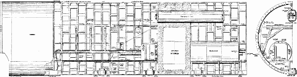 Sectional View of Tunnels Under North River
During Construction Showing Shield, Airlocks, Platform, Piping,
Lighting, etc.
Sectional View of Tunnels Under North River
During Construction Showing Shield, Airlocks, Platform, Piping,
Lighting, etc.
Click to view larger image.
In order to get at the bolts, special platforms were necessary, and
throughout the greater part of the work, a traveling platform was
used. This enabled the men to reach handily all parts of the seven
leading rings. This platform was supported and moved forward on
wheels fixed on brackets to the tunnel, and was pulled forward by connecting
chains every time the shield was shoved. In the early part of
the work it was not possible to use platforms, because, in order to maintain
the correct circular shape of the iron lining, it was necessary
to put in temporary horizontal turnbuckles at axis level. These, however,
were very convenient for supporting the planks which were
used as a temporary bolting platform for the sides of the tunnel, and a
temporary platform resting on 6 by 6-in. timbers across the tunnel enabled
the bolts in the crown of the tunnel to be reached, while the
6 by 6-in. timbers were left in to support the emergency platform
previously described (Plate XL), which extended the entire length
of the tunnel.
The time taken to erect the iron lining became shorter and shorter
as the tunnel organization became more perfect and the force better
trained, so that, whereas, in the early part of the work, it frequently
took 6 hours to erect a ring, in the latter part, when the work was
nearing completion, it was a common occurrence to erect a ring in
30 min. The average time in the "heavy iron" section, which included
the greater part of the work under the river, was 1 hour 4
min. for the erection of the ring and 40 min. for tightening the bolts
after that had been completed, so that the total time spent by the
whole gang on erection and bolting averaged 1 hour 44 min. per ring,
exclusive of the time spent by the small gang which was always engaged
in tightening the bolts. The average time spent in erecting
and bolting, for the whole length of the tube tunnels, was 2 hours
15 min. per ring.
Tables of Progress.—Tables 24,
25, 26, and 27
have been prepared to show the time taken in the various operations at
each working face.
In Tables 24, 25,
26, and 27, the following
symbols are used:
A—Including assistant superintendents, foremen, and electricians,
in driving the shield, erecting iron, mucking, attending to
the electric lights, and repairing the pipe line.
B—Drillers, drillers' helpers, drill foremen, and nippers.
C—All men grouting.
D—Engineers and laborers wholly employed on transport between
the first lock and the face.
E—In rock, one car = 0.60 cu. yd.; in sand or silt = 1.20 cu.
yd. in place.
F—Time between completion of mucking and putting in first
plate, spent in shoving the jacks back.
G—In ordinary iron = the whole time spent on erection and
bolting. In heavy iron = the time between putting in the
first plate and placing the key only.
H—Time between placing the key and starting the next shove,
spent by the whole gang in tightening bolts. In addition
to this, there was a small gang which spent its whole time at
this work.
I—In Table 24 the first pair of
bore segments is at ring 207-208.
In Table 25
the first pair of bore segments is at ring 201-202.
In Table 26
the first pair of bore segments is at ring 185-186.
In Table 27
the first pair of bore segments is at ring 171-172.
Outside diameter of tunnel = 23 ft. 0 in.
Inside diameter of tunnel = 21 ft. 2 in.
Length of ring = 2 ft. 6 in.
In the "Ordinary Iron" section the time is divided between mucking
(which included the shoving and pushing back of the jacks) and
the erection time (which included the time spent by the whole gang
in tightening bolts). In the "Heavy Iron" section these times are
all separated into "Mucking," "Pushing Back Jacks," "Erecting,"
and "Bolting," and here the bolting time included only that spent
on bolts by the whole gang; in addition, there was a small gang engaged
solely in tightening bolts. The lost time is the average time
lost due to the break-down of hydraulic pipe lines, damaged jacks,
and broken erector chains. The erection time is separated for the
various kinds of rings, that is, straight ordinary rings, rings
containing No. 1 bore segments, rings containing No. 2 bore segments,
and taper rings, and it will be seen that, on the average, taper rings
took 22 min. (or 24%) more time to erect and to bolt than ordinary
ones, and that rings containing No. 2 bore segments took 14 min.
(or 15%) more.
PLATE XLI.
TRANS. AM. SOC. CIV. ENGRS.
VOL. LXVIII, No. 1155.
HEWETT AND BROWN ON
PENNSYLVANIA R. R. TUNNELS: NORTH RIVER TUNNELS.
TABLE 24.—
Shield-Driven Tunnel Work, Manhattan Shaft, River Tunnel North.
Table showing the size of the gang, the amount of excavation, and the
time per ring taken for the various operations involved in building
tunnel through the several kinds of ground encountered; also the extent
and nature of all the unavoidable delays.
| Weight of iron |
Section between rings |
Description |
Ave. No. of Men |
Av. No. of cu. yd. per ring |
Time Mucking per cu. yd. |
Av. Time per ring, shoving and Mucking |
Time for Jacks |
Time for Ring Erection, Hrs. and Min. |
Bolting Time, Whole Time on Bolts After Ring is Complete. |
Time lost repairing hydraulic piping |
Total Time. |
| Length in feet |
Material |
Ave air Pressure |
Method of Excavation |
Shield |
Drilling |
Grouting |
Air trans |
Total |
Ordinary |
Bore 1 |
Bore 2 |
Taper |
Mean |
Ordinary |
Bore 1 |
Bore 2 |
Taper |
Mean |
Ordinary |
Bore 1 |
Bore 2 |
Taper |
Mean |
| A |
B |
C |
D |
E |
F |
G |
G |
G |
G |
G |
H |
H |
H |
H |
H |
| Ordinary |
1-54 |
135.0 |
Rock |
0 |
[P] |
|
|
|
|
14 |
|
|
|
Time for jacks for light iron is included in shoving and mucking |
4-00 |
|
|
4-21 |
4-04 |
Excavation partially completed previously. |
| 55-80 |
65.0 |
" |
19 |
[P] |
24 |
7 |
⅓ |
1 |
32 |
41 |
0-31 |
21-00 |
6-04 |
|
|
5-30 |
5-57 |
} |
Bolting time for light iron is included in erection. |
{ |
|
27-4 |
|
|
26-30 |
26-57 |
| 81-107 |
65.0 |
Soft rock |
18 |
[P] |
22 |
5 |
|
2 |
29 |
41 |
0-33 |
22-30 |
4-26 |
|
|
|
4-26 |
} |
{ |
|
26-56 |
|
|
|
26-56 |
| 108-153 |
117.5 |
Rock |
14 |
[P] |
17 |
11 |
|
2 |
30 |
41 |
0-39 |
26-31 |
3-10 |
|
|
3-30 |
3-12 |
} |
{ |
|
29-41 |
|
|
30-1 |
29-43 |
| 154-194 |
102.5 |
Rock and earth |
14 |
[P] |
23 |
6 |
|
2 |
31 |
41 |
0-27 |
18-34 |
2-08 |
J. |
J. |
2-40 |
2-10 |
} |
{ |
|
20-42 |
|
|
21-14 |
20-44 |
| 195-215 |
52.5 |
Silt |
19 |
[P]Breasting |
28 |
|
|
2 |
30 |
41 |
0-10 |
6-46 |
3-03 |
3-30 |
3-30 |
|
3-09 |
} |
{ |
|
9-49 |
10-16 |
10-16 |
|
9-55 |
| 216-393 |
445.0 |
" |
20 |
[Q]8 doors |
27 |
|
|
4 |
31 |
46 |
0-05 |
3-53 |
2-40 |
2-56 |
3-00 |
3-10 |
2-50 |
} |
{ |
0-09 |
6-42 |
6-58 |
7-02 |
7-12 |
6-52 |
| 394-429 |
90.0 |
Silt, piles, rip-rap |
24 |
[P]Breasting |
28 |
|
|
4 |
32 |
46 |
0-18 |
17-09 |
3-43 |
3-39 |
4-46 |
4-11 |
3-56 |
} |
{ |
|
23-79 |
23-25 |
24-32 |
23-57 |
23-42 |
| 430-509 |
200.0 |
Silt |
23 |
[Q]1 door |
24 |
|
|
3 |
27 |
11 |
0-10 |
1-42 |
3-14 |
4-12 |
3-59 |
3-46 |
3-34 |
} |
{ |
0-18 |
5-14 |
6-12 |
5-59 |
5-46 |
5-34 |
| 510-692 |
457.5 |
" |
23 |
[Q]3 doors |
26 |
|
|
4 |
30 |
30 |
0-05 |
1-47 |
2-08 |
2-21 |
2-32 |
2-50 |
2-18 |
} |
{ |
0-11 |
4-06 |
4-19 |
4-30 |
4-48 |
4-16 |
| 55-692 |
1,593.0 |
|
20 |
|
25 |
2 |
|
3 |
30 |
30 |
0-15 |
7-35 |
[N] |
3-02 |
|
|
4-31 |
3-12 |
} |
{ |
0-17 |
10-54 |
|
|
12-23 |
11-04 |
| 216-692 |
1,192.5 |
|
22 |
|
26 |
|
|
4 |
30 |
30 |
0-07 |
3-42 |
[N] |
2-38 |
2-59 |
3-08 |
1-30 |
2-50 |
} |
{ |
0-25 |
6-45 |
7-06 |
7-15 |
5-37 |
6-57 |
| Heavy |
693-954 |
655.0 |
Silt |
24 |
[Q]1 door |
28 |
|
|
6 |
34 |
11 |
0-12 |
1-02 |
[N] |
1-52 |
2-05 |
2-15 |
2-29 |
2-0 |
} |
{ |
0-13 |
3-7 |
3-20 |
3-30 |
3-44 |
3-15 |
| 955-1,014 |
150.0 |
" |
24 |
[Q]1 " |
28 |
|
|
8 |
36 |
12 |
0-04 |
0-48 |
0-16 |
0-51 |
1-18 |
1-08 |
0-50 |
0-58 |
0-24 |
0-21 |
0-37 |
0-10 |
0-25 |
0 |
2-19 |
2-43 |
2-49 |
2-04 |
2-27 |
| 1,015-1,074 |
150.0 |
" |
24 |
[Q]1 " |
25 |
|
|
8 |
33 |
12 |
0-03 |
0-41 |
0-13 |
0-43 |
0-46 |
0-55 |
0-40 |
0-45 |
0-31 |
0-30 |
0-52 |
0-23 |
0-34 |
0-02 |
2-10 |
2-12 |
2-43 |
1-59 |
2-15 |
| 1,075-1,134 |
150.0 |
" |
24 |
[Q]1 " |
27 |
|
|
9 |
36 |
8 |
0-04 |
0-34 |
0-12 |
1-04 |
1-01 |
1-15 |
1-20 |
1-08 |
0-28 |
0-35 |
1-40 |
0-52 |
0-44 |
0-03 |
2-21 |
2-25 |
3-44 |
3-01 |
2-41 |
| 1,135-1,194 |
150.0 |
" |
25 |
[Q]1 " |
26 |
|
|
8 |
34 |
8 |
0-04 |
0-33 |
0-13 |
0-53 |
0-51 |
0-58 |
0-46 |
0-53 |
0-32 |
0-20 |
0-24 |
0-18 |
0-26 |
0 |
2-11 |
1-57 |
2-08 |
1-50 |
2-05 |
| 1,195-1,224 |
75.0 |
" |
25 |
[Q]1 " |
24 |
|
|
9 |
33 |
6 |
0-04 |
0-24 |
0-12 |
0-58 |
0-42 |
0-53 |
0-50 |
0-54 |
0-19 |
0-20 |
0-34 |
0-35 |
0-23 |
0 |
1-53 |
1-38 |
2-03 |
2-01 |
1-53 |
| 1,225-1,262 |
95.0 |
" |
25 |
[Q]1 " |
23 |
|
|
9 |
32 |
5 |
0-05 |
0-23 |
0-10 |
0-48 |
0-49 |
0-50 |
0-35 |
0-47 |
0-29 |
0-29 |
0-36 |
0-18 |
0-30 |
0 |
1-50 |
1-51 |
1-59 |
1-26 |
1-50 |
| 1,263-1,277 |
37.5 |
" |
25 |
[Q]1 " |
24 |
|
|
10 |
34 |
10 |
0-04 |
0-36 |
0-11 |
0-47 |
0-50 |
0-52 |
0-48 |
0-52 |
0-23 |
0-23 |
0-41 |
0-23 |
0-27 |
0 |
1-57 |
2-0 |
2-20 |
1-58 |
2-06 |
| 1,278-1,307 |
75.0 |
" |
25 |
[Q]1 " |
21 |
|
|
10 |
31 |
17 |
0-04 |
1-09 |
0-10 |
1-03 |
1-01 |
1-06 |
0-00 |
1-04 |
0-33 |
0-34 |
0-51 |
0-0 |
0-36 |
0 |
2-55 |
2-54 |
3-16 |
0-0 |
2-59 |
| 1,308-1,326 |
47.5 |
" |
28 |
[Q]1 " |
27 |
|
|
11 |
38 |
22 |
0-05 |
1-39 |
0-18 |
1-25 |
1-48 |
1-50 |
0-50 |
1-31 |
0-49 |
0-42 |
0-58 |
0-25 |
0-48 |
0 |
4-11 |
4-27 |
4-45 |
3-12 |
4-16 |
| 955-1,326 |
930.0 |
|
24 |
|
26 |
|
|
9 |
35 |
11 |
0-04 |
0-41 |
0-13 |
0-55 |
0-59 |
1-03 |
0-55 |
0-58 |
0-29 |
0-27 |
0-49 |
0-31 |
0-32 |
0 |
2-18 |
2-20 |
2-46 |
2-20 |
2-24 |
| 693-1,326 |
1,585.0 |
|
24 |
|
27 |
|
|
8 |
35 |
12 |
0-04 |
0-51 |
[N] |
1-27 |
1-34 |
1-41 |
1-38 |
1-31 |
[O] |
|
|
|
|
0-06 |
2-24 |
2-31 |
2-38 |
2-35 |
2-28 |
| All |
216-1,326 |
2,777.5 |
|
23 |
|
27 |
|
|
7 |
34 |
19 |
0-06 |
1-59 |
[N] |
1-55 |
2-08 |
2-16 |
1-35 |
2-03 |
[O] |
|
|
|
|
0-16 |
|
|
|
|
4-18 |
| 55-1,326 |
3,180.0 |
|
22 |
|
26 |
|
|
6 |
32 |
21 |
0-10 |
4-13 |
[N] |
|
|
|
|
2-22 |
[O] |
|
|
|
|
0-12 |
|
|
|
|
6-47 |
SUMMARY
| Weight of iron |
Section between rings |
Description |
Ave. No. of Men in Gang |
Average No. of cubic yard per ring |
Time mucking, per cubic yard |
Average Time per Ring |
Unavoidable Delays (Not Included in Average Time per Ring). |
| Length in feet |
Material |
Ave. air Pressure |
Method of Excavation |
Shield |
Drilling |
Grouting |
Air Trans |
Total |
Shoving and mucking[N] |
Erection[O] |
Lost time |
Total |
Items |
Time hrs--min |
| Ordinary |
1-54 |
135.0 |
Rock |
0 |
[P] |
|
|
|
|
14 |
|
|
|
4-14 |
|
|
First bulkhead |
172-00 |
| 55-194 |
350.0 |
Earth and rock |
16 |
[P] |
22 |
6 |
⅓ |
2 |
30 |
41 |
0-32 |
21-44 |
4-04 |
|
25-48 |
Second bulkhead |
119-00 |
| 195-393 |
497.5 |
Silt |
20 |
[P]Breasting |
27 |
|
|
4 |
31 |
38 |
0-07 |
4-11 |
2-52 |
0-09 |
7-12 |
Grouting |
200-00 |
| 394-440 |
117.5 |
" |
24 |
[P]Breasting |
28 |
|
|
4 |
32 |
41 |
0-18 |
11-54 |
4-17 |
1-41 |
17-52 |
Blowout |
73-00 |
| 441-692 |
630.0 |
" |
23 |
[Q]3 doors |
25 |
|
|
4 |
29 |
17 |
0-06 |
2-04 |
2-34 |
0-42 |
5-20 |
Cradle |
100-00 |
| 216-692 |
1,192.5 |
|
22 |
|
26 |
|
|
4 |
30 |
30 |
0-07 |
3-42 |
2-50 |
0-25 |
6-57 |
Total |
664-00 |
| 55-692 |
1,595.0 |
|
20 |
|
25 |
2 |
|
3 |
30 |
30 |
0-15 |
7-35 |
3-12 |
0-17 |
11-04 |
Per ring |
0-39 |
| Heavy |
693-1,326 |
1,585.0 |
Silt |
24 |
[Q]1 door |
27 |
|
|
8 |
35 |
12 |
0-04 |
0-51 |
1-31 |
0-06 |
2-28 |
|
|
| All |
55-1,326 |
3,180.0 |
|
22 |
|
26 |
|
|
6 |
32 |
21 |
0-10 |
4-13 |
2-22 |
0-12 |
6-47 |
|
|
TABLE 25.—
Shield-Driven Tunnel Work, Manhattan Shaft, River Tunnel South.
Table showing the size of the gang, the amount of excavation, and the
time per ring taken for the various operations involved in building tunnel
through the several kinds of ground encountered; also the extent and nature
of all the unavoidable delays.
| Weight of iron |
Section between rings |
Description |
Average No. of Men in Gang |
Av. No. of cu. yd. per ring |
Time Mucking, per cu. yd. |
Av. time per ring shoving and Mucking |
Time for Jacks |
Time for Ring Erection, Hrs. and Min. |
Bolting Time, Whole Time on Bolts After Ring is Complete. |
Time lost repairing hydraulic piping |
Total Time. |
| Length in feet |
Material |
Ave air pressure |
Method of Excavation |
Shield |
Drilling |
Grouting |
Air trans |
Total |
Ordinary |
Bore 1 |
Bore 2 |
Taper |
Mean |
Ordinary |
Bore 1 |
Bore 2 |
Taper |
Mean |
Ordinary |
Bore 1 |
Bore 2 |
Taper |
Mean |
| A |
B |
C |
D |
E |
F |
G |
G |
G |
G |
G |
H |
H |
H |
H |
H |
| Ordinary |
1-68 |
170.0 |
Rock |
0 |
[R] |
20 |
5 |
5 |
2 |
32 |
41 |
0-14 |
9-53 |
Time for jacks for light iron is included in shoving and mucking |
5-27 |
|
|
4-32 |
5-07 |
Excavation partially completed
previously. Bolting time for light iron is included in
erection. |
|
15-20 |
|
|
14-25 |
15-00 |
| 69-95 |
67.5 |
Rock and earth |
13 |
[R] |
22 |
8 |
|
2 |
32 |
41 |
0-24 |
16-18 |
3-02 |
|
|
2-40 |
3-00 |
|
19-20 |
|
|
18-58 |
19-18 |
| 96-141 |
115.0 |
Rock |
10 |
[R] |
21 |
13 |
|
2 |
36 |
70 |
0-16 |
18-16 |
2-08 |
|
|
2-27 |
2-09 |
0-03 |
20-27 |
|
|
20-46 |
20-28 |
| 142-191 |
125.0 |
Rock and earth |
15 |
[R] |
24 |
7 |
|
2 |
33 |
52 |
0-20 |
17-27 |
2-08 |
J |
J |
2-04 |
2-08 |
0-12 |
19-47 |
|
|
19-43 |
19-47 |
| 192-203 |
30.0 |
Silt |
18 |
[R]Breasting |
23 |
|
|
3 |
26 |
36 |
0-13 |
7-58 |
2-27 |
6-00 |
2-10 |
3-15 |
2-47 |
1-20 |
11-45 |
15-18 |
11-28 |
12-33 |
12-05 |
| 204-388 |
462.5 |
" |
18 |
[S]7 doors |
27 |
|
|
3 |
30 |
37 |
0-05 |
3-19 |
2-41 |
2-49 |
2-54 |
2-56 |
2-47 |
0-05 |
6-05 |
6-13 |
6-18 |
6-20 |
6-11 |
| 389-429 |
102.5 |
Silt, piles and rip-rap. |
22 |
[S]
6 doors
[R]Breasting |
24 |
|
|
4 |
28 |
40 |
0-17 |
12-42 |
3-15 |
2-36 |
5-03 |
3-26 |
3-27 |
0-38 |
16-35 |
15-56 |
18-23 |
16-46 |
16-47 |
| 430-504 |
187.5 |
Silt |
21 |
[S]3 doors |
23 |
|
|
5 |
28 |
20 |
0-06 |
1-51 |
2-53 |
3-17 |
3-00 |
2-57 |
2-59 |
0-39 |
5-23 |
5-47 |
5-30 |
6-27 |
5-29 |
| 505-629 |
312.5 |
" |
22 |
[S]4 doors |
25 |
|
|
6 |
31 |
27 |
0-05 |
2-20 |
2-23 |
2-40 |
2-45 |
2-28 |
2-30 |
0-23 |
5-06 |
5-23 |
5-28 |
5-11 |
5-13 |
| 630-692 |
157.5 |
" |
23 |
[S]2 doors. |
24 |
|
|
8 |
32 |
22 |
0-05 |
1-53 |
1-54 |
2-10 |
2-22 |
2-23 |
2-02 |
0-08 |
3-55 |
4-11 |
4-23 |
4-24 |
4-03 |
| 204-692 |
1,222.5 |
|
21 |
|
25 |
|
|
5 |
30 |
30 |
0-07 |
3-27 |
[T] |
2-34 |
2-45 |
2-58 |
2-35 |
2-42 |
0-18 |
6-19 |
6-30 |
6-43 |
6-20 |
6-27 |
| 69-692 |
1,560.0 |
|
17 |
|
23 |
4 |
0 |
3 |
30 |
36 |
0-11 |
6-40 |
[T] |
2-47 |
|
|
3-18 |
2-52 |
0-15 |
9-42 |
|
|
10-13 |
9-47 |
| Heavy |
693-766 |
185.0 |
Silt |
24 |
[S]2 doors |
21 |
|
|
6 |
27 |
22 |
0-05 |
1-35 |
0-25 |
1-18 |
1-44 |
1-30 |
1-40 |
1-25 |
0-43 |
1-09 |
0-52 |
0-50 |
0-49 |
0-07 |
4-08 |
5-00 |
4-29 |
4-37 |
4-21 |
| 767-806 |
100.0 |
" |
24 |
[S]2 " |
22 |
|
|
7 |
29 |
22 |
0-05 |
1-19 |
0-21 |
1-00 |
0-56 |
1-37 |
1-21 |
1-08 |
0-38 |
0-24 |
0-43 |
0-38 |
0-42 |
0-02 |
3-20 |
3-02 |
4-02 |
3-41 |
3-32 |
| 807-900 |
235.0 |
" |
24 |
[S]1½ " |
23 |
|
|
8 |
31 |
19 |
0-05 |
1-11 |
0-17 |
0-58 |
1-13 |
1-08 |
1-12 |
1-04 |
0-39 |
0-34 |
0-56 |
0-31 |
0-40 |
0-06 |
3-11 |
3-21 |
3-38 |
3-17 |
3-18 |
| 901-933 |
82.5 |
" |
25 |
[S]1 door |
30 |
|
|
10 |
40 |
19 |
0-04 |
1-13 |
0-09 |
0-59 |
1-05 |
0-59 |
|
1-00 |
0-34 |
0-26 |
1-47 |
|
0-43 |
0-05 |
3-00 |
2-58 |
4-13 |
|
3-10 |
| 934-988 |
137.5 |
" |
25 |
[S]1 " |
30 |
|
|
11 |
41 |
16 |
0-04 |
0-54 |
0-12 |
0-49 |
0-44 |
0-56 |
|
0-50 |
0-28 |
0-34 |
0-34 |
|
0-30 |
0-06 |
2-29 |
2-30 |
2-42 |
|
2-32 |
| 989-1,043 |
137.5 |
" |
25 |
[S]1 " |
28 |
|
|
11 |
39 |
13 |
0-05 |
0-52 |
0-14 |
0-51 |
0-44 |
0-52 |
1-14 |
0-52 |
0-33 |
0-24 |
0-51 |
0-35 |
0-35 |
0-04 |
2-34 |
2-18 |
2-53 |
2-59 |
2-37 |
| 1,044-1,053 |
25.0 |
" |
26 |
[S]1 " |
25 |
|
|
9 |
34 |
16 |
0-07 |
0-40 |
0-15 |
1-04 |
1-15 |
0-50 |
0-55 |
1-02 |
0-23 |
0-38 |
0-30 |
0-55 |
0-36 |
|
3-22 |
3-48 |
3-15 |
3-45 |
3-33 |
| 1,054-1,068 |
37.5 |
|
26 |
[S]1 " |
26 |
|
|
9 |
35 |
8 |
0-05 |
0-36 |
0-08 |
0-57 |
0-40 |
1-02 |
|
0-56 |
0-33 |
0-25 |
0-35 |
|
0-32 |
|
2-14 |
1-49 |
2-21 |
|
2-12 |
| 1,069-1,110 |
105.0 |
" |
26 |
[S]1 " |
30 |
|
|
11 |
41 |
14 |
0-06 |
1-00 |
0-15 |
0-48 |
0-54 |
1-06 |
1-31 |
0-56 |
0-32 |
0-40 |
0-48 |
0-46 |
0-37 |
0-05 |
2-40 |
2-54 |
3-14 |
3-37 |
2-53 |
| 693-1,110 |
1,045.0 |
|
25 |
|
25 |
|
|
8 |
33 |
18 |
0-05 |
1-29 |
[T] |
1-01 |
1-08 |
1-09 |
1-19 |
1-05 |
0-37 |
0-39 |
0-52 |
0-40 |
0-40 |
0-05 |
3-12 |
3-21 |
3-35 |
3-33 |
3-19 |
| All |
204-1,110 |
2,267.5 |
|
23 |
|
25 |
|
|
6 |
31 |
25 |
0-06 |
2-35 |
[T] |
2-09 |
2-19 |
2-33 |
2-19 |
2-17 |
[U] |
|
|
|
|
0-12 |
4-56 |
5-06 |
5-20 |
5-06 |
5-04 |
| 69-1,110 |
2,605.0 |
|
20 |
|
24 |
2 |
|
5 |
31 |
29 |
0-09 |
4-36 |
[T] |
2-19 |
|
|
2-46 |
2-25 |
[U] |
|
|
|
|
0-14 |
7--0 |
|
|
7-36 |
7-15 |
SUMMARY
| Weight of iron |
Section between rings |
Description |
Ave. No. of Men in Gang |
Average No. of cubic yards per ring |
Mucking, per cubic yard |
Average Time per ring |
Unavoidable Delays (not Included in Average Time per Ring). |
| Length in feet |
Material |
Ave. air pressure |
Mehod of Excavation |
Shield |
Drilling |
Grouting |
Air Trans |
Total |
Shoving and mucking[T] |
Erection [U] |
Lost time |
Total |
Items |
Time hrs min |
| Ordinary |
1-68 |
170.0 |
Rock |
0 |
[R] |
20 |
5 |
5 |
5 |
32 |
41 |
0-14 |
9-53 |
5-07 |
|
15-00 |
First bulkhead |
160--00 |
| 69-191 |
307.5 |
Rock and earth |
13 |
[R] |
22 |
9 |
|
2 |
33 |
54 |
0-19 |
17-20 |
2-26 |
0-05 |
19-51 |
Second bulkhead |
157--45 |
| 192-388 |
492.5 |
Silt |
18 |
[R]Breasting
[S]7 doors |
25 |
|
|
3 |
28 |
37 |
0-09 |
5-39 |
2-47 |
0-63 |
9-29 |
Grouting |
200--00 |
| 389-429 |
102.5 |
Silt piles and rip-rap |
22 |
[R]
Breasting [S]6 doors |
24 |
|
|
4 |
28 |
40 |
0-17 |
12-42 |
3-27 |
0-38 |
16-47 |
Blowout |
69--45 |
| 430-692 |
657.5 |
Silt |
22 |
[S]3 doors |
24 |
|
|
6 |
30 |
24 |
0-05 |
1-58 |
2-29 |
0-22 |
4-49 |
Waiting for heavy iron |
64--0 |
| 204-692 |
1,222.5 |
|
21 |
|
25 |
|
|
5 |
30 |
30 |
0-07 |
3-27 |
2-42 |
0-18 |
6-27 |
Total |
715--30 |
| 69-692 |
1,560.0 |
|
17 |
|
23 |
4 |
0 |
3 |
30 |
36 |
0-11 |
6-40 |
2-52 |
0-15 |
9-47 |
Per ring |
0--39 |
| Heavy |
693-1,110 |
1,045.0 |
|
25 |
[S]1 door |
25 |
|
|
8 |
33 |
18 |
0-05 |
1-29 |
1-45 |
0-06 |
3-19 |
|
|
| All |
69-1,110 |
2,605.0 |
|
20 |
|
24 |
|
|
5 |
31 |
29 |
0-09 |
4-36 |
2-25 |
0-14 |
7-15 |
|
|
TABLE 26.—
Shield-Driven Tunnel Work, Weehawken Shaft, River Tunnel North.
Table showing the size of the gang, the amount of excavation, and the time
per ring taken for the various operations involved in building tunnel through
the several kinds of ground encountered; also the extent and nature of all
the unavoidable delays.
| Weight of iron |
Section between rings |
Description |
Ave. No. of Men in Gang |
Av. No. of cu. yd. per ring |
Time Mucking, per cu. yd. |
Av. Time per ring, shoving and mucking |
Time for Jacks |
Time for Ring Erection, Hrs. and Min. |
Bolting Time, Whole Time on Bolts After Ring is Complete. |
Time lost repairing hydraulic piping |
Total Time. |
| Length in feet |
Material |
Ave air Pressure |
Method of Excavation |
Shield |
Drilling |
Grouting |
Air trans |
Total |
Straight |
Bore 1 |
Bore 2 |
Taper |
Mean |
Straight |
Bore 1 |
Bore 2 |
Taper |
Mean |
Straight |
Bore 1 |
Bore 2 |
Taper |
Mean |
| A |
B |
C |
D |
E |
F |
G |
G |
G |
G |
G |
H |
H |
H |
H |
H |
| Ordinary |
1-24 |
60.0 |
Rock |
0 |
[X] |
9 |
.04 |
0 |
0 |
10 |
46 |
0-06 |
4-32 |
Time for jacks for light iron is included in shoving and mucking. |
6-23 |
|
|
|
6-23 |
Excavation partially completed previously. |
|
10-55 |
|
|
|
10-55 |
| 25-55 |
77.5 |
" |
20 |
[X] |
14 |
5 |
0.5 |
1 |
21 |
46 |
0-51 |
39-33 |
4-25 |
|
|
5-10 |
4-29 |
|
43-58 |
|
|
44-43 |
44-02 |
| 56-72 |
42.5 |
Mixed sand and rock |
10 |
[X]Breasting |
22 |
2 |
.09 |
2 |
26 |
44 |
0-21 |
15-05 |
2-53 |
3-15 |
|
|
2-55 |
0-04 |
18-02 |
|
|
18-24 |
18-04 |
| 73-165 |
232.5 |
Sand and gravel |
10 |
[X] " |
22 |
0 |
0.1 |
2 |
24 |
39 |
0-11 |
6-56 |
2-27 |
|
|
2-21 |
2-26 |
Bolting time for light iron is included in erection. |
0-09 |
9-32 |
|
|
9-26 |
9-31 |
| 166-184 |
47.5 |
Sand and silt with piles |
20 |
[X]
Breasting and cutting piles |
22 |
0 |
.38 |
3 |
25 |
42 |
0-09 |
6-19 |
2-31 |
J |
J |
6-30 |
2-37 |
0-07 |
8-57 |
|
|
12-56 |
9-03 |
| 185-253 |
172.5 |
Silt and piles |
24 |
23 |
0 |
.71 |
3 |
26 |
43 |
0-09 |
6-13 |
1-57 |
2-44 |
2-52 |
2-00 |
2-15 |
0-15 |
8-25 |
9-12 |
9-20 |
8-28 |
8-43 |
| 254-293 |
100.0 |
Silt |
26 |
[Y]8 doors |
22 |
0 |
0 |
3 |
25 |
6 |
0-18 |
1-45 |
1-58 |
1-57 |
2-15 |
2-45 |
2-02 |
0-14 |
3-57 |
3-56 |
4-14 |
4-44 |
4-01 |
| 294-301 |
20.0 |
" |
27 |
|
19 |
0 |
0 |
2 |
21 |
0 |
1-08 |
|
0-58 |
1-45 |
1-50 |
|
1-17 |
|
2-06 |
2-53 |
2-58 |
|
2-25 |
| 302-307 |
15.0 |
" |
27 |
[Y]8 doors |
21 |
0 |
0 |
2 |
23 |
26 |
0-09 |
4-03 |
2-20 |
1-40 |
1-55 |
2-57 |
2-22 |
|
6-23 |
5-43 |
5-58 |
7-00 |
6-25 |
| 308-342 |
87.5 |
" |
28 |
|
19 |
0 |
0 |
2 |
21 |
0 |
0 |
0-36 |
2-00 |
1-34 |
2-42 |
1-58 |
2-02 |
|
2-36 |
2-10 |
3-18 |
2-29 |
2-38 |
| 343-347 |
12.5 |
" |
28 |
[Y]8 doors |
15 |
0 |
0 |
2 |
17 |
2 |
0-36 |
1-11 |
2-15 |
2-20 |
|
2-43 |
2-33 |
0-39 |
4-05 |
4-10 |
|
4-43 |
4-23 |
| 348-459 |
280.0 |
" |
28 |
|
20 |
0 |
0 |
3 |
23 |
0 |
0 |
0-33 |
2-03 |
2-04 |
2-09 |
2-23 |
2-06 |
0-14 |
2-50 |
2-51 |
2-56 |
3-10 |
2-53 |
| 460-494 |
87.5 |
" |
28 |
[Y]8 doors |
21 |
0 |
0 |
3 |
24 |
9 |
0-09 |
1-23 |
2-49 |
2-30 |
2-50 |
1-50 |
2-38 |
0-27 |
4-39 |
4-20 |
4-40 |
3-40 |
4-28 |
| 495-513 |
47.5 |
" |
28 |
8 " |
23 |
0 |
0 |
4 |
27 |
17 |
0-05 |
1-28 |
2-35 |
2-23 |
1-55 |
2-10 |
2-26 |
|
4-03 |
3-51 |
3-23 |
3-38 |
3-54 |
| 514-605 |
230.0 |
" |
28 |
8 " |
25 |
0 |
0 |
4 |
29 |
26 |
0-04 |
1-44 |
2-12 |
2-34 |
2-29 |
2-15 |
2-19 |
|
3-56 |
4-18 |
4-13 |
3-59 |
4-03 |
| 606-624 |
47.5 |
" |
28 |
8 " |
24 |
0 |
0 |
4 |
28 |
16 |
0-04 |
1-07 |
1-54 |
2-33 |
2-16 |
1-35 |
2-04 |
|
3-01 |
3-40 |
3-23 |
2-42 |
3-11 |
| 625-640 |
40.0 |
" |
28 |
8 " |
38 |
0 |
0 |
5 |
43 |
24 |
0-03 |
1-13 |
|
2-14 |
2-55 |
2-35 |
2-46 |
2-28 |
|
3-27 |
4-08 |
3-48 |
3-59 |
3-41 |
| 25-640 |
1,540.0 |
|
20 |
|
|
|
|
|
|
|
|
|
|
|
|
|
|
|
|
|
|
|
|
|
| 185-640 |
1,140.0 |
|
26 |
|
23 |
0 |
0.2 |
3 |
26 |
16 |
0-07 |
1-58 |
[V] |
2-07 |
2-19 |
2-26 |
2-15 |
2-13 |
0-09 |
4-14 |
4-26 |
4-33 |
4-22 |
4-20 |
| Heavy |
641-647 |
17.5 |
Silt |
28 |
[Y]8 doors |
24 |
0 |
0 |
6 |
30 |
19 |
0-04 |
0-08 |
[V] |
1-20 |
2-08 |
1-65 |
1-40 |
1-41 |
0-40 |
0-35 |
1-25 |
0-55 |
0-47 |
|
3-08 |
3-51 |
4-28 |
3-43 |
3-36 |
| 648-751 |
260.0 |
" |
28 |
[Y]8 " |
22 |
0 |
0 |
4 |
26 |
14 |
0-03 |
0-36 |
0-12 |
1-21 |
1-22 |
1-26 |
1-55 |
1-23 |
0-31 |
0-29 |
0-38 |
0-30 |
0-32 |
0-12 |
2-52 |
2-51 |
3-04 |
3-25 |
2-55 |
| 752-795 |
110.0 |
" |
28 |
[Y]8 " |
18 |
0 |
0 |
7 |
25 |
10 |
0-03 |
0-29 |
0-14 |
0-46 |
1-25 |
1-31 |
2-37 |
1-10 |
0-48 |
0-31 |
0-44 |
0-35 |
0-43 |
0-05 |
2-22 |
2-44 |
3-03 |
4-00 |
2-41 |
| 796-825 |
75.0 |
" |
28 |
[Y]8 " |
19 |
0 |
0 |
10 |
28 |
5 |
0-08 |
0-40 |
0-11 |
0-48 |
1-31 |
1-34 |
0-53 |
1-03 |
0-31 |
1-03 |
0-49 |
3-27 |
0-51 |
|
2-10 |
3-25 |
3-14 |
5-11 |
2-45 |
| 826-854 |
72.5 |
" |
28 |
[Y]8 " |
17 |
0 |
0 |
3 |
20 |
15 |
0-03 |
0-48 |
0-19 |
0-54 |
1-12 |
1-02 |
1-23 |
1-01 |
0-22 |
0-37 |
0-38 |
0-20 |
0-27 |
0-06 |
2-29 |
3-02 |
2-53 |
2-56 |
2-41 |
| 855-881 |
67.5 |
" |
28 |
[Y]8 " |
23 |
0 |
0 |
9 |
32 |
7 |
0-05 |
0-33 |
0-16 |
0-59 |
0-45 |
1-15 |
1-20 |
1-01 |
0-22 |
0-21 |
0-45 |
0-40 |
0-26 |
0-45 |
2-55 |
2-40 |
3-34 |
3-34 |
3-01 |
| 882-982 |
252.5 |
" |
28 |
[Y]8 " |
20 |
0 |
0 |
8 |
28 |
10 |
0-02 |
0-20 |
0-14 |
0-49 |
1-02 |
1-01 |
0-50 |
0-54 |
0-41 |
0-36 |
0-36 |
0-15 |
0-39 |
0-12 |
2-16 |
2-24 |
2-23 |
1-51 |
2-19 |
| 983-990 |
20.0 |
" |
28 |
[Y]8 " |
21 |
0 |
0 |
7 |
28 |
17 |
0-02 |
0-34 |
0-14 |
0-40 |
0-40 |
0-48 |
|
0-44 |
1-15 |
0-15 |
0-28 |
|
0-48 |
|
2-43 |
1-43 |
2-04 |
|
2-20 |
| 991-1,049 |
147.5 |
" |
28 |
[Y]8 " |
23 |
0 |
0 |
7 |
30 |
8 |
0-03 |
0-21 |
0-11 |
0-40 |
0-48 |
0-39 |
|
0-41 |
0-41 |
0-34 |
0-55 |
|
0-41 |
|
1-53 |
1-54 |
2-06 |
|
1-54 |
| 1,050-1,074 |
62.5 |
" |
28 |
[Y]8 " |
24 |
0 |
0 |
9 |
33 |
7 |
0-03 |
0-18 |
0-10 |
0-43 |
0-44 |
0-46 |
0-40 |
0-43 |
0-35 |
1-15 |
0-07 |
0-35 |
0-48 |
0-04 |
1-50 |
2-31 |
2-25 |
1-47 |
2-03 |
| 1,075-1,110 |
90.0 |
" |
28 |
[Y]8 " |
25 |
0 |
0 |
10 |
35 |
16 |
0-02 |
0-33 |
0-12 |
0-50 |
1-02 |
1-06 |
0-58 |
0-55 |
0-35 |
0-46 |
0-58 |
2-10 |
0-41 |
0-21 |
2-31 |
2-54 |
2-10 |
4-14 |
2-42 |
| 641-1,110 |
1,175.0 |
|
28 |
|
21 |
0 |
0 |
7 |
28 |
8 |
0-04 |
0-30 |
0-14 |
0-56 |
1-08 |
1-12 |
1-29 |
1-02 |
0-36 |
0-36 |
0-44 |
0-54 |
6-38 |
0-11 |
2-27 |
2-27 |
2-51 |
3-18 |
2-35 |
| All |
185-1,110 |
2,315.0 |
|
28 |
|
22 |
0 |
0.1 |
5 |
27 |
12 |
0-07 |
1-20 |
0[V] |
1-48 |
2-01 |
2-11 |
2-17 |
1-56 |
[W] |
|
|
|
|
0-10 |
3-18 |
3-31 |
3-41 |
3-47 |
3-26 |
| 25-1,110 |
2,715.0 |
|
26 |
|
21 |
0.1 |
0.1 |
3 |
24 |
17.1 |
0-12 |
3-13 |
[V] |
|
|
|
|
2-05 |
[W] |
|
|
|
|
0-09 |
|
|
|
|
5-27 |
SUMMARY
| Weight of iron |
Section between rings |
Description |
Average No. of Men in Gang |
Average No. of cubic yards per ring |
Time mucking, per cubic yard |
Average Time per Ring. |
Unavoidable Delays (not
Included in Average Time per Ring). |
| Length in feet |
Material |
Ave. air Pressure |
Method of Excavation |
Shield |
Drilling |
Grouting |
Air trans |
Total |
Shoving and mucking [V] |
Erection [W] |
Lost time |
Total |
Items |
Time hrs min |
| Ordinary |
1-24 |
60.0 |
Rock |
0 |
[X] |
9 |
.04 |
0 |
0 |
10 |
46 |
0-06 |
4-32 |
6-23 |
0-00 |
10-55 |
First bulkhead |
132-00 |
| 25-55 |
77.5 |
" |
20 |
[X] |
14 |
5 |
0.5 |
1 |
21 |
46 |
0-51 |
39-33 |
4-29 |
0-00 |
44-02 |
Second bulkhead |
158-50 |
| 56-72 |
42.5 |
Mixed sand and rock |
10 |
[X]Breasting |
22 |
2 |
.09 |
2 |
26 |
44 |
0-21 |
15-05 |
2-55 |
0-04 |
18-04 |
Grouting |
240-00 |
| 73-165 |
232.5 |
Sand & gravel |
10 |
[X]Breasting |
22 |
0 |
.1 |
2 |
24 |
39 |
0-11 |
6-56 |
2-26 |
0-09 |
9-31 |
Old cave-in |
234-00 |
| 166-184 |
47.5 |
Sand and silt with piles |
20 |
[X]Breasting and cutting piles |
22 |
0 |
.38 |
3 |
25 |
42 |
0-09 |
6-19 |
2-37 |
0-07 |
9-03 |
Shoving tube |
128-00 |
| 185-253 |
172.5 |
Silt w/ piles |
24 |
[X]Breasting and cutting piles |
23 |
0 |
.71 |
3 |
26 |
43 |
0-09 |
6-13 |
2-15 |
0-05 |
8-43 |
- |
- |
| 254-640 |
110.0 |
Silt |
26 |
[Y]Doors |
22 |
0 |
0 |
3 |
25 |
11 |
0-07 |
1-13 |
2-20 |
0-08 |
3-41 |
Total |
892-50 |
| 25-640 |
1,540.0 |
|
20 |
[Y]Doors |
21 |
0.3 |
.12 |
3 |
24 |
24 |
0-14 |
5-06 |
2-24 |
0-08 |
7-38 |
per ring |
0-49 |
| Hvy |
641-1,110 |
1,175.0 |
|
28 |
|
21 |
0 |
0 |
7 |
28 |
8 |
0-04 |
0-44 |
1-40 |
0-11 |
2-35 |
|
|
| All |
25-1,110 |
2,715.0 |
|
26 |
|
21 |
0.1 |
0.1 |
3 |
24 |
17.1 |
0-12 |
3-13 |
3-05 |
0-09 |
5-27 |
|
|
TABLE 27.—
Shield-Driven Tunnel Work, Weehawken Shaft, River Tunnel South.
Table showing the size of the gang, the amount of excavation, and the
time per ring taken for the various operations involved in building
tunnel through the several kinds of ground encountered; also the extent
and nature of all the unavoidable delays.
| Weight of iron. |
Section between rings. |
Description. |
Ave. No. of Men in Gang. |
Av. No. of cu. yd. per ring. |
Time Mucking, per cu. yd. |
Av. Time per ring Shoving and Mucking. |
Time for Jacks. |
Time for Ring Erection, Hrs. and Min. |
Bolting Time, (Whole Time
on Bolts After Ring is Complete.) |
Time lost repairing hydraulic piping. |
Total Time. |
| Length in feet. |
Material. |
Ave. air Pressure. |
Method of Excavation. |
Shield. |
Drilling. |
Grouting. |
Air trans. |
Total. |
Straight. |
Bore 1. |
Bore 2. |
Taper. |
Mean. |
Straight. |
Bore 1. |
Bore 2. |
Taper. |
Mean. |
Straight. |
Bore 1. |
Bore 2. |
Taper. |
Mean. |
| A |
B |
C |
D |
E |
F |
G |
G |
G |
G |
G |
H |
H |
H |
H |
H |
| Ordinary. |
1-27 |
67.5 |
Rock |
9 |
[B] |
Excavation partially completed previously. |
|
|
8-30 |
|
|
3-45 |
8-08 |
Bolting time for light iron is
included in erection. |
0-14 |
21-11 |
|
|
16-26 |
20-49 |
| 28-42 |
37.5 |
" |
12 |
[B] |
13 |
4 |
1 |
1 |
19 |
48.7 |
0-25 |
20-33 |
|
4-23 |
|
|
4-00 |
4-21 |
0-12 |
25-08 |
|
|
24-45 |
25-06 |
| 43-58 |
40.0 |
Rock or gravel |
12 |
[B] |
19 |
2 |
2 |
2 |
25 |
44.2 |
0-46 |
33-44 |
|
4-16 |
|
|
5-45 |
4-44 |
1-15 |
39-15 |
|
|
40-44 |
39-43 |
| 59-153 |
237.5 |
Gravel and sand |
16 |
[B]Breasting |
25 |
|
1 |
4 |
30 |
39.0 |
0-12 |
8-06 |
|
2-19 |
|
|
4-18 |
2-23 |
0-30 |
10-55 |
|
|
12-54 |
10-59 |
| 154-170 |
42.5 |
Sand and silt with piles |
18 |
" |
26 |
|
1 |
5 |
32 |
41.6 |
0-10 |
7-10 |
|
2-00 |
J. |
J. |
1-48 |
1-59 |
0-00 |
9-10 |
J. |
J. |
8-58 |
9-09 |
| 171-236 |
165.0 |
Silt with piles |
22 |
Top half |
22 |
|
1 |
3 |
26 |
42.6 |
0-10 |
7-23 |
|
2-36 |
2-55 |
2-58 |
1-24 |
2-35 |
0-05 |
10-04 |
10-23 |
10-26 |
8-52 |
10-03 |
| 237-259 |
57.5 |
Silt |
25 |
[C]1 door |
18 |
|
1 |
3 |
22 |
13.8 |
0-11 |
2-29 |
|
3-01 |
2-05 |
1-28 |
2-00 |
2-32 |
0-20 |
5-50 |
4-54 |
4-17 |
4-49 |
5-21 |
| 260-302 |
107.5 |
" |
27 |
[C]1 door |
15 |
|
|
2 |
17 |
0 |
|
0-32 |
|
2-34 |
2-35 |
3-38 |
4-28 |
3-05 |
0-08 |
3-14 |
3-15 |
4-18 |
5-08 |
3-45 |
| 303-350 |
120.0 |
" |
27 |
[C]8 doors |
15 |
|
|
4 |
19 |
6.9 |
0-07 |
0-52 |
|
2-59 |
2-28 |
2-37 |
1-44 |
2-41 |
0-07 |
3-58 |
3-27 |
3-36 |
2-43 |
3-40 |
| 351-378 |
70.0 |
" |
27.5 |
[C]8 " |
18 |
|
|
6 |
24 |
0 |
|
0-33 |
|
2-05 |
2-32 |
2-48 |
2-00 |
2-18 |
0-17 |
2-55 |
3-22 |
3-38 |
2-50 |
3-08 |
| 379-424 |
115.0 |
" |
27.5 |
[C]8 " |
19 |
|
|
4 |
23 |
6.9 |
0-07 |
0-48 |
|
3-34 |
2-51 |
3-18 |
3-19 |
3-22 |
0-25 |
4-47 |
4-09 |
4-31 |
4-32 |
4-35 |
| 425-522 |
245.0 |
" |
28 |
[C]1 door |
19 |
|
|
4 |
23 |
6.7 |
0-06 |
0-45 |
|
3-09 |
3-51 |
3-00 |
3-28 |
3-16 |
0-16 |
4-10 |
4-52 |
4-01 |
4-29 |
4-17 |
| 523-625 |
257.5 |
" |
28 |
[C]1 " |
20 |
|
|
4 |
24 |
0 |
|
0-32 |
|
1-36 |
1-37 |
1-47 |
1-51 |
1-39 |
0-12 |
2-20 |
2-21 |
2-31 |
2-35 |
2-23 |
| 171-625 |
1,137.5 |
|
27 |
|
19 |
|
|
4 |
23 |
9.7 |
0-11 |
1-44 |
[Z] |
2-37 |
2-41 |
2-41 |
2-32 |
2-38 |
0-13 |
4-34 |
4-38 |
4-38 |
4-29 |
4-35 |
| 28-625 |
1,495.0 |
|
25 |
|
19 |
.8 |
0.8 |
3.4 |
24 |
17.8 |
0-14 |
4-14 |
[Z] |
|
|
|
|
2-41 |
0-16 |
|
|
|
|
7-11 |
| Heavy. |
626-649 |
57.5 |
Silt |
28 |
[C]1 door |
16 |
|
|
3 |
19 |
12.2 |
0-12 |
2-23 |
[Z] |
2-19 |
2-30 |
2-05 |
1-42 |
2-16 |
1-01 |
1-04 |
1-04 |
0-50 |
1-01 |
0-32 |
6-15 |
6-29 |
6-04 |
5-27 |
6-12 |
| 650-733 |
210.0 |
" |
28 |
[C]8 doors |
19 |
|
|
4 |
23 |
13.5 |
|
0-57 |
0-13 |
1-42 |
1-24 |
1-47 |
1-48 |
1-39 |
1-15 |
0-52 |
0-55 |
0-42 |
1-07 |
0-32 |
4-39 |
3-58 |
4-24 |
4-12 |
4-28 |
| 734-753 |
50.0 |
" |
28 |
[C]8 " |
24 |
|
|
5 |
29 |
8.3 |
0-05 |
0-41 |
0-17 |
1-06 |
1-55 |
0-38 |
1-20 |
1-12 |
0-38 |
0-44 |
1-13 |
0-20 |
0-44 |
0-06 |
2-48 |
3-43 |
2-55 |
2-44 |
3-00 |
| 754-844 |
227.5 |
" |
28 |
[C]8 " |
26 |
|
|
8 |
34 |
12.8 |
0-04 |
0-51 |
0-16 |
1-19 |
1-41 |
1-52 |
0-50 |
1-29 |
0-39 |
0-50 |
0-54 |
0-40 |
0-44 |
0-25 |
3-30 |
4-08 |
4-18 |
3-02 |
3-45 |
| 845-859 |
37.5 |
" |
28 |
[C]8 " |
27 |
|
|
9 |
36 |
5.6 |
0-07 |
0-39 |
0-19 |
1-24 |
1-08 |
1-10 |
|
1-20 |
0-45 |
0-15 |
0-15 |
|
0-37 |
0-48 |
3-55 |
3-09 |
3-11 |
|
3-43 |
| 860-899 |
100.0 |
" |
28 |
[C]8 " |
24 |
|
|
8 |
33 |
16.5 |
0-02 |
0-39 |
0-13 |
1-00 |
1-05 |
1-13 |
|
1-04 |
0-59 |
0-32 |
0-49 |
|
0-52 |
0-07 |
2-58 |
2-36 |
3-01 |
|
2-55 |
| 900-935 |
90.0 |
" |
28 |
[C]1 door |
25 |
|
|
7 |
32 |
11.5 |
0-03 |
0-29 |
0-14 |
0-47 |
1-13 |
0-52 |
1-10 |
0-52 |
0-39 |
0-43 |
0-32 |
0-20 |
0-38 |
0-04 |
2-18 |
2-43 |
2-11 |
2-17 |
2-17 |
| 936-963 |
70.5 |
" |
28 |
[C]1 " |
25 |
|
|
8 |
33 |
5.9 |
0-03 |
0-19 |
0-15 |
0-59 |
0-47 |
0-55 |
|
0-56 |
0-34 |
0-16 |
0-41 |
|
0-32 |
0-37 |
2-44 |
2-14 |
2-47 |
|
2-39 |
| 964-1,003 |
100.0 |
" |
28 |
[C]1 " |
25 |
|
|
10 |
35 |
8.1 |
0-03 |
0-27 |
0-10 |
0-51 |
0-52 |
1-05 |
|
0-53 |
0-32 |
0-45 |
0-37 |
|
0-35 |
0-16 |
2-16 |
2-30 |
2-35 |
|
2-21 |
| 1,004-1,060 |
142.5 |
" |
28 |
[C]1 " |
26 |
|
|
10 |
36 |
8.7 |
0-03 |
0-30 |
0-15 |
1-01 |
1-09 |
1-05 |
0-45 |
1-03 |
0-54 |
0-37 |
0-49 |
0-40 |
0-49 |
0-24 |
3-04 |
2-55 |
3-03 |
2-34 |
3-01 |
| 1,061-1,110 |
125.0 |
" |
28 |
[C]1 " |
37 |
|
|
10 |
47 |
6.2 |
0-03 |
0-19 |
0-10 |
0-42 |
0-49 |
0-54 |
0-45 |
0-45 |
0-24 |
0-26 |
0-39 |
0-25 |
0-27 |
0-00 |
1-35 |
1-44 |
2-02 |
1-39 |
1-41 |
| 1,111-1,238 |
320.0 |
" |
28 |
[C]1 " |
30 |
|
|
9 |
39 |
15.6 |
0-02 |
0-38 |
0-16 |
0-48 |
1-06 |
1-04 |
1-23 |
0-56 |
0-36 |
0-34 |
0-57 |
1-12 |
0-41 |
0-02 |
2-20 |
2-36 |
2-57 |
3-31 |
2-33 |
| 1,239-1,312 |
185.0 |
" |
28 |
|
39 |
|
|
9 |
38 |
13.0 |
0-03 |
0-36 |
0-18 |
1-04 |
1-01 |
1-02 |
1-15 |
1-07 |
0-39 |
0-43 |
1-12 |
0-59 |
0-50 |
0-10 |
2-47 |
2-48 |
3-18 |
3-18 |
3-01 |
| 626-1,312 |
1,717.5 |
" |
28 |
|
35 |
|
|
8 |
33 |
10.6 |
0-04 |
0-42 |
0-14 |
1-06 |
1-15 |
1-16 |
1-18 |
1-10 |
0-45 |
0-40 |
0-52 |
0-54 |
0-47 |
0-16 |
3-03 |
3-07 |
3-20 |
3-24 |
3-09 |
| All |
171-1,312 |
2,855.0 |
|
28 |
|
23 |
|
|
6 |
29 |
10.2 |
0-07 |
1-15 |
[Z] |
2-09 |
2-13 |
2-21 |
2-20 |
2-13 |
[A] |
|
|
|
|
0-15 |
3-39 |
3-43 |
3-51 |
3-50 |
3-43 |
| 28-1,312 |
3,212.5 |
|
26 |
|
21 |
|
|
5 |
26 |
14.1 |
0-10 |
2-28 |
[Z] |
|
|
|
|
2-18 |
[A] |
|
|
|
|
0-15 |
|
|
|
|
5-01 |
SUMMARY
| Weight of iron. |
Section between rings. |
Description. |
Ave. No. of Men in Gang. |
Average No. of cubic yards per ring. |
Time mucking, per cubic yard. |
Average Time per Ring. |
Unavoidable Delays (not Included in Average Time per Ring). |
| Length in feet. |
Material. |
Ave. air Pressure. |
Method of Excavation. |
Shield. |
Drilling. |
Grouting. |
Air Trans. |
Total. |
Shoving and mucking.
[Z] |
Erection.[A] |
Lost time. |
Total. |
Items. |
Time, hrs. min. |
| Ordinary. |
28-42 |
37.5 |
Rock |
12 |
[B]Breast |
13 |
4 |
1 |
1 |
19 |
48.7 |
0-25 |
20-33 |
4-21 |
0-12 |
25-06 |
First bulkhead |
80-00 |
| 43-58 |
40.0 |
Rock and gravel |
12 |
" |
19 |
2 |
2 |
2 |
25 |
44.2 |
0-46 |
33-44 |
4-44 |
1-15 |
39-43 |
Second bulkhead |
156-00 |
| 59-153 |
237.5 |
Gravel and sand |
16 |
" |
25 |
|
1 |
4 |
30 |
39.0 |
0-12 |
8-06 |
2-23 |
0-30 |
10-59 |
Grouting rock sections |
280-00 |
| 154-170 |
42.5 |
Sand or silt, with piles |
18 |
" |
26 |
|
1 |
5 |
32 |
41.6 |
0-10 |
7-10 |
1-59 |
0-0 |
9-09 |
Blow-outs |
222-00 |
| 171-236 |
165.0 |
Silt with piles |
22 |
" |
22 |
|
1 |
3 |
26 |
42.6 |
0-10 |
7-23 |
2-35 |
0-05 |
10-03 |
Shield repairs |
326-40 |
| 237-259 |
57.5 |
Silt |
25 |
[C]1 door |
18 |
|
1 |
3 |
22 |
13.8 |
0-11 |
2-29 |
2-32 |
0-20 |
5-21 |
Horz. timbers |
69-30 |
| 260-625 |
915.0 |
" |
27 |
1 " |
18 |
|
|
4 |
22 |
3.6 |
0-06 |
0-40 |
2-39 |
0-14 |
3-33 |
Total |
1,134-10 |
| 28-625 |
1,495.0 |
|
25 |
|
19 |
.8 |
0.8 |
3.4 |
24 |
17.8 |
0-14 |
4-14 |
2-41 |
0-16 |
7-11 |
Per ring |
0-53 |
| Heavy. |
626-1,312 |
1,717.5 |
Silt |
28 |
|
25 |
|
|
8 |
33 |
10.6 |
0-4 |
0-56 |
1-57 |
0-16 |
3-09 |
|
|
| All. |
28-1,312 |
3,212.5 |
|
26 |
|
21 |
|
|
5 |
26 |
14.1 |
0-10 |
2-28 |
2-18 |
0-15 |
5-01 |
|
|
The average time taken for each operation at all the working
faces is given in Table 28. The work has been
subdivided into the different kinds of ground encountered.
The progress, as shown by the amount of work done each month
by each shield, is given in Table 29.
TABLE 28.
—Shield-Driven Tunnel Work.—Total Number of
Rings Erected and Shifts Worked by All Four Shields in Contracts
Gy-West and Gj, and the Average Size of Gang,
Amount of Excavation and Time Taken per Ring for the
Various Operations Involved in Building Tunnel in Each of the
Several Kinds of Ground Encountered;
Also the Extent and Nature of All the Unavoidable Delays.
| Weight of iron. |
Description of Material. |
Total No. of rings. |
Total No. of feet. |
Total number of 8-hour shifts. |
Average air pressure. |
Ave. No. of Men in Gang. |
Cu. yd. per ring. |
Time per cu. yd. |
Average Time per Ring. |
Ave. Unavoidable Delay per Working Face. |
| Shield. |
Drilling. |
Grouting. |
Air trans. |
Total. |
Shoving and mucking. |
Erecting. |
Lost time. |
Total. |
Items not included in previous figures. |
Time. |
| Unit. |
Unit. |
Hrs. Min. |
Hrs. Min. |
Hrs. Min. |
Hrs. Min. |
Ave. unit. |
| Unit. |
Unit. |
Unit. |
Unit. |
Unit. |
K |
L |
M |
Hrs. Min. |
| Ordinary |
Rock. |
165 |
412.5 |
597 |
16 |
18 |
9 |
0.25 |
1 |
28 |
51 |
0-27 |
25 15 |
3 41 |
0 02 |
28 58 |
1st Bulkhead |
136 00 |
| Rock and earth and rock and gravel. |
177 |
442.5 |
500 |
14 |
22 |
5 |
0.3 |
2 |
30 |
45 |
0-26 |
19 31 |
2 55 |
0 11 |
22 37 |
2d " |
147 54 |
| Sand and gravel (unobstructed), NJ |
188 |
470.0 |
241 |
13 |
24 |
|
0.6 |
3 |
27 |
39 |
0-12 |
7 31 |
2 24 |
0 20 |
10 15 |
Grouting |
246 00 |
| Sand and silt (with piles.) |
171 |
427.5 |
199 |
22 |
23 |
|
1.0 |
3 |
27 |
43 |
0-09 |
6 46 |
2 24 |
0 09 |
9 19 |
Blow-outs |
91 11 |
| Silt under R. R. tracks, NY |
396 |
990.0 |
355 |
19 |
27 |
|
|
3 |
30 |
42 |
0-06 |
4 09 |
2 51 |
0 10 |
7 10 |
Miscellaneous |
230 33 |
| Rip-rap and silt under bulkhead. |
77 |
192.5 |
193 |
23 |
26 |
|
|
4 |
30 |
43 |
0-21 |
14 47 |
3 41 |
1 34 |
20 02 |
Total |
851 38 |
| Total mixed and difficult ground. |
1,174 |
2,935.0 |
2,085 |
17 |
22 |
4 |
0.3 |
3 |
29 |
43 |
0-18 |
11 02 |
2 54 |
0 16 |
14 12 |
|
|
| Silt--ordinary iron |
1,302 |
3,255.0 |
676 |
25 |
22 |
|
|
4 |
26 |
12 |
0-07 |
1 20 |
2 35 |
0 14 |
4 12 |
|
|
| Heavy |
Silt--heavy iron. |
2,209 |
5,522.5 |
791 |
26 |
25 |
|
|
8 |
33 |
12 |
0-05 |
0 58 |
1 44 |
0 10 |
2 52 |
|
|
|
Silt--ord and heavy iron under river. |
3,511 |
8,777.5 |
1,467 |
26 |
24 |
|
|
6 |
30 |
12 |
0-06 |
1 09 |
2 05 |
0 12 |
3 26 |
|
|
| Grand total. |
4,685 |
11,712.5 |
3,552 |
21 |
23 |
2 |
0.2 |
4 |
29 |
20 |
0-11 |
3 33 |
2 15 |
0 13 |
6 01 |
|
|
Average delay per ring—0 hrs. 44 min.
Average rings built by one shield = 1,146¼.
| Average time per ring. |
6 hr 01 min |
| Delays. |
44 min |
|
————— |
| Total time per ring. |
6 hr 45 min |
Note.—The "unavoidable delays" included in this table do not embrace the periods
during which the work was at complete or partial standstill due to experiments and
observations, shortage of iron due to change of design, and holidays.
K-Including time for jacks.
L-Including time spent by the whole gang on bolting; in addition to this
there was a small gang which spent its whole time bolting.
M-Chiefly due to breakdowns of hydraulic lines and erector.
Air Pressure.—The air pressure varied from 17 to 37 lb. Behind
the river line it averaged 17 lb. and under the river 26 lb. Behind
the river lines the pressure was generally kept about equal to the
water head at the crown, except where at Weehawken, as previously
described, this was impossible.
In the silt the pressure was much lower than the hydrostatic head
at the crown, but if it became necessary to make an excavation ahead
of the shield, for example at the junction of the shields, the air pressure
required was about equal to the weight of the overlying material,
namely, the water and the silt, as the silt, which weighed from
97 to 106 lb. per cu. ft. and averaged 100 lb. per cu. ft., acted like
a fluid.
TABLE 29.—
Monthly Progress of Shield-Driven Tunnel Work.
| Month |
North Manhattan. |
South Manhattan. |
North Weehawken. |
South Weehawken. |
Average progress per shield lin. ft. per month. |
| Number of rings erected. |
Station of leading ring. |
Lin. ft. for month. |
Number of rings erected. |
Station of leading ring. |
Lin. ft. for month. |
Number of rings erected. |
Station of leading ring. |
Lin. ft. for month. |
Number of rings erected. |
Station of leading ring. |
Lin. ft. for month. |
| For month. |
To date. |
For month. |
To date. |
For month. |
To date. |
For month. |
To date. |
| 1905 |
| May |
26 |
26 |
200 + 83.7 |
63.7 |
|
|
|
|
|
|
|
|
|
|
|
|
15.9 |
| June |
26 |
52 |
201 + 49.0 |
65.3 |
|
|
|
|
24 |
24 |
260 + 76.6 |
59.3 |
12 |
12 |
260 + 70.0 |
30.0 |
38.6 |
| July |
28 |
80 |
202 + 19.2 |
70.2 |
|
|
|
|
12 |
36 |
260 + 46.6 |
30.0 |
15 |
27 |
260 + 32.4 |
37.6 |
34.4 |
| Aug |
26 |
106 |
202 + 84.3 |
65.1 |
|
|
|
|
15 |
51 |
260 + 09.1 |
37.5 |
16 |
43 |
260 + 07.4 |
25.0 |
31.9 |
| Sept |
21 |
127 |
203 + 36.8 |
52.5 |
31 |
31 |
200 + 96.4 |
76.4 |
1 |
52 |
260 + 06.6 |
2.5 |
18 |
61 |
259 + 47.2 |
60.2 |
47.9 |
| Oct |
25 |
152 |
203 + 99.4 |
63.6 |
45 |
76 |
202 + 09.2 |
112.8 |
10 |
62 |
259 + 81.5 |
25.1 |
20 |
81 |
258 + 97.2 |
50.0 |
62.9 |
| Nov |
31 |
183 |
204 + 76.9 |
77.5 |
31 |
107 |
202 + 86.5 |
77.3 |
29 |
91 |
259 + 09.0 |
72.5 |
39 |
120 |
257 + 99.7 |
97.5 |
81.2 |
| Dec |
59 |
242 |
206 + 24.6 |
147.7 |
34 |
141 |
208 + 71.8 |
85.3 |
46 |
137 |
257 + 94.0 |
115.0 |
77 |
197 |
256 + 07.1 |
192.6 |
135.1 |
| 1906 |
| Jan |
94 |
336 |
208 + 59.8 |
235.2 |
27 |
168 |
304 + 39.4 |
67.6 |
77 |
214 |
256 + 01.4 |
192.6 |
73 |
270 |
254 + 24.6 |
182.5 |
169.4 |
| Feb |
78 |
414 |
210 + 54.9 |
195.1 |
64 |
232 |
205 + 99.6 |
160.2 |
133 |
347 |
252 + 68.6 |
332.8 |
165 |
435 |
250 + 11.7 |
412.9 |
275.2 |
| Mar |
56 |
470 |
211 + 95.2 |
140.3 |
96 |
328 |
208 + 39.9 |
240.3 |
142 |
489 |
249 + 13.3 |
355.3 |
111 |
546 |
247 + 34.0 |
277.7 |
253.4 |
| April |
119 |
589 |
214 + 93.0 |
297.8 |
84 |
412 |
210 + 59.1 |
210.2 |
32 |
521 |
248 + 33.3 |
80.0 |
78 |
624 |
245 + 38.9 |
195.1 |
195.7 |
| May |
129 |
718 |
218 + 15.7 |
322.7 |
70 |
482 |
212 + 25.3 |
165.2 |
121 |
642 |
245 + 30.6 |
302.7 |
2 |
626 |
245 + 33.9 |
5.0 |
198.9 |
| June |
218 |
936 |
232 + 60.9 |
545.2 |
140 |
622 |
215 + 75.5 |
350.2 |
162 |
804 |
241 + 25.3 |
405.3 |
157 |
788 |
241 + 41.1 |
392.8 |
423.4 |
| July |
155 |
1,091 |
227 + 48.5 |
387.6 |
82 |
704 |
217 + 80.7 |
205.2 |
113 |
917 |
238 + 42.4 |
282.9 |
118 |
901 |
238 + 45.9 |
295.2 |
292.7 |
| Aug |
145 |
1,236 |
231 + 11.2 |
362.7 |
134 |
838 |
221 + 15.8 |
335.1 |
138 |
1,055 |
234 + 97.1 |
345.3 |
140 |
1,041 |
234 + 95.8 |
850.1 |
348.3 |
| Sept |
89 |
1,325 |
233 + 34.1 |
222.9 |
168 |
1,006 |
225 + 35.8 |
420.0 |
55 |
1,110 |
233 + 59.5 |
137.6 |
177 |
1,218 |
230 + 52.8 |
443.0 |
305.9 |
| Oct |
|
|
|
|
105 |
1,111 |
227 + 98.6 |
262.8 |
1 |
1,111 |
233 + 57.0 |
2.5 |
94 |
1,312 |
228 + 16.8 |
236.0 |
125.3 |
| Nov |
|
|
|
|
7 |
1,118 |
228 + 16.8 |
18.2 |
9 |
1,120 |
233 + 34.1 |
22.9 |
|
|
|
|
10.3 |
A ½-in. air line was taken direct from the working chamber to
the recording gauges in the engine-room, which enabled the engine-room
force to keep a constant watch on the air conditions below. To
avoid undue rise of pressure, a safety valve was set on the air line
at each lock, set to blow off if the air pressure rose above that desired.
The compressor plant was ample, except, as before described, when
passing the gravel section at Weehawken.
Records were kept of the air supply, and it may be said here that
the quantity of free air per man per hour was in general between
1,500 and 5,000 cu. ft., though in the open gravel where the escape
was great it was for a time as much as 10,000 cu. ft. For more than
half the silt period it was kept between 3,000 and 4,000 cu. ft., but
when it seemed proved beyond doubt that any quantity more than
2,000 cu. ft. had no beneficial effect on health, no attempt was made
to deliver more, and on two separate occasions for two consecutive
weeks it ran as low as 1,000 cu. ft. without any increase in the number
of cases of bends.
The amount of CO2 in the air was also measured daily, as the
specifications called for not more than 1 part of CO2 per 1,000 parts
of air. The average ranged between 0.8 and 1.5 parts per 1,000, though
in exceptional cases it fell as low as 0.3 and rose to 4.0. The air
temperature in the tunnels usually ranged from 55° to 60° Fahr.,
which was the temperature also of the surrounding silt, though at
times, in the earlier parts of the work when grouting extensively in
long sections of the tunnel in rock, it varied from 85° to 110° Fahr.
Grouting.—Grout of one part of Portland cement to one part of
sand by volume was forced outside the tunnel lining by air pressure
through 1½-in. tapped and plugged grout holes formed in each segment
for this purpose, wherever the ground was not likely to squeeze
in upon the metal lining as soon as this was erected. That is to
say, it was used everywhere up to the river line; between river lines it
was not used except at the New York bulkhead wall in order to fill voids
in the rip-rap, and at the point of junction of the shields where the
space between the metal lining and the shield skins outside it was
grouted. Cow Bay sand was used, and it had to be screened to remove
particles greater than 1/10 in. in diameter, which would choke the valves.
For later grouting work, namely, in the top of the concrete lining
inside the metal lining, Rockaway Beach sand was used. This is
very fine, and did not need screening; it cost more, but the saving
of screening and the non-blocking of valves, etc., resulted in a saving.
The grout was mixed in a machine shown in Fig. 2, Plate XLI,
which is a view of the grouting operation.
The grout pipes were not screwed directly into the tapped hole
in the segments, but a pipe containing a nipple and valve was screwed
into the grout hole and the grout pipe screwed to the pipe. This
prevented the waste of grout, enabled the valve to be closed and the
grout pipe disconnected, and the pipe to be left in position until the
grout had set. In the full rock section, 20 or 30 rings were put in
without grouting; then the shield was stopped, the last two or three
rings were detached and pulled ahead by the shield, a masonry stop-wall
was built around the outside of the last ring left in, and the
whole 20 or 30 rings were grouted at one time. In the landward silt
and gravel each ring had to be grouted as soon as the shield had left
it, in order to avoid the flattening caused by the weight coming on
the crown while the sides were as yet unsupported. The grout was
prevented from reaching the tail of the shield by plugging up the
space with empty cement bags, assisted by segmental boards held
against the face of the leading ring by U-shaped clamps, fitting over
the front circumferential flange of the ring and the boards, and tightened
by wedges. The air pressure varied between 70 and 100 lb. per
sq. in. above normal.
The force consisted of one pipe-fitter and one or two laborers
employed part of their time. When a considerable length was being
grouted at a time, as in the full rock section, many laborers were employed
for a short period.
The transportation and disposal will be described under the following
headings:
Receipt and Unloading of Materials,
Surface Transportation,
Tunnel Transportation,
Disposal.
Receipt and Unloading of Materials.—At the Manhattan Shaft
the contractor laid a spur siding into the yard from the freight
tracks of the New York Central Railroad, which immediately adjoins
the yard on the west. There was also wharfage on the river
front about 1,500 ft. away.
At the Weehawken Shaft there were four sidings from the Erie
Railroad and one from the West Shore Railroad. Access to the river
was gained by a trestle direct from the yard, and Baldwin Avenue
adjoined the yard.
All the iron lining arrived by railroad. It was unloaded by derricks,
and stacked so that it was convenient for use in the tunnel.
The Manhattan derricks were a pair of steel ones with 39-ft. booms,
worked by a 30-h.p., 250-volt, electric motor. There was also a stiff-leg
derrick with 50-ft. boom, on a platform near the shaft, which was
worked by a 40-h.p., 250-volt motor. At Weehawken there were two
45-ft. boom, stiff-leg derricks of 2 tons capacity, one worked by a 42-h.p.
Lidgerwood boiler and engine, and the other by a 25-h.p., 250-volt,
electric motor. These derricks were set on elevated trestles
near the Erie Railroad sidings. There was a 50-ft. stiff-leg derrick
with a 70-h.p. Lidgerwood boiler and engine near the cement warehouse
on the West Shore Railroad.
The storage area for iron lining was 1,800 sq. ft. at Manhattan
and 63,000 sq. ft. at Weehawken; the maximum quantity of lining in
storage at any one time was 150 rings at Manhattan and 1,200 rings
at Weehawken.
The cement, which was issued and sold by the Company to the
contractor, was kept in cement warehouses; that at the New York
side was at Eleventh Avenue and 38th Street, or some 1,200 ft. from
the shaft, to which it was brought by team; that at Weehawken was
adjacent to the shaft, with a 2-ft. gauge track throughout it and
directly connected with the shaft elevator.
Surface Transportation.—In the early days the excavation was
handled in scale-boxes of 1 cu. yd. capacity which were hoisted up
the shafts by a derrick, but, when the iron period began, two-cage
elevators were put in at each shaft. They were worked by a single,
friction-drum, Lidgerwood, steam hoisting engine of 40 h.p.
All materials of construction were loaded on cars on the surface
at the point where they were stored, and hauled on these to the elevators,
sent down the shaft, and taken along the tunnels to the desired
point without unloading.
The narrow-gauge railway on the surface and in the tunnel was
of 2-ft. gauge with 20-lb. rails. About 70 flat cars and 50 mining
cars were used at each shaft. On the surface at Manhattan these were
moved by hand, but at Weehawken, where distances were greater,
two electric locomotives on the overhead trolley system were used.
Tunnel Transportation.—The mining cars shown in Fig. 19 were
of 1¼ cu. yd. capacity. The short wheel base and unbalanced loading
caused a good many upsets, but they were compact, easily handled,
and could be dumped from either side or end.
The flat cars shown in Fig. 20 were of 3 tons capacity, and could
hold two tunnel segments. As the working face was down grade
from the shafts, the in-bound cars were run by gravity. For out-bound
cars a cable haulage system was used, consisting of double-cylinder,
Lidgerwood, single friction-drum, hoisting engines (No. 32)
of 6 h.p., with cylinders 5 in. in diameter and 6 in. stroke and drums
10 in. in diameter. These were handily moved from point to point,
but, as there was no tail rope, several men had to be used to pull the
cable back to the face. After the second air-lock bulkhead walls
had been built, a continuous-cable system, worked electrically, was
put in each tunnel between the first and second air-locks.
The engine consisted of an electric motor driving a 3-ft. 6-in.
drum hoist around which a ¾-in. steel wire cable passed three times.
The cable was led around a sheave, down the tunnel on the right side
of the in-bound track, and returned on the left side of the out-bound
track. It was then carried around a set of sheaves, where a tension
of 1,000 lb. was supplied by a suspended weight which acted on a
sheave with a sliding axle on the tension carriage. The cable was
supported throughout its length on 8-in. pulleys set in the floor at
50-ft. intervals. All the guide sheaves were 36 in. in diameter.
Each car was attached to the cable by a grip at its side. This
was fastened and unfastened by hand, but was automatically released
just before reaching the turn in the cable near each lock. This
system could haul without difficulty an unbalanced load of 10 muck
cars, spaced 100 ft. apart, up a 2% grade. The cable operated over
about 1,000 ft. of tunnel, the motor being placed at the top of the
grade. The driving motor was of the semi-armored, 8-pole, series-wound
type, rated at 25 h.p., 635 rev. per min., and using direct
current at 220 volts. The speed of handling the cars was limited
by their having to pass through the air-locks on a single track. As
many as 106 cars have been hauled each way in one 8-hour shift.
Disposal.—At Manhattan the tunnel muck was carried from the
elevator over the upper level of the yard trestle and dumped into
bins on the 33d Street side, whence it was teamed to the public dump
at 30th Street and North River. At Weehawken the rock excavation
was removed by the Erie Railroad on flat cars on which it was
dumped by the tunnel contractor, but all the silt muck was teamed
away to some marshy ground where dumping privileges were obtained.
The typical forces employed on transportation were as follows:
Receipt and Unloading of Material: Surface Transportation and
Disposal.
At Manhattan Shaft, on 10-hour shifts:
| 2 |
Engineers on derricks. |
@ |
$3.00 |
per |
day. |
| 2 |
Foremen. |
" |
3.25 |
" |
" |
| 15 |
Laborers loading and unloading iron. |
" |
1.75 |
" |
" |
| 7 |
Laborers on disposal. |
" |
1.75 |
" |
" |
| 6 |
Teams. |
" |
7.50 |
" |
" |
At Weehawken Shaft, on 10-hour shifts:
| 3 |
Engineers on derricks and locomotives. |
@ |
$3.00 |
per |
day. |
| 16 |
Laborers loading and unloading iron. |
" |
1.75 |
" |
" |
| 3 |
Foremen. |
" |
3.50 |
" |
" |
| 11 |
Laborers on disposal. |
" |
1.75 |
" |
" |
| 6 |
Teams on disposal. |
" |
6.50 |
" |
" |
Tunnel Transportation (Including Shaft Elevator):
Shaft elevators and to and from the first air-lock on 10-hour shift:
| 2 |
Engineers. |
@ |
$3.00 |
per |
day. |
| 2 |
Signalmen. |
" |
2.00 |
" |
" |
| 1 |
Foreman. |
" |
3.00 |
" |
" |
| 12 |
Laborers. |
" |
1.75 |
" |
" |
Between first lock and working face, on 8-hour shifts, the force
varied:
| From 1 to 3 (average 2) Hoist engineers |
@ |
$3.00 |
per |
day. |
| From 0 to 2 (average 1) Lockman |
" |
2.75 |
" |
" |
| From 1 to 2 (average 2) Trackmen |
" |
3.00 |
" |
" |
| From 2 to 7 (average 4) Cablemen (pulling back cable) |
" |
3.00 |
" |
" |
Pumping.—The water was taken out of the invert by a 4-in. blow-pipe
which was always kept up to a point near the shield and discharged
into the sump near the shaft.
When the air pressure was removed and the blow-pipe device,
consequently, was unavailable, small Cameron pumps, driven by compressed
air, and having a capacity of about 140 gal. per hour, were
used, one being set up wherever it was necessary to keep the invert
dry; for example, at points where caulking was in progress.
Lighting.—The tunnels were lighted by electricity, the current
being supplied, at a pressure of 250 volts, from the dynamos in the
contractor's power-house.
Two 0000 wire cables were used as far as the second air-locks,
about 1,650 ft. from the power-house, on each side; and beyond that
point, to the junction of the shields (about 1,750 ft.), 00 and 0 wires
were used. These cables also carried the current for the cable haulage
system. Two rows of 16-c.p. lamps, provided with reflectors, were
used in each tunnel; one row was along the side just above the axis,
with the lights at about 30-ft. intervals; the other along the crown,
with the lamps halfway between the side lamps, also at 30-ft. intervals.
At points where work was in progress three groups of 5
lights each were used. The tunnels as a whole were well lighted, and
in consequence work of all kinds was much helped.
Period No. 2.—Caulking and Grummettng.—November, 1906, to
June, 1907.—After the metal lining had been built completely across
the river in both tunnels, the work of making it water-tight was
taken up. This consisted in caulking into the joints between the
plates a mixture of sal-ammoniac and iron borings which set up into
a hard rusty mass, and in taking out each bolt and placing around
the shank under the washer at each end a grummet made of yarn
soaked in red lead. These grummets were made by the contractor on
the works, and consisted of three or four strands of twisted hemp
yarn, known as "lath yarn," making up a rope-like cross-section about
¼ in. in diameter. Usually, one of these under each washer was
enough, but in wet gravel, or where bolts were obliquely in the bolt-holes,
two were used at each end. After pulling the grummets in, all
the nuts were pulled up tight by wrenches about 3 ft. long, with two
men on one wrench. Bolts were not passed as tight unless the nut
resisted the weight of an average man on a 2½-ft. wrench.
Before putting in the caulking mixture, the joints were carefully
scraped out with a special tool, cleaned with cotton waste, and washed
with a stream of water. The usual mixture for sides and invert was
about 2 lb. of sal-ammoniac and 1 lb. of sulphur to 250 lb. of iron
filings or borings. In the arch, 4 lb. of sal-ammoniac and 3 lb. of
sulphur to 125 lb. of filings was the mixture. A small hand-hammer
was used to drive the caulking tool, but, in the sides and invert, air
hammers were used with some advantage. The success of work of this
kind depends entirely on the thoroughness with which the mixture is
hammered in; and the inspection, which was of an exceedingly monotonous
nature, called for the greatest care and watchfulness on the
part of the Company's forces, especially in the pocket iron, where
each bolt had to be removed, the caulking done at the bottom of the
pockets put in, the bolts replaced; and the rest of the pockets filled.
The results have been satisfactory, as the leakage under normal air
and prior to placing the concrete averaged about 0.14 gal. per lin. ft.
of tunnel per 24 hours, which is about 0.0035 gal. per lin. ft. of joint
per 24 hours. With each linear foot of joint is included the leakage
from 1.27 bolts. Afterward, when the concrete lining was in, the
leakage was found to be about 0.05 to 0.06 gal. per lin. ft. of tunnel
per 24 hours, which compares favorably with the records of other
lined tunnels. The typical gang employed on this work was as follows:
In Pocket Iron:
| 1 |
General foreman |
@ |
$5.00 |
per |
day. |
| 1 |
Mixer |
" |
3.00 |
" |
" |
| 1 |
Nipper |
" |
3.00 |
" |
" |
| 5 |
Caulkers |
" |
3.00 |
" |
" |
| 10 |
Grummeters |
" |
3.00 |
" |
" |
In Pocketless Iron:
| 1 |
General foreman |
@ |
$5.00 |
per |
day. |
| 1 |
Mixer |
" |
3.00 |
" |
" |
| 1 |
Nipper |
" |
3.00 |
" |
" |
| 3 |
Caulkers |
" |
3.00 |
" |
" |
| 12 |
Grummeters |
" |
3.00 |
" |
" |
The average amount of caulking and grummeting done per shift
with such a gang was (with pocketless grooves), 348 lin. ft. of joint
and 445 bolts grummeted; and in pocket iron: 126 lin. ft. of joint and
160 bolts grummeted.
The caulking and grummeting work was finished in June, 1907,
this completing the second period.
Period No. 3.—Experiments, Tests, and Observations.—April, 1907,
to April, 1908.—The third period, that of tests and observations in
connection with the question of foundations, is dealt with in another
paper. It occupied from April, 1907, to November, 1908. The results
of the information then gathered was that it was not thought advisable
to go on with the foundations.
Period No. 4.—Capping Pile Bores, Sinking Sumps, and Building
Cross-Passages.—April, 1908, to November, 1908.—In order to reduce
the leakage from the bore segments to the least possible amount before
placing the concrete lining, it was decided to remove the plugs and
replace them with flat cover-plates; these have been described before,
together with the filling of Bore Segments No. 2 with mortar to
reduce the leakage around the distance piece.
During this period the turnbuckles to reinforce the broken plates
were put in, and the sump sunk at the lowest point of the tunnel.
These sumps have been described in a previous part of this paper; they
were put down without trouble. As much as possible of the concrete
lining was put in before the lining castings were taken into the tunnel,
as the space inside was very restricted. The first lining casting was
bolted to the flat flanges of the sump segment, the bolts holding the
latter to the adjacent segments were removed, and the whole was forced
down with two of the old shield jacks, taking a bearing on the tunnel.
The two together exerted a pressure of about 150 tons. The plugs in
the bottom of the sump segment were taken out, and pipes were put in,
through which the silt squeezed up into the tunnel and relieved the
pressure on the sump segment.
If the silt did not flow freely, a water-jet was used. The sump was
kept plumb by regulating the jacks. In this way the sump was sunk,
adding lining sections one by one, and finally putting on the top
segment, which was composed of three pieces.
The time taken to sink one sump was about 4 days, working one
8-hour shift per day, and not counting the time taken to set up the
jacks and bracing. The sinking of each section took from 4 to 6
hours. The air pressure was 25 lb. and the hydrostatic head 41 lb.
per sq. in. The force was 1 assistant superintendent at $6.00 per day,
1 foreman at $4.50, and 6 laborers at $3.00 per day.
Cross-Passages.—It was during this period that the five cross-passages
previously mentioned were built. In the case of those in the
rock, careful excavation was needed so as to avoid breaking the iron
lining. Drilling was done from both ends, the holes were closely
spaced, and about 2 ft. 6 in. deep, and light charges of powder were
used. The heading, 5 by 7 ft. in cross-section, was thus excavated in
five lengths, with 24 holes to a length, and about 23 lin. ft. of hole per
yard. About 5.3 lb. of powder per cu. yd. was used. The sides, top,
and bottom were then drilled at a very sharp angle to the face and the
excavation was trimmed to the right size. This widening out took
about 7½ ft. of hole per cu. yd., and 0.9 lb. of powder.
In the passages in silt the excavation had to be 12 ft. wide and
13 ft. 8 in. high to give enough room inside the timbers. The plates at
one end of the passage were first removed. An air pressure of 17 lb.
was carried, which was enough to keep the silt from squeezing in and
yet left it soft enough to be chopped with a spade.
A top heading, of full width and 6 ft. 8 in. high, was first taken
out, and the roof was sheathed with 2-in. boards held by 10 by 10-in.
head trees at 3-ft. centers, with 10 by 10-in. side trees. The lower 7 ft.
of bench was then taken out, a tight floor of 6 by 6-in. cross-timber
was put in, and also longer side trees, the head trees being temporarily
held by two longitudinal 10 by 10-in. stringers blocked in place. The
bulk of the space between the side trees was filled with 10 by 10-in.
posts and blocking. The plates at the other end of the passage were
then taken out from the other tunnel.
After the excavation was out, the outer reinforced concrete lining
was built. Rough forms were used, as the interior surfaces of the
passages were to be rendered with a water-proofing cement. A few
grout pipes were built in, and all voids outside the concrete were
grouted. Grouting was also done through the regular grout holes of
the metal lining around the openings.
In the case of the most westerly of the cross-passages at Weehawken,
which was in badly seamed rock carrying much water, a steel inter-lining,
rather smaller than the concrete, was put in. The space between
the concrete and the steel was left open, so that water coming through
the concrete lining was stopped by the steel plate. This water was led
back to the shield chamber in a special drain laid in the bench of the
river tunnel and behind the ducts. From the shield chamber the
water ran with the rest of the drainage from the Weehawken Land
Tunnels to the Weehawken Shaft sump.
Period No. 5.—Placing the Concrete Lining.—November, 1908, to
June, 1909.—During the fifth period the concrete lining was put in.
This lining was placed in stages, as follows: First, the invert; second,
the duct bench; third, the arch; fourth, the ducts; and fifth, the face
of the bench. This division can be seen by reference to Fig. 21.
All the work was started on the landward ends and carried toward
the middle of the river from both sides. Except where the Weehawken
force passed the lowest point of the tunnel, which is at Station 241 or
nearly 900 ft. to the west of the middle of the river, all the work was
down grade.
Before any concrete was placed, the surface of the iron was cleaned
with scrapers and wire brushes, and washed with water. Any leaks in
the caulking and grummeting (finished by June, 1907, and therefore
all more than 12 months old) were repaired. All the grout hole plugs
were examined, and the plugs in any leaking ones were taken out,
smeared with red lead, and replaced. The leakage in the caulking was
due to the fact that the tunnel had been settling slightly during the
whole 12 months of pile tests, and, therefore, had opened some of the
joints. After the caulking had been repaired and the surface
thoroughly cleaned, the flanges were covered with neat cement (put
on dry or poured on in the form of thick grout) just before the concrete
was placed.
Invert Concrete.—The form used for the landward type of
concrete, that is, the one with a middle drain, consisted of a frame
made of a pair of trussed steel rails on each side of the tunnel and
connected at intervals with 6 by 6-in. cross-timbers; two "wing forms"
were hung from this frame by adjustable arms. These wings formed the
curved sides of the invert, the lip, and the form for the middle drain.
The whole form was supported on three wheels, two on the rear end
running on a rail laid on the finished concrete, and the third in front
attached to the frame by a carriage and running on a rail temporarily
laid on the iron lining. The form was braced from the iron lining by 6
by 6-in. blocks.
For the soft-ground type of invert, namely, the one without the middle
drain, a form of the same general type was used, except that the form
for the middle drain was removed. After the form had been in use for
some time, "key pieces" (made of strips of wood about 1 ft. 3 in. in
length and 3 by 3 in. in cross-section) were nailed circumferentially on
the under side of the wings at 2-ft. intervals. This was done because,
at the time, it was not known whether ballasted tracks or some form of
rigid concrete track construction would be adopted, and, if the latter,
it was desirable not to have the surface smooth.
The concrete was received in cars at the rear end of the form and
dumped on a temporary platform. It was then loaded into wheel-barrows
on the runways, as shown in Fig. 22. The concrete was
thrown from the barrows into the invert, where it was spaded and
tamped.
In cases where there was steel-rod reinforcement, the concrete was first
brought up to the level of the underside of these rods, which came
between the wings; the rods were laid in place, and then more concrete
was placed over the rods and brought up to the level of the bottom of
the wings. Where there was no reinforcement, the concrete was brought up
in one lift.
After this was finished, the concrete behind the wings was placed,
thoroughly spaded and tamped, and, where there were longitudinal
reinforcing rods, these were put in at their proper level. Where there
were circumferential rods, the 16-ft. rods had already been put in when
the lower part of the concrete was placed. As the invert was being
finished off, the 8-ft. rods were embedded and tied in position.
The longitudinal rods were held in place at the leading end of each
length of arch by the wooden bulkhead, through which holes were
drilled in the proper position. At the rear end they were tied to the
rods projecting from the previous length. The quantity of water used
in mixing the invert concrete needed very nice adjustment; if too wet,
the middle would bulge and rise when the weight of the sides came on
it; and, if too dry, it would not pack properly between the flanges of
the iron lining. The difficulties as to this were often increased by the
flow of accumulated leakage water from the tunnel behind on the
concrete while it was being put in. To prevent this, a temporary dam
of sand bags was always built across the last length of finished invert
concrete before beginning a new length. A sump hole, about 4 by 1 ft.
and 1 ft. deep, was left every 800 ft. along the tunnel, and a small
Cameron pump was put there to pump out the water.
The invert forms were left in place about 12 hours after the pour
was finished. The average time taken to fill a length of 30 feet was
7 hours, the form was then left 12 hours, and it took 2 hours to set it
up anew. The total time for one length, therefore, was 21 hours, equal
to 34 ft. per 24 hours. At one place, a 45-ft. form was used, and this
gave an average speed of 45 ft. per 24 hours.
An attempt was made to build the invert concrete without forms
(seeing that a rough finish was desired, as previously explained, to form
a key for possible sub-track concrete), but it proved a failure.
The typical working force (excluding transport) was as follows:
| 1 |
Foreman |
@ |
$3.25 |
per |
shift. |
| 2 |
Spaders |
" |
2.00 |
" |
" |
| 9 |
Laborers |
" |
1.75 |
" |
" |
The average time taken to lay a 30-ft. length of invert was 7 hours;
the two spaders remained one hour extra, smoothing off the surface.
For setting the form, the force was:
| 1 |
Foreman |
@ |
$4.50 |
per |
shift. |
| 5 |
Carpenters |
" |
3.25 |
" |
" |
| 6 |
Carpenters' helpers |
" |
2.25 |
" |
" |
The average time taken to erect a form was 2 hours, 1 carpenter
and 1 helper remaining until the concrete was finished.
Duct Bench Concrete.—The duct bench (as described previously) is
the portion of the concrete on which the ducts are laid. The exact
height of the steps was found by trial, so as to bring the top of the
ducts into the proper position with regard to the top and the face
of the bench.
Both kinds of duct bench forms were of the same general type. A drawing
of one of them is shown on Plate XLII. The form consisted of a skeleton
framework running on wheels on a track at the level of the temporary
transportation tracks. The vertical faces of the steps were formed by
boards supported from the uprights by adjustable arms. The horizontal
surfaces were formed by leveling off the concrete with a shovel at the
top of the vertical boards. Where the sheets of expanded metal used for
bonding came at a step, the lower edge of the boards forming the back of
the step was placed 1 in. above the one forming the front of it; but,
when the expanded metal came in the middle of a step, a slot 1 in. wide
was left at that point to accommodate it.
A platform was formed on the top of the framework for the form, and on
this a car forming a sort of traveling stage was run. There was ample
room to maintain traffic on a single track through the form. A
photograph of the form is shown in Fig. 1, Plate XLIII.
The concrete, for the most part, was received at the form in ¾-cu.
yd. dumping buckets. The buckets were lifted by the rope from a
small hoisting engine. This rope passed over a pulley attached to the
crown of the tunnel and dumped into the traveling stage on the top
of the form. In this the concrete was moved along to the point where
it was to be deposited, and there it was thrown out by shovels into the
form below. For a portion of the period, while the duct bench concrete
was being laid, it was not necessary to maintain a track for
traffic through the form and, during that period, the concrete for the
lower step was placed from below the form, the concrete being first
dumped on a temporary stage at the lower track level.
Owing to the horizontal faces of the steps being uncovered, there
was a tendency for the concrete there to rise when concrete was placed
in the steps above. For this part of the work, also, it was necessary
to see that the concrete was not mixed too wet, for, when that was the
case, the concrete in the upper steps was very apt to flow out at the
top of the lower one. At the same time, there was the standing objection
to the mixture being too dry, namely, the responsibility of getting
a sufficient amount of spading and tamping done. Particulars of the
exact quantity of water used are given later in describing "Mixing."
Fig. 2, Plate XLIII, illustrates the process of laying.
PLATE XLII.
TRANS. AM. SOC. CIV. ENGRS.
VOL. LXVIII, No. 1155.
HEWETT AND BROWN ON
PENNSYLVANIA R. R. TUNNELS: NORTH RIVER TUNNELS.
In the section of the tunnel in which there were circumferential
reinforcement rods in the duct bench, the rods were in place before the
laying commenced, as they had been placed with the invert concrete.
The circumferential reinforcing rods in the arch came down into the
upper part of the duct bench concrete; these rods were put in position
and tied to the iron lining in the crown at the same time as the duct
bench concrete was being finished off. Openings for the manholes were
left in the duct bench at the regular stationing.
The average time taken to fill a length of 35 ft. was about 6 hours;
the form was then left in position for about 8 hours—usually enough
to let the concrete set properly—and then moved ahead; it then took
about 3 hours to set it up again ready to continue work. The total
time for a length, therefore, was about 17 hours, equal to an average
progress of about 49 ft. per day. The average force engaged in duct
bench concrete (not including transport) was:
| 1 |
Foreman |
@ |
$3.25 |
per |
day. |
| 2 |
Spaders |
" |
2.00 |
" |
" |
| 9 |
Laborers |
" |
1.75 |
" |
" |
Arch Concrete.—By far the greater part of the arch work was put
in with traveling centers before the face of the bench was built, in
which case the whole of the arch was built at once. A short length of
arch at each end of the tunnel was built after the face of the bench, in
which case the haunches or lower 5 ft. were laid first and the upper
part of the arch later.
The first traveling centers were used on the New York side, and
were 50 ft. long. The laggings were of 4-in. yellow pine, built up in
panels 10 ft. long and 16 in. wide for the sides, and solely longitudinal
lagging 5 ft. long for the key.
It was pretty certain that the results to be obtained from forms
of such a length would not be satisfactory, and this was pointed out
to the contractor, who, however, obtained permission to use them on
trial. Grout pipes were built in, as it was not likely that the concrete
could be packed tightly into the upper part of the lining.
After about 300 lin. ft. of arch had been built with these forms, a
test hole was cut out and large voids were found, and, to confirm this,
another hole was cut, and similar conditions observed.
The results were so unsatisfactory that orders were given that the
use of longitudinal key lagging should be discontinued, and cross or
block lagging used instead. These block laggings were 6 in. in length
(in the direction of the tunnel) and 2 ft. in width; at the same time, the
system of grout pipes was changed. This will be described later under
"Grouting." It was soon found that with block lagging a better job
could be made of packing the concrete up into the keys, but the time
taken to "key up" a 50-ft. length was so great that the rest of the arch
had set by the time the key was finished. Despite a lot of practice,
this was the case, even in the unreinforced type. When the reinforcing
rods were met, the time for keying up became still greater, and therefore
the contractor was directed to shorten the forms to 20-ft. lengths.
A typical working force for a 50-ft. length was:
| 1 |
Foreman |
@ |
$3.25 |
per |
day. |
| 4 |
Spaders |
" |
2.00 |
" |
" |
| 12 |
Laborers |
" |
1.75 |
" |
" |
Details of the 20-ft. forms are shown on Plate XLIV. The
lower 4 ft. of lagging was built on swinging arms, which could be
loosened to allow the centers to be dropped and moved ahead. The
rest of the lagging was built up in panels 10 ft. long and 1 ft. 4 in.
high. The ribs rested on a longitudinal timber on each side; these
were blocked up from the top step of the duct bench concrete. When
the form was set, or when it was released, it was moved ahead on
rollers placed under it.
The concrete was received at the form in ¾-cu. yd. dumping buckets;
from the flat cars on which they were run, these were hoisted to the
level of the lower platform of the arch form. At this level the concrete
was dumped on a traveling car or stage, and moved in that to the point
on the form where it was to be placed. For the lower part of the arch,
the concrete was thrown directly into the form from this traveling
stage, but, for the upper part, it was first thrown on the upper platform
of the arch. The hoisting was done by a small Lidgerwood compressed-air
hoister, and set up on an overhead platform across the tunnel. The
pulley over which the cable from the hoister passed was attached to the
iron lining near one end of the form, and the traveling stage ran back
from the arch form on a trailer, shown on Plate XLIV. When it was
impossible to hang a pulley—owing to the concrete arch having been
built at the point where the trailer stood—an A-frame was built on the
trailer, and the pulley was attached to that.
PLATE XLIII.
TRANS. AM. SOC. CIV. ENGRS.
VOL. LXVIII, No. 1155.
HEWETT AND BROWN ON PENNSYLVANIA R. R. TUNNELS: NORTH RIVER TUNNELS.
In laying the lower part of the arch, about 1 ft. of lagging (including
the swinging arms) was first set, the other panels being pulled
up toward the top of the arch. When that was filled, the next panel
above was lowered into place, and the work continued. As the concrete
rose toward the key, it was packed up to a radial surface, so that
the arch would not be unduly weakened if the sides set before the key
was placed. All the time, great care was taken to see that the concrete
was carefully packed into the segments of the metal lining.
The quantity of water used in the concrete was carefully regulated,
more being used in the lower than in the upper parts of the arch.
In places where there were no reinforcing rods, the width of the
concrete key was the length of the block lagging, namely, 2 ft. Where
there was circumferential reinforcement, the key had to be more than
5 ft. wide, in order to take the 5-ft. closure rods used in the key. This
naturally increased the time of keying very much. On the places
where the 5-ft. longitudinal laggings were used, it was impossible to
fill the flanges of the metal lining much higher than their undersides.
As the concrete used in the key had to be much drier than that used
elsewhere, it was not easy to get a good surface. This trouble was overcome
by putting a thin layer of mortar on the laggings just before the
concrete was put in.
The overhead conductor pockets were a great hindrance to the placing
of the key concrete, especially where the iron was below true grade.
Whenever an especially troublesome one was met, a special grout pipe
was put in to fill up unavoidable holes by grouting after the concrete
had set. All the circumferential reinforcing rods were bent in the
tunnel by bending them around a curved form of less diameter than
the required bend. This generally left them all right in the middle of
their length, but with their end portions too straight; in such cases
the ends were bent again. All rods were compared with a template
before being passed for use.
The arch forms were left up for 48 hours after keying was finished.
Levels taken after striking the forms showed that no appreciable settlement
occurred. An average gang for a 20-ft. length of arch was:
| 1 |
Foreman |
@ |
$3.25 |
per |
shift. |
| 2 |
Spaders |
" |
2.00 |
" |
" |
| 10 |
Laborers |
" |
1.75 |
" |
" |
Table 30 shows the progress attained under various conditions.
Whenever the face of the bench concrete was constructed before the
arch, the latter was built in two separate portions, that is, the bottom
5 ft., or "haunches" of the arch, as they were termed, were built on
each side and the rest of the arch later. This involved the use of two
separate sets of forms, namely, for the haunch and for the arch. Not
very much arch was built in this way, and, as the methods were in
principle precisely the same as those used when all the arch was built
in one operation, no detailed description is needed.
No provision was made in the contract for grouting the concrete
arch, but it soon became evident that by ordinary methods the top
part of the concrete could not be packed solid against the iron segments,
especially in the keys. As it was imperative to have the arch
perfectly solid, it was determined to fill these unavoidable gaps with
a 1:1 Portland cement grout, at the same time making every effort to
reduce the spaces to a minimum. This made it necessary to build
grout pipes into the concrete as it was put in.
The first type of grout pipe arrangement is shown as Type A, in Fig. 23.
This was used with the longitudinal key laggings; when this method
was found to be no good, and cross-laggings were used, the system shown
as Type B, in Fig. 23, was adopted, in which vents were provided to
let out the air during grouting. The expense of these pipes was high,
and the contractor obtained permission to use sheet-iron tubes, which,
however, were found to be unsuitable, so that the screwed pipes were
used again. The contractor next obtained permission to try dispensing
altogether with the vent pipes, and so Type C, in Fig. 23 was evolved.
This, of course, was found to be worse than any of the other systems, as
the imprisoned air made it impossible to force grout in. Several other
modifications were made, and are shown in Fig. 23.
It was then decided to devise as perfect a system as possible, without
allowing the question of cost to be the ruling factor, and to use that
system throughout. In this system, shown as Type S, in Fig. 23, most
of the vent pipes were contained in the concrete, and their size was
independent of the thickness of the arch, so that they were easily fixed
in position and not subject to disturbance while placing the concrete.
This system was used for about 80% of the total length of the tunnel,
and proved entirely satisfactory. The machine used for grouting was the
same as that used for grouting outside the metal lining.
PLATE XLIV.
TRANS. AM. SOC. CIV. ENGRS.
VOL. LXVIII, No. 1155.
HEWETT AND BROWN ON
PENNSYLVANIA R. R. TUNNELS: NORTH RIVER TUNNELS.
TABLE 30.—
Average Time Taken for Various Operations Connected with Building Concrete
Arches in Subaqueous Tunnels.
| Average time in hours, form stood after filing. |
Type of reinforcement. |
Length of section, in feet. |
Time, in hours, moving and erecting forms. |
Time, in hours, placing concrete in Arch. |
Time, in hours, placing concrete in key. |
Time, in hours, placing concrete in key and arch. |
Total Time in hours, for moving, erecting, and filling. |
Total time in hours, per linear foot, for moving, erecting, and filling. |
Remarks. |
| 70 |
A day work |
50 |
20 |
15 |
15.40 |
30.40 |
50.40 |
1.01 |
|
|
Moving |
Erecting |
|
|
A day work |
20 |
2 |
3 |
8.30 |
2.40 |
11.10 |
16.10 |
0.80 |
|
| 53 |
B day work |
20 |
2 |
3 |
10.40 |
11.20 |
22.10 |
27.00 |
1.35 |
Includes placing rods |
| 58 |
C day work |
20 |
2 |
3 |
11.00 |
7.20 |
18.20 |
23.20 |
1.16 |
do. |
| 58 |
D day work |
20 |
2 |
3 |
9.30 |
4.35 |
14.25 |
19.25 |
0.91 |
do. |
| 53 |
D day work |
20 |
2 |
3 |
6.15 |
2.05 |
8.20 |
13.20 |
0.05 |
do. |
| 53 |
Sub-Type No. 1 piece work |
20 |
2 |
3 |
6.00 |
3.00 |
9.00 |
14.00 |
0.70 |
do. |
The only compressed air available was the high-pressure supply, at
about 90 lb.; a reducing valve, to lower this pressure to 30 lb. was used
between the air line and the grouting machine. This was thought to
be about as high a pressure as the green concrete arch would stand,
and, even as it was, at one point a section about 2 ft. by 1 ft. was
blown out.
A rough traveling stage resting on the bottom step of the duct
bench concrete was used as a working platform. In the earlier stages
of the work the grouting was carried on in a rather haphazard
manner, but, when the last system of grout and vent pipes was adopted;
the work was undertaken systematically, and was carried out as
follows:
Two 20-ft. lengths of arch were grouted at one time, and, in order
to prevent the grout from flowing along the arch and blocking the pipes
in the next lengths, a bulkhead of plaster was made at the end of
every second length to confine the grout.
After a section had been grouted, test holes were drilled every
50 ft. along the crown to see that all the voids were filled; if not,
holes were drilled in the arch, both for grouting and for vents, and
the faulty section was re-grouted. An average of ¾ bbl. of cement
and an equal quantity of sand was used per linear foot of tunnel.
The average amount put in by one machine per shift was 15 bbl., and
therefore the average length of tunnel grouted per machine per shift
was 20 ft. The typical working force was:
| 1 |
Foreman |
@ |
$3.75 |
per |
shift |
| 1 |
Laborer running grout machine |
" |
2.00 |
" |
" |
| 2 |
Laborers handling cement and sand. |
" |
1.75 |
" |
" |
| 1 |
Laborer tending valve and grout pipes |
" |
1.75 |
" |
" |
After the grouting was finished, the arches were rubbed over with
wire brushes to take off discoloration, and rough places at the junctions
of adjoining lengths or left by the block laggings were bush-hammered.
Face of Bench Concrete.—The form used for this portion of the
work is shown on Plate XLV. It consisted of a central framework
traveling on wheels, and, from the framework, two vertical forms were
suspended, one on each side, and equal in height to the whole height
of the bench. Adjusting screws were fitted at intervals both at top
and bottom, and thus the position of the face forms could be adjusted
accurately. The face forms were built very carefully of 3-in. tongued
and grooved yellow pine, and one 50-ft. form was used for 3,000 ft. of
tunnel without having the face renewed. Great care was taken to set
these forms true to line and grade, as the appearance of the tunnel
would have been ruined by any irregularity. Joints between successive
lengths were finished with a V-groove.
The concrete was received at the form in dumping buckets; these
were hoisted to the top of the form by a Lidgerwood hoister fixed to a
trailer. The concrete was placed in the form by shoveling it from the
traveling stage down chutes fitted to its side. The quantity of water to
be used in the mixture needed careful regulation. The first few batches
in the bottom had to be very wet, and were made with less stone than
the upper portion, in order that the concrete would pack solidly around
the niche box forms and other awkward corners.
The forms for the ladders and refuge niches were fastened to the
face of the bench forms by bolts which could be loosened before the
main form was moved ahead, and in this way the ladder and niche forms
were left in position for some time after the main form was removed.
At first the forms were kept in place for 36 hours after finishing
a length, but, after a little experience, 24 hours was found to be
enough. In the summer, when the rise of temperature quickened the
set, the time was brought down to 18 hours. The average time taken
for a 50-ft. length was:
| Laying concrete |
4½ |
hours. |
| Interval for setting |
18 |
" |
| Moving forms ahead and resetting |
5 |
" |
|
——— |
|
| Total |
27½ |
hours. |
The typical working gang was:
Laying Concrete.
| 1 |
Foreman |
@ |
$3.25 |
per |
shift. |
| 2 |
Spaders |
" |
2.00 |
" |
" |
| 8 |
Laborers |
" |
1.75 |
" |
" |
TRANS. AM. SOC. CIV. ENGRS.
VOL. LXVIII, No. 1155.
HEWETT AND BROWN ON
PENNSYLVANIA R. R. TUNNELS: NORTH RIVER TUNNELS.
Moving and Setting Forms.
| 1 |
Foreman |
@ |
$4.00 |
per shift. |
| 10 |
Laborers |
@ |
1.75 |
per shift. |
After the forms were removed, any rough places at the lower edge,
where the concrete joins the "lip," were bush-hammered; no other
cleaning work was done.
Duct Laying and Rodding.—The design and location of the ducts
have already been described. It will have been seen that the duct-bench
concrete was laid in steps, on which the ducts were laid, hence
the maintenance of the grade and line in the ducts was an easy
matter. The only complication was the expanded metal bonds, which
were bent up out of the way of the arch forms and straightened out
again after the arch forms had passed. The materials, such as ducts,
sand, and cement, were brought into the tunnel by the regular transportation
gang. The mortar was mixed in a wooden trough about
10 ft. long, 2 ft. 6 in. wide and 8 in. deep.
After the single-way ducts had been laid, all the joints were
plastered with mortar, in order to prevent any foreign substance from
entering the ducts. This was not necessary with the multiple duct, as
the joints were wrapped with cotton duck. The ducts were laid on a
laying mandrel, and, as soon as possible after the concrete was laid
around a set of ducts, they were "rodded" with a rodding mandrel.
Not many obstructions were met, and these were usually some stray
laying mandrel which had been left in by mistake, or collections of
mortar where the plastering of the single-way joints had been defective.
In the 657,000 duct ft. of conduit in the river tunnels only eight
serious obstructions were met. That the work was of exceptionally
high quality is shown by the fact that a heavy 3-in. lead cable has been
passed through from manhole to manhole (450 ft.) in 6 min., and the
company, engaged to lay the cables in these ducts, broke all its previous
records for laying, not only for tunnel work, but also in the open.
Fig. 1, Plate XXXV, shows a collection
of the tools and arrangements used in laying and rodding ducts. The typical
working force was:
| Laying Multiple Ducts. |
| 1 |
Foreman |
@ |
$3.50 |
per |
shift. |
| 9 |
Laborers |
" |
1.75 |
" |
" |
| Laying Single-Way Ducts. |
| 1 |
Foreman |
@ |
$3.50 |
per |
shift. |
| 8 |
Laborers |
" |
1.75 |
" |
" |
| Rodding Multiple Ducts. |
| 1 |
Foreman |
@ |
$3.50 |
per |
shift. |
| 5 |
Laborers |
" |
1.75 |
" |
" |
| Rodding Single-Way Ducts. |
| 1 |
Foreman |
@ |
$3.50 |
per |
shift. |
| 5 |
Laborers |
" |
1.75 |
" |
" |
| The average progress per 10-hour shift with such gangs was: |
| Laying multiple ducts |
4,000 |
duct |
ft. |
| Laying single-way ducts |
1,745 |
" |
" |
| Rodding multiple ducts |
4,040 |
" |
" |
| Rodding single-way ducts |
2,532 |
" |
" |
No detailed description need be given of the concreting of the
cross-passages, pump chambers, sumps, and other small details, the
design of which has been previously shown. The concrete was finished
on June 1st, 1909.
Period No. 6.—Final Cleaning Up.—June, 1909, to November,
1909.—As soon as all the concrete was finished, the work of cleaning up
the invert was begun. A large quantity of débris littered the tunnels,
and it was economical to remove it as quickly as possible. The remaining
forms were first removed, and hoisting engines, supported on cross-timber
laid across the benches, were set up in the middle of the
tunnel at about 500-ft. intervals.
Work was carried on day and night, and about 169 ft. of single
tunnel was cleared per 10-hour shift. Work was begun on May 28th,
and finished on July 15th, 1909. For part of the time it was carried
on at two points in each tunnel, working toward the two shafts, but
when the work in the Weehawken Shaft, which was being done at the
same time, blocked egress from that point, all material was sent out by
the Manhattan Shaft.
The total quantity of material removed was 5,350 cu. yd., or about
0.44 cu. yd. per lin. ft. of tunnel. The average force per shift was:
In Tunnel.
| 3 |
Foremen |
@ |
$3.25 |
per |
shift |
| 1 |
Hoist engineer |
" |
3.00 |
" |
" |
| 1 |
Signalman |
" |
2.00 |
" |
" |
| 38 |
Laborers |
" |
1.75 |
" |
" |
On the Surface.
| 1 |
Foreman |
@ |
$3.25 |
per |
shift |
| 1 |
Hoist engineer |
" |
3.00 |
" |
" |
| 1 |
Signalman |
" |
2.00 |
" |
" |
| 12 |
Laborers |
" |
1.75 |
" |
" |
After the cleaning out had been done, the contractor's main work
was finished. However, quite a considerable force was employed, up
to November, 1909, in doing various incidental jobs, such as the installation
of permanent ventilation conduits and nozzles at the intercepting
arch near the Manhattan Shaft, the erection of a head-house
over the Manhattan Shaft, and collecting and putting in order
all the miscellaneous portable plant, which was either sold or returned
to store, sorting all waste materials, such as lumber, piping,
and scraps of all kinds, and, in general, restoring the sites of the
working yards to their original condition.
The plant used in mixing the concrete for the land tunnels was
pulled down and re-erected before the concrete work in the river
tunnels was begun. At the New York shaft two new bins for sand
and stone were built, bringing the total capacity up to 950 cu. yd.
Two No. 6 Ransome mixers, driven electrically by 30-h.p. General
Electric motors, using current from the contractor's generators, were
set up on a special platform in the intercepting arch.
At Manhattan the sand and stone were received from the bins in
chutes at a small hopper built on the permanent upper platform of
the intercepting arch. Bottom-dumping cars, divided by a partition
into two portions, arranged to hold the proper quantities of sand and
stone for a 4-bag batch of concrete, were run on a track on this upper
platform, filled with the proper quantities of sand and stone, and
then run back and dumped into the hoppers of the mixer. After
mixing, the batch was run down chutes into the tunnel cars standing
on the track below. The water was brought in pipes from the
public supply. It was measured in barrels by a graduated scale within
the barrels. The water was not put into the mixer until the sand
and stone had all run out of the mixer hopper. The mixture was
revolved for about 1½ min., or about 20 complete revolutions.
At Weehawken Shaft the mixing plant was entirely rebuilt. Four
large bins, two for sand and two for stone, were built in the shaft.
Together, they held 430 cu. yd. of stone and 400 cu. yd. of sand.
The sand and stone were dumped directly into the bins from the cars
on the trestle which ran from the wharf to the shaft. The materials
were run through chutes directly from the bins to the hoppers
of the mixers, where they were measured. Two No. 6 Ransome
mixers, electrically driven, were used here, as at New York, and,
as there, the water was led into measuring tanks before being let
into the mixer.
The quantity of water used in the various parts of the concrete
cross-section, for a 4-bag batch consisting of 1 bbl. (380 lb.) of
cement, 8.75 cu. ft. of sand, and 17.5 cu. ft. of stone, is given in
Table 31.
TABLE 31.—
Quantity of Water per 4-Bag Batch of Concrete, in U.S. Gallons.
| Portion of cross-section. |
Maximum. |
Minimum. |
Average. |
| Invert |
40 |
20 |
26 |
| Duct bench |
36 |
21 |
27 |
| Arch (excluding key) |
37 |
19 |
25 |
| Key of arch |
27 |
15 |
20 |
| Face of bench |
31 |
22 |
27 |
The maximum quantities were used when the stone was dry and
contained more than the usual proportion of fine material, the minimum
quantity when the sand was wet after rain.
The resulting volumes of one batch, for various kinds of stone, are
given in Table 32.
TABLE 32.—
Volume of Concrete per Batch, with Various Kinds of Stone.
| Mixture. |
Description of Stone. |
Resulting volume per barrel of cement, in cubic yards. |
Remarks. |
| Passed screen. |
Retained on screen. |
| 1 : 2½ : 5 |
1½-in. |
⅜-in. |
0.815 |
Measured in air |
| 1 : 2½ : 5 |
2½-in. |
Run of crusher. |
0.827 |
Measured in air. |
| 1 : 2½ : 5 |
|
General average. |
0.808[D] |
Measured from plan. |
| 1 : 2½ : 5 |
2-in. |
1½-in. |
0.768[E] |
Measured from plan. |
The sand used was practically the same for the whole of the river
tunnel section, and was supposed to be equal to "Cow Bay" sand. The
result of the mechanical analysis of the sand is shown on Plate XLVI.
The stone was all trap rock. For the early part of the work it consisted
of stone which would pass a 2-in. ring and be retained on a 1½-in. ring,
in fact, the same as used for the land tunnels. This was found to
be too coarse, and for a time it was mixed with an equal quantity of
fine gravel or fine crushed stone. As soon as it could be arranged, run-of-crusher
stone was used, everything larger than 2½ in. being excluded.
About three-quarters of the river tunnel concrete was put in with
run-of-crusher stone. The force was:
At Manhattan.
| 1 |
Foreman |
@ |
$3.00 |
per |
shift |
| 4 |
Men on sand and stone cars |
" |
1.75 |
" |
" |
| 4 |
Men handling cement |
" |
1.75 |
" |
" |
| 2 |
Men dumping mixers |
" |
1.75 |
" |
" |
At Weehawken.
| 1 |
Foreman |
@ |
$3.00 |
per |
shift |
| 2 |
Men hauling cement |
" |
1.75 |
" |
" |
| 2 |
Men dumping mixers |
" |
1.75 |
" |
" |
The average quantity of concrete mixed per 10-hour shift was about
117 batches, or about 90 cu. yd. The maximum output of one of the
mixers was about 168 batches, or 129 cu. yd. per 10-hour shift.
Surface Transportation.—At Manhattan the stone and sand were
received in scows at the wharf on the river front. For the first part
of the work, the wharf at 32d Street and North River was used, and
while that was in use the material was unloaded from the scows into
scale-boxes by a grab-bucket running on an overhead cable, and then
teamed to the shaft. For the latter part of the work, the wharf used
was at 38th Street and North River, where facilities for unloading
were given to the contractor by the Pennsylvania Railroad Company
which was the permanent lessee of the piers. The material was unloaded
into scale-boxes by a grab-bucket operated by a derrick, and
teamed to the shaft. When the scale-boxes arrived at the shaft they
were lifted from the trucks by derricks and dumped into the bins.
At Weehawken all the stone and sand, with the exception of the
stone crushed on the work, was received by water at the North slip.
Here it was unloaded by a 2-cu. yd. grab-bucket and dumped into
3-cu. yd. side-tipping cars, which were hauled by a small steam locomotive
over the trestle to the shaft, where they were dumped directly
into the bins.
Before beginning the concrete lining, the 2-ft. gauge railway, which
had been used for the surface transportation during the driving of the
iron-lined tunnels, was taken up and replaced by a 3-ft. gauge track
consisting largely of 30-lb. rails. The cars were 3-cu. yd. side-dumping,
with automatic swinging sides. Two steam locomotives which were
being stored at Weehawken (part of the plant from another contract),
were used for hauling the cars in place of the electric ones used with
the 2-ft. gauge railway.
Tunnel Transport.—The track used in the tunnel was of 2-ft.
gauge, laid with the 20-lb. rails previously used in driving the iron-lined
tunnels. The mining cars (previously mentioned in describing
the driving of the iron-lined tunnels) were used for transporting the
invert concrete, although, for most of the work, dumping buckets carried
on flat cars were used. Several haulage systems were considered
for this work, but not one of them was thought to be flexible enough
to be used with the constantly changing conditions, and it was eventually
decided to move all the cars by hand, because, practically all
the work being down grade, the full cars could be run down by gravity
and the empty ones pushed back by hand. Two men were allotted to
each car, and were able to keep the traffic moving in a manner that
would have been perhaps impossible with any system of mechanical
haulage. This system was apparently justified by the results, for the
whole cost of the tunnel transport, over an average haul of about
2,000 ft., was only about 50 cents per cu. yd., which will be found to
compare favorably with mechanical haulage on similar work elsewhere,
provided full allowance is made for the use of the plant and power.
Force Employed.—The average force employed on transport, both
on the surface and in the tunnel, is shown in Table 33.
During the work, careful records of the actual cost to the contractor
of carrying out this work were kept by the Company's forces; these
costs include all direct charges, such as labor and materials, and all
indirect charges such as head office, plant depreciation, insurance, etc.,
but do not include the cost of any financing, of which the Company
had no information.
TRANS. AM. SOC. CIV. ENGRS.
VOL. LXVIII, No. 1155.
HEWETT AND BROWN ON
PENNSYLVANIA R. R. TUNNELS: NORTH RIVER TUNNELS.
TABLE 33.—
Average Force per Shift for Transportation in Two Tunnels.
| Location |
Grade |
Rate |
Work in Progress |
| Two inverts and two duct benches |
Two arches, two inverts, and two duct benches |
Four arches and one face of bench |
| Tunnel |
Foreman |
$3.00 |
2 |
2 |
2 |
| Laborer |
1.75 |
24 |
28 |
70 |
| Switchmen |
2.00 |
|
2 |
2 |
| Hoisting engineers |
3.00 |
2 |
4 |
5 |
| Surface |
Foreman |
3.00 |
1 |
1 |
2 |
| Laborers |
1.75 |
8 |
8 |
15 |
| Teams |
6.50 |
1 |
1 |
2 |
The field staff may be considered as divisible into five main divisions:
(A).—Construction, including alignment,
(B).—Cost records,
(C).—Testing of cement and other materials of construction,
(D).—Photography,
(E).—Despatch-boat service.
(A).—Construction(Inspection and Alignment) Staff.—A comparatively
large staff was maintained by the Company, and to this
two causes contributed. In the first place, the contractor maintained
no field engineering staff, because, early in the proceedings, it was
arranged that the Company would carry out all this work, and thus
avoid the overlapping, confusion, and lack of definite responsibility
which often ensues when two engineering forces are working over the
same ground. Even had the contractor maintained an engineering
force, it would have been necessary for the Company to check most
of the contractor's work.
In the second place, this work gave rise to a number of special
surveys, tests, borings, and observations of various kinds, most of which
were kept up as a part of the regular routine work, and this necessitated
a staff. Also, for a whole year, active progressive work was
at a standstill while the pile tests were going on.
(B).—Cost Records Staff.—A distinct feature was made of keeping
as accurately as possible detailed records of the actual cost to the
contractor of carrying out the work. A small staff of clerks, retained
solely for this purpose, tabulated and recorded the information furnished
by the members of the construction staff. About $12,000, altogether,
was spent in salaries in this department, and it may be considered
an extremely wise investment, for, not only is the information
thus obtained of great value and interest in itself, but it also puts the
Company in an excellent position should any claim or discussion arise
with the contractor.
(C).—Cement-Testing Department.—As the Company furnished
the cement to the contractor, it became incumbent to make careful tests
of the quality. A cement-testing laboratory was established at the
Manhattan Shaft offices, under the charge of a cement inspector who
was furnished with assistants for sampling, shipping, and testing
cement. All materials used on the work, such as bricks, sand, stone,
water-proofing, etc., were tested here, with the exception of metals,
which were under the charge of a metal inspector reporting directly to
the head office. This department cost about $10,000 for salaries and
$3,000 for apparatus and supplies, or about $13,000, in all.
There were 800,000 bbl. of cement tested, and samples from 2,100,000
brick. A large amount of useful information has resulted from the
work of this laboratory.
(D).—Photography.—It was desired to keep a complete photographic
record of the progress of the work, and therefore a photographer was
appointed, with office room at the Manhattan Shaft. The photographer
took all the progress photographs on the work of the North River
Division, made photographic reductions of all drawings and plans,
made lantern slides of all negatives of a more important nature, and,
in addition, during the period of compressed air, analyzed the samples
of compressed air, brought into the office for the purpose, for the
amount of CO2 present. About $8,000 was spent on this department.
(E).—Despatch-Boat Service.—To provide access to the New Jersey
side, a despatch boat was purchased. This boat was at first (June,
1904) chartered, and in May, 1905, was bought outright, and ran on
regular schedules, day and night. It continued in the service until
April, 1909, when it was given up, as the tunnels were so far completed
that they provided easy access to New Jersey. The cost of the
boat (second-hand) was about $3,000. It was then thoroughly overhauled
and the cabin remodeled. The monthly cost, when working
a 12-hour shift, was $270 for manning, $65 for supplies, and $64 for
coal. On two 12-hour shifts, the monthly cost was $533 for manning,
$100 for supplies, and $96 for coal. About 100,000 passengers were
carried during the boat's period of service, and the total cost was
about $37,500.
For the major part of the period embraced by this paper, B. H. M.
Hewett, M. Am. Soc. C. E., served as General Resident Engineer, in
charge of the Field Work as a whole.
W. L. Brown, M. Am. Soc. C. E., was at first Resident Engineer of
the work constructed from the Manhattan Shaft, while H. F. D. Burke,
M. Am. Soc. C. E., was Resident Engineer of the work constructed from
the Weehawken Shaft. After the meeting of the shields, Mr. Burke left
to take up another appointment, and from that time Mr. Brown acted as
Resident Engineer.
It may be said, without reflecting in any way on the manufacturers,
that the high standard of all the metal materials also testified to the
efficient inspection conducted under the direction of Mr. J. C. Naegeley.
It is impossible to close this brief account of these tunnels without
recording the invaluable services at all times rendered by the members
of the Company's field staff. Where all worked with one common aim
it might seem invidious to single out names, but special credit is due
to the following Assistant Engineers: Messrs. H. E. Boardman, Assoc.
M. Am. Soc. C. E., W. H. Lyon, H. U. Hitchcock, E. R. Peckens, H. J.
Wild, Assoc. M. Am. Soc. C. E., J. F. Sullivan, Assoc. M. Am. Soc. C.
E., and R. T. Robinson, Assoc. M. Am. Soc. C. E. Mr. C. E. Price was
in charge of the cement tests throughout the entire period, and brought
to his work not only ability but enthusiasm. Mr. H. D. Bastow was in
charge of the photographic work, and Mr. A. L. Heyer of the cost
account records, in which he was ably seconded by Mr. A. P. Gehling,
who, after Mr. Heyer's departure, finished the records and brought
them into their final shape. The organization of the Company's field
engineering staff is shown graphically by
Fig. 24.
FIELD ORGANIZATION OF THE O'ROURKE ENGINEERING CONSTRUCTION COMPANY FOR
THE BUILDING OF THE PENNSYLVANIA RAILROAD TUNNELS INTO NEW YORK
CITY—NORTH RIVER DIVISION.
Sections Gy East, Gy West Supplementary, Gy West, and Co.
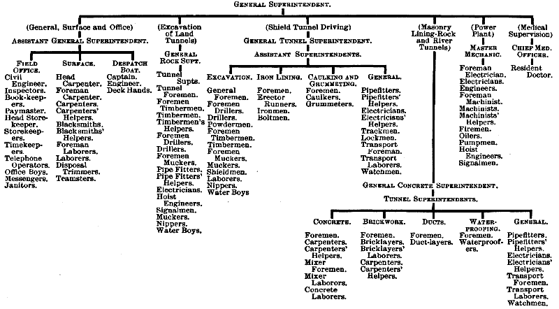 Fig. 24.
Contractor's Organization.—The contracting firm which did the
work described in this paper was the O'Rourke Engineering Construction
Company, of New York City. The President of this Company was
John F. O'Rourke, M. Am. Soc. C. E., the Vice-President was F. J.
Gubelman, Assoc. M. Am. Soc. C. E. The General Superintendent was
Mr. George B. Fry, assisted by J. F. Sullivan, Assoc. M. Am. Soc. C. E.
The duties of General Tunnel Superintendent fell to Mr. Patrick Fitzgerald.
The generally pleasant relations existing between the Company
and the contractor's forces did much to facilitate its execution.
The organization of the Contractor's field staff is shown on Fig. 25.
PENNSYLVANIA TUNNEL AND TERMINAL RAILROAD COMPANY.
NORTH RIVER DIVISION.
Sections Gy East, Gy West Supplementary, Gy West,
Gj, and I, i. e., From 10th Avenue, Manhattan, to the Weehawken
Shaft, Field Engineering Staff Organization.
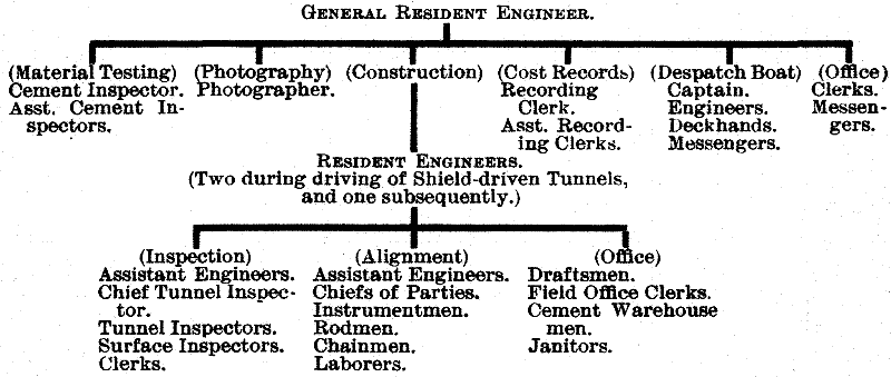 Fig. 25
In conclusion, the writers cannot forego the pleasure of expressing
their deep obligation to Samuel Rea, M. Am. Soc. C. E., as representing
the Management of the Company, to the Chief Engineer, Charles M. Jacobs,
M. Am. Soc. C. E., and to James Forgie, M. Am. Soc. C. E., Chief
Assistant Engineer, for their permission to write this paper, and also
to all the members of the field office staff for their great and
unfailing assistance in its preparation.


