1. BRICKWORK AND MASONRY BRIDGES—HANWELL VIADUCT—MAIDENHEAD
BRIDGE—FLYING BRIDGES—LETTER FROM MR. BRUNEL ON BRIDGE
CONSTRUCTION (DECEMBER 30, 1854)—2. TIMBER BRIDGES—SONNING
BRIDGE—BATH BRIDGE—STONEHOUSE VIADUCT—BOURNE VIADUCT—ST. MARY’S
VIADUCT—VIADUCTS ON THE SOUTH DEVON RAILWAY—IVY-BRIDGE—VIADUCTS
ON THE SOUTH WALES RAILWAY—NEWPORT—LANDORE—VIADUCTS ON THE
CORNWALL RAILWAY—ST. PINNOCK—VIADUCTS ON THE WEST CORNWALL AND
TAVISTOCK RAILWAYS—PRESERVATION OF TIMBER—3. CAST-IRON
BRIDGES—LETTER ON USE OF CAST IRON (APRIL 18, 1849)—HANWELL
BRIDGE—EXPERIMENTS ON CAST-IRON GIRDERS—EXTRACT FROM LETTER TO
SECRETARY OF COMMISSION ON APPLICATION OF IRON TO RAILWAY
STRUCTURES (MARCH 13, 1848)—4. WROUGHT-IRON BRIDGES—GIRDER
BRIDGES—EXPERIMENTS ON WROUGHT-IRON GIRDER—OPENING
BRIDGES—TRUSSED BRIDGES—NEWPORT VIADUCT—WINDSOR BRIDGE—CHEPSTOW
BRIDGE—METHOD OF SINKING THE CYLINDERS—DESCRIPTION OF THE MAIN
TRUSS—THE FLOATING OPERATIONS—THE ROYAL ALBERT BRIDGE AT
SALTASH—THE CENTRE PIER—DESCRIPTION OF THE SUPERSTRUCTURE—THE
FLOATING AND RAISING OF THE TRUSSES—OPENING OF THE BRIDGE BY H. R.
H. THE PRINCE CONSORT—NOTE: EXPERIMENTS ON MATTERS CONNECTED
WITH BRIDGE CONSTRUCTION.
IN Chapter IV. a general history has been given of the railways of which
Mr. Brunel was the engineer; but the bridges and viaducts designed by
him are so numerous and important that it has been thought advisable to
devote a separate chapter to their consideration.
The bridges selected for mention have been grouped according to the
nature of the material used in their superstructure. This arrangement is
the most convenient one for giving a concise description of the most
remarkable of Mr. Brunel’s bridges, and for stating the circumstances
which guided him in the determination of the particular form of
construction used in each case.
The works are therefore divided into four groups, namely, brickwork and
masonry, timber, cast iron, and wrought iron.[77]
Brickwork and Masonry Bridges.[78]
The viaduct which carries the Great Western Railway over the valley of
the river Brent near Hanwell is the first of Mr. Brunel’s important
railway works.[79] It is a handsome brickwork structure, 65 feet high,
with eight semi-elliptical arches, each 70 feet span and 17 feet 6
inches rise. The spandrils of the arches are lightened by longitudinal
spandril-walls; the piers are also hollow, and the structure is
throughout made as light as possible. It is on this account interesting,
as showing the care taken by Mr. Brunel from the commencement of his
practice to distribute the material in the simplest and most effective
manner.[80]
The great bridge over the Thames at Maidenhead contains two of the
flattest, and probably the largest arches that have yet been constructed
in brickwork. The river, which is about 290 feet wide, flows between low
banks; in the middle of the stream there is a small shoal, of which Mr.
Brunel took advantage in building the centre pier.
It was originally intended that the foundation of the bridge should be
on the chalk, which was at a short distance below the surface; but it
was found to be very soft, and Mr. Brunel therefore decided to place the
foundations of the bridge on a hard gravel conglomerate overlying the
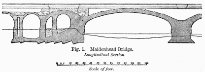
chalk. The main arches are semi-elliptical, each of 128 feet span and 24
feet 3 inches rise. They are flanked at each end by four semicircular
arches, one of 21 feet span, and three of 28 feet span, intended to give
additional water-way during floods. The radius of curvature at the crown
of the large arches is 165 feet, and the horizontal thrust on the
brickwork at that point is about 10 tons per square foot.
In the interior of the structure immediately landward of the large
arches, Mr. Brunel constructed flat arches loaded with concrete. The
centerings of these were struck, and an active thrust opposed to the
main arches before their centerings were eased.[81] The line of
pressure of each main arch was diverted downwards by the thrust of the
flat arch adjoining it without the necessity of employing a great mass
of brickwork in the abutment.
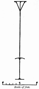
The woodcut (fig. 1) shows the form of the main arches and the flat arch
referred to.[82]
The Maidenhead bridge is remarkable not only for the boldness and
ingenuity of its design, but also for the gracefulness of its
appearance. If Mr. Brunel had erected this bridge at a later period, he
would probably have employed timber or iron; but it cannot be a matter
of regret that this part of the Thames, although subjected to the
dreaded invasion of a railway, has been crossed by a structure which
enhances the beauty of the scenery.
There are two other large brick bridges over the Thames, one at
Gathampton and another at Moulsford, that at Moulsford crossing the
river obliquely at an angle of 45°. In each of these bridges there are
four arches, of 62 feet span on the square.
Other good examples of brick bridges are the turnpike road bridge, 60
feet high, with three arches, across the deep cutting at Sonning Hill,
and the bridge, with one opening of 60 feet and four side arches of 18
feet span, over the river Kennet at Reading.
The bridge over the Avon at Bathford, of 87 feet span, and the bridge
crossing the same river at Bath, with an arch of 88 feet span, are
handsome Bath-stone structures with semi-elliptical arches. Near Bristol
there is an ornamental bridge of masonry with three Gothic arches, the
centre arch having a span of 100 feet.[83] Another bridge of Gothic
design, with two arches of 56 feet span, carries the railway over the
Floating Harbour.[84]
The bridges which have hitherto been noticed are all on the Great
Western Railway. On the Bristol and Exeter Railway there is a large
stone bridge over the New Cut at Bristol, built in 1840, which has a
single segmental arch of 120 feet span, and 20 feet rise. Owing to some
imperfect workmanship in the interior masonry of the arch, and possibly
to some unequal yielding of the abutments, the crown sunk much more than
had been expected.
On his later railways Mr. Brunel did not build large arches of brickwork
or masonry, though he constructed several lofty and extensive viaducts
of these materials with spans varying from 40 to 60 feet.
Mr. Brunel seldom employed artificially piled foundations to support
masonry. When the ground was soft, he preferred to rely on a large
extent of bearing surface, and ensured uniformity of settlement by an
accurate distribution of the load. Several of his large viaducts and
bridges, standing on ground of a soft and spongy nature, were
constructed on this principle.
A class of bridge of striking outline was used in the cuttings on the
Bristol and Exeter Railway, and on the other railways subsequently made.
Bridges of this class were called flying bridges. Instead of arches
resting on piers and abutments, the bridge has a single arch, reaching
from one side of the cutting to the other, and springing from the
slopes, which it helps in some measure to support. A flying bridge of
large dimensions near Weston-super-Mare carries a road across the
cutting at a height of 60 feet above the line of rails, with a clear
span of 110 feet.
The quantity of masonry in these bridges is much less than in those of
the ordinary construction; and lofty and expensive centering is not
required, as the bridge can be built before the cutting is excavated to
its full dimensions.
This class of bridge, by the avoidance of abutments and counterforts,
simplifies the construction of skew arches, while on sharp curves it
presents but little obstruction to the view along the line.
A curious use of arches of this construction, as applied by Mr. Brunel,
may be seen on the South Wales Railway near Llansamlet, between Neath
and Swansea. A deep cutting through the coal measures showed a tendency
to slip, and a large amount of excavation would have been required to
flatten the slope, as a hill rose immediately above the side of the
cutting. Four of these flying arches were thrown across the cutting at
short intervals, and weighted with heavy copper slag, so that the sides
of the cutting are kept apart by the thrust of the loaded arches.
Among the skew bridges on Mr. Brunel’s railways, there are a few of
extreme obliquity. Of these may be mentioned two large road bridges near
Berkeley, over the Bristol and Gloucester Railway, one being 48° and the
other 53° off the square. Both the bridges are of brickwork, and in the
arch of the first one, which was set in Roman cement, hoop iron was
introduced in the manner successfully employed by Sir Isambard Brunel.
On the South Devon Railway, near Plympton, there is a skew bridge 63°
off the square.
On the Great Western Railway, in the neighbourhood of Bath and Bristol,
there are skew bridges of ashlar masonry built on the mechanically
correct principle of spiral tapering courses, the bed-joints in every
part of the arch being made at right angles to the lines of pressure. By
this method the arch does not depend for its stability on the friction
and cohesion of the materials, as it does to a great extent in very skew
bridges, built in the usual way with spiral parallel courses, especially
when the arches are semi-circular or semi-elliptical.
Mr. Brunel’s bridges of masonry and brickwork were well known for the
comparatively small quantity of material used in them; and, though it
was requisite that the materials and workmanship should be of superior
quality, their cost was comparatively small.
The specifications he prepared for all his works, and on which the
contracts were based, were noted for the completeness with which they
were drawn up, and for their not requiring a standard of perfection
higher than that which was actually to be carried out. The confidence
with which Mr. Brunel was regarded enabled him to insist with effect on
the work being executed according to his interpretation of the
contract.
In connection with the design of engineering works, and especially of
brickwork and masonry bridges, the following letter from Mr. Brunel to
one of his assistants, who was abroad, will be found interesting:—
December 30, 1854.
Let me give you one general piece of advice—that while in all
works you endeavour to employ the materials used in the most
economical manner, and to avoid waste, yet always put rather an
excess of material in quantity. You cannot take too much pains in
making everything in equilibrio; that is to say, that all forces
should pass exactly through the points of greater resistance, or
through the centres of any surfaces of resistance. Thus, in
anything resembling a column or strut, whether of iron, wood, or
masonry, take care that the surface of the base should be
proportioned that the strain should pass through the centre of it.
Consider all structures, and all bodies, and all materials of
foundations to be made of very elastic india-rubber, and proportion
them so that they will stand and keep their shape: you will by
those means diminish greatly the required thickness: then add 50
per cent. So in trussed framework of wood or iron, experience
shows that you cannot refine too much upon the perfection of the
designing of every little detail by which all strains are carried
exactly through the centres of the rods or struts and the centres
of the bearing surfaces. And remember, always in retaining walls to
give plenty of batter; never build an upright wing-wall, or
retaining wall. To a man who has an instinctively mechanical
mind—and no other can be an engineer—the advice I have given you
above is all I need say; but this advice is the result of a good
deal of experience, purchased by failures of my own, and by looking
at those of others, and is, I assure you, valuable advice, to be
followed literally and strictly, and not to be considered as a mere
theoretical refinement, to be neglected in practice. Practically
too much attention cannot be paid to these precautions. I have
found that there is not a single substance we have to deal with,
from cast-iron to clay, which should not practically be treated
strictly as a yielding elastic substance, and that the amount of
the compression or tension, as the case may be, is by no means to
be neglected in practice any more than in theory. Bear in mind also
that which is too often neglected and involves serious
consequences, that masonry or brickwork has not half the strength
which is generally calculated upon until the mortar is hard, and
that you cannot keep centres or shores up too long.
Timber Bridges and Viaducts.
Mr. Brunel’s timber bridges and viaducts are remarkable on account of
the extensive scale on which he employed that material, and the simple
and efficient type of construction which he adopted in the largest
structure as well as in the smallest.
In 1841 Mr. Brunel constructed a timber bridge of five spans to carry a
public road over the Sonning cutting of the Great Western Railway, a
short distance east of Reading. The total width of the space across
which the road had to be carried was 240 feet. The superstructure rests
on four tall frameworks or trestles of timber forming the piers. Two of
these piers are on either side of the railway, and the others are about
halfway up each slope.
The road rests on a platform of timber planking, carried on three
longitudinal beams, which are supported at nearly equal distances by
timber struts radiating from points on the piers about 12 feet below the
level of the carriage road. The system of arrangement of these struts
will be best understood by a reference to the woodcut given below (fig.
5, p. 187) of one of the Cornwall viaducts, of which the Sonning bridge
may be regarded as in some measure the prototype.[85]
The skew timber bridge on the Great Western Railway near the Bath
Station, carrying the line over the river Avon, was constructed about
the same time as the Sonning bridge. It has two spans of 36 feet each on
the square, but the obliquity is so great that the span on the skew is
89 feet. Each opening has six laminated arched ribs parallel to the line
of the railway. These support the platform of the bridge, and are built
up in five layers of curved Memel timber, six inches thick, bolted
together. The thrust is counteracted by iron ties connecting the ends of
the ribs. The inner spandrils are filled in by cross-ties and braces,
and those of the outer ribs by ornamental cast ironwork.
The two bridges already described are almost the only timber bridges of
importance on the main line of the Great Western Railway from London to
Bristol. Shortly after the completion of this railway Mr. Brunel began
to make an extensive use of timber in his designs, and in so doing took
full advantage of the largeness of the material, in order to avoid
intricacy of construction.
A well-known arrangement for forming beams of greater strength than
could be obtained by single pieces of timber was adopted by Mr. Brunel
after a careful investigation of its merits. This arrangement consists
in joining together two beams of timber placed one above the other, by
means of bolts and joggles, so as to form a beam nearly equivalent in
strength to a single piece of timber of the same depth as the two pieces
united.[86] By this plan, the length which could be spanned by simple
beams, without the introduction of trussed framework, was nearly
doubled.
The distance between the piers of railway bridges is generally too great
to allow of the superstructure being constructed of simple beams, and in
such cases Mr. Brunel adopted forms of framing similar in the
arrangement of their parts to the common designs of king and queen
trusses employed in roofs.
One of Mr. Brunel’s early timber viaducts was that erected in 1842 at
Stonehouse, on the Bristol and Gloucester Railway. It consisted of a
series of five openings of queen trusses 50 feet span, resting on piers
formed of timber trestles.
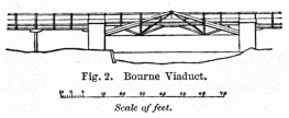
In the Bourne viaduct, across the Stroudwater Canal, on the Cheltenham
and Great Western Union Railway, there was a span of 66 feet, with three
timber trusses, for the two lines of way. Each of these trusses may be
described as a king truss with an internal queen truss. The inclined
timbers or principals rested in iron shoes upon the piers, and were
connected together by bolts and joggles.
The upper horizontal or collar beam of the queen truss carried the
roadway planking, which was continued upon beams supported by the
principals. The timbers carrying the roadway received support from
struts radiating from the feet of the queen posts, which were connected
with the apex of the king truss by iron ties. The horizontal tie bars
were of wrought iron. The arrangement of the truss is shown in the
woodcut (fig. 2).
The side openings consisted of four spans of 30 feet, with trusses of
the Stonehouse viaduct type, of one span of 25 feet and ten spans of 20
feet, with double beams.
The St. Mary’s viaduct, across the canal in the Stroud Valley, was
constructed with one span of 74 feet, with trusses similar to those at
the Bourne viaduct.[87]
In the year 1846 Mr. Brunel made an elaborate series of experiments on
the strength of large timber. Some account of these is given in the note
to this chapter.
Fortified by the information thus obtained, he was able to proceed with
confidence to an extensive use of timber in the viaducts of the South
Devon, the Cornwall, and other railways.
Between Totness and Plympton, the South Devon Railway, running along the
skirts of Dartmoor, crosses four deep valleys, by lofty viaducts, all of
the same design.
Three of them can be seen at one time, and they form striking and
elegant features in the landscape.
The viaduct at Ivybridge is the highest of these. It is on a curve, and
has eleven openings of 61 feet each; the extreme height is 104 feet.
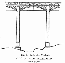
The piers are of masonry, each consisting of two slender and slightly
tapered shafts about 7 feet square, rising to the level of the rails.
The superstructure was originally designed for a railway on the
Atmospheric System, and was therefore only intended to bear the load of
a train of carriages. The framework was placed below the level of the
rails, and, as will be seen in the woodcut (fig. 3), it consists of a
polygonal frame, with a few subsidiary struts, the feet of the main
timbers being tied together by wrought-iron rods. There are two of these
frames, one at each side of the bridge, to support the planking of the
roadway. Before the construction of the viaducts was proceeded with, a
complete span of the superstructure, consisting of a pair of the frames
with the planking, was erected at Bristol, and tested to ascertain the
efficiency of every part.
When it became necessary to strengthen the superstructure to enable it
to carry the weight of locomotives, a strongly trussed parapet was added
above the trusses, as shown in the woodcut. After the lapse of twenty
years, the timber having begun to decay, wrought-iron girders have been
inserted, which rest on the stone piers; the framing, however, has not
been removed.
Shortly after the completion of the viaducts on the South Devon Railway,
those on the South Wales Railway were constructed. The most important on
this line are those at Landore and Newport.
The viaduct at Landore, near Swansea, is 1,760 feet long, as the railway
here crosses a wide valley. It has 37 openings, and there are a variety
of spans, one of 100 feet, two of 73 feet, two of 64 feet, two of 50
feet, and the rest of about 40 feet each. Most of these consist of a
superstructure of queen trusses. The piers are of different materials,
some being almost entirely of masonry, some partly of masonry and partly
of timber, and others entirely of timber, according to the nature of the
foundation.[88] The chief feature is the centre span, with an opening
of 100 feet, the superstructure of which is a very fine piece of
timber-work.[89] It has four trusses, one on either side of the two
lines of rails, of the form shown in the woodcut (fig. 4). The truss
consists of a four-sided frame placed within a five-sided frame, the
angles of each polygon being connected by bolts and struts with the
middle of the sides of the other polygon.
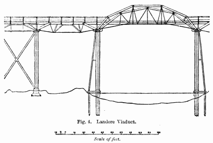
The planking of the roadway rests on double beams, supported at several
points in the manner shown in the woodcut, each point having
suspension-rods to connect it with the nearest angles of the frames. The
arrangement of the double polygonal frame and of the tie-rods enables
the transverse strength of the timbers to exercise considerable
resistance to any distortion of the shape of the truss by a rolling
load. To prevent any tendency of the top of the frame to yield sideways
under the compressive strain, the tops of the trusses are connected by
transverse struts or braces, the two outside trusses being steadied by
raking ties attached to outriggers projecting from below the flooring of
the bridge. The thrust of the polygonal frames is resisted by
wrought-iron tie-bars at the level of the roadway beams. All the
tie-rods in this bridge are double, with one bar on each side of the
timbers, to avoid the necessity of making large bolt-holes.[90]
The viaduct at Newport consists of eleven spans with queen trusses,
resting on piles. The main span, over the river Usk, is 100 feet, and
was constructed with timber trusses very similar to those at Landore.
Shortly before it was finished, the viaduct was burnt down. In
rebuilding it, wrought-iron trusses were employed for the main span.
The works of the Cornwall Railway were commenced in the year 1852. The
district through which the line passes is very deficient in the
materials requisite for the construction of a railway. The granite of
the country is for the most part only applicable for ashlar; and the
slate, which is flat-bedded and so far fit for rubble masonry, is
frequently inferior in quality.
In consequence of the number of valleys that the railway had to cross,
the aggregate length of the viaducts, thirty-four in number, exclusive
of the Saltash bridge, is upwards of four miles on a line of sixty
miles. By the use of timber, a great saving was effected in the first
cost of the works; and though it is a material which in time requires
renewal, its use on the Cornwall Railway enabled the line to be made
with the capital at the command of the Company; while, allowing for the
cost of subsequent repairs, the total expenditure did not differ much
from what it would have been had the superstructure of the viaducts been
of more durable materials. The comparatively small cost of these
structures enables them to be, in certain places, economically
substituted for embankments, as was done on the Cornwall Railway.
The viaducts are to be found over the whole length of the line, but they
are most frequent between the Liskeard and Bodmin Road stations, where
the railway crosses numerous branches of the Glynn valley.
Most of these viaducts are of one type of construction.
The piers are formed of plain walls, built up to thirty-five feet below
the level of the rails, those of the more lofty viaducts being
strengthened by buttresses. In the woodcut (fig. 5) is shown a portion
of the St. Pinnock viaduct, from which the form of these piers will be
understood.
This viaduct is the loftiest on the Cornwall Railway, the rails being at
a height of 153 feet above the ground. A description of the
superstructure will serve to explain the design of the principal
viaducts on the line.
The roadway planking rests on three beams, which run longitudinally
throughout the whole length of the viaduct. Each of these beams consists
of two pieces of timber, one above the other, fastened together by bolts
and joggles. The piers are 66 feet apart, centre to centre, and the
longitudinal beams are supported, at four nearly equidistant points in
this space, by straight single timbers radiating from the tops of the
piers. The feet of the timbers, which rest on the masonry in cast-iron
shoes, are connected together by wrought-iron tie-bars; and the
framework is made rigid by iron diagonals.
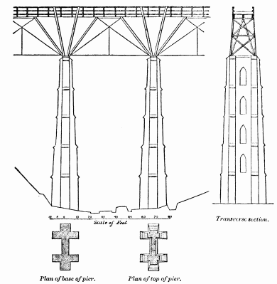
It will be observed in the transverse section (fig. 5) that the whole
weight of the superstructure is concentrated immediately over those
points in the piers where the three buttresses meet. The diagonal braces
which are attached to each set of the main timbers give transverse
stability to the superstructure.[91]
It was desirable, both in first construction and in subsequent repairs,
to have a uniform dimension for the spans, and the subdivision of 66
feet was determined on as being suitable for the economic construction
of the greater part of the work. The subdivision of this length was such
as to allow of single whole timbers being sufficient for the direct
supports of the longitudinal beams; and as these beams were supported at
intervals of 15 to 20 feet, no intermediate trussing was required. As
the inclined timbers met the tops of the piers at a moderate
inclination, the outward thrust caused by unequal loading of the spans
of the viaduct was inconsiderable, and was easily counteracted by light
iron ties.
The stone for the piers was for the most part procured in the
neighbourhood, the design of the masonry being such as to enable stone
of the country to be used; and, as the timber superstructure was built
in pieces of moderate size,[92] and easily obtained, the expenditure was
probably not far from the minimum under the existing conditions.[93]
On the South Devon and Tavistock Railway, the viaducts are six in
number, and from 62 to 132 feet in height. In these the piers were made
of a somewhat simpler form than those just described. At the lofty
viaducts, the buttresses were made with a uniform batter throughout
their height. The Walkham viaduct, near Tavistock, 132 feet high, with
fifteen openings of 66 feet span each, may be considered to exhibit the
most matured design of Mr. Brunel’s timber viaducts.
On the West Cornwall Railway a type of viaduct similar to that described
above was adopted; but as the general height was not so great, the spans
were 50 feet each, and the longitudinal beams were supported at three
points in each span, instead of at four as on the Cornwall Railway. In
consequence of the nature of the foundations, the piers of the nine
viaducts on this line were for the most part formed of upright timbers
well braced together, standing upon masonry footings. The viaduct at
Angarrack, 98 feet high, with 16 spans, which was constructed in 1851,
was remarkable for its light appearance, owing to the small number of
timbers in the superstructure and piers.
Mr. Brunel paid great attention to the preservation of the material of
the timber bridges and viaducts. As early as 1835 he had been in
communication with Mr. Faraday as to the best method of testing the
extent to which the Kyanising solution penetrated into wood. Mr. Brunel
made a careful trial of all the different methods of preserving timber,
and employed the more successful of them on a very considerable scale.
He was so impressed with the importance of the preserving processes
being properly applied, that he on several occasions preferred to keep
the operation of preserving the timber in the hands of the Company, in
order that it might be done thoroughly, and under his own supervision.
He also minutely attended to the details by which timber structures may
be protected from decaying influences.
Cast-Iron Bridges.
Mr. Brunel did not make an extensive use of cast iron for the
superstructure of bridges. His views as to the employment of this
material in girders are clearly expressed in the following extract from
a letter to one of the Directors of the Great Western Railway:—
April 18, 1849.
Cast-iron girder bridges are always giving trouble—from such cases
as the Chester Bridge, and our Great Western road bridge at
Hanwell, which, since 1838, has always been under repair, and has
cost its first cost three times over, down to petty little ones,
which, either in frosty weather or from other causes, are
frequently failing. I never use cast iron if I can help it; but, in
some cases it is necessary, and to meet these I have had girders
cast of a particular mixture of iron carefully attended to, and I
have taught them at the Bridgewater foundry to cast them with the
flange downwards instead of sideways. By these means, and having
somebody always there, I ensure better castings, and have much
lighter girders than I should otherwise be obliged to have. The
number I have is but few, because, as I before said, I dislike
them, and I pay a price somewhat above ordinary castings, believing
it to be economy to do so.
I won’t trust a bridge of castings run in the ordinary way, and at
foundries where I have not a person always watching; and, even if I
did, the weight requisite in a beam of ordinary metal and mode of
running would more than make up for the reduced price.
The bridge at Hanwell referred to in this letter was one on the main
line of the Great Western Railway, over the Uxbridge road. In 1847 the
planking caught fire, and the cast-iron girders were destroyed by the
heat.
The researches of Mr. Eaton Hodgkinson had drawn attention to the
importance of a proper proportionment of the top and bottom flanges of
cast-iron girders, and Mr. Brunel now made some experiments on this
point. As part of this investigation, eight girders, 30 feet long and 16
inches deep, were tested by weights until they gave way. The
comparative areas of the top and bottom flanges were varied until a
correct proportion between the two was arrived at. The general result of
these large-scale experiments showed a lower breaking-weight than that
deduced from Mr. Hodgkinson’s formula.
When Mr. Brunel afterwards had occasion to use cast-iron girders, which
was chiefly for road bridges over railways, they were made of the form
which his experiments had shown to be the best;[94] but he repaired the
Hanwell Bridge with wrought iron.
At about the same time the necessity for spanning wide openings had led
to larger girders being required than could be manufactured in single
castings, and Mr. Brunel had a large cast-iron girder made, 46 feet long
and 4 feet deep, of five pieces bolted and keyed together. It was tested
until it gave way with a load of 92 tons on the middle. The result
showed that the several parts had been well connected, and that the
strength of the beam was not much less than the calculated strength of a
beam of the same size in a single piece. Mr. Brunel did not, however,
use girders of this construction, as the rapid introduction of wrought
iron rendered it unnecessary.
Cast iron was introduced, though not for girders, in many of the brick
and stone bridges on the Great Western Railway. It was used in the form
of troughs sunk into the crown of the arch in bridges where the headway
was very limited. The rails were laid along the bottom of the trough
within a few inches of the soffit or underside of the arch.
Although, after the careful experiments and investigations he had made,
and the experience he had obtained, Mr. Brunel did not make use of cast
iron for large girders, he looked forward to the possibility of such
improvements being introduced into the manufacture as would enable sound
castings of considerable size to be made of homogeneous material.
He expressed this opinion in a letter to the Secretary of the Commission
on the Application of Iron to Railway Structures. This Commission (which
Mr. Brunel called ‘The Commission for stopping further improvements in
bridge building’) was appointed ‘for the purpose of inquiring into the
conditions to be observed by engineers in the application of iron in
structures exposed to violent concussions and vibration.’ Mr. Brunel, in
common with most engineers, thought it would be very inexpedient that
any règles de l’art should be laid down, and took up the cudgels
boldly on behalf of the liberty of the profession:—
March 13, 1848.
At present cast iron is looked upon, to a certain extent, as a
friable, treacherous, and uncertain material; castings of a limited
size only can be safely depended upon; wrought iron is considered
comparatively trustworthy, and by riveting, or welding, there is no
limit to the size of the parts to be used. Yet, who will venture to
say, if the direction of improvement is left free, that means may
not be found of ensuring sound castings of almost any form, and of
twenty or thirty tons weight, and of a perfectly homogeneous
mixture of the best metal? Who will say that beams of great size of
such a material, either in single pieces or built, may not prove
stronger, safer, less exposed to change of texture or to injury
from vibration, than wrought-iron, which in large masses cannot be
so homogeneous as a fused mass may be made and which when welded is
liable to sudden fracture at the welds?[95]
Wrought-Iron Bridges.
Notwithstanding the cost of wrought iron, but a short time elapsed
between its introduction into bridge building and its use in structures
of great magnitude. Mr. Brunel had been long familiar with the
application of riveted wrought-iron work, and he was the first to
encourage its use on a large scale in shipbuilding by recommending its
adoption in the ‘Great Britain’ steam-ship in 1838.
Girder Bridges.
The strains on girders made of homogeneous material have been carefully
and ably calculated by mathematicians; and the investigations thus made
have directed inquiry into the right channels for determining the nature
of the stresses on the several parts of the built-up structures now so
much in use. Principles have by degrees been laid down, and lines of
thought have been suggested and followed out which were unknown at the
time when wrought-iron girders were first introduced in the construction
of railway bridges.[96]
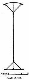
Shortly after Mr. Brunel began to use wrought iron for bridge girders,
he made an experiment in order to determine the weak points of a large
wrought-iron plate-girder. Mr. Edwin Clark, in his work on the
‘Britannia and Conway Tubular Bridges,’ vol. i. p. 437, gives a
description of what he justly terms ‘this magnificent experiment.’ The
girder was of the section shown in the woodcut (fig. 6), 70 feet in
length, and of ¼-inch plate throughout. It was weighted gradually, and
gave way with a load of 165 tons on the centre, by the tearing apart of
the vertical web plate near the ends of the girder. When this portion
had been strengthened, and the girder again loaded, it gave way with a
load of 188 tons by the simultaneous failure of the top and bottom
flanges, that is to say, of the plates forming the triangles shown in
the woodcut.[97]
The superior tensile strength of wrought iron to that of cast iron, and
the facility with which pieces could be joined together by riveting,
enabled girders of great size to be made. The thin wrought-iron plates
were arranged so as to form the top and bottom flanges of the girders as
well as the upright web connecting them. The metal in the top of a
girder being in compression, it was important so to dispose it that it
should resist the tendency to yield sideways under the strain. This
requirement was met in the experimental girder by the triangular section
of the top flange; and the convenience of this form for joining together
a number of plates, without difficulty or the use of long rivets, led
Mr. Brunel to use the triangular section also for the bottom flange.
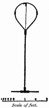
Subsequent improvements in the facilities for bending wrought-iron
plates enabled him to use a form of cross section of wrought-iron
girder, the top flange of which was a nearly circular tube, the best
shape of strut to resist longitudinal compression. It is shown in the
woodcut (fig. 7), and was used in many of his bridges.
This form was afterwards modified to that shown in fig. 8. The
semicircular top plate is stiffened by occasional cross diaphragms, and
while it was a good form to resist compression, it was more easily
painted than the closed-in top flanges shown in figs. 6 and 7.
The forms of wrought-iron girder already referred to are those known as
plate girders, with continuous webs made of plates riveted together, and
therefore analogous to the beams of cast iron which they almost entirely
superseded. On Mr. Brunel’s railways there are a great number of bridges
of these forms of girder, where the spans do not exceed 100 feet. For
larger spans he used wrought iron, in large and deep trussed frames, by
which means a great degree of economy was attained in the employment of
the material.
The care which he had taken to satisfy himself of the action of the
strains in plate girders was of service in all the greater structures he
designed, as in all of them he employed wrought-iron girders to carry
the roadway, of a type somewhat similar to those already described, the
girders being supported at frequent intervals by the main framework or
truss.
Opening Bridges.
The first large opening bridge which Mr. Brunel constructed was a
roadway swing bridge, 12 feet wide, across the new lock at the Bristol
Docks. The length of the overhanging end is 88 feet, and the other, or
tail end, which is 34 feet long, rests upon two wheels, which travel on
a circular rail. The weight of the overhanging end is rather more than
counterbalanced by large blocks of cast iron, forming part of the
pavement of the tail end. Almost the whole weight is borne on a centre
pivot, assisted by four wheels in fixed bearings, upon which runs an
inverted circular rail attached to the underside of the bridge. On the
pivot, which rests on a large cast-iron bed-plate, are two discs, one of
steel and the other of brass, which can readily be lubricated, or taken
out and renewed.
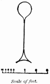
On the sides of the bridge are longitudinal wrought-iron plate-girders.
The top flange is pear-shaped, and the bottom flange triangular, having
three curved plates. The flanges are connected together by a vertical
plate web of wrought iron. The section is shown on the woodcut (fig. 9).
It admits of very simple riveting, without the use of angle irons. The
form of the bottom flange is suited to the compressive strain it has to
bear when the bridge is being moved. The top flange has also
wrought-iron tie-bars within the tube. When the bridge is across the
lock and open for traffic, the overhanging end rests on cams, which are
tightened up so as to lift and support the ends of the girders. As the
bridge rests almost entirely on a pivot of small diameter, it turns with
great ease.
Near Gloucester there are two skew swing bridges somewhat similar to
each other in arrangement. Almost all the weight while turning is
supported on the piston of a hydraulic press, and the bridge therefore
turns round on the water in the cylinder. The first bridge is on the
main line of railway leading to South Wales, across a branch of the
River Severn, and is for two lines of way. It has three girders, 125
feet long, of the form shown in fig. 7 (p. 194). The water pivot is in
the middle of the length of the bridge, which spans two openings of 50
feet on the square. Before being turned the bridge was intended to be
lifted slightly off its bearings by the hydraulic press, and steadied by
four wheels, on which a portion of the weight was to be made to rest by
long springs within the girders, the range of which was to be limited in
one direction by a fixed stop. The central pier consists of five
cylinders of cast iron, each 6 feet in diameter, filled with concrete,
surmounted by a cast-iron ring or roller path. The railway company was
obliged to make this an opening bridge in order to provide for the free
navigation of the river should the old stone bridge lower down be
altered. This has not been done, and the railway swing bridge,
constructed in 1851, has not yet been opened.
The other swing bridge at Gloucester is on the Dock branch, for one line
of way, with an opening of 50 feet on the square, the overhanging length
of the girders being 70 feet. While raised from its bearing and turning
on its water pivot it is steadied by two tail wheels, like the bridge at
the Bristol Docks.
On the Bullo Pill branch of the South Wales Railway there is a small
wrought-iron drawbridge, for one line of way, of 30 feet span. It is a
lifting bridge on the bascule principle, like many bridges over canals
in this country and in Holland. The opening part turns on a horizontal
axle, and is lifted by rods attached to the ends of two large beams or
levers, turning vertically, which are supported above the railway on a
timber framework. At the other ends of these beams is a counterbalance
weight. The bridge is opened or shut by pulling down either end of the
beams with a small chain.
The other bridges are on the main line of the South Wales Railway, and
are four in number, each for two lines of way.
One at Loughor is a wrought-iron swing bridge, of 30 feet opening, of
the ordinary construction, with girders 90 feet in length, resting upon
36 rollers, which are secured in a ring concentric with the pivot. The
opening and closing is effected by means of a crab, fixed clear of the
bridge, near the centre. A chain passes from the overhanging end of the
bridge to this crab, and taking one or two turns round the barrel, to
ensure a sufficient amount of friction, is led to the tail end. The
bridge can thus be opened or shut by turning the crab handle in opposite
directions. The overhanging end, when across the river, is raised
upwards to a small extent by weighted levers, and wedges are then drawn
in under it to give it a solid bearing.
At Kidwelly and at Haverfordwest there are wrought-iron lifting bridges,
the former of 20 feet, and the latter of 30 feet span. Each of these
turns on a horizontal axle like the Bullo Pill bridge; but, instead of
being lifted by levers overhead, it has a narrow, heavily-weighted tail
end, beneath the planking of the viaduct, which is pulled down with a
chain worked by a crab. The portion which carries each line of way is
made to open independently. In this form of bridge no wedges or
adjusting arrangements are required for the bearings of the overhanging
end.
Over the river at Caermarthen is a skew bridge of three girders, each
116 feet long, for a double line of way. It occupies two spans and rolls
back, so as to leave a 50-feet opening for the navigation. The swing
bridge at Bristol, already described, was at first intended to be a
rolling bridge, and to be furnished with wheels to run back on fixed
rails, but the difficulty of forming a good foundation for the wheel
path led to the design being altered. At Caermarthen the same difficulty
was overcome by putting wheels turning in fixed bearings on the pier and
abutment of the bridge. The undersides of the girders carry inverted
rails, and run back on the wheels. The bridge, when shut, is on an
incline of 1 in 50. When about to be opened it is made to assume a
horizontal position by turning a supporting cam to lower the overhanging
end, and the tail end then rises sufficiently to pass clear above the
part of the railway over which it runs back.
By this arrangement the bridge, while in motion, moves along a level
path. It is opened and closed by hydraulic machinery.
All these opening bridges have worked satisfactorily since they were
constructed.
Trussed Bridges.
When the timber viaduct over the river Usk, at Newport, was burnt
down,[98] Mr. Brunel decided to form the new superstructure of the
centre opening with three iron trusses, for the two lines of way.
These are bow and string girders, of 100 feet span, and were made of
considerable height, not only to reduce the strain on each of the
members of the framework, but also in order that the rib or upper
portion of each truss might be braced diagonally to the corresponding
portion of the other trusses, and headway left for the locomotive
chimneys to pass underneath. This bracing counteracts any tendency of
the ribs to bend sideways under the compressive strain. The form of the
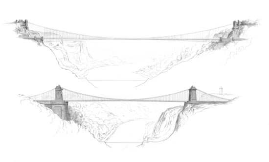
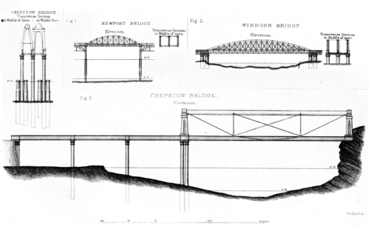
trusses is shown in fig. 1, Pl. IV. (p. 206). Each truss is a
wrought-iron polygonal arch of triangular section, from which is
suspended a horizontal girder supporting the roadway. This girder also
forms the tie which connects the feet of the arch and counteracts its
thrust. The diagonal braces shown on the elevation of the bridge prevent
the arch from being distorted by the unequal loading caused by a
passing train. The middle truss is twice the strength of each of those
at the outside, being made so by increasing the thickness of the plates.
One of the outside trusses was tested with a distributed load of 1½ tons
per foot-run of its length.
At about the same time that the Newport viaduct was reconstructed, Mr.
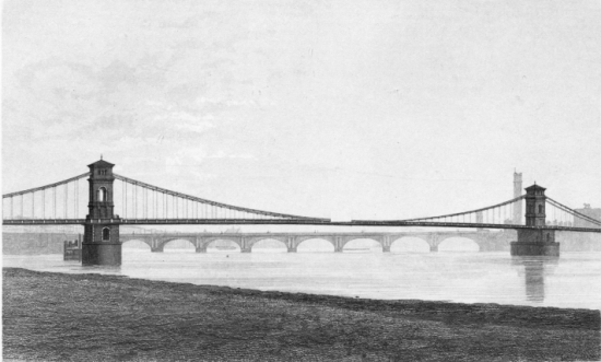
Brunel designed the bridge over the Thames on the Windsor branch of the
Great Western Railway. This is a very large example of the bow and
string girder, the span being 202 feet, and the height of the truss 23
feet. The trusses are three in number, for two lines of way, the middle
one being twice the strength of the outside trusses. The elevation of
the Windsor bridge is shown in fig. 2, Pl. IV. (p. 206). The bridge is
oblique to the river, being 20° off the square. To steady the arched
ribs sideways a system of diagonal bracing extends over the whole of the
top of the trusses, except at the ends, where headway has to be left for
the trains.
A section of the arched ribs and of the roadway girders in the centre of
one of the trusses is given in the woodcut (fig. 10). The arched rib, to
resist compression, is of triangular section.[99]
The borings to ascertain the nature of the ground at the foundations of
the piers were made in 1846, but it was not until 1848 that the works
were commenced. Each abutment consists of six cast-iron cylinders, 6
feet diameter, which were sunk by excavating the gravel from their
interior by hand dredging and by placing weights on the top so as to
force them down.
When each cylinder had been by this means sunk low enough to ensure a
good foundation, it was filled with concrete in the following manner. A
mixture formed of Thames ballast and Portland cement, in the proportions
of 8 to 1, was put into a canvas bag; this was lowered inside the
cylinder to the bottom, and, by pulling a rope, the mouth of the bag was
opened, and the concrete deposited under water in the bottom of the
cylinder. Whenever the work was interrupted, great care was taken before
recommencing it to clean off any deposit, in order that the new concrete
might adhere well to the old. When the cylinder had been filled to such
a height that there was no danger of its floating up when emptied, the
water was pumped out. The inside was then filled with concrete in the
ordinary manner. On the top were placed oak platforms, which support the
trusses of the bridge.
One of the outside trusses was tested at Bristol in July 1849, by
loading it gradually with iron rails, beginning from one end, until the
whole truss was uniformly weighted with 270 tons, or 1½ tons per
foot-run, observations on the deflection of different points of the
bottom girder being made both during the loading and unloading. The
results of this test were perfectly satisfactory.
The superstructure of the bridge was erected on scaffolding, and the
line was opened on October 8, 1849.
It will be desirable here to notice one or two important features in
this as in almost all Mr. Brunel’s bridges.
The ordinary permanent way was laid over the bridges with ballast of
sufficient thickness to enable the road to be kept in repair in the same
manner as the other parts of the line. As there was no change in the
nature of the support given to the rails, no concussion was caused on a
train entering or leaving a bridge. The ballast took off from the
structure the vibration of the train; and, in the event of carriages or
even engines getting off the line, it helped in a great measure to
prevent their ploughing through the flooring. Where the flooring was of
timber the ballast protected it from fire. Also in long bridges there
was no necessity for any contrivance of sliding rails to allow for the
effects on the structure of changes of temperature. On the other hand,
the ballast added to the weight on the bridge. With the timber viaducts
this was an advantage, since it kept the various parts of the framework
in close contact, and prevented sudden jars being brought on them by the
rapidly applied load of a passing train. Even on the large bridges the
cost of the extra material requisite to support the weight of the
ballast was more than compensated for by the advantages above referred
to.
Mr. Brunel employed timber flooring, as being the safest in the case of
carriages getting off the line, and also as being the cheapest. This
flooring in the iron bridges was generally laid diagonally on
wrought-iron cross girders, which were placed not at right angles to the
line, but obliquely, in order that the two wheels of the same axle of an
engine or heavy waggon might be on different cross girders at the same
time. By this arrangement the cross girders could be made of less
strength, and a saving effected in their cost and weight.
The bridge over the Wye at Chepstow, and the Royal Albert Bridge over
the Tamar at Saltash, are the largest and most important of Mr. Brunel’s
bridges.
They are remarkable not only for their dimensions, but also for the
economical character of the designs, the form of their superstructures,
and the methods by which the foundations of the piers were made.
At the part of the river Wye where it is crossed by the Chepstow Bridge,
a cliff of limestone rock rises on the left bank to a height of 120 feet
above the bed of the river, forming the precipitous edge of a broad
table-land; while on the right bank the ground slopes gently for a
considerable distance, rising only a little above high water, and is
composed partly of clay and partly of loose shingle interspersed with
large boulder stones. As it was necessary to leave a clear headway of 50
feet above high water for the navigation, the line on one side of the
river is on an embankment of great height, and on the other side it
penetrates the cliff about 20 feet below the top. The whole space to be
bridged over, 600 feet wide, was divided into a river span of 300 feet,
and three land spans of 100 feet each (see fig. 3, Pl. V. p. 206.) At
one end of the great span a secure abutment was offered by the cliff of
limestone rock; but at the other end, and under the piers of the smaller
spans, the ground throughout was soft, and full of water. There was,
however, rock at a depth of 30 feet below the bed of the river.
To reach this foundation with masonry, by means of a coffer dam, was
almost impracticable, as it was 84 feet below high water.
The plan of building a stone pier on a foundation of piles was
considered, and abandoned on account of the expense.
The method of sinking the cast-iron cylinders of the Windsor bridge has
been already described. The pneumatic process of sinking cylinders had
been introduced with great success at the Rochester bridge.
In this process the cylinder is closed at the top and air forced in by
pumps until the water is expelled at the bottom. Workmen in the interior
excavate the ground and remove any obstacles which prevent the cylinder
from sinking, weights being added to force it down. As the air within is
at high pressure, the workmen enter, and the materials are passed in and
out, through an intermediate chamber, called an ‘air lock,’ fitted with
air-tight doors. The pneumatic method was ultimately employed at
Chepstow, to assist in sinking the cylinders.
Before he decided on the plan for the foundations, Mr. Brunel had an
experimental cylinder made of cast iron, 3 feet in diameter, at the
bottom of which was an exterior screw flange 12 inches broad, and 7
inches pitch, making one complete turn. This screw cylinder penetrated
the ground like an ordinary screw pile. In one instance it was rapidly
sunk to a depth of 58 feet, through stiff clay and sand, in 142
revolutions;[100] yet, on another trial, when boulders were encountered,
there did not appear to be sufficient penetrating power. In one of these
trials, the screw, having got into a bed of running sand, had no hold,
and failed to descend. Mr. Brunel then had the cylinder partly raised,
and another screw added at some distance above the lower one. It was
then successfully screwed down.
Mr. Brunel, however, ultimately decided on forming the piers of
cast-iron cylinders forced down by loading and afterwards filled with
concrete, and the work was commenced in the spring of 1849.
With this form of construction all uncertainty of obtaining a secure
foundation was removed, as the pneumatic method was in reserve, in case
of excessive influx of water, to sink the cylinders to the rock, if it
could not be reached by simpler means; and additional cylinders could be
added, so as to obtain any amount of area of base that might be thought
necessary.
The land piers for the 100 feet spans consist each of three cylinders,
which are 6 feet in diameter, joined together in lengths of 7 feet. The
main pier, which supports one end of the great truss, consists of a
double row of cylinders, six in all, the lower parts of which are 8 feet
in diameter, joined together in lengths of 6 feet. The bottom of each
cylinder was made with a cutting edge, so as to penetrate the ground
easily.
Most of the cylinders were sunk by the process of excavating the ground
within them and weighting the top, the water being kept down by pumping.
As the ground consisted chiefly of wet sand and shingle, danger was
apprehended from its tendency to run in from the outside, while the
excavation was in progress. This would have diminished the lateral
stability of the cylinders; and great care was taken not to excavate too
near the bottom, but merely to loosen the ground round the cutting edge
and to force the cylinder down by weights. Stiff clay was sometimes used
to prevent the wet sand and gravel from being squeezed in from the
outside. When the cylinders had been sunk to the rock, and it had been
dressed off to form a level foundation, they were filled with concrete
in the same manner as at the Windsor bridge.
In sinking the cylinders of the main pier, much greater difficulties
were encountered than with those of the land piers, owing to large
boulders and pieces of timber being met with near the bottom. When still
at some distance from the rock, a length of one of these large
cylinders cracked, from its having met with an obstruction. Timber
struts were then fixed within it, until the obstacle was passed, when it
was strengthened by a strong wrought-iron hoop, and forced down to the
rock.
In April 1851, when the greater number of the cylinders had been sunk,
it was apparent that, from delays due to the influx of water and other
causes, some of them could not be completed by the time that the
superstructure would be ready. Mr. Brunel then decided to employ the
pneumatic method, and by means of this apparatus some of the remaining
cylinders were sunk. In the main pier four auxiliary columns, formed of
7-feet cylinders, were placed close to the others. They were connected
to the 8-feet cylinders by strong brackets, and supplied a great
additional bearing surface. Any slight inaccuracy of position in the
cylinders was corrected by adjusting cones at the level of the ground;
on these cones 6-feet cylinders were built up to the level of the
railway.
The depth to which the cylinders were sunk and their position are shown
in fig. 3, Pl. IV. From this drawing also the general form of the
superstructure will be understood.
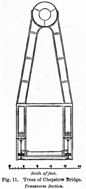
The bridge is for two lines of way; each line is carried between two
longitudinal girders 7½ feet deep, of the section given in the woodcut,
fig. 11 (p. 208). Each girder has a triangular top flange with a plate
iron vertical web, and a slightly curved plate for the bottom flange.
The roadway girders over the three land spans of 100 feet are in one
piece, and are therefore continuous girders, 300 feet long, supported at
two intermediate points. Those across the main span are also 300 feet
long, and are supported by the main truss.
PLATE IV
IRON BRIDGES
[Larger view]
[Largest view]
The truss for each line of way consists of two suspension chains, one on
each side of the roadway, hung from either side of the ends of a
horizontal circular tube, arched slightly for the sake of appearance,
which rests on piers rising about 50 feet above the level of the rails.
The pier at the land end is of masonry, and the upper part of the middle
pier is of cast iron, resting on the cylinders already mentioned. Each
pier has two archways for the trains to pass through. The chains carry
the roadway girders at four points, and the tube is supported at two
intermediate points in its length by upright standards resting on the
chains. Thus, while the weight of the structure is supported somewhat in
the same manner as in a suspension bridge, the inward drag of the chains
is resisted by the tube. To prevent the framework from being distorted
by unequal loading, it is made rigid by diagonal chains connecting the
upper and lower ends of the two upright standards.
The main truss may be described as an inverted queen truss. The tube
which has to resist the compressive strain due to the inward pull of the
chains is 9 feet in diameter, and is made of boiler plate ¾ and ⅝ of
an inch thick, stiffened at intervals by diaphragms. The chains are like
those of suspension bridges, each formed of 12 and 14 links alternately,
these being 10 inches deep, and varying from ¾ to 11/16 of an inch
thick.[101]
At the ends of the tube, where the chains are connected to it, there are
several thicknesses of plate, between which the links of the chains are
introduced, and a round pin, 7 inches in diameter, passes through both
plates and links. The strain is thus conveyed from the chains to the
ends of the tube.
Though the trusses for the two lines of way are completely distinct,
the tubes are braced together horizontally, to increase their stiffness
sideways.
The woodcut (fig. 11) represents a transverse section of the truss for
one line of way, and shows the circular tube with the internal
diaphragms, the upright standards which support it, the roadway girders,
and the chains.
In consequence of the great depth of the truss, which is about 50 feet,
or one-sixth of the length, the strains on the several parts are
comparatively small for such a large span.
The weight of wrought-iron work in each of the trusses of the main
opening is 460 tons, inclusive of the longitudinal and cross girders,
which weigh 130 tons.
At the points where the roadway girders are intersected by the inclined
chains, they are not fixed to the chains, but rest upon them, rollers
and saddles being placed between; and at the ends of the short
horizontal links, in the middle of the span, there are screws for
adjusting the level of the girders.
These arrangements were made in order that the roadway girders might not
be strained by the slight alteration in the form of the truss which
takes place when a load comes on the bridge.
The continuous roadway girders were, in the case of the large span,
supported at six points, and in those over the three land spans at four
points. As the strains on continuous beams, supported at so many points,
had not at that time been fully investigated, Mr. Brunel had the
subject carefully enquired into both by calculation and experiment, and
was thus enabled to proportion the section of the girders to the strains
at each point in their length. Some account of this investigation is
given in the note at the end of this chapter.
As soon as the ironwork for the first truss was completed, it was put
together parallel to the river bank close to the site of the bridge. The
ends were supported on temporary piers, and the structure was uniformly
weighted with a load of 770 tons, or 2¾ tons per foot run. In unloading
it, the weight was taken off from one end of the truss, so as to test
its strength when unequally loaded. The testing having been
satisfactorily completed, the truss was taken to pieces, and
preparations were made for erecting it.
It was necessary that the river traffic should not be interrupted for
any long period; this circumstance materially influenced the nature of
the design of the superstructure, which was such that no scaffolding was
required in its erection, nor was there any interference with the
navigation for more than a single tide. The truss was made so that it
could be divided into parts, each of which could be lifted separately
and quickly. For the operation of lifting Mr. Brunel determined to use
chain purchases worked by crabs.[102] The tube was temporarily stiffened
by portions of the main chains, arranged so as to form a truss. With
this assistance it was able to carry its own weight when suspended by
the two ends.
The preliminary operation of slewing the tube to its position on a
platform at right angles to the river, was a work requiring a good deal
of careful contrivance. When this had been accomplished, a pontoon,
consisting of six wrought-iron barges, was placed opposite the end of
the tube, and all was ready for floating it across the river.
The floating took place on Thursday morning, April 8, 1852. The tube had
been rolled forward on two trucks till its end overhung the pontoon;
and, as the tide rose, the pontoon floated with the end of the tube
resting on it. In order to guide it in a straight line across the river,
hawsers were attached to points on the bank up and down the stream, and
were led to crabs on the pontoon, so that by hauling on either hawser
the tube was kept in its right course. As spring tides at Chepstow rise
40 feet, there is a rapid current except for a very short time.
The operation of drawing the tube across was commenced at a little after
nine o’clock, and by a quarter to ten the pontoon had reached the other
side safely, and the tube spanned the river. All proceeded with perfect
quiet and regularity under the management of Mr. Brunel, who was
assisted by Mr. Brereton and Captain Claxton. As soon as the pontoon
reached the further shore, the chains of the lifting tackles were
attached to the tube. The tube was lifted in the course of the day to
the level of the railway, and afterwards to its place on the top of the
piers, when the suspension chains and the rest of the truss were
attached to it. The bridge was opened for a single line of way on July
14, 1852. The second tube was floated in a similar manner to the first,
and the bridge was completed shortly afterwards.
The total cost of the Chepstow bridge was 77,000l.[103]
The Royal Albert Bridge, which carries the Cornwall Railway across the
River Tamar at Saltash, is the last and greatest of Mr. Brunel’s railway
works.
A railway into Cornwall, crossing the river Tamar, was proposed as early
as 1844. Mr. Brunel at one time thought of carrying the trains across on
a steam ferry similar to those which had been successfully introduced by
Mr. Rendel.
In 1845 a company was formed and an application made for an Act to
construct the railway either with a steam ferry at Torpoint or by a
bridge at Saltash. The latter plan was sanctioned by Parliament.
The height of the line shown on the section at the crossing of the Tamar
was 80 feet above high water. The Admiralty, however, required that this
height should be increased. No further steps were taken till the
beginning of 1847, when some preliminary borings and sections were made,
in order to prepare definite plans for the bridge. The facts then
ascertained were so encouraging as to strengthen Mr. Brunel in his
opinion that the difficulties to be encountered would not be found
greater than had been anticipated.
The river at Saltash is 1,100 feet wide, with a depth in the middle of
about 70 feet at high water. It had at first been intended to construct
the bridge with one span of 255 feet, and six of 105 feet, with
superstructures of timber-trussed arches.[104] In compliance with the
requirements of the Admiralty, the design was altered to two spans of
300 feet, and two of 200 feet, with a clear headway of 100 feet. This
arrangement would have required three piers in deep water. Mr. Brunel
subsequently decided to have only one pier in deep water, and to have
two spans of 465 feet each. It was afterwards found that these could be
reduced to 455 feet.[105]
Twenty years before, while engaged with his father on the Thames Tunnel,
he had conceived the idea of working under a diving-bell of great
dimensions. Sir Isambard approved of the suggestion, and thought of
applying it in sinking the shafts of the Tunnel. Drawings were prepared,
but the circumstance of a patent for a similar idea having been taken
out by Lord Cochrane partly deterred him from carrying out the project,
though some sketches were afterwards made for constructing a lighthouse
by means of this arrangement. When the construction of the Cornwall
Railway had to be considered, Mr. Brunel thought that his old idea would
be applicable to the difficulties to be encountered at Saltash.
Although the plan of using a large diving-bell was one which was nearly
certain to be successful, Mr. Brunel thought it probable that a large
cylinder of wrought iron could be constructed to serve as a coffer-dam,
and that after sinking it through the mud, the bottom edge might be
sufficiently water-tight to admit of the water being pumped out, and the
masonry of the pier built in the ordinary manner.
A trial cylinder, 6 feet diameter and 85 feet long, was made, partly to
ascertain whether or not this plan was practicable, but mainly for the
purpose of thoroughly examining the site of the centre pier, where the
surface of the rock was 80 feet below high water.
A strong framework was fitted on two gun-brig hulks, with powerful
tackle for lowering and raising the cylinder. After it had been lowered
to the bottom, five borings were taken within it, reaching through the
mud to the rock. The cylinder was then shifted and similar borings made.
The positions of the borings, one hundred and seventy five in all, were
carefully recorded; and thus a minute and accurate survey was obtained
of the surface of the rock. The site of the pier was afterwards
determined by means of a model constructed from these observations. In
January 1849, when sufficient information had been obtained, the water
was pumped out of the trial cylinder, and the mud excavated down to the
rock. A short piece of masonry was then built, to demonstrate the
practicability of building a pier in such a situation.
The expenditure of the Company for works of all kinds was shortly
afterwards curtailed as much as possible, and no further progress was
made for upwards of three years. However, information had been gained
which proved that a masonry pier could be built in the middle of the
river, on a good rock foundation which was there covered by a thickness
of about 16 feet of mud.
During the suspension of the works, all the plans were revised, with the
view of reducing the first cost wherever practicable; and Mr. Brunel
decided not to make the bridge for a double line, even if there were
money forthcoming to do so. His reason for this is given in the
following report to the Board of Trade, made in 1852:—
This bridge had been always assumed to be constructed for a double
line of railway as well as the rest of the line. In constructing
the whole of the line at present with a single line of rails,
except at certain places, the prospect of doubling it hereafter is
not wholly abandoned, but with respect to the bridge it is
otherwise.
It is now universally admitted that when a sufficient object is to
be attained, arrangements may easily be made by which a short piece
of single line can be worked without any appreciable
inconvenience.... This will make a reduction of at least
100,000l.
In the summer of 1852 the designs of the bridge were matured, and by the
beginning of 1853 the Admiralty had approved of them; the work of
constructing the great cylinder for the centre pier was then commenced.
It was determined to provide for the possibility of having to employ the
pneumatic process. The cylinder had a diameter of 35 feet at the
bottom, and about 20 feet above the lower end of it a dome was made to
form the roof of the diving-bell; from the centre of the dome rose a
tube 10 feet in diameter to the level of the top of the great cylinder.
As a diving-bell of this size, under 80 feet of water, might have proved
unmanageable, an annular space, forming a gallery or jacket of 4 feet in
width and 20 feet high, was formed round the inner circumference of the
bottom of the cylinder below the dome. This annular space was divided by
radial vertical partitions into eleven compartments, and was connected
at the top by an air-passage with a 6-foot cylinder, which was placed
eccentrically inside the 10-foot cylinder already mentioned, and served
as a communication between the outside and the annulus. On the top of
the 6-foot cylinder were placed the air-locks of the pneumatic apparatus
which had been used at Chepstow. Thus air might be pumped into the
annular space, the water expelled, and the work carried on without
having to use air pressure under the whole of the dome. In that part of
the 10-foot cylinder which was not occupied by the 6-foot cylinder a
powerful set of pumps were fixed to keep down the water in the central
space, and diminish the pressure under which the men worked, thus
utilising whatever advantage could be gained from the great cylinder
acting as a coffer-dam. As it had been ascertained that the surface of
the rock dipped to the south-west to the extent of about 6 feet in the
width of the pier, the bottom of the cylinder was made oblique, so as to
fit the surface of the rock. These arrangements are represented in the
transverse section of the great cylinder (Pl. V. p. 218).[106]
The great cylinder, having been constructed on the river-bank, was moved
down to low water on launching-ways, and floated off by the rising tide.
Guided between four pontoons, it was finally sunk in correct position in
June 1854.
Some delay in penetrating the mud was caused by a bed of oyster shells,
which had to be cut through by one edge of the cylinder. In consequence
of some irregularities of the surface of the rock, the cylinder at first
deviated considerably from an upright position; and it was necessary to
use the pneumatic apparatus to gain access to the rock, and excavate it.
The height of the annulus below the dome was such that it was not quite
filled by the mud when the cylinder rested on the bottom. The work of
getting the mud out of the annular space was much facilitated by the
division of it into compartments.
By February 1855, the cylinder had been sunk to its full depth in an
upright position, and it then rested everywhere on the rock, its lowest
point being 87 feet 6 inches below high water.
Much trouble was given by a spring of water issuing out of a fissure in
the rock, in one of the compartments, but the flow was stopped by
driving close sheet piles into the fissure. The rock in the annulus was
dressed, and the space filled by a ring of granite ashlar masonry which
was built to a height of about 7 feet all round. The state of the work
at this time is that represented in the section of the cylinder, (Pl. V.
p. 218).
The rock consisted of greenstone trap, so hard that tools could with
difficulty be got to work it. When the ring of masonry was completed, it
was expected that the bottom might be sufficiently water-tight to act as
a coffer-dam, and allow of the mud being taken out from the central part
of the cylinder, below the dome. But the pumping power was not at first
sufficient for this purpose, and it was thought that it would be
necessary to employ the pneumatic process in this space also.
However, by rapid and incessant pumping the water was lowered so as to
allow of the mud and rock being excavated, and the masonry in the
central space built without having again recourse to the use of air
pressure. The leakage water was conveyed to two wells, formed of
cast-iron pipes built into the masonry, from which the water was pumped.
The inner plates of the annulus were cut out, and the work in the centre
which consisted of granite ashlar set in cement was thoroughly bonded
into the ring of masonry already built. When the work was carried up to
the level of the dome, both the dome and the internal 10-foot cylinder
were cut out and removed. When the building had been carried up some
height, the pump wells were filled with cement concrete, and the influx
of water stopped. Finally, about the end of 1856, when the masonry was
completed to the cap of the pier, the upper part of the great cylinder
was unbolted and taken ashore, it having been made in two halves with
that object. Thus the most difficult part of the undertaking was
successfully completed.[107]
The centre pier of the Saltash bridge is, like many great engineering
works, out of sight, and little regarded by any but professional men.
The rest of the bridge forms a striking feature in a beautiful
landscape, and its appearance is well known.
The whole length of the bridge is about 2,200 feet, and is divided into
two great spans over the river of 455 feet each and seventeen side
spans, varying from 70 to 90 feet, which are on sharp curves. The piers
of the side spans, as well as the two large piers carrying the land ends
of the main trusses, are of masonry. The masonry of the centre pier is
35 feet in diameter, and is carried up about 12 feet above high water
level. On it stand four cast-iron octagonal columns, rising up to the
level of the railway. The piers which support the ends of the great
trusses are constructed with arched openings, through which the trains
pass.
The transverse elevation of the centre pier (Pl. V.) shows the octagonal
columns connected by cast-iron open-work, and the arched opening. The
upper part of the centre pier is a cast-iron standard, and that of the
land piers is of masonry cased with cast iron.[108]
The elevation shows the great height of the structure, the rails being
190 feet and the highest part of the truss 260 feet above the lowest
point of the foundations.
The railway is carried over each of the smaller openings between two
longitudinal girders, and over the main spans it is carried between
similar longitudinal girders, which are suspended at intervals from the
main truss.
PLATE V
THE ROYAL ALBERT BRIDGE
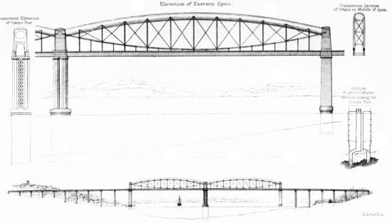
[Larger view]
[Largest view]
Each truss consists of a wrought-iron oval tube, which forms an arch,
and of two suspension chains,[109] one on either side of the tube,
connecting its two ends. The rise of the arched tube above its
abutments on the top of the piers is the same as the fall of the
suspension chains below the same level. At eleven points in the length
of the truss the chains are connected to the tube by upright standards,
which are braced together by diagonal bars, in order to resist the
strains due to unequal loading. The roadway girders are suspended from
the truss at the upright standards already mentioned, and at an
intermediate point between each of them.
The truss has the great depth of 56 feet in the centre; this conduces
materially to the economy of the construction, as it diminishes the
strain upon the principal parts, the tube and the chains, and so enables
them to be made of smaller dimensions.
The woodcut (fig. 12) is a transverse section in the centre of the
truss, showing the oval tube, the chains, the upright and standards, the
roadway girders.
The tube is made oval in section with the greater diameter horizontal,
in order that it may have stiffness sideways under the compressive
strain, and that the main chains may hang vertically at such a distance
as to leave room for the roadway between them. The tube is 16 feet 9
inches broad and 12 feet 3 inches in height. Each chain consists of two
tiers of links, each tier formed of 14 and 15 links alternately. These
are 7 inches deep and about 1 inch thick. The arrangements of the
ironwork of the tube and its connections with the main chains are
generally similar to those at Chepstow.
The truss may be described as a combination of an arch and a suspension
bridge, half the weight being placed on the one and half on the other,
the outward thrust of the arch on the abutments being counterbalanced by
the inward drag of the chains.
The mechanical arrangement of the Saltash truss is similar to that of
the one at Chepstow.[110] The tube, resting on standards, the railway
passing beneath, the suspension chains hung from either side of the
tube, the upright standards, and the diagonal bracing are common to the
two structures.
The difference in the form of the two trusses is principally the result
of the difference in the circumstances attending the construction of the
bridges at Chepstow and Saltash. The design of the Chepstow truss was
chiefly determined by the necessity of lifting up the separate parts of
it under conditions of peculiar difficulty; while at Saltash the mode of
floating and lifting the superstructure had great influence in the
preparation of the design.
On Plate V. (p. 218) is given an elevation of one span of the Saltash
bridge, and a general elevation on a smaller scale of the whole bridge.
The total weight of wrought ironwork in the superstructure of each span
is 1,060 tons.[111]
The trusses at Saltash were not lifted in parts, as at Chepstow; for,
as the river was divided by the centre pier into two openings, one of
them could be left clear for the navigation, and each truss, with its
roadway girders attached, could be raised to its position slowly and in
one piece. The trusses were constructed parallel to the river on the
Devonshire side, close to the site of the bridge. When the truss for the
Cornwall or western span was completed, temporary piers were erected to
support the ends, and the scaffolding having been removed, the roadway
was loaded with 1,190 tons, uniformly distributed.[112]
This test having proved satisfactory, preparations were made for
floating the truss. Docks were made underneath it near the two ends, and
in each of these docks two iron pontoons were placed. Valves were then
opened to admit water, and the pontoons were allowed to sink on timbers
prepared to receive them.
Upon each pair of pontoons was erected an elaborate framework of timber
to carry the weight of half the truss, or between 500 and 600 tons. The
framework consisted of stout timber props, some of them 40 feet long,
extending from the pontoon to the arched tube, and was attached to the
tube by iron suspension rods, so that when the operation of floating was
completed, the pontoons would be free to pass from underneath the truss.
Mr. Brunel had previously taken part in operations of this nature. When
Mr. Robert Stephenson was about to undertake the floating of the tubes
of the Conway and Britannia bridges, he asked his friends Mr. Brunel
and Mr. Locke to give him their assistance. They were present at all, or
nearly all, these difficult operations, and Mr. Brunel had an active
share in the work, especially in the floating of the first Conway tube.
By Mr. Brunel’s advice Mr. Stephenson had obtained the services of
Captain Claxton to superintend the nautical part of the work; and
Captain Claxton was, as a matter of course, with Mr. Brunel in a similar
capacity at Chepstow and Saltash.
At Saltash fortunately there was not so swift a tide as there had been
at the Britannia and Conway floatings.
In order to haul the truss out, warps were laid from the pontoons to a
gun-brig hulk near the centre pier, and to a barge higher up the river.
On this barge were also placed ready for use the ends of four warps,
leading to capstans and crabs on board vessels moored at various points.
To keep the truss from being drifted up or down the river while being
moved out, radius lines were laid from the pontoons to moorings, with
arrangements for hauling in on them if required.
In order to ensure his directions being clearly understood and promptly
attended to, Mr. Brunel assembled a number of his assistants, one of
whom was placed as ‘Captain’ in each of the vessels containing the
hauling capstans, to superintend the men, and to execute orders. These
orders were given by signals.
It was most important that the attention of the captain should not be
diverted by looking out for the signals, and that there should be no
chance of a signal not being seen by him because he was attending to
some other of his duties. There was, therefore, in each vessel an
assistant whose sole duty it was to watch for the signals, to give the
appropriate interpretation to the captain, and to acknowledge the signal
by a flag corresponding to that by which it was given.
Mr. Brunel directed the operations from a platform in the centre of the
truss. The signals were given from a smaller platform immediately above,
and were made by red and white flags, held in front of black boards,
which were turned towards the vessel signalled to. Printed papers
containing instructions were distributed to all engaged; the signalling
was carefully rehearsed, as also was every other part of the operations
which could be tried beforehand.
September 1, 1857, was the day fixed for the floating. During the
morning, the men, about 500 in number, assembled at their stations on
the vessels and pontoons. Captain Claxton had command of the
arrangements afloat, and as a reserve force to act in any emergency
several boats were lent from H.M.S. ‘Ajax’ and the Dockyard. With Mr.
Brunel were Mr. Brereton and Captain Harrison, the commander of the
‘Great Eastern.’ Mr. Robert Stephenson was expected, but a serious
attack of illness prevented him from being present.
At about one o’clock in the afternoon signals from the tops of the
temporary piers on which the truss rested, showed that the ends had been
lifted three inches clear. Mr. Brunel then gave the signal for the men
in the pontoons to haul on the warps, and the great structure glided
slowly out to the centre of the river. A pause was then made, while the
warps which were to swing the truss round into its place were being
attached to the pontoon which was farthest from the centre pier. When
this was done, the different ropes were hauled upon in obedience to
signals, so as to keep the other pontoon close to the centre pier, upon
which, as a pivot, the truss swung round in a quarter circle till it
occupied the whole of the western half of the river, and was brought
close to its appointed resting-place. It was finally adjusted to its
exact position by strong tackles attached to the piers. Water was then
admitted into the pontoons; and, as the tide fell, they were allowed to
drift away, leaving the truss resting on the piers, the roadway girders
being but a few feet above the water.
The whole operation was conducted with the most perfect order and
regularity. The beauty of the scenery and the changing effect produced
by the truss in the various positions it assumed as it was being moved
forward and swung round into its place, rendered the operation as
interesting to the spectators as its results were satisfactory to Mr.
Brunel and to those who assisted him.[113]
In the task of lifting the truss, as well as in that of floating it, Mr.
Brunel had the great advantage of the experience gained at the Britannia
Bridge. There the piers were built first, and the tubes hauled up with
link chains by hydraulic presses placed on the tops of the towers. The
design of the piers at Saltash did not allow of this plan being adopted,
and they were built up under the truss as it was lifted. Under each end
of the truss were three hydraulic presses; the two outside presses
combined, or the middle one by itself, were sufficient to lift the
weight. Mr. Brunel had also at first intended to have strong
screw-jacks, which were to be kept screwed up underneath the truss, and
so to support the weight, if by any accident the presses failed. A
modification of this plan was adopted; the rams of the presses had a
screw thread cut on them, and a large nut on each was kept screwed up
hard against the top of the press as the ram emerged from it. As an
additional precaution, timber packing, in thin layers, was placed in the
space between the completed portion of the pier and the end of the truss
as it was lifted. Great care was thus taken to guard against any mishap.
The tube was lifted 3 feet at a time at each end. The operation went on
slowly, in order to allow the masonry of the land pier to set after it
had been built up underneath the truss. The work was carried on with
great system and care under the immediate superintendence of Mr.
Brereton. Mr. Brunel was only able to be present during one of the
lifting operations, as he was then engaged in the launch of the ‘Great
Eastern.’
By July 1858, the first truss had been lifted to its full height, and
the second truss was ready for floating. The arrangements were generally
similar to those on the previous occasion; the course, however, to be
traversed by the pontoons was more intricate than on the previous
occasion, as the land pier on the Devonshire side of the river, over
which the first truss had passed, had been built up to receive the end
of the second.
This truss had, therefore, to be moved first outwards till the pontoons
were clear of the docks, then it had to move endways up the river, and
to swing round into position. Mr. Brunel was obliged to remain abroad
from ill-health, and Mr. Brereton conducted the operations. Although the
weather was not favourable, and the wind high, the truss was safely
landed on the piers; and was afterwards raised in the same manner as the
first one.[114]
The general elevation, Plate V., shows the proportions of the bridge. On
the Devonshire side, the side spans pass over fields, and on the
Cornwall side over the town of Saltash.
The general effect of the bridge is in no way heightened by an
expenditure of money on architectural ornament; for, with the exception
of a few unimportant mouldings, the bridge is absolutely unadorned. The
total cost was 225,000l.—a very moderate expenditure, especially when
the difficult work at the centre pier is taken into account. This result
is due not only to the careful manner in which all the details of the
design were prepared, but also to the great attention given throughout
to the construction.
His Royal Highness the Prince Consort, as Lord Warden of the Stannaries,
permitted the bridge to be called the Royal Albert Bridge, and consented
to open it in person. The ceremony was performed on May 3, 1859. Mr.
Brunel was compelled to be absent on the Continent, for the sake of his
health, and was represented on the occasion by Mr. Brereton.
After Mr. Brunel’s return to England, he paid a hurried visit to the
Cornwall Railway, and, for the first and last time, saw in its completed
state the great work on which he had expended so much thought and care.
Experiments on Matters connected with Bridge Construction.
No account of the structures designed by Mr. Brunel would be complete
without a reference to the elaborate care he always took, wherever it
was practicable, to satisfy himself by experiment of the qualities of
the materials employed, and of the correctness of the principles
followed. It would not here be possible to give a detailed record of all
his experiments, but an account of some of the methods employed by him
will be interesting.
Some of the larger of Mr. Brunel’s experiments on cast and wrought-iron
girders have already been mentioned.[115] He scarcely ever made any
large girder or framework without having it fully tested, and he made
extensive and elaborate experiments, most of them on a very large scale,
on the strength of some of the materials and component parts of his
different structures.
Among the large scale experiments tried by Mr. Brunel, were those on the
compressive strength of yellow pine-timber, which were made at Bristol
in 1846, and were on specimens from 10 to 40 feet in length, and from 6
to 15 inches square. A framework of four upright pieces of whole timber,
nearly 50 feet high, contained four strong bars of wrought iron, placed
vertically, and attached at their lower ends to the cylinder of a
hydraulic press. Along these bars, a casting could be moved, and
fastened at different heights by keys, in such a manner as to have its
under-surface, which was planed, perfectly horizontal. The ends of a
specimen having been made exactly square to its length, it was put in
this apparatus, with the upper end bearing against the lower surface of
the movable casting, and the lower end resting on the top-surface of the
ram of the hydraulic press, which was also planed and adjusted so as to
be horizontal. The keys, which attached the movable casting to the bars,
were now driven tight, and the pump of the press worked, weights being
placed on the end of the lever, to correspond with increments of
pressure on the ram. These weights were added gradually, until the
specimen gave way. The accuracy of this mode of measuring the pressure
was tested by direct loading of the ram with rails, which was repeated
several times during the course of the experiments, so as to guard
against any change in the amount of friction of the press. For each
increment of weight, the compression of the specimen was measured on its
four faces, and its deflection, or amount of bending, on two adjacent
faces. The transverse stiffness of long specimens was also tried, by
supporting them at each end, and loading them in the middle. The
deflection in the middle thus observed corresponded very closely with
what might have been expected from the observations on the direct
compression; and from the constants so obtained, the strength of those
specimens, whose length was very great as compared with their transverse
dimensions, could be obtained by Euler’s theory, but for the stouter
specimens the strength per square inch was found to be nearly constant.
From these experiments, a complete practical knowledge of the properties
of yellow pine timber, when subjected to end pressures, was obtained,
knowledge new at the time, and almost essential to Mr. Brunel in
designing the many viaducts which he afterwards constructed.
Mr. Brunel also made experiments on the strength of pine timber when
exposed to pressure on the side or at right angles to the fibre. By this
means he determined the area which it was desirable to provide for the
washers of bolts, and the weight which might safely be placed on
transverse timbers or sills of viaducts.
Mr. Brunel’s experiments on riveting were also important. Most of these
were made with specimens 20 inches wide, and half an inch thick. They
were compared with specimens of solid iron, of the same quality and
thickness as the riveted specimens, and also the same width minus the
rivet holes, so as to have equal efficient sectional areas. Double
covering plates and double riveting were used in all cases, the
variation being in the widths of the covering plates, and the number and
arrangement of the rivets. The experiments were continued until thirty
in all had been made, and the strongest form of joint was considered to
have been arrived at.
In connection with the lifting of the parts of the Chepstow Bridge, an
elaborate series of experiments was made on ropes, chains, and
wire-rope, so as to ascertain which of these it was desirable to employ,
as possessing the greatest advantages. The experiments made were of two
kinds, one to determine the absolute strength of the specimen when
subjected to a straight pull, and the other to observe what took place
when it was worked over a sheave. In the first set the specimen was held
at each end in the jaws of a pair of wrought-iron clamps, which were
tightened up by means of screws. One of the clamps was attached to a
fixed beam, and from the other was suspended a large cylindrical tank,
which was gradually filled with water until the specimen gave way, the
breaking strain being the weight of the tank and water. This weight was
ascertained by actual weighing with a steelyard when the water in the
tank was at different heights. Observations on the extension, shrinkage
of the circumference, and change in the pitch of the spiral of the rope
were made with different loads, and the strength of a sufficient number
of the yarns of which the rope was composed was tried to ascertain the
loss of strength by combining the yarns into a rope. In the second set
the specimen, clamped as before, was passed over a sheave, the axle of
which rolled horizontally on planed cast-iron plates, in order to
diminish friction. To each clamp was attached a cylindrical iron tank.
Water being admitted to the highest tank until downward motion
commenced, its influx was stopped, and the tank descended, the other one
rising. Water was then admitted to the now highest tank until motion
again commenced, and this process was repeated until the specimen gave
way, the tanks getting fuller of water at each movement, at which times
the difference of weight of the two tanks was observed. This, minus the
slight friction of the apparatus, represented the rigidity of the rope.
The extensions were observed as in the first set of experiments.
The specimens consisted of hemp, manilla, shroud laid and hawser laid
ropes, from 8 to 10 inches in circumference, round and flat wire ropes,
and chains of different sizes of about the same strength as the ropes.
The sheaves also were of different diameters. These experiments resulted
in Mr. Brunel deciding to use chains for lifting the bridge, and this
mainly from the circumstance that chains work more satisfactorily over a
sheave than either hemp or wire ropes.
Some small scale experiments made by Mr. Brunel are deserving of notice.
These were made to verify calculations on the longitudinal girders of
the Chepstow truss, which are virtually continuous beams of five unequal
spans. It was desirable to test the results of analysis by experiment,
in order to be assured that no errors had been committed in its
application. Mr. Brunel accordingly devised the following simple form of
experiment for this purpose. A deal rod, exactly half an inch square and
38 feet long, quite free from knots, was supported on props of equal
height, above the perfectly horizontal and planed surface of a large
beam of timber. The props were placed so as to correspond relatively to
the actual spans, and the rod was loaded uniformly by means of a chain.
It was thus bent into an elastic curve, the ordinates of which were very
carefully measured, at every foot along the length, by a finely divided
scale and magnifier. The pressure on each prop was also determined, by
removing any particular one, and suspending the point of the rod
immediately over it to a steel-yard, the weight being observed when the
point of the rod was exactly at the same level as before the prop was
removed. The obvious condition, that the sum of the pressures on the
props should be equal to the weight of the rod and its load, furnished a
satisfactory means of testing the results of these weighings. The rod
being turned over on each of its four sides, the experiments were
repeated, and the average taken, in order to eliminate the effects of
initial curvature, or of unequal elasticity. Diagrams of the elastic
curves were then made, showing the correspondence of theory with
experiment, and this was so close as to leave no doubt that a true
knowledge of the nature of the strains had been arrived at. One of these
diagrams is given by Mr. Edwin Clark in his work on the ‘Britannia and
Conway Tubular Bridges,’ vol. i. p. 462.
By modifications of the plan Mr. Brunel adopted in this experiment, the
strains on continuous beams of varying section may be ascertained with
considerable accuracy.