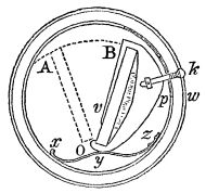
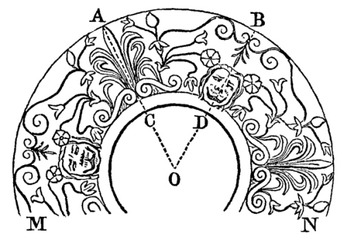
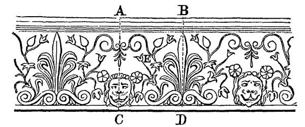
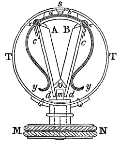
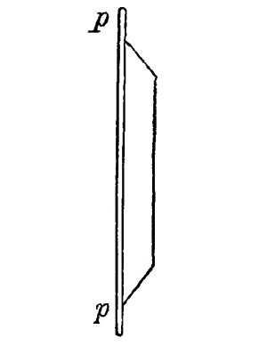
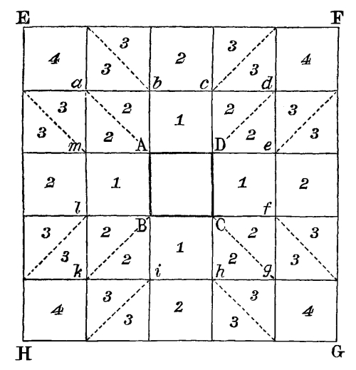
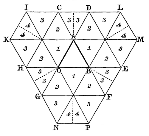
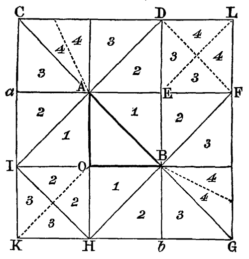
THE KALEIDOSCOPE, ITS HISTORY, THEORY, AND CONSTRUCTION.
WITH ITS APPLICATION TO THE FINE AND USEFUL ARTS.
BY SIR DAVID BREWSTER, K.H., M.A., D.C.L.,
F.R.S., V.P.R.S., EDIN., M.R.I.A., F.G.S., F.R.A.S.,
ASSOCIATE OF THE IMPERIAL INSTITUTE OF FRANCE, HONORARY OR
CORRESPONDING MEMBER OF THE ACADEMIES OF PETERSBURGH, VIENNA, BERLIN,
COPENHAGEN, STOCKHOLM, BRUSSELS, GOTTINGEN, MODENA, AND OF THE NATIONAL
INSTITUTE OF WASHINGTON, AND PRINCIPAL OF THE UNITED COLLEGES OF
ST. SALVATOR AND ST. LEONARD, ST. ANDREWS.
The name Kaleidoscope, which I have given to a new Optical Instrument,
for creating and exhibiting beautiful forms, is derived from the Greek
words χαλός, beautiful; εἶδος, a form; and σχοπέω,
to see.
The first idea of this instrument presented itself to me in the year
1814, in the course of a series of experiments on the polarization of
light by successive reflexions between plates of glass, which were
published in the Philosophical Transactions for 1815, and which
the Royal Society did me the honour to distinguish by the adjudication
of the Copley Medal. In these experiments, the reflecting plates were
necessarily inclined to each other during the operation of placing
their surfaces in parallel planes; and I was therefore led to remark
the circular arrangement of the images of a candle round a centre, and
the multiplication of the sectors formed by the extremities of the
plates of glass. In consequence, however, of the distance of the
candles, &c., from the ends of the reflectors, their arrangement was
so destitute of symmetry, that I was not induced to give any farther
attention to the subject.
On the 7th of February 1815, when I discovered the development of the
complementary colours, by the successive reflexions of polarized light
between two plates of gold and silver, the effects of the Kaleidoscope,
though rudely exhibited, were again forced upon my notice; the
multiplied images were, however, coloured with the most splendid tints;
and the whole effect, though inconceivably inferior to the creations
of the Kaleidoscope, was still far superior to anything that I had
previously witnessed.
In giving an account of these experiments to M. Biot on the 6th of
March 1815, I remarked to him, “that when the angle of incidence (on
the plates of silver) was about 85° or 86°, and the plates almost
in contact, and inclined at a very small angle, the two series of
reflected images appeared at once in the form of two curves; and that
the succession of splendid colours formed a phenomenon which I had no
doubt would be considered, by every person who saw it to advantage, as
one of the most beautiful in optics.” These experiments were afterwards
repeated with more perfectly polished plates of different metals, and
the effects were proportionally more brilliant: but notwithstanding
the beauty arising from the multiplication of the images, and the
additional splendour which was communicated to the picture by the
richness of the polarized tints, it was wholly destitute of symmetry,
as I was then ignorant of those positions for the eye and the objects,
which are absolutely necessary to produce that magical union of parts,
and that mathematical symmetry throughout the whole picture, which,
independently of all colouring, give to the visions of the Kaleidoscope
the peculiar charm which distinguishes them from all artificial
creations.[1]
Although I had thus combined two plain mirrors, so as to produce highly
pleasing effects, from the multiplication and circular arrangement of
the images of objects placed at a distance from their extremities, yet
I had scarcely made a step towards the invention of the Kaleidoscope.
The effects, however, which I had observed, were sufficient to prepare
me for taking advantage of any suggestion which experiment might
afterwards throw in the way.
In repeating, at a subsequent period, the very beautiful experiments
of M. Biot, on the action of homogeneous fluids upon polarized light,
and in extending them to other fluids which he had not tried, I found
it most convenient to place them in a triangular trough, formed by two
plates of glass cemented together by two of their sides, so as to form
an acute angle. The ends being closed up with pieces of plate glass
cemented to the other plates, the trough was fixed horizontally, for
the reception of the fluids. The eye being necessarily placed without
the trough, and at one end, some of the cement, which had been pressed
through between the plates at the object end of the trough, appeared to
be arranged in a manner far more regular and symmetrical than I had
before observed when the objects, in my early experiments, were
situated at a distance from the reflectors. From the approximation to
perfect symmetry which the figure now displayed, compared with the
great deviation from symmetry which I had formerly observed, it was
obvious that the progression from the one effect to the other must
take place during the passage of the object from the one position to
the other; and it became highly probable, that a position would be
found where the symmetry was mathematically perfect. By investigating
this subject optically, I discovered the leading principles of the
Kaleidoscope, in so far as the inclination of the reflectors, the
position of the object, and the position of the eye, were concerned.
I found, that in order to produce perfectly beautiful and symmetrical
forms, three conditions were necessary.
1. That the reflectors should be placed at an angle, which was an
even or an odd aliquot part of a circle, when the object
was regular, and similarly situated with respect to both the mirrors;
or the even aliquot part of a circle when the object was
irregular, and had any position whatever.
2. That out of an infinite number of positions for the object, both
within and without the reflectors, there was only one where
perfect symmetry could be obtained, namely, when the object was placed
in contact with the ends of the reflectors. This was precisely the position
of the cement in the preceding experiment with the triangular trough.
3. That out of an infinite number of positions for the eye, there was
only one where the symmetry was perfect, namely, as near as
possible to the angular point, so that the circular field could be
distinctly seen; and that this point was the only one out of an
infinite number at which the uniformity of the light of the circular
field was a maximum, and from which the direct and the reflected images
had the same form and the same magnitude, in consequence of being
placed at the same distance from the eye. This, also, was the position
in which the eye was necessarily placed when looking through the fluid
with which the glass trough was partially filled.
Upon these principles I constructed an instrument, in which I fixed
permanently, across the ends of the reflectors, pieces of
coloured glass, and other irregular objects; and I showed the
instrument in this state to some members of the Royal Society of
Edinburgh, who were much struck with the beauty of its effects. In this
case, however, the forms were nearly permanent; and slight, though
beautiful, variations were produced by varying the position of the
instrument with respect to the source of light.
The great step, however, towards the completion of the instrument
remained yet to be made; and it was not till some time afterwards that
the idea occurred to me of giving motion to objects, such as pieces
of coloured glass, &c., which were either fixed or placed loosely in a
cell at the end of the instrument. When this idea was carried into
execution, and the reflectors placed in a tube, and fitted up on the
preceding principles, the Kaleidoscope, in its simple form, was
completed.
In this form, however, the Kaleidoscope could not be considered as a
general philosophical instrument of universal application. The least
deviation of the object from the position of symmetry at the end of
the reflectors, produced a deviation from beauty and symmetry in
the figure, and this deviation increased with the distance of the
object. The use of the instrument was therefore limited to objects in
contact with the ends of the reflectors, or held close to them, and
consequently to objects, or groups of objects, whose magnitudes were
less than its triangular aperture.
The next, and by far the most important step of the invention, was
to remove this limitation, and to extend indefinitely the use and
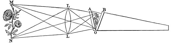
application of the instrument. This effect was obtained by employing a
draw tube, containing a convex lens, or, what is better, an achromatic
object-glass of such a focal length, that the images of objects, of
all magnitudes and at all distances, might be distinctly formed at the
end of the reflectors, and introduced into the pictures created by the
instrument in the same manner as if they had been reduced in size, and
placed in the true position in which alone perfect symmetry could be
obtained.
When the Kaleidoscope was brought to this degree of perfection, it was
impossible not to perceive that it would prove of the highest service
in all the ornamental arts, and would, at the same time, become a
popular instrument for the purposes of rational amusement. With these
views I thought it advisable to secure the exclusive property of it by
a Patent;[2]
but in consequence of one of the patent instruments
having been exhibited to some of the London opticians, the remarkable
properties of the Kaleidoscope became known before any number of
them could be prepared for sale. The sensation excited by this
premature exhibition of its effects is incapable of description, and
can be conceived only by those who witnessed it. “It very quickly
became popular,” says Dr. Roget, in his excellent article on the
Kaleidoscope in the Encyclopædia Britannica,
“and the sensation it excited in London throughout all ranks of people was
astonishing. It afforded delight to the poor as well as the rich; to
the old as well as the young. Large cargoes of them were sent abroad,
particularly to the East Indies. They very soon became known throughout
Europe, and have been met with by travellers even in the most obscure
and retired villages in Switzerland.” According to the computation of
those who were best able to form an opinion on the subject, no fewer
than two hundred thousand instruments were sold in London and Paris
during three months. Out of this immense number there were perhaps not
one thousand constructed upon scientific principles, and capable of
giving anything like a correct idea of the power of the Kaleidoscope;
and of the millions who have witnessed its effects, there is perhaps
not a hundred individuals who have any idea of the principles upon
which it is constructed, who are capable of distinguishing the spurious
from the real instrument, or who have sufficient knowledge of its
principles to be able to apply it to the numerous branches of the
useful and ornamental arts.
Under these circumstances I have thought it necessary to draw up
the following short treatise, for the purpose of explaining, in as
popular a manner as I could, the principles and construction of the
Kaleidoscope; of describing the different forms in which it is fitted
up; of pointing out the various methods of using it as an instrument
of recreation; and of instructing the artist how to employ it in the
numerous branches of the useful and ornamental arts to which it is
applicable.
CHAPTER I.
PRELIMINARY PRINCIPLES RESPECTING THE
EFFECTS OF COMBINING TWO PLAIN MIRRORS.
The principal parts of the Kaleidoscope are two reflecting planes, made
of glass, or metal, or any other reflecting substance ground perfectly
flat and highly polished. These reflectors, which are generally made
of plate glass, either rough ground on their outer side, or covered
with black varnish, may be of any size, but in general they should be
from four or five to ten or twelve inches long; their greatest breadth
being about an inch when the length is six inches, and increasing in
proportion as the length increases. When these two plates are put
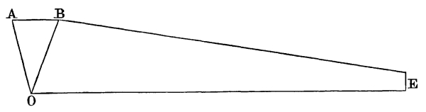
together at an angle of 60°, or the sixth part of a circle, as shown in
Fig. 1, and the eye placed at the narrow end
E, it will observe the opening A O B multiplied six
times, and arranged round the centre O, as shown in Fig. 2.
Fig. 1.
Fig. 2.
In order to understand how this effect is produced, let us take a small
sector of white paper of the shape A O B, Fig. 2, and having
laid it on a black ground, let the extremity A O of one of the
reflectors be placed upon the edge A O of the sector. It is then
obvious that an image A O b of this white sector of paper
will be formed behind the mirror A O, and will have the same
magnitude and the same situation behind the mirror as the sector A
O B had before it. In like manner, if we place the edge B O
of the other reflector upon the other side B O of the paper
sector, a similar image B O a will be formed behind it.
The origin of three of the sectors seen round O is therefore
explained: the first, A O B, is the white paper sector seen by
direct vision; the second, A O b, is an image of the
first formed by one reflexion from the mirror A O; and
the third is another image of the first formed by one reflexion
from the other mirror B O. But it is well known, that the
reflected image of any object, when placed before another mirror, has
an image of itself formed behind this mirror, in the very same manner
as if it were a new object. Hence it follows, that the image A O
b being, as it were, a new object placed before the mirror B
O, will have an image a O α of itself formed behind
B O; and for the same reason the image B O a will
have an image b O β of itself, formed behind the mirror
A O, and both these new images will occupy the same position
behind the mirrors as the other images did before the mirrors.
A difficulty now presents itself in accounting for the formation of the
last or sixth sector, α O β. Mr. Harris, in the xviith
Prop. of his Optics, has evaded this difficulty, and given a false
demonstration of the proposition. He remarks, that the last sector, α
O β is produced “by the reflexion of the rays forming either of
the two last images” (namely, b O β and a O
α); but this is clearly absurd, for the sector α O β would thus
be formed of two images lying above each other, which is impossible.
In order to understand the true cause of the formation of the sector α
O β, we must recollect that the line O E is the line of
junction of the mirrors, and that the eye is placed any where in the
plane passing through O E and bisecting A O B. Now, if
the mirror, B O, had extended as far as O β, the sector
α O β would have been the image of the sector b O
β, reflected from B O; and in like manner, if the mirror A
O had extended as far as O α, the sector α O β would
have been the image of the sector a O α reflected from
A O; but as this overlapping or extension of the mirrors is
impossible, and as they must necessarily join at the line O E,
it follows, that an image α O e, of only half the sector
b O β, viz., b O r, can be seen by
reflexion from the mirror B O; and that an image β O
e, of only half the sector a O α, viz., a
O s, can be seen by reflexion from the mirror A O.
Hence it is manifest, that the last sector, α O β, is not,
as Mr. Harris supposes, a reflexion from either of the two last
images, b o β, a o α, but is composed of the images
of two half sectors, one of which is formed by the mirror A O,
and the other by the mirror B O.
Mr. Harris repeats the same mistake in a more serious form, in his
second Scholium, § 240, where he shows that the images are arranged in
the circumference of a circle. The two images D, d, says
he, coincide and make but one image. Mr. Wood has committed the very
same mistake in his second Corollary to Prop. xiv.,
and his demonstration of that Corollary is decidedly erroneous. This Corollary
is stated in the following manner:—“When a (the angle of the
mirrors) is a measure of 180° two images coincide,” and it is
demonstrated, that since two images of any objectX (Fig. 2)
must be formed, viz., one by each mirror, and since these two
images must be formed at 180° from the object X, placed between
the mirrors, that is, at the same point x, it follows that
the two images must coincide. Now, it will appear from the simplest
considerations, that the assumption, as well as the conclusion, is
erroneous. The image x is seen by the last reflexion from the
mirror B O E, and another image would be seen at x, if
the mirror A O E had extended as far as x; but as this
is impossible, without covering the part of the mirror B O E,
which gives the first image x, there can be only one image seen
at x. When the object X is equidistant from A and
B, then one-half of the last reflected image x will be
formed by the last reflexion from the mirror B O, and the other
half by the last reflexion from the mirror A O, and these two
half images will join each other, and form a whole image at e,
as perfect as any of the rest. In this last case, when the angle A O
B is a little different from an even aliquot part of 360°, the eye
at E will perceive at e an appearance of two incoincident
images; but this arises from the pupil of the eye being partly on one
side of E and partly on the other; and, therefore, the apparent
duplication of the image is removed by looking through a very small
aperture at E. As the preceding remarks are equally true,
whatever be the inclination of the mirrors, provided it is an even
aliquot part of a circle, it follows,—
1. That when A O B is ¼, ⅙, ⅛, ⅒, ¹/₁₂, etc., of a circle, the
number of reflected images of any object X, is 4 - 1, 6 - 1, 8 -
1, 10 - 1, 12 - 1.
2. That when X is nearer one mirror than another, the number of
images seen by reflexion from the mirror to which it is nearest will
be ⁴/₂, ⁶/₂, ⁸/₂, ¹⁰/₂, ¹²/₂, while the number of images formed by the
mirror from which X is most distant will be ⁴/₂ - 1, ⁶/₂ - 1,
⁸/₂ - 1, ¹⁰/₂ - 1; that is, an image more always reaches the eye from
the mirror nearest X, than from the mirror farthest from it.
3. That when X is equidistant from A O and B O,
the number of images which reaches the eye from each mirror is equal,
and is always
4 - 1
,
6 - 1
,
8 - 1
,
10 - 1
,
12 - 1
.
2
2
2
2
2
which are fractional values, showing that the last image
is composed of two half images.
When the inclination of the mirrors, or the angle A O B, Fig. 3,
is an odd aliquot part of a circle, such as ⅓, ⅕, ⅐, ⅑, etc.,
the different sectors which compose the circular image are formed in
the very same manner as has been already described; but as the number
of reflected sectors must in this case always be even,
the line O E, where the mirrors join, will separate the two
last reflected sectors, b O e, a O
e. Hence it follows,—
Fig. 3.
1. That when A O B is ⅓, ⅕, ⅐, ⅑, etc., of a circle, the number
of reflected images of any object is 3 - 1, 5 - 1, 7 - 1, etc., and,—
2. That the number of images which reach the eye from each mirror is
3 - 1
,
5 - 1
,
7 - 1
,
2
2
2
which are always even numbers.
Hitherto we have supposed the inclination of the mirrors to be
exactly either an even or an odd aliquot part of a circle. We
shall now proceed to consider the effects which will be produced when
this is not the case.
If the angle A O B, Fig. 2, is made to increase
from being an even aliquot part of a circle, such as ⅙th, till it becomes
an odd aliquot part, such as ⅐th, the last reflected image β
O α, composed of the two halves β O e, α O
e, will gradually increase, in consequence of each of the halves
increasing; and when A O B becomes ⅐th of the circle, the
sector β O α will become double of A O B, and α O
e, β O e will become each complete sectors, or
equal to A O B.
If the angle A O B is made to vary from ⅙th to ⅕th of a circle,
the last sector β O α will gradually diminish, in consequence
of each of its halves, β O e, α O e,
diminishing; and just when the angle becomes ⅙th of a circle, the
sector β O α will have become infinitely small, and the two
sectors, b O β, a O α, will join each other
exactly at the line O e, as in Fig. 3.
CHAPTER II.
ON THE PRINCIPLES OF THE KALEIDOSCOPE, AND THE
FORMATION OF SYMMETRICAL PICTURES BY THE
COMBINATION OF DIRECT AND INVERTED IMAGES.
The principles which we have laid down in the preceding chapter must
not be considered as in any respect the principles of the Kaleidoscope.
They are merely a series of preliminary deductions, by means of which
the principles of the Instrument may be illustrated, and they go no
farther than to explain the formation of an apparent circular aperture
by means of successive reflexions.
All the various forms which nature and art present to us, may be
divided into two classes, namely, simple or irregular
forms, and compound or regular forms. To the first class
belong all those forms which are called picturesque, and which cannot
be reduced to two forms similar, and similarly situated with regard to
a given point; and to the second class belong the forms of animals, the
forms of regular architectural buildings, the forms of most articles of
furniture and ornament, the forms of many natural productions, and all
forms, in short, which are composed of two forms, similar and similarly
situated with regard to a given line or plane.
Now, it is obvious that all compound forms of this kind are composed
of a direct and an inverted image of a simple or an irregular form;
and, therefore, every simple form can be converted into a compound
or beautiful form, by skilfully combining it with an inverted image
of itself, formed by reflexion. The image, however, must be formed
by reflexion from the first surface of the mirror, in order that the
direct and the reflected image may join, and constitute one united
whole; for if the image is reflected from the posterior surface, as
in the case of a looking-glass, the direct and the inverted image can
never coalesce into one form, but must always be separated by a space
equal to the thickness of the mirror-glass.
If we arrange simple forms in the most perfect manner round a centre,
it is impossible by any art to combine them into a symmetrical and
beautiful picture. The regularity of their arrangement may give some
satisfaction to the eye, but the adjacent forms can never join, and
must therefore form a picture composed of disunited parts.
The case, however, is quite different with compound forms. If we
arrange a succession of similar forms of this class round a centre, it
necessarily follows that they will all combine into one perfect whole,
in which all the parts either are or may be united, and which will
delight the eye by its symmetry and beauty.
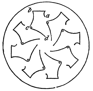
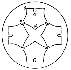
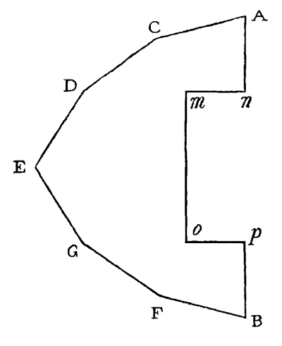
In order to illustrate the preceding observations, we have represented
in Figs. 4 and 5 the effects produced by the multiplication of single
and compound forms. The line a b c d, for example, Fig. 4,
is a simple form, and is arranged round a centre in the same way as it would
be done by a perfect multiplying glass, if such a thing could be made.
The consecutive forms are all disunited, and do not compose a whole.
Fig. 5 represents the very same simple form, a b c d,
converted into a compound form, and then, as it were, multiplied and arranged
round a centre. In this case every part of the figure is united,
and forms a whole, in which there is nothing redundant and nothing
deficient; and this is the precise effect which is produced by the
application of the Kaleidoscope to the simple form a b c.
Fig. 4.
Fig. 5.
The fundamental principle, therefore, of the Kaleidoscope is, that
it produces symmetrical and beautiful pictures, by converting simple
into compound or beautiful forms, and arranging them, by successive
reflexions, into one perfect whole.
This principle, it will be readily seen, cannot be discovered by any
examination of the luminous sectors which compose the circular field of
the Kaleidoscope, and is not even alluded to in any of the propositions
given by Mr. Harris and Mr. Wood. In looking at the circular field
composed of an even and an odd number of reflexions, the arrangement
of the sectors is perfect in both cases; but when the number is odd,
and the form of the object simple, and when the object is not similarly
placed with regard to the two mirrors, a symmetrical and united picture
cannot possibly be produced. Hence it is manifest, that neither the
principles nor the effects of the Kaleidoscope could possibly be
deduced from any practical knowledge respecting the luminous sectors.
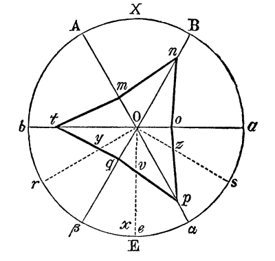
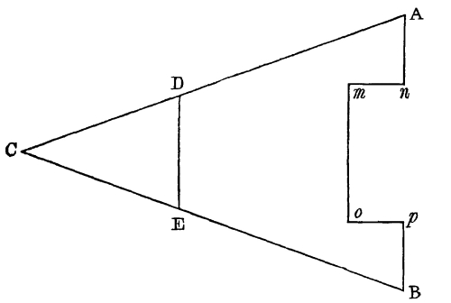
In order to explain the formation of the symmetrical picture shown in
Fig. 5, we must consider that the simple form m n,
Fig. 2, is seen by direct vision through the open sector
A O B, and that the image n o, of the object m n, formed by
one reflexion in the sector B O a, is necessarily an inverted image.
But since the image o p, in the sector a O α,
is a reflected and consequently an inverted image of the inverted
image, m t, in the sector A O b, it follows,
that the whole n o p is an inverted image of the whole n m
t. Hence the image n o will unite with the image o p,
in the same manner as m n unites with m t. But as these
two last unite into a regular form, the two first will also unite into
a regular or compound form. Now, since the half β O e of
the last sector β O α was formerly shown to be an image of the
half sector a O s, the line q v will also
be an image of the line o z, and for the same reason the line
v p will be an image of t y. But the image v p
forms the same angle with B O or n q that t y
does, and is equal and similar to t y; and q v forms
the same angle with A O that o z does, and is equal and
similar to o z. Hence, O o = o q,
and O y = O v, and therefore q v
and v p will form one straight line, equal and similar to t
q, and similarly situated with respect to B O. The figure
m n o p q t, therefore, composed of one direct object, and
several reflected images of that object, will be symmetrical. As the
same reasoning is applicable to every object extending across the
aperture A O B, whether simple or compound, and to every angle
A O B, which is an even aliquot part of a circle, it follows,—
1. That when the inclination of the mirror is an even aliquot
part of a circle, the object seen by direct vision across the aperture,
whether it is simple or compound, is so united with the images of it
formed by repeated reflexions, as to form a symmetrical picture.
2. That the symmetrical picture is composed of a series of parts, the
number of which is equal to the number of times that the angle A O
B is contained in 360°. And—
3. That these parts are alternately direct and inverted pictures of the
object; a direct picture of it being always placed between two inverted
ones, and, vice versa, so that the number of direct pictures is
equal to the number of inverted ones.
When the inclination of the mirrors is an odd aliquot part
of 360°, such as ⅕th, as shown in Fig. 3, the picture
formed by the combination of the direct object and its reflected images is
symmetrical only under particular circumstances.
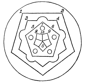
If the object, whether simple or compound, is similarly situated with
respect to each of the mirrors, as the straight line 1, 2 of Fig. 6,
the compound line 3, 4, the inclined lines 5, 6, the circular object 7,
the curved line 8, 9, and the radial line 10, O, then the images
of all these objects will also be similarly situated with respect to
the radial lines that separate the sectors, and will therefore form a
whole perfectly symmetrical, whether the number of sectors is odd or even.
Fig. 6.
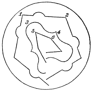
But when the objects are not similarly situated with respect to each
of the mirrors, as the compound line 1, 2, Fig. 8, the
curved line 3, 4, and the straight line 5, 6, and, in general, as all irregular
objects that are presented by accident to the instrument, then the
image formed in the last sector a O e, Fig. 7,
by the mirror B O, will not join with the image formed in the
last sector b O e, by the mirror A O. In
order to explain this with sufficient perspicuity, let us take the case
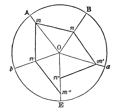
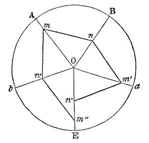
where the angle is 72°, or ⅕th part of the circle, as shown in Fig. 7.
Let A O, B O, be the reflecting planes, and m n
a line, inclined to the radius which bisects the angleA O
B, so that o m > o n; then m nʹ, n mʹ,
will be the images formed by the first reflexion from A O and
B O, and nʹ mʺ, mʹ nʺ, the images formed by
the second reflexion; but by the principles of catoptrics, O
m = O mʹ = O mʺ, and O n = O nʹ = O nʺ, consequently since
O m is by hypothesis greater than O n, we
shall have O mʺ greater than O nʺ; that is,
the images mʹ nʺ, nʹ mʺ, will not coincide. As O
n approaches to an equality with O m, O
nʺ approaches to an equality with O mʺ, and when
O m = O n, we have O nʺ =
O mʺ, and at this limit the images are symmetrically
arranged, which is the case of the straight line 1, 2 in Fig. 6.
By tracing the images of the other lines, as is done in Fig. 8,
it will be seen, that in every case the picture is destitute of symmetry when the
object has not the same position with respect to the two mirrors.
Fig. 7.
Fig. 8.
This result may be deduced in a more simple manner, by considering
that the symmetrical picture formed by the Kaleidoscope contains half
as many pairs of forms as the number of times that the inclination
of the mirrors is contained in 360°; and that each pair consists of
a direct and an inverted form, so joined as to form a compound form.
Now the compound form made up by each pair obviously constitutes a
symmetrical picture when multiplied any number of times, whether even
or odd; but if we combine so many pair and half a pair, two direct
images will come together, the half pair cannot possibly join both with
the direct and the inverted image on each side of it, and therefore
a symmetrical whole cannot be obtained from such a combination. From
these observations we may conclude,—
1. That when the inclination of the mirrors is an odd aliquot
part of a circle, the object seen by direct vision through the aperture
unites with the images of it formed by repeated reflexions, and forms
a complete and symmetrical picture, only in the case when the object
is similarly situated with respect to both the mirrors; the two last
sectors forming, in every other position of the object, an imperfect
junction, in consequence of these being either both direct or both
inverted pictures of the object.
2. That the series of parts which compose the symmetrical as well as
the unsymmetrical picture, consists of direct and inverted pictures of
the object, the number of direct pictures being always equal to half
the number of sectors increased by one, when the number of sectors is
5, 9, 13, 17, 21, etc., and the number of inverted pictures being equal
to half the number of sectors diminished by one, when the number of
sectors is 3, 7, 11, 15, 19, etc., and vice versa. Hence, the
number of direct pictures of the object must always be odd, and the
number of inverted pictures even, as appears from the following table:—
Inclination of the Mirrors.
Number of Sectors.
Number of Inverted Pictures.
Number of Direct Pictures.
120°
3
2
1
72
5
2
3
51³/₇
7
4
3
40
9
4
5
32⁸/₁₁
11
6
5
27⁹/₁₃
13
6
7
24
15
8
7
21³/₁₇
17
8
9
18¹⁸/₁₉
19
10
9
17⅐
21
10
11
3. That when the number of sectors is 3, 7, 11, 15, 19, etc., the two
last sectors are inverted; and when the number is 5, 9, 13, 17, 21,
etc., the two last sectors are direct.
When the inclination of the mirrors is not an aliquot part of 360°,
the images formed by the last reflexions do not join like every other
pair of images, and therefore the picture which is created must be
imperfect. It has already been shown at the end of Chap. I. that when
the angle of the mirrors becomes greater than an even or less than an
odd aliquot part of a circle, each of the two incomplete sectors which
form the last sector becomes greater or less than half a sector. The
image of the object comprehended in each of the incomplete sectors must
therefore be greater or less than the images in half a sector; that
is, when the last sector β O α, Fig. 2, is greater
than A O B, the part q v in one half must be the image of more
than o z, and v p the image of more than t y,
and vice versa, when β O α is less than A O B.
Hence it follows that the symmetry is imperfect from the image in the
last sector being greater or less than the other images. But besides
this cause of imperfection in the symmetry, there is another, namely,
the disunion of the two images q v and v p. The angles
O q v and O o p are obviously equal, and
also the angles O p v, O p o; but since the
angle β O α, or q O p, is by hypothesis
greater or less than p O o, it follows that the
angles of the triangle q O p are either greater or
less than two right angles, because they are greater or less than the
three angles of the triangle p O o. But as this
is absurd, the lines q v, v p, cannot join so as to form
one straight line, and therefore the completion of a perfect figure
by means of two mirrors, whose inclination is not an aliquot part of
a circle, is impossible. When the angle β O α is greater than
p O o, or A O B, the lines q v,
v p, will form a re-entering angle towards O, and when
it is less than A O B, the same lines will form a salient angle
towards O.
CHAPTER III.
ON THE EFFECTS PRODUCED BY THE MOTION
OF THE OBJECT AND THE MIRRORS.
Hitherto we have considered both the object and the mirrors as
stationary, and we have contemplated only the effects produced by the
union of the different parts of the picture. The variations, however,
which the picture exhibits, have a very singular character, when either
the objects or the mirrors are put in motion. Let us, first, consider
the effects produced by the motion of the object when the mirrors are
at rest.
Fig. 9.
If the object moves from X to O, Fig. 9,
in the direction of the radius, all the images will likewise move towards O,
and the patterns will have the appearance of being absorbed or extinguished
in the centre. If the motion of the object is from O to
X, the images will also move outwards in the direction of the
radii, and the pattern will appear to develop itself from the centre
O, and to be lost or absorbed at the circumference of the
luminous field. The objects that move parallel to X O will have
their centre of development, or their centre of absorption, at the
point in the lines A O, B O, aO, bO, etc. where the direction in which the images move cuts these
lines. When the object passes across the field in a circle concentric
with A B, and in the direction A B, the images in all the
sectors formed by an even number of reflexions will move in the same
direction A B, namely, in the direction β b, a
α; while those that have been formed by an odd number of reflexions
will move in an opposite direction, namely, in the directions aB, Ab. Hence, if the object moves from A
to B, the points of absorption will be in the lines B O,
α O, and bO, and the points of development in
the lines A O, aO, and β O, and vice
versa, when the motion of the object is from B to A.
If the object moves in an oblique direction m n, the images
will move in the directions m t, o n, o p, q
t, q p, and m, o, q, will be the
centres of development, and n, p, t, the centres
of absorption; whereas, if the object moves from n to m,
these centres will be interchanged. These results are susceptible of
the simplest demonstration, by supposing the object in one or two
successive points of its path m n, and considering that the
image must be formed at points similarly situated behind the mirrors;
the line passing through these points will be the path of the image,
and the order in which the images succeed each other will give the
direction of their motion. Hence, we may conclude in general,
1. That when the path of the object cuts both the mirrors A O
and B O like m n, the centre of absorption will be in
the radius passing through the section of the mirror to which the
object moves, and in every alternate radius; and that the centre of
development will be in the radius passing through the section of the
mirror from which the object moves, and in all the alternate radii: and,
2. That when the path of the object cuts any one of the mirrors and
the circumference of the circular field, the centre of absorption
will be in all the radii which separate the sectors, and the centre
of development in the circumference of the field, if the motion is
towards the mirror, but vice versa if the motion is towards the
circumference.
When the objects are at rest, and the Kaleidoscope in motion, a new
series of appearances is presented. Whatever be the direction in which
the Kaleidoscope moves, the object seen by direct vision must always
be stationary, and it is easy to determine the changes which take
place when the Kaleidoscope has a progressive motion over the object.
A very curious effect, however, is observed when the Kaleidoscope has
a rotatory motion round the angular point, or rather round the common
section of the two mirrors. The picture created by the Instrument
seems to be composed of two pictures, one in motion round the centre
of the circular field, and the other at rest. The sectors formed by an
odd number of reflexions are all in motion in the same direction as
the Kaleidoscope, while the sector seen by direct vision, and all the
sectors formed by an even number of reflexions, are at rest. In order
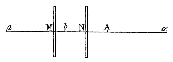
to understand this, let M, Fig. 10, be a plane
mirror, and A an object whose image is formed at a, so that
a M = A M. Let the mirror M advance to N,
and the object A, which remains fixed, will have its image
b formed at such a distance behind N, that b N
= A N; then it will be found that the space moved through by the
image is double the space moved through by the mirror; that is, a
b = 2 M N. Since M N = A M - A N, and since A M =
a M, and A N = b N, we have M N = a
M - b N; and adding M N or its equal b M
+ b N to both sides of the equation, we obtain 2M N =
a M - b N + b N + b M; but -b
N + b N = 0, and a M + b M = a
b; hence 2M N = a b. This result may be obtained
otherwise, by considering, that if the mirror M advances one
inch towards A, one inch is added to the distance of the
image a, and one subtracted from the distance of the object;
that is, the difference of these distances is now two inches, or twice
the space moved through by the mirror; but since the new distance of
the object is equal to the distance of the new image, the difference of
these distances, which is the space moved through by the image, must be
two inches, or twice the space described by the mirror.
Fig. 10.
Let us now suppose that the object A advances in the same direction
as the mirror, and with twice its velocity, so as to describe a space
A α = 2 M N = a b, in the same time that the
mirror moves through M N, the object being at α when the mirror
is at N. Then, since A α = a b and b
N = A N, the whole α N is equal to the whole a
N, that is, a will still be the place of the image.
Hence it follows, that if the object advances in the same direction
as the mirror, but with twice its velocity, the image will remain
stationary.
Fig. 11.
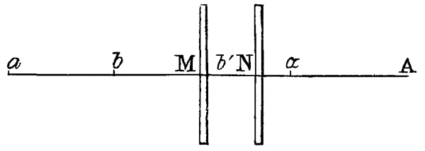
If the object A moves in a direction opposite to that of the
mirror, and with double its velocity, as is shown in Fig. 11;
then, since b would be the image when A was stationary, and
when M had moved to N, in which case a b = 2
M N, and bʹ the image when A had advanced to α
through a space A α = 2 M N, we have b N =
A N, and bʹ N = α N, and, therefore, b
bʹ = A N - α N = A α = 2 M N, and a
b + b bʹ or its equal a bʹ = 4 M N. Hence it
follows, that when the object advances towards the mirror with twice
its velocity, the image will move with four times the velocity of the
mirror.
If the mirror M moves round a centre, the very same results will
be obtained from the very same reasoning, only the angular motion of
the mirror and the image will then be more conveniently measured by
parts of a circle or degrees.
Fig. 12.
Now, in Fig. 12, let X be a fixed object, and
A O, B O, two mirrors placed at an angle of 60° and moveable round
O as a centre. When the eye is applied to the end of the mirrors
(or at E, Fig. 1), the fixed object X,
Fig. 12, seen by
direct vision will, of course, be stationary, while the mirrors
describe an arch X of 10° for example; but since A O has
approached X by 10°, the image of X formed behind A
O must have approached X by 20°, and consequently moves
with twice the velocity in the same direction as the mirrors. In like
manner, since B O has receded 10° from X, the image of
X formed by B O must have receded 20° from X,
and consequently must have moved with twice the velocity in the same
direction as the mirrors. Now, the image of X in the sector
b O β is, as it were, an image of the image in B
O a reflected from A O. But the image in B
O a advances in the same direction as the mirror A
O and with twice its velocity, hence the image of it in the sector
b O β will be stationary. In like manner it may be shown,
that the image in the sector a O α will be stationary.
Since α O e is an image of b O r
reflected from the mirror B O, and since all images in that
sector are stationary, the corresponding images in α O e
will move in the same direction α β as the mirrors; and for the same
reason the images in the other half-sector β O e will
move in the same direction; hence, the image of any object formed in
the last sector α O β will move in the same direction, and
with the same velocity as the images in the sectors A O
b, B O a.
By a similar process of reasoning, the same results will be obtained,
whatever be the number of the sectors, and whether the angle A O
B be the even or the odd aliquot part of a circle. Hence we may
conclude,
1. That during the rotatory motion of the mirrors round O, the
objects in the sector seen by direct vision, and all the images of
these objects formed by an even number of reflexions are at rest.
2. That all the images of these objects, formed by an odd number of
reflexions, move round O in the same direction as the mirrors,
and with an angular velocity double that of the mirrors.
3. That when the angle A O B is an even aliquot part
of a circle, the number of moving sectors is equal to the number of
stationary sectors, a moving sector being placed between two stationary
sectors, and vice versa.
4. That when the angle A O B is an odd aliquot part of a
circle, the two last sectors adjacent to each other are either both in
motion or both stationary, the number of moving sectors being greater
by one when the number of sectors is 3, 7, 11, 15, etc., and the number
of stationary sectors being greater by one when the number of sectors
is 5, 9, 13, 17, etc. And,
5. That as the moving sectors correspond with those in which the images
are inverted, and the stationary ones with those in which the images
are direct, the number of each may be found from the table given in page 24.
When one of the mirrors, A O, is stationary, while the other,
B O, is moved round, and so as to enlarge the angle A O
B, the object X, and the image of it seen in the stationary
mirror A O, remain at rest, but all the other images are in
motion receding from the object X, and its stationary image;
and when B O moves towards A O, so as to diminish the
angle A O B, the same effect takes place, only the motion of
the images is towards the object X, on one side, and towards
its stationary image on the other. These images will obviously move in
pairs; for, since the fixed object and its stationary image are at an
invariable distance, the existence of a symmetrical arrangement, which
we have formerly proved, requires that similar pairs be arranged at
equal distances round O, and each of the images of these pairs
must be stationary with regard to the other. Now, as the fixed object
is placed in the sector A O B, and its stationary image in the
sector A O b, it will be found that in the semicircle
M b e, containing the fixed mirror, the
1st reflected image and direct object,
are stationary with respect to each other.
2d
3d reflected image
4th
5th
6th
7th
8th
9th
while in the same semicircle M b e, the
1st reflected image and
2d reflected image
are movable with respect to each other.
3d
4d
5th
6th
7th
8th
9th
10th
On the other hand, in the semicircle M a e, containing
the movable mirror, the phenomena are reversed, the images which were
formerly stationary with respect to each other being now movable, and
vice versa.
In considering the velocity with which each pair of images revolves, it
will be readily seen that the pair on each side, and nearest the fixed
pair, will have an angular velocity double that of the mirror
B O; the next pair on each side will have a velocity four
times as great as that of the mirror; the next pair will have a
velocity eight times as great, and the next pair a velocity
sixteen times as great as that of the mirror, the velocity
of any pair being always double the velocity of the pair which is
adjacent to it on the side of the fixed pair. The reason of this will
be manifest, when we recollect what has already been demonstrated, that
the velocity of the image is always double that of the mirror, when the
mirror alone moves towards the object, and quadruple that of the mirror
when both are in motion, and when the object approaches the mirror with
twice the velocity. When B O moves from A O, the image
in the sector B O a moves with twice the velocity of
the mirror; but since the image in b O β is an image of
the image in B O a reflected from the fixed mirror A
O, it also will move with the same velocity, or twice that of the
mirror B O. Again, the image in the sector a O α,
being a reflexion of the stationary image in A O b from
the moving mirror, will itself move with double the velocity of the
mirror. But the image in the next sector α O β is a reflexion of
the image in b O β from the moving mirror B O; and
as this latter image has been shown to move in the direction b
β, with twice the velocity of the mirror B O, while the mirror
B O itself moves towards the image, it follows that the image in
α O β will move with a velocity four times that of the mirror.
The same reasoning may be extended to any number of sectors, and it
will be found that in the semicircle M b e, containing
the fixed mirror,
The images formed by
2 and 3
reflexions, move with
2
times the velocity of the mirror;
4 and 5
4
6 and 7
8
8 and 9
16
whereas in the semicircle M a e, containing the movable
mirror,—
The images formed by
1 and 2
reflexions, move with
2
times the velocity of the mirror;
3 and 4
4
5 and 6
8
7 and 8
16
a progression which may be continued to any length.
Before concluding this chapter, it may be proper to mention a very
remarkable effect produced by moving the two plain mirrors along one of
two lines placed at right angles to each other. When the aperture of
the mirrors is crossed by each of the two lines, the figure created by
reflexion consists of two polygons with salient and re-entering angles.
By moving the mirrors along one of the lines, so that it may always
cross the aperture at the same angle, and at the same distance from the
angular point, the polygon formed by this line will remain stationary,
and of the same form and magnitude; but the polygon formed by the
other line, at first emerging from the centre, will gradually increase
till its salient angles touch the re-entering angles of the stationary
polygon; the salient angles becoming more acute, will enclose the
apices of the re-entering angles of the stationary polygon, and at last
the polygon will be destroyed by truncations from its salient angles.
When the lines cross each other at a right angle, the salient angles
of the opening polygon can never touch the salient angles of the
stationary polygon, but always its re-entering angles. If the lines,
however, form a less angle than the complement of the angle formed
by the mirrors, then the salient angles of the opening polygon may
touch the salient angles of the stationary polygon, by placing the
mirrors so as to form re-entering angles in the polygon. When the
lines form an angle between 90° and the complement of the angle formed
by the mirrors, the salient angle of the opening polygon may be made
to touch the salient angles of the stationary one, but in this case
the stationary polygon can have no re-entering angles. The preceding
effects are finely exemplified by the use of a Kaleidoscope with a
draw-tube and lens described in Chapter X., and
by employing the vertical and horizontal bars of a window, which may be
set at different angles, by viewing them in perspective.
CHAPTER IV.
ON THE EFFECTS PRODUCED UPON THE
SYMMETRY OF THE PICTURE BY VARYING THE POSITION OF THE EYE.
It has been taken for granted in the preceding chapters, not only that
the object seen by direct vision is in a state of perfect junction
with the images of it formed by reflexion; but that the object and
its images have the same apparent magnitude, and nearly the same
intensity of light. As these conditions are absolutely necessary to the
production of symmetrical and beautiful forms, and may be all effected
by particular methods of construction, we shall proceed to investigate
the principles upon which these methods are founded, in so far as the
position of the eye is concerned.
When any object is made to touch a common looking-glass in one or more
points, the reflected image does not touch the object in these points,
but is always separated from it by a space equal to the thickness
of the glass, in consequence of the reflexion being performed by
the posterior surface of the mirror. The image and the object must
therefore be always disunited; and as the interval of separation must
be interposed between all the reflected images, there cannot possibly
exist that union of forms which constitutes the very essence of
symmetry. In mirror-glass there is a series of images reflected from
the first surface, which unite perfectly with the object, and
with one another. When the angles of incidence are not great, this
series of images is very faint, and does not much interfere with the
more brilliant images formed by the metallic surface. As the angles of
incidence increase, the one series of images destroys the effect of the
other, from their overlapping or imperfect coincidence—an effect which
increases with the thickness of the glass; but when the reflexions are
made at very oblique incidences, the images formed by the metallic
surface become almost invisible, while those formed by the first
surface are as brilliant and nearly as perfect as if the effect of the
posterior metallic surface had been entirely removed. In the following
observations, therefore, it is understood that the images are reflected
either from a polished metallic surface, or from the first surface of glass.
Fig. 13.
In order to explain the effects produced upon the symmetry of the
picture by a variation in the position of the eye, we must suppose the
object to be placed at a small distance from the end of the mirror.
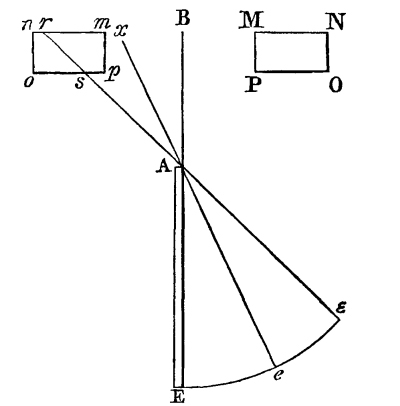
This position is represented in Fig. 13, where A E
is a section of the mirror in the direction of its length; M N O P an
object placed at a distance from the extremity A of the mirror, and
m n o p, its image seen by an eye to the right hand of E,
and which, by the principles of catoptrics, will be similar to the
object and similarly situated with respect to the mirror A E.
Now, if the eye is placed at ε, it will see distinctly the whole object
M N O P, but it will only see the portion n r s o of
the image cut off by drawing the line ε A r through the
extremity of the mirror, so that there cannot be a symmetrical form
produced by observing at the same time the object M N O P and
this portion of its image; and the deviation from symmetry will be
still greater, if M N O P is brought nearer the line B A,
for the image m n o p will be entirely included between the
lines A r and A B, so that no part whatever of
the image will be visible to an eye at ε. As the eye of the observer
moves from ε to e, the line ε A r will move into
the position e A x, and when it has reached the
point e, the whole of the image m n o p will be visible. The
symmetry, therefore, arising from the simultaneous contemplation of the
object and its image will be improved; but it will still be imperfect,
as the image will appear to be distant from the plane of the mirror,
only by the space m x, while the distance of the object is
M x. As the eye moves from e to E, the line
e A x will move into E A B, and the object
and its image will seem to be placed at the equal distances M B,
m B from the plane of the mirror, and will therefore
form a symmetrical combination. When the object is moved, and arrives
at B A the image will touch the object, and they will form one
perfect and united whole, whatever be the shape of the line M P.
Hence we conclude, that when an object is placed at a little
distance from the extremity of a plain mirror, its image formed by
reflexion from the mirror cannot unite with the object in forming a
conjoined and symmetrical picture, unless the eye is in the plane of
the mirror.
Fig. 14.
When two mirrors, therefore, are combined, as in Fig. 14,
the eye must be in the plane of both, in order that the object and its image may
have a symmetrical coincidence, and therefore it must be at the point
E where the two planes cut each other. The necessity of this
position, and the effects of any considerable deviation from it, will
be understood from Fig. 14, where A O B is the angle
formed by the mirrors, and M N the place of the object. Then if the eye
is placed at ε, the aperture A O B will be projected into a
b ω upon a plane passing through M N and at right angles
to E Oʹ; but the orthographic projection of A B O upon
the same plane is Aʹ Bʹ Oʹ, or, what is the same thing, the
reflecting surfaces of which A O, B O are sections, will,
when prolonged, cut the plane passing through M N in the lines
Aʹ Oʹ, Bʹ Oʹ; hence, rays from the objects situated
between Aʹ Oʹ Bʹ and a ω b cannot fall upon the
mirrors A O E, B O E, or images of these objects cannot
be formed by the mirrors. The images, therefore, in the different
sectors formed by reflexion round O as a centre, cannot include
any objects without Aʹ Oʹ Bʹ; and since the eye at ε sees all
the objects between Aʹ Oʹ Bʹ and a ω b, there can
be no symmetry and uniformity in the picture formed by the combination
of such an object with the images in the sectors. When the eye descends
to e, the aperture A O B is projected into aʹ oʹ
bʹ, which approaches nearer to A O B; but for the reasons
already assigned, the symmetry of the picture is still imperfect. As
the eye descends, the lines aʹ oʹ, bʹ oʹ approach to
Aʹ Oʹ, Bʹ Oʹ, and when the eye arrives at E, a
point in the plane of both the reflecting surfaces, the projection of
the aperture A O B will be Aʹ Oʹ Bʹ, and the images in
all the sectors will be exactly similar to the object presented to
the aperture. Hence we conclude in general, that when an object
is placed at any distance before two mirrors inclined at an angle,
which is an even aliquot part of 360°, the symmetry of the picture is
perfect, when the eye, considered as a mathematical point, is placed
atE, and that the deviation from symmetry increases as
the eye recedes fromEtowardsε.
If the object were a mathematical surface, all the parts of which were
in contact with the extremities A O, B O of the mirrors,
then it is easy to see that the symmetry of the picture will not be
affected by the deviation of the eye from the point E, and, in
consequence of the enlargement of the sector, seen by direct vision.
The symmetry of the picture, is, however, affected in another way, by
the deviation of the eye from the point E.
We have already seen, that, in order to possess perfect symmetry, an
object must consist of two parts in complete contact, one of which is
an inverted image of the other. But in order that an object possessing
perfect symmetry may appear perfectly symmetrical, four conditions
are required. The two halves of the object must be so placed with
respect to the eye of the observer, that no part of the one half shall
conceal any part of the other; that whatever parts of the one half
are seen, the corresponding parts of the other must also be seen;
and that the corresponding parts of both halves, and both halves
themselves, must subtend the same angle at the eye. When we stand
before a looking-glass, and hold out one hand so as to touch it, the
hand will be found to conceal various parts of its image; and, in
some positions of the eye, the whole image will be concealed, so that
a symmetrical picture cannot possibly be formed by the union of the
two. If the eye is placed so obliquely to the looking-glass, that the
hand no longer interferes with its image, it will still be seen, that
parts of the hand which are not directly visible, are visible in its
reflected image, and therefore that a symmetrical picture cannot be
created by the union of two parts apparently dissimilar. If the eye of
the observer is placed near his hand, so that he can see distinctly
both the hand and its image, the angular magnitude of his hand is much
greater than that of its image; and therefore, when the two are united,
they cannot form a symmetrical object. This will be better understood
from Fig. 15. When the eye is placed at ε, the object
M N O P is obviously nearer than its image m n o p, and must
therefore appear larger; and this difference in their apparent magnitudes will
increase as the eye rises above the plane of the mirror A E. As
the eye approaches to E, the distances of the object and its
image approach to an equality; and when the eye is at E, the
object M N O P, and its image m n o p, are situated at
exactly the same distance from the eye, and therefore have the same
angular magnitude. Hence it follows, that when they are united, they
will form a perfectly symmetrical combination.
Fig. 15.
When the eye is placed in the plane of both the mirrors, the field
of view arising from the multiplication of the sector A O B,
Fig. 14, will be perfectly circular; but as the eye rises
above the plane of both the mirrors, this circle will become a sort of ellipse,
becoming more and more eccentric as the eye comes in front of the
mirrors, or rises in the direction E ε. If the observer were
infinitely distant, these figures would be correct ellipses; but as the
eye, particularly when the mirrors are broad, must be nearly twice as
far from the last reflected sector as from the sector seen by direct
vision, the field of view, and consequently every pattern which it
contains, must be distorted and destitute of beauty, from this cause
alone.
Hitherto we have alluded only to symmetry of form, but it is manifest
that before the union of two similar forms can give pleasure to the
eye, there must be also a symmetry of light. If the object M N O
P, Fig. 15, is white, and its image m n o p black,
they cannot possibly form, by their combination, an agreeable picture. As
any considerable difference in the intensity of the light will destroy
the beauty of the patterns, it becomes a matter of indispensable
importance to determine the position of the eye, which will give the
greatest possible uniformity to the different images of which the
picture is composed.
It has been ascertained by the accurate experiments of Bouguer, that
when light is reflected perpendicularly from good plate glass, only 25
rays are reflected out of 1000; that is, the intensity of the light of
any object seen perpendicularly in plate glass, is to the intensity
of the light of its image as 1000 to 25, or as 40 is to 1. When the
angle of incidence is 60°, the number of reflected rays is 112, and the
intensities are nearly as 9 to 1.—When the angle of incidence is 87½°,
the number of reflected rays is 584, and the intensities are nearly
as 17 to 10, so that the luminousness of the object and its image
approach rapidly to an equality. It is therefore clear, that, in order
to have the greatest uniformity of light in the different images which
compose the figure, the eye must be placed as nearly as possible in the
plane of both the mirrors, that is, as near as possible to the angular
point.—But as it is impracticable to have the eye exactly in the plane
of both mirrors, the images formed by one reflexion must always be less
bright than the direct object, even at the part nearly in contact with
the object. The second and third reflexions, etc., where the rays fall
with less obliquity, will be still darker than the first; though this
difference will not be very perceptible when the inclination of the
mirrors is 30° or upwards, and the eye placed in the position already
described.
It is a curious circumstance, that the positions of the eye which
are necessary to effect a complete union of the images—to represent
similar parts of the object and its images—to observe the object and
its image under the same angular magnitude, and to give a maximum
intensity of light to the reflected images—should all unite in the
same point. Had this not been the case, the construction of the
Kaleidoscope would have been impracticable, and hence it will be seen
how vain is the attempt to produce beautiful and symmetrical forms from
any combination of plain mirrors in which this position of the eye is
not a radical and essential principle.
CHAPTER V.
ON THE EFFECTS PRODUCED UPON THE SYMMETRY OF THE
PICTURE BY VARYING THE POSITION OF THE OBJECT.
Having ascertained the proper position of the eye, we shall now proceed
to determine the position of the object.
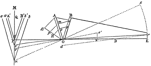
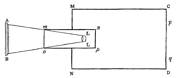
If the object is placed within the reflectors at any point D,
Fig. 16, between their object end O, and their
eye-end E, a perfectly symmetrical picture will obviously be formed
from it;but the centre of this picture will not be at O, the centre
of the luminous sectors, but at the point D, where the object is
placed, or its projection d, so that we shall have a circular
luminous field enclosing an eccentric circular pattern. Such a position
of the object is therefore entirely unfit for the production of a
symmetrical picture, unless the object should be such as wholly to
exclude the view of the circular field, formed by the reflected images
of the aperture A O B.
As the point D approaches to O, the centre d of
the symmetrical picture will approach to O, and when D
coincides with O, the centre of the picture will be at O,
and all the images of the object placed in the plane A O B will
be similarly disposed in all the sectors which compose the circular
field of view. Hence we may conclude, that a perfectly symmetrical
pattern cannot be exhibited in the circular field of view, when the
object is placed between O and E, or anywhere within
the reflectors. If the eye could be placed exactly at the angular
point E, so that every point of the line E O should
be projected upon O, then the images would be symmetrically
arranged round O; but this is obviously impossible, for the
object would, in such circumstances, cease to become visible when this
coincidence took place. But independent of the eccentricity of the
pattern, the position of the object within the mirrors prevents that
motion of the objects, without which a variation of the pattern cannot
be produced. An object between the reflectors must always be exposed
to view, and we cannot restrict our view to one-half, one-third, or
one-fourth of it, as when we have it in our power to move the objects
across the aperture, or the aperture over the objects.
Fig. 16.
Another evil arising from the placing of the objects within the
mirrors, is, that we are prevented from giving them the proper degree
of illumination which is so essential to the distinctness of the last
reflexions. The portions of the mirrors, too, beyond the objects, or
those between D and O, are wholly unnecessary, as they
are not concerned in the formation of the picture. Hence it follows,
that the effects of the Kaleidoscope cannot be produced by any
combination of mirrors, in which the objects are placed within them.
Let us now consider what will happen, by removing the object beyond
the plane passing through A O B. In this case the pattern will
lose its symmetry from two causes. In the first place, it is manifest,
as already explained, that as the eye is necessarily raised a little
above the point E, and also above the planes A O E, B
O E, it must see through the aperture A O B a portion of the
object situated below both of these planes. This part of the object
will therefore appear to project beyond the point, or below the plane
where the direct and reflected images meet. If we suppose, therefore,
that all the reflected images were symmetrical, the whole picture would
lose its symmetry in consequence of the irregularity of the sector A
O B seen by direct vision. But this supposition is not correct;
for since the image m n, Fig. 3, seen by direct vision
does not coincide with the first reflected images mnʹ, nmʹ, it is
clear that all the other images will likewise be incoincident, and,
therefore, that the figure formed by their combination must lose its
symmetry, and, consequently, its beauty.
As the eye must necessarily be placed above a line perpendicular to
the plane A B O at the point O, it will see a portion of
the object situated below that perpendicular continued to the object.
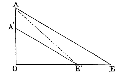
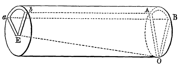
Thus, in Fig. 16, if the eye is placed at e above
E, and if M N is the object placed at the distance P O,
then the eye at e will observe the portion P Oʹ of the object
situated below the axis P O E, and this portion, which may be
called the aberration, will vary with the height E e of
the eye, and with the distance O P of the object.
Fig. 17.
Let us now suppose E e and O P to be constant,
and that a polygonal figure is formed by some line placed at the point
Q of the object M N. Then if P Q is very great
compared with P Oʹ, the polygonal figure will be tolerably
regular, though all its angles will exhibit an imperfect junction, and
its lower half will be actually, though not very perceptibly, less than
its upper half. But if Q approaches to P, P Oʹ
remaining the same, so that P Oʹ bears a considerable ratio
to P Q, then the polygonal figure will lose all symmetry, the
upper sectors being decidedly the largest, and the lowest sectors the
smallest. When Q arrives near P, the aberration becomes
enormous, and the figure is so distorted, that it can no longer be
recognised as a polygon.
The deviation from symmetry, therefore, arising from the removal of the
object from the extremity of the reflectors, increases as the object
approaches to the centre of the luminous sectors or the circular field,
and this deviation becomes so perceptible, that an eye accustomed to
observe and admire the symmetry of the combined objects, will instantly
perceive it, even when the distance of the object or P O is less
than the twentieth part of an inch. When the object is very distant,
the defect of symmetry is so enormous, that though the object is seen
by direct vision, and in some of the sectors, it is entirely invisible
in the rest.
The principle which we have now explained is of primary importance
in the construction of the Kaleidoscope, and it is only by a careful
attention to it that the instrument can be constructed so as to give
to an experienced and fastidious eye that high delight which it never
fails to derive from the exhibition of forms perfectly symmetrical.
From these observations it follows, that a picture possessed of
mathematical symmetry, cannot be produced unless the object is placed
exactly at the extremity of the reflectors, and that even when this
condition is complied with, the object itself must consist of lines all
lying in the same plane, and in contact with the reflectors. Hence it
is obvious, that objects whose thickness is perceptible, cannot give
mathematically symmetrical patterns, for one side of them must always
be at a certain distance from O. The deviation in this case is,
however, so small, that it can scarcely be perceived in objects of
moderate thickness.
In the simple form of the Kaleidoscope, the production of symmetrical
patterns is limited to objects which can be placed close to the
aperture A O B; but it will be seen in the sequel of this
treatise, that this limitation may be removed by an optical
contrivance, which extends indefinitely the use and application of the
instrument.
CHAPTER VI.
ON THE INTENSITY OF THE LIGHT IN DIFFERENT PARTS OF THE
FIELD, AND ON THE EFFECTS PRODUCED BY VARYING THE
LENGTH AND BREADTH OF THE REFLECTORS.
When we look through a Kaleidoscope in which the mirrors are placed
at an angle of 18° or 22½°, the eye will perceive a very obvious
difference in the intensity of the light in different parts of the
field. If the inclination of the mirrors be about 30°, and the eye
properly placed near the angular point, the intensity of the light is
tolerably uniform; and a person who is unaccustomed to the comparison
of different lights, will find it extremely difficult to distinguish
the direct sector from the reflected ones. This difficulty will be
still greater if the mirrors are made of finely polished steel, or
of the best speculum metal, and the observer will not hesitate in
believing that he is looking through a tube whose diameter is equal to
that of the circular field. This approximation to uniformity in the
intensity of the light in all the sectors, which arises wholly from the
determination of the proper position of the eye, is one of the most
curious and unexpected properties of the Kaleidoscope, and is one which
could not have been anticipated from any theoretical views, or from any
experimental results obtained from the ancient mode of combining plain
mirrors. It is that property, too, which gives it all its value;
for, if the eye observed the direct sector with its included objects
distinguished from all the rest by superior brilliancy, not only would
the illusion vanish, but the picture itself would cease to afford
pleasure, from the want of symmetry in the light of the field.
Fig. 18.
Before we proceed to investigate the effects produced by a variation in
the length of the reflecting planes, it will be necessary to consider
the variation of the intensity of the light in different parts of the
reflected sectors. In the direct sector A O B, Fig. 2,
the intensity of the light is uniform in every part of its surface; but
this is far from being the case in the images formed by reflexion. In
Fig. 17, take any two points m, o, and draw
the lines m n, o p, perpendicular to A O, and meeting β
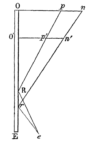
O in n and p. Let O E, Fig. 18,
be a section of the reflector A O seen edgewise, and let O
p, O n, be taken equal to the lines m n,
o p, or the height of the points n, p, above the
plane of the reflector A O. Make O R to R E as
O p is to E e the constant height of the eye
above the reflecting plane, and O r to r E
as O n to E e, and the points R,
r, will be the points of incidence of the rays issuing from
p and n; for in this case O R p = E
R e, and O r n = E r e. Hence it
is obvious, that E R e is less than E r e,
and that the rays issuing from p, by falling more obliquely
upon the reflecting surface, will be more copiously reflected. It
follows, therefore, that the intensity of the light in the reflected
sector A O β is not uniform, the lines of equal brightness, or
the isophotal lines, as they may be called, being parallel to
the reflecting surface A O, and in every sector parallel to the
radius, between the given sector and the reflecting surface by which
the sector is formed.
As it is easy from the preceding construction to determine the angles
at which the light from any points m, n, is reflected,
when the length O E of the reflectors, and the position of
the eye at E is given, we may calculate the intensity of the
light in any point of the circular field by means of the following
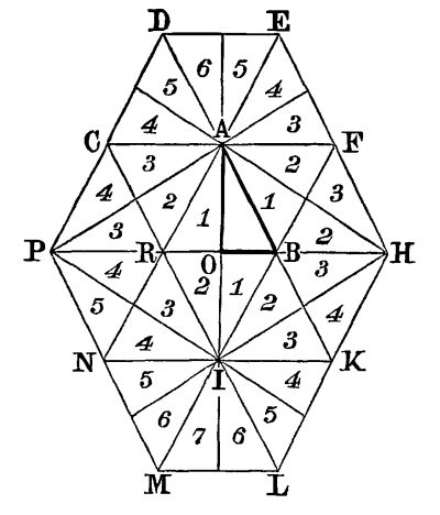
table, which shows the number of rays reflected at various angles of
incidence, the number of incident rays being supposed to be 1000.
Part of this table was computed by Bouguer for plate glass not
quicksilvered, by means of a formula deduced from his experiments. By
the aid of the same formula I have extended the table considerably.
Table showing the quantity of light reflected at
various angles of incidence from plate glass.
Complement of the Angles of Incidence.
Rays Reflected out of 1000.
2½°
584
5
543
7
474
10
412
12½
356
15
299
20
222
21
210
25
157
26
149
30
112
31
105
34
85
35
79
36
74
37
69
38
65
39
61
40
57
46
40
50
34
55
29
60
27
70
25
80
25
90
25
In order to explain the method of using the table, let us suppose
that the angle of incidence, or O R p, Fig. 19,
is 85°: then the number of rays in the corresponding point π of the reflected
sector A O b (Fig. 17) will be 543. By letting
fall perpendiculars from the points μ, π, upon the mirror B O, and
taking O p, O n, Fig. 19, equal
to these perpendiculars, we may ascertain the angles at which the light from the
points μ, π, suffer a second reflexion from the mirror B O. Let
the angle for the point π be 10°, then the number of rays out of 1000
reflected at this angle, according to the table, is 412; but as the
number of rays emanating from π, and incident upon B O, is not
1000, but only 543, we must say as 1000: 412 = 543: 224, the number
of rays reflected from B O, or the intensity of the light in a
point in the line O bʹ corresponding to π.
Fig. 19.
The preceding method of calculation is applicable only with strictness
to the two sectors A O b, B O a, formed
by one reflexion, for the intensity of the light in the other sectors
which are formed by more than one reflexion, must be affected by the
polarization which the light experiences after successive reflexions;
for light which has acquired this property is reflected according to
laws different from those which regulate the reflexion of direct light.
When the mirrors are metallic, the quantity of reflected light is also
affected by its polarization, but it is regulated by more complicated
laws.
In Kaleidoscopes made of plates of glass, the last reflected image β
O ω, Fig. 2, is more polarized than any of the rest,
and is polarized in a plane perpendicular to X E, or in the same manner
as if it had been reflected at the polarizing angle from a vertical
plane parallel to X E.
Fig. 20.
Let us now consider what will take place by a variation in the length
of the reflecting planes, the angular extent of the field of view
remaining always the same. If A O E, A O Eʹ, Fig. 20,
be two reflecting plates of the same breadth A O, but of different
lengths, it is manifest that the light which forms the direct sector
must be incident nearer the perpendicular, or reflected at less
obliquities in the short plate than in the long one, and, therefore,
that a similarly situated point in the circular field of the shorter
instrument, will have less intensity of light than a similarly situated
point in a larger instrument. But in this case, the field of view in
the short instrument is proportionally enlarged, so that the comparison
between the two is incorrect. When the long and the short instrument
have equal apparent apertures, which will be the case when the plates
are A O E, Aʹ O Eʹ, then similarly situated points of the
two fields will have exactly the same intensity of light.
This will be better understood from Fig. 19, where O E
may represent the long reflector and Oʹ E the short one. Then, if
these two have exactly the same aperture, or a circular field of the
same angular magnitude, the rays of light which flow from two given
points, p, n, of the long instrument, will be reflected
at a certain angle from the points R, r; but as the
points pʹ, nʹ, are the corresponding points in the field
of the shorter instrument, the rays which issue from them will be
reflected at the same angles from the points R, r, the
eye being in both cases placed at the same point e. Hence it
is obvious, that the quantity of reflected light will in both cases
be the same, and, therefore, that there is no peculiar advantage to
be derived, in so far as the light of the field is concerned, by
increasing the length of the reflectors, unless we raise the eye above
e, till every part of the pupil receives the reflected rays.
There is, however, one advantage, and a very important one, to be
derived from an increase of length in the mirrors, namely a diminution
of the deviation from symmetry which arises from the small height of
the eye above the plane of the mirrors, and of the small distance of
the objects from the extremity of the mirrors. As the height of the eye
must always be a certain quantity, E e, Fig. 17,
above the angular point E, whatever be the length of the reflectors,
it is obvious, that when the length of the reflectors is e
O, the deviation from symmetry will be only P oʹ,
whereas when the length of the reflectors is reduced to eʹ
O, the height of the eye eʹ Eʹ being still equal
to e E, the aberration will be increased to P
o. This advantage is certainly of considerable consequence;
but in practice the difficulty of constructing a perfect instrument,
increases with the length of the reflectors. When the plates are long,
it is more difficult to get the surface perfectly flat; the risk of a
bending in the plates is also increased, which creates the additional
difficulty of forming a good junction, on which the excellence of the
instrument so much depends. By augmenting the length of the reflectors,
the quantity of dust which collects between them is also increased,
and it is then very difficult to remove this dust, without taking the
instrument to pieces. From these causes it is advisable to limit the
greatest length of the reflectors to seven or eight inches.
CHAPTER VII.
ON THE CONSTRUCTION AND USE
OF THE SIMPLE KALEIDOSCOPE.
In order to construct the Kaleidoscope in its most simple form, we must
procure two reflectors, about five, six, seven, or eight inches long.
These reflectors may be either rectangular plates, or plates shaped
like those represented in Fig. 1, having their broadest
ends A O, B O, from one to two inches wide, and their narrowest
ends a E, b E, half an inch wide. If
the reflectors are of glass, the newest plate glass should be used,
as a great deal of light is lost by employing old plate glass, with
scratches or imperfections upon its surface. The plate glass may be
either quicksilvered or not, or its posterior surface may be ground,
or covered with black wax, or black varnish, or anything else that
removes its reflective power. This, however, is by no means absolutely
necessary, for if the eye is properly placed, the reflexions from the
posterior surface will scarcely affect the distinctness of the picture,
unless in very intense lights. If it should be thought necessary to
extinguish, as completely as possible, all extraneous light that may be
thrown into the tube from the posterior surface of the glass plates,
that surface should be coated with a varnish of the same refractive and
dispersive power as the glass.
If the plates of glass have been skilfully cut with the diamond, so as
to have their edges perfectly straight, and free from chips, two of
the edges may be placed together, as in Fig. 17 (p. 49),
or one edge of one plate may be placed against the surface of the other plate,
as shown in the section of Mr. Bates’s Kaleidoscope. But if the edges are
rough and uneven, one of them may be made quite straight, and freed
from all imperfections, by grinding it upon a flat surface, with very
fine emery, or with the powder scraped from a hone. When the two plates
are laid together, so as to form a perfect junction, they are then to
be placed in a brass or any other tube, so as to form an angle of 45°,
36°, 30°, or any even aliquot part of a circle. In order to do this
with perfect accuracy, direct the tube containing the reflectors to any
line, such as m n, Fig. 2, placed very obliquely
to one of the reflectors A O, and open or shut the plates till the figure
of a star is formed, composed of 8, 10, or 12 sectors, or with 4, 5, or
6 points, corresponding to angles of 45°, 36°, and 30°. When all the
points of the star are equally perfect, and none of the lines which
form the salient and re-entering angles disunited, the reflectors must
be fixed in that position by small arches of brass or wood A B,
a b, Fig. 21, filed down till they
exactly fit the space between the open ends of the plates. The plates
must then be kept in this position by pieces or wedges of cork or wood,
or any other substance pushed between them and the tube. The greatest
care, however, must be taken that these wedges press lightly upon the
reflectors, for a very slight force is capable of bending and altering
the figure even of very thick plates of glass.
When the reflectors are thus placed in the tube, as in Fig. 21,
their extremities a E, b E, next the eye, must
reach to the very end of the tube, as it is of the greatest importance
that the eye get as near as possible to the reflectors. The other ends
of the reflectors A O, B O, must also extend to the other
extremity of the tube, in order that they may be brought into contact
with the objects which are to be applied to the instrument. In using
transparent objects the cell or box which contains them may be screwed
into the end of the tube, so as to reach the ends of the reflectors,
if they happen to terminate within the tube; but an instrument thus
constructed is incapable of being applied to opaque objects, or to
transparent objects seen by reflected light.
Fig. 21.
If the plates are narrower at the eye-end, as in Fig. 21,
the angular point E should be a little on one side of the axis of the tube,
in order that the aperture in the centre of the brass cap next the eye
may be brought as near as possible to E. When the plates have
the same breadth at both ends, the angular point E will be near
the lower circumference of the tube, as it is at O; and in this
case it is necessary to place the eye-hole out of the centre, so as to
be a little above the angular point E. This construction is less
elegant than the preceding; but it has the advantage of giving more
room for the introduction of a feather, or a piece of thin wood covered
with leather, for the purpose of removing the dust which is constantly
accumulating between the reflectors. In some instances the plates have
been put together in such a manner that they may be taken out of the
tube, for the purpose of being cleaned; but though this construction
has its advantages, yet it requires some ingenuity to replace the
reflectors with facility, and to fix them at the exact inclination
which is required. One of the most convenient methods is to support the
reflector in a groove cut out of a solid cylinder of dry wood of nearly
the same diameter as the tube; and after a slip of wood, or any other
substance, is placed along the open edges of the plates, to keep them
at the proper angle given by the groove, the whole is slipped into the
tube, where it remains firm and secure from all accident.
If the length of the reflectors is less than the shortest distance at
which the eye is capable of seeing objects with perfect distinctness,
it will be necessary to place at the eye-end E a convex lens,
whose focal length is equal to, or an inch or two greater than, the
length of the reflectors. By this means the observer will see with
perfect distinctness the objects placed at the object end of the
Kaleidoscope. This lens, however, must be removed when the instrument
is to be used by persons who are short-sighted.
The proper application of the objects at the end of the reflectors
is now the only step which is required to complete the simple
Kaleidoscope. The method of forming, selecting, and mixing the objects,
will be described in the next chapter. At present, we shall confine our
attention to the various methods which may be employed in applying them
to the end of the reflectors.
Fig. 22.
The first and most simple method consists in bringing the tube about
half an inch beyond the ends of the reflectors. A circular piece of
thin plane glass of the same diameter as the tube, is then pushed into
the tube, so as to touch the reflectors. The pieces of coloured glass
being laid upon this piece of glass when the tube is held in a vertical
position, another similar disc of plane glass, having its outer surface
ground with fine emery, is next placed above the glass fragments, being
prevented from pressing upon them, or approaching too near the first
plane glass by a ring of copper or brass; and is kept in its place by
burnishing down the end of the tube. The eye being placed at the other
end of the instrument, the observer turns the whole round in his hand,
and perceives an infinite variety of beautiful figures and patterns,
in consequence of the succession of new fragments, which are brought
opposite the aperture by their own gravity, and by the rotatory motion
of the tube. In this rude state, however, the instrument is by no means
susceptible of affording very pleasing exhibitions. A very disagreeable
effect is produced by bringing the darkest sectors, or those formed by
the greatest number of reflexions, to the upper part of the circular
field, and though the variety of patterns will be very great, yet the
instrument is limited to the same series of fragments, and cannot
be applied to the numerous objects which are perpetually presenting
themselves to our notice. These evils can be removed only by adopting
the construction shown in Fig. 22, in which the reflectors reach the
very end of the tube. Upon the end of the tube a b, c d,
Fig. 22, is placed a ring of brass, m n, which moves
easily upon the tube a b c d, and is kept in its place by a shoulder
of brass on each side of it. A brass cell, M N, is then made to
slip tightly upon the moveable ring m n, so that when the cell
is turned round by means of the milled end at M N, the ring
m n may move freely upon the tube. The fragments of coloured
glass, etc., are now placed in a small object-box, as it may be called,
consisting of two glasses, the innermost of which, m n, is
transparent, and the other ground on the outside P, and kept
at the distance of ⅛th or ⅒th of an inch by a brass rim: this brass
rim generally consists of two pieces, which screw into one another, so
that the object-plate can be opened by unscrewing it, and the fragments
changed at pleasure. This object-box is placed at the bottom of the
cell M N, as shown at O P, and the depth of the cell is
such as to allow the side O to touch the end of the reflectors,
when the cell is slipped upon the ring m n. When this is done,
the instrument is held in one hand with the angular point E,
Fig. 21, downwards, which is known by a mark on the upper
side of the tube between a and b, and the cell is turned round with
the other hand, so as to present different fragments of the included
glass before the aperture A O B. The tube may be directed to
the brightest part of the sky in the day-time, or in the evening to a
candle, or an Argand Lamp, so as to transmit the light directly through
the coloured fragments; but it will always be found to give richer and
more brilliant effects if the tube is directed to the window-shutter,
a little to one side of the light, or is held to one side of the
candle—or, what is still better, between two candles or lamps placed
as near each other as possible. In this way the picture created by the
instrument is not composed of the harsh tints formed by transmitted
light; but of the various reflected and softened colours which are
thrown into the tube from the sides and angles of the glass fragments.
When the pattern remains fixed in any position of the instrument, a
variety of beautiful changes may be effected by making the end of the
tube revolve round a candle or a bright gas flame, placed near the
object-plate. The general pattern remains the same, but its colours
vary both in their position and intensity, as the light falls upon
different sides of the fragments of glass.
In the preceding method of applying the objects to the reflectors,
the fragments of coloured glass are introduced before the aperture,
and pass across it in concentric circles; and as the fragments always
descend by their own gravity, the changes in the picture, though
infinite in number, constantly take place in a similar manner. This
defect may be remedied, and a great degree of variety exhibited in
the motion of the fragments, by making the object-plates rectangular
instead of circular, and moving them through a groove cut in the
cell at M N, in the same manner as is done with the pictures
or sliders for the magic lantern and solar microscope. By this means
the different fragments that present themselves to the aperture may
be made to pass across it in every possible direction, and very
interesting effects may be produced by a combination of the rotatory
and rectilineal motions of the object-plate. When the object or objects
are fixed, and the tube with the reflectors moved round a centre, as
described in Chapter II.,[3]
we have the same succession of symmetrical pictures; but in this case
every alternate sector is stationary, and the same number in motion,
the moving figures always changing their form, and assuming that of the
figures in the stationary sectors, which of course change, while the
ends of the mirror pass over the fixed objects.
When the simple Kaleidoscope is applied to opaque objects, such as a
seal, a watch-chain, the seconds hands of a watch, coins, pictures,
gems, shells, flowers, leaves, and petals of plants, impressions
from seals, etc., the object, instead of being held between the eye
and the light, must be viewed in the same manner as we view objects
through a microscope, being always placed as near the instrument as
possible, and so as to allow the light to fall freely upon the object.
The object-plates, and all transparent objects, may be viewed in this
manner; but the most splendid exhibition of this kind is to view minute
fragments of coloured glass, and objects with opaque colours, etc.,
placed in a flat box, the bottom of which is made of mirror-glass. The
light reflected from the mirror-glass, and transmitted through the
transparent fragments, is combined with the light reflected both from
the transparent and opaque fragments, and forms an effect of the finest
kind.
As dust is apt to collect in the angle formed by the reflectors, it may
be removed when the reflectors are fixed, either by the end of a strong
feather, or blown away with a pair of bellows. When the dust is lodged
upon the face of the reflectors, it should be removed by a piece of
soft leather.
CHAPTER VIII.
ON THE SELECTION OF OBJECTS FOR THE
KALEIDOSCOPE, AND ON THE MODE OF CONSTRUCTING THE OBJECT-BOX.
Although the Kaleidoscope is capable of creating beautiful forms
from the most ugly and shapeless objects, yet the combinations which
it presents, when obtained from certain shapes and colours, are so
superior to those which it produces from others, that no idea can be
formed of the power and effects of the instrument, unless the objects
are judiciously selected.
When the inclination of the reflectors is great, the objects, or the
fragments of coloured glass, should be larger than when the inclination
is small; for when small fragments are presented before a large
aperture, the pattern which is created has a spotted appearance, and
derives no beauty from the inversion of the images, in consequence of
the outline of each separate fragment not joining with the inverted
image of it.
The objects which give the finest outlines by inversion, are those
which have a curvilineal form, such as circles, ellipses, looped
curves like the figure 8, curves like the figure 3 and the letter S;
spirals, and other forms, such as squares, rectangles, and triangles,
may be applied with advantage. Glass, both spun and twisted, and of all
colours, and shades of colours, should be formed into the preceding
shapes; and when these are mixed with pieces of flat coloured glass,
blue vitriol, native sulphur, yellow orpiment, differently coloured
fluids, enclosed and moving in small vessels of glass, etc., they
will make the finest transparent objects for the Kaleidoscope.
When the objects are to be laid upon a mirror plate, fragments of
opaquely-coloured glass should be added to the transparent fragments,
along with pieces of brass wire, of coloured foils, and grains of
spelter. In selecting transparent objects, the greatest care must be
taken to reject fragments of opaque glass, and dark colours that do
not transmit much light; and all the pieces of spun glass, or coloured
plates, should be as thin as possible.
When the objects are thus prepared, the next step is to place them
in the object-box. The distance between the interior surfaces of the
two plane glasses, of which the object-plates are generally composed,
should be as small as possible, not exceeding ⅛th of an inch. The
outermost of these glasses has its external surface rough ground, or
is what is called a grey glass, the principal use of which is to
prevent the lines of external objects, such as the bars of the window,
or the outlines of the illuminating flame from being introduced into
the picture. When a strong light is used, a circular disk of fine thin
paper placed outside of the object-box may be advantageously employed
in place of the ground glass. The thickness of the transparent glass
plate next the reflectors should be just sufficient to keep the glass
from breaking; and the interior diameter of the brass rings into which
the transparent and the grey or ground plates of glass are burnished,
should be so great that no part of the brass rim may be opposite the
angular part of the reflectors during the rotatory motion of the
cell. If this precaution is not attended to, the central part of the
pattern, where the development of new forms is generally the most
beautiful, will be entirely obliterated by the interposition of the
brass rim. Instead of using transparent or grey glasses on the sides
of every object-box, some of the boxes should be made with disks of
flint glass, the interior surface of which have been stamped while in
a state of fusion with a sort of pattern, or with curved lines of a
pleasing form. In others, the outer surface alone of the plate next the
reflectors might be thus formed. An object-box might also be formed
of disks of glass, one side of which is colourless, and the other
coloured, some of the coloured portions being ground away irregularly,
as in certain Bohemian articles of glass; and the colour in one disk
may be complementary to that in the other. In object-boxes of this
kind, pieces of coloured glass may also be placed. When the two parts
of the object-boxes thus constructed are screwed or fixed together,
the box should be nearly two-thirds filled with the mixture of regular
and irregular objects, already mentioned. If they fall with difficulty
during the rotation of the cell, two or three turns of the screw
backward, when there is a screw, will relieve them; and if they fall
too easily, and accumulate, by slipping behind one another, the space
between the glasses may be diminished by placing within the box another
glass in contact with the grey glass.
When the object-box, now described, is placed in the cell, and examined
by the Kaleidoscope, the pictures which it forms are in a state of
perpetual change, and can never be fixed, and shown to another person.
To obviate this disadvantage, an object-box with fixed objects generally
accompanies the instrument; the pieces of spun and coloured glass are
fixed by a transparent cement to the inner side of the glass of the
object-plate, next the eye, so that the patterns are all permanent, and
may be exhibited to others. After the cell has performed a complete
rotation, the same patterns again recur, and may therefore be at any
time recalled at the pleasure of the observer. The same patterns,
it is true, will have a different appearance, if the light falls in
a different manner upon the objects, but its general character and
outline will, in most cases, remain the same.
The object-boxes which have now been described, are made to fit
the cell, but at the same time to slip easily into it, so that
they themselves have no motion separate from that of the cell. An
object-plate, however, of a less diameter, called the vibrating
object-plate, and containing loose objects, is an interesting addition
to the instrument. When the Kaleidoscope is held horizontally, this
small object-plate vibrates on its lower edge, either by a gentle
motion of the tube, or by striking it slightly with the finger; and the
effect of this vibration is singularly fine, particularly when it is
combined with the motion of the coloured fragments.
Another of the object-boxes, in several of the instruments, contains
either fragments of colourless glass, or an irregular surface of
transparent varnish or indurated Canada balsam. This object-box gives
very fine colourless figures when used alone; but its principal use
is to be placed in the cell between an object-box with bright colours
and the end of the instrument. When this is done, the outline of the
pieces of coloured glass are softened down by the refraction of the
transparent fragments, and the pattern displays the finest effects of
soft and brilliant colouring. The colourless object-box supplies the
outline of the pattern, and the mass of colour behind fills it up with
the softest tints.
Some of the object-boxes are filled with iron or brass wires, twisted
into various forms, and rendered broader and flatter in some places by
hammering. These wires, when intermixed with a few small fragments of
coloured glass, produce a very fine effect. Other object-plates have
been made with pitch, balsam of tolu, gum lac, and thick transparent
paints; and when these substances are laid on with judgment, they
form excellent objects for the Kaleidoscope. Lace has been introduced
with considerable effect, and also festoons of beads strung upon wire
or thread; but pieces of glass, with cut and polished faces, are ill
fitted for objects. When the object-box is wide, certain insects may
be introduced temporarily, without killing or injuring them, and
the crystallization of certain salts from their solution, and other
chemical changes, may be curiously exhibited.
Hitherto we have supposed all colours to be indiscriminately adopted in
the selection of objects; but it will be found from experience, that
though the eye is pleased with the combination of various objects,
yet it derives this pleasure from the beauty and symmetry of the
outline, and not from the union of many different tints. Those who are
accustomed to this kind of observation, and who are acquainted with the
principles of the harmony of colours, will soon perceive the harshness
of the effect which is produced by the predominance of one colour, by
the juxtaposition of others, and by the accidental union of a number;
and even those who are ignorant of these principles, will acknowledge
the superior effect which is obtained by the exclusion of all other
colours except those which harmonize with each other.
In order to enable any person to find what colours harmonize with each
other, I have drawn up the following table, which contains the harmonic colours.
Deepest Red,
Blue and Green equally mixed.
Red,
Blue and Green, with most Blue, mixed.
Orange Red,
Blue mixed with much Indigo.
Orange,
Blue and Indigo, the Indigo predominating.
Orange-Yellow,
Indigo unmixed.
Yellow,
Violet and Indigo nearly in equal portions.
Greenish Yellow,
Pale Violet.
Green,
Violet.
Greenish Blue,
Violet and Red in equal portions.
Blue,
Orange Red, Red.
Indigo,
Orange-Yellow.
Violet,
Green.
It appears from the preceding table that Bluish Green harmonizes
with Red, or, in other words, Red is said to be the
accidental colour of Bluish Green, and vice versa.
These colours are also called complementary colours, because the
one is the complement of the other, or what the other wants of white
light; that is, when the two colours are mixed, they will always form
white by their combination.[4]
The following general method of finding the harmonic colours will
enable the reader to determine them for tints not contained in the
preceding table. Let A B, Fig. 23, be the prismatic
spectrum, containing all the seven colours, namely, Red, Orange,
Yellow, Green, Blue, Indigo, and
Violet, in the proportion assigned to them by Sir Isaac Newton,
and marked by the dotted lines. Bisect the A B at m, so
that A m is equal to B m, and let it be
required to ascertain the colour which harmonizes with the colour in
the Indigo space at the point p. Take A m, and
set it from p to o, and the colour opposite o,
or an orange-yellow, will be that which harmonizes with the indigo
at p. If p is between m and A, then the
distance A m must be set off from m towards n.
Fig. 23.
In order to show the method of constructing object-boxes on the
preceding principles, we shall suppose that the harmonic colours of
orange-yellow and indigo are to be employed. Four or five regular
figures, such as those already described, must be made out of
indigo-coloured glass, some of them being plain, and others twisted.
The same number of figures must also be made out of an orange-yellow
glass; and some of these may be drawn of less diameter than others,
in order that tints of various intensities, but of the same colour,
may be obtained. Some of these pieces of spun glass, of an indigo
colour, may be intertwisted with fibres of the orange-yellow glass. A
few pieces of white flint-glass, or crystal spun in a similar manner,
and intertwisted, some with fibres of orange-yellow, and others with
fibres of indigo glass, should be added; and when all these are joined
to some flat fragments of orange-yellow glass, and indigo-coloured
glass, and placed in the object-plate, they will exhibit, when applied
to the Kaleidoscope, the most chaste combinations of forms and colours,
which will not only delight the eye by the beauty of their outline,
but also by the perfect harmony of their tints. By using the thin and
highly-coloured films or flakes of decomposed glass, very brilliant and
beautiful patterns are produced. These films may be placed either upon
a mirror plate or upon black wax, and they may be placed among other
objects, or fixed in movable cells. By applying the Kaleidoscope to
crystals in the act of formation, shooting out in different directions,
symmetrical patterns are instantaneously created.
The effect produced by objects of only one colour is perhaps even
superior to the combination of two harmonic colours. In constructing
object-plates of this kind, various shades of the same colour may be
adopted; and when such objects are mixed with pieces of colourless
glass, twisted and spun, the most chaste and delicate patterns are
produced; and those eyes which suffer pain from the contemplation of
various colours, are able to look without uneasiness upon a pattern in
which there is only one.
In order to show the power of the instrument, and the extent to which
these combinations may be carried, I have sometimes constructed a
long object-plate, like the slider of the magic lantern, in which
combinations of all the principal harmonic colours followed one another
in succession, and presented to the eye a series of brilliant visions
no less gratifying to some persons, and to some others even more
gratifying, than those successions of musical sounds from which the ear
derives such intense delight.
We cannot conclude this chapter without noticing the fine effects which
are produced by the introduction of carved gems, and figures of all
kinds, whether they are drawn or engraved on opaque, or transparent
grounds. The particular mode of combining these figures will be pointed
out in a subsequent chapter.
CHAPTER IX.
ON THE ILLUMINATION OF TRANSPARENT OBJECTS
IN THE KALEIDOSCOPE.
When the Kaleidoscope is directed to the sky, or to a luminous object,
such as a gas flame, or the flame of a candle, a uniform tint is seen
through the pieces of glass, or other transparent fragments that
have flat surfaces, and there is a certain degree of hardness in
their outlines. When the instrument is not opposite the flame, but
directed to one side of it, the light enters the transparent fragments
obliquely, and a much finer effect is produced. The pattern, indeed,
changes very considerably by making the Kaleidoscope move round the
flame. An excellent effect is obtained, as we have already stated,
by directing the tube between two bright lights; and the richness of
the symmetrical pattern increases with the number of lights which
illuminate the objects. As it would be inconvenient to adopt such a
mode of illumination, it becomes of importance to have some contrivance
attached to the instrument, by which we can illuminate the objects by
light falling upon them in different directions.
Fig. 24.
The simplest method of thus illuminating the objects, is to fix on the
end of the Kaleidoscope the portion of a metallic or silvered-glass
cone. The light of a bright flame, placed in front of the cone, will
be reflected from its interior surface, and fall obliquely on the
fragments of coloured glass. In many cases the effect will be increased
by placing in the base or mouth of the cone a circular stop, or opaque
disk, in order to prevent any light from falling directly upon the
objects, their oblique illumination being produced solely by the
rays reflected from the interior surface of the cone. This will be
understood from the annexed figure, where M A N C is a portion
of the cone, fixed to the end E F of the Kaleidoscope, and m
n o p the object-box. If the angle formed by the sides of the cone
is such that a ray of the sun’s light falling upon M, the upper
margin of the reflecting surface of the cone, is reflected to o,
the lower side of the object-box, then all the rays of a beam of the
sun’s light incident upon the upper half of the conical surface, will
be reflected upon the object-box; and, for the same reason, if a ray
falling on N is reflected to m, all the other rays
falling on the lower half of the conical surface will be reflected upon
the object-box, and illuminate obliquely the objects which it contains.
In the Kaleidoscopes of more recent construction, the object-box is
made transparent throughout,—the plates of glass m n, o
p being fixed in a cylindrical case of glass m n o p, so
that rays R R, either parallel or diverging, may be reflected
from the cone A B C D, and after passing through the transparent
cylindrical rim m n o p, illuminate the objects. Another cone
A M N C, with its angle less than a right angle, may be joined
to A B D C, so as to throw the rays obliquely, into m n
and o p, and also, if desired, upon the front glass m o
of the object-box, the direct rays being excluded by an opaque disk
S S. In this construction, the outer face of the glass m
o should not be ground, as it would prevent the admission of the
light to the objects, the exclusion of external objects, the purpose
for which the grey glass is required, being effected by the stop S
S. The illuminating cone may be of tin, or, what is much better, of
plated copper, which reflects more light than any other metal, and it
must be so attached to the tube containing the reflectors, as to have a
rotatory motion.
The same kind of lateral illumination may be obtained from polyhedral
cones or hemispheres of solid glass. If A B C D, Fig. 25,
is the section of a polyhedral cone of flint or plate glass, a portion m n
o p is cut out of its base A B, to form an object-box for
the reception of the pieces of coloured glass, or other objects. The
sides m n, m o, o p, being highly polished, rays
of light, either parallel, as emanating from the sun, or diverging
from artificial sources of light, will be refracted and fall obliquely
upon the faces of the object-box, and illuminate its contents with the
irregular prismatic spectra which are formed by refraction. The apex
D C E may, in some cases, be cut off, and the polygonal section
D E blackened in order to prevent the introduction of direct
light, and act as the stop S S in the preceding figure.
Fig. 25.
A similar effect will be obtained from a polyhedral solid, of a
hemispherical form, as shown in Fig. 26, where A C,
C D, D E, B F, F G, G E, are polished facets,
by which parallel or diverging rays immediately before it, or incident
in any lateral direction, may be refracted so as to illuminate by the
prismatic rays the objects in the box m n o p. The front D
E C may have an apex, as in Fig. 25, or may be made
spherical to act as a condensing lens, the surface of which may be blackened when
necessary, for the purpose of excluding the direct light. These
illuminators may be attached in various ways to the tube containing the
reflectors, so to have a rotatory motion in front of them.
Fig. 26.
When the light is strong, a circular disk of fine grained white paper
may be advantageously placed upon the outer face m o of the
object-box.
CHAPTER X.
ON THE CONSTRUCTION AND USE OF
THE TELESCOPIC KALEIDOSCOPE, FOR VIEWING OBJECTS AT A DISTANCE.
We have already seen, in explaining the principles of the Kaleidoscope,
that a symmetrical picture cannot be formed from objects placed at
any distance from the instrument. If we take the simple Kaleidoscope,
and holding an object-box in contact with the reflectors, gradually
withdraw it to a distance, the picture, which is at first perfect in
every part, will, at the distance of one-tenth of an inch, begin to be
distorted at the centre, from the disunion of the reflected images;
the distortion will gradually extend itself to the circumference, and
at the distance of eighteen inches, or less, from the reflectors, all
the symmetry and beauty of the pattern will disappear. An inexperienced
eye may still admire the circular arrangement of the imperfect and
dissimilar images; but no person acquainted with the instrument could
endure the defects of the picture, even when the slightest distortion
only is visible at the centre.
As the power of the Kaleidoscope, therefore, in its simple form, is
limited to transparent objects, or to the outline of opaque objects
held close to the aperture of the reflectors, it becomes a matter of
consequence to extend its power by enabling it to produce perfectly
symmetrical patterns from opaque objects, from movable or immovable
objects at a distance, or from objects of such a magnitude that they
cannot be introduced before the opening of the reflectors. Without such
an extension of its power, the Kaleidoscope might only be regarded as
an instrument of amusement; but when it is made to embrace objects of
all magnitudes, and at all distances, it takes its place as a general
philosophical instrument, and becomes of the greatest use in the fine,
as well as the useful arts.
Fig. 27.
In considering how this change might be effected, it occurred to me,
that if M N, Fig. 27, were a distant object, either
opaque or transparent, it might be introduced into the picture by placing a
lens L L, single or achromatic, at such a distance before the
aperture A O B, that the image of the object may be distinctly
formed in the air, or upon a plate of glass, the inner side of which
was finely ground, and in contact with the ends A O, B
O of the reflectors, the plane passing through A O B. By
submitting this idea to experiment, I found it to answer my most
sanguine expectations. The image formed by the lens at A O B
became a new object, as it were, and was multiplied and arranged by
successive reflexions in the very same manner as if the object M
N had been reduced in the ratio of M L to L A, and
placed close to the aperture.
Fig. 28.
The Compound or Telescopic Kaleidoscope is therefore fitted up as shown
in Fig. 28, with two tubes, A B, C D. The inner
tube, A B, contains the reflectors as in Fig. 27,
and at the extremity C, of the outer tube C D, is placed
a lens which, along with the tube, may be taken off or put on at
pleasure. The focal length of this lens should always be much less than
the length of the outer tube C D, and should in general be such
that it is capable of forming an image at the end of the reflectors,
when A B is pulled out as much as possible, and when the object
is within three or four inches of the lens. When it is required to
introduce into the picture very large objects placed near the lens,
another lens of a less focal length should be used; and when the
objects are distant, and not very large, a lens, whose principal focal
length is nearly equal to the greatest distance of the lens from the
reflectors, should be employed.
When this compound Kaleidoscope is used as a simple instrument for
viewing objects held close to the aperture, the tube A B is
pushed in as far as it will go, the cell with the object-plate
is slipped upon the end C of the outer tube, and the instrument
is used in the same way as the simple Kaleidoscope.
In applying the compound Kaleidoscope to distant objects, the cell is
removed and the lens substituted in its place. The instrument is then
directed to the objects, and the tube A B drawn out till the
inverted images of the objects are seen perfectly distinct, or in
focus, and the pattern consequently perfectly symmetrical. When this is
done, the pattern is varied, both by turning the instrument round its
axis, and by moving it in any direction over the object to which it is
pointed.
When the object is about four inches from the lens, the tube requires
to be pulled out as far as possible, and for greater distances it must
be pushed in. The points suited to different distances can easily be
determined by experiment, and marked on the inner tube, if it should be
found convenient. In most of the instruments there is, near the middle
of the tube A B, a mark which is nearly suited to all distances
beyond three feet. The object-plates held in the hand, or the
mirror-box placed upon a table, at a distance greater than five or six
inches, may be also used when the lens L is in the tube. The
furniture of a room, books and papers lying on a table, pictures on
the wall, a blazing fire, the moving branches and foliage of trees and
shrubs, bunches of flowers, horses and cattle in a park, carriages in
motion, the currents of a river, waterfalls, moving insects, the sun
shining through clouds or trees, and, in short, every object in nature
may be introduced by the aid of the lens into the figures created by
the instrument.
The patterns which are thus presented to the eye are essentially
different from those exhibited by the simple Kaleidoscope. Here the
objects are independent of the observer, and all their movements are
represented with the most singular effect in the symmetrical picture,
which is as much superior to what is given by the simple instrument, as
the sight of living or moving objects is superior to an imperfect
portrait of them. When the flame of a blazing fire is the object, the
Kaleidoscope creates from it the most magical fireworks, in which the
currents of flame which compose the picture can be turned into every
possible direction.
In order to mark with accuracy the points on the tube A B,
suited to different distances, the instrument should be directed to a
straight line, inclined like m n, Fig. 3,
to the line bisecting the angular aperture A O B, and brought
nearer to the centre O of the field. The perfect junction of the
reflected images of the line at the points mʹ nʹ, &c., so
as to form a star, or a polygon with salient and re-entering angles,
will indicate with great nicety, that the tube has been pulled out
the proper length for the given distance. In this way, a scale for
different distances, and scales for different lenses, may be marked on
the tube.
In the construction of the Tele-Kaleidoscope, as it may be called, the
greatest care must be taken to have the lens of sufficient magnitude.
If it is too small, the field of view will not coincide with the
circular pattern, that is, the centre of the circular pattern will
not coincide with the centre of the field; and this eccentricity will
increase as the distance of the lens from the reflectors is increased,
or as the object introduced into the picture approaches to the
instrument. The boundary of the luminous field is also an irregular
outline, consisting of disunited curves. These irregularities are
easily explained. When the lens is too small, the luminous field is
bounded by the brass rim in which the glass is fixed; and as this brass
rim is at a distance from the reflectors, the portion of it presented to
the angular aperture cannot be formed by successive reflexions into a
continuous curve; and for the same reason, the upper sectors of the
luminous field are larger than the lower ones, and consequently the
centre of the pattern cannot coincide with that of the field. In order
to avoid these defects, therefore, the diameter of the lens should be
such, that when it is at its greatest distance from the reflectors,
the field of view may be bounded by the arch A B, Fig. 13,
and not by the brass rim which holds the lens. This may be readily known
by removing the eye-glass, and applying the eye at E when the
lens is at its greatest distance. If the eye cannot see the brass rim,
then the lens is sufficiently large; but if the brass rim is visible,
the lens is too small, and must be enlarged till it ceases to become
visible. Sometimes the lens has been made so small that the brass rim
is seen not only at A B, but appears also above the angular
point O, and produces a dark spot in the centre of the picture.
Instead of using two tubes, a lens is sometimes fitted into a tube
about an inch longer than the focal length of the glass, and this tube
is slipped upon the object end A B O, Fig. 21.
This mode of applying the lens is, however, inferior to the first method, as
there is little room for adjusting it to different distances; whereas with
the long tube all objects at a greater distance than four inches from
the lens may be introduced into the picture—a property which possesses
very peculiar advantages.
The extension of the instrument to distant objects is not the only
advantage which is derived from the use of the lens. As the position
for giving perfect symmetry is rather within the extremities of the
reflectors than without them; and as it is impossible to place movable
objects within the reflectors, we are compelled to admit a small
error, arising principally from the thickness of the objects, and from
the thickness of the plate of glass which is necessarily interposed
between the objects and the reflectors. The compound Kaleidoscope,
however, is entirely free from this defect. The image of a distant,
or even of a near object, can be formed within the reflectors, and in
the mathematical position of symmetry; while, at the same time, the
substitution of the image for the object itself, enables us to produce
all the changes in the picture which the motion of the object could
have effected, merely by turning the instrument round its axis, or by
moving it horizontally, or in any other direction across the object.
This instrument may be advantageously placed upon a stand like a
telescope, and may either have a partial motion of rotation by means
of a ball and socket, as shown in the figure, or what is better, a
complete motion of rotation round the axis of the tube C D,
within a brass ring, occupying the place of the ball and socket.[5]
CHAPTER XI. — Bate’s Polyangular Kaleidoscope with Metallic Reflectors. — Bate’s Polyangular Kaleidoscope with Glass Reflectors.
ON THE CONSTRUCTION AND USE OF POLYANGULAR KALEIDOSCOPES,
IN WHICH THE REFLECTORS CAN BE FIXED AT ANY ANGLE.
In all the preceding instruments, the reflecting planes are fixed at
an invariable angle, which is some even aliquot part of 360°; and
therefore, though the forms or patterns which they create are literally
infinite in number, yet they have all the same character, in so far
as they are composed of as many pairs of direct and inverted images
as half the number of times that the inclination of the reflectors is
contained in 360°.
It is therefore of the greatest importance, in the application of the
Kaleidoscope to the arts, to have it constructed in such a manner, that
patterns composed of any number of pairs of direct and inverted images
may be created and drawn. With this view, the instrument may be fitted
up in various ways, with paper, cloth, and metallic joints, by means
of which the angle can be varied at pleasure; but the most convenient
methods are shown in the Figures from Fig. 29 to 35,
inclusive, which represent two different kinds of Polyangular
Kaleidoscopes, as made by the late Mr. R. B. Bate, Optician, London,
who had devoted much time and attention to the perfection of this
species of Kaleidoscope.
Fig. 29.
Fig. 30.
The three Figures, viz., 29, 30,
and 31, represent the Polyangular Kaleidoscope
with metallic reflectors, as made by Mr. Bate. Fig. 29
shows the complete instrument, when mounted upon a stand; Fig. 30
is a section of it in the direction of its length; Fig. 31
is a transverse section of it through the line S T,
Fig. 30, and Fig. 32 shows
the lens of the eye-hole E. The tube of this instrument is
composed of two cones, M M, N N, Fig. 30,
connected together by a middle piece or ring, R R, into which they are
both screwed. These two cones enclose two highly polished metallic
reflectors, A O, B O, Fig. 31, only one of them, viz.,
B O E, being seen in Fig. 30. One of these reflectors, B
O E, is fixed to the ring R R, by the intermediate piece
K G L. The reflector is screwed to this piece by the adjustable
screws K, L; and the piece K G L is again fixed
to the ring R R, by two screws seen above and below G,
in Fig. 31. Hence the tube, consisting of the cones M M,
N N, and the ring R R, are immovably connected with the mirror
B O E. The surface of the reflector B O E is adjusted by
the screws at K and L, till it passes accurately through
the axis of the cones and ring as seen in Fig. 31. The other
reflector A O, is fixed to an outer ring r r, by means of an
intermediate piece, similar to K G L, the arm F of which,
corresponding to G, passes through an annular space or open
arch, of more than 90°, cut out of the circumference of the inner ring
R R. The arm F is fixed to the outer ring r r by
two screws, seen above and below F; and the reflector A O
is fixed to the bar corresponding to K L, Fig. 30,
by similar screws, for the purpose of adjusting it.
Fig. 31.
Fig. 32.
The lower edge O E of the reflector B O E extends about
the 15th of an inch below the axis of the cones, as represented by the
dotted line in Fig. 30; but the lower edge O E
of the other reflector A O E, which is finely ground to an acute angle,
forming a perfectly straight and smooth line, is placed exactly in
the axis of the cones, so as just to touch a line in the reflector
A O E, which coincides with the axis of the cone, and to form a
junction with that line in every part of the two meeting planes. The
very nice adjustments which are necessary to produce so exact a motion
are effected by the screws corresponding to K and L.
If we now fix the outer ring r r into the ring of a stand S
T, so as to be held fast, and turn the cones with the hand, we
shall give motion to the reflector B O, so as to place it at any
angle we please, from 0° to 90°; and during its motion through this
arch, the junction of the two reflectors must remain perfect, if the
touching lines are adjusted, as we have described them, to the axis
of motion, which must also be the axis of the cones and rings. If, on
the contrary, we take away the stand, and, holding the instrument in
the hand by either of the cones M, N, turn the ring R
R with the other, we shall give motion to its reflector A O,
and produce a variation in the angle in the same manner as before. The
same effect may be produced by an endless screw working in teeth, cut
upon the circumference of the outer ring r r.
In order to enable the observer to set the reflectors at once to any
even aliquot part of a circle, or so as to give any number of pairs of
direct and inverted images, the most convenient of the even aliquot
parts of the circle are engraven upon the ring r r; so that we
have only to set the index to any of these parts, to the number 12,
for example, and the reflectors will then be placed at an angle of 30°
(12 × 30 = 360°), and will form a circular field with twelve
luminous sectors, or a star with six points, and consequently a
pattern composed of six pairs of direct and inverted images.
As the length of the plates is only about five inches, it is necessary,
excepting for persons very short-sighted, to have a convex lens placed
in front of the eye-hole E, as shown in Figs. 30
and 32. A brass ring containing a plane glass
screws into the outer ring C D, when the instrument is not in
use; and there is an object-box containing fragments of differently
coloured glass. This object-box consists of two plates of glass, one
ground and the other transparent, set in brass rims. The transparent
one goes nearest the reflector, and the brass rim which contains it
screws into the other, so as to enclose between them the coloured
fragments, and regular figures of coloured and twisted glass. A loose
ring surrounds this object-box; and when this ring is screwed into the
circular rim C D, the object-box can be turned round so as to
produce a variety of patterns, without any risk of its being detached
from the outer cone.
In applying this instrument to opaque objects, such as engravings,
coins, gems, or fragments of coloured glass laid upon a mirror, the
aperture of the mirrors is laid directly over them, the large cone
M M having been previously unscrewed, for the purpose of
allowing the light to fall freely upon the objects. This property of
the Kaleidoscope is of great importance, as in every other form of the
instrument opaque objects must be held obliquely, and therefore at
such a distance from the reflectors as must affect the symmetry of the
pattern.
As the perfection of the figures depends on the reflectors being kept
completely free of dust, particularly at their junction, where it
naturally accumulates, the greatest facility is given by the preceding
construction in keeping them clean. For this purpose, the large cone
must be unscrewed; the reflectors having been previously closed, by
turning the index to 60 on the ring. They are next to be opened to the
utmost, and the dust may in general be removed by means of a fine
point wrapped in clean and dry wash-leather. If any dust, however,
still adheres, the small screw in the side of the ring opposite to
the index should be removed, and the smaller cone, N N, also
unscrewed. By easing the supporting screws of either of the reflectors,
their touching sides will separate, so as to allow a piece of dry
wash-leather to be drawn between them. When every particle of dust has
been thus removed, the metals should be re-adjusted and closed before
the cones are replaced; both of which should be screwed firmly into the
ring R R.
As the axis of motion in the preceding construction is necessarily the
axis of the cones and rings, the diameter of these cones and rings must
everywhere be double the breadth of the reflectors. From this cause,
the tube, and consequently the object-box, are wide, and the instrument
is, to a certain degree, not very portable. This defect is completely
avoided in another Polyangular Kaleidoscope constructed by Mr. Bate,
upon entirely different principles, which we shall now proceed to describe.
Fig. 33.
Fig. 34.
Fig. 35.
Fig. 36.
A section of the whole of this instrument, in the direction of its
length, is shown in Fig. 33. A section through M N or O
P, near the eye-end, is shown in Fig. 35,
Fig. 34 representing the mode of supporting
the fixed reflector, and Fig. 36 the mode of supporting the movable
reflector. The tube of the Kaleidoscope, in Fig. 33, is represented by
b c d e f g h, and consists of two parts, b c g h, and
c d e f g. The first of these parts unscrews
from the second, and the second contains all the apparatus for holding
and moving the reflectors. At the parts M N O P, of the tube,
are inserted a short tube, a section of which is shown in Fig. 34.
The object of these tubes is to support the fixed mirror A O, which
rests with its lower end O upon the piece of brass t. It
is kept from falling forwards by the tongue r, connected with
the upper part s s, and from falling backward by the piece of
cork Q, which may be removed at any time, for the purpose of
taking out and cleaning the reflectors. This little tube is fixed to
the outer tube by the screws s, s. The contrivance for
supporting and moving the second reflector B O, is shown in Fig. 36,
in section; and a longitudinal view of it is given in Fig. 33. The
mirror B O lies in an opening, cut into two pieces of brass,
v B p, one of which is placed at M N,
and the other at O P. These two pieces of brass are connected
by a rod m n, Fig. 33; and in the middle of this rod there is
inserted a screw k, which passes through the main tube c d e
f g, into a broad milled ring w w, which revolves upon the
tube. As the screw k, therefore, fastens the ring w w to
the rod m n, the reflector B O will be supported in the
tube by the ring w w. The lower part of the mirror B O,
or rather of the brass piece v B p, rests at
y, upon the piece of watch-spring x y z, fastened to the
main tube at z. This spring presses the face of the reflector
B O against the ground and straight edge of the other reflector
A O, so as always to effect a perfect junction in every part of
their length:—The apparatus for both reflectors is shown in Fig. 35.
An arch of about 45° is cut out of the main tube, so as to permit the
screw k to move along it; and hence, by turning the broad ring
w w, the reflector B O may be brought nearly to touch the
reflector A O, and to be separated from it by an arch of 45°,
so as to form every possible angle from nearly 0° to 45°, which is a
sufficient range for the Kaleidoscope. The main tube terminates in a
small tube at E, upon which may be screwed, when it is required,
a brass cap e f, containing a convex lens. A short tube, or
cell, a a a a, for containing the object-boxes, slips upon the
end of the tube, and should always be moved round from right to left,
in order that the motion may not unscrew the portion of the tube b
c g h, upon which it moves. When the instrument is used for opaque
objects, the end piece, b c g h of the tube, screws off, so as
to admit the light freely upon the objects.
The advantages which the Polyangular Kaleidoscopes possess over all
others are—
1st, That patterns of any number of sectors, from
the simplest to the most complicated, can be easily obtained.
2d, That the reflectors can be set, with the most
perfect accuracy, to an even aliquot part of a circle.
3d, That the reflectors can be at any time
completely cleaned and freed from all the dust that accumulates between
them, and the instrument rendered as perfect as when it came from the
hands of the maker.
In order to apply this Kaleidoscope to distant objects, or make it
telescopic,[6]
a piece of tube with a lens at the end of it is put upon the end piece,
b c g h, and may be suited to different distances within a
certain range.
CHAPTER XII. — Mr. Dollond’s Universal Kaleidoscope. — Ruthven’s Universal Kaleidoscope.
ON THE CONSTRUCTION AND USE OF ANNULAR
AND PARALLEL KALEIDOSCOPES.
In the instruments already described, the pictures which they create,
though they may be made of various outlines, have all a centre to which
the reflected images are symmetrically related. The same instruments
give an annular pattern, or a pattern returning into itself, and
included between two concentric circles, by keeping the objects from
the central part of the aperture; but as such a pattern can never have
its greatest radius more than the breadth of the mirror, and as annular
patterns of a very great radius, where the eye can see only a portion
of them at a time, are often required, it becomes of importance to
adapt the Kaleidoscope for this species of ornament.
Fig. 37.
Let A C B D, Fig. 37, be two plane mirrors, and let
their inclination be measured by the angle A O B; then, if the eye is
placed between C and D, it will observe the reflected
images of the objects which are placed before the aperture A C B
D, arranged, in the annular segment M A B N, round O,
as a centre. The effect is exactly the same as if the reflectors had
been continued to O, with this difference only, that the annular
segment can never be complete. This defect in the segment arises from
two causes: When the centre O is near C D, the defect is
occasioned by the want of a reflecting surface to complete the ring,
and not from any want of light in the reflected images; but when the
centre O is remote from C D, the defect arises from the
want of light in the last reflexions, as well as from the want of a
reflecting surface.
The theory of the Annular Kaleidoscope is exactly the same as that of
the common instrument; and therefore all the contrivances for producing
symmetrical pictures, from near and distant objects, are applicable to
this instrument. As the picture, however, never can return into itself,
it is of no importance that the angle A O B be the aliquot
part of a circle, the picture being equally complete at all angles.
In order to have the most perfect symmetry with this Kaleidoscope,
the eye should be placed at E, between the nearest ends of the
reflectors, as it will there be nearer the plane of both reflectors
than in any other position. If the two mirrors are brought nearer each
other, so that their surfaces always pass through the point O, the
deviation from perfect symmetry will diminish as the eye becomes more
and more in the plane of both; and for the same reason the light of the
field will be more brilliant.
When the point O is infinitely distant, the two reflectors become
parallel to each other, as in Fig. 38, and the series of
reflected images extends in a straight line, forming beautiful rectilineal
patterns for borders, &c. In this position of the reflectors the eye
should be placed in the centre at E, and the symmetry of the
picture and the light of the field will increase as the distance of the
reflectors diminishes, or as their length is increased.
Fig. 38.
Two different kinds of instruments have been constructed on the
preceding principles, the one by Mr. Dollond, and the other by Mr. John
Ruthven, both of which possess very valuable properties.
Fig. 39.
Fig. 40.
The instrument constructed by Mr. Dollond is represented in Figs. 39,
40, and 41, in section, and is intended
to unite the properties of a common Kaleidoscope, in which the reflectors are inclined
at an angle of 30°, and also those of an Annular and a Parallel Kaleidoscope.
Fig. 39 represents the reflectors, etc., when they act as a common
Kaleidoscope; and Fig. 40 shows them when they form a parallel
Kaleidoscope, an annular Kaleidoscope being formed when they have an
intermediate position. The tube of the instrument is shown, in section,
by T T; and to this tube is fixed, by the screws s s, a
frame of metal, a b, to which the reflectors are fastened. The
reflectors, which are made of the finest speculum metal, are shown
at A O, B O, and are attached to plates of brass, c
d, c d, whose breadth exceeds that of the reflectors so as
to allow their extremities to descend below the point O, Fig. 39.
A double spring, y x x y, is placed in the tube, so as to
press upon the back of the reflectors, and keep them in contact, as
shown in Fig. 39, and is sufficiently elastic as to allow them to open,
as in Fig. 40. The milled head M N, which passes through the
lower part of the tube, carries, at its lower end, a very eccentric
button or wheel, the least diameter of which is seen at m, Fig. 39,
and the greatest at m, Fig. 40. In the first position
it has allowed the reflectors to come into contact at O. In the other
position it has forced them open into the position of parallelism. By
turning the milled head, the lower ends (O O) of the reflectors
may be brought to any distance less than O O, so as to form an
annular Kaleidoscope. The eye-end of the instrument is shown in Fig. 41.
The lens E is placed in a slider, C D, which is to
be moved according to the position of the reflectors, being a little
above O, in Fig. 39, opposite the centre
of the tube in Fig. 40, and at an intermediate
position in the intermediate position of the reflectors.
Fig. 41.
This instrument is attached to a stand with a draw-tube, which screws
into the bottom of a mahogany box. The object-plates, and the lens for
introducing distant objects, are placed at the end of the instrument,
in the same manner as those of the usual construction. Particular kinds
of objects are selected for giving rectilineal borders.
Fig. 42.
Fig. 43.
The instrument constructed by Mr. Ruthven is also a Universal
Kaleidoscope, which unites the properties of a Polyangular one with
those of Annular and Parallel Kaleidoscopes. Its construction will
be understood from Figs. 42, 43,
and 44, where A B E F G H
represents a frame of iron or brass, which slips into the tube. The
two sides A B, F H, of this frame, are kept together
by four cross pieces, a b, c d, etc., the other
two corresponding to these being invisible in the figure. The two
reflectors, the ends of which are seen at Aʹ O, Bʹ O, are
each fixed to a plate of metal p p, a section of which is seen
in Fig. 44. Each plate of metal has four cylindrical pins,
p, p, etc., both on its upper and under edge. The two pins nearest
the ends of the reflectors pass through openings in the cross pieces
a b, c d. On the top of the frame is placed a plate of
brass M N Q P, in which are cut grooves e f, g h,
k l, m n; e f and k l, and also g h
and m n, being parallel to each other. This plate can be moved
forwards and backwards between the cross pieces a b, c
d, by means of a small screw S S, working in a female screw
fixed upon the edge N O of the plate, and as the middle pins
p p, attached to the plates which carry the reflectors, pass
through the grooves, any change in the position of the plate M
Q, produces a change in the distance, p p, of the pins, and
consequently in the distance of the upper edges of the reflectors.
By turning the screw S S, therefore, the upper edges of the
reflectors may be either brought into contact, or separated to a
distance regulated by the inclination of the grooves e f g h.
A similar plate with a similar screw is placed upon the lower edges
of the reflectors, so that we are furnished with the means of giving
the plates any inclination to each other, or placing them at any
distance within certain limits. For example, if the lower edges of the
plates are in contact, we can vary the angle of their inclination by
separating or closing their upper edges by means of the upper screw.
By separating the lower edges, we give them the position for annular
patterns, and by making the distance of the lower and upper edges the
same, we obtain from them rectilineal patterns; and the figures of
these annular and rectilineal patterns may be either contracted or
expanded, by altering the distance of the plates when in this parallel
position.
Fig. 44.
CHAPTER XIII. — 1. On combinations of four mirrors forming a square. — 2. On combinations of four mirrors forming a rectangle. — 3. On combinations of three reflectors at angles of 60°. — 4. On combinations of three reflectors at angles of 90°, 45°, and 45°. — 5. On combinations of three reflectors at angles of 90°, 60°, and 30°.
ON THE CONSTRUCTION AND USE OF POLYCENTRAL KALEIDOSCOPES.
Hitherto we have considered the effects of combining two reflectors,
by means of which the reflected images are arranged around one
centre, either visible or invisible; but it must be obvious, from
the principles already explained, that very singular effects will
be obtained from the combination of three or more reflectors. As
in instruments of this kind the reflected images are arranged
round several centres, we have distinguished them by the name of
Polycentral.
As 90° is the greatest angle which is an even aliquot part of 360°,
and as all regular polygons, with a greater number of sides than four,
must have their interior angles greater than 90°, it follows, that
symmetrical pictures cannot be created by any number of reflectors
greater than four, arranged like the sides of a regular polygon. If the
polygon is irregular, and consists of four sides, or more, then one of
its angles must exceed 90°, and consequently it cannot give symmetrical
patterns. In constructing Polycentral Kaleidoscopes, we are limited to
combinations of four or three reflectors.
The only modes in which we can combine four reflectors, are so as
to form a hollow square, or a hollow rectangle; but though these
combinations afford regular patterns, from their angles being even
aliquot parts of 360°, yet these figures are composed merely of a great
number of squares, or rectangles, the point where every four squares
or rectangles meet being the centre of a pattern. Those, however, who
may wish to construct such instruments, must make the plates as narrow
as possible at the eye-end, so as to bring the eye, as much as can be
done, into the plane of all the four reflectors.
In combining three reflectors, the limitation is nearly as great; but
the effect of the combination is highly pleasing. Since the angles at
which the reflectors must be placed are even aliquot parts of 360°,
such as 90°, 60°, 45°, 36°, 25-¹⁰/₁₄° 22½°, 20°, 18°,etc., which are
the quotients of 360°, divided by the even numbers, 4, 6, 8, 10, 12,
14, 16, 18, 20, etc.; and since the reflectors are combined in the
form of a prism, the section of which is everywhere a triangle, the
sum of whose angles is 180°, we must select any three of the above
even aliquot parts which amount to 180°; and when the reflectors are
combined at these angles, they will afford forms perfectly symmetrical.
Now, it is obvious, that these conditions will be complied with when
the angles are—
The Polycentral Kaleidoscopes are therefore limited to five
different combinations, namely,—
1. Four reflectors of equal breadth, forming a square.
2. Four reflectors, two of which are broader
than the other two, and form, a rectangle.
3. Three reflectors at angles of 90°, 45°, and 45°.
4. Three reflectors at angles of 90°, 60°, and 30°.
5. Three reflectors at angles of 60°, 60°, and 60°.
Fig. 45.
The first of these Kaleidoscopes is represented in Fig. 45,
where A B, B C, C D, D A, are the four equal and
similar reflectors placed accurately at right angles to each other.
If we consider the effect only of the two reflectors A B, B
C, and regard A D, D C as only the limits of the
aperture, it is obvious, from the principles explained in Chap. II.,
that we shall have a regular figure D m k h D,
composed of four squares, one of which D B is seen by direct
vision; other two A l, C i formed by one
reflexion from each mirror; and the fourth B k composed
of two half squares, each half being formed by a second reflexion
from each mirror. In like manner, if we suppose A D, D
C to act alone, they will form a square pattern B b d
f, composed like the last; and the same result will be obtained
by supposing B A, A D, and B C, C D to
act alone. The combination of these effects will produce a square
a d g k, composed of nine squares, four of which, formed by
second reflexions, are placed at the angles; other four formed by
first reflexions in the middle; and one, seen by direct vision, in the
centre. Hence, it follows, that the light of the different squares
is symmetrical as well as the patterns, a property which does not
belong to all polycentral instruments. The pattern, however, does not
terminate with the square a d g k, but extends indefinitely on
all sides till the squares become invisible, from the extinction of the
light by repeated reflexions. In order to discover the law according to
which the squares succeed each other, we shall examine in what manner
a still larger square E F G H is completed round the central
square, seen by direct vision. By considering every square in the large
square a d g k as an object placed before the four reflectors,
and recollecting that the reflected images must be similarly situated
behind the reflectors, we shall find that the larger square E F
G H is completed by images that have suffered two, three, and
four reflexions, as marked in the figure, and that all these are
symmetrically arranged with regard to the central square. The squares
which are crossed with a dotted diagonal line, are those composed of
two halves, each half being formed by a different reflector. When a
Kaleidoscope is formed out of the preceding combination, the aperture,
or the breadth of the plates next the eye, should not exceed one-sixth
of an inch. The effect is very pleasing when the reflectors are
accurately joined and nicely adjusted, and when distant objects are
introduced by means of a lens.
When the reflectors are of different breadths, so as to form a
rectangle, the very same effects are produced as in the preceding
combination, with this difference only, that the images are all
rectangular, in place of being square.
Fig. 46.
When three reflectors are combined at angles of 60°, as shown at A
O B, Fig. 46, they form an equilateral triangle, and
therefore all the images will also be equilateral triangles. The figure
C D E F G H, which is a truncated equilateral triangle, is obviously composed
of three hexagonal patterns, of which the sectors, or rather triangles,
are arranged round the three centres A, O, B;
the triangle A O B being common to all the three. The three
triangles, adjacent to the sides of A O B, are formed by one
reflexion from each mirror. The three which spring from the vertices
A, O, B, of the triangle, consist of two halves,
each of which is formed by three reflexions, the last reflexion of
the one half being made from one of the nearest mirrors, and that
of the other half from the other nearest mirror. If we consider the
formation of a more extended figure, I L M P N K, which is also
a truncated equilateral triangle, with its truncations corresponding
to the sides of the former figure, we shall find that it has been
completed by an addition, to each side of the former, of three
equilateral triangles, two of which are formed by three reflexions,
and the third, consisting of two halves, formed by four reflexions.
This figure consists of three entirely separate hexagons, I C A
O H K, L D A B E M, and B O G N P F, all of which
are formed of reflected images;—of one triangle A O B seen by
direct vision,—and of three triangles A C D, B E F, O
G H, consisting of half sectors.
In constructing this Kaleidoscope, which, like the two former, has
the equally luminous images symmetrically arranged round the aperture
A O B, it is unnecessary to shape all the reflectors with
accuracy. When two of them, both of which have a greater breadth than
is wanted, are placed together, with the edge of the one resting upon
the face of the other, the third reflector, which must be ground with
great accuracy to the desired shape of the tapering equilateral prism,
may then be placed so that each of its edges rests upon the faces of
the other two. When this instrument is nicely executed with metallic
plates, and when all the junctions are perfect, the effects which it
produces are uncommonly splendid.
Fig. 47.
The effect produced by the combination of three reflectors at angles
of 90°, 45°, and 45°, is shown in Fig. 47. The two reflectors
A O, A B produce a pattern C D B I, composed of eight
triangles; the reflectors B O, B A, likewise give a
pattern A F G H, composed of eight triangles; and the reflectors
A O, O B, give a pattern A B H I, composed of
four triangles. The triangle I H K is an image formed by three
reflexions, one half of it being a reflexion of half of A I
a, from the mirror B O, and the other half a reflexion
of half of B H b, from the mirror A O; and the
triangle D E F consists of two half images, which are reflexions
of the two half images in I O H. The remaining triangle D L
F is a reflexion of I K H, from the mirror A B, and
is therefore formed by four reflexions.
As the three mirrors are not symmetrically placed, with regard to each
other, the equally luminous images are not arranged symmetrically round
the open triangle A O B, as in the preceding combinations.
The effect is, however, very pleasing, and all the reflected images
included in the figure C L G K are sufficiently bright.
Fig. 48.
The most complicated combinations of three reflectors is represented
in Fig. 48. In the first combination, all the angles were
equal; in the second, two of the angles only were equal; but in the present
combination, none of them are equal. The field of view, represented in
the figure by D E H L M P, is a truncated rhomb, consisting of
no fewer than thirty-one images of the aperture A O B.
The figure is composed of two hexagons D E F B R C, R B K
L M N, every division of the hexagon consisting of two reflected
images, and of two rhombs C R N P, F B K H, each of which
is composed of four reflected images.
In this combination, as in the last, the equally luminous sectors are
not symmetrically arranged round the centre O of the figure. In
the rhomb C R N P, for example, the four images are formed by
three, four, and five reflexions; whereas in the corresponding rhomb
F H K B, they are formed by two, three, and four reflexions. The
effects produced by a Kaleidoscope constructed in this manner are very
beautiful, particularly when the reflectors are metallic. In the four
figures which represent the different combinations of the reflectors,
the small figures indicate the number of reflexions by which each image
is produced.
CHAPTER XIV.
ON KALEIDOSCOPES IN WHICH THE EFFECT IS
PRODUCED BY TOTAL REFLEXION FROM THE INTERIOR SURFACES OF TRANSPARENT SOLIDS.
When light is incident upon the most perfectly polished metals, a very
considerable quantity of it is absorbed, and even when the reflexion is
made at the greatest obliquities, there is a very manifest difference
in the intensity of the direct and the reflected pencil. In the total
reflexion of light from the second surfaces of transparent bodies, the
loss of light is very inconsiderable, and the reflexion is made with a
degree of brilliancy far surpassing that of the most resplendent metals.
Fig. 49.
In constructing a Kaleidoscope upon this principle, we must procure a
piece of glass entirely free from veins, and cut it into the form shown
in Fig. 49.[7]
The two surfaces B O E, A O E, must be
inclined at an angle which is the even aliquot part of a circle. They
must be ground perfectly flat and highly polished, and the junction
O E must be made as fine as possible. The upper surface A B
E should be rough-ground, and the side A B O, and the side
at E, should be parallel and well polished. If the glass is
colourless and good, the eye, when placed at E, will see the
very same appearance as in the simple Kaleidoscope; and objects placed
at A B O will be arranged into the same beautiful figures. The
only defects attending this form of the Kaleidoscope, are the loss
of light occasioned by its passing through a mass of solid glass,
not perfectly transparent, and the difficulty of obtaining a perfect
junction of the two reflecting planes. The first of these evils is,
however, counterbalanced by the great intensity of the light which
suffers total reflexion; and the second does not exist when the
Kaleidoscope is intended to give rectilineal or annular patterns.
In the construction of instruments of this kind, it is necessary to
make the prism of glass longer than the distance at which the eye
can see objects with perfect distinctness; that is, if the eye is
capable of seeing objects distinctly at the distance of five inches,
it will not perceive the same objects distinctly when they are placed
at the end of a prism of glass five inches long. This singular effect
arises from a property of plain lenses or pieces of plain glass, in
consequence of which, they cause divergent rays to diverge from a point
nearer the lens or plate, than that from which they radiated. It will
therefore be more convenient, for many reasons, to make the glass prism
only two or three inches long, and obtain distinct vision by means of a
lens placed at the eye-end of it; but, for the reason already
mentioned, the focal length of the lens must be less than the length of
the glass prism. The lens may even be joined to the prism, by grinding
the eye-end into a spherical form, but the degree of convexity must be
calculated upon the principles already stated.
The solid form of the Kaleidoscope is peculiarly fitted for polycentral
instruments, as we have only to polish the side, which would otherwise
have been left rough, the prism being supposed to be cut to the angles
which are necessary to give symmetrical forms, according to the
principles stated in Chapter XIII.
CHAPTER XV.
ON THE APPLICATION OF THE KALEIDOSCOPE TO
THE MAGIC LANTERN, SOLAR MICROSCOPE, AND CAMERA OBSCURA.
Fig. 50.
In the various forms of the Kaleidoscope which have been described
in the preceding chapters, the pictures which it creates are visible
only to one person at a time; but it is by no means difficult to fit
it up in such a manner as to exhibit them upon a wall to any number of
spectators. The necessary limitation of the aperture at the eye-end
of the instrument, however, is hostile to this species of exhibition,
as it requires a very intense light for the purpose of illuminating
the objects. The general principle of the apparatus requisite for
this purpose is shown in Fig. 50, where C D G F is
the tube containing the reflectors A O E, etc. The objects from which the
pictures are to be created are placed in the cell C D, which may
be made either to have a rotatory movement round the axis of the tube,
or to slide through a groove, like the sliders of a magic lantern.
These objects are powerfully illuminated by a lens B, which
concentrates upon them the direct light of the lamp or candle H,
and also the part of the light which is reflected from the mirror
M N. At the eye-end E of the Kaleidoscope, is placed a
lens L L, close to the end of the reflectors, and having its
centre coincident with the centre of the aperture at E. In order
that this lens may form behind it an image P P of the objects
placed in the object-plate C D, its focal length must be less
than the length A E of the plates. If the focal length of L
L is so small as one-half of A E, then it follows, from the
principles of optics, that the distance L P at which the image
is formed behind the lens, will be precisely equal to the distance A
E of the object; but this is obviously too small a distance, for
the diameter of P P would be equal only to the apparent diameter
of the circular aperture of the Kaleidoscope, or to twice A O.
Hence it is necessary, that the focal length of the lens L L be
less than A E, and greater than half of A E. Two-thirds,
or three-fourths of A E will be found to be a suitable focal
length; for if it is larger than this, the image will be formed upon
the wall or screen at too great a distance from the instrument.
When the instrument is thus fitted up, an enlarged image of the pattern
will be thrown upon the wall, which must be covered with white paper,
or some white ground, in order to exhibit the colours to advantage. By
turning the object-plate round its centre, or, if it is a rectilineal
one, by pushing it through the groove, and at the same time giving it
a rotatory motion, the pattern on the wall will undergo every possible
transformation, and exhibit to the spectators, in a magnified form, all
those variations which have been observed by applying the eye to the
Kaleidoscope.
When the preceding apparatus is used in daylight, so that the objects
are illuminated by the rays of the sun, the mirror M N is
unnecessary. The Kaleidoscope, etc., must, however, be attached to the
part of the frame of a Solar Microscope, which goes into the aperture
in the window-shutter.
As the most brilliant light is obtained from the burning of oxygen,
either by itself, or along with coal gas, as in the Bude
light,[8]
a lamp of this kind is peculiarly fitted for displaying the pictures
of the Kaleidoscope to a number of spectators. One of Mr. Bate’s
Polycentral Kaleidoscopes was, many years ago, fitted up with a lamp
of this kind, for exhibition, at the lectures on natural philosophy,
delivered at Guy’s Hospital, by that eminent chemist, the late William
Allen, Esq., F.R.S.
The patterns which are created by the Telescopic Kaleidoscope from
natural objects, or from objects independent of the instrument, may, in
like manner, be exhibited to several spectators at once. If the objects
are in a room, such as bunches of flowers, statues, human figures, or
large pictures, they must be placed in one apartment, and strongly
illuminated. The lens must then be placed upon the end A O of
the Kaleidoscope, the object-plate C D having been removed, and
must be so adjusted that the images of the objects may fall exactly
upon the end A O of the reflectors. The objects may be placed at
any distance from the lens, from six inches to twelve feet, according
to their magnitude, and the pictures will be exhibited with great
distinctness and effect upon the wall of the other apartment. If a
blazing fire is employed, the most brilliant display of fireworks may
be exhibited. When the objects are out of doors, such as trees, shrubs,
etc., the Kaleidoscope, with its two lenses, must be fixed in the
circular opening of a window-shutter, and the picture received upon
white paper, or any other suitable ground, as in the Camera Obscura.
Similar effects may be produced in a portable Camera Obscura, by
placing the apparatus C F L L G D in the moveable drawer of
that instrument. If the lens L L is of such a focal length as
to admit the formation of the image within the instrument, the picture
will be finely displayed upon the ground glass, and may be copied with
considerable exactness.
In the preceding applications of the Kaleidoscope, the great difficulty
to be overcome arises from the smallness of the aperture which can
be obtained at the eye-end of the reflectors. If we take a larger
aperture, for the purpose of gaining more light, the light of the
reflected images is diminished by this very circumstance, and the
picture loses its symmetry at the centre. The only method by which we
can remove this evil is to lengthen the reflectors, and consequently
increase their breadth in the same proportion. Let us suppose, for
example, that when the reflectors are five inches long, we can
safely employ an aperture one-fourth of an inch in diameter;
then if the plates are made ten inches long, we may use an aperture
two-fourths in diameter, the symmetry continuing as complete,
and the light of the reflected images as intense, as when their length
was only five inches. By increasing the length of the reflectors,
therefore, we increase also the quantity of light; but, unfortunately,
this increase of length is unfavourable to the other properties of the
instrument; for we must now use a lens L L of a great focal
length, which will render it necessary to receive the image at a great
distance from the instrument.
In order to render the effect as brilliant as possible, the inclination
of the reflectors should, in the present case, never exceed 30°, and
might be even 36° or 45°. The objects should be selected as thin as
possible, and none with dark tints ought to be admitted into the
object-boxes.
CHAPTER XVI.
ON THE CONSTRUCTION OF KALEIDOSCOPES WHICH COMBINE THE
COLOURS AND FORMS PRODUCED BY POLARIZED LIGHT.
In the preceding chapters we have supposed that the objects are
illuminated by common light, and that the forms which compose the
symmetrical figure are those of material bodies. If we employ polarized
light we may introduce into the Kaleidoscopic figures, the splendid
colours produced by crystallized bodies, and also the forms which
these colours assume, round the optical axes of crystals, or through
different thicknesses of the doubly-refracting substance. The part of
the polarizing apparatus which polarizes the light, may be a large
Nicol’s prism, or a bundle of thin glass plates, or a single plate of
black glass, fixed at the object end of the Kaleidoscope. The analysing
part of the apparatus may be a Nicol’s prism, or plates of the sulphate
of iodo-quinine, discovered by Dr. William Herapath, of Bristol.
Owing to the thickness of a Nicol’s prism, it is not well fitted for
the analyser, as it prevents the eye of the observer from getting
sufficiently near the small eye-hole of the Kaleidoscope. The plates of
the sulphate of the iodo-quinine, are therefore peculiarly adapted for
analysers; and when they can be obtained of the same size as the
angular aperture of the Kaleidoscope, with fixed reflectors, or of the
whole circular aperture when the reflectors are movable, they will also
form the best polarizers.
The crystals which are to give the colours and forms produced
by polarized light and its subsequent analysis, may be either
uniaxal crystals, such as calcareous spar, or quartz, or beryl,
or biaxal crystals, such as selenite, topaz, mica, arragonite,
nitre, etc.[9]
These crystals must be placed at the end of the reflectors, and when
they transmit polarized light, their brilliant colours and forms will
vary by turning the cell which contains them, or by giving a motion
of rotation to the analyser. Thin films, or laminæ of selenite of
different thicknesses, and generally of such a thickness as gives the
bright rings of the second order of colours in Newton’s scale,
may be placed in a narrow cell or object-box, and may have their
outlines of various curvatures, so as to combine both form and colour
in the Kaleidoscopic figure. Different forms may also be obtained by
using pieces of colourless glass of different shapes, or pieces of thin
wire bent into a variety of curves. If the outlines of the pattern are
to be obtained from pieces of glass or wire, the films of selenite
might be cemented to one of the glass plates of the object-box, so as
to have their axes lying in different directions.
The coloured figures produced by glass quickly cooled, might also
be advantageously employed, and, likewise, the remarkable forms of
circular crystals and crystalline groups, when they are sufficiently
large to be seen by the naked eye.
Very beautiful objects may be made by cementing a plate of sulphate
of lime (selenite), 0.01818 of an inch thick, to a plate of
glass, and cutting out, upon a turning-lathe, grooves or bands of
such different depths, as to give different colours by polarized
light. Beautiful patterns may be thus executed in bands or lines of
different colours; but for the purposes of the Kaleidoscope, it will be
sufficient to have curves or portions of curves of such different forms
and curvatures, as will produce agreeable figures by their combination.
These curves and irregular forms of any kind, may be scratched or
excavated in the plate of selenite by the point of a sharp knife, and
afterwards polished, or even deepened, by the action of water, which
has the property of slowly dissolving the selenite.
In order to observe the effects produced by polarized light, it is
not necessary to have the polarizing and analysing apparatus attached
to the Kaleidoscope. The polarizer, in the form of a plate of black
glass, or a bundle of plates of common window-glass, may be laid on
the table so as to reflect the light into the Kaleidoscope at an angle
of 56°, and the analyser may be held in one hand, and the Kaleidoscope
in the other. In this case, however, it would be better to have the
Kaleidoscope fixed, in order that the observer may have the use of his
left hand, to turn the object-box, which contains the doubly-refracting
crystal.
Without the use of polarized light, very fine forms, and these
splendidly coloured, may be obtained by means of the coloured rings
exhibited in the Iriscope.[10]
When two such systems of rings are formed by breathing through a tube
upon black glass, over which soap has been rubbed and subsequently
wiped off, by a piece of chamois leather, they form a double system,
similar to the biaxial system in mica and topaz, with curves of various
shapes, which exhibit beautiful combinations in the Kaleidoscope.
CHAPTER XVII.
ON THE CONSTRUCTION OF STEREOSCOPIC KALEIDOSCOPES.
If we apply the Kaleidoscope to any statue or architectural ornament,
or any other solid object represented, photographically, on a
transparent binocular slide, the figures will be combined into a
flat symmetrical pattern, as shown in a future chapter. But if, in
the lenticular stereoscope, we place a Kaleidoscope between each of
the two semi-lenses and the statue, or other object in the binocular
slide, we shall then see the statue or other object in full relief
in the symmetrical figure. This, in a rude form, is the Stereoscopic
Kaleidoscope.
In order to construct the instrument independently of the stereoscope,
we have only to combine two equal Kaleidoscopes, with their reflecting
mirrors equally inclined to each other, and place at the eye-end of
them two semi-lenses or quarter lenses, at the distance of two and a
half inches, and having their focal lengths equal to the length of the
stereoscope. If the two right and left eye photographs, to which we
apply them, are opaque, upon paper or silver plate, an opening must
be left above the object end of the reflectors, of sufficient size to
allow light to be thrown upon the photographs. When the figures are
transparent, this aperture must be closed.
If the objects in the binocular slides represent either bas-reliefs
or alto-relievos, or statues, or vases, or portions of any solid
bodies, such as animals, plants, or flowers, which can be combined into
symmetrical patterns, they will appear in their true relief in the
Stereoscopic Kaleidoscope. In this way the artist may avail himself
of the instrument in designing circular Gothic windows, the circular
decorations of ceilings, and rectilineal or curvilineal belts, that
are to be cut out of metals, marble, freestone, or wood, or formed of
plaster of Paris, or metals susceptible of fusion.[11]
If we combine two Telescopic Kaleidoscopes, in the manner already
described, so that the centres of their object-lenses are distant two
and a half inches, and receive the right and left eye pictures of real
objects upon disks of ground glass, with the ground side touching
the ends of the reflectors, these objects, though themselves in true
relief, will be reduced to plane pictures on the ground glass, and
again brought into stereoscopic relief, and combined into symmetrical
patterns by the instrument. The effect thus produced is different from
what we should see were the ground glass removed, and the image of the
object formed in the air at the end of the reflectors, for the same
reason that the picture of an object in the stereoscope is different
from what it appears if viewed directly by the eyes.
CHAPTER XVIII.
ON THE CONSTRUCTION OF MICROSCOPIC KALEIDOSCOPES.
The name of Microscopic Kaleidoscope may be given to the
instrument, under two forms, namely, when it is made to produce
symmetrical patterns from microscopic objects, or when it is made
so short that a lens of a high power is necessary at one end of the
reflectors, to see distinctly, and magnify the objects at the other
end. In both these forms I have often constructed them so small as one
inch and one inch and a half in length. As the Kaleidoscope, in this
minute state, has been applied both in this country and abroad, as
a female ornament, we shall proceed to point out the best method of
constructing it.
Since the aberration from symmetry increases, as the length of the
reflectors is diminished, and since the light of the field diminishes
from the same cause, it becomes extremely difficult to obtain correct
figures, and uniformity of light in small instruments. In order to
overcome these difficulties, as far as possible, the reflectors should
be metallic, and may be either made of polished steel or polished
speculum metal. The inclination at which they are fixed should not be
less than 36° or 45°; and the eye-hole, which should not exceed ¹/₁₅th
of an inch in diameter, must be placed as near as possible to the
angular point. Since the aberration from symmetry increases with the
distance of the object from the reflectors, and is much augmented in
small instruments, the greatest care must be taken to have the objects
at the least possible distance from the reflectors. To accomplish this,
the objects themselves should be as thin and slender as they can be
made; the colours should be brilliant and not gloomy; and they should
be separated from the reflectors by a thin film of the most transparent
mica, which is superior to glass of equal thickness, even if it could
be got, from its extreme toughness and elasticity. The mica, indeed,
is easily scratched, but if this should take place to any extent, it
can easily be replaced by a new film. It would even be of consequence
to bend the mica into a slight concavity, so as to permit the objects
to lie rather within than without the extremity of the reflectors. In
order to see the pattern with perfect distinctness, a lens must be
placed at the end of the instrument; the focal length of this lens,
however, must not be exactly equal to the distance of the objects from
the eye, but as much greater as possible, so that the eye, by a little
exertion, may be able to obtain distinct vision. The reason of this
will be understood, by considering that the images of the objects,
seen by reflexions, are thrown to a greater distance, as it were, from
the eye, and could not therefore be seen distinctly by using a lens
adjusted exactly to the nearest part of the picture. Consequently,
the focal length of the lens must be a mean between the distances of
different parts of the picture, that is, a little greater than that
which is suited to the sector seen by direct vision.
When small Kaleidoscopes are made with four or with three mirrors, the
preceding directions are equally applicable, the greatest care being
taken that the reflectors taper nearly to a point at the eye-end, so as
not to leave an aperture greater than ⅟₁₅th of an inch in diameter.
When they are made of solid glass, the focal length of the lens must be
determined from the principles contained in the last chapter.
The preceding instruments may be fitted up with a draw-tube and lens,
and when it is required to introduce drawings of pictures and statues,
small microscopic photographs may be employed.
CHAPTER XIX.
ON THE CHANGES PRODUCED BY THE KALEIDOSCOPE.
The property of the Kaleidoscope, which has excited more wonder,
and therefore more controversy than any other, is the number of
combinations or changes which it is capable of producing from a small
number of objects. Many persons, entirely ignorant of the nature of the
instrument, have calculated the number of forms which may be created
from a certain number of pieces of glass, upon the ordinary principles
of combination. In this way it follows, that twenty-four pieces of
glass may be combined 1,391,724,288,887,252,999,425,128,493,402,200
times—an operation, the performance of which would require hundreds of
thousands of millions of years, even upon the supposition that twenty
of them were performed every minute. This calculation, surprising
as it appears, is quite false, not from being exaggerated, but from
being far inferior to the reality. It proceeds upon the supposition
that one piece of glass can exhibit only one figure, and
that two pieces can exhibit only two figures, whereas
it is obvious that the two pieces, though they can only be combined
in two ways, in the same straight line, yet the one can be put
above and below the other, as well as upon its right
side and its left side, and may be joined, so that the line connecting
their centres may have an infinite number of positions with respect
to a horizontal line. It follows, indeed, from the principles of the
Kaleidoscope, that if only one object is used, and if that object
is a mathematical line without breadth, the instrument will form an
infinite number of figures from this single line. The line may
be placed at an infinite number of distances from the centre of the
aperture, and equally inclined to the extremities of the reflectors.
It may be inclined at an infinite variety of angles to the radii of
the circular field, and it may be placed in an infinite variety of
positions parallel to any radius. In all these cases, the Kaleidoscope
will form a figure differing in character and in magnitude. In the
first case, all the figures are polygons of the same character, but of
different sizes. In the second case, they are stars, differing from
each other in the magnitude of their salient and re-entering angles;
and in the third case, they form imperfect figures, in which the lines
unite at one extremity and are open at the other.
If, instead of supposing a mathematical line to be the object, we take
a single piece of coloured glass, with an irregular outline,
we shall have no difficulty in perceiving, from experiment, that an
infinite variety of figures may be created from it alone. This system
of endless changes is one of the most extraordinary properties of
the Kaleidoscope. With a number of loose objects, it is impossible
to reproduce any figure which we have admired. When it is once lost,
centuries may elapse before the same combination returns. If the
objects, however, are placed in the cell, so as to have very little
motion, the same figure, or one very near it, may, without difficulty,
be recalled; and if they are absolutely fixed, the same pattern will
recur in every revolution of the object-plate.
CHAPTER XX. — 1. Architectural Ornaments. — 2. Ornamental Painting. — 3. Designs for Carpets.
ON THE APPLICATION OF THE KALEIDOSCOPE
TO THE FINE AND USEFUL ARTS.
If we examine the various objects of art which have exercised the
skill and ingenuity of man, we shall find that they derive all their
beauty from the symmetry of their form, and that one work of art excels
another in proportion as it exhibits a more perfect development of this
principle of beauty. Even the forms of animal, vegetable, and mineral
bodies, derive their beauty from the same source. The human figure
consists of two halves, one of which is the reflected image of the
other; and the same symmetry of form presents itself in the shapes of
almost all the various tribes of animated beings. In the structure of
vegetables, the principle of symmetry is less perfectly developed. From
the extreme delicacy and elasticity of its parts, a plant, regularly
constructed, would have lost all its symmetry from the influence of
gravitation, or from the slightest breath of wind; and therefore a
symmetrical combination of parts has been effected only in its leaves
and flowers. When the laws of crystallization are allowed to perform
their functions uncontrolled, the beautiful geometrical forms which
they create are marked with the most perfect regularity. Even their
physical properties are symmetrically related to some axis or fixed
line; and though all their functions are performed in utter silence and
repose, yet their physiology, if we may apply that name to the actions
of apparently dead matter, is not less wonderful than that which
embraces the busy agencies of animal and vegetable bodies.
The irregular forms which are the foundation of picturesque beauty
constitute a single exception to the general law, and therefore the
landscape painter is the only artist who is not professionally led to
the study of that species of beauty which arises from the inversion and
multiplication of simple forms.
When we consider the immense variety of professions connected both with
the fine and the useful arts, in which the creation of symmetrical
ornaments forms a necessary part, we cannot fail to attach a high
degree of utility to any instrument by which the operations of the
artist may be facilitated and improved. We are disposed to imagine
that no machine is really useful, unless it is directly employed in
providing for our more urgent wants. This, however, is a vulgar error.
An engine which forms the head of a pin, has, in reality, as much
importance as an engine for raising water, or for manufacturing cloth;
for in these cases the three machines have the same object, which
is merely that of abridging manual labour. The water would still be
raised, and the cloth and pins manufactured, if the machines did not
exist; but the machinery insures us a more regular supply of these
articles, and enables us to receive them at a cheaper rate.
The operations of machinery have, however, a still higher character in
comparison with those of individual exertion, when they enable us to
obtain any article, either of necessity or of luxury, in a more perfect
state. In this case, the machine effects what is beyond the reach of
manual labour; and instead of being the mere representative of animal
force, it exhibits a concentration of talent and skill which could not
have been obtained by uniting the separate exertions of living agents.
When we consider, that in this busy island thousands of individuals are
wholly occupied with the composition of symmetrical designs, and that
there is scarcely any profession into which these designs do not enter
as a necessary part, so as to employ a portion of the time of every
artist, we shall not hesitate in admitting, that an instrument must
have no small degree of utility which abridges the labour of so many
individuals. If we reflect further on the nature of the designs which
are thus composed, and on the methods which must be employed in their
composition, the Kaleidoscope will assume the character of the highest
class of machinery, which improves at the same time that it abridges
the exertions of individuals. There are few machines, indeed, which
rise higher above the operations of human skill. It will create, in a
single hour, what a thousand artists could not invent in the course of
a year; and while it works with such unexampled rapidity, it works also
with a corresponding beauty and precision.
The artist who forms a symmetrical design, is entirely ignorant of the
effect till it is completed—and if the design is to be embodied in
coloured materials, or in stone, or any other solid substance, he has
no means of predicting the final effect which it is to produce. Every
result, in short, is a matter of uncertainty: and when the work is
completed, it must remain as it is. The art of forming designs,
therefore, is in a state of extreme imperfection; and a more striking
proof of this could not be obtained than from the servility with which
we copy, at the present moment, the mouldings and ornaments of Greek
and Gothic architecture, and the decorations which embellish the
furniture, the dresses, and the utensils of the Romans.
If the Kaleidoscope had been an instrument which merely enabled us to
project upon a plane surface a variety of designs of the same character
as those which the artist forms with his pencil, it would still have
been an instrument of great utility. But it does much more than this.
When properly constructed, and rightly applied, it exhibits the
final effect of the design, when executed in the best manner;
and it does this, not only by embodying the very materials out of which
the reality is to be produced; but by exhibiting, instead of lights and
shades, the very eminences and depressions which necessarily exist in
every design the parts of which lie in various planes.
In proceeding to point out the practical methods of obtaining these
effects from the Kaleidoscope, we take it for granted that the artist
has one or other of the correct instruments described in the preceding
chapters, and that they are mounted upon a stand, and furnished with
Dr. Wollaston’s Camera Lucida, for enabling him to copy the designs
which he wishes to perpetuate.
Almost every public and private edifice, with the exception of
picturesque cottages, and buildings erected for the purposes of
defence, has a regular form, consisting of two halves, one of which is
the inverted image of the other. The inferior parts of the building,
such as the doors and windows, have the same regular character; and
hence it necessarily follows, that all the decorations, whether in
the form of rectilineal borders, circular patterns, or groups of
figures, should not only have the same symmetry, but should also
be symmetrically related to the bisecting line which separates the
building into two halves. If, for example, a rectilineal border,
surrounding a building like a belt, consists of a pattern, or of
lines inclined in one direction, such a border is not symmetrically
related to the vertical and horizontal lines of which the building
consists. Hence it will follow, that sculptures, representing an
action of any kind, or statues representing living objects, when they
are sufficiently large to be seen at the same time with the whole
building, can never connect themselves with its regular outline. If
these sculptures, or statues, are inverted so as to form a Kaleidoscope
pattern, like the beautiful sculpture in the door of the temple of
Jun-wassa,[12]
they may then be employed without the risk of destroying the general
symmetry of the edifice. These remarks are equally applicable to every
object which derives its beauty from symmetry; and it is curious to
observe the numerous deviations from this principle, and the bad
effects they produce on some of the finest vases and ornaments of the
Romans.[13]
If Mr. Cockerell’s ingenious theory[14]
of the original composition of the statues of Niobe and her children be
correct, the mode of grouping the figures will show how much the
artist was disposed to sacrifice every other kind of effect, to obtain
something like a symmetrical group within the pediment. The gradual
increase in the height of the statues towards the middle of the
tympanum, and their inclination on both sides towards the same point,
form strong proofs of Mr. Cockerell’s hypothesis, and afford a singular
example, the only one with which we are acquainted, of an attempt to
reconcile the apparently incongruous effect of a real picture and a
symmetrical group. Had the statues been confined to one-half of the
tympanum, while the other half was a reflected image of the first,
we are persuaded, that though the effect, as a picture, would have
been diminished, yet the effect, as a part of the temple, would have
been greatly increased. A very remarkable example of this species of
symmetry is shown in the fine painting of the Four Sibyls, by Raphael,
which is now in the church of Santa Maria della Pace, at Rome.
After the architect has fixed upon the nature and character of his
ornaments, he must cut, upon the surface of a large stone, or place in
relief upon it, the elements of a variety of patterns. These elements
need not be exact representations of any object, or any portion of
it, though, in some cases, an approximation to this may be desirable.
When this stone is set in a vertical position, and so that the light
may fall obliquely upon its surface, for the purpose of giving light
and shade to the pattern, the Kaleidoscope should be placed exactly
opposite the stone, and at a distance from it corresponding to the
magnitude of the pattern which is wanted. The tube containing the lens
or lenses, being put on, or the inner tube being drawn out, if the
instrument consists of two complete tubes, it must be adjusted to
the distance of the stone, or till an image of the stone is formed
at the end of the reflectors. When this adjustment is perfect, the
Kaleidoscope must be directed to the carved part of the stone, out of
which it is proposed to form the pattern; and by slight changes in its
position, by turning it round its axis, and by varying the inclination
of the reflectors, an immense variety of the most beautiful designs
will be exhibited, in the finest relief, and as perfect as if they had
been carved out of the stone by the most skilful workman. The architect
has therefore only to select from the profusion of designs which are
thus presented to him; and when he has made his choice, he may either
copy it photographically, or with his eye, or by means of the Camera
Lucida; or he may trace upon the stone the projection of the angular
aperture of the instrument, in order that, in the execution of his
work, he may have constantly before his eyes the real element out of
which the picture is created. If, in the course of this selection, the
picture should become capable of improvement, either by giving it depth
in particular parts, or by altering the outline, this alteration can
be easily made, and its effect throughout the whole ornament will be
instantly seen.
If the architect is desirous to introduce into his ornament a natural
object, such as a leaf, he may first try the effect which it will
produce when applied in its natural state to the instrument, and he
may then carve either the whole or the half of it in stone, and then
examine what will be its final effect. If one half of the leaf is an
inverted image of the other half, it is necessary only to carve one
half of it, and place the reflectors at an angle contained as many
times in a circle as twice the number of times that he wishes the whole
leaf to be multiplied: for example, if the whole leaf is to be
multiplied six times, the angle of the mirrors must be ¹/₁₂th of 360°,
or 30°. The very same effect would be obtained by applying the whole
leaf to the instrument when the inclination of the reflectors is 60°,
or ⅙th of 360°. But when the whole leaf is not symmetrical in itself,
or consists of two dissimilar halves, it must be applied in its entire
state to the instrument.
In the formation of circular Gothic windows, the architect will find
the Kaleidoscope a most important auxiliary. By applying it to a
mullion drawn upon paper, with a portion of the curves which he wishes
to introduce, or by placing it upon various ornamental parts of the
drawing of a Gothic cathedral, he will obtain combinations to which he
has never observed the slightest approximation.
In designing the decorations for ceilings, which are generally made of
plaster of Paris, the same method should be followed as that which we
have described for architectural ornaments.
In ornaments carved out of stone or marble, or formed from plaster of
Paris, the idea of colour does not enter into the consideration of
the architect. The forms, however, which are necessary in ornamental
painting, are always associated with colour; and therefore, in the
invention and selection of these forms, the Kaleidoscope performs a
double task. While it creates the outline, it at the same time fills it
up with colour; and by representing the effect of the two in a state of
combination, it enables the artist to judge of the harmony of his
tints, as well as of the proportion of his forms.
In the decoration of public halls and galleries, there is no species of
ornament more appropriate than those which consist in the combination
of single figures, or of groups of heads, which are either directly
or metaphorically associated with the history or object of the
institution. Regular historical paintings on the ceiling of a room are
quite incompatible with the symmetrical character of a public gallery.
If they are well executed, they can never be seen to advantage, and
therefore their individual effect is lost, while, from their very
nature, they cannot possibly produce that general effect as an ornament
which good taste imperiously requires. In employing regularly combined
groups of figures, there is sufficient scope given to the powers of
the artist, while the systematic arrangement of his work prevents it
from interfering with the general character of the place which it is to
embellish.
The effects which the Kaleidoscope develops, when applied to the
representations of living objects, will, we have no doubt, give very
great surprise to those who have not previously examined them. In
order to enable the reader to form some notion of them, we have given,
in the annexed Plate, a series of reduced figures, taken principally
from the antique. In order to separate an individual figure from the
rest, we have only to cut an opening of nearly the same size in a
piece of paper, and lay it upon the surface of the plate, so as to
conceal all the adjoining figures, and permit the required figure to
be seen through the aperture. By applying a Kaleidoscope, in which the
inclination of the mirrors does not exceed 30°, the figure will be
combined into a fine pattern, exhibiting, perhaps, the head and a part
of the body in every sector; while the hands, or the lower extremities,
are thrown into the stiff part of the design. The singular ease and
grace with which the figure necessarily rises out of the formal part
of the pattern, and with which it connects itself with the general
picture, produces a new effect, which, so far as we can learn, no
artist had ever attempted to produce.
In order to group these single figures with perfect accuracy, the
Kaleidoscopes constructed by Mr. Bate should be employed, as both his
instruments have a contrivance which allows the light to fall freely
upon the surface of the picture.[15]
Fig. 51.
When the figures which we wish to introduce are larger than the
aperture of the Kaleidoscope, we must use the lens, and place them at
such a distance as to reduce them to the proper magnitude.
The effect which is produced by these simple outlines will convey some
idea of the beauty which must characterize the designs when the figures
are finely shaded, or chastely coloured.
By the application of the lens, paintings or statues of any size may be
reduced and admitted into the figure.
In order to convey to the reader some idea of the effect produced by
the Kaleidoscope in grouping figures, we have given in Fig. 51
a design created by the instrument. The inclination of the mirrors by which the
figures were arranged is 36°, or ⅒th of a circle; and therefore the
object is multiplied ten times, so as to give five pair
of direct and inverted images.
There is none of the useful arts to which the creations of the
Kaleidoscope are more directly applicable than the manufacture of
carpets. In this case, the manufacturer requires not merely the outline
of a design, but a design filled up with the most brilliant colours;
and upon the nature of the figure which he selects, and the tints with
which he enriches it, will depend the beauty of the effect which is
produced. A carpet, indeed, is in general covered with a number of
Kaleidoscope designs, arranged in lines parallel to the sides of the
apartment; and while this instrument creates an individual pattern, it
may also be employed, by the assistance of the lens, in exhibiting the
effect or arranging or grouping these individual patterns, according
to the form of the apartment, and other circumstances which should
invariably be attended to.
When a plasterer ornaments the ceiling of a room, the figure which
he chooses is always related to the shape of the ceiling, and varies
according as it is circular, elliptical, square, or rectangular. In
like manner, a carpet should always have a relation to the form of
the apartment, not only in the shape and character of the individual
designs, but in the mode in which they are combined into a whole.
Although the designs given by the Kaleidoscope are in general circular,
yet, when they are once drawn, their outline may be made either
triangular, square, rectangular, elliptical, or of any other form that
we please, without destroying their beauty. The outline of the pattern
may be varied in the instrument, by varying the shape of the part of
the tube or aperture which bounds the field of view at the widest
end of the angular aperture; but it is only at certain inclinations
of the reflectors that any of the regular figures can be produced in
this way. If the bounding line is circular, the field of view will be
a circle; if the bounding line is rectilineal, and equally inclined
to the reflectors, the field of view will be a regular polygon, of as
many sides as the number of times that the angle of the reflectors is
contained in 360°; if the bounding line is rectilineal, but placed
at right angles to one of the reflectors, the figure will still be a
regular polygon, but its number of sides will be equal to half
the number of times that the angle of the reflectors is contained in
360°. Hence it follows, that a square field may be obtained in two
ways, either by placing the mirrors at an angle of 45°, and making the
bounding line perpendicular to one of the reflectors; or by inclining
the mirrors 90°, and making the bounding line equally inclined to both
reflectors;—and that a triangular field may be obtained, either by
inclining the mirrors 60°, and setting the bounding line at right
angles to one of the reflectors, or by making the inclination 120°, and
placing the bounding line at an angle of 60° and 30° to the reflectors.
An elliptical field may be obtained, by giving the bounding line the
shape of one quarter of an ellipse, and placing it in such a manner
that the vertex of the conjugate axis falls upon one of the reflectors,
and the vertex of the transverse axis upon the other.
The form of the pattern being determined, the next step is to select
an outline, and the colours which are to enter into its formation. In
order to do this to the greatest advantage, the differently coloured
worsteds which the manufacturer proposes to employ should be placed
upon a plane surface, either in the state of thread, or, what is
much better, when they are wrought into cloth. These differently
coloured pieces of carpet, which we may suppose to be blue, green, and
yellow, must then be placed at the distance of a few feet from the
Kaleidoscope, so that their image may, by means of the lens, be formed
at the end of the reflectors. In this state a very perfect pattern will
be created by the instrument, and the blue, green, and yellow colour
will predominate according as a greater or a lesser portion of these
colours happens to be opposite to the angular aperture. By shifting the
position of the Kaleidoscope, any one of the colours may be made to
predominate at pleasure; and the artist has it thus in his power, not
only to produce any kind of outline that he chooses, but regulate the
masses of colour by which it is to be filled up; and to try the effects
which will be produced by the juxtaposition of two colours, by the
separation of others, or by the transference of the separate or
combined masses to different parts of the design. It would be foreign
to our object to describe the apparatus by which these changes in the
quantities of colour, and in their relative position, may be most
easily and conveniently effected; the artist can have no difficulty in
constructing such an apparatus for himself, and by means of it he will
be enabled to obtain results from the Kaleidoscope which he would have
sought for in vain from any other method.
As the methods we have described of using the Kaleidoscope in
ornamental architecture, or ornamental painting, and in the manufacture
of carpets, will apply to the various other professions in which
the formation of symmetrical designs is a necessary part, I shall
merely state, that it will be found of the greatest advantage to the
jeweller in the arrangement of precious stones; to the bookbinder, the
wire-worker, the paper-stainer, and the artist who forms windows of
painted glass. In this last profession, in particular, the application
of the Kaleidoscope cannot fail to indicate combinations far superior
to anything that has yet been seen in this branch of art. From the
uniformity of tint in the separate pieces of glass which are to be
combined, the effect produced by the instrument from portions of the
very same glass that is to be used for the windows, may be considered
as a perfect fac-simile of the window when well executed on a large scale.
CHAPTER XXI. — The Kaleidoscope Camera.
ON THE PHOTOGRAPHIC DELINEATION OF THE
PICTURES CREATED BY THE KALEIDOSCOPE.
In a preceding chapter we have referred to the delineation of the
pictures created by the Kaleidoscope, when they are received on the
ground glass of a camera obscura, or when a camera lucida is placed
at the eye-end of the instrument. Both of these methods are very
imperfect, and when the pictures have been copied for useful purposes,
we believe that they have generally been executed by a skilful
draughtsman, who delineated carefully one of the sectors of which the
figure is composed, and then repeated it so as to complete the picture.
Fig. 52.
Since the invention of the Kaleidoscope, the discovery of the
photographic art—of the Daguerreotype and Talbotype processes, has
given a new value to the instrument. By means of a Kaleidoscope Camera,
the most complex figures can be almost instantaneously transferred to
paper, or to plated copper, and hundreds of designs offered to the
choice of the artist who is to employ them. The very same figure which
is obtained by one mode of illumination, may be altered indefinitely,
by merely changing the direction or the intensity of the light, all the
objects which give the figure remaining fixed in the object-box.
The optical arrangement by which these figures may be copied,
photographically, is substantially the same as that which is shown
in Fig. 52, where C G D F is the Kaleidoscope,
A O the object-box, and L L a small achromatic lens, of rock
crystal or glass, a quarter of an inch in diameter, placed in contact with
the extremities of the glass or metallic reflectors, and having its centre
immediately behind the small opening at E. When the rays of the
sun, or any other strong light, containing the actinic rays, are thrown
obliquely upon the object-box A O, an image of the Kaleidoscopic
figure, produced by the objects in the object-box, will be formed at
P P, in the focus of the lens L L. If the focal length of
the lens L L is equal to one-half C G, the length of the
Kaleidoscope, the image will be formed behind L L, at a distance
equal to C G, and of the same size as the object-box; but if the
focal length of L L is greater than the half of C G, the
image will be formed at a greater distance than C G, behind the
lens, and the size of it will be greater than that of the object-box,
the distance and the size of the picture increasing as the focal length
of the lens increases; and when it becomes equal to C G, the
size and the distance of the picture will be infinitely great. When the
focal length of the lens is less than half C G, the figure will
be smaller than the object-box, and nearer the lens.
Every camera employed for the purposes of photography may be readily
adapted for taking the pictures formed by the Kaleidoscope. We have
only to take out the lens or lenses which belong to it, and place
the Kaleidoscope furnished with its lens L L, Fig. 52,
in the inner tube, which is movable by means of the rack and pinion. If the
picture can be made distinct on the grey glass by the rack and pinion,
a negative or positive copy of it may be taken on collodion or paper,
in the same manner as other photographs. In some cameras the end of the
box which contains the grey glass is movable, backwards and forwards,
so that the adjustment for rendering the picture distinct may be effected,
though the Kaleidoscope is fixed in the front portion of the box.
When the camera is made for the express purpose of taking Kaleidoscope
pictures, it becomes a very simple instrument and may be constructed
easily and cheaply. It requires no lens excepting the small one L
L of rock crystal or of glass, a quarter of an inch in diameter.
The aperture required for this lens is so small that the spherical
and chromatic aberration cannot injure, in any sensible manner, the
distinctness of the picture. The difference between the chemical and
luminous focus, which cannot be made to coincide with a single lens,
may be easily determined by experiment, or in order to avoid this, the
small lens may be made achromatic.[16]
The form of the camera as fitted up with one of Mr. Bate’s
Kaleidoscopes, with metallic reflectors, is shown in the annexed
figure, where M C D N is the body of the camera, m n o
p the tube which is moved out and in by a milled head attached
to the pinion which drives the rack on the tube m n o p. The
Kaleidoscope A B L L, exhibiting the figure which is to be
copied, is temporarily fixed in this tube by pieces of cork or wood,
so that its axis, or the line of junction of the reflectors, may be
perpendicular to the surface of the grey glass p q, which can be
taken out, so as to allow the collodion or paper slide to be placed in
the same groove.
Fig. 53.
The pictures should always be taken, when it is possible, by sunlight
incident obliquely upon the object-box, or with the illuminators
already described. When this cannot be done, artificial light,
containing the actinic or chemical rays, may be thrown upon the object,
as shown in Fig. 52. The light of coal gas, which may be
condensed for any length of time upon the objects in the object-box, will be found
to answer the purpose; but if a more rapid process is required, we may, as
proposed by Mr. Moule, use the Bengal lights, which contain a large
quantity of the actinic rays.[17]
These lights are composed of six parts of nitre,
two of sulphur, and one of the sulphuret of
antimony. The powder is made up in the shape of a cone, which is
ignited at the top; but it would be better to spread it out widely, in
order that it may be condensed upon the object-box. The lime-ball light
may also be employed, but the Bude light, which is a coal gas flame,
rendered more intensely luminous by a stream of oxygen, is preferable
to any other artificial flame. In using it, or any other of the lights
already mentioned, for obtaining Kaleidoscope figures, it must either
be placed very near the object-box, or condensed upon it by a large
lens, on account of the small size of the aperture at the eye-end of
the Kaleidoscope.
In the formation of the Kaleidoscope figures, it is necessary to pay
particular attention to the colour of the objects of which they are to
be composed, red, orange, and dark yellow objects,
which transmit few, if any, actinic rays, should not be employed. Blue
glasses, which transmit no red rays, are actinically more luminous
than colourless glasses, and therefore pale blue, pale green, and pale
yellow glasses may be advantageously combined with colourless glasses
as objects for the object-box.
When we wish to copy photographically the pictures obtained from
external objects, we must use the Telescopic Kaleidoscope of Mr. Bates,
by which the images of these objects are formed at the extremity of
the reflectors. These objects may be flowers, plants, architectural
ornaments, or parts of them, paintings, photographs, statues, or loose
and irregularly placed materials of any kind. In the figures created by
the common Kaleidoscope, we must trust to chance for the formation
of the figures, and can only choose those which we like out of a
large number accidentally formed; but when we make use of external
objects, we can group them and illuminate them in any manner we choose,
selecting those forms and colours which, when combined, produce the
effect that we desire.
This power, of arranging the objects, when in contact with the ends of
the reflectors, may be obtained with the Kaleidoscope of Mr. Bates,
shown in Fig. 29, by removing the anterior half of the cone
when the objects are opaque, and placing the camera in a vertical position.
The objects being placed upon a horizontal plate, may, if opaque, be
illuminated, by reflected light, and the picture of them, when combined
by the Kaleidoscope, taken in the same manner as when the instrument
was in the position shown in Fig. 52. If the figure is
not what we like, we can shift any individual object, or remove it, or replace
it by another, till we are satisfied with the combination.
The very same power of altering the combination, may be obtained
for transparent objects. We have only to place these objects on a
horizontal plate of glass, not connected with the Kaleidoscope, but
capable of being removed from it, and again brought close to the ends
of the reflectors. When the objects on the glass plate have been put
into their proper place, so as to give the desired picture, the plate
is brought as near as possible to the ends of the reflectors, and
the objects are illuminated either by solar or other light reflected
upwards upon the object-box.
CHAPTER XXII.
ON THE ADVANTAGES OF THE KALEIDOSCOPE
AS AN INSTRUMENT OF AMUSEMENT.
The splendid discoveries which have been made with the telescope and
microscope have invested them with a philosophical character which can
never be attached to any other instrument. It is only, however, in the
hands of the astronomer and naturalist that they are consecrated to the
great objects of science; their ordinary possessors employ them solely
as instruments of amusement, and it is singular to remark how soon they
lose their novelty and interest when devoted to this inferior purpose.
The solar microscope, the camera obscura, and the magic lantern, are
equally shortlived in their powers of entertainment; and even the
wonders of the electrical and galvanic apparatus are called forth, at
long intervals, for the occasional purposes of instructing the young,
or astonishing the ignorant. A serenity of sky very uncommon in our
northern climate, is absolutely necessary for displaying the powers
of some of the preceding instruments; and the effects of the rest can
only be exhibited after much previous preparation. From these causes,
but principally from a want of variety in their exhibitions, they
have constantly failed to excite, in ordinary minds, that intense and
continued interest which might have been expected from the ingenuity of
their construction and the splendour of their effects.
The pleasure which is derived from the use of musical instruments is
of a different kind, and far more intense in its effects, and more
general in its influence than that which is obtained from any of the
preceding instruments. There are, indeed, few minds that are not alive
to the soothing and exhilarating influence of musical sounds, or that
do not associate them with the dearest and most tender sympathies of
our nature. But the ear is not the only avenue to the heart; and though
sorrow and distress are represented by notes of a deep and solemn
character, and happiness and gaiety by more light and playful tones,
the same kind of feelings may also be excited by the exhibition of dark
and gloomy colours, and by the display of bright and aërial tints.
The association, indeed, is not so powerful in the one case as in the
other, for we have been taught from our infancy, in consequence of the
connexion of music and poetry, to associate particular sentiments with
particular sounds; but there can be no doubt that the association of
colour is naturally as powerful as that of sound, and that a person who
has never listened to any other music but that of nature, nor seen any
other colours but those of the material world, might have his feelings
as powerfully excited through the medium of the eye as through that of
the ear.
The first person who attempted to supply the organ of vision with the
luxuries of light and colour, was Father Castel, a learned Jesuit, who
had distinguished himself chiefly by his opposition to the splendid
optical discoveries of Newton. About the year 1725 or 1726, he
published in the Mercure de Paris, his first ideas of an organ,
or ocular harpsichord. A full account of this curious instrument was
afterwards published at Hamburgh, in 1739, by M. Tellemann, a German
musician, who had seen one of the harpsichords in the possession of the
inventor, when he was on a visit to Paris. This account was afterwards
translated into French, and printed at the end of Castel’s L’Optique
des Couleurs,[18]
which appeared at Paris in 1740. The ocular harpsichord is a common
harpsichord, fitted up in such a manner, that when a certain sound
is produced by striking the keys, a colour related to that sound is
at the same instant exhibited to the eye in a box or frame connected
with the harpsichord; so that when a piece of music is played for the
gratification of the ear, the eye is simultaneously delighted by the
display of corresponding colours.
In adjusting the colours and the sounds, Castel lays down the following
six propositions:—
1st,—There is a fundamental and primitive sound in nature,
which may be called ut, and there is also an original and
primitive colour, which is the foundation of all other colours, namely,
blue.
2d,—There are three chords, or essential sounds, which depend
upon the primitive sound ut, and which compose with it a
primitive and original accord, and these are ut, mi,
sol. There are also three original colours depending on the
blue, which, while they are not composed of any other colours,
produce them all, namely, blue, yellow, and red.
The blue is here the note of the tone, the red is the
fifth, and the yellow is the third.
3d,—There are five tonic chords, ut, re,
mi, sol, la, and two semitonic chords, fa
and si. There are also five tonic colours, to which all the
rest are ordinarily related, namely, blue, green,
yellow, red, and violet, and two semitonic or
equivocal colours, namely, aurora and violant (related to
the orange and indigo of Newton).
4th,—Out of these five entire tones, and two semitones, is
formed the diatonic scale, ut, re, mi, fa,
sol, la, and si; and, in like manner, out of the
five entire or tonic colours, and the two demi-colours, are formed
the gradation of colours, blue, green, yellow,
aurora, red, violet, and violant; for the
blue leads to green, which is demi-blue; the
yellow to aurora, which is gilded yellow; the
aurora leads to red, the red to violet,
which is two-thirds of red, and one-third of blue; and
the violet to violant, which has more blue than
red.
5th,— The entire tones divide themselves into semitones; and
the five entire tones of the scale or gamut, comprehending in this the
two natural semitones, make twelve semitones, viz., ut natural,
ut dieze, re, re dieze, mi, fa,
fa dieze, sol, sol dieze, la, la
dieze, and si. In like manner there are twelve demi-colours, or
demi-tints, and there can be neither more nor less, according to the
opinion of painters themselves, and as may be demonstrated by other
means. These colours are blue, sea-green, green,
olive, yellow, aurora, orange, red,
crimson, violet, agathe, and violant.
Blue leads to sea-green, which is a greenish blue;
sea-green leads to green; green to olive,
which is a yellowish green; olive to yellow;
yellow to aurora; aurora to orange;
orange to red, the colour of fire; red to
crimson, which is red mixed with a little blue;
crimson to violet, which is still more blue;
violet to agathe, or bluish violet; and
agathe to violant.
6th,—The progression of sounds is in a circle, setting out from
ut, and returning back: thus, ut, mi, sol,
ut, or ut, re, mi, fa, sol,
la, si, ut. This is called an octave, when the
last ut is one-half more acute than the first. The colours also
have their progression in a circle.
7th,—After an octave, ut, re, mi,
fa, sol, la, si, there recommences a new
one, which is one-half more acute, and the whole circle of music
produces several octaves.
Such are the principles upon which the ocular harpsichord was founded;
but though the instrument, from its singularity, excited great
attention when it was first constructed, we have not been able to learn
that it was ever supposed to possess the power of affording pleasure to
the eye. It must be obvious, indeed, to any person who considers the
subject, that colour, independent of form, is incapable of yielding a
continued pleasure. Masses of rich and harmonious tints, following one
another in succession, or combined according to certain laws, would no
doubt give satisfaction to a person who had not been familiar with the
contemplation of colours; but this satisfaction would not be permanent,
and he would cease to admire them as soon as they ceased to be new.
Colour is a mere accident of light, which communicates richness and
variety to objects that are otherwise beautiful; but perfection of form
is a source of beauty, independent of all colours; and it is therefore
only from a combination of these two sources of beauty that a sensation
of pleasure can be excited.
Those who have been in the habit of using a correct Kaleidoscope,
furnished with proper objects, will have no hesitation in admitting
that this instrument realizes, in the fullest manner, the formerly
chimerical idea of an ocular harpsichord. The combination of fine
forms, and ever-varying tints, which it presents in succession to
the eye, have already been found, by experience, to communicate
to those who have a taste for this kind of beauty, a pleasure as
intense and as permanent as that which the finest ear derives from
musical sounds. An eye for admiring and appreciating the effect of
fine forms, seems, indeed, to be much more general than an ear for
music; and we have heard of many cases where the tedium of severe and
continued indisposition has been removed, and where many a dull and
solitary hour has been rendered cheerful, by the unceasing variety of
entertainment which the Kaleidoscope afforded. In one respect, indeed,
this instrument is superior to all others. When it is once properly
constructed, its effects are exhibited without either skill or labour;
and so numerous are its applications, and so inexhaustible its stores,
that the observer is constantly flattered with the belief that he has
obtained results which were never seen before, and that he has either
improved the instrument, or extended its power, by new applications.
Such are the advantages, as an instrument of amusement, which the
Kaleidoscope possesses, even in its present imperfect state. To what
degree of perfection it may yet arrive, it is not easy to anticipate;
but we may venture to predict, because we see the steps by which the
prediction is to be fulfilled, that combinations of forms and colours
may be made to succeed each other in such a manner as to excite
sentiments and ideas with as much vivacity as those which are excited by
musical composition. If it be true that there are harmonic colours
which inspire more pleasure by their combination than others; that
dull and gloomy masses, moving slowly before the eye, excite feelings
of sadness and distress; and that the aërial tracery of light and
evanescent forms, enriched with lively colours, are capable of
inspiring us with cheerfulness and gaiety; then it is unquestionable,
that, by a skilful combination of these passing visions, the mind may
derive a degree of pleasure far superior to that which arises from the
immediate impression which they make upon the organ of vision. A very
simple piece of machinery is alone necessary for introducing objects of
different forms and colours, for varying the direction of the motion
across the angular aperture, and for accommodating the velocity of
their motion to the effect which it is intended to produce.
These combinations of colours and forms may be adapted to a piece of
music, and their succession exhibited on a screen by means of the
electric, or lime-ball, or other lights to which we have already had
occasion to refer. The coloured objects might be fixed between long
stripes of glass, moved horizontally or obliquely across the ends of
the reflectors; and the effects thus obtained might be varied by the
occasional introduction of revolving object-boxes, containing objects
of various colours and forms, partly fixed and partly movable. Similar
forms in different colours, and in tints of varying intensity, losing
and resuming their peculiar character with different velocities, and in
different times, might exhibit a distinct relation between the optical
and the acoustic phenomena simultaneously presented to the senses.
Flashes of light, coloured and colourless, and clouds of different
depths of shadow, advancing into, or emerging from the centre of
symmetry, or passing across the radial lines of the figure at different
obliquities, would assist in marking more emphatically the gay or the
gloomy sounds with which they are accompanied.
A slight idea of the effects which might be expected from an ingenious
piece of mechanism for creating and combining the various optical
phenomena, and exhibiting them in connexion with musical sounds, may
be obtained by a single observer, who looks into a fine Kaleidoscope,
firmly fixed upon a stand, and produces with his two hands all the
variations in form and colour which he can effect by such inadequate
means, and which he considers appropriate to the musical piece that
accompanies them.
CHAPTER XXIII.
HISTORY OF THE COMBINATIONS OF PLANE MIRRORS WHICH HAVE
BEEN SUPPOSED TO RESEMBLE THE KALEIDOSCOPE.
It has always been the fate of new inventions to have their origin
referred to some remote period; and those who labour to enlarge the
boundaries of science, or to multiply the means of improvement, are
destined to learn, at a very early period of their career, that the
desire of doing justice to the living is a much less powerful principle
than that of being generous to the dead. This mode of distributing
fame, injurious as it is to the progress of science, by taking away one
of the strongest excitements of early genius, has yet the advantage of
erring on the side of generosity; and there are few persons who would
reclaim against a decision invested with such a character, were it
pronounced by the grave historian of science, who had understood and
studied the subject to which it referred.
The apparent simplicity, both of the theory and the construction of the
Kaleidoscope, has deceived very well-meaning persons into the belief
that they understood its mode of operation; and it was only those that
possessed more than a moderate share of optical knowledge, who saw that
it was not only more difficult to understand, but also more difficult
to execute, than most of the philosophical instruments now in use. The
persons who considered the Kaleidoscope as an instrument consisting
of two reflectors, which multiplied objects, wherever these objects
were placed, and whatever was the position of the eye, provided that
it received only the reflected rays, were at no loss to find numerous
candidates for the invention. All those, indeed, who had observed the
multiplication and circular arrangement of a fire blazing between two
polished plates of brass or steel; who had dressed themselves by the
aid of a pair of looking-glasses, or who had observed the effects of
two mirrors placed upon the rectangular sides of a drawing-room, were
entitled, upon such a definition, to be constituted inventors of the
Kaleidoscope. The same claim might be urged for every jeweller who had
erected in his window two perpendicular mirrors, and placed his wares
before them, in order to be multiplied and exhibited to advantage;
and for every Dutch toy-maker, and dealer in optical wonders, who had
manufactured show-boxes, for the purpose of heaping together, in some
sort of order, a crowd of images of the same object, of different
intensities, seen under different angles, and presenting different
sides to the eye. This mode of grouping images, dissimilar in their
degree of light, dissimilar in their magnitude, and dissimilar in
their very outlines, produced such a poor effect, that the reflecting
show-boxes have for a long series of years disappeared from among the
number of philosophical toys.
From these causes, the candidates for the merit of inventing the
Kaleidoscope have been so numerous, that they have started up in every
part of the world; and many individuals, who are scarcely acquainted
with the equality of the angles of incidence and reflexion, have not
scrupled to favour the world with an account of the improvements which
they fancy they have made upon the instrument.[19]
The earliest writer who appears to have described the use of two plane
mirrors, was Baptista Porta, who has given an account of several
experiments which he performed with them, in the second chapter of the
seventh book of his Magia Naturalis.
As the combination of plane mirrors which he there describes has been
represented as the same as the Kaleidoscope, we shall give the passage
at full length:—
Speculum è planis multividum construere.
“Speculum construitur, quod polyphaton id est multorum
visibilium dicitur, illud enim aperiendo et claudendo solius
digiti viginti et plura demonstrat simulacra. Sic igitur id
parabis. Ærea duo specula vel crystallina rectangula super
basim eandem erigantur, sintque in hemiolia proportione,
vel alia, et secundum longitudinis latus unum simul colligentur,
ut libri instar apte claudi et aperiri possint, et anguli
diversentur, qualia Venetiis factitari solent: faciem
enim unam objiciens, in utroque plura cernes ora, et hoc
quanto arctius clauseris, minorique fuerint angulo: aperiendo
autem minuentur; et obtusiori cernes angulo, pauciora numero
conspicientur. Sic digitum ostendens, non nisi digitos
cernes, dextra insuper dextra, et sinistra sinistra convisuntur;
quod speculis contrarium est: mutuaque id evenit
reflexione, et pulsatione, unde imaginum vicissitudo.”
—Edit. Amstelod, 1664.
The following is an exact and literal translation of this passage:—
How to construct a multiplying speculum out of plane ones.
A speculum is constructed, called
polyphaton, that is, which shows many objects, for
by opening and shutting it, it exhibits twenty and more images of
the finger alone. You will therefore prepare it in the following
manner:—Let two rectangular specula of brass or crystal be erected
upon the same base, and let their length be one and a half times their
width, or in any other proportion; and let two of their sides be placed
together, so that they may be opened and shut like a book, and the
angles varied, as they are generally made at Venice. For
by presenting your face, you will see in both more faces the more they
are shut, and the less that the angle is; but they will be diminished
by opening it, and you will see fewer as you observe with a more obtuse
angle. If you exhibit your finger, you will see only fingers, the right
fingers being seen on the right side, and the left on the left side,
which is contrary to what happens in looking-glasses, and this arises
from the mutual reflexion and repulsion which produce a change of
the images.[20]
It is quite obvious, from the preceding passage, that the multiplying
speculum described by Porta was not an invention of his own, but had
been long made at Venice. In the very next chapter, indeed, where
he describes a speculum theatrale or amphitheatrale
(the show-box of Harris and other modern authors), he
expressly states, that a multiplying speculum was invented by
the ancients.—“Speculum autem è planis compactum, cui si unum
spectabile demonstrabitur, plura illius rei simulachra demonstrabit,
prudens invenit vetustas; ut ex quibusdam Ptolemæi scriptis
quæ circumferuntur percipitur;” that is, “a speculum consisting of
plane ones, which, when one object is presented to it, will exhibit
several images of it, was invented by skilful antiquity, as appears
from some of the writings of Ptolemy.” This speculum, which consists of
several mirrors arranged in a polygon, with the object within it, is
characterized by Porta as puerile, and much less wonderful and
agreeable than one of his own, which he proceeds to describe. This
new speculum consists of ten mirrors, placed within a box, in a
sort of polygonal form, with one of the sides of the polygon open.
Architectural columns, pictures, gems, pearls, coloured birds, etc.,
are all placed within the box, and their images are seen heaped
together in inextricable disorder, as a whole, but so as to astonish
the spectator by their number, and by the arrangement of individual
groups. Porta speaks of this effect as so beautiful, “ut nil
jucundius nil certe admirabilius oculis occurset nostris,”—that
nothing more agreeable, and certainly nothing more admirable, was ever
presented to our eyes.
It would be an insult to the capacities of the most ordinary readers
to show that the instruments here described by Baptista Porta have no
farther connexion with the Kaleidoscope than that they are composed of
plane mirrors.
The sole purpose of these instruments was to multiply objects
by reflexion; and so little did the idea of producing a symmetrical
picture enter into Baptista Porta’s contemplation, that he directs the
mirrors to be placed at any angle, because the multiplying property
of the mirrors is equally developed, whatever be the angle of their
inclination.
The show-box of which Porta speaks with such admiration, has so many
mirrors, and these are placed at such angles, that not one of the
effects of the Kaleidoscope can be produced from them. Its beauty is
entirely derived from the accumulation of individual images.
The next competitor for the invention of the Kaleidoscope is the
celebrated Kircher, who describes, as an invention of his own, the
construction of two mirrors which can be opened and shut like the
leaves of a book. This instrument is represented in Fig. 54,
and is described in the following passage:—
Fig. 54.
Parastasis I.
Specula plana multiplicativa sunt specierum unius rei.
Vide Fig. 54.
Mira quædam et a nemine, quod sciam observata proprietas elucescit in
duobus speculis ita constructis, ut ad instar libri claudi et aperiri
possint; ponantur illa in plano quopiam, in quo semicirculum in gradus
suos descriptum habeas. Si enim punctum, in quo specula committuntur,
in centro semicirculi statuas, ita ut utrumque speculi latus diametro
insistat, semel tantam videbitur rei imago, apparebuntque duæ res, una
extra speculum vera, altera intra, phantastica: Si vero specula ita
posueris, ut divaricatio laterum 120 gradus intercipiat, videbis rei
intra latera est, quia angulus reflexionis et incidentiæ tantus est,
quantus est angulus interceptus a lateribus, videlicet 120 grad. qui
cum obtusius sit, non nisi binam imaginem causare potest, ut in Propos.
v. fol. 848, ostensum est. Si vero specula interceperint angulum 90
graduum, videbis in plano circulum in quatuor partes divisum, in
quibus totidem simulacra rei positæ comparabunt, tria phantastica,
et unum verum; cum enim reflectio fiat ad angulos rectos utrumque
latus reflectens formam causabit intra se alias duas formas, unde et
consequentur pro multiplicatione laterum formæ multiplicabuntur, quæ
et in reflectione laterum normam servabunt uti in Propos. v. fol.
848, ostendimus. Porro si speculorum latera interceperint angulum 72
graduum, videbis in plano horizontali efformari perfectum et regulare
pentagonum, in quo totidem formæ apparebunt, item, si sexaginta
graduum interceperint angulum, videbis hexagonum totidemque formas
quinque nimirum phantasticas unam veram. Ita, si speculorum angulus
interceperit 51 gradus cum ³/₇ comparebit perfectum heptagonum,
cum totidem rei intra specula collocatæ formis; non secus angulus
speculorum 45 graduum dabit octogonum; 40 graduum dabit enneagonum;
36 graduum decagonum; 32 graduum angulus cum ⁸/₁₁ dabit endecagonum
et denique angulus 30 graduum referet dodecagonum cum totidem formis,
et sic in infinitum; ita ut semper tot laterum sit futurum polygonum
anacampticum totidemque formarum, quot polygonum cuivis latus
speculorum intercipit divaricatio, latera habuerit: quorum omnium
rationes dependent a Propos. v. precedentis distinctionis. —Kircheri,
Ars Magna Lucis et Umbræ. Rom. 1646, p. 890.
The following is a translation of the preceding passage:—
Parastasis I.
Plane specula may be made to multiply the images of one object.
A wonderful, and, so far as I know, a new property, is exhibited by
two specula, so constructed that they may be opened and shut like a
book. If they are placed upon any plane, in which there is a semicircle
divided into degrees, in such a manner that the point where the specula
meet is in the centre of the circle, and the edge of each speculum
stands upon the diameter of the semicircle, one image only will be
visible, and there will appear two things, namely, a real one, without
the specula, and another formed by reflexion behind them,[21]
and so on, as in the following table, where the first column shows
the inclination of the specula, and the second the figure which is produced:—
Angle of Specula.
Effect produced.
180°
one image and one object,
*120°
two images and one object,
90°
four images,
*72°
a pentagon and five forms,
60°
a hexagon and six forms,
*51³/₇°
a heptagon and seven forms,
45°
an octagon and eight forms,
*40°
an enneagon and nine forms,
36°
a decagon and ten forms,
*32⁸/₁₁°
an endecagon and eleven forms,
30°
a dodecagon and twelve forms,
and so on, ad infinitum, the polygon formed
by reflexion having always as many sides as the number of times that
the angle of the specula is contained in 360°.
The combination of plane mirrors, which Kircher describes in the
preceding extract, is precisely the same as that which is given by
Baptista Porta. The latter, indeed, only mentions, that the number of
images increases by the diminution of the angle, whereas Kircher gives
the number of images produced at different angles, and enumerates the
regular polygons which are thus formed.
It must be quite obvious to any person who attends to Kircher’s
description, that the idea never once occurred to him of producing
beautiful and symmetrical forms by means of plane mirrors. His sole
object was to multiply a given regular form a certain number of
times; and he never imagined that, when the mirrors were placed at
the angles marked with an asterisk, there could be no symmetry in
the figure, and no union of the two last reflected images, unless in
the case where a regular object was placed, either by design or by
accident, in a position symmetrically related to both the reflectors.
In Kircher’s mirrors the eye was placed in front of them. The object
therefore was much nearer the eye than the images, and the light of
the different reflected images was not only extremely unequal, but the
difference in their angular magnitude was such that they could not
possibly be united into a symmetrical whole. From the accidental
circumstance of his using lines upon paper as an object, the
distortion of the pictures arising from the erroneous position of the
eye was prevented; but if the same combination of mirrors were applied
to the object-plates of the Kaleidoscope, it would be found utterly
incapable of producing any of the fine forms which are peculiar to that
instrument.
If it were necessary to prove that Kircher and his pupils were entirely
ignorant of the positions of the eye and the object which are necessary
to the production of a picture, symmetrical in all its parts, and
uniformly illuminated, and that they went no farther than the mere
multiplication of forms that were previously regular and symmetrical,
we would refer the reader to Schottus’ Magia Universalis Naturæ et
Artis, printed at Wurtzbourg in 1657, where he repeats, almost word
for word, the description of Kircher, and adds the following curious
observation:—“But it is not only the objects placed in the semicircle
in the angle of the glasses that are seen and multiplied,
but also those which are more distant; for example, a wall, with
its windows, and in this case the multiplication produced by the
mirrors will create an immense public place, adorned with edifices
and palaces.” This passage shows, in the clearest manner, not only
that the multiplication of an object, independent of the union of the
multiplied objects into a symmetrical whole, was all that Kircher and
his followers proposed to accomplish; but also that they were entirely
unacquainted with the effects produced by varying the distance of the
object from the mirrors. If any person should doubt the accuracy of
this observation, we would request him to take Kircher’s two mirrors, to
direct them to a “wall with its windows,” either by Kircher’s method,
or even by any other way that he chooses, and to contemplate “the
public place adorned with edifices and with palaces.” He will see
heaps of windows and of walls, some of the heaps being much larger
than others; and some being farther from, and others nearer to, the
centre; and some being dark, and others luminous; while all of them are
disunited. Let him now take a Telescopic Kaleidoscope, and direct it
to the same object; he will instantly perceive the most perfect order
arise out of confusion, and he will not scruple to acknowledge, that no
two things in nature can be more different than the effects which are
produced by these two combinations of mirrors.
Fig. 55.
Fig. 56.
We come now to consider the claims of Mr. Bradley, Professor of Botany
in the University of Cambridge. In a work, entitled, New
Improvements in Planting and Gardening, published in 1717, this
author has drawn and described Kircher’s apparatus as an invention of
his own; and, instead of having in any respect improved it, he has
actually deteriorated it, in so far as he has made the breadth of the
mirrors greater than their height. An exact copy of the mirrors used
by Bradley is shown in Fig. 55, from which it will be at
once seen, that it is precisely the same as Kircher’s, shown in Fig. 54.
We are far from saying that Bradley stole the invention from Kircher, or that
Kircher stole it from Baptista Porta, or that Baptista Porta stole it
from the ancients. There is reason, on the contrary, to think that the
apparatus had been entirely forgotten, in the long intervals which
elapsed between these different authors, and there can be no doubt that
each of them added some little improvement to the instrument of their
predecessors. Baptista Porta saw the superiority of two mirrors, as a
multiplying machine, to a greater number used by the ancients. Kircher
showed the relation between the number of images and the inclination of
the mirrors; and Bradley, though he rather injured the apparatus, yet
he had the merit of noticing, that figures upon paper, which had a
certain degree of irregularity, like those in Fig. 56,
could still form a regular figure.
In order that the reader may fully understand Bradley’s method of using
the mirrors, we shall give it in his own words:—
“We must choose two pieces of looking-glass (says he), of equal
bigness, of the figure of a long square, five inches in length,
and four in breadth; they must be covered on the back with paper
or silk, to prevent rubbing off the silver, which would else be too apt
to crack off by frequent use. This covering for the back of the glasses
must be so put on, that nothing of it may appear about the edges on the
bright side.
“The glasses being thus prepared, they must be laid face to face, and
hinged together, so that they may be made to open and shut at pleasure,
like the leaves of a book; and now the glasses being thus fitted for
our purpose, I shall proceed to explain the use of them.
“Draw a large circle upon paper; divide it into three, four, five, six,
seven, or eight equal parts; which being done, we may draw in every one
of the divisions a figure, at our pleasure, either for garden-plats or
fortifications; as, for example, in Fig. 55, we see a circle
divided into six parts, and upon the division marked F is drawn part
of a design for a garden. Now, to see that design entire, which is yet
confused, we must place our glasses upon the paper, and open them to
the sixth part of the circle, i.e., one of them must stand upon
the line b, to the centre, and the other must be opened exactly
to the point c; so shall we discover an entire garden-plot in a
circular form (if we look into the glasses), divided into six parts,
with as many walks leading to the centre, where we shall find a basin
of an hexagonal figure.
“The line A, where the glasses join, stands immediately over
the centre of the circle, the glass B stands upon the line
drawn from the centre to the point C, and the glass D
stands upon the line leading from the centre to the point E:
the glasses being thus placed, cannot fail to produce the complete
figure we look for; and so whatever equal part of a circle you mark
out, let the line A stand always upon the centre, and open your
glasses to the division you have made with your compasses. If, instead
of a circle, you would have the figure of a hexagon, draw a straight
line with a pen from the point c to the point b, and, by
placing the glasses as before, you will have the figure desired.
“So likewise a pentagon may be perfectly represented, by finding the
fifth part of a circle, and placing the glasses upon the outlines of
it; and the fourth part of a circle will likewise produce a square, by
means of the glasses, or, by the same rule, will give us any figure
of equal sides. I easily suppose that a curious person, by a little
practice with these glasses, may make many improvements with them,
which, perhaps, I may not have yet discovered, or have, for brevity
sake, omitted to describe.
“It next follows that I explain how, by these glasses, we may, from the
figure of a circle, drawn upon paper, make an oval; and also, by the
same rule, represent a long square from a perfect square. To do this,
open the glasses, and fix them to an exact square; place them over a
circle, and move them to and fro till you see the representation of
the oval figure you like best; and so, having the glasses fixed, in
like manner move them over a square piece of work till you find the
figure you desire of a long square. In these trials you will meet with
many varieties of designs. As for instance, Fig. 56,
although it seems to contain but a confused representation, may be
varied into above two hundred different representations, by moving the
glasses over it, which are opened and fixed to an exact square. In a
word, from the most trifling designs, we may, by this means, produce
some thousands of good draughts.
“But that Fig. 56 may yet be more intelligible
and useful, I have drawn on every side of it a scale, divided into
equal parts, by which means we may ascertain the just proportion of any
design we shall meet within it.
“I have also marked every side of it with a letter, as A,
B, C, D, the better to inform my reader of the
use of the invention, and put him in the way to find out every design
contained in that figure.
“Example I.—Turn the side A to any certain point, either to the
north, or to the window of your room; and when you have opened your
glasses to an exact square, set one of them on the line of the side
D, and the other on the line of the side C, you will then
have a square figure four times as big as the engraved design in the
plate: but if that representation should not be agreeable, move the
glasses (still open to a square) to the number 5 of the side D,
so will one of them be parallel to D, and the other stand upon
the line of the side C, your first design will then be varied;
and so by moving your glasses, in like manner, from point to point, the
draughts will differ by every variation of the glasses, till you have
discovered at least fifty plans, differing from one another.
“Example II.—Turn the side marked B, of Fig. 56,
to the same point where A was before, and by moving your glasses
as you did in the former example, you will discover as great a variety
of designs as had been observed in the foregoing experiment; then turn
the side C to the place of B, and, managing the glasses
in the manner I have directed in the first example, you may have a
great variety of different plans, which were not in the former trials;
and the fourth side, D, must be managed in the same manner with
the others; so that from one plan alone, not exceeding the bigness
of a man’s hand, we may vary the figure at least two hundred times;
and so, consequently, from five figures of the like nature, we
might show about a thousand several sorts of garden-plats; and if it
should happen that the reader has any number of plans for parterres
or wilderness-works by him, he may, by this method, alter them at
his pleasure, and produce such innumerable varieties, that it is not
possible the most able designer could ever have contrived.”
In reading the preceding description, the following conclusions cannot
fail to be drawn by every person who understands it.
1. Dr. Bradley, like Kircher, considers his mirrors as applicable to
regular figures, such as are represented in Fig. 55, and was
entirely unacquainted with the fact, that the inclination of the mirrors must
be an even aliquot part of a circle. This is obvious, from his
stating that the mirrors may be set at the third, fourth,
fifth, sixth, seventh, or eighth part of a circle; for if
he had tried to set an irregular object between the mirrors when placed
at the third, fifth, or seventh part of 360°, he
would have found that a complete figure could not possibly be produced.
2. From the erroneous position of the eye in front of the mirrors,
there is such an inequality of light in the reflected sectors, that the
last is scarcely visible, and therefore cannot be united into a uniform
picture with the real objects.
3. As the place of the eye in Bradley’s instrument is in front, and
therefore much nearer the object, or sector, seen by direct vision,
the angular magnitudes of all the different sectors are different,
and hence they cannot unite into a symmetrical figure. This is so
unavoidable a result of the erroneous position of the eye—a position
too, rendered necessary from the absurd form of the mirrors—that
Bradley actually employs his mirrors to convert a circle into an
ellipse, and a square into a rectangle!
4. In Bradley’s instrument, the sectors thus unequally shaped, and
unequally illuminated, are all separated from one another, by a space
equal to the thickness of the glass plates; and from the same cause,
the images reflected from the first surface interfere with those
reflected from the second, and produce a confusion or overlapping of
images entirely incompatible with a symmetrical picture.
These results are deduced upon the supposition that the object consists
of lines drawn upon the surface of paper, the only purpose to which
Bradley ever applied his mirrors; but when we attempt to use these
mirrors as a Kaleidoscope, and apply them to the objects which are
usually adapted to that instrument, we shall fail entirely, as
the mirrors are utterly incapable of producing the beautiful and
symmetrical forms which belong to that instrument.
We come now to consider the method of applying the mirrors to the
object shown in Fig. 55, which is an exact, but reduced
copy of Bradley’s figure. Because the angles of this figure are 90°, he directs
that the mirrors “be opened and fixed to an exact square; and that the
edge of one of the mirrors must always be placed so as to coincide
exactly with one of the sides of the rectangle, and carefully kept
in this line when the position of the mirrors is changed.” Hence it
is manifest, that Bradley was entirely ignorant of the fundamental
principle of the Kaleidoscope, namely, that if the inclination of the
mirrors is an even aliquot part of a circle, and if they are set
in any position upon any object or set of objects, however confused,
or distorted, or irregular, they will create the most perfect and
symmetrical designs. But even if Bradley had been aware of this
principle in theory, neither he nor any other person was acquainted
with the mode of constructing and fitting up the reflectors, in order
to render them capable of producing the effect. The position of the
eye, for symmetry of light, and for symmetry of form;—the position of
the mirrors, to produce a perfect junction of the last sectors;—the
position of the object necessary to produce an equality and perfect
junction between the object and the reflected images;—and the method
of accomplishing this for objects at all distances, were fundamental
points, in the combination of plane mirrors, which, so far as I know,
have never been investigated by any author. But even though a knowledge
of these theoretical points had been obtained, numerous difficulties in
the practical construction of the instrument remained to be surmounted;
and it required no slight degree of labour and attention to enable the
instrument to develop, in the most simple and efficacious manner, the
various effects which, in theory, it was found susceptible of producing.
As the combination of mirrors, described by Kircher and Bradley, had
been long known to opticians, and had excited so little attention that
they had even ceased to be noticed in works on optical instruments, it
became necessary to discover some other origin for the Kaleidoscope.
The thirteenth and fourteenth Propositions of Wood’s Optics, and
some analogous propositions in Harris’s Optics, were therefore
presumed to be an anticipation of the invention. Professor Wood gives a
mathematical investigation of the number and arrangement of the images
formed by two reflectors, either inclined or parallel to each other.
These theorems assign no position to the eye, or to the object, and do
not include the principle of inversion, which is absolutely necessary
to the production of symmetrical forms. The theorems, indeed, which
have no connexion whatever with any instrument, are true, whatever
be the position of the eye or the object; and Mr. Wood has frankly
acknowledged, “that the effects produced by the Kaleidoscope were never
in his contemplation.”[22]
The propositions in Harris’s Optics relate, like Professor
Wood’s, merely to the multiplication and circular arrangement of
the apertures or sectors formed by the inclined mirrors, and to the
progress of a ray of light reflected between two inclined or parallel
mirrors; and no allusion whatever is made, in the propositions
themselves, to any instrument. In the propositions respecting the
multiplication of the sectors, the eye of the observer is never once
mentioned; and the proposition is true, if the eye has an infinite
number of positions; whereas, in the Kaleidoscope, the eye can only
have one position. In the other proposition (Prop. xvii.)
respecting the progress of the rays, the eye and the object are
actually stated to be placed between the reflectors; and
even if the eye had been placed without the reflectors, as in the
Kaleidoscope, the position assigned it, at a great distance from the
angular point, is a demonstration that Harris was entirely ignorant
of the positions of symmetry, either for the object or the eye, and
could not have combined two reflectors so as to form a Kaleidoscope
for producing beautiful or symmetrical forms.[23]
It is important also to remark, that all Harris’s propositions relate
either to sectors or to small circular objects; and that he supposes
the very same effects to be produced when the inclination of the
mirrors is an odd, as when it is an even, aliquot part
of a circle. It is clear, therefore, that he was neither acquainted
with the fundamental point in the theory of the Kaleidoscope, nor
with any of its practical effects. The only practical part of
Harris’s propositions is the fifth and sixth scholia to Prop. xvii. In the fifth scholium he proposes a sort of
catoptric box, or cistula, known long before his time, composed of four
mirrors, arranged in a most unscientific manner, and containing opaque
objects between the speculums. “Whatever they are,” says
he, when speaking of the objects, “the upright figures between the
speculums should be slender, and not too many in number, otherwise
they will too much obstruct the reflected rays from coming to
the eye.” This shows, in a most decisive manner, that Harris
knew nothing of the Kaleidoscope, and that he has not even improved
the common catoptric cistula, which had been known long before. The
principle of inversion, and the positions of symmetry, were entirely
unknown to him. In the sixth scholium, he speaks of rooms lined with
looking-glasses, and of luminous amphitheatres, which were known even
to the ancients, and have been described and figured by all the old
writers on optics.
APPENDIX.
Although I have no doubt that the observations contained
in the preceding Chapters are sufficient to satisfy
every candid and intelligent person respecting the true
nature of all the combinations of plane mirrors that preceded
the invention of the Kaleidoscope, yet as there are
many who are incapable, from want of optical knowledge,
to understand the comparison which has been made between
them, I shall here present the opinions of four of the most
eminent mathematicians and natural philosophers.
The first of these is contained in a note from the late
Professor Wood, Master of St. John’s College, Cambridge,
written in reply to a letter, in which I requested him to
say, if he had any idea of the effects of the Kaleidoscope
when he wrote the thirteenth and fourteenth Propositions
of his works on Optics.
“St. John’s, May 19, 1818.
“Sir,—The propositions I have given
relating to the number of images formed by plane reflectors, inclined
to each other, contain merely the mathematical calculation of their
number and arrangement. The effects produced by the Kaleidoscope
were never in my contemplation. My attention has for some years
been turned to other subjects, and I regret that I have not time
to read your Optical Treatise, which I am sure would give me great
pleasure.—I am, Sir, your obedient humble servant,
“J. Wood.”
The following is the opinion of the late celebrated Mr. James Watt:—
“It has been said here,” says Mr. Watt, “that
you took the idea of the Kaleidoscope from an old book on gardening.
My friend, the Rev. Mr. Corrie, has procured me a sight of the book.
It is Bradley’s Improvements of Planting and Gardening. London, 1731,
Part II. Chap. I. It consists of two pieces of looking-glass, of equal
bigness, of the figure of a long square, five inches long, and four
inches high, hinged together upon one of the narrow sides, so as to
open and shut like the leaves of a book, which, being set upon their
edges upon a drawing, will show it multiplied by repeated reflexions.
This instrument I have seen in my father’s possession seventy years
ago, and frequently since, but what has become of it I know not. In my
opinion, the application of the principle is very different from that
of your Kaleidoscope.”
The following is the opinion of the late Mr. Playfair, Professor of
Natural Philosophy in the University of Edinburgh:—
“Edinburgh, May 11, 1818.
“I have examined the Kaleidoscope invented by Dr. Brewster, and
compared it with the description of an instrument which it has been
said to resemble, constructed by Bradley in 1717. I have also compared
its effect with an experiment to which it may be thought to have some
analogy, described by Mr. Wood in his Optics, Prop. xiii. and xiv.
“From both these contrivances, and from every optical instrument
with which I am acquainted, the Kaleidoscope appears to differ
essentially, both in its effect and in the principles of its construction.
“As to the effect, the thing produced by the Kaleidoscope is a
series of figures presented with the most perfect symmetry, so as
always to compose a whole, in which nothing is wanting and nothing
redundant. It matters not what the object be to which the instrument is
directed; if it only be in its proper place, the effect just described
is sure to take place, and with an endless variety. In this respect the
Kaleidoscope appears to be quite singular among optical instruments.
Neither the instrument of Bradley, nor the experiment or theorem in
Wood’s book, have any resemblance to this; they go no further than the
multiplication of the figure.
“Next, as to the principle of construction, Dr. Brewster’s
instrument requires a particular position of the eye of the
observer, and of the object looked at, in order to produce its
effect. If either of these is wanting, the symmetry vanishes, and
the figures are irregular and disunited. In the other two cases, no
particular position, either for the eye or the object, is required.
“For these reasons, Dr. Brewster’s invention seems to me quite
unlike the other two. Indeed, as far as I know, it is quite singular
among optical instruments; and it will be matter of sincere regret,
if any imaginary or vague analogy, between it and other optical
instruments, should be the means of depriving the Doctor of any part of
the reward to which his skill, ingenuity, and perseverance, entitle him
so well.
“John Playfair, Professor of Natural Philosophy in the University of Edinburgh.”
“P.S.—Granting that there were a resemblance between the
Kaleidoscope and Bradley’s instrument, in any of the particulars
mentioned above, the introduction of coloured and movable objects,
at the end of the reflectors, is quite peculiar to Dr. Brewster’s
instrument. Besides this, a circumstance highly deserving of attention,
is the use of two lenses and a draw-tube; so that the action of the
Kaleidoscope is extended to objects of all sizes, and at all distances
from the observer, and united, by that means, to the advantages of the
telescope.
“J. P.”
Professor Pictet’s opinion is stated in the following letter:—
“Sir,—Among your friends, I have not been
one of the least painfully affected by the shameful invasion of your
rights as an inventor, which I have been a witness of lately in London.
Not only none of the allegations of the invaders of your patent,
grounded on a pretended similarity between your Kaleidoscope and
Bradley’s instrument, or such as Wood’s or Harris’s theories might have
suggested, appear to me to have any real foundation; but I can affirm,
that, neither in any of the French, German, or Italian authors, who,
to my knowledge, have treated of optics, nor in Professor Charles’s
justly-celebrated and most complete collection of optical instruments
at Paris, have I read or seen anything resembling your ingenious
apparatus, which, from its numberless applications, and the pleasure it
affords, and will continue to afford to millions of beholders of its
matchless effects, may be ranked among the most happy inventions that
science ever presented to the lovers of rational enjoyment.
“M. A. Pictet, Professor of Natural Philosophy in the Academy of Geneva.”
Those who wish to examine farther the ancient combinations of plane
mirrors, and other subjects connected with the Kaleidoscope, are
referred to the following works:—
Baptista Porta’s Magia Naturalis. Kircher’s
Ars Magna Lucis et Umbræ. Schottus’s Magia Universalis Naturæ
et Artis. Bradley’s Treatise on Planting and Gardening.
Harris’s Treatise on Optics. Wood’s Optics. Dr. Roget
on the Kaleidoscope, in the Annals of Philosophy,
vol. xi. p. 375. Encyclopædia Britannica, Art. Kaleidoscope, by Dr. Roget; and the
Compte Rendu des Travaux de L’Académie de Dijon, pour 1818,
pp. 108-117.
Works by SIR DAVID BREWSTER.
MORE WORLDS THAN ONE: the Creed of the Philosopher, the
Hope of the Christian. Cr. 8vo., 4s. 6d.
THE MARTYRS OF SCIENCE: Galileo, Tycho Brahe, and
Kepler. Cr. 8vo., 4s. 6d.
THE KALEIDOSCOPE Practically Described. Cr. 8vo.,
with Illustrations, 4s. 6d.
THE STEREOSCOPE Practically Described. Cr. 8vo.,
with Illustrations, 4s. 6d.
London:
JOHN CAMDEN HOTTEN, 74, PICCADILLY.
Footnotes:
[1]
An account of the experiments above alluded to was given in the
Analyse des Travaux de la Classe des Sciences Mathématiques et
Physiques de l’Institut Royal de France, pendant l’année 1815,
par M. le Chev. Delambre, p. 29, &c. The colours produced by
repeated reflexions from plates of silver are those of Elliptical
Polarization, and are explained at great length in my paper on that
subject, published in the Philosophical Transactions for 1830.
[2]
As this Patent, in so far as the simple Kaleidoscope is concerned, was
to a great extent infringed, it has been supposed that it was reduced
in a Court of Law. The validity of the Patent was never questioned
by any lawyer, or any philosopher acquainted with its theory and
construction, as will appear from the opinion of four competent judges,
given in the Appendix.
In a trial for the infringement of a Patent several years ago, a
distinguished judge (we believe it was Judge Alderson) stated it as
a fact, that the Patent for the Kaleidoscope had been set aside in a
Court of Law. The party whose case was prejudiced by this erroneous
assertion, applied to me for an affidavit, by which he was enabled to
contradict it in Court, and remove any unfavourable impression it might
have made upon the jury.
[4]
See the article Accidental Colours, in the
Edinburgh Encyclopædia, vol. i. p. 88.
[5]
An instrument called The Improved Kaleidoscope has been recently
brought out in Paris. It is merely the Telescopic Kaleidoscope
deteriorated. It consists of a lens fixed at the distance
of about two inches in front of the reflectors, and can therefore give
symmetrical pictures of objects only at one distance, while it
cannot be used as an ordinary Kaleidoscope. The instrument described
in the preceding page, with a lens that can be slipped off, is a much
better Kaleidoscope.
[7]
When this chapter was written (1818), it was very difficult to
procure glass sufficiently homogeneous for this purpose: but it can
now be procured from the Glass Works of Messrs. Chance & Co., at
Smethwick, near Birmingham.
[8]
This light was first proposed by myself. See Edinburgh
Review, April 1833, vol. lvii. p. 192.
[9]
See my Treatise on Optics, Edit. 1853, Chaps. xxviii, xxix.
[16]
A thin lens of rock crystal will transmit more of the
actinic rays than one rendered achromatic.
[17]
See the Journal of the Photographic Society, vol. iv. p. 137.
[18]
This work is entitled, L’Optique des Couleurs, fondée sur les
simples observations et tourné surtout à la pratique de la peinture, de
la teinture, et des autres arts coloristes. Par le R. P. Castel,
Jesuite. Paris, 1740.
[19]
It would be an easy matter to amuse the reader with an account of these
improvements. One of the most notable of them consists in covering the
back of the reflectors with white paint, for the purpose of increasing
the light of the circular field. This scheme is identically the same
as if the author had proposed to improve the magnificent telescopes
of Herschel, when rendered dark with a high magnifying power, by
white-washing the interior of the tube.
[20]
We request that the reader will take the trouble of
comparing with the original the following translation of Baptista
Porta’s description, which was published in London, and copied into
all the foreign newspapers, etc. We hope the translator of it had no
improper motive in altering the obvious meaning of the original; yet it
is singular, that in the journal where this translation appeared, the
specification of the patent was published under the title of Directions
for making the Kaleidoscope, purporting to be an original communication
to that journal, the name of the patentee, and the technical parts
of the specification having been left out, apparently to promote the
belief that there was no patent, and that every person might make them
with impunity. The following is the translation alluded to:—
“In the following manner we may construct a mirror for seeing a
multitude of objects on a plain surface. This kind of mirror, when
constructed, is what is called polyphaton, that is to say,
multiplying, for by opening and shutting, it shows twenty and more
images of one single finger. If, therefore, you wish to prepare it, let
two brazen or crystal rectangular mirrors be erected on the same base,
and let the proportion of length be one and a half of the width, or any
other proportion; and let each side for the whole of its length be so
connected together that they may easily be shut and opened like a book,
and that the angles may be varied, as they are usually constructed
at Venice; for if you place one object opposite to the face of
each, you will see several figures; and this in proportion
as you shut it closer, and the angle shall be less. But, by opening,
the objects will be reduced in number, and the more obtuse the
angle under which you see it, the fewer objects will be seen.
So if you exhibit your finger as the object, you will see
nothing but fingers. The right fingers will be seen on the right side,
and the left on the left side, which is contrary to the usual custom
with looking-glasses; but this happens from the mutual reflexion and
repulsion which produce a change of the images.”
[21]
I have thrown the rest of the passage into a tabular form,
that the reader may see, more readily, the effect produced by the
variation of the angle.