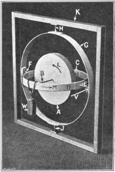
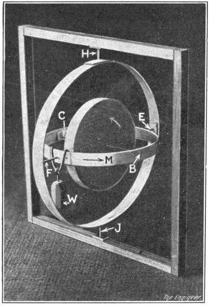
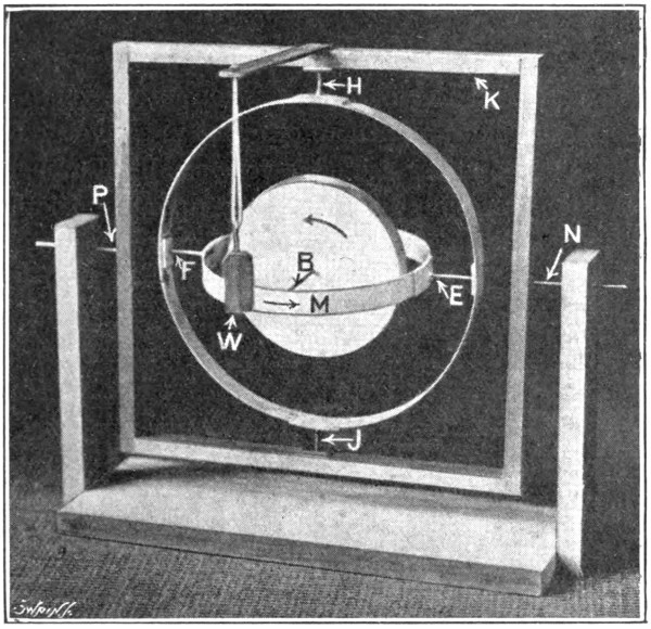
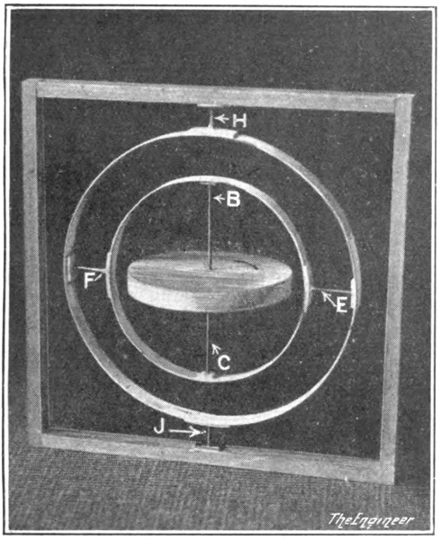
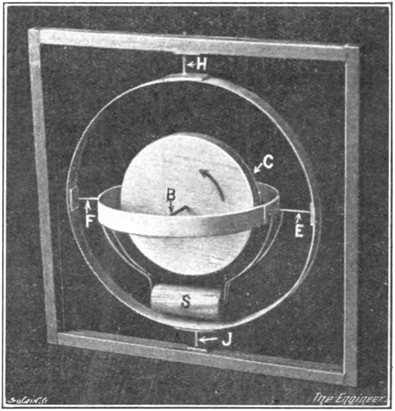
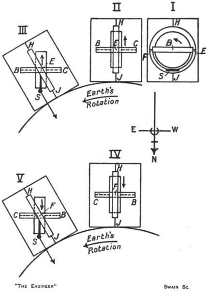
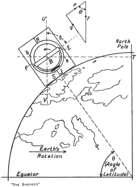
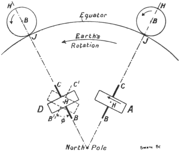
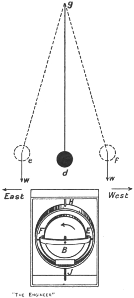
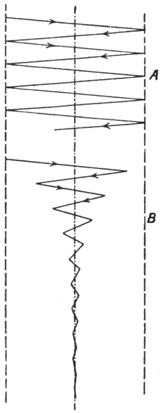
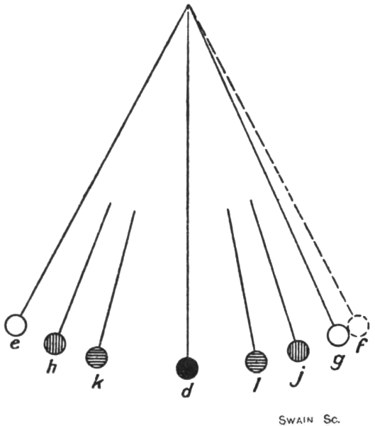
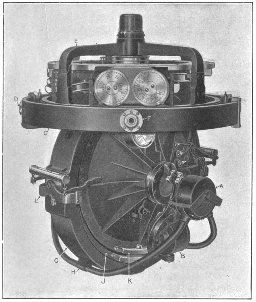
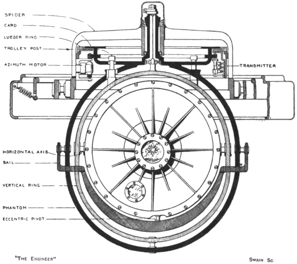
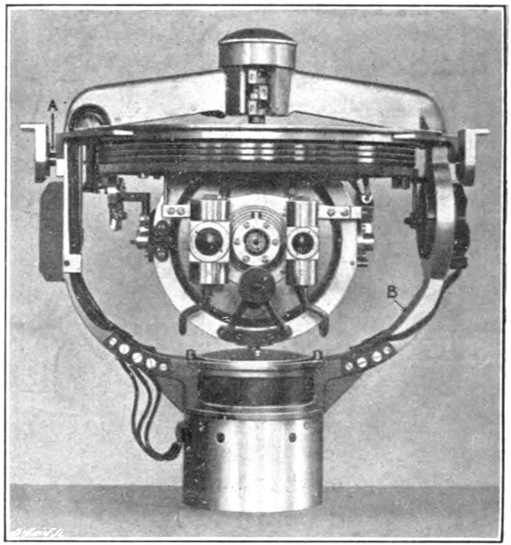
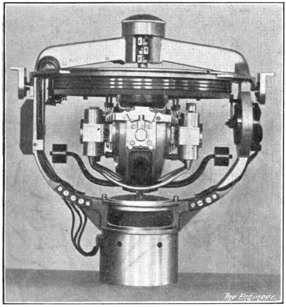
From our description of the cause of the quadrantal
error it should be clear that it is of a variable erratic
nature, or at least that, unlike the latitude and north
steaming errors, its magnitude cannot be forecast from
a knowledge of the ship’s speed, course, latitude, or other
factors. Its direction is determined by the direction of
the ship’s course, but its amount is settled by the violence
of the rolling and pitching, and cannot therefore be calculated
and tabulated in a practically useful way. It
follows, therefore, that to get rid of the upsetting influence
of the quadrantal error we cannot resort to “correcting”
the compass readings for it, but must entirely eliminate it.
In the early (1910) Anschütz compass there were no
means of eliminating the quadrantal error, for the
existence of the error, or at least the importance to be
attached to it, was not at first recognised. The compass,
we believe, showed errors from this cause of as much as
20 deg. to 40 deg. As a result, within a very short time
the design was discarded, and what amounted to an
entirely different compass was substituted for it. The
1912 Anschütz compass will be briefly described later on,
but here it may be said that the quadrantal error in it is
eliminated by adding two more gyro-wheels to the sensitive
element. The theory of this compass is not very
easy to understand, so that it will be best if we explain
first how the quadrantal error is eliminated in the Sperry
and the Brown compasses.
The early Sperry, like the early Anschütz compass,
was open to the full action of the quadrantal error.
In the form now in use, however, it is prevented from
taking effect by controlling automatically the position
of the excentric pin connecting the weight or “bail”
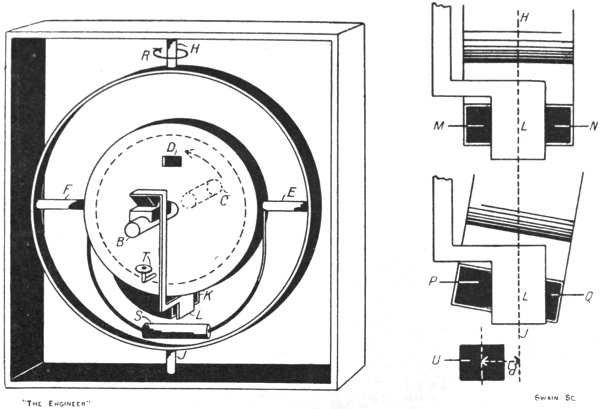
to the gyro casing. In the Sperry compass, as we know,
the weight S (Fig. 35) is not hung from the inner supporting
ring or its equivalent, but from the follow-up or
phantom ring, its pendulous effect being communicated
to the casing and thence to the spinning wheel through
the excentric pin A. The kicks of the weight at the out
positions during the rolling of the ship are also transmitted
through the pin to the casing and wheel inside it.
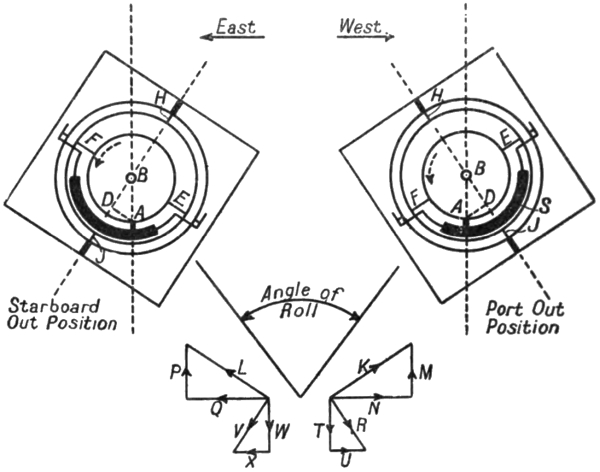
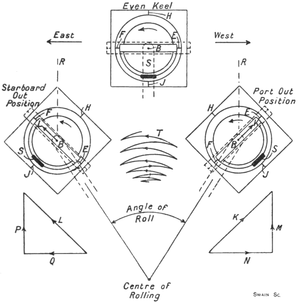
Fig. 35. Sperry Compass on N.W. course.
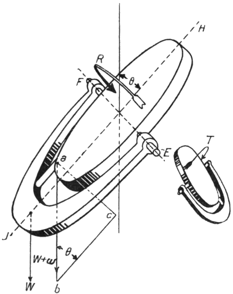
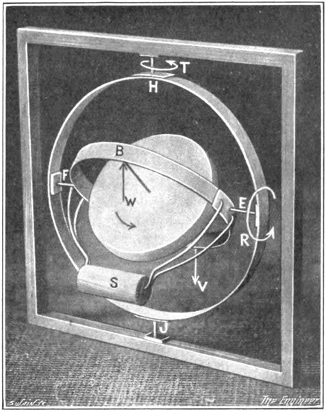
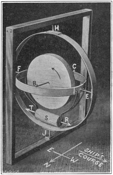
Let us suppose, as shown in Fig. 35, that at the port
out position of the compass swing the excentric pin is
east of the axis H J by the amount required just to bring
it vertically below the centre of the spinning wheel.
Then the southward kick of the weight when the vessel
rolls on a north-west course is transmitted to the casing
as a southward force applied at the point A. This force,
acting about the axis E F as before, produces precession
in the direction K, and, as before, we may resolve this
movement into the components N M. The force at A
has, however, in addition, a turning moment about the
axis H J, for it is applied to the casing at a point lying
at a distance A D from this axis, and not, as in Fig. 33,
at a point virtually on it. This moment about H J
would tend to make the end B of the axle turn in the
direction of F, and therefore results, in accordance with
the rule of the gyroscope, in an actual movement about
the axis E F, the end B of the axle precessing downwards
towards J, that is, in the direction R. We may resolve
the precession R into two components T U.
Similarly, at the starboard out position, let us suppose
that the excentric pin is this time westwards of the axis
H J by exactly the amount required again to bring it
vertically below the centre of the wheel. As before,
in the case shown in Fig. 33, the northward kick of the
weight acting about E F results in a precession L, which
may be resolved into the components P Q. The kick,
however, as at the port out position, also has a moment
about the axis H J. The kick is reversed in direction,
but the point of its application to the casing is now on the
other side of H J. Consequently the kick tends to rotate
the casing about H J—and therefore produces precession
about E F—in the same direction as does the kick at
the port out position. The precession produced is
represented by V, and can be resolved into the components
W X.
Considering now the four pairs of component precessions,
we see that they cancel out in pairs. Thus
N and Q cancel, U cancels X, T wipes out M, and W
does the same to P. The two components M P, which
were the cause of the quadrantal error, are just balanced
by the two additional components T W. The axle therefore
does not rise vertically, but remains horizontal,
and as a result no quadrantal error can arise.
It will be seen that the Sperry method of eliminating
the quadrantal error requires the excentric pin to be
movable relatively to the bail and casing. To be more
precise, while the casing, the bail, the phantom ring,
and all the other parts of the compass may swing round
the axle of the spinning wheel, or the external gimbal
axis coincident or parallel with the axle, matters have
to be arranged in such a way that when the ship rolls
the excentric pin shall not partake of this motion, but
remain constantly in the vertical below the centre of the
spinning wheel. We have to remember, however, that the
Sperry method of damping the horizontal vibrations of
the axle hangs upon the pin being displaced towards the
east of the axis H J when the compass is in the even keel
position. The two requirements are met by so controlling
the position of the pin relatively to the bail and casing
that when the bail, casing, etc., swing sideways under the
influence of the rolling of the ship, the pin is maintained
at a fixed distance eastwards of the true vertical through
the centre of the spinning wheel at all points in the oscillation
of the bail, casing, etc.
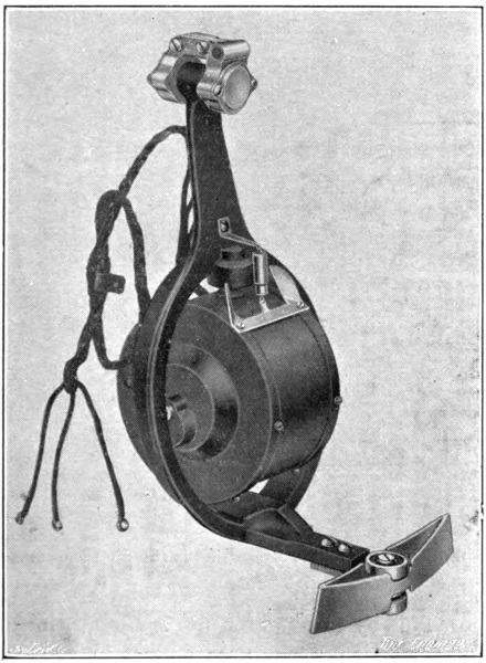
Fig. 36. Sperry Ballistic Gyro.
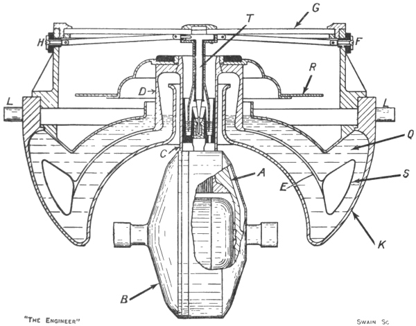
The stabilisation of the excentric pin in this manner
is effected gyroscopically by means of the attachment
shown in Fig. 36. This device consists of a small high-speed
electrically driven gyroscope running inside a
casing which is mounted rotatably on a vertical axis
inside a stirrup frame. This frame, as shown in Fig. 37,
is hung pendulum-wise on the north side of the main
gyro casing, the axis of its suspension being collinear with
the axle of the main gyro-wheel. The axle of the small
gyro-wheel is thus aligned in the east and west direction.
The stirrup bracket is turned up horizontally below the
casing of the small gyro, and at its end is fitted with
guides, carrying a pair of rollers. These rollers constitute
the excentric pin and, as shown in Fig. 37, engage within
two curved channel-sectioned tracks attached one to the
bail and one to the main gyro casing. If when the bail,
casing, etc., swing under the influence of the ship’s
rolling the excentric pin should attempt to follow suit—either
by reason of friction at the axis of suspension of
the stirrup bracket or at the track rollers—the wheel
and casing of the small gyro will start processing round
the vertical axis inside the stirrup, for the attempt is
equivalent to an endeavour to tilt the small gyro-axle
in an east and west vertical plane, and therefore calls
forth the usual gyroscopic reaction. The precession of
the small gyro on its vertical axis is made to react on the
stirrup bracket by means of a spring connection between
the bracket and the casing, as shown in Fig. 36. The
direction of spin of the small gyro-wheel is such that the
force thus applied to the stirrup bracket opposes and just
balances the frictional or other force trying to make
it swing with the bail, casing, etc., of the main gyro.
In this way the excentric pin as the vessel rolls is caused
to maintain its original distance from the vertical line
through the centre of the spinning wheel.
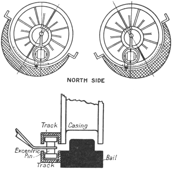
Fig. 37. Stabilized Excentric Pin (Sperry Compass).
The suppression, or rather the avoidance of the quadrantal
error in the Brown compass, is achieved in a
manner which is mechanically very distinct from that
adopted for the same purpose in the Sperry compass.
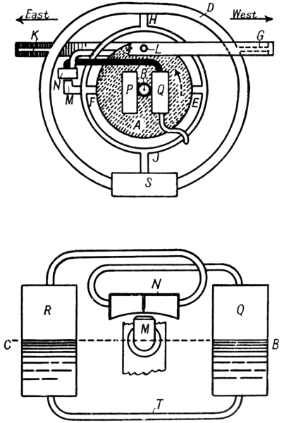
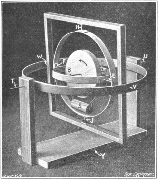
Fig. 38. Diagram of Brown Compass.
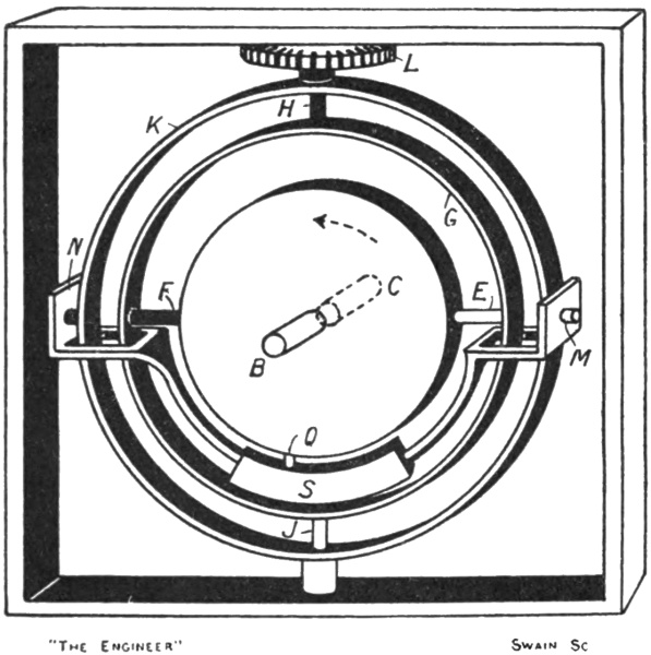
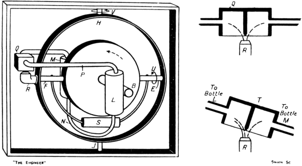
An elementary diagram of the Brown compass is given
in Fig. 38. In this sketch A is the casing, inside which
the gyro-wheel mounted on the axle B (C) rotates in the
direction of the dotted arrow—B, as before, representing
the north-seeking end of the axle. The casing is supported
on an east and west horizontal axis E F inside a vertical
ring, this ring being journalled at H J inside a frame D,
the equivalent of the square frame in our simple model.
To obtain complete freedom for the gyro the frame D
is mounted on an athwartship axis G K, which is itself
carried inside a ring journalled within the binnacle on an
axis L parallel with the ship’s longitudinal centre line.
The pendulum weight S is fixed to the lowest point of
the frame D. If the weight S and frame D be set swinging
on the axis G K, the swinging movement will, of course,
be directly communicated through the journals H J to
the vertical supporting ring, but, as the trunnions E F of
the casing are really supported on knife edges, the swinging
movement of the frame D cannot be communicated from
the vertical ring through the trunnions E F to the casing
A, and thence to the wheel. Yet it is essential that the
weight S should be able to act pendulum-wise on the
casing and wheel, for otherwise, as we know, the system
would be without directive force.
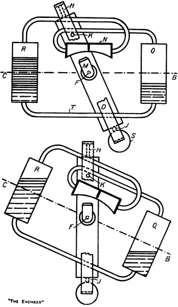
Fig. 39. Oil Control Bottles (Brown Compass).
The connection between the weight and the casing is
not a mechanical one, but is effected by making use of the
air blast created by the fan-like action of the wheel inside
the casing. As we have explained in connection with the
damping system adopted in this compass, the trunnion
F is hollow, and delivers the air blast through a nozzle M,
fixed relatively to the vertical supporting ring, into a
divided box N. From this box pipes are led to two oil
bottles—one of which is shown at P—fixed to the casing
on the east side of the axle, one bottle being on the north
face of the casing and the other on the south. The
pressure of the air blast acting unequally upon the oil in
these two bottles when the casing tilts about the axis E F
results, as we have already explained, in any horizontal
oscillation of the sensitive element about the axis H J
being damped. In a similar way two bottles Q R half-filled
with oil are fixed to the north and south faces of the
casing on the west side of the axle of the spinning wheel.
These bottles are also connected to the box N, but the
connecting pipes are crossed so as to join each bottle Q R
to the division of the box remote from it, and not to the
adjacent division, as in the case of the damping bottles P.
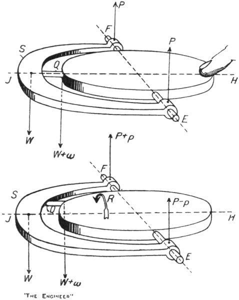
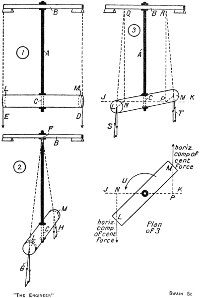
When, therefore, the weight S and frame D are swung
slowly pendulum-wise on the axis G K, as shown in the
first view in Fig. 39, the nozzle M, being fixed to the
vertical ring, delivers more air into one division of the
box N than the other, and therefore a greater air pressure
is exerted inside one bottle than inside the other. Consequently
oil flows through the connecting pipe T from the
former bottle to the latter until the columns of oil are
sufficiently unequal to balance the difference of pressure
of the air inside the bottles. It will be noticed that the
crossing of the pipes connecting the bottles with the box
N results in the oil being accumulated in that bottle,
which lies away from the side to which the weight S has
been swung. Hence, although there is no mechanical
connection between the weight and the casing of the
spinning wheel, the effect when the weight S is swung
slowly is thus substantially the same as it would be if
there were, for the weight of the extra oil forced into the
bottle R exerts a turning moment on the casing about the
axis E F, and tends therefore to make the casing follow
the deflection of the weight S and frame D.
Similarly, should the axle B C dip, as shown in the
second view in Fig. 39, extra oil will accumulate in the
bottle which has been elevated by the dipping, and as a
result a restoring moment about the axis E F will be
applied to the casing, just as it would be if the weight S
had been directly connected to the casing and had been
deflected by the dipping movement.
The second view in Fig. 39 illustrates the generation
of the directive force in the Brown compass. Let us
suppose that the compass is at the equator, and that by
some agency the axle is turned so that its end B points
due west. The rotation of the earth will cause the axle
to dip slowly into some such position as that shown.
During this slow dipping movement oil will flow slowly
from the bottle Q into the bottle R. The unbalanced
weight of oil will apply a turning moment to the sensitive
element about the axis E F and will therefore produce
actual motion about the axis H J, which will precess the
end B of the axle towards the north. Any tendency for
the axle to vibrate about the north and south line as a
result of the momentum acquired by the sensitive
element while coming up from the west will be damped
by the air blast acting upon the oil in the two other
bottles P fixed, as shown in Fig. 38, on the east side of the
axle.
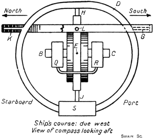
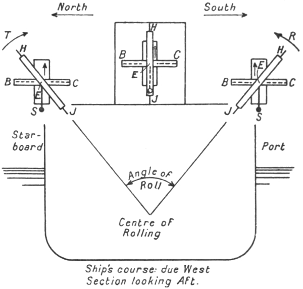
Fig. 40. Brown Compass on West Course.
The point we require here to notice especially about
this action is that, as the tilting of the axle produced
by the rotation of the earth takes place very slowly—it
cannot exceed the speed of rotation of the earth on
its polar axis, namely, 0.0007 of a revolution per minute—the
flow of oil from the bottle Q to the bottle R takes
place very slowly also. The oil therefore acquires
practically no momentum, and rises in the bottle R in
strict accordance with the tilt acquired by the axle. If
the tilting motion be stopped or reversed, the oil would
remain in the bottle R at just the level it had reached, or
would immediately begin to flow back again, for its
momentum being negligible, it has not sufficient kinetic
energy to rise higher in the bottle R after the upward
motion of the bottle has ceased.
On the other hand, when the ship rolls, say, on a due
west course, as represented in Fig. 40, the outer gimbal
ring supporting the athwartship axis G K, the frame D
carrying the weight S, and the vertical supporting ring
will acquire an oscillation about the fore and aft axis L in
tune with the rolls of the ship. The air blast will thus be
directed into the two divisions of the box alternately, and
therefore oil will flow from one bottle to the other. It is
to be noticed, however, that the rolling motion of the ship
induces in this manner a flow of oil from one bottle to the
other at a very much greater rate than does the tilting
action of the earth’s rotation dealt with above.
A ship rolling through 45 deg., out to out, in a complete
period of 10 seconds rotates about its rolling centre
with an average velocity equivalent to 1.5 revolutions
per minute—or over 2000 times as fast as the speed of
rotation of the earth on its polar axis—and at the mid
point of its roll it will move with an actual velocity of
about twice the average. The momentum acquired by
the oil in flowing from bottle to bottle is therefore in this
case not negligible. In fact, when the ship reaches one of
its out positions and starts to return, the oil does not
immediately begin to flow back into the other bottle, but
is carried by its kinetic energy to a still higher level in the
bottle in which it has been rising. As a result, the oscillation
of the oil between the two bottles lags behind the
oscillation of the pendulum weight S, and therefore that
of the ship itself. The lag acquired is such that the oil is
just level in the two bottles when the ship is at either of
its out positions, and when the ship is at the mid point, or
even keel position of its roll, although the air blast is for
the moment evenly distributed between the two compartments
of the divided box, the oil is standing at its
maximum level in the bottle on that side of the wheel
from which the ship is recovering herself. The action of
the oil in the bottles during a rapid oscillation of the
compass system is, in fact, quite analogous to that of the
water in the Frahm system of anti-rolling tanks.
It will thus be seen that the net effect of transmitting
the “kicks” derived during rolling from the pendulous
weight of the wheel through the Brown oil bottle arrangement
is simply to delay the application of the kicks to the
gyro-wheel by a constant amount, namely, by the time
taken for the ship to roll from either out position to the
mid position or a quarter of a complete period. Thus as
the ship sailing due west rolls through the mid position
from starboard to port the compass system experiences
the turning moment about the axis E F, which with a
rigidly fixed pendulum it would receive at the starboard
out position from the northwards kick of the weight.
Similarly, the equivalent of the southwards kick of the
weight at the port out position is felt by the wheel when
the compass is passing through the even keel condition on
the subsequent roll from port to starboard. It is clear
that with the ship sailing due west—or east—this delaying
of the kick does not affect the result established previously
for a rigidly connected pendulous weight. Any tendency
for the axle to precess towards the west when the compass
is passing through the even keel position in one direction
is completely annulled by the tendency to precess towards
the east at the succeeding passage through the even keel
position in the opposite direction.
On quadrantal courses, however, the delay in the
application of the kick is most important, for when the
ship rolls it results in the elimination of the quadrantal
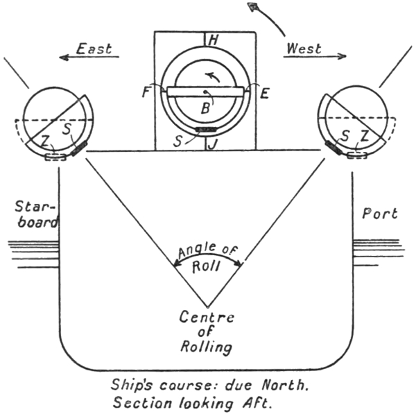
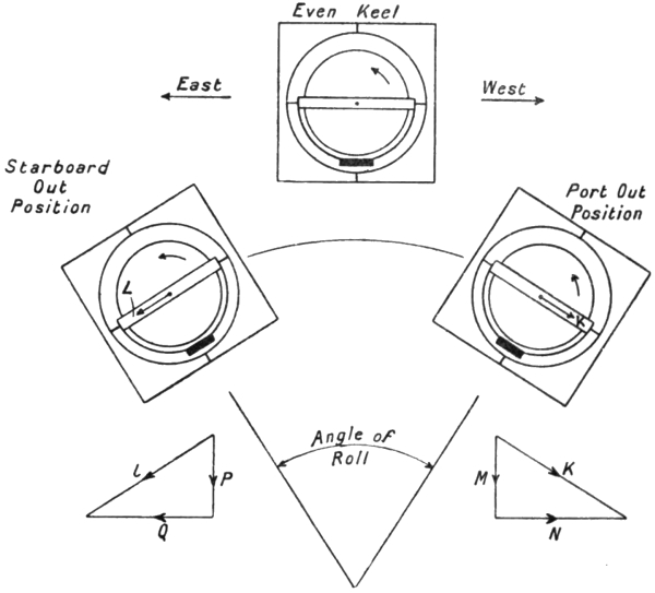
error. That it does so can easily be understood by reference
to Fig. 33. The kicks, being received when the
compass is passing through the even keel position, and not
at the out positions, precess the wheel about the axis H J
at a time when this axis is truly vertical, and not when it
is inclined. The precessional movements have therefore
no vertical components M P. They are represented
completely by the horizontal components N Q. The
axle thus does not depart from the horizontal plane, and
any movements in this plane arising from the tendency
to precess in the directions N Q cancel each other at successive
passages of the compass through the mid position.
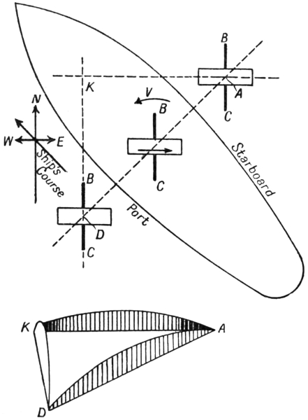
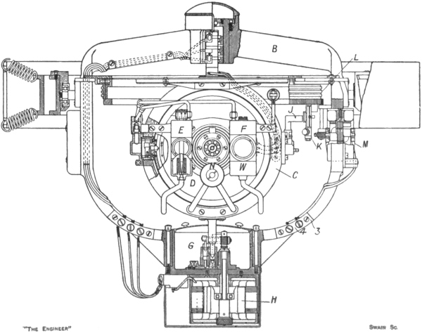
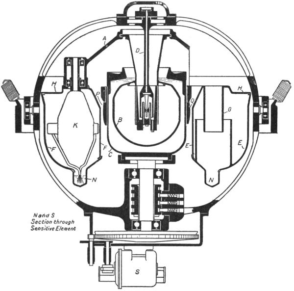
The early form of Anschütz compass was followed by
the 1912 pattern in which the quadrantal error was
successfully eliminated. An example of the 1910 form
was obtained by Messrs. Elliott Brothers, of Lewisham,
from Anschütz and Co., of Kiel, and was, we believe,
fitted on board H.M.S. New Zealand. Its defects becoming
apparent, its manufacture in this country was not
proceeded with, but upon the appearance of the improved
type in 1912, Messrs. Elliott took up its construction and
supplied several to the Admiralty. The Sperry compass,
however, secured the preference in the British Navy, and
with the outbreak of the war Messrs. Elliott ceased
practically to make Anschütz compasses. On the other
hand, the German Navy continued to use the 1912 type
of Anschütz compass, with very little alteration or
addition, right throughout the war. In view of the fact
that every German submarine was fitted with a compass
of this form, and bearing in mind the high degree of
excellence attained in the navigation of the enemy’s
underwater craft, there can be no doubt that the modern
Anschütz compass is a very satisfactory device.
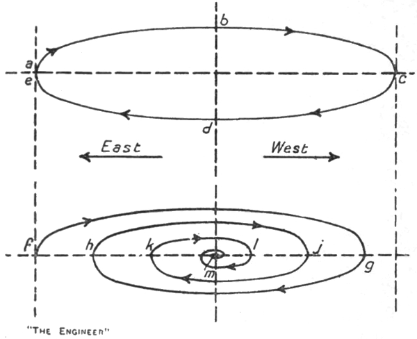
In Fig. 41 we give a purely diagrammatic representation
of the compass. The outer square frame may, as usual,
be regarded as mounted within external gimbal rings,
providing a fore-and-aft axis and an athwartship axis.
The square frame contains a vertical ring free to turn
about the axis H J and itself containing a horizontal ring
mounted on an east and west axis F E. The pendulum
weight S is attached, as usual, to the inner horizontal
ring. The essential difference between the 1912 and the
1910 forms of Anschütz compass lies in the fact that, as
shown in our diagram, the inner ring, or its equivalent,
does not surround a single gyro-wheel, but has attached
to it the casings of three distinct gyros.
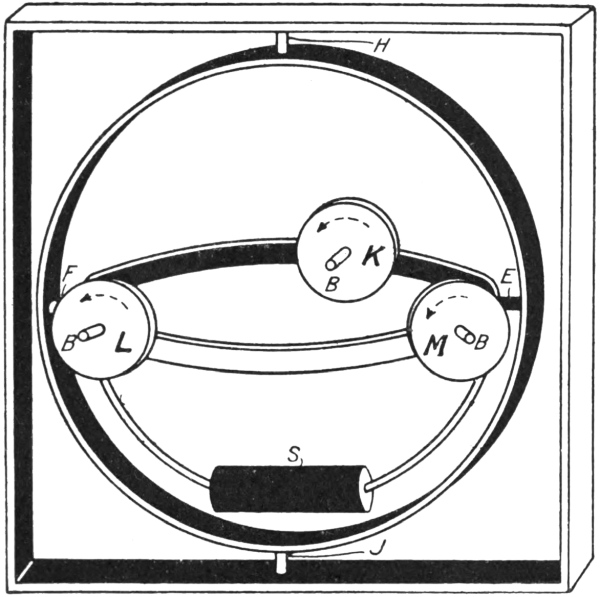
Fig. 41. Diagram of Anschütz (1912) Compass.
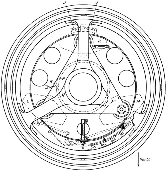
As shown in the first plan—in Fig. 42—the three gyros
are situated at the corners of an equilateral triangle. One
gyro K is placed at the south end of the meridional
diameter of the horizontal ring, with its axle pointing
towards the centre of the ring. The two other gyros L M
are placed at 60 deg. east and 60 deg. west of north, with
their axes pointing towards the centre of the gyro K—not
towards the centre of the ring. The wheels of all three
gyros rotate anti-clockwise, as seen from the north, looking
south—that is, they rotate in the same direction as
do the wheels of all single-gyro compasses as seen from the
same standpoint.
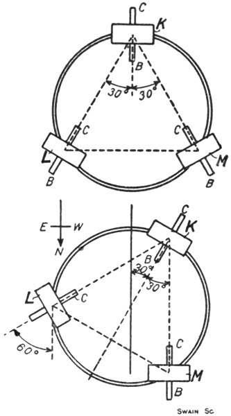
Fig. 42. Plans of Gyros.
If we neglect the two gyros L M for the moment,
imagining them to be replaced by simple deadweights
to counterbalance the weight of the gyro K, it will be
seen that this system differs from that of the early
Anschütz compass only in the fact that the gyro-wheel
has been reduced in size, and has been displaced from
the centre of the horizontal ring to the southern edge.
The displacement of the wheel in this manner in no way
affects the essential working of the compass. In a single-gyro
compass we might with some advantage similarly
displace the spinning wheel, for by so doing and by
counterbalancing the displaced weight we should, at least
partially, get rid of the concentration of mass about
the east-west axis, which, as we shall see, introduces,
if not corrected, an additional source of error into
the compass readings when the ship rolls on quadrantal
courses.
The reduction in the size of the gyro-wheel would, of
course, reduce the magnitude of the directive force. In
the 1912 design the wheels of all three gyros run at
20,000 revolutions per minute—that is, at the same speed
as the wheel in the 1910 design. But each wheel is only
5 in. in diameter instead of 6 in., and weighs, with its axle,
5 lb. 2 oz., or only half as much as the wheel in the earlier
form. The gyro K considered alone would therefore
supply a directive force of but half the former
amount.6
It follows, obviously, that if a second gyro of the same
speed and size as that at K be fixed in accurate alignment
at the north end of the meridional diameter of the
horizontal ring the directive force at any angle of horizontal
deflection away from the north will be doubled,
that is, will be made equal to that developed in the 1910
design. Such a compass might be constructed, but it
would exhibit the quadrantal error—or at least the inertia
force portion of that error—just as badly as did the early
Anschütz.
The essence of the 1912 design lies in the fact that not
one but two gyros are attached to the north side of the
horizontal ring, and in the additional fact that the axles
of these two gyros are not parallel with but are inclined
to the axle of the south gyro K.
When the sensitive element of this compass is in the
north resting position, the axle of the gyro K is aligned
with the meridian and therefore the rotation of the earth—the
compass being supposed at the equator—merely
moves the axle parallel with itself. On the other hand,
with the sensitive element in the north resting position,
the axles of the gyros L M are inclined to the meridian at
30 deg. The gyro L is virtually in the condition of a
single-gyro compass, with the north end of its axle
partially turned towards the east. Under this condition,
as we know, the rotation of the earth will tend to make
the north end B of the axle rise above the horizontal plane.
Conversely, the gyro M is in the condition of a single-gyro
compass, with the north end of its axle partially
turned towards the west. The earth’s rotation in this
case tends to make the north end of the axle dip below the
horizontal plane. Thus, in the 1912 Anschütz compass,
when the sensitive element is in the north resting position,
the gyro K under the rotation of the earth is without
effect on the pendulous weight S, the gyro L is striving to
swing it towards the north, and the gyro M is trying with
an equal effort to swing it towards the south. The weight,
therefore, remains in the plumb line and applies no
turning moment to any of the gyros. As there is no
turning moment, there is no precessional tendency. The
sensitive element remains directed towards the north.
This alignment, as in a single-gyro system, is the true
resting position, and under it no directive force is applied
to the sensitive element.
To study how the three gyros act together to restore
the sensitive element to the north resting position should
it be deflected therefrom, let us suppose that the deflection
suffered is one of 30 deg. towards the east. As shown in
the second plan in Fig. 42, the effect of such a deflection
is to place the three gyros K L M in the condition respectively
of a single-gyro system when the axle is (k) deflected
30 deg. to the east, (l) deflected 60 deg. to the east, and
(m) aligned on the north. At this deflection, then, the
gyro M contributes no restoring force. The directive
force contributed by the gyro K is half that contributed
by the single gyro of the 1910 design when the deflection
is 30 deg., for the mass—or moment of inertia—of the
wheel is half the earlier value. The directive force contributed
by the gyro L is something greater than that
contributed by the gyro K, for the virtual deflection eastwards
is 60 deg. instead of 30 deg., and, as we know, the
directive force increases with the deflection. Thus, the
three gyros taken together supply a directive force, when
the sensitive element is deflected through 30 deg., which
is somewhat greater than that supplied by the single
double-sized wheel of the 1910 design.7 This result is
a general one. Whatever the deflection may be, the
directive force supplied by the three-gyro compass is
always about one-third greater than the directive force
of the 1910 design at the same deflection. This increased
force is developed even if the deflection be less than
30 deg. In such cases the gyro M will, of course, supply a
force, a non-restoring force, to the sensitive element. Only
when the deflection exceeds 30 deg. eastwards does the
gyro M assist the gyros K and L to restore the sensitive
element to the north resting position. If the deflection be
to the west, however, the gyro M is the chief assistant of
the gyro K, a laggard’s part being played by the gyro L
until 30 deg. of westerly deflection is reached.
The manner in which this three-gyro system avoids
the quadrantal error can now be discussed. The
quadrantal error, it may be recalled, arises when the ship
rolls on an intercardinal course, and is primarily caused
by the fact that the whole compass system can swing on
its external gimbal axis in tune with the rolls of the ship.
If we could so arrange matters that during the roll of the
ship from side to side the compass system would swing on
the external gimbals, no more and no less than the amount
required just to keep the axis H J truly vertical at all
points of the roll, then the north and south “kicks”
received on the weight S at the out positions of the roll
would cause the sensitive element to precess first one way,
then the other, but always in a horizontal plane. There
would be no vertical component in the precession, the
cumulative effect of which, as we have seen, produces the
quadrantal error.
In the Brown compass, the quadrantal error is eliminated
by delaying the effect of the “kicks” on the weight
S until the axis H J is truly vertical—that is to say, the
“kicks” on the weight are not transmitted to the spinning
wheel until the compass system is passing through the
even keel position. In the Sperry compass the weight S
is virtually shifted back and forth from east to west of the
axis H J in tune with the rolling of the ship in such a way
as to introduce a second component of vertical precession,
which in amount and direction is just sufficient to
nullify the vertical component causing the quadrantal
error. In the 1912 Anschütz compass, the object aimed
at is the maintenance of the axis H J truly vertical at all
times during the rolling condition.
This object is achieved, as we shall now show, by
setting the axles of the gyros L M—Fig. 41—inclined
to the axle of the gyro K. In a single-gyro compass,
or in the 1912 Anschütz compass with the gyros L M
suppressed, the system is very stiff against vibrations on
the east-west axis E F, but is quite easily set vibrating
about the north-south axis provided by the external
gimbal mounting. The reason is, of course, that any
vibration about the axis E F is met by the resistance of the
gyro-wheel, for the vibration causes the axle to alter its
direction, whereas no gyroscopic resistance is called into
play by the vibration on the north and south axis, for this
axis is coincident or parallel with the gyro-axle. Thus,
in the 1910 Anschütz compass the period of vibration
about the east-west axis was something like 70 min.,
whereas the period about the north and south axis was
only one or two seconds. The smallness of the latter
period readily resulted in the compass system getting
into a swing in tune with the period of rolling of the ship—from
five to twelve seconds or so. Were the axles of the
gyros L M in the 1912 form set parallel with that of the
gyro K, there would still be no gyroscopic resistance
exerted against vibration on the north-south axis. As it
is, the inclination of the axles of these two gyros, taken
together, has virtually the same effect as would be
obtained by the addition to the sensitive element of a
separate single gyro, with its axle aligned at right angles
to the axle of the gyro K.
The gyroscopic stiffness against vibration about the
east-west axis E F is hardly affected by the inclination
of the gyros L M at the angle chosen by the designers.
The resistance, instead of being that contributed by three
gyros, is equivalent to that supplied by about 2¾ gyros.
The period of vibration on this axis E F is arranged to be
the standard 85 min. About the north and south axis we
have virtually the resistance of one gyro. The period of
vibration about this axis, instead of being only one
or two seconds, is about 80 sec. With this lengthened
period of vibration there is practically no chance of the
compass system getting into a swing in tune with the
rolling of the ship, for every 2½ to 6 seconds the vibrating
influence is reversed in direction, and in this interval of
time the system cannot acquire any substantial degree of
swinging motion. Thus, as the compass, following the
rolls of the ship, moves from side to side, it suffers a pure
translational movement. The axis H J remains truly
vertical at all instants during the roll, and therefore the
north and south kicks of the pendulous weight at the out
positions of the roll precess the gyro-axle about H J in
purely a horizontal plane, the precessional tendency at
one out position cancelling that at the other. There is no
vertical component in the precession, and therefore there
can be no quadrantal error.
It is of interest and of some amusement to note that
during the war the Germans applied a fourth gyro to the
Anschütz compass, and that this additional gyro was
carefully removed from every compass before they surrendered
their submarines to us. The deceit was,
however, of no avail, for the application of the fourth
gyro was known to us long before the war ended, a
complete compass so fitted having been recovered from a
sunken submarine and repaired and carefully studied.
The fourth gyro was applied to the external gimbal rings.
These rings, when the submarine rolled, were found to
acquire at times a violent oscillation of their own, for, of
course, they received no stabilisation from the gyroscopic
elements of the compass. On board submarines the
violence with which the rings vibrated would occasionally
threaten to wreck the compass. By adding a gyroscope
to the gimbal rings, the period of vibration of the rings
was lengthened to about 16 sec., so that little or no
opportunity to swing was left to them. With the exception
of this addition, the Anschütz 1912 compass was
used by the Germans throughout the war practically
without alteration.