THE GUNSMITH’S MANUAL. — CHAPTER I. HISTORY OF THE GUN.
Discovery of Gunpowder.—No authentic records
have been left to show when or by whom was discovered
the wonderful properties of the chemical
compound now known as gunpowder; nor have we
any information concerning the uses to which it was
originally applied. There is little probability that it
was at once employed as an agent in fire-arms; indeed,
we have pretty strong evidence to show that it
was not, for Roger Bacon refers to it in his famous
treatise, De Nullitate Magiæ, published A. D., 1216,
while fire-arms are mentioned by no writer as having
been known earlier than about 1338.
The First Fire-Arms.—The first fire-arms, or
guns, as we now call them, are said to have been
rude cannon, formed by banding together flat iron
bars, something on the plan of our wooden casks or
barrels of to-day. These guns were fired with a
“slow match,” the gunners retiring to a safe distance
while the match was burning to the priming.
Their earliest use was as engines of war. The writers
of ancient history tell us that they were so employed
by the Moors at the noted siege of Algesiras, Spain,
in 1341, and at the battle of Calais, in 1346. At the
latter battle, Edward III is credited with having
had four pieces, which made him victorious.
Earliest Hand-Guns.—It is claimed by Spanish
historians that to Spain belongs the honor of having
been the first power to furnish her soldiers with fire-arms
so small that they could be transported by
a single person. They were unwieldy affairs at the
beginning, however; really small cannon lashed upon
wooden scantlings. The soldier could not fire his
piece off-hand, but was forced to carry a “rest”
with him wherever he went. Being ready to discharge
his arm he balanced it upon the rest, steadied
it by holding the scantling under his arm, and then
“touched it off” with a live coal of fire, while he
sighted along the barrel to take aim at his object.
What happened immediately after the coal came in
contact with the powder the historian saith not, but
a modern writer, who has been examining one of
these old guns in a museum, jumps to the conclusion
that the soldier, with the scantling under his
arm, must have been launched suddenly into an impressive
dream of first-class earthquakes, or something
else “like unto the combined kicking of about
fifty mules.”
Prejudice Against Fire-Arms.—For about two
centuries after the invention of hand fire-arms they
were so inefficient that the cross-bow, then in general
use, was able to quite successfully hold its own
against them. It was not until 1596 that Queen
Elizabeth, by a proclamation, directed that cross and
other bows used in the army should be discarded entirely
in favor of muskets. And thereat there arose
much murmuring of dissatisfaction throughout the
English Empire, according to Michael Montaigne, a
most prominent man of his time, who narrates the
fact, and adds: “Except the noise in our ears, to
which we will be henceforth accustomed, I think the
fire-arm is one of very little effect, and I hope that
we shall one day give up its use.” Could he return
to earth at this age, and see the wonderful fire arms
that have developed from the humble beginning of
which he was then treating, he would speedily lose
his hope to the effect that one day its use would be
entirely given up.
The First Rifle.—The first rifle is said to have
been made about the close of the fifteenth century,
by one Gaspard Zollner, of Vienna. It was a simple
barrel with straight grooves; the only object of
the grooves being to prevent its becoming so “dirty”
from continued use, as did the smooth-bore. Spiral
grooving does not seem to have been thought of until
many years later.
The Arquebus.—The earliest noted improvement
in the hand-gun, making it lighter and giving it a
longer barrel, was called the arquebus; but even this
was so heavy that a “rest” was necessary while discharging
it. This rest was a single staff armed with
a steel point which went into the ground like the
Jacob-staff of a surveyor, but which fitted it for
use as a pike when not employed in connection with
the gun. It was called the schweine feder, which
rendered into English means the “hog’s bristle.”
The arquebus was a regular “match-gun;” that
is, it had a “pan” or receptacle at the side of the
breech for the priming powder, which communicated
with the interior of the barrel by a small perforation
called the “touch-hole.” The priming was
lighted by a match, which consisted of a coil of
small rope saturated with some kind of chemical,
which caused it to burn readily and hold fire for a
long time. The soldier using the arquebus carried
the match in his hand and kept it burning during an
action. The manner of setting off the piece was
about the same as with the live coal—he secured his
sight and then touched the priming with his lighted
match.
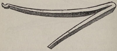
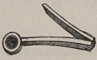
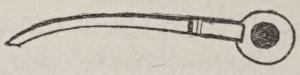
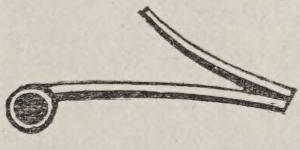
The Match Lock.—Later, the serpent-match was
invented and looked upon as a startling improvement.
It was a simple S-shaped piece of iron or wire hinged
to the side of the gun just back of the priming
pan. The upper end was provided with a beak
which gripped the lighted fuse, while the lower end
played the part of a modern trigger. With this contrivance
the gunner had only to take sight and then
pull with his finger upon the lower end of the S
until the lighted fuse was brought down into the
priming. After many years of use an improvement
was made upon the S, consisting of a small
spring which threw it back into an erect position so
soon as the pressure upon the lower end was discontinued.
The powder employed with the old arquebus was
of two grades as to size of grain; a coarse grade for
the charge, and a fine grade for the priming. Its
chemical composition does not seem to have differed
materially from that of our modern gunpowder.
The serpent match, so called because the upper
end holding the fuse was often shaped to represent
the head of a serpent, was the first actual step taken
towards a gun-lock. It was thought to be perfection
itself, especially after the returning spring had
been added, and so strong a hold did it take upon
all nations that only a few years has elapsed since
it was wholly abandoned in some of the most benighted
regions, as in China, for instance, where it
is known to have been used in the army at a date
as late as 1860.
Musket-Petronel.—Next in order to the arquebus
came the musket, a Spanish invention. It was
heavier than its predecessor, and carried a charge
twice as large. Almost simultaneously with this
appeared the first cavalry fire-arm, which was called
the petronel. It was shorter than the musket and
larger in bore; the horseman rested its breech
against his breast and communicated the fire by
means of the serpent match.
The Wheel-Lock.—In 1517 the Germans astonished
the world by inventing and bringing into use
the “wheel-lock,” which was a regular gun-lock,
entirely doing away with the lighted match. It
consisted of a small disk of steel fluted on the edges,
set in close contact with the priming pan, and made
to revolve with great rapidity by means of a spiral
spring arranged somewhat on the plan of the spring
of a spring-clock. In contact with its fluted edge,
and held there by a spring, was arranged a sharp
flint; hence when the steel disk was set in motion a
train of sparks was thrown off as it revolved over
the edge of flint. These sparks fell into the priming
pan and ignited the powder, discharging the piece.
The spring was wound up like winding a clock or
watch, and a slight pressure upon a trigger under
the breech set the wheel in motion. The pressure
was continued until the gun was discharged, when
it was discontinued, the result of which was an immediate
stopping of the wheel. A single winding
would usually discharge the gun about half a dozen
times.
The Pistol.—The wheel-lock went into quite general
use, finally leading to the invention of the
pistol, about 1544. The first pistols were single
barrel, and very short. The stock was heavy, and
the breech or handle, instead of leaving the barrel
with a curve, as in later days, dropped at right
angles to the iron. It was put into use as a cavalry
arm, first by the Germans and afterwards by the
people of many other nations. In 1607 the German
horse soldiers were all regularly armed with double-barrel
wheel-lock pistols.
The Snaphaunce.—After the date just mentioned
modifications and improvements in fire-arms were
rapid and constant. The wheel-lock was finally followed
by the “snaphaunce,” which was a straight
piece of furrowed steel brought to bear upon the
flint instead of the disk. It was more simple in its
construction than the wheel-lock, and hence less
liable to get out of order. Of course it worked in
obedience to the action of a spring, but the spring
was not a spiral—it was more on the plan of the
mainspring in modern gun-locks.
The Flint-Lock.—About 1630 Spain again popped
to the surface; this time with the regular flint-lock,
embracing precisely the same mechanism as the flint-lock
used in our Revolutionary war, and familiar
to very many of the older people of the present day.
Its advantages over the wheel-lock and the snaphaunce
were so marked that France at once adopted
it for use in her armies, but England held back, contending
that the wheel-lock was the better invention,
till 1690, when she gave up the contest, and
adopted the flint-lock.
Important Improvements.—Rapidly following the
invention of the flint-lock came important improvements
in the musket. The stock was lightened and
put into better shape, and sights were invented and
placed upon the barrels. Up to this time the soldier
had been forced to carry his ammunition in bulk,
but now cartridges were brought into use, carried
in convenient and neatly made cartridge-boxes.
Steel bayonets to set over the muzzle of the gun also
appeared, the first in 1693. Prior to this time a rude
kind of bayonet had been more or less in use—it was
a sort of dagger set into a wooden handle, the latter
to be thrust into the muzzle of the gun in case of a
hand-to-hand charge, where loading and firing could
not be attended to. Iron ramrods took the place of
the inconvenient and unsafe wooden ones formerly
in use, which was regarded as a long stride in the
efficiency of the musket. With the old wooden
ramrods, clumsy and easily broken, the loading of a
musket was a slow and laborious task, but the iron
rod secured comparative ease and rapidity.
Advance of the Rifle.—With the general improvement
of fire-arms the rifle had worked gradually
into favor and use. Its main drawback, as an
army gun, laid in the difficulty experienced in loading
it. But it was admirably adapted to the wants
of the people settling the wilds of the American
continent, hence they adopted it almost to the entire
exclusion of any other kind of fire-arm. In the
armies its use was limited to a few corps of sharp-shooters,
usually on the frontiers where it was advantageous
to harass the enemy by picking off his
men at long range. England seems to have been
rather prejudiced against the rifle until after our war
with her for Independence. In that war she appears
to have had so striking a demonstration of its efficiency
that she soon after adopted it as a military
arm; and other nations, having faith in her superior
judgment, finally followed her example, bringing
the rifle rapidly upward in rank as an effectual implement
of war.
The Percussion Lock.—In 1807 a Scotch clergyman
by the name of Alexander Forsyth, invented a
new method of igniting the charge in fire-arms,
which, after various changes and improvements,
settled down to what is now known as the percussion
cap. The percussion lock was a simultaneous
invention, of course; though it did not differ materially,
in point of construction, from the old flint-lock
already in use. The main difference consisted
in the substitution of a cylinder and tube for the
priming pan and frizzen, and a hammer for the
cock.
A strong current of prejudice set at once against
the percussion lock, though nobody could tell why.
All declared it would not do, but none attempted to
give a reason for the faith that was in them. As a
result the new invention was pretty effectually
held in the background until 1834, when its opponents
accepted a challenge for a public test of its
merits against those of the flint-lock. The test extended
to 6,000 rounds. In the course of these the
percussion lock (afterwards more commonly known
as the cap-lock), gave but six miss-fires, while the
flint-lock scored nine hundred and twenty-two misses.
This astounding defeat at once sealed the fate of
the flint-lock; still it was a long time before the
prejudice existing against the other could be entirely
removed. Even as far down as the date of our
Mexican war, General Scott flatly objected to its
use in his army, and had his men armed with the
flint-lock, although there were then in our arsenals
percussion-lock muskets enough to have armed all
his forces more than twice over.
But facts are such stubborn things that even the
strongest prejudice must give way to them sooner
or later. So it proved in this instance; one by one
the manufacturers of flint-lock fire-arms adopted the
improvements resulting from the discoveries of the
Scotch clergyman, until finally no more flint-locks
were made, and the percussion lock was in undisputed
possession of the field.
The Breech-Loader.—When the percussion-lock
had been fully adopted by the public, and all the
“latest improvements” had been added to it, people
thought that the fire-arm had attained to such a degree
of perfection as to preclude any further change
in the future; but how mistaken! The fate of the
percussion-lock is now as much sealed as was that of
the flint-lock at the test-trial of 1834. It is going
the way of all its predecessors, and its entire extinction
is only a matter of time. The breech-loader,
with charge and ignition combined in the same
cartridge, is rapidly taking its place, and, until some
new and wonderful discovery comes to the surface,
must, undoubtedly, stand paramount as the gun of
the future.
While springing into general favor at one leap, as
it were, the breech-loader is no new and sudden appearance.
In truth it is of great antiquity. In the
Tower of London, the Woolwich Museum, and in the
Museum of Paris, may be seen hundreds of breech-loaders
that were made centuries ago. Of course
they were not made to use the percussion cartridge
peculiar to many such guns of modern make, nevertheless
they were veritable breech-loaders, and the
real suggestors, no doubt, of the modern arm of that
character.
In the Museum of Artillery, at Woolwich, there
is a breech-loading pierrier, or paterera, of the time
of Edward IV. (1471). It consists of a directing barrel,
terminating in a square bar or frame of iron,
and a separate loading chamber, with handle, which
was fastened in its place for firing by an iron wedge.
There are also found in the museums many breech-loading
pistols, that were evidently in use about
cotemporaneous with this gun.
The records kept at St. Etienne, France, show that
the French monarch, Henry II, shot with a breech-loading
gun in 1540. And the English records show
that the Marquis of Worcester took out a patent in
that country for a breech action on the “cut-screw”
principle in 1661. A portion of the specification
reads as follows:
“An invencione to make certain guns or pistols
which in the tenth part of one minute of an hour
may be re-charged; the fourth part of one turne of
the barrell, which remains still fixt, fastening it as
foreceably and effectually as a dozen shrids of any
screw, which, in the ordinary and usual way require
as many turnes.”
There are several specimens of the breech-loader
made on this plan, now in the Woolwich Museum.
There are also other specimens, on a plan entirely
different, made at a date but a little more recent,
for it seems that then, as in modern days, one invention
was very apt to suggest another. Three
years after the Marquis of Worcester had taken out
his patent, one Abraham Hill, of London, patented
some six different systems of breech-loaders. In his
specification concerning one of them he says:
“It is a new way of making a gun or a pistoll,
the breech whereof rises on a hindge, by a contrivance
of a motion under it, by which it is also let
down and bolted fast by one of the same motion.”
This, as will be readily seen, was rubbing pretty
close upon the breech-loader of the present day.
Since the dates of the patents just referred to, the
breech-loading fire-arm is known to have been in
uninterrupted existence; but so strong was the current
turned against it by popular prejudice, that it
was little known to the people in general. A want
of scientific training among the masses was the
cause which held it back; they were unable to
clearly understand all the whys and wherefores connected
with its workings, and, therefore, rejected it
on the plea that it was dangerous, without really
knowing whether it was or not.
Great improvements in the breech-loader now
succeeded each other with astonishing rapidity up
to the time when M. Lefaucheux, of France, capped
the climax by inventing the cartridge containing
within itself the cap, or means of igniting the charge.
This made it available as a sporting gun, and hence
promptly set it forward into public attention; and
finally, after a score or so of improvements, usually
at the hands of the English, into public favor. It is,
at last, the gun of the period, and the old muzzle-loader,
with all its good qualities (and they were
certainly many), is rapidly surrendering the field to
the more successful candidate, and retiring in the
footsteps of its honored predecessors, the wheel-lock
and the flint-lock.
CHAPTER II. HOW GUNS ARE MADE.
Gunsmith—Gunmaker.—The modern gunsmith is
not necessarily a gunmaker, but rather a repairer of
guns that have happened to get out of order. In
earlier days the devotees to his calling may, in their
little shops, have made guns entire, but now, if the
gunsmith makes them at all, that making consists
in merely finishing up the parts and putting them
together—generally making the stock entire. All
gun parts can now be bought as “gunsmith’s materials,”
either finished or in the rough, as may be desired.
They are made by a variety of workmen,
the business of each man being to make a single
part, and nothing more. There is at present too
much in a good gun to admit of all being made advantageously
by one man; he would need to be a
kind of “Jack-of-all-trades,” and, like the traditional
Jack, it is but reasonable to suppose that he
would be really first-class at none.
In some of the large establishments where guns
are made all these different workmen are employed,
hence such an establishment is really a collection of
workers in many trades. The gunsmith who has
his shop for repairing purposes, or for putting together
materials under the name of gunmaking, will
not be specially concerned with reference to any of
these trades; still it is but reasonable to suppose that
he would like to know something of how the implements,
or parts of implements, that he will be constantly
handling, were put up; and, besides, there
will exist something akin to a necessity for his possession
of such knowledge, owing to the fact that
his customers will often call upon him to answer
many a question as to how this or that gun was
made, etc. With this view of the case, it is really
necessary to give a brief outline of gunmaking, following
the work from the rough material to the
final finish.
Gun-Barrels—Best Materials for.—The barrels of
the finest and best guns, either Damascus, or other
steel, or iron, are formed, as made in Europe and
England, of scraps of iron suited to the purpose,
and selected with great skill and the greatest possible
care. These scraps, which are usually bought
up about the country, are placed in what is called a
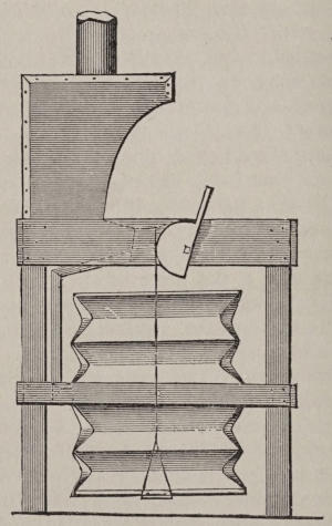
“shaking tub”—a vessel which is violently shaken
and rocked about by machinery or otherwise (depending
upon the particular locality) for the purpose of
scouring and brightening the scraps. This done,
they are carefully picked over by adepts, who cull
out the unsuitable pieces. So rigid is the culling
that it often happens that out of a ton of scoured
scraps not more than one hundred pounds weight of
them are chosen as suitable for going into the best
barrels.
Among the scraps usually thought to be best are
old chains that have been used for many years, the
wear and rust of time having left only the best
elements of the iron. The Damascus steel, which
has attained to so high a reputation, got it by
being manufactured out of old coach springs. Of
course it is not all made of coach springs now, but
it was in years ago; agents then traveled all over
the country hunting and buying them up, paying a
much higher price for an old broken spring than a
new one would cost its owner.
On Making Gun-Barrels.—The selected scraps to
be worked into gun-barrel material are cut into
small pieces and thrown into a furnace, where they
are exposed to intense heat until fused, after which
they are brought forth an adhering mass and placed
under a hammer, which drives them together and
forges them into bars. The bars are next rolled
into thin plates, and then cut into strips twelve
inches long and six inches wide. The very best guns
are made of a combination of iron and steel. Both
materials having been rolled and cut into sheets of
exactly the same size, these sheets (one-fourth of
an inch thick) are piled upon each other alternately
to the number of thirty, and subjected to a welding
heat; they are then driven together under a five-ton
hammer into a consolidated slab. The slabs so
formed are next worked down into one-fourth inch
square rods. The more the material is hammered
and worked the better it is. The rods are next
twisted until they present the appearance of a strand
of rope, some rods being twisted to the right and
others to the left. Two rods, with opposite twist,
are heated to the welding degree, placed upon each
other, and rolled together; they are now in a narrow
slab, presenting that fine curl of “grain” peculiar
to the Damascus, or that beautiful wavy figure
peculiar to the laminated steel, as the case may be.
The next operation is to coil one of these slabs
around a mandrel in a spiral form, and weld it securely
under the blows of hand-hammers. It is
now a gun-barrel in the rough.
Finishing and Proving.—The rough barrel goes
from the welder to the borer, where it is put through
the process of “rough boring.” From the “rough
borer” it goes into the hands of the “fine borer,”
who bores it out smoothly and to near the size it is
to be when finished. Another operator then takes
it in charge and dresses it to smoothness externally,
then the “tester” takes it and dips it into strong
acid, which soon shows any imperfection in either
twist or welding that might exist. If not perfect,
it is sent back to be worked over; if all right, it
passes to the next department, where it is straightened
inside. This part of the work is governed entirely
by the eye, and hence demands the services of
a workman of great skill, and experience.
Having been “passed on” by the “straightener,”
the barrel goes to the “turner,” who turns it in a
lathe until the outside is true and correspondingly
straight with the interior, and is of exactly the required
weight. If the arm is to be a double-barrel
shot gun, the barrel next goes into the hands of a
workman who joins it to another barrel with the
utmost nicety; to attain which, levels and other suitable
instruments are brought into requisition. Like
the man who straightens the bore, the man who
joins the barrels must be a workman of great skill.
The next operation is to braze on the “lumps;”
then, next in order, the ribs are put on. Now comes
the “proving.” The rear ends having been securely
plugged, they go to the proof department, where is
placed into each barrel fully four ordinary charges
of gunpowder; then, atop of this, a wad of strong
brown paper, rammed securely down, then a leaden
bullet large enough to exactly fit the bore, and then
another wad of brown paper. The charge is fired,
and if the barrels stand the ordeal unfazed, they
are ready to be fitted to the action; otherwise, they
go back to be worked over. In some houses the
“proving” is done before the barrels are joined together.
Action, Stock and Final Finish.—The “action
man” now takes the perfect barrels in hand and
performs his part of the work. In the meantime
the stock-maker has not been idle. A stock is already
in waiting, and next must come a series of
fittings of the most exquisite nicety, until the gun
is actually a gun and ready for its final test. This
is applied by the “targeteer,” who passes upon it
according to its merits. If his report comes in favorable,
the gun goes to the proper department for final
finish. The stock is dressed up, finished in oil or
varnish and chequered, and its mountings put on.
Every piece of metal is polished and burnished to
the highest possible degree, and all the needed engraving
is done. Next comes the case-hardening,
coloring, and the browning or bronzing; and this
having been well and satisfactorily performed, the
gun is ready for market.
On Making the Rifle.—The processes employed in
making the modern rifle do not differ materially
from those named in the foregoing. Of course there
are some processes employed on the shot gun that
are not called for in the manufacture of the rifle,
and some on the rifle not needed on the shot gun.
The general principle is the same, however, and
therefore it is not necessary to consume time in
further description. The great care mentioned is
only done to make a good gun; only the cheap and
inferior guns are pitched together in an easier and
more irregular way. But the gunsmith would not
thank any one for a treatise on cheap and bad guns.
They are legion, more’s the pity, and his extensive
dealings with them will afford annoyance sufficient
to do away with any desire on his part to fight his
battles over in a book.
Plain Steel-Barrel Guns.—Of course there are
guns with “plain steel barrels,” as they are called,
which pass muster as fair; and the barrels of these
are made by a process differing materially from that
described in the foregoing; all else connected with
the making is the same. These plain steel barrels
are made of round bars of steel two inches in diameter.
The bars are first cut into lengths of nine
inches each; a hole or bore three-fourths of an inch
in diameter is drilled through the centre. They are
now called moulds, and the next step is to pass them
through rolls, which reduce them to the required
size for barrels and stretch them out to the required
length, holding them, at the same time, in the proper
shape, externally. Having been thus rolled, they
are bored out internally, turned and ground externally,
until they have attained to the shape and
proportions of correctly-formed barrels. After this
comes the fitting up and “proving,” as in the case
of the finer guns.
CHAPTER III. GUNS NOW IN USE.
Guns Defined.—Excepting the pistol, and the mortar,
perhaps, all fire-arms now in use are classed under
the name of guns. The cannon or artillery
ordnance in all its sizes and forms, is simply a large
gun. It is variously divided off, according to character,
into heavy siege-guns, field-pieces, rifled-cannon
and smooth-bores. These again are sub-divided into
a large number of different kinds, as the Armstrong,
the Dahlgren, the Columbiad, the Paixhan, the
Parrot, the Whitworth, etc. But with guns of this
class the practical gunsmith will have nothing to do,
and hence it is but reasonable to suppose that he
feels no particular concern about them. It is with
the small-arms that his concern will mainly lie, and
therefore from this page to the conclusion of this
work the gun mentioned will be some instrument
classing with the small fire-arms, and liable to be
brought to a gunsmith’s shop for repairs.
The small arms, or hand guns, are muskets, rifles,
carbines, fowling-pieces and pistols. These may be
properly divided into three classes: the flint-lock, the
percussion-lock and the cartridge breech-loader.
The Old Flint-Lock Guns.—Of the old flint-locks,
only a few are now in existence within the United
States. Here and there one has been kept as a kind
of heirloom by some family, and occasionally these
drop in upon the gunsmith for repairs, but not
often. They are more common along the Mexican
border in Texas, perhaps, than in any other portion
of the country.
A minute description of the old flint-lock-gun need
not be given, as, in general characteristics it does
not differ materially from all other muzzle-loaders.
The barrel is usually longer than that of the more
modern gun; and, in the case of the rifle, the stock
(all wood) extends nearly to the muzzle. It is what,
in later days, when half-stocks had been invented,
was called a full-stock. As already intimated the
interior mechanism of the lock differs very little
from that of the more modern cap or percussion-lock.
On the outside, in place of the cap-hammer
is a cock arranged with two lips for holding a flint.
The lips are brought together firmly upon the flint
by means of a screw which passes down immediately
back of it. In the top of the lock-plate, directly
in front of the cock, is set the priming-pan;
a small iron receptacle made to contain, say the
fourth of a teaspoonful of gunpowder. When the
lock is in position the butt or open end of the pan
comes squarely up against the barrel of the gun
where a small hole called the “touch-hole” communicates
with the interior, and with the charge,
when the gun is loaded. Over the priming-pan a
cover fits nicely, lying horizontally when the pan is
closed, and turning up at right angles on the edge
nearest the cock, and standing erect, a small plate of
steel, immediately in front of the flint. This cover,
with its vertical plate is called the frizzen. It works
on a hinge, and is held into whatever position set,
by means of a small spring called the heel spring.
When the cock is set in motion by drawing upon the
trigger and releasing the check to the mainspring,
the flint comes in contact with the steel plate of the
frizzen, throwing it back upon its hinge and scraping
down its face directly towards the priming-pan.
As the frizzen flies back the pan is uncovered, of
course, enabling the flint to end its journey directly
in the priming powder of the pan. In its scrape
over the steel plate of the frizzen it causes many
brilliant sparks of fire, which descending with it
into the priming sets off the charge.
The Percussion-Lock Gun.—As has already been
stated, the immediate successor of the old flint-lock
was the percussion or cap-lock. While now far beyond
its zenith, it is still the prevailing gun in many
portions of the country; especially in out-of-the-way
districts South and West. In the oldest make of
these guns a small plug of iron is screwed into the
barrel at the point where the touch-hole of the flint-lock
was located. It is called the cylinder. The end
passing into the barrel is drilled to communicate
with the powder-bed of the gun, and with a cap-tube,
which is screwed into the cylinder, to stand
erect near the side of the barrel. In more modern
guns the cylinder has been discarded, the tube going
directly into the barrel and communicating with the
powder-bed.
The oldest percussion-lock rifles are set in whole-stock,
on the plan of the flint-lock gun; and on account
of the fact that all the old-fashioned folks are
not yet dead, some factories put up new guns after
the same model, calling them Kentucky rifles. The
stock reaches the full length of the barrel, which is
heavy and about four feet long. It is octagon in
shape. But in most of the more modern rifles the
barrel is shorter, say from 32 to 36 inches in length,
and comparatively light; and the stock extends
only half the length of the barrel, joining to a rib
affixed to the barrel for the purpose of holding the
ramrod-thimbles.
The “patent-breech” may be mentioned as another
peculiarity of the percussion-lock gun, since it
was not known in the days ere the flint-lock had
lost its prestige. In those early days the breech end
of the barrel was closed by a plug of iron, screwed
in and called the breech-pin. From its upper side
there extended backward along the stock a thin plate
or strap, through which screws passed at right
angles to hold the barrel in place. This method of
securing the breech-end of the barrel into the stock
has been done away with by the patent breech,
which secures it by means of a short hook on the
end of the breech-pin; or, rather, on the end of the
short plug screwed into the barrel in place of the old
breech-pin. It is much more convenient than the old
fashioned arrangement, as it enables the barrel to
be taken from the stock in a moment, doing away
with the labor of drawing the breech-pin screws.
On the Muzzle-Loaders.—The percussion-lock
muzzle-loaders all work upon about the same principle.
The charge must go in at the muzzle and be
put down to the breech. In the case of army guns
it is usually contained in a paper cartridge. The
soldier bites off the end of the cartridge in which
the powder is inclosed, to admit of a communication
with the cap, and then forces it down with the ramrod.
But in the case of rifles and fowling pieces, or
shotguns, as the latter are most commonly called
in this country, cartridges are seldom employed. In
loading a rifle the powder is first measured in a
“charger,” and then poured down the barrel; next
comes the patch, which is usually a piece of new
and strong cotton cloth, most commonly the kind
known as white drilling. This, having been tallowed
upon one side, the tallowed side is spread over
the muzzle of the gun, and the bullet is pressed
upon it into the muzzle, the side from which the
“neck,” formed in moulding, has been cut, must be
directly downward. Generally with the handle of
a knife the bullet is pressed into the bore as far as it
can be sent by such means; then the patch is gathered
around it and cut smoothly off exactly flush with
the muzzle end of the barrel. The next operation
is to draw the ramrod, throw the gun under the left
arm, with its breech resting upon the ground and
its muzzle in front of the breast, and then having
set the butt end of the ramrod upon the bullet and
grasped it in both hands, the bullet is gradually, and
by main strength, forced downward into position.
To make sure that it is entirely down the gun is
taken from under the arm, by some, and set with
the breech resting upon the ground more in front,
after which the ramrod is raised up a foot or so and
pitched down the bore like throwing a pike. If it
does not bound back the bullet is not down solid
upon the powder, and the pitching is repeated until
it does bound. The upward bound of a few inches
is sufficient to settle it that the bullet is down.
In the early times the bullet of the rifle was
patched with dressed deer-skin exclusively.
Charging the shot-gun muzzle-loader is an operation
somewhat different. First comes the powder
poured down the bore from a charger, as in the case
of the rifle. Next comes a wad, usually of paper,
which must fit tightly, and be rammed down solid
upon the powder. Following this comes the shot,
measured in the same charger, or in one of the same
capacity. The measure of powder and the measure
of shot usually made about the same. Over the shot
is rammed a loose wad—it needs only to be tight
enough to prevent the shot from rolling out when
the muzzle of the gun happens to come lower than
the breech. Disk-like wads of pasteboard or felt
cloth are the latest invention.
The Breech Loaders.—The breech-loading gun is
now before the public in considerable variety; and
being really the gun of the day, and, consequently,
engaging the best thought of inventors, it is constantly
appearing in new forms. This being the
case, about all that could be expected in this work,
is a mere mention of the general principles upon
which it works.
Taking a double-barrel shot-gun for illustrating
these general principles, it may be stated that the
barrels are movable at the breech or rear end, and
butt upon the face of the standing breech peculiar to
the latest and best muzzle-loaders. The face of
these barrels fits smoothly against that of the standing
breech. There is nothing in the way of a breech-pin
to resist the backward force of the ignited
powder, or hold the barrels in place. The hooks
mentioned as peculiar to the patent breech muzzle-loader
are not there—nothing at all like them. But
the barrels, when put into place for shooting are
held there by means of a solid piece of iron attached
to them underneath, called the “lump.” To effect
this, it descends into an iron bed on the stock called
the “action,” its projections fitting into suitable recesses
in the action and being held there by the
agency of keys, wedges, bolts or grips.
There are many devices for gripping, bolting or
wedging up the gun, as it is called; and also many
for attaching the barrels to the stock. In all cases
the barrels play upon a hinge pin, which admits of
their dropping down at the muzzle and rising at the
breech, the latter to reject the empty cartridge and
receive the loaded one. At every discharge the gun
is opened and closed by throwing up the barrels for
the purpose just named, and then letting them down
again into position for shooting. The means by
which this opening and closing is effected vary
greatly in the guns of different makers.
Variety of Breech-Loaders.—This gives the general
idea of about all there is of it. There are a few
breech-loaders made in both this country and in
Europe whose barrels are fixed, the cartridge being
inserted through some other device; and there are
still a few others whose barrels slide forward or sideways
in the stock to receive the load—do not tilt on
a hinge-pin—but neither of these kinds are so common
as the kinds just referred to.
CHAPTER IV. PISTOLS NOW IN USE.
Old-Style Pistols.—Pistols, the smallest of fire-arms,
were originally plain implements of a single
barrel; but, as improvements advanced, a second
barrel was added to many of them, presenting what
is known as the double-barreled pistol. Some of
these old-fashioned single and double-barreled pistols
will still occasionally find their way into the shop of
the gunsmith, though their numbers, as now in use,
are comparatively small, especially the muzzle-loaders.
In rare instances a flint-lock “horse pistol” or
holster may put in an appearance, though none such
are now on sale at any house dealing in fire-arms.
Some few houses are still offering the old cap-lock
army holster, always a second-hand article that
once belonged to the Government, and was bought
up by dealers when the Government had discarded
it for the adoption of more modern and better arms.
A description of this kind of weapon is unnecessary
as it is simply a small musket with side-lock, and
all on the usual plan, differing only in being short
and having a turned-down handle, to be held in one
hand, instead of the usual breech. The single or
double-barrel muzzle-loaders, outside the line of
army holsters, will usually have the central lock,
which is next to no lock at all; simply a mainspring
working in the handle and throwing the cap-hammer,
which is fitted in the middle of the piece
immediately behind the breech-end of the barrel.
Some very cheap pistols for boys are still made on
this plan.
The Derringer.—The old Derringer, though not now
much manufactured in this country, is still among
the people in considerable numbers. It is a muzzle-loader,
with side-lock and full-stock in wood; and,
by the way, it is a very good pistol of its kind.
The Pepper Box.—There are quite a number of
little breech-loading cartridge-pistols, with single
barrels, now in use, but the pistol of the day is a
repeater, of which there are kinds in great variety.
One of the oldest and now rarest of these is the
“pepper-box,” so called. It has a single barrel containing
from five to seven bores, which are loaded
from the muzzle. A tube for percussion caps communicates
with each bore at the breech, and upon
these a hammer strikes, having an automatic action,
rising up and striking in response to pressure upon
a trigger underneath, which pressure also revolves
the barrel, bringing the caps into proper position for
receiving the blow. It was never a popular pistol,
people objecting to a kind of way it had of sometimes
letting off its seven charges simultaneously,
when the person operating it had intended to fire
but one.
Old Colt’s Revolver.—Next among the repeaters,
in point of scarcity, is the Colt’s revolver of the
earliest patent. It has a stationary single barrel
and revolving cylinder, the latter containing from
five to seven chambers for receiving the charges.
It is not a muzzle-loader, though the charges must
be put into the chambers at the breech, somewhat
on the muzzle-loading plan. It is fired by means of
percussion caps. The cylinder revolves, throwing
the chamber to be discharged into proper position
at the breech of the barrel when the cap-hammer is
drawn back. Though inconvenient, compared to
the cartridge pistol of more modern make, the old
Colt’s revolver is yet an excellent arm. There are
houses still making revolvers on the same plan.
Sharp’s Four Shooter.—Next to the old Colt’s
revolver may be placed the Sharp’s four shooter. It
is a neat and strong-shooting, little breech-loading
pistol, using a No. 22 cartridge. The barrel has
four bores but does not revolve; but the hammer
has a revolving point, for striking the cartridge,
which moves into proper position for a new discharge
every time it is drawn back to full cock.
The barrel slides forward upon the stock for receiving
new cartridges.
The Breech-loading Cartridge Revolvers.—Next
comes the regular breech-loading cartridge revolver,
which is the pistol now most common and most
popular. To attempt a detailed description of every
style of this weapon would be to swell our book to
unwieldy proportions, and even were the multitudinous
styles at present before the public described, it
would be impossible to keep pace with the number
which would be constantly introduced. But, even
were it possible to do so, no good purpose would be
subserved. Various as the styles appear, they all
embrace devices and combinations which are substantially
covered by our several chapters, and the
intelligent workman will not require minute descriptions
to recognize or understand the individual
weapon when well grounded in a knowledge of the
class of fire-arms to which it belongs. It is our purpose
to give such descriptions, directions and illustrations
as shall make everything sufficiently clear
and explicit to enable the reader, with careful attention
thereto, to handle successfully and satisfactorily
any job likely to come to his hands.
CHAPTER V. ON GENERAL GUNSMITHING.
The Gunsmith and his Trade.—Few trades present
so little regular routine as does that of the gunsmith.
In most trades it is the same thing over and
over again; but, with the exception of taking the
gun to pieces and putting it together; and, perhaps,
of tempering, case-hardening and the like, the gunsmith
may work regularly for a long time without
being called upon to do precisely the same thing
twice. As a consequence, the gunsmith must be
merely an ingenious mechanic or worker in metals,
capable of thinking deeply and searching out causes
and requirements—there is little need of his being
anything more. The gun, in all its forms, is only a
machine, and a simple one at that—so simple as to
be easily understood by any one capacitated for
making an intelligent study of machinery.
Fitting up a Shop.—The specialties to claim the
attention of the gunsmith in fitting up his shop if
his means are limited may be few. It will be about
like fitting up the shop of any general worker in
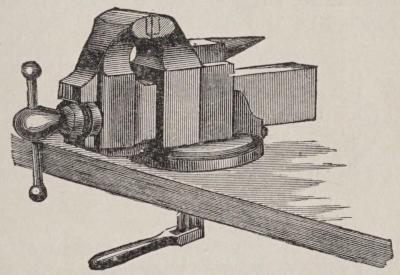
metals. He will need a forge, an anvil and a vise;
in a word he will need a light but complete set of
blacksmith’s tools, to begin with. This outfit will
be his foundation, so to speak; and he can add to
it such smaller tools as judgment and experience
may suggest as wanted; such, for instance, as a
hand-vise or two, cutting-pliers, bending-pliers, holding-pliers,
small files of various shapes, small drills,
a screw-plate or two, a few gravers, and so on. He
might have many special tools, such as could not be
bought at the ordinary hardware store, or at any
house dealing in outfits for the general worker in
metals, but for ordinary repairing, he will not have
much need of them. Among the special tools that he
will be compelled to have will be a rifle-guide, a few
sets of rifle-saws and a few mould-cherries. These
with proper instructions he can make himself if he
finds he cannot buy them cheaper than he can make
them. There are a few specialties in the way of
tools or machines for gunsmiths that are offered to
the trade by houses dealing in gunsmith’s materials,
and some of them may be found very useful as
labor-savers, but the gunsmith can get along without
them if he does not wish to buy. Prominent
among these is a mainspring-vise or clamp, which
has several advantages over the common hand-vise
sometimes employed for clamping the mainspring.
It would be well to look after these things, and to
adopt them in every case where it appeared beyond
question that they could be made to pay. There is
no occasion to speak against any of the specialties
that may be presented to the attention of the trade—of
their merits the party most concerned must be
his own judge.
CHAPTER VI. TAKING APART, CLEANING AND PUTTING GUNS TOGETHER.
To Take the Gun Apart.—With the muzzle-loading
guns now in common use this is an operation so
simple as to be scarcely worthy a mention. If the
gun is an old-fashioned breech-pinned muzzle-loader,
the first thing is to push out the small wire pins or
bolts which pass through the stock, under the barrel,
and through the barrel-loops. The next thing is to
draw the breechpin screw; this lets the barrel out
of the stock. If it is desirable to unbreech the gun,
it is done by clamping the breechpin in a vise, and
then turning the barrel by hand until it is screwed
off the pin.
The patent-breech muzzle-loader comes apart the
same way in every particular, with the exception
that there is no breechpin screw to draw; the barrel
can be easily lifted from the stock by simply raising
the muzzle and unhooking the patent breech, so soon
as the pins or bolts before mentioned as holding it
down have been removed. The unbreeching is done
at the vise much the same as in the other case.
To take apart the ordinary breech-loader, begin
by setting the hammer at half-cock. Open the lever,
then draw the bolt, starting it with a tap from the
handle of the screwdriver. Next detach the fore-piece,
and the barrel will come out without further
resistance. Instructions to take down and assemble
different kinds of breech-loading guns will be found
in Chapter XL.
To Clean the Gun when Apart.—In olden times a
bucket of water and a wisp of tow and a stout
“wiper” had to be brought into requisition, particularly
for the interior of the barrel, but now these
things are mainly obsolete, so far as relates to the
outfit of the gunsmith. The owner of a muzzle-loader,
who does not wish to remove the breechpin,
may still resort to the old plan of washing out the
barrel, though there is now really no necessity for
it. A little benzine poured down the muzzle, after
stopping the tube, will do the work of cleaning effectually
and in a few minutes. Let stand a short
time, then remove the plug from the tube and force
the benzine out by running down a tow wad on the
wiper—all the dirt will go out through the tube with
it, leaving you nothing to do but wipe the benzine
from the bore with the tow.
In the case of a gun unbreeched, or a breech-loader,
all that is necessary is to saturate a bit of
cotton flannel with benzine and run it through the
barrel a few times. If the gun is a fine one, well
finished, this process will leave the interior as shining
and bright as a mirror.
With the same arrangement rub thoroughly any
of the metal parts that happen not to be clean, and
all impurities will promptly leave them. After this,
oil and wipe with a chamois skin, and the work is
done.
Benzine may be had at any drug store at about
the price of kerosene. It is especially valuable as a
gun cleaner for two reasons: its peculiar fitness for
detaching and carrying away dirt, and its highly
volatile properties, which cause it to evaporate and
entirely leave the metal in a short time after the application
has been made. Its adoption has completely
done away with the necessity of ever using a
drop of water upon a gun, in any case, which is a
matter of decided importance and advantage.
To Put the Gun Together.—With the muzzle-loaders
the operation of putting together is simply
a work directly in reverse to that of taking
apart. In case of the common make of breech-loaders
a little more variation may be regarded as
necessary. Take the grip of the stock in the left
hand, having the lever open. Hook on the barrel
and turn the gun over with the hammers underneath,
still holding the stock at the grip. The
weight of the barrel will keep it in place. With the
right hand attach the forepiece and push in the bolt.
Of course there are guns of peculiar make, now
and then to be met with, which will require a different
routine, both in taking apart and putting together.
The details, with full directions for taking
down and assembling nearly all the breech-loading
guns now made, will be found explained, with cuts
of their mechanism and working parts, in Chapter
XLII.
A careful study will soon show the gunsmith how
they come apart and how they go together. The
main thing is to work with extreme care, and to
never act until you clearly understand what you are
doing.
CHAPTER VII. TOOLS REQUIRED FOR WORK, THEIR COST, ETC.
Given in alphabetical order are some of the tools
that will be required by the gunsmith, and in connection
a very brief sketch is given of their approximate
cost at hardware stores. This list is intended
only as a sort of guide in purchasing, and is by no
means intended as a complete list of what may be
wanted.
Figure 1.
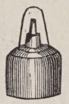
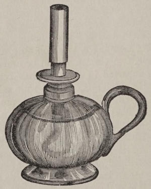
The Alcohol Lamp.—This lamp, shown in Fig. 1,
is useful for small soldering, tempering small taps,
drills, etc. Glass or brass lamps with caps to prevent
evaporation, are sold for about 50 cents each.
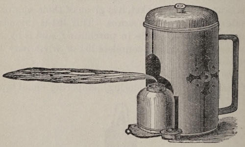
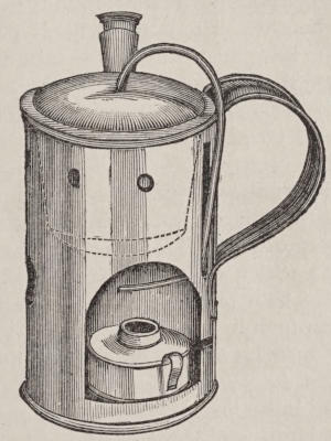
Alcohol Lamp, Self-Blowing.—This lamp, shown
in Fig. 2, very convenient when continued blowing
is required, or when the “knack” of using the common
plow-pipe cannot be readily acquired. It may
be used for soldering, brazing small articles, or hardening
small tools, Size 2½ inches diameter and 5
inches high, $2; about 3 inches diameter and 6 inches
high, $3.
Figure 2.
Anvil.—An anvil weighing about ninety or one
hundred pounds is heavy enough. An Eagle anvil
of this weight will cost about $9 or $10. The body
of this kind of anvil is cast iron with steel face and
horn. Price per pound is about ten cents.
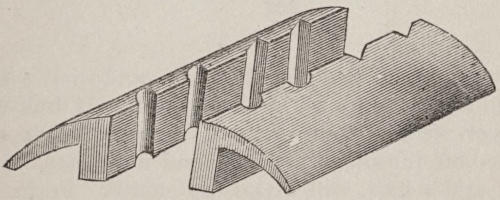
Barrel Planes.—These planes are now but little
used, except for stocking guns or rifles which are to
be fitted with full-length stocks. As this form of
gun is somewhat going out of use, so the stocker’s
planes are getting to be cast to one side. They are
made similar to a narrow rabbet plane, but have the
iron set close to the fore end. Any narrow plane
with the fore end cut off to within half an inch of
the opening in which the iron is placed will make a
substitute for the stocker’s plane. The plane with
round face is used to let in round barrels, and one
with a face equal in width to the sides of an octagon
barrel, for letting in such barrels. A narrow
plane is used to let in the ramrod, by cutting a groove
centrally in the bottom of the barrel groove. The
planes used are about four in number and the cost
is about seven or eight dollars for the set as sold by
dealers.
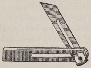
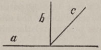
Bevel.—Bevels for ascertaining and forming surfaces,
not at a right angle with some certain line, can
be had from one dollar upward in price. The four
inch is very good size. The blade is held in position
by a screw, which forms part of the joint on which
the blade turns. Shown in Fig. 3.
Figure 3.
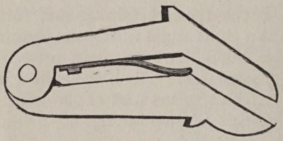
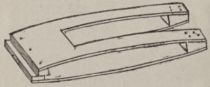
Beveling Clamp.—These tools are generally made
of about three sizes, and are used for holding hammers
when filing the bevel upon the sides. They
are also useful for holding lock-plates while filing
the bevel on them. In the vise, work can only be
conveniently held at a vertical or horizontal position;
this clamp is designed to furnish a means to
hold it so as to file an angle of about 45 degrees.
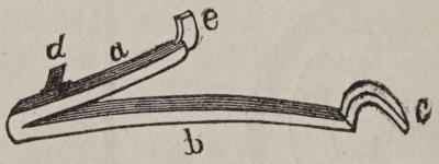
The tool is shown in Fig. 4. It is held in the vise,
the shoulders resting on the vise jaws. The spring
between the jointed portions opens the tool when the
vice jaws are opened, the closing of the vise
jaws, of course, closing the clamp upon the work
that is placed in it. The cost of these tools is from
two to three dollars, according to size and quality.
Figure 4.
Blacksmith Tongs.—Blacksmith tongs can now be
purchased of the hardware dealer. The twelve-inch
length are used for small work, and the fifteen or
eighteen for heavier work. The twelve inch cost
about 50 cents; the fifteen, 62, and the eighteen, 75
cents each.
Blow-Pipe.—Select a blow-pipe eight or ten inches
in length, with bulb or without, as fancy may dictate.
If the end where the mouth comes in contact
be silver or nickle-plated, it will not taste of brass.
If it be difficult to get one plated, tin it with soft
solder by wetting with soldering acid, and melting
the solder on it by holding it over the lamp. Wipe
off all superfluous solder with a rag. The cost of
plain eight or ten inch pipe is about 25 cents. Add
about one-third or one-half this price for pipes with
bulb.
Breeching Taps.—Breeching taps ought to be obtained
in pairs, one to enter first and another to
follow, cutting a full thread at the bottom. The
prices per pair are for the ⅜ inch $2.25; ½ inch, $2.50;
⅝ inch, $2.75. For shot gun taps, ¾ inch, $3.00; ⅞
inch, $3.25. A stock with dies will cost about a like
sum, but if the stock be fitted with only two sets
of dies, it will be much less. The two threads used
for rifle pins are 14 and 16 to the inch.
The 14 and 16 threads are not always adhered to.
A house in Philadelphia say they use taps of 18
threads, and a firm in Pittsburg advertise taps of 20
threads per inch.
Calipers and Dividers.—The best length of spring
calipers and dividers, for common bench work, is
about four inches. The cost is from 50 cents to
$1.50, according to quality.
Chisels.—The chisels, as used by stockers, are
about half a dozen in number. The narrowest is
about one-eighth of an inch wide, and the widest
about half inch. The set of six will cost about a
dollar or a dollar and a half.
Cutting Pliers.—A pair of cutting pliers, six
inches in length, for cutting wire, are indispensable.
Select those of good quality. Poor pliers of this description
are poor, indeed. The cost will be from 75
cents to $1.50. There are patented pliers of this
kind in market that are recommended by many who
use them.
Drill Stock.—Many kinds are in market, from
eight inches in length upward. Some are termed
hand drills, and the larger ones, used against the
breast, are called breast drills. The hand drills can
be obtained as low as 50 cents and upward; the
price of breast drills from two to three dollars.
Select a drill stock, if one be required, of a size and
strength to suit the work to which it will be used.
File Card.—This is for cleaning filings, dirt, etc.,
that may collect in files. It consists of a strip of
common cotton card tacked to a piece of wood conveniently
shaped to handle. It is also useful to clean
the dirt and debris that will collect in screw taps.
The cost is about 25 cents. Shown in Fig. 5.
Figure 5.
Fitting Square.—A fitting square with a four,
five or six-inch blade is required for many purposes,
not only for laying out iron stocks and marking
off “square work,” but other work that will come
into a gun shop. The gun squares used by carpenters
and cabinet makers are very good. If the stock be of
iron, or an iron frame filled with wood, they are better
than those with wooden stocks. The cost of the
six-inch may be about 75 cents. The other somewhat
less.
Floats.—For half-stocking, the gouge and floats
are used for letting in barrels. The floats are made
with a handle bent at an angle so that the hand will
not hit the work. The round float in form resembles
a gouge with teeth like a coarse file cut on the
rounded or bottom surface. Floats have been made
by drawing the temper of a thick gouge and cutting
teeth in it, or taking a half-round file and drawing
the temper, and then cutting teeth on the round
side. Floats for octagon barrels are flat, like a
chisel with teeth cut on one of the flat sides. A thin
float for letting in cross bolts is made in the same
manner. A float for fitting ramrods may be made
of a steel rod with teeth cut on one end, and a handle
fixed to the other. The bolt float will cost about 50
cents. The rod float about $1.00 each for two sizes.
Rifle, two sizes, about $1.25 each. Shot gun, two
sizes, about $1.50 each.
Forge.—Little advice can be given respecting a
forge. Some prefer the bellows forge, while others
select the fan blower. The great requirement of
the gunsmith is portability and occupying little
space. It should also be so enclosed as to prevent
escape of dust, and be free from accident of fire escaping
if left with the fire lighted. The cost of either
form of portable forge will be from $20, upward.
Glue Pot.—Glue pots can be purchased with kettle
fitting inside the pot and tinned on inside,
quart size about 75 cents. A glue pot may be extemporized
by selecting a common round fruit can,
cutting out the cover so as to allow a smaller can
to fit and be held in place. Where economy is desired
or a pot cannot be purchased, the can glue pot
will answer every purpose.
Gouges.—About six gouges are needed. The sizes
are about one-eighth for the smallest, and increasing
to three-quarters for the largest. The cost of the set
will be about one dollar and a quarter.
Grind Stone.—An Ohio stone, about 20 inches
diameter and 2½ inches thick, mounted plain, can be
got up for about three or four dollars. The iron
fixtures will cost about a dollar, and the stone
a cent and a half or more per pound, according to
locality.
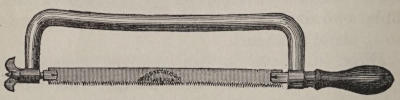
Hack Saw.—A hack saw shown in Fig. 6, with
iron frame, to hold a blade of eight or ten inches in
length is required for cutting off barrels, slotting
screws, cutting off rods of iron, brass, etc., besides
many other uses. The eight inch with blade will
cost about $1.25, the ten inch about $1.50. If at
any time a blade be broken they can be replaced
at from 25 to 50 cents.
Figure 6.
Hammers.—In choosing hammers select the plain
riveting hammer with cross pein. The sizes generally
most used are a four ounce, a twelve ounce and
a heavier one for use at the forge. The four ounce
costing about 30 cents, the twelve ounce about 50
cents, and the larger one according to weight. In
selecting hammers try the pein with a fine file to
learn the temper. In many cases the pein is left
too soft for riveting steel.
Handles.—Handles for files or screwdrivers are
best when made of maple or apple wood. Maple is
generally preferred. Some mechanics like soft wood,
as bass-wood or white birch, for file handles, but
they are not so neat as those made of maple. Get
those with ferrules made from sheet brass, raised to
form. Soft wood handles are worth about 25 cents
per dozen, and the hard wood about 50 cents.
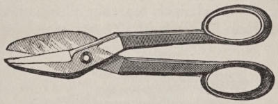
Hand Shears.—For cutting sheet tin, brass, thin
sheet steel, small springs, etc., select a pair of hand
shears about nine or ten inches in length, costing
about $1.50. With these, common watch-springs
can be cut lengthwise, for making small springs for
pistols. The temper need not be drawn to cut them.
(Shown in Fig. 7.)
Figure 7.
Hand-vise.—A hand-vise for holding wire, screws,
etc., is needed. About four or four and a half inches
in length is most convenient. For holding small
wire, cut a groove with a three-square file across the
jaws toward the jointed end. The cost will be from
50 cents to $1.00, according to quality.
Figure 8.
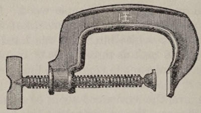
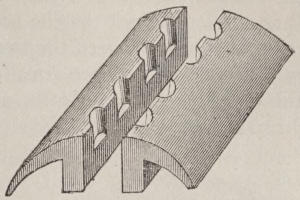
Iron Clamps.—A pair of malleable iron clamps
(shown in Fig. 8), opening about four inches, are
useful for holding barrels into the stock during
stocking, holding a lock plate or strap in place for
marking, holding barrels together, pieces of wood to
be glued, etc. Cost, about 50 cents each.
Figure 9.
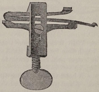
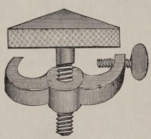
Mainspring Vise.—This tool (shown in Fig. 9, as
clamping a spring) is used to clamp the mainspring,
preparatory to removing it from the lock. The
hammer is set at full cock, and the vise applied, the
screw tightened until the spring can be lifted from
place. In taking down double guns, a vise for each
lock spring is very convenient, as the springs can
then rest in the vise, being cramped in place, until
ready to be put back into their respective places.
The cost of these vises is from 25 cents to $2 each,
according to quality and make. For a left-side
lock, reverse the sliding piece, so that the short end
will bear on the bend of the mainspring.
Marking Gauge.—A wood marking gauge is used
for laying out lines parallel to a surface already
formed. If made of beech wood, and plain, it is
generally sold for about 25 cents each.
Screw-cutting Tools.—A small die stock and dies,
with taps for lock work, will cost about $2.50. A
plate and ten taps, suitable for all sizes of nipples,
English and German, can be had for about $8.00.
Screw Wrench.—One of Coe’s patent wrenches,
about twelve-inch size, costing about a dollar, is the
best make and the most durable size for all purposes.
This wrench is generally known as a
“monkey wrench.”
Soldering Copper.—A copper for soldering, similar
to the kind used by tinners, is the kind to get.
A good size—No. 3—will weigh about a pound and
a half, costing about 75 cents.
Screw-drivers.—Several screw-drivers are required,
and of several widths, to fit different sized
screw heads. The narrowest may be about one-eighth
inch, and the widest, say, half inch to five-eighths
inch. If the mechanic desires to make
these himself, select octagon steel, about one-quarter
inch diameter, draw one end to form the tang,
and the other to form the screw-driving part. Get
good apple, beech or maple wood handles. Let the
length project about six or seven inches from the
handle. For the larger size screw-drivers get steel
three-eighths diameter. Old files, with the temper
drawn and the points ground to shape, make a passable
screw-driver. Screw-drivers purchased at the
store, are generally not so satisfactory as those made
from rods. Stub’s round steel wire rod makes good
screwdrivers
Pliers.—Three kinds of pliers are used by gunsmiths;
flat nose, round nose, and long flat nose or
clock-makers’ pliers. Six inch is about the right
length for general use. The round nose are useful
for bending wire or metal into circular forms. The
long flat nose for holding work for soldering and
handling work at the forge. Of the flat nose a five
inch pair are useful in many cases. The cost of
pliers (six inch), is from about 50 cents to $1.00 per
pair according to quality.
Wing Dividers.—A pair of wing dividers, about
eight inches in length, will be found the best size for
general use. The cost will be about 75 cents. In
purchasing see that the screw that binds the leg to
the arc or wing is well fitted. The thread, either in
the leg or the screw, is sometimes stripped or worn
out after a little using.
CHAPTER VIII. TOOLS, ETC., AND HOW TO MAKE THEM.
The tools given in this chapter are such as are
needed by the gunsmith, and as directions are given
for making them, they can be made by almost any
ingenious person during leisure hours.
The Alcohol Lamp.—A lamp for this kind of work
is easily made. A common gum or mucilage bottle
with a tube inserted in the cork has been used, so
has a small tin spice-box, with a tube soldered into
the cover. A common copper or brass cartridge,
with the head filed off, can be used for a tube. A
common oil can, such as is used for oiling sewing
machines, with about half of the taper tube cut off,
will make a serviceable lamp. These appliances are
small, unsightly and not to the taste of the mechanic
who has a pride in the appearance of his tools.
The best form of lamp, shown in Fig. 10, may be
made by obtaining a small glass kerosene hand lamp,
which will cost only a trifle of two or three shillings.
Cut off that portion of the burner above the screw,
where it is held to the socket that is fastened to the
lamp. Remove the tube that holds the lamp-wick
and also the little contrivance made to raise and
lower the wick. In the place where the tube was
inserted, generally a flat one, file out with a round
file, a place which is large enough to receive a
common brass 44-cartridge that has had the head
cut off or removed by filing; this is the tube for the
wick. Fasten it in place with soft solder. Let this
tube project a little into the lamp, and solder it on
the under side. The greater portion of the tube projects
above the place where soldered.
Figure 10.
The wick is made of common cotton wicking,
letting the end inside touch the bottom of the lamp.
Fill with alcohol, and the lamp is ready for use. Be
careful that the wick is not too tight in the tube, or
in other words, do not fill the tube with too much
wick, as it will prevent the alcohol from rising and the
lamp from burning. To prevent evaporation of the
alcohol and to have the wick always ready for lighting,
cover the tube with a cap that fits it quite closely
and has the upper end closed. A brass cartridge
that will go over the tube makes a good cover. Remove
the primed cap or see that the cap has been
exploded before using it to cover the lamp tube.
Figure 11.
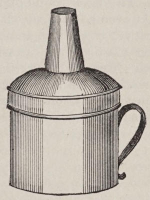
A Self-blowing Lamp.—A very good form of this
lamp is shown in Fig. 11. It consists of a lamp enclosed
in a kind of cup which has an open place at
the bottom to admit the lamp and a small boiler,
fitting loosely, and held by a flange on its top. A
small pipe is soldered to the top of this boiler and
extends downward, and has an end like a blow-pipe
that passes through one side of the cup and ends
near or a little above the lamp wick. The operation
is as follows: the lamp being lighted, heats alcohol
placed in the boiler, and the steam thereby made
produces a jet that blows the lamp flame the same
as is done with the mouth.
The size of the cup may be from three inches to
three and a half in diameter, and about five inches
high. The opening at the bottom may extend about
half of the height. The lamp is made of less diameter
than the interior of the cup to admit of moving
to get a good flame from the blow-pipe. The lamp
may be 1¾ inches in diameter and an inch high. The
boiler is about two inches high and has the bottom
made a little convex, as shown by dotted lines,
and is some smaller than at the top where a flange
is formed to admit of its resting on the top of the
cup. The top of the boiler is also convex, and has a
short tube in which a cork is fitted, for the purpose
of filling it. The blowing tube is about three-sixteenths
of an inch in diameter. There is a long slot
in the cup near its handle which readily admits of
its being put in position for blowing. There are
several small holes near the top of the cup to insure
draft to the lamp, and there is a large hole about an
inch in diameter opposite the end of the blow-pipe
through which the flame issues where the work is
held.
For silver soldering, small brazing, tempering, or
any similar small work, this lamp is most excellent.
To make the small blowing-pipe, drill a smooth hole
through a piece of iron or steel and ream out one
side of it. Cut a strip of thin copper or soft brass of
a width just enough to fill the hole if it were made
into a tube. Point one end of the strip and roughly
form it into a tube, insert in the hole and pull it
through. Or the strip can be rolled around a piece
of iron wire forming it to a tube by hammering.
Soft solder it after being formed to shape.
Breech Wrenches.—In many shops the monkey
wrench is made to do duty in removing breech-pins,
but at the expense of marring the pin where the
wrench engages it. If many guns with breech-pins
like those used in army guns are handled, it is worth
while to have solid wrenches forged of iron like Fig.
12. The length may be about fifteen inches, with
an opening to fit the shoulder of the breech-pin.
The width at this place may be about one and a half
inches; thickness, about half an inch; diameter at
end of handle, about three-quarters of an inch, and
at the small portions near the centre, about half an
inch.
Figure 12.
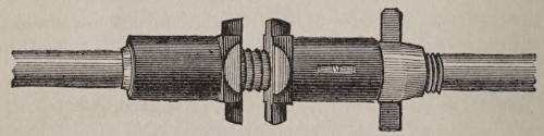
A wrench for removing patent breeches or nuts
from double guns is made like Fig. 13. It consists
of a steel bar about fifteen or sixteen inches long
and about three-quarters of an inch diameter. At a
little to one side of the center is fastened a steel collar
that has four projections made at one end. A
similar piece is fitted opposite to it, but is made to
move back and forth to fit the work by means of a
screw that is formed behind where it is fitted. A
slot is made in the extension of the piece and a key
fitted to prevent its turning around as the nut is
turned to advance it toward its fellow piece.
The only substitute to answer for this tool is to
file down the jaws of a monkey wrench so that they
will turn between the extensions of a patent breech
while the first breech is being removed. This is a
poor substitute, as there is only one handle to turn
with, and when force is applied to remove the breech
it does not have the force applied equally to each
side as in the other kind of wrench, consequently it
is not as effective nor so easy to remove the breech.
If an extension to form another handle could be improvised
it would make it much better.
Figure 13.
The Bit Stock.—Even if the gunsmith have a
lathe there is much work that can be done to advantage
with a common bit-stock. But as the drills
and tools used in the lathe generally have round
shanks by which to hold them in the chuck, the
square hole where bits and tools are held in the
bit stock must be filled by brazing or soldering a
piece of iron into it and boring a hole to fit the
shank of the lathe tools. It is advisable to have
these shanks about seven-sixteenths diameter, as
explained under the heading “Shanks of Tools.”
In holding small drills made of steel wire or twist
drills a small drill chuck must be fitted to the bit
stock.
A small solid chuck with a quarter inch hole may
be made with a shank to fit the seven-sixteenth hole.
A set screw must be fitted to hold the shanks of the
two sizes mentioned.
Figure 14.
Bottoming Tools.—Bottoming tools are used for
letting in locks, cutting out for escutcheons, and are
useful in other places where a chisel cannot be made
to operate. The form of this tool is shown in
Fig. 14. It consists of a square or round shank
about three-sixteenths or a quarter-inch in diameter
and about six inches long. At one end a wooden
handle is attached, and the other end is bent at
an angle which is about half an inch or perhaps
a little more, and on this angle is another one
turned parallel with the shank and which is about
three-eighths of an inch long. This is the cutting
end and is fashioned like the cutting edge
of a chisel, and is about a quarter of an inch
wide. The bottom side, as it would be held for use,
is ground flat and the upper side bevelled like a
chisel. The cutting edge may be square or rounded
to suit round places as letting in the bridle of a
lock. The size given is that generally used, but if
it be made about twice this size it will be found very
useful in letting in octagon rifle barrels; if the tool
be made larger and hollow like a gouge it is very
useful in letting in round gun barrels. In letting in
break off straps it will be found to take the place of
a chisel to some advantage.
Chequering Tools.—The tools used for chequering
are very simple. Imagine a small saw, or rather
two small saws about one inch or more long, made
at the end of a straight steel shank. The form is
given in Fig. 15. The double saw can be made by
filing it as one thick saw and then cutting a groove
lengthwise with it. In using, one blade first forms
a groove and the other blade works the next cut;
as the first cut is finished, another mark is being
made while so doing. This insures equal width of
the cuts. Care must be exercised in using them so
as not to tear the wood. A fine cut, sharp edged,
three square or a small half round file may be used
to finish the work if desired.
Figure 15.
Nipple Wrenches.—Two forms of nipple wrenches
are used, one for square and the other for two-sided
nipples. The most serviceable of these are made
from a straight rod of steel, with a cross handle
and an opening at the opposite end to correspond
with the square on the nipple. For
the two-sided, a hole to receive the round part of
the nipple where the cap goes on, may be drilled in a
rod of steel and a slot filed across to receive the
shoulders of the sides. The square shouldered
kind must have a hole drilled of the diameter of the
square, and then being heated a square punch of the
size of the square is driven in. The nipples used for
Government or military arms have the squares larger
than sporting guns, and the wrenches are generally
made of a flat piece of steel with a square
hole made through from side to side at one end and
squared to fit the tube. When made, harden and
draw to a blue color for temper.
Portable Forge.—The following description of a
“home made” portable forge shown in Fig. 16 is
given by a contributor to the Blacksmith and
Wheelwright: “In size it is two feet square and
three feet high; it is made entirely of wood; the
bellows are round and are sixteen and a half inches
in size, covered then with the best sheep skins. The
bed of the forge consists of a box six inches deep.
It is supported by corner posts, all as shown in the
sketch. Through the centre of the bottom is a hole
six inches in diameter for the tuyere; this is three
inches in outside diameter, and is six inches high.
The bed is lined with brick and clay. It does not
heat through. The bellows are blown up by means
of two half circles with straps from a board running
across the bottom, all of which will be better understood
by reference to the sketch. In addition to protecting
the bed by brick and clay, the tuyere is set
through a piece of sheet iron doubled and properly
secured in place. The hood which surmounts the
forge may be made out of old sheet iron, and will be
found sufficient for the purpose. The connection
between the tuyere and bellows is a tin pipe.”
Figure 16.
Vise Appendages.—The best vise for general use
is one made by C. Parker, Meriden, Conn., and is
termed a “swivel” vise. To the bench is attached
a round plate of iron, and on this plate the vise
turns to right or left as may be desired. It is held
in position by screwing up a nut by means of a handle
underneath the bench. The jaws are of steel,
and a small projection back of the jaws, formed
like a small anvil, is very convenient for bending
work or to lay work upon for cutting, working with
prick punch, etc. The width of jaws of No. 22,
the size that is most convenient, is three and five-eighths
inches, the weight about thirty-five or forty
pounds, and the price about eight dollars, or perhaps
a little more. This vise is shown in Fig. 17.
Figure 17.
As the jaws of the vise where the steel faces
come together are cut like a file and tempered, they
will necessarily mar or bruise the work. Pieces of
brass or copper must be bent so as to be retained in
place and at the same time cover the file-like surface
of the jaws. Pieces of leather, common belt leather,
upon which a little beeswax has been spread, may
be placed between the jaws, and by forcing them together
with the screw the leather will be retained in
place. In holding barrels, stocks, and for stocking a
fixture made like the cut, Fig. 18, is best. Two
pieces of thin board, or even two pieces of a wide
barrel stave may make it. The opening is for the
purpose of “straddling” the square box of the vise
that encloses the screw. Nail a piece of wood about
an inch and a half thick across the bottom part, before
the opening is made, and also nail a thin piece
across the top of the pieces, being careful to sink
the nail heads to as to not mar the work. The top
ends of the fixture must come even with the top of
the vise jaws.
Figure 18.
For holding screws without damaging the heads
use a pair of false jaws made of cast brass, like those
shown in Fig. 19. The heads being held in the indentations
formed along the upper edges of the fixture.
For holding rods or small square pieces without
injury a similar pair of false jaws are made
which are shown in Fig. 20.
Figure 19.
Figure 20.
For holding articles that are tapering a fixture is
required like that given in Fig. 21. The yoke clasps
the neck of the vise, and is held in place by a set-screw.
The upright pin is received in the yoke by
turning on a screw cut for the purpose, and by turning
this up or down, the triangular piece at the upper
part is made to accommodate itself to the height of
the vise. The back angular corner of this piece has
a bearing against the jaw of the vise, and the opening
made between the other jaw of the vise and the
front of this angular piece will be the same as the
piece of work that is held between the two.
Figure 21.
Shanks of Tools.—The best two sizes for shanks
of tools are about seven-sixteenths and about
quarter-inch. Two solid chucks, fitted with set-screws,
may be made for the lathe, and they will be
found sufficient for all kinds of work. If half-inch
octagon steel be used for the larger size, a light chip
turned off for about an inch and a quarter, or an
inch and a half, will make the shank. From this
size steel may be made large drills, reamers, countersinks,
bullet cherries, etc. The shanks of many
other tools may be made to this standard.
When a bit stock is fitted to hold this size of shank,
the tools may be used either in the lathe or by hand
with the bit stock.
Octagon steel, a quarter-inch in diameter, may be
used for smaller tools, or round steel rod of this size
may be employed. For small drills and tools, taps,
etc., it will be found very convenient. No turning
is necessary to fit to the solid chuck.
The common cheap bit stock, made from round
steel, may be selected, and the square hole filled with
a piece of iron and then brazed to make it solid. A
hole is then drilled to fit the seven-sixteenths shank.
A solid chuck is to be made to fit this, and drilled
with a quarter-inch hole to fit the smaller sized
shanks. This solid chuck will also fit the chuck for
the lathe. If barrel boring tools, quick boring
reamers, be made with the larger sized shank, they
can be used both in the lathe and with the bit stock.
CHAPTER IX. THE WORK BENCH.
Material for the Work Bench.—The first thing to
do in fitting up a shop is to put up a work bench.
Do not make a rude affair of an unplaned plank and
a rough board, but let it be seen that you fitted up
your bench for use, and at the same time sought to
have it neat and durable. A plank two inches
thick is heavy enough, yet in some respects it is
light enough; for the front portion of the bench
twelve or fourteen inches is a good width. Pine
wood makes a very good bench, but as it is soft, it
will absorb oil, and in time will become black and
dirty. As a remedy for this, give it two or three
coats of shellac varnish. The best bench is made
from a hard or sugar maple plank that has been
well seasoned and has been planed true in a planing
machine. Ash wood does very well, so does beech.
Oak is not good; it absorbs grease and dirt readily,
and if struck much with a hammer will soon show
splinters, the fibres of the wood easily separating by
the blows. A hard maple plank has one advantage;
after being discarded as a bench, it will make
good rifle stocks; the years of use will so season it
that it will be valuable. For that part of the bench—that
is, back of the two-inch plank—use a board
ten or twelve inches wide. Select pine or any other
kind that fancy may dictate. Calculate the plank
and board so that the width of the bench will be
twenty-two or twenty-four inches.
How to Make the Work Bench.—For supports for
the bench use 2 × 4 inch studding, such as carpenters
use in house building. Pine, oak or any other material
will answer. Plane smooth on all sides. For
each support cut three pieces; two of the height of
the bench, and one about an inch less than the width,
so that when the bench is made the plank in front
projects an inch or so in front of the supports. As
the short piece on which the bench rests is four
inches wide, cut away half of the thickness of the
uprights of this width at the upper end, and cut
enough in length to receive the short piece, when
it is halved together—as is the term used—thus
making it four inches thick when put in place.
Fasten with nails or screws—the latter being the
best fastening. To keep these uprights steady, nail
a piece of board about three inches wide, and about
twelve inches from the bottom, from front to the
rear upright. On these pieces a board or two may
be placed, with the other end resting upon a neighboring
support, and it forms a convenient shelf
upon which to place boxes and other things that
will soon accumulate in any shop.
The height of bench from the floor may be about
two feet and ten inches and a half. This will be
found to be the most convenient height.
Putting the Vise in Place.—In putting the vise in
place, fix it on the bench far enough in front so that
if a gun stock or barrel were held upright in the
jaws it will not touch the bench. If there be a
window in front, put it a little to the left of the
window. The light will then shine more on the
right side of the vise, and consequently it will be
more easy to distinguish lines or marks that may
be made on work held in the jaws, as it is more
convenient to look on the right side of work to see
what is being done than on the left. The height of
the vise at the top of the jaws should be on a level
with the elbow of the person who is to work at it.
In no instance try to work with the jaws of the vise
higher than the elbows as the workman stands erect
before it. The reason is this: as the workman
grasps the file handle in the right hand and the
point of the file in the left, the arms are in a natural
position, and can be thrust forward and brought
back in a horizontal line. If the elbows were to be
raised from the natural position the horizontal forward
and back motion could not be made with
facility.
Place for Drawer.—A few inches to the right of
the vise is the best location for a drawer. This is
generally opened or drawn out with the right hand,
and when so placed can be readily opened with that
hand without stepping to one side.
The Gun Brace.—A gun brace, as shown in Fig.
22, is made from a piece of inch and a half or two
inch plank, with its upper edge of a height about
an inch less than the height of the vise jaws. It is
hinged or pivoted by a single screw passing through
the end of the bottom extension, this screw passing
into the bench, the brace turning freely upon it. It
can be swung around back out of the way, and when
needed for use is turned in front, and is ready to
support a barrel or gun stock which is held in the
vise. This brace is put to the right of the vise, but
if another one like it is put in the left side it will be
found useful at times.
Figure 22.
In cutting out gun-stocks from the plank, many
times pieces of just the right form for these braces
will be found among the “scraps” that will be
made. The shape is of little moment so long as
they are of the proper height and have an extension
through which to put the pivot screw.
To Deaden the Noise of Hammering.—In shops,
especially if the work-room be in an upper story, to
deaden the noise of hammering, etc., put pieces of
rubber under the legs of work benches, the feet of
lathes, anvil-block, etc. If rubber cannot be obtained,
any woolen texture as felt or thick loose-made
cloth may answer the purpose, but not with
so good results as the rubber. The anvil may be
set in a tub made by cutting off the top of a barrel
to the right height and filling it nearly full of
sand or earth.
CHAPTER X. ON WORKING IN IRON.
Hand-Forging.—Two rates of heat figure in this
operation. If the object is merely a smoothing of
the surface of the iron, the “cherry-red heat,” so-called,
is the rate wanted. The work of smoothing
is performed by striking lightly and evenly with the
hand-hammer, until the desired condition is secured.
The same degree of heat is employed where hammer-hardening
the iron is one of the objects to be obtained;
in this case the blows with the hammer
must be heavier than in the case first named.
If the forging is to extend to a material change
in the shape of the iron, the rate of heat must be
much higher; it must be increased to what smiths
call the “white flame heat.” The hammering must
be much heavier, of course; if the piece is large a
sledge-hammer must be brought into requisition.
But the gunsmith will seldom have work heavy
enough to demand the aid of an assistant with a
sledge-hammer.
Welding.—The “welding” or “sparkling heat”
is required in this process, which is a higher degree
of heat than either named in the forgoing. In securing
this heat, the metal is brought nearly to a state
of fusion; which condition is made known by its
sparkling, and presenting the appearance of being
covered with a glaze, or a fresh coat of varnish. So
soon as the two pieces of iron to be welded together
have both attained to this necessary degree of heat,
they are taken from the fire with the utmost dispatch,
the scales or dirt which would hinder their
incorporation scraped off, placed in contact at the
heated point, and hammered until a union has been
effected, and no seam or fissure remains visible. If
the first effort fails to unite them sufficiently, they
must be reheated and rehammered until the desired
end is secured.
The fire for welding should be free from sulphur;
and the iron, while heating, should be taken out
now and then and sprinkled over at the point of
greatest heat with powdered glass, or with powdered
borax. A small proportion of sand or powdered
clay is sometimes mixed with the borax. These applications
tend to prevent the iron from running or
burning, and they are supposed to assist the adhesion
when the two pieces are brought together in
the act of welding.
Hardening Iron by Hammering.—Iron may be
hardened to the character of a pretty fair spring metal
by simply hammering it thoroughly while in a cold
state. Many of the cheap spiral springs in use, as
those attached to small bells for the purpose of
imparting a vibratory motion, are hardened or
stiffened in this way. They are first cut from soft
sheet-iron and then hammered into the required
hardness. Some heat to a cherry red and hammer
to and after entire coldness.
Case-Hardening.—The various parts of gun
mountings, such as guards, heel plates, etc., and
the different parts of locks, such as hammers, tumblers,
triggers and plates, as received by the gunsmith
from the manufacturer or dealer in such articles,
are generally in the rough or partially finished
condition. Many gunsmiths, particularly those in
the country, where there is more or less a class of
cheap work, finish up these parts with a file and a
little hand polishing, and when the work is put
together hand it over to the customer. Not only
tumblers and triggers, but even sears and tubes are
finished up in this manner. As these parts are
almost always made of soft iron, the result is they
soon wear and have to be repaired.
The gunsmith who does good work will thoroughly
case-harden the parts when they are fitted
and finished, and by so doing will turn out a really
good piece of work that will wear as well as hardened
steel. Why the majority of the trade do not
case-harden their work cannot very well be explained,
unless they are ignorant of the process or
do not care to be put to the trouble of doing it. It
is true it may be made a tedious job or a quick and
easy one.
Some gunsmiths, when such work is finished,
heat it red hot, smear it with prussiate of potash or
cyanide of potassium, and while hot, plunge it into
cold water, letting it chill. This produces a superficially
hardened surface that is not “skin deep,”
and as soon as this surface becomes abraded will
wear away rapidly.
If the case-hardening of the expert manufacturer
be examined, it will be observed that the surface of
such work has a fine grayish appearance, and in
many places mottled with colored tints that are
pleasing and beautiful to the mechanical eye. It
will be further observed that the hardening is of
such depth that it will wear for a long time. In
fact it will wear better than hardened steel. The
condition of the material is that of a hardened steel
surface stretched over and shrunk upon the iron
body of the work. It is stronger than steel, for it
has the tenacity of iron for its interior. It has the
advantage of steel, inasmuch as it may be bent
when cold to a limited degree, and when so hardened
will not break as readily as steel. This property
of bending is not confined to all articles, as
they may case-harden entirely through, and then
they will be very brittle and easily broken, but by
drawing them to temper after hardening, in the
same manner as a tool is drawn to temper, they
may be of any hardness desired.
A good way to Case-Harden.—The easiest and
perhaps the best way to case-harden gun work is to
have a number of short pieces of common gas pipe,
such as will be adapted to the size or quantity of the
work, and have one end of these pieces securely
plugged or closed. One way will be to heat the
pipe and close by flattening the end with a hammer
on the anvil, but it is a “slouchy” way of doing it.
A neater way is to have a gas fitter cut a thread in
the pipe and then screw in a plug, such as are used
to close ends of gas pipe; if such cannot be obtained,
drive in a cast-iron plug and upset the end of the
pipe so that it will not readily come out. In these
pieces of pipe place the work, packing it well with
good, fine bone-dust, such as is used by farmers for
fertilizing land. Be careful to so pack that the different
pieces of work will not touch each other.
Stop the open end of the pipe with a cover, but in
such a manner as to be readily opened; place the
pipe and its contents in a good fire, letting it remain
at a red heat for fifteen minutes or more, dependent
upon the thickness of the articles or the depth they
should be hardened. Remove from the fire and
quickly empty the contents of the pipe into a pail
of cold water.
If pieces of gas pipe cannot very well be obtained,
thimbles from old carriage hubs may be used instead.
Plug up the small end, fit a cover to the
large end and use as if it were gas pipe. As these
thimbles are made of cast iron they will not bear
the rough usage nor the heat that wrought iron will
withstand. Common cast malleable iron makes the
best receptacles to contain work for case-hardening.
Articles of malleable iron and cast iron are as
easily case-hardened as wrought iron. A poor quality
of steel is benefited by the operation, as the
metal imbibes carbon in which it was before deficient.
Material for Case-Hardening.—For case-hardening,
bone-dust is the article most readily obtained and
it is clean and neat to use; but it will not produce
the mottled tints that charred or burned leather will
give. The leather may be prepared by cutting up
old shoes or boots, putting them in an old pan and
setting the mass on fire. Let it burn until it is a
charcoal that will readily crumble in pieces by using
a little force. Grind this charcoal to a fine powder
by pounding in a mortar or by running it through
an old coffee or spice mill. Pack the work with the
powder, the same as bone-dust. Bone-black may
be used the same as bone-dust, but it is not very
satisfactory in its results. It is also dirty to use
and to have around a shop. Ivory dust will also
answer the same purpose as bone-dust. Gun
guards, straps, and long pieces of work will become
shorter by case-hardening, and it is best not to fit
such pieces into the stock until after they are hardened.
If it be desired to have a portion of the work
left soft and the other parts hardened, securely
cover the places to be left soft, with a coating of
moist clay, and this will prevent the hardening
material from coming in contact, and, consequently,
it will have no opportunity to absorb carbon and
harden when put in the cold water.
It may also be observed that articles that are case-hardened
will not rust so readily as those not so
treated.
If the articles be quite thin and there be danger
of their cracking by sudden chilling, the water may
be warmed a little, or a film of oil may be spread on
the water which will tend to prevent a too sudden
contraction of the articles while cooling.
If it be desired to have the work present the
colors or mottled tints as seen on some kinds of
case-hardened gun work, the surface of the work
before being put in the receptacles containing the
burnt leather, must be nicely polished and then
buffed or burnished. The higher the finish the
more brilliant will be the colors.
In using prussiate of potash to case-harden, the
potash must be finely powdered, the work heated
and dipped in, or if the work be large the potash
must be spread over it. The work must be hot
enough to fuse the potash, and if it become somewhat
cold by removing from the fire it must be reheated,
removed quickly from the fire and quenched
in cold water.
Another way to Case-Harden.—Collect such articles
of animal origin as cows’ horns, or hoofs of
either cows or horses, or leather trimmings from
about the shoe-shops, or old cast off boots or shoes, and
burn them until sufficiently charred to admit of being
easily pounded into a powder. Having finished up
the article to be hardened, ready for the final polish,
place it in an iron box, and surround it completely
on all sides by a packing of the powder. Pour into
the box, until the powder is made moist, a saturated
solution of common salt in urine. Next close the
box and seal it until airtight, with wet and well-worked
clay, then put it into the furnace and blow
up gradually until heated to a cherry red. Don’t
run the heat any higher, but hold it at that about
five minutes, then take out and plunge at once into
the slack-tub.
By this means a piece of soft malleable iron is rendered
as hard as hardened steel. Some workmen
contend that the salt solution is of no particular importance—that
just as good results will come of
packing in the animal charcoal alone. The iron box,
though very convenient when a good deal of case-hardening
is to be done, is not an absolute necessity.
If the article, surrounded by the animal charcoal, is
incased in a ball of stiff and well-worked clay, and
then exposed to the proper heat and slacking, the
results will be the same as if heated in an iron box.
Another Formula.—In earlier times, when guns
were more in use than either agricultural or mechanical
implements, and there was a gunsmith’s
shop at almost every cross-road, they had a way of
case-hardening that was much more simple than
either of the foregoing, and yet quite effectual.
Scraps of old leather, as cut from old boots or shoes,
were tightly wrapped and tied around the piece of
iron to be made hard, to the extent of several thicknesses.
Around this was placed a layer of sand and
salt in equal proportions, to the thickness of half an
inch. The sand and salt was dampened with water
to make it stick together. A layer of plastic clay,
an inch in thickness, was worked around the whole,
and the ball, so made, was exposed to heat at about
the cherry-red degree, sufficiently long to consume
the leather, when it was dropped suddenly into the
slack-tub.
Still Another Formula.—Make a powder of pulverized
prussiate of potash, sal-ammoniac and saltpetre
in equal parts. Heat the iron to cherry-red
and sprinkle thoroughly on all sides with the powder,
then immediately plunge into the slack-tub.
Some smiths contend that the pulverized prussiate
of potash, used in the same way, is entirely effectual
without the other ingredients.
To Chill Cast Iron.—Make a powder by pulverizing
together, salt, 2 lbs.; saltpetre, ½ lb.; alum, ½ lb.;
ammonia, 4 ozs., and salts of tartar, 4 ozs. Heat
the iron to cherry-red, sprinkle thoroughly with the
powder and then plunge into cold water.
Another Mode.—Make a solution by dissolving in
10 gallons of soft water, salt, 1 peck; oil vitriol, ½ pint;
saltpetre, ½ lb.; prussiate of potash, ¼ lb., and cyanide
of potassium, ½ lb. Heat the iron to cherry-red
and plunge at once into the cold solution. This
makes cast iron hard enough to cut glass, and is the
method usually resorted to for hardening the cheap
cast-iron glass cutters, now so common on the market.
To Soften Wrought Iron.—Heat the iron with a
slow blast to a dark-red, then pour upon the burning
coals half a pint of fluoric acid. Keep up the
blast gently, without increasing the degree of heat,
until all sign of the acid has disappeared, then lay
out the iron to cool gradually of itself.
Alloy for Filling Holes in Iron.—Melt together
nine parts lead, two parts antimony and one part
bismuth. Pour into the hole while in a molten
state, or drive in while the iron is somewhat hot.
This alloy possesses the peculiarity of expanding as
it cools, consequently the plug tightens as its temperature
falls.
To Harden Iron for Polishing.—Pulverize and dissolve
the following-named articles in one quart of
boiling water: blue vitriol, 1 ounce; borax, 1 ounce;
prussiate of potash, 1 ounce; charcoal, 1 ounce, and
common salt, ½ pint. Add to this 1 gallon raw linseed
oil. Having finished up the article ready for
polishing, heat it to a cherry-red, and plunge into
the mixture; a rapid stirring of the mixture should
be going on at the time when the plunge is made.
This preparation hardens the iron to such a degree
that it takes and retains polish almost equal to
the best of steel.
CHAPTER XI. ON WORKING IN STEEL.
Hand-Forging Steel.—In the main this does not
differ materially from the same work in iron. Special
care must be exercised to have the fire clear of
sulphur, hence charcoal is the best fuel to use. In
cases where the use of bituminous coal cannot be
avoided, the fire should be blowed up for several
minutes before putting in the steel, to drive off the
sulphur.
Steel to be forged should not be heated to so high
a degree as is employed for iron; for ordinary light
work a little above a cherry-red is enough. It does
not work well under a high degree of heat; and, to
make amends, it can be worked much colder than
iron. In fact, it is always best to hammer it with
light blows until the red color of the heat has entirely
disappeared, as this improves its texture by
adding decidedly to the closeness of the grain.
Welding Steel.—The common method employed
for welding iron to iron is often resorted to for welding
steel to steel, but a great deal more care is necessary
to success in the latter than in the former case.
There must be much precision so far as relates to
the rate of heat, as the margin for variation is extremely
small. If the temperature is not high
enough there will be no adhesion, of course; and if
it attains to only a few degrees above what is actually
necessary, the steel either “runs” and is
ruined, or is ruined by going into an unworkable
condition known as “burnt.” It sometimes becomes
necessary to weld steel and iron together;
this may be effected by the same process as that
employed in welding steel to steel. None but workmen
of thorough experience would be apt to succeed
in either case, on the old plan of proceeding the
same as in welding iron to iron.
But steel may be more easily welded than on the
old plan by the employment of certain welding compositions.
One of them consists of half a pound of
saltpetre dissolved in half a pound of oil of vitriol,
and afterwards added to two gallons of soft water.
Heat the pieces to a cherry-red, then plunge them
into this composition; after which proceed to reheat
and weld in the usual way. At the welding the
strokes of the hammer should be quick and light.
Another composition is made by pulverizing together
ten parts of borax and one part of sal-ammoniac.
Thoroughly melt the composition so made in
an iron pot, then pour out upon some level surface
to cool. When cooled grind to a fine powder. Heat
the pieces of steel and sprinkle this welding powder
over them; then return to the fire, and again heat
up, and it is ready to go together under the hammer.
Some smiths claim to weld steel successfully by
dusting over the heated pieces a powder composed
of clear white sand, 2 lbs., and plaster of Paris, 1 lb.;
then reheating and proceeding in the usual way.
In welding steel to iron the foregoing processes
are employed the same as if both pieces were steel.
Tempering.—Heat the steel to a bright cherry-red,
and plunge it at once into cold water. It will then be
as hard as fire and water could make it, and too
hard for anything except hardened bearings for machinery,
or for some kind of implements necessary
to be extremely hard, as tools for cutting glass, and
the like. In this condition it is almost as brittle
as glass itself, and hence would not stand for most
of the uses to which tempered steel is applied. Its
great degree of hardness must, therefore, be reduced
to the proper standard, depending upon what it is
to be used for. This is done by heating and closely
observing the resulting colors as they appear upon
the metal. If the piece under process is an edge-tool
of considerable bulk, only the cutting-edge,
and a little back of it, is plunged into the water at
the hardening, the rest of the implement being left
still hot. It is then held into the light and observed
closely, when the different colors, indicating the different
degrees of hardness, will be seen moving
slowly, one after the other, down towards the edge,
driven by the heat still left in the part of the metal
not plunged. When the color wanted has reached
the edge, the entire piece is plunged into the slack-tub,
which stops further action of the heat, and
establishes the required degree of hardness exactly
where it is desired. But very light articles and implements
cannot be tempered in this way, as they
will not retain sufficient heat to drive the colors; it
will be necessary to reheat them gradually in some
way to make the colors move. Very light pieces,
as drills and the like, are best tempered in a spirit or
alcohol lamp; after having been hardened they
should be held in the flame of the lamp a little back
of the point or cutting-edge, which will enable the
operator to note the movement of the colors. In
this case his actions, so far as the colors are concerned,
will be governed the same as in the other.
Small articles to be tempered alike all over may be
placed upon a bit of sheet-iron, after hardening, and
the iron held over the fire of the forge, or directly
over the flame of the lamp, until the required color
has appeared, when they must be quickly plunged
into the water. On large articles the colors will be
often so strongly marked as to be readily seen on
the surface of the metal, rough, just as it came
from the hammer, but in small articles they will be
somewhat faint; hence it is best to give small articles
a slight polish before exposing them to heat for
drawing the temper. Nine shades of color will present
themselves one after the other as a piece of
thoroughly-hardened steel is exposed to gradually-increasing
heat. They are:
1. Very faint yellow, appearing at a temperature
of 430° Fahrenheit. If slacked at this color, the
piece will be very hard, having a temper admirably
suited to drills for working in hard metals or
hard stone.
2. Pale straw-color—450°. Still very hard, suitable
for the faces of hammers and anvils.
3. Full yellow—470°. Shears and scissors.
4. Brown—490°. Gravers and turning-tools for
hard metals; also percussion-lock gun tubes.
5. Brown, with purple spots—510°. Wood-working
tools and most of the steel parts in a gun-lock
with the exception of the springs; also knives of
all sorts for cutting wood.
6. Purple—538°. Butcher-knives and other flesh-cutting
implements.
7. Dark blue—550°. Tools requiring strong cutting-edges
without extreme hardness, as case-knives.
8. Full blue—560°. Chopping-axes.
9. Grayish blue, verging on black—600°. Springs,
saws, swords, and the like.
Various other methods of tempering steel are
sometimes recommended, as with oils, tallow, lead,
mercury and divers solutions; but since the matter-of-fact
gunsmith will find use for none of them, it
is not deemed proper to encumber this book with
anything further on the subject of tempering. It
might be well to state, however, that the hardest
degree to which steel can be brought is secured by
heating the piece to a light yellow and instantly
plunging it into cold mercury.
To Restore “Burnt” Steel.—Pulverize together
two parts horn or hoof filings; one part sal ammoniac;
one part charcoal, and one part common soda.
When thoroughly ground together, work in tallow
enough to make a kind of wax or paste. Bring the
damaged steel to a bright cherry-red heat, and then
cover with the paste, leaving it to cool gradually.
The process may be repeated several times with
profit if considered necessary. While a piece of
badly-burnt steel may not be entirely restored by
this process, it can be much improved. Entire restoration
is scarcely possible.
Annealing Steel.—Heat the steel to a cherry-red
in a charcoal fire, the last thing to be done before
quitting work at the forge for the day or night;
then smother the fire down with a thick layer of
ashes or sawdust, leaving the steel in, just as heated.
Let so remain until the fire is all out, and the steel
entirely cool, which will require several hours. Some
smiths use a piece of gas-pipe in which to heat small
steel articles for annealing, claiming that it is very
advantageous. They put the piece into the pipe and
heat to a cherry red, looking in occasionally to ascertain
when it has attained to that temperature; then
they cover the fire, pipe and all, and leave it to cool
as in the other case.
To Blue Steel.—Polish the article to be blued, then
place it upon a strip of sheet iron and heat slowly
over a forge fire or lamp, until the desired blue color
appears. Let cool, and the color will remain permanent.
To Remove Blue Color from Steel.—Immerse for a
few minutes in a liquid composed of equal parts muriatic
acid and oil of vitriol. Rinse in pure water and
rub dry with chamois skin or some kind of soft cloth.
Tempering Knife Blades.—To heat the blades lay
them in a clear charcoal fire, with the cutting edge
downwards, and heat very slowly. It is not particular
if the back of the blade, which is uppermost,
is so very hot or not. Harden in clean luke-warm
water. If many blades are to be hardened at once,
lay a number in the fire and remove one at a time
as they are properly heated. To temper, brighten
one side on a grindstone or emery wheel so that the
temper color can be seen, and lay the blades in the
fire, or on an iron plate heated over the fire, with
the backs down and the cutting edges uppermost.
On the plate place wood ashes or fine sand to help
keep the blades in proper position, and also facilitate
even drawing. When the proper color is seen on
the brightened portion of the cutting edge, remove
and cool in cold water.
When an extra tough blade is wanted, after it is
hardened, handle it so that it will not draw any
lower after removing from the fire, and let it cool
without putting in water.
Long blades, when they are being drawn, can be
straightened, if necessary, by putting them between
two pins in the anvil or pins fixed in an iron block
and bending between these until straight, wetting
the blade with a cloth or sponge saturated with
water, when the blade is thus straightened. Surprising
as it may seem, when hardened steel is being
drawn, it can be bent to quite an extent, and when
cooled will remain as bent. File makers straighten
files in this manner. Sword blades and blades of
butchers’ knives undergo the same process of manipulation
to be made straight.
The Lead Bath for Tempering.—Among the
many secrets of tempering is the employment of
the lead bath, which is simply a quantity of molten
lead, contained in a suitable receptacle and kept hot
over a fire. The uses of this bath are many. For
instance, if it be desired to heat an article that is
thick in one portion and thin in another, every one
who has had experience in such work knows how
difficult it is to heat the thick portion without overheating
the thin part. If the lead bath be made
and kept at a red heat, no matter how thick the
article may be, provided sufficient time be given,
both the thick and thin parts will be evenly and
equally heated, and at the same time get no hotter
than the bath in which they are immersed.
For heating thin cutting blades, springs, surgical
instruments, softening the tangs of tools, etc., this
bath is unequaled.
If a portion of an article be required to be left
soft, as the end of a spring that is to be bent or riveted,
the entire may be tempered, and the end to be
soft may be safely drawn in the lead bath to the
lowest point that steel can be annealed without disturbing
in the least the temper of the part not
plunged in the bath. Springs, or articles made of
spring brass, may be treated in the same manner.
One great advantage in using the lead bath is that
there is no risk of breakage or shrinkage of the
metal at the water line, as is often the case when
tempered by the method of heating and chilling in
cold water.
As lead slowly oxidizes at a red heat, two methods
may be used to prevent it. One is to cover the surface
of the lead with a layer of fine charcoal or
even wood ashes. Another and a better plan, when
the work will admit of its use, is to float on the top
of the lead a thin iron plate, fitting the vessel in
which the lead is contained, but having a hole in
the centre or on one side, as most convenient, and
large enough to readily admit the articles to be tempered
or softened.
Test for Good Steel.—Break the bar of steel and
observe the grain, which in good steel should be fine
and present a silvery look, with sometimes an exfoliated
or leaf-like appearance. One of the best
tests of steel is to make a cold chisel from the bar
to be tested, and when carefully tempered (be careful
not to overheat), try it upon a piece of wrought
iron bar. The blows given will pretty correctly tell
its tenacity and capability of holding temper. Remember
the temper you gave it, and if it proves
tough and serviceable, take this temper as a guide
and temper other tools in like manner. Inferior
steel is easily broken, and the fracture presents a
dull, even appearance, which may very appropriately
be termed a lifeless look.
Etching on Steel.—Make an etching solution by
pulverizing together sulphate of copper, one ounce;
alum, one-quarter ounce, and common salt, one-half
teaspoonful. Add one gill strong vinegar and twenty
drops nitric acid. Stir till thoroughly dissolved.
Polish up the metal to be etched, and then cover its
polished surface with a thin coating of bees-wax.
This can be accomplished with neatness by simply
heating the metal till the wax flows evenly over its
surface. Now draw upon the wax, cutting cleanly
through to the steel the figure you wish to etch;
then cover the figure so prepared with the etching
solution, and let stand for a short time, depending
upon the depth of cut desired. Finally rinse off
with clear water, and then remove the bees-wax.
It will be found that the solution has cut into the
surface of the steel wherever exposed, leaving untouched
all parts covered by the wax.
Very good etching can be done by applying, on
the foregoing plan, nitric acid alone. Etching
offers a good method of cutting a man’s name on his
gun or pistol. It works on silver or brass the same.
CHAPTER XII. ON WORKING IN SILVER, COPPER AND BRASS.
To Forge Silver.—The gunsmith will not have
much to do with silver in the work of his trade,
though instances may occur now and then when he
will be called upon to make or repair mountings or
ornaments for gun-stocks formed of this metal, and
also foresights, particularly for the old fashioned
Kentucky rifle.
In shaping silver under the hammer no heat will
be necessary at the hammering—it would do no
good. The metal is so malleable that it may be
drawn into almost any shape by simply hammering
cold. The only trouble liable to come up in this
kind of work will be the hardening of the metal under
the influence of the hammer; but this trouble
may be pretty effectually removed by heating the
silver to redness, and then letting it cool gradually
of itself. Care must be taken not to heat it too
much above the first appearance of red, as it melts
quite easily.
To Polish Silver.—File it down to the shape desired,
then dress with a fine file; then work over
thoroughly with a burnisher. Next buff it off with
rotten stone, and if a particularly fine finish is desired
buff again with rouge.
Light Plate for Copper or Brass.—Dissolve silver
in nitric acid by the assistance of heat; put some
pieces of copper into the solution and immediately
the silver will be precipitated. With fifteen or
twenty grains of the precipitate thus obtained mix
half a drachm of alum and two drachms each of
tartar and common salt. Pulverize well together.
Having thoroughly cleaned the surface to be plated,
rub it well and hard with the mixture, using a bit of
chamois skin, until it presents a white appearance.
Next polish off with soft leather until bright.
Inferior as this kind of plating would seem, it
will wear a long time.
To Clean Silver.—Wash with a little spirits of
ammonia reduced in strength by twice its bulk of
pure water, then rub dry and bright with soft
leather. No kind of polishing powder will be necessary.
Some workmen clean silver by first washing
it over with diluted muriatic acid, then immediately
covering the surface with dry prepared chalk,
then brushing off and rubbing clean with a bit of
chamois skin. It acts very well, but care must be
had to get the acid thoroughly cleaned off else it
will have a tendency to soon tarnish the silver.
To Work Copper.—This metal is almost as malleable
as silver, and works very well under the hammer
in a cold state. Heat adds nothing to its malleability,
though, as in the case of silver, exposure to
a low degree of heat, followed by gradual cooling,
softens it somewhat when it has been rendered hard
and brittle by long hammering. It polishes very
well, but does not long retain its polish and brilliancy
on account of its disposition to oxidize. Heating
increases its oxidation; repeatedly heating and cooling
would soon wear it entirely away.
To Work Brass.—This material is a combination
of copper and zinc, and since zinc is not so malleable
as copper, it renders the brass less malleable. Nevertheless
it forges out pretty well under the hammer,
in a cold state, the only condition in which it
can be so worked. Hammering increases its hardness
with great rapidity, soon converting it into a
very fair spring metal. Brass springs are quite common—they
are all made by repeatedly hammering
or rolling the metal while cold. As in the case of
both silver and copper, heating and gradual cooling
removes this hardness. This is the plan for softening
usually recommended in books on working
metals, but no advantage will be found to arise
from the gradual cooling in the case of either silver,
copper or brass. The custom is to heat the metal to
the lowest degree that would show redness and then
plunge it directly into cold water.
To Cast Brass.—The gunsmith may occasionally
find it necessary to cast something in brass. This he
can do without trouble, as brass melts quite easily.
The mould should have vents at or near the top to
admit the free escape of air as the molten metal
runs in to take its place; and it is always best, if
possible, to arrange so that the metal will enter the
mould near the bottom and rise up in the filling.
Without such an arrangement there is danger of
air bubbles remaining under the metal and spoiling
the casting. The metal should be heated only to a
degree high enough to admit of flowing freely and
no higher.
To Brass Iron.—Clean and polish the iron
thoroughly, being extremely careful not to touch its
surface with the fingers at the finishing; then plunge
it into molten brass. Take out immediately; a
thin coating of brass will be found covering the
iron, which may be polished or burnished, giving
the article the appearance of solid brass.
To Clean Brass.—To half a pint of soft water add
one tablespoonful of oxalic acid. Wash the article
with this, then cover with prepared chalk, brush dry
and polish with chamois skin, as in cleaning silver.
The solution may be bottled and kept on hand for
use as wanted.
To Solder Brass.—The processes in soft soldering
are the same for all metals, full instructions for
which may be found in Chapter XXXIV. Hard
soldering (see also Chapter XXXIV) is something
different, and in the case of brass it is somewhat
different on account of the low degree of temperature
at which the metal melts. The solder most
commonly used is composed of two parts of common
brass and one part of zinc, melted together.
Reduce your solder to fine bits by cutting or filing,
and then mix with sal-ammoniac and borax, the
two latter having been pulverized together in equal
parts and moistened with water to form a kind of
paste. Carefully clean the pieces to be joined, lay
them together, place the soldering compound along
the upper edge of the joint, which must be held
vertically, and then heat gradually over a charcoal
fire until the solder is seen to run down between the
pieces. The instant the solder is seen to run remove
the work from the fire, tap the work gently
with a small hammer to jar the solder into all interstices,
and, if the work be so that it can be done,
scrape off the superfluous solder and burnt borax
with an old file.
CHAPTER XIII. ON WORKING IN WOOD.
The Woods Most in Use.—Various woods are now
employed for making gun stocks, but among them
all, the most popular, perhaps, is black walnut. It
is deservedly so from the fact that it is light, works
easily, takes a superior polish, has a rich dark color,
naturally, and when finished up does not incline to
“check.” So popular is it, indeed, that most of the
other woods worked into gun stocks are stained and
finished up to imitate walnut.
In some portions of the country hard or sugar
maple (“sugar tree”) is worked quite extensively
by the local gunsmiths. It makes a very nice stock,
finishing to good advantage, especially “curled
maple,” which is really beautiful. Soft maple is
also extensively used, stained and finished to imitate
either hard maple or walnut.
The common dogwood makes an excellent gun-stock,
but it works badly on account of the smallness
of the tree rendering it difficult for one to get
the pieces sawed out in proper shape at the beginning.
Holly also makes a good stock, but presents
the same objection as the dogwood. Cherry has
few superiors, but it is now becoming a very scarce
wood. Sweet gum is getting to be quite extensively
used for cheap guns, stained to imitate either walnut
or cherry. It has fine grain, and works very
well, the chief objection to it being that it is wonderfully
inclined to warp.
Wood for Gun Stocks.—The wood for a gun stock
should combine strength and lightness, and at the
same time it is desirable that it be easy to cut. The
fibres of the wood should be close and possess
great cohesion and should be little liable to split.
In this country black-walnut is generally selected
for shot guns, and either black-walnut or hard
maple for rifles. The grain of the wood should be
straight at the small of the stock, which is the
weakest portion of the work. Between this and the
end of the breech it little matters how the grain
runs. If there be curls, waves or a hard knot, let
it come about midway between the small and the
end of the butt. As the wood at this place is simply
“rounded” it is easy to work it into shape, as the
shape given to it is such that any deviation of the
fibres or grain from a straight line can be shown to
the best advantage, also at this place there is less
demand for strength of wood than at any other
part of the gun stock. Around the small it is very
necessary that the grain be straight and run in the
direction of the shape given and also continue
straight until past the place where the locks are set
in. A little distance in front of the barrel breech
it matters but little how the grain runs, but if the
fibres of the wood where the barrel is let in run
toward the breech it will be found to be easier to work
out for the reception of the barrel. For then as
the tools are worked toward the breech they are
cutting with the fibres or grain and not against it.
But as the majority of guns are now half-stocked
the distance to cut in order to let in a barrel is so
small that but little attention need be paid to the
grain at this spot.
The best and most serviceable stocks are those
made from parts of the tree where large branches
join the trunk. In these parts, too, will be found
the curled and irregular grain that is so much admired
when the stock is so made that these irregularities
come in the stock a little in front of the butt
plate. When large trees are cut down, it will be
observed very often that there are portions of the
stump that have a kind of convex form, and extending
downward terminate in large roots. If
these be dug out or separated from the stump by
splitting them, they are almost always of a proper
shape, to have the grain run nearly straight in the
curves as given to the stock. In black-walnut and
hard maple these root portions are very firm of
fibre, quite hard and have a splendid grain that finishes
up beautifully. Portions of some root pieces
have a mottled appearance and are of a different
color from the wood as cut from the trunk of the
tree; this is especially the case with black-walnut.
As these stumps can be had by the trouble of removing
them, the gunsmith can very cheaply secure
pieces of wood that are very valuable. Oftentimes
black-walnut stumps are found floating in the water,
and on the banks of western rivers, that are perfectly
sound and so darkened by water soaking that
they make beautiful stocks.
The dryness and fitness of the wood may be ascertained
by the easy crumbling of the shavings and
by the dryness of the sawdust. It is necessary that
the wood be well seasoned, for if any moisture or sap
remains in it, the barrel and portions of the lock
that come in contact with the wood, will in a short
time be covered with rust.
CHAPTER XIV. ON GUN STOCKS.
Form of Gun Stocks.—When a customer orders
a stock to be made, or has a gun to be re-stocked,
the gunsmith will observe the length of his customer’s
arms, length of neck, his height and general
carriage. From these he can gather some data as
to the length and form of stock to be made. Give
him a gun, and observe his mode of raising it and
taking aim, and the manner of his holding his head
while aiming, and deductions may be drawn as to
what the customer requires.
A tall, long-limbed and long-armed man requires
a longer stock than a shorter person, and a straight
stock will better answer for a short-necked, high-shouldered
man than for a long-necked, low-shouldered
person. A straight stock is much more suitable
for a short-necked, high-shouldered person than
a bent one, and for this reason, that, in fast shooting
the point of sight at the end of the gun would come
up to the range of the eye before the butt could be
placed full against the shoulder, and one consequence
would be, when fired, a severe recoil of the
gun at every discharge. A stock rather long is
much better than one too short, and one rather
crooked to one that is too straight. If a gun be not
held on a perfect level, but the muzzle higher than
the breech, the load will be carried over the object
aimed at, supposing that object to be on a level with
the eye. Let a customer take a gun, such as would
be thought to be best suited to his “build,” and request
him to close both eyes and raise the gun to a
level, as if to shoot thus. Have him hold the gun
immovable thus, and then request him to open his
eyes, and it is evident if he requires a stock to be
made different from the one he has in hand. If the
face comes naturally to the breech and the eye has a
“fine sight” along the barrel, it is just the pattern
of gun stock for him to have. If it be too straight
he will shoot over, if too much crooked he will
shoot under. In the first instance the muzzle is
brought too high by an effort of the face to find a
position at the breech, and in the other case it so
readily finds a place that no further effort is made,
except by practice, to raise the muzzle to the proper
level.
A tall, slim person requires a gun with a long,
crooked stock, and rather heavier and made fuller
behind the small, as this will fill up his want of a
full face, and will better permit his eye a command
of sight along the middle of the barrels, supposing
the gun to be a double one. For a short individual
a short, straight stock is required, and it should
be made thinner behind the small, so as to easily
permit access to the line of sight. If a person be in
the habit of firing too low and behind a bird, if the
stock be made a little straighter it will prove a remedy
for the fault.
That part of the stock where the cheek comes to
rest should be full, as it gives more support to the
line of fire. The heel of the stock should be in a
straight line with the upper rib between the barrels.
If a single gun, on a line with the barrel. The
length of stock from the centre of front trigger to
centre of butt-plate, from thirteen to fifteen and a
half inches; a short person requiring the less measurement,
while a very tall one might require the
longest one.
Figure 23.
The cut, Fig. 23, gives a better idea of what the
stock should be. Place a rule or straight-edge upon
the rib of the gun, and long enough to reach from
the sight of the gun over and beyond the butt. Be
particular that the straight-edge lies along the rib
and touches it at both muzzle and breech. The
measurement from a to b on the butt is what is
termed the “drop,” and this may be from two and
a half to four inches, according to the requirements
of the shooter. The cheek of the sportsman comes
between c and d, and almost always touches the
stock at this place when bending his head forward
over the stock of his gun to take the line of sight.
This part of the gun should command particular
attention.
Another point of considerable importance to observe
is, that a due regard be paid to the proper fall
of equipoise or centre of gravity of the gun when
stocked and ready for use. This centre of gravity
should fall at a point about two feet two inches, or
perhaps an inch more, from the heel of the butt.
In this case the arm is easier to handle and easier to
carry. If the breech be too light, lead may be inserted
to advantage in the butt, the butt-plate being
removed for that purpose.
Dimensions for Single Gun.—The following may
be considered very good dimensions for a single gun
stock: Whole length of stock, from butt to cap,
two feet two inches; length or depth of butt, five
and a half inches, with a trifling concave surface;
width of stock at butt, two inches; from point of
centre of the lock-tumbler to cap, eleven inches;
width of stock before the guard, one inch and three-eighths,
and made nearly square.
Dimensions for Double Gun.—For a double gun:
Length of stock, from butt to cap, two feet one
inch; length or depth of butt, five and a half
inches, with a slightly concave surface two inches
in width; from centre of lock-tumbler to cap, ten
and one-quarter inches; width of stock before guard,
one inch and three-quarters, and made nearly
square.
Laying out Gun Stocks.—Several patterns each, of
double and single, and rifle stocks are necessary.
These patterns may be made of thin wood or thick
straw-board. These patterns ought to be a little
larger than the finished stock, and are intended
only for a proximate measurement of the stock
when to be sawed from the rough wood. Select
the wood, lay the pattern upon it, mark around with
a pencil or crayon, and then saw out by the lines
made.
With a plane, smooth one side of the wood so as
to show the grain and the direction in which it runs.
This must govern the position of laying the pattern.
The weakest portion of the stock is the small, and
there it is almost a necessity that the grain should
not run across the line of the stock, but with it. If
a very little divergence be made, it may not matter,
provided the wood be of a hard and close grain. If
the grain run across, or at an angle at this weakest
spot, a slight blow or accidental fall is liable to cause
a breakage which can best be repaired with a new
stock. If the wood be in some places mottled, with
curled or twisted grain, or has a knot that is hard
and sound, let this spot come in the center of the
butt, for by its width and thickness no accident is
liable to break it, and the rounded form gives opportunity
to show off the irregular grain to good advantage.
Let the wood where the butt plate is attached
be of straight and regular grain if possible.
The grain where the locks are let in, and also where
the barrel is let in, should be straight and run in the
same line as the barrel.
The planks or rough pieces for double gun stocks
should be about two and a quarter inches thick before
they are reduced. Two inches for a single gun,
and about one and three-quarter inches, or a little
thicker, for rifles, depending on their weight and
the taste of the customer.
It is best to have a number of stocks roughed out.
Maple for rifles and black-walnut for single and
double guns. Let them lay in a dry place to thoroughly
season, and if they remain in this manner
for several years, they are all the better for it. It
is claimed that it takes seven years for a plank to
season, and even then when sawed into stocks, they
will be observed to shrink and change form, and
often small cracks will appear.
Unhesitatingly reject all pieces that are unsound,
or have any appearance of being brash, or with any
signs of decay. Often in laying the patterns upon
the wood these places can be readily avoided, and
thrown away as the plank is cut up. Draw a straight
line where the barrels will come, and cut to this line,
but be sure to leave plenty of wood where the breech
of the barrels rest, and where the break-off is set in.
When the stock is roughed out, this spot will have
the appearance of a rise or swell with a sharp curve
in front, down on to the line which is just below the
centre of the line of the barrels for double guns, and
on the centre for single guns and rifles. Except in
the case of some who may fancy the old Kentucky
rifle, all guns will probably be made with half-stock.
It would be hardly advisable to keep only a very
limited stock of full length stocks on hand. If
such are to be roughed out, pay particular attention
to have the grain of the wood as straight as
possible the full length where the barrel is to be
let in.
How to Stock a Gun.—Stocking a gun is the most
difficult portion of the gunsmith’s trade. The
change from iron work to the manipulation of wood
is so great that many workmen refuse to work at
both branches of the business. Then again, if the
stock be not well done and the parts well fitted, they
show a greater per cent. worse than perhaps they
really are. The letting in of the barrel and locks
should be done with care and nicety, and no apparent
openings between wood and metal should be
visible. The parts should be closely adherent to the
wood, yet easy to be removed and returned to place.
Where straight lines of the wood work are required,
as along the line of the barrels and other places, let
the lines be straight. Where the convex lines of the
breech and butt occur, let the lines be graceful and
of even proportions.
The First Operation.—After receiving the rough
formed stock, as roughed out for seasoning, the first
thing to do is to plane it to a thickness, and there
are two places to measure for this thickness. One
is the thickness of the butt, which in double guns
may be two inches, and the same width in heavy
single guns, and a trifle lighter if it be a light gun.
The other place for measurement is across where
the locks are to be let in. Observe how the locks
are to rest, against the break-off or against the barrels.
Note this measurement and add the thickness
of the locks. This may be an inch and three-eighths
to an inch and a half for single guns, and an inch
and five-eighths to an inch and three-quarters for
double guns, yet as the formation of the breech and
style of locks differ so will these measurements vary
from the measurements given. When these measurements
are made, and the stock reduced to the
proper width, draw a line both on the upper side of
the stock as well as the under side, exactly between
the breech and lock measurements, and continue
this line from the end of the butt to the end of the
fore-stock. Cut down to a straight line the stock
where the barrels are to be let in, and fit in the
break-off. Take pains to fit it well, for on the fitting
of this in a great measure depends the life of the
stock. If the barrels be loose fitted, each recoil of
the gun on firing tends to loosen the break-off from
the barrels, and the joint soon becomes open and
shackling.
When this part is snugly fitted and the strap let
in, put in temporary screws to hold it for a season.
Cut out the groove for the barrels, keeping in mind
all the time that the central line between the barrels
must be on the line as drawn on the centre of the
stock. If a single gun, this line must pass directly
through the axial line of the bore.
Letting in Barrels.—When it is thought that
wood enough has been removed to admit the barrels,
rub oil on them on the under side where they
come in contact with the stock, put the hooks in the
break-off, and with the hand press the barrels to
place—the oil will show on the wood, on removing
them, and then, with gouge or float, remove this
portion and again put the barrels in place, observing
the oil marks, and reduce the wood again until
the barrels lie in their beds evenly and solidly, and
the joining at the break-off is in place, square and
true. The heel of the stock should come in a
straight line with the middle of the rib, and will
come so, if observance of the lines first drawn has
been made.
Measure for the Stock.—Now measure for the
drop of the stock, which is illustrated in Fig. 23.
From the line a to b, which is a continuation of a
line along the top of the barrels, may be, for instance
about three inches. Cut the stock away on top to
this measurement, and fit on the butt plate. To get
the length of the breech, measure from the spot
where the end of the front trigger will come, and
this measurement extended, straight back to the
centre of the butt, gives the length. For a person
with long arms about fifteen and a half inches is
enough; about fourteen and a half for a person with
ordinary length of arm, and thirteen and a half or
thirteen and three-quarters for a person with short
arms.
The Butt.—The depth of the butt for a double or
single may be about five and a half inches, but for a
light single gun a little less but not very much.
Letting in the Locks.—The locks should now be
let in their proper places, and, while so doing, have
great care that no more wood be removed than is
necessary. See that the lock-plates have all the
support possible where they fit into the wood. Cut
out enough for full play of the mainspring and sear-berg
spring carefully, do not remove wood where
the edges of the lock-plate come, so as to leave open
spaces for admission of water, dust or moisture. In
letting in the locks the portions of wood to be removed
can be ascertained by touching the prominent
parts of the lock with oil, or holding the lock
over a smoky lamp, so as to have soot adhere, then
observe where it touches, on pressing the locks into
place. Observe if the cup of the hammer comes
squarely on the nipple, and put in the side bolts as
they are to remain.
Letting in the Trigger-Plate.—Let the trigger-plate
into the stock so that the arm of the sear bears
wholly on the thick of the trigger, and not on the
outer end. For this reason, if it engages the outer
end, on being pulled to disengage the nose of the
sear from the tumbler notch, it produces a sort of
“twisted leverage” which does not work quick and
strong enough to properly disengage the sear without
some effort on account of this. If the arm of the
sear bears only in part on the thick of the trigger,
it works hard and stiff, and the parts soon wear each
other. Observe if the arm of the sear be not too
short, for it might happen that the trigger will slip
off at the end upon a quick pressure being applied,
leaving the parts disengaged and the hammer standing
at full-cock.
Letting in the Trigger.—The trigger should be so
disposed in the plate that a distance of an inch and
about three-eighths exist between the right trigger
and the front of the trigger guard, and an inch and
three-sixteenths or more between the two triggers,
and a sufficient space between the rear of the left
trigger and the guard behind it to admit of free
movement of the trigger. Observe if the triggers
do not come too close to each other; if they do they
may so rub upon each other that the action of one
will compel the other to follow its motion, and the
result will be a descent of both hammers at the
same time.
Observe if the curves of the two triggers are at
sufficient distance from each other so that the left
barrel can be fired without the projecting and inner
edge of the right or first trigger hurting the finger
that pulls the trigger.
Secure Fastenings.—For a secure fastening of the
break-off, and, at the same time, to bind the stock
together and prevent splitting through where the
locks are let in, insert a screw through the tang of
the strap and have it received in the front end of the
trigger-plate. Have a good thread where the screw
goes into the trigger-plate, and have the plate firmly
drawn to its bed in the wood. Fit the guard, observing
the measurements for space in front and rear
of the triggers.
Fitting Bolt-Loops.—To ascertain the position of
the loop where the bolt or wire goes through to hold
the barrel in place, insert a fine steel needle through
the wood until it strikes the hole, and then enlarge
around it to accommodate the hole and the loop.
If for a bolt, a slender tool made like a saw will enlarge
the hole in the wood, letting the tool follow in
the loop and act as a guide to shape the hole. The
finishing of the hole in the wood may be done with
a bolt float, shown in Fig. 24.
Figure 24.
Hints for Finishing.—In finishing up the stock
have the part where the cheek rests in firing made
pretty full. Make it rather long than short, and
have it more straight than curved. The length of a
stock, be it double or single gun, from butt to front
end of stock, may be from about two feet to two
feet two inches; from the centre of the hammer-screw
to front end of the stock, from ten to
eleven inches.
Fitting the Break-off.—On good fitting of the
break-off depends, in a great measure, the lasting
quality of the gun. If this be not properly fitted to
the hooks of the breech, to the breech itself, and
into the stock, the gun is soon “kicked” to pieces
by its own recoil. The extension of the break-off
that is let into the stock toward the breech is called
tang, strap or tail, and these are of two lengths,
called the long and the short. These lengths usually
correspond with the lengths of breech pins. The
smallest diameter of break-off is one inch, and increases
by eighths of an inch up to two inches.
To let in Escutcheons, etc.—Do not fit in an escutcheon
until that part of the stock is finished or
made to form. Then, after the bolt is fitted to its
place through the loop, remove the bolt, make the
hole in the escutcheon so that the bolt slides easily
through it. Hold the escutcheons on the stock in
the place they are to occupy and put the bolt
through them. Mark around them with the sharp
point of a knife and remove them. Cut out the
wood of a depth to correspond with the thickness of
the escutcheon with a bottoming tool. Put them in
place and fasten them. They can now be finished
down with a file even with the stock.
It is well to have escutcheons with the ends long
enough to admit of small screws being inserted to
hold them. They are more permanent than those
that are held by a wire-like extension that goes
through the wood and is clinched a little. By using
the screws the workman can make his own escutcheons.
Sheet iron, brass or German silver may
be used. The slot can be cut with a punch or drift,
and finished with a thin, flat file. The handles of
old German silver spoons make very good escutcheons.
If too thick, hammer out thinner. Heat
them to soften so that they will not crack in hammering.
In putting escutcheons to place where they are to
remain, heat them quite warm, smear with gum
shellac and, while soft and melted, press into place.
If done expertly, a neat job will be the result.
How to Cast Tips on Fore-end of Stock.—Tips
are cast on the fore-end of half-stocked single guns
and rifles for the purpose of preventing the stock
from splitting, and, at the same time, give it a finished
appearance. After the stock is finished to
shape and the rod fitted, put the barrel in place, and
put a short piece of wood in the rod groove, the
same as the rod would be if put there. Let the
piece project from the wood four or five inches. It
serves a double purpose, preventing the metal from
flowing into the hole and making a hole to receive
the rod. Now, wind thick, smooth paper—manilla
paper is best—around the stock and barrel where
the tip is to be cast, confining it with a cord, taking
care to have all tight so that no portion of the metal
will escape. See that the space between the paper and
wood is left large enough, so that the metal can be
dressed down a little; little notches may be cut in
the wood to have it hold the better.
Fix the gun so as to stand upright, so that the
metal will pour evenly. Heat the metal pretty hot
and pour carefully into the paper, and pour in more
than is wanted for the length of the tip, as the dross
will float to the top and can be removed when cold
by sawing off a little of the tip. File up and finish
to suit the taste.
The best metal for tips is pure block tin, as it remains
white. If it be wished to make it a little
harder, add a very little antimony, but this is hardly
necessary. Old type, when melted, make a very
good material for tips when pure tin cannot be obtained.
Tin has the advantage of always retaining
a clear white color, which when alloyed with lead,
it will not do.
Chequering.—To lay out the work preparatory for
chequering, take a piece of card—a firm pasteboard,
cut it to the shape of the spot to be chequered; mark
around it with a lead pencil. If it be the small of a
gun stock, place it at the other side from that first
marked and mark that place. See that both places
are marked alike. Then place the paper on, so that
when it is used as a guide the tool will cut a groove
where the line was drawn. Cut outlines in the
same manner, the paper serving as a guide for the
tool. After one groove is cut, this is a guide for
grooving the space inclosed by the outlines.
To finish the cuts or grooves, fold a short piece of
fine sand-paper and run the folded edge along the
cuts. Be careful not to cut down too much with the
sand-paper. A fine-cut, three-square file can be
used to finish up the grooves made by the chequering-tool.
Be careful to select a file that has very
sharp corners. If one of the flat surfaces of the file
be ground smooth, the teeth on the corners will be
found to be very sharp, and will answer first-rate
for finishing. The same may be used for finishing
the shading or outside lines around the chequered
surface.
Coloring Gun Stocks.—Gun stocks are colored
with linseed oil in which alkanet root has been
placed. The oil will then be of a bright red color.
The oil may be applied cold or warm, as most convenient.
After the application let the stock stand
for a day or two until the wood has absorbed all the
oil possible. Four ounces of the alkanet root to half
a pint of the oil are sufficient. Unboiled or raw linseed
oil is generally used. It may take five or six
days to color, after the root is put in. It may be
put on the work four or five times, with a bit of
sponge or a rag.
To Stain a Maple Stock.—Mix an ounce and a
half of nitric acid with about equal quantity of iron
turnings or filings. Wait until all the gas evolved
has evaporated, and then dip a rag in the liquid and
wash the portions of the stock to be colored. When
this is dry, wet with the oil and alkanet root.
Another Method.—A stock may be oiled and then
passed over a brisk flame, as that made from dry
shavings, until the oil is scorched off, and then
lightly rubbed down with fine sand-paper and
then finished in the usual way.
To Color a Maple Stock Brown.—Dissolve a few
grains of sulphate of manganese in water; wet the
stock and hold over the flame of an alcohol lamp so
as to scorch it. By heating some parts more than
others the color can be variegated. Oil with raw
linseed oil, and polish with a piece of hard wood.
The oil and polishing will develop the color, which
may be dull at first.
To Color a Reddish Brown.—Brush the wood
with dilute nitric acid, and when dry apply the following
with a brush: Dragon’s-blood, four ounces;
common soda, one ounce; alcohol, three pints. Repeat
if not dark enough.
To Color a Black.—Boil half a pound of logwood
chips in two quarts of water; add one ounce of
pearlash, and wash the work with it while hot.
Then, when dry, go over the work with the following:
Boil half a pound of logwood in two quarts of
water; add half an ounce of verdigris and green
copperas, in which has been put half a pound of
rusty steel or iron filings.
Rosewood Stain.—Boil half a pint of logwood in
three pints of water till the mixture is very dark
red; add salts of tartar, one-half ounce, while boiling
hot; and while still in this condition apply to
the wood, repeating the application two or three
times, as the previous application becomes dry.
Rub over with a soft cloth when the last application
has dried, and set away for a day or so. In the
meantime boil one pound of logwood in four quarts
of water until of a deep color, then add one pint
of vinegar, heat hot and apply to the wood already
stained, with a suitable brush, streaking on in imitation
of rosewood. When thoroughly dry rub off
all loose matter with a soft cloth, and varnish.
Black-Walnut Stain.—Put together gum asphaltum,
one pound, and turpentine, half a gallon. Dissolve
by gentle heating, taking care not to heat so as
to ignite the turpentine. Rub over the wood, and
when dry, if not sufficiently dark, repeat the operation.
Having the shade to suit, polish down by
rubbing hard with a woollen cloth, followed with a
bit of soft wood, then varnish. A stain, not quite
so good, but cheaper and more simple, is burnt umber,
such as can be bought at any paint shop, ground
in oil, thinned with a little turpentine. It should
be put on very thick, and then rubbed off to the
proper shade with a woollen cloth. Dry and varnish.
Mahogany Stain.—It is not often that guns are
stocked in mahogany, but the gunsmith ought to
know how to stain in imitation of that wood, should
occasion happen to call for it. Put together, water,
one half gallon; madder, four ounces; and fustic,
two ounces. Boil. Lay on the wood with a brush
while hot; and while yet damp, but not wet, rub off
with a woollen cloth; then, when dry, go over with
a second coat in streaks to imitate the grain of mahogany.
Rub off all loose matter when dry, and
varnish.
Cherry Stain.—Put two ounces of annatto in
half a gallon of rain water. Boil until the annatto
is dissolved, then add half an ounce of potash. This
preparation is intended for wood of a light color. It
may be bottled and kept for use when wanted.
Nothing to do in the application but rub over the
wood, let dry, and then varnish.
Oil Finish for Gun Stocks.—Mix common Spanish
whiting with some kind of coloring material until
it is exactly the shade of the wood you desire to
finish. For instance, if it is walnut to be finished,
the coloring agent will be dry burnt umber. Having
the whiting ready, give the wood, which has
been well finished up with fine sand paper, a coat of
raw linseed oil, then sprinkle the whiting mixture
over it, and with a woollen cloth rub thoroughly
and hard. This forces the colored whiting into all
the pores of the wood. Lastly, rub down heavily
with a piece of soft white pine, and then set away
to dry. It may be left in this condition, or it may
be varnished, when dry, if thought desirable.
Varnishing and Finishing.—After the stock is
shaped and sand-papered so that the surface is smooth
and free from any marks of the rasp and scratches
of sand-paper wipe it over with a cloth a little moist
with water, this will raise the grain of the wood a
little, when dry, sand-paper it off smooth. With a
small brush, such as is used by painters and called a
sash brush, apply the varnish. Shellac varnish is
the kind generally used by gunsmiths. It will dry
in a little time, but ought to stand about twenty-four
hours before being rubbed down. This is done
with fine sand-paper the same as finishing the stock,
the object being to fill the pores of the wood as much
as possible. It may require two, three or even four
coats of the varnish to do this, each one after it is
thoroughly dried, being sand-papered down to the
wood.
The last coat of varnish is laid on with a flat varnish
brush made of soft fine hair; see that the varnish
be free from dirt or specks and not too thick;
put it on evenly and quickly. See that it does not
run down so as to show in streaks. When this coat
is thoroughly dry, rub it down smooth with powdered
pumice stone applied with a rag wet with
water. Take care not to cut through the varnish
so as to show the wood underneath, as the pumice
powder cuts very fast. When the surface is made
smooth and even, wash off all traces of the pumice
powder with a wet cloth, and wipe it dry. Now go
over it with powdered rotten-stone applied with a
rag moistened with oil. Rub until the varnished
surface shows a finish or a glassy appearance, then
wipe off all trace of rotten stone and oil. If a little
flour be dusted over, it will better remove the oil
traces that may remain; with the hand rub the surface
until it presents a gloss. The hand must be
soft to do this and must be free from dirt.
Figure 25.
The Varnish for Gun Stocks.—Some workmen use
copal varnish because it is cheap and convenient, but
it is objectionable on account of its softness and its
disposition to crack when exposed to the sun. There
are a number of special varnishes recommended to
the gunsmith, but for general use perhaps good coach
varnish, will answer in many cases. It should be
made quite thin with turpentine, and be put on
lightly.
Varnish Can.—A very good form of varnish can
is shown in Fig. 25. The essentials are to have a
cover with a stem to receive the handles of the
brushes, and a bridge crossing the can a little distance
down from the top. The cover never sticks,
no varnish collects around the sides, and it is always
clean and tidy. The can is round and made of tin.
The cover shuts over the outside at the top. In
wiping the brush across the bridge, be careful not to
get any upon the outside of the can where the cover
comes in contact. The size of can maybe made according
to the needs of the mechanic, but the stem
of the cover must be wide enough as well as long
enough to receive the brush handles.
CHAPTER XV. ON GUN BARRELS.
Long and Short Barrels.—A long barrel may be
preferable for several reasons: 1st. A longer distance
between the sights is given and the back sight can
be put farther from the eye, so that finer sighting is
possible; 2d. A long barrel is steadier in off-hand
shooting; 3d. It permits a slower burning powder to
be used, so that the charge starts more slowly and
yet allows the full strength of the powder to be
used before it leaves the barrel, getting a high initial
velocity with but little recoil.
The short barrel has an advantage over the long
one inasmuch as it can be handled with greater
quickness and the sight can be brought to bear more
readily, especially if the game be moving. If the
barrel be long enough to give the charge the full
benefit of the propelling power of the powder it may
be deemed all sufficient. Yet, as to this, tastes and
experience may so differ as to raise many conflicting
opinions.
Except in some localities, as in case of districts
where the old-fashioned Kentucky rifle is used, long
barrels have been pretty much abandoned. A few
years ago it was not uncommon to find barrels three
and even four feet long, now the lengths will range
from twenty-six to thirty-two inches. The length
of the old Government musket barrel was originally
forty inches, but has been lessened about seven
inches. With the long barrels, a coarse, slower
burning powder may be used and get a good result,
but as a general thing cut off the barrel to a convenient
length for off-hand shooting and moving
game, use a finer-grained powder, which will be
quicker burning and just as good results are obtained.
A gun having barrels over thirty inches in length,
must needs be made with heavy barrels, and is
very fatiguing to carry in an all day hunt. A gun
of this kind, to be safe and well-proportioned, ought
to weigh nine or ten pounds.
If fine and quick-burning powder be used in a long
barrel, the powder is flashed into propelling gas, instantaneously,
and beyond a certain length of barrel
has no further expansive power, and the result is a
friction of the charge in escaping, that affects the
shot and consequently the pattern on the target. If
slow burning powder be employed in a short barrel,
the whole of the powder cannot be so instantly
flashed into the propelling gas and some portion of
it is, as a result, driven unconsumed from the muzzle
of the gun.
This fact can be very readily ascertained by
firing a gun over a bed of clean snow or over a
spread of white cloth. The unconsumed grains can
be readily seen on the white ground. If a less
charge be used in order to consume all the powder,
less velocity will be given to the projected charge,
and weak shooting and a poor, scattering effect on
the target is the consequence.
Proof of Barrels.—In consequence of the bursting
of guns of an inferior quality, all barrels of English
manufacture that are intended for home use,
and also those designed for exportation, except a
certain class of arms, are required by law to be
proved and stamped with the proof-mark and also
what is termed a view mark, which is a stamp or impress
of the inspection after the barrels were grooved.
There are two of these proofs called, respectively,
the London and the Birmingham proof. In 1855,
an Act was passed by the English Parliament,
called, “The Gun Barrel Proof Act,” which enacted
that all barrels should be proved, first, in the rough,
and was called the provisional proof, and afterward
when the barrels were put together, breeched and
percussioned they were proved again, and this was
called the definitive proof.
The arms to be proved are to be divided into classes,
and the first class comprises single-barrelled military
arms of smooth bore, and they are not qualified for
proof until they are fitted and complete to be set up
or assembled. The second class comprises double-barrelled
military arms of smooth bore and rifled
arms of every description, whether of one or more
barrels, and constructed of plain or twisted iron.
The fourth class comprises double-barrelled guns for
firing small shot, and these are subject to the two
proofs, provisional and definitive. For provisional
proof, if of plain metal, the barrels are to be bored
and ground to size, the vent hole drilled of a size not
exceeding one-sixteenth of an inch diameter, and a
vent enlarged to one-tenth disqualified it for proof.
Notches in the plugs, instead of drilled vents, also
disqualified them. If the arms are of twisted metal,
they are to be fine bored and struck up, with proving
plugs attached, and vents drilled the same as in plain
barrels.
For definitive proof the barrels, either plain or
twisted, must be finished ready for assembling, with
break-offs and locks fitted. The top and bottom ribs
have to be rough struck up, pipes, loops and stoppers
on, and the proper breeches in. The same finished
condition is required for rifles, but, in addition, the
barrels must be rifled. The third class comprises
single-barrelled shot guns, and for proving they are
to be finished ready for assembling, with breeches in;
and all barrels, with lumps for percussioning, are to
be proved through the nipple hole. The fifth class
comprises revolving and breech-loading arms of
every description and system, and for revolving arms
are to have the cylinders with the revolving action
attached and complete. The barrels for breech-loaders
are subject to provisional proof, according to the
class to which they belong, and to definitive proof,
when the breech-loading action is attached and complete.
Barrels made by the United States Government,
or barrels made for the Government, are subject to
severe proofs. At the armory at Springfield, the
barrels submitted for proof are loaded, first, with a
500-grain slug and 280 grains of powder, and afterward
with a slug of the same weight and 250 grains
of powder. An inspection of the barrel is made
after each firing, and other inspections after rifling,
browning, etc.
Probably the most severe proof of barrels was
made with the Turkish Peabody-Martini rifles as
made for the Turkish Government by the Providence
Tool Co. The barrels were first proved for
strength, and were loaded with 205 grains of powder
and 715 grains of lead. The regular cartridge for
service contains only 85 grains of powder and 480
grains of lead.
Figure 26.
Proof Marks on Gun Barrels.—The marks applicable
to the definitive proof are the proof and view
marks of the two English companies, viz.: the London
and the Birmingham. The provisional proof marks
consist of, for the London company, the letters
G. P., interlaced in a cypher surmounted by a lion
rampant, and for the Birmingham company the
letters B. P., interlaced in a cypher surmounted by
a crown. The London marks are shown in Fig. 26,
and the Birmingham in Fig. 27.
The method of affixing the proof marks in arms
of the first and third classes, the definitive proof
mark and view mark is impressed at the breech end
of the barrel, and, if the barrel be designed for a
patent breech, the view mark is also impressed
upon the breech. In arms of the second, fourth
and fifth classes, the proof mark is impressed at the
breech end of the barrel; the definitive proof and
view marks are impressed upon the barrel above the
provisional proof marks. If the barrel be made
with patent breech or with revolving cylinders or
chambers, the view mark is impressed upon the
breech or upon the cylinders or chambers, as the
case may be.
Figure 27.
On all barrels the gauge size of the barrel is struck
both at the provisional and at the definitive proof.
These gauge marks are readily recognized, as shown
in the cuts of the proof marks.
Barrels stamped with London marks are not always
made in London, for some gunmakers send
their barrels to London to be proved, because guns
so marked find a readier sale. Barrels with foreign
proof marks are exempted, except in case of being
marked as of English manufacture. Old muzzle-loaders,
if of English manufacture, intended for
conversion into other styles of guns, must be subjected
to both provisional and definitive proof.
It is said to be a fact that the proof marks of both
companies are forged and imitated, both in England
and in Germany, and many cheap guns so stamped
are exported to this country. A cheap gun, with
the stamps mentioned, may be looked upon with
suspicion as to its really having been in the official
proof-houses.
The proof marks employed by the inspectors in
the U. S. Government armories, and placed on all
arms inspected by them, even if made in private
armories, are V for viewed, and P for proved, together
with the initial letters of the inspector’s
name, and are found stamped on each barrel. On
many guns of the old model arms will be found, in
addition to these marks, the head of an eagle. This
is the mark that indicated that the barrels were
made at the armory at Harper’s Ferry, when those
works were in operation.
Gauge of Gun Barrels.—Guns are gauged by
numbers, and these numbers were originally designed
to express the number of round balls to the
pound that would fit the bore of the barrel. Thus a
ten gauge, a ball of which ten made a pound, would
fit the bore, etc. Ten and twelve bores are generally
used by sportsmen, especially those who use breech-loaders.
The twelve, perhaps, is the one most employed.
The following list shows the sizes of various
gauges, the values of the numbers being those
adopted by the English proof companies. The
diameters of bores being expressed in decimal thousands
of an inch:
Number of Gauge.
Diameter of bore in inches.
1
1.669
2
1.325
3
1.157
4
1.052
5
.976
6
.919
7
.873
8
.835
9
.803
10
.775
11
.751
12
.729
13
.710
14
.693
15
.677
16
.662
17
.650
18
.637
19
.626
20
.615
21
.605
22
.596
23
.587
24
.579
25
.571
26
.563
27
.556
28
.550
29
.543
30
.537
31
.531
32
.526
33
.520
34
.515
35
.510
36
.506
Muzzle-loaders are of almost every variety of
gauge, while breech-loaders are made of a limited
number of sizes. The sizes of this class of guns are
8, 10, 12, 14, 16 and 20, and are limited to these
sizes, there being no intermediate sizes. The 10 and
12 bore are mostly in use, the 12 being in especial
demand. The calibre or bore of military guns during
the Revolution was 75 hundredths of an inch,
and has been reduced by successive stages until now
it is but 45 hundredths. Down to 1856 the calibre of
the Springfield musket was 58 hundredths. In 1856
it was changed to 50 hundredths or one-half inch;
and again, in 1873, it was changed to the present
calibre of 45 hundredths.
Bursting of Barrels.—Bursting of barrels may result
from three causes: Poor quality of iron of which
the gun is made; an excess of charge; or some
obstruction in the barrel so as to form an air space
between the charge and the obstruction. Of poor
quality barrels, and excess of charge it is needless to
make mention. The instances of bursting from
obstructions forming the air space or chamber may
be mentioned in military guns, firing the charge
but neglecting to remove the wooden tompion from
the muzzle of the gun. In sporting guns snow may
accidentally get into the muzzle or a lump of dirt
may “somehow” get in so as to fill the bore, and
when the gun is fired, it will probably, yes, most
certainly be blown off or blown open where the obstruction
exists; the muzzle of a gun being thrust
into water for a couple of inches or more will have
like effect. The gas formed by burning the powder
finds no outlet of escape, and the whole expansive
force concentrates itself on the weakest portion
of the barrel, and as a result it is forced apart. In
good guns the portion toward the muzzle is the
thinnest, and obstructions are generally at or above
this place, and it is in this proximity where most
guns are burst. If within three, four or five inches
from the muzzle, the portion so destroyed can be
sawed off, the barrels squared up and it will not always
seriously affect the shooting of the gun.
In loading a gun be careful that there be no air
space left between the charge and the ball or shot
cartridge. In double guns, frequent firing the right
barrel, which is the one fired the most, the recoil
will often cause the ball or shot charge in the left
barrel to be thrown forward from the powder, and
when it is fired may either strain or burst the
barrel. Even if there be a small air space between
the powder and the ball or shot cartridge it will
affect the shooting. Every one using double guns
should accustom himself to the use alternately
of both barrels, not only for safety but for good
shooting. A barrel is often said to be a poor
shooter, when its bad qualities may be wholly ascribed
to the air space produced above the powder
by the recoil occasioned by firing the other barrel.
To Prevent Gun Barrels from Rusting.—Heat the
barrel to about the temperature of boiling water, no
higher, and then cover it with a good coating of
copal varnish. Let it stand at same temperature
about half an hour, then rub off the varnish while
still hot with a soft cloth. In this process the
varnish will enter the pores of the metal sufficiently
to prevent rusting, but will not show on the surface
after having been carefully rubbed off as directed.
A polished surface like that of a finished gun barrel,
is not much liable to rust, and, indeed, seldom
begins to rust, the rust starting in the pores of the
metal and finally working outward. This being the
case it will readily be seen that sheltering the pores
by filling them with some kind of substance impervious
to moisture cannot do otherwise than act
as a splendid preventive.
Protection from Rust.—It sometimes happens that
finished up articles in steel or iron must be laid
away for a considerable length of time, in which case
it is desirable to employ some means for protecting
them from the effects of rust. One of the most
common things is to either grease them or wrap
them in a greasy rag. This may answer in many
cases, but it is not nearly so good as to paint them
over with a mixture of white lead and tallow in
equal parts, the white lead to be such as has been
ground in oil for the painter’s use. In this simple
mixture will be found an effectual protection; and
as the tallow will prevent drying, it may be entirely
removed at pleasure by rubbing with a little
kerosene or turpentine.
Where it is desirable to protect an article that
must be handled a great deal, as gun-barrels on sale
in a store, for instance, a very good plan is to heat
the article sufficiently hot to readily melt beeswax
brought in contact with it, then rub it thoroughly
with the wax. Let it stand until the wax is about
ready to harden, then rub off with a coarse woolen
cloth. The wax remaining on the metal will not
show, but there will be enough left to protect it
from rust.
CHAPTER XVI. ON WORK ON GUN BARRELS.
Boring Gun Barrels.—The tool used for this purpose
consists of a rod a little longer than the barrel
to be bored, with a cutter head at one end. This
cutter is about one-half or three-quarters of an inch
long, and of a diameter a little larger than the bore
that is to be enlarged. It can be made to be pulled
through the barrel or to be pushed through when
cutting. In the armories where many guns of the
same calibre are made, a portion of the shank, next
to the cutter, is made of the bore of the barrel, and
the cutter made of the size the bore is to be enlarged.
The portion that fills the bore acts as a
guide, so that the cutter is forced to follow after it,
and the enlarged bore is in the same line as the boring
previously made. The cutting edges of the tool
are, of course, next to the enlarged portion. As the
tool is pulled through the barrel, the cuttings are
left behind it as it advances; oil is to be supplied
while cutting, and care must be exercised not to let
it get clogged with cuttings, as a tearing of the surface
of the barrel would be the result.
When the tool is made to be pushed through
while cutting, the cutting edges of the tool is on the
end, and it operates like a reamer. This cutting
end should be bevelled off so as to follow the bore to
be enlarged.
How to make Cutters for Boring.—One way to
make these cutters is like a many-fluted reamer,
with five, seven, or more cutters. The odd numbers
will operate better than even ones. If made
with too many cutting edges, there will not be
clearance enough for the chips, and clogging will be
the result. Then again, the cutters must not be too
long, or there will be too much friction, and the
barrel will become very hot in working. Also,
if the friction is too great, the barrel may be bent
and sprung in consequence.
One form of cutter is made like the cherry to
make an elongated bullet, or like the cherry of a
Minie bullet. They may also be made in form of an
egg. A common twist drill welded to a steel rod
has been used for small bores. A small fluted reamer
welded to a rod will do where the enlarging is
quite small. When the tool is to be pulled through
the cutter may be made like a short twist drill not
over an inch long, with the cutting edges next the
rod, and not on the end, as these drills are generally
made.
Quick-Boring Gun Barrels.—The way to bore gun
barrels by hand is this: Make a steel rod with a
square bit about six or eight inches long on one end,
and a little less in diagonal diameter than the bore
of the barrel. The whole rod should be a little
longer, say a foot or so, than the barrel to be bored.
Harden and temper the bit end. See that it is true
and perfectly straight when ground. The grinding
should be done by drawing the bit across the face of
the grindstone, and this will leave the sides of the bit
a little hollowing, and the edges quite sharp. Pack
up one side with a thin strip of soft pine until it will
just enter the breech end of the barrel. By means
of a strong bit stock, or a handle affixed like an
auger, turn it around, at the same time forcing it
toward the muzzle, until it has cut its way through
the entire length of the barrel. While the cutting
is going on keep the interior of the barrel plentifully
supplied with good oil. Now, as the bit will be a
very little smaller than the bore of the barrel, remove
it and take off the little strip of wood and
place between it and the bit a strip of writing paper
of the length and width of the side of the bit where
the wood was placed; then insert the bit again at the
breech and bore through to the muzzle. Repeat the
operation again by inserting a second slip of paper,
and so proceed, using plenty of oil, until the bore or
calibre of the barrel is sufficiently enlarged.
Proving the Size during Boring.—A method of
proving the size of the interior of the barrel and at
the same time test its being perfectly of the same
size throughout, is to cast an ingot of lead about an
inch long in the muzzle, and with a rod forcing it
through.
If the work be well done the interior of the barrel
will present a bright mirror-like appearance, and
will need no further finishing.
Draw-Boring.—Draw-boring is done with a rod
that nearly fills the bore of the gun, and at one end
of this rod is fitted a tool made like a short piece of
file, but with the teeth made a great deal coarser
and larger. This tool may be about an inch long,
and of a round form on the cutting side, to fit the
curvature of the bore. This tool is put on the end
of the rod and worked back and forth, also turning
it around, so as to present the cutter to all sides of
the bore in which it is to operate. When it will cut
no more the cutter is removed from its seat, a slip
of paper put under it, and it is put in place and the
operation repeated, and so continued until the bore
of the gun is sufficiently enlarged.
Pieces of thin files, broken to length and with the
ends ground to fit the rod, have been used for draw-boring,
but the best and most effective tool is a bit
of steel filed up to shape and properly fitted. One
half of the cutting teeth should point forward and
the other half backward, so that the cutter will remove
some of the metal as it works in either direction,
forward or back. If the cutter be an inch
long, about three or four teeth may point one way,
and as many the reverse direction.
In using these tools, keep them well oiled, to prevent
tearing into the metal.
Choke-Boring.—The method of making a choke-bore
is similar to quick-boring, except the cutting
end of the rod does not go quite through the barrel,
being withdrawn and again inserted with a slip of
paper placed between the slip of wood and the cutter.
This is worked not quite so far as the previous boring,
being withdrawn and another slip of paper
placed between the wood and the cutter, and this is
worked in as far as desired. Care must be taken
that the choke be gradual and even. A finish can
be given by folding a piece of fine emery cloth or
emery paper around a rod, and by turning this in
the barrel, equalize any unevenness that may occur.
To enlarge the interior of a barrel, boring it
choked at both breech and muzzle, push the rod to
the distance from the breech the enlarging is to
commence, and then commence boring, leaving off
where the muzzle choke is to commence.
If the bore of a barrel is made to taper from muzzle
to breech, it will scatter. If made to taper too
much from breech to muzzle, it will compress the
shot, and by so doing mangle or deface them so that
they will “shoot wild,” while at the same time the
effect on the gun will be to spring the barrel, and,
if it be thin at the muzzle, as generally made, there
is danger of enlargement of the bore at this portion
of it.
Choke-Dressing a Gun Barrel.—A very slight variation
in the size of the bore of a gun-barrel at one
of its ends often has a marked effect on its shooting.
In case where a shotgun is disposed to “scatter”
too much, the remedy lies in enlarging the bore at
the breech. Choke-boring would be the means resorted
to where such an operation was convenient;
but where not, choke-dressing may be made to answer
a very good purpose. This consists in dressing
out the breech with fine emery paper or cloth,
wrapped upon a round wooden rod. A little oil
should be used in finishing the dressing, which need
not extend above half the length from the breech to
the muzzle. No particular attention need be given
as to the slope, as the size of the bore, under this
operation, is sure to be left largest at the breech.
Barrels most Suitable for Choke-Boring.—Laminated
steel barrels are the most suitable for choke-bore
guns, being harder and more tenacious than
Damascus, and, therefore, resist the repeated strain
of heavy charges better; they will be found to be
more durable, and lead less than barrels of softer material.
Barrels of plain steel, or decarbonized steel,
so called, should never be used for choke-bore guns,
as they are unsafe for guns with light muzzles. Decarbonized
steel is most suitable for rifles, where
great strength of metal is employed. The finest pattern
in Damascus is not always desirable, as the
excessive twisting necessary to make the fine pattern
often weakens the fibre of the metal.
Freeing Gun Barrels.—It is often desired to free
a barrel at the muzzle, or at both breech and muzzle;
and the amount to be removed is so very little
that it is hazardous to insert the boring bit for fear
of removing too much. It is easily accomplished in
this manner: Select a straight wood rod that does
not quite fill the bore of the gun and saw a slit with
a fine saw at one end, for about three or four inches,
and parallel with the length of the rod. Cut strips
of fine emery paper, or emery cloth, the width of
which should be the same as the length of the slot,
insert one end in the slot and wrap the projecting
part around the rod, introduce this end into the barrel
and work it up and down, if it be desired to finish
the barrel that way, or turn it around by means
of a bit stock or lathe if the finish is to be thus done.
Many gunsmiths cast soft lead at the end of a rod,
using the muzzle of the gun as a size mould, and
after removing from the barrel, apply oil and fine
emery, and with this work the inside of the barrel.
Figure 28.
Another Method.—There is another plan. Make a
rod of soft pine wood that almost fills the bore and
make a small hole, say about one-eighth of an inch
diameter at the point where the saw kerf is to terminate.
Cover this portion of the rod with good glue,
made thin, and then roll it in the emery, the same
as making an emery wheel or a buff-stick. When
dry use it in the same way as the other forms of rod.
When desired to increase the size, which will be
necessary, a thin wedge can be inserted in the saw-kerf
and pressed deeper in as the bore increases, or
near as the rod diminishes its size. By wrapping
the rod with fine twine where the hole is made
there will be no danger of splitting the rod when the
wedge is pushed in. The same form of wedge can
be used in the rod first described, and at the same
time the wedge will help keep the emery cloth or
paper in place. The cut, Fig. 28, shows the rod as
ready to receive the coating of emery.
Finishing Muzzles of Gun-Barrels.—To shorten a
barrel, the general custom is to cut it off with a
three-square file, by filing a groove around it, or
else saw it off with a hack-saw; the latter method
being preferable, as by sawing completely through
the barrel the piece is removed with no temptation
to sever it by bending, as is often the case when cutting
off with a file.
Figure 29.
After the piece is removed use a tool like the one
shown in Fig. 29, to square up the end. This tool
has a cutting part an inch in diameter and about an
inch long. It is turned smaller back of the cutting
portion, to make it lighter or better to handle. A
hole, three-eighths of an inch diameter, is made centrally
in the cutting end, and in this hole are inserted
iron or brass plugs made to fit, and the other end of
a size to fit the bore of different guns. After the barrel
is squared up, bevel the inner edge of the muzzle
with the tool, Fig. 30, which is nothing more
than a common “rose-head,” and is made with similarly
formed cutting teeth. About sixteen teeth
are sufficient for these tools. The rose head tool has
the cutting end about an inch diameter and nearly
the same length, one-half the length being taken up
by the pointed cutting end.
Figure 30.
Old Method of Straightening Barrels.—The old-time
method of straightening a gun-barrel was by
means of a fine thread of black silk or a hair, which
was passed through the bore of the barrel. This
line was drawn tight by being stretched from two
ends of a rod of wood or spring steel, the elasticity
of which kept it taut, and the workman looking
through turned the barrel round so as to bring the
thread of hair into coincidence successively with every
portion of the inner surface. If there existed any
concavity in any part of this surface, the thread
would show it by the distance which would there
appear between the thread itself and its reflection
in the metal.
The New Method.—There is another process of
straightening barrels which was explained by a
writer in a scientific paper a few years ago, which
is termed “straightening by the shade,” and by this
method barrels can be straightened with a greater
degree of precision than by any other known process.
The principle is something like this: If we
examine a plane mirror for the purpose of ascertaining
whether its reflecting surface is a true plane, we
cause objects to be reflected from it to the eye at
small angles of incidence. If under these circumstances
every part of the mirror gives an image true
to nature, he pronounces it perfect; for the slightest
deviation from a true plane would cause a manifest
distortion of the image. In the process of
straightening barrels by the shade, crooks in the bore
are detected upon the same principle. The internal
surface of the barrel is a mirror, and whatever
objects are reflected to the eye from any portion of
it that lies beyond a certain distance, will be reflected
under very small angles of incidence. As the interior
surface of the barrel is not a plane mirror, the
reflected image will not be true to nature. If the
bore be straight, the image will have a normal distortion,
which is due to the transverse or cylindrical
curvature of the mirror; while if there be longitudinal
flexures or crooks, there will be an abnormal
distortion of the image, which will reveal the defect.
Figure 31.
When the eye looks into a gun barrel the interior
surface appears to be spread out into a plane circular
disk, as far from the eye as the other end of the barrel.
Through the centre of this disk is a circular orifice,
and surrounding this at equal distances from it
and from each other, respectively, are several well-defined
concentric circles, dividing the disk into as
many bright concentric rings, each of an apparent
breadth, precisely equal to the diameter of the central
orifice which is the other end of
the bore as seen by direct vision. The
several concentric circles are so many
images of the end of the bore reflected
to the eye from different points along
its length. The first of these circles,
or that nearest the central orifice, is
an image formed by light once reflected.
The second, third, fourth, etc.,
respectively, are images formed by
light reflected two, three, four, times,
etc. In order to see how these images
are formed, and to find their respective
points of location in the bore, consider
that a ray of light from each point in
the end of the calibre, as shown at a,
Fig. 31, may pass to same point b, on
the other side of the bore, and be thence
reflected to the eye, thus forming at b,
an image at the end of the bore, of one
reflection. Another ray from the same
point may pursue the route a, c, d, e,
forming an image at d of two reflections.
Another ray may take the
route, a, f, g, h, e, forming an image at
h by three reflections, and so on for the
other images since in the formation of
each of these images, respectively, the
angles of incidence and reflection are
equal, it follows that the focus, or
point of place of the image b, formed by one reflection
of light, is at one-third of the distance
from the eye to the further end of the bore; that
formed by two reflections d, is one-fifth; that by
three reflections is one-seventh, and the succeeding
ones, one-ninth, one-eleventh, etc., of the same distance.
Therefore, it will be observed that all these images
are located within the third part of the length of the
bore nearest to the eye. Consequently there are two-thirds
of the entire length of the bore in which none
of these images appear. It is to this part of the bore,
only that the workman directs his attention, for it is
here only that he can cause the “shade” to appear
which discloses the crooks in the bore if any exist.
When this part is straightened, he inverts the barrel
and works from the other end.
Figure 32.
The practical application of the process is made in
this manner: the workman has a rest, generally
consisting of an upright strip of board of convenient
height with a V cut in its upper end for convenience
in resting the barrel in case of rotating it.
Across a window opposite, at almost any distance,
say about ten or twelve feet, is nailed horizontally,
a strip of board like a common lath, as the horizontal
bar of the window sashes where they come together
at the middle of the window (provided there be upper
and lower sashes) will answer nearly as good a
purpose. Now place one end of the barrel in the V
of the rest, look into the bore, directing the eye to
the lower side of it and to the point just beyond the
image b; gradually depress the end held in the hand,
bringing the direction nearer and nearer to the horizontal
strip, or the sash bar as the case
may be, and a dark shade is soon seen as
shown at m, Fig. 32. This is the reflected
image of the horizontal strip, or sash
bar, the curved part of the outline being
the image of the straight-edge. Depress
the end more and more and the shade
lengthens to n, o, p, etc. If the bore be
perfectly straight, the shade will always
maintain a true and symmetrical parabolic
form, growing more and more
pointed at its apex, until it reaches the
further end of the bore. But if there be
even the slightest flexure or crook in the
bore the parabolic figure of the shade will
be distorted. If a distortion be discovered,
the barrel is slowly revolved about
its axis as it is retained in the rest; at
the same time slightly elevating and depressing
the end held in the hands, until
the shade assumes a form in which the
two sides near the apex are equally drawn
in toward each other as shown at q. If
the crook be considerable the two sides
may be drawn quite together, cutting off
a portion of the shade of the apex as at r.
This tells that there is a crook at q, and
also tells that the bore is concave downward at that
point. It will require some experience to tell how
far that point is from the eye, but when that is
learned, the fore-finger placed upon this point on the
under side of the barrel tells where the blow must
be given to straighten it as it ought to be.
Another Method.—Another method to ascertain if
a barrel be straight, is to insert a slip of card into
the muzzle of the gun and then look through the
bore to the light. If the slip of card be properly
placed the “shade” can readily be seen. The card
slip need not be more than one-quarter of an inch in
width and in length to just fit the muzzle so that it
will be retained in place. It must be placed with
the edge of the card toward the eye.
Fitting Barrels Together.—When selecting a pair
of gun barrels, preparatory to joining them for the
purpose of making a double-barreled gun, it is necessary
to ascertain if the barrels be of the same
length, and have the same size at breech and muzzle,
and also at points between the breech and muzzle.
Nearly all shot-gun barrels are ground, or made some
smaller at the centre of their length than at other
portions. Any one who is not conversant with this
may be somewhat surprised on placing a straight-edge
along the side of a barrel, a common musket
barrel, for instance. Place the straight-edge on the
top or bottom side, as the right and left hand sides
are flattened, near the breech, and, of course, on
these sides the hollowing of the centre is not so
readily observed.
As the musket barrel has been mentioned, it may
be inferred that two of these barrels are to be joined
together. The first step is to cut them off at either
end, to make them of the length desired, for as
issued from the armories for army use, the barrels
are too long to make a gun to be handled with ease
and convenience. If they are cut down to the
length of thirty or thirty-two inches they will be
long enough for sporting purposes. According to
the weight of gun desired, cut from either end; cut
off the breech if a light gun is wanted, or cut off the
muzzle to make a heavy gun.
The first step after cutting off and truing up the
ends of the barrels, is to select the two sides to be
joined together and file these two sides flat, more at
the breech and less at the muzzle, until the smaller
diameters at the middle just touch each other, without
being so filed.
When you have in this way both barrels flattened
as nearly alike as possible and as straight as can be
done by testing with a straight-edge, lay both barrels
on a level surface, and see that the flattened places
touch each other true and evenly. To know if the
flattening has been done parallel with the outside
flats at the breech (supposing these to be left on the
barrels) place a small square on the same surface on
which the barrels are laid, letting the upright arm
of the square just touch the outside flat. If the
square touch the flat alike from top to bottom, then
the flats are parallel, but if there be an open space to
be seen, then file away the flat to be joined until the
square indicates that both inner and outer flats are
parallel. Be particular in regard to this, as it is
easier to correct the inner flattened surface than to
make parallel the outer one.
If the same amount be taken from the breech as
from the muzzle, the point of divergence will not be
sufficient for accurate shooting. More must be taken
from the breech to allow of this divergence to be
extended a greater distance. The flattening at the
muzzle does not require to be very great, yet must
be done to some extent; but, as before remarked,
this will depend upon the smallness or size of the
middle portions of the barrel.
It is very doubtful if any two gunsmiths will agree
as to the inclination of a pair of barrels. Perhaps
it would be almost foolishness to insist on any definite
or certain inclination, so that the converging
lines would come to a point. As an instance, let the
point of divergence be two and a half yards, it follows
that at forty yards the right barrel, if the gun
were rigidly held as if fixed in a vice, would throw
its charge about six inches to the left of the mark,
and the left barrel, vice versa.
Let it be supposed that two barrels are each thirty-two
inches in length and one-sixteenth inch thick at
the muzzle and three-sixteenths thick at the breech,
it requires the difference four-sixteenths be multiplied
by the times the length of the barrels are contained
in the forty yards, this being forty-five, to ascertain
what distance the point of the different lines
are from each other. In this case it is eleven and
one-quarter inches, or five inches and five-eighths of
an inch from the centre or line of sight. It may be
remarked that if the point of convergence be forty
yards it will be productive of as good results, perhaps,
as any other.
Joining Barrels Together.—After the barrels are
fitted together so that they are parallel, touching
each other their entire length and equally in a vertical
line, the next thing in order is to fit the top and
bottom ribs. Fit the lower thimble or pipe through
which the cross-bolt goes and cut the under rib to
fit both above and below it, as this thimble is
soldered direct to the barrels, not to the rib. Mark
along the sides of the ribs with a sharp scriber, so
as to leave a distinct line on the barrels to indicate
their location. File bright and smooth the parts of
the pipe and ribs where they are to be joined to the
barrels and tin with good soft solder. Also tin the
barrels where they are to be joined, and where the
ribs come in contact. This is easily done by using a
clear charcoal fire and heating the barrels and ribs
quite slowly. Use muriate of zinc for flux, and
apply the solder with a common soldering copper.
If the copper be quite heavy and well heated the
ribs can be tinned from the heat of the copper, as
there is no need of putting these parts in the fire.
If the barrels be properly heated and the solder
beaten out thin on an anvil, it may be rubbed on
the barrels without the aid of the copper. When it
melts and flows, wipe off the surplus with a woolen
rag which has been slightly moistened with oil.
When the barrels and other parts are nicely
tinned, let them cool, and then fasten them in place
in the manner they are to remain with binding-wire.
Put a rod of iron through the lower thimble,
and also through the upper thimbles, if they are to
be fastened at this time. The reason of putting in
this rod is twofold: it serves to keep the thimbles
straight with the barrels, so as to properly receive the
ramrod, and at the same time tends to hold the under
rib firmly in place.
Before fastening the parts with binding wire, fill
the space between the top rib and barrels with small
pieces of solder, or what is better, a small rod of
solder like a wire, but not large enough to interfere
with the rib fitting close to the barrels.
Soldering Barrels Together.—Now begin to carefully
heat the work, commencing at the breech, and
when sufficiently hot, don’t heat too fast nor too
hot, apply solder, using the muriate of zinc as a
flux, to the joinings of the ribs and barrels. If the
solder be hammered quite thin it will be readily
melted by the heat of the barrels, and will be
“sucked in” until the space between the different
pieces is completely filled. Proceed carefully in this
way until the entire length of the barrels is gone
over. Turn the work often in the fire, so that all
portions are evenly heated. At the muzzle fit and
insert a small piece to fill the interstice between the
barrels and the top rib.
It is necessary that all the space between the top
rib and the barrels be completely filled with solder,
or rust will form there, which will prove of serious
detriment to the barrels, and in time work under the
ribs, throwing them from the barrels if even a little
torsion or springing of the barrels should ever take
place.
During the progress of soldering, see that the
parts are kept pressed close together, and that they
do not spring away from each other by their expansion
during heating. A small iron clamp screw
placed at the breech and also one at the muzzle, is
very convenient, as by tightening the screw there is
less danger of the parts springing apart. When the
breech is soldered and somewhat cooled, the clamp
there placed can be removed. These clamps, made
of malleable iron, can be obtained at the hardware
stores.
When the work is soldered and is cool, wash it
well with warm water, using a stiff brush to remove
dirt and all traces of the acid flux that may remain
on the work. With a chisel or scraper remove all
superfluous solder and brighten the work with
emery cloth or paper of different grades. Begin
with the coarser and finishing with the fine or with
flour and emery.
Why not Braze Barrels?—It was formerly the
practice to braze barrels together, with spelter solder,
at the breech or at both breech and muzzle, but good
workmen condemn the practice, as heating the barrels
to a high heat in order to melt this solder somewhat
diminishes the strength of the metal, and as it
is also necessary to again clean and brighten the
work after brazing, and to perfectly brighten the
flats where they lie together is not so easy a matter.
In the life of the gun, it was found to be of no real
benefit to thus braze them, as the parts were securely
held in place if well soldered with soft solder, and
of late years but very few barrels have been thus
brazed.
Select solder of good quality, put the work well
together, and the barrels will remain firmly and
rigidly in place, and will not be separated except by
unfair means.
Percussioning.—The term Percussioning is used
to designate the operations of drilling, and finishing
the cone or nipple seat, tapping, putting in the tube
or cone (by some called nipple) and otherwise finishing
up the parts bearing relationship to the cone
seat.
The first operation, after ascertaining the locality
where to drill the hole for the nipple, is to drill this
hole. If a double gun the nipples must be inserted
as near the centre of the breech as possible to get
them and have a direct communication, with no unnecessary
angles, in the passage-way of the flame
of the cap to the powder in the chamber. From
the bottom of the hole drilled for the nipple a small
vent, as small as can conveniently be made, must or
ought to communicate directly to the powder chamber.
The nipple ought to be seated or screwed to
the bottom of the hole and the vent be an unbroken
continuation of the opening through the nipple.
Let there be no chamber or reservoir between the
bottom end of the nipple and the bottom of the hole
in which it is screwed.
Figure 33.
But to return to the drilling. From the axial or
central line of the barrel, this hole must be drilled
at an angle of forty-five degrees so that the nipple
when inserted shall stand at that angle. In the cut
Fig. 33, a represents the central line of the barrels, b
a line at right angles to this, and c the angle of forty-five
degrees. If the workman have no lathe and is
necessitated to use a bit-stock or breast drill, a piece
of iron can be fitted to lay upon the barrels with one
end elevated three or four inches with the end turned
at an angle in a hole drilled in this end to receive the
drill, which should fill the hole. By clamping this
upon the barrels, inserting the drill in the hole and
having a prick mark where the hole is to be made
for the nipple, it forms a reliable guide to insure the
correctness of the hole, and also to get any number
of holes alike. To insure the hole to be tapped or
threaded properly the guide can be kept in position
and the hole tapped after being cupped to form the
seat.
If a lathe be used to drill the hole, a piece of wood
or an iron forging can be fitted to the spindle against
which the work is held and when made of the proper
angle and the barrel confined upon it to drill the hole,
no guide is necessary, as the drill being held in the
spindle and the spindle running in its bearings operates
upon the same principle as the guide clamped
upon the barrels. An upright drill can be fitted
with a forging or casting to hold the barrels in the
same manner.
The size of hole to be drilled ought to be that of
the smaller sized nipples, as in time frequent re-tappings
to insert new nipples will enlarge the hole.
Perhaps a broken nipple may necessitate drilling or
cutting out and the thread may be injured somewhat,
so that it may have to be bored out and a new
thread made to receive a larger nipple.
Figure 34.
After the hole is drilled it is cupped or a seat
formed for the shoulders of the nipple to rest upon.
This is done with the tool shown in Fig. 34. The
guide is used to get the proper angle of this seat, the
same as in drilling. The stem at the end of the cutting
portion of the tool, enters and fills the hole
drilled, which insures the correct formation of the
seat. The tap is held in the guide in the same manner
and it follows that the thread has been made at
the same angle that the hole was drilled.
Finishing Nipple Seat.—The filing and finishing
of the nipple seat is one in which tastes differ or the
price of the work may demand. This hint may be
given, the seating tool must cut a seat large enough
to receive the nipple and in filing keep this seat full
size, taking care not to allow the file to take away
or reduce any portion of it. A study of this portion
of different guns that may come under the observation
of the workman is the best guide for forming
and shaping these parts. The first effort may
be to form a nipple seat from a piece of hard wood
shaped like the barrel with its lump, using the drill,
the seating tool and even the tap, then finish up
with files, as if it were iron, and insert the nipple.
Better to correct a fault in a “sham” of wood than
spoil a good barrel breech.
The Vent, in Percussion Gun Barrels.—When the
old flint-lock was pushed to one side by the introduction
of the percussion principle, it was thought by
many that there was a difference in shooting and
that the flint-lock shot “smoother” than its substitute.
In the percussion gun there was thought to be
more recoil than in the other form of gun. It was
supposed that the hermetically closing of the breech,
as the firing took place, was the cause of this, and to
remedy the matter a small vent was drilled near the
locality of the vent or “touch-hole” of the old-time
arm. A few gunsmiths and many users of arms
cling to the vent and could “not do without it.”
Some claim that this vent is of use, as it enables air
to circulate through the barrel, after the ignition of
the charge. While both these theories are doubted
by others, one thing is quite certain, it increases the
certainty and also aids the rapid ignition of the
charge, as the air contained among the powder and
held there in a more or less state of pressure, being
so forced and held by the wadding, retards in some
measure the entrance of the fire from the percussion
cap. The vent allows this confined air to escape,
and that is the only real and apparent good that can
be accredited to it. In making these vents make
them very small, and in no instance let them exceed
a thirty-second of an inch. To prevent their being
closed by rust or the debris of burnt powder, drill a
larger hole, tap a thread in it and screw in a silver
wire and then drill the vent through the wire after it
has been finished to conform to the shape of the
parts adjacent.
The Patent Breech.—The patent breech has been
the subject of much discussion and much experimenting,
some experts claiming one form to be superior
to others, and then again there are those who
set the patent breech aside and claim that the old
flat-faced breech-pin is as good as any ever yet made.
The formation of the base of the breech-loading
shell has been called up as evidence in favor of the
latter claim. The two forms are called in question,
and then the query is made, “Does not the breech-loader
shoot better or as well as the patent-breeched
muzzle-loader?” But the patent breech is
in favor with the mass of those who use the muzzle-loader,
and no doubt has its advantages. The attempt
has been made to form the interior base of a
cartridge for breech-loaders upon the model of the
interior of a patent breech, but thus far has not
come into very extensive use.
Form of the Chamber or Cup.—While many forms
of the chamber or cup of the patent breech are in
use, the most simple form, and the one easiest to
make, is that of an inverted elliptical cone. This
form may be represented by the shape of an acorn
if it were cut off even with the top of the cup. The
shape is also one that will not weaken the breech
nor affect the strength of the thread where it enters
the barrel. The tool to shape it is easy to make.
Turn a piece of steel the exact shape the “cup” is to
be and then make a cutting tool of it by filing a
groove on two sides, exactly like a flat drill of the
required elliptical form, but with a “bulge” or
cheek left on each side, and then file a groove mid-way
in this cheek from point to base, and make it so
as to form two cutting edges on each side of the cut
first made. Each prominent part must be formed
into cutting edges, like the cutting edges of a conical-shaped
cherry to cut out bullet moulds. The
cut, of bullet cherry, Fig. 71, Chapter XXVII,
shows the way to make this tool.
With this form of “cup” there is great solidity
of breech, and there need be but little fear of miss-fire
or hang-fire in shooting, if the gun be properly
loaded.
CHAPTER XVII. TOOLS FOR BREECHING GUNS.
Breeching Reamers.—The form of breeching
reamers is shown in Fig. 35. The extension is supposed
to fill the bore of the gun, and when it does
so the tool will make a cut that is straight and true.
When this extension does not fill, then slip a brass
ferrule or a piece of tubing on it, or it may be even
wrapped with a piece of card or strong paper, as
mentioned in case of taps that have extensions
smaller than the bore of the gun.
Figure 35.
The size of these reamers must be to suit the taps;
that is they must be of a size corresponding to the
tap if the thread were removed. The length of
the extension may be about an inch, and the cutting
portion of a length to correspond to the length
of the breech-pins, for when using them where the
reamer has entered the barrel until it is flush or
even with the length of the cutting part, it is evident
that it has penetrated as far as it ought to go.
Be careful to keep the reamer well oiled when using
it to ream out a breech.
In making these reamers, turn them to the size
and shape, and then file four spiral flutes, equi-distant
from each other, with a small round file, but
remember to file them “right hand,” like a right
hand screw thread. About a quarter’s turn in the
length is sufficient. The end where the cutting is
done must be “cut back” between each flute, so as
to make a cutting edge, or lip. The flutes serve to
carry the chips away from the work, and prevent
clogging. Above the end of the cutting portion, the
reamer may be turned down to a size a little larger
than the extension, and it will be then a very easy
matter to nicely cut the flutes with a round file, as
directed.
Breeching Taps.—The usual diameters of rifle
breech pins are three-eighths, one-half, and five-eighths
of an inch; of shot guns three-quarters and
seven-eighths of an inch. The thread of the rifle is
generally fourteen to the inch, and the shot gun
sixteen to the inch. The breech pins of military
arms vary. Some are made with coarse thread and
some with fine thread, ranging from ten to eighteen
threads per inch. There is no arbitrary rule for
breeching guns, and excepting English made guns,
almost every conceivable size and thread may be
found in guns that are brought in to be repaired.
In rifle and shot guns the fourteen and sixteen
thread will be found to predominate. In unbreeching
guns that have been made by “experts” of
some country town, who built the arms “to order,”
or in overhauling guns that have been repaired at
the same kind of establishments, it will not be uncommon
to find threads in the barrels that have
been cut with a blacksmith’s taper tap, and the pin
tapered to suit the thread so formed. It will be
nothing uncommon to find a breech that is made to
one side of the bore, or made with a crooked thread.
If tapped with the taper tap, the thread may be
found to be ten or twelve to the inch, according as
a tap to fit the breech could be found.
Let the workman discard all such ways of breeching
guns. Let him procure a set of taps of the sizes
and threads as noticed at the beginning of this article,
and “stick to these sizes.” If the thread in a
gun be worn, and the pin be loose or leak fire, then
ream out the old thread, cut it anew, and put in a
new pin.
Figure 36.
Breeching taps should be made in pairs, one tapered
a little and its mate made straight and with a
full thread, so as to cut full at the bottom where the
thread terminates. If the first tap be not tapered a
little, the thread should be nearly all removed at the
end, and gradually increased for five or six threads,
when it will be of full size. A stem or projection is
made as shown in the cut, Fig. 36, which enters and
fills the bore of the gun and so serves to insure a
thread straight with the barrel. If the bore be
larger than the extension, slip over it a piece of
brass tube or a ferrule of some kind, until it fits a
little snug in the bore. If but little be wanting to
make the fit, a piece of writing paper or a bit of
card may be wrapped around it. Old-fashioned
gunsmiths have been known to wind tow around an
extension to make a fit.
Figure 37.
The diameter of these extensions must be that of
the smallest bored gun in which they will be used.
The extension of the shot-gun tap may be about
half-inch diameter. The length of the extension
may be about an inch for rifles and an inch and a
quarter for shot guns, the thread about an inch in
length. The whole length of rifle taps may be
about three and a half inches, for shot-guns about
four inches.
Breech Pin Formers.—These tools are made of
steel and have holes drilled through them and
cutting teeth formed on one end (as shown in Fig.
37). In use it may be held stationary, and the
breech-pin turned in the hole until the teeth form
it to size and remove enough in length for the screw
to be cut on the pin. Eight teeth are enough for
the smaller sizes of these tools. If made with more
teeth they are consequently finer and shallower and
do not operate so well, or cannot be ground to an
edge or sharpened with an oil stone if they become
dull. The sizes must correspond with the size of
the breech taps, or a little less than this size, as
the dies used in cutting generally “raise” a thread
a little larger than the work. The length of these
tools may be about three-fourths of an inch or an
inch, as may be best to make them. In use they can
be held in a lathe chuck and the pin presented to
them while running, or the operation may be reversed,
the pin being rotated and the cutter held
stationary. If to be used by hand, hold them in a
vise or clamp, or make a fixture to hold the pin,
using a bit-stock for turning them for cutting.
The advantage of these tools is that the work is
done quick, the body of the pin is of the same diameter,
and the shoulder where it abuts against the
barrel is true with the body; using a file for the
work, it is difficult to produce these requirements.
CHAPTER XVIII. TOOLS FOR CHAMBERING BREECH-LOADING BARRELS.
When chambering barrels for breech-loaders, the
utmost care should be observed to make the chamber
exactly concentric with the bore, and have it
smooth and well finished. Do not trust to a drill or
a flat reamer; neither will a half-round or a common
fluted reamer answer the purpose. Take, for
instance, a bore for a thirty-eight cartridge. Fig.
38 shows the tool for chambering, and Fig. 39 the
tool for recessing for the head of the cartridge.
The diameter of the tool for chambering is thirteen
sixty-fourths. The tool for recessing for the
head is seven-sixteenths. The body of the cutting
portion is about seven-eighths or an inch long. An
extension is formed beyond the cutting part which
must exactly fill the bore of the barrel and serves as
a guide to insure the cutting part making the chamber
in proper relation to the bore.
Figure 38.
The neck or recess in front of the cutting part is
for a three-fold purpose; it forms a receptacle for
the chips or cuttings, which otherwise would clog
the tool as soon as the teeth were filled, and would
probably result in a rough surface by being forced
between the wall of the chamber and the tool back
of the teeth; it also serves to produce a better
shaped tooth, which is done with a fine cut three-square
file, and finally by the teeth being made below
the surface of the extension a square cut is produced
with no feather edge where the chamber terminates.
Figure 39.
The cutting teeth of the chambering tool are made
so as to produce a bevel at the end of the chamber,
and by this means avoid shaving the ball, as would
be the case if it passed over a sharp angle. The recessing
tool is made square on the cutting end.
Figure 40.
For larger bores than a forty-four, the tools may
be advantageously made a little different, as shown
in Fig. 40. The shank of the tool may be made of
a cheaper grade of steel and the extension much
smaller than the bore of the gun. At a, is shown a
steel thimble that is turned to the proper size and
has teeth cut on the end. This is tempered and is
put on over the extension and held by a wire or pin
passing through both thimble and extension. At b
is another thimble, made preferably of brass, that
fits the bore. It can then be worked in the barrel
with less fear of scratching the barrel, as might be
the case if it were of steel or iron. The space left
between the brass thimble and the teeth forms a recess
to receive the cuttings. The diameter of a
twelve gauge chambering tool will be about forty-nine
sixty-fourths, and the diameter of the chambering
tool will be about twenty-seven thirty-seconds.
The length of the cutting thimbles can be
about one inch. The brass thimbles about three-quarters
of an inch. The cutting thimbles should
rest against a shoulder, as at c. These thimbles
should be fastened, a finish turned on the shanks on
which they are to remain, after the shanks are
turned. The brass thimbles are held by being
driven on the extension, and should be turned up
true after being driven in place.
When making these tools, form the cutter for the
chamber about one-hundredth of an inch larger
than the bore of the cartridge to allow for easy extraction.
The brass thimbles ought to be of the size
of the interior of the cartridge, which is supposed to
be exactly the same as the bore. The tool for recessing
the head may be a trifle larger, say about a thirty-second,
than the diameter of the cartridge head.
If it be made one-sixteenth larger it will not matter.
Eight cutting teeth are enough for these tools.
CHAPTER XIX. ON GUN RIBS.
How to Straighten a Gun Rib.—Gun ribs, as received
from the manufacturer or dealer, are more or
less crooked and winding and must be made straight
before being fastened to the gun barrel. Sometimes
this straightening can be done with the hands alone,
by bending and twisting the rib. If there are short
crooks, the hammer must be used. Select a hammer
that has a flat pene and this pene must be “across”
or at right angles to the handle. See that the pene
is not too sharp, but smooth and rounded at its edge.
Place the rib to be straightened on a piece of hard
wood plank, or what is better, get a piece of two-inch
plank about a foot wide and long enough to
reach from the floor to a height a little above the
work-bench, say about the height of the top of the
vise. It may be held in an upright position by means
of a screw passing through it into the bench, or it
can be so held by setting it on the floor and clamping
one side between the jaws of the vise. On this
hold the rib, lengthwise with the end of the plank,
and using the pene of the hammer, strike blows on
the inner or curved side of the rib. Do not strike
hard enough to dent or bruise the rib so as to show
on the opposite side. By a little practice a rib can
be made very straight and true.
How to Fit a Rib.—Sometimes one side of a rib is
longer than the other. Fit it into a properly shaped
groove in a piece of board, clamp it so as to hold
firmly and file away the longer side so as to match
the narrow one. The clamps can be made of two
pieces of wood placed on each side of the part to be
filed, holding them and the rib with wood screws, the
rib being moved along as a portion is filed.
How to Fit a Rib to an Octagon Barrel.—To fit a
rib to an octagon barrel, file the portion where it
comes in contact, square across so as to have all the
surface possible to touch the barrel. To fit it to a
round barrel, file lengthwise with a half-round file,
and so file that the outer edges will fit close, leaving
the inner edges a little open, or not quite touching
the barrel. A half-round file for fitting ribs to round
barrels should have the tang bent toward the flat
side so that when the file handle is put on, it will
not interfere with filing.
How to Solder on a Rib.—The inner edges of the
rib must be filed bright and smooth, so must that
portion where it touches the barrel. Bear in mind
that solder will not adhere, unless the surface is made
bright. This being done wet a short length of the
rib with soldering acid, warm it to a proper heat in
the forge fire, and with a common soldering copper,
also properly heated, tin or cover the melted surface
with solder. With the acid wet another distance, say
about three inches, heat and tin this, and so repeat
until the entire length of the rib has been gone over.
Be careful to have plenty of solder adhering to the
inner sides. Also be very careful not to heat the rib
so as to blue or blacken it, for when so done no
solder will adhere, and the surface so made must
be brightened up again before going any further
with the tinning.
The next thing to be done is to draw-file the gun
barrel where the rib is to be fastened on, and care
must be taken to have the surface bright and clean,
or the solder will not adhere. Place the breech end
of the barrel in a clean charcoal fire and carefully
warm it sufficiently, wet with the acid, and with the
soldering copper tin over where it was draw-filed.
Two tests can be applied to learn if the barrel be
sufficiently heated. One is that when a drop of acid
is put on it will “sizzle” or boil; the other test is to
hold it close to the cheek and if a warm “glow” of
heat is felt from it, it is hot enough.
When the surface is tinned, and before the barrel
is cold enough so as to harden the solder, wipe off
the surplus with a rag, and if the rag be slightly
oiled, it will operate all the better. The solder used
is common soft solder such as used by tinsmiths.
Repeat the process of heating and tinning three or
four inches at a time, until the entire length of the
barrel has been gone over. Then, after it is cool,
place the rib in position, confining it in place with
binding wire, putting it round both rib and barrel,
twisting the ends pretty firmly together. Fasten the
rib in this way, at intervals of about six inches, being
careful that the rib is held evenly, closely and
firmly to the barrel.
Now commence at the breech, heat both barrel and
rib carefully, avoiding all smoke and soot, wetting
the joint on each side of the rib with the acid, touching
the part with solder taken up on the point of
the heated soldering copper. The surplus solder on
the inner surface of the rib will flow down to the
joint, between the rib and the barrel, as it is heated,
and by touching the joint with the copper charged
with solder, the outer edges of the joint will be completely
filled, and both barrel and rib be perfectly
united. So continue until the rib is soldered its entire
length. When cool remove the binding wires,
and wash thoroughly with warm water. This will
remove the acid, which would otherwise rust the
bright surface. Wipe dry and if the work is to stand
for any length of time, oil it lightly by rubbing it
over with a rag that is moistened with oil.
The best way to remove the surplus solder at the
joints is by means of scrapers. Take an old flat file,
about six inches long, grind the teeth clean off on
each side for an inch or two at the end, and also
grind the end “square.” By using this tool in the
same way that a chisel is used, it is very effective.
A scraper made of an old three-square file with the
teeth ground away at the end is also a good tool.
Carefully remove all traces of solder or it will show
after the barrel has been used a little. If the work
is to be browned, the browning will not “take”
where the solder remains.
How to Re-solder Ribs.—It often happens that
double guns are brought in that have the top rib
loosened from the barrels at the breech, and sometimes
the soldering of the barrels, also at the breech,
has been broken, so that they are quite separated.
The cause of this is generally an effort to remove
the patent breeches by some one who has not the
proper appliances for the work. The barrels being
caught in a vise, and a monkey-wrench, or some
similar kind of wrench, applied, and as the breeches
fit very tight, perhaps being rusted somewhat, considerable
force is applied, and the torsion or twisting
so occasioned starts and separates the parts as described.
To re-unite these parts, remove the breeches, carefully
raise the rib as far as can be done without
bending it, and hold it thus in place by inserting a
slip of wood so as to retain it. Use a slim-pointed
scraper and scrape bright and clean the surface of
the rib, and both barrels, where the rib comes in
contact. Tin the parts with a heavy soldering
copper, but do not put them in the fire to heat
them; rely solely on the heat of the copper, taking
time to do the work. When nicely tinned, put the
rib in place, confining it with binding wire, and
finish the soldering in the forge fire, the same as
when putting on new ribs.
Before putting the rib in place, fill the space between
the rib and barrels pretty full of solder, cut
in strips, like pieces of wire. If necessary, use the
copper to assist the soldering, as they are being
worked in the fire.
A scraper for such work may be made of a small
three-square file, say about four inches long; grind
the sides so as to remove the teeth, and sharpen to
a point.
As a precaution against starting the rib from the
barrel by heating, put pieces of binding wire tightly
around, both above and below, twisting them tightly.
With this security there will be no harm done even
if the solder be melted between rib and barrel, in
proximity to the thimble.
Height of Ribs.—The only way to ascertain the
proper height of a gun rib, when put on the barrels,
is to take the length of the barrels, and from this
length make the calculation, as different lengths
require some difference in height of rib. It is to be
supposed that forty yards is the distance from the
shooter to the object fired at, and at this distance a
heavy charge of shot will drop about twelve inches.
As the sights on shot guns are fixed, it is necessary
that the rib be so elevated as to compensate for this
dropping of twelve inches. Of course a lighter
charge of shot will not drop so much as the heavy
one, but the calculation may be based on the heavy
charge.
To ascertain the elevation at the breech, take the
thickness of the breech and muzzle and multiply the
difference by as many times as the length of the
barrels is contained in the forty yards. This gives
the elevation of the barrels without the rib, and the
difference must be made out by elevating the rib.
Many shooters complain that when their barrels
have been shortened the shooting is not the same,
and they lay this fault to the barrels being cut
shorter, when it is often due to the difference of
elevation from that they were accustomed to use.
Suppose a pair of barrels were to be shortened, say,
four inches, at the same elevation there will be
more lengths in the forty yards, hence a difference
in the sighting and consequently in the shooting.
The calculation for the elevation of ribs is the
same as that given for fitting barrels together, and
the same principles there given will apply to this
subject.
CHAPTER XX. ON THIMBLES.
How to Make Thimbles.—What is called a thimble
by gunsmiths is the short tube, soldered, or otherwise
attached to the gun barrel, which retains the
ramrod in place when not in use. To make these
thimbles, form them on a piece of steel about a foot
long, turned tapering; the large end being about
nine-sixteenths, and the small end about five-sixteenths
of an inch in diameter. This will answer
for about all sizes of wooden rods as they are purchased.
These rods are generally, the largest of
them, about five-eighths of an inch diameter at the
large end and about three-eighths at the small end.
The thimbles may be made of brass, iron, or
German silver, according to taste, but iron is generally
preferred. Take common sheet or Russia iron,
the same as used for making stove-pipe. The best
thickness is about twenty-two or twenty-three, by
the English gauge. For convenience, get the sheet
cut in strips from an inch to an inch and a-half in
width—the tinsmith’s squaring shears being a ready
means to cut up the sheet into strips. Generally
make the upper thimble about an inch and a half
long, and the lower or middle thimbles, be these one
or two, a little narrower, say, about an inch. For
permanency and looks a long thimble is preferable.
Cut off pieces from the strips of sheet-iron, just
long enough to go around the ramrod, then roll
them up like a tube by bending them around a
tapered steel rod, using a small hard wood mallet
for the purpose, holding them in the vise to assist
in the operation.
For rifle rods, which are not tapered, the thimbles
may be rolled up on a straight piece of steel, a trifle
larger than the rod, so that the rod will slide easily
within when put in place. Take pains in forming
them, so that the fold or joint will come evenly and
squarely together.
How to Put Thimbles on Barrels.—File bright
and tin the thimbles where they are to be
joined to the rib. Observe if the thimbles fit the
rod properly by putting the rod in them and then
inserting the rod in place in the gun stock. Mark
the place on the rib or barrel where the thimbles are
to be fastened, and remove both rod and thimbles
from the gun. If to be attached to a rib, file a spot
the length of the thimbles where it was marked,
and file it of a depth equal to the thickness of the
metal of which the thimble is made. Too deep
filing may cut through the rib, and too little filing
will leave the thimble projecting above the rib, so
that the rod will hit or rub as it is being pushed
down in place. Also let the joint of the thimble
come in the centre of the rib when it is soldered in
place. Tin the places filed, by heating the barrel
carefully over the forge fire, using the soldering acid
as for tinning the thimbles. A common tinner’s
soldering copper is best to apply the solder.
When the barrel is cool enough to handle put the
thimbles on the rod, and the rod in place as it is
intended to be when finished. Confine the thimbles
to the barrel with pieces of binding wire, using two
pieces to a thimble, one at each end. By putting
the rod into the thimbles and confining them thus,
there is no danger of their being “askew” after
being fastened, and by putting on two wires there
is less danger of their moving while being soldered
to the barrel.
Make a clear fire in the forge, using charcoal if it
can be obtained, heat the barrel very carefully until
small pieces of solder will be melted when placed on
the inside of the thimble. Have the soldering
copper heated, and by using it and applying the acid
an even amount of the solder can be applied to the
joint outside the thimble where it joins the barrel.
When all are soldered let the barrel cool, remove
the binding wires and wash with warm water to remove
the acid flux, which would rust the work. A
stiff brush is best to wash with. Scrape off the
superfluous solder, rub the thimbles bright with
emery-cloth, or let them remain the black color, as
may be desired.
CHAPTER XXI. ON RIFLING OF GUNS.
Importance of Rifling.—In a rifle the grooving is
of the utmost importance; for velocity without
accuracy is useless. To determine the best kind of
groove has been, accordingly, the object of the most
laborious investigations. The ball requires an initial
rotary motion sufficient to keep it “spinning” up
to its range, and is found to gain in accuracy by increasing
this rotary speed; but if the pitch of the
grooves be too great, the ball will refuse to follow
them; but being driven across them, “strips”—that
is, the lead in the grooves is torn off, and the
ball goes on without rotation. The English gun-smiths
avoided the dilemma by giving the requisite
pitch and making the grooves very deep, and even
by having wings or lugs cast on the ball to keep it
in the grooves—expedients which increase the friction
in the barrel and the resistance of the air enormously.
The American gun-makers solved the problem by
adopting the “gaining twist,” in which the grooves
start from the breech nearly parallel to the axis of
the barrel, and gradually increase the spiral, until,
at the muzzle, it has the pitch of one revolution in
three to four; the pitch being greater as the bore
is less. This gives, as a result, safety from stripping,
and a rapid revolution at the exit, with comparatively
little friction and shallow groove-marks on
the ball, accomplishing what is demanded of a rifled
barrel, to a degree that no other combination of
groove and form of missile ever has. There is no
way of rifling so secure as that in which the walls
of the grooves are parts of radii of the bore. They
should be numerous, that the hold of the lands,
or the projection left between the grooves, may
divide the friction and resistance as much as possible,
and so permit the grooves to be as shallow as
may be. Fig. 41 represents grooves cut in this way,
but exaggerated to show more clearly their character.
In the Kentucky rifle this law is followed,
except that for convenience in rifling, the grooves
are made of the same width at the bottom and top,
as shown in Fig. 42, which is, for the grooves of the
depth of which they are generally made, practically
the same, the depth in the cut being two or three
times that generally used.
Figure 41.
U. S. Rifling Machines.—The rifling machines
in use by the U. S. Government at the Springfield
Armory for cutting their grooved rifles may thus be
described: The barrel is placed in a horizontal position
in an iron frame, and held there very firmly.
The grooves are made by three short steel cutters
placed within three mortices, made to receive
them, near the end of a steel tube which is
moved through the bore of the barrel by slow
rotary and progressive motion. The cutters are
narrow pieces of steel having upon one side three
angular shaped teeth about one-sixteenth of an inch
in height, and of the width of the groove, ground to
a very sharp edge at the top. It is these which produce
the rifling. The three cutters, when inserted
in the tube, form upon their inner surface a small
opening which decreases toward the inner end. Into
this is inserted a tapered steel rod, and is so controlled
by a connecting cog-wheel that this rod is
pushed, at every revolution, a little further into the
tapered opening formed by the inner edges of the
three cutters. The effect of this is to increase the
pressure of the cutters upon the inner surface of the
barrel, and thus gradually, at each stroke of the
machine, deepen the cuts as produced by the rifling.
The rod makes about twelve revolutions in a minute
and it occupies about thirty minutes to rifle a barrel.
Figure 42.
Old-Fashioned Rifling Machine.—But the gun-maker
who builds rifles to order, and perhaps then
but a single one at a time, uses quite a different apparatus
for rifling, although the principle involved
is the very same. Many of the old gunsmiths made
their own rifling machines. The simplest form was
a common joist, two inches thick and six inches
wide. The length about twice that of any barrel to
be rifled. At one end, on the narrow side, was
fixed in two bearings, one at each end so as to turn
freely, an old rifle barrel. At the other end of the
timber, in a line with the barrel was fixed two
standards in which to firmly fasten the barrel to be
rifled. At the end of the old rifle barrel, and on
the end nearest to the end of the timber was fixed
a circular plate of iron, like a wheel which was
made with divisions on its circumference, and had
a catch which was fastened to the wood, and when
the end of this catch engaged one of the divisions it
would firmly hold the barrel in place. When this
plate was turned the barrel also turned. Inside of
this barrel was placed a rod of iron, around which
was cast some soft metal, as babbit metal or old
type metal, or even lead. This was done by putting
the rod in the barrel and then pouring in the metal
when melted. A handle, similar to an auger
handle was fixed transversely to one end, but in
such a manner as to turn around freely on the rod.
As the rod was pushed back and forth the soft metal
followed the rifling grooves, and this caused a turn,
first in one direction and then in another. By the
rod being loose on the handle the hands were held
in the same position.
The rifling rod was attached to the opposite end
of the rod in the old barrel and carried a cutter let
into a narrow groove made in the extreme end of
the rifling rod. Very often these rods were made
of wood like a straight ramrod. It is evident if a
barrel be placed in the clamps and the rifling rod
bearing a suitable cutter be entered in the bore of
the barrel and the rod thrust forward by pushing
it with the handle, that a faint spiral like cut will be
the result. When the cutter had done its work, or
done all that it would cut, the plate was turned
one division, rotating the old barrel with the rifling
rod just that amount, the barrel to be rifled, of
course, not being turned at all. Another cutting
was done like the first one, then another, and so on
until the complete circle of the divisions had been
made, and a certain number of faint rifles made in
the fixed barrel. The cutter was then removed
from its slot, a slip of writing paper placed in the
bottom of the slot and the cutter put in place and
a repetition of the same operation gone over again,
and then repeated until the rifling was of the desired
depth. Oil was supplied to the centres while
going back and forth in their work.
Gain Twist Rifling Machine.—What is called
a gain twist was made with a slightly different
apparatus. What is termed a “lead” was fixed
so as to revolve in standards, and at the same
time be capable of being thrust forward and
pulled back to its starting place. This lead carried
at one end the rifling rod. At the opposite end
the handle for operating it, was fixed. The lead was
several inches in diameter and the holes in the
standards that supported it of like diameter. One
make of lead had a groove cut spiralling in its surface
and exactly the same as the rifling to be made.
In one of the standards a stud was fixed that entered
the groove and compelled it to turn according as the
groove was made. The barrel to be rifled was fixed
so as to turn as needed to make the different rifles
or grooves. Another make of lead had a rib made
of a strip of hard wood that was bent around the
rod and was held in place by screws. This rib was
the counterpart of the rifling and was received in a
mortice cut for it in one of the standards, the
management of the rifling rod being the same in all
cases.
Re-rifling.—One method of re-rifling is to make
a rod with a mortice in one end to receive a rifling
cutter or “saw” as some term them, and fix at the
other end a handle like an auger handle, but so
fixed that the rod will turn around freely no matter
how the handle may be held. This rod is inserted
in the barrel to be re-rifled and the cutter forced
through one of the rifles, which must be deep enough
to force it to follow its direction when pushed forward
and pulled back until it would cut no more, it
would be placed in another rifle and so continued
until the circuit of the rifling is made. A slip of
paper is then put under the cutter and a repetition
of the process made and continued until the rifles
are cut as deep as desired.
If it be feared that the rifles, opposite to those
where the cutter is at work, will be injured by its
bearing upon them, a dove-tailed groove is made
across the rod opposite where the cutter is placed,
and in this is fitted a slip of wood that is cut to fit
the curvature of the base of the barrel. If a bit of
half-round file or a cutter be made to be inserted in
place of the slip of wood, the lands can be finished
at the same time that the grooves are being cut
deeper.
When barrels are so worn that the rifles have not
depth enough to hold the tool described for re-rifling,
another process must be resorted to. Make a rod
of hard wood about six or seven inches long and so
as to slide easily through the barrel. In one end of
this fix the cutter. Around the other end cast lead
or other soft metal so as to fill the rifles. It is evident
if this short rod be forced through the barrel
by means of a longer one, that it must turn with the
rifling, being so forced to do by the soft metal engaging
the several rifles. The operation of working
being the same as previously described.
CHAPTER XXII. ON GUN LOCKS.
Quality of Locks.—It is impossible to judge the
quality of a gun lock by a mere examination, for if
the metal be not the very best and the workmanship
be also good, some portions, as a spring, may grow
weak and in an unguarded moment give way. If
the mainspring be not thoroughly tempered it may
break the first time it be used on a frosty morning.
It is well to see if the attachment of the stirrup or
swivel be well made and fitted, as this controls the
movements and play of the mainspring. The fitting
of the sear spring on the sear is important. If too
much cramped, it may give way; if not enough
cramped, then it may grow weak and there will not
be that sharp, clear click that the admirer of a good
lock likes to hear.
On the hanging of the swivel or stirrup depends
the smoothness of play of the mainspring. On the
placing of the hole for the sear-pin depends the
sweetness of the sear operating on the tumbler.
On the pitching of the sear depends the cutting of
the notches of the tumbler, and on the formation
of the first notch depends the liability of the lock
catching at half-cock when the trigger is made to be
easily pulled from the full cock notch. On the formation
of the half-cock notch depends the safety of
carrying the arm at half-cock.
The Back Action Lock.—There are various forms
of gun locks, and each form has its admirers. The
back action shown in Fig. 43 admits of the arm
being put together more strongly and securely than
any other plan. Other advantages claimed for it
are that the mainspring can be made longer and
will therefore be less liable to break, and by such
length has a smoother working motion to the hammer.
As the lock plate is almost entirely surrounded
by the wood of the stock, there is less liability of wet
getting into the interior, and this may especially be
the case as the hand, in carrying the gun, covers
some portion of the lock.
Figure 43.
The Bar Lock.—This lock, Fig. 44, is so called
from a bar formed at the breech end of the barrel,
and to this bar the lock is fitted. The great advantage
of this lock is that it admits of the stock to be so
shaped that the grasp of the hand naturally tightens
as the gun is raised to the shoulder. The objection
raised by some to this lock is that it is more
pervious to wet than the back action lock.
This lock possesses the advantage of having an
arm of the tumbler so made that by the swivel or
stirrup being hung upon that when the lock is at full
cock the weight of the spring force is lessened by
the arm acting as a lever to bring the moving force
in the immediate vicinity of the axis on which the
tumbler turns, and when the spring is bringing the
hammer down on the nipple, increasing that force
by divergence. It is sometimes called the Full Bar
Lock.
Figure 44.
Side Action Lock.—In Fig. 45 is shown another
form of lock, commonly called a side action. The
mechanism and arrangement is similar to the full
bar, but it has a shoulder that fits up to the barrel.
If the gun be fitted with a plug or cylinder a suitable
half round recess is cut in this shoulder to
receive the plug.
Figure 45.
The Wesley Bar.—The Wesley bar shown in Fig.
46 differs from the common bar lock by being of different
shape at the fore end, and this end does not
fit up to the barrel like the bar lock. By the wood
almost surrounding the plate, the interior is pretty
well protected from wet. It has the same merit of
the stock being so shaped as to tighten in the hand
when raised to take sight. This lock has one objection,
the wood between the lock-plate and barrel has
to be cut so thin that the recoil of the gun is very
apt to break and splinter it.
The Central Lock.—There is a grade of guns made
with locks enclosed in the breech, or a continuation
of the breech, in the same manner as common
revolvers and other pistol locks are made. A view
of this lock is given in Fig. 47. The principle is
much the same as the back action lock when the
hammer is placed on one side as in the back action
lock. One side of the frame has the same office as
the lock plate, and the other side supports the
tumbler and other parts the same as the bridle. The
formation of the tumbler is such that no sear is
necessary, the trigger bearing directly against it;
the point of the trigger having the same office as
the nose of the tumbler, a small spring keeping it to
place to catch in the tumbler notches. Generally
this form of lock has the hammer placed directly in
the central line of the bore of the barrel, and when
so placed the lower end of the hammer has the same
office as the tumbler and is shaped and has notches
cut as in a side lock tumbler. As this form of lock
has few parts, and has a long feather-like mainspring,
it is easy and pleasant to operate.
Figure 46.
Cleaning Locks, etc.—While the gunsmith will be
called upon to clean and repair various parts of fire-arms,
the lock is the part with which he will have
considerable to do. And, in most kind of guns, it
is the most complicated part, and, consequently, the
most difficult part to manage. Not a few gun-owners
look upon it as a kind of mystery without the
range of ordinary comprehension, hence they carry
it to the shop, not only at the slightest indication of
“something wrong,” but so often
as it would seem to need thorough
cleaning and oiling. This is all
well enough, for the gun as much
as anything comes clearly within
the application of the rule which
admonishes that “a stitch in
time saves nine.” All of which
being the case, one of the earliest
things that the gunsmith will be
called upon to study will be
Figure 47.
How to Take Down a Lock.—Having
removed the lock from
the gun, set the hammer at full-cock.
Apply the hand-vise, or
mainspring clamp, if he has one, to the mainspring,
having first placed a bit of chamois skin
or felt between the jaws of the vise and the
spring to prevent bruising or scratching the
polished surface of the latter. Turn up the vise
gently until the hammer feels loose. Now press
upon the sear-spring and let down the hammer.
The mainspring is now entirely loose, and may be
lifted out with the vise. This ends the complication
of the lock; it is now only a plain machine, with
parts held into position by screws, which may be
removed one at a time until every piece has been
taken from the plate.
In taking down a lock the beginner should work
slowly and cautiously, thinking in every case before
acting. His screwdriver should be pressed well-down
in the notch of every screw to prevent damage
to the head, and if he apprehends the slightest
danger of getting “things mixed,” he should lay
each screw and its piece in different places upon his
bench. Of course, there will be no such necessity
after a few locks have been taken down, but such a
necessity might exist at the very beginning; at least
there is no harm to grow out of taking what is
known to be the safe side in every case.
The directions given for taking down, refer to the
common lock, while locks of some of the modern
guns will be made on plans quite different. But the
principle will be the same, and hence there is no
reasonable demand for going into further detail.
The first object will be to get control of the mainspring
so that it can be lifted out with ease. This
attained, and all the rest of the work is easy
enough.
To Clean and Oil the Lock.—Botches usually wipe
the old oil and dirt from the parts with a rag, put
on fresh oil, and then put the lock together again.
This is a poor way, for a portion of the old gummy
oil will be left to combine with the new, thus soon
making it about as bad as the old. Every part
should be thoroughly cleansed and dried before any
new oil is used. First wipe the dirt and old oil off
as thoroughly as possible with a piece of cloth or
felt, and then rub it over with powdered chalk or
Spanish whiting. Next brush off and rub with a
stiff brush such as is used by jewelers or watchmakers.
This will remove all the old oil, after which
the new oil may be applied.
Cases may turn up in which the lock has been
long neglected, and the oil and dirt have gummed
together so badly as not to admit of wiping off. In
such cases the parts should be soaked for a short
time in kerosene or in benzine, which is still better.
This will dissolve the gum and render it easy of removal.
In oiling, only oil enough should be applied to
lubricate the parts—there is much more danger of
getting on too much oil than too little. It should
be put on with a stubbed camel’s hair brush or pencil,
as the painters call it, and with extreme lightness.
And there is but one kind of oil fit to be used
on a lock, the very best “watchmaker’s oil” obtainable.
Such an oil is comparatively costly, but a
single bottle, costing 25 cents, will oil hundreds of
locks, hence the cost is really not entitled to consideration,
on account of its being so decidedly superior
to any other oil in use.
How to Put up a Lock.—In taking down the lock
the last thing removed was the sear-spring, perhaps—it
is most convenient to make that the last
thing. Now, in putting up the lock, that is the first
part to claim our attention. Screw the sear-spring
into position, then the sear; next put in the tumbler,
and then put on the bridle. Having this all
right, screw on the hammer and let it down. Then
take the mainspring, clamped as it was at the taking
down, hook it on to the swivel, and bring it up
until the little steady-pin is in its hole in the plate.
Now unscrew the vise and the lock is ready for
work.
It will be necessary to always handle the mainspring
with care. It is the first thing to come off in
taking down, and the last to go on in putting up the
lock; and the vise or clamp must be turned upon it
only just enough to bring it loose, and no more. If
more, it may be damaged, possibly broken.
Handling the parts of a lock with chamois skin or
paper, is a good idea, while brushing off the chalk
and rubbing them clean with the brush, and it is
also a good idea not to touch them with the naked
fingers afterwards. Few gunsmiths would be inclined
to take this precaution, but it is worthy of
consideration if one desires to be ranked among the
very best and most careful of workmen; as handling
with the naked fingers is apt to leave the parts in
such a condition as will cause them to eventually
rust, slightly at least.
CHAPTER XXIII. ON FITTING GUN HAMMERS.
To Fit a Hammer on a Tumbler.—To file the hole
in a gun-hammer so that it will rest firmly and
evenly upon the squared end of the tumbler, has
tested the skill and patience of nearly every gunsmith.
The usual practice is to drill a hole nearly
the diameter of the square of the tumbler, then file
this hole until it fits the square, and unless skill and
patience are brought into requisition, and a nice fit
be the result, the hammer soon works loose, then
needs refitting. The remedy then generally is, remove
the hammer from the tumbler and close the
hole a little by cutting around the squared opening,
a little distance back from the edge, with a sharp
cold chisel, thus throwing some of the metal inward,
closing the hole a trifle. The hammer is then put
upon the tumbler, and if it be a little tight is driven
to place with a hammer. After some usage it becomes
loose again, and has to be again refitted.
It is evident that unless what might be called a
“perfect fit” be made, that the sudden arrest of the
hammer upon the tube or cone, as it descends by
force of the mainspring, will cause some slight displacement
of metal where the hammer and tumbler
come in juxtaposition. A repetition of these sudden
arrests increases the displacement, and often there
is considerable looseness of the parts.
Figure 48.
The Drift for Squaring the Hole.—The remedy for
this is very simple, and can be performed with but
little labor. After the hole in the hammer is drilled
introduce the end of a square drift, and drive it
steadily through with blows of a hammer. The
drift will cut a clean hole, the exact counterpart of
its form, and this hole will need no finishing, if the
drift be properly made to insure its correctness as to
being smooth and true. Bear in mind that while
driving the drift, the work must rest evenly and
solidly upon some firm support, but in such a way
that the tool will easily pass through. The drift is
shown in Fig. 48. In construction it is a rod of steel
filed or so shaped that its transverse section is of the
precise form that the hole is to be made, and too
great care cannot be taken to insure its being as correct
as possible. The entering end of the tool should
be made round, and almost fill the hole as drilled in
the hammer, and it should increase gradually in size
until it arrives at the full proportions and then gradually
decrease to the upper end, so that it will readily
pass through the opening made by the larger
portion. On the sides of this tool are cut teeth that
extend around it, being continued from side to side
after the manner of a screw thread upon a bolt. It
will be observed by reference to the cut that the
teeth commence on each side of the square and resemble
a four-threaded screw, with saw-shaped
teeth, made upon a square rod. A file is the most
ready tool to cut these teeth. Forge the steel carefully,
temper equally, and do not leave too hard.
When properly made it will last for an untold
amount of work.
The number of cuts or teeth to the inch may be
about ten. There must be sufficient depth between
the teeth to receive the cuttings, and they must be
made strong enough to withstand the hammer
blows. In driving use oil on the teeth, and be careful
to keep it upright, so as to form a hole that will
enable the gun-hammer to stand properly on the
tumbler.
If it be feared that there will be a variation of the
hole from the “square,” turn the drift a quarter
turn after the first driving and drive again; then
turn another quarter and drive the third time, and
so on of the fourth.
The drift may be made of almost any shape, and
will produce holes of irregular form as readily as
square ones. Another example is the mortice in the
loop attached under gun-barrels, through which the
bolt passes, and also the same size mortice or slot in
escutcheons, which are let into the stock, through
which the same bolt passes. The holes in small
solid wrenches to receive square or six-sided nuts
can be readily and easily made in the same manner.
A Tool for Fitting Hammers to Gun Locks.—The
usual practice in fitting hammers to gun locks is to
measure with the dividers the distance from the
centre of the tumbler, where it projects beyond the
lock-plate, to the centre of the tube or cone, and so
get the length of the hammer; then drill the hole in
the hammer, square this
hole by the rule of “guess,”
and file until it fits upon
the square of the tumbler.
Figure 49.
A simple tool can be
made by any gunsmith,
that will greatly facilitate
his operations in fitting
hammers. The accompanying
cut (Fig. 49) shows
this tool in full size. It is
made of iron or steel, one-eighth
of an inch thick.
The body, A, of the tool is
one-half inch wide, and has
a slot, a, three-sixteenths
of an inch wide and one
inch long. The curved slot,
b, is the same width, and embraces about one-fourth
of a circle. The nose-piece, B, is shaped
like the top portion of a hammer, and is held to
the body, A, by a screw, c, and to insure its moving
in a line, and being held properly in the slot, a,
there is a small stud, d, that fills the slot. In the
lower curved portion of the body, which is seven-eighths
of an inch in diameter, there is a five-eighths
hole, which receives the round portion of the piece,
C. This piece has an extension, as shown by the
dotted lines, and is held to A by a screw, e. The
square hole in this piece is intended to fit the square
of the tumbler of the lock. The thickness of C, at
the round part where it enters A, is the thickness of
both A and B. There is a shoulder of the thickness
of B, and of the size of the body of the tool at the
lower end, being of the same diameter, so that the
back surfaces of B and C are of the same thickness.
The front surface of C is flush with A.
To use the tool, put the square of the lock tumbler
in the square hole of C, and put the tumbler screw
in place. Loosen the screw, e, and turn the piece,
C, until the nose of B will rest pretty firmly on the
gun-tube; then turn the screw to hold it in place.
Loosen the screw, c, that holds B in place, and move
this piece up or down until the centre of the nose
rests squarely on the tube; then confine it in place
by turning up the screw, c. This is now an exact
pattern, giving the length, shape of the hammer,
and also a guide to form the square where it fits the
tumbler.
It must be observed that the screws and the stud,
d, ought to fill the slots on the shoulder of the piece,
C, a good fit, so that it will turn evenly and properly
in the hole of A. The screws may be the same that
are used for tumbler screws for army muskets.
These screws are hardened, and, as they have large
flat heads, they answer for this purpose very well.
The part, C, can be made of two pieces of the
same thickness as the other parts. Finish them
separately, except the square hole, and then solder
or rivet them together. The square hole is best finished
up when the two parts are fastened together.
CHAPTER XXIV. ON NIPPLES OR CONES.
The terms nipple, cone and tube are applied in
rather an indiscriminate manner to that portion of a
gun breech on which the copper cap containing the
fulminate designed for firing the arm is placed. To
be good and serviceable, the nipple should be made
of steel, and carefully tempered; but many are
made of a low grade of steel, of common iron, and
even malleable iron has been used, and case-hardened
to render them fit for use.
Figure 50.
Figure 51.
Figure 52.
Forms of Nipples.—There are as many forms of
nipples as there are qualities, and they may be divided
into classes, as the musket nipple (called
“cone” by the armory operatives), the American,
English, and German. The German have coarser
threads than the American. The English musket
nipple has a thread or screw of 18 threads per inch;
it has a flat top, and has a hole of one taper, being
large at the bottom and smaller at the top. The
American musket tube has a screw of 24 threads to
the inch, has a vent resembling two inverted cones,
meeting with a small opening near the centre. The
top of the nipple, consequently, resembles a narrow
circular ring. Fig. 50 shows the English nipple,
and Fig. 51 the American; Fig. 52 the different
forms of vents.
Nipples for Breech-loading Arms.—For breech-loading
arms, using loose powder and ball, the nipple
is made similar to the American, but the vent is
made quite large at the top, and decreases like an
inverted cone, and terminates in a small opening a
little larger than a common pin. In this nipple the
fire from the cap is concentrated and caused to rush
with some force through the small aperture, the
same as heat is concentrated in a single point by
using a blow-pipe for that purpose. The object is to
burn through the material of which the cartridge is
composed.
Nipples with Flat Tops.—The use of a nipple with
a broad, flat top requires a vigorous mainspring,
and then quite a volume of the detonating flame
escapes outside the nipple and between it and the
cap. The small portion that passes down the tube
may be so impeded, if the nipple be foul or rusty, as
to cause the gun to hang fire, and even to miss fire.
Should the mainspring be too weak, the cap will
come in contact with the broad surface of the nipple,
forcing the priming of the cap from its position, and
leaving it unexploded. Often the cap is made to
bear the blame, when the fault is due entirely to the
formation of the top of the nipple.
The American Musket Nipple.—The American
musket nipple has a thin edge and a wide opening
at the top, so as to allow the flame to readily enter,
the thin edge enabling the cap to be very readily
exploded, even with the blow from a weak mainspring.
In this form of nipple the detonating powder
is ignited at the edge, and being forced to enter
the wide opening, is compelled to pass down the
vent to the powder. If there be any little dirt or
obstruction, it is generally forced along with the
fire, and the ignition of the powder is certain, and
miss-fires are few.
When nipples are made with the small opening of
the vent at the bottom, coarse-grain gunpowder can
be used, as it is not necessary that the grains need
to be admitted to the nipple. This is the case as regards
military arms fitted with nipples. The powder
is too coarse to be received in the nipple when
freed from the cartridge and placed uncovered in
the gun breech.
It has been claimed by some that gunpowder can
be glazed too smooth to readily take fire, and this is
a source of miss-fires. Also that the flame from the
detonating powder will form a mass of condensed
air around itself, preventing contact with the powder
until the heat is expended. This was especially
thought to be the fact when there was a volume of
air between the powder and the end of the nipple.
These two theories are presented for what they may
be worth.
Nipples used in Sporting Guns.—Of nipples used
in sporting guns there may be found the broad top,
the countersunk top, the taper bored, the countersunk
taper, the reverse taper, double reversed, etc.,
etc. They are generally put up with the screw portion
made in assorted sizes. The threads also vary,
being as coarse as 26 to the inch, and as fine as 32
threads per inch.
Preparing Nipples for Guns.—It is well for the
gunsmith to test the nipples with a fine file to ascertain
their hardness before inserting them in guns.
If too soft, they will be returned on his hands. If
there is also a liability of the gun-hammer battering
the top where it strikes, which soon is so broad as to
cause miss-fires. If too hard, they are liable to break
short off at the square, and the screw portion left in
the gun is difficult to remove. Sometimes so much
so that it is necessary to unbreech the gun, remove
the patent breech and heat it to soften the portion
of broken nipple so that it can be drilled out. In
drilling there is a risk of injury to the thread of the
nipple seat. The heating necessitates labor to refinish
the part and it is to be again case hardened
before screwing into the barrel. If found too hard,
nipples can be drawn to a better temper by holding
the top portion in a pair of pliers in exposing the
bottom part to the flame of an alcohol lamp. If
they be too soft, enclose in a short piece of gas pipe,
pack them well with bone-dust, stop close the ends
of the pipe, and heat to a red, letting them remain
so for fifteen or twenty minutes and then open the
end of the pipe to let the contents fall into water.
They can be drawn to temper to suit. They may
also be heated hot, rolled in prussiate of potash or
cyanide of potassium, again heated, and thrown into
water. As cyanide of potassium is a deadly poison,
be very careful how it is used and where it is kept.
Do not breathe the flames when put on hot iron, and
do not let it come in contact with sores or raw places
on the hands.
Remedy for Bad Nipples.—In case guns come in
to be repaired because they will “not snap a cap,”
see if a weak mainspring be not one cause, and a
nipple with broad top, another. For the latter evil,
ream or counter sink it so as to have a thin cup like
edge. See also if the cup of the hammer strikes properly
on the nipple, and that it be not too much cupped
by long usage in striking. In this case, the
cup may be filled by drilling in and inserting a bit
of iron or steel to fill it and then re-harden.
Pistol Nipples.—Pistol nipples, Colt’s for instance,
have a different thread from gun nipples. The thread
used in Colt’s revolver nipples is 40 to the inch.
But one size is employed—nipples are sometimes provided
with a thin, round washer of copper, which is
put on at the shoulder where the thread terminates.
This shields that part of the seat where it is placed
from rust, and some claim that it acts as a sort of
cushion to deaden the blow of the hammer, thus
preserving the nipple from breakage.
Plugs for Nipples.—Plugs can be made from a rod
of iron of suitable size that is sound and free from
flaws. The size of the part that screws into the barrel
is about three-eighths of an inch, and the thread
is twenty to the inch. This is the size and thread
generally used. There may be exceptions that will
require a different size and a different thread, but,
if possible, let the sizes given govern the work. The
end on which the screw is to be cut can be turned in
the lathe, cut down with a hollow mill in the method
given for making breech pins, or it can even be filed
to shape in absence of any other way to make it.
Before cutting the plug to the length where the nipple
is to be seated, screw it into the barrel, mark the
place for the nipple which can be found by letting
down the hammer of the lock, then remove drill and
fit the nipple. Cut off all that is not required beyond
the nipple and screw into place, the nipple
forming a shoulder on which to rest the wrench in
screwing it home. The finished plug is shown in
Fig. 53.
Figure 53.
It is best to remove the barrel from the stock in
screwing in the plug. With an improper wrench,
it often happens that a nipple will be broken off at
the square if it be very hard, and then it is difficult
to remove. To obviate all danger of this, make a
wrench with a handle at each end, and in the middle
have a hole that will fit the plug, and then file an
opening so that it will just fit over the nipple. It
should fit close to the nipple at the square, and be
free so as not to have a bearing at the end of the
nipple where the cap is put on.
Plugs are sometimes left bright, but if blued it
improves their appearance and there is less tendency
to rust. If desired to be very durable, case-harden
them. The better polish that can be made on them
will make a better blue or case-hardened surface.
Many of the cheap plugs in market are nothing
but cast malleable iron. The best material of which
to make them is decarbonized steel, or what is known
as “soft steel.” It comes in smooth round rods and
is homogeneous and easy to work. Cold-rolled iron
rod makes very good plugs. The diameter may be
half-inch or nine-sixteenths, the latter size being
most preferable. With a three-eighth size screw
the half-inch rod gives a one-sixteenth shoulder,
which must fit tight to the barrel. If not fitted
tight, the gas from the powder when the gun is
fired will soon cause a leak which is difficult to
remedy. In some localities the name plug is discarded
and the term “cylinder” adopted.
CHAPTER XXV. MAINSPRINGS.
Mainsprings.—Mainsprings are made for right
and left side locks, and are known as right and left.
Very few gunsmiths make these springs, as they are
kept in stock and can be purchased of the dealers at
any time. Fig. 54 is called the forward or side-action
hook spring; Fig. 55 the forward or side-action
swivel, and are used in bar locks.
Fig. 56 is the back-action mainspring, such as used
in cheap made locks. These springs are also made
with sear spring combined. Fig. 57 is swivel back-action
with sear spring combined.
Figure 54.
Sear Springs.—Sear springs are made for right
and left hand locks. The side-action or bar-lock
springs are shown in Fig. 58, and the back-action
lock springs in Fig. 59. In one kind of back-action
lock there is used a bent spring similar to the bar-lock
spring which is shown in Fig. 60. It will be
observed that the lower branch of this spring is
longer than that which is used in the bar or side-action
locks.
Figure 55.
How to Forge Mainsprings.—If the gunsmith desires
to forge his own mainsprings he must select
a good quality of spring steel, as cast steel is generally
too quick or fiery for springs that have as
severe a duty to perform as a mainspring. Get the
steel of the same thickness as the mainspring and
of a width equal to the spring and the pivot that
goes through the lock plate.
Figure 56.
Draw the spring out carefully over a fire that has
been burned enough to free it from sulphur, if bituminous
coal be used, and be very careful not to over-heat
the metal. Form to shape with any tools or
means that may be at hand.
For straight springs, as some kinds of pistol and
gun-lock springs, procure steel of the thickness and
width of the spring at the widest and thickest end,
and draw down to the requisite width and thickness
of the smallest end.
Figure 57.
How to Temper Mainsprings.—If it be a single
spring that is to be tempered, heat it carefully or
evenly in a fire that is well burned to free it from
sulphur, or preferably in a charcoal fire, and when
at a light-red heat, harden by plunging it in any
animal oil. An iron pan may be used to contain the
oil, and any refuse or poor oil that may collect may
be used. Lard oil is good, but if oil be wanting,
use common lard or even tallow. If hard, melt before
using.
Figure 58.
To temper the spring, remove from the oil, and
hold it all dripping with the oil over a clear fire until
the oil takes fire and blazes off. It is best to dip
it in the oil and blaze off the second time.
Figure 59.
If there are a number of springs enclose them in
a piece of gas pipe to heat them, and when hot, turn
them into the oil. To temper, remove them, put
them in an old wrought-iron frying pan, add a little
oil, heat the pan over the fire, shaking it in the
meantime, until the oil takes fire and blazes off.
Let the work cool without putting it in water or oil.
Figure 60.
Cheap Mainsprings for Revolvers.—Make springs
for cheap revolvers from strips of sheet steel. Cut
the springs so that the length of the spring will be
lengthwise of the sheet from which it is cut, or, in
other words, the grain of the steel must not be
across the spring, but lengthwise with it.
When fitted, harden in oil and blaze off in an old
sheet-iron pan; an old frying pan being very good
for the purpose, and literally fry them in the oil. If
heavy, blaze two or three times. Agitate well in
the pan during the blazing process.
An old saw blade, one that is quite thin, when cut
up in strips will make springs for cheap work. If
too hard temper, it cannot very well be used until
the temper be drawn to suit. They can be bent into
form with a strong pair of pliers. By warming the
strips over a fire they can be readily bent into shape.
Old table-knife blades, sometimes called case-knife
blades, that are well tempered, have been employed,
the blades being cut lengthwise with a pair of hand
shears.
Coiling Wire for Springs, &c.—There are several
methods of coiling wire for springs. The most simple
is to clamp a rod in the vise and wind the wire
around it by hand, but this is a very unsatisfactory
method and it is rather difficult to wind the wire
evenly. Another method is to revolve a rod in the
lathe and let the wire coil upon it as the lathe is
turned. To insure equal space between the coils, a
piece of metal is held “behind” the wire, and as
this piece of metal bears against, or in advance of
the coil just made, it produces an even spring. A
hook made of a piece of wire or a piece of metal
with one end formed into a hook and clasping the
rod on which the wire is moved is an excellent way
to form an even spring. Two, or even three or
more pieces of wire may be wound at one time, and
this will insure springs of even space.
Another way in which a spring of even coil can
be made, is to hold a bolt that has a good thread,
upright in the vise and confine the wire by clamping
it to the bolt, then wind the wire, letting it follow
the thread of the bolt. When enough is wound,
remove and release the spring by “screwing the
bolt out of it,” the same as if holding a nut fast in
the hand and turning the bolt out of it. Springs of
almost any coil, but not of “almost any diameter,”
can be made in this way.
Figure 61.
In the absence of a lathe a wire winding tool may
be made by bending a rod into the form of a crank
and insert the long end through a piece of hard
wood, as shown in Fig. 61. This can be held in the
vise to use, or fastened by two or three screws to
the bench or any convenient place. A slot is made
in the end of the part that projects through the
wood, and in this slot the end of the wire is placed
and is wound toward the crank. Of course the
spring can be made no longer than this projecting
end. To make different sized springs different sized
rods must be used, and holes to fit must be made
through the piece of wood.
To insure even space between the coils, a strip of
thin steel may be fastened by one or two screws at
or near the bottom of the piece of wood, and a hole
is made near the top of the winding rod to pass
through. A space is cut out, as shown in the cut,
to admit of the wire being removed. In winding
the upper end the steel strip is held away from the
wood by its spring, or by a wooden wedge, and the
wire must be held close to the wood by the hand or
by a piece of wire formed as a sort of staple. To
wind a very long spring, or a spring longer than the
rod, a clamp may confine the wire to the rod, and
when the spring has been wound to its length, remove
the clamp, draw back the winding rod, fix the
clamp close to the outer end and begin to wind again
without cutting the coil, push it off the end of the
rod as it is filled each time. As all wire, like
hard drawn brass or steel wire, will “spring open”
after being coiled, the rod must be made much
smaller than the spring to be formed. Different sized
holes may be made in the same block of wood to receive
different sized winding rods over.
Hooks or eyes on the ends of the rods can be readily
made in like manner. When the rod is too large
to admit of ready bending to form the crank to turn
it with, a crank of cast-iron can be riveted upon it.
If the mechanic wishes to make a tool of this
kind, that will be more serviceable and at the same
time “look like something,” he can procure a casting
similar to the movable head of a lathe, and put
in the hole where the spindle is placed a similar
spindle, but with the end where the wire is to be
wound large enough to form a shoulder to keep it in
place, and on the other end put a wheel eight or ten
inches in diameter, with a handle to turn it with.
The end where the shoulder is may be made with a
screw to fit the lathe chuck or with a hole to receive
the lathe tools, and they can be held there the same
as holding them in the lathe chuck. The spindles
to wind the wire may be inserted in the hole and
held in place by the set-screw. The tool may be
fastened to the bench by a rod screwed into the base,
or held by a nut under the bench.
This tool will be found to be a very ready one with
which to work out bullet moulds. The cherry being
held the same as a rod. It can also be used to free
the muzzle or breech of barrels, using the wooden
rods covered with emery, as described in Chapter
XVI. It is also useful for reaming holes and can
be used for drilling in case of an emergency. As a
tool for holding taps to tap the thread in holes it has
no equal—the work being held in the left hand and
the wheel turned with the right hand.
CHAPTER XXVI. ON RODS.
How to Make Ramrods.—Ramrods are of two
forms, the straight rod used for rifles, and the
tapered rod used for shot guns. The wood that is
most in use is hickory, which is split and then
turned into shape. The other woods used are ebony,
redwood, snakewood, rosewood, etc. Rifle rods are
generally made of sizes from three-sixteenths inch
to half-inch diameter. Shot gun rods from one-half
inch to three-quarters inch in diameter. The measurement
of the shot gun rods is at the largest
diameter.
One way of making rods for rifles is very similar
to that in which screws are made. A hollow tool is
used with cutting lips, three are enough, and the rod
is passed through this tool, the tool being turned
very rapidly during the cutting. The operation may
be reversed and the wood being rotated while the
tool is held in the hand and is passed along as it
cuts.
A better kind of tool is made like a wheel about
two inches in diameter, and three-quarters of an inch
thick. A hole of the size of the rod is made through
the diametrical centre, and one side of the circumference
is cut away so that a tool partaking of the
nature of the gouge and finishing chisel is so held by
a screw, that the gouge portion advances and roughs
out the rod, while the chisel shaped part following
it shaves the roughness and leaves the work smooth
and nice. The hole through the tool must be of the
size the rod is to be made, and the cutting tool set
so as to allow the work to pass through the hole
easily. Only one size rod can be made with this tool,
and different sizes must be made for different sized
rods; except the cutter which must be of steel, it
can be made of cast iron.
To make rods by hand, the wood is split out as
straight as can be and then rough shaved into form
with a drawing knife. It is then planed square with
a carpenter’s plane and then the square corners are
taken off, leaving the rod of octagon form. A few
strokes of the plane will then remove these corners
and it will be nearly round. A new file and sand-paper
will finish it true and even. After the rod has
been planed square, the best way to hold it for removing
the corners and make it octagon form is to
have a V groove made in a piece of hard wood of the
length of the rod in which to lay it. Otherwise, it
will be very difficult to hold while using the
plane.
Round straight rods can be finished with a tool
like a moulding plane, and if this tool be of the
proper form, and the work be turned around two or
three times during the operation, a good rod can be
made very expeditiously.
When wood is cross-grained it cannot be planed
very well and must be finished with a file and rasp.
To hold the rod while being worked, get a piece of
hard wood about three-quarters of an inch thick and
about four inches wide; in one edge have a groove
made a quarter inch wide and three-eighths deep.
Rest the rod in this groove, holding it at one end
with a hand vise so as to turn it while filing, and
reduce first with the rasp and then finish with a file.
To finish easily with sand-paper, wrap the sand-paper
around a piece of wood shaped like a file, and use as
if filing.
Pieces of broken window glass may also be used
to advantage in reducing rods, and then finish with
fine sand-paper.
Figure 62.
How to make a Wiping Rod.—Take any straight
rod, a ramrod for instance, but be sure that the
wood be strong and tough, and cut one end like the
form shown in Fig. 62. By folding a rag over the
end, doubling it so as to fill the bore of the gun, it
will be found that it can be used in muzzle-loading
guns without pulling off when the rod is being withdrawn.
The rounded end prevents the end of the
rod being pushed through the cloth, and the deep
notch receives the folded sides so that it presents no
inequalities to the bore of the gun. The square
shoulder prevents its being pulled from place on
being withdrawn from the gun.
An iron rod may be made in the same way, but a
rod made of good hickory wood has no equal.
A wiping rod may be made of an iron rod having
a slot or mortice cut through one end, and through
this a rag is drawn. It may be used in breech-loading
guns where it can be pushed in at one end and
drawn out at the other, but in a muzzle loading gun
it cannot well be withdrawn on account of the rag
being folded upon itself in attempting to withdraw
it.
If a wiping rag be put in a gun and cannot be
withdrawn, it may be sometimes relieved so as to be
withdrawn by turning a little warm water down
the barrel so as to saturate and soften the rag.
Wiping brushes should not be thrust down the
bore of a muzzle-loader as they cannot be readily
withdrawn, and in instances where they are of larger
diameter than the bore, the gun must be unbreeched
to have the brush taken out. These brush wipers
are very nice for that class of breech-loaders where
they can be inserted at one end and withdrawn from
the other. In using them in this class of guns, insert
at the breech and remove from the muzzle, and then
there will be no dirt or debris thrown among the
breech mechanism.
CHAPTER XXVII. ON BULLET MOULDS.
Joints for Bullet Moulds.—Simple as it may seem,
the joint of bullet moulds, unless produced by the
manufacturer, who has ample tools at his command,
is not often well done. The want of the
proper knowledge how “to lay out” such a joint
may be the excuse for ill-fitting work. Yet it is
easy enough, only “know how.”
Figure 63.
By reference to the cut, Fig. 63, the joint and one
side of the body of a bullet mould, it will be observed
that the line A is the surface where the two
halves abut or come together. The line B is drawn
at right angles to this and in the diametrical centre
of the round projection that is to form the joint.
At the point of intersection of these two lines, or in
other words where these two lines cross each other,
make an indent with a sharp-pointed prick-punch,
and there drill a hole of the size that the rivet is to
be made.
Figure 64.
Fig. 64 shows the finished joint ready to receive
its mate and be rivetted together. After the hole
for the rivet is made, a tool must be used to
“sweep” or cut down the surface at C, and also
leave a sharp and smooth shoulder as shown at D.
Figure 65.
To make this tool, select a piece of steel, centre it
in the lathe, and turn one end—say an inch or so—of
the same size that the joint is to be. In this
end drill a hole lengthwise, but exactly in the centre,
of the same size that the rivet is to be. Cut
teeth on this end, and temper as any tool for cutting
metals. Insert a steel pin in the hole, leaving it
projecting half an inch or more, and the tool is
ready for use. The cutting end of the tool is shown
in Fig. 65. Of course the other end must be fitted
to the lathe chuck or a bit-stock in order to use it.
Insert the projecting end of the pin in the hole A,
drilled for the joint, and by means of the lathe or
bit-stock, cut down each half of the mould to about
half of its thickness. The outer circle or cut of the
tool will be a guide to which to file the circle of the
joint. If the cutting end of the tool be made a little
convex it will form the surface of the joint a little
hollowing, and a better fit will be the result.
Countersink the outer ends of the hole, insert the
rivet, and rivet them together. The perfection of
the joint can be ascertained by opening and closing
the mould a few times, removing the surface where
the rubbing is apparent, with a fine-cut file.
If the surfaces of the two halves at B, Fig. 64, do
not exactly come together, and the material be brass
or malleable iron, a few blows with a hammer will insure
close contact. It may be necessary to say that
the surface at B must first be made true and square,
so that the two halves will fit closely, and then “lay
out” the joint from this surface.
If there be many bullet moulds to make the circle
of, the joints can be made by means of a cutter
revolving in the lathe. Make this cutter about two
and a half inches in diameter and half an inch
thick. Cut teeth in the sides as well as on the circumference.
Fit it in a spindle so it will revolve.
After the joint is drilled fit it so as to turn on a pin
fixed in a piece of iron that is held at one side of the
cutter. By feeding the mould up to the cutter the
surface or shoulder is cut where the two portions of
the joint come in contact when opened. By turning
the mould slowly around a portion of the circle is
cut, say about one-half. Remove the mould from the
pin, invert it, and the remainder of the circle can
be cut; the whole “round” and the abutting surfaces
being produced at two cuts; a little smoothing
up with a file being necessary to finish it. This
operation and the cutting is shown in Fig. 66.
Figure 66.
How to Make a Ball Cherry.—The term “cherry,”
as applied to the tool used to make the mould for
spherical balls or bullets, was no doubt borrowed
from the fruit of the same name—in fact the fruit
and tool are very similar in form and size. To any
one not conversant with the process of producing a
sphere in metal it seems a very difficult operation,
but nevertheless it is very simple, and only requires
a little knowledge and experience to make a cherry
to fit any bore of gun. This is the rule governing
the operation: A rotating body is passed through a
properly-shaped circular aperture in a flat steel die
that is held with its upper or cutting in the same
plane as the axial line of the body rotating. That’s
all.
Figure 67.
Now, to make application of the rule. Suppose
we have a rifle of a certain bore to which is to be
fitted a round ball. First, take a piece of steel, we
will say about one-quarter of an inch thick, about
one inch wide and about six or eight inches long.
An old file of good quality, with the temper drawn
and the teeth ground away, may answer the purpose.
It should be annealed as soft as possible.
With a drill make a hole near one end, but a little
less in size than the bullet to be produced. With a
taper half-round reamer cut out the hole until that
side of it which is to be the upper or cutting edge is
exactly the size of the bullet desired.
The advantage of using this taper half-round
reamer is the hole is made perfectly round, and at
the same time the taper of the reamer gives a bevel
to the hole that forms a good, strong and effective
cutting edge. With a file cut out a portion of the tool
of a V shape, bevelling the edges the same as the hole
as shown in Fig. 67. This V may be either cut
on the end, a side of the tool, as shown, but in
use it is preferred to be cut on the side, as then, if
necessary, the hand can find a hold on that end to
assist it in operating. When done, temper for use.
For the cherry, turn a piece of steel in the lathe to
fit a chuck. Half-inch octagon is perhaps the best
size of steel from which to make cherries of less
diameter than half-inch, and the length about six
inches. The end on which the cherry is to be made
is roughly fashioned into a ball, leaving the end
where the centre supports it to be removed by the
lathe tool or by filing.
Figure 68.
When fitted so that the rough blank will be held
firmly in the chuck, run the lathe at moderate speed,
set the T rest so that the steel die can be held on it
about level with the under side of the rotating
blank. On the rest lay the die, and press the opening
so as to receive the rough sphere, applying oil
and not pressing too hard. Let it gradually scrape
its way through the circular aperture, the V-shaped
opening in the side receiving the stem to which
the cherry is attached. In Fig. 68 is shown the finished
blank after being passed through the die. If
it be preferred the die may be held in the hands and
not supported on the T rest. Take care to supply
plenty of oil to the work, as this will prevent
scratching or tearing the cherry while being formed.
It is well to make two of these holes, one at each
end of the piece of steel, roughing the blank with
the first, which is a little larger than the one used
to finish the cherry of the exact size. When this
tool gets dull grind on the upper or cutting edge, but
not too much, as it will enlarge the hole, and the result
will be to make a larger cherry.
To form these blanks into cutting tools, a copy
can be taken from the cherries as sold to the trade.
Bear in mind to leave the grooves deep enough to
receive the metal cut from the blank mould when in
operation.
Figure 69.
It will be observed that the cherries as purchased
(Fig. 69) do not have their cutting edges terminate
in that portion of the mould, but usually on one
side. This is done to insure a perfectly spherical
form by having a cutting side operating at the bottom
of the hole while it is being formed. It is
somewhat difficult to make this form of cutting
edge, and some patience and care must be exercised
or the blank may be spoiled.
Every mechanic knows how nice and rapidly a
well-made drill will cut. Suppose this form of cutting
edge be applied to the bullet cherry. It is no
matter if this cherry be round or of conical form.
Fill two cutting edges like a drill on opposite sides
of the blank from the shank to the end of the
cherry. It is evident that here the two rounded
portions that are left on each side of the cutting
edges to be removed that the tool is nothing more
nor less than a peculiar shaped drill or reamer that
might form an internal sphere. But as this form
could not well be applied between the sides of blank
bullet moulds, and as the full rounded sides would
not permit of these edges cutting, then form the
rounded surfaces into similar cutting edges like the
two first made, only not so large, making three or
four on each side, according to the size of the cherry.
These cuts can very easily be made with a fine cut
three-square or half-round file. A cherry of this
form for a round ball is shown in Fig. 70, and one
for a conical ball in Fig. 71.
Figure 70.
Figure 71.
In using a three-square file, to get a fine-cutting
edge that will make a sharp V cut, grind away the
teeth of one side. This will remove the slightly
rounded or blunt edge as usually made on this form
of file. By grinding thus, two acute cutting angles
can be had from one file. If they get a little dull
on the sharp cutting corner, a little grinding will
restore the edge and make it sharp again.
Tempering Bullet Cherries.—In tempering the
cherry do not leave it too hard, and be careful not to
temper too hard above the spherical portion. Leave
the shank softer, as it will be less liable to break.
It is not necessary to shape the shank so as to exactly
conform to the shape of the V opening in the
forming tool, for, as the edges of this opening have
been bevelled the same as the opening that shapes
the cherry, they will act as cutters, and will reduce
the shank to conform to the V. It is well to mark
the cherries in some conspicuous place on the shank,
with their size in hundredths of an inch, the same
as cartridges are numbered, and also mark them
with the number of round balls to the pound, as
was formerly in vogue among gunsmiths. The
finished cherries, as purchased from dealers, are so
numbered.
Cherries, as purchased, have shanks fitted to be
used with a bit-stock, but if the gunsmith fits these
tools to be used in a lathe chuck that has a round
hole, necessitating a round shank, and also wishes
to use them in a bit-stock, he can fill up the square
hole in the bit-stock by brazing therein a piece of
iron, and then drilling a round hole to fit the tool.
CHAPTER XXVIII. SCREW-MAKING TOOLS.
The tools used by the “old time” gunsmith for
screw making were few and simple, and are now
seldom found except in the shop of some “old veteran”
of the trade. Twenty-five or thirty years ago
modifications of these tools were used in some of
the armories where Government arms were made,
and even now the same principle of these tools is
employed but changed in form and adapted to machinery
operated by steam or other power.
Figure 72.
Fig. 72 shows a tool to be held in the vise by the
projection, and the rough form of the screw, or a
piece of wire of suitable size is inserted in the hole
in the centre of the raised portion, cut with radial
teeth, and a screwdriver inserted in a transverse slot
in the other end of the rough screw, or bit of rod;
it is then rotated by a bit stock until by the pressure
applied the teeth cut away the metal and so forms the
body of the screw. To form the head of the screw
another tool, shown in Fig. 73 having a countersunk
hole made in the centre of the diameter of
the head but a little deeper, is used. The unenlarged
portion of the hole in the tool corresponding to the
body of the screw, which being inserted in the hole
is rotated by means of the screwdriver in the bit
stock, until the head is shaped in the same manner
that the body was formed. Of course, different
tools had to be made for different sized screws.
Figure 73.
Figure 74.
In forming the tang screw, which has the head
bevelled on the under side, a tool was used like
Fig. 74. The rod was turned into a tool in the same
manner as for making a flat headed screw; then
the body was inserted in the bevelled head-making
tool and rotated as for making a flat head. The
edges of the bevelled teeth being so formed as to
become cutters upon the inner or central edges, and
so reduce the screw head to that shape.
Figure 75.
For countersinking, to let in the heads of these
bevelled forms of screws, a tool is used like the one
as shown in Fig. 75—the stem serving as a guide
when inserted in the work, and a slot to admit the
screw-driver, for turning them, being made in the
large end. This tool is made about two inches in
length, the head being about half an inch in
diameter.
The length of the tools in Figs. 72, 73 and 74,
where they are held in the vise, is about an inch
and a half or an inch and three-quarters; the width
from half an inch to five-eighths, according to
size; the thickness one-quarter inch. The round
part with the cutting teeth is about three-quarters
of an inch in height from the flat portion, and is
about the same diameter. The teeth may be in
number five, six or eight, as most convenient to
make. The tools for bevelled heads are best made
with five teeth.
Making Small Taps.—The best manner of making
large taps is to turn them to size in a lathe, and
then cut the screw by the same means of with a die
plate. Small taps cannot very well be so made. A
very good way is to get good steel wire—generally
sold of all sizes, under the name of Stubs’ steel
wire—and from this make taps; the thread can be
cut by means of a die stock.
When the thread is properly made, there are several
ways to form it so as to make it a cutting tool.
One method is to file it with four sides, making it a
square. In this case it scarcely cuts, but rather
“jams” up a thread. Another one is to file it triangular
or “three square.” This form makes it
rather a better form, as regards cutting quality; but
as in case of the square form, it will be observed
that the inclination of the sides is such that they
would not be selected for a cutting tool if such an
angle were made as a tool for that purpose. If
two flutes or grooves be made of angular form, with
a square file, or two hollows be cut with a round
file, these flutes running lengthwise with the tool,
the edges then present more of the aspect of a cutting
tool; but the distance is so great between the
flutes that there is great friction, and breakage will
result if the hole to be tapped be too small, or too
much force be applied. If three or four flutes be
made the evil of friction will then be remedied. Be
sure to cut the flutes deep enough to receive all cuttings
that may be removed or the tap will become
clogged, and can with difficulty be turned out, or
perhaps may be broken.
A cheap and good way to finish a tap is, after the
thread is made, to file away one-half of its diameter
nearly the length of the thread. This will give
great clearance and space for the cuttings, and at the
same time the cutting edge is very sharp and is
strong. It will be found to cut very easily. If a
tap of this make becomes dull it can be sharpened
by grinding on the flat formed by filing it away.
If the tap be too large it can be made smaller by
thus grinding.
Large taps work equally well made in this way,
but care must be taken in starting them in a hole or
the thread may be made crooked.
Reamers, both large and small, straight or taper,
can be made in this manner, and are effective as
well as cheap to make, and can be kept sharp by
grinding them on the flat side.
CHAPTER XXIX. NOMENCLATURE.
Figure 76.
Figure 77.
Nomenclature of the Gun Stock.—Fig. 76 shows
a gun stock with the locks, plates and other metal
portions removed, a, is the butt; b, the small or
handle; c, the head; d, the bump; e, the comb; f,
the toe; g, lock-bed; h, fore-end or fore-arm; i,
pistol-grip; k, cap or end of pistol-grip; l, tip of
fore-end; m, escutcheons; n,
mortice for bolt; o, chequering.
Figure 78.
Figure 79.
Nomenclature of the Gun Lock.—The
number of pieces in a
common gun lock, as shown,
are thirteen, and are fully illustrated
in the cut, Fig. 77. A, is
the lock-plate; B, the hammer;
C, mainspring; D, the bridle;
E, the tumbler; F, the sear; G,
the sear-spring; H, the swivel
or stirrup; I, the sear-spring
screw; K, K, K, the bridle
screws; L, hole for side-screw.
In some locks there are only
two bridle screws. In others a screw holds the
mainspring to place instead of a lip catching under
the stud.
Figure 80.
Figure 81.
Nomenclature of the Hammer.—The names of different
parts of the hammer, Fig. 78, are: a, the body;
b, the head; c, the comb; d, the nose; e, the cup;
f, tumbler-hole.
Figure 82.
Nomenclature of the Lock-Plate.—The names of
different portions of the lock-plate, Fig. 79, are: a,
the bolster; b, mainspring-catch; c, hole for mainspring-pivot;
d, hole for side-screw; e, hole for arbor
of tumbler; f, hole for sear-screw; g, hole for sear
spring-screw; h, slot for sear-spring stud; i, i, holes
for bridle screws.
Figure 83.
Figure 84.
Nomenclature of the Tumbler.—The names of the
tumbler, Fig. 80, are: a, the body; b, arbor; c,
squares; d, pivot; e, swivel arm; f, pin-hole, and g,
the tumbler-screw hole.
Nomenclature of the Bridle.—The bridle, Fig. 81,
consists of: a, the body; b, the eye for tumbler-pivot;
c, hole for sear-screw; d, d, holes for
bridle screws. Some tumblers have a pin
that goes in a hole in the lock-plate, and
this pin is called a pivot.
Figure 85.
Nomenclature of the Mainspring.—The
mainspring, Fig. 82, consists of: a, the upper
branch; b, the lower branch; c, the hook;
d, the pivot; e, the catch which is sometimes called
the tang.
Figure 86.
Nomenclature of the Sear.—The sear, Fig. 83, consists
of: a, the body; b, the nose; c, the arm; d,
screw-hole.
Nomenclature of the Sear-Spring.—The sear-spring,
Fig. 84, consists of: a, the blade; b, upper
branch; c, lower branch; d, the stud; e, screw-hole.
Nomenclature of the Swivel.—The mainspring-swivel
or stirrup, Fig. 85, consists of: a, the body;
b, the axis; and c, the tumbler-pin hole.
Nomenclature of the Breech-Pin.—Fig. 86 shows
full size of musket-barrel breech-pin. a, plug with
threads; b, tenon; c, tang; d, tang-screw hole; e,
face.
In sporting guns the tang is often called the
“strap,” and is distinguished as long and short.
The length varying from two and a half inches as
shortest, and five inches as the longest. Sometimes
the term “tail” is employed instead of tang or
strap. The diameter of the plug is generally one-half,
five-eighths, and three-quarters of an inch.
The diameter of the pin used in United States muskets
and rifles is three-quarters of an inch.
Nomenclature of Screws.—In all the screws, the
parts are the stem, the head, the slot and the
thread.
CHAPTER XXX. ON BROWNING.
Object of Browning.—Browning is done for the
purpose of subduing the bright color of the barrel
from the sight of game; to bring out the fibres of
the metal to show their form and beauty, and also
to show whether the metal be free from flaws. It
does not prevent barrels from rusting, but rust will
not attack so readily as if left in a bright condition.
The browning is very certain to make all defects appear,
except those designedly hidden, and not only
defects of materials but the filing and finishing of
the barrel, if not well done, will appear in marks in
certain lights. A thoroughly well-filed barrel presents,
what may be called, a deep liquid appearance.
Preparatory Process.—The process of browning
is simple and cheap, and at the same time serves to
protect a gun, in some measure, from rust, and also
adds to its appearance. The operation consists in
producing a very thin uniform film of rust, or oxide,
upon the iron and giving a gloss to its surface
by rubbing wax over it, or by coating it with some
kind of varnish, as shellac varnish.
Preparatory to browning, the barrel having been
filed and polished bright, is rubbed with lime to remove
all grease. Some gun makers use wet lime or
lime water and then rub in dry powdered lime.
The vent holes are to be stopped with wax or
wooden plugs, and both breech and muzzle are to
be plugged with wooden rods which serve as handles
to hold the barrel during the operation. The
object of plugging is to prevent the mixture from
finding its way into the interior of the barrel and
the breech and muzzle plugs also serving as handles,
prevent the hands from coming in contact with the
barrel, which would prevent the stain from “taking,”
and consequently cause a spot of different
color from that on other portions of the work. The
solution is generally applied with a sponge or cloth,
sponge being preferable, until the surface is equally
moistened, and after standing in a warm place, generally
about twenty-four hours, it is rubbed off with
a stiff brush or a wire card. The state of the atmosphere
will have much to do with the action of the
browning mixture. It can be easily ascertained
when the barrels are dry enough to work, as by applying
the card, if dry, the rust will fly off quickly,
but if not dry, the rust will adhere firmly and the
surface of the barrel will look streaky. Some mixtures
will dry in twelve hours or even less, but
twenty-four hours will insure their being perfectly
dry. The process of wetting and brushing, or
“carding,” is repeated until the barrel has acquired
the desired color. When this stage is reached the
barrel is freely washed with hot water, in which a
little potash may be mixed. Then wash with clean
water and dry thoroughly. A little lime water may
be used as a wash to destroy any free acid that may
remain in the pores of the metal.
The Processes of Browning.—A browning or rust
may be obtained very speedily and well by enclosing
the barrels in a chamber and subjecting them to the
vapor of muriatic acid. The same end may be obtained
by moistening the surface with dilute muriatic
or nitric acid. There is another material sometimes
used, which is butter or chloride of antimony.
It is sometimes called “bronzing or browning salt.”
In using this substance, a uniform mixture is made
with it and olive oil; this is rubbed upon the barrel,
which is slightly heated, and is then exposed to the
air until the required degree of browning is arrived
at. The operation of the antimony is quickened by
rubbing on after it, a little aquafortis.
Browning Damascus Barrels.—Damascus barrels
are browned by first burnishing the barrels very
nicely, then cover with bone oil; pound, or drop,
or strew wood ashes all over, then heat in a wire
cage filled with charcoal, until the first dark blue is
obtained. After the barrels are cold, mix a small
quantity of sulphuric acid in water, and with a hard
brush apply to the barrel. The acid will remove the
color from the steel portion of the barrel, leaving
the iron, on account of its greater adhesion, still retaining
its blue color. Take care to keep a good
color and not extract too much.
Browning Belgian Damascus Barrels.—The characteristic,
bright, wavy appearance of Belgian Damascus
barrels is generally “eat up,” and the process
is termed “pickling.” The process results in
eating away the softer metals from the harder, used
in forming the barrel. The preparation used is one
pound of blue vitriol dissolved in a gallon of soft
water, at the boiling point, and the boiling continued
until the quantity is reduced about one-fourth;
then let it cool, and pour out into a lead trough. Plug
the barrels securely at both breech and muzzle, so
that the liquid cannot get into the interior. When
the barrels are immersed in the solution, it will act
upon the metal in fifteen to twenty minutes. Remove
and wash with water, and if not satisfactory,
immerse again, until the operation is complete.
Pour boiling water over them, and scratch well with
a steel brush or card, which will eventually give the
beautiful, bright, wavy appearance. Laminated
steel barrels may be subjected to this same operation.
Browning Inferior Barrels.—Inferior quality of
Birmingham barrels are browned as follows: Dissolve
as much muriate of mercury as can be taken
up in a glassfull of alcohol. Mix this solution in
one pint or more of water. A small quantity of
this mixture is poured on a little whitening and laid
on the barrel with a sponge, rather lightly. As soon
as dry, brush off and lay on a fresh coating. So
proceed until the barrel is dark enough, which is
generally about two or three days. The effect is to
make the softer portions of the metal a beautiful
brown, while the harder portions remain quite light.
The rusting process is killed by washing in hot
water, after which the barrels are suddenly immersed
in cold water. This has the effect of heightening
the brightness of both colors.
Plain Welded Barrels made to Resemble Twist.—Plain
welded barrels are made to resemble twist
barrels by wetting a thread or fine cord with dilute
acid, and winding it around the barrel so as to make
spiral lines, running all along its surface. Wherever
the thread touches a slight coating of rust will be
formed. The barrel may be treated in this way two
or three times, and the spiral windings of the thread
will exhibit fine dark lines closely resembling twist
barrels. To wind the thread the barrel may be put
between the centres of a lathe, and so turned while
it winds the thread upon it, being guided by the
hand, or the barrel may be supported between centres
or put on a rod of wood, which may be turned
by a crank or handle.
Barrels may be colored by exposing them to a degree
of heat sufficient to produce a blue tinge, and
is done to color pistol barrels, but when double gun
barrels are soft-soldered together this cannot be done
on account of danger of melting the solder. The
inner surface of the barrel, which is also so colored,
must be polished after the operation.
Smoke Staining.—This method of coloring barrels
is as follows: The barrels are washed with a little
sulphuric acid, to cause the metal to receive the
effects of the gas more readily; it is then washed off,
and the barrels rubbed dry. A fire is built with coal
possessing as much hydrogen gas and as little sulphur
as possible. Burn the coals until they give a
clear, white flame, with no black smoke. Pass the
barrels through that flame, backward and forward,
until the whole are covered with a black, sooty coating.
Place them in a damp, cool cellar and let them
stand about twenty-four hours, and if the place be
sufficiently damp, the iron parts will be covered
with a red rust, while the steel portions still retain
the sooty coat. Scratch them off with a wire card
and rub with a piece of cloth, and wash or polish
with water, using on the cloth a little flour of emery.
The steel will be found to be of the original
bright color, while the iron will be a little darker.
Rub dry, and pass the barrels through the flame
again. Allow them to stand about twelve hours to
rust, and then polish as before. With every smoking
the colors will be a little darker. The darkest
color to be obtained is a fine purple-black color on
the iron; the steel inclining to a copper color.
The principle of this stain is simply the hydrogen
gas contained in the coal acting on the iron, iron
being of a softer nature than the steel, which it does
not affect, the flame also possessing a quantity of
tar, it is imperceptibly embodied by the iron during
the action of the oxide, and, when finished, by filling
up the spaces created, it becomes decidedly more
impervious to damp or wet than any other stain or
browning which is composed entirely of oxide of
iron.
CHAPTER XXXI. RECIPES FOR BROWNING GUN BARRELS.
Solution for Browning Gun Barrels.—Make a
solution by putting together in a glass vessel, spirits
of nitre, three-quarter ounce; tincture of steel, three-quarter
ounce; black brimstone, one-quarter ounce;
blue vitriol, one-half ounce; corrosive sublimate,
one-quarter ounce; nitric acid, one drachm, and
copperas, one-quarter ounce. Mix with one and
one-half pints of rain water, and bottle for use.
Clean the barrel till entirely bright, rubbing it over
with finest emery paper, then apply the solution
with a clean white cloth. Set away for twenty-four
hours. At the end of this time a rust will have
formed over the barrel. Go over it with a steel
scratch-brush, then rub off all the rust with a
woolen cloth. If you find the brown not dark
enough, cover again with the solution and set away
twenty-four hours longer. Remove the rust exactly
as in the first instance, then, the color suiting, wash
off with a wet cloth, rub to thorough dryness, and
finish by rubbing with linseed oil, to prevent further
rusting.
This application browns the barrel beautifully,
and in case of twist leaves the markings prominently
plain.
The tincture of steel is sometimes not to be obtained
at a small drug store, in which case the unmedicated
tincture of iron may be made to answer
reasonably well.
2. Sulphate of copper, one ounce; sweet spirits of
nitre, one ounce; water, one pint. Mix. In a few
days it will be ready for use.
3. Tincture muriate of iron, one ounce; nitric
ether, one ounce; sulphate of copper, four scruples;
rain water, one pint; if the process is to be hurried,
add two or three grains of oxymuriate of mercury.
Put in lime water to neutralize acid.
4. Spirits of nitre, one pound; alcohol, one pound;
corrosive sublimate, one ounce. Mix and cork for
use.
5. Tincture of muriate of iron, one ounce; nitric
ether, one ounce; sulphate of copper, four scruples;
rain water, one pint.
6. Alcohol, one and a half ounce; tincture of steel,
one and a half ounce; corrosive sublimate, one and
a half ounce; sweet spirits of nitre, one and a half
ounce; blue vitriol, one ounce; nitric acid, three-quarters
of an ounce. Mix and dissolve in one quart
of warm water. Keep in glass bottles.
7. Nitric ether, six ounces; alcohol, one ounce;
sulphate of copper (blue vitriol), one and a half
ounce; muriated tincture of iron, one and a half
ounce; tincture of gum benzoin, one and a half
ounce. Dissolve the sulphate of copper in water,
add the other ingredients, previously mixed, and
then add three pints of boiling water.
8. Spirits of nitre, one pound; alcohol, one pound;
corrosive sublimate, one ounce. Mix in a bottle
and keep corked for use.
9. Soft water, one quart; dissolve in it blue vitriol,
two ounces; corrosive sublimate, one ounce; and one
ounce of spirits of nitre. Put on one coating, and
in about an hour a second one, then let the work
stand twelve hours. Oil and rub with cloth.
10. One ounce nitric acid; one ounce blue vitriol;
dissolve in four ounces rain water, and mix all
together in a pint of water. Warm the mixture
slightly and apply gently with a sponge.
11. Nitric acid, one-half ounce; sweet spirits of
nitre, one-half ounce; alcohol, one ounce; blue vitriol,
two ounces; tincture of iron, one ounce; soft
water, one quart.
12. Sweet spirits of nitre, one and a half ounce;
nitric acid, one ounce; tincture of steel, two ounces;
alcohol, one and a half ounce; blue vitriol, one-half
ounce. Dissolve the blue vitriol in cold rain water,
and add the other ingredients to make one quart.
13. Apply the following fluid by means of a clean
white cloth: Spirits of nitre, one pound; alcohol,
one pound; corrosive sublimate, one ounce. Mix in
a bottle and keep corked for use. Apply one coat
and set in a warm, dark place, until a red rust is
formed over the whole surface, which will require,
in warm weather, from ten to twelve hours; in cold,
from fifteen to twenty hours. Then card it down
with a gun-maker’s card, and rub off with a clean
cloth. Repeat the process until the color suits, as
each coat gives a darker shade.
Browning Recipes for Twist and Laminated
Barrels.—1. Sweet spirits of nitre, one-half ounce;
tincture of steel, one-quarter ounce; corrosive sublimate,
one-half ounce; aqua fortis, sixty drops;
nitrate of silver, four grains; a small lump of chalk
and one pint of rain water.
2. Tincture of sesqui-chloride of iron, one-half
ounce; corrosive sublimate, one drachm; sulphate
of copper, one-half drachm; nitric acid, one drachm
to one and a half drachms; alcohol, six drachms;
water, eight ounces. Dissolve the corrosive sublimate
in the alcohol, then add the solution to the
other ingredients and let the whole stand for a
month or six weeks, when it will be ready for use.
3. Sweet spirits of nitre, one ounce; tincture of
steel, one-half ounce; blue vitriol, one-quarter ounce;
nitric acid, six drops; corrosive sublimate, fourteen
grains; water, one pint. When the barrels are dark
enough, drop a few drops of muriatic acid in water
and wash the barrel slightly to brighten the twists.
4. Muriatic tincture of steel, one ounce; alcohol,
one ounce; muriate of mercury, one-quarter ounce;
strong nitric acid, one-quarter ounce; blue vitriol,
one-eighth ounce; water, one quart. Thoroughly
mix the ingredients. Let them stand about thirty
days before using. Wet the barrels with the mixture,
applied with a sponge, about once every two
hours. Scratch off with wire card every morning
until the barrels are dark enough.
To Blue Gun Barrels.—A very pretty bluish color
may be imparted to gun barrels by dressing them off
to brightness with fine emery paper, and then rubbing
them over quickly with nitric acid. When the
desired color has appeared, wash them off with clean
water, rub dry with a soft cloth, and then rub with
linseed oil to prevent any further action of the acid.
Brown Tint for Iron or Steel.—Dissolve, in four
parts water, two parts of crystalized chloride of iron;
two parts of chloride of antimony; and one part of
gallic acid, and apply the solution with a sponge or
cloth to the barrel, letting it dry in a warm place.
Repeat the process according to the depth of color
desired. Wash with warm water, and dry; then
rub over with boiled linseed oil. The metal receives
a brown tint and resists moisture. The chloride of
antimony should be as little acid as possible.
Transparent Blue for Iron or Steel.—Put together
Demar varnish, one quart; fine ground Prussian
blue, one-quarter ounce. Polish the metal to brightness,
and put on thinly with a varnish brush. A
beautiful transparent blue color, but one that will
not stand rough usage.
Varnish for Browned Barrels.—1. Dissolve ten
parts clear grains of mastic, five parts camphor, fifteen
grains sandarac, and five parts elemi, in a sufficient
quantity of alcohol, and apply the varnish
without heat. The articles treated with this varnish
will not only be preserved from rust, but their
metallic lustre will not be in the least dimmed by
exposure to dampness.
2. Another varnish may be made by using gum
shellac, one ounce; gum sandarac, one ounce; Venice
turpentine, one drachm; and ninety-eight per cent.
alcohol, one gallon.
3. Another formula consists of shellac, one ounce;
dragon’s blood, one-quarter of an ounce; alcohol, one
quart. A little less dragon’s blood may be used if
the color be too great.
Finish for Browned Barrels.—There are many
ways of finishing barrels after browning. Some
gunsmiths warm the barrels and rub them while
quite warm with a flannel cloth and finish with a
little bees-wax and turpentine. Some polish with a
steel burnisher or rub with white wax; others use a
wash of thin shellac varnish laid on carefully and
evenly with a camel’s hair brush. Some finish off
with a solution of two ounces of shellac and three
drachms of dragon’s blood dissolved in two quarts of
good alcohol.
To Remove Old Browning.—To remove old brown browning,
plug the vent and muzzle of the barrels; immerse
the browned parts, for about one hour, in hot
lime water, or strong lye, to remove the varnish or
grease; wipe them and put them in vinegar, in a
wooden trough, for an hour or less, when the browning
may be wiped off with a rag.
CHAPTER XXXII. MISCELLANEOUS.
Shellac and its Uses.—Gum shellac is the gunsmith’s
friend. It is the best material from which
to make the varnish he uses, and in wood-working,
if there be cracks or checks in the material, or in
stocking should a little slip of the tool occur while
letting in locks or other parts, a little of the gum
judiciously applied remedies the defect, and, like
charity, “covers a multitude of little sins.”
Shellac is often adulterated with resins, and it requires
some knowledge of the article to detect this
adulteration. It can only be ascertained by experience
in handling, or by ocular demonstration with
an expert.
To make Shellac Varnish.—To make varnish, put
the shellac in a clean vessel and put over it a quantity
of good alcohol, enough to about cover it, if it
lie somewhat compact in the receptacle; if too thick
when made it can be thinned with alcohol. While
the gum is dissolving keep it covered from dust and
let it stand in a warm place, as in the sun during
the summer, or near a warm stove in the winter.
Too much warmth will tend to evaporate the alcohol;
and for this reason it ought to be somewhat sealed
from the air. It may take two or three days to
thoroughly dissolve the gum for varnish, according
to the temperature in which it is placed, etc.
When the gum is dissolved, thin with alcohol to
the proper consistency for easy application with the
brush. If it be dirty, or it be desired to have it
clear and nice, filter it through good blotting paper.
When not using the varnish, keep close covered to
prevent evaporation.
How to conceal Bad Places in Wood-work.—If
there be cracks in a stock or a bad cut made in
stocking, as will sometimes happen where locks and
straps are let in, apply a piece of the gum to the
place and with a warm iron melt it into the place,
so that it will be well filled; also warm the wood in
close proximity to be sure of good adhesion. Let it
remain until cold and solid, and then finish down
the same as the stock is finished down.
Another Method.—Another method of filling bad
places in wood-work is to get fine dust, as made
with a fine rasp or file, and mix this dust with thin
glue, and rub it into the interstices, letting it remain
until hard and solid, and then finish same as
the adjoining wood. Neither this nor shellac will
adhere where there is oil, or where the surface to
adhere has been oiled.
Emery Cloth and Emery Paper.—Emery paper is
the cheaper, but is not so durable as the cloth. The
paper is soon worn out and is torn in using, but the
cloth is seldom destroyed, and can be used so long
as any abrasive material remains upon it.
There are about six grades, say Nos. 00, 0, 1, 1½,
2 and 3, which may be selected. To use on plain
surfaces cut the sheet up in small, convenient pieces,
fold a piece around a file and use as if using the
file. In using a finer number, be careful to remove
all the marks left by using the previous number.
If moistened with oil, a fine, soft-appearing, dead
finish is obtained. To use in a lathe, run the work
with fast speed and hold the cloth to place with the
hand, or put it around a file and so hold it. After
the pieces are somewhat worn, they can be used to
finish with.
In selecting by the numbers remember that 00 is
the finest, and is called flour of emery cloth, or paper;
0 is a little coarser, and then follow the different
grades in numerical order.
Uses of the Alcoholic Lamp. How to make Small
Springs.—An alcohol lamp is almost indispensable
to the jobbing gunsmith. Suppose a small bent
spring is to be made, a little trigger spring, for instance,
such as is used in many kinds of revolvers,
it can be easily formed in this manner: Take a bit
of old watch-spring, heat it in the lamp until it is
blue, then, with the snips or hand-shears, divide it
lengthwise to the necessary width; heat in the flame
of the lamp, and, with a pair of pliers, bend to
the required shape. It is not always necessary to
temper these springs, but if it be necessary to
do so, heat until red in lamp, using a blow-pipe if
the heat be insufficient, harden in oil, and then
draw the temper to suit. The whole operation
can be done without moving from the bench,
and much quicker, and certainly better, than could
be done at the forge.
How to make Small Drills.—Then, again, to make
small drills of steel wire, use the lamp for heating
and tempering. If a small drill be broken, draw
the temper in the lamp preparatory to forming it
anew. Drills of larger size may be hardened in the
forge fire, brightened by grinding or rubbing on a
piece of fine emery cloth, and the temper readily
drawn in the lamp. The same process may be
applied to tempering small screw taps. Small screws
can be readily blued in the same manner.
Advantages of the Alcohol Lamp.—The lamp has
this advantage over the forge-fire; it draws the
temper very evenly, and the temper color can be
readily seen, as the flame of alcohol makes no
smoke to obscure it. Even for small tempering,
when once employed, no gunsmith will think of
discontinuing its use.
The Soldering Copper.—The soldering copper for
the use of the gunsmith should be about one and a
half pounds in weight. The length of the copper
should be about four or five inches, of octagon
form, with a square pyramidal shaped point. It is
fixed to an iron rod about eight inches long, on the
end of which is a wooden handle.
How to Heat the Copper.—When heating the
copper for use, the best way to ascertain the proper
heat is to hold it near the face, and if a bright warm
glow is felt, it is hot enough for use. If heated too
hot the tinning will be burned off, and it will not
work satisfactorily. To replace the tinning, heat it
warm enough to just melt the solder, and file the
surface to be tinned bright and smooth, then place a
little solder and a bit of resin on a piece of sheet-tin,
and in this rub the heated copper until the
brightened surface has received a coating of the solder,
the resin acting as a flux during the operation.
How to Tin the Copper.—Another method to tin
a copper is to put the solder and the resin on a brick,
heat the copper and rub until it receives the tin
coating. The common soldering acid may be used
instead of the resin for a flux. During the operation
the point of the copper may be dipped in the
acid to facilitate the tinning. It will be found that
a too free use of the acid, if used as a flux, for general
work, will soon destroy the point of the copper.
When this is the case file off the roughness and heat
the copper quite warm, and draw it out to shape on
the anvil, the same as if working a piece of iron.
When so shaped, file smooth and re-tin as directed.
To Prevent Gun Barrels from Glimmering.—It
sometimes happens that gun-barrels are disposed to
throw off a kind of glimmer without any apparent
cause, thus seriously interfering with the hunter or
sportsman in getting a correct sight. Of course, the
gunsmith would remedy the evil by browning the
barrel, but the sportsman in the woods could not do
this. Had his friend, the gunsmith, known that
such a thing was going to happen he would have
told him to get a green hazel-nut pod, crush it, and
rub the juice over the barrel, which would produce
a beautiful non-glimmering brown. If a green
hazel-nut pod could not be had, a green wild plum
or a green wild crab-apple or a bunch of green wild
grapes would answer the same purpose reasonably
well. In the absence of these an unripe black-walnut
crushed and rubbed over the barrel would stop
the glimmering; and early in spring, when no kind
of fruits had yet appeared, a young sprout of wild
grape-vine crushed and rubbed over the barrel
would make a very good substitute. These were
the means resorted to by the “hunters of Kentucky”
in the long-gone days of backwoods life,
when “Old Kentuck” was young.
Repairing Shot-Chargers.—Very often the stud
that holds the lever of a shot-charger will become
loose or be forced from its position. The best
method to repair it is to remove the lever with its
spring and the cutters, put the stud back in place,
wet the joint on the inside the charger with soldering
acid, and, holding it with the stud downwards,
put a bit of soft solder upon the joint, and hold it
over an alcohol lamp until the solder melts. If well
done it will “stay put.”
Sometimes the lever spring will not remain in
place, but will slip out. To remedy the evil, take a
common Berdan cartridge primer, or any other kind
will do, only take one that has been used or has had
the priming removed, put inside it a drop of soldering
acid and a bit of solder, enough to fill it when
melted. Hold it over the lamp until the solder
fuses. When it has cooled, wet the charger with a
touch of the acid just where the bend of the spring
comes, and there place the primer with the solder
next the wet place. Hold it in position with a bent
piece of wire or a strip of steel bent like a loop.
Hold over the lamp, with the primer downward,
until the solder is melted. Replace the spring, and
it will be found that it will remain firmly in its
place.
Broken Plunger Nipples.—When plunger nipples
are broken or are lost from the gun, and none are at
hand to repair the damage, a substitute may be
found in a common gun-nipple by filing away a portion
of the cone where the cap is placed. It is
worth while to save broken nipples, as they are
taken from guns with this end in view for their use.
They can be annealed or the temper drawn, and they
can be kept ready for drilling for the strikers and
cutting over to fit the gun in which they are to be
inserted. The nipple used in military arms makes
a good substitute for a broken plunger nipple, as the
thread is nearly the same as that of some plunger
nipples.
How to Remove Rusted Screws, Broken Nipples,
etc.—Sometimes it so happens that a screw is so
rusted in a lock or other part of a gun, or a rusted
nipple refuses to start from its seat, and by repeated
trials the sides of the screw-head adjoining the slot
are worn away or the squares of the nipple are
forced off, and the removal of either screw or nipple
an almost impossibility with the hand screw-driver
or nipple wrench. In such cases have a screw-driver
or the nipple wrench fitted to the lathe chuck,
and, holding the screw or nipple in place to be thus
turned out, move the dead spindle of the lathe so
that the work be firmly held in place, with no
chance to “give back,” then turn the lathe by moving
the fly-wheel with the hand, or hold the wheel
fast and turn the work, and, as there is no chance
for the tool to slip from its place, the screw and
nipple is almost sure to be started. If so, it may be
readily turned from its place by hand.
Converting Muskets to Sporting Guns.—Very
often old muskets are brought to the gunsmith to
have the rifling bored out and changed so as to present
more of the appearance of a sporting gun. If
properly worked over they make a gun not very
bad-looking, but very serviceable, as they will stand
a great amount of abuse and will bear large charges.
For shooting hawks and keeping corn-fields clear of
depredators they are “just the thing.”
After the rifling is removed, cut off the barrel to
30 or 32 inches in length. Take off the bands and
throw them away. Cut off the stock where the top
of the lower band comes, solder a rib on under side
of the barrel and attach two thimbles to receive a
wooden ramrod. Bore out the stock to receive the
wooden rod, using the thimbles on the rib as guides
in so doing. Fit the rod as in sporting guns. Cast
a tip on fore end of stock where the lower band was,
using the lower shoulder where the band rested for
the shoulder of the tip. Remove the elevating sight
by heating, if it be soldered on, and fix muzzle sight
by soldering on a bit of brass, or by drilling a hole
and putting in a pin and filing to shape.
In boring for the rod the bit may strike the forward
lock-screw, and when this be the case float the
stock so that the rod will go above the screw.
Don’t attempt to change the shape of the stock by
removing any portion of it, otherwise than stated,
for by so doing the shape and symmetry will be
lost, and it will show to be a botch job.
To hold the barrel in place a loop for either wire
or bolt must be attached to the barrel a little distance
back from the fore end, and a wire or bolt put
through the stock the same as other guns are made.
In place of the wire or bolt a very good plan is to
put a short stud on the barrel, and from the under
side of the fore end put in a screw with a large head,
like a tumbler-screw. In this case it is necessary to
drill a hole through the stud to let the ramrod pass
through.
Patent Breech, Bursted.—As the right-hand barrel
of double muzzle-loading guns is fired more than
the other, it sometimes happens that the patent
breech of this barrel is destroyed or becomes defective.
It can be replaced by taking a piece of good
sound iron, cut down one end of it, and cut a thread
the same as if making a breech-pin. After being
fitted to the barrel cup it for powder-chamber like
the one removed, and cut the hook end off to length.
Make the nipple seat as given in the article on that
subject. File the hook so as to fit the break-off, remove
from the gun, and case-harden. A somewhat
formidable-looking job to the one who never made
one, but very easy and simple when once accomplished.
Broken Tumblers.—It often happens that the
tumbler in a lock is broken off where the hammer
goes on, and no tumbler is at hand to replace it. A
repair may be made by filing away the broken
square and filing a groove or slot down the round
part where it went through the lock plate. Fit a
piece of square iron or steel, of the size of the
broken square, or a round piece that will make the
square, to the tumbler by filing away one end to fit
the slot filed in the round part. Hold it in place
with a piece of binding wire twisted around it, and
braze it with spelter solder or good soft copper or
brass, then finish to fit the hammer.
Another way is to remove the end where it goes
into the bridle and then drill a hole through the
tumbler of the size of this end or bearing; make the
piece to be brazed on with one end to fit this hole
and put it through far enough to make the end filed
away. When fitted, braze and finish.
When the trigger catch of a tumbler is broken or
is worn away, it can be entirely removed by filing
and a piece of steel fitted or held by a small rivet
and then brazed. After being finished up and fitted
to the trigger, the tumbler can be hardened, care
being taken not to heat it sufficiently to melt the
brazing material.
Describing Lines on Bright Surfaces.—Many
gunsmiths find it difficult to make the pattern of
work upon iron or steel, especially after the surface
is finished. Yet it is necessary to have the outline
of the intended form. For instance, if the pattern
of a hammer for a revolver or a gun hammer, the
sides of which are both flat (in fact the hammers of
many breech-loading rifles are made in this manner),
be required to be made on a piece of iron or steel
that has been faced down, the method is to drill a
hole for the screw or pin on which it turns, then
fasten the pattern to the work by driving a piece of
wire into the hole, and, with a sharp scriber, mark
around the pattern, which is then removed and the
work filed away to the line. If the hammer be a
broken one, then care must be taken to have the
pieces held carefully as they were before being
broken. If the pieces be somewhat small and
difficult to hold properly, warm them over a spirit
lamp and smear the sides to be put against the
blank, lightly with beeswax, and this will tend to
hold them better in place and prevent their slipping.
To obtain a more permanent line and one that
will show very distinctly in all its tracings, coat the
surface on which the line is to be made with a film
of copper. To do this take a lump of sulphate of
copper, sometimes called blue vitriol or blue stone,
wet it with water and rub over the bright surface of
the work. The moisture will dry in a few minutes,
leaving a surface or film of pure copper. Put the
pattern in place and describe the outline. Upon
removing the pattern the line will be found to be
clear and showing very distinctly through the coppery
surface. Three or four light rubs with the
sulphate are sufficient to produce this surface, which
is so very thin that it may be easily removed when
the work is done with a fine file, or by rubbing with
a bit of emery paper or emery cloth.
CHAPTER XXXIII. ON POWDER AND SHOT. — COMPARATIVE SIZES OF SHOT. — COMPARATIVE SIZES OF BALLS — COMPARATIVE SIZES OF GUNPOWDER.
To Select Buck Shot.—The proper way is to put a
wad in the muzzle of the gun, about half an inch
down, and fit the shot in perfect layers; if this is
observed, there will be no necessity to try them in
the cartridge case, as they will be sure to fit. Buck-shot
cast from a mould with nine to the 1⅛ ounce,
will just fit a twelve-bore barrel at the muzzle in a
choke bore. If smaller shot is required, choose four
to a layer, or five, and avoid the sizes that come between.
At forty yards, all these pellets ought to go
in a 26-inch circle, and the penetration be equal to
a small rifle.
Weighing Powder, etc.—For weighing powder
charges for rifles, Apothecaries’ scales and the
Apothecaries’ table of weights and measures are
used. The table is:
20 grains,
1 scruple;
3 scruples,
1 drachm;
8 drachms,
1 ounce;
12 ounces,
1 pound.
Powder is bought and sold by Avoirdupois weight,
which has 16 ounces to the pound. The table is:
16 drachms,
1 ounce;
16 ounces,
1 pound.
The standard unit of weight of the U. S., is the
pound, Troy weight, the table of which is:
24 grains,
1 pennyweight;
20 pennyweights,
1 ounce;
12 ounces,
1 pound.
The grain, ounce, or pound, Troy, and the grain,
ounce, and pound, Apothecaries’ weight, are precisely
the same; but the ounce is differently divided.
The grain weight is the same in both tables. The
pound Avoirdupois, like the pound Troy, contains
7,000 grains. The pound Apothecaries, contains
5,760 grains.
One pound of powder, Avoirdupois weight, will
load 140 fifty-grain cartridges; 93 seventy-five-grain
cartridges; 70 one-hundred-grain cartridges.
A dram Avoirdupois is equal to 27¹¹⁄₃₂ grains.
In weighing bullets and powder in grains, Troy
weight is used, and 437½ grains are equal to one
ounce Avoirdupois. The drachm, Dixon measure, is
27½ grains, Troy or Apothecaries’ weight.
Description.
SOFT SHOT PELLETS TO OUNCE.
Sparks
Tatham
Le Roy
Baltimore
Chicago
St. Louis
English
Diameter of Shot
Extra Fine Dust.
84,021
¹½⁄₁₀₀
Fine Dust.
10,784
³⁄₁₀₀
Dust.
5910
4565
⁴⁄₁₀₀
No. 12.
3316
2326
1778
2232
2400
2820
⁵⁄₁₀₀
” 11.
1660
1346
982
1536
1414
1700
⁶⁄₁₀₀
” 10.
950
848
822
815
854
1006
1728
⁷⁄₁₀₀
” 9.
615
568
560
600
596
680
984
⁸⁄₁₀₀
” 8.
426
399
375
365
434
490
600
⁹⁄₁₀₀
” 7.
305
291
278
290
323
360
341
¹⁰⁄₁₀₀
” 6.
245
218
209
190
246
250
280
¹¹⁄₁₀₀
” 5.
182
168
166
150
172
190
218
¹²⁄₁₀₀
” 4.
130
132
121
125
146
158
177
¹³⁄₁₀₀
” 3.
118
106
98
90
118
126
135
¹⁴⁄₁₀₀
” 2.
90
86
82
70
92
95
112
¹⁵⁄₁₀₀
” 1.
80
71
69
60
75
82
82
¹⁶⁄₁₀₀
” B.
63
59
58
50
62
68
75
¹⁷⁄₁₀₀
” B.B.
55
50
49
45
53
55
58
¹⁸⁄₁₀₀
” B.B.B.
48
42
44
40
46
47
¹⁹⁄₁₀₀
” A.
50
” A.A.
40
” T.
41
36
38
35
²⁰⁄₁₀₀
” T.T.
36
31
32
30
²¹⁄₁₀₀
” O.
38
39
²⁰⁄₁₀₀
” O.O.
33
34
²¹⁄₁₀₀
” O.O.O.
27
28
²²⁄₁₀₀
” T.T.T.
27
26
²²⁄₁₀₀
” T.T.T.T.
24
²³⁄₁₀₀
” F.
22
27
²²⁄₁₀₀
” F.F.
24
²³⁄₁₀₀
CHILLED SHOT PELLETS TO OUNCE.
” 12.
3328
2385
⁵⁄₁₀₀
” 11.
1670
1380
⁶⁄₁₀₀
” 10.
960
868
1700
⁷⁄₁₀₀
” 9.
618
585
1000
⁸⁄₁₀₀
” 8.
432
409
606
⁹⁄₁₀₀
” 7.
318
299
350
¹⁰⁄₁₀₀
” 6.
253
223
270
¹¹⁄₁₀₀
” 5.
190
172
220
¹²⁄₁₀₀
” 4.
142
136
180
¹³⁄₁₀₀
” 3.
120
109
130
¹⁴⁄₁₀₀
” 2.
106
88
110
¹⁵⁄₁₀₀
” 1.
89
73
80
¹⁶⁄₁₀₀
” B.
61
¹⁷⁄₁₀₀
” B.B.
52
¹⁸⁄₁₀₀
” B.B.B.
43
¹⁹⁄₁₀₀
Description.
BALLS TO POUND.
Sparks
Tatham
Le Roy
Baltimore
Chicago
St. Louis
English
Diameter of Shot
Buck 3.
320
312
²⁵⁄₁₀₀
” 8.
320
²⁵⁄₁₀₀
” 4.
300
²⁵⁄₁₀₀
” 3.
288
270
²⁵⁄₁₀₀ ²⁸⁄₁₀₀
S.S.S.G.
272
S.S.G.
240
Buck 2.
212
225
238
250
²⁸⁄₁₀₀ ²⁷⁄₁₀₀ ²⁹⁄₁₀₀
” 8.
234
²⁶⁄₁₀₀
” 7.
212
194
²⁹⁄₁₀₀
S.G.
176
Buck 6.
165
176
³¹⁄₁₀₀ ²⁹⁄₁₀₀
I. C.
174
Buck 1.
165
172
160
182
³¹⁄₁₀₀ ³⁰⁄₁₀₀ ³²⁄₁₀₀
O.
166
Buck 5.
147
³⁰⁄₁₀₀
O.
144
140
145
³²⁄₁₀₀ ³²⁄₁₀₀ ³⁴⁄₁₀₀
M.G.
136
C.P.
136
³³⁄₁₀₀
Buck 5.
136
³³⁄₁₀₀
L. Buck.
128
³⁴⁄₁₀₀
Buck 4.
127
³²⁄₁₀₀
O.O.
120
120
³⁵⁄₁₀₀
Buck 4.
113
³⁴⁄₁₀₀
” 3.
113
³⁴⁄₁₀₀
O.O.
112
113
³⁵⁄₁₀₀ ³⁴⁄₁₀₀
R. 4.
100
³⁶⁄₁₀₀
O.O.O.
100
³⁶⁄₁₀₀
Buck 3.
100
³⁶⁄₁₀₀
” 2.
97
³⁶⁄₁₀₀
O.O.O.
88
L.G.
88
O.O.O.
85
85
³⁸⁄₁₀₀ ⁴⁰⁄₁₀₀
Balls 38.
85
³⁸⁄₁₀₀
N.P.
85
Buck 1.
84
³⁸⁄₁₀₀
” 2.
70
⁴⁰⁄₁₀₀
58.
58
R. 2.
55
⁴⁴⁄₁₀₀
A.P.
53
Balls 44.
50
48
⁴⁴⁄₁₀₀
Buck 1.
50
⁴⁴⁄₁₀₀
R. 1.
36
⁵²⁄₁₀₀
32.
32
½ oz.
32
⁵²⁄₁₀₀
M. 18.
18
⁶³⁄₁₀₀
M. 16.
16
16
⁶⁵⁄₁₀₀
COLT PISTOL SIZES.
Colt 31.
Buck 1
Buck 6
” 36.
R. 4
000
Buck 3
Buck 2
” 44.
R. 2
B’lls 44
Buck 1
44
Commencing with the Coarsest Grain of each Quality.
Oriental.
Orange.
Hazzard.
Dupont.
Common Sporting.
C
Fg
Fg
Fg
Fg
FFg
FFg
FFg
FFg
FFFg
FFFg
FFFg
FFFg
Fine Sporting.
Falcon
American
No. 1
No. 1
” 2
” 2
” 3
” 3
E. R.
Fine Ducking.
Falcon & Wild Fowl.
No. 4
No. 5
No. 5
No. 1
” 3
” 4
” 4
” 2
” 2
” 3
” 3
” 3
” 1
” 2
” 2
Best Quality Sporting.
Di’mond Grain.
Lightning
Electric.
No. 4
No. 7
No. 4
” 3
” 6
” 3
” 2
” 5
” 2
” 1
” 4
Fg
Diamond Grain.
FFg
FFFg
Dupont’s Eagle Rifle powder is the finest grain of sporting powder
made; Oriental Falcon Sporting, No. 3 grain, is the nearest to it in
size.
CHAPTER XXXIV. MISCELLANEOUS RECIPES.
Soft Soldering.—Soft solder, so called, is a composition
made by melting together two parts tin
and one part lead. If the gunsmith ever has occasion
to use it, he will need a soldering fluid, which
is made by dropping clippings of zinc into muriatic
acid until ebullition has ceased, then adding to the
acid its equal in bulk of pure water, although some
mechanics do not consider the addition of water as
necessary.
Clean thoroughly the parts to be soldered together,
then wet them with the soldering fluid.
Next place in the joint a thin bit of the soft solder,
and expose to heat, the heating agent to be clear of
oil. The pieces should be held, pressed between the
blades of large tweezers, so that when the solder
melts the two parts will come directly together. So
soon as the solder melts, the work must be taken
from the fire, as the soldering will be complete. A
little longer exposure would burn the solder and
spoil the work.
Good Soft Solder.—Good soft solder is composed
of equal parts of pure tin and good soft lead. The
lead from old tea-chests is excellent. Plumbers’
solder is often made of lead three parts and tin one
part.
Soldering Fluid.—A soldering fluid for jewelers’
use is made by adding to alcohol all the chloride of
zinc it will dissolve.
Brazing.—This consists in uniting iron and other
hard-melting metals with a brass solder. Put the
parts together as for soft soldering, lay the brass between
the pieces or along the upper edge of the
joint, if it can be held vertically, and add a goodly
supply of pulverized borax to act as a flux. Heat
over a charcoal fire till the brass melts and runs
down into the joint, then take from the fire and
cool. Before beginning the operation of brazing
the parts to be put together must be made entirely
clean, and then freshly filed to brightness.
To Braze Lugs on Gun Barrels.—When not practicable
to fasten the lugs by means of pins or rivets,
hold them in place with binding wire. Take a piece
of iron, say ¼ inch thick and 2 inches or more in
width, and make in it a slot some larger than the
lug to be brazed. Lay the barrel on the iron sideways,
and pack up the lug so as to lie level, if
necessary, also taking care that it is on straight.
Pure copper is excellent for all kinds of brazing,
when the color of the copper is not objectionable.
Hard Soldering.—See “To Solder Brass,” in
Chapter XII, which about covers the whole thing,
varying only in the composition of the solder for
different metals. The brass solder there described
acts equally well for soldering copper, but for silver
a solder is made composed of two parts silver and
one part brass.
Hard Solders.—1. A hard solder that is yellow
and easily fusible is made of copper, 4½ parts, and
zinc, 5½ parts.
2. To hard solder iron use good tough brass or
sheet copper, with borax as a flux.
3. Pure copper, cut in thin strips, with borax as a
flux, is excellent for brazing iron or steel.
Alloy for Adhering to Iron or Steel.—Melt together,
tin 3 parts, zinc 7½ parts, and copper 39½
parts. Clean the iron or steel, file to brightness
and cast the alloy upon it. The iron or steel should
be heated up to about the melting temperature of
the alloy. This alloy will adhere firmly to the
other metal, and as its rate of expansion is about
the same as the iron or steel, under all circumstances,
it will never come loose. It finishes up
nicely and presents a very neat, light yellow appearance.
Some gunsmiths use it for brazing purposes
on account of its adhesive properties and its
ease of fusion. It does not make so strong a joint
as brass or copper, and therefore would not give so
“honest” a job.
Gun Oil.—A good quality of sperm oil is undoubtedly
the best oil to apply to gun work, especially
the locks. Any fine animal oil may be used as a
substitute. The oil from the fat of the woodchuck
or ground-hog is admired by many. Fine quality of
sewing-machine oil is very good. It must not be
thinned or “cut” with kerosene or benzine, as this
reduces its wearing quality. It must not thicken
with exposure to the cold.
Vegetable oils are unfit for the locks of guns.
Castor oil will gum up and become filthy in the extreme.
Olive oil or “sweet oil” has very often
been agitated, with common salt, nitric ether, sulphuric
acid or hydrochloric acid to keep it from becoming
rancid. Application of such oil, in addition
to its bad lubricating quality, will rust and spoil
work where applied.
If desired to clarify oil, put in a bottle, say a
quart of oil, and add about half a pound of fine lead
shavings. In a short time the impurities will collect
on the lead, when the clarified portion may be
poured off. Let the bottle stand in the sun for two
or three weeks during the process, and then filter
through fine white blotting-paper. If some portion
be found to congeal by cold, separate the clear portion
from the other, reserving the uncongealed for
use during exposure of the gun to cold weather.
Gunsmith’s Glue.—Dissolve four ounces of good
glue in sixteen ounces of strong acetic acid by exposure
to gentle heat. This is not exactly a liquid
glue preparation—it is only semi-liquid. It may be
kept for any length of time desired, and, when
wanted for use, a slight warming up is all the preparation
necessary. The gunsmith finds it not only
very convenient, in case he should have occasion to
use glue about his woodwork, but also very good.
CHAPTER XXXV. ON JUDGING THE QUALITY OF GUNS.
The Muzzle-Loading Shot-Gun.—In the days when
the gun of this character was at its zenith, its quality
could be approximately decided upon by a glance at
the manufacturer’s brand which it bore, but at
present that rule cannot be so safely trusted. Many
of the houses which built for themselves a fine
reputation by the manufacture of fine guns of the
muzzle-loading order, have either ceased to exist, or
have gone exclusively into the manufacture of
breech-loaders, consequently the old brands, though
they may still be met with, are not reliable. In
truth they are more often dangerous signs than
otherwise, in consequence of the fact that unscrupulous
manufacturers not unfrequently apply them
surreptitiously as an agent to aid in working off
their bogus goods. It is, therefore, best to give
brands but little consideration in judging the quality
of new muzzle-loaders, trusting mainly on personal
knowledge as to what a good gun should be, backed
up by thorough test in all cases where such a thing
is necessary.
The man capable of becoming a good gunsmith
will require no special rules for his government in
this matter. He will know that a steel gun is preferable
to an iron gun, and he will be able to readily
distinguish between steel and iron. He will also
know that a gun finely finished in every particular,
is, undoubtedly, a better gun than one put together
in the rough, and his own eyes will quickly tell him
as to the finish. Prompted by these considerations,
the muzzle-loading shot-gun is turned over to the
good sense of the gunsmith for adjudgement as to
superior or inferior qualities, leaving him to decide
upon it, unbiased by any rules that could be given,
which is the most rational course to pursue, since,
under existing circumstances it would be impossible
to make rules that would be entirely reliable.
The Muzzle-loading Rifle.—In the case of the old-fashioned
Kentucky rifle, still on the market in
limited numbers, eyesight and test, if necessary, will
have to be the main reliance of the gunsmith in
judging of quality. The barrel of a first-quality
gun of this character is wrought iron, made eight-square,
and finely finished. The lock is steel, well
put up, and provided with double or set triggers.
The stock is either black-walnut or maple highly
polished and oil-finished. The bore is given as perfect
a degree of finish as iron is capable of taking,
and the rifles are deeply-cut and entirely regular all
the way through. The sights are made with great
care, some of the finest guns having an elevating
hind-sight to be changed for long or short range—say,
for 500 or 50 yards. In some of the older made
guns the foresights are silver, though as a general
rule they are made of some kind of white metal
compound not so liable to glimmer as silver. The
tube-cylinder has a vent screw in the end of it, which
may be taken out for the purpose of working in
powder in case a ball should have been accidently
put down without powder, which accident, without
this provision, would be apt to necessitate an unbreeching
of the gun. The barrels are of different
lengths, ranging from 26 to 40 inches, and the size
of bore is equally varied. It is usually estimated by
the number of round bullets a pound of lead will
cast to fit it, as 200 (smallest bore), 175, 100, and so
on down to 50, which is considered the largest bore
in common use. The weight of the gun complete
usually ranges at from six to twelve pounds.
A steel-barrel rifle made on the Kentucky plan
may be met with occasionally, though not often.
The steel barrel generally adds about five dollars in
cost over that of the iron barrel finished in the same
way, and is supposed to be at least that much better
on account of less liability to wear and roughen
in the bore.
The muzzle-loading rifle of more modern style
differs very materially from the old Kentucky rifle
in many respects. Mr. Barber, in his “Crack Shot,”
says of it that so many changes are constantly taking
place, and opinions are so diversified, that it is
really difficult to state what is the prevailing style;
but he is of opinion that a barrel of from thirty to
thirty-four inches in length, with a bore from thirty-eight
hundredths inch to forty-four hundredths inch
will be found to answer best for general purposes.
If for sporting purposes exclusively the barrel ought
to be a little shorter, perhaps, though he believes the
great hunters of the plains use rifles with barrels of
from thirty five to forty inches in length, and of a
calibre so small as to enable them to make sixty
round balls out of one pound of lead.
But, still adopting Barber, it is very difficult to
lay down particular rules as to what a muzzle-loading
rifle of modern style should be, as marksmen and
gunmakers are both whimsical, and each has his set
ideas and notions concerning the matter. Some advocate
a long barrel, while others maintain that anything
beyond thirty-three inches militates against
good shooting.
There are many prominent establishments engaged
in the manufacture of modern muzzle-loading
rifles, some of them carrying splendid reputations,
hence in this case a good deal of reliance can be
placed upon brands. For instance, should a rifle be
seen marked to Wesson, it is a guarantee of a good
gun, for the reputation of the manufacturer is worth
too much to admit of risking its tarnish by putting
upon the market goods bearing his brand that are
not fully up to all that is claimed for them.
And now that reference has been made incidentally
to Wesson, a description may as well be made of
some of the peculiarities of his muzzle-loading rifle
as presenting a fair sample of a first-class gun of this
order. And to do this under the best of authority,
reference is made to Mr. Chapman’s book on the
Rifle, which is generally accepted as a standard
work.
Referring to the Wesson muzzle-loading rifle, Mr.
Chapman says that the barrel is made of cast steel,
not highly carbonized, but thoroughly annealed in
an air-tight oven. The length of the barrel is two
feet eight inches when the loading muzzle is off.
Outside, the barrel tapers a little from breech to
muzzle, the difference in diameter being one fourth
of an inch. The barrel is not furnished with a rib,
except it be that the short tube at the breech can be
called a rib, the peculiarity of stocking doing away
with the necessity for a regular rib. The gun has a
patent breech, which is made of iron case-hardened.
It is joined to the break-off by the old-fashioned
hook, with the addition of a half-lap joint, secured
by a square-headed screw. Such a mode of fastening
the barrel destroys the necessity for wood forward
of the breech, and gives a peculiarly elegant
and striking appearance to the arm. The loading-muzzle
is put on by means of four steel wire pins
about one-eighth of an inch in diameter and three-eighths
long, and the holes for these pins are located
as near the outside as possible.
The grooves of this rifle are cut with a twist,
which turns the bullet once in three feet six inches.
There are six grooves, and the spaces between them
are left entirely square to the interior surface, presenting
a kind of dove-tail appearance. The grooves
are not quite so wide as the spaces between them.
The breech is furnished with a vent or breathing
nipple, about the diameter of a common pin, and
bushed with platinum. The lock has back-action,
furnished with a single set. The stock is of black
walnut, made as straight as possible. It is furnished
with a patch box, and also a small box to
contain a wiper, which can be attached to the end
of the ramrod. A globe sight is fixed into the stock,
just behind the break-off, while a bead sight holds
position at the muzzle-end of the barrel. The
weight of the gun complete is ten pounds.
Of course it will be clearly understood that this
description is not offered as of the best muzzle-loading
rifle made, but simply because it happened
to be convenient to make. There are, doubtless,
other guns equally as good, and a preference of one
over the other, in all probability, would have to be
born of circumstances, as something peculiar in the
tastes or requirements of the person by whom the
gun was to be used, or in the particular line of use
to which it was to be applied.
The Breech-loading Shot Gun.—Gloan tells us
that, in judging the quality of a breech-loader,
there are other things to be taken into consideration
besides the mere shooting of the gun. First among
these is its safety relative to the person using it.
There is more machinery and complication about it
than there is about the muzzle-loader, and to that
extent, if not made upon sound principles, and perfectly
well made, it is more dangerous, to say nothing
of being less durable.
But the principle must be a prime consideration,
for, if a gun, no matter how well made, is constructed
with a working movement which presents
great strain and great friction, it must speedily wear
out. Even the best breech-loader, with the soundest
known action, must wear out sooner than would an
arm of less complication, because some peculiar
strain and friction cannot possibly be avoided; hence
the great importance of passing judgment entirely
favorable upon only the best.
The first thing to decide upon, then, is the principle
upon which the gun works. No special rules
can be given to govern in the formation of this decision
other than that simplicity is always worthy of
favorable consideration—the greater the simplicity
the better, provided it works to the full accomplishment
of all the ends desired. Next to simplicity
may be ranked durability, and next to this may
come in good shooting and safety. These last two
considerations are put as third and fourth, when
many persons would be inclined to rank them as
second and first. Why this is done is because many
of the most common guns are safe enough, so far
as that is concerned, while not a few of them shoot
very well for a while.
Some most excellent shooting has been done with
extremely common guns, working upon a principle
so complicated and so imperfect as to render it impossible
for them to remain in order beyond a comparatively
short length of time.
The English manufacturers, of good reputation,
take great pains with their breech-loading shot-guns;
hence, until within a very few years, English
guns were considered entirely superior to those of
American make, but now it is acknowledged, even
by the English people, that in America we put up,
at least, some guns that have no superiors. This
last named fact has somewhat destroyed the weight
of English brands with persons who are looking for
a gun of the very best quality. But the advance
on the part of American gunmakers is not the only
thing that has worked against the reputation of
English guns for being eminently the best. The
gun-making business of Belgium has seriously injured
the general good name of English guns, just
as the watch-making business of Switzerland has
injured the good name of English watches. For
instance, Liege, in Belgium, is almost literally a city
of gunmakers. It is estimated that there are now
more small fire-arms made in Liege than in all the
rest of the world put together, though Liege gets
credit for comparatively few of them. The different
parts are manufactured there, and shipped to
other countries as gunmakers’ materials, where they
are put together and branded with the name of a
maker who really played no part whatever in the
making. In Liege each manufacturing house is devoted
to the manufacture of but a single part,
knowing nothing whatever of the other parts manufactured
at other establishments. As a result the
gun made of Liege materials is simply a patchwork,
and hence could not possibly be so reliable as a gun
whose every part is made in the same establishment,
and under the eye of the same general superintendent.
England has gone largely into the putting up
of these patchwork guns, simply for the reason
that she can buy the Liege materials much
cheaper than she can make them at home. This
cheapness is due to the inferior materials used by
the Liege manufacturers, and to the extremely low
rate of wages in Belgium. It is asserted, upon
good authority, that the English “manufacturer”
can get his finished materials from Liege, paying
regular Government duty, and put together what
would appear to be a fair quality of double-barrel
breech-loading shot-gun, at the cost of about seven
dollars. And he does it, giving the gun to the market
under his own brand, or surreptitiously under
that of some other house known to be more reliable
than his own. As a consequence, English reputation
is sadly injured as regards the business of
making the best guns, and gunsmiths can no longer
trust to English brands as a sure guarantee of
first-class quality. Of course there are some English
manufacturers whom it will always do to trust,
provided one knows to a certainty that the gun is
really genuine.
If that patchwork game is played in this country
at all it is on a small scale as yet, and is confined to
the cheapest guns. A gun from any of our prominent
houses is quite sure to be as represented; and,
until the gunsmith becomes so familiar with all the
requirements of a good gun, the maker’s price may
be taken as a pretty safe rule by which to judge of
quality. Each manufacturing house is apt to have
its guns graded, and priced accordingly—the higher
the price asked the better the gun in every case, for
it is as much the desire of the prominent manufacturer
to make a good name as it is to make a good
gun.
Of course this rule can only be considered entirely
safe in case where the scale of prices has been obtained
directly from headquarters. Passing through
half a dozen or so of middle houses might work
important changes from the original price list.
Where none of these rules can be brought to bear
it is but natural that the inexperienced gunsmith
should turn to his Manual for aid in forming judgment
upon the quality of the gun. A few general
ideas may not be out of place.
All the movements of the action should be smooth,
and all the joints should fit to perfection. The locks
should have due consideration. When the hammer
is drawn back it should come with less and less resistance
as it rises, and vise versa when the hammer
is let down, exerting its greatest power immediately
on reaching the nipple or firing-pin. But this increase
and decrease of power should be extremely
gradual, and not great. Throughout the movement
there should be a steadiness and freeness, or, as
Gloan says, an oiliness, which when once realized,
can never afterwards be mistaken. And when by a
regular pressure upon the trigger the hammer is expertly
raised and lowered in rapid succession, the
locks should emit a clear ringing sound at the whole
and half-cock with the resonance and regularity of
beats in music. When once heard, this, too, can
never afterwards be mistaken. The locks which
perform to perfection under the tests mentioned
are technically said to “speak well.”
Turning from the lock to the lever, the latter
should close with such ease as not to require any
particular exertion of the wrist, and when closed it
should hold with such a degree of firmness as to
place safety, while discharging the gun, entirely beyond
question. The wedges of the action should
be fully and squarely set in the lump.
If a pin gun the pin should fit in the hole with
nicety. If too tight, the barrels might not close, or
the pin might be held back to such an extent that
the cap would not be exploded. If too loose an unnecessary
escape of gas at the discharge would be
unavoidable, to the discomfort of the gunner and
the weakening of the shot.
If a central fire the plungers should strike the
centre of the cap unvaryingly. The hammer should
come upon the plunger with a blow—not a mere
push.
The countersink of the chambers, and the length
and breadth of the action bed, should be closely observed.
The countersink should be cut clean and
deep enough to take the rim of the cartridge without
leaving the slightest projection—else the gun
will not shut perfectly. But if, on the contrary, the
countersink be too deep the cartridge comes back on
the breech before the charge makes its exit, which
increases the recoil and renders accuracy less certain.
The central fire strikers should not be too short, an
imperfection which might cause the discharge of
the gun while closing it. On the other hand, they
should not be too long, as that would interfere with
the free motion of the gun. In the case of a pin gun
the pin should invariably stand in exact line with
the hammer, otherwise the blow would be apt to
bend it, and the chances for exploding the cap would
be less certain.
There should be no crevices between the wood and
iron. If any such crevice exists between the stock
and the false breech it is likely that the wood was
green when put up, which would settle it that the
gun was not the work of a responsible maker, for
no such person would work imperfectly-seasoned
wood.
The extractor of the central fire should never be
permitted to escape the closest scrutiny. It should
work without the slightest hitch, and its arms
should enclose about one-half of the cartridge rim.
The countersink should fit the rim precisely, in order
that there may be no slipping.
The Breech-Loading Rifle.—Most of the rules suggested
as aids in forming judgment upon the quality
of the breech-loading shot gun, can be trusted as
bearing with equal force in case of the breech-loading
rifle. The makers of breech-loading rifles in the
United States have won for themselves a noble reputation
throughout the world; and, to be perfectly
plain, there are very few unreliable manufacturers
to be met with among them. As a consequence,
there is not much risk to run in passing judgment
upon a breech-loading rifle of American make. The
first thing to decide upon is the principle, if there
is a preference in this direction. Such decision
brings up the gun of some particular maker, after
which the road is easy enough—the price set upon
the grade of gun by the maker, may always be accepted
as a clear indication of its quality.
In referring thus to American rifles the idea is not
advanced that good guns are not made in other countries—such
a position would be going wide of the
truth. There are some gunmakers in England
who turn out the finest rifles that the world has yet
seen, and the most costly. They are models of perfection
in every particular, but when the best shooting
is ascertained it is discovered that they have not
proven themselves superior in that respect, to the
more substantial (generally speaking), but less finely
finished and less expensive guns of the American
makers. It is this matter of a really good rifle at
comparatively low figures that has given the American
product such an enviable reputation throughout
the world.
Then there is another reason for favorable mention
of American rifles in cases where the quality of
the gun is to be judged—there are fewer chances for
meeting with counterfeits on American guns than
there are on guns of foreign make. Here the gunmaker
is so deeply concerned in his own good name
that it would be very unsafe to attempt running a
“bogus” upon him—he would trace it to the “last
ditch.” Not so in case of the English maker—having
no direct interests thrown all over this country
like a network, as have the American makers,
he would, in all probability, never hear of the bogus
gun branded to him and sold on his good reputation
for many times more than it was really worth.
In case where there are no means of getting at the
quality of a rifle from the grade affixed and tests
made by a responsible manufacturer, the gunsmith
will of course be forced to fall back upon his own
resources. What these are we need not state. The
gun must be subjected to a most critical examination
in every part, in obedience to rules laid down
for examining breech-loading shot guns, after which
its shooting qualities must be thoroughly tested. To
no botch at the business can be trusted the shooting
test, if it be wished to decide whether or not a certain
rifle can be recommended as being of first-class
quality—the work must be performed at the hands
of an expert, and it must be continued until is secured
unmistakable proof as to how the gun shoots.
When a man buys a good rifle he does it in the expectation
of becoming the owner of a gun qualified
to shoot well, and, no matter how perfect it might
be in all other respects, the slightest deficiency in
this particular would be sure to rouse a high degree
of uncompromising dissatisfaction.
CHAPTER XXXVI. ON USING THE RIFLE.
The Old Kentucky Rifle.—The old backwoods
hunters who used the long Kentucky rifle, had
really but a very imperfect idea of its capabilities.
The gun was provided with a hind and a fore-sight,
the latter a “bead” located near the muzzle and rising
but little above the common level of the surface
of the barrel, and the former a small vertical plate
set in the barrel a short distance in advance of the
lock, and containing in the centre of its upper edge
a fine slit through which to look at the “bead” in
the act of taking aim. The hind-sight stood further
above the barrel than the fore-sight, but why it
so stood was something about which the owner seldom
concerned himself. Of course the gunsmith
knew it was for the purpose of setting the “aim”
below the starting line of the bullet, in order that
the natural curve in its flight might be accommodated,
but this was usually a secret of the gunsmiths
which nobody cared to possess. The sight
was immovable, could neither be raised nor lowered,
consequently the gun could not be adapted to
circumstances of long or short range. The elevation
of the sight usually crossed the line of vision
and that of the flight of the bullet at about one
hundred yards distance, hence the shooting at
shorter range was apt to be a little too high and too
low at longer range. At two hundred yards it was
merely accidental, though the bullet struck with a
degree of force apparently unabated at that distance.
If the hunter killed his game at two hundred yards,
he did it by aiming a few feet too high for a “sight”
at one hundred yards, consequently he never shot
at that distance so long as there was a prospect of
being able to creep nearer. And yet, with the right
kind of elevated sight the gun would have been
equally as effectual at two hundred yards as at one
hundred; in truth it would have been good for four
and perhaps six hundred yards, but the old hunter
had not so much as a dream of any such thing, but
went creeping about through the woods endeavoring
to steal upon his game, unconsciously carrying upon
his shoulder an instrument that with so simple a
contrivance as an elevated sight of proper grade
might have brought it down almost as far as the
eye could have seen it. And the game well knew
the limited capacity of his gun, particularly the
deer, which would frisk off to the distance of about
three hundred yards and there stop, turn around,
stamp their feet and “whistle” at him in apparent
derision. Ah! that he had understood the real
capabilities of his gun, and had suddenly invented
and applied an elevated or long-range sight made
after some of the approved modern plans, how he
would have astonished them!
In those days of pioneer life in the States now no
longer on the frontier, “match shooting” (it was
not called target shooting, then) was always confined
to a certain distance, sixty yards off-hand or
one hundred yards with a rest. The marksman was
permitted to take his own choice of modes. “Shooting
matches” were very common in those earlier
times, usually for beef. A fat ox was put up to be
shot for at so much per shot, something on the plan
of the modern raffle. When the amount asked
for the animal had been made up, the shooting
commenced. The best shot took first choice, which
was one of the hind quarters of the ox, the second
best took second choice, which was the other hind
quarter; the third best took third choice, which was
one of the fore quarters, and so on to the fifth
choice, which consisted of the hide and tallow.
Happy occasions, indeed, were those old “shooting
matches,” and splendid, indeed, was some of the
shooting. A regular attendance upon numerous
target matches of more modern times, with all the
modern appliances, in the hands of marksmen with
national reputations, has never shown us better
shooting at sixty yards, off-hand, or one hundred
yards with a rest.
General Directions.—Mr. Edward C. Barber, author
of the “Crack Shot,” says the greatest care
and nicety is required in loading any kind of rifle,
if we desire to have it shoot with accuracy. A few
grains too much or too little powder will alter the
range of the bullet, and the bullet itself, if not
placed in the barrel exactly right, in the case of the
muzzle-loader, will come out at an irregular angle,
and, instead of going straight to the mark, will be
turned sideways. This trouble is avoided by the
use of a “starter,” to be had at any gun store.
Supposing that a young man has just possessed
himself of a rifle, but who knows nothing of its use
save such information as he has been able to gather
from mere theorists. He makes choice of a suitable
place for taking his first practical lesson, where
there is no danger of inflicting harm upon disinterested
persons. He puts up his target and steps off
fifty yards, or it might be better to measure it more
accurately than by stepping.
Suppose the gun to be a first-class modern muzzle-loader.
The target is now arranged; proceed to
load. Grasp the barrel of the gun near the muzzle;
turn it round so that the lock is outward, then pour
from the flask the proper charge of powder, using
the charger which the gunmaker has furnished. Be
sure that the charger is exactly full—no more nor
less. Pour the powder gently down the barrel,
holding the latter upright so that none of the powder
will lodge in the grooves or rifles. Get ready a
“patch,” which has been previously prepared by
oiling on one side a piece of fine but substantial
linen with sperm oil such as is used for sewing machines,
and cutting out with a “patch-cutter,”
always to be had with a new gun. Place this patch
over the muzzle, oiled side downward, and then set
the bullet perfectly straight and true in the muzzle,
and with the “starter” press it downward two or
three inches, using the ramrod to force it home.
Avoid the common error of “ramming” home the
bullet, for two reasons: firstly, because the bullet
being jammed on the powder meals and grinds it,
thereby depriving it of a portion of its strength, and,
secondly, because injury is done to the face of the
ball, which works against its taking a perfectly true
and accurate flight. The old plan of making the ramrod
rebound to prove that the ball was home, as mentioned
in another chapter, was wrong. Nothing
more than a moderate pressure is necessary, and if
you are not willing to trust to this a mark on your
ramrod, to come exactly to the muzzle when the
ball is entirely down, will always tell the tale. Now
place a cap on the tube or nipple, which is, doubtless,
full of powder, and the “shootist” is ready for
operations.
There are two modes of shooting with a rifle: off-hand,
and with a rest, as has already been intimated.
Choose the mode that suits best, and begin
practice.
Off-hand Shooting.—Barber says the position
which should be chosen for off-hand shooting is one
that admits of a good deal of discussion. There is
great difference of opinion on the subject, some good
shots contending that they never could see any difference
in their shooting, whether they were in one
position or the other; while others maintain that it
is absolutely necessary to good shooting that certain
fixed rules should be adhered to. There are three
recognized methods of firing, viz., the British or
Hythe position, the Swiss position and the American
position. In the first named, the rifleman
stands perfectly erect, head slightly bent forward,
feet at right angles to each other, the left advanced
about twelve inches, the right arm raised well up,
the left hand advanced so as to take a firm yet easy
grip of the rifle, the butt of which is to be pressed
firmly against the right shoulder, the right hand
grasping firmly the small of the stock. Captain
Heaton describes the second method, or Swiss position,
by stating that no particular manner of placing
the feet is required. The whole body is kept perfectly
rigid, the chest expanded as much as possible,
against which the left elbow is allowed to rest, the
rifle being held with the left hand as near the trigger
guard as it can be placed. The Swiss rifles have
a kind of handle provided for this purpose. The
upper part of the body is thrown back. Before
firing the Swiss marksman invariably takes a long,
deep inspiration, which he holds until the bullet has
left his rifle, when he breaks the suspension with a
loud grunt of satisfaction if the shot happens to
please him. In the American position, to draw
again from Barber, the legs are kept wide apart,
body slightly bent backward, the left shoulder a
little back; with the left hand he grasps the rifle
well out, bringing the arm nearly under the barrel,
so as to form a support; the right arm is thrown out
square, similar to the style adopted in the English
position. The butt of the rifle is not pressed against
the shoulder, but in the hollow between the biceps
muscle and the shoulder. Cleveland prefers this
method to that of the English, but Barber does not,
as he considers it more constrained than the other.
But, of course, great men must differ; the world
could not get along all right were it otherwise. The
matter of method had best be left to stand as a matter
of taste, or of feeling as to convenience to the
marksman, as very good shooting has been done
through all of them.
Having settled this point, bring the rifle up carefully
into position, the eye being steadily fixed upon
the object to be fired at; slowly raise the barrel until
the sights and the object are in direct line, and the
instant that this condition is fully apparent press
upon the trigger, still keeping the eye steadily on
the mark.
It is always best to hold the breath at the instant
of firing; and in pressing the trigger the forearm
alone should act, the arm and wrist being stationary.
No other movement of the body or any member
thereof should take place between the time of
securing aim and discharging the gun. The aim
should be quickly taken—a long dwell, with wabblings
on and wabblings off the mark is apt to do
more harm than good. On this point Frank Forrester
says: “Though it is necessary to get a sure
aim before firing, it is not necessary to dwell on it
before doing so. Every second between having
taken true sight and the giving fire is a second lost,
or worse than lost; for the longer the rifle is held to
the face, the greater the tension of the muscles and
nerves, and the likelier are both to shake and give
way. The first true sight is always, with all fire-arms,
the best sight, and a quick shot has as much
or more advantage over a slow shot, with the rifle
as with any other weapon.” Barber says he considers
“the pull of the trigger a very important consideration;
it should not be too slight, so as to go
off almost involuntarily, nor so hard as to require
force, but so that, by a gentle pressure, commenced
at the moment of taking aim, the slightest extra
squeeze will cause the hammer to fall at the very
instant when the aim is perfected.”
Rest Shooting.—If the old-fashioned backwoods
hunters shot with a rest at all that rest had nothing
complicated about it, being usually only the side of
a tree. The rifle was brought up against the side of
a tree and pressed there with the left hand, which
held it pretty much after the plan employed in the
American method of off-hand shooting. If the object
to be fired at was occupying an elevated position,
as a squirrel among the branches of a neighboring
tree, this kind of rest was a very easy and
good one, but it was not so easy where a horizontal
shot had to be made. In match-shooting with a
rest the most common plan was to lie upon the
ground, face downward, somewhat in the natural
position of a swimmer, and put the gun out in front,
its muzzle resting upon a small log or block of wood.
These plans are still more or less in vogue in all
regions where the old-style Kentucky rifle remains
in common use.
The most popular modern rest, according to Barber,
is to have a bench made about three and a half
feet long and ten inches wide, with four stout legs
standing out at considerable angle. The height
should be about level with the breast when sitting
down. At one end place a stout piece of wood
about five or six inches high, crosswise, with
notches cut in it to lay the barrel in. It should be
well covered with cloth or some other soft material,
and should be securely fastened to the bench. The
end of the bench nearest the shooter may be hollowed
out a little for the breast to fit in. This is a
rest for target shooting—it would not be well suited
for the hunter to carry around in the woods with
him, of course.
The same authority tells how to make a cheaper
rest, by tying three moderately stout sticks together
near the top, and then throwing out the other ends
upon the ground after the manner of the feet of a
tripod. Place your coat in the crotch formed at the
top to rest your rifle upon—that is all there is
of it.
Having decided upon the kind of rest to be used,
the question of rest-shooting is settled, as everything
else is performed the same as in shooting off-hand.
Most modern sportsmen object to rest-shooting to
such an extent that no artificial rest is admitted at
their target matches. Their reasons for such objections
are that a rest is an inconvenient arrangement
that could not be employed either in war or field-sports,
and hence, people ought to learn to shoot
well without it. And they do, but in many instances
they shoot with a rest at last, making one
of themselves by lying upon the ground and shooting
off the knee or some other part of the person,
or by setting the elbows upon the ground so as to
brace with the gun as permanently as any artificial
rest could possible be. The methods employed by
the noted marksmen, Messrs. Fulton and Bodine,
were of this character.
CHAPTER XXXVII. ON USING THE SHOT-GUN.
Born Shooters.—Every man who uses a gun at all
will feel an ambition to use it skillfully, and when
he finds himself falling short of his aspirations he
will apply to his gunsmith for instructions, for the
gunsmith is expected to set the owner all right as
well as his gun. There will be some difference in
results to the gunsmith, however, for when the gun
gets out of fix, and the gunsmith repairs the imperfections,
the owner expects to pay for services rendered,
but not so with reference to himself. He will
expect the gunsmith to spend an hour or so in telling
him how to shoot, but it will not occur to him
that time is worth the same in dollars and cents
spend it as we may, hence he will never think of
tendering the slightest remuneration for the time
consumed in giving him instructions. We have
often thought that a chapter in some book telling
about all there is to tell the novice on the subject of
shooting would be worth a great deal to the gunsmith,
as he could turn it over to his inquiring customers
and go on about his work, leaving them to
sift out from the “black and white” the information
desired, taking their own time for it, and
digesting everything in accordance with their own
notions. And right here, it may be remarked, is a
proper place to put in just such a chapter, which is
done without further preface.
Some popular writer has said that, like the poet,
the first-class shot with a gun, or the “dead shot,”
as he is often called, must be born such—he cannot
be made. Good shooting is a fine art, and in none
of the fine arts can perfection be acquired where
there does not exist a natural talent, or natural
capacity, if the term be better. Any man with fair
calculation and a reasonably good mechanical eye
may, by practice, become a very passable shot, but
without this peculiar natural requirement, which
no one can clearly explain, it will be impossible for
him to ever excel as an expert marksman.
It is not often that a real born shot is met with—they
are about as scarce as true poets and true
painters. When one does meet with him one soon
knows him, if there is any shooting going on. Perhaps
he is at his first shooting match. He does not
know himself as a “shootist,” possibly. Curiosity
alone, it may be, prompts him to try a shot, so he
takes the gun, and wholly without study or previous
experience, blazes away, and, to the astonishment
of all present, shoots almost to perfection. It is in
him as a gift. Some peculiar balance in his organization
is the cause of it, and it is folly to be envious
even in the least degree. Nor is it worth while to
despair because such a peculiar balance of organization
did not happen to fall to “our” lot. If there be
a wish to succeed, a little patient study, industry
and practice may soon bring the “shootist” up to
the average at least, and that will leave no reasonable
cause for complaint.
How to Shoot.—This part of the subject need not
be brought down to the simple operation of merely
discharging a gun, for it is supposed that every person
with common sense, and old enough to handle a
gun would know how to discharge it when loaded.
What is meant, then, by “how to shoot,” is how to
shoot well, and to enable any one to do this, one of
the most important requisites lies in taking aim on
the object at which is expected to be shot. Most
young gunners close one eye in this operation,
which, according to the best authorities, is entirely
wrong. A man will learn to take correct aim with
a shot-gun much sooner by keeping both eyes naturally
open than he will by holding one closed. Once
got in the habit of shooting with a closed eye, it
will be found a most difficult habit to break up—the
“hiding eye” will “close up” just as the finger is
being pressed upon the trigger. And with that
“closing up” is very apt to come a deviation of the
gun from the line of correct aim.
Some years ago Mr. Dougall, in his “Shooting
Simplified,” advanced many strong arguments in
favor of shooting with both eyes open, basing them
upon correct science. He says the person who takes
aim with one eye closed has robbed himself of half
his vision. The single open eye cannot see the
whole of the object at which it looks, but only a
part, or one side of it. Then, it requires the use of
both eyes to see and calculate distance correctly.
One eye may outline a thing, but it calls for the
employment of two eyes to give it a perfect perspective.
When an object is hastily caught within the
range of both eyes, the sense of vision is instantly
assured as to position of the object, its distance
from the gun, and, if moving, the rate of speed at
which it is going. By a mental operation the brain
is promptly impressed with all this, giving confidence
and, consequently, calmness. Here the main
point favoring success has been attained—calmness
and a strong belief that the shot is going to succeed.
The moment when this is felt is the one in which to
press upon the trigger. It means that a correct
sight is secured, whether there be time to think
about it or not, and hence an instantaneous discharge
of the gun is almost sure to bring down the
game.
Since beginning to write this book one of the
authors interviewed a wonderfully successful sportsman
with reference to his mode of taking aim at
birds on the wing. “Why, bless your soul!” said he,
“I never take aim at all. I throw my gun in range
of the bird, look at the bird with both eyes open,
and the moment a feeling comes over me that I
shall kill the bird if I shoot, I pull the trigger, and
it’s about always my bird.” So it is. But this expert
is evidently mistaken with reference to taking
aim: he takes aim mechanically. He thinks only
about killing the bird, without thinking about taking
aim, and in response to the securing of a perfect
aim comes the feeling, unexplained in his thoughts,
that if he shoots he shall kill the bird. It is simply
a powerful concentration of thought, which is
always of paramount importance in shooting. A
mind scattering over all creation at the time of
shooting is no more to be depended upon for good
results than a gun scattering to all sides of a ten-acre
field. There must be concentration in both
cases. A man cannot buy goods, grow crops, swap
horses, make poetry, edit a newspaper and kill birds
on the wing with unvarying success all at the same
instant.
Brewster on the Use of Two Eyes.—As the novice
who has not devoted much thought to the subject
of shooting, will be apt to feel some surprise at the
idea of the use of both eyes being recommended in
taking aim, the liberty will be assumed of quoting a
paragraph from the writings of Sir David Brewster,
offering it as evidence in substantiation of the foregoing
position. In his able work on the Stereoscope
he says: “When we look with both eyes open at a
sphere, or any other solid object, we see it by uniting
into one two pictures—one as seen by the right, and
the other as seen by the left eye. If we hold up a
thin book perpendicularly, and midway between
both eyes, we see distinctly the back of it and both
sides with the eyes open. When we shut the right
eye, we see with the left eye the back of the book
and the left side of it; and when we shut the left
eye, we see with the right eye the back of it and the
right side. The picture of the book, therefore, which
we see with both eyes, consists of two dissimilar
pictures united, namely, a picture of the back and
left side of the book as seen by the left eye, and a
picture of the back and right side of the book as
seen by the right eye.”
This argues that the sportsman who closes one
eye at the time of taking aim at an away-going
bird, really has a very imperfect view of it—but
half a picture, as it were—hence the aim could not
possibly be so perfect as in case where the picture
was rendered more distinct by the use of both eyes,
in accordance with the clear explanation of Sir
David, who goes on to state:
“But though we see with one eye the direction
in which any object or point of an object is situated,
we do not see its position or the distance from the
eye at which it is placed. In monocular vision we
learn from experience to estimate all distances, but
particularly great ones, by various tests, which are
called the criteria of distance, but it is only with
both eyes that we can estimate with anything like
accuracy the distance of objects not far from us.
“The most important advantage which we derive
from the use of two eyes is to enable us to see distance,
or a third dimension in space. That this
vision is not the result of experience as monocular
vision is, is obvious from the fact that distance is
seen as perfectly by children as by adults; and it has
been proved by naturalists that animals newly-born
appreciate distance with the greatest correctness.”
Dougall’s Reasoning.—Mr. Dougall says, in his
“Shooting Simplified,” that “A thorough good gun
will knock over a hare running broadside, with four
or five shots at seventy yards distance, but full elevation
must be taken, and the gun fired with the
head well raised and the eyes kept steady on the
aim, not taking sight along the rib, with the eye
well down behind the breech, as has been erroneously
recommended.
“Distance requires elevation in proportion. A
rifle is fitted with graduated sights to meet this, but
the elevation of the rib of a fowling-piece is fixed
and immovable. But by a simple law of perspective,
when you look at a hare (or any other object)
seventy yards away, bringing mechanically the sight
to bear upon it, you have the breech of the gun
lower than if it were only forty yards off; whereas,
if you adopt the one-eye system, you fire at exactly
the same elevation at all distances. It would be as
absurd to take a level aim along the rib at seventy
yards as it would be to fire a rifle at a mark at two
hundred yards with the sight set for one hundred.
“While everything has been done to increase the
range of the fowling-piece, nothing has been done
to give the elevation necessary to take full advantage
of the increase of power. As long as the one-eye
system of shooting is adopted, the object, if hit
at all, will be struck only by outside weak pellets,
and not by the effective central shot.
“The proper way is to throw the gun well up and
into the shoulder; the setting off of the stock will
then bring the gun right in front of the face; and,
the head being erect, and both eyes fixed intently on
the object, the line of motion is commanded, and
the aim taken instinctively. The central pellets
have thus an allowance given them to compensate
for distance and the motion of the object. You look
along the imaginary line, higher at the breech according
to distance, and at this elevation the gun is
fired, exactly as a rifle target-shooter sets his breech
sights to a given distance.
“How does a man drive a nail? Certainly not by
closing one eye and looking along the hammer; but
with both eyes open, he mechanically balances the
hammer and strikes instinctively, never, if accustomed
to the use of the tool, missing his aim. It is
the same in shooting.”
Coming directly to the subject of employing binocular
vision in taking aim to shoot, Mr. Dougall
quotes from a paper in Once-a-Week to the effect
that monocular vision, while much employed for
this purpose, cannot at all be depended upon. To
prove this position, place upon a table an empty
small-mouthed vial, and taking another similar vial
full of water in one hand, shut an eye and approach
the vial upon the table; when apparently near
enough, stretch out your arm quickly and endeavor
to pour the water from the full vial into the other,
still keeping the eye closed. You will be very apt
to find, as the water comes down, that it is missing
the mouth of the empty vial on account of a miscalculation,
due to monocular vision. Now repeat the
operation with both eyes open, and if care is exercised
success will be the invariable result. A similar
miscalculation will be shown to the person who endeavors
to approach and snuff a candle with one eye
shut.
Mr. Dougall thinks there can be no reasonable
question as to the advantages of learning to use the
shot-gun with both eyes open. This has been
proven time and again by the most rigid tests. It is
even a settled fact that the nearer the eyes of an
individual set together in the head the less he is
likely to shoot well. “And yet,” says Mr. Dougall,
“how strange it is to find sportsmen who would
still further narrow this fine provision of nature
into the diameter of one retina only. Throwing the
fowling-piece into a line with the object of aim by
an instinctive effort, keeping both eyes firmly fixed
on and following the flight of the object, is the first
great principle in shooting well.”
Gloan on Taking Aim.—The clever author of a
neat little book entitled “The Breech-Loaders,”
tells us that when the shot leave the gun the powder
which propels the pellets has started them with
sufficient force to keep them up for a short time
against all natural resistances acting upon them,
but finally gravitation, which is pulling upon them
all the time, begins to tell, and carry them downward
from the line upon which they set out.
“The shot have a journey to perform after they
leave the gun, and before they reach the bird. It
may be a long journey or a short journey, according
to the distance of the bird; but still it is a journey,
and it takes some time to do it in. While the
shot are traveling on their way, the bird is flying on
his way. If the bird is flying across the shooter,
and the aim is at the bird, naturally, by the time
the shot get to the point of aim, the bird has gone
on beyond it, and is untouched by the shot. And if
the distance is great, gravitation has affected the
shot and pulled them down below the point of aim.
Possibly, too, the wind is strong, and has blown
them a little to one side. So that, assuming that a
sportsman aims steadily and exactly at a cross-flying
bird, sixty yards distant, going a mile a minute,
the gun making a pattern good enough to kill,
what results?
“When the shot arrive at their point of destination
they are from eight to ten feet behind the point
to which the bird has flown; and they are from ten
to twelve inches below the line upon which the bird
was flying. If the wind is high they are blown
aside, even on the lower line, and the other pellets
become harmless if they hit. The bird escapes, as
a matter of surprise to the young sportsman, who
is confident that he ‘covered it exactly.’
“He did cover it, literally, and exactly, and that
was the cause of the miss. If he had aimed the
length of a fence rail ahead of the bird and half the
length above it, he would probably have brought it
down. As the shot was, however, the bird was
sure to be lost.
“An old shot will shine on range and allowance.
His eye will measure distance as though with a
tape-line. He will estimate velocity as with a registering
instrument. He makes his cheek an index
of the wind, and before his gun is at his shoulder he
has decided with unfailing skill where the aim must
be, and there he plants the load. If the bird does
not fall it is the gun’s fault, not his.
“By the binocular vision these difficulties, which
are so trying to the novice, are the more readily
overcome. The eyes take in the flight of the bird,
and convey the rate of speed at which it flies. The
full distance of the whole perspective of the landscape
is made palpable to the sense, and the finger
responds to the call, which is made all the more
quickly and all the more truly because of the certainty
which the eyes impart.”
CHAPTER XXXVIII. ON USING THE PISTOL.
Natural Talent.—The number of persons who are
really good shots with the pistol is smaller than one
would be apt to suppose after considering how many
weapons of this kind are in every-day use. They
are almost as common as pocket-knives, and some
of them are capable of shooting reasonably well at
considerable length of range, and yet not an average
of one man in five hundred, who owns a pistol,
could be found, perhaps, who could put fifty per
cent. of his bullets through a hat set up for a target
ten paces away. The fact is, the pistol, while capable
enough, if well made, is the most difficult of all
our fire-arms to manage, so far as relates to good
performances. There are men who can take a good
revolver and shoot a chicken’s head off every time,
ten or fifteen paces, but of such men there are not
very many. And none of them have ever communicated
how they happened to become such fine shots
with the pistol. In some cases they had practiced a
good deal, but not more than had hundreds who
were but comparatively poor performers. To come
squarely down to the point at once, the peculiarity
which made them good shots with the pistol was a
“born-gift,” as in the case of the best shots with
the shot gun. Any man who practices with the
pistol, in accordance with the established rules governing
its use for best results, may soon become a
fair shot, but it calls for more than mere practice to
make him an excellent shot.
Taking Aim.—The best shots do not take aim by
sighting along the barrel of the pistol, holding it out
at arm’s length after the manner of the wooden
figure standing in front of the city shooting-gallery.
They do not close one eye and turn sideways to the
object of aim like the ideal duelist, but they hold
out the pistol, look at the object (not the pistol),
with both eyes open, and blaze away, usually putting
the bullet about where they want it to go.
There is really no aim-taking in the case, any more
than there is in the case of a boy playing at marbles.
Indeed, shooting a pistol to the best advantage is
very much on the same principle as shooting a marble.
The boy takes the marble properly between
his thumb and first finger, holds out his hand in the
direction of the marble to be shot at, but considerably
below his line of vision, looks at the object-marble
with both eyes open and “flips” in obedience
to the promptings of a kind of unconscious calculation
as to distance, force at command, effect of
gravitation, and so on. The marble “flipped” curves
out on its way, and, if shot from the hand of a skillful
player, strikes its mark with astonishing certainty.
Just so with the bullet sent from the pistol;
under the management of a skillful performer it
goes in obedience to an unconscious calculation, and
not in obedience to the squinting of one eye along
the barrel. Sight-taking won’t do in either case;
the good marble player would be a hopeless failure
if he held up his arm to his line of vision and took
sight every time he went to “shoot”—the pistol-shooter
who performs upon the same plan is invariably
a marksman of sterling uncertainty, to say the
least.
Cane Aiming.—Some people are so deficient in
the species of calculation necessary to successful pistol-shooting,
on the plan suggested in the foregoing,
that they cannot do much at it. Such as these have
some excuse for taking sight, but holding the pistol
out at arm’s length and sighting along the barrel or
through its “sights” rarely gives them more than
very little certainty. The best method of actually
taking sight with a pistol is performed in connection
with a rod some three feet long—usually with a
walking cane. Grasp the grip of the pistol in the
right hand, in the usual way, and take the cane in
the left hand. Bring the handle of the cane up
against the shoulder like the breech of a gun, pass
the pistol down along the side of it till the barrel
reaches the left hand, and both hands are in easy
position. Hold the cane between the thumb and first
finger of the left hand, letting them pass beyond it
and grip the barrel of the pistol between the end of
the thumb and the turned-up end of the finger. Let
the thumb and first finger of the right hand also
grip the cane beyond the “grip” of the pistol. The
aim of the pistol should range a little to the right of
the direction pointed by the cane, which it will very
naturally do.
This plan steadies the pistol and affords as fine an
opportunity of taking perfect sight as one could
have with a rifle. A little practice with it, to enable
one to arrive at a certain conclusion as to the
rise or fall of the bullet, will soon pave the way for
pretty fair shooting. A kind of clasp with which to
fasten the pistol to the cane is now on the market,
and may be made to work very well, though some
would always prefer holding the pistol with the
hands, in the manner just described.
The Best Pistols to Use.—It is not advisable to say
a recommendatory word about any particular make—how
could it be done, under the above heading,
when there are twenty or thirty really good pistols
now before the public under the brand of the
same number of different manufacturers? The best
pistol for any person to use is any good pistol that
this person happens to like, and no other kind. All
pistols do not shoot alike, and, hence, when any one
has practiced with a certain kind until accustomed
to its peculiarities they had better stick to it, as a
change would be apt to throw at least some derangement
in the shooting calculations, putting them
under the necessity of a repeated practice. All the
best shots invariably stick to some particular make
of pistol, and usually to some particular size.
In making choice of a size it is best to be governed
by the character of work the pistol is desired
to perform. The large pistols shoot stronger, and,
as a general rule, with greater accuracy than the
small ones; still, comparatively small pistols are
sometimes known to shoot reasonably well. They
are intended only for short range however, and
hence must not be depended upon when a good performance
of long-range pistol shooting is desired.
The large pistol has many advantages over the small
one, while the latter can claim but two over the
former. These two consist in its lightness, fitting
it to figure as a pocket pistol, and in the lesser cost
of its ammunition.
CHAPTER XXXIX. VOCABULARY OF MECHANICAL TERMS USED BY GUN-MAKERS.
Action.—The iron bed attached to the stock of a
breech-loading gun, into the recess of which the
lump descends and is secured. The term is used
generally as “side action,” “snap action,” etc. The
word is also used to indicate the different form of
gun locks, as back-action, bar-action, front-action,
etc.
Anneal.—To render more soft, as in the case of
iron and other metals.
Auxiliary Rifle.—A rifle-barrel some twenty inches
in length, and so arranged that, like a cartridge, it
may be slipped within the barrel of a breech loading
shot-gun, thus at once converting the shot-gun into
a rifle. The rifle-barrel, charged with its cartridge,
may be placed in the shot-gun in a moment and at
pleasure.
Back-action Lock.—A lock that is located entirely
back of the barrel, being bedded in the stock alone.
Bar-action Lock.—When the lock is bedded partly
back of the barrel and partly along side of it.
Barrel.—The iron or steel tube of the gun through
which the charge passes in the act of firing.
Barrel-loop.—A metallic loop under the barrel,
through which a small bolt passes to hold the barrel
into the stock.
Bents.—The notches in the tumbler of a gun-lock.
Black-Walnut.—A tree, native to North America,
whose wood is extensively used in the manufacture
of fine gun stocks; the Juglans nigra of botanists.
Binocular Vision.—Seeing with two eyes.
Bolt.—The part which, in a breech-loader, passes
into the lump of the barrel and holds it into the action
when the gun is closed.
Bore.—The interior of the barrel along which the
charge passes.
Bores are made of the following forms: True
cylinders; cylinders enlarged at the breech; cylinders
enlarged or freed at the muzzle; tapered to narrow
at the muzzle; narrowed to close at the muzzle;
cylindrical, with ring cut out near muzzle; narrowing
the muzzle with depth cut out, modified, etc.
Bores are also made elliptical, hexagonal, polygonal,
etc.
Brazing.—Soldering iron with brass or copper as
a solder.
Breech.—In earlier days all that portion of the
gun back of the lock was considered the breech, but
now a gun is regarded as having two breeches: the
breech of the barrel, the place where the cartridge is
inserted, as in the case of the breech-loaders, and the
breech of the stock, being that part which comes
against the shoulder.
Breech-bolt.—A small iron bar used in some
make of guns to assist in holding the barrel secure
to the action.
Bridle.—That piece in the lock connected with the
tumbler as a kind of cap.
Browning.—A rust produced on the surface of
gun-barrels by means of acids.
Bump.—The corner of the stock at the top of the
heel-plate.
Burnisher.—A piece of smooth and hardened steel
used in polishing the surface of metals.
Calibre.—The diametrical measurement of the
bore of a gun barrel. Breech loaders are made of 10,
12, 14, 16 and 20 calibre. Muzzle loader of every
variety of measurement.
Cap.—The metal covering placed on the end of a
pistol handle. Also the small cup-like contrivance
put on the nipple upon which the hammer strikes to
fire the gun.
Carbine.—A short form of rifle; so made to be
easily carried by persons who used them mounted on
horses.
Cartridges.—The ammunition for a gun, contained
in metal or paper cases. They are sized to regular
numbers, as gauge 10 or 12, etc., and are of two
kinds, central-fire and rim-fire.
Case-hardening.—A hardened, steel-like exterior
given to iron by heating it in connection with
animal charcoal, and then plunging while hot in
cold water.
Central-fire.—Setting off the cartridge by striking
it in the centre, where the fulminate is placed.
Chamber.—The enlarged space in the breech of
the barrel wherein the cartridge is placed, or where
the charge rests in the case of a muzzle-loader. The
bores intended to receive the charge in the cylinder
of a revolver. In loading a gun with coarse shot, if
they rest in the barrel side by side in regular layers
or strata, we say they chamber; but if they are a
little too large for this, so that some of the shots
must lie above the common level for want of space
between other shots and the side of the bore to
admit of their going down, we say the gun will not
chamber shot of that particular size. A gun is not
supposed to shoot shot to perfection which she cannot
chamber.
Charger.—A small measure employed for measuring
powder in loading a gun or cartridge-shell.
Chequer-work.—The chequered carving as made
on the stock of a gun.
Cherry-mould.—A small spherical cutting-tool,
used for enlarging the interior of bullet moulds. It
may be bought of houses dealing in gunsmith’s materials,
or it may be made by dressing a piece of soft
steel down to proper shape, cutting file-teeth upon
it and then hardening in the usual way. To use the
cherry, close the mould upon it and then turn it
round and round until the interior of the mould is
cut out to the required size and shape.
Cherry Tree.—A North American tree, growing
to about medium size and furnishing a hard, reddish
and most beautiful wood, highly prized for fine gun
stocks. It is now getting to be quite scarce. Botanical
name, Cerasus serotina.
Choke-bore.—A gun-bore slightly larger at the
breech than at the muzzle.
Choke-dressing.—Dressing out the bore of a gun
so as to make it slightly larger at the breech than at
the muzzle.
Clamp, Mainspring.—A mainspring clamp is a
kind of vise used by gunsmiths for clamping the
mainspring preparatory to taking it from the lock.
Cock.—In flint-lock guns, that part of the lock
which holds the flint. The name is also often applied
to the hammer of percussion and other locks
of more modern make. When the hammer has
been pulled back to its last catch, we say the gun is
cocked, or at full-cock; when pulled back to the
catch next preceding the last, we say the gun is
half-cocked, or at half-cock.
Comb.—That portion of the stock upon which the
cheek rests at the time of firing.
Cone.—See Nipple.
Countersink.—The recess in the chamber in
which the rim of the cartridge fits.
Cross-Fire.—We say a rifle “crosses fire” when
it plays the balls on the same level without varying
upward or downward.
Curled Maple.—This is not a species of growth,
but an unexplained condition to be met with in the
wood of the maple, most commonly in that of the
sugar or hard maple (the Acer saccharinum of botanists),
though occasionally in Acer rubrum, or red
maple. The grain of the wood lies in regular waves,
presenting a most beautiful appearance when nicely
dressed up. It is very popular for fine gun
stocks.
Cylinder.—That part of a revolver in which the
charges are placed. In the older make of percussion
lock guns a short plug screwed into the side of
the barrel at the breech, in which was placed the
cap-tube or nipple, and through which the fire from
the cap was communicated to the charge.
Damascus.—The variegated appearance on gun
barrels, produced by welding together metals dissimilar,
as steel and iron, and then, while heated,
twisting these metals into various tortuous forms
and re-welding. The colors of the dissimilar metals
are brought out by browning mixtures.
Direct Fire.—That arrangement in a breech-loader
by which the plunger lies and strikes the ignition
horizontally.
Dog.—That part of the gun-lock acted upon by
the trigger to release the tightened mainspring and
set the hammer in motion. Earlier gunsmiths
called it by this name, but it is now usually called
the sear.
Double Triggers.—Often called set-triggers. A
pair of triggers arranged to a rifle, occasionally, to
admit of setting it off with but slight pressure. The
triggers are located one in advance of the other under
the guard. To operate pull upon the rear one
until it “clicks” and is “set,” after which cock the
gun. The slightest pressure upon the front trigger
springs the “set,” which acts suddenly upon the
sear, releasing the mainspring.
Drop.—Distance measured from the top of the
butt of a gun stock to a line drawn rear-ward from
the top of the barrels, usually from 2 to 3½ inches.
Elevated Rib.—The raised rib on top of and between
the barrels of a shot gun.
Escutcheons.—Pieces of metal, through which the
bolt to hold the barrel to the stock, is passed.
Extractor.—An automatic working rod in central
fire guns, by which the empty cartridge is partly
withdrawn from the chamber.
False Breech.—A piece of iron permanently
screwed to the stock to fit squarely against the
breech of the barrel. In the modern muzzle-loader
the barrel is secured against it by hooks. It is also
called a patent breech, also a standing breech.
Fastenings.—Mechanism for holding the barrel of
breech-loaders securely to the frame or action when
the barrel is in position for firing.
Flash.—In the days of the old flint-lock a gun was
said to “flash” when the priming ignited in the
pan but failed to fire the charge.
Flux.—A substance or mixture used to facilitate
the melting of metals or minerals, as glass, borax,
and the like.
Fore Piece.—That portion of the stock lying under
the barrel, forward of the lock, called also fore-end
and fore-arm.
Fore Sight.—The sight located nearest the muzzle
end of the barrel.
Forge.—A furnace with its accompaniments
where iron or other metals are wrought by heating
and hammering. When a piece of metal is hammered
into some required shape, the operation is
termed “to forge it.”
Fowling Piece.—A smooth bored gun, used for
hunting small game, shooting shot or small
pellets.
Freeing.—Slightly enlarging the bore of a gun at
the muzzle.
Frizzen.—In the old flint-lock the steel plate that
covers the pan and stood up in front of the flint,
against which the flint struck to produce fire to ignite
the priming.
Grip.—A name usually applied to the round part
of a gun stock just back of the locks. It is also applied
to the handle of a pistol.
Guard.—The piece of metal which curves around
the triggers and protects them.
Half Stock.—A gun stock that does not extend
the full length of the barrel.
Hammer.—That part of the gun-lock that strikes
the plunger or cap, or other form of ignition. See
cock.
Hammer-Gun.—A gun whose lock works with a
hammer.
Hammerless Gun.—A gun whose arrangements
for setting off the ignition are contained inside the
breech mechanism, and not visible when the arm is
ready for use.
Handle.—See grip.
Hazel Nut.—A small shrub growing abundantly
in many portions of the United States. The Corylus
of botanists, divided into two species, Americana
and Rostrata.
Head.—In a gun stock, the part where the breech
end of the barrel rests against.
Heel Plate.—The metal piece terminating the
breech end of a gun stock.
Hind Sight.—The sight upon the barrel, nearest
the breech.
Hinge Pin.—A pin fixed in the action on which
the barrel plays.
Ignition.—Any chemical combination which can
be caused to explode and fire the charge, as in a cap
or cartridge, for instance.
Kentucky Rifle.—A form of rifle, once very popular
with Western hunters, and now used to some extent.
It is muzzle loading, and the great length of
the barrel was one great peculiarity.
Kick.—When a gun rebounds at firing the term
is used “it kicks.”
Land Space.—The space in the bore of a rifle between
the grooves.
Lever.—The bar or rod the working of which
locks or unlocks the action of a breech-loader, enabling
the operator to open or close the gun. As top-lever,
side-lever, under-lever, etc.
Lock Plate.—The flat plate to the inside of which
all the other parts of the gun-lock are secured.
Loop.—The projection under the barrel to which
the fore end is fastened. See barrel loop. They
are of two kinds, wire and bolt loop.
Long Fire.—When a noticeable space of time intervenes
between the striking of the hammer and
the explosion of the charge, hence the term, the
gun has made “long-fire.”
Lower Rib.—The rib underneath and between the
barrels of a shot gun.
Lump.—The iron piece soldered to the barrel of a
breech-loader, which descends into the action and is
there secured preparatory to firing.
Magazine Rifle.—A rifle provided with an interior
magazine for containing cartridges, and so made
that they are passed automatically into a chamber
ready for firing.
Mainspring.—The large spring in the gun-lock
which imparts action and power to the hammer.
Monocular Vision.—Seeing with only one eye.
When one eye is closed, as some do in taking sight
with a gun, it is a case of monocular vision.
Mould.—An implement for moulding bullets. The
plural form is generally given to it, as bullet moulds.
Musket.—A form of gun, smooth bored and formerly
used for military purposes. When grooves are
cut in the interior of the barrel, it is called a rifle.
Nipple.—In a percussion-lock gun, the tube upon
which the cap is placed. In the central-fire breech-loader,
the tube through the standing breech in
which the striker or plunger works.
Nipple Wrench.—An implement used for screwing
the nipples into position or out. It is often
called a tube-wrench.
Oblique Fire.—Indicates that the plungers of a
breech-loader lie and strike the ignition obliquely.
Pan.—A small pan-like outside on the flint-lock,
which holds the priming, and in which the latter is
ignited by a spark from the flint striking the frizzen.
Patent Breech.—See false breech.
Pepper Box Pistol.—One form of revolver pistol,
in which the barrels are made full length from one
piece of metal. The rotation of the barrels and the
action of the lock to fire the arm was produced by
pulling the trigger.
Picker.—A small wire implement hung to the
shot-pouch of the hunter in the days of the old flint-lock,
and used when occasion required for picking
priming into the touch-hole of the gun.
Pipes.—Short tubes attached to a barrel or to a
rib attached to the barrel to receive the ramrod and
hold it in place.
Pistol.—A small variety of fire-arm, so made as to
be easily carried in the pocket or a holster, and
readily manipulated and fired with one hand.
Pistol Grip.—A gun stock whose grip inclines to
turn down like the handle of a pistol, is said to have
a pistol grip.
Play.—A rifle which does not shoot with regularity
is said to play its balls.
Plungers.—The pins which are struck by the
hammers, in breech-loaders, and which in turn
strike and explode the ignition.
Powder Bed.—The chamber, in a muzzle-loader,
where the powder lies when the gun is charged.
Priming.—The powder in the pan of a flint-lock
gun.
Proof Marks.—Impressions of stamps made in
gun barrels to indicate that they have been proved.
Proving.—Firing gun barrels with very heavy
charges of powder and balls to ascertain if they are
of proper strength.
Ramrod.—A rod with which the tightly fitting
portions of the charge are pushed home in loading a
muzzle-loader.
Rebounding Lock.—A lock which has the top of
the mainspring and crank of the tumbler lengthened
to such an extent that when the trigger is pulled
the hammer delivers its blow and immediately rebounds
to the half-cock.
Rib.—The metallic strip lying between and connecting
the barrels of a shot-gun. See lower rib
and upper rib.
Rifle.—A gun having grooves cut parallel with
each other along the interior of the barrel. They
usually take a more or less spiral course for the purpose
of imparting to the bullet thrown a whirling or
twisting motion on its flight through the air. The
grooves thus cut are sometimes called rifles.
Rifle.—A gun with grooves cut in a twisted or
spiral-like manner on the interior of the barrel, for
the purpose of giving the projectile a rotary motion
on its axis during its flight. The design being to
give greater accuracy to the course of the bullet.
Rifle Cane.—A metallic walking staff, which is
virtually a rifle, capable of shooting with much
force. The lock works internally, and everything is
so arranged as to pretty effectually conceal the true
character of the arm, it, at a casual glance, presenting
only the appearance of a neat walking-stick.
Rifle Guide.—An implement used by the gunsmith
to guide the course of his rifle-saws in cutting
grooves in the bore of a barrel.
Rifle-Saws.—Short files made to fit in the grooves
of a rifle. They are usually attached to a rod, near
the end, and drawn to and fro through the gun for
the purpose of filing the grooves down to greater
depth, where such a thing is required. In cases
where new grooves are to be cut in a smooth-bore,
the rod passes through a rifle-guide, which forces
the saws to take the proper twist through the
barrel.
Rim-Fire.—A cartridge whose ignition is around
the rim instead of in the centre, and which, consequently,
can be used only by some arm striking
the cartridge at the rim.
Rouge.—A fine powdery material, used for putting
a high polish upon the surface of well-finished
metals. It is usually applied by rubbing in connection
with soft leather, either in the form of a buff or
otherwise.
Saturated Solution.—A liquid holding in solution
as much of some particular soluble chemical as it
will dissolve. For instance, if salt be put in water
until a portion remains undissolved at the bottom of
the vessel, there is in the liquid a saturated solution
because it holds in suspension all the salt that it can
dissolve.
Scatter.—When a shot gun throws the pellets
over a range of space unusually wide, it is said that
it scatters.
Scroll Guard.—An extension downward from the
trigger guard, to steady the hand. It is designed to
answer the same as pistol grip.
Sear.—Sometimes called dog, which see.
Sear-Spring.—The small spring in a gun-lock
which presses the sear into the notches of the
tumbler.
Set-Triggers.—See double-triggers.
Side-Lever.—A lever which works at the side of a
breech-loader.
Side-Screw.—The long screw holding the lock to
the stock.
Slack-Tub.—A vessel containing cold water, to be
used in suddenly cooling hot metals, as in hardening
steel, for instance.
Smooth Bore.—A gun for throwing single bullets,
made on the plan of a rifle, but having no grooves
in the bore. It is sometimes called a “smooth-bore
rifle.”
Standing Breech.—See false breech.
Steady-pin.—The small projection on the mainspring
which fits into the lock-plate.
Strap.—The metal strip in a breech-loader which
runs from the breech-works down the stock, in
place of the tail, or the old fashioned breech-pin.
Strikers.—See plungers.
Sugar Maple.—A tree indigenous to the United
States, whose wood is extensively used in the manufacture
of gun-stocks. See curled maple.
Swivel.—The small piece in a lock connecting the
tumbler and the mainspring.
Tear.—When a bullet makes a hole larger than
its own diameter, particularly in the flesh of an
animal, the gun from which it was shot is said to
tear.
Tenons.—Iron projections on the lump of a breech-loader,
to fit into corresponding spaces in the
action.
Thimbles.—The metallic loops on the under side
of a muzzle-loader, made to hold the ramrod when
not in use.
Toe.—The extremity of the breech which rests
nearest the armpit when in the act of taking off-hand
aim.
Top Lever.—The lever of a breech-loader, which
works on the upper side of the gun, just back of the
hammers.
Trigger.—The small lever under the gun, upon
which is pressed with the finger to release the confined
mainspring and allow the hammer to descend.
Trigger-Plate.—The iron plate in which the trigger
works.
Trigger Spring.—A small spring to keep the
trigger pressed close to the sear.
Tube.—The modern gunmaker calls the gun-barrel
a tube; in old times the only tube known to the
gunsmith was that projection upon which the percussion
cap was exploded. See nipple.
Tube.—See nipple.
Tumbler.—That part of the lock directly connected
with the hammer, and in which are the two set
notches.
Tumbler-Screw.—The screw on the outside of the
lock, passing through the hammer and holding it
securely in its connection with the tumbler.
Upper Rib.—The rib above and between the barrels
of a double-barrel shot-gun.
Vent.—A small hole in side of the gun breech communicating
with the interior or powder chamber.
Vise.—An implement for clamping or holding.
White Maple.—The Acer dasycarpum of botanists—a
near relative of the sugar maple. Common in
many parts of the United States. Called soft
maple in some localities.
Whole-Stock.—A gun-stock extending the entire
length of the barrel.
Wiper.—A long ramrod used only in wiping out
and cleaning the bore of a muzzle loader. Also a
small spiral implement made to screw on the end of
a ramrod for the purpose of boring into and drawing
a wad from a gun, or for holding material for
wiping. Sometimes called a wormer.
Wormer.—See wiper.
CHAPTER XL. VOCABULARY OF CHEMICALS AND SUBSTANCES USED IN BROWNING, VARNISHES, &C.
Acid, Gallic.—Acid produced in yellowish colored
crystals, derived from nut-galls or oak-apples. Soluble
in water and alcohol. Nut galls are an import
ingredient in the manufacture of good black ink.
Acid, Muriatic.—Called also Hydrochloric Acid
and sometimes spirit of salt. Made by the action
of sulphuric acid on common salt (chloride of sodium).
Mingled with half its volume of Nitric Acid
it forms Aqua Regia.
Acid, Nitric.—Sometimes called Aqua Fortis.
Made by the decomposition of Nitre, or saltpetre by
strong sulphuric acid.
Acid, Sulphuric.—Called oil of vitriol, made from
sulphur and nitre or saltpetre.
Acid, Hydrochloric.—Called Muriatic Acid, which
see.
Alcohol.—The product of the fermentation of
sugar, and is contained in all fermented liquors. It is
a colorless fluid, boils at 173° F. and burns without
smoke. The volatile oils and resins are dissolved by
it, as well as many acids and salts, the caustic alkalies,
etc. The resulting compounds of the acids
upon alcohol are called ethers.
Alkanet Root.—The root of a species of Bugloss.
It affords a fine red color to alcohol and oils, but a
dirty red to water. The spirituous tincture gives to
white marble a beautiful deep stain.
Annatto.—Also spelled Anotta and Anotto. A
red coloring substance obtained from the pulp of the
seed-vessel of the plant Bixa orellana. It dissolves
better and more readily in alcohol than in water.
Antimony, Chloride of.—Called also Butter of
Antimony and Sesquichloride of Antimony. Made
by distilling the residue of the solution of sulphuret
of antimony in strong hydrochloric acid, or by distilling
a mixture of corrosive sublimate and antimony.
It is highly corrosive. In medicine, used as
a caustic.
Antimony, Butter of.—See Antimony, Chloride of.
Aqua Fortis.—Called also Nitric Acid, which
see.
Aqua Regia.—Made by mixing one part nitric
acid in two muriatic acid, by measure; keep the
mixture in a bottle in a cool, dark place.
Asphaltum.—Native bitumen, will dissolve in turpentine
with gentle heat.
Benzoin, Gum or Gum Benjamin.—A gum extracted
from the tree, Styrax benzoin, which grows
in the East Indies. It fuses at a gentle heat, can be
dissolved in alcohol and imperfectly dissolved in
ether. It is employed as a varnish for toilet and
other articles, which give out an agreeable smell
when warmed by the heat of the hand.
Blue Vitriol.—Sulphate of copper. A salt formed
by sulphuric acid in combination with copper. It is
soluble in cold or warm water, used much in dyeing
and exciting galvanic batteries.
Brimstone.—See sulphur.
Brimstone, Black.—Crude sulphur.
Burnt Umber.—Umber is a mineral of brown
color from the Island of Cyprus. Two kinds are
found in the market, raw and burnt.
Butter of Antimony.—See antimony, chloride of.
Camphor.—A solid concrete substance, Laurus
camphor or Indian laurel tree, which grows in the
East Indies, China and Japan. Soluble in alcohol,
ether, oil and acetic acid.
Chloride of Antimony.—See antimony, chloride of.
Chloride of Mercury.—Called corrosive sublimate,
which see.
Chloride of Iron.—See muriate of iron.
Copal.—The concrete juice of a tree growing in
South America and the East Indies. Strictly speaking,
it is not a gum or a resin, but rather resembles
amber. It may be dissolved by digestion in linseed
oil with heat little less than sufficient to boil the oil.
The solution, diluted with oil of turpentine, forms a
transparent varnish. It also dissolves in ether, and
the ethereous solutions may be mixed with alcohol.
Copperas.—Sulphate of iron or green vitriol. A
salt made by the decomposition of iron or iron
pyrites in oil of vitriol. Dissolved in water, is the
basis of black dyes, and is used in making ink, &c.
Copper, Sulphate of.—Called blue vitriol, which
see.
Corrosive Sublimate.—Chloride of mercury. A
salt prepared by the decomposition of sulphate of
mercury by common salt. It is a deadly poison.
It is soluble in alcohol, ether, in two or three parts
of hot water and in about 15 parts cold water. It
melts and sublimes about 600°. The white of eggs
is an antidote for the poison.
Damar or Dammar.—A gum obtained from the
agathis or dammar tree, allied to the pine trees,
growing in the East Indies. It is soluble in alcohol
and in oil of turpentine.
Dragon’s Blood.—The inspissated juice of various
plants, of a red color, used for tinging varnishes,
tooth tincture, staining marble, &c.
Ether, Nitric.—Mode of distilling equal parts of
strong nitric acid and alcohol with a few grains of
urea. It is liquid, colorless, of sweet taste, and insoluble
in water. It boils at 185° F. The vapor
explodes at moderate heat.
Elemi.—A resin obtained from plants grown in
the East Indies and South America. In making
lackers, it is used to give toughness to the varnish.
Fustic.—The wood of a tree growing in the West
Indies. Used for dyeing yellow.
Gallic Acid.—See Acid, gallic.
Green Copperas.—Sulphate of iron. See Copperas.
Green Vitriol.—Copperas, which see
Hydrochloric Acid.—Muriatic Acid, which see
Iron, Chloride of.—See Muriate of Iron.
Iron, Muriate of.—See Muriate of Iron.
Iron, Sulphate of.—See Sulphate of Iron.
Iron, Sesqui-Chloride of.—Perchloride of iron or
permuriate of iron. Made by dissolving rust of
iron in muriatic acid and then crystalizing. It
forms red crystals. Soluble in water, alcohol and
ether. Very corrosive.
Logwood.—The wood of a tree growing in Central
America. The extract is used in dyeing black color.
Madder.—A plant of the genus Rubia, one species
of which is used in dyeing red.
Manganese, Sulphate of.—A beautiful rose-colored
salt, used to give a fine brown dye.
Mastic.—A resin exuding from the mastic tree.
It is in yellowish-white, semi-transparent tears.
Used as an ingredient in varnishes.
Mercury, Quicksilver.—A metal fluid at ordinary
temperatures. Congealable at about 40° below zero.
Boils at 660° and forms a colorless dense vapor. It
is used in barometers and thermometers, and in
alloy with tin in coating mirrors. It unites with
chloroform, forming calomel and corrosive sublimate.
The only acids that act on it are sulphuric
and nitric. To unite with the latter it must be
heated.
Mercury, Chloride of.—See Chloride of Mercury.
Mercury, Horn.—Called Chloride of Mercury.
Mercury, Muriate of.—Chloride of Mercury.
Muriate Tincture of Steel.—See Muriate of Iron.
Muriate of Iron.—Called Chloride of Iron. Made
by dissolving iron filings in muriatic acid and
crystalizing by evaporation. Crystals of green color
being the result.
Nitrate of Silver.—Made by dissolving silver in
nitric acid and evaporating the solution in crystals.
Will dissolve in warm water. Is used for indelible
ink to mark clothing and in photography. When
fused and cast in small sticks is called lunar caustic.
Nitric Acid.—See Acid, nitric.
Nitric Ether.—See Ether, nitric.
Oil of Vitriol.—See Acid, sulphuric.
Pearlash.—Carbonate of potassa. An alkali obtained
from the ashes of trees by leaching. When
evaporated to dryness in iron kettles it is called potash,
but when calcined to burn off the coloring matter
it is called pearlash.
Potash.—See Pearlash. Sometimes called salts of
tartar.
Pumice Stone.—A substance resembling the slag
from furnaces, ejected from volcanoes. The pulverized
material is used to remove the gloss and imperfections
on varnished surfaces by rubbing with a
woolen cloth and water.
Quicksilver.—See Mercury.
Rotten Stone.—A soft stone used for fine grinding
and polishing. Generally used after pumice stone,
and is applied with a soft woolen cloth and sweet
oil.
Salts of Tartar.—See Potash.
Sandarac.—A resin that exudes from tree growing
in Africa. Fusible by heat and soluble in alcohol.
Used in varnishes.
Sesqui-Chloride of Iron.—See Iron, Sesqui-chloride
of.
Shellac.—Lac is a resinous substance produced
mainly from the banyan tree of the East Indies. It
is the product of an insect. Stick lac is the resin in
its natural state; seed lac when broken up, cleaned
of impurities and washed; shellac when it is
melted and formed in thin flakes. United with
ivory-black or vermilion it makes sealing wax.
Dissolved in alcohol it makes lackers and varnishes.
Silver, Nitrate of.—See nitrate of silver.
Soda.—Common. See potash.
Spanish Whiting.—Ground chalk carefully cleaned
from all stony matter.
Spirits of Nitre.—An alcoholic solution of nitrous
ether.
Steel, Tincture of.—See muriate tincture of steel.
Sulphate of Iron.—Copperas or green vitriol. See
copperas.
Sulphate of Manganese.—See manganese, sulphate
of.
Sulphur.—Often called brimstone. A mineral of
yellowish color. Soluble in turpentine, fat oils,
bisulphuret of carbon and hot liquor of potassa.
With oxygen it forms sulphuric and sulphurous
acids, and with the metals it combines as sulphurets
or sulphides. It is an essential ingredient in gunpowder,
and the gas arising from its combustion is
employed in bleaching straw and woolen goods.
Tartar, Salts of.—See potash.
Turpentine.—An oleo-resinous substance as flowing
from several species of pine, larch and fir trees.
Oil of turpentine is obtained by distilling the crude
turpentine.
Umber, Burnt.—See Burnt Umber.
Venice Turpentine.—A liquid resin which exudes
from the larch tree. The Venice turpentine usually
met with is turpentine to which is added a quantity
of black melted resin.
Verdigris.—A green oxide of copper, very poisonous.
The white of eggs is an antidote for the poison,
when taken into the stomach.
Vitriol, Blue.—Called sulphate of copper. See
Blue Vitriol.
Vitriol, Green.—Sulphate of iron. See Copperas.
Vitriol, Oil of.—See Acid, sulphuric.
Whiting, Spanish.—See Spanish Whiting.
CHAPTER XLI. CALIBRES OF GUNS, RIFLING, TWIST OF RIFLING, ETC.
European Guns.—The Enfield Rifle; Muzzle
Loader, Cal. 577; 3 grooves; regular twist, slightly
deeper at breech than at the muzzle; rifling one turn
in 6 feet 6 inches.
The Purdy Rifle, Muzzle Loader; Cal. 650; 4
grooves; increasing twist, commencing at one turn
in 6 feet and ending at one turn in 4 feet 9 inches.
The Wilkinson Rifle, Muzzle Loader, Cal. 530; 5
grooves with a regular twist of one turn in 6 feet 6
inches.
The Lancaster Rifle, Muzzle Loader. Bore smooth
and elliptical diameter at muzzle; greater axis, 550;
lesser axis, 540; greater axis at breech, 557; lesser
axis, 543. The twist is one quarter turn in whole
length of barrel. Length of barrel, 39 inches.
The Snider Rifle, Muzzle Loader; Cal. 577; 5
grooves, one turn in 4 feet.
The Whitworth Rifle, Muzzle Loader. Polygonal
or hexagonal form of bore. Rifling, one turn in 20
inches. Bore, 564 across the flats. 568 across center
of flats.
The Jacobs Rifle, Muzzle Loader; 4 grooves; loads
and grooves equal. Rifling four-fifths turn in 24
inches.
The Turner Rifle, Muzzle Loader. Bore, 568.
Rifling Turner’s Patent, one turn in 4 feet.
The Rigby Rifle, Muzzle loader. Rifling 6 grooves;
one turn in 4 feet.
The Boucher Rifle, Muzzle Loader. Bore hexagon
with angles, rounded off so as to form shallow
grooves, 608 deep in center. Bore, 570. Rifling one
turn in 3 feet 3 inches.
The Prussian Needle Gun, Breech Loader. Rifling
4 grooves, one turn in 40 inches.
The Chassepot Rifle, Breech Loader; Cal. 433;
rifling 4 grooves, turning from left to right, one
turn in 21½ inches.
The Snider Enfield, Breech Loader. Rifling 3
grooves slightly deeper at breech than at the muzzle,
one turn in 78 inches. Diameter, 577. Depth
of rifling at muzzle, 05. At breech, .13. Width of
grooves three-sixteenths inch.
Westley Richard’s, Breech Loader. Bore octagonal
form. Rifling one turn in 20 inches.
Regulation Minie Rifle, Muzzle Loader. Rifling
one turn in 6 feet 6 inches.
American Guns.—The Peabody-Martini Rifle,
Breech Loader. Rifling 7 grooves, one turn in 22
inches, gain twist, lands and grooves of equal
width.
Maynard Rifle, Breech Loader. Rifling 3 grooves,
one turn in 5 feet, lands and grooves equal width;
depth, .01.
Sharp’s Rifle, Breech Loader. Lands and grooves
equal width. Rifling one turn in 20 inches.
Bown & Sons’ Kentucky Rifle, Muzzle Loader.
Standard number of grooves 7, but made with 4, 5,
6, and 7 grooves, same width as lands. Even twist
one turn in 42 inches. Gain twist commences at 9
feet and ends at 6 feet.
Powel & Son’s Breech Loading Rifle, 6 and 7
grooves, one turn in 36 inches.
Steven’s Rifle, Breech Loader. Regular twist,
one turn in 26 inches.
Springfield, U. S. Rifle, Breech Loader, Cal. 45.
Rifling 3 plain concentric grooves. Lands and
grooves equal width. Uniform twist, one turn in
22 inches, depth .005.
Frank Wesson’s Rifle, Breech Loader. Long and
mid-range guns using long slugs, even twist, one
turn in 18 inches, grooves 6, lands and grooves equal
width. Short range guns, using slugs having short
bearing, increase twist commencing on 6 feet, and
ending on 2 feet, 5 and 6 grooves, lands and grooves
of equal width.
Wesson’s Muzzle Loading Rifle. Barrel 2′ 8″ long.
Rifling one turn in 3′ 6″ 6 grooves; space between
grooves equal to interior surface presenting a
dovetail appearance. Groves not so wide as spaces.
The Whitney Arms Co.’s Guns, Breech Loading,
comprising the Whitney, Kennedy, and Phœnix
systems. Rifling 6 grooves, one turn in 22 inches.
Lands and grooves of equal width.
Marston’s Rifle (Toronto, Canada), Muzzle Loader,
number of grooves 6, lands and grooves equal
width; regular twist, one turn in 30 inches; depth of
groove 15-thousandths inch, slightly freed at breech.
Pistols.—Colt’s Army Pistol, Breech Loading Revolver,
Cal. 45. Rifling 6 grooves, twist uniform,
one turn in 16 inches; depth .005.
Schofield, Smith & Wesson Revolver for Army
Use, Breech Loader. Bore, .435. Number of
grooves 5, uniform twist, one turn in 20 inches.
Depth of rifling .0075.
CHAPTER XLII. DIRECTIONS FOR TAKING APART AND ASSEMBLING RIFLES, DOUBLE-BARRELLED SHOT GUNS AND PISTOLS, OF THE MOST NOTED MAKERS IN THE UNITED STATES.
The Ballard Rifle.—(Made by the Marlin Arms
Co., New Haven, Conn.)
To Take Apart.—1, take the sight from the barrel;
2, take off the stock by unscrewing butt-plate; and
turning out the long tang screw; 3, drop the lever
and take out lever screw; take out the extractor
then the block; 4, unscrew the barrel from the
frame and take the tang from the frame; 5, take
the screws from the lock and pry the plates apart.
To Assemble.—Proceed in reverse order.
The Burgess Repeating Rifle.—(Made by Whitney
Arms Co., New Haven, Conn.)—1, receiver; 2, bottom
tang; 3, lever; 4, breech-block; 5, top lever;
6, ejector; 7, carrier-block; 8, bottom plate; 9,
bottom plate snap; 10, hammer; 11 mainspring;
12, hammer-screw; 13, side loading spring cover
as seen from the back; 14, trigger.
To Take Apart.—1st, take out the bottom plate
screw, and remove the plate; 2d, take out the top
cover screws and slide the cover back against the
hammer, having depressed the lever sufficiently to
let it pass by, then pull back the hammer as far as
possible and take the cover out; 3d, take out the
carrier screws, there being one on each side of the
upper rear portion of the receiver, and the stop
screw on the upper front left hand side of the receiver,
then the lever, breech-block, extractor and
earner can be taken out through the top.
To Disengage the Lever from the Breech Block.—Take
out, 1st, the firing pin screw; 2d, the firing
pin; 3d, the ejector from the side of the breech-block;
4th, the large pin from either side. In assembling,
replace the pin in exactly the same position
it was when taken out.
To Assemble.—1st, place the lever, breech-block,
extractor and carrier in their proper position, relatively
to one another, as they were when taken out,
with the projection on the breech-block inside, and
under the front part of the carrier. 2d. Replace the
above parts taken together in the receiver, passing
the handle of the lever first through the top, put in
the carrier side screws and the stop screw. 3d.
cock the hammer, slide the top cover into place, the
breech being left half way open, then put in the
screw; 4th, close the breach and screw the bottom
plate to place.
Burnside’s Breech Loading Rifle.—To clean the
gun, unlatch the guard and drop the chamber; press
down the small spring bolt at the guard joint with
the finger nail, while the lever of the joint-bolt is
turned out of place and taken from the joint. To
detach the movable breech-pin from the chamber,
press it back with the thumb and forefinger of the
left hand; hold the bolt in this position with the
thumb nail of the right hand inserted in the notch
of the bolt, while with the fore finger of the same
hand, the breech-pin is pushed into the chamber,
and the head or button of the spring-bolt is turned
from its place, when the breech-pin may be removed.
Every part of the arm, except the lock is now exposed
to view. Put together in reverse order of
taking apart.
The Evans Magazine Rifle.—(Made by the Evans
Magazine Rifle Co., Mechanics Falls, Me.; Merwin,
Hulbert & Co., agents, New York City.)—To load
the magazine, introduce the cartridge through the
opening in the butt plate. Each complete movement
of the lever forward carries the cartridge to its
chamber. Repeat the motion till the magazine is full.
To use as a single loader, drop the lever to right
angle with the barrel and insert the cartridge directly
in the chamber.
The full motion of the lever forward discharges
the empty shell, the return places the loaded cartridge
in position, when the arm is ready for discharge.
Semi-Hammerless.—The American Arms Company
are now producing a gun at a low price called
the semi-hammerless single gun, for which the manufacturers
claim that it combines the advantages of
a hammerless without the danger of the self-cocking
principle. To cock the gun press down the little
lever on the side. The lock-plate is easily removed
to get at and oil the lock. Its construction is such
that no water or dirt can penetrate to the lock.
The Hotchkiss Magazine Gun.—(Made by Winchester
Arms Co., New Haven, Conn.)—To remove
the magazine cut off, turn the notched end to the
front; place the point of a screw-driver under the
rear end and bear down gently, slightly supporting
the front end against the pressure with the
fingers of the left hand. To remove the breech-bolts
press on the trigger and at the same time unlock
the bolt and withdraw it. N. B.—The bolt can
be removed in the following manner: unlock and
draw back the bolt until the cocking piece just
clears the receiver; then, letting go the handle, take
hold of the cocking piece and turn it down to the
right until the projection on the bolt-head leaves the
groove under the front end of the locking-tube. The
latter may then be drawn out at the rear, and the
head at the front of the receiver. To return the
bolt, the head must be inserted from the front and
the part from the rear, unless the cut-off be removed.
To remove the magazine-spring and cartridge-follower,
insert the point of a screw-driver in the hole
at the rear of the magazine tube, and draw out the
tube. The barrel cannot be removed until the magazine
has been taken out. Remove then the trigger
spring screw and spring, the cartridge stop pin
and stop, the trigger pin and trigger using a punch
to drive out the pin. Remover the trigger catch
pin and catch, using the point of a screw-driver in
the notched end of the pin to draw it out.
To dismount the breech-bolt, remove the bolt-head,
which can be done by holding the cocking-piece
firmly in the left hand, and with the right
turn down the handles as in the act of locking the
bolt; the head will then slip off. Turn out the firing-pin
screw; slip the bolt-head partly on the projecting
end of the firing-pin, and use it as a wrench
to unscrew the pin; the mainspring may then be
removed. Remove the extractor by tapping gently
on its projecting end with a piece of wood.
To assemble, proceed in the reverse order.
Howard’s Sporting Rifle, “The Thunderbolt.”—To
clean the lock, take out the screw that attaches
the back end of the yoke to the breech piece; unscrew
the barrel; then take the nut from the back end of
the sliding breech-pin, which with the mainspring
and hammer, constitute the lock.
In using, if the operator does not wish to have
the piece cocked, he has only to hold the trigger
back while closing the guard, and it will not be
cocked. To cock it from this position, he has only
to open the guard a short distance, and close it. If
he wishes to load and fire rapidly, it will cock itself.
If in no haste, or does not wish it cocked, he has
only to hold back the trigger, while closing its
guard.
The Kennedy Magazine Gun.—(Made by Whitney
Arms Co., New Haven, Conn.)—Directions for taking
apart:
1. Take out the two side screws, on the left side
of the receiver, that are nearest together. 2. Remove
the bottom plate and carrier block through the
bottom of the receiver. 3. Full cock the hammer
and take out the extractor screw from top cover,
then depress the lever sufficiently to let the cover
pass over it, pull back the hammer as far as possible
and slide the cover out over it. 4. Remove the
breech-block and lever together through the top
of the receiver.
To disengage the breech-block: 1. Take out the
firing-pin screw. 2. The firing pin. 3. The ejector
from the side of the breech-block. 4. The large pin
from either side.
To assemble, put the parts together in reverse
order from which they were taken out.
Marlin’s Magazine Rifle.—(Made by Marlin Arms
Co., New Haven, Conn.)—Figure No. 1 shows the
arm in a closed position. A, represents the Lever;
B, the Bolt; C, Extractor; D, the Carrier Block; E,
the Ejector; F, the Carrier Block Spring; G, the
Hammer; H, the Trigger; I, the Firing Pin.
To take the action apart: 1. Take out the lever
pin screw, and drive out the lever pin, allowing the
lever to be removed. 2. Take out the tang screw
(this allows the stock to be removed), hammer
screw, and front pin that goes through trigger strap;
now remove the trigger strap with lock work attached.
3. The bolt can now be slipped out.
To assemble the action, put the parts into the receiver
in reverse order from that in which they were
taken out.
Maynard Rifle, Self-Priming Model.—(Made by
Mass. Arms Co., Chicopee Falls, Mass.)—To detach
the barrel: Loosen the lever at its rear end and
move it forward. There is a button that keeps
the magazine closed; turn this button downward
and forward as far as it will go; then pull it out
as far as it will come; this will detach the lever
from the breech-piece, so that it will come partly out
of it; unhook the barrel, and the lever will pass quite
out of the breech-piece. To attach the barrel reverse
the operation.
To remove the nipple: On the left side, opposite
the nipple, is the screw which fastens it; take out
this screw; put a stick of hard wood in the screw-hole;
strike the stick a little and the nipple will be
driven out.
To dissect the rifle for a thorough cleaning: There
are four screws on the under side of the gun, behind
the hole where the lever is pivoted. Take out the
two farthest back, and the stock may then be drawn
back so as to separate it from the breech-piece.
To adjust the joint between the end of the barrel
and the breech-piece: There are two screws visible
on the under side of the breech-piece, forward of
the lever. They are to adjust the joint to the
thickness of the flange of the cartridge. To do this:
First, turn the screw nearest the lever once round to
the left; now raise the butt-end of the barrel, put in
a cartridge, and observe as you bring the butt-end
down again whether the joint is too close, so as to
pinch the flange, or not close enough to hold it firmly.
The exact degree of tightness allows the lever
to work easily, but holds the barrel perfectly firm.
This degree will be found by turning the forward
screw to the right or left. Having found this degree,
turn the rear screw to the right, tightly, and
the joint is adjusted.
The Peabody-Martini Rifle.—(Made by Providence
Tool Co., Providence, R. I.)—1. Butt Stock. 9.
Stock Bolt. 10. Receiver, or Body. 11. Trigger
Spring. 12. Screw for Locking Bolt Spring and Trigger
Spring. 14. Stop Nut. 15. Block Axis Pin. 16.
Striker, or Firing Pin. 19. Block. 25. Tumbler.
26. Indicator. 27. Block Lever. 28. Extractor.
29. Tumbler Rest. 30. Tumbler Rest Axis Screw.
31. Extractor Axis Screw. 32. Guard. 33. Trigger.
34. Trigger Axis Screw. 35. Swivel. 36. Swivel
Axis Screw. 46. Barrel. 47. Fore, or Tip-Stock.
48. Cleaning Rod.
To dismount body or receiver: Turn keeper-screw
so the groove in head will allow block axis pin to
drop out; open the breech, and with the thumb press
with force oil front end of block, and, at the same
time, raise the lever; turn the keeper-screw so as to
allow the tumbler axis to be pushed out. This also
relieves the tumbler. Take out extractor axis screw.
To assemble body: Put lever back to its place in
assembled guard and insert both in the body. Drop
in extractor and turn in extractor axis screw. Put
tumbler in place and put in tumbler axis, point upright
and secure keeper screw. With the right hand
raise the lever so as to touch the lever catch, then,
with the first finger, pull the trigger back, and with
the thumb push the trigger axis forward, and drop
in the assembled block, the front end entering first.
Apply a little force to back end of block with the
left hand, moving the lever a little at the same time
with the right hand, and the block will drop into
place. Insert block axis pin and secure it with the
keeper screw.
To dismount guard: Take out tumbler rest axis
screw, relieving tumbler rest. Take out trigger
spring screw, relieving trigger spring and locking
bolt spring. Take out trigger axis screw, relieving
trigger. Take out locking bolt screw, if found
necessary.
To assemble guard: Hold trigger in place and turn
in trigger axis screw. Restore locking bolt and
thumb piece to place and turn in screw. Restore
locking bolt spring and trigger spring and turn in
trigger spring screw. Insert tumbler rest and turn
in tumbler rest axis screw. The parts are now ready
to be attached to the body, or receiver.
To dismount block: Turn keeper screw on end of
block and take out stop nut. The firing pin and
coil spring will then drop out.
To assemble block: Restore firing pin and coil
spring. Turn in stop nut, and turn keeper screw to
secure it.
The firing pin has a rectangular slot near one end.
This slot is longer on one side than on the other.
The long side should be so placed as to admit end of
the tumbler freely.
The Phœnix Breech-Loader.—(Made by Whitney
Arms Co., New Haven, Conn.)—No special directions
are necessary for dismounting and assembling
the Phœnix system. The breech-block is taken
out by loosening the screw that holds the pin, and
then taking out the pin. After the breech-block
has been removed let the hammer down as far as it
will go, which relieves it from the pressure of the
main spring, and it can then be easily removed by
taking out the screw which holds it.
The Remington Breech-Loading Rifle.—(Made by
E. Remington & Sons, Ilion, N. Y.)—Explanation
of parts and technical names: AA. Receiver. B.
Breech Piece. C. Hammer. D. Locking Lever.
a. Main Spring. bb. Pins. c. Trigger. d. Lever
Spring. e. Trigger Spring. f. Firing Pin. g. Extractor.
To remove the breech piece and hammer: Loosen
the button screw until the button can be removed
from the heads of the breech and hammer pins.
Cock the hammer, push out the breech pin, take out
the breech piece, let down the hammer as far as it
will go (which leaves the main spring resting upon
a stationary pin, and obviates the necessity of using
a main spring vise in readjusting the parts). Remove
the hammer pin and take out the hammer.
To replace the hammer and breech piece: Lay the
arm down on the right side, press upon the trigger
at the same time replacing the hammer with the
thumb piece forward and downward, until the hole
in the hammer and receiver correspond. Replace
the hammer pin, cock the hammer, replace the
breech piece, insert breech pin in receiver, and by
pressing on the pin at the same time pressing down
the breech piece and working it back and forth
slightly the pin will enter. Adjust the button and
tighten the button screw.
To take the entire arm apart: Take out the extractor
screw, open the breech, remove the extractor,
take out the breech piece and hammer, as described.
In military arms remove the wiping rod by unscrewing
the same, remove the bands, separate the
tip stock from the barrel at the muzzle, until it is
liberated from the stud upon the under side of the
barrel, when it maybe withdrawn from the receiver;
take out the tang screw and remove the butt stock.
To detach the guard strap: Take out the two side
screws which pass through the guard strap, always
removing the rear screw first. Unscrew the barrel
from the receiver, taking care that the extractor has
been removed before unscrewing the barrel.
To assemble the arm: Screw the barrel into the
receiver, until the mark on the top of the barrel and
receiver correspond. Replace the extractor and
screw, place the forward end of the guard strap in
the receiver, putting in the screw. See that the
main spring is in the center of the guard strap, press
the rear end in until the screw will enter. Replace
the hammer and breech piece, as previously described.
Replace butt stock and tip. In putting
on the bands of military guns, see that the letters
upon them are upon the same side with the band
springs. Replace the wiping rod by screwing it in.
The locking lever, attached to the guard strap,
serves a double purpose: one end locking the sear,
or trigger, when the breech is open to receive the
cartridge, which effectually prevents accidental discharge,
the other end working in a groove on the
under side of the breech piece, serving to close the
breech piece and keep it closed in the act of firing.
The Remington Magazine Gun; Keene’s patent.—(Made
by E. Remington & Sons, Ilion, N. Y.)—To
remove the breech, turn the large screw at the
right hand side of the stock below the hammer to
the right until the carrier (which should be in its
lower position at the time) drops free of the bolt and
allows it to be withdrawn. N. B. The screw referred
to is cut with a left hand thread. To separate
the rear end of the bolt and firing pin from the
front end, bend back the hammer and twist it
around to the right until the shoulder on front end
of rear cap slides back in the groove in breech bolt.
To reassemble it reverse the operation described.
To take out the extractor, press back the extractor
bolt, using the hooked end of the screw-driver for
this purpose, thus releasing the rear end of the extractor,
which may then be lifted out of its seat.
Care should be taken not to let the extractor be
thrown out by the spring when released. To remove
the stock, take off the bands; take out the
screw at the end of the metal tip, and remove the
tip-stock by slipping it forward over the magazine
tube. Unscrew the magazine tube, take out the
tang screw, remove the guard bow, and take off the
butt stock. The barrel should never be unscrewed
except with proper appliances to avoid injuring the
receiver.
To assemble the parts, reverse the operations described,
taking care in screwing in the magazine
tube that the follower does not catch against the cut-off
and interfere with replacing the tube.
Remington No. 3 Rifle.—(Hepburn’s Patent, made
by E. Remington and Sons, Ilion, N. Y.)—Remove
the upper screw on the left hand side, and the
breech block may be taken out. To take out the
hammer, remove the upper screw and slip the hammer
forward into the breech block hole. To take
out the extractor, remove the forward screw on left
hand side. The lever which operates the breech
block passes through the rocker sleeve with a square
stud and is held in place by a set screw directly under
the fore stock, which must be removed if it is
ever desired to take off the lever. If necessary to
remove the guard it can be done by taking off the
butt stock and taking out the side screws in the
usual way. The barrel should not be unscrewed
from the frame except with proper appliances.
When necessary to unscrew the frame, the extractor
should be taken out and the breech block
and guard put back in place, before putting on the
wrench.
Sharp’s Rifle, (old model using paper or linen
cartridge, also model of 1874 using metallic cartridge;
made by Sharp’s Rifle Co., Bridgeport, Conn.)—To
take the arm apart: Relieve the lever key from
pressure of spring by throwing down the lever
guard, the key can then be taken out and the slide
with lever guard attached, removed.
To replace, put slide in place, leaving guard down,
then insert lever key, turning the key to place.
To take off the lock, give four or five turns to the
side screws; tap their heads gently with the handle
of the screw-driver to start the lock from its bed,
the side screws can then be taken out and the lock
removed. To replace the lock, press it firmly into
its bed, before entering the screws and then turn
them up close.
Sharp’s Rifle, (Borchardt’s Patent model of 1878;
made by Sharp’s Rifle Co., Bridgeport, Conn.)—Plate
3—AAA, receiver; BB, slide; CC, sear; D,
firing bolt; E, cam; F, extractor; G, connection;
H, trigger; K, safety catch; L, safety lever; MM, lever;
NN, mainspring; O, lever spring; P, barrel stud;
R, ramrod stop, military; S, ramrod, military; T,
swivel, military; UU, barrel; W, forearm; W,
link; X, butt-stock bolt; 1, lever pin; 2, lever
screw.
To take the arm apart: Loosen the rear screw
under the barrel, and this will relieve the pressure
of the lever spring. Cock the gun by opening and
closing. Bring down the guard lever half way.
Take out the lever pin on which the lever rotates.
This pin is held in place by a small screw directly
above it. Turn this screw to the left until the circular
cut in its side is on a line with the lever pin,
and the latter can then be removed. Pull lever out
of the joint. Replace lever pin so as to hold extractor
in place. Remove screw which connects
lever and link, through hole in left side of link.
Take out lever. Push slide up and out, and then
take out extractor.
To strip the slide, uncock it and push out sear pin
and remove sear. Take out pin at rear end of
slide. Take out slide plug and mainspring. Drive
cross pin out of firing bolt and remove same. Remove
link by taking last screw out of slide. To remove
trigger, safety and safety lever, drive out trigger
pin and safety pin above it. Pull back safety
catch and pull out trigger. Push forward safety
catch as far as it will go, and it will drop out, together
with the safety lever above it.
To assemble, replace safety catch, safety lever
and trigger. Assemble slide and cock it. Push
safety catch into notch of trigger. Put in extractor
and lever pin. Insert slide and push it down, keeping
extractor close to its place, in base of barrel.
Attach lever. Take out lever pin, bring lever into
the joint, replace the pin, and secure it by giving
small screw above it half a turn to the right.
Tighten the screw which was loosened under the
barrel.
Never use a hammer or other force either in taking
apart or assembling this system. If the parts
are in proper position, everything will go into place
easily.
The U. S. Muzzle Loading Rifle and Musket.—To
take apart: Draw the ramrod; turn out the tang
screw; put the hammer at half cock; partially unscrew
the side screw, and with a light tap on the
head of each screw with the handle of the screw-driver
or a light wood mallet, loosen the lock from
its bed in the stock, then turn out the side screws
and remove the lock with the left hand. Remove
the side screws and take off the bands. Take out
the barrel by turning the gun horizontally, barrel
downward, holding the barrel loosely with the left
hand below the rear sight, the right hand grasping
the stock by the small; if it does not leave the stock,
tap the muzzle on the top side against the work
bench which will effect loosening it at the breech.
To assemble, put together in the inverse order of
taking apart. Squeeze the barrel in place with the
hand; give the butt of the stock a gentle tap on the
floor to settle the breech end of the barrel against
the head of the stock.
Springfield Breech Loading Rifle (made at Springfield,
Mass. by U. S. Government; adopted by U. S.
Government.)—A, Bottom of Receiver; B, Barrel;
C, Breech Screw; E, Hinge Pin; F, Cam Lock;
G, Cam Latch Spring; H, Firing Pin; I, Firing Pin
Spring; J, Extractor; K, Ejector Spring and
Spindle; L, ejector Stud; M, Lug of Extractor.
To dismount the breech loading parts: 1. Remove
the hinge pin by pressing on its point with a
small-sized punch until the end carrying the arm
projects sufficiently to enable it to be grasped
and removed by the fingers. 2. Remove the breech
block carefully, so as not to allow the extractor and
ejector spring to fall out. 3. Remove the extractor
and ejector spring. 4. Remove the cam latch by
unscrewing the breech block cap screw, and loosen
the cap with the point of a screw-driver. 5. Remove
the cam latch spring. 6. Turn out the firing
pin screw, then take out the firing pin and spring
from the breech block.
To assemble: 1. Insert the firing pin screw in
the breech block, then the firing pin, and then replace
the firing pin screw. 2. Insert the cam latch
spring in its place. 3. Replace the cam latch and
the breech block cap; turn the cap screw well down.
4. Insert the ejector spring in its place. 5. Replace
the extractor in such a position in the breech block
that the small recess in the back of the extractor
will be in a position to be presented to the point of
the ejector spring spindle. 6. Insert the breech
block. After seeing that the point of the spindle
has entered the recess in the back of the extractor,
strike the breech block over the thumb piece and
head of the firing pin, a smart blow with the palm
of the hand, forwards and downwards, this will
cause it to enter sufficiently to hold it in place.
Then press it into position by grasping the block and
receiver with the fingers and thumb, the thumb
uppermost, and squeeze it home. 7. Insert the
hinge pin by striking it a sharp blow with the palm
of the hand. See that the stud in the arm enters
the recess cut for it on the side of the receiver.
Should the thumb piece interfere with the head of
the hammer in raising the breech block, it is probable
that either the tumbler or sear screw is too loose
or broken.
Whitney Breech Loading Gun (made by Whitney
Arms Company, New Haven, Conn.)—To take
apart: 1. Give the screw in the side of the frame
or receiver (that holds the two fulcrum pins) a
few turns to release the flanges or heads of the
two pins, then turn them away from the screw
a little. 2. Place the hammer on the half-cock,
open the breech half way, and press the locking
shoulder back with the screw-driver until it is held
by the catch on the locking lever made for the
purpose. 3. Knock out the pin that holds the breech
block, and take out the breech block, lever and cartridge
extractor at the same time. 4. Bring the hammer
to full-cock, so as to release the locking shoulder,
and then uncock it, pressing it forward so as to relieve
the tension of the springs; knock out the
large pin, and take out the hammer and locking
shoulder together.
To assemble: 1. Draw back the trigger to its
usual place and insert the hammer and locking
shoulder (placed together, as when taken out) into
the receiver, pressing them forward so as to relieve
them from the tension of their springs; then insert
the hammer pin, half-cock the hammer, and press
back the locking shoulder until it is held by the catch
on the locking lever. 2. Insert the lever, breech
block and cartridge extractor placed together, put
in the fulcrum pin, turn the heads or flanges of the
two pins to their places against the binding screw,
and turn it up to its place. 3. Open the breech in
the usual way, or simply bring the hammer to full
cock, when the locking shoulder will be released and
the piece ready to operate. The ramrod is held in
place by being screwed into the steel on the lower
side of the barrel.
Whitney New System Breech Loading Gun (made
by Whitney Arms Company, New Haven, Conn.)—1,
Receiver or Frame; 2, Bottom Tang; 3, Barrel;
4, Breech Block; 5, Hammer; 6, Breech Block Fulcrum
Pin; 7, Hammer Fulcrum Pin; 8, Extractor;
9, Mainspring; 10, Trigger; 11, Stud.
To take apart the lock work: 1. Give the screw
in the side of the frame or receiver (that holds the
two large fulcrum pins) a few turns to release the
flanges or heads of the two pins, then turn them
away from the screw a little. 2. Place the hammer
on the full cock, open the breech half way, knock
out the pin that holds the breech block and the extractor
screw in the side of the receiver, then take
out the breech block and cartridge extractor at the
same time. 3. Uncock the hammer, pressing it forward
so as to relieve the tension of the spring;
knock out the large pin and take out the hammer.
To assemble the lock work: 1. Draw back the
trigger to its usual place, and insert the hammer
into the receiver, pressing it forward so as to relieve
it from the tension of the spring; then insert the
hammer pin and cock the hammer. 2. Insert the
breech block and cartridge extractor, placed together,
put in the fulcrum pin, turn the heads or flanges of
the two pins to their places against the binding
screw, and turn it up to its place; then put in the
extractor screw.
Winchester Magazine Gun.—(Made by Winchester
Arms Co., New Haven, Conn.)—To take apart:
To take out the barrel: Take out the two tip
screws, the magazine ring pin, pull out the magazine
tube, and take off the forearm; then, before
unscrewing the barrel from the frame, the breech
pin must be thrown back by moving the finger-lever
forward, otherwise the attempt to unscrew it will
break the spring catch that withdraws the cartridge,
and ruin the breech-pin.
To remove the breech pin model of 1866: After
removing the side plates and links, the spring-catch
must be next taken out, which is done by moving
the breech-pin back so that the pin that holds the
spring catch will be in a line with a corresponding
hole through the frame; then with a small steel
wire punch out the pin, then move the breech-pin
forward and take out the spring catch; the piston
can then be unscrewed with pliers or hand vise, first
setting the hammer at full cock, or taking it out.
In models of 1873 and 1876: After removing the
side plates and links, take out the link pin and retractor;
the piston can then be pulled out with the
fingers, first removing the hammer or setting it at
full cock. Should the main spring require strengthening
it can be done by turning up the strain-screw,
which will be found directly under it, on the under
side of the frame.
Remington’s Rifle Cane.—(Made by E. Remington
& Sons Ilion, N. Y.)—Directions for using: To
load, unscrew the handle or breech from the body
of the cane; insert the cartridge and replace the
handle, drawing back the handle will cock the piece
ready for firing, when pressing on the trigger-knob
underneath will discharge it. Do not press on the
trigger-knob when the piece is being cocked.
The lock-case or breech may be closed by a slight
pressure upon the spring sight.
For hunting or target practice, remove the tip or
ferule at the muzzle. If it is required to use the
arm suddenly, as for self-defense, it is not necessary
to remove the tip.
To remove the lock-case, remove the ferule under
the handle by driving it down, take out the pin under
the ferule, draw out the handle, draw the cane
to full cock and press down and back the trigger,
unscrew the lock from the barrel and push the cock
out at the top end of the case.
In replacing the lock be careful to get the slot on
a line with the guide inside of the case, and press
down the sight spring.
Billings’ Breech Loading Shot Gun.—(Made by
Billings & Spencer, Hartford, Conn.)—This arm is
provided with a backward and upward moving
breech block in the rear of the cartridge, the
breech block turning backward upon the hinge,
which is a more natural motion than a forward turn.
To open the breech for loading, half cock the
piece; draw the locking bolt with small handle on
right side, and pull towards you; this retracts the
firing pin, also extracts the shell automatically at
the same time.
The Fox Breech Loading Shot Gun.—(Made by
American Arms Co., Boston, Mass.)—To take apart:
To detach the barrels, first open the gun as if for
loading, which is done by pressing forward the
thumb-piece on the top of the stock; then with the
left thumb at a point about two inches from the end
of the barrels, press the barrels towards the right
and the gun is in position to load. Next turn the
gun over in the right hand, holding it by the small
of the stock, the end of the stock under the elbow
supporting the weight of the gun; with the left
thumb press the extractor home, and, with the
thumb placed on the extractor spring, as close up
to the fore end as convenient, press down the extractor
firmly, and gently swinging the stock to the
right until the detachment is obtained.
To attach the barrels again, grasp the barrels
with the plate up, so that the large screw at the
head of the plate comes about at the center of the
hand; be sure that the extractor is home. Place
the opening for the screw which is in the breech-plate,
over the screw, with the stock at an angle of
about forty-five degrees with the barrels, at the
same time put the left thumb on the end of the fore
end, holding it firmly and flat on the plate, the
stock-plate covering the guide-pin next the screw
on the barrels, but not the pin on the extractor;
gently move the stock until the two plates come
into perfect contact, when the barrel will swing
into position.
To remove the extractor, detach the barrels from
the stock, lay them on a table with the plate up and
muzzle from gun; pull out the extractor as far as it
will come readily, then turn it to the left until the
short arm strikes end of the barrels; now draw it
straight out, meanwhile holding a finger over the
extractor button to prevent its springing out and
getting lost, when the button and locking stud will
fall out of their own weight.
To replace the extractor, lay the extractor button
in its cavity and slide the long shank of the extractor
through it, then place the locking stud in position,
holding it snug against the rear end of its seat,
run the extractor into it, solid home, and turn to
the right till the short arm is opposite its hole, when
push straight in.
To take out firing pins, remove the screw holding
them, which will be found in the breech-piece at the
rear of the scroll-fence.
The Lefever Hammerless Gun.—(Made by Daniel
Lefever, Syracuse, N. Y.)—Locks are rebounding.
To take apart: To take off the lock, see that
both hammers are down; take out lever-screw;
remove lever; turn out lock plate screw and drive
off right hand lock by tapping on head of lock plate
screw; take out the screw and insert in sear hole,
and drive off left hand plate.
To take out the hammers, turn in the screws in
bottom of the frame until the mainspring will allow
the hammer to drop back far enough to allow its
being lifted out of the frame. In putting back, be
careful to press the projection on the lever on top of
the spring that holds it, up to place, before putting
the lever-screw in.
Parker Double-barreled Breech-loading Shot Gun. (Made
by Parker Brothers, Meriden, Conn.)—1.
Finger piece. 2. Guard. 3. Lifter. 4. Locking
bolt screws. 5. Locking bolt. 6. Barrel lug. 7.
Trip. 8. Trip spring. 11. Extractor. 13. Joint
Roll. The finger piece is solid and a part of lifter.
Pressing up the finger piece in front of guard
raises the lifter, and its beveled side coming in contact
with the locking bolt screw, acts as a wedge to
draw the locking bolt from the mortise in the lug,
and releases the barrels so that they tilt upward
ready to receive the cartridges. When the bolt is
back to the position shown in Fig. 2, the small hole
which is drilled in the under side of the bolt comes
directly over the trip, which, by the assistance of
the trip spring, is made to enter the hole in the bolt
and thereby hold it in position.
For cleaning, it can be very easily removed by
taking off the locks and removing the locking bolt
screw from the end of the locking bolt, then press
down on the trip, which will allow the lifter to be
withdrawn without removing either stock, guard or
trigger-plate.
To replace the plunger: Withdraw the cone with
a common screw-driver, by pressing it against the
plunger until the screw-driver enters the slot. After
removing the plunger and spring, be careful to replace
them with spring at side of plunger.
Remington Double-barreled Breech-loading Shot
Gun. (Made by E. Remington & Sons, Ilion, N. Y.)—A,
thumb piece; B, lever, engaging locking
bolt; C, pivot of lever B; D, locking point; H,
joint check; K, pivot pin; L, joint check screw,
limiting motion of barrels; M, hammer lifter; N,
extractor; O, wire, a shoulder of which rests against
P; P, shoulder of dog engaging locking bolt; S,
snap action spring.
To take apart: To remove the barrels, take off
the tip-stock, full cock both hammers and press the
thumb-piece (between the hammers, and used for
unlocking the barrels for loading) upward as far as
it will go. The barrels can thus be detached.
In Fig. 3, the locking bolt is drawn as far as the
shoulder P will allow it to move. This shoulder
P is formed on one side of a little dog, in the other
side of which is a corresponding shoulder, resting
against the wire O. So long as the tip-stock
is in place this dog cannot yield or permit the locking-bolt
to be drawn far enough to allow the joint-check
to come out of the mortise in the frame; but
when the tip-stock is removed, the wire O can slip
part way out, as in Fig. 4, allowing the shoulder P
to move back, so that the locking-bolt can be drawn
back clear of the joint-check—thus releasing the
barrels.
The Roper Four-shooting Shot-gun and Rifle. (Made
by the Billings & Spencer Co., Hartford, Conn.)—A,
frame; B, receiver; B¹, hinged lid of receiver;
C, hammer; D, plunger; D¹, head of plunger; E,
plunger link; F, cartridges; G, carrier in which
shells are placed; H, lever to revolve carrier; I,
mainspring; J, sear; a, ratchet; b, stirrup; c, link
connecting hammer with mainspring; d, pin of
lever H; e, pivot of carrier G; f, firing pin; h, elastic
tail of lever H.
To take apart: To take the gun apart, turn in
the set screw on under side of cylinder forward of
the guard plate screw, until it comes to a stop.
Then bring the hammer to cock notch and unscrew
the cylinder from breech. N. B.—This set screw
turns in to take the gun apart, and turns out to
fasten the cylinder.
In putting the gun together, screw up the breech
until the set screw can be replaced. This screw
should be turned sufficiently tight to prevent any
looseness of the breech.
To take off the stock and expose the lock, take
out the long screw that runs through the small,
rear end of receiver on top, and the screw in the
guard plate which fastens it to the receiver underneath
in front. Then remove the stock, and the
working parts are exposed and can be readily
cleaned and oiled. The firing pin should be detached
occasionally, cleaned and oiled, as its easy
working insures certain fire. To do this, take out
the small screw in the top of the hammer and
remove the piston entirely from the receiver, and
the piston and firing pin are readily separated. In
replacing the piston, care should be taken to put it
in right side up, the retractor spring being at the
bottom. Never attempt to take out the screw
which fastens the link to the piston, until the
firing pin is detached.
Colt’s Revolver For Army Use, Cal. 45.—(Made
by the Colt Pat. Fire Arms Co., Hartford, Conn.)—A,
barrel; B, Frame; B¹, recoil plate, C, cylinder;
DD, firing pan; D¹, center pin bushing; E, guard;
F, back strap; G, hammer; H, main spring; I, hammer
roll and rivet; J, hammer screw; K, hammer
cam; L, hand and hand spring; M, bolt and screw;
N, trigger and screw; O, hammer notches. P, firing
pin and rivet; Q, ejector rod and spring; Q¹, ejector
tube; R, ejector head; S, ejector tube screw; T, short
guard screw; U, seat and bolt spring (combined)
and screw. V, back strap screw; W, main spring
screw; X, front sight; Y, center pin catch screw.
To take apart: To dismount the pistol, half-cock
the hammer, loosen the centre pin catch screw;
draw out the centre pin, open the gate, and the cylinder
can then be withdrawn. To remove the
ejector, turn out the ejector tube screw, then push
the front end away from the barrel and pull it towards
the muzzle. The stock can be removed by
turning out the two screws just behind the hammer,
and that at the bottom of the strap. Remove
the main spring and trigger guard; the parts of the
lock can then be readily separated. The cylinder
bushing should then be pushed out for cleaning.
To remove the gate, turn out a screw in the lower
side of the frame (hidden by the trigger guard), then
the gate spring and catch can be withdrawn, and
the gate can be pushed out.
To assemble the pistol, follow the directions for
dismounting in reverse order. The mainspring is
most conveniently mounted by turning in the screw
part way, then swinging around the front end of
the main spring until it bears against the under side
of the friction roll. The cylinder bushing should be
frequently removed for cleaning.
North’s Patent Revolving Pistol.—To take the
pistol apart, take out the screw in the forward end
of the lock and barrel frame, which runs through the
base-pin, then draw back the operating lever so as
to bring the hammer to the half-cock, turn the
cylinder round by hand until the mortise in the back
end of the cylinder is found, which mortise connects
the cylinder with the recoil shield; then unlock the
rammer and draw it and the base-pin out; the cylinder
is then left free to be taken out. When the
cylinder is taken out be careful not to leave the
spiral spring which lays in a recess made in the front
end of the cylinder, and in putting together be careful
to replace this spring.
To take the lock apart, first take out the main and
lever springs which are both held by one screw; then
take out the hammer, next the small screw connecting
the lever with the link of the toggle-joint (this
screw is in the lever on the outside of the pistol just
back of the trigger). Next bend up the toggle-joint
and take out the lever and trigger, which are both
held by one screw; then take out the toggle-joint
and revolving lever, which are connected together
by two screws.
To put the lock together, first put in the toggle-joint,
then the main and lever springs, next the
hammer, then the lever and trigger; next screw the
revolving lever to the toggle-joint.
To put the cylinder in its place, first put the recoil
shield (the piece with ratchets made for turning the
breech) into its place and draw back the operating
lever so that the hammer will come to full cock, at
the same time pressing back the recoil shield as far
as it will go, still holding back the operating lever;
see that the spiral spring is in place in front of the
cylinder, put the cylinder in place, let the projecting
pin on the recoil shield come into the mortise in
back end of cylinder; then put base-pin and rammer
to place and turn in the screw which holds it.
The Remington Revolver (Smoot’s Patent, made
by E. Remington & Sons, Ilion, N. Y.)—To load:
Half-cock the hammer; then turn the cylinder
around so as to bring the chambers in line with the
opening in the recoil shield, in which position the
cartridges can be inserted, or the empty shells extracted
by means of the rammer on the side of the
barrel.
To remove the cylinder: Half-cock the hammer,
then slide forward the stud in front of the cylinder
through which the extractor rammer operates. The
cylinder is replaced in the same way, but it is generally
necessary to turn it in its seat to get the pawl
out of the way before the centre pin will enter the
hole in the cylinder.
To take the arm apart for cleaning: Remove the
cylinder; then take out the two screws for holding
the guard to the frame. When the guard is taken
off, all the lock work is accessible for cleaning.
In order to keep a revolver in good condition, the
cylinder should be taken out and oiled before putting
it away after firing. The centre pin should be removed
and cleaned to prevent it from rusting and
impeding the rotation of the cylinder.
The Remington Magazine Pistol.—(Rider’s Patent.
Made by E. Remington & Sons, Ilion, N. Y.)—To
load: Draw the tube from the magazine; hold the
pistol barrel upright; drop the cartridge, rim downwards,
into the magazine; when full, insert the feeding
tube in the magazine and lock in place by turning
the caps and engaging catch in the notch under
the barrel.
To fire: Grasp the pistol in the usual manner,
press the thumb upon the breech-block, carrying the
block downward until released from the recoil
shoulder; then draw the block and hammer backward
until the hammer engages in the cock notch;
then let the block forward by an easy motion and
the cartridge will be carried into the chamber; the
pistol will remain at full cock and is discharged by
pulling the trigger. In case the pistol should be
loaded, and cocked, and not needed for use, the
cartridge in the chamber may be returned to the
magazine by simply drawing back the breech and
pressing the carrier downward until the cartridge is
in position to enter the magazine, then letting the
block forward. This is to insure safety in carrying.
The principle of this arm is such that the same motion
cocks the hammer and carries the charge from
the magazine to the chamber.
Schofield, Smith & Wesson Revolver, cal. 45.—(Made
by Smith & Wesson, Springfield, Mass.)—To
dismount the pistol: The only part of the
pistol which will ordinarily require removal is the
cylinder, which can be taken out as follows: Turn
the cylinder catch just 180 deg., as indicated by the
notch on its head; open the pistol; press up the
head of the catch until it clears the cylinder; draw
out the cylinder; replace it in inverse order.
To remove the cylinder and ejector of the pocket
pistols, open the pistol until the piston protrudes
half way, raise the barrel catch and turn the
cylinder two turns to the left.
To replace the cylinder and ejector, open the
pistol to its full capacity, raise the barrel catch,
press the cylinder forward upon the base pin and
give it two turns to the right.
The Automatic (Merwin, Hulbert & Co.) is so
simple in its arrangements as to need no directions
for assembling or taking apart.