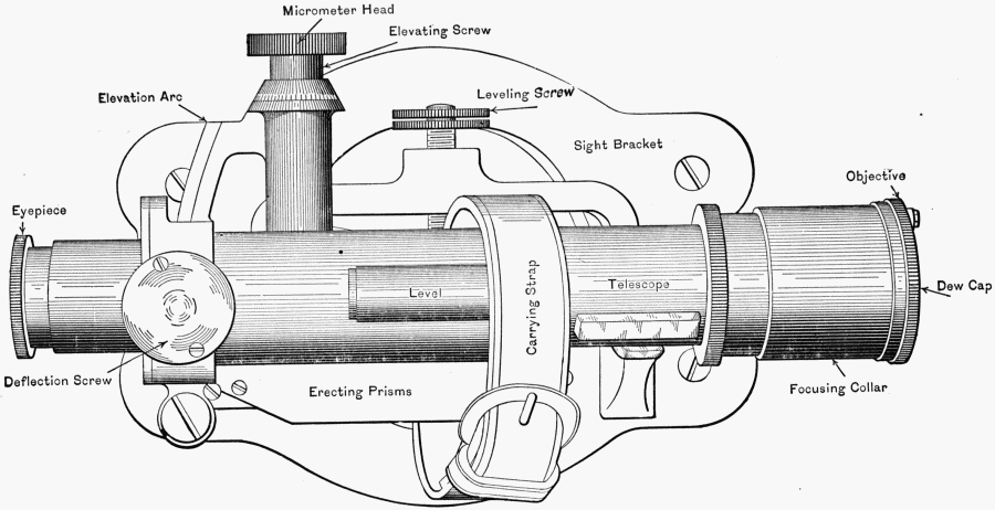
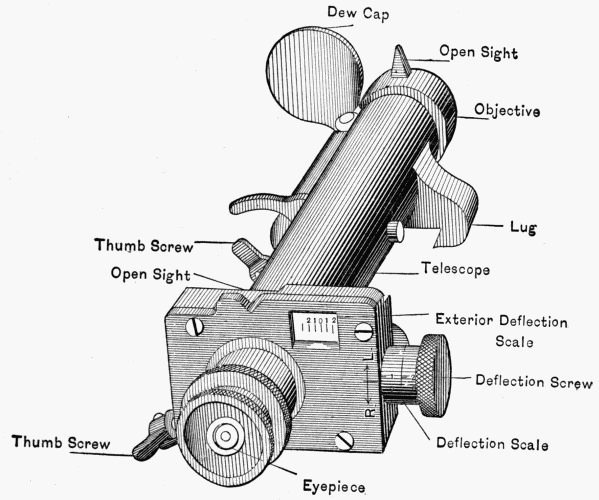
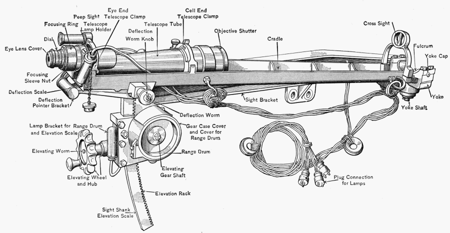
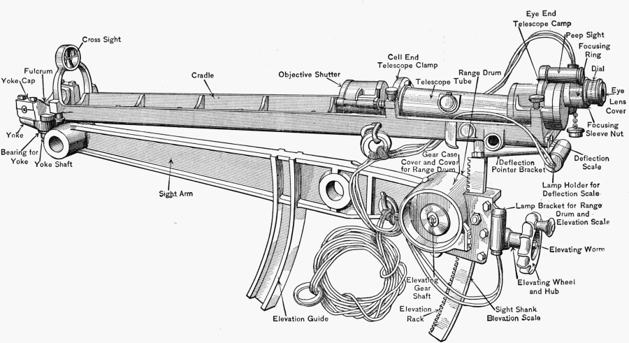
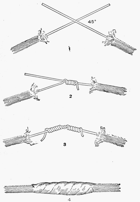
144. A candidate to be eligible for qualification as first-class
gunner must have previously qualified as second-class gunner,
though both qualifications may be made at the same examination.
145. Boards of examination shall be convened annually in
each artillery district by the district commander, to meet within
one month after the expiration of the indoor instruction period.
Separate boards may be convened for the examination of candidates
for first and second-class gunners and also for the posts
attached to the artillery district. All boards shall consist of three
artillery officers, selected with reference to their special qualifications
for this duty; provided, that when a member of the
board is a company commander he will, during the examination
of candidates from his company, be replaced by an officer of
another company. Where travel is necessary the selection of
an officer for this duty will be made subject to the approval of
the authority competent to order the necessary journeys.
146. Each company commander will, previous to the commencement
of the examination, submit to the adjutant a duly
signed list, in the triplicate, giving the full names, arranged in
muster-roll order, of all the men in his company who are to be
examined for first or second-class gunners, with the statement
that he believes that each man so presented is capable of qualifying
in the class designated. These lists will be transmitted to
the senior member of the board by the post commander.
147. In determining the qualifications of candidates credit
shall be given for practical knowledge of subjects rather than for
text-book answers to questions.
148. For candidates in companies assigned to gun defence:
| For second-class gunners— |
| (a) Service of the piece | 25 |
| (b) Guns and carriages | 25 |
| (c) Powders, projectiles, primers, and fuses | 25 |
| (d) Cordage, gins, shears, jacks | 15 |
| (e) U. S. magazine rifle | 10 |
| | —— |
| | 100 |
| |
| For first-class gunners— |
| (a) The azimuth instrument | 20 |
| (b) Duties in the plotting-room | 50 |
| (c) Aiming and laying guns and mortars | 15 |
| (d) Elementary gunnery | 5 |
| (e) Warships | 10 |
| | —— |
| | 100 |
149. The examination of candidates for first-class gunners of
organizations assigned exclusively to rapid-fire guns not provided
with separate position-finding system shall include the
following head in lieu of that given above under (b):
(b) Subcaliber firing 50
150. The examination of candidates for first-class gunners
shall be held as far as practicable at such places as the material
or equipment pertaining to the subject in hand is located, i.e.,
at the guns or in the plotting-rooms.
151. The examination in subjects (a), (b), (c) for second-class
gunners and in subjects (a), (b), (c) and (d) for first-class
gunners shall be confined to the material of the battery and its
accessories to which the company is assigned. If no azimuth
instrument is included in the battery equipment, the instrument
used in the company instruction shall be used in the examination.
If for any cause beyond the power of the battery commander any
part of this equipment has been removed from his control and
has not been available for instruction for at least two months
previous to the examination, such material shall form no part of
the examination.
152. For candidates in companies and detachments assigned
to mine defence:
| For second-class gunners— |
| (a) Ammunition, nomenclature, and service of guns assigned |
| to the company of which the candidate is a member | 15 |
| (b) Material of and duties in the loading room (except |
| electrical principles involved) | 35 |
| (c) Material for and duties on water | 30 |
| (d) Cordage | 10 |
| (e) U. S. magazine rifle | 10 |
| | —— |
| | 100 |
| For first-class gunners— |
| (a) Care and preservation of mine material | 20 |
| (b) Handling high explosives | 20 |
| (c) Knowledge and use of the azimuth instrument |
| and plotting-board | 20 |
| (d) Batteries, generators, and searchlights assigned to |
| the company of which candidate is a member | 20 |
| (e) Apparatus and operation of switchboard and care |
| and use of telephone | 20 |
| | —— |
| | 100 |
153. The qualifying mark for classification as first or second-class
gunner shall be in each case not less than an average of
75 per centum. Whenever, during the progress of the examination
of a candidate for either grade, the sum of the marks received
on subjects in which he has already been examined, increased
by the maximum allowed for the remaining subjects, is less than
75, his examination will be discontinued.
154. Instruction in the course for first or second-class gunner
will be given to such men as the company commander may consider
capable of mastering the prescribed schedules.
155. Men not receiving instruction in the gunners' classes
will perform such duties at their batteries or elsewhere during
the hours for instruction as their company commander, with the
approval of the post commander, may direct.
156. The board shall keep a record of its marks during the
examination, but these marks shall not be published in orders.
The record of each company shall be sent to the artillery district
commander as soon as possible after the completion of the examination,
to be published immediately. The report of the
board to be published in orders shall contain the names of those
who have qualified as first and second-class gunners and recite
the date of the report, which will be the date of the completion
of the company examination in each case, the names being arranged
for each organization in each class in muster-roll order.
The following syllabus gives the outline of the scope of the
examination of candidates for gunners in companies assigned
to gun defense. While the indoor instruction in any subject
need not be limited to what is indicated in this syllabus,
the examination of candidates for gunners shall be confined
thereto.
(a) Service of the Piece.
Questions on the service of the piece and nomenclature of
the piece to which organization is assigned. If the company is
assigned to pieces of different calibers, the candidate will be
examined upon the piece of the caliber selected by the company
commander. Examining boards are cautioned not to attach too
much importance to nomenclature, where a candidate shows
a knowledge of the practical use of the part under examination.
(b) Guns and Carriages.
Explain briefly how a breech-block of a heavy gun or mortar
is dismantled; having a breech-block completely dismantled (not
dismounted), how it is assembled and adjusted for firing; how
old packing is removed from recoil-cylinders, and how they are
repacked; how recoil-cylinders are filled. Object, care, and use
of throttling-valve for guns and by-pass valve for mortars. Parts
and surfaces of guns and carriages to be oiled; how much oil to
use, and how it is used. Adjustment of grease-cups. In the
case of rapid-fire guns explain how to adjust firing mechanism,
percussion, and electric (if so equipped).
(c) Powders, Projectiles, Primers, Fuses.
Examination: Name the kind of powder used in the pieces
of battery to which organization is assigned; give the weights of
service charges and corresponding muzzle velocities of these
pieces; also the lowest and highest muzzle velocities of the steel
and cast-iron mortars, if assigned to mortar battery. Name the
projectiles used in the pieces and give their weights. Tell how
to distinguish from the painting of projectiles used, its kind,
armor-piercing quality, and nature of bursting charge. Point
out the cap, the ogive, the bourrelet, the body, the base, the
rotating band, the fuse hole of a projectile.
Name each kind of fuse used in the battery (ring resistance,
centrifugal, combination, detonating, see Ordnance Department
pamphlet No. 1727); tell how it is inserted to make a tight joint.
Name the different kinds of primers used in the battery. Friction,
electric, combination (electric-friction), percussion, igniting.
Reload a drill primer. (Ordnance Department pamphlet No.
1881.)
(d) Cordage.
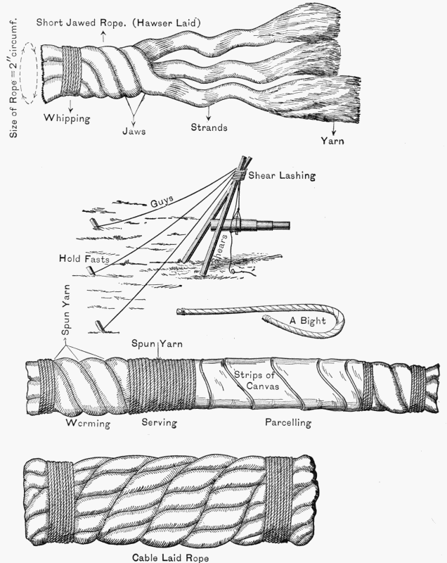
How is the size of a rope denoted? How do you serve a rope?
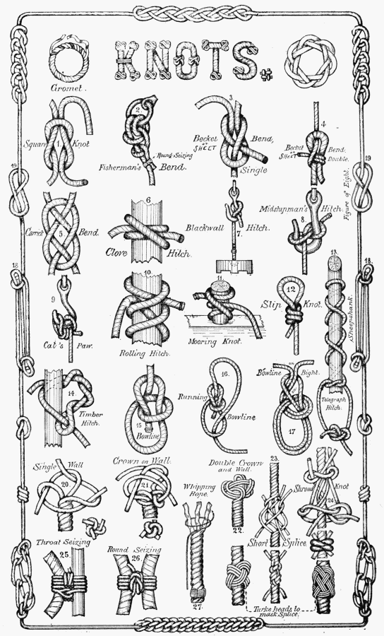
Make a square knot; a bowline; rolling hitch; blackwall hitch;
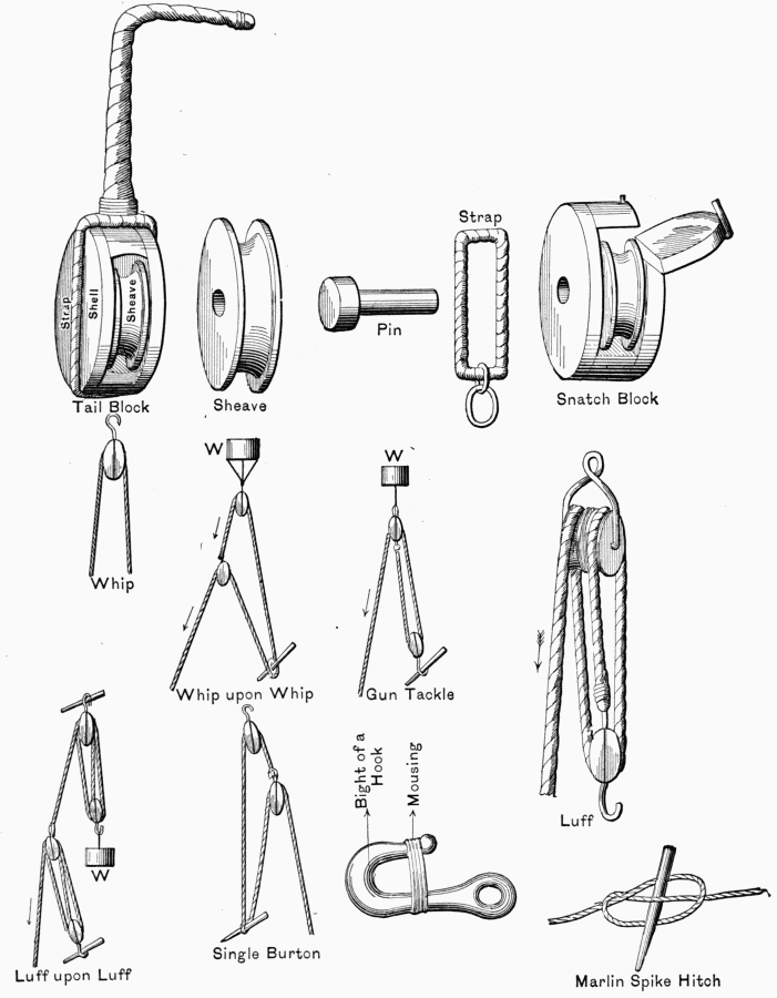
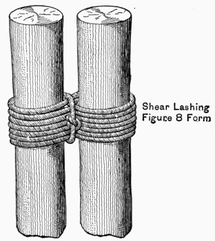
round turn and two half hitches; clove hitch. What is a strap
or sling, and what is its use? Make a shear lashing. Mouse a
hook and explain for what purpose used.
Point out the shell, sheave, pin, strap of a block, and
describe the different kinds (single, double, treble, snatch, and
tail blocks). Point out the running part; the standing part; the
fall of a tackle.
Rig the following: Whip, gun tackle, luff, single burton.
Gins.—Name the different parts of a garrison-gin. Explain
briefly how it is assembled and raised (the drill is not required).
How can the upper block be placed in position after the gin has
been raised?
Sheares.—What do sheares consist of, how are they rigged
and raised, and what are they used for? How and when is the
tackle made fast? How are sheares held in position after being
raised?
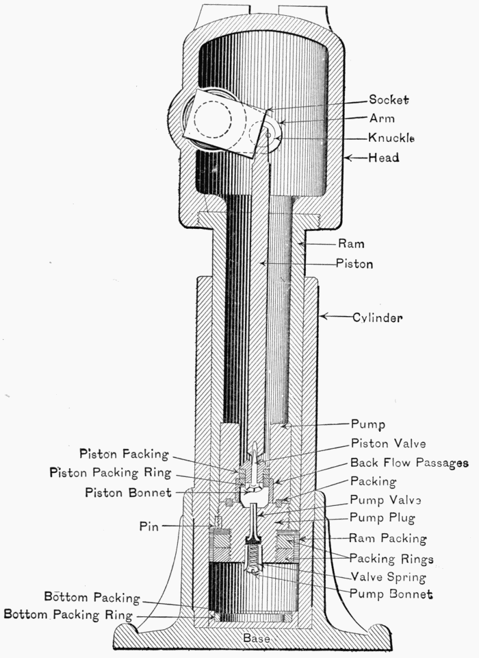
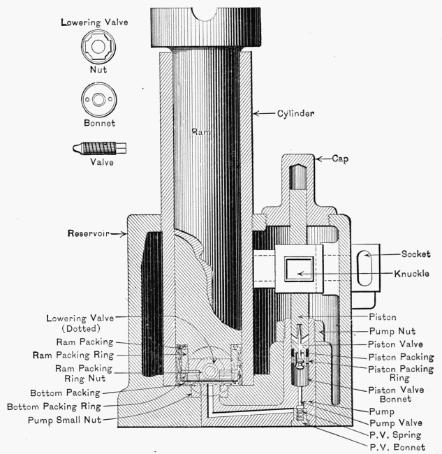
Hydraulic Jacks.—For what is a hydraulic jack used? What
liquids are used in the jack? How is it filled and emptied? How
is the jack cared for when not in use? Show how to use the jack
when lifting a heavy weight; in lowering a heavy weight; use of
the claw in connection with the jack.
(e) U. S. Magazine Rifle.—Nomenclature of the piece, kind
and weight of powder used, description and weight of projectile,
muzzle velocity. Setting of sight for range and deflection.
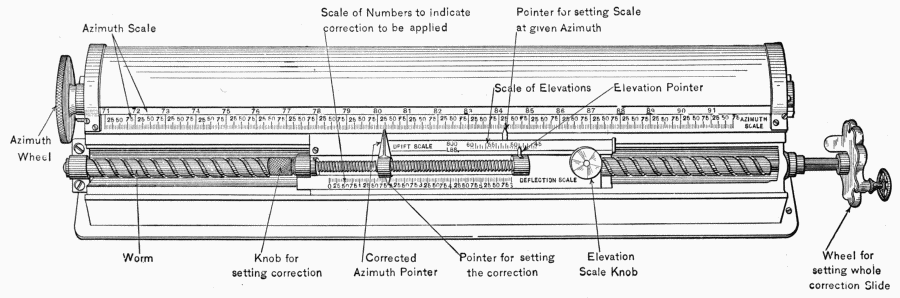
(a) Azimuth Instrument (pattern in use by the company for
instruction), definition of angles, horizontal angles, vertical angle,
angle measured by the instrument, leveling and orientation;
focussing the telescope. Graduation of the instrument: Set up
the instrument over a given point and orient it from sufficient
data; direct the telescope successively on a series of points and
read their azimuths with accuracy.
(b) The Plotting-room (for guns).
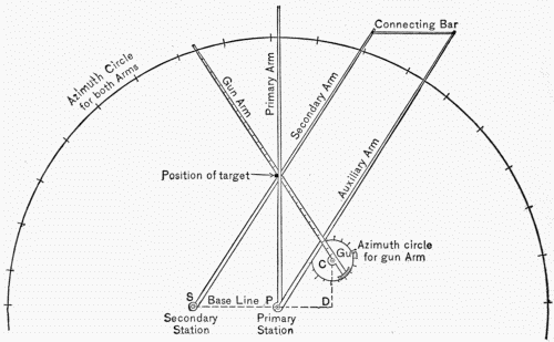
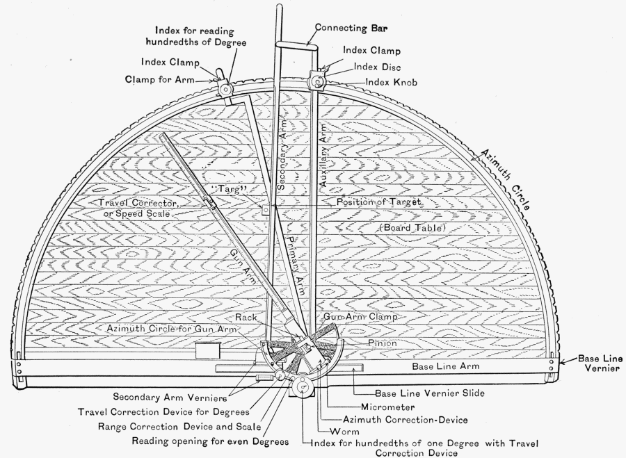
1. Plotting-board.—Point out the following: Primary and
secondary stations, directing gun, displacement, gun-arm, travel-scale,
azimuth-correction scale, tally dials, range-correction
scale.
Lay off a distance of so many yards on the board; conversely,
tell the distance in yards between two given points on the
board.
The azimuths of a fixed target from the primary and secondary
station being given, locate the corresponding point on the board,
and give its azimuths and range, from the directing gun or directing
point.
The azimuths of a fixed target from the primary and secondary
stations being given, locate the corresponding point on the board
and determine its range and azimuth from the directing gun or
point.
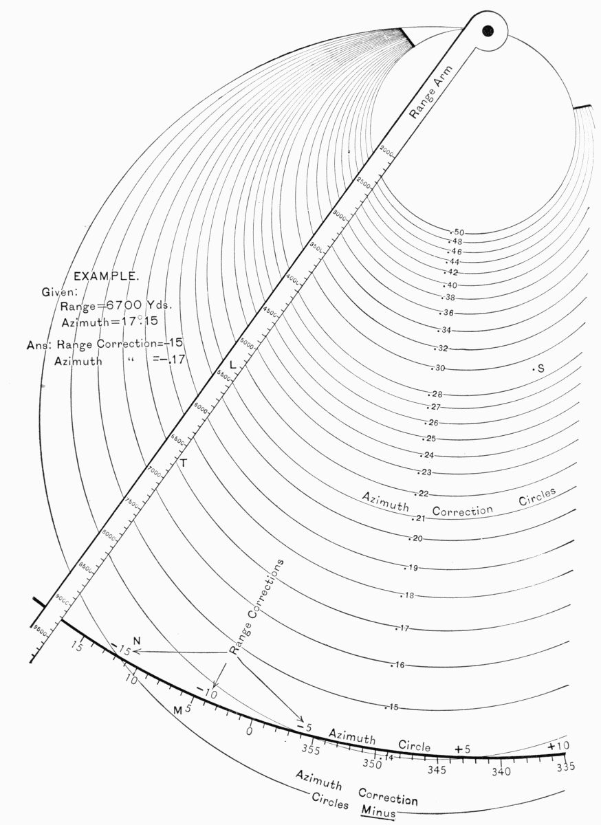
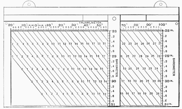
2. Range Board.—Show how to make the range corrections
for atmosphere, wind, tide, muzzle velocity, travel, and how this
range correction is applied to the range-correction scale.
3. Deflection Board.—Show how to make deflection correction
for wind, drift, and travel. Show how to make azimuth correction
in Case 3 for wind, drift, travel, and how this correction is
applied to azimuth correction scale.
What data are sent to the guns in Case 1, Case 2, and
Case 3?
The plotting-room (for mortars).
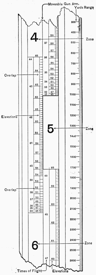
1. Plotting-board.—Point out the following: Primary and
secondary stations, directing point, gun-arm, gun-arm azimuth
circle, displacement, powder zones, elevation, times of flight.
Lay off a distance of so many yards on the board; conversely
tell the distance between two given points on the board.
The range and azimuth of a fixed point (from primary station)
being given, locate the corresponding point on the board. Tell
the zone, elevation for firing at this point, and its azimuth from
the directing point. The azimuth of a fixed target from the
primary and secondary stations being given, locate the corresponding
point on the board and determine its range and azimuth
from the directing point.
2. Show how a target is tracked, how to get travel, how the time
of flight is used, how to get predicted point, how to get set-forward
point. What is the predicted point used for? What is
the set-forward point used for? What data are sent to the pit
and what to the B. C. station? Show how range corrections are
made.
3. Drift Device (for deflection board if issued).—Show how
to make arbitrary and drift corrections.
(c) Aiming and Laying Guns or Mortars.
1. For Rapid-fire Guns.—Set and read the sight for given
elevations and deflections; aim the gun at some object; show
how elevating and traversing hand-wheels are used; explain the
use of the deflection scale for firing right and firing left. What
is Case 1?
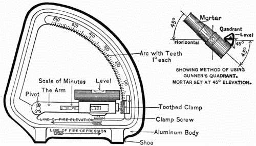
2. For Mortars.—Use of the gunner's quadrant, setting and
reading the instrument, when and how placed when used with
mortars. With the data received from the plotting room lay
the piece. What is Case 3?
3. For Heavy Guns.—(Heavy guns refer to 8-inch, 10-inch,
and 12-inch rifles and other guns which are provided with a
system of vertical and horizontal position finders.) Name the
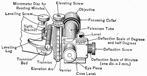
principal parts of the telescopic sight (one used for instruction
purposes); show how it is used. Its readings for elevation and
deflection, east count of its scales. Place it on the Hagood
tripod mount, level it; set it for given elevation and deflection.
4. Use of Difference Chart.—An example like the following
will be given: Range 4500 yards, azimuth 210. Put down the
corrected range and azimuth.
Examination in the foregoing subject (c) to be confined to
the authorized systems in use by the company during the year
and to the complete equipment of the battery to which the company
is assigned.
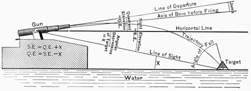
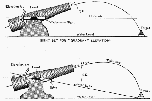
(d) Elementary Gunnery.—Axis of the bore; line of departure;
line of sight; drift; muzzle velocity; quadrant elevation; sight
elevation; angle of fall; jump; trajectory; time of flight.
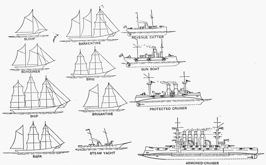
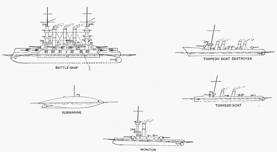
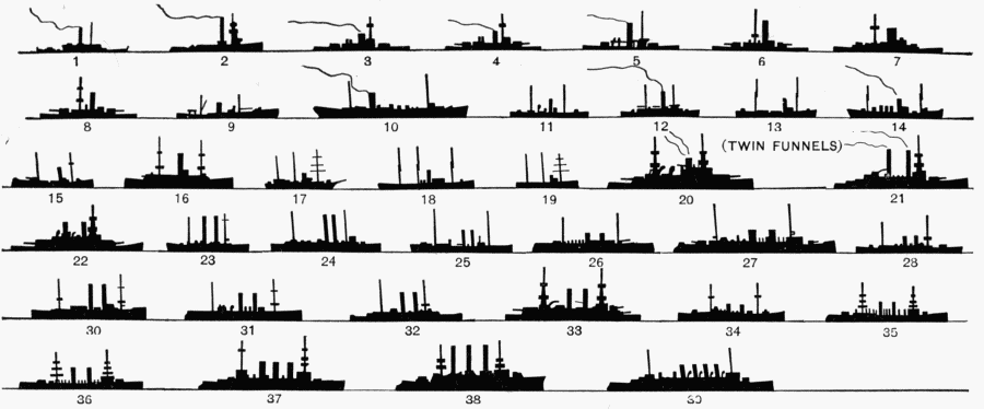
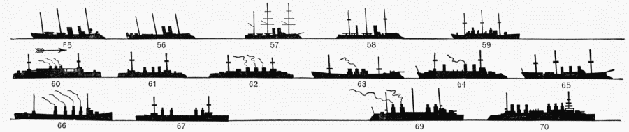
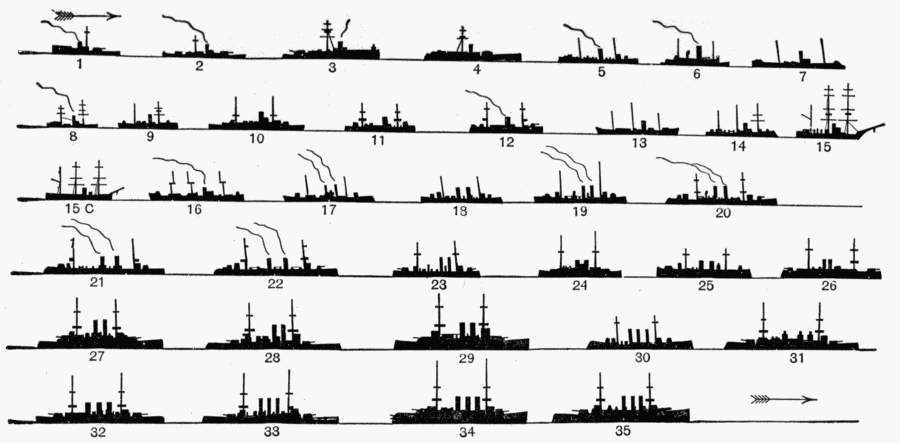
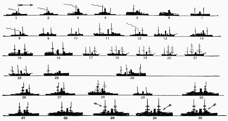
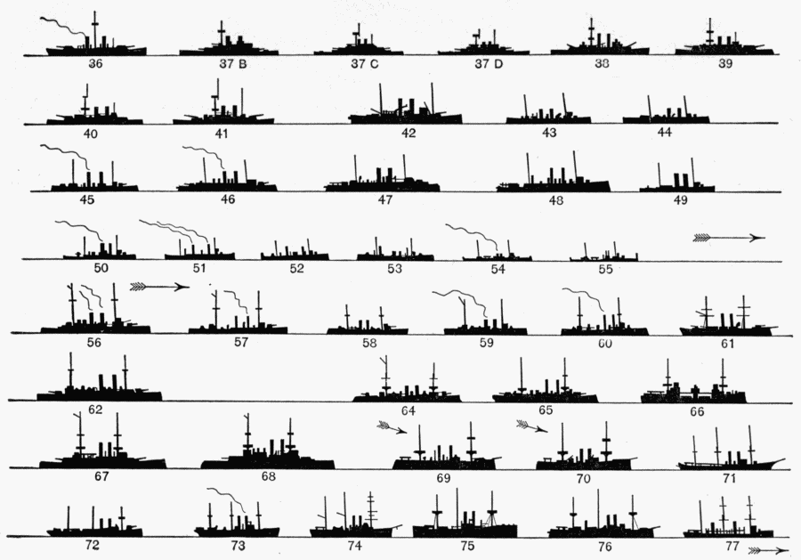
(e) General Features of Warships.—General features of battleships
(broad beam compared to length, low freeboard, general
massive appearance, large turrets fore and aft, heavy guns, heavy
armor, generally moderate speed).
Armored cruisers: (High freeboard, narrow beam compared
to length, medium armor, medium turrets, medium guns, high
speed).
Protected cruisers: (Fine lines, moderate size, no armor,
medium guns usually with shields, protective deck).
Torpedo-boat destroyers: (High bow, generally great speed,
light guns, no armor).
Torpedo boats: (Small size, high speed, no armor).
The following head will take the place of subject (b) in the
examination of candidates for first-class gunners of organizations
assigned exclusively to rapid-fire guns:
(b) Subcaliber Firing.—The 15-pounder gun and subcaliber
attachment will be used. The target will be Target X, miniature
target, page 25, Small-arms Firing Regulations, 1906, pasted
on a screen of sufficient size to catch all the shots, preferably
the screen used for small-arms Target A; range about 95 feet,
where six minutes on the scale is equal to 2 inches at the target;
method of scoring as prescribed for small-arms practice.
During the test one member of the board will be at the target
and will personally superintend the marking.
The preliminary shots will be fired under direction of the examining
board until three hits have been obtained with the same
elevation and deflection. The center of impact of these three
shots will be referred to the horizontal and vertical axes through
the bulls'-eye of the target and its coordinates carefully measured.
This center of impact will not be on the miniature target and
may be changed by the board as often as they deem necessary
during the examination. These measurements, with the elevation
and deflection used, will be given to the candidate, who
will be required to make corrections corresponding to the distance
of the center of impact from the bull's-eye. Each candidate
will fire five shots, the piece being thrown off the target
between shots. Each shot will be marked as fired, the candidate
making such changes in elevation and deflection as he may deem
necessary before firing the next shot. The ratio of the candidates'
score to the maximum score possible will determine the credit,
the maximum credit being 20.
After this test the candidate will fire at the fixed subcaliber
target anchored at about 500 yards, without knowing the exact
distance, five rounds under service conditions in one minute and
thirty seconds. Three sighting shots will be allowed each candidate
preceding the latter test. Each hit on the material target
counts 6.
The following syllabus gives the outline of the scope of the
examination of candidates for gunner in companies and detachments
assigned to mine defense. It is not intended that the
theoretical instruction in any subject shall be limited to what is
indicated in this syllabus, but the examination for candidates for
gunners will be closely confined thereto.
(a) Ammunition, Nomenclature, and Service of Guns assigned
to the Company of which the Candidate is a Member.
Duties of the cannoneer and nomenclature of the piece to
which assigned. (Note: If not assigned to a piece, or if the
company is assigned to different pieces of different calibers, the
candidate will be examined upon the piece of the caliber selected
by the company commander.)
Describe the ammunition and name all the projectiles used
for the piece upon which examined.
(b) Material of and Duties in the Loading Room (except electrical
principles involved).
What apparatus is used in making a Turk's head? A telegraph
joint? A joint to be used under water? Name all the
parts of an assembled mine. Name all the parts of a compound
plug and explain how to load one. What is a cut-out plug?
Explain how to prepare a cut-out plug and box. What apparatus
is used in preparing a compound plug? How are mines numbered?
How are mooring pipes prepared, and what are the
rules for lengths of mine cables and of mooring ropes?
(c) Material for and Duties on the Water.
What apparatus is taken out in the grand-junction box-boat?
How and in what way are the cores of cable numbered? How
is a mine, together with its attachments, arranged on a boat for
planting? Name the apparatus on the boat used in planting
and raising mines. What are the duties in the triple-junction
box-boat in planting and in raising mines, and what precaution
is taken so that cables may be distinguished when box is raised?
Explain how soundings for a triple group are made.
(d) Cordage.
Name the important knots used in mine work and explain
how to make four of them. The mooring rope of a heavy weight
cannot pass over the winch, but lifting must be done with the
fall; explain the method of proceeding.
(e) U. S. Magazine Rifle.—Nomenclature of the piece, kind
and weight of powder used, description and weight of projectile,
muzzle velocity. Setting of sight for range and deflection.
(a) Care and Preservation of Mine Material.
Name the supplies necessary for cleaning mine material.
Name those used in preserving it, stating for what each is used,
and how certain ones (to be selected by the examiner) are applied.
(b) Handling High Explosives.
What high explosives are used in mines? What are the
important precautions to be taken in loading mines? How is
frozen dynamite thawed? Where is the main supply of explosive
kept, and how much is taken out at one time to the explosive
house near the loading-room?
(c) Knowledge and Use of Azimuth Instrument and Plotting
Board.
Names of important parts. Set up the instrument with given
data. Read angles from instrument. Act as observer. Act as
reader.
Describe a plotting board. Explain the method of computing
the time from any plotted point to a mine. Act as plotter.
(d) Batteries, Generators, and Searchlights assigned to the
Company of which the Candidate is a Member.
Name the batteries used in mine work. Describe the casemate
battery. What precautions are necessary in keeping it in
order? What is used as the signal battery in mine work? Describe
a searchlight. Describe parts of generators and important
points to be observed in caring for them.
(e) Apparatus and Operation of Casemate Switchboard and
Care and Use of Telephone.
Name the apparatus of the switchboard. Explain how to
fire a mine by judgment, and how to start the motor generator.
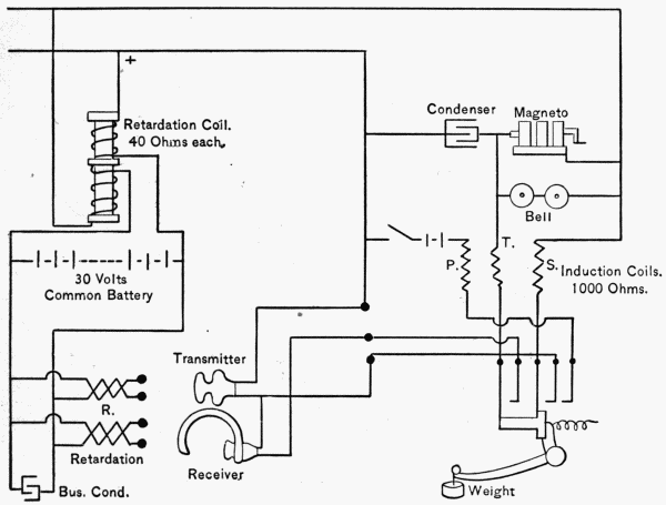
Explain how to test mine and cable ends. How are boat telephones
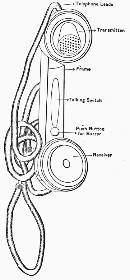
operated? Name the parts of fire-control telephones
used in mine-commander stations, and give the principal points
to be observed in operating them.
General Information.
1. Gunnery is the science and art of operating and firing guns.
2. A gun is a machine which throws projectiles with great
force in a certain direction under the expanding force of powder
gas.
3. The army is composed of the following divisions: The line
and the staff. The line is composed of Infantry, Cavalry,
Artillery, Engineers, etc. The staff of Quartermaster Dept., Commissary
Dept., Ordnance Dept., Signal Corps, Pay Dept., etc.
4. The artillery in our army is organized as a corps of Coast
Artillery composed of 169 companies and 6 regiments in the
Field Artillery.
5. A battery of coast artillery consists of two or more guns
or two or more pits of mortars.
6. A fire command is composed of two batteries or more whose
fire sweeps the same area or adjoining areas; this fire is controlled
by one man, called the fire commander.
7. A battle command is two or more fire or mine commands
sweeping the same or adjacent areas; this commanded by one
man—the battle commander.
8. A mine command is a portion of submarine defenses and
rapid-fire guns, all commanded by one man—the mine commander.
9. The number of men required for a fire, battle, or mine
command depends on the number and caliber of the guns or
mortars or the size of the mine command.
10. The number of men in a coast artillery company is 109;
in a troop of cavalry 65, in a company of infantry 60.
EXTRACTS FROM G. O., 9, W. D. 1908.
IV. Seacoast Artillery Table of Annual Allowances of Ammunition for Target Practice and Instruction per
Battery in Commission.
| |
| Entries of the first column: |
| A = 15 pdr. R. F. (all models) |
| B = 4-inch and 4·72-inch R. F. |
| C = 5-inch R. F., models of 1897 and 1900 |
| D = 6-inch Ordnance Department R. F., models of 1897, 1900, 1903, and 1905 |
| E = 8-inch rifle |
| F = 10-inch rifle, models of 1888, 1895, and 1900 |
| G = 12-inch rifle, models of 1888, 1895, and 1900 |
| H = 12-inch mortar, models of 1886 and 1890: |
| H1 = At batteries to which only one company is assigned |
| H2 = At batteries to which two companies are assigned |
| |
| | Full Service Charges. | | Additional |
| | | | | | | Primers for Drill. |
| Guns, Caliber | Trial Shots. | Record Shots. | Sub- | Service | Drill |
| and Model. | | caliber. | Primers. | Primers. |
| | 1st | 2d | 1st | 2d |
| | Pract. | Pract. | Pract. | Pract. |
| A | 3 | 3 | 10 | 10 | 3000 | 160 | 800 |
| B | 3 | — | 10 | — | 900 | 225 | 225 |
| C | 3 | — | 10 | — | 900 | 60 | 400 |
| D | 3 | 3 | 10 | 10 | 900 | 60 | 400 |
| E | 3 | 3 | 6 | 4 | 600 | 60 | 400 |
| F | 3 | 3 | 6 | 4 | 600 | 60 | 400 |
| G | 3 | 3 | 6 | 4 | 600 | 60 | 400 |
| H |
| H1 | 3 | 3 | 16 | 16 | 150 | 100 | 400 |
| H2 | 3 | 3 | 16 | 16 | 300 | 200 | 800 |
Note.—All projectiles will be service weight and form, cast iron only, or such projectiles as are specially designated for target practice.
Companies which cannot have subcaliber practice at home station have only one-half the annual subcaliber allowance.
12-inch Mortars.—The number of zones, muzzle velocities
corresponding thereto, zone limits, width of zones and overlaps
for the 12-inch mortar, cast-iron, steel-hooped, and the 12-inch
mortar, steel, have been rearranged and are now as shown by the
following table:
| Column headings: |
| A = Number of Zone. |
| B = Muzzle Velocity. |
| C = Weight of Projectile. |
| D = Zone Limits. |
| E = Width of Zone. |
| F = Overlaps. |
| |
| | 12-inch Mortar, Cast-iron, Steel-hooped. | 12-inch Mortar, Steel. |
| |
| A | B | C | D | E | F | B | C | D | E | F |
| | F. S. | Lbs. | Yds. | Yds. | Yds. | F. S. | Lbs. | Yds. | Yds. | Yds. |
| 1 | 560 | 1046 | 2225-3000 | 775 | 400 | 550 | 1046 | 2210-2970 | 760 | 370 |
| 2 | 610 | 1046 | 2600-3480 | 880 | 480 | 600 | 1046 | 2600-3431 | 831 | 361 |
| 3 | 670 | 1046 | 3080-4110 | 1030 | 400 | 660 | 1046 | 3070-4030 | 960 | 399 |
| 4 | 743 | 1046 | 3710-5000 | 1290 | 400 | 725 | 1046 | 3631-4800 | 1169 | 371 |
| 5 | 837 | 1046 | 4600-6240 | 1640 | 400 | 810 | 1046 | 4429-5940 | 1511 | 420 |
| 6 | 910 | 1046 | 5840-7319 | 1479 | 594 | 915 | 1046 | 5520-7476 | 1956 | 449 |
| 7 | 1050 | 824 | —— | —— | —— | 1050 | 1046 | 7027-9250 | 2223 | 492 |
| 8 | —— | —— | —— | —— | —— | 1300 | 824 |
Note.—Each smokeless powder cartridge to have 10-ounce igniter (black rifle powder)
at each end in addition to above charges.
All smokeless-powder charges for mortars will be issued made up, ready for use, as
the charges vary with each lot of powder. They will be distinctly marked to indicate
the zone number.
Q. Give the general duties of a gun commander.
A. The gun commander repeats the commands "Commence
firing" and "Cease firing," announces the kind of projectile
to be used, the order to fire, the method of pointing, and in restricted
fire the number of shots and the firing interval, all in
accordance with the orders of a battery commander. The gun
commander is responsible to the battery commander for the
condition of the material and the efficiency of the personnel of
his command.
Q. Give the general duties of a chief of detachment.
A. Each chief commands his own subdivision whenever it
acts separately; is responsible for its drill efficiency and for the
condition of the material to which it is assigned. He will especially
see that the gas-check seat is clean and kept free from
injury; that the projectile is rammed fully home; that the chamber
is sponged properly after each firing; that the vent is properly
served; that the cylinders are properly filled and the throttling-valve
properly set before firing; that the mushroom head
and gas-check are properly adjusted; that the kind of projectile
designated by the battery commander is used, and that the breech
detail observe great care and caution in sponging out and wiping
breech mechanism and recess free from powder residue, dirt,
etc., after each round fired.
Q. Describe how to signal elevate or depress.
A. Elevate: Raise either hand to the height of the head,
fingers pointing upward. Depress: Raise either hand to the
height of the head, fingers pointing downward.
Q. Describe how you would signal traverse right or traverse left.
A. Motion with either hand, fingers pointing in the required
direction.
Q. Give the signals for the following: Clamp or Halt; Ready.
A. Clamp or Halt: Raise either arm to a horizontal position,
fingers closed. Ready: Raise either arm vertically to its
full extent, fingers extended.
Q. How would you signal stand fast with the whistle at a
rapid-fire gun?
A. One blast signifies stand fast, the pause being of sufficient
duration to enable orders to be correctly given and received;
to resume operations the command "Go on!" will be given.
Other signals may also be used.
Q. What composes a gun section?
A. A gun commander, a gun detachment, an ammunition
detachment, and a reserve.
Q. How many men in a gun detachment?
A. One chief, one gunner, one range-keeper, and eighteen
privates.
Q. Name the details into which a detachment is divided, and
give posts of each.
A.
| Details. | Posts. |
| Chief of detachment | Two yards in rear of the breech, facing it |
| (sergeant). | or wherever presence is necessary. |
| Gunner (duly qualified | Sighting-platform or wherever presence is |
| non-commissioned | necessary. |
| officer or private). |
| Range-keeper (non- | Near the elevation-scale, on the right or |
| commissioned officer | left of the carriage. |
| or private). |
| Breech detail (Nos. | Nos. 1 and 2 in line immediately in rear of |
| 1, 2, and 3). | the breech, facing it, No. 1 on the right; |
| | No. 3 on the right of the piece, two feet |
| | from and facing it, opposite the elevating-band. |
| Rammer detail | At the platform rail facing the carriage, No. |
| (Nos. 4, 13, and 14). | 4 opposite the rammer, four feet from its |
| head, Nos. 13 and 14 four paces to his |
| | right and left respectively. |
| Elevating detail | At the elevating hand-wheels, facing them, |
| (Nos. 5 and 6). | No. 5 on the right of the carriage, No. 6 |
| | on the left. |
| Traversing detail | In front of the traversing-cranks, facing |
| (Nos. 7 and 8). | from the parapet, No. 7 on the right of |
| | the carriage, No. 8 on the left. |
| Tripping detail | At the tripping-levers, facing the carriage, |
| (Nos. 9 and 10). | No. 9 on the right of the carriage, No. 10 |
| | on the left. |
| Truck detail | Near the hoist, in rear of a loaded truck, |
| (Nos. 11 and 12). | No. 11 on the right, No. 12 on the left, |
| | both facing the truck. |
| Telautograph detail | At the telautograph. |
| (No. 15). |
| Hoist detail (Nos. | At the delivery-table and facing it. |
| 16, 17, and 18). |
Q. Name the equipments or implements which each member
procures and places in proper position at the command "Posts!"
on first arriving at the gun.
A. Gunner: Sight and difference-chart.
Range-keeper: Stop-watch and prediction-scale.
No. 1: Translating roller or crank, can with sponge and oil,
and a silk wiper.
No. 2: Loading-tray and a silk wiper.
No. 3: Primer-pouch, bag for empty primers, scabbard containing
punch, gimlet, and reamer, and a lanyard.
No. 4, assisted by No. 13: Rammer.
No. 9: Wrench, funnel, and measure with oil.
No. 10: Chamber-sponge and wrench.
No. 11: Dummy-cartridge extractor.
No. 12: Shot-trucks.
No. 13: Same as No. 4 (Rammer). No. 13 assists No. 4.
Q. State in brief what each member of the gun detachment
inspects and tests at the command "Examine gun!"
A. Chief inspects gun and carriage throughout.
Gunner inspects and tests sight, sight-standard, azimuth
subscale, traversing-gear, and firing-key.
Range-keeper inspects elevating gear.
No. 1 removes breech-cover and inspects breech mechanism,
and assists in sponging bore when necessary.
No. 2 examines bore, chamber, gas-check seat, and breech-recess,
cleans them when necessary, and oils breech-recess.
No. 3 cleans vent and primer-seat, hangs lanyard on elevating-arm.
No. 4 brings sponges and assists Nos. 1 and 2 when necessary
and replaces sponges.
Nos. 5 and 6 test elevating-gear with range-keeper.
Nos. 7 and 8 test traversing-gear with gunner.
Nos. 9 and 10 examine recoil-cylinders to see that they are
properly filled. No. 9 does the filling with oil when necessary.
Wrenches, funnel, and measure are passed back and replaced,
filling-plugs replaced, and Nos. 9 and 10 take posts two paces
on right and left, respectively, of No. 4.
No. 11 receives and disposes of muzzle-cover, passes up and
replaces funnel and oil-measure when necessary, then takes post
near No. 12 at the trucks.
No. 12 removes muzzle-cover, examines trucks.
No. 13 inspects and tests telautograph. If a telephone is
used, he puts on head receiver and wears it until dismissed.
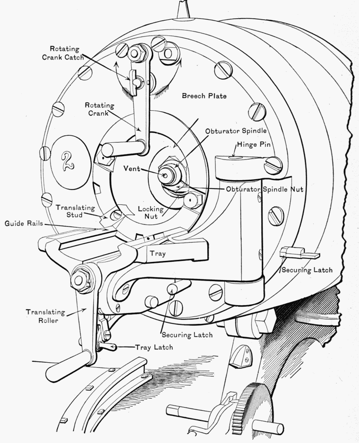
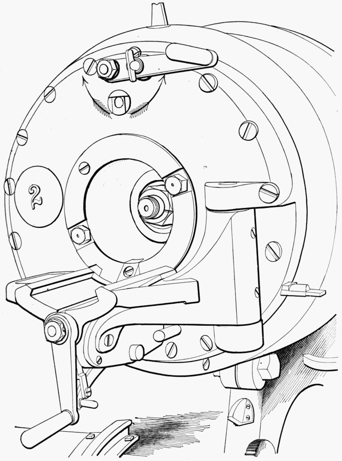
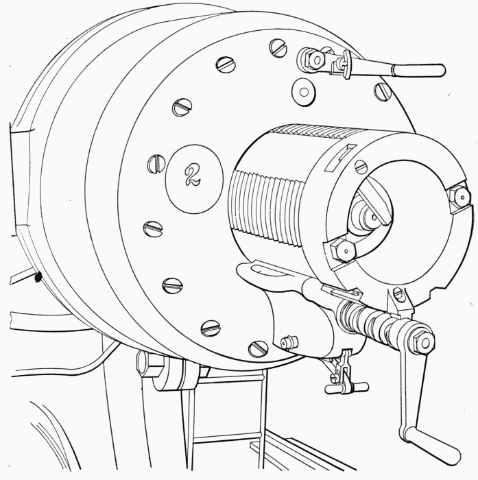
Q. Explain briefly how to open a breech mechanism, Model
1888.
A. Figure 1 shows breech in normal position—closed. No. 2
turns rotating crank-catch 90° to left and turns rotating-crank
in the direction of the arrow till it stops (Fig. 2).
No. 1 turns translating-roller to left till, at the end, the
shock releases the block (Fig. 3), then swings block free to right
of gun till it engages securing-latch (Fig. 4). Mechanism 1895
is opened by No. 3 turning crank continuously till motion stops,
being careful that crank does not catch safety-lanyard.
Q. Give duties of each member of the detachment at the
command "Load!"
A. Chief commands: (1) "With shot!" (shell or dummy projectile);
(2) "Load!"
Gunner gives direction to piece according to the system
used, and either fires electrically or signals to No. 3 to fire.
(Except in Case 3.)
Range-keeper calls off range, using predicting-scale, and corrects
same for gun difference; signals or calls out "Elevation-set!"
No. 1 assists in opening and closing breech. Examines for
dirt, etc., the breech-block and gas-check. Oils same. When
necessary, assists in ramming. Places third section of cartridge
on shot-tray.
No. 2 assists in opening and closing breech, examines for dirt,
etc., and oils gas-check seat and threads of breech-recess. He
commands: (1) "Home!"; (2) "Ram!" Observes scale on
rammer, places second section of cartridge on front part of
shot-tray, pushes fourth section into chamber, such that its base will
almost clear the gas-check seat. If necessary, inserts loading-tray
and sponges, assisted by No. 10.
No. 3 inserts a primer. At command "Trip!" steps to rear
and slightly to right of piece. Fires at gunner's signal. Coils
lanyard. Removes old primer and places it in a bag.
No. 4 brings up rammer and places it against base of projectile,
assisted by Nos. 9 and 13. Assists in ramming projectile
and sections of cartridge. Replaces rammer on its support.
Nos. 5 and 6 set the elevation-scale for given range.
Nos. 7 and 8 traverse, at the command of the gunner.
Nos. 9 and 10 assist in ramming. Trip the piece. After
firing No. 10 brings up chamber-sponge.
Nos. 11 and 12 bring loaded truck and place it in position,
adjusting height of shot-tray to that of the breech. No. 11 steps
to right, and No. 12 to left, of truck. If there be a brake, No. 12
sets it; if not, No. 11 chocks the front wheels. No. 12 places first
section of cartridge on tray, No. 11 the fourth. Both remove
truck to delivery-table and take posts at a loaded truck.
Nos. 13 and 14 assist in ramming projectile and sections of
cartridge. Assist 9 and 10 at pinch-bars when piece will not trip.
No. 13 assists No. 4 in bringing up and replacing rammer.
No. 15 calls out and posts ranges and deflections or azimuths
received.
No. 16 notifies chief of ammunition detachment kind of projectile
required, also when to start and stop the hoist.
Nos. 16, 17, and 18 load the trucks.
Q. Give the positions of the ramming detail.
A. Nos. 1, 4, 9, and 13 on right. Nos. 2, 10, and 14 on left.
All face rammer and grasp it with both hands.
Q. Explain the method of ramming.
A. Nos. 13 and 14 take hold near the end of the rammer,
rammer-head being on base of projectile. At the command
"Ram!", all rush forward, carrying projectile to its seat with force.
Nos. 1 and 2 quit the rammer when near the truck. First three
sections of cartridge are rammed without command.
Q. Explain how to unload a dummy charge.
A. The chief commands "Unload!" Breech is opened and
truck brought up as for loading. No. 4 brings up extractor and
pulls out sections. No. 1 puts two sections on right of truck,
No. 2 puts others on left.
Nos. 1, 2, 3, and 4 withdraw projectile to truck. Truck is
removed and extractor replaced.
Q. Explain how to retract a gun.
A. Chief commands (1) "From battery!", (2) "Heave!", (3)
"Halt!"
At the first command Nos. 7 and 8 go to the retraction-cranks.
No. 7 operates the retaining-pawl and speed-crank to permit the
pulling out of the ropes. Nos. 9 and 10 mount on the gun-levers
and place the ends of the ropes on the hooks, receiving them from
Nos. 3 and 4, who mount on the chassis to assist. Nos. 1 and
2 pull out the ropes and pass the ends to Nos. 3 and 4. No. 7
takes in the slack. Nos. 7, 8, 9, and 10 take positions at the
retraction-cranks, and at the second command turn the cranks.
Nos. 3, 4, 5, and 6 relieve Nos. 7, 8, 9, and 10 when directed
by the chief of the detachment. Odd numbers work on the
right side of the carriage, even numbers on the left side. When
the gun has reached the loading position the command "Halt!"
is given. As the command "Cast off!" is given No. 7 lets out
enough slack to enable Nos. 1 and 2 to take the rope-ends off the
hooks.
Q. Where electric motors are provided, who operates them?
A. The gunner the traversing-controllers, No. 5 the elevating
and retracting controllers; No. 6 watches the circuit-breakers,
and when broken by an overload he closes the breaker.
Q. When the shot-hoist is on the right, what changes in the
service of the piece are made?
A. No. 4 in ramming takes position between Nos. 2 and 10
on the left side. Nos. 10 and 14 assist No. 4 in bringing up and
replacing the rammer, instead of Nos. 9 and 13. No. 9 brings
up and replaces sponge and assists in sponging, instead of No. 10.
Q. How many men in the ammunition detail?
A. One chief and twelve privates.
Q. Name the details into which it is divided, and the numbers
composing each.
A. Hoist detail, Nos. 1 and 2.
Projectile detail, Nos. 3, 4, 5, and 6.
Cartridge detail, Nos. 7, 8, 9, 10, 11, and 12.
Q. Give the duties of each in brief.
A. No. 1 operates the controller and starts the hoist supplying
the delivery-table with ammunition.
No. 2 repeats name of projectile announced, rolls same with
cartridge to hoist-carrier.
Nos. 3 and 4 operate a trolley and differential pulley.
Nos. 5 and 6 operate another trolley and pulley.
Nos. 7 and 8 uncase cartridges.
Nos. 9, 10, 11, and 12 place sections on receiving-table in
proper order. If electrical power fails, Nos. 1 and 2 operate
hoist by hand-cranks.
Note.—Since the drills for the 10-inch and 8-inch disappearing
guns differ from the drill for the 12-inch in so few minor details,
no separate questions and answers in these cases are given. In
the 10-inch piece the following differences were noted: Nos. 13 and
14 are omitted in the rammer detail; No. 4 in procuring implements
attends to the rammer alone; in loading, No. 2 pushes the
second section of cartridge into the chamber instead of the fourth;
in ramming, the positions from front to rear are Nos. 1 and 9
on right, Nos. 2, 4, and 10 on left, facing rammer, etc. When
hoist is on right side No. 10 assists No. 4 (No. 13 being left out).
In the 8-inch piece the rammer detail consists of No. 4 (13 and
14 omitted), the truck detail of No. 11 (12 omitted), and the
hoist detail of Nos. 16 and 17 (No. 18 omitted). The duties of
the numbers omitted in these details are performed by the remaining
numbers in that detail, otherwise the drill is precisely
the same as for the 12-inch piece. In extracting a dummy Nos.
2 and 3 do not assist in withdrawing; Nos. 1 and 4 do this.
Q. How many men in a detachment?
A. One chief, one gunner, one range-keeper, and nineteen
privates.
Q. Name the details into which a gun detachment is divided,
and give posts of each.
A.
| Name of Detail. | Posts. |
| Chief of detachment (sergeant). | Two yards in rear of the |
| | carriage-platform, facing it. |
| Gunner (duly qualified | Sighting-platform. |
| non-commissioned officer |
| or private). |
| Range-keeper (non-commissioned | On the left of the carriage, opposite |
| officer or private). | the elevation-scale. |
| Breech detail (four privates, | Nos. 1 and 2 immediately in |
| Nos. 1, 2, 3, and 4). | rear of the breech, Nos. 3 |
| | and 4 one yard in rear of |
| | Nos. 1 and 2, all facing the |
| | breech, odd numbers on the right. |
| Elevating detail (two privates, | At the elevating hand-wheels, |
| Nos. 5 and 6). | facing them, No. 5 on the |
| | right of the carriage, No. 6 |
| | on the left. |
| Traversing detail (two privates, | At the traversing-cranks, facing |
| Nos. 7 and 8). | the carriage, No. 7 on the |
| | right of the carriage, No. 8 |
| | on the left. |
| Sponge and rammer detail (two | One yard in rear of the carriage |
| privates, Nos. 9 and 10). | platform, facing it, No. |
| | 9 on the right. |
| Shot-hoist detail (four privates, | No. 11 opposite the shot-hoist |
| Nos. 11, 12, 13, and 14). | tackle, facing the carriage, |
| | Nos. 12 and 13 in rear of the |
| | windlass crank-handle, facing |
| | it, No. 13 on the right, No. 14 |
| | in front of the windlass |
| | crank-handle, facing it. |
| Truck detail (two privates, | Near the hoist, in rear of a |
| Nos. 15 and 16). | loaded truck, No. 15 on the right. |
| Telautograph detail (one private, | At the telautograph. |
| No. 17). |
| Telautograph detail (two privates, | At the delivery-table and facing it. |
| Nos. 18 and 19). |
The posts of the gun detachment as given above are for inspection,
and preparatory to the service of the gun.
The chief of detachment and gunner go wherever their presence
is necessary.
Q. Name the equipments or implements which each member
procures and places in proper position at the command "Posts!"
A. Gunner: Sight and difference-chart.
Range-keeper: Stop-watch and prediction-scale.
No. 1: Translating-roller (or crank), can of oil with sponge,
lanyard, and silk wiper.
No. 2: Loading-tray, primer-pouch, etc.
No. 5: Wrench, funnel, and measure of oil.
No. 6: Wrench.
No. 9: Rammer and prop.
No. 10: Chamber-sponge.
No. 11: Dummy-extractor.
Nos. 15 and 16: The trucks.
Q. State in brief what each member inspects and tests at the
command "Examine gun!"
A. Chief: Gun and carriage generally.
Gunner: Sights and sight-standard, azimuth subscale, traversing-gear,
and firing-key.
Range-keeper: Elevating-gear.
No. 1: Removes breech-cover and inspects breech mechanism.
No. 2: Bore, chamber, gas-check seat, breech-recess, vent,
primer-seat.
Nos. 3 and 4 assist in sponging bore if on No. 2's inspection
it is found to need it.
Nos. 5 and 6: Recoil-cylinders.
No. 9 passes up funnel, measure, etc., to No. 5.
Nos. 7 and 8: Traversing-gear with gunner.
No. 10 passes up and replaces sponge when necessary.
Nos. 11 and 12: Shot-hoist tackle; remove muzzle-cover.
Nos. 13 and 14: Shot-hoist gearing.
Nos. 15 and 16: Trucks.
No. 17: Telautograph or telephone.
Q. Give duties of each member of the detachment at the
command "Load!"
A. Chief gives commands for loading.
Gunner and range-keeper same as for 12-inch disappearing.
No. 1 assists in opening and closing breech. Examines for
residue, dirt, etc., the breech-block and gas-check, and oils same
if necessary. Inserts first and third sections of cartridge.
Adjusts lanyard. Fires at command of gunner.
No. 2 assists in opening and closing breech. Examines gas-check
seat and breech-recess; oils and cleans the same if necessary.
Inserts loading-tray. Swings projectile into position and gives
commands for ramming. Observes scale on rammer. Inserts
second and fourth sections of cartridge, seeing that the last
section is properly seated. Removes loading-tray. Breech being
closed, inserts a primer. After firing removes primer and places
it in bag. Assisted by No. 4, sponges chamber.
No. 3 receives rammer and places it on base of projectile.
Assists in ramming projectile and first three sections of cartridge.
Passes rammer back to No. 9.
No. 4 assists in ramming. Receives chamber-sponge and
assists in sponging. Passes sponge back to No. 10.
Nos. 5 and 6 elevate and depress the piece.
Nos. 7 and 8 traverse the piece at the gunner's command,
and assist in depressing the piece if necessary.
No. 8 closes safety-switch at command "Ready!"
No. 9 passes up rammer to No. 3, and assists in ramming.
Replaces rammer.
No. 10 passes up and replaces chamber-sponge. Mounts
carriage-platform and assists in ramming.
No. 11 hooks tackle to shot-tray and commands "Hoist!",
mounting the steps and steadying the projectile in time to command
"Halt!" When the projectile is at height of breech commands
"Lower!", and guides tray to truck-platform and unhooks
it.
Nos. 12 and 13 hoist the projectile. Pass sections of cartridge
to Nos. 1 and 2.
No. 14 assists in hoisting, and, while Nos. 12 and 13 pass up
sections, lowers shot-tray.
Nos. 15 and 16 bring up and return trucks.
No. 17 calls out data received and posts it.
No. 18 notifies chief of ammunition detachment when to
start and stop hoist. Repeats to him kind of projectile designated.
Nos. 18 and 19 load the trucks.
Q. Give positions of rammer detail.
A. Nos. 1, 3, and 9 on right; Nos. 2, 4, and 10 on left,
facing rammer.
Note.—No. 2 commands "Ram!", and by about three
separate rushes the projectile is rammed home; No. 2 giving
"Home!", "Ram!", when the brass scale on rammer is about two
feet from face of breech. Nos. 3 and 4 withdraw rammer.
Q. Explain how to unload a dummy.
A. Chief commands "Unload!" (gun being depressed to 0°
elevation).
No. 10 passes extractor to No. 4, who withdraws cartridge.
Shot-tray being in position at the breech as in loading, Nos. 1,
2, 3, and 4 withdraw projectile to shot-tray. It is lowered and
replaced by the shot-hoist detail. Where no chain ammunition-hoist
is provided the drill will be modified to meet the conditions
by the battery commander.
The ammunition detachment and duties of members operating
electric motors are the same as in the 12-inch disappearing-gun
drill.
Q. In what particulars does the drill for the 10-inch non-disappearing
gun differ from the 12-inch non-disappearing?
A. First. Nos. 1, 2, 3, and 4 man the rammer.
Second. Sponge and rammer detail is composed of No. 9 only.
Third. Truck detail consists of No. 10 only.
Fourth. The cartridge detail consists of four men only.
Q. How many privates in a detachment?
A. Fifteen.
Q. Name the details into which a detachment is divided, and
give posts of each.
A.
| Name of Detail. | Posts. |
| Chief of detachment (sergeant). | Two yards in rear of the carriage, |
| | facing it. |
| Gunner (duly qualified | Sighting-platform. |
| non-commissioned officer |
| or private). |
| Range-keeper (non-commissioned | On the left of the carriage, |
| officer or private). | opposite the elevation-scale. |
| Breech detail (two privates, | In line, immediately in rear of |
| Nos. 1 and 2). | the breech, facing it, No. 1 |
| | on the right. |
| Elevating detail (two privates, | At the elevating hand-wheels, |
| Nos. 3 and 4). | facing them, No. 3 on the |
| | right of the carriage, No. 4 |
| | on the left. |
| Traversing detail (two privates, | In front of the traversing cranks, |
| Nos. 5 and 6). | facing from the parapet, No. |
| | 5 on the right of the carriage, |
| | No. 6 on the left. |
| Shot-hoist detail (four privates, | Nos. 7 and 8 at the |
| Nos. 7, 8, 9, and 10). | windlass-cranks, |
| | facing to the rear, No. |
| | 7 on the right of the carriage, |
| | No. 8 on the left, No. 9 |
| | opposite the shot-hoist tackle, |
| | facing the carriage, No. 10 |
| | at the foot of the steps to the |
| | carriage-platform, on the left |
| | of the carriage, facing it. |
| Sponge and rammer detail (one | One yard in rear of the |
| private, No. 11). | carriage-platform, facing it. |
| Truck detail (one private, No. 12). | Near the hoist, in rear of a |
| | loaded truck. |
| Telautograph detail (one private, | At the telautograph. |
| No. 13). |
| Hoist detail (two privates, Nos. | At the delivery-table, facing it. |
| 14 and 15). |
The posts of the gun detachment as given above are for inspection,
and preparatory to the service of the gun.
The chief of detachment and gunner go wherever their presence
is necessary.
Q. Name the equipments or implements which each member
procures and places in proper position at the command "Posts!"
A. Gunner, range-keeper, Nos. 1, 2, 5, and 6 procure the
same as for the 12-inch piece.
No. 9: Chamber-sponge.
No. 10: Extractor for dummy.
No. 11: Rammer and prop.
No. 12: Trucks.
Q. State in brief what each member inspects and tests at the
command "Examine gun!"
A. Chief, gunner, range-keeper, Nos. 1 and 2 the same as
for the 12-inch piece, Nos. 3 and 4 the elevating-gear.
Nos. 5 and 6: Recoil-cylinders, traversing gear.
No. 7 passes up and replaces funnel and measure.
No. 8: Hoisting-gear, and removes muzzle-cover.
No. 9 and 10: Tackle of shot-hoist.
No. 11 passes up and replaces sponges.
No. 12: Trucks.
No. 13: Telautograph or telephone.
Q. Give the duties of each at the command "Load!"
A. Chief, gunner, and range-keeper are the same as for the
12-inch piece.
No. 1 assists in opening and closing breech. Examines gas-check
and breech-block. Assists in launching projectile on the
loading-tray. Assists in ramming projectile. Passes back to
No. 11 the rammer. Hooks lanyard to firing-leaf. Fires at
signal of gunner.
No. 2 assists in opening and closing breech. Examines gas-check
seat and breech-recess. Inserts loading-tray. Commands
"Home!", "Ram!", and assists in ramming. Observes scale on
rammer. Inserts sections of cartridge and pushes them home by
hand. Removes loading-tray. Inserts a primer and lowers slide.
Removes old primer and places it in a bag. Sponges chamber.
Nos. 3 and 4 elevate the piece.
Nos. 5 and 6 traverse the piece.
Nos. 7 and 8 hoist the projectile at the command "Hoist!"
No. 8 lowers the shot-tray.
No. 9 hooks the tackle to the shot-tray and commands "Hoist!"
Steadies the projectile. Places section of cartridge on rear of
carriage-platform.
No. 10 mounts steps and commands "Halt!" when projectile
is level with breech. Launches it on loading-tray, and swings
shot-tray clear of carriage-platform and resumes post.
No. 11 passes rammer to No. 2.
As soon as projectile is rammed passes both sections of cartridge
to No. 2 and returns rammer.
No. 12 brings up and returns trucks.
No. 13 calls out and posts data received.
No. 14 repeats to ammunition-sergeant kind of projectile to be
used; also notifies when to start and stop the hoist.
Nos. 14 and 15 load the trucks.
Q. How is a dummy charge unloaded?
A. The gun is brought to 0° elevation. No. 11 passes up
extractor. No. 2 withdraws sections of cartridge. No. 10 passes
them to No. 11, who places them on truck. The shot-tray is
held in position while No. 2 withdraws the projectile to the
shot-tray, when it is lowered to the truck.
Note.—The ammunition detachment is the same as prescribed
for the 12-inch disappearing gun.
Q. What comprises a gun detachment?
A. Chief of detachment, gunner, and ten privates.
Q. Name the details into which it is divided, and give the
posts of each.
A.
| Name of Detail. | Posts. |
| Chief of detachment (sergeant). | Two yards in rear of the breech, |
| | facing it. |
| Gunner (duly qualified corporal | Near the azimuth subscale |
| or private). | facing the mortar. |
| Breech detail (two privates, | In line immediately in rear of |
| Nos. 1 and 2). | the breech, facing it, No. 1 |
| | on the right. |
| Sponge and rammer detail (two | At the sponge and rammer, |
| privates, Nos. 3 and 4). | facing the mortar. |
| Elevating detail (two privates, | At the elevating hand-wheels, |
| Nos. 5 and 6). | facing them, No. 5 on the |
| | right of the carriage, No. 6 |
| | on the left. |
| Traversing detail (two privates, | At the traversing-cranks, facing |
| Nos. 7 and 8). | the mortar, No. 7 at the right |
| | crank, No. 8 at the left. |
| Truck detail (two privates, | In the gallery, near the entrance, |
| Nos. 9 and 10). | in the rear of and facing a |
| | loaded truck, No. 9 on the |
| | right, No. 10 on the left. |
The posts of the gun detachment as given above are for inspection
and preparatory to the service of the mortar.
Q. State in brief what equipments or implements each procures
and places in proper positions.
A. No. 1: Oil-can, hand-sponge, and silk wiper.
No. 2: Silk wiper.
No. 3: Long lanyard, bore and chamber sponge.
No. 4: Rammer.
No. 5: Wrench for filling plug.
No. 6: Wrench for filling plug, measure and funnel.
No. 8: Primer-pouch, bag, scabbard, etc.
Q. How is a breech-block opened and closed?
A. In the same manner as for the 8-, 10-, and 12-inch guns.
Q. What does each member of the detachment inspect or
test with a view of cleaning or oiling, if necessary, at the command
"Examine gun!"?
A. Chief: Mortar in general.
Gunner: Azimuth subscale and traversing-gear.
No. 1: Breech-block and breech mechanism.
No. 2: Bore, chamber, gas-check seat, and breech-recess.
No. 3: Lanyard. (He coils it properly.)
No. 4: Muzzle-cover. (Removes it and places it aside.)
Nos. 5 and 6: Elevating-gear and recoil-cylinders.
Nos. 7 and 8: Traversing-gear. No. 8 clears vent and wipes
primer-seat.
Nos. 9 and 10: Trucks.
Q. After examining gun, what changes in posts are made?
A. The chief of detachment and gunner go wherever their
presence is necessary. No. 7 takes post at the door of the
cartridge-room.
Q. Give the duties of each member of the detachment at
the command "Load!"
A. Gun commander operates switches and firing-plug. Observes
all detachments.
Chief generally supervises the proper loading of his piece,
signals "Ready" or "Misfire," etc.
Gunner gives the piece the proper azimuth, signals "Azimuth
set" to the chief.
No. 1 assists in opening and closing breech. Examines or
oils, if necessary, the breech-block and gas-check. Assists in
ramming.
No. 2 assists in opening and closing breech. Examines or
oils, if necessary, the gas-check seat and breech-recess. Commands
"Home!", "Ram!" Assists in ramming. Observes the
scale on the rammer. Inserts loading-tray and withdraws same.
Pushes cartridge properly into chamber. After firing, assisted
by No. 5, sponges chamber and bore.
No. 3 assists in ramming. If firing by lanyard be used, he
attaches the long lanyard to the short one and, after the piece is
elevated, hooks the short lanyard to eye of firing-leaf and fires at
the command. After firing, brings bore and chamber-sponge and
assists No. 2 in sponging. Replaces sponge.
No. 4 brings up rammer, and places its head on the base of
the projectile. Assists in ramming. Replaces rammer.
Nos. 5 and 6 give elevation at command of chief. (No. 5
operates the clamp and lock.) Assists in ramming.
After piece is fired, brings piece to 0° elevation.
No. 7 brings up cartridge and takes post at traverse-crank.
On taking cover he returns to cartridge-room.
No. 8 inserts and removes primers.
Nos. 7 and 8 traverse the mortar at the signal of the gunner.
Nos. 9 and 10 bring up loaded trucks.
Q. What are the positions for ramming?
A. Nos. 1, 3, and 5 on right, Nos. 2, 4, and 6 on left, all facing
rammer. The projectile is rammed home in one motion.
Q. In taking cover, what is the order of formation in rear of
pits?
A. They take cover as shown in the following diagram:
| Mortar No. 4 | Mortar No. 2 |
| " " 3 | " " 1 |
| | {8, 6, 5, G.} | | {8, 6, 5, G.} |
| 4th detachment | { } |
2d detachment | { } |
| | {4, 3, 2, 1 } | | {4, 3, 2, 1 } |
| | {8, 6, 5, G.} | | {8, 6, 5, G.} |
| 3d detachment | { } |
1st detachment | { } |
| | {4, 3, 2, 1 } | | {4, 3, 2, 1 } |
Q. What comprises an ammunition detachment?
A. One chief, two corporals, and sixteen privates.
Q. Name the details.
A. Projectile: One corporal and Nos. 1 to 12.
Cartridge: One corporal and Nos. 13 to 16.
Q. Give their duties in brief.
A. The chief has general supervision and is responsible for the
proper supply of ammunition.
Nos. 1 and 2 operate a trolley and pulley, and load trucks
with shell.
Nos. 3 and 4, 5 and 6, 7 and 8 operate other trolleys similarly.
Nos. 9, 10, 11, and 12 run up empty trucks, and when loaded
return them to gallery entrance.
Nos. 13, 14, 15, and 16 pass designated cartridge to No. 7.
Note.—Where there are two magazines to an emplacement
there is a separate detachment for each, composed of three
non-commissioned officers and eight privates each. (Nos. 1 to 6
compose the projectile detail, and Nos. 7 and 8 the cartridge
detail.)
Q. How does the drill for the 12-inch mortar carriage, model
1891, differ from that of model 1896?
A. Nos. 1 and 2 lift shell-tray from hoist-scoop to truck after
ramming.
Nos. 5 and 6 man the shell-hoist and hand-wheel, in addition
to assisting in ramming.
No. 6 returns to hoist hand-wheel after ramming, and lowers
scoop when directed by No. 2.
Nos. 9 and 10 deliver shell on scoop, and return truck.
Q. What composes a gun detachment?
A. One chief, a gunner, and ten privates.
Q. What are their posts preparatory to inspection or service
of the piece?
A. Chief of detachment, two yards in rear of the breech,
facing it.
Gunner, sighting-platform.
No. 1, two feet to the right and rear of the breech, facing it.
No. 2, two feet to the left and rear of the breech, facing it.
No. 3, two yards in rear of the breech, facing it.
No. 4, at the elevating hand-wheel, facing it.
Nos. 5 and 6, at the serving-table at the rear side of the
loading-platform, facing to the front, No. 5 on the right side, No. 6
on the left.
No. 7, on the gun-platform at the head of the steps leading
to the cartridge-room.
No. 8, at the telautograph.
Nos. 9 and 10, on the banquette, facing the gun, No. 9 on
the right.
Q. What implements or equipments do each procure?
A. Gunner: Sight and difference-chart.
No. 1: Silk wiper, lanyard, sponge and oil-can.
No. 2: Loading-tray and silk wiper.
No. 3: Rammer and prop.
No. 5: Plug-wrench, funnel and measure.
No. 6: Plug-wrench.
No. 7: Chamber-sponge and dummy-extractor.
Q. What does each inspect or test with a view to cleaning or
oiling, if necessary, at the command "Examine gun!"?
A. Chief: Gun and carriage throughout.
Gunner: Sight-standard, sight, azimuth subscale, traversing- and
elevating-gears.
No. 1: (Removes breech-cover) breech-block and breech mechanism,
vent, lanyard (hangs lanyard on elevating-arm).
No. 2: Bore, chamber, gas-check seat, and breech recess, and
cleans them if necessary.
No. 3: The sponges (hangs them up when necessary).
No. 4: (Removes muzzle-cover, etc.) elevating- and traversing-gears
under gunner's direction.
Nos. 5 and 6: Recoil-cylinders.
No. 7 passes up funnel and oil-measure when used.
No. 8: Telautograph or telephone.
Q. Give in brief the duties of each at the command "Load!"
A. Those of chief and gunner are practically the same as
for the 8-inch disappearing.
No. 1 opens breech (by one continuous motion). Inserts a
primer and takes lanyard. Closes breech. Fires at the signal.
After piece is fired coils lanyard, and opens breech and removes
primer.
No. 2 inserts loading-tray. Inserts cartridge by hand.
No. 3 rams projectile home. Replaces rammer. Operates
tripping-lever, and trips at the command. After piece is fired
sponges chamber.
No. 4 sets the elevation, signalling "Elevation set" by holding
one hand at height of head until signal "Ready" is made by
chief.
Nos. 5 and 6 alternate in bringing up projectiles and placing
them on the loading-tray.
No. 7 receives a cartridge from No. 4 or No. 5 of the ammunition
detachment. Passes it to No. 2. Closes safety-switch
when gun is in battery.
No. 8 calls out and posts data received.
Nos. 9 and 10 receive projectiles from a truck and place
them on serving-table.
Q. How is a dummy charge unloaded?
A. The chief of detachment commands: "Unload!"
No. 1 opens the breech.
No. 2 inserts the loading-tray, withdraws the cartridge and
passes it to No. 7, and, as soon as the projectile is withdrawn,
removes the loading-tray.
No. 3 brings up the extractor, pulls the projectile on to the
loading-tray, and replaces the extractor.
No. 5 withdraws the projectile and returns it to the serving-table.
No 7 carries the cartridge to the steps and passes it to No.
4 or No. 5 of the ammunition detachment.
Q. How is the piece retracted?
A. The chief of detachment commands: (1) "From battery!";
(2) "Heave!"; (3) "Halt!" At the first command No. 3 goes to
the retraction-crank and operates the pawl and speed-crank to
permit the pulling out of the ropes. Nos. 5 and 6 mount on the
carriage and place the loops of the ropes on the hooks. Nos. 1
and 2 pull out the ropes and pass the ends to Nos. 5 and 6.
No. 3 takes in the slack. Nos. 3 and 4 take positions at the
retraction-crank, and at the second command turn the crank.
Nos. 5 and 6 relieve Nos. 3 and 4 when directed by the chief of
detachment. When the gun has reached the loading position
the command "Halt!" is given. At the command "Cast off!"
No. 3 lets out enough slack to enable Nos. 1 and 2 to take the
loops off the hooks.
Q. In an emplacement provided with an ammunition-hoist
what changes in the above drill are made?
A. Nos. 5 and 6 serve projectiles from a loaded truck placed
in rear of the gun.
Nos. 9 and 10 are posted at the delivery-table, and run loaded
trucks to Nos. 5 and 6, returning empty ones.
Q. What composes an ammunition detachment?
A. One chief and five privates. Nos. 1, 2, and 3 in the shell-room,
and Nos. 4 and 5 in the cartridge-room.
Q. Give their duties in brief.
A. The chief exercises general supervision.
Nos. 1 and 2 load trucks.
No. 3 runs up trucks convenient to the rear of gun, and returns
them to shell-room.
Nos. 4 and 5 uncase cartridges and pass them to No. 7.
Note.—Owing to the comparative simplicity and the similarity
of drill of almost all smaller-calibered pieces they are omitted
in this work.
For definite details in the drill for 6-inch Pedestal, 5-inch
Balanced Pillar, 4·7-inch Quick-firing, 15-pounder and 6-pounder
Rapid-fire Guns, see Coast Artillery Drill Regulations.
Q. What are projectiles?
A. They correspond to the bullets in small-arm cartridges.
Q. Why are projectiles made oblong and guns rifled?
A. To prevent the projectile from tumbling, thereby securing
greater penetration, and better results in accuracy of fire.
Q. What is the difference between guns and mortars?
A. Guns are long in comparison with their calibers, mortars
are short in comparison with their calibers.
Q. What is meant by a built-up gun?
A. One that is composed of several cylindrical forgings separately
shrunk one over the other.
Q. Why are these forgings shrunk on?
A. To give an initial compression to the steel toward the bore,
such that the strength of the gun to resist the pressure of the
powder-gas will be increased.
Q. Name the principal parts of a built-up gun.
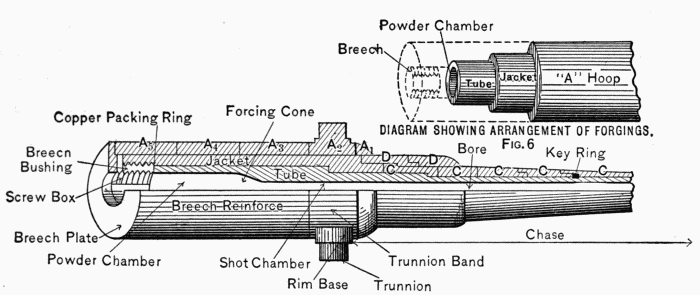
A. The tube, jacket, hoops, and trunnion-band. (See Figs.
5, 6, and 23.)
Q. What is a wire-wound gun?
A. One in which wire takes the place of the jacket and hoops
and is wound over the tube. The wire is really in the form of a
ribbon.
Q. Define the breech-reinforce.
A. That portion of the gun between the rear of the trunnion-band
and the front of the breech. (Fig. 5.)
Q. Define the chase.
A. That portion of the gun between the front of the trunnion-band
and the muzzle. (Fig. 5.)
Q. What is a barbette gun?
A. One that fires over a parapet.
Q. What two classes of barbette guns are there?
A. Barbette disappearing and barbette non-disappearing.
Q. What is the center of gravity?
A. That point where, if the gun were pivoted, it would balance.
It is always near the trunnions.
Q. What is the difference between front-pintle and center-pintle
carriages?
A. Front pintle is where the gun traverses about a point in
the front part of the carriage; center pintle where it traverses about
a point in the center of the carriage.
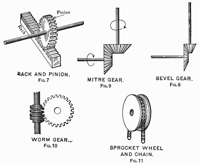
Q. What is a rack?
A. A bar or arc having teeth that engage in a gear-wheel
or worm. (See Fig. 7.)
Q. What is a gear-wheel?
A. A wheel with teeth on the circumference.
Q. What is a bevel-gear?
A. Two wheels whose axles are at an angle to each other and
whose teeth engage. (Fig. 8.)
Q. What is a miter-gear?
A. A bevel-gear with axles of equal-sized wheels at right
angles. (Fig. 9.)
Q. What is a worm?
A. A gear-wheel in the form of a continuous screw. (Fig. 10.)
Q. What is a sprocket-wheel?
A. A toothed wheel that engages the links of a chain. (Fig.
11.)
Q. What is a spur-wheel?
A. A gear-wheel with teeth parallel with the axle of the
wheel. If in Fig. 7 the rack were in form of a wheel, it would
be a spur-wheel. (The pinion is also a spur-wheel.)
RACK AND PINION.
Fig. 7.
MITRE GEAR.
Fig. 9.
BEVEL GEAR.
Fig. 8.
WORM GEAR.
Fig. 10.
SPROCKET WHEEL AND CHAIN.
Fig. 11.
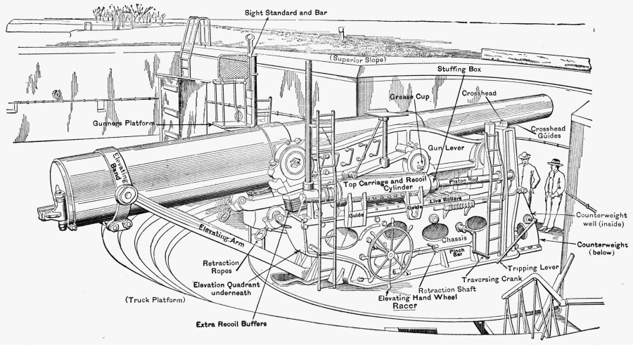
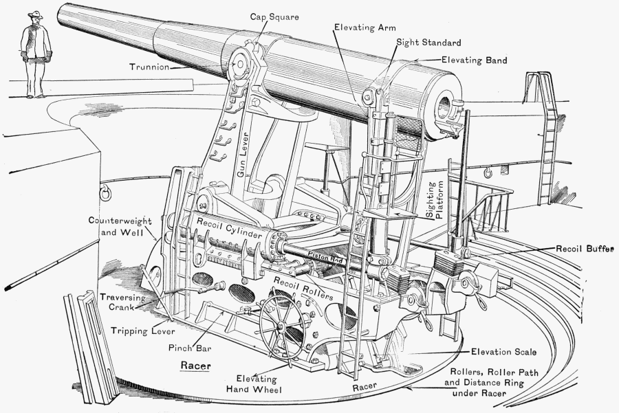
Q. Point out or describe the location of the following parts
of a seacoast carriage:
Base-ring.
Foundation-bolts.
Leveling-bolts.
Upper-roller path.
Lower-roller path.
Traversing-rack.
Conical rollers.
Distance-ring.
Dust-guard.
Racer.
Chassis.
Top-carriage.
Recoil-cylinder.
Piston.
Piston-head.
Throttling-bars.
Followers.
Stuffing-box.
Packing.
Guide-hooks.
Trunnion-bed.
Trunnions.
Kim-base.
Cap-squares.
Cap-square bolts.
Elevating mechanism.
Traversing mechanism.
Azimuth circle.
Azimuth indicator.
Retraction-gear.
Sight standard.
Shot-hoist.
Crane.
Shot-hoist drum.
Pawl.
Elevating-arc.
Recoil-rollers.
Chassis-rails.
Gun-shield support.
Loading-platform.
Elevating-shaft.
Extra for R. F. guns:
Pillar-base.
Shoulder-rest.
Electric batteries.
Pistol-grip.
Range-drum.
Extra for disappearing guns:
Gun-lever.
Lever-axle.
Counterweight-shaft.
Counterweight.
Cross-head.
Cross-head guides.
Cross-head rack.
Tripping-bars.
Counter-recoil-buffers.
Gunner's platform.
Retraction-ropes.
Extra recoil-buffers.
Electric traversing-controller.
Electric elevating-controller.
A. See Figs. 12 to 22 inclusive.
Q. Point out or describe the location of the following parts
of the gun and breech mechanism of 8" and 12", Model 1888:
Bore.
Shot-chamber.
Muzzle.
Powder-chamber.
Forcing-cone.
Screw-box.
Breech-block.
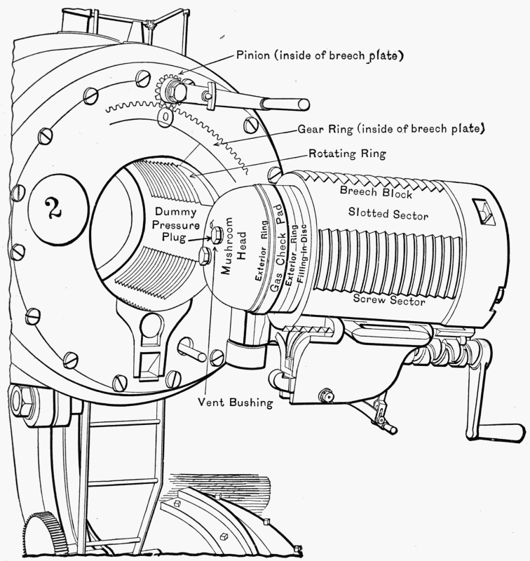
Mushroom head.
Spindle.
Gas-check pad.
Vent.
Hinge-pin.
Rotating-crank.
Translating-roller.
Tray.
Breech-plate.
Slotted sectors.
Screw sectors.
Pinion- and gear-segment.
Vent-bushing.
Filling-in disc.
Exterior ring.
Interior ring.
Vent-cover.
Rotating-crank catch.
Obturator-spindle.
Obturator-spindle nut.
Locking-nut.
Translating-stud.
Guide-rails of tray.
Tray-latch.
Securing-latch.
Securing-latch catch.
Rotating-ring.
Rotating-pinion.
12" DISAPPEARING. (From Battery.)
Fig. 12.
12" DISAPPEARING. (in Battery.)
Fig. 13.
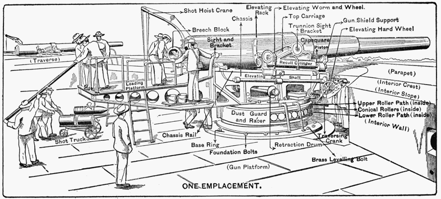
12" BARBETTE NON-DISAPPEARING.
Fig. 14.
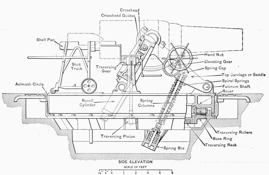
UNITED STATES CARRIAGE
MODEL OF 1896
FOR
12 INCH B.L. MORTAR.
(Steel)
Fig. 15.
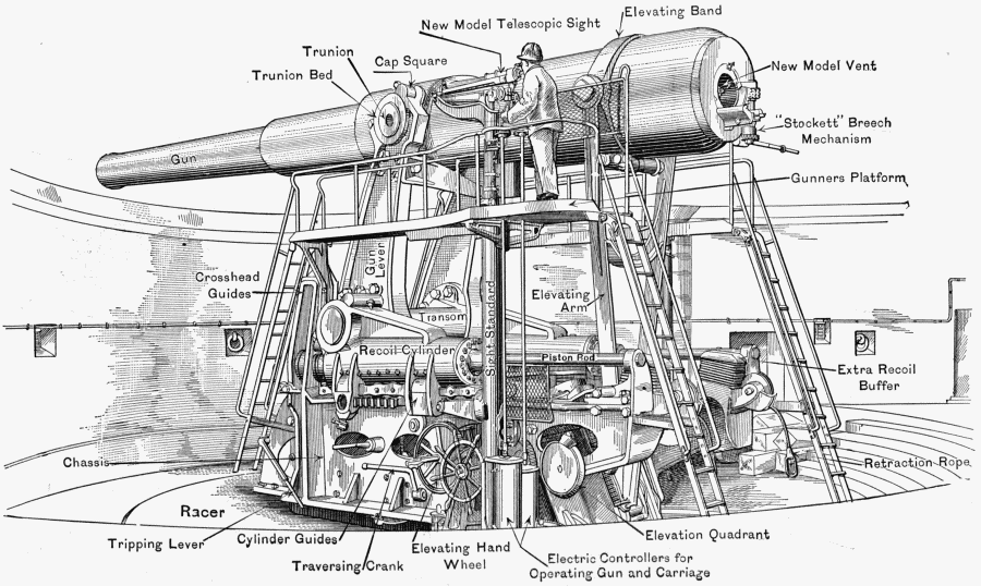
LATEST MODEL 12" DISAPPEARING CARRIAGE AND GUN.
Fig. 16.
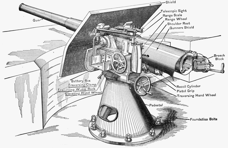
3" RAPID-FIRE GUN. (Pedestal Mount.)
Fig. 17.
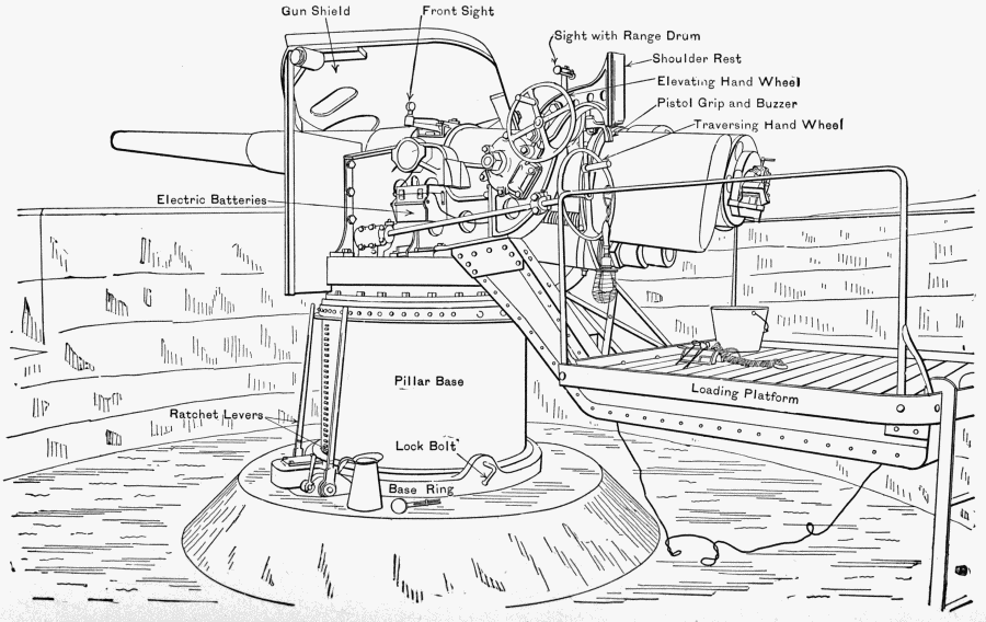
5" RAPID FIRE. (Balanced Pillar Mount.)
Fig. 18.
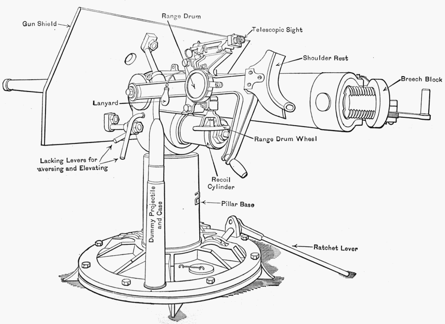
3-INCH R.F. GUN (Masking Parapet Mount).
Fig. 19.
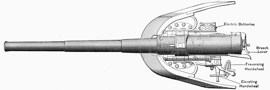
4.7 INCH 120 m/m Q.F. GUN ON CENTRE PIVOT PEDESTAL MOUNTING.
Fig. 20.
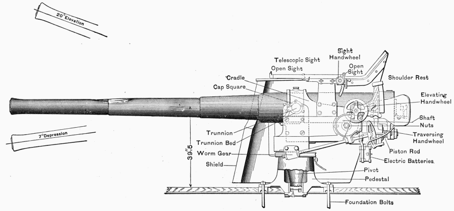
4.7" Q.F. (Pedestal Mount.)
Fig. 21.
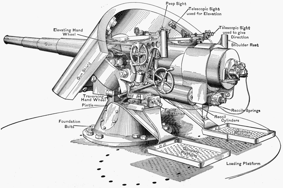
5" RAPID-FIRE GUN. (Pedestal Mount.)
Fig. 22.
(Continued from Q. on page 40).
For continuous-motion or "Stockett" mechanism the following:
Spiral-gear.
Crank.
Worm-shaft.
Worm.
Worm-wheel.
Catch-bolt.
Spring-bolt.
Tray-latch catch.
Spindle-ball bearing.
A. See Figs, 1, 2, 3, 4, 23.
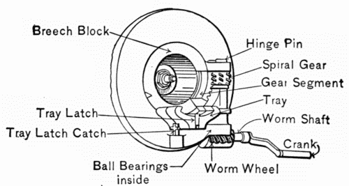
CONTINUOUS MOTION
BREECH MECHANISM.
Fig. 23.
Q. Point out or describe the location of the following parts
of the 5" R.F. breech mechanism:
Block-carrier.
Hinge-pin.
Spindle-key.
Latch-bolt.
Latch-lever.
Lever.
Pinion.
Breech-block.
Gear-segment.
Vent-bushing (copper).
Exterior split ring (front).
Exterior split ring (rear).
Interior split ring.
Gas-check pad.
Filling-in disc.
Tripping-stud.
Latch-bolt seat.
Slide-housing.
Slide-stop.
Slide.
Slide-handle.
Contact-plate.
Firing-leaf.
Circuit-breaker housing.
Circuit-breaker spring.
Circuit-breaker contact-pin.
Firing-cable.
A. See Figs. 24 and 25.
Q. Point out or describe the following parts of the 4·7-inch
quick-firing breech mechanism: Carrier-link, spindle, hand-locking
lever, firing-pin, spring-catch, sliding-block, retaining-nut,
bolt.
A. See Figs. 26 and 27.
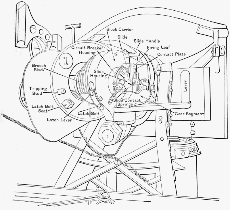
5" R.F. GUN. SHOWING BREECH MECHANISM.
Fig. 24.
Q. Explain briefly how a breech-block of a heavy gun or
mortar is dismantled.
A. The breech being open, remove the locking-nut and spindle-nut,
place a block of wood against the spindle and gently
hammer the mushroom head free from the gas-check pad, then
remove it by hand. Pry the exterior and interior split rings free
from the gas-check pad and remove them, also the filling-in disc.
The spindle-washers can be removed at any time. The parts
are assembled as follows: Adjust in the following order: the gas-check
pad, exterior and interior split rings, filling-in disc, and
spindle-washers. The spindle-washers must be put on after the
spindle is put in. Then gently insert the spindle and screw on
the locking- and spindle-nuts as prescribed for adjusting the
gas-check pad.
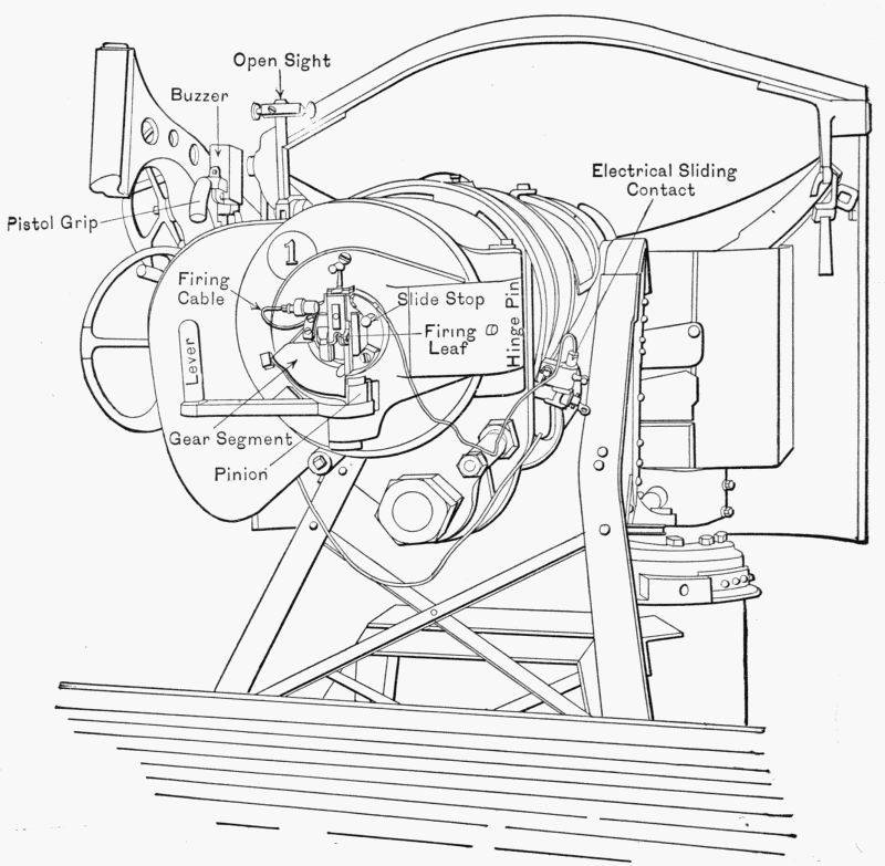
5" R.F. GUN AND BREECH MECHANISM.
Fig. 25.
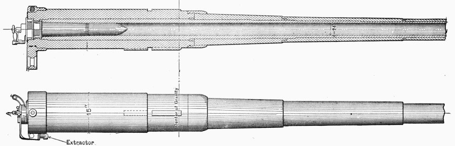
4.7 INCH 120m/m QUICK FIRING GUN.
Fig. 26.
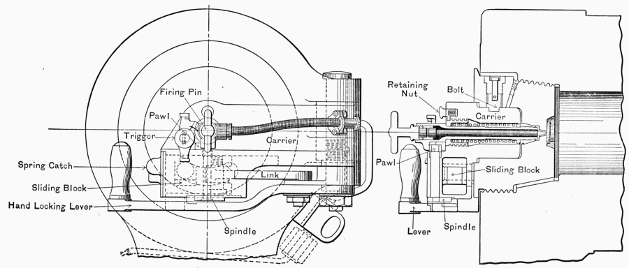
4.7 INCH.
BREECH CLOSING AND FIRING GEAR.
Fig. 27.
Q. Point out or describe the following parts of the one-pounder
subcaliber tube for the 12" B. L. R., model 1895:
Gun.
Adapter clamp-wedge.
Clamp-wedge screw.
Thread clamp-screw.
Rear adapter.
Center support.
Front adapter.
Adjusting-wrench.
Clamping-wrench.
Locating-gauge.
Clip-extractor.
Obturator spindle-plate.
A. See Fig. 28.
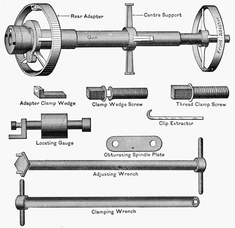
ONE-POUNDER SUBCALIBER TUBE.
Fig. 28.
Q. How should gas-check pads be adjusted before firing?
A. First: Close the breech.
Second: Loosen spindle and locking-nuts.
Third: Rotate block half-way.
Fourth: Tighten spindle and locking-nuts in the usual
manner, rotate the breech-block home, and pad is adjusted.
Q. How far should a projectile be rammed?
A. Until the zero of the brass ring on the rammer comes
flush with the face of the breech-plate. (See Fig. 29.)
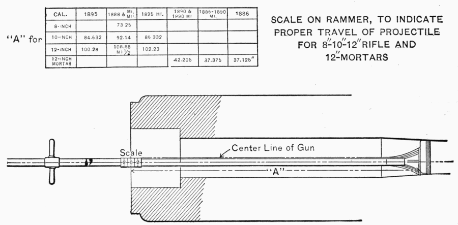
SCALE ON RAMMER, TO INDICATE
PROPER TRAVEL OF PROJECTILE
FOR 8"-10"-12" RIFLE AND
12"-MORTARS
Fig. 29.
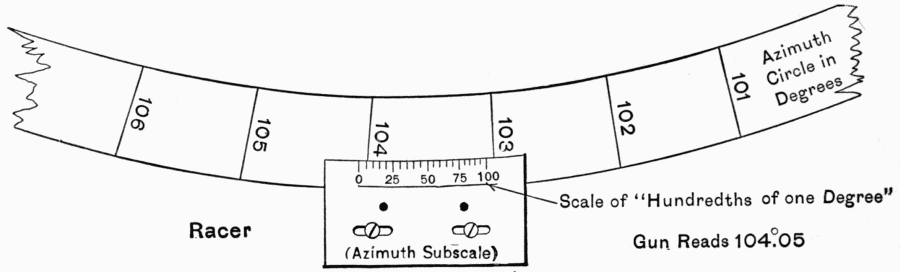
Q. Describe how to set the azimuth indicator-plate for a
given azimuth.
A. Traverse the gun until the mark on the indicator-plate
representing the number of hundredths is opposite the mark on
the azimuth circle representing the number of degrees. In Fig.
30 the gun is set at 104°.05.
Q. How do you repack a stuffing-box?
A. If any of the old packing is used, it should be put in after
the new. See that the stuffing-boxes are well cleaned and
oiled.
Put on the piston-rod one ring of 1-inch Garlock's "waterproof
hydraulic" packing, and force it well to the bottom of the
stuffing-box by a wooden stick and mallet. Treat each layer
of packing in a similar manner, being careful to break joints
until five rings of new packing have been inserted, or an equal
amount of new and old when any of the latter is used. Place the
gland on the follower, enter them together in the box and screw
up the follower.
No more force should be used on the spanner-wrench than
that of two men, and generally that of one man is sufficient. The
addition of the pipe to the end of the spanner-wrench should
not be permitted.
Q. How do you remove old packing from recoil-cylinders?
A. Remove the gland and follower (using new extractor, to
be furnished by the Ordnance Department). Close the extractor
around the piston-rod and insert the locking-pin. Turn the
extractor to the left, with pressure on the packing, until the needles
are firmly engaged in the packing. Draw the packing out,
turning slowly to the left. In the case of a box with interior thread,
and if the ring is tight, it should be unscrewed and not stripped
out by the thread, because unless unscrewed it would catch upon
and be injured by the thread.
Extractor-bars are provided to be used for starting the packing
from its seat, and by inserting the toes of the bar in the rack-teeth
and prying over the edge of the box, being careful not to injure
the thread.
Q. What is the object of the throttling-valve?
A. To regulate the flow of oil from the front to the rear of the
recoil-cylinders. (See Fig. 31.)
Q. What precautions should be taken where the throttling-valve
is provided?
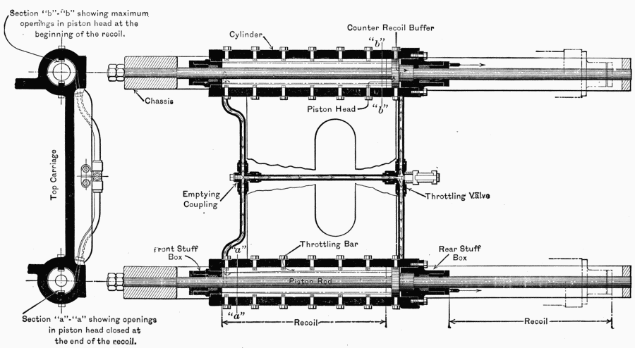
GENERAL METHOD OF CONTROLLING THE ENERGY
OF RECOIL IN GUN CARRIAGES.
Fig. 31.
A. That there is a lock on the valve to prevent any one from
changing the setting without authority.
Q. Give some general directions for the care and preservation
of guns and gun-carriages.
A. All guns and carriages should be elevated and traversed
to their full limits daily. Ordinarily a gun and carriage should be
painted at least once a year. However, climatic conditions may
vary this rule. Sperm-oil, cosmic or light slushing oil should never
be applied to a surface that has a suspicion of grit, moisture, or
rust upon it. Brass gearing should have a thin film of sperm-oil
or synovial oil on it. All oil-holes and recoil-cylinders should
be examined daily at the beginning of drill. Special attention
should be given to grease-cups on disappearing guns to see that
they function properly. Retraction-ropes should be kept oiled
and cleaned. No part of the carriage should at any time be
allowed to rust, and if the carriage is to remain unused for short
intervals, all bright and bearing parts should be covered with a
thick coat of light slushing oil or cosmic. If the carriage is to
remain unused for long intervals, the cosmic should be mixed
with 25 per cent of resin. The mixture is well adapted for the
purpose, but must be renewed from time to time. The rollers
and roller-paths should be cleaned and covered with slush oil, and
the space between the dust-guard and base-ring should be filled
with waste or oakum to keep out dust, and wrench-holes
inside base-ring should be plugged tightly with fitted wooden
blocks.
To oil bore, use is made of an ordinary counter-brush secured
to the end of a rod and provided with a half-disc of wood to keep
the brush against the bore. By this means any required thickness
of the mixture may be applied. The brush-rod is, for the rifles,
fitted with a socket for connecting it with the special sponge-staff.
For mortars the brush is supplied with a special handle. As a
rule, the cosmic and resin mixture can be sufficiently removed
from the bore for firing by using the scraper alone, this being a
semicircular disc of iron.
Q. Describe throttling bars.
A. Bars of steel bolted on the sides of recoil cylinders. (The
bolt heads can be seen on the outside of the cylinders.)
The piston head is slotted to receive the bars as shown in
Fig. 31, and the bars are thicker at one end than at the other,
this varies the amount of oil that can pass through the piston
head slots and therefore the pressure keeps uniform.
(Extract from War Department, 1905.)
Circular }
No. 48. }
Light slushing-oil will be used on the different parts of breech
mechanisms, including the threads on the block and in the breech
recess, in bores of guns, and on all other bright steel or iron surfaces
of mobile and seacoast armament, as a preservative when the
material is to remain unused for an appreciable length of time.
The slushing-oil will replace synovial oil as a lubricant for cross-head
guides, etc., which should be given a light coating only.
The use of light slushing-oil as a lubricant on breech mechanisms,
including the threads on the block and in the breech recess, is
forbidden: synovial oil will be used exclusively for lubricating
the different surfaces of breech mechanisms, including the threads
on the block and in the breech recess, on translating-screws and
rollers, and in all oil-holes and on gears, etc., of carriages. Number
4½ lubricant only will be used in grease-cups. If exposed to
rain within thirty hours after its application, all surfaces should
be carefully examined and recoated if necessary. It can be applied
by means of paint-brushes known as sash-tools No. 6,
issued for that purpose. Except in very cold weather it can be
applied in a thin uniform coat by using the brush, as when painting.
During cold weather it should be applied by stippling—i.e.,
lightly tapping the surface with the end of the brush—the brush
being held perpendicular to the surface to be covered. It can be
applied to the bores of guns by means of the slush-brush issued
for the purpose. In cold weather it should be warmed before
being applied to the bores of guns. In all cases it should be applied
in a thin coat, since this is all that is necessary to give good protection.
This oil can be readily removed by the use of burlap or waste
dipped in kerosene oil. Lye dissolved in hot water and used
while hot will also remove it, but not as satisfactorily as kerosene
oil. In order to reduce the amount of kerosene oil to be used
for its removal, a thick coating of slushing-oil when present should
first be removed with a scraper before applying the kerosene.
Water without the addition of lye or kerosene should be
used for cleaning bores of guns after firing. They should be
permitted to drain and then be wiped dry before applying the
slushing-oil.
Before applying the slushing-oil to any surface it should be
thoroughly cleaned so as to be free from rust, water, kerosene
oil, lubricating-oil, etc., as their presence will cause rusting underneath
the slushing-oil. If applied to an oiled surface, the slushing-oil
has been found to run off when heated.
On account of the superior protection afforded by this material
it will not be necessary to completely remove it for inspection
purposes as frequently as has been found necessary
with the protecting materials heretofore used. Its frequent
removal from a limited area will serve as an indication of the
protection which is being afforded.
III. Mortars will hereafter be dismounted from their carriages
once every twelve months, and the trunnions and trunnion-beds
thoroughly cleaned, including the oil-grooves in the
trunnion-bed liners.
The counter-recoil springs will at the same time be dismounted,
the old paint removed, and each spring given two coats of new
paint. The spring should not be reassembled until the paint is dry.
By order of the Acting Secretary of War:
J. C. Bates,
Major-General, Acting Chief of Staff.
Q. Describe the general parts of the throttling-valve and how
it operates.
A. The two equalizing-pipes connecting the front and rear
of opposite recoil-cylinders have a pipe connecting them; if this
pipe is open completely, oil can move freely from the front to
the rear of the cylinders. If it be closed partly by a valve called
the throttling-valve, much less oil will pass this way. Thus, by
regulating the adjustment of this valve, the recoil of the gun is
regulated. It is seen that the throttling-bars work with the
throttling-valve. (See Fig. 31.)
Q. How much oil should be removed from recoil-cylinders
having the filling-plugs on the top of the cylinders?
A.
12-inch disappearing carriages, all models, 3 gallons.
10-inch disappearing carriages, all models, 1½ gallons.
8-inch disappearing carriages, all models, 1 gallon.
6-inch disappearing carriages, model 1898, ½ gallon.
Q. Where new filling-plugs have been inserted explain how
the cylinders are filled.
A. For full charges remove the two filling-plugs (one from each
cylinder), pour oil into one filling-hole until it flows out of the
hole in the other cylinder, wait a moment to allow the oil to settle,
and examine for any pocketed air or any temporary obstruction.
If necessary, pour in more oil until the oil is observed to be
in both cylinders up to the level of the filling-holes, then insert
the screw-plugs without removing any oil.
Q. Prior to firing, what should be done to the bore of the gun?
A. Prior to artillery practice the bore, including the powder-chamber,
of each piece to be used in practice will be thoroughly
cleaned and freed from lubricant before any shot is fired.
Q. How is powder residue removed after firing?
A. After firing the bore may be cleaned by using a sponge
covered with burlap well saturated with water. The bore should
then be permitted to drain and thoroughly dry before being oiled.
Q. If any rust has accumulated on a bearing part, would you
use sandpaper to remove it?
A. The use of sandpaper is forbidden, and emery-cloth No. 1,
being coarse enough for any ordinary rusting, should be used, the
rust being softened if necessary by kerosene.
Q. Describe the recoil-cylinder
for mortars and its
action.
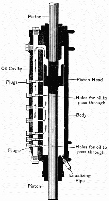
RECOIL CYLINDER
FOR MORTARS.
Fig. 32.
A. Fig. 32. When the
mortar is fired, the piston is
forced down, causing the
piston-head to force oil
through the oil-holes shown
on the left of Fig 32. This
oil passes through the oil-cavity
upward and in rear of
the piston-head. By opening
or closing these oil-passages
by withdrawing or inserting
different-sized plugs the friction,
hence the recoil, can be
adjusted.
Note.—For steel mortars
model '91 the plugs are as in
Fig. 32; that is, from top to
bottom: closed, ½, 0, 0, ½,
closed, closed. For C. I.
mortars '91: c., ½, 0, 0, ¾, c.,
c. For model '96 c., ½, ¼,
0, ¼.
Q. What are "grease-cups"?
A. Brass cups placed on the trunnions of guns to lubricate or
oil the trunnions and trunnion-beds.
Q. How are they filled and adjusted?
A. Fill up to the bevel edge of the cup with the special oil
provided by the Ordnance Department. The cup is then put on
and screwed down until the plunger sticks out one quarter of an
inch. By doing this a spring bearing on the plunger is forced to
act, causing the plunger to press upon the oil, forcing it into the
grooves and channels cut under the trunnions. The plunger
should be kept at this distance (¼") from the cap by screwing
down the cap from day to day. When the plunger will no longer
be pressed out it is known that no more oil is in the cup, and it
should be refilled.
Q. State some rules to be observed in painting guns and
carriages.
A. The gun is painted gray, and the carriage olive-green.
These are the only colors authorized. The entire surface of the
gun is painted except where the console, or tray, touches the gun.
Two coats annually are usually allowed.
Bronze trays will not be painted. Steel trays, excepting the
upper and front surfaces and guide-rails, will be painted the
same color as the gun. No parts of the breech-block or mechanism
will be painted. The unpainted surfaces will be kept
clean and bright with rottenstone and oil or "Putz-pomade."
All steel and iron non-bearing surfaces, both inside and out,
will be painted. This includes the exposed parts of shafts (except
squared ends), bottom plate of counterweight, ladders, cross-heads,
cranks (not handles), cross-head pawls (except teeth), and large
bronze pieces, including web and spokes of wheels and cylinder-heads.
The following parts are not painted: All wearing or bearing
surfaces, which includes the handles of hand-wheels and cranks,
teeth of all gear-wheels, teeth of cross-head pawls, teeth of cross-heads,
elevating-rack guides, rollers and surfaces on which they
travel, piston-rods, crosshead-guides, etc.
The bronze sight-holders will not be painted, nor will the
azimuth and elevating-scales and pointers and the followers of
the stuffing-boxes; these parts will be kept clean and, with the
exception of the sight-holders, will also be kept bright with rottenstone
and oil or "Putz-pomade."
The raised surfaces of letters and rims of direction and name-plates
are to be kept clean and bright; the background of these
plates will be painted the same color as the carriage.
Name-plates shall never be removed in painting the carriage.
This is prohibited by orders.
Q. How is old paint removed?
A. Dissolve one pound of concentrated lye, powdered form,
in six pints of hot water, and slake in enough lime to give the
solution the consistency of paint. Use the solution freely mixed,
and apply to the parts where paint is to be removed, with a brush
preferably, or with waste tied on the end of a stick. When the
solution begins to dry on the surface use a scraper to remove the
old paint, and complete the cleaning of the surface with a mop and
water. If one application is not sufficient to loosen the paint,
apply a second coat. Before applying the new coat of paint
wash the surface with liquid made by dissolving one half pound
of washing-soda in eight quarts of water, and wipe dry. Let
stand a sufficient length of time to have all parts thoroughly dry
before painting.
Q. Should oil or grease ever be applied to the surfaces of
electrical contacts on a gun or carriage?
A. No. Grease or oil acts as an insulator and prevents the
current from passing the contacts.
Q. Point out or describe the following parts of a battery:
Emplacement, parapet, traverse, parados, exterior slope, interior
crest, interior slope, superior slope, interior wall, gun-platform,
truck-platform, loading-platform.
A. See Fig. 14.
Q. Explain how to adjust the firing mechanism.
A. Insert the safety bar in the safety-bar notch of the slide
housing. Slip the slide housing over the spindle, at the same
time inserting the safety bar in its recess in the breech block.
Press both home firmly. Slip on the yoke, pressing down until
the notch above the ring is just visible. (In this operation it
may be necessary further to adjust the spindle if the yoke does
not go on completely, and the gas-check pad may have to be
flattened for this purpose.)
Put the ejector in place with the ejector raised and the slide
stop pulled out. Place the slide in position.
Q. When the weather is freezing what should be done to the
recoil-cylinders before firing service charges?
A. A small amount of oil should be taken out and a reduced
charge fired, then fill the cylinders and fire full service.
Q. Where should primers and fixed ammunition be
kept?
A. Separate place from powder: never in the magazine.
Primers should be kept preferably in the ammunition-chests, and
fixed ammunition in the shot-room.
Q. How is the weight of a cored shot or plugged shell brought
to standard weight?
A. By adding sand mixed with iron filings, water, or sawdust,
according to the degree of increase required.
Q. How should throttling-bar bolts be adjusted?
A. First loosen them slightly, scrape away any paint that
clogs them, and then tighten them to full limit.
Q. What is a priming-charge, and where is it placed?
A. A small charge of black powder in both front and rear of
every section of cartridge.
Q. Should the trunnion-seats of sight-standards be polished?
If not, why not?
A. No. Polishing wears away the brass and throws the sight
out of adjustment. They should be wiped clean, however.
Q. Is the removal of the name-plates or sight-brackets authorized
at any time?
A. No.
Q. How do you test the adjustment of the azimuth indicator?
A. Insert the bore-sights, traverse the gun until the line of
sight through the front and rear bore-sights intersects a datum
point whose azimuth is known. If the indicator reads this
azimuth, the gun is in azimuth.
Q. How do you test the level of a carriage?
A. If the trunnion sight-bracket is correctly adjusted, place
the telescopic sight upon it, set the sight and gun at zero elevation,
and traverse the carriage to the full limits. If the bubble in the
telescope-level remains stationary, the carriage is level. If not,
adjust by turning the leveling-bolts.
Q. How do you distinguish the following powders: Musket,
sphero-hexagonal,[1] brown prismatic, black prismatic, and smokeless.
A. Musket is black and very fine grained. Sphero-hexagonal
is black and in the shape of a small ball with a six-sided ring
around it. Brown prismatic is brown, in the form of a six-sided
prism with a hole in the center. All smokeless powder has the
appearance of translucent celluloid and smells of ether. This
powder grades in size according to the caliber of the gun, and has
for large guns a cylindrical form with small holes running lengthwise
in it. (See Fig. 33.)
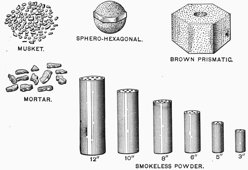
MUSKET.
SPHERO-HEXAGONAL.
BROWN PRISMATIC.
MORTAR.
SMOKELESS POWDER.
Fig. 33.
Note.—The smokeless powder used in the U. S. Coast Artillery
is made out of ordinary cotton waste. The process of manufacture
is briefly as follows: The cotton waste is first thoroughly
washed, cleaned, picked, and then put through shredding- and
cutting-machines. It is then dried in ovens for many hours. It
is then placed in pots and a mixture of strong nitric and sulphuric
acid is poured over it. It is then washed in running water for
many more hours. It is now called "guncotton." It is then
dissolved with a mixture of alcohol and ether and put under a
hydraulic press. On coming out of the press it looks like yellow
gum. It is then forced through different sized dies, and in this
shape looks like macaroni. It is then cut into various lengths
and sizes, according to the caliber of gun for which it is to be used.
Q. Give the weight of charge, weight of projectile, and initial
velocity of the piece to which your company is assigned.
A. See table on page 75. (Ref. Ordnance Department, G. O.
9, W. D. '08.) Slight variations from the requirements of this
table will be permitted; but it is desired that these requirements
shall be fulfilled as nearly as practicable.
Q. Name the different kinds of primers.
A. Common friction, common electric, obturating friction,
obturating electric, and combination electric friction.
Q. Explain the action of the common friction and the
obturating friction primer.
A. Its action consists in the friction of a saw-tooth wire being
pulled through a portion of mercuric fulminate, which explodes
and ignites a small charge of powder in the primer, which in
turn ignites the main charge in the gun. (See Figs. 34 and 35.)
Q. Explain the action of the common and obturating electric
primer.
A. Two insulated wires entering the primers are joined
by a platinum wire. (A little guncotton is sometimes imbedded
around the platinum wire.) The current heats the platinum,
which ignites a small charge of powder or fulminate, if it be a
common electric, in the primer, which ignites the main charge.
(See Figs. 36 and 37.)
Table of Charges, Velocities, etc., for Rapid-fire and Seacoast Guns.
Weights of projectiles, powder charges, muzzle velocity, and pressure for rapid-fire
and seacoast guns, service and practice charges.
| Column headings: |
| Col A: 1-pounder Subcaliber Tube. |
| Col B: 18-pounder Subcaliber Tube. |
| Col C: 6-pounder. |
| Col D: 15-pounder, Models of 1891 and 1902. |
| Col E: 15-pounder, Model of 1903. |
| Col F: 4-inch D.-S. |
| Col G: 4·72-inch Armstrong. |
| Col H: 6-inch Armstrong. |
| Col I: 5-inch O. D. Model, of 1897. |
| Col J: 5-inch O. D. Model of 1900. |
| |
| | A | B | C | D | E | F | G | H | I | J |
| Weight of |
| projectile (lbs.) | 1·06 | 18 | 6 | 15 | 15 | 33 | 45 | 106 | 58 | 58 |
| Weight of charge |
| (lbs.): |
| Smokeless-- |
| Nitroglycerin | | | 1·25 |
| | | | | | | | { 40-7·5 | } |
| Nitrocellulose | [2]2·5 |
[2]7 | 1·35 | 5 | 6·06 | 7·5 | {45-10·5 | } 19 | 16·5 | 23 |
| | | | | | | | {50-10·5 | } |
| | | | | | | | { 40-5·5 | } |
| Cordite | | | | | | | { 45-8·2 | } 13·3 |
| | | | | | | | { 50-8·2 | } |
| Brown prismatic | | | | | | 12·0 |
| Muzzle velocity |
| (f.s.): |
| Smokeless | 2100 | 750 | 2400 | 2600 | 2600 | 2300 | | | 2600 | 2600 |
| | | | | | | | {40-2150 | } |
| Cordite | | | | | | | {45-2570 | } 2150 |
| | | | | | | | {50-2600 | } |
| Brown prismatic | | | | | | 2000 |
| Maximum permissible |
| pressure (pounds |
| per square inch) | 25000 | 18000 |
37460 | 34000 | 41000 |
34000 | 34000 | 34000 |
38000 | 36000 |
| Column headings: |
| Col K: 6-inch O. D., Model of 1897 M1. |
| Col L: 6-inch O. D., Model of 1900, 1903, and 1905. |
| Col M: 8-inch. |
| Col N: 10-inch R., Models of 1888 and 1895. |
| Col O: 10-inch R., Models of 1900. |
| Col P: 12-inch R., Models of 1888 and 1895. |
| Col Q: 12-inch R., Model of 1900. |
| Col R: 12-inch M., Models of 1886 and 1886-90 M1. |
| Col S: 12-inch M., Steel Model of 1890 M1. |
| |
| | K | L | M | N | O | P | Q | R | S |
| Weight of projectile |
| (lbs.) | 106 | 106 | 316 | 604 | 604 | 1046 | 1046 | 824 | 1046 | 824 | 1046 |
| Weight of charge |
| (lbs.): |
| Smokeless-- |
| Nitrocellulose | 29·75 | 39·1 | 80 | 155 | 205 | 275 | 325 | 33 | 33 | 62 | 54 |
| Brown prismatic | | | 135 | 280 | | 490 | | 75 | 75 | 105 | 105 |
| Muzzle velocity |
| (f.s.): |
| Smokeless | 2600 | 2600 | 2200 | 2250 | 2250 | 2250 | 2250 | 1050 | 910 | 1300 | 1050 |
| Brown prismatic | | | 1975 | 2025 | | 2025 | | 1020 | 900 | 1150 | 1020 |
| Maximum permissible |
| pressure (pounds |
| per square inch) | 38000 | 36000 |
38000 | 38000 | 38000 |
38000 | 38000 | 27500 |
27500 | 33000 | 33000 |
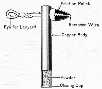
COMMON FRICTION.
Fig. 34.
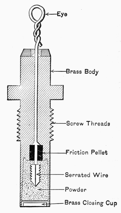
OBTURATING FRICTION.
Fig. 35.
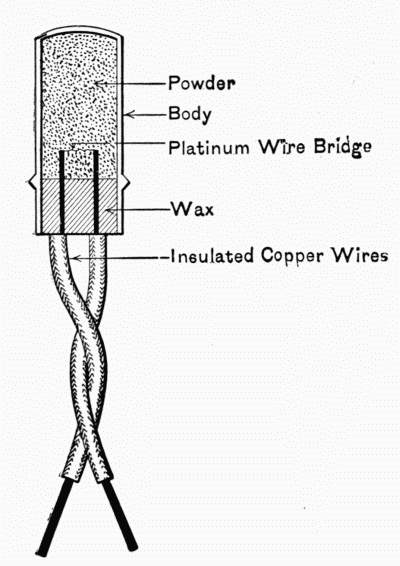
COMMON ELECTRIC.
Fig. 36.
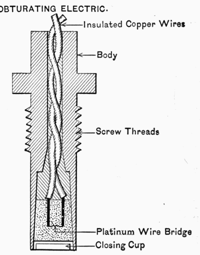
OBTURATING ELECTRIC.
Fig. 37.
Q. Explain the action of the combination electric friction primer.
A. It is a combination of the two above principles, except that
in the electric feature there is no return wire in the combination
primer. The current comes in through the stem from the copper
contacts on the firing mechanisms, heats the platinum, etc., and
goes out through the case of the primer to the breech-block of
the gun, thence to the trunnion and to the other pole of the firing-battery.
This primer is also obturating. (Fig. 38.)
Q. What is an obturating-primer?
A. One which prevents the escape of powder-gas through
the vent. (It need not necessarily be screwed into the vent.)
Q. What are percussion-primers?
A. Such as are used in fixed ammunition and go off by the
snap of the firing-pin. They are commonly called caps.
Q. What are high- and low-resistance fuses?
A. A high-resistance fuse is one that requires a high initial
velocity to cause the plunger to be released, and is therefore safer
in handling. A low-resistance fuse does not require such a high
initial velocity to cause it to act. Low-resistance fuses are provided
with "safety-wires." (See Fig. 39.)
Q. What fuses are used in the United States service?
A. Frankford Arsenal base percussion, point percussion, and
combination. The first two are of either high or low resistance,
and vary in size for different calibers of guns. All fuses that
are not "centrifugal" have become obsolete for all calibres above
1·65", except the combination fuse, but those on hand will be in
service until used up.
Q. How are fuses inserted to make a tight joint?
A. By putting a special preparation, supplied by the Ordnance
Department, on the threads. Never use red lead.
Q. Describe the action of a percussion-fuse and name parts.
A. On firing, the plunger-sleeve is forced to the rear and
remains in this position during flight. On striking, the plunger
and plunger-sleeve are forced forward and the prick-point of the
plunger strikes the fulminate of the fuse; this ignites the priming
charge in the fuse, which ignites the charge in the shell (Fig. 39).
Note.—There is a new fuse now prescribed for our artillery called "The Detonating
Fuse." No one is permitted to take this fuse apart and its construction
is kept secret.
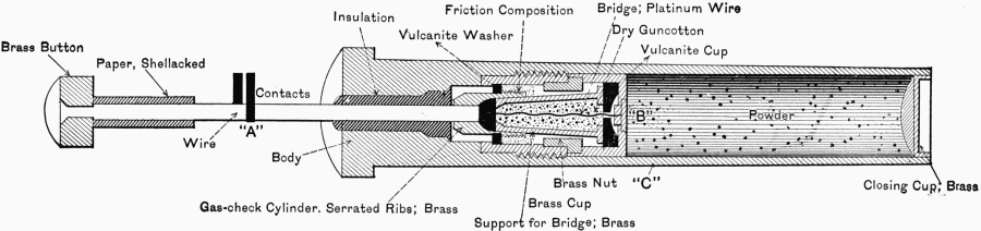
COMBINATION ELECTRIC-FRICTION PRIMER.
NOTE: Current comes from the contacts at "A" passes through the platinum wire
(heating it) out at "B" and thence to the body at "C" thence to the ground.
Fig. 38.
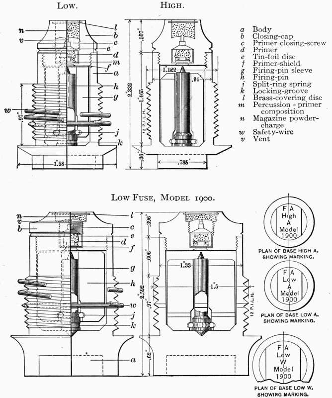
FRANKFORD ARSENAL BASE PERCUSSION FUSES.
Low. High.
| a | Body |
| b | Closing-cap |
| c | Primer closing-screw |
| d | Primer |
| e | Tin-foil disc |
| f | Primer-shield |
| g | Firing-pin sleeve |
| h | Firing-pin |
| j | Split-ring spring |
| k | Locking-groove |
| l | Brass-covering disc |
| m | Percussion-primer composition |
| n | Magazine powder-charge |
| w | Safety-wire |
| v | Vent |
Low Fuse, Model 1900.
Fig. 39.
Q. Explain the action of the combination fuse and name parts.
A. Before firing a hole is punched through the hole on the
time-cone corresponding to time of flight at which it is desired
that the projectile burst. On firing, the time-plunger strikes
the firing-pin for the time-train, then the time-train begins to
burn from the point where the hole in the cone was made, and
at the end of the time of flight the flame reaches the interior of
the fuse, thence to the shell. If this fails or it be desired to use
the fuse as a percussion-fuse, the action is as in an ordinary
percussion-fuse. Combination fuses are now always made with
the centrifugal arming device as in percussion. (See Figs. 40 and 42.)
Q. What is a delayed-action fuse?
A. One which does not explode until a short time after striking.
Q. Explain the action of the new centrifugal fuse.
A. This fuse can act only when a rotary motion is given to
it. This rotary motion, due to the rotating band, causes the
plunger to bulge away from the center into two parts; when
these parts separate it is seen from Fig. 41 that the firing-pin
takes up a position parallel to the longer axis of the fuse and
its point is almost touching the friction composition. When
the projectile strikes, the plunger drives the firing-pin into the
friction composition. The action is then the same as in the
ordinary percussion-fuse. This fuse is therefore perfectly safe to
handle, transport, or use. It becomes active only when a high
rotary motion is given it. (See Figs. 41 and 42.)
Q. How are drill-primers loaded?
A. Insert a serrated wire with friction-pellet in the body of
the primer, hold it in position with the assembling-tool, screw a
rear wire or bottom wire (depending on whether it is an old- or
new-model vent) fast to the serrated wire, fill with musket-powder,
and close with a brass closing-cup, using the assembling-tool.
Q. Name the different kinds of projectiles in the United
States service.
A. Solid shot, cored shot, shell, shrapnel, and canister. (See
Fig. 43.)
Q. What is the rotating-band and what is its use?
A. The copper band near the base end. It is forced into
the grooves of the rifling and causes the projectile to take up a
rotary motion to prevent tumbling during flight.
Q. Why are some projectiles capped?
A. Experimental tests have shown that it will penetrate
armor-plate deeper than those not capped.
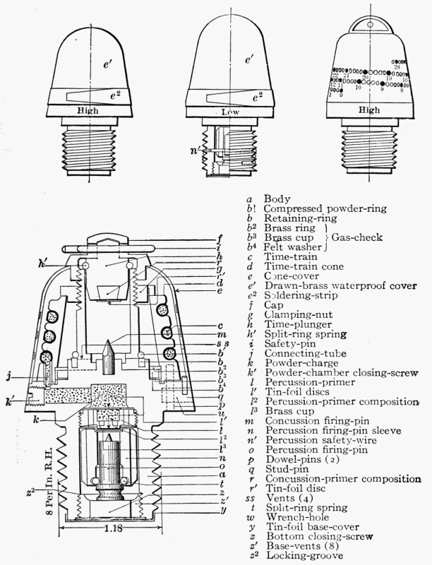
FRANKFORD ARSENAL TIME PERCUSSION OR COMBINATION
FUSE. MODEL 1900.
| a | Body |
| b' | Compressed powder-ring |
| b | Retaining-ring |
| b2 | Brass ring | } |
| b3 | Brass cup | } Gas-check |
| b4 | Felt washer | } |
| c | Time-train |
| d | Time-train cone |
| e | Cone-cover |
| e' | Drawn-brass waterproof cover |
| e2 | Soldering-strip |
| f | Cap |
| g | Clamping-nut |
| h | Time-plunger |
| h' | Split-ring spring |
| i | Safety-pin |
| j | Connecting-tube |
| k | Powder-charge |
| k' | Powder-chamber closing-screw |
| l | Percussion-primer |
| l' | Tin-foil discs |
| l2 | Percussion-primer composition |
| l3 | Brass cup |
| m | Concussion firing-pin |
| n | Percussion firing-pin sleeve |
| n' | Percussion safety-wire |
| o | Percussion firing-pin |
| p | Dowel-pins (2) |
| q | Stud-pin |
| r | Concussion-primer composition |
| r' | Tin-foil disc |
| ss | Vents (4) |
| t | Split-ring spring |
| w | Wrench-hole |
| y | Tin-foil base-cover |
| z | Bottom closing-screw |
| z' | Base-vents (8) |
| z2 | Locking-groove |
Fig. 40.
Note.—In punching fuse see that pin enters up to shoulder to insure penetration
of cone d.
If fired for percussion-burst, punch at maximum time-setting but do not remove
safety-pin i.
Ignition of time-train c is due to punched hole acting as vent for gases from
primer-charge r and compressed powder-ring b.
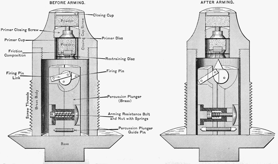
FRANKFORD ARSENAL CENTRIFUGAL FUSES.
BASE FUSE "S".
BEFORE ARMING. AFTER ARMING.
Fig. 41.
Q. What is the difference between shrapnel and canister?
A. Shrapnel is composed of a number of spherical balls in a
cast-iron case, of the usual shape of a projectile, and has a bursting-charge
in either the point or the base to scatter these balls.
Canister is in a cylindrical case and has no bursting-charge.
Shrapnel has a point combination fuse and is thus readily distinguished
from all other projectiles. (See Fig. 43.)
Q. What is the difference between cored shot and shell?
A. Cored shot have hollowed centers, as also have shell, but
in the latter the hollow is much larger. Owing to the recent
manufacture of a suitable bursting-charge, cored shot can be
filled with it and used the same as shell.
Q. What is the general color of the main body of all projectiles?
A. Black.
Q. How is the kind of metal of which it is composed marked?
A. By a painted band around the center, half-caliber wide.
Q. How is the degree of armor-piercing capacity marked?
A. By a greater or lesser portion of the head being painted
with the color representing the metal of the projectile.
Q. How is the interior bursting-charge marked?
A. By a distinct color around the base below the rotating-band.
Q. Give the colors for the following metals:
| 1. Forged steel. | A. | 1. Blue-gray. |
| 2. Cast steel. | | 2. Brownish gray. |
| 3. Cast iron. | | 3. Olive-green. |
| 4. Chilled iron. | | 4. Light olive-green. |
Q. Give the colors for the following bursting-charges:
| 1. Gunpowder. | A. | 1. Bright red. |
| 2. Maximite. | | 2. Brown. |
| 3. Explosive D. | | 3. Yellow. |
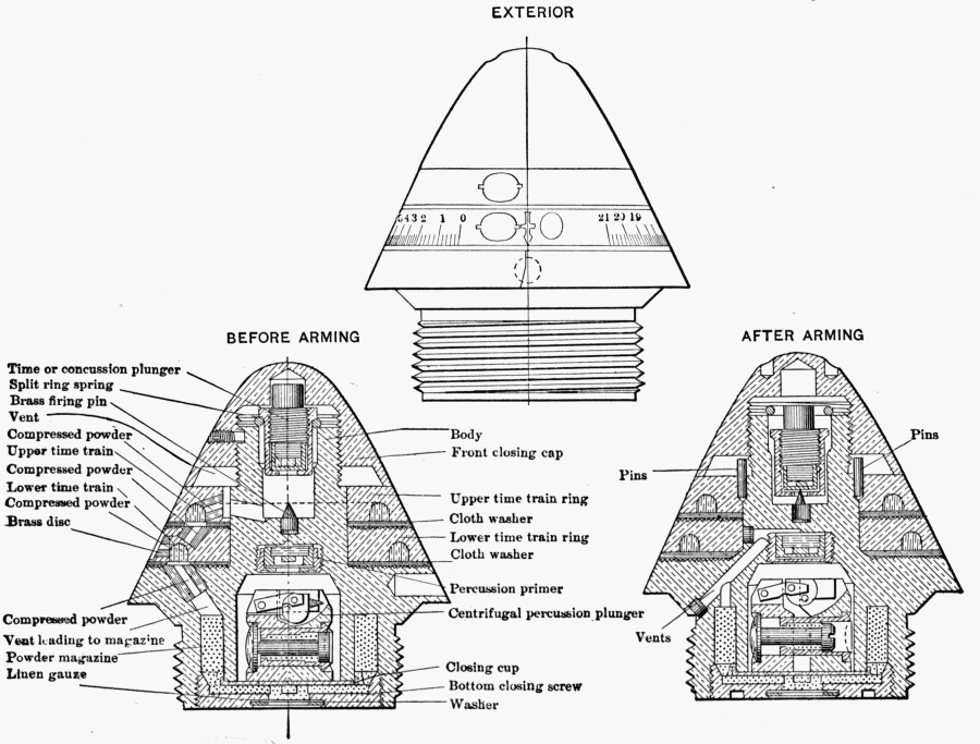
FRANKFORD ARSENAL 21-SECOND COMBINATION FUSE. (Centrifugal.)
EXTERIOR
BEFORE ARMING
AFTER ARMING
Fig. 42.
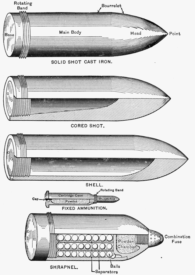
PROJECTILES.
SOLID SHOT CAST IRON.
CORED SHOT.
SHELL.
FIXED AMMUNITION.
SHRAPNEL.
Fig. 43.
Q. How are the interiors of shells coated?
A. With a special varnish furnished by the Ordnance Department.
Q. How are canister painted?
A. Black all over.
Q. How are shrapnel painted?
A. The whole body black, with a band of bright red on the
head below the fuse to indicate front charge, or on the cylindrical
portion of the body in rear of the copper band to indicate base
charge, depending on which class—base or front charge—it is.
Q. How are shrapnel distinguished from shell?
A. By the combination point fuse, which is always used with
shrapnel.
Q. What is meant by fixed ammunition?
A. That in which the powder-charge and projectile are fixed;
as examples, the ammunition for small-arm pieces and that for
the 6-pdr. R.F. gun (which is made in the same way, only of a
larger size), the powder being contained in a brass case, the projectile
being fastened to the end of the brass case and a percussion-primer
or cap being in the base of the same. (See Fig. 43.)
Q. Name the principal parts of a projectile.
A. The main body, the head, the bourrelet, the point, the base,
and the rotating-band. (See Fig. 43.)
Q. In what kinds of projectiles are fuses used?
A. Shell, cored shot, and shrapnel.
Q. What is the rotating-band made of?
A. Copper.
Note.—Recent experiments have shown the superiority of a
wider and heavier band. This new band will in all probability
soon be adopted.
Q. Give some instructions for filling shell.
A. Unscrew and remove the plug from the shell. Place the
filling-rod in the bag and fold the latter round the rod; insert it
through the plug-hole, taking care not to force the end of the rod
through the bottom of the bag; carefully push in the bag until
the neck only is in the plug-hole, a portion being kept outside, as
the whole bag must not be allowed to slip into the shell during
the operation of filling; then withdraw the rod and insert the
funnel into the neck of the bag, pressing the funnel well down
into the plug-hole; pass the filling-rod through the funnel and
gradually pour in a small quantity of the powder (say about half
the charge); take out the funnel and rod, lift up the bag and jerk
it, so as to "set" the powder well down to the bottom and to open
the bag; then reinsert the funnel and rod as before, and continue
the filling; choke the bag and cut off the superfluous choke. The
filling-rod should be moved up and down while pouring in the
powder, to facilitate its passage through the funnel, the powder in
the shell being tamped on at the same time. The use of a large
mallet against the side of the shell (any piece of wood will answer
the same purpose) will materially assist in getting the maximum
amount of powder into the shell.
When the shell is quite full withdraw the funnel and filling-rod,
and tie the neck of the bag with two hitches of twine close to
the top of the plug-hole. Cut off the superfluous choke, and push
the neck of the bag well down the plug-hole into the shell, then
screw in the plug as required.
Lead rings are supplied for the armor-piercing shell. The ring
is hammered into the recess round the head of the plug, and the
superfluous metal removed.
No preparation of the bag by pricking or otherwise is
necessary.
Q. Suppose a projectile when weighed on a scale comes to
1044 lbs. and that it has a blue-gray head and a blue-gray band
around its center of gravity, and below the copper band it is painted
yellow; state what gun it is for, what kind of a projectile it is
(whether a shell or solid shot), what it is made of, and if a shell,
what is inside of it.
A. It is an armor-piercing shell for a 12-inch gun; it is made
of forged steel, and is filled with explosive "D."
Q. What are shell and cored shot filled with?
A. Maximite, explosive "D," and rarely gunpowder.
Q. Why should shell always be coated carefully with a lacquer
or varnish before being filled?
A. Because some of the explosives now used to fill shell, though
perfectly stable and harmless in themselves, become very sensitive
explosives when exposed to steel or iron. The slightest friction
will sometimes detonate them.
Q. Why is red lead or white lead prohibited on fuse-threads?
A. Because, as with iron, some shell-fillers change into extremely
sensitive explosives on contact with lead.
Q. Why should all fixed ammunition and primers be stored
separately from magazines containing powder?
A. Because they are liable to explode by dropping or breaking,
etc., and the shock of one primer or charge exploding might
explode the whole magazine.
Q. Should rubber shoes be worn in magazines?
A. Yes.
Q. Why?
A. Because there are always priming-charges of black powder
in every section of smokeless powder, and powder-dust from these
might fill the air when opening cases, and a spark from a nail
in a shoe on the concrete floor would ignite it. There is also a
remote chance of the vapor of ether from the new smokeless
powder exploding when in combination with the air.
Rubber matting on magazine floors would be best.
Q. Define yarn, strands, jaws of rope, short- and long-jawed
rope, guys, spun-yarn, marlin, standing rigging, running rigging,
and a bight.
A. Yarn are called threads of hemp or other fibrous material
which compose a rope.
Strand is a number of yarns twisted together.
Jaws of rope are the interstices between the strands of rope.
Short-jawed rope is a rope tightly laid up together.
Long-jawed rope is a rope loosely laid up together.
Guys are stationary ropes to hold spars, such as pry-poles,
shears, etc., from falling.
Spun-yarn is made by twisting together very loosely two or
more well-tarred yarns. It is used for serving, seizings, stops,
etc., and is very pliable.
Marlin is also made of tarred yarns, but is tightly twisted and
is much harder and smoother than spun-yarn.
The bight of a rope is any part not an end.
A bight of a rope is formed by bending or doubling the rope
so as to form a loop.
Standing rigging are those ropes which are stationary.
Running rigging are those which run through blocks or pulleys.
(See Figs. 45 and 46.)
Q. Explain the difference between hawser-laid rope and
cable-laid rope.
A. Cable-laid rope is composed of nine strands, and is made
by first laying up three ropes of three strands each with the sun,
and then laying the three ropes together into one, against the
sun. Hawser-laid rope must be coiled with the sun. Hawser-laid
rope is a right-handed rope, and cable-laid is therefore left-handed.
(See Fig. 44.)
Q. How is the size of the rope denoted?
A. The size of the rope is always denoted in inches and
fractions, and is measured on the circumference. (See Fig. 44.)
Q. (a) How do you worm a rope? (b) Why?
A. (a) Worming a rope is filling up the divisions between the
strands by passing spun-yarn along them. (b) This is to render
the surface smooth for parceling and serving. (See Fig. 44.)
Q. (a) How do you parcel a rope? (b) Why?
A. (a) Parceling rope is wrapping narrow strips of canvas
about it, well tarred, put on with the lay of the rope. (b) To
secure it from being injured by rain-water or to prevent chafing
or cutting of a rope when a strain is brought against a rough
surface or sharp edge. (See Fig. 44.)
Q. (a) How do you serve a rope? (b) Why?
A. (a) Serving is the laying on of spun-yarn or other small
stuff in turns around the rope close together, and hove taut by
the use of a serving-board for small rope and mallet for large
rope. Small ropes are sometimes served without being wormed,
as the crevices between the strands are not large enough to make
the surface very uneven. But a large rope is always wormed
and parceled before being served. (b) The service is put on
against the lay of the rope. (See Fig. 44.)
Q. (a) How do you whip a rope? (b) Why?
A. (a) Whipping is securing the end of a rope with twine.
(b) To prevent it from fraying out. (See Fig. 44.)
Q. Make the following knots and give the use of each:
A square knot, a bowline, single sheet-bend (weaver's knot),
double sheet-bend, rolling hitch, round turn and two half-hitches,
clove-hitch, catspaw, blackwall hitch, sheep-shank, a marlinspike-hitch.
A. See Fig. 45. This figure illustrates the manner of making
these knots. Their uses are as follows:
Square knot: A quick knot to tie two ends of rope together
that will not slip.
Bowline: To form a temporary eye at end of a rope. This
knot can be easily made and remembered by making a marlinspike-hitch
and putting the loose end of the bowline through the
loop where the spike would go.
Single and double sheet-bend: To tie two ropes together.
These knots do not jam. When one rope is smaller than the
other the double sheet-bend is always used, making the double
turn with the smaller rope.
Rolling hitch: For shifting the fall from one end of a windlass
to the other.
Round turn, two half-hitches, and clove-hitch: These are very
useful in securing the guys of a gin to the stakes, etc.
Catspaw: To apply the purchase or tackle to the fall of another.
Blackwall hitch: To fasten the end of a rope to a hook when
there is a steady strain on rope.
Marlinspike-hitch: Very useful in putting on lashings, etc.
Q. What is a strap or sling, and what is its use?
A. A strap or sling is formed by knotting or splicing together the
ends of a short strand of rope. It is used for hooking tackles into.
Q. What is a splice?
A. Splicing is putting the ends of rope together by opening
the strands and placing them one into the other, or by putting
the strands of the rope between those of the bight.
Q. How is an eye-splice made?
A. Unlay the end of the rope for a short distance and lay the
three strands upon the standing part, so as to form an eye. Put
the first end through the strand next to it. Put the second end
over the strand and through the second, and then put the remaining
end through the third strand on the other side of the rope.
Taper them as in the short splice by dividing the strands and
sticking them again. The eye-splice is used to form a permanent
loop in the end of a rope. (See Fig. 48.)
Q. How do you make a short splice?
A. Unlay the strands for a convenient length; take an end
in each hand, place them one within the other, and draw them
close. Hold the end of one rope and the three strands from the
other in the left hand; if the rope is large, stop them down to it
with a rope yarn. Take the middle strand, which is free, pass it
over the strand which is first next to it, then through under the
second and out between the second and third from it, and then
haul it taut. Pass each of the six strands in the same manner,
first those of one end and then those of another. The same
operation may be repeated with each strand, passing each over
the third strand from it, under the fourth and through; or, as is
more usual, after the ends have been stuck once untwist each
strand, divide the yarns, pass one half as above described, and cut
off the other half. This tapers the splice. (See Figs. 45 and 46.)
Q. How do you make a long splice?
A. Unlay the ends of two ropes to a distance three or four
times greater than for a short splice, and place them within
one another as for a short splice. Unlay one strand for a considerable
distance and fill up the interval which it leaves with the
opposite strand from the other rope. Twist the ends of these
two together, then do the same with two more strands. The
two remaining strands are twisted together in the place where
they were first crossed. Open the two last-named strands,
divide in two, take an overhand knot with the opposite halves,
and lead the ends over the next strand and through the second
as the whole strands were passed for the short splice. Cut off
the other two halves. Do the same with the others that are
placed together, dividing, knotting, and passing them in the same
manner. Before cutting off any of the half-strands, the rope
should be well gotten upon a stretch. Sometimes the whole
strands are knotted, then divided, and the half-strands passed
as above described. This splice does not increase the diameter
of the rope, and it is used for splicing a fall or other rope that
runs through blocks. (See Fig. 45.)
Q. What is a tackle?
A. A tackle is a purchase formed by reeving a rope through
one or more blocks for the purpose of hoisting or pulling.
Q. Name the parts of a block.
A. The shell, sheave, pin, and strap. (See Fig. 49.)
Q. Describe the following blocks: Single, double, treble,
snatch, and tail.
A. Single blocks have one sheave; double, two; treble, three.
A tail-block is a single block strapped with an eye-splice and
having a long end by which to make the block fast temporarily.
A snatch-block is a single block having a notch in one cheek to
receive the bight of a fall. (See Fig. 49.)
Q. What are the standing parts, the running parts, and the
fall?
A. The standing parts are between the fasts and sheaves, the
running parts between the sheaves, and the fall the part held in
hauling.
Q. Describe the whip.
A. A rope through a single block. (See Fig. 49.)
Q. What is the power gained if the block be fixed?
A. None.
Q. Describe the whip upon whip.
A. The block of one whip is made fast to the fall of another.
(See Fig. 49.)
Q. What is the power gained?
A. Double if only one block moves. Quadruple if both move.
Q. Describe the gun-tackle.
A. A rope passed through two single blocks and made fast to
one. (See Fig. 49.)
Q. What is the power gained?
A. Double. Treble if block to which rope is made fast moves.
Q. Describe the luff-tackle.
A. A rope hove through a single and a double block and made
fast to the single block. (See Fig. 49.)
Q. What is the power gained?
A. Treble. Quadruple if the block moves.
Q. What is a luff upon luff?
A. A luff-tackle on the fall of another luff. (See Fig. 49.)
Q. Describe the single Burton.
A. A rope rove through two single blocks, with a hook in the
bight of the running part.
Q. What is the power gained?
A. Treble. Quadruple if both blocks move.
Q. How is power determined when one tackle is applied to
the fall of another?
A. It is equal to the product of their respective powers.
Q. What is mousing, and what is its purpose?
A. A seizing around a hook to prevent it from spreading or
unhooking. (See Fig. 49.)
Q. What is a bight of a hook?
A. The middle of a bend of a hook. (See Fig. 49.)
Q. Name the different parts of a garrison-gin.
A. It is composed of three poles (two legs and a pry-pole),
braces, a bolt, clevis, windlass, two handspikes, three shoes, and
a hoisting-apparatus consisting of two blocks (one triple and one
double). (See Fig. 50.)
Q. How much can be safely lifted with it?
A. 17,000 lbs.
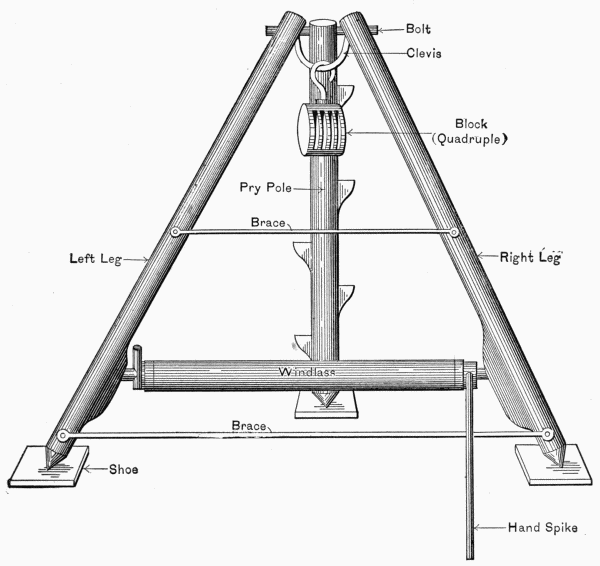
THE GARRISON GIN.
Fig. 50.
Q. How can the upper block be placed in
position after the gin has been raised?
A. By rigging a truce rope through the clevis and hoisting it up.
Q. Explain briefly how you would raise a gin.
Q. Describe the parts of the shears.
A. Two spars lashed together at one point, forming an inverted
V, the ends being called heels, the upper end the head,
and the part where the lashing is applied is called the cross.
The equipment consists of the following stores: Two double
blocks, two single blocks for gin-tackles; one double block, one
treble block, and one snatch-block for the main-tackle fall;
guys, head-lashing, heel-lashing, and straps for main tackle;
snatch-block, holdfasts, and some spun-yarn for mousing, etc.;
two cleats for heels to prevent lashing from slipping; stakes for
holdfasts for guys and heel-posts; two shoes for heels. (See Fig.
44.)
Q. What are shears used for?
A. For lifting heavy weights over the face of a wall or cliff,
or in other situations where the gin could not be used for want
of a footing for the pry-pole.
Q. How do you pass a shear-lashing?
A. Middle the lashing and take a turn around both legs
at the cross; pass one end up and the other down, around
and over the cross, until half of the lash is expended;
then ride both ends back again on their own parts and knot
them in the middle; frap the first and riding turns together
on each side with sennit. This will be useful in rigging
shears for hoisting guns when a gin is not available. Any two
spars that will support the weight can be used. (See Fig. 51.)
Lay the middle of the back guy in the cross; bring the left-hand
end up around the right leg and over the head of the left
leg; then carry the right-hand end around under both legs; let
it cross over the left-hand end, and seize them together with
spun-yarn.
Q. How is a square lashing made?
A. Place two spars at right angles and pass several turns
around two opposite angles of the X, then several turns around
the other two opposite angles. Continue this until the spars are
firmly lashed and will not move; tie the ends. This lashing is
used to make two spars rigid and at right angles to each other.
Q. How are shears rigged and raised?
A. Lay the heads of the spars on a trestle about three feet
high, the right leg above the left, so that they cross at about
twice their thickness from the ends, with the heels in their proper
positions.
Make a bowline-knot in the end of the fore guy and slip it over
the head of both legs.
Lay the middle of the main-tackle strap under the cross above
the fore guy; bring the ends up over the cross; hook the upper
block to them under the cross below the fore guy and mouse it,
taking care that the splice comes in the middle of the strap and
that the fall leads to the rear.
Drive the heel-posts on each side the heels about a foot toward
the head and one foot outside; lay the shoes under the heels;
make a timber-hitch around the inner posts with the heel-lashings;
pass three turns over the legs below the cleats, and hitch
the lashings to the outer posts. Drive four holdfasts for each
back guy, as follows: two on each side the line of the legs prolonged,
three feet apart, and two six feet in the rear of these.
Lay the ends of the guy-straps over the front stakes; connect
each pair of front and rear stakes with a strap twisted up taut
to insure the strain being distributed properly.
Drive two holdfasts for the fore guy, one in the rear of the
other, in the prolongation of the axis of the shears.
Hook the upper blocks of the guy-tackles to a bowline in the
end of the guys, and the single block to the guy-strap, and mouse
them all.
Ordinarily the fore guy can be worked without a tackle, belaying
it over the holdfasts, first taking a round turn over the one
next the shears. If not too heavy, the shears may be raised by
lifting the head and hauling on the guy-tackles, slacking the
heel-lashings as required, and tending the fore guy carefully to
prevent the shears falling over toward the rear.
Q. How are shears held in position after being raised?
A. By guys and holdfasts.
Q. What is the inclination or rake of the shears with the level
of the ground?
A. About 20 degrees.
Q. How can a change in the direction of the fall of the tackle
be made to lead to a capstan?
A. Hook the snatch-block to a strap placed below the cleat on
either, and pass the fall through it to the capstan.
Q. For what is the hydraulic jack used?
A. For lifting very heavy weights.
Q. What is the difference between the base jack and the horizontal
jack?
A. The former has the lever, socket, etc., at the top of the
jack, while the latter has the working parts near the base. (See
Figs. 52 and 53.)
Q. What is the principle involved in hydraulic jacks?
A. A pump operated by hand forces a small amount of alcohol
through a narrow valve into a recess containing a ram or large
piston-rod. As the alcohol is forced into this recess it raises the
ram: thus a weight upon the ram-head is raised. The alcohol is
prevented from running back into the main reservoir by valves
similar to those on all pumps.
Q. What is the best liquid to use in filling jacks?
A. For the base jack one part alcohol, two parts water; for
the horizontal jack one part alcohol, one part water, and for
both add a tablespoonful of sperm-oil.
Q. Name the principal parts of a jack.
A. The cylinder, ram, reservoir, socket, knuckle, piston,
piston-valve, pump, pump-valve, lowering-valve, packing-springs,
etc. (See Figs. 52 and 53.)
Q. How can a weight be raised when the jack will not go under
the weight?
A. By the use of a movable claw.
Q. Give some general instructions for the care and use of the jack.
A. Never fill with water, kerosene, or wood-alcohol. Keep
the ram down when not in use. If the valve sticks on its seat,
strike the lever a few sharp blows up and down, thus jarring the
valve. Use the alcohol supplied by the Ord. Dept.
Base jacks should never be used so that the head is lower than
the foot. A jack should be used once a week to keep the packing
in order.
Never apply more than 150 pounds to the lever: this equals
about the weight of the average man.
Q. Point out the following parts of the Model 1903, Cal. 30
magazine rifle:
Barrel,
Stock,
Butt,
Bayonet,
Bolt,
Trigger,
Sights,
Guard,
Cut Off,
Sleeve,
Sleeve Lock,
Stacking Swivel,
Extractor,
Ejector,
Windage Screw,
Firing Pin,
Cocking Piece,
Main Spring,
Follower,
Hand Guard,
Drift Slide,
Striker.
A. See Figs. 54, 55.
Q. Point out the following parts of the Ball Cartridge:
Case,
Primer,
Charge,
Bullet.
A. See Fig. 56.
Q. What is meant by the term caliber?
A. It is the diameter of the bore in inches.
Q. What is the trigger pull?
A. Three to four and one half pounds.
Q. What is the weight of the rifle and bayonet?
A. 9·69 pounds.
Q. What is the maximum ordinate at 1000 yards?
A. 21·26 feet.
Q. What is the weight of the bullet?
A. 220 grains.
Q. What is the weight of charge of powder?
A. 42 grains of smokeless powder.
Q. What is the muzzle velocity?
A. 2200 f. s.
Q. How many cartridges will the magazine hold?
A. Five.
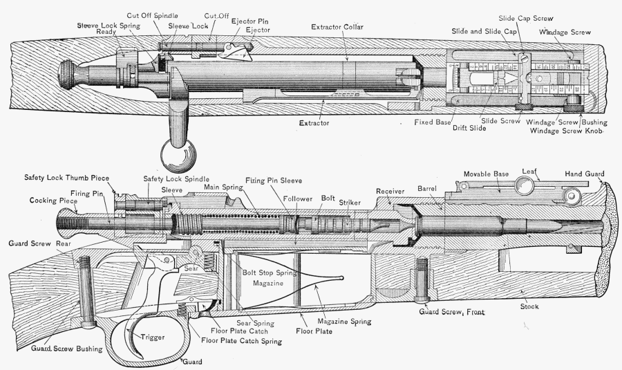
Fig. 54.
U. S. MAGAZINE RIFLE, MODEL 1903.
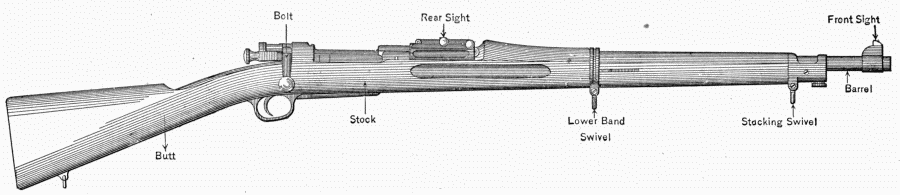
Fig. 55.
U. S. MAGAZINE RIFLE, CALIBER 30, 1903.
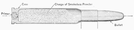
Fig. 56.
CALIBER 30 BALL CARTRIDGE.
Q. How is the rifle cleaned?
A. To clean the barrel, insert in the chamber a cartridge shell,
the front end of which has been filled with a wooden plug, and
close the bolt. Clean the bore with a rag saturated with soda
water, or if this is not obtainable, with water. Wipe dry with
clean rags. Remove the bolt and the cartridge shell, clean and
dry the chamber from the rear. Thoroughly oil the chamber and
the bore with a light coat of cosmoline oil. The stock and hand
guard may be coated with raw linseed oil and polished by rubbing
with the hand.
Q. When is the multiball cartridge used?
A. In cases where the great range of the service bullet would
endanger persons or property at a considerable distance from firing.
Q. Of what is a multiball cartridge composed?
A. The service case charged with 34 grains of smokeless powder
and two round balls.
Q. What is the effective range of the multiball cartridge?
A. 200 yds., when sights must be set for 350 yds. At 100 yds.
or less fire point blank.
Q. Illustrate to the instructor how you would set the sight for
a given range, using both open and peep sights.
Q. To shoot to the right (or left), which way would you move
the sight?
Nomenclature.
(For Reference Only.)
COMPONENT PARTS.
(One hundred and two in number.)
Barrel:
Barrel. }
Front Sight Stud. }
Front Sight Stud-Pin. }
Rear Sight Base. } Assembled.
Rear Sight Base Pin. }
Rear Sight Base. }
Spline. }
Bayonet:
Bayonet Blade. }
Bayonet Guard. } Assembled.
Bayonet Guard Rivets (2). }
Bayonet Catch.
Bayonet Scabbard Catch.
Bayonet Spring.
Bayonet Spring Cup.
Bayonet:
Bayonet Grip, right. }
Bayonet Grip Screw Washer. } Assembled.
Bayonet Grip, left. }
Bayonet Grip Screw Nut. } Assembled.
Bayonet Grip Screw.
Bolt:
Bolt. }
Extractor Collar. } Assembled.
Bolt Stop:
Bolt Stop Pin. }
Bolt Stop Spring. } Assembled.
Butt-plate:
Butt-plate.
Butt-plate Cap.
Butt-plate Cap Pin.
Butt-plate Cap Spring.
Butt-plate Cap Spring Screw.
Butt-plate Screw, large.
Butt-plate Screw, small.
Butt Swivel:
Butt Swivel. }
Butt Swivel Pin. } Assembled.
Butt Swivel Plate. }
Butt Swivel Plate Screws (2).
Cut-off:
Cut-off.
Cut-off Spindle.
Cut-off Spindle Screw.
Cut-off Spring.
Cut-off Spring Spindle.
Ejector.
Ejector Pin.
Extractor.
Firing Pin:
Cocking Piece. }
Firing Pin Rod. } Assembled.
Firing Pin Sleeve.
Follower.
Front Sight:
Front Sight.
Front Sight Pin.
Front Sight Movable Stud.
Front Sight Movable Stud Screw.
Floor Plate.
Guard:
Guard.
Floor Plate Catch.
Floor Plate Catch Pin.
Floor Plate Catch Spring.
Guard Screw, front.
Guard Screw, rear.
Guard Screw Bushing.
Hand Guard.
Lower Band.
Lower Band Spring.
Lower Band Swivel.
Lower Band Swivel Screw.
Magazine Spring.
Mainspring.
Rear Sight:
Base Spring.
Drift Slide. }
Drift Slide Pin. } Assembled.
Joint Pin.
Leaf.
Movable Base.
Rear Sight:
Slide.
Slide Binding Screw.
Slide Binding Screw Pin.
Slide Cap.
Slide Cap Screw.
Windage Screw.
Windage Screw Collar.
Windage Screw Knob.
Windage Screw Knob Pin.
Windage Screw Spring.
Receiver.
Safety-lock:
Safety-lock Spindle. }
Safety-lock Spring. }
Safety-lock Spring } Assembled.
Spindle. }
Safety-lock Thumbpiece. }
Sear.
Sear Joint Pin.
Sear Spring.
Sleeve:
Sleeve.
Sleeve Lock.
Sleeve Lock Pin.
Sleeve Lock Spring.
Stacking Swivel.
Stacking Swivel Screw.
Stock.
Striker.
Trigger.
Trigger Pin.
Upper Band.
Upper Band Screw.
APPENDAGES.
Cleaning Rod.
Front Sight Cover.
Oiler and Thong Case:
Oiler and Thong Case, Collar,
and Partition.
Thong Case Cap and Leather
Pad.
Oiler Cap and Dropper.
Oiler Cap Washer.
Screw-driver.
Thong and Brush:
Brush.
Thong Cord.
Thong Tip.
Thong Weight.