It is useful, before describing the mechanical parts or
mounting of the telescope, to explain the difference between
the two kinds of telescope, refracting and reflecting, employed
in astronomical work. The refracting telescope is the most
familiar type as the ordinary spyglass or draw-tube telescope
and the field or opera glass are all refracting telescopes. The
refracting telescope is so called because the light from the
distant object is refracted through a lens at the outer end of
the tube and forms an image of the object at the inner end,
just as a camera forms an image on the ground glass or film,
and this image is viewed and magnified by the eyepiece or
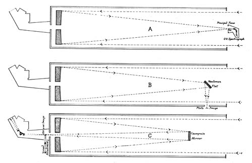
ocular. The reflecting telescope on the other hand has the
upper or outer end of the tube open and the light from the
distant object is reflected (hence the name) from a concave
mirror at the lower end of the tube, forming the image of
the object at the top, where it can be viewed and magnified
by the ocular as in the refractor.
Each type of telescope has its astronomical advantages and
disadvantages. The refractor is better suited for visual
observations such as the measurement of double stars and the
study of planetary detail and is less affected by temperature
changes than the reflector. On the other hand the reflector,
on account of its perfect achromatism, is the instrument par
excellence for photographic observations, and, as more than
three-fourths of modern astronomical work is photographic,
it appears to be superseding the refractor. This advantage is
increased by the fact that the refractor has apparently reached
the useful limit in size and that it costs at least three times
as much as a reflector of the same aperture. Although each
type of telescope has its characteristic type of mounting for
astronomical purposes, the principles are the same for each
and can probably be most easily followed by describing the
essential parts of the mounting of the 72-inch telescope.
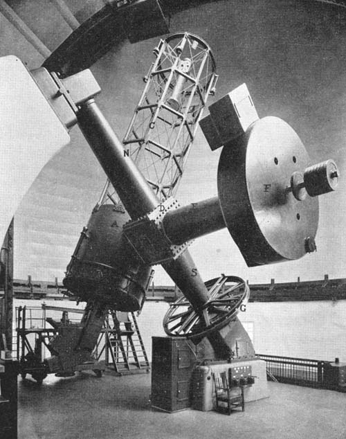
The tube performs the important function of carrying in
relatively invariable position and adjustment the optical
parts of the telescope. The tube of the 72-inch telescope is
31 feet long, 7 feet 4 inches outer diameter and weighs 15
tons. Its form and construction are well shown in Figs. 2
and 3. It consists of the main or central section A, Fig. 2
the lower section B which carries the main mirror and the
skeleton section C which carries the secondary mirrors.
The central section is a cylindrical steel casting heavily
ribbed on the inside about 6 feet high and weighs 7 tons.
The lower section is securely bolted to it through the flanges
shown and with the mirror and its supporting mechanism
weighs about 6 tons. The upper skeleton section is built
up of structural steel, 3 inch I beams, firmly braced and
rivetted together in the manner shown in the figures. A
special feature of this skeleton tube, making it more rigid
than any previous design, consists of the diagonal tension rods
in each rectangular compartment screwed up each to a tension
of about 2,000 pounds, so that the whole tube is under tension
in every position. This stiffness is essential for the proper
performance of the optical parts, as the principal and secondary
mirrors at bottom and top of tube respectively should
occupy the same relative positions in whatever direction the
tube is pointed.
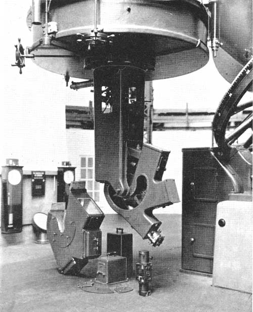
The telescope tube is firmly screwed at right angles to the
flanged end of a massive shaft 16 inches in diameter, called
the declination axis, extending through the cubical section
D of the polar axis NDS, Fig. 2, through the declination
sleeve E into the housing F. This declination axis is rotated,
carrying the tube with it, on ball bearings in D and F, this
rotation being effected by an electric motor with reduction
mechanism, gearing into a large spur gear attached to the
end of the declination axis, the whole being concealed within
the declination housing F. Hence the tube can be turned at
the rate of 45 degrees to the minute to any required position
up or down, north or south. The position in the sky, the
declination, corresponding to latitude on the earth, is read
on a large circle graduated into degrees within F and subdivided
into 5 minute intervals on the small auxiliary circle H.
As positions north or south are given by turning the tube
on the declination axis, so positions east or west are given by
rotation on the polar axis, so called because it points to the pole
of the heavens and is exactly parallel to the axis of the earth.
The Polar axis NDS Fig. 2, which is 21 feet long and weighs
9·5 tons, is built up of three steel castings, a central cubical
section D and two conical end sections, all securely bolted
together and turning in ball bearings on its ends. The
upper, north, bearing is carried in an adjustable pillow block,
by which the final parallelism with the earth’s axis is obtained,
bolted on the curved cement pier shown at the left or north in
Figs. 2 and 3. The lower, south, bearing is carried in a
massive cast iron pedestal bolted to the south cement pier.
The polar axis is rotated on these bearings, also at the rate of
45 degrees per minute, carrying the declination axis and tube
with it to any position east or west in the sky by an electric
motor and reduction gearing concealed within the south
pedestal. The position east or west in the sky, the right
ascension as it is called corresponding to longitude on the
earth, is read by means of a graduated circle shown above
G, Fig. 2, which is divided into 24 hours and each hour into
single minutes. While longitudes on the earth are occasionally
expressed as so many hours and minutes east or west of
Greenwich, right ascensions in the sky are almost invariably
given in hours and minutes rather than degrees.
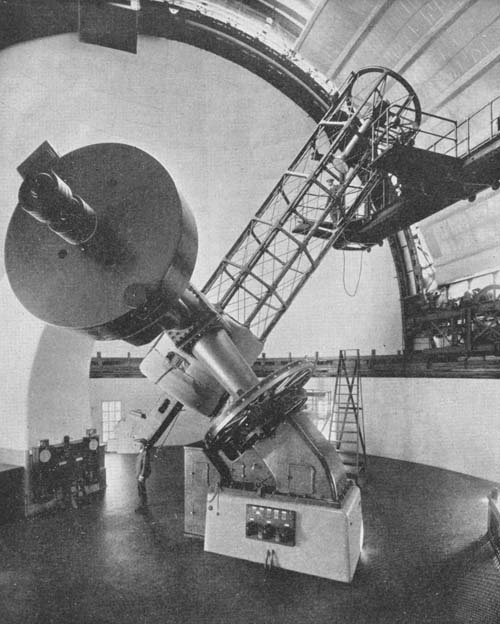
Fig. 3.—TELESCOPE FROM THE WEST
It is evident, by rotation of the telescope on the declination
and polar axes by means of the quick-motion motors, that the
tube can be pointed in any direction in the sky, towards any
star. But owing to the rotation of the earth on its axis from
west to east, which is the cause of the apparent motion of
sun, moon and stars from east to west, the telescope will be
quickly carried eastward of the star which will only remain
for an instant in the field.
The mechanism by which the rotation of the earth is
compensated for is called the driving clock and is contained in
the case L, Fig. 2, at the north side of the south pier. In the
lower half of the case a governor similar to the governor of a
steam engine is driven once per second by a train of gears in
the upper section actuated by a weight of 300 pounds below
the floor. If the speed of the governor tends to increase the
balls raise by centrifugal force and bring increased friction to
bear thus reducing the speed to normal while if the speed
tends to decrease, the balls drop and reduced friction quickly
allows it to accelerate to normal speed. A shaft with a coarse
screw thread on it, called technically a “worm” and situated
at the top of the case, is driven by intermediate gearing from
the governor at the rate of one revolution every two minutes.
The thread on this shaft engages into teeth cut in the worm
wheel G, Fig. 2, which is 9 feet in diameter. As there are
720 teeth very accurately spaced in this worm wheel, it is
driven around by the worm in 2 × 720 = 1,440 minutes, 24
hours, the same rate as the earth. This worm wheel, normally
loose on the polar axis on which it turns on ball bearings,
allowing the axis to be moved freely to any position, can be
rigidly clamped to it by pressing a button. When this is
done, it will evidently turn the polar axis and hence the tube
at the same rate as the earth but in the opposite direction,
on an axis parallel to the axis of the earth, thus exactly compensating
for the rotation of the earth. Hence any star at which
the telescope is pointed will automatically remain central in
the field. Owing to the great magnification all this mechanism
requires the highest grade of workmanship, else there will be
wandering of the image, a most annoying and troublesome
defect. Few telescopes are entirely free from periodic error
and that the 72-inch drives so regularly and smoothly is a
great advantage and evidence of the perfection of workmanship
throughout.
It has already been described how the telescope can be
moved by motors north or south and east or west at the rate of
45 degrees per minute. These motors are operated from small
switchboards on each side of the south pier, the one at the
west being seen in Figs. 2 and 3. The left-hand reversing
switch moves the telescope east or west, the centre switch
north or south and the right-hand switch revolves the dome
east or west. In addition to these quick motions of the
telescope for rapidly bringing it to the approximate position,
much finer and slower motions are required for bringing the
image exactly central and for guiding. These slow motions
are also operated by electric motors actuated by two small
aluminium switchboards attached by flexible cables to the
top and bottom of the tube. These switchboards can be
carried in the hands of the observer or rested on the observing
ladder. Pressure on suitable buttons moves the telescope
north or south, east or west at either one of two different
speeds, a speed of one revolution in 36 hours for centering the
image and a speed of one revolution in 30 days for guiding,
correcting for slight irregularities due to air disturbance or
other causes. Although these speeds may seem excessively
slow, the motion of the image even with the monthly rate is
at once evident on pressing the button and faster speeds
would make accurate guiding difficult. In addition to the
two quick and two slow motion motors there are two clamping
motors and one for automatically rewinding the clock weight,
seven in all. These with the three motors operating the dome
are all continuous current motors which can be started and
reversed more readily and have greater initial torque than
alternating motors. Each motor is supplied with an automatic
control, so that all that is necessary is to throw the
switch or press the button to start or reverse. Current is
supplied by a motor generator set on the ground floor.
A description of the method of setting upon the required
star, when, for example, photographing the spectra of the
stars, will help to make the operation of the telescope more
clearly understood. It is easily possible to pull the telescope
around by hand to the required star identified by eye among
the constellations. Although the moving parts of the telescope
weigh nearly 45 tons, so perfect are the ball bearings in which
it turns that a weight of 3 pounds at the upper end of the tube
is sufficient to set it in motion. However the settings can be
much more quickly and certainly made by turning the telescope
to the right ascension and declination of the star by the
electrical motions. A programme of the stars to be observed
with their right ascensions and declinations is prepared beforehand.
The observing assistant stands beside the small
switchboard on the south pier and rapidly moves the telescope
east or west and north or south until the indexes on the
graduated circles point to the tabulated positions, while the
dome can be turned to the required position at the same time
by means of the third operating switch. By pressing two
buttons the telescope is then firmly clamped and the driving
clock starts the telescope automatically following the star.
In the meantime the observer has inserted the plate holder in
the spectrograph and drawn the slide and by means of the
aluminium switchboard brings the star, which is generally
near the centre, exactly to the centre of the finder, when it
will be visible on the slit of the spectrograph through a guiding
eyepiece and can quickly be brought central and the exposure
commenced. The time required from the end of one exposure
to the beginning of the next, unless the stars are far apart in
the sky, does not generally exceed two minutes, a shorter
time than usually required for even quite small telescopes.
This rapid operation is due to special care in design and
construction and markedly increases the efficiency and
capacity of the instrument.
The mounting of the 72-inch telescope has several new
features not hitherto used and sets a new standard for convenience
and accuracy of operation. The observatory is
much indebted to the Warner & Swasey Co., who have made
most of the large mountings in America, for the spirit in which
they undertook and carried through this work. Their sole
object was to produce the best possible mounting regardless
of cost and no suggestion of the writer looking to improvement
was refused. To Mr. Swasey, the president, are due many of
the original features of the mounting and the beauty and
harmony of the design, while Mr. Burrell, the works manager,
is responsible for the simplification of the mechanism and the
beautiful co-ordination of the details. No greater testimony
to the perfection of design and construction can be given
than to say that after five years use there is no feature the
director would wish changed, and no single defect of construction
has been revealed.
It may be of interest to note the principal improvements in
this mounting.
1. All parts of the sky can be readily reached. This is not
possible with all types of reflecting telescopes.
2. The elimination of cylindrical bearings with cumbrous
friction-relieving devices, formerly considered necessary for
maintaining collimation and adjustment on declination and
polar axes, and the use of ball bearings for both friction-relieving
and collimating purposes has resulted in remarkable
ease of movement of the telescope.
3. Freedom from periodic or other errors in driving and
smoothness and freedom from “backlash” in slow motions.
4. Ease, speed and accuracy with which settings can be
made due to careful design and original features in setting
motors and setting circles.
5. Great stiffness of tube and improvements in method of
attaching and changing secondary mirrors.
6. Beauty and harmony of design and appearance.