Upon so potent a help as these two
last mentioned inventions, a water-work is,
by many years' experience and labour, so
advantageously by me contrived, that a
child's force bringeth up, an hundred feet
high, an incredible quantity of water, even
two feet diameter. And I may boldly
call it, the most stupendous work in the
whole world: not only with little charge to
drain all sorts of mines, and furnish cities
with water, though never so high seated,
as well to keep them sweet, running through
several streets, and so performing the work
of scavengers, as well as furnishing the inhabitants
with sufficient water for their private
occasions: but likewise supplying the
rivers with sufficient to maintain and make
navigable from town to town, and for the
bettering of lands all the way it runs; with
many more advantageous, and yet greater effects
of profit, admiration, and consequence:
so that deservedly I deem this invention to
crown my labours, to reward my expenses,
and make my thoughts acquiesce in way of
further inventions. This making up the
whole Century, and preventing any further
trouble to the reader for the present, meaning
to leave to posterity a book, wherein,
under each of these heads, the means to
put in execution and visible trial all and
every of these inventions, with the shape
and form of all things belonging to them,
shall be printed by brass plates.—Besides
many omitted, and some of three sorts willingly
not set down, as not fit to be divulged,
lest ill use may be made thereof,
but to show that such things are also within
my knowledge, I will here in myne owne
cypher sett down one of each, not to be concealed
when duty and affection obligeth me.
In bonum publicum, et ad majorem Dei gloriam.
NOTE.
The three last inventions may justly be considered
as the most important of the whole "Century,"
and when united with the 68th article, they
appear to suggest nearly all the data essential for
the construction of a modern steam-engine. The
noble author has furnished us with what he calls
a "definition" of this engine; and although it is
written in the same vague and empirical style,
which characterises a large portion of his Inventions,
it may yet be considered as affording additional
proofs of the above important fact.
The Marquis's "definition" is exceedingly rare,
as the only copy known to be extant is preserved
in the British Museum.—It is printed on a single
sheet without date, and appears to have been
written for the purpose of procuring subscriptions
in aid of a Water Company, then about to be
established.
"A stupendous, or a water-commanding engine,
boundless for height, or quantity, requiring
no external, nor even additional help or force to
be set, or continued in motion, but what intrinsically
is afforded from its own operation, nor yet
the twentieth part thereof. And the engine consisteth
of the following particulars:—
'A perfect counterpoise, for what quantity
soever of water.
'A perfect countervail, for what height soever
it is to be brought unto.
'A primum mobile, commanding both height
and quantity, regulator-wise.
'A vicegerent or countervail, supplying the
place, and performing the full force of man, wind,
beast, or mill.
'A helm or stern, with bit and reins, wherewith
any child may guide, order, and control the
whole operation.
'A particular magazine for water, according
to the intended quantity, or height of water.
'An aqueduct, capable of any intended quantity
or height of water.
'A place for the original fountain or river to
run into, and naturally of its own accord incorporate
itself with the rising water, and at the
very bottom of the aqueduct, though never so
big or high.
'By divine providence, and heavenly inspiration,
this is my stupendous water-commanding
engine, boundless for height and quantity.
'Whosoever is master of weight, is master of
force; whosoever is master of water, is master
of both: and consequently to him all forcible actions
and atchievements are easie.'"
It may now be adviseable to trace the history
of the steam-engine through some of its earlier
modifications; and we shall find that, although
the present form of this stupendous machine almost
deserves the title of an invention, yet that
many steps have been taken, and much labour
and much ingenuity expended, before it was
brought to that point from which the more modern
improvements may be said to have begun.
And whilst we admire the genius of those who
have perfected the application of a mighty power,
let us not refuse the tribute of praise to those,
who first pointed out that such a power existed.
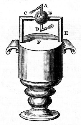
The first apparatus of this description, of which
any authentic account has been preserved, was
suggested by Hero of Alexandria, and consisted
of a vessel F in which steam was generated by
the application of external heat. The ball G was
supplied with the elastic vapour thus procured,
by means of the bent pipe E B, a steam tight joint
being provided for that purpose. Two tubes
bent to a right angle at A and D, are the only
parts open to the air, and as the steam rushes
out from very minute apertures, a rotatory motion
is produced. An account of this apparatus
is preserved in Hero's Spiritalia, published by the
Jesuits in 1693; and a copy of this highly curious
work, with a Latin translation prefixed, is now
in the Library of the London Institution.
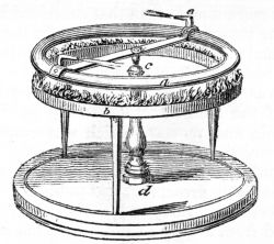
A modification of Hero's apparatus is represented
beneath:
It was constructed by Mr. Styles for the use
of the Editor in his public lectures. The circular
tube a is in this case supported by the upright
pillar c d; and the flame of alcohol in the trough b,
by generating high pressure steam, which rushes
from the apertures e, produces a rotatory motion.
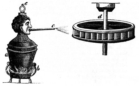
Brancas's revolving apparatus, as will be seen
by reference to the diagram in the preceding page,
was still more simple than that contrived by Hero.
A copper vessel filled with water, (in the original
figure made in the form of an ornamental head,)
was furnished with a pipe c, through which the
steam was propelled, and striking against the
vanes of the float wheel d, readily gave motion
to a pestle and mortar, which was employed in
the alchemist's laboratory.
The only work in which a description of this
engine has been preserved, was published in 1629;
it is exceedingly rare, and the above diagram is
engraved from a copy in the possession of Major
Colby.
A slight examination of the principle upon
which this simple apparatus is constructed, will
shew that no very considerable force could have
been obtained; as the steam passing through the
atmosphere in its passage to the wheel, must, to
a certain extent at least, be converted into water.
After the publication of the work by Brancas,
more than thirty years elapsed ere the publication
of the Marquis's "Century" recalled the attention
of the scientific world to this important subject;
and this invention, which he states as having been
completely carried into effect, was evidently very
different from that of his predecessors.
It is said that the Marquis, while confined in
the Tower of London, was preparing some food
in his apartment, and the cover of the vessel,
having been closely fitted, was, by the expansion
of the steam, suddenly forced off and driven up
the chimney. This circumstance attracting his
attention, led him to a train of thought, which
terminated in the completion of his "water-commanding
engine."[9] Of the Marquis's invention no
record has been preserved beyond the articles to
which we have already alluded in the present
work: and in the absence of other data, the Editor
readily introduces Professor Millington's design
for an engine on similar principles; and which,
with a few alterations, might be made available
for the purposes recommended by our author.
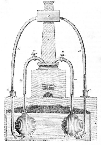
In this diagram, q represents a strong and close
vessel or boiler to contain water, set in brick work
like a common copper, with a fire-place r underneath
it, having a chimney s. The boiler thus constructed,
is intended to afford the means of producing
steam: and if we conceive two casks or
strong hollow vessels of any form to be placed
under the surface of the water, near the boiler,
as at t and v, and that each of these vessels has a
valve opening into it in its lower part as u u, and
two pipes w w, proceeding from the upper part of
the vessels to the top of the steam boiler q, while
two other pipes x x proceed from the lower parts
of these vessels into a cistern y, forty feet above
the level of the water; an apparatus thus constructed
will nearly form the water-commanding
engine, for if the vessels t and v are both filled
with water by the valves u u, and the cock z be
opened after the steam has accumulated in the
boiler, the elastic fluid thus generated will instantly
rush down into the vessel t, and when the surface
of the water is heated expel the whole of
its contents up the pipe a x, into the cistern y,
where it will be retained by a valve opening upwards
in any part of that pipe, as at a. This done,
the cock z must be shut, and after permitting the
steam to accumulate for a short time, that at b
must be opened, and the steam will rush into
the vessel v and perform a similar office, c being
the valve to prevent the return of the water.
When the steam is shut off from the vessel t, the
elastic fluid which had previously been introduced
to expel the water, will be condensed by the cold
media round it, and thus a vacuum will be produced
in the vessel t, consequently a part of the
water in which it is immersed will rush into it by
the valve u, and occupy the whole internal cavity,
thus putting it in a state of preparation for a second
opening of the cock z, by which its contents
will be again discharged into the cistern y, and so
of the two vessels alternately; for while v is emptying,
t will be filling, and vice versâ, which agrees
with the Marquis's account when he says, "that
the man is but to turn two cocks, that one vessel
of water being consumed, another begins to
force," &c.
The above suggestion for an engine capable of
raising water may be still further improved by
adding a suction pipe to the valves u u, and the
pressure of the atmosphere will increase the working
power of the engine more than thirty feet:
and should a less height be required, the forcing
pipe may be shortened in a proportionate degree:
indeed this fact was attended to by the next person
who claims the honour of having invented the
steam-engine, to which it may now be adviseable
to direct the reader's attention.
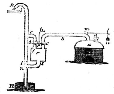
The engine suggested by Savery for the purpose
of raising water, consisted of a boiler a furnished
with a safety valve v. The steam-vessel r
was connected with the well H, by a suction pipe
n; and when water was to be raised the vessel r
was filled with steam, which rushing in, soon expelled
the air: when that was completely effected,
the communication with the boiler was closed,
and the steam condensed, which diminishing its
bulk, formed a vacuous space within the vessel;
the pressure of atmosphere then operating
upon the surface of the water in the well, drove
it up the pipe. In this form of the apparatus, the
inventor was seldom able to raise water more than
thirty feet: and when a greater altitude was required,
it was effected by the impellent force of high
pressure steam. This was accomplished by the ascending
pipe k, which was sometimes carried sixty
feet higher than the steam-vessel s; and a reference
to the great expansive force of steam will
show that this operation must be attended with
considerable danger. After condensing the steam
and filling the vessel r with water, a new supply
of steam was then introduced, which pressing on
the surface of the water, drove it up the pipe k;
and it will be evident that the pressure on the
internal surface of the boiler must be proportioned
to the height of the column of water thus
raised by the steam.
The principal objection to this form of the engine
arises from the great consumption of fuel,
a considerable portion of the caloric employed in
the generation of the steam being absorbed in
heating the new surface of cold water last raised
from the well; and where great heights are
required, there appears no mode of completely
obviating this objection. Should it, however, be
required merely to raise water about thirty feet,
there are few contrivances more economical or
better adapted for general use.
While speaking of Savery's apparatus it may
be adviseable to notice the very ingenious adaptation
of the same principle to the construction of
a gas engine, by Mr. Brown. In the latter case
a vacuum is formed by the introduction of an inflamed
jet of carburetted hydrogen gas, which
consumes the oxygen, and rarefies the nitrogen,
by the increase of temperature which ensues.
The vacuum thus produced is much more perfect
than would at first view have been supposed, from
the nature of the process resorted to by the patentee;
but the economy of employing carburetted
hydrogen gas as a substitute for condensible
vapour is still somewhat problematic.[10]
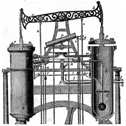
To more fully understand the nature of Mr.
Brown's engine, it may be better to revert to a
diagram, which will sufficiently explain its general
principles.
In the above view, the cylinders c and d, are
the vessels in which a vacuum is alternately effected;
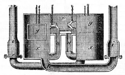
g i g and h j h are two pipes, leading into
the lower cylinders x x, shewn in the next page,
from which the water rises along those pipes to
fill the vacuum cylinders alternately. The water
thus supplied is discharged through the pipes B
into the tank or trough z, where it falls upon the
overshot water-wheel, and, by the rotatory motion
thus produced, gives power to such machinery as
may be connected to it. The water runs from
the wheel along a case surrounding the lower
half, into a reservoir v, from which the lower
cylinders x x, are alternately supplied.
The gas is supplied to the cylinders by the
pipes k k k, which must be, of course, attached to
a gasometer, or some other reservoir of gas. The
gas also passes along the small pipe l l (which
communicates also with the gasometer), and being
lighted at both ends of that pipe, is kept constantly
burning in order to ignite the gas within
the cylinders.
The gas being admitted along the pipe k, the
flame from the pipe l is now freely communicated
to the gas in the cylinder, through the orifice, by
the opening of the sliding valve s, which is raised
by the arm r, lifted by the rod o by means of the
beam.
The water in the reservoir v passing down one
of the pipes w, into one of the lower cylinders x,
causes the float y in that cylinder to rise, and,
pushing up the rod o, raises the end b of the
beam, which, of course, draws up with it the cap
f, and forces down the cap e of the other cylinder
c.
The alternate action of each cylinder is produced
by chains and rods, attached to a glass or
iron vessel p, more than half filled with mercury,
and turning upon a pivot; each end receives its
movements of elevation and depression from the
rise and fall of the projecting arms q, by the action
of the beam above; the mercury within
flowing to the lower end, giving an impetus, and
thus regulating the supply of gas to the cylinders,
and the movement of the slide in the trough v.
By this action the water from the reservoir flows
down the pipe w, into the vessel x, and produces
the elevation of the float y and the rod n, and
raises the cap e by the ascent of the beam at a.
The motion thus produced in one part of the
machinery, operates upon the corresponding
parts on the other side, and hence a corresponding
motion is obtained: the slider in the trough v,
moved by the action of the mercurial tube p, being
removed from its position, allows the water to
fall into the other pipe w; and, as it ascends,
suffers the float y to descend, and rising into the
main cylinder, then lifts again the beam at b, and
its connexions, and forces down the cap e on the
top of the other cylinder.
When the vacuum is produced in the cylinders,
the air must be admitted to allow the water to be
discharged, and the caps to be raised: this is
effected by a sliding valve in the air-pipe m m,
acted upon by chains t t, attached to the floats
in the reservoir, and as motion is given to them,
the valve is made to fly backwards and forwards,
so as to allow the free admission of atmospheric
air.
Chains u u, with suspended weights, open the
cocks in the pipe k k, and produce the alternate
flow of the gas, and regulate and modify its supply.
In the pipes g i g, and h j h, are clacks to
prevent the return of the water, when the air is
admitted into the cylinders.
A piston may be worked as is above described,
with the machinery attached; but it may also be
worked in a distinct vessel so as to communicate
with several cylinders, and, consequently, several
pistons may work at the same time, the air and
vacuum valves being opened and closed by similar
means to those adapted to work the induction and
eduction valves of steam-engines.
The atmospheric engine comes next in order,
and its claim to practical utility is of a very early
date.
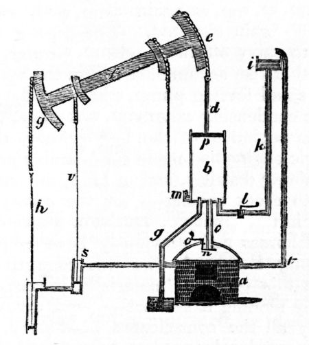
The cylinder b, is in this engine placed over a
boiler n, and if we suppose the piston p made to
fit air-tight, it will be evident, that it must be driven
up by the action of the steam beneath, should
a sufficient supply of heat be applied; when this
is effected, the condensible vapour may be reduced
to its original bulk, by the introduction of water
from the cistern i. In the working engine however,
the ascent of the piston is effected by the
action of the lever e g, acting on the fulcrum f.
To the end g of this lever or working beam is
attached the pump-rod h, and it will be evident
that whenever that preponderates over the piston
p, that the latter must be drawn up. On the readmission
of the steam, a new supply of condensing
water is introduced by turning the cock l,
and the pressure of the atmosphere above the
piston being unbalanced by any resistance beneath,
the end e is again depressed, and the
pump-rod again elevated. The pipe g is employed
to carry off the condensing water, which
would otherwise accumulate within the cylinder;
and the small forcing pump, with its rod v s, supplies
the condensing cistern i, by the pipe t.
At the beginning of the last century, the atmospheric
engine had made considerable progress
in the mining districts, and in 1718, the patentees
agreed to erect an engine for the owners of a
colliery, in the county of Durham, where several
hundred horses had previously been employed.
Mr. Henry Beighton, who was engaged as an
agent in this concern, materially improved the
engine by making it self-acting, and divesting it
of nearly all the complicated machinery, which
had been previously employed for that purpose.
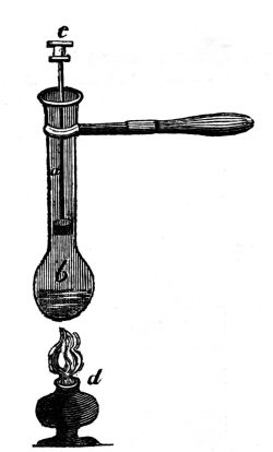
A very simple and at the same time ingenious
mode of illustrating the operations of an atmospheric
steam-engine will be found in the annexed
apparatus, suggested by Professor Brande, and
employed in his lectures at the London Institution.
The glass tube and bulb b is shewn with its
piston a, the rod being hollow and closed by a
screw c. If steam be generated by the spirit
lamp d, the air will speedily be expelled, and
after this is effected, the screw c may be closed,
and a working stroke produced by artificial condensation.
We come now to a new and distinct era in the
history of this important invention, and in noticing
the labours of Mr. Watt, we may almost speak
of his engine as the gigantic offspring of a hand
giving birth to an automaton, no less powerful
than that of the fabled enchanters of the olden
time.
Mr. Watt's first great improvement in the engine
of Newcomen may be best understood by
reference to the annexed diagram, in which a represents
the cylinder, and b its plug or piston
made to fit air-tight. The pipe d is furnished
with a stop-cock, by means of which the elastic
vapour is occasionally admitted.—A similar pipe,
furnished with a stop-cock at f, passes from the
other side of the cylinder, and enters the vessel g;
e being the reservoir to contain water.
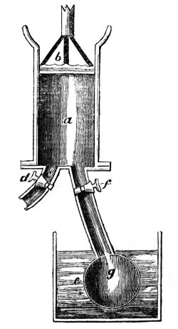
If we now suppose the piston at the bottom of
the cylinder, and steam admitted by the pipe d,
its expansive force will elevate the piston, and
when the air is expelled, the whole internal cavity
of the tube will be filled with condensible vapour.
On closing the steam-cock, and opening that connected
with the vessel g, a portion of the vapour
will immediately expand itself, and coming in
contact with the cold sides of the vessel, a portion
of its heat must be absorbed by the water
at e. A new portion of steam then descends,
and is also condensed, and indeed the same process
continues till the whole of the steam is drawn
from the tube. A vacuum being thus formed,
the pressure of the atmosphere will preponderate,
and the piston rod be depressed to the bottom of
the tube. On closing the stop-cock f, a new
supply of steam may be admitted by the other
pipe, and after raising the piston, the process of
condensation may be readily repeated.
The advantages that arise from this mode of
forming a vacuum are very considerable, not the
least important of which, is a saving of nearly
half the fuel.
In the old engine, the condensing water must
reduce the temperature of the internal surface of
the cylinder to that of the atmosphere, before a
vacuum could be produced, and when the condensing
water was applied more sparingly, the
elastic vapour remaining in the cylinder was found
to materially reduce the pressure of the air operating
above. From this it will be seen that the
great advantage of Mr. Watt's apparatus consists
in performing the condensation in a separate vessel,
so that the cylinder is always preserved at
the temperature of boiling water.
Having thus produced a vacuum without the
intervention of condensing water beneath the piston,
Mr. Watt's next improvement consisted in
closing the top of the cylinder, so that the piston-rod
worked through an air-tight hole in the centre
of the cap; and to ensure the necessary pressure
within the cylinder, steam with an elastic force
greater than that of the atmosphere was admitted
above the piston. The atmospheric engine of
Newcomen was thus converted into a steam-engine,
and its power was easily regulated.
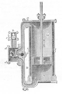
A cylinder and piston constructed on the most
improved principles may now be examined.
In the annexed diagram, the cylinder A is furnished
with a steam-tight piston, the rod of which
is supposed to be connected with the working
beam. B represents the pipe which admits the
steam from the boiler, the quantity being regulated
by the throttle valve c, and the elastic vapour
is now passing through the box d d, so that
it enters beneath the piston. At the same instant
of time, a communication is formed through the
aperture m n to the pipe p, which leads to the
condenser. When the piston reaches the top of
the cylinder, the sliding bridge or valve has its
direction changed, so that the pipe r, and consequently
the bottom of the cylinder, is connected
with the condenser, while a passage is opened from
the pipe m n to the steam box. Thus a communication
is alternately made between the top and
bottom of the piston.
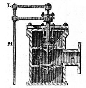
The slide-valve represented above is not invariably
employed in the double-acting engines, and
we frequently find the annexed contrivance resorted
to, in some of the best engines.
The pipe 14 represents the passage to the cylinder,
and a communication is now opened with
the steam chamber g. The raised valve is perforated
and a similar valve beneath closed by the
rod which passes through it. On closing the
valve g, the lower valve h is opened, and a free
passage between the condensing pipe beneath and
the upper part of the cylinder is the result. If
we now suppose a similar double valve placed at
the bottom of the cylinder, it will easily be seen
that an effect similar to that described in the
sliding valve will be produced.
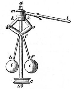
The speed of the engine is regulated by a very
ingenious contrivance introduced by Mr. Watt,
called the governor, and represented beneath.
The balls i i are supported by the bent levers
h f, and as they are made to revolve with the fly
wheel axis, by means of a band passing round the
pulley c, any increase in the speed of the engine
will cause the balls to diverge. The moment this
takes place, the shorter arm of the lever n is depressed,
and as the extremity l is connected with
the steam-pipe by the throttle valve, the supply
of steam must of necessity be diminished, and
the speed of the engine reduced.
As the working power of the engine depends
very materially on the accurate fitting of the piston,
it may be adviseable to examine some of the
modes of effecting this important object.
Mr. Smeaton, who greatly improved the atmospheric
engine, coated the under side of the
piston with elm or beech planks about two inches
thick; the wooden bottom being screwed to the
iron with a double thickness of flannel and tar, to
exclude the air between the iron and the wood.
By the adoption of this improvement, its property
of conducting heat was reduced, and the wood
having been previously jointed, with the grain
radiating in all directions from the centre, was
not liable to expand by the heated steam. This
piston was kept air-tight by a small stream of
water continually falling on its upper surface;
but in Mr. Watt's engine he was compelled to
make the piston fit tight without any other media
than the oil that was employed to lubricate it.
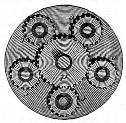
The piston is now cast with a projecting rim
at bottom, which is fitted as accurately as possible;
the part above the rim being about four
inches less than the cylinder, thus leaving a circular
groove for the hemp which forms the packing.
To keep this in its place, a lid or cover is
put over the top of the piston, with a projection
which enters into the circular groove for the
packing, and pressing upon it, the plate is forced
down by screws, which work into the body
of the piston. By this means the packing is
made to fill the internal part of the cylinder with
tolerable accuracy, and thus prevents for a time
any steam passing between the piston and the
cylinder. When, however, by continued working,
the packing ceases to fit, it occasions a waste of
steam, to remedy which, the cylinder cap must be
removed, and as this is attended with a considerable
degree of trouble to the engine-man, it is
seldom attended to till a considerable loss of
power has arisen. There are two improvements
on the piston, by which this inconvenience is to a
certain extent obviated.
In the first, by Mr. Woolfs, each of the screws
is furnished with a wheel or nut, and these are
all connected together by means of a central
wheel, working loose upon the piston-rod in such
a manner, that if any one of the screws be turned,
a similar motion is given to the remainder.
In a piston thus constructed, there is little difficulty
in drawing down the packing, by applying
a key to the square head of the projecting screw,
employed to communicate with the rest: the
key-hole being afterwards closed by a cap.
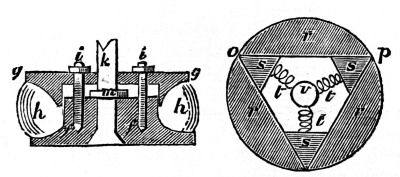
The second contrivance is by Mr. Barton, a
diagram of which, accompanied by a piston as it
is usually constructed, is shewn beneath.
In the first piston, the screws i i are made to
compress the packing h h, by acting upon the
plate n n, the piston-rod r being firmly attached
by the nut c.
In one of the modifications of Barton's piston,
on the contrary, the packing is dispensed with, as
the flexible springs t t t press upon the wedges
c c c, and expand the intermediate plates. A
break-joint is readily formed, by making the series
of plates double; the second set of plates
falling upon the spaces which occur between the
first row.
The action of the high pressure engine depends
upon the great elastic force acquired by steam,
when exposed to the action of heat at very high
temperatures.—It may indeed be considered as a
return to the principle of Brancas and the Marquis
of Worcester, as in this engine no condensing
water is necessary; and it acts merely by the
elastic or repellant force of steam. In the high
pressure engine, the condenser is taken away;
and the steam, instead of being converted into
water by artificial cold in a close vessel, is allowed
to escape into the atmosphere from one side of
the piston, while it is acting forcibly on the other.
The advantages of the high pressure engine
over that used with a condenser, are cheapness in
construction, and a saving of the whole expense
attendant on procuring a sufficient supply of condensing
water, which in some cases is an object
of considerable importance.
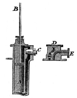
In the annexed section, the piston B passes
through an air-tight stuffing box, and the steam
is entering beneath it, by the four-way cock E.
If we now suppose the piston at the top of the
cylinder, a new arrangement of the communicating
pipe takes place, as the steam which was beneath
escapes, while a fresh supply enters above. The
four-way cock may be best explained by a section
in the opposite direction. Two pipes are seen at
the lower extremity of the cock, which communicate
with the upper and under sides of the piston.
The aperture D opens to the air, while the pipe
C serves for the admission of steam from the
boiler.
We have now to notice the double cylinder engine
constructed by Woolfs, which will be found,
by reference to the diagram in the preceding page,
to consist of a high pressure cylinder, connected
with a condensing apparatus.
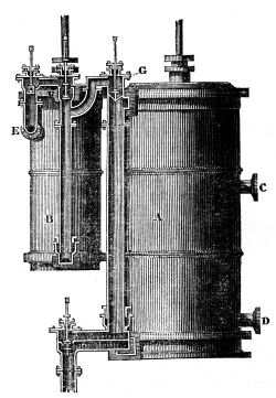
A and B represent the two cylinders, in the
larger of which the steam is allowed to expand
itself, after passing from the high pressure cylinder
B. The steam, which in the first instance is
of considerable elasticity, is admitted to the cylinder
B, by the tube and valve E, and entering
the cylinder above its piston, impels it to the
bottom. When this is effected, a communication
is opened between the upper part of the cylinder
B, and the under side of the cylinder A. The
communication between the cylinder B and the
steam-pipe E, is now reversed, and the steam is
made to press on the under side of the piston B,
a communication being at the same time formed
between the upper part of the cylinder A, and the
pipe leading to the condenser which is seen beneath.
So that if we suppose the two pistons
connected by means of their rods with one end
of an ordinary working beam, the upward and
downward strokes of each will be performed at
the same time. We have hitherto considered
the steam as passing direct from the boiler to the
cylinder B; this, however, is in reality effected by
a more circuitous route, as it is in the first instance
admitted to the steam-case of the larger cylinder
by the pipe C, and passing round a similar case,
encircling the cylinder B, it is then made to enter
at E. The pipe at D is merely intended to form
a communication for carrying back to the boiler
any water that may be produced by condensation
in the steam-case, before the engine arrives at a
proper temperature for working.
Having thus briefly examined the nature of
Mr. Woolf's engine, it may now be advisable to
revert to the boiler, by which he proposes to generate
steam of sufficient elasticity for the use of
the small cylinder, which requires elastic vapour
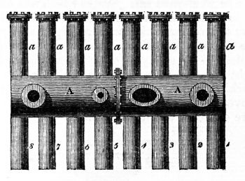
of great expansive force. The boiler, represented
by the diagram beneath, consists of a series of
tubes, of cast-iron, connected by screw-bolts with
the under side of a larger vessel A A, communicating
with the engine. The upper boiler is furnished
with four, and in some cases, with five
apertures; the first of which is intended for the
admission of water, to supply the waste which
continually arises from evaporation. The safety
valves, man-hole, and water-pipe are also shewn.
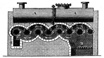
The mode of setting this boiler is also of considerable
importance, as it is advisable to give a
long and waving course to the chimney.
A A still represents the principal boiler, while
the figures 1, 2, 3, &c. indicate the passage of
the flame and heated air; a section of the chimney
being shewn at O.
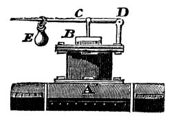
The steel-yard safety-valve which was employed
in all the early engines is simple, and the nature
of its construction may readily be understood.
A represents a portion of the upper part of the
boiler; B the safety-valve or plug made to fit air-tight
on the valve-seat beneath; C the lever
working on its axis at D, and furnished with a
moveable weight E, adjusted to balance the pressure
of steam within the boiler.
When steam of great elasticity is required, the
weight is placed at the extremity of the lever,
and as such, acts with greater force on the safety-valve,
than when removed to a point nearer to
the axis on which it revolves: so that should low
pressure steam, or that which has a less expansive
force, be required, it will only be necessary
to remove it nearer towards the axis on which it
turns.
The lever and balance-ball safety valve already
described, appear but little calculated for
those engines in which high pressure steam is
employed, as the engine-man, in an over anxious
zeal for the full performance of the machinery
confided to his care, has been frequently known
to increase the internal pressure of a large boiler
many thousand pounds beyond the resistance to
which it was originally proved. To prevent a
recurrence of those accidents, which first drew
the attention of the legislature to this important
part of the engine, it appears advisable to inclose
the safety-valve in an iron case, of which a section
is annexed.

The valve B in this case rests upon a conical
seat in the boiler A, and is furnished with a series
of small moveable plates lettered c, which are
employed to increase or diminish the entire weight
of the safety-valve, the whole being covered by
the box D; and as this is pierced with a number
of small holes, the steam readily escapes when the
expansive force exceeds the resistance offered by
the loaded valve.
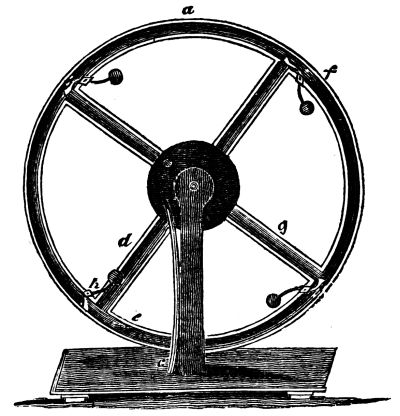
The patent revolving wheel invented by Mr.
Masterman, appears to promise the best results
of any rotatory engine yet invented, the friction
being much less than in any other apparatus in
which steam is employed as a prime mover. In
this engine, Mr. Masterman proposes to employ
water, or the fluid metal mercury as the immediate
agent, which he effects by inclosing it in the
tubular rim of a large wheel, furnished with valves
opening in one direction. This wheel, as is shewn
in the opposite diagram, is made to revolve on a
hollow axis connected with the steam boiler. The
arms or spokes which radiate from the axis are
also hollow; and on the admission of steam from
the boiler, it is conducted through the arm immediately
opposite, and entering the rim of the wheel,
comes in contact with, and presses against the
column of water beneath and the closed valve
above the arm. The water being previously
heated to the boiling point, no condensation ensues,
but the whole weight of water, which was
previously balanced in two columns of equal
height, is driven, by the pressure of the steam, to
the side opposite to that at which the elastic
vapour entered, and that side of the wheel will
necessarily preponderate. If this process be repeated,
the steam being allowed to blow through
each radiating arm in succession, a continuous
rotatory motion will be produced. Should it be
advisable to employ steam of less elasticity, a
condenser may be added, and that too without
materially increasing the expense.
The application of steam-engines to the propelling
of carriages on the public road, has hitherto
been considered as a refinement in mechanics,
rather to be wished for than a matter of reasonable
expectation. The locomotive engine was first
employed for this purpose by Messrs. Trevithick
and Vivian, in 1802; and it found a ready introduction
to the mining districts where rail-roads
are general. In some cases, five, six, and even
ten waggons laden with coal are dragged up an
inclined plane by means of these vehicles; and of
course impelled by a high pressure engine, from
the utter impossibility of carrying condensing
water in a moveable vehicle.
An engine of four horses' power, employed by
Mr. Blenkinsop, impelled a carriage lightly loaded
on a rail-road at the rate of ten miles an hour,
and when connected with thirty coal waggons,
each weighing more than three tons, its average
rate was about one-third of that pace.
When the locomotive engine was first tried, it
was found difficult to produce a sufficient degree
of re-action between the wheels and the tract
road; so that the wheels turned round without
propelling the vehicle. This inconvenience was,
however, obviated by Mr. Blenkinsop, who, when
he adopted the locomotive engine, took up the
common rails, on one side of the whole length of
the road, and replaced them by a series of racks,
or rails, furnished with large teeth. The impelling
wheel of the engine was made to act in these
teeth, so that it continued to work in a rack
which insured a sufficient degree of re-action.
From the great weight of an ordinary locomotive
engine as well as the construction of its impelling
wheel, it must be evident that the employment of
this species of prime mover on the public roads
would be in the highest degree destructive; and
as such that its use will for some years to come
be partially confined to the mining districts, in
which the greatest facilities are offered for its
general adoption. Indeed, we find in one neighbourhood
alone, and within a space of less than
thirty square miles, more than twenty miles of
road admirably adapted for this species of conveyance;
and it is a well known fact, that there
are many situations in which iron rail-roads
might be advantageously employed, in which it
would be quite impossible to open a navigable
canal. In illustration of the above fact, it may be
proper to state, that a company, with a large
capital, is now forming for the express purpose
of facilitating the conveyance of goods by locomotive
engines.
The mode of applying the steam-engine to the
purposes of navigation is equally simple with its
employment in our manufactures.
It is generally supposed that the steam-boat is
of very recent invention; on the contrary, however,
the possibility of employing steam as a prime
mover in the propelling of vessels was suggested
as far back as the reign of Charles I.
In one of the old tracts preserved in the library
of the London Institution there is a very curious
representation of a steam-boat, constructed by an
engineer of the name of Hulls. And this individual,
now so little known, was undoubtedly the
first who applied a steam-engine to the purpose
of navigation.
To impel a vessel by this means, two paddle
wheels, like those used in an under-shot water-wheel,
are connected by means of a long axis and
crank, with the working beam of the steam-engine;
and if this motion is not found sufficiently
rapid, a wheel and pinion are added, which,
although it decreases the effective power of the
engine, yet increases the velocity of the paddle
wheels.
To illustrate the great advantages possessed
by the steam-engine, even in its rudest state,
over every other species of prime mover yet enumerated,
it may now be advisable to examine its
effective force when employed in the working of
pumps. It has been found that one hundred
weight of coals burned in an engine on the old
construction, would raise at least twenty thousand
cubic feet of water twenty-four feet high; an engine
with a twenty-four inch cylinder doing the
work of seventy four horses. An engine on Capt.
Savery's plan, constructed by Mr. Keir, has been
found to raise nearly three millions of pounds of
water, and Mr. Watt's engine, upwards of thirty
millions of pounds the same height.
To the mining interests this valuable present
of science to the arts has been peculiarly acceptable;
as a large portion of our now most productive
mineral districts must long ere this have
been abandoned, had not the steam-engine been
employed as an active auxiliary in those stupendous
works. In the draining of fens and
marsh lands, this machine is in the highest degree
valuable; and in England, particularly, it might
be rendered still more generally useful. In
practice it has been ascertained that an engine of
six-horse power will drain more than eight thousand
acres, raising the water six feet in height;
whilst the cost of an engine for this species of
work, including the pumps, will not exceed seven
hundred pounds. This is more than ten windmills
could perform, at an annual expenditure of
several hundred pounds; while, in the former
case, the outgoings will not exceed one hundred
and fifty pounds per annum. To the mariner
also, the steam-engine offers advantages of a no
less important and novel nature than those which
have already been described. By its use he is
enabled to traverse the waters both against wind
and tide, with nearly as much certainty, and, as
the machinery is now constructed, with much less
danger, than by the most eligible road conveyance.
It too frequently, however, happens that
the faults of any new invention are unjustly magnified,
while its real advantages are seldom duly
appreciated; and this axiom has been fully verified,
in the clamour so unjustly raised against the
application of the steam-engine to nautical purposes.
Accidents are now, however, but of rare
occurrence; and it is more than probable, that
the great improvements which have been made
in the boiler and safety-valve will effectually secure
these parts of the engine from a recurrence
of such tremendous explosions as characterised
the first introduction of steam navigation. And,
lastly, the political economist must hail with the
most heartfelt gratification, the introduction of so
able and efficient a substitute for animal labour
as the steam-engine. For it has been calculated
that there are at least ten thousand of these machines
at the present time at work in Great
Britain, performing a labour more than equal to
that of two hundred thousand horses, which, if
fed in the ordinary way, would require above one
million acres of land for subsistence; and this is
capable of supplying the necessaries of life to more
than fifteen hundred thousand human beings.[11]
An ingenious foreigner, who lately visited
England, has published an estimate of the mechanical
force set in action by the steam-engines
of this country.
He supposes that the great pyramid of Egypt
required for its erection the labour of more than
10,000 men for 20 years:—but if it were required
again to raise the stones from the quarries,
and place them at their present height, the action
of the steam-engines of England, which are managed
at most by 36,000 men, would be sufficient
to produce the same effect in 18 hours.
THE END.
LONDON:
PRINTED BY C. ROWORTH, BELL YARD,
TEMPLE BAR.
Minor typographical and punctuation errors have been corrected without note. Irregularities and inconsistencies in the text have been retained as printed.
The cover for the eBook version of this book was created by the transcriber and is placed in the public domain.
On pages 84 and 85 there are two items both of which are numbered LXXXVIII. The table of contents reflects the same.
In the table of contents the following page numbers have been changed to match the book:
Page lxxxii:
33. A Needle Alphabet—39 changed to 38
38. A Sieve Alphabet—ibid. changed to 41
Page lxxxiv:
79. A total locking of Cabinet Boxes—78 changed to 77
80. Light Pistol Barrels—ibid. changed to 78