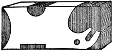
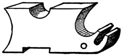
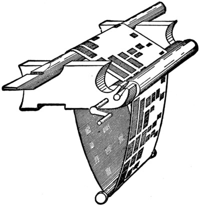
To make a model steamboat that will go is the ambition of most boys, but the
high price of engine and boiler deters many from doing so. In this chapter instructions
are given for making a model screw steamboat, the machinery for which
every boy can make for himself, by the exercise of a little ingenuity, at a very trifling
cost—which machinery, too, may be fitted into any boat, the rigging of which may
have gone by the board off the dangerous coast of the duck-pond.
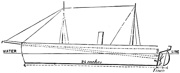
Fig. 1
First you must procure your boat; but if you should wish to make the boat
yourself you will need no instructions from me, as several capital chapters on boat-building
appear in another part of this volume. The only directions I need
give are, that your craft shall be very light, and hollowed out as thin as possible, be
twenty-four inches long, four inches wide at midships, and three and a half inches
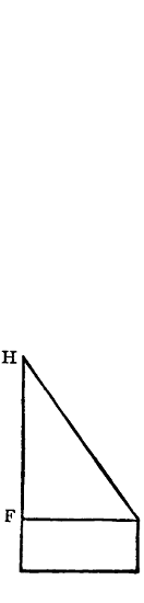
deep; the sternpost to be about an inch and a half within the stern, to be raking,
and two and a half inches high, as marked in Fig. 1; a strip of lead one-eighth of
an inch thick to be fastened along the bottom of the keel; the bows to be sharp,
and the boat to have a clean run aft. When the boat is finished paint it, and when
dry put it into water, and mark on the sternpost the height the water comes. Now
you must bore a hole in the sternpost right through into the boat, in the direction
of the top of the stem. This must be done with a red-hot wire; the hole is to be
three-eighths of an inch across.
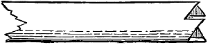
Fig. 2
The next thing to do is to get a brass tube from the gasfitter’s, or get a tinman to
make you one of tin three-eighths of an inch inside measurement. This tube must
be long enough to reach from the sternpost to three and a half inches beyond the
top of the stem. Four inches from one end of this tube solder a strip half an
inch
wide and one and three-quarter inches along, bending the middle of it half round
the tube, and bending the ends outwards; punch a hole in each end of this strip;
in this end of the tube cut four teeth like saw-teeth, one-eighth of an inch deep, like
Fig. 2. Put this tube in the boat thus. Push the end, without the tin strip, through
the hole in the sternpost from the inside of the boat, so that the tube is flush with
the wood, and fasten the other end by driving tacks through the holes in the tin
strip into the boat. Put some putty round the tube where it goes through the wood,
to keep the water out. Now make the deck of board one-eighth of an inch thick,
plane it, and fix it in its place by pins, leaving a gunwale of half an inch all round.
Stop up with putty, and mark with a pencil the boards on the deck. Bore a hole
near the stern one-sixteenth of an inch wide right through the deck and boat,
coming out under the counter one inch from the sternpost. This is the rudder-hole.
To make the rudder get a piece of brass wire one-sixteenth of an inch in diameter,
and six inches long; cut your rudder out of tin, and solder it on to the wire, so
that the heel of the rudder is flush with one end of the wire. Now push the other
end up through the hole in the counter, and bend it down on to the deck; this will
form the tiller, and, by pressing tightly on to the deck, will keep the rudder firm
and in its place for steering.
Two inches abaft the middle of the deck cut a hole three-quarters of an inch in
diameter for the chimney, which is a tube of tin three-quarters of an inch in diameter
and four inches long. Bore two more holes in the deck three-eighths of an inch in
diameter, one halfway between the stem and chimney, the other halfway between
the rudder and chimney; these are for the masts, which are made of wood, and
should stand about nine inches above deck; put a pin into the end of each
mast,
and cut the head off, leaving about half an inch of the pin projecting; put the
masts in their places, and the pins will keep them firm by being pushed into the
bottom of the boat.
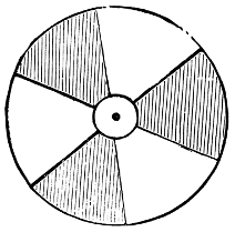
Fig. 3
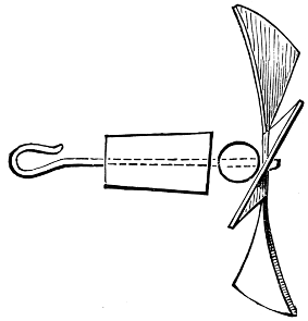
Fig. 4
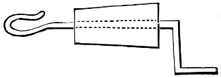
Fig. 5
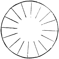
Make the propeller out of a circular piece of stout tin two inches in diameter,
cut as in Fig. 3. The dark parts are to be cut away. The projections are to be
three-quarters of an inch long. Punch a hole one-sixteenth of an inch in the centre,
and fix a piece of brass wire one-sixteenth of an inch, two inches long, in the hole,
to form an axle for the propeller. Twist each of the fans of the screw out of the
plane of the circle about a quarter of an inch, in the manner of the sails of a
windmill, as in Fig. 4. Now make two little wooden plugs three-quarters of an
inch long, and half an inch wide at one end, tapering to a quarter of an inch at the
other. Bore a hole through each from end to end one-sixteenth of an inch wide.
Take the propeller, and put a glass bead, that will fit easily, on the wire, and push
the wire through one of the wooden plugs from the large end; bend the wire into a
loop at the small end. Next take another piece of wire, two and a half inches long,
and make a similar loop at one end, and put the other end through the other little
plug, from the small end, and bend the wire into a handle (Fig. 5). Now the only
thing we want is the power. This is a strip of strong elastic about three and a half
feet long and a quarter of an inch wide; tie the ends together to make a band—a
large stout elastic ring will do, or two smaller rings looped together. Fasten a string
to the elastic, and pass the string through the tube in the boat, from the stern end;
hook the loop on the propeller-wire into the elastic, and push the wooden plug into
the tube so that the screw is clear of the rudder; draw the elastic, by the string,
through the other end of the tube, and hook the wire in the other plug into it;
take off the string and push the plug into its place. You must cut the plug away
so that the handle can catch in the teeth cut in the tube. Now the boat is
ready for use.
To use it wind up the elastic by the handle at the end of the tube, holding the
screw firmly with the other hand. As soon as wound up enough set the rudder and
put the boat into the water; release the screw, and the boat will go till the elastic
is quite unwound. The distance it will travel will be regulated by the extent to
which the elastic is wound up.
I have already described the method of making a small boat move through the
water by means of an elastic band, which is simply twisted up and then released, but
I have no doubt that many readers would like to possess a simple model boat to
work by steam.
Such models can now be purchased at all shops where mechanical toys are sold,
at prices varying from one shilling, the smallest, eight inches in length, to about
twenty pounds, the largest, five feet in length. Although all these boats really go
by steam, the application of the power is different in the different sizes.
The small boats are of course the simplest. In these the steam from the boiler
is conducted through a short pipe to the sternpost of the boat, where by its
pressure on the water in escaping it forces the boat along.
The next class have a further development of the application of steam-power.
In the centre of the boat, close behind the boiler, is a fan-wheel, turning on an
axle, which in the case of a paddle-boat carries the paddles, and in the case of
a screw carries the propeller. The steam is conducted from the boiler through a
short pipe to the front of the fan-wheel, which it blows round as it escapes.
The third class are the steamboats proper, varying in price from five shillings
upwards. In these the steam-power is applied as in ordinary engines. The
cheapest have one single-action oscillating cylinder, and the better sorts two double-action
cylinders.
As the two first-mentioned classes are, after all, only imitations, I do not think
it worth while to describe them; and of the third class I have chosen the largest to
describe, as I think that if it is worth while making a model at all, it is worth while
to make a good one, and the small engines take almost as much time to make, and
quite as much care to fit, as the large ones, and unless they are well fitted the loss
of power by friction and waste of steam is very great.
The engine here described is a model of a real screw-engine, with a pair of
double-action oscillating cylinders, having reversing gear and boiler complete, ready
to be put into the boat. It will be capable of driving a boat from four to five feet
long, provided it is well hollowed out and that the engine is made and fitted with
care, to reduce friction and waste of steam as much as possible.
In this section the exact dimensions of the several parts are given when
possible, but, owing to small differences in the size of the cylinders, I am only able
to approximate in some cases—in which cases, however, I have used the word
‘about,’ at the same time explaining how to obtain the exact measurements.
In all engines the most important parts are the cylinders, which must be well
fitted. Boys who have a turning-lathe and the requisite practice in metal-turning
can buy rough castings of all the parts of the engine for a few shillings and finish
them up themselves. But as only a few of my readers may be so favoured, I will
suppose that the cylinders are purchased ready for use. For these cylinders there
is a great range in the prices quoted by different firms, the prices varying for the
No. 4 cylinder from eight shillings at one firm to twelve shillings and sixpence at
another. Messrs. Theobald and Co., of 20, Church Street, Kensington, quote the
lowest prices to me, and have further consented to supply the No. 4 double-action
oscillating cylinders for this engine at seven shillings each to any one mentioning
this section.
The dimensions of these cylinders are three quarters of an inch in the diameter
of the bore, and an inch and a half in the length of stroke—i.e., an inch and a
half difference in the length the piston-rod projects from the top of the cylinder
when in and out to its fullest.
Get a pair of these cylinders which have the steam-blocks, pivot-pillars, and
screw-crossheads complete. Ask for the No. 4 double-action oscillating cylinders.
When buying them see that the piston-rods work true, and not to one side; see
also that the small indentations on the opposite sides to the steam ports are
correctly drilled, so that when the cylinders are swung between the blocks and
pivots they work true. To test this, place the block on its back on the table, and
put the cylinder on it, with the pivot in the proper hole for it. Now turn
the
cylinder round on the block and place a pin in the indentation, and if it is truly
drilled the pin will not move; but if not, the point of the pin will describe a small
circle. You can find out by this pin the exact spot where the pivot-hole ought to
be drilled.
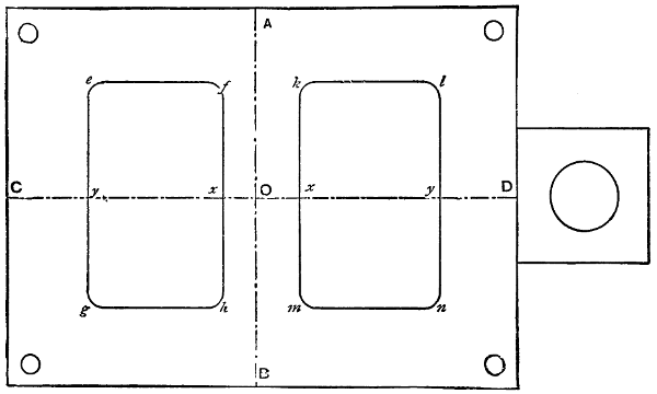
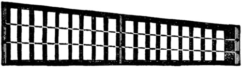
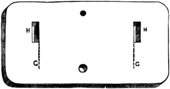
Fig. 1
We will now set to work at the construction of the engine, and the first thing to
be done is to make the top plate (Fig. 1). For this get a small brass plate four
inches long and three inches wide, and an eighth of an inch thick, with a projecting
piece an inch and a quarter square at one end of it, as in the figure. Get two of
these plates, as the second will be required for the bed-plate, but will not have the
square projecting piece. Take the first of these plates and square it up, so that
each corner is a right angle. Now proceed to mark it as in Fig. 1. Divide the
large part lengthwise into two equal parts by the line C D, and crosswise, also into
two equal parts by the line A B, these two lines
intersecting in the point O. From
this point mark off, each way along the lines O C and
O D, the following distances.
O to x a quarter of an inch, and x to y an inch and a quarter; and through these
four points draw the lines e-g, f-h, k-m, and l-n, making them two inches
long each, and projecting one inch on each side of the line C D. Join the points
e-f, g-h, k-l, and m-n.
Cut out the two rectangles so formed carefully, so as not to injure the lines.
This can be done easily by first drilling a small hole, about an eighth of an inch in
diameter, near one corner, and then putting a fretwork saw through it and fixing it
in the frame, and sawing the metal away just inside the lines. The saw must be
kept well moistened with water. The corners can be left circular, which will add
to the finish of the plate, and make the cutting with the saw easier.
After the holes are cut they must be finished quite up to the lines, but without
injuring them, with a fine-cut flat file. Through each corner of the plate a hole
must be drilled an eighth of an inch in diameter, and about an eighth of an
inch
from the edges, as in Fig. 1. The top plate is now ready for mounting the cylinders
on, which we will set about doing.
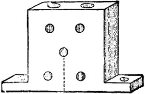
Fig. 2
Take the two steam-blocks (Fig. 2) and draw a pencil mark on each from the
centre hole to the bottom, and at right angles to it (Fig. 2). Next place the two
blocks back to back on the middle of the top plate, between the two large holes, so
that the pencil marks coincide with the line C D, and so that the bottom edges of
the faces coincide with the lines f-h and k-m. Be very careful in setting these
blocks right. When in their places mark the top plate through the screw-holes in
the projecting bases of each, and drill four holes straight down through the plate,
making them a little smaller than the holes in the bases of the blocks. Now replace
the blocks and fasten them there with two small screws each. These screws
correspond with the size of the cylinders, and can be purchased by the dozen,
together with taps, for each size, to make the thread in the holes with.
Next take the pivot-blocks and mark them with pencil, as the steam-blocks were
marked, and put them on the line C D on the outer sides of the large holes, using
the same care to get them properly centred along the line C D, and at right angles
to it, and about an eighth of an inch from the lines e-g and l-n. Mark the
screw-holes and drill them as before, and fasten the pillars in their places.
Now the cylinders can be hung. Unscrew the pivots about a quarter of an inch
and place the cylinders in their places, with the spindles in the proper holes for
them in the blocks. Now screw in the wire pivots till they catch in the indentations
drilled for them in the sides of the cylinders. They will now swing freely between
the blocks and pivots.
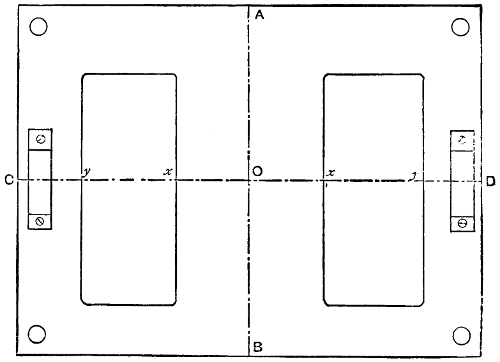
Fig. 3
Now to cut the bed-plate (Fig. 3). Take your second brass plate and divide it
by the lines A B and C D
as before. From the point O mark off each way along the
line C D the distances five-eighths of an inch from
O to x, and three-quarters of an
inch from x to y. Through these points draw four lines two inches long,
and
projecting one inch on each side of the line C D, and
parallel to the line A B. Join
the lines in pairs as before, and cut out the rectangles so formed. Finish up the
edges, and bore a hole in each corner, as in the top plate. On the line A B, and
half an inch from each end, bore two holes an eighth of an inch in diameter, and
countersink them at the top, as in the figure.
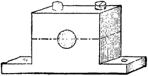
Fig. 4
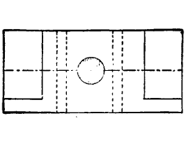
Fig. 5
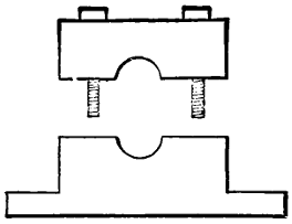
Fig. 6
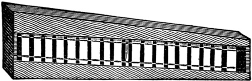
Now the bearings for the crank-shaft must be made. Fig. 4 is a perspective
view of one of these. Get two pieces of brass one inch long, half an inch wide, and
a quarter of an inch thick, as Fig. 5. Along the face of each block draw a line,
dividing it lengthwise into two equal parts, and in the centre of these lines drill a
hole right through the brass one-eighth of an inch in diameter. Cut the brass away
at the ends (as in Figs. 4 and 5), leaving the projecting pieces a quarter of an inch
long and a little more than one-sixteenth of an inch thick. Through each of these
flanges drill a hole, to screw the bearings to the bed-plate by. Drill two holes down
through the top of the block, passing one on each side of the bearing-hole (as in
Fig. 5, the dotted lines showing the positions of the holes). Drill a small hole
through the top of the cap into the bearing-hole, for oiling purposes. Cut the block
in two along the line passing through the middle of the bearing-hole with a stiff-backed
saw. This will make the block as in Fig. 6, having a movable cap which
can be fastened in its place with two screws. Screw these bearing-blocks in their
places, one at each end of the bed-plate, using the same care to get them properly
centred along the line C D and at right angles to it.
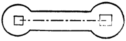
Fig. 7
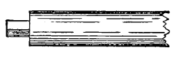
Fig. 8
We must now make the crank-shaft. This can be made with bent wire one-eighth
of an inch thick. But when made in this way it very seldom works steadily
and true. The best way is to build it up. You must get a piece of iron wire a
quarter of an inch in diameter and about two feet long. Part of this will be required
for the screw-shaft; straighten and smooth the wire and polish it up. Cut from the
end three pieces, one an inch long, the second two inches long, and the third one
and seven-eighths of an inch long. Next get four pieces of flat iron plate one-eighth
of an inch thick, one inch long, and half an inch wide. Cut them into the shape
shown in Fig. 7. The distance between the centres of the holes is to be a little less
than three-quarters of an inch. The largest hole is one-eighth of an inch square,
and the smallest hole a little less. The metal is to be left one-eighth of an inch
wide round the holes. Take the shortest piece of iron wire and cut one end of it
away, leaving a square pin and shoulder; the pin is to be three-sixteenths of an inch
long, and one-eighth of an inch square (Fig. 8). Cut both ends of the two-inch
piece and one end of the remaining piece in the same way. Counter-sink the largest
holes in the plates (Fig. 7) and rivet them on the pins of the portions of the shaft,
being careful that they are at right angles to the rods. The plates on the
two-inch
piece must be at right angles to each other. The pins should fit very tightly in the
holes, to make them firm when riveted.
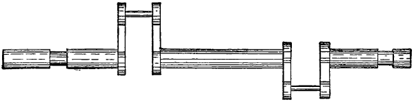
Fig. 9
Cut two pieces of iron wire one-eighth of an inch in diameter and five-eighths of
an inch long, and at each end of each piece make a pin and shoulder to fit the small
holes in the plates, leaving a full quarter of an inch of the wire between the pins
untouched. Join the cranks together in pairs by riveting in these wires, being
careful to keep the cranks at right angles to the shaft, and also to keep the several
pieces of the shaft in the same straight line. Place the shaft on the bearing-blocks
in the position it will occupy, with the cranks over the holes in the bed-plate and
with the longest end to the after end of it. Mark on the shaft the position and
thickness of the bearing-blocks, and cut the metal of the rods away in these places
till it is reduced to one-eighth of an inch in thickness, so that it will work freely in
the bearing-holes. The crank will now look like Fig. 9.

Fig. 10
The next step is to connect the top and bed-plates by four pillars. The length
of these will depend on the length of the piston-rod. They must be made of four
pieces of brass wire a quarter of an inch thick. Take one of the cylinders and a
sheet of paper; on this paper draw a line about six inches long, and at one end
mark the point A (Fig. 10).
Push the piston-rod in as far as it will go, and push the
pivot of the cylinder through the point A, and mark
on the line the point B, exactly
under the hole in the crosshead of the piston-rod. Now draw out the piston-rod as
far as it will go, and mark the point C exactly under the hole as before. Bisect the
portion of the line between B C in the point
D, and measure the distance between A
and D. Reduce this length by the distance the centre hole in the steam-blocks is
from the lower edge, and add to it a quarter of an inch for the height of the centre
of the bearing-block from the upper surface of the bed-plates, one-eighth of an inch
for the thickness of the bed-plate, and a quarter of an inch for riveting.

Fig. 11
This will give you the length of the pillars including the pins. File a pin and
shoulder at each end, as in Fig. 11, making the pins one-eighth of an inch in
diameter and a quarter of an inch long. Rivet a pillar firmly in each corner hole of
the bed-plate, and put the top plate on the top ends of the pillars, and rivet them
firmly in. Be careful that the pillars are upright. Rehang the cylinders and
unscrew the caps of the crossheads. Fit the cranks into the holes in them and
screw on the caps.
If the cylinders are made without screw-crossheads the pin of the cranks must
be placed through the hole in the heads before riveting the cranks together.
Unscrew the caps of the bearing-blocks, and put the crank-shaft into the bearing-holes,
and screw on the caps again. Oil all bearings and parts that work together.
Now you must get a heavy brass fly-wheel three inches in diameter, which can be
purchased with the other things, and costs about two shillings. This wheel has a
screw-bolt through one side of the centre block to fix it to the shaft by. Fix this
wheel on the long end of the shaft by tightening the screw. It would be better to
make a small hole in the shaft for the point of the screw to enter. The wheel must
have two iron pins, about one inch long, in the face of it.
Now if all the fittings are well made and oiled, the engine ought to work easily
and smoothly without noise if the fly-wheel is spun round.
Fig. 26 at the end of this section represents the engine as finished.
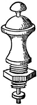
Fig. 12
We must now turn our attention to the boiler. For this you must obtain
some sheet copper; get the size known as 12-lb. copper—that is, the sheet two
feet by eight feet weighs 12 lb. You must also procure some copper tubing
one-third of an inch in diameter. Get also the following articles; two brass
gauge-taps, 1s. 3d. each; one steam-tap with union, 1s. 6d.; man-hole or water-filler,
1s. 6d.; spring safety-valve set to 30 lb. the inch, 1s. 4d. If these are not
already fitted with screw-blocks get them so fitted when buying them. Fig. 12
represents the safety-valve with the screw-block.
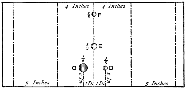
Fig. 13
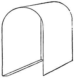
Fig. 14
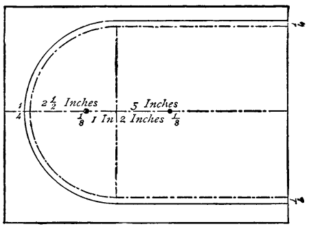
Fig. 15
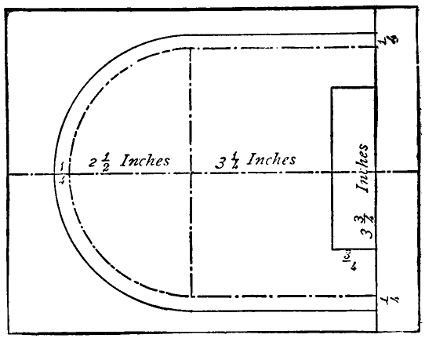
Fig. 16
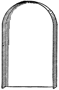
Fig. 17
Cut out of your copper a piece (Fig. 13) eighteen inches and three-quarters long
and nine inches wide. Draw a line A B at right angles to the two long sides, and
bisecting them. From A and B mark off the distances shown in the figure. Bore
the holes, C, D,
E, and F, the sizes marked, and in the places indicated. Bend the
plate so that the middle eight inches form a semicircle with a radius of two and a
half inches, and the five-inch parts are straight and five inches apart. Turn in the
remaining half inch at each side to form a foot for the boiler to stand on. The
copper will now be like Fig. 14, and will form the body of the boiler. Take two
small sheets of copper eight inches long by six inches wide, and mark one as in
Fig. 15 and the other as in Fig. 16.
Cut them out carefully, and in Fig. 15 bore
two holes one-eighth of an inch in diameter in the places marked. Turn up the
edge all round the sides and circular portions of both plates, a quarter of an
inch
wide, till it is at right angles to the other part of the plate, as in Fig. 17. Fit one
of these pieces on each end of the boiler body, so that the turned-up edges of the
ends fit outside the boiler body. The Fig. 16 is to fit over the end of the boiler that
has the two holes in the top. Solder or braze the ends to the boiler body.
I should strongly recommend all the joints of the boiler being brazed, as in the
event of the vessel steaming far from shore, the water running short, and the lamp
still burning, it would melt the solder, and the boiler would fall to pieces, but if
brazed it would not be injured if made red-hot. If you solder the parts together
you can do it yourself from directions given in the section on the magic-lantern, but
in soldering copper or brass together both surfaces of the joint must be first tinned
over.
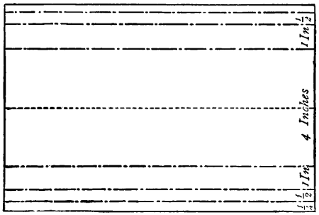
Fig. 18
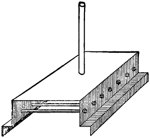
Fig. 19
If you decide to have the joints brazed you can get it done at the ironmonger’s,
if you first cut out and fit the parts together and explain what you require. The
floor of the boiler is made out of a piece of sheet copper nine inches long and seven
and a half inches wide. Mark it as in Fig. 18. Bend it along the lines into the
shape shown in Fig. 19. In the middle of the top make a hole one-third of an inch
in diameter. Bore seven holes one-third of an inch in diameter along each of the
sides and half way up. Cut a piece of the brass tube six and a half inches long, and
braze one end of it into the hole in the top, as in Fig. 19. Cut seven pieces of the
tube four and a half inches long each, and connect the holes on opposite sides by
brazing the tubes across into the holes, as in the figure. Take the screw-block off
the safety-valve and solder it over the hole marked D in Fig. 13 on the inside of the
boiler. Solder the screw-block of the steam-tap inside over the hole marked F, and
solder on the inside the two blocks of the gauge-taps over the holes in the end of
the boiler. The block of the man-hole must be brazed on the outside over the
hole C, Fig. 13.
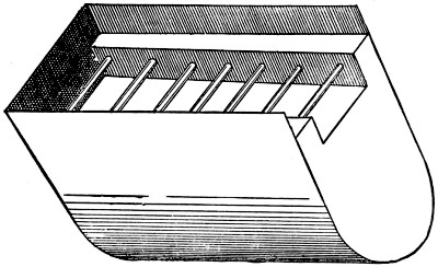
Fig. 20
Now fit the floor of the boiler in its place, passing the end of the tube, fastened
to the top of it, through the hole marked E in the top of the boiler, and projecting
about half an inch, and braze it in. Fig. 20 will show the position of the boiler
floor. The top of it is to be two inches from the bottom of the sides. Braze it in
firmly, being very careful to make all the joints steam-tight. Screw in the man-hole
cover, safety-valve, steam-tap, and gauge-taps. On the top of the boiler and
over
the projecting pipe solder a piece of brass tube seven inches long and an inch and a
quarter in diameter, raking aft a little, for the funnel. Now the boiler is finished
and ready to be connected with the engine. But before this can be done we must
make the reversing-gear.
Procure a block of brass, three-quarters of an inch wide, one inch long, and half
an inch high. Square this up true, and bore a hole right through it from top to
bottom, three-sixteenths of an inch in diameter. With the end of a rat-tailed file
taper the hole to a little more than a quarter of an inch at the top. Get a piece of
brass rod a little more than a quarter of an inch thick, and file one end of it taper to
fit the hole, and square off the bottom end of it, making the taper portion half an
inch long. Smoothen this with fine glasspaper, and then oil it and dust over it some
fine emery-powder, and put it in the hole in the block and grind the two together till
they fit perfectly. Cut the taper portion off exactly the length of the depth of the
block.
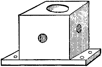
Fig. 21
Cut the brass away at the ends of the block, leaving a flange at the bottom, at
each end, a quarter of an inch long and one-sixteenth of an inch thick, as in Fig. 21.
In each flange bore two small holes, to screw it to the top plate by. Drill four
holes,
one through each side of the block one-eighth of an inch in diameter, right into the
centre hole and at right angles to each other, as in Fig. 21. Wipe the plug and
hole quite clean from the oil and emery, and replace the plug. Put a needle-point
into one of the side holes, and lying on the bottom of it and pressing against the
plug. Turn the plug round in the socket. Now move the needle-point to the top
of the hole and turn the plug round again.
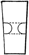
Fig. 22
Take out the plug, and there will be two lines one-eighth of an inch apart scratched
all round it, as in Fig. 22. With a small round file cut two grooves opposite each
other in the plug, by filing between the scratched lines, leaving the brass between
them one-sixteenth of an inch or less thick, as seen in Fig. 22. Drill a hole one-eighth
of an inch in diameter and a quarter of an inch deep down the top end of the
plug, and another up the lower end, to fit one of your small screws. Be careful that
neither of these holes enters the grooves.
Cut a small circular plate of copper seven-sixteenths of an inch in diameter,
and drill a small hole in the middle of it. Give this plate two or three taps with a
small hammer in the middle to hollow it a little. Put the plug in its place in the
block, and turn it over and place the circular plate on the bottom, with the concave
side to the plug, and fix it there with a screw. This will keep the plug from coming
out of the block. Solder an iron wire one-eighth of an inch thick and six inches
long into the hole in the top of the plug. Fasten the block on to the square
projecting piece of the top plate, first cutting out of it a circular hole half an inch
in diameter, to let the circular plate at the bottom of the plug drop into. The valve
must now be connected with the steam-blocks. Take two pieces of steam-pipe
three-sixteenths of an inch in diameter and an inch and a quarter long, and bend
them the shape of Fig. 23, so that the distance apart of the ends is the same as from
one hole in the top of one block to the corresponding hole in the other.
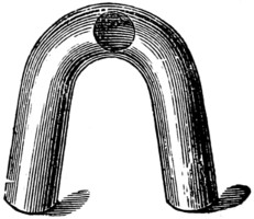
Fig. 23
Cut a hole in one side of the bent piece, as in Fig. 23, large enough for the
end of another piece of the pipe to fit into when tapered a little. This piece is to
be about three and a quarter inches long, and bent so as to pass from the steam-blocks
round the cylinder to the hole in that side of the reversing-valve block. Fit
the end of this pipe into the hole in the bent tube and braze it in the following
way. Rub a small lump of borax on a moistened tile and rub the joint to be
brazed with the mixture of borax and water. Cut a small piece of silver off a
threepenny-piece about the size of a large pin-head, and put it on the joint. Now
hold the end of the tube in the left hand, covered with a cloth, and with a blow-pipe
direct the flame of a spirit-lamp or gas-jet on to the joint till it is red-hot, when
the silver will melt and flow round the joint and fix it. If you cannot do
this
yourself a jeweller or watchmaker will do it for you. Make two of these bent
tubes with double ends, and solder them in their places, connecting the steam-blocks
with the reversing-valve. You must enlarge the holes, to let the ends of the
pipe in before soldering.
Bend a piece of steam-pipe, a quarter of an inch in diameter and eight inches
long, so that about two inches of one end stands at right angles to the other part.
The bend must be circular, or it will compress the pipe. Solder this end firmly into
the front hole in the reversing-valve. Bend another piece of the pipe about the
same length so as to go into the after hole of the valve and be parallel with the
other pipe. On the top of the boiler solder a piece of pipe about six inches long;
one end is to be bent up about one inch and inserted through a hole in the bottom
of the funnel, and directed upwards inside, the other end is to project about
one inch from the end of the boiler.
In the end of the steam-pipe solder the union of the steam-tap. Next make the
stand for the engine and boiler. Make it out of a piece of deal eighteen inches
long, five inches wide, and half an inch thick. Screw the bed-plate of the engine
on one end of it, so that the after end of the plate is flush with the stand. The
wood must be cut away under the square holes,
to let the cranks work in. Screw two strips of
copper at the other end, for the turned-in feet of
the boiler to slide under. Put them so that the
end of the boiler will be about three and a half
inches from the fore end of the bed-plate. Put
the boiler in its place, and bend the steam-pipe
so that the union can be screwed to the steam-tap
and the exhaust-pipe so that the end of it is opposite the projecting pipe from
the boiler, and connect these two ends with a piece of indiarubber tubing.
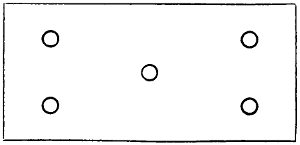
Fig. 24
The spirit-lamp must be in the shape of a closed box, made of sheet copper,
four inches wide, eight inches long, and three quarters of an inch deep. In the top
cut five holes, as in Fig. 24, a quarter of an inch in diameter. In these holes solder
five tubes half an inch long, and projecting from the top a quarter of an inch.
These are for the wicks. At the front end of the top solder a screw filling-tap. At
this end solder also a piece of small pipe four inches long. This is to be bent so
that it will stand upright outside the end of the boiler, and is to act as a vent, to
prevent the spirit being forced too freely up the wicks. Fill the wick-holes tightly
with cotton. Now fill the lamp half full of spirit. Pour hot water into the boiler
till it just flows out of the top gauge-tap. See that all the taps are turned off.
Light the lamp and put it under the boiler, and while steam is getting up oil the
engine well with sewing-machine oil. In a short time the steam ought to be up
and the engine at work. Try the reversing-gear and see if it acts properly. The
engine ought to work smoothly and without noise, and the frame ought not to jar.
We must now make the screw propeller. The boat, which I suppose already
made, is to be five feet long, ten inches wide, and eight inches deep, without the
keel, and hollowed out to about a quarter of an inch thick at the gunwales and
three-quarters of an inch thick at the bottom, and must be rather flat-bottomed, as
steamships are, so that the inside at the bottom is five inches wide.
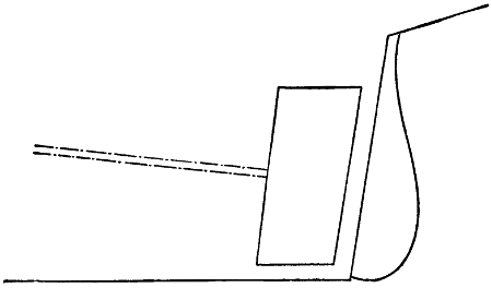
Fig. 25
Put the engine and boiler in the boat so that the boiler is a little abaft the
middle. Cut away the dead wood of the stern to make a hole four inches high and
two inches wide, as in Fig. 25. Bore a hole from the hole in the dead wood right
through into the interior of the boat, as shown by the dotted lines in Fig. 25. This
hole is to be directed to the centre of the fly-wheel of the engine. The shaft is
made out of the quarter-inch wire. Cut a square pin and shoulder three-eighths of
an inch long and an eighth of an inch square at one end of the shaft. Cut a piece
of the same wire three and a half inches long and drill a square hole in the middle,
and rivet it on the end of the shaft crosswise. In the hole in the stern of the boat
you must fix a tube and stuffing-box, which may be got—together with the screw,
which is to be a three-fanned one, measuring three inches across the fans—with the
other things, of Messrs. Theobald and Co., and similar houses.
Put the shaft in its place inside the boat, with the cross-piece resting across the
pins in the fly-wheel, about half way. Mark the end of the shaft so that it will
project an inch and three-quarters, and cut it off there. The bearing must now be
made out of a strip of brass
one-sixteenth of an inch
thick, three quarters of an
inch wide, and two inches
longer than the width of the
inside of the boat. In the
middle of this bore a hole
a quarter of an inch in
diameter, and bend one
inch of each end at right
angles to the other part.
In each bent piece drill
two small holes, to screw
them to the sides of the
boat by. Slip a piece of
tubing, one inch long and of a size to fit tightly on the shaft, close up against the
cross-piece. Put the shaft through the bearing and stuffing-box tube, and put the
cross-piece on the pins in the fly-wheel, and screw the bearing to the boat, so that
it is close against the tube on the shaft. The screw has a screw-bolt like the fly-wheel
to fix it to the shaft by. Drill a small hole in the shaft for it, and put the
screw on the end of the shaft and fix it by tightening the screw.
The deck of the boat must be cut the shape of the inside of the gunwales, out of
quarter-inch board, and is to be fixed so that the gunwales are one inch high. It
must have a hole cut in the middle to go over the boiler and pipes. A hole must
also be cut over the engine, and one also in the front part of the deck large enough
to admit your hand, to allow of your removing and lighting the lamp. These two
holes ought to be covered by movable skylights. A hole must be bored in the deck
just in front of the after-skylight for the wire from the reversing-valve to project
about half an inch. A wire handle must be fixed by riveting to the end of this, and
two pegs driven into the deck, one on each side, in front, to prevent the handle
being turned too far to either side. It should only turn one quarter of the way round.
If you have followed these directions your boat ought to steam for two hours and
a half without refilling the boiler; though the lamp would not burn all that time.
But if you solder a short piece of tube a quarter of an inch in diameter into the
front end of the lamp and quite at the bottom edge of it, and have a closed tin tank
with a like tube to it in the front part of the boat, and this tank is filled with spirits,
and connected to the lamp by a piece of india-rubber tubing joining the two tubes,
the lamp will supply itself from the tank as it gets low. The spirit from the tank
will not fill the lamp, but will just cover the hole of the tube and keep at that
height so long as there is any spirit in the tank. Such an engine as here
described would cost to purchase about £7 10s., and the boat with engine
complete, quite double that sum.
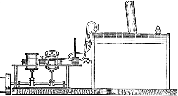
Fig. 26
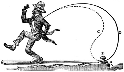
Fig. 1.
It is now some years since one evening at Christmas time I made one of a large
family party assembled at the house of a relative. The evening had passed very
pleasantly, and we were chatting together, and watching an arrangement which was
being made in a recess behind a pair of curtains, before which was a small table.
After some little time waiting in expectation, there suddenly appeared from between
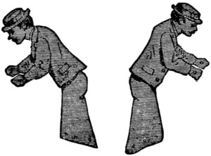
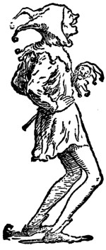
the curtains the agile gentleman who is portrayed at the head of this chapter. The
operator, concealed (all but a portion of his arm) behind the curtains, placing the
stand on the table, and cleverly manipulating the wire, caused the figure to dance
in the most amusing and ridiculous manner, creating the greatest merriment.
Afterwards, some lively jigs and reels being played on the piano, the figure footed it
away, cleverly keeping time to the music.
Coming across the stand of the figure brought the memory of it to my mind,
and I thought that making and working such a figure would be an amusing occupation
for boys in the long winter evenings.
The nigger, when he first came out, was rather an expensive toy, and I have not
latterly seen anything quite like it, but it is within the capabilities of any ingenious
lad to make one for himself at a very small expense. The one I have described was
about eight inches high, and had a proportionately-sized stand; but of course it can
be made of any size, though a smaller one would be quite as troublesome to make,
and not so funny. We will take the figure as being about the height described.
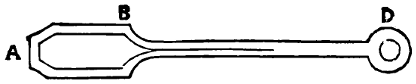
Fig. 2.
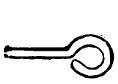
Fig. 3.
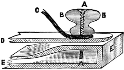
Fig. 4.—A Screw. B B Button.
C Wire spring. D Spring-board.
E E Stand.
The stand (A) is a piece of common deal about 13 in. long (for the figure eight
inches high; if the figure is made larger or smaller all details will of course also
be
proportionately more or less). The width of the stand is 23⁄4 in., and it is shaped as
in the sketch. On top of the stand is a spring-board; this board is shaped as Fig. 2,
rather less than 1⁄8 in. thick. From A
to the shoulder at B is 6 in., and from B to the
centre of the hole at D is 9 in., the whole length being therefore 15 in., and the
spring-board in consequence projecting 4 in. beyond the end of the stand. At D on
the stand is a button screwed to the stand, the screw passing through the hole in the
spring-broad, and by tightening up the screw the spring-board can be made more or
less rigid as required. The spring marked C C (which can be put in either way;
the dotted line is perhaps the least effective way, as the greater the spring—within
limits—the better) is made of steel or iron wire, one end being stuck into the back
of the figure and the other being bent as in Fig. 3, and put under the button, the
screw passing through all, as shown in Fig. 4.
The next thing is the figure. The head you must shape as fancy dictates,
and
the result will be the criterion of your cleverness as a wood-carver. If you cannot
manage to carve a head, you might buy one and stick it on, or make your figure out
of a large Dutch doll.
The head and body must be in one piece; the hat may be separate and glued
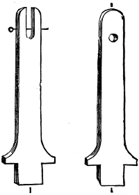
on, or carved with the head, as you prefer. The trunk must terminate as in Fig. 5,
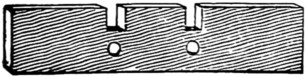
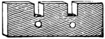
to allow the legs to fit in and swing easily. The legs must be made in two pieces
(Figs. 6 and 7).
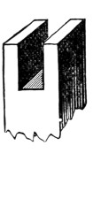
Fig. 8.
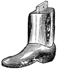
Fig. 9.
Figures 8 and 9 speak for themselves. The flanges must correspond of course
with the slots, and a pin is run through to keep the leg in its place, while it is fitted
loosely so as to swing. The lower part of the leg and boot should be made rather
heavy, so as to come down with some force on the spring-board.
When you have made your figure you can dress him if you like, but the legs
must be left free at the joints. Loose trousers of very light striped stuff can be
fitted, but they must not come much below the knee. The figure may be painted
a dark brown, the hat red or white, the boots of course black, and the stand green
or blue picked out with black, but you must use your taste in these matters.
When all is finished it is not difficult to make the gentleman dance; but still your
spring-board must be tightened to the right pitch, and the spring wire bent so that
the feet of the figure are just off the spring-board; then by slightly agitating the wire
the nigger will commence to dance; and it will entirely depend on its owner’s
tuneful ear whether he dances in time to the music or not.
Many a penny have I invested when, as a lad, visiting such places of amusement as
the Crystal Palace, Polytechnic, London Crystal Palace, and Pantechnicon, in
obedience to the entreaty forming the sub-title of this chapter, placed on the cases
containing models and figures; and I yet very vividly remember the delight
experienced from seeing the models start into motion. Indeed, even now, though
arrived at man’s estate, I rarely miss dropping a penny into the coffer of any case
containing a moving model when I chance to come across one.
Now these models, complicated as they may sometimes seem, can be easily
made by any boy who can use his tools, and, as the construction and exhibition of
them will afford great amusement, I propose in this chapter to give detailed practical
instructions for making them.
The subjects I have chosen are a windmill, a yacht in full sail, a watermill with
real water, dancing niggers, etc., so that there should be sufficient variety to suit all
tastes and skill.
The windmill being the simplest in construction of the working models, we will
take it first. The model, with the necessary pictorial background, is to be enclosed
in a case, which will bear somewhere on the front of it the legend forming the title
of this chapter, and the sails will go merrily round on dropping a penny into the box,
thus practically illustrating the old song, ‘Money makes the mill to go.’ The cost
of the whole model and case will be something under 8s. Now for the construction.
We will make the case first. For this get some half-inch deal board, 12 in.
wide, and plane it smooth on both sides. Cut the pieces for the back, top, bottom,
and sides, and square them up true. The dimensions of these pieces are as follows:
the back, 20 in. long and 12 in. wide; the top and bottom pieces, 12 in. long and
10 in. wide; and the two side pieces are each 20 in. long and 10 in. wide.
Having cut and trued up these pieces, proceed to form them into a box by
joining the edges by dovetailing, if you are skilful at cabinet-making, or get some
friendly carpenter to do it for you, if you are not up to the work. If you cannot
manage either to do it yourself or to get it done for you, the parts can be joined
with glue and screws, but the side pieces will have to be cut one inch shorter than
for dovetailing, in order that the top and bottom pieces may fit in flush with the
back piece.
The front of the box is to be closed by a door, of which the upper 12 in. is of
glass. Make the door out of a piece of half-inch board, 8 in. by 11 in. for the
bottom piece, and fasten to each end a strip of wood 20 in. long and
1⁄2 in. square,
so that one end of each strip is flush with the lower edge of the board, leaving 12 in
of each strip projecting beyond the upper edge.
These strips should have a groove 1⁄8 in. deep cut in them to hold the glass.
This you had better get cut for you. Put your glass, which must be about 111⁄4 in.
wide and 11 in. long, into the grooves, and the upper edge of it will be half an inch
from the ends of the strips. Fasten it in by a cross-piece of wood 1⁄2 in. square and
11 in. long, glued and screwed to the two side strips.
If you prefer it, the glass
can be put in the door
after the manner of window-panes.
In this case the
side and top strips must
have a rebate cut in them,
and the top edge of the
wooden portion served in
the same way. You must
choose for yourself which
method you will adopt.
Either will do, but the latter
is perhaps the neater.
In the top of the right-hand
end of the wooden
portion cut a slot large
enough to allow the necessary
penny to pass freely.
The door you will fasten to
the box with two small
brass hinges, and you must
put a small brass hook on
the other side of the box to
keep it fastened. But it
will be better if you do not
hang the door till the inside
arrangements are completed,
for fear of breaking
the glass.
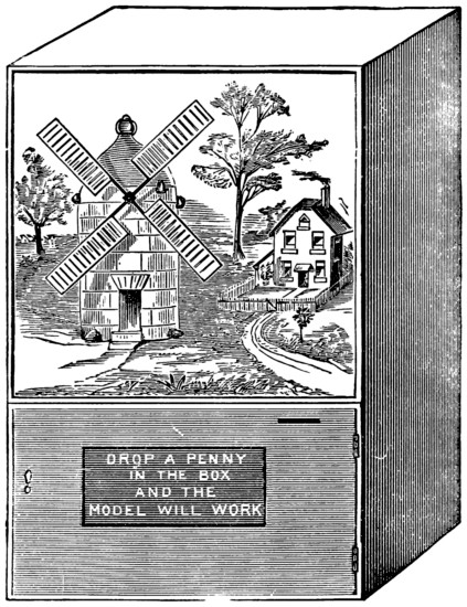
Fig. 1.
Fig. 1 represents the
case and model complete.
Divide the interior of the box into two portions by a horizontal partition, fastened
to the back and sides by glue and screws. The space below the partition is to be
7 in. deep. In the right of this space fit a cash drawer 9 in. long, 3 in. deep, and
3 in. wide, to hold the pennies. The side of this drawer nearest the machinery
must have a slot cut in it for the starting lever (A, Fig. 3) to work in. The sides of
the case are made of wood, so that the working of the model can only be seen from
the front and so that the flow of pennies will be larger.
Paint the back of the inside of the case to represent a landscape, or a
suitably
coloured picture can be pasted in, and serve the horizontal partition in the same
manner to represent ground, blending the back and ground together in a natural
manner. Paint also the top board to represent sky.
Make the mill out of wood or cardboard. It is to be 73⁄4 in. high, and the holes
for the spindle carrying the sails 53⁄4 in. from the bottom.
The sails are to be 91⁄2 in.
across, and can be made of wood or cardboard, or, better still, wood cross-pieces
with cardboard sails. Make the spindle of iron wire 1⁄8 in. in thickness. It should
be about 31⁄2 in. long. Flatten one end of the wire and drive it into the centre point
of the cross-pieces of the sails, being careful to keep it quite square and upright.
Pass the spindle through the holes in the back and front of the mill, and put a
knob of sealing-wax on the end, to prevent it working out when the mill is at work.
If the mill is made of cardboard, the inside must be strengthened with wood to
support the spindle.
We will next turn our attention to the mechanism to set the mill in motion.
Very few of my readers possess the tools and skill to use them necessary to cut and
fit the wheels, and, as it would come very expensive to get them made specially, it
will come very much cheaper to buy one of the cheap eight-day clocks, which will
suit our purpose admirably. These can be procured at most of the suitable shops,
and will cost about 5s. 6d.
Take the frame and works out of the clock case, and remove the pendulum and
hands, as you will not require them. If you now turn round the spindle on which
the minute hand fits, you will notice that, although the parts that carry the hands
are in motion, the rest of the wheels are stationary. On examining these hand-turning
wheels carefully, you will notice that the one carrying the minute hand is
fixed on the central spindle by jambing only, and that it turns a small flat wheel
which, in turn, gives motion to the wheel carrying the hour hand. This wheel is
fixed to a tubular spindle, which fits over the spindle of the minute-hand wheel,
which itself is tubular and jambs on the central spindle. Now, as you will not
require this movement, take off the hour-hand wheel, and after removing the
small
flat wheel, replace it and fasten it, together with the minute-hand wheel, to the
central spindle with solder.
Some of the cheap clocks have the minute hand fixed direct to the central
spindle, the hour wheel only being tubular. In this case the hour wheel and the
spindle must be soldered together after the small flat wheel has been removed. As
you will not require the escapement wheel, push on one side the small spring clip
that presses on the end of the spindle, and it will drop out.
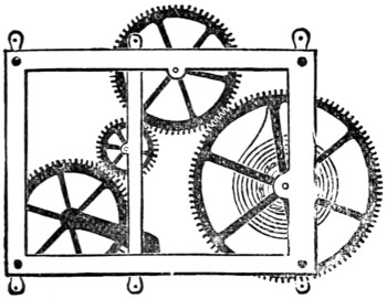
Fig. 2.
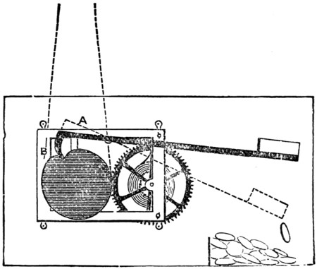
Fig. 3.
You will now want a pulley wheel (B, Fig. 3). One of the wooden sheaves used
in Venetian blinds for the cords to run over will do very well indeed, or if you
possess a lathe you can turn one for yourself. It should be 11⁄2 in. in diameter and
1⁄4 in. thick, having a small hole right through the centre, of a size to fit tightly on
the hour spindle of your works. Fig. 2 represents the frame after the wheels not
required have been removed. Fig. 3 represents the starting lever and pulley. This
pulley must have a notch 1⁄4 in. deep cut in one rim, for the hook of the lever to fall
into and stop the machinery. This pulley must not be more than 11⁄2 in. in diameter,
or you will not be able to get at the winding-up pin.
The frame carrying the wheels must now be mounted in its place under the
horizontal partition. For this purpose fasten with screws a block of wood to the
floor board, or back of the case, in such a position that the front of the frame is
about 51⁄2 in. from the front of the case, and so that the centre of the wooden wheel
is about 4 in. from the horizontal partition, and immediately under the spindle
carrying the sails of the mill. The horizontal partition must have a slot cut in it,
inside the mill, for the connecting cord to pass. The frame is to be fastened to the
supporting block by screws, but before doing this you must make the all-important
starting and stopping lever.
Get a piece of iron wire 1⁄8 in. thick, and about 10 in. long. Flatten one end and
bend down about half an inch of this end to form a hook, standing about at right
angles to the length; place this hook in the notch of the wheel when it is a little
beyond the centre of the pulley, as seen in the cut, and cut the wire to such a length
that the other end of it will be about 1 in. from the side of the case, when the gear
is in position. Drill a hole crosswise through the wire about 3 in. from the hook,
and fasten a small wire to the gear-frame, standing at right angles to it, about 21⁄2 in.,
measured horizontally from the spindle of the pulley, and near the top. This is for
the lever to turn on, as shown in the cut. At the free end of the lever solder a
piece of tin bent up on three sides like a small tray, with the edge not bent at the
extreme end. This tray or scoop should be about 11⁄2 in. square, and is to catch the
penny as it is dropped in.
The hooked end of the lever must be weighted, to slightly outbalance the other
part, so that the hook will drop into the notch in the pulley. The frame can now
be put in its place and fixed to the block with screws. Bend the long end of the
lever till the scoop is 31⁄2 in. from the under side of the partition. In bending the
lever you must also see that the scoop is horizontal, or the penny will not remain in
it long enough to start the gear. Now connect the spindle of the sails and the
wooden pulley-wheel by passing a silk cord or fine string round both tightly, and
knotting the ends together.
Now on winding up the spring and pressing down the lever the works will
start
into motion and the sails will revolve. The speed can be regulated by placing
the sails at such an angle that they will offer more or less resistance to
the air.
The slot in the door for the insertion of the penny must be cut three-quarters of
an inch below the upper edge of the wooden partition, and inside you must fasten a
tin trough to conduct the penny to the scoop at the end of the lever. This trough
must slope downwards to the edge of the scoop, or the penny will not fall into it, but
remain just inside the hole.
The model is now complete, and works as follows: The spring having been
wound up and the door closed, the works are kept from moving by the hook of the
lever catching in the notch of the pulley, but on a penny being put into the hole,
and sliding into the scoop at the other end of the lever, its weight presses down the
scoop end and lifts the hooked end out of the notch in the pulley, which turns
round, and continues to do so, carrying the sails of the mill round with it till the
notch again comes under the hook, which (the penny having fallen out of the scoop
into the drawer) falls into it and stops the machinery, giving one revolution of the
pulley for a penny. The pulley being twelve times larger than the spindle of the
sails, these will revolve twelve times each time the model is started. The model will
work about 204 times each time it is wound up.
Having finished the windmill to your satisfaction, we will now turn our attention
to the construction of a model requiring rather more complex machinery. This is
shown at Fig. 4, and represents a cutter-yacht sailing on the port tack, on a lee
shore; which, if carefully made, so as to produce the effect of the rolling and pitching
of a real yacht upon a real sea, will catch many a penny.
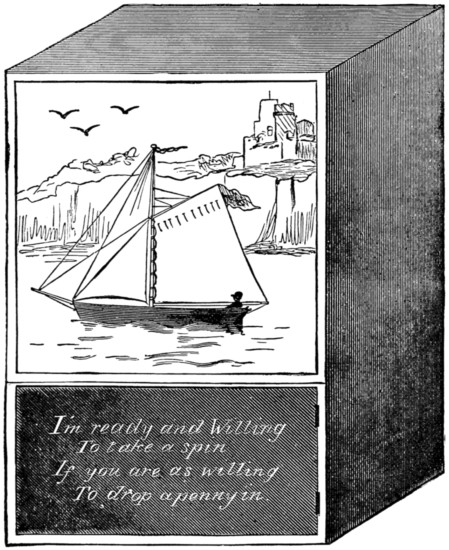
Fig. 4.
The case is made exactly in the same manner as the former one, and has the
same dimensions, but has no horizontal partition, only a cross-piece in the front,
half an inch square.
The inside of the back you must paint to represent a cliff and sky, or you can
paste a coloured picture of the same on it.
The yacht is to be 5 in. long, and is to be set in a sea of silk, which will be
described further on. If you prefer it, a full-rigged ship can be substituted for the
yacht. For the machinery you will require, as before, an eight-day clock movement,
some brass wire, and three or four pulley-wheels. Fig. 5 shows the front view of
the mechanism when complete, and Fig. 6 the end view of the same.
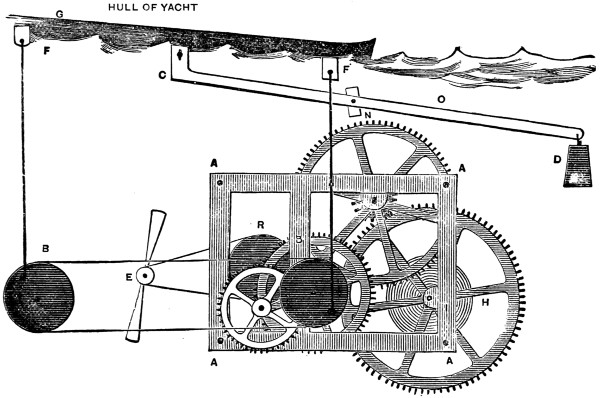
Fig. 5.
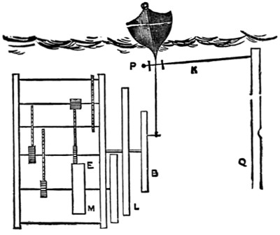
Fig. 6.
As was the case in preparing the works for the windmill, you will require to
make some alteration in the wheels, but in this case, as the hour and minute
movement will be required for the starting gear, the minute spindle only is to be
soldered to the central spindle, and the small flat wheel retained in its place. The
escapement wheel must also be retained. B (Fig. 5) is one of the wooden pulleys,
1 in. in diameter, fixed to the minute-hand spindle, and is in connection with
another pulley-wheel of the same size (B), turning on a screw fixed in a block of
wood fastened to the floor-board in such a position that the centres of the two
pulleys are the same height from the floor and 41⁄2
in. apart. O is a lever of wire
about 7 in. long, working on a pivot passing through it about
21⁄2 in. from the end
C.
This end is connected with the keel of the boat, and the other end is weighted, to
balance the boat.
Now take your boat, and at each end of the keel fix a small brass plate having
a hole drilled in it (FF, Fig. 5),
41⁄2 in. apart, and fix another plate drilled in the
same way at C, about 23⁄4 in. from the stem of the boat. Take two pieces of wire
5 in. long and bend one end of each into an eye and the other end into a hook,
crosswise with regard to the eye, and hook a wire into each of the plates FF, on the
keel of the boat, and
connect the other ends
with the pulleys B and
B by two small brass
screws passing into the
fronts of BB, as shown
in Fig. 5, and arrange
the pulleys so that one
of the pivots shall be
up while the other is
down.
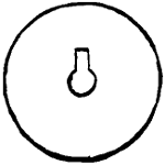
Fig. 7.
All these joints and
connections must work
freely, although not
loosely. The two pulleys,
BB, you must
connect with a cord
passing round both.
The pitch of the vessel
is regulated by the
distance the pivot
screws are from the
centres of the pulleys,
which should be about
half an inch. You
must next make the
regulating gear or fly E
(Fig. 5). To do this
you must take out the
pin from the left-hand
lower corner of the
frame-plate and prise
up the plate and take out the fourth wheel near R (Fig. 5), and on the spindle of it
fix a pulley, which can be readily done in the following manner. Cut a small notch
in one side of the hole in the centre of the pulley just large enough to admit a
piece of your wire. Solder about half an inch of this wire along one side of the
spindle about the middle of it, and force the pulley on to the spindle over this
piece, and it will jamb lightly and be keyed to it. Fig. 7 will show you how to cut
the hole in the pulley.
Now return the wheel to its place and re-fasten the frame-plate. Next you must
make the fly E. Get a small brass pulley about
1⁄4 in. in diameter, and to it solder a strip
of tin cut to the shape shown, but being wider in proportion at the ends, say 1 in. wide
and 4 in. long. Twist the ends of this fly askew like the fans of a screw propeller,
so that it will catch the wind in revolving. Now fix a block of wood to the bottom
of the case and fix the fly to it by a small brass screw passing through its centre, so
that it works freely and is 31⁄2 in. from the centre
of the driving pulley R and level
with it. Fasten a block of wood to the back of the case, in which you must fix the
screw N (Fig. 5) for the
lever O to pivot on. You must next make the starting gear.
This is shown in Fig. 8.
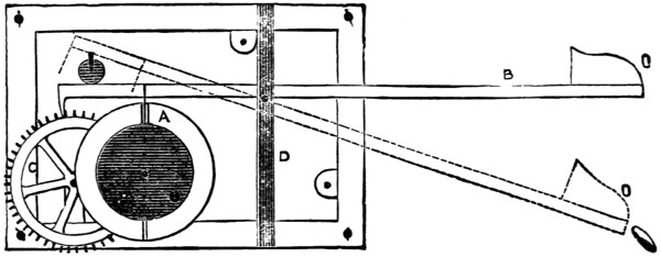
Fig. 8.
As we require the pulleys BB to revolve about twelve times, and as they are
attached to the minute-hand spindle, the hour-hand spindle will revolve once.
Therefore, on this spindle fix behind the pulley B, by soldering, a circular plate of
tin or brass, a little larger than the pulley, and cut in one edge of it a slot a quarter-inch
deep and one-eighth of an inch wide. Make your lever as before, but long
enough for the hook to catch in the teeth of the wheel C, Fig. 8; and solder a piece
of tin to the lever, to fall at the same time into the slot in the
disc A, Fig. 8. This
piece of tin must be long enough to keep the hook free of the teeth of the wheel C
during the revolution of the disc A. The length of the other part of the lever is to
be the same as for the windmill. Fig. 6 shows an end view of the machinery. K is
a wire connecting the keel with the lever Q, and helps to give the rolling motion so
suggestive to voyagers.
Fix your gear into the case in such a position that the keel of the boat will be
7 in. above the floor of the box, and bend
the starting lever so that the scoop will be
the same distance from the floor and front
of the box as in the former case. You have
now to make the sea. Get a piece of silk
of the kind called Persian, dark green or
‘undecided’ blue, about 18 in. square, and
in the middle of it cut a slit 6 in. long, and
in this slit fasten the hull of the boat with
glue, puckering up the silk, to form the
waves on the sides of the vessel. Crumple
the whole of the silk into miniature waves,
and glue the edges round the edges of the
case and to the strip of wood fastened
across the front 7 in. from the floor. Touch
the crests of the waves with white paint.
The silk waves will rise and fall with the motion of the vessel, and appear themselves
to be the cause of that motion. If the silk has a tendency to drop in, it can
be supported by a floor-board, 7 in. from the bottom, with a hole cut in the centre
5 in. long and 2 in. wide for the boat to work in, and a slot cut for the wire K,
Fig. 6. Be very careful that all the joints and connections work easily, or a jerky
motion will be the result.
Wind up the works and drop in a penny, and the lever hook will be lifted out of
the escapement wheel, and round will go the pulleys, causing the little ship to pitch
and roll till the slot A comes round again, when down falls the lever hook and stops
the movement. The pace of the movement can be regulated by the angle of the
fans of the fly catching more or less air.
As the minute spindle revolves twelve times, the pulleys will revolve only once,
which will give about seventeen revolutions each time of winding.
Fig. 9 is a view of a case of dancing ‘niggers,’ and is easily made. In the
sketch the figures are one-third the real size.
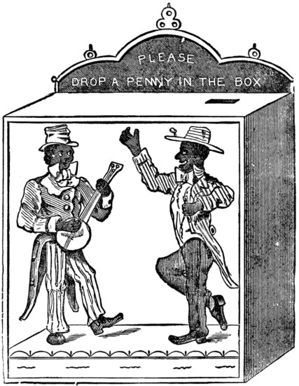
Fig. 9.
The case measures 9 in. high, 7 in. wide, and 7 in. deep. The back forms a
hinged door by which you can get at the gear. The slit for the penny is in the top,
and near the right-hand back corner. The legs of the right-hand figure are both
made separate from the body and
jointed at the knees. They are
fastened to the body by small
pins, to allow of free working.
This figure you must strengthen
by glueing a piece of wood behind
it 1 in. long, 1⁄2 in. wide, and
1⁄4 in. thick. The other figure has
only the left leg moveable, and
must not be jointed at the knee.
Glue a strip of wood about 1⁄2 in.
wide and 1⁄4 in. thick right up the
back of this figure, and glue it to
the floor board. The left leg must
have a similar piece of wood
glued behind it, and projecting
1⁄2 in. longer at the thigh end. Fix
the leg to the body by a small pin,
for it to work freely on, and in the
piece of wood projecting fix, at
right angles, a piece of wire about
2 in. long, and cut a curved slit
in the background for this to
work in, when the figure is about
1 in. from it.
This background you must
make out of cardboard, and fix
about 3 in. from the front of the
case, which is glass. The background
you can paint to any design you please, such as a street scene, or on
the sands, and the floor to correspond.
Behind the right-hand figure cut a vertical slit in the background about 1⁄8 in.
wide and 2 in. long, so that the centre of it comes opposite the centre of the figure
when the feet are just touching the floor. Fix a piece of wire about 7 in. long into
the centre of the figure behind, and at right angles to it, and bend this wire downwards
at right angles about 2 in. from the figure. About 1 in. behind the background
fix an upright block of wood, to come as high as the centre of the figure, and in
front of it fix two small staples, one near the top, and the other about 2 in. lower,
but directly under it. Into these slip the end of the wire attached to the figure, after
passing it through the slot in the background. This will keep the figure in its
place and allow of its moving up and down.
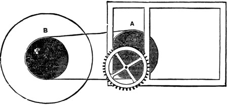
Fig. 10.
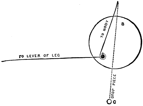
Fig. 11.
Prepare the works as for the yacht model, and also insert a pulley (A), as
shown in Figs. 10 and 5. This is connected with another pulley (B, Fig. 10),
which is fixed to a block by a screw that is countersunk below the face of it, and
to which is fastened by a small screw two wires working freely and passing one to the
wire from the left-hand figure,
and the other to the cross-piece
of the wire from the
right-hand one, and connected
with them by the ends
being bent into rings. From
the cross wire to the figure
to the right is also hung a
drop wire with a small weight
at the end, to help to pull it
down. Fig. 11 will explain
the fixing of this gear. A
fly must be also fitted to the
movement, to check the pace.
This can be fixed to the
pulley (B) or in front of the
escapement wheel. The
stopping motion is the same
as in Fig. 8, but more slots
may be cut in the disc, to
regulate the length of time
allowed for a penny.
The works you must fix
behind the background so
that the starting lever comes
conveniently for the penny
in its fall.
With these three examples
of the necessary
clockwork you will be able
by the exercise of a little ingenuity and the power of contriving to make moving
models of any subjects that may suggest themselves to you, such as the following: a
steamboat with revolving paddle-wheels, cobbler mending shoes, soldiers marching,
etc., etc.
I will now tell you how to make the model shown in Fig. 12, consisting of a
water-mill working with real water, a small fountain in the middle, and children
playing at see-saw in the background.
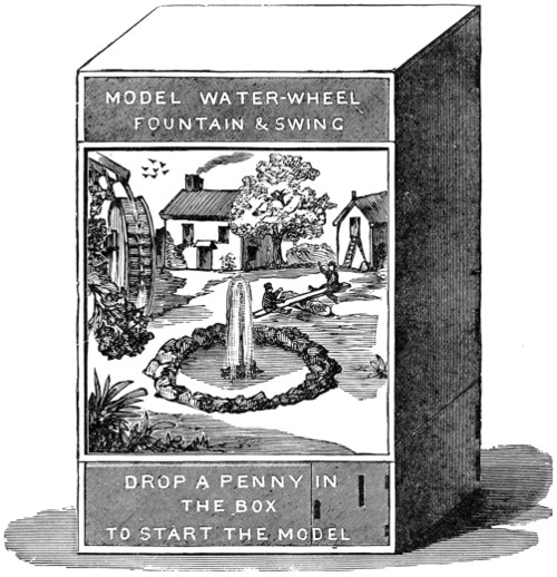
Fig. 12.
This model is worked with water-power only, and has no clockwork. The case
you must make larger than in either of the former cases—24 in. high, 14 in. wide,
and 14 in. deep; the height of the floor of the model from the bottom of the case
4 in., and the depth of the upper partition 4 in., the intermediate space closed by
a glass door 16 in. by 14 in. The case must be made out of 1⁄2 in. stuff and well
dovetailed together. In the right-hand bottom corner a drawer for the
pennies
with a slot in front. The back or one of the sides should have a door in it, to
get at the machinery, should it at any time require attending to.
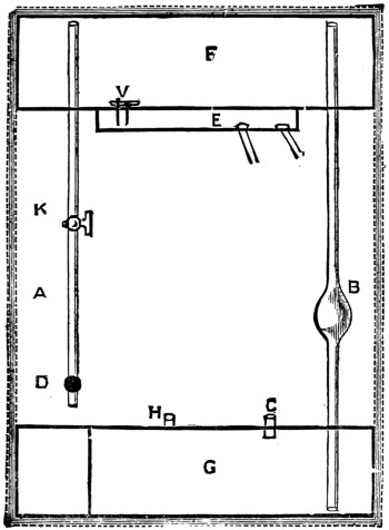
Fig. 13.
You must now make two zinc tanks, the top one air-tight, to occupy the whole
of the upper space, the other also air-tight at first, to occupy the space left in the
lower partition by the drawer. The top tank will be 13 in. by 13 in. by 31⁄2 in., and
will have a small receiver, about 6 in. square by 1 in. deep, soldered to the bottom
of it, and communication with it by a small hole, as shown in E, Fig. 13, about a
quarter of an inch in diameter, and having also a small pipe passing from it to the
outer air through the large tank. This pipe is not shown in the figure, but it is
soldered to the top and bottom of the tank and the ends filed off flush. The zinc
for the bottom and sides of the tanks can be cut out of one piece, as shown in
Fig. 14. The edges of the tops should be turned over, to add strength. The
soldering must be made air-tight. The background of the picture is a false
back
inserted about 2 in. from the true one, behind which the pipes are placed connecting
the vessels together, as shown in Fig. 13, which is a back view.
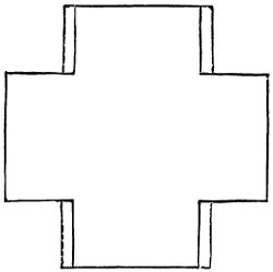
Fig. 14.
These pipes must be carefully soldered
in. A is the air-pipe to supply reservoir F
when in use; B is the pumping-pipe, in
the middle of which is fixed an india-rubber
force-ball, to be procured at any
india-rubber shop, in which is a small
pin-valve, to prevent the water flowing
back. This pipe extends from the bottom
of tank G to the top of tank F, leaving
a space of about 1⁄8 in. between the ends
of the pipes and the metal of the tanks.
C is a small pipe by which the water from
the basin of the fountain is run into G.
E is the receiver into which water from F
runs, and from which two pipes lead, one
to the wheel of the mill, and the other
to the fountain. K is a regulating tap, to
govern the supply of air and regulate the
amount of water passed into E. D is the
stopcock connected with the starting
lever, which is about 6 in. long and
soldered to the handle of the tap. This
tap must work easily, and yet be air-tight.
The lever must be counterweighted,
to close the tap when the penny has fallen
off the scoop at the end of the lever.
H is a small pipe fixed in the top of the
tank G to allow the air to pass out when
the water is running into it through C.
The basin of the fountain should be
made of zinc, and fastened to the tube C,
and the jet is formed of the end of a
blow-pipe connected to the tube from E.
The rockery you must form of cinders
and paint them to a suitable colour.
The mill-wheel should be made of zinc
and painted, and the water from it conducted
to the basin of the fountain. The
other pipe from E you must conduct to a
position suitable to set the wheel in
motion.
The see-saw you must place so that
it can be set in motion by the axle of the mill-wheel, which is carried out long
enough under the rockery-bank to reach it, and has a cross-piece of wire
soldered
to it at a point immediately under one of the figures, and which in revolving tips
up one end of the board.
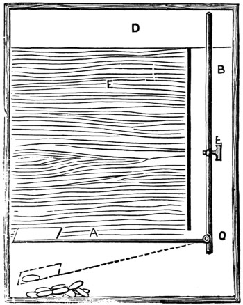
Fig. 15.
This end of the board is made, slightly heavier than the other, which will make it
return to be again tipped up. We will now
see how the model is worked. Pour water
into the basin of the fountain till it is full,
and open the starting lever as shown in
Fig. 15. The bottom vessel will now be
quite full. Now work the force-ball, which
will pump the water out of G into F, the air
rushing into G through the pipe H. As soon
as the upper tank is full the starting lever is
to be closed, and the model is ready to begin
work. Now as F, Fig. 13, is an air-tight
vessel, no water can run from F into E. But
as soon as a coin is dropped into the scoop
at the end of the lever A, Fig. 15, its weight
presses it down and opens the cock D, which
allows the air to be drawn into F, and consequently
allows water to pass into E, Fig. 13.
The quantity of air allowed to pass is
regulated by the extent to which K, Fig. 13,
is opened. The water being in E, and this
vessel communicating with the atmosphere
through the pipe not shown in the Figs.,
the water falls into the two pipes, and is conducted by one to set the wheel in
motion, and by the other to the fountain-jet, through which it issues and again falls
into the basin, and thence again into G.
An ingenious and inexpensive timekeeper may be made by any boy for a few
pence and a little labour. Buy a sheet of millboard, the thicker the better—size,
27 in. by 22 in.—cut off a strip 10 in. by 27 in., and shape it as shown in Fig. 16,
the top part to be 10 in. square, and the lower 17 in. by 4 in. Next mark off the
remainder of the millboard into three equal parts of 4 in. each, as shown in Fig. 17,
then, with a straightedge and a sharp knife, cut half through the lines AA. This
will form the two sides and back of the case. The funnel (B, Fig. 18) should be made
of tin, with a square top to fit over the millboard, and have a very small aperture at
the point; any tinman will make this for 3d. or 4d. The spindle
(C, Fig. 18) must be
33⁄4 in. long, 31⁄2
in. deep in front, diminishing to 2 in. at back, have a screw-shaped
groove from end to end, and work on a small spindle or axle, projecting 1 in.
in front, for the hand to be connected to, and 1⁄2 an inch at rear. If the young
horologist has not a lathe at his disposal, the spindle can be obtained from a turner
for a few pence. The weight may be made of a piece of shaped stone, or of an
empty stone ink-bottle, from the neck of which the cord passes over the bar (C),
round the grooves of the spindle, and out of the hole
(K). A small weight, such
as a bullet, must be fastened to the other end. A piece of canvas should be
glued round the edges of the case, and the whole painted with a good coating
of Brunswick black, over which any design may be made, either with gold lines,
grotesque figures, or coloured pictures. The dial should be of white paper, 7 in. in
diameter, and the hand cut out of the spare millboard and then gilded. Four small
reels (E, Fig. 17), such
as are used for silk,
should be glued on
the back, to keep the
case from the wall,
and a ring fastened
to the top to hang
it by.
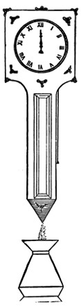
Fig. 16.
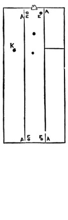
Fig. 17.
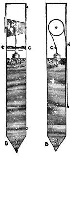
Fig. 18.
It is now ready
for the motive power,
which is obtained by
the falling of sand,
as in the hour-glass.
The sand must be first
well washed, dried,
and sifted, to remove
all stones, then
poured through the
case top to within two
inches of the cross-bar
(C, Fig. 18), the weight
resting on the surface. As the sand runs through the funnel-point
the weight will descend with it at the rate of about 1 in. per hour.
The flow of sand will be perfectly equable from the time the case is
filled until it is nearly empty, which is explained by the fact that the
sand lies in a succession of conical heaps, only the first of which
presses on the bottom, the others throwing their weight on the sides
of the case. A gallon of sand will be more than sufficient to fill the
cases, and as it falls it should be caught in a vase placed beneath
for that purpose. In winding up the clock the inside weight must be raised to
the cross-bar by pulling down the bullet end of the cord, and the sand poured
through a paper funnel into the top of the case, care being taken to set the hand
to the right hour. A clock of the dimensions here given will work for about
twelve hours, but by lengthening the sand-box the working hours will be increased
in proportion. It will save time and trouble to have a double supply of sand and
two vases, and use them alternately. Of course one does not pretend that such a
simple clock as this will keep accurate time.
‘What shall we do to amuse the boys?’ was the question asked at a friend’s
house. ‘They are tired of Christmas trees, and it is so difficult to think of
anything new.’
‘Well,’ I suggested, ‘why not have a Christmas ship?’
A Christmas ship! We never heard of such a thing! What is it?’
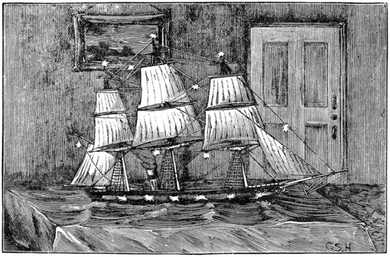
Fig. 1.—The Good Ship Santa Claus.
And this was the commencement of the planning and building of the vessel in
question. To commence was a comparatively easy matter, but before she was
finished and ready for her cargo the shipbuilders got rather weary. But you see
they had to do everything for the first time, and with little or no previous experience.
By attention to the details given in this chapter, those who go in for this Christmas
ship will get on faster than we did, profiting by our experience, and not having
to
retrace their steps and do things over again, which was often the case with us in
our first attempt.
When all was finished, the ship, as she appeared in the library, was an extremely
pretty sight, her long black hull illumined by the light from the open ports, through
which was caught a glimpse of her main deck with its fittings. Around her extended
a very realistic sea, ruffled in miniature waves, and far above, towering over the
heads of the young people present, were her lofty masts with their complicated
rigging. Some of the sails were set, while others were stowed on the yards. Deep
down in her hold were most of the presents, while many others were suspended
from her yards and rigging, which too were lighted up with small coloured lanterns.
Everything had been kept a profound secret until the library door was thrown
open to the guests, and the Christmas ship, glowing with her illuminations and
crammed full of presents, stood before them. Such was her capacity, that, although
there were some thirty or forty young people ready and eager to plunder her, it was
not until they had made three successive raids on the goods and cargo that the hold
was declared to be empty, and even then in some of its recesses there still remained
a few unappropriated gifts. And now to the details of her construction.
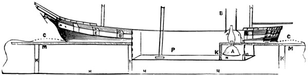
FIG 2
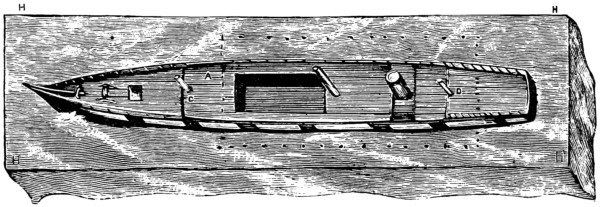
FIG 3
The first operation is to make the frame or stand. This is shown in Fig. 2 and
Fig. 3, as well as in the sketch
of the ship complete. It is marked H H H H in
Fig. 3. The size of the stand will of course entirely depend on the size you intend
making the ship, but it should be in about the same proportion to the hull of the
vessel as is shown in the diagram (Fig. 2). If the ship is to be 5 ft. long and 3 ft.
wide, the stand should be 8 ft. long. You will require two pieces of 11-in. deal
plank, 3⁄4 in. thick, and a short piece about 3 ft. long, which will be used as follows.
For the hold of the ship you must get a suitable box, which may be obtained
from
the grocer. An old currant or biscuit box will do. We used a Florence oil case,
which answered very well with the V end turned down and the bottom taken off
(see Fig. 6). Fig. 7 shows the manner in which the boards for the stand are
arranged round the box. A is the box,
B an 11-in. board with a slot about 2 in.
deep cut to fit the box. C is a similar
board the other side, and D D are two filling
pieces placed between the long boards to fill up the space left at either end of the
box. A couple of cross pieces may be placed at the dotted lines to secure the
frame together. The top of the box is left flush with the upper edge of the stand.
In Fig. 3 the dotted line shows the outline of the box. When the stand is made
and put together, the simplest plan to adopt is to take any large packing case which
the stand will cover, by about a foot at each end and a few inches at the sides, and
nail the stand down on this case. A block of wood must then be put under where
the box for the hold comes, of sufficient thickness to keep this box up just flush
with the top of the stand, and when the block is nailed down the box can be
screwed to it. No fastening will be necessary at the top, as the stand should fit all
round it too closely to prevent it working. Care should be taken that there are no
nails or splinters inside the box, or when the presents are being taken out some
one’s fingers may suffer. It is a good plan to glue some smooth thick wrapping
paper over the inside of the box after it is screwed down.
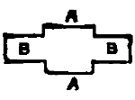
FIG 4A
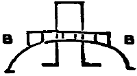
FIG 4
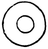
FIG 5
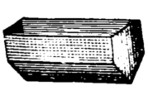
FIG 6
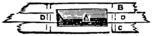
FIG 7

FIG 8

FIG 9
The sides of the ship, which are only the height of the vessel above water, can
be made of thick cardboard. Millboard will do, but it cracks easily. The shape of
the side having been cut out, a couple of lines must be marked within which the
ports are to be cut. The lower edge of the port should be about two inches above
the water-line, and the ports themselves two inches high and three wide, the whole
height of the vessel’s side out of water amidships being about 61⁄2 inches (this is for
a 5 ft. ship), while at the bow it will be an inch or so higher and half an inch at the
stern (see Fig. 1). In cutting the ports you will find a sharp chisel the best tool to
use, particularly if you are operating on thick millboard. When the ports are cut
out the pieces of millboard cut away will do for port lids (see Fig. 10). A is the
ship’s side, B the port lid, which is hinged on to the upper port sill by a piece of
calico D D, glued on; C
is the tricing line for raising or lowering the port. Fig. 9
shows the battens (A A). These are about an inch high and three-quarters thick;
they are screwed down on the stand just inside the line the side of the ship will take,
and serve to secure the lower part of the ship’s side by glue or screws; or another
batten can be run outside the ship’s side—the two battens taking one side of the
ship between them, and this is the stronger plan. The deck should be made of a
stout piece of deal board, about three-quarter-inch; it must be strong, as it serves
to bind the whole fabric together, and the sides are none too strong. This deck is
the upper deck, the main deck being formed by that part of the stand inside
the
vessel’s hull, and the main hatchway being the box. The deck must be placed just
at the top of the line of ports (see A A in Fig. 8), so as to leave room between the
two decks, and also to leave a bulwark all round the upper deck. The stern may
be made of a piece of deal an inch thick, shaped as Fig. 11. Fig. 12 shows the
section and the way the edges are bevelled off at A A. The bows can be fastened
together by screws or glue, to a wedge-shaped piece of wood put between them (see
Fig. 13). C is a
triangular block of wood shaped to suit the vessel’s lines, B B the
millboard sides, A is a piece of millboard
or wood shaped as Fig. 14. The part A A
goes between the sides which terminate at the line B B, shown in Fig. 8. The hook
B is formed by a piece of wire inserted into the end of the knee of the head, and is
used to hang a small figure for a figure-head. Those little plaster angels which
have a small wire eye between the wings from which they are generally suspended
by elastic, are the most suitable, as the wings fit on either side of the bowsprit, and
the figure looks very well.
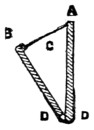 |
 |
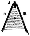 |
| Fig. 11. |
 |
| FIG 10 |
FIG 12 |
FIG 13 |
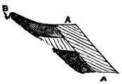 |
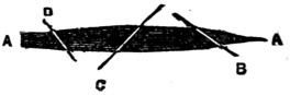 |
| FIG 14 |
FIG 15 |
The most effective part of the affair has now to be described, and that is the way
the hold is lighted up. Fig. 2 shows this. A is a common paraffin lamp, with say
a three-quarter inch burner (though an inch is better); L is a tin reflector so fitted
as to throw the light downward and forward toward the bow; at K is a strong
partition to secure the lamp from being upset or damaged while the hold is being
pulled about for presents; M M shows the line of the main deck, opening from which
is the box P. The rays from this lamp light up the whole length forward of the
main deck, and, if the ports are open, send a bright radiance from them through
the room.
The upper deck must be fitted with a hatchway of sufficient size just over the
box which constitutes the hold, and this hatchway must be so placed that
every
part of the box can be reached through it even by a small child. The ports may be
made to open and shut simultaneously by bringing all the tricing lines into one
hauling part, which on being pulled hauls up all the ports at once. This is very
effective if the ports fit well, as the room can be darkened, and the ports being
suddenly hauled up, the whole interior of the ship is shown brightly illuminated.
The fittings for the lamp on the upper deck have next to be considered. The
principal part is the funnel, which can be made of an old canister by cutting it
down where soldered together, reducing it to the required diameter and boring
holes along the lapping and lacing it together up the side. This is better than
soldering, as the heat of the lamp cannot affect the joint. The lower ends of the
tube are cut and opened out as at Fig. 4, and a kind of tin washer is cut out
(Fig. 5), the inner circle just being large enough to slip over the funnel, but being
stopped by the lower ends. The outside circumference of the washer must be
large enough to cover these ends. By screwing the washer down on the upper
deck, having previously slipped the funnel through it, the funnel is firmly fixed in
position, the rake being determined by the way in which the lower ends are cut.
To further steady the funnel and make a neat job, a small bridge is cut out of
another tin canister or piece of sheet-tin or zinc, as at Fig. 4, B B. This may be
made of any suitable width and pierced with a hole in the centre to pass it over the
funnel; it is then bent down to the required curve, the ends joining the bulwarks
and fitting in the upper deck. A light rail may be fitted, as shown in the elevation,
or if the tin is cut as Fig. 4A
the side pieces A A can be bent up to form a rail.
This bridge may be painted with japan black, which can also be used for those
parts of the vessel which require to be painted black.
The partition K (Fig. 2) must be made to remove, working in slides, so that the
reservoir of the lamp, by taking off the chimney, can be got out for filling and
trimming; the chimney is got off by pushing it up the funnel far enough to clear
the lamp.
It will have a good effect if a poop and topgallant forecastle are fitted, as in
Fig. 8. C is the poop and
D the forecastle. These decks can be made of millboard,
and light strips of wood are glued along inside the rail or bulwark, the top of which
comes about half an inch short of the top of the rail. The small deck is then placed
so as to rest on these strips; it can be fitted with a rail as shown, or not, as the
builder decides.
The sea is made of green glazed calico, which must be large enough to cover
the stand and hang over all round, touching the floor and concealing the rough
stand and its supports. A long slit is made in the centre line of the calico, to pass
it over the ship’s hull, and it is then glued along the ship’s sides before they are
painted, care being taken that this is carefully done, no rucks or puckers being left.
The waves are made by rolls of thin paper introduced here and there, under the
calico and glued to the stand, and wherever a wave crest appears the calico is
touched up with white paint, and if this is artistically done the effect is very good.
The sides of the ship are now painted black, and if the calico comes far up on
the side, it must be painted over and considered as part of the vessel’s side; but
along the water-line there should be a certain amount of undulation indicated by
the paint, and at the bows and here and there along the side, a little white
paint
must be put, to show the broken water and foam, while the vessel’s wake should also
be indicated by lines of foam diverging at an angle from the course of the ship.
Copper may be shown by a copper-red just at the bow and stern along the water,
but all black will do very well. The streak containing the ports should be painted
white, the outside of the ports black, and the inside red.
The rigging will now have attention. The masts may be made in only two
pieces; the topmasts, topgallant masts, and royals being all in one. The lower
masts should be rather stout, and can be made of common deal; they must be
firmly stepped in blocks secured below for their reception, and the mainmast must
be so placed as not to unduly interfere with the hold being got at. The rigging and
spars and sails of a ship are given in full with diagrams in other articles in this volume,
and need not be repeated here.
The character of the rigging and the number of sails set must depend on the
ideas of the builder. The ship may be made at anchor, to save trouble, with all her
sails stowed, and a good effect can be easily produced by furling the sails, as is the
case with the lower yards in the first illustration. Any rough piece of canvas the
proper size will do for this. The ends are made fast to the yardarms, the corners
are then folded behind (away from the bows) to the middle of the sail, in order to
make a bunt, and the sail rolled up and secured to the yard by lashings of thread
or string.
To look well, the sail when stowed should be much larger in the roll at the
middle and diminish off to nothing at the ends.
Those stays which it is intended to suspend lamps from should be of wire, and
the topgallant yards, if used for a similar purpose, should also be of wire, and if
the yardarms are used for this purpose short pieces of thick wire should be lashed
to them.
When all is ready, to allow of free access to the hold without damaging the sails
or rigging, it is best to brace the head yards sharp up and the main yards aback.
This is shown in Fig. 15. By doing this a sufficient space is left on one side of the
ship. A A is the fore-and-aft line of the vessel,
B the fore yard, C main yard, showing
the space B C. D is the mizen trimmed in the same way as the fore yard. The
ship would then be ‘hove-to,’ which is an almost stationary position adopted when
speaking another vessel or waiting for a boat, etc.—in this case for her Christmas
visitors.
I do not think any explanation will be necessary as to the presents. The
smaller ones, whatever they are, can be just mixed up together in the hold, and if
there are any of a superior character, they can be very well fixed in various places
in the rigging.
The Christmas ship in which I had a hand was well found in boats, anchors,
cannon, etc., all of which were distributed among the boys of the party. In
conclusion, I can only hope that, should you decide to build such a vessel, it may
prove a source of amusement to yourselves and gratification to your friends, and
no doubt very many will be only too anxious to learn when the good ship Santa
Claus is likely to arrive.
This chapter is intended to fully describe the constructive details of miniature
steam-engines. It is proposed to first give an idea of the general principles which
govern steam-engines, and to explain the various characteristics and methods of constructing
different types of engines. The boiler and its several fittings and attachments
will be duly described, and then minute directions given for constructing
engines with oscillating and slide-valve cylinders. Illustrations of both vertical
and horizontal engines will be given, and also sketches in all cases where they will
serve to explain more fully the meaning of the text.
This is a brief outline of the scope of the present chapter. Those readers who
have acquired only slight manual dexterity in the use of tools will find little
difficulty in making the engines illustrated, if the instructions given are carefully
followed. In each case the minute details of the various processes incidental to
our engineering work will be carefully described, so that those unacquainted with
the mechanical arts will be able to comprehend the method of procedure.
Model engines, in every stage of manufacture, from the rough castings direct
from the foundry to the complete, highly-finished working model, may now be
purchased in nearly every town of importance throughout Great Britain. Though
this trade is of but recent growth, its continual extension proves that model engines
are objects of interest to a large number of the rising generation, and hence it is
felt that information as to their manufacture will prove acceptable to very many
readers.
It will be advisable to gain an insight into the principles which govern the
action of a steam-engine, and to learn some of the technical peculiarities, before
proceeding to attempt its manufacture. There are numerous text-books on the
steam-engine, which may be studied with advantage, and which show the theoretical
principles.
The modern engine, which now claims our attention, is the result of numerous
successive improvements. The application of steam as a motive power was
probably originally made by Hero, who, 150 B.C., constructed, or at least described,
an Æolipile. This was a hollow sphere with hollow bent arms attached; when
water placed inside the sphere was heated, and steam generated, it issued from
the arms, and reacting on the air caused the sphere to rotate. A model of this,
the primogenitor of the modern steam-engine, can be bought at many opticians’
shops for about one shilling.
The commencement of the eighteenth century began the first steps towards
the development of the modern form of engine. Savery and Newcomen made
improvements, which were perfected by James Watt, who was born at Glasgow in
1737. Amongst other valuable improvements he first contrived to convert the
reciprocating motion into a rotary one by means of the crank. In the year 1800
Watt retired from business, leaving the steam-engine in much the same condition
as we find it now. The application of steam-power for locomotion on both land
and water followed, and now stationary, locomotive, and marine engines, driven
by steam, are distributed all over the civilised world.
The varieties of model engines are in many cases indicated by their names.
Stationary engines are intended to be fixed, as those used for driving machinery.
Locomotives are those which are intended to travel by steam, and are self-moving.
Marine engines are those used to propel ships. Of these three classes we shall
deal only with the first and third in the present chapter. Locomotives are much
more complicated in their construction, and consequently are more difficult to
make.
Horizontal engines are those having the cylinder lying with its axis in a horizontal
position. Vertical engines have the cylinder upright; sometimes they are
designated by the latter adjective. Beam engines have an oscillating beam; one
end is connected to the piston and the other to a rod which drives the crank. Cylinders
are single-acting when the steam is admitted only at one end, and consequently
with these the crank is only propelled during half of its rotation. Double-acting
cylinders are provided with valves which admit the steam at each end of the cylinder
alternately. Oscillating cylinders are fitted to oscillate with the motion of the crank,
and the steam-valves are usually contrived to act by this oscillating motion. Slide-valve
cylinders have a sliding valve, worked by a rod connected to an eccentric on
the crank shaft, which opens the steam ports to alternately admit live steam and
exhaust at both ends of the cylinder. Slide-valve cylinders are invariably double-acting.
Boilers, which are the vessels in which water is converted into steam, are usually
described by their shape and position. They may be cylindrical, spherical, etc., and
horizontal or vertical. The construction also forms a distinguishing characteristic.
Tubes are usually inserted in the boiler to convey the heat from the fire. These
tubes—which are more properly called flues, especially in large boilers—vary in
number from one of large gauge to scores of small ones, thus naming the respective
boilers single-flue or multiflue. It may be advisable to mention here that tubular
boilers are those in which the water circulates in the tubes, and the fire impinges on
the outer surface. When the fire operates inside the tube it is called a flue. A tube
carries water; a flue carries flame and the volatile products of combustion.
Boilers, or steam generators, that are used to contain the water which, when
converted into steam, drives the engine, require to be sufficiently strong to withstand
an internal or bursting pressure. This pressure is very great in high-pressure engines,
but in models it is generally very low, and seldom exceeds twenty pounds to the
square inch. The evaporating capacity of the boiler is according to the requirements
of the engine it has to supply. The resistance of the piston to the steam shows the
pressure at which it should be supplied. Boilers are generally tested, by means of
a
hydraulic pump, to stand a pressure at least double that at which it is intended to
use them. It is unsafe to generate steam in any vessel that has not been properly
tested. This fact cannot be too strongly impressed upon the mind of the reader.
Suppose a double-action cylinder, 1-inch bore and 2-inch stroke, is to make one
hundred revolutions of the crank per minute, let us see how much steam will be
wanted to drive it. The area of the piston is ·785 inch, and each revolution of
the crank will require the cylinder to be filled twice—that is, one stroke in each
direction. This will take a column of steam ·785 inch in diameter and 4 inches
long for each revolution, or 314 cubic inches of steam per minute. If the speed
is greater, the quantity of steam must be increased proportionately; and when
running at the rate of one thousand revolutions per minute—a speed often attained—3,140
cubic inches of steam will be wanted to supply the cylinder. That is at
the rate of about 100 cubic feet per hour.
The pressure of the steam has not yet been taken into account, but it obviously
forms a most important factor in the calculation. Water in an open vessel boils at
a temperature of 212° Fahr. Provided that the vessel allows the steam to escape
freely, all the heat that can be applied will only generate steam at the same pressure,
though it will escape faster. As the bubbles of steam ascend to the surface they
escape, having only the pressure of the atmosphere to overcome. When water is
confined in a closed vessel, like the boiler of a steam-engine, the temperature may
be raised to considerably above the usual boiling-point. The heat is always proportionate
to the pressure, and steam at a pressure of 120 lb. per square inch is equivalent
to the heat represented by 345° Fahr.
A correct knowledge of the fact that pressure depends on temperature cannot be
urged too strongly on the mind of the model engineer. In many model boilers it is
quite impossible to raise the heat sufficiently to produce an adequate pressure.
Boiling water at 212° Fahr. does not produce any available pressure of steam, it
merely counterbalances the weight of the atmosphere, which is 15 lb. to the square
inch. By increasing the heat, which can only be done in a closed vessel, available
pressure is obtained. Thus 228° = 5 lb., 241° = 10 lb., 251° = 15 lb., and so on.
The steam, and the water from which it is generated, and with which it remains in
contact, have both the same temperature.
A cubic foot of water weighs 62·5 lb., and it will produce 882 cubic feet of
steam, at a pressure of 15 lb. to the square inch above the normal atmospheric
pressure; this is equal to a temperature of 251° Fahr. If the pressure is raised to
150 lb., which requires a temperature of 371°, only 187 cubic feet of steam will be
produced. Steam is elastic, and hence the more it is compressed the greater will
be its force. If one cubic inch of steam, at a pressure of 30 lb., is admitted into a
cylinder, and the supply cut off when half filled, the steam will expand till it has
filled the cavity, and in increasing its bulk twofold its force will diminish in inverse
ratio. The pressure will therefore diminish to 15 lb. to the square inch. The
expansive force of steam is always at work on the piston of the engine, and it
varies in accordance with the arrangement of the valves.
Let us now trace the effect of the steam when admitted to the cylinder. When
the governor valve is opened the steam flows along the pipe to the slide valve
chest, and if one of the ports are open it reaches the cylinder. In traversing
the
pipes which conduct it to the cylinder the steam is cooled considerably and
its force diminished. In course of time the parts become heated to a certain
extent, and then the loss of power is less. When the steam enters the cylinder it at
once exerts a certain force on the piston. This has the effect of turning the crank
shaft, and in due course the slide valve closes the steam inlet. Now the steam
within the cylinder acts expansively, and continues to drive the crank shaft to the
end of the stroke. Then the exhaust port is opened, and allows the spent or dead
steam to escape. At the same time the inlet at the other end is opened and the
live steam rushes in and exerts its full pressure on the piston, causing it to travel in
the opposite direction. The opening and shutting of the steam ports is effected by
an eccentric on the crank shaft. In treating of the construction of these parts, the
relative sizes will be given and the correct motion explained.
The most simple form of toy engine is that illustrated herewith. It consists of
a tin boiler, a single-action oscillating cylinder, and a fly-wheel. These parts are
sold ready for putting together at a very low price, and a complete engine may
be bought for a couple of shillings, though one of ‘superior make’ at twice that
sum is by far a preferable investment.
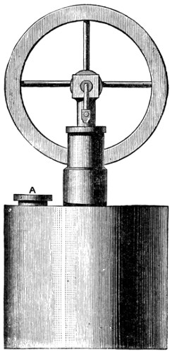
Fig. 1.
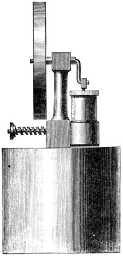
Fig. 2.
The drawing represents the most simple way of constructing a steam-engine,
and, if the workmanship is fairly good, a working model will be produced. First
is the boiler; a tin box 13⁄4 in. deep and 2 in. in diameter, will serve for this. The
joint at the side should be made by folding the edges of metal over each other, and
then soldering. The top and bottom are both soldered on their respective places,
steam-tight, of course. The top of the boiler must be provided with small bosses of
metal, soldered on the inner side, into which the pillar (Fig. 3) and the safety-valve
(Fig. 5) are screwed.
The tin plate is not sufficiently thick to afford a hold for the thread on the
pillar and valve. A disc of brass, say the size of a sixpence, and 1⁄8 in. thick, is
soldered on the under side of the lid, and the holes, which are tapped to receive
the pillar and valve, are bored and threaded before the lid is fixed. By this means
a strong hold is secured for the fittings. The screw plug A (Fig. 1) is similarly
provided for. When each piece is screwed into its place a little hemp or cotton,
placed between the shoulder of the ‘fitting’ and the surface of the tin plate, will
assist to ensure a steam-tight joint.
The standard or pillar is brass, about 2 in. long from end to end. Any form
may be given to it, according to fancy, the one shown in Fig. 2 being perhaps as
good as any. The lower part is circular, 1⁄2 in. in diameter, and it has a flat face on
one side, against which the valve face of the cylinder works. Fig. 3 shows this.
The centre of the pillar is bored up in the middle of the screwed part to meet one
of the holes a b, it is immaterial which. The other hole is bored right through the
pillar to the opposite side, and forms the exhaust port, the one communicating with
the central hole in the pillar being the steam port. For the sake of distinction we
will suppose that a is bored into the central hole, and b is bored through the pillar;
then, when the pillar is screwed on to the boiler, and steam is generated, it issues
from the port hole a.
The upper end of the pillar is bored through at right angles to the flat at the
bottom (see Fig. 2). Through the top a piece of brass tubing about 5⁄8 in. long is
fixed, generally by soldering; this is the bearing for the crank-shaft. The crank-shaft
itself is a piece of steel wire bent to the form required. The fly-wheel is fixed
to one end, and prevents the shaft coming out of the bearing, the bend of the arm
serving the same purpose at the other end.
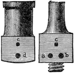
Fig. 3.
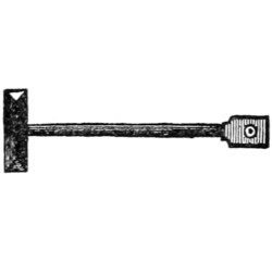
Fig. 4.
The cylinder itself is shown at Fig. 3, and also in
Figs. 1 and 2. The piston,
piston-rod, and bearing which fits the crank-pin are shown in Fig. 4. It will be
evident that the dimensions of this engine are microscopic. The bore of the
cylinder is 5⁄16 in., and the barrel itself is often made of triblet-drawn brass tube.
The enlarged part at the bottom is a casting with a flat face, as shown in Fig. 3, on
one side. Some makers use a casting for the entire cylinder, but the tube is perhaps
the cheaper method of making. A piece of good tube is sufficiently accurate in
the
bore for use as bought, so that the trouble of boring the cylinder is dispensed with.
The base, for the tube to fit in, is bored to the external diameter, and the tube fixed
with solder. The lid or cover is fixed only by being snapped on. Its object is
only to guide the piston-rod.
A reference to Fig. 3 will show the working of the oscillating valve. The face
of the pillar is shown on the right. On this, a is the hole from which the live steam
issues, and b is the exhaust hole. These holes are technically called ports. The
hole c is bored through the pillar, and takes the trunnion, or pin on which the
cylinder oscillates. Fig. 2 shows this trunnion-pin prolonged and having a nut on
the end. A spiral spring around the trunnion, between the nut and the pillar, keeps
the valve face in close contact with the pillar face. Again, turning to Fig. 3, the
holes in the cylinder on the left are:—c, into which the trunnion is screwed; and d,
the steam-way.
When the cylinder is in the position shown in Figs. 1 and 2, the port-hole d
(Fig. 3) is over the solid metal between the holes a and b. On turning the fly-wheel
the crank draws the piston out very slightly and inclines
the cylinder sideways, bringing the port d over a. The
live steam from the boiler at once enters and forces the
piston upwards, and on the crank reaching the highest
point the cylinder is again vertical and the hole d is mid-way
between a and b. The momentum of the fly-wheel
carrying the crank round brings the hole d opposite b, and
allows the steam to escape. There is no force to keep
the engine going during this part of the time except the
momentum of the fly-wheel. When the cylinder again
inclines to the opposite side d comes over a, and force is
again applied under the piston. This will keep the
engine going.
The single-action oscillating cylinder, being supplied with steam at one end
only, exerts power only during half the revolution of the crank. The return
stroke is dependent entirely on the momentum of the fly-wheel, which also has to
drive the steam out of the cylinder. Steam only acts in the lower part of the
cylinder, and as there is no power tending to force off the cover, it may be simply
snapped on like the lid of a pill-box. The piston, Fig. 4, has for its head a
disc of brass, with a V-shaped groove in its edge. This is packed with hemp
or lamp cotton, to make it fit the cylinder steam tight. The rod is a steel wire
about 1⁄16 in. diameter; it is fixed in the piston by riveting, to save the trouble of
screwing. The end of the rod has a small piece of brass fixed on to it which fits on
the crank-pin.
The crank itself is all of one piece; a straight length forms the shaft; it is bent
at right angles to form the throw, and a piece bent from this, parallel to the shaft,
forms the pin. This is the most simple way of making a crank, and when large
quantities are made the wire is bent upon a template. A better type of crank is
made by using a steel rod for the shaft, a brass arm riveted on to it, and a steel pin
riveted into that. In the portion of this chapter devoted to the horizontal engine
will be found a more complete description of such a crank.
The safety-valve, Fig. 5, is very important as a safeguard in working. Though
they are sometimes omitted, yet safety-valves are essential for security. They allow
steam to escape from the boiler when the pressure exceeds a certain amount, and
thus the danger of an explosion is removed. The valve illustrated in
section has a spiral spring to keep the valve itself on its seat. This is
effective when the power of the spring has been definitely gauged, but
when the valves are put together haphazard no dependence can be placed
on the pressure at which the valve will blow off.
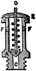
Fig. 5.
The body of the valve is A, shown in section. B is the valve itself,
fitted to a rod, D; it rests on the conical seat of A, and is pressed down
by the spiral spring within the barrel of A. The body is screwed into
the boiler by the thread at the bottom, and the steam coming up the hole
C presses on the under side of the valve B. When the pressure of the
steam is sufficient to overcome the pressure of the spiral spring the valve is lifted
and the steam escapes through the holes F F. The cover E is screwed on the body
part and confines the spring; it has a hole through its centre to allow the valve-rod
D to pass. Especial attention should always be given to the safety-valve when heat
is to be applied to a boiler. See that the valve is not fixed to its seat or in any
way confined, or an explosion may follow the want of care.
The engine shown by the illustrations is usually mounted on a three-legged
stand, which raises it about two or three inches. A wire stand may be made according
to fancy, or perhaps some contrivance may be improvised to support the boiler at a
convenient height for applying the heat under it.
A small lamp burning methylated spirits—that is, spirits of wine—will supply the
requisite heat. It should have a clean and dry wick of lamp cotton; the size of
the flame may be regulated, to an extent, by the amount of wick which is drawn out.
The lamp must not be quite filled with spirit—about two-thirds full will be ample—and
thus the spirit will not be liable to overflow.
When charging the boiler it is best to use boiling water from a kettle. This will
save the time which would be lost in heating cold water with the spirit lamp. The
water is poured in through the water-plug hole, A, Fig. 1. The boiler must only be
filled to a little over half way. The plug is screwed in again and the lamp put
under; steam will be generated in due course, and if the fly-wheel is turned in the
right direction by hand for a few turns the engine will presently work of its own
accord.
It is scarcely necessary to say that the engine above described is of the most
simple kind, and every unnecessary detail is omitted. I will now proceed to describe
engines of a more elaborate character.
Small model engines are composed mainly of brass castings and of steel which
requires no special forging for the purpose. The screws or bolts used to unite the
parts are usually purchased in a finished state. Makers of these employ machinery
which acts almost automatically, and the screws are sold at a very cheap rate.
Larger models require special forgings for the crank shaft, and the castings employed
are of iron, which is considerably cheaper than brass.
The castings are made from patterns which are counterparts of the object required.
These are imbedded in sand, and leave a matrix, into which molten metal is poured,
producing, on solidifying, a facsimile of the pattern. The operation is always carried
out in a foundry, where the necessary furnaces and moulding appliances are at hand.
The founders charge for the rough castings by weight, and they cost merely a trifle
over the value of the metal. It is, however, necessary to supply the requisite patterns
before a founder can proceed to do his part of the work.
All vendors of castings have patterns from which their castings are moulded,
and of course they charge, in addition to a profit on the cost of the metal,
something for the use of the patterns. The patterns for a founder’s use require
certain modifications, which it is unnecessary to explain in detail. Some are made
in two or more parts, with pins to hold them together. Some have projections
affixed to them; these make prints in the mould to receive cores, which form holes
in the casting. Those patterns which enter deeply into the moulding sand are
made tapering, to draw out easily. In all cases they must be made sufficiently
large to allow for shrinkage in the metal. Ordinary iron castings shrink about
one-eighth of an inch to the foot; brass about half as much again. Pattern-makers
use a ‘contraction-rule’ to work by; this is made longer than the standard
measurement, and patterns made according to it are the correct size to allow for
shrinkage.
From what has just been said it will be readily understood that vendors of
castings charge various prices for their goods. Nor in every case is the quality
in accordance with the price, and it is difficult to give the exact prices that should
be paid for good castings. Speaking generally, the price is regulated by the weight,
and the rate per pound is decided by the seller. In the catalogues issued by
various firms will be found the prices charged. As an example of the difference,
I notice that a certain size of bolts made by one firm are retailed by shopkeepers
at rates varying from 33 to 200 per cent. profit; the same rule probably holds good
in all other items.
Those readers who are not possessed of a lathe will not have the means of
finishing the cylinders and some other parts which have to be turned. These can,
however, be bought in various stages of completion, and the beginner who has
only a screwdriver may now purchase the component parts, and, having screwed
his engine together, he may claim some merit for his share in the erecting
department.
Sets of castings quite finished and ready to be screwed together are now sold.
These are generally of the cheaper class, and, tacked on cards, may be seen in the
windows of opticians. The prices for the complete engine, with boiler, lamp, and
all other parts, range from about five shillings upwards. A few words on the better
type of partially finished parts.
These castings are more expensive than those quite rough, but they afford an
opportunity of displaying considerable skill and judgment in completing them.
Boring the cylinders is the operation most likely to baffle the tyro. This is
done by vendors of castings for about two shillings and sixpence for cylinders
1-in. bore. This charge includes turning the flanges ready to receive the covers,
and also boring the steam-ways and cutting the port-holes. When all this has
been
done it will be necessary to use a lathe to turn the covers for the cylinder, and also
for making the piston. The cylinder may be purchased complete with the covers
screwed on and the slide-valve fitted. One an inch in the bore costs half a guinea.
Every piece of an engine may be bought separately in a finished state, so that they
only require putting together, and when the young engineer has not the requisite
tools for doing the work his best plan will be to purchase the finished parts.
A glance at an engine will show that nearly every part of it has been fashioned
on a lathe. This tool is indispensable for all kinds of engineering work, but as it
is somewhat costly it frequently occurs that tyros are compelled to forego its
ownership and get the necessary turning executed by a professional latheman.
Those readers who are happily possessed of the king of tools—or the father of
mechanism, as the lathe has been aptly dubbed—will have the advantage of being
able themselves to execute the work throughout.
A few particulars of the different kinds of engines which a beginner may make,
will assist him in deciding as to the form and size best suited to his requirements.
An idea of the general forms and peculiarities of engines may be gleaned from
what has been already said. It is a matter entirely at the choice of the maker
whether he will build a vertical or a horizontal engine—whether it shall have
oscillating or slide-valve cylinders, and whether it shall be of microscopic dimensions
or a powerful model. All these points are for the consideration of the constructor,
and some hints will be of service to, and assist him in arriving at a useful result—that
is, the production of a working model.
The dimensions of the cylinder to an extent indicates the power; the pressure
of steam must also be considered. The friction in models is very great in proportion
to their size, and hence the very small ones are often barely able to generate sufficient
power to keep them going. The bore of the cylinder governs the area of the piston,
and this multiplied by the pressure of steam and the length of stroke gives the power
of the engine.
Let us compare the power of two small cylinders, one half-inch in bore and one-inch
in stroke, the other one-inch bore and two-inch stroke. We will suppose the
pressure of steam to be the same in both cases, viz., ten pounds to the square inch.
Speaking off-hand, many tyros would be apt to say that one cylinder was twice the
size of the other, and, as a natural deduction, twice the power. Comparison will at
once show the fallacy of the idea.
The area of the half-inch cylinder is nearly two-tenths of a square inch, that of
the other nearly eight-tenths. Thus we see that the larger one has four times the
area; also the length of stroke is twice as much. According to the rule given
above we find the power thus: 2⁄10 × 10 ×
1 = 2, and 8⁄10 × 10 × 2 = 16. So that the
power of the larger cylinder is precisely eight times that of the small one. In every
case it is necessary to allow a certain percentage of the power to overcome friction.
The smaller the engine the greater will be the percentage lost in friction. These
simple facts will at once show that size is a most important consideration. If the
friction in the small engine was two pounds, the power would not drive it, whereas
if it were that much in the large one, there would still be fourteen pounds of available
power.
A cylinder 13⁄8-inch bore and the same length of
stroke, viz., 2 inches, would
give exactly double the power of the 1-inch bore cylinder just mentioned. If the
bore was increased to 2 inches, the power would be exactly four times that of the
1-inch bore, the length of stroke and pressure of steam remaining the same.
The velocity of the piston also forms a factor in calculating the power, which is
increased in the same proportion as the velocity. It will be readily understood that
when the pressure of the steam is constant, the speed of the engine will depend on
the amount of work it has to do. It must also be remembered that the pressure of
steam against the piston is by no means necessarily the same as it is in the boiler.
In passing from the boiler to the cylinder the steam pressure is always reduced, and
the greater the distance, and more exposed or tortuous the steam-pipe, the greater
will be the loss of pressure.
Every one knows that the power of steam-engines is given in ‘horse-power.’
This was a term originated by James Watt, and it is now universally adopted. The
mechanical equivalent is a lifting power that will raise 33,000 pounds 1 foot high in
one minute. On this estimate the power of an engine is calculated. The rule is
this: Multiply the pressure on the piston by velocity per minute and divide by
33,000. The velocity of the piston is twice the length of stroke in feet multiplied
by the number of revolutions per minute.
Let us calculate the horse-power of the 1 × 2 inch cylinder, already dealt with
at a pressure of 10 pounds, the speed being 100 revolutions per minute. By the
previous calculation we found that the pressure was 16 pounds. The velocity is
4⁄12 × 100 = 331⁄3
(feet). Multiply these together, 16 × 331⁄3 = 5331⁄3, and divide
533⁄33000 = ·016. That is, the engine is
16⁄1000 of a horse-power, or capable of raising
528 pounds 1 foot high in one minute. That is supposing all the power was
available for duty. In large engines about 20 per cent. is allowed for friction, and
in the model we must allow at least 50 per cent. This at once reduces the calculated
power to half.
The power of an engine is the nominal, and the duty is the actual work that it
will perform. When the horse-power of an engine is spoken of it must be taken in
a qualified sense. By urging the furnace greater effect may be obtained, and by
keeping the furnace low an effect less than the nominal power is produced. Duty
is the term used to represent the amount of work absolutely done; it disregards the
size of the engine, and simply inquires how much work is done by a given expenditure
of fuel. True economy in working will add to the duty of an engine, whilst woful
waste in no way affects the power.
In order to supply the requisite quantity of steam, boilers should evaporate at
the rate of one cubic foot of water per hour per horse-power; that will produce
1700 cubic feet of free steam. The capacity of a boiler should be four or five times
as much as the water it boils off per hour, and the steam space should be at least
ten times as large as the consumption of steam at each stroke. The heating surface
should be from fifteen to twenty square feet per horse-power. Many circumstances
tend to modify these rules, but they maybe taken as fairly reliable.
Engines of the horizontal type are usually employed to furnish the power
required to drive fixed machinery in factories. The construction is simple, and the
form is adapted for fixing readily anywhere where a tolerably level foundation is to
be found.
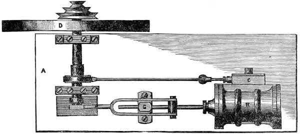
Fig. 1.
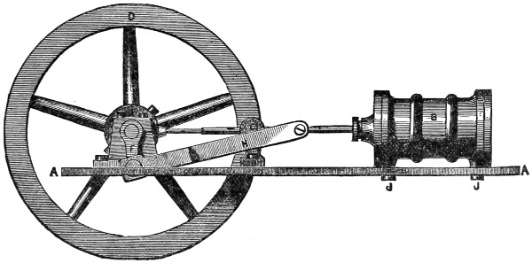
Fig. 2.
The several illustrations given herewith are drawn to scale, and they will show at
a glance constructive details which could not well be explained in letterpress. Fig. 1
shows a plan view, and Fig. 2 an elevation of the complete engine. In both
drawings the lettering is the same. The bed-plate A A is the foundation on which
the parts of the engine are fixed. A piece of sheet brass is used for small models,
but larger ones have cast-iron foundations. Cylinders 11⁄2
inches in the bore and
upwards are usually mounted on iron bed-plates, the saving in cost of metal being
considerable when the castings are so large. Cast bed-plates have a moulded edge,
which adds both to their strength and appearance. Sheet metal has to be mounted
on columns sufficiently high to raise the fly-wheel above the ground-level.
The cylinder is shown in Figs. 1 and 2 at B; at
C (in Fig. 1 only) is the steam-chest
containing the slide-valve. D is the fly-wheel fixed
on the shaft E, which has
at its opposite end the crank F. The piston-rod is
shown passing through a guide G
fixed to the bed by two screws. The connecting-rod from the piston to the crank-pin
is marked H. The eccentric is shown at I, and the rod from it to the steam-chest
is the eccentric-rod. J J,
Fig. 2 only, show two screws which fix the cylinder
to the bed-plate. These references are sufficient to enable the inexperienced reader
to identify the principal parts of the engine. By carefully studying the drawings the
whole combination of the machine will be understood.
Each of the chief component parts which possess any intricacy of detail are
shown on a much larger scale. The description of each one may be taken as
generally applicable to engines of the type shown in Figs. 1 and 2. The dimensions
are suited to the size known as ‘3⁄4-inch bore
and 11⁄2-inch stroke.’ These measurements
refer to the cylinder. It will not be difficult to modify any of the minor
details to suit another size, whether it be larger or smaller.
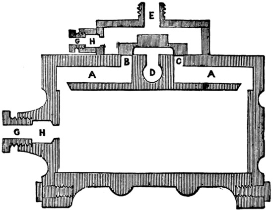
Fig. 3.
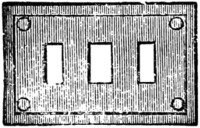
Fig. 4.
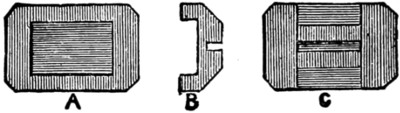
Fig. 5.
A section of the cylinder is shown in Fig. 3; the piston and its rod are absent,
to prevent confusion of the parts. The cylinder with the covers on is 2 inches long
and 13⁄8 inches diameter across the flanges. The bore is
3⁄4 inch and 15⁄8 inches (full)
long. The face of the cylinder where the valve works is level with the diameter of
the flanges. This face is shown at Fig. 4, where the size and position of each porthole
may be seen. The rectangle represents the steam-chest itself, and the four
small circles are the screw-holes in the valve-face for attaching the steam-chest.
Returning to Fig. 3, the steam-ways are shown at A A. These are drilled from
the ends to meet the inlet ports B and C, which are closed by the slide-valve (see
Fig. 5). The exhaust way is at D, and the port-hole communicating with it needs
no special mention. The steam inlet is E; the threaded exterior is for attaching the
steam-pipe from the boiler. The glands and stuffing-boxes, for keeping the piston
and valve-rod steam-tight, are shown in section. G G are the glands screwed into
the castings; the parts bored out to receive the packings are marked H H. It will
not be necessary to make special reference to the body of the cylinder, the covers,
&c., as the reader will have become acquainted with these in the previous chapters.
By reference to Fig. 3 the passage of the steam may be traced. It enters at E,
filling the steam chest, and as the valve is shown it could find no outlet. The valve
on being moved would uncover one port, say B, and allow the steam to enter by the
steam-way A, through the slot filed in the edge. When in the cylinder it would
force the piston towards the bottom, the action of the eccentric meanwhile pushing
the valve along and further opening B. When the piston had made half its stroke
the valve would commence to close again, and by the time the end was reached the
valve would be again in the position shown. The momentum of the fly-wheel would
carry round the eccentric, and with it the valve would move so as to open the way
from B to D, thus allowing the steam in the cylinder to escape. The port-hole C
would also be opened to
the live steam, which
would then exert its pressure
on the lower side of
the piston. By the motion
of the valve the steam is
let into B and C alternately,
and thus the reciprocating
motion of the piston is
maintained.

Fig. 6.
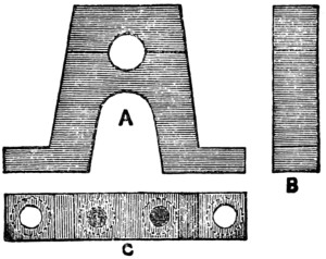
Fig. 7.
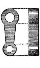
Fig. 8.
The slide-valve is shown
at Fig. 5, where A is a view
of the face. The centre is
hollowed out, as shown at
B of the section, to allow
the steam to pass into the exhaust. The back is shown at C; the saw-cut receives
the valve-rod, which is thinned down to fit it. The face of the valve, that is, all
the outer part of A, is made perfectly flat, to fit steam-tight on the valve face of the
cylinder. Contact is ensured by the pressure of the live steam in the steam-chest;
this is always more than that of the exhaust.
The crank-shaft, marked E in Fig. 1,
is shown alone full size at Fig. 6. This is
a rod of round steel 1⁄4 inch in diameter, the
total length is 31⁄8 inches. At the right-hand
end it is reduced in size a length of 7⁄8 inch, to receive the fly-wheel and
the driving pulley. These are generally screwed on to a thread cut on the shaft, but
wedging is a more workmanlike way of securing driving wheels and pulleys. The
two journals are to rest in the bearings shown at Fig. 7; the neck at the left-hand
end is to receive the crank-arm. The collars on the shaft outside of each journal
are of the widths shown. One of the bearings for the crank-shaft is shown at Fig. 7.
A is a side view, B
an edge view, and C a view from the top; in this the dotted lines
represent the screw-heads. These bearings are usually brass castings; they are fixed
on the bed-plate by two screws each, and the cap is also held on by two other
screws.
Various designs may be obtained, but the one illustrated is as good as any. The
thickness of the bearing is nearly 1⁄4 inch. The height must be precisely that which
will bring the centre of the crank-shaft level with the centre of the piston-rod.
Fig. 8 is the crank-arm, giving an end and side view. It should be made of
steel and fixed on the shaft by keying, though more often it is screwed on. The
thickness is shown about 3⁄16; the shape may be according to fancy. The hole at the
bottom is for the crank-pin, which is riveted in. The ‘throw’ of the crank is an
important point, and it must never be so much that the piston touches the ends of
the cylinder. In the present case the ‘throw,’ that is, the distance from the
centre of the crank-shaft to the centre of the crank-pin, is 5⁄8 inch. This gives
11⁄4-inch stroke; there is plenty of
space in the cylinder for another 3⁄16
inch, and possibly the nominal stroke,
11⁄2 inches, could be managed by
using a thin piston-head. The crank-pin
is shown at the top of Fig. 10.
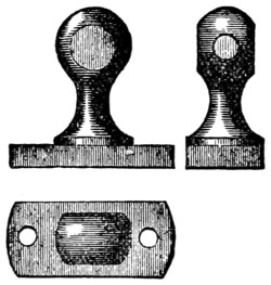
Fig. 9.
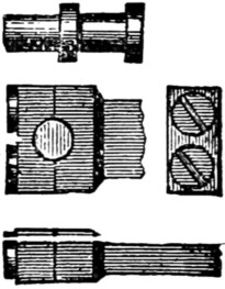
Fig. 10.
The guide-block, Fig. 9, serves
to guide the piston-rod, and steadies
it against the influence of the crank.
The shape is shown by the illustrations.
The hole for the piston-rod
is bored on a level with the axis of
the cylinder and the centre of the
crank-shaft. The block is secured
to the bed-plate by two screws, holes
for which are shown in the top view.
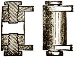
Fig. 11.
Fig. 10 shows the crank-pin and
three views of the head of the connecting-rod.
The crank-pin is steel,
3⁄16 inch diameter, turned down to
1⁄8 inch at the journal and at the neck,
which is riveted into the arm (Fig. 8).
The head of the rod is fitted with a
cap, held by two screws, so that it
may be placed over the crank-pin
into the groove. The other end of the rod, which is forked, is shown at Fig. 11.
Here a section and elevation are given; the round piece, called the cross-head,
which receives the two screws (see section), is bored to fit the piston-rod, and it
is clamped to this by the points of the screws shown. The sides of the fork are
bored to fit freely over the threads of the screws, so that it may oscillate with the
motion of the crank. The position of the cross-head on the piston is determined
when the engine is together; it is placed so that the piston slides midway between
the ends of the cylinder.
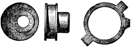
Fig. 12.
Fig. 12 shows the eccentric and the eccentric strap. The first is a piece of
brass; the large circle has a groove turned in it to receive the strap, and the boss is
eccentric, as shown in the left-hand figure. The amount of eccentricity is
1⁄16 inch,
which gives a travel of 1⁄8 inch to the slide-valve. These eccentrics are turned on a
mandrel having double centres, one pair serving when turning the boss, and the other
when turning the eccentric itself. A set-screw tapped through the boss serves to
secure it on the crank-shaft.
The strap on the right of Fig. 12 is cast in the form shown, the centre is bored to
fit the groove in the eccentric, and the strap then cut in halves through the lugs.
These lugs serve to take screws, which hold the strap together. The projecting
piece on the right is to receive the eccentric rod, which is screwed into the strap
at this point.
This completes the description of the various parts of a model horizontal
engine. A glance at Figs. 1 and 2 will show the relative position of each.
Herewith are drawings of an engine with an oscillating cylinder. This form of
construction economises space and weight; it is also more simple than slide-valve
cylinders. In all oscillating engines the cylinder is mounted on trunnions or gudgeons,
so that it may swing to and fro through a small arc, and allow the piston-rod
to follow the motion of the crank. No connecting-rod is required in this engine, the
piston-rod being attached direct to the crank-pin.
The illustration shows an engine specially adapted for propelling a model boat.
The entire machine is kept low down, which is generally necessary for small
boats. The fly-wheel is shown much heavier than are those attached to toyshop
engines, but it is not unnecessarily large. Experiments show that a weighty fly-wheel
is required on an engine which has the constant drag of a screw propeller
to overcome. This fact is ignored by some makers of engines, and I have known
cases where a useless engine has been made effective by the substitution of a
much heavier fly-wheel. (See page 132.)
The framework on which the cylinder is mounted, and which also generally
serves to carry the bearings for the driving shaft, may be of almost any design.
There is no set pattern for this purpose, and it rests with the designer to fashion
his pattern according to fancy. The form shown possesses the essential characteristics.
It is strong, yet light; there is a good base by which to secure the
engine to the hull of the boat. Suitable provisions are made for the bearings of
the crank-shaft, also for the valve-face and the cylinder trunnion. So long as these
are provided for, the mere contour is of little importance.
Fig. 1 gives a side elevation, and Fig. 2 an end view of the same engine. The
cylinder is 1 in. bore and 1 in. stroke. The length without covers is 11⁄2 in., that
allows 1⁄4 in. for thickness of piston,
1⁄16 in. for each of the projections of the two
covers, and the same distance left vacant at each end. The diameter of the cylinder
across the flanges is 11⁄2 in., and a semicircular rib is shown in the middle. Each
cover is held on by six hexagon-headed bolts, placed equidistant round it, tapped
into the flange. These bolts are not shown in the lower cover.
The piston-rod is shown out from the cylinder to its fullest extent. The rod is
of round steel 1⁄8 in. diameter. The crank-pin head is of brass screwed on to the
end of the rod. Though shown as a solid piece, it would be better if this
head
was cut across horizontally at the diameter of the crank-pin, and the cap secured
by two screws. The crank-pin is marked E. It is steel riveted into the disc which
forms the crank. A crank-arm would do equally well, and the disc is shown simply
as illustrating a different plan. The disc F is fixed on the crank-shaft either by
screwing, by a transverse pin, or by a key.
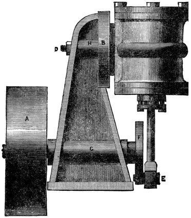
Fig. 1.
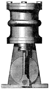
Fig. 2.
The crank-shaft is 1⁄4 in. steel, and should be turned smooth and parallel to fit
the hole in the standard. This hole should also be smooth and parallel, which it
will be if properly bored with a suitable tool. A long bearing has no more friction
than a short one, though a contrary opinion seems to be prevalent. A small hole
for supplying the oil necessary for lubrication should be made near the middle of
this bearing. The same remarks apply to the bearing H through which the
trunnion passes.
The fly-wheel is marked A in Fig.
1; it is cast-iron, 21⁄2 inches in diameter and
3⁄4 in. wide on the rim. The rim should be half an inch
thick at least, and the boss
in the centre as wide as the rim. If bored fairly true, the casting need not be
turned on its edge, though it will look better if bright. A small key should be used
to fix the fly-wheel on the shaft. This latter, shown broken off in the drawing,
projects slightly, and carries a small disc with two pins, which engage in a fork on
the end of the propeller shaft and so drive it, and the screw is attached to its end.
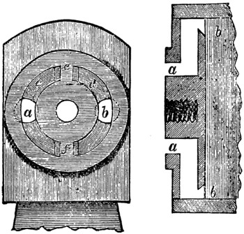
Fig. 3.
The valve-face of the standard, B, Fig. 1. must be made perfectly flat and at
right angles to the boring for the crank-shaft C. Fig. 3 shows the face of this
standard as it would be seen in Fig. 2 if the cylinder was removed. It is convenient
to turn the valve-face in the lathe, and
at the same time cut the circular groove, which,
after being stopped by plugging at both top
and bottom, forms the supply and exhaust
ports respectively. The face may be made
flat by filing when a lathe is not available, and
the groove cut by means of a circular cutter.
This is an annular bit with teeth on its edge,
which cut a channel but do not touch the
inner part.

Fig. 4.
Through the centre of the valve-face a hole
is bored to receive the cylinder trunnion.
This trunnion, Fig. 4, is a steel pin screwed
into the valve-face of the cylinder (see Fig. 3,
section of cylinder showing valve-face and
steam-ways). The outer end is threaded for
a nut, D; this has a washer beneath it, and
keeps the cylinder close against the standard,
with the faces of the valves held together
steam-tight, yet so that the cylinder may oscillate
freely. A spiral spring beneath the nut is
sometimes used, but in good work the adjustment
is made with a pair of lock-nuts. The
hole through the standard must be perfectly at
right angles to the face, and the trunnion in
the cylinder must also be perpendicular to the
valve-face, or the two faces cannot come
together steam-tight.
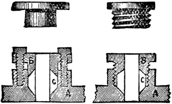
Fig. 5.
The stuffing-box, 1, of the piston is made
with a gland drawn down on the packing by two screws. This arrangement is
shown in section at Fig. 5. The method of fitting the gland, whether by screwing
direct into the boss of the cylinder cover, as shown at the right in Fig. 5, or by
screws tapped through the flange, as in the left-hand illustration, is quite optional.
By referring to Fig. 5, the construction of the two forms of stuffing-boxes will be
understood. The gland belonging to each is shown separate immediately above
the sections. The same lettering is used in both. A is the cylinder cover, with the
projecting boss into which the gland B is fitted. The space for the stuffing or
packing is marked C. This is filled with lamp cotton, and
when the gland is
screwed down the cotton is compressed, so that it makes a steam-tight fitting for the
piston-rod to slide in. The hole for the piston-rod is shown through the centres
of both sections. As before explained, the gland on the left is secured by two
screws shown in the section; it is fitted into a plain cylindrical hole. The other
gland is threaded to screw direct into the cylinder cover, which is tapped to receive
it. The first method is the one always employed in large engines. The screwed
gland has a milled edge, so that it may be
turned with the thumb and finger.
The action of the valves in a double-action
oscillating cylinder will be best explained by
reference to Fig. 3. This shows the face of
the standard and the section of the cylinder.
There is a flat face to the cylinder, usually
circular; this has the two steam-ways a, a,
bored in it. These holes meet others, drilled
from the ends of the cylinder, parallel with its
bore, and conduct the steam to the ends of the
cylinder through the passages at b, b. On the
face of the standard are two holes a and b
drilled from the back, one to receive the steam
from the boiler, the other to take the exhaust
pipe. These holes are not bored through, but
communicate with the circular groove c, d.
This groove is stopped at e and f. The
cylinder is placed against the standard and
held close to it, as shown in Fig. 1, by means
of the trunnion illustrated by Fig. 4.
When the cylinder is vertical, as shown in
Fig. 2, the port-holes are opposite the solid
part of the face e and f. Suppose live steam
issues from a and fills c, directly the cylinder
is moved on one side and one of the port-holes
comes over the groove e, the steam enters the
cylinder and, pressing against the piston,
compels the crank to revolve. By the same
motion the other port is uncovered into d, and the dead steam escapes. When
the cylinder again reaches a vertical position the steam-ports are again closed,
but the momentum of the fly-wheel carries it over the dead centre, and then the
positions of the ports are reversed. The one formerly over the exhaust now opens
to the live steam and vice versâ. Thus the steam is admitted alternately at both
sides of the piston, and so the engine continues to work.
A few words on model boilers and their construction will now be advisable. They
have been mentioned several times incidentally in the course of these sections, but,
with
the exception of the small tin boiler for the oscillating engine first described,
particulars of their construction have been omitted. It is not an easy task making
a steam boiler, and in most cases it will be found cheapest in the end to purchase
ready made.
The materials most generally used are brass and copper; sometimes iron, or
what amounts to the same thing, tin-plate, is employed. Brass or copper, from the
ease with which they can be manipulated, are the best for a beginner to work on.
Brass can be bought in the form of tube of sufficient size for small models, and
strong enough to stand the steam pressure. The edges of the bought tube are brazed
together, and thus the joint is made nearly as strong as the other part. The tube
is afterwards drawn, and, except from a slight discoloration, the joint is not
noticeable.
Brass tube, from two inches to six inches in diameter, cut in lengths suited for
boilers, is sold by most of the model engineers. The price of the tube ranges from
about 2s. per foot for the small to about 10s. per foot for the large size; the short
length necessary for a boiler being charged at about the same proportion. This is
merely for the tubular body part of the boiler, and it may be placed vertically or
horizontally as required.
The ends or flanges which have to be fitted on are extra pieces. Sometimes a
plain disc of metal is fixed by soldering with pewter; but this plan should be
strenuously avoided. The ends should at least be brazed on. It is best also to
use discs with a rim round them to fit over the boiler tube. This gives a much
stronger hold than is possible with a plain disc of sheet metal.
Castings used for the boiler ends must be quite free from any flaws, or the weak
part will be apt to give way under the steam pressure. It is often advisable to use
castings, which may be made of a shape exactly suited to certain requirements.
An inverted cup-shaped casting for the lower end of a vertical boiler gives a good
heating surface. A flue for the chimney must be put in it, and this goes up to the
top end of the boiler, which may appropriately be dome-shaped.
The flue and both ends of the boiler should be brazed in their places, not soft-soldered.
Some prefer to use silver solder for such purposes, and this is an excellent
material. When the joints are made to fit properly, as they should do before
soldering, only very little solder is required to unite the parts. Borax is used as the
flux, both for the alloy employed in brazing and for silver solder. The heat required
to flow these properly may be got from an ordinary gas jet, with the burner or nipple
removed, using a common blow-pipe to urge the flame.
A horizontal boiler is frequently only a plain tube, with the ends soldered in, and
supported on legs to raise it sufficiently to allow a lamp to be put underneath. The
heat applied in this manner does not take effect as it should. The flame is deflected
from the surface of the boiler, and, moreover, any breath of wind stirring will blow
the flame aside. A plain saddle-shaped boiler is much better; in this form the
heating surface is large, and the heat from the furnace is applied to it direct, and
cannot well be deflected.
Flues or tubes are very desirable in any form of boiler, and one or the other
should be used. The plain straight chimney put through the boiler is the most
simple form of flue. If this is of spiral form, like a corkscrew, the effect is infinitely
increased, because the heat, instead of ascending straight up through the
vertical
tube, is met at every turn with a fresh surface of metal. In winding its way through
a spiral tube, the heat is absorbed in a way quite unattainable when a straight tube
is used. Several small tubes are of course better than one large one of the same
area. By increasing the number of flues the cost of making a boiler is also increased,
and it is to save expense that large flues are used.
Boilers for locomotives, which are required to make steam very fast, have an
immense number of tubes running through them. The space between the tubes,
which is occupied by the water, is often very small, and in fact the tubes are put as
closely together as possible. As the heat rushes through them it is absorbed by the
water in contact with the tube, and turns it into steam. The greater the heating
surface the more readily is the steam generated.
Tubes are often put across the fire-grate; they are then called cross-tubes. Two,
placed one above the other and crossing each other, will give a large amount of
heating surface. By adding this simple contrivance to a vertical boiler with a
straight flue it may be made to give off much more steam. One or two cross-tubes
generally suffice to convert a useless boiler, that is, one that will not generate
enough steam, into an effective one.
The fuel used to heat small boilers is generally spirits of wine. This is put in a
suitable receptacle and burnt through a cotton wick. Several wicks are used in
large boilers, and they are placed to heat the largest surface available. Spirit lamps
are a source of danger if proper precautions are not taken. Unless there is a free
outlet for the air within the lamp, it will be expanded by the heat and cause the
spirit to rise too quickly in the wick. Sometimes it will overflow, and then it
burns wherever it may be. Care must therefore be exercised in using spirit fuel.
In model boats it occasionally happens that the spirit overflows, and the boat is all
ablaze. An iron tea-tray, or some such utensil, should be used to stand the boiler
on when the furnace is to be lighted.
Charcoal is a better fuel, when there is sufficient space in the fire-box to contain
a supply. The waste steam from the cylinder must always be conveyed to the
chimney and escape up it to make a draft through the fire. Without this it cannot
be made to burn sufficiently fierce for the purpose. A charcoal fire will act very
well, with a little attention, and except for the smallest engines it is always preferable
to methylated spirit.
As it is not possible to give any adequate instructions on boiler-making in the
limited space at my disposal, the above hints are chiefly intended for the guidance
of purchasers.
A safety valve should always be fitted to a steam boiler. One of the spring
valves has been illustrated in the chapter treating of the small oscillating engine.
The lever safety valve is more certain in its action, especially in model work, and is
better adapted for stationary purposes. A weighted lever is of no use to a locomotive
or marine boiler, as the motion of travelling would disarrange the gear. The
safety valve of every engine should be tested frequently, to make sure that it does
not stick in its place and that all works perfectly free.
A glass gauge, by which the height of water may be seen at a glance, is frequently
attached to boilers having any pretension to high-class workmanship.
There is a good deal of work in a properly made gauge, and the cost is
correspondingly
high. Two or three stop-cocks are required in a gauge, and these
involve good workmanship, or they will not stand the pressure. Leaky taps are a
sign of inferior work.
Gauge cocks are sometimes used instead of the water gauge just mentioned.
These are plain taps with straight noses. Two are wanted on a boiler; they are
screwed in, one at high-water and the other at low-water level. By turning on
these taps it is easy to see whether the water is within these limits; but the precise
height cannot be ascertained. The gauge-glass is therefore much preferable.
Whistles are fitted to boilers only as ornaments. They are quite useless as
signals, except such as can be given by word of mouth, are not required in working
model engines. These attachments are made to sound by allowing the steam to
act as the breath does in common whistles.
Force-pumps are used to force water into the boiler to make up for that converted
into steam, and conveyed through the cylinder. These pumps are actuated
by an eccentric on the crank-shaft, and, at every revolution of the crank, throw a
small quantity of water into the boiler. When we consider how much water is
evaporated to make the quantity of steam used for each revolution of the cylinder,
we may arrive at an idea of the work required of a force pump. Practically the
water to be injected at each stroke is too small to be dealt with, unless a large
cylinder has to be supplied. The only way to work a force pump for a model
satisfactorily is by gearing, so that a stroke of the plunger is performed about once
to each hundred revolutions of the crank.
A better plan for feeding small boilers is by hand. The force pump is attached
to the boiler in the usual way, but not connected to the engine. The plunger is
worked by a hand lever, and when it is seen that water is wanted in the boiler, a
few strokes of the lever will suffice.
Governors are used to control the speed of the engine. Without any such
contrivance the engine runs at a speed corresponding to the work it has to do.
The heavier the load the slower the speed, and immediately that the load is decreased
the speed increases. A governor consists of a pair of balls, which are
attached to arms pivoted to an axis revolved by the engine. The faster the speed
the greater is the centrifugal force of the balls, and by connecting these with a
valve, called a throttle valve, in the steam pipe, the supply of steam is reduced as
the speed increases. By this means a uniform rate of speed is attained, irrespective
of the steam pressure or the duty demanded of the engine.
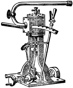
I propose in this chapter to give a few practical hints showing how to build a
perfect model of an inverted-cylinder direct-action engine with link-motion reversing
gear, like the sketch below, which represents a type in daily use on the river and
sea. Such a model, having a fixed cylinder, has not the friction of other types, and
therefore it gives more power, size for size, than an oscillating engine, and does not
get so easily out of order.
You must of course have a lathe, which I will therefore suppose you to possess;
but should there not be a slide-rest to it, you must get the cylinder bored by a
professional turner, for which he will charge
about two shillings, according to the size
of your castings.
Let me first briefly explain the action of
the steam in the engine by a diagram (Fig. 1,
p. 139). The cylinder A is bolted into the
standard, B; the ports or steam-passages are
shown at C; and the slide-valve that allows
the steam to pass alternately to each side
of the piston is marked D, in its case F.
G G are the stuffing-boxes, which have to
be packed with lamp-cotton greased to make
them steam-tight, H is the piston, with its
rod finishing in a cross-head J, which is cut
with a groove to slide up and down the
standards to guide it and prevent the piston-rod
being bent out of shape. K shows the
connecting-rod, attached at its lower end
to the crank L. M is one of the eccentrics
working the slide-valve. N is the main
shaft, resting on the plummer blocks O O,
having a heavy fly-wheel at P and the coupler at
Q. R is the top cylinder plate,
drilled to screw in the grease-cock, of which I will presently give a drawing on an
enlarged scale, S is the bed-plate,
T the steam supply, and X the exhaust.
You will observe that the steam is coming in at the top of the cylinder, through
the top port, as shown by the arrow, pressing the piston down and allowing the
waste steam that has already raised the piston to escape through the lower port, and
so into the exhaust. By that time the slide-valve is raised (by the eccentric)
sufficiently to cut the steam off from the top port, which by that means is in its
turn
put in communication with the exhaust, and allows the steam to pass out of the top
part of the cylinder, whilst it admits it to the lower portion, and so on alternately.
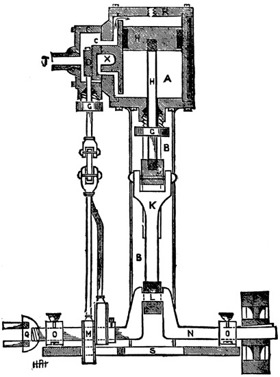
FIG 1
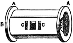
FIG 2
And now to the practical work. After having the cylinder bored, as already
mentioned, get a piece of oak or other hard wood 11⁄2 inch square and about 6 inches
long. Turn one end of it in the lathe, so that it fits the inside of cylinder, and drive
it on. Then put it in the lathe again, and turn the flanges A (Fig. 2) down, and be
very careful that they are quite true
and square.
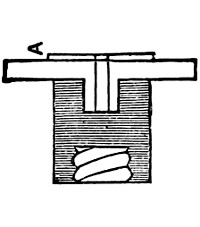
FIG 3
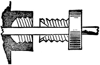
FIG 4
The top and bottom cylinder-covers,
with the stuffing-box, come
next. Screw a piece of hard wood
on the end of your lathe mandrel,
turn it down to about a quarter of
an inch less in diameter than the
flanges of your cylinder, make a
small hole for the stuffing-box to be
driven in, as in Fig. 3. You can
now turn the edge and side—that
next the cylinder. The projecting
part A is to be the exact size of the
diameter of cylinder. When this is
done, take it out and place it in
another chuck, and drill and turn
the stuffing-box out, and screw it to
receive the gland (Fig. 4).
Now chuck the top cover and
turn it down to size. The piston is
a casting, and has to be turned in
the lathe to fit the cylinder, and a
groove run round it to hold the
greased cotton to make it steam-tight.
Whilst in the lathe drill a
hole in the centre, and tap it to receive
the piston-rod, which you can
make out of steel wire. Then pass
one end through the stuffing-box on
cylinder-cover and screw it on the
cross-head J (Fig. 1), having first
filed it up quite square and true and
finished it off with emery. Now
take the standards B (Fig. 1), and finish them up with a file in the same way, and
be careful that the insides forming the guides for cross-heads are quite true. We
can now make the lagging for cylinder. Get a piece of mahogany the length
of the outside circumference of cylinder and the width of the distance between
flanges of same. Then plane it down to about an eighth of an inch and score
it with a penknife every eighth of an inch down its width; it will then bend
round
the cylinder, and you can fasten it on by a couple of brass bands, screwing the
ends down near the slide-valve case.
We will next tackle the steam-ports in the cylinder B (Fig. 2). They are
simply two holes drilled side by side until they reach the openings
C C (Fig. 2) in the
casting; they must not be drilled any farther.
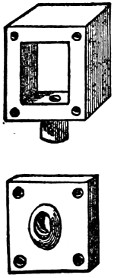
FIG 5
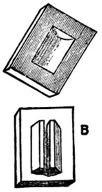
FIG 6
Now place the ends on cylinder and drill through them so as to screw them on
to the flanges. The slide-valve case is a casting with separate lid (Fig. 5), and has
to be faced up with a file, and four holes drilled through the lid and corners to screw
on to the cylinder face. The boss on lid must now be drilled and tapped for steam-pipe
to be screwed in.
The slide-valve itself is like Fig. 6, has a hollow cast in its face, and a small projection
on the back
(B), which you must
make a narrow groove
in with a saw, and
file the end of the
valve-rod down to fit
it, as shown at C,
Fig. 6.
The face of the
cylinder and also of
the slide-valve must
now be made to work
steam-tight by rubbing
on a perfectly
flat stone until true,
and then putting
some emery and oil
on a board and working
them up until
they are quite true.
The eccentrics
may now receive attention.
They will
require to be chucked twice, and the true centre marked. Do not drill it out
yet, as the hole for the crank-shaft must not be in the centre, but half the travel
of the slide valve from the centre. For instance, if the valve travelled one inch
you would have to drill hole for shaft half an inch out of true centre of eccentric.
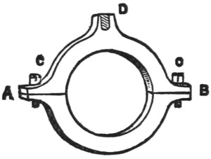
FIG 7
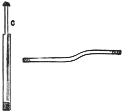
FIG 8
The straps (Fig. 7) have to be turned quite true to the size of the groove on
eccentrics, then taken out of lathe and cut through line A B with a fine saw, and
screwed together at C C.
A hole has now to be drilled at D and tapped for the
eccentric rods to be screwed into, one of which will have to be bent like Fig. 8, so as
to allow it to work on to the quadrant. It is the neatest way to key the eccentrics
on to the shaft with a small steel wedge.
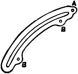
FIG 9
The quadrant (Fig. 9) is of brass, and will have to be finished up with a file and
emery, and the holes A B
B drilled through. The shaft ought to be turned up in
the
lathe as well as the fly-wheel and coupler, with a slight groove sunk in where the
plummer blocks support it, so as to take the thrust.
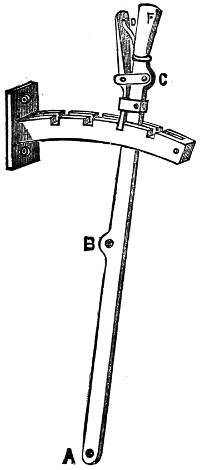
FIG 10
The reversing quadrant with the lever attached I have shown at Fig. 10. It is
best cut out of brass. The notches are cut with a small file after the two pieces
have been brazed together with a small piece an eighth of an inch thick between
either end. It is then screwed on to the slide-valve case.

FIG 11
The lever is drilled at A, B,
and C with small holes, and can be made of flat steel
wire; A is for a pin to work into a joint or hinge on
bed-plate. B is attached to the
hole A (Fig. 9) by a small length of brass rod, so as to work easily. Cut with a slot
at each end and then drill like Fig. 11.
The small spring D (Fig. 10) is to keep the ratchet down in place, and is best
made from a watch-spring, and the handle F is turned out of some brass wire.
The different-size drills you will require can be easily made from various steel
knitting-needles warmed, filed up to shape, and then tempered to a light-straw
colour.
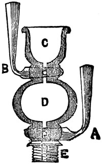
FIG 12
We now come to the grease or oil cocks, which I have mentioned before. They
can be bought ready finished at most model shops, but for those who like to
make
everything for themselves, this is the way to proceed. Fig. 12 is a section showing
interior oil chamber that allows the cylinder to be oiled without stopping the engine
by turning off cock A and opening cock
B, then filling with oil; then shutting B and
opening A allows the oil to descend into the cylinder and lubricate the surface.
Now for the method. Chuck a piece of brass wire about a quarter of an inch in
diameter in the lathe, and turn up to external shape; then turn out cup C and drill
through from end to end with fine drill; then enlarge chamber D with small bent
graver, and take out of lathe and drill through at right angles to previous hole at A
and B with larger drill; then put plugs of brass wire in and fit them with emery and
oil; rivet over one end, and the other turn up into a handle. Then turn them in
straight line with the oil-cup, and drill through with the small drill again. Tap the
end E, and screw into cylinder cover, when it is finished.
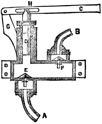
FIG 13
To keep the boiler full of water as the fire empties it by driving it off in steam,
the usual thing is to use a force-pump worked by an eccentric on shaft; but, as the
friction is excessive, it takes a great deal of power away from a model. It is best,
therefore, to work it by a hand lever, and the pump may be screwed on to the side
of boat, the suction A (Fig.
13) being led through the boat’s side and riveted over,
and the supply B brazed into lower part of boiler.
C is the lever, and D the plunger,
which must be quite true, and turned up in the lathe; likewise the valves
E and F
and the stuffing-box tapped and drilled. It is best to work it up from a casting, and
the outside smooth down with an old file. The projection G will then have to be
drilled and the lever pivoted through, having first cut a slot at H to allow the lever
to rise and fall.
I will now describe a method of making an injector, or machine for filling the
boiler with water by the power of the steam alone, and not in connection with
the engine.
The injector was an accidental discovery by a Mr. Gifford, and has now become
a universal favourite on board both large and small craft, as it works splendidly
without affecting the engine. So you can run the boiler up with water whilst the
engine is at rest in harbour or otherwise. And another great advantage over pumps
is that the steam, being mixed with the water, raises it in temperature to nearly
boiling-point, and so is a great saving in fuel.
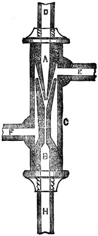
FIG 14
Fig. 14 is a section of the instrument as fit for model work, and if you will follow
these instructions carefully it will act well.
It consists of three parts—the cone A, the cone
B, and the casing C. The steam
is admitted at D, and the water at
E, the waste water overflows at F, and the hot
steam and water is projected with great force into the boiler through the pipe H,
which should be led to the bottom of boiler well below low-water mark, and it is
quite imperative that the steam-pipe should come from top of boiler as so to get
plenty of dry steam, and must not be tapped on to any other pipe.
The injector can be fastened to side of boat by brass band and screws, and the
water-supply pipe brought through the side and riveted, as in the case with the
pump. The injector will lift water several inches, but it always works better if the
water can flow into it freely.
Now we will set to work at it. Take a piece of brass rod and chuck it in the
lathe and turn two cones the shape of A and
B (Fig. 15). Take them off the
lathe
and drill A through as far as practicable, and finish with a small rhymer, having first
made a small hole right through not larger than a knitting-needle; then tap the port C
with an internal screw to take the steam-pipe, and turn a screw on the outside at D.
Now, with the rhymer bore out the conical hollow at E in
B, and tap it outside
at F and inside at G,
in the same manner as the former cone; then drill a small
hole right through from end to end, and a smaller one at right angles to the other
right through at H. This communicates with the overflow, and takes off the water
not carried into the boiler.
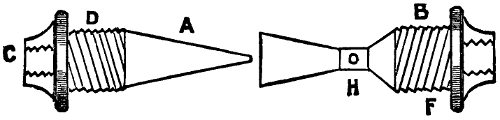
FIG 15
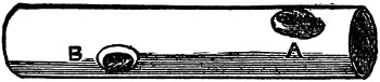
FIG 16
Next take a piece of brass tubing five-eighths of an inch in diameter, and turn a
screw at each end inside (Fig. 16). The screws
turned on the outside of the cones must be the
correct size to fit these; then drill a hole at A,
and screw in a small tube for water-supply with
tap; then drill another at B for the waste water
to escape by. Finally, screw in the cone
A (Fig. 15) and attach it to the boiler by a pipe,
and the nearer the boiler the better, as if the
steam condenses before reaching the injector it
will stop working. The steam-pipe must of course
have a tap to cut off steam when not required.
We must now screw in the lower cone B
(Fig. 15) until there is an annular space between
the two cones not exceeding a sixteenth of an
inch. Then screw in the small pipe at C (Fig. 15),
and attach the other end into the boiler below
the water-line, where it must have a stop-valve to prevent the water returning.
To start the injector, turn on the water-tap until it runs out of the overflow
freely. Then turn on the steam full power, and the overflow will cease, or nearly so.
Should it still drip at the overflow, reduce the water supply by the tap accordingly.
It requires carefulness and patience to make an injector, but when done, and
working properly, there are few boys with a mechanical turn of mind who would
not think themselves well repaid in watching and controlling its mimic action. They
would then have an engine fit to show to their most critical friends, and one they
might well be proud of; and I shall be content if I have helped in any way to
contribute to their happiness.
CHAPTER XI.—THE BOY’S OWN
MODEL LOCOMOTIVE, AND
HOW TO BUILD IT.
By H. F. Hobden.
CHAPTER XI.—THE BOY’S OWN
MODEL LOCOMOTIVE, AND
HOW TO BUILD IT.
By H. F. Hobden.
Those who class model engines as mere toys, and fit only
to amuse the very youngest members of the human family,
entirely forget the important place they hold in the estimation
of inventors and those interested in mechanism as a
means by which they can practically carry out their ideas,
because models not only have the advantage of cheapness
in construction as compared with the full-sized machine, but
also the still greater advantage of being, from the small size and light weights of their
parts, capable of construction by the inventor himself without having to employ
strangers.
I suppose there is no taste more universal amongst boys, old as well as young,
than that for mechanism and engineering. What boy does not feel interested in the
models displayed in the various shop windows in our large towns, and what lad with
any mechanical bent but has a longing to make one for himself and feels an intense
pleasure in being able to do so? And it is with the intention of helping those who
would like to build one, but have not the necessary knowledge, that I purpose to
explain, as simply as possible, the best method of building model locomotives.
In previous pages of this volume, practical instructions by skilled writers have
been given on model stationary engines of a simple make, and also on engines
for steamboats, but of all models the locomotive has the greatest charm for most
boys, and not unjustly so, as when well finished and carefully painted it has a
very handsome appearance, and moreover has the additional charm of its locomotive
power.
Those of my readers who have practically carried out the instructions in the
previous chapters just referred to, have become, I have no doubt, by this time quite
au fait in handling their tools and feel at home in their workshop; but for the
benefit of those boys who have had no practical experience, let me give a word or
two of advice before we begin our locomotive.
First then, with all engineering work, either large or small, great care must
be taken to get the measurements perfectly correct in spacing out the various parts
to be joined together, and do not think, because it is only a model you are
making,
that any off-hand way will do, because you will find before the engine is half finished
that great accuracy is necessary if you wish your model to be a working one.
A slight mistake in the measurements of a large engine will cause so much
friction as to take half its power to overcome, and the same thing occurring in
a model would stop it entirely.
Then with respect to any part you may require to solder, be careful always to
make the brass or other metal you wish to unite quite hot. You will then get a good
firm joint.
Do not just touch the metal with the soldering iron and then take it away. You
might certainly stick the parts together slightly in that way, but they would be sure
to come apart the first time they received a blow or any pressure was put on them.
Soldering on the best work should be used very seldom, and all the fastenings
should be either done by riveting, screwing, or brazing; and I need hardly remark
that no part of a boiler should be soldered which comes in direct contact with the
flame of the lamp or furnace.
Brazing, with the exception of very small articles, is beyond the ordinary powers
of an amateur.
Even to braze the seams of a model boiler requires a forge fire or
very powerful gas-blast, which is too expensive for most boys to get; but
small things, such as a broken slide, valve rod, etc., can be easily brazed
by using a gas blow-pipe, and as it will cost you very little to make and
will prove a useful tool for sweating in solder as well as brazing, I
will briefly explain.
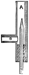
Fig. 1.
Fig. 1 is a section of the blow-pipe complete.
To make it, first get a small piece of brass tube (A) of about half
an inch diameter and five inches long; drill a hole at two inches from
one end, and insert a piece of gas tube (B) and solder it in place.
Next take a piece of glass tubing a quarter of an inch diameter and
about seven inches long, hold one end in a gas flame, and when red-hot
draw it out to a fine point, then file round and break off the tip, leaving a
small hole.
Next squeeze a sound cork into the tube A
as at C, and drill a quarter of an inch
hole through its centre and insert the glass tube D, and the blow-pipe is finished.
To use it you connect the pipe B with a gas bracket by a rubber tube, and the glass
tube D must be fastened to a pair of bellows by means of another piece of rubber
tubing; the bellows should have an air-bag attached, to enable you to keep a constant
pressure up and prevent having a jerky flame.
When requiring to braze any article, bind the parts together with some very fine
brass wire and cover it up with a little powdered borax and water, then lay the
article on a piece of charcoal, and if it is necessary to preserve the temper of
the steel you are about brazing, cut a potato in half and push each end of the steel
rod into the halves, which will prevent the temperature of the rod getting too high.
When you have it all nicely fixed, turn on the gas and light your blow-pipe,
immediately work the bellows with your foot, and by either pushing in the glass
tube D, or drawing it slightly out, you can regulate the shape of the flame as
required.
Then bring the flame to bear on the joint, well supplied with the borax, and soon
you will find the brass wire melt and run into the joint like water. It must then be
neatly filed up, and the join will be scarcely visible.
Having made this useful tool, I will mention a few others you should get before
commencing work; they will not cost much.
A centre punch or pointed steel spike for marking metal for drilling, etc., and a
small riveting hammer, three or four files of different degrees of fineness, a screw
plate and taps, and also a small hand-drill with a set of drills to fit, will be most
useful; and of course very little can be done without a good firm vice.
If you have a lathe, so much the better; it will enable you to save lots of odd
coppers for turning various parts. Curves for bending metal on you can easily
make from pieces of bar iron, holding them in the vice when working on them.
When you have your tools ready, the materials are required you intend working
on, which will consist of several sheets of brass and copper, the castings and various-sized
screws and bolts; and having got these all together, we can set to work on
our locomotive.
I think it would be better to first give you directions for making a simple one of
about fifteen inches, and then to proceed to a more perfect model after.
In a previous article you will find a description of the action of the steam
in the cylinder, and although that is in a marine engine, the action is precisely
the same in the cylinders of a locomotive, and you should therefore read the
description carefully and thoroughly understand it; there is also given a method
of turning the cylinders, and hence I shall not describe the process again, but
consider that you already know sufficient about it, should you wish to make your
cylinders in preference to buying them ready finished.
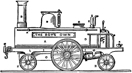
Fig. 2.
At the commencement of this chapter is a drawing of the model we are about to
build in its finished condition, and Fig. 2 is a side view of the same, of which A is
the boiler, B the chimney,
C a screw head to fill boiler with water, D the steam chest
with safety valve on top, E the whistle,
F the steam tap to start the engine with, HH
are the leading and trailing wheels, and I
the driving ditto, K the cylinders,
L the
frame, M the buffers, N
a set thumb-screw to fasten a tender on by, O is the lamp, and
P is a small tap, used to ascertain the quantity of water in the boiler. The handrails
R and S complete
it; and I think this is sufficiently clear for you to perfectly understand
the general working arrangements of the model.
Locomotives, whether real or only model ones, can all be divided into three
principal parts, viz., the carriage or framework, the engine or cylinders and parts
connected with them, and the boiler, and we will now proceed to make each part
in turn, beginning with the framework.
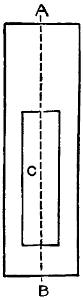
Fig. 3.
First take a sheet of brass for the bed-plate, about one-sixteenth of an inch thick,
and cut it to an oblong shape, four inches wide by fourteen inches long, as in Fig. 3,
and be very careful that the corners are right angles. This is to be hammered out
quite flat and filed up smooth, and finished with emery cloth held round a flat piece
of wood; you must also cut a hole in it for the boiler to rest in as at C, beginning
half an inch from B and making the hole eleven inches long by one inch and a half
wide, taking care it is quite central on the line AB, or you would get your engine
lopsided, and you must take the same care in setting the chimney, steam dome, etc.,
as when not exactly central it gives a bad unsightly look to an otherwise well-finished
model.

Fig. 4.
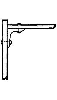
Fig. 5.
The next step is to cut out the side frames (Fig. 4),
drilling holes at A B C for the
axles to work in; you can finish both sides in the same way, and, turning the bed-plate
upside down, fasten the frames on at a quarter of an inch from either side by
small angle pieces, as in Fig. 5, or by soldering, which is much quicker. Then
fasten by the same means a piece across each end about half an inch deep, and the
frame is ready for the wheels.
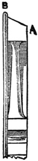
Fig. 6.
These can be had ready finished, but if you have the castings, they must
be chucked in the lathe and the tires turned up to the form shown in Fig. 6. The
small wheels should be about two and a half inches diameter and the driving wheels
four inches. The rim B should project a little over one-sixteenth of an inch, and
the rest of the edge should be bevelled off slightly as at A.
The spokes may then be filed up smooth, previously drilling out the centre hole
for axle before removing it from the lathe.
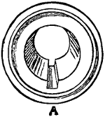
Fig. 7.
Great care must be taken to turn both the driving-wheels to exactly the same
diameter, or one wheel would travel farther in a revolution than the other, and as
they ought to be both fixed rigidly on to the crank shaft, the engine would never
travel in a straight line, but would always run in a circle. You will require some
steel wire for the axles, and can fasten them to the wheels by soldering or by
cutting a slot with a fine file in the centre of wheel, as at
A, Fig. 7; then filing a
small portion of the ends of the axle flat, drive in a brass wedge made from a piece
of wire, which will hold them together firmly.
The crank shaft or axle must be hammered up to shape, making it hot occasionally
in the gas flame whilst working it.
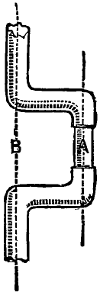
Fig. 8.
The cranks should be at right angles to each other, and the throw of the crank
is to be half the distance of the cylinder stroke. For instance, say the cylinders
are an inch and a half in stroke, the distance between A B
(Fig. 8) will be three-quarters
of an inch; you must then ease the size of crank at A, to prevent the piston
knocking the cylinder ends.
The cylinders require such extreme care in turning that it is by far the best
plan to buy them ready to put on your framework; and if you get a pair of
oscillating ones three-quarters of an inch bore and about an inch and a half stroke,
you will get sufficient power to drive your locomotive several miles an hour.
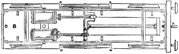
Fig. 9.
Fig. 9 shows you an underneath view of the framework and the position to
place the cylinders in, which should be supported by a couple of lugs (A A) screwed
to the bed-plate B which must have a piece cut out on either side to allow the
driving-wheels (C) to work in, as at
D, because, being larger than the others, they
project beyond the top of the bed-plate, as shown in Fig. 2. You can now screw
on by means of the hook F the buffer-beam, previously cut from a piece of mahogany,
five inches long, half an inch thick, and one inch deep, nicely squared and sand-papered.
Drill a hole at G and pass the shank of hook through the beam and piece of
brass in front of frame, and screw up tight with nut H.
The buffers can be properly turned up and fitted with springs, but that I will
explain when making our more perfect model, and content ourselves now with a
couple of brass flat-headed screws, such as are used in connections of electric
batteries, and which form capital imitation buffers, one having to simply screw
them
into the beam about one inch from either end, leaving them projecting about half
an inch.
The framework is now sufficiently complete to be lacquered. First polish every
part intended to be bright, carefully removing all traces of file-marks and any
grease that may be on the work by a little acid; and after drying it place it on a
sheet of iron held over the gas—or fire, if clear—until it is moderately warm. You
can then apply the lacquer with a small brush, taking care not to go over any part
more than once. The lacquer can be had at most model shops, and is cheaper to
buy ready-made than to prepare yourself.
The spokes of the wheels should be painted; black-lined on green looks very
well, and the ordinary tube oil-paint, mixed with a little mastic varnish, is the best
to use.
The buffer-beam should be varnished, and the cylinders ought to have a coat of
paint, leaving the cylinder-covers and the flanges bright.
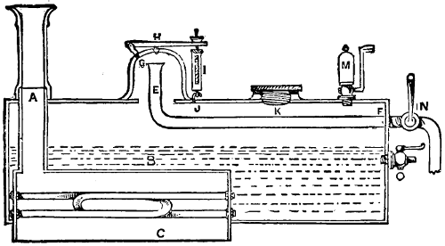
Fig. 10.
The frame may now be put aside to dry, covered up from dust by a paper box,
whilst we proceed to make the boiler (Fig. 10).
This is a most important part of the locomotive, and is the cause of a great
many failures and unsatisfactory working, even amongst the professionally-built
models. I well remember how, when a lad at school, I fell deeply in love with a
beautiful highly-polished brass locomotive of about the size we are now building,
which was displayed in an optician’s window. Having made inquiries about the
price, and got it reduced from to £5 to £4, with a promise to keep it for me, I set to
work to save my pocket-money, and for some months rigidly abstained from all
kinds of tarts and toys; and when finally the last shilling was saved which completed
the amount, and I carried it—my first model—home in triumph, no boy was
ever happier. But, oh! the bitter disappointment when, after getting up the steam
and trying to start the engine, I found it would not work.
I was too young then to find out the reason, and the man who kept the shop,
not being a practical mechanic, could give me no help, and although, after we had
tried it together, he offered to take it back, I decided to keep it with a view to
remedy the defect, if possible; but it was a long time before I found out that the
fault lay in the boiler not being able to supply sufficient steam for the cylinders, in
consequence of not having enough heating surface acted on by the lamp.
Since that day I have made numerous models, and have always taken precautions
to avert such a difficulty, and although the method I am about to describe entails a
little extra work, you will feel well repaid for the trouble when you find what a
splendid head of steam can be kept up.
The boiler should be eleven inches long by three inches and a half in diameter,
and you can buy copper tubing of that size which is very suitable for the job, or
you can form it from a sheet of copper or brass bent to shape round a wooden
roller, and either riveted or soldered together. You must then turn two circles
of brass about an eighth of an inch thick for the ends, and polish the outside of
each nicely.
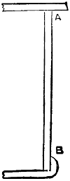
Fig. 11.
Then push them into either end of the boiler about an eighth of an inch from
the edge, as in A (Fig. 11); they can now be soldered in place, and you will find
your gas blow-pipe very useful here. The projecting flange should be
hammered
down all round, like B (Fig. 11), which can also be sweated afterwards with solder,
and finished off with a half-round file.
When filing solder or lead, only use an old worn file, as the soft metal soon fills
up and spoils a good one, and although it can be melted out by heat, it is not
advisable to do so.
You will now require to drill a hole at A (Fig. 10) for the chimney, which should
be three-quarters of an inch in diameter. Then cut a slot in the bottom of the
boiler six inches long
by an inch and a half
wide, commencing a
quarter of an inch from
the forward end of the
boiler.
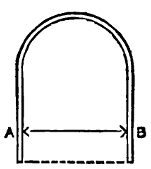
Fig. 12.
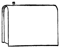
Fig. 13.
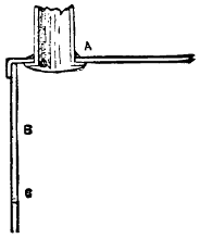
Fig. 14.
Now take a sheet of
copper and cut a piece
about six inches and a
quarter long by six
inches broad, and bend
it over a wooden roller
to the shape shown at
Fig. 12, keeping it an
inch and a half apart
between A B. Cut also
two other pieces of
copper to the shape
of your bent sheet
(Fig. 12), and make
it long enough to reach
to the dotted line.
These form the two
ends, which may be
placed an eighth of an
inch from the edges,
as in Fig. 13, and
soldered in place, and
the projecting rims turned over and sweated with solder from the outside in the
same manner as you did to the boiler-ends in Fig. 11. Then drill a three-quarter-inch
hole at B (Fig. 13) for the bottom of chimney-tube to go into, and cut
a piece of three-quarter-inch brass tubing of sufficient length to pass out at top of
boiler about half an inch, as shown at A (Fig. 10). You can then hammer out a
rim or flange on the bottom end of chimney-tube, and push it up through the hole
in the copper box and solder it in place from the top, as at A (Fig. 14).
Now drill a couple of small holes at each end of the box B C (Fig. 14); these
should be rather more than an eighth of an inch in diameter, to allow an eighth of
an inch tube to pass through.
Get two twelve-inch lengths of hard-drawn steam-piping of an eighth of an
inch
in diameter, and with your screw-plate put a thread on each end of about half
an inch in length, then drill some holes in any odd piece of brass plate, and with
the screw-taps form eight nuts to fit the threads on the piping, and finish them up
to shape with a file.
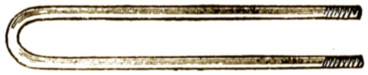
Fig. 15.
Then take the piping and bend it very gently, to prevent it cracking, round a bar
of iron or handle of some tool held in the vice until it is of the form shown at
Fig. 15. Do each one the same, and then mix a little turps with some white lead
and smear each end where you have formed the screws, taking care not to get any
into the tubes, and they might have a plug of paper put in temporarily to prevent it.
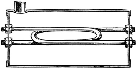
Fig. 16.
Now put a nut on at either end as far as the thread will allow it, and smearing
a little white lead round the holes drilled in ends of box B C (Fig. 14), push the
tubes in from the inside and screw up firmly with the remaining nuts in the
position shown at Fig. 16. The inside nuts can then be tightened up with a
spanner, and if you have carefully done this you will never be troubled with any
leakage, no matter what pressure you may get in the boiler.
These tubes are immensely strong, and from their small size the water in them
is raised quickly to a higher temperature than that contained in the rest of the
boiler, causing a continual circulation to take place and a constant supply of steam
to be formed.
The box can now be placed in the boiler through the slot cut in the bottom,
taking care that the top of box is not more than half way up the boiler, as in B
(Fig. 10). This will leave a portion projecting below the lower edge of boiler,
like C. This part protects the flame of the lamp from being blown away by the
draught caused by travelling along, which would cause you to lose steam. Solder
it firmly in position from the outside, to prevent the flame touching any soldered
portion. Also solder neatly round A (Fig. 10).
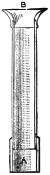
Fig. 17.
The chimney can be made from another piece of three-quarter brass tube. Chuck
it in the lathe, and turn it up bright, and put a collar on it at
A (Fig. 17) to allow it
to push on to the piece of tube left projecting at A (Fig. 10).
The top of chimney, or bell-mouth, B (Fig. 17), will require turning in the lathe
also, and fitting on neatly.
The steam-chest D (Fig. 10) is a brass casting you can turn up also, and after
cutting a circular hole in top of boiler of about an inch in diameter it can be either
screwed or soldered on, previously putting the steam-pipe E in position by drilling
a hole at F, and after bending it as shown, pass it
through at F and solder in place.
The top of pipe E should be about a quarter of an inch from top of inside of
steam-chest.
Before soldering on the steam chest drill a couple of holes, as at G H (Fig. 10),
one for the small lug G to be screwed into, which holds one end of the lever of the
safety valve, and that at H should be drilled conical
with a rhymer, and the valve H
can be turned in the lathe, and afterwards ground to fit the hole with a little emery
and water, by means of a slot cut across the top and worked round with a screw-driver.
The spring-case of safety-valve is easily made from a piece of the one-eighth of
an inch brass tubing, and using some small, hard brass wire to form the spring of.
When finished it should be hooked to the eye screwed into boiler at V.
The manhole, or screwhead, K, is
used to refill the boiler by when it has steamed
low, and will require to be turned up to shape; and the bed L it screws into can be
firmly soldered on the boiler, having first drilled a hole slightly larger than the
diameter of the screw itself, which should be sufficiently large to allow an ordinary
tin funnel to be used to refill by, and the screw ought to be large enough to hold a
leather washer under the head to keep it steam-tight.
The whistle M will require a hole drilled for it to be screwed into, and that, as
also the steam-tap N and water-tap
O, can be bought cheap ready to put on, and is
more satisfactory than making them yourself. But should you wish to do so, the
method I have already described in Chapter X. of making an oil-cup applies equally
to these.
The tap O should be screwed in at a slightly
higher level than the top of box B,
and when working the engine, should steam issue from it when turned on instead
of water, you ought to immediately blow off steam by safety-valve H. Then unscrew
K, and refill the boiler with water.
By this time the framework will no doubt be quite dry, and you can then clean
and polish the boiler and attach it to the frame by a screw or solder at the forward
end, and the steam-pipe N can be screwed on to the projecting
piece of tube left at F, whilst you also screw a short
length of pipe into the steam-box of engine through a hole
in the bed-plate. Then bend it up to the steam-tap and
solder them carefully in position; this will hold the after
end of boiler firmly.
Go over every soldered joint to see if any small hole
is left, and re-solder where necessary, as a hole in the
boiler not larger than a pin’s point would prevent you
getting any adequate pressure of steam, as the water would
all blow out.
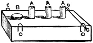
Fig. 18.
When so far complete, you can either lacquer or paint
the boiler as suits your fancy, and whilst it is drying
there will be time to make the lamp (Fig. 18).
It is simply an oblong box made of tin or any piece of thin metal you may have,
and should be one inch and a quarter wide by five inches long, and about three-quarters
of an inch deep. To make it, cut say a piece of tin four and a half inches
by five inches, and bend it to shape, then solder the two edges together and cut
two ends to fit. Push them in and solder in place.
Then cut three pieces of brass quarter-inch tubing into three quarter-inch lengths,
drill holes in top of lamp and insert them, allowing about a quarter of an inch to
project, as at A (Fig.
18); then solder them on four pieces of bent wire (C C C C), by
which to hang the lamp by means of two wire pins run through them and small holes
drilled in sides of projecting piece C (Fig. 10).
The screw-filler B (Fig. 18) will have to be soldered in also, and when complete
the tubes A may be filled with cotton wick, and the lamp about three parts full of
methylated spirit, which will give a clear smokeless flame.
You can now start your locomotive by filling the boiler about three parts full of
hot water, and then hooking the lamp underneath; you will soon get a good pressure
of steam up.
See that all the taps are turned off; and if there is no leakage from careless
workmanship, you will find, on turning the steam-tap on, the locomotive will run
beautifully, and will travel at great speed either on a smooth oil-cloth or wood floor.
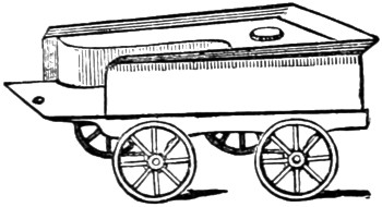
Fig. 19.
I will presently explain how to make a set of rails, on which she would run much
quicker still; but for this engine, if you make a small tender of the shape shown at
Fig. 19, and fasten it at any angle by the set-screw on the foot-plate of the engine
shown at N (Fig. 2), the model will run in any sized circle you may wish, without
lines, according to the angle at which you fix the tender to the engine.
Wooden coal trucks, etc., you can easily make to complete the train if you wish;
but of course each one is an extra load for the engine to draw, and will prevent it
going as quickly as when alone.
Tin is the best material to use for the tender, as no great strength is required;
indeed, it should be made as light as possible. The wheels and axles you must
finish in the same manner as those on the engine; and it could be made into a
tank, to hold an extra supply of spirit, by soldering a piece of tin round the inside,
and covering it in with another piece cut to shape, and fitted with a screw-nut to fill
by, as shown in Fig. 18.
If you have carefully followed these simple directions, and also practically
carried them out, you will be able, and no doubt anxious to try your constructive
powers on a more complete model, and I will therefore endeavour to help you to
do so.
Should you be able to draw, you will find it a great help if you carefully sketch
out on a sheet of cartridge paper the locomotive to the exact size you intend
building it.
You can then take all the measurements from it, which will prove to be a saving
in time and trouble. Of course the larger you make the engine, the more expensive
the castings and materials will be; but if you persevere in making the locomotive I
am about to describe, you will have a model of real value to you, and which would
probably cost fifty pounds to buy ready finished; and if you turn the wooden models
for the castings yourself, and use sheet-iron for the framework, etc., where possible,
the total expense will not be so very great.
Fig. 20 is a side view of the locomotive in its finished state, and we will begin to
work at it in the same manner as in the former model, viz., with the framework;
but as some of my readers may have a preference for some special type of engine
other than the one drawn, they can easily build it from the following directions, and
keeping the same proportion in size as in Fig. 20, which is drawn to 1⁄8-inch scale.
The entire length should be about three feet two inches, and the bed-plate
thirty-five inches by nine inches wide. The driving-wheels are eight and a quarter
inches in diameter, and the leading wheels five and a quarter inches, and about six
and a half inch gauge, viz., the space between the lines on which the wheels run.
The cylinders should be one and three-quarter inch bore by two and a half inch
stroke, which will give sufficient power to drive the engine at a high rate of speed,
with 30 lb. to 50 lb. of steam. The boiler is twenty-eight inches long, including
smoke-box, by five inches diameter.
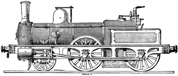
Fig. 20.
Fig. 20 enlarged (200 kB)
In Fig. 20 I have lettered the various parts, and it will be well to look over
them carefully, as this engine differs materially from the previous model in its
arrangement, being constructed exactly similar to a real engine.
A is the chimney, B
steam-blast used to increase the intensity of the fire, and is
worked by rod C running through the hollow handrail
D, and ending in handle F.
G the steam-dome and safety-valve is the same pattern
as previously used, H extra
safety-valve, worked from foot-plate; I steam-whistle,
K wind-guard, L starting-lever,
M smoke-box (with door), N
O spring-buffers; P is the line-clearer, or wheel-guard;
Q leading wheels, and R R
driving ditto; S one of the cylinders, with piston-rod and
guides bolted to frame, and showing double connecting rod at T
T; U U are the
springs which support the weight of the boiler, etc., on the axle-bearings; the spring
on rear wheel does not show, being inside the safety-guard and handrail
V. W is the
back-pressure valve, through which the water is thrown by the force-pump into the
boiler; and X is the blow-off tap to clear the model from all water after having
used it; and Y shows the side of ash-pan.
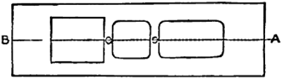
Fig. 21.
Now to commence making the framework. This should be made of one-eighth
of an inch sheet-iron, squared up perfectly true and flat, and cut out as shown in
Fig. 21, commencing four inches and a half from
A, and leaving six inches at B, and
cutting it six inches wide there by eight inches long, and continuing it four inches
wide for the rest of the distance. Be careful to keep it quite central on the line
A B, and leave two connecting strips one inch wide, as at C C.

Fig. 22.
The side-frames come next. These must be much stronger, and quite different
from those used in our previous model, and should be cut from the same eighth of
an inch plate-iron to the shape shown in Fig. 22.
The centre of slot B is seventeen inches from
one end, the centre of A ten inches
from B, and centre of C
thirteen inches from B.
In marking out work always measure from a fixed centre, for if you add
one
measurement to another any slight inaccuracy gets increased with each fresh
measurement, and you might finally get the different portions out of place.
The slots are each an inch and a quarter wide by two inches deep, leaving one
inch of iron at top as shown. The ornamental spaces can then be cut out, which
lightens it considerably without weakening it much.
The frames, after being smoothed up, can be fastened to the bed-plate in the
manner described before by angle-irons or knees riveted on. Two end-pieces must
also be prepared an inch deep, and the ends hammered square at right angles, and
then riveted to the bed-plate and side-frames, as shown by the rivets in Fig. 20.
Then drill three holes in them about an inch and a half from either end, and one
in centre by which to bolt on the buffer-beams by means of a couple of screws put
in from the back.
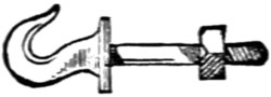
Fig. 23.
The buffer-beams should be mahogany, one inch wide, two inches deep, and ten
inches long, squared nicely and sand-papered. A hook can then be made (Fig. 23),
and, a hole being drilled in the centre of beam, you can pass the hook-stem through
and into central hole of framework, and screw up tightly with nut at back, which
will hold all firmly in place.
The buffers for this model must be made properly with springs to take the
pressure, should you let it run into anything.
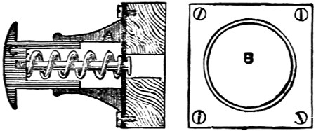
Fig. 24.
Turn out a wooden mould in the lathe and get four castings in brass made from
it. Fig. 24 is an ordinary kind of buffer in general use, and, being in section, shows
you the working arrangement of the spring, A is cast with a square base-plate two
inches square, as in front view B, and is secured to buffer-beam by four flat-headed
screws. The piece C must be turned true, and just the size to slide in and out A easily.
Each part must be finished up in the lathe. A should be about an inch and a half long.
Drill a hole in beam to allow the head of pin to work in freely, and another hole
in base-plate of buffer the size of pin, whose head prevents the spring forcing C
entirely away from A.
The spring should be made of thick steel wire; the buffers can then be
screwed on as just mentioned. The wheel-guard, or line-clearer P (Fig. 20), can
next be cut out to shape and bolted on to frame, and should just clear the line by a
quarter of an inch.
We will now proceed with the axle-bearings and springs U (Fig. 20). The
wheels can be finished up in the same manner as previously described, so I need
not say anything further about them.
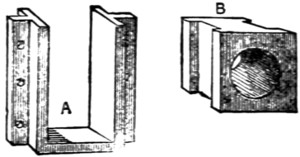
Fig. 25.
Make a wooden model like Fig. 25 and get six castings in brass made from it.
They then must be filed up square and smooth and fitted into the slots cut at
A B C (Fig. 22), and either screwed or riveted on by the side holes.
Before finally fixing them prepare six brass bearings (B, Fig. 25). They must
fit exactly, and slide easily in the inner surface of A, and a hole is to be drilled
centrally through each five-eighths of an inch in diameter. These take the axles,
which in this model are all straight, and three-quarters of an inch in diameter,
shouldered off to five-eighths for the bearings.
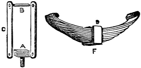
Fig. 26.
The springs next require attention. Four pieces of either sheet iron or brass are
wanted in each support an inch and a half long by a quarter wide. A hole is to be
drilled at either end, as shown at C in
Fig. 26. A should be three-eighths of an inch
wide, drilled through and a pin put in, and all riveted together loosely.
The spring is best made from clock-spring, and cut to shape as at D. The top-piece
requires to be made hot with your blowpipe, and then the ends turned over
to hold the pin B. Each piece of spring must be slightly shorter than the upper,
and the ends nicely graduated off, and when ready held together by the brass band F,
which has a small hole drilled at F to hold the end of pin by which the pressure is
directed on to the axle-boxes, as shown in Fig. 20. A hole is also to be drilled
in bed-plate over centre of each axle-box to allow pin to pass through, and also a
smaller one an inch and a half on each side for the support A (Fig. 26) to screw
into. They can all be fitted into position.
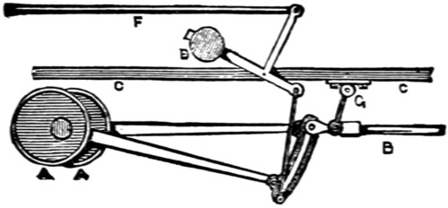
Fig. 27.
The cylinders come next, and should be, as previously mentioned, an inch and
three-quarters bore by two and a half inch stroke. These should be of the fixed
slide-valve pattern, with double eccentrics fitted on middle axle-shaft, and reversing-lever
brought to quadrant on foot-plate, as I will show presently, and for the method
of making them I will again refer you to my article on the Model Launch Engine, and
will simply give you in Fig. 27 the modified form necessary to suit a locomotive, in
which
A A are the eccentrics, B
slide valve-rod, with guide G attached; C C the bed-plate,
D the balance-weight, and
F the rod leading to quadrant and lever on foot-plate.
The cranks are put on outside the wheels and fastened by keys, as in Fig. 20.
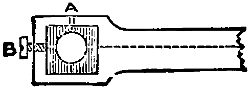
Fig. 28.
The connecting rods T should be cut to the form shown in Fig. 28, and the ends
squared out and a brass bush filled in with a hole drilled from top (A) to oil by,
and a set-screw B fitted to adjust the bearings perfectly.
Although these little things give extra work in fitting a model, they add considerably
to its finish and lessen the friction.
If you wish to fit a force-pump, it should be placed centrally between the cylinders,
and be worked by an eccentric on main shaft, but a pump on a model locomotive
is of very slight use unless it is arranged to work by hand also.
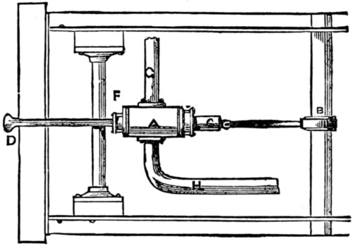
Fig. 29.
In Fig. 29 I have given a practical method of arranging one to be worked either
way as desired. A is the pump,
B the eccentric on main-shaft to work it by steam
power; but when requiring to work the pump by hand, you have only to push up
hook connection at C, which disconnects it from eccentric, and then by working the
handle D, which is screwed into bottom of
plunger C, the water is forced into boiler.
This pump is a little more troublesome to make, as it requires an extra stuffing-box
at F, but it is very neat and useful, and the
handle lying quite out of the way, does not spoil
the appearance of the model.
G is the exhaust water-pipe bent up to the back
pressure-valve on boiler, and H the supply-pipe
carried on to rear of engine.
You will find two small blow-off cocks on each
cylinder very handy to get rid of the condensed
steam when starting the engine with cold cylinders,
as without them the cylinders get choked, and you
stand a good chance of getting scalded by the hot
water being thrown up the chimney with considerable
force.
The blow-off cocks can be connected with a
tye-rod, and both worked from the foot-plate by a
single handle.
The parts being all finished to your satisfaction, you should paint the bed-plate
black, and side frames red, and when dry carefully line them black and white, and
also pick out the rivets with black.
Of course individual taste has a great deal to do with the finish of a model, so I
will leave it to you, merely suggesting you should get a fine lining tool to finish with,
and when all is complete put it aside to dry whilst we proceed to build the boiler.
This will require the greatest care, but with due attention you will be able to
turn it out well. Some sheet copper will be required one-eighth of an inch thick,
and although this is more expensive than iron, it does not rust, and is more suitable
for the work in hand.
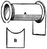
Fig. 30.
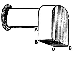
Fig. 31.
First cut a piece nineteen inches long by sixteen wide, and bend it round,
forming a cylinder five inches in diameter; the lap must be closely riveted, and
then the two ends hammered out into a flange outwards, leaving the body of boiler
seventeen inches long, as in Fig. 30;
B is the shape of piece to be next
riveted on
at after end, then take another sheet nine inches wide, and hammer a half-inch
flange round it so as to fit over the dotted line in A.
Then rivet them firmly together, and also another piece in after end.
It will now have the appearance of Fig. 31, and should be four and a half inches
deep from A to B,
and forming a copper box six inches wide from B to C, and eight
inches from C to D.
Then rivet together another box to form the inner casing four and a half inches
wide by six and a half inches long and nine inches deep.
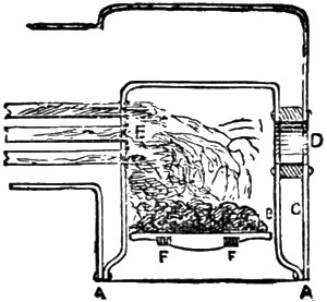
Fig. 32.
The bottom of this must be hammered outwards to the dimensions of BC CD,
as shown in section Fig. 32 at AA. A hole is next to be cut out in the centre of
rear plate, and also the rear part of inner casing which comes opposite to it, and
one three-quarter inches by two and a half, forming an elliptical opening for the
furnace door.
A casting of that shape and three-quarters of an inch thick, which is the distance
between the inner and outer casing BC, must be procured and drilled with holes
every three-eighths of an inch, and firmly riveted in position, as shown in section
at D.
Two pins or lugs (FF) should project on either side
of the inner surface to
support the fire-bars and ash-pan, and the bars should be made of cast-iron, and
small enough to be got out easily by tilting up one side, and the bars ought to run
lengthways of the engine.
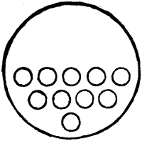
Fig. 33.
You next require some hard-drawn brass tubing three-quarters of an inch
diameter, and must cut the pieces slightly over seventeen inches long, then drill ten
holes in the inner plate as at E (Fig. 32), and in the position and arrangement
shown in Fig. 33. These tubes should have a wire ring brazed on about a quarter
of an inch from either end, and then being placed in their respective holes in tube
plate, the projecting portion is to be beaded back with a flange, or you can fit them
in as described previously (Fig. 16) by each being double-screwed and nutted.
These tubes allow the smoke and flame to pass through from the furnace to the
smoke-box (M Fig. 20), and so away up the chimney, and by the large surface they
expose to the fire, help to raise steam very quickly.
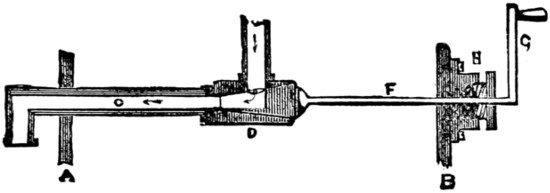
Fig. 34.
If you just add together the combined surfaces of these tubes, you will find there
is more than two square feet of surface exposed and acted on by the fire, which
enables the boiler, although small, to make steam rapidly. In some large engines
three hundred tubes are fitted. The steam supply-pipe and regulating lever-handle
should now be made and placed in position, and Fig. 34 shows the shape to
make it.
A B are the front and rear plates of
boiler, C is the supply pipe, bent with a screw
end downwards after passing plate A, and then upwards into steam-dome, where it
should be securely fastened by a cross-piece; D is the tap or valve, which can be
turned on or off from the foot plate by means of the long rod F, ending in lever-handle
G.
The rod must be fitted with a stuffing-box, the same as those used on the
cylinders, and packed with cotton to prevent loss of steam by leakage; and when
this is all firmly fixed, the forward end of the boiler can be furnished with tube-plate,
riveted on and the tubes flanged over.
You should now take the boiler to a practical brazier and have it properly hard-brazed
in every join and round each tube, and you might cut the hole for steam-dome
and have it brazed on at the same time. If this is properly done you never need
be in fear when the water runs low, as the boiler might get almost red-hot without
injuring it much. Of course it is not advisable, as it would blister and spoil the
appearance of the paint outside. This is a good opportunity to test the boiler before
fitting it up, and you should fill it with water through a hole drilled in top of dome, and
then fix on the test-pump, which you could borrow from any engineering-shop. If
too far away from town to do that, you must make use of the force-pump attached to
your model, and work it by hand, watching the pressure-gauge in the meanwhile. Test
it to 100 lb. per square inch, which will be sufficient, as 50 lb. will be a fair working
pressure. Should you have to test it with your own pump, the pressure-gauge will
have to be bought then, as that is an article you cannot make yourself. A small
gauge of Bourdon’s make, of an inch and a half diameter, will cost about twenty-five
shillings, and although it may seem a rather high price for such a small thing, it is
absolutely necessary to have it, as you could not tell what dangerous pressure you
had raised in the boiler without it.
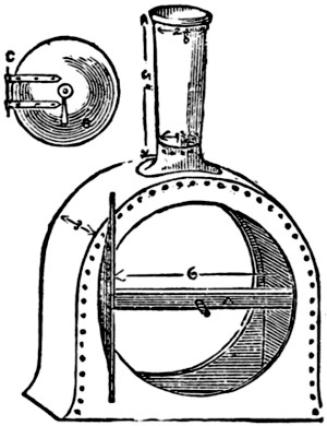
Fig. 35.
This being done, proceed to make the smoke-box, which should be three
inches
deep, and of the same shape and dimensions shown in Fig. 35. This and the
chimney can be made of iron, hammered up to shape and finished with a brass ring.
The smoke-box can be screwed to the forward flange on boiler. The door is drawn
open to show the amount of bulge it should be hammered to.
In the centre a hole should be drilled through which to pass the screw used to
close it, which is attached to the loose bar A.
The handle B is then screwed up tight.
The door is circular and must be large enough to overlap the opening about
half an inch, and have a couple of bright iron or brass eyes (C) riveted on to form
the hinge.
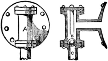
Fig. 36.
We can now make the back pressure-valve (Fig. 36). A is a front view, with
plate by which it is bolted on to boiler, as at W (Fig. 20).
It is very simple to make, and consists of the casting A with the top and bottom
covers, and the ball-valve B, which ought to be ground with a little emery-and-oil
to fit perfectly. It acts in this manner. The water
being forced up C from the pump, raises B and
passes into the boiler. On the up-stroke of pump
the pressure is removed from under B, and pressure
of steam in boiler causes it to fall back and close
opening entirely, preventing any water passing away
from boiler. A small flange can be put on each
outer side of boiler near furnace to support it on
bed-plate level with smoke-box.
The boiler should now have a coating of flannel,
cut to shape and wrapped round the body part,
and a casing of sheet tin put over it and secured
by brass bands, and small nuts underneath, as shown
in Fig. 20.
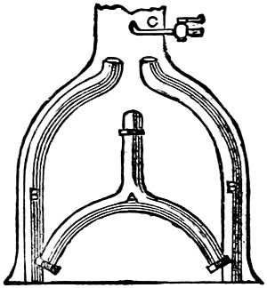
Fig. 37.
The steam supply-pipe can now be connected
with the cylinders, and it should be made forked, as
in Fig. 37. A leads from steam-pipe, and branches
off to each cylinder, where it must be screwed up
with white lead.
The exhaust-pipes (B B) should be of larger
tubing, and bent round up the sides of smoke-box,
so as to be out of the way when you require to clean the tubes. A small brass
pipe (C) must also be passed through chimney, and bent upwards and fitted with
tap, which should take steam from top of boiler, and be used as shown at
D and F
(Fig. 20). This helps to raise steam very quickly.
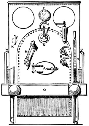
Fig. 38.
Fig. 38 is a rear view of the foot-plate, and shows the necessary fittings you
must either make or buy to complete the model. The cocks you can manage
easily, but the water-gauge is beyond most amateurs’ skill to turn out satisfactorily.
A is the furnace-door, B two
gauge-taps, C starting lever-handle, D spring-balance
safety-valve, F wind-guard (with two look-out hobs),
G steam-whistle handle,
H pressure-gauge, K steam-blast
handle, M glass water-gauge, N the quadrant and-lever
for reversing the engine, O the rear buffer beam (with
buffers), P the wheels
showing axle, R R the springs for same, and
V is the safety-guard rail on either side.
When these fittings are made, holes must be drilled in rear-plate for each, and
then firmly screwed in place with white-lead: and the glass tube in water-gauge
and the stuffing-box in gland of starting-lever should be packed with tallow and
cotton wick.
The entire engine can now have another coat of paint.
The smoke-box chimney and rear-plate should be black, and the body any
colour, according to fancy, leaving the brass bands bright.
When lined and quite dry it should have a coat of the best hard, clear varnish,
and again be allowed to dry thoroughly before using it, which by this time, I have
no doubt, you are anxious to do. Whilst it is drying you will have time to make
the lines for it. And you should get some square bar-iron, cut it into six-foot lengths,
if you wish the lines to be portable, and drill a hole in each end half an inch
deep. They then can be joined end to end by a wire, pin, or plug.
The lines must be kept at a proper distance apart by being secured to pieces of
wood placed transversely underneath by screws passing through holes drilled in the
rails at about every six inches. You can then lay them down end to end and
form a long line. If you want a circular line, each section must be bent to a portion
of a circle; one of about thirty feet diameter is suitable for this model.
When finished, place the locomotive on them and get up steam. Fill the boiler
with water by means of a funnel until you see it rise up three parts of the way in the
glass water-gauge. Then see that all taps are turned off and light the fire. Charcoal
forms the best fuel to use, as it gives a clear, hot fire, without smoke.
Try occasionally if you have any steam by lifting safety-valve, and when there
is any turn on the blast-tap, which will soon draw up the fire, and you will presently
see the pressure rise, and be indicated in the pressure-gauge.
When showing 30 lbs. of steam you might start her, turning on the cocks on
cylinders until no more condensed steam issues from them. Then shut them off and
turn on steam full power, and watch your model travel, gradually increasing its
speed; and I hope you will have many pleasant hours’ enjoyment in running your
locomotive and showing its action to your friends, which will well repay you for
the time spent in building it.
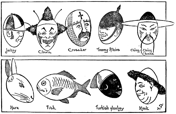
ART AT PLAY.
[Here is a new use for eggs! All that is needed are a pen or pencil, a few eggs or egg-shells, a little artistic talent, with a
few ‘ideas’ and there you are! If also furnished with a gum-pot, pair of scissors, and some paper, there need
be no difficulty about the frills, etc.]

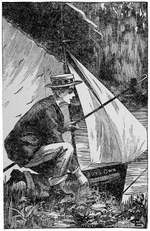
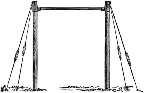
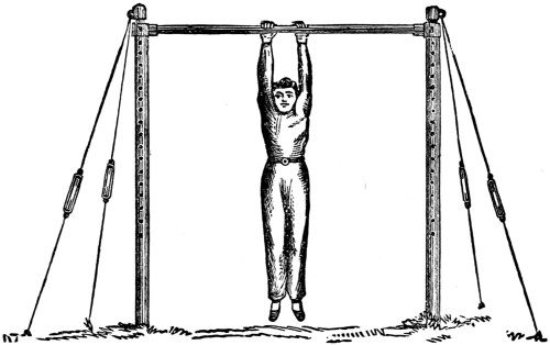
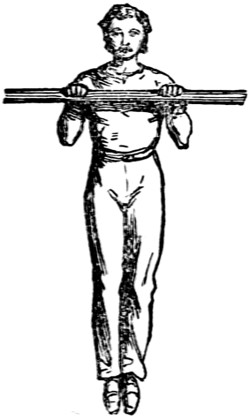
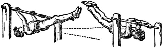
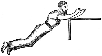
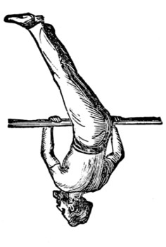
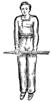
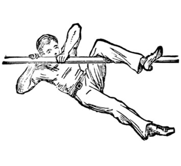
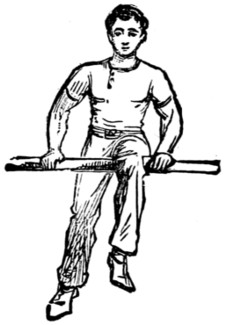
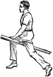
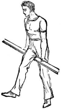
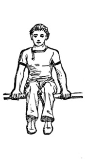
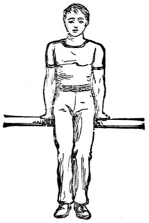
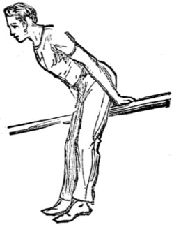
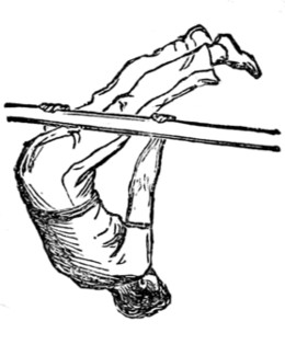
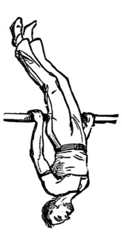
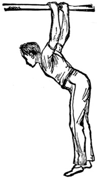
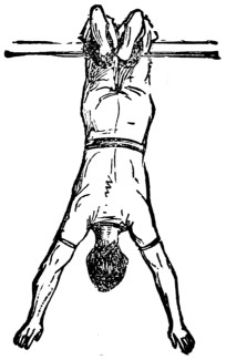
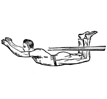
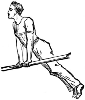
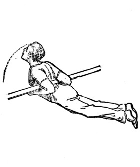
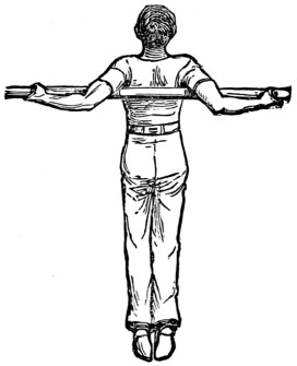
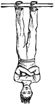
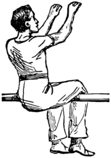
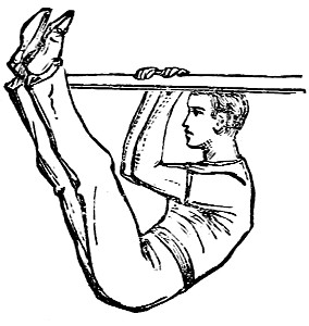
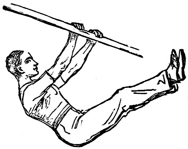
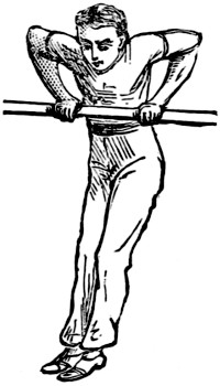
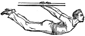
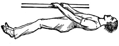
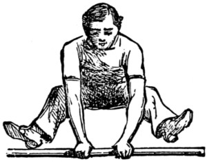
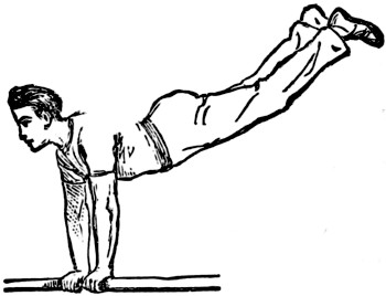
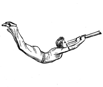
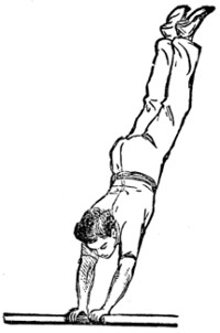
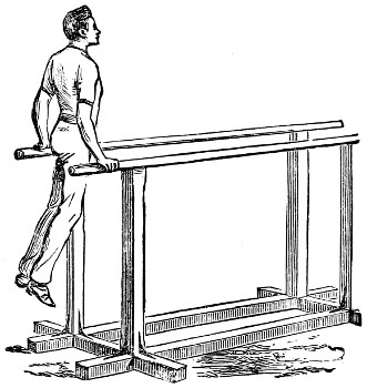
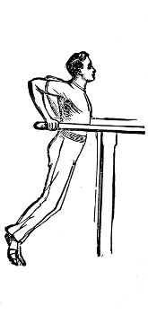
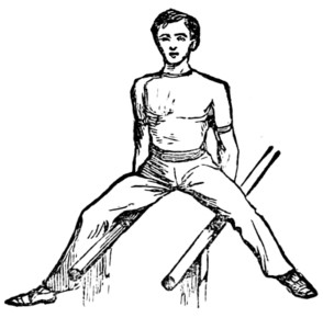
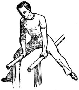
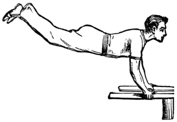
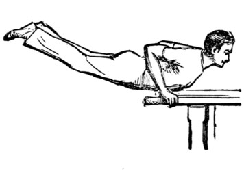
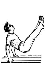
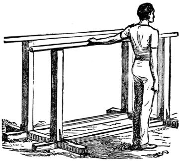
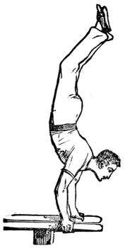
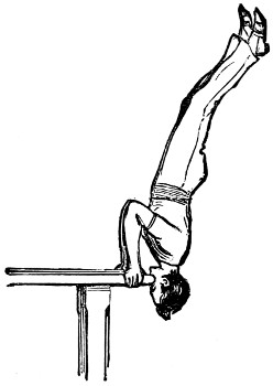
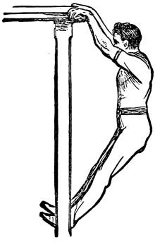
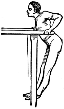
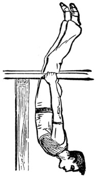
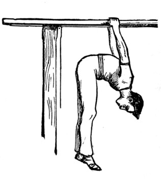
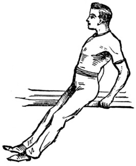
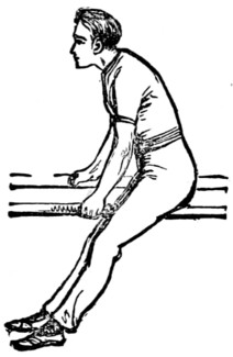
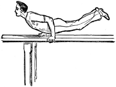
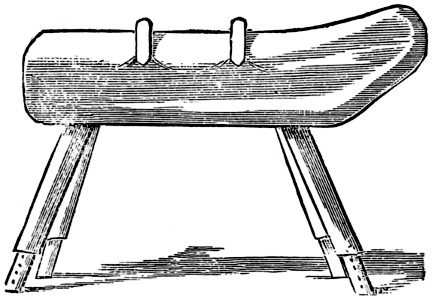
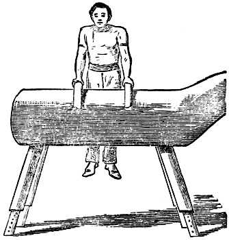
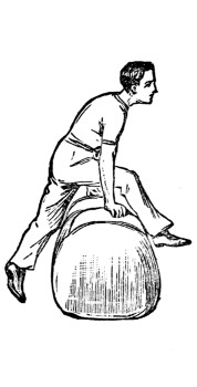
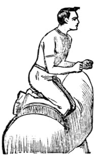
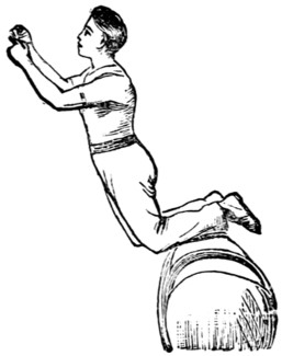
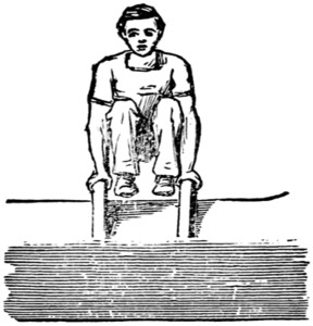
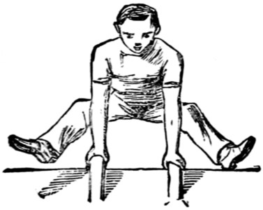
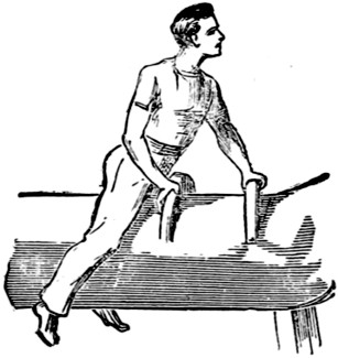
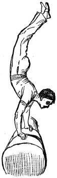
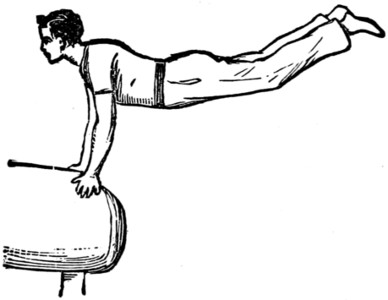
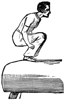
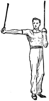
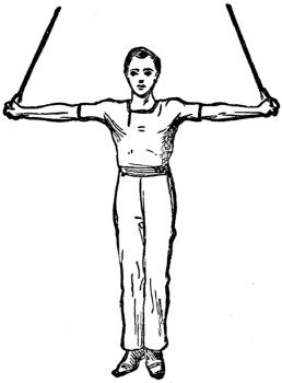
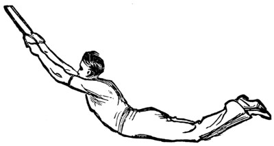
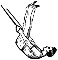
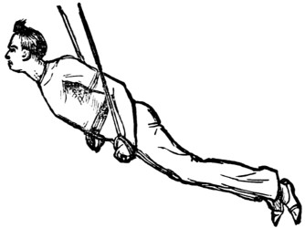
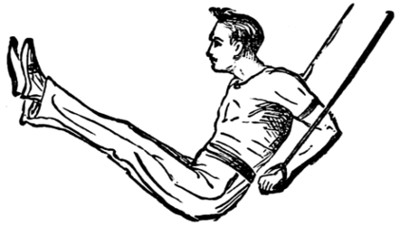
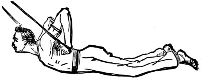
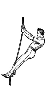

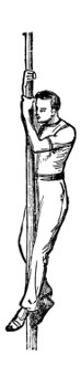
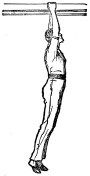
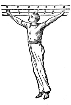
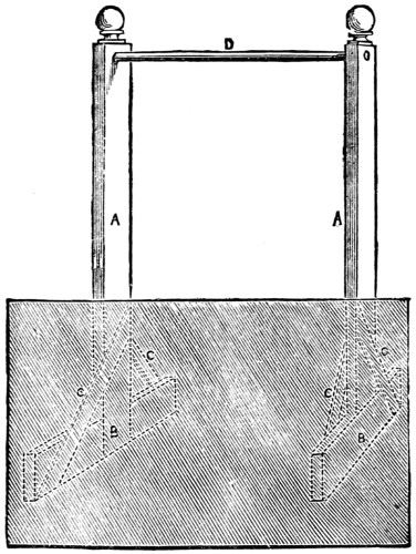
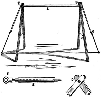
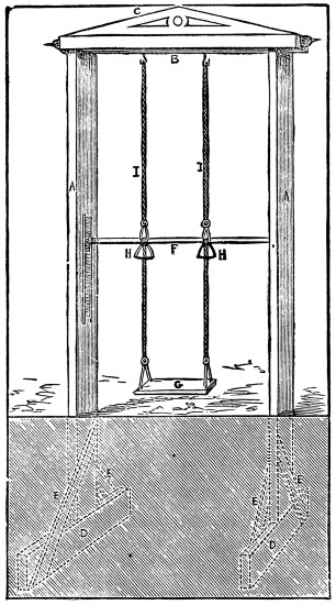

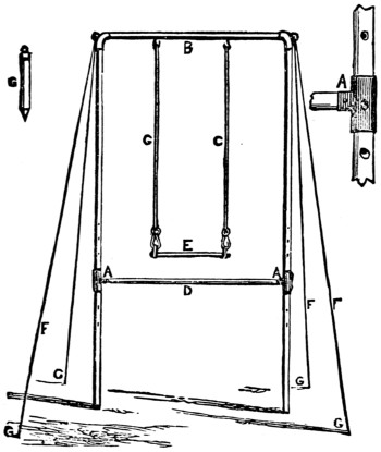
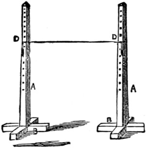
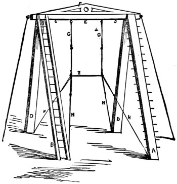
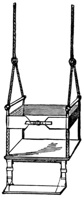
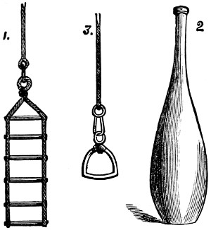
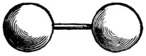
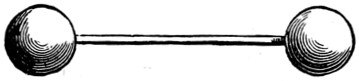
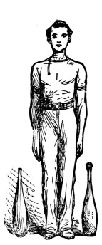
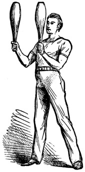
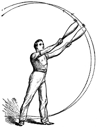
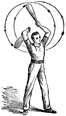
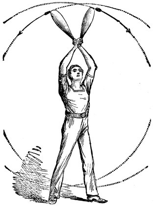
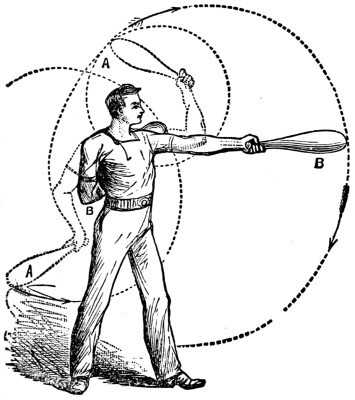
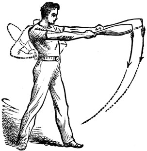
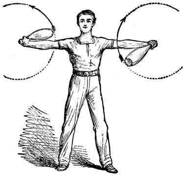
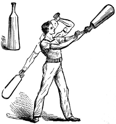

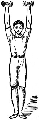
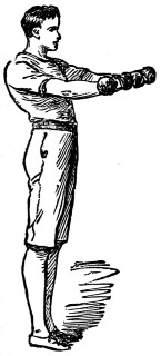
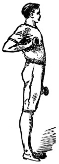
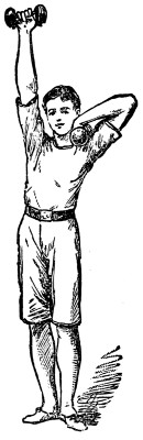
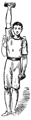
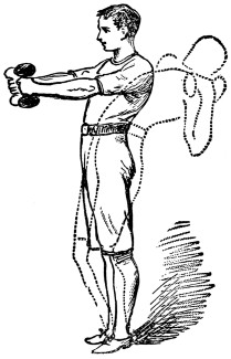
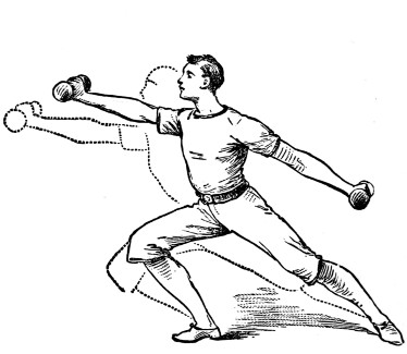
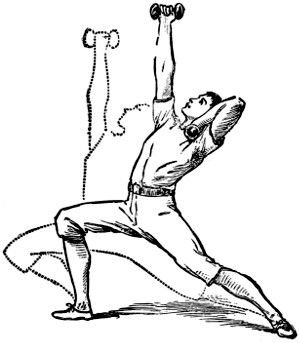
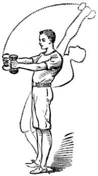
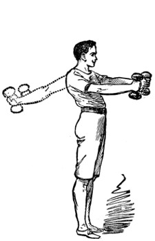
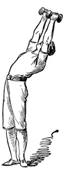
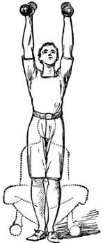
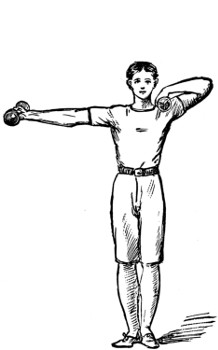
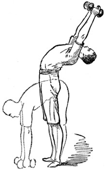
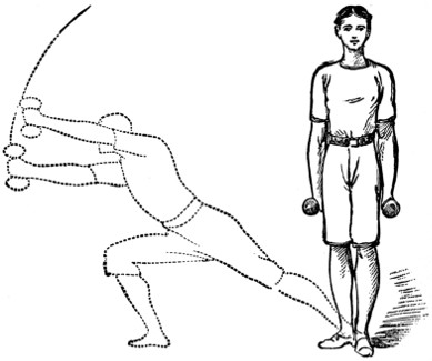
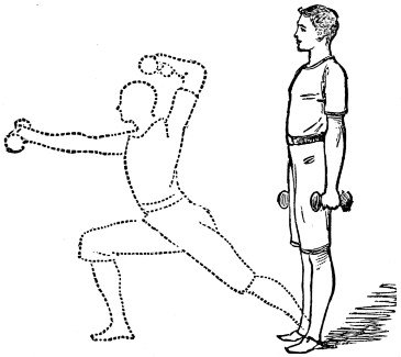
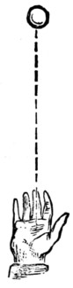
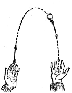
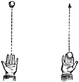
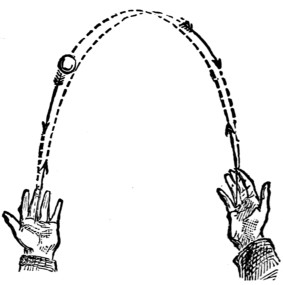
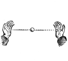
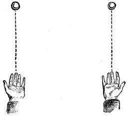
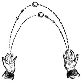
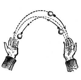
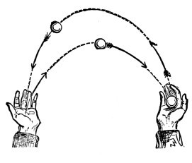
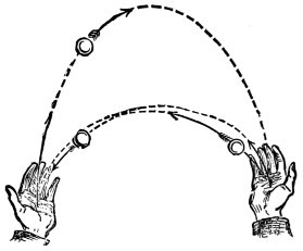
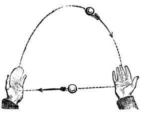
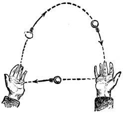
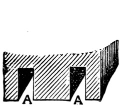
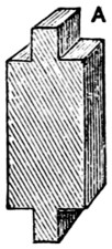
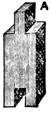



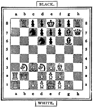
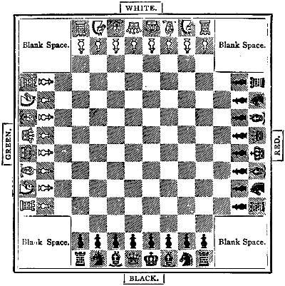
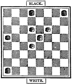
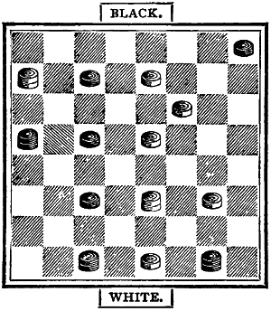
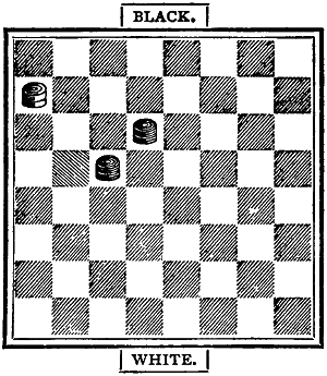
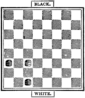
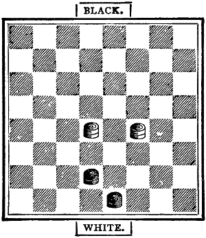
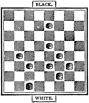
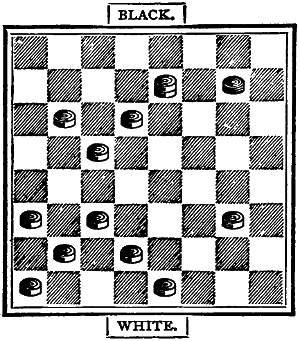
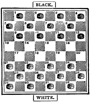
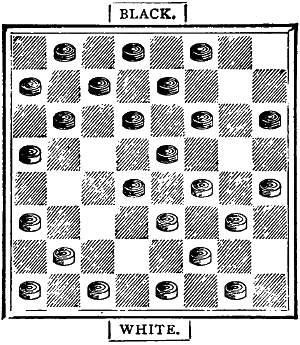
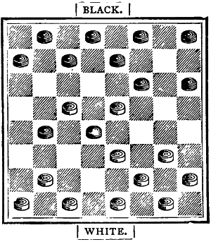
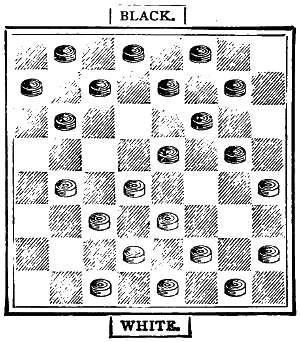
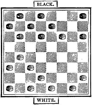
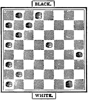
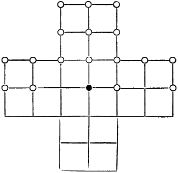
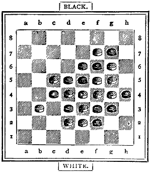
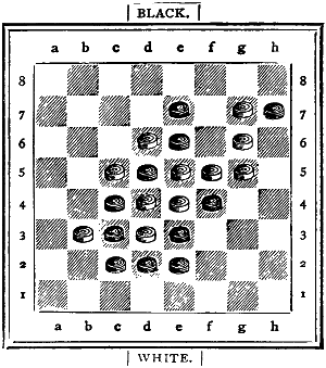
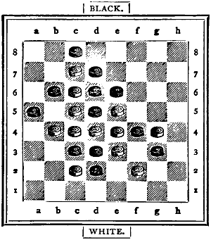
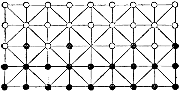
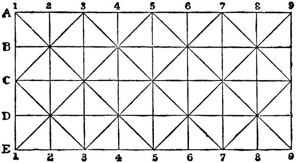
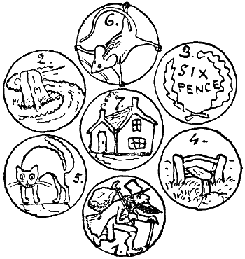
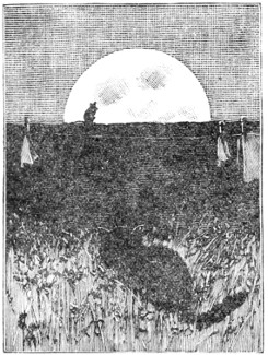
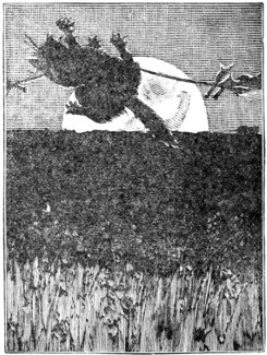
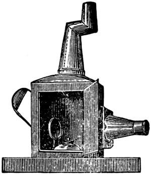
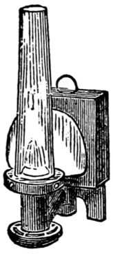
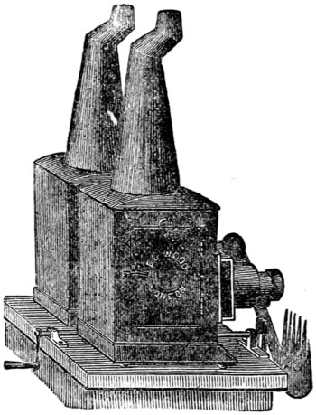
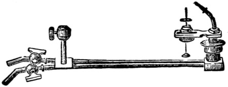
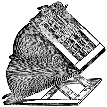
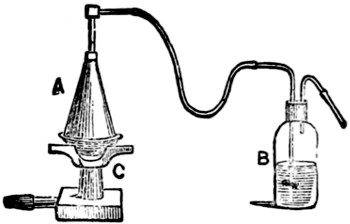
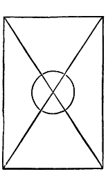
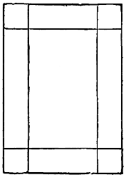
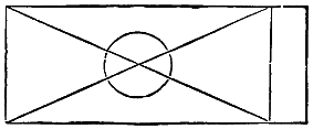
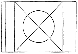
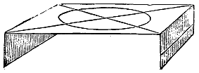
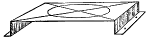

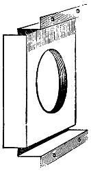
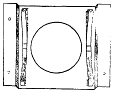
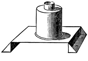
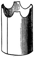
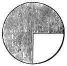
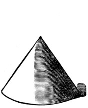
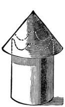
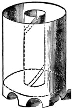
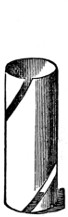
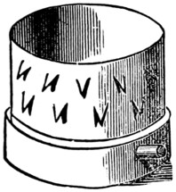
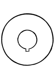
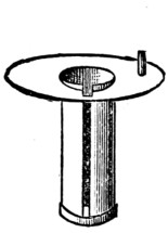

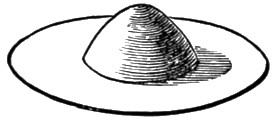
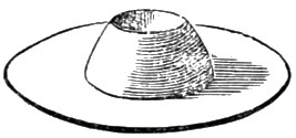
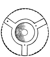
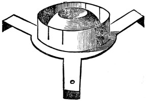
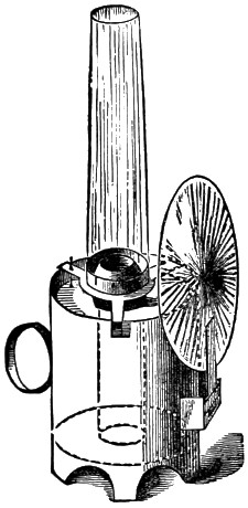
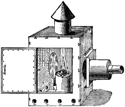
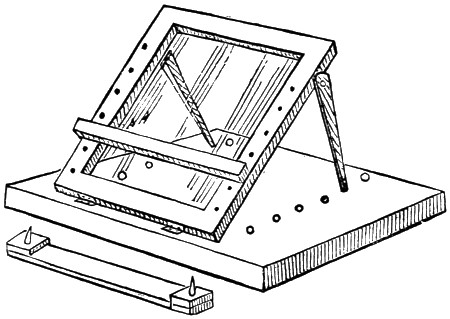
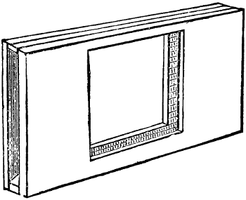
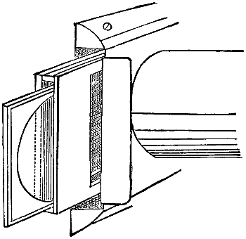
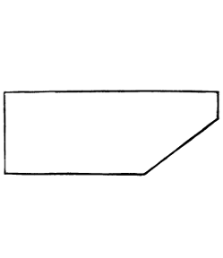
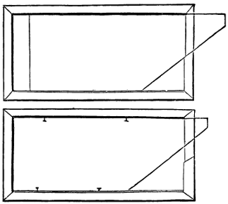
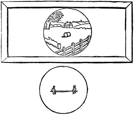
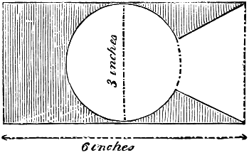
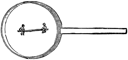
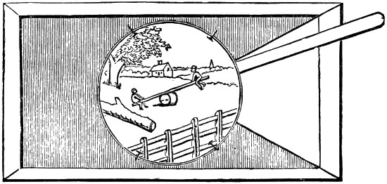
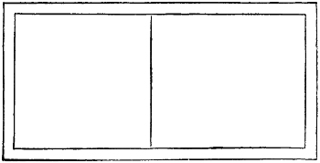
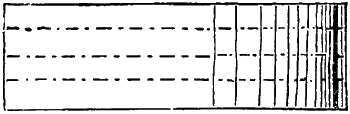
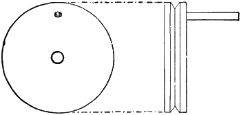
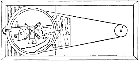

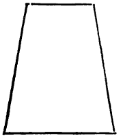
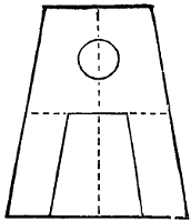
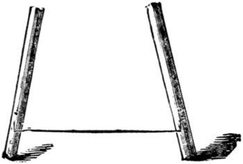
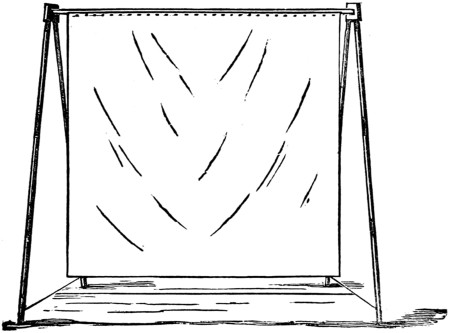
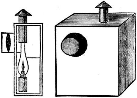
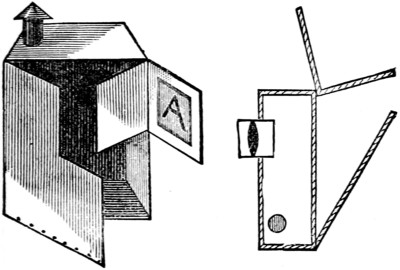
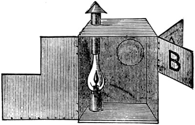
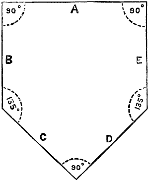
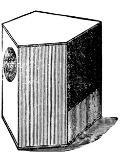
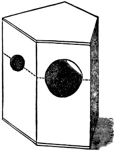
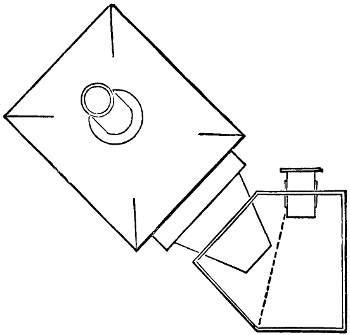
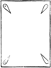
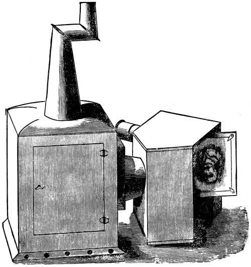
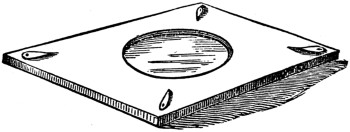
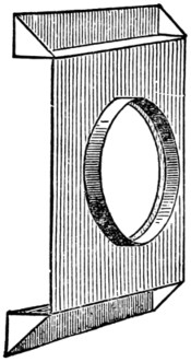
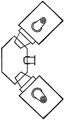
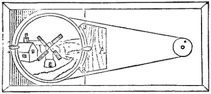
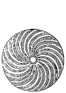
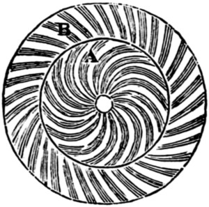
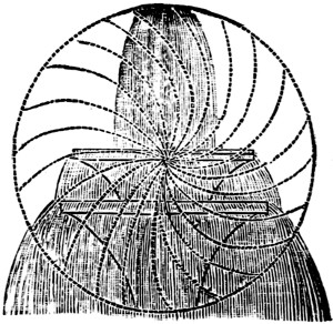
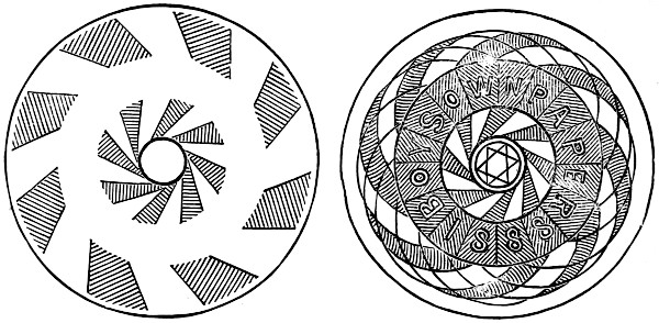
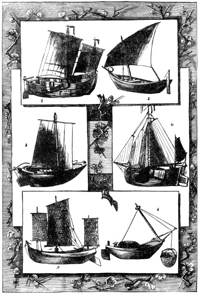
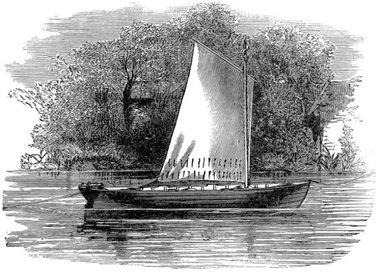
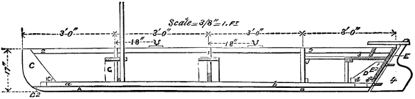
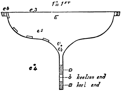
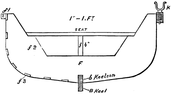
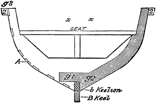
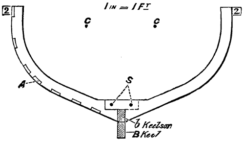
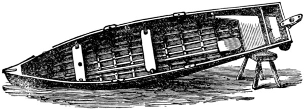
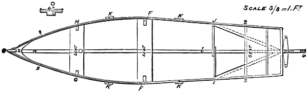

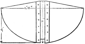
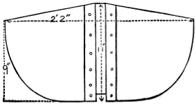


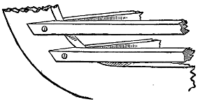
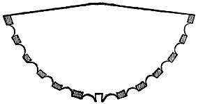
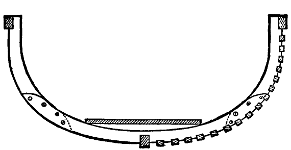
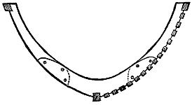
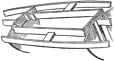

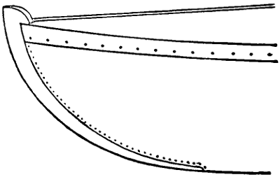
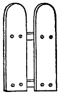
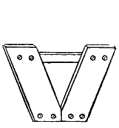
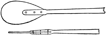
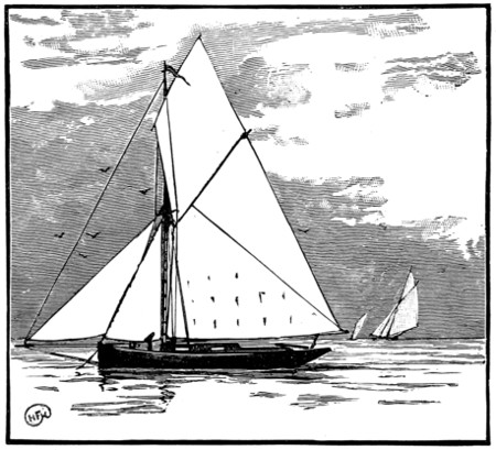
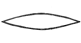
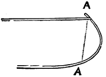
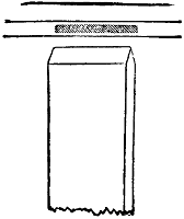
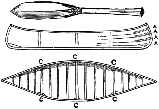
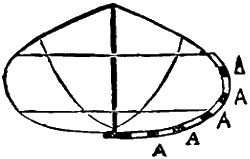
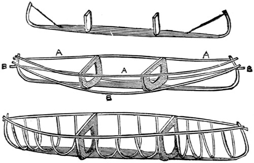
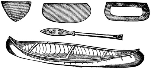
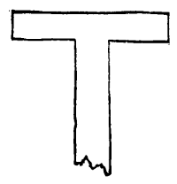
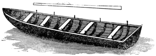
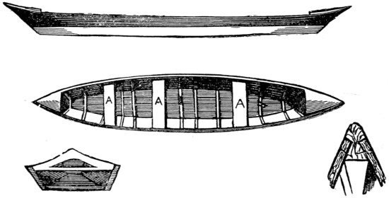
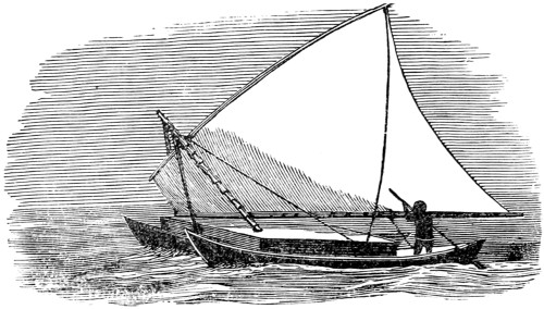
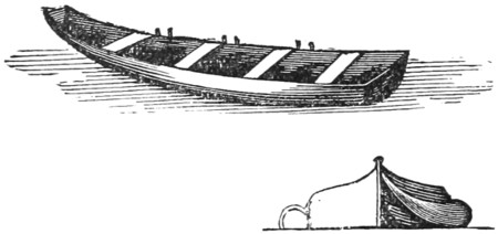
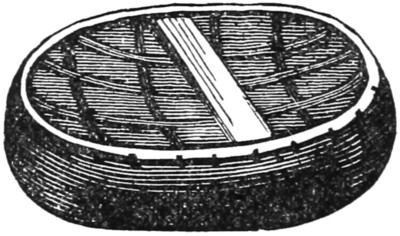
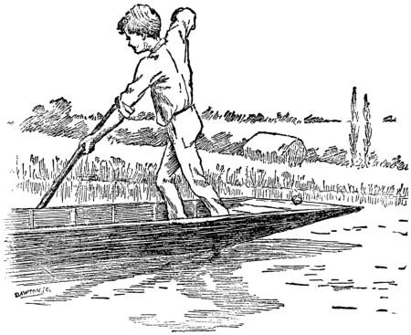
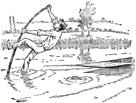
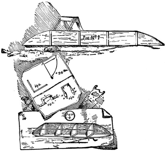
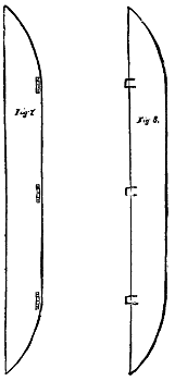
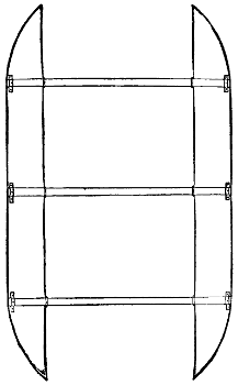
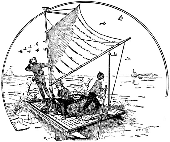
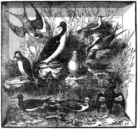
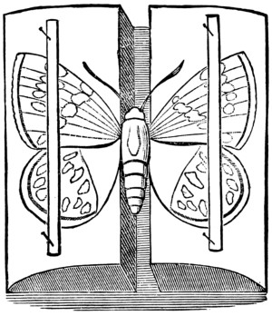
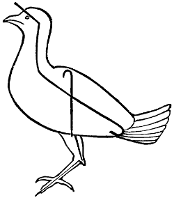
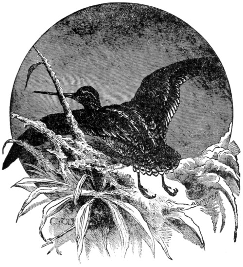
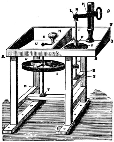
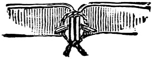
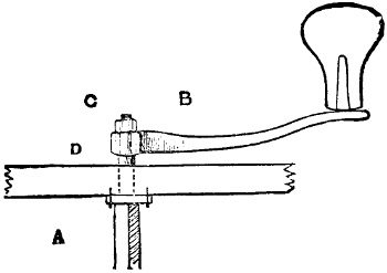
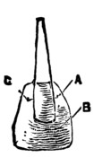
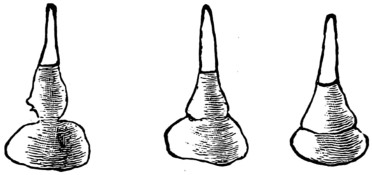
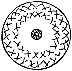
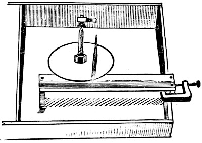
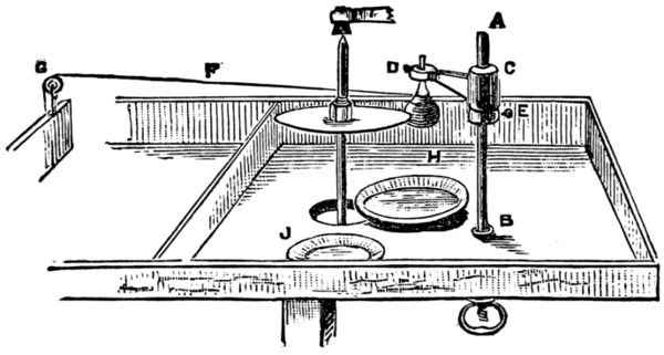
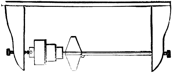
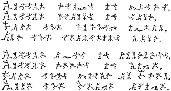
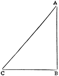
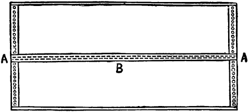
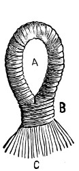
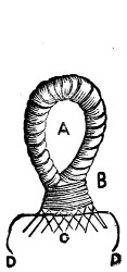
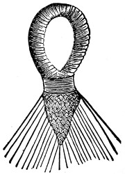
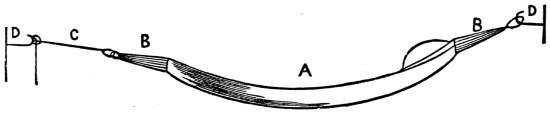
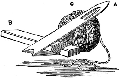
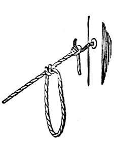

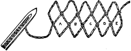
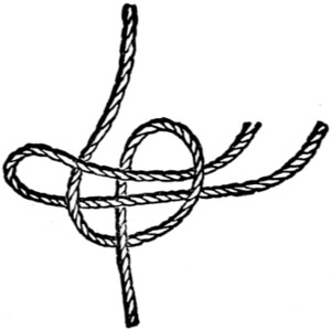
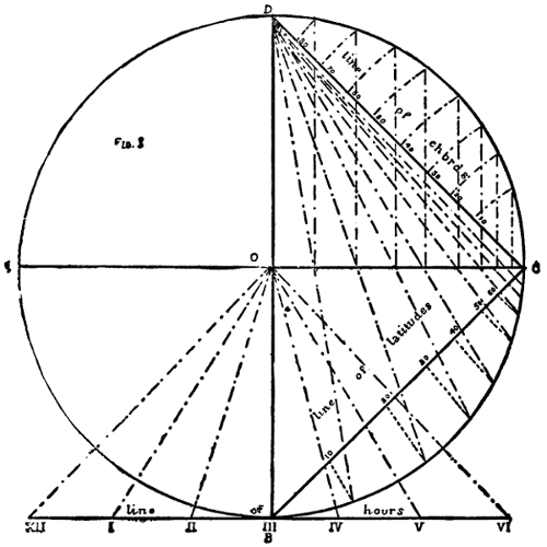
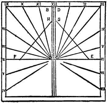
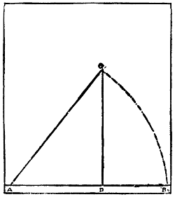
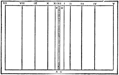
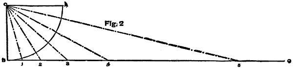
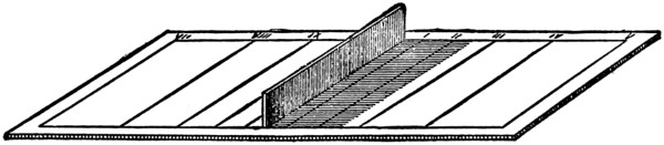
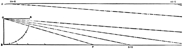
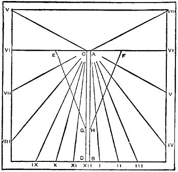
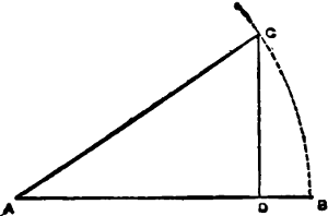
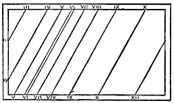
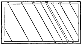
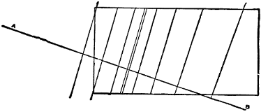
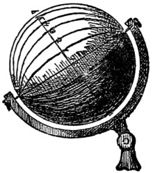
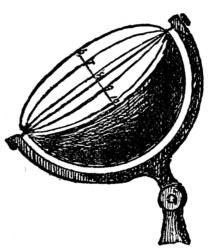
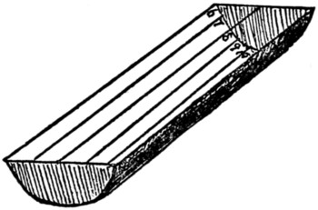
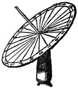
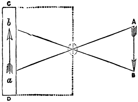
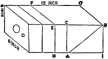
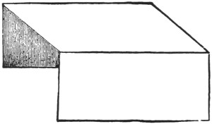
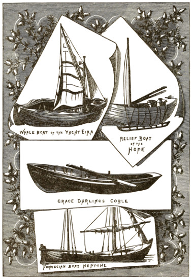
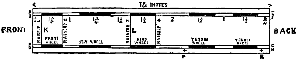
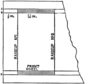
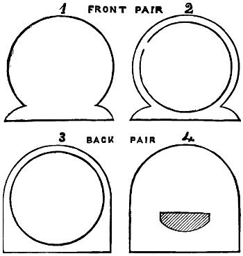
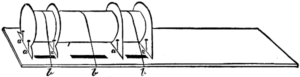
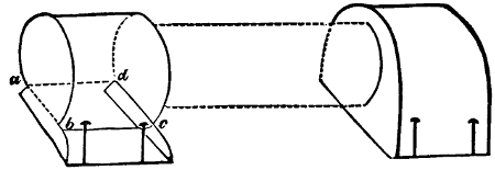
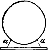 .
The position of the strips is shown at a. In all gumming use plenty of gum, but
let the greater part be on the side hid from view.
.
The position of the strips is shown at a. In all gumming use plenty of gum, but
let the greater part be on the side hid from view.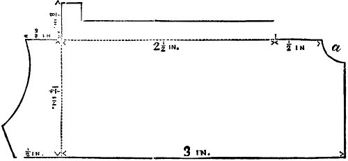
 .
And by bringing the two edges of the groove together, thus,
.
And by bringing the two edges of the groove together, thus,
 ,
you will be
enabled to fold the card at right angles at those places without breaking it.
Having cut this as required, it must be folded and gummed into shape (put
plenty of gum into the joints and corners), and kept in this position on a piece
of wood by pins.
,
you will be
enabled to fold the card at right angles at those places without breaking it.
Having cut this as required, it must be folded and gummed into shape (put
plenty of gum into the joints and corners), and kept in this position on a piece
of wood by pins.

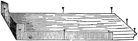

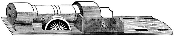
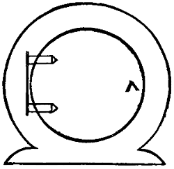
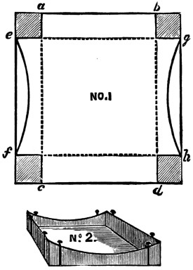
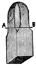
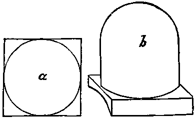
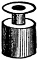
 .
In these holes insert pins, with the heads showing outside, and
this will give the effect of bright rivets.
.
In these holes insert pins, with the heads showing outside, and
this will give the effect of bright rivets.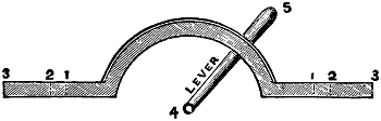

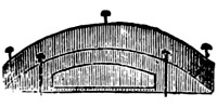
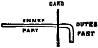
 and shape, for handle
of tap. Two or three of these should be placed on the boiler end, at the
left side above the furnace.
and shape, for handle
of tap. Two or three of these should be placed on the boiler end, at the
left side above the furnace.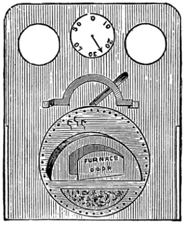
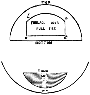
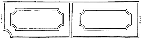
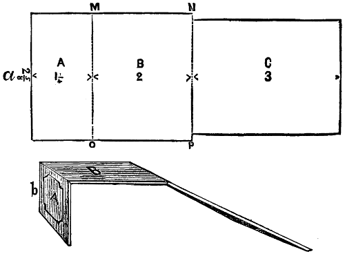
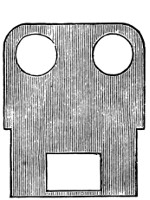
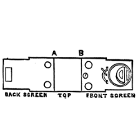
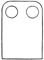
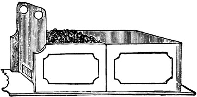

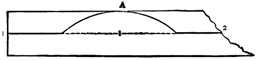

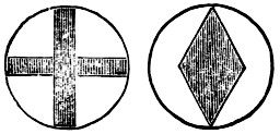
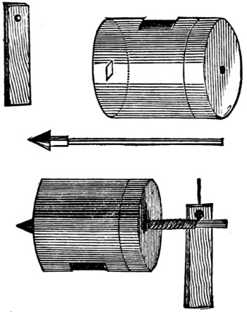
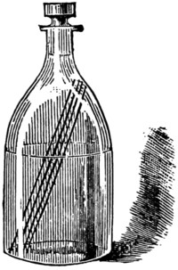
 squeezing the rubber where it comes round
the finger above into a flattened crest. The two surfaces
will stick together quite as much as is desirable.
Now let the operator, with a pair of sharp scissors, and at
one sweep, cut away the crest close up to the finger.
You will then have an india-rubber finger-stall.
squeezing the rubber where it comes round
the finger above into a flattened crest. The two surfaces
will stick together quite as much as is desirable.
Now let the operator, with a pair of sharp scissors, and at
one sweep, cut away the crest close up to the finger.
You will then have an india-rubber finger-stall.