Transcriber's Notes — THE BOY MECHANIC BOOK 2 — The Boy Mechanic BOOK 2 — 1000 THINGS FOR BOYS TO DO — HOW TO CONSTRUCT DEVICES FOR WINTER SPORTS, MOTION-PICTURE CAMERA, INDOOR GAMES, REED FURNITURE, ELECTRICAL NOVELTIES, BOATS, FISHING RODS, CAMPS AND CAMP APPLIANCES, KITES AND GLIDERS, PUSHMOBILES, ROLLER COASTER, FERRIS WHEEL AND HUNDREDS OF OTHER THINGS WHICH DELIGHT EVERY BOY — WITH 995 ILLUSTRATIONS
Two minor typographical errors were found and corrected. In the chapters on making fly-fishing rods (pages 59-71), two lists of materials that were printed as running text have been reformatted as unsigned lists for clarity. The text is unchanged.
The page numbers that appear in the right margin are links. To snap a page to the top of the window, click the page number. To obtain a link to a particular page, right-click on the page number and copy the link.
To speed loading, drawings in-line with the text are at most 512 pixels wide, often less. Drawings that have dimensions or other details that are important to properly executing a project (as well as some drawings that are simply charming to look at) are preserved as higher-resolution images linked to the embedded images. When an in-line image has a thin black border, you can click on it to open the larger version. These larger images are sized to print correctly at 150 px/in (60 px/cm).


FOUR-PASSENGER COASTING BOBSLED See Page 24
COPYRIGHTED, 1915, BY H. H. WINDSOR
CHICAGO
POPULAR MECHANICS CO.
PUBLISHERS

After the First Station has been Selected, It is Marked by a Pile of Stones, a Stake, or, If Precise Work is to be Done, a Tack in the Top of a Stake. The Table is Then Set Up over This Station Point and Leveled So That the Surface of the Paper will Be Truly Horizontal (Inset: UNCLE JOHN'S FARM Scale 1/16" = 1' Jimmy Smith—Surveyor)

The Boy Surveyor
Plane-Table Surveying By Harold G. McGee
[In the training of a boy for a trade or profession there is none so profitable for outdoor work as that of a surveyor. This article sets forth how to accomplish surveying and the making of simple maps with the use of commonplace tools that any boy can make.—Editor.]
Surveying and map making have always been two of the most interesting things a civil engineer has had to do. And, like George Washington, many of the men we look up to today as successes in different lines worked as surveyors in their younger days. Surveying takes one out of doors, and is apt to lead him into the unknown and unexplored byways of the earth.
Though modern surveyors often use precise and expensive instruments, creditable surveys can be made with simple and inexpensive apparatus. Of such apparatus, two of the simplest are the plane table and the camera. Since one must know the principles of plane-table surveying before he can do camera surveying, this paper will describe the plane table alone, leaving the camera for another chapter.
A plane table is simply a drawing board mounted on a tripod so that it can be set up and worked upon in the field. One kind of plane table, which is used in the army for reconnaissance, does not even have a tripod; it is simply strapped to the arm of the man who is using it.
Plane-table maps vary greatly in scale and the area they represent. Landscape artists' plans may show only single city lots, while some topographic maps cover hundreds of square miles on a single sheet. For maps of a small farm, a park, or a residence block in the city, a plane table is almost ideal, since plane-table maps are made with rather simple apparatus and do not require much actual measuring on the ground. Most objects are located without ever going to them, or even sending a rod-man to them.

Just a Few Weeks After George Washington's Sixteenth Birthday, in 1748, Lord Fairfax, Owner of a Large Estate in Virginia, Took Him into His Employ as a Surveyor
Besides the plane table itself and a sheet of paper, only a small carpenter's level, a tape to measure a few distances with, and some spikes for markers, a hard lead pencil, a ruler, and a few needles are absolutely necessary for this sort of a map.

Three Stations are Used for Setting the Plane Table in Succession to Locate the Various Objects
TABLE AT STA. A - TABLE AT STA. B - TABLE AT STA. C
To start a plane-table map, a station must first be selected from which as many as possible of the objects to be located on the finished map can be seen. Ordinarily, the objects one would locate are corners of buildings, fence corners, intersections of roads, corners of lots, banks of streams, possibly trees, and section and quarter-section corners in the country. A railroad, a lake, a mountain, or anything which forms a noticeable landmark in any particular locality, ought to be on the map. In mapping a territory which has never been surveyed before, the first surveyor may name the hills and streams.
After the first station has been selected, it is marked by a pile of stones, a stake, or, if precise work is to be done, a tack in the top of a stake. The table is then set up over this station point and leveled so that the surface of the paper will be truly horizontal. Generally, too, the board is "oriented," that is, placed so that two of its edges point north and south and two east and west. It is then clamped so that it will not move while working on it.
To begin the map, a point on the table is chosen to represent the station on the ground over which the table is set. This point is marked by sticking a fine needle into the paper, vertically. A small triangle should be drawn around the needle hole in the paper and labeled "Sta. A," so that it will not be lost in the maze of points which will soon cover the sheet. By sighting past this needle toward some object which is wanted on the map, like the corner of a house, its direction can be marked by setting another needle on the far side of the table, in line with the first and the given object. Then, if a ruler or straightedge be placed against these two needles and a fine line drawn connecting them, this line will show the exact direction of the object from Sta. A. All the other objects which are wanted on the finished map and can be seen from Sta. A are located by direction in the same way.
The first points to have their direction thus marked ought to be the next stations to be occupied. If all the objects to be located can be seen from three stations, or even two of three stations, three stations will be sufficient. The distance to one of them from Sta. A should be carefully measured and laid off to scale along its direction line on the map. Its place on the map should be marked exactly as the first station was, substituting B for A. It is wise, after every few sights at other objects, to take a sight along the line AB to make sure that the board has not turned. A good map is impossible if the board twists.
To measure the distance between stations, a 50 or 100-ft. tape, or some accurate substitute, is necessary. An ordinary piece of iron telegraph wire, 105 ft. long, is a good substitute. A point, about 2-1/2 ft. from one end, is marked with a little lump of solder. A chisel dent in this solder will mark one end of the 100-ft. section. Then, with a borrowed tape or a good rule, measure off and mark every 10 ft., just as the first point was marked, until the entire 100 ft. have been laid off. The last 10 ft. should be divided into feet. In all this measuring and marking, the wire must be stretched out taut and straight. The extra 2-1/2 ft. at each end are used for making handles. By estimating the tenths of a foot, measurements can be made with such a tape, or "chain," as an old-time surveyor might call it, just as accurately as they can be laid off on the map.
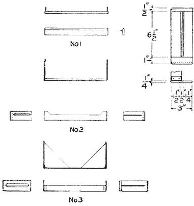
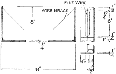
An Alidade, Consisting of Two Sights and a Straightedge, Takes the Place of the Two Needles
Two men are required for measuring, or "chaining," a head and a rear chainman. The rear chainman holds the 100-ft. end of the tape on the station point, while the head chainman takes his end forward toward the station to which they are measuring. When he has gone nearly the length of the tape, the rear chainman calls "halt." The head chainman stops and draws the tape up tight, while the rear chainman holds his division end on the starting point. Then the head chainman sticks a spike into the ground to mark the place where his division end comes, calls out "stuck," and starts on toward the object point.
Large spikes make good marking pins, especially if they have little red or white strips of cloth tied to them. Surveyors use 11 markers. One is stuck into the ground at the starting point and is carried forward by the rear chainman, who also picks up the markers at each 100-ft. point as soon as the head chainman calls "stuck." In this way, the number of markers which the rear chainman has in his hand is always the same as the number of hundreds of feet which the last set marker is from the starting point.
In measuring between two points, care must be taken to draw the tape out taut and straight, its two ends must be level with each other, and it must be exactly in line with the two points between which the measurement is being made. In measuring downhill, one end may have to be held up high, and the point on the ground where the end division would come, found by dropping a stone from the place where it is in the air and watching for the spot where the rock strikes the ground. A surer way to do this is to hold a plumb-bob string on the last division and carefully let the bob down until it touches the ground. A rod with a red or white flag on it ought to be placed at or just beyond the point to which the measurement is to be made so that the rear chainman can easily line in the head chainman. The latter, before he places his marker, looks back to the rear chainman to be told whether or not he is "on line" with the object point. If he is not, and ought to go to the rear chainman's right to get "on," the latter holds out his right arm and the head chainman moves accordingly. When he reaches the right point, the rear chainman signals "all right" by holding out both of his arms and then dropping them to his side; the marker is stuck, and both move up a hundred feet and repeat the process.
After all the points possible have been located from Sta. A, and the direction lines labeled lightly in pencil so that they can be distinguished when the board has been removed from the station, the plane table is picked up and carried to Sta. B. Here it is again set up, leveled, and oriented by making the direction of the line AB on the paper exactly the same as that of the line from Sta. A to Sta. B on the ground. This is done by placing needles at points A and B on the table and then turning the board until the two needles and Sta. A are in line. Sights are taken on the same objects which were "shot" at Sta. A, and to objects which were not visible from Sta. A. The intersection of the lines of sight toward a given object from A and from B marks the location on the paper of that object. If the two ends of a straight fence have been located in this way, a straight line joining the points will show the location of the fence on the map. By exactly similar methods, every other object is located on the paper.
In order to avoid errors, it is an excellent scheme to locate three stations near the outside edges of the area to be mapped, and locate all objects possible by sights from each of the three stations. If, instead of all three crossing each other at a point, the lines of sight from the three stations form a triangle, something is wrong. If the triangle is very small, it may be safe to use its center as the correct point; if not, the work must be repeated and checked. Locating even a few points by this method may prevent some bad blunders. The three stations ought to form as nearly as possible, an equilateral triangle; and the distances between all of them should be measured and laid out accurately on the plane table.

A Rigid Tripod is Made of Strips for Legs, Which are Fastened to a Large Top
There are two ways in which the map may be finished, inked, or traced. By drawing in the "culture," that is, the things built by man, like the houses, the fences, the roads, and the railroads, in black ink; the topography, that is, the hills and valleys, in brown; the water, in blue, and then erasing all the construction lines, a very neat map can be made. Another way is to get some "onion-skin" paper, or some tracing cloth, tack it over the penciled map, and trace the lines right through, using black India ink. This tracing can be blueprinted, just as a photographic film. A plain, neat title, describing location of map; who made it and when; the scale used; why it was made, if it was made for a special purpose, and the direction of the north point, ought to be on every map. The topographic sheets published by the United States Geological Survey are good samples to follow. They have been published for a great many places all over the country, and single copies can be obtained by sending 10 cents to the Director, United States Geological Survey, Washington, D. C.
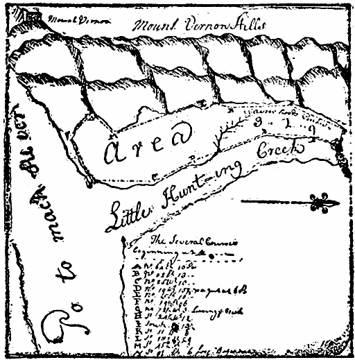
From an Original Drawing of a Survey of Mount Vernon, Made by George Washington at the Age of 14
Plane tables are almost as easily made as they are bought. If there is no old drawing board around the house, a new bread board from the ten-cent store will serve. For ordinary work, a table which is 15 or 20 in. square will do very well. The board must be mounted on a tripod so that it will be rigid while it is being worked upon and yet can be unclamped and oriented. A brass plate, with a hole in it and a nut soldered over the hole, screwed to the bottom of the board will permit the board and tripod to be bolted together in good shape. Another method, which is not nearly as good, is to drill a hole clear through the board, countersink it on top for a bolt head, and bolt the board and tripod head directly together. With the brass plate and nut, the camera tripod can be pressed into service if a nut of the proper size has been used. The camera tripod is, however, apt to be wabbly with a drawing board on top; a much more satisfactory tripod can be built as shown in the accompanying drawings. Each leg is made of two strips of wood, 3/4 by 3/8 in. and 3 ft. long. These strips are screwed together at their lower ends, gripping a spike between them which will prevent the legs from slipping on the ground. The tops of the strips are spread apart and screwed to the opposite ends of an oak or maple cleat. This cleat is, in turn, screwed to the under side of the circular tripod head.
In place of the two needles and the ruler described for marking the line of sight, most plane-table men use an alidade, which is a combination of two sights and a straightedge. A very simple alidade may be made by mounting two needles on a ruler. The straight edge of the ruler is placed against the needle which marks the station at which the plane table is set up. Then, by swinging the ruler around this needle until its two sighting needles come in line with some object, the line of sight can be drawn directly on the paper along the edge of the ruler. A surveyor in India once made an alidade out of a piece of straightedge and two sights made of native coins hammered out by a native blacksmith. Two pieces of cigar box, one with a fine vertical saw slit in it, and the other with a vertical slot and a piece of fine wire or silk thread stretched down the center, glued to a well planed, straight, flat piece of wood, make a fine alidade. A careful worker may be able to put his sights on hinges so that they will fold down when not in use.
More than anything else, map making rewards care and accuracy, and shows up slipshod workmanship. If the pencils are sharp, the lines fine, and if the work is checked often, beautiful maps can be made with very simple apparatus.
White marks on waxed surfaces may be removed by rubbing lightly with a soft rag moistened in alcohol, after which rub with raw linseed oil.
Machine for Sketching Pictures
An ordinary drawing board, with the attachments shown, provides an easy way to sketch pictures, even if one is not proficient in this line of work. It is only necessary to look through the sight and move the pencil about so that the knot in the thread follows the outline of the landscape or object being drawn.

This Machine Aids a Person in Drawing the True Outline of a Picture
The size of the machine depends on the one building it, but a fair-sized drawing board is sufficient for the beginner. A strip of wood is fastened to the board, near one edge, which has a metal piece on each end, fastened to the under side and bent up over the end to form an extension for the rod to support the moving parts. The strip of wood should be 3/4 in. wide and 1/4 in. thick, and the sliding arm, holding the pencil, 1/2 in. wide and 1/4 in. thick. A like strip, but much shorter than the one fastened to the board, is also fitted with metal pieces in an inverted position so the projections will be downward. A 3/16-in. rod is run through holes in the metal pieces of the strips at both ends, and soldered to those on the strip fastened to the board. This will make a hinged joint, as well as one that will allow the upper strip to slide horizontally.
Centrally located on the upper strip are two more strips, fastened with screws at right angles to the former, with a space between them of 1/2 in. for the sliding center piece holding the pencil. These pieces are further braced with a wire at the back, and crosspieces are screwed both on top and under side, to make a rigid guide for the sliding pencil holder. An upright is fastened to the side of one of these pieces over the center of the upper horizontal sliding piece for a screw eye to hold the thread. Another screw eye is turned into the crosspiece just under the one on the support, so that the thread will run perpendicularly between them. Two more screw eyes are fastened, one into the upper surface of the rear crosspiece, and the other in the end of the pencil holder, near the pencil. By connecting these screw eyes, as shown, with a thread, having a rubber band fastened in the rear end and a knot tied in it near the screw eye in the upper end of the vertical stick, a means for following the outlines of the picture is provided.
A vertical stick is fastened to the front edge of the board by means of a notch and wedge. In the upper end of this stick a very small hole is bored for a sight, similar to a peep sight on a rifle.
To use the machine, set the board on a table, or tripod, and level it up in front of the object to be drawn. Look through the sight at the front of the board and move the pencil about to keep the knot of the thread on the outlines of the picture to be drawn.—Contributed by Wm. C. Coppess, Union City, Ind.
A walnut filler is made of 3 lb. burnt Turkey umber, 1 lb. of burnt Italian sienna, both ground in oil, then mixed to a paste with 1 qt. of turpentine and 1 pt. of japan drier.

THE BOY SURVEYOR
Camera Surveying By Harold G. McGee — Camera Preparation
[This article explains the preparation of the camera for taking the pictures at each of the three stations, after which the plates are developed, printed and kept until a convenient time may be had for plotting the ground. The succeeding article will give in detail the making of the map from the photographs.—Editor.]
Camera surveying is simply plane-table surveying in which the landscape has been photographically picked up and carried indoors. It has the enormous advantage that one can obtain a record of the utmost fidelity in a small fraction of the time taken to do the field work of even a sketchy plane-table survey, and that plotting can be done in the comfort and with the conveniences of a drafting room. When the hours one can work are short or the periods of clear, dry weather are few and far between, a camera is an ideal surveying instrument. It sees and records with the click of the shutter.
Surveying by camera was proposed early in the infant days of photography; but not until the eighties were photographic surveys commenced in earnest. With the extensive surveys of the Canadian Rockies by the Canadian government within the past decade and the topographic surveys of the Alps, the camera has very recently indeed achieved the dignity of being known as a "sure-enough" surveying instrument. Even today, few surveyors have ever used photography for making surveys, even though for mountain topography or any survey which includes a large number of distinctive, inaccessible landmarks, the camera asks no odds of either the plane table or the stadia transit.
A camera survey taken of the summer cottage or the camping ground will be a source of great delight while it is being plotted up of winter evenings. There is something weird in watching each tent and dock slip into its place with naught but a pair of dividers and a few pictures to do the trick. And when the map is done, there are all the data to tell just where a tennis court can go or a walk ought to be built.
In making surveys, a plate camera will do more accurate work than will a film camera; and a fixed focus is a big help in plotting. In spite of the special and expensive instruments which have been designed solely for surveying work, a little ingenuity on the part of the owner of most any kind of a camera, be it big or little, film or plate, box or folding, will do wonders toward producing good results.
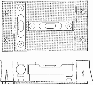
A T-Shaped Level with Adjusting Nuts is Located on the Camera Box, or on the Bed of the Folding Camera
To be used for surveying, a camera must be fitted with a spirit level and some arrangement for cross hairs. A T-shaped level on the bed or the box, carefully adjusted, will show when the plate is vertical and when the perpendicular line from the center of the plate to the center of the lens is horizontal. Actual cross hairs in the camera are not as good as four tiny points of V's, one projecting from the middle of each side, top, and bottom of the camera box, just in front of the plate holder. How the level is to be adjusted so that a line between the upper and lower points will be truly vertical, and one through the die-side points truly horizontal and on a level with the center of the lens when the bubbles are in the center of the spirit level, will be described later.

To Prepare a Camera for Surveying, It is Necessary to Arrange That the Axial Center Line through Lens to the Plate Shall be Level
(Inset: The Camera is Set Up, Complete with Thread or Pencil-Line Cross Hairs and Level, Then Focused on a Stake so That Its Top will Just Come to the Horizontal Cross Hair at the Center of the Plate When the Level Tube Parallel with the Center Line of Lens Reads Level)
To prepare a camera for surveying, it is necessary to arrange that the axial center line through the lens to the plate shall be level, and that the location of the horizontal and vertical center lines shall be indicated on the plate. A spirit level is the best solution of the first problem, and indicated center points of the second.
The spirit level preferably may be of the T-form, with two level tubes, or of the "universal" circular form, with which some hand cameras are equipped. However, ordinary hand-camera levels are generally too rough and difficult of adjustment to insure accurate work. On a view camera, the level may be conveniently located on the bed which carries the lens board. If it is screwed to the under side of the arms it will be convenient for use and out of the way. The bed is likewise a good location for the level on a folding hand camera, while the top of the box is about the only possible location with a box-type instrument.
The cross hairs or center-line indicators should be placed on the back of the camera, just in front of the plate. If indicators are used, fine-thread cross hairs or pencil lines drawn on the ground glass must be used temporarily for making adjustments. Generally, the two cross hairs will divide the plate vertically and horizontally into four equal parts and the hairs or indicators will join the center point of the sides and top and bottom of the opening immediately in front of the plate. But it is essential that the cross hairs have their intersection in a line perpendicular to the plate and passing through the center of the lens. Thus in a camera in which the lens is not placed in the center of the plate, or in which the rising and sliding front has placed the lens off center, either or both of the cross hairs may be off center with regard to the plate.
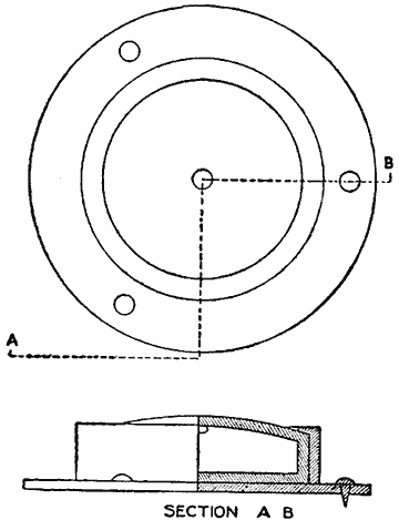
The Ordinary Round Level may be Used, but It Is Not so Good as the T-Level
After the cross-hair indicators and the level have been attached to the camera, adjustments are necessary. Surveyors distinguish between permanent and temporary adjustments, permanent adjustments being those for which the instrument maker is responsible, and temporary adjustments being those which can be and are made in the field. The principal permanent or maker's adjustments of the surveying camera are those which insure the center line through the lens, or axial center line, or line of collimation, being perpendicular to the plate, the intersection of the cross hairs being on this line, and that the cross hairs themselves are mutually perpendicular. Temporary or field adjustments must be so made that one tube of the spirit level shall be parallel with the axial center line through the lens and the other parallel with the horizontal cross hair.
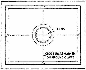
The Cross Hairs or Center-Line Indicators should be Placed on the Back of the Camera
The first field adjustment is made in the following manner. The camera is set up, complete with thread or pencil-line cross hairs and level, and focused on a stake whose top shall just come to the horizontal cross hair at the center of the plate, when the level tube parallel with the center line of the lens reads level. This stake may be driven to the required elevation or a rod may be held on it and the point where, in the image on the ground glass, it is intersected by the cross hair marked with pencil on the rod as it is held vertically on the stake. The distance to this stake is measured from the camera and another similar stake set at the same elevation by the same method, but in an opposite direction and at the same distance from the camera. The two stakes or the mark on the vertical rod which is held on these stakes in turn will be level with each other, though they may not be level with the camera. The camera is then moved to a point very much closer to one stake than to the other and again leveled. The vertical distance from one stake-top or mark on the rod is measured and the camera then focused on the second stake. If the level is actually in adjustment, the distance from the second stake top or mark will be exactly the same as it was on the first. If not, the difference, or "error," is found between the two vertical distances from the cross hair to the two stake tops. Half this error is corrected by raising or lowering one end of the level tube by means of the threaded nuts which are placed on it for the purpose. The whole process is then repeated until the vertical distances from the horizontal cross hair at the center to the two level stakes, one close to and one distant from the camera, are identical. The axial center line of the lens, or the line of collimation, is then in adjustment with the level. All that remains is to make the horizontal cross hair parallel with the cross level.
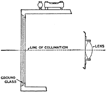
The Maker's Adjustments Should Insure the Line of Collimation being Perpendicular to the Plate
This is done by using one marked stake. The camera is leveled as far as the "fore-and-aft" level is concerned and the horizontal cross-hair point at the center marked on the stake. The camera is then swung round until the stake just shows on one edge of the ground glass, the fore-and-aft or longitudinal level being checked to make sure its bubble is still in the center. Then the bubble in the cross or transverse level tube is brought to the center by means of the threaded adjusting nuts, and the camera is thrown hard over so that the stake appears along the opposite edge of the plate. This time, the bubble of the longitudinal level being kept in the center, half the error introduced by turning from one edge to the other is corrected. All of the adjustments are then rechecked, and if they are found correct the instrument is ready for use. If a circular level be used, the method of adjustment is exactly the same, the swing of the bubble along the axis of the camera and transverse to it being used to determine the longitudinal and transverse adjustments. Slips of paper may be used for lifting one side in place of the adjustment nuts of the T-level.
A leveling head or ball-and-socket joint on the top of the tripod will be found of material aid in leveling the instrument.
No great mechanical genius is necessary to prepare a camera for or to make a successful camera survey. But if a boy have not patience and an infinite desire for accuracy, camera surveying, or indeed any sort of surveying, will be a source of neither pleasure, satisfaction, nor profit.
To Make Transparent Paper
Transparent paper of parchmentlike appearance and strength, which can be dyed with almost all kinds of aniline dyes and assumes much more brilliant hues than ordinary colored glass, can be made in the following manner: Procure a white paper, made of cotton or linen rags, and put it to soak in a saturated solution of camphor in alcohol. When dry, the paper so treated can be cut up into any forms suitable for parts of lamp shades, etc.
Toasting Bread over an Open Fire
Having experienced some difficulty in obtaining good toast over a gas or open fire I tried the following plan with good results: An old tin pan was placed over the flame and the ordinary wire bread toaster clasping the slice of bread was held about 1/2 in. from the pan. In a few minutes the toast was crisp and ready to serve.—Contributed by Katy Doherty, New York City.
Adjustable Stilts
The beginner with stilts always selects short sticks so that he will not be very far from the ground, but as he becomes more experienced, the longer the sticks the better. Then, too, the small boy and the large boy require different lengths of sticks. The device shown makes a pair of sticks universal for use of beginners or a boy of any age or height.
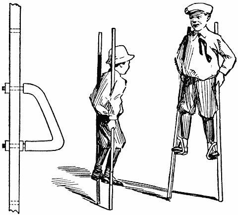
Stilts Having Stirrups That can be Set at Any Desired Height
To make the stilts, procure two long sticks of even length, and smooth up the edges; then begin at a point 1 ft. from one end and bore 12 holes, 3/8 in. in diameter and 2 in. apart from center to center. If there is no diestock at hand, have a blacksmith, or mechanic, make a thread on both ends of a 3/8-in. rod, 12 in. long. Bend the rod in the shape shown, so that the two threaded ends will be just 2 in. apart from center to center. The thread on the straight horizontal end should be so long that a nut can be placed on both sides of the stick. A piece of a garden hose or small rubber hose, slipped on the rod, will keep the shoe sole from slipping. The steps can be set in any two adjacent holes to give the desired height.—Contributed by Walter Veene, San Diego, Cal.
Grape Arbor Built of Poles
In building outdoor structures, such as grape arbors, pergolas, or arches, it is not necessary to use sawed lumber, as they can be built as substantial, and frequently more artistic and cheap, of poles. These are easily obtained, especially in the country or in the smaller cities where there usually are many trees and gardens.
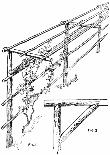
Arbor Made of Poles Which are Supported by One Row of Uprights (Fig. 1, Fig. 2)
The illustrated grape arbor consists of but one row of uprights. Across the top of each is placed a horizontal support for the roof poles, as shown in Fig. 1, which is carried near its outer end by an inclined brace. The brace should be connected at each end with a toe joint, as shown in Fig. 2. The upper end of the upright is beveled off on both sides, to form a double-splayed joint with the crosspiece. In order to securely bind the roof of the arbor, the long poles, or roof beams, should be notched near each end to fit over the supports. Similar notches in the poles forming the side of the arbor are to fit the uprights, thereby binding them together and preventing toppling over. Each set of long poles connecting two uprights should have the end notches the same distance apart, one pole being used as a gauge. All the joints and notches may be cut with a sharp hatchet.
In setting the arbor, the uprights should first be assembled complete with braces and roof supports, and placed in the ground a distance apart corresponding to that of the notches on the long poles. The uprights being set, the long poles are placed and fastened with nails.—Contributed by W. E. Crane, Cleveland, Ohio.
Forcing Fruit Blossoms for Decorations
Twigs trimmed from the fruit trees rather late in the season had quite large buds on them, and we experimented with them in this way: A large box was filled with wet sand, and the twigs were stuck in it and the box set in the warmest corner of the yard. The buds soon swelled and burst into bloom. We then arranged a smaller box of sand and put the blooming twigs into it, and took it into the house where they remained fresh for several days.—Contributed by A. Louise Culver, Oakland, Cal.
Corner Cleaner Attached to a Scrubbing Brush
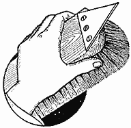
Dirt will accumulate and harden in the corners of a floor and the baseboard just because the end of the scrubbing brush will not enter them. The water gets in with the dirt and leaves a hard crust. This may be easily cleaned out if a metal point is attached to the end of the brush handle, as shown in the illustration. It is used as a scraper to break up the crust and clean it out where the bristles will not enter.—Contributed by L. E. Turner, New York City.

The Boy Surveyor
Plotting a Camera Survey By Harold G. McGee
[The camera records pictures that can be taken in camp or on a vacation trip and kept until more leisure may be had in winter for plotting the ground.—Editor.]
A previously measured base triangle with "stations" at each corner is necessary for making a camera survey, just as it is for the plane-table survey. It is preferable to have each of the three sides measured independently, though if one side has been accurately chained, the other two may be less satisfactorily determined by the use of the plane table. If the camera has a fixed focus, it is possible to make an entire survey from the two ends of a single base line; but this method has no check and should be used only when and where the triangle method is impossible. With an adjustable focus, it will rarely give good results.

Two Fine Hair Lines must be Scratched on Each Plate Before It is Used to Plot From, or to Make Pictures from Which the Plotting is Done
Once the triangle has been laid out, the fieldwork is very simple. The camera is set up at one station, carefully leveled, and then a series of pictures is taken, each single plate overlapping the last so as to form a panorama of the area to be mapped. The focus of the lens must not be changed during a series, and plotting is facilitated by keeping the focus constant during all the exposures which make up a survey. To secure good depth of focus, a small stop is generally used, since it is necessary to use a tripod to keep the camera level. If contours are to be drawn, the height of the lens above the ground at the station should be measured and recorded. After a series has been taken at each station, the fieldwork is complete. It is an excellent plan to keep a record of the plate numbers, and the order in which and the station from which the exposures were made, so that the 10 or 12 plates which a small survey will comprise may not get hopelessly mixed up. If the camera is turned each time to the right, clockwise, and the plates are numbered A-1, A-2, B-4, etc., indicating by A-1, for example, the leftmost plate taken at Sta. A; by A-2, the plate just to the right of A-1, just as II is to the right of I on the clock dial, and by B-4, the fourth to the right taken at Sta. B, there ought to be no difficulty in identifying the plates after the exact details of the ground are forgotten.

Plot of the Ground as It Should Appear After Locating the Objects as They are Shown on the Pictures from Each Point of the Triangle
While the pictures are being taken, "flags" of white wood or with white-cloth streamers tied to them must be stuck in the ground or held at the other stations in order that their exact location can be readily and certainly found on the plates. A few distinctive stakes, some with one and some with two or three strips of cloth tied to them, placed at important points on the ground will help immensely in the location of knolls and shore lines.
In plotting a camera survey, either the original plates, the prints, or enlargements may be used. The plates are the most accurate if a corrected lens has been used; and the enlargements made back through the lens will be best if the images on the plates are distorted. In any case, two fine hair lines must be scratched on each plate before it is used to plot from, or to make the prints from which the plotting is to be done. One of these lines should connect the points at the top and bottom of the plate, and the other, the points at the sides. The vertical line divides the objects which were on the right of the center of the camera from those that were on the left, and the horizontal line connecting the points on the sides separates the objects that were above the camera from those that were below.
If the survey has been made with a lens that does not cover the plate fully or that has considerable uncorrected aberration, causing distorted shapes near the edges and corners of the picture, results can be materially improved by plotting from enlargements. In making the enlargements, the back of the camera should be removed and the light should be allowed to pass through the plate and the lens in the reverse order and direction of that in which it passed when the negative was made. In this way, the errors which were made by the lens originally will be straightened out, and the resulting enlargements will be free from distortion. To make successful enlargements for surveying work, the easel on which the bromide paper is tacked must be square with the camera, and the paper itself should be flat and smooth. It is just as necessary to keep the easel at a constant distance from the camera during the enlarging as it was to keep the same focus while the original negatives were being made.

In Plotting a Camera Survey the Base Triangle is First Carefully Laid Out on the Paper to Such a Scale That the Map will be of Desirable Size
In plotting a camera survey the base triangle is first carefully laid out on the paper to such a scale that the map will be of a desirable size. With the apex of the triangle representing Sta. A, say, as a center, a circle is drawn with a radius as nearly equal as possible to the distance between the optical center of the lens and the plate when the picture was taken. Ordinarily this will be the focal length of the lens; but if the camera was not focused most sharply on an object a great distance off, the radius may be greater. This radius is called the "mapping constant." When an approximate distance for the mapping constant has been determined by measurements on the camera or by knowing the focal length of the lens, the circle, or rather the arc, FG between the two lines to stations B and C, is drawn. The plates taken at Sta. A, and ranged around this circle on the outside and just touching it, will show the landscape exactly as seen from A.
In the accompanying diagram showing the method of determining the mapping constant and of locating the traces of the plates, the letters F, G, H, J, P, R and S designate points referring to the true mapping constant, and the construction necessary to locate the traces of the plates. The primed letters F', F'', G', G'', etc., are used to show similar points where the trial mapping constant is either too long or too short. The following description refers equally to the construction necessary with true or trial-mapping constants.
Next, a line FH is drawn perpendicular to the line AB of the triangle at the point F where the arc intersects it. On this line is laid off, in the proper direction, a distance equal to the distance on the plate or print from Sta. B to the center vertical line. From this point is drawn a light line, HJ, toward the center of the arc. Where this line crosses the arc, at J, a tangent, KJM, is drawn, which will show the location of the plate A-1 on the drawing. This line is called the trace of the plate. An object which appears both on plate A-1 and A-2 is next picked out and its location on the trace of plate A-1 determined by measuring the distance JN equal to the distance on the plate from the image of the object to the center vertical line. A light line, NO, joining this last-found point with Sta. A, is then drawn. Where this last line crosses the arc, at O, a tangent, OP, to the arc is drawn, and the trace of the plate A-2 is found with the aid of the point which appears on both plates just as plate A-1 was located from the picture of Sta. B. The traces of plates A-3 and A-4 are found in exactly the same way as was that of A-2. If the radius of the arc has been estimated correctly, Sta. C will be found to be exactly on the point where the trace of the plate showing the station crosses the line AC on the paper. If it does not fall on the line AC, which is generally the case, everything must be erased except the original triangle. First, however, a radial line S'G', or S''G'', is drawn from the location of Sta. C on the trace of the plate A-2, 3 or 4, as the case may be, to the arc, and the point of intersection of this line and the arc, G' or G'', is preserved. If this point, G' or G'', is outside the base triangle, the next trial arc should be drawn with a larger mapping constant as a radius, or vice versa. If the second mapping constant is off, find again the point of intersection of the radial line through the new location of Sta. C on the newly located trace of the last plate and the new arc. Join this point and the one found previously, in the same manner, with a straight line, G'G''. The point G where this last drawn line intersects the line AC of the base triangle, will be the point through which the arc, with the correct mapping constant as radius, ought to pass, provided the first two approximations were not too far in error. This third trial ought to make the location of the traces of the plates exactly correct. If, however, the focus of the camera was changed between exposures at one station, the traces of the plates will not all be at an equal distance from the station point, and their location will be an almost impossible task. The traces of the plates taken at stations B and C are found in exactly the same manner as were those for Sta. A. After the traces have all been located, it is a good plan to ink them in lightly and erase the pencil construction lines which would otherwise form an impenetrable maze. The traces located, the difficult and tiresome part of the plotting is over; the landscape, brought indoors photographically, is located as with the plane table; all that remains to be done is to take the sights and find the points on the paper which show where the objects were on the ground.

From Each Station the Mapping Constant is Laid Out by the Focal Distance of the Camera or Distance of the Plate from the Lens, and the Location of Traces of the Plates Determined
This taking the sights is a simple matter. With a pair of dividers, the distance from a given object from the center line of the plate is measured. This distance is laid off on the proper side of the point marking the center line of the trace of the same plate; a radial line is drawn through the trace at the given distance from the center-line point and the station at which the given plate is taken; this is one line of sight to the object. The same object is located from another station in the same way; as on the plane table, the intersection of the two lines to the same object marks the location of the point which represents the object on the map.
Obtaining elevations for the drawing of contours is a slightly longer process. Contours are lines joining points of equal elevation; they represent successive shore lines, if the area mapped were inundated and the water should rise slowly foot by foot. If the contours are close together, the ground represented has a steep slope, and vice versa. If, on a map, a number of points are of known elevation, it is simply a question of judgment and practice to tell where contour lines go.
Before contours can be drawn the elevations of a considerable number of points must be known. If the elevation of any one of them is known and the difference between that one and any other can be found, determining the elevation of the second point is simply a problem in addition or subtraction. If it be desired to find, for instance, the difference in elevation between Sta. C and the corner of the fence, as shown in the sketch, two solutions are possible, as follows:
First: Perpendicular to the line of sight from Sta. C to the fence corner, two lines are drawn, one at the intersection of the trace of the plate by the line of sight, and one at the point on the paper which shows the location of the fence corner. On the first of these two lines is laid off the distance Y', equal to the distance of the ground at the fence post above or below the horizontal center line on the plate. Through this point, on the first perpendicular on the line of sight, is drawn a line through the Sta. C and extended to an intersection with the second drawn perpendicular. The distance from the corner of the fence, on the paper, to this intersection is the distance Y, the difference in elevation from the center of the camera at Sta. C to the ground at the fence post. This solution is longer and less desirable than the second.
Second: In place of perpendicular lines to the line of sight, the trace of the plate, and a line, through the point representing the object, parallel with the trace, may be used.
A datum plane, or reference surface, from which all elevations are measured up to the ground surface must be assumed. The United States Geological Survey uses mean, or average, sea level for the datum in all its topographic sheets. Generally, unless there is a United States Geological Survey "bench mark," a monument of carefully determined elevation referred to sea level, within the limits of the survey, it is better to assume the elevation of some point, as Sta. C, at 100 ft., or greater if necessary to place the datum plane below the ground level at all points within the area to be mapped. Other elevations are figured from the assumed elevation of Sta. C. Allowance must be made for the height of the center of the camera above the ground at Sta. C in computing elevations above Sta. C. All elevations determined for the purpose of drawing contours are ground elevations and not the elevation of the top of objects located on the map. The topographic sheets of the Geological Survey are good examples to follow, in drawing contours. For many purposes, contours are not essential, and the refinements necessary for their drawing may be omitted.
How to Build a Skiff
The following is a description of an easily constructed 12-ft. skiff, suitable for rowing and paddling. This is the type used by many duck hunters, as it may be easily pushed through marshes. It is constructed of 3/4-in. dressed pine, or cypress.
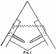
The Skiff is Especially Constructed for Use in Shallow Water and Marshes by Duck Hunters, but with the Addition of a Keel It Makes a Good Craft for Almost Any Water as a Rowboat (Fig. 1)
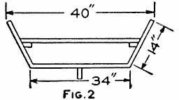
(Fig. 2)
The sides consist of planks, 14 in. wide, but 12-in. planks may be used, the length being 12 ft. 4 in. Two stem pieces are constructed as shown in Fig. 1, and the plank ends are fastened to them with screws. Nail a crosspiece on the plank edges in the exact center, so as to space the planks 34 in. apart, as shown in Fig. 2; then turn it over and nail another crosspiece in the center of the planks for width, and make the spacing of the other edges 40 in. Plane the lower edges so that, in placing a board across them, the surfaces will be level. The floor boards are 6 in. wide and fastened on crosswise, being careful to apply plenty of red lead between all joints and using galvanized nails, 2 in. long.
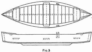
(Fig. 3)
A deck, 18 in. long, is fastened on each end, as shown in Fig. 3. It is made of strips fastened to a crosspiece. The seats, or thwarts, consist of 10-in. boards, and are placed on short strips fastened to the side planks about 5 in. from the bottom. The oarlocks are held in a wedge-shaped piece of wood, having a piece of gas pipe in them for a bushing, the whole being fastened at the upper edge of the side planks with screws, as shown in Fig. 4. The location of these must be determined by the builder.
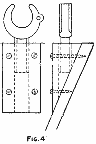
(Fig. 4)
Some calking may be required between the bottom, or floor, boards, if they are not nailed tightly against one another. The calking material may be loosely woven cotton cord, which is well forced into the seams. The first coat of paint should be of red lead mixed with raw linseed oil, and when dry any color may be applied for the second coat.
While, for use in shallow water, these boats are not built with a keel, one can be attached to prevent the boat from "sliding off" in a side wind or when turning around. When one is attached, it should be 3/4 in. thick, 3 in. wide, and about 8 ft. long.—Contributed by B. Francis Dashiell, Baltimore, Md.
An aniline color soluble in alcohol, by adding a little carbolic acid, will hold fast on celluloid.
Double-Swing Gate with Common Hinge

The Post and Gate are Cut Away Back of the Hinge to Allow the Latter to Swing Back
Ordinary hinges can be easily bent and so placed on posts that a gate can be swung in either direction. As shown in the illustration, hinges can be made to fit either round or square posts. The gate half of the hinge is fastened in the usual way. The post half is bent and so placed that the hinge pin will approximately be on a line between the centers of the posts. The gate and post should be beveled off to permit a full-open gateway.—Contributed by R. R. Schmitz, Birmingham, Ala.
Testing Out Induction Coils
While winding an induction coil, I found it necessary to test the sections for continuity. Having no galvanometer, I connected a battery and low-resistance telephone receiver in series with the section and battery. The battery and telephone receiver may also be used for testing out the secondary of an induction coil, to determine if it is burnt out.—Contributed by John M. Wells, Moosomin, Can.
How to Make a Surveyor's Transit By Bennett Blacklidge

Detail of Parts for the Construction of a Transit Which can be Used, with Fairly Accurate Results, in Doing Amateur Surveying for Railroad Work, Town Sites and the Laying Out of Maps
A boy who likes to do the things that "grown ups" do can derive considerable pleasure from the making of a transit, which will enable him to start in surveying railroads, laying off town sites, and doing lots of kindred work. It is necessary to have a compass, and one, 1-3/4 in. in diameter, can be purchased at a reasonable price. A hole is bored with an expansive bit into a board, 7/8 in. in thickness, just deep enough to admit the compass snugly, then a circle, A, 4-1/2 in. in diameter, is drawn, having the same center as the compass hole, and the disk is cut out with a compass or scroll saw. A ring, B, is cut in the same manner from the same material, its inside diameter being such that the ring just fits around the disk A, and the outside diameter, 6-3/4 in. Another block, 5-1/2 in. in diameter, is glued to the bottom of the small disk A. This will appear as shown at C. A small hole is bored in the center of the bottom block on the under side to receive the threaded end of the screw on a camera tripod. By careful adjustment the threads in the wood will hold the transit firmly. A plumb bob must be attached exactly in the center of the tripod head. This can be easily done if the head is wood, but in case the top is of metal, the line can be attached to the screw with a double loop, as shown at D, so that the bob will hang centrally. Two standards are made as shown at E, each about 5 in. high, and fastened to the ring B in the positions shown in the drawing of the complete instrument. An arc of a circle is marked on one of the standards, as shown, to designate angles, the markings being laid out with a bevel protractor. The pointer is a hand from an old alarm clock.
The telescope arrangement consists of a piece of pasteboard tubing, about 1-1/4 in. in diameter, one end being covered with a piece of black paper with a pinhole in the exact center, and the other equipped with "cross hairs." Four small notches are cut in the latter end of the tube, exactly quartering it, and two silk threads as fine as can be obtained, are stretched across in these notches. The tube is fastened to a block of wood, 5 in. wide and 7 in. long, with small tacks and two pieces of fine copper wire. This block is pinioned between the standards with two nails. The hand is secured to the nail in such a position that it will point straight down when the tube is level.
The instrument is adjusted in the following manner: It is set up where a lone tree can be seen, about one mile distant, and the center of the cross hairs is carefully set on the tree. Then a very fine wire is stretched across the compass, as shown at F, and while keeping it directly over the center of the compass it is also placed on a direct line pointing to the tree. Very small brass nails, driven in at G and H, serve to fasten it in the position thus found. When this adjustment has been made the telescope can be turned to sight any object, after first placing the instrument so that the needle points to the N on the dial, and a glance at the wire will show the exact direction in which the object is located.
The instrument is then taken to a level stretch of road and set up, and a stick is placed on end and marked at the height of the telescope. The stick is taken along the road about 200 yd., the telescope sighted on it, and the hand set. This makes the instrument level enough for all practical purposes. The plumb bob is then dropped, a distance of 20 ft. measured from it on the road, and a mark made. The telescope is sighted on this mark, and a mark is made on the standard at the point of the arc, to which the hand points. Another 20 ft. is measured, or 40 ft. from the bob, and another mark made. The telescope is sighted on it, and the location of the hand again marked. This works well up to about 300 ft., then the marks begin to come very close together. This method is used for laying out town sites. The instrument is set up directly over a stake from which to work, and the telescope is turned down until the 20-ft. mark is indicated, when the operator looks through the telescope and tells his helper where to set the stake. Then another is driven at the next point, and so on, until the limit of the instrument is reached.
When doing railroad surveying several start out together, one with an ax to cut away brush; one to carry pegs; two to measure, or chain, the distance between stakes, and one to do the sighting. In this manner a line can be run that comes very near being perfectly straight for three miles.
A concrete example of how the transit was used to lay out a map of a ranch will now be given. The start was made on an east and west fence. The instrument was set 5 ft. from the fence at one point, and at the other end of the fence the stick was set at a point 5 ft. from the fence. When the stick was sighted, the wire cut the E and W on the compass, thus showing that the fence was set on a line, due east and west. The distance was measured from the fence to the house, which was 1/4 mile, and this was noted in a book. This operation was repeated on the rear, and the distance found to be 780 ft. while the compass showed the direction to be 4 deg. west of south. The next line ran 427 ft. and 1 deg. east of south. This was kept up all the way around. After these notes had been obtained, it was an easy matter to take a piece of plain paper and strike a line representing north and south and lay off the directions. A bevel protractor was used to find the degrees. The transit was set on the posts of the corrals and this saved the measuring out from the inclosure. The creek was surveyed in the same manner. So many feet south-west, so many feet west, so many feet 5 deg. south of west, and so on, until its length was run.
The transit can also be used for finding distances without measuring. A line from A to B is sighted, and F represents a point 1/2 mile distant, the line from F to G being 100 ft. A line is now sighted from A, through G to C. A person standing at D is directed to move toward the point E and he is stopped as soon as sighted in the telescope. He then measures the distance from D to E. Suppose this distance is 250 ft. As each 100 ft. means 1/2 mile, and the 50 ft., 1/4 mile, the point E is 1-1/4 miles from the transit. This method can be used quite extensively and distances obtained are fairly accurate.
A small whisk broom makes a handy cleaner to brush the caked grease and lint from pulleys and gear wheels where waste and rags are useless.
To Enlarge or Reduce Plots
Sometimes it is necessary to enlarge or reduce a plot to a different scale. This can be easily and quickly accomplished without resorting to the slow process of protracting the angles and scaling the individual lines.

Enlarging and Reducing Plots by Radial Lines from a Common Point Located Properly
Take any point, P, and from it draw light pencil lines through each of the corners of the plot. On any one of these lines, as AP, lay off with dividers AC equal to CP. Place a triangle on the line AB and with a straightedge, or another triangle, laid on the line AP, slide the former to the point C, then draw line CD parallel with AB until it intersects the radial line PB. In the same manner draw line DE parallel with BF, and so on, all about the plot. A test of accuracy will be in striking the point C with the last line. If the original plot has a scale of 40 ft. to the inch the reduced plot would be 80 ft. to the inch. If it is required to enlarge the plot to 20 ft. to the inch, make AG equal to AP, and proceed as in the first case, using G as the starting point.
The location of the point P is arbitrary and may be outside of the boundary of the plot or figure to be enlarged or reduced, but should be so located, if possible, that the radial line to any corner does not parallel either of the plot lines to that corner. If the point cannot be so located for all the lines, it may be necessary to scale the lines. A little practice in picking out the best location for the point will give gratifying results.—Contributed by Junius D. McCabe, Pittsburgh, Pa.
A Lathe Bench
While working at a bench, or foot-power lathe, it is quite convenient to have some sort of a seat to sit on while at work, or between operations. In making such a seat, I used a board, 27 in. long and 12 in. wide, for the top, and two boards, 19 in. long and 12 in. wide, for the supports. These boards were 3/4 in. thick. The supports were squared at the ends and securely fastened to the top with nails, their positions being 3 in. in from the ends of the top board. These were well braced, as shown, and a cross board was placed between them, near the lower ends.

The Bench Provides a Seat for the Worker in Doing Operations on a Small Foot Lathe
The projecting ends of the top were cut out, and a box, 5 in. deep, constructed against the supports. A covering was made to fit in each of the openings in the top board and hinged to the outer edge of the box. The boxes made a convenient place for the tools used in the turning work.—Contributed by Harold R. Harvey, Buhl, Idaho.
Cleaning and Polishing Shoes
In using the polishes now on the market for tan shoes, I found that the leather cracked in an unreasonably short time. The following was suggested and tried out with good results. Wash the shoes with castile soap and water by applying the mixture with a dauber. Work up a little lather and then rub dry with a cloth, without rinsing. The leather will be cleaned without becoming dark, and it will not crack. A higher polish may be obtained by using some paste polish in the usual manner.—Contributed by George Bliss, Washington, D. C.
Shaving Cabinet Mounted on an Adjustable Pedestal
The illustration represents a shaving cabinet mounted on an adjustable pedestal, whose style and size are such that it may easily be moved about or set away without requiring much room. The material required for its construction is as follows:
| 1 | framed mirror, 8 by 10 in. |
| 1 | square-head bolt and wing nut, 1/2 by 4 in. |
| 2 | cabinet sides, 1/2 by 7 by 15 in. |
| 2 | partitions and shelf, 1/2 by 6 by 6 in. |
| 1 | cabinet top, 1/2 by 7 by 10-1/2 in. |
| 1 | cabinet bottom, 1/2 by 6 by 10-1/2 in. |
| 2 | cabinet backs and doors, 1/2 by 6-1/2 by 10-1/2 in. |
| 4 | cabinet moldings, 1 by 4 by 4 in. |
| 1 | cabinet support, 2 by 2 by 26 in. |
| 4 | pedestal moldings, 1 by 1 by 6 in. |
| 4 | pedestal frames, 1 by 3 by 36 in. |
| 1 | base, 2 by 12 by 12 in. |
| Screws, nails, and varnish. |

The Mirror and Cabinet are Mounted on a Pedestal That can be Moved as Desired
The sidepieces of the cabinet are extended at one corner, thereby forming the supports for the mirror. The door fits in between the sides and may be attached either by hinges or two wood screws, one on each side, holes being bored in the sides forming a loose fit for the screw so they can freely turn with the door. The pedestal consists of a 4-in. square box resting on the base block, and secured in place by means of molding strips. The sliding support for the cabinet consists of a 2-in. square piece secured to the bottom of the cabinet by means of molding, and provided with a slot so the support can freely slide over the clamp bolt, which fastens it in place by clamping it against the pedestal. If it is desired to conceal the head of the bolt, a recess should be made in the pedestal frame for it, as shown, so the support will freely slide over it. Before assembling the pedestal it will be necessary to drill a hole in the front side in line with the recess of the back side, and insert the bolt. If this precaution is not taken, it will not be possible to insert the bolt, unless a hole be made for the head either through the back side or front side.—Contributed by D. Toppan, Watervliet, N. Y.
Four-Passenger Coasting Bobsled By R. H. Allen

Coasting Is One of the Best Sports a Boy Enjoys during Winter, and a Sled of Luxury Is Something to Be Proud of among Others on a Hill or Toboggan Slide
Coaster bobs usually have about the same form of construction, and only slight changes from the ordinary are made to satisfy the builder. The one shown has some distinctive features which make it a sled of luxury, and the builder will pride himself in the making. A list of the materials required is given on the opposite page. Any wood may be used for the sled, except for the runners, which should be made of ash.
Shape the runners all alike by cutting one out and using it as a pattern to make the others. After cutting them to the proper shape, a groove is formed on the under edge to admit the curve of a 5/8-in. round iron rod about 1/4 in. deep. The iron rods are then shaped to fit over the runner in the groove and extend up the back part of the runner and over the top at the front end. The extensions should be flattened so that two holes can be drilled in them for two wood screws at each end. If the builder does not have the necessary equipment for flattening these ends, a local blacksmith can do it at a nominal price. After the irons are fitted, they are fastened in place.
The top edges of the runners are notched for the crosspieces so that the top surfaces of these pieces will come flush with the upper edges of the runners. The location of these pieces is not essential, but should be near the ends of the runners, and the notches of each pair of runners should coincide. When the notches are cut, fit in the pieces snugly, and fasten them with long, slim wood screws. Small metal braces are then fastened to the runners and crosspiece on the inside, to stiffen the joint.

Details Showing the Method of Rear-Sled Oscillation, the Bracing, and the Steering Wheel
As the rear sled must oscillate some, means must be provided for this tilting motion while at the same time preventing sidewise turning. The construction used for this purpose is a hinged joint. The heavy 2 by 5-in. crosspiece is cut sloping on the width so that it remains 2 in. thick at one edge and tapers down to a feather edge at the opposite side. This makes a wedge-shaped piece, to which surface the three large hinges are attached. The piece is then solidly fastened to the upper edges of the runners that are to be used for the rear sled, and so located that the center of the piece will be 8 in. from the front end of the runners.
The supporting crosspiece on the front sled is fastened on top of the runners, at a place where its center will be 11 in. from the front end of the runners.
The top board is prepared by making both ends rounding and planing the surfaces smooth. On the under side, the two crosspieces are placed, which should have two 1/2-in. holes bored through the width of each, near the ends, to receive the eyebolts. They are placed, one with its center 12 in. from the end to be used for the rear, and the other with its center 8 in. from the front end, and securely fastened with screws. The shore is placed in the center of the board, and wires are run over it connecting the eyebolts. The eyebolts are then drawn up tightly to make the wire taut over the shore. This will prevent the long board from sagging.
LIST OF MATERIALS
| 1 | top. 6-1/2 ft. long, 16 in. wide, and 1-1/4 in. thick. |
| 4 | runners. 22 in, long, 4 in. wide, and 1 in. thick. |
| 4 | crosspieces, 16 in. long, 3 in. wide, and 1 in. thick. |
| 3 | pieces, 16 in, long, 5 in. wide, and 2 in. thick. |
| 1 | piece, 16 in. long, 5 in. wide, and 1 in. thick. |
| 1 | shore, 16 in. long, 3 in. wide, and 1 in. thick. |
| 4 | seat backs. 12 in. long, 16 in. wide, and 1 in. thick. |
| 1 | dowel. 3 ft. long, and 1 in. in diameter. |
| 4 | rods. 5/8 in. in diameter, and 30 in. long. |
| 4 | eyebolts, 1/2 in. by 6 in. long. |
| 3 | hinges, 5-in. strap. |
| 8 | hinges, 3-in. strap. |
On the upper side of the board and beginning at the rear end, the backs are fastened at intervals of 18 in. They are first prepared by rounding the corners on the ends used for the tops, and the opposite ends are cut slightly on an angle to give the back a slant. They are then fastened with the small hinges to the top board. On the edges of the top board, 1-in. holes are bored about 1 in. deep, and pins driven for foot rests. These are located 18 in. apart, beginning about 5 in. from the front end. The dowel is used for the pins, which are made 4 in. long.

The Top Board is Well Braced on the Under Side and Fitted with Four Backs on Top to Make It a Luxurious Riding Sled, and the Runners are Provided with Metal Shoes for Speed
The steering device consists of a broom handle, cut to 18 in. in length, with one end fastened in a hole bored centrally in the 5-in. crosspiece of the front sled. A hole is bored in the top board through the center of the crosspiece fastened to the under side for the steering post. The broomstick is run through this hole after first placing two metal washers on it. After running the stick through, a collar is fastened to it just above the top board, so that the top cannot be raised away from the sled. At the upper end of the broomstick a steering wheel is attached, made from a nail-keg hoop. A piece of wood is fastened across its diameter, and the hoop is covered with a piece of garden hose and wrapped with twine. In the center of the crosspiece, a hole is bored to snugly fit on the broom handle, which is then fastened with screws.
The rear sled is fastened to the top board with screws through the extending wings of the hinges and into the crosspiece. Holes are bored in the front ends of all runners, and a chain or rope is attached in them, the loop end of the rear one being attached to the under side of the top board, and the one in the front used for drawing the sled.
To Prevent Drill from Catching As It Passes through Metal
The regular slope of a drill will cause the cutting edge to catch as it breaks through the metal on the opposite side of the piece being drilled. But if a twist drill is ground more flat like a flat drill, it will not "grab" into the metal as it passes through.—Contributed by James H. Beebee, Rochester, N. Y.

An Ice Boat and Catamaran By Robert K. Patterson
This combination is produced by using the regular type of ice boat and substituting boats for the runners, to make the catamaran.
In constructing the ice boat, use two poles, or timbers, one 16 ft. and the other 10-1/2 ft. long, crossed at a point 2-1/2 ft. from one end of the longer timber. The crossed pieces are firmly braced with wires, as shown.
The mast, which should be about 12 ft. long, is set into a mortise cut in the long timber, 15 in. from the front end, and is further stabilized by wires, as shown. A jib boom, about 6 ft. long, as well as a main boom, which is 11-1/2 ft. long, are hung on the mast in the usual manner.

The Ice Boat Provides an Ideal Outing in Winter Where There Is a Body of Water Large Enough for Sailing
The front runners consist of band-iron strips, 18 in. long, 3 in. wide, and 1/8 in. thick, with one edge ground like the edge of a skate, and the ends rounding, which are fastened with bolts to the sides of wood pieces, 18 in. long, 6 in. wide, and 2 in. thick, allowing the ground edge to project about 1 inch.
When the ice-boat frame is made of poles, the runners are attached to a piece of wood, 12 in. long, shaped as shown and fastened at right angles with bolts running through the shouldered part diagonally. This makes a surface on which the pole end rests and where it is securely fastened with bolts. If squared timbers are used, the runners can be fastened directly to them. The rear, or guiding, runner is fastened between two pieces of wood, so that its edge projects; then it is clamped in a bicycle fork, which should be cut down so that about 3 in. of the forks remain. A hole is bored through the rear end of the long pole to receive the fork head, the upper end of which is supplied with a lever. The lever is attached to the fork head by boring a hole through the lever end at a slight angle to fit the head, allowing sufficient end to be slotted, whereupon a hole is bored through the width of the handle, and a bolt inserted, to act as a clamp.

The Ice-Boat Details, Showing Construction with Straight Poles Having Detachable Runners So the Boats can be Supplied in Their Stead to Make a Sailing Catamaran for Use in Summer
A board is fastened on two crosspieces mortised in the upper part of the pole, for a place to sit on when driving the boat. The sail can be constructed of any good material to the dimensions given.
To rig up the ice boat for use as a catamaran, place a pole across the stern, the length of the pole being equal to the one used on the front part of the ice boat. Two water-tight boats are constructed, 16 ft. long, 12 in. wide, and 10 in. deep at the center. To make these two boats procure six boards, 16 ft. long, 10 in. wide, and 1 in. thick. Three boards are used to make each boat. Bend one board so that it will be in an arc of a circle, then nail on the two side boards, after which the edges of the sides are cut away to the shape of the bent board. The runners are removed from the ice boat, and the boats fastened to the pole ends. A rudder is attached in the place of the rear, or guiding, runner. The tops of the boats, or floats, can be covered and made water-tight.
Mind-Reading Effect with Cards
Five cards are shown, and some one person is asked to think of two cards in the lot, after which the performer places the cards behind his back and removes any two cards, then shows the remaining three and asks if the two cards in mind have been removed. The answer is always yes, as it cannot be otherwise.
To prepare the cards, take any 10 cards from the pack and paste the back of one card to another, making five double cards. Removing any two cards behind the performer's back reduces the number of cards to three, and when these are turned over they will not have the same faces so that the ones first seen cannot be shown the second time even though all five cards were turned over and shown.
An Air Pencil to Make Embossed Letters
The device illustrated is for making embossed letters on show cards, signs, post cards, etc. A small bulb, such as used on cameras, is procured, also the spout from a small oilcan. The bulb is fastened to the spout as shown.
The material for use in the pencil is quick-drying mucilage thickened with flake white. If some special color is desired, tint the mixture with aniline. Fill the spout with the mixture and attach the bulb. Squeeze the bulb gently while forming the letters, then dust over with bronze, and allow to dry.
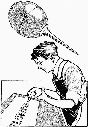
The Oilcan Spout Is the Reservoir to Hold the Paint, and the Bulb Produces the Air Pressure
An Endless Dish or Floor Mop
A good way to use up cord that collects about the house, is to make an endless dish or floor mop of it. Procure a thin board that will make a good length and wind the cord around it, then remove it from the board and tie the bunch together in the center.
Combination Tie Rack and Collar Holder
An unusual though simple tie rack can be made by supporting the tie bar in the center. By this arrangement the ties can be placed on it from either end, thus avoiding the tedious threading through, required on the ordinary rack supported at each end. Collars may be hung on a peg placed above the tie bar. The pieces can be glued together and a good finish given in the usual way. The rack can be hung up by two screw eyes. The material required consists of four pieces, dimensioned 5/8 by 5 by 8 in., 3/8 by 7/8 by 7-1/2 in., 3/8 by 5/8 by 3-1/8 in., and 7/8 by 7/8 by 2 in. respectively.—Contributed by Arthur C. Vener, Dallas, Texas.
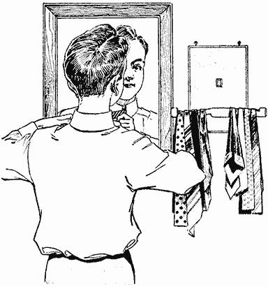
Collar and Tie Rack with Open-End Hangers So That the Articles can be Slipped On Easily without being Passed behind a Bar as Is Usually the Case

Skates Made of Wood
Skates that will take the place of the usual steel-runner kind and which will prevent spraining of the ankles, can be made of a few pieces of 1/2-in. boards.
Four runners are cut out, 2 in. wide at the back and 1-1/2 in. wide at the front, the length to be 2 in. longer than the shoe. The top edges of a pair of runners are then nailed to the under side of a board 4 in. wide, at its edges.
A piece of board, or block, 2 in. wide is fastened between the runners at the rear, and one 1 in. wide, in front. Two bolts are run through holes bored in the runners, one just back of the front board, or block, and the other in front of the rear one.
Four triangular pieces are fastened, one on each corner, so that the heel and toe of the shoe will fit between them, and, if desired, a crosspiece can be nailed in front of the heel. Straps are attached to the sides for attaching the skate to the shoe. Both skates are made alike.—Contributed by F. E. Kennar, Hennessey, Okla.

Skates Made of Wood to Take the Place of the Steel-Runner Kind and Prevent Sprained Ankles
The best paint for paper roofing is asphaltum varnish.

An Ice Glider By Mildred E. Thomas
The enthusiastic pushmobilist need not put aside his hobby during the winter, as an amusement device for use on ice, which will surpass the very best pushmobile, can be easily made as shown in the illustration.
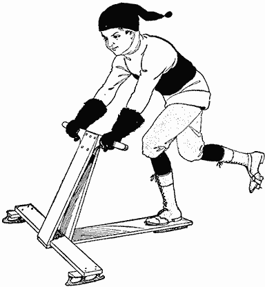
The Glider is Pushed over the Ice Similarly to a Pushmobile, and the Speed That can be Attained is Much Greater
Similar to an ice yacht, only a great deal smaller, the ice glider will require three ordinary skates, two of which are fastened to the ends of the front crosspiece, so that their blades will stand at an angle of about 30 deg. with their edges outward. To get this angle, tapering blocks are fastened to the crosspiece ends, as shown. The skates are then fastened to these blocks.

Detail of the Parts for the Construction of the Ice Glider, or Pushmobile
The crosspiece is 30 in. long and about 8 in. wide. In the center of this piece an upright is constructed, 26 in. high. The edges of the front crosspiece are cut on a slant so that a piece nailed to its front and back edge will stand sloping toward the rear. A handle, 24 in. long, is fastened between the two uprights at the upper end. The rear part is made of a board, 8 in. wide and 40 in. long. The remaining skate is fastened in a perfectly straight position on the rear end. The skates may be attached with screws run through holes drilled in the top plates, or with straps. The front end of the rear board has a hole for a bolt to attach it to the center of the front crosspiece, so that the latter will turn to guide the glider.
A pusher is prepared from a block of wood, into which nails are driven with their ends projecting on the under side. The block is strapped to one shoe, as shown.

The Block of Wood with Projecting Nails to Fasten on the Shoe That Does the Pushing
The glider is used in the same manner as a pushmobile.
The pusher can be made in another way by using sole leather instead of the block. Small slots are cut in the sides for the straps. Nails are driven through the leather so that the points project. Either kind of pusher is especially adapted for the pushmobile to prevent wear on the shoe.
Prony Brake for Testing Small Motors
The ordinary prony brake is not, as a rule, sensitive enough to make an accurate test on small motors, such as those used in driving sewing machines, washing machines, vacuum cleaners, etc. The arrangement shown in the accompanying sketch has been used for this purpose with good results and was very accurate. The operation of the brake is exceedingly simple.

Prony Brake Used in Connection with a Small Balance to Find the Horsepower
A pulley without a crown face is attached to the shaft of the motor, which is fastened to the top of a table or bench, and a balance mounted directly over the pulley. The support for the balance should be a narrow strip, which in turn is supported on two upright pieces, as shown. A light rope is put under the pulley, and the ends are looped over the platforms of the balance so that it does not interfere with the operation of the balance. The ends of the rope should be vertical and parallel. The piece upon which the balance rests is raised by inserting wedges, thus increasing the tension in the rope. The resulting friction of the rope on the pulley increases the load.
If the motor is running in the direction indicated by the arrow on the pulley, the tension in the left-hand end of the rope will be greater than in the right-hand end and a weight must be placed on the right-hand platform of the balance. When the weight W is adjusted so that the two pointers on the platforms are exactly opposite each other, the value of the weight W, in pounds, will represent the difference in pull, in pounds, between A and B. If the value of the weight W is known and also the speed of the machine when the weight was determined, the horsepower output can be computed by means of the following equation:
| 6.2832 × L × W × R.P.M. | |
| Hp. = | |
| 33,000 × 12 |
In this equation, L is the distance in inches from the center of the pulley to the center of the rope. Two ordinary spring balances may be substituted for the beam balance and the difference in their readings taken for the value W. For best results, the tension in the slack end of the rope should be as small as possible, and it may be necessary to wrap the rope one or more times completely around the pulley.
A Mystic Fortune Teller
Fortune telling by means of weights striking glasses or bottles is quite mysterious if controlled in a manner that cannot be seen by the audience. The performer can arrange two strikes for "no," and three for "yes" to answer questions. Any kind of bottles, glass, or cups may be used. In the bottles the pendulum can be suspended from the cork, and in the glasses from small tripods set on the table.

The Rocking of the Table is Caused by the Pressure of Air in the Bulb under the Foot, the Movement Causing the Pendulum to Swing and Strike the Glass
The secret of the trick is as follows: A rubber tube with a bulb attached to each end is placed under a rug, one bulb being located under one table leg and the other near the chair of the performer set at some distance from the table where it can be pressed with the foot. Some one selects a pendulum; the performer gazes intently at it, and presses the bulb under his foot lightly at first; then, by watching the swaying of the pendulum selected, he will know when to give the second impulse, and continue until the weight strikes the glass. As the pendulums are of different lengths they must necessarily swing at different rates per second. The impulses must be given at the proper time or else the pendulum will be retarded instead of increased in amplitude. A table with four legs is best to use, and the leg diagonally opposite that with the bulb beneath it must not touch the carpet or floor. This can be arranged by placing pieces of cardboard under the other two legs.—Contributed by James J. McIntyre.
Holding Prints in a Liquid-Filled Tray
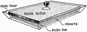
Push Pins on the Under Side of the Board Raise It and Provide a Space for the Prints in the Liquid
After having considerable trouble in keeping my paper prints in the hypo fixing bath from curling, which would force the edges out of the liquid, I found the plan here illustrated a success. I procured a piece of wood, the size of a postcard, and stuck four glass push pins into one surface, one at each corner, and fastened a handle to the center of the upper side. The papers are first placed in the bath, then the board is set over them with the pins down. This holds the prints under the liquid but does not press them tightly together.—Contributed by J. J. Kolar, Maywood, Ill.
A piece of an old gunny sack will polish brass work very nicely.
Cellar-Door Holder
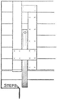
A cellar door that opened up against a wall required a catch of some kind to keep it open at times. As I did not want a catch to show on the wall, I devised a holder as shown. Three pieces of wood were nailed to the under side of the door in such positions that they formed a recess in which a fourth piece, 2 in. wide and 1 in. thick, would slide endways. A knob was attached to the upper end of the slide, which served the double purpose of a handle and a stop for the slide. The manner of using the holder is clearly shown.—Contributed by H. T. Smith, Topeka, Kansas.
An Emergency Pencil Compass
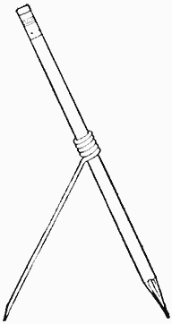
The need of a compass when none was at hand caused me to quickly devise a substitute for the work. A piece of stiff wire, about the length of the pencil, was procured, and several turns were made around the pencil, as shown. The lower straight end was filed to a point. The wire can be bent to obtain the radius distance.—Contributed by Preston Ware, Rome, Ga.
A very effective dip for brass and copper articles, that will leave a clean and bright finish, is 2 qt. of aqua fortis, 1 gal. of sulphuric acid, 1 pt. of water and a pinch of salt.
Renewing Carbon Paper
When carbon paper has been used several times, the preparation becomes almost worn off on some parts, while other parts of the paper are as good as new. The process of renewing is very simple and it can be done by anyone without special apparatus. All that is necessary is to hold the paper in front of a fire or over a radiator a few seconds. The heat will cause the preparation to dissolve and spread over the paper, so that when it is dry the paper will have a new coating. This can be repeated, and in some cases will double the life of the carbon paper.—Contributed by Chester M. Kearney, Danville, Quebec.
How to Clinch a Finishing Nail
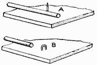
A wire or finishing nail may be clinched as nicely as a wrought nail, if a nail punch or piece of iron is placed along the side of it, as shown at A, and the nail hammered into an arched form, as at B. The punch or rod is then withdrawn and the arch driven into the wood.—Contributed by James M. Kane, Doylestown, Pa.
To Prevent Washbasin Bottom from Wearing Out
The ears from some sirup buckets were removed and three of them soldered, at equal distances apart, on the bottom of the washbasin near the outside edge of the lower part. These prevented the wear from coming on the bottom of the basin, and it lasted several times as long as ordinarily.—Contributed by A. A. Ashley, Blanket, Texas.
To curl feathers, heat slightly before a fire, then stroke with something like the back of a case knife.

Snowshoes: How to Make and Use Them By Stillman Taylor — Part I—Shapes of Snowshoes
To the inventive mind of the North American Indian we owe the snowshoe, and its conception was doubtless brought about through that prolific source of invention—necessity. The first models were crude web-footed affairs, but improvements in model and manner of filling the frames were gradually added until the perfected and graceful shoe of the present was finally reached. The first snowshoes were made by the Indians, and the Indians of Maine and Canada continue to fashion the finest models today.
The snowshoe is a necessity for the sportsman and trapper whose pleasure or business leads him out in the open during the winter season, when roads and trails are heavily blanketed by a deep fall of powdery snow. But the use of the web shoe is by no means confined to the dweller in the wilderness, since the charm of wintry wood and plain beckons many lovers of the outdoors to participate in this invigorating sport, and snowshoe tramps are fast growing in popularity in and about our cities and towns.
All the modern snowshoes are constructed upon practically the same general lines, although the types of frames differ considerably in size as well as in shape, and the filling of hide is often woven in many varied and intricate patterns. The frame or bow—usually made of ash in order to get strength with light weight—is bent in many shapes, but the one shown in the diagram is a typical general-purpose shoe, and may be called standard. The frame is held in shape by means of two wooden cross braces, neatly mortised into the frame. These braces are spaced some 15 or 16 in. apart, and so divide the shoe into three sections, known as the toe, center, and heel. The filling is woven into a lanyard, which is a light strip of hide firmly laced to the frame through a double row of holes drilled in the wood. The center filling is woven of heavy strands of rawhide, in a fairly coarse mesh, because this part of the shoe must bear the weight of the body and the brunt of wear. The end fillers for toe and heel are woven of lighter strands of hide, and the mesh is, of course, smaller.

The Frame of a Snowshoe in Its Usual Construction, Showing the Crosspieces with Their Laced Fillings of Hide and the Different Parts Named, for a Ready Reference
As may be noted by referring to the drawing, a center opening or "toe hole" is provided, and as the greater strain on the filling lies directly under the ball of the foot, the shoe is reinforced at this point by the "toe cord" running across, and the "toe-cord stays," which are tied in on each side of the toe hole—one end being fastened to the toe cord and the other lashed over the wooden cross bar of the frame. These reinforcing cords are formed of several strands of hide, the stays being again wound with finer strands.
To prevent slipping and to secure a good foothold while walking, the manner of attaching the foot to the shoe is of importance, and this is done by making use of a toe strap, which will allow the toe to push down through the toe opening as the heel of the foot is lifted in the act of walking. A second strap, or thong, leading from the top around the foot, above the curve of the heel, is needed to lend additional support in lifting the snowshoe, to effect the easy shambling stride characteristic of the snowshoer.
There are, of course, a great number of models or styles, some one style being popular in one locality, while an altogether different style is preferred in another part of the country. The most representative types are well shown in the illustrations, and a brief description will point out their practical advantages, because each model possesses certain merits—one model being designed for fast traveling in the open, another better adapted for brush travel, while others are more convenient for use in a hilly country where much climbing is done, and so on.

A: Snowshoe Experts Regard This as an Extreme Style, for It is Long and Narrow
Style A is regarded by snowshoe experts as an extreme style, for it is long and narrow. It is designed for fast traveling over smooth and level country, and over loose, powdery snow. This style is much used by the Cree Indians, and is usually made 12 in. wide by 60 in. long, with a deeply upcurved toe. It is a good shoe for cross-country work, but is somewhat difficult to manage on broken trails, when the snow is packed, and also affords rather slippery footing when crossing ice. Owing to the stout construction of the frame and reinforcement needed to retain the high, curved toe, style A is more difficult to manage than the more conservative models, and its stiffness of frame makes it more fatiguing to wear, while its use is a decided handicap in mountainous districts, because a curved toe always makes hill climbing more difficult.

B: This Snowshoe is Considered the Ordinary Eastern Model and One Best Adapted for All-Around Use
Style B may be considered the ordinary eastern model, and a common style best adapted for all-around use. It is a neat and gracefully designed frame, about 12 in. wide and 42 in. long, and is usually made with a slightly upcurving toe, about 2 in. turn at the toe being correct. When made by the Indians of Maine, this model is fashioned with a rather heavy heel, which is an advantage for fast walking, while it increases the difficulty in quick turning.

C: The Style Illustrated Here is Splendid for General Purposes and is a Favorite among Hunters and Woodsmen
Style C is a favorite model among the hunters and woodsmen of New England. This is a splendid style for general purposes in this section of the country, since the full, round toe keeps the toe up near the surface, and lets the heel cut down more than the narrow-toe models. Style C is an easy shoe to wear, and while not so fast as the long, narrow frame, its full shape is more convenient for use in the woods. It is usually made with about 1 to 1-1/2-in. turn at the toe.

D: This is the Familiar "Bear's-Paw" Model, Originated by the Northeastern Trapper for Use on Short Tramps and in Brush
Style D is the familiar "bear's paw," a model originating with the northeastern trapper. This model is well adapted for short tramps in the brush, and having a flat toe, is likewise a good shoe for mountain climbing. For tramping about in thick brush, a short, full shoe enables one to take a shorter stride and turn more quickly, but it is a slow shoe for straight-ahead traveling.
When purchasing a pair of snowshoes, some few important considerations should be kept in mind, and the size and model will depend upon the man to some extent, since a large, heavy man will require a larger snowshoe than would suffice for a person of lighter weight. Height also enters into the choice, and while a small person can travel faster and with less fatigue when equipped with a proportionately small shoe, a tall man will naturally pick out a larger-sized snowshoe for his use. For a country where deep snows prevail, larger sizes are best, but in localities where the snow packs solidly and there is considerable ice, and in mountainous districts, or for rough-country traveling, the smaller sizes will give more satisfaction and prove more durable also. For a wet-snow locality, the center filling should be strung in rather coarse mesh, while for soft, powdery snow, a finer mesh will be the logical choice.
There are snowshoes and snowshoes, and while there are fine models regularly stocked by a few of the better sporting-goods firms, there is likewise a deal of poorly made snowshoes on the market. It is well to pay a fair price and secure a dependable handmade article, for the cheaper snowshoes—often filled with seine twine and the cheapest hide (commonly known in the trade as "gut")—will warp and twist in the frame, and the shoddy filling will soon become loosened up and "bag" after a little use. The best snowshoes that the writer is acquainted with are made by the Indians, and the filling is ordinarily made of neat's hide; cowhide for the center filling, and calfskin for the toe and heel. A first-class pair of snowshoes may be had for about $6 to $7.50, and when possible to do so, it is best to have them made to order. This plan is, of course, necessary in case one wishes to incorporate any little wrinkles of his own into their making, or desires a flatter toe, lighter heel, or a different mesh from the usual stock models.
Where but one pair of snowshoes is purchased, style B will probably prove the best selection, and should be ordered with the flat toe, or a turn not greater than 1 in. The frame may be in either one or two pieces, depending upon the size of the shoe and the ideas of the Indian maker, but it is well to specify white ash for the frames in the order. No Indian maker would be guilty of using screws or other metal fastenings, but many of the cheap and poorly fashioned snowshoes are fastened at the heel with screws, thus making this a decidedly weak point, since the wood is quite certain to split after a little rough service. In contrast to the poor workmanship of these low-priced snowshoes, the Indian-made article is fashioned from sound and properly seasoned wood; the cross bars are snugly fitted by mortising to the frame; the filling is tightly woven, and the heel is properly fastened by lacing with a rawhide it is a good idea to select a filling of good heavy weight and with a firmly woven and open mesh, say, about 3/4 in. The toe and heel sections will, of course, be of finer-cut hide and smaller mesh, and it is wise to avoid those shoes employing seine twine for the end filling. Some factory-made snowshoes are given a coat or two of varnish, but this, while serving to make them partly waterproof, makes them rather slippery when crossing logs and ice. Most woodsmen prefer to leave both frame and filling in their natural condition.
The Indian-made snowshoe is always thong. However, Indian makers are likely to make the toe small and leave the wood to form a rather heavy heel. Some few woodsmen and sportsmen may prefer this model, but the majority favor a fuller toe and a lighter heel for general use, because the regulation Indian model, cutting down at toe and heel equally deep, increases the difficulty of easy traveling over soft snow, although it is a good shoe when used over broken trails.
When buying snowshoes at the store, see that the frames are stoutly and well made, and for all-around use, provided with a generously large toe hole, so that ample foot covering may be used. This point is generally overlooked in the machine-made product, and the toe cords are also frequently roughly formed, thus chafing the feet and making them sore. These details may or may not prove a handicap for short tramps near town, but for long trips through the woods, they are important considerations.
The Indian manner of tying the snowshoe to the foot by means of a single twisted and knotted thong is a good method of attachment, in that, if the thong is properly adjusted to the requisite snugness in the first place, the shoes may be quickly removed by a simple twist of the ankle. A better fastening is secured by using a fairly wide (3/4 in.) toe strap and a long thong. The toe strap is placed over the toes, immediately over the ball of the foot, and secured against slipping by weaving the ends in and out between the meshes of the filling until it reaches the frame on either side. This grips the toe strap firmly and does away with the necessity of tying a knot. A narrow thong, about 4 ft. long, is now doubled, the center placed just above the heel of the foot, and the ends passed under the toe cord, just outside of the toe-cord stays on each side. The thong is then brought up and across the toes, one end passing over and the other under the toe strap. Each end of the thong is now looped around the crossed thong, on either side, and then carried back over the back of the heel and knotted with a common square or reef knot. Calfskin makes a good flexible foot binding, or a suitable strip of folded cloth or canvas may be used.
The regulation snowshoe harness, consisting of a leather stirrup for the toe and an instep and heel strap, will be found more comfortable than the thong, and when once adjusted snugly to the foot, the shoes may be quickly taken off and put on again by pushing the heel strap down, when the foot may be slipped out of the toe stirrup.
The use of heavy leather shoes is of course undesirable, and the only correct footwear for snowshoeing is a pair of high-cut moccasins, cut roomy enough to allow one or more pairs of heavy woolen stockings to be worn. The heavy and long German socks, extending halfway to the knee, drawn on over the trouser legs, are by far the most comfortable for cold-weather wear. The feet, thus shod, will not only be warm in the coldest weather, but the free use of the toes is not interfered with. Leather shoes are cold and stiff, and the heavy soles and heels, chafing against the snowshoes, will soon ruin the filling.
Soldering and Riveting By John D. Adams
There are two simple processes that every experimenter should master: soldering and riveting. The large soldering copper will find only a very restricted use with the amateur on account not only of its clumsiness, but of the fact that it requires a fire, which is often impracticable to obtain. The experimenter should therefore construct a small alcohol lamp, which, after a little experience, will reveal the following advantages: It may be brought into instant use at any place; it will make a more perfect connection; with a small blowpipe places may be reached that are entirely inaccessible to the large iron; several small pieces may be set in position and soldered without disturbing them, which is quite impossible with the large iron.
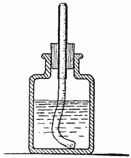
(alcohol lamp)
To make such a lamp, procure a small wide-mouthed bottle so that very little alcohol will be necessary and the lamp may be tipped at any desired angle. A short piece of seamless brass tubing should be procured, or, preferably, one of those capped brass cylinders for holding pencil leads, the button of which should be sawn off and the cap used to keep the alcohol from evaporating. A good, sound cork is next in order, and in cutting the central hole, use the brass tube, which should be sharpened around the lower end. Proceed with a rotary motion, and a clean core will be removed. If an ordinary lamp wick is not at hand, soft cotton string may be bundled up as a substitute. Such a lamp is safe, odorless and will not blacken the work in the least as in the case of kerosene or gasoline.
There are many good soldering fluxes on the market, but that obtained by dissolving as much scrap of zinc as possible in muriatic acid will solder practically everything that may be necessary, provided, of course, the surfaces are filed or scraped bright. Wire solder is usually the most convenient, as small pieces can be readily cut off and placed directly on the work where required. A small blowpipe is often a valuable adjunct, as it makes possible a long, narrow flame that may be directed in almost any direction.

A Small Torch Made of a Penholder is Handy to Use in Soldering Electrical Apparatus
Where numerous small connections are to be made, as is often the case with electrical apparatus, the small torch illustrated will be found very convenient. It is simply an old penholder with the wood portion shortened somewhat and the metal end filed off square and cleaned out. This is then filled with wicking, and it is only necessary to dip it in alcohol in order to soak up enough to solder an ordinary connection.
The second simple process, of which many fail to appreciate the usefulness in experimental work, is that of riveting—particularly when done on a small scale. Very often the material in hand is tempered steel and cannot, therefore, be soldered to advantage, or it may be a case where subsequent heating makes a heat-proof connection imperative. Then, again, the joint may require the combined strength of both solder and rivet.
When properly set, the strength of the ordinary brass pin, when used as a rivet, is quite great. Should the work require a particularly soft rivet, it is only necessary to hold the pin for a moment in the flame of a match. A somewhat larger and stronger rivet may be made by softening and cutting to the required length the small flat-headed nails used in making cigar boxes. The ordinary shingle nail is also of a suitable shape after the burrs have been filed off under the head.
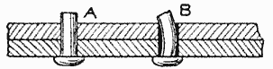
In setting these small rivets, it is absolutely necessary that they closely fit the holes, as at A, otherwise the result will be as indicated at B in the sketch. Be careful not to leave too great a length for rounding over on the metal. This extra length should approximately equal the diameter of the rivet and must be filed flat on the top before riveting. In case of pins, it will be found easier to cut them off to the proper length after they are inserted. Use the smallest hammer available, striking many light blows rather than a few heavy ones.
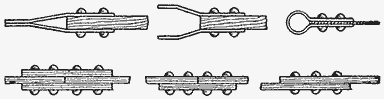
A Few Joints Where Rivets are Used to Hold the Parts Solidly Together
A Whistle
Cut a circular piece of tin any convenient size, preferably 3 in. in diameter, and bend it across the diameter so that it will be in a narrow U-shape. Then drill or punch a hole through both parts as shown. Place it in the mouth with the open edges out, being sure to press the lips on the metal tightly on both upper and lower pieces outside of the holes and to rest the tongue against the edge of the tin, even with the holes, and blow.
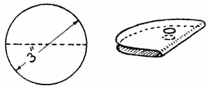
The result of the first attempt may not be a sound, but with a little practice any familiar tune may be whistled.—Contributed by Chas. C. Bradley, W. Toledo, O.
Card-and-Coin Trick
If a card is balanced on the finger and a coin placed on the card directly over the finger, one would not think that the card could be flipped out leaving the coin on the finger end. This is easily accomplished, if care is taken to snap the card sharply and squarely.—Contributed by R. Neland, Minneapolis, Minn.
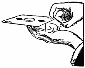
How to Make a Costumer
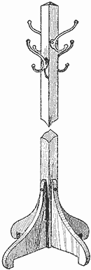
With but little skill, and such tools as are ordinarily found around a home, a plain but serviceable costumer can be made, as shown in the sketch. The necessary materials for it are: One main post, 1-1/2 in. square and about 6-1/2 ft. long; four legs, or foot brackets, 3/4 by 6 by 9 in.; four brass clothes hooks, and the necessary screws and varnish for assembling and finishing.
The center post should be chamfered at the top to relieve the abruptness. The four legs should all be made alike and in some shape that allows them to be fastened to the post in a simple manner. In the sketch, the legs are fastened to the post by one visible screw at the top and one put in on an incline through the bottom edge of the leg. The clothes hooks are fastened to the post in pairs at different heights, thereby preventing the screws of adjacent hooks from running into one another. The finish of the costumer should be such as to match the woodwork of its surroundings.—Contributed by Harry A. Packard, Norway, Maine.
Window Catch Used for Locking an Extension Table
To prevent the two ends of an extension table from pulling apart when not desired, an ordinary window catch can be fastened and locked in place to the under side of the table top with one part on each end of the table. If but one catch is used and fastened in the center, it is best to mark it off first, and then pull the table ends apart to fasten the catch more easily. It may be desired to use two catches for a very heavy table, in which case it would be best to place one on either side of the center.—Contributed by F. M. Griswold, New York, N. Y.
Relieving Pressure on Heated Canned Foods for Opening
In opening a can of food that has been heated, the instant the cover is punctured the steam will force out a part of the contents, which is very annoying. To avoid this, pour a little cold water on the cover and allow it to remain a few seconds, then turn it off and immediately puncture the cover. This will counteract the interior force, and the can may be opened without trouble.—Contributed by Joseph Kohlbecher, Jr., San Francisco, Cal.
Clothespin Bag
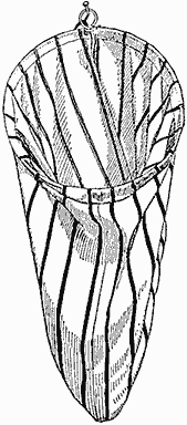
Clothespins are usually kept in a bag, and the one our home possessed had a draw string which would always stick and hold the bag shut. The remedy for this, and a time saver also, was to remove the draw string and insert instead a piece of wire, which was afterward shaped to a circle with an eyelet at the joint. The bag can be hung on a nail and the mouth is always open to its fullest extent, yet lies flat against the wall.—Contributed by Jas. A. Hart, Philadelphia, Pa.

Snowshoes: How to Make and Use Them By Stillman Taylor — Part II—Making the Shoe
[In making the snowshoe it may be necessary to refer to the previous chapter to select the style, or to locate the name of the parts used in the description.—Editor.]
Snowshoe making is an art, and while few, if any, white men can equal the Indian in weaving the intricate patterns which they prefer to employ for filling the frames, it is not very difficult to fashion a good solid frame and then fill it by making use of a simple and open system of meshing. For the frames, white ash is much the best wood, but hickory and white birch are dependable substitutes, if the former cannot be obtained. Birch is perhaps the best wood to use when the sportsman wishes to cut and split up his own wood, but as suitable material for the frames may be readily purchased for a small sum, probably the majority of the readers will elect to buy the material. Any lumber dealer will be able to supply white ash, and it is a simple matter to saw out the frames from the board. The sawed-out frame is inferior to the hand-split bow, but if good, selected material can be obtained, there will be little, if any, difference for ordinary use.
When dry and well-seasoned lumber is used, the frame may be made to the proper dimensions, but when green wood is selected, the frame must be made somewhat heavier, to allow for the usual shrinkage in seasoning. For a stout snowshoe frame, the width should be about 1-1/16 in.; thickness at toe, 7/16 in., and thickness at heel, 9/16 in. The frame should be cut 2 in. longer than the finished length desired, and in working the wood, remember that the toe of the finished frame will be the center of the stick; the heel, the end of the stick, and the center of the shoe will lie halfway between the heel and toe.

The Design of the Snowshoe is Traced on a Board, and Blocks are Used to Shape the Frame or Bow
After the frames have been finished, the dry wood must be steamed before it can be safely bent to the required shape, and before doing this, a wooden bending form must be made. An easy way to make this form is to first draw a pattern of the model on a sheet of paper, cut out the pencil mark, and, placing this pattern on a board, carefully trace the design on the wooden form. A number of cleats, or blocks, of wood will now be needed; the inside blocks being nailed in position, but the outside stay blocks being simply provided with nails in the holes, so they may be quickly fastened in position when the steamed frame is ready for the form.
To make the frame soft for bending to shape, steaming must be resorted to, and perhaps the easiest way of doing this is to provide boiling water in a wash boiler, place the wood over the top, and soak well by mopping with the boiling water, shifting the stick about until the fibers have become soft and pliable. After 10 or 15 minutes of the hot-water treatment, wrap the stick with cloth and bend it back and forth to render it more and more pliable, then use the hot-water treatment, and repeat the process until the wood is sufficiently soft to bend easily without splintering. The toe being the greatest curve, must be well softened before putting on the form, otherwise the fibers are likely to splinter off at this point. When the frame is well softened, place it on the bending form while hot, slowly bend it against the wooden inside blocks, and nail on the outside blocks to hold it to the proper curve. Begin with the toe, and after fastening the outside blocks to hold this end, finish one side, then bend the other half to shape. The bent frame should be allowed to dry on the form for at least a week; if removed before the wood has become thoroughly dry and has taken a permanent set, the frame will not retain its shape. The same bending form may be used for both frames, but if one is in a hurry to finish the shoes, two forms should be made, and considerable pains must be taken to make them exactly alike in every way.
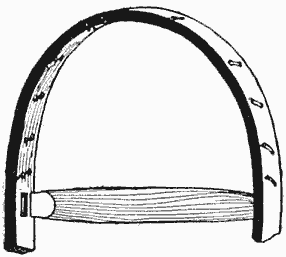
Locate the Cross Bars by Balancing the Frame, Then Fit the Ends in Shallow Mortises
When the frames are dry, secure the tail end of the frame by boring three holes about 4 in. from the end, and fasten with rawhide. The work of fitting the two cross bars may now be undertaken, and the balance of the snowshoe depends upon fitting these bars in their proper places. Before cutting the mortise, spring the two bars in the frame about 15 in. apart, and balance the shoe in the center by holding it in the hands. When the frame exactly balances, move the bars sufficiently to make the heel about 3 oz. heavier than the toe, and mark the place where the mortises are to be cut. The cross bars and mortise must be a good tight fit, and a small, sharp chisel will enable the builder to make a neat job. It is not necessary to cut the mortise very deep; 1/4 in. is ample to afford a firm and snug mortised joint.
The lanyard to which the filling is woven is next put in, by boring pairs of small holes in the toe and heel sections, and lacing a narrow rawhide thong through the obliquely drilled holes. Three holes are then bored in the cross bar—one on each side about 1-1/2 in. from the frame, and the third in the center of the bar; the lanyard being carried through these holes in the cross bar.

Begin Weaving the Toe Filling at the Corner of Cross Bar and Frame, Carrying It Around in a Triangle until Complete
Begin the toe filling first, by making an eye in one end of the thong, put the end through the lanyard loop and then through the eye, thus making a slipknot. Start to weave at the corner where the bar and frame are mortised, carry the strand up and twist it around the lanyards in the middle of the toe, then carry it down and make a like twist around the lanyard loop in the opposite corner. The thong is now looped around the next lanyard (No. 2 from the crossbar lanyard) and fastened with the twisted loop knot illustrated. Continue the strand across the width of toe space and make a similar loop knot on No. 2 lanyard on the starting side, twist it around the strand first made and loop it under the next cross-bar lanyard loop, then carry it up and twist it around the lanyard loop in the toe of the frame, continuing in the same manner until the last lanyard of the toe is reached, when the space is finished by making the twisted loop knot until the space is entirely filled. It is a difficult matter to describe by text, but the illustrations will point out the correct way, and show the manner of making an endless thong by eye-splicing, as well as illustrating the wooden bodkin or needle used in pulling the woven strands taut. This bodkin is easily made from a small piece of wood, about 1/4 in. thick, and about 2 in. long. To simplify matters, the heel may be filled in the same manner as the toe.
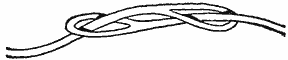
An Endless Thong is Made with Eyes Cut in the Ends of the Leather, and Each Part is Run through the Eye of the Other
For the center, which must be woven strong and tight, a heavier strand of hide must be used. Begin with the toe cord first, and to make this amply strong, carry the strand across the frame five or six times, finishing with a half-hitch knot, as shown, then carry it up and twist it around the cross bar to form the first toe-cord stay.

The Heel Filling is Woven by Making the Connection with the Lanyard in the Same Manner as for the Toe Filling
As may be noted, the center section is filled by looping back and twisting the strands as when filling the toe. However, the filling is looped around the frame instead of a lanyard, and a clove hitch is used. A toe hole, 4 in. wide, must be provided for, and when enough of the filling has been woven in to make this opening, the thong is no longer looped around the cross bar, but woven through the toe cord. As the filling ends in the toe cord, it should be woven in and out at this point several times, finishing the toe hole by looping a strand around the cross bar at the side of the toe hole, then passing it down the toe-cord stay by twisting around it; then twisted around the toe cord along the filling to the other side of the toe hole, where it is twisted around the toe-cord stay on the opposite side, looped around the frame and ended in a clove hitch.

The Center must be Woven Strong and Tight, and for This Reason a Heavier Strand of Hide must be Used
At the first reading, it will doubtless appear difficult, but a careful examination of the illustrations will soon show how the trick is done, and indeed it is really a very simple matter, being one of those things which are easier to do than it is to tell how to do them. The method of filling has been purposely made simple, but the majority of shoes are filled in practically the same manner, which answers quite as well as the more intricate Indian design.
The knack of using the snowshoe is quickly mastered, providing the shoes are properly attached, to allow the toe ample freedom to work down through the toe hole as each foot is lifted. The shoe is, of course, not actually lifted in the air, but rather slid along the surface, half the width of one shoe covering the other when it is lifted in the act of walking. At first the novice may be inclined to think snowshoes a bit cumbersome and unwieldy, and doubt his ability to penetrate the brush. However, as the snowshoer becomes accustomed to their use, he will experience little if any difficulty in traveling where he wills. When making a trail in a more or less open country, it is a good plan to blaze it thoroughly, thus enabling one to return over the same trail, in case a fall of snow should occur in the meantime, or drifting snow fill up and obliterate the trail first made. When the trail is first broken by traveling over it once by snowshoe, the snow is packed well and forms a solid foundation, and even should a heavy fall of snow cover it, the blaze marks on tree and bush will point out the trail, which will afford faster and easier traveling than breaking a new trail each time one journeys in the same direction.
A well-made pair of snowshoes will stand a couple of seasons' hard use, or last for a year or two longer for general wear. To keep them in good shape, they should be dried out after use, although it is never advisable to place them close to a hot fire, or the hide filling will be injured. Jumping puts severe strain on the frame of the shoe, and while damage may not occur when so used in deep, soft snow, it is well to avoid the possibility of breakage. Accidents will now and then happen, to be sure, and as a thong may snap at some unexpected moment, keep a strand or two of rawhide on hand, to meet this emergency.
Combination Settee Rocker and Cradle
By fastening a frame with hinges to the front of a settee rocker, a combination piece of furniture can be made, which may be used either as a regular settee or as a cradle. For this purpose, a covered frame should be provided, being sufficiently long to extend across the front between the arm supports and having such a width that it will easily fit under the arms when hinged to the seat, as shown in the illustration. To keep the frame in position while serving as a cradle front, or when turned down for regular use, screw hooks are placed at each end, so that, in the former case, the frame, when swung up, can be secured in place by attaching the hooks to screw eyes fastened under the arm supports; while, for regular use, the frame is secured in its swung-down position by fastening the hooks into screw eyes properly placed in the front legs.—Contributed by Maurice Baudier, New Orleans, La.
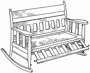
A Settee Rocker with a Front Attachment to Make It into a Cradle When Desired

A Snowball Thrower By Albert Bates, Jr.
The snow fort with its infantry is not complete without the artillery. A set of mortars, or cannon, placed in the fort to hurl snowballs at the entrenched enemy makes the battle more real. A device to substitute the cannon or a mortar can be easily constructed by any boy, and a few of them set in a snow fort will add greatly to the interest of the conflict.

The Dimensioned Parts and the Detail of the Completed Snowball Thrower
The substitute, which is called a snowball thrower, consists of a base, A, with a standard, B, which stops the arm C, controlled by the bar D, when the trigger E is released. The tripping of the trigger is accomplished by the sloping end of D on the slanting end of the upright F. Sides, G, are fastened on the piece F, with their upper ends extending above the bar D, to prevent the latter from jumping out when it is released by the trigger.
The trigger E is tripped with the handle H, connected to the piece J, on which all the working parts are mounted. The upper end of the arm C has a piece, K, to which is attached a tin can, L, for holding the snowball to be thrown. A set of door springs, M, furnishes the force to throw the snowball.
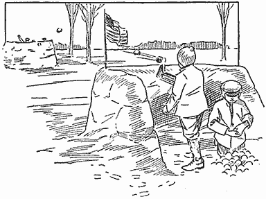
Cannonading a Snow Fort with the Use of a Snowball Thrower
All the parts are given dimensions, and if cut properly, they will fit together to make the thrower as illustrated.
Springs on the Chains of a Porch Swing
Two coil springs of medium strength placed in the chains of a porch swing will make it ride easier and also take up any unpleasant jars and rattles occasioned when a person sits heavily in the swing. If the swing is provided with a four-chain suspension, the springs should be used on the two rear chains to get the best results.—Contributed by E. K. Marshall, Oak Park, Illinois.
Homemade Water Meter
Where it is necessary to measure water in large quantities the meter illustrated will serve the purpose as well as an expensive one, and can be made cheaply. The vessel, or bucket, for measuring the water is made diamond-shaped, as shown in Fig. 1, with a partition in the center to make two pockets of a triangular shape, each holding 2 qt., or any amount of sufficient size to take care of the flow of water.

When a Bucket is Filled to the Proper Amount It is Turned Out by the Weight (Fig. 1, Fig. 2, Fig. 3)
The part forming the pockets is swung on an axis fastened to the lower part, which engages into bearings fastened to the sides of the casing, as shown in Fig. 2. Stops, A, are placed in the casing at the right places for each pocket to spill when exactly 2 qt. of water has run into it. It is obvious that when one pocket is filled, the weight will tip it over and bring the other one up under the flow of water.
The registering device consists of one or more wheels worked with pawls and ratchets, the first wheel being turned a notch at a time by the pawl B, Fig. 3. If each pocket holds 2 qt., the wheel is marked as shown, as each pocket must discharge to cause the wheel to turn one notch. The second wheel is worked by the lever and pawl C, which is driven with a pin D located in the first wheel. Any number of wheels can be made to turn in a like manner.—Contributed by F. A. Porter, Oderville, Utah.
A Snowball Maker
Snowball making is slow when carried on by hand, and where a thrower is employed in a snow fort it becomes necessary to have a number of assistants in making the snowballs. The time of making these balls can be greatly reduced by the use of the snowball maker shown in the illustration.

A Device for Making Snowballs Quickly and Perfectly Spherical in Shape
The base consists of a board, 24 in. long, 6-1/2 in. wide, and 1 in. thick. A block of wood, A, is hollowed out in the center to make a depression in the shape of a hemisphere, 2-1/2 in. in diameter and 1-1/4 in. deep. This block is nailed to the base about 1 in. from one end. To make the dimensions come out right, fasten a block, B, 6 in. high, made of one or more pieces, at the other end of the base with its back edge 14-1/2 in. from the center of the hemispherical depression. On top of this block a lever, C, 20 in. long is hinged. Another block, D, is made with a hemispherical depression like the block A, and fastened to the under side of the lever, so that the depressions in both blocks will coincide. The lever end is shaped into a handle.
Two uprights, E, are fastened to the back side of the block A as guides for the lever C. A piece is fastened across their tops, and a spring is attached between it and the lever. A curtain-roller spring will be suitable.
In making the balls a bunch of snow is thrown into the lower depression and the lever brought down with considerable force.—Contributed by Abbott W. France, Chester, Pa.
An Inexpensive Bobsled
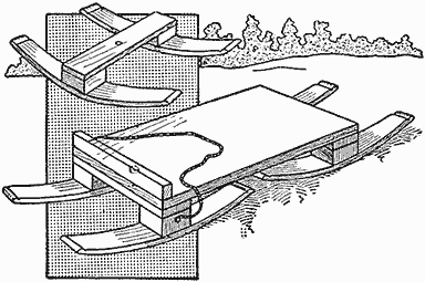
A Bobsled of Simple Construction Using Ordinary Barrel Staves for the Runners
Any boy who can drive a nail and bore a hole can have a bobsled on short notice. The materials necessary are four good, solid barrel staves; four blocks of wood, 4 in. long, 4 in. wide, and 2 in. thick; two pieces, 12 in. long, 4 in. wide, and 1 in. thick; one piece, 12 in. long, 2 in. wide, and 1-3/4 in. thick; and a good board, 4 ft. long, 12 in. wide, and 1 in. thick.
The crosspieces and knees are made with the blocks and the 1-in. pieces, 12 in. long, as shown; to which the staves are nailed for runners. One of these pieces with the runners is fastened to one end of the board, the other is attached with a bolt in the center. The 1-3/4 by 2-in. piece, 12 in. long, is fastened across the top of the board at the front end. A rope fastened to the knees of the front runners provides a means of steering the sled.
The sled can be quickly made, and it will serve the purpose well when an expensive one cannot be had.—Contributed by H. J. Blacklidge, San Rafael, Cal.
Motor Made of Candles
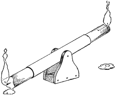
Tallow Dripping from the Ends Alternately Lessens the Weight of the Arms and Causes the Tube to Tip
A tube of tin, or cardboard, having an inside diameter to receive a candle snugly, is hung on an axle in the center that turns in bearings made of wood. The construction of the bearings is simple, and they can be made from three pieces of wood as shown. The tube should be well balanced. Pieces of candle are then inserted in the ends, also well balanced. If one is heavier than the other, light it and allow the tallow to run off until it rises; then light the other end. The alternate dripping from the candles will cause the tube to tip back and forth like a walking beam. It will keep going automatically until the candles are entirely consumed.—Contributed by Geo. Jaques, Chicago.
Kettle-Handle Support
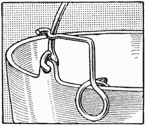
The handle of a kettle lying on the kettle rim will become so hot that it cannot be held in the bare hand. To keep the handle fairly cool it must be supported in an upright position. To do this, form a piece of spring wire in the shape shown, and slip it over the kettle rim. The shape of the extending end will hold the handle upright and away from the heat.
How to Make a Monorail Sled
A monorail sled, having a simple tandem arrangement of the runners, is very easily constructed as follows: The runners are cut from 1-in. plank of the size and shape given in the sketch, and are shod with strap iron, 1 in. wide and 1/4 in. thick. Round iron or half-round iron should not be used, as these are liable to skid. The square, sharp edges of the strap iron prevent this and grip the surface just as a skate.
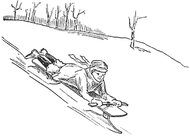
An Exhilarating Glide Accompanied by a Buoyant Sense of Freedom Only Obtained in the Monorail Type
The top is a board 6 ft. long and 1 in. thick, securely fastened to the runners as follows: Blocks are nailed, or bolted, on either side of the upper edge of the rear runner and the top is fastened to them with screws. The runner is also braced with strap iron, as shown. The same method applies to the front runner, except that only one pair of blocks are used at the center and a thin piece of wood fastened to their tops to serve as the fifth wheel.

The Construction is Much More Simple Than Making a Double-Runner Bobsled
The hole for the steering post should be 6 in. from the front end and a little larger in diameter than the steering post. The latter should be rounded where it passes through the hole, but square on the upper end to receive the steering bar, which must be tightly fitted in place.
In coasting, the rider lies full length on the board with his hands on the steering bar. This makes the center of gravity so low that there is no necessity for lateral steadying runners, and aside from the exhilarating glide of the ordinary sled, the rider experiences a buoyant sense of freedom and a zest peculiar to the monorail type. Then, too, the steering is effected much more easily. Instead of dragging the feet, a slight turn of the front runner with a corresponding movement of the body is sufficient to change the direction or to restore the balance. This latter is, of course, maintained quite mechanically, as everyone who rides a bicycle well knows.—Contributed by Harry Hardy, Whitby, Ont.
Binding Magazines
To bind magazines for rough service, proceed as follows: Place the magazines carefully one on top of the other in order, and space the upper one, near the back edge, for two rivets, marking off three equal distances, or, perhaps, the center space longer than the other two. Make two holes through all the magazines on the marks with an awl, or drill, then drive nails of the right length through them. Use small washers on both ends of the nails under the head and at the point, which is cut off and riveted over. This makes a good, serviceable binding for rough use.—Contributed by Carl W. Lindgreen, Los Angeles, Cal.
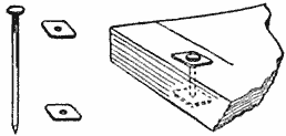
A Shellac Cement
As shellac is the basis of almost all cements, a good cement can be made by thickening shellac varnish with dry white lead. The two may be worked together on a piece of glass with a putty knife.

A Blackboard for Children
Take a wide window shade and attach it to a roller as if hanging it to a window. Cut it to about 3 ft. in length, hem the lower edge and insert in the slot in the usual manner. Procure some black slate paint and cover the shade on one side, giving it two coats. Allow sufficient time for the first coat to dry before applying the second coat.
A blackboard of this kind is strong, and if attached to the wall with the shade fixtures, it can be rolled out of the way when not in use.—Contributed by Elizabeth Motz Rossoter, Colorado Springs, Col.
How to Make a Ski Staff
A ski staff will greatly assist progress over level stretches and is an aid to the ski runner in preserving his balance. A homemade staff that is easy to construct is shown in Fig. 1. At the upper end is a narrow leather loop for the wrist; at the extreme lower end a spike is placed for use on icy ground, and just above this spike is a disk, or stop, which, in deep snow, prevents the staff from sinking in too far and gives the necessary leverage for steering, propelling or righting oneself as needed.
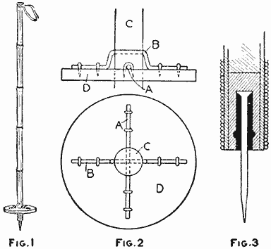
The Staff, being Made of a Bamboo Pole, is Strong as Well as Light (Fig. 1, Fig. 2, Fig. 3)
The staff is made of a piece of bamboo pole, 1-1/4 or 1-1/2 in. in diameter, and 4-1/2 ft. long. The leather for the loop can be made from an old strap, shaved down thinner and cut to a width of about 1/2 in. The stop is a disk of wood, 1/2 in. thick and 5 in. in diameter. This material should be well-seasoned white pine or spruce and coated with shellac. A hole is bored through the center of the disk to let it pass upward on the staff about 6 in. Here it is fastened with two pieces of heavy wire, A and B, Fig. 2. In this diagram, C is the staff, and D, the stop or disk. The wire A passes through the staff below the wire B and at right angles to it, wherefore the wire B must be bent as shown. Both wires are fastened to the stop with staples.
The lower end of the staff, as shown in Fig. 3, is plugged with hard wood, which is bored part way through its center to admit a wire spike. Slight recesses are made in the sides of this hole to anchor the lead which is poured in around the spike. The point of the latter is sharpened and then the bamboo wound with waxed twine, or fine wire, to prevent its splitting.
Fine emery cloth, glued to both sides of a piece of bristol board, makes a handy tool for cleaning the platinum points of a vibrator.
A Game Played on the Ice
A novel and interesting winter game for young and old, described as a novelty by a Swedish paper, is played as follows:

A Player in Action Ready to Spear a Ring that Hangs on the Line between the Poles
Two poles of convenient height are erected on the ice; if skating on a shallow pond they may be driven through the ice and into the ground, but if the water is deep, holes must be bored through the ice and the poles will soon freeze solidly in them. A rope is stretched between the poles at such a height as is suited to the size of the players, or as agreed on to make the game more or less difficult, and on this are strung a number of pieces of board, A, each having a ring of spring steel, B, attached to its lower end. The purpose of the game is to run at good speed between the poles and catch a ring on a spear, each player being entitled to make a certain number of runs, and the winner being the one who can catch the most rings.
The spears may be made of broom handles tapered toward one end, and with a shield made of tin and attached at a suitable distance from the thicker end (Pattern C). The line is fastened at the top of one pole and run through a pulley, D, at the top of the other, thence to a weight or line fastener. Each player should start from the same base line and pass between the poles at such a speed that he will glide at least 100 ft. on the other side of the poles without pushing himself forward by the aid of the skates. Twenty runs are usually allowed each player, or 10 players may divide into two parties, playing one against the other, etc. An umpire will be needed to see that fair play is maintained and settle any disputes that may arise.
An Electric Display for a Show Window
A novel window display that is very attractive, yet simple in construction and operation, can be made in the following manner: First, make a small watertight chamber, A, as long as the focal length of the lens to be used, and having a glass window, B, at one end, and a small round opening, C, at the other. In this opening is placed a cork through which a glass tube about 2 in. long is inserted. The tube makes a smooth passage for the stream of water flowing out of the box. Water from any source of supply enters the chamber through the tube D, which may be a pipe or hose, whichever is most convenient. The interior is painted a dull black.
A convenient and compact light is placed at the window end of the box. A very good light can be made by placing an electric light with a reflector in a closed box and fastening a biconvex lens, F, in the side facing the window of the water box. When the electric light and the water are turned on, the light is focused at the point where the water is issuing from the box, and follows the course of the stream of water, illuminating it in a pleasing manner.
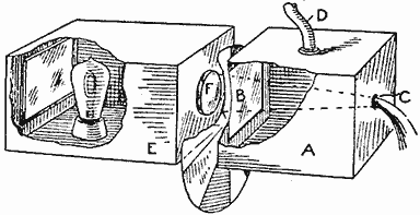
The Arrangement of the Boxes Showing the Path of the Light Rays through the Water
A still better effect can be obtained by passing colored plates between the lens F and the window B. A glass disk with sectors of different colors may be revolved by any source of power, such as a small electric motor or even a waterwheel turned by the flowing water.
Two or three streams of water flowing in different colors make a very pretty display and may be produced by using two or more boxes made up in the same manner. The apparatus should be concealed and nothing but the box end or tube with the flowing water shown.—Contributed by Grant Linton, Whitby, Ont.
Strainer for a Milk Pail
Even though a milker may be careful, small particles of dirt, hairs, etc., will fall into the milk pail. It is true that the milk is strained afterward, but a large percentage of the dirt dissolves and passes through the strainer along with the milk. The best plan to prevent this dirt from falling into the milk is to put a piece of cheesecloth over the pail opening, securing it there by slipping an open wire ring, A, over the rim. The milk will readily pass through the cloth without spattering.—Contributed by W. A. Jaquythe, Richmond, Cal.
Baking Bread in Hot Sand
A driving crew on the river wanted to move camp, but the cook objected as he had started to bake. One of the party suggested using a modified form of the method of baking in vogue more than a century ago, which was to place the dough in the hot earth where a fire had been burning. So, to help the cook out, a barrel was sawed in half and the bread, after being properly protected, was placed in each half barrel and covered with hot sand. Two of the men carried the half barrels on their backs. When the new camp was reached the bread was done.—Contributed by F. B. Ripley, Eau Claire, Wis.
How to Make Small Cams
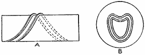
Channels of the Cams Formed with Strips of Brass Soldered to the Drum or Disk
In making models of machinery or toy machines, cams are very often required. A simple way of making these is to lay out the cam plate, or drum, and then bend pieces of brass to the correct shape and solder them in place, whereupon they may be smoothed up with a file or scraper. A cam of this sort on a drum is shown in the sketch at A, and on a faceplate, at B. The method is not quite as accurate as milling, but answers the purpose in most cases.—Contributed by Chas. Hattenberger, Buffalo, N. Y.
Display Holder for Coins
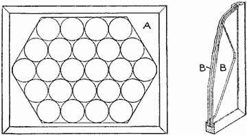
Two Pieces of Glass Inclosing between Them Coins of the Same Size and Thickness
If the luster of coins fresh from the mint is to be preserved, they must be immediately placed so as to be protected against contact with the hands. A good holder that will display both sides of a coin can be made of two pieces of glass, BB, between which is placed a cardboard cut as shown at A. The cardboard should be about the same thickness as the coins. The glass may be framed by using strips of wood rabbeted to receive the edges of both pieces; or their edges may be bound with passe-partout tape. Even when a frame is used, it is best to bind the edges as this will prevent tarnish from the air. Old negative glass is suitable for making the holder.—Contributed by R. B. Cole, New Haven, Conn.
Holder for Skates while Sharpening
The base of the holder is cut from a board and should be about 3 in. longer than the skate. Two clamps are cut as shown at A, from metal of sufficient thickness to hold the skate firmly, then bent to shape and attached to the baseboard with bolts having wing nuts, as shown at B and C.

The Holder Provides a Way to Grind a Slight Curve in the Edge of a Skate Blade
One edge of the board is provided with two pins, D and E, solidly fastened, which are of sufficient height to bring the center of the blade on a level with the grinder axle. An adjusting screw, F, is provided for the grinder base to adjust the skate blade accurately. The support G is for use on baseboards where skates with strap heels, H, are to be sharpened. The shape of the clamp for this support is shown at J.
When the skate is securely clamped to the base the blade can be easily "hollow ground" or given a slight curve on the edge.—Contributed by C. G. Smith, Brooklyn, N. Y.
A Homemade Direct-View Finder for Cameras
Every hand camera and most of the tripod cameras are equipped with finders of one type or another, and usually one in which the image of the field is reflected upward on a small ground glass—being, in fact, a miniature camera obscura. The later and generally more approved style of finder has a small concave lens conveniently set on the outer edge of the camera. When this direct-vision type of finder is used, the camera is held so that the finder is at the height of the eye, a condition that is particularly desirable. When in a crowd, of course, the professional and many amateurs are familiar with the method of holding the camera inverted over the head and looking up into the finder to determine the range of the field. Even this method is inconvenient, often impractical.
The up-to-date newspaper photographer insists on having his camera equipped with direct finders, as it saves him much trouble and many failures. Anyone with a little ingenuity can change one of the old-type finders into a combination device, either direct or indirect. The sketches are self-explanatory, but it may be said that Fig. 1 represents a box camera with a regulation finder set in one corner of the box. To make it a direct finder, a small brass hinge is used. Cut off part of one wing, leaving a stub just long enough to be attached to the front of the camera directly above the lens of the finder and so as not to interfere with it, and high enough to permit the other wing to be turned down on the ground glass, with space allowed for the thin glass mirror A, that is to be glued to the under side of the long wing. The joint of the hinge should work quite stiffly in order to keep it from jarring out of any position in which it may be set.
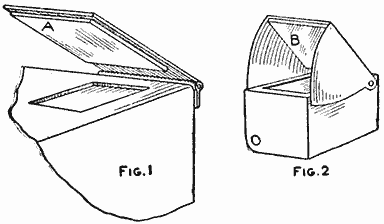
Two Types of Ordinary View Finders and Methods of Converting Them into Direct-View Finders
If the wing is turned upward at an angle of 45 deg., the finder can be used as a direct-vision instrument when held at the height of the eyes. The image reflected from the small mirror is inverted, but this is no disadvantage to the photographer. The small pocket mirror given out for advertising purposes serves very well for making the reflecting mirror.
The finder shown in Fig. 2 is another very common kind, and one that is readily converted into the direct type by inserting a close-fitting mirror, B, on the inside of the shield to be used as a reflector of the finder image. If the mirror is too thick, it may interfere with the closing of the shield, though in many cases this is not essential, but if it should be necessary to close down the shield in order to fold the camera, it can usually be readjusted to accommodate the mirror.
A Non-Rolling Spool
Bend a piece of wire in the shape shown in the illustration and attach it to a spool of thread. The ends of the wire should clamp the spool slightly and the loop in the wire will keep it from rolling. Place the end of the thread through the loop in the wire and it will not become tangled.—Contributed by J. V. Loeffler, Evansville, Ind.
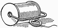
How to Make a Cartridge Belt
Procure a leather belt, about 2-1/2 in. wide and long enough to reach about the waist, also a piece of leather, 1 in. wide and twice as long as the belt. Attach a buckle to one end of the belt and rivet one end of the narrow piece to the belt near the buckle. Cut two slits in the belt, a distance apart equal to the diameter of the cartridge. Pass the narrow leather piece through one slit and back through the other, thus forming a loop on the belt to receive a cartridge. About 1/4 in. from the first loop form another by cutting two more slits and passing the leather through them as described, and so on, until the belt has loops along its whole length.

Two Pieces of Leather of Different Widths Forming a Belt for Holding Cartridges
The end of the narrow leather can be riveted to the belt or used in the buckle as desired, the latter way providing an adjustment for cartridges of different sizes.—Contributed by Robert Pound, Lavina, Mont.
Removing Iodine Stains
A good way to chemically remove iodine stains from the hands or linen is to wash the stains in a strong solution of hyposulphite of sodium, known as "hypo," which is procurable at any photographic-supply dealer's or drug store.
There is no danger of using too strong a solution, but the best results are obtained with a mixture of 1 oz. of hypo to 2 oz. of water.
Bed-Cover Fasteners
The arrangement shown in the sketch is easily made and will keep the bed covers in place. The covers are provided with eyelets, either sewed, A, or brass eyelets, B, 6 or 8 in. apart along the edge. A wood strip, C, 3 by 1-1/2 in., is cut as long as the width of the bed and fastened to the frame with wire, bolts, or wedges. Screwhooks, about 1-1/4 in. long, are turned into the strip so that they will match with the eyelets placed in the covers. Thus the covers will be kept in place when the bed is occupied, and the bed is also easily made up.—Contributed by Warren E. Crane, Cleveland, O.
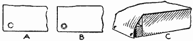
The Hooks Prevent the Covers from Slipping Off the Sleeper and Keep Them Straight on the Bed
Collar Fasteners
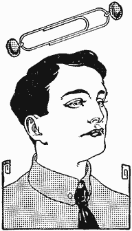
An excellent fastener to be used on soft collars can be assembled from an ordinary paper fastener and two shoe buttons of the desired color. This device keeps the soft collar in good shape at the front, and serves the purpose just as well as a more expensive collar fastener. The illustration shows how it is used.—Contributed by B. E. Ahlport, Oakland, Cal.
Operating a Bathroom Light Automatically
A device for automatically turning an electric light on and off when entering and leaving the room is illustrated in the sketch. A pull-chain lamp socket is placed upon the wall or ceiling, and is connected to a screw hook in the door by a cord and several rubber bands, as shown.
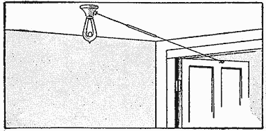
Operating the Electric Lamp Switch or Key by the Opening of the Door
When the door is opened, the lamp is lit, and when leaving the room the opening of the door again turns it out. The hook should be placed quite close to the edge of the door, to reduce the length of the movement, and even then it is too much for the length of the pull required to operate the switch, hence the need of the rubber bands.
The lamp chain pulls out just 1 in., and consequently the lamp is lit when the door is opened part way; and swinging the door farther only stretches the rubber. This is an advantage, however, because the lamp is sure to light regardless of the swing of the door. If no rubber were used, the door would have to open just a certain distance each time.
If the cord is connected to the hook with a loop or a ring, it may be easily disconnected during the day when not needed. A light coil spring may be used in place of the rubbers.—Contributed by C. M. Rogers, Ann Arbor, Michigan.
A Finger-Ring Trick
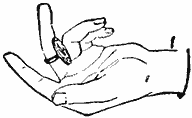
A coin soldered to some inexpensive ring, or a piece of brass cut from tubing, will make an interesting surprise coin for friends. The ring when placed on the middle finger with the coin in the palm makes the trick complete. Ask some one if he has ever seen such a coin, or say it is a very old one, as the date is almost worn away. He will try to pick it up, but will find it fast to the finger.—Contributed by Wm. Jenkins, New York City.
Preventing Marks from Basting Threads on Wool
In making up woolen garments it is necessary to press portions of them before removing the basting threads. Sometimes the marks of the basting threads show after the pressing. This can be avoided by using silk thread for basting instead of the usual cotton thread. The silk thread will not leave any marks.—Contributed by L. Alberta Norrell, Gainesville, Ga.
Cranberries will keep fresh for weeks if placed in water in a cool place.
Skating Merry-Go-Round By Henry Burich
After once making and using the ice merry-go-round as illustrated, no pond will be complete unless it has one or more of these devices. To construct an amusement device of this kind, select a good pole that will reach to the bottom of the pond. The measurement can be obtained by cutting a hole in the ice at the desired place and dropping in a line weighted on one end. A sufficient length of the pole should be driven into the bottom of the pond to make it solid and allow the upper end to project above the surface of the ice at least 4 feet.
A turning crosspiece for the upper end of the pole is made as follows: First prepare the end of the pole by sawing it off level, then cutting off the bark and making it round for a metal ring which should be driven on tightly. A pin, about 3/4 in. in diameter, is then driven into a hole bored in the end of the pole. The crosspiece is made of 2 by 6-in. material, at least 18 ft. long. A hole is bored in the center to receive the pin in the pole end.

Skaters Holding the Rope Ends are Drawn Around in a Circle Rapidly by the Revolving Crosspiece, Turned near the Center by Other Skaters
The crosspiece is easily pushed around the pole and the faster it goes the closer to the center the pushers can travel. Ropes can be tied to the ends of the crosspiece for the skaters to hold on to as they are propelled around in a circle.
Relieving Air Pressure When Closing Record Boxes
The ordinary pasteboard boxes for holding phonograph records are very hard to close, due to the air pressure on the inside. I overcome this difficulty by making three small holes in the cover with a pin.—Contributed by Robert Bandul, New Orleans, La.
A Steering Sled
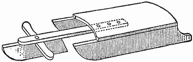
The Extra Runner in Front is Pivoted, and When Turned, Guides the Sled
An ordinary hand sled can be easily converted into a sled that can be guided like a bobsled by the addition of one extra runner. To attach this runner, a piece of wood is fastened to the under side and in the center at the front end of the sled top. A runner with a crosspiece on top is pivoted to the extending wood piece, which should be of a length to make the position comfortable when the coaster, sitting on the sled top, has his feet on the ends of the crosspiece. Careful measurements should be made to have the lower edge of the runner on a level with or a little lower than the sled runners.
To Hold a Straw Hat on the Head
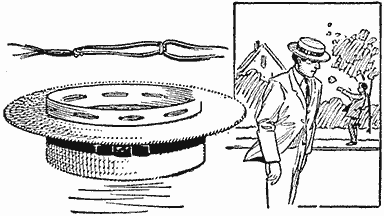
The Rubber Bands are Linked Like a Lock Stitch and Fastened in the Band
On windy days it is almost impossible to make a straw hat stay on the head. To avoid this trouble, place rubber bands through the sweatband. Before inserting, make them into loops, as shown, and draw enough to be comfortable to the head. This device will save a good many steps when the wind blows.—Contributed by T. D. Hall, Fort Worth, Texas.
Carrying Fishhooks in a Cane Pole
The person using a cane pole for fishing can easily provide a place for the hooks and sinkers in the first large joint of the pole. Cut the cane off just above the first large joint, and it will leave a space, 4 or 5 in. long, which can be used for the hooks and sinkers. A cork is fitted in the end, to hold them in place.—Contributed by Victor E. Carpenter, South Bend, Ind.
Drying Small Laundered Articles
Where mechanical drying is not in use it takes considerable time to hang out a number of handkerchiefs, laces, collars, etc., and very often the wind will blow away many of them. The task of drying these articles is made light by using a bag of mosquito netting with the articles placed in it and hung on a line. The air can pass through the netting and when the articles are dry it does not take long to take them out.—Contributed by Edward P. Braun, Philadelphia, Pa.
Decorative Wood Panels
Procure an unplaned board that is deeply scored by the teeth of the saw and mark an outline of the desired figure on its surface. Sandpaper the background lightly, cut in a moon and smooth down the tree trunks. The background can be smoothed with a sharp chisel, or large portions planed, but in all cases leave the foliage rough.
Finish the surfaces with oils or stains, applying colors to suit the parts; a piece of dried red cedar, oiled, will produce a warm red, and a green red cedar, oiled, becomes soft yellow, each producing a very pretty effect. These panels offer unlimited opportunity for originality in design and color finishing of different woods.—Contributed by Mrs. Wm. Donovan, Seattle, Wash.

The Designs are Worked into the Unfinished Surface of Boards with Sandpaper, Sharp Chisels and a Plane, and Then Colored with Dyes to Produce the Desired Effect
Fishing-Rod Making and Angling By Stillman Taylor Part I—A One-Piece Casting Rod — Kind of Material — The Necessary Tools — Five-Foot Bait-Casting Rod — Winding, or Whipping, the Rod — Varnishing the Rod
The pleasures of outdoor life are most keenly enjoyed by those sportsmen who are familiar with all the little tricks—the "ins and outs"—of the open. It is the active participation in any chosen sport which makes the sport well worth while, for the enjoyment gleaned from little journeys to forest and stream largely rests with the outer's own knowledge of his sport. Not all of the fun of fishing lies in the catching of the fish, since the satisfaction which comes through handling a well-balanced rod and tackle must be reckoned the chief contributor to the outing. In other words, the pleasures of fishing do not depend so much upon the number of fish caught, as the manner in which the person fishes for them. The rod is naturally the first and important consideration in the angler's kit, and it is the purpose of these articles to set forth, at first, a few hints which my own long experience leads me to think may be of some assistance to those anglers who enjoy making and repairing their own rods and tackle, to be followed, later, by some suggestions on the art of angling generally. The hints given are merely my own methods, and while they may not be the best way of accomplishing the desired end, a good fishing rod may be constructed. Like the majority of amateurs, I have achieved the desired results with a few common tools, namely, a saw, plane, jackknife, file, and sandpaper. These simple tools are really all that is needed to turn out a serviceable and well-finished rod of excellent action.
The great elasticity and durability of the split-cane or split-bamboo rod cannot be easily disputed. The handmade split bamboo is unquestionably the best rod for every kind of fishing, but it is also the most expensive and the most difficult material for the amateur to work. In making the first rod or two, the beginner will be better satisfied with the results in making a good solid-wood rod. Of course, glued-up split-bamboo butts, joints, and tip stock may be purchased, and if the angler is determined to have only bamboo, it is advisable to purchase these built-up sections rather than to risk certain failure by attempting to glue the cane. However, there are several good woods particularly well adapted for rod making, and while slightly inferior to the finest bamboo in elasticity and spring, the carefully made solid-wood rod is good enough for any angler and will probably suit the average fisherman as well as any rod that can be purchased.
Bethabara, or washaba, a native wood of British Guinea, makes a fine rod, but it is a heavy wood, very hard, and for this reason is perhaps less desirable than all other woods. With the single exception of snakewood it is the heaviest wood for rod making and is only used for short bait-casting rods. Possessing considerable strength Bethabara can be worked quite slender, and a 5-ft. casting tip can be safely made of 5 oz. weight.
Greenheart, a South American wood, is popular alike with manufacturers and amateur rod makers, and 90 per-cent of the better class of solid-wood rods are made of this material. It resembles Bethabara in color, but is lighter in weight, although it apparently possesses about the same strength and elasticity. In point of fact, there is little, if any, choice between these woods, and providing sound and well-selected wood is used, the merits of a rod made of Bethabara or greenheart are more likely to be due to the careful workmanship of the maker than to the variety of the wood used.
Dagame, or dagama, a native of the forests of Cuba, is in many respects the ideal material for rod making, as it has strength and elasticity. This wood is straight-grained and free from knots, which makes it easily worked; it polishes well and is durable. While there is always more or less difficulty about procuring first-class Bethabara and greenheart, dagame of good quality is easily obtained.
Lancewood is much used in turning out the cheaper grades of fishing rods, but it is somewhat soft and has a marked tendency to take set under the strain of fishing and warp out of shape. It is less expensive than the other woods, and while it has a straight and even grain, there are numerous small knots present which make this material less satisfactory to work than the other woods. For heavy sea rods, lancewood may serve the purpose fairly well, but for the smaller fishing tools this material is inferior to Bethabara, greenheart, and dagame. Other woods are often used, and while a good rod may be frequently made from almost any of them, the three mentioned are held in the highest esteem by the angling fraternity. For the first rod, the amateur will make no mistake in selecting dagame, whether the slender fly rod or the more easily constructed short bait-casting tool is to be made.
The construction of a thoroughly well-made and nicely balanced rod is more a matter of careful work than outfit, but a few suitable tools will greatly facilitate the labor. A good firm workbench, or table, 4 ft. or more in length, will be needed. A regulation bench vise will come in handy, but one of the small iron vises will do very well. A couple of iron planes, one of medium size for rough planing-up work, and a small 4-in. block plane for finishing, will be required. As the cutters of the planes must be kept as sharp as possible to do good work, a small oilstone—preferably one in a wood case with cover to keep out dust—will be needed; a coarse single-cut mill file about 16 in. long; a few sheets of No. 1 and No. 0 sandpaper; a sheet or two of fine emery cloth; a small thin "back" or other saw, and a steel cabinet scraper.
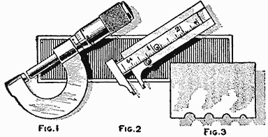
Two Tools for Gauging the Diameter of the Rods, and a Homemade Scraper (Fig. 1, Fig. 2, Fig. 3)
A caliper of some kind is a necessity, and while the best is a micrometer, Fig. 1, registering to a thousandth part of an inch, as well as indicating 8ths, 16ths, 32ds, and 64ths, this tool is somewhat expensive, but a very good caliper may be had in the sliding-arm type, Fig. 2, with the scale graduated to 64ths and taking work up to 2 in. in diameter. Cheaper measuring gauges are to be had in plenty, but as the brass and boxwood scales are provided only with coarse graduations, the better quality of mechanics' tools will give better satisfaction.
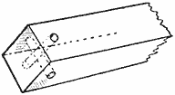
(Fig. 4)
The set of grooved planes used by the professional rod makers are rather expensive, although they are most convenient for quickly rounding up the rod to the desired diameter. However, the beginner may dispense with the planes by making the tool illustrated in Fig. 3. To make this handy little tool purchase a steel wood scraper, such as cabinetmakers use, and file a series of grooves along the edges with a round file. File at right angles to the steel, finishing up with a finer file to give a sharp cutting edge. The tool thus made is very handy for scraping the rod after it has been roughly rounded with the plane. Its use will be mentioned later on in the description.
The short one-piece bait-casting rod with but one ferrule is the easiest rod to make, and for this reason the beginner will do well to select this popular type for the first attempt. As the total length of the rod is to measure 5 ft., exclusive of the agate tip, the wood should be 1 or 2 in. longer to allow for cutting down to 60 inches.
Having selected a good strip of dagame, 5/8 in. square, run the plane along each side and from both ends. This will determine the direction in which the grain runs. Drill two holes at the end decided upon for the butt, spacing them about 1/4 in. from the end, as shown in Fig. 4. Drive a stout brad in the corner of the bench top and hook the butt end over the nail. By rigging the stick up in this manner it will be securely held, and planing may be done with the grain with greater ease and accuracy than when the end of the stick is butted up against a cleat nailed to the bench top.
The wood should be planed straight and true from end to end and calipered until it is 1/2 in. square. It may appear crooked, but this need not trouble one at this stage of the work, since it may be made perfectly straight later on. Overlook any kinks, and do not attempt to straighten the stick by planing more from one side than the other. The chief thing to be done is to fashion a square stick, and when the caliper shows the approximate diameter, draw crosslines at the ends to find the center.
The length of the hand grasp should be marked out. If a double grasp is wanted, allow 12 in. from the butt end. This will afford an 11-in. hand grasp after sawing off the end in which the holes were drilled. For a single hand grasp make an allowance of 11 in. However, the double grasp—with cork above and below the reel seat—is preferred by most anglers because it affords a better grip for the hand when reeling in the line. Mark the hand-grasp distance by running a knife mark around the rod 12 in. from the butt end.

Diagram or Layout for a One-Piece Bait-Casting Rod, Showing Calipered Dimensions for Each Six Inches of Length. A Paper Pattern of Any Rod may be Drawn Up, Providing the Amateur Rod Maker Has a Rod to Use for a Pattern, or Possesses the Exact Diameter of the Rod at Intervals of Six Inches along Its Length (Fig. 5)
Lay out a diagram showing the full length of the rod by placing a strip of paper—the unprinted back of a strip of wall paper is just the thing—on the bench and drawing two lines from the diameter of the butt to that of the tip. While the caliber of casting rods differs somewhat, the dimensions given will suit the average angler, and I would advise the beginner to make the rod to these measurements. For the butt, draw a line, exactly 1/2 in. long, across the paper and from the center of this line run a straight pencil mark at right angles to the tip end, or 60 in. distant, at which point another crossline is drawn, exactly 1/8 in. long, to represent the diameter. Connect the ends of these two crosslines to make a long tapering form. Divide this pattern into eight equal parts, beginning at 12 in. from the butt end, marking a crossline at every 6 in. This layout is shown exaggerated in Fig. 5. If it is desired to copy a certain rod, find the diameter at the several 6-in. stations with the caliper and write them down at the corresponding sections of the paper diagram. However, if a splendid all-around casting rod is desired, it is perfectly safe to follow the dimensions given in Fig. 5, which show the manner of dividing the paper pattern into the equal parts and the final diameter of the rod at each 6-in. station, or line.

Gauge Made of Sheet Brass Having Slots Corresponding in Length and Width with the Caliper-Layout Measurements (Fig. 6)
Procure a small strip of thin brass, or zinc, and file nine slots on one edge to correspond in diameter with the width of the horizontal lines which indicate the diameter of the rod on the pattern. This piece is shown in Fig. 6. By making use of the pattern and the brass gauge, the rod may be given the desired taper and the work will proceed more quickly than if the caliper is alone relied upon to repeatedly check up the work.
When a good layout of the work is thus made, the next step is to carefully plane the stick so that it will be evenly tapered in the square. Plane with the grain and from the butt toward the tip end, and make frequent tests with caliper and gauge, noting the diameter every 6 in. Mark all the thick spots with a pencil, and plane lightly to reduce the wood to the proper diameter. Reduce the stick in this manner until all sides have an even taper from the butt to the tip. The stick should now be perfectly square with a nice, even taper. Test it by resting the tip end on the floor and bending it from the butt end. Note the arch it takes and see if it resumes its original shape when the pressure is released. If it does, the elasticity of the material is as it should be, but if it remains bent or takes "set," the wood is very likely to be imperfectly seasoned and the rod should be hung up in a warm closet, or near the kitchen stove, for a few weeks, to season.
To facilitate the work of planing the stick to shape, a length of pine board with a groove in one edge will be found handy. A 5-ft. length of the ordinary tongue-and-groove board, about 1 in. thick, will be just the thing. As the tip of the rod is smaller than the butt, plane the groove in the board to make it gradually shallower to correspond to the taper of the rod. Nail this board, with the groove uppermost, to the edge of the workbench, and place the rod in the groove with one of the square corners up, which can be easily taken off with the finely set plane. Plane off the other three corners in a like manner, transforming the square stick into one of octagon form. This part of the work should be carefully done, and the stick frequently calipered at each 6-in. mark, to obtain the proper taper. It is important to make each of the eight sides as nearly uniform as the caliper and eye can do it. Set the cutter of the small plane very fine, lay the strip in the groove and plane off the corner the full length of the stick, then turn another corner uppermost and plane it off, and so on, until the stick is almost round and tapering gradually from the mark of the hand grasp to the tip.
To make the rod perfectly round, use the steel scraper in which the grooves were filed and scrape the whole rod to remove any flat or uneven spots, and finish up by sandpapering it down smooth.
The action of the rod differs with the material used, and in trying out the action, it is well to tie on the tip and guides and affix the reel by a string in order to try a few casts. If the action seems about right, give the rod a final smoothing down with No. 0 sandpaper.

The Four Different Types of Hand Grasps Are a Wood Sleeve Bored to Fit the Butt of the Rod; the Built-Up Cork over a Wood Sleeve; a Cane-Wound Grasp, and the Double Cord-Wound Grasps with a Reel Seat between Them (Fig. 7)
For the hand grasp nothing is so good as solid cork, and while hand grasps may be purchased assembled, it is a simple matter to make them. In Fig. 7 are shown four kinds of handles, namely, a wood sleeve, or core, A, bored to fit the butt of the rod and shaped for winding the fishing cord; a built-up cork grasp, B, made by cementing cork washers over a wood sleeve, or directly to the butt of the rod; a cane-wound grip, C, mostly used for salt-water fishing, and the double-wound grip, D, made in one piece, then sawed apart in the center, the forward grip being glued in place after the reel seat is in position.
To make a grip, select a number of cork washers, which may be obtained from dealers in the wholesale drug trade, or from any large fishing-tackle dealer. Make a tool for cutting a hole in their centers from a piece of tubing, or an old ferrule of the required diameter, by filing one edge sharp, then covering the other end with several thicknesses of cloth. Turn this tube around in the cork like a wad cutter. If the cutter is sharp, a nice clean cut will result, but the opposite will likely occur if an attempt is made to hammer the tube through the cork.
Having cut the butt end of the rod off square, about 1 in. from the end, or enough to remove the holes, smear a little hot glue on the end, drop a cork washer over the tip of the rod and work it down to the butt. Cut another cork, give the first one a coat of glue, slip the former over the tip and press the two together, and so on, until about 10 corks have been glued together in position. This will give a hand grasp a trifle over 5 in. long.
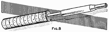
The Corks Glued in Place on the Butt and the Wood Sleeve, or Reel-Seat Core, Ready to Slide Down and Glue in Position (Fig. 8)
A sleeve will be needed for the reel seat to slip over, and a soft-wood core of this sort can be purchased from any dealer in rod-making materials, or it can be made at home. For the material procure a piece of white pine, about 3/4 in. in diameter and 5 in. long. A section sawed from a discarded curtain roller will serve the purpose well. Bore a 15/32-in. hole through the piece and plane down the outside until it slips inside the reel seat. It should be well made and a good fit, and one end tapered to fit the taper of the reel seat, while the opposite end should be about 1/4 in. shorter than the reel seat. Slide this wood sleeve down the rod, as shown in Fig. 8, coat the rod and the upper part of the last cork with glue and force the sleeve tightly in place. A day or two should be allowed for the glue to set and thoroughly dry, before giving the hand grasp the final touches.
If a lathe is at hand, the hand grasp may be turned to any desired shape, but most anglers prefer a cylindrical-shaped grip, leaving the top cork untrimmed to form a kind of shoulder when the metal reel seat is pressed into the cork. If corks of 1-1/4-in. diameter are purchased, but little trimming will be necessary to work the hand grasp down to 1-1/16 in. in diameter. This size seems to fit the average hand about right. The lower corks will need a little trimming to fit the taper of the butt cap so that it may fit snugly in place. Cement the butt cap in place by heating the cap moderately hot, then rub a little of the melted ferrule cement inside the cap, and force it over the cork butt. When the cement has hardened, drive a small brass pin or brad through the cap, and file the ends off flush with the metal surface. All the guides, ferrules, and reel seat are shown in Fig. 9.
The regulation metal reel seat is about 4-1/2 in. long, and in fitting it to the old type of bait rod, the covered hood is affixed to the upper end of the reel seat. This arrangement is satisfactory enough for the 9-ft. bait rod, but it is rather awkward in fitting it to the short bait-casting rod, as with the hood at the upper end the reel is pushed so far forward that it leaves 1 in. or more of the reel seat exposed, and the hand must grip this smooth metal instead of the cork. To avoid this, it is best to cut the reel seat down to 3-7/8 in. and affix the reel seat to the rod with the hood at the lower end near the hand. For a single hand grasp, a tapered winding check will be needed to make a neat finish and this should be ordered of the correct diameter to fit the reel seat at the lower end and the diameter of the rod at the other. In the double hand grasp the winding check is used to finish off the upper end of the cork, which is tapering to fit the rod at this point.
In assembling the reel seat, push it with the hooded end well down and work it into the cork to make a tight waterproof joint. Push the reel seat up the rod, coat the sleeve with cement and push the reel seat home. Drive a small pin through the hooded end and reel seat to make the whole rigid. This pin should not be driven through the rod or it will weaken it at this point. Just let it enter the wood a short distance to prevent the reel seat from turning.
The upper or double grasp is fashioned after the reel seat is in position, and the corks are cemented on and pushed tightly together in the same manner as used in forming the lower grasp. The first cork should be pressed tightly against the upper end of the reel seat and turned about so that the metal may enter the cork and form a tight joint. As many corks as are required to form a grip of proper length are in turn cemented to each other and the rod. After the glue has become dry, the cork may be worked down and tapered to make a smooth, swelled grasp. The winding check is now cemented on, to make a neat finish between the upper grip and the rod.
Before affixing the guides, go over the rod with fine sandpaper, then wet the wood to raise the grain, and repeat this operation, using old sandpaper. If an extra-fine polish is wanted, rub it down with powdered pumice and oil, or rottenstone and oil, and finish off with an oiled rag.
To fit the agate tip, file down the end of the rod with a fine-cut file until it is a good fit in the metal tube. Melt a little of the ferrule cement and smear a little on the tip of the rod, then push the agate down in place.
Spar varnish is often used to protect the rod, but extra-light coach varnish gives a better gloss, and it is as durable and waterproof as any varnish. It is only necessary to purchase a quarter pint of the varnish, as a very small quantity is used. The final varnishing is, of course, done after the rod has been wound and the guides are permanently whipped in position. However, it is an excellent idea to fill the pores of the wood by rubbing it over with a cloth saturated in the varnish before the silk whippings are put on. Merely fill the cells of the wood and wipe off all surplus, leaving the rod clean and smooth.
The guides may now be fastened in place, and for the 5-ft. rod, but two of them are necessary. The first guide should be placed 19-1/2 in. from the metal taper which finishes off the upper hand grasp, and the second guide spaced 15-1/2 in. from the first. By spacing the guides in this manner, the line will run through them with the least possible friction.
Before whipping on the guides, take a fine file and round off the sharp edges of the base to prevent the possibility of the silk being cut. Measure off the required distances at which the guides are to be affixed, and fasten them in position by winding with a few turns of common thread. Ordinary silk of No. A size may be used, but No. 00 is the best for small rods. Most anglers agree that the size of the silk to use for the whippings should be in proportion to the size of the rod—heavy silk for the heavy rod, and fine silk for the small rod. Size A is the finest silk commonly stocked in the stores, but one or more spools of No. 00 and No. 0 may be ordered from any large dealer in fishing tackle. As a rule, size 0 gives a more workmanlike finish to the butt and joints of fly and bait rods, while No. 00 is about right to use for winding the tips. In fact, all rods weighing up to 6 oz. may be whipped with No. 00 size.

The Mountings Used on a Bait-Casting Rod Consist of a Reel Seat, Butt Cap, Taper Sleeve, Narrow Agate Guide, Agate Offset Top, One Ring Guide, and a Welted, Shouldered Ferrule (Fig. 9)
In whipping the rod, the so-called invisible knot is used. Begin the whipping, as shown at E, Fig. 10, by tucking the end under the first coil and holding it with the left thumb. The spool of silk is held in the right hand and the rod is turned to the left, sufficient tension being kept on the silk so that it can be evenly coiled with each strand tightly against the other. A loop of silk, some 4 in. long, is well waxed and placed so that its end will project a short distance beyond the last coil which finishes the whipping. This detail is shown at F. In whipping on guides, begin the whipping at the base and work over the pointed end of the flange, winding on sufficient silk to extend about 1/8 in. beyond the pointed flange of the guide base. When the last coil is made, cut off the thread from the spool and tuck the end under the whipping by pulling on the ends of the waxed loop, as shown at G. Cut off the ends neatly with a sharp knife.
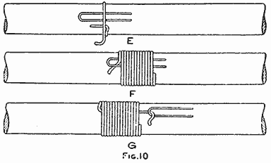
Both Ends of the Silk Thread are Placed under the Winding to Form an Invisible Knot (Fig. 10)
For colors, bright red and a medium shade of apple green are the best, since these colors keep their original tint after varnishing, and are less likely to fade than the more delicate shades. Red finished off with a narrow circle of green always looks well, and red with yellow is likewise a good combination. Narrow windings look much better than wide whippings, and a dozen turns make about as wide a winding as the angler desires. For edgings, three or four turns of silk are about right, and these should be put on after the wider windings have been whipped on and in the same manner, although it is best to tuck the ends of the edging beneath the wider winding when pulling the end through to make the invisible knot.
After winding the rod, see that all fuzzy ends are neatly clipped off, then go over the silk windings with a coat of shellac. The shellac can be made by dissolving a little white shellac in grain alcohol. Warm the shellac and apply it with a small camel's-hair brush, giving the silk only two light coats. Allow the rod to stand a couple of days for the shellac to become thoroughly dry.
A small camel's-hair brush will be required for the varnishing—one about 1/2 in. wide will do. If the varnishing is to be done out of doors, a clear and warm day should be selected, and the can of coach varnish should be placed in a pot of hot water for five minutes, so that the varnish will spread evenly. A temperature of about 75 deg. is best for this work, as the varnish will not spread if cold or in a cold place. The varnish should be evenly brushed on, and care taken that no spots are left untouched. Hang up by the tip to dry in a room free from dust. While the varnish will set in four or five hours, it is a good plan to allow three days for drying between coats. Two coats will suffice to protect the rod, but as coach varnish, properly applied, is rather thin in body, three coats will give complete protection to the wood.
The materials required for this rod are,
- 1 dagame or greenheart stick, 5 ft. long and 5/8 in. square;
- 1 reel seat with straight hood, 3/4 in.;
- 1 butt cap, 1 in.; 1 taper, small end 15/32 in.;
- 1 offset, or angle, agate top, 3/32 in., and 2 narrow agate guides, 1/2 in., all in German silver;
- 2 doz. corks, 1-1/4 by 1-1/8 in.,
- and two 50-yd. spools of silk, red and green, 00 size.
Automatic Watering System for Poultry Yards
Where a large number of poultry is cared for, the annoyance and attention necessary to furnish a constant water supply can be overcome by using the system shown in the illustration. For this purpose a storage tank must be provided. This may be some old toilet flush tank, or any open reservoir that will hold sufficient water to keep all the drinking pans supplied. A float is provided and connected with a stop valve, so that when the float drops below a certain level, the valve will be turned open, and a fresh supply of water will enter the storage tank, thereby again raising the float and closing the valve.

Simple Arrangement of a Flush Tank in Connection with a System of Pipes to Supply One or More Pans of Water for the Poultry Yard
Each drinking pan should be about 10 in. in diameter by 4 in. deep, and is drilled for a 7/8-in. hole to fit a 1/2-in. pipe. At the pan end, the pipe is threaded so that a lock nut and leather washer can be attached on each side of the pan bottom, to provide a watertight joint; at the other end, the pipe is screwed into a tee in the 1/2-in. main line which connects with the storage tank.
In using the system, sufficient water is run into the tank to fill the pans about three-quarters full. The float may then be adjusted to a shut-off position for the inlet valve. All pans are automatically kept at one level, even though several may be used considerably more than others. When the general water level has dropped sufficiently, the float, dropping with it, will open the stop valve, and cause the water to enter the tank and pans until the original level is again restored.—Contributed by D. E. Hall, Hadlyme, Connecticut.
Changing Pip on a Card
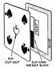
Cut out the center pip on the five-spot of spades with a sharp knife. Cut a slot centrally in another card, about 3/8 in. wide and 1-1/4 in. long. Glue the surfaces of both cards together near the edges to form a pocket for a slide, which is cut from another card and has one-half of its surface colored black. A drop of sealing wax attached to the back of the sliding part, so that it projects through the slot, provides a means of moving the slide in the pocket. A lightning change can be made from a five-spot to a four-spot while swinging the card.
To Make a Special Envelope
Any size of envelope for mailing special papers or documents can be made as follows: All envelopes are of the same shape as shown in Fig. 1; the size for the papers to be inclosed is represented by the dotted lines in Fig. 2. The projections A are coated with paste, and the flap B is folded over them. The envelope is then ready for the inclosure. The flap C is pasted and folded over as with an ordinary envelope.—Contributed by L. E. Turner, New York City.
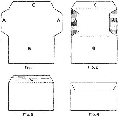
Various Stages in the Forming of an Envelope to Make Any Size for Special Papers (Fig. 1, Fig. 2, Fig. 3, Fig. 4)
Automatically Extinguishing a Candle
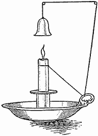
Candles can be easily fitted with attachments to extinguish the light at a set time. To determine the length of time, it is necessary to mark a candle of the size used and time how long a certain length of it will burn. Then it is sufficient to suspend a small metal dome, or cap, to which a string is attached, directly over the flame, and run the opposite end of the string over nails or through screw eyes, so that it can be tied around the candle such a distance from the flame end, that the part between the flame and the string will be consumed in the time desired for the light to burn. When this point is reached, the string slips off the candle, and the cap drops on the flame.
Clothespin Newspaper Holder
A simple newspaper holder can be made by cutting away a portion of one side of an ordinary clothespin, drilling a hole through the thick end for a screw or nail, and fastening it in place where desired. Another way is to split off one side of a clothespin and cut the bottom of the remaining part tapering as shown; then drill a hole to avoid splitting the piece and fasten in a convenient place.—Contributed by J. P. Rupp, Norwalk, O.
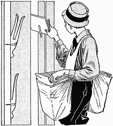
Shaping a Clothespin Head and Fastening It to a Wall Provides a Holder for Newspapers
Holder for a Dory Rudder
The rudder of a sailing dory or rowboat often comes off in rough water, and in order to keep it in place and yet have it easily detachable at will, the following method is useful: Procure a 10-in. length of soft-iron rod and bend one end of it into a loop large enough to fit around the rudder pin after the latter is inserted in the eyelet. Insert screws at A, B and C, letting them project about 1/2 in. from the surface. Bend the rod at D and A in the shape shown, and with a little adjustment it will easily snap into position. It will prevent the rudder from riding up out of the eyelets, but can be detached instantly. The device should be applied to the upper pin so as to be within easy reach.—Contributed by B. A. Thresher, Lakeville, Connecticut.
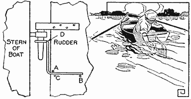
The Loop on the Iron Rod Holds the Pin of the Rudder in the Eye
Trimming Photographs
In trimming small photograph prints I experienced some difficulty in getting them square, and I did not care to invest in a trimming board. By following a line drawn around the print with a triangle, it was impossible to make a perfect rectangle. In the place of a trimming board I now use a piece of glass cut a little smaller than the desired print. The edges of the glass are smoothed by filing or grinding them. In making a glass, be sure to have the corners cut at perfect right angles and the edges ground straight.
The glass is easily located over the print, and by holding the two tightly together the edges of the print can be trimmed with a pair of shears.—Contributed by E. Leslie McFarlane, Nashwaaksis, N. B.
A Metal Polish
A metal polish that is safe to use about the home is composed of 30 parts alcohol, 3 parts ammonia water, 45 parts water, 6-1/2 parts carbon tetrachloride, 8 parts kieselguhr, 4 parts white bole, and 8 parts of chalk. These substances can be purchased at a local drug store and should be mixed in the order named. Any grease on metal will be dissolved by this solution.—Contributed by Loren Ward, Des Moines, Iowa.

The Making of a Rod Not Only Affords Much Pleasure, but the Rod can be Constructed as Desired
Fishing-Rod Making and Angling By Stillman Taylor — Part II—Various Two and Three-Piece Rods — Fly Rods for Trout and Bass — The Independent-Butt Rod
While the action of the one-piece rod is undeniably better than when the rod is made in two or three pieces, it is less compact to carry. To make a 5-ft. two-piece bait-casting rod, the same dimensions as given for the one-piece rod will make a very fine fishing tool. It is well to make two tips in view of a possible breakage. The rod may consist of two pieces of equal length, but a rod of better action is secured by making the butt section somewhat shorter with a relatively longer tip. By making the butt section about 23 in. long, exclusive of ferrule and butt cap, and the tip section 32-1/2 in. long, a splendid little rod is obtained which will fit any of the regulation rod cases of 35-in. length. To make a 6-1/2-oz. rod of this kind with a cork hand grasp, caliper it in the same manner as the one-piece rod, making the butt section 32-1/2 in. long, tapering from 15/32 in. at the upper end of the hand grasp to 19/64 in. at the ferrule. The tip is made 33 in. long, tapering from 17/64 in. to 7/64 in. By making the tip and butt to these lengths, both parts will be of equal length when the ferrules and the tops are added. The material list is as follows, the attachments being made of german silver:
- Dagame or greenheart butt, 5/8 in. by 3 ft. long;
- two tips 3/8 in. by 3 ft. long;
- one 3/4-in. reel seat with straight hood;
- one 1-in. butt cap;
- one taper, 15/32 in. at the small end;
- two 3/32-in. offset agate tops;
- two 1/2-in. narrow agate guides;
- two No. 1 size one-ring casting guides;
- one 17/64-in. welted and shouldered ferrule, with two closed-end centers, one for each tip;
- two dozen cork washers, 1-1/4 in. in diameter,
- and two spools of winding silk.
The three-piece rod should be made up to 6 ft. in length to secure the best action, but even if so made, the use of the extra ferrules makes the rod less resilient and elastic than the rod of one or two-piece construction. The best action is obtained only when the rod bends to a uniform curve, and since the ferrules cannot conform to this curve, or arc, the more joints incorporated in a rod, the less satisfactory it will be from an angling standpoint. Convenience in packing and carrying are the sole merits which the many-jointed rod possesses. Complete specifications for making a three-piece bait-casting rod, together with a material list, is as follows: A rod, about 5-1/2 ft. long with a single or double hand grasp made of cork, will weigh about 7 oz. Caliper the butt so that it will taper from 15/32 in to 11/32 in at the cap of the ferrule, making it 21-1/2 in. long. The middle joint is tapered from 21/64 in. to 15/64 in., and is 21-3/4 in. long. The tips are 21 in. long and are tapered from 13/64 in. to 7/64 in. Dagame or greenheart is used for the butt, joint, and tips, and german silver for the fittings. All pieces are 2 ft. long, the butt is 5/8 in., the joint and tips, 3/8 in.
- One 3/4-in. reel seat with straight hood;
- one 1-in. butt cap;
- one taper, small end 15/32 in.;
- one 21/64-in. welted and shouldered ferrule;
- one 15/64-in. welted and shouldered ferrule with two closed centers, one for each tip;
- two 3/32-in. offset agate tops;
- two 1/2-in. narrow agate guides;
- two No. 1 size one-ring casting guides;
- two dozen cork washers, and winding silk, size 00 or 0.
Having made a good bait-casting rod, the amateur will find little trouble in making a rod with a number of joints, and no special instructions need be given, since the work of planing and smoothing up the wood, and finishing and mounting the rod, is the same as has been described in detail before. For fly fishing for trout, accuracy and delicacy are of more importance than length of cast, and the rod best suited to this phase of angling differs greatly from that used in bait casting. A stiff, heavy rod is entirely unsuited for fly casting, and while it is, of course, possible to make a rod too willowy for the sport, the amateur, working by rule of thumb, is more likely to err on the other side and make the fly rods of too stout a caliber. The idea is simply to help the amateur over the hard part by giving a list of dimensions of a representative trout and a bass fly rod. To make a 9-ft. trout fly rod, with a cork grasp having a length of 9 in. above the reel seat, caliper the material as follows: The butt is tapered from
- 7/16 in. to 25/64 in. at 1 ft. from the butt end;
- 1-1/2 ft., 11/32 in.;
- 2 ft, 21/64 in.;
- 2-1/2 ft., 5/16 in., and 3 ft., 19/64 in.
- The first 6 in. of the middle joint is calipered to 9/32 in.;
- 1 ft, 17/64 in.;
- 1-1/2 ft, 15/64 in.;
- 2 ft., 7/32 in.;
- 2-1/2 ft, 13/64 in., and
- 3 ft., 3/16 in.
- The first 6 in. of the tips are calipered to 11/64 in.;
- 1 ft, 5/32 in.;
- 1-1/2 ft., 1/8 in.;
- 2 ft., 7/64 in.;
- 2-1/2 ft, 3/32 in., and
- 3 ft., 5/64 in.
All joints are made 36-1/2 in. long. The material used is dagame, or greenheart, the butt being 5/8 in. by 4 ft., the joint 3/8 in. by 4 ft., and the tips 3/8 in. by 4 ft. The attachments, of german silver, are:
- One 3/4 in. reel seat, fly-rod type with butt cap;
- one taper, 33/64 in. at the small end;
- one 9/32-in. welted and shouldered ferrule;
- one 11/64-in. welted and shouldered ferrule with two closed-end centers, one for each tip;
- two No. 4 snake guides for the butt joint;
- three No. 3 snake guides for the middle joint, and
- six No. 2 snake guides, three for each tip section;
- two No. 7 agate angle fly tops, the kind to wind on;
- one dozen cork washers, and
- two 10-yd. spools of winding silk, 00 size.
A bass fly rod 9-1/2 ft. long, weighing 7-1/2 oz., with a cork grasp, 9-1/2 in. above the reel seat, is calipered as follows:
- The butt is tapered from 13/32 in. to 25/64 in. 1 ft. from the end;
- 1-1/2 ft. from butt, 23/64 in.;
- 2 ft., 11/32 in.;
- 2-1/2 ft., 21/64 in., and
- 3 ft., 19/64 in.
- The first 6 in. of the middle joint is 19/64 in.;
- 1 ft., 9/32 in.;
- 1-1/2 ft., 17/64 in.;
- 2 ft., 15/64 in.;
- 2-1/2 ft., 7/32 in., and 3 ft., 13/64 in.
- The first 6 in. of the tips, 11/64 in.;
- 1 ft., 5/32 in.;
- 1-1/2 ft., 9/64 in.;
- 2 ft, 1/8 in.;
- 2-1/2 ft., 7/64 in., and
- 3 ft, 5/64 in.
The joints are 36-1/2 in. long. The mountings are the same as for the trout fly rod. Dagame, or greenheart, wood is used, the butt being 5/8 in. by 4 ft., the joint 3/8 in. by 4 ft. and the tips 3/8 in. by 4 feet.
The two-piece salt-water rod with an 18-in. double cork hand grasp, the whole being 6-1/2 ft. long, is made to weigh about 13 oz., with the following caliperings:
- A uniform taper of 35/64 in. to 29/64 in., from the cork grasp to the ferrule, is given to the butt.
- The first 6 in. of the tips is 13/32 in.;
- 1 ft., 25/64 in.;
- 1-1/2 ft., 11/32 in.;
- 2 ft, 21/64 in.;
- 2-1/2 ft., 9/32 in.;
- and to tip, 15/64 in.
The joints are made 36-3/4 in. long. Dagame, or greenheart, is used with german-silver mountings. Both pieces of wood are 4 ft. long, the butt being of 3/4-in. and the tip of 1/2-in. material. One 7/8-in. reel seat with straight hood, one 1-in. butt cap, one 7/16-in. ferrule, one taper with small end 35/64-in.; one 10/32-in. stirrup-tube agate top; two No. 3 bell guides; two dozen cork washers, and two spools, size A, winding silk.

The Mountings for a Fly Rod Consist of a Reel Seat with a Straight Hood, a Taper, Snake Guide, Agate Angle Top, and Serrated Ferrule. The Toothed Ends are Wound with Silk to Afford Additional Strength
The independent-butt rod, in which the hand grasp contains the ferrule and the tip is made in one piece, is a favorite type with many of the best fishermen. This mode of construction may be used with all classes of rods, the light fly and bait-casting rods, and the heavier caliber rods used in salt-water angling. In rods of this type, it is only necessary to use the same size ferrule to make as many tips as desired to fit the one butt. Tips of several calibers and weights may thus be fashioned to fit the one butt, and if the single-piece tip is too long for some special use, one tip may be made a jointed one for ease in carrying.
The independent butt, or hand grasp, is made by fitting the ferrule directly on a length of dagame, or greenheart, which has been rounded so that the seated ferrule will not touch the wood. The ferrule is then cemented and riveted in place, and a soft-pine sleeve is fitted over the wood core and the ferrule. The forward end of the sleeve is, of course, tapered to fit the taper of the reel seat, and when properly fitted, its lower end will project about 1/4 in. beyond the pine sleeve. Glue the sleeve on this wood core, cement the reel seat to the sleeve, and rivet the reel seat in place.
The cork washers are glued in position, working the first one into the metal edge of the reel seat, to make a nice, tight joint at this point. The other corks are then glued in place until the hand grasp is of the desired length. The projecting end of the wood core is then cut off flush with the last cork, and the rod is mounted in the usual manner.
In making a double hand grasp, the forward grasp may be fitted over the wood core in the fashion already described in making the hand grasp for the one-piece bait-casting rod, or the forward grasp may be fitted to the tip, just above the ferrule, as preferred. Both methods are commonly used, the only difference being in the manner of finishing up the forward grasp. If the forward grip is affixed to the ferruled end of the tip, two tapered thimbles will be required to make a nice finish.
The heavy-surf, or tarpon, rod is made up of an independent, detachable butt, 20 in. long, having a solid-cork or cord-wound hand grasp, and a one-piece tip, 5-1/2 ft. long, altogether weighing 23-1/2 oz. It is uniformly calipered to taper from 29/32 in to 5/16 in. One piece of dagame, or greenheart, 1 in. by 6-1/2 ft., will be required.
- One 1-in. reel seat for detachable butt, including one 3/4-in. male ferrule;
- one 1-1/8-in. butt cap; two No. 11 wide, raised agate guides;
- two No. 1 trumpet guides;
- one 3/8-in. agate stirrup top;
- two spools of winding silk, A-size, and
- two dozen cork washers, or sufficient fishline to cord the butt.
The guides are whipped on double, the first set spaced 10 in. from the top, and the second, 26 in. from the reel. The core of the independent, or detachable, butt is constructed of the same material as the rod, which makes the hand grasp somewhat elastic and very much superior to a stiff and rigid butt.
Homemade Ball Catch for Cabinet Doors
To make a ball catch, procure a piece of brass, 1 in. long, 1/2 in. wide, and about 1/16 in. thick, and an old gas burner having a diameter of 3/8 in. As described by Work, London, the threaded part of the burner is cut off, which forms a contracted end that will hold a steel ball 5/16 in. in diameter and allow it to project 1/8 in. A hole is drilled in the center of the brass plate, and the barrel soldered in place. A piece of spiral spring is inserted behind the ball. The stiffness of the spring will depend on the use of the catch. The barrel is cut to length and plugged. Another plate of brass is fitted with screw holes and a hole in the center to receive the projecting ball part, for the strike.
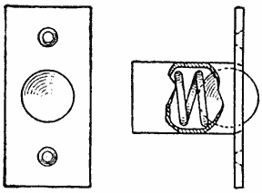
Combination Needle and Thread Tray
When any attempt is made to keep sewing material, such as needles, spools, or buttons, separate, each of the articles is usually kept in some special drawer, or by itself, and when necessary to use one, the others must be found, frequently necessitating many extra steps or much lost time in hunting up the various articles. The illustrated combination tray avoids this difficulty. It consists of two round trays fastened together near one edge with a wood screw, which is loosely fitted in the lower tray but screwed into the upper to permit them being swung apart. Extra thickness and weight should be given the bottom piece so no tipping will result when the top is swung out to expose the buttons in the lower section. The thread spools are placed on pegs set in the upper tray, and the cushion in the center is provided for the pins and needles.—Contributed by J. Harger, Honolulu, Hawaiian Islands.
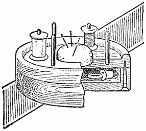
Repairing Worn Escapement Wheel of a Clock
When the ordinary clock has served its usefulness and is apparently worn out, the jeweler's price to overhaul it frequently amounts to almost as much as the original purchase price. One weak place in the clock is the escapement wheel. The points soon wear down, thereby producing a greater escapement and pendulum movement, resulting in an increased strain and wear of the clock. If the tips of the teeth on the wheel are bent up slightly with a pair of pliers, the swing of the pendulum will be reduced, thereby increasing the life of the clock. Many of the grandfather's clocks can be put in order in this manner so as to serve as a timepiece as well as a cherished ornament.—Contributed by C. F. Spaulding. Chicago, Ill.
A piece of work should never be fingered while filing it in a lathe.

If He would Take Full Advantage of Any Sport and Reap the Greatest Pleasure from a Day Spent in the Open, the Sportsman should Get Together a Good Outfit
Fishing-Rod Making and Angling By Stillman Taylor — Part III—Trout Fishing with Fly and Bait — Selecting a Good Fly Rod — The Proper Kind of Reel — The Kind of Line to Use — A Fine Leader Marks the Expert Caster — Flies for Trout Fishing
The art of angling is generally viewed as one of the world's greatest recreations, and while each and every phase of fishing may be said to possess certain charms of its own, fly fishing for trout is regarded by most well-informed sportsmen as the alpha and omega of the angler's art. This is so because the trout family are uncommonly wary and game fish, and the tackle used for their capture is of finer balance and less clumsy than any employed in angling for the coarser game fishes. If he would take full advantage of any sport and reap the greatest pleasure from a day spent in the open, it is really necessary for the sportsman to get together a good outfit. It is not essential to have a very expensive one, but it should be good of its kind, well proportioned for the purpose for which it is to be used. The beginner, who buys without good knowledge of the articles required, or fails to use careful discrimination, is almost certain to accumulate a varied assortment of junk, attractive enough in appearance, perhaps, but well-nigh useless when it is tested out on the stream. A good representative outfit, then, is of the first importance; it means making a good beginning by initiating the novice in the sport under the most favorable conditions. Let us then consider the selection of a good fishing kit, a well-balanced rod, the kind of a reel to use with it, the right sort of a line, flies, and the other few items found in the kit of the practical and experienced trout fisherman.
The ordinary fishing pole may be bought offhand at almost any hardware store, but a well-balanced rod for fly fishing should be well tested out beforehand. The requirements call for a rod of comparatively light weight, a rod that is elastic and resilient, and yet strong enough to prove durable under the continued strain of much fishing. If the angler has made his own rod, as suggested in former chapters, he will have a good dependable fly rod, but the large majority of anglers who are about to purchase their first fishing kit should carefully consider the selection of the rod. At the outset it must be understood that good tackle is simply a matter of price, the finest rods and reels are necessarily high in price, and the same thing may be said of lines and flies. Providing the angler has no objection to paying $15, or more, for a rod, the choice will naturally fall upon the handmade split bamboo. For this amount of money a fair quality fly rod may be purchased, the finer split bamboos costing anywhere up to $50, but under $15 it is very doubtful whether the angler can procure a built-up rod that is in every way satisfactory. The question may arise, Is a split-bamboo rod necessary? The writer's own long experience says that it is not, and that a finely made solid-wood rod, of greenheart or dagame, is quite as satisfactory in the hands of the average angler as the most expensive split bamboo. A good rod of this sort may be had for $10, and with reasonable care ought to last a lifetime.
The points to look for in a fly rod, whether the material is split bamboo or solid wood, is an even taper from the butt to the tip; that is, the rod should register a uniform curve, or arc, the entire length. For general fly casting 9 ft. is a handy length, and a rod of 6-1/2 oz. weight will prove more durable than a lighter tool. A good elastic rod is wanted for fly casting, but a too willowy or whippy action had best be avoided. However, for small-brook fishing, where the overgrown banks prohibit long casts, a somewhat shorter and stiffer rod will be more useful. For casting in large northern streams, where the current is swift and the trout run to a larger size, a 9-1/2 or 10-ft. rod of 8 oz. weight is often preferred. Of course, the veteran angler can safely use a much lighter rod than the beginner, and one occasionally meets a man on the stream that uses a 5-oz. rod for pretty heavy fishing. To be on the safe side, the novice will make no mistake in choosing a rod of fair length and conservative weight.
When selecting a rod in the tackle shop, do not rest content with a mere examination of the appearance, but have the dealer affix a reel of the weight and size intended to be used with it. By reeling on a short length of line and reeving it through the guides and then fastening the end to a weight lying upon the floor, a very good idea of the rod's behavior may be gained, since by reeling in the line and putting tension on the rod its elasticity and curve may be seen and felt as well as in actual fishing. To give the utmost satisfaction, the rod should fit its owner, and several rods should be tried until one is found that most fully meets the angler's idea of what a rod should be. If one happens to have a good fly reel, by all means take it along and attach it to the rod while making the tests. It is practically impossible to gauge the balance of a rod without affixing the reel, and many a finely balanced tool will appear badly balanced until the proper-weight reel is affixed to it.
For fly fishing nothing is so good as the English style of click reel, which is made with a one-piece revolving side plate and with the handle affixed directly to it. Any kind of a balanced-handle reel is an out-and-out nuisance on the fly rod, because it has no advantage in quickly recovering the line, and the projecting handle is forever catching the line while casting. In fly casting, the length of cast is regulated by the amount of line taken from the reel before the cast is made, and it is while "pumping" this slack line through the guides, in making the actual cast, that the balanced or projecting handle is very apt to foul the line. A good reel that is smooth-running like a watch will cost about $10, but a very good one may be had for $5, and cheaper ones, while not so durable, may be used with fair satisfaction. The heavier multiplying reels, so essential for bait casting from a free reel, are altogether unsuited for the fly rod, being too heavy when placed below the hand, which is the only proper position for the reel when fly casting. The single-action click reel, having a comparatively large diameter, but being quite narrow between the plates, is the one to use, and hard rubber, or vulcanite, is a good material for the side plates, while the trimmings may be of german silver or aluminum. The all-metal reel is of about equal merit, but whatever the material, the most useful size is one holding about 40 yd. of No. E size waterproof line. A reel of this capacity will measure about 3 in. in diameter and have a width of about 7/8 in. between plates. A narrow-spooled reel of this type enables the fisherman to reel in the line plenty fast enough. Owing to the fact that the reel is placed below the grip on fly rods, a rather light-weight instrument is needed to balance the rod. Of the two extremes, it is better to err on the side of lightness, because a heavy reel makes a butt-heavy rod and, throwing extra weight on the wrist and arm, makes casting increasingly difficult after an hour's fishing. An old hand at the game will appreciate this point better than the novice.
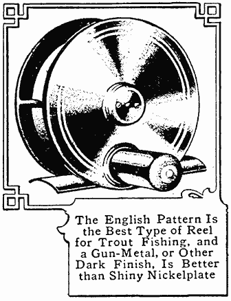
The English Pattern Is the Best Type of Reel for Trout Fishing, and a Gun-Metal, or Other Dark Finish, Is Better than Shiny Nickelplate
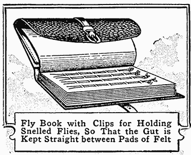
Fly Book with Clips for Holding Snelled Flies, So That the Gut is Kept Straight between Pads of Felt
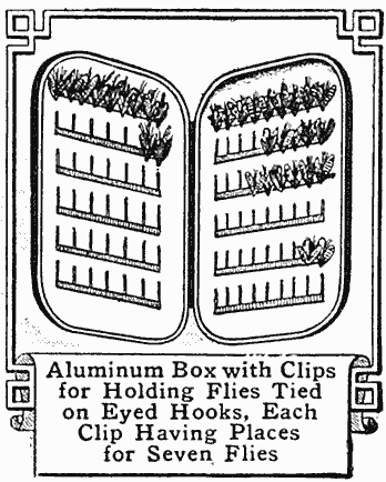
Aluminum Box with Clips for Holding Flies Tied on Eyed Hooks, Each Clip Having Places for Seven Flies
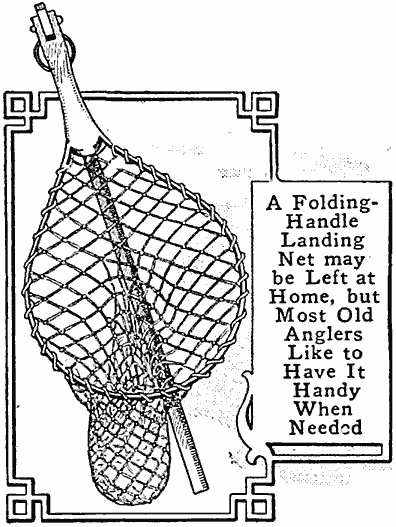
A Folding-Handle Landing Net may be Left at Home, but Most Old Anglers Like to Have It Handy When Needed
Willow Creel, or Basket, Leather-Bound with a Metal Fastening, the Number Three Size being About Right
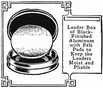
Leader Box of Black-Finished Aluminum with Felt Pads to Keep the Leaders Moist and Pliable
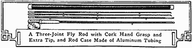
A Three-Joint Fly Rod with Cork Hand Grasp and Extra Tip, and Rod Case Made of Aluminum Tubing
The fly-casting line used by a veteran is generally of silk, enameled and having a double taper; that is, the line is thickest in the center and gradually tapers to a smaller diameter at each end. Single-tapered lines are likewise extensively used, and while they cost less, they are tapered at one end only and cannot be reversed to equalize the wear caused by casting. The level line, which has the same diameter throughout its entire length, is the line most generally used, but the cast cannot be so delicately made with it. For the beginner, however, the level line in size No. E is a good choice. For small-brook fishing, No. F is plenty large enough. In choosing the size of line, there is a common-sense rule among fly casters to select a line proportioned to the weight of the rod. For a light rod a light line is the rule, and for the heavier rod a stouter line is the logical choice. If the rod is of a too stiff action, use a comparatively heavy line, and it will limber up considerably; if the rod is extremely "whippy," use the lightest line that can be purchased, and used with safety.
The leader for trout is preferably of single gut, and as fine as the angler's skill will allow. The fly caster's rule is to use a leader whose breaking strain is less than the line, then, when the tackle parts, it is simply a question of putting on a new leader and the more expensive line is saved. Ready-made leaders may be purchased, or the angler can tie them up as desired. For length, a 3 or 3-1/2-ft. leader is about right for average fishing. Longer leaders are used, and while they sometimes are of advantage, the 3-ft. length is more useful. A longer leader is awkward to handle because the loop is apt to catch in the top of the rod when reeling in the line to bring the fish close to the landing net. Leaders may be had with a loop at each end, or with loops tied in, for using a cast of two or three flies. For all average casting, the two-fly cast is the best, but the expert angler uses the single-fly very often. For lake fishing, the single large fly is generally preferred. For using two flies, the leader is provided with three loops, one at the top, another at the bottom, and an extra loop tied in about 15 in. from the lower loop. In fly casting, the first, or upper, fly is known as the "dropper," and the lower one as the "tail" fly. For the single-fly cast but two loops are required.
Gut used for leaders should be carefully selected, and only those lengths which are of uniform diameter and well rounded chosen, the lengths which show flat and rough spots being discarded. Dry gut that is very brittle should be handled very little, and previous to a day's fishing the leaders must be soaked in water over night to make them pliable, then coiled in between felt pads of the leader box to keep them in fishing shape. After use, put the frayed leaders aside and dry them out between the flannel leaves of the fly book.
Gut is the product of the silkworm, and the best quality is imported from Spain. It comes in bundles, or hanks, of 1,000 strands, 10 to 20 in. long and in different thicknesses, or strengths. The heaviest are known as "Royal" and "Imperial," for salmon; "Marana," for extra-heavy bass; "Padron," for bass; "Regular," for heavy trout; "Fina," for light trout, and "Refina," for extra-light trout. The grades "Fina" and "Refina" are well suited for all average fly fishing, while the heavier sizes are useful for heavy large fishing.
To make the leaders, soak the strands of gut in warm water over night until they are soft and pliable. Select the strands for each leader of the desired thickness and length so that the finished leader will have a slight taper to one end only. By using the "Fina" gut for the upper length and tying in two lengths of "Refina" gut, a nicely tapered leader of light weight is obtained. Begin the leader by uniting the strands together to make it the correct length, three 12-in. strands being about right for average casting. The "single water knot" is the strongest and neatest to use. Make it by taking the thick end of the strand and doubling it back enough to tie in a common knot just large enough for the line to pass through and drawing it up tightly. Tie a single loose knot in the other end of the strand, about 1/8 in. in diameter and close to the end; take the next thickest strand of gut, thread the thicker end through the loose knot and tie a second square knot around the strand, as shown at A. By pulling on the two long ends the loops can be drawn up tightly, and the two knots will slide together and make a neat and very strong knot. Repeat this operation until as many strands of gut are knotted together as required to make the leader of the desired length. For making the loop at the ends, a double-bighted knot, tied as shown at B, is used. If a dropper fly is desired, do not pull the water knot tightly, but first insert a short length of gut with a common knot at the end and a loop in the other, then draw the water knot up tightly, and a short snell will be made for attaching the fly as usually.

(A) The Single Water Knot Used in Tying Leaders; (B) a Good Knot for Making the Loop at the End of the Leaders; (C) an Angler's Knot Used for Attaching the Line to the Leader, and (D) a Jam Knot for Attaching Eyed Flies, or Hooks, to the Leader or Snell
The standard selection of artificial flies numbers about 60, but the average fisherman will find about 24 selected patterns to answer every need. For making up the most "killing" flies for the trout season, the following can be recommended: Use red ibis, stone fly, cinnamon, red spinner, and parchmenee belle, for April; turkey brown, yellow dun, iron blue, spinner, montreal and red fox, for May; spider, black gnat, silver doctor, gray drake, orange dun, and green drake, for June; July dun, grizzly king, pale evening dun, red ant, and brown palmer, for July; Seth green, coachman, shad, governor, August dun, and royal coachman, for August, and black palmer, willow, whirling dun, queen of the water, and blue bottle, for September.
To attach a line to the leader the well-known "angler's knot" is mostly used. This knot is shown at C. The snelled fly is attached by passing the loop over the loop of the leader and inserting the fly through the leader loop. When eyed flies are used they are often attached direct to the leader, or a looped snell may be used as in the ordinary American-tied fly. To attach the eyed fly direct to the leader, the common "jam knot," shown at D, is mostly used, and when the slipknot is drawn up tightly and the extra end cut off it makes a small, neat knot, not apt to slip.
Catch to Hold Two Joining Doors Open
Where two open doors meet, a catch to keep them open can be made of a piece of wire, shaped as shown. The hooks at the ends of the wire are slipped over the shanks of the knobs.—Contributed by W. A. Saul, Lexington, Mass.
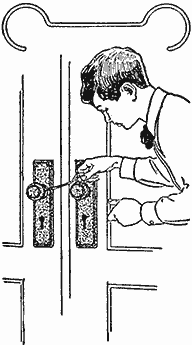
Strips cut from wood dishes used by grocers for butter, thoroughly soaked in warm water, will make excellent repair pieces for market baskets.
Bicycle Oil Lamp Changed to Electric Light
The desire for an electric light for my bicycle caused me to change a fine oil lamp, too good to be thrown away, so that an electric globe could be used in it. The oil cup of the lamp was removed, and a wood push button fastened in its place with three screws. Before fastening the push button, a porcelain socket was attached to its bottom, and connections were made between socket and push button, ends being left protruding for connection to the battery. A small flash-light battery was fastened to the lamp bracket. A small rubber washer was placed between the head of the push button on the switch and the cap, so that in screwing the cap up, a permanent connection was made. The lamp can be used as a lantern when removed from the bicycle.—Contributed by Lee Baker, Chicago.
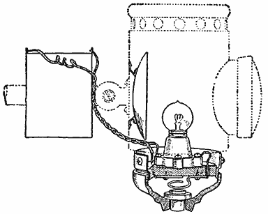
A Push Button with Socket and Miniature Globe Used in an Oil Lamp for Electric Light
Lifter for Removing Eggs from Hot Water
An improvement over the customary way of removing eggs from hot water with a tablespoon, is to use an old-fashioned coffee strainer. This brings up the eggs without carrying hot water with them.—Contributed by L. E. Turner, New York, N. Y.
Genuine oxalic acid may be used for removing stains from all woods except mahogany.
Double Top for a Table
The need of two tables in a kitchen where there was space for only one, was the cause of devising the arrangement shown in the illustration. An ordinary kitchen table was mounted on trunk casters or domes so that it could be moved easily, whereupon a zinc top was put on it with raised edges. The table was then placed against the wall where it was to be used, and an extra, plain top fitted to it and hinged to the wall.
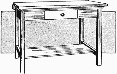
An Extra Top Covers the Table When It is Placed against the Wall
When it was desired to wash dishes on the zinc top, the table was pulled out without disturbing the articles on the hinged top. After drying the dishes, they are removed from the zinc top to the hinged part, and the table is pushed back against the wall.—Contributed by Louis Drummond, Philadelphia, Pa.
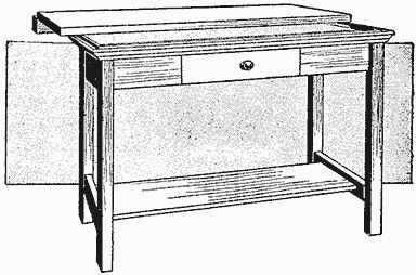
The Table When Drawn Out Uncovers the Zinc Tray, Fastened on Top

As a General Thing, the Veteran Fly Fisherman Prefers to Wade with the Current, and Fishes the Water in Front of Him by Making Diagonal Casts across the Stream
Fishing-Rod Making and Angling By Stillman Taylor — Part IV—Trout Fishing with Fly and Bait — How to Cast the Fly — Handling the Flies in the Water
To be able to cast the artificial fly a distance of 50 ft., or more, and let the feathered lure alight upon the desired bit of water as lightly as a falling leaf is no small accomplishment, for fly casting is an art, and to become an expert, much practice is necessary. The personal assistance of a skillful caster is not often available, but if the angler will follow the suggestions outlined, a beginner will soon grasp the knack of handling the fly rod, and the casting will steadily improve with practice. As the knack of handling a gun is best gained—not in the field, shooting live game, but through shooting at targets—so may the art of fly casting be more quickly acquired by intelligent practice conducted away from the stream, in the back yard, or any other place roomy enough to swing the rod and a moderately long line. By practicing in this way, the angler's attention is focused upon the cast and is not partly occupied with the excitement of fishing. To make a good beginning, let the reel contain about 25 yd. of common, braided, linen line (size E is about right) and instead of a fly, or hook, affix a small split shot to the end of the line. It is well to begin with a cheap rod and save a good outfit, and if the angler learns how to make a fairly long and accurate cast with a common rod, he may feel assured that he can even do better with a first-rate outfit.
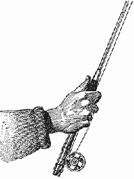
Fig. 1—The Proper Way to Take Hold of the Handle with the Reel on the Under Side
The first point to observe in making the cast is to grip the rod correctly, and this is done by grasping the rod at the right point where it balances best. By shifting the hand about this point of balance is quickly found, for at no other point will the rod "hang" well in the hand. In casting, the reel is turned to the under side of the rod with the thumb extended along the top of the grip, as shown in Fig. 1. Taking up an easy casting position, with the left foot slightly advanced, pull from the reel about 25 yd. of line and let this slack line fall in coils upon the ground in front; bring the rod up slightly above the horizontal, as shown in Fig. 2, and with a quick snap of the wrist, avoiding shoulder or body movement, throw the tip upward, checking it sharply as soon as the tip is carried over the shoulder about 25° beyond the vertical plane as in Fig. 3. This snappy upstroke of the rod makes the "back cast," by projecting the line high in the air, and carries it well behind the angler. Before the line has fully straightened out behind, and before it has an opportunity to fall much below the caster's shoulders, the rod is snapped forward with a quick wrist-and-forearm movement, which throws the line forward in front of the fisherman and in the direction he is facing, which finishes the cast with the rod in the position shown in Fig. 4.
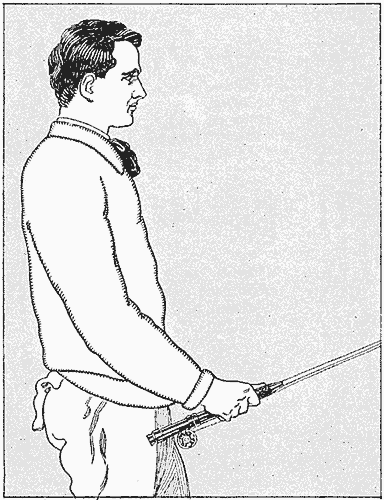
Fig. 2—Begin the Cast with the Rod in a Position Just above the Horizontal Plane
Long and accurate fly casting is much more a matter of skill than muscle, and while some fly fishermen cast directly from the shoulder and upper arm, and thus use a considerable amount of muscular force in making the cast, this cannot be regarded as the best method of casting. The great elasticity of the fly rod ought to be taken full advantage of by the caster, and if this is done, casting will be naturally accomplished by the wrist and forearm. To make strenuous efforts to hurl the fly through the air, using an arm or body movement, is extremely tiring after an hour or so of fishing, while if the cast is made from the wrist, aided by the forearm, the snap of the rod may be depended upon to project the fly to greater length of line and allow it to fall close to the desired spot, lightly and without splashing.
Timing the back cast is the most difficult detail of fly casting, because the line is behind the angler and the eye cannot aid the hand. The novice will soon acquire the knack of casting, however, if he will remember to keep the elbow close to the side, and to keep the line well up in the air when making the back cast, and to begin the forward movement before the line has fully straightened out behind him. After a little practice, the hand will feel the slight tension communicated to the rod as the line begins to straighten out, and this should be taken advantage of to correctly time the forward movement. Counting "one" for the upstroke, "two and" for the interval required for the line to straighten out in the rear, and "three" for the forward movement, is also a good way to time the cast.
At the beginning the caster should make no attempt to secure distance. Accuracy and delicacy in placing the fly on the water is of much more importance than length of cast in trout fishing, and to attain this end, it is a good plan to place a newspaper about 25 ft. distant and try to drop the end of the line on this mark. When the caster can drop the line on the target lightly and with reasonable accuracy, he may feel justified in lengthening his cast. Other casts than the overhead cast just described are occasionally used, as the Spey, switch, wind, and flip casts, but the overhead cast is mostly used, although it is much more difficult to master.
To make the Spey cast, the angler requires a rapid stream which will carry the line downstream until it is straight and taut, the tip of the rod being held as long as possible to accomplish this end. The rod is then raised high in the air with a quick wrist movement, which lifts the line from the water to the extreme end, then without pausing the rod is carried upstream with just sufficient force to let the fly fall just above the angler. The line is now on the reverse, or upper, side of the fisherman, when with a sweep of the rod the line is projected over the water's surface—not along the surface—in the manner used in making the overhead cast.
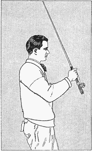
Fig. 3—The Rod is Quickly Checked When It is Carried over the Shoulder About 25 Degrees
The switch cast is sometimes useful when trees or rocks are immediately back of the fisherman, thus preventing the line from extending far enough backward to make the overhead cast. In making this cast the line is not lifted from the water, but merely to the surface by raising the tip of the rod. The line is dragged through the water by carrying the tip in the direction one is standing until it is as far in the rear as the obstructions will permit. By a quick downward sweep of the rod the line is projected with sufficient force to roll it forward in a large coil or loop, much as a wheel rolls on a track.
The wind cast is a modification of the switch cast, but easier to make. The caster brings his line almost to his feet, and with a quick downward motion of the rod the line is thrown in a long loop against the wind. The underhand and the flip casts are so simple that it seems almost unnecessary to describe them. Both are short casts and are only used when the angler is fishing in an overgrown stream. The underhand cast is really a side cast, inasmuch as the short line is lifted from the water in a loop and propelled in the desired direction by a side sweep of the rod. The flip cast is made by holding the fly between the thumb and finger and with a few coils of line in the right hand. Bend the rod like a bow, release the fly suddenly, and the snap of the rod will project it in the desired direction and allow it to drop lightly like a fly.
As a general thing the veteran fly fisherman prefers to wade with the current and fishes the water in front of him by making diagonal casts across the stream. A good fisherman will systematically cover every inch of good water and little will be left to chance. The novice is inclined to fish his flies in a contrary manner, he casts more or less at random, and is as likely to splash the flies recklessly about in the most impossible places as he is to drop them in a favorable riffle or pool. To be able to pick out fishable water, the angler should know something about the habits of the trout, their characteristics at the several seasons of the fishing year, and their habits, which differ greatly in different streams. A fishing knowledge of the stream to be visited is of much value, but if the angler knows how to make a fair cast and possesses average skill in handling flies on water, there should be no question but that he will creel a fair number of trout even though he casts in strange waters.
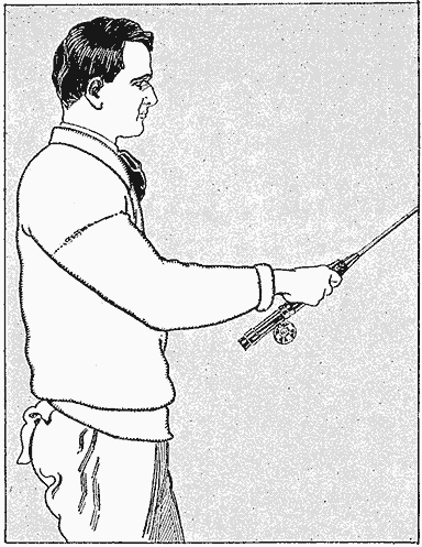
Fig. 4—The Cast is Finished by Throwing the Line Forward with a Quick Wrist-and-Forearm Movement
To imitate the action of the natural insect is the most successful manner of fishing the flies, and as the natural fly will struggle more or less when borne down with the current, the fisherman endeavors to duplicate this movement by making his artificial fly wriggle about. This motion must not be overdone, for if the flies are twitched and skipped about, or pulled against the current, the wary trout will refuse to fall for any such obvious deceit. A gentle motion of the wrist will cause the fly to move somewhat as the natural insect will struggle.
In making the cast do not cast directly down or upstream, but across the current at an angle. Let the flies fall upon the water as lightly as possible, so that the water will carry them downstream over the likely places where the trout are hiding. Keep the line as taut as possible by drawing the slack in with the left hand. The flies should not be allowed to soak in the water, neither should they be retrieved in haste. The experienced fly caster will invariably fish with a wet line, that is to say, with a slightly submerged fly, and will let the flies drag over as much water as possible before making a second cast. Owing to the fact that trout lie with their noses pointing upstream awaiting their food carried down by the current, the caster will naturally take pains to float his flies downstream with the leader fairly taut. To neglect this detail and allow the leader to float in a wide loop near or before the flies is slovenly fishing, and few trout will strike a fly presented in this amateurish fashion.
Early in the fishing season, and when the stream is flooded and discolored after a heavy rain, it is a good plan to fish the flies below the surface. Fishing in this manner makes it more difficult to tell when to strike a fish, and some little practice is needed to determine the opportune moment by feeling the slight tension on the line. Many fish will be pricked to be sure, but some trout will be creeled, and fishing with the submerged fly is sometimes the only way trout can be taken.
On fair days and in smooth water, better luck may be expected when the fly is kept upon the surface, and this is easily managed by keeping the tip of the rod well in the air. Often the fisherman can take advantage of a bit of floating foam, and if the fly is cast upon it and allowed to float with it downstream, the ruse will often prove effective.
The trout is a hard striker and it is not unusual to have a trout rush ahead of the fly in his attempt to mouth it. In rapid water the savage rush of the fish is sufficient to hook it securely, but when casting in quiet pools, the hook is imbedded by a snap of the wrist. At what exact moment to strike, as well as the amount of force to use, depends upon circumstances. When fishing in small streams and brooks where the trout run small, much less force is necessary to hook the fish, but in quiet water and in larger streams where 2 or 3-lb. trout are not uncommon, the fish may be struck with a smart upward jerk of the forearm and wrist. So far as my experience goes, the matter of striking is governed by the temperament as well as the judgment of the angler. The deliberate thinking man is likely to strike too late, while the nervous individual, striking too early, is apt to prick the trout and roll him over.
The best time to fish for trout is when they are feeding on the surface; and in the early days of spring, when there are few flies about, the warmer part of the day, say, from 10 in the morning to 5 in the afternoon, will prove to be the most successful time. Later on, when flies are numerous, good luck may be expected at an early hour in the morning, and in the hot summer months the cooler hours of the day may be chosen. Of course, there are many exceptions, since there are many cool days in summer, as well as exceptionally warm days in spring, and these changes of weather should be considered. However, extremes are not likely to make good fishing, and the trout will not rise as freely on cold, windy days, nor will they fight as gamely. On hot days, too, not so much luck can be expected during the hours of the greatest heat—12 to 4—but a good basket of trout may be creeled early in the morning or late in the afternoon of summer. A bright, clear day is usually the best for fly fishing, because the sun brings out more flies, but a warm rain, or even a fog, is also considered good fishing weather.
Among the live baits available for trout fishing are the minnow, white grub, cricket, grasshopper, and other insects, and last, but by no means least, the common angle or earthworm. The minnow is beyond a doubt the most enticing morsel that can be offered to a hungry trout, and a minnow may be reckoned to secure a rise when other baits fail. The inconvenience of transporting this bait is a great drawback, and as minnows are delicate fish, a minnow bucket is necessary for their preservation. This means a lot of trouble, as the water must be frequently changed or aerated, and this labor, together with the difficulty of carrying a bulky pail through the brush, makes this desirable bait almost impossible for stream and brook fishing. The salt-water minnow, known as a "shiner" or "mummychug," is a topnotch trout bait, and being much tougher than the fresh-water minnow, makes a bait often used by anglers residing near the seacoast.
The white grub, or larvae of the so-called May beetle, is a good bait available for early-season fishing, and may be obtained in the early spring months by spading up grass land. The grub is about 1 in. long, and of a creamy yellow color with a darker head. It may be kept a month, or more, by putting it in a box with a number of pieces of fresh turf.
Crickets, grasshoppers, and many other insects, make good baits, while the earthworm is a good all-around bait for trout. A supply dug some days before and kept by packing in fresh moss and slightly moistening with milk and water will prove more attractive in appearance and the worms will be tougher and cleaner to handle than when carried in earth.
Other good baits include the fin of a trout, and if this is used in combination with the eye of the same fish, it forms an attractive lure. In using this bait, do not puncture the eyeball, but hook through the thin flexible skin surrounding the eye. A fat piece of salt pork, cut into pieces 1 in. long and 1/4 in. wide, makes a fairly good bait. Spoons and other spinning baits are presumably attractive, but few sportsmen use them when angling for so fine a fish as trout.

Houses Made of Poles

Houses Made of Poles By Lola A. Pinchon
[In this article descriptions are given of several shelters suitable for a resort, but the reader may select any one of them that answers his needs and build a camp house, or fit up a more substantial one to make living quarters for the whole year.—Editor.]
Being forced to take the open-air treatment to regain health, a person adopted the plan of building a pole house in the woods, and the scheme was so successful that it was decided to make a resort grounds, to attract crowds during holidays, by which an income could be realized for living expenses. All the pavilions, stands, furniture, and amusement devices were constructed of straight poles cut from young growth of timber with the bark remaining on them. Outside of boards for flooring and roofing material, the entire construction of the buildings and fences consisted of poles.

The Frame Construction of the House Made Entirely of Rough Poles, the Verticals being Set in the Ground, Plumbed, and Sighted to Make a Perfect Rectangle of the Desired Proportions
A level spot was selected and a house built having three rooms. The location was in a grove of young timbers, most of it being straight, and 13 trees were easily found that would make posts 12 ft. long, required for the sides, and two poles 16 ft. long, for the center of the ends, so that they would reach to the ridge. The plot was laid out rectangular and marked for the poles, which were set in the ground for a depth of 4 ft., at distances of 6 ft. apart. This made the house 8 ft. high at the eaves with a square pitch roof; that is, the ridge was 3 ft. high in the center from the plate surfaces for this width of a house. The rule for finding this height is to take one-quarter of the width of the house for the height in the center from the plate.
The Steps are Supported on Pairs of Vertical Poles Set in the Ground to Make Different Levels
The corner poles were carefully located to make the size 12 by 24 ft., with a lean-to 8 by 12 ft., and then plumbed to get them straight vertically. The plates for the sides, consisting of five poles, were selected as straight as possible and their ends and centers hewn down to about one-half their thickness, as shown at A and B, and nailed to the tops of the vertical poles, the connection for center poles being as shown at C.
The next step was to secure the vertical poles with crosspieces between them which were used later for supporting the siding. These poles were cut about 6 ft. long, their ends being cut concave to fit the curve of the upright poles, as shown at D. These were spaced evenly, about 2 ft. apart from center to center, on the sides and ends, as shown in the sketch, and toenailed in place. The doors and window openings were cut in the horizontal poles wherever wanted, and casements set in and nailed. The first row of horizontal poles was placed close to the ground and used both as support for the lower ends of the siding and to nail the ends of the flooring boards to, which were fastened in the center to poles laid on stones, or, better still, placed on top of short blocks, 5 ft. long, set in the ground. These poles for the floor should be placed not over 2 ft. apart to make the flooring solid.
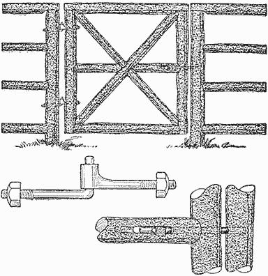
Gate Openings were Made in the Fence Where Necessary, and Gates of Poles Hung in the Ordinary Manner
A lean-to was built by setting three poles at a distance of 8 ft. from one side, beginning at the center and extending to the end of the main building. These poles were about 6 ft. long above the ground. The rafter poles for this part were about 9-1/2 ft. long, notched at both ends for the plates, the ends of the house rafters being sawed off even with the outside of the plate along this edge. The rafter poles for the house were 10 in all, 8 ft. long, and were laid off and cut to fit a ridge made of a board. These poles were notched about 15 in. from their lower ends to fit over the rounding edge of the plate pole, and were then placed directly over each vertical wall pole. They were nailed both to the plate and to the ridge, also further strengthened by a brace made of a piece of board or a small pole, placed under the ridge and nailed to both rafters. On top of the rafters boards were placed horizontally, spaced about 1 ft. apart, but this is optional with the builder, as other roofing material can be used. In this instance metal roofing was used, and it only required fastening at intervals, and to prevent rusting out, it was well painted on the under side before laying it and coated on the outside when fastened in place. If a more substantial shelter is wanted, it is best to lay the roof solid with boards, then cover it with the regular prepared roofing material.
Some large trees were selected and felled, then cut into 4-ft. lengths and the bark removed, or if desired, the bark removed in 4-ft. lengths, and nailed on the outside of the poles, beginning at the bottom in the same manner as laying shingles, to form the siding of the house. If a more substantial house is wanted, boards can be nailed on the poles, then the bark fastened to the boards; also, the interior can be finished in wall board.
The same general construction is used for the porch, with horizontal poles latticed, as shown, to form the railing. It is very easy to make ornamental parts, such as shown, on the eave of the porch, by splitting sticks and nailing them on closely together to make a frieze. Floors are laid on the porch and in the house, and doors hung and window sash fitted in the same manner as in an ordinary house.

All Furniture, Together with the Large Lawn Swings, Took on the General Appearance of the Woodland, and As the Pieces were Made Up of the Same Material As the Houses, the Cost Was Only the Labor and a Few Nails
A band stand was constructed on sloping ground, and after setting the poles, the floor horizontals were placed about 2 ft. above the ground, on the upper side, and 4 ft. on the lower side. The poles used were about 18 ft. long. Instead of having the horizontals 2 ft. apart, the first was placed 1 ft. above the floor, the next at about one-half the distance from the lower one to the plate at the top, and the space between was ornamented with cross poles, as shown. A balcony or bay was constructed at one end, and a fancy roof was made of poles whose ends rested on a curved pole attached to the vertical pieces. Steps were formed of several straight poles, hewn down on their ends to make a level place to rest on horizontal pieces attached to stakes at the ends. A pair of stakes were used at each end of a step, and these were fastened to a slanting piece at the top, their lower ends being set into the ground. The manner of bracing and crossing with horizontals makes a rigid form of construction, and if choice poles are selected for the step pieces, they will be comparatively level and of sufficient strength to hold up all the load put on them. The roof of this building was made for a sun shade only and consisted of boards nailed closely together on the rafters.

The Entrance to the Grounds was Given an Inviting Appearance with Large Posts and Swinging Gates
An ice-cream parlor was built on the same plan, but without any board floor; the ground, being level, was used instead. There were five vertical poles used for each end with a space left between the two poles at the center, on both sides, for an entrance. This building was covered with prepared roofing, so that the things kept for sale could be protected in case of a shower.
A peanut stand was also built without a floor, and to make it with nine sides, nine poles were set in the ground to form a perfect nonagon and joined at their tops with latticed horizontals. Then a rafter was run from the top of each post to the center, and boards were fitted on each pair of rafters over the V-shaped openings. The boards were then covered with prepared roofing. A railing was formed of horizontals set in notches, cut in the posts, and then ornamented in the same manner as for the other buildings.
Fences were constructed about the grounds, made of pole posts with horizontals on top, hewn down and fitted as the plates for the house; and the lower pieces were set in the same as for making the house railing. Gates were made of two vertical pieces, the height of the posts, and two horizontals, then braced with a piece running from the lower corner at the hinge side to the upper opposite corner, the other cross brace being joined to the sides of the former, whereupon two short horizontals were fitted in the center. A blacksmith formed some hinges of rods and strap iron, as shown, and these were fastened in holes bored in the post and the gate vertical. A latch was made by boring a hole through the gate vertical and into the end of the short piece. Then a slot was cut in the side to receive a pin inserted in a shaft made to fit the horizontal hole. A keeper was made in the post by boring a hole to receive the end of the latch.
Large posts were constructed at the entrance to the grounds, and on these double swing gates, made up in the same manner as the small one, were attached. These large posts were built up of four slender poles and were considerably higher than the fence poles. The poles were set in a perfect square, having sides about 18 in. long, and a square top put on by mitering the corners, whereupon four small rafters were fitted on top. The gates were swung on hinges made like those for the small gate.
Among the best and most enjoyed amusement devices on the grounds were the swings. Several of these were built, with and without tables. Four poles, about 20 ft. long, were set in the ground at an angle, and each pair of side poles was joined with two horizontals, about 12 ft. long, spreaders being fastened between the two horizontals to keep the tops of the poles evenly spaced. The distance apart of the poles will depend on the size of the swing and the number of persons to be seated. Each pair of side poles are further strengthened with crossed poles, as shown. If no table is to be used in the swing, the poles may be set closer together, so that the top horizontals will be about 8 ft. long. The platform for the swinging part consists of two poles, 12 ft. long, which are swung on six vertical poles, about 14 ft. long. These poles are attached to the top horizontals with long bolts, or rods, running through both, the bottom being attached in the same manner. Poles are nailed across the platform horizontals at the bottom for a floor, and a table with seats at the ends is formed of poles. The construction is obvious.
A short space between two trees can be made into a seat by fastening two horizontals, one on each tree, with the ends supported by braces. Poles are nailed on the upper surface for a seat.
Other furniture for the house and grounds was made of poles in the manner illustrated. Tables were built for picnickers by setting four or six poles in the ground and making a top of poles or boards. Horizontals were placed across the legs with extending ends, on which seats were made for the tables. Chairs and settees were built in the same manner, poles being used for the entire construction.
An Electric Water Heater
Procure the barrel and cap from a hand bicycle pump and prepare them as follows: Make a tube of paper, about double the thickness of a postal card, to fit snugly in the pump barrel and oil it slightly before slipping it into place. Procure some resistance wire of the proper length and size to heat quickly. The wire can be tested out by coiling it on some nonconducting material, such as an earthen jug or glazed tile, and connecting one end to the current supply and running the other wire of the supply over the coil until it heats properly. Cut the resistance at this point and temporarily coil it to fit into the bottom of the pump barrel, allowing one end to extend up through the space in the center with sufficient length to make a connection to supply wires.
Mix some dental plaster to the consistency of thick cream and, while keeping the wire in the center of the pump barrel, pour in the mixture until it is filled to within 1-1/2 in. of the top. Allow the plaster to set for about a day, then remove it from the barrel and take off the paper roll. The coil of wire at the bottom is now straightened out and wound in a coil over the outside of the plaster core, allowing sufficient end for connecting to the supply wires.

An Electric Heating Coil Made of Resistance Wire Placed in a Bicycle-Pump Barrel for Boiling Water
Cut two or three disks of mica to fit snugly in the bottom of the pump barrel, also cut a mica sheet to make a covering tube over the coil on the plaster core and insert the whole into the barrel. The two terminals are connected to the ends of a flexible cord which has a plug attached to the opposite end. Be sure to insulate the ends of the wire where they connect to the flexible cord inside of the pump barrel under the cap. In winding the resistance wire on the core, be sure that one turn does not touch the other. The heater when connected to a current supply and placed in 1 qt. of water will bring it to a boil quickly.—Contributed by A. H. Waychoff, Lyons, Colo

Camps By F. S. Charles — Division of Work — Tents — Protection from Insects — A Permanent Camp — Camp Fires — Food Supplies
A good site, pure water in abundance, and a convenient fuel supply, are the features of a temporary camp that should be given first consideration when starting out to enjoy a vacation in the woods. The site should be high and dry, level enough for the tent and camp fire, and with surrounding ground sloping enough to insure proper drainage. A sufficient fuel supply is an important factor, and a spot should be chosen where great effort is not required to collect it and get it into proper shape for the fire.
Wall Tent
Lean-To of Boughs
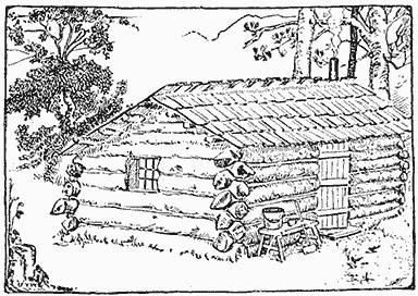
Log Cabin
When locating near streams of water be careful to select a spot above high water mark so the ground will not be overflowed by a sudden rise of the stream. Do not select the site of an old camp, as the surroundings are usually stripped of all fuel, and the grounds are unclean.
Clear the selected spot and lay out the lines for the tent, camp fire, etc. If the camping party consists of more than two persons, each one should do the part allotted to him, and the work will be speedily accomplished. Remember that discipline brings efficiency, and do not be slack about a camp just because it is pleasure. One of the party should attend to the camp fire and prepare the meals while another secures the fuel and water. The tent can be unpacked and the ground cleared by the other members of the party, and when ready, all should assist in raising the tent, especially if it is a large one.
An ordinary A or wedge tent is sufficient for one or two campers. Where you do not wish to locate permanently, this tent can be set up and taken down quickly. It should have a ring fastened to the cloth in each peak through which to pass a rope or line to take the place of a ridge pole. Such a tent can be pitched between two trees or saplings, and, after tying the rope to the trees, it can be tightened with a long forked stick, placed under one end of the rope. If two trees are not conveniently located, then two poles crossed and tied together will make supports for one or both ends, the ridge line running over them and staked to the ground.
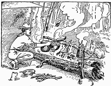
Fire between Two Logs
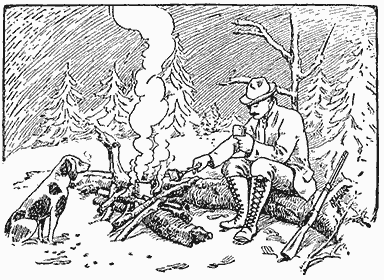
Fire Built against a Log
On a chilly night, the A tent is quite advantageous. The stakes can be pulled on one side and the cloth doubled to make a lean-to, open on the side away from the wind. A fire can be built in front and the deflected heat on the sleeper will keep him comfortable and warm.
For larger parties, the wall tent with a fly is recommended. These tents can be purchased in various sizes. The fly is an extra covering stretched over the top to make an open air space between the two roofs. It keeps the interior of the tent delightfully cool in hot summer weather and provides a better protection from rain. The fly can be made extra long, to extend over the end of the tent, making a shady retreat which can be used for lounging or a dining place.
Where mosquitoes and other insects are numerous, it is well to make a second tent of cheesecloth with binding tape along the top to tie it to the ridge pole of the regular tent. The sides should be made somewhat longer than the regular tent so that there will be plenty of cloth to weight it down at the bottom. This second tent should be made without any opening whatever. The occupant must crawl under the edge to enter. The cheesecloth tent is used inside of the ordinary tent, and when not in use it is pushed aside.
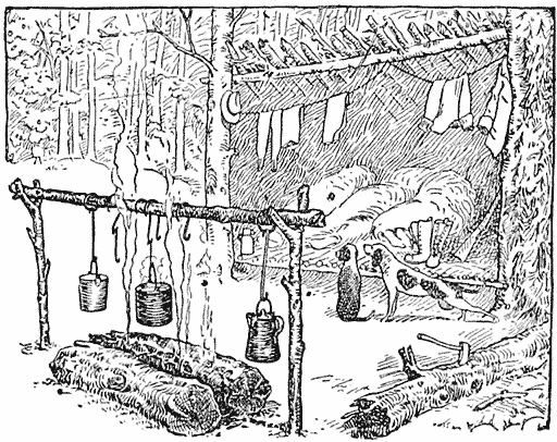
Forked Sticks Supporting Cooking Utensils
Two camps are illustrated showing the construction of a lean-to for a temporary one-season camp, and a log cabin which makes a permanent place from year to year. (A more elaborate and more expensive camp was described in the May issue of this magazine.) The construction of these camps are very simple. The first is made of poles cut in the woods. A ridge pole is placed between two trees or held in place with poles of sufficient length, set in the ground. Poles are placed on this at an angle of about 45 deg., forming a lean-to that will be entirely open in front when finished. The poles are covered, beginning at the bottom, with pine boughs, laid in layers so as to make a roof that will shed water. A large fire, built a short distance from the open front will make a warm place to sleep, the heat being reflected down the same as described for the A tent.
A good permanent camp is a log cabin. This can be constructed of materials found in the woods. Trees may be felled, cut to length, and notched to join the ends together at each corner so as to leave little or no space between the logs. The roof is constructed of long clapboards, split from blocks of wood. The builder can finish such a camp as elaborately as he chooses, and for this reason the site should be selected with great care.
There is no better way to make a camp fire than to have a large log or two against which to start a fire with small boughs. Larger sticks can be placed over the logs in such a way as to hold a pot of water or to set a frying pan. Forked sticks can be laid on the log and weighted on the lower end with a stone, using the upper end to hang a cooking vessel over the flames. Two logs placed parallel, with space enough between for the smaller sticks, make one of the best camp cooking arrangements. Two forked sticks, one at each end of the logs, may be set in the ground and a pole placed in the forks lengthwise of the fire. This makes a convenient place for hanging the cooking utensils with bent wires.
The conditions in various localities make a difference in the camper's appetite and in consequence no special list of food can be recommended, but the amount needed by the average person in a vacation camp for two weeks, is about as follows:
| Bacon | 15 | lb. |
| Ham | 5 | " |
| Flour | 20 | " |
| Corn Meal | 5 | " |
| Rice | 5 | " |
| Baking Powder | 1/2 | " |
| Sugar | 5 | " |
| Beans | 4 | " |
| Salt | 2 | " |
| Lard | 3 | " |
| Coffee | 3 | " |
A number of small things must be added to this list, such as pepper, olive oil, sage, nutmeg and vinegar. If the weight is not to be considered, canned goods, preserves, jam and marmalade, also vegetables and dried fruits may be added. Do not forget soap and matches.
Food can be kept cool in a box or a box-like arrangement made of straight sticks over which burlap is hung and kept wet. This is accomplished by setting a pan on top of the box and fixing wicks of cloth over the edges. The wicks will siphon the water out evenly and keep the burlap wet.
A Drinking Tube
When on a walking tour through the woods or country, it might be well to provide a way to procure water for drinking purposes. Take with you several feet of small rubber tubing and a few inches of hollow cane of the size to fit the tube.
In one end insert the cane for a mouthpiece, and allow the other end to reach into the water. Exhaust the air from the tube and the water will rush up to your lips.—Contributed by L. Alberta Norrell, Augusta, Ga.
Washing Photographic Prints
The usual way of washing photographic prints is to place them in a shallow tray in which they will become stuck together in bunches, if they are not often separated. A French magazine suggests that a deep tank be used instead, and that each print be attached to a cork by means of a pin stuck through one corner, the cork thus becoming a float which keeps the print suspended vertically, and at the same time prevents contact with its nearest neighbor.
Camp Furnishings By Chelsea Curtis Fraser
When on a camping trip nothing should be carried but the necessities, and the furnishings should be made up from materials found in the woods. A good spring bed can be made up in the following manner: Cut two stringers from small, straight trees, about 4 in. in diameter, and make them about 6 ft. long. All branches are trimmed off smooth and a trench is dug in the ground for each piece, the trenches being 24 in. apart. Small saplings, about 1 in. in diameter, and as straight as can be found, are cut and trimmed of all branches, and nailed across the stringers for the springs. Knots, bulges, etc., should be turned downward as far as possible. The ends of each piece are flattened as shown at A, Fig. 1, to give it a good seat on the stringers.
A larger sapling is cut, flattened, and nailed at the head of the bed across the stringers, and to it a number of head-stay saplings, B, are nailed. These head-stay pieces are cut about 12 in. long, sharpened on one end and driven a little way into the ground, after which they are nailed to the head crosspiece.
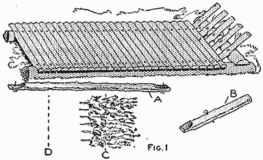
A Camp Bed Made of Saplings with Several Layers of Boughs for the Mattress (Fig. 1)
In the absence of an empty mattress tick and pillow cover which can be filled with straw, boughs of fir may be used. These boughs should not be larger than a match and crooked stems should be turned down. Begin at the head of the bed and lay a row of boughs with the stems pointing toward the foot. Over this row, and half-lapping it, place another row so that the tops of the boughs lie on the line C and their stems on the line D. This process is continued until the crosspiece springs are entirely covered, and then another layer is laid in the same manner on top of these, and so on, until a depth of 6 or 8 in. is obtained. This will make a good substitute for a mattress. A pillow can be made by filling a meal bag with boughs or leaves.
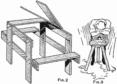
A Table Made of Packing-Box Material and a Wash Basin Stand of Three Stakes (Fig. 2, Fig. 3)
A good and serviceable table can be constructed from a few fence boards, or boards taken from a packing box. The table and chairs are made in one piece, the construction being clearly shown in Fig. 2. The height of the ends should be about 29 in., and the seats about 17 in. from the ground. The other dimensions will be governed by the material at hand and the number of campers.
A wash-basin support can be made of three stakes, cut from saplings and driven in the ground, as shown in Fig. 3. The basin is hung by its rim between the ends of the stakes.
Wherever a suitable tree is handy, a seat can be constructed as shown in Fig. 4. Bore two 1-in. holes, 8 in. apart, in the trunk, 15 in. above the ground, and drive two pins, about 12 in. long, cut from a sapling into them. The extending ends are supported on legs of the same material. The seat is made of a slab with the rounding side down.
A clothes hanger for the tent ridge pole can be made as shown in Fig. 5. The hanger consists of a piece, 7 in. long, cut from a 2-in. sapling, nails being driven into its sides for hooks. The upper end is fitted with a rope which is tied over the ridge pole of the tent.
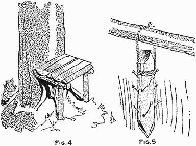
A Seat Against the Trunk of a Tree, and a Clothes Hanger for the Tent Ridge Pole (Fig. 4, Fig. 5)
A Fruit Stemmer
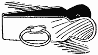
In the berry season the stemmer shown in the sketch is a very handy article for the kitchen. It is made of spring steel and tempered, the length being about 2-1/2 in. The end used for removing the stem is ground from the outside edge after tempering. A ring large enough to admit the second finger is soldered at a convenient distance from the end on one leg.—Contributed by H. F. Reams, Nashville, Tennessee.
A Homemade Fountain Pen
A very serviceable fountain pen can be made from two 38-72 rifle cartridges and a steel pen. Clean out the cartridges, fit a plug tightly in the end of one shell, and cut it off smooth with the end of the metal. Drill a 3/16 in. hole in the center of the wood plug and fit another plug into this hole with sufficient end projecting to be shaped for the length of the steel pen to be used. The shank of the pen and the plug must enter the hole together. One side of the projecting end of the plug should be shaped to fit the inside surface of the pen and then cut off at a point a little farther out than the eye in the pen. On the surface that is to lie against the pen a groove is cut in the plug extending from near the point to the back end where it is to enter the hole in the first plug. The under side of the plug is shaped about as shown.

One Cartridge Shell Makes the Fountain Part of the Pen, and the Other the Cap
The other cartridge is cut off at such a point that it will fit on the tapering end of the first one, and is used for a cap. The cartridge being filled with ink and the plug inserted, the ink will flow down the small groove in the feeder plug and supply the pen with ink. Care must be taken that the surface of the smaller plug fits the pen snugly and that the groove is not cut through to the point end. This will keep the ink from flooding, and only that which is used for writing will be able to get through or leak out.—Contributed by Edwin N. Harnish, Ceylon, Canada.
Destroying Caterpillars on Grapevines
The grapes in my back yard were being destroyed by caterpillars which could be found under all the large leaves. The vine was almost dead when I began to cut off all the large leaves and those eaten by the caterpillars, which allowed the sun's rays to reach the grapes. This destroyed all the caterpillars and the light and heat ripened the grapes.—Contributed by Wm. Singer, Rahway, N. J.
It will require 1 gal. of ordinary mixed calcimine to cover 270 sq. ft. of plastered surface, 180 sq. ft. of brickwork and 225 sq. ft. of average woodwork.
A Camp Provision Box
While on a camping-and canoeing trip recently, I used a device which added a touch of completeness to our outfit and made camp life really enjoyable. This useful device is none other than a provision or "grub" box.

The Provision Box Ready for Use in Camp, the Cover Turned Back on the Brackets and the Legs Extended
From experience campers know that the first important factor in having a successful trip is compactness of outfit. When undertaking an outing of this kind it is most desirable to have as few bundles to carry as possible, especially if one is going to be on the move part of the time. This device eliminates an unnecessary amount of bundles, thus making the trip easier for the campers, and doubly so if they intend canoeing part of the time; and, apart from its usefulness as a provision container, it affords a general repository for the small articles which mean so much to the camper's welfare.
The box proper may be made of any convenient size, so long as it is not too cumbersome for two people to handle. The dimensions given are for a box I used on a canoe trip of several hundred miles; and from experience I know it to be of a suitable size for canoeists. If the camper is going to have a fixed camp and have his luggage hauled, a larger box is much to be preferred. A glance at the figures will show the general proportions of the box. It may be possible, in some cases, to secure a strong packing box near the required dimensions, thus doing away with the trouble of constructing it. The distinguishing features of this box are the hinged cover, the folding legs, and the folding brackets. The brackets, upon which the top rests when open, fold in against the back of the box when not in use. The same may be said of the legs. They fold up alongside the box and are held there by spring-brass clips.

The Brackets for the Cover as Well as Each of the Four Legs Fold Against the Sides of the Box in Such a Manner as to be Out of the Way, Making the Box Easy to Carry and Store Away in a Small Space
On our trips we carry an alcohol stove on which we do all of our cooking. The inner side of the top is covered with a sheet of asbestos, this side being uppermost when the hinged top is opened and resting on the folding brackets. The stove rested on this asbestos, thus making everything safe. The cover is large enough to do all the cooking on, and the box is so high that the cooking can be attended to without stooping over, which is much more pleasant than squatting before a camp fire getting the eyes full of smoke. The legs are hinged to the box in such a manner that all of the weight of the box rests on the legs rather than on the hinges, and are kept from spreading apart by wire turnbuckles. These, being just bolts and wire, may be tucked inside the box when on the move. The top is fitted with unexposed hinges and with a lock to make it a safe place for storing valuables.
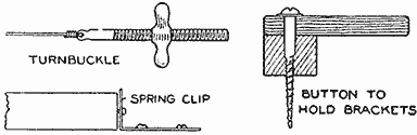
Detail of the Turnbuckle, Button to Hold the Brackets, and the Spring Clip for Holding the Legs on the Side of the Box
In constructing the cover it is well to make it so that it covers the joints of the sides, thus making the box waterproof from the top, if rain should fall on it. A partition can be made in one end to hold odds and ends. A tray could be installed, like the tray in a trunk, to hold knives, forks, spoons, etc., while the perishable supplies are kept underneath the tray. Give the box two coats of lead paint, and shellac the inside.
The wire braces for the legs are made as follows. Procure four machine bolts, about 1/4 in. in diameter and 2 in. long—any thread will do—with wing nuts and washers to fit. Saw or file off the heads and drill a small hole in one end of each bolt, large enough to receive a No. 16 galvanized iron wire. Two inches from the bottom of each leg drill a hole to take the bolt loosely. Determine the exact distance between the outside edges of the legs when the box is resting on them. Make the wire braces 1 in. longer than this distance so that the bolts will protrude through the holes in the legs and allow for putting on the nuts and washers. Screwing up on the nuts draws the wire taut, thus holding the legs firm.
The size of the top determines the dimensions of the folding brackets which support it when open. These brackets may be solid blocks of wood, but a lighter and more serviceable bracket is constructed as follows. If the top is 20 in. wide and 30 in. long, make the brackets 10 by 13 in. Constructing the brackets so that their combined length is 4 in. shorter than the total length of the box, facilitates their folding against the back of the box when not in use. This point is clearly shown in the drawing. Our brackets were made of 1/2-in. oak, 1-1/2 in. wide, and the joints halved together. They are hinged to the back of the box as shown; and when folded are held in place by a simple catch. The weight of the lid is sufficient to hold the brackets in place when open, but to make sure they will not creep when in use insert a 1/4-in. dowel in the end of each so that it protrudes 1/4 in. Drill two holes in the top to the depth of 1/4 in., so that when the top rests on the brackets, these holes engage with the dowels. In hinging the brackets to the back see that they are high enough to support the lid at right angles to the box.
The box here shown is made of 7/8 in. white pine throughout. The legs are 7/8 by 2-1/2 by 18 in. They are fastened to the box with ordinary strap hinges. When folded up against the box they do not come quite to the top so that the box should be at least 19 in. high for 18-in. legs. About 2 in. from the bottom of the legs drive in a brad so it protrudes 1/8 in. as shown. This brad engages in a hole in the spring-brass clip when folded up as shown in the illustration.
If in a fixed camp, it is a good idea to stand the legs in tomato cans partly full of water. This prevents ants from crawling up the legs into the box, but it necessitates placing the wire braces higher on the legs.
Our box cost us nothing but the hardware, as we knocked some old packing boxes to pieces and planed up enough boards to make the sides. Of course, the builder need not adhere to these dimensions, for he can make the size to suit his requirements, while the finish is a matter of personal taste.
A blue writing ink is easily made of 1 oz. Prussian blue, 1-1/2 oz. oxalic acid and 1 pt. of soft water. Shake and allow it to stand until dissolved.
Wall Pockets in a Tent
When camping I find a few wall pockets sewed to the tent walls at the back end provide a convenient means to hold the soap, mirror, razor and other small articles liable to be lost. The pockets can be made of the same material as the tent and sewed on as a patch pocket.—Contributed by A. M. Barnes, Atlanta, Ga.
Camp Stoves
The camp stoves illustrated are different forms of the same idea. Both can be taken apart and laid flat for packing. Iron rods, 1/2 in. in diameter, are used for the legs. They are sharpened at the lower end so that they may be easily driven into the ground. The rods of the one shown in the first illustration are bent in the form of a hook at the upper end, and two pieces of light tire iron, with holes in either end, are hung on these hooks. Across these supports are laid other pieces of the tire iron. In the other stove, the rods have a large head and are slipped through holes in the four corners of the piece of heavy sheet iron used for the top. A cotter is slipped through a hole in each rod just below the top, to hold the latter in place.—Contributed by Mrs. Lelia Munsell, Herington, Kansas.
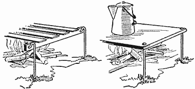
Camp-Stove Top, Either Solid or Pieced, Supported on Rods at the Corners
Attractor for Game Fish
A piece of light wood, shaped as shown and with four small screweyes attached, makes a practical attractor for game fish, such as bass, etc., by its action when drawn through the water or carried by the flow of a stream. Hooks are attached to three of the screweyes and the fourth one, on the sloping surface, is used for the line.—Contributed by Arthur Vogel, Indianapolis, Ind.
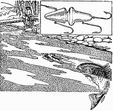
A Device for Attracting Game Fish Which is Used in Place of Bait
Simple Photographic-Print Washer
The ordinary washbowl supplied with a faucet may be easily converted into a washing tray for photographic prints or film negatives. Procure a medicine dropper from a druggist, and attach it to the faucet end with a short piece of rubber tubing. Be sure to procure a dropper that has the point turned at right angles to the body.
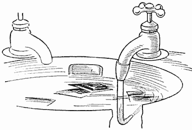
The Whirling Motion Set Up by the Forced Stream at an Angle Thoroughly Washes Prints
When the water is turned on it is forced through the small opening in the dropper in such a manner that the water in the bowl is kept in a constant whirling motion. This will keep the prints on the move, which is necessary for a thorough washing.
How to Make an Electric Fishing Signal
A unique electric fishing signal, which may be rigged up on a wharf or pier, and the electric circuit so arranged as to operate an electric bell or buzzer, located in the fisherman's cottage, or any other convenient place, may be constructed as follows: Obtain two pieces of 1/16-in. spring brass, one 6 in. long and 3/4 in. wide, and the other 7 in. long and 1/2 in. wide. Mount a 2-in. brass wood screw, A, in one end of the 6-in. piece as shown.
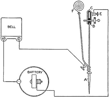
Construction of the Parts to Make the Contact Points and the Electric Connections
Place over the end of the 6-in. piece a thin sheet of insulating fiber, B, allowing it to extend down on each side about 1 in. Then bend a piece of 1/16-in. brass, C, over the insulating fiber, allowing it to extend down on each side the same distance as the insulating fiber. Drill a small hole through the lower ends of the U-shaped piece of brass, C, the insulation, B, and the 6-in. piece, while they are all in place. Remove the insulation and the U-shaped brass piece, and tap the holes in the brass for a machine screw, D. Enlarge the hole in the 6-in piece, and provide an insulating bushing for it with an opening of the same diameter as the brass machine screw. Mount a small binding post, E, on one side of the U-shaped piece of brass, and the parts may then be put together and held in place by means of the brass screw.
Drill two holes in the other end of the 6-in piece, also two holes in one end of the 7-in piece, and rivet them together with two small rivets. The 7-in. piece should project beyond the end of the 6-in. piece. A piece of thin spring brass should be made into the form of a spiral, F, and fastened to the upper end of the 7-in. piece. Provision should be made for attaching the fishline to the inside end of the brass spiral. A small binding post should be soldered to either the 6-in. or 7-in. piece, at the bottom.
If the device is set up with the head of the brass adjusting screw in the top of the 6-in. piece, pointing in the direction the line to the fishing hook is to run, and if a fish pulls upon the line, the 7-in. piece is pulled over and touches the point of the adjusting screw. If a battery and bell, or buzzer, is connected as shown, the circuit will be completed when the 7-in. piece comes in contact with the adjusting screw, and the bell will ring.
A Chair Swing
A comfortable porch or lawn swing can be easily and quickly made with a chair as a seat, as follows. Procure some rope of sufficient strength to bear the weight of the person, and fasten one end securely to one of the front legs of the chair and the other end to the same side of the back as shown in the illustration, allowing enough slack to form a right angle. Another piece of rope, of the same length, is then attached to the other side of the chair. The supporting ropes are tied to these ropes and to the joist or holding piece overhead.—Contributed by Wm. A. Robinson, Waynesboro, Pa.
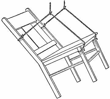
The Ropes are Tied to the Chair so That It will be Held in a Reclining Position
Another Broom Holder
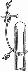
Of the many homemade devices for holding a broom this is one of the simplest, and one that any handy boy can make.
It consists of a string, about 1 ft. long, with a knot at one end and the other tied to a nail or staple driven into the wall. To hang up the broom simply turn the string around the handle as shown, and the broom will be held securely, because its weight will pull the string taut and the knot at the end will prevent the string from running off the handle.—Contributed by Jef De Vries, Antwerp, Belgium.
Squaring Wood Stock
The device shown in the sketch is a great help to the maker of mission furniture as a guide on short cuts. It consists of two pieces of wood, A and B, preferably of oak, fastened together at right angles by two large flat-head screws. The pieces should be placed exactly at right angles.
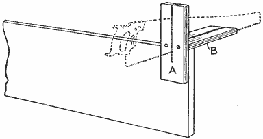
The Saw Teeth Edge can be Run through Both Pieces, the Stock being in the Corner
A cut is then made through both pieces. The cut on B should be exactly at right angles to the surface of piece A. This device can be either clamped on a board or merely held by hand, and will insure a true cut.—Contributed by F. W. Pumphrey, Owensboro, Ky.
A Wind Vane
A novelty in wind vanes is shown in the accompanying sketch. The vane can be made of sheet metal or carved from light wood. The wings are so set on the body as to cause the dragon to rise when the wind strikes them. The dragon is pivoted on a shaft running through its center of gravity, so it will readily turn with the wind. The tail part may also be made to revolve as the propeller of an aeroplane.
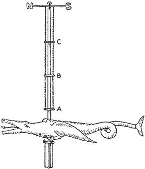
The length and size of the shaft will depend on the dimensions of the dragon, and similarly, the location of the weights on the chains will be determined by its size and weight. Upon these circumstances and the varying velocities of the wind will depend how high the dragon will rise on its shaft, and the height reached by it will thus serve to indicate—in a relative manner only—the velocity of the wind, but it is also possible to arrange the weights at such distances apart that the dragon will rise to A in a 20-mile wind, to B in a 30-mile wind, to C in a 40-mile gale, and so on, with as many weights as desired. This can be done with the aid of an anemometer, if one can be borrowed for some time, or the device may be taken to the nearest weather bureau to be set.—Contributed by H. J. Holden, Ontario, Cal.
Never rock a file—push it straight on filing work.
How to Make a Flutter Ring
The flutter ring is for inclosing in an envelope and to surprise the person opening it by the revolving of the ring. The main part is made of a piece of wire, A, bent so that the depth will be about 2 in. and the length 4 in. Procure or make a ring, 2 in. in diameter. The ring should be open like a key ring. Use two rubber bands, BB, in connecting the ring to the wire.
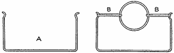
The Shape of the Wire and Manner of Attaching the Rubber Bands to the Ring
To use it, turn the ring over repeatedly, until the rubber bands are twisted tightly, then lay it flat in a paper folded like a letter. Hand it to someone in this shape or after first putting it into an envelope. When the paper is opened up, the ring will do the rest.—Contributed by D. Andrew McComb, Toledo, O.
A Kitchen Utensil Hanger
Every cook knows how troublesome it is to have several things hanging on one nail. When one of the articles is wanted it is usually at the back, and the others must be removed to secure it. A revolving rack for hanging a can opener, egg beater and cooking spoons, etc., takes up less space than several nails, and places every article within easy reach as well as providing individual hooks for all the pieces.
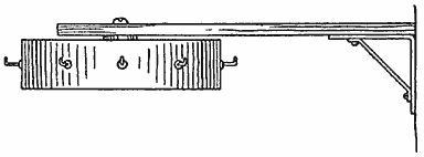
The Hook Support Revolves so as to Make Each One Readily Accessible for Hanging Utensils
The rack is easily made of a block of wood, 2-1/2 in. in diameter and 1 in. thick; an arm, 3/4 in. wide, 1/4 in. thick and 6 in. long, and a metal bracket. The arm is fastened to the bracket and the bracket to the wall. A screw is turned through a loose-fitting hole bored in the end of the arm and into the disk. Screw hooks are placed around the edge of the disk as hangers.—Contributed by A. R. Moore, Toronto, Can.
Homemade Hinges for Boxes
A very simple form of hinge can be made as shown in the sketch. It is merely a matter of cutting out two pieces of flat steel, A, punching holes in them for screws or nails, and fastening them to the box corners, one on each side. When the box is open, the lid swings back clear and is out of the way. A hinge of this kind is very strong. For a light box, the parts can be cut from tin.—Contributed by Chas. Homewood, Waterloo, Iowa.
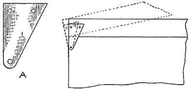
Hinge Parts Made of Sheet Metal and Their Use on a Box Cover
To Remove Odors from Ice Boxes
An easy way to prevent odors in an ice box is to place a can of coke in the box. This will take up all gases and prevent milk from tasting of onions or vegetables which may be kept in the box.
In factories where bad odors are apt to spoil the men's lunches put up in pails or baskets, a box can be constructed to hold these receptacles and a large pail of coke placed in it. Anything placed in this box will remain free from odors, and fresh.—Contributed by Loren Ward, Des Moines, Iowa.
Preventing Window Sash from Freezing to the Sill
When it is cold enough to cause the window sash to freeze fast in the bathroom and bedrooms not having double sash, much discomfort will be experienced and the health may even be menaced. I have discovered a simple method to overcome this difficulty. Lay on the outside sill, close up against the window frame, a thin, narrow strip of wood, on which the window can rest when down. This gives a continual current of fresh air between the sashes at the center, but no unpleasant draft below, and no amount of dripping and freezing will fasten the window sash upon it.—Contributed by Mary Murry, Amherst, Nova Scotia.
A Hanger for the Camp
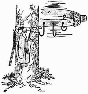
A garment, or utensil, hanger can be easily made for the camp in the following manner: Procure a long strap, about 1-1/4 in. wide, and attach hooks made of wire to it. Each hook should be about 4 in. long and of about No. 9 gauge wire. Bend a ring on one end of the wire and stick the other end through a hole punched in the center of the belt. The ring will prevent the wire from passing through the leather, and it should be bent in such a manner that the hook end of the wire will hang downward when the width of the belt is vertical. These hooks are placed about 2 in. apart for the length of the belt, allowing sufficient ends for a buckle and holes. The strap can be buckled around a tree or tent pole.—Contributed by W. C. Loy, Rochester, Ind.
Never stand in a direct line of a swiftly revolving object, such as an emery wheel.
Locking Several Drawers with One Lock
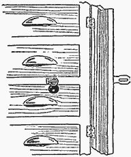
A lock for a number of drawers in a bench or cabinet may be applied with a strip of wood hinged to the cabinet edge so that it will overlap the drawer fronts, as shown. A hasp and staple complete the arrangement for use with a padlock.—Contributed by H. W. Hahn, Chicago.
A Lightning-Calculation Trick
By means of a simple arrangement of numbers, a calculation can be made which will easily puzzle any unsuspecting person. If the two numbers 41,096 and 83 be written out in multiplication form, very few will endeavor to write down the answer directly without first going through the regular work. By placing the 3 in front of the 4 and the 8 back of the 6, the answer is obtained at once, thus: 41,096 × 83 = 3,410,968. A larger number which can be treated in the same way is the following: 4,109,589,041,096 × 83 = 341,095,890,410,968.
An Adjustable Nutcracker
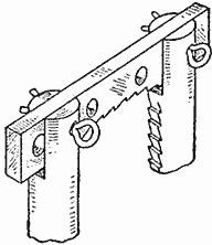
The advantage of the nutcracker shown in the illustration is that it can be adjusted to various-sized nuts. The handles are similar to those usually found on nutcrackers except that they are slotted at the cracking end to receive a special bar. This bar is 2 in. long, 1/2 in. wide, and 1/8 in. thick, with 1/8-in. holes drilled in it at intervals to allow for adjustment. Cotters are used in the holes as pins.
Substitute for a Rubber Stamp
A large number of coupons had to be marked, and having no suitable rubber stamp at hand, I selected a cork with a smooth end and cut the initials in it. I found that it worked as well, not to say better, than a rubber stamp. An ordinary rubber-stamp pad was used for inking. Angular letters will cut better than curved ones, as the cork quickly dulls the edge of any cutting tool.—Contributed by James M. Kane, Doylestown, Pa.
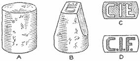
Initials Cut in a Cork Served the Purpose in the Absence of a Rubber Stamp
A Furniture Polish
A good pastelike furniture polish, which is very cheap and keeps indefinitely, can be made as follows: Mix 3 oz. of white wax, 2 oz. of pearlash, commonly known as potassium carbonate, and 6 oz. of water. Heat the mixture until it becomes dissolved, then add 4 oz. of boiled linseed oil and 5 oz. of turpentine. Stir well and pour into cans to cool. Apply with a cloth and rub to a polish. The paste is nonpoisonous.
A Hanging Vase
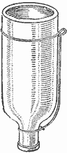
A very neat and attractive hanging corner vase can be made of a colored bottle. The bottom is broken out or cut off as desired and a wire hanger attached as shown. The opening in the neck of the bottle is well corked. Rectangular shaped bottles fitted with hangers can be used on walls.—Contributed by A. D. Tanaka, Jujiya, Kioto, Japan.
Filing Soft Metals
It is well known to mechanics that when lead, tin, soft solder or aluminum are filed, the file is soon filled with the metal and it will not cut. It cannot be cleaned like the wood rasp by dipping it into hot water or pouring boiling water over it, but if the file and the work are kept wet with water, there will be no trouble whatever. Both file and work must be kept thoroughly wet at all times.—Contributed by J. H. Beebee, Rochester, N. Y.
Locking Screws in Door Hinges
When screws once work loose in hinges of doors they will never again hold firmly in the same hole. This trouble can be avoided if the screws are securely locked when they are first put on the door. The sketch shows a very successful way to lock the screws. The hole in the hinge for the screw is filed to produce a notch, as shown at A, deep enough to receive a small wire nail or brad, which is driven through the slot in the screw head at one side, as shown at B.
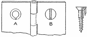
The Screw is Permanently Locked with a Small Nail Driven into the Slot Prepared for It
To Remove Grease from Clothing
Equal parts of ether, ammonia and alcohol make a solution that will readily remove grease from clothing. The solution must be kept away from fire, and should be contained in corked bottles as it evaporates quickly, but can be used without danger. It removes grease spots from the finest fabrics and is harmless to the texture.
Jeweler's rouge rubbed well into chamois skin is handy to polish gold and silver articles with.

Stove Made of an Old Oilcan with Extending Sides and Weighted with Sand for Use on a Fishing Boat Holds the Cooking Vessel Safely in a Sea
A Canoe Stove By F. V. Williams
Limited space and the rocking motion of salmon-fishing boats in a heavy sea on the Pacific coast brought about the construction of the canoe stove shown in the illustration. It is made of a discarded kerosene can whose form is square. A draft hole is cut in one side of the can, 4 or 5 in. from the bottom, and a layer of sand placed on the bottom. Two holes are punched through opposite sides, parallel with the draft hole and about 3 in. from the top edge. Rods are run through these holes to provide a support for the cooking utensil. The smoke from the fire passes out at the corners around the vessel.
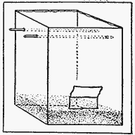
The main reason for making the stove in this manner is to hold the cooking vessel within the sides extending above the rods. No amount of rocking can cause the vessel to slide from the stove top, and as the stove is weighted with the sand, it cannot be easily moved from the place where it is set in the canoe.
The use of such a stove in a canoe has the advantage that the stove can be cleaned quickly, as the ashes and fire can be dumped into the water and the stove used for a storage box. The whole thing may be tossed overboard and a new one made for another trip.
To Prevent Washboard from Slipping in Tub
The modern stationary washtubs are box-shaped, with one side set at an outward angle or slope. The washboard, when used in these tubs, will slide up and down against the sloping part of the tub while the clothes are rubbed against them. This annoying trouble can be avoided by tacking, on the top edge of the board, strips of rubber cut from a discarded bicycle tire, placing the rubber side out. The friction of the rubber prevents any motion of the board.—Contributed by Jas. A. Hart, Philadelphia, Pa.
To print on celluloid, use a good gloss ink and old rollers.
Clips to Hold Magazine Pages Together
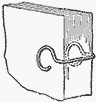
When a magazine is placed in a bookcase the outer pages are liable to turn back if it is inserted with the back on the outside. To overcome this difficulty I made clips for each magazine to hold the open pages together. Each clip was made of wire, about 8 in. long, shaped as shown. The width of the clip is made equal to the thickness of the magazine and the extending ends are slightly pressed together so that they will spring and grip the pages.—Contributed by W. A. Saul, E. Lexington, Massachusetts.
Slide-Opening Cover for a Plate Holder
The length of time required for the slide of a plate holder to be removed on a reflecting camera spoiled many of my plates, because strong light would enter the unprotected slot when the camera was in certain positions. To protect this slot so that the slide could be left out indefinitely, I made a cover of a piece of sheet metal having three slots, to admit screws turned into the camera. A knob was attached at the center. The illustration shows the application of this cover. In Fig. 1 the plate holder is shown slipped in with the cover back, and Fig. 2 shows the slide drawn and the cover over the slot opening.—Contributed by B. J. Weeber, New York City.
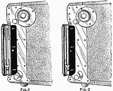
The Two Positions Occupied by the Slide-Opening Cover as It is Used on a Camera (Fig. 1, Fig. 2)
Magnetic-Suspension Pendulum
When a pendulum is not periodically supplied with energy its amplitude grows smaller and finally the motion ceases, due to the resistance of the air and the friction at the point of suspension. Usually the suspension is in the form of a knife edge bearing against plates of agate; sometimes the pendulum rod is simply attached to a very slender and flexible spring without any bearings. But the minimum of friction is obtained by means of magnetic suspension, as the following experiment will prove.
If the rod of a pendulum about 12 in. long, beating half seconds, is sharpened to a needle point and suspended from one of the poles of a magnet, it will be found that, if set into motion, it will continue to swing 15 times as long as the ordinary knife-edge suspended pendulum, and it will not stop until after about 16 hours, while one working on agate plates will stop in from 50 to 60 minutes. Similarly a top, provided with a fine-pointed axis of iron, will spin much longer when suspended from a magnet.
Magnetic suspension is used in precision instruments; for example, the minute mirrors which are used in certain telegraph systems to register writing photographically at the receiving end.
Use for Pencil Stubs
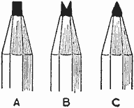
In mechanical drawings cast iron is indicated by a series of straight lines across the parts made of this material. These lines can be quickly made with the usually discarded pencil stubs, if these are saved and sharpened in the following manner: The point is filed flat, as shown at A; then a slot is filed in the center of the lead with a knife file, as shown at B, and the points sharpened as in C. In this way two lines are drawn at one stroke neatly and in half the time.—Contributed by J. Kolar, Maywood, Ill.
To sharpen a carving knife draw the edge through and against the open edge of a pair of shears.

How to Build a Paddle-Wheel Boat By P. A. Baumeister
The paddle-wheel boat, illustrated herewith, was built in the spare time I had on rainy afternoons and Saturdays, and the enjoyment I derived from it at my summer camp more than repaid me for the time spent in the building. The materials used in its construction were:
| 2 | side boards, 14 ft. long, 10 in. wide and 7/8 in. thick. |
| 2 | side boards, 14 ft. long, 5 in. wide and 7/8 in. thick. |
| 1 | outside keel board, 14 ft. long, 8 in. wide and 7/8 in. thick. |
| 1 | inside keel board, 14 ft. long. 10 in. wide and 7/8 in. thick. |
| 120 | sq. ft. of tongue-and-groove boards, 3/4 in. thick, for bottom and wheel boxes. |
| 1 | piece, 2 in. square and 18 in. long. |
| 4 | washers. |
| 2 | iron cranks. |
| 10 | screweyes. |
| 30 | ft. of rope. |
| Nails. |
The dimensions given in the drawing will be found satisfactory, but these may be altered to suit the conditions. The first step will be to cut and make the sides. Nail the two pieces forming each side together and then cut the end boards and nail them to the sides. Lay this framework, bottom side up, on a level surface and proceed to nail on the bottom boards across the sides. The ends of these boards are sawed off flush with the outside surface of the sides after they are nailed in place. The material list calls for tongue-and-groove boards for the bottom, but plain boards can be used, although it is then difficult to make the joint water-tight. When the tongue-and-groove boards are used a piece of string, well soaked in white lead or paint and placed in the groove of each board, will be sufficient to make a tight joint.
Having finished the sides and bottom, the next step will be to fasten on the bottom keel. Adjust the board to its position and nail it in the center part where it lies flat on the bottom boards, then work toward the ends, gradually drawing it down over the turn and nailing it down. If the keel board cannot be bent easily, it is best to soak it in hot water where the bend takes place and the wood can then be nailed down without the fibers breaking. The inside keel is put on in the same manner, but reversed.

The Boat As It Appears without the Spring and Running Board and Used as a Pleasure Craft or for Carrying Freight, the Operator Facing in the Direction of the Boat's Travel
The next procedure is to make the paddle wheels. The hub for each wheel is made of a 2-in. square piece of timber, 9 in. long. Trim off the corners to make 8 sides to the piece, then bore a 3/4-in. hole through its center. The 8 blades of each wheel, 16 in all, are 17 in. long, 6 in. wide and 3/4 in. thick. One end of each blade is nailed to one side of the hub, then it is braced as shown to strengthen the wheel.

Detail Drawing of the Boat and One of the Paddle Wheels. All the Material Required for the Construction is Such That can be Cut and Shaped with Ordinary Tools Found in the Home Workshop
The cranks are made of round iron, 3/4 in. in diameter, and they are keyed to the wheels with large nails in the manner shown. I had a blacksmith shape the cranks for me, but if one has a forge, the work can be done at home without that expense. The bearings for the crankshafts consist of wood, although it is preferable to use for this purpose two large iron washers, having a hole slightly larger than the diameter of the shaft, and drill holes in their rims so that they can be screwed to the wheel-box upright as shown. The bearings thus made are lubricated with a little lard or grease.

Detail of Paddle-Wheel Fastening, the Springboard Construction and the Fastening for the Rudder Control
The paddle-wheel boxes are built over the wheels with the dimensions given in the drawing, to prevent the splashing of water on the occupants of the boat.
The trimmings for the boat consist of three seats, a running board and a springboard. The drawings show the location of the seats. The springboard is built up of 4 boards, 3/4 in. thick, as shown, only nailing them together at the back end. This construction allows the boards to slide over each other when a person's weight is on the outer end. The action of the boards is the same as of a spring on a vehicle.
It is necessary to have a good brace across the boat for the back end of the springboard to catch on—a 2 by 4-in. timber being none too large. At the point where the springboard rests on the front seat there should be another good-sized crosspiece. The board can be held in place by a cleat and a few short pieces of rope, the cleat being placed across the board back of the brace. A little diving platform is attached on the outer end of the springboard and a strip of old carpet or gunny sack placed on it to prevent slivers from running into the flesh. In making the spring and running board, it is advisable to make them removable so that the boat can be used for other purposes.
The boat is steered with a foot-operated lever, the construction of which is clearly shown. For the tiller-rope guides, large screweyes are used and also for the rudder hinges, the pin of the hinge being a large nail. The hull can be further strengthened by putting a few angle-iron braces either on the in or outside.
To make the boat water-tight will require calking by filling the cracks with twine and white lead or thick paint. The necessary tools are a broad, dull chisel and a mallet. A couple of coats of good paint, well brushed into the cracks, will help to make it watertight as well as shipshape. The boat may leak a little when it is first put into the water, but after a few hours of soaking, the boards will swell and close the openings.
This boat was used for carrying trunks, firewood, rocks, sand, and for fishing, and last, but not least, for swimming. The boat is capable of carrying a load of three-quarters of a ton. It draws very little water, thereby allowing its use in shallow water. It has the further advantage that the operator faces in the direction the boat is going, furnishing the power with his hands and steering with his feet.
A Camp Loom
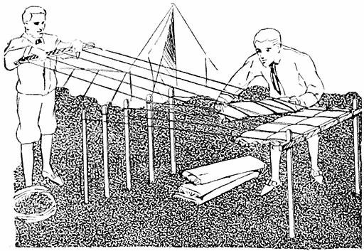
Loom Constructed of Sticks for Weaving Grass or Moss into a Camp Mattress
The camper who desires to "rough it" as much as possible and to carry only the necessities will find it quite a comfort to construct the bedding from grass or moss by weaving it in the manner of making a rag carpet, using heavy twine or small rope as the warp. Two stakes are set the width of the bed or mattress to be made, and a cross stick is attached to their tops. Several stakes are set parallel with the cross stick and at a distance to make the length of the mattress. The warp is tied between the tops of the stakes and the cross stick. An equal number of cords are then attached to the cross stick and to another loose cross stick which is used to move the cords up and down while the grass or moss is placed in for the woof. The ends of the warp are then tied to hold it together. When breaking up camp the cords can be removed and carried to the next camp.—Contributed by W. P. Shaw, Bloor West, Can.
A Milk-Bottle Carrier
Carrying a milk bottle by the rim is tiresome work for the fingers, so I constructed a handle, as shown in the sketch, from a piece of wire. The carrier can be easily placed in the pocket.
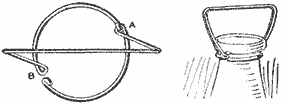
A Carrier Made of Wire to Quickly Attach on a Milk-Bottle Neck
The part fitting under the rim of the bottle neck is bent to form two semicircles, one hooking permanently at A, while the other is hooked at B after it is sprung around the neck of the bottle.—Contributed by Lawrence B. Robbins, Harwich, Mass.
How to Make a War Kite By Park Snyder
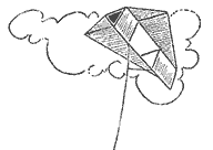
The material required for the making of a war kite is three pine sticks, each 60 in. long, one stick 54 in. long, one stick 18 in. long, all 1/2 in. square; 4 yd. of cambric; a box of tacks; some linen thread, and 16 ft. of stout twine.
Place two 60-in. sticks parallel with each other and 18 in. apart, then lay the 54-in. piece across at right angles to them 18 in. from the upper ends, as shown in Fig. 1, and fasten the joints with brads. At a point 21 in. below this crosspiece, attach the 18-in. crosspiece.
The extending ends of all the three long pieces are notched, Fig. 2, and the line is stretched taut around them, as shown by the dotted lines.
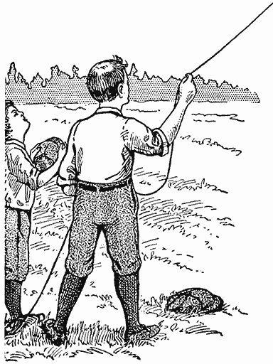
The Line should be a Very Strong One, Then Banners can be Flown on It
If the cambric is not of sufficient size to cover the frame, two pieces must be sewed together, then a piece cut out to the shape of the string, allowing 1 in. to project all around for a lap. The cambric is sewn fast to the string with the linen thread. Fasten the cloth to the frame part with the tacks, spacing them 1 in. apart. The space in the center, between the sticks, is cut out. Make two pieces of the remaining goods, one 36 in. by 18 in., and the other 36 in. by 21 in. The remaining 60-in. stick is fastened to these pieces of cambric, as shown in Fig. 3, and the whole is fastened to the main frame so as to make a V-shaped projection. The bridle strings, for giving the proper distribution of pull on the line to the kite, are fastened, one to the upper end of the long stick in the V-shaped piece attached to the kite, and the other to the lower end, as shown in Fig. 4. The inclination can be varied to suit the builder by changing the point of attachment of the kite line to the bridle. If it is desired to fly the kite directly overhead, attach the line above the regular point and for low flying make the connection below this point. The regular point is found by trial flights with the line fastened temporarily to the bridle, after which the fastening is made permanent.

The Sticks are Fastened Solidly with Brads, and the Cloth Sewed to the String around Their Ends (Fig. 1, Fig. 2, Fig. 3, Fig. 4)
Paper Glider That Loops the Loop By C. A. Thompson
The usual paper glider shaped as shown in Fig. 1 can be made to loop the loop and make corkscrew flights if prepared according to sketches herewith. It should be carefully made in the first place so that in its regular form it flies perfectly straight.

Ordinary Paper Glider and the Manner of Throwing It to Make the Different Flights (Fig. 1, Fig. 2, Fig. 3, Fig. 4, Fig. 5, Fig. 6, Fig. 7, Fig. 8)
To make the glider loop, the rear corners of the wings should be turned up at right angles, as in Fig. 2, and the glider launched with a great deal of force with the nose pointed slightly upward. This will require some practice, but one soon learns the trick. After looping once, as shown in Fig. 3, the glider descends in volplane. This form of glider will also right itself, if dropped from a height, nose downward, as shown in Fig. 4.
For a corkscrew flight the glider is prepared as in Fig. 5; one rear corner being bent up and the other down. In this form it flies horizontally, or downward, while rapidly rotating around its longitudinal axis, as shown in Fig. 6.
To make a spiral descent, the rear corners of the wings are bent up as in Fig. 2, and, further, the rear corner of the keel is bent at right angles, Fig. 7, whereupon it is thrown in the ordinary manner. It then takes the course shown in Fig. 8.
A Water Filter
A cheap and very effective water filter can be made of a flower pot by plugging the hole in the bottom with a piece of sponge and fitting it as follows: Place powdered charcoal on top of the sponge to a depth of 1 in., then 1 in. of clean silver sand, and lastly 2 in. of small stones and gravel. It is hung with a bail at the top.
A Combination Electrically Operated Door Lock
The illustration shows a very useful application of an ordinary electric door lock in the construction of a combination lock and alarm to be operated from the outside of the building.

The Brass-Tack Heads Holding the Numerals in Place Constitute the Combination Points
The three numerals, 1, 2, and 4, or any other combination of numbers constituting the house number on a door, are made of some kind of insulating material and fastened in place on a base of insulating fiber, or wood, about 1/4 in. thick, by means of ordinary brass-headed tacks, as indicated by the black dots. The tacks will extend through the base a short distance so the electrical connections may be made by soldering wires to them, as shown by the diagram, alternate tacks being connected together with the exception of three; for instance, A, B, and C.
The terminals of the leads that are connected to alternate tacks are in turn connected to the terminals of a circuit composed of an ordinary vibrating bell, D, and battery, E. If any two adjacent tack heads be connected together, except tacks A, B, and C, the bell circuit will be completed and the bell ring, which will serve as an indication that some one is tampering with the circuit. The person knowing the combination, connects the tack heads A and B, and at the same time connects the tack head C with F or G, or any other tack head that is connected to the plus side of the battery, whereby a circuit will be completed through the lock H and the door is opened. Any metallic substance, such as a knife, key, or finger ring, may be used in making the above indicated connection, and there will be no need of carrying a key for this particular door so long as the combination is known.
The base upon which the numbers are mounted and through which the points of the tacks protrude, should be mounted on a second base that has a recess cut in its surface to accommodate the wires and points of the tacks.
The combination may be made more or less complicated, as desired, by connecting the tacks in different ways, and by using a separate battery for the bell and lock. The circuit leading to the door lock, if there is one already installed, may be used and then no extra circuit is needed.
Such a device has been used on a private-desk drawer with entire satisfaction. The battery was placed in the back end of the drawer, and if it happened to fail, a new one could be connected to the points B and J so that the drawer could be opened and a new battery put in.
Lock for a Fancy Hairpin
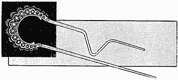
The Bend in the Pin will Hold in the Hair and Prevent the Loss of the Pin
To avoid losing a fancy hairpin, bend one leg of the pin as shown in the illustration. The hair caught in the notch formed by the bend will prevent the pin from dropping out.—Contributed by W. C. Loy, Rochester, Ind.
A metal surface polished with oil will keep clean longer than when polished dry.

An Aeroplane Kite By W. A. Reich
After building a number of kites from a recent description in Amateur Mechanics I branched out and constructed the aeroplane kite shown in the illustration, which has excited considerable comment in the neighborhood on account of its appearance and behavior in the air.
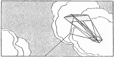
The Kite Being Tailless Rides the Air Waves Like an Aeroplane in a Steady Breeze
The main frame consists of a center-stick, A, 31 in. long, and two cross-sticks, of which one, B, is 31 in. long and the other, C, 15-1/2 in. long. The location of the crosspieces on the centerpiece A is shown in the sketch, the front piece B being 1-3/4 in. from the end, and the rear piece C, 2-1/4 in. from the other end. The ends of the sticks have small notches cut to receive a string, D, which is run around the outside to make the outline of the frame and to brace the parts. Two cross-strings are placed at E and F, 7 in. from either end of the centerpiece A, other brace strings being crossed, as shown at G, and then tied to the cross-string F on both sides, as at H.

General Plan and Outline of the Kite, Which may be Built in Any Size, If the Proportions are Kept, and Its Appearance in the Air on a Steady Breeze
The long crosspiece B is curved upward to form a bow, the center of which should be 3-1/4 in. above the string by which its ends are tied together. The shorter crosspiece is bent and tied in the same manner to make the curve 2-1/2 in., and the centerpiece to curve 1-3/4 in., both upward. The front and rear parts, between the end and the cross-strings E and F, are covered with yellow tissue paper, which is pasted to the crosspieces and strings. The small wings L are purple tissue paper, 4 in. wide at M and tapering to a point at N.
The bridle string is attached on the centerpiece A at the junction of the crosspieces B and C, and must be adjusted for the size and weight of the kite. The kite is tailless and requires a steady breeze to make it float in the air currents like an aeroplane.
The bridle string and the bending of the sticks must be adjusted until the desired results are obtained. The bridle string should be tied so that it will about center under the cross-stick B for the best results, but a slight change from this location may be necessary to make the kite ride the air currents properly. The center of gravity will not be the same in the construction of each kite and the string can be located only by trial, after which it is permanently fastened.
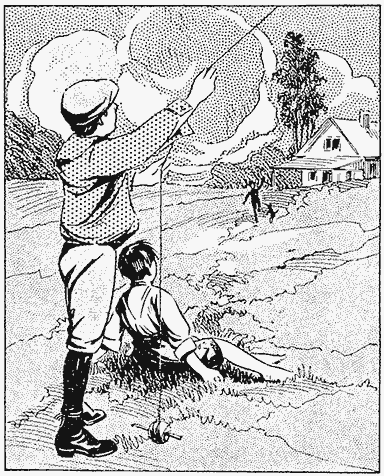
Distilling Apparatus for Water
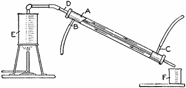
Homemade Still for Removing the Impurities in Water That is Used in Mixing Chemicals
Pure water, free from all foreign substances, is frequently wanted for making up photographic solutions and many other purposes. An apparatus for distilling water can be very easily made from galvanized pipe fittings. The outer cooling jacket A is a piece of 1-in. pipe, 2 ft. long, threaded on both ends, and bored and tapped for 1/2-in. pipe at B and C. A hole is bored and tapped for 1/2-in. pipe in each of the two caps used on the ends of the pipe A, and a piece of 1/2-in. pipe, D, 2 ft. 8 in. long, is run through the holes as shown. The joints are soldered to make them water-tight. Two 1/2-in. nipples, 4 in. long, are screwed in at B and C. The retort, or boiler, E, in which the impure water is boiled may be made of any suitable vessel and heated with a Bunsen or gas burner. A beaker, or other vessel, F, is placed below the lower end of the small pipe. The cold water from the faucet, which flows into the outer jacket at C and out at B, condenses the steam in the small pipe D, turning it into water which falls into the beaker in large drops. The water is often distilled a second time to remove any impurities which it might still contain.—Contributed by O. E. Tronnes, Evanston, Ill.
Telephone Stand for a Sloping Desk
Having a sloping-top desk and being compelled to use the telephone quite frequently, I devised a support for the telephone so that it might stand level and not fall off. The sides of the stand were cut on the same slope as the desk top, and their under edges were provided with rubber strips to prevent slipping.—Contributed by J. M. Kane, Doylestown, Pa.
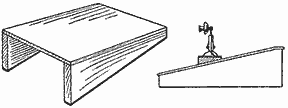
Stand with a Level Surface for a Desk Telephone to be Used on a Sloping Desk Top

Tandem Monoplane Glider By George F. Mace
The monoplane glider illustrated has better fore-and-aft stability than the biplane, is lighter in proportion to the supporting surface, simpler to build, and requires very little time to assemble or take apart. The material list is as follows:
FRAME
| 4 | pieces of bamboo, 14 ft. long, tapering from 1-1/2 to 1 in. |
| 8 | pieces of spruce, 1/2 in. thick, 1 in. wide, and 3 ft. long. |
| 8 | pieces of spruce, 1/2 in. thick, 1 in. wide, and 2 ft. long. |
WINGS
| 4 | main-wing bars, spruce, 3/4 in. thick, 1-1/4 in. wide, and 18 ft. long. |
| 8 | wing crosspieces, spruce, 3/4 in. square, and 4 ft. long. |
| 38 | wing ribs, poplar or spruce, 1/4 in. thick, 3/4 in. wide, and 64 in. long. |
The first thing to do is to make the main frame which is composed of the four bamboo poles. The poles take the corners of a 2-ft. square space and are supported with the pieces of spruce that are 2 ft. and 3 ft. long, the shorter lengths running horizontally and the longer upright, so that each upright piece extends 1 ft. above the two upper poles. All joints should be fastened with 3/16-in. stove bolts. The wire used to truss the glider is No. 16 gauge piano wire. The trussing is done in all directions, crossing the wires between the frame parts, except in the center or space between the four poles.

The Start of the Glide should be Made from the Top of a Hill, Then a Little Run will Carry the Airman Several Hundred Feet through the Air
The framework of the main wings is put together by bolting one of the crosspieces at each end of two wing bars, then another 4 ft. from each end, whereupon the wing bars are bolted to the main frame. The frame is then braced diagonally between these pieces. The ribs, spaced 1 ft. apart, are fastened to this frame with 1-in. brads. The ribs are so bent that the highest part will be 5 or 6 in. above the horizontal. The bending must be uniform and is done when fastening them in place.
The material used to cover the wings and rudders is strong muslin. The cloth is first tacked to the front wing bar, then to the ribs, and sewed to a wire which is fastened between the ends of the ribs. Large brass-head tacks should be used through a strip of tape to fasten the cloth to the ribs. The rear wings are constructed in a similar manner. After the cloth is in place it is coated with starch or varnish.

Details of Tandem Monoplane Glider, Showing the Main Frame and Wing Construction, and the Manner of Placing the Crossed Bracing Wires Between the Parts and to the Wing Ends

The two vertical rectangular spaces in the main frame, just under the rear wings, are covered with cloth to act as a rudder. The upper and lower bracing wires for the wings are attached with snaps and rings so that the glider can be easily taken apart.
It is best not to use the glider in a wind greater than 30 miles an hour. It is started from the top of a hill in the usual manner. Glides can be made running from 60 to several hundred feet.
Carrier for a Suitcase
Where it is necessary to carry a well filled and heavy suitcase the light truck shown in the sketch will be a great assistance. The truck is constructed on the folding plan, similar to a go-cart, and can be carried on the side of the case. The wheels are those used on a go-cart, with rubber tires and about 6 in. in diameter. These are fitted to standards carrying a hinged top piece, the upper ends of the standards being hinged in a like manner. The standards should be cut to the proper length for the person carrying the suitcase.—Contributed by Mrs. Harriet M. S. Kerbaugh, Allentown, Pa.
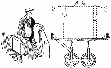
The Small Truck will Greatly Assist the Carrying of a Heavily Loaded Suitcase
Light in a Keyhole
Remove the lock and cut the mortise deep enough to admit a 3-volt battery lamp with a suitable socket attached. The lamp is then connected to wires which are concealed and run to a battery of three dry cells in the basement or other convenient place. A small push button is attached in the line and placed near the knob on the door. A small recess must be cut in the mortise so that the light from the lamp will shine directly on the inside of the plate over the keyhole.—Contributed by Armand F. Lamarre, St. Remi, Can.

How to Make a Monoplane Glider By William Grotzinger — Construction — Assembling — Gliding
A simple glider of the monoplane type can be easily constructed in a small workshop; the cost of materials is not great and the building does not require skilled workmen. Select the material with care and see that the wood is straight-grained and free from knots. The following list of spruce pieces is required:
| 4 | main wing spars, 3/4 by 1-1/4 in. by 17 ft. |
| 2 | rudder spars, 3/4 by 1 in. by 8 ft. |
| 8 | wing crosspieces, 3/4 by 3/4 in. by 4 ft. |
| 4 | rudder crosspieces, 1/2 by 1/2 in. by 2 ft. |
| 1 | piece for main-frame crosspieces, 1/2 by 1 in. by 12 ft. |
| 2 | arm pieces, 1-1/2 by 2 in. by 3-1/2 ft. |
The following list of poplar pieces is required in making the supports for the cloth covering on the wings and rudders.
| 34 | main-wing ribs, 1/4 by 3/4 by 64 in. |
| 8 | rudder ribs, 1/4 by 1/2 by 36 in. |
| 5 | rudder ribs, 1/4 by 3/4 by 48 in. |
The following list of oak pieces is needed:
| 1 | piece, 5/8 by 1-1/4 in. by 12 ft. |
| 1 | piece, 5/8 by 1-1/4 in. by 6 ft. |
| 1 | piece, 3/4 by 3/4 in. by 3-1/2 ft. |
| 2 | pieces, 5/8 by 1-1/2 in. by 5 ft. |
| 4 | pieces, 3/4 by 1 by 28 in. |
In addition to the lists given, four pieces of bamboo, 16 ft. long, tapering from 1 or 1-1/4 in. at the large end to 3/4 in. at the small end, are used for the main frame.

Monoplane Glider in Flight
The first part to make is the main frame A which is constructed of the four bamboo poles. They are made into a rectangular frame with crossbars marked B cut to the right length from the 12-ft. piece of spruce, 1/2 in. by 1 in. The bars C and D are of oak cut from the 6-ft. piece, 5/8 in. by 1-1/4 in. All of these crossbars are fastened together in rectangular form by means of stove bolts. The bamboo poles are then bolted to the inner corners of the frames with 3/16-in. bolts. Place the bolts through the bamboo close to a joint to prevent splitting. The frame is then rigidly trussed by diagonal wires marked E crossing all rectangles. The wire used for trussing all the parts throughout the glider is piano wire, 16 gauge. The arm pieces are bolted to the sides of the rectangular frames beneath the wings.

Plan View

Side Elevation

Front Elevation
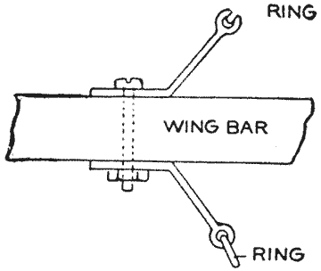
Wing Bar
The framework of the main wings or planes should be put together by bolting the cross struts F at regular intervals on the under side of the main spars G. Brace the frame diagonally with the piano wire. The ribs are nailed to the main spars by using 1-in. brads. The ribs are spaced 1 ft. apart, and curved so that the highest part will be 5 in. from the horizontal. Each rib extends 15 in. back of the rear spar. The rudder is made in the same manner.
The vertical rudder is made to fold. A small pocket arrangement H is made from which the rigs of the vertical rudder diverge.
The covering of the wings and rudders should be a good quality of muslin or some light aeronautical goods. The cloth should be tacked to the front spar, to the ribs, and then sewn to a wire which connects the ends of the ribs.
Construct the triangular arrangement marked J to which the wings are braced. The wing bar supports are shown in the illustration. The bottom wires are braced to the crossbar K shown in the front elevation.
The bracing wires are all fastened to a snaphook which can be snapped into the rings at the places marked L. This method will allow one quickly to assemble or take apart the plane and store it in a small place. The vertical rudder should be braced from each rib to the front spar of the horizontal rudder and then braced by the wires M to hold the rudder from falling back. The rudder is then braced to the main frame and the main frame is braced by the wires N to the wings. This will hold the plane rigid. Use snaphooks and eyebolts wherever possible so that the plane can be quickly assembled.
The triangular arrangement J is bolted to the wings and the top wires put in place. The wings are then put on the main frame and bolted to the bars marked C and D, after which the bottom wires are fixed in place.
Take the glider to the top of a hill, step into the center of the main frame just a little back of the center of the wings. Put your arms around the arm pieces, face the wind and run a few steps. You will be lifted off the ground and carried down the slope. The balancing is done by shifting the legs. The glides should be short at first, but by daily practice, and, as the operator gains skill, glides can be made up to a length of several hundred feet. Do not attempt to fly in a wind having a velocity of more than 15 miles an hour.
Exerciser for a Chained Dog
The exerciser consists of a disk, 5 ft. in diameter, pivoted in the ground near the kennel. The disk revolves on a 5/8-in. pin set in a post made of a 4 by 4-in. piece of timber. The disk is made of common lumber fastened together with battens on the under side. Our dog seems to enjoy this kind of exercise.—Contributed by Hazel Duncan, Denver, Colo.
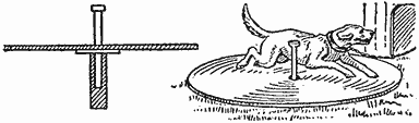
Revolving Disk Exerciser
A Laboratory Gas Generator
The sketch illustrates a gas generator designed for laboratories where gases are needed in large quantities and frequently. The shelf holding the large inverted bottle is of thick wood, and to reinforce the whole apparatus, a 1-in. copper strip is placed around the bottle tightly and fastened with screws turned into the woodwork. The shelf above is attached last, and upon it rests the bottle of commercial acid required in the gas generation. The pump shown is for use in starting the siphon.
Gas Generator of Large Capacity That will Work Automatically as the Gas is Removed
The large bottle used as a generator may be either a 3 or 5-gal. size, and after it is placed in the position shown, a sufficient amount of the solid reagent needed in gas generating is placed in the mouth before the exit tube, leading away below, is fixed in position. If sulphureted hydrogen is required, ferrous sulphide is used; if hydrogen is required, zinc is placed within; and to make a carbon dioxide, marble, or its equivalent, is inserted. Whatever gas is required, a sufficient quantity of the solid material is put in to last for some time in order not to disturb the fastenings.
When all is ready, the pump is used gently to start the acid over the siphon and into the generator from below. The gas generated by the action of the acid on the solid soon fills the bottle. The screw clamp on the exit tube is loosened and the gas passes into the bottle of water and charges it, in the case when sulphureted hydrogen is required. In the other cases, when sufficient gas has been generated, the screw clamp is tightened, and the gas soon attains considerable pressure which forces the acid back out of the generator and into the acid bottle above. The whole apparatus now comes to an equilibrium, and the gas in the generator is ready for another use.—Contributed by W. M. Mills, Bakersfield, Cal.
Holding Small Armatures for Winding
Procure a strip of sheet metal, 6 in. long, 1 in. wide, or as wide as the armature core is long, and 3/32 in. thick. Bend this into a U-shape, as shown, and file each end similar to the barb on a fishhook. Drill two holes for a bolt to pass through the sheet-metal ends. Fasten a screw or bolt in the center of the bend, to be used for gripping in a chuck or polishing head. Core segments can be quickly wound with this device.—Contributed by Geo. B. Schulz, Austin, Illinois.
Armature Cores are Easily Revolved to Fill the Core Openings with Insulated Wire

Footstool for Cement Floors
A clerk finding the cement floor of the office uncomfortably cold to the feet, devised a footstool in the following manner: A shallow box was procured, and four small truck casters were fastened to the bottom. A piece of carpet was laid on the inside of the bottom and some old newspapers placed on top of it. When seated at the desk, he placed his feet inside the box on the papers. The casters elevated the box from the cement, just high enough to avoid dampness and cold, and permitted an easy change of position.—Contributed by L. Alberta Norrell, Gainesville, Ga.
Homemade Telegraph Sounder
The material required to construct a telegraph sounder, like the one shown in the sketch, consists of two binding posts, magnets, a piece of sheet metal, and a rubber band. These are arranged as shown, on a wood base or, better still, on a metal box. In using a metal-box base, be sure to insulate the connections at the magnet coils and binding posts.
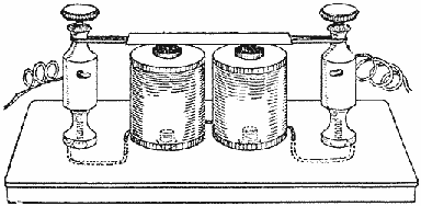
An Inexpensive and Homemade Sounder for Use in Learning the Telegraph Codes
This instrument will be found by those studying the telegraph codes to give good results, equal to any of the expensive outfits sold for this purpose.—Contributed by Chas. J. La Prille, Flushing, N. Y.
Laboratory Force Filter
The sketch represents a force filter which is well adapted for use in small laboratories. The water is turned on at the faucet and draws the air through the side tube by suction, which in turn draws the air in a steady stream through the Wolff bottles. The tubes may be attached to a filter inserted in a filter bottle and filtering thus greatly facilitated. The connection to the faucet can be made, as shown in the detailed sketch, out of a long cork, by boring a hole large enough to fit the faucet through the cork and another slanting hole, joining the central hole, on the side for a pipe or tube. At the lower end of the cork a tube is also fitted, which may be drawn out to increase the suction. The inclined tube should be slightly bent at the lower end.—Contributed by W. M. Mills, Bakersfield, Cal.

A Slight Vacuum is Formed by the Water Flowing through the Cork, Which Forces the Filter
Beginner's Helper for Roller Skating
One of the most amusing as well as useful devices for a beginner on roller skates is shown in the sketch. The device is made of 3/4-in. pipe and pipe fittings, with a strip of sheet metal 1 in. wide fastened about half way down on the legs. On the bottom of each leg is fastened an ordinary furniture caster which allows the machine to roll easily on the floor. The rear is left open to allow the beginner to enter, then by grasping the top rail he is able to move about on the floor at ease, without fear of falling.—Contributed by J. H. Harris, Berkeley, Cal.
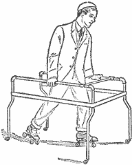
Beginner Cannot Fall
Atmospheric Thermo-Engine
The device illustrated has for its object the production of power in small quantities with little attention and no expense. All that is needed to produce the power is common ordinary water, and the device will continue to operate until the amount of water placed in the receptacle has evaporated.

Details of the Engine
The device consists of a rectangular vessel provided with legs and a cover. Each end of the vessel is provided with an opening, A, adapted to receive and hold in place plaster-of-paris cups, B. The part extending into the tank is provided with a wick, C, which reaches to the bottom of the vessel. A glass tube, D, is provided with a bulb on each end and partly filled with alcohol, the remaining space being exhausted of air. The glass tube is secured to a hanger which is pivoted to the bottom of the vessel.
After a quantity of water has been poured into the vessel and the device allowed to stand undisturbed for a few minutes, the tube will begin to move with an oscillating motion. Some of the water in the vessel has been conducted by means of the wicks C to the bent plaster cups, from the surface of which it evaporates, thus absorbing latent heat and producing a lower temperature in the cups than that of the surrounding atmosphere. The bulb in contact with the cup thus acquires a lower temperature than the one at the end D, which will result in condensation of the alcohol vapor within the former. The pressure of the vapor in the lower bulb will then force the alcohol up the inclined tube into the higher bulb, the evaporation in the lower bulb maintaining the pressure therein.
When a sufficient quantity of alcohol has been forced into the upper bulb, it will descend, and thus elevate the other bulb into its cup. The phenomena just described will be repeated in this bulb and the oscillation will continue until the water in the vessel has been absorbed and evaporated.—Contributed by E. W. Davis, Chicago.
A Mirror an Aid in Rowing a Boat
The young oarsman is apt to experience difficulty in keeping a straight course until he has had some practice. Rowing a boat in a narrow channel calls for considerable skill to hold a course in mid-stream. A variation of force in pulling the oars almost instantly results in the rowboat making a landfall on one or the other of the banks.
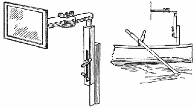
The Mirror Attached to a Boat
The skilled oarsman does not need an appliance that the beginner might welcome. With the aid of a mirror conveniently supported at a suitable angle and height before the oarsman's face, the water, the shores and approaching boats may be seen with distinctness. The mirror may be set directly in front or a little distance to one side as shown in the sketch.—Contributed by Thaleon Blake, Sidney, O.
Developing Tray Made of a Tin Can
Obtain a tomato or other can, 5 or 6 in. long and 4 in. in diameter, which should be secured before it has been opened, says Camera Craft. Cut both ends exactly half way around, keeping close to the edge, as shown in the first sketch, and slit it lengthwise to open the side. Trim off the end pieces to within 1 in. of the center and cut off the surplus tin of the sides of the can, leaving enough to bend over and form the ends of the tank as shown in the second sketch.
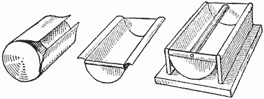
For Developing Roll Films
The support, as shown in the last sketch, is made by screwing together three pieces of wood, the base piece being 6-1/2 in. square and thick enough to make the tank solid and heavy. Bend the sides of the can over the edges of the two uprights and tack them firmly to the sides, bending the tin so as to have a rounded surface that will not scratch the films. The ends of the can are bent over sharply to form the sides of the tank. Procure a round wood stick, the length of the tank, place in position, and fasten with a screw through the tin at both ends. Give the whole tank two coats of black asphaltum varnish to protect it from the action of the developer.
White Rubber on Croquet Arches
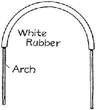
A white cloth is usually tied to croquet arches when the game is played late in the evening. A much better plan is to slip a piece of white rubber tubing about 1 ft. long on the arch. This tubing can be purchased at any local drug store. This makes the top part of the arch conspicuous so that it may be plainly seen in the dark, and, when the tubing becomes soiled it can be cleaned off with a damp cloth.—Contributed by John Blake, Franklyn, Mass.
Illuminating an Outside Thermometer
During the season of furnace fires the thermometer outside the north window becomes of added interest and usefulness in helping one to judge the proper draft adjustments of the furnace for the night. A pocket electric flashlamp is convenient for examining the thermometer after dark, but it is not always at hand, matches are dangerous when lace curtains are at the window, and besides, the reflection from the glass of both matches and flashlamp on the inside makes it very difficult to read the thermometer.
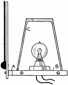
To avoid these difficulties I attached to my thermometer the device shown herewith, which consists of a miniature battery lamp placed at the back of the translucent-glass thermometer and operated by a battery within the house, the light being turned on by an ordinary push button placed conveniently inside of the window.
A strip of brass, A, 3/8 in. wide by 1/16 in. thick, was riveted (soldering will do) to the lower support of the thermometer. The free end of this brass strip was bent around a disk of hardwood, B, and fastened to it by three or four small screws in such a manner that the disk made a circular platform just behind the thermometer scale. This disk was slightly larger than the mouth of a small, thin tumbler. On the upper surface of this disk was fastened with shellac and small nails close to the periphery, a disk of cork, 1/4 in. thick, this cork disk being a close fit for the mouth of the tumbler. A miniature porcelain electric-lamp socket was fastened with screws on the cork of the base. Wires were then run from the lamp socket through the cork and wood disks and the whole painted with melted paraffin to close all apertures and keep out moisture. Good rubber-covered electric-light wire will do nicely for the wiring outside the house, although, if it can be obtained, a piece of lead-covered paired wire is preferable. These wires must be only long enough to reach inside the house, where they may be joined to the ordinary sort of wire used in electric-bell work for connecting with push button and battery.
A 4-volt lamp of about 2 cp. will be sufficient to illuminate the thermometer and allow the scale and mercury column to be distinctly seen. It may be found necessary to make some adjustment by bending the brass strip in order to bring the lamp centrally behind the scale and at the proper height to give the best lighting on the range of from 10 to 40 deg. Over the lamp is placed the tumbler for protection from the weather, and, if desired, half of the tumbler may be painted as a reflector on the inside with white enamel paint, although, in practice, I have not found this necessary.
Within the house the push button should be placed at the window where it can be most conveniently reached when viewing the thermometer, and connections may be made to the battery regularly used for ringing the house bells, or to a separate battery of, say, 4 dry cells, placed in some location, as a closet, near the thermometer.—Contributed by C. F. A. Siedhof, Winchester, Mass.
How to Make an Automobile Robe
When driving an automobile in cold weather, it is impossible to have a robe come down over the feet without being in the way so that it is inconvenient in working the pedals. Procure a common heavy robe and cut two holes in it about 5 in. from the bottom just large enough for the toe of the shoes to slip through and bind the edges with cloth or fur. The 5 in. of robe below the holes should come back under the feet so that no wind can enter. Make the holes far enough apart so that both outside pedals can be reached easily and you will have no trouble with your feet. This robe, with the use of overshoes, will insure comfort in driving a car.—Contributed by Earl R. Hastings, Corinth, Vt.
Locating a Droplight in the Dark
It is very hard to locate an electric-light globe in a dark room. Anyone trying to find one by striking the air in its vicinity with one hand, usually finds that the globe is not there, although the hand may have passed within 1/2 in. of the globe.
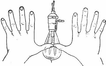
Covering a Wide Range
The best way to locate a globe is to approach the proximity of the drop with thumbs touching and fingers extended as shown in the sketch, in which manner the hands will cover a radius of about 14 in. and offer a better chance of locating the light quickly than if one groped about with one hand extended.—Contributed by Victor Labadie, Dallas, Tex.
Lighting a Room for Making Photographs
When it becomes too cold for the amateur photographer to take pictures outdoors, he generally lays aside his camera and thinks no more about it until the coming of another spring or summer. While some winter scenes would make up an interesting part of anyone's collection, it is not always pleasant to go out to take them.
Some derive pleasure from making groups and portraits, but this is very difficult, if the room is not well lighted. Overhead light is the best for this work and few residences are constructed to furnish this kind of light.
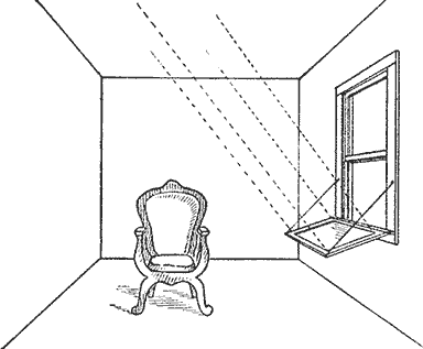
Light Reflected on Ceiling
I find a very good way to get a light overhead is to take a large mirror—one from an ordinary dresser will do—and place it in the window in such a position that the reflection will strike the ceiling just above the subject. The result will be a soft but very strong light, almost equal to a north skylight. Splendid portraits can be made in this way.—Contributed by Chas. Piper, Kokomo, Ind.
Detachable Hinged Cover for Kettles
A kettle cover equipped with the hinge shown in Fig. 1 will not fall off when in place, and can be raised or removed entirely when desired.
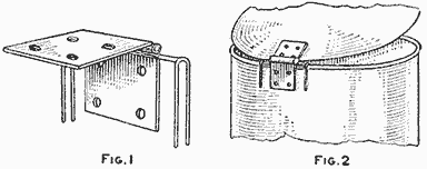
Wire Clasps on Hinge (Fig. 1, Fig. 2)
One wing of an ordinary hinge is soldered or riveted to the cover and wire clasps soldered to the other wing. It is slipped on the kettle as shown in Fig. 2. The cover is interchangeable and can be placed on almost any kettle.
A Use for Discarded Wafer Razor Blades
A paper trimmer and mat cutter can be made from a wafer razor blade. As a paper trimmer, place the blade C over the part A of the razor, as shown, with only two of the holes engaging in one post and the center screw. Then place the part B in position and clamp with the handle. This will allow about 1/2 in. of the blade to project at one end. If a part of the extending blade is cut or broken off, it will be more easily handled. The cutter is guided along the straightedge as shown in Fig. 1.
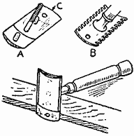
(Fig. 1)
If it is desired to make a more permanent form of instrument, or if no holder is at hand and only a castoff wafer blade, a handle, C, may be cut from a piece of wood and fitted with two or three binding-posts, A, taken from an old battery, to hold the blade B in place, as shown in Fig. 2.
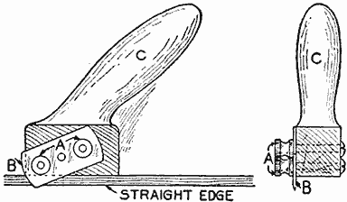
Blade Attached to Handle (Fig. 2)
Armatures for Small Motors
Without the proper tools and material, the amateur electrician will find it quite difficult to construct a small armature for a battery motor that will run true, without vibration and have a neat appearance. Ordinary cast-iron gears or pinions, as shown in Fig. 1, make excellent cores for armatures on small motors. A gear of any number of teeth can be used for an armature with a smaller number of coils by cutting out a certain number of teeth. For example, a gear with 12 teeth will take 12 coils, but if every other tooth is cut out, it will take only 6 coils, etc. The teeth can be easily chipped out with a cold chisel.
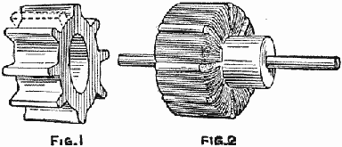
Gear Used as a Core (Fig. 1, Fig. 2)
Larger armatures can be made from gears with spokes, the spokes being cut out, if a ring armature is desired. The gear, when wound, can be mounted on a hub made of empty thread spools. The spool can be turned at one end to insert it in the armature, and if too long, one end will serve for the core of the commutator, as shown in Fig. 2. This combination will make a neat, efficient little armature, which will run quite free from vibration. Only simple tools, such as a hammer, cold chisel, file, jackknife and a vise, are required.—Contributed by R. J. Nault, Hartford, Conn.
Ice Creeper for Shoe Heels
Many persons, young and old, have falls every winter on the ice or snow which can be avoided if their shoes are fitted with ice creepers. A very efficient device of this kind, which any boy can make at home in a short time, is shown in the sketch. These ice creepers need not be removed from the shoes or boots until the winter is past, for they may be worn indoors without injuring the finest floor.
The two plates A may be made from either iron or steel—preferably the latter. An all-steel scraper, or a piece of a saw blade, makes good creepers. Draw the temper by heating the steel to a cherry red and then letting it cool slowly. It may then be sawn with a hacksaw, cut with a cold chisel, or filed into plates of the proper shape, as shown. The teeth are filed to points. The two L-shaped slots are made by drilling 3/16-in. holes through the plates, and then sawing, filing or chiseling out the metal between the holes. The projections at the ends are then bent out at right angles with heavy pliers or the claws of a hammer, and finally the plates bent to fit the curve of the heel.

Creeper Attached to Heel
The creepers are attached by means of round-head wood screws turned into the leather. In this operation place the teeth of the plates just below the bottom of the heel and turn the screws into the ends of the upright slots until the heads just bind. The plate as set when indoors or else not needed is shown at B. To place the plate so it will grip the ice, slide it to the right, which will bring the screws into the horizontal slots, as shown at C.—Contributed by Chelsea C. Fraser, Saginaw, Mich.
Opening Screw-Top Fruit Jars
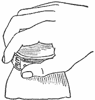
Screw-top fruit jars may be easily opened in the following manner: Secure a strap with a buckle and place it around the top as if it were to be buckled, but instead draw the loose end back and hold it with the thumb as shown. Turn cover and strap while held in this position and it will easily turn from the jar.—Contributed by Chas. A. Bickert, Clinton, Iowa.
Lamp-Chimney Cleaner
Lamp chimneys of various makes are very difficult to clean quickly and thoroughly. The simple device shown in the sketch makes the cleaning process a simple matter. The cleaner is made of a round rubber ball with slits cut in it as shown and then fastened to the end of a stick. When a cloth is placed over the ball it presses evenly against the curved surfaces of the glass. There is no danger of breaking a chimney with this cleaner.
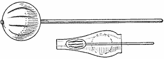
Rubber Ball on Stick
A Pop-Corn Popper
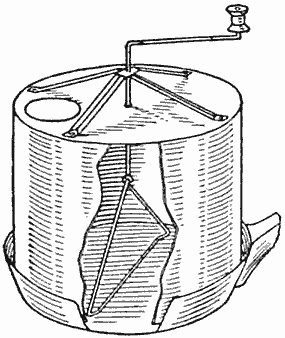
The accompanying sketch shows the construction of a pop-corn popper for thoroughly flavoring the corn with the hot butter or lard, and at the same time mixing it with the necessary amount of salt. Procure a metal bucket that just fits the bottom of the frying pan. The stirring device is made of heavy wire bent as shown and provided with an empty spool for a handle. A brace is made of tin bent in the shape shown and riveted to the bottom of the bucket.—Contributed by F. A. Wirth, Farwell, Texas.
A Homemade Floor Polisher
An efficient and cheap floor polisher may be readily constructed in the following manner: Make a box about 4 by 6 by 12 in., or the exact size may be determined by building it around the household flatirons as these are used to give weight and pressure. The handle, which is attached as shown, should be at least 2-1/2 in wide at the hinged end and should be sandpapered where it is grasped by the hands. A half-strap hinge is preferable, with the strap part fastened to the handle. The bottom of the polisher is covered with a piece of Brussels carpet.
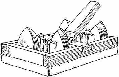
Flatirons in the Box
In use, it is well to set the polisher on a soft piece of cotton or flannel cloth, which may be readily renewed when badly soiled.
A more sightly polisher may be made by filling the box with pieces of old iron or lead, tightly packed with paper to prevent rattling, and attaching a cover over the top. The handle may be hinged directly to this cover by means of a full-strap hinge.—Contributed by B. O. Longyear, Ft. Collins, Colo.
Simple Way to Mark Poison Bottles
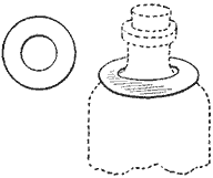
A way to prevent any possible mistake of taking bottles containing poisons is to mark them as shown in the sketch. This method provides a way to designate a poison bottle in the dark.
The marker is made of a circle of heavy cardboard with a hole in the center so as to fit tightly over the neck of the bottle. No matter how dark it may be or how much of a hurry a person may be in, one cannot fail to note the character of the contents of the bottle as soon as the hand touches the cardboard marker.—Contributed by Katharine D. Morse, Syracuse, N. Y.
Removing Varnish
A good and easy way to remove varnish from old furniture is to wash the surface thoroughly with 95-per-cent alcohol. This dissolves the varnish and the wood can then be cleaned with a strong solution of soap, or weak lye. If lye is used, it should be washed off quickly and the wood dried with flannel cloth. When the wood is thoroughly dry it will take a fine finish.—Contributed by Loren Ward, Des Moines, Iowa.
Curling-Iron Heater
The curling-iron holder shown in the sketch can be made of metal tubing having the size to fit both iron and gas jet. One-half of the tubing for a portion of its length is removed, as shown in Fig. 1. The remaining part is bent as in Fig. 2 and set on the burner of the gas jet.
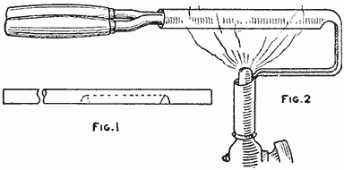
Heater on Gas Jet (Fig. 1, Fig. 2)
The tube prevents the curling iron from becoming black with soot. The position on the jet may be changed. The tube can be placed on the jet and removed with the curling iron.—Contributed by W. A. Jaquythe, Richmond, Cal.
A whisk broom is the best cleaner for a gas stove. It will clean dirt from nickel parts as well as from the burner, grates, ovens and sheet-metal bottoms.
Preserving Flowers in Color and Form
One of the most distressing sides of botanical study is the short life of the colors in flowers. Those who have found the usual method of preserving plants by pressure between paper unsatisfactory will be interested to learn of a treatment whereby many kinds of flowers may be dried so that they retain a great deal of their natural form and color.
The flowers should be gathered as soon as the blossoms have fully opened. It is important that they should be quite dry, and in order to free them of drops of rain or dew, they may be suspended with heads downward for a few hours in a warm place. It is well to begin with some simple form of flower.
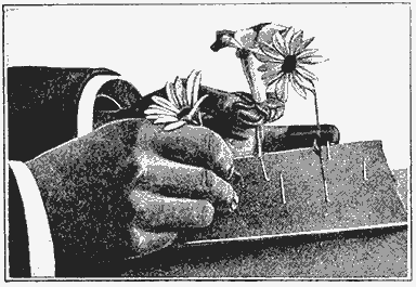
Placing the Flowers on the Steel Pins...
A large, strongly made wooden box—one of tin is better—will be necessary, together with a sufficient amount of sand to fill it. If possible, the sand should be of the kind known as "silver sand," which is very fine. The best that can be procured will be found far from clean, and it must, therefore, be thoroughly washed. The sand should be poured into a bowl of clean water. Much of the dirt will float on the surface. This is skimmed off and thrown away, and clean water added. The sand should be washed in this manner at least a dozen times, or until nothing remains but pure white grains of sand. The clean sand is spread out to dry on a cloth in a thin layer. When thoroughly dry, it should be placed in a heavy earthenware vessel and further dried in a hot oven. Allow it to remain in the oven for some time until it is completely warmed through so that one can scarcely hold the bare hands in it.
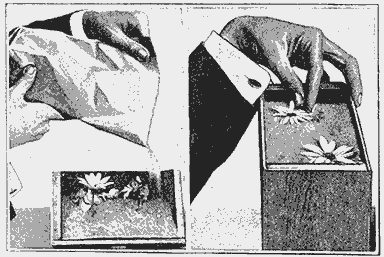
...and Pouring the Dry Sand around Them
Obtain a piece of heavy cardboard and cut it to fit easily in the bottom of the box. Through the bottom of the cardboard insert a number of steel pins, one for each of the flowers to be preserved. Take the dry blossoms and press the stalk of each on a steel pin so that it is held in an upright position. When the cardboard is thus filled, place it in the box.
The Dried Flowers
The warm sand is put in a bag or some other receptacle from which it can be easily poured. Pour the sand into the box gently, allowing it to trickle slowly in so that it spreads evenly. Keep on pouring sand until the heads of the flowers are reached, taking care that all of them stand in a vertical position. The utmost care must be taken, when the heads are reached, to see that all the petals are in their right order. Remember that any crumpled flowers will be pressed into any position they may assume by the weight of the sand. When the box is filled it should be covered and set aside in a dry place.
The box should be allowed to stand at least 48 hours. After the first day, if only a small amount of sand has been used, the material may have cooled off to some extent, and the box must be set in a moderately heated oven for a short time, but no great amount of warmth is advisable. After 48 hours the box may be uncovered and the sand carefully poured off. As the flowers are now in a very brittle condition, any rough handling will cause serious damage. When all the sand has been emptied, the cardboard should be removed from the box and each blossom taken from its pin. In the case of succulent specimens, the stems will have shrunk considerably, but the thinner petals will be in an almost natural condition. The colors will be bright and attractive. Some tints will have kept better than others, but most of the results will be surprisingly good. Whatever state the flowers are in when they are taken from the box, if the drying process has been thorough, they will keep almost indefinitely.
Flowers preserved in this manner are admirable for the decoration of homes. If they are exposed to light, care should be taken to see that the direct sunshine does not strike them, as it will fade the colors. Sprigs with leaves attached may be dried in this way, but it has been found that much of the intensity of the green is lost in the process.
Reading Pulse Beats with the Sun's Rays
The pulse beats may be counted by this unusual method. On a clear day, when the sun is shining brightly, darken a room and select one window toward the sunlight, which should be prepared as follows: Draw the curtain part way down and cover the rest of the window with a heavy cardboard. Cut a small hole in the cardboard to admit a beam of light. Set a bowl of water on a table in the path of the beam so as to deflect it to the ceiling as shown by the dotted lines in the sketch.
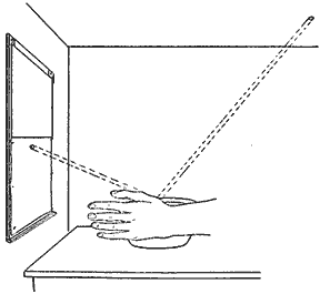
Sun's Rays Deflected to the Ceiling
It is now a simple matter to show the pulse beats. Place the wrist against the edge of the bowl as shown, and the beam of light directed to the ceiling will record every beat of the pulse by short, abrupt movements.
Artistic Wood Turning
Some very odd and beautiful effects can be obtained in lathe work by making up the stock from several pieces of various kinds of wood glued together. The pieces can be arranged in many pleasing combinations, and if good joints are made and a good quality of glue used, the built-up stock is just as durable as a solid piece.
Candlesticks turned from built-up stock are especially attractive, parts of the various light and dark woods appearing here and there in all manner of odd shapes and proportions. If the stock is placed off center in the lathe, a still greater variety of effects will be produced.
The application of a potassium-bichromate solution to the finished work turns each piece a different color. This solution can be made in any depth of color by varying the amounts of potassium salt and water. Maple or birch treated with this solution are colored to a rich Osage orange which cannot be surpassed in beauty. Mahogany is turned a deep reddish brown, and walnut is darkened a great deal. The solution is applied as evenly as possible with a camel's-hair brush while the wood is turning in the lathe. The grain of the wood is somewhat roughened by this process, but it can be dressed down again with very fine sandpaper.
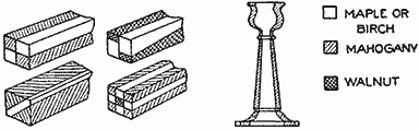
Vase Made of Different Woods
In polishing the work, only the best shellac should be used, and several thin coats applied rather than one or two heavy ones. Each coat, with the exception of the last, should be sandpapered slightly. Powdered pumice stone on a cloth held in the palm of the hand can be used to apply a beautiful luster. Some suggestions as to the manner of combining various woods, and a simple candlestick of mahogany and maple are shown in the sketch.—Contributed by Olaf Tronnes, Wilmette, Ill.
A Variable Condenser
A simple variable condenser for receiving in wireless, which will give good results, was made by a correspondent of Modern Electrics as follows: Each clip on the switch was made of ribbon brass or copper in the shape shown at A, the first one from the joint of the knife switch being the longest and each succeeding one shorter. The handle was taken from a single-pole switch. The case was made of oak and varnished and the condenser was made of tinfoil and thin sheets of mica, 2 by 3 in. in size. After placing the condenser in the case, hot paraffin was poured around it.
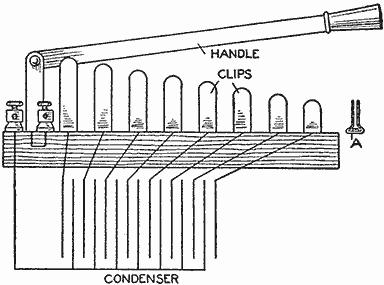
Lever and Clips
Adjustable Baking-Pan Shoes
At times bread, meat, or other food, placed in ordinary baking pans in the oven becomes burned on the bottom. If the detachable metal strips shown in the sketch are placed on the pan, this will not happen, as the pan does not come in direct contact with the oven floor.
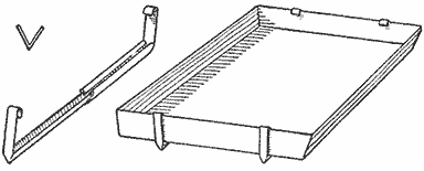
Shoe and How It is Attached to the Pan
The attachment can be placed on agate ware or sheet-iron pans of any length. The shoes are made from light V-shaped metal strips and in two parts, as shown, with the edges of one part lapped over so that the other strip will slide in it.

Cars Lined Up Ready for the Start and the Course Patrolled by the Boy Scouts, All Traffic being Halted for the Race and the Roadway Made Clear for the Entire Half Mile of Track
A Pushmobile Race
Pending the time set for a 500-mile international automobile race that was scheduled to take place several weeks later, a number of boys in the sixth and seventh grades of a public school were enthusiastic over the idea of building for themselves, in the school shops, pushmobiles and having a race meet similar to the large one advertised.
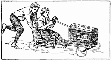
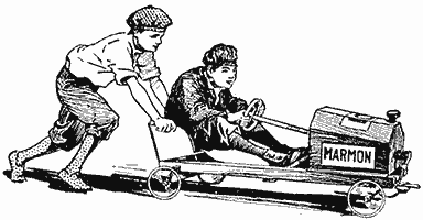
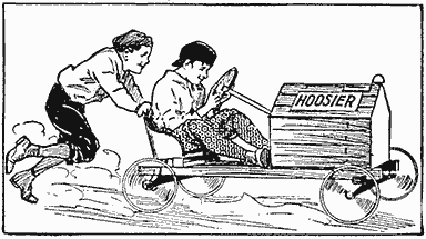
The Cars Winning the First, Second and Third Prizes Respectively, the "Hoosier" being Penalized 10 Yards at the Starting Tape for Having Larger and Better-Grade Wheels
The pushmobiles were made and the race run as an opening feature of a field meet held in the city. The course was about a half mile long, and was chosen to give the contestants plenty of curves, a part of the run being over brick streets and the final quarter on the regular track where the field meet was held.
Interest was added to the event by petitioning the mayor of the city for a permit to run the race, and the Boy Scouts patrolled the route, while the city policemen cleared the streets, and during the race all traffic was halted.
Two of the requirements for entering the race were that the car had to be made in the school shops and that it must have a certain kind of a wheel, which in this case was one condemned by a local factory, thus making the wheels and wheel base of all cars alike. Two boys to a car constituted a racing team, and during the race they could exchange positions at their pleasure. The necessity of "nursing" their cars down the steep grades and around difficult corners developed into an important factor. All cars were named and numbered.
The car that finished first was disqualified for the reason that it took on a fresh pusher along the course.
The cars were constructed under the supervision of the regular shop instructor, and a drawing was furnished each boy making a car. The design of the hood and the arrangement of the seat and steering gear was left for each boy to settle as he desired. The matter of expense was watched closely by each one. Most of the hoods and seats were constructed of empty dry-goods boxes.

The Entire Chassis was Made of Cypress Wood, All Cars of the Same Length and Width, the Hoods and Seats Being the Only Parts Optional in Size and Shape for the Builder
With the aid of the sketch any boy can make a car as strong as the "Peugeot" that won the race. The side rails of the main frame were made of cypress, 58 in. long and 2 in. square. The location of the crossbars A and B is very important, as they give rigidity to the frame and reinforce the two bolsters C and D. The size of the hood and the location of the seat determine where they should be set into the rail, after which they are fastened with large wood screws. The three bolsters C, D, and E are cut from regular 2 by 4-in. stock. Be careful to get a uniform distance between the rails when they are framed together. If desired, the dimensions can be increased, but do not reduce them, as this will narrow the tread too much. The bolt connecting the bolsters C and E is a common carriage bolt, 5 in. long and 1/2 in. in diameter. A washer is placed between the pieces C and E, to make the turning easy.
Two pieces of 1/2-in. soft-steel rod were used for the axles, a hole being drilled near each end for a cotter, to hold the wheels in place, and also holes through the diameter between the wheels, for 1-1/2-in. screws to fasten the axles to the bolsters.
The steering wheel is constructed of a broom handle with a small wheel fastened to its upper end, and the lower end supported by a crossbar, F, and the back end of the hood. Before fastening the crossbar F in place, adjust the steering wheel to the proper height for the seat; then it is fastened with nails driven through the sides of the hood.
The construction of the steering device is very simple. The crossarm G is a piece of timber, 7 in. long, 2 in. wide and 1 in. thick, rounded on the ends and provided with a large screw eye near each end on the under side to which are fastened the ends of two small-linked chains. The chains are then crossed and fastened to the bottom bolster in front and as near the wheels as practical. The connection is made with a screw eye similar to the one used in the crossarm. Another type of steering device may be made by building on the rod a 5-in. drum which takes the place of the steering arm. It is a more positive appliance, but is somewhat harder to make and adjust.
The making of the hood and the seat completes the car. Decide upon the shape and size of the hood, but, in any case and irrespective of the size, it will require a front and back end. These are made first and then secured at the proper distance apart with two side rails. These two ends are nailed on the ends of the connecting rails. It is then well to fasten the hood skeleton to the car frame and cover it after the steering device is in place.
The seat bottom is cut the shape desired, and fastened to the rear bolster and crosspiece, first placing a piece of the proper thickness under the front edge, to give it the desired slant backward. The back curved part can be formed of a piece of sheet metal and lined on the inside with wood pieces, or with cloth or leather, padded to resemble the regular cushion.
Pencil Rack
The simple pencil rack shown in the sketch can be easily made from any suitable strip of metal, preferably brass of about No. 15 gauge. Mark off a number of rectangles corresponding to the number of pencil holders desired. With a sharp chisel, cut through the metal on three sides of each rectangle, leaving one of the short sides untouched. The loose laps can then be bent to a shape suited to hold a pencil. The rack can be fastened in place with nails or screws through holes pierced at each end.—Contributed by Mark Gluckman, Jersey City, N. J.
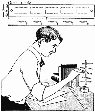
A Strip of Sheet Metal Cut and Clips Formed to Make a Pencil Rack
Indistinct but not entirely worn-off dates on coins may be read by heating slightly.
Reducing Size of a Hat Sweatband
Very often a hat has been worn for some time and it becomes too loose on the head, then paper is used in the sweatband to reduce the size. A better, easier, and neater method, as well as one that will be cooler for the head, is to insert a flat lamp wick inside of the sweatband. Wicks of all thicknesses and widths are easily obtained.—Contributed by Maurice Bandier, New Orleans, La.
A Catapult
The catapult shown in the sketch is one I constructed some time ago and found to be amusing and very inexpensive. The catapult consists of a small piece of dowel or pine, whittled into the shape of a handle, a screweye, an elastic band and an arrow. It is surprising how a well-balanced arrow will fly into the sky until lost to sight when propelled through the eye of the screw with a medium-strong elastic. A number of forms of this simple gun were made, but the one shown is the simplest and most effective.—Contributed by C. A. Needham, New York, N. Y.
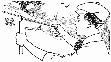
The Eye of the Screw Serves as a Guide for the Arrow
Growing Clean Strawberries
A very good method of growing individual strawberry plants that will produce large clean berries is to provide a covering constructed from a board 10 in. square with a 3-in. hole bored in the center. This covering is placed over the plant, as shown in the sketch, to keep down weeds, retain moisture, and to make a base for the ripening berries. A shower cannot spatter dirt and sand on the growing fruit. The rays of the sun beating on the surface of the board will aid in the ripening.
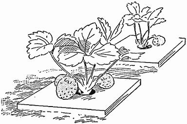
Growing Strawberries on the Surface of a Board Where They will Ripen Fast and Keep Clean
If a log can be obtained, the boards can be made better and more quickly. Disks about 1 in. thick are sawed from the log and holes in their centers either cut with a chisel or bored, as desired. The grain of the wood will be vertical and no warping will take place—Contributed by Johnny Banholster, Gresham, Oregon
A Magic Change Card
Procure two cards, the "5" of diamonds and the "5" of spades, for example. Bend each exactly in the center, with the face of the cards in, and then paste any card on the back, with its face against the two ends of the bent cards. The two opposite ends will then have their backs together, and these are also pasted. The illustration clearly shows this arrangement.
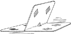
A Card Having Two Faces, Either of Which can be Shown to the Audience Instantly
To perform the trick pick up this card, which is placed in the pack beforehand, and show to the audience both the front and back of the card, being sure to keep the center part flat against one end or the other, then pass the hand over the card, and in doing so catch the center part and turn it over. The card can be changed back again in the same manner.—Contributed by R. Bennett, Pittsburgh, Pa.
Cleaning Pearl Articles
A good way to clean pearl articles or ornaments is to moisten them with alcohol and then dry in magnesia powder or French chalk. These last two articles may be purchased at any drug store and the process of cleaning is absolutely harmless. It also polishes the pearl and will not bleach delicate colors.
Bed for a Camp
A quickly made bed for a camp is shown in the illustration. The corner posts consist of four forked stakes driven in the earth so that the crotches are on a level and about 1 ft. from the ground. Poles are laid in the crotches, lengthwise of the bed, and canvas covering double-lapped over them. If desired, the canvas can be stitched along the inside of the poles.—Contributed by Thomas Simpson, Pawtucket, R. I.
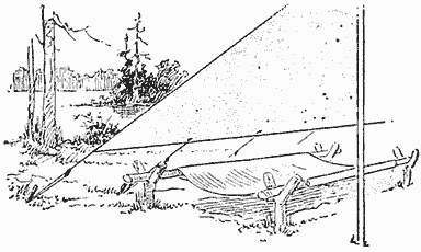
Canvas Bed Made on Two Poles Laid in the Crotches of Forked Stakes
Sail for a Boy's Wagon
Every boy, who loves a boat and has only a wagon, can make a combination affair in which he can sail even though there is no water for miles around. One boy accomplished this as shown in the illustration, and the only assistance he had was in making the sails.
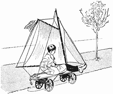
The Sail Wagon will Travel at a Good Speed in a Stiff Breeze
The box of the wagon is removed and the boat deck bolted in its place. The deck is 14 in. wide and 5 ft. long. The mast consists of an old rake handle, 6 ft. long; the boom and gaff are broomsticks, and the tiller is connected with wire to the front axle, which gives perfect control of the steering. The sails are made of drilling.
On a brick pavement the sail wagon can draw two other wagons with two boys in each, making in all five boys. Of course a good wind must be blowing. With two boys it has made a mile in five minutes on pavement.—Contributed by Arthur Carruthers, Oberlin, Ohio.
Extracting a Broken Screw
A screw will often break off in a piece of work in such a manner that it is quite impossible to remove it by using a pair of pliers or a wrench. In this case the following method is very efficient and expedient.
Drill a small hole in the screw as near the center as possible. Roughen the edges on the tang of a file with a cold chisel, and drive the tang into the hole with a mallet. The roughened edges of the tang exert enough friction on the metal to remove the screw by turning the file in the proper direction.
Keeping Out Dampness
A good way to keep a bed from becoming damp, if left for any length of time, is to place a blanket on the top after it is made up. Take the blanket off before using and the bed covers will be quite dry, as the blanket absorbs the moisture.—Contributed by G. Nordyke, Lexington, Ore.
A Double-Claw Hammer for Pulling Nails Straight
A nail pulled with an ordinary claw hammer will be bent in the operation, and for this reason the double claw is used to draw the nail straight out of the wood. An ordinary claw hammer can be easily converted into a double-claw by filing out one of the claws as shown. The notch is filed only large enough to slip under the head of an average-size nail. After drawing the nail a short distance in the usual manner the small notch is set under the head of the nail which is then pulled out straight.—Contributed by J. V. Loeffler, Evansville, Ind.
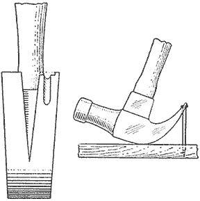
The Small Notch on the End of the Claw Makes It Easy to Pull a Nail Straight

A Cyclemobile By Frank Pfefferle
The cyclemobile is of the three-wheeled type and can be easily constructed in the home workshop with ordinary tools. The main frame is built up of two sidepieces, AA, Fig. 1, each 2 in. thick, 4 in. wide, and 7 ft. long, joined together at the front end with a crosspiece, B, of the same material, 17 in. long. The sides are placed slightly tapering so that the rear ends are 11 in. apart at the point where they are joined together with the blocks and rear-wheel attachments. A crosspiece, C, 13 in. long, is fastened in the center of the frame.
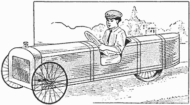
Three-Wheeled Cyclemobile Propelled Like a Bicycle and Steered as an Automobile
The place for the seat is cut out of each sidepiece, as shown by the notches at D, which are 2 ft. from the rear ends. Two strips of wood, E, 1/2 in. thick, 4 in. wide, and 22 in. long, are fastened with nails to the rear ends of the sides, as shown. The rear wheel is a bicycle wheel, which can be taken from an old bicycle, or a wheel may be purchased cheaply at a bicycle store. It is held in place with two pieces of strap iron, F, shaped similar to the rear forks on a bicycle, and each piece is bolted to a block of wood 3 in. thick, 4 in. wide, and 6 in. long, which is fastened to the sidepiece with the same bolts that hold the strap iron in place. The blocks are located 20 in. from the rear ends of the sidepieces.

Detail of the Parts for Constructing an Automobile-Type Foot-Power Car (Fig. 1)
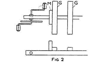
(Fig. 2)
The pedal arrangement, Fig. 2, consists of an ordinary bicycle hanger, with cranks and sprocket wheel set into the end of a piece of wood, 2 in. thick, 4 in. wide and 33 in. long, at a point 4 in. from one end. The pieces GG are nailed on across the frame at the front end of the car, to hold the hanger piece in the center between the sidepieces, as shown in Fig. 1. A small pulley, H, is made to run loosely on a shaft fastened between the sidepieces. This is used as an idler to keep the upper part of the chain below the seat.
(Fig. 3)
The front axle is 30 in. long, pivoted as shown at J, Fig. 3, 6 in. from the front end of the main frame. Two small brass plates, KK, are fastened with screws on the under edge of each sidepiece, as shown, to provide a bearing for the axle. The front wheels are taken from a discarded baby carriage and are about 21 in. in diameter.
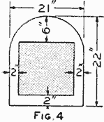
(Fig. 4)
A good imitation radiator can be made by cutting a board to the dimensions given in Fig. 4. A large-mesh screen is fastened to the rear side to imitate the water cells.

(Fig. 5)
The steering gear L, Fig. 5, is made of a broom handle, one end of which passes through the support M and fits into a hole bored into the lower part of the imitation radiator board. A steering wheel, N, is attached to the upper end of the broom handle. The center part of a rope, O, is given a few turns around the broom handle, and the ends are passed through the openings in screweyes, PP, turned into the inner surfaces of the sidepieces AA, and tied to the front axle.

(Fig. 6)
The seat is constructed of 1/2-in. lumber and is built in the notches cut in the main frame shown at D, Fig. 1. The body frame is made of lath, or other thin strips of wood, that can be bent in the shape of the radiator and nailed to the sidepieces, as shown in Fig. 6. These are braced at the top with a longitudinal strip. The frame is then covered with canvas and painted as desired.
How to Make a Humidor
The humidor is an ideal gift for any person who smokes. The wood for making one, as shown in the illustration, may be of Spanish cedar, mahogany, or quartered oak, as the builder desires. The box and cover are made and glued together in one piece, then the cover is sawed off to insure a perfect fit. A strong corner connection is shown at A. A piece of a strawberry box or peach basket makes a good key to glue in the grooves. Care must be taken to run the grain with the width and not with the length of the strip.

The Amount of Moisture within the Box is Shown on the Dial in the Cover
Finish the outside of the box with two coats of the desired stain, then cover with a coat of wax, shellac, or varnish. The inside should be finished with one coat of white lead and two or three coats of white enamel, to make the wood impervious to moisture.
In the center of the cover top is set a piece of glass and to the under side of the latter a hygrometer is attached with a little glue. This instrument tells the relative humidity, or the amount of moisture, in the air within. The moisture may be regulated by adding a few drops of water, as needed, to a piece of ordinary blotting paper placed on the inside.—Contributed by James T. Gaffney, Chicago.
Telephoto Attachment for a Hand Camera
It is not necessary to purchase an expensive telephoto lens for a box or hand camera if the owner has a pair of opera or field glasses. First focus the glasses on the distant object to be photographed and then set the camera. One of the glasses is placed directly in line with and in front of the camera lens, as shown in the sketch. If the camera is of the focusing type, it is focused in the ordinary manner. Box and other cameras are set as usual.
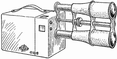
A Field Glass Placed in Front of a Camera Lens will Increase the Diameter of the Photograph
The glasses should be well supported in front of the camera lens, as any slight move will be quite perceptible on the ground glass. As the light rays are largely reduced in passing through the field glass and camera lens, it is necessary to give a much longer exposure. This can only be determined by trying it out, as lenses have different speeds.—Contributed by Charles Leonard, St. John, Can.
A Turn Feeding Table for Birds
Never in the past has the public at large taken so great an interest in protecting and furthering the well-being of birds as at present. In addition to protective legislation, clubs everywhere are organizing to promote bird life and many citizens, old and young, are making bird houses and feeding tables.
One of the best forms of feeding tables which I have ever seen is shown in the sketch. It possesses a great advantage over the average table in being turned automatically, whirling about by the action of the winds and always keeping its open front on the lee or protected quarter. This is a good feature especially in the fall and winter, the very time when birds need and seek protection from storms and cold winds.
To make such a feed table almost any kind of boards can be utilized. The shelter may be of any shape or size to suit the tastes of the maker, but one constructed to the dimensions given will be found to work well in most localities. Along the center of the roof is attached a wing, A, which is an active aid in causing the wind to keep the open front turned away. The shelter turns upon a wood or iron rod which passes from the end of a post up through the central bottom and central roof of the structure. If wood is used for the rod, it should be about 1 in. in diameter and of hard stock. An iron rod may be somewhat smaller. Keep the holes well greased.

A Feeding Table for Birds That will Keep Its Open Side Protected from the Storms
The house should be given a couple of coats of white, red, or green paint, and the post painted to correspond. Feed and water are placed in shallow dishes on the floor and they should be blocked to keep them from sliding out.—Contributed by C. C. Fraser, Saginaw, Mich.
A Sack Holder
An old granite kettle or tin pail with the bottom cut out and three 8-penny wire nails bent and fastened on with rivets, as shown at A, makes as good a sack holder as one could desire. A chain attached to the handle makes it conveniently adjustable to the proper height for the sack.
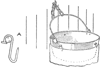
A Granite Kettle Forms a Holder That Makes It Easy to Fill the Sack
Time Indicator for Medicine Bottles
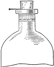
The time to give a patient the next dose of medicine can be set on the indicator, as shown in the sketch, and retained without fear of its being changed until the dose is again given. The indicator consists of a strip of paper which will reach around the bottle neck and is divided into 24 equal parts representing hours and half hours. The paper is then pasted to the bottle neck. An ordinary pin is then pushed into the cork as shown. After a dose of medicine is given to the patient the cork is replaced so that the head of the pin will indicate the time for the next dose. By this method, an accidental shifting of the indicator is almost impossible.
A Washtub Stand
Usually two old chairs or an old box makes the stand for the washtub, and these are not always the right height. A stand, like that shown in the illustration and having the proper height for the one who does the washing, can be easily made of 2 by 4-in. material and a few boards. As it is shown, the wringer is fastened on top of the back and may remain there all the time, it being out of the way, always in its proper place, and held very firmly.
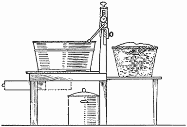
Stand Provides a Place for the Washing Utensils and It is Always the Proper Height
A light bracket, on which to set the clothes basket, can be made and fastened on the back of the stand, connected with two hinges and supported by a leg hinged to the bracket, the lower end of the leg resting on the floor back of the stand.
A small drawer may also be provided in the front, in which to put away the soap and brushes, and the wash boiler can be set underneath. When one is through washing, the bracket at the back is let down, the washstand set up against the wall out of the way, and everything is then in its place, ready for the next wash day.—Contributed by Chas. Homewood, Waterloo, Ia.
Pipe Used as a Leather Punch
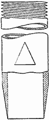
The sketch shows how a very cheap and serviceable leather punch can be made of an old pipe nipple. Pieces of pipe of almost any size can be found around a shop, and it is, therefore, usually possible to quickly make a punch of the required size. The cutter end can be ground very thin to prevent an over-cut, while a small slot cut a little above it will allow the removal of the leather slugs. For its purpose, this homemade tool is all that can be desired in cheapness and utility.
To Prevent Oilcloth from Cracking
A good method to prevent oilcloth from cracking, when it is used on shop tables or counters, is to first cut a paper cover for the table on which to place the oilcloth and prepare it as follows: The paper should be well oiled with common machine oil and placed smoothly on the table to be covered. The oilcloth is then smoothed out on top of the paper and stretched tightly. The oiled paper tends to keep the under side of the cloth moist, which prevents cracking. The cloth wears much longer because the paper acts as a pad.

How to Make a Flymobile By Edward Sieja
The boy owning a pushmobile, or even a power-driven auto car, is often very much disappointed because motion soon stops when the power is not applied. The car illustrated is of a little different type, being equipped with a flywheel that will propel the car and carry the rider a considerable distance after stopping the pedaling. The flywheel also aids the operator, as it will steady the motion and help him over a rough place or a bump in the road.
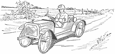
The Flymobile is a Miniature Automobile in Appearance and is Propelled by Foot Power
The main frame of the flymobile is made up of a few pieces of 2 by 4-in. timbers. The pieces A are 6 ft. 4 in. long, and the end crosspieces B, 24 in. long. These are jointed, glued and screwed together, as shown in Fig. 1. The frame that supports the driving parts consists of a piece, C, 6 ft. 2 in. long, and a piece D, 2 ft. 11 in. long. These are fitted in the main frame and securely fastened to the end crosspieces B. Two other crosspieces, E and F, are used to strengthen the driving-parts frame.

Plan and Elevation of the Flymobile, Showing the Location of the Working Parts, to Which, with a Few Changes, a Motorcycle Engine can be Attached to Make It a Cyclecar; also Details of the Brakes, Belt Tightener and Coaster-Brake Hub (Fig. 1)
The entire hanger G, with its bearings, cranks and pedals, can be procured from a discarded bicycle and fastened to the piece C; the barrel holding the bearings being snugly fitted into a hole bored in the piece with an expansive bit. The location will depend on the builder and should be marked as follows: Place the hanger on top of the piece C, then put a box or board on the frame where the seat is to be and set the hanger where it will be in a comfortable position for pedaling. Mark this location and bore the hole.
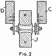
(Fig. 2)
The transmission H consists of a bicycle coaster-brake hub, shown in detail in Fig. 2. A split pulley, J, 6 in. in diameter, is bored out to fit over the center of the hub between the spoke flanges. The halves of the pulley are then clamped on the hub with two bolts, run through the holes in opposite directions. Their heads and nuts are let into countersunk holes so that no part will extend above the surface of the pulley. The supports for the hub axle consist of two pieces of bar iron, 4 in. long, drilled to admit the axle ends, and screws for fastening them to the frame pieces C and D. This construction is clearly shown in Fig. 2.
The arrangement of the coaster-brake hub produces the same effect as a coaster brake on a bicycle. The one propelling the flymobile may stop the foot-power work without interfering with the travel of the machine, and, besides, a little back pressure on the pedals will apply the brake in the same manner.
The flywheel K should be about 18 in. in diameter with a 2-in. rim, or face. Such a wheel can be purchased cheaply from any junk dealer. The flywheel is set on a shaft, turning between the pieces C and D and back of the coaster-brake wheel H. Two pulleys, L, about 3 in. in diameter, are fastened to turn with the flywheel on the shaft and are fitted with flanges to separate the belts. The ends of the shaft should run in good bearings, well oiled.
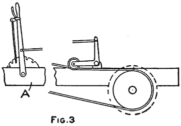
(Fig. 3)
Another pulley, M, 6 in. in diameter, is made of wood and fastened to the rear axle. An idler wheel, shown in Fig. 3, is constructed of a small pulley, or a large spool, attached to an L-shaped piece of metal, which in turn is fastened on the end of a shaft controlled by the lever N. The function of this idler is to tighten up the belt or release it, thus changing the speed in the same manner as on a motorcycle.
The elevation of the flymobile is given in Fig. 4, which shows the arrangement of the belting. The size of the pulleys on the flywheel shaft causes it to turn rapidly, and, for this reason, the weight of the wheel will run the car a considerable distance when the coaster hub is released.

(Fig. 4)
The rear axle revolves in bearings, half of which is recessed in the under edges of the pieces A while the other half is fastened to a block, screwed on over the axle. A simple brake is made as shown in Fig. 5. Two metal pieces, O, preferably brass, are shaped to fit over the shaft with extending ends for fastening them to the pieces P and Q, as shown. These pieces are hinged with strap iron, R, at one end, the other end of the piece P being fastened to the crosspiece F, Fig. 1, of the main frame. The lower piece Q is worked by the lever S and side bars, T. A small spring, U, keeps the ends of the pieces apart and allows the free turning of the axle until the brake lever is drawn. The lever S is connected by a long bar to the hand lever V.

(Fig. 5)
The steering apparatus W, Figs. 1 and 4, is constructed of a piece of gas pipe, 3 ft. 4 in. long, with a wheel at one end and a cord, X, at the other. The center part of the cord is wound several times around the pipe and the ends are passed through screweyes in the main frame pieces A and attached to the front axle, which is pivoted in the center under the block Y. The lower end of the pipe turns in a hole bored slanting in the block. A turn of the steering wheel causes one end of the cord to wind and the other to unwind, which turns the axle on the center pivot.
The wheels are bicycle wheels, and the ends of the front axle are turned to receive the cones and nuts, instead of using the regular hub axles. The ends of the rear axle are turned to closely fit the hubs after the ball cups have been removed. A large washer and nut clamp each wheel to the axle so that it will turn with it.
The body can be made up as desired, from sheet metal, wood, or cloth stretched over ribs of wood, and painted in the manner of an automobile. A tank and tires can be placed on the back to add to the appearance. Fenders and a running board can be attached to the main frame.
With the addition of some crosspieces in the main frame at the front and a motorcycle engine fastened to them so that the driving sprocket will be in line with the sprocket on the coaster hub, the builder will have a real cyclecar.
The Die-and-Box Trick
The die-and-box trick, so often performed on the stage, is a very interesting and mystifying one. The apparatus, however, is simple, consisting of a box, die, a piece of tin in the form of three adjacent sides of the die, and a hat. The die and box are constructed entirely of wood, 1/8 in. thick, and the piece of tin can be cut from any large coffee can. The box is closed by four doors, as shown in Fig. 1, two of which are 2-3/4 in. square, and the others, 3-1/8 in. by 3-1/4 in. The first two are the front doors and are preferably hinged with cloth to the two uprights A and B. Small pieces of tin are fastened on the doors at C and D, to provide a means to open them. The other doors are placed on top and are hinged to the back, as shown.
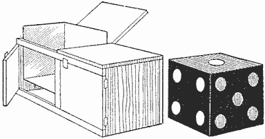
With the False Die in Place It Appears as If the Box Were Empty
The die is 3 in. square on all sides, and is constructed of two pieces, 3 in. square; two pieces, 2-3/4 in. by 3 in., and two pieces, 2-3/4 in. square. These are fastened together with 1/2-in. brads. The tin, forming the false die, is cut out as shown in Fig. 2, and is then bent on the dotted lines and soldered together on the joint formed by the two edges E and F. All parts should be painted a dull black with white spots on the die and false die.

The Box with Doors on One Side and the Top, (Fig. 1)
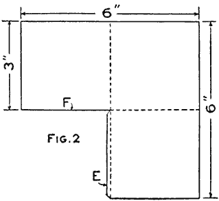
...and the False-Die pattern (Fig. 2)
The trick is performed as follows: Procure a hat from some one in the audience and place in it the die with the tin false die covering three sides of the block, at the same time telling the audience that the block will be caused to pass from the hat into the box, the latter being placed some distance away. Inform the audience that it would be more difficult for the die to pass from the box into the hat. Remove the tin piece from the hat and leave the die, holding the surfaces of the false die toward the audience. This will give the impression that the die has been removed. Set the hat on the table above the level of the eyes of the audience. With the back of the box toward the audience, open one top door and insert the tin piece in the right-hand compartment so that one side touches the back, another the side and the other the bottom of the box. Close the door and open the two doors of the opposite compartment which, when shown, will appear to be empty. Tilt the box to this side and open the doors of the side opposite to the one just opened, which, of course, will be empty. This should be done several times until some one asks that all doors be opened at the same time. After a few more reversals and openings as given, open all doors and show it empty, then take the die from the hat.—Contributed by Harold L. Groesbeck, Salt Lake City, Utah.
Homemade Pantograph
The pantograph consists of four pieces of wood, the dimensions depending somewhat on the size of the work to be drawn. A convenient size for ordinary drawing and enlarging is constructed of four pieces of hardwood, preferably maple, 3/16 in. thick and 5/8 in. wide, two of them 20-3/4 in. in length and the other two, 18-3/4 in. long. These are planed and sandpapered and the ends cut round.

A Picture can be Enlarged or Reduced by Setting the Screweyes in the Holes Designated
All four pieces are laid flat on a level board or bench top with their edges together so that the edges of the two longer pieces make right angles with a line drawn tangent to their ends. One end of one short piece is placed flush with the lower ends of the two long pieces, and one end of the other short piece flush with the upper ends, as shown. They should be clamped down solidly to keep them from moving while laying off the divisions. Light lines are drawn across their faces as designated by the dimensions. On these lines and exactly in the center of the pieces make small marks with a pencil point. Through the pieces A and B holes are drilled to snugly receive the body of a small screweye. The other two pieces are drilled with a smaller drill so that the threads of the screweye will take hold in the wood.
The end C of the piece A has a metal stand made of brass as shown at D. This is fastened to the end of the wood with a small bolt. The hole should be a snug fit over the body of the bolt. The lower ends of the brass are drilled to admit thumb tacks for holding it to the drawing board.
The joint at E is made of a suitable binding post that can be procured at an electrical shop, the shank below the two joined pieces to be the same length as the height of the metal stand D. The end should be filed round and polished so that it will slip over the board or paper easily.
The stylus or tracing point F is made of another binding post, in the same manner, but instead of a rounding end a slightly blunt, pointed end is filed on it. The end of the piece G is strengthened by gluing a small block of the same material on both upper and under side. A hole is then made through them to receive a pencil rather tightly.
The holes, as will be seen, are numbered from 1 to 34. At the crossing of each pair, H and J, the screweyes must be set in the holes numbered alike on both pieces of each pair. This will insure the proper working of the parts. The other numbers designate how much the instrument will enlarge a picture or reduce it. On the pair not numbered in the sketch the numbers run in the opposite direction.
The end C is fastened to the left side of the drawing board, the picture to be enlarged is placed under the stylus or tracer point, and the paper under the pencil point G. Move the tracing point over the general outline of the picture without making any line before starting, so as to make sure that the paper and picture are located right. It is then only necessary to take hold of the pencil and move it over the paper while watching the tracer point to keep it following the lines of the picture. To make a reduced picture, the original is placed under G, the tracer point changed to G and the pencil to F.
Trapping Mosquitoes
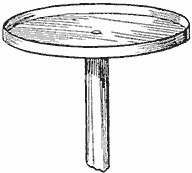
Mosquitoes that light on the ceiling may be easily destroyed with the instrument shown in the sketch. It consists of a cover, such as used on jelly glasses, nailed to the end of an old broom handle. A little kerosene oil is placed in the cover and the device is passed closely beneath the location of the mosquitoes. They will be overcome by the fumes and drop into the fluid as soon as it comes under them.—Contributed by J. J. Kolar, Maywood, Ill.
Pen Rack on an Ink Bottle
A piece of wire, about 1 ft. long, is bent into the shape shown and slipped over the neck of the ink bottle. The ends forming the loop around the neck should fit tightly. The upper part of the wire is shaped to hold the penholder.—Contributed by W. A. Saul, E. Lexington, Mass.
Substitute for a Broken Bench-Vise Nut
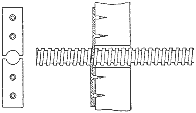
Two Pieces of Strap Iron Shaped to Fit the Square Thread Make a Good Substitute Nut
It is frequently the case that the nut on a bench-vise screw breaks from being subjected to a too violent strain. If one is working in a place where a new nut cannot be obtained, the broken part may be replaced by the substitute shown in the sketch. Any piece of strap iron may be used, and with a round file and a drill the two pieces can soon be made and attached to the bench with screws or bolts. A slight twist of the shaped ends is necessary to make them fit the angle of the thread.—Contributed by Oscar M. Waddell, Lamedeer, Mont.
Scissors Sharpener

In Attempting to Cut the Hardened Steel Pin the Edge is Drawn Sharp
Procure an ordinary wood clothespin and drill a 1/8-in. hole through its blades, then insert a piece of hardened 1/8-in. drill rod, which should be a driving fit. In using this device, take the scissors and attempt to cut the steel rod. Do this three or four times and a good cutting edge will be obtained.—Contributed by Wm. J. Tolson, Lyons, Iowa.
An imitation-gold color may be made with flake white, ground in varnish and tinted with a touch of vermilion. When striping or lettering is done with this, it will have the appearance of real gilding work.
Floor Push Button
An ordinary electric push button can be used for a floor push button by placing it on a bracket or shelf attached to a joist, as shown, and using a nail for the extension push. A 1/4-in. hole is bored through the floor, also through a small piece of wood fastened beneath the floor, at the right place to direct the nail so that it will strike directly upon the small black knob of the push button. The nail should be just long enough to rest lightly on the knob.—Contributed by Reginald R. Insole, Hamilton, Can.
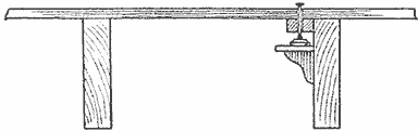
Push Button on Joist
A Wrist Brace
To strengthen a weak wrist, take a piece of leather, preferably white oak tanned, 2 in. wide and 14 in. long, and carefully shave it down with a sharp knife, until it is 1/16 in. thick. Then cut it as shown in Fig. 1, the wide part or body being 7 in. long, and the narrow part or neck, 6 in. long and 1 in. wide. Cut a semicircular hole, 1 in. from the extreme end of the body, 1/2 in. wide and 1-1/4 in. long, to allow the neck to slip through, then punch three holes in each end and lace with rawhide or shoestring, or, better still, if you happen to have a small buckle, sew it neatly to the body. It looks better and saves time in adjusting. When complete and on the wrist, it will appear as in Fig. 2.—Contributed by J. H. Harris, Berkeley, Cal.
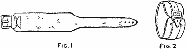
Brace Made of Leather
Protecting a Kettle Handle from Heat
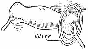
The wood handle of a kettle or cooking utensil when not in use usually comes in contact with the side of the vessel and it will absorb enough heat each time to finally char and crack the wood. The heat of the handle at times is so intense that it often results in a burned hand. The spiral metal handle provides a way for cooling by exposing a considerable surface to the air, yet the metal retains the heat so that many times it is too hot to handle. If a wood handle is provided with a coil of wire as shown in the accompanying sketch, the wood cannot come in contact with the side of the heated vessel and the air encircling the wood prevents it from getting too hot to handle. The spiral can be attached to a metal handle with solder.
Tin Can Used for Watering Chickens
An ordinary discarded tomato can makes a good watering vessel for young chickens. Care must be taken in opening the can to cut the tin so the cover will hinge. Cut the tin about 1-1/2 in. from the bottom so that it will form a U-shaped piece as shown in the sketch and push the hanging portion in the can. Fill the can up to the opening with water, close the cover and set it in the coop.—Contributed by L. Alberta Norrell, Augusta, Ga.

How to Make a Hurdle
The hurdle consists of two standards, a reach, and a swing. The swing is first made in the shape of a rectangle of four pieces of wood, about 7/8 in. thick and 1-1/2 in. wide, of which two are 36 in. and the others 18 in. long. These pieces are nailed together in the manner shown.
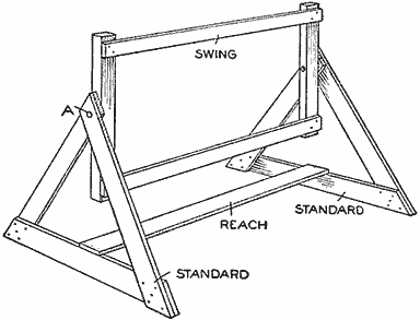
The Swing of the Hurdle will Turn When Slightly Touched and Right Itself Again
Each standard is made of three pieces of wood, 7/8 in. thick, 3 in. wide, and 18 in. long. Nail the pieces firmly together, as shown, and connect their bases with another piece of the same material, 36 in. long. When this is finished, connect the swing to the standards with long nails, A, at the ends slightly off center. Before inserting the nails, make the holes in each standard to receive them large enough to permit the nails to turn freely without allowing the heads to pass through. Thus the frame will swing freely at the slightest touch of the jumper's foot, and right itself immediately.—Contributed by C. C. Fraser, Saginaw, Mich.
Oil Burner for a Cook Stove
The parts of the burner consist of ordinary gas pipe and fittings. The pipe in which the kerosene oil is converted into gas is 1/2 in. in diameter and is connected to a supply tank of oil with 1/4-in. pipe. The burner part is also constructed of 1/4-in. pipe having three 1/16-in. holes drilled in each end for the gas to escape where it burns. These burners are located just beneath the large pipe so that the flames will heat it and convert the oil into gas. A needle valve, A, is used to control the flow of oil. The burner is placed in the fire box of the stove, and the pipes connected through a hole drilled in the stove door, at B.
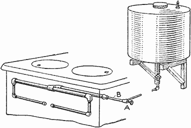
A Very Cheap Grade of Kerosene Oil can be Used in This Burner with Success
The tank may be rectangular or round and should be of sufficient strength to withstand 5 or 10 lb. of pressure. The top of the tank has a pet cock where a connecting hose from an air pump may be attached. The tank is filled about half full and just a little pressure of air is put on the oil. To start the burner, run a little oil in a pan or fire shovel and light it so that the flames will convert the oil into gas in the large pipe, then turn the valve A and regulate the flame.—Contributed by Robert Hays, Siloam Springs, Ark.
A Fish Stringer
The illustration shows a very simple and inexpensive device for the angler to string and carry fish. It is made of a pail handle through which is passed a piece of soft wire, having sufficient length for bends or loops at each end, and a piece of chain. A chain 18 in. long is sufficient. One end of the chain is fastened in the loop at one end of the handle, and the other has a piece of wire attached for pushing through the gills of the fish. The other end of the wire through the handle is arranged in a hook to catch into the links of the chain.—Contributed by G. O. Reed, Stratford, Canada.
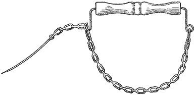
Inexpensive Stringer Made of a Pail Handle and Small Chain
Substitutes for Drawing Instruments
Three of the most used draftsman's instruments are the compass, ruler and square or triangle. When it is necessary to make a rough drawing and no instruments are at hand, common and easily obtainable things can be used as substitutes.
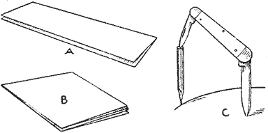
A Compass, Ruler and Square Made of Ordinary Things at Hand
A sheet of heavy paper folded as shown at A will serve as a ruler, and the same sheet given another fold will make the square B. If given another fold diagonally, a 45-deg. triangle is formed. A substitute compass is readily made of a short pencil and a pocket knife, as shown at C.—Contributed by Jas. J. Joyce, Olongopo, Philippine Islands.
How to Make an Aspirator
A simple aspirator that may be used for a number of different purposes, such as accelerating the process of filtering, emptying water from tubs, producing a partial vacuum in vessels in which coils are being boiled in paraffin, etc., may be constructed as follows: Obtain two pieces of brass tubing of the following dimensions: one 7 in. long and 3/4 in. outside diameter, and the other, 3 in. long and 1/4 in. outside diameter. Drill a hole in one side of the large tube, about 3 in. from one end, of such a diameter that the small brass tube will fit it very tightly. Take an ordinary hacksaw and cut a slot in the side of the large piece, as shown at A. This slot is sawed diagonally across the tube and extends from one side to the center. Obtain a piece of sheet brass that will fit into this slot tightly, and then solder it and the small tube into the large tube. The slot and hole for the small tube should be so located with respect to each other that the small tube will empty into the larger one directly against the piece of sheet brass soldered in the slot.

Detail of the Aspirator and Its Connections to a Faucet, for Increasing the Speed of Filtration
The upper end of the large tube should be threaded inside to fit over the threads on the faucet, or an attachment soldered to it similar to those on the end of an ordinary garden hose. A rubber hose should be attached to the small tube and connected, as shown, to a piece of glass tubing that is sealed in the cork in the top of the large bottle. The funnel holding the filter paper is also sealed into the cork. Melted paraffin may be used in sealing the glass tube, funnel and cork in place, the object being to make them airtight. The filter paper should be folded so that it sticks tightly against the sides of the funnel when the liquid is poured in, thus preventing any air from entering the bottle between the paper and the funnel. Turn on the faucet, and it will be found that the time required to filter any liquid will be greatly reduced. Be careful, however, not to turn on too much water, as the suction may then be too strong and the filter paper become punctured.
A Key-Holder Hook
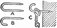
A good hook for hanging keys, toothbrushes and other small articles can be made from ordinary wire staples, as shown at A. One leg of the staple is cut away as shown at B and the other leg driven into the board as shown at C. These will answer the purpose as well as screwhooks.—Contributed by W. C. Heidt, Chicago.
A Hand Hoe
A hand hoe, especially adapted for weeding or cultivating small truck, particularly onions, can be made of a piece of hard wood, 7/8 by 1-3/4 in. by 4 ft. long, and a piece of old bucksaw blade. A blade, 18 in. long and 2 in. wide, bent into a loop is attached with bolts to the handle.—Contributed by Geo. H. Miller, Iowa City, Iowa.
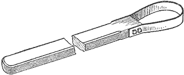
Bucksaw Blade Attached to a Hardwood Handle
Seed Receptacle for Bird-Cages
A handy seed and water container for a bird-cage can be made of a common spice tin. The receptacle can be filled without removal by simply taking off the cover. Thus the seed will not be scattered.
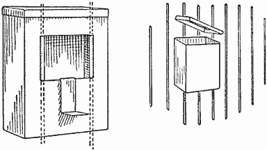
Spice Tin Attached to the Wires of a Bird-Cage for a Water or Seed Receptacle
The tin is attached by cutting a hole in the back as shown, and bending the side edges to fit over the wires to hold it in place. The bottom strip is a support which rests on the floor of the cage and prevents the tin from slipping down on the wires.
Kitchen-Utensil Scraper
A flexible utensil scraper is one of the most useful articles I have in my kitchen. It covers such a large surface in scraping pans, kettles, etc., that this most disagreeable part of the kitchen work is quickly and easily accomplished.
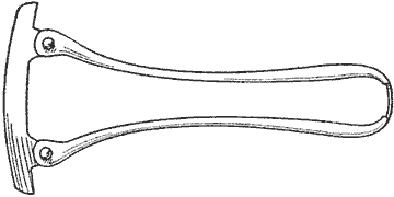
The Blade is Flexible so It can Readily Shape Itself to the Curves of a Kettle
The flexible blade is attached to the tin handles with small rivets. The blade should be thin and narrow enough to allow it to bend. When the handles are pressed together, the blade curves to the shape of the utensil's surface.—Contributed by Mrs. Della Schempp, Brodhead, Wis.
Anchor Posts for a Lawn Swing
A very substantial and convenient base for a lawn swing can be made by using four anchor posts of cement, as shown in Fig. 1. The posts are made with a recess, A, to receive the legs of the swing, and of any suitable size. They may be placed with the upper face on a level with the lawn, or higher if desired.
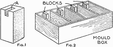
Ar. Anchor Post of Cement and a Mold Box for Shaping Four Posts at a Time (Fig. 1, Fig. 2)
A rough mold box, Fig. 2, lined with paper, will do for making the posts. The box does not require any top or bottom; it is simply placed on a board and lifted away when the blocks are thoroughly dried. If the blocks are leveled when placed in the earth, the swing may be taken down and erected again without the usual leveling and bracing.—Contributed by James M. Kane, Doylestown, Pa.
Automatic Filter
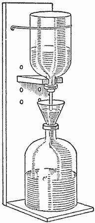
This funnel-filling filter automatically prevents the solution from running over if the filtering is slow or the filter substance becomes clogged. The upper inverted bottle holds the solution to be filtered, the cork being fitted with a glass tube as shown, and when in use the cork is forced into the neck of the bottle so that no air can enter between it and the glass. The support for holding the bottles has two brackets, one to fit the neck of the upper bottle and the other used as a shelf for the receiving bottle. In operation, the solution runs from the upper bottle into the funnel, holding the filter paper, but it cannot fill the funnel completely, because the end of the glass tube is lower than the edge of the funnel, and as soon as the liquid in the funnel covers the end of the tube, all inflow of air into the upper bottle is stopped, and, thereby, further flow of the solution into the funnel prevented, until enough has filtered through to uncover the end of the tube and thus permit air to again enter the upper bottle.—Contributed by G. Simons, Chicago.
Grinding Scissors
Whether a pair of scissors be ground or filed, the marks or scratches left from the contact with the abrasive should all extend across the bevel in the direction of the line ED, Fig. 1, and never in the direction of the line GF. If the cutting edge be examined under a magnifying glass, the tool marks or scratches left by the sharpening process will be very plainly seen, and where these scratches intersect with the face HI, Fig. 2, of the blade, they will appear as teeth along the cutting edge IK.
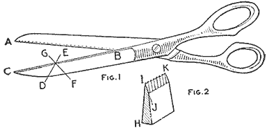
The Direction of the Grinding Tool should be Slightly Sloping Toward the Handles
As a pair of scissors close, the natural tendency is to thrust the material to be cut out of the angle ABC, Fig. 1, but if these small teeth formed on the cutting edge point in the direction of the line ED, this slipping action is prevented or retarded because the fibrous material adheres to the fine teeth on the cutting edge of the blades.
Wet paper, silks, mohair cloths, etc., can be sheared with perfect ease and dispatch, when scissors are sharpened in this manner. The same principle holds good for metal snips.
The angle HIJ, Fig. 2, varies according to the material to be cut, and the type of shear. A greater angle is required on metal shears than on shears for domestic uses.—Contributed by A. Clifton, Chicago.
To Repair a Leak in a Canoe
After striking some rocks with our canoe, it sprung three very bad leaks. These were effectively patched with pieces of cheesecloth, well soaked in liquid shellac, which were pasted on the outside of the leak. After allowing this to set for a few hours, it will be almost impossible to remove the patch. This is an inexpensive and almost invariably a sure remedy for leaks. When the cloth is dry, paint it over with the same color as the boat, and the repair can scarcely be seen.—Contributed by William B. Smith, New York City.
Holder for Loose Window Glass
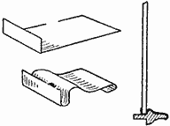
When the putty becomes loose and the glazing points work out on window glass, temporary repairs may be made by using a small piece of tin or sheet iron bent as shown in the sketch. The clip is inserted under the edge of the glass and hooked over the back of the sash parts. This will hold the glass firmly in place and also prevent rattling.
A Homemade Bench Vise
A form of a bench vise that can be easily made and attached to a workbench is shown in the illustration. This vise requires no screw, and the parts can be made from scrap material.
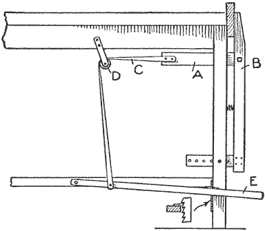
The Vise Jaw as It is Attached to the Bench and the Substitute Screw Arrangement
The substitute A for the screw is a rectangular piece of wood and is fastened with a tenon in a mortise cut in the vise jaw B. The clamping arrangement consists of a strap, C, attached to the piece A, then run over a pulley, D, and fastened to a foot pedal, E. The foot pedal is fulcrumed on a crosspiece of the bench and has a ratchet so as to hold it when the vise is set. The lower end of the vise is fitted with the usual form of device for parallel adjustment. A coil spring is located in the center for use in quickly opening the vise when the foot pedal is released.—Contributed by A. C. Westby, Porter, Minn.
A Cover Strainer
Quite frequently the cook or housewife wishes to pour the hot water or liquid from boiling vegetables or other foods without removing the solids from the kettle. This is easily accomplished, if small holes are drilled in the cover as shown in the sketch. The saucepan or kettle can be tilted and the liquid drains through the holes. Further, the steam from cooking food can readily escape through the holes, thus preventing the cover from vibrating, or the liquids from boiling over.
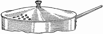
A Sufficient Number of Holes are Drilled in the Edge of the Cover to Make a Strainer
Homemade Corn Sheller
Where there is but a small quantity of corn to be shelled a sheller can be made of a few scraps of wood usually found on a farm. A block of wood having a sloping notch cut from one end is mounted on three legs as shown. The notched part as well as the lever is thickly filled with spikes driven in so that their heads protrude about 1/2 in.
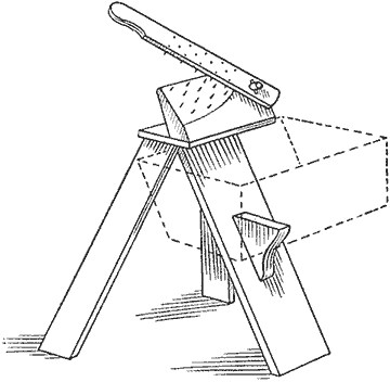
The Projecting Nail Heads in the Block and Lever, as They Pass, Shell the Corn
The ear of corn is placed in the notched part and the lever pressed down. Two or three strokes of the lever will remove all the kernels from the cob. A box is provided and conveniently located on one leg to catch the shelled corn.—Contributed by A. S. Thomas, Gordon, Ont.
An Ornamental Metal Flatiron Holder
This antique iron holder or stand can be easily constructed by the amateur bent-iron worker. A strip of iron is bent over at the ends to form the side legs, and the front leg is formed of another piece, welded in the center.
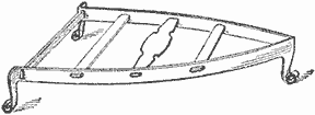
Ornamental Stand Made of Either Strap Iron or Sheet Metal to Hold a Flatiron
Openings for the crosspieces are then cut, the legs bent into a scroll shape, and the crosspieces inserted and fastened by spreading or upsetting the ends.
Instead of using strap iron, the stand can be cut from good sheet metal. This would save the trouble of welding on the front leg.
How to Make a Watch Demagnetizer
A watch demagnetizer that will give excellent satisfaction may be made as follows:

Dimensioned Parts for the Construction of the Core over Which the Insulated Wire is Wound
Procure a sheet of 1/16 in. brass, 3-1/4 in. by 7 in. Bend this piece of brass around a piece of hard wood having a rectangular cross section of 2-1/2 in. by 1 in. The joint between the two ends should be made on one side, and the edges should lack about 1/8 in. of touching. Next obtain two pieces of 1/8 in. brass, 3-3/4 in. by 3 in., and cut an opening in each of these, 2-5/8 in. by 1-1/8 in., as shown in the sketch. Bend one edge of each of these pieces over at right angles to the main portion of the piece. Solder these two pieces on the ends of the rectangular tube of brass and cut a slot in each of them to correspond to the one in the rectangular tube. Place the rectangular piece of wood back in the tube and you are ready for the winding. Use No. 18 gauge single cotton-covered copper wire and fill the winding space. Several layers of paper should be placed on the brass tube and between the layers of wire, to serve as an insulation. Holes may be drilled in the projecting portions on the ends and the coil can then be mounted on a wooden base. Mount two binding posts on this base and connect the terminals of the winding to them.
To use the demagnetizer, connect it to a 110-volt alternating-current circuit with a rheostat in circuit of such a form that the current will not exceed three amperes and that it may be reduced to practically zero in value by increasing the resistance of the rheostat. The magnetic field inside the coil is rapidly changing in direction and will tend to destroy any permanent magnetism that may be possessed by an object placed inside of it. The full current of three amperes should be allowed to pass through the winding for a few minutes after the object to be demagnetized is inserted, and then gradually reduced, and the object removed.
Remodeling a Talking Machine
Having a talking machine of an old model with a tapered horn I decided to change it into a more modern type, and this was accomplished as follows: An auxiliary base was constructed of 1/2 in. wood on which to set the part which revolves the disks. The inside of this base is so constructed as to form a horn or sounding box. The two sides and sloping bottom of the horn-part are made of 1/4 in. wood. The form of this box is shown in Fig. 1. The dimensions should be determined according to the size of the talking machine.
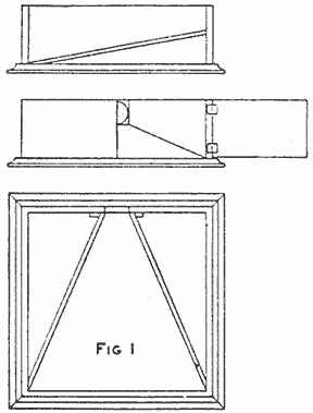
The Horn or Sounding Box Is Constructed in the Auxiliary Base... (Fig. 1)
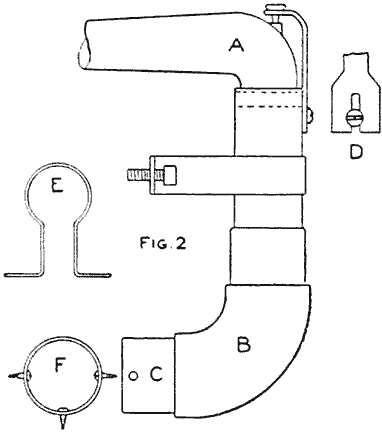
...and the Part for Connecting the Sounding Tube to the Box Consists of Ordinary Gas Pipe Fastened with a Clip at the Back (Fig. 2)
The connecting parts to the original horn were turned downward, as shown at A, Fig. 2, with the opening entering a piece of ordinary gas pipe of sufficient length to allow an elbow with a nipple to enter the auxiliary base. The pivot-holding device for connection A is shown at D. The parts are attached to the box with a clasp, E, and with three screws in the nipple C, the end view of which is shown at F. The talking machine is placed on the auxiliary base as shown in Fig. 3. This construction produces a talking machine on the order of a cabinet machine without the tapering horn.—Contributed by H. W. J. Lomglatz, Harrisburg, Pa.
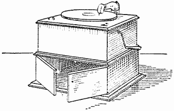
(Fig. 3)
Needle for Sewing Burlap
A needle for sewing burlap can be easily made of the ordinary opener that comes with sardine cans. All that is necessary to convert this tool into a needle is to grind the blunt end to a sharp point, as shown in the sketch.—Contributed by G. C. Beven, Sault Ste. Marie, Ont.
The Can Opener is Provided with an Eye and to Make a Needle the End is Sharpened
A Mysterious Revolving Wheel
The mystery of this wheel is that it seems to revolve automatically without any visible external power. It is at the same time an amusing trick and an instructive experiment. The apparatus required is very simple and can be made at home.
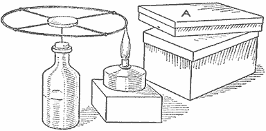
The Wheel as It is Mounted on a Needle, and Lamp and Box Containing Magnet to Make It Turn
A glass bottle is half filled with sand and water, so that it will stand securely, and a cork placed in the neck. Into this cork a needle should be inserted so that it projects perpendicularly, which is most easily done by heating one end of the needle to a red heat and then pushing it into the cork as deeply as possible. Into a disk of cork of suitable thickness and at four points on its side, at equal distances apart, are inserted four pieces of copper wire of the same length, each bent at the outer end to form a hook—these copper wires thus forming the spokes of the wheel. The rim is made of a small iron wire bent in a circular shape and held in the hooks on the ends of the copper wires. The now completed wheel is balanced on the free point on the needle, so that it can turn easily.
Place an alcohol lamp in such a position that when it is lighted the tip of the flame will just reach the rim of the wheel. (Any other flame that will not soot the rim may be used.) In the box A, placed with its bottom level with the wheel, put a horseshoe magnet so that the flame is opposite one of its poles. After the lamp has been lighted for a few seconds, the wheel will begin to revolve, seemingly without cause. Why does it do so? Because the magnet magnetizes or attracts the part of the ring nearest it while cold, but not when it is glowing. Instead, it will attract the cooler part of the ring nearest behind the flame and so on, the wheel thus spinning round, faster in the same proportion as the magnet is stronger and the iron rim smaller.
If this experiment is shown before spectators as a trick, the performer may say to the audience that he alone can make the wheel spin around without touching it. Should some one accept his challenge, he may, in a careless way, move the box containing the magnet away or turn it around so that it will not influence the iron ring and then, of course, the wheel will remain immovable.
How to Make a Rabbet Plane
A rabbet plane is very little used by mechanics, but when it is wanted for a piece of work, it is wanted badly. While doing an unusual piece of work I needed a rabbet plane, and having none, I made a plane as shown in the sketch in less time than it would have taken to go out and borrow one.
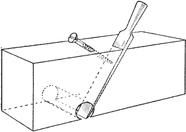
A Plane Made of a Piece of 2 by 4-In. Pine, a Chisel and a Large Wood Screw
The body of the plane was made of a piece of 2 by 4-in. pine, 1 ft. long. A 1-in. chisel was used for the bit. A place was marked on one side of the wood to be cut out for the chisel, and a 1-in. hole bored through, the narrow way, so that one edge of the bit cut through the bottom, forming a slit for the edge of the chisel. After cutting a groove for the chisel blade and turning in a long wood screw as shown, to hold the chisel in place, I had as good a rabbet plane as could be purchased.—Contributed by W. H. Young, Thompson, Ga.
Eye Shield for a Microscope
The difficulty and discomfort amateurs experience in learning to use a microscope with both eyes open, or in trying to keep one eye shut, can be easily overcome by attaching a piece of cardboard, similar in shape to the one shown in the sketch, to the barrel of the microscope. The hole A should be of sufficient diameter to allow the cardboard to slide freely up and down on the barrel to the proper adjustment. This simple arrangement will relieve a great deal of the eye strain and will be of assistance to the most experienced users of microscopes.—Contributed by G. B. Fenton, Charleston, W. Virginia.
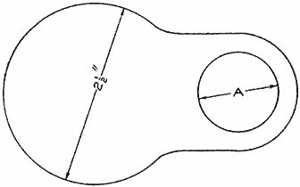
Shield to Cover the Eye That is Not Used When Looking into a Microscope
Transferring Magazine Pictures
Select pictures from newly printed papers and magazines. Rub wax from a paraffin candle over a sheet of clean white paper, covering a space as large as the picture to be copied. Place the paper, waxed side down, on the picture and while holding it firmly with the fingers of one hand, rub the back thoroughly with some hard substance until all parts of the picture have been gone over. Remove the paper and a perfect copy of the picture will be found upon the waxed side.—Contributed by Kenneth G. Merlin, Brooklyn, N. Y.
A Homemade Egg Separator
Secure some small wire and a very large can. Cut the wire into several pieces and bend them as shown at A, cut the can and bend the side down as shown and punch holes to receive the upper ends of the wires. Make the holes so that the wires will be about 5/16 in. apart.
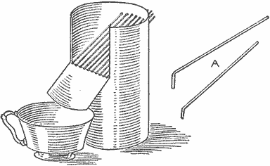
The Contents of the Egg is Placed on the Wires Which will Separate the Yolk from the White
A Glue-Spreader Holder
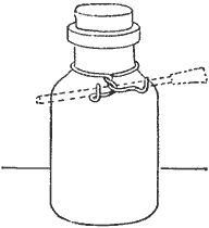
The spreader that is supplied with bottles of liquid glue should not be placed on any surface, as it will soon stick to it. A holder that will keep the spreader in a safe place can be made of a piece of wire which is twisted about the neck of the bottle, as shown in the sketch, and the ends bent up to receive the spreader.
Stop on a Chair Rocker for a Baby
For a baby, too small to rock without tipping the chair over, a small willow or other suitable rocking chair may be made safe in the following manner:
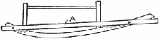
The Strip on the Rocker Prevents the Child Tipping the Chair Too Far Either Way
A strip, A, is fastened on the outside of the rocker with small screws so that it may be removed without injuring the chair. A rubber-covered tack driven in on the under side at each end of the strip modifies the shock and the baby can rock to its heart's content without danger of turning over.—Contributed by Mrs. G. W. Coplin, Bay City, Mich.
Homemade Countersink for Wood
A round or flat-head bolt can be made into a good rosebit or reamer for countersinking holes for screw heads. In the illustration, Fig. 1 shows a reamer made of a round-head bolt, and Fig. 2, one made of a square-head bolt. The round-head makes the best reamer as more cutters can be filed in the surface and less work is required to file it into shape.
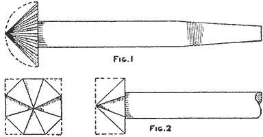
Round and Square Heads of Bolts Shaped and Notched to Make Countersinks (Fig. 1, Fig. 2)
To Maintain a Constant Level of Liquids in Vessels
It is frequently desirable in laboratory experiments, and in practical work as well, to maintain a constant level in a tank without allowing it to become full. In many cases an outlet pipe at a certain height in the side of the tank is not desirable, and in laboratory experiments with beakers or crocks is, of course, impossible.
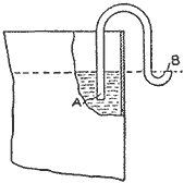
The diagram shows a simple but effective constant-level device. The outer end of the inverted U-tube is curved upward so that it never empties. If desired, the upward curve may be omitted and the straight end immersed in a small vessel of water. All that is necessary now for the successful working of the device is that the inner or tank end, A, of the tube be lower than the outer end—in other words, below the level of the end B—and the inner end below the level of the fluid. Of course, the U-tube must be first filled with liquid and will then act as an intermittent, never-breaking siphon. Should the tank fill above the end B, the siphon drains the fluid down to that level and no lower, even if the inner leg of the tube reach the bottom. To maintain this level against loss by evaporation some slight inflow is necessary.
It will be noted that if the inner end of the siphon were above the outer end, the siphon would break as soon as the liquid in the tank fell to the inner mouth.—Contributed by Harry N. Holmes, Richmond, Ind.
Homemade Electric Bed Warmer
The heat developed by a carbon-filament lamp is sufficiently high to allow its use as a heating element of, for instance, a bed warmer. There are a number of other small heaters which can be easily made and for which lamps form very suitable heating elements, but the bed warmer is probably the best example. All that is required is a tin covering which can be made of an old can about 3-1/2 in. in diameter. The top is cut out and the edge filed smooth. The lamp-socket end of the flexible cord is inserted in the can and the shade holder gripped over the opening. A small lamp of about five candlepower will do the heating.
A flannel bag, large enough to slip over the tin can and provided with a neck that can be drawn together by means of a cord, gives the heater a more finished appearance, as well as making it more pleasant to the touch.

A Flash-Light Telegraph on a Kite Line
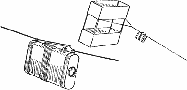
The Flash of the Light on the String may be Read as Far as It can be Seen
An ordinary pocket flash lamp is prepared in the following manner: A brass spring, as shown in the sketch, is bound tightly to the flash lamp with a cord, and two wires, one at each end, are twisted around the lamp's body, forming two loops at the top. The kite string is run through the loops and over the spring. The lamp is then placed near the kite. The ordinary pull on the kite string does not close the spring, but a sharp jerk will pull the string in contact with the push button and its slight pressure causes an instant flash of the light. By this method words may be spelled out in the telegraph code.—Contributed by Joe V. Romig, Allentown, Pa.
Hangers for Barn Tools
Means should be provided to have a place for all the tools used in and about a barn. The forks and shovels are usually stood up in a corner, but they can be more conveniently taken care of by making a hanger for them. The illustration shows how a hanger can be easily made and screwed to the wall of a barn. The hanger is cut from a piece of board and has a hole bored into it the size of the handle on the fork or shovel, then a notch is sawn into the hole to pass the handle through. The board may contain one or as many notches as there are forks and shovels to be hung on it. The implements are hung with the fork or shovel end upward.—Contributed by R. Snyder, Glidden, Ia.
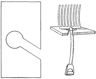
A Notched Board Provides a Way to Hang All the Tools Used about a Barn
Guide Ropes on a Bobsled
The sketch shows the front end of a bobsled or double runner made of a plank bolted upon two sleds. The front sled is so pivoted on the bolt A that it may be turned to steer the bob, and to accomplish this result the steersman ordinarily sits with his feet braced against the projecting ends of the crosspiece and passes the steering ropes outside of his feet, with the ropes crossed as shown. The crossing of the ropes is supposed to add leverage, but that is quite wrong.
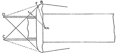
The Most Efficient Way of Attaching Ropes to the Guiding Runners of a Bobsled
The rope, running from B to C, has a lever arm from A to E. If the ropes were not crossed, the rope would lie along the dotted line BD, whose lever arm is the distance AF, which is always greater than AE, therefore the uncrossed ropes have more leverage.
Observe what takes place when the sled is steered to the left: The distance AE decreases much more rapidly than AF, and when the crossed ropes have lost all their power, the uncrossed ropes are still useful. Many a spill has been caused by turning the sled to a position from which the crossed ropes were unable to restore it to a central position, and most of such spills would have been avoided if the ropes had not been crossed.—Contributed by R. R. Raymond, Wilmington, Del.
Brush Hanger for a Dark Room
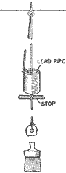
Necessity may be the mother of invention, but it is also the grandmother of application, and application is the practical side of invention. Both the amateur and the professional photographer have been bothered by spotting and unequal development of negatives and prints in tray development, due to various causes, and sometimes by the presence of dirt particles or the unequal or incomplete flowing of the developer over the surface of the sensitive emulsion.
Most professionals and many amateurs are familiar with the use of the camel's-hair brush to avoid failures of this character, and many of them use a brush for local development in certain cases where it is necessary or desirable. Usually the brush is kept in a small glass cup, somewhere close at hand, but it is often in the way when not wanted and misplaced when most needed. The brush can be kept within reach and handy for the operator by arranging a light counterweight and pulley with a string attached to the brush, so that, normally, the brush will hang from the ceiling directly over the developing tray and can be obtained for use when desired.
The detail of this brush-string and counterweight combination was deliberately appropriated from the old plan of suspending the piece of chalk over a billiard table, so that the players could easily reach it, when needed, while, when released, it would be pulled out of the way by the counterweight. The developing brush thus suspended is always ready, never misplaced, nor in the way for other operations. This arrangement is particularly convenient where a bathroom is used as a dark room, and the shelf space is limited.
This same manner of counterweighting chalk on the billiard table may be applied to a stove-lid lifter, to keep it within easy reach and always cool enough to handle. The simplest and most inexpensive way of making this apparatus is to cut off a small piece of lead pipe for a counterweight, and, in the absence of a suitable pulley, use an ordinary screweye fastened in the ceiling. The latter is really better than a pulley because the string cannot run off the screweye. The arrangement is better understood by referring to the sketch.
Lighting a Basement Light
There was no switch at the basement door and it was difficult to find the droplight in the dark. Instead of going to the expense of placing a switch, the contrivance illustrated and described was rigged up and proved equal to the requirements.
A 7/8-in. piece of wood was cut about 6 in. long by 2 in. wide and a recess made at one end for the socket, as shown. A 1/8-in. hole was drilled in the center, about 2 in. from one end, and another, large enough to receive the projection from a pull socket, about 2 in. from the other end, or the end to be used as the bottom of the block. A clamp made of spring brass, as shown, was screwed securely to the board, to clamp the socket firmly. A wire was passed through the small hole and stretched across the room from the door at a height to bring the light about 6 ft. from the floor. Then the socket was clamped to the strip with the chain passed through the hole cut for it. The cord attached to the chain was run to the door casing, passed through a screweye and weighted with a nut or some light object, to keep it taut. To light the lamp or put it out only a pull on the string was necessary.
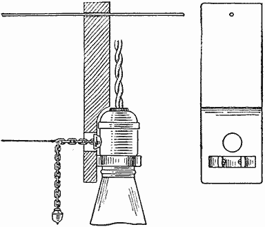
Socket Attachment to Turn a Basement Light On or Off from a Distance
The light can be slid along on the wire from one end of the room to the other, or can be detached from the strip when desired by unhooking the cord from the chain and taking the socket from the clamp. If more desirable, the block can be fastened permanently to some object instead of being on the wire.—Contributed by L. M. Eifel, Chicago.
Projecting Protractor Readings
A simple and efficient means of projecting protractor readings to a larger size is shown in Fig. 1. One point of the compass is placed at the center of the protractor and an elastic band is looped between the points. Then the points are spread to the radius desired, and the protractor is read where the elastic band crosses its scale. A light band should be used, and looped as shown in Fig. 2. In this way a circle of any size may be quickly divided, if a pencil mark is made each time the band comes over the proper figure.—Contributed by Thos. L. Parker, Wibaux, Mont.
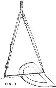
The Extension Marks can be Easily Read on the Protractor under the Elastic Band (Fig. 1)
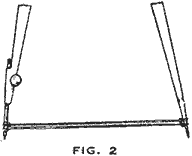
(Fig. 2)
Removing Grease from Paint
When removing grease from paint by using ordinary cleaners, the paint is liable to come off in the washing. A good and cheaply applied method is to rub the painted surface with a paste of ordinary whiting. This is allowed to dry and when it is rubbed off with a cloth the dirt and grease is taken away with it. The whiting is cheap and can be purchased at any drug store.
A Door Stop
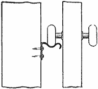
A very good door stop can be easily made of a piece of metal as shown in the sketch. The metal is bent and fastened with screws to the wall against which the door swings. The extending end fits under the door knob and prevents it from striking the wall.—Contributed by C. R. Poole, Los Angeles, California.
Stretching a Curtain without a Frame
A good way to avoid using the ordinary four-pole curtain stretcher is to make use of the following method. Take the lace curtain and fold it once lengthwise; then pin it up on a tightly stretched line with a large number of clothespins, and slip a clean pole between the two sides to keep it taut. This method not only stretches the curtain satisfactorily, but saves considerable time otherwise required in pinning the curtain to the four-sided frame.—Contributed by H. Wynning, Chicago, Ill.
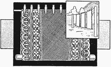
A Lace Curtain Hung Double on a Line with a Pole Inserted in the Fold
Welding Small Resistance-Wire Connections
In making connections, especially in electrical heating devices subject to high temperatures, it is out of the question to use solder, since the temperature reached in the device would cause the solder to melt and run out. A convenient arrangement for welding the connections of flatirons, or any other fine wires, is shown in the illustration. The ends of the wires to be welded are twisted together, and the weld is completed by forming an arc, one electrode of which is the twisted connection and the other a piece of carbon. The resistance of the heating unit in the iron is sufficient to limit the amount of the current flow so that a short circuit does not result.—Contributed by G. Irving Davis, Albany, N. Y.
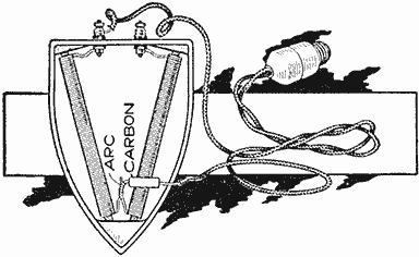
An Arc is Formed with a Piece of Carbon, to Weld the Twisted Ends of Wire Together
Bench with Folding Seats
To provide a bench with seats, or shelves, which cannot easily be taken away unless the table is brought along, hinged brackets are attached to stationary crosspieces, which are fastened on the extended end braces of the table. When in use, the brackets are turned down, thereby providing a rigid support for anything that may be put on them. If it is desirable to have the brackets out of the way, as when carrying the bench, it is only necessary to fold them up.—Contributed by J. M. Kane, Doylestown, Pa.

Bench, or Table, with a Seat on Each Side That can be Folded for Carrying Purposes
Rim of Wire Wastebasket Wrapped with Felt
In offices where wire wastebaskets are used, the finish of the desks is often marred by the top rim of the baskets rubbing against them. This can be overcome by wrapping strips of felt around the rim to form a buffer.—Contributed by Miss F. D. Schweiger, Kansas City, Mo.

A Homemade Roller Coaster By J. H. Sanford
The popular roller coaster that furnishes untold amusement for the multitudes that patronize amusement parks during the summer can be easily duplicated in a smaller way on a vacant lot or back yard for the children of the home; or the boys of a neighborhood could contribute to a fund and construct quite an elaborate affair, on the same lines as described, for the combined use of the owners. The one described was built with a track, 90 ft. long, 5 ft. high at one end and 3 ft. at the other, the track between being placed on the ground. In coasting from the high end to the low one, the coaster will run up on the incline, then drift back to within 24 ft. of the starting end. The car was built to seat four children or two adults. The cost of all the materials for building this roller coaster did not exceed $10.

Inexpensive Back-Yard Roller Coaster, Suitable for the Enjoyment of the Young as Well as the Older Persons
The track is of simple construction and requires but little description. It is necessary to have it straight and nailed firmly to the crossties on the ground and to the trestles where it is elevated. The ties and trestles are placed about 6 ft. apart. The two trestles for the starting platform should be set so that there is a slant to the track of about 6 in. for starting the car without pushing it. The car can be carried back for starting by adults, but for children a small rope can be used over the platform to draw it back on the track, or a small windlass may be arranged for the purpose.
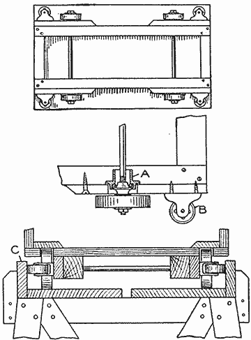
Detail of the Car, Wheels and the Trestle, Which is Attached to a Tie
The main frame of the car is 3 ft. long and about 13 in. wide, firmly fastened at the corners. The axles for the wheels are machine steel, 19 in. long, turned up on the ends and threaded in the manner of a bicycle axle to fit parts of bicycle hubs, attached to the main frame as shown at A. The wheels are solid, 4 in. in diameter and 1 in. thick, and are set on the bicycle cone of the ball cup, after they are properly adjusted, and securely fastened between washers with a nut on the end of the axle. Guide wheels, B, are placed on the sides in the manner shown. These wheels are ordinary truck casters, not the revolving kind, 2 in. in diameter.
About 1/2-in. clearance should be provided between the guide wheels B and the guard rail C, on the track. When the car is made in this manner it runs close to the track and there is no place where a child can get a foot or hand injured under or at the sides of the car. The one described has been used by all the children, large and small, for a year without accident.
Door-Bell Alarm
A simple door-bell alarm for informing one when the door of a shop or dwelling is opened is shown in the accompanying sketch. It consists of a piece of spring brass, A, bent into a circle in the center so that it may be clamped on the doorknob bar by means of a small bolt or screw. The two ends of this piece should be separated as shown and a second piece, B, mounted on the door so that its outwardly projecting end is between the ends of the piece A. One terminal of an ordinary vibrating bell circuit is then connected under the head of the clamp screw, and the other terminal under one of the screws holding the piece B in place on the door. It is now obvious that the bell circuit will be completed and the alarm sounded when the knob is turned. Make sure that the piece A is bent so that the circuit is completed before the latch has moved a sufficient amount to allow the door to open.
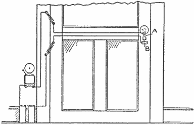
Wiring Diagram and Connections to an Electric Bell That Rings When a Door Knob is Turned
The circuit leading to and from the switch may be completed through the hinges of the door, but it would be better to use small coil springs as shown. There would then be no likelihood of the circuit being open at any time, which might occur if the hinges were used.
Discolored coffee and teapots may be restored to their original brightness by boiling them a few minutes in a solution of borax water.

A Playground Ferris Wheel
The whole wheel is carried on two uprights, each 3 by 4 in., by 10 ft. long. In the upper ends of these pieces, A, a half circle is cut out to receive the main shaft B. The end of the uprights are sunk 3 ft. into the earth and about 4 ft. apart, then braced as shown. They are further braced by wires attached to rings which are secured with staples near the top. The bearings should each have a cap to keep the shaft in place. These can be made of blocks of wood with a semicircle cut out, the blocks being nailed over the shaft, while it is in place, the nails entering the ends of the uprights.
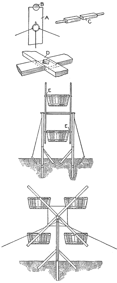
Detail of the Uprights, Axle and Spokes, and the End and Side Elevations of the Completed Wheel, Showing Braces and Cars Attached
The main shaft C is made of a 2-1/2-in. square piece of good material, 4 ft. long. The ends are made round to serve as bearings, and the square part is fitted with the spokes or car carriers. These consist of 4 pieces, each 1 in. thick, 4 in. wide and 13 ft. long. In the center of each piece cut a notch one-half the thickness so that when each pair of pieces is crossed they will fit together with the surfaces smooth, as shown at D. A square hole is cut through the pieces as shown to fit on the square part of the main axle. While it is not shown in the illustration, it is best to strengthen this joint with another piece of wood, cut to fit on the axle and securely attached to the spokes.
The cars or carriers are made of two sugar barrels cut in half. The hoops are then securely nailed, both inside and outside; a block of wood, E, securely attached to the half barrel on the outside, and another block on the inside opposite the outside block. Holes are bored 2-1/2 ft. from the ends of the spokes and a bolt run through them and through the blocks on the edges of the half barrels. The extending ends of the spokes are used to propel the wheel. Four children can ride in the wheel at one time.—Contributed by Maurice Baudier, New Orleans, La.
A Merry-Go-Round Pole
An inexpensive merry-go-round can be made of a single pole set in the ground where there is sufficient vacant space for the turning of the ropes. The pole may be of gas pipe or wood, long enough to extend about 12 ft. above the ground. An iron wheel is attached on the upper end so that it will revolve easily on an axle, which may be an iron pin driven into the post. A few iron washers placed on the pin under the wheel will reduce the friction.
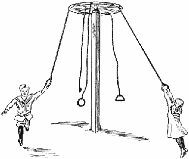
The Ropes being Tied to the Wheel Rim will Easily Turn around the Pole
Ropes of varying lengths are tied to the rim of the wheel. The rider takes hold of a rope and runs around the pole to start the wheel in motion, then he swings clear of the ground. Streamers of different colors and flowers for special occasions may be attached to make a pretty display.—Contributed by J. Bert Mitchell, Wichita, Kans.
A Theatrical Night Scene with the Appearance of Fireflies
Use small shining Christmas-tree balls, about the size of a hickory nut, strung on strong black linen threads. The thread is put loosely over a hook at the back of the stage among the evergreens that are used for the background. The ends of the threads are brought, like a pair of reins, to the front of the stage, diagonally, and there manipulated by some one in a wing near the front, standing high enough to prevent the threads from touching the heads of the actors. These bright little particles darting back and forth among the trees appear very lifelike, and with the addition of a crescent moon just peeping through the trees, the likeness to a summer night is quite striking.
The moon effect is made by using a piece of dark cardboard, about 2 ft. square, covered thickly with small green boughs, and by cutting a crescent-shaped opening in the center, covering it with yellow tissue paper. This cardboard is placed well back in the trees and a lantern hung behind it.—Contributed by Miss S. E. Jocelyn, New Haven, Conn.
Hulling Walnuts
Procure a barrel that is water-tight and mount it on a shaft so that it runs between standards like a barrel churn. Fill the barrel about half full of walnuts, cover them with water and throw in a small quantity of gravel as grinding material. Close the opening tightly and turn the barrel for about 20 minutes. The walnuts will come out clean and smooth as glass.—Contributed by Arthur Seufert, The Dalles, Oregon.
Stick for Lowering Top Sash of a Window
To make it easy to raise and lower the upper sash of a bathroom window which is behind the bathtub I devised the following: Procuring two screweyes I opened one sufficiently to slip it into the other as shown at A. Then one was screwed into the top rail of the sash and the other into the end of a light stick a little longer than the length of upper sash.
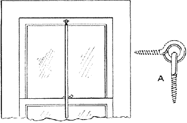
The Stick is Fastened to the Window Sash with Screweyes and is Always Ready for Use
The device is left on the window permanently and affords a ready means of handling the sash without stepping into the bathtub, which would otherwise be necessary.—Contributed by W. E. Morey, Chicago.
An Adjustable Hacksaw Frame
The frame is constructed of cold-rolled steel, 1/4 in. in diameter and 17-1/2 in. long, bent into the shape shown and then cut in two parts at A. Starting at a point about 5/16 in. from the ends made by the cut, drill 1/8-in. holes, then space three other holes 1 in. between centers and drill them 1/8 in. in diameter.
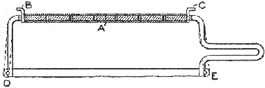
The Frame is Shaped of Cold-Rolled Steel and Made Adjustable with a Piece of Steel Tubing
A piece of steel tubing, 1/4 in. in inside diameter and 6-3/4 in. long, is notched on the ends to receive the pins B and C. Slots are cut in the ends D and E, to admit the blade of a saw, and half-round notches filed on the outside surface for holding pins used in the hole of the saw blade. The spring of the steel will be sufficient to keep the saw blade in place. The 1/8-in. holes in the frame will permit adjustment for different lengths of blades.—Contributed by Clarence B. Hanson, Fitchburg, Mass.
A Bedroom Cabinet
The cabinet shown in the illustration can be made an ornament with a little care in workmanship and a choice selection of materials. The cabinet may be either fastened to the head or foot of the bed, facing in either of two directions.
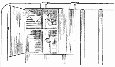
The Cabinet Makes a Handy Place to Keep Necessary Articles for a Sick Person
The size of the cabinet will depend on the choice of the maker, and if the bed is brass, the wood can be finished natural and fitted with brass bands for brackets and holding clips.—Contributed by W. E. Crane, Cleveland, O.
A Dull Black for Cameras
Such parts of a camera that are apt to reflect light must be covered with a dull black. A mixture for this purpose is made of lampblack, about a teaspoonful, and enough gold size to make a paste as thick as putty. Add about twice the volume of turpentine and apply to the parts with a camel's-hair brush.
As the turpentine fumes are detrimental to the sensitive plate, the camera should be left open until these fumes have entirely disappeared.
A Door Fastener
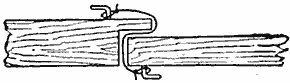
Sometimes it is necessary to fasten a door in a manner to prevent children from opening it, yet so that it is easily opened from either side. This can be done by putting a screw or curtain hook on the inside of the door frame and using a piece of cord long enough to loop over both hooks. A person coming in or out can remove the loop from either side.—Contributed by John A. Cohalan, Philadelphia, Pa.
A floor wax can be made by melting 1 lb. of yellow beeswax in 1/2 pt. of hot, raw linseed oil; then adding 1 pt. of turpentine.
Umbrella Used as a Flower Trellis
Procure a discarded umbrella and remove the cloth, leaving only the steel frame. Join the ends of the ribs by running a fine wire through the tip of each rib and giving it one turn around to hold them at equal distances apart. The handle is then inserted in the ground and some climbing vine planted beneath it. The plant will climb all over the steel frame and make a very attractive lawn piece.—Contributed by John F. Campbell, N. Somerville, Massachusetts.
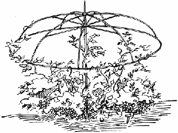
Frame Supporting a Vine
Combined Shade and Awning
An ordinary window shade makes a good awning as well as a shade, if it is attached to the outside of the window with the device shown in the illustration. The shade and spring roller are put into a box for protection from the weather and the box is fastened in the window casing at the top. A narrow slit on the under side of the box permits the shade to be drawn out. The stick at the end is removed and a U-shaped wire inserted in the hem in its stead. The wire is bent so the ends may be inserted in holes in the window casing. As the shade is drawn out, it is extended outward by the wire in the position of an awning.—Contributed by Arthur Kesl, Chicago, Ill.
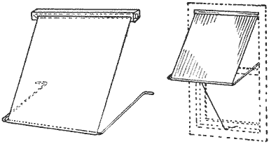
Shade Attachments
Vaulting-Pole Attachments
Some means must be provided on vaulting-pole standards to allow for the free release of the pole should the vaulter strike it in going over. One of the simplest of the many devices that can be used for this purpose is shown in Fig. 1. It is made of heavy wire, bent and slipped over the standard as shown in Fig. 2. The projection on the inside of the link is used similar to the tongue of a buckle in adjusting the height of the pole on the standards.
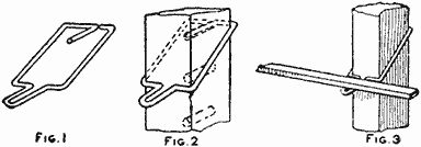
Pole Adjuster on Standard (Fig. 1, Fig. 2, Fig. 3)
Each standard has a series of holes on its front side. These holes may be numbered for convenience. The pole in place is shown in Fig. 3.—Contributed by John Dunlap, Craghead, Tollcross, England.
Separating Drinking Glasses
When two thin glasses are put one into the other they often become stuck and cannot be removed. To separate them with ease, set the lower glass in warm (not hot) water and pour cold water in the upper one. The expansion of the lower and the contraction of the upper will make release an easy matter.—Contributed by Maurice Baudier, New Orleans, La.
Bronze striping, when thoroughly dry, should be covered with a thin coat of white shellac to keep it from tarnishing.
A Magic String
Procure a few pieces of cotton string, each about 1-1/2 ft. long, and fill them well with soap. Prepare a brine by dissolving three tablespoonfuls of salt in a cup of water. Place the strings in the brine and allow them to soak for two hours, or longer. It is necessary that they be thoroughly saturated with the brine.
When taken out of the brine and thoroughly dried, suspend one of them from a nail on a ledge, and hang a finger ring on its lower end. Apply a lighted match to the string and allow it to burn. The ring will not fall, but will hang by the ash.—Contributed by C. Frank Carber, Dorchester, Mass.
Edging Flower Beds
To improve the appearance of a flower bed, it must be edged evenly and quite often. As this became a tiresome task, I constructed an edger, as shown in the sketch. It consists of a wheel on a 4-ft. length of material, 2 by 4 in. in size, made tapering and having a cross handle, 18 in. long, attached to its end. The wheel is 8 in. in diameter, and the cutter is attached, as shown, across the center of the wheel axle, to make the edger turn easily on curves and corners. The cutter is 12 in. long and turned under 1-1/2 in. It is pushed along in the same manner as a garden cultivator.—Contributed by A. S. Thomas, Amherstburg, Can.

An Edger, Similar to a Garden Plow, for Quickly Trimming the Sod around a Flower Bed
An Electric Stirring Machine
Desiring a stirring machine for mixing photographic chemicals, I set about to design the one shown in the illustration. The base and upright are made of pine, 1 in. thick, the former 8 in. wide and 10 in. long, the latter 8 in. wide and 16 in. long. A 3/8 in. slot, 12 in. long, is cut in the center of the upright, and two pieces of sheet metal or tin, 2 in. wide and 12 in. long, bent at right angles along the center of their length, are placed at equal distances, on each side of the slot, and fastened with screws. The distance between these pieces depends on the motor used, as its base should fit snugly between them.
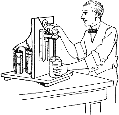
A Self-Contained Electric Stirring Machine for Use in Mixing Photographic Chemicals
A small battery motor is purchased, and its shaft is removed and replaced with one measuring 10 in. in length. To the end of the shaft is soldered a piece of wire, bent as shown in the sketch. A bolt is attached to the center of the motor base, so that its threaded end will pass through the slot in the upright, where it is held with a wing nut. The battery cells may be placed on the back of the upright and a small switch mounted at the top and in front.—Contributed by Ray F. Yates, Niagara Falls, N. Y.
A Clothes Rack
The rack is constructed of hard wood throughout, and as each piece is made, it should be sandpapered and varnished or otherwise finished. The plan view is shown in Fig. 1; the construction of an arm, in Fig. 2; and the pin, in Fig. 3.
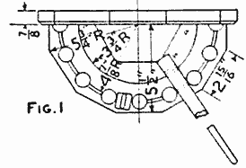
Any Number of Arms Up to Its Limit may be Used at a Time (Fig. 1)
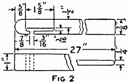
(Fig. 2)
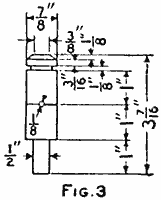
(Fig. 3)
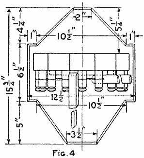
(Fig. 4)
The base is 7/8 in. thick and of the dimensions shown in Fig. 4. The projection on each side, measuring 6-1/2 in. long and 1 in. wide, is made separately and glued to the main part after dressing and beveling the edges.
The shelf consists of material 2 in. thick and made in a semicircular form on a radius of 5-3/4 in. On this arc, lay off chords, as shown in Fig. 1; the first ones on each side being one-half the length of the others. Carefully square up the edges for appearance. To lay off the post holes, scribe an arc of a circle on a 4-7/8-in. radius. Start at the edge on this arc and lay off eight chords of equal lengths, and bore 1/2-in. holes on the marks.
The posts are turned up, as shown by the detail, Fig. 3. This will require seven posts and two half posts. The half posts are secured to the base with small brads. The round part at the end is turned slightly tapering, so as to make a tight fit in the hole of the shelf. After stringing the posts on a piece of brass wire, 1/8 in. in diameter, and bending it in the proper shape, the posts are glued in the holes.
A T-shaped slot with a long top and a short leg is cut out with a scroll saw in one end of each arm. Make sure to have each slot exactly 1/2 in. from the upper side of each arm. All edges should be well rounded to prevent tearing of the clothes.
Make a semicircular platform for the arms to bear upon when extended. This may be either half of a turned disk or built up in the three segments, each fastened with screws to the base. If the brass wire is exactly 1 in. from the shelf and the thickness of the wood between the T-slot and the upper edge of the arm 1/2 in., the thickness of the platform should be slightly under 1/2 in. to make the arms rest horizontally when they are extended.
The shelf is fastened to the base with three or four 2-in. screws, and the ends of the brass wire are run through holes in the base and clinched on the back side. The rack may be fastened in place on the kitchen wall with two large wood screws, or, if the wall is brick, with expansion bolts. The fastening in either case must be secure to hold the heavy weight of wet clothes.—Contributed by D. A. Price, Wilmington, Del.
How to Make a Pair of Foot Boats
On ponds or small lakes not deep enough for a boat one can use the foot boats, as illustrated, for walking on the water. The boats are made of white wood, known as basswood, as this wood is easily bent when steamed, and the curved part should be shaped neatly.

Foot Boats for Walking on Shallow Water Where a Boat cannot be Used
Two sides are cut out, as shown, and the boards are nailed or, better still, screwed to them. Each straight part may consist of one piece, in which case there will be no joints to make waterproof, but if boards of sufficient size cannot be had, pieces can be used. In this instance the edges should be planed smooth, so that a good joint may be had, which can be made watertight with white lead.
It is best to make the bottom of one piece if possible, at least for the length of the curve. The wood is thoroughly steamed, then fastened in place on the curved part.
A strap of suitable length is fastened on the top for the toe, so that the boats can be controlled with the feet.
To propel the boats along easily, a web or wing should be attached to the under side, so that it will catch the water on the back thrust while it will fold up when the boat is slid forward.—Contributed by Waldo Saul, Lexington, Mass.
A Green-Corn Holder
Neat and attractive green-corn holders for table use can be made of small-sized glass drawer knobs, having a bolt 1 in. in length. The bolt head is cut off with a hacksaw, and its body is filed to make four sides running to a taper, leaving enough threads to secure it in the knob. The threads are smeared with white lead, then it is screwed into the knob and sufficient time allowed for the lead to set before using it.
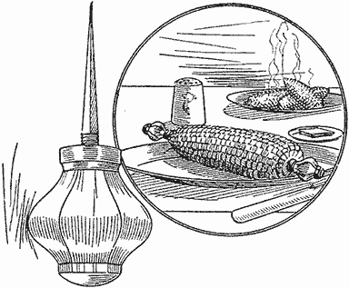
The Glass Knobs Make a Clean and Sanitary Holder for the Ear of Corn
A pair of knobs are required for each ear of corn served. The square bolt end will hold the ear securely while the kernels are eaten from the cob.—Contributed by Victor Labadie, Dallas, Texas.
Inflating Toy Balloons
The inflation of rubber balloons may be accomplished with manufactured gas by using the simple pipe arrangement shown in the sketch. The connection A is for the gas hose, which is similar to those used for a table lamp. The gas bag B is a football or punching bag connected to the pipe as shown. This receives the gas as it is let in by the valve A. The toy balloon C is connected to the pipe in the same manner and the valve D used to regulate the flow of gas. The gas is easily pressed out of the ball into the balloon.
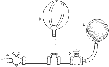
Pipe Arrangement, Punching Bag and Valves to Admit Gas to a Toy Rubber Balloon
As hydrogen gas is much better than the manufactured gas, it is best to use and can be put in the balloon in the same manner.
Electric-Light Mystery
A novel attraction for a window display can be made of a piece of plate glass neatly mounted on a wood base, and an electric light which is placed on the top edge and may be lighted apparently without any wire connections.
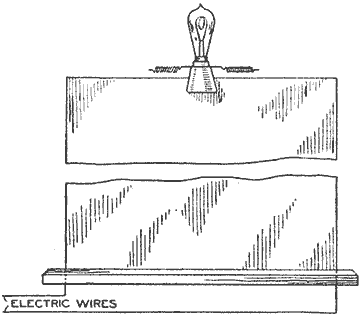
Electric Light Mounted on Top of a Plate Glass with Hidden Connections on the Glass Edge
The method of concealing the connections is to paint the edges of the glass green, then, before the paint is quite dry, lay on a thin strip of copper, making the connections at the base on both sides, and to the lamp in the same manner. Another coat of paint is applied to cover the strip. The color should be an imitation of the greenish tint of glass edges. Any desired lettering can be put on the glass.—Contributed by O. Simonson, Brooklyn, N. Y.
An Oar Holder
Persons rowing boats, particularly beginners, find that the oars will slip out of the oarlocks, turn or fall into the water. This may be avoided by turning a screweye of sufficient size to prevent binding on the lock into the oar and placing it over the lock as shown at A, so that the pull will be against the metal. The oars will never slip or jump out, will always be in the right position, and it is not necessary to pull them into the boat to prevent loss when not rowing. The locks will not wear the oars, as the pull is on the metal eye. Place the eye so it will have a horizontal position on the side of the oar when the blade is in its right position.
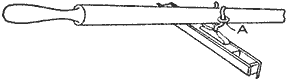
The Screweye in Position on the Oar and over One Prong of the Oarlock
Cooking Food in Paper
A flat piece of paper is much more convenient to use than a paper sack in cooking, as it can be better fitted to the size of the article to be cooked. Wrap the article as a grocer wraps sugar, folding and refolding the two edges together until the package is of the proper size, then fasten with clips and proceed to close the ends in the same way. This avoids all pasted seams and makes the package airtight.—Contributed by J. J. A. Parker, Metamora, O.
Washing Photograph Prints
Photographic prints may be washed in a stationary washbowl with just as good results as if washed in a high-priced wash box, by cutting off the upper end of the rubber nipple on a bent glass medicine dropper and placing it on the faucet as shown in the illustration. This arrangement causes the water to whirl around in the bowl, which keeps the prints in constant motion, thus insuring a thorough washing.—Contributed by L. O. D. Sturgess, Arlington, Oregon.
A Medicine Dropper on a Faucet Produces a Whirling Motion of the Water in the Bowl
Combination Lock for a Drawer
The principal parts of the combination lock are the five disks shown in Fig. 1. These are best made of sheet brass, about 1/16 in. thick and 1-1/2 in. in diameter. The pins for turning the disks are each made a driving fit for a hole drilled through the metal at a point 15/32 in. from the center. Notches are cut in the disks C, D and E, Fig. 1, to receive the latch end, and the disk B is made like a cam, its use being to raise the latch into its keeper when the handle is turned backward. The disk A is without a notch and has only a pin for turning the other disks.

The Parts as They are Attached to a Drawer Front to Make a Combination Lock (Fig. 1)
The disks are mounted on the inside of the drawer front in a U-shaped piece of metal, F, Fig. 2, which carries a 1/4-in. pin, G, as their bearing. The disks are placed on this pin with rubber washers, H, J, K, L and M, between them. These serve the purpose of preventing the disks from turning too freely. The disk A is fastened tightly to the end of the rod N, which is 1/4 in. in diameter. The outer end of this rod is fitted with a handle or turning head as desired. That shown at O is made of two pieces of wood screwed together, with a pointer, P, placed between them. A washer, R, is placed between the drawer end and the handle to take up any looseness and to allow the free turning of the rod.

(Fig. 2)
A dial, S, is made of paper and the division marks and numbers placed upon it. The latch T is fitted in a U-shaped piece of metal, U, which is fastened to the inside of the drawer end where its heel will rest on the edges of the disks. When the right combination is made by turning the handle first one way and then the other, the latch will drop into the notches of the disks as they will be all in one place.
When the drawer is to be locked, turn the handle back from the last turn made for the combination and the latch will be driven upward into its keeper and the notches scattered so that the latch will not drop until the combination is again set.
The numbers for the combination can be found after the disks are in place and by turning the handle until the notch comes up to the place for the heel of the latch. The number beneath the pointer is noted; then the next turned up in a like manner, all being done while the drawer is open and the disks in plain sight. The combination can be changed only by changing the location of the pins in the disks.—Contributed by C. B. Hanson, Fitchburg, Massachusetts.
How to Start Small Machine Screws
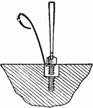
Small machine screws are sometimes very difficult to start, especially when used in parts of a machine that cannot be easily reached with the fingers. A good way to start them is by means of a piece of fine wire wound snugly around the screw under its head. They can be placed and started by means of the wire and when the first threads have caught the screw it can be held by the screwdriver while the wire is withdrawn.—Contributed by F. W. Bently, Huron, S. D.
An Umbrella Holder for Display Purposes
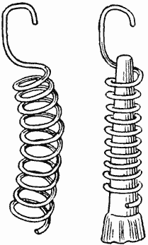
A holder that is especially adapted for use in hanging umbrellas for display in a store can be easily made of a piece of wire wound in a coil, as shown in the sketch, to fit over the end on the umbrella stick. The coil at one end of the spring is formed into a hook so that the umbrellas may be hung in screweyes or on a line, as the case may be. The end of the umbrella is stuck into the spring, as shown, which grips it tightly.—Contributed by Abner B. Shaw, N. Dartmouth, Mass.
Holder for a Milk Card
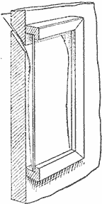
It is the general practice of milkmen to furnish a monthly card on which the housewife marks the needs of the day and then hangs it outside of the door for the information of the driver. This card also serves as a record for checking the accounts of the milk delivered during the month, and therefore it is desirable to protect it from snow and sleet.
In order to furnish this protection and at the same time make it unnecessary for any one to go outside of the door to hang up the card on stormy days, one of our readers has submitted the following plan which he has used for some time.
On the outside of the kitchen door, where the milkman is to deliver his bottles, this man has fastened an ordinary picture frame with glass but no backing except the door. Through the door and just below the upper edge of the glass is cut a thin slot inclining downward and outward so that the milk card can be easily pushed through the slot and thus be displayed behind the glass in the frame. By this protection it is kept free from mud, snow and ice. It is not necessary to step outside to place the card in the frame.
Frame for Printing Post Cards from Negatives
As I desired to print only a portion of some of my 5 by 7-in. plates on post cards and the part wanted was near the edge of the plate, I cut out the printing frame, as shown at A in the sketch, to accommodate that part of the card I reserved for a margin. This permitted the card to be placed in the frame without making a bend.—Contributed by J. H. Maysilles, Rochelle, Ill.
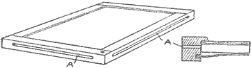
Slots Cut in the Frame to Receive the Post Cards without Bending Them
Finger Protection on Laboratory Vessels
A simple way of protecting the fingers against being burned by laboratory vessels in which liquids are boiling or chemical reactions producing great heat are going on, is shown in the sketch. A rather thick cord or yarn is wrapped around the neck of the vessel in the manner shown, the upper end being drawn through the loop at the top and cut off, and the lower end then pulled out and a knot tied in it close to the windings of the yarn.
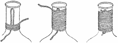
The Ends of the Cord are Held Tightly and the Winding Protects the Hands
Inlaying Metals by Electroplating
Very pretty and artistic effects of silver or nickel inlay on bronze, copper, etc., or copper on dark oxidized metals, may be obtained by means of etching and electroplating.
The metal on which the inlay is to be used is first covered with a thin coating of wax and the design scratched through to the metal with a sharp, hard point of some kind. The design is then etched in slowly with well diluted nitric acid, allowing the etching to penetrate quite deeply. The metal is then taken out and after a thorough rinsing in water is hung in the plating bath.
As the wax has been left on, the plating will fill the lines of the design only, and will not touch the covered surface. When the etched lines are filled, the object is taken out of the bath and the wax removed.—Contributed by S. V. Cooke, Hamilton, Can.
A Novel Show-Window Attraction
This moving show-window attraction can be simply and cheaply made. The things necessary are a small battery motor, a large horseshoe magnet and a large polished steel ball, perfectly true and round, such as used in bearings. The other materials usually can be found in any store. Procure some thick cardboard and cut two disks, 8 in. in diameter, and two disks, 7-1/2 in. in diameter. Glue these together to make the wheel A, the larger disks forming the flanges. Make a smaller wheel, B, the size of which will be governed by the speed of the motor used. The wheel A is mounted in a box to run with its surface close to the under side of the cover, which should be of a thin, stiff cardboard. The wheel B is mounted on an axle that runs in metal bearings. The magnet D is placed on the wheel A. The steel ball E is put on the thin cover of the box, and the magnet causes it to roll around as the wheel turns. The box inclosing the mechanical parts should be placed out of sight when used in a window.—Contributed by Clarence Guse, Spokane, Wash.

The Steel Ball is Caused to Roll Around on the Cover by the Moving Magnet
How to Make a Mop Wringer
A mop wringer may be made and attached to an ordinary pail in the following manner: Two pieces of metal, A, are attached securely at opposite sides of the edge of the pail, holes being drilled in their upper ends to serve as bearings for the roller B. The piece of metal C, which is duplicated at the opposite side of the pail, is pivoted on a bolt. These pieces also carry a roller, E, at their upper ends, and have a crosspiece, F, at their lower ends. Discarded wringer rollers can be used for B and E. A coil spring is attached as shown, to keep the rollers separate and in a position to receive the mop. When the mop is placed between the rollers they are brought together by a pressure of the foot on the crosspiece F.—Contributed by J. Dennis McKennon, New Britain, Conn.
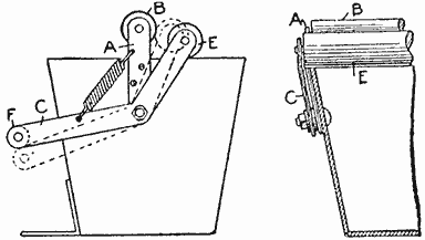
The Parts may be Either Attached to a Metal or Wood Pail with Bolts or Screws
A Vise Used as a Caliper Gauge
Not infrequently it is desired to know the distance from one side to another of some part that cannot be directly measured with a rule, and when no calipers are at hand. But with a vise handy, the measurement can be made with ease and with sufficient accuracy for all practical purposes if the vise is not too worn. This trick is particularly adapted for calipering threaded parts, as threads cannot be measured readily with ordinary calipers. How this may be done is shown in the sketch, which illustrates the method as applied to a screw. The work is gripped between the jaws of the vise and the opening then measured with a rule.—Contributed by Donald A. Hampson, Middletown, New York.
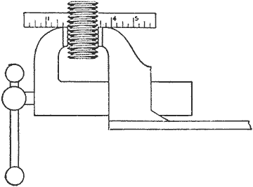
The Jaws of a Vise, If They Are True, Will Make a Caliper Gauge Giving a Perfect Measurement
Homemade Tack Puller
A very handy tack puller can be made of a round-head bolt. On one side of the head file a V-shaped notch and screw a wood handle on the threads. This makes a very powerful puller that will remove large tacks from hardwood easily.

The Shape of the Head Permits a Leverage Action That Lifts the Tack Easily
How to Make a Radium Photograph
The radium rays, like the X-rays, affect the photographic plate, as is well known, but it would naturally be supposed that the enormous cost of radium would prevent the making of such a photograph by the amateur.
It is a fact, however, that a radium photograph can be made at home at practically no cost at all, provided the amateur has patience enough to gather the necessary material, which is nothing else but broken incandescent gas mantles. These (especially Welsbach mantles) contain a salt of the rare metal thorium, which is slightly radioactive. The thing to do, then, is to collect a sufficient quantity of broken mantles to cover the bottom of a small cardboard box—a dryplate box, for instance—with a layer of powdered mantle substance. Upon this layer and pressed tightly against it is placed a piece of cardboard; then some metal objects, a button, hairpin, a buckle, or the like, are laid on the cardboard and covered with a sensitized paper. This is again covered with a piece of cardboard and the box filled with crumpled paper to the top. The cover is then put on, the box tied up with a piece of string and set in some place where it is sure to be left undisturbed.
The radium rays from the powdered mantles readily penetrate the cardboard and paper, but not the metal articles. Being very weak, the rays must be given four weeks to accomplish their work. After that time, however, if the sensitive paper is taken out, pictures of the metal objects in white on a dark background will be found on it. These pictures will not be so sharp as ordinary photographs, because the rays are not focused, but they fairly represent the originals and the experiment is an interesting one.
A good imitation mahogany stain consists of 1 part Venetian red and 2 parts yellow lead, mixed with thin glue size, and is laid on with a woolen cloth.
Fountain for an Ordinary Pen
Fill the hollow end of an ordinary penholder with cotton—not too tightly—and one dip of the pen will hold enough ink to write a full page. The cotton should be changed each day. A small piece of sponge will answer the same purpose. It is necessary to dip the pen deeply into the ink.—Contributed by J. E. Noble, London Junction, Ontario.
Pulling Wire through Curved Electric Fixtures
To facilitate the running of electric wires through curved fixtures, nick a heavy shot, A, and fasten it on a cord, B, in the same manner as a fishline is weighted. The shot will roll through the fixture tube, carrying the cord with it. A cord strong enough to pull the wires through can be easily drawn through the opening in this manner. The shot should, of course, not be so large that it can possibly bind in the tube.
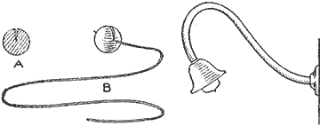
A Shot That will Pass through the Fixture Arm will Carry a Cord for Pulling in the Wires
An Automatically Closing Drawer
A very ingenious way to have a drawer close automatically is to attach a weight so that the rope or cord will pull on the rear end of the drawer. The sketch clearly shows the device which is an attachment similar to that used for closing gates. This can be applied to drawers that are frequently drawn out and in places where a person is liable to have the hands full.
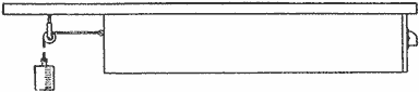
The Rope and Weight Attached to the Back End of the Drawer Pulls It Closed
A Cork Puller
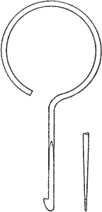
The stopper of any ordinary bottle can be easily removed with a puller such as shown in the sketch. The puller is inserted between the stopper and the neck of the bottle until the hook end will pass under the bottom of the stopper, then given a quarter turn and pulled upward.
The construction of the puller vents the cork as it enters and thus no vacuum is created. The cork is pulled more easily than with an ordinary corkscrew, and there is no danger of tearing the cork to pieces.
Uses for a Bamboo Pole
Select a good bamboo pole, about 18 ft. long, and cut it into three lengths as follows: A piece from the top, 2-1/2 ft. long; the next length, 5-1/2 ft. long, and the remaining end of the pole, about 10 ft. long. The 2-1/2-ft. length is equipped with a screw hook in the smaller end, as shown in Fig. 1. This stick is useful in lowering window shades that have a ring or screw eye attached to the lower part of the shade. When the stick is not in use, it is hung on the edge of the window casing.
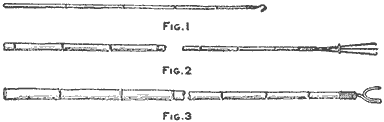
A Bamboo Pole Cut in Three Pieces Makes a Window-Shade Stick, Duster Holder and Clothesline Pole (Fig. 1, Fig. 2, Fig. 3)
The 5-1/2-ft. length makes the long handle for a duster. Procure an old-style lamp-chimney cleaner, wind a cord around the wires a few inches below the point where they begin to spread to keep them from coming apart, then cut or file the wires off 2 in. below the winding. This leaves a straight shank, over which a ferrule is slipped before it is inserted into the small end of the pole. Fill the remaining space in the pole end with plaster of Paris, and when it has set, slip the ferrule into place on the pole end. If a ferrule is not at hand, a fine wire can be wound around the end to prevent the pole from splitting. When using this pole to dust hardwood floors, tops of doors, window casings and picture frames, put a dusting cloth into the claws and slide the ring into place, as shown in Fig. 2.
The longer and larger end of the pole is used as a clothesline pole. One end of this pole is fitted with a yoke made of No. 6 gauge galvanized wire, as shown in Fig. 3. The wire for the yoke is 10 in. long, and after bending it in shape, the two upper ends should be 2 in. wide at the top and 2 in. deep. Insert the straight end of the wire into the smaller end of the pole and set it in firmly with plaster of Paris. The end of the pole should be securely wound with wire to keep the bamboo from splitting.—Contributed by Gertrude M. Bender, Utica, N. Y.
Making Common Lock Less Pickable
The ordinary lock can be readily changed so that it will be quite impossible to pick it with a common key. The way to do this is to cut off the small hollow portion of the key that fits over the pin. This part is placed on the pin of the lock and soldered, or fastened by any other means, so it cannot come out of the lock. This will prevent any ordinary key from entering the keyhole.—Contributed by A. J. Hamilton, Benton, Ark.
The Small End Cut from the Key is Fastened on the Pin of the Lock
To Color Tan Leather Black
An inexpensive and effective way to blacken tan leather is as follows: The leather is first rubbed with a 10-per-cent solution of tannic acid, which may be purchased at any drug store. This treatment should be applied and the leather well dried. It should be rubbed with a cloth hard enough to produce a polish, then apply a 10-per-cent solution of iron sulphate. A chemical reaction takes place as the last solution is rubbed into the leather, making it black. After this is dry, the leather can be polished in the usual way.
To Prevent Corks Sticking in Bottle Necks
Corks will always adhere to the necks of bottles containing glue or other sticky liquids, with the result that it becomes necessary to cut or dig the cork into small pieces in order to remove the contents from the bottle.
A simple and effective way to prevent a cork from sticking is to place a small piece of waxed paper on the bottle opening so that when the cork is pressed in, the paper will be between the cork and glass, as shown.
To Remove Rust Stains from Clothing
Many times when working around machinery, the clothes will come in contact with iron and get rust stains. These may be removed by using a weak solution of oxalic acid which must be applied carefully as it is highly poisonous. Sometimes the stain can be removed by washing the spot in buttermilk, in which case rubbing is necessary.
Small bits of onion placed in a room will absorb the disagreeable odors of paint and turpentine.
Eraser Holder
Any small piece of steel with a point, similar to that shown in the sketch, will make a good eraser holder. The saving of erasers is nothing compared to the convenience of having a small eraser with a chisel edge or point when delicate erasing is required. It is not clumsy as the usual chunk of rubber with a blunt point, for the person erasing can see what he is doing. I use a leg of an old pair of dividers and cut my erasers in four parts in shapes similar to that shown in the sketch by the dotted lines, and can use them easily until they are about the size of a pea. The friction between the rubber and steel, after the point has been inserted into the rubber, holds the two together nicely.—Contributed by James F. Burke, Lakewood, O.

A Very Small Eraser can be Held on the Point and Used for Delicate Erasures
Bleaching Ivory
A good method to bleach ivory ornaments is to rub on a solution made of a small quantity of unslaked lime, bran and water. The mixture should be wiped off after the ivory has become sufficiently bleached, and the surface then rubbed with sawdust or magnesia, which gives it a brilliant polish.
A Soap Shake
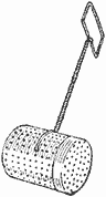
To utilize scraps of soap, make a soap shake of a medium-size baking-powder can, as shown in the sketch. Punch holes in the can with an ice pick or some other sharp-pointed instrument, and attach a large wire to the center, twisting the ends to form a handle.—Contributed by Elizabeth P. Grant, Winchester, Virginia.
Ear Repair on a Bucket
A broken ear for a bail on a metal pail or bucket can be replaced with a window-shade fastener, such as shown at A in the sketch. The base of the fastener is turned down flat and attached with screw bolts or rivets, as shown at B.—Contributed by Harold Robinson, Suffern, N. Y.
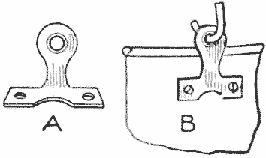
Cleaning Dirt from Tufts in Upholstering
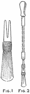
(Fig. 1, Fig. 2)
A handy device for cleaning furniture upholstering and vehicle-seat tuftings may be easily made as follows: Take an ordinary round paintbrush and cut the handle off, leaving it about 1-1/2 in. long, then saw a V-shaped notch in it, as shown in Fig. 1. Attach the brush to the ratchet screwdriver, Fig. 2, by inserting the screwdriver blade in the notch of the brush handle, and secure it by wrapping a strong cord around the handle. Place the brush in the tuft and work the screwdriver handle, as in turning a screw. A few quick turns of the brush will throw out the dirt which is impossible to remove with a straight brush.
Painting Lead Pipe
The paint applied to lead pipes will chip and peel off, and to prevent this I first cover the lead surface with a thin coat of varnish, then apply the paint on the varnish. A lead pipe painted in this way will retain its coating.—Contributed by F. Schumacher, Brooklyn, N. Y.
Attaching a Vise Jaw to a Bench
Procure a toothed metal rail or rack, A, such as is used for small ladder tracks, and mount it on the lower edge of the guide rail for the lower end of the vise jaw. Provide a slot, B, in the leg of the bench, through which the rail can run with plenty of play room. A beveled plate, C, is attached to the face of the bench leg at the bottom of the slot, so that it will engage the teeth of the rack.
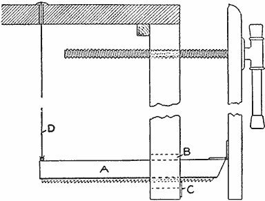
The Rack on the Lower Guide Rail Provides a Means to Keep the Vise Jaws Parallel
In use, when opening the vise by means of the screw, the rack will drag along the plate, and stop and engage a notch when the opening operation ceases. When it is desired to reduce the opening, it is only necessary to lift the rail by means of the string D. A button is tied to the upper end of the string on top of the bench, to keep it handy for changing the jaw.—Contributed by Harry F. Lowe, Washington, District of Columbia.
Removing Vegetable Stains
To remove stains of vegetables or fruits of any kind from cloth or wood, the following method is very good: The stained piece is first moistened with water and then placed in a jar or pail that can be covered. A lump of sulphur is ignited and dropped into the jar. Place the sulphur on a fire shovel when lighting it to avoid burns. The burning sulphur should be placed in the receptacle on the side where the stain will be exposed to the fumes. The sulphur burns slowly so that the articles will not be harmed.
After the sulphur has burned away, the jar should be kept closed for a few minutes and when the articles are removed, the stains will be gone. This is harmless to try, and the cloth will not be injured if it is in a dry condition. The articles should be washed and dried as soon as they are taken out of the jar.
Picture-Frame Corner Joints
Very often the amateur craftsman comes across a picture which he would like to have framed, but the difficulty and insecurity of the ordinary miter joint for the corners discourage him from trying to make the frame. A very easy way to construct a rigid frame is shown in the illustration. The size of the frame must be determined by the picture to be framed. The width, A, of the pieces depends upon one's own taste.
Four pieces, the desired length and width and 1/2 in. thick, should be dressed out of the material intended for the frame. Four other pieces, 3/8 in. thick and 1/2 in. narrower than the first four pieces, are next made ready and fastened with glue and flat-head screws to the back of the first pieces, as shown. This allows 3/8 in. for glass, picture and backing, and 1/2 in. to lap over the front of the picture on all edges.
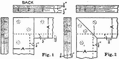
Square and Mitered Lap Joints for Making Rigid Picture Frames in Natural or Stained Woods (Fig. 1, Fig. 2)
By arranging the pieces as shown in Fig. 1, a strong corner lap is secured. A miter lap joint which is not so strong is shown in Fig. 2. The latter gives a mitered-joint effect. This method does away with the use of the rabbeting plane and miter box, both of which are difficult to use with accuracy. Two screws should be used in each joint to reinforce the glue.—Contributed by James Gaffney, Chicago, Ill.
Hunting-Knife Handles
Very artistic handles for hunting knives and carving sets can be made by using disks of horn. Procure some cowhorns from a slaughter house and split them with a saw, using only the large portion of the horn. The split horn is then heated by dry heat—an oven is best—then pressed between two cold plates to a flat piece. If well heated, it is surprising how easily this can be done. The piece is then cut into squares of suitable size which are marked and perforated in the center, the hole being a trifle smaller than the tang of the blade. The tang should be flat and a little longer than the desired handle, with the end made round and threaded for a nut.
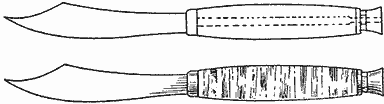
The Finished Handle, If the Work is Well Done, is Easily Mistaken for Agate
A suitable washer is placed on the tang, which is then heated sufficiently to burn its way through the pieces of horn as they are put on the metal. When a sufficient number of disks are on the tang a washer should be slipped on and followed by a round nut. Pressure is applied by turning the nut and repeated heatings of the disks will force them together to make perfect joints. Only a moderate pressure should be applied at a time.
The handle is now to be finished to the shape desired. If black and colored pieces of horn are interspersed, the finished handle will have the appearance of agate. The blade and handle can be lacquered and the ferrules nickelplated.—Contributed by James H. Beebee, Rochester, N. Y.
Holding Wood in a Sawbuck
Anyone who has used a sawbuck knows how inconvenient it is to have a stick roll or lift up as the saw blade is pulled back for the next cut. With the supplementary device, shown in the sketch, which can be easily attached to the sawbuck, these troubles will be eliminated. It consists of two crosspieces hinged to the back uprights of the sawbuck and a foot-pressure stirrup fastened to their front ends as shown. Spikes are driven through the crosspieces so that their protruding ends will gouge into the stick of wood being sawed. The stirrup is easily thrown back for laying a piece of wood in the crotch.
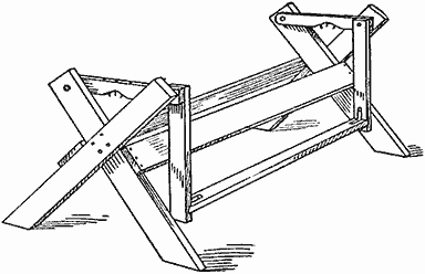
The Holding Attachment Easily Adjusts Itself to the Stick of Wood Placed in the Crotch
A New Pail-Cover Handle
The handle of the cover, instead of being attached to the center, is placed near the edge and bail of the pail. On the bail and just above the handle of the cover there is formed a loop large enough to accommodate the thumb. With this arrangement, the cover may be removed with the use of but one hand.
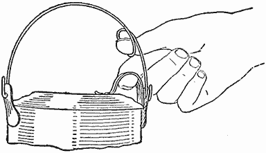
The Bail Loop and the Handle Make It Easy to Remove the Cover with One Hand
Drip-Pan Alarm
The trouble caused by overflowing of the drip pan for an ice box or refrigerator can be overcome by attaching a device that will sound an alarm when the water reaches a level safely below the overflow point. A device of this kind may be attached to the back of the refrigerator as shown in the sketch. A float, A, is attached to the lower end of a rod, B, which slides through staples CC. At the upper end of the rod, a V-shaped copper sheet, D, is soldered. This makes the contact points in the electric wiring. The battery E can be placed under or back of the refrigerator as desired. The method of wiring is clearly shown.
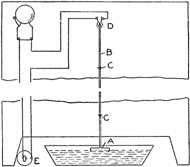
The Float in the Pan, and Contacts for Closing the Circuit to Ring the Bell
A Live-Bait Pail
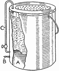
Every fisherman knows that live bait will soon die if they do not receive sufficient air. I have succeeded in keeping bait alive and healthy by using a pail of my own construction, which is provided with a compressed-air space to force air to the surface of the water. The air space A takes up one-fifth of the interior at the bottom of the pail, and an ordinary hand bicycle pump is used to fill it through a bicycle-tire valve, B. The pipe C from the air space extends up along the side of the pail and the upper end is bent so that it just touches the surface of the water. The pipe contains a valve to regulate the flow of air.
After the pail has been standing for an hour or more, the bait will rise to the top. The valve is then opened for a few minutes, and the minnows will soon swim around in the water as when this was fresh.—Contributed by T. Whelan, Paterson, N. J.
A Mouse Trap
After using various means to catch the mice in my pantry, I finally decided I could not catch them in the ordinary manner. Knowing that mice are not afraid of dishes but will run all over them, while they will stay away from other things, I took a dinner plate, a bowl that held about 1 qt., a thimble, filled with toasted cheese, and arranged the articles as shown in the sketch, balancing the bowl on the thimble. When the mouse nibbled the cheese, the bowl came down on it, making it a prisoner. The whole was then dropped in a pail of water. Scald the dish and bowl before using them again to remove all traces of the mouse.
Quickly Made Rheostat
A short time ago I found it necessary to melt some silver, and in setting up an arc light to obtain the heat I made a rheostat by winding wire around a large earthenware jar. As the jar is a conductor and would not burn, it served the purpose perfectly. In winding the wire, be careful to keep the coils from touching each other.—Contributed by P. D. Merrill, Chicago, Ill.

Sunlight Flasher for the Garden By Claude L. Woolley
The following apparatus is likely to be novel, and certainly very striking when erected on country estates, particularly on high lands, hillsides, and along the seashore, where the flashes may be seen for many miles out at sea.
It is not unusual in country gardens to see a large hollow glass globe silvered on the inside, mounted on a pedestal, brilliantly reflecting the sunlight. The apparatus described is an elaboration of the idea. The drawing shows in diagram the general construction, exact measurements not being given. However, a convenient height is 3-1/2 to 4 ft., and the circular frame, carrying the mirrors, may be 10 to 14 in. in diameter.

The Flasher as It Appears on the Stand and the Details of Its Construction
The supporting frame, of galvanized sheet iron or sheet copper, may be either circular or hexagonal in shape. Mounted upon a vertical shaft is a skeleton circular frame, carrying a double row of small mirrors, or ordinary flat mirror glass, mounted in grooves provided for them; the upper row inclined slightly upward, and the lower row slightly downward. If a greater number of angles of reflection are desired, the mirrors may be smaller, and arranged in four circular rows instead of two, each row being inclined at a slightly different angle.
The shaft is pointed at the lower end and rests in a bearing drilled with a V-shaped depression, the bearing being supported by soldering or riveting at each end to the inner sides of the pedestal shell. The upper portion of the shaft passes through a bearing which is also soldered or riveted at the ends, to the inner surfaces of the pedestal shell.
The mirrors, mounted on the shaft, thus are free to revolve vertically with very little friction. Upon the lower end of the shaft is fastened a light gear wheel of rather large diameter, and this in turn is geared to a smaller gear mounted on the end of the armature shaft of a small electric motor of the type that may be driven with a few dry cells; the relation of the sizes of the gears being such as will cause the mirrors to revolve slowly, when the motor is running at normal speed.
Connected to the motor are two or more dry, or other suitable batteries, a small door being provided on the side of the lower part of the pedestal to enable the batteries to be replaced, or turned off, and to give access to the motor. A circular shield is erected over the mirror carrier, surmounted by an ornamental ball, to protect from the weather and to provide a more finished appearance. A waterproof canvas cover may be slipped over the whole in rainy weather.
As new mirror faces at varying angles are constantly being presented to the sun, vivid flashes are constantly occurring when viewed from almost any angle or position on the side where the sun is shining. The circular shield on top is supported in position by four metal strips secured by soldering to the shield and the supporting pedestal.
Such a device may be constructed without much expense, producing a most brilliant effect over miles of territory. The small driving motor may be replaced with a suitable spring or weight-driven clockwork; or four hollow hemispherical metal cups may be mounted on arms, or placed at right angles, and the arms in turn mounted upon a vertical shaft and arranged above the mirror carrier and geared in such manner that the mirrors will revolve slowly, while the cups are revolving with comparatively high speed by the force of the wind.
The mounted revolving cups are similar in form to the apparatus used by the U. S. Weather Bureau for measuring the speed of the wind. They will respond to a good breeze from any point of the compass.
An Automatic Blowpipe
A fine-pointed flame can be used to advantage for certain work, and the alcohol flame and blowpipe have become a necessity, but these may be improved upon so as to make the apparatus automatic in action and more efficient in its work. A bottle or receptacle, A, having a large bottom to provide a sufficient heating surface, is supplied with a cork and a tube, B, bent at right angles. The receptacle, A, is supported on a stand so that it may be heated with a small lamp, C. The light D may be a candle, alcohol lamp, or any flame set at the right distance from the end of the tube B.
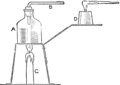
The receptacle A is partly filled with alcohol, and the heating lamp lit. The heat will turn the alcohol into gas and cause a pressure, driving it through the tube B, so that it is ignited by the flame from D. The flame will have a fine point with sufficient heat to melt glass.—Contributed by W. R. Sears, St. Paul, Minn.
Homemade Steam-Turbine Engine
Select a tomato can, or any can in which vegetables or fruit is sold, and carefully unsolder the small cap on the end when removing the contents. When the can is empty, clean it well and solder the cap in place again. Procure a strip of brass, bend it as shown at A and solder it to the can top in the center. Cut a piece of about No. 14 gauge wire, the length equal to the opening between the uprights of the U-shaped piece of brass, with about 1/2 in. added for a small pulley wheel. The uprights are punched or drilled at their upper ends to admit the wire which is then adjusted in place.
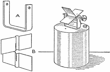
The Boiler is Made of a Fruit or Vegetable Can and the Turbine of Thin Metal Strips
Two strips of tin are cut to fit in between the standards and are notched in the center, as shown at B, and slightly bent to fit over the wire shaft. These are soldered to the wire between the uprights. A small hole is punched on one side in the top of the can so that it will center the paddle of the wheel. On the opposite side of the top another larger hole is punched and tightly fitted with a wood plug. This is the opening for filling the boiler with water. The can should be filled about two-thirds full and set on a stove. The steam, coming under pressure from the small hole, strikes the paddles of the wheel with considerable force and causes it to revolve rapidly. Be careful not to set the boiler on too hot a fire.
Electric Switch for Exposing Photographic Printing Papers
The proper time to expose a printing paper under a negative should be determined and the negative marked for future printing. When this time has been found some means should be provided for making the exposure exactly the same, then the prints will be perfect and of a good tone at all times. For this purpose the instrument shown in the illustration was designed and used with entire satisfaction.
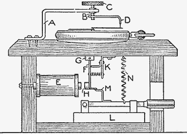
Time Switch for Operating an Electric Light in Printing Photographic Developing Papers
The device consists of an ordinary cheap watch, a standard, or support, for an adjusting screw, a small coil, a movable armature, a knife switch, and a trip arrangement. A neat box or case, about 5 in. square and 3 in. high, is first constructed. A round recess, 1/8 in. deep, is cut in the center of the top, to admit the watch. The standard A is made of brass, 1/8 in. thick and 1/2 in. wide, bent as shown, and a 3/16-in. hole is drilled in the end of the long arm where it will exactly center over the pivot holding the watch hands. A 3/16-in. rod, B, is closely fitted in the hole and supplied with a knurled wheel, C, on the upper end, and an L-shaped arm, D, is fastened to the lower end. The end of this arm should be filed to a point, or a very thin piece of brass soldered to it, so that the end will just touch the minute hand of the watch. The tip end of the point should be bent slightly from the perpendicular toward the direction in which the watch hands are moving, so that, when it is set, the moving hand will easily break the contact.
The magnetic arrangement consists of a 3-ohm coil, E, mounted, as shown, to one side of the case, where it operates the trip levers. The armature parts consist of an L-shaped piece of brass, F, pivoted at G, to which a square piece of soft iron, H, is attached. Two small parts, K, are bent and attached as shown, to furnish a limit stop for the piece F and a support for a spiral spring which holds the armature H away from the coil.
The knife switch L is fastened to the bottom of the case so that the handle will project through a slot in one side of the box. A trip piece, M, and a small eye for attaching a spiral spring, N, are soldered to the knife switch. These two attachments for the switch are insulated from the other parts.
Two binding posts are mounted on top, one being connected to one terminal of the coil E and the other to the watch case. The other terminal of the coil is connected to the standard A. The two binding posts are connected in series with one or two dry cells, and the switch L is connected in series with the lamp used for printing.
The operation is as follows: The arm D, being set for a certain time, the lever of the switch L is set and the light remains lit until the minute hand strikes the point on the arm D, when the battery circuit is closed causing the coil to draw the armature H and allowing the spring N to open the switch L. The lamp is then extinguished.—Contributed by James P. Lewis, Golden, Colorado.
How to Make a Wing Nut
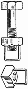
Finding that I needed some wing nuts and not being able to purchase them in the size I wanted, I made them from the ordinary nuts. A hole was drilled through opposite corners of each nut and a staple made of wire riveted in the holes as shown in the sketch. The staple should be long enough to admit the end of the bolt.—Contributed by Clarence L. Orcutt, Buffalo, N. Y.
Cork-Covered Clothes Peg
When screws or nails are used to hang clothes or other articles on, run the nail or screw through a bottle cork as shown. The cork will prevent the nail or screw from tearing the article and also insure the cloth against rust marks, should the article be wet.
Shaping an Old Broom
A broom, having the straws bent and out of shape, yet not worn out, can be fixed up like new in the following manner: Slightly dampen the straw with water and wrap with heavy paper, then place a weight on it. After standing under pressure for several days the straw will be restored to the shape of a new broom. Paint brushes can be treated in the same manner, but in that case linseed oil should be used instead of water.
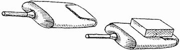
Method of Straightening the Straws
How to Make a Bolster
The sketch shows a simple bed bolster which I have made and which can be constructed at very little cost. Three circular pieces of poplar or pine, 10-1/2 in. in diameter, are required. These may be made in one cut by nailing the pieces together. Then nail on ten 3/8 by 2-in. strips, 52 in. long, or as long as the width of the bed, leaving about 1/2 in. space between the strips. These strips will thus go about two-thirds of the way around the circle, leaving room to insert the pillows when the bed is not in use. Cover the bolster with building paper or any other suitable material, and it is ready for the pillow shams.—Contributed by C. Martin, Jr., Chicago.
A Fish-Scaling Knife
A useful fish-scaling and skinning knife can be made of an old broken hacksaw blade. This must be at least 6 in. long and will make a knife with a 3-in. blade. Grind the blade to the shape shown and make a handle for it by using two strips of maple, 1/4 in. thick and 4 in. long. These are riveted together with 3 in. of the blade between them.—Contributed by John L. Waite, Cambridge, Mass.

Scaling Knife
To Prevent Moles from Damaging Growing Seeds
The food most liked by the ground mole is the sprouts of peas and corn. A way to protect these growing seeds is to dip them in kerosene just before planting. The mole will not touch the oil-covered seed, and the seeds are not injured in the least.—Contributed by J. W. Bauholster, Gresham, O.

The Heliograph as It is Used by Neighboring Boys to Send Messages on a Clear Day by Flashing the Sun's Rays from One to the Other, Which can be Read as Far as the Eye can See the Light
How to Make a Heliograph By R. B. Huey
The heliograph which is used in the army provides a good method of sending messages by the reflection of the sun's rays. In the mountains there are stations from which messages are sent by the heliograph for great distances, and guides carry them for use in case of trouble or accident. The wireless telegraph delivers messages by electricity through the air, but the heliograph sends them by flashes of light.
The main part of the instrument is the mirror, which should be about 4 in. square, set in a wood frame and swung on trunnions made of two square-head bolts, each 1/4 in. in diameter, and 1 in. long, which are firmly held to the frame with brass strips, 1/2 in. wide, and 3 in. long. The strips are drilled centrally to admit the bolts, and then drilled at each end for a screw to fasten them to the frame. This construction is clearly shown in Fig. 1.
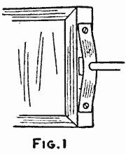
Detail of the Parts for Making the Mirror and Sight Rod Which are Placed on a Base Set on a Tripod Top, the Whole being Adjusted to Reflect the Sun's Rays in Any Direction Desired (Fig. 1)
A hole is cut centrally through the backing of the frame and a small hole, not over 1/8 in. in diameter, is scratched through the silvering on the glass. If the trunnions are centered properly, the small hole should be exactly in line with them and in the center.
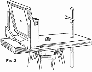
(Fig. 2)
A U-shaped support is made of wood strips, 3/8 in. thick and 1 in. wide, the length of the uprights being 3-1/2 in. and the crosspiece connecting their lower ends a trifle longer than the width of the frame. These are put together, as shown in Fig. 2, with small brackets at the corners. A slot, 1/2 in. deep and 1/4 in. wide, is cut into the upper end of each upright to receive the trunnions on the mirror frame. Nuts are turned on the bolt ends tightly, to clamp the standard tops against the brass strips on the mirror frame. The cross strip at the bottom is clamped to the base by means of a bolt, 1-1/2 in. long. The hole for this bolt should be exactly below the peephole in the mirror and run through one end of the baseboard, which is 3/4 in. thick, 2 in. wide and 10 in. long.
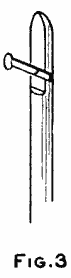
(Fig. 3)
At the opposite end of the base, place a sighting rod, which is made as follows: The rod is 1/2 in. in diameter and 8 in. long. The upper end is fitted with a piece of thick, white cardboard, cut 1/4 in. in diameter and having a projecting shank 1 in. long, as shown in Fig. 3. The rod is placed in a 1/2-in. hole bored in the end of the baseboard, as shown in Fig. 2. To keep the rod from slipping through the hole a setscrew is made of a small bolt with the nut set in the edge of the baseboard, as shown in Fig. 4.
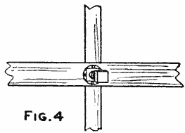
(Fig. 4)
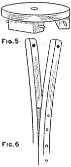
The Parts in Detail for Making the Tripods... (Fig. 5, Fig. 6)
The tripod head is formed of a wood disk, 5 in. in diameter, with a hole in the center, and three small blocks of wood, 1 in. square and 2 in. long, nailed to the under side, as shown in Fig. 5. The tripod legs are made of light strips of wood, 3/8 in. thick, 1 in. wide and 5 ft. long. Two of these strips, nailed securely together to within 20 in. of the top, constitute one leg. The upper unnailed ends are spread to slip over the blocks on the tripod top. These ends are bored to loosely fit over the headless nails driven part way into the block ends. One tripod leg is shown in Fig. 6.
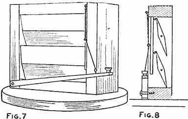
...and the Shutter for Flashing the Light,... (Fig. 7, Fig. 8)
The screen, or shutter, is mounted on a separate tripod and is shown in Fig. 7. Cut out two slats, 3/8 in. thick, 2-1/2 in. wide and 6 in. long, from hard wood, and taper both edges of these slats down to 3/16 in. Small nails are driven into the ends of the slats and the heads are filed off so that the projecting ends will form trunnions for the slats to turn on. Make a frame of wood pieces, 3/4 in. thick and 2-1/2 in. wide, the opening in the frame being 6 in. square. Before nailing the frame together bore holes in the side uprights for the trunnions of the slats to turn in. These holes are 1-3/4 in. apart. The frame is then nailed together and also nailed to the tripod top. The shutter is operated with a key very similar to a telegraph key. The construction of this key is shown in Fig. 7. A part of a spool is fastened to a stick that is pivoted on the opposite side of the frame. The key is connected to the slats in the frame with a bar and rod, to which a coil spring is attached, as shown in Fig. 8. Figure 9 shows the positions of the tripods when the instrument is set to flash the sunlight through the shutter. The regular telegraph code is used in flashing the light.
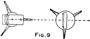
...and Diagram Showing the Location of the Tripods to Direct the Light through the Shutter (Fig. 9)
To set the instrument, first turn the cardboard disk down to uncover the point of the sight rod, then sight through the hole in the mirror and adjust the sight rod so that the tip end comes squarely in line with the receiving station. When the instrument is properly sighted, the shutter is set up directly in front of it and the cardboard disk is turned up to cover the end of the sight rod. The mirror is then turned so that it reflects a beam of light with a small shadow spot showing in the center made by the peephole in the mirror, which is directed to fall on the center of the cardboard sighting disk. It will be quite easy to direct this shadow spot to the disk by holding a sheet of paper 6 or 8 in. in front of the mirror and following the spot on the paper until it reaches the disk. The flashes are made by manipulating the key operating the shutter in the same manner as a telegraph key.
Twine Cutter for Use at a Wrapping Counter
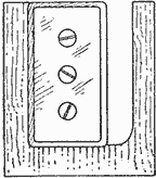
A cutter for use at the wrapping counter in a drug or confectionery store may be easily made from a double-edged razor blade and a piece of thin board—a piece of cigar box will do. Cut the wood in the shape shown, with a protecting piece over the edge of the razor. Screws are turned through the holes in the blade and into a support on the paper holder or any other convenient place.—Contributed by T. F. Managhan, Philadelphia, Pa.
Frosting Brass
A very fine ornamental finish, resembling brushed work, may be applied to brass articles by boiling them in a caustic-potash solution, then rinsing in clear water, whereupon they are dipped into dilute nitric acid until the oxide is removed, then rinsed quickly and dried in sawdust. The surface should be lacquered while the metal is hot.
A Cupboard-Door Spice-Box Shelf
To keep the spice boxes in a handy place where they would be together and not behind larger articles on the cupboard shelves, I made a special spice-box shelf, as shown, to hang on the inside of the cupboard door. The shelf swings out with the door as it opens, and is made of two bracket ends to which a bottom board and front crosspiece is nailed. The size of the shelf and its capacity are only limited by the space on the door.—Contributed by Austin Miller, Santa Barbara, California.
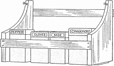
The Shelf will Hold All the Spice Boxes and Keep Them Handy
Starting a Siphon
It is often necessary in a laboratory to siphon acids and poisonous liquids. If a pump is used there is always danger of the liquid entering the pump and damaging it, and, besides, a pump is not handy for this purpose. To fill a siphon by suction from the mouth, great care must be taken to keep from drawing the liquid into the mouth. One of the best ways to fill a siphon is to procure a large dropper and having pressed all the air out of the bulb insert the end in the siphon. Releasing the pressure on the bulb will cause it to draw the liquid into the siphon.—Contributed by Bedell M. Neubert, Newtown, Conn.
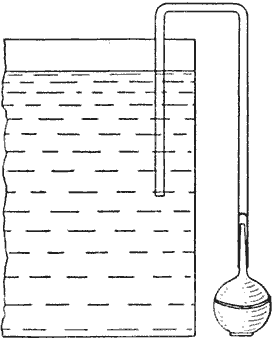
A Window-Seat Sewing Box
The combined window seat and sewing box shown was made by using a shoe-packing box for the foundation. This was covered with matting and the edges and corners finished with wood strips, 1/2 in. thick and stained a dark red. Three trays were provided on the inside at the top part of the box, each of the two upper ones occupying one-fourth of the box opening and sliding on a pair of guides fastened to the sides of the box while the lower tray is one-half the length of the box and slides on guides placed far enough below the upper trays to allow it to pass beneath these. The three trays were used for keeping sewing materials, such as buttons, hooks and eyes, etc. When the trays are all moved to one end it gives access to the lower part of the box where the work or mending is kept out of sight.
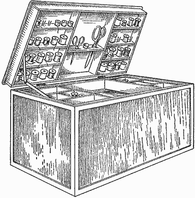
A Window-Seat Workbox for Sewing Materials, Made of an Ordinary Shoe-Packing Box
The inside of the cover is 1-1/2 in. deep and shelves are arranged for thread and silk spools on either side, the center space being used for the shears, thimbles and scissors. The little shelves are made of two pieces each half as wide as the depth of the box cover. The first half of the shelf is fastened in place, then a row of cotters attached with wood screws whereupon the other half of the shelf is put in place. The edges of the cover are rounded on the outside to make an attractive seat.
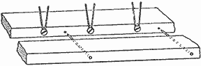
The Spindles for the Spools are Made of Cotters Fastened with Screws in the Shelves
While no dimensions are necessary, as the box can be of any size to suit the maker it may be mentioned that the one shown is 28 in. long, 12 in wide and 16 in. deep.—Contributed by R. B. Thomas, Lowell, Mass.
Cutting a Glass Bottle
It is sometimes necessary to cut a heavy glass bottle or cylinder. Four methods are in use. A carborundum disk having a thin edge, if kept wet and rotated at a high speed, will cut heavy glass, but the cylinder must be fed against the wheel very gently. A better way is to make a file mark—clean, but not very deep—around the cylinder and heat it with a long slender flame while slowly rotating the cylinder all the time. It is very important that the gas flame should not spread over the surface of the glass, for it is only the file mark that should be heated. A mere glancing touch is sufficient. Usually the glass will crack off in a very clean cut.
Sometimes a fine platinum wire is wound around in the file mark and heated by an electric current. Less common is the trick of wrapping a strand of yarn soaked in turpentine around the mark and burning it. The principle is the same in each case. The unequal heating of the glass causes it to break.—Contributed by Harry H. Holmes, Richmond, Ind.
To Clean Painted or Frescoed Walls
Use a paste made of vinegar and baking soda with a small amount of salt added. The ingredients should be mixed in a large dish and applied to the wall with a cloth. The grease and fly specks as well as the carbon deposits from kitchen smoke are quickly removed. The mixture is harmless. After the wall is thoroughly cleaned, it should be washed with warm water and soap, then dried with a cloth. The mixture works equally well on enameled baths and glass or white porcelain.
Securing Papers in a Mailing Tube
The illustrations show two methods of securing papers or photographs in a mailing tube. In Fig. 1 the mailing tube A is shown in cross section and the manner of running the string through the pasteboard walls illustrated. The ends of the string are drawn up and tied over or under the label. If the label is pasted over the string or string ends as they are tied, it makes a sealed package which is rated as first-class matter.
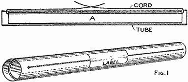
The String in Either Case Prevents the Papers from Slipping Out of the Mailing Tube (Fig. 1)
The second way is to run the cords in a cross form through holes near the ends, as in Fig. 2, then tie the knots as at BB. In each instance even if the papers fit the tube loosely, they will be held securely and can be easily extracted when the knots are untied.
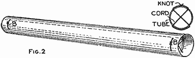
(Fig. 2)
Cooling Tube for a Laboratory Still
A simple and very effective device to replace the cumbersome cooling or condensation coil of a still for the amateur's laboratory can be easily made as follows:
Procure an ordinary straight glass tube of fairly large diameter and heat it in the flame of an alcohol lamp with the use of a blowpipe or in a Bunsen burner with a very reduced flame so that only a small spot of the tube is brought to a red heat at one time Then, with a previously pointed and charred stick of wood—a penholder for instance—produce a small recess in the wall by pushing the charred end gently into the glowing part of the tube. This procedure is repeated until the whole tube is thus provided with small recesses. The indentations should be made in spiral lines around the tube, thus increasing the surface that is in contact with the cooling water. The operation of making the recesses is shown in Fig. 1. The walls of the recesses should have a regular and uniform slant.
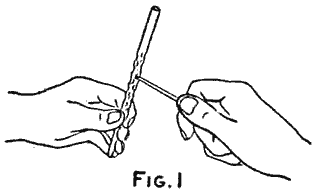
Method of Indenting the Walls of the Glass Tube and Its Application as a Still (Fig. 1)
The tube thus produced can either be used as a rectifier (Fig. 2) above a vessel, for fractional distillation because it will allow the most volatile parts to pass out first, or as a condenser (Fig. 3), the arrangement of which needs no explanation. The amateur will find it much easier to make this tube than to coil a very long one.
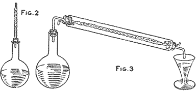
(Fig. 2, Fig. 3)
A Comb Cleaner
A good comb cleaner that does the work easily and quickly can be made from a worn-out varnish brush. The brush selected should not be over 2 in. wide; it should be thoroughly cleaned with benzine and the bristles cut to a bevel, as shown in the sketch. In use, brush across the comb parallel with the teeth, and the dirt between them will be easily removed.—Contributed by John V. Loeffler, Evansville, Ind.
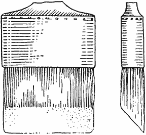
Scraping Off Surplus Water on a Grindstone
When using a grindstone, an ample flow of water is desirable in order to insure good cutting, and the objectionable spattering may be overcome by fastening a piece of leather to the grindstone frame so that its edge will bear lightly upon the stone just below the point where the work is held. This will scrape off all surplus water from the grinding surface and prevent spattering.—Contributed by Thos. L. Parker, Wibaux, Mont.
A Paper Drinking Cup
The cup is readily made of a piece of paper 8 in. square. Lay the paper on a flat surface, turn the point A over to meet the point B and crease on the dotted line CD, Fig. 1, then turn the corner D up to meet the line BC, Fig. 2, making sure that the new edge DE is parallel with the lower edge and crease. Turn the corner C in the same manner, that is, fold it over to the point E and crease. Fold the two corners at B outward and down, and crease, and the cup is complete as shown in Fig. 3.—Contributed by W. Douglas Matthews, Chappaqua, New York.
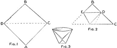
Several Cups can be Nested Together and Carried in the Pocket or Hand Bag (Fig. 1, Fig. 2, Fig. 3)
Homemade Brush for Cleaning Upholstered Furniture
A durable brush for cleaning upholstered furniture can be made in the following manner: Procure a piece of haircloth, which is made of horsehair woof and linen warp. Strips of haircloth, cut lengthwise and 1-3/4 in. wide, are laid out smooth on a table and a strip of wrapping paper, 1/2 in. wide, is firmly glued to one edge. When this has dried, take out the warp that is not covered by the paper. Brush the fringe of horsehair until it is straight and even, and before commencing to wind, measure 6 in. from one end and glue this portion to the side of a strip of soft wood, 6 in. long, 5/8 in. wide and 1/16 in. thick. When dry, wind the glued length of haircloth and paper around the wood strip, applying glue to each separate turn of winding. The turns should be kept flush on the side that has been glued and the fringed part brushed and straight.

Brush Made of Strip of Upholsterers' Haircloth with the Warp Removed and Fastened to a Handle
The part to be glued to the handle must be perfectly even in its windings and held firmly in place while the glue is hardening. The winding should be continued until the brush is 1-1/2 in. thick.
The handle is made of a piece of wood, 14 in. long, 1-3/4 in. wide and 1/2 in. thick. Wood that takes a cherry or mahogany stain is preferable. Shape it about as shown in the sketch and round off the edges. The part to which the brush is to be attached must be given a light coat of glue. When that has dried, glue the back of the brush to it, and after the glue has hardened, glue a piece of gimp around the brush part, then drive upholsterers' tacks into the gimp and wood, 3/4 in. apart. Stain and varnish the handle. The back of the handle can be used as a beater, and the brush for removing the dust.—Contributed by Gertrude M. Bender, Utica, N. Y.
Removing Calcium Deposits on Glass
A good way to clean glass vessels in which hard water is boiled is to use the following mixture to remove not only the calcium deposits, but also rust or sulphur stains that may be present. The solution is a mixture of ammonia water and a few ounces of salt. This should be placed in the glass vessel and boiled until the deposits disappear. The ammonia water may be made of any strength by diluting if necessary.
A Cold-Chisel Guide
When making long cuts with a cold chisel, it is almost impossible to guide the chisel edge along a line made with a scriber or pencil and have a straight cut. I find that it is much easier to use a guide, as shown in the sketch. The guide is made of a piece of wood, about 1 ft. long and 1-1/2 in. wide. A slot is cut in the center, wide enough to receive the chisel edge snugly, and about 9 in. long. The guide is clamped to the work, and the cold chisel slipped along in the slot as it is successively hit with a hammer.—Contributed by G. H. Holter, Jasper, Minn.
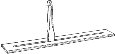
The Guide Makes It Easy to Follow along a Straight Line When Cutting with a Cold Chisel
Care of Paintbrushes
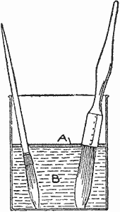
When laying aside paintbrushes, the usual custom is to place them in water and then forget all about them until needed again, with the result that the water usually is found more or less evaporated and the brushes hardened. If a quantity of oil, A, is poured on the water B, it will prevent this evaporation and keep the brushes in good shape.
Filter in a Pump Spout
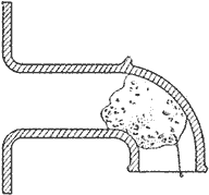
The sketch shows how to place an ordinary sponge in a pump spout, to filter out sand and dirt particles that may come up with the water as it is pumped. A wire is fastened in the sponge so that it can be easily taken out for washing. When washing the sponge give the pump handle a few strokes so that the dirt collected in the spout will be washed out. Do not press the sponge too tightly into the spout, as this will stop the flow of water.—Contributed by Chas. Homewood, Waterloo, Iowa.
Brown Stain for Wood
Bichromate of potassium gives a lustrous, rich, light to dark brown stain on woods. The crystals are first dissolved into a saturated solution, which is then diluted with water. The stained surface needs no rubbing, as the stain leaves the wood perfectly clear for any desired finish. The satinlike appearance of wood treated by this stain cannot be produced with any of the pigment stains.—Contributed by August Meyer.
An Egg Boiler
In boiling eggs the usual method of dropping the eggs from a spoon into the boiling water often results in a burn, as well as in cracking of the eggs by the fall. In removing the eggs from the hot water and taking one out at a time, no two will be cooked alike. To overcome these difficulties I constructed an egg boiler as illustrated.
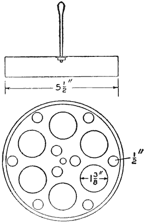
The Eggs are Prevented from Becoming Cracked and All are Easily Handled in One Operation
A pan was procured—tin or aluminum as desired—about 1 in. deep and 5-1/2 in. in diameter, and holes were drilled in the bottom having dimensions as shown. A handle was attached to the center with washers and nuts. The small ends of the eggs are set in the 1-3/8-in. holes and the whole pan set in a vessel of boiling water. When the boiling is completed, the entire lot of eggs are removed at the same time. As the device with its load of cooked eggs is quite pleasing in appearance, it may be set on a plate and the eggs served from it on the table.—Contributed by W. E. Crane, Cleveland, O.
Removing Black Deposit an Bathtubs
A good way to remove the black deposit left on bathtubs by the water is to use a strong solution of sulphuric acid. The acid should be poured on the discolored enameled surface and washed around with a cloth. The acid should not touch the hands so it is best to use a stick to move the cloth. Neither should it be allowed to touch the metal parts, but if this happens, no harm will result if it is quickly rubbed off with a cloth and water then applied.
In using this acid never pour water into the acid, but always pour the acid into the water.—Contributed by Loren Ward, Des Moines, Iowa.
A Stocking-Stretcher Form
A simple as well as inexpensive device for preventing the shrinking of stockings, more particularly those of children, after they have been washed, thus saving great wear and tear on the fabrics and increasing their length of life, is shown in the illustration. The stretcher can be made by anyone, a knowledge of woodcraft or art being unnecessary. If used, the device will prove to effect quite a saving in money, labor and worry in the course of a year.
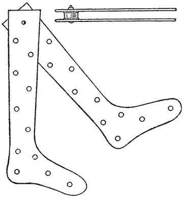
The Spring of the Two Parts Tends to Hold the Yarn and Keep It from Shrinking
Place a new and unused stocking, that properly fits the foot, flat on a heavy piece of cardboard or a wood board, if desired, and mark an outline of the stocking on the board with a pencil. Cut out the design with a penknife or heavy pair of scissors and smooth the edges. A design having the same shape and size as the stocking results. Duplicate boards can be easily made. Place a spool, such as used to hold the finest silk thread, near the upper end of the first form and on top of this place the second. Then drive a nail through the boards and spool and clinch it, or better still, use a small bolt. When the stockings are washed and the dampness wrung out as well as possible, stretch them over the boards and hang them up to dry. They will retain their shape and are easily ironed.—Contributed by Wm. P. Kennedy, Washington, D. C.
Stick Holder for a Chopping Block
Having a lot of branch wood, from 1/2 in. to 1 in. in diameter, to saw, and not wishing to bother with a sawbuck, I rigged up a chopping block, as shown in the sketch, by fastening a piece of board to one side of the block with small lag screws. The piece to be sawed was laid across the block in the notch. If the piece is held down on the block with one foot, the wood is very easily sawn.—Contributed by Wilfred B. Sylvester, Reading, Mass.
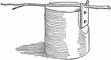
The Notched Board Fastened to the Chopping Block Turns It into a Sawbuck
Cleaning Gold and Platinum
A good way to clean gold or platinum jewelry is to first brush with soapsuds, then dust magnesia powder over the article and allow it to dry. A few rubs with a cloth makes the article shine with great luster. As magnesia powder is highly inflammable, it must be kept away from fire.
A Twine Spool
The pieces of twine used in tying parcels delivered to a residence are either thrown away or tied together and wound into a ball for future use. The method I use for keeping the pieces of twine is to wind them over a discarded photographic-film spool. The spool was slipped on a finishing nail driven into the wall. The crank for turning the spool was made of a piece of wire, bent as shown and slipped into the slot end of the spool. One end of the first piece of string was tied to the core and then wound around it, the next piece tied to the first and wound up, and so on, as the strings were taken from the packages from time to time. When a string is needed for any purpose I always know where to find it, and it is easier to take it from the spool than from a ball.—Contributed by W. Resseguie, Susquehanna, Pa.
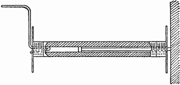
The Film Spool as It is Attached to a Wall, and the Crank for Turning It
Reinforcing Chair Bottoms
Embossed-leather-board chair bottoms can be made as serviceable as leather in the following manner: Turn the chair upside down and fill the hollow beneath the seat with excelsior, soft rags or fine shavings, then nail a 1/4-in. wood bottom over the filling with brads. Make the wood bottom 1/2 or 3/4 in. larger than the opening. It will thus not be seen, and the seat will last as long as the chair.—Contributed by J. H. Sanford, Pasadena, California.
A Novelty Chain
An inexpensive chain for hanging painted glass panels, transparencies or photographs can be made by joining paper clips together to form the links. A box of 100 clips will make a chain about 10 ft. long. Such a chain can be made in a few minutes and a length of 10 ft. will hold about 4 lb.

The Paper-Clip Links may be Joined to Make a Chain of Any Desired Length
If the chain is to be used for holding photographs, each inner loop end is bent out slightly.
Closet Holders for Linen
A combination drawer and shelf for a linen closet is much better than a shelf or a drawer. It is constructed in the manner of a drawer with sides and a back, the front being open and the ends of the sides cut rounding. A clip is attached to the under side of the bottom, near the front edge, to provide a means for pulling out the holder.
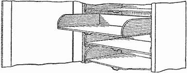
The Holder can be Pulled Out Like a Drawer and is as Accessible as a Shelf
Sheets, towels, table cloths, napkins, etc., can be neatly piled on the holder and can be seen without digging down to the bottom. It has the advantage over the shelf that it can be pulled out without anything falling off, and the linen on the back part can be easily reached as well as that in front. The closet may contain as many holders as is necessary and should be provided with a door for keeping out dust.—Contributed by H. A. Sullwold, St. Paul, Minn.
Preserving Dry Batteries
The life of dry batteries, which are to be used in wet or damp places, may be considerably lengthened by being treated in the following manner:
The batteries are placed in glass jars a little wider and higher than themselves. A layer of dry sawdust is placed in the bottom, for the battery to rest on, and the sides are packed with sawdust to within 1/2 in. of the top. Waterproof wires are connected to the binding posts and melted paraffin poured over the battery to the top of the jar. The carbon and zinc terminals should be marked to avoid trouble when connecting several cells together. Batteries treated in this manner are waterproof and can be submerged in water if necessary.—Contributed by Olaf Tronnes, Evanston, Ill.
A Cleaner for Brass
In some recent laboratory experiments the following solution was found to cleanse brass very quickly without harm to the hands or the metal. An ounce of alum was put into a pint of boiling water and the solution rubbed on the brass with a cloth. Stains as well as tarnish were quickly removed. The solution is inexpensive and easily prepared.—Contributed by Loren Ward, Des Moines, Iowa.
Homemade Graduate
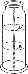
If a certain quantity of liquid is to be frequently measured out, it is best to have a graduate marked for this amount without any other markings upon it. To make a graduate for this purpose, procure a pickle or olive bottle of the type shown in the drawing and file a vertical line, A, on each side. These lines should be at least 1/8 in. wide. Place the bottle on a level surface and pour in the amount desired to be measured. Mark on each vertical line with a lead pencil and connect this mark or marks with lines, filed as shown at BB.—Contributed by James M. Kane, Doylestown, Pa.
Mending a Break in Felt
A good way to mend partially broken felt or a felt hat is to hold a lighted match under the break and smooth out the crevice with the hand. The shellac in the felt is melted by the heat and runs together, mending the felt in such a way that the break is hardly noticeable. This method may also be used to mend felt articles in the laboratory.
Imitating Ebony on Oak
The wood is immersed for 48 hours in a warm solution of alum and sprinkled several times with the following mixture: One part of logwood of the best quality is boiled with 10 parts of water, then it is filtered through linen and the liquid evaporated at a low temperature until its volume is reduced by one-half. To every quart of this bath are added 10 to 15 drops of a saturate of soluble indigo entirely neutral in reaction.
Smaller pieces may be steeped for a time in this solution, then the wood is rubbed with a saturated and filtered solution of verdigris in warm, concentrated acetic acid, and this operation continued until a black color of the desired intensity is obtained. The oak wood dyed in this manner is very similar to real ebony.
Tongue Holder for a Boy's Wagon
To prevent any mishap when coasting in a boy's play wagon fasten the tongue with a coil spring so that it will be kept in a vertical position. The tongue is always out of the way when it is not used for drawing the wagon. The spring is only strong enough to hold the tongue, so that when this is used for pulling there is little or no tendency of the spring to draw the tongue upward. The coil spring is fastened with one screweye in the tongue and one in the front axle.—Contributed by Wm. F. Benson, Brockton, Massachusetts.
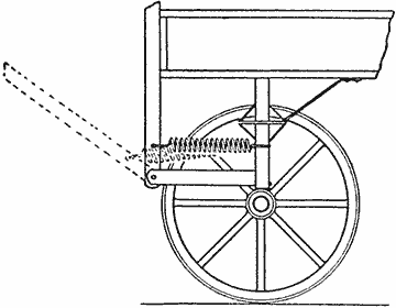
Holder for the Wagon Tongue to Keep It in a Vertical Position When Not in Use
Gluing Small Mitered Frames
The mechanic who attempts to fasten a mitered frame in the home workshop usually comes to grief. This is due to lack of proper facilities for holding the frame straight and out of wind, and for clamping or drawing the miter joint together after the glue has been applied. The little device shown in the sketch, if properly made and used, does away with the usual difficulties and annoyances. It consists of a triangular block of wood with raised strips on the two edges that make the right angle, and the clamping piece with the wood screw through the center on the long side. The raised strips are made somewhat thinner than the frame to be fastened, as the clamping piece should bear on the frame and not on the strips; the function of the strips being to hold the frame square. The triangular block should be large enough to take the corner of the frame and leave room enough for the wood screw that holds it in place on the block. Four of these blocks will be necessary and they should be used in conjunction with pinch dogs. These dogs come in different sizes and may be purchased at supply stores or made as shown. The outside of the legs should be straight and parallel and the inside tapered so as to draw the joint together.

Clamp for Holding the Corner of a Frame While Gluing and Fastening the Mitered Joint
When a joint is ready to be glued, a piece of paper is placed on the block under the joint to keep it from sticking. Apply the glue and push the two sides into the corner formed by the raised strips, the dog is then driven in lightly and the clamping piece screwed down tightly, and if the miter has been properly cut, a nice close-jointed and square corner will be the result.—Contributed by J. Shelly, Brooklyn, New York.
Handle Attachment for a Sickle
For cutting around flower beds or bushes and in close places I find that an extension handle for a sickle is quite an assistance. The auxiliary handle is bound to the sickle handle with wire at the ends and is further fastened with a screw in the center. The arrows show the directions in which the hands should be moved in working the sickle.—Contributed by A. S. Thomas, Gordon, Can.
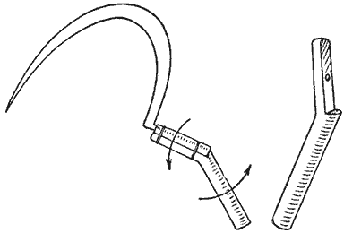
The Extension Handle Makes It Much Easier to Control the Sickle in Cutting around Obstacles
A Clothesline for Small Goods
Handkerchiefs and small pieces included in the week's laundry are usually quite troublesome to hang with the larger pieces, and for this reason I constructed a special line for the small goods. A line was cut to fit between two porch posts and a hook made of galvanized wire tied to each end, staples being driven into the posts to receive them. Three or four wire grips were formed and attached to the line. It was only necessary to draw the corner of a handkerchief into the grip as it was wrung out, placing several in each grip. The line with its load was then carried out and attached between the porch posts. This made it unnecessary to look through the clothes for the small articles. It also prevented chilling the fingers and no pins were needed.—Contributed by R. D. Livingston, Hopkinton, Iowa.
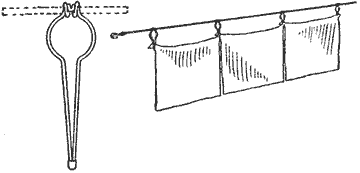
Line and Holders are Always Together and can be Washed as the Clothes
Automatically Controlled Ice-Box Lights
Often the ice box is placed in a dark closet or some out-of-the-way place, and it is almost impossible to locate articles already in the box or put others away without considerable inconvenience on account of the lack of proper light. This difficulty can be easily overcome by mounting a small electric lamp in each of the different compartments of the box, which will be automatically lighted when the lid of the box is raised or the door opened. The circuit through the lamp is controlled by a special switch mounted in such a way that its contacts are open when the doors and lid of the box are closed. A diagram of the circuit is given in Fig. 1, which shows three lamps, each controlled by a separate switch, connected in parallel to a battery of several dry cells. The lamps should be of low voltage and need not be very high in candlepower. The number of cells needed in the battery will depend upon the voltage of the lamps. The voltage of the battery and the rated voltage of the lamps should be approximately the same.
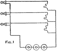
The Lamps will be Automatically Lighted When the Door of the Ice Box is Opened (Fig. 1)
A special switch that will serve the above purpose is shown in Fig. 2. It consists of two pieces of spring brass, A and B, about 3/8 in. wide, bent into the forms shown. These pieces are mounted in a recess cut in the jamb of the door or lid in such a way that the free end of the piece A is held away from the piece B when the door or lid is closed. When the lid of the box or the door is open the two springs come in contact and the lamp lights; upon closing the lid or door the contact is broken and the lamp goes out.
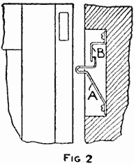
(Fig. 2)
A good quality of rubber-insulated copper wire should be used in making the connections, and all parts should be as well protected from moisture and the possibilities of mechanical abuse as possible. It would be best to tape the lamps in the sockets with a piece of friction tape so as to prevent moisture getting into the socket and, perhaps, shortening the lamp. A short piece of brass tubing can be mounted around the lamp to protect it mechanically. Be sure to place the batteries where they will be kept dry.
A Bottle-Cap Lifter
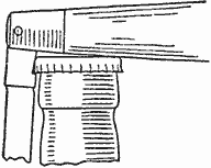
To remove the crimped bottle cover so extensively used requires a special lifter, the corkscrew being of little use for this purpose. When a cap-cover remover is not at hand, prepare a pocketknife in the manner shown, and it makes an excellent substitute. It only requires a small notch filed in the heel of the blade, which does not interfere with the ordinary use of the knife in the least.—Contributed by John V. Loeffler, Evansville, Indiana.
Ants may be effectively destroyed by placing a coop with a chicken in it over the hill.
A Mechanical Bicycle Horn
The body of the horn A is made of metal, about 3 in. in diameter, with a screw cover. The shaft B, to which is attached a driving pulley, C, and a ratchet wheel, D, is fitted in holes drilled through the diameter of the body. The diaphragm E is clamped, between the edge of the body and the cover, on a seat made of rubber rings, F, and carries a contact device, G, that is riveted to its center. The diaphragm should be set so that the contact will touch the ends of the ratchets.

The Horn is Sounded by Making Connections with the Moving Surface of the Tire
A metal cone is fastened in an opening cut in the center of the cover, over the diaphragm. The back of the body is fitted with a bracket for attaching it to the front fork on a bicycle. The lever H carries an idler pulley which is forced against the bicycle tire and the pulley C by means of a cord, J.
Adjusting the diaphragm contact on the ratchet wheel will change the tone of the horn.—Contributed by P. Mertz, Jamaica, L. I.
Retarder for Plaster of Paris
When it is desired to lengthen the time of setting after preparing plaster of Paris, dissolve 1 oz. of citric acid in water used for mixing 100 lb. of plaster, and it will retard the setting for about three hours.
An Inkwell Stopper
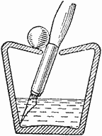
A good way to keep an inkwell of the type shown in the sketch clean is to place a marble over the opening. The marble keeps out flies and dust, is easily rolled aside and is no obstacle to the pen entering the well.—Contributed by James M. Kane, Doylestown, Pennsylvania.
A Grass Rake
This adaptation of an ordinary iron rake for use on a lawn was the outcome of not having a lawn rake at hand. Two spools, each 1-1/2 in. in diameter, were procured and one forced on each end tooth of the rake. The spools were forced on the teeth just far enough to allow the rake to slide on the ground and prevent the other teeth from digging out the grass. The end of the spools may be rounded and smoothed so that they will slide easily on the ground.—Contributed by H. E. Gray, Montclair, N. J.
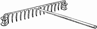
The Spools Prevent the Teeth from Injuring the Grass Roots as the Rake Passes over the Ground
A Staple Puller
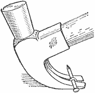
A very simple way to pull a staple is to use the claws of an ordinary carpenter's hammer and a nail, as shown in the sketch. The staple can be removed quickly without being bent, and no damage to the material into which it was driven will result.
To Remove Acid Stains from Cloth
Apply pearlash directly to the stain, allowing it to set a minute or two, then boil the article in soap water for several minutes. The method is harmless and inexpensive, and can be used by anyone.
Repairing Rocker on a Chair
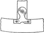
The tenons on the posts of a rocking chair being broken off so close to the rocker that it was impossible to make the ordinary repairs, four window-shade-roller brackets were used in the following manner: The metal was straightened so that it would lie flat and two brackets were used on the end of each post. This made a neat and strong repair.—Contributed by Chas. Schmidt, Baltimore, Md.
Electric-Lamp Reflector for a Target
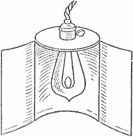
An ordinary 1-lb. coffee can may be quickly fashioned into a most effective reflector for an electric bulb. The light is projected upon the target while the marksman's eyes are shielded. Of course, this device can be used for other purposes.
The can is shaped into a reflector by cutting it open along one side with a pair of snips, then following the circumference of the bottom halfway around on each side. Bend the flaps outward as far as desired and cut a hole in the bottom just large enough to insert the bulb, as shown.—Contributed by Burke Jenkins, Port Washington, L. I.
Linoleum may be renewed by applying floor wax in liquid form.
Making Small Taps
The owner of a private workshop has need for taps and occasionally wishes to make them, not because they are cheaper, but for the sake of experience or to get some special thread. In cutting the flutes, whether it be by hand or in a shaper, it is a good plan to give the flutes an angle, that is, to cut them, not parallel with the axis of the tap, but at an angle of 5 to 15 deg. with the center line. This makes the tap cut easier, giving it a wedge action instead of just simply pushing the metal off. The same method applies to counterbores and countersinks, which, when so made, take less power to drive.
Sink a Substitute for a Dishpan
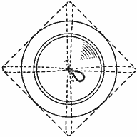
On special occasions when company is entertained or in large families, it is almost impossible to wash all the dishes in an ordinary dishpan; in fact, the large platters will not go in at all, so I devised the following method as a substitute for a larger pan. A tin disk was cut from the top of a tomato can with a can opener so as to be as round as possible, then a piece of cheesecloth was folded into an even square, the disk placed in the center and all four corners of the cloth drawn over to the center of the disk. A nail was driven through the center of the disk, to make a hole, through which a string was drawn with the nail and tied to it to form a loop on the head. This is used to stop the sink drain.
When this is put over the drain outlet the sink may be used as a dishpan. The same result could be obtained a little better with a piece of an old rubber boot or rubber coat, but usually this material is not at hand, and the cheesecloth will do almost as well.—Contributed by Hannah Jennings, Chicago.
How to Make Small Coil Springs
Procure a nut, having a small thread that will admit the size of the wire to be used in making the spring. Cut a small notch to the depth of the thread where the thread starts, and procure a smooth rod that will pass snugly through the threads of the nut. Shape one end of the rod to fit a carpenter's brace, if there is no drill chuck at hand, and drill a hole in the other end to admit one end of the spring wire.
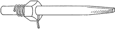
The Threads in the Nut Will Guide as Well as Coil the Spring Evenly
Bend the wire at right angles and insert the end in the hole. Place the end of the rod in the nut, which should be gripped in a vise, and turn the rod, at the same time seeing that the wire is guided into the notch cut at the start of the thread. The wire will follow the thread of the nut and make a perfect spring of an even opening throughout its length. Closed or open coils can be made by using a nut having the proper number of threads.—Contributed by A. Spencer, Kinston, N. C.
A Pruning-Saw Guard
The double-edged pruning saw with coarse teeth on one side and fine on the other would be far more widely used, if it were not for the fact that the unused edge so often injures the bark of the trunk when the saw is being used. A very satisfactory guard may be quickly made of a brass curtain rod by prying it apart slightly at the seam and cutting a suitable length to fit over the edge, as shown in the sketch. This will cling to the saw blade by its own tension.—Contributed by James H. Brundage, Katonah, N. Y.
The Teeth on the Unused Edge are Covered with a Piece of Brass Curtain Rod

Home-Made Motion-Picture Camera and Projector By Charles Frank — In Three Parts—Part I — The Camera
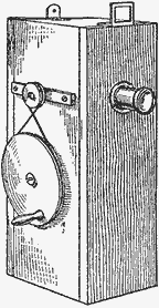
(Fig. 1)
Motion pictures are made and reproduced by means of a camera and projector, each having a similar mechanism that would seem entirely too complicated for the average person to construct at home, yet a correspondent of the Nickelodeon has devised a simple rotary cylinder shutter that can be substituted for the complicated parts. While this simple cylinder shutter is not claimed to be infringing on existing patents, yet, as it has no commercial value, there would be no objection on this score. The instruments described are nothing more than toys, and if the amateur photographer can secure a few dozen feet of animated photographs about the home that are dear to his heart, and reproduce them on a screen, it will have served its purpose. The camera and projector described uses standard film, 1-3/8 in. wide, with perforations every 3/16 in.
The ordinary hand camera for making still pictures consists of a light-tight box with a lens at one end and a sensitized plate or film at the other. The motion-picture camera (Fig. 1) is nothing more than a hand camera with a mechanical device for stepping a long roll of film through a space in the focal plane of the lens at a speed of about 16 pictures a second, and stopping the film long enough to make the requisite exposure on each division. The first thing to consider is the lens. A lens having ordinary speed for a hand camera, and one with about 3 in. focal length will give satisfactory results. If one does not care to purchase a lens, a small 1-1/2 in. or 2 in. reading glass can be used, if it is stopped down, or a lens may be taken from a hand camera. The width of the camera from front to back (W, Fig. 2) must be determined by the focal length of the lens. The dimensions given in the drawing are only approximate, and they can be changed if the camera is to be used in making an extra long film negative.
The roll of unexposed film (A, Fig. 2) is placed on a small shaft between U-shaped bearings, made of sheet metal and screwed to the top board of the camera. The lens B is set in the front board at a point 4 in. below the top. If a large roll of film is to be used, this distance must be greater to allow room for the film roll in the top of the camera. The cylinder C, which acts as a shutter and intermittent movement, revolves directly behind and in the path of the light passing through the lens. Partitions, DD, are set in grooves cut in the boards, forming the sides of the camera. These partitions are to keep the light, which may be diffused from the lens, from striking the film at either side of the shutter, and at the same time acting as guides for the film at the rear end of the camera. Their edges at the back are covered with black velvet. The back of the box is a hinged door, rabbeted on all edges, and opening at the side to allow the insertion and removal of the film, and also acting as a guide for the film when closed. A strip of black velvet, E, a little wider than the film, is pasted to the inside surface of the door, so that it bears lightly against the back edges of the partitions DD. The film passes between the edges of the partitions and the velvet on the door with some friction, which keeps it from moving except when pulled through with the roller shutter. A wire-staple guide, F, is fastened in the lower partition, through which the end of the film is passed before closing the door. The film as it is run through drops in folds in the bottom of the box.

Fig. 2—Details of Camera
The rotary cylinder shutter is the heart of the machine and should be made well and strictly according to the dimensions. The detail of this part is shown in Fig. 3. A rectangular opening is mortised through one of its diameters to admit light on the film when in certain positions. The cylinder is of wood with a 1/4 in. steel rod inserted in the center of each end for axles. A small grooved pulley (G, Fig. 2), about 1 in. in diameter, is fastened to the outer end of one of these rods. The cylinder is revolved by a round belt from a drive wheel, H, 3 or 3-1/2 in. in diameter and turned by the aid of a crankpin. Owing to the backward rotation of the cylinder, the belt must be crossed between the drive wheel H, and the pulley G. The projections or sprockets, Fig. 3, must be accurately set at a distance of 3/8 in. from the 90 deg. point, using the center of the mortised hole as a base. These projections can be pins or small staples, but they must not be over 1/16 in. in size. The base of the sprockets must fit the hole in the film snugly, but the points should be slightly rounding, so that they will easily enter the perforations. When the upper sprocket, which is approaching the film, engages a perforation, just below the upper partition, it will carry the film downward until the sprocket disengages from the perforation at the lower partition. The distance of travel must be exactly 3/4 in., as that is the height of each picture. The cylinder requires some adjustment to meet this condition; therefore the axles are made to revolve in holes bored in two strips of wood, JJ, which can be moved forward or backward to obtain the proper distance from the film. To allow for this movement, the axles pass through slots cut in the sides of the camera box instead of round holes. The strips JJ are fastened temporarily and when the correct position for the cylinder is found, they are permanently fastened to the box. Grooves, K, are cut through the black velvet and into the back of the door to allow a space for the sprockets to pass through freely. The inside of the box should be painted a dead black, and black paper pasted on all corners and joints. Black velvet is pasted in the rabbet of the door to insure a light-tight joint when the door is closed. The cylinder shutter is also painted a dead black inside and out.

Fig. 3—Details of Shutter
The cylinder in revolving exposes the film immediately behind it through the mortised hole. The sprockets or cylinder does not touch the film while the exposure is being made, but as the hole turns toward a perpendicular position, the sprockets catch the perforations of the film and it moves down 3/4 in. Just as soon as the sprockets disengage the film, the shutter exposes the next section of film, and so on as rapidly as the cylinder is turned, but the average should be about 16 pictures per second. A view finder must be supplied so the field covered by the lens can be determined. Such a finder is made of two pieces of metal, L and M, bent L-shaped and fastened to the top of the camera box. One of the pieces (L) has a rectangular opening 1 in. wide and 3/4 in. high, and the other (M) is drilled with a 1/8 in. drill, the distance between the two pieces being the focal length of the lens. One eye applied to the 1/8 in. hole in the piece M will see through the rectangular hole in the piece L about the same field as covered by the lens. The pieces should be accurately placed and fastened on the box when the camera is set, so that the lens will throw the same portion of the picture on the space where the film passes as will be seen through the finder.
A Swimming Raft
Swimming is learned only by experience and to get this experience one must not be afraid to trust himself in the water. This is sometimes accomplished by the use of a swimming raft or water wings. As the water wings need to be inflated frequently, I made a swimming raft instead, in the following manner: Two logs, about 6 or 7 ft. long and about 8 in. in diameter, were fastened together with large nails, as shown in the illustration, and a piece of burlap or other strong material was nailed across the center with slack enough for it to be partially submerged.
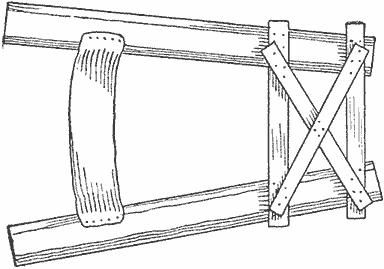
Plan of Raft
The middle of the band, its depth, etc., can be adjusted to suit the user. Be sure to remove all the roughness of the logs and boards with a rasp and sandpaper.—Contributed by W. P. Johnston, Sumner, Ill.
Removing Finger Marks on Books
Dampen a piece of wash leather and use it to rub pumice on the spot to be cleaned. Brush off the pumice and rub again with a piece of dry wash leather.
Tightening a Tennis Net
Anyone who has ever played tennis will readily see the advantage of the net-tightening device shown, in preference to the old method of pulling the net tight by hand. All that is necessary to make the device is 1 ft. of ordinary gas or water pipe, 8 or 10 in. of 1/2-in. iron bar, and two twenty-penny nails. The posts generally used are 6 by 6 in. About 4 in. from the top of the post bore a 1-in. hole, parallel with the direction the rope is to run. On the inside surface of the post bore four 1/4-in. holes.
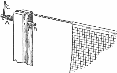
Tightener on Post
Drill a 1/2-in. hole 1 in. from one end of the pipe, and a 1/4-in. hole 1 in. from the other end. Put the iron bar in the 1/2-in. hole, tie the rope around the pipe and bar at A and wind. With the leverage of the iron bar one can readily pull the net to any desired tightness. After the net is drawn in position, put one of the nails through the 1/4-in. hole in the pipe and the other in one of the 1/4-in. holes in the post.—Contributed by Wm. S. Looper, Gainesville, Ga.
Holding Fishing-Rod Joints Together
The addition of two or three screweyes properly placed in a jointed fishing rod of the ordinary type will prove decidedly worth while, as the joints will often pull out easily when they should not and stick tightly when they should pull apart.
Assemble the rod and bore small holes through the brass sockets into the joints as shown in Fig. 1 and place some screweyes into the holes. Mark the joints so that the holes in the joints and holes in the brass sockets will always be in the same position.
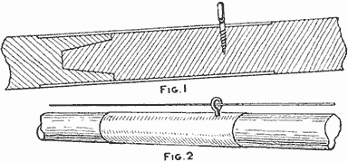
Screweye in Joint (Fig. 1, Fig. 2)
The screweyes prevent the joints from pulling out when an effort is made to free the line from some object in which it has become entangled. They also act as guides for the line. Should the joints fit too tightly, scrape the ends until they slip easily into the sockets, as the screweyes will hold them properly, even if they fit a little loose after the scraping.
Roller Skate on a Bicycle Wheel
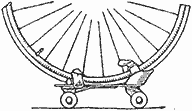
When the front tire on a bicycle will not hold and needs to be taken to a repair shop, strap or tie a roller skate to the rim of the wheel, as shown, and no trouble will be experienced in wheeling or riding the bicycle to the shop.—Contributed by K. Chase Winslow, Elizabeth, N. J.
Rope Oarlocks
Having considerable trouble because of breaking of oarlocks, I devised a successful way by which the difficulty was overcome. The device is extremely simple and is nothing more than a piece of rope fastened to the gunwale as shown in the sketch.—Contributed by Arthur L. Chetlain, Rogers Park, Illinois.
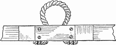
Piece of Rope in Place
Home-Made Motion-Picture Camera and Projector In Three Parts—Part II — Developing — Printing
After having exposed the film in the camera, the next steps are to develop and make a positive film from the negative. The developing and exposing of the film for the positive are the same as in ordinary photography for making negatives and lantern slides, the only difference being in the apparatus for handling the long films. One of the simplest ways of developing a long film is to use a large tray in connection with a cross arm having upright pins around which the film is wrapped in a continuous spiral. A film 100 ft. long would require a tray 18 by 22 in., with pins set in the cross arm about 3/8 in. apart. This method of developing is shown in Fig. 4.
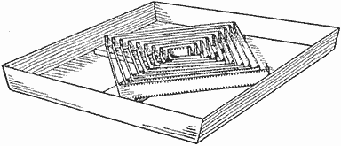
Fig. 4—Cross Arms with Pins
A long film can be developed in a small tray by using two flanged wheels or spools mounted on a frame (Fig. 5) that holds them directly above the liquid in the tray. The spools have a wood core or center with metal sides of sufficient diameter to take in the length of film to be developed. One end of the undeveloped film is attached to one spool and then wound upon it, then the other end is passed through the guides, gelatine side down, and fastened to the other spool. The film is first run slowly through a water bath until it is thoroughly saturated, then it is passed through the developing solution again and again until the proper density is secured. The trays can be easily removed and others substituted for fixing, washing, hardening and soaking, the film being passed through each solution in the same manner. Before developing either negative or positive film, small test strips should be run through the solution so that the proper timing and treating of the full-length strip will correspond to the test strip.
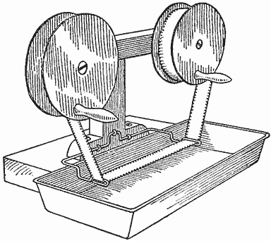
Fig. 5—Developing Long Films
A reel should be prepared for drying the film. This can be made of small slats placed around two disks to form a drum (Fig. 6) about 1-1/2 ft. in diameter and 2-1/2 ft. long. After the film has been passed through the various solutions and is ready for drying, it is wound spirally around on the slats with the gelatine side out, and the whole hung up to dry.
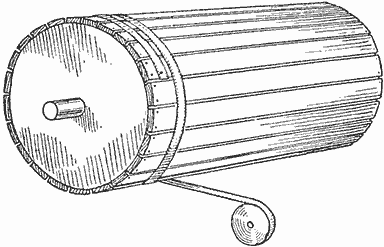
Fig. 6—Drying Reel
The printing to make the transparency is accomplished by a very simple arrangement. The negative and positive films must be drawn through a space admitting light while their gelatine surfaces are in close contact. A box may be constructed in several ways, but the one shown in Fig. 7 illustrates the necessary parts and their relative positions.

Fig. 7—Printing Machine
The sprocket A is placed directly back of the opening B which may be regulated to admit the proper light. The sprocket can be purchased from a moving-picture stock house cheaply, but if the builder so desires, one can be made from wood turned up about 1 in. in diameter, or so that the circumference will receive sprockets at points 3/16 in. apart. The sprockets are made of metal pins driven into the wood. Two rows of them are placed around the wood cylinder about 1-1/8 in. apart.
The cylinder is provided with a small metal shaft at each end which turns in round holes or bearings in the sides of the box. One of the shafts should project through the side of the box and have a grooved wheel, C, attached. The sprocket cylinder is driven by a smaller grooved wheel or pulley, D, to which a crank is attached for turning. The relative sizes of these wheels are determined by the speed of the exposure and the kind of light used. A 3-in. or 4-in. wheel on the cylinder sprocket shaft, driven by a pulley about 1 in. in diameter, will be suitable under ordinary circumstances. The opening B may be adjusted by two metal slides which fit tightly in metal grooves fastened to the wood front. The metal grooves and slides can be made of tin and painted a dead black. The films after passing over the sprocket, fall into the bottom of the box, or, if very long films are to be made, the instrument can be used in the dark room and the light admitted only to the opening B, then the ends can be dropped into a basket or other receptacle at the bottom and the unprinted portions carried on reels above the box.
The speed of the exposure and the width of the opening B can be determined by making test strips. This can be done by setting the opening B to a certain width and turning the crank for 10 or 15 seconds and counting the number of revolutions. The proper exposure can be easily attained by this method.
An Emergency Clamp
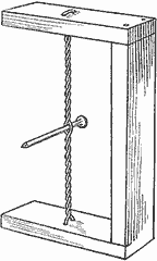
While making an extra large guitar I did not have clamps large enough to hold the top and bottom onto the sides while gluing, so I fastened three pieces of wood together, each piece being about 1 by 2 in., as shown in the sketch. Then I bored holes in both top and bottom pieces and inserted a piece of soft wire in the form of a loop, which, when twisted, drew the ends of the clamp together.—Contributed by Geo. E. Walsh, Buffalo, N. Y.
While camping, remember a hot stone wrapped up makes an excellent substitute for a hot-water bag.
Home-Made Motion-Picture Camera and Projector In Three Parts—Part III — The Projector
The film positives are projected on a screen with the same kind of a lantern as is used for lantern slides, with the addition of the device for stepping the film through, one picture at a time, and flashing light on each picture as it remains stationary for an instant. The projector (Fig. 8) is composed of a lamp house, a condensing lens to make the beam of light converge upon the film for illuminating it evenly, a film-stepping device, and a projecting lens for throwing the enlarged picture of the illuminated film upon a screen.

Fig. 8—Projector Complete
The lamp house is made of ordinary stovepipe metal and the dimensions given in the sketch are for a size suitable to use an acetylene or gas burner. The metal is laid out as shown by the pattern (Fig. 9) and bent on the dotted lines to form the sides and ends of the house. The joint may be riveted, or, if taken to a tinshop, lock-seamed. The cover is cut out as shown, the sides and ends having bent holes which are covered on the inside with perforated sheet metal, A. In order to deflect the light, a small angular strip, B, is riveted on so that its upper portion will cover the holes and allow a space for the heat to pass out. The cover may be hinged or set on like a cover on a can. The lamp house is attached to a sliding wood base for adjusting its position on the baseboard.

Fig. 9—Details of the Lamp House
The condensing lenses are fixed into a metal barrel having a tapering end. This can be made of the same material as used in the lamp house. The parts can be rolled and a lock joint made at a local tinshop, or the pieces shaped over a wood form and riveted. Small L-shaped pieces are riveted to the inner surfaces to hold each lens in place. A rim is turned up on the back end of the metal tube for attaching the lens barrel to the lamp house.

Fig. 10—Details of the Lamp, Stepping Device and Base
An ordinary mantle or acetylene burner is attached to a gas pipe that has for its base a drop elbow fastened to a sliding board similar to the slide of the lamp house on the baseboard. A good reflector should be attached to a standard just back of the burner. The standard is also fastened to the sliding board. The proper distance of the light from the condensing lens can be easily set by this adjusting device. This arrangement is shown in Fig. 10 in the diagram entitled "lamp parts."
The device for stepping the film is a duplicate of the one used in the camera as described in Part I, with the exception of the lens. The lens should be about 2 in. in diameter with such a focal length that will give a picture of the required size, or a lens of 12-in. focus enlarging a 1-in. film to about 6 ft. at a distance of 24 ft. A regular lens fitted in a metal tube can be purchased from a moving-picture stock house at a reasonable price. The box is made up similar to the camera box, but with a metal back instead of the wood. The intense heat from the light would quickly burn the wood and for this reason the light should be kept from the film while it is not in motion. The projecting lens barrel should be fitted snugly, yet loose enough for focusing.
The baseboard is cut as shown and the film-stepping device is firmly attached to the small end. The sides extend over the baseboard and are fastened with screws and braced with metal brackets. The slot in the small end of the baseboard is for the film to pass through. The film should have a tension the same as in the camera with velvet placed on the edges of the partitions. It is well to have a guide below the roller shutter to keep the film from encircling the roller as it turns.
Homemade Graining Tools
Desiring to do some fancy graining and having no tools at hand, I hastily made two of them from pieces of garden hose, as shown in the sketch. Two pieces were cut from the hose, each 5 in. long, and the first one made as follows: A small hole, about 1/4 in. in diameter, was cut through the outside layer of rubber with a sharp knife at two points on opposite sides of the hose and exactly in the center for length. Around these holes rings of the rubber were cut out, or rather peeled off from the canvas part, the rings being 3/16 in. wide, and the grooves, or parts removed, also 3/16 in. wide. The hose will then appear as shown in the upper left-hand corner of the sketch.
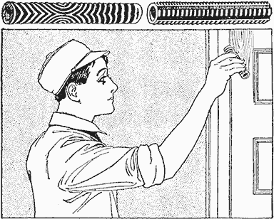
Tools Cut from Pieces of Garden Hose for Making Grains of Wood in Painted Surfaces
To use this grainer, first paint the ground color, using a buff tint for imitation light oak, and allow it to dry, then put on a light coat of raw sienna, and while wet, take the prepared hose and draw it slowly over the length of wood, at the same time revolving the grainer slowly.
The other piece of hose, at the other corner, is made to take the place of a steel graining comb. The rubber is cut away lengthwise, leaving four segments, about 4 in. wide, on four sides of the hose. These segments are then notched out, like threads on a tap, each segment having a different number to the inch. These are used in the same manner as steel combs.—Contributed by A. H. Waychoff, Koenig, Colo.
Needle for Repairing Screens
In attaching patches to window or door screens, the work requires a continual shifting from one side to the other, or two persons, one on each side, must be present to pass the threaded needle back and forth. The operation can be easily simplified by using a bent needle, which has been heated and suitably shaped. The point of this needle can always be made to return to the side from which it entered, thereby avoiding the need of an assistant or the tiresome shifting back and forth.—Contributed by G. Jaques, Chicago, Ill.
An Emergency Tourniquet
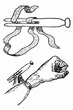
A valuable addition to any shop medicine cabinet is the tourniquet. A device that will answer the purpose of the tourniquet can be made from an ordinary clothespin and a piece of binding tape, about 3/4 in. wide and 14 in. long. To stop the bleeding from a wound on a limb, pass the tape around the injured member between the wound and the blood supply. Pass the tape through the slot in the pin, wind the ends around the pin two or three times to prevent slipping, then turn the pin to draw up the tape tightly until the flow of blood is stopped.
Mechanical Aid to Singers
Procure a large cigar box, of the square variety, and three ordinary drinking glasses with very thin walls and of different sizes, and place them in the box, as follows: Space them evenly, and drive three brads close to the circumference of each glass bottom, so that the glasses will have to be forced in between them. To prevent the glasses from touching the wood place a one-cent piece under each one.
A fourth glass is used, but from this the bottom must be removed. This can be done by saturating a string, or piece of yarn, in kerosene oil, wrapping it once around the glass near the bottom, then lighting it and allowing the string to burn out. The glass is then quickly dropped into cold water, which will remove the bottom.
A hole is cut in the cover of the box to receive the bottomless glass from the upper side, so that its lower edge will be flush with the under surface. Cut a slot, 3 in. long and 1/8 in. wide, in the cover near the back side.
To use, close the cover and at a distance of about 1/2 in. from the glass in the cover, or mouthpiece, sing into it. The glasses will impart to the voice a peculiar tone delightful to hear.—Contributed by J. B. Murphy, Plainfield, New Jersey.
Model Boat with Aerial Propeller
Procure or make a small model boat, 12 or 18 in. long, and place in the hold one or two cells of dry battery. Make a small platform in the stern and mount on it a small battery motor with the shaft parallel with the length of the boat and in the center. Directly above and parallel with the motor shaft run a shaft—a hatpin will do—in bearings fastened to the deck. Attach a drive pulley directly over the pulley on the motor and belt it up with a cord or rubber band. Purchase or make a propeller blade and attach it to the rear end of the shaft. A switch can be located on the deck for controlling the motor.—Contributed by Geo. B. Riker, Ft. Wayne, Ind.
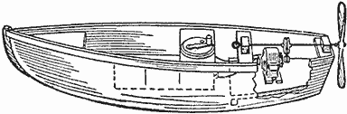
The Aerial Propeller is Driven by a Small Battery Motor Placed in the Boat
Lantern-Slide Binding Machine
The machine shown in the illustration is very simple to make and when complete is one of the greatest time savers that a photographer can possess. The base is made of a piece of board, 9 in. long, 2 in. wide, and 7/8 in. thick. The uprights support a small bar upon which the roll of binding revolves. An old ink bottle filled with water and with some cotton stuffed in the neck serves as a moistener for the binding. The use of this machine insures a neat job in a very short space of time. The slide is always in the center of the binding. The end of the slide should run a little over the end of the base so that the binding may be fixed to the edge with the fingers, using a downward motion. The slide is then turned over on the other edge with a rolling motion and the operation repeated.—Contributed by Alvin G. Steier, Union Hill, N. Y.
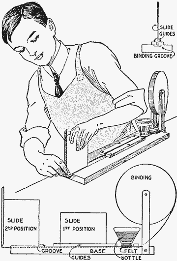
A Machine That will Help to Bind Lantern Slides Quickly and Neatly
Adjustable Film-Developing Machine
The simple homemade developing machine, shown in the illustration, can be easily made with three film spools, some strong wire, and odd pieces of wood. It consists of an open frame, having two side pieces provided with slots down the center, sufficiently wide to allow an ordinary wood screw, of suitable size, to slide up or down freely. The two end-connecting pieces act as supports for the developing tray and should be made of sufficient length so the tray can pass freely between the sliding upright frame, made to fit in between the side pieces of the base. This frame can be adjusted to suit the length of film and is clamped in place at the desired position by wood screws, fitting in the long notches and screwed into the uprights. The two bottom rollers consist of film spools which are fastened in place by being slipped over a suitable wire, bent so the spool can enter the developing tray and the wire pass over the sides. Another bend at the outer end provides for the adjustment of the spools and for securing the wire in place by staples. The top spool is secured to a wire fitted with a crank at the outer end, so that in turning the wire, the spool will also turn, thereby driving the film. When placing the film on the machine, the sensitive side should face outward so it will not rub against the spools. The ends of the film may be connected with pins or ordinary paper fasteners.—Contributed by H. R. F. Richardson, Ottawa, Ont.
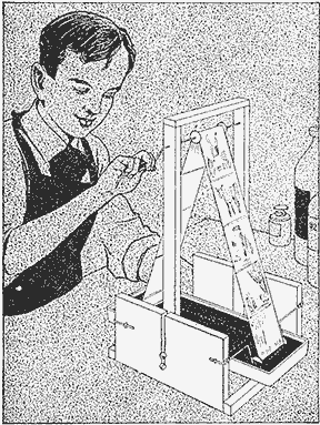
Developing a Roll Film in a Tray with a Machine That Drives the Film around Rollers and through the Developing Liquid by Turning a Crank
Preventing Loss of Fish from Covered Baskets
In the cover of fish baskets an opening is frequently made permitting the fish to be put in without lifting the cover. In traveling over rough places, or when the basket is full, some of the fish are likely to be shaken out, or may wiggle out of the basket. To guard against this, a leather flap can be provided covering the hole on the inside. At one end of the flap, four holes should be punched. It can then be placed in position and securely laced to the cover. The flap acts as a valve, allowing fish to be put into the basket, but preventing their escape.—Contributed by A. W. Cook, Kamela, Ore.
Repair for a Broken Lock Keeper
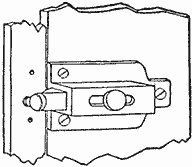
Having broken the recess half of a common cupboard lock, or latch, which was used to fasten a hinged storm window, I used a round-head wood screw as shown. The screw was easily placed, and it serves the purpose as well as the regular keeper.—Contributed by R. F. Pohle, Lynn, Mass.
When using glue contained in screw-stoppered vessels it is advisable to smear a little vaseline on the thread to prevent the stopper from adhering to the container.

Throwing a Spot Light with the Lantern on Individuals of a Home Play, Which can be Given Brilliant Effects by the Use of the Tinted Celluloid in the Openings of the Revolving Wheel
Lantern for Spot and Colored Lights
The school play in pantomime is not complete unless the different parts of the play are illuminated in different colors, especially if the performers are clad in glittering garments. A spot light is also a feature not to be forgotten in singling out the star player or the one singing a song. The cost of a light for this purpose is entirely out of the reach of the average schoolboy, but if he has any ingenuity and a little time, a lantern for throwing those colored lights can be made at home, and the necessary parts will not cost much.

Pattern for Cutting the Metal to Form the Entire Lantern, or Lamp House, Also the Pattern for the Top and the Metal Bracket That Makes a Bearing for the Revolving Wheel, Having Openings Covered with Tinted Celluloid
The metal necessary can be the ordinary stovepipe material, but if it is desired to have a fine-appearing lantern, procure what is called Russian iron. This metal has a gloss, and if used, it should be gone over from time to time with a rag soaked in oil, then wiped dry, to keep it from rusting. The pattern for the body of the lantern, or lamp house, is shown with dimensions.
If metal, long enough for the whole length, cannot be procured, then make it in two pieces, being sure to allow 1/2-in. end also on the second part, as shown on the first, for a riveted joint. The metal is bent on the dotted lines and cut out on the full ones. The distance between the lines A to be bent is equal to the radius B. The part A forms the sloping side of the top, and the 2-in. part at the top of the side extends vertically on the upper or vertical part, it being 1/2 in. narrower to provide an outlet for the heat.
An opening is cut in the rear end, as shown, also a hole, 5 in. in diameter, in the front end. The size of the round hole is optional, as it should be cut to suit the condensing lens provided. If a lens 5 1/2 in. in diameter is used, then a 5-in. hole should be cut. This is enough difference in size to hold the lens from dropping through, while clips riveted on the inside of the lamp-house end will hold it in place. The lens is set in the hole with the curved side outward from the inside of the lamp house.
The top, or covering, is cut out of the same material as used in making the lamp house, the length being 12 in., and the sides are cut to extend 1/2 in. on each side of the ventilator. The edges, being turned down on the dotted lines, provide a covering to prevent any great amount of light from passing out through the 1/2-in. ventilating opening mentioned in connection with the side construction of the lantern. The 1-in. parts of the cover ends are turned down and riveted to the ends of the lamp house. The little extensions on the ends provide a means of riveting the side, to make a solid joint.
The arm C is made of a piece of 1/8 or 3/16-in. metal, shaped as shown, to fit on the corner of the lamp house, where it is riveted. This provides a support and a place for an axis for the large revolving wheel holding the colored-celluloid disks.
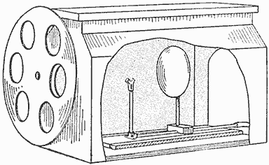
The Base of the Lantern is Provided with a Sliding Part Carrying the Light for Adjustment
The metal forming the lamp house is fastened on a baseboard, cut to snugly fit on the inside. The base has two cleats, nailed lengthwise to form a runway, 4 in. wide, into which another board is fitted to carry the burner. While the illustration shows an acetylene burner, any kind of light may be used so long as it is of a high candlepower. If manufactured gas is at hand, a gas burner with a mantle can be fitted, or a large tungsten electric light will give good results.
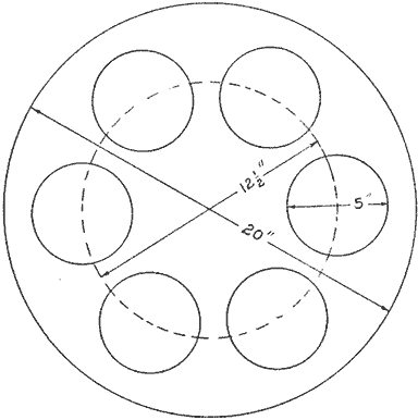
Pattern for the Revolving Wheel in Which Six Holes are Cut and Covered with Tinted Celluloid
The wheel, carrying the colored disks, is made of the same kind of metal as used for the lamp house. The edges should be trimmed smooth, or, better still, turned over and hammered down to prevent injury to the hands while turning it. A washer should be used between this wheel and the arm C on a bolt used for the shaft, to make the wheel turn freely. The colored disks of celluloid are fastened to the outside of the wheel over the openings.
A yoke to support the lantern and provide a way for throwing the light in any direction, is made as shown. A line along which the lantern balances is determined by placing it on something round, as a broom stick, and the upper ends of the yoke are fastened on this line with loosely fitted bolts for pivots.
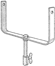
Yoke for Supporting the Lantern
The lantern is set in front of the stage at the back of the room and the light is directed on the players, the colors being changed by turning the wheel. Sometimes good effects can be obtained by using the lantern in the wings, or for a fire dance, by placing it under the stage, throwing the light upward through grating or a heavy plate glass.
Homemade Palette Knife
A corset steel makes a good substitute for a palette knife because of its flexibility. It gives better satisfaction if cut in the shape shown than if left straight. Should a handle be desired, one can be easily made by gluing two pieces of thin wood on the sides.—Contributed by James M. Kane, Doylestown, Pa.

A Palette Knife Made of a Corset Steel and a Wood Handle Attached
To remove a white mark on wood having a wax surface, rub it lightly with a rag moistened in alcohol; then rub with a little raw linseed oil.
Self-Closing Gate
This gate is suspended from a horizontal bar by chains, and swings freely about a 1-in. gas pipe, placed vertically in the center of the gate. The chains are of the same length, being fastened equidistant from the pipe, the upper ends farther out than the lower. The distance depends on the weight of the gate and the desired force with which it should close. Any of the numerous styles of latches can be used, if desired.—Contributed by Kenneth Osborn, Loveland, Colo.
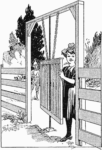
The Gate will Swing in Either Direction and Come to a Rest Where It Closes the Opening
A Poultry Shade
If a poultry yard is in an open space where the sun's rays will strike it squarely, a shade can be put up as follows: A piece of old carpet, rug, or canvas, fastened to the wire mesh with clothespins, will produce a shade at any place desired.—Contributed by Walter L. Kaufmann, Santa Ana, Cal.
Reflector for Viewing Scenery from a Car Window
Construct a box of pasteboard or thin wood, about 9 in. long, 3 in. wide and 2 in. thick, and fasten two pieces of mirror in the ends at an angle of 45 deg., both sloping in the same direction with their reflecting surfaces toward each other. An opening as large as the mirror is cut, facing it, in the box at the end A, and a small hole bored through at the end B so that it will center the mirror. Both of these apertures are covered with plain pieces of glass.
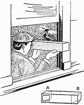
The Reflecting Device as It is Used in a Car Window for Viewing the Scenery Ahead
In use, the end A is placed outside of the car window and the user places an eye to the small hole B. It is impossible to be struck in the eye with a cinder or flying object.—Contributed by Mildred E. Thomas, Gordon, Can.
A Muskrat Trap
It is difficult to catch muskrats in an ordinary steel trap, as a broken bone allows them to sever the flesh and escape. During the summer these rats build a shelter for the winter constructed of moss and sticks placed on the river or lake bed, the top extending above the water level and the entrance being through a hole in the bottom near one side, while the passage itself is under water. It, therefore, only remains for the trapper to make one of these houses over into a huge wire trap so that the animal may be caught alive.
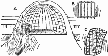
A Trap for Catching Muskrats Alive in One of Their Mounds Built of Moss and Sticks
The house A is prepared by removing the top and building the trap from heavy mesh wire which can be easily shaped, the joints being held together by binding the edges with wire. The passage is then fitted with a double trapdoor, the first, B, provided with sharp points on the swinging end, while the other is a falling cover. These two doors are placed in an entrance way, C, made of wire mesh and fastened over the passageway.
The muskrat comes up through the passage, pushing a bunch of moss or sticks and does not notice passing the trapdoors. The upper door is to keep the animals caught from getting at the first door.—Contributed by Vance Garrison, Bemidji, Minn.
A Casein Glue
Casein glues are splendid in woodworking, making cardboard articles, and when the composition is varied somewhat, make excellent cements for china and metals. Casein is made from the curd of soured milk after removal of the fat, and is put on the market in the form of a dry powder.
To make the glue, soak the casein powder two hours in an equal weight of hot water. To this gummy mass add about one-seventh the weight of the casein in borax which has been dissolved in very little hot water. Stir until all is dissolved after mixing borax and casein. This can be thinned with water to suit and is a good glue, but it can be made more adhesive by the addition of a little sodium arsenate. Any alkali, such as soda or ammonia, could be substituted for the borax.
To make a china cement, lime or water glass should be substituted for the borax. Addition of burnt magnesia increases the speed of hardening.

The Mile-O-View Camera By T. B. Lambert
Many have tried, but heretofore no one has succeeded in taking panoramic views from the side of fast-moving trains or street cars. Motion pictures are easily obtained from the front or rear of moving trains, but none with the camera lens pointing at right angles, or nearly so, to the track. A complete apparatus for taking continuous and perfect panoramic pictures of any desired length as one travels through a country is too complicated to be described in detail within the limits of this article, but a simple arrangement, invented and constructed by the writer, will enable anyone to perform the experiment at practically no cost except for the film.

The Board Used Instead of a Tripod is Placed across the Backs of Two Car Seats
Some form of a roll-film camera is essential, and simply as a working basis, it will be assumed an ordinary camera is used, post-card camera in size, for which the following things will be required: A piece of thin black card, or hard rubber; a small board, and a piece of wire to be used as a crank.
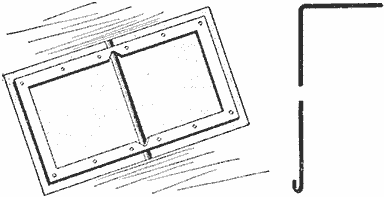
These Two Articles Constitute the Only Parts Necessary to Change a Camera into a Mile-O-View
Prepare the paper, or hard rubber, by cutting it to a size that will exactly cover the rear camera opening when the back of the camera is removed, which, in the case of a post-card size, is 6 in. long and 3-3/4 in. wide; then cut a narrow slot, about 3/64 in. wide crosswise through the center of the material. This slot should extend to within about 1/2 in. of each edge, and the edges must be perfectly smooth and straight. If paper is used, glue it to the opening in the camera. If hard rubber is used, it can be made up as shown and set in the camera opening. This will bring the slot directly back of the lens center and at right angles to the direction in which the film moves when being rolled.
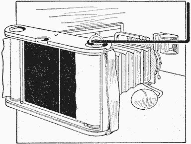
The Two Parts as They are Applied to an Ordinary Roll-Film Camera
A board is prepared, about 4 ft. long, 10 in. wide and 3/4 in. thick. This is to take the place of a tripod, and it must have a small hole and suitable wing nut to attach the camera near the center. This length of board will reach from the back of one seat to another when it is placed to support the camera during the exposure.
A wire, about 1/8 in. in diameter, is bent, as shown, with a short hook on one end, and the other turned up at right angles, to serve as a handle. This wire, when hooked into the wing nut, will enable one to wind up the film at a fairly uniform speed. This completes all the necessary apparatus.
To take pictures with this panoramic outfit, load the camera in the usual way, but do not wind it up to exposure No. 1; stop at a point where the beginning of the film will be nearly opposite the narrow slot in the black paper, or rubber. This would be to stop the turning at about the time the hand pointer appears in the small back window. Attach the camera firmly to the board and brace up the lens end so that it will not easily shake with the movement of the car. Place the board across the backs of two adjacent seats, so that the camera will point out of the window at exactly right angles to the car.
When ready to expose, open the shutter wide, turn the crank that is hooked into the wing nut, and slowly wind up the film while the train is running. This will give a panoramic picture, continuous in character, and if the speed of turning is well judged, some very splendid views can be made.
The speed of turning the crank will be governed by the focal length of the lens and the speed of the train. For an average lens, the crank should be given one turn per second when the car is traveling about 15 miles an hour, or the average speed of a street car, A train traveling 30 miles an hour will require two turns of the crank per second. A good method of trying this out is to use one film as a test and turn the crank a few times and note its speed by the second, then stop and begin again at another speed for a few turns and so on, until the entire film is exposed, always noting the turns and time for each change, also the speed of the train. When the film is developed the one that shows best will give the proper number of turns per second.
The following points must be considered: The track should not be rough, and the camera must be perfectly steady and not twisted out of position by turning the crank, otherwise the resulting picture will be wavy. If the slot in the back board is not smooth and true, the picture will be streaked. Turning the film too fast will make the picture elongated, and too slowly, condensed. Should the camera be pointed otherwise than at right angles the picture will be distorted. This arrangement cannot be used to take moving objects except under special conditions. A picture of a passing train of cars can be made if the camera is stationary, but the wheels and drive rods will appear twisted out of shape. It is best for the experimenter to confine himself to scenery at the beginning, avoiding architectural objects, because a variation in speed of turning the crank to wind the film naturally distorts the architecture, which variation is not so noticeable in a scenic view.

A Photographic Worktable for Small Quarters By K. V. Reed
Flat dwellers have no space at their disposal for a person to work at photography, and the bathroom must take the place of a dark room. As this was very inconvenient in my case, I constructed a table, that from all appearances was nothing more than a large-size kitchen worktable, and such a table can be used in case the builder does not care to construct it.
The table is turned upside down and the top removed by taking out the screws. The top is made of several pieces glued together and will remain in one piece. It is then hinged at one side to the top edge of the rail, so that it can be turned back like a trunk, or box, cover.
Boards are then nailed to the under edge of the rails. If a very neat job is required, these boards should be set inside on strips nailed to the inside surfaces of the rails, at the proper place to make the boards come flush with the under edges of the rails.
At the back side and in the center of the new bottom, a hole is cut, 6 or 7 in. square, and a box fastened beneath it, to form a bottom several inches below the main bottom. In this space bottles filled with solutions are kept. The main bottom should be painted with an acid-proof varnish.

An Ordinary Kitchen Worktable Fitted Up as a Handy Workshop for the Amateur Photographer Who Has a Limited Space in a Flat, and Where a Table can be Used to Advantage in a Room
The space in the table is then divided, and partitions set up, which can be arranged to suit the builder.
Another attachment, which comes in exceedingly handy, is the ruby light. This consists of a box, large enough to receive a printing frame at the bottom. Two holes are cut in the table top, at the right places to make a window for the light and a slit for the printing frame. When the table top is raised, the box with the light is fastened over the openings with hooks, the arrangement of which will depend on the size and shape of the box. In closing, the lamp box is removed, and pieces of board are set in the holes. This can be easily arranged, if the holes and blocks are cut on a slight slope, so that the latter when set in will not fall through the openings.
Back Thrust Prevented on Skis
To overcome the difficulty of skis slipping back when walking uphill either of the two devices shown is good, if the attachments are fastened to the rear end of the skis.
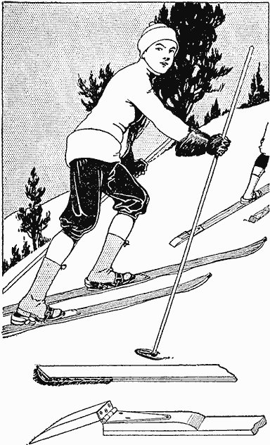
Two Methods of Making an Attachment to Prevent the Backward Thrust of a Ski
The first represents a piece of horse-hide, about 4 in. square, tacked on the ski and with the hair slanting backward. This will not interfere with going forward, but will retard any movement backward.
The other consists of a hinged portion that will enter the snow on a back thrust. As the ski end is thin, a block of wood must be attached to it on the upper side, and the projecting piece hinged to the block. The bevel at the end allows it to dig into the snow when the ski starts back. In going forward, it will swing out of the way freely.
Crystallization Shown on a Screen
The formation of chemical crystals can be shown in an interesting manner as follows: Spread a saturated solution of salt on a glass slide, or projection-lantern glass, and allow it to evaporate in the lantern's light or beneath a magnifying glass. The best substances to use are solutions of alum or sodium, alum being preferable. Ordinary table salt gives brilliant crystals which reflect the light to a marked degree. For regular formation, where the shape of the crystal is being studied, use a solution of hyposulphite of soda.
Many startling facts may be learned from the study of crystals in this manner, and watching them "grow" is great sport even to the chemist.—Contributed by L. T. Ward, Des Moines, Iowa.
Furniture Polish for Fine Woods
Boiled olive oil, to which a few drops of vinegar has been added, makes an excellent furniture polish for very fine woods. It will be found to work nicely on highly polished surfaces, and also for automobile bodies. It is applied in moderate quantities, and rubbed to a luster with a flannel cloth.

Enlarging Photographs By A. E. Swoyer
When the photographer wishes to make an enlarged print from a small negative, he arranges a suitable light and condensers back of the negative and by means of a lens projects the resultant image upon a sheet of sensitive paper. Owing to the comparative weakness of the light, however, it is necessary either to use bromide paper or some of the faster brands of developing-out paper. If a more artistic medium is desired, a glass positive must first be made and enlarged to produce a negative from which the final prints will be made by contact. This process is somewhat clumsy and expensive, for if any retouching or doctoring is to be done, it must be upon a glass surface, either that of the two negatives or of the intermediate positive. As all of this work is done by transmitted light, there is the loss of fine detail common to all enlargements.
The difficulties incident to this process may be done away with by the use of a modification of the popular post-card projector; the alteration consisting simply in the substitution of a better lens for the cheap plate glass with which such instruments are usually fitted.
A contact print, preferably on glossy paper, ferrotyped, is made from the original negative by contact in the usual way; this is then placed in the modified projector and the image thrown upon a sensitive plate of the desired size. After a brief exposure, development will show an enlarged negative having every quality of the original.
The advantages of this process are obvious. In the first place, the comparative cheapness of the apparatus is a factor; in the second, the intermediate glass positive is eliminated, the print which is substituted for it providing a much better medium for retouching, faking or printing in. Transparent water colors in the less actinic shades may be used upon this print to control the final result, and if spoiled, it may be replaced at a negligible cost.
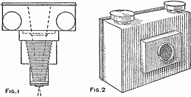
An Ordinary Post-Card Projector Used Back of a Camera to Illuminate a Photograph Which is Enlarged on a Plate to Make a Negative Instead of a Print (Fig. 1, Fig. 2)
At first glance, it would appear as if this method were simply a form of photographic copying; it is, in fact, the reverse. For in copying any object with a camera, the sensitive medium is behind the lens and the object to be copied is in front, and the size of the copy is therefore limited both by that of the camera and by its bellows draw. In the reflection process, the object to be copied is back of the lens and the sensitive medium is in front; as large a copy can be made with a small camera as with an eight by ten. It is really more convenient to work with a short-focus lens and a camera of limited bellows extension; the nearer the lens is to the back of the camera the larger will be the projected image.
The diagram (Fig. 1) shows that the size of the object to be enlarged does not depend upon the focal length of the lens used, as in ordinary enlarging, but simply upon the size of the opening in the front of the projector. The dotted lines are drawn from the edges of the card to be projected through the lens. Figure 2 is a sketch of a projector with the lens tube removed, so that it may be used with a camera as shown in Fig. 3.
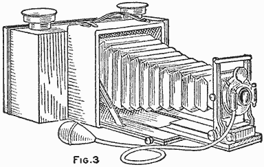
(Fig. 3)
Homemade Screen-Door Spring
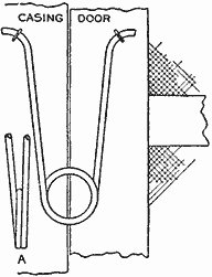
A screen or storm-door spring can be easily made of spring-steel wire. The wire is bent to the shape shown in the sketch and two turns given to the coil as shown at A. The ends of the wire are fastened to the casing and door with staples. Two or three of these springs can be attached to one door where it is necessary to have more strength.—Contributed by Wm. Rosenberg, Watertown, Mass.
A Surprise Water Bottle
The performer produces a bottle and gives it with a glass to anyone in the audience, asking the person selected to take a drink of a very delicious concoction. When the person attempts to pour out the solution it is found to be frozen.
To perform this trick, the fluid must be previously made with a saturated solution of sulphate of soda and hot water. Fill a clean white bottle with the solution, taking care to cork the bottle while the liquid is hot. The liquid remains in a fluid state as long as the bottle is corked. When the bottle is shown, it appears to contain a liquid, and in handing it to a person the performer must be careful to take out the cork in time to allow it to solidify. In order to gain the proper time, pretend to be looking for a glass, make some remark about a sudden chill or feel the hand holding the bottle and say it is very cold. In the meantime, the air acting upon the solution has caused it to become fixed and immovable, and when the person attempts to pour it out, he finds it is impossible.
A Graduate Holder
A simple and easily constructed graduate holder in the form of a bracket placed in the corner of a dark room is shown in the sketch. The bracket not only holds the graduates securely, but allows them to drain perfectly and prevents dust settling on the inside, as they are suspended by the base. Holes of different size are cut in the board to accommodate large, medium and small graduates.
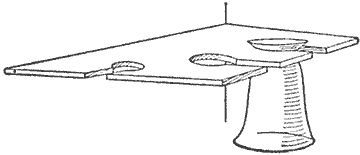
The Graduate Holder is Permanently Fastened in a Corner of the Dark Room
Homemade Enlarging Camera
The ordinary hand camera of the focusing type can be used to enlarge pictures from negatives of its own make. The requirement is a device to hold the negative rigid in a position in front of the camera lens, and at such a distance that the rays of light passing through the negative and lens will enter a box of sufficient size for the desired enlargement and focus plainly on a sheet of sensitive paper attached to the end of the box.
The first thing to do is to find the distance that is required from the camera lens to the paper enlargement to make the proper size, and the distance from the lens to the negative. A correspondent of Camera Craft gives the following rule for finding these dimensions: To find the distance between the lens and paper enlargement, add 1 to the number of times the picture is to be enlarged and multiply the result by the focus of the lens in inches. The example given is for a 6-in. focus lens. An example: A 4 by 5-in. negative enlarged to 8 by 10 in. is a two-time enlargement (four times in area); 2+1 = 3, and 3×6 = 18, the distance in inches of the lens from the sensitive paper. To find the distance of the lens to the negative, divide the above result, 18 in., by the number of times desired to enlarge, 18×2 = 9, the distance in inches from the lens to the negative.
With these figures as a working basis, the box can be made in any size to use any focusing camera. The dimensions given in the drawing are for a 4 by 5-in. camera having a 6-in. focus lens, and to enlarge the pictures from a 4 by 5-in. negative to 8 by 10 in. In the first place make a box 8-1/2 in. wide, 10-1/2 in. deep and 14 in. long, inside measurement, using 3/4-in. material, as shown in the sectional drawing A. One end is left open and in the center of the other a hole is cut 5 in. square.

Details of Construction and Camera Complete
The back end of the camera is placed over this hole as shown at B and 1/4-in. strips nailed to the box end around the camera back to exclude all light. The camera must be centrally located.
The next to be made is the end board or easel, consisting of two pieces of 3/4-in. material, one 8-1/2 by 10-1/2 in., which should fit easily into the end of the box, and a larger one, 10 by 12 in., the outside dimensions of the box, as shown at C. Nail the smaller piece to the center of the large one, crossing the grain of wood in so doing. The end board is the easel upon which the sensitive paper is fastened with push pins, and should be covered with a sheet of white paper, pasting it on the 8-1/2 by 10-1/2-in. board with a thin coat of glue. The slide D is a piece of wood 3/4 in. thick, 3-1/2 in. wide and 26 in. long. This is fastened to the under side of the box with four screws, placing it exactly in the center and parallel with the sides of the box. Be careful to have the slide parallel or the holder will not freely slide upon it.
The negative holder E is made of a piece of 3/4-in. board, 8 in. wide and 10 in. long. A hole 5-1/2 by 7-1/2 in. is cut in its center, leaving a margin of 1-1/4 in. on all sides. This holder is set in a groove cut in a block of wood having a mortise cut 3/4 by 3-1/2 in. to fit on the slide easily. A thumb screw is fitted in the center of the bottom of the block of wood. This is used for fastening the negative holder rigidly to the slide when the focus is secured.
A 1-in. hole is bored in the upper corner of the box end, as shown, to serve as a peephole for seeing the image on the end board or easel. This is covered before putting the sensitive paper in the box. The end board is held in position with two flat brass hooks. The camera is held in place with two buttons placed on blocks of wood the height of the camera back, as shown at F. Two pieces of clear glass, 6 by 8 in. in size, are held in place in the negative holder by means of buttons, the film negative being placed between them. All the joints in the box must be carefully puttied and the inside of the box blackened, which is done with a mixture of lampblack and alcohol, to which is added a small quantity of shellac to give it body.
A darkroom is not essential, a bathroom with the window covered over with orange paper will do, or even a large room with the shades drawn and pinned close to the window casing. It is best to leave a space in one of the windows to be covered with orange paper, doing the developing about 10 ft. from the source of light.
To operate the camera place it on the enlarging box, hook the easel in place, put a negative in the holder with the film side toward the lens. Take the outfit to a shady place outdoors, point the holder end at an unobstructed portion of the sky and look through the peephole. Rack the lens in and out to focus the picture. The easel should have heavy black lines drawn upon it inclosing parallelograms from 5 by 7 in. to 8 by 10 in., so that one can readily see the size of the enlargement to be made. When the focus is obtained take the outfit into the darkroom, remove the easel and fasten the sensitive paper with push pins. Replace the easel and take the outfit outdoors again, point it toward the clear sky and make the exposure, which should be at least 5 seconds with a 16 stop. It is best to make a trial exposure on a small strip of paper to find the proper time. Directions for the use of bromide papers will be found in each package.
An Easy Way to Make a Shelf
Procure an ordinary packing box and mark a line from corner to corner on both ends, as shown, from A to B in Fig. 1. Pull out all the nails from the corners that may cross the line. Nail the top to the box and saw it on the lines marked and two shelves will be formed which may be used as shown in Fig. 2. Boxes dovetailed at the corners will make excellent shelves and look neat if painted.
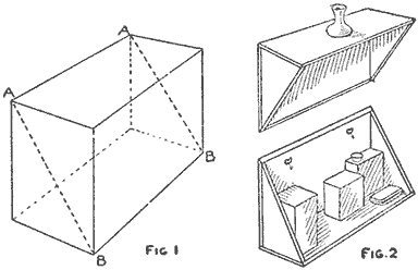
Two Shelves Made of One Box (Fig. 1, Fig. 2)

Multiplying Attachment for a Camera By J. C. Moore
The hand camera suitable for this work is the kind commonly known as the reversible back, which is a detachable part that carries a ground glass for focusing and a place to insert the plate holders. When this part is removed, it will be seen that the back of the camera is mortised to prevent light from entering. Construct a frame to take the place of the back, but make it about 5/8 in. larger all around, and make one surface to fit the mortise of the camera box.

The Attachment as It is Fitted to the Camera and the Reversible Back in the Frame
A back is now made and attached to the frame, to carry the ground-glass reversible back, so that it can be shifted over the center of focus for each small portion of the plate on which the picture is to be made. Measure the outside of the plate holder and, doubling the dimensions both ways, lay out a diagram on a piece of paper. Lay the plate holder on the paper and move it to the extreme left, then to the right, to see if the center of the plate will coincide with the center of the back. In the same manner locate the center in a vertical position. If the center lines do not coincide, increase the dimensions until this occurs. Mark, in the exact center, an opening the size of the plate and cut out the wood. It is best to use a three-ply wood for making the back, but if this cannot be obtained, procure a dry piece of wood and mortise and glue strips to the ends to keep the wood from warping. Glue the frame to this back, over the opening, and make attachments to hold it to the camera in the same manner as the reversible back was attached.

Manner of Laying Out the Pattern for the Back and Locating the Exact Center
If pictures of two or three different sizes are to be made, the opening in the new back should be fitted with as many new pieces as there are sizes of pictures, each to have an opening of corresponding size. For a 5 by 7-in. plate, 1-1/8 by 1-1/4-in. pictures is a good size, as there will be room for 24 pictures on the plate with a small margin left for notes. The piece to fill the opening should be made of the same material as the back so that a smooth joint will result. As a board cannot be made smooth enough for a perfectly light-tight joint, the surface on the new back, over which the reversible back travels, must be covered with cloth—a piece of black velvet is suitable—to exclude all light as the plate holder is shifted over the back.
A frame is now made to carry the reversible back of the camera, the size of which will depend on the size of the other parts, as well as on the size of the camera to be used. This frame consists of two horizontal strips joined at the ends with grooved pieces, fitting the edge of the new back, so that it may be slid up and down in the grooves. The crosspieces are also rabbeted to receive the reversible back and allow it to be moved back and forth horizontally. The rabbet in the horizontal strips should not be so deep as to permit the extending edge to overlap the ground-glass frame, thus preventing it from moving back as the plate holder is inserted.
If the frame on the back and the reversible back fit tightly, they will remain in any position, but if they are loosely fitted, it will be necessary to provide some means to hold them. Small springs with pins may be fitted to the vertically moving frame to hold it in the position for the horizontal rows of pictures.
The ground glass should be marked for the size picture to be taken. The positions of the frame and plate carrier should also be marked so that the plate holder need not be taken out to find the location and focus for the next picture.
Connecting a Pipe to Sheet Metal
In the absence of a waste nut, an iron pipe can be easily fastened to sheet-metal work as shown in the sketch. The end of the pipe, Fig. 1, is slotted with a hacksaw to form four projections, which are turned outward and their ends rounded as shown in Fig. 2. The face of the projections are tinned and then riveted to the sheet-metal surface, as shown in Fig. 3. After soldering the joint, it will be as good or better than if a waste nut had been used.—Contributed by Lorin A. Brown, Washington, D. C.
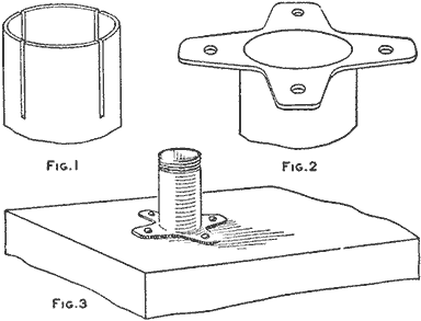
The End of the Pipe as It is Prepared to be Riveted on the Sheet Metal (Fig. 1, Fig. 2, Fig. 3)
An Acid Siphon
When siphoning off acids or other disagreeable or poisonous liquids, it is very important that none of it touch the flesh or mouth. It is almost impossible to do this when starting the ordinary siphon. A siphon that does away with this inconvenience and danger can be made as follows:
Procure a good Bunsen burner and two pieces of 1/4 in. glass tube, one 2 ft. and the other 18 in. long. Heat the 2 ft. length at a point 8 in. from one end in the flame until it can be bent as shown at A. The other piece should be plugged at one end and then slowly and evenly heated at a point 10 in. from one end. When the glass is soft, blow slowly and steadily into the open end, at the same time turning the tube around in the flame. This will form a bulb, B. The ends of the glass tube are heated and bent as shown, at C and D, and then fused onto the piece A, as shown at E. This can be accomplished by heating the piece A at a point 4 in. from the unbent end. When the glass becomes soft, place one end of a short piece of tube in it and pull out into a thread. Break this off as close to the tube as possible, to make a hole in the tube. Heat the end of the tube D and also the glass around the hole, and when both become soft, they can be fused together.
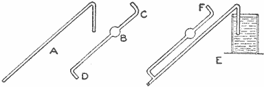
When Starting This Siphon It is Difficult for the Liquid to Touch the Mouth or Flesh
In use, close the end not in the liquid and, placing the mouth at F, exhaust the tube, thus filling it with the liquid. When the closed end is opened, the siphon will flow. The liquid collects in the bulb, and if a little care is used, none of it can reach the mouth.—Contributed by O. F. Tronnes, Evanston, Ill.
Bottle-Opening Trick
A local junk dealer, who was also known as the "strongest man in town," used to mystify the folks by opening a bottle, apparently with a stroke of his index finger. His audience saw his index finger strike the stopper, but did not see the knuckle of his second finger strike the eccentric at the point A, as shown in the sketch, causing it to fly up while his index finger B assisted the stopper out of the bottle mouth.
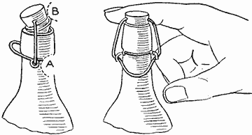
In Striking the Bottle Cork, the Knuckle of the Second Finger Loosens the Wire Lock
When trying the trick, it is best to select a bottle with a loose stopper, or else wear a glove, as the gentleman who demonstrated the trick had hands of the hard and horny type.—Contributed by James M. Kane, Doylestown, Pa.
Setting Colors in Fabrics
The colors of fabrics or other materials of any kind may be set by boiling the articles in the following solution: To 1 gal. of soft water add 1 oz. of ox gall. This solution should be boiling when the articles are dropped into it. A chemical reaction results and the colors are set or made nonfading. The process is harmless. Colors in wood may be treated in the same manner.
Towel-Roller Brackets
Very serviceable brackets for a towel roller can be made by using ordinary wire clothes hooks, as shown in the illustration. The roller is made of wood and two nails with their heads cut off, one in each end, form bearings to turn in the ends of the hooks. When it is desired to remove the roller, the hooks are sprung apart enough to allow it to drop out.—Contributed by Hugh Carmichael, West Lorne, Ont.
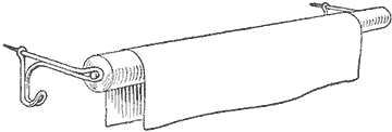
The Roller Brackets are Easily Adjusted in Any Location and Serve the Purpose Admirably
A Developing-Tray Rocker
The tank method of photographic development is acknowledged as the best, yet there are many who, for various reasons, still use the old-style tray method. For those who use the tray, a splendid and simple method that combines the good qualities of both the tank and tray is the tray-rocking device shown in the illustration.

Developing-Tray Rocker to Keep the Liquid in Motion over the Plate Automatically
The rocker consists of a wood box, 13 in. long, 9 in. wide and 1-1/2 in. deep, made of 3/8-in. material, together with a similar box 1-1/2 in. deep, that fits over the other as a light-proof cover. Both are given a coat of black paint.
At the center on the under side of the tray part, a right angle made of strap iron is fastened with screws. On the part projecting down, a hole is drilled to receive a sleeve made of a brass tube which is soldered in place. An ordinary shelf bracket is procured, one end of which is filed and fitted with a strip of metal having both ends turned up slightly. Small-pointed pins are fastened in holes drilled near the turned-up part. The points of the pins serve as a knife-edge for the rocker. The extending end of the strap iron is fitted with a pendulum rod having a weight at the bottom.
The rocker is attached to the wall in a convenient place in the dark room. The tray with the developer and plate is placed in the box, which is light-tight, and the pendulum is started swinging.—Contributed by T. B. Lambert, Chicago.
An Adjustable Bookholder
A very satisfactory adjustable holder for books or letters can be constructed of ordinary materials. A board is used for the base, and two pieces, C, cut from the grooved edges of flooring boards, are fastened on top as shown. A permanent end, A, is fastened to one end of the base. A good-size holder is 19 in. long, 6 in. wide, made of material 3/4 in. thick.
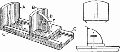
The Holder may be Used for Books or Letters and Papers as a File
The movable slide B has two pieces attached to its under side, which are cut from the tongued edges of flooring boards. The piece D answers the double purpose of a handle and brace. A lock, E, is made of a bolt, having a long thread and a square head. A hole is bored from the under side through the brace, and a portion of the wood is cut out to admit the nut. A square place is cut out to admit the square bolt head in the bottom pieces. To lock the slide, simply screw the nut upward so that it will push the bolt head against the base.—Contributed by James M. Kane, Doylestown, Pa.
An Old-Oak Stain
To make old oak of ash, elm, box alder, chestnut, maple, yew, and sycamore wood use a solution of copper acetate, or iron acetate. Either of these can be made by allowing a strong acid to come in contact with copper or iron. Acetic acid, or vinegar, will do for the acid. The chemical can be obtained from a local druggist if it is not desired to make the stain. By varying the strength of the solution, several shades may be obtained. A weak solution of iron acetate gives various brown hues. As the strength of the salt increases by concentration, the shades of brown darken.
Tablespoon End Used as Lemon Squeezer
In an emergency, the ordinary tablespoon can be used as a lemon squeezer by turning the lemon around the end of the spoon. This produces the same result as obtained with the regular squeezers, which act on the principle of extracting the juice by turning and crushing the lemon over a rough projection which approximately matches the shape of a half lemon.—Contributed by L. E. Turner, New York, N. Y.
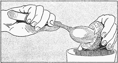
The Shape of the Spoon Bowl Produces the Same Effect as the Lemon Squeezer
A Back Stop for a Workbench
In planing small pieces on a bench, they usually have a tendency to tip up or slide around. This difficulty can be easily overcome by providing the bench with an extra back stop. For this purpose a discarded plane iron will do very well. Its edge should be notched so that it will easily enter the wood. The edges of its central slot should be beveled off, if an ordinary wood screw is used to fasten it to the bench. A series of holes, several inches apart and in line with the regular back stop, should be bored in the bench so the screw and iron can be readily changed, to fit varying lengths.—Contributed by C. S. Rice, Washington, D. C.
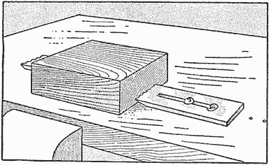
A Plane Bit Fastened to the Top of a Bench to Hold Blocks While Planing Them
Croquet Mallets Protected by Metal Rings
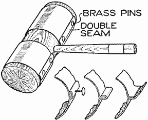
Due to the severe service they are subjected to, croquet mallets very frequently split off at the ends, which spoils them for further use in accurate driving. To prevent this, metal bands may be placed around the ends of the mallets. Thin sheet iron, or tin, can be used for this purpose. One end is bent up at right angles, the opposite end is provided with a loop to fit over the upright portion of the first end, and then the loop is closed up and hammered down to draw the metal tightly around the mallet. The ring is secured in place with several tacks, or short nails, driven through the seam.—Contributed by H. E. Stratmeyer, Rockville, Md.
Distance Marker for Printing Photographs
A convenient homemade printing device, or distance marker, for printing photographs by artificial light consists of a smooth board on which twelve 1-in. marks are drawn, as shown. A wall-base electric socket is attached on the first line and the others are numbered up to 12. A trial test of a negative marks the distance and time of exposure which should be recorded on the negative. Such a device makes uniform prints possible and provides a means of recording time on negative-storage envelopes.—Contributed by Harold Davis, Altoona, Pa.
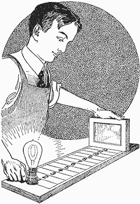
The Same Distance with the Same Exposure will Always Produce Uniform Prints
Mantel Picture Frames Made in Plaster
Procure a small oval or rectangular frame of a suitable size and use it as a pattern in making a mold. If it is not necessary to select an expensive frame, one that is straight without any floral designs is the best to use. Ordinary molding made into a frame will do as well, or a pattern, whittled out of wood in oval shape, will produce good results.
Make a flask out of any small box, and fill it with clay instead of molding sand. Make an impression of the frame in the clay, and the mold is ready for the plaster.
Procure four 8-oz. bottles, fill them with water, and tint the water in three of them red, green, and blue, with dyes. When purchasing the plaster of paris—2 lb. will do—also get some brass filings from a machine shop, and mix it with the plaster while in a dry state; then divide the lot into four parts of 1/2 lb. each, or equal parts.
Use the tinted water to mix the plaster and pour it into the mold. This will give the combinations red, green, blue, and white.
Picture frames made in this manner will stand enough polishing to keep the brass filings on the surface bright and shining, which gives a pretty effect.—Contributed by J. B. Murphy, Plainfield, N. J.
A Five-Pointed Star
There are many ways of making a five-pointed star, but the one illustrated is new and easy to apply. A long strip of paper, which should be transparent, is tied into a knot. When the ends A and B are drawn tightly, the paper strip takes the position shown in C. The end A is folded forward, or in front of the knot; then the whole is turned over and it will take the position shown in D. Hold the paper to a good light and a perfect five-pointed star will be seen.—Contributed by J. J. Kolar, Maywood, Ill.
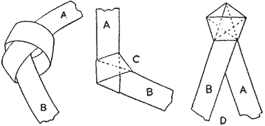
Holding the Knot to the Light a Star will be Seen, Shown by the Dotted Lines
Fastening Portière Pole in a Doorway
A pole can be fastened between two supports, posts, or in a door casing neatly and without fixtures in the following manner: The pole is cut 1/8 in. shorter than the space between the casings, and a 5/16 in. hole is drilled in each end, one to a depth of 1-1/2 in. and the other 3/8 in. deep, a coil spring being placed in the deepest hole.
Screws are turned into the center of the location for the pole in the door jambs, allowing one screw head to project 1/8 in., and the other at least 1/4 inch.
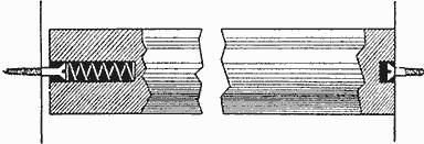
No Fixtures That will Show are Required with This Fastening of a Portière Pole
To place the pole in position, put the end with the spring in the hole on the screw head projecting 1/4 in. and push the pole against the jamb, allowing the other end to pass over the other projecting screw head until it slips into the hole by pressure from the spring. The spring will keep the pole in position.—Contributed by Ernest F. Dexter, Hartford, Conn.
Trick with Knives and Glasses
An interesting trick may be performed with three tumblers and three table knives. Place the tumblers in an equilateral triangle on a table so the knife ends, when the knives are laid between them, as shown in the plan sketch, are about 1 in. away from the tumblers. The trick is to arrange the knives so that they are supported by the tops of the three tumblers and nothing else. Most observers will say that it is impossible; some will try it and in most cases fail. It can be done, and the illustration shows how simply it may be accomplished.—Contributed by R. Neland, Minneapolis, Minn.
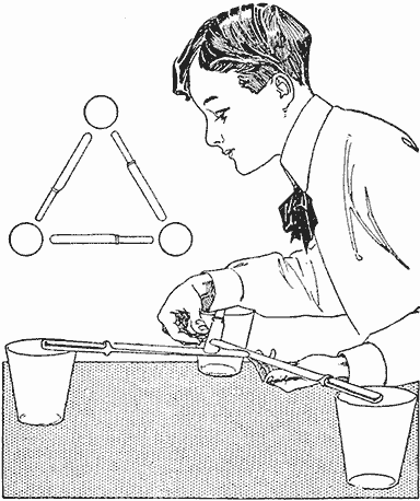
Knives Placed in Such a Manner as to be Supported by the Three Glasses
A Scraper Handle
In using the ordinary steel-plate scraper, much inconvenience and cramping of the hands is experienced unless some suitable handle is attached. If a piece of scrap wood is taken and cut to a convenient shape, with a groove tightly fitting the scraper steel, greater pressure can be exerted and more effective work produced, without cramping the hands or tiring out the operator as readily.—Contributed by A. P. Nevin, Hancock, Mich.
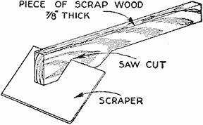
An Ordinary Piece of Board Shaped for a Handle and Notched for the Scraper Blade
Photographic Tray-Rocking Stand
Films develop better if the tray holding the solution is kept in motion or rocked. This is inconvenient and tiresome where a great many films are to be developed. The trouble may be overcome by the use of the rocking device shown in the sketch. It may be made of any light wood, the right size to suit the photographer's needs.
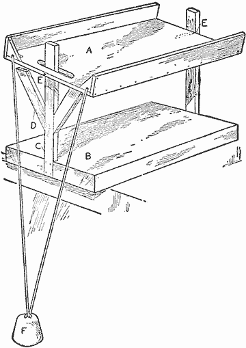
Tray Rocked Automatically by a Weight
The tray holder A is pivoted on the uprights C with pins EE. The uprights are fastened to a base, B. Two braces, D, one on each side of the upright C, limits the tip of the tray holder A. The weight F works as a pendulum, which automatically rocks the tray when set in motion.—Contributed by Abner B. Shaw, No. Dartmouth, Mass.
Kite-Line Traveler
The amusement of kite flying can be broadened by adding the kite-line traveler shown in the sketch. The frame of the traveler is made of poplar, spruce or soft pine, 1/4 in. square. The horizontal piece is 24 in. long and the piece to which the wings are fastened is 8 in. long. This piece is cut so it will have a slight slant. The brace is a mitered piece, 13 in. long. The frame is fastened together with small brads, giving it the appearance shown in Fig. 1.

Traveler Details (Fig. 1)
After the frame is finished, the traveler wheels are made and attached. They should be 1/4 in. thick, about 1-1/4 in. in diameter, and have a groove cut 3/16 in. into their faces. The pattern for cutting the bearings is shown in Fig. 4. These are bent at the places shown by the dotted lines and attached to the main frame stick as shown by BB in Fig. 3. The end view of the bearing is shown in Fig. 5. The metal is bent in as shown by AA, so that the wheel will rotate without much friction.
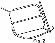
(Fig. 2)

(Fig. 3, Fig. 4, Fig. 5)
In Fig. 6 is shown the method of attaching the wings to the slanting frame part. The wings are made of light cardboard and each fastened with tacks to a wood arm, cut as shown. The large end of each arm is made to hinge in a piece of tin with brads AA.
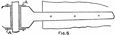
(Fig. 6)
Fasten a string to the ends of the arm pieces, as shown in Fig. 1, and attach a wire loop to the middle of the string, as shown in Fig. 3. The wire shown at L in Fig. 3 is bent and attached to the main frame so it will slide easily. The trip for dropping the wings, as shown in Fig. 2, is a small block of wood about 2 in. square and 1/4 in. thick with a 1/2-in. hole in the center. Slip the kite line through the hole before tying it to the kite. Place the trip about 100 ft. from the kite and wedge it to the string with a small piece of wood. The eyelets SS are necessary, as they make it impossible for the pulley to run off the string.
The traveler is first put on the kite string with the end having the loop L (Fig. 3) up, then, after letting out 100 ft. of string, the trip block is fastened in place and the kite tied to the end of the string. Hook the wire loop on the string attached to the ends of the wings in place in the wire catch of L, and it is ready for the flight. When the traveler reaches the trip, the loop L is pushed back, thus causing the end of the wire to slip out of wire loop and the wings to fall back as shown in Fig. 2, when the traveler descends ready to be set for another flight.—Contributed by Stanley C. Funk, Bellefontaine, Ohio.
A Mouse Trap
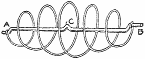
A simple mouse trap can be made of two lengths of steel wire. The spiral wire is 1/16 in. in diameter and the center wire is of larger size. The trap is set by pulling out the spring and catching the ends on the bends A and B. The bait is tied on at C. When the mouse puts his head through the coils and pulls the bait, the springs are released and his head is caught between the coils.
How to Make a Small Electric Furnace
The furnace consists of a large flower pot containing an ordinary clay crucible about 6 in. in height, the space between the two being packed with fireclay. Two 3/4-in. holes are bored through the sides of the crucible about half way between the top and the bottom. Holes corresponding to these holes are molded in the fireclay, which should extend several inches above the top of the flower pot. A smaller crucible is placed inside of the large one for use in melting such metals as copper, brass and aluminum. With metals that will melt at a low degree of heat, such as tin, lead or zinc, the large crucible can be used alone. Each crucible should be provided with a cover to confine the heat and keep out the air. The electrodes are ordinary arc-light carbons.
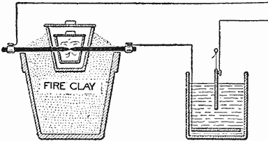
Electric Connections to Furnace
The furnace is run on an ordinary 110-volt lighting circuit and it is necessary to have a rheostat connected in series with it. A water rheostat as shown in the sketch will serve to regulate the current for this furnace. Small quantities of brass or aluminum can be melted in about 10 minutes in the furnace.—Contributed by Leonard Stebbins, Denver, Colo.
Repairing a Broken Knife Handle
A piece was broken from the pearl handle of my knife and I repaired it in the following manner: After cleaning both the edges of the pearl and the brass beneath, I run in enough solder to fill the place of the piece of pearl broken out. The solder was then filed, sandpapered and polished. The broken part cannot be felt and it appears to be only an end decoration.—Contributed by W. A. Humphrey, Columbus, O.
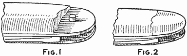
Repairing with Solder (Fig. 1, Fig. 2)
Picture-Frame and Triangle Clamp
A picture frame or triangle is quite difficult to hold together when fitting the corners. It is still more difficult to hold them together while the glue dries. The clamp illustrated will be found quite satisfactory in solving this problem, and at the same time is very simple to construct and easy to manipulate. The material list for making the clamps and corner blocks is as follows:
-
Picture frame clamp:
- 4 pieces, 1-1/4 by 1-1/4 by 15 in.
- 2 pieces, 1-1/4 by 1-1/4 by 5 in.
-
Triangle clamp:
- 3 pieces, 1-1/4 by 1-1/4 by 10 in.
- 1 piece, 1-1/4 by 1-1/4 by 4 in.
-
Corner blocks:
- 4 pieces, 7/8 by 3-1/2 by 3-1/2 in.
- 8 pieces, 7/8 by 1 by 2 in.
-
The pieces mentioned are of oak, S-4-S.
- 1 piece 3/8-in. maple for dowels
-
Hardware:
- 10 bolts, 1/4 by 2 in.
- 4 bolts, 1/4 by 3 in.
- 2 bolts, 3/8 by 6 in.
The picture-frame clamp consists of the four arms A, B, C and D, Fig. 1. A 1/4-in. hole is bored in one end of each piece, 1/2 in. from the end. A series of 3/8-in. holes, 1 in. apart, are bored along the center in each piece. The two short pieces, E and F, have two 1/4-in. holes bored in their centers, 1/2 in. from each end. These pieces are bolted to the four arms with 1/4-in. bolts as shown in the sketch. A 3/8-in. hole is bored in the middle of each piece E and F for one of the 6-in. bolts K.

The Corner Blocks on Both Picture Frame and Triangle Clamps are so Constructed That They Hold the Molding together While Fitting the Corners and also Hold Them Securely While the Glue is Hardening (Fig. 1)
The four corner blocks G, H, I and J, Fig. 1, have a 3/8-in. hole bored in the center of each and a dowel glued into it with the end projecting 1-1/4 in. on the under side and level with the surface on the upper side. Each of the corner blocks is fitted with two pieces like X, Fig. 2. Each of these pieces has one end round or a semicircle, and in its center a 1/4-in. hole is bored. The other end has a 3/8-in. hole bored 1/2 in. from the end.

(Fig. 2, Fig. 3)
After making the small pieces, take the four corner blocks G, H, I and J and draw a line on the upper side in the center, with the grain of the wood, and mark the angles as follows, so that one-half the angle will be on each side of the center line: On one end of the pieces G and H mark a 90-deg. angle, on the other end a 45-deg. angle, on the piece I mark a 90-deg. and 30-deg. angle and on J mark a 90-deg. and 60-deg. angle. Mark the number of degrees of each between the sides of the angle. Place two of the pieces marked X, Fig. 2, on each of the corner blocks, one piece on each side between the different angle lines, so their round ends will be toward the center and toward each other with a space of 1/4 in. between them. Clamp the pieces to the corner blocks and bore the 1/4-in. holes through them to secure perfect alinement. Put the bolts in and turn the pieces first to one angle and then the other, and while in the respective positions, bore the 3/8-in. holes 3/8 in. deep in the corner blocks. Glue a dowel in each 3/8-in. hole of the small pieces, allowing it to project 1/4 in. on the under side so it will fit in the 3/8-in. hole in the corner block. Be sure to countersink the holes for the heads of the bolts. All bolts should be fitted with wing nuts. All that is necessary to change from one angle to another is to loosen the nuts and swing the small pieces around so the dowel pins will drop into the other holes, then tighten the nuts.
The triangle clamp is made in the same manner as the picture-frame clamp, except that the arms L and M, Figs. 2 and 3, are half-lapped into the crosspiece P. The bolt O is 3/8 in. and the head is cut off. Drill a 1/8-in. hole in the bolt, 1/4 in. from the end, and bore a 3/8-in. hole in the end of the arm N. Insert the headless bolt O in this hole and drive a nail through the side of the arm N, so it will pass through the hole drilled in the bolt. This keys the bolt in the end of the arm N.
To clamp a picture frame, set the corner blocks G, H, I and J to the 90-deg. angles and adjust them on the arms A, B, C and D to accommodate the size frame to be made, as shown in Fig. 1. Tighten the thumbnut on the bolt K, and this will draw all four corners together with the same pressure. The corners can then be examined to see if they fit properly. If they do not, saw in the joints with a backsaw until they do fit.
The triangles are clamped in the same way. The corner blocks are set to take the proper angles. The ends of the bolts should be slightly burred over so that the thumbnuts cannot be turned off.—Contributed by Chas. A. Pettit, Baltimore, Md.
Exterior Sliding Fly Screen
The method shown for fitting fly screens on the outside of the upper and lower sash permits the screen to be raised and held at different heights. Screweyes are turned into the outer strips, as shown in Fig. 1. The sides of the screen frame are grooved, Fig. 2, to allow it to slide up and down on the screweyes.

The Heads of the Screweyes in the Window-Frame Stop Slide in a Groove Cut in the Screen Frame (Fig. 1, Fig. 2, Fig. 3)
The screen can be raised and two of the screweyes turned from the normal vertical position, A, Fig. 3, to a horizontal position, B, to hold the frame at that point. By the use of a greater number of screweyes more places can be provided to support the screen at different heights.—Contributed by James M. Kane, Doylestown, Pa.
Bushing a Stovepipe in a Chimney Hole
When a stovepipe is too small for the hole in the chimney, a bushing can be made of the kind of metal tobacco boxes that are curved to fit in a pocket. Remove the tops and bottoms of the boxes and shove them in around the pipe. If such tobacco boxes are not at hand, tin cans of any kind can be used by melting off the tops and bottoms and bending the remaining cylindrical shells into proper shape.—Contributed by Elmer McConaughy, Dayton, O.
A Screweye Driver
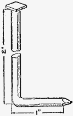
An ordinary wire nail, 3 in. long, bent as shown and with its head filed square, makes a good tool for turning in screweyes. The square head is readily held in the chuck on most braces. The screweye can be turned in with greater speed than by the ordinary method.—Contributed by Robert T. Johnston, Buffalo, New York.
Copying Stand for Photographic Enlarging and Reducing
A camera stand or table, which can be put to many uses, is easily made and, when made, will be of particular service, says Work, London, for enlarging, reducing, copying, and, with a slight modification, for making lantern slides by reduction.
Copying with a camera on a tripod is always a more or less complicated job, because of the ease with which a picture, being focused, may be thrown out of focus, and even out of the field of view, the camera not being attached to the same support as the picture. With the stand shown in the illustration, the picture is attached to the same support as the camera. This makes it possible to place the apparatus on a table, out in the open, or in any other suitable position, where the light may be best for the work. When used for enlarging with artificial light it will also be found convenient, as it may be placed in any position in a darkened room.

Camera Stand for Use in Copying and Enlarging, as Well as for Making Lantern Slides (Fig. 1)
The size of the stand will depend on the sizes of pictures to be made, but it is better to have it too large than too small, as a small camera can be used on a large stand while a small stand would be of only limited use. The general appearance of the stand is shown in Fig. 1. The material list is as follows:
| 2 | Sides, 1/2 in. by 9-1/2 in. by 5 ft., S-2-S. |
| 4 | Crosspieces, 1/2 in. by 3 in. by 1 ft. 7 in., S-2-S. |
| 4 | Guides, 3/4 in. by 1-1/4 in. by 2 ft. 6 in., S-2-S. |
| 2 | Bottom Pieces, 1 in. by 9 in. by 2 ft. 6 in., S-2-S. |
| 1 | Easel, 3/4 in. by 1 ft. 6 in. by 2 ft., S-2-S. |
| 2 | Cleats, 1/2 in. by 1-1/2 in. by 1 ft. 4 in., S-2-S. |
Straight-grained soft pine or poplar is the best material to use. The side pieces should be narrowed at one end or to a point about halfway of their length. The extent of this narrowing will depend somewhat on circumstances. The guide pieces are then attached with screws, the two upper pieces so that they have their upper edges flush with the edges of the side boards.
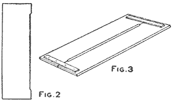
(Fig. 2, Fig. 3)
The bottom piece, on which the camera is to be set, is made of the two pieces, cut as shown in Fig. 2, and joined with cleats, as in Fig. 3. The space left after part of one side of each board has been cut away, should be sufficient to make a slot which, when the boards are joined together, will admit the screw to hold the camera in place. A rod is run through holes bored in the sides, just below the two pairs of guides, and fitted with a wing nut for clamping the sliding bottom when a focus and the size of the picture is found.
In copying, the camera is attached to the bottom board and the picture is tacked to the easel. The camera is then focused roughly by means of the rack and pinion, the final, fine focusing being done by moving the sliding bottom board. For enlarging, the lantern is placed on the sliding bottom and the bromide paper tacked to the easel.
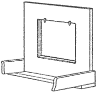
(Fig. 4)
For lantern-slide work, which is reducing, it is necessary to cut an aperture in the easel, after the manner shown in Fig. 4. The edges of the opening have a rabbet to receive first a ground glass and then the negative, both being held in place with turn buttons. It is not necessary to have two easels, as this opening can be fitted with a piece to make a level surface when the apparatus is used for copying or enlarging.
To Make Whitewash Stick to Surfaces Coated
In using whitewash much difficulty is experienced in making it stick to the substance covered. A good way to prevent the coating from cracking and peeling off is to add 2 oz. of pure sodium chloride to every 1 gal. of whitewash mixture. This is not expensive, but should be secured at a drug store because some salts of sodium are not pure and will darken the whitewash. The sodium chloride should be added after the whitewash solution is made up. When this mixture is used in buildings it will destroy all vermin which it touches.
A Mechanical Camera
The young person who likes to draw will find the device illustrated of great assistance for outlining a portrait or a bit of scenery which can be filled in to make the picture. The camera consists of a box without a cover, about 12 in. long, 6 in. wide and 4 in. deep. An oblong hole is cut in one end, a small hole bored in the other, and a piece cut out of the lower edge so that one eye can be placed close to the hole. The oblong hole, shown by the dotted lines, is covered with a fine perforated cardboard, the kind used for working in mottoes with yarn. Supports are nailed in the corners of the box, their length being calculated to allow the operator to sit or stand, as desired.
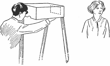
Outlining a Portrait on the Perforated Paper Placed over the Oblong Hole in the Camera
The camera is used in the manner illustrated. If a portrait is to be drawn, then the one sitting for it must be quiet until the outlines are completed. The operator, looking through the hole, traces the lines on the cardboard between the perforations. When the outlines are drawn in this manner, the cardboard is removed and placed on the paper or cardboard used for the picture. The outline is then transferred by marking with a sharp-pointed pencil through the perforations on the outlines as drawn. After separating the two pieces, the markings can be connected with a continuous line and an exact outline will be obtained which can be filled in as desired. The outline picture is a sample of work done with the camera.—Contributed by Florence Thomas, Gordon, Ont.
Gauge Attachment for a Pocket Rule
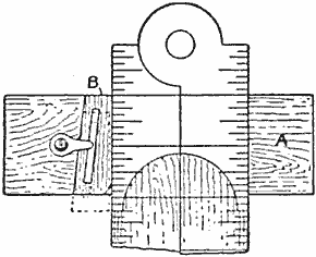
The base of the gauge A is cut from a block of hard wood, about 2-1/2 in. long, 1 in. wide and 3/8 in. thick. A notch is cut in one side to admit the rule and the wedge B, which has a slot that slides on a pin in the base. A small metal clip keeps the wedge in place. The gauge can be readily set on the rule at any mark.
Plate Hangers
In hanging old china plates for decorative purposes use three large white dress hooks, placed at equal distances apart on the edge of the plate. The hanging wire or cord is run through them from the back side and drawn up tightly. These hooks are much better than the ordinary plate hanger, as they are small and will not show much on the plate.
An Electrically Operated Camera Shutter

The Electromagnet Trips a Spring Plunger That Forces a Piston on the Camera Air Bulb
It is often quite desirable to operate the shutter of a camera from a distance, especially in photographing birds and animals. The device shown in the accompanying sketch serves the above purpose very nicely, and its construction and operation are exceedingly simple. In brief, the operation is as follows: The switch A is mounted on the limb of a tree, in such a manner that it is not conspicuous, and connected in series with a magnet, B, and a battery by means of a piece of flexible conductor, such as lamp cord. The magnet B is energized when the switch is closed and attracts the iron armature C, which is mounted on an arm, pivoted at D. The lower end of this arm is in the form of a latch, which supports the rod E when it is raised to its upper position. The rod E when it is raised compresses the coiled spring F, which is held between the gauge G and the washer H mounted on the rod. A small coil spring holds the armature C away from the core of the magnet B. The lower end of the rod E is in the form of a piston operating in a wooden cylinder J. The rubber bulb at the end of the tube leading to the camera shutter is located in the lower end of the cylinder J. When the rod E is released by the latch K, it moves downward in the cylinder J, due to the action of the spring F, and compresses the bulb L, causing the shutter of the camera to be operated. A small handle, M, may be mounted on the rod to be used in raising it to the upper position. The component parts of this device may be mounted on a small wooden base by means of brass straps, and the terminals of the electric circuit connected to the binding posts N and O, as shown. The switch A may be dispensed with and a push button used in its place, as the operator may station himself several hundred feet away. It may be necessary to use a battery of more than one cell in such cases.
Electroplating without a Tank
Electroplating without a plating tank is made possible with the following easily homemade apparatus described in a German scientific magazine. It consists of a rubber ball, A, fitted at one end with a glass tube, B, which carries at the opposite end a small sponge. A rod, D, passes through the rubber ball, which is tightly corked at both ends, into the glass tube B and carries at that end the anode E. A small glass tube, F, also connects the rubber ball with the larger tube B. The connections from the battery to the cathode, G, the object to be plated, and to the projecting end of the anode-carrying rod, D, are made as shown. The rubber ball is filled with the electrolyte, and is squeezed so as to force the fluid through the small tube F, into the larger tube, B, filling it and soaking the sponge C. The current is then turned on, and by moving the wet sponge over the cathode G, the latter will be plated. Not only is this an interesting accessory for the amateur's laboratory, but it can be used in the industry where only parts of some object are to be plated, and where it is desired to remedy bad spots without putting the articles back into the bath.
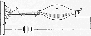
A Hand Tool for Applying a Plate Electrically to the Surface of Metal
A Milk-Bottle Tray
Bottled milk is difficult to deliver without knocking the bottles together when carrying them or while in a wagon. There are several kinds of wire baskets for carrying the bottles, but they all have the disadvantage of allowing the bottles to strike one another. A carrier not having this fault can be made very cheaply as follows: Procure a board 1 in. thick, 8 in. wide and 2 ft. long, plane and make it smooth, and use ordinary tin fruit or vegetable cans for the bottle holders. Cut each can off 2-1/2 in. from the bottom and smooth off the jagged edges with a file. Nail these in two rows on the board, starting 1 in. from each end. Attach a segment of a barrel hoop for a handle. The carrier can be painted as desired.—Contributed by G. H. Clemmons, Storm Lake, Iowa.
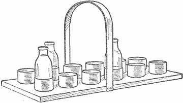
Parts of Tin Cans Fastened to a Board for Holding Milk Bottles