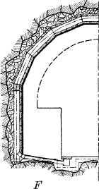
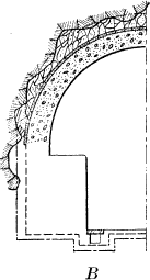
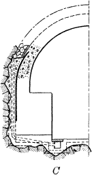
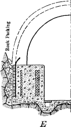
By F. Lavis, M. Am. Soc. C. E.
Location.—That section of the
Pennsylvania Railroad’s New York Tunnels lying west of the Hudson River
is designated Section “K,” and the tunnels are generally spoken of as
the Bergen Hill Tunnels. Bergen Hill is a trap dike (diabase) forming
the lower extension of the Hudson River Palisades.
There are two parallel single-track tunnels, cross-sections of which
are shown on Plate VIII of the paper by Charles M. Jacobs, M. Am.
Soc. C. E. The center line is a tangent, and nearly on the line of
32d Street, New York City, produced, its course being N. 50° 30' W. The
elevation of the top of the rail at the Weehawken Shaft (a view of
which is shown by Fig. 2, Plate XXII),
on the west bank of the Hudson River, is about 64 ft. below mean high
water; and at the Western Portal, or Hackensack end, the rail is about
17 ft. above; the grade throughout is 1.3%, ascending from east to west.
The length of each tunnel between the portals is 5,920 ft.
A general plan and profile of these tunnels is shown on Plate I of
the paper by Charles W. Raymond, M. Am. Soc. C. E. At
Central Avenue a shaft 212 ft. deep was sunk. It is 3,620 ft. from the
Weehawken Shaft.
Skip to text
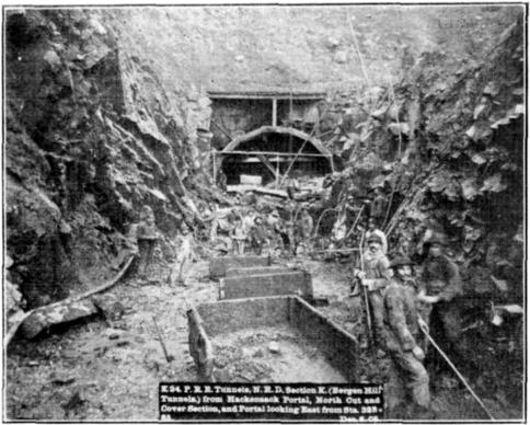
Fig. 1.
K 94. P.R.R. Tunnels, N. R. D. Section K. (Bergen Hill Tunnels.) from
Hackensack Poral, North Cut and Cover Section, and Portal looking East
from Sta. 323. Dec. 8, 05.
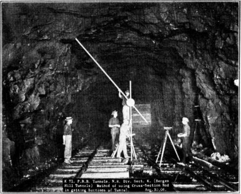
Fig. 2.
K 71. P.R.R. Tunnels, N.R. Div. Sect. K. (Bergen Hill Tunnels) Method of
using Cross-Section Rod in getting Sections of Tunnel. Aug.
30, 06.
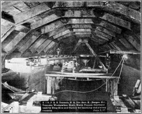
Fig. 3.
K 115. P.R.R. Tunnels, N. R. Div. Sect. K. (Bergen Hill Tunnels)
Weehawken Shaft, North Tunnel Conveyor used by King Rice and Garney for
handling and placing concrete. June 3, 07.
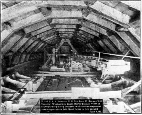
Fig. 4.
K 116. P.R.R. Tunnels, N. R. Div. Sect. K. (Bergen Hill Tunnels)
Weehawken Shaft, North Tunnel. View of conveyor for placing concrete,
with bucket suspended over hopper above belt. Steel forms in fore
ground. June 4, 07.
History.—The contract for this work
was let on March 6th, 1905, to the John Shields Construction Company; it
was abandoned by the Receiver for that company on January 20th, 1906,
and on March 20th, of that year, was re-let to William Bradley, who
completed the work by December 31st, 1908.
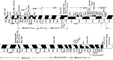
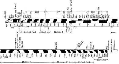
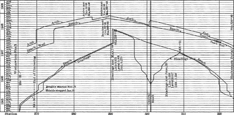
The progress of excavation and lining in the North Tunnel is shown
graphically on the progress diagram, Fig. 9,
that of the South Tunnel being practically the same.
Geology.—Starting west from the
Weehawken Shaft, the tunnels pass through a wide fault for a distance of
nearly 400 ft., this fault being a continuation of that which forms the
valley between the detached mass of trap and sandstone known as King’s
Bluff, which lies north of the tunnels, and the main trap ridge of
Bergen Hill.
The broken ground of the fault, which consists of decomposed
sandstone, shale, feldspar, calcite, etc., interspersed with masses of
harder sandstone and baked shale, gradually merges into a compact
granular sandstone, which, at a distance of 460 ft. from the shaft, was
self-supporting, and did not require timbering, which, of course, had
been necessary up to this point.
A full face of sandstone continued to Station 274 + 60, 940 ft. from
the shaft, where the main overlying body of trap appeared in the
heading. The full face of the tunnel was wholly in trap at about Station
275 + 30, and continued in this through to the Western Portal, where the
top of the trap was slightly below the roof of the tunnel, with hardpan
above. The contact between the sandstone and the overlying trap was very
clearly defined, the angle of dip being approximately 17° 40' toward the
northwest.
The sandstone and trap are of the Triassic Period, and the trap of
this vicinity is more particularly classified as diabase.
The character of the trap rock varied considerably. At the contact,
at Station 275, and for a distance of approximately 200 ft. west,
corresponding to a thickness of about 60 ft. measured at right
angles to the line of the contact, a very hard, fine-grained trap,
almost black in color, was found, having a specific gravity of 2.98, and
weighing 186 lb. per cu. ft. The hardness of this rock is attested by
the fact that the average time required to drill a 10-ft. hole in the
heading, with
a No. 34 slugger drill, with air at 90 lb. pressure, was almost
10 hours. The specific gravity of this rock is not as high as that
of some other specimens of trap tested, which were much more easily
drilled. This rock was very blocky, causing the drills to bind and stick
badly, and, when being shoveled back from the heading, as it fell it
sounded very much as though it were broken glass.
The remainder of the trap varied from this, through several changes
of texture and color, due to different amounts of quartz and feldspar,
to a very coarse-grained rock, closely resembling granite of a light
color, though quite hard. The speed of drilling the normal trap in the
heading was approximately 20 to 25 min. per ft., as compared with the
60 min. per ft. noted above, the larger amounts of quartz and
feldspar accounting for the greater brittleness and consequently the
easier drilling qualities of the rock. The normal trap in these tunnels
has a specific gravity varying from 2.85 to 3.04, and weighs from 179 to
190 lb. per cu. ft.
The temperature of the tunnels, at points 1,000 ft. from the portals
at both ends, remained nearly stationary, and approximately between 50°
in winter and 60° in summer, up to the time the headings were holed
through, being practically unaffected by daily changes in the
temperature outside. At the western end, after the connection with the
Central Shaft headings was made, there was almost always a current of
air from the portal to the shaft, and ascending through the latter. This
tended to make the temperature in this part of the tunnel correspond
more nearly with the outside temperature; in fact, the variation was
seldom more than 5° Fahr.
Timbering.—These tunnels have
been excavated entirely by the center top heading method, almost
invariably used in the United States. Timbering, where required, was of
the usual segmental form with outside lagging, as shown in several of
the photographs. In a few places it was necessary to hold the ground as
the work progressed, and, in such cases, crown bars were used in the
headings.
There was some little trouble at the Western Portal, where the top of
the rock was very near the roof of the tunnel, as shown by Fig. 1,
Plate XXI. A side heading was driven at
the level of the springing line until a point was reached where the roof
was self-supporting, and the timbering was brought out to the face of
the portal from that point.
Skip to text
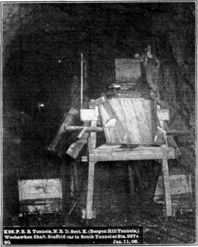
Fig. 1.
K 26. P.R.R. Tunnels, N. R. D. Sect. K. (Bergen Hill Tunnels,) Weehawken
Shaft. Scaffold car in South Tunnel at Sta. 267+60. Jan.
11, 06.
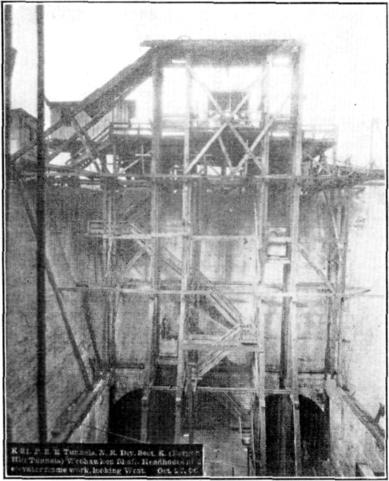
Fig. 2.
K 31. P.R.R. Tunnels, N. R. Div. Sect. K. (Bergen Hill Tunnels)
Weehawken Shaft. Headhouse
at ? elevator frame work, looking West. Oct. 17, 06.
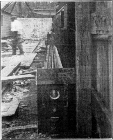
Fig. 3.—Round Holes in Concrete Forms.
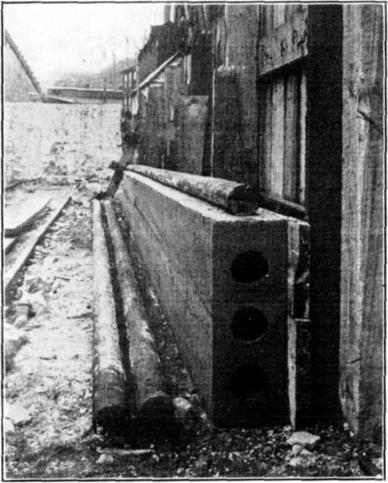
Fig. 4.—Round Holes in Concrete Forms
Completed.
Drilling.—Where no timbering was required, several
different methods were used in drilling and excavating the solid rock,
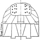
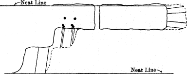
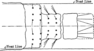
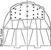
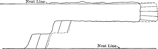
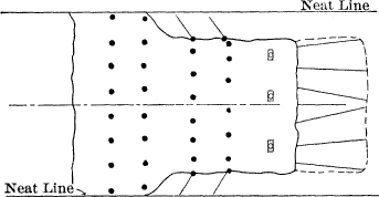
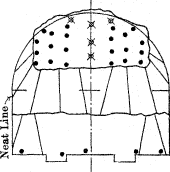
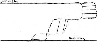
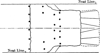
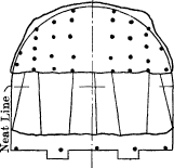
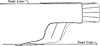
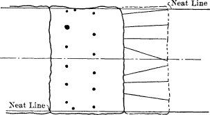
though in all cases a center top heading was driven. The four diagrams,
Figs. 1, 2, 3, and 4, give typical examples of these methods and
show, in the order of their numbers, the general tendency of the
development from a small heading kept some distance ahead of the bench,
to a large heading with the bench kept close to it. The notes on each
diagram give the general details of the quantity of drilling and powder
used, methods of blasting, etc., and on the progress profile, Fig. 6, is indicated those portions of the tunnels in
which each method was used.
All the drills used throughout the work by Mr. Bradley were Rand No.
34 sluggers, with 3⅝-in. cylinders, and the steel was that known as the
“Black Diamond Brand,” 1⅜-in., octagon. It was used in 2, 4, 6, 8, 10,
and 12-ft. lengths; toward the end of the work it was proposed to use
14-ft. lengths, but owing to some delay in delivery this length was
never obtained. The starters, 18 to 24 in. long, were sharpened to 2¾ to
3-in. gauge, which was generally held up to depths of 6 ft.; then
the gauge gradually decreased until it was 1¾ to 2¼ in. at the bottom of
a 12-ft. hole. Frequently, as many as three or four starters were used
in starting a hole, and generally two sharpenings were required for each
2 ft. drilled, after the first 6 ft. It is estimated that
about ¼ in. of steel was used for each sharpening, and that there
was an average of one sharpening for every foot drilled.
The total quantity of steel used up, lost, or scrapped on the whole
work was almost exactly 1 ft. for each 10 cu. yd. excavated, equal
to 1¼ in. of steel per yard, distributed approximately as
follows:
| Sharpening |
|
¾ to ⅞ in. |
| Other losses |
|
½ to ⅜ ” |
| Total |
|
1¼ in. per cu. yd. |
An “Ajax” drill sharpener was used, and proved very satisfactory.
Rubber and cotton hose, covered with woven marlin, was used for the
bench (3 in. inside diameter, in 50-ft. lengths), for drills
(1 in. in diameter, in 25-ft. lengths), and for steam shovels
(2½ in. in diameter, in 50-ft. lengths). Hose coverings of wound
marlin, and of woven marlin with spiral steel wire covering were tried,
but were not satisfactory, owing to the unwinding of the marlin and the
bending of the steel covering.
Skip to Text
Figures 1-4 were identically laid out; Figure 1 is representative.
In the enlarged views, the plans have been rotated to match the
longitudinal section. In the tables, variation between “to” and “-”,
and formatting of table entries, is as in the original.
Adv.: Advance
Cu. Yd.: Cubic Yards
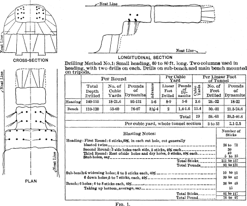
The average quantity of powder used on the whole work was about 2.9 lb.
per cu. yd. The tables on the diagrams, Figs. 1, 2, 3, and 4, show
that the quantity actually used in making the advance at the main
working faces was about 2.5 lb. The difference is accounted for by the
larger percentage of powder used for trimming the sides, breaking out
the cross-passages between the tunnels, and the excavation of the
ditches, the latter operation not being done until the concrete lining
was about to be put in.
There was some time, too, during the earlier stages of the work, when
it is believed that an excessive quantity of powder was used; for one or
two months it ran up to 4 lb. per cu. yd.
Fig. 5.
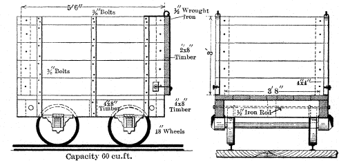
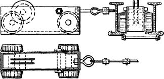
MUCK CAR USED AT WEEHAWKEN SHAFT
The dynamite used was “Forcite.” At first, both 40% and 60% were
used, the 60% generally only for blasting the cut in the headings;
during the latter part of the work, however, the 60% was used
exclusively.
The rock as a rule broke very well, and only a comparatively small
quantity could not be handled by the shovels without being broken up
further by block-holing. In the sandstone the quantity of powder per
cubic yard was much more than for any of the trap.
In drilling the Central Shaft, a 6-hole cut was made approximately on
the center line, east and west, the enlargement requiring about 18 more
holes, which were generally about 6 ft. deep, the average advance
being about 4 ft. per day of 24 hours.
The drills were run by steam until a depth of about 150 ft. had been
reached, air from the plant at Hackensack being available after
that time. Four drills were used most of the time, and six later when
air was available. This work was done entirely by the John Shields
Construction Company, and a depth of 205 ft. was sunk in 6 months
(from July 15th, 1905, to January 15th, 1906). A derrick was used
for hoisting and lowering men and tools during the sinking, elevators
being put in later.
Skip to text
larger view
Drilling Data.—During the progress
of the work, both general and detailed observations were made of the
drilling, the results of which are shown in the tables. Table 1 has
been compiled from the records as platted daily on the chart from the
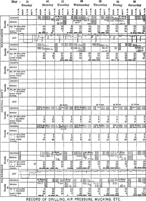
inspectors’ reports, as shown by Plate XXIII, and described on page 113. Table 2 contains some data relating to the
drilling in the headings.
The general results of these observations show that the average time
the drills were “actually working” was 5.2 hours per shift, and
that they were actually “hitting the rock” about half of this time, or
about 2.5 hours per shift. The average depth drilled per hour,
during the time the drills were “actually working,” was
2.66 ft.
The “actual working time,” as noted above, covers the period from the
time the drills were first set up in the heading after blasting until
they were taken down for the next blast; it does not include the time
occupied in setting up or taking down, which would probably average
30 min. more per shift. It is believed that this figure will also
apply very closely to drills working on the bench, though no actual
observations were taken to determine this, on account of the
irregularity with which they were worked.
The actual working time of the drills in the 736 shifts (7,360 hours)
covered by Table 1, was 3,826 hours, or 5.2 hours per shift. The
average depth drilled per yard, as shown in the last column of
Table 1, agrees fairly well with the figures on the diagrams,
Figs. 1, 2, 3, and 4.
Table 2 has been compiled from detailed timed observations of
individual drilling of down holes in the bench, for periods of 7 or 8
hours each, in January, 1907. The work at that time was in fairly normal
condition at all points.
The figures in the third column of Table 2 include the time required
for moving from one hole to another, when this occurred during the
observation, the time required for changing bits, oiling drills, etc.,
and all delays of all kinds. A close record of the delays was
kept, and it was considered that, of the 93 hours, 48 min., in
Table 2, the unnecessary delays amounted to 5 hours, 7 min.,
or about 5½ per cent.
|
Shifts: Number of shifts covered by observations.
Hours: Average number of hours worked per shift.
D/Hr: Average depth drilled per hour per drill
D/Yd: Average depth drilled per yard.
|
|
Hack.: Hackensack
Whk.: Weehawken
CS: Central Shaft
|
| Method. |
Date. |
Shifts |
Place. |
Hours |
D/Hr |
D/Yd |
No. 1—
4-drill |
Aug. ’06 |
44 |
Hack., |
N. |
5.69 |
2.78 |
10.1 |
| Sept. ’06 |
38 |
” |
N. |
5.80 |
3.77 |
11.1 |
| Aug. ’06 |
43 |
” |
S. |
5.60 |
2.89 |
9.1 |
| Sept. ’06 |
36 |
” |
S. |
6.18 |
2.65 |
8.7 |
| Jan. ’07 |
16 |
CS E. |
N. |
5.99 |
2.99 |
8.2 |
| Jan. ’07 |
20 |
” |
S. |
6.05 |
2.9 |
7.1 |
| Apr. ’07 |
48 |
CS W. |
N. |
4.92 |
3.3 |
6.7 |
| Apr. ’07 |
48 |
” |
S. |
5.00 |
3.2 |
7.7 |
Nos. 2 and 3—
5-drill |
Dec. ’06 |
54 |
Whk., |
N. |
4.95 |
2.16 |
4.52 |
| Dec. ’06 |
54 |
” |
S. |
5.23 |
2.14 |
4.54 |
| Dec. ’06 |
52 |
Hack., |
N. |
5.03 |
2.2 |
5.77 |
| Dec. ’06 |
54 |
” |
S. |
5.90 |
1.82 |
5.67 |
No. 4—
7-drill |
June ’07 |
56 |
Whk., |
N. |
4.77 |
2.55 |
4.23 |
| June ’07 |
58 |
” |
S. |
4.82 |
2.26 |
3.88 |
8-drill
|
May ’07 |
60 |
Hack., |
N. |
4.67 |
2.44 |
5.00 |
| May ’07 |
60 |
” |
S. |
4.54 |
2.57 |
4.80 |
| Date. |
Place. |
Total working time. |
Number of
feet drilled. |
|
|
Hours. |
Minutes. |
|
| Jan. 14th, 1907 |
Weehawken |
N. |
8 |
0 |
15 |
| ” 15th, 1907 |
” |
N. |
7 |
32 |
12 |
|
” |
N. |
7 |
22 |
14 |
| ” 12th, 1907 |
” |
S. |
8 |
0 |
20 |
|
” |
S. |
8 |
0 |
11 |
|
” |
S. |
8 |
0 |
10 |
| ” 11th, 1907 |
Hackensack |
N. |
8 |
0 |
13 |
| ” 17th, 1907 |
” |
N. |
7 |
10 |
10 |
|
” |
N. |
7 |
5 |
11 |
|
” |
N. |
7 |
10 |
10 |
| ” 16th, 1907 |
” |
S. |
4 |
20 |
10 |
|
” |
S. |
6 |
9 |
10 |
|
” |
S. |
7 |
... |
8 |
| Totals. |
|
93 |
48 |
154 |
Average: 36.6 min. per ft. drilled, or 1.64 ft.
drilled per hour.
As a check on the average figures obtained from various sources, the
following estimate of the cost of drilling per cubic yard was made up
from these average figures, for comparison with the actual average cost
on the whole work. The cost records show this to be about $2.25 per yd.,
exclusive of power for running the drills, almost exactly what
the following estimates give for theoretical average conditions,
although no effort was made to have this latter compare so closely.
Estimated Cost per Drill per Day.
Drill Runner |
1 |
at $3.50 per day, |
$3.50 |
Helper |
1 |
” 2.00 ” ” |
2.00 |
Nipper |
1/5 |
” 1.75 ” ” |
0.35 |
Heading foreman |
1/12 |
” 5.00 ” ” |
0.42 |
Walking boss |
1/50 |
” 7.50 ” ” |
0.15 |
Blacksmith |
1/12 |
” 4.00 ” ” |
0.34 |
Blacksmith helper |
1/12 |
” 2.00 ” ” |
0.16 |
Machinist |
1/12 |
” 3.00 ” ” |
0.25 |
Machinist helper |
1/24 |
” 1.75 ” ” |
0.07 |
Pipe fitter and helper |
1/50 |
” 5.00 ” ” |
0.10 |
Oil, waste, blacksmith coal, etc. |
| |
0.24 |
Drill steel, 6 in. per shift |
| |
0.20 |
| | |
$7.78 |
Average number of feet drilled per cubic yard |
3 to 3.5 |
Number of feet drilled per drill, per shift |
10.5 to 12 |
Number of yards per drill, per shift |
3.5± |
Cost of drilling, per yard, $7.78/3.5 |
$2.22± |
In all the foregoing tables and computations, the quantities used
have been those paid for. The quantity taken out, however, has been 10%
more than that paid for, and 28% more than the contractor was actually
required to take out.
The specifications required that the excavation should be taken
entirely outside of the neat line, as shown on Plate VIII of the paper
by Mr. Jacobs, but not necessarily beyond this line, but that the
contractor would be paid for rock out to the standard section line,
which is 1 ft. larger on the sides and top and 6 in.
deeper in the bottom than the neat line.
A great deal of the extra quantity was due to rock falling from the
core-wall side whenever one working face was behind the other. Blasting
at the face behind generally loosened more or less rock on the core-wall
side of the tunnel which was ahead, in one or two instances breaking
entirely through, as shown in Fig. 2, Plate
XXVI, the hole in the core-wall in this case being utilized by
building a storage chamber in it.
Table 3 gives some of the statistics of drilling in the Simplon Tunnel,
as compared with the drilling on this work, the figures for the Simplon
being taken from papers read before the Institution of Civil Engineers
of Great Britain.
|
Bergen Hill. |
Simplon. |
Drills set up in heading, percentage of total
elapsed time |
50% |
60% |
Actually drilling the rock, percentage of total
elapsed time |
25% |
50% |
Average advance per round (attack) |
8.5 ft. |
3.8 ft. |
Average time for each attack |
36 hours. |
5 hours. |
Average advance per day of 24 hours |
5 ft. |
18 ft.† |
Depth of holes |
10 ft. |
4.6 ft. |
Diameter of holes |
2¾ in. |
2¾ in. |
Linear feet drilled per hour, per drill |
2.7 |
7.0 |
Linear feet drilled per cubic yard |
5.0 |
6.0 |
Pounds of dynamite per cubic yard |
3.4 to 5.7 |
8½ |
Average depth drilled with one sharpening |
12 in. |
6½ in. |
Total number of men per day of 24 hours* |
450 |
3,300
|
The figures in Table 3 are for “heading only” in both cases, except
for the last item (number of men), the heading in the Simplon Tunnels
being about 60 sq. ft., as compared with the heading of Method
No 4 (which has been used for comparison), of 210 sq. ft.
Mucking and Disposal.—The
conditions affecting the disposal of the muck, after blasting, were
quite different at the two ends, the grade descending in the direction
of the loads at Weehawken and ascending at the Hackensack end. At the
Weehawken end the mouth of the tunnels was at the bottom of a shaft some
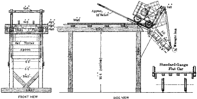
80 ft. deep, Fig. 2, Plate XXII, the
muck in the tunnel cars being hoisted by elevators to a platform at the
top from which it was dumped into standard-gauge cars supplied by the
Erie Railroad, as shown by Fig. 7; or later
hauled to the crusher or storage pile, some 500 ft. distant, on the
north side of Baldwin Avenue. At the western end, the cars were hauled
directly to the surface through the approach cut, and the material,
except that required for concrete and rock packing, was deposited in the
embankment across the Hackensack Meadows, a haul of from 1,000 to
3,000 ft. beyond the portal.
All disposal tracks were of 3-ft. gauge, the main running tracks
being generally laid with 60-lb. second-hand rails, although some of
lighter weight were used.
Except for about 1,000 ft. in each tunnel at the Weehawken end, where
the muck was loaded by hand, four steam shovels, operated by compressed
air, were used, one at each working face. One of these was a “Marion,
Model No. 20,” weighing 38 tons, the others were “Vulcan Little Giant,”
of about 30 tons each. All these shovels were on standard-gauge track,
and were moved back from 300 to 500 ft. from the working face during
blasting.
At Weehawken, previous to the time the shovels were installed, the
muck was shoveled by hand into the cars from the bottom of the bench,
and the heading muck was dumped into them from the movable platform
(Jumbo) shown by Fig. 1, Plate XXII.
There were three loading tracks at the face. The cars used at that time
were similar to that shown by Fig. 5, but
were about two-thirds the size and had no end door; stop-planks were
supposed to be placed in the ends but seldom were. The loads averaged
about ½ cu. yd. (measured in place). After the shovel was
installed the cars shown by Fig. 5 were used, and the loads
averaged nearly 1 cu. yd.
The empty cars were pushed up to the shovel by hand from the storage
track. When loaded, they were given a start with the bucket of the
shovel, and were then allowed to coast by gravity out to the storage
track near the shaft, where they were stopped by placing rolls of cement
bags or burlap on the rails. After the lining was started, the loaded
cars were stopped on the inside of the lining and only sent out over the
single track through this latter at stated intervals,
when several cars followed in close succession, with a long interval
which permitted the concrete to be brought in. The empty cars were
hauled back to the storage track near the working face by mules, one
mule usually hauling two cars at a time.
Up to the time the trap rock was reached, about 1,100 ft. from the
shaft, the excavated material was disposed of by loading it on flat
cars. All the trap, however, was stored to be used later for concrete
and ballast.
When the tunnels were in full working order, sixty muck cars of the
type shown by Fig. 5, were in use, about
evenly divided between the two tunnels. For some time the work was
greatly hampered by lack of cars, and even with the sixty finally
obtained, there were many times when extra cars could have been used to
advantage to keep the shovel working.
When mucking by hand, the mucking gangs consisted of from 15 to 20
men. The maximum output was 50 cu. yd., and averaged about 35
cu. yd. per shift; there was a great deal of trouble in keeping the
gangs full, as labor at that time was very scarce, and the tunnels were
quite wet. The maximum output of either of the shovels was 159
cu. yd. in one shift, and the best average in any month—which
was between July and December, 1907, during which time only the
enlargement and bench of the Central Shaft headings was being taken out
from the western end—was 60 cu. yd. per shift. As the shovels
were generally idle for one shift out of three, the quantity actually
handled averaged 90 cu. yd. per shift during the shifts the shovel
worked. All these quantities were “measured in place,” and, as
previously noted, would be about equal to twice as much measured loose
in the cars.
The shovels at both ends were usually worked with three crews for the
two tunnels; two day crews, one at each shovel, and a night crew which
was used in either tunnel as occasion required. The day crews generally
averaged from 45 to 60 hours overtime during the month, one of them
working during the early part of the evenings in the opposite tunnel to
the night crew. For a short time, when the ventilation at the western
end was very bad, four crews were worked, day and night crews in each
tunnel; but, as a general rule, the method of working three crews was
preferred by the men, and was less expensive for the contractor.
At the Hackensack end, 4-yd., Allison, one-way, dump cars were used,
being handled by “dinky” locomotives, of which there were three in use
up to October, 1907, and four after that. One 15-ton Porter engine, with
10 by 16-in. cylinders, was used outside the tunnels for handling the
trains (from 6 to 8 cars) on the dumps and to the crusher; the other
three, 12-ton Vulcans, 9 by 14-in., were used in the tunnels. About
30 dump cars were in use, and of these there were generally from
3 to 6 under repair.
Generally, 4 cars were hauled out together, although 5 and
occasionally 6 were handled. The work was generally arranged so that the
heavy mucking shift alternated in the two tunnels, the two engines being
worked there and a single engine in the other tunnel.
The tunnel engines left the cars on a track just outside the portal,
from which they were made up into trains of from 6 to 8 cars and taken
to the dump or crusher by the large “dinky.”
The muck from the Central Shaft headings was loaded by hand into cars
similar to that shown by Fig. 5, but smaller
and having no door at the forward end. A double elevator took the
cars to a platform about 20 ft. above the surface, where they were
dumped by revolving platforms, similar to those at Weehawken, into
storage bins or directly into wagons. The muck was all hauled away in
wagons; part of it was used to fill some vacant lots, and part was
hauled to the crusher at the Western Portal.
The method under which the best results were obtained was that in
which a full round was blasted every 36 hours, securing an advance of
practically 9 ft. of full section. During the first shift of the
three, as soon as the blasting had been completed and lights strung, the
shovel was moved forward, and cleaned up the floor to the main pile of
muck, the material from the blast being scattered from 150 to 300 ft.
back from the face; during this shift, also, the drillers mucked the
heading and set up their drills, the muckers helping to carry in the
columns and drills. During the second shift the main pile of muck was
disposed of, leaving not more than 2 or 3 hours’ work for the
shovel on the third shift. This left nearly the whole of the third shift
for drilling the lift holes.
Ventilation.—At Weehawken
considerable difficulty was caused by fog and smoke accumulating in the
tunnels after blasting. This was generally worse on days when the
barometric pressure was low outside,
and worse in the North than in the South Tunnel. A 6-ft. fan,
driven by an electric motor, was installed in the cross-passage at
Station 274, 900 ft. from the shaft, the headings at that time being
about 300 ft. in advance of this point, to force the air from the South
into the North Tunnel, drawing it in at the mouth of the South Tunnel
and discharging it at the mouth of the North Tunnel, thus insuring a
circulation in both tunnels, as shown in plan by Fig. 8.
This necessitated, of course, that the cross-passages between that in
which the fan was placed and the mouths of the tunnels should be blocked
tight. There was some difficulty in keeping this blocking tight, owing
to the force of the blasting blowing out the bulkheads. The fan,
however, did good service when it and the bulkheads were in good order.
The compressed air discharged from the drills kept the headings fairly
clear, as well as that part of the tunnel between the headings and the
fan. The fan was moved ahead to the next cross-passage at Station 277
when the work had progressed far enough, and was used there for some
time; it was found, however, that by the time the excavation had reached
Station 280, about 1,500 ft. from the shaft, there was practically no
further difficulty from fog and smoke. No satisfactory explanation was
found for this, as it would rather be expected that the ventilation and
trouble with smoke and fumes from blasting would be worse as the
distance increased between the mouth of the tunnel and the working face.
One explanation was offered: That the blasting of the softer sandstone
tended to create more and lighter dust than the heavier trap rock;
whether or not this was so, it is a fact that there was far less trouble
with fog and smoke after the sandstone was passed.
Fig. 8.

At Hackensack, the principal cause of trouble was the smoke from the
“dinky” locomotives. As the tunnels progressed, this gradually became
worse, until a connection was made with the Central Shaft headings.
A fan was installed in the cross-passage at Station
316 (700 ft. in from the portal), but was never worked properly.
Apparently, the men, at least the walking bosses and foremen, had little
faith in the fan as a means of ventilation; no real attempt was made to
keep it in order or operate it properly, and a great deal of time and
money was lost groping around in the smoke and fog, the density of which
increased, not only with the state of the atmosphere, but also with the
direction of the wind. On some days the tunnels easily cleared
themselves, and on others the smoke was so thick that a candle held at
arm’s length could not be seen. At this end, the South Tunnel was
generally worse than the North. After the headings were holed through
between the portal and the Central Shaft there was very little trouble,
there being usually a strong up-draft through the shaft. This was so
pronounced when the wind was blowing toward the portal, that the
moisture-laden air, as it ascended from the mouth of the shaft,
presented the appearance of a heavy rainstorm with the rain ascending
instead of descending. When the wind was blowing away from the portal,
that is, from the southeast, the effect of the shaft as a chimney was
neutralized, and, consequently, the smoke accumulated in the tunnels. To
overcome this, a large blower, with a fan 9 ft. in diameter,
and with blades 4 ft. wide and 2 ft. 3 in. long,
operated by a vertical 12-h.p. engine, was installed at the top of the
shaft, and this kept the tunnels reasonably clear of smoke at all times.
After the bench and enlargement had passed the bottom of the shaft, the
use of the fan was abandoned, as it was found that the tunnels cleared
themselves fairly well, probably owing to the larger cross-section
reaching all the way to the Shaft. What little fog and smoke there might
be did not cause enough trouble to warrant the cost of running the fan,
which, owing to its location, required the whole time of a mechanic in
attendance day and night.
Lighting.—During the earlier
stages of the work, gasoline lamps and Kitson lights were used. The
former, of the familiar banjo type, and a modification of this, with a
section of wrought-iron pipe for the reservoir, were very
unsatisfactory, and were out of repair and leaking a large proportion of
the time. The Kitson lights were given only a short trial, but were
found unsatisfactory, owing to the necessity of moving them frequently
and having to set them up in insecure positions. Electric lights were
installed by Mr. Bradley, on his assumption of the contract.
The number of lamps maintained in each of the tunnels for the excavation
was approximately as follows:
| At the main working face |
From 8 to 10 |
| On and around the shovel |
” 9 to 12 |
| Between the portal and the working face |
” 60 to 80 |
The cost of lighting for the whole work averaged about 15 cents per
cu. yd., which is quite large. This was mainly due to the fact that
current was bought from outside sources during a large part of the time
(one-third of the yardage). Part of this current cost 5 cents per
kw-hr., and there were fairly heavy charges for connecting the tunnel
wiring system with the source of supply. Current bought from the Public
Service Corporation cost from 10 to 12 cents per kw-hr. delivered at the
mouth of the tunnel.
Pumping.—The quantity of water
encountered during the excavation of the tunnels, measured somewhat
roughly, was approximately as follows:
| At Weehawken |
74 gal. per min. |
| At Central Shaft |
1 ” ” ” |
| At Hackensack |
18 ” ” ” |
The water at the Weehawken end had to be pumped from the bottom of
the shaft, a lift of about 90 ft., while at the Hackensack end it
had to be pumped back from the face up grade to the portal.
The cost of pumping was about $100 to $125 per month for labor for
the whole work, besides the cost of the plant (about $1,200) and the
power for running it.
The total time elapsed from the time of starting work at the
Weehawken end, in May, 1905, to the completion of the excavation, in
May, 1908, was almost exactly three years. Of this time about 40 days
were lost in February and March, 1906, when work was stopped by the
Receiver of the Shields Company, the total number of days actually
worked being about 940, giving an average progress of 6.26 ft. per
working day in each of the two tunnels, which, omitting the Central
Shaft headings, gives an average rate of progress for each working face,
of 3.13 ft. per day.
These 940 days include practically all the time elapsed, except Sundays
and such few holidays as were observed. For some of this time, work was
being carried on at only one or two points; the time, therefore,
represents practically the total possible working time during the period
covered.
Progress at Weehawken.—At
Weehawken the total number of days worked was 763, divided as
follows:
186 days in timbered section, about 426 ft., an average rate of
2.3 ft. per day in each tunnel;
176 days in hard sandstone, about 563 ft., an average rate of
3.2 ft. per day in each tunnel;
112 days in hard trap, about 267 ft., an average rate of 2.4 ft. per day
in each tunnel;
289 days in ordinary trap, about 1,316 ft., an average rate of 4.55 ft.
per day in each tunnel.
Progress at Central Shaft.—At
Central Shaft the average length driven per day in each of the four
headings is shown by Table 4.
| Location. |
Number of days worked. |
Total length of heading, in feet. |
Average length of heading driven per day worked, in
feet. |
| N.E. |
227 |
446 |
1.96 |
| S.E. |
168 |
346 |
2.06 |
| N.W. |
272 |
768 |
2.82 |
| S.W. |
234 |
698 |
2.98 |
Progress at Hackensack.—At
Hackensack the total number of days worked on the tunnels proper, all in
trap rock (omitting the cut and cover) was about 792, divided as shown
in Table 5.
| Location. |
Number of days worked. |
Advance. |
Average advnce per day. |
Station 323 to Central Shaft headings |
492 |
1,450 |
4.5 |
Bench and enlargement of Central Shaft
headings |
159 |
{1,150*
{ 906† |
7.2*
5.7† |
Central Shaft headings to Weehawken headings |
141 |
620 |
4.4 |
The best month’s work in each location was as follows, the actual
yardage excavated and paid for being reduced to equivalent linear feet
of full section. The tunnels were generally taken out to full section,
except for a small amount left in the bottom, which latter reduced the
equivalent linear feet of full section to about 95% of the actual
advance at the face.
Weehawken.—
| | |
Linear
feet. |
Feet
per
day. |
| Full timbered section, |
North Tunnel |
Nov., 1905, |
87 == 3.0 |
| Sandstone |
” ” |
May, 1906, |
109 == 3.9 |
| Trap (normal) |
South ” |
July, 1907, |
144 == 5.3 |
Hackensack (All trap).—
| | |
Linear
feet. |
Feet
per
day. |
Portal to Central Shaft headings, |
South Tunnel |
May, 1907, |
139 == 5.0 |
* Enlargement of headings, |
” ” |
Nov., 1907, |
175 == 6.0 |
Central Shaft headings to Weehawken headings,
North Tunnel |
Apr., 1908, |
145 == 5.2 |
Central Shaft Headings.—During
April, 1907, 122 lin. ft. of heading, averaging 3.8 cu. yd. per lin.
ft., were taken out in the South Tunnel, west of the shaft. This was
equal to 5.0 ft. per day for the 24 days worked.
The Best Week’s Work.—The best
week’s work at either of the main working faces, when the full section
was being excavated in trap rock, was 803 cu. yd., equal to 41.8 lin.
ft. of full-section tunnel, or an average of 6.0 lin. ft. of full
section per day; this was from the South Tunnel at Hackensack for the
week ending January 11th, 1908.
The Best Yardage.—The largest
number of yards taken out in any one week from one working face was
1,087, equivalent to 56.6 lin. ft. of full section, or an average of 8.1
lin. ft. of full section per day. This was bench and enlargement only
(Central Shaft headings) in the North Tunnel, Hackensack, for the week
ending October 19th, 1907.
The largest yardage for the whole work in any one week was 3,238 cu.
yd. from four working faces—two at Weehawken in full section and
two at the Hackensack bench and enlargement (Central Shaft headings).
This was equivalent to 168.4 lin. ft. of full-section tunnel, or an
average of 6 ft. per day from each working face.
The Best Month’s Work.—The best
month’s work with each of the four methods of drilling the headings, as
shown in Figs. 1, 2, 3, and 4, where the work was straight forward
and the full section was being taken out, was as follows:
| Method |
No. 1 |
|
About |
90 ft. in sandstone. |
| ” |
No. 2 |
|
” |
100 ” in trap. |
| ” |
No. 3 |
|
” |
137 ” in trap. |
| ” |
No. 4 |
|
” |
145 ” in trap. |
In regard to these figures it should be noted, as stated previously,
that the organization of the men and plant was not properly completed
until near the time Method No. 4 was put in operation.
In Fig. 9 is shown graphically the relation of
the progress to the time elapsed in the North Tunnel, the diagram for
the South Tunnel being almost exactly the same.
The plant installed by the John Shields Construction Company, and
taken over by Mr. Bradley, was composed very largely of second-hand
material, and eventually most of it had to be replaced. Insufficient and
inefficient plant and delay in installation were largely responsible for
the small progress made by the Shields Company, and Mr. Bradley’s
endeavor to utilize this plant not only caused much delay during the
first 8 or 10 months after he started work, but also involved large
expense.
Power Plant.—At Weehawken the
plant installed by the Shields Company consisted of three old locomotive
boilers, each having a nominal capacity of about 125 h.p., and one Rand
and one Ingersoll-Sergeant compressor, each of a rated capacity of about
1,250 cu. ft. of free air per min. compressed to 100 lb.
To this Mr. Bradley added two more second-hand locomotive boilers,
and another Rand compressor of the same type and capacity as the first.
The theoretical steam capacity of each of the five old locomotive
boilers was about 4,250 lb. per hour, or a total capacity of 21,250 lb.
per hour.
Theoretically, the demand on this steam was:
| |
Pounds
per hour. |
|
Three compressors, about 5,600 lb. per hour each |
16,800 |
| One dynamo |
About |
1,000 |
| One 500-gal. pump |
” |
1,000 |
| One hoisting engine for elevators |
” |
2,000 |
| Total |
20,800 |
Actually, there was considerable deficiency of steam when an endeavor
was made to work the three compressors at their full capacity.
A separate boiler was afterward installed to run the hoisting
engine for the elevators and the pumps, thus leaving a requirement of
only approximately 18,000 lb. of steam per hour, but even this was
beyond the capacity of the boilers, especially as one was almost always
out of commission.
The two Rand compressors were 24 by 24 by 30-in., straight-line,
one-stage, steam-driven, with a nominal capacity of 1,250 cu. ft.
of free air per min. at 80 rev. per min. The Ingersoll-Sergeant was of
similar type and capacity. Therefore, the theoretical quantity available
was 3,750 cu. ft. of free air per min.
The theoretical air requirements (as taken from manufacturers’
catalogues) were:
|
Cubic feet
of free air
per minute. |
| 20 Rand slugger drills (12 by 174) |
2,088 |
2 Little Giant shovels (taking air two-thirds of the
time) |
1,100 |
| Total |
3,188 |
This estimate, based on the assumption (given in the catalogues) that
the drills would be working about three-fifths of the time, and the
shovels about two-thirds of the time, left apparently an ample margin
between the full capacity of the compressors and the requirements for
the drills; as a matter of fact, however, it was seldom that more than
80 lb. of air was available, and the pressure often dropped to 60 or 50
lb. at the compressors. During the time this plant was in use the
greatest distance to the drills was about 1,500 ft.
As this plant proved to be entirely inadequate to the demands, an
arrangement was made with the O’Rourke Construction Company on
August 17th, 1906, whereby they agreed to supplement the air supply by
1,000 cu. ft. of free air per min. at 100 lb. pressure. This arrangement
was not altogether satisfactory, and finally (on December 5th,
1906) an arrangement was made with the same company to supply air up to
4,000 cu. ft. of free air per min. at 100 lb., and the old plant was
shut down.
The new plant had been in use previously in the construction of the
River Tunnels. The air from it was compressed to 40 lb. by low-pressure
machines, one being used all the time and two when necessary. These
machines were built by the Ingersoll-Sergeant Company, the engines being
of the Corliss duplex type, cross-compound steam, with simple duplex air
cylinders, each compressor having a capacity of nearly 4,000 cu. ft. of
free air per min. This air, at 40 lb., was delivered to an
Ingersoll-Sergeant high-pressure machine, having Corliss cross-compound
engines, 14 by 26 by 36-in., with air cylinders of the piston inlet
type, 13¼ by 36-in., which compressed it to 100 lb. The capacity of this
latter machine, taking air at normal pressure, is 920 cu. ft. of free
air per min. working at 85 rev. per min.; by taking the air at
40 lb., and working at a somewhat higher speed, this machine alone
supplied all the air used at the Weehawken end (approximately 4,000 ft.)
from December, 1906, to November, 1907, and, with very few exceptions,
the pressure was steadily maintained at from 90 to 100 lb., there being
no break-down of any kind.
At Hackensack the plant taken over by Mr. Bradley consisted of six
old locomotive boilers and four Rand compressors, all of the same type
as those at Weehawken. To this he added two second-hand marine boilers,
each of a stated capacity of about 350 h.p., and two more Rand
compressors of the same type and capacity as the others, making the
total theoretical steam power available approximately 1,450 h.p., with a
compressor capacity of approximately 7,500 cu. ft. of free air per min.,
equal to about 1,500 h.p., allowing for 15% of loss.
Nowhere near the theoretical steam power was ever developed from the
boilers. The tubes of the old locomotive boilers were filled with mud in
many cases, and were always leaking. The marine boilers were not
properly installed to give the best results, and it was seldom possible
to work more than four compressors at once, or to keep the air pressure
at the power-house much greater than from 70 to 80 lb. at any time.
This plant had been built by the Shields Company on the meadows
alongside the Erie and New York, Susquehanna and Western Railroads, and
the foundations were not made sufficiently strong to resist the effect
of the vibration caused by the passing trains. It was impossible to keep
the steam connections tight, and there was not only the loss of steam
due to leaky joints, but positive danger of one of the main steam lines
breaking entirely. After attempting to operate this plant for nearly
5 months, Mr. Bradley determined to abandon the site and the
boilers, and build a new plant, farther back from the railroad, on solid
ground, in such a position that a spur track could be built to a coal
trestle in front of the boilers.
Two pairs of Stirling boilers, with a total capacity of 2,000 h.p.,
were installed. As a rule, at times of maximum demand, three of the
boilers were in use; after the Central Shaft was stopped, two were
generally sufficient, until, toward the latter part of the excavation,
the losses in the transmission of the air made it necessary to keep
three going.
Eight compressors (the six old ones with two brought from Weehawken),
were installed in the new power-house. All were of the same type,
namely, Rand, straight-line, steam-driven, 24 by 24 by 30-in., each with
a nominal capacity of 1,250 cu. ft. of free air per min. Seven of these
were generally worked to their full capacity in order to keep up the
necessary supply of air.
The maximum requirements of air at this end were primarily estimated
as follows:
| Central Shaft, four headings |
24 drills. |
| Hackensack, two working faces |
20 drills. |
| Total |
44 drills. |
| |
Cubic feet
of free air
per minute. |
| 44 |
Slugger drills (25 by 174) require |
4,350 |
| 2 |
Steam shovels |
1,600 |
|
Pumps and machine-shop, say |
1,000 |
| 4 |
Hoisting engines, placing concrete |
2,000 |
| 4 |
Derricks |
2,000 |
|
Total |
10,950 |
The theoretical capacity of the whole eight compressors was:
1250 × 8 = 10,000 cu. ft. of free air per min.
It was considered that not more than two-thirds of the above
equipment would be working at the same time; the actual requirement,
therefore, was taken at about 8,000 cu. ft. of free air per min., thus
leaving a margin of one spare compressor.
As actually worked out, there were probably never more than eight
drills working at any one time at the Central Shaft, and this work was
entirely suspended in June, 1907, before there was any demand for power
in connection with the tunnel lining. The heaviest actual requirement,
therefore, was approximately as follows:
(A) Previous to June 25th, 1907:
| |
Cubic feet
of free air
per minute. |
| 40 |
Drills (22 by 174) |
3,828 |
| 2 |
Shovels |
1,600 |
|
Pumps and machine-shop, say |
1,000 |
| 2 |
Derricks |
1,000 |
|
Total |
7,428 |
(B) After November, 1907 (after completion of
enlargement of Central Shaft headings):
| |
Cubic feet
of free air
per minute. |
| 32 |
Drills (17 by 174) |
2,958 |
| 2 |
Shovels |
1,600 |
|
Pumps, etc |
1,000 |
| 3 |
Hoisting engines on concrete, each working one-third
time |
500 |
| 2 |
Derricks |
1,000 |
|
Total |
7,058 |
The average number of drillers per shift was about 25 at the two main
working faces. There were also from 5 to 10 drills trimming and cleaning
up for concrete, say an average of 7, making 32 in all.
After November 1st, it actually required three boilers under steam
all the time, and not less than seven compressors running at full
capacity, to keep the air at proper pressure, the theoretical capacity
of the compressors being 8,750 cu. ft. of free air per min., as against
7,000 to 7,400 cu. ft., the theoretical maximum requirement.
Some of this deficiency was due to losses in transmission, part also
was due to the fact that the actual was probably considerably below the
theoretical capacity of the compressors.
Two accidents occurred to the powder magazines, the causes of which
were never absolutely determined. The first occurred on January 10th,
1907, when the dynamite burned up without exploding. The second accident
was on March 3d, 1907, when an explosion occurred which damaged property
over a very large area, but did not involve any serious injury to
persons, only one man being slightly hurt.
The only serious blasting accident in the tunnels occurred on January
26th, 1908, and was due to a premature blast, the cause for which could
not be ascertained.
Contractor’s
Organization.—The work was in general charge of a
superintendent, and, during the time it was being carried on at both
ends, an assistant superintendent had charge at night. At each end there
was a day and a night walking boss, who had general supervision of the
men in the tunnels, the day walking boss being the superior, and
responsible for the general conduct of the work at his end, both day and
night. Two 10-hour shifts were worked, thirteen shifts every two weeks,
no work being done on alternate Sundays and Sunday nights. With the
exception of the walking bosses and the master mechanic, all the men
changed from the day to the night shift every two weeks.
The organization was approximately as follows, for each shift:
General—Both Tunnels.
|
1 Master mechanic (days only),
1 Machinist,
1 Engine runner,
2 Firemen,
2 Oilers,
1 Electrician and helper,
1 Drill machinist and helper,
3 Blacksmiths and helpers,
1 Powderman,
|
|
1 Walking boss,
4 Locomotive engine runners,
4 Brakemen,
1 Switchman,
1 Foreman on dump,
6 Men on dump,
1 Foreman on track,
6 Men on track.
|
In Each Tunnel.
| Drilling and Blasting. |
|
Mucking. |
|
1 Foreman,
12 Drillers,
12 Helpers,
1 Nipper,
1 Pipe-fitter.
|
|
1 Shovel engineer,
1 Cranesman,
1 Muck boss,
12 Muckers.
|
The records of the work have been based largely on the reports of the
day and night inspectors, which were made out on regular forms.
A daily report card was made out each morning and forwarded to the
office of the chief engineer. It covered the work done for the previous
24 hours, up to 6 o’clock each morning.
A telephone report was made to the resident engineer by the
inspectors each day at 8.30 A.M.,
giving the conditions, number of men, etc., at the opening of the day’s
work.
A daily progress profile, on 10 by 10 to the inch cross-section
paper, covering the whole length of the tunnels, was kept in the office
of the resident engineer. This was mounted in sections, on a piece of
composition board, and hung on the wall for convenient reference. The
information, showing the progress up to 6 o’clock each morning, was
shown on the report of the night inspector, and was plotted on this
profile at 7 o’clock each morning. The plotting was left in pencil,
and each month’s work was colored in. A progress profile was taken
by the men of the alignment corps each Saturday morning and plotted by
them, alternate weeks being in red and blue ink on the same profile.
A chart showing the number of drills working, time worked, blasting
periods, etc. (Plate XXIII), was
plotted each morning and was extremely useful, not only in keeping in
touch with the work, but in compiling many of the statistics used in the
preparation of this paper. These cross-section sheets were ruled 12 by
12 to the inch, thus giving one space per hour horizontally. In the top
vertical space are shown the heading drills, their time of stopping and
starting, and their number, each heavy line representing one drill. In
the next space below are shown the drills on the bench, lift holes,
etc.
The blasting time is shown by the portion hatched (shown in red on
the original), which covers the whole vertical space when a complete
round of both heading and bench is blasted, and only part, top or
bottom, as the case might be, if only one or the other. The number of
drillers and muckers at the main working face is shown, and below that
(in red ink on the original) the number of cubic yards handled each
shift. The time the shovel is working is shown by the heavy line filling
a whole space; and the air pressure, platted from the recording gauge
charts, is shown in the space below.
A combination daily and weekly report, showing the total number of
men working on each section, and the number of cubic yards excavated,
was entered every day and kept on a filing board in the office of the
resident engineer, and a copy was sent to the main office at the end of
the week, with such notes on the back as might be necessary, or of
interest.
A report was made out weekly and sent to the contractor’s
superintendent, showing any deviations from grade, any tight places, and
the station of bench and headings.
A monthly report was made to the chief engineer, giving detailed
statistics of the amount of work done, etc., plant installed, and short
notes of any matter of interest affecting the work in any way.
Preliminary Considerations.—For
the placing of the concrete lining, a sub-contract was given to
Messrs. King, Rice and Ganey, by Mr. Bradley, which provided
substantially that all materials should be supplied by him, and
delivered to the sub-contractors at track level, at or near the point in
the tunnel at which they were to be placed, and that he would supply
light and power; the sub-contractors were to supply the plant, forms,
and labor necessary for placing the concrete and water-proofing,
building the conduit lines, manholes, etc., etc., to complete the
lining, the general form of which is shown on Plate VIII of the paper by
Mr. Jacobs, and in Fig. 10. The latter also shows
the different sections into which the lining was divided for purposes of
construction, and the nomenclature adopted for each. It may be noted,
incidentally, that the cubic contents of the lining per linear foot of
tunnel is almost exactly half the quantity excavated, out to the
standard section lines, and as there was some excavation outside of
these lines, all of which had to be replaced, the actual quantity of
material which had to be brought back into the tunnel
was quite a little more than half the quantity taken out. It will be
evident, therefore, that the question of transportation was an important
one.
Fig. 10.
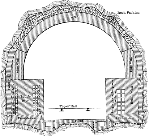
SKETCH SHOWING DIVISION OF LINING FOR PURPOSES OF CONSTRUCTION, AND
NAMES OF SECTIONS
An essential part of the agreement with the sub-contractors provided
that the operations incident to the placing of the lining should be
carried on so as to provide at all times space for a single track of
3-ft. gauge, running through the work, and the necessary clearance for
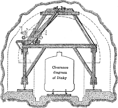
the locomotives and cars used in hauling out the muck. A clearance
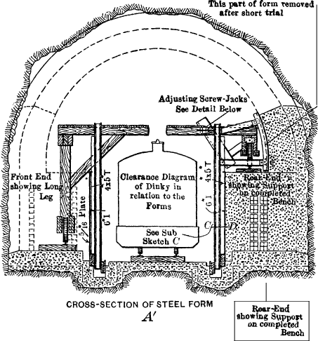
diagram of one of the “dinkys” used in the tunnels, and its relation to
the forms used, is shown by Fig. 12 and also by
Fig. 16, the 4-yd. Allison cars, used for
handling the muck, taking practically the same width, although they were
not quite as high. This requirement and the limited space available must
be kept in mind in considering the design finally adopted for the forms
and plant required in placing
the lining. It should also be kept in mind that, with the rolling stock
used, there was only room for a single track through that part of the
tunnel where any concrete had been built. As the concrete progressed,
therefore, the length of single track was necessarily lengthened, and
the problem of transportation was made increasingly difficult.
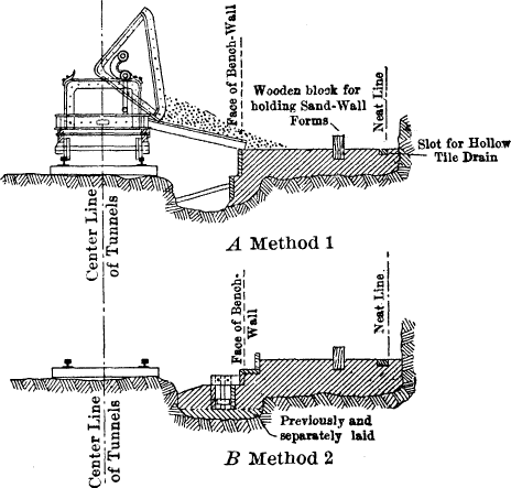
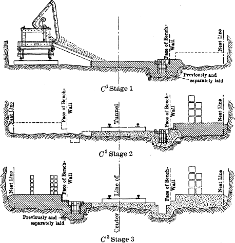
In working out a design for the bench-wall forms, another highly
important and controlling factor, which had to be considered, was the
arrangement of the conduit lines, as shown in the general
cross-section.2
The quantities of the various materials in the lining, per linear
foot of tunnel, were as follows:
| Concrete |
7.64 cu. yd. |
| Rock packing: Paid for |
1.48 cu. yd. |
|
| Outside standard section line |
1.74 ” ” |
|
|
|
3.22 ” ” |
| Iron and steel |
44.2 lb. |
| Vitrified conduits |
84.0 duct ft. |
| Water-proofing |
13.0 sq. ft. |
| Flags |
3.3 ” ” |
General Methods.—The lining was
started at both ends of the tunnels before the headings were finally
holed through, so that there was practically a separate organization at
each end, each in charge of one of the members of the firm. The work at
the Weehawken end was started first, and the plant and scheme of working
adopted there was thoroughly tried out before the plant for the western
end was built, consequently, the latter was somewhat more efficient,
being designed in the light of the experience gained at the Weehawken
end.
The general sequence of the plan first adopted in placing the
concrete is shown by Fig. 10. The concrete was
first placed in the foundations up to the elevation of the bottom of the
conduit bines, this work, of course, being kept well in advance; next
followed, in the order named, the sand-walls, water-proofing, conduits,
bench-walls, and finally the arch. The foundation was built in any
convenient lengths, multiples of 16 ft., the length of one section of
form, the sand-walls in lengths of from 25 to 35 ft., the bench-walls in
25-ft. lengths, and the arch in 10-ft. lengths. Concrete was placed
during the day shift only,
the forms being moved partly at night, and partly on the alternate days
when concrete was not being placed in them.
Five gangs were organized at each end, the first placed concrete in
the foundations in both tunnels, as the excavation was ready. In each
tunnel there was a gang which built sand-wall one day and bench-wall the
next, the two tunnels alternating so that only one bench-wall was built
each day, and finally a gang in each tunnel building arches,
a 10-ft. section being completed each day. During the night shift,
the arch forms and travelers were moved, and all other forms, etc., were
made ready for the concrete to be placed the following day. Some of the
conduit laying was done by the night shift, but part of it was
necessarily done during the day, as the concrete was built up.
A small gang was kept busy in both tunnels, during the day shift,
laying conduits and water-proofing. The latter two operations were
generally performed by the same gang.
This organization, of course, required considerable regularity in the
work, and this was finally attained, but at the beginning many sections
were often not finished on time, thus creating considerable confusion.
The progress possible with this organization (finally maintained with
great regularity) was 75 ft. of bench-wall and 60 ft. of arch per week
at each of the two working faces in each tunnel. This allowed the
bench-wall to gain considerably on the arch, and therefore at a suitable
point, as shown on the progress diagram, Fig. 9,
a third pair of arches was started, one in each tunnel, increasing
the progress on the arches to 180 ft. per week in each tunnel.
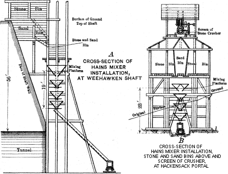
Mixing and Transportation.—All the
concrete used on this section was mixed in Hains mixers, one being at
each end. At the Weehawken shaft the mixer was installed in the
framework supporting the head-house and elevators; and storage bins were
arranged above, as shown by Fig. 11, A,
the whole structure being somewhat strengthened to allow this to be
done. At the western end the mixer was placed immediately under the bins
of the stone crusher, as shown by Fig. 11, B, the track
below being connected directly with the tunnels. The stone bin under the
screen of the crusher plant at the Hackensack end was divided into three
parts, the center being filled with sand by a derrick having a
clam-shell bucket, the other two with stone directly from the screen
above.
Skip to Text
This type of mixer proved very efficient on this work. The largest
number of full batches (0.8 cu. yd.) mixed in one plant per hour was
about 35; the largest number per day of 10 hours was about 240; but the
apparatus was never worked to its full capacity, the quantity of
concrete which it was possible to use being limited by other
considerations.
The concrete for the foundations was hauled in steel,
V-shaped, dumping cars holding about 1 cu. yd., and the
concrete for the bench-walls and arches in Stuebner, 1-yd.,
bottom-dumping buckets placed on small flat cars, as shown by
Fig. 1, Plate XXIV. Rock packing was
handled in Allison 4-yd. cars and also in the cars shown by Fig. 5, as well as in the Stuebner buckets, the latter,
however, being most generally used. Mules were used for a short time at
the Weehawken end to haul the concrete in, but proved entirely
inadequate to haul the loaded cars up the 1.3% grade, and
locomotives were substituted after the headings were holed through. At
the western end the cars were allowed to coast in, and, up to the time
the headings were holed through, were hauled back by mules; after that
they were pushed out by a locomotive which had gone in ahead of them. As
a rule, from 8 to 10 cars of concrete and rock packing were sent in, one
after the other, in proper order, a boy riding on each car and
stopping it at the proper place; all these cars were pushed out together
when empty.
Skip to text
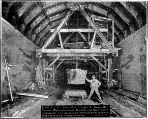
Fig. 1.
K 131. P.R.R. Tunnels, N. R. Div. Sect. K. (Bergen Hill Tunnels)
Weehawken Shaft, North Tunnel. Rear view of conveyor for concrete,
showing method of hoisting bucket from car on track in hopper over belt.
June 7, 07.
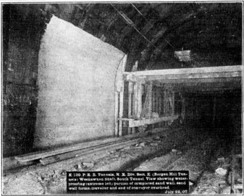
Fig. 2.
K 130. P.R.R. Tunnels, N. R. Div. Sect. K. (Bergen Hill Tunnels)
Weehawken Shaft, South Tunnel. View showing waterproofing (extreme left)
portion of completed sand wall, sand wall forms, traveller and end of
conveyor overhead. July 22, 07.
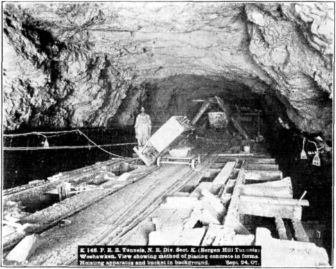
Fig. 3.
K 148. P.R.R. Tunnels, N. R. Div. Sect. K. (Bergen Hill Tunnels)
Weehawken. View showing method of placing concrete in forms. Hoisting
apparatus and bucket in background. Sept. 24, 07.
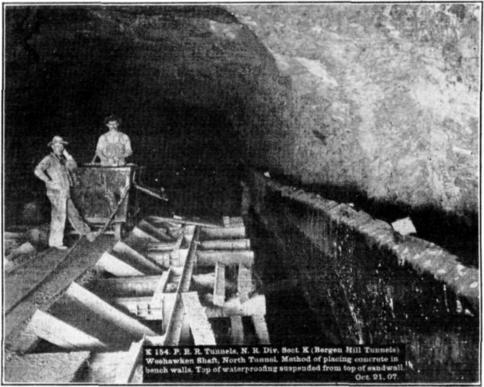
Fig. 4.
K 154. P.R.R. Tunnels, N. R. Div. Sect. K. (Bergen Hill Tunnels)
Weehawken Shaft, North Tunnel. Method of placing concrete in bench
walls. Top of waterproofing suspended from top of sandwall. Oct.
21, 07.
During the time the excavation was being carried on simultaneously with
the lining at the Weehawken end, the rock packing was loaded at the
working face and sent out to the point where it was to be used; after
that the rock packing was sent in from outside from the reserve pile on
the north side of Baldwin Avenue.
At the western end the larger part of the rock packing was sent in
from outside, but occasionally, during the time the excavation was going
on, the cars from the heading were stopped at convenient points,
generally under the gantries, where the lining was being placed, and
whatever stone could be utilized was sorted from the top and passed up
to the platforms above.
After the headings were holed through, there was considerable
difficulty at times in getting a sufficient supply of concrete and rock
packing into the tunnel at the time it was required, and while
undoubtedly the transportation facilities may have had some influence in
this, the principal trouble lay in the difficulty of securing a
sufficient supply of proper stone for rock packing, and for the
crusher.
While the excavation was progressing, the cars of muck, as they came
from the headings, were taken directly to the crusher and dumped into
it, the proportion of fine material being fairly constant and the supply
regular. At this time, also, a portion of the rock not required at
the crusher was dumped along the edge of the bank on the south side of
the approach, the larger stones rolling to the bottom where they were
easily available to be loaded into cars for rock packing, being entirely
free from the fine material; as this stone at the bottom of the bank was
used up, the supply was renewed, the rock suitable for rock packing
being automatically separated from the fine material as it rolled to the
foot of the slope.
After the excavation was completed, however, it was necessary to go
into the bulk of the storage piles to get material for the crusher and
for rock packing, and then the difficulties were materially increased by
the large quantity of fine material encountered, the proportion
remaining after the rock packing had been sorted out being too large to
send through the crusher. It was not only the handling over of this fine
material which caused delay, but the difficulty of disposing of it. On
rainy days the trouble was increased by the difficulty of getting men to
work in the open.
The delays due to transportation were usually caused by derailments,
which were more numerous than they should have been, and were due to the
condition of the rolling stock rather than to that of the track. These
delays, especially when they occurred in the early part of the day,
greatly increased the cost, by necessitating over-time work;
a delay of 1 hour in the forenoon generally meant
2 hours’ work after 6 o’clock to finish the day’s work.
The average number of cars handled (round trips of 1 car) during
a day (two 10-hour shifts) at the Hackensack end during January, 1908,
when the excavation and lining were in full swing, was about 125 cars of
muck and 200 cars of lining material, the former being hauled by
locomotives and the latter by mules.
Methods of Handling Concrete in the
Tunnels.—The concrete for the floor, ditches, and
foundations, was brought into the tunnel in V-shaped steel,
dumping cars, and dumped as near as possible to the place it was to
occupy.
The concrete for the arches and bench-walls was loaded at the mixers
into 1-yd., Stuebner, bottom-dumping buckets which just held a 4-bag
batch. These buckets were placed on small flat cars, hauled into the
tunnel, placed beneath the traveling gantry, as shown by Fig. 1, Plate XXIV, and hoisted to the platform
above.
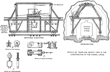
These traveling gantries, the details of which are shown by Fig. 12, consisted essentially of platforms at each end of
which an A-frame was erected; the latter supported at their
apexes two I-beams, from the lower flanges of which was suspended
a traveling block, shown at A, Fig. 12, and through which
the hoisting rope was rigged. The buckets were hoisted through an
opening in the platform and then moved along to where they could be
dumped. The platforms were supported on wheels traveling on rails laid
on the concrete of the foundation (for the bench-wall gantries) or on
top of the bench-wall (for the arch gantries).
Skip to Text
Each of the first two of these traveling gantries used was equipped
with a belt conveyor working on a cantilever arm, as shown by Figs. 3
and 4, Plate XXI, and Figs. 1
and 2, Plate XXIV. In using these
belt conveyors, the concrete was dumped from the Stuebner bucket into a
hopper, Fig. 1, Plate XXIV, with an adjustable slot in the
bottom, under which the belt ran.
It was the original intention, in designing the conveyor, that the
end of the cantilever arm should be swung from one side of the tunnel
to the other, and that the traveler should be moved backward or forward,
as might be required, and thus deliver the concrete from the end of the
belt directly over the place in which it was to be deposited in the
bench-walls. As a matter of fact, it was found impractical in operation
to move the gantry readily, owing to its great weight, which was
supported on only four ordinary car wheels and their bearings, and it
was found more convenient to leave the arm in one position near the
center, letting the concrete drop on the platform above the bench- or
sand-wall forms, whence it could be shoveled into place, than to attempt
to move it as had been intended. Both of these difficulties might
possibly have been overcome by modifications in the design of the gantry
and conveyor, had this method of handling the concrete seemed otherwise
desirable.
The principal difficulty with its use, however, was the inability to
take care of more than one batch of concrete at a time. When one batch
had been dumped into the hopper, a second could not be disposed of
until the first had nearly all run through on the belt, and this took
from 7 to 20 min., varying with the consistency of the concrete, etc. In
a few instances, where there happened to be some fairly dry batches, the
concrete could not be started through the slot at all, and had to be
shoveled out of the hopper. On the other hand, it is stated that some
batches, under favorable conditions, passed through in about
2 min., but this was quite exceptional, and the operation was
irregular and uncertain.
Before the final method of handling the concrete was adopted,
a trial was made of two forms of cars and buckets, to be used on
the top platform, as shown by Figs. 3 and 4,
and Plate XXIV. In the method
shown by Fig. 3, Plate XXIV, the concrete was hoisted in the
regular Stuebner buckets, one of which can be seen suspended in the
background of this photograph, and dumped into the car shown, which was
mounted so that it could be revolved in a horizontal plane. It was
intended to move this car on the tracks to the point at which the
concrete was required, and dump it directly through a chute into the
bench-walls. This car was abandoned, as there was a great deal of
difficulty in turning it when it was loaded, and in several instances it
had to be dumped straight ahead in the middle of the platform and the
concrete shoveled into the forms. This method was also objectionable
when the bucket was dumped, inasmuch as the force of the impact
of a whole batch of concrete dumped from such a height into the forms,
not only tended to throw the conduits out of line, and to break them,
but also caused considerable strain on the forms.
The bucket shown by Fig. 4, Plate XXIV,
was next tried. It had a slanting bottom and a door opening at the side.
It was filled at the mixer, came into the tunnel on a small flat car,
and was hoisted and placed on a similar car on top, as shown. This
bucket was not successful, as its great weight made it difficult to
handle, and it generally required a man to shovel the concrete out,
which latter, of course, had been pretty well compacted in the bottom of
the bucket by its trip from the mixer. All these cars were hauled
backward and forward on the top platform by a rope running to the winch
on the hoisting engine on the traveling gantry.
Aside from the fact that neither type was a success, neither of these
schemes was much improvement over the belt, inasmuch as only one batch
could be handled at a time, owing to the necessity of using the engine
to haul the cars back and forth on the platform. The final solution was
found in the use of the traveling gantry, shown by Fig. 12 and Fig. 1, Plate
XXVI, the latter being one of the arch gantries. The gantry used for
the bench- and sand-walls was supported on framed bents on wheels
running on rails laid on the foundation; that for the arch was the same,
except that the high-framed bent was dispensed with, the side-sills
resting directly on the journals of wheels traveling on rails on top of
the finished bench-wall.
These gantries were used only as a means of hoisting the buckets and
moving them along to where they could be dumped directly on the
platform, whence the concrete was shoveled into wheel-barrows, which
could be dumped directly into the bench-walls; or, in the case of the
arches, shoveled from the platform of the gantry to the intermediate
platform on the arch ribs, and thence directly into the arch. This use
of wheel-barrows, though apparently a somewhat crude method and a
retrogression from the use of the belt conveyor, proved very successful,
and really involved no more labor than did the conveyors, although this
might not have been the case had these latter worked as they were
originally designed to.
The method finally adopted allowed as many as four buckets to be
dumped on the platform on one end of the arch gantry at one time, and
eight on one end of that used for the bench-walls, the workmen
handling about three of these latter into the forms by the time the last
of the eight was dumped. It required about 1½ min. to place a car
under the gantry, hoist the bucket, dump, close it, and return it to the
car below.
Rock packing was stored at the other end of the platform, for use as
required, when it was not handled directly from the end nearest the
work. This method allowed the concrete and other materials to be brought
in in trains at infrequent intervals, and provided a sufficient supply
of material on hand so that the men handling it on top could be kept
steadily at work.
Each hoisting engine on these gantries had 7 by 10-in. cylinders, and
a double drum; some of them were Lamberts and some Mundys, operated by
compressed air.
Ditches, Floor and Foundations.—The
first method of building the foundation was that shown by Fig. 13, A; no attempt was then made to build the
ditch, or floor, the intention being to leave these until the completion
of the remainder of the lining. In building the bench-wall on this
foundation, however, it was found difficult to secure the bottom of the
forms properly (Fig. 2, Plate XXV), so as
to prevent any give, as the material under the track was not solid
enough to brace against. It was decided, therefore, to build the whole
of the ditch (see Fig. 13, B) so that the
bottom of the forms could be braced against the solid concrete. At the
beginning of the work, the face of the bench-wall was built up to the
level of the bottom of the conduits with the foundation; if, therefore,
in placing the concrete above this level, extreme care were not taken to
get a tight fit between the bench-wall form and the lower face, and then
to hold it rigidly in place, the result was a rather unsightly
horizontal joint high enough to be plainly visible. The position of this
joint may be seen in Fig. 2, Plate XXV,
which shows the first section of bench-wall built. Several subsequent
sections showed an overhang above this joint, amounting in one or two
cases to as much as ½ in., due to the fact that the bench-wall form
moved or did not fit tightly. This defect was obviated by building the
foundations with an offset on the face, shown by Fig.
13, B, so that the joint came at the level of the top of the
flagging over the ditches, and therefore was almost entirely concealed;
at the same time this allowed a sufficient surface, on the plane of the
face of the bench-wall, against which the bench-wall forms could be
braced and lined up.
Skip to Text
The ditch forms were set very carefully to line and grade by the
alignment corps, as this formed the starting point of all the rest of
the work, the only other thing which was necessary was to give a level
at the front end of the bench-wall form, after it was set, for the
elevation of the top of the bench, and to check up the stations of the
ends of the sections occasionally to see that they were at the even
25-ft. points (that is +08, +33, +58, and +83).
After a short length had been built with the ditches only, it was
thought desirable to try and put in the floor as well, so that the whole
of the concrete would be put in place as the lining advanced, and leave
less cleaning up to be done over the end of a single track, in the
restricted spaces between the bench-walls. Fig.
13, C, shows the method finally adopted. In this may be seen
the three stages in which it was put in, the details of the ditch forms
being shown by Fig. 13, D.
In that part of the tunnel where sand-walls were built, a hollow tile
drain was built into the foundation, as shown in Fig.
13, A and B, along the foot of the water-proofing and
connected at intervals with the drains by 4-in. cast-iron pipes. When
the sand-walls and water-proofing were not built, however, the concrete
of the foundations was sloped from the neat line back to the rock, as
shown by Fig. 13, C3, so that in case any water
found its way down through the rock packing, its tendency would be to
flow back against the rock, or to follow the low part of this concrete
to 4-in. cast-iron pipes leading to the side ditches, rather than to
find its way through the joint between the foundation and the bench-wall
and so into the lower duct lines.
Sand-Walls.—The sand-wall forms
first used are shown in Fig. 2, Plate
XXIV, with a section of the finished sand-wall. As this work was
only intended to give a comparatively smooth surface against which to
place the water-proofing, no particular care was taken with the surface,
except to avoid sharp projections which might cut through the felt and
pitch used for this purpose. A rather porous concrete (with all the
rock which could be safely embedded in it and have the wall stand) was
used, so that it would not act as a dam, but rather tend to allow the
water to find its way to the bottom of the tunnel, and so into the
drains.
The traveling gantry for placing the concrete in the sand-walls, as
first designed, with the belt conveyor, could of course only deliver the
concrete at one end. Before setting the forms for a new section, it
was necessary, therefore, to move the gantry ahead, before the
cross-bracing between the tops of the forms, which also held the top
platform, could be placed in position. Fig. 2, Plate XXIV, shows the end of the conveyor over the top
of the cross-braces. In order to hold the bottom of these forms, small
wooden blocks were embedded in the foundation concrete, against which
they could be wedged, as shown by Fig. 13,
A; these blocks were cut out after the sand-wall had been
built.
After the forms had been filled, the conveyor could not be moved back
to the bench-wall until the concrete had set sufficiently so that these
cross-braces could be removed, and, on account of the overhang at the
top, the set had to be fairly good in order to prevent this overhang
from breaking off. This arrangement, therefore, for placing the concrete
was found to be impractical, if the proposed schedule of a section of
bench-wall and a section of sand-wall to be built on alternate days, was
to be carried out. In a few instances, where the sand-wall was finished
fairly early in the afternoon, the forms were released next morning, and
the conveyor was moved back, but, even then, 2 or 3 hours at least
were lost at the beginning of the shift. The conveyor, however, was
abandoned, for the reasons previously given, and the traveling gantry
was rearranged to allow concrete to be delivered at either end; it was
then only necessary to move it backward and forward between the bench-
and sand-wall forms instead of through these forms. This permitted the
construction of the much more substantial type of forms shown by Fig. 14.
Fig. 14.
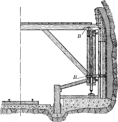
TRAVELING FORM FOR BUILDING SAND-WALL
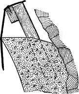 |
DETAIL SHOWING METHOD
OF HANGING WATER-PROOFING
FROM TOP OF SAND-WALL
|
After being moved ahead on the track on top of the foundation, the
form was first blocked up to grade, and then adjusted to line by the
screws and slotted cleats shown at B, Fig.
14, after which it was secured by the braces from the ditches, as
shown. The face lagging was placed in separate pieces and held against
the uprights by lightly nailing every third or fourth piece; the whole
was removed each time the form was moved, and built up again as the
concrete was placed.
Considerable care was taken to slope the top of the sand-wall back
toward the rock, as shown by Fig. 14, and to
allow free drainage along the top (which ran parallel to the grade of
the tunnel) to the 4-in. cast-iron drain pipes which carried the water
from the rock packing above the arch to the drains beneath the
track.
Sand-walls were built for a length of about 1,100 ft. in each tunnel
at the Weehawken end, and about 700 ft. in each tunnel at the western
end, the remainder of the work, with the exception of a few short
stretches, not being considered wet enough to require
water-proofing.
Skip to text
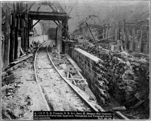
Fig. 1.
K 173. P.R.R. Tunnels, N. R. Div. Sect. K. (Bergen Hill Tunnels.)
Hackensack Portal and Approach. Telephone and Telegraph ducts and
mandrels. Nov. 20, 08.
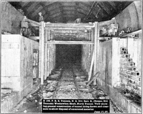
Fig. 2.
K 125. P.R.R. Tunnels, N. R. Div. Sect. K. (Bergen Hill Tunnels)
Weehawken Shaft, North Tunnel. View showing general construction of
tunnel lining forms, and clearance to allow disposal of excavated
material. June 17, 07.
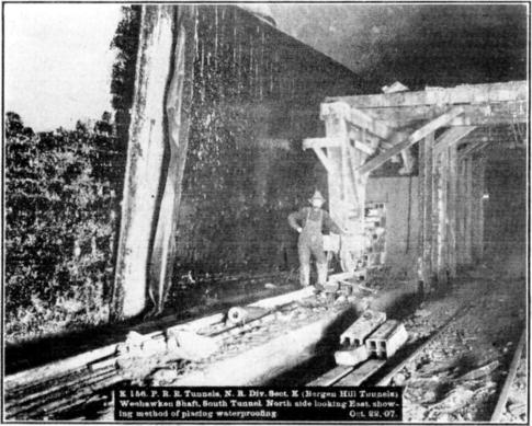
Fig. 3.
K 156. P.R.R. Tunnels, N. R. Div. Sect. K. (Bergen Hill Tunnels)
Weehawken Shaft, South Tunnel. North side looking East, showing method
of placing waterproofing. Oct. 22, 07.
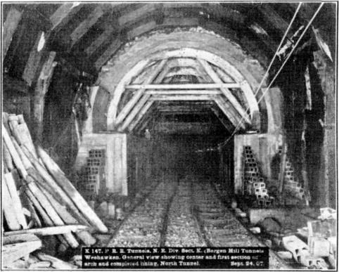
Fig. 4.
K 147. P.R.R. Tunnels, N. R. Div. Sect. K. (Bergen Hill Tunnels)
Weehawken. General view showing center and first section of arch and
completed lining, North Tunnel. Sept. 24, 07.
Conduits.—The arrangement of the
conduit lines is shown in the general cross-section.3 On the core-wall side
there are 48 lines for telegraph and telephone cables, built of 4-way
multiple conduit, each piece of which is 3 ft. long and about 10
in. square outside. On the other side there are the high- and
low-tension lines, built of single conduit 18 in. long and a little
more than 5 in. square outside. Manholes or splicing chambers are
built every 400 ft., and are about 8 ft. long and 4 ft.
wide. General views of the conduits as built are shown in Fig. 4,
Plate XXV, which shows all the lines in one
tunnel, and in Fig. 1, Plate XXV, which shows the telegraph and
telephone lines, with the expanding mandrels used in laying them.
In attempting to plan the work of placing the lining, two methods of
building the bench-wall were considered. One was to build the wall in
longitudinal sections, each section separated by a line of ducts; and
the other was to attempt to build the wall in the manner called for by
the specifications, which required the concrete to be carried up in
layers as the conduits were laid. In this latter method, it was
proposed to bond the concrete together with the forked bonds, the
details of which are shown by Fig. 15, A,
but, as it might have been impractical to use these if the wall had been
built in sections, provision was made in the contract to place expanded
metal, as shown by Fig. 15, B, if this was thought advisable. The
method of construction necessary, if the wall had been built in
sections, is shown graphically by the five sketches, Fig. 15, B,
1, 2, 3, 4, and 5.
The form and details of the expanding mandrel which was finally
designed to meet the conditions, and proved so satisfactory in every
way, are shown by Fig. 15, C. The mandrel
consisted of two triangular pieces of hard pine, separated by wedges
attached to one piece which fitted into slots in the other; these, when
expanded, practically filled the whole of the inside of the ducts. One
of these mandrels was placed in each line of single ducts and two in
each 4-way duct, placed diagonally, as shown in Fig. 1, Plate XXV. This required 60 mandrels at each working
point, or 240 for the whole work. The mandrels were 35 ft. long, so that
they easily covered the whole of a 25-ft. section, projected
sufficiently far back into the previously finished work to assure the
continuity of the alignment, and allowed the ends to be racked out at
the forward end to secure proper breaks between the joints.
In laying the single conduits, as a rule, the (collapsed) mandrels
were pulled ahead from the previous section as each line was laid, and
the conduits were strung on it until the whole length was completed; the
conduits were then pushed up tight together, so as to close the joints
as tightly as possible, and then the mandrel was expanded. The conduits
were thus held firmly in position, and the forward end of the line was
lifted slightly so that the wraps could be placed around the joints. The
4-way conduits were generally laid in the ordinary way, except that no
laying mandrel was necessary. One dowel was used between each of the
pieces of conduit, at the center, and the joints were wrapped. When a
line was finished, two mandrels were placed diagonally in each line and
expanded simultaneously, so that any inequalities in the ducts
themselves were divided as far as possible. In connection with the use
of these mandrels, one of the points which was most carefully watched
was that they projected back into the last completed section, thus
insuring the continuity of the alignment.
It was originally intended to wrap the joints of the 4-way ducts
only, but it was found to be impractical to keep the grout from the wet
concrete entirely out of the single ducts, and, after a short trial, it
was decided to wrap these also. The expanding mandrel kept out a great
deal of the cement, and, in the sections laid without wraps, the only
difficulty from this cause seemed to be that a slight film of grout,
from 1/16 to ⅛ in. thick, was deposited on the bottom of the inside
of the ducts at some places, and although this was not considered a
serious defect, it was thought that the slight extra cost of placing the
wraps would undoubtedly be justified by the practically perfect results
obtained by using them.
Considerable attention was given to breaking the joints of the ducts
properly, so as to maintain throughout the conduit lines the greatest
break possible. The joints in each superimposed line were broken at half
the length of the individual pieces of conduit, the joints in lines in
the same horizontal plane being broken at one-quarter the length, thus
preventing any joints from touching one another either at the sides or
corners, which tended to prevent a burn-out on one line from being
communicated to another. There was some little difficulty at first in
maintaining the breaks, owing to slight variations in the lengths of the
conduit, but after a very short time both the workmen and the inspectors
became very expert at this and in the proper use of short lengths to
maintain the spacing; after the first few weeks there was little if any
difficulty in attaining at all times almost perfect results. The method
of making the breaks is shown in the photographs and by the isometric
sketch at F, Fig. 15.
All the conduits used on this work were furnished by the Great
Eastern Clay Company, and were made at its factory at South River, N.J.,
where they were inspected before shipment.
The mandrel used in the final rodding was made as shown at G,
Fig. 15, the larger size being used for all
lines. The rods for pushing it through the conduit lines were made of
6½-ft. lengths of ordinary 1-in. wrought-iron pipe with extra long
(3-in.) couplings. The lines were rodded in both directions from
alternate manholes, thus avoiding uncoupling the rods and allowing every
pull to be effective in pushing the mandrel through the ducts.
Wooden rods were used at first, but proved entirely too light, as the
mandrels used were a close fit, and it required considerable effort to
push them through 400 ft. of conduit. Iron pipe with ordinary couplings
was next tried, but the couplings broke quite often, as the threads
became worn in uncoupling the sections to move the rods from one line to
another, and the break was generally inside a duct line. The long
couplings were finally adopted, and a set of rods was put in each line,
that is, six sets in all, so that when coupled up they remained in the
line until it was finished. The expense of the extra quantity of pipe
thus required was more than offset by the decreased labor cost.
Skip to Text
It was thought necessary at first to run a cutter, Fig. 15, E, through the conduits ahead of the final
rodding mandrel, but this was soon found to be unnecessary except in a
very few instances, and, after a short experience, the cutter was only
used at places where an obstruction was encountered by the mandrel.
At such times as the pipe became uncoupled inside the duct line, the
part remaining inside was recovered by the use of the tool shown at
D, Fig. 15, called a “weasel.” In two
instances, the mandrel became stuck in such a manner that the duct line
had to be cut into in order to take it out.
The best day’s work of the rodding gang (1 foreman and 4 men) was
20,400 duct ft. of the 4-way conduit in the telegraph and telephone
line, and 19,200 duct ft. of single conduit on the low-tension line, an
average day’s work under ordinary conditions being about 10,000 duct ft.
The cost, including labor, material, and all tools, for rodding for the
whole work was slightly less than 0.2 cent per duct ft. The average cost
of the single conduit was about 0.25 cents per ft., and of the 4-way,
0.15 cents per ft. About 10% of the conduit lines were rodded twice,
owing to partial sections having been rodded once before completion. The
best continuous work on rodding was done between October 22d and 29th,
1908, when in 7 working days, 105,600 duct ft. were rodded, an
average of a little more than 15,000 ft. per day.
Bench-walls.—The original
design for the tunnels provided for the construction of a brick arch
above a point 22° above the springing line, that is, the part above the
side-walls (Fig. 10). It was thought desirable,
therefore, in designing the bench-wall forms, to provide for placing the
concrete in the side-walls and bench-walls at one operation. These
forms, as first designed, are shown by Fig. 2, Plate XXV, and the details in Fig.
16, A and A’; they were built of steel, the facing
plates being 5/16 in. thick, in pieces 4 ft. 6 in. wide, and
in length about 6 in. more than the height of the bench-wall.
Skip to Text
The design was controlled very largely by the necessity of providing the
requisite clearance for the locomotives and muck cars, and the principal
feature was the support of the forms on two trusses, one at either side,
the front ends of which were supported from the foundation on a long
leg, as shown in Fig. 3, Plate XXV, and
the rear ends directly on the journal-boxes of wheels traveling on a
rail on the top of the finished bench, as shown in Fig. 2, Plate
XXV.
Although it had been decided to substitute concrete for brick in the
arch before any of the lining was actually placed, two sets of forms for
the Weehawken end had already been ordered and delivered, so it was
decided to use them as designed, and place the side-wall with the
bench.
The forms were designed so that 30-ft. lengths could be built, and
this was done at the start, but owing to the occurrence of the refuge
niches, ladders, etc., at 25-ft. intervals, it was soon seen that it
would be advisable to build the bench-wall in sections of that length
(25 ft.), or multiples of it, and as the clearance conditions
seemed to preclude the possibility of making the forms 50 ft. long,
25 ft. was adopted. This permitted the removal of one of the
panels, 4 ft. 6 in. wide, and at the same time it was decided
to remove the side-wall forms. This decreased the load on the trusses
considerably, but being still a trifle weak, they were strengthened by
the substitution of 1¼-in. truss rods instead of the ¾-in. rods used
originally. The top platform and the cross-bracing were also stiffened a
little and tightened up to prevent racking.
The construction of the side-walls in conjunction with the bench-wall
was abandoned for three reasons: First, it was found that there would be
a much more even distribution of the work by including the side-wall
with the arch rather than with the bench; second, there was difficulty
in getting a good finish for the top of the bench-wall, as of course a
top form for the latter had to be placed to prevent the concrete from
squeezing up when the side-wall was built above it, which prevented
troweling; the third reason was the weakness of the whole form as
designed, and the increasing difficulty of adjusting it to line as the
work progressed, the principal difficulty being with the curved
side-wall forms.
The bench-wall forms were set in position, after they had been moved
ahead, by first blocking the bottom against the face of the
foundation, as shown by Fig. 13. As previously
noted, this foundation face had been built very carefully to line. The
back end of the form, of course, was blocked tightly against the end of
the previously finished section, and the top was made plumb by the
adjusting screwjacks shown in Fig. 16, B.
At first these screws were ¾-in., but they were afterward changed to
1¼-in. The only points which it was necessary for the alignment corps to
give in setting these forms was a grade at each of the front ends for
the top of the finished bench.
The steel face forms in both tunnels gave excellent results, as far
as smoothness of finish was concerned, but, owing to the imperviousness
of the steel, small air holes were formed in the surface, though not in
sufficient numbers or size to cause trouble or disfigure the work in any
way.
The design of the bench-wall forms used at the western end, where
this differs from the steel form, is shown by Fig.
16, D. The principal features in which they differed from
those used at the Weehawken end was in the substitution of 2½-in.
tongued and grooved hard pine for the face. This timber was of the very
best quality obtainable, each piece being especially selected and as
nearly clear and free from knots or other defects as it was possible to
get it. The edges of each piece were planed at the back so as to insure
a tight joint on the face, and all joints were shellacked. These forms
were used, without renewal of the face timber and with only two
planings, for a length of 2,500 ft., or 100 separate sections, and gave
good satisfaction.
In order to obtain a surface to which the face lagging could be
fastened, wooden uprights were used and were reinforced on either side
by light channels bolted together through the timber, in place of the
I-beams used on the steel forms. The lagging was nailed to these
uprights by 6-in. wire nails driven through the top edges of each piece
as it was placed in position, thus leaving the surface entirely clear
and free from any marks or nail holes, and in condition for planing when
this became necessary. Runways for wheeling the concrete were built one
either side over the bench-walls instead of having a center platform
with chutes, as was used at Weehawken.
When the original lagging had become too much worn for further use,
it was resurfaced with strips of ⅞ by 2½-in., clear, tongued and
grooved, hard pine, placed vertically, which did fairly well and lasted
to the end (about 1,000 ft.), although it was not altogether
satisfactory,
and the last eight or ten sections built had to be rubbed down with a
wooden float in order to obtain a suitable finish.
In designing the forms for all exposed surfaces in the tunnels, it
was the desire of the contractors to obtain directly from them a surface
which would be satisfactory to the engineers without
further finishing than the patching of minor defects. In this they were
generally quite successful, and excellent results were obtained, as
shown in the view of the finished tunnel, Fig. 2, Plate XXVII. The surface of the bench-walls was
obtained solely by spading the face with a flat spade as the work
progressed. No after treatment was resorted to, except for the few
sections where the forms became worn. The top of the bench-wall was
finished with a float about 2 or 3 hours after the concrete was
placed.
When the work was well organized, a bench-wall was built at each end
each day, one day in the North Tunnel, and the following day in the
South. During the time sand-walls were being built, a sand-wall and
bench-wall were built on alternate days in each tunnel, care being taken
that when a bench-wall was being built in one tunnel, the sand-wall was
being built in the other, this being necessary in order to equalize the
work of the night gang and the conduit layers as well as the
transportation.
The conduit layers on the day shift, two or three men and a foreman,
required about 2 hours in the forenoon and 1 hour in the
afternoon to lay their portion of the conduits, and usually finished
this work by 3 P.M. At other times
during the shift they were utilized at those points where rock packing
was heaviest, and when the packing was brought in in the large cars, as
shown in Fig. 1, Plate XXVI, these men
helped unload it so that the track could be cleared as soon as possible.
When water-proofing was to be done, the number of men in this gang was
increased, so as to enable them to do that work also.
Skip to text
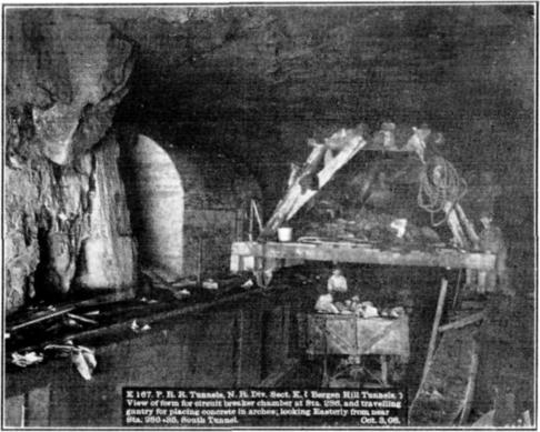
Fig. 1.
K 167. P.R.R. Tunnels, N. R. Div. Sect. K. (Bergen Hill Tunnels.) View
of form for circuit breaker chamber at Sta. 286, and travelling gantry
for placing concrete in arches, looking Easterly from near Sta. 280+85,
South Tunnel. Oct. 3, 08.
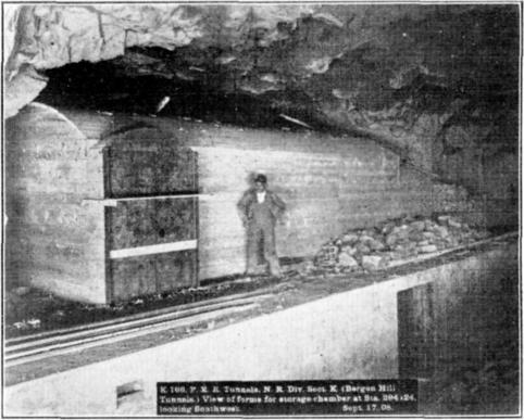
Fig. 2.
K 166. P.R.R. Tunnels, N. R. Div. Sect. K. (Bergen Hill Tunnels.) View
of forms for storage chamber at Sta. 294+24, looking Southward. Sept.
17, 08.
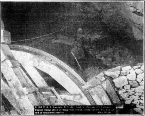
Fig. 3.
K 163. P.R.R. Tunnels, N. R. Div. Sect. K. (Bergen Hill Tunnels.) Tunnel
lining. Rock packing over arches, South tunnel Sta. ???+?? end of completed section.
May 19, 08.
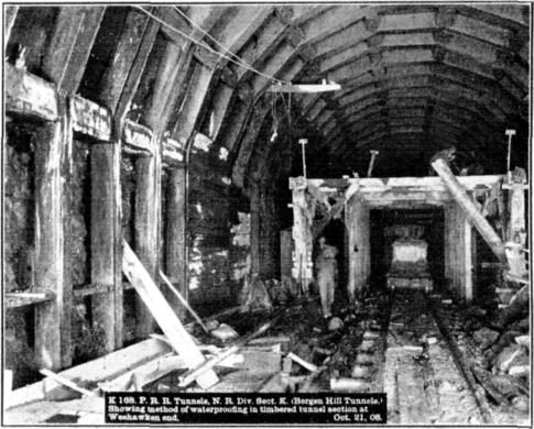
Fig. 4.
K 168. P.R.R. Tunnels, N. R. Div. Sect. K. (Bergen Hill Tunnels.)
Showing method of waterproofing in timbered tunnel section at Weehawken
end. Oct. 21, 08.
A gang of four rough carpenters and a foreman was employed on the day
shift; they moved and set the bench-wall forms or sand-wall forms, as
the case might be, and moved the traveling gantry into position. This
was done in the afternoon, and required about 3 hours. They also
took out, cleaned, repaired, and set all ditch forms, all passenger
forms, circuit-breaker forms, and did all other repair work. The ladder
forms, the refuge-niche forms, and overhead conductor
pocket forms were attended to by one man, who set, removed, cleaned, and
repaired them. The carpenters on the night shift set the arch centers
and gantries, also the manhole forms when needed. The conduit layers on
the night shift laid up half the 4-way conduits (3-high) and one-third
of the single ducts (4-high). This one gang laid the conduits in two
sections of bench-wall each night, that is, one section at Weehawken and
the other at the western end.
In concreting the bench-walls, the concrete was first placed on the
side containing the single conduit until it reached the top of the four
tiers laid, then the concrete gang was turned over to the side with the
4-way conduits while four more tiers of single conduits were laid, the
work thus progressing, the conduits being laid on one side while
concrete was placed on the other. On the side of the 4-way conduits the
concrete was built in two layers while that on the side of the single
ducts was built in three; the interval between the different layers was
not sufficiently long to prevent a complete bond being obtained, and
there were only one or two instances where there was any mark on the
face to indicate a break.
After the work had been in progress some time, it was found to be
quite feasible to build all the 4-way conduits at night and half the
single conduits, that is, 6 ducts high, as the mandrels proved
amply sufficient to hold them in place; in fact, had it been necessary,
the writer has no doubt that all the ducts might have been laid and held
in place with very little extra precaution, by the use of the expanding
mandrels, as described under the head of conduit laying.
A V-shaped joint about ½ in. deep was made between each
section of bench-wall so that the expansion cracks would follow this
joint rather than show irregularly on the face. These joints divided the
face into the even 25-ft. panels, and were very effectual in concealing
what few cracks there were.
After the construction of the sand-walls was discontinued, the space
behind the bench-walls, between the neat line and the rock, was filled
with rock packing, which was generally built, part way up at least, as a
dry wall ahead of the construction of the bench-wall, or it was put in
place simultaneously with the concrete, care being taken to keep it as
free as possible for the drainage of any water there might be. Toward
the latter part of the work, owing to the difficulty of getting
sufficient rock packing during the day, a rough back form
for the bench-wall was built at the neat line, in places where the
section was at all large, and the space was filled with rock afterward,
generally at night or on Sundays.
In the sections where water-proofing was required, where no sand-wall
was built, the rock was taken out for 2 ft. outside the neat line,
if the excavation was not already that far out (at the expense of
the contractors, who preferred to do this rather than build the
sand-walls for the short sections required), so that there would be
sufficient room for placing the water-proofing on the back of the
bench-walls, as shown by Fig. 18, E. The
water-proofing of these sections was left until just before the arch was
to be built, and after being placed it was protected by a single row of
brick laid on edge before the rock packing was filled in.
Arches.—The centering used for the
arches is shown very clearly in Fig. 4, Plate
XXV, which is a view of the back end of the first section built at
Weehawken. In this part of the tunnel, the lower part of the arch, about
5 ft. above the bench-wall, was built first, as previously referred
to, but the centers, as will be seen, were built so that they could be
used for the whole of the arch. The forward bulkhead, and the shoveling
platform on a section being built, are shown in Fig. 3, Plate XXVI.
The front bulkheads used were made in nine sections, bolted to a 2½
by 2½-in. angle bent to the radius of the arch, as shown in Fig. 3,
Plate XXVI, and fitting on the end of the
lagging; when set they were braced partly against the rock of the roof
and partly against the gantry. After the ribs and part of the lagging
had been set by the night gang for a fresh section of arch, the braces
holding the bulkheads were knocked out, the concrete placed during the
day having set sufficiently by this time; the whole of the bulkhead was
then easily moved ahead, sliding along the lagging to the forward end,
and made ready for the next day’s work. The middle section at the top
was taken out temporarily, to facilitate working at the sides, until it
was needed.
The traveling gantry used in handling the concrete for the arch is
shown in Fig. 1, Plate XXVI, which also
shows the form for the circuit-breaker chamber, and a car of rock
packing on the track beneath.
The arches were built in 10-ft. sections, the ribs being spaced
5 ft. apart, the end ribs of each section supporting the end of the
lagging
on two adjoining sections. Five sets of lagging and ten ribs were used
at each place where the arch was being built, thus giving each section
practically 4 days’ set before removing the centers. Probably in the
greater part of the work the centers could have been removed in from 40
to 48 hours after the concrete had been placed, but 3 days was
considered the least time which would certainly be safe at all times,
and the contractors thought that the very slight additional expense
involved in leaving the centers up 4 days was more than warranted
by the additional feeling of security.
The lagging was made from 3 by 6-in. clear, hard pine, 10 ft. long,
dressed to about 2½ in. in thickness, about 5½ in. in width, and
the sides to radial lines. As it was placed, every third or fourth piece
was lightly nailed to the ribs; when the latter were released and taken
down, the nails pulled out, and the lagging was left in place until one
piece was pried out, allowing the others to fall. A light
A-frame, about 8 ft. long, spanning the bench-walls, was
placed below, in order to break the fall and allow the lagging to slide
to the top of the bench-walls rather than fall to the track beneath.
Cross-passages between the two tunnels were built every 300 ft.,
their form being shown on Plate VIII of the paper by Mr. Jacobs. There
were two circuit-breaker chambers, one at Station 286 and the other at
Station 310. Steel doors are provided so that all the openings between
the two tunnels can be closed. At Station 294+24, the core-wall broke
through for a length of about 40 ft., and instead of filling this in,
a storage chamber 34 ft. long and 11 ft. wide, inside, was built
there, the form for which is shown in Fig. 2, Plate XXVI. This photograph, as well as Fig. 1,
Plate XXVI, a form for a circuit-breaker chamber, shows the method
of setting the steel doors in the forms, so that they were built into
the concrete instead of being fastened in with expansion bolts
afterward, thus showing a perfect fit and a much neater job.
During construction the arches in each tunnel were kept even with
each other, so that when the cross-passages were reached, they, and the
sections of arch which they joined, could be completed at one
operation.
By the methods used on this work, one section of arch was easily
built in a shift, so that the monolithic construction of each section
was easily secured, and concrete, as wet as it was possible to handle
with
shovels, could be used for all except the last 5 ft. or so at the
top, thus getting a structure which was as nearly impervious as possible
under the circumstances.
The gangs placing the arches were paid over-time when they were
required to work after 6 o’clock to finish their section, which was
generally only necessary when the quantity of rock packing to be placed
was very large. If they finished their section before 6 o’clock,
however, they were allowed to quit when this was done, and were given a
full day’s pay. The difference in time, when there was any, was usually
due to the greater or less quantity of rock packing, as the excavation
varied from the standard section line.
In building the arches, the night gang set the two ribs (one at the
center and one at the forward end of the section to be built), placed
the lagging on the sides, 4 or 5 ft. high, built the shoveling
platform on the horizontal cross-braces of the ribs, and placed the
traveling gantry in position for use. The forward end of the gantry
(that is, the end farthest from the arch being built), as shown in
Fig. 1, Plate XXVI, was loaded with rock
packing to be used as required. As the concrete was brought into the
tunnel it was hoisted and dumped on the end of the gantry next the arch,
and shoveled from there to the platform on the ribs and from there into
place. The rock packing brought in during the day was dumped on the
front or back end of the gantry, as was most convenient, and handled
into the work in the intervals between batches of concrete. The concrete
and rock packing, with the back-lagging and water-proofing, where these
were used, were placed simultaneously, or nearly so, and brought up the
sides together until the key was reached; the latter was then worked
from the back toward the front. The key was usually made about
5 ft. wide, the lagging for this width was made 5 ft. long and
put up in two sections. It was found to be more convenient to have the
key of this width than narrower.
The method used in making the closures where two sections of the arch
came together is shown by Fig. 17.
Skip to Text
Water-proofing.—As already
pointed out, the original design for the lining of these tunnels
provided for a brick arch. It was intended to cover this arch with
water-proofing, this latter extending over the whole of the roof and
down the sides as far as the bottom of the conduit lines. The
water-proofing was to be placed against the sand-walls
on the sides, up to the top of the side walls, Figs. 10 and 14. Over the arch, after
being placed, it was to be protected by an armor course of brick, laid
flat, the space between the brick and the excavation, which was required
to be not less than 4 in. (and, as a matter of fact, was actually a
great deal more), being filled with rock packing. Besides filling the
space, this latter was designed to allow any water from the roof of the
tunnel to find its way easily to the top of the sand-wall, from there
being carried through the 4-in. cast-iron pipes, shown on Plate VIII4 to the
side ditches in the floor of the tunnel.
All the water-proofing placed in these tunnels was of felt and pitch,
six-ply felt and seven layers of pitch. The felt was required to be
Hydrex, or of equal quality, and the pitch, “Straight run coal-tar pitch
which will soften at 60° Fahr., of a grade in which the distillate oils
will have a specific gravity of 1.05.”
In addition to tests as to the above qualities, the pitch was
analyzed
to determine the amount of free carbon it contained, and was not
accepted if this fell below 20 per cent.
It was considered quite important that there should be absolutely
free drainage on the outer side of the lining, so that there would be no
chance for any water to acquire a head. More than three-quarters of the
length of these tunnels is below the level of mean high water, and while
it was hardly expected that there would be any direct connection between
the water in the Hudson River and the groundwater of the section
penetrated, it was thought wise to provide ample drainage.
Before the lining was started, however, the excavation had progressed
sufficiently to show that the tunnels, while very wet in places, and
varying from that to quite damp, would be, on the whole, much dryer than
had been anticipated. It was then decided to substitute concrete for the
brick in the arch and omit the water-proofing over the top, except at
places where water came into the tunnels in sufficiently large
quantities to form practically a continuous stream. Three general types
of construction for the arch were decided on, as shown in Fig. 18. The first, as shown at A, was to be used
where the tunnel was quite dry. In this type, the sand-wall was omitted
entirely, and the concrete and rock packing were built up together, the
rock packing impinging to a certain extent on the concrete, and the
concrete squeezing somewhat into the rock packing, as shown by
Fig. 4, Plate XXV. The section shown at
B was used where the tunnels were damp, or where there were
slight droppers not forming a continuous stream. The back lagging, of
1-in. boards, which was left in place, provided a practically smooth
outer surface on the concrete arch, and allowing the concrete and rock
packing to be built almost simultaneously. It was considered that the
free drainage through the rock packing, the surface of the boards, and
the smooth outer surface of the concrete in the arch would allow the
comparatively small quantity of water in these parts of the tunnel to
find its way to the sides, and thence to the ditches at the bottom,
rather than to percolate through the concrete, and this proved to be
very generally the case, as is shown by the dry condition of the tunnel
as built. The back lagging was used over the arch, both where the
sand-wall was built and where it was omitted, as well as being placed
over the water-proofing of the arch as an armor course where
water-proofing was required. Where the sand-walls
were built and water-proofed, and where the water-proofing was not
carried over the arch, the water-proofing was turned in at the top, as
shown at C, Fig. 18.
Skip to Text
The third method provided for water-proofing the whole of the arch,
and was the same as B except for the addition of the
water-proofing inside the back lagging. In placing this water-proofing,
the felt was cut in strips about 11 ft. long (about 1 ft. longer
than the length of a section of arch), and six thicknesses were cemented
together with hot pitch. These mats were then laid shingle-fashion, as
shown at D, Fig. 18, up the sides of the
arch until a space about 5 ft. wide remained at the crown; shorter
mats were then brought out over this, laying them perpendicular to the
axis of the tunnel. Care was taken in making all laps, irrespective of
the direction in which the arch was built, so that they would lay with
the grade, that is, so that the water would tend to flow over the edges
of the laps rather than against them.
Most of the wet sections of the tunnel were at the ends, where
sand-walls had been built for the purpose of providing a smooth surface
against which the water-proofing was to be placed; there were several
wet places at isolated points in the tunnels, however, and, in order to
avoid building sand-walls at these points, the method shown at E,
Fig. 18, was adopted. This involved a slightly
larger excavation, 2 ft. outside of the neat line, up to the height
of the top of the bench, where there was not already that much room. The
bench-wall was built with a back form on the neat line, the
water-proofing was placed as shown, protected by an armor course of
brick, and then continued over the arch when this latter was built. The
excavation and refilling with rock packing were done at the contractor’s
expense, which he was willing to assume rather than build these short
sections of sand-wall.
Skip to text
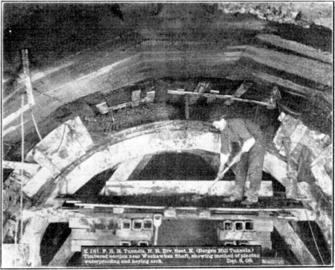
Fig. 1.
K 181. P.R.R. Tunnels, N. R. Div. Sect. K. (Bergen Hill Tunnels.)
Timbered section near Weehawken Shaft, showing method of placing
waterproofing and keying arch. Dec. 8, 08.
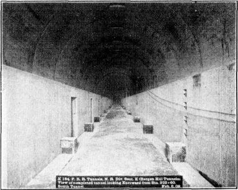
Fig. 2.
K 184. P.R.R. Tunnels, N. R. Div. Sect. K. (Bergen Hill Tunnels). View
of completed tunnel looking Eastward from Sta. 323+60. South Tunnel.
Feb. 8, 09.
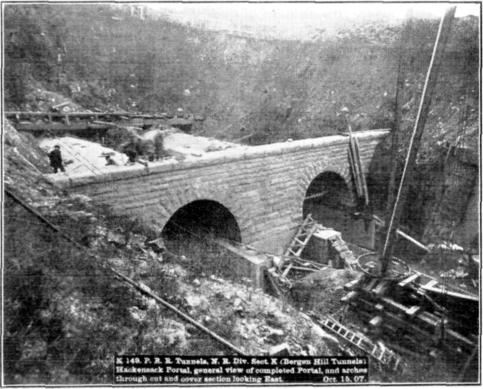
Fig. 3.
K 149. P.R.R. Tunnels, N. R. Div. Sect. K. (Bergen Hill Tunnels)
Hackensack Portal, general view of completed Portal, and arches through
cut and cover section looking East. Oct. 15, 07.
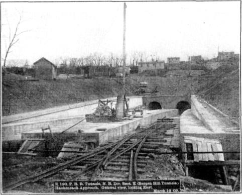
Fig. 4.
K 190. P.R.R. Tunnels, N. R. Div. Sect. K. (Bergen Hill Tunnels.)
Hackensack Approach. General view, looking East. March 16, 09.
The method of water-proofing that part of the timbered section which
was very wet, is shown at F, Fig. 18, and
in Fig. 4, Plate XXVI, and Fig. 1,
Plate XXVII. A lagging of 1-in. boards
was nailed up the sides and to the soffit of the segmental timbering,
all the spaces outside of this lagging being carefully filled with rock
packing. Before starting any concrete work, a single thickness of
water-proofing felt was nailed to the inner side of the lagging, which
not only served to protect the finished surfaces of the concrete from
the
water which fell copiously from the roof, but also provided a
comparatively dry surface to which the regular six-ply water-proofing
could be cemented with pitch and held in position, while the concrete
was placed against it.
In placing the water-proofing in this section on the sides, the
strips of felt were placed vertically, nailed at the top to the
wall-plate, to support their weight, and lapped and cemented with pitch
to the sides as on the sand-walls, except that there was no trouble from
the overhang. After the bench-wall had been built, the felt was cut just
below the nails and about 2 ft. above the top of the bench, so that
the mats which were placed over the arch could be inserted behind it.
The roof was covered with three-ply mats and lapped over a little more
than half, as shown diagrammatically on the drawing.
When the upper part of the arch was reached, where the cementing
strength of the pitch was not sufficient to hold the felt in place, the
mats were braced temporarily from the centering, as shown by
Fig. 1, Plate XXVII, until the concrete
could be packed against it.
Where the water-proofing was placed against the sand-wall, the method
of securing the sheets at the top is shown in the small sketch on Fig. 14 and by Figs. 3 and 4, Plate XXIV. Fig. 3, Plate
XXV, shows the laps of the sheets and the method of hanging. At the
start an attempt was made to stick the water-proofing to the sand-wall,
but this could not be done on account of its dampness and the overhang
at the top.
The sand-wall water-proofing was kept about 35 ft. ahead of the
finished bench-wall, as shown by Fig. 3, Plate XXV. As the bench-wall form was moved ahead and
set, the mat was braced back against the sand-wall from the forms at a
point just above the top of the finished bench, care being taken to
avoid wrinkles, as, if these were once formed, it was practically
impossible to straighten them out.
The completion of the bench-wall left the upper part of this
water-proofing stretched taut across the curved top of the sand-wall,
forming a chord of the arc. As the arch was built up, the top was
gradually slackened so as to allow the concrete to press the mat back
into place until the top of the sand-wall was reached, when the end was
turned in, as shown at C, Fig. 18, or the
water-proofing was continued over the arch, if that was necessary.
The desire to obtain a dry tunnel, and the methods adopted to
secure it, were responsible in a great measure for the decision to build
the arch in short lengths, as well as the reasons given under the head
of arches. Had the tunnels been dry throughout, the method shown at
A, Fig. 18, could have been used
exclusively, and, except for the fact that monolithic concrete might not
have been obtained, there would have been no objection to building
longer lengths.
The quantity of water reaching the tunnel drains and flowing out of
their lower ends after the completion of the lining was about 100,000
gal. per day, or 75 gal. per min.; of this it is estimated that
considerably less than 1% comes through the lining in the form of leaks.
The very general distribution of this water over the roof is indicated
by the fact that, during the excavation of the first 1,000 ft. of both
tunnels from the Weehawken end, oilskins had to be provided for the
laborers to induce them to work at all. The success, therefore, of the
rock packing as a means of diverting this water to the side drains, is
shown, especially in view of the fact that, excluding the cut-and-cover
section, only 10% of the length of the arch, 1,189 ft., was
water-proofed.
Considerable care was taken to make all joints in the concrete which
were in such a position that water might follow through them to the
inside of the tunnel lining, in such a manner that they would slope
outward toward the rock. The top of the sand-wall is shown by Figs. 14 and 18. The slope of the
back of the foundation may be noted in Fig. 18, and the method of making
the joint in the arch, in the few instances where a section was not
completed at one operation, is shown at A, Fig. 18. These
joints in the arch were not allowed to be made above a point 60° above
the springing line.
Skip to Text
Hackensack Portal and Approach.
The approach cut at the western end is 300 ft. long, the alignment
being a 2° curve, as shown in Fig. 19. The
bench-walls and conduit lines built throughout the length of the tunnels
are extended through the approach cut, the top of the former gradually
sloping from the portal to the mouth of the cut, where they are just
level with the top of the rail, the conduits also being depressed to the
same relative position with the tops of the benches.
The top of the rock at the mouth of the cut, Station 327, was from 4
to 6 ft. below the top of the rail, and gradually rose through
the approach until at the portal it was about 6 or 8 ft. above the
roof of the tunnel. The rock was covered with hardpan. A profile of
this part of the work is shown on Fig. 19. The
rock throughout the approach was water-bearing to a considerable extent,
and a face-wall was built at the sides with free drainage, through rock
packing and vitrified and cast-iron drains behind it, to keep this water
from flowing over the tops of the bench-walls, and also to keep the
lines of conduits dry.
The retaining walls were built in 25-ft. sections, the joints
corresponding to those in the benches, being at the even stations, +08,
+33, +58, and +83. V-shaped joints were made down the face, and
the ends of the sections were made as shown by Fig.
19. The back part of the joint was mopped with hot pitch before the
next section was built, so that there was practically no bond between
any two adjoining sections.
The concrete in these walls was placed late in the season, and the
expansion cracks, which were entirely confined to the V-shaped
joints, were quite small even in the coldest weather of the following
winter, nor were there any indications during the past summer of any
stresses due to expansion. The coping and drain at the top of the wall
were built together, but separate from the rest of the wall, the joint
being made as shown in the sketch on Fig. 19.
Thus far, there has seemed to be no seepage through either the vertical
or horizontal joints.
The portal is built of granite, a half elevation being shown on Fig. 19, the stone being supplied by the Millstone
Granite Company, Millstone Point, Conn. Fig. 3, Plate XXVII, shows the portal and the cut-and-cover
section after the arches were completed but not covered.
The forms for the concrete in the approach were made of ordinary
dressed lumber, and the surface was rubbed twice after the forms were
removed, which was as soon as possible after the concrete had set. The
surface was first very lightly rubbed with a piece of soft,
light-colored, sandstone to remove any irregularities, being wetted
slightly if necessary while being rubbed. After the concrete had become
fairly hard and dry, it was rubbed a second time and a uniform texture
and color obtained. The completion of this work was delayed until the
second week in January, and considerable difficulty was encountered in
obtaining a good finish of that part which was built after
cold weather set in, when it was necessary to protect it from frost.
Unless extreme care was taken to prevent freezing after the rubbing, the
entire surface was likely to scale off, although no cement or other
material was added to it after the removal of the forms. A general
view of the completed approach is shown by Fig. 4, Plate XXVII.
| Title. |
Day. |
Night. |
| No. |
Rate. |
Amount. |
No. |
Rate. |
Amount. |
| Walking bosses |
2 |
$5.00 |
$10.00 |
|
|
|
| Timekeeper |
2 |
3.00 |
6.00 |
|
|
|
| Watchmen |
|
|
|
5 |
$2.00 |
$10.00 |
| Waterboys |
1 |
1.50 |
1.50 |
|
|
|
| Carpenter foremen |
2 |
3.50 |
7.00 |
1 |
4.00 |
4.00 |
| Carpenters |
14 |
2.50 |
35.00 |
8 |
2.50 |
20.00 |
| Pipe-fitters |
1 |
3.00 |
3.00 |
|
|
|
| Pipe-fitter’s helper |
1 |
1.75 |
1.75 |
|
|
|
| Wheelwright |
1 |
2.75 |
2.75 |
|
|
|
| Wheelwright’s helper |
1 |
1.75 |
1.75 |
|
|
|
| Blacksmith |
1 |
3.00 |
3.00 |
|
|
|
| Blacksmith’s helper |
1 |
1.75 |
1.75 |
|
|
|
| Foremen riggers |
1 |
3.00 |
3.00 |
|
|
|
| Riggers |
6 |
1.75 |
10.50 |
|
|
|
| Foremen trackmen |
1 |
3.00 |
3.00 |
|
|
|
| Trackmen |
6 |
1.50 |
9.00 |
|
|
|
| Machinist |
2 |
3.00 |
6.00 |
|
|
|
| Machinist’s helper |
1 |
1.75 |
1.75 |
|
|
|
| Electrician |
2 |
3.00 |
6.00 |
1 |
2.50 |
2.50 |
| Electrician’s helper |
1 |
1.75 |
1.75 |
|
|
|
| Lampman |
1 |
1.50 |
1.50 |
|
|
|
| Pumpman |
1 |
1.50 |
1.50 |
|
|
|
| Finishers |
3 |
2.50 |
7.50 |
|
|
|
| Hoist engineers |
12 |
3.00 |
36.00 |
|
|
|
| Dinky engineers |
5 |
2.75 |
13.75 |
1 |
2.75 |
2.75 |
| Brakemen |
5 |
1.75 |
8.75 |
1 |
1.75 |
1.75 |
| Switchmen |
1 |
1.50 |
1.50 |
|
|
|
| Barnmen |
1 |
2.00 |
2.00 |
1 |
2.50 |
2.50 |
| Drivers |
9 |
1.50 |
13.50 |
|
|
|
| Foremen ductmen |
|
|
|
2 |
2.50 |
2.50 |
| Ductmen |
|
|
|
5 |
2.00 |
10.00 |
| Foremen laborers |
13 |
3.50 |
45.50 |
2 |
3.50 |
7.00 |
| Laborers |
120 |
1.75 |
210.00 |
20 |
1.75 |
35.00 |
| Compressor engineer |
1 |
3.50 |
3.50 |
1 |
3.50 |
3.50 |
| Firemen |
2 |
2.50 |
5.00 |
1 |
2.50 |
2.50 |
| Oiler |
1 |
1.75 |
1.75 |
|
|
|
| Coal passers |
2 |
1.75 |
3.50 |
1 |
1.75 |
1.75 |
| Totals |
334 |
|
$469.75 |
50 |
|
$108.25 |
|
Total daily labor expense |
$578.00 |
The water finding its way into the side ditches in the approach,
which of course included all rain falling in this area, was intercepted
just inside the portal and carried back to the mouth of the cut through
24-in. cast-iron pipes laid beneath the conduits in the central
bench-wall, thus disposing by natural drainage of a not inconsiderable
quantity of water which would otherwise have flowed through the tunnels
to the sump at the Weehawken Shaft, from which it would have had to be
pumped to the surface.
About 100 ft. of the tunnel immediately east of the Hackensack Portal
was built by the cut-and-cover method, and the arch section used in the
tunnel was modified by widening the haunches, the thickness of the arch
at the crown being gradually increased from 22 in. at the portal,
Station 324, to 34 in. at Station 323, where the regular segmental
timbering at the tunnel commenced. A general view of the approach
during construction is shown by Fig. 1, Plate
XXV.
Contractor’s Organization.
Table 6 shows approximately the number of men employed daily on the
tunnel lining, by both the contractor and the sub-contractors, their
occupation, the average rate of wages and the total daily expense for
labor when the work was in full swing.
Engineering Organization.
The whole of the work of the North River Division was designed and
executed under the direction of Charles M. Jacobs, M. Am. Soc.
C. E., Chief Engineer, and James Forgie, M. Am. Soc.
C. E., Chief Assistant Engineer, the construction of Section “K,”
Bergen Hill Tunnels, being directly in charge of the writer as Resident
Engineer.
PENNSYLVANIA TUNNEL AND TERMINAL RAILROAD COMPANY,
SECTION “K”—BERGEN HILL TUNNELS.
Organization of Staff of Resident Engineer.
Organization Previous to the Holing Through of
the Tunnels.
Fig. 20.
| Resident Engineer. |
| | |
| |
|
|
| |
| |
| |
|
|
|
|
| |
Assistant Engineer. |
|
Assistant Engineer. |
| |
|
|
| | |
|
|
|
|
|
| | |
|
Cost and Office Records. |
Field Inspection. |
Alignment. |
| |
|
| | |
|
|
|
|
|
|
|
|
|
|
|
Weehawken. |
Hackensack. |
Weehawken. |
Hackensack. |
|
|
|
|
|
|
|
|
|
| Inspector. |
Chief Inspector. |
Chief Inspector. |
|
|
| | |
|
|
|
|
|
|
Two Clerks.
Stenographer.
Telephone Operator.
Messenger.
Janitors.
|
Inspector, N. Tunnel.
——”—— S. Tunnel.
——”—— Mixer.
——”—— Excavation and Force Account.
Inspector, Night.
Cement Warehouseman.
|
Inspector, N. Tunnel.
——”—— S. Tunnel.
——”—— Mixer.
——”—— Excavation and Force Account.
Inspector, Night.
Cement Warehouseman.
|
Chief of Party.
Instrumentman.
Rodman.
Chainman.
|
Chief of Party.
Instrumentman.
Rodman.
Chainman.
|
|
Conduit Inspector. |
| |
Organization After the Tunnels Had Been Holed Through.
Fig. 21.
| Resident Engineer. |
| | |
| |
|
|
| |
| |
|
|
|
|
Assistant Engineer. |
|
|
Assistant Engineer. |
| |
|
|
|
|
|
|
|
Alignment. |
Cost and Office Records. |
Field Inspection. |
|
|
|
|
|
|
|
|
|
|
|
|
|
Tunnels. |
Conduit Inspector. |
1 Instrumentman.
1 Draftsman.
2 Rodmen.
3 Chainmen.
|
|
|
|
|
|
|
Two Inspectors.
Two Clerks.
Stenographer.
Telephone Operator.
Messenger.
Janitor.
|
Chief Inspector.
|
8 Tunnel Inspectors.
2 Mixer Inspectors.
1 Night Inspector.
|
Inspector, Hackensack Approach.
|
The general organization of the staff is shown by the two diagrams,
Figs. 20 and 21. Fig. 20
shows the organization previous to the holing through of the tunnels,
during which time a separate office was maintained at the western end
for the use of the men stationed there; Fig. 21 shows the
organization during the latter part of the time, after the tunnels were
holed through. The Assistant Engineer in charge of the construction was
J. R. Taft, Assoc. M. Am. Soc. C. E.; the Chief Inspector,
J. S. Frazer, Jun. Am. Soc. C. E., had charge of about 75% of
the work of the lining of the tunnels. The alignment has been from the
beginning under the charge of R. L. Reynolds, Assistant
Engineer.
(added by transcriber)
Plates are numbered continuously through the volume; Figures are
numbered from 1 within each article.
Some illustrations have been repositioned to avoid breaking up the
text. Page numbers in the table refer to the original printed volume.
Plates were unpaginated; numbers such as “85” or “129” mean “facing page
84“, “facing page 128”. When a Figure took up a full (numbered) page,
its page number is shown in italics. They may be slightly out of
sequence with nearby page numbers.
| Plate |
|
Page |
|
XXI. |
Hackensack Portal, Bergen Hill Tunnels; Method of Using
Cross-Section Rod; and Belt Conveyor for Handling and Placing
Concrete |
85 |
|
XXII. |
Scaffold Car; Headhouse; and Round Holes in Concrete
Forms |
87 |
|
XXIII. |
Record of Drilling, Air Pressure, Mucking, etc., in Bergen Hill
Tunnels |
95 |
|
XXIV. |
Belt Conveyor for Handling and Placing Concrete; Water-Proofing,
Portion of Completed Sand-Wall, etc.; and Methods of Placing Concrete in
Forms and Bench-Walls |
119 |
|
XXV. |
Telephone and Telegraph Ducts and Mandrels; Tunnel Lining Forms;
Placing Water-Proofing; and Section of Completed Lining |
129 |
|
XXVI. |
Form of Circuit-Breaker Chamber and Traveling Gantry; Forms for
Storage Chamber; Rock Packing Over Arches; Method of Water-Proofing in
Timbered Tunnels, etc. |
137 |
|
XXVII. |
Method of Placing Water-Proofing and Keying Arch; View of
Completed Tunnel; General View of Completed Hackensack Tunnel and Arches
Through Cut-and-Cover Section; and View of Hackensack Approach |
145 |
| Fig. 1. |
Drilling Method No. 1
|
88 |
| 2. |
Drilling Method No. 2
|
89 |
| 3. |
Drilling Method No. 3
|
90 |
| 4. |
Drilling Method No. 4
|
91 |
| 5. |
Muck Car Used at Weehawken Shaft |
92 |
| 6. |
Progress Profiles of North and South Tunnels Showing Monthly
Excavation
|
93 |
| 7. |
Method of Emptying Dump Cars at Weehawken Shaft
|
98 |
| 8. |
Ventilation System (no caption) |
101 |
| 9. |
Progress Profile—North Tunnel
|
107 |
| 10. |
Sketch Showing Division of Lining for Purposes of Construction, and
Names of Sections
|
115 |
| 11. |
A Cross-Section of Hains Mixer Installation, at Weehawken
Shaft
B Cross-Section of Hains Mixer Installation, Stone and Sand
Bins Above and Screen of Crusher, at Hackensack Portal
|
118 |
| 12. |
Details of Traveling Gantry Used in the Construction of the Tunnel
Lining
|
121 |
| 13. |
Plan Showing Various Methods of Building Floor and Foundation, and
Details of Forms
|
125 |
| 14. |
Traveling Form for Building Sand-Wall
|
128 |
| 15. |
Electrical Conduits: Methods of Laying, Rodding, etc.
|
131 |
| 16. |
Details of Traveling Forms Used in the Construction of the Bench
Walls
|
131 |
| 17. |
Sketch Showing Method of Making Arch Closure
|
141 |
| 18. |
Various Types of Arches, and Water-Proofing Used
|
143 |
| 19. |
Bergen Hills Tunnels. Hackensack Portal and Approach. Sections and
Elevations.
|
148 |
| 20. |
Organization of Staff of Resident Engineer. Organization Previous to
the Holing Through of the Tunnels.
|
150 |
| 21. |
Organization of Staff of Resident Engineer. Organization After the
Tunnels Had Been Holed Through.
|
151 |