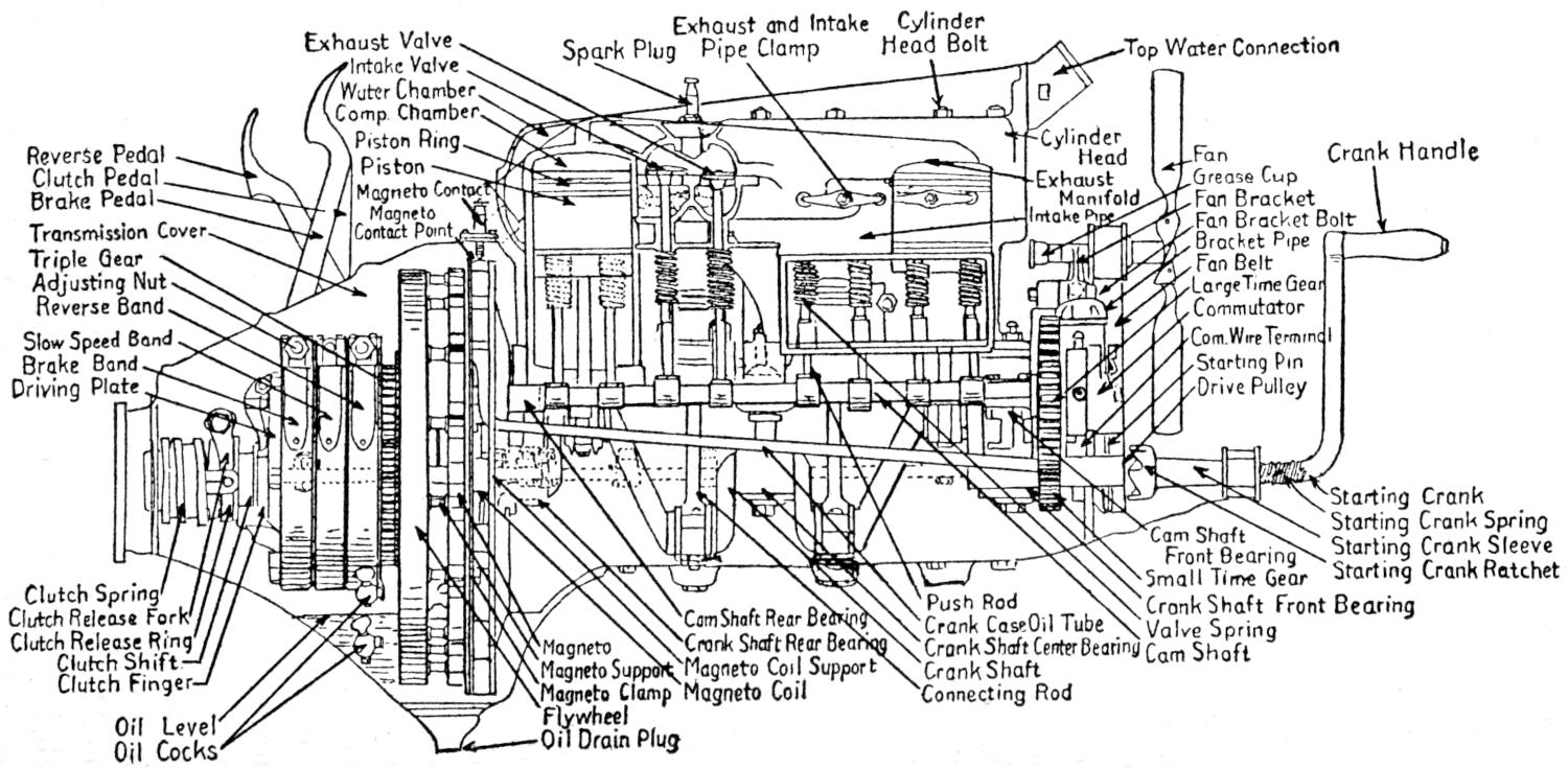
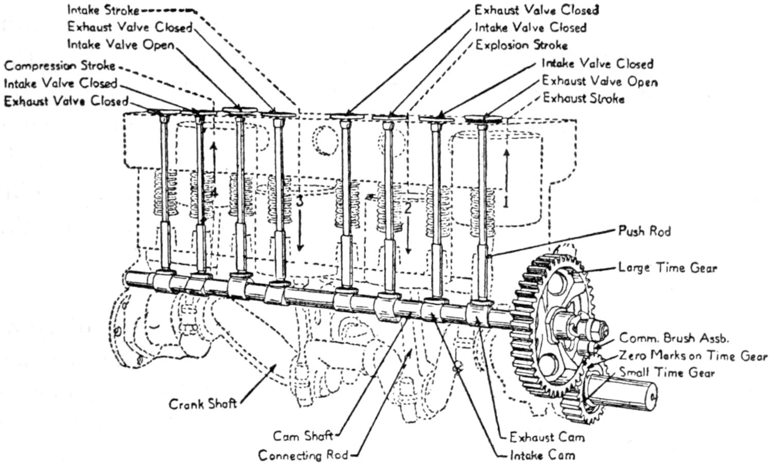
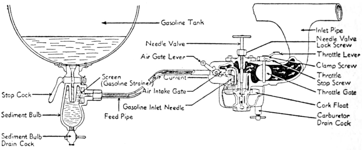
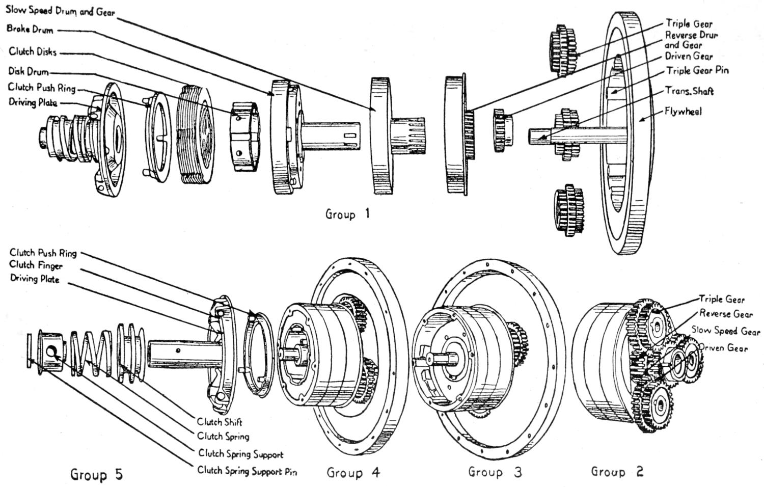
The automobile has taken its place as one of the most successful
and useful inventions of the day. It is equaled only
by the internal combustion gas engine, which is a factor in
making it practical and efficient.
Gasoline-propelled vehicles have become one of man’s greatest
aids in business efficiency, but nevertheless it is very important
that we consider the facts, that the adoption of the
automobile by man for business, commerce and pleasure is
on a very large scale, and that the production by manufacturers
is so great that very little thought is given to proper
care, which is an ever-present factor in economical operation
and a fair return for the investment.
The purpose of this book is to serve as a practical guide for
those who own, operate, or contemplate purchasing an automobile.
The contents of this book cover the entire field that would
be of value to the owner or chauffeur in making his own repairs.
The parts and expressions are given in their simplest
form; technical terms, tables and scales have been entirely
eliminated, as they mean little or nothing to the average
owner, and are of value only to the mechanical engineer and
draftsman.
The illustrations, drawings and diagrams are intended only
for the purpose of bringing out points that are more readily
understood and explained in this manner. No attempt has
been made to conform to proportionate exactness or scale accurateness.
Since there are many different makes of cars, motors, and
equipment, the functional action of all is practically the same,
therefore we use for illustration only those which are used by
the majority of manufacturers.
While, as a general rule, you will find all automobiles efficient
and reliable, troubles and conditions are bound to arise
that are somewhat puzzling; therefore, to assist the owner,
we have written a chapter on trouble hints conveniently arranged
in three columns, headed troubles, cause, and remedy.
The entire book is worked out along such lines, and so
arranged, that a man or a boy with a common school education
can easily master it and become an efficient mechanic.
INTRODUCTION
After twelve years’ experience with the automobile, I find
that only one-third of the present-day owners understand the
mechanical operation, care and proper upkeep of their cars;
the other two-thirds know little or nothing of their cars, and
are unable to locate or detect trouble, or make the slightest
adjustment necessary to remedy it. This fact remains as the
chief cause of the present high depreciation in cars, and the
loss of millions of dollars annually to automobile owners.
After two years of observation and close investigation, I
find the vast majority of the present owners are eager to acquire
mechanical knowledge, but they have not accomplished
their aim, chiefly because the available books to attain that
end are too technical, dry, and overdescriptive for the average
owner and beginner in mechanics.
The automobile is not an individually constructed piece of
machinery, but a combination of individual inventions, each
adapted to a functional purpose, which is necessary to the
harmony of successful operation. A great many of these
mechanical achievements are of delicate construction, and very
apt to get out of adjustment. This, however, is not always
the case, as grease, dirt and foreign matter with which the
various parts come in contact often prevent them from operating
properly.
Therefore a little common knowledge of operation and a
little care will enable an owner to operate his car successfully,
thereby avoiding unnecessary trouble, damage and expense.
One of the chief aims of the writer is to make this book
interesting and thorough, in order to hold the reader until
he understands the entire contents, after which he should be
able to make any necessary repairs and adjustments, or to
hold a position as automobile mechanic.
In order to accomplish the foregoing and prevent a student
from becoming discouraged we use functional principle
as the base for explanation whenever possible.
The instructions set forth in this book are not taken merely
from theory, but have been put into successful operation by
the writer, who for several years sold cars in outlying districts
where garage facilities were limited, and where it was
necessary to make a mechanic of every purchaser in order
to sustain the high reputation of the car sold. Later on his
plan of instructions was used in an automobile school where
he was chief instructor, and still later they were developed
into a note system which he used in establishing an automobile
school in the city of Toledo, Ohio.
The students turned out by this school were very efficient
and successful, and finished the course in less than one-half
the time usually required for the average automobile course.
This book was written during the twenty months that the
writer spent in the U. S. Army, from the note system used
in his automobile school.
Explaining the cycle. The 4-, 6-, 8-, 12-cylindered engine—The Knight sleeve valve engine—S. A. E.
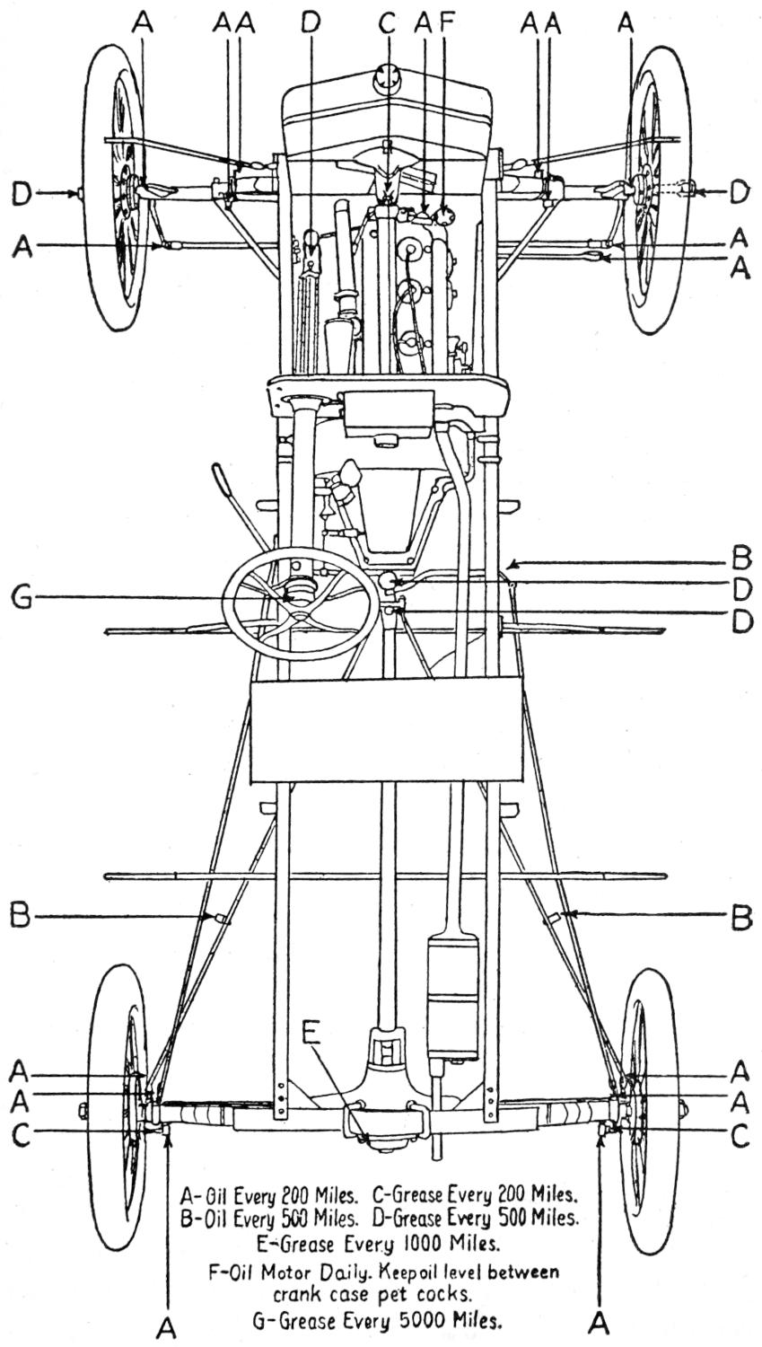
Horse Power scale—Displacement-Engine charts—Lubrication oils and greases—Lubrication systems—Care—Cleaning—and adjusting
of lubrication systems.
Purpose of cooling system—Circulating systems—The force pump circulating system—Overheating—Radiator
cleaning—Freezing—Freezing solutions—Radiator repairing—The air cooling system.
Operating principle—Purpose of the air vent—Failure to feed gasoline to carburetor—Removing
top—Cleaning gasoline strainer screen—Operating principle and general maintenance.
Operating principle—Primary or low tension circuit—Secondary or high tension circuit—Timing
magneto gears—Timing magneto with engine—The condenser—Safety spark gap—Interrupter timing range—Cutting out
ignition—Caution—Care—Maintenance.
Type K-2-Operating principle—Operation of contact maker—Contactless distributor—Wiring diagram of
current flowage—Setting and timing the unisparker—Timing with engine—Automatic spark advance—Contact point adjustment—Oiling
diagram—Condenser—Testing for ignition trouble.
CHAPTER XXI.
Philbrin Single Spark, and High Frequency Duplex Ignitioystems
Model G starter-generator operation—Wiring diagram—Starter-generator action—Mounting—Drive—Charging
rate adjustment—Fuse—Locating trouble—Starting switch and reverse current cut-out—Running with battery disconnected.
Motoring the generator—Cranking the engine—Generating electrical energy—Diagram of motor generator
operation—Lubrication—Ignition switch—Circuit breaker—Ignition coil—Distributor—Contact breaker and timer—Care.
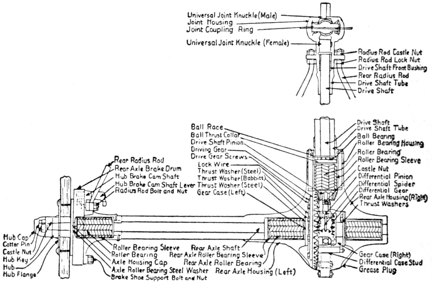
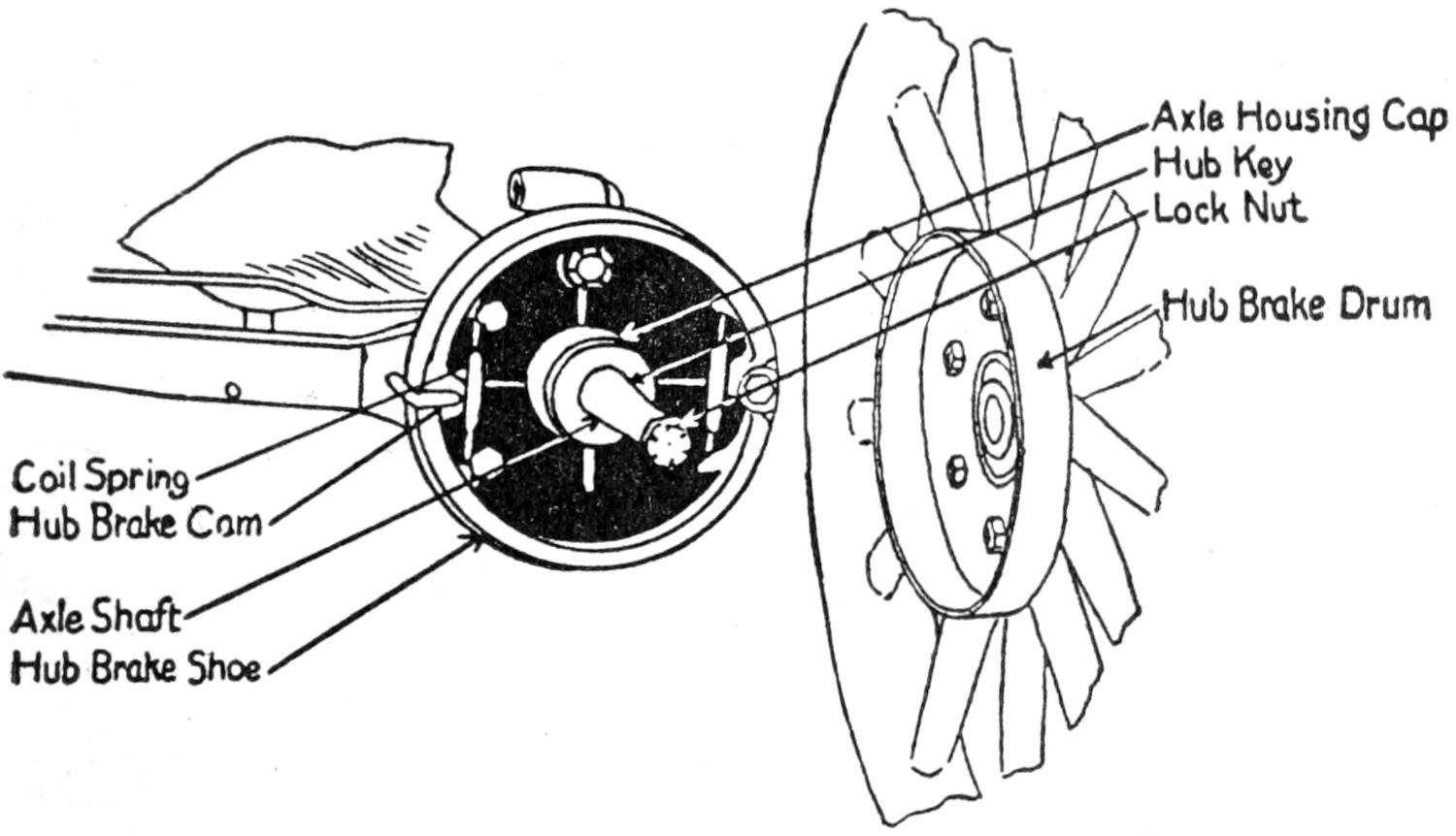
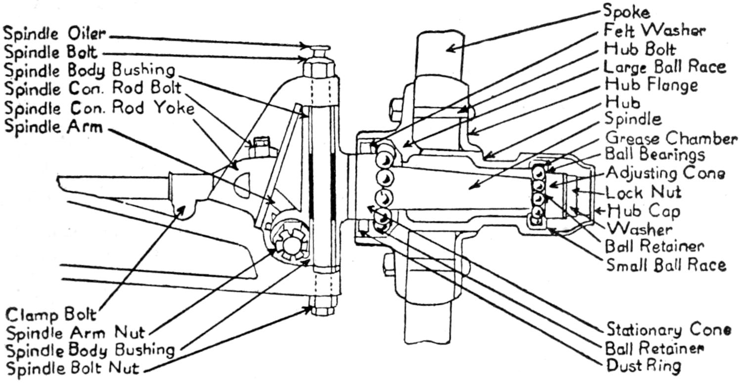
Dead axles—The semi-floating axle—Adjustment—Lubrication—The full-floating
axle—Construction—Adjustment—Lubrication—The I-beam front axle—The spindle—Steering knuckle—Care of all types.
Operation of worm and sector type—Adjustment of worm and sector type—Worm and nut type—Adjustment
of worm and nut type—Rack and pinion type—Connections—Drag link—General care.
INTRODUCTORY CHAPTER HISTORY OF THE GAS ENGINE AND EARLY AUTOMOBILE CONSTRUCTION — PURCHASING A NEW CAR Things to be Considered to Make the Investment Safe — PURCHASING A USED CAR How to Estimate Its Value — DRIVING INSTRUCTIONS — ROAD RULES FOR CITY AND COUNTRY — WHAT TO DO IN CASE OF ACCIDENT
THE AUTOMOBILE OWNER’S
GUIDE
A great many experiments were conducted with the explosive
type of motor between 1840 and 1860. These motors
were very heavy and crude affairs and furnished little or no
power. They were either abandoned or given up by those
conducting the experiments, and had all but disappeared in
the later 50’s. The chief difficulties that they could not overcome
were, the finding of a suitable and combustible fuel,
a way to distribute it to the explosion chambers in proper
proportion, and a device to ignite it at the proper time.
Many of these early inventions used coal tar gases and gunpowder
as fuel.
The first designs for an internal combustion engine of the
four stroke cycle type were devised in 1862 by M. Beau de
Rochas. These designs were taken in hand by a German by
the name of Otto, and many experiments were conducted by
him and two other Germans, Daimler and Benz, which resulted
in a fairly successful engine. The Otto Gas Engine
Co., of Deutz, Germany, was then formed with Daimler as
general manager. Experiments were carried on which resulted
in many improvements, such as valve adjusting and
electrical spark ignition. Many other smaller improvements
were worked out which overcame many of the difficulties of
the former and cruder devices.
The first gas engines were all of the single cylinder type,
very heavily constructed and produced from three to five
horse power. In 1886, Daimler conceived the idea of constructing
the multiple type of engine with water-jacketed
cylinders. Benz also completed a very successful motor in
the late fall of 1886, which embodied the water cooling idea.
The practical beginning of the gas engine as a factor in
vehicle propulsion began in the fall of 1886, when Daimler
applied his motor to a two-wheeled contrivance, which greatly
resembled our present-day motorcycle. While this machine
ran, it was not considered a very great success. Benz in the
early part of 1887, connected his motor to a three-wheeled
vehicle with which he was able to travel at the rate of three
miles per hour.
The real beginning of the present-day automobile took place
in Paris, France, in 1890, when M. Panhard secured the
patent rights from Daimler to use his engine. He then built
a four-wheeled vehicle, which carried some of the ideas of
present-day construction, such as a steering device and brakes.
To this he applied his engine and was able to travel at the rate
of six miles per hour. In 1891 Peugeot Frères completed
their vehicle and installed a Benz engine. This vehicle or
car, as it was then called by the French government on account
of its being mechanically driven, was able to make from
seven to eight miles per hour.
The perfecting of the automobile was hampered very much
between the years 1891 and 1898 by stringent laws that had
been enacted by the French government, which all but prohibited
the driving of a car on the public thoroughfare.
The first American-made automobile of the gas propelled
type was completed in the year 1892 by Charles Duryea.
This car embodied many of our present-day ideas but was
very lightly constructed and under-powered.
In 1893 another car made its appearance in America. This
car was built by Edward T. Haynes and was the beginning
of the present-day Haynes’ line of famous cars.
The first automobile club was organized in Paris, France,
in the year 1894 with the Marquis de Dion as president.
The purpose of this club was to secure a reformation of the
laws that had been enacted when the automobile made its first
appearance on the public thorough-fare, and to make laws
and rules to govern automobile racing.
At that time it was necessary when driving on a public
highway to have some one run seventy-five feet in advance
of a car waving a red flag, and to shout a warning at street
intersections. These stringent laws, however, were repealed by
the government through influential aid brought to bear on it
by the automobile club assisted by the rapid progress of the
automobile industry.
When you are going to buy a new car go about it in this
manner and protect your investment.
First.—Choose the car that suits you best in regard to
cost, operation, and appearance.
Second.—Inquire as to the financial status of the manufacturer.
If there is anything wrong with the car, or the
management of the company, it will show up here.
Third.—Orphaned cars may run as well and give as good
service as anybody could ask for, but when a company fails
or discontinues to manufacture a model, the car immediately
loses from one-third to one-half of its actual value. That is,
providing you wish to trade it in or sell it as a used car.
Fourth.—What kind of service does the agency in your
vicinity give? Do they take any interest in the cars they sell
after they are in the hands of the purchaser?
Fifth.—The amount of interest taken in your purchase by
the agent or service station usually determines the amount of
depreciation at the end of the season.
Sixth.—If you are purchasing your first car some little adjustments
will be required, and conditions will arise that require
understanding and attention. You, therefore, must acquire
either a functional and mechanical knowledge of the
operation, or depend on the agent or service station for help.
Seventh.—You will probably say that you can get along
without such help. You probably can, but what will be the
results? Will you be required to stand a loss in the long run
resulting from excessive repair bills and depreciation which
could have been prevented to a great extent?
Eighth.—Remember that an agent can fool you when you
are buying, but that you cannot fool him if you wish to sell
or trade in.
Ninth.—Remember that this book, The Automobile Owners’
Guide, was written to assist you in just such cases as we have
presented, and that by spending a little time in study you
can acquire a working knowledge of your car, and become
independent of the service station and the agent, which will
result in a big saving in both repair bills and depreciation.
The question is often asked, Does it pay to invest money
in a second-hand car? The answer may be either yes or no,
and depends entirely upon the condition of the car.
For example, A and B purchase a new car at the same
time. A is rather conservative. He is also a careful driver
and gives his car the best of attention. B is a careless driver
and pays little or no attention to adjustments and lubrication.
A has seen to proper lubrication and has kept the parts
properly adjusted and tightened up, and his careful driving
has kept the alignment in perfect condition. His car at the
end of the first season requires a little overhauling which will
put it in as good condition as it was when it was new as far
as service is concerned, and it is worth 85 to 90 per cent of
its original value.
B has not seen to proper lubrication and has allowed his
motor to overheat. The cylinders and pistons are scored and
worn, and the valves are warped and do not seat properly.
He drove into deep ruts and chuck-holes, and bumped into
curbs and posts while turning around. His axles and wheels
are out of line; the frame and all the running parts which
it supports are out of alignment. Overhauling will not put
this car in A-1 condition, and it is not worth more than 30
per cent. of the original cost price. It would be a poor investment
at any price to an owner who is buying it for his
own use.
Selecting and Testing a Used Car.—First.—If you are buying
from a dealer who trades in cars, judge his statement of
the condition of a car according to his ability as a mechanic
and according to his reputation for accuracy. If you are
buying from a reputable used car dealer his word can usually
be taken as a correct statement of conditions as his business
depends upon the accuracy of his statements and he knows
the condition of a car before he buys it.
Second.—See the former owner. Get his statement of the
condition of the car and the care it has had, and judge it
by his appearance, and the general appearance of his home
and property.
Third.—If the car is listed as Rebuilt or Overhauled, see
if the oil-pan, differential, and transmission covers have been
removed. If this has been done the old grease will either
have been cleaned off or show marks of the removal. If these
marks are found the proper adjustments and replacements
have probably been made.
Fourth.—Don’t judge the mechanical condition of a car by
its outward appearance.
Fifth.—Examine the tires and figure the cost of replacement
if any are found in poor condition.
Sixth.—Jack up the front axle and test the wheels for
loose or worn bearings.
Seventh.—Grasp the wheel at the top and bottom and
wiggle it to determine whether the spindle bolts or steering
device connections are worn.
Eighth.—Jack up the rear axle, set the gear shift-lever
into high-speed, move the wheel in and out from the bottom
to discover worn bearings, and move the wheel, forward and
backward, to determine the amount of back-lash in the differential
and universal joints.
Ninth.—Test the compression of the cylinders while the engine
is cold using the hand crank. If one cylinder is found
weak, a leak exists and the escaping compression can be
heard.
Tenth.—Run the motor until it is warm. If any weakness
in compression is noticeable the cylinders are probably scored,
or the rings may be worn. The valves may also be warped,
thereby preventing them from seating properly.
Eleventh.—Examine the shoulders of the cross-members
supporting the engine, radiator, or transmission to see if
they are cracked or broken.
Twelfth.—The battery may have deteriorated through improper
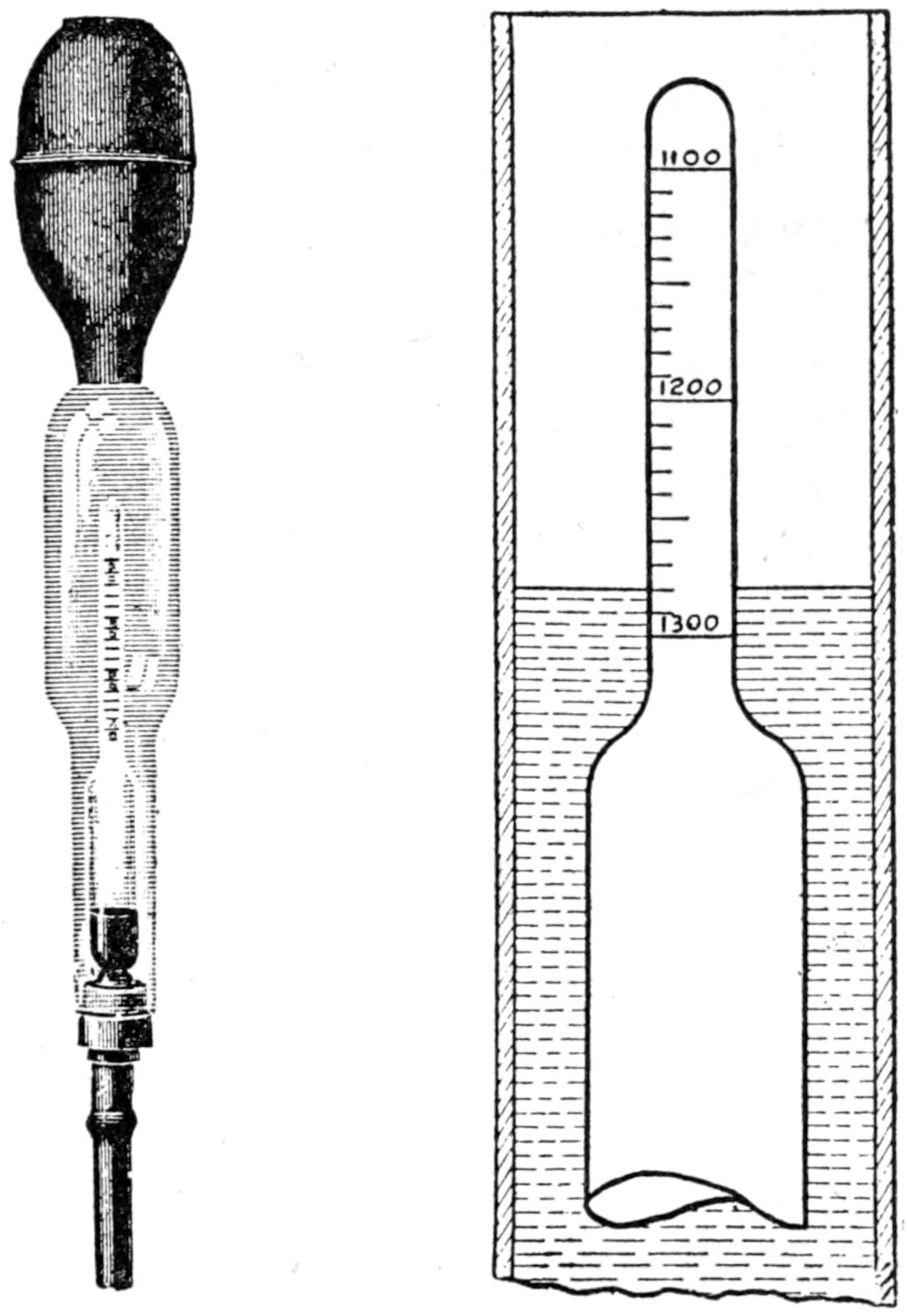
attention. Test the solution with a hydrometer. If
it is found well up, it can be passed as O. K.
Thirteenth.—Don’t judge the condition of the car by the
model, as a two or three-year-old model may be in better
mechanical condition than a six-month or year-old model.
A new driver should remain cool and take things in a
natural way as a matter of course. There is nothing to get
nervous or excited about when learning to drive a car. Any
one can master the art of driving quickly by remaining cool
and optimistic.
First.—Acquire some definite knowledge of the operation of
the engine and its accompanying devices.
Second.—Have some one explain the operation of the
accelerator, spark, and throttle levers.
Third.—Study the relative action of the clutch and gear-shifting
pedal.
Fourth.—The new driver takes the wheel and assumes a
natural and calm position with the muscles relaxed.
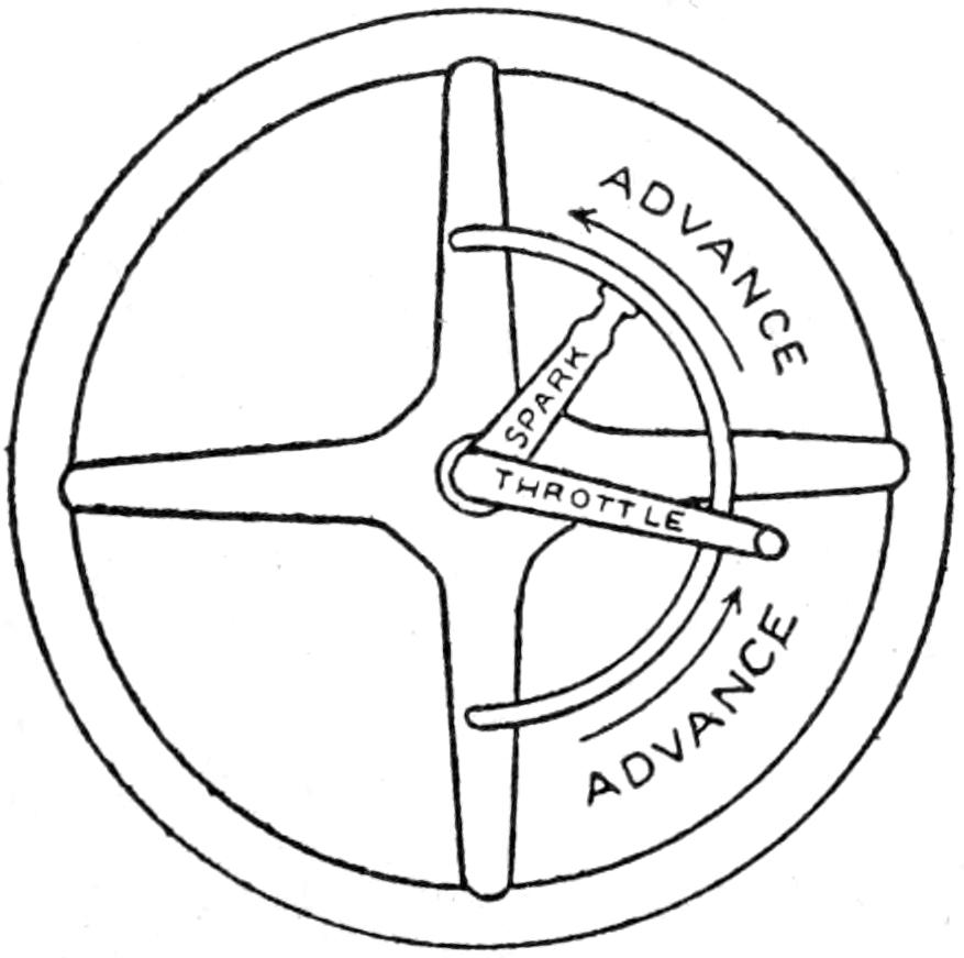
Fifth.—He adjusts the motor control levers. The throttle
lever is advanced one-fourth its sliding distance on the quadrant.
The spark lever is set to one-half the sliding distance
on the quadrant.
Sixth.—Push the ignition-switch button, IN, or ON, and
press the starter button, letting it up as soon as the engine
begins to fire.
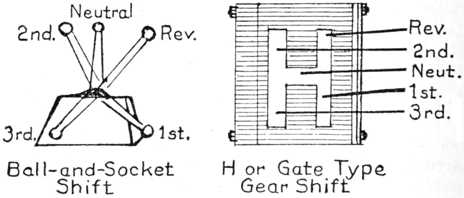
Seventh.—Not all gear-shifts are marked, consequently it
is a good idea to let the new driver feel out the different
speed changes. This is accomplished by pushing out the
clutch and placing the shift-lever into one of the four slots.
Now let up the clutch pedal until it starts to move the car,
continue the feeling-out process until the reverse speed gear
is located, and at this point impress on him that first and
reverse speeds, are always opposite each other, lengthwise
either on the right or left side of neutral, while second speed
is always crosswise opposite reverse, and high-speed is opposite
first on the other side of neutral.
Eighth.—Starting the car with engine running, advance the
spark-lever three-fourths the distance on the quadrant, advance
the throttle until the engine is turning over nicely
(not racing). Place one hand on the steering-wheel and with
the other grasp the gear-shift-lever, push in the clutch pedal,
hold it for five seconds, in order that the clutch brake may
stop rotation. Place the shift-lever into the first-speed slot
and let up on the clutch pedal. The car should be driven
four or five hundred feet on this speed until the driver acquires
the “nack” of steering.
Ninth.—To shift to second speed advance the gas throttle
until the car gathers a smooth rolling motion, press in the
clutch pedal and allow three to five seconds for the brake to
retard the speed of the clutch, then shift the lever to second
speed and release the clutch pedal easily.
Tenth.—To shift into high-speed retard the throttle lever
a trifle (to prevent the engine from racing), throw out the
clutch and shift the lever into the high-speed slot. Perform
these operations slowly but without hesitation.
Eleventh.—To shift to reverse speed go through the same
operation that you followed when first was used, except that
the shift-lever is placed in the reverse slot.
Twelfth.—The reverse speed-gear is never engaged unless
the car is at a “stand-still,” as this gear turns in an opposite
direction.
Thirteenth.—Always test the emergency brake lever and the
speed shift-lever, to be sure that they are in a neutral position
before starting the engine.
Fourteenth.—Remember that in case of emergency the car
can be stopped quickly by pushing in both foot-pedals. Pressure
on the clutch pedal disconnects the engine from the car,
while pressure on the “foot” or service brake pedal, slows up
the motion of the car and will bring it quickly to a stand-still.
Fifteenth.—Always push the clutch out when using the
service brake to check the rolling motion of the car.
Sixteenth.—When you wish to stop the car and motor kick
out the clutch and hold it in this position while you stop the
rolling motion of the car with the service brake and shift
the gears to neutral. Then set the emergency brake and turn
off the switch to stop the motor.
If the engine cannot take the car up a steep grade in low
speed (due to defective motor or gravity fuel feed) stop, engage
reverse speed, turn off the ignition switch, and let the
car back down to level or a place where you can turn around,
and back up the hill. The reverse speed is geared from one
and a half to two times lower than first speed.
Nineteen.—To stop the back wheels from skidding turn the
front wheels in the direction which the back wheels are sliding
and release the brakes. Turning away or applying the
brakes adds momentum to the sliding motion.
Twenty.—If for any reason you must or cannot avoid driving
into the ditch unless the ditch is very shallow, turn the
car directly toward the opposite bank. The front or rear
springs will lodge in the bank and prevent the car from
rolling over and crushing the occupants, and the car can be
drawn out more easily from this position.
1.—Be courteous to all whom you meet and give your assistance
if necessary.
2.—When encountering a bad stretch of road, with the
track on your side, don’t drive in and force another machine
coming towards you to get out of the track. WAIT.
3.—Never block a track. In case you wish to stop and
talk to some one, drive to one side.
4.—Keep on the right hand side of the road at all times,
whether moving or standing, except as prescribed in Paragraph
5.
5.—In passing vehicles traveling in the same direction,
always pass on the left and blow the horn.
6.—In passing a vehicle that has just stopped, slow down
and sound the horn.
7.—In changing your direction, or stopping, always give the
appropriate hand signal.
8.—Hand signals, straight up or up on 45° angle, STOP.
Straight out or horizontal, TURNING TO THE LEFT.
Down at an angle of 45°, TURNING TO THE RIGHT.
9.—The distance between vehicles outside of towns and
cities, 20 yards; between vehicles passing through towns and
cities, 5 yards; between vehicles halted at the curb, 2 yards.
10.—Bring all vehicles under easy control at street and road
intersections.
11.—A maximum driving speed should not exceed 7 miles
in business sections of cities, 15 miles in residential sections,
25 miles on country roads.
12.—Form the habit of slowing down and looking both ways
before crossing tracks.
13.—Always pass a street car on the right side.
14.—Always stop 8 feet from a street car when passengers
are getting off, unless there is a safety zone, then
drive slowly.
15.—Never drive over the side-walk line while waiting for
signal of traffic officer.
16.—Notify traffic officer which way you wish to turn
with hand signal.
17.—Always stop and wait for an opening when driving
from a side street or road into a main thoroughfare.
18.—Make square turns at all street corners unless otherwise
directed by traffic officer.
19.—If you wish to turn from one street into another wait
until the traffic officer gives the straight ahead signal, then
give the appropriate signal to those in the rear.
20.—Always drive near the curb when you wish to turn to
the right, and to the right of the center line of the street
when you wish to turn to the left.
21.—Drive straight ahead at 42nd St. and 5th Ave., N. Y.,
and at Market and Broad St., Newark, N. J. These corners
handle more traffic than any two corners in the United States.
No turns are made at either corner.
22.—Exercise care not to injure road ways.
23.—Do not damage improved roads by the use of chains
when unnecessary.
24.—In case the car is not provided with chains, rope
wrapped around the tires will make a good substitute.
25.—In case of fire, do not try to put it out with water as
the gasoline will only float and spread the fire. Use a fire
extinguisher or smother with sand or with a blanket.
1.—In case of injury to person or property stop car and
render such assistance as may be needed.
2.—Secure the name of person injured or of owners of
said property.
3.—Secure names and addresses of witnesses to the accident.
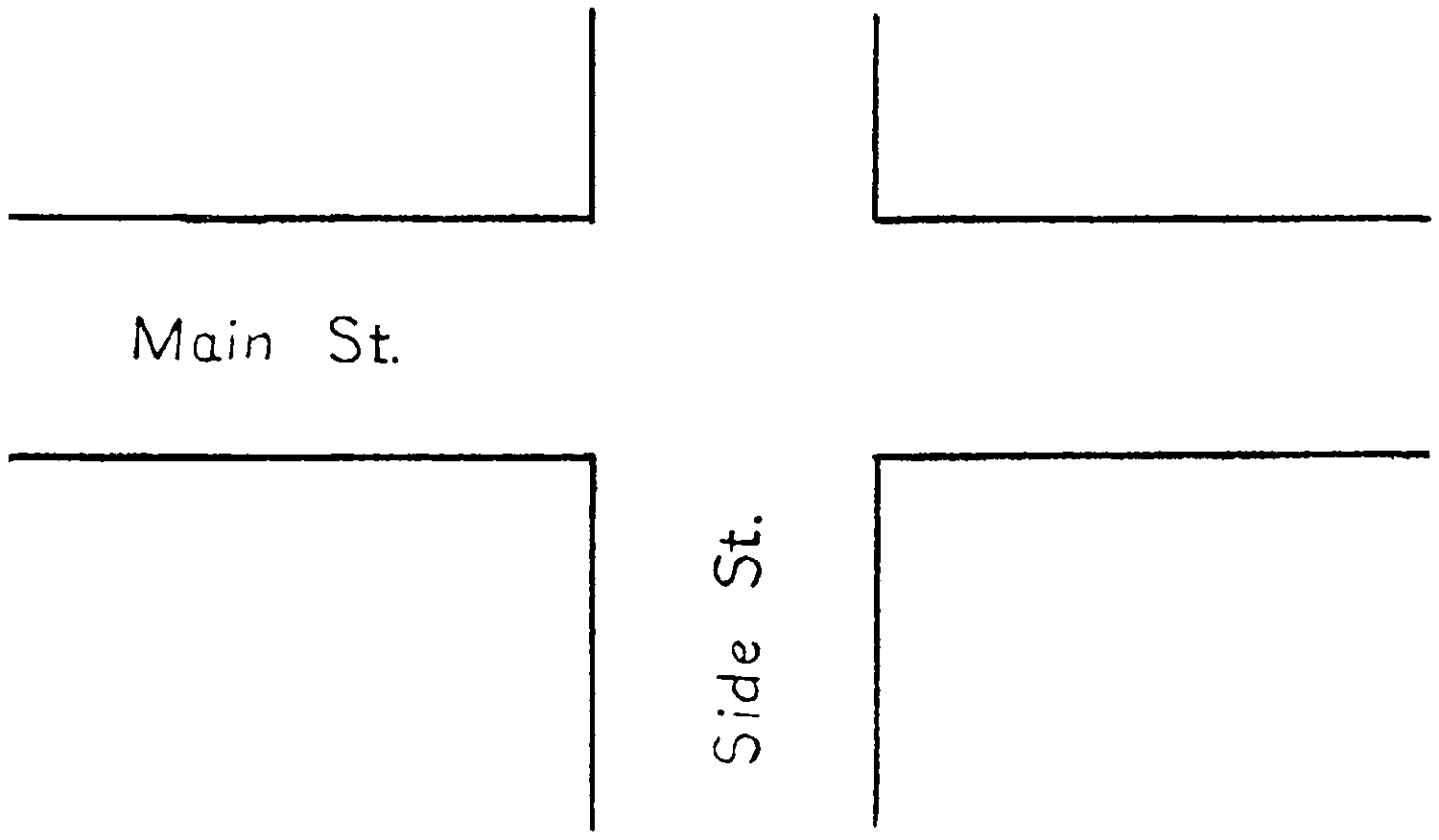
4.—Draw diagram of streets as shown in Fig. A. Show
relative positions of the colliding vehicles and the object of
pedestrian just before the accident.
Fig. A. Street Intersection
5.—Label streets and every object depicted and add measurements
and line showing course followed by vehicles, etc.,
and any explanatory statements which would aid an understanding
of the occurrence.
6.—File this report at police headquarters.
CHAPTER I GAS ENGINE CONSTRUCTION, AND PARTS
We will use for purposes of illustration the common four-cylinder,
four cycle, cast en bloc, “L”-head type of motor, as
this type is used probably by 90% of the automobile manufacturers.
The block of this type of motor is cast with an
overlapping shoulder at the upper left hand side which contains
a compartment adjoining the combustion chamber in
which the intake and exhaust valves seat, and the casting is
made, in the shape of the Capital letter L turned upside down.
This arrangement allows both valves to seat in one chamber
and to operate from one cam shaft.
The operation of each cylinder is identically the same
whether you have a one or a many cylindered motor, consequently
when you have gained a working knowledge of one
cylinder, others are a mere addition. This may sound confusing
when the eight or twelve cylindered motor is mentioned,
but is more readily understood when we consider the
fact that an eight or twelve cylindered motor is nothing more
than two fours or two sixes, set to a single crank-case or base
in V-shape to allow the connecting rods of each motor to
operate on a single crank shaft. This arrangement also allows
all the valves to operate from a single cam shaft, thereby
making the motor very rigid and compact, which is an absolute
necessity considering the small space that is allowed for
the motor in our present-day designs.
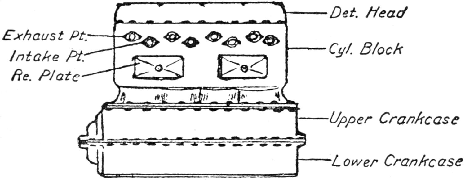
Fig. 1. The casting or block, which is the foundation of the
whole motor or engine, usually has a removable head which
allows for easy access to the pistons and valves. The block
is cast with a passage or compartment through the head
and around the cylinders through which water circulates for
cooling the adjoining surfaces of the cylinders. This alleviates
the danger from expansion and contraction caused by
the tremendous heat generated in and about the combustion
chambers. This block also contains the cylinders and valve
seats. The pistons and valves are fitted to their respective
positions as construction progresses.
Det. Head
Exhaust Pt.
Intake Pt.
Re. Plate
Cyl. Block
Upper Crankcase
Lower Crankcase
Fig. 1. Typical Four-cylinder Block
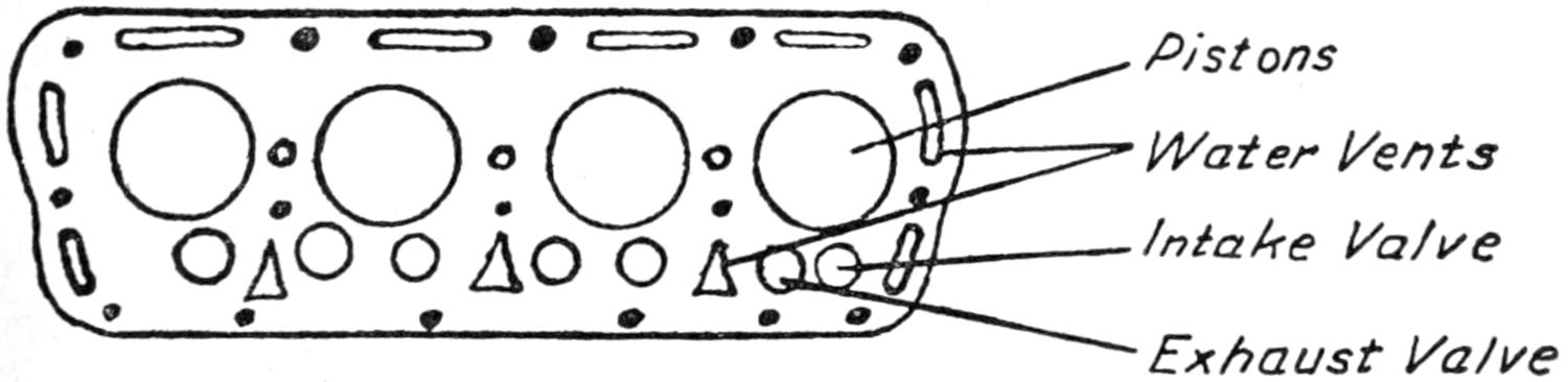
Fig. 2. The block with head removed shows the smooth
flush surface of the block face and the location of the cylinders
in which the pistons operate or slide, with each power
impulse or explosion. When the piston is at its upper extreme
it comes within a sixteenth of an inch of being flush
with the top of the block, while the valves (also shown in
Fig. 2) rest on ground-in seats, in their respective chambers,
and are operated by a stem which extends downward from
the head through a guide bushing in the block to the cam
shaft.
Pistons
Water Vents
Intake Valve
Exhaust Valve
Fig. 2. Cylinder Block With Head Removed
The location of the water vents is also shown, through
which water is circulated to prevent the cylinders from overheating
which would cause the pistons to “stick” from expansion.
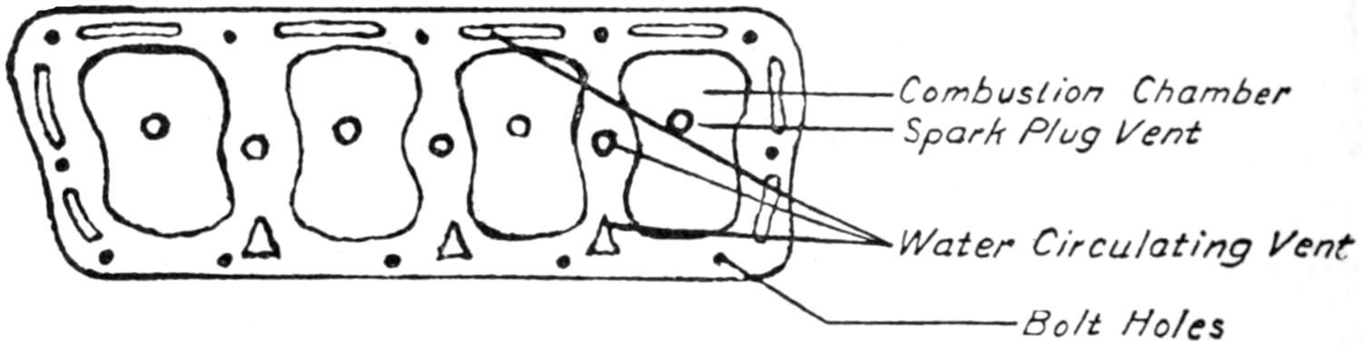
Fig. 3. The top or head of the motor is removed, exposing
the combustion chambers. These chambers must be absolutely
air-tight as the charge of gas drawn in through the
inlet valve is compressed here before the explosion takes place,
and low compression means a weak explosion, which causes
the motor to run with an uneven-jumpy motion, and with
an apparent great loss of power. A copper fiber insert gasket
is placed between the top of the block and the head before it
is bolted down. This gasket prevents any of the compression
from escaping through unevenness of the contact surfaces, as
metal surfaces are prone to warp when exposed to intense heat.
It is necessary to turn the bolts in the head down occasionally,
as the heat causes expansion. The following contraction,
which loosens them, results in a loss of compression and a
faulty operation of the motor.
Combustion Chamber
Spark Plug Vent
Water Circulating Vent
Bolt Holes
Fig. 3. Removable Cylinder Head (Reversed)
The spark-plug vents through the head are usually located
directly over the piston although in some cases they are over
the valve head and in some motors which are cast without a
removable head they may be at one side of the combustion
chamber. The location of the spark-plug does not materially
affect the force of the explosion, although when it is located
directly over the piston a longer plug may be used, as the
pistons do not come up flush with the top of the block,
and a spark-plug extended well into the combustion chamber
will not become corroded with carbon or burnt oil as is usually
the case with a plug which does not extend beyond the upper
wall surface of the combustion chamber.
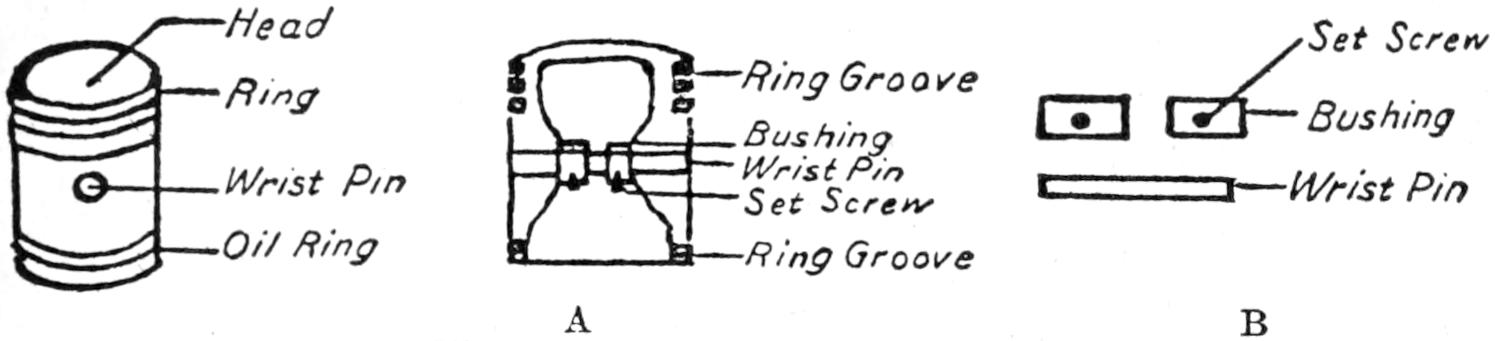
Fig. 4. The plunger or piston is turned down to fit snugly
within the cylinder and is cast hollow, with two shoulders extending
from the inside wall.
Head
Ring
Wrist Pin
Oil Ring
Ring Groove
Bushing
Wrist Pin
Set Screw
Ring Groove
Set Screw
Bushing
Wrist Pin
Fig. 4. Typical Cylinder Piston
Fig. 4A shows a split piston. Three grooves are cut into it
near the head to receive the piston rings. The width and
depth of these grooves vary according to the size of the piston.
A hole is bored through the piston and shoulders about half
way from each end. The bushing or plain bearing shown in
Fig. 4B is pressed into this hole and forms a bearing for the
wrist pin also shown in Fig. 4B. Wrist pins are usually made
of a much softer metal than the bearing, and are subjected to
severe duty, which often causes them to wear and produce a
sharp knock; this may be remedied by pressing out the pin,
giving it a quarter turn, and replacing it in that position.
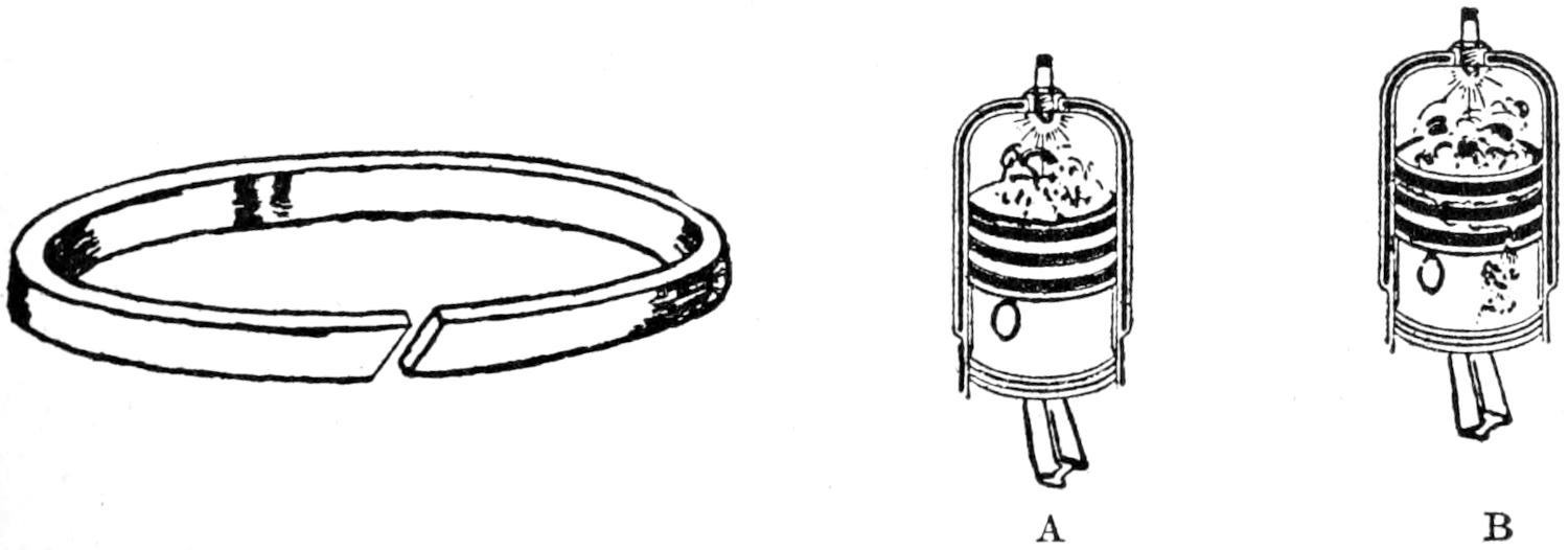
Fig. 5. Typical Piston Ring
Fig. 5 shows a split joint piston ring. Piston rings are
usually made from a high grade gray iron, which fits into
the grooves in the piston and springs out against the cylinder
walls, thereby preventing the compressed charge of gas from
escaping down the cylinder, between the wall and the piston.
Fig. 5A shows a piston equipped with leak-proof rings; this
type of piston ring has overlapping joints, and gives excellent
service, especially when used on a motor which has seen
considerable service. Fig. 5B illustrates how piston rings
may line up, or become worn from long use, or from faulty
lubrication. This trouble may be easily detected by turning
the motor over slowly. The escaping charge can usually be
heard and the strength required to turn the motor will be
found much less uniform on the defective cylinder.
The motor should be overhauled at least once every year,
and by applying new rings to the pistons at this time new
life and snappiness may be perceived at once.
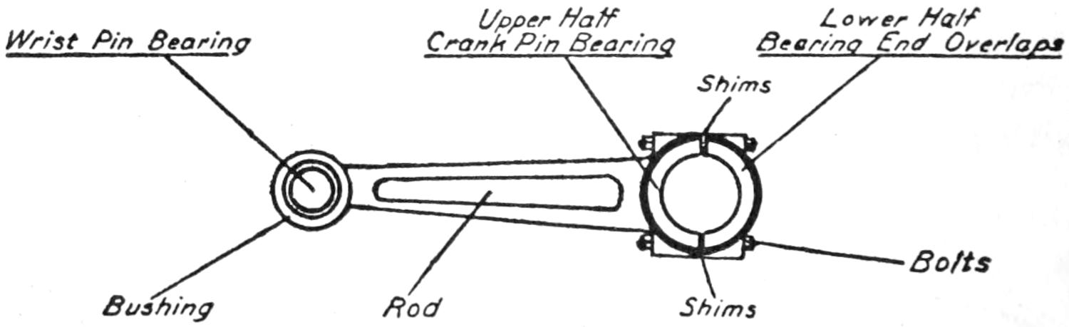
The connecting rod shown in Fig. 6 has a detachable or split
bearing on the large end, and takes its bearing on the crank
pin of the crank shaft. The small or upper end may have
either a hinge joint or press fit to the wrist pin. This rod
serves as a connection and delivers the power stroke from the
piston to the crank shaft. These rods are required to stand
very hard jars caused by the explosion taking place over the
piston head. The bearings are provided with shims between
the upper and lower half for adjusting. Piston or connecting
rod bearings must be kept perfectly adjusted to prevent
the bearings from cracking or splitting which will cause the
rod to break and which may cause considerable damage to the
crank case.
Wrist Pin Bearing
Upper Half Crank Pin Bearing
Lower Half Bearing End Overlaps
Shims
Bolts
BushingRod
Shims
Fig. 6. Typical Connecting Rod
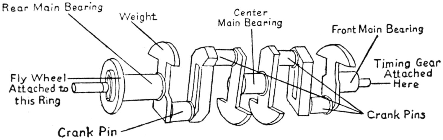
Fig. 7 shows a counter balanced crank shaft. This type
of crank-shaft is provided with weights which balance the
shaft and carry the momentum gathered in the revolution.
Rear Main Bearing
Weight
Center Main Bearing
Front Main Bearing
Fly Wheel Attached to this Ring
Timing Gear Attached Here
Crank Pin
Crank Pins
Fig. 7. Counter-Balanced Crank Shaft
Main Bearings
Fig. 8. 5-M-B Crank Shaft
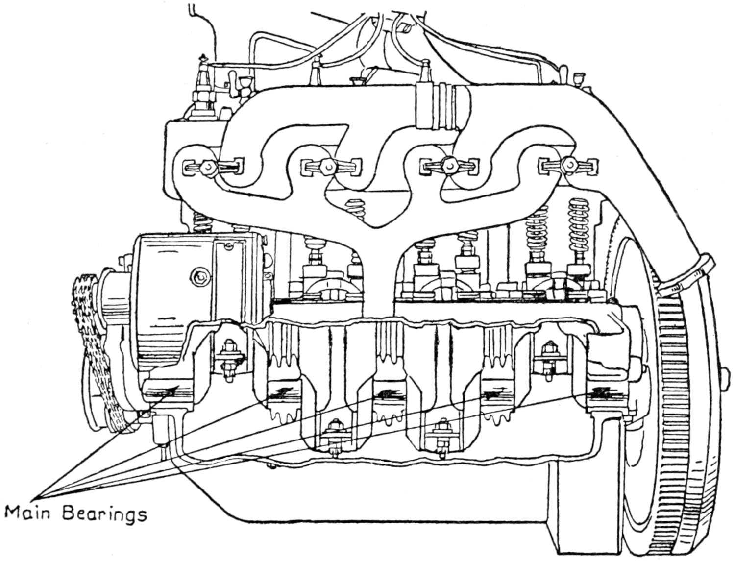
Fig. 8 shows the plain type of crank shaft with the timing
gear attached to the front end and the fly-wheel attached to
the rear end. The crank shaft shown is carried or held by five
main bearings, which is an exception, as the majority of motor
manufacturers use only three main bearings to support the
crank shaft, while in some of the smaller motors only two are
used. These bearings are always of the split type, the seat
for the upper half is cast into the upper part of the crank-case,
and the lower half is usually attached to the upper half
by four bolts which pass through the flange at each side of
the bearing. Small shims of different sizes are employed between
the flanges of each half of the bearing in order to secure
a perfect adjustment which is very essential, as these
bearings are subjected to heavy strains and severe duty. A
shim may be removed occasionally as the bearing begins to
show wear. A worn main bearing can be detected by placing
the metal end of a screw-driver or hammer on the crank-case
opposite the bearing and the other end to the ear. If the
bearing is loose or worn a dull bump or thud will be heard.
This looseness should be taken up by removing a shim of the
proper thickness.
Cam Gear
Bearings
Cams
Cams
Fig. 9. Cam Shaft
Main bearings run loose for any length of time will be
found very hard to adjust as the jar which they are subjected
to invariably pounds them off center which makes readjustment
a very difficult task to accomplish with lasting effect.
New main bearings in a motor should always be scraped to
secure a perfect fit. A loose piston or connecting rod bearing
will produce a sharp knock which can easily be determined
from the dull thud produced by a loose main bearing. (Fig.
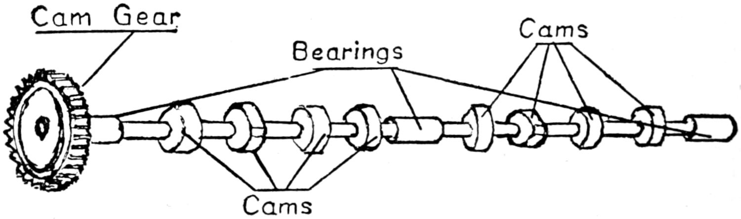
9.) The cam shaft revolves on bearings and is usually located
at the base of the cylinders on the left hand side looking toward
the radiator and carries a set of cams for each cylinder.
The cam pushes the valve open, and holds it in this position,
while the piston travels the required number of degrees of the
cycle or stroke.
The cam shaft is driven from the crank shaft usually
through a set of timing gears, and operated at one-half the
speed of the crank shaft in a four cycle motor, as a valve is
only lifted once, while the crank shaft makes two revolutions
or four strokes. The cam-shaft bearings, and the timing gears
are usually self-lubricating and require very little attention.
Timing of the cam shaft is a rather difficult matter and will
be treated in a following chapter under the head of valve
timing.
Start Gear
Key-Seat
Shaft-Seat
Cone Clutch Seat
Disc Clutch Small Disc Bolt on Here
Fig. 10. Flywheel
The oil pan or reservoir forms the lower half or base of the
crank case. The lubricating oil is carried here at a level which
will allow the piston rods to dip into it at each revolution of
the crank shaft. The timing gears receive their lubrication
from the supply carried in the reservoir by means of a plunger
or piston pump which is operated from the cam shaft. The
balance of the motor is usually lubricated by a splash system
taken up in a later chapter on lubrication. The oil is carried
at a level between two points marked, high and low, on a glass
or float gauge which is located on the crank case. A gasket
made of paper or fiber is used between the union or connection
of the oil reservoir and the upper half of the crank
case to prevent the oil from working out through the connection.
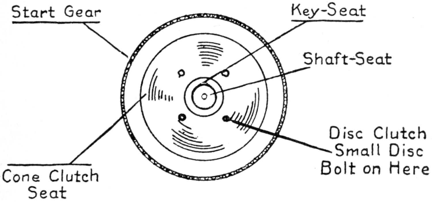
Fig. 10 represents the flywheel. The flywheel is usually
keyed to the crank shaft directly behind the rear main bearing.
This wheel is proportionate in weight to the revolving speed
of the motor, which it keeps in balance by gathering the force
of the power stroke. The momentum gathered by it in this
stroke carries the pistons through the three succeeding strokes
called the exhaust, intake, and compression strokes. The flywheel
also serves as a connection between the power-plant and
the running gear of the car, as a part of the clutch is located
on it, and the connection takes place either in the rim or on
the flange.
CHAPTER II VALVE CONSTRUCTION, TYPES, AND OPERATION — VALVE CONSTRUCTION, TYPES, AND OPERATION 8-CYLINDERED V-TYPE ENGINE — VALVE CONSTRUCTION
The proper and accurate functional operation of the valves
is as necessary to successful motor operation as the proper
adjustment of a hairspring is to a watch, for if a hairspring
becomes impaired in any way, a watch will not keep
correct time. This is the case in a motor when a valve becomes
impaired. The valves in a motor, therefore, must be
considered the most vital part conducive to successful and
economical operation of the motor.
The valves are manufactured from a high grade tungsten
or carbon steel, and are designed to withstand the intense
heat which the heads located in the combustion chambers
are subjected to, without warping. A perfect seat is required
to prevent leaking, which will cause low compression and a
weak power impulse, thus reducing the power and harmony
of successful operation.
The poppet valve is used by about ninety-five per cent. of
motor manufacturers. This type of valve is mechanically
operated from the cam shaft at one-half the crank shaft
speed, as a valve is lifted only once in every four strokes,
or two revolutions of the crank shaft. The reduction in
speed is accomplished by using a gear on the cam shaft,
twice the size of that on the crank shaft.
The heads and chambers must be kept free from carbon
which forms and bakes into a shale and has a tendency to
crack and chip as the temperature changes in the combustion
chambers. These chips are blown about in the
cylinders until they lodge or are trapped by the descending
valves. It then forms a pit on the seat and prevents the
valves from seating properly. This leaves an open space
which attracts more carbon, and the entire functional action
of the valve is soon impaired, necessitating regrinding in order
that it may properly seat again.
Carbon is generated from a poor gas mixture or from
excessive use of lubricating oil and may be considered the
chief cause of improper functional action of the valves.
Valve Head
Removable Plates
Cam Shaft
Valve Head
Valve Seat
Valve Seat
Tappet for Adjusting Valves
Tappet for Adjusting Valves
Fig. 11. 8-Cylinder Valve Arrangement
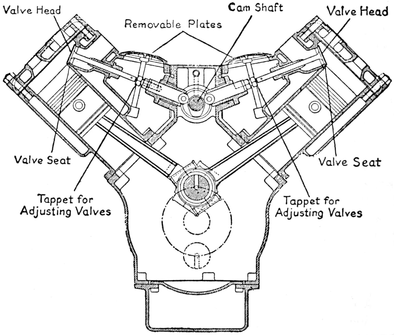
Fig. 11 shows the location of the cam shaft, valves, and
tappet adjustment, on a V-shaped engine. The cylinders
of this type of engine are arranged in two blocks, consisting
of four cylinders in each, set directly opposite each other
on an angle of 90°. The connecting rods from opposite
cylinders are yoked and take their bearing on the same crank
pin. This arrangement allows the intake and exhaust valves
of each opposite cylinder to operate from a single cam shaft,
or in other words the entire sixteen valves are operated by
a single cam shaft carrying eight cams. Consequently an
eight or twelve cylindered engine is identical in regard to
valve timing to either a four or six cylindered engine.
Valve Head
Valve Seat
Valve Guide
Valve Stem
Valve Spring
Sp. Seat
Cap Screw
Tappet
Lock Nut
Guide Bushing
Push Block
Roller
Cam
Fig. 12. Poppet Valve
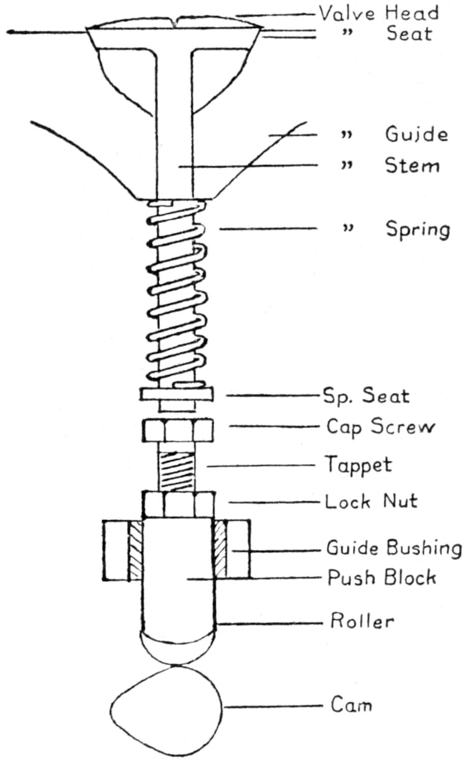
Fig. 12 shows a poppet valve. This type of valve has
only one adjustment, called the tappet. The adjustment is
made by turning the cap-screw out of the push block until
the head comes into contact with the valve stem. The lock
nut on the cap screw is then turned down tightly to the
push block to hold the adjustment. A strong spring is placed
on the valve stem which causes it to close quickly and remain
closed until it comes into contact with the cam.
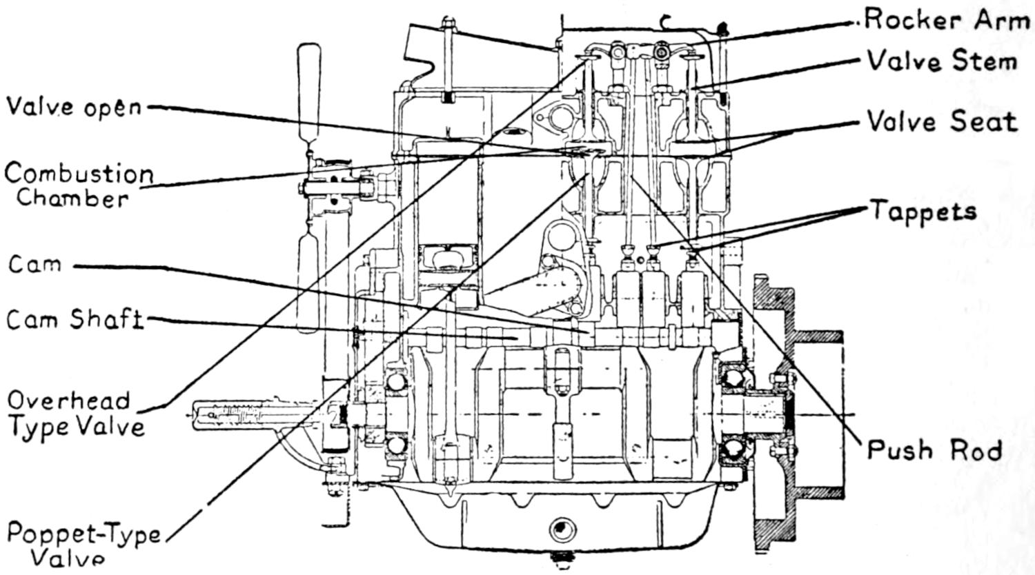
Valves are set and operate in three different positions as
shown in Fig. 13. The exhaust valve in this case seats on
the floor of the combustion chamber and is operated by the
stem which extends through the casting to the tappet, while
the intake valve seats on the upper wall of the combustion
chamber and is operated from over head by a push-rod extending
from the tappet to a rocker-arm. When both valves
are operated from above and seat on the upper wall of the
combustion chamber the motor is referred to as the overhead
valve type of motor. In the majority of motors both
valves seat on the floor of the valve chamber.
Rocker Arm
Valve Stem
Valve Open
Valve Seat
Combustion Chamber
Tappets
Cam
Cam Shaft
Overhead Type Valve
Push Rod
Poppet-Type Valve
Fig. 13. Valve Types, Location and Operation
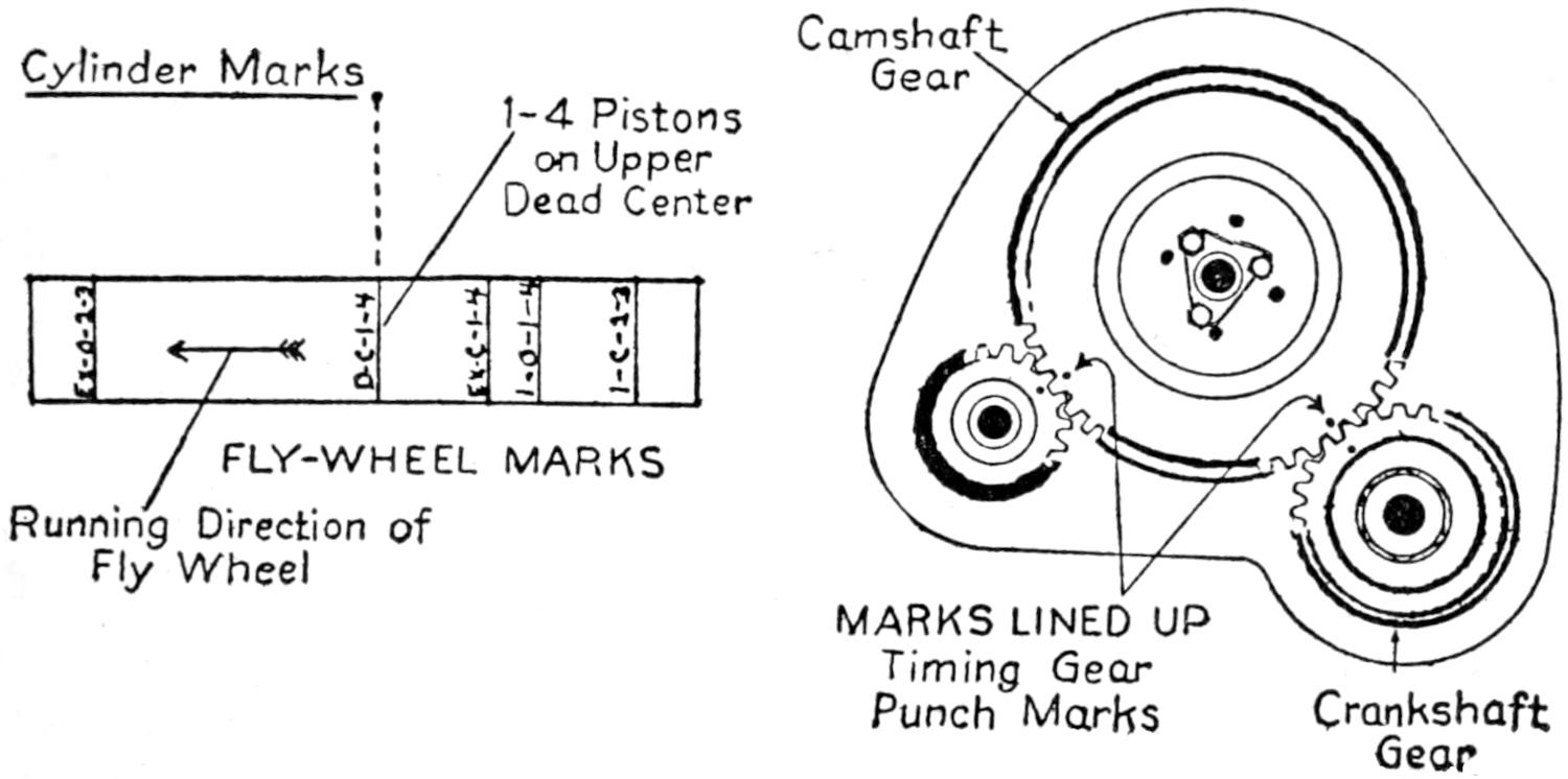
Valve Timing.—Valve timing is usually accomplished by
setting the first, or exhaust valve cam, to correspond with a
mark on the flywheel and cylinder (shown in Fig. 14).
This is accomplished by lining up the 1⁄4, or 1⁄6 D-C mark on
the flywheel rim with the center mark on the cylinder block,
and means that 1⁄4, or 1⁄6, pistons are on upper dead center of
the compression stroke, the flywheel is then turned a trifle
until the marks E-C, or Ex-C, is at upper dead center and in
line with the mark on the cylinder block. This means that
the exhaust valve closes at this point. The cam shaft is then
turned in the running direction and the cam shaft gear meshed
at the valve closing or seating point. This is all that is necessary
as the other cams take up correct operation when any
one cam is set properly.
Another method of valve timing used by some motor manufacturers
is shown in Fig. 14. It is simply necessary in
this case to line up the prick punch marks on the timing gears—after
getting the first position on upper D-C of the compression
stroke—to acquire correct valve time. No definite or
average scale can be given for valve timing, as all different
types of motors are timed differently. These instructions must
be secured from the manufacturer when the motor is not
marked.
Cylinder Marks
Camshaft Gear
1-4 Pistons on Upper Dead Center
FLY-WHEEL MARKS
Running Direction of Fly Wheel
MARKS LINED UP Timing Gear Punch Marks
Crankshaft Gear
Fig. 14. Valve Timing Marks
Valve Grinding.—A valve-grinding compound can be purchased
at any garage or service station or one may be compounded
by mixing emery dust with a heavy lubricating oil
until a thin paste is formed. The valve spring is released
next by forcing up the tension with a screw driver or valve
lifter. A small H-shaped washer is drawn from a groove
near the end of the stem, which frees the valve; it can then
be pushed up and raised through the guide. A small spring
is placed over the valve stem. This spring should be strong
enough to raise the valve one-half inch above the seat. A
thin film of the grinding compound is evenly applied to the
seating face of the valve head, a screw driver or ratchet fork
is set in the groove on the head of the valve, and the handle
rolled between the palms of the hands, covering about one-third
of the distance around the valve seat; the valve is let up
after the motion has been repeated four or five times, and repeated
at another angle until the entire surface of the valve
is smoothly ground and allows the valve to seat perfectly.
Valves.—The sleeve valve type of motor was invented
several years ago by Charles A. Knight. He met with some
difficulty in having it manufactured in this country because
the lubrication system was thought to be inadequate and the
poppet valve was then at the height of its popularity with
the manufacturer of engines.
Knight took his engine to Europe and made some slight
improvements on it. It was then taken over and manufactured
by one of the large automobile manufacturing companies
of that continent and is now being used by many of
the celebrated automobile manufacturers of every country.
The principle of operation does not differ in any respect
from the ordinary type of four cycle motor, except, that instead
of having the poppet type of valves it has a set of
sleeves which slide up and down on the piston. The sleeves
are operated from an eccentric shaft by a short connecting
rod and carry ports which are timed to line up with the
ports of the intake and exhaust manifold ports at the proper
time in the cycle of operation.
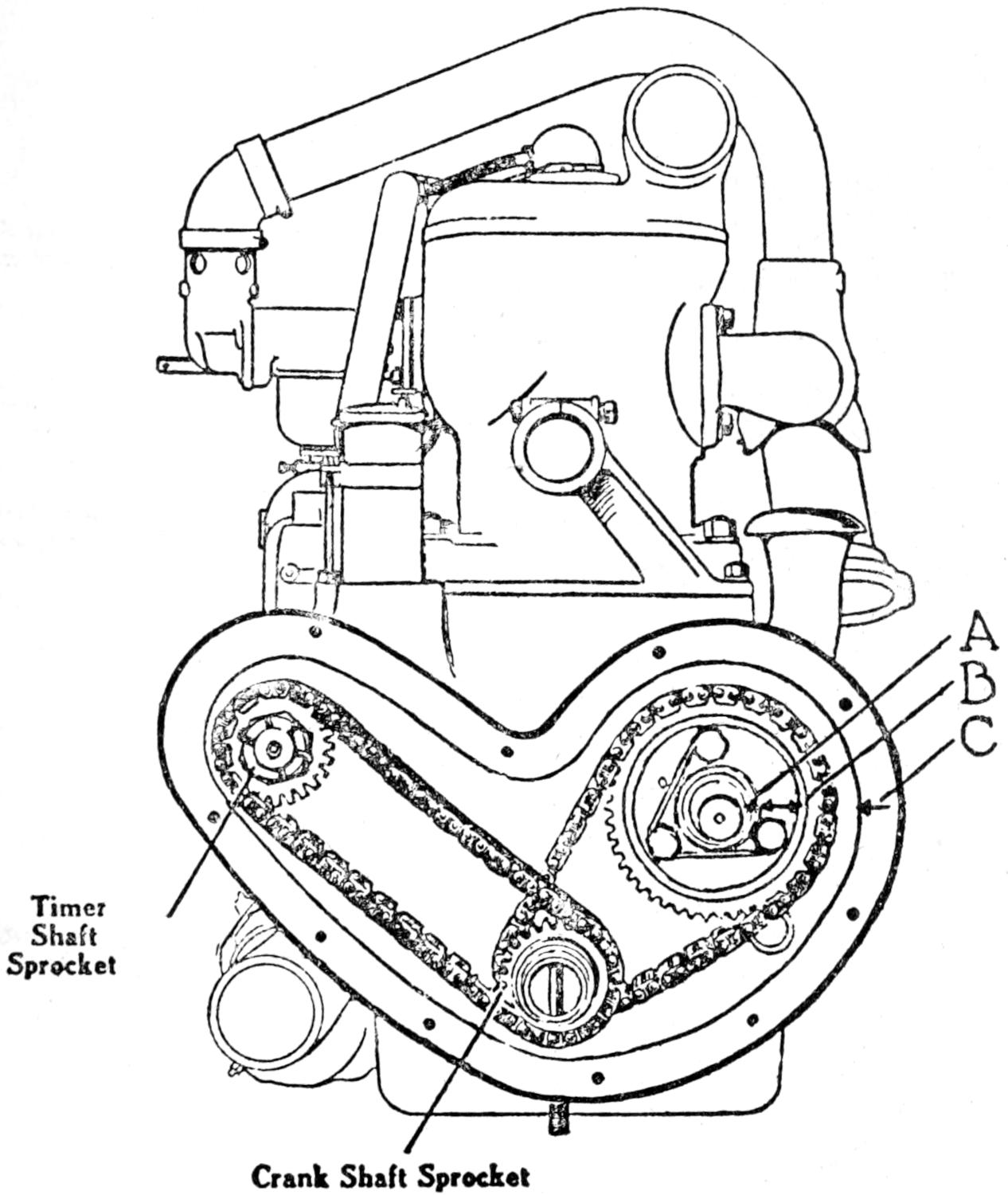
Fig. 15 shows the method of timing the sleeves on the
four cylinder engine. First, turn the motor over in the running
direction until the marks (I-4-T-C) on the flywheel are
in alignment with the marks on the cylinder casting. Turn
the eccentric shaft in the running direction until the marks
A, B, C, shown in Fig. 15 are lined up, and then apply
the chain.
Timer Shaft Sprocket
Crank Shaft Sprocket
Fig. 15. Knight Valve-Timing Marks—4-Cylinder
To check up on the timing, back the flywheel up an inch
or two and insert a thin piece of tissue paper into the exhaust
port and turn the engine in the running direction until the
paper is pinched, which signifies that the valve is closed.
The marks on the flywheel, timing gears, and the crank case
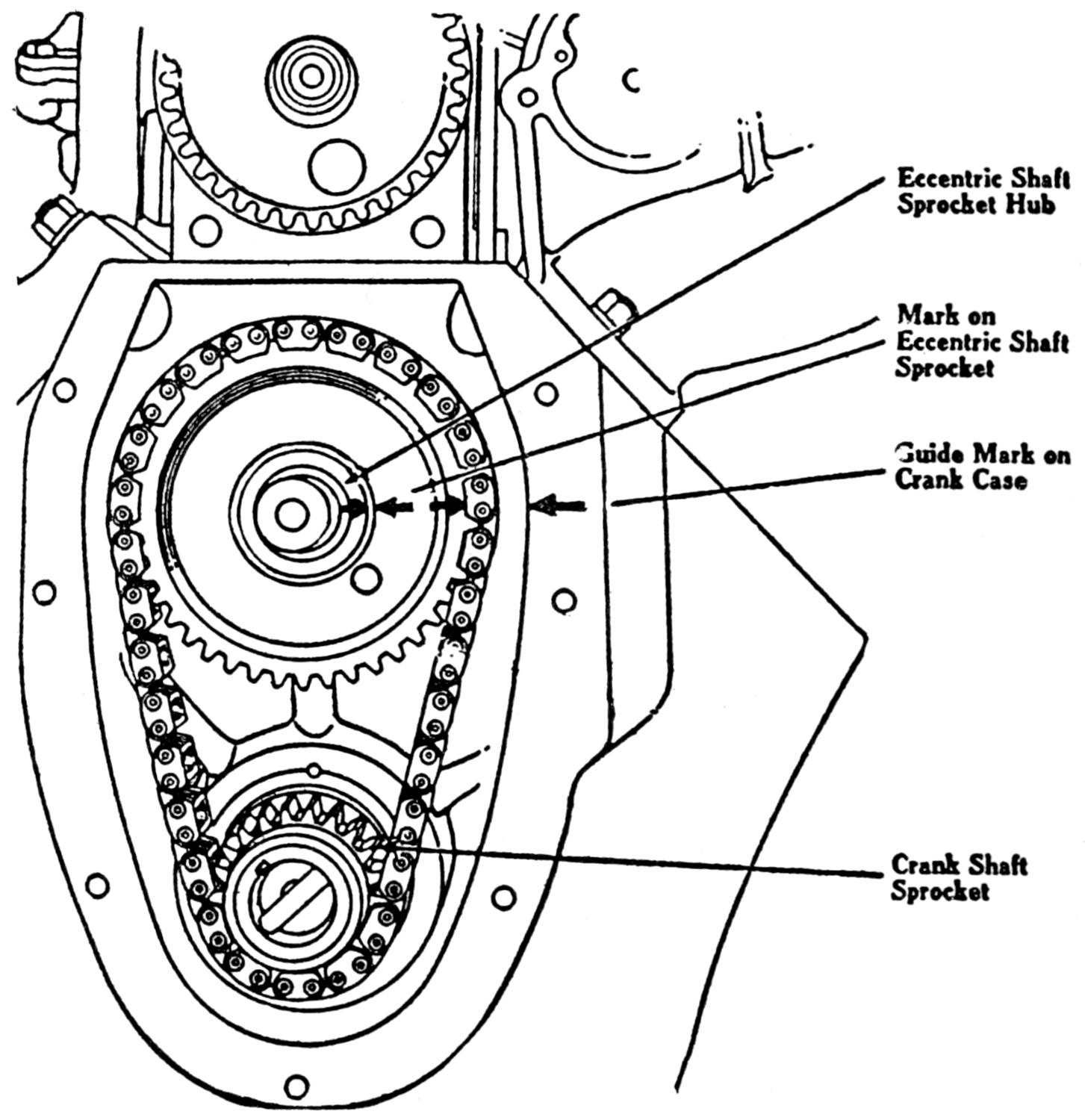
should be in alignment. Fig. 16 shows a diagram of the
timing marks on the eight cylinder Knight engine. The
method of timing this engine is as follows: (1) Turn the
engine over until the marks I-4-R-H—D-C align with the
marks on the crank case. (2) Turn the eccentric shaft and
sprocket until the arrows shown in Fig. 16 are in line with
the guide marks on the front end of the chain housing. Then
put on the chain and check up the timing, using the thin
piece of tissue paper.
Eccentric Shaft
Sprocket Hub
Mark on
Eccentric Shaft
Sprocket
Guide Mark on
Crank Case
Crank Shaft
Sprocket
Fig. 16. Knight Valve-Timing Marks—8-Cylinder
If the sleeve rods are removed for some reason, the bearings
should be fitted very loosely to the eccentric shaft when
they are put back. A looseness of about .008 of an inch is
permissible.
CHAPTER III THE OPERATION OF A 4-CYCLE, 4-CYLINDERED ENGINE — DISPLACEMENT — LUBRICATION SYSTEMS, OILS, AND GREASES
The four-cycle or Otto stroke type of gasoline engine should
rightly be called the four-stroke-cycle engine, as it requires
four strokes and two revolutions of the crank shaft to complete
one cycle of operation.
This type of motor is used almost universally by the manufacturers
of pleasure cars due to its reliability, and to the
ability it has to furnish continuous power at all speeds with
the minimum amount of vibration.
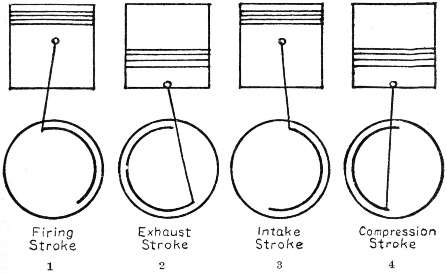
Firing Stroke
Exhaust Stroke
Intake Stroke
Compression Stroke
1
2
3
4
Fig. 17. 4-Stroke Cycle. 1—Cylinder in Action
Fig. 17 shows a diagram of one cylinder in the four strokes
of the cycle, and the distance traveled by the crank shaft during
each stroke. No. 1 begins with a charge of compressed
vapor gas in the cylinder and is called the firing or power
stroke. The ignition system (explained in a later chapter)
furnishes a spark at from five to fifteen degrees early or before
the piston reaches top dead center. Although the stroke
theoretically starts before the piston reaches its highest point
of ascent, the actual pressure or force of the explosion is not
exerted until the piston has crossed dead center. This is due
to the fact that the piston travels very rapidly, and that it
requires a small fraction of a second for spark to ignite the
compressed charge of gas. It may, therefore, be easily seen
that, if the spark did not occur until the piston is on or has
crossed dead center, the piston would have traveled part of the
distance of the stroke, and as it is moving away from the highest
point of compression the pressure is reduced by allowing
more volume space which causes a weak explosion and a short
power stroke. The intake and exhaust valves are closed
through the duration of the power stroke.
No. 2. The exhaust stroke begins from fifteen to thirty degrees
early, or before the piston reaches lower dead center on
the firing stroke. The exhaust valve opens at the start of this
stroke allowing the pressure of the burnt or inert gas to escape
before the piston begins to ascend on the upward part of the
stroke, and closes seven to ten degrees late to allow the combustion
chamber to clear out before the next stroke begins.
No. 3. The intake or suction stroke begins with the piston
descending from its highest level to its lowest level. The intake
valve opens ten or twenty degrees late, and as the piston
is traveling on its descent, considerable vacuum pressure has
formed which draws suddenly when the valve opens and starts
the gas from the carburetor in full volume. The entire length
of this stroke creates a vacuum which draws a full charge of
vaporized gas into the cylinder through the open intake valve.
The intake valve closes from ten to twenty degrees late in
order that the full drawing force of the vacuum may be
utilized while the piston is crossing lower center.
No. 4. The compression stroke begins at the end of the intake
stroke with both valves closed. The piston ascends
from its lowest extreme to its highest level, compressing the
charge of gas which was drawn into the cylinder on the
intake or suction stroke; and at the completion of this stroke
the cylinder is again in position to start No. 1, the firing
stroke, and begin a new cycle of operation. The cam shaft
is driven from the crank shaft through a set of gears or a
silent chain, and operates at one-half the speed of the crank
shaft as a valve is lifted once through the cycle of operation,
or two revolutions of the crankshaft.
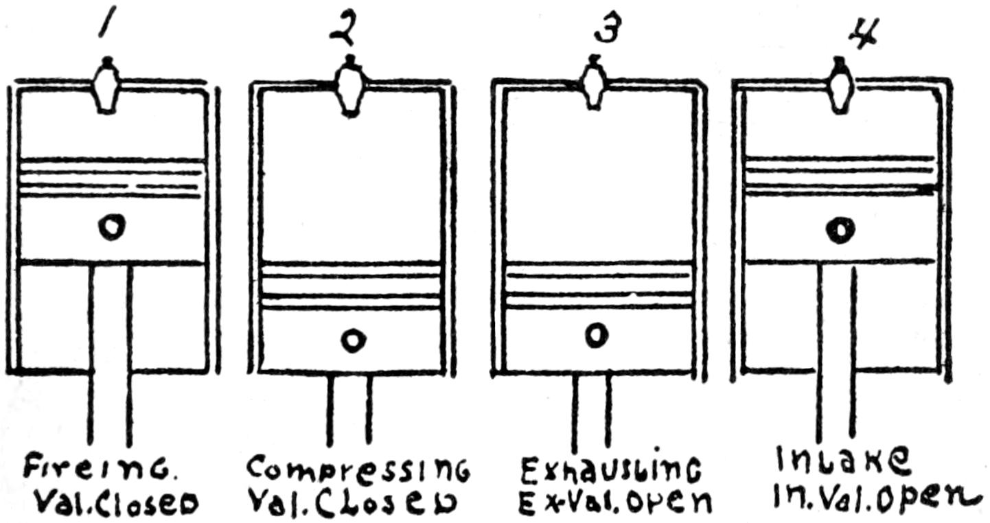
1
2
3
4
Firing Val. Closed
Compressing Val. Closed
Exhausting Ex. Val. Open
Intake In. Val. Open
Fig. 18. Diagram of Action, 4-Cylinder 4-Cycle Engine
Fig. 18 shows the operation of a four-cylindered motor as
it would appear if the cylinder block were removed. The
timing or firing order of the motor shown in this diagram
is 1-2-4-3. No. 1 cylinder is always nearest the radiator and
on the left in this diagram. No. 1 cylinder is firing. The intake
and exhaust valve remain closed while this stroke is taking
place. This causes the entire force of the explosion to be exerted
on the head of the receding piston. The cylinders, as
may be seen in the diagram, are timed to fire in succession,
one stroke behind each other. While No. 1 cylinder is on the
firing stroke, No. 2 cylinder is compressing with both valves
closed and will fire and deliver another power impulse as soon
as No. 1 cylinder completes and reaches the lowest extreme
of its firing stroke. No. 3 cylinder, being fourth in the firing
order, has just completed the firing stroke and is starting the
exhaust stroke which forces the burnt and inert gases out of
the cylinder through the open exhaust valve. No. 4 cylinder
which is third in the firing order has just completed the exhaust
stroke and is about to start the intake or suction stroke
with the exhaust valve open. This diagram should be studied
and memorized as it is often necessary to remove the wires
which may easily be replaced if the firing order is known, or
found by watching the action of the exhaust valves and made
to conform with the distributor of the ignition system. (Note
the running direction of the distributor brush and connect the
wires up in that direction.) For the firing order given above
connect No. 4 wire to No. 3 distributor post, and No. 3 wire to
No. 4 post, as this cylinder fires last.
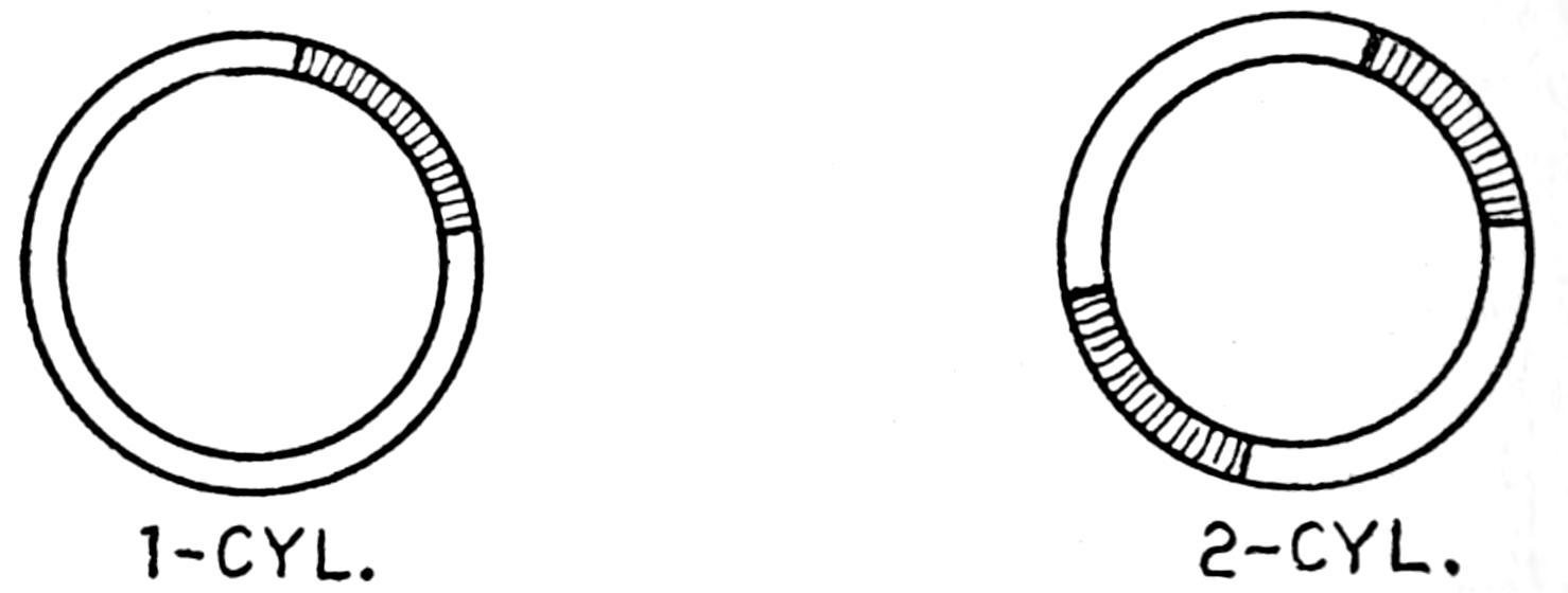
1-CYL.
2-CYL.
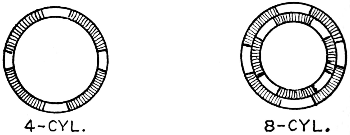
4-CYL.
8-CYL.
Fig. 19 Power Stroke Diagram
Fig. 19 shows a diagram of the power stroke impulse delivered
to the cycle in a one, two, four, and eight cylindered
motor. A complete cycle consists of 360 degrees, and
as there are four strokes to the cycle an even division would
give a stroke of ninety degrees, which is not the case, however,
owing to the fact that the valves do not open and close
at the theoretical beginning and ending point of each stroke
which is upper dead center and lower dead center. The firing
or power impulse stroke begins at approximately five to seven
degrees before the piston reaches upper dead center on the
compression stroke and ends from fifteen to thirty degrees
before the piston or cycle of rotation of the crankshaft reaches
lower dead center. This results in a power impulse of less
than ninety degrees, which varies accordingly with valve timing
in the different makes of motors. Consequently we have
a power stroke of a little less than ninety degrees in a one-cylinder
motor; two power strokes of a little less than 180
degrees in a two cylinder motor, while the power impulse of
the four-cylinder motor very nearly completes the cycle. In
the six, eight, and twelve cylinder motor the power strokes
overlap, thereby delivering continuous power of very nearly
equal strength.
Twin, Four, and Six Cylindered Motors.—The operation of
the twin cylindered motor varies very little from the single
four or six. It is simply a case where two, four, or two six
cylindered motors are set to a single crank case at an angle
which will allow the piston or connecting rods from the opposite
cylinders to operate on a single crank shaft. When the
cylinders are set directly opposite each other the connecting
rods are yoked and take their bearing on a single crank pin
of the crank shaft. This, however, is not always the case, for
in some motors the connecting rods take their bearing side
by side on the crank pin. The cylinders in this case are set
to the crank case in a staggered position to allow the connecting
rods from each cylinder to operate in line with the crank
shaft.
The cylinder blocks are usually set to the crank case at an
angle of ninety degrees and are timed to furnish the power impulse
or stroke opposite each other in the cycle of operation.
The advantage of this formation is that two power strokes are
delivered in one cycle of operation, which increases the power
momentum and reduces the jar or shock of the explosion
causing a sweet running vibrationless motor.
The valves are usually operated by a single cam shaft located
on the upper inside wall of the crank case. Valve timing
is accomplished by following the marks on the flywheel or
lining up the prick punch marks on the gears, as shown in
Chapter II on valves.
When a magneto is used to furnish the current for ignition
on an eight cylinder motor it has to be operated at the same
speed as the crank shaft, as a cylinder is fired at each revolution
of the crank shaft and an interruption of the current is
required at the breaker points to produce the secondary or
high tension current at the spark plug gaps.
Twelve cylindered motors are usually equipped with two
distributors or a dual system, or two magnetos driven separately
through a set of timing gears.
Knight or Sleeve Valve Motor.—The Knight or sleeve valve
motor operates on the same plan as the ordinary type of motor
except that the valves form a sleeve and slide over the piston.
The sleeves are operated by an eccentric shaft and are provided
with ports which are timed to conform with the ports
of the intake and exhaust manifolds at the proper time.
MOTOR HORSEPOWER S. A. E. Scale FOUR-CYCLE HORSEPOWER RATING
Bore
1 cyl.
2 cyl.
4 cyl.
6 cyl.
2
3⁄4
3.00
6.00
12.00
18.00
2
7⁄8
3.00
6.50
13.00
20.00
3
.00
3.50
7.00
14.50
21.50
3
1⁄4
4.00
8.50
17.00
25.50
3
1⁄2
5.00
10.00
20.00
29.50
3
3⁄4
5.50
11.00
22.50
34.00
4
.00
6.50
13.00
25.50
38.50
4
1⁄4
7.00
14.50
29.00
43.50
4
1⁄2
8.00
16.00
32.50
48.50
4
3⁄4
9.00
18.00
36.00
54.00
5
.00
10.00
20.00
40.00
60.00
5
1⁄4
11.00
22.00
44.00
66.00
5
1⁄2
12.00
24.00
48.00
73.00
5
3⁄4
13.00
26.50
53.00
79.50
6
.00
14.50
29.00
57.50
86.50
This scale gives the nearest equivalent to the whole or half
horsepower, as is required by State where licenses are paid at
so much per horsepower.
There are probably few men operating cars to-day who fully
understand what is meant by the term displacement, often
used in referring to automobile races. It is one of the main
factors or points in determining the class in which a car is
qualified to enter under the laws that govern races. In looking
over a race program, you will note that there are usually
two or more classes, one of which is open, and another with a
limited piston displacement, which gives the smaller cars a
competing chance in their class.
Consequently piston displacement is merely the volume displaced
by all the piston in moving the full length of the
stroke. The volume of a single cylinder is equal to the area
of the bore multiplied by the length of the stroke, and the
total displacement of a four cylinder motor will be four times
this and that of a six cylinder motor, six times this.
Piston displacement:
D2 times S times N times 3.144
Where
D equals bore in inches
S equals stroke in inches
Where N equals number of cylinders
Example:
Required to find the piston displacement of a
31⁄2 × 5 inch four-cylindered motor. D equals 3.5
S equals 5. and N equals 4.
Piston Displacement
3.52
times 5 times 4 times 3.144
3.5 times
3.5 times 5 times 4 times 3.144
equals 173.58 cubic inches.
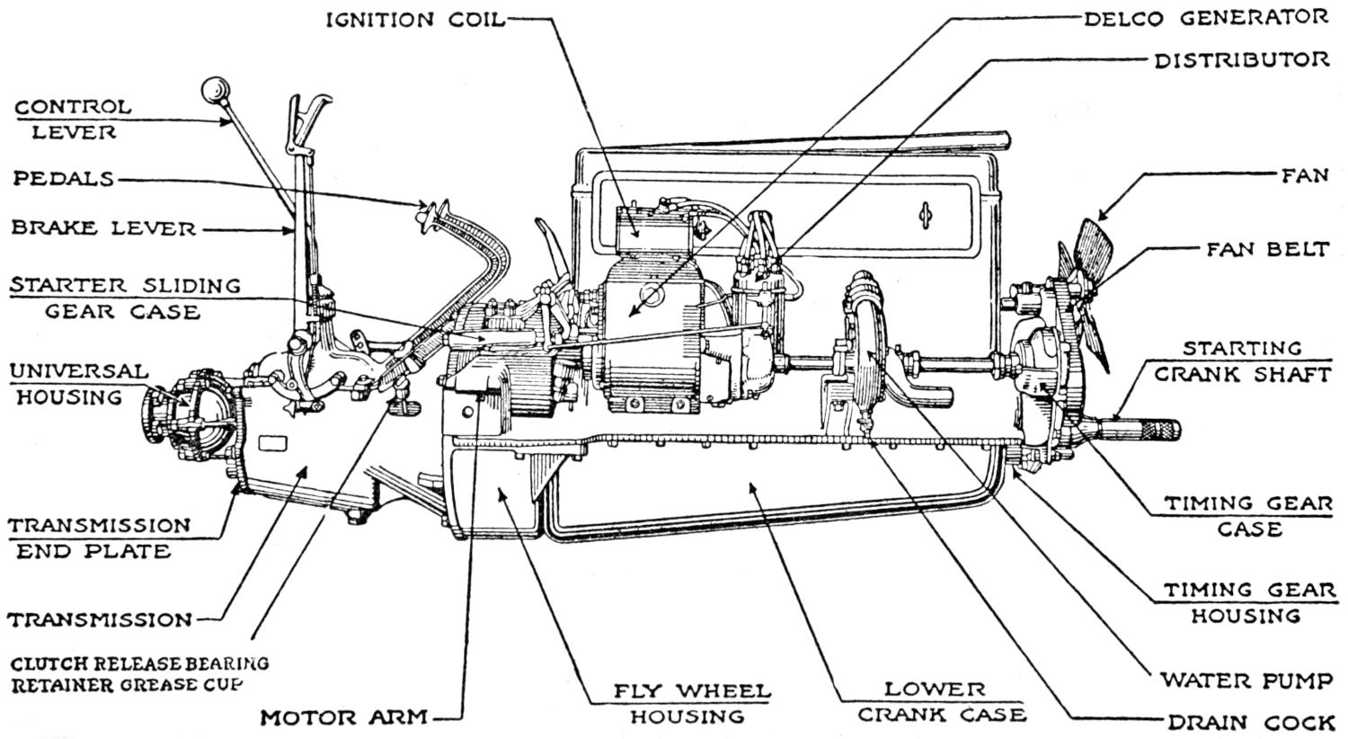
IGNITION COIL
DELCO GENERATOR
DISTRIBUTOR
CONTROL LEVER
PEDALS
FAN
BRAKE LEVER
FAN BELT
STARTER SLIDING GEAR CASE
UNIVERSAL HOUSING
STARTING CRANK SHAFT
TRANSMISSION END PLATE
TIMING GEAR CASE
TRANSMISSION
TIMING GEAR HOUSING
CLUTCH RELEASE BEARING RETAINER GREASE CUP
WATER PUMP
MOTOR ARM
FLY WHEEL HOUSING
LOWER CRANK CASE
DRAIN COCK
Fig. 20. Buick Engine—Parts Assembly
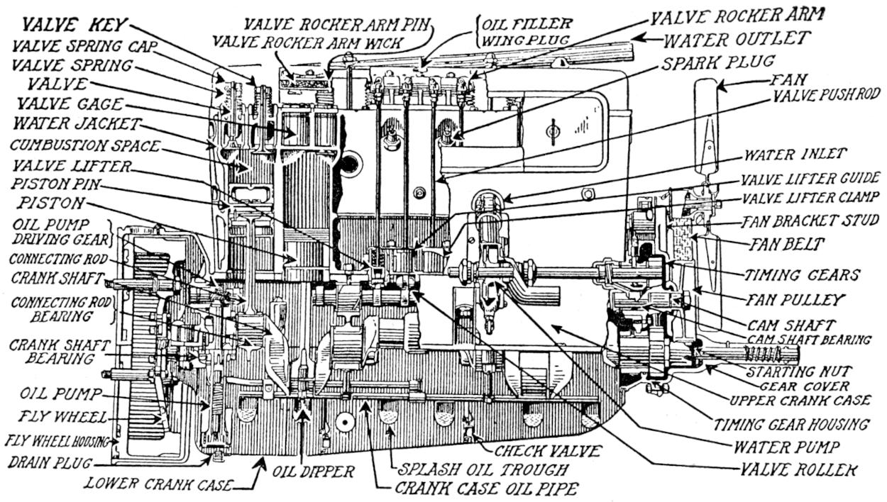
VALVE KEY
VALVE ROCKER ARM PIN
OIL FILLER WING PLUG
VALVE ROCKER ARM
VALVE SPRING CAP
VALVE ROCKER ARM WICK
WATER OUTLET
VALVE SPRING
SPARK PLUG
VALVE
FAN
VALVE GAGE
VALVE PUSH ROD
WATER JACKET
COMBUSTION SPACE
WATER INLET
VALVE LIFTER
VALVE LIFTER GUIDE
PISTON PIN
PISTON
VALVE LIFTER CLAMP
OIL PUMP DRIVING GEAR
FAN BRACKET STUD
FAN BELT
CONNECTING ROD
CRANK SHAFT
TIMING GEARS
CONNECTING ROD BEARING
FAN PULLEY
CAM SHAFT
CRANK SHAFT BEARING
CAM SHAFT BEARING
STARTING NUT
OIL PUMP
GEAR COVER
UPPER CRANK CASE
FLY WHEEL
TIMING GEAR HOUSING
FLY WHEEL HOUSING
CHECK VALVE
WATER PUMP
DRAIN PLUG
OIL DIPPER
SPLASH OIL TROUGH
VALVE ROLLER
LOWER CRANK CASE
CRANK CASE OIL PIPE
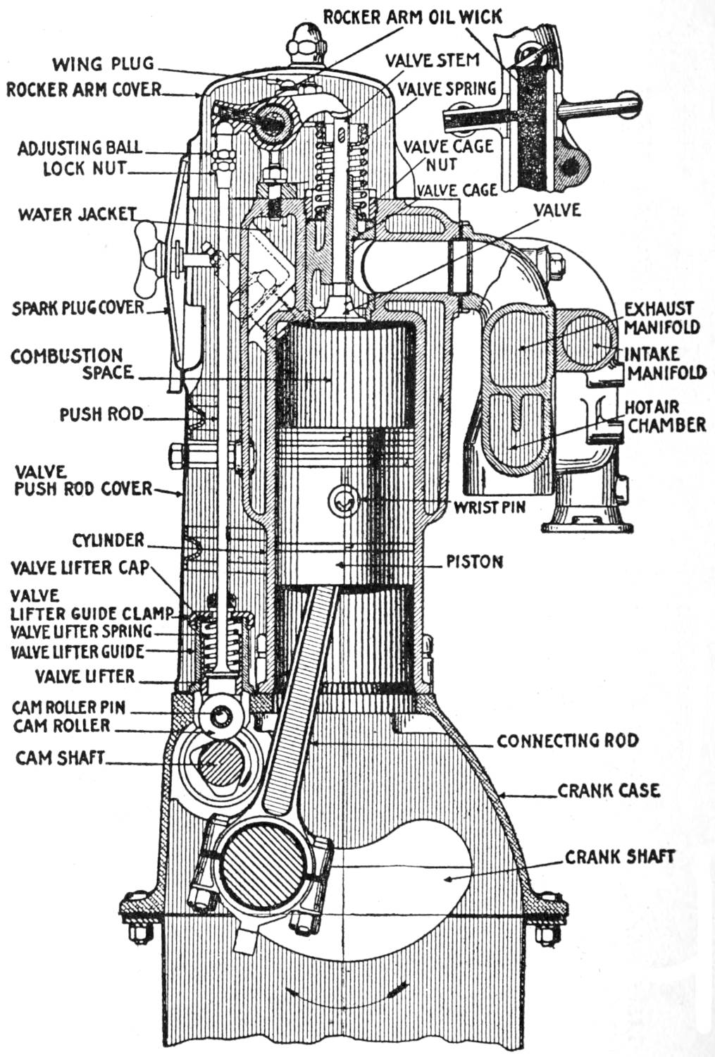
Fig. 21. Buick Engine—Location Inside Parts Assembly
ROCKER ARM
OIL WICK
WING PLUG
VALVE STEM
ROCKER ARM COVER
VALVE SPRING
ADJUSTING BALL
VALVE CAGE NUT
LOCK NUT
VALVE CAGE
WATER JACKET
VALVE
SPARK PLUG COVER
EXHAUST MANIFOLD
COMBUSTION SPACE
INTAKE MANIFOLD
PUSH ROD
HOT AIR CHAMBER
VALVE PUSH ROD COVER
WRIST PIN
CYLINDER
VALVE LIFTER CAP
PISTON
VALVE LIFTER GUIDE CLAMP
VALVE LIFTER SPRING
VALVE LIFTER GUIDE
VALVE LIFTER
CAM ROLLER PIN
CAM ROLLER
CONNECTING ROD
CAM SHAFT
CRANK CASE
CRANK SHAFT
Fig. 22. Buick Motor—End View
Fan Belt
Adjustment
Split Collar
with Locking Cup
Valve Tappet
Adjustment
Cam Shaft End
Thrust Adjustment
Shims for
Adjustment of
Connecting Rods
Oil Passage to
Connecting Rod
Oil Pipe to
Piston Ring
Oil Pump
Filter Screen
Oil Sump
Filter Screen
Oil Pump
Felt Gasket
Oil Drain Plugs
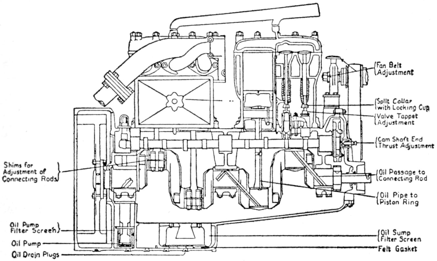
Fig. 23. Liberty U. S. A. Engine
Special attention should be given to regular lubrication, as
this, more than any one thing, not only determines the life but
also the economic up-keep of the car.
Whenever you hear an owner say that his car is a gas eater,
or that it uses twice or three times as much oil as his neighbor’s,
which is the same model and make, you know at once
that he, or some one who has used the car before him, either
did not give sufficient attention to lubrication, or used a poor
grade of oil. It is almost impossible to impress the importance
of the foregoing facts upon the minds of the average
motorist, and we have, as a direct result, a loss of millions of
dollars annually through depreciation.
The manufacturers of automobiles and gasoline engines
have earnestly striven to overcome this negligence by providing
their products with automatically fed oiling systems
which alleviate some of the former troubles. These systems,
however, also require some attention to function
properly.
Grease.—A medium grade of light hard oil grease is best
adapted for use in grease cups, universal joints, and for
packing wheel bearings and steering gear housings. The
transmission and differential operate more successfully when a
lighter grade of grease is used, such as a graphite compound,
or a heavy oil known as 600 W.
Oils.—Great care should always be exercised in purchasing
lubricants. None but the best grades should be considered under
any circumstances. The cheaper grades of oil will always
prove to be the most expensive in the end. The ordinary farm
machinery oils should never be used in any case as an engine
lubricant, for in most cases they contain acids, alkalies, and
foreign matter which will deteriorate and destroy the bearings
of the motor.
An oil to give the best satisfaction must be a purely mineral
or vegetable composition which will flow freely at a temperature
of 33° Fahrenheit and also stand a temperature of 400°
Fahrenheit without burning. Always choose an oil which is
light in color as the darker oil usually contains much carbon.
Lubrication (Lat. Lubricus, meaning slippery).—-Lubrication
is provided on all types of automobile engines, and at
various other places where moving parts come in contact or
operate upon each other.
Three different types of lubricating systems are found in
common use.
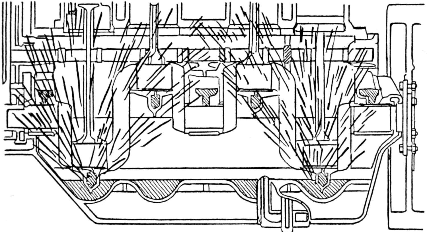
Fig. 24 shows the splash system. The oil is placed into
the crank case and maintained at a level between two points,
marked high and low, on a float or glass gauge at the lower
left-hand side of the crank case. The oil is usually poured directly
into the crank case through a breather pipe provided
to prevent excessive vacuum pressure.
The lower end of the connecting rod carries a spoon or
paddle which dips into the oil at each revolution and splashes
it to the cylinder walls and various bearing surfaces within the
motor.
Fig. 24. Splash Oiling
Care of the Splash System.—This type of oiling system does
not require any adjustments, or special care, except that the
oil level be constantly kept between the high and low level
marked on the gauge.
Cleaning the Splash System.—Lubricating oils lose their
effectiveness and become thin and watery after a certain period
of use due to a fluid deposit called residue which remains in
the combustion chambers after the charge of gas has been
fired. This fluid generally works its way into the crank case,
thinning the oil.
The crank case should, therefore, be drained, cleaned, and
refilled with fresh oil every fifth week or thousand miles that
the car is driven. This will prevent much wear and give a
quiet and satisfactory running motor. Draining and washing
out the crank case is accomplished by removing a drain plug
at the bottom of the crank case. The old oil is drained off and
thrown away. Kerosene is then poured into the crank case
through the breather pipe until it flows out of the drain clear
in color. The plug is then replaced and the crank case replenished
with fresh oil until the three-quarter from low level
is reached on the gauge. The oil level should be carried as
near this point as possible to obtain the most satisfactory
result.
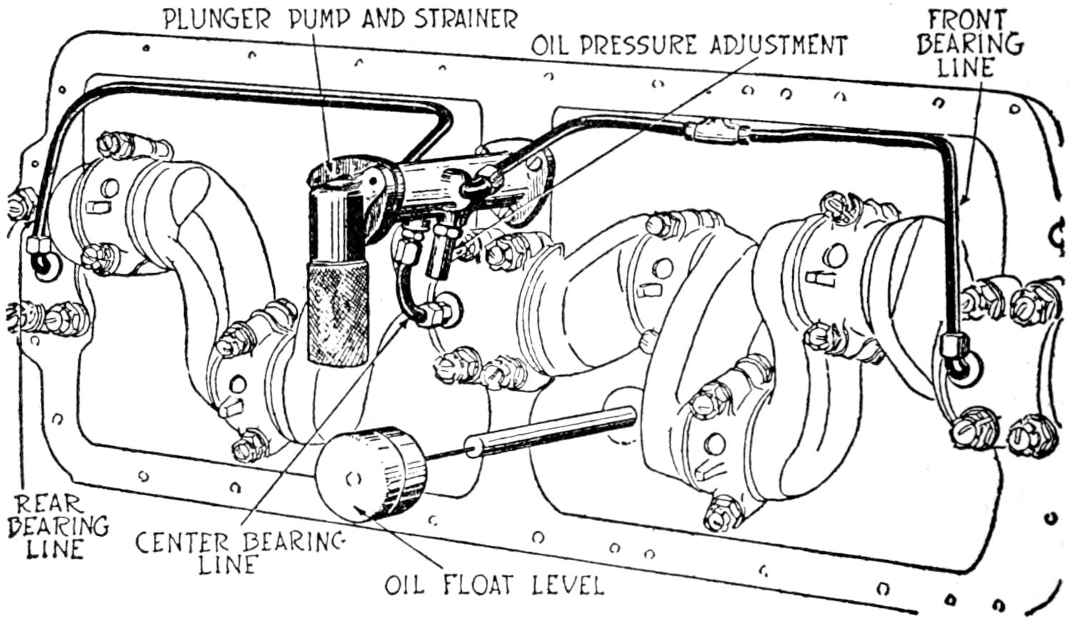
Fig. 25 shows the plunger or piston pump pressure system
usually used in conjunction with the splash system. The
oil is carried in a reservoir at the bottom of the crank case
and is drawn through a fine meshed screen by the oil pump,
which is of the plunger type operated off the cam shaft. It
forces the oil through copper tubes in the three main bearings.
The front and center bearings have an outlet which
furnishes the oil to the gears in front and to the troughs in
which the connecting rods dip. The troughs have holes
drilled to keep the level of the oil, the surplus being returned
to the reservoir.
PLUNGER PUMP AND STRAINER
OIL PRESSURE ADJUSTMENT
FRONT BEARING LINE
REAR BEARING LINE
CENTER BEARING LINE
OIL FLOAT LEVEL
Fig. 25. Plunger Pump Oiling System
There is a pipe line running from the pump to the gear
case with a screw adjustment to regulate the oil pressure by
turning either in or out. There is a pipe line running to a
gauge on the dash which gives the pressure at all times. The
cam shaft and cylinder walls get the oil by the splash from the
connecting rods. The bottom rings of the pistons wash the
oil back into the crank case. The overflow from the front
bearings falls into a small compartment immediately under
the crank shaft gear where it is picked up by this gear and
carried to the other gears and the bearings of the water pump
shaft. A small oil throw washer on the pump shaft prevents
any surplus oil from being carried out on the shaft or the
hub of the fan drive pulley. Any overflow from the gear
compartment is carried immediately to the splash pan where
it provides for the splash lubrication of the connecting rod
bearings and the cylinder walls. The dippers on the connecting
rod bearings should go 1⁄4 in. beneath the surface of
the oil. The upward stroke of the oil pump plunger draws
the oil through the lower ball check into the pump body and
the downward stroke discharges it through the upper ball
check into the body of the plunger which is hollow and has
outlets on either side. This allows the oil to flow from the
plunger into the by-pass in the oil pump body and then into
the lines running to the main crank shaft bearings. The next
upward stroke forces the oil through the lines to the main
bearings.
The oil pressure regulator is located on the body of the
pump and connects to the by-pass. It consists of a hollow
sleeve screwed into the body of the pump which has a small
ball check held by a short coiled spring the tension of which
determines the oil pressure. The tension and the pressure
may be increased by turning the nut to the right. The nut
should not be given more than one turn at a time in either
direction as it is very sensitive. A loose main bearing will
allow more oil to pass through it. Consequently the pressure
registered on the oil gauge will be reduced. This will come
about gradually. It is not advisable to attempt to adjust the
oil pressure without first noting the condition of the main
crank shaft bearings.
The most common cause of failure to operate is the collection
of dust and dirt on the sleeve at the lower end of the
pump or from an accumulation of sediment back of the ball
check. This needs to be cleaned from time to time.
Force and Gravity Oiling System.—The force and gravity
oiling system operates in much the same manner as the plunger
pump system, except that the oil is pumped into an elevated
tank from which it flows through lines by gravity to the various
bearings. Oil pumps, however, differ in construction and
some manufacturers use eccentric, centrifugal, and gear
pumps. Oil pumps are very simple in construction and action
and can be readily understood by recalling their functional
action.
Oil pumps rarely give any trouble, and if they fail to function
properly, dirt should be immediately suspected, and the
ball valves and pipes inspected and cleaned.
CHAPTER IV BRIEF TREATISE ON CARBURETION — STROMBERG MODEL L CARBURETOR
A carburetor is a metering device whose function is to mechanically
blend liquid fuel with a certain amount of air to
produce as nearly a homogeneous mixture as possible, and
in such proportions as will result in as perfect an explosive
mixture as can be obtained.
If a gas is used as a fuel it is of course not so difficult to
obtain a homogeneous mixture due to the intimacy with which
a gas will mechanically mix with air. This intimacy is a
result of the minuteness of the molecules of both the gas and
the air. With a liquid fuel, such as gasoline, however, it is
quite different, especially with low test gasoline. If it were
possible to completely transfer the liquid fuel into its vapor
the latter would act as a gas and would, therefore, mix with
the air to form a homogeneous mixture. It should be, and is,
therefore, the aim of the carburetor designer to produce an instrument
which will atomize the fuel and break it up into
small particles so that every minute particle of the fuel will
be surrounded by a correct proportion of air when it is
discharged into the intake manifold of the motor. To facilitate
the vaporization of these minute particles of fuel it is
advisable to preheat the air taken into the carburetor, thereby
furnishing the necessary heat units required to vaporize the
fuel by virtue of its physical property known as its latent
heat of evaporation.
There is a range of proportions of air to vapor, for a
given fuel, between which combustion will obtain. This range
extends from that proportion known as the upper limit of
combustion to that known as the lower limit of combustion.
The upper limit is reached when the ratio of air to vapor is
a maximum at which combustion will take place; that is to
say, any addition of air in excess of this maximum will render
the mixture non-combustible. The lower limit is reached when
the ratio of air to vapor is a minimum at which combustion
will take place, any decrease of air below this minimum producing
a non-combustible mixture. It should be remembered
that the limits of combustion of any fuel with air are dependent
upon the temperature and pressure.
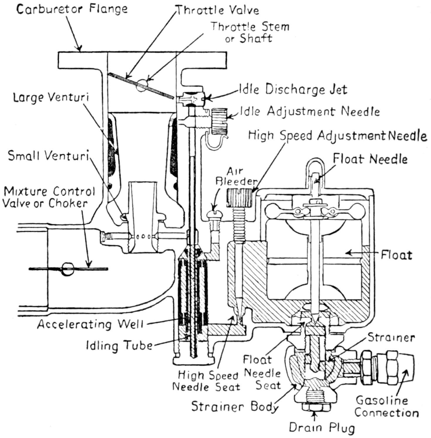
Carburetor Flange
Throttle Valve
Throttle Stem or Shaft
Large Venturi
Idle Discharge Jet
Idle Adjustment Needle
High Speed Adjustment Needle
Small Venturi
Float Needle
Air Bleeder
Mixture Control Valve or Choker
Float
Accelerating Well
Idling Tube
Strainer
Float Needle Seat
High Speead Needle Seat
Strainer Body
Gasoline Connection
Drain Plug
Fig. 26. Stromberg Model M Carburetor—Sectional View
Under given temperature and pressure the rate at which the
combustible mixture will burn depends upon the ratio of air
to vapor. This rate of burning is known as the rate of
propagation, and it is apparent that it is desirable to obtain a
mixture whose rate of propagation is a maximum, because the
force of the explosion will depend upon the rapidity with
which the entire mixture is completely ignited.
The limits of combustion of gasoline (.70 sp. gr.) can be
taken approximately as follows: lower limit, 7 parts air (by
weight) to 1 part gasoline, upper limit, 20 parts air to 1 part
gasoline.
The Stromberg Plain Tube Model M Carburetor.—A plain
tube carburetor is one in which both the air and the gasoline
openings are fixed in size, and in which the gasoline is metered
automatically, without the aid of moving parts by the suction
of air velocity past the jets.
Fig. 26 shows a longitudinal section of a type M plain tube
carburetor, and shows the location of the gasoline when
the motor is at rest. The various parts are indicated by
names and arrows. An elementary requirement of a carburetor
is that as a metering device it shall properly proportion
the gasoline and air throughout the entire operating
range.
Fig. 27. Stromberg Carburetor Model M—Air Bleeder Action
In the carburetor under discussion this mixture proportioning
is properly maintained by the use of what is termed the
air bleed jet. Fig. 27 shows the principle of the action of the
air bleeder. The gasoline leaves the float chamber, passes the
point of the high speed adjusting needle, and rises through a
vertical channel “B.” Air is taken in through the air bleeder
“C,” and discharged into the gasoline channel before the
latter reaches the jet holes in the small venturi tube “E.”
The result is that the air thus taken in breaks up the flow of
gasoline and produces a finely divided emulsion. Upon reaching
the jet holes of the small venturi tube this emulsion is
discharged into the high velocity air stream in the form of a
finely divided mist. If the reader will recall how thoroughly
a soap bubble divides itself when it bursts, he will readily
appreciate how completely the air bleed jet will atomize the
fuel.
Before explaining the operation of the accelerating well it
is advisable to know the reason for its existence. Suppose
we had a large tube such as the intake manifold of a motor
through which air and particles of gasoline were flowing due
to a certain suction at one end. What would be the result if
we suddenly increased the suction? It would be this: Due to
the fact that air is so much lighter than gasoline, the air would
respond almost instantly to the increased suction and its flow
would be accelerated very suddenly, whereas the particles of
gasoline, owing to that characteristic known as inertia, would
not respond so rapidly, and due to its heavier weight its flow
would not accelerate as much as the air. This would mean
that the air would rush ahead of the gasoline particles, and the
proportion of air to gasoline would be greater until the inertia
forces had been overcome and the gasoline particles responded
completely to the increased suction. This very thing will take
place in a carburetor unless provision is made for it. That is
to say a sudden opening of the throttle will tend toward
producing a very lean mixture at the motor due to the lagging
of the gasoline explained above. A lean mixture at this
time, when acceleration is desired, would obviously be detrimental
to the result wanted. It is at this particular time that
additional gasoline is most desirable in order to compensate
for the lagging gasoline and maintain the proper mixture at
the motor. In the Stromberg carburetor this is accomplished
by means of the accelerating well shown in Fig. 28. The
operation is as follows: The action is based upon the principle
of the ordinary U tube. If a U tube contains a liquid,
and if pressure is applied to one arm of the tube, or what is
the same, if suction is applied to the other arm, it is self-evident
that the level of the liquid will rise in the arm on
which the suction is applied and will drop in the other arm.
So it is in the construction of the accelerating well. Referring
to the illustration, Fig. 28, the space “F” forms the
one arm of the U tube, and the space “B” the other arm.
These spaces communicate with each other through the holes
“G” thus forming a modified form of U tube.
Fig. 28. Stromberg Carburetor Model M—Accelerating Well
When the motor is idling or retarding in speed, the accelerating
well or space “F” fills with gasoline. Now when
the throttle is opened, thereby increasing the suction in the
venturi tube, the following takes place: atmospheric pressure
at the bleeder “C” exerts itself on the gasoline in the space
“F” forcing the liquid down to join the regular flow from
“H” and passing up the space “B” and out into the high
velocity air stream through the small venturi tube. While the
well acts the flow of gasoline is more than double the normal
rate of flow, thereby compensating for the lagging of the
gasoline referred to previously.
Upon close observation it will be noticed that there is a
series of small holes down the wall of the well. Referring
to the analogy of the U tube, these holes directly connect the
two arms of the U tube. It is obvious that the smaller and
fewer these holes, the faster will the well empty, due to the
U tube suction, and the larger and more these holes, the slower
will the well empty. It is therefore apparent that the rate of
discharge of the well can be regulated as required by different
motors, different grades of gasoline, different altitudes, etc.,
by inserting wells of different drillings. The action of the
well is also dependent upon the size of the hole in the bleeder
“C” because it is the relative area of this hole in the bleeder
as compared to the area of the holes in the well which determine
the rate at which the well will empty.
The foregoing characteristics of the model M carburetor
have dealt more with the open throttle or high speed operation.
We shall now consider the operation when the motor
is idling. Earlier types of carburetors, when high test and
very volatile gasoline was employed, were designed with a
mixing chamber in which the gasoline, after being discharged
from the nozzle, would mix with the air and evaporate very
freely. Present day gasoline, however, is considerably heavier
and very much less volatile, and we therefore cannot depend
upon its volatility to accomplish its vaporization.
Fig. 29. Stromberg Carburetor Model M—Idling Operation
Fig. 29 shows the arrangement and idling operation of the
model M Stromberg carburetor. Concentric and inside of the
passage “B” is located the idling tube “J.” When the motor
is idling, that is, when the throttle is practically closed, the
action which takes place is as follows: the gasoline leaves the
float chamber, passes through the passage “H” into the idling
tube through the hole “I,” thence up through the idling tube
“J” to the idling jet “L.” Air is drawn through the hole
“K” and mixes with the gasoline to form a finely divided
emulsion which passes on to the jet “L.” It will be noted
that this jet directs the gasoline-air emulsion into the manifold
just above the lip of the throttle valve. Inasmuch as this
throttle valve is practically closed the vacuum created at
the entrance of the jet “L” is very high and exceeds 8 pounds
per square inch. It is obvious, therefore, with this condition
existing, that the gasoline will be drawn into the manifold in a
highly atomized condition. It is well to call attention here to
the fact that the low speed adjusting screw “F” operates a
needle valve which controls the amount of air which passes
through the hole “K,” and it is the position of this needle
valve which determines the idling mixture.
Fig. 30. Stromberg Carburetor—Throttle 1⁄5 Open
As the throttle is slightly opened from the idling position
a suction is created in the throat of the small venturi tube as
well as at the idling jet. When idling the suction is greater
at the idling jet, and when the throttle is open the suction is
greater at the small venturi tube. At some intermediate position
of the throttle there is a time when the suction at the
idling jet is equal to that at the small venturi, and, therefore,
at this particular time the gasoline will follow both channels
to the manifold. This condition which is illustrated in Fig.
30 lasts but a very short while, because as the throttle is
opened wider the suction at the small venturi tube rapidly
becomes greater than that at the idling jet. The result is
that the idling tube and idling jet are thrown entirely out of
action, the level of the gasoline in the idling tube dropping
as illustrated in Fig. 31, where the throttle is shown to be
wide open, in which case all of the gasoline enters the manifold
by way of the holes in the small venturi tube.
Fig. 31. Stromberg Carburetor—Throttle Wide Open
It will be remembered that at this position of the throttle
the accelerating well has emptied, and therefore there is a
direct passage for air from the bleeder to the gasoline in the
main passage giving the air bleed jet feature explained before.
This is being mentioned again in order to call attention
to the fact that care should be taken not to use too large a
bleeder, because the air which enters through the bleeder
partly determines the mixture, and if the bleeder hole is too
large the mixture is very apt to be too lean at high speeds.
Fig. 32 shows an exterior photograph of one of the type
M Stromberg carburetor. Before discussing the installation
and adjusting of this carburetor it will be well to say a few
words concerning the use of the venturi tube and its construction.
The object in using the venturi tube in carburetor design
is to produce a maximum air velocity at the jet and at the
same time not cause undue restriction. This high air velocity
creates the suction necessary to properly atomize the gasoline.
The use of the double venturi tube construction has developed
the best possible results. In this construction the mouth of
the smaller venturi tube is located at the throat of the larger
one, and with this arrangement the highest degree of atomization
is attainable, and at the same time the air restriction is
held down to a minimum.
In order that any carburetor may do justice to what is
claimed for it, it is absolutely essential that the motor on
which it is installed is in good condition in other respects
because, besides poor carburetion, there are numerous things
about an internal combustion engine which will cause its poor
operation. Therefore, assuming that the following conditions
exist, we can proceed with the installation of the carburetor
and after adjusting it we can expect very good results as to
the operation of the motor.
1. The ignition should be properly timed so that with a
retarded spark the explosion takes place when the piston of
the cylinder in which the explosion occurs is at its upper dead
center.
2. The inlet and exhaust valves should be so timed that they
open and close at the proper time during the cycle. In this
respect a motor is usually timed when it comes from the
manufacturer.
3. The valves should be ground in so that they form a perfect
seal with the valve seat. Any accumulation of carbon on
the upper part of the exhaust should be removed so as to prevent
the valve stem from sticking in the guide and thereby not
permitting the valve to close upon its seat.
4. Any undue wear of the valve stem guides should be corrected
because the clearance between the stem and the walls
of the guide will permit air to be drawn up into the motor
thus ruining the mixture from the carburetor. Similarly any
leaky flange at any joint along the intake system will produce
the same detrimental result.
Fig. 32. Stromberg Model M—Adjustment Points
5. All piston rings should be tight and leak proof in order
to insure good and even compression in all the cylinders.
Without good and even compression in all the cylinders it is
impossible to obtain the maximum power from the motor, and
it is also impossible to obtain good idling of the motor.
6. It should be seen that the ignition system is delivering a
spark to each spark plug without missing.
7. The spark plugs should be clean, and the accumulation
of carbon on the inside of the plug should not be sufficient to
cause fouling or short-circuiting of the plug. In the case of
a short circuited plug it is impossible to obtain a spark at
the end of the high tension cable, but this does not indicate
that the plug is firing. For best results the gap of the spark
plug should never be less than .020″ nor more than .032″.
A good setting is at about .025″.
The foregoing constitute some of the more important
troubles to look for when the motor is not performing satisfactorily.
Installation and Adjusting.—We are finally ready to proceed
with instructions for installing and adjusting Model M
carburetors.
1. Try the throttle lever and the air horn lever by moving
same with the hand before the carburetor is installed, and be
sure that the butterfly valves are open to the limit when the
respective levers come in contact with their stops. Also be
sure that when the throttle valve is closed, the lower side of the
butterfly is adjacent to the hole through which the idling jet
projects.
2. Prepare a paper gasket about .020″ thick to fit the flange
of the carburetor. Shellac same and then attach the carburetor
to the flange of the intake manifold very securely by
means of proper cap screws.
The attaching of the gasoline line, hot-air stove, hot air
flexible tubing, and choke control need not be discussed in detail
as these installations are very simple.
After having properly installed the carburetor on the motor,
turn both the high and low speed adjusting screws, A and
B, completely down clockwise so that the needle valves just
touch their respective seats. Then unscrew (anti-clockwise)
the high speed adjusting screw A about three turns off the
seat, and turn the low speed adjusting screw B anti-clockwise
about one and one-half turns off the seat. These settings
are not to be considered as final adjustments of the carburetor.
They are merely to be taken as starting points because the
motor will run freely with these settings.
After the motor has been started, permit it to run long
enough to become thoroughly warm then make the high speed
adjustment. Advance the spark to the position for normal
running. Advance the gas throttle until the motor is running
at approximately 750 r. p. m. Then turn down on the high
speed screw A gradually notch by notch until a slowing down
of the motor is observed. Then turn up or open the screw
anti-clockwise until the motor runs at the highest rate of
speed for that particular setting of the throttle.
To make the low speed adjustment B proceed as follows:
Retard the spark fully and close the throttle as far as possible
without causing the motor to come to a stop. If upon
idling the motor tends to roll or load it is an indication that
the mixture is too rich and therefore the low speed screw B
should be turned away from the seat anti-clockwise, thereby
permitting more air to enter into the idling mixture. It is
safe to say that the best idling results will be obtained when the
screw B is not much more or less than one and one-half turns
off the seat.
After satisfactory adjustments have been made with the
motor vehicle stationary, it is most important and advisable
to take the vehicle out on the road for further observation and
finer adjustments. If upon rather sudden opening of the
throttle the motor backfires, it is an indication that the high
speed mixture is too lean, and in this case the high speed screw
A should be opened one notch at a time until the tendency to
backfire ceases. On the other hand if when running along with
throttle open, the motor rolls or loads, it is an indication that
the mixture is too rich, and this condition is overcome by turning
the high speed screw A down (clockwise) until this loading
is eliminated.
There are three adjustments; the high speed, the extremely
low speed or idle, and the “economizer.”
The high speed is controlled by the knurled nut “A” which
locates the position of the needle “E” past whose point is
taken all the gasoline at all speeds. Turning nut “A” to the
right (clockwise) raises the needle “E” and gives more gasoline,
to the left, or anticlockwise, less.
Fig. 33. Stromberg Model “L”—Adjustment Points
If an entirely new adjustment is necessary, use the following
practice. Put economizer “L” in the 5th notch (or farthest
from float chamber) as an indicator, turn nut “A” to the left,
anticlockwise, until needle “E” reaches its seat, as shown by
nut “A” not moving when throttle is opened and closed.
When needle “E” is in its seat it can be felt to stick slightly
when nut “A” is lifted with the fingers. Find adjustment of
“A” where it just begins to move with the throttle opening,
then give 24 notches to the right or clockwise (the notches can
be felt). Then move the economizer pointer “L” back to the
0 notch (toward float chamber). This will give a rich adjustment.
After starting and warming up the motor, thin
out the mixture by turning “A” anticlockwise, and find the
point where the motor responds best to quick opening of the
throttle, and shows the best power.
The gasoline for low speed is taken in above the throttle
through a jet at “K” and is regulated by dilution with air as
controlled by the low speed adjusting screw “B.” Screwing
“B” in clockwise gives more gasoline; outward, less. The
best adjustment is usually 1⁄2 to 3 turns outward from a
seating position. Note that this is only an idling adjustment
and does not effect the mixture above 8 miles per hour. When
motor is idling properly there should be a steady hiss in the
carburetor; if there is a weak cylinder or manifold leak, or
if the idle adjustment is very much too rich, the hiss will be
unsteady.
The economizer device operates to lean out the mixture by
lowering the high speed needle “E” and nut “A” a slight but
definitely regulated amount at throttle positions corresponding
to speeds from 5 to 40 miles per hour. The amount of drop
and consequent leaning is regulated by the pointer “L.”
After making the high speed adjustment for best power,
with pointer “L” in 0 notch, as above described, place throttle
lever on steering wheel to a position giving about 20 miles
per hour road speed. Then move pointer “L” clockwise (away
from float chamber), one notch at a time, till motor begins to
slow down. Then come back one notch.
The amount of economizer action needed depends upon the
grade of gasoline and upon the temperature.
In the mid-west the best economizer adjustment will usually
be the third or fourth notch. With Pennsylvania gasoline and
in the South, the 2nd notch; while on the Pacific coast no
economizer is necessary unless distillate (which should not
be below 59 degrees Baume) is used. Also fewer notches
economizer action will be necessary in summer than in winter.
CHAPTER V “NITRO”-SUNDERMAN CARBURETOR — THE SCHEBLER MODEL “R” CARBURETOR
Fig. 34. Sunderman Carburetor
Fig. 34 shows a through section of the new “Nitro”-Sunderman
carburetor. This is practically a new model presented
to the automobile industry for 1919 and 1920. It is claimed
that it is an exact fulfillment of the long sought method of
accurate compensation. It is of the single plain tube design
with a single gasoline nozzle in the shape of a mushroom
placed in the center of the air passage. Around this nozzle,
however, rests the floating venturi which is a large end and
small center floating air tube seen in Fig. 35 which hurries
the air at low speeds and checks the rush at high velocities.
Fig. 35 shows the commencement of action at idling speeds,
and as the gasoline for idling comes from the same nozzle
which furnishes the maximum power, an air by-pass is provided
to reduce the suction on the nozzle at low speeds. The
one single adjustment on this type of carburetor is shown
at (X) in Fig. 36, and is used only to control the passage
of air through the by-pass at idling or low speeds. In Fig.
34 the engine’s demand has increased to a point where the
suction is greater than the weight of the venturi, which
causes it to rise on the air stream, and open up the air passage
around the head of the nozzle. This allows the compensation
for the correct ratios of the air and gasoline mixtures.
Fig. 35. Sunderman Carburetor
In Fig. 37 the venturi closes the air by-pass and under full
suction, gives the maximum area around the nozzle for leaner
mixtures and full volumetric. The unrestricted air passage
in the plain tube type of carburetor is here worked out to its
fullest development.
Fig. 36. Sunderman Carburetor
The Venturi.—This is a stream line air passage tapered
to a narrow throat near the center which increases the velocities
without offering a restriction to the free air passage,
and being of a very loose fit in the carburetor, is allowed to
float up and down on the air stream around the nozzle over
which it automatically centers at all times. The venturi goes
into action slowly as it is retarded by the action of the air by-pass,
but rises fast when the latter is cut off. It rides on the
air stream at a perfect balance and offers no resistance to
the air passage because of its stream line taper, and as the
venturi float is sensitive to a fine degree, it is ready for any
change in the motor suction and compensates accordingly.
The jet tube running up into the mushroom head contains
a jet which is drilled for the particular requirements of the
motor on which the carburetor is installed. This jet feeds
into the mushroom head which is drilled with four small
holes which spread the gasoline by capillary action in a fine
fan film to all sides of the under surfaces of the slot. Here
the ascending air picks it off at right angles to its path in
a very fine vapor. This vapor is carried up the stream line
venturi without cross currents and is in a finely mixed state
of flame-propagation. The heavier fuels are readily broken
up with this nozzle and straight kerosene has been used with
success. This carburetor does not require any other care
than a thorough cleaning out once or twice in a season.
Fig. 37. Sunderman Carburetor
Fig. 38 shows a section view of operation and adjustment
on the model “R” Schebler carburetor. This carburetor is
designed for use on both four and six cylindered motors.
It is of the single jet raised needle type, automatic in action,
the air valve controlling the needle valve through a leverage
arrangement. This leverage attachment automatically
proportions the amount of gasoline and air mixture at all
speeds. This type of carburetor has but two adjustments.
The low speed adjustment which is made by turning the air
valve cap and an adjustment on the air valve spring for
changing its tension. (A) shows the air valve adjusting cap.
(B) is the dash control leverage attachment. (C) is the air
valve and jet valve connection. (D) is the boss that raises
the jet valve needle and lowers the spring tension on the air
valve giving a rich mixture in starting. The needle valve
seats in E and controls the nozzle spray. (F) is the air
valve spring tension adjusting screw.
Fig. 38. Schebler Model R Carburetor Assembled
Model R Adjustment.—To adjust this carburetor turn the
air valve cap to the right until it stops, then to the left one
complete turn, start the motor with the throttle 1⁄4 open; after
it is warmed up turn the air valve cap to the left until the
motor hits perfectly. Advance throttle 3⁄4 on quadrant. If
the engine backfires turn screw (F) up, increasing the tension
on the air spring until acceleration is satisfactory.
CHAPTER VI THE STEWART CARBURETOR
Fig. 39 shows the Stewart carburetor used on Dodge
Brothers cars, which is of the float feed type in which a
fine spray of gasoline is drawn from an aspirating tube by
a current of air induced by the engine pistons. The supply
of gasoline being regulated by a float which actuates a needle
valve controlling the outlet of the feed pipe. This tube is
also called the spray nozzle. This type of carburetor is commonly
used on automobile engines.
It consists of a float chamber containing a float, functions
of which are described below, a mixing chamber in which the
gasoline spray is reduced to vapor and mixed with air (i. e.,
“carbureted” in proper proportion).
The float and valve maintain a constant or even supply
of gasoline for the carburetor.
The gasoline flows from the filter Z into the float chamber
C through the inlet valve G, which is directly actuated by the
float F, so that it closes or opens as the float rises or falls.
As the float rises the valve is closed until the float reaches
a certain predetermined level, at which the valve is entirely
closed. If the float falls below this level because of a diminishing
supply of gasoline in the float chamber, the valve is
automatically opened and sufficient fresh gasoline is admitted
to bring the level up to the proper point. From the foregoing
it will be seen that the float chamber in reality serves as
a reservoir of constant supply, in which any pressure to which
the gasoline has been subjected in order to force it from the
tank is eliminated. When the engine is running gasoline is,
of course, being constantly drawn off from the float chamber
through the aspirating tube L, as will be described later, to
meet the requirements of the motor, but in practice the resulting
movement of the inlet valve is very slight and hence
the flow of gasoline into the float chamber is nearly constant.
The gasoline inlet valve is also called the “needle valve.”
Fig. 39. Stewart Carburetor
Between the float chamber C and the engine connection of
the carburetor is an enclosed space called the mixing chamber
O. This compartment is provided with a valve for the ingress
of free air.
Extending into the mixing chamber from a point below
the surface of the gasoline in the float chamber is a passage,
L for gasoline, ending with a nozzle, so constructed that gasoline
drawn through it will come forth in a very fine spray.
This is called the aspirating tube, atomizer, or more commonly,
the spray nozzle.
The air inlet AA to the mixing chamber on the carburetor
used on the Dodge is in the shape of a large tube extending
from the carburetor to a box on the exhaust manifold.
Air supplied from this source is heated in order that vaporization
of gasoline may be more readily accomplished.
A cold air regulator is interposed between this tube and the
carburetor proper so that in hot weather cool air may be admitted.
This should always be closed when the temperature
of the atmosphere is below 60 F.
The action of the carburetor is as follows: The suction
created by the downward stroke of the pistons draws air into
the mixing chamber through the air ducts (drilled holes HH).
The same suction draws a fine spray of gasoline through the
aspirating tube L (spray nozzle) into the same compartment,
and the air, becoming impregnated with the gasoline
vapor thus produced, becomes a highly explosive gas. In
order that the proportion of air and gasoline vapor may be
correct for all motor speeds, provision is made by means of
a valve A for the automatic admission of larger quantities
of both at high motor speeds. The ducts are open at all
times, but the valve is held to its seat by its weight until the
suction, increasing as the motor speed increases, is sufficient
to lift it and admit a greater volume of air. The valve A
is joined to the tube L, hence the latter is raised when the
valve is lifted and the ingress of proportionately larger quantities
of gasoline is made possible. This is accomplished by
means of a metering pin P normally stationary, projecting
upward into the tube L. The higher the tube rises the smaller
is the section of the metering pin even with its opening, and
hence the greater is the quantity of gasoline which may be
taken into the tube. The carburetor thus automatically produces
the correct mixture and quantity for all motor speeds.
The metering pin is subject to control from the dash, as
will be explained later, by means of a rack N, and pinion M.
To change the fixed running position of the pin, turn the stop
screw to the right or left. Turning this screw to the right
lowers the position of the metering pin and turning it to
the left raises it. As the pin is lowered more gasoline is
admitted to the aspirating tube at a given motor speed, thus
enriching the mixture.
A wider range of adjustment of the position of the metering
pin may be had by releasing the clamp of the pinion
shaft lever and changing its position with relation to the
shaft. This should never be attempted by any save experts
in this class of work.
The carburetor used on the Dodge Brothers car is so nearly
automatic in its action that it is not effected by climatic conditions,
or changes in altitude or temperature. It automatically
adjusts itself to all variations of atmosphere. It is,
therefore, wise to see if the causes of any troubles which
may develop are not due to derangements elsewhere than at
the carburetor before attempting any changes of its adjustment.
Make all adjustments with dash adjustment all the way in.
The metering pin should not be tampered with unless absolutely
necessary.
If replacement of this pin should become necessary, it may
be accomplished as follows: First, remove the cap nut at
the bottom of the rack and pinion housing. Next, turn pinion
shaft slowly from right to left (facing toward the carburetor)
until the bottom of the metering pin appears at the bottom
of the pinion shaft housing. Continue to turn the shaft
slowly in the same direction, releasing the connection to the
dash control if necessary, until the rack to which the pin is
fastened drops out. The palm of the hand should be held
to receive this as the parts are very loosely assembled. The
pinion shaft should be retained at the exact position at which
the rack is released. Install a new metering pin, the way to
do this will be obvious, and return the rack to its proper
mesh with the pinion. Replace dash attachment (if detached),
replace cap, adjust per instructions given on previous page.
The loose assembling of the metering pin in the rack is
for the purpose of providing for freedom of movement of the
metering pin and in order that binding in the aspirating
tube may be avoided.
The gasoline filter is installed on the carburetor at a
point where the fuel pipe is connected.
The pressure within the gasoline tank forces the fuel
through the pipe, through the filter screen (ZO in the filter)
and thence out through the opening to the carburetor.
The filter cap CC may be removed by turning the flanged
nut on the bottom of carburetor to the left, thus releasing the
inlet fitting.
The filter screen or strainer should occasionally be cleaned.
This may be readily accomplished by removing the filter cap
to which the screen is attached.
The filter should be screwed up tight when replaced.
CHAPTER VII THE CARTER CARBURETOR
Fig. 40—Carter Carburetor
Fig. 40 shows the Carter carburetor which embodies a
radically new principle. It belongs to the multiple-jet type,
but possesses this striking difference, variations in fuel level
are utilized to determine the number of jets in action at any
time. The variations in fuel level occur in a vertical tube
known as the “stand pipe.” They take place in instant response
to the slightest change in the suction exerted by the
engine. As this suction depends directly on the engine’s
speed, it can clearly be seen that this provides a marvelously
sensitive means of automatic control. A large number of exceedingly
small jets are bored spirally around the upper portion
of this tube. As a result, the level at which the fuel
stands within it, determines the number of jets from which
delivery is being made at any instant and the gasoline supply
is always directly proportioned to the engine speed, however
suddenly changes in speed take place. Owing to the comparatively
large number of these jets, their exceedingly small
size, and their correspondingly short range of action, the
flow of fuel is absolutely uninterrupted.
The instrument is permanently adjusted for low and intermediate
speeds at the time of installation. An auxiliary air
valve controlled from dash or steering post forms the high
speed adjustment as well as affording a means of securing
absolute uniformity of mixture under widely varying conditions
of weather, temperature, or altitude, directly from the
driver’s seat. A simple method of enabling each cylinder
to such a rich priming charge direct from the float chamber
is another valuable feature that obviates all need of priming
and insures easy starting in the coldest winter weather.
CHAPTER VIII THE SCHEBLER PLAIN TUBE CARBURETOR MODEL “FORD A” — INSTRUCTIONS FOR INSTALLING AND ADJUSTING THE SCHEBLER FORD “A” CARBURETOR
Fig. 41. Schebler Carburetor Model Ford A—Sectional View
D
—
CHOKER OR SHUTTER IN AIR BEND.
BE
—
LEVERS CLOSING CHOKER, OPERATED FROM STEERING COLUMN AND FRONT OF RADIATOR.
H
—
LOW SPEED GASOLINE ADJUSTING NEEDLE.
I
—
HIGH SPEED GASOLINE ADJUSTING NEEDLE.
K
—
IDLE AND LOW SPEED BYPASS.
M
—
ACCELERATION WELL.
P
—
PILOT OPENING.
The Pilot tube principle is introduced for the first time in
the carburetor and this Pilot tube or improved type of gasoline
nozzle is so designed or built that it automatically
furnishes a rich mixture for acceleration and thins out this
mixture after the normal motor speed has been reached.
This furnishes a very economical running mixture at all motor
speeds, together with a smooth and positive acceleration.
The importance of this Pilot tube or nozzle principle cannot
be over emphasized, as it furnishes a flexible, powerful
and economical mixture, without the addition of any complicated
parts. The Ford “A” carburetor has no parts to
wear or get out of adjustment.
Fig. 42. Schebler Carburetor Model Ford A—Adjustment Points
Two gasoline needle adjustments are furnished. One for
low speed and idling and one for high speed. These adjustments
have been found advisable and necessary to properly
handle the present heavy grades of fuel and the variations in
the motor due to wear, etc. Those adjustments also insure
the attaining of the widest range of motor speed.
A double choker is furnished, and with these controls the
Ford can be easily started under the most severe weather
conditions and the mixture controlled from the driver’s seat.
With the Ford “A” carburetor a low speed of four to five
miles an hour can be secured without any loading or missing.
Also, with this carburetor the maximum speed and power of
the motor are obtained.
First, remove the Ford carburetor from the manifold, also
the dash board control, the hot air drum, and tubing, and the
radiator choke wire. Be sure to save the cotter pin used in
the throttle control.
Install the Schebler carburetor, using gasket and cap screws
which are furnished with the equipment. The gasoline connection
is the same as regularly furnished on the Ford equipment
and no other connections are necessary. Screw the connections
on the Ford gasoline line onto the connection furnished
on the carburetor. Attach the hot air drum and the
tubing to the exhaust manifold and run the choke wire through
the radiator.
Before adjusting carburetor, see that the spark plugs are
clean and set about .035, or nearly the thickness of a new
dime. See that the compression is good and equal on all
four cylinders. See that the timer is clean and in good shape,
as an occasional miss is due to the roller in the timer becoming
worn. Also, be sure that there is no leak in the intake
manifold.
The steering post control must be set so that the tubing is
fastened into set screw (A) and the control wire is fastened
through the binding post in lever (B) with steering post
control or plunger pushed clear in and the butterfly shutter
(D) in the hot air horn or bend open, so that when the
plunger control is pulled out the wire (C) in the binding
post (B) on lever closes the shutter (D) almost completely.
This will furnish a rich mixture for starting and warming
up the motor under normal weather conditions.
The wire running to the front of the radiator must be attached
to lever (E) so that when the motor is cold, the
shutter (D) can be closed tight, thus insuring positive starting.
However, this wire must be released immediately upon
starting the motor or the motor will be choked by excess of
gasoline.
To start the motor, open low speed needle (H) and high
speed needle (I) about four or five complete turns. You
will note that the needles have dials which indicate turning
needle to the right cuts down the gasoline supply.
Pull out steering post control, open throttle about one-quarter
way, retard the spark, pull out radiator choke wire
which will close shutter and crank the motor. After motor
is started, immediately release radiator choke wire and gradually
push in the steering post control or plunger and let the
motor run until it is warmed up. Then first adjust the high
speed needle (I) until the motor runs smoothly and evenly
with retarded spark. Close throttle part way and adjust idle
needle until motor runs smoothly at low speed.
In order to get the desired low throttle running, use the
throttle stop screw (L) which will control the throttle opening
and give you the desired low speed running.
A strainer is furnished on the carburetor which prevents
dirt or sediment getting into the bowl of the carburetor and
choking up the gasoline nozzle or causing flooding.
CHAPTER IX KEROSENE CARBURETORS
Experiments have been carried on for quite some time
pertaining to the development of a more successful carburetor
which will burn the heavier fuels. The chief difficulty encountered
is to find a more suitable way to vaporize these low
grade fuels.
Kerosene can be used, only with an application of heat
to the manifold to aid in the evaporation of the heavier parts
of this fuel. The exhaust pipes are available for this source
of heat, but as there is no heat from this source until the
engine is running, it is necessary to start the engine on gasoline
and switch over to the heavier fuels after the warming-up
process.
Fig. 43. Holley Kerosene Carburetor
Fig. 43 shows the Holley kerosene carburetor which is
adaptable to any type of engine by making simple changes in
the exhaust manifold to include the heating coil tube. This
carburetor will operate successfully on any hydro-carbon fuel
with a boiling point below 600° F. Two float chambers are
provided to take care of the starting and running fuels. The
engine is started on the gasoline part of the carburetor and
after a short warming-up period the feed is switched to the
kerosene part of the device.
Fig. 44. Holley Kerosene Carburetor Installment
The principle upon which this device operates is to provide
a primary mixture by means of a needle valve and
a very small aspirating jet which gives a mixture that is
too rich for combustion. This rich mixture of atomized fuel
is carried through a coil tube of very thin wall thickness,
which is exposed to the exhaust gases, directly in the exhaust
manifold.
The temperature in this coil tube reaches as high as 500
degrees F. The globules of the over rich mixture are broken
up here and flow directly into the mixing chamber, where additional
air enters, diluting the mixture to make it combustible.
The opening of the air valve is controlled by the suction
of the engine and by the throttle valve. The shifter valve for
changing the operation from gasoline to kerosene is conveniently
arranged for dash control, when the engine becomes
warm. A primer is arranged in the manifold just above the
carburetor and aids in cold weather starting.
Fig. 44 shows the installation of the Holley kerosene
carburetor. In this case it was necessary to add a compartment
on the exhaust manifold to contain and heat the coil
tube. There are some details that must be taken care of on
installation. A small auxiliary tank must be provided to
hold the gasoline for starting, while a larger tank must be
provided to carry the main supply of kerosene.
The adjustments of this type of carburetor is through a
needle valve located in each fuel chamber, and as it is impossible
to give any set adjustment that would apply to the
many different types of motors, the proper adjustment must
be worked out. This is done by shifting to the gasoline and
turning the needle valve to the right and left and noting the
point at which the engine runs the smoothest. The needle
valve is then set at this point. The fuel shifter valve is
turned to feed the kerosene, and this adjustment is made in
the same manner.
CHAPTER X HEATED MANIFOLDS AND HOT SPOTS
Heat added to the manifold is the probable solution
of the present low-test fuel supplied to the motorist.
In the first place you may be satisfied if your motor
runs and does not give any noticeable loss of power. But
the question is, are you getting full power out of your motor
in accordance with the amount of fuel consumed? And are
you getting the proper amount of mileage out of each gallon?
The answer to both questions would probably be in the
negative, if both questions were taken up individually by
owners.
EXHAUST
INTAKE
EXHAUST
GOVERNOR
GOVERNOR
CARBURETOR
Fig. 45. Hot Spot Manifold
One of the best solutions, if not the best, is the new hot-spot
manifold used on the Liberty engine, which was designed
for Army use. Fig. 45 shows the hot-spot Liberty engine
manifold. The intake manifold is external but short, therefore
does not offer much opportunity for the liquid to condense.
From the carburetor it rises up straight to a point
well above the valve ports and the cylinder blocks, and at
the top of the rise it touches the exhaust pipe and divides,
the two branches sweeping downward quite clear of the exhaust
manifold to each block of cylinders. About three inches
of the intake passage is exposed to the exhaust manifold top.
The advantage of this design is that the heating element
affects practically only the liquid fuel and does not have
much effect on the fuel already vaporized. Naturally the
liquid fuel is heavier than the vapor, and as the mixture
rushes up the manifold at a high rate of speed and turns to
the right or left, the heavier liquid particles are thrown
straight against the hot-spot, where they are boiled off in
vapor.
Thus, although the total amount of heat supplied to the
incoming charge is small, vaporization is good, since pains
have been taken to supply the heat where it is needed.
Fig. 46. Holley Vapor Manifold—Ford Cars
Fig. 46 shows the Holley vapor manifold for Ford cars
which is intended to completely vaporize gasoline by applying
heat at the proper point. As will be noted by the arrows,
the exhaust gases pass down, striking a hot-spot at the top
of the internal intake passage. The exhaust gases flow along
this passage and finally pass out at the bottom. The heavier
particles of fuel, after leaving the carburetor, strike against
the wall at point (A) and there are broken up by the exhaust
gases. Should any of the globules not be broken up at this
point, they will be vaporized when they strike the hot-spot
at (B) as this is directly in contact with the exhaust gases.
It will be noted that the heavier globules are subjected to a
rising temperature. Starting at (A) and finishing at (B) a
control valve regulates the amount of heat supplied to the
intake manifold.
CHAPTER XI COOLING SYSTEMS Type, Operation and Care
Cooling systems are provided on all types of gasoline engines.
As the heat generated by the constant explosions in
the cylinders would soon overheat and ruin the engine were
it not cooled by some artificial means.
Circulation Systems.—There are two types of water circulating
systems. The Thermo Syphon, and the Force Pump
circulating systems.
Fig. 47. Thermo-Syphon Cooling System
Fig. 47 shows how the water circulates in the Thermo-Syphon
system. It acts on the principle that hot water seeks
a higher level than cold water, consequently when the water
reaches a certain temperature, approximately 180° F., circulation
commences and the water flows from the lowest radiator
outlet pipe up through the water jackets into the upper
radiator water tank, and down through the thin tubes to the
lower tank to repeat the process.
The heat is extracted from the water by its passage through
the thin metal tubing of the radiator to which are attached
scientifically worked out fins which assist in the rapid radiation
of the heat. The fan just back of the radiator sucks
the air through the small tubes which connect the upper and
lower radiator tanks. The air is also driven through between
these tubes by the forward movement of the car.
The Force Pump Circulation System.—The Force Pump
circulating system is constructed in the same manner as the
Thermo Syphon Cooling System. The only difference in the
two systems is that a small pump is attached to the lower
radiator pipe to force the circulation of the water.
The pump is usually of the centrifugal type and consists
of a fan-shaped wheel operated in a snugly fitted housing.
The water enters at the hub and is thrown out against the
housing and is forced on by the rapid action of the fan
blades. Another type of pump is used by some manufacturers
which consist of two meshed gears of the same size,
which operate in a snugly fitted housing. These gears operate
in a direction toward each other, the water is carried forward
or upward in the space between the teeth, and is forced
on when the teeth mesh and fill the space.
Overheating.—Overheating may be caused by carbonized
cylinders, too much driving on low speed, not enough or a
poor grade of lubricating oil, spark retarded too far, racing
the engine, clogged muffler, poor carburetor adjustment, a
broken or slipping fan belt, jammed radiator tube, leaky connection,
or low water.
Radiator Cleaning.—The entire circulation system should
be thoroughly cleaned occasionally. A good cleaning solution
is made by dissolving one-half pound of baking soda in
three and one-half to four gallons of soft water. The
radiator is filled with the solution and left to stand for twenty
to thirty minutes. The hose is then removed from the lower
pipe, water is then turned into the radiator through the filler
spout until the system is thoroughly flushed out.
Freezing.—Unless an anti-freezing solution is used through
the cold months you are bound to experience trouble. The
circulation does not commence properly until the water becomes
heated. It is apt to freeze at low temperatures before
circulation commences. In case any of the small tubes are
plugged or jammed they are bound to freeze and burst open
if the driver attempts to get along without a non-freezing
solution.
Freezing Solution.—Wood or denatured alcohol can be used
to a good advantage. The following table gives the freezing
point of solutions containing different percentages of alcohol.
20% solution freezes at 15° above zero.
30% solution freezes at 8° below zero.
50% solution freezes at 34° below zero.
A solution composed of 60% of water, 10% of glycerine, and
30% of alcohol is commonly used, its freezing point being
8° below zero.
Evaporation.—On account of evaporation, fresh alcohol
must be added frequently in order to maintain the proper solution.
Radiator Repairs.—A small leak may be temporarily repaired
by applying brown soap, or white lead, but the repair
should be made permanent with solder as soon as possible. A
jammed radiator tube is a more serious affair. While the
stopping up of one tube does not seriously interfere with circulation,
it is bound to cause trouble sooner or later, and the
tube will freeze in cold weather. Cut the tube an inch above
and below the jam and insert a new piece soldering the connection.
If the entire radiator is badly jammed or broken, it
will probably be advisable to install a new one.
Air Cooling System.—Air cooling has been developed to
a point where fairly good results are attained. This system
has an advantage over the circulating systems, in that the
weight of the radiator and water is done away with, and no
trouble is experienced with stoppage of circulation and leaky
connection. This system, however, has its drawbacks, in that
it cannot be used successfully on the larger and more compact
engines. In order to allow the necessary large space for
radiation, the cylinders are heavily flanged and set separately.
The fan is placed in a much higher position than usual, in order
that the air current may strike the heads of the cylinders
and circulate downward. Compression is also lowered considerably
to prevent heat generation and pre-ignition. On account
of the small size of the cylinders and low compression,
it is necessary to operate an air cooled engine at a very high
rate of speed to produce sufficient power for automobile locomotion.
The fan must be kept in good working condition, and care
should be exercised in not allowing the engine to run idle for
any length of time.
CHAPTER XII MUFFLER CONSTRUCTION, OPERATION AND CARE
The muffler was designed to silence the otherwise loud report
of the exploding charge of gas, which is released from
the cylinders by the sudden opening of the exhaust valves.
While these devices are differently shaped and formed,
the functional purpose and action is practically the same in all
designs.
The burnt or inert gases are forced from the cylinders on
the exhaust stroke. It passes into the exhaust manifold which
absorbs some of the heat before it reaches the muffler.
Hanger
Tie Rod
Split Clamp Nut
Muffler Shell
Spacer Spacer
Nozzle
Center Pipe
Fig. 48. Muffler—Three Compartment
Fig. 48 shows a three compartment muffler. The burnt
gases enter compartment No. 1 from the exhaust pipe. This
compartment is sufficiently large to spread the volume which
lessens the pressure and force. It then enters the rear compartment
No. 3, through the center pipe; it expands again and
passes through the perforated spacer plate, enters compartment
No. 2, and escapes through the nozzle in an even silent
flow.
The muffler at all times produces a certain amount of back-pressure
on the engine which results in a slight loss of power.
The back pressure exerted by the majority of mufflers, however,
is very slight and has a tendency to counter balance
or equalize the sudden shock delivered to the bearings by the
explosion over the piston head.
The muffler may also become fouled by the use of too much
or too heavy a grade of lubricating oil, which will cause the
expansion space and the small holes in the spacer plates to
become clogged with carbon and soot. This carbon and soot
soon bakes into a hard crust causing much back pressure
which results in a considerable loss of power. This condition
will become noticeable first by a loss of considerable power
caused by an overheated motor. If this condition is not remedied,
the exhaust manifold and pipe leading to the muffler
will soon become red-hot, causing much danger of a serious
damage loss to the car from fire.
Fig. 49. Muffler
Muffler.—To eliminate or remedy this condition, disconnect
manifold pipe from the muffler, remove the muffler from
hangers, and disassemble it by removing the nuts from the
tie rods which release the end plates. This will allow the
compartment walls and spacer plates to be drawn from the
sleeve. Each compartment and spacer plate should be removed
sectionally, and its position carefully noted, in order
that it may be replaced correctly in re-assembling. The walls
of the sleeve, and the compartment end plates are scraped
and rubbed with a piece of sandpaper. A small round file
may be used in cleaning the center pipe. The spacer plates
are scraped and sandpapered. The small holes in the spacer
plates may be opened by using the tapered end of a small file.
Fig. 49 shows a muffler of another design. The burnt gas
enters a compartment containing three saucer shaped spacers
which retard and break up the volume. It then passes through
an open compartment and enters reversed spacers through
small holes near the sleeve wall. It centers or forms slightly
in volume and escapes to the next compartment through a
small hole in the center of the second spacer. This action of
forming and breaking is kept up until the outlet is reached.
CHAPTER XIII VACUUM SYSTEMS Construction, Operation and Care
The vacuum systems have proved to be one of the important
inventions pertaining to successful motor operation. They
are self contained, simple in construction and automatic in
operation. They do away with the troublesome power and
hand pressure pumps and their connections.
AIR VENT
FROM INTAKE MANIFOLD
FROM GASOLINE SUPPLY TANK
Fig. 50. Vacuum System—Top Arrangement
Fig. 50 shows the top arrangement and connections. R is
the air vent over the atmospheric valve. The effect of this
is the same as if the whole tank were elevated, and is for the
purpose of preventing an overflow of gasoline, should the position
of the car ever be such as to raise the fuel supply tank
higher than the vacuum tank. D shows the pipe connection
from the fuel supply tank. C shows the pipe connection to
the intake manifold. W shows a tap or vent through which
gasoline may be fed into the upper chamber, in case the
fuel supply tank is damaged or put out of commission. R
shows the air vent connection from the lower tank.
Fig. 51 shows a general diagram of vacuum system installation.
One of the chief advantages is that it allows the carburetor
to be placed near the head of the motor and does
away with the long manifold connections required with the
gravity feed systems. This also reduces the frictional resistance,
gives a richer mixture and greater volume of flow.
AIRVENT
A—CONNECTION BETWEEN INTAKE MANIFOLD AND VACUUM TANK
C—CONNECTION FROM VACUUM TANK TO CARBURETOR
B— CONNECTION BETWEEN MAIN GASOLINE SUPPLY TANK AND VACUUM TANK
Fig. 51. Vacuum System Installation
Fig. 52 shows a sectional view of the Stewart Vacuum System
and explains the operative value of each part. A is the
suction valve for opening and closing the connection to the
manifold through which a vacuum is extended from the engine
manifold to the gasoline tank. B is the atmospheric
valve, and permits or prevents an atmospheric condition in
the upper chamber. When the suction valve A is open and
the suction is drawing gasoline from the main supply tank,
the atmospheric valve B is closed. When the suction valve
A is closed, the atmospheric valve B must be open, as an atmospheric
condition is necessary in the upper tank in order
to allow the gasoline to flow through the flapper valve H into
the lower chamber. C is a pipe connecting the tank to the
intake manifold of the engine. D is a pipe connecting the
tank to the main fuel supply tank. E is the valve control
lever and has two coil tension springs S attached to operate
the short valve lever F. G is the metallic air-containing float,
which controls the action of the valves through the spring and
lever arrangement. H is the flapper valve at the outlet of T,
and it closes by suction when the vacuum valve A is open.
When the vacuum valve A closes, the atmospheric valve B
opens and relieves the suction in the upper tank, the flapper
valve H opens and allows the fuel to flow from the upper
tank into the lower chamber.
AIR VENT
TO INTAKE PASSAGE
FROM GASOLINE TANK
FLOAT VALVE
UPPER CHAMBER
LOWER CHAMBER
TO CARBURETOR
Fig. 52. Vacuum System Diagram—Stewart Warner
J is a plug in the bottom of the tank which can be removed
to clean or drain the tank. This plug can be removed and
replaced with a pet-cock for drawing off gasoline for priming
or cleaning purposes. K is the line to the carburetor.
It is extended on the inside of the tank to form a pocket for
trapping water and sediment. L is a channel space between
the inner and outer shells and connects with the air vent R,
thus admitting an atmospheric condition to exist in the lower
chamber at all times, and thereby permitting an uninterrupted
flow of gasoline to the carburetor. R is an air vent over the
atmospheric valve; the effect of this valve is the same as if
the whole tank was elevated. It is also for the purpose of
preventing an overflow of gasoline should the position of the
car ever be such as would raise the fuel supply tank higher
than the vacuum tank. Through this tube the lower or reservoir
chamber is continually open to atmospheric pressure.
T is the outlet at the bottom of the float chamber in which
the flapper valve H is located. U is the float stem guide. V
is a strainer which prevents foreign matter from passing into
the vacuum chamber. W is a tap or vent through which gasoline
may be fed into the upper chamber if the fuel tank is
damaged or put out of commission.
The simple and durable construction of this system makes it
unlikely that the car owner will ever need to make internal
repairs. Before attempting to repair this tank make sure
that the trouble is not due to some other cause.
Air Vent.—A small amount of gasoline may escape through
the air vent occasionally. This will do no harm and no adjustment
is needed. However, if the vent tube continues to
overflow, one of the following conditions will be responsible:
1. The air hole in the main supply tank is stopped up, or
the hole is too small. Enlarge the hole or clean it out. 2.
If gasoline leaks from the system except from the vent tube,
it can only do so from one of the following causes: a. A
leak may exist in the outer wall of the tank. If so soldering
it up will eliminate the trouble. b. The carburetor connection
on the bottom of the tank may be loose. c. There may be
a leak in the tubing at the head of the tank. d. The cover
of the tank may be loose.
Failure to Feed Gasoline to the Carburetor.—This condition
may be due to other causes than the vacuum system. Do
not tinker with it until you are sure that the trouble is not
elsewhere. Flood the carburetor. If gasoline runs out of the
float chamber you may be sure that the vacuum system is performing
its work properly.
To Remove Cover.—To remove the cover for inspection,
take out the screws and run a knife blade carefully around the
top to separate the gasket without damaging it. Shellac the
gasket before you replace it to make the tank air-tight.
Faulty Feed.—If faulty feed is traced to the vacuum tank,
one of the following conditions may be the cause. The float
valve G may have developed a leak. To repair, remove the
top of the tank to which it is attached. Dip the float into a
pan of hot water. Bubbles will show the leak. Punch two
small holes, one at the top, and one at the bottom, and blow
the gasoline out. Then solder up the holes and the leak.
Use solder carefully in order not to add too much weight to
the float. A small particle of dirt may be lodged under the
flapper valve. This trouble can usually be remedied by tapping
the side of the tank. In order to determine whether or
not the flapper valve is working properly, plug up the air
vent tube and remove the pipe extending from the bottom of
the tank to the carburetor. Start the engine and place a
finger over the opening (from which you removed the tube).
If continual suction is felt, it is evident that the flapper valve
is being held off its seat. If tapping the side of the tank will
not remedy this condition, remove the cover and withdraw the
upper chamber. The valve is attached to the pipe projecting
from the bottom.
Strainer.—Remove and clean the strainer screen located at
V, Fig. 52, every five or six weeks. This screen collects all
the dirt and foreign matter in the gasoline, and often becomes
stopped up.
CONNECTION TO GASOLINE TANK
SUCTION TUBE CONNECTION TO INTAKE MANIFOLD
STRAINER
VENT TUBE CONNECTION
COVER
ATMOSPHERIC VALVE
SUCTION VALVE
VALVE LEVER
INNER TANK
SPRINGS
OUTER TANK
FLOAT LEVER
FLOAT
GUIDE
FLAPPER VALVE
DRAIN PLUG
CONNECTION TO CARBURETOR
Fig. 53. Vacuum System—Inside View of Parts—Stewart Warner
Filling the Vacuum Tank.—To fill the tank after it has
been cleaned or repaired, leave the spark off, close the gas
throttle, and crank the engine over a few times with the
starter or by hand. It takes less than ten seconds to create
sufficient vacuum to fill the tank.
CHAPTER XIV ELECTRICAL DICTIONARY OF PARTS, UNITS AND TERMS
Before taking up the study of automobile ignition systems
and electrical appliances, we will first devote a little time to
study, in order to become familiar with the different electrical
parts, functions, terms and names applied to the various units,
and machines.
In the first place electricity is not a juice or fluid that flows
through a wire, but is a generated electro-motive force that
may be held in storage or conducted from one place to
another. It will not flow without a round circuit and seeks
ground return at the slightest opportunity. It is designated
in terms which express quality, quantity, force and action.
Voltage.—A volt is an electrical unit, expressing the force
or pressure of the current. The voltage of a system simply
means the difference of pressure exerted on the system measured
in volts.
Ampere.—An ampere is an electrical unit expressing the
quality or intensity of the current.
Ohm.—An ohm is an electrical unit expressing resistance;
or the resistance of conductors to the flow of current.
Current.—The current is the generated electro-motive force.
Circuit.—Electricity will not flow unless there is a circuit
or ground return to its original source.
Low Tension Current.—Low tension current is generated in
the primary winding or coil by placing it in a magnetic field.
It will flow from one point to another but has very little
strength and will not jump the gap at the spark plug. It is
used for lighting purposes, or conducted to an induction coil
which transforms it into a high tension alternating current.
High Tension Current.—High tension current is generated
in the secondary coil by interruption of the primary current
or by the rapid magnetization and demagnetization of the
core and primary coil.
Direct Current.—Direct current is produced by placing a
coil or wire in a magnetic field. It is usually conducted to an
induction coil where it is transformed into a high tension alternating
current.
Alternating Currents.—Alternating currents are produced
by the rapid breaking down and building up of the primary
current. An alternating current flows forward from zero to
its highest point of strength and back again to zero. The
alternating action takes place so rapidly that a light can be
connected in this circuit and it will burn steadily without any
noticeable fluctuation.
Fig. 54. Coil Diagram
Induction Coil.—An induction coil consists of a soft iron
core; a primary and secondary winding, and a set of platinum
points. The primary winding is wound directly over the core
and consists of a few turns of thick wire. The secondary
wire is wound over the primary and consists of a great many
turns of thin wire. Fig. 54 shows the functional action of
an induction coil. Both of the coils are wound on the soft
iron core A-B. The primary current which is supplied in this
case by a cell or number of cells, C and D, is broken at frequent
intervals of time. The method of doing this is as follows:
One terminal of the primary coil is connected to the
fixed platinum stud D, the other terminal to a spring which
carries a piece of soft iron, E. When the spring is unbent it
touches the stud D, and a current passes in the primary. The
core of soft iron becomes magnetized and attracts the soft iron
disc, E, thus breaking contact at D. The current is stopped
and the core immediately becomes unmagnetized, the spring
flies back and the contact is again made. The process is then
repeated. When the contact in the primary is broken the
current flows in one direction in the secondary coil, when it is
made the current flows in the opposite direction in the secondary.
Thus an alternating current is set up in the secondary
current of great frequency.
Commutator.—The commutator or timer as it is commonly
called is used only in connection with the induction coil to
complete the circuit when a spark is required at the plug in
the cylinder.
Insulation.—Insulating is the act of covering a conductor
with a non-conducting substance to prevent the spark from
jumping or seeking ground.
Choking Coil.—A choking coil in simple form consists of a
coil and iron core to increase self-induction. It is used to
reduce currents of high pressure and is commonly called a
bucking coil.
Fuse.—A fuse is used to prevent conductors or coils from
being damaged by heat generated from high pressure currents.
It consists of a metal and glass tube which contains a
fine wire. This wire being much thinner than the wire of the
cable, the heat naturally develops faster at this point, and is
soon high enough to melt the wire and break or open the circuit,
and thus any further damage to the insulation is prevented.
Condenser.—A condenser usually consists of a few strips
of folded tin foil insulated from each other with paraffined or
oiled paper. It absorbs, restricts and distributes high pressure
currents and also prevents excessive sparking at the
contact points.
Fig. 55. Dynamo—Diagram of Action
Dynamo.—A dynamo is a machine which converts mechanical
energy into electric energy, and must consist of at least
two separate parts; the field magnets to create the magnetic
field, and the armature or conductor in which the current is
generated. One or the other of these must be in motion in
order to cut the lines of magnetic force crossing the field.
Fig. 55 shows the operation of the most common or simplest
type of alternating current producing machine, which is similar
and conforms in action to the high tension magneto and
generator. Field pieces magnetize the pole pieces N and S.
A wire coil is placed in the field at right angles to the magnetic
lines of force turned to the right. It takes up the position
of the dotted lines and no lines of force are cut,
whereas in its original position, as many lines of force as
possible are cut. Turning the coil on its axles, a-b, causes
the lines of force cut by c-d, and e-f to vary from the highest
number of lines that it is possible to cut to zero and back
again, thus constantly changing the flowing direction of the
current. The reversal of the current takes place at the instant
that the coil passes the point where it cuts the greatest number
of lines of force. The ends of the coil are connected to a
commutator on the shaft a, b. Steel insulated brushes pick
the current from the commutator ring and conduct it to the
brush post; an insulated wire conductor is attached to this
post and conducts the current to the place of use or storage.
Voltaic Cell.—The source of energy of a voltaic cell is the
chemical action. (Seeaccumulator).
Accumulator.—The standard accumulator or storage battery
is composed of three cells or hard rubber jars in which
a number of lead plates are immersed in a solution of sulphuric
acid and water known as electrolyte. The plates are
stiff lead grids which hold a paste made of various oxides of
lead. Six plates in each cell are joined to the positive terminal,
and seven plates in each cell are joined to the negative
terminal. Thin wooden separators are inserted between the
plates to prevent them from touching one another. In the
forming process the material on the positive plates becomes
converted into brown peroxide of lead; the negative plates
assume the form of gray metallic lead. The material on
both plates is known as active material. When current is
taken from the cells the sulphuric acid in the electrolyte combines
with the active material of the plates to form sulphate
of lead, and when the battery is recharged the lead sulphate
is again converted into the original active material and the
acid set free in the solution.
Electrolyte.—A chemical solution used in voltaic cells consisting
of two parts sulphuric acid added to five to seven parts
of water by volume.
Hydrometer.—A hydrometer is used to test the electrolyte
solution in the cells of storage batteries. It consists of a
weighted float and a graduated stem, and as sulphuric acid is
heavier than water, the specific gravity reading will be proportional
to the amount of acid. The hydrometer thus measures
the relative amount of acid in the electrolyte and consequently
reveals the condition of the battery.
Ammeter.—An ammeter is an electrical instrument which
indicates the amount of current that the generator is supplying
to the storage battery, or the amount of current that the
storage battery is supplying for ignition, lights and horn.
Circuit Breaker.—The circuit breaker is a device which prevents
excessive discharging of the storage battery. All the
current for lights is conducted through the circuit breaker
(Delco system). Whenever an excessive current flows through
the circuit breaker it intermittently opens the circuit causing
a clicking sound. This will continue until the ground is removed
or the switch is operated to open the circuit on the
grounded wire. When the ground is removed the circuit is automatically
restored, there being nothing to replace as is the
case with fuses.
Switch.—A switch opens and closes the various circuits and
is for the purpose of controlling the light, ignition, generator
and storage battery circuits.
Regulation.—(Delco). On account of the various speeds
at which the generator must operate it is necessary that the
output be regulated so that sufficient current is obtained at
the low engine speeds without excessive current at the higher
speeds. The regulation in this case is what is known as the
third brush excitation in which the current for magnetizing
the frame is conducted through the auxiliary or third brush
on the generator commutator. With this arrangement the
natural function of the generator itself causes less current
to flow through the shunt field winding at the higher engine
speeds. This weakens the magnetic field in which the armature
is rotating and decreases the output of the generator.
The purpose of the magneto is to furnish electrical current
at regular intervals, to jump the spark plug gaps and to
ignite the gas which has been compressed in the combustion
chambers. The discovery was made years ago that, by placing
a coil of wire between two magnetic poles, current would
be present at once. But it is only while the wire coil is in
motion that the current will flow or circulate, and while there
are many theories why this takes place only while the coil is
in motion, none seem to explain the fact satisfactorily. The
strength of the current depends on the size of the magnetic
field, and the number of wraps of wire in the coil. Consequently
the larger the coil the more intense the current. Fig.
56 represents the magnets, of which there are from three to
six. The U-shaped pieces are made of steel which has been
case hardened and charged with electricity which causes them
to become magnetized. Magnets have two poles or axes, one
of which is positive from which the current flows, and one of
which is negative to which the current flows or passes.
Fig. 56A shows the pole pieces which are located on the inside of the
lower or open end of the magnets. The pole pieces are channel
ground, leaving a round space or tunnel in which the armature
revolves.
Fig. 57 shows the soft iron core which is shaped like the
block letter H, and wound with fine wire, making up the coil
shown in Fig. 57A of the wound armature.
Fig. 57. Armature Core—Wound Armature
Fig. 58. Primary and Secondary Winding and Current Direction
Fig. 58 shows the primary and secondary winding. The
primary or heavy wire is wound on the core lengthwise, each
strand being separated from the other with rubber or tin foil
insulation. The current passes from the top of the left pole
piece to the top of the core until it passed out of range,
crossing the upper gap between the two pole pieces. As the
top of the core leaves or breaks the contact flow of current,
the bottom of the core comes in contact range, leaving an
open space which breaks the current and changes the direction
of flowage as shown in Fig. 58A and 58B. This current is
of a low tension nature, and will not jump the gap at the
spark plugs when the engine is running slow. The secondary
winding, shown in Fig. 58, is made up of many more windings
of a finer wire. The low tension or primary current is
led through the armature shaft to a contact breaker at the
rear of the magneto.
Fig. 59 shows the contact breaker, which consists of a housing
in which two platinum points are arranged, one point stationary,
the other attached to an arm on a pivot. The points
are held together by spring tension.
Fig. 59. Breaker—Slip Ring—Distributor
A cam on the armature shaft comes into contact with the
arm on which the second point is located, forcing it from
the stationary point, thus breaking the low tension current
which returns to the secondary coil, the magnetizing and demagnetizing
caused by the break in the low tension current,
and sets up a rapid alternating current. One end of the secondary
is led to a collector ring on the front of the magneto.
Fig. 59A shows the collector ring. A carbon brush collects the
current from the ring and conducts it to the distributor’s centrally
located arm. Fig. 59B shows the distributor. The centrally
located arm is timed to deliver the current, or comes
into contact with one of the segments or brushes and allows
the current to flow from the segment to the gap at the spark
plug, where it jumps the gaps and ignites the gas in the cylinders
at the proper time. Then it returns through the
ground (the engine and the frame) to the magneto, where it
passes back into the secondary coil, passing through an insulated
condenser consisting of small plates of steel insulated
from one another. This regulates the flowage of the returning
current, by reducing it through resistance, and prevents
the armature from heating.
A safety spark gap is provided on some magnetos which
causes the spark to jump and lose some of its force through
resistance when the plugs become shorted. This also restricts
the current and greatly aids the condenser in performing its
purpose.
CHAPTER XVI BOSCH HIGH TENSION MAGNETO Operation, Adjustment and Care
Like all other types of high tension magnetos, the Bosch
Type ZR. Ed. 16 explained in this chapter, generates its own
current and is usually employed as sole ignition on an engine.
The timer and distributor are integral; and the rotation of
the armature, between the poles of strong permanent field
magnets, sets up or induces a current in the armature primary
circuit, which is farther augmented at every one hundred and
eighty degrees of revolution of the armature shaft, by the
abrupt interruption of the primary circuit by means of the
magneto interruptor. At the opening of the primary circuit
the resulting discharge of current from this circuit induces a
current of high voltage in the armature secondary circuit.
The high tension current thus created is collected by a slip
ring on the armature and passes to the slip ring brush then
to the various magneto distributor terminals each of which
is connected to a spark plug in its respective cylinder.
The operation of the instrument will be more clearly understood
from a study of the complete circuits, primary and
secondary, which follows.
The Primary or Low Tension Circuit.—The beginning of
the armature primary circuit is in metallic contact with the
armature core, and the end of the primary circuit is connected
by means of the interruptor fastening screw to the insulated
contact block supporting the long platinum contact
on the magneto interruptor. The interruptor lever carrying
a short platinum contact, shown in Fig. 60 at C is mounted on
the interruptor disc, which in turn, is connected to the armature
core. The primary circuit is completed whenever the
two platinum contacts of the interruptor are brought together,
and separated whenever these contacts are separated.
From the latter point the high tension current passes to the
distributor brush (shown at D) which is held in a brush holder
on the distributor gear, and consequently rotates with the
distributor gear. Metal segments are imbedded in the distributor
plate and as the distributor brush rotates it makes
successive contacts with the segments, passing the current
onto the spark plug gaps through the high tension cables
which are attached to the segment terminal posts.
Fig. 60. Bosch M Distributor and Interruptor—Housing Removed
Fig. 61 shows a circuit diagram of the Type ZR. Ed. 16.
Bosch Magneto. Note that the spark plugs must be connected
up in accordance with the firing order of the engine.
The metal segments imbedded in the distributor plate are
connected with the terminal studs on the face of the plate,
and the latter are connected by cable to the spark plugs in
the various cylinders. In the cylinders the high tension current
produces a spark which produces ignition, and then returns
through the ground and the engine to the magneto armature,
thus completing the circuit.
Timing the Magneto.—With the average four cycle engine
the proper operating results are obtained by timing the magneto
as follows: The crank shaft is rotated to bring the piston
in No. 1 cylinder (in automobile practice this is the cylinder
nearest the radiator) exactly on top dead center of the compression
stroke. The timing control lever on the housing is
then placed in the fully retarded position. With this done,
the magneto distributor plate should be removed by withdrawing
the two holding screws, or by releasing the two
holding springs as the case may be.
DISTRIBUTOR
BRUSH HOLDER
SAFETY SPARK GAP
SLIPRING
CONDENSER
ARMATURE
INTERRUPTER
GROUND
GROUND
Fig. 61. Wiring Diagram Bosch Magneto, Type ZR-4
The operation of the platinum contact points is controlled
by the action of the interruptor lever as it bears against
the two steel segments secured to the inner surface of the
interruptor housing.
In Fig. 60, A shows the distributor with the face plate
removed to show the position of the distributor segments
which are connected to the terminal posts on the back of the
plate. B shows the interruptor housing and cover removed
from its position on the magneto. C shows the complete assembly
of the distributor and interruptor. Note that the face
plate of the distributor is fastened on with a set of screws
while the interruptor cover is held in position with a latch.
The Secondary or High Tension Current.—The high tension
current is generated in the secondary circuit only when
there is an interruption of the primary circuit, the spark being
produced at the instant the platinum interruptor contact
points separate. The armature secondary circuit is a continuation
of the armature primary circuit, the beginning of
the secondary circuit being connected to the primary, while
the end of the secondary is connected to the insulated current
collector ring mounted on the armature just inside the driving
shaft end plate of the magneto. The slip ring brush is held
in contact with the slip ring by a brush holder at the shaft
end of the magneto which receives the high tension current
collected by the slip ring by means of a connecting bar which
passes under the arch of the magnets, and passes the current
to the center of the distributor plate, thus exposing the distributor
brush and gear. The cover of the interruptor housing
is also to be removed to permit observation of the interruptor
points.
The armature should then be rotated by means of the exposed
distributor gear in the direction in which it is driven
until the platinum contact points are about to separate, which
occurs when the interruptor lever begins to bear against one
of the steel segments of the interruptor housing. Timing or
installation is completed by replacing the interruptor housing
cover and distributor plate, and connecting the cables between
the magneto and the spark plugs.
Exact Magneto Timing.—The foregoing will establish the
desired relationship between the magneto armature shaft and
the engine crank shaft. It should be noted, however, that
while these instructions cover the average engine, the exact
magneto timing for individual engines is best determined by
trial.
When specific instructions for magneto timing are given by
the engine manufacturer, it is recommended that such instructions
be followed in preference to those herein given.
It must always be borne in mind that while making connections
the distributor brush travels in the opposite direction
to the rotation of the armature shaft.
The Condenser.—The condenser consists of a set of metal
discs, insulated from one another with tin foil. It is carried
at the interruptor end of the magneto. It is connected in the
primary current and forms a shunt connection with the interruptor
contact points, and through resistance to the returning
ground current prevents excessive sparking at the interruptor
contact points which would soon burn the points
and ruin the coils.
The Safety Spark Cap.—A safety spark cap is provided to
protect the armature and other current carrying parts. Under
normal conditions the current will follow its path to the spark
plug, but if for any reason the resistance in the secondary
wire is increased to a high point, as when a cable becomes disconnected,
or a spark gap too wide, the high tension current
will discharge across the safety spark gap.
Caution.—The current should never be allowed to pass over
the safety spark gap for any length of time, and if the engine
is operated on a second or auxiliary ignition system, the
magneto must be grounded in order to prevent the production
of high tension current. The snapping sound by which the
passage of current across the safety spark gap may be noted
should always lead to an immediate search for the cause of the
difficulty.
The Safety Spark Gap.—The safety spark gap consists of
a pointed metal electrode projecting from the mounting flange
of the slip ring holder, inside the shaft end hood. The tip
of the electrode extends to within a short distance of the connecting
bar, extending from the brush holder to a magneto
distributor plate center post.
Timing Range.—The magneto interruptor housing is arranged
so that it may be rotated through an angle of thirty-four
to thirty-seven degrees with respect to the armature shaft.
The movement of this housing in one direction or another
causes the interruptor lever to strike the steel segments earlier
or later in the revolution of the armature, the spark occurring
correspondingly earlier or later in the cylinder. The spark
can be advanced by means of moving the interruptor housing
which is connected to the spark lever on the steering gear, in
the direction opposite the rotation of the armature. The armature
rotation is usually indicated by an arrow on the cover
at the driving end of the magneto.
Cutting Out Ignition.—Since a high tension current is
generated only on the interruption of the primary circuit, it
is evident that in order to cut out the ignition, it is merely
necessary to divert the primary current to a path that is not
affected by the action of the magneto interruptor. This is
accomplished as follows: An insulated grounding terminal is
provided on the cover of the magneto interruptor housing with
its inner end consisting of a spring with carbon contact pressing
against the head of an interruptor fastening screw. The
outer end of the grounding screw is connected by low tension
cable to one side of the switch, and the other side of the
switch is grounded by connecting a cable between it and the
engine or frame. When the switch is open the primary current
follows its normal path across the interruptor points,
and is interrupted at each separation of these contact points.
However, when the switch is closed, the primary current
passes from the head of the interruptor fastening screw to the
carbon contacts of the grounding terminal, thence through the
switch to the engine and back to the magneto, and as the primary
current remains uninterrupted when following this path,
no ignition current is produced.
Care and Maintenance.—Aside from keeping the magneto
clean externally, practically the only care required is the oiling
of the bearings. Of these there are two sets supporting
the armature, and a single plain bearing supporting the shaft
of the distributor gear. Any good light oil may be used for
this purpose (never cylinder oil), and each of the bearings
should receive not more than two or three drops about every
thousand miles. Apply the oil through the oil ducts at each
end of the armature shaft. The interruptor is intended to
operate without oil, as oil on the interruptor platinum points
prevents good contact, and causes sparking, burning, and misfiring.
Care should be taken to prevent oil entering these parts.
CHAPTER XVII MAGNETO WASHING, REPAIRING AND TIMING
One point that cannot be over sufficiently emphasized is
the warning that only those who are thoroughly familiar with
the magneto should attempt to disassemble it. Therefore every
part should be studied, and its functional action fully
understood before any repairs or adjustments are undertaken.
The manufacturers of magnetos have developed their product
to a point of high efficiency and dependability, and if
they are properly lubricated and washed occasionally to prevent
gumming up, very little trouble may be expected from
this type of ignition system.
Magneto Cleaning.—Magneto parts should be washed with
gasoline as it has the ability to remove grease and dirt and
evaporates rapidly leaving a perfectly dry surface. Care
should be exercised to prevent fire, for the present grade of
gasoline does not evaporate as readily as it did some time ago
when refiners furnished a high test grade of fuel and the surface
of the armature and indentures of the magneto may retain
a pool or film which may be ignited by a short circuit, or from
the breaker box, and cause a fire which would ruin the magneto.
There is, however, little danger from fire if the gasoline is
used sparingly, and each part wiped dry before reassembling
the magneto.
It is considered a good point when the magneto has been
taken apart to be cleaned to go over every part with a cloth
dampened in kerosene, because gasoline leaves a very dry surface
which is liable to rust. The bearings especially are most
easily affected in this way.
The armature may be washed with a brush which has been
dipped into gasoline, but should not be immersed as that
would soften the insulation and cause it to rot.
The way in which the parts come off should be carefully
noted in order to avoid trouble in reassembling, and the gears
operating the distributor should be carefully marked to assure
correct timing, which will result in a saving of time and
trouble.
When the magnets are removed, close the ends with a file
or piece of steel to prevent them from becoming demagnetized.
Magneto Repairing.—As previously stated, it is not likely
that a magneto will require any further attention than the
regular monthly oiling. Two or three drops of light sewing
machine oil should be dropped into the oil wells which supply
the bearings at each end of the armature shaft.
If any trouble arises that can be traced directly to the
magneto, examine the breaker box mechanism first; the locknut
at the point adjustment may have worked loose, and the
points may be closed, or some abnormal condition may exist
that has caused the points to pit and stick.
Breaker point adjustment varies from the thickness of a
sheet of writing paper to one sixty-fourth of an inch; an adjustment
anywhere between these two points usually results
in satisfactory operation.
If the magneto does not function properly after the breaker
box and external wire connections have been examined, the
trouble is probably due to an internal short circuit, and repairs
of this nature should only be undertaken by an expert
magneto mechanic.
To remove the magneto, disconnect the high tension wires
leading to the spark plugs from the distributor terminal posts,
tag and number each wire to correspond with the number
stamped below the post. If the engine fires 1-2-4-3, number
three wire will be attached to number four terminal post.
Then remove the ground wire and disconnect the universal
joint and remove the metal strap, or the set screws, from the
base.
To Time the Magneto.—Place the timing control lever in
a fully retarded position; remove the plates from the distributor
housing to expose the distributor brush and gear,
then remove the cover from the interruptor housing to permit
observation of the points, and rotate the armature in the direction
which it is driven until the point begins to open. At
this point mesh the distributor gear so that the distributor
lever will just be touching one of the segments which connect
to the distributor terminal posts.
Timing the Magneto with the Engine.—Rotate the crank
shaft until No. 1 cylinder is up on dead center on the compression
stroke; rotate the armature, with the spark lever in
full retard until the distributor arm begins to make contact
with No. 1 segment, and mesh the timing gear at this point.
CHAPTER XVIII NORTH EAST IGNITION SYSTEM
The N.-E. Model O Distributor Ignition System is used on
Dodge Brothers cars. This system provides high tension ignition
for the engine by transforming the low voltage of the
starter generator or the battery into a high voltage capable of
jumping freely between the spark plug electrodes. This is
accomplished through the agency of an induction coil, the
primary winding of which, in series with an interruptor or
contact breaker, receives current under normal running conditions
from the starter generator. The starting and lighting
battery, however, supplies this current instead of the
generator whenever the engine is starting or running very
slowly.
At each interruption of the primary current there is set up
in the secondary winding of the coil a high tension current,
and this current flows from the coil through a high tension
cable to the distributor rotor from which point it is selectively
conducted to the proper spark plug. Upon reaching the spark
gap in the plug, it jumps from the inner electrode to the outer
one, which is grounded, and then returns through the engine
frame to the grounded end of the secondary winding on the
ignition coil. The high tension spark thus produced in the
cylinder ignites the gas and so brings about the necessary combustion.
Wiring (Fig. 62).—As will be evident upon reference to
the accompanying wiring diagram, the primary circuit of the
ignition system leads from the positive terminal of the battery
through the charging indicator to the ignition switch
binding post marked “Bat.,” thence, when the switch is turned
on, through the switch to one of its binding posts marked “Ign.
Coil.” Continuing on from this point through the ignition
coil and the breaker contacts, it returns to the second switch
binding post marked “Ign. Coil,” where it passes through the
switch again. It then finally reaches the grounded negative
terminal of the battery through the grounded terminal of the
switch and the car frame.
CHARGING INDICATOR
IGNITION AND LIGHTING SWITCH
SPARK PLUGS
GROUNDED THROUGH CASE
CONTACT-STUD LOCK NUT
STATIONARY CONTACT-STUD
MANUAL CONTROL LEVER
BREAKER-ARM
GROUND CONNECTION
BREAKER-CAM
STARTING SWITCH AND REVERSE CURRENT CUT-OUT
BREAKER-CAM NUT
CONDENSER
BREAKER- CONTACTS
IGNITION COIL
BREAKER BOX
DISTRIBUTOR HEAD
BATTERY
SECONDARY COIL
PRIMARY COIL
SAFETY SPARK GAP
GROUND CONNECTION
GROUNDED THROUGH CASE
Circuit Diagram of the Model O Ignition System on the Dodge Brothers Motor Car
Fig. 62. Wiring Diagram, North-East System—on Dodge Car
The ignition switch is so constructed that it produces a reversal
of polarity in the distributor circuit each time the
switch is turned off and then on again. For this reason there
is no necessity of making a distinction between the two wires
leading from the distributor to the two switch binding posts
marked “Ign. Coil,” because the operation of the system cannot
be affected by the transposition of these wires. With
this one exception, however, the ignition circuit connections
must always be made exactly as indicated in the diagrams, if
satisfactory operation of the system is to be maintained.
HIGH TENSION DISTRIBUTOR TERMINALS
DISTRIBUTOR-BRUSH
DISTRIBUTOR-HEAD
DISTRIBUTOR-ROTOR
BREAKER-CAM NUT
BREAKER-ARM
LOCK WASHERS
VERTICAL SHAFT
BREAKER-CAM
VERTICAL SHAFT BEARING SLEEVE
STATIONARY CONTACT-STUD SUPPORT
PRIMARY COIL TERMINALS
GREASE CUP
COUPLING YOKE
HIGH TENSION COIL TERMINAL
HORIZONTAL SHAFT
ADVANCE PLATE
COIL HOUSING
VERTICAL SPIRAL GEAR
ADVANCE WEIGHTS
IGNITION COIL
HORIZONTAL SPIRAL GEAR
Fig. 63. North-East Distributor—Model O—Ignition
Ignition Distributor. (Fig. 63).—The model O ignition
distributor is mounted on the right-hand side of the Dodge
Brothers engine where it is held rigidly in position by means
of four bolts. The horizontal shaft of the distributor is connected
directly to the engine pump shaft through a flexible
coupling, and runs, therefore, at engine speed. The vertical
distributor shaft is driven from the horizontal shaft by means
of spiral gears which reduce its speed to one-half that of the
engine.
The complete distributor unit consists essentially of three
self-contained assemblies: The ignition coil, the breaker box
and distributor base assembly which include the automatic
spark advancing mechanism. Each one of these three elements
is so constructed as to be readily detachable from the distributor
unit independently of the others.
Ignition Coil.—The ignition coil, which is contained in a
separate housing, forming part of the distributor unit, is constructed
for 12 volt service and operates directly on the
starting and lighting circuit. The coil housing is attached to
the distributor base by means of four screws and serves also
as a cover for the automatic advance compartment. The
high tension terminal located on the coil housing is designed
to provide a safety spark gap, as well as to act as a binding
post for the high tension cable which connects the coil to the
distributor head.
Breaker Box and Distributor Head Assembly. (Fig. 64).—The
breaker box and distributor head assembly is mounted
in an upright position near the center of the distributor base
and is secured in place by a large-headed screw in the vertical
portion of the base. This screw projects into the annular
groove in the vertical shaft bearing sleeve, thereby preventing
the breaker box assembly from becoming detached from the
distributor base and yet at the same time permitting it to turn
freely from side to side. The short lug projecting downward
from the manual control lever on the breaker box extends
into the round hole near the middle of the distributor
base and acts as a stop to limit the travel of the breaker box.
In case it should become necessary to remove the breaker
box and distributor head assembly, the distributor head should
first be detached from the breaker box and then, with the
breaker box in the position of full retard, the exact location
of the distributor rotor should be marked accurately on the
edge of the box. This mark should be made with special
care, because it has to serve as the sole guide for the correct
position of the vertical shaft when the assembly is put back
in place again on the distributor base. Moreover, while the
breaker box assembly is separated from the base, the horizontal
shaft in the base must not be turned from the position it
occupied at the time when the location of the rotor was marked.
If either of these precautions is neglected, the correct relationship
between the several moving parts of the system will
be likely to be disturbed to such an extent that the complete
retiming of the distributor will become necessary.
Fig. 64. North-East Breaker-Box
Condenser.—The condenser, shunted across the breaker contacts
to absorb the inductive surges that occur in the primary
circuit at each interruption, serves to intensify the effect produced
in the secondary circuit by these interruptions, and also
to protect the breaker contacts from injurious arcing. It is
contained in a sealed case which protects it against possible
external injury, and is located in the breaker box close to
the breaker contacts where its maximum effectiveness is obtained.
Being very substantially constructed, the condenser ordinarily
requires no attention. If for any reason it should become
inoperative, the best course is always to replace it with
a new one, because condenser repairs are not economically
practicable. The entire condenser unit can be easily removed,
whenever desired, by disconnecting the two condenser
leads from the breaker box binding posts, and then unscrewing
the two nuts on the under side of the breaker box that
hold the condenser case in place.
Breaker Contacts.—The breaker arm, which carries one of
the two breaker contacts, is mounted on a pivot post from
which it is thoroughly insulated by a fiber bushing. The helical
spring, which is attached to the lug at the pivot end of
the arm, holds it normally in such a position that the breaker
contacts are kept closed. But the fiber block near the middle
of the breaker arm lies in the path of the breaker cam and
is consequently struck by each lobe of the cam as the vertical
shaft revolves. Each of these blows from the cam cause the
breaker contacts to be forced apart, and thereby produce the
necessary interruptions in the primary circuit. The second
contact is carried by the stationary contact stud, which is adjustably
mounted in an arched support. With this stud properly
adjusted the difference between the contact points when
they are fully separated by the cam, is twenty thousandths of
an inch (.020″).
If it should ever become necessary to renew the breaker
contacts, a complete replacement of the entire breaker arm
and the contact stud assemblies will in general be found to be
the most effectual method of handling the work. The breaker
arm can be removed by simply lifting it off its pivot bearing
after its pigtail has been disconnected from the breaker box
binding post. The spring attached to the breaker arm lug will
slip off of its own accord as soon as the arm is raised sufficiently
from its normal position. After the breaker arm has
been taken off, the stationary contact stud can be removed by
releasing its lock nut and unscrewing it from its support. To
replace the breaker arm it is merely necessary to insert the
lug in the spring, and then, with the spring held taut, to push
the arm firmly down upon its pivot post until it snaps into
position.
Breaker Cam.—The breaker cam, by which the interruptions
in the primary circuit are produced has four projections on
its working surface, so spaced that one of them strikes the
breaker arm and causes the breaker contacts to be abruptly
separated each time a spark is required. The cam is held in
place on the upper end of the vertical shaft by means of a
slotted nut and set of special lock washers. It should never
be disturbed if avoidable, because its accurate setting is absolutely
essential to the correct operation of the entire system.
If, at any time, however, its position should become
altered accidentally, it must be carefully reset at once in accordance
with the timing directions given later on.
The breaker cam and the distributor rotor are both mounted
on the vertical shaft and are rotated at exactly one-half engine
speed. Accordingly, since the engine is of the usual four-cycle
type requiring two revolutions of the crank shaft for one
complete cycle of operation, the distributor rotor and breaker
can make one revolution during the completion of each full
cycle of the engine.
Distributor Head.—The distributor head contains five high
tension terminals. The central terminal receives the current
from the secondary winding of the ignition coil and transmits
it to the rotor arm by which it is distributed to the four outer
terminals. These outer terminals are numbered 1, 2, 3, 4
respectively, corresponding to the firing order of the engine,
and are connected to the four spark plugs in accordance with
their markings. The distributor rotor in completing one full
revolution establishes contact successively between the rotor
brush and each one of these four outer distributor terminals,
each contact being made at the same moment that the primary
circuit is interrupted by the action of the breaker cam. Thus
when the spark plug leads are properly connected, the high
tension current, as soon as produced in the secondary circuit,
is conducted to the spark plug of the proper cylinder just at
the moment when the gas in that particular cylinder is ready
for firing. If, therefore, the spark plug leads ever have to
be removed from the distributor head, they must always be attached
again carefully in the correct order.
Automatic Advance Mechanism. (Fig. 65).—Combustion
does not follow instantaneously upon the occurrence of the
spark, however, because a small time interval is always needed
for the gas in the cylinder to ignite. Consequently, unless
some means are provided for offsetting the lag between spark
and combustion, the explosion of the gas could not always be
made to take place at exactly the correct moment under varying
conditions of engine speed.
Fig. 65. Automatic Spark Advance Mechanism—North East
To compensate for this lag, therefore, there is incorporated
in the distributor a centrifugally actuated mechanism, which
is capable of automatically advancing or retarding the time
of the spark in exact accordance with the rate of speed at
which the engine is running.
The operating characteristics of the automatic advance are
accurately proportioned to conform throughout the entire
speed range with the requirements of the engine; and in order
to insure the permanence of this relationship the device is
so constructed as to be practically nonadjustable.
Manual Spark Control.—Besides this automatic advance
there is also the usual manual control mechanism for changing
the time of the spark independently of the centrifugal device.
This manual control is for use principally for retarding the
spark when starting or idling the engine or for facilitating
carburetor adjustments. During normal operation of the
engine, the spark lever on the steering wheel quadrant should
be advanced as far as permissible without causing the engine
to knock, and the actual regulation of the spark position
be left entirely to the automatic advance mechanism. The
arrangement of the manual control is such, provided the
breaker cam is properly set, that when the spark lever is in
the position of full retard, and the engine is running very
slowly, the spark will occur in each cylinder at 5 engine degrees
after the piston has passed the upper dead center of
its compression stroke. With the spark lever advanced to the
limit of its travel on the quadrant, the spark will occur 15
degrees before the upper dead center position has been reached
by the piston on its compression stroke.
Timing the Distributor.—Whenever it becomes necessary to
disconnect the distributor shaft from the engine pump shaft
the exact relative positions of the two halves of the coupling
joining these two shafts, as well as the location of the distributor
rotor, should be carefully noted and marked. This is
necessary in order to make possible the reëstablishment of
the correct relations between the distributor shaft and the
pump shaft when original conditions are being restored.
Moreover, care must be taken to avoid turning the engine
while the distributor is disconnected, because the proper timing
relations can only be retained by keeping the position of
the pump shaft unchanged during this time.
Should it ever happen, however, that the distributor has
been taken off without the proper precautions having been
observed, or that the timing arrangement has been disturbed
in any other fashion, it will thereupon become necessary to
make a complete readjustment of the timing relations of the
distributor and the engine. This is to be done always after
the distributor has been reconnected to the engine, the first
step being to ascertain definitely the relative position of the
engine pistons and valves. With this done, the positions of
the breaker cam and the distributor rotor are then to be reset
as directed below.
Since all the parts of the engine follow a regular sequence
of operation, only the position of the piston and valves in the
No. 1 cylinder need be considered in this process, and the
three remaining cylinders may be practically disregarded.
There are numerous methods, varying in their degree of accuracy,
for locating the position of the engine pistons, but the
most dependable one is that of removing the cylinder head so
as to expose the pistons and valves to full view. With the
head thus removed, the engine should be cranked slowly by
hand until the No. 1 piston has risen to the top of its compression
stroke and has just started to descend on its combustion
stroke. At this moment the spark, when fully retarded,
should normally occur in No. 1 cylinder.
Under circumstances where it is not convenient or desirable
to remove the cylinder head the following approximate method
for determining the location of No. 1 piston may be employed
with a fair degree of success. Open the cocks of the priming
cups on all the cylinders, and crank the engine slowly by
hand until the No. 1 piston has just reached the top of its
compression stroke. This can be ascertained by holding the
thumb over the No. 1 priming cup and noting carefully the
moment when the compression ceases to increase. After locating
the dead center position of No. 1 piston in this way,
turn the crank shaft a very slight distance further until the
No. 4 exhaust valve is just at the point of closing. Under
these conditions, provided the No. 4 exhaust valve lifter is in
correct adjustment, the No. 1 piston should be approximately
in the desired position of 5 engine degrees beyond dead center.
With the No. 1 piston thus carefully set in accordance with
one of the above methods, preferably the former, bring the
distributor into the position of full retard. To do this, disconnect
the manual control attachment and turn the break-box
as far as it will go in the direction in which the vertical
shaft rotates. Then after making sure that the ignition
switch is turned off, remove the distributor-head and the distributor
rotor and the breaker box, and with a broad bladed
screw driver back off the breaker cam nut until the cam is
free to turn on its shaft. Next, replace the rotor temporarily,
and turn the cam slowly until the breaker contacts just
begin to open when the rotor occupies the position where
it normally makes contact with the No. 1 distributor terminal.
This adjustment can be made to the best advantage by turning
the cam forward to separate the contacts then back again
slowly until the contacts just come together, at which point
the cam should be allowed to remain.
After the proper setting has thus been obtained, remove
the rotor again and lock the cam securely in position by
tightening the slotted nut that holds it. Finally, replacing
the rotor, rock the vertical shaft backward and forward as
far as the slack in the gears will permit, and note carefully
the action of the break contacts. The setting of the cam
must be so accurate that when the gears are rocked forward
to take up the slack, the contacts will be just held apart and
yet when the gears are rocked backward as far as the slack
permits, the contacts will be actually closed.
A convenient method of verifying this adjustment is to turn
on the ignition current and connect an ordinary 14 or 16 volt
2. c. p. lamp across the two binding posts of the breaker
box. The lamp thus attached, will serve as a sensitive indicator
for representing the action of the contact-points when
the vertical shaft is rocked forward and backward to take
up the slack in the gears. The moment the contacts begin to
be separated, the lamp will light; but as soon as they are
allowed to come together the lamp will at once go out again.
Should the test prove the first setting to be inaccurate, the
cam must be readjusted, and the test repeated several times
if necessary until the correct setting is finally obtained. Too
much care cannot be employed in making this adjustment,
because even a very slight inaccuracy in the setting of the
cam will produce a considerably magnified effect upon the
operation of the engine. This is due to the fact that the
engine speed is twice as great as that of the vertical shaft.
General Care.—Under normal operating conditions the ignition
system requires very little care aside from the usual
precautions against moisture and dirt. There are, in fact, but
three points of importance that need attention during service:
1. Lubrication.
2. Cleaning and adjustment of the breaker contacts.
3. Inspection of the wiring and the spark plugs.
CHAPTER XIX ATWATER KENT IGNITION SYSTEMS Construction, Operation and Care
Atwater Kent ignition systems have been adopted of late
by many prominent automobile manufacturers as a means of
distributing or conveying electrical spark to the cylinders at
the proper firing time.
This type of quick break distributing system has proved
very efficient and dependable, and will usually outlast the
life of the motor as there are very few moving parts, which
eliminates troubles caused by worn parts getting out of adjustment.
This type of ignition system operates in much the same
manner as the high tension magneto, and differs only in
that the parts have been taken from the compact magneto
case and distributed in other locations in separate units. As
this type takes its current from the lighting and starting battery,
it does not contain an armature or field magnets to manufacture
the electrical force.
Fig. 66 illustrates the principles of operation of the type
CC Atwater Kent closed circuit system, which consists of the
unisparker containing the contact maker and distributor. The
only moving parts are located in this unit. The coil consists
of a soft iron core, with a primary and secondary winding
sealed in an insulated tube or container. A resistance unit
is located in the top and regulates the current automatically.
The system is controlled by a switch located on the dash.
The contact breaker shown in Fig. 67 consists of an exceedingly
light steel contact arm. One end rests on a hardened
steel cam which rotates one-half as fast as the crank shaft.
This cam has as many sides as the engine has cylinders.
When the contact points are opened by the movement of the
cam the primary circuit is broken and produces a discharge of
secondary high tension current at one of the spark plug
gaps.
CONTACT MAKER
TO PLUG TO PLUG
DISTRIBUTOR
CONDENSER
TO PLUG
CONTACT MAKER GROUNDED
SPARK PLUG
BATTERY GROUND
PRIMARY
BATTERY
GROUND
SWITCH
SECONDARY
GROUND
REGULATING RESISTANCE
Fig. 66. Atwater Kent Circuit Diagram—Type CC
Fig. 68 shows the simple Atwater Kent contactless distributor.
The high tension distributor of the Atwater-Kent
system forms the top of the contact maker. Each spark plug
wire terminates in an electrode, which passes through the
distributor cap. A rotating distributor block takes the high
tension current from the central terminal and distributes it
to the spark plugs in proper firing order. The distributor
block or arm does not make direct contact with the distributor
posts. The current jumps the small gap between the distributor
block and the terminal electrodes and does away with
frictional wear resulting from actual contact.
Fig. 67. Atwater Kent Contact Breaker—Type CC
Fig. 68. Atwater Kent Distributor and Contactless Block
Fig. 69 shows the method of connecting the high tension
wires to the distributor; the insulation is removed, or the
wire bared in a space 11⁄4″ long. The removable terminal
cover is pushed up on the wire as shown at A, the bared end
of the wire is then passed through the hole in the secondary
terminal as shown at B. The end of this wire is then twisted
back on itself, for two complete turns as shown at C, so
that the end will not project beyond the diameter of the insulation.
The wire will then be tightly held when the terminal
covers are screwed down as shown in Fig. D. Never use
pliers to tighten these covers and do not solder the wires to
the terminal posts.
Fig. 69. Distributor Wire Connections to Distributor
Adjustment.—The only parts of this system that are adjustable
are the contact points. These need to be adjusted
only for natural wear. Do not adjust the points unless you
are convinced, by trying everything else, that it is the points
that need attention.
In making adjustments, note the following directions. The
normal gap between the points should not be less than .005″,
or more than .008″, the standard setting is .006″, which is
about the thickness of two ordinary sheets of writing paper.
TO UNGROUNDED
TERMINAL OF BATTERY
SWITCH
COIL
DISTRIBUTOR
GROUND
CONTACT
MAKER
Fig. 70. Atwater Kent Type CC Wiring Diagram
The contact points are made of tungsten steel, the hardest
known metal. When contact points are working properly
small particles of tungsten steel will be carried from one
point to the other, which sometimes causes a roughness and
a dark gray coloring of the surfaces. This roughness does
not in any way effect the proper working of the points, owing
to the fact that the rough surfaces fit into each other perfectly.
It should not be necessary to file or redress the points unless
they become burned, due to some abnormal condition or
accident. The dark gray appearance is the natural color of
the tungsten steel.
Oilings.—A very small amount of ordinary vaseline or
grease applied to the cam and a drop or two of oil applied
to the cups every few weeks, is all the lubrication necessary.
Do not get oil on the contact points, and wipe off any free
oil or grease on the contact maker.
The springs in this system are set at exactly the right tension.
Do not try to bend or tamper with them.
The wiring of the type CC ignition system is very simple,
as shown in Fig. 70, and is known as the one wire with ground
return method. Well insulated primary wire is used for the
primary circuit between the coil and the ignition switch. The
best quality of five-sixteenth inch secondary wire is used to
conduct the high tension current from the coil to the distributor,
and from the distributor to the spark plug.
Setting or Timing the Type CC System.—The piston in
number one cylinder should be raised to high dead center,
between the compression and firing strokes, the clamp which
holds the unisparker should be loosened and the unisparker
turned backward, or opposite the rotating direction of the
timer shaft until the contact points commence to open. The
spark occurs at the exact instant of the opening of the point.
After completing the electrical connection the current can
be turned on, and the unisparker timed exactly from the
spark at the plugs. For this purpose the plugs should be
removed from the engine and laid on top of the cylinders.
CHAPTER XX ATWATER KENT IGNITION SYSTEM, TYPE K-2
The operating principle of the Atwater Kent ignition
system type K-2, differs from type CC system in that it
operates on the open circuit plan, whereas the type CC
system explained in the preceding chapter, operates on the
closed circuit plan.
A-K ignition system type K-2 consists of three parts:
No. 1. The unisparker combining the special contact maker,
a condenser, and a high tension distributor.
No. 2. The coil, consisting of a simple primary and secondary
winding, and a condenser. These parts are all imbedded
in a special insulating compound. The coil has no vibrator
or other moving parts.
No. 3. The ignition switch. This switch controls the system
by opening and closing the primary current.
The Principle of the Atwater Kent System.—The function
of this system is to produce a single hot spark for each
power impulse of the motor. It differs from other types of
battery ignition systems in that the contact points do not
touch except during the brief instant of the spark. The
ignition circuit is, therefore, normally open, whence the name
“open circuit” results. The contact maker consists of a pair
of contact points, normally open, which are connected in
series with a battery, and the primary circuit of the non-vibrating
induction coil. The mechanism for operating the
contacts consists of a notched shaft having one notch for
each cylinder, rotating at one-half the engine speed, a lifter
which is pulled forward by the rotation of the shaft, and a
coil spring which pulls the lifter back to its original position
after it has been drawn forward and released by the
notched shaft; hardened steel latch, against which the lifter
strikes on its recoil and which in turn operates the contact
points.
LATCH
CONTACT SCREW
NOTCHED SHAFT
LIFTER
CONTACT SPRING
LIFTER SPRING
Fig. 71. Atwater Kent Contact Breaker—Diagram of Action—Type
K-2 System.
Fig. 72. Atwater Kent Contact Breaker—Diagram of Action—Type K-2
System
Fig. 73. Atwater Kent Contact Breaker—Diagram of Action—Type K-2
System
Fig. 74. Atwater Kent Contact Breaker—Diagram of Action—Type K-2
System
Operation of the Contact Maker.—It will be noted in Fig.
71 that the lifter is being pulled forward by the notched
shaft. When pulled forward as far as the shaft will carry it
(Fig. 72), the lifter is suddenly pulled back by the lifter
spring. In returning, it strikes against the latch, throwing
this against the contact spring and closes the contact for a
brief instant. This movement is far too quick for the naked
eye to follow (Fig. 73).
Fig. 74 shows the lifter ready to be pulled forward by the
next notch.
Note that the circuit is closed only during the brief instant
of the spark. No current can flow at any other time, not
even if the switch is left on when the motor is not running.
No matter how slow or how fast the notched shaft is turning,
the lifter spring will always pull the lifter back at exactly
the same speed, so that the operation of the contact, and therefore
the spark, will always be the same no matter how fast
or how slow the engine is running. The brief instant that
the contact points touch, results in very little current consumption.
The high tension current from the coil is conveyed
to the rotating distributor block, which seats on the end of the
unisparker shaft to each of the spark plug terminals in the
order of firing.
Fig. 75. Atwater Kent Distributor and Contactless Block
The important advantage which the distributor possesses is
the fact that there are no sliding contacts or carbon brushes.
The distributor blade is so arranged that it passes close to
the spark plug terminals without quite touching (as shown in
Fig. 75), thus permitting the spark to jump the slight gap
without any loss of current pressure. This also eliminates all
wear and trouble caused by sliding or rubbing contacts.
Fig. 76 shows the wire connections and direction of current
flowage. The distributor blade is about to make contact
with the terminal leading to the spark plug in No. 2
cylinder. At the instant that contact is made the breaker
points in the contact maker shown in the lower part of the
diagram close, thus allowing a primary or low tension current
to flow between the contact maker, coil, and battery. The
sudden breaking of this current occurs when the points open
again, thereby creating a current of high tension voltage in
the secondary coil which is conducted to the center terminal
of the distributor where it is distributed to the spark plug
terminals through the rotation of the distributor blade. The
high tension cables leading from the distributor are heavily
insulated, thus the current in seeking ground return chooses
the easiest path, by jumping the slight gap at the spark
plugs.
DISTRIBUTOR
GROUND
COIL
BATTERY
CONTACT MAKER
Fig. 76. Atwater Kent Wiring Diagram Type K-2
Setting and Timing the Unisparker.—The type K-2 unisparker
is installed, so as to allow a small amount of angular
movement or, in other words, the socket into which the unisparker
fits is provided with a clamp which will permit it to
be turned or locked in any given position.
Timing.—The piston in No. 1 cylinder is raised to high dead
center between the compression and power stroke. Then
loosen the clamp which holds the unisparker and turn the unisparker
backward, or contrary to the direction of rotation
until a click is heard. This click happens at the exact instant
of the spark. Clamp the unisparker tight at this point
being careful not to change its position. Note that current
for this system is usually supplied by the starting and lighting
battery. When changing batteries be sure that the voltage
of the battery is the same as that marked on the coil.
To Plugs
To Plugs
Contact- maker
Switch
Contact Maker
BAT.
S & INT. INT. S.
INT. INT.
COIL
SEC
Ground To Motor
Ground to Motor
POS NEG
BATTERY
Fig. 77. Atwater Kent K-2 Wiring—Cut 1, Under Hood Coil; Cut 2,
Kick Switch Coil
The external wiring of the A-K type K-2 is very simple,
as shown in the diagrams, Figs. 77 and 77A. Fig. 77 shows
the wire connections, when the reversing switch and under-hood
coil is used. Fig. 77A shows the connections, when using
plate or kick switch coil. A well insulated braided primary
wire is used for the primary or battery circuit. See that this
wire is well protected against rubbing or abrasion wherever it
comes into contact with metal parts of the car. When the
starting and lighting battery is used to furnish the ignition
current, two wires should run directly to the battery terminals.
The two types of Atwater Kent systems described are provided
with automatic spark advance mechanism. Provisions
are also made for manual lever control, by simply connecting
the unisparker to the throttle lever at the base of the
steering gear.
Fig. 78. Atwater Kent Automatic Spark Advance Mechanism—A K
Type K-2
Fig. 78 shows the automatic spark advance mechanism. It
is located on the underside of the contact maker base plate,
and consists of a set of weights which swing out from the
center against spring tension, and advances the unisparker on
the shaft, according to the amount of centrifugal action or
speed of the shaft. When the shaft is not in motion the
springs draw the weights toward center, which automatically
shifts the unisparker on the shaft until the spark is in a fully
retarded position.
Contact Point Adjustment.—The only adjustment aside
from the initial timing is in the contact points. They are adjustable
only for natural wear, and one adjustment should
last at least six months. The contact screw is provided with
a number of shim washers against which it is set up tight.
When the points eventually become worn, they should be
dressed flat and smooth. A sufficient number of the washers
should be removed so that when the contact screw is set up
tightly it will maintain the proper gap between the points.
The distance between the contact points should be about the
distance of a thin visiting card. They should never touch
when at rest.
Oil lightly every
1000 miles
Oil
Fig. 79. Atwater Kent Contact Breaker—Oiling Diagram—A-K Type K-2
Fig. 79 shows an oiling diagram of the contact maker.
The latch, lifter, and lifter spring are not adjustable or subject
to wear. They should be well cleaned and oiled every
five hundred miles. Use a light oil and avoid getting it on
the contact points.
The Condenser.—The condenser of this system acts somewhat
like a shock absorber to the contact points. It absorbs
the spark or arc and makes the break in the primary current,
clean and abrupt. The condenser is very accessible, but
should never be tampered with, as it does not require any
attention.
Testing for Ignition Trouble.—If the engine misses without
regard to speed, test each cylinder separately by short
circuiting the plug with a screw driver, allowing a spark to
jump. If all cylinders produce a good regular spark the
trouble is not with the ignition system.
If any cylinder sparks regularly this will indicate that the
ignition system is in working order so far as the unisparker
and coil are concerned. The trouble is probably in the high
tension wiring between the distributor and plug, or in the
plugs themselves. Examine the plugs and wiring carefully.
Leaky secondary wiring is frequently the cause of missing and
backfiring.
Frequently, when high tension wires are run from the distributor
to the spark plugs through a metal tube, trouble is
experienced with missing and backfiring, which is due to induction
between the various wires in the tube. This is
especially likely to happen if the main secondary wire from
the distributor to the coil runs through this tube with the
spark plug wires.
Whenever possible the distributor wires should be separated
by at least one-half inch of space. They should be supported
by bracket insulators, rather than run through a tube.
In no case should the main distributor wire run through a
conduit with other wires.
If irregular sparking is noted at the spark plugs, examine
the battery and connections.
If the trouble commences suddenly, it is probably due to a
loose connection in the wiring, if gradually, the battery may
be weakening or the contact points may require attention.
CHAPTER XXI PHILBRIN SINGLE SPARK IGNITION SYSTEM Operation, Adjustment and Care
The Philbrin ignition system consists of a specially designed
contact maker and interrupter, a distributor mounted on the
same shaft, a nonvibrating heat and moisture proof coil, an
armored heat, moisture, and puncture proof condenser, and a
special Duplex switch.
Fig. 80. Philbrin Contact Maker—Point Adjustment
Fig. 80 shows an illustration of the Philbrin contact maker
which operates in this manner. The cam A strikes against the
end of the plunger B and forces the points together at C,
and holds the contact for approximately three and one-half
degrees of the revolution of the cam. The spark occurs
simultaneously with the separation of the contact points.
The contact maker has but one adjustment; that of the adjustable
contact screw, which is in direct line with the contact
plunger. The contact points are brought together gradually
by the surface formation of the cam. When the point of
ample saturation of the coil is reached, the breaking of the
contacts is instantaneous. The duration of the spark is in
proportion to the speed of the engine, but breaking of the
points is always instantaneous and entirely independent of
the engine’s speed thereby producing the required spark at all
speeds without any spark lag.
Fig. 81. Philbrin Contact Maker and Distributor Blade
Fig. 81 shows the distributor blade mounted over the contact
maker. The distributor blade is so arranged that it
clears the spark plug lead terminals in the cover by a slight
margin, and does not make actual contact, thereby eliminating
all friction due to such contacts.
Operation.—Turning on the switch sets up a low tension
current in the coil and primary wire coil when the contact
points close. The sudden breaking of this current
causes demagnetism of the core and the primary coil to set
up a high tension current in the secondary coil. This current
is led to the distributor blade and passes to the spark
plug terminals as the blade comes in contact range.
The Philbrin high frequency system uses the same coil and
distributor as the single spark system. But as the circuits
of the two systems are entirely distinct and separate, they
do not conflict with each other. The high frequency system
has its own condenser and interrupter located in the switch
case, and supplies a continuous flow of sparks.
Fig. 82. Switch Case
Fig. 82 shows the interior of the switch case. This part of
the mechanism controls the interruption of the battery current.
The current is supplied to the interruptor through a
polarity reverser, which reverses the direction of the current
each time the switch button is turned. This equalizes the
wear on the contact points.
Attention is again called to the distributor blade shown in
Fig. 82, which is used for both systems. Because of the shape
of this blade, there is a continuous flow of sparks after the
explosive spark has been delivered to one cylinder until the
forward edge of the distributor blade is within range of the
distributing point of the next terminal. By this action the
first spark delivered to the cylinder is an efficient one, and
the follow up continues at intervals of approximately one-thousandth
of a second. These sparks are all perfectly
synchronous.
The operation of the high frequency system does not differ
in function action from the single spark system explained on
the foregoing page. Either system may be had singly, or
in duplex formation. Consequently either the single or the
double system may be encountered. When the duplex system
is used the driver has his choice and can use either the high
frequency or single spark system, by turning the rubber
roll switch on the distributor to the system indicated.
This follow-up feature has been found particularly advantageous
for starting in cold weather, or where a poor grade
of gasoline is encountered, and in case of a poor carburetor
adjustment or foul spark plugs. The high frequency system
also has the unique feature of keeping the spark plugs clean
without disintegrating the electroids, as is often the case with
the high tension magneto.
Fig. 83. Duplex High Frequency Switch
Fig. 83 shows the Duplex switch. Ordinarily a storage
battery is used for one source of current, and a set of dry
cells for the other. This is so arranged that either source
of current can be used with either the single spark system
or the high frequency system at will. One source of current
only can be used if so desired, that is, the storage battery
only or the dry cells alone. Where the source of current is
dry cells only, the single spark system is used as it is more
economical in current consumption. All of the switch contacts
are of the pressure plunger type, thereby eliminating the
uncertainty of brush contacts. Each switch is provided with
a lock operating through the hub of the lever. When the
switch is locked in the off position it is impossible to remove
the cover without breaking it as the cover of the switch locks
to the back.
Ratchet buttons select which one of the systems is to be
used, by a movement of 45°. This button operates only in
a clock-wise direction.
C-2 Circuit 2
C-1 Circuit 1
Bat.-1 Battery 1
Bat-2 Battery 2
Sec-Secondary
C-Circuit
Sec. Gr. Secondary Ground
To Spark Plugs
BAT. (SEC.GR.) C
BAT.-2
BAT.-1
Coil
C.R.
Distributor
Fig. 84. Philbrin Wiring Diagram
Fig. 84 shows a wiring diagram of the Philbrin system.
The wire connections come to the contact maker directly from
the switch, instead of from the coil. This provides for control
of the current to the contact maker in such a manner
that if a short circuit occurs in either of the systems, by
turning a button it is entirely cut off and the other system
put into operation.
Tungsten contact points are used on the single spark system
as they are not effected by the use of light oil. The contact
points for the high frequency system are platinum-iridium.
They are mounted inside of the switch case and
need little or no attention. The contacts, due to the reversed
polarity, have an extremely long life and can be used without
attention until they are worn down to the base metal.
The duel type of system, however, may be purchased in separate
units, and an owner may choose either the high frequency
system or the single spark system separately if so desired.
This type of ignition system is manufactured for four, six,
eight, and twelve cylindered cars.
CHAPTER XXII ELECTRICAL STARTING AND LIGHTING SYSTEMS Construction, Operation and Care
A great many different types of mechanical, and compressed
air starters were devised and tried out as equipment
by the manufacturers of automobiles a few years ago.
These devices were either mechanically imperfect, or required
considerable attention from the owner to keep them in
working order and have all but disappeared from the market,
being supplanted by the electrical starter, which has been
perfected to a high state of efficiency and dependability.
The general principle of all electrical starters is much
alike and they usually operate in much the same manner.
The electrical force or current is produced by a generator
driven from the engine. This current is collected, or held
in storage by chemical reproduction plates in a storage battery.
The battery, in turn, is connected to a small electric
motor carried at the side of the engine.
The Generator.—The operating principle of current production
of the generator is practically the same as explained
in the magneto, which may also be termed a generator or
dynamo.
A generator consists of an iron frame, a set of magnetic
field windings, a wound armature with a commutator on the
end, and a brush which collects the current from the commutator.
The current is induced in the armature by rotating it in a
magnetic field. The amount of voltage induced in the armature-coil
depends on its rotating speed, as the faster the armature
turns, the greater the number of magnetic field lines cut,
and the greater the amount of voltage induced in the armature
coil.
The Regulator.—The generator is provided with a regulator
to control the output rate of voltage when the engine is
running at excess speeds. This is necessary to prevent the
higher charging rate from overcoming the capacity of the
storage battery. The regulating of the voltage output may
be accomplished by mechanical or electrical means. The
mechanical regulator usually consists of a governor which
is timed to release the armature from the drive shaft when
the engine reaches a certain rate of speed. The electrical
regulator usually consists of a reversed series of field winding
which acts against the force of the magnetic field, or of
a bucking coil.
The Automatic Cut-out.—All types of generators which
supply current to a storage battery are equipped with an
automatic cut-out arrangement which is entirely automatic in
action and requires no attention.
The function of the automatic cut-out is to prevent the
current from flowing back to the generator when the current
production of the generator is less than the charged strength
of the storage battery. The cut-out may be located anywhere
on the conductor, between the storage battery and the
generator, and consists of a simple electro-magnet, which is
operated by the direction of current flowage.
One Unit System.—The generator furnishes the current
for ignition and starting, and is also reversible to act as a
starting motor. The system is referred to as a one unit system.
Two Unit System.—When the starting motor and the generator
act singly, and are contained in a separate casting, the
system is referred to as a two unit system.
Three Unit System.—When the generator and starting
motor are located as a separate unit, and when the ignition
current is supplied by a magneto, this system is referred to
as a three unit system.
The Starting Motor.—The starting motor is constructed in
the same manner as the generator, and is simply a reversal
of action. When cranking, the current from the storage battery
flows through the motor winding and magnetizes the
armature core. This acting upon the magnetism of the frame
causes the turning effort.
Lubrication.—Regularly every two weeks, or every five hundred
miles, two or three drops of thin neutral oil should be
dropped into the oil wells supplying the armature bearings
and usually located at each end of the armature shaft.
Fig. 85. Bijur 2-V System Mounted on Hupmobile Engine
Care.—Regularly every two weeks, inspect all connections
as a full volume of current will not flow over a loose or corroded
connection. Never allow any oil or dirt to collect on
the motor or generator, as it interferes with the terminal
connection and misdirects the current, and the instrument soon
becomes inoperative.
Fig. 85 shows the location of the two unit Bijur electrical
starting and generating system mounted on an engine. The
starting motor is bolted to the flywheel housing, and is provided
with a square armature shaft which carries a pinion
which can be moved horizontally on the shaft. This pinion
meshes directly with teeth cut in the steel flywheel ring. No
intermediate gears or roller clutches are used. The control
lever connects through linkage to the shifting fork which
shifts the pinion on the square shaft of the motor. The
same foot pedal linkage operates the starting switch. Normally
a spring holds the motor pinion out of mesh with the
flywheel teeth and also holds the starting switch in the “off”
position.
The Generator.—The generator is bolted to an extension on
the crank case at the front side of the gas motor, and is
driven by a silent chain from the crank shaft. After the
gas motor attains a speed equivalent to a car speed of ten
miles per hour on high speed, the generator begins to generate,
and will generate a current which is highest at low
speeds, and diminishes somewhat at higher speeds.
The machines are both self-contained as there are no regulators
or automatic switches which require separate mounting.
The automatic switch for opening and closing the circuit
between the generator and storage battery is mounted inside
the generator. This switch is properly adjusted before the
generator leaves the factory, and no further adjustments are
necessary.
Two wires lead from the generator. One of these is connected
at the starting motor to one of the heavy cables coming
from the storage battery, while the other generator wire
is grounded on the chassis, the chassis forming a part of the
circuit. The generator polarity is reversible and the connections
at the machine may be made haphazard and without
regard to polarity. If connections are reversed at the generator,
no damage will result, as the machine will automatically
assume the correct polarity to charge the battery.
Fig. 86 shows the position of the Bijur starting system, and
the relative neutral positions of starting pedal, motor pinion,
and starting switch, when the starting equipment is not in
action.
Fig. 86A shows the normal position of the various parts
after the starting pedal has been depressed and just before
the starting motor begins to operate. The pinion is now in
full mesh with the flywheel ring and further depressing the
starter pedal will close the switch.
FOOT PEDAL
POSITION 1--OUT OF ACTION. STARTING
SWITCH OFF. PINION UP AGAINST MOTOR
HEAD.
FLYWHEEL
SHIFTING FORK
STARTING SWITCH
MOTOR SHAFT
OIL HERE
MOTOR
OIL HERE
COLLAR
CLEVIS PIN
SHIFTING ROD
STOP
SHIFTER SPRING
RELEASE SPRING
OIL DRAIN
KEEP THIS HOLE CLEAR
PINION
OIL HERE
CRANK CASE
POSITION 2--ABOUT TO CRANK.
GEARS HAVE MESHED BUT
SWITCH HAS NOT YET MADE CONTACT.
Fig. 86. Bijur Starter Mechanism Showing Action
Fig. 87 shows all the parts in their positions for cranking.
The small gap between the collar on the shifting rod and
clevis pin permits the switch rod to move and thus open
the starting switch without moving the motor pinion when
the starting pedal is released.
POSITION 2A—ABOUT TO CRANK.
GEARS NOT YET MESHED, TEETH
ARE BUTTING, BUT SWITCH HAS
MADE CONTACT. SHIFTER SPRING
STRONGLY COMPRESSED READY
TO DRAW PINION INTO MESH.
POSITION 3—CRANKING, NOTE
GAP BETWEEN COLLAR ON
SHIFTING ROD AND CLEVIS PIN.
SHIFTING FORK IS UP AGAINST
STOP AND SHIFTER SPRING IS
SLIGHTLY COMPRESSED.
Fig. 87. Bijur Starter Mechanism Showing Action
Fig. 87A shows the condition when on depressing the foot
pedal, and sliding the pinion on the motor shaft towards the
flywheel the pinion does not mesh with the flywheel, and the
teeth butt. Depressing the foot pedal will close the starting
switch strongly compressing the shifter spring. After the
switch is closed the motor will begin to rotate and allow
the pinion to slip into mesh with the flywheel. The motor
will then crank in the normal way.
HEAD LAMP
MOTOR
SWITCH TERMINAL
GROUNDED
GENERATOR
STARTING
SWITCH
BATTERY
IGNITION SWITCH
INTERRUPTOR
AND
DISTRIBUTOR
SPARK PLUGS
REAR LAMP
HORN
COIL
INSTRUMENT LAMP
HEAD LAMP
HORN BUTTON
LIGHTING SWITCH
Fig. 88. Wiring Diagram Model N—Hupmobile
Fig. 88 shows a complete diagram of the Model N Hupmobile
wiring system.
CHAPTER XXIII ELECTRIC STARTING AND LIGHTING EQUIPMENT — ELECTRIC STARTING AND LIGHTING OPERATION
Fig. 89 shows a diagram of the Bijur lighting and starting
system on the Jeffrey “Chesterfield-six.” The generator
supplies current for the lights and charges a storage battery
when the gas motor is running at speeds equivalent to
ten or more miles per hour on high gear.
When the gas motor is running at speeds corresponding
to less than ten miles per hour, all currents for lamps are
drawn from the storage battery.
The starting motor is in operation only during the period
of starting, and remains idle at all other times. The appliances
shown in the diagram constituting the equipment are
a six volt constant voltage generator, a six volt starting motor,
starting switch, six volt hundred ampere hour battery, lamp
controller, and a high tension magneto. Due to the reversible
characteristics of the generator, no attention need be
paid to the polarity of the wiring when it is removed and
again replaced.
The starting motor pinion meshes with teeth on the flywheel
when the starting switch mounted on the housing covering
the motor pinion is compressed.
Operation of System Shown in Diagram.—After the gas
motor reaches a speed equivalent to a car speed of approximately
ten miles per hour on the third speed gear, the generator
will generate and maintain a constant voltage, or electrical
pressure at higher speeds and will also maintain this
pressure constant at all loads.
The current output from the generator at any time will depend
upon the condition of the storage battery. If a car has
been left standing for some time with the lights burning, the
storage battery will become more or less discharged and its
voltage lowered. Under these conditions the generator voltage
or pressure will be higher than that of the battery, forcing
a comparatively high charging current into the battery.
This current may be from 5 to 20 amperes, and the battery
will rapidly approach the fully charged condition.
3⁄8 LOOM
No. 14
No. 10
3⁄8 LOOM
No. 14
No. 10
1⁄4 LOOM
No. 14
RIGHT HEAD LIGHT
TERMINAL POSTS
FUSES 10 AMPERES
NEGATIVE
STORAGE
BATTERY
GENERATOR
MAGNETO
POSITIVE
SWITCH
CYLINDERS
BATT -
LIGHTING
SWITCH
No. 14
No. 14
BATT +
TONNEAU LIGHT
GROUND
No. 10
GROUND FUSE
MAGNETO SWITCH
No. 18 DUPLEX
No. 14
DASH & EXTENSION
LIGHT
No. 10
AMMETER
No. 0
HORN BUTTON
REAR LIGHT
HEAD LIGHT
MOTOR
STARTING SWITCH
HORN
25⁄8 LOOM
Fig. 89. Wiring Diagram—Jeffrey-Chesterfield Six
As a battery becomes charged its voltage increases reducing
the difference in pressure between the generator and battery
and decreasing the charging current to the battery.
Current from the generator passes through an ammeter
and this meter shows the current being supplied to the battery
and the lights, or to the battery only when no lights are
in operation.
Starting Motor.—The starting motor is provided with a
square shaft and carries a pinion which can be moved horizontally
on this shaft. This pinion meshes directly with teeth
cut on the flywheel.
The starting pedal located at the driver’s seat connects
through linkage to fork which shifts the link on the square
shaft of the motor. The same foot pedal linkage operates
the starting switch. Normally a spring holds the motor
pinion out of mesh with the flywheel teeth, and also holds the
starting switch in an “off” position.
Operation of the Starter.—Depressing the starter, one
pedal operates the starting switch and makes a preliminary
contact which connects the starting motor to the storage battery
through a resistance located inside of the starting switch.
This resistance permits a small amount of current to pass
through the starting motor, causing its armatures to rotate
at relatively slow speed. This slow rotation insures proper
meshing of the pinion and flywheel teeth when they are
brought into engagement. Depressing the foot pedal also
shifts the pinion on the square shaft of the motor so as
to bring it into contact with the teeth on the flywheel.
When the pinion is in full mesh with the teeth on the fly,
the moving contact in the starting switch has traveled to a
position where the resistance is cut out of the circuit, connecting
the storage battery directly to the starting motor. The
starting motor will then spin the gas motor.
Starting.—First see that the necessary adjustments have
been made, then depress the starting foot pedal as far as it
will go and hold it firmly in place until the gas motor starts.
The instant the gas motor begins firing the foot pedal should
be released. The starting pedal should be pressed as far as
it will go without any pausing on the downward stroke.
Fig. 90 shows diagram of operation and wiring of the
Bijur electrical system used on Jeffery 4-cylinder car.
If the pinion and flywheel teeth do not mesh properly
do not hold the starting pedal down, release it and after a
few seconds pause, depress the pedal again.
If the gas motor does not start firing promptly after spinning
it with the electric motor, do not continue to spin it,
but see that the proper adjustments for starting have been
made and that there is gasoline in the carburetor, and that the
ignition is in working order.
Continued spinning of the gas motor by the electric motor
will not damage the electrical equipment but constitutes a useless
drain on the storage battery and should be avoided.
Wiring.—Fig. 90 shows the circuits for all electric appliances
on the Jeffrey-4 car. The various units are wired on
the two-wire system. The “out of focus” filaments in the head
lamp bulbs are wired on the three-wire system, the chassis
acting as a neutral wire, one side of the “out of focus” filament
being grounded in the head lamps. The “in focus”
filaments are on the two-wire system.
The dash lamp is on the tail lamp circuit and is so arranged
that these two lamps are always in operation when
any combination of head lamp filaments are in use.
Fuse Circuits.—Each head lamp is separately fused, the
current for both filaments in each head lamp bulb passing
through one fuse.
GROUND TO OIL PIPE
GROUNDED TO INSTRUMENT
ASSEMBLY
RIGHT HEAD LIGHT
GENERATOR
DASH LAMP
SWITCH
INDICATOR
CYLINDERS
1 2 3 4
CONNECTIONS THROUGH SWITCH
IN “DIM” POSITION
FUSE AND
JUNCTION BLOCK
HORN
CONNECTIONS THROUGH SWITCH
IN “ON” POSITION
MAGNETO
HORN BUTTON
MOTOR
STARTING SWITCH
BATTERY
WIRING FOR 6-CYLINDER MODEL
661 IS THE SAME AS FOR 4-CYLINDER
MODEL 462, EXCEPT FOR HIGH TENSION
LEADS BETWEEN MAGNETO
AND SPARK PLUGS.
LEFT HEAD LIGHT
NOTE:—DOTTED LINES INDICATE PERMANENT
CONNECTIONS BETWEEN FUSE
CABINET, DASH LAMP, CURRENT INDICATOR
AND SWITCH. CONNECTIONS AS SHOWN
FACING FUSE CABINET.
SWITCH GROUNDED
REAR
Fig. 90. Wiring Diagram—Jeffrey-Four
Separate fuses are provided for the electric horn circuit and
for the rear lamp circuit. The push button for operating the
electric horn is mounted on the center of the steering post.
Ground Fuse.—A fuse is located in the ground circuit
between the lamp controller and the magneto top to ground.
Fig. 91. Hydrometer Syringe
Lamp Controller.—A pair of wires from the terminals of
the storage battery connect to the five position lamp controller.
All lighting circuits connected to this controller
which may be locked in any of the five positions.
Oiling should be practiced regularly every two weeks or
every five hundred miles. Two or three drops of thin neutral
oil should be put in each of the two oilers of the motor and
in each of the two oilers of the generator. Do not flood the
bearings with oil.
At the same time the starting motor shaft should be oiled.
An oil hole is provided in the top of the starting motor gear
case and about ten drops of cylinder oil should be used.
Fig. 91 shows a hydrometer syringe used for determining
the specific gravity or density of the solutions in the battery
cells.
To take specific gravity readings unscrew the filler or vent
plug and insert the tube into the cell and release bulb slowly
to draw the acid solution into the chamber until the hydrometer
floats. The enlarged graduated stem shows a reading
of 1.280 at the point where it emerges from the solution.
After testing, the solution must be returned to the cell from
which it was taken. Specific readings above 1200 show the
battery more than half charged.
Gravity below 1.150 indicates battery completely discharged
or run down.
Should the gravity fall below 1.150 the gas motor should be
given a long run to restore the battery.
CHAPTER XXIV NORTH EAST STARTER SYSTEM USED ON DODGE BROTHERS’ CARS
The North East starter system shown in Fig. 911⁄2 comprises
the North East Model G starter-generator and the combined
starting switch and reverse current cut-out. This equipment
serves to start the engine and provide current for the lamps
and other electrical accessories as well as for the ignition
system. The battery as the source of current while the engine
is not in operation or is running slowly; but at all
engine speeds above 350 R. P. M. the starter-generator supplies
current for the entire electrical system.
Wiring.—In the accompanying wiring diagrams the starting
circuit is represented by the very heavy cables; the
charging circuit, where it does not coincide with the starting
circuit, by the cables of medium weight, and the lighting and
the ignition circuits by the light cables. As will be seen from
the diagrams, the starting circuit extends from the positive
terminal of the battery to the starting switch, and thence,
when the switch is closed, through the starter-generator armature
and field coils back to the negative terminal of the battery
by way of the grounded negative starter-generator terminal,
the car frame, and the battery ground connections.
The charging circuit is identical with the starting circuit except
at the starting switch, where instead of passing from
one switch terminal to the other through the switch contactor
it extends through a parallel path which includes the
reverse current cut-out and the charging indicator. The cable
leading to the lighting and ignition switch is attached to the
positive terminal of the indicator. From this switch the lighting
and the ignition circuits become distinct, and each, after
passing through its proper course, reaches the car frame and
returns through it to the source of supply.
Charging
Indicator
Lighting & Ignition
Switch
Dash
Lamp
Horn
Head Lamp
Ground
Tail
Lamp
Ground
Horn Button
Starting Switch
and
Reverse Current
Cut-out
Ground
Ground
Connection
Ground
Head Lamp
Battery
Ground
Starter-Generator
Ground Connection
Fig. 911⁄2. Dodge Wiring Diagram
Without exception all the connections of the starting and
lighting system must be made as indicated in this diagram if
entirely satisfactory results are to be obtained from the equipment.
Starter-Generator (Fig. 92).—The starter-generator is
mounted on the left side of the engine by means of an adjustable
support and a clamping strap. It runs at three times
engine speed, operating directly from the crank shaft through
a silent chain drive. Being a single unit machine, it employs
but one armature with only one commutator, one set of field
windings and one set of brushes for the performance of all of
its functions both as a starter and as a generator.
While starting the engine it acts as a cumulatively compounded
motor; but while serving as a generator it operates
as a differentially compounded machine with its output positively
controlled through the agency of a Third Brush Regulating
system, supplemented by the differential influence of the
series field upon the shunt field.
The machine is designed for 12 volt service and, when driven
by the engine, normally begins to deliver current to the battery
as soon as the car speed is brought up to approximately
10 miles per hour. From this point on, the charging rate
rises rapidly with increasing speed until the standard maximum
rate of 6 amperes is reached at a car speed of 16 or 17
miles per hour. From this speed to 20 or 21 miles per hour
it remains practically constant, but above 21 miles per hour
it decreases gradually until at the upper speed limit of the
engine it may become as low as 3 amperes.
This charging rate conforms throughout with the standard
recommendations of the battery manufacturers. The early
maximum reached by the starter-generator output provides
amply for the demands of current at ordinary driving speeds;
while the tapering characteristic, which comes into effect at
high speeds, serves to protect the battery from superfluous
charging in instances where cars may be subjected to continuous
high speed service.
FIELD COIL
TIE ROD
ARMATURE
FIELD RING
FUSE
RETAINING PLATE
CORK PACKING WASHER
COMMUTATOR
ARMATURE SHAFT
BALL BEARING
SPROCKET
COMMUTATOR-END
HOUSING
3RD BRUSH PLATE
ADJUSTING-STUD
SPRING END-PLAY
WASHER
BALL BEARING
LOCKING SLEEVE
BEARING-CAP
FELT
OILING-WASHERS
BALL BEARING
OIL SLINGER.
CLAMP-SCREW
3RD BRUSH PLATE
CLAMP
CRIMPED SPACER
COVER-BAND
SPROCKET-END HOUSING
BRUSH-HOLDER STUD
BRUSH
BRUSH HOLDER
Fig. 92. North East Model G Starter-Generator
Adjustment of Charging Rate.—The third brush system is
so constructed as to permit the charging rate to be changed
when desired to a higher or to a lower value than that for
which it is normally adjusted. Such adjustments should not
be attempted by the car owner himself, and should never be
made except in cases of actual necessity where the normal
charging rate does not meet the special service conditions
under which the equipment may be required to operate permanently.
In every instance where there is any reason to believe
that a modification of the rate would be beneficial, the
car owner should refer the equipment to the North East Electric
Company or its nearest branch or service station.
Fuse.—The fuse is located on the commutator end of the
starter-generator. Its purpose is to protect the electrical system
if possible by rendering the starter-generator inoperative
whenever abnormal operating conditions may occur. Due to
its protective function the fuse is always the first point in the
system to be inspected in case the starter-generator ever failed
to produce current. If the fuse is found to be “blown” or
missing, a new one should be applied and the machine given
a preliminary test before further search for trouble is made.
Should the generator fail to deliver current even after a new
fuse has been installed or should the new fuse “blow” when
the machine is in operation, the entire electrical system should
then be inspected thoroughly for possible faults such as open
circuits, improper connections or abnormal grounds. Under
such circumstances the difficulty should always be corrected
before any further attempt is made to operate the equipment.
Precautions Necessary for the Operation Without Battery
in Circuit.—The third brush regulating system requires a
closed charging circuit for the successful performance of its
duties. The battery, therefore, forms an indispensable link
in the system and its presence in circuit is always essential to
the proper operation of the starter-generator. Should the
machine ever have to be operated with the battery disconnected
or with the charging circuit otherwise incomplete, the electrical
system must be protected by rendering the machine inoperative.
This is to be done by removing the fuse from its
clips.
When the starter-generator thus rendered incapable of producing
current, no ignition current will be available from the
usual sources. Under such circumstances, therefore, the engine
cannot be operated without some provisional source of
ignition current. A battery of nine or ten dry cells will serve
satisfactorily as a temporary substitute provided they are
used for ignition only.
Starting Switch and Reverse Current Cut-out.—The reverse
current cut-out is located in the same case with the
starting switch. This combined switch and cut-out is mounted
near the center of the toe-board where the switch push-rod
button is within convenient reach from the driver’s seat.
CHAPTER XXV THE DELCO ELECTRICAL SYSTEM—BUICK CARS
The motor generator which is located on the right side of
the engine is the principal part of the Delco System. This
consists essentially of a dynamo with two field windings, and
two windings on the armature with two commutators and corresponding
sets of brushes, in order that the machine may
work both as a starting motor, and as a generator for charging
the battery and supplying the lights, horn and ignition.
The ignition apparatus is incorporated in the forward end of
the motor generator. This in no way affects the working of
the generator, it being mounted in this manner simply as a
convenient and accessible mounting. The motor generator has
three distinct functions to perform which are as follows:
1.—Motoring the generator.
2.—Cranking the engine.
3.—Generating electrical energy.
Motoring the generator is accomplished when the ignition
button on the switch is pulled out. This allows current to
come from the storage battery through the ammeter on the
combination switch, causing it to show a discharge. The first
reading of the meter will be much more than the reading after
the armature is turning freely. The current discharging
through the ammeter during this operation is the current required
to slowly revolve the armature and what is used for
the ignition. The ignition current flows only when the contacts
are closed, it being an intermittent current. The maximum
ignition current is obtained when the circuit is first
closed and the resistance unit on the front end of the coil is
cold. The current at this time is approximately 6 amperes,
but soon decreases to approximately 31⁄2 amperes. Then as
the engine is running it further decreases until at 1000 revolutions
of the engine it is approximately 1 ampere.
LEAD TO SWITCH.
TO SHUNT FIELD.
IGNITION COIL.
RESISTANCE UNIT.
TO THIRD BRUSH.
TO POS. BATTERY.
DIS. HEAD LOCATING TONGUE.
TO NO 1 TERMINAL.
TO NO 2 TERMINAL.
BRUSH OPERATING ROD.
OILER A.
TO STARTING PEDAL.
STARTING GEARS.
A
FIELD COIL.
OILER B.
DISTRIBUTOR
SHAFT GEAR.
FLY WHEEL.
PUMP SHAFT.
ARMATURE.
LUBRICATOR C.
GENERATOR
CLUTCH.
ROLLER BEARING.
BALL BEARING.
OIL DRAIN.
ONE WAY CLUTCH BUILT IN
THIS GEAR.
MOTOR COMMUTATOR.
GENERATOR COMMUTATOR.
Fig. 93. Delco Motor Generator—Showing Parts
This motoring of the generator is necessary in order that
the starting gears may be brought into mesh, and should
trouble be experienced in meshing these gears, do not try to
force them, simply allow the starting pedal to come back
giving the gears time to change their relative positions.
A clicking sound will be heard during the motoring of the
generator. This is caused by the overrunning of the clutch
in the forward end of the generator which is shown in
Fig. 93.
The purpose of the generator clutch is to allow the armature
to revolve at a higher speed than the pump shaft during
the cranking operation and permitting the pump shaft to
drive the armature when the engine is running on its own
power. A spiral gear is cut on the outer face of this clutch
for driving the distributor. This portion of the clutch is
connected by an Oldham coupling to the pump shaft. Therefore
its relation to the pump shaft is always the same and
does not throw the ignition out of time during the cranking
operation.
The cranking operation takes place when the starting pedal
is fully depressed. This causes the top motor brush to come
in contact with the motor commutator. As this brush arm
lowers, it comes in contact with the gear in the generator
brush arm raising the generator brush from its commutator.
At the same time the current from the storage battery flows
through the heavy series field winding, motor brushes and
motor winding on the armature. The switching in this circuit
is accomplished by means of the top motor brush which is
operated from the starting pedal. (Shown in Fig. 94).
This cranking operation requires a heavy current from the
storage battery, and if the lights are on during the cranking
operation, the heavy discharge from the battery causes the
voltage of the battery to decrease enough to cause the lights
to grow dim. This is noticed especially when the battery is
nearly discharged; it also will be more apparent with a stiff
motor or with a loose or poor connection in the battery circuit.
It is on account of this heavy discharge current that the
cranking should not be continued any longer than is necessary,
although a fully charged battery will crank the engine for
several minutes.
Brush Operating Rod
Motor Brush
Generator Brush
Generator
Commutator
Motor Commutator
Third Brush
Plate Slotted To Permit
Third Brush Adjustment
Fig. 94. Delco Motor Generator—Diagram of Operation
During the cranking operation the ammeter will show a
discharge. This is the current that is used both in the shunt
field winding and the ignition current; the ignition current,
being an intermittent current of comparatively low frequency,
will cause the ammeter to vibrate during the cranking operation.
If the lights are on the meter will show a heavier discharge.
The main cranking current is not conducted through the
ammeter, as this is a very heavy current and it would be impossible
to conduct this heavy current through the ammeter
and still have an ammeter that is sensitive enough to indicate
accurately the charging current and the current for lights and
ignition.
As soon as the engine fires the starting pedal should be
released immediately, as the overrunning motor clutch is
operating from the time the engine fires until the starting gears
are out of mesh. Since they operate at a very high speed, if
they are held in mesh for any length of time, there is enough
friction in this clutch to cause it to heat and burn out the
lubricant. There is no necessity for holding the gears in
mesh.
The motor clutch operates between the flywheel and the
armature pinion for the purpose of getting a suitable gear
reduction between the motor generator and the flywheel. It
also prevents the armature from being driven at an excessively
high speed during the short time the gears are
meshed after the engine is running on its own power.
This clutch is lubricated by the grease cup A, shown in
Fig. 93. This forces grease through the hollow shaft to the
inside of the clutch. This cup should be given a turn or two
every week.
When the cranking operation is finished the top brush is
raised off the commutator when the starting pedal is released.
This throws the starting motor out of action (Fig. 94).
The top brush comes in contact with the generator commutator,
and the armature is driven by the extension of the
pump shaft.
At speeds above approximately 7 miles per hour the generator
voltage is higher than the voltage of the storage battery
which causes current to flow from the generator winding
through the ammeter in the charge direction to the storage
battery. As the speed increases up to approximately 20 miles
per hour this charging current increases, but at the higher
speeds the charging current decreases.
Lubrication.—There are five places to lubricate the Delco
System:
1. The grease clutch for lubricating the motor clutch.
2. Hole at B (Fig. 93) for supplying cup grease for
lubricating the generator clutch and forward armature
bearing.
3. The oiler C in the rear end cover for lubricating the
bearing on the armature shaft. This should receive
a few drops of oil once a week.
4. The oil hole in the distributor at A (Fig. 93) for
lubricating the top bearing of the distributor shaft.
This should receive oil once a week
5. This is the inside of the distributor head. This should
be lubricated with a small amount of vaseline, carefully
applied two or three times during the first 2000
miles running of the car, after which it will require
no attention. This is to secure a burnished track for
the rotor brush on the distributor head. This grease
should be sparingly applied and the head wiped clean
from dust and dirt.
The combination switch (Figs. 95 and 96) is for the purpose
of controlling the lights, ignition, and the circuit between
the generator and the storage battery. The button next to
the ammeter controls both the ignition and the circuit between
the generator and the storage battery, the latter circuit being
shown in the heavier line as shown on the circuit diagram
(Fig. 98). The button next to this controls the head lights.
The next button controls the auxiliary lamps in the head
lights. The button on the left controls the cowl and tail
lights.
The circuit breaker is mounted on the combination switch as
shown in Fig. 96. This is a protective device, which takes
the place of a fuse block and fuses. It prevents the discharging
of the battery or damage to the switch or wiring to
the lamps, in the event of any of the wires leading to these
becoming grounded. As long as the lamps are using the normal
amount of current the circuit breaker is not affected.
But in the event of any of the wires becoming grounded an
abnormally heavy current is conducted through the circuit
breaker, thus producing a strong magnetism which attracts
the pole piece and opens the contacts. This cuts off the flow
of current which allows the contacts to close again and the
operation is repeated, causing the circuit breaker to pass an
intermittent current and give forth a vibrating sound.
It requires 25 amperes to start the circuit breaker vibrating,
but once vibrating a current of three to five amperes will
cause it to continue to operate.
In case the circuit breaker vibrates repeatedly, do not attempt
to increase the tension of the spring, as the vibration
is an indication of a ground in the system. Remove the
ground and the vibration will stop.
The ammeter on the right side of the combination switch is
to indicate the current that is going to or coming from the
storage battery with the exception of the cranking current.
When the engine is not running and current is being used for
lights, the ammeter shows the amount of current being used
and the ammeter hand points to the discharge side, as the
current is being discharged from the battery.
When the engine is running above generating speeds and no
current is being used for lights or horn, the ammeter will
show charge. This is the amount of current that is being
charged into the battery. If current is being used for lights,
ignition and horn, in excess of the amount that is being generated,
the ammeter will show a discharge as the excess current
must be discharged from the battery, but at all ordinary
speeds the ammeter will read charge.
The ignition coil is mounted on top of the motor generator
as shown in Fig. 94 and is what is generally known as the
ignition transformer coil. In addition to being a plain transformer
coil it has incorporated in it a condenser (which is
necessary for all high tension ignition systems) and has included
on the front end an ignition resistance unit.
The coil proper consists of a round core of a number of
small iron wires. Wound around this and insulated from it is
the primary winding. The circuit and arrangement of the different
parts are shown in Fig. 97. The primary current is
supplied through the combination switch through the primary
winding and resistance through the coil, to the distributor contacts.
This is very plainly shown in Fig. 98. It is the interrupting
of this primary current by the timer contacts together
with the action of the condenser which causes a rapid
demagnetization of the iron core of the coil that induces the
high tension current in the secondary winding. This secondary
winding consists of several thousand turns of very fine copper
wire, the different layers of which are well insulated from
each other and from the primary winding. One end of the
secondary winding is grounded and the other end terminates
at the high tension terminal about midway on top of the coil.
It is from this terminal that the high tension current is conducted
to the distributor where it is distributed to the proper
cylinders by the rotor shown in Fig. 98.
Connects
To Switch
High Tension Wire
To Center Of Distributor
Connects To
Distributor
Primary
Winding
Resistance
Unit
Secondary
Winding
Iron Core
Condenser
Coil Bracket Must Be Grounded
Fig. 97. Delco Ignition Coil
The distributor and timer, together with the ignition coil,
spark plugs, and wiring, constitute the ignition system.
The proper ignition of an internal combustion engine consists
of igniting the mixture in each cylinder at such a time
that it will be completely burned at the time the piston reaches
dead center on the compression stroke. A definite period of
time is required from the time the spark occurs at the spark
plug until the mixture is completely expanded. It is therefore
apparent, that, as the speed of the engine increases, the
time the spark occurs must be advanced with respect to the
crank shaft, and it is for this reason that the Delco ignition
systems are fitted with an automatic spark control.
CIRCUIT BREAKER
AMMETER
COWL LIGHT
RESISTANCE UNIT
SWITCH
BRUSH SWITCHES
OPERATED BY
STARTING PEDAL
CONDENSER
IGNITION COIL
TONNEAU
LIGHT
HEAD
LIGHTS
SERIES FIELD
ROTOR FOR DISTRIBUTING
HIGH TENSION CURRENT
MOTOR
GENERATOR
TAIL LIGHT
STORAGE
BATTERY
SHUNT
FIELD
TO SPARK PLUGS DISTRIBUTOR
ADVANCE
TUNGSTEN
TIMING
CONTACTS
AUX
LIGHT
HORN BUTTON
IN WHEEL
Fig. 98. Delco Wiring Diagram—Buick Cars
The quality of the mixture and the amount of compression
are also factors in the time required for the burning to be
complete. Thus a rich mixture burns quicker than a lean
one. For this reason the engine will stand more advance with
a half open throttle than with a wide open throttle, and in
order to secure the proper timing of the ignition due to these
variations and to retard the spark for starting, idling and carburetor
adjusting, the Delco distributor also has a manual
control.
The automatic feature of this distributor is shown in Figs.
99 and 100. With the spark lever set at the running position
on the steering wheel (which is nearly all the way down
on the quadrant), the automatic feature gives the proper spark
for all speeds excepting a wide open throttle at low speeds,
at which time the spark lever should be slightly retarded.
When the ignition is too far advanced it causes loss of power
and a knocking sound within the engine. With too late a
spark there is a loss of power which is usually not noticed
except by an experienced driver or one very familiar with
the car and heating of the engine and excessive consumption
of fuel is the result.
The timer contacts shown at D and C (Fig. 100) are two
of the most important points of an automobile. Very little
attention will keep these in perfect condition. These are
tungsten metal, which is extremely hard and requires a very
high temperature to melt. Under normal conditions they wear
or burn very slightly and will very seldom require attention;
but in the event of abnormal voltage, such as would be obtained
by running with the battery removed, or with the
ignition resistance unit shorted out, or with a defective condenser,
these contacts burn very rapidly and in a short time
will cause serious ignition trouble. The car should never be
operated with the battery removed.
3 AUTOMATIC
WEIGHTS
DISTRIBUTOR
CONTACT BREAKER
CAM
Fig. 100. Delco Ignition Contact Breaker and Timer
It is a very easy matter to check the resistance unit by observing
its heating when the ignition button is out and the
contacts in the distributor are closed. If it is shorted out it
will not heat up, and will cause missing at low speeds.
A defective condenser such as will cause contact trouble
will cause serious missing of the ignition. Therefore, any of
these troubles are comparatively easy to locate and should be
immediately remedied.
These contacts should be so adjusted that when the fiber
block B is on top of one of the lobes of the cam, the contacts
are opened the thickness of the gauge on the distributor
wrench. Adjust contacts by turning contact screw C, and
lock nut N. The contacts should be dressed with fine emery
cloth so that they meet squarely across the entire face.
The rotor distributes the high tension current from the
center of the distributor to the proper cylinder. Care must be
taken to see that the distributor head is properly located,
otherwise the rotor brush will not be in contact with the terminal
at the time the spark occurs.
The distributor head and rotor should be lubricated as described
under the heading “Lubrication.” The amount of
ignition current required for different speeds is described
under the heading “Motoring the Generator.”
CHAPTER XXVI STORAGE BATTERY Construction, Operation and Care
The modern storage battery does not produce or generate
electrical force. It was designed to carry an extra supply of
current in storage to operate lighting and starting systems,
and in most cases the current required for ignition is drawn
from this supply.
Terminal Post
Cell Retainer Case
Cell Jar
Negative Plate
Separator
Positive Plate
Fig. 101. Storage Battery, Sectional View
A storage battery is also called an accumulator, as it accumulates
and retains a charge of electrical current for future
use.
Fig. 101 illustrates a storage battery
with a section of the
cell retainer case removed to show the location of the cells,
their respective order, terminal posts and connections. A section
of the cell jar, has also been removed to show the core,
which consists of a set of positive and negative plates. The
positive plates are inserted between the negative plates and
are held in this position through their respective connections
to the positive and negative terminal posts. The cell retainer-jars
are made of zinc or rubber, and contain an acid
and water solution called electrolyte into which the core is
entirely immersed.
The Positive and Negative Plates.—The plates are held
from direct contact with each other by a wood or rubber separator.
These plates are formed with small sectional compartments
called grids, into which a lead compound in paste form
is pressed. The positive plates are made of lead oxide (zinc),
and are dark gray in color, while the negative plates are
made of pure lead, and are light gray in color.
Cells.—The cells are connected up in series, that is, the positive
terminal post of one cell is connected to the negative terminal
post of the next cell, forming a direct path through the
cell arrangement. Each cell will retain a two-volt pressure
until fully discharged. The voltage of a battery is determined
by adding the number of two-volt cells that it contains.
Amperage.—The standard type of storage battery shown in
Fig. 102 is composed of three two-volt cells which form a six-volt
unit of sixty ampere hours, which means that a fully
charged battery will deliver one ampere per hour for sixty
hours. This, also, is about the rate of amperage consumed by
the modern battery ignition system.
Electrolyte Solution.—The electrolyte solution is composed
of a mixture of one part of sulphuric acid added to four to
six parts of water. This solution is poured into the cell
through the filler cap, until the plates are covered from one-fourth
to one-half inch in depth as shown in Fig. 102.
Care should always be exercised to keep the air vent in the
filler cap free from grease and dirt in order that the gases
formed through evaporation may escape.
Battery Charging.—The cells are charged by passing a direct
current through them, which causes a chemical action to
take place as the current flows in, changing the nature of the
positive and negative plates, thereby retaining a current force
equal to the difference of the changed nature of the plates.
The battery is entirely discharged when the plates become
alike in nature.
Unscrew
this Cap
Fill up to
this Point
SOLUTION
Don’t fill
above
this Point
PLATE
Fig. 102. Storage Battery, Sectional View
Storage Battery Care and Maintenance.—Regularly once
every week during the summer, and every two weeks during
the winter, add water to each of the three cells of the battery,
until the tops of the plates are covered. Use water only;
never add acid of any kind. Water for battery purposes
should be distilled fresh rain or melted ice, and must be free
from alkali, iron, or other impurities. The battery should be
kept clean and free from dirt. Use only clean non-metallic
vessels for handling and storing water for battery purposes.
The state of charge of a battery is indicated by the specific
gravity or density of the solution. Fig. 103 shows a hydrometer
syringe used for taking specific gravity readings. The
filler or vent plug in the top of the cell is removed and the
rubber tube of the hydrometer syringe inserted into the cell
so that the end of the tube is below the solution. Then
squeeze the rubber bulb slowly, drawing the solution into the
acid chamber until the hydrometer floats.
Fig. 103. Hydrometer Syringe
The reading on the graduator stem at the point where it
emerges from the solution is the specific gravity or density of
the solution.
Fig. 103 shows an enlarged section of the hydrometer floating
so that the reading of the graduated scale is 1.280 at the
point where it emerges from the solution. This is the specific
gravity or density of the solution.
After testing, the solution must be returned to the cell from
which it was taken.
Never take specific gravity readings immediately after
adding water to the cells.
The specific gravity readings are expressed in “points,”
thus the difference between 1.275 and 1.300 is 25 points.
When all the cells are in good condition the specific gravity
will be approximately the same in all cells and the difference
should not be greater than 25 to 30 points.
With a fully charged battery the specific gravity of the solution
will be from 1.280 to 1.300.
Specific gravity readings above 1.200 indicates that the battery
is more than half charged.
Specific gravity readings below 1.200, but above 1.150 indicates
battery less than half charged.
Gravity below 1.150 indicates battery discharged or run
down.
Should the gravity fall below 1.150 the gas motor should
be given a long run with all lights turned off, to restore the
battery.
This condition may result from leaving a car standing for
prolonged periods with all lights in use and insufficient running
of the gas motor in between these periods to replace the
current taken to supply the lights.
When the specific gravity shows the battery to be half discharged,
the lights should be used sparingly until the gravity
rises to approximately 1.275.
If the specific gravity in one cell is much lower than that
of the others, and if successive readings show the difference
to be increasing, this indicates that the cell is not in good
order.
If one cell regularly requires more water than the others
(continually lowering the specific gravity), a leaky jar is indicated.
Leaky jars should be replaced immediately.
If there is no leak and the specific gravity falls 50 to 75
points below that of the other cells in the battery, an internal
short circuit is indicated and should be remedied.
Battery to Remain Idle.—Where a battery is to remain out
of active service for a long period, it may be kept in good
condition by giving it a freshening charge at least once a
month, by running the gas motor idle.
When a battery has been out of service for some time it
should be given a thorough charge before it is placed in
service again.
If the gas motor cannot be run to give a freshening charge,
the battery should be taken from the car and placed at a
garage, which makes a business of charging storage batteries.
It can be charged at least once a month. This charge should
be 4 and 3⁄4 to 5 amperes for twenty-four hours.
Battery Freezing.—In order to avoid freezing, a battery
should be kept in a fully charged condition, as a fully charged
battery will not freeze except at extreme temperatures. As a
battery discharges the specific gravity of the solution decreases,
and the specific gravity of a fully discharged battery
will be approximately 1.120. Batteries of this low gravity
will freeze at 20° F. above zero, whereas, the density of the
solution in a battery approximately three-quarters charged will
be 1.260, and a solution of this density will not freeze until
60° F. below zero.
SeeAccumulator. Chapter 14, Electrical Dictionary—Function
and Chemical Action.
CHAPTER XXVII SPARK PLUGS AND CARE
Some definite knowledge of spark plug construction quality,
and care, will be found very useful to the average motorist
in purchasing new plugs, and keeping those in present use,
in good condition. A good plug properly constructed should
outlast the life of the motor. When purchasing new plugs,
first examine the old plug and get one of the same length.
This is very important as spark plugs are made in as many
different lengths as required by high and low compression
motors. High compression motors have a small low walled
combustion chamber, while low compression motors usually
have a spacious high wall chamber and require a longer plug,
whereas if the long plug is used in the high compression
motor it may be put out of commission by the ascending
piston. Next determine the size of the plug and the gauge of
the thread. The majority of motors use the 3⁄4 inch plug,
with the S. A. E. thread, while a few still use the A. L. A. M.
thread which is much finer gauged. Another point to be remembered
is that it is an unwise expenditure to purchase
cheap plugs because the intense heat and pressure that they
are subjected to and required to stand, demands that they be
made of the highest quality of material and workmanship.
Fig. 104. Spark Plug
Fig. 104 shows the sectional construction of a spark plug
costing from one dollar to one dollar and fifty cents. No. 1,
the terminal, is designed to fit all connections. No. 2 nut
which holds electroids firmly in place. No. 3 represents
round edged shoulders which prevent the plug from short
circuiting on the outside. No. 4 is a heavy electroid which
will not break or burn. No. 5 is an extra heavy insulator
which insures a good spark in case the outer porcelain insulator
becomes broken or cracked. No. 6 is a bushing which
holds the insulator firmly in place from the top. No. 7 is a
high compression washer which allows for upward expansion
and makes an even seat for the bushing which holds the insulator
in position. No. 8 is a massive porcelain insulator
designed to withstand a high temperature without cracking.
No. 9 is a copper asbestos washer that allows for the downward
expansion of the insulator. No. 10 is the shell casting
which holds and protects the insulator. No. 11 are rounded
corners which will allow the plug to be screwed down flush
without coming into contact with the curved walls of the cup
containers. No. 12 is a high compression washer which prevents
all leakage. No. 13 shows elastic cement which
strengthens the lower construction of the insulator and prevents
the compression from escaping through the center of the
insulator. No. 14 is a hardened polished steel tipped electroid.
No. 15 is a bent polished steel electroid dipped on
each side of the spark in order to prevent oil from running
down from the shell casting and closing the spark gap. No.
16 represents an extended center electroid which prevents any
oil that may have lodged on it from stopping at the spark gap.
Spark Plug Cleaning.—To insure a smooth running motor
and a good spark, the spark plugs should be cleaned at thirty
day intervals. It is not always necessary to disassemble them
at this time as the carbon usually collects and bakes on the
metal casting shell and can be removed by running a thin
knife blade or finger nail file around the inner surface. However,
when the insulator becomes pitted or carbon burnt the
plug should be disassembled and the insulator wiped clean
with a cloth dampened in kerosene. Never immerse the insulator
in kerosene, as this will loosen the cement around the
center electroid and cause the plug to leak compression. The
shell may be immersed. It is then wiped dry and the inside
surfaces scraped or rubbed with a piece of sand or emery
paper to dislodge the carbon pits. After all parts have been
thoroughly dried the plug is reassembled, using new washers.
CHAPTER XXVIII CLUTCH CONSTRUCTION, TYPE AND CARE — OPERATION — BORG AND BECK CLUTCH — CONE CLUTCH CLEANING
The clutch used in automobile construction of the present
day becomes a necessary part of the equipment upon the
adoption by manufacturers of the progressive and selective
types of sliding gear transmissions.
When the engine is started the clutch is “in,” that is, in contact
with the flywheel, and all parts of the clutch revolve with
it at the same speed. The shaft on which the clutch is
mounted extends into the transmission gear case, but as the
transmission gears are in a neutral position, the movement
of the car is not affected.
When the car is to be started the clutch foot pedal (usually
on the left side of the steering column) is pressed down.
This throws the part attached to the drive shaft out of contact
with the part attached to the flywheel, and in its backward
movement it comes into contact with the clutch brake, as
shown in Fig. 105, which stops it from revolving. The hand
gear control lever is shifted into the first speed slot or position.
The pressure on the foot pedal is then gradually released
and the clutch is carried in by spring tension, and the car
moves off at first speed.
Second Speed.—The clutch is thrown “out” after a brief
lapse of three to five seconds has been allowed for the
brake to slow up rotation in order that the gears to be meshed
will be rotating at the same speed. The hand control lever is
now shifted into the second speed slot, and the clutch pedals
released.
High Speed or Direct Drive.—The clutch is thrown out and
a few seconds allowed for it to slow up. The hand control
lever is shifted into the high speed slot, which connects the
drive or propeller shaft directly to the clutch shaft and the
car is driven at crank shaft speed when the clutch is let in.
Reverse.—The clutch is employed in the same manner.
However, the motion of the car, the clutch and all gears must
be at a stand still before the gear control lever is shifted to
the reverse speed slot, as the gears in the transmission operate
in the opposite direction.
Fig. 105. Cone Clutch and Brake
A clutch always consists of two parts, one part which is
attached to the flywheel, and another part which operates on
or against the part formed by the flywheel.
While there are five to seven different types of clutches, but
two types are used by the majority of automobile manufacturers.
The single or multiple disc clutch is used almost exclusively
in unit power plant construction, while the cone
type is used when the transmission is carried in a separate
unit.
Fig. 105 shows the cone clutch with its three adjusting
springs and clutch brake. The cone is shown in a lighter color
than the flywheel. It has a funnel-shaped surface with a slant
or angle of from thirty to thirty-eight degrees. The slanted
surface is faced with leather and fits into the rim of the flywheel
which has been ground to the same slant. The cone
clutch is not attached to the flywheel but forms a part and
revolves with it when the faces are in contact. The cone is
carried on a separate short shaft which extends into the transmission
case. This shaft carries a steel plate or disc at the
front end to which the cone which slides on the shaft is anchored
by studs extending from the plate through the cone.
The studs usually number three or four and carry a two to
three inch spring on the outer end back of the cone. The
cone is backed out of contact with the flywheel face, against
the tension of these springs, in a toggle leverage connected to
the foot pedal. The clutch brake shown in Fig. 105 is adjustable
and makes contact with the rim of the cone retarding
the rotation when the cone is drawn out of contact with the
flywheel.
Cone Clutch Care.—The leather face of the cone should
receive 5 to 7 drops of Neat’s foot oil every thirty days. A
grease cup will be found on the cone which provides lubrication
for the shaft on which the cone slides. This should be
given a half turn every second day.
Cone Clutch Adjustment.—The three studs extending
through the cone, have a lock nut adjustment on the outer
end, and the cone may be adjusted up to make a stronger face
contact by loosening the lock nut and turning the inner nut
to the right. This strengthens the spring tension and causes
the contact faces to set more firmly. This adjustment, however,
should take place only when clutch slipping is noted.
Only a little movement of the nuts is necessary, and all three
or four nuts should be taken up a like amount in order to
prevent the cone from running out of line or making uneven
contact.
Fig. 106 shows the multiple disc clutch used almost exclusively
in connection with the unit power plant. This type
of clutch consists of a set of plates attached and driven by
the flywheel, and another set of plates or thin discs attached
to the drive shaft. The drive shaft plates operate between the
flywheel plates. The contact is frictional and the plates are
held together by spring tension.
Fig. 106. Multi-Disc Unit Power Plant, Clutch and Transmission
The new Borg and Beck Clutch is provided with a thrust
bearing at the inner end of the clutch sleeve, which does
away with the friction between the parts, and eliminates the
need of a clutch brake.
The clutch is mounted in the customary way in a housing
which contains both the flywheel and the clutch.
Fig. 107. Borg and Beck Clutch
Referring to the sectional view, Fig. 107, the action of the
clutch is clear if it is kept in mind that among the rotatable
parts only the driven group, comprising of the disk A and
the shaft B, can stand still when the flywheel is running. All
the other rotatable parts are anchored to the flywheel, and
must revolve and drive with the latter. The clutch brake was
formerly mounted at the inner end of the clutch shaft, and
has been replaced by the thrust bearing shown at C.
When the clutch is disengaged there is no friction between
the shaft B, and the throw out sleeve D. The thrust bearing
takes the rotating drag of the clutch shaft, thereby eliminating
the necessity for a brake to check the spinning action. The
friction and power action is readily understood as, when the
clutch is thrown in, all the rotating parts are friction locked
into a single combination and revolve as one with the flywheel.
The power of the release clutch spring E, acting through
the throwout-collar F, and the bell crank pivot G, drives
the thrust shoes outwardly with a lever wedge toggle combination
of powers against the overhanging, inward beveled
face to the thrust ring H, since the parts on which they are
mounted are backed against the cover wall or rigid end of the
clutch casing. It therefore follows that the full part shafting
effect of the thrust is communicated to the thrust ring H,
and the latter, in being driven hard toward the flywheel, sets
up between itself and the inner casing wall a friction grip
sufficiently powerful to stop the slippage of the asbestos rings
upon the polished faces of the discs, thus giving the drive to
the car.
When the pedal is depressed to release the clutch, the retracing
parts telescope the coil of the spring E, until it
occupies nearly a single plane. The withdrawing parts also
release the clutch shoes a sufficient distance from the face of
the thrust ring H to permit the latter, together with its companion
friction ring, to back away from the disc, thus breaking
the friction grip and permitting it to come to a stop,
while the flywheel and the parts of the clutch anchored to it
are left free to revolve idly.
The release disc A is so light that its spinning does not continue
except for a very short time and does not offer any
clashing action on the gears. The full thrust of the spring
transmitted through the powerful lever toggle action to the
friction grip parts is always sufficient to lock the driving flywheel
parts, and the driven disc, into a fixed nonslipping relation
for a full driving action; but it is still always within
control of the driver, through the foot lever, to let the clutch
into engagement by degrees, and thus by a gradual increase of
the friction grip, gradually overcome the starting slippage.
Adjustments.—Taking up adjustments are provided by
means of bolts acting through adjustment slots in the cover.
When the bolts are loosened and shifted in their cover slots,
they control and shift with them an adjustment ring which
brings all the shoes to new seats against the nonslipping
thrust ring and these seats being farther up the inclines of the
tapered ring, the ring is necessarily thrust much farther toward
the other friction parts, thus compensating the wear.
The adjustment for throw-out can be controlled by taking
up the friction grip adjustment, the latter being identical with
the take up adjustment just described, as these too are taken
care of by the same mechanical means to make the adjustment
on the clutch.
Disc Clutch Cleaning; Dry Plate.—Dry plate clutches do
not require any oil, except that the grease cups (which provide
lubrication for the sleeve shaft and bearings) be filled
weekly and given a half turn every second day. The housing
and plates should be cleaned whenever slipping becomes
noticeable. To do this remove the cover from the housing,
and the drain plug from the bottom, hold the clutch out, and
squirt kerosene over the plates with a dope gun. This will remove
the grease from the plates, and also any dirt or grit that
may have lodged in the bottom of the housing.
Disc Clutch Cleaning; Wet Plate.—The wet plate clutch is
cleaned in the same manner as the dry plate, except that the
plug is first removed from the bottom of the housing and the
oil drained off before using the kerosene. After the plates
and housing have been cleaned, replace the drain plug and
fill the housing up to the clutch shaft with a heavy cylinder oil.
Cone clutches are always in perfect condition when leaving
the factory and should not require any further attention
during the first season or for eight to ten thousand miles of
service.
After that it is usually necessary to replace the leather, or
reline the cone, which makes it as good and as serviceable as
when it was new.
New Clutch Leathers.—New clutch leathers may be obtained
from the manufacturer, or from the service station, by
giving the number and model of the car. New clutch leathers
obtained in this way are cut, shaped, and have the ends cemented,
and are ready to be slipped on or off, over the cone
and riveted into place. However, the leather must first be
soaked in water or Neat’s foot oil to make it soft and pliable.
This allows it to be driven or stretched over the cone. The
rivets must be counter-sunk to prevent the heads from extending
above the top surface of the leather, which would cause the
clutch to “grab” or jerk upon being engaged.
Fig. 108. Cone Clutch Leathers—Pattern—Cutting
Measuring and Cutting Clutch Leathers.—Whenever possible
it is advisable to purchase clutch leathers cut and cemented,
ready to put on. But in case of emergency or when
the proper size cannot be obtained, a new leather may be cut
from a piece of leather three-sixteenth of an inch in thickness
using the old leather as a pattern. But in case the old
leather is not available to serve as a pattern, proceed in the
following manner which is illustrated in Fig. 108, which shows
how to make an exact pattern out of paper without going
into technicalities. Take a piece of heavy wrapping paper,
forty or fifty inches long and twenty inches wide, lay the cone
on the left hand edge about one inch from the bottom of the
sheet, roll the cone keeping the paper flat on the face until
the starting edge meets the sheet, hold the wrapped cone and
draw a line around the inside of the paper, letting the pencil
rest against the edge of the large diameter of the cone; repeat
at the small end of the cone, then draw a line parallel
to the starting edge where it meets the sheet. This will give
you a pattern similar to that shown with the dotted lines in
Fig. 108.
Now secure a piece of unstretchable leather (belting is
preferable). This belting or leather should be slightly longer
than the pattern you have just completed and sufficiently
wide to embrace the curve; about twelve to fifteen inches
wide for the average clutch will be sufficient, and about three-sixteenths
of an inch thick.
Cut out the paper pattern and lay it on the leather belting
as shown in Fig. 108, and cut out with a sharp knife, leaving
one-half inch over at each end as a safety measure and for
mitering the joints. Fit this leather to the cone and cut the
ends the exact size, miter the ends and cement with a good
leather cement. Be sure that you have the rough or flesh side
of the new facing on the outside; rivet it firmly in place and
smooth down the rough spots with a piece of coarse sand
paper, clean off all dirt, grease, and grit, especially the grit
from the sand paper, as this will grind and score the smooth
surface of the flywheel and cause clutch slipping. Paint the
leather with Neat’s foot oil and the clutch is ready to be assembled
and adjusted.
Cone Clutch Cleaning.—Cone clutches usually do not require
any special care or cleaning unless oil or grease, other
than (Neat’s foot or castor) are applied accidentally or by mistake
to the leather face. If this happens the grease must be
thoroughly cleaned off of the leather face with kerosene or
gasoline otherwise the clutch will not hold. After the clutch
leather has been washed allow it to dry for twenty minutes
and apply a thin coat of Neat’s foot oil evenly on the leather
face before reassembling the clutch.
CHAPTER XXIX TRANSMISSIONS, TYPES, OPERATION AND CARE
Transmission came into use with the application or adoption
of the internal combustion engine as a factor in motor car
propulsion.
As this type of engine develops its power by a rapid succession
of explosions in the combustion chambers, each explosion
delivers an impulse or power stroke to the piston,
which in turn sets the crank shaft and flywheel to revolving.
The momentum gathered by the crank shaft and flywheel may
therefore be termed the power for duty, or in other words,
unless there is momentum or carrying motion at this point,
there will be little or no power for duty.
This brings us up to a point where it is easy to see that a
rapid series of explosions are necessary to gain carrying momentum
or power to move a dead weight load. As this motional
power could not be applied to the load without serious
damage to the gears and bearings, it was necessary to invent
a device to gradually transmit or apply the power to the
movable load by graduating the leverage. This resulted in
the development of the automobile transmission. The natural
way of doing this at first seemed to be by applying the power
to the load by frictional slippage. Many ingenious devices
of this sort were tried out without much success until the
driving and driven disc type made its appearance.
Fig. 109 shows the driving and driven disc type of friction
transmission. This type of transmission is not being used
by any of the present day manufacturers of automobiles, but
may still be found on some of the three and four-year-old
models still in operation.
A, the drive shaft, is squared and slides backward a distance
of three inches through a squared sleeve extending from
the hub of the flywheel. The action of this shaft is controlled
by a leverage arrangement to a foot pedal. B, the
steel plate driving disc, is attached to the end of shaft A, and
drives C, when held back against it by pressure on the foot
pedal. Disc C can be slid in any position on the jack or
cross shaft D, and is controlled by a leverage arrangement
connected to a hand lever. The various speeds are obtained
by sliding disc C into different positions and contacts on the
left side of disc B. Reverse speeds are obtained by sliding
disc C over center where it forms contact on the right side of
B and is driven in an opposite direction.
Fig. 109. Friction Transmission
The Planetary Type of Transmission.—The planetary type
of transmission made its appearance along about the same time
as the friction type. The power is transmitted to the load
through a set of reduction gears arranged in a drum. A king
gear on the engine shaft operates a set of small gears in the
drum. These small gears reduce the leverage speed and transmit
the power to the drive shaft, a band similar to that used
on brakes is fitted to the face of the drum. When this drum
containing the reduction gears is not in use it turns at crank
shaft speed. The speed is used by pressing a foot pedal
which tightens the brake band and holds the drum stationary,
thereby forcing the smaller gears into action.
Planetary transmissions are shown and fully explained in
a later chapter. (See Model T Ford Supplement.)
The Sliding Gear Transmission.—This type of transmission
has proved very successful, and is used by 98 per cent of the
present day automobile manufacturers. This type of transmission
made its first appearance with a progressive gear
shift, that is, it was necessary to proceed through one speed
or set of gears to engage the next. This arrangement caused
considerable confusion at times, as it was necessary to reshift
the gears back through these speeds to attain neutral, when
the car was brought to a stand still.
The control lever operated on a straight forward and backward
direction on a quadrant, having a notch for each speed
change. This gear shifting arrangement has also been abandoned
by manufacturers in favor of the selective gear shift
which is arranged so that the driver may choose any speed at
will. Fig. 110 shows the control lever which operates in a
frame resembling the block letter H and the ball and socket
shift which operates in the same manner. Fig. 111 shows the
complete assembly of the selective sliding gear transmission.
The sliding gears are arranged on a separate core and are
operated by an individual throw fork, which seats in a groove
on the shoulder of the gear. Low and reverse are always opposite
each other on the same core. High and intermediate
are located on another core, and are controlled by another individual
shifting fork. The gear box arrangement (Fig. A)
shows the cast gear box which contains the gears, shafts, and
bearings, and a roomy compartment below the gears in which
grease is carried, as the gears in this type of transmission always
operate in an oil bath which prevents excessive wear and
causes them to operate noiselessly. Fig. B, the gear case
cover, contains the slotted sliding shafts, to which the gear
in shifting forks are attached. Fig. C shows the arrangement
of the gears in the case and explains their operation. Gear
No. 1 is attached to the extreme end of the engine shaft, and
is continually engaged with gear No. 4, which causes the
counter shaft No. 11, containing the stationery gears, to revolve
whenever the engine shaft No. 9 is in operation. The
drive shaft No. 8 does not run straight through and connect
with No. 9, the engine shaft, but ends and takes its bearing
in the core of gear No. 1. Consequently, when the gears on
the drive shaft are slid into mesh with the gears on the counter
shaft, variable speeds are attained. Low speed is obtained by
sliding gear No. 3 into mesh with gear No. 6; second or intermediate
is obtained by meshing gears No. 2 and gear No. 5.
High, or engine speed, is obtained by sliding gear No. 2
which is cored and shouldered over the end of gear No. 1,
making a direct connection of the drive shaft No. 8, and the
engine shaft No. 9, at this point. Reverse is obtained by meshing
gear No. 3 on the drive shaft with gear No. 10, which is
an extra or idle gear mounted on a stub shaft on the rear of
the gear case. Idle gear No. 10 is always in mesh with gear
No. 7, on the counter shaft.
Functional operation engine shafts always turn to the
right or clockwise, which causes the counter shaft to turn to
the left or anti-clockwise. This causes the drive shaft to turn
to the right when low or intermediate speed gears are engaged,
driving the car forward. Reverse, is obtained by the
use of an extra gear in this way. Counter shaft turning to
the left turns idle gear to the right, and this gear turning to
the right, turns gear on the drive shaft to the left, and causes
the car to be driven in a backward direction. In the unit
power plant shown in Fig. 112, the operation and gear shifting
are identical with that of the separate gear case. The
crank case of the motor is either extended or another case attached
to the motor which has a compartment arranged to
contain the clutch and transmission gears. This arrangement
results in compactness, and does away with the supports
required to carry the transmission separately.
Transmission Care.—The transmission should be thoroughly
cleaned and refilled with fresh grease or heavy oil once in every
thousand miles that the car is driven to prevent excessive
wear and much noise. To clean, remove the plug at the bottom
of the case, and the cover from the top. After the old
oil has drained out, replace the plug, fill the case half full of
kerosene, replace the cover, and let the motor run for a few
minutes with the gears in neutral. Drain the kerosene off,
and wash the case and gears off with a paint brush which has
been dipped into fresh kerosene. Then examine the gears for
blunt burrs and the bearings for looseness. If the gears are
burred or chipped, file, or grind them down to level. If the
bearings are loose they will have to be replaced, as the bearings
used to carry both the counter and drive shaft are seldom
provided with means of adjusting. These bearings, however,
will not show wear for years if properly cared for. Next,
see that the gear case is free from grit and filings, replace the
drain plug, and fill the gear case to within one half inch from
the drive or propeller shaft with a light graphite grease or
heavy oil, and replace the cover using a new gasket.
Fig. 112. Clutch and Transmission Assembly—Unit Power Plant
CHAPTER XXX UNIVERSAL JOINTS
Oil Plugs
Slip Joint
Oil-tight Washer
Oil Plugs
Slip Joint
Oil-tight Washer
Fig. 113. Slip Joint and Universal
Universal joints were designed to transmit power from one
shaft to another at constantly changing angles. An automobile
engine cannot be hung at the low level required to allow
straight line drive, as it would have to be carried from six to
eight inches lower than it is in present construction, and this
would allow very little road clearance if any. And as the
rear axle receives the power transmitted to it at a constantly
changing level due to torque and spring action, it is necessary
to have a flexible coupling on the propeller shaft between the
engine and the rear axle to prevent the gears and bearings
from being damaged from distortion.
Universal joints are made of the best steel or bronze, do not
require any adjusting, and will outlast the life of a car, providing
they are not driven at too great an angle, and are kept
well lubricated. A metal shell or leather boot is fitted to the
joint to carry and provide constant lubrication. This boot
or container should be kept well-packed with a heavy oil,
(600-W steam oil, Whitemore’s compound or a light graphite
grease).
No 3001
No 3004
No 3003
No 3002
No 3006
No 3007
No 3008
No 3005
No 3009
No 3010
No 3011
Fig. 114. Universal-Joint Construction Diagram
Remove the oil plug every thirty days and pack the housing.
Use a dope or oil gun to force in the lubricant. The housing
should be subjected to regular inspections quite frequently as
the lubricant often escapes from the end boot due to distortion
and wear.
Fig. 113 shows the rigid construction of a heavy duty universal
joint and slip joint. The ends of the shafts are yoked
and fitted to a swivel cross block; the leather boot follows the
angle of the shaft and makes the housing oil tight.
Fig. 114 shows a sectional view of the “Standard” universal
joint, manufactured by the Universal Machine Co., of Bowling
Green, Ohio. The left-hand cut shows the forward section
and tapered shaft seat. This joint gives a combined universal
action and slip on a two inch square. All points are
concentric and always in balance. The bearings are provided
with grooves and holes for lubrication. A metal and leather
boot is also provided for protection, and as a grease retainer.
And owing to the flange type there are but four bolts
to remove in order to disassemble this joint.
The names of the various parts are given according to corresponding
numbers.
3001—Flange
3003—Adapter for same
3002—Socket
3006—Bronze caps
3007—Trunion head
3008—Metal boot
3009—Leather boot
3010-11—Boot clamps
3004—Oil plug
3005—Bolts
CHAPTER XXXI THE DIFFERENTIAL GEAR
Differential gears were designed to allow for equalization
of the power strain transmitted to the rear axles.
The rotary movement is transmitted to the axles joining the
wheels by a bevel gear, which if simple would drive both wheels
at the same speed. This is satisfactory on the “straight
ahead” drive, but it is clear that in turning a corner the car
is describing a portion of a circle, and the inner wheel having
a smaller circumference to traverse, must go at less speed than
the outer. The differential gear was devised to allow for this
difference in power stresses.
Fig. 115. Differential Action Diagram
It is perhaps the functional action more than the simple
mechanism that one finds the most confusion about. The diagram
given in Fig. 115 shows how the functional action is
mechanically carried out.
In the first place, each wheel, W, is fixed firmly to an independent
axle turned by pinions, D and E. These pinions
are connected by another, C. Now if D turns, E will rotate
in the opposite direction due to the action of C. If D and E
are rotating in the same direction at the same speed, C will
merely lock with them and not rotate. If now, D accelerates
slightly, C will turn, slowly retarding E, while if E accelerates,
C will turn slowly in the opposite direction retarding D.
This is precisely what is required in turning a corner. Now
fix these in a box, driven as a whole by the bevel or ring
gear B driven by the driving pinion gear A. When the car
is on the straight ahead drive D, C, E are locked. C does not
rotate and the three act as a single axle. As the car turns,
C turns slowly, acted upon by the outer wheel, and gives the
differential action.
The Worm Gear Drive.—The worm gear drive differential
action is practically the same as the bevel gear action, the
only difference being that there is a worm gear on the end of
the drive shaft which engages with a helical toothed gear,
which takes the place of the bevel gear B.
Fig. 116. Differential Assembly
Fig. 116 shows the differential gear assembly which is carried
by a set of bearings. These bearings are held in place
by a set of shoulders, or retainers which are built into the
housing on each side of the differential assembly. These
bearings may be of either the radial, roller, or ball type.
However, when the ball or roller bearing is used for carrying
the differential, an end thrust bearing must be used in conjunction
to take the end thrust and for adjusting purposes.
The differential assembly shown is known as the bevel gear
and pinion drive. The pinion gear is keyed to the tapered
end of the drive shaft and usually does not carry an adjustment.
The bevel gear mesh adjustment is made by setting
the bearing supporting the differential assembly backward or
forward. This adjustment, however, applies mostly to the
full floating axle, as the axle shaft in this case usually has a
square end which slides into the small bevel gear of the differential.
The shaft used in this type of axle may be drawn out
through the wheel and replaced without disassembling the
axle or removing the weight from the wheels.
Fig 117. Differential Adjusting Points
When the Hotchkiss drive is employed in combination with
the semi-floating or three-quarters floating axle, three adjusting
points will be found. Fig. 117 shows the three points
at which adjustments are made. The short drive shaft carries
the pinion gear at the rear end, and a universal joint at
the front end is supported by a set of radial bearings inside
of the front and rear ends of the housing.
The adjustment on this shaft is made by turning the notched
cone A1 to the right, which pushes the bearings farther upon
the bearing cones and reduces the looseness. After the short
shaft has been properly adjusted, remove the lugs B, which
fit into the notches of the adjustment nuts, A2 and A3, and
turn A2 to the left to loosen, now turn A3 to the right until
the bevel gear is meshing properly with pinion gear, then replace
the lugs, B, to hold the adjustment. It is only necessary
to make this adjustment when play occurs from natural wear,
which will happen probably once in every five to seven thousand
miles.
CASE
CAM
CAM FULCRUM PIN
PAWL
PAWL BLOCK
LUG
RETAINING PLATE
RATCHET RING
Fig. 118. Allen Gearless Differential
Fig. 118 shows a cross-section of the Allen gearless differential.
The main gearing is bolted to the casing. The wheel
shafts are splined to ratchet rings. The two lugs of the pawl
block are secured in slots in the casing so that the block turns
with it. Eight pawls on the pawl block drive, the ratchet rings
two on each side operate for forward, and two on each side
for reverse. The pawls permit either ratchet ring to overrun
them and move freely in the direction of motion, so long
as it is moving faster than the pawl block. The lugs of the
pawl block have a little motion, about 3⁄16″, in the slots, so
that the casing moves this distance before engaging them for
forward or reverse motion. This operates the rocking cams
by their heads inserted in slots in right angles to the lugs,
having the effect of pressing on and disengaging the forward
or reverse pawls according to the direction of the motion.
When the car is running by its momentum with the clutch
out, the action is reversed and the ratchet rings drive the
casing and driving gear through the pawl block.
The adjustment given above also applies to the setting of the
Allen differential.
Two types of rear axles are being used by the manufacturers
of automobiles—the live axle, and the dead axle. The
live axle which carries the weight of the load and transmits
the power of rotation to the wheels, is built in two distinct
designs called the semi-floating axle, and the full-floating
axle. The semi-floating design is used extensively in
manufacturing cars of light weight, while the full-floating
design is favored more by the manufacturers of cars of medium
and heavy weight. Both designs give equally satisfactory
results.
The dead axle carries the weight of the car and load in
much the same manner as a horse drawn vehicle. The power
is conveyed to the loose wheels on the axle, by means of a
chain which operates on a sprocket attached to the hub of the
wheel, or by an internal gear drive arranged and housed in the
brake drums.
The Semi-floating Axle.—In the semi-floating design of
axle, the axle shaft carries the weight and transmits the rotation
power to the wheel, which is keyed and locked to the
outer end. The axle shaft is provided with a bearing at each
end which operates on the inside of a closely fitted housing.
The inside end of each axle shaft is bolted directly to the differential.
The housing is split or divided into two halves, and
bolts together in the center over the differential. This design
of axle gives excellent service, but has one disadvantage in
that it is somewhat difficult to disassemble, as the rear system
must be disconnected from the car to take the housing apart.
Fig. 119 shows a part sectional view of a semi-floating axle
used by the Detroit Taxicab Co. The wide series of S. K. F.
ball bearings used on this axle are self aligning, which prevents
any binding action from shaft deflection.
Fig. 119. Semi-Floating Rear Axle
The Full-floating Axle.—The full-floating design of axle
serves the same functional purpose as the semi-floating design,
but is constructed differently and operates on a widely different
plan. In the full-floating design of axle, the axle shaft
does not support any of the weight of the car or load, but
serves simply as a member to transmit the power rotation to
the wheels. The wheels are mounted on separate bearings,
which operate on the outside of the outer end of the housing.
The inner ends of the axle shafts are squared, or splined and
slide into slots or seats in the differential gears. The differential
assembly is in a separate unit, and is floated on bearings
held by retainers extending from the forward end of the
large ball-shaped center of the housing. The outer end of the
axle shaft extends through the hub of the wheel, and has
an umbrella-shaped plate on the end which bolts to the outside
face of the wheel, as shown in Fig. 120, thus transmitting the
power directly to the outside of the wheel, without the axle
shaft taking any bearing. The axle shaft may be drawn out
through the wheel, by removing the nuts which secure the umbrella
plate, without removing the weight of the car from the
wheels. The differential unit can also be removed without disassembling
the housing, by removing a large cover plate from
the center of the housing. Fig. 121 shows a typical full-floating
axle, with a spiral bevel gear drive. The wheels in
this case are mounted on a set of double series radial and
thrust ball-bearings. The Hotchkiss type of short shaft final
drive is carried in the forward extended part of the housing.
Two types of front axles are used by the manufacturers of
automobiles. The I-beam type, which is a one piece drop
forging, and the tubular or hollow type, which is round and
has the yoke fitted into the ends. Both types operate on the
same principle and plan, the only distinction between the types
is that one type has the I-beam cross member and the other
type has a pipe or tubular cross member.
Fig. 122. Steering Knuckle and Front Axle Parts
The front axle consists of an I-beam or tubular cross member,
which is yoked at each end as shown at A, in Fig.
122. A
steering knuckle B is held between the ends of the yoke by C, a
king pin, which allows the knuckle to swing in a half circle.
D, the spindle or short axle, is provided with a set of radial
thrust bearings. The wheel is adjusted snugly to the bearings
E by a castillated nut F. The adjustment is held by a cotter
pin which extends through the spindle and head of the nut F.
A short arm extends backward from each steering knuckle,
shown at G, in Fig. 122, and are connected together by an adjustable
tie or spread rod shown at H. A half circle ball arm
extends from the knuckle and circles over the axle. A rod or
drag link forms the connection between the ball arm and the
steering arm of the steering gear. Fig. 123 shows the location
of the parts assembled on a typical drop forged I-beam
front axle. A section of the hub has been removed to show
the location of the double row radial end thrust ball bearings.
This type of bearing is becoming very popular for automobile
uses.
Adjustments of the Semi-floating Type of Axle.—The short
shaft carried in the forward part of the housing has a center
nut adjustment between the universal joint and the pinion
gear; moving this notched nut to the right facing the rear
axle draws the shaft backward and meshes the teeth of the
pinion gear deeper with the teeth of the ring gear. After
this adjustment is made, examine the teeth for even mesh; it
may be necessary to shift the differential unit to secure an even
bearing. (See chapter on differential gears for detailed instructions
in regard to differential adjusting.)
Fig. 123. I-Beam Front Axle
Adjustments on the Full-floating Axle.—The adjustments
on the full-floating axle are usually made by shifting the differential
unit, although a pinion gear adjustment is usually
provided as described above.
Care.—The housing of both the semi-floating and the full-floating
axle should receive a fresh supply of medium fiber or
graphite grease every thousand miles. To grease, remove the
plug on the large part of the housing and force in grease with
a dope gun until it begins to bulge out of the hole.
Wash out the housing every five thousand miles, and replace
the lubricant, as small metallic particles are worn off the gear
teeth and this grit, which is destructive to the gears and bearings,
mixes with the grease making it necessary to remove it
that often.
A grease cup will be found located at the outer end of each
half of the axle housing, which supplies the lubricant for the
outer bearing. This grease cup should be filled weekly with a
medium cup grease and given a half turn each day.
Care of Front Axle.—Pack the space between the bearings
in the hub of the wheel every thousand miles. Use a heavy
cup grease. The king bolts which hold the steering knuckles
between the ends of the yokes are hollow and carry a grease
cup on the head, which forces the grease out through finely
perforated holes, and lubricates the bushings on which the
pins take their bearing. This cup should be filled weekly and
given a half turn each day.
CHAPTER XXXIII BRAKE TYPES, OPERATION AND CARE
An automobile is always equipped with two sets of brakes,
as they are required by law. The functional action of the
brakes is to check the motion of the car when the driver wishes
to stop or reduce the rolling speed. The service brake usually
operates on the external surface, or on the outside of the drum
flange, and is connected to the right foot pedal through a set
of linkage. The emergency brake operates on the internal
surface of the drum, and connects through linkage to a hand
lever operating on a notched quadrant. The service brake is
used in ordinary driving to check the rolling motion and to
stop the car. The emergency brake is used to assist the
service brake and to hold the car, in case the driver wishes to
allow it to stand on a grade.
Fig. 124 shows a set of brakes assembled on the axle ready
to receive the horizontal flange of the brake drum. The brake
drum is attached to the wheel; consequently when a wheel has
been removed and is about to be replaced, the first operation
consists of starting the drum flange into the space between the
lining of the external and internal bands; care should always
be exercised in making this adjustment, in order not to burr
the outer edge of the lining, as a brake with an uneven frictional
contact surface is of little value in checking the motion
of the car.
In Fig. 124, A shows the position of the band on the inside
of the drum; B shows the contracting tension coil spring which
holds the bearing surfaces of the band in contact with the
flat surface of the cam when the brake is not in use; C shows
the cam shaft, and the flat surfaces of the double action cam,
which expands the band and brings it into even contact with
the inner horizontal surface of drum flange, thereby checking
the motion of the wheel by frictionally grasping the drum.
The service brake shown in Fig. 124 is of the external contracting
type, which operates on, or frictionally grasps the
outside horizontal surface of the drum. D shows the lined
band, which is held in a stationary position from the rear; E
shows the leverage arrangement with its expanding coil spring,
which holds the band free from the drum, when the brake is
not in use; F is the lever to which the pull rod is connected;
G is the lever on the internal brake cam shaft to which the
hand lever is connected by the pull rod.
Fig. 124. Brake—Types and Adjustment
Fig. 125 shows a new type of internal expanding brake,
which is being used on many of the late models. The brake
band in this case is supported at three points and has an adjustment
at the rear main point of support. The cam has
been done away with, and the band is expanded by a leverage
toggle arrangement which operates through a much larger area,
and is more dependable as there is no danger of its “sticking”
or turning over, as was often the case with the cam.
Fig. 126 shows another type of service brake which may be
encountered on a few of the former models. This type of
brake is usually located on the propeller shaft at the rear end
of the transmission case. This type of brake operates in the
same manner as the service brake at the end of the axle.
Fig. 125. Brake—Showing Toggle Arrangement
Fig. 126 shows an equalizer which allows for any difference
that may occur in making adjustments.
Fig. 126. Transmission Brake—Equalizer
Fig. 127 shows the complete brake assembly, and the points
of adjustment on late Buick cars.
Brake Adjustment.—All types of brakes are adjustable.
The service brake usually has two adjusting points, one at the
drum, which is made by turning the nut on the leverage pull
pin, and another on the pull rods. A long neck clevis, or a
long butted turn buckle will always be found on the pull rods,
or on the rod leading to the equalizer. The adjustment is
made by turning either to the right to shorten, or take up, and
to the left to lengthen. The clevis is always threaded to the
right, while the turn buckle has a right and left thread which
carries each end of the rod into the butt when it is turned
to the right. The lock nuts must always be turned up tight
to the butts after the adjustment is made in order to hold it.
BRAKE SHAFT
SERVICE BRAKE PEDAL
PULL RODS
ADJUSTING TURNBUCKLE
EMERGENCY BRAKE
LEVER
INTERNAL BRAKE SHAFT
EXTERNAL BRAKE SHAFT
ADJUSTING THUMB SCREW
ADJUSTMENT
INTERNAL BRAKE BAND
EXTERNAL BRAKE BAND
Fig. 127. Brake—Arrangement and Adjustment—“Buick”
Brake Care.—A great deal depends upon the proper operation
of the brakes. They should be regularly inspected at
least once a month for loose adjustments and uncleanliness.
The need of adjustment usually occurs from natural wear,
while an unclean frictional surface is usually the result of oil
or grease seepage through the outer axle bearing. A felt
washer is provided to prevent this from taking place, but as
these washers are subjected to considerable pressure, they often
become caked and hardened and lose their absorbing effectiveness.
These washers can be purchased at any accessory store
for a few cents apiece, and applied with very little trouble.
Cleaning the Surface of the Brake Bands.—This is accomplished
by removing the wheel and washing the friction contact
surface with gasoline, after the surfaces have become thoroughly
dry. Drop three or four drops of castor or Neat’s foot
oil on the contact surfaces of the drum, and replace the wheel
and spin it a few times before releasing the jack.
Caution.—After you have set the gears for starting, and
before you release the clutch pedal, always reach and make
sure that the emergency brake lever is in the neutral position.
New drivers invariably forget to do this, which results in severe
strain on the bearings, and causes them to get loose; the
average brake band will not stand more than fifteen to twenty
minutes of continuous contact before it burns or wears beyond
the point of usefulness.
CHAPTER XXXIV SPRING CARE TESTS
Information recently gathered from observation and interviews
shows that the average owner who operates and cares for
his car, invariably overlooks the springs and their connections
while giving the car the bi-monthly or monthly tightening-up
and greasing, while the balance of the car usually receives
the required attention.
This fact seems to be due mostly to an oversight, for the
springs are usually inspected while the car is motionless and
at this time they do not show defects readily, and have
the appearance of being rigid, inactive, and compact.
Weekly Spring Care.—Weekly spring care should consist
of filling the grease cups (with a medium hard oil cup grease)
and turning them down until the grease makes its appearance
at the outer edge of the spring eye. This, under ordinary
driving conditions, will be sufficient lubrication for one week.
But in cases where the car receives more than ordinary use
the grease cups should be given one-half turn every second
day. The shackle connections should then be wiped dry to
prevent dust and grit clinging and working into the bearing,
which causes much wear on even a sufficiently lubricated bearing
surface.
Bi-monthly Spring Care.—Special attention should be given
at this time to the U-shaped clips which connect the spring
to the axle. A loose clip means a broken spring at the first
severe jolt, caused by the rebound taking place between the
clips. Therefore, tightly adjusted clips will prevent action
from taking place at the point between the clips where the
leaves are bolted together and will entirely eliminate spring
breakage. Tighten up the nut on the leave guide clip bolt to
prevent rattling. The shackles should be inspected for side
play. To determine whether there is side play, jack up the
frame until the weight is off the spring, then grasp it near the
shackle and shake with an in and out motion. If there is
play a rattle thump will be heard. To take out play, remove
cotter pin and turn up castillated nut snugly on the shackle
pin. If the nut cannot be turned up a full notch, place a thin
washer over the end of the pin. The nut, however, should
not be turned up too tight as a certain amount of action is
necessary.
Lubrication of the Spring Leaves.—Lubrication of the
spring leaves should take place once every month. This
point must be kept in mind and adhered to, as a spring cannot
produce the marked degree of action necessary for smooth
and easy riding, when the sliding surface is dry and rusty.
The leaves slide on each other when the spring opens and
closes, and if the sliding surface is not well lubricated the
movement will be greatly checked by the dry friction; these
dry surfaces also gather dampness which soon forms into
dry-rust, which, in time entirely retards action and results
in a very hard riding car.
It is not necessary to disassemble the spring at the monthly
greasing period, unless the spring has been neglected and
rust has formed on the sliding surfaces. In this case the
sliding surface of each blade must be cleaned with a piece of
sand or emery paper.
When the springs receive regular attention, it is only necessary
to jack up the frame until the wheels and axles are
suspended, the weight of which will usually open the leaves
sufficiently to insert a film of graphite grease with a thin case
knife. In some cases where the leaves are highly curved, it
may be found necessary to drive a small screwdriver in between
them. However, great care should be exercised in doing
this, as the blades are highly tempered and spring out of
position very easily.
Wrapping Springs.—Car owners in some parts of the country
grease their springs and wrap them with heavy cord or adhesive
tape. While this serves to keep the grease in and the
dust and dirt out, it also binds the leaves and prevents free
action. If the car is to be driven for any length of time on
sandy or muddy roads, wrapping may be found very beneficial.
But use only a water-proof material (heavy oil paper
or canvas) to wrap with. Cut the material into one and one-fourth
inch strips, and wrap from the center toward the outer
end to prevent binding.
The following shows the results of a spring care test conducted
by the writer. The cars were chosen at random and
only those accepted which had seen six months or more
service.
Eighteen owners were interviewed. Six of this number gave
their springs a thorough greasing and tightening up every
two weeks, and not one of this group made a complaint of
any nature regarding breakage, stiffness, or noise.
Five of the remaining twelve, gave their springs occasional
attention. Their reports were not entirely unsatisfactory, but
had a tendency toward such troubles as rattles, squeaks, and
stiffness in action.
The remaining seven did not give their springs any attention
whatever, and all made unsatisfactory reports ranging
from broken leaves, to side play, jingles, squeaks and hard
riding.
Therefore the results of careful and regular attention may
readily be seen by the reports of the first six owners. All
nuts and connections were tightened, and the sliding surfaces
of the leaves greased on an average of once every two weeks.
The springs gave satisfactory results, and the cars retained
that easy, soft, springy action, so noticeable in a new car.
The reports of the five who gave their springs occasional
attention would probably have been the same as the first six,
had they given the proper attention more frequently. But
they usually waited until the trouble became annoying, which
caused wear on the spring eye, shackle strap, and pin, on
each occurrence making a good adjustment impossible. The
stiffness in action and squeaks were caused by dry fractional
surfaces between the leaves which prevented free action.
Types.—There are five standard types of springs, and two
or three types of special design. The riding qualities of
all types of springs depend on their length and resiliency,
which is taken into consideration by the engineer and designer.
Consequently there is not much choice between the
different types.
Fig. 128. 1⁄2-Elliptical Front Spring
Fig. 128 shows the semi-elliptical type of spring used principally
for front suspension. The front end of this spring
is bolted rigidly to the downward end slope of the frame while
the rear end carries a movable shackle arrangement.
Fig. 129. Full-Elliptic Spring
Fig. 129 shows the full elliptical type of spring which may
be used for either front or rear suspension. The ends may
be fastened together solidly with a yoke and eye arrangement,
or shackled as shown in the above cut.
Fig. 130 shows a spring of the three-quarters elliptical
type used in rear suspension only. This type of spring carries
a shackle arrangement at the front and rear end which
allows backward and forward motion to take place very freely,
consequently it is very necessary to use a very substantial set
of torque rods to keep the proper alignment.
Fig. 130. 3⁄4-Elliptical Rear Spring
Fig. 131 shows the three link or commonly termed platform
type of spring used only in rear suspension on the heavier
models.
Fig. 131. Platform Spring
Fig. 132 shows the front type of cantilever spring. The
front end of this type of spring is bolted to a seat on the
front axle, while the rear end may be fastened directly to
the under side of the frame or attached to a specially arranged
casting seat at the side of the frame. This type of
spring is sometimes employed in multiple formation.
Fig. 132. Cantilever Spring, Front
Fig. 133. Cantilever Spring, Rear
Fig. 133 shows the rear type of cantilever spring, which
may employ a shackle arrangement on one or both sides, while
a hinged seat is usually employed near the center or slightly
over-center toward the front end.
CHAPTER XXXV ALIGNMENT
Attention should be given quite frequently to wheel alignment,
as the life and service of tires depends almost entirely
upon wheel alignment.
When either of the front wheels become out of line, through
a bent spindle, worn spindle pin, loose or worn bearing the
tire on this wheel is subject to cross traction. That is, when
the car moves forward, the tire on the out of line wheel is
forced to move forward by the other three points of traction,
and as it is not in line with the forward movement the tire
must push or drag crosswise at the traction point. This results
in the tread being worn or filed off in a very short time,
exposing the layers of fabric to dampness and wear which
results in a “blow-out” and ruined tire, which would probably
have given several thousand miles of service had proper attention
been given to wheel alignment.
Alignment Test.—To test the alignment, first look at the
lower side of the springs where they rest on the axle seats.
If one of the springs has slipped on the seat through a loose
clamp, the direction and distance of the slip may be noted
by the rust mark left by the movement. Drive the axle back,
leave the clamp loose, measure the distance between the centers
of the front and rear hub caps on the unaffected side
with a tape or string, move the tape to the affected side and
make the center distances the same, tighten the nuts on all
clamps using new spring or lock washers.
Lengthwise Wheel Alignment.—Before lining up the wheels
lengthwise, jack each wheel separately and shake it to detect a
loose bearing or worn spindle pin which is usually the seat of
the trouble. After the defective part has been readjusted or
replaced, test the alignment as follows: Using a string or
straight edge, which should be placed or drawn across the
front and rear tire, making four contacts as near center as
possible without interference from the hubs. The string or
straight edge is then moved to the other side of the car and
three contacts are made, one on the rear center of the front
tire, and two across the center of the rear tire. The spread
rod should then be adjusted to allow the front contact point
to converge or lean from the line toward the other front
wheel.
Fig. 134. Wheel-Alignment Diagram
Mechanical Alignment.—When a motor vehicle turns the
inside wheel has to describe a curve of smaller radius than
the outside wheel. A line drawn lengthwise through the
steering arms, extending from the spindles or knuckles, should
meet at a point in the center of the rear axle to determine the
correct wheel base, otherwise the car will turn in two angles,
which causes the tire on the outside to slide crosswise at the
traction point. Fig. 134 shows the position of the wheels and
the direction they travel in describing two distinct curves in
turning to the left. The correct mechanical alignment and
wheel base will be seen in the diagram, A B. The front
wheels have been turned to a 45 per cent angle, e-e1 lines
drawn through the spindles will meet at E, a line drawn
through the rear axle. E1 in this diagram shows the effect
on the steering of lengthening the wheel base of the car. In
this case the wheel base has been lengthened 10″ and the
lines e and e1 meet at different angles at a point on E1.
The car tries to turn about two distinct centers, as this is an
impossibility, sliding of the tire occurs.
CHAPTER XXXVI STEERING GEARS, TYPE, CONSTRUCTION
Operation and Care
The steering mechanism used in automobile construction is
arranged to operate independent of the axle, or in other
words the wheels turn on a pivot, or knuckle, held between
the yoked ends of the axle. A spindle or axle extends outward
from each steering knuckle to accommodate the wheels.
A set of short arms extend to rear of the steering knuckles; an
adjustable spacer bar, commonly called a tie or spread rod,
serves as the connection between the arms. The arms incline
slightly toward each other; which causes the inside
wheel to turn on a shorter angle than the outside wheel when
turning a corner. Another steering arm carrying a ball at the
outer end, describes a half circle over the axle, and is attached
to either the spread rod arm or the steering knuckle.
An adjustable rod, or drag-link, carrying a ball socket at
each end serves as the connection between the steering arm
extending from steering gear and the half circle arm of the
knuckle. To adjust wheels see chapter on “Wheels and Axle
Alignment.”
Steering Gear Types.—Three types of steering gears are
commonly used by automobile manufacturers. They are
namely, the worm and sector, worm and nut, and rack and
pinion types.
Fig. 135 shows the construction and operation of the worm
and sector type. The lower end of the steering shaft carries a
worm gear which meshes with the sector gear supported by a
separate shaft. The sector has a ball arm extending downward,
which moves in a forward and backward direction when
the steering shaft is turned.
Steering Wheel
St. Column
Worm
Sector
Spark
Throttle
Frame
Fig. 135. Worm and Sector Steering Gear
Adjusting the Worm and Sector Type of Steering Gear.—An
eccentric bushing is provided to take up play between the
worm and sector. This adjustment is made by driving the
notched cone to the right to take out play, and to the left to
slack up or take out stiffness.
Fig. 136 shows the worm and nut type of steering gear.
This type of steering gear as well as the worm and sector, is
called the irreversible steering gear, which means that no
reverse action takes place, or is present at the steering
wheel, should one of the front wheels encounter a stone in
the road, or drop into a deep rut. The worm and nut type
consists of a double armed and pivoted steering arm. Each
arm carries a ball. The drag link socket is attached to the
ball on the lower arm while the ball on the upper and shorter
arm fits in a socket in the nut through which the worm on the
steering shaft passes. This nut is threaded to fit the worm
which passes through it and moves up and down on the worm
according to the direction which the steering wheel is turned.
The housing of this type of steering must be well packed with
a light cup or graphic grease to prevent the screw or worm
from binding, which will make steering difficult and tiresome.
Steering Column
Worm Screw
Nut
Pivot
Frame
Drag Link
St. Arm
Fig. 136. Worm and Nut Type Steering Gear
Steering Shaft
Ball
Gear
Housing
Sliding tooth Shaft
Fig. 137. Rack and Pinion Type Steering Gear
Fig. 137 shows the rack and pinion type of steering gear.
This type of steering gear is used on a few of the lighter
weight cars and is not as dependable owing to a reverse action
through the steering mechanism when an obstruction is encountered
by one of the front wheels. This type of steering
device consists of a solid shaft with the steering wheel keyed
to the upper end.
A small spur gear is keyed and locked to the lower end,
and meshes with a horizontal toothed shaft which slides inside
of a housing. The connection between the steering gear and
the steering knuckles is made by a short rod or drag link
carrying a split ball seat on each end. One end of
the drag link socket is fitted to a ball on the end of the horizontal
toothed shaft, while the socket on the other end is
fitted to a ball on the upper end of the bolt which connects
the tie rod and knuckle.
Steering Gear Care.—Steering gears should be closely adjusted.
The housing should be packed with a medium hard
oil or graphite grease at least once in every thousand miles
that the car is driven. All bolts and nuts connecting the
different parts of the steering gear should be regularly inspected
and kept in a perfectly tight condition.
Fig. 138. Steering Wheel
Fig. 138 shows the location of the spark and gas control
levers which usually operate on a quadrant on the upper side
of the steering wheel. The short lever always controls the
spark, which may be advanced or retarded by moving it. The
long lever is attached to the carburetor, and controls the speed
of the motor by regulating the volume of gas vapor supplied
to the motor.
CHAPTER XXXVII BEARING TYPES, USE AND CARE
Three types of bearings are being used by the manufacturers
of automobiles and gasoline engines. They are, namely, the
plain bearing or bushing, the solid and flexible roller-bearing,
and the double and single row of self-aligning ball bearings.
Bearings were designed to prevent wear and friction between
parts, which operate on, or against each other.
Fig. 139 shows three types of plain bearings. A, the split
type of plain bearing, is used widely by the manufacturers
of engines as main bearings to support the crank shaft and
at the large end of the connecting rod. B is a cylindrical
type of plain end bushing, used to support light shafts in end
walls. C is a center or sleeve type of plain bushing.
Fig. 139. Plain Bearings or Bushings
All three types of plain bearings described above will stand
unusually hard use, but must be kept well lubricated or run
in an oil bath to prevent frictional heating and excessive
wear. Fig. 140 shows two types of shims used between the
retainer jaw of a split bearing, which allows the wear to be
taken up when the bearing gets loose and begins to pound.
The shims may be either solid or loose leafed, and are of
different thickness. The loose leafed shim has an outer casing,
which contains seven to ten metal sheets of paper-like thinness,
which may be removed to the exact thickness required for
an accurately fitted bearing.
Fig. 140. Shims
Fig. 141. Bock Roller Bearing
Fig. 141 shows the Bock type of radial and end thrust
roller bearing. The end of each roller is provided with a section
of a perfect sphere which rolls in unison with the tapered
rollers and makes the end contact practically frictionless. The
advantage claimed for this type of bearing is that it embodies
both the ball and roller bearing strength and reduces the
friction on the roller and thrust end to a minimum. This type
of bearing is used in the hub of the wheel, which must be
cleaned and well packed with a medium grease every thousand
miles. The bearing is best cleaned by dropping it into a
container of kerosene and scrubbing it with a stiff paint brush.
Do not run the car with the hub cap off.
Fig. 142. Hyatt Roller Bearing
Fig. 142 shows the Hyatt flexible type of roller bearing.
This type consists of an inner and outer race and a cage
which holds the flexible rolls. The flexible rolls are spirally
wound from a high grade sheet alloy steel. The rolls are
placed in the cage in alternative positions. This arrangement
of rollers has a tendency to work the grease back and
forth on the surfaces of the races. Another advantage claimed
for this type of bearing, is that the weight is more evenly distributed
at the point of contact, due to the fact that the
wound rolls allow a certain amount of resiliency, and accepts
road shocks easily, which reduces the amount of frictional
wear to a minimum. This type of bearing requires the same
attention as the Bock, described above.
Fig. 143. Double Row Radial Ball Bearing
Fig. 143 shows a type of double row ball bearings. Ball
bearings are being used more extensively each year by the
manufacturers of light and heavy duty motor vehicles. The
efficient reliability and ease of action has proven to be the
main factor in the development of this type of bearing. One
of the big features in considering ball bearings is that a ball
rolls equally well in any direction, and the slightest effort
will start it to rolling. It is a proven fact, that a ball is
started more easily than any other type of supportive element.
This explains why ball bearings of all types come
nearest to being frictionless. Once upon a time people believed
that the ball in ball bearings carried the load by point
of contact, which is not true, as ball bearings carry the load
on a definite area. And in bearing construction, such as shown
in Fig. 143, where the inner and outer
race curves around the
balls and increases the contact area, the contact capacity is
greatly increased. Thus a one-fourth inch S. K. F. ball showed
a crushing resistance of nine thousand and seven hundred
pounds, while the one-half inch ball showed a crushing strength
of twenty-five thousand pounds. The sectional view of a
radial bearing, shown in Fig. 142, consists essentially of four
elements, which are the following: (a) The outer ball race,
(b) the two rows of balls, (c) the ball retainer, and (d) the
inner ball race.
The inner surface of the outer race is spherically ground
in the form of a section of a sphere whose center is the center
of the axis of rotation. This provides that both rows of balls
shall carry the load at all times. This reduces the load carried
by each ball to the least amount.
The ball retainer is made of a single piece, which provides
for proper spacing of the balls, and positively circulates the
lubricant. The retainer is open at the sides, which permits
free access of lubricant, and makes inspection easy.
The inner ball race contains two grooves to accommodate
the two rows of balls, and the curvature of the outer race
is slightly larger than that of the balls. The fact that both
inner and outer races are curved gives an ample surface contact
between the balls and the races.
Fig. 144 shows a double thrust bearing. This type of bearing
was designed to take end thrust in both directions. It is
used to stabilize the shaft against lateral motion and to
accept reversing thrust loads. It is also automatically self-aligning.
The assembly of balls and races forms a section of a
sphere within a steel casing. The inside of this casing is
ground spherically to the same radius as the spherical seats,
thus permitting the assembled bearing parts to adjust themselves
to any shaft deflection.
This type of double thrust bearing is so designed that the
central rotating disc, two rows of balls, and the aligning seats
are combined in a single unit within the casting.
The unit construction of this type of bearing insures ease
in mounting, and eliminates much costly machine work usually
encountered in setting double thrust bearings, and renders the
bearing practically dirt, dust and fool-proof. If it becomes
necessary to disassemble the machine upon which these bearings
are mounted, the user has every assurance that the shafts
can be relocated precisely in its original position, with the
minimum of time, labor and expense. This type of bearing is
also entirely free from adjustment, loose parts, costly machine
work, and the possible abuse at the hands of inexperienced
workman are entirely done away with.
Fig. 144. Double Row Thrust Bearing
Fig. 145. End Thrust Bearing
Fig. 145 shows a thrust bearing designed to carry the load
in one direction, along the shaft, and consists of two hardened
steel discs provided with grooved ball-races, and a single row
of balls held in position between the races by means of a
suitable retainer.
Cleaning Bearings.—To clean bearings, use gasoline, kerosene,
or a weak solution of baking soda and soft water. Place
the cleaning fluid in a shallow receptacle, take a piece of wire
and bend a hook on the end, place the hook through the center
of the bearing and rinse up and down in the fluid, spinning it
with the hand occasionally. If some of the grease has dried
or baked on the roll or roller guide or retainer and refuses to
be dislodged by this method, lay the bearing flat and scrub
with a brush which has been dipped into the cleaning fluid.
CHAPTER XXXVIII CAR ARRANGEMENT, PARTS, ADJUSTMENT, CARE
1. Oil cup on shackle bolt or loop pin. Fill every week
with medium cup grease giving one half turn every second day.
2. Right front spring. Loosen the small clips No. 47, clean
off all dirt and grease with a brush dipped in kerosene, and
jack up the frame, which will open the leaves. Force graphite
between the leaves, let the frame down and wipe off all the
grease that is forced out, in order to avoid the gathering of
dust and grit (see chapter on Spring Care).
3. Front lamp. Keep brackets and vibration rod well
tightened. Wipe lens with a damp cloth (inside and outside),
and polish with tissue paper. Adjust or focus both lamps so
that the center rays will strike side by side 45 feet ahead of
the car. Push the light bulbs well into the sockets, otherwise
a dark spot will appear in the center. Test the wire connection
plugs occasionally for weak springs or sticking contact
pins.
7. The fan. It usually operates on a ball and cone bearing,
which must be kept well adjusted and greased to prevent
a clattering or rumbling noise.
8. The fan belt. This should be well tightened to prevent
slipping, which will cause over-heating. Apply belt dressing
occasionally to prevent dry-rot and cracking.
9. Adjust the starter chain from time to time by setting
down the idler gear.
10. Metal tube for carrying the high tension leads to the
spark plugs. Remove the wires from the tube when overhauling
and tape worn insulation.
Before starting to dismantle the car for overhauling, see
that all the necessary tools are at hand and in good condition.
Place them out separately on a bench or board near
the car. Then secure a number of boxes to hold the parts of
each unit in order that they may not become intermixed.
When overhauling is to take place, start at the front of the
car and work back. First, disconnect and remove the radiator
and inspect the tubes for dents or jams. If any of any consequence
are found, pry the fins up and down on the tubes
clearing the affected part, which is removed and replaced with
a new piece of tubing and soldered in place. Then turn a
stream of water into the radiator and let it run for fully an
hour, or until it is fully flushed out. Next, inspect the hose
connections, as the rubber lining often becomes cracked and
breaks away from the fabric which retards the circulation, by
filling the passage with hanging shreds of rubber. Then plug
up the lower entrance to the water jackets and fill the jackets
with a solution of 2 gal. of water to 1⁄2 lb. of washing soda.
Let this solution stand in the jackets for one-half hour; then
flush out with clean water. The carburetor and manifolds
should be removed and cleaned. The float, if cork, should be
allowed to dry. It is then given a coat of shellac and allowed
to dry before reassembling the carburetor.
The engine should then be turned over slowly to test the
compression on each cylinder. If it is found to be strong on
each cylinder, the piston rings and cylinder wall may be
passed as being in good condition. In case you find one cylinder
is not as strong as the others, the trouble may be ascertained
by inspection. It may be caused by a scored cylinder
wall, worn piston rings, leaky gasket, or pitted valve seats.
Next remove the head of the motor and remove the carbon with
a scraper and wash with kerosene. If the motor is not of the
detachable head type, remove the valve cup and use a round
wire brush to loosen the carbon. It is best in this case to burn
out the carbon with oxyacetylene flame.
Next remove the valves and test the springs for shrinkage
or weakness. If any are found that do not conform in length,
replace them with new springs. Grind the valves (see previous
Chapter on Valve Grinding).
Next examine the water pump and pack the boxing with a
wick or hemp cylinder packing.
Cleaning the Lubricating System.—Remove the plug in the
bottom of the crank case and drain out the oil. Replace the
plug and pour 1 gal. of kerosene into the crank case through
the breather pipe and spin the motor. Then remove the drain
plug and allow the kerosene to drain out. After it has quit
running, turn the motor over a few times and allow it to
drain one-half hour. Replace the plug and fill the crank case
to the required level with fresh cylinder oil. Next, remove
the plate from the timing gear case and inspect the gears for
wear and play. If they are packed in grease, remove the old
grease and wash out the case with kerosene. If they receive
their oil supply from the crank case it will only be necessary
to inspect them for wear. Then replace the motor head,
timing gear case plate and manifolds, using new gaskets and
new lock washers. Next clean the spark plugs and ignition
systems (see chapter on Spark Plugs and Ignition System).
Then we proceed to the different types of clutches. The
cone clutch usually does not require cleaning, but in cases
where it has been exposed to grease or lubricating oil the
leather face may be cleaned with a cloth dampened in kerosene,
after which a thin coating of Neat’s foot oil is applied to the
leather facing. The cone is then replaced and the springs adjusted
until it runs true. This is determined by holding it
out and spinning it.
The wet and dry plate clutches are treated in much the same
manner. First drain out all the oil or grease and wash out
the housing with kerosene. Examine all parts for wear and
adjust or replace loose parts. Fill the housing up to the
slip shaft with fresh oil or grease, that is, providing it is a
wet plate clutch. The dry plate clutch need only be washed
with kerosene to remove any grease or dirt that has lodged on
the plates.
Cleaning the Transmission.—First drain off the oil and
wash the gear with a brush dipped in kerosene. Then inspect
the bearings for looseness. If you find one badly worn, replace
the bearing at each end of the shaft. Next, examine the
gears. If they are blunt, burred or chipped, smooth them off
on an emery wheel or with a coarse file. Wash out the case
with kerosene and fill with a thick transmission oil or grease
until the fartherest up meshing point is covered to the
depth of from 1 to 11⁄2 inches. Examine the slots or notches
on the horizontal sliding shafts in the cover of the case which
holds the gears in or out of mesh. If the slots are badly worn
it will be necessary to replace sliding shafts or it may be necessary
to replace the springs which hold the ball or pin to the
shaft and slots.
The universal joints are cleaned and freed of all grease and
dirt. The bushings and trunion head are inspected for looseness.
If any exists a new set of bushings will usually remedy
the trouble. The housing should then be packed with a
medium or fairly heavy cup grease.
Next we come to the differential which is treated in the
same manner as the transmission, except that the housing is
packed with a much heavier grease, and new felt washers are
placed at the outer end of the housing where the axle extends
to the wheels.
The rear system is then jacked up until both wheels clear
the ground. The brakes are then tested and adjusted (see
chapter on Brakes), and the rear wheels tested for looseness.
If the axle is of the full floating type looseness may be
taken up by withdrawing the axle and loosening the lock nut
back of the cone and driving the notched cone ring to the
right (facing it) until the play is taken up. When looseness
is found in the semi-floating or three quarters floating axle it
is necessary to replace the outer bearing which is located
inside of the outer end of the housing tube.
This brings us to the steering gear, which should be inspected,
tightened up, and freed from all play at the various
joints and connections, after which it should be well packed
with grease.
The front wheels should be jacked up and tested for loose
or worn bearings and spindle pins. The bearings can usually
be adjusted while the loose spindle pin or bushing should be
replaced. After the bearings have been adjusted or replaced,
pack the space in the hubs between the bearings with a medium
hard oil or cup grease, which will sufficiently lubricate the
bearings for 2000 miles of service.
The wheels and axles are then lined up (See chapter on
Alignment).
Next, take a piece of sharp wire and remove all the dirt,
gum, and hard grease from oil holes supplying clevis joints
and plain bearings. Take up all play which is liable to produce
noise and rattles with new bolts, pins and washers.
Clean and fill all grease cups boring out the stem heads with
a piece of wire.
The necessary repair equipment should be divided into two
sets, one to be carried with the car, which we will call road
repair necessities, such as 25 ft. of 5⁄8″ manilla hemp rope,
which will probably come in very handy and save the original
cost many times in one year. Even with good roads and the
general tendency toward improvements, there still remains a
great many miles of bad road that becomes very troublesome
with their customary chuck holes and slippery brims, which
often lead a motorist to bring up in a ditch after a short rain
storm. The advantages of this rope are explained in this way;
should you slide into the ditch or get into a deep rut, the
wheels will usually spin and you are helplessly stuck. A pull
from a passing motorist, or farmer, will help you out of your
difficulty. Should any part of your car break, or give out,
any passing motorist or farmer will give you a tow to the
nearest garage and thereby avoid delays.
Therefore, we will head our list of road repairs with: 25
ft. of 5⁄8″ manilla hemp rope, 2 inner tubes, 1 blowout patch,
1 outer shoe, 1 set of chains, 1 jack, 1 pump, 1 tire gauge, 1
tube repair outfit and patches, an extra spark plug, several
cores and terminals, a few feet of primary and secondary wire,
1 box of assorted bolts, nuts, washers and cotter pins, 1 qt.
can of lubricating oil, 1 complete set of good tools neatly
packed in a small box and secured to the floor of the car under
the rear seat by fastening both ends of a strap to the floor
and placing a buckle in the center which will hold the box
securely and avoid all noise.
Garage repair equipment should consist of the following:
1 set of tire jacks, 1 small vulcanizing set and supplies, 1 can
of medium cup grease, 1 can or tank of lubricating oil, 1 small
vise, 1 box of felt washers, 1 box of assorted cotter pins, 1
box of assorted nuts, 1 box of assorted lock washers, 1 box
assorted cap screws and bolts, 1 set of assorted files, 1 hack
saw, 1 Stilson wrench, 1 dope gun, 1 air pressure oil can, 1
valve lifter, several valve and assorted springs, 1 box of auto
soap, 1 sponge and a good chamois skin.
This outfit should all be purchased at the same time and
each supply and tool packed or placed in respective places,
so that it will not be necessary to look far and wide when
you wish to use some particular tool. With this equipment,
and some knowledge and patience, the average man should
be able to keep his car in excellent condition by doing his
own adjusting and repairing.
CHAPTER XLI CAR CLEANING, WASHING AND CARE
Body.—The body is the carrying part of the car and usually
consists of an oak or ash frame covered with a thin sheet
steel. It is bolted to the frame of the car, and aside from
washing and cleaning and keeping the bolts tight to prevent
squeaks, it requires no further care.
Body Washing.—When about to wash the body, soak the
dirt off with a gentle open stream of cold water. That is,
remove the nozzle from the hose, and do not rub. Remove
mud before it gets dry and hard whenever possible. Grease
can be removed with soap suds and a soft sponge. Use a
neutral auto soap, and rub as little as possible. Rinse thoroughly
with a gentle stream of cold water, and dry and polish
with a clean piece of chamois skin. If the body has a
dull appearance after washing, due to sun exposure or too
frequent washing, apply a good body polish lightly and polish
until thoroughly dry with a clean piece of gauze or cheese
cloth.
Running Gear Washing.—Scrape the caked grease and dirt
off from the brake drums and axles, and scrub lightly with a
soft brush dipped in soap suds. Rinse thoroughly with a
gentle stream of cold water. Dry with a piece of cloth or a
chamois. Old pieces of chamois skin which are too dirty to
use on the body can be used to dry the running gear. If the
running gear takes on a dirty appearance after becoming dry,
go over it with a cloth dampened with body polish. Tighten
up all bolts and make all adjustments while the car is clean.
Engine Cleaning.—Clean the engine with a paint brush
dipped in kerosene. Then go over it with a cloth dampened
with kerosene.
Top Cleaning.—The top should never be folded until it is
thoroughly cleaned and dried. Dust on the outside can be removed
by washing it with clear cold water and castile soap.
Be sure to rinse it thoroughly with clear water. The inside
should be dusted out with a whisk broom. Be careful when
folding it and see that the cloth is not pinched between the
sockets and bows, and always put on the slip cover when it is
folded to keep out the dust and dirt.
Curtain Cleaning.—Wash the curtains with castile soap.
After they are dry go over them with a cloth dampened in
body polish. Always roll the curtains; never fold them.
Cleaning Upholstering.—If the car is upholstered with
leather or imitation leather, it should be washed with warm
water and castile soap, then wiped off thoroughly with a clean
cloth dampened in clear warm water. If the upholstering is
with cloth it should be brushed thoroughly with a stiff whisk
broom, then gone over lightly with a cloth dampened in water
to which a few drops of washing ammonia has been added.
Rug Cleaning.—Clean the rugs with a vacuum cleaner, or
stiff whisk broom.
Windshield Cleaning.—Add a few drops of ammonia or
kerosene to a pint of warm water; and wash the wind shield
with this solution and polish with a soft cloth or tissue paper.
Sedan or Closed Body Cleaning.—Follow directions given
for cleaning upholstering and windshields.
Tire Rim Cleaning.—Remove the tires twice each season.
Drive the dents out of the rims, rub off all rust with sand
paper, and file off all sharp edges and paint the rims with
a metal filler. Allow the paint to dry thoroughly before replacing
the tire. Rust on the rims causes rapid tire and tube
deterioration.
Tire Cleaning.—Rinse the mud and dirt off the tires, and
wash them with soap suds and a coarse sponge. Rinse with
clear water.
Lens Cleaning.—To clean the light lens follow the instructions
given above for cleaning windshields.
Cover the car at night to prevent garage dust from settling
into the pores of the paint. This type of dust causes the
varnish to check and take on a dull dirty appearance, and is
very hard to remove without the use of soap. Use a neutral
soap and rinse thoroughly with clear cold water.
A good serviceable throw-cover can be made from any kind
of cheap light goods, or by sewing several old sheets together.
Caution.—Do not dust the car immediately after driving it
in the sun and never use a feather duster as this only pads
the dust into the varnish, and scratches it.
A good dusting cloth is made by dampening a soft cloth
with an oil polish. The cloth should be left to dry in the sun
for several hours after being dampened with oil.
Rinsing the body off with clear cold water and drying it
with a chamois skin is always preferable as it produces a
clean appearance and freshens the paint.
CHAPTER XLII TIRES, BUILD, QUALITY, AND CARE
Building a tire is like building a house or laying a cement
sidewalk; the foundation must be right or the job will not
stand up.
The foundation of a tire as every motorist knows consists
of alternative layers of rubber, fabric, or cord, covered with
a tread and breaker strip of rubber. The tread and breaker
strip, however, are not worth the space they occupy if they
are placed over a poorly constructed foundation of cheaply
made fabric. Therefore, great care should be exercised in
choosing a tire of standard make which has been tested, inspected,
and guaranteed to be in perfect condition, and gives
a mileage guarantee.
The cheaper grades of tires may be very deceiving in looks,
but the point remains, that beneath the tread and breaker
strip there must be something that is cheaper in quality than
the material used in building a standard tire or it could
not be sold for less, as tire building material sells at a market
price obtainable to all; and the standard tire is usually produced
in large quantities at a small profit, which may be seen
by comparing the production records and the dividends paid
on capitalization.
This point alone shows the wise economy in purchasing tires
of standard build and avoiding all so-called low priced tires
as they usually cost the motorist considerable more before the
average mileage of a good tire is obtained.
Tires given close attention will usually give from one to two
thousand more miles of service than those that do not receive
prompt attention. Therefore, close inspection should be
made frequently for cuts, rents, stone bruises, or a break in
the tread which exposes the underlying fabric to wear and
dampness.
When a break is discovered in either the tread or breaker
strip, it should be slightly enlarged and well cleaned. A coat
of raw rubber cement is applied and allowed to dry. Another
coat of cement is applied, and when this coat is fairly
dry, fill the indenture with raw rubber gum and cook for
thirty minutes with a small vulcanizer. The cement, rubber,
and vulcanizer may be purchased at any accessory store for
a couple of dollars.
Tire Care.—Always keep the garage floor clean and free
from oil, grease and gasoline, in order that the tires may not
come in contact with it or stand in it. All three are deadly
enemies to rubber. This is easily accomplished by spreading a
thin layer of sawdust or bran on the floor and dampening it.
This not only makes floor cleaning easy but also keeps the air
moist and causes the dust to settle quickly.
When a tire comes in contact with either grease, oil, or
gasoline, it should immediately be washed with warm water
and castile soap.
Mud must not be allowed to dry and bake on the tires as it
causes the rubber to loose its springy elastic qualities, and
dry-rot or rubber scurvy takes place immediately, and the
tread begins to crack and crumble.
Tire Chains.—Use tire chains only when they are absolutely
necessary to overcome road conditions, as the use of chains
under the most ideal conditions results in a certain amount
of damage to the tires, and also causes destruction to improved
roads. Chains are easily put on by stretching them out at
the rear of the car and rolling the car on them. The clamps
should be placed forward in order that the contact with the
road may serve to keep them closed.
Adjust the chains to the tire loosely in order that the cross
chains may work around and distribute the wear evenly.
Cross Chains.—Inspect the cross chains occasionally for
wear and sharp edges.
Do not use springs across the front of the wheel to hold
the chains, as they prevent the cross chains from working
around on the tire and the opposite side chain is often drawn
onto the tread, and as these chains are not continuous, the
link connections wear and cut the tread exposing the underlying
layers of fabric to dampness and wear.
Tube Care.—When an extra tube is carried with the car
shake some tire talc or soap stone on it and wrap with tissue
paper. It can then be carried in a small box with the tools
without being damaged from vibration.
Tube Repairing.—A tube should always be vulcanized to
make the repair permanent; but in case you must make a
road repair and have not a vulcanizer with you, an emergency
repair can be made by sticking on a patch. The surface
of the tube and the patch is cleaned and roughened with a
fine file or piece of emery paper. A coat of cement is applied
next and allowed to dry. Another coat of cement is applied
and allowed to dry until it becomes tacky. The patch is then
pressed on the tube and held under pressure fifteen or twenty
minutes until the cement is dry. This repair will serve for
a short time but should be made permanent at the first opportunity.
Tire Storage.—When the car is to be stored for the winter,
the tires should be left on the wheels and deflated to thirty
pounds pressure (that is, after they have been relieved of the
weight of the car), except in cases where the garage is cold
and very damp and subjected to weather changes. In this
case remove the tires and hang them up in a cool dry place
(store room or cellar).
Always remove the old valve cores from the valve stems
and replace them with new ones before putting the tires back
into service, as the rubber plungers deteriorate very rapidly
when inactive. Valve cores can be purchased at any service
station in a small tin container for thirty-five to fifty cents
per dozen.
CHAPTER XLIII ELECTRICAL SYSTEM Tuning Hints
The average car owner usually fights shy of the electrical
system. This deserves attention when overhauling the car,
as well as any other part of the car, and a few simple precautions
will go a long way toward eliminating electrical
troubles.
The entire electrical system should be gone over. One of
the most important things demanding inspection is the wiring.
It often happens that the insulation becomes chafed or worn,
through contact with other parts of the car. It is, therefore,
important to look over the wiring very carefully. Where
there is any doubt as to the insulation being insufficient, new
wires should be used. This eliminates the possibility of there
being an accidental ground, or short circuit, rendering a part
or the entire system inoperative.
All terminals should be gone over to determine whether
they are clean and tight. This is especially true of the terminals
on the storage battery, and at the point where the
battery is grounded to the frame of the car if it is a single
wire system.
The connections between the storage battery and the starting
motor should be clean and free from corrosion. If these
connections are not tight and clean, improper performance
of the starting motor is the result.
Apply a small amount of vaseline to the battery terminals
for protection of the metal from the action of the acid fumes
and prevention of corrosion. It is well to have the battery
inspected by a battery specialist and any necessary repairs
taken care of.
Distributor and relay points should be examined to see if
they are pitted or burned. If they are, they should be
smoothed down with a fine platinum file and adjusted to the
proper gap. It is essential that the contact points meet
squarely. If this is not done burning and pitting will result.
The generator and starting motor commutator should be examined
for undue wear and high mica. It may be necessary
in order to insure good performance that the commutator
be turned down in a lathe and the mica undercut.
The brushes should be properly seated by careful sanding.
This is especially necessary when the commutator is turned
down. It is desirable to have three-quarters of the brush
face bearing on the commutator. This can be determined by
examination of the glazed area on the brush after running
a short time.
Should the starter drive be of the bendix type, the threaded
shaft and pinion should be cleaned, and any grease which has
hardened should be removed.
Lamps should be examined. Dim and burned out lamps
should be replaced.
All connections of the lighting and ignition switch should
be inspected. It should be noted whether the terminals are
touching, or nearly touching. If any wires are rubbing thus,
entailing the possibility of a short circuit or ground, they
should be fixed.
Electric cables that rub on sharp edges of the battery box
will soon wear through the insulation from vibration of the
car and a short circuit will occur that may be hard to find.
Such parts of the wire should be well protected with adhesive
tape and should be also frequently inspected.
High tension currents are very hard to control, and a short
or leakage often occurs where the wire is cramped. The
center wire works or wears through the rubber insulation
causing the current to jump to the nearest metal part. This
kind of trouble is especially hard to locate as the outer surface
of the braided insulation does not show the break.
It is a good plan to examine the wiring for short circuits
occasionally in this manner. When putting the car in at
night, close the garage door and turn out the lights, running
the motor at various speeds and gently moving each wire.
If there are any short or grounded circuits a brilliant spark
will jump at the defective point.
CHAPTER XLIV AUTOMOBILE PAINTING
Painting a car requires a great amount of patience. But
a fairly good job may be done by the average amateur
painter, providing the work is done carefully and exactly.
However, this work should be undertaken only in a warm,
dry room where it is possible to keep an even temperature.
The old paint is first removed with a paint remover, or
solution which is applied to the surface and allowed to penetrate
into the pores. Another coat is then applied. The surface
is then scraped with a putty knife until it is smooth
and free from the old paint. In some cases it may be found
necessary to use a blow torch to soften the old paint.
After the old paint has been thoroughly removed, the rough
spots should be smoothed over with a piece of sand or emery
paper, and all counter sunk screw heads, joinings, and
scratches filled with putty, to make an even surface. The
metal primer is applied and allowed to dry. A second coat
consisting of equal parts of white lead, turpentine and boiled
oil is next applied and allowed to dry. Three or four coats
of color are applied next and allowed to dry. Colors come
in a paste form, and may be turned into a paste by adding
a little turpentine. Two coats of color and an equal amount
of rubbing varnish are next applied in turn and rubbed
with powdered pumice stone and water. The car is then
stripped and allowed to dry, and the job finished by applying
a coat of finishing varnish.
All the foreign matter and grease is removed from the running
gear. The rough places are scraped and rubbed with a
piece of emery paper. Two coats of metal primer are applied
and allowed to dry. A coat of color varnish is applied which
completes the job.
CHAPTER XLV — CARBON REMOVING — TROUBLES
It is necessary to remove the carbon deposits from the
combustion chambers and piston heads at frequent intervals
in order to maintain an economical and efficient motor.
There are various methods and ways of doing this without
removing the casting or cylinder head; that is, providing
regular attention is given to prevent the deposit from baking
and forming in a shale which can be removed only by burning
or scraping.
There are a number of carbon removing compounds on the
market which give excellent satisfaction, although some of
these compounds may prove very harmful unless the directions
are followed very carefully.
A great many owners use kerosene once or twice a month.
An ounce or two may be poured into each cylinder while they
are quite warm and allowed to stand for several hours. The
motor is then turned over a few times which allows the kerosene
to escape through the valves. The particles of carbon
are blown out through the muffler when the motor is started.
Others prefer to feed it into the motor through the carburetor.
This is done by speeding up the motor and feeding
a little at a time into the float chamber or air valve. Others
use chloroform, turpentine, and alcohol in the same way.
The latest method is to take the car to a garage and have
the carbon burnt out occasionally with a carbon dioxide flame.
This vaporizes and consumes the carbon and blows it out in
the form of soot. The flame of an acetylene welding outfit
may be used successfully. Great care must be taken to prevent
fire. The carburetor is removed and the fuel line drained
and tied out of range of the flame.
Given in Questions and Answers—This Supplement also
Covers the 1-Ton Truck
Q. What should be done before starting the car?
A. Before trying to start the car fill the radiator (by removing
the cap at the top) with clean fresh water. If perfectly
clean water cannot be obtained, it is advisable to
strain it through muslin or other similar material to prevent
foreign matter from getting in and obstructing the small
tubes of the radiator. The system will hold approximately
three gallons of water. It is important that the car should
not be run under its own power unless the water circulating
system has been filled. Pour in the water until you are sure
that both radiator and cylinder water jackets are full. The
water will run out of the overflow pipe onto the ground
when the entire water system has been properly filled. During
the first few days that a new car is being driven it is a
good plan to examine the radiator frequently and see that it
is kept well filled. The water supply should be replenished
as often as it is found necessary to do so. Soft rain water,
when it is to be had in a clean state, is superior to hard
water, which may contain alkalies and other salts which tend
to deposit sediment and clog the radiator.
Q. What about gasoline?
A. The ten gallon gasoline tank should be filled nearly
full and the supply should never be allowed to get low.
Strain the gas through chamois skin to prevent water and
other foreign matter from getting into the tank. Dirt or
water in the gasoline is sure to cause trouble. When filling
the tank be sure that there are no naked flames within several
feet, as the vapor is extremely volatile and travels
rapidly. Always be careful about lighting matches near where
gasoline has been spilled, as the air within a radius of several
feet is permeated with the highly explosive vapor. The
small vent hole in the gasoline tank cap should not be allowed
to get plugged up, as this would prevent proper flow of
gasoline to the carburetor. The gasoline tank may be
drained by opening the pet cock in the sediment bulb at the
bottom of the tank.
Q. How about the oiling system?
A. Upon receipt of the car see that a supply of medium
light high-grade gas engine oil is poured into the crank case
through the breather pipe at the front of the engine (a metal
cap covers it). Down under the car in the flywheel casing
(the reservoir which holds the oil) you will find two pet
cocks. Pour oil in slowly until it runs out of the upper
cock. Leave the cock open until it stops running, then close
it. After the engine has become thoroughly warmed up, the
best results will be obtained by carrying the oil at a level
midway between the two cocks, but under no circumstances
should it be allowed to get below the lower cock. All other
parts of the car are properly oiled when it leaves the factory.
However, it will be well to see that all grease cups are filled
and that oil is supplied to the necessary parts. (See chapter
on Lubrication.)
Q. How are spark and throttle levers used?
A. Under the steering wheel are two small levers. The
right hand (throttle) lever controls the amount of mixture
(gasoline and air) which goes into the engine. When the
engine is in operation, the farther the lever is moved downward
toward the driver (referred to as “opening the
throttle”) the faster the engine runs and the greater the
power furnished. The left hand lever controls the spark
which ignites the gas in the cylinders of the engine. The
advancing of this lever “advances the spark,” and it should
be moved down notch by notch until the motor seems to reach
its maximum speed. If the lever is advanced beyond this
point a dull knock will be heard in the engine. (See chapter
on Ignition.)
Q. Where should these levers be when the engine is ready
to crank?
A. The spark lever should usually be put in about the
third or fourth notch of the quadrant (the notched half
circle on which the levers operate). The throttle should
usually be opened five or six notches. A little experience
will soon teach you where these levers should be placed for
proper starting. Care should be taken not to advance the
spark lever too far as the engine may “back-kick.”
Q. What else is necessary before cranking the engine?
A. First, see that the hand lever that comes up through
the floor of the car at the left of the driver, is pulled back
as far as it will go. The lever in this position holds the
clutch in neutral and engages the hub brake, thus preventing
the car from moving forward when the engine is started.
Second, after inserting the switch key in the switch on the
coil box, throw the switch lever as far to the left as it will
go, to the point marked “magneto.” This switch connects the
magneto to the engine. The engine cannot be started until
it is on; and the throwing off of the switch stops the engine.
The next step is to crank the engine.
Q. How is the engine cranked?
A. By the lifting of the starting crank at the front of
the car. Take hold of the handle and push it toward the
car until you feel the crank ratchets engage, then lift upward
with a quick swing. With a little experience this operation
will become an easy matter. Do not as a usual thing crank
downward against the compression, for then an early explosion
may drive the handle vigorously backward. This does
not mean, however, that it is advisable, when the car is hard
to start, to occasionally “spin” the engine with the starting
handle but be sure that the spark is retarded when spinning
or cranking the engine against compression, otherwise
a sudden back-fire may injure the arm of the operator. When
the engine is cool it is advisable to prime the carburetor by
pulling on the small wire at the lower left-hand side of the
radiator while giving the engine two or three quarter turns
with the starting handle.
Q. How is the engine best started in cold weather?
A. As gasoline does not vaporize readily in cold weather,
it is naturally more difficult to start the motor under such
conditions. The usual method of starting the engine when
cold is to turn the carburetor dash adjustment one-quarter
turn to the left in order to allow a richer mixture of gasoline
to be drawn into the cylinders. Then hold out the
priming rod which projects through the radiator while you
turn the crank from six to eight quarter turns in quick succession.
Another method of starting a cold troublesome motor
is as follows: Before you throw on the magneto switch, (1)
close throttle lever. (2) Hold out the priming rod while
you crank several quick turns, then let go of the priming
rod, being careful that it goes back all the way. (3) Place
spark lever in about the third notch and advance throttle
lever several notches. (4) Throw on switch being sure to get
it on the side marked “magneto.” (5) Give crank one or
two turns and the motor should start. After starting the
motor it is advisable to advance the spark eight or ten notches
on the quadrant and let the motor run until it is thoroughly
warmed up.
If you start out with a cold motor you will not have much
power and are liable to “stall.” The advantage of turning
on the switch last, or after priming, is that when you throw
on the switch and give the crank one-quarter turn you have
plenty of gas in the cylinders to keep the motor running,
thereby eliminating the trouble of the motor starting and
stopping. After motor is warmed up turn carburetor adjustment
back one-quarter turn.
Note. Many drivers make a practice of stopping their engine
by walking around in front of the car and pulling out
on the priming rod which has the effect of shutting off the
air suction and filling the cylinders full of a very rich gasoline
vapor. This should not be done unless the car is going
to stand over night or long enough to cool off. If the motor
is stopped in this way and then started when hot, starting is
apt to be difficult on account of the surplus gasoline in the
carburetor.
Q. How do the foot pedals operate?
A. The first one toward the left operates the clutch, and
by it the car is started and its operations largely controlled.
When pressed forward the clutch pedal engages the low speed
gear. When halfway forward the gears are in neutral (i. e.,
disconnected from the driving mechanism of the rear wheels),
and, with the hand lever thrown forward the releasing of the
pedal engages the high-speed clutch. The right hand pedal
operates the transmission brake.
Q. What function does the hand lever perform?
A. Its chief purpose is to hold the clutch in neutral position.
If it were not for this lever the driver would have to
stop the engine whenever he left the driver’s seat. He would
also be unable to crank the engine without the car starting
forward with the first explosion. When pulled back as far
as it will go, the hand lever acts as an emergency lever on the
rear wheels, by expanding the brake shoes in the rear wheel
drums. Therefore the hand lever should be back as far as
it will go when cranking the engine or when the car is at
rest. It should be only in a vertical position, and not far
enough backward to act as a brake on the rear wheels when
the car is to be reversed. When the car is operating in
high or low speed the hand lever should be all the way forward.
Q. How is the car started?
A. Slightly accelerate the engine by opening the throttle.
Place the foot on the clutch pedal, and thereby hold the
gears in a neutral position while throwing the hand lever
forward. Then to start the car in motion, press the pedal
forward into low speed and when under sufficient headway
(20 to 30 feet), allow the pedal to drop back slowly into high
speed, at the same time partially closing the throttle which
will allow the engine to pick up its load easily. With a little
practice the change of speeds will be easily accomplished, and
without any appreciable effect on the smooth running of the
machine.
Q. How is the car stopped?
A. Partially close the throttle. Release the high speed by
pressing the clutch pedal forward into neutral. Apply the
foot brake slowly but firmly until the car comes to a dead
stop. Do not remove the foot from the clutch pedal without
first pulling the hand lever back to neutral position, or
the engine will stall. To stop the motor, open the throttle
a trifle to accelerate the motor and then throw off the switch.
The engine will then stop with the cylinders full of gas, which
will naturally facilitate starting.
Endeavor to so familiarize yourself with the operation of
the car that to disengage the clutch and apply the brake becomes
practically automatic, the natural thing to do in case of
emergency.
Q. How is the car reversed?
A. It must be brought to a dead stop. With the engine
running, disengage the clutch with the hand lever and press
the reverse pedal forward with the left foot, the right foot
being free to use on the brake pedal if needed. Do not bring
the hand lever back too far or you will set the brakes on the
rear wheels. Experienced drivers ordinarily reverse the car
by simply holding the clutch pedal in neutral with the left
foot, and operating the reverse pedal with the right.
Q. How is the spark controlled?
A. By the left hand lever under the steering wheel. Good
operators drive with the spark lever advanced just as far
as the engine will permit. But if the spark is advanced too
far a dull knock will be heard in the motor, due to the fact
that the explosion occurs before the piston in the engine has
completed its compression stroke. The best results are obtained
when the spark occurs just at the time that piston
reaches its highest point of travel, the gas being then at its
highest point of compression. The spark should only be retarded
when the engine slows down on a heavy road or steep
grade, but care should be exercised not to retard the spark too
far, for when the spark is “late” instead of getting a powerful
explosion, a slow burning of gas with excessive heat will
result. Learn to operate the spark as the occasion demands.
The greatest economy in gasoline consumption is obtained by
driving with the spark advanced sufficiently to obtain the
maximum speed.
Q. How is speed of car controlled?
A. The different speeds required to meet road conditions
are obtained by opening or closing the throttle. Practically
all the running speeds needed for ordinary travel are
obtained on high gear, and it is seldom necessary to use the
low gear except to give the car momentum in starting. The
speed of the car may be temporarily slackened in driving
through crowded traffic, turning corners, etc., by “slipping
the clutch,” i. e., pressing the clutch pedal forward into neutral.
Q. Is it advisable for owners to make their own adjustments?
A. The Ford is the simplest of all cars. Most of the
ordinary adjustments an owner will soon learn to make for
himself. But we must strongly recommend that when it becomes
necessary to employ the services of a mechanic, the
car be taken to a Ford mechanic—one of our own representatives
who thoroughly understands the car—and who will
have no motive for running up useless repair bills. The entire
Ford organization is interested in keeping every individual
Ford car in constant operation, at the lowest possible
cost. We have known of much damage done to many cars by
unskilled repair men.
Q. What attention does the car need?
A. Remember that a new machine requires more careful attention
during the first few days it is being driven than after
the parts have become thoroughly “worked in.” The car
which is driven slowly and carefully when new usually gives
the most satisfactory service in the end. Never start out with
your car until you are sure that it has plenty of oil and
water. Frequently inspect the running gear. See that no unnecessary
play exists in either front or rear wheels, and that
all bolts and nuts are tight. Make a practice of taking care
of every repair or adjustment as soon as its necessity is discovered.
This attention requires but little time and may
avoid delay or possible accident on the road. We aim to deliver
the car in proper mechanical adjustment. Afterwards
it is plainly the duty of the driver to keep it in that condition.
II THE FORD ENGINE
Q. What is the principle of the gasoline driven engine?
A. Gasoline when mixed with air and compressed is highly
explosive. An explosion is a violent expansion caused by instantaneous
combustion of confined gases. In the gasoline
engine the mixture is drawn into the cylinder, where it is compressed
by an advancing piston and then exploded by an
electric spark, which sends the piston violently downward,
and through the connecting rod imparts a rotary motion to the
crank shaft. (See cut No. 147.)
Q. What are functions of the pistons?
A. On the downward stroke the suction of the piston
draws the fresh gas from the carburetor, through the inlet
pipe and valve, into the cylinder. The upward movement of
the piston compresses the gas into a very small space, between
the top of the piston and the depression in the cylinder
head, known as the “combustion chamber.” (The compressed
gases inert a pressure of approximately 60 pounds to the
square inch.) At this point the electric spark, generated by
the magneto, explodes the gas-driving piston downward, thus
producing the power which turns the crank shaft. On the
next stroke upward the piston drives the exploded gas out
through the exhaust valve and pipe to the muffler. The accompanying
cut shows clearly the relative positions of the
pistons and valves during the different strokes.
Q. How is the connecting rod removed?
A. It is a vanadium steel rod connecting piston and crank
shaft. Should the babbitt bearing become worn, or burned
out through lack of oil, a knocking in the engine will result,
in which case the entire connecting rod should be replaced.
To make this replacement, (1) drain oil from crank case; (2)
take off cylinder head; (3) remove detachable plate on bottom
of crank case; (4) disconnect connecting rod from crank
shaft; (5) take piston and rod out through top of cylinder.
Exhaust Valve
Spark Plug
Exhaust and Intake
Pipe Clamp
Cylinder
Head Bolt
Top Water Connection
Intake Valve
Water Chamber
Comp. Chamber
Reverse Pedal
Piston Ring
Cylinder
Head
Fan
Crank Handle
Clutch Pedal
Piston
Exhaust
Manifold
Grease Cup
Brake Pedal
Magneto Contact
Fan Bracket
Transmission Cover
Magneto Contact Point
Intake Pipe
Fan Bracket Bolt
Bracket Pipe
Triple Gear
Fan Belt
Adjusting Nut
Large Time Gear
Reverse Band
Commutator
Slow Speed Band
Com. Wire Terminal
Brake Band
Starting Pin
Driving Plate
Drive Pulley
Starting Crank
Starting Crank Spring
Cam Shaft
Front Bearing
Starting Crank Sleeve
Starting Crank Ratchet
Clutch Spring
Push Rod
Small Time Gear
Clutch Release Fork
Cam Shaft Rear Bearing
Crank Case Oil Tube
Crank Shaft Front Bearing
Clutch Release Ring
Magneto
Crank Shaft Rear Bearing
Crank Shaft Center Bearing
Valve Spring
Clutch Shift
Magneto Support
Magneto Coil Support
Crank Shaft
Cam Shaft
Clutch Finger
Magneto Clamp
Magneto Coil
Connecting Rod
Oil Level
Flywheel
Oil Cocks
Oil Drain Plug
Fig. 147. Ford Motor—Sectional View
Q. What is the valve arrangement?
A. One intake and one exhaust valve are located in each
cylinder. The former admits the fresh gas drawn from the
carburetor through the inlet pipe, the latter permits the exploded
gas to be driven out through the exhaust pipe. The
valves are alternately opened and closed (see Fig. 148) by
the cams on the cam shaft striking against push rods which in
turn lift the valves from their seats.
Intake Stroke
Exhaust Valve Closed
Intake Valve Open
Intake Valve Closed
Exhaust Valve Open
Exhaust Stroke
Push Rod
Large Time Gear
Comm. Brush Assb.
Zero Marks on Time Gear
Small Time Gear
Crank Shaft
Cam Shaft
Exhaust Cam
Connecting Rod
Intake Cam
Fig. 148. Ford Motor—Valve and Cylinder Assembly
Q. What about valve timing?
A. In timing the engine the points of opening and closing
of the valves are, of course, what should be considered. As
the valves are properly timed at the factory when the engine
is built, the necessity for retiming would occur only when
such parts as the cam shaft, time gears, or valves were removed
in overhauling the engine. In fitting the large time
gear to the cam shaft it is important to see that the first
cam points in a direction opposite to the zero mark (see
Fig. 148). The time gears must also mesh so that the tooth marked
(0) on the small time gear will come between the two teeth
on the large gear at the zero point. The time gears now being
properly set, the exhaust valve on No. 1 cylinder is open
and the intake valve closed, the other valves being in the
position indicated in cut No. 148. The opening and closing of
the valves are as follows: The exhaust valve opens when the
piston reaches 5⁄16″ of bottom center, the distance from the
top of the piston head to the top of the cylinder casting
measuring 33⁄8″. The exhaust valve will close on top center,
the piston being 5⁄16″ above the cylinder casting. The intake
valve opens 1⁄16″ after the top center and closes 9⁄16″ after
bottom center, the distance from the top of the piston to the
top of the cylinder casting measuring 31⁄8″ The clearance between
the push rod and the valve stem should never be greater
than 1⁄32″ nor less than 1⁄64″. The correct clearance is
naturally halfway between these two measurements. The gap
should be measured when the push rod is on the heel of the
cam.
Q. What about the care of the valves?
A. They seldom get out of order, but they do get dirty as
a result of carbon collecting on the valve seats. These carbon
deposits, by preventing proper closing of the valves, permit
the gases under compression to escape, resulting in loss of
power and uneven running of the motor. If, when turning
the engine over slowly, there is lack of resistance in one or
more cylinders, it is probable that the valves need regrinding.
As the “life” of the engine depends largely upon the proper
seating of the valves, it is necessary that they be ground occasionally.
Q. How are valves removed for grinding?
A. (1) Draining radiator; (2) remove cylinder head; (3)
remove the two valve covers on the right side of the engine;
(4) raise the valve spring with lifting tool and pull out the
little pin under the valve seat. The valve may then be lifted
out by the head, preparatory to grinding.
Q. How are valves ground?
A. For this work use a good grinding paste of ground
glass and oil procurable from auto supply houses. A convenient
way is to put a small amount in a suitable dish, adding
a spoonful or two of kerosene and a few drops of lubricating
oil to make a thin paste. Place the mixture sparingly
on the bevel face of the valve. Put the valve in position
on the valve seat, and rotate it back and forth (about a
quarter turn) a few times with a Ford grinding tool. Then
lift slightly from the seat, change the position and continue
the rotation, and keep on repeating this operation until the
bearing surface is bright and smooth. The valve should not
be turned through a complete rotation, as this is apt to cause
scratches running around the entire circumference of the
valve and seat. When the grinding is completed the valve
should be removed from the cylinder, thoroughly washed with
kerosene, and the valve seat wiped out thoroughly. Extreme
care should be taken that no abrasive substance gets into the
cylinders or valve guides. This can be avoided if the grinding
paste is applied sparingly on the bevel face of the valve.
If the valve seat is worn badly or smeared, it is best to have it
reseated with a valve seating tool. This operation requires
considerable skill, and perhaps had better be done by an expert
mechanic. Care should be exercised against making too
deep a cut, necessitating the retiming of the valve.
Q. What should be done when the valves and push rods
are worn?
A. When the valves and push rods become worn so as to
leave too much play between them, thus reducing the lift of
the valves and diminishing the power of the motor, it is best
to replace the push rods with new ones. The clearance between
the push rod and the valve stem should never be greater
than 1⁄32″ nor less than 1⁄64″. If the clearance is greater,
the valve will open late and close early, resulting in uneven
running of the motor. If the clearance is less than 1⁄64″
there is danger of the valve remaining partially open all the
time. If replacing the push rod does not give the proper
clearance, the valve should also be replaced. We do not
recommend drawing out the valve stem, as the operation required,
and the price of a new part does not warrant the time
and expense necessary to properly do the work.
Q. What about valve springs?
A. When the valves fail to seat themselves properly, there
is a possibility that the springs may be weak or broken. A
weak inlet spring would probably not affect the running of the
engine, but weakness in the exhaust valve spring causes a
very uneven action, which is difficult to locate. The symptoms
are a lag in the engine due to the exhaust valve not closing
instantaneously, and as a result a certain per cent. of the
charge under compression escapes, greatly diminishing the
force of the explosion. Weakness in a valve spring can
usually be detected by the following method: Remove the
plate which encloses them at the side of the cylinder and
insert a screw driver between the coils of the spring while
the engine is running. If the extra tension thus produced
causes the engine to pick up speed, the spring is obviously
weak and should be replaced by a new one.
Q. What causes “knocking” in the engine?
A. There are several causes which may be enumerated as
follows: (1) carbon knock, which is by far the most common,
resulting from carbonizing of cylinders; (2) knock caused by
a too advanced spark; (3) connecting rod knock; (4) crank
shaft main bearing knock; (5) knock due to loose fitting piston
or broken ring; (6) knock caused by piston striking the
cylinder head gasket. When the engine knocks from any
cause whatsoever, the matter should be promptly investigated
by an experienced mechanic and the difficulty corrected.
Q. How may the different knocks be distinguished?
A. (1) The carbon knock is a clear hollow sound most
noticeable in climbing sharp grades, particularly when the engine
is heated. It is also indicated by a sharp rap immediately
on advancing the throttle. (2) Too advanced spark will be indicated
by a dull knock in the motor. (3) The connecting
rod knock sound is like the distant tapping of steel with a
small hammer, and is readily distinguished when the car is
allowed to run idly down grade or upon speeding the car
to twenty-five miles an hour, then suddenly closing the throttle,
the tapping will be very distinct. (4) The crank shaft main
bearing knock can be distinguished as a dull thud when the
car is going up hill. (5) The loose piston knock is heard
only upon suddenly opening the throttle, when the sound
produced might be likened to a rattle. The remedies for these
knocks are treated under their proper divisions.
Q. How is carbon removed from the combustion chamber?
A. First, drain the water off by opening the pet cock at the
bottom of the radiator; then disconnect the wires at the top
of the motor and also the radiator connection attached to the
radiator. Remove the 15 cap screws which hold the cylinder
head in place. Take off the cylinder head and, with a putty
knife or screw driver, scrape from the cylinder and piston
heads the carbonized matter, being careful to prevent the
specks of carbon from getting into the cylinders or bolt
holes. In replacing the cylinder head gasket turn the motor
over so that No. 1 and No. 4 pistons are at top center; place
the gasket in position over the pistons and then put the cylinder
head in place. Be sure and draw the cylinder head
bolts down evenly (i. e., give each bolt a few turns at a time).
Do not tighten them on one end before drawing them up at the
other.
Q. How are spark plugs cleaned?
A. After removing the plug from the engine the points
may be cleaned with an old tooth brush dipped in gasoline.
However, to do the work thoroughly, the plug should be taken
apart by securing the large hexagon steel shell in a vise and
loosening the pack nut which holds the porcelain in place.
The carbon deposits can then be easily removed from the
porcelain and shell with a small knife. Care should be exercised
not to scrape off the glazed surface of the porcelain,
otherwise it will be apt to carbonize quickly. The porcelain
and other parts should be finally washed in gasoline and
wiped dry with a cloth.
In assembling the plug care should be taken to see that the
pack nut is not tightened too much so as to crack the porcelain,
and the distance between the sparking points should be
1⁄32″, about the thickness of a smooth dime. Dirty plugs
usually result from an excess of oil being carried in the
crank case, or from using oil of poor quality.
Q. How is the power plant removed from the car?
A. (1) Drain the water out of the radiator and disconnect
the radiator hose. (2) Disconnect the radiator stay rod which
holds it to the dash. (3) Take out the two bolts which fasten
the radiator to the frame and take radiator off. (4) Disconnect
the dash at the two supporting brackets which rest on the
frame. (5) Loosen the steering post bracket, fastened to the
frame, when the dash and steering gear may be removed as
one assembly, the wires first having been disconnected. (6)
Take out the bolts holding the front radius rods in the socket
underneath the crank case. (7) Remove the four bolts at
the universal joint. (8) Remove pans on either side of cylinder
casting and turn off gasoline; disconnect feed pipe from
carburetor. (9) Disconnect exhaust manifold from exhaust
pipe by uncovering large brass pack nut. (10) Take out the
two cap screws which hold the crank case to the front frame.
(11) Remove the bolts which hold the crank case arms to the
frame at the side. Then pass a rope through the opening
between the two middle cylinders and tie in a loose knot.
Through the rope pass a “2 by 4,” or stout iron pipe about
ten feet long, and let a man hold each end; let a third man
take hold of the starting crank handle, when the whole power
plant can be lifted from the car to the work bench for adjustment.
Q. How are the connecting rod bearings adjusted?
A. Connecting rod bearings may be adjusted, without taking
out the engine, by the following method: (1) Drain off
the oil; (2) Remove plate on bottom of crank case, exposing
connecting rods; (3) Take off the first connecting rod cap,
and drawfile the ends a very little at a time; (4) Replace cap,
being careful to see that punch marks correspond, and tighten
bolts until it fits shaft snugly; (5) Test tightness of bearing
by turning engine over with the starting handle. Experienced
mechanics usually determine when the bearing is properly
fitted by lightly tapping each side of the cap with a
hammer; (6) then loosen the bearing and proceed to fit the
other bearings in the same manner; (7) after each bearing
has been properly fitted and tested, then tighten the cap bolts
and the work is finished.
Remember that there is a possibility of getting the bearings
too tight, and under such conditions the babbitt is apt to
cut out quickly, unless precaution is taken to run the motor
slowly at the start. It is a good plan after adjusting the
bearings to jack up the rear wheels and let the motor run
slowly for about two hours (keeping it well supplied with
water and oil) before taking it out on the road. Whenever
possible these bearings should be fitted by an expert Ford
mechanic.
Worn connecting rods may be returned, prepaid, to the
nearest agent or branch house for exchange at a price of 75
cents each to cover the cost of rebabbitting. It is not advisable
for any owner or repair shop to attempt the rebabbitting
of connecting rods or main bearings, for without a special
jig in which to form the bearings, satisfactory results will not
be obtained. The constant tapping of a loose connecting rod
on the crank shaft will eventually produce crystallization of
the steel, resulting in broken crank shaft and possibly other
parts of the engine damaged.
Q. How are the crank shaft main bearings adjusted?
A. Should the stationary bearings in which the crank shaft
revolves become worn (evidenced by a pounding in the motor)
and need replacing or adjustment, proceed as follows: (1)
After the engine has been taken out of the car, remove crank
case, transmission cover, cylinder head, pistons, connecting
rods, transmission and magnetic coils. Take off the three babbitted
caps and clean the bearing surfaces with gasoline.
Apply Persian blue or red lead to the crank shaft bearing surfaces,
which will enable you, in fitting the caps, to determine
whether a perfect bearing surface is obtained.
(2) Place the rear cap in position and tighten it up as much
as possible without stripping the bolt threads. When the
bearing has been properly fitted, the crank will permit moving
with one hand. If the crank shaft cannot be turned with one
hand, the contact between the bearing surface is evidently too
close, and the cap requires ohming up, one or two brass lines
usually being sufficient. In case the crank shaft moves too
easily with one hand, the shims should be removed and the
steel surface of the cap filed off, permitting it to set closer.
(3) After removing the cap, observe whether the blue or
red “spottings” indicate a full bearing the length of the cap.
If “spottings” do not show a true bearing, the babbitt should
be scraped and the cap refitted until the proper results are obtained.
(4) Lay the rear cap aside and proceed to adjust the
center bearing in the same manner. Repeat the operation with
the front bearing, with the other two bearings laid aside.
(5) When the proper adjustment of each bearing has been
obtained, clean the babbitt surface carefully and place a
little lubricating oil on the bearings, also on the crank shaft;
then draw the caps up as closely as possible, the necessary
shims, of course, being in place. Do not be afraid of getting
the cap bolts too tight, as the shim under the cap and the oil
between the bearing surfaces will prevent the metal being
drawn into the close contact. If oil is not put on the bearing
surfaces, the babbitt is apt to cut out when the motor is
started up before the oil in the crank case can get into the
bearing. In replacing the crank case and transmission cover
on the motor, it is advisable to use a new set of felt gaskets
to prevent oil leaks.
III THE FORD COOLING SYSTEM
Q. How is the engine cooled?
A. The heat generated by the constant explosions in the
engine would soon overheat and ruin the engine were it not
cooled by some artificial means. The Ford engine is cooled
by the circulation of water in jackets around the cylinders.
The heat is extracted from the water by its passage through
the thin metal tubing of the radiator, to which are attached
scientifically worked out fins, which assist in the rapid radiation
of the heat. The fan, just back of the radiator, sucks
the air around the tubing through which the air is also driven
by the forward movement of the car. The belt should be inspected
frequently and tightened by means of the adjusting
screw in the fan bracket when necessary. It should not be too
tight, however. Take up the slack till the fan starts to bind
when turned by hand.
Q. How does the water circulate?
A. The cooling apparatus of the Ford car is known as the
thermo-syphon system. It acts on the principle that hot
water seeks a higher level than cold water. Consequently
when the water reaches a certain heat, approximately 180
degrees Fahrenheit, circulation commences and the water flows
from the lower radiator outlet pipe up through the water
jackets, into the upper radiator water tank, and down through
the tubes to the lower tank, to repeat the process.
Q. What are the causes of overheating?
A. (1) Carbonized cylinders; (2) too much driving on low
speed; (3) spark retarded too far; (4) poor ignition; (5)
not enough or poor grade oil; (6) racing motor; (7) clogged
muffler; (8) improper carburetor adjustment; (9) fan not
working properly on account of broken or slipping belt; (10)
improper circulation of water due to clogged or jammed
radiator tubes, leaky connections or low water.
Q. What should be done when the radiator overheats?
A. Keep the radiator full. Do not get alarmed if it boils
occasionally, especially in driving through mud and deep sand
or up long hills in extremely warm weather. Remember
that the engine develops the greatest efficiency when the
water is heated nearly to the boiling point. But if there is
persistent overheating when the motor is working under ordinary
conditions, find the cause of the trouble and remedy
it. The chances are that the difficulty lies in improper driving
or carbonized cylinders. Perhaps twisting the fan blades
at a greater angle to produce more suction may bring desired
results. By reference to the proper division of this book each
of the causes which contribute to an overheated radiator is
treated and remedies suggested. No trouble can result from
the filling of an overheated radiator with cold water, providing
the water system is not entirely empty, in which case the
motor should be allowed to cool before the cold water is introduced.
Q. How about cleaning the radiator?
A. The entire circulation system should be flushed out
occasionally. To do this properly, the radiator inlet and outlet
hose should be disconnected, and the radiator flushed out
by allowing the water to enter the filler neck at ordinary pressure,
from whence it will flow down through the tubes and
out at the drain cock and hose. The water jackets can be
flushed out in the same manner. Simply allow the water to
enter into the cylinder head connections and to flow through
the water jackets and out at the side inlet connection.
Q. Will the radiator freeze in winter?
A. Yes; unless an anti-freezing solution is used in the
circulating system you are bound to experience trouble. As
the circulation does not commence until the water becomes
heated, it is apt to freeze at low temperature before it commences
to circulate. In case any of the radiator tubes happen
to be plugged or jammed they are bound to freeze and
burst open if the driver undertakes to get along without using
a non-freezing solution. Wood or denatured alcohol can be
used to good advantage. The following table gives the freezing
points of solutions containing different percentages of
alcohol: 20% solution freezes at 15 degrees above zero. 30%
solution freezes at 8 degrees below zero. 50% solution freezes
at 34 degrees below zero. A solution composed of 60%
water, 10% glycerine and 30% alcohol is commonly used, its
freezing point being about 8 degrees below zero. On account
of evaporation fresh alcohol must be added frequently in order
to maintain the proper solution.
Q. How are leaks and jams in the radiator repaired?
A. A small leak may be temporarily repaired by applying
brown soap or white lead, but the repair should be made permanent
with solder as soon as possible. A jammed radiator
tube is a more serious affair. While the stopping of one
tube does not seriously interfere with the circulation, it is
bound to cause trouble sooner or later, and the tube will freeze
in cold weather. Cut the tube an inch above and below the
jam and insert a new piece, soldering the connections. If the
entire radiator is badly jammed or broken it would probably
be advisable to install a new one.
IV THE GASOLINE SYSTEM
Q. How does the carburetor work?
A. The carburetor is of the automatic float feed type, having
but one adjustment, the gasoline needle valve. The cross-section
diagram of carburetor (Fig. 149) shows how the
gasoline enters the carburetor, is vaporized by a current of
air and passes through the inlet pipe to the engine in the
form of an explosive mixture. The gasoline, entering the
bowl of the carburetor, gradually raises the float to a point
where the inlet needle is forced upwards into its seat, thus
cutting off the flow of gasoline. As the gasoline in the bowl
recedes, the float lowers, allowing the needle to drop from its
seat and the flow of gasoline is resumed. It is plain to see
that a constant level of gasoline is maintained in the carburetor
by the automatic action of float and needle. The
quantity of gasoline entering into the mixture is governed by
the needle valve (seefollowing page). The volume of gas
mixture entering the inlet pipe is controlled by opening and
closing the throttle, according to the speed desired by the
driver.
Gasoline Tank
Inlet Pipe
Needle Valve
Needle Valve
Lock Screw
Air Gate Lever
Throttle Lever
Clamp Screw
Screen
(Gasoline Strainer)
Air Current
Throttle
Stop Screw
Air Intake Gate
Throttle Gate
Stop Cock
Cork Float
Gasoline Inlet Needle
Sediment Bulb
Feed Pipe
Carburetor
Drain Cock
Sediment Bulb
Drain Cock
Fig. 149. Ford Fuel System
Q. Why is carburetor adjustment placed on dash?
A. For the convenience of the driver in adjusting the carburetor.
After the new car has become thoroughly worked in,
the driver should observe the angle of the carburetor adjustment
rod at which the engine runs most satisfactorily. In cold
weather it will probably be found necessary to turn the dash adjustment
one-quarter turn to the left, particularly in starting
a cold engine. As gasoline vaporizes readily in warm weather,
the driver will find it economical to reduce the quantity of
gasoline in the mixture by turning the carburetor adjustment
to the right as far as possible without reducing the speed.
This is particularly true when taking long drives where conditions
permit a fair rate of speed to be maintained, and accounts
for the excellent gasoline mileage obtained by good
drivers.
Q. What is meant by a “lean” and a “rich” mixture?
A. A lean mixture has too much air and not enough gasoline.
A rich mixture has too much gasoline and not enough
air. A rich mixture will not only quickly cover the cylinders,
pistons and valves with soot, but will tend to overheat the
cylinders, and is likewise wasteful of the fuel. It will often
choke the engine and cause misfiring at slow speeds, although
at high speeds the engine will run perfectly. The mixture
should be kept as lean as possible without the sacrifice of any
of the power of the motor. A lean mixture will often result
in backfiring through the carburetor, for the reason that the
gas burns slowly in the cylinder, and is still burning when the
inlet valve opens again, which causes the gas in the intake to
ignite. A rich mixture is shown by heavy, black exhaust
smoke with a disagreeable smell. Proper mixture will cause
very little smoke or odor.
Q. How is the carburetor adjusted?
A. The usual method of regulating the carburetor is to
start the motor, advancing the throttle lever to about the sixth
notch, with the spark retarded to about the fourth notch. The
flow of gasoline should now be cut off by screwing the needle
valve down to the right until the engine begins to misfire.
Then gradually increase the gasoline feed by opening the
needle valve until the motor picks up and reaches its highest
speed and no trace of black smoke comes from the exhaust.
Whenever it is necessary to turn the adjusting needle down
more than a quarter turn below its normal position, the lock
nut on the top of the carburetor at the point through which
the needle passes should first be loosened, as otherwise it is
impossible to tell when the needle is turned down in its seat
too far. Turning the needle down too tightly will result in
its becoming grooved and the seat enlarged. When those parts
are damaged it is difficult to maintain proper adjustment of
the carburetor. Having determined the point where the motor
runs at its maximum speed, the needle valve lock nut should
be tightened to prevent the adjustment being disturbed. For
average running a lean mixture will give better results than a
rich one.
Q. Why does water clog the carburetor?
A. The presence of water in the carburetor or gasoline
tank, even in small amounts, will prevent easy starting and
the motor will misfire and stop. As water is heavier than
gasoline it settles to the bottom of the tank and into the sediment
bulb along with other foreign matters. As it is difficult
nowadays to get gasoline absolutely free from impurities,
especially water, it is advisable to frequently drain the sediment
bulb under the gasoline tank. During cold weather the
water which accumulates in the sediment bulb is likely to freeze
and prevent the flow of gas through the pipe leading to the
carburetor. Should anything of this kind happen it is possible
to open the gasoline line by wrapping a cloth around the sediment
bulb and keeping it saturated with hot water for a short
time. Then the water should be drained off. In event of the
water getting down into the carburetor and freezing, the same
treatment may be applied.
Q. What makes the carburetor leak?
A. The flow of gasoline entering the carburetor through
the feed pipe is automatically regulated by the float needle
raising and lowering in its seat. Should any particle of dirt
become lodged in the seat, which prevents the needle from
closing, the gasoline will overflow in the bowl of the carburetor
and leak out upon the ground.
Q. What should be done when there is dirt in the carburetor?
A. The spraying nozzle of the carburetor having a very
small opening, a minute particle of dirt or other foreign matter
will clog up the orifice. The result is that the motor will
begin to misfire and slow down as soon as it has attained any
considerable speed. This is accounted for by the fact that
at high speeds the increased suction will draw the particles of
dust, etc., into the nozzle. By opening the valve needle half
a turn and giving the throttle lever two or three quick pulls
the dirt or sediment will often be drawn through, when the
needle may be turned back to its original place. If this does
not accomplish the purpose, the carburetor should be drained.
Q. If the engine runs too fast or chokes with throttle retarded,
what is to be done?
A. If the engine runs too fast with throttle fully retarded,
unscrew the carburetor throttle lever adjusting screw until
the engine idles at suitable speed. If the motor chokes or
stops when throttle is fully retarded, the adjusting screw
should be screwed until it strikes the boss, preventing the
throttle from closing too far. When proper adjustment has
been made, tighten lock screw so that adjustment will not be
disturbed.
Q. What is the purpose of the hot air pipe?
A. It takes the hot air from around the exhaust pipe and
conducts it to the carburetor where the heat facilitates the
vaporizing of the gasoline. It is usually advisable to remove
this pipe in the hot season, but it is an absolutely necessary
feature during cold weather.
Q. What is the purpose of the cork float?
A. It automatically controls the flow of gasoline into the
carburetor. If it floats too low, starting will be difficult; if
too high, the carburetor will flood and leak. A cork float
which has become fuel soaked should be removed and replaced
by a new one or thoroughly dried and then given a couple of
coats of shellac varnish to make it waterproof.
Q. Should priming rod be used in cranking when motor is
warm?
A. No. The carburetor does not ordinarily require priming
when the motor is warm, and cranking with the rod pulled
out is apt to “flood” the engine with an over rich mixture of
gas, which does not readily explode. This naturally causes
difficulty in starting. If you should accidentally flood the
engine, turn the carburetor adjusting needle down (to the
right) until it seats; then turn the engine over a few times
with the starting crank in order to exhaust the rich gas. As
soon as the motor starts, turn back the needle to the left and
readjust the carburetor.
V THE FORD IGNITION SYSTEM
Q. What is the purpose of the ignition system?
A. It furnishes the electric spark which explodes the
charge in the combustion chamber, thus producing the power
which runs the engine. It is important that the charge be
correctly ignited at the proper time, in order to obtain satisfactory
results in running the car. In the Ford car the
ignition system is as simple as it is possible for human invention
to make it.
Q. How does the magneto generate the current?
A. In revolving at the same rate of speed as the motor,
the magnets on the flywheel passing the stationary coil spools
create an alternating low tension electric current in coils of
wire which are wound around spools fastened to the stationary
part of the magneto, and is carried from these coils to the
magneto connection (wire) leading to the coil box on the
dash.
Q. Should the coil vibrator adjustment be disturbed?
A. The present style of coil unit is properly adjusted when
it leaves the factory and this adjustment should not be disturbed
unless to install new points or to reduce the gap between
the points which may have increased from wear. When
adjustments are necessary they should, whenever possible, be
made by one of the Ford service stations who have special
equipment for testing and adjusting units and will gladly
furnish expert service. If the points are pitted they should be
filed flat with a fine double-faced file and the adjusting thumb
nut turned down so that with the spring held down the gap between
the points will be a trifle less than 1⁄32 of an inch.
Then set the lock nut so that the adjustment cannot be disturbed.
Do not bend or hammer on the vibrators, as this
would affect the operation of the cushion spring of the vibrator
bridge and reduce the efficiency of the unit.
Q. How is a weak unit detected?
A. With the vibrators properly adjusted, if any particular
cylinder fails or seems to develop only a weak action, change
the position of the unit to determine if the fault is actually
in the unit. The first symptom of a defective unit is the
buzzing of the vibrator with no spark at the plug. Remember
that a loose wire connection, faulty spark plug, or worn commutator
may cause irregularity in the running of the motor.
These are points to be considered before laying the blame on
the coil.
Q. How may short circuit in commutator wiring be detected?
A. Should the insulation of the primary wires (running
from coil to commutator) become worn to such an extent that
the copper wire is exposed, the current will leak out (i. e.,
short circuit) whenever contact with the engine pan or other
metal parts is made. A steady buzzing of one of the coil
units will indicate a “short” in the wiring. When driving the
car the engine will suddenly lag and pound on account of
the premature explosion. Be careful not to crank the engine
downward against compression when the car is in this condition,
as the “short” is apt to cause a vigorous kick back.
Q. Does coil adjustment affect starting?
A. Yes. When the vibrators are not properly adjusted
more current is required to make and break the contact between
the points, and, as a result, at cranking speeds you
would not get a spark between the spark plug points. Do
not allow the contact points to become “ragged,” otherwise they
are apt to stick and cause unnecessary difficulty in starting,
and when running they are apt to produce an occasional
“miss” in the engine.
Q. What is the purpose of the commutator?
A. The commutator (or timer) determines the instant at
which the spark plugs must fire. It affects the “make and
break” in the primary circuit. The grounded wire in the magneto
allows the current to flow through the metal parts to the
metal roller in the commutator. Therefore, when the commutator
roller in revolving, touches the four commutator contact
points, to each of which is attached a wire connected with
the coil unit, an electrical circuit is passed through the entire
system of primary wires. This circuit is only momentary,
however, as the roller passes over the contact point very rapidly
and sets up the circuit in each unit as the roller touches
the contact point connected with that unit. The commutator
should be kept clean and well oiled at all times.
Q. What about the spark plug?
A. One is located at the top of each cylinder and can be
taken out easily with the spark plug wrench included with
every car, after the wire connection is removed. The high
voltage current flows out of the secondary coils in the coil
box and on reaching the contact points on each spark plug it
is forced to jump 1⁄32″ gap, thereby forming a spark which
ignites the gasoline charge in the cylinders.
The spark plug should be kept clean (i. e., free from carbon)
and should be replaced if they persist in not working
properly. There is nothing to be gained by experimenting
with different makes of plugs. The make of plug with which
Ford engines are equipped when they leave the factory are
best adapted to the requirements of our motor, notwithstanding
the opinion of various garage men to the contrary. All
wire connections to spark plugs, coil box and commutator
should, of course, at all times be kept in perfect contact.
Q. What are the indications of ignition trouble?
A. The uneven sputter and bang of the exhaust means that
one or more cylinders are exploding irregularly or not at all,
and that the trouble should be promptly located and overcome.
Misfiring, if allowed to continue, will in time injure
the engine and the entire mechanism. If you would be known
as a good driver you will be satisfied only with a soft, steady
purr from the exhaust. If anything goes wrong, stop and fix
it if possible. Do not wait until you get home.
Q. How can one tell which cylinder is missing?
A. This is done by manipulating the vibrators on the spark
coils. Open the throttle until the engine is running at a
good speed and then hold down the two outside vibrators,
No. 1 and No. 4, with the fingers, so they cannot buzz. This
cuts out the two corresponding cylinders, No. 1 and No. 4,
leaving only No. 2 and No. 3 running. If they explode regularly
it is obvious the trouble is in either No. 1 or No. 4.
Relieve No. 4 and hold down No. 2 and No. 3 and also No. 1;
if No. 4 cylinder explodes evenly it is evident the misfiring is
in No. 1. In this manner all of the cylinders in turn can be
tested until the trouble is located. Examine both the spark
plug and the vibrator of the missing cylinder.
Q. If the coil and plug are right, what?
A. The trouble is probably due to an improperly seated
valve, worn commutator, or short circuit in the commutator
wiring. Weakness in the valves may be easily determined by
lifting the starting crank slowly the length of the stroke of
each cylinder in turn, a strong or weak compression in any
particular valve being easily detected. It sometimes happens
that the cylinder head gasket (packing) becomes leaky permitting
the gas under compression to escape, a condition that can
be detected by running a little lubricating oil around the edge
of the gasket and noticing whether bubbles appear or not.
Q. Does a worn commutator ever cause misfiring?
A. Yes. If misfiring occurs when running at high speed,
inspect the commutator. The surface of the circle around
which the roller travels should be clean and smooth, so that
the roller makes a perfect contact at all points. If the roller
fails to make a good contact on any of the four points, its
corresponding cylinder will not fire. Clean these surfaces if
dirty. In case the fiber, contact points, and roller of the commutator
are badly worn, the most satisfactory remedy is to
replace them with new parts. The trouble is probably caused
by short circuited commutator wires. The spring should be
strong enough to make a firm contact between the roller points
if they are worn or dirty.
Q. How is the commutator removed?
A. Remove cotter pin from spark rod and detach latter
from commutator. Loosen the cap screw which goes through
breather pipe on top of time gear cover. This will release the
spring which holds the commutator case in place and this part
can be readily removed. Unscrew lock nut; withdraw steel
brush cap and drive out the retaining pin. The brush can
then be removed from the cam shaft.
In replacing the brush, care must be exercised to see that
it is reinstated so that the exhaust valve on the first cylinder
is closed when the brush points upward. This may be ascertained
by removing the valve door and observing the operation
of No. 1 valve.
Q. Does cold weather affect the commutator?
A. It is a well known fact that in cold weather the best
grades of lubricating oil are apt to congeal to some extent.
If this occurs in the commutator it is very apt to prevent the
roller from making perfect contact with the contact points
imbedded in the fiber. This, of course, makes difficult starting,
as the roller arm spring is not stiff enough to brush
away the film of oil which naturally forms over the contact
points. To overcome this, as well as any liability to the contact
points to rust, we recommend a mixture of 25% kerosene
with the commutator lubricating oil, which will thin it sufficiently
to prevent congealing, or freezing, as it is commonly
called. You have probably noticed in starting your car in
cold weather that perhaps only one or two cylinders will fire
for the first minute or so, which indicates that the timer is in
the condition described above and as a consequence a perfect
contact is not being made on each of the four terminals.
Q. How is the magneto removed?
A. It is necessary to take the power plant out of the car
in order to remove the magneto. Then remove crank case and
transmission cover. Take out the four cap screws that hold
the flywheel to the crank shaft. You will then have access
to the magnets and entire magneto mechanism. In taking
out these parts, or any parts of the car, the utmost care should
be taken to make sure that the parts are marked in order that
they may be replaced properly.
Q. What is to be done when the magneto gets out of order?
A. A Ford magneto is made of permanent magnets and
there is very little likelihood of their ever losing their strength
unless acted upon by some outside force. For instance, the
attachments of a storage battery to the magneto terminal will
demagnetize the magnets. If anything like this happens, it is
not advisable to try to recharge them, but rather install a
complete set of new magnets. The new magnets will be sent
from the nearest agent or branch house, and will be placed on
a board in identically the same manner as they should be
when installed on the flywheel. Great care should be taken
in assembling the magnets and lining up the magneto so that
the faces of the magnets are separated from the surface of
the coil spool just 1⁄32 of an inch. To take out the old
magnets, simply remove the cap screw and bronze screw
which hold each in place. The magneto is often blamed when
the trouble is a weak current caused by waste or other foreign
matter accumulating under the contact spring cover.
Remove the three screws which hold the binding post in
place; remove binding post and spring and replace after foreign
substance has been removed.
VI THE FORD TRANSMISSION
Q. What is the function of the transmission?
A. It is that part of the mechanism of an automobile
which lies between the engine shaft and the propeller shaft
and by which one is enabled to move at different speeds from
the other. It is the speed gear of the car. It sends the car
forward at low and high speeds and by it the car is reversed.
Q. What is meant by the term “planetary transmission”?
A. One in which the groups of gears always remain in
mesh and revolve around a main axis. The different sets of
gears are brought into action by stopping the revolution of
the parts which support the gears. By means of bands (similar
to brake bands) the rotation of the different parts is
stopped. The planetary transmission is the simplest and most
direct means of speed control and is a distinct advantage to
the Ford car.
Q. What is the purpose of the clutch?
A. If the crank shaft of the engine ran without break
straight through to the differential and through it applied its
power direct to the rear wheels, the car would start forward
immediately upon the starting of the engine (were it possible
to get it started under such conditions). To overcome this
difficulty the shaft is divided by means of the clutch.
The part of the shaft to which the running engine is delivering
its power is enabled to take hold of the unmoving part
gradually and start the car without jolt or jar. The forward
part of the shaft is referred to as the crank shaft, the
rear part as the drive shaft.
Q. How is the clutch controlled?
A. By the left pedal at the driver’s feet. If the clutch
pedal, when pushed forward into slow speed, has a tendency
to stick and not to come back readily into high, tighten up
the slow speed band. Should the machine have an inclination
to creep forward when cranking, it indicates that the clutch
lever screw which bears on the clutch lever cam has worn, and
requires an extra turn to hold the clutch in neutral position.
When the clutch is released by pulling back the hand lever
the pedal should move forward the distance of 13⁄4″ in passing
from high speed to neutral. See that the hub brake shoe
and connections are in proper order so that the brake will
act sufficiently to prevent the car creeping very far ahead.
Also be sure that the slow speed band does not bind on account
of being adjusted too tight. Do not use too heavy a
grade of oil in cold weather, as it will have a tendency to
congeal between the clutch discs and prevent proper action of
the clutch.
Q. How is the clutch adjusted?
A. Remove the plate on the transmission cover under the
floor boards at the driver’s seat. Take out the cotter key on
the first clutch finger and give the set screw one-half to one
complete turn to the right with a screw driver. Do the same
to the other finger set screw. But be sure to give each the
same number of turns and do not forget to replace the cotter
key. And after a considerable period of service the wear in
the clutch may be taken up by installing another pair of
clutch discs, rather than by turning the adjusting screw in
too far.
Caution. Let us warn you against placing any small tools
or objects over or in the transmission case without a good wire
or cord attached to them. It is almost impossible to recover
them without taking off the transmission cover.
Q. How are the bands adjusted?
A. The slow speed bands may be tightened by loosening
the lock nut at the right side of the transmission cover, and
turning up the adjusting screw to the right. To tighten the
brake and reverse bands, remove the transmission case cover
door and turn the adjusting nuts on the shaft to the right.
See that the bands do not drag on the drums when disengaged,
as they exert a brake effect, and tend to overheat the motor.
However, the foot brake should be adjusted so that a sudden
pressure will stop the car immediately, or slide the rear wheels
in case of emergency. The bands, when worn to such an extent
that they will not take hold properly, should be relined,
so that they will engage smoothly without causing a jerky
movement of the car. The lining is inexpensive and may be
had at any of the eight thousand Ford service stations at small
cost.
Slow Speed Drum and Gear
Triple Gear
Brake Drum
Reverse Drum
and Gear
Clutch Disks
Driven Gear
Disk Drum
Triple Gear Pin
Clutch Push Ring
Trans. Shaft
Driving Plate
Flywheel
Group 1
Clutch Push Ring
Clutch Finger
Driving Plate
Triple Gear
Reverse Gear
Slow Speed Gear
Driven Gear
Clutch Shift
Clutch Spring
Clutch Spring Support
Group 5
Clutch Spring Support Pin
Group 4
Group 3
Group 2
Fig. 150. Ford Transmission Assembly
Q. How are the bands removed?
A. Take off the door on top of transmission cover. Turn
the reverse adjustment nut and the brake adjustment nut to
the extreme ends of the pedal shafts, then remove the slow
speed adjusting screw. Remove the bolts holding the transmission
cover to the crank case and lift off the cover assembly.
Slip the band nearest the flywheel over the first of
the triple gears, then turn the band around so that the opening
is downward. The band may now be removed by lifting
upward. The operation is more easily accomplished if the
three sets of triple gears are so placed that one set is about
ten degrees to the right of center at top. Each band is removed
by the same operation. It is necessary to shove each
band forward on to the triple gears as at this point only is
there sufficient clearance in the crank case to allow the ears
of the transmission bands to be turned downward. By reversing
this operation the bands may be installed. After being
placed in their upright position on the drums pass a cord
around the ears of the three bands, holding them in the center
so that when putting the transmission cover in place no trouble
will be experienced in getting the pedal shafts to rest in the
notches in the band ears. The clutch release ring must be
placed in the rear groove of the clutch shaft. With the
cover in place remove the cord which held the bands in place
while the cover was being installed.
Q. How is transmission assembled?
A.Cut No. 150 shows the transmission
parts in their relative
assembling positions and grouped in their different operations
of assembling.
The first operation is the assembling of group No. 2, which
is as follows: Place the brake drum on table with the hub
in a vertical position. Place the slow speed plate over the
hub with the gear uppermost. Then place reverse plate over
the slow speed plate so that the reverse gear surrounds the
slow speed gear. Fit the two keys in the hub just above the
slow speed gear. Put the driven gear in position with the
teeth downward so that they will come next to the slow speed
gear. Take the three triple gears and mesh them with the
driven gear according to the punch marks on the teeth, the
reverse gear or smallest of the triple gear assembly being
downward. After making sure that the triple gears are properly
meshed tie them in place by passing a cord around the
outside of the three gears. Take the flywheel and place it
on the table with the face downward and the transmission
shaft in vertical position. Then invert the group which you
have assembled over the transmission shaft, setting it in position
so that the triple gear pins on the flywheel will pass
through the triple gears. This will bring the brake drum on
top in a position to hold the clutch plates, etc. The next
step is to fit the clutch drum key in the transmission shaft.
Press the clutch disc drum over the shaft and put the set
screw in place to hold the drum. Put the large disc over the
clutch drum, then the small disc, alternating with large and
small discs until the entire set of discs are in position, ending
up with a large disc on top. If a small disc is on top it is
liable to fall over the clutch in changing the speed from
high to low and as a result you would be unable to change the
speed back into high. Next put the clutch push rings over
the clutch drum, and on top of the discs, with the three pins
projecting upward (see group No. 4, cut No. 149). You will
note the remaining parts are placed as they will be assembled.
Next bolt the driving plate in position so that the adjusting
screws of the clutch fingers will bear against the clutch push
ring pins. Before proceeding further it would be a good
plan to test the transmission by moving the plates with the
hands. If the transmission is properly assembled the flywheel
will revolve freely while holding any of the drums stationary.
The clutch parts may be assembled on the driving plate hub
as follows: Slip the clutch shift over the hub so that the
small end rests on the ends of the clutch fingers. Next put
on the clutch spring, placing the clutch supports inside so that
the flange will rest on the upper coil of the spring and press
into place, inserting the pin in the driving plate hub through
the holes in the side of the spring support. Then turn the
clutch spring support until the pin fits into the lugs on the
bottom of the support. The easiest method of compressing
the spring sufficiently to insert the pin is to loosen the tension
of the clutch finger by means of the adjusting screws. When
tightening up the clutch again the spring should be compressed
to within a space of two or two and one-sixteenth inches to
insure against the clutch spring slipping. Care should be
exercised to see that the screws in the fingers are adjusted so
the spring is compressed evenly all around.
VII THE REAR AXLE ASSEMBLY
Q. How is the rear axle removed?
A. Jack up car and remove rear wheels as instructed below.
Take out the four bolts connecting the universal ball
cap to the transmission case and cover. Disconnect brake
rods. Remove nuts holding spring perches to rear axle housing
flanges. Raise frame at the rear end, and the axle can
be easily withdrawn.
Q. How is the universal joint disconnected from the drive
shaft?
A. Remove two plugs from top and bottom of ball casting
and turn shaft until pin comes opposite hole, drive out pin
and joint can be pulled or forced away from the shaft and
out of the housing.
Q. How are the rear axle and differential disassembled?
A. With the universal joint disconnected, remove nuts in
front end of radius rods and the nuts on studs holding drive
shaft tube to rear axle housing. Remove bolts which hold the
two halves of differential together. If necessary to disassemble
differential a very slight mechanical knowledge will
permit one to immediately discern how to do it once it is
exposed to view. Care must be exercised to get every pin,
bolt and key lock back in its correct position when reassembling.
Q. How is the drive shaft pinion removed?
A. The end of the drive shaft, to which the pinion is attached,
is tapered to fit the tapered hole in the pinion, which
is keyed onto the shaft, and then secured by a cotter pinned
“castle” nut. Remove the castle nut, and drive the pinion
off.
Q. How are the differential gears removed?
A. The compensating gears are attached to the inner ends
of the rear axle shaft. They work upon the spider gears when
turning a corner, so that the axle shaft revolves independently,
but when the car is moving in a straight line the spider gears
and compensating gears and axle shaft move as an integral
part. If you will examine the rear axle shafts you will notice
that the gears are keyed on, and held in position by a ring
which is in two halves and fits in a groove in the rear axle shaft.
To remove the compensating gears, force them down on the
shaft, that is, away from the end to which they are secured,
drive out the two halves of ring in the grooves in shaft with
screw driver or chisel, then force the gears off the end of the
shafts.
Gear Case (Right)
Differential Case Stud
Grease Plug
Fig. 151. Ford Rear Axle System
Q. How is the rear axle shaft removed?
A. Disconnect rear axle as directed above, then unbolt the
drive shaft assembly where it joins the rear axle housing at
the differential. Disconnect the two radius rods at the outer
end of the housing. Take out the bolts which hold the two
halves of the rear axle housing together at the center. Take
the inner differential casing apart and draw the axle shaft
through the housing at the center. After replacing the axle
shaft be sure that the rear wheels are firmly wedged on at
the outer end of the axle shaft and the key in proper position.
When the car has been driven thirty days or so, make
it a point to remove the hub cap and set up the lock nut to
overcome any play that might have developed. It is extremely
important that the rear wheels are kept tight, otherwise
the constant rocking back and forth against the key may
in time cause serious trouble. If the rear axle or wheel is
sprung by skidding against the curb, or other accident, it is
false economy to drive the car, as tires, gears and all other
parts will suffer. If the axle shaft is bent, it can, with proper
facilities, be straightened, but it is best to replace it.
Axle Housing Cap
Hub Key
Lock Nut
Hub Brake Drum
Coil Spring
Hub Brake Cam
Axle Shaft
Hub Brake Shoe
Fig. 152. Ford Brake
VIII THE FORD MUFFLER
Q. Why is the muffler necessary?
A. The exhaust as it comes from the engine through the
exhaust pipe would create a constant and distracting noise
were it not for the muffler. From the comparatively small
pipe, the exhaust is liberated into the larger chambers of the
muffler, where the force of the exhaust is lessened by expansion
and discharged out of the muffler with practically no noise.
The Ford muffler construction is such that there is very little
back pressure of the escaping gases, consequently there is
nothing to be gained by putting a cut-out on the exhaust pipe
between the engine and the muffler.
Q. How is the muffler kept in order?
A. It should be cleaned occasionally. Remove it and take
off nuts on ends of rods which hold it together, and disassemble.
In reassembling muffler, be careful not to get the holes in
the inner shells on the same side or end.
Q. How is the muffler disconnected?
A. To disconnect the muffler it is not necessary to disconnect
the exhaust pipe from the motor (although it is a good
plan and a simple matter, necessitating only unscrewing the
union). To disconnect muffler from frame, unscrew union at
formed end of pipe, drop it down so it will clear the frame and
slip it back off the tube. If the muffler from any cause becomes
materially damaged it will probably be cheaper to replace
it with a new one than to attempt to repair it.
IX THE RUNNING GEAR
Q. What care should the running gear have?
A. In the first place it at all times should have proper lubrication
(see chapter on Lubrication). Once in every thirty
days the front and rear axles should be carefully gone over
to see that every moving part, such as the bushings in spring
connections, spring hangers, steering knuckles and hub bearings,
are thoroughly lubricated, and that all nuts and connections
are secured with center pins in place. The spring
clips, which attach the front spring to the frame, should be
inspected frequently to see that every thing is in perfect order.
Spindle oiler
Spindle Bolt
Spindle Body Bushing
Spindle Con. Rod Bolt
Spindle Con. Rod Yoke
Spindle Arm
Spoke
Felt Washer
Hub Bolt
Large Ball Race
Hub Flange
Hub
Spindle
Grease Chamber
Ball Bearings
Adjusting Cone
Lock Nut
Hub Cap
Washer
Ball Retainer
Small Ball Race
Clamp Bolt
Spindle Arm Nut
Spindle Body Bushing
Spidle Bolt Nut
Stationary Cone
Ball Retainer
Dust Ring
Fig. 153. Ford Spindle
Q. How is the front axle removed?
A. Jack up front of car so wheels can be removed. Disconnect
steering gear arm from the spindle connecting rod,
disconnect radius rod at ball joint, and remove two cotter pin
bolts from spring shackle on each side, so detaching front
spring.
To disconnect radius rod entirely, take the two bolts out of
the ball joint and remove lower half of cap.
Q. In case of accident, how is the front axle straightened?
A. Should the axle or spindle become bent, extreme care
must be used to straighten the parts accurately. Do not
heat the forgings, as this will distemper the steel, but
straighten them cold. If convenient it would be better to return
such parts to the factory, where they may be properly
straightened in jigs designed for that purpose. It is very
essential that the wheels line up properly. The eye is not
sufficiently accurate to determine whether the parts have been
properly straightened, and excessive wear of the front tires
will occur if everything is not in perfect alignment.
Q. What about the wheels?
A. The wheels should be jacked up periodically and tested,
not only for smoothness of running, but for side play as well.
If in spinning a front wheel a sharp click is heard, now and
then, and the wheel is momentarily checked, it is probable that
there is a chipped or split ball in the bearing which should be
removed, otherwise it may necessitate the removal of the entire
bearing. A wheel in perfect adjustment should after spinning,
come to rest with the tire valve directly below the hub.
Undue wear of the hub bearings, such as cones, balls and races,
is usually caused by lack of lubrication and excessive friction,
due to the adjusting cone being drawn up too tight. It is a
good plan to clean the bearing frequently and keep the hub
well filled with grease.
Q. How are the wheels removed?
A.Front wheels. Take off hub cap, remove cotter pin
and unscrew castle nut and spindle washer. The adjustable
bearing cone can then be taken out and the wheel removed.
Care should be taken to see that the cones and lock nuts are
replaced on the same spindle from which they were removed,
otherwise there is a liability of stripping the threads which are
left on the left spindle and right on the opposite as you stand
facing the car. Back wheels. They should not be removed
unless absolutely necessary, in which case proceed as above.
Then with a wheel puller remove the wheel from the tapered
shaft to which it is locked with a key. In replacing rear
wheels be sure that nut on axle shaft is as tight as possible
and cotter pin in place. The hub caps of the rear wheels
should be removed occasionally and the lock nuts which hold
the hub in place tightened. If these nuts are allowed to work
loose, the resulting play on the hub key may eventually twist
off the axle shaft.
Q. How does the setting of the front wheels differ from
that of the rear wheels?
A. It will be observed that the front wheels are “dished”;
that is, the spokes are given a slight outward flare to enable
them to meet side stresses with less rigid resistance, while
the spokes of the rear wheels are straight. The front wheels
are also placed at an angle, that is to say, the distance between
the tops of the front wheels is about three inches greater
than between the bottoms. This is to give perfect steering
qualities and to save wear on tires when turning corners. The
front wheels should not, however, “toe-in” at the front, at
least not more than a quarter of an inch. Lines drawn along
the outside of the wheels when the latter are straight in a
forward position should be parallel. All wheels should always
be kept in proper alignment, otherwise steering will be
difficult and tire wear will be greatly increased. Adjustment
can be made by turning the yoke at the left end of the spindle
connecting rod, to draw the wheels into a parallel position.
Q. What care do the springs need?
A. The springs should be lubricated frequently with oil or
graphite. To do this, pry the leaves apart near the ends and
insert the lubricant between them. Whenever a car is given a
general overhauling, the springs should be disassembled and
the leaves polished with emery cloth, afterwards packing them
with graphite when reassembling. Rust can be prevented
from accumulating on the springs by painting them when
necessary with a quick drying black paint. You will find that
these suggestions if carried out will not only improve the
riding qualities of the car but prolong the life of the parts
as well.
Q. Should spring clips be kept tight?
A. Yes. If the spring clips are allowed to work loose the
entire strain is put on the tie bolt which extends through the
center of the spring. This may cause the bolt to be sheared
off and allow the frame and body to shift to one side. It is
a good plan to frequently inspect the clips which hold the
springs to the frame and see that they are kept tight.
Q. What about the steering apparatus?
A. It is exceedingly simple and will need little care except,
of course, proper lubrication. The post gears which are arranged
in the “sun and planet” form are located at the top of
the post just below the hub of the wheel. By loosening the
set screw and unscrewing the cap after having removed the
steering wheel they may readily be inspected and replenished
with grease. To remove the steering wheel unscrew the nut on
top of the post and drive the wheel off the shaft with a block
of wood and hammer.
Q. How is the steering gear tightened?
A. Should the steering gear become loose, that is, so that
a slight movement of the wheel does not produce immediate
results, it may be tightened in the following manner: Disconnect
the two halves of the ball sockets which surround the
ball arm at the lower end of the steering post and file off the
surface until they fit snugly around the ball. If the ball is
badly worn it is best to replace it with a new one. Also
tighten the ball caps at the other end of the steering gear
connecting rod in the same manner. If the bolts in the steering
spindle arms appear to be loose, the brass bushings should
be replaced with new ones. Excessive play in the front axle
may be detected by grasping one of the front wheels by the
spokes and jerking the front axle back and forth. After the
car has been in service two or three years excessive play in
the steering gear may make necessary the renewal of the little
pinions, as well as the brass internal gear just underneath the
steering wheel spider.
It is also advisable to inspect the front spring hangers occasionally
to determine whether or not new bushings are necessary
to overcome any excessive vibration.
X THE FORD LUBRICATING SYSTEM
Q. How does the Ford lubricating system differ from others?
A. It is simplified,—and there are fewer places to oil.
Practically all of the parts of the engine and transmission are
oiled by the Ford splash system, from the one big oil reservoir
in the crank case. Fig. 154 shows the principal points
of lubrication, and specifies when replenishment should be
made, according to mileage. This chart should be studied carefully
and often. It is a good plan to frequently supply all oil
cups with the same oil used in the engine (any good light
grade lubricating oil will answer) and the dope cups with good
grease. Be sure to see that the commutator is kept freely
supplied with oil at all times.
Q. Which is the best way to fill the dope cups?
A. When it is advisable to fill the dope cup covers screw
them down, refill with grease and repeat the operation two
or three times. Always open oil cups by turning to the right,
as this keeps tightening them rather than loosening them.
Occasionally remove front wheels and supply dope to wearing
surface. A drop of oil now and then in crank handle bearing
is necessary, also on fan belt pulleys and shaft. The axles,
drive shaft, and universal joint are well supplied with lubricant
when the car leaves the factory, but it is well to examine
and oil them frequently.
A—Oil Every 200 Miles.
C—Grease Every 200 Miles.
B—Oil Every 500 Miles.
D—Grease Every 500 Miles.
E—Grease Every 1000 Miles.
F—Oil Motor Daily. Keep oil level between
crank case pet cocks.
G—Grease Every 5000 Miles.
Fig. 154. Ford Chassis Oiling Chart
Q. What kind of oil should be used?
A. We recommend only light high grade gas engine oil for
use in the model T motor. A light grade of oil is preferred
as it will naturally reach the bearings with greater ease and
consequently less heat will develop on account of friction. The
oil should, however, have sufficient body so that the pressure
between the two bearing surfaces will not force the oil out
and allow the metal to come in actual contact. Heavy and
inferior oils have a tendency to carbonize quickly, also “gum
up” the piston rings, valve stems and bearing. In cold
weather a light grade of oil having a low cold test is absolutely
essential for the proper lubrication of the car. The nearest
Ford branch will advise you concerning the lubricating oil
this company has found best suited for its cars, both for summer
and winter weather. Graphite should not be used as a
lubricant in the engine or transmission as it will have a tendency
to short circuit the magneto.
Q. How often should the oil be drained from crank cases?
A. It is advisable to clean out the crank case by draining
out the dirty oil when the new car has been driven four or
five hundred miles; thereafter it will only be necessary to repeat
this operation about every thousand miles. Remove plug
underneath the flywheel casing and drain off the oil. Replace
the plug and pour in a gallon of kerosene oil through the
breather pipe. Turn the engine over by hand fifteen or twenty
times so that the splash from the kerosene oil will thoroughly
clean the engine. Remove crank case plug and drain off
kerosene oil. In order to get all of the kerosene out of the
depressions in the crank case the car should be run up a little
incline, about the height of the ordinary street curbing. Refill
with fresh oil.
Q. How often should the commutator be oiled?
A. Keeping the commutator well oiled is a matter of far
greater importance than many drivers believe, and is necessary
in order to have a smooth operating engine. Do not be
afraid to put a little oil into the commutator every other day—at
least every two hundred miles. Remember that the commutator
roller revolves very rapidly, and without sufficient oil
the parts soon become badly worn. When in this condition
perfect contact between the roller and the four contact points
is impossible, as a result the engine is apt to misfire when running
at a good rate of speed.
Q. What about lubricating the differentials?
A. Do not make the mistake of putting too much grease in
the differential housing. The housing should not be more than
one-third full. The differential is supplied with the required
amount of lubricant when the car leaves the factory. The oil
plug should be removed about every 1000 miles and more
grease added if necessary. If a fluid is used the level should
be approximately one and one-half inches below the oil hole.
XI CARE OF TIRES
Q. How are Ford tires removed?
A. First, jack up the wheel clear of the road. The valve
cap should be unscrewed, the lock nut removed and the valve
stem pushed into the tire until its bead is flush with the rim.
This done, loosen up the head of the shoe in the clinch of
the rim by working and pushing with the hands, then insert
one of the tire irons or levers under the beads. The
tire iron should be pushed in just enough to get a good
hold on the under side of the bead, but not so far as to pinch
the inner tube between the rim and the tool. A second iron
should be inserted in the same fashion some seven or eight
inches from the first, and a third tool the same distance
from the second. As a cylinder tire must be pried over the
clinch, three or four levers will come in handy in a case
of a “one man job,” and the knee of the driver can be used
to good advantage to hold down one lever while the other
two are being manipulated in working the shoe clear of the
rim. After freeing a length of the bead from the clinch, the
entire outer edge of the casing may be readily detached with
the hand, and the damaged inner tube removed and “patched”
or a spare tube inserted. Always use plenty of soapstone in
replacing an inner tube.
Q. How are casings repaired?
A. Should the casing be cut so there is danger of the inner
tube being blown through it, a temporary repair can be made
by cementing a canvas patch on the inside of the casing. Before
applying the patch the part of the casing affected should
be cleaned with gasoline and when dry, rubber cement applied
to both casing and patch. This will answer as an emergency
repair, but the casing should be vulcanized at the first opportunity.
To prolong the life of the tire casings, any small cuts in the
tread should be filled with patching cement and a specially
prepared “plastic” sold by tire companies.
Q. How may tire expense be reduced?
A. Tire cost constitutes one of the most important items
in the running expenses of an automobile. To get the most
service at the least expense, the tire should be inspected frequently
and all small cuts or holes properly sealed or repaired,—thus
preventing dirt and water working in between
the rubber tread and the fabric, causing blisters or sand boils.
Tires should never be run partially deflated, as the side
walls are unduly bent and the fabric is subject to stress,
which is known as rim cutting. The chances of getting a
puncture will be greatly reduced by keeping your tires properly
inflated, as a hard tire exposes much less surface to
the road than a soft tire, and also deflects sharp objects
that would penetrate a soft tire.
Running a flat tire, even for a short distance, is sure to be
costly. Better run on the rim, very slowly and carefully,
rather than on a flat tire.
Remember that fast driving and skidding shorten the life of
the tires. Avoid locking the wheels with the brakes,—no tire
will stand the strain of being dragged over the pavement
in this fashion.
Avoid running in street car tracks, in ruts, or bumping the
side of the tire against the curbing.
The wheel rims should be painted each season and kept
free from rust.
When a car is idle for any appreciable length of time, it
should be jacked up to take the load off the tires. If the
car is laid up for many months, it is best to remove the tires,
and wrap up the outer casings and inner tubes separately,
and store them in a dark room not exposed to extreme temperature.
Remove oil or grease from the tires with gasoline.
Remember that heat, light and oil are three natural enemies
to rubber.
Q. How is a puncture in the inner tube repaired?
A. After locating the puncture, carefully clean the rubber
around the leak with benzine or gasoline. Then rough the
surface with sand paper from your tire repair kit to give
a hold for the cement. Apply the cement to both patch and
tube, allowing it to dry for about five minutes, repeating
the application twice with like intervals between for drying.
When the cement is dry and sticky press the patch against
the tube firmly and thoroughly to remove all air bubbles
beneath it and insure proper adherence to the surface. Then
spread some soapstone or talc powder over the repair so as
to prevent the tube sticking to the casing. Before the tube
is put back into the casing plenty of talc powder should be
sprinkled into the latter. A cement patch is not usually permanent
and the tube should be vulcanized as soon as possible.
In replacing the tire on the rim be very careful not to
pinch the tube.
XII POINTS ON MAINTENANCE
Q. What is the proper way to wash the car?
A. Always use cold or lukewarm water,—never hot water.
If a hose is used, do not turn on the water at full force, as
this drives the dirt into the varnish and injures the finish.
After the surplus mud and grime have been washed off, take
a sponge and clean the body and running gear with a tepid
solution of water and ivory or linseed oil soap. Then rinse
off with cold water; then rub dry and polish the body with
a chamois skin. A body or furniture polish of good quality
may be used to add luster to the car. Grease on the running
gear may be removed with a gasoline soaked sponge or rag.
The nickeled parts may be polished with any good metal
polish.
Q. What care does the top need?
A. When putting the top down be careful in folding to
see that the fabric is not pinched between the bow spacers,
as they will chafe a hole through the top very quickly. Always
slip the hood over the top when folded to keep out dust
and dirt. Applying a good top dressing will greatly improve
the appearance of an old top.
Q. What should be done when the car is stored?
A. Drain the water from the radiator, and then put in
about a quart of denatured alcohol to prevent freezing of
any water that may possibly remain. Remove cylinder head
and clean out any carbon deposits in combustion chamber.
Draw off all the gasoline. Drain the dirty oil from the crank
case and cleanse the engine with kerosene as directed above.
Refill the crank case with fresh oil and revolve the engine
enough to cover the different parts with oil. Remove the
tires and store them away. Wash up the car, and if possible
cover the body with a sheet of muslin to protect the finish.
Q. What attention do the electric headlights require?
A. Very little. When the cars leave our factory the
lamps are properly focussed and unless the bulb burns out
there should be no occasion for removing the door, as there
is nothing to get out of order. Should the door be removed
for any reason care should be exercised not to touch the
silver-plated reflector or the bulb with anything but a soft,
clean rag, preferably flannel. To focus the lamps turn the
adjusting screw in the back of the lamp in either direction
until the desired focus is attained. The bulbs we are furnishing
in electric head lamps are 8 volts, 2 amperes, and best
results will be obtained by securing lamps of this voltage and
amperage when replacement is necessary.
XIII THE FORD MODEL T ONE TON TRUCK
Q. Do the instructions relative to the car apply to the
truck?
A. The answers pertaining to the car are applicable to the
truck.
Q. How is the rear axle removed?
A. Jack up the truck, place supports under rear axle
housings, and remove the rear wheels. Take out the four
bolts connecting the universal ball cap to the transmission case
and cover. Disconnect brake rods. Remove nuts holding
spring perches to rear axle housing flanges. Raise frame by
placing a long iron bar or gas pipe under the frame just
in front of rear spring, one end resting on a substantial support
of the proper height. Two workmen at the other end
of the bar can raise the frame and place the end of the bar
on another support. The rear axle assembly can then be
easily removed.
Q. How is the universal joint disconnected from the drive
shaft?
A. Remove two plugs from top and bottom of ball casting
and turn shaft until pin comes opposite hole, drive out
pin and the joint can be pulled or forced away from the
shaft and out of the housing.
Q. How are the rear axle and differential disassembled?
A. With the universal joint disconnected, remove the bolt
in front end of radius rods and the cap screws which hold the
drive shaft tube to the rear axle housing. Then remove the
rear axle housing cap; also the bolts which hold the two
halves of the differential housing together. With the differential
exposed to view, the manner of disassembling it will be
apparent. Care must be exercised to get every part back
in its correct position when reassembling, being sure to use
new paper liners.
Q. How is the worm removed?
A. To remove the worm, drive out the pins which hold the
coupling to the worm and drive shaft. Then remove the felt
washer, roller bearing sleeve, and roller bearing by slipping
them over the coupling. Drive the coupling off from the drive
shaft and then force the worm from the coupling. Removing
the worm nut will permit the removal of the retaining
washer, thrust bearing and rear worm roller bearing. In reassembling
be sure that the pin which holds the retaining
washer stationary is in place.
Q. How is the rear axle shaft removed?
A. Remove the rear axle assembly as directed above. Disconnect
brake rods and radius rods at rear axle housing
flange; also remove nuts holding spring perches to flanges.
Take out the cap screws holding the drive shaft tube to the
rear axle housing and remove the rear axle housing cap and
the bolts which hold the two halves of the differential housing
together, then pull or force the housing from the shafts
and disassemble differential. After replacing the axle shaft
be sure that the rear wheels are firmly wedged on at the
outer end of the axle shaft and the key in proper position.
When the truck has been driven thirty days or so make it
a point to remove the hub cap and set up the lock nut to overcome
any play that might have developed. It is extremely
important that the rear wheels are kept tight, otherwise the
constant rocking back and forth against the keyway may in
time cause serious trouble.
Q. How is the differential gear removed from the shaft?
A. The differential gear is fastened to the inner end of
the rear axle shaft by means of splines, and is held in position
by a ring which is in two halves and fits in a groove
in the rear axle shaft. To remove the gear, force it down on
the shaft, that is, away from the end to which it is fastened,
drive out the two halves of the ring in groove in shaft with
screw driver or chisel, and force the gear off the end of the
shaft.
Q. What about lubricating the rear axle?
A. Extreme care must be used in lubricating the differential.
An A-1 heavy fluid or semi-fluid oil, such as Mobiloil
C or Whittemore’s Worm Gear Protective, should be used
and cared at a level with the upper oil plug. The differential
is supplied with the required amount of lubricant when
the car leaves the factory and the supply should be maintained
by replenishments as required. After running the
truck about 500 miles, the oil should be drained off by removing
the lower oil plug, and the differential filled with fresh
lubricant. This operation should be repeated at approximately
1000 miles, and after that whenever necessary. The
rear axle outer roller bearings are lubricated by means of
dope cups. These cups should be kept filled with a good
grade of grease and given a full turn every 100 miles. Before
putting the truck back into service after the rear axle
has been taken out fill the differential with oil, jack up the
axle and run it for five or ten minutes to insure proper lubricant
of all bearings.
XIV THE F. A. STARTING AND LIGHTING SYSTEM INSTALLED ON SEDANS AND COUPÉS
Q. Of what does the starting and lighting system consist?
A. The starting and lighting system is of the two unit type
and consists of the starting motor, generator, storage battery,
charging indicator, and lights, together with the necessary
wiring and connections.
Q. Where is the starter located?
A. The starting motor is mounted on the left hand side of
the engine and bolted to the transmission cover. When in
operation the pinion on the Bendix drive shaft engages with
the teeth on the flywheel.
Q. What must be done before starting the engine?
A. The spark and the throttle levers should be placed in
the same position on the quadrant as when cranking by hand,
and the ignition switch turned on. Current from either battery
or magneto may be used for ignition. When starting,
especially when the engine is cold the ignition switch should
be turned to battery. As soon as the engine is warmed up,
turn switch back to magneto. The magneto was designed to
furnish ignition for the Model T engine and better results will
be obtained by operating in this way. Special attention must
be paid to the position of the spark lever as a too advanced
spark will cause serious backfiring which in turn will bend
or break the shaft in the starter. The starting motor is
operated by a push button, conveniently located in the floor
of the car at the driver’s feet. With the spark and throttle
levers in the proper position, and the ignition switch turned
on, press on the push button with the foot. This closes
the circuit between the battery and the starting motor, causing
the pinion of the Bendix drive shaft to engage with the
teeth on the flywheel, thus turning over the crank shaft.
When the engine is cold it may be necessary to prime it by
pulling out the carburetor priming rod, which is located on
the instrument board. In order to avoid flooding the engine
with an over rich mixture of gas, the priming rod should
only be held out for a few seconds at a time.
Q. What if the engine fails to start?
A. If the starting motor is turning the crank shaft over
and the engine fails to start, the trouble is not in the starting
system. In this event, release the button at once so as not
to unnecessarily discharge the battery and inspect the carburetor
and ignition system to determine the trouble.
Q. What if the starting motor fails to act?
A. If the starting motor fails to act, after pushing the
button, first inspect the terminal on the starting motor, the
two terminals on the battery and the two terminals on starting
switch, making sure all the connections are tight; then
examine the wiring for a break in the insulation that would
cause a short circuit. If the wiring and connections are
O. K. and the starting motor fails to act, test the battery
with the hydrometer. If the hydrometer reading is less than
1.225 the trouble is no doubt due to a weak or discharged
battery.
Q. How is the generator operated?
A. The generator is mounted on the right hand side of the
engine and bolted to the cylinder front end cover. It is
operated by the pinion on the armature shaft engaging with
the large time gear. The charging rate of the generator is
set so as to cut in at engine speeds corresponding to ten
miles per hour in high speed and reaches a maximum charging
rate at twenty miles per hour. At higher speeds the charge
will taper off, which is a settled characteristic of battery
charging. This operation of cutting in and cutting out at
suitable speeds is accomplished by the cut-out, which is
mounted on the dash. This cut-out is set properly at the
factory and should not under any circumstances be tampered
with.
Q. What about oiling?
A. The starting motor is lubricated by the Ford splash
system, the same as the engine and the transmission. The
generator is lubricated by a splash of oil from the time gears.
In addition an oil cup is located at the end of the generator
housing and a few drops of oil should be applied occasionally.
Q. What should be done when repairing the ignition?
A. The introduction of a battery current into the magneto
will discharge the magnets and whenever repairing the ignition
system or tampering with the wiring in any way, do not
fail to disconnect the positive wire from the battery. The end
of this wire should be wound with tape to prevent its coming
in contact with the ignition system or metal parts of the car.
Q. How does the charging indicator work?
A. The charging indicator is located on the instrument
board. This indicator registers “charge” when the generator
is charging the battery and “discharge” when the lights are
burning and the engine not running above ten miles per hour.
At an engine speed of 15 miles per hour or more the indicator
should show a reading of from 10 to 12 even with the lights
burning. If the engine is running above 15 miles per hour
and the indicator does not show “charge,” first inspect the
terminal posts on the indicator, making sure that the connections
are tight, then disconnect the wire from the terminal
on generator, and with the engine running at a moderate
speed, take a pair of pliers or a screw driver and short circuit
the terminal stud on the generator to the generator housing.
If the generator is O.K., a good live spark will be noted.
(Do not run the engine any longer than is necessary with the
terminal wire disconnected.) Next inspect the wiring from
the generator through the charging indicator to the battery
for a break in the insulation that would result in a short
circuit.
Q. How are the lights operated?
A. The lighting system consists of two 2-bulb headlights
and a tail light operated by a combination lighting and ignition
switch located on the instrument board. The large bulbs
are of 6-8 candle-power type. The small bulbs of 6-8
volt two candle-power type. The small bulb is also used in
the tail light. All of the lamps are connected in parallel so
that the burning out or removal of any one of them will
not effect the other. Current for the lamps is supplied by
the battery. Do not connect the lights with the magneto as
it will result in burning out the bulbs and might discharge
the magnets.
Q. What about repairing starter and generator?
A. If either the starter or generator fails to give proper
service, the owner should at once consult an authorized Ford
dealer. If the trouble is not found in the wiring, connections,
etc., as outlined, the dealer will remove the starter
or generator, or both if necessary, and return them intact
to the nearest branch for repair or replacement. Dealers or
owners should not attempt to repair or tamper in any way
with the mechanism of the starter and generator.
Q. How is the starter removed?
A. When removing the starter to replace transmission
bands, or for any other reason, first remove the engine pan
and the left hand side of the engine and with a screw driver
remove the four small screws holding the shaft cover to the
transmission cover. Upon removing cover and gasket, turn
the Bendix drive shaft around so that the set screw on the
end of the shaft is in the upward position. Immediately
under the set screw is placed a lock washer, designed with
lips or extensions opposite each other on the outside diameter.
One of these is turned against the collar and the other is
turned up against the side of the screw head. Bend back
the lip which has been forced against the screw and remove
the set screw. As the lock washer will no doubt be broken
or weakened in removing the starter, a new one must be
used in replacing it. These washers may be obtained from
the nearest branch. Next, pull the Bendix assembly out of
the housing, being careful that the small key is not misplaced
or lost. Remove the four screws which hold the starter
housing to the transmission cover and pull out the starter,
taking same down through the chassis,—this is why it was
necessary to remove the engine pan. Extreme care should
be used in removing the Bendix drive and other parts that
none are misplaced nor lost and that they are replaced in their
former positions. In replacing the starter, be sure that the
terminal connection is placed at the top. If the car is to
be operated with the starter removed, be sure to put the
transmission cover plates in position. These plates may also
be obtained from the nearest branch.
Q. How is the generator removed?
A. If it is found necessary to remove the generator, first
take out the three cap screws holding it to the front end
cover and by placing the point of a screw driver between
the generator and front end cover; the generator may be
forced off the engine assembly. Always start at the top
of the generator and force it backward and downward at the
same time. Plates may be obtained from the nearest branch
to place over the time gear if the car is to be operated
with the generator removed.
Q. Can the engine be run with the generator disconnected
from the battery?
A. If for any reason it is run with the generator disconnected
from the battery, as on a block test, or when battery
has been removed for repair or recharging, be sure that the
generator is grounded to the engine by running a wire
from the terminal on generator to one of the valve cover
stud nuts. A piece of wire 1⁄16″ or more in diameter may
be used for this purpose. Be sure that the connections
at both ends of the wire are tight. Failure to do this
when running the engine with the generator disconnected
from the battery will result in serious injury to the generator.
Q. What about the care of the battery, repairing of recharging?
A. The Ford Starting System uses a 6-volt 13-plate
“Exide” battery, type 3-XC-13-1. The care of the battery
in service is summed up in the following rules:
1. Add nothing but pure water to the cells and do it often
enough to keep the plates covered at all times. Distilled
water, melted artificial ice or rain water collected in clean
receptacles is recommended. In cold weather add water only
just before running the engine so that the charging may mix
the water and the electrolyte and freezing of the water be
avoided.
2. Take frequent hydrometer readings to make sure that the
generator is keeping the battery charged. To take reading
remove filler cap of cell, insert end of hydrometer syringe in
filler opening, squeeze bulb, and release, drawing up enough
liquid to float hydrometer bulb free in the liquid. The reading
of the scale at the surface of the liquid when hydrometer
is floating in the specific gravity (density) of the electrolyte.
A fully charged battery will show a reading of 1.275 to 1.300.
A battery half charged will show a reading of 1.225 to 1.250.
A completely discharged battery will show a reading of 1.200
or less. When taking hydrometer readings remove the filler
cap from only one cell at a time and be sure to return
electrolyte to the cell from which it was taken. Then replace
and tighten the filler cap. Hydrometer tests taken immediately
after filling with water and before water has become
thoroughly mixed with the electrolyte will not show
the true condition of the battery.
3. If hydrometer reading shows battery less than half
charged it should be taken to the nearest Exide Battery Service
Station for recharging. Continued operation in a less
than half charged condition is injurious to the battery, just
as running in a soft or deflated condition is injurious to the
tires.
4. Keep the filler caps in place and screwed tight,—a half
turn tightens them. Keep battery connections tight and
clean. A coating of heavy oil or vaseline will protect the
connectors from corrosion. Keep battery firmly secured in
place. If hold-downs are loose battery will shift about in
compartment and result in loose connections, broken cells or
other trouble.
5. Exide Battery Stations are maintained in principal cities
and towns throughout the country to assist you to obtain good
service from your battery. Do not entrust your battery to
the care of a novice.
Q. What about battery guarantee?
A. The Exide batteries are guaranteed by the manufacturers
(The Electric Storage Battery Company, Philadelphia,
Pa.) to be free from defects in material and workmanship.
At any time within three months from date of delivery to
the purchaser any battery which may prove to be defective or
incapable, when fully charged, of giving its rated capacity,
will be repaired or replaced free of expense upon receipt,
transportation charges prepaid, at any Exide Battery Depot
or authorized Exide Battery Service Station. This guarantee
does not cover the free charging of batteries nor the making
good of damage resulting from continued lack of filling the
cells from time to time with pure water. No claims on account
of alleged defects can be allowed unless made within
three months of date of delivery of battery to purchaser, and
the right is reserved to refuse to consider claims in the case
of batteries opened by other than authorized Exide Battery
Service Stations.
Purchasers of cars equipped with the “Exide” batteries
are earnestly urged to coöperate with the battery manufacturers
to taking their cars, as promptly as possible after receipt,
by the nearest Exide Battery Service Station in order
that the battery may be tested and its condition and installation
checked. No charge is made for this inspection.
The text of this e-text is that as printed in the source document. Unless listed under Changes
below, factual errors, inconsistent spelling and hyphenation, the inconsistent use of quote marks surrounding
reference letters or model and type letters, the inconsistent use of per cent with and without full stop, etc. have not been
corrected or standardised. The automobile brand consistently called Jeffrey in the text was actually called Jeffery. The
(minor) differences in wording and structure between the table of contents and the text have not been standardised.
Hyperlinks have been provided only where the target is clear and unambiguous.
Depending on the hard- and software used to read this text and their settings, not all elements may display
as intended.
Page 8: there are no seventeenth and eighteenth items listed; items nineteen and twenty are cardinal rather than
ordinal numbers in the source document.
Page 14, Fig. 3: the oddly shaped cylinder head is as printed in the source document.
Page 33, ... Twin, Four, and Six Cylindered Motors ... and ... a case where two, four, or two six cylindered motors
are set ...: as printed in the source document; the commas between Twin and Four and between two and four are possibly
erroneous.
Page 35, calculation of piston displacement: the calculation results in 192.42 cubic inches.
Page 54: Fig. 32 shows an exterior photograph ...: as printed in the source document; Fig. 32 is obviously a drawing.
Page 128 and 135: Fig. 68 and Fig. 75 and their captions are identical in the source document.
Page 159 and 183: Fig. 91 and Fig. 103 and their captions are identical in the source document.
Page 205 Whitemore and page 327 Whittemore: possibly misspellings of Whitmore.
Changes made
Most tables and illustrations have been moved out of text paragraphs. In some tables and lists the ditto character
has been replaced with the dittoed text.
Some minor obvious typographical and punctuation errors have been corrected silently.
Above or underneath some illustrations dashed boxes provide
transcriptions (and an indication of their relative positions) of the explanatory and descriptive texts inside the
accompanying illustration. These transcriptions do not occur as such in the source document but have been provided for
the sake of legibility and searchability.
Page xii: page number 126 inserted.
Page 1-2: Daimler was consistently spelled Diamler; this has been corrected.
Page 3: Marquis de Doin changed to Marquis de Dion.
Page 33: ... a staggard position ... changed to ... a staggered position ....
Page 47: ... through a verticle channel ... changed to ... through a vertical channel ....
Page 47, 48: ... air bled jet ... changed to ... air bleed jet ... (2 ×).
Page 70: ... which embodies a radically new principal ... changed to ... which embodies a radically new principle ....
Page 82: It acts on the principal that ... changed to It acts on the principle that ....
Page 84: ... its freezing point being 8% below zero ... changed to ... its freezing point being 8° below zero ....
Page 87: ... are scrapped and rubbed ... changed to ... are scraped and rubbed ....
Page 98: reference letters A-F in paragraph Dynamo changed to lower case as in illustration.
Page 117: ... the verticle shaft bearing sleeve ... changed to ... the vertical shaft bearing sleeve ....
Page 126: ... which eliminate troubles ... changed to ... which eliminates troubles ....
Page 152: Figs. 87 (Position 2A) and 87A (Position 3) have been placed in the right order.
Page 169: ... in contact with the ear ... changed to ... in contact with the gear ....
Page 178: ... shown at D and C (Fig. 99) ... changed to ... shown at D and C (Fig. 100) ....
Page 231: ... E-EL lines drawn through the spindles will meet at F ... changed to ... e-e1 lines drawn through the
spindles will meet at E ...; ... the lines E and E1 meet at different angles ... changed to ... the lines e and e1 meet
at different angles ....
Page 260: ... the nearest mettle part. changed to ... the nearest metal part.
Page 333: ... show a reading of 1,200 or less. changed to ... show a reading of 1.200 or less.