The artillerist’s manual, and british soldier’s compendium
Whole book · 98 sections
TRANSCRIBER’S NOTE
Footnote anchors are denoted by [number], and the footnotes have been
placed at the end of the book.
Notes specific to a table have not been treated as footnotes, and remain
at the bottom of the table with an * or † or ‡ marker.
Some wide tables have been split into two and sometimes three parts.
New original cover art included with this eBook is
granted to the public domain.
Some minor changes to the text are noted at the end of the book.These are indicated by a dashed blue underline.
THE ARTILLERIST’S MANUAL, AND BRITISH SOLDIER’S COMPENDIUM.
By MAJOR F. A. GRIFFITHS,
R. F. P. ROYAL ARTILLERY.
Si quid novisti rectius istis,
Candidus imperti: si non, his utere mecum.
SEVENTH EDITION.
Published by Authority.
LONDON:
SOLD BY W. H. ALLEN AND CO., LEADENHALL STREET;
PARKER AND SON, 445, WEST STRAND;
CLOWES AND SONS, CHARING CROSS;
SIMPKIN, MARSHALL AND CO., STATIONERS’ HALL COURT;
J. BODDY AND SON, AND W. P. JACKSON, WOOLWICH;
&C. &C. &C.
1856.
Entered at Stationers’ Hall.
PRINTED BY W. CLOWES AND SONS, STAMFORD STREET, AND CHARING CROSS.
PREFACE. SEVENTH EDITION.
Similar to each of the preceding editions of “The Artillerist’s
Manual, and British Soldier’s Compendium,”
the present work contains much additional matter; and
notice has been taken of the subjects in which improvements,
or alterations have been adopted. To those Officers, and
Non-commissioned Officers, who are in possession of the 6th
edition of The Manual, it is advisable that I should specify
the chief additions, &c., in the present edition, viz.:—
Alterations:
Percussion small arms.
Manufacture of cartridges.
Ball cartridge barrels, and boxes.
Carcasses.
Quick match.
Shells, weight, &c.
Ordnance, length, weight, &c.
Service, and management of heavy ordnance.
Wads for heavy ordnance.
Charges for the Royal Navy.
Additions:
Manual, and platoon exercise of Riflemen.
Instructions for aiming with the rifle musket.
Light infantry signals, and sounds.
Fusil exercise.
Instructions for pitching, and striking tents.
Lights, long. Lights, signal.
Parachute light ball.
Water fuze.
To extricate a shot when jammed in a gun.
To ascertain if a magazine is damp.
Detail for active service of 9-Pounder Troop of Royal Horse Artillery.
Reserve of gun, and small arm ammunition.
Detail for active service—18-Pounder Field battery. ” ” ” 9-Pounder Ditto. ” ” ” 32-Pounder Howitzer Ditto.
Small arm ammunition reserve.
Exercise of rockets.
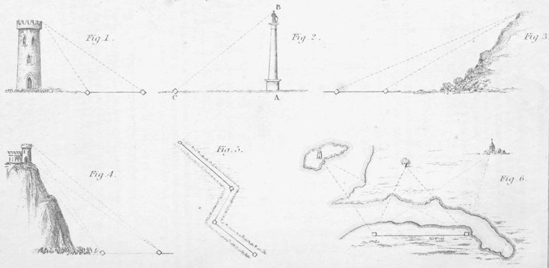
To estimate distances in the field.
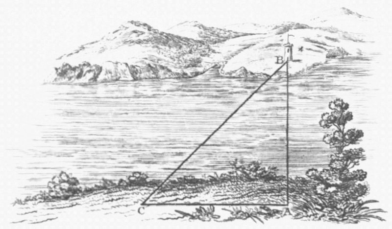
To find the distance from an object, height known.
Instructions for the exercise, and service of great guns, and shells, on board Her Majesty’s ships.
Instructions for landing seamen, and marines, with Field pieces.
Charges for the Royal Navy, for boats.
Proportion of charges, for a 51-screw steam frigate. Ditto Ditto 50-gun frigate.
Also—1 New Plate. 2 ” woodcuts. 1 ” diagram.
In the publication of each edition my object has been the
same—to render The Manual a Compendium of all that can
be required by Officers in the Field; and if I may be allowed
to judge by the gratifying manner in which the work has
been received by the Officers of the United Services, my
humble exertions have indeed been successful, ten thousand
copies of The Manual, including the present edition, having
been printed.
The extensive circulation of “The Artillerist’s Manual,
and British Soldier’s Compendium,” is no doubt, however,
chiefly to be attributed,—
1st. To the highly favourable notice of the Military
Authorities, as evinced by the General order of the
Master-General of the Ordnance, dated 25th April 1840,
and by the Memorandum, dated Horse Guards, 10th
December 1840.
2nd. To the considerate notice of The Lords Commissioners
of the Admiralty, a copy of the work having
been ordered to be included in the libraries of all Vessels
of war.
3rd. To the liberal distribution, by the Honourable Court
of Directors of the East India Company, of copies of each
edition to the military authorities at the several Presidencies
in India.
In conclusion, I have to express my grateful feelings to His
Royal Highness the General Commanding in Chief, who has
been graciously pleased to promulgate the Memorandum,
dated Horse Guards, 13th October 1856;[1] and my warm
thanks are also due to the Officers of the various Departments
at Head Quarters, for the kind manner in which they
have invariably assisted me in the revision of the work, in
order that each succeeding edition may keep pace with the
improvements, alterations, or requirements of the United
Services.
F. A. GRIFFITHS.
Putney, October 13th, 1856.
(Copy.)
Horse Guards,
Memorandum.
13th October 1856.
His Royal Highness, the General Commanding in Chief,
strongly recommends to the Officers, and Non-commissioned
Officers of the Army, the Revised edition of a Work, entitled
“The Artillerist’s Manual, and British Soldier’s Compendium,”
a work replete with the most useful Military information,
and of which Major Griffiths, R.F.P., Royal Artillery,
is the author.
By command of His Royal Highness, The General Commanding in Chief, (Signed) G. A. Wetherall, Adj.-General.
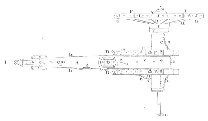
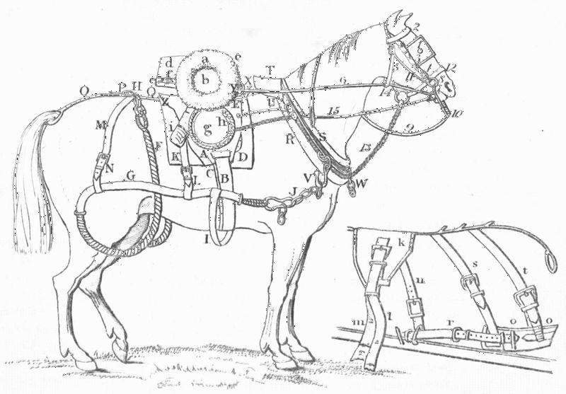
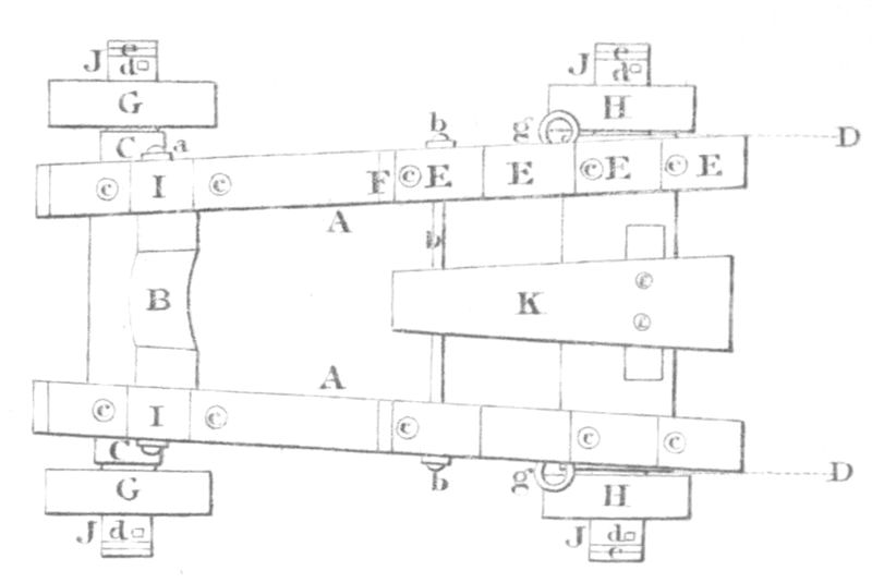
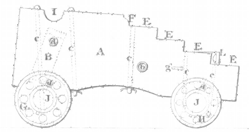
Field battery Exercise. Detail for active service of a
Troop of Horse Artillery; Field batteries, &c. Interior
management of a Battery. Embarking, and disembarking. Application
of Field artillery. Encamping, and picketing. Tents. Horses. Forage.
Veterinary directions. Congreve rocket exercise
The Battalion in line changes position by breaking into open column, marching
up in column to the point where its head is to remain, and entering the line
by the flank march of Companies
The Battalion in line changes position by breaking into open column, marching
to a point where its head is to rest, and to which its rear divisions form by
passing each other, and wheeling up
FIELD BATTERY EXERCISE. DETAIL FOR ACTIVE SERVICE OF
9 Pr. TROOP OF HORSE ARTILLERY, 9 Pr. FIELD BATTERY,
18 Pr. FIELD BATTERY, 32 Pr. HOWITZER FIELD BATTERY,
GUN AND SMALL ARM AMMUNITION RESERVE. INTERIOR
MANAGEMENT OF A BATTERY. EMBARKING, AND DISEMBARKING.
APPLICATION OF FIELD ARTILLERY. ENCAMPING,
AND PICKETING. TENTS. HORSES. FORAGE. VETERINARY
DIRECTIONS. CONGREVE ROCKET EXERCISE.
Telling off the Detachment. Posts of the Detachment
To take ground to a flank. 6. To make a half turn on the march. 7. To form column of divisions in rear
of a flank. 8. To form column of divisions in front of a flank
To retire from a flank in column. 18. To retire from the centre, in a double column of sub-divisions.
19. To retire from a flank by alternate half batteries in action
To form line to the rear of the rear division. 28. To form line to the rear, on the centre division.
29. To form line to the reverse flank on the leading division
Parallels. Zig-zags, or roads of communication. Redan. Redoubt. Star Fort. Têtes de pont. Lines.
Epaulment. Loop holes. Palisades. Fraises. Chevaux de frise. Abattis. Hurdles. Trous de loup
The redan. The lunette. The square redoubt. The pentagonal redoubt. The hexagonal redoubt.
The circular redoubt. The star fort. The field fort with bastions, and half bastions
Instructions for the Exercise, and Service of Great guns, and Shells, on board Her Majesty’s ships.
Field battery Exercise, and Movements.
The Horse, with a treatise on draught.
Directions for the guidance of the Farriers of the Royal Artillery
} Mr. C. Percivall.
Instructions, and Regulations for the Service, and Management of Heavy Ordnance, &c.
Fortification
{ Lieut.-General Pasley.
{ Mr. J. Landmann.
{ Mr. Lochée.
Field fortification
{ Captain Malorti.
{ Captain Macaulay.
Military Surveying
Lt.-Col. Basil Jackson.
Treatises on Attack, and Defence
Lt.-Colonel Jebb.
Artificial fireworks
Mr. G. Mortimer.
{ Dr. Hutton.
Mathematics
{ Dr. O. Gregory.
{ Mr. Trotter.
Practical Geometry
Mr. J. Landmann.
Natural Philosophy
Dr. Fergusson.
The practical Mechanic’s guide.
The practical Engineer’s guide.
The Engineer’s, and Contractor’s pocket-book
Tables
Mr. Beardmore.
&c. &c. &c.
PART I. INFANTRY EXERCISE, MOVEMENTS, &c.
THE
ARTILLERIST’S MANUAL,
AND
BRITISH SOLDIER’S COMPENDIUM.
MUSKET—FLINT LOCK.
lb.
lb.
Weight of Musket
10 }
11
Do. of Bayonet
1 }
Charge, Ball cartridge 6 drams.
Blank cartridge 5 drams.
PERCUSSION SMALL ARMS.
1. Percussion Musket, Smooth-bore: 1842 Pattern.
Barrel
{Length
3 ft. 3 in.
{Diameter of bore
·753 inch.
Musket
{Length
4 ft. 7 in.
{Weight
10 lb. 2 oz.
Bayonet
{Length beyond muzzle
1 ft. 5½ in.
{Weight
1 lb. 1 oz.
Arm complete
{Length
6 ft. ½ in.
with bayonet
{Weight
11 lb. 3 oz.
Bullet (Spherical) ·689 inch diameter, weight 490 grains.
Charge, 4½ drams F. G.
Sixty rounds with 75 Caps = 6 lb. 10 oz.
2. Artillery Carbine: 1853 Pattern.
Barrel
{Length
2 feet.
{Diameter of bore
·577 in.
Carbine
{Length
3 ft. 4½ in.
{Weight
6 lb. 7½ oz.
Sword Bayonet
{Length
1 ft. 10¾ in.
beyond muzzle
{Weight
1 lb. 12 oz.
Arm Complete
{Length
5 ft. 3 in.
with bayonet
{Weight
8 lb. 3½ oz.
The Rifling is 3 grooves and one turn, 6 ft. 6 in.[2]
Bullet
{Weight
530 gr.
{Diameter
·568 in.
Charge of Powder, 2 drams F. G.
Weight of 20 Rounds, with 25 Caps = 1 lb. 11 oz. 2 drams.
3. Regulation Rifle—Musket: 1851 Pattern.
Barrel
{Length
3 ft. 3 in.
{Bore
·702 in.
Rifling, 4 Grooves, one turn in 6 ft. 6 in.
Musket
{Length
4 ft. 7 in.
{Weight
9 lb. 9¼ oz.
Bayonet
{Length beyond muzzle
1 ft. 5½ in.
{Weight
15½ oz.
Arm complete
{Length
6 ft. 0½ in.
with bayonet
{Weight
10 lb. 8¾ oz.
Bullet (Minie)
{Weight
696 gr.
{Diameter
·691 in.
Sixty rounds and 75 Caps = 7 lb. 0 oz. 8 drs.
Charge, 2½ drs. F. G.
4. Enfield Rifle—Musket: 1853 Pattern.
Barrel
{Length
3 ft. 3 in.
{Bore
·577 in.
Three grooves, one turn in 6 ft. 6 in.
Musket
{Length
4 ft. 7 in.
{Weight
8 lb. 8 oz.
Bayonet
{Length beyond muzzle
1 ft. 5½ in.
{Weight
11 oz.
Complete with
{Length
6 ft. 0½ in.
Bayonet
{Weight
9 lb. 3 oz.
Bullet
{Weight
530 gr.
{Diameter
·567 in.
Charge, 2½ drams F. G.
Sixty rounds and 75 Caps = 5 lb. 8 oz. 4 drams.
5. Victoria Carbine: (For Cavalry.)
Barrel
{Length
2 ft. 2 in.
{Bore
·733 in.
Bullet (Spherical)
{Weight
490 gr.
{Diameter
·689 in.
Charge, 2½ drams F. G.
Arm complete
{Length
3 ft. 6 in.
{Weight
7 lb. 9 oz.
6. Naval Rifle.
1842 Pattern. Percussion musket, Rifled with 3 or 4 grooves.
Bullet (Minie),
{Weight
848 gr.
with iron cup
{Diameter
·746 in.
Charge, 3 drams F. G.
7. Pistol: Army pattern.
Barrel
{Length
9 inches
{Weight
1 lb. 6 oz.
{Diameter of bore
·733 in.
Arm complete
{Weight
3 lb. 4 oz.
{Length
1 ft. 3½ in.
Charge of Powder for Ball cartridges, 2½ drams.
Ball, Lead, the same as for the Line-pattern Musket.
BLANK CARTRIDGES.
The charge of powder for Blank cartridges, for all the above-mentioned
Small arms, is the same; viz., 3½ drams.
The cartridges are made with blue paper.
MANUFACTURE OF CARTRIDGES.
The following articles are required for the manufacture of Cartridges:
Five tin measures, containing two and a half drams.
Five tin funnels. A large knife.
An iron straight edge for cutting the paper.
Five cylindrical mandrels of hard wood, to roll the cartridge.
A former, to make the hollow in the inner case, to receive the point
of the bullet.
A set of tin patterns for shaping the paper.
Cartridge paper and fine white paper.
Bullets and gunpowder.
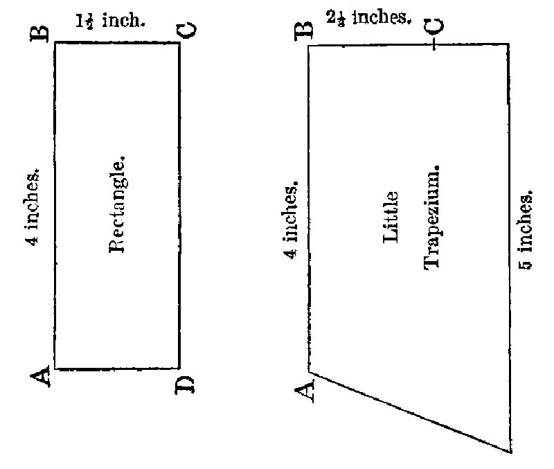
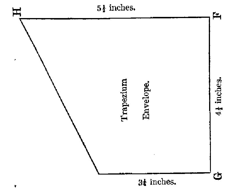
To construct the Cartridge.—Cut the paper according to the patterns,
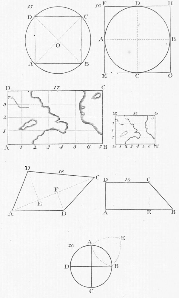
place the rectangle (fig. 9) on the little trapezium (fig. 10), the
sides A B C of the rectangle coinciding with the sides A B C of the
trapezium, lay the mandrel on the rectangle, parallel to the side B C,
the base of the mandrel even with the side C D of the rectangle; roll
the whole tightly on the mandrel; place it vertically, and fold the
remainder of the trapezium paper into the hollow in the base of the
mandrel; commencing with the acute angle of the trapezium, make
use of the point of the former to close the folds; examine the bottom
of the inner case thus formed, to see that there remains no hole for
the escape of the powder when charged; introduce the point of the
bullet into the aperture at the base of the mandrel; take the trapezium
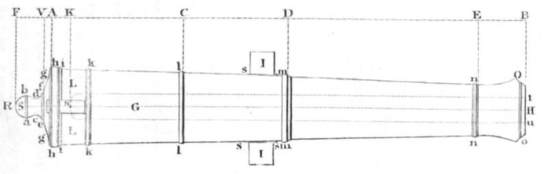
envelope (fig. 11), place the mandrel and bullet parallel to
the side F G, the base of the bullet at half an inch from the base F H,
of the envelope; press up the point of the bullet into the cavity; roll
the envelope tightly on the bullet and on the mandrel; fold the
remainder of the envelope on the base of the bullet, commencing with
the acute angle; place the base of the cartridge on the table; withdraw
the mandrel, squeezing the case of the cartridge with the left
hand, and raising up the mandrel with the right hand.
To charge the cartridge, introduce the point of the copper funnel
into the bottom of the case of the cartridge; pour in 2½ drams of fine
grain powder from the powder-flask; withdraw the funnel, taking care
that none of the powder escapes between the case and the envelope;
squeeze the top of the cartridge, and twist it round.
When completed, the base of the cartridge must be dipped up to
the shoulder of the bullet in a pot of grease, consisting of six parts
tallow to one of bees-wax.
SMALL ARM AMMUNITION.
Dimensions of Boxes.
Length, 1 ft. 4 in. Depth, 8⅝ in.Breadth, 7¼ in.
including the cleat.
Weight of Boxes.
Empty, 7 lb. 6 oz.
Contents and Weight of Barrels and Boxes.
Barrel.
Box.
No. of Cart-ridges.
No. of Caps.
Weight filled.
No. of Cart-ridges.
No. of Caps.
Weight filled.
lb. oz.
lb. oz.
Rifle Musket, Pattern 1842
500
625
79
0
..
..
..
Rifle Musket, ” 1851
700
875
66
4
500
625
65
4
Rifle Musket, ” 1853
700
875
73
8
560
700
60
6
Artillery Carbine
800
1000
81
8
660
825
63
0
Victoria Carbine
700
875
69
0
600
750
60
8
INSTRUCTIONS FOR BROWNING GUN BARRELS.
The following ingredients, viz.:—
1½ oz. of Spirits of wine,
1½ oz. Tincture of steel,
½ oz. of Corrosive sublimate,
1½ oz. of Sweet spirit of Nitre,
1 oz. of Blue vitriol,
¾ oz. of Nitric acid.
are to be mixed and dissolved in one quart of soft water.
Previous to commencing the operation of browning, it is necessary
that the barrel should be made quite bright with emery or a fine
smooth file (but not burnished), after which it must be carefully
cleaned from all greasiness; a small quantity of pounded lime rubbed
well over every part of the barrel is best for this purpose: a plug of
wood is then to be put into the nose of the barrel, and the mixture applied
to every part with a clean sponge or rag. The barrel is then to be
exposed to the air for twenty-four hours; after which it is to be well
rubbed over with a Steel scratch-card or Scratch-brush, until the rust
is entirely removed; the mixture may then be applied again, as before,
and in a few hours the barrel will be sufficiently corroded for the
operation of scratch-brushing to be repeated. The same process of
scratching off the rust and applying the mixture is to be repeated
twice or three times a day for four or five days, by which the barrel
will be made of a very dark-brown colour.
When the barrel is sufficiently brown, and the rust has been carefully
removed from every part, about a quart of boiling water should
be poured over every part of the barrel, in order that the action of
the acid mixture upon the barrel may be destroyed, and the rust
thereby prevented from rising again. The barrel, when cold, should
afterwards be rubbed over with linseed oil, or common oil. It is
particularly directed that the use of the hard hair-brush be discontinued
in browning, and the steel scratch-card or scratch-brush used
in place of it, otherwise the browning will not be durable, nor have a
good appearance. The browning mixture must be kept in glass bottles,
as it will soon lose its virtue if kept in earthenware.
The locks are on no account to be made of the hardening colour,
as the repetition of the operation of hardening has a very injurious
tendency.
PERCUSSION FIRELOCKS.
Muskets with Percussion locks require to be carefully handled, to
prevent the cocks being made loose, by which their direct fall on the
nipples would be rendered uncertain.
They will, at all times, when unloaded, be used with the cocks
down upon the nipples; but, when they are loaded, the caps, or
primers, will be put on, and the muskets carried at half-cock for
safety, there being then less risk of accidental explosion than with the
cocks resting on the caps.
When marching with the cap on, the cock will be brought up under
the arm-pit, the sling resting on the arm; but at other times the
firelock may be carried with the barrel downwards, the right hand
grasping the piece between the loop and swell; and the left the right
arm just below the elbow.
INFANTRY EXERCISE, AND MOVEMENTS,
Extracted from
“FIELD EXERCISES AND EVOLUTIONS OF THE ARMY,”
the Parts and Sections being numbered according thereto.[3]
PACES.
Slow time, each step, 30 inches, and 75 paces in a minute.
Quick time, each step, 30 inches, and 108 paces in a minute.
Double time, each step, 36 inches, and 150 paces in a minute.
Back step, each 30 inches. Side or Closing step, 10 inches.
To calculate the number of Paces (each 30 inches) required for a given
number of Files.
As a soldier occupies 21 inches, take two-thirds of the number of
Files in the division, and add an inch for each File.
Table of the number of Paces corresponding to a given number of
Files.
Number of Files in a Division, each occupying 21 inches.
5
15
16
18
20
30
40
50
Front of Divisions in Paces of 30 inches.
P. I.
P. I.
P. I.
P. I.
P.
P.
P.
P.
3 15
10 15
11 6
12 18
14
21
28
35
FLINT FIRELOCKS.
MANUAL EXERCISE.
1. Secure arms.
2. Shoulder arms.
3. Order arms.
4. Fix bayonets.
5. Shoulder arms.
6. Present arms.
7. Shoulder arms.
8. Port arms.
9. Charge bayonets.
10. Shoulder arms.
11. Advance arms.
12. Order arms.
13. Advance arms.
14. Shoulder arms.
15. Support arms.
16. Stand at ease.
17. Attention.
18. Carry arms.
19. Slope arms.
20. Stand at ease.
21. Attention.
22. Carry arms.
23. Order arms.
24. Unfix bayonets.
25. Stand at ease.
PLATOON EXERCISE.
As front rank standing.
or, As rear rank standing.
— As front rank kneeling.
— As rear rank kneeling.
1. Prime, and Load.
2. Handle cartridge.
3. Prime.
4. ’Bout.
5. Draw ramrods.
6. Ram down cartridge.
7. Return ramrods.
8. As front rank, Ready.
9. Present.
10. Load.
11. Shoulder arms. As rear rank, Ready, &c.
AS A COMPANY.
Prime and Load. Company Ready. Present. At the word “Cease firing,” the Company, if made ready, receives
the words, Half-cock arms. Shoulder arms. Or the word will be given to
“Fire a volley; and half-cock,”
(at priming position,) Shoulder arms. Shut pans.
INSPECTION OF A COMPANY.
1. Attention.
2. Fix bayonets.
3. Shoulder arms.
4. Rear rank take open order—March.
5. Open pans.
6. Slope arms.
7. Carry arms.
8. Shut pans.
9. Order arms.
10. Examine arms.
11. Return ramrods.
12. Unfix bayonets.
13. Rear rank take close order—March.
14. Stand at ease.
Words of Command similar to those for Muskets with Flint locks.
THE PLATOON EXERCISE, AND DIFFERENT FIRINGS FOR THE
ORDINARY OR RIFLE MUSKET.
To load from the shoulder, standing
Prepare to load.
” from the Advance, standing
Prepare to load.
” from the Order, standing
Prepare to load.
Load.
Rod.
Home.
Return.
Cap.
As Front, or Rear rank
—Yards, Ready,
Present.
Load, &c., as above.
To shoulder, when at the Capping position
Shoulder arms.
To advance arms, from the Capping position
Advance arms.
To make ready from the shoulder
—Yards—Ready.
” from the Advance
—Yards—Ready.
To fire kneeling
As front rank kneeling.
—Yards—Ready.
Present.
Load, &c., as above.
Cap.
Shoulder arms.
Advance arms.
To load from the shoulder,
As front rank, kneeling.
as Front Rank, kneeling
Prepare to load.
To load from the Advance,
As front rank, kneeling.
as Front Rank, kneeling
Prepare to load.
Shoulder, or } as before
Advance arms, } directed.
As rear rank, kneeling, Yards—Ready.
Present.
Load, &c., as above.
Cap.
Shoulder, or } as before
Advance arms, } directed.
To load from the shoulder,
As rear rank, kneeling,
as Rear Rank, kneeling
Prepare to load.
To load from the Advance.
As rear rank, kneeling,
as Rear Rank, kneeling
Prepare to load.
As a Company, Load
Company, at yards, Ready.
Present.
Half-cock arms.
Shoulder arms.
Firing as a wing, or as a Battalion, is performed precisely as laid down for a Company.
A Company, Wing, or a Battalion can load, or make ready from the Order with the same ease, as from the shoulder.
Trailing arms
Trail arms.
Change arms.
To resist Cavalry
Prepare to resist Cavalry.
Ready, &c.
FUSIL EXERCISE.
1. Secure arms.
2. Shoulder arms.
3. Order arms.
4. Fix bayonets.
5. Shoulder arms.
6. Port arms.
7. Charge bayonets.
8. Shoulder arms.
9. Support arms.
10. Stand at ease.
11. Attention.
12. Carry arms.
13. Slope arms.
14. Stand at ease.
15. Attention.
16. Carry arms.
17. Trail arms.
18. Shoulder arms.
19. Order arms.
20. Unfix bayonets.
21. Stand at ease.
22. Attention.
THE MANUAL AND PLATOON EXERCISES OF RIFLEMEN.
THE MANUAL EXERCISE.
Present arms.
Shoulder arms.
Order arms.
Shoulder arms.
Support arms.
Carry arms.
Trail arms.
Shoulder arms. From the Order, to Trail arms.
Trail arms. From the Trail, to Order arms.
Order arms.
Fix swords.
Shoulder arms.
Charge bayonets.
Shoulder arms.
Order arms.
Unfix swords.
Stand at ease.
THE PLATOON EXERCISE.
Prepare to load.
Load.
Rod.
Home.
Return.
Cap.
Shoulder.
Make ready.
Present. After firing, the rifle to be brought immediately to the position of—
Prepare to load.
INSTRUCTIONS FOR AIMING WITH THE RIFLE MUSKET.
Firing at a Human figure.
Firing at the Target.
At 100 yards.—Aim at the waist.
Aim with the sight down, straight at the bull’s-eye.
At 150 yards.—Raise the sliding-bar, raise the sight, and aim with the 200 yards’ point at the thigh.
Raise the sliding-bar, raise the sight, aim with the 200 yards’ point at the bottom of the black ring.
At 200 yards.—Aim at the waist with the 200 yards’ point.
Aim at the bull’s-eye with the 200 yards’ point.
At 250 yards.—Press down the sliding-bar, aim with the 300 yards’ point at the knees.
Press down the sliding-bar, aim with the 300 yards’ point six inches below the black ring.
At 300 yards.—Aim with the 300 yards’ point at the waist.
Aim with the 300 yards’ point at the bull’s-eye.
At 350 yards.—Raise the sliding-bar at half distance between the 300 and 400 yards’ point, and aim at the waist.
Raise the sliding-bar to half distance between the 300 and 400 yards’ point, and aim at the bull’s-eye.
From 400 yards to 800 yards.—Make use of the sliding-bar, by raising it to the respective distances,
as marked on the back sight.
WORDS OF COMMAND FOR FUNERAL PARTIES.
Ranks open—Arms shouldered—Bayonets unfixed, facing the quarters
of the Deceased.
When the Corpse is brought out: | Present arms—Reverse arms—Rear rank take close | order—March.
Divisions, Sub-divisions, or Sections are wheeled forwards (or
backwards) to form Column left in front. | Rear rank take open order—March.
When arrived at the Burial-ground: | Halt—Ranks, left and right wheel—Quick | march—Halt—Inwards face—Rest upon your | arms reversed—Stand at ease.
When the Corpse has passed through: | Attention—Reverse arms—Re-form Column—Ranks, | right and left wheel—Quick march—Halt, | front—March.
When facing the grave: | Rest upon your arms reversed—Stand | at ease.
After funeral service: | Attention—Present arms—Shoulder arms—Load | with blank cartridge—Fire three volleys | in the air—Order arms—Fix bayonets—Shoulder | arms—Rear rank take close order—March.
March back to barracks, right in front.
COMPANY DRILL.
Part 2.—Section 1.—Formation of the Company.
The Company is ordered to “Fall in” at close order; is then
sized from flanks to centre; and told off in Sub-divisions, and four
sections. In Column of Sections, the Senior officer takes the Leading,
the second senior the Third, the third Senior the Fourth, and the
junior the Second section. The Company is also told off by “Threes
from the right,” numbered 1, 2, 3. Should there be a blank file in
telling off the company in line, it will invariably be the fourth file
from the left. The Company is also told off from the right by alternate
files, right, and left.
In Close order the Rear rank is one pace, in Open order two paces,
and for inspection three paces, from the front rank.
S. 2. Marching to the Front.
By the right (left, or centre)—March.
The Company will occasionally be ordered, to
Step out—Mark time—Step short—Open, and close ranks—Oblique—Diagonal march.
S. 3. The Side, or Closing step.
To the right (or left) close—Quick march—Halt.
S. 4. The Back step.
Step back—March.
S. 5. To form four deep.*
Form four deep—March.
* In telling off the files, should the last file be a right file, the left file on its right will double
in the rear of it, completing it to four deep, and leaving the other Section only two deep
Rear form four deep—March.
Right form four deep—March.
Left form four deep—March.
To re-form two deep, from each of these formations.
Front. (or Halt—Front.†)
† If the Company is in movement.
S. 6. File marching.
To the left face—Quick march.
Halt, Front.
From the Halt.
Advance in double files from the centre—Sub-divisions inwards face—Quick march.
After facing, the leading files disengage.
Front form Company—(or, To the right form Company.)
Forward.
Right Sub-division—Halt, Front, Dress. The remainder of the Company march on in file,
and form in succession on left of halted Sub-division.
On the March.
Advance in double files from the Centre.
Sub-divisions, inwards turn—Right and left wheel.
S. 7. Wheeling from a Halt.
Right (or left) wheel—Quick march.
Halt, Dress.
S. 8. Wheeling forward by Sub-divisions, from Line.
By Sub-divisions right wheel—Quick march.
Halt, Dress.
S. 9. Wheeling backward by Sub-divisions, from Line.
By Sub-divisions on the left backward wheel—Quick march.
Halt, Dress.
S. 10. Marching on an Alignement, in Open column of Sub-divisions.
March—(or, Quick march).
S. 11. Wheeling into Line, from Open column of Sub-divisions.
1. Halt—Left wheel into line—Quick march.
Halt, Dress, Eyes front.
2. On the Moveable pivot.
Shoulders forward—Forward (or, Halt, Dress.)
S. 12. In Open column of Sub-divisions entering into a new direction on a moveable pivot.
Right (or left) shoulders forward—Forward.
S. 13. Counter-marching.
Counter-march by files.
Right (or left) face—Quick march.
Halt, Front, Dress.
Counter-march by ranks.
Right and left face—Right countermarch—Quick march.
Halt, Front, Dress.
S. 14. Wheeling on the centre of the Company.
Company On the centre—March.
{ Right
}
Halt, Dress.
{ Left
} Wheel
{ Right about
}
{ Left about
}
S. 15. Diagonal march.
The pivots, or outward Files, march in the direct line to which they have faced, the others conforming to them.
S. 16. Increasing the Front of an Open column halted Right in front.
Form Company.
Left Sub-division, Left half face—Quick march—Halt, Front, Dress up.
Diminishing the front of an Open column, halted.
Form Sub-divisions.
Left Sub-division—Right about three-quarters face—Quick march. 2nd Senior. Halt, Front, Dress.
S. 17. Increasing the front of an Open column, on the march.
Form Company.
Left Sub-division, Left half turn, Double—Front turn, Quick.
Diminishing the front of an Open column, on the march.
Form Sub-divisions.
Left Sub-division, Mark time—Right half turn—2nd Senior, Front turn.
When the above movements, 16 and 17, are performed Left in front,
the Words Right will be altered to Left,
and Left to Right.
The same directions apply to sections.
S. 18. In Open column of Sub-divisions to pass a short defile, by breaking off files.
Break off —— files.
—— Files on the left, Right turn—Left wheel.
After passing the defile.—Files to the front.
S. 19. The Company in line halted, or on the march, moves to a flank in Column of sections, or Sections of threes.
For accurate dressing, or when the alignement is to be preserved.
Right (or left) wheel into line—Quick march.
Halt, Dress.
S. 20. Forming Company, Sub-divisions, Sections, or Sections of threes, from file marching.
Front form Company (Sub-divisions, or Sections)—*Forward.
* If the march is to be continued.
Marching in file from the right, to form the Company to the Left flank.
Halt—Front.
Marching in file from the right, to form the Company to the Right flank.
On the leading file to the right form Company.
To form to the Right about.
On the leading file to the right about form Company.
S. 21. To form to either flank, from Open column of Sub-divisions.
To the Left flank.
Halt—Left wheel into line—Quick march.
Halt, Dress, Eyes front.
To form the Company to its Right flank.
To the right forward form Company.
Leading sub-division Left shoulders forward—Forward, Halt, Dress. 2nd Sub-division
(Left oblique till clear of the right Sub-division)—Left shoulders forward—Forward, Halt, Dress up.
S. 22. Company moving to the front, to gain ground to a flank, by march in echellon, by sections.
Sections right—Forward.
To form Company—
Form Company—Forward.
S. 23. To form the Rallying square.
Form the Rallying Square. When the Square is to march—The Square will move to the front,
(rear, right, or left,) Inwards Face—quick march—Halt—Prepare to resist Cavalry—Ready.* Reduce the Square—Quick march.
* If ordered to fire, the Standing ranks onlywill commence an independent fire.
MODE TO BE OBSERVED IN DISMISSING A COMPANY OFF PARADE.
Recover arms.
Right face.
Lodge arms.
In turning in a Guard, or Piquet, the same mode is to be observed.
MANNER OF INSPECTING A COMPANY ON PARADE.
Attention.
Fix bayonets.
Shoulder arms.
Rear rank take open order—March.
Slope arms.
The inspection of Arms will now take place
Carry arms.
Order arms.
Examine arms.
Return ramrods.
An inspection of the Appointments, Clothing, &c., is now to be made.
Unfix bayonets.
Rear rank take close order—March.
Stand at ease.
MOVEMENTS OF A BATTALION. — EVOLUTIONS OF THE BATTALION. — LIGHT INFANTRY. — INFANTRY SWORD EXERCISE. — INSTRUCTIONS FOR PITCHING, AND STRIKING TENTS.
Part 3.—Section 1. Commands.
All words of command must be given short, quick, and loud.
S. 2. Degrees of march.
The Slow step is particularly applicable to purposes of parade,
and occasionally to the march of extended lines.
The Quick march is the usual pace to be applied to all general
movements of Battalions, or greater bodies, in Column, or Line.
The Double march is only to be applied to the movements of the
Divisions of a battalion, except upon peculiar occasions for short
distances.
S. 3. Marching in line.
The March in line is generally adopted where the country is
open.
S. 4. Wheeling.
Wheels are made on a Halted pivot from Line into Column, and
from Column into Line. The principle of the Moveable pivot must
always be applied to the wheel of divisions marching in column.
Wheels of divisions may be either made forward, or backward. In
progressive movements they are to be made Forward, but particular
occasions require that they should be made Backward on the pivot
flank. The Backwards wheel need not, however, be practised where
the ground is uneven, and the Divisions stronger than 15 or 16 files:
where this is the case, the Command will be
Form open column, right (or left) in front—Right about face—Right (or left) wheel—Quick march.
Halt, Front.
S. 5. Movements.
Every movement must be divided into its distinct parts, and
each part executed by its cautionary and executive words of command.
All field movements and firings are to be performed with fixed
bayonets, except when troops are acting as Light infantry.
S. 6. The Alignement.
To march in an Alignement is to make troops march in any
straight line, which joins two given points—or to form upon any such
given line. When troops are to form in a straight line, two necessary
points in it must always be previously ascertained. One, the point of
Appui at which one flank of the Body is to be placed, and the other
the distant point of formation or dressing, on which the front of the
body is directed.
S. 7. Points of formation.
The line on which troops move, or are successively to form, may
be taken up to any extent by the prolongation of an original short
base, given in the direction which the Commander of a line will point
out.
S. 8. Dressing.
The Officer in dressing is placed on that flank of his division to
which the men’s eyes are turned on the word “Dress,” and from
the second file from the flank of the Company towards which his
wheeling flank moves from column, or his inward flank from echellon:
he makes his corrections on his intermediate point. In all wheelings
into line the word “Eyes Front” will be given as soon as the dressing
is completed. When Officers change from one flank to the other
in order to close, they will pass by the front, and repass by the rear
of their Companies. On all other occasions, when it is necessary to
change their flanks in line, they will pass and repass by the rear.
S. 9. Open column.
All changes of position, by means of the Open column, will be
effected by the formation of a column, right or left, in front, on the
named division. If on a flank division, the caution will specify
whether the other flank is to be thrown back, or forward: if on a
central division, the caution will in like manner specify which wing is
to be thrown forward. An open column may effect a change of
position upon its front, rear, or any central division by the named
division wheeling up according to the front to which it is intended
to change; and the other divisions facing, and filing into the new
alignement.
S. 10. Column at Quarter distance, and Close column.
When Close columns are formed, the Companies or Divisions
must be at one pace distance. In the wheel of a Column at quarter
or close distance, the leading division acts as a moving base for the
rear Companies to follow; its length of step is regulated according to
the depth of the column, and when at quarter distance must be very
short to enable the rear to circle simultaneously round at the usual
pace. Upon the wheel being ordered, all the rear divisions make a
half face to the wheeling flank; but at a quarter distance, the leading
division will advance six paces on the word “Quick (or Double)
March,” and will wheel round the pivot file at a shortened pace,
while each succeeding division will advance, in circling round, to
quarter distance, which will leave room for the rear divisions to circle
into their relative positions at that distance. In wheeling on the
Moveable pivot, the rear divisions make a half turn towards the
shoulder brought forward, and the front division wheels and advances
at a shortened pace in the new direction, the rear divisions circling
round. In Close column, the supernumeraries will form on the reverse
flanks of companies; and when the column marches to a flank,
they will move with their companies; when the Close column is to
countermarch they will remain on the reverse flank, and countermarch
on their own ground. When a Column deploys on a rear
division, the named division when uncovered will move up to the
front (which its covering Serjeant will mark); the points, therefore,
necessary for the formation of the Battalion will be taken in prolongation
of these points, and the Divisions which successively move up
must Halt, Front, until their front is clear.
S. 11. Echellon.
The Echellon position and movements are applicable to the oblique
or direct changes of situation, which a Battalion may be obliged to
make to the front or rear, or on a particular fixed division of the line.
The oblique changes are produced by the wheel (less than the quarter
circle) of divisions, which places them in the echellon situation. The
direct changes are produced by the perpendicular and successive
march of divisions from line to front or rear. In Echellon, the inner
flank, (or that which first joins its preceding division when the line is
to be formed forward,) is the directing one; and in Oblique echellon
the wheels are made on it, into echellon—forward, and into line—backward.
Practical rule for the Battalion and Line on all occasions of Wheeling
by Companies into echellon.
“Each covering Serjeant having previously placed himself before or
behind a given file (the 8th) from the standing flank, will take the
named number of paces from the centre of that file on the arc of the
circle, and thereby become a direction for the Company to wheel up
to, and halt.”
As eight paces from the eighth file complete the Quarter circle, so
four paces give the One-eighth, and two paces the One-sixteenth of
the circle. All changes of front by the Echellon march are performed
by the forming divisions wheeling half the angle wheeled by the
division to be formed upon. In all changes of position by echellon,
whether direct or oblique, the leaders of companies will invariably be
on that flank towards which the change of position is to be made.
But in taking ground to a flank on the march, in echellon of Sub-divisions
or Sections, Companies’ leaders remain in their places as
when in line.
S. 12. Squares.
Squares are formed either from Line, or from Column at full,
half, or quarter distance. The Hollow square, four deep, is sufficiently
solid to oppose an attack of Cavalry: it possesses, at the same time
the advantage of rendering the fire of all the men available to the
resistance of the enemy. The Solid square should seldom be adopted,
because a proportion of the men cannot give their fire. Close columns
should in all cases when practicable, open therefore to quarter distance,
and form Square (as in Sec. 21, No. 1, Part III.). But as
every position in which a Battalion may be placed should be susceptible
of ready resistance against Cavalry, the Close column can always
assume an efficient posture of defence, by the six centre Companies
wheeling outwards by Threes, and closing to the front, and the two
rear Companies facing to the right about: the Officers and Serjeants
taking post in the centre. The wing of a battalion can in like manner
form the solid square from a Close column of Sub-divisions. When
Cavalry is not to be resisted, it will be sufficient to form the Square
two deep to the rear. The formation of Battalion squares, either
from Line or Column, is to be completed as expeditiously as possible;
and the Squares may afterwards be placed in direct echellon for mutual
defence.
S. 13. Firings.
In all movements, Firing should commence after a formation.
In firing by Companies, the Leaders will give the Word “Ready”
when the previous division fires, preserving the pause of slow time
between this and “Present,” the men firing when they have covered
their objects. In firing by wings, one wing will receive the word
“Ready,” the instant the other has completed its loading. Great
care must be taken in file firing that it is not hurried, and that the
men “Present” deliberately. The value of a soldier’s ammunition,
and a jealousy of its expenditure without effect, must be carefully
inculcated; for in proportion as a cool and well-directed fire serves to
distract and throw an enemy into disorder, so is a wild, confused, and
hurried fire (which is always without effect) calculated to give him
confidence, and a contempt for his opponent. Soldiers should, therefore,
bear in mind that nothing makes so strong an impression on an
enemy, as the thinning of his ranks by a well-directed fire; and that
nothing tends more to animate and encourage troops than the diminished
fire from ranks so thinned; affording also the most favourable
opportunity for a successful charge. In firing in square, the two
front ranks are to come to the kneeling position without cocking, on
preparing to receive cavalry. The standing ranks in square will fire
independently from the right of faces.
Street firing.
A Column at open, half, or quarter distance, formed in a street
or narrow ground where deployment is impracticable, may be required
to fire previous to charging forward, or by successive divisions in
retiring. It will be performed in the following manner:—
If advancing, the two front Companies only will fire in succession;
the leading Company firing and loading kneeling, the second
Company closing to the front, and firing standing. When the
enemy’s fire has been overcome, or at any favourable moment that
may present itself, the column will charge briskly forward, and
make good the ground it is contending for.
In retiring, the leading division will give its fire; Slope arms;
Face outwards by sub-divisions; File to the rear; Re-form Company;
Load; and remain halted, until its front is again clear, or the whole
column is put in motion. The moment the front of the second company
is clear, it will give its fire; Face outwards by sub-divisions;
and file to the rear as above directed: and so on by companies in
succession: the companies thus follow each other, and when the
front of the column occupies the whole breadth of the street, the
outward files of companies will double in the rear, to give the companies
which have fired room to pass. It must never be forgotten,
in entering towns or villages occupied by the enemy, that the first
thing to be done, on gaining a footing in the place, is to clear the
houses on both flanks, and the column should on no account proceed
through the streets without previously occupying the houses on either
side; the troops employed for that purpose breaking through partition
walls, or pushing on from house to house, so as to accompany the
march of the main body, and protect its flanks.
FORMATION OF THE BATTALION.
When the Battalion is formed, there is to be no interval between
any of the Companies, and every part of the front of the Battalion
should be equally strong. The Grenadiers will be on the right,
Light company on the left, the other companies from right to left.
The Battalion will be told off into Right, and Left wings.
FORMATION OF THE BATTALION, AT CLOSE ORDER.
The Commanding officer is advanced in front for the general
purpose of exercise when the Battalion is single; but in the March
in line, and in the firings, he is in the rear of the Colours. The
Lieutenant-colonel is behind the colours, twelve paces from the
supernumerary rank. The 1st Major is six paces in the rear of the
second Battalion company from the right flank; 2nd Major at the
same distance in the rear of the second Battalion company from the
left; the Adjutant at the same distance in rear of the colours. One
Officer is on the right of the front rank of each company, and One on
the left of the Battalion; all these are covered in the rear rank by
their respective Serjeants; and the remaining Officers and Serjeants
are in a third rank behind their companies. The colours are placed
(both in the front rank) between the two Centre companies. The
supernumerary rank is at three paces distance when in Line; and
when in Column, it is at the distance of one pace.
When the Battalion takes Open order.
Rear Rank take Open Order—March.
Officers of Companies and those with the Colours dress three paces in front of the Line.
The 1st Major is on the right of the Officers, the 2nd Major on the left. The Adjutant on the left
of the front rank. The Colonel ten paces, and the Lieutenant-colonel six paces, in front of the Colours.
When the Battalion resumes Close order.
Rear Rank take Close Order—March.
MOVEMENTS OF THE BATTALION FROM LINE.
S. 14. 1. The Battalion halted, and correctly dressed, is to advance
in Line.
Commander’s Words of command.
Executive Words of command, Directions, &c.
The Battalion will advance—March (or Quick march)—Halt.
2. When the Battalion is to retire.
The Battalion will retire—Right about face—Quick March.
3. While advancing in Line, the Battalion may form to either
flank by the Divisions wheeling to the Bight (or Left) on the Moveable
pivot, and forming on the flank Company (which will be halted in
the direction of the new front) by the Echellon march of divisions.
S. 15. When a Battalion advancing in Line is to charge.
Prepare to charge—Charge—Halt.
S. 16. When a Battalion moving in Line passes a wood, &c., to
Front or Rear, by the flank march of Companies in file.
1. If to pass to the Front.
From the right (or left) of Companies pass by files to the front. Companies, right (or left) turn—Right (or left) wheel.
2. If to pass to the Rear.*
From the proper right (or left) of Companies pass by files to the rear—left (or right) turn—Right (or left) wheel—Halt—Front.
* The Battalion in Line having arrived at the point where it must break. Companies may also pass to the front or rear by Sections of Threes.
3. If a Battalion in first Line passes through a second, which advances
and relieves it.
Pass by files to the rear—Right face—Right wheel—Quick march—Halt—Front.
The relieving Battalion marches up within twelve Paces of the front Line, the Companies of which proceed to the rear through the second Line.
4. When the second Line does not advance to relieve the first.
Pass by files to the rear—Left turn—Right wheel.
The first Line retires, and when within twelve paces passes through the second.
S. 17. When the Battalion advances, or retires, by half Battalion,
and fires.
1. If the Battalion is in march, and advancing.
The Battalion will advance by wings. (2nd Major) Left wing, halt—March (or quick march).
(Senior Major)* Right wing, halt—Ready—Present—Load—March (or quick march). (2nd Major)
Left wing, halt—Ready, &c.
* After having advanced 15 paces.
2. If the Battalion is in march, and retiring.
The Battalion will retire by wings. (Senior Major) Right wing, halt—Front. (2nd Major)*
Left wing, halt—Front. (Senior Major) Right wing, ready—Present—Load—Right
about face—March (or quick march). (2nd Major) Left wing, halt—Front. †Left wing, ready—Present—Load, &c.
* After retiring 15 paces.
† When Right wing has retired 15 paces.
S. 18. A Battalion in Line to move to attack, or pass a bridge, &c.,
to the front, from either flank, or from the centre.
1. If from a Flank, by Companies, or Sub-divisions.
Right (or left) Division to the front.—Remaining Divisions, right (or left) shoulders forward—Quick march—Forward.
5. To form Line to the right, from the Double column.
Form line to the right—Right wing left shoulders forward.
Right wing Sub-divisions—Halt, Dress. Left wing Sub-divisions successively—Left shoulders forward—Forward—Halt, Dress up—Eyes front.
S. 19. A Battalion in Line to retire over a bridge, or defile, or
retreat from a Flank or Flanks, in rear of the Centre.
1. If from a flank.
Retire by Companies (or Sub-divisions) from the left (or right) in rear of the right (or left).
Left (or Right) Company—Company (or Sub-division)—Right about face—Quick march—Right (or Left) shoulders forward—Forward.
When at inward flank of right (or left) Division—Right (or left) shoulders forward—Forward. The other Divisions follow in succession.
2. If the Retreat is from both flanks.
Retire from both flanks by sub-divisions in rear of the centre.
Right (or left) Sub-division—Right about face—Quick march—Right (or left) shoulders forward—Forward.
When arrived at the proper points—Right (or left) shoulders forward—Forward.
Remaining right, and left Sub-divisions follow in succession. Two centre Sub-divisions,
when the Divisions next to them have commenced their second wheel—Right about face—Quick march.
S. 20. A Battalion in Line to march off in Column of divisions, successively
to a flank.
1. If the Movement is along the rear, and from the right flank.
The Battalion will move in Column of Divisions (or Sections) from the right along the rear.
Right Division (or Section)—Left face—Left wheel—Quick march—Front turn.
2. When the Movement is from the left flank.
Left Division (or Section)—Right face—Right wheel—Quick march—Front turn.
In both movements the Divisions follow in succession the leading
division.
S. 21. When the Battalion, halted in Line, is to form Square on a
named Company, or on two centre Sub-divisions.
1. If on a Central company.
Column at quarter distance on the right (or left) centre Company—Threes, right and left shoulders forward—Double march,
When the Companies reach their places in Column, they receive successively Threes right (or left) shoulders forward—Halt, Dress.
Form square—Quick march. When the Second Company has closed upon the front Company, which stands fast— Sections outwards.
The two rear Companies close up, and form the rear face of the Square, receiving Halt—Right about face. The remaining Companies wheel outwards by Sections, the rear Sections closing to the front, after the wheel.
2. If on a Flank Company, and to a flank.
Square on the right (or left) Company—Companies right (or left) shoulders forward—Double march—Forward.
Leading Company—Halt. Second Company closes on it—Halt. Remainder (except the two last Companies),
as they successively arrive at Quarter distance— Sections outwards. Two last Companies when closed up—Halt—Right about face.
3. When the Square is to resist Cavalry.
Prepare for Cavalry —Ready. *Kneeling ranks—Ready— Present—Load. Prepare for Cavalry (or shoulder arms).
The Kneeling ranks do not cock until required to fire. The Standing ranks fire by Files. * The Kneeling ranks,
when required to fire a volley.
4. To reduce the Square.
Re-form column.
Quick march.
Rear sections of side Faces step back to wheeling distance, pivot men facing to their proper front, and atQuick marchwheel backwards—Halt, Dress. Front Company advances to quarter distance—Halt, Dress. Two rear Companies retire—Halt, Front, Dress.
5. If the Square is to be formed on the two centre Sub-divisions.
On the two centre Sub-divisions form square.
The outer Sub-divisions of the two centre Companies face inwards, and leading files disengage; the two flank Companies face inwards,
and the remaining Companies of the Battalion face to the right about.
Right and left shoulders forward.
Quick march.
No. 1, 2, 3, 6, 7, 8 Companies, Sections successively, Halt, Front. The two centre Sub-divisions close by the side step,
upon the interval left by the Colours. The Sub-divisions of the two flank Companies are conducted to form the rear Face,
the right Sub-division of the Grenadiers covering its left Sub-division, and the left Sub-division of the Light Company covering
its right Sub-division, each receiving Halt, Right (or Left) face.
6. To reduce the Square and form Line.
Re-form line—Quick (or double) march.
The flank Companies face outwards; and the rear Sub-divisions of the centre face outwards, and file into line atQuick (or double) march—Halt, Front, Dress. The two centre Sub-divisions open by the side step to right,
and left. The flank Companies move in file to their respective places. The other Companies deploy by Sections and (when at their places)
receive Right (or left) shoulders forward—Forward—Halt, Dress up.
7. But should it have been previously necessary to move the Square.
Form double column of Sub-divisions—Quick march.
The rear Sub-divisions of the side faces fall back to Section distance, and the Pivot men face to their proper front, and atQuick march, the Sections which formed the side faces wheel backwards; and the two Sub-divisions of the front face,
and four Sub-divisions of the rear face, advance to quarter distance. The Sub-divisions of front face receive—Halt. Sub-divisions of the
rear face receive—Halt—Front.
8. When the Line is retiring, the Square may be formed at once
without halting.
On two centre Sub-divisions form square.
The two centre Sub-divisions Halt—Front. The outer Sub-divisions of centre Companies “Inwards turn,” and the formation will proceed
(as directed in No. 5,Section 21) at the Double march.
S. 22. When the Battalion forms a Square, or Oblong two deep, to
protect baggage, &c., against Infantry.
1. Form square, two deep, on the two centre Companies. Remaining Companies, right and left shoulders forward—Quick march.
The two centre Companies stand fast, remaining Companies face to the rightabout, and atQuick marchthe two centre Companies (4 and 5) close inwards: the remainder right, and left shoulders forward, and move into Square. Nos. 1, 2, and 3,
form the right face, 6, 7, and 8 the left face, the Grenadier, and Light Infantry the rear face of the Square, respectively receiving
Halt, Front, Dress.
2. When the Square or Oblong is to march by any one face.
The square will march to the front (rear, right, or left) face.
Flank Faces—by sub-divisions on the right and left backwards wheel—Quick march.
The rear face advances two paces and faces about—Halt, Dress.
Quick march.
The Square marches two faces in Line, (by their centre,) and two faces in Open column of Sub-divisions.
Halt—Re-form square—Quick march.
The Sub-divisions in column wheel up and form their faces, and the rear face will close up and then face about.
3. To reduce the Square.
Form line—Right and left shoulders forward—Quick march.
The two centre Companies open out by the side step, to leave room for the Colours. Remaining Companies,
Right (or left) shoulders forward—Forward—Halt, Dress up.
S. 23. A Battalion halted in Line, to change front to the rear
upon the centre.
Remaining Companies,Threes right, and left shoulders forward—Right and left counter-march— Quick march.
The Companies pass each other by the left, those of the Right wing describing a circle to allow room for the others to pass,
and when in their proper position—Right (or left) shoulders forward—Forward—Halt, Dress up—Eyes front.
CHANGES OF POSITION OF THE BATTALION FROM LINE BY
MOVEMENTS OF THE OPEN COLUMN ON A FIXED POINT.
S. 24. The Battalion to change position to the front on the right
halted Company, by throwing forward the whole Left, and by the flank
march of Companies.
1. Form open column in front of the right Company—Remaining Companies—Right face—Quick march.
If the change of front is to be at right angles with the old line, the right Company stands fast; if oblique to it, that Company
will wheel back on the right flank as many paces as will make it perpendicular to the new direction. Remaining Companies face to the right,
and disengage to the left—Halt, Front, Dress.
Right wheel into line.
Halt, Dress—Eyes front.
2. The Battalion may change its position to the Left, Right thrown
forward, by the formation of the Open column in front of the left
halted Company.
3. If the Change of position is effected by the formation of the Open
column on a central Company, the caution will specify which flank is
to be thrown forward. The Companies face inwards, and disengage.
4. When a Battalion is to change position on a flank halted Company,
by throwing back the other flank.
Form open column in rear of the right (or left) Company— Remaining Companies— Right (or left) face— Quick march.
Remaining Companies—Halt, Front, Dress.
Right (or left) wheel into line—Quick march.
Halt, Dress—Eyes front.
ON A DISTANT POINT.
S. 25. The Battalion in line changes position by breaking into Open
column, marching up in column to the point where its head is to
remain, and entering the line by the flank march of Companies.
Right (or left) face—Quick march. Halt.
The Battalion in Open column to form at a point where its leading flank is to be placed, receives—Halt—
when its leading division is at wheeling distance short of that point.
S. 26. The Battalion formed in line, changes position by breaking
into Open column, marching to a point where its head is to rest, and
to which its rear divisions form, by successively passing each other,
and wheeling up.
S. 27. When the leading flank of the Column is changed by the
successive march of Divisions from the rear to the front.
Halt— By successive divisions —Rear wing to the front.
If Right in front; Rear Company—Right face—Quick march—Front turn. Remaining Divisions in succession,
when their rear Division passes them—Right face—Quick march—Front turn. If left in front, the rear Divisions are faced to the left.
S. 28. To change the Wings of a column formed upon a road,
where the space does not admit of the Flank movement.
By double files from the centre, rear wing to the front. Two centre Sections outwards wheel—Quick march.*
Rear Company—Inwards face, by Files from the centre. Remaining Companies*—Halt, Dress. Rear Division when
clear of the column—Form Company—Forward. Remaining Divisions in succession when clear—Inwards face—Quick march—Form Company—Forward.
S. 29. When the Column, at open, or half distance, is required to
form a Square.
1. If the Square is to be formed on the front Company.
Form square on the right (or left) centre Company—Right (or left) wing—Right about face—Quick (or double) march.
The Officer commanding the named Division, gives—Sections outwards; the rear Sections closing on the front Sections.
The Left wing will close to Section distance, and the Companies receive, in succession—Sections outwards; the Right Wing will move to the Centre,
rear Rank in front, and when each Company shall close up to the one preceding it, Companies 3, 4, 5, 6, Front turn, Sections outwards,
and the rear Sections close to the front. Nos. 1 and 2—Halt, Front,—Nos. 7 and 8—Halt, Right about face.
3. If an Open column, moving to front, or rear in File, or Sections
of Threes, be attacked by Cavalry.
If in File.
Form square on the centre—Wings inward turn—Double march.
The Divisions turn to the right, and left; and if the Column be right in front, when the left centre Company has turned
it receives—Sections outwards; the Wings close on the centre, at the double march, and each Company wheels outwards into Square; as in No. 2.
If the Column is moving in Sections of Threes.
Right (or left) shoulders forward. Forward—Square on the centre—Right wing, right about turn—Double.
The Formation proceeds as before. The Column is re-formed as directed in S. 21, No. 4.
QUARTER DISTANCE, AND CLOSE COLUMN.
S. 30. When a Battalion forms a close, or quarter distance Column,
from Line.
1. If a Close Column before, or behind, either of the flank Companies.
Form close (or quarter distance) column on —— Company, right (or left) in front—Right (or left) face—Quick march.
All except the named Company—Halt, Front, Dress.
2. On a central Company.
Inwards face—Quick march.
All except the named Company—Halt, Front, Dress.
In the same manner, Column may be formed from Line upon any
Company facing to the rear; that Company countermarching by files,
and the Wings facing outwards, and countermarching to the right, or
left; and forming as before.
In all Counter-marches from Line, the Company of formation will
be faced by the command of its own Officer.
3. If a Quarter distance Column upon any named Company.
Form column at quarter distance, right (or left) in front, —— on Company—Remaining Companies, threes—
Shoulders forward— Quick (or double) march—Forward.
Shoulders forward—Halt, Dress, as in Nos. 1 and 2.
The leading threes of the Company next the one of
formation must wheel upon its centre file in disengaging to the rear.
4. The Close column may be formed from Open column.
Close to the front—Quick (or double) march. Or without halting—Close to the front—Double.
If on the March, Leading division—Halt. Remaining divisions successively—Halt: When on the Double march—Quick.
S. 31. When the Column, at close, or quarter distance, marches to
a flank.
Column will march to the right (or left) flank—Right (or left) face—Quick march—Halt, front.
If the Column is at quarter distance, it may be marched to a flank
in Sections of threes.
Threes right (or left) shoulders forward—Quick march—Forward.
S. 32. When the Column at quarter distance, moving to front, or
rear, takes ground to the Right, or Left, by the Echellon march of
Sections.
1. Sections right (or left)—Forward. 2. Re-form Column—Forward.
Officers remain on their proper pivot flank.
Ground may be taken to a flank by the diagonal march.
Right (or left) half turn.
S. 33. When a Column halted, at Close, or Quarter distance, is to
wheel on a fixed, or moveable pivot.
1. At close distance on a fixed pivot.
Column to the right (or left) wheel—Quick (or double) march—Halt.
The flank file of front Company will face. Remaining Companies make a half face. Vide S. 10. No. 6.
2. At close distance on a moveable pivot.
Right (or left) shoulders forward—Halt (or forward).
Rear Divisions will make a half turn to the outward flank, and circle round.
If the Column is to wheel in double time.
Double—Forward—Quick.
3. At Quarter distance on a fixed pivot.
Right (or left) wheel— Quick (or double) march—Halt.
Rear Divisions half face to the wheeling flank. The front Division will advance six paces, and wheel at shortened pace round the Pivot,
the rear Divisions circling round.
4. At Quarter distance on a moveable pivot.
Right (or left) shoulders forward—Double— Forward—Quick.
The Front division moves round at a short pace, the pivot-man gradually advancing in the new direction.
S. 34. When a Close, or Quarter distance Column is to change
its front by the wheel and countermarch of Sub-divisions round the
centre.
1. If at the halt.
Counter-march by Sub-divisions round the centre—Right (or left) Sub-divisions—Right about face—Quick (or double) march—*Halt, Front, Dress.
The Reverse sub-divisions face about. The whole wheel round in succession.
* When the leading Sub-division is
in a line upon the new front of the Column. Front applies to the Reverse sub-divisions only.
2. If the Column at Quarter distance is on the march.
Right (or left) Sub-divisions—Right about turn—Front turn—Forward.
S. 35. When a Column at close, or quarter distance, is to open out
to full, or half distance, from front, or rear.
1. If from the front.
Column will open from the front—Right about face—Quick march.
The requisite number of paces are counted by the leaders of each Division. Halt, Front.
2. If from the rear.
Column will open from the rear—Quick march.
Each Division leader gives Halt to the Company in his front, when at the ordered distance.
DEPLOYMENTS.
Deployments are made from Column invariably on the base of the
front Company; Close columns deploy in File.
S. 36. When the Battalion in column of Companies, at Close, or
Quarter distance (right in front), deploys into Line.
FROM CLOSE COLUMN.
1. On the Front Company.
Deploy on the front Company—Remaining Companies, left face—Quick march.
Each Company, in succession—Front turn—Halt, Dress up—Eyes front.
2. On the Rear Company.
Deploy on the rear Company—Remaining Companies, right face—Quick march.
When the front of the named Company is clear, the Officer commanding it gives— Double march—Halt, Dress up—Eyes front—Remaining Companies
successively —Halt, Front. When uncovered, Quick march, and when in the alignement, Halt, Dress up—Eyes front.
Deployments on a central Company are performed in a similar
manner. In deploying on a rear, or central Company, the Company
of formation will be moved up in Double time.
FROM QUARTER DISTANCE COLUMN.
3. When a Battalion in Column of Companies at quarter distance,
right in front, deploys upon its Front division.
Deploy on the front Company—Remaining Companies, threes— Right shoulders forward —Quick (or double) march—Forward.
Left shoulders forward—Forward— Halt, Dress up—Eyes front.
4. On a Rear Company.
Deploy on the rear Company—Remaining Companies, threes— Left shoulders forward —Quick march—Forward.
When the Front is clear, Rear Company —Double march—Halt, Dress up—Eyes front. The other Companies successively —shoulders forward—Halt.
When uncovered —Quick march—Halt, Dress up—Eyes front.
The Base points are three paces in advance of the Front Company
of the Column.
ECHELLON FORMATIONS AND MOVEMENTS.
S. 37. When a Battalion from Line wheels forward by Companies,
to either flank, into Echellon.
1. Companies —— paces to the —— wheel—Quick march.
Halt, Dress.
2. When the Echellon thus formed marches forward, and halts.
Quick march—Halt.
S. 38. When the Battalion having wheeled from Line into Echellon,
has marched, and halted, and is to form back parallel to the Line it
quitted.
Wheel back into line—Quick march.
Halt, Dress—Eyes front.
S. 39. When the Battalion having wheeled from Line into Echellon,
has marched and halted, and is to form up oblique to the Line it
quitted.
1. If the Formation is made forward.
Leading Division, —— paces right (or left) wheel— Quick march. Form line—Quick march.
Leading Division—Halt, Dress—Eyes front. Remaining Divisions—shoulders forward—Halt, Dress up—Eyes front.
2. If the wheel of the leading Division exceed the number of paces
which it before wheeled from Line into Echellon, the others wheel up
one-half of that excess, move on, and successively dress up with it.
3. If the formation is to be on the prolongation of the front Division
as it stands, the others wheel back one-half of what they originally
wheeled forward, then move on, and dress up with it.
S. 40. When the Battalion formed in Line changes front on a fixed
flank Company, by throwing forward the rest of the Battalion.
Change front on —— Company, right (or left) thrown forward, —— Company —— paces right (or left) wheel.
Company of formation—Halt, Dress.
Remaining Companies, —— paces to the —— wheel—Quick march.* Quick march.†
S. 42. When the Battalion changes front on a central Company, by
advancing one Wing, and retiring the other.
The Company of the Wing to be thrown back is wheeled backward,
and the Company of the wing to be brought forward is wheeled forward;
or a Central Company is wheeled upon its centre into the new
direction.
—— Wing, right about face—Companies —— paces inwards wheel—Quick march.
Halt, Dress.
Quick march.
Companies successively—shoulders forward— and when in Line, those of the advancing Wing receive—Halt,
Dress up: the retiring Wing—Halt, Front, Dress up.
S. 43. When, from Open column, the Companies wheel backward
into Echellon, in order to form in Line on the front Company.
1. Form line on the leading Division. Remaining Divisions —— paces on the —— backward wheel—Quick march.
Quick march.
The front Company remains square to the Column, or is wheeled backward into the intended direction of the Line by its Officer. If the front Company remains square, the remaining Companies wheel back four paces, or the eighth of a circle; but if the direction be Oblique,
then the remaining Companies wheel one-half the number wheeled by the front Company, in addition to the eighth of a circle—Halt,
Dress. —— shoulders forward—Halt, Dress up—Eyes front.
2. If the Line be formed on the rear Company of the Column, that
Company will stand fast, the others will receive.
Right about face, —— paces on the —— Backwards wheel—Quick march. Quick march.
4. If the Line be formed on a Central Company of the Column.
Form line on the Right (or Left) centre Company, —— wing right about face—Four paces on the right (or left) backwards wheel—Quick March.
All except the central Company Halt, Dress.
Quick march.
Companies of Wings (except Company formed on)—— shoulders forward—Halt, Dress up—Eyes front. Or ——
shoulders forward—Halt, Front, Dress up—Eyes front.
S. 44. When from Line the Companies of a Battalion march off in
Echellon, successively and directly to the front; and again form Line
to the front, or flank.
1. When the intention is to form Line to the front.
Advance in direct echellon of Companies from the right (or left).
When the leading Division receives—Halt, the others move on, and Halt, Dress up, in line with it.
2. When the intention is to form Line to the flank.
Form line to the right (or left) flank.
Leading Division—Halt, Dress—Eyes front.
By Divisions, shoulders forward—Forward.
Remaining divisions—Halt, Dress up— Eyes front.
3. If a Column is to be formed to the flank, from a direct Echellon.
Form column in rear of the leading Division—Threes— Shoulders forward— Forward.
—— shoulders forward—Halt, Dress.
S. 45. When a Battalion, in Echellon of Companies, halted, or in
motion, is required to form square.
Companies right (or left) shoulders forward—Forward—Form square.
The formation will proceed as directedin Section 29.
S. 46. When a Battalion marching in Line is to take ground to a
flank by the Echellon movement of Sub-divisions, or Sections.
1. Sub-divisions (or Sections) right (or left)—Forward.
2. When sufficient ground has been taken to the flank.
Re-form line—Forward— Halt.
3. When sufficient ground has been taken in Echellon to a flank,
and a forward formation of the Line is to be made.
Form line on the leading Division.
The head Division is wheeled up two paces more and halted. Divisions successively ——
shoulders forward. Halt, Dress up—Eyes front.
In taking ground to a flank, if a small degree of obliquity from the
former position is to be taken, the Line may wheel forward by Companies;
if a greater, by Sub-divisions; and if a greater still, by
Sections.
SIGNALS AND SOUNDS FOR REGULATING MOVEMENTS.
The Officers’ call—as established, and therefore not numbered.
1. To extend.
2. To close.
3. To advance.
4. To halt.
5. To fire.
6. Cease firing.
7. To retreat.
8. Assembly.
9. Incline to the right.
10. Incline to the left.
11. The alarm.
Words of command throughout
THE PROGRESSIVE INSTRUCTIONS OF THE DRILL.
The words in Italics are to serve as a caution only.
Section I.
EXTENSION MOTIONS, AND POSITIONS.
Attention. First extension motions.—One—Two—Three—Four—Five. First position in three motions.—One—Two—Three. Second position in two motions.—One—Two. Balance motions.—One—Two—Three—Four. First position. Third position in two motions.—One—Two. Second extension motions.—One—Two—Three.
First position.
Front.
Stand at ease.
Attention.
Positions.
First—Second—First—Third.
First—Second—Third—Second.
Single attack—Double attack.
Advance—Single attack—Retire—Double attack.
Front—Stand at ease.
Section II.
PREPARATORY INSTRUCTION WITH THE SWORD.
Attention.
Draw swords—Return swords—Draw swords—Slope swords.
Stand at ease.
Attention.
Prepare for Sword exercise.
Right prove distance—Slope swords.
Front prove distance—Slope swords.
Assault.
One—Two—Three—Four—Five—Six—Seven.
First Point—Two—Second Point—Two—Third Point—Two.
Defend.
Second—Third—Fourth—Fifth—Sixth—Seventh.
Parry—Two. Slope swords. Stand at ease.
Attention.
Guard—Inside guard—Outside guard.
Cut one.
First guard.
Cut two.
Second guard.
Cut three.
Third guard.
Cut four.
Fourth guard.
Cut five.
Fifth guard.
Cut six.
Sixth guard.
Cut seven.
Seventh guard.
First point.
Two.
Second point.
Two.
Third point.
Two.
Parry.
Two.
Guard.
Slope swords.
Stand at ease.
Section III.
REVIEW, OR INSPECTION EXERCISE.
Attention.
Prepare for Sword exercise.
Right prove distance—Slope swords.
Front prove distance—Slope swords.
Guard—Inside Guard—Outside guard.
One—Two—Three—Four—Five—Six—Seven.
Points—First—Second—Third—Parry.
Guard—Slope swords.
SWORD PRACTICE.
Guard. Inside, and outside Cuts.—One—Two—Three—Four—Five—Six.
Inside guard. Outside Cuts.—Two—Four—Six.
Outside guard. Inside Cuts.—One—Three—Five.
Guard—Slope swords—Stand at ease.
Section IV.
ATTACK AND DEFENCE.
Attention.
Front rank, Right about face—Prepare for Attack, and Defence.
Prove distance—Slope swords.
Guard—Inside guard—Outside guard.
Left cheek—Right cheek—Wrist—Leg.
Left side—Right side—Head.
First point—Two—Third point—Two.
Guard—Slope swords.
Point, and Parry.—Guard—Third point—Point.
Point (continuing as long as requisite).
Guard—Slope swords—Stand at ease.
Section V.
STICK DRILL.
First Practice.
Guard—Continuing the same words of command and movements
as in the “Attack and Defence” in Section 4th, omitting the word
“Two” in the delivery of each point.
Second Practice.
Guard—Continuing, &c., as the “Point and Parry,” but not exceeding
Six points.
When perfect, by Word of command, the whole of this Section is
to be performed in Quick time, by the drill officer naming only the
practice required, but first giving the caution—Stick drill by practice
divisions.
1. Whenever possible, the quartermaster, or an officer acting for
him, with a non-commissioned officer and a camp colourman per
company, will precede the corps to be encamped.
2. This officer will take up ground for the companies’ and the
officers’ and other tents, &c., according to the directions he may have
received, to conform to one or other of the methods laid down in the
“Regulations for Encampments,” marking by a picket the spot to be
occupied by each tent-pole, and taking care that the lines of tents are
perpendicular and correctly covered.
3. Before arriving in camp the men will be told off for their
several functions as pole-men, peg-men, and unpackers of tents, two
men being allotted for each of these duties, and six in all for every
tent. More than this number only impede each other.
Each tent requires, therefore, one section of threes to pitch, or
strike it.
4. From the remainder of the company the parties will be told off
for provisions, wood, water, fire, guards and pickets, and for the
pitching of the officers’ orderly-room, store-room, guard-tents, &c.
To each tent, as far as possible, a non-commissioned officer will be
told off.
5. It is known that the soldiers’ tent, with its cords, occupies a
space of nearly 6 yards—that is, between 7 and 8 paces from pole to
pole.
6. The pole-men, being stationed at the spots indicated by the
pickets, the pole is lowered, and the cap of the tent fixed on, and all
things prepared for the raising of the tent. On the signal, or word of
command, the whole of the poles are raised together, the skirt of the
tent being lifted over the poleman’s head.
7. It will be remembered, that, to insure stability, four of the
cords which divide the circumference accurately into quarters, must
be first made fast before any of the others.
8. Each cord must be stretched on the true prolongation of the
tent seam.
9. The slides must be made fast at an equal distance from the
tent and the ground peg, so as to permit shifting, as expansion or
contraction of the cord ensues on atmospheric changes.
10. The non-commissioned officer sees that the door is properly
placed, and attends especially to the fastenings of the first four pegs,
with a view to the general uprightness of the pole and security of the
tent, under the general superintendence of the company’s officers;
one being stationed at the flank, the more easily to detect and correct
errors.
11. In order to strike the tents, all the pegs are drawn except the
four first driven, and four men place themselves at these in readiness
for the signal; they draw these pegs, and hold down the tent till the
signal be given.
12. On the signal, the pole-men lower the poles to the rear, and
come out by the door, bringing the poles with them.
13. In rolling up the tent, the cap is turned on one side, in such a
manner as shall make it visible at one end when the tent is rolled.
This prevents the cap from cutting the tent.
PART II. ROYAL ARTILLERY. — CARBINE EXERCISE. — CAVALRY, SWORD EXERCISE. — OFFICERS’ SALUTE.
MANUAL EXERCISE.
Present arms.
Shoulder arms.
Order arms.
Shoulder arms.
Slope arms.
Stand at ease.
Attention.
Carry arms.
Trail arms.
Shoulder arms.
Order arms.
Trail arms.
Order arms.
Fix bayonets.
Shoulder arms.
Charge bayonets.
Shoulder arms.
Order arms.
Unfix bayonets.
Stand at ease.
PLATOON EXERCISE.
1. As a front rank standing. 2. As a rear rank standing. 3. As a front rank kneeling. 4. As a rear rank kneeling. As front rank standing, Load. Handle cartridge. Draw ramrods. Ram down cartridge. Return ramrods. ’Bout. Prime. As front rank—Ready. Present. Load, as before directed. ’Bout. Prime. Shoulder arms. As rear rank standing—Ready. Present. Load. &c., &c.
TO FIRE KNEELING.
As front rank kneeling—Ready. Present. Load, as before directed. ’Bout. Prime. Order, or Shoulder arms. As rear rank kneeling—Ready. Present. Load, as before directed. ’Bout. Prime. Order, or Shoulder arms. Wing or Battalion: Company, prepare to load. Load. Company, Wing, } Ready. or Battalion. } Present. Half-cock arms. Shoulder arms.
To fire a volley, and half-cock. Ready. Present. Shoulder arms.
INSPECTION OF A COMPANY.
Double distance—Rear rank take open order—March.
Port arms.
Half-cock arms.
Ease springs.
Shoulder arms.
Order arms.
Examine arms.
Return ramrods.
Fix bayonets.
DISMISSAL OF A COMPANY.
Recover arms.
Right face.
Lodge arms.
TO FIRE A FEU-DE-JOIE.
With blank cartridge—Load.
Ready.
Present.
Commence firing from the right, and then reload.
After the third fire.
Shoulder arms.
Present arms.
Shoulder arms.
Order arms.
Three cheers.
FUNERAL EXERCISE.
Present arms.
Reverse arms.
Rest upon your arms reversed.
Stand at ease.
Attention.
Reverse arms.
Rest upon your arms reversed.
Present arms.
Shoulder arms.
With blank cartridge—Load.
Ready.
Present.
After the third round.
Shoulder arms.
Rear rank take close order—March.
On all occasions the percussion Carbine, when capped, or having
the snap-cap on, is to be kept at the half-cock, either when the soldier
is on duty, or at drill, or when the carbine is lodged in the arm-rack of
the guard-room or barrack-room; and on no account whatever is the
cock to be allowed to remain down upon the cap at any time, except
during the interval between the words of command, “Fire,” and
“Load,” in the Platoon exercise.
SWORD, ROYAL ARTILLERY.
lb.
oz.
Weight
{ Sword
2
7½ }
4 lb.
{ Scabbard, steel
1
8½ }
inches.
Length
{ Blade
28¾ }
33¾ inches.
{ Handle
5 }
Light Cavalry pattern of 1822, for Royal Horse Artillery.
lb.
oz.
Weight
{ Sword
2
5 }
4 lb. 6 oz.
{ Scabbard, steel
2
1 }
inches.
Length
{ Blade
35 }
40¾ inches.
{ Handle
5¾ }
Review, or Inspection exercise.
Right prove distance—Slope swords.
Front prove distance—Slope swords.
Perform Sword exercise—First division—Second division.
The time to be taken from the Flugleman as follows:—
Words of Command.
Flugleman.
Right prove distance
Right.
Slope swords
Right.
Front prove distance
Right.
Slope swords
Right.
Perform sword exercise.
Engage
Right.
Right guard
Right.
Left guard
Right.
Assault 1, 2, 3, 4, 5, 6, 7, 1st, 2nd, 3rd, Left and Right.
Right defend, 2nd, 3rd, 4th, 5th, 6th, 7th, Parry Right.
Left defend, 2nd, 3rd, 4th, 5th, 6th, 7th.
Parry
Right and Left.
Slope swords
Left.
FIRST DIVISION.
SECOND DIVISION.
Assault
Left.
Assault
Left.
One
Left.
One
Left.
Point
Left.
Point
Right.
Two
Right.
Two
Right.
Point
Right.
Point
Left.
Three
Right.
Three
Right.
Point
Right.
Point
Left.
Four
Left.
Four
Left.
Point
Left.
Point
Right.
Five
Left.
Five
Left.
Point
Left.
Point
Right.
Six
Right.
Six
Right.
Point
Right.
Point
Left.
Seven
Right.
Seven
Right.
Point
Right.
Point
Right rear.
Slope swords
Right.
Slope swords
Right rear.
FORMATION FOR SWORD EXERCISE ON FOOT.
Officers take post in front.
Right prove distance.
Quick march.
Slope swords.
From the inward flanks of wings
Front prove distance.
tell off by Threes.
Slope swords.
From the right of the left wing
Sword exercise.
open your files.
First division.
Quick march.
Second division.
From the right of threes to the
Eyes right.
front, File.
Return swords.
Quick march.
Front form line.
Halt.
Quick march.
Prepare for sword exercise.
Close to the right of the
Eyes right.
left wing.
Draw swords.
Inwards face.
Slope swords.
Quick march.
FORMATION FOR SWORD EXERCISE MOUNTED.
From the right of threes to the
Slope swords.
front, File.
Sword exercise.
March.
First division.
Halt.
Second division.
Right prove distance.
Front form ranks.
Slope swords.
March.
Front prove distance.
The Officers to be formed in line at four paces distant from each
other, “Standing at ease” with the point of the sword lowered
between the feet, the edge to the right, and left hand covering the
right.
Attention—Carry swords.
Rear Rank take open Order—“Recover swords” and move
forward an oblique pace to the left, so as to be placed in front, and
just clear of the second File.
March—Advance three paces to the front, and bring the sword to
the “Port,” the blade being diagonally across the body, the edge
upwards, and arms nearly extended; the left elbow bent with the
hand as high, and in front of the shoulder; holding the blade between
the forefinger and thumb, the knuckles to the front, and elbows close
to the side.
Present Arms—“Recover swords” at the second motion of the
carbine; and at the third motion lower the sword (to the full extent
of the arm) to the right, with the edge to the left, and point in the
direction of the right foot, the elbow close to the side, at the same
time raising the left arm as high as the shoulder, and bringing the
hand round by a circular motion over the peak of the cap, the knuckles
uppermost, and fingers extended.
Shoulder Arms—“Recover swords” at the first motion of the
carbine; and at the second motion “Port swords.”
Rear Rank take close Order—“Right face;” and as the right
foot is drawn to the rear, “Recover swords.”
March—Move back into the front Rank. “Front” and “Carry
swords.”
The Salute on the march is to commence when at ten paces from
the Reviewing officer, the Officer on the right giving the signal to
prepare the other Officers by raising the fingers of the left hand two
paces, previous to saluting; the sword is then raised by extending the
arm to the right, and by a circular motion brought to the “Recover;”
and continuing the motion to the right shoulder, from whence the
sword is lowered, and the left hand is then gradually raised over the
peak of the cap in the manner before directed. The time for completing
the salute is six paces, commencing with the left foot, and
may be divided (for Drill practice) as follows:—First pace, the sword
raised to the right; Second pace, to the “Recover;” Third pace, to
the right shoulder; Fourth pace, the sword lowered to the right;
Fifth pace, the left arm raised; Sixth pace, hand brought to the peak
of the cap.
The head should be slightly turned towards the Reviewing Officer,
whilst passing him, and having done so six paces, and given the signal
(as before) “Recover swords” at one pace, and in “Port” the following
pace.
The same time is given for the Salute when mounted (which is to
be completed in four motions), but the sword should then be kept in a
line with the knee.
On the march, or when manœuvring, the sword may be carried to
the full extent of the arm, the guard of the hilt resting upon the inside
of the fingers, the back of the blade being against the hollow of the
shoulder.
PART III. ORDNANCE, CARRIAGES, ETC. — ORDNANCE.
GUNS.
Guns are distinguished from each other by their metal, and weight of
their shot.
A Gun is divided into five parts, which are named Cascable, First
reinforce, Second reinforce, Chase, Muzzle.
The metal is made thicker towards the breech than at the muzzle,
to strengthen the piece, for the elastic force of the Gunpowder is
there greatest, and diminishes in power as the space it occupies is
extended. The metal is made thinner towards the muzzle to make
the gun lighter.
The Dispart is half the difference between the diameter of the
Gun at the base ring and at the swell of the muzzle. By affixing
on the muzzle a piece of metal equal to the height of the dispart,
the line of sight will be made parallel to the axis of the bore, and
therefore an object within point blank range can be seen. Howitzers,
and some guns which have a patch or projection on the upper part
of the muzzle, have no dispart, the semi-diameter of the muzzle
with the patch added to it being equal to the semi-diameter of
the base ring. Iron ordnance (Bloomfield’s) are intended to have
a degree and a half dispart, but the founder is allowed two-tenths
of an inch variation in casting Iron ordnance, for any difference
which there may be between the intended and actual diameter of the
base ring and muzzle.
Light Brass Field Guns 12, 6, and 3-pounders have a dispart of
one degree, and Medium 12-pounders and 9-pounders have one degree
and a quarter.
The Angle of dispart is the number of degrees the axis of the bore
would point above the object aimed at, when laid by the surface of
the gun.
Point blank range is when the piece is laid at the object without
any elevation; the plane and the axis of the bore being parallel to
each other. Its distance is measured from the muzzle of the piece
(fired with the service charge of powder) to the first graze of the
shot, or point at which it first touches the ground.
When a Shot is fired from a gun, it is acted upon by three
forces:—
1st. The explosion of the Powder, which urges it forward.
2nd. The resistance of the Air, which tends to stop it.
3rd. The force of gravity, which causes it to descend.
A BRASS GUN.
NAMES OF THE SEVERAL PARTS OF A GUN.
AB Length of the Gun
AC First Reinforce
CD Second Reinforce
DE Chase
EB Muzzle
FA Cascable
GH Bore
RH Axis of the Piece
I Trunnions
L Vent Field
N Vent
O Swell of the Muzzle
VAK Breech
S Button
ab Button Astragal
cd Neck
ef Neck Fillet
g Breech Ogee
h Base Ring
i Base Ring Ogee
k Vent Field Astragal & Fillets
l First Reinforce Ring
m Second Reinforce Ring & Ogee
n Muzzle Astragal & Fillets
o Muzzle Mouldings
s Shoulder of the Trunnion
tu Diameter of the Bore or Calibre
When a Shot has been fired from a gun one second of time, it has
fallen 16-1/12 feet; in two seconds, 64⅓ feet; in three seconds, 144¾ feet;
and proportionally for every additional second.[4] For this reason, it
is necessary to give a certain degree of elevation to a gun: as, for
instance, should the time of flight of a shot be two seconds, the gun
must be pointed 64⅓ feet above the object intended to be struck,
because in that time it will have fallen through that space; therefore,
the more distant the object is, the greater must be the elevation given
to enable the shot to reach it.
There are three modes of extending the range of a Shot without
increasing the charge of powder, viz.:—
1st. By raising the piece to a higher level.
2nd. By giving its axis greater elevation.
3rd. By excentric projectiles; recent experiments having shown
that if the centre of gravity is placed directly above the centre of
figure the range is greatly increased.[5]
A Tangent scale is affixed to the breech of Guns and Howitzers,
by means of which the requisite elevation may be given, and the
object seen at the same time. This scale has divisions, called
degrees, marked on it, and it is placed in a groove at the breech, from
which it can be raised (being fastened by a screw) to give the necessary
elevation.
The divisions on the Tangent scale are found by multiplying the
length of the piece in inches, from the base ring to the swell of the
muzzle, by ·017455, and the product will give the length nearly of
each degree or division on the tangent scale. By subtracting the
dispart from this product, the length of the tangent scale above the
base ring for one degree of elevation will be obtained.
The Sights of a gun are two small notches marked on the upper
part of the base ring (or on the top of the tangent scale) and
swell of the muzzle. Their situation is ascertained by means of a
spirit level.
The line of metal is an imaginary line drawn along the surface of
the metal between the two sights.
The line of metal Elevation is obtained by laying a Gun at an
object by means of the sights, without giving any elevation; from the
thickness of metal at the breech, the line of metal elevation varies
from one to two degrees.
The Centre of metal is indicated by a line drawn through the
uppermost point of the base ring and swell of the muzzle; and is
ascertained by means of a spirit level.
Windage is the difference between the diameter of the bore, and
that of the shot. The windage formerly allowed was one-twentieth
the diameter of the shot, but it is now reduced considerably: (Field
Guns having only one-tenth of an inch) and this diminution of windage
is very beneficial, longer ranges being obtained with the same charges
of powder, and also greater precision of fire.
The Vent, for every nature of Ordnance, is two-ninths of an inch
in diameter.
Bouching a gun is fixing a pure copper vent into it; which is done
by drilling a hole in the piece, where the vent is usually placed, about
one inch in diameter, and screwing therein a piece of wrought copper
with a vent of two-ninths of an inch through the centre of it.
Tertiating a gun is examining the thickness of metal, whether the
bore is perfectly straight, the trunnions properly placed, &c. It is
performed by means of calliper compasses, and other instruments.
Quadrating a gun is ascertaining if it is properly placed on its carriage,
and if the wheels are of an equal height.
A Gun is honeycombed when the surface of the bore has cavities, or
holes in it.
The Length of a gun is ascertained by measuring it from the rear
of the base ring to the face of the muzzle.
The Calibre of a gun is the diameter of the bore.
To find the length of a gun, in feet and inches, its length in Calibres
being known—
Divide the product of the number of Calibres and the diameter of
the bore, in inches, by 12, and the quotient will be the length in feet
and inches.
To find the Number of calibres in the Length of a gun.
Divide the length of the gun in inches by the number of inches in
the calibre.
Gun metal is a compound of 8 lb. or 10 lb. of tin, to 100 lb. of
copper. The property of tin being to harden, the largest proportion
(10 lb.) is used for mortars, they requiring a greater degree of hardness
than guns.
Ordnance cast of gun metal are generally designated Brass
Ordnance.
Brass guns are used for field batteries, they having been considered
preferable to iron for the service, being lighter than iron guns could
be cast of the same calibre, without risking their bursting.
Brass guns are, however, soon rendered unserviceable by repeated
and quick firing.
Iron guns are better adapted for batteries in the attack or defence
of towns or fortresses, and also for service on board ship; being less
expensive than brass, and better able to sustain long-continued and
rapid firing. At the siege of Badajoz the firing continued for 104
hours, and the number of rounds fired from each 24-pounder
averaged 1249; at the siege of St. Sebastian, each piece fired about
350 rounds in 15½ hours. None of these guns were rendered unserviceable;
but three times the number of brass guns would have
been required to produce the same effect, or maintain such long and
rapid firing.
Service Charges of powder.
For heavy guns
⅓ the weight of the shot.
For light do.
¼ do.do.
The Point blank range of Iron 32, 24, 18, and 12-pounders with
solid shot varies from 380 to 260 yards; from which to 1200
yards, every ¼ degree increases the range about 100 yards; and
from 1200 to 1500 yards, every ¼ degree increases the range about
50 yards.
The Point blank range of Brass, Medium 12, 9, and Heavy
6-pounders, with solid shot, is 300 yards, and from which to 700
yards, every ¼ degree elevation increases the range 100 yards; from
700 to 1000, every ¼ degree increases it 75 yards, and from 1000 to
1200, every ¼ degree increases it 50 yards.
The Point blank range of Brass, Light 12, 6, and 3-pounders
is 200 yards, from which to 600 yards, each ¼ degree increases the
range 100 yards, and from 600 to 1000, each ¼ degree increases it
50 yards.
Note.—For Weights, Dimensions, Ranges, Charges, &c., vide Tables.
HOWITZERS.
Howitzers are a short description of Ordnance, either Brass or
Iron, and are used for projecting Shells. Their principal advantages
are that they can be more easily loaded, and are considerably lighter,
in proportion to their calibre, than Guns; and they also may be
used as Mortars. They have no dispart, the diameter of the
base ring and swell of the muzzle being equal, except in the 24 and
12-pounders; which, however, are provided with a patch to make up
the difference.
Millar’s howitzers differ from the old pattern in the increased
length, being from six to ten calibres; and in the conical form given
to their Chambers (called Gomer) which are the frustrum of a cone,
terminating in an hemisphere.
Note.—Vide Tables for Weights, Dimensions, Ranges, Charges, &c.
CARRONADES.
A Carronade is a short piece of Iron Ordnance, with a loop under
the reinforce instead of trunnions. Its construction is materially
different to that of guns; having a chamber; a part scooped out
inside the muzzle forming a cup; also a patch on the reinforce.
They take their name from the Carron Foundry (where they were
first cast for the Navy in 1779), are considerably lighter than Guns of
similar calibres, and are fired with charges of about one-twelfth the
weight of the shot.
Carronades are chiefly used on board ship, but occasionally in casemates,
and retired flanks of fortresses.
The highest charge is
one-eighth the weight of the shot.
The lowest charge
one-sixteenth do.do.
Note.—For Weights, Dimensions, Ranges, &c., vide Tables.
MORTARS.
Mortars differ from Guns in the construction of their bore,
and also in their form, which is considerably shorter, the metal
being much thicker, and the trunnions being at the extremity of the
breech.
They are used for throwing Shells into a town, or battery, setting
fire to and overthrowing works, blowing up magazines, and breaking
through the roofs of barracks, casemates, magazines, &c. They are
distinguished from each other by the diameter of their bore. Their
chambers are in the form of a frustrum of a cone, in which the powder
is more concentrated; the Shell fits close to the sides of the piece, and
thereby receives the whole force of the expansion of the powder. The
greatest charges their chambers will contain, and the corresponding
Ranges, are as follows:—
13-inch.
10-inch.
18-inch.
Land Service.
Land Service.
Land Service.
Greatest charge
9 pounds.
4 pounds.
2 pounds.
Greatest range
2706 yards.
2536 yards.
1726 yards.
When Mortars are used in firing on Inclined planes, up or down
hill, should the inclination be considerable, take half the angle it
makes with the horizon, and add it to, or subtract it from 45 degrees
(which is for a medium plane), and it will give the greatest range
upon the required plane.
Note.—Vide Tables of Dimensions, Weight, Charges, Ranges, &c.
VALUE OF ORDNANCE.
BRASS ORDNANCE.
Dependent on the market price of metals; at £100 per ton, after
their combination, the value of gun metal is from 4 pence to 4½
pence per lb.
IRON ORDNANCE.
The value is variable according to the market price. Average
from £14 to £16 per ton, according to the nature of the ordnance,
the higher price being the value of the smaller pieces.
PROOF OF ORDNANCE.
All natures of Ordnance undergo several kinds of proof before they
are received into the service:—
1st. They are gauged as to their several dimensions, internal and
external; as to the justness and position of the bore, the chamber,
vent, and trunnions, &c.
2nd. They are fired with a regulated charge of powder and shot,
being afterwards searched to discover irregularities, or holes produced
by the firing.
3rd. By means of engines, an endeavour is made to force water
through them.
4th. They are examined internally by means of light, reflected
from a mirror.
IRON GUNS.
The guns are first examined as to their proper dimensions, in
which no more than ·3 of an inch variation is allowed; and in the
diameters of the bore only ·033 from 42 to 18 pounders, and ·025
from 12 to 6 pounders; but in the position of the bore ·5 of an inch
out of the axis of a piece from a 42 to an 18 pounder, and ·334 of an
inch from a 12 to a 6 pounder is allowed.
They are then fired twice with the charge in the following table,
with one shot and two high junk wads, and examined with a searcher
after each round.
In this examination they must not have any hole or cavity in the
bore of two-tenths of an inch in depth behind the first reinforce ring,
or one-fourth of an inch in depth before this ring.
PROOF CHARGES.
Nature
42 Pr.
32 Pr.
24 Pr.
18 Pr.
12 Pr.
9 Pr.
6 Pr.
3 Pr.
Charge, in }
25
21½
18
15
12
9
6
3
pounds }
BRASS GUNS.
From 3 to 12 pounders the diameter of the bore must not vary
more than ·025 of an inch, nor in any dimensions more than ·2.
PROOF CHARGES.
Nature
12 Pr.
medium.
12 Pr.
light.
9 Pr.
6 Pr.
3 Pr.
Charge
4 lb.
4 lb.
3 lb.
2 lb.
1 lb.
The 12 pounders are fired twice, the remainder three times. Any
hole ·15 of an inch upwards, or sideways in the bore, or ·1 in the
bottom, between the breech and first reinforce; or ·2 of an inch upwards,
or sideways, or ·15 in the bottom of the bore before the first
reinforce ring, will be sufficient to condemn them.
MORTARS, AND HOWITZERS.
The exterior dimensions are in no respect to deviate more than
·1 of an inch in the 10, and 8 inch Howitzers, and ·05 of an inch in
the 24, and 12 pounder Howitzers, and Royal and Coehorn Mortars,
and Howitzers. Their bores and chambers must not deviate from
their true diameters, or positions more than ·025 of an inch.
PROOF CHARGES.
The Brass Mortars, and Howitzers are fired twice with their
chambers full of powder, and an iron shell. The Mortars on their
own beds at an elevation of about 75 degrees, and the Howitzers on
their carriages at an elevation of about 12 degrees. The Iron
Mortars are proved with a charge equal to the full chamber, and a
solid shot equal in diameter to the shell. Royal or Coehorn Mortars,
and also 24, and 12 pounders, or Royal Howitzers, having a hole of
·1 of an inch in depth in the chamber, or ·15 of an inch in the chase
are rejected. A hole ·15 of an inch in depth in the chamber, or ·2
of an inch in the chase is sufficient to condemn the 10 and 8 inch
Howitzers.
CARRONADES.
The bores, and chambers of Carronades must not deviate more than
·05 of an inch from their true dimensions, and positions.
PROOF CHARGES.
They are proved with two rounds, with their chambers full of
powder, and one shot and wad. A hole of ·2 of an inch in depth in
the bore, or ·1 in the chamber condemns the piece.
WATER PROOF.
All Ordnance, after having undergone the before-mentioned proofs,
and the subsequent searchings, are subject to the Water proof.
This is done by means of a forcing pump, having a pipe or hose
fitted and secured to the mouth of the piece, and a plug to stop up
the vent.
After two or three efforts to force the water through any honeycombs
or flaws, which there may be in the bore, they are left to dry,
and generally the next day examined by light reflected from a mirror.
If the bore should contain any small holes or flaws, which have not
been discovered by the former proofs, they are very readily found by
this, as the water will continue to weep or run from the holes, after
the solid parts of the bore are perfectly dry.
When a gun bursts in proving, the remainder in proof at the same
time are subjected to another proof round.
Ordnance condemned, for any of the foregoing reasons as unserviceable,
is marked as follows:—
D × for faulty in dimensions.
S × by Searcher.
W × by Water proof.
Condemned Shells are thus marked:—
F — for Fuze hole faulty.
N × for Non-concentric.
W × for Water proof.
INSTRUCTIONS FOR THE CARE AND PRESERVATION OF
IRON ORDNANCE.
Great attention should be paid to the care and preservation of iron
Ordnance when in Depôt or on Service, to prevent the irreparable injury
Guns sustain from rust and corrosion.
With this view the first step to be taken is to clear their bores and
exterior surfaces from all rust and dirt, which is done on the inside
with circular Spring Scrapers, fixed on the end of a long shaft or
handle, these scrapers are made to press strongly on the sides of the
cylinder, and by being drawn backwards and forwards by two or three
efficient labourers, will remove the rust, and if not in a very bad
state, will restore a regular smooth surface; the bottom or end of the
bore is also scraped with a tool for that purpose, and the vent is
opened by passing a square steel rimer of its diameter through it,
gently turning the tool round until the vent is clear; after which the
bore must be well brushed out, first with a hard round brush, and
then with a Turk’s-head brush, so that not the least dirt remains in
it. This being performed, the first coat of lacquer may be laid on, to
which when dry, a second is to be added. This is done with a
common painter’s brush, fixed vertically on the end of a staff sufficiently
long to reach down the cylinder; and the bottom of the bore
is lacquered by another brush fixed horizontally at the end of the
staff; the outside or exterior parts of the pieces are also to be well
scraped with an old sea-service sword, or steel tool of that nature,
tolerably sharp, especially about the mouldings, where former coatings
and dirt have accumulated, and when the rust will not give way, it
should be slightly hammered, so as to loosen it. These operations
must be continued until the whole coat of old paint, rust, or dirt, is
completely removed, after which the dust must be well brushed or
rubbed off, and the piece will then be fit to receive its first coat of
anticorrosion, to which, when dry, a second is to be added.
Before the work is commenced the pieces should be arranged as
nearly as possible in the places where they are to remain, as too much
rolling is apt to disturb the coating of paint, especially before it has
gained sufficient hardness to be durable.
The following objects also require to be particularly attended to—viz.:
In skidding Guns, &c., care must be taken that they are laid under
metal, so that their muzzles may be sufficiently inclined downwards
to prevent rain or any moisture lodging, and the bores from time to
time should be swept out, as dust or sand blowing into them and being
suffered to remain, would be very destructive; nor should the Guns
be ever stacked one over the other, if the space where they are kept
is sufficiently large to admit of their being laid in single tiers.
After the Ordnance is once got into a complete state of preservation,
by following these instructions, very little trouble or expense
will attend their being kept so, for a slight coat of anticorrosion on
the exterior, and a thin coat of lacquer in the cylinder every three
or four years, is all they will require, provided they are every now
and then brushed out as before stated.
On coating the Guns, it may be found useful to let the painter
mark on them the date, which will show how long it lasts, as this
may differ at different stations, especially such as are exposed to much
damp air, and it will afford the means of calculating the necessary
demands of articles for this purpose at stated periods.
The same rules are to be observed in the preservation of all iron
Ordnance mounted on works, with regard to the application of lacquer
and anticorrosion, and the precautions of keeping the pieces laid under
metal, and frequently brushing out their bores, &c., as recommended
in the foregoing instructions.
MIXTURE OF INGREDIENTS FOR COATING AND LACQUERING IRON
ORDNANCE.
lb.
Anticorrosion
40
Linseed oil, gallons
4
Black (Grant’s) ground in oil
4
Turpentine (spirits of) pint
1
Red lead, as a drier
3
This mixture, when well stirred and incorporated, will be fit for
use, but, as by long keeping in this state it becomes hard, no more
should be mixed than is required for present use.
BLACK LEAD LACQUER, FOR THE BORE OR CYLINDER.
lb.
lb.
oz.
Black lead (Cumberland)
9
Red lead
2
8
Linseed oil, gallons
4
Lamp black, or wad
0
4
The oil to be boiled, and the paint to be well ground. This will
keep. Great care should be taken in boiling the oil, as any damp
falling in would cause an explosion.
INSTRUCTIONS FOR LACQUERING SHOT, AND SHELLS.
All Shot and Shells (including Shrapnell) are first to be cleaned
exteriorly by the machine or otherwise, and then such as are found
sufficiently correct and up to their proper gauge are to be twice lacquered
with the following composition, leaving sufficient time between
for the coats to become perfectly dry and hard. The warmest weather
is the proper time for this operation. Ten labourers can examine,
clean, and lacquer with two coats one thousand shot in a day, provided
the weather be favourable.
COMPOSITION.
Grant’s black 40 lb. Red lead 5 lb. Raw linseed oil 5 gallons.
The red lead is to be ground into a part of the oil, in order that the
whole of the ingredients may be thoroughly incorporated.
TO RENDER ORDNANCE UNSERVICEABLE BY SPIKING, ETC.
The most effectual method of rendering Guns unserviceable, or of
no further use, is by removing one or both of the trunnions, which
may be done by striking it near its end with a sledge hammer; or by
firing a shot against it from a carronade, or howitzer, the muzzle of
the piece being placed near the trunnion.
Brass Ordnance may also be rendered unserviceable by firing whole
or broken shot into the bore from another piece; or by filing a shot
against the chase, which generally bulges the metal within the bore.[6]
For spiking Ordnance, two kinds of spikes are used:—
1st. The Common spike, which is 4 inches long, ·27 inches in
diameter at the head, and about ·1 at the point. It is driven as far
as it will go into the vent, and afterwards broken off close to the gun.
2nd. The Spring or temporary spike, which is ·17 in diameter,
and varies in length from 3·25 to 5·25 inches. It has a flat head to
prevent its falling through the vent into the bore, and also a spring
about two inches in length, which extends from the point towards the
head. In passing through the vent, this is compressed, but as soon as
it is clear of the metal, it expands and cannot be withdrawn, unless it
is again compressed sufficiently to allow its being again drawn into
the vent, which may be done by pressing a rammer head against it,
provided the spring is towards the muzzle, which may be known by a
small notch cut in the head of the spike to point out its direction.
A long spike with a soft point may be driven into the vent, and
the end projecting into the bore clenched; which, as well as either a
common nail or even a wooden peg would answer as a temporary expedient
if a proper spike were not at hand. Should a momentary
abandonment of the guns become unavoidable, by taking away the
cap-squares, elevating screws, quoins, linch-pins, or side-arms, the
Enemy will be prevented using them for some time.
An artilleryman should, however, never forget that the guns are
his Standard, which it should be his pride and glory to defend to the
last moment, never deserting them without positive orders to do so,
or until the last glimmering hope of saving them is destroyed. But
should the necessity of abandoning the guns appear imperative, then
let the Artillerist remember that a parting shot (especially canister)
at the advancing columns of the enemy, may insure not only his own
safety, but also that of a large portion of the army.
UNSPIKING ORDNANCE.
If a gun has been spiked with a Common steel spike, load with
a charge of powder equal to half the shot’s weight: lay a leader of
quick match along the bore, and double shot the gun, introducing the
shot, however, very carefully.
By affixing a piece of slow match to the end of the quick match
which reaches to the muzzle, the gun may be easily and safely fired.
Should the spike not be removed, the operation may be repeated.
When Brass guns have been spiked, it would be advisable, a day or
two before making the above experiment, to scratch round the spike
with a graver, and pour a few drops of Sulphuric, or Nitric acid into
the circle, which, being repeated, will find its way down between the
spike and the metal, particularly if the former is not perfectly round.
When the gun cannot be unspiked by the above-mentioned operations,
make a large fire round the breech to soften the spike, and after the
gun has been gradually cooled, the spike may generally be removed by
using the drill.
When a gun cannot be unspiked, the only means of rendering it
serviceable is to drill another vent, about half an inch from the original
one.
To drill a new Vent will require about an hour per inch. Care
must be taken that a very small drill is first used, and afterwards
one rather less than the diameter of the vent, otherwise the vent will
run the risk of being too much enlarged.
Length, Weight, Calibre, Charge, &c., of Ordnance.
Length.
Charges, Land Service.
Shot.
Nature of
In feet and
In
Weight.
Calibre.
Service.
Proof.
High
Low
piece.
inches.
Calibres.
gauge.
gauge.
ft.
in.
cwt.
inches.
lb. oz.
lb.
oz.
inches.
inches.
10-Inch
9
4
11·
85
10·
12 †
20
8
9
13·3
65
8·05
10 †
20
7·95
7·9
8
10
13·05
60
8·05
10 †
20
”
”
8
11·82
52
8·05
8 †
16
”
”
6
8
9·93
50
8·05
8 †
14
”
”
68 Pr.
10
10
16·15
112
8·12
18
30
”
”
10
14·78
95
8·12
14
28
”
”
9
6
14·
87
8·12
14
25
”
”
56 Pr.
11
17·6
98
7·65
14
28
7·51
7·45
10
16·
87
7·65
14
25
”
”
42 Pr.
10
17·21
84
6·97
14
25
”
”
10
17·21
75
6·97
14
25
6·79
6·73
9
6
16·43
67
6·93
10
23
”
”
32 Pr.
9
7
17·95
64
6·41
10
21
5
6·2
6·14
9
6
17·78
56
6·41
10
21
5
”
”
9
16·35
46
6·35
6
12
”
”
8
6
16·
45
6·35
7
16
”
”
8
14·9
48
6·41
8
21
8
”
”
8
15·1
42
6·35
6
14
”
”
*
7
6
14·1
40
6·35
6
12
”
”
*
6
6
12·38
32
6·3
5
10
”
”
*
6
11·4
25
6·3
4
9
”
”
24 Pr.
9
6
19·57
50
5·82
8
18
5·63
5·58
9
18·54
48
5·82
8
18
”
”
6
6
13·39
33
5·82
6
12
”
”
18 Pr.
9
18·52
42
5·29
6
15
5·12
5·07
8
18·14
38
5·29
6
15
”
”
*
7
16·24
22
5·17
3
7
”
”
*
6
13·92
20
5·17
3
7
”
”
*
5
6
12·76
15
5·17
2
5
”
”
12 Pr.
9
23·14
34
4·62
4
12
4·54
4·50
8
6
22·
33
4·62
4
12
4·54
4·50
7
6
19·46
29
4·62
4
12
”
”
6
15·57
21
4·62
4
10
4·50
4·50
9 Pr.
8
6
24·28
28
4·2
3
9
4·11
4·08
7
6
21·4
26
4·2
3
9
”
”
7
20·
25
4·2
3
9
”
”
5
6
15·71
17
4·2
2
8
4·11
4·08
6 Pr.
7
6
24·53
21
3·66
2
6
3·58
3·55
6
19·6
17
3·66
2
6
3·56
3·55
* Bored-up guns.
† Hollow shot.
Length, Weight, Calibre, Charge, &c., of Ordnance.
Length.
Charges.
Shot* Shell.
Nature of
In feet
In
Weight.
Calibre.
Service.
Proof.
High
Low
piece.
and inches.
Calibres.
gauge.
gauge.
ft.
in.
cwt.
inches.
lb.
oz.
lb.
oz.
inches.
inches.
CARRONADES.
68 Pr.
5
4
7·9
36
8·05
5
13
7·95
7·9
42
4
6
7·8
22
6·84
3
8
9
6·79
6·72
32
4
7·6
17
6·25
2
10
8
6·2
6·14
24
3
9
7·9
13
5·68
2
6
5·63
5·58
18
3
4
7·7
10
5·16
1
8
4
5·12
5·07
12
2
8
7·
6
4·52
1
3
4·47
4·43
IRON HOWITZERS.
10-inch
5
6·
40
10·
7
7
9·88
9·8
8
4
6·
20
8·
4
4
7·9
7·82
IRON MORTARS.
13-inch
4
5
4·
100
13·
20
11
12·88
12·8
13
3
5
2·8
36
13·
9
12·88
12·8
10
3
9
4·5
52
10·
9
8
9·88
9·8
10
3
9
4·5
41
10·
9
8
9·88
9·8
10
2
4
2·8
16
10·
4
9·88
9·8
8
1
10
2·7
8
8·
2
7·9
7·82
BRASS GUNS.
12 Pr.†
6
6
17·
18
4·62
4
5
4·47
4·43
9 Pr.
6
17·
13½
4·2
2
8
3
8
4·1
4·06
6 ‡
5
16·3
6
3·66
1
8
2
3·56
3·53
3 †
4
16·4
3
2·91
12
1
2·83
2·8
3 †
3
12·3
2¼
2·91
10
1
2·83
2·8
1
5
29·8
2½
2·01
6
12
1·99
1·92
BRASS HOWITZERS.
32 Pr.
5
3
10·5
18
6·3
3
0
3
0
6·2
6·1
24
4
8·6
9·8
13
5·72
2
8
2
8
5·62
5·57
12¼
3
9·2
9·8
6½
4·58
1
4
1
4
4·47
4·43
4⅖
1
10
4·8
2½
4·52
8
8
4·47
4·43
BRASS MORTARS.
10-inch
2
3
2·7
12¼
10·
4
9·88
9·8
8
1
9
2·6
6½
8·
2
7·9
7·82
5½
1
3
2·6
1¼
5·62
7
5·62
5·57
4⅖
1
0
2·6
¾
4·52
5
4·47
4·43
* Shot for guns: Shells for howitzers and mortars.
† Medium.
‡ Long.
CARRIAGES.
Garrison carriages are made of oak and other hard wood. Trucks
iron; but in those situations which are not exposed to enfilade, the
carriages are cast iron.
Ship carriages.—The Brackets and Transoms are elm, Axletrees
oak, Trucks elm.
Field gun carriages.—All Travelling carriages are now made
entirely of oak. The Carriages, for the heavy iron 12 and 9-pounders
with bracket-trail, and also for all heavy battering ordnance, are made
of oak. Limbers have the axletree beds of oak; Futchells, Splinter,
or Sweeping-bar, of ash; Foot-boards, fir or elm. Limber boxes have
the sides elm, and the rest fir. Ring-tires are used for light
3-pounders and hand-cart wheels. Shafts are always made of ash.
Wheels have the Nave of elm, Spokes (12) of oak, Felloes (6) of ash.
Sleighs are used for the conveyance of artillery, during the winter,
in Canada.[7] The sleigh consists of a platform six feet ten inches long,
and three feet ten inches wide, placed on runners sixteen inches high;
upon this rest two strong transoms, to which the brackets supporting
the gun are secured. A box, distinct from the ammunition boxes, is
placed on each side of the gun, together capable of containing about
thirty rounds of ammunition, and which serve as seats for Nos. 1
and 6. These boxes usually contain the shot, and small stores carried
in the axletree boxes, as well as long reins for driving, when in single
draught. The extreme breadth of the runners is three feet.
Packing the Intrenching tools, &c.
Marching order.—In marching order, the following stores and intrenching
tools are on the gun sleighs; two fitting ropes, one spare
swingletree; swords of Nos. 1 and 6 on front platform under breast
of gun, claw hammer, wrench, and pincers; in sockets, two portfire
sticks on right rear of platform.
On No. 1 ammunition sleigh; two fitting ropes, prolonge, two
spare swingletrees, and sword of No. 3, on front part of platform;
carbines of No. 1 and 6, on front box; spare sponge, and worm on
platform right of boxes; spare handspike on left side; 4 spare traces
between front and rear boxes; swords of Nos. 4 and 5 on platform in
rear of boxes, covered by knapsacks of Nos. 1, 6, 5, and 4. The
knapsacks are strapped from off-handle of off-box to rear handle of
rear box.
On No. 2 sleigh; felling axe, and two camp kettles, on front of
platform; sword of No. 2 on front box; pickaxe in rear of front box;
four spades strapped to front of rear boxes; four water buckets strapped
to guard irons of front box, two at each side; swords of Nos. 7 and 8
in rear of boxes, covered by knapsacks of Nos. 2, 3, 7, and 8.
DEPRESSION CARRIAGES.
Of these there are two descriptions—
1st. Those in the batteries at Gibraltar.
2nd. Those constructed for general service.
These latter carriages are similar to common standing carriages,
excepting that they are about a foot longer, and the front transom is
hollowed so as to allow of a greater depression, and has a bolt behind
it for the end of the stool bed. There is also a skid, or transom,
placed across the last step of the carriage, which has a thread in it for
the elevating screw that supports one end of the stool bed. These
carriages admit of a depression of 30°, but after every round the piece
must be brought horizontal to load, which is done by taking out
altogether the rear transom. Depression Carronade carriages differ
from the common carriages in having their trucks in rear instead of in
front. They are depressed by an iron segment of a circle, which is
moveable in a slit in the trail, and which has holes in it about an inch
apart, through which a bolt is to be placed to support it at any height,
the intermediate depression being given by a screw.
Weight of Field Carriages, Limbers, &c.
Spare wheels are not included in the following Table of weights.
Nature of Carriage.
No. of
Weight.
Total.
Rounds.
cwt. qrs. lb.
cwt. qrs. lb.
{ Gun
38
2
}
{ Carriage
18
1
26
}
18 Pr. Iron
{ Limber
7
1
10
} 66
2
18
{ Side-arms
24
}
{ Stores
2
14
}
{ Limber
8
2
10
}
{ Ammunition
24
5
6
}
18 Pr. Waggon
{ Stores
1
12
} 37
2
{ Body
10
3
24
}
{ Ammunition
36
7
2
17
}
{ Stores
3
2
17
}
{ Gun
18
}
{ Carriage
12
2
8
}
Brass
{ Limber
24
8
3
6
} 44
17
12 Pr. Medium
{ Ammunition
3
2
22
}
{ Side-arms
1
14
}
{ Stores
2
23
}
{ Limber
9
2
2
}
12 Pr. Medium
{ Ammunition
32
4
3
2
}
Ammunition
{ Stores
2
27
} 36
1
9
Waggon
{ Body
10
3
24
}
{ Ammunition
48
6
3
24
}
{ Stores, Tent, &c.
3
2
8
}
12 Pr. Medium
{ Carriage
13
1
21
}
Spare wheel
{ Limber
8
2
11
} 30
1
15
Carriage
{ Stores
8
1
11
}
{ Gun
13
2
}
{ Carriage
12
1
8
}
9 Pounder
{ Limber
8
17
} 38
2
9
{ Ammunition
32
3
2
25
}
{ Side-arms
1
10
}
{ Stores
2
23
}
{ Limber
8
1
24
}
9 Pounder
{ Ammunition
32
3
2
25
}
Ammunition
{ Stores
2
27
} 34
1
17
Waggon
{ Body
10
3
24
}
{ Ammunition
64
6
3
22
}
{ Stores, &c.
3
2
5
}
9 Pounder
{ Carriage
12
2
}
Spare wheel
{ Limber
7
3
11
} 29
2
15
Carriage
{ Stores
9
1
4
}
Nature of Carriage.
No. of
Weight.
Total.
Rounds.
cwt. qrs. lb.
cwt. qrs. lb.
{ Gun
12
1
}
{ Carriage
11
26
}
6 Pr. Heavy
{ Limber
8
24
} 36
2
11
{ Ammunition
50
3
3
18
}
{ Side-arms
1
4
}
{ Stores
2
23
}
{ Limber
8
24
}
6 Pr. Heavy
{ Ammunition
50
3
3
18
}
Ammunition
{ Stores
2
27
} 33
19
Waggon
{ Body
8
3
21
}
{ Ammunition
100
7
3
8
}
{ Stores
3
2
5
}
6 Pr. Heavy
{ Carriage
11
2
14
}
Spare wheel
{ Limber
7
3
11
} 28
2
20
Carriage
{ Stores
9
23
}
{ Gun
6
}
{ Carriage
9
1
15
}
{ Shot, Axletree
6
1
27
}
6 Pr. Light
{ Side-arms
1
2
} 28
23
{ Limber
8
1
18
}
{ Ammunition
40
2
3
22
}
{ Stores
2
23
}
{ Limber
8
1
18
}
6 Pr. Light
{ Ammunition
48
3
2
}
Ammunition
{ Stores
2
27
} 33
3
8
Waggon
{ Body
10
3
3
}
{ Ammunition
100
6
3
11
}
{ Stores
3
2
5
}
6 Pr. Light
{ Carriage
9
2
11
}
Spare wheel
{ Limber
7
3
11
} 26
2
26
Carriage
{ Spare Stores
9
1
4
}
{ Gun
6
}
{ Carriage
8
1
24
}
{ Shot, Axletree
8
1
10
}
3 Pr. Heavy
{ Side-arms
24
} 26
2
15
{ Limber
8
6
}
{ Ammunition
70
2
3
14
}
{ Stores
2
21
}
{ Limber
8
6
}
3 Pr. Heavy
{ Ammunition
70
2
3
14
}
Ammunition
{ Stores
2
27
} 30
1
25
Waggon
{ Body
8
3
18
}
{ Ammunition
168
6
1
14
}
{ Stores
3
2
2
}
Nature of Carriage.
No. of
Weight.
Total.
Rounds.
cwt. qrs. lb.
cwt. qrs. lb.
3 Pr. Heavy
{ Carriage
9
15
}
Spare wheel
{ Limber
7
3
11
} 24
3
1
Carriage
{ Stores
7
3
3
}
{ Gun
3
}
{ Carriage
4
1
8
}
3 Pounder Light
{ Shot, Axletree
16
} 12
3
11
{ Limber
3
3
4
}
{ Ammunition
34
1
8
}
{ Side-arms & Stores
2
3
}
3 Pounder Light
{ Car Stores, &c.
60
6
1
24
} 6
1
24
{ Howitzer
10
}
5½ in. Howitzer
{ Carriage
13
3
15
} 37
2
1
Heavy
{ Limber
8
1
3
}
{ Side-arms & Stores
24
5
1
11
}
5½ in. Howitzer
{ Limber
8
1
3
}
Heavy, Ammunition
{ Body, &c. }
24
1
18
} 32
2
21
Waggon
{ Ammunition }
60
yy
yy
yy
}
{ Howitzer
4
3
}
5½ in. Howitzer
{ Carriage
10
1
23
} 26
3
21
Light
{ Limber
8
1
16
}
{ Ammunition
22
3
1
10
}
5½ in. Howitzer
{ Limber
8
16
}
Light, Ammunition
{ Body, &c.
10
3
3
} 28
1
9
Waggon
{ Ammunition
62
9
1
18
}
{ Howitzer
2
2
}
4⅖ in. Howitzer
{ Carriage
5
1
2
} 13
11
{ Limber
3
1
16
}
{ Ammunition, &c.
16
1
3
21
}
Limber 4⅖ in.
{ Carriage
3
3
20
} 7
26
Howitzer
{ Ammunition, &c.
32
3
1
6
32 Pounder Brass
{ Carriage
13
3
2
} 23
3
13
{ Limber
10
11
{Howitzer
12
2
}
24 Pounder Brass
{Carriage
12
2
13
}
Howitzer
{Side-arms
25
} 39
1
11
Gen. Millar’s
{Limber
8
2
4
}
{Ammunition
24
4
3
2
}
{Stores
2
23
}
{Limber
8
2
4
}
24 Pounder Brass
{Ammunition
24
4
3
2
}
Howitzer
{Stores
2
27
} 35
1
20
Ammunition
{Body
10
3
4
}
Waggon
{Ammunition
36
6
3
24
}
{Stores
3
2
15
}
Nature of Carriage.
No. of
Weight.
Total.
Rounds.
cwt. qrs. lb.
cwt. qrs. lb.
{ Howitzer
6
2
}
12 Pr. Brass
{ Carriage
9
3
14
}
Howitzer
{ Side-arms
23
} 29
17
Gen. Millar’s
{ Limber
8
21
}
{ Ammunition
36
3
2
20
}
{ Stores
2
23
}
{ Limber
8
1
3
}
12 Pr. Brass
{ Ammunition
36
3
2
20
}
Howitzer
{ Stores
2
27
} 31
2
13
Ammunition
{ Body
8
3
22
}
Waggon.
{ Ammunition
64
6
1
12
}
{ Stores
3
2
13
}
3 Pr. Colonial
{ Gun
3
}
service Gun
{ Carriage
4
3
} 12
15
4 feet
{ Limber, Stores, &c.
34
5
12
}
{{ Car
3
3
14
}} 6
1
24
{{ Stores, &c.
60
2
2
10
1 Pr. Mountain
{ Gun
2
2
}
service Gun
{ Carriage
2
3
2
} 8
1
22
drawn by two
{ Four small boxes
2
20
}
mules
{ Stores, &c.
72
2
2
}
Carried on the
{ Two large boxes
2
4
} 2
2
1
backs of 2 mules
{ Ammunition, &c.
112
1
3
25
{ Limber
8
9
}
Forge Waggon
{ Body
9
2
25
}
with lockers,
{ Bellows
2
15
} 24
11
&c.
{ Anvil
1
2
18
}
{ Smith’s tools, &c.
4
}
Forge cart, Cavalry, complete;
11
2
16
} 11
2
16
including frame, &c.zz
Flanders waggon Ammunition
15
2
} 15
2
Store Limber
{ Limber
8
9
} 18
3
16
Carriage
{ Body, &c.
10
3
7
{ Limber
7
2
4
}
Ball cartridge
{ Body lb.oz.
7
26
}
Waggon
{ 20 Boxes at 12 4
2
21
} 34
2
7
Gen. Millar’s
{ 20,000 Rounds
16
2
27
}
{ 2,000 Flints & Boxes
3
13
}
Sling Cart
16
1
17
} 16
1
17
Large Gyn
{ Gyn
9
2
22
} 12
2
19
{ Blocks and Tackles
2
3
25
Common Gyn
{ Gyn
7
3
3
} 10
2
4
{ Blocks and Tackles
2
3
1
Traversing Platform (Iron)
51
} 72
2
18
Platform Carriage (24 Pounder) Iron
21
2
18
Nature of Carriage.
No. of
Weight.
Total.
Rounds.
cwt. qrs. lb.
cwt. qrs. lb.
Devil Carriage
{ Large carriage
28
2
7
} 36
15
complete
{ Small Ditto
7
2
8
Sling Waggon
{ Carriage
18
0
26
} 27
1
27
{ Limber
9
1
1
Large Pontoon
{ Carriage
13
3
20
}
Carriage
{ Two pontoons
9
1
9
} 45
20
Blanshard’s
{ Appurtenances
21
3
19
}
Small Pontoon
{ Carriage
9
}
Carriage
{ Five pontoons
5
} 21
1
23
Blanshard’s
{ Appurtenances
7
1
23
}
Small boat for
{ Carriage
7
5
} 10
2
5
Pontoon bridge
{ Wooden boat
3
2
Baggage cart
9
0
7
Hand cart
4
3
4
French cart
5
2
13
Ball Cartridge cart
7
3
4
Class.
WHEELS. Guns, Howitzers, &c.
Diameter.
Weight.
feet. inches.
cwt. qrs. lb.
per pair.
1
or Heavy 6-Pounder Wheel, used by 12-Pr. Gun and Limber, by 9-Pr. and heavy 6-Pr.
Gun carriage, and by heavy 5½ inch, and 24-Pr. Howitzer Carriage
5
4
2
4
2
or Light 6-Pr. Wheel, used by Limbers of the above, and by light 6-Pr. heavy 3-Pr.,
light 5½ inch and 12-Pr. Howitzer carriage and Limber, and by Body and Limber of ammunition Waggon
5
3
3
18
3
used by Light 3-Pr.
4
4
2
1
4
used by mountain Guns, &c.
3
3
22
24 Pr.
Gun and 10-inch Howitzer
5
8
1
12
18
Ditto 8-inch ditto
5
7
Limber to the above
3
10
3
2
10
Platform Waggon, hind
5
5
1
26
Ditto ditto fore
4
4
2
Devil Carriage, hind
7
12
1
18
Ditto ditto fore
5
5
1
26
Sling cart, Gun or Mortar
5
6
8
3
10
Flanders Waggon, hind
5
3
3
18
Ditto ditto fore
4
2
2
3
20
Hand cart
4
4
2
1
Weight of Carriages for Iron guns, Heavy howitzers, &c.,
also Weight of Traversing platforms.
Nature of Ordnance.
Travelling.
Garrison, with trucks, &c., complete.
Traversing Platforms.
Gun Carriage.
Limber.
Wood.
Iron.
Wood.
Iron.
Guns.
cwt. qrs. lb.
cwt. qrs. lb.
cwt. qrs. lb.
cwt. qrs. lb.
cwt.
cwt.
42 Pr.
16 3 13
26 1
23
51
32
15 1 2
23 2
23
24
23 3 25
7 1 27
13 2 23
21 2
19
18
18 1 26
7 1 27
12 3 1
18 3 19
19
12
12 22
6 11
11 2 7
17 16
19
9
11 2 6
6 11
10 1 13
15 1 7
6
9 20
14 19
3
6 1 24
Millar’s Howitzers.
10 in.
31 2 9
7 1 27
16
25 1 5
8
24 1 13
7 1 27
14
18 1 18
5½
11 2 23
6 10
15 1 24
Carronades.
Block Trail.
68 Pr.
17 2 25
42
10 1 21
32
8 3 24
11 3
24
7 3 21
10 3 20
18
6 3 20
9 2 10
12
6 1
8 1 12
Nature of Ordnance.
Weight
Carriages, Garrison, Wood, Sliding.
Dwarf traversing Platforms.
Carriages, Garrison, Common Wood.
Traversing Platforms, common.
Wood.
Iron.
Guns.
cwt.
cwt. qrs. lb.
cwt. qrs. lb.
cwt. qrs. lb.
cwt. qrs. lb.
cwt. qrs. lb.
68 Pr.
112
16 0 26
56 Pr.
98
18 2 22
31 1 26
8 in.
65
13 1 0
26 0 21
52 0 5
13 3 11
25 1 2
32 Pr.
56
12 1 23
26 0 21
52 0 5
13 3 0
25 1 2
Weight and Dimensions of Trucks, for Land Service.
Nature of Trucks.
Fore.
Hind.
Diameter.
Width of sole.
Weight of a pair.
Diameter.
Width of sole.
Weight of a pair.
Truck.
Hole.
Truck.
Hole.
ft. in.
in.
in.
cwt. qrs. lb.
ft. in.
in.
in.
cwt. qrs. lb.
42 Pr.
1
7
7·5
6·62
3
0
20
1
4
7·5
5·
2
0
4
32
1
7
7·5
6·62
3
0
20
1
4
7·5
5·5
2
0
4
24
1
7
6·5
5·
2
1
26
1
4
6·5
4·5
1
2
5
18
1
7
6·5
5·
2
1
26
1
4
6·5
4·5
1
2
5
12
1
7
6·5
5·
2
1
26
1
4
6·5
4·5
1
2
5
9
1
7
6·5
5·
2
1
26
1
4
6·5
4·5
1
2
5
6
1
6
5·5
4·25
1
3
4
1
4
6·5
3·5
1
1
6
3
1
6
5·5
4·25
1
3
4
1
4
6·5
3·
1
1
6
Weight and Dimensions of Mortar beds.
OLD PATTERN.
Nature of Bed
Weight.
Dimensions.
Land service.
Length.
Breadth.
Height.
cwt.
qrs.
lb.
ft.
in.
ft.
in.
ft.
in.
13 Inch Iron
35
2
22
5
5½
3
1
2
1
10 Inch Iron
16
1
16
4
4
3
1
1
7
8 Inch Iron
7
2
27
3
3
3
1
1
3
5½ Inch Wood
1
10
2
7
1
3
9
4⅖ Inch Wood
3
5
2
5
1
3
NEW PATTERN.
Nature of Bed
Weight.
Dimensions.
Land service.
Length.
Breadth.
Height.
cwt.
qrs.
lb.
ft.
in.
ft.
in.
ft.
in.
13 Inch Iron
35
2
20
6
1
3
2¾
2
½
10 Inch Iron
17
3
16
4
4
3
1
1
7
8 Inch Iron
8
3
3
3
3
3
1
1
3
The Breadth and Length of each Bed are measured from the
extremities of the traversing bolts.
PART IV. — RANGE, ELEVATION, ETC., OF BRASS ORDNANCE.
SOLID SHOT.
COMMON CASE SHOT.
Elevation.
Med. 12 Pr. 9 Pr. Long 6 Pr.
Light 12 Pr. Ditto 6 Pr. Heavy 3 Pr.
Elevation.
Med. 12 Pr. 9 Pr. Long 6 Pr.
Light 12 Pr. Ditto 6 Pr. Heavy 3 Pr.
degrees.
yards.
yards.
degrees.
yards.
yards.
P. B.
300
200
P. B.
150
100
¼
400
300
¼
175
125
½
500
400
½
200
150
¾
600
500
¾
225
175
1
700
600
1
250
200
1¼
775
650
1¼
275
225
1½
850
700
1½
300
250
1¾
925
750
1¾
325
275
2
1000
800
2
350
300
2¼
1050
850
2½
1100
900
2¾
1150
950
3
1200
1000
3¼
1250
1050
3½
1300
1100
3¾
1350
1150
4
1400
1200
24 Pr. Howitzer.
12 Pr. Howitzer.
5½ in. Howitzer.
Charge 2½ lb.
Charge 1½ lb.
Heavy | Light
2 lb. Charge 1 lb.
Com. Shells.
C. Case.
Com. Shells.
C. Case.
Com. Shells.
Elev-ation.
Fuze.*
Range.
Elev-ation.
Range.
Elev-ation.
Fuze.*
Range.
Elev-ation.
Range.
Elev-ation.
Range.
Range.
deg.
10ths
yds.
deg.
yds.
deg.
10ths
yds.
deg.
yds.
deg.
yds.
yds.
P. B.
250
P. B.
150
1
1
400
P. B.
100
P. B.
250
150
¼
300
¼
175
1¼
1½
450
¼
125
1
400
300
½
350
½
200
1½
2
500
½
150
2
550
450
¾
400
¾
225
1¾
2½
550
¾
175
3
700
600
1
1
450
1
250
2
3
600
1
200
4
850
750
1¼
1½
500
1¼
275
2¼
3½
650
1¼
225
5
975
850
1½
2
550
1½
300
2½
4
700
1½
250
6
1100
950
1¾
2½
600
1¾
325
2¾
4½
750
1¾
275
7
1225
1050
2
3
650
2
350
3
5
800
2
300
8
1350
1150
2¼
3½
700
2¼
375
3¼
5½
850
9
1450
1200
2½
4
750
2½
400
3½
6
900
10
1550
1250
2¾
4½
800
3¾
6¼
950
11
1650
1300
3
5
850
4
7
1000
12
1750
1350
3¼
5½
900
4¼
7½
1025
3½
6
950
4½
7¾
1050
3¾
6½
1000
4¾
8
1075
4
7
1025
5
8¼
1100
5¼
8½
1125
5½
8¾
1150
* Fuze—Old pattern.
Ranges, Elevation, &c., of 8-inch Howitzer.
Common Shells.
Shrapnell Shells.
Ricochet firing.
Charge.
Fuze.
Elevation.
Range.
Fuze.
Elevation.
Charge.
Elevation.
Range.
Fuze.
lb.
inches
deg.
yards.
inches
deg.
lb.
deg.
yards.
inches
4
·3
2
450
..
..
..
..
..
..
·4
2½
600
·3
2⅝
1
9·5
400
·85
·52
3
750
·5
3½
1·5
6·
400
·8
·65
3¾
900
·7
4½
1·5
9·
600
1·
·8
4½
1050
·9
5⅝
2
6·25
600
·9
·95
5⅜
1200
1·1
6⅞
2·5
5·5
600
·75
1·1
6¼
1350
1·35
8¼
2
8·5
800
1·2
1·3
7¼
1500
1·6
9¾
2·5
6·25
800
1·
1·5
8¼
1650
1·75
9⅜
1800
1
34·5
1170
2·
10½
1950
2
34·5
2010
2·3
11¾
2100
2·6
13
2250
3
5
900
3·
14⅜
2400
3
10
1200
3·4
15¾
2550
3
15
1930
3·9
17¼
2700
32 Pr. Brass Howitzer.
Range.
Common Case.
Common Shell.
Shrapnell Shell.
Range.
Common Case.
Common Shell.
Shrapnell Shell.
Yards.
Elev- ation.
Elev- ation.
Fuze.
Elev- ation.
Fuze.
Yards.
Elev- ation.
Elev- ation.
Fuze.
Elev- ation.
Fuze.
200
P B
1150
4⅜
·8
4¼
300
1°
1200
4⅞
·9
4⅝
·8
400
2°
¾
·2
P B
1250
5½
·9
5°
450
⅞
·2
¼
·2
1300
..
..
·9
5¼
·9
500
1°
·2
½
1350
..
..
1·0
5⅝
550
1¼
·3
1°
1400
..
..
1·0
6°
1·0
600
1⅜
·3
1¼
1450
..
..
1·1
6¼
650
1½
·3
1⅝
·3
1500
—
7½
1·1
6⅝
700
1¾
·4
2°
1550
1·2
7°
750
2°
·4
2¼
1600
1·3
7¼
800
2¼
·5
2½
·4
1650
1·4
7⅝
850
2½
·5
2¾
1700
1·5
8°
900
2¾
·6
3°
·5
1750
1·6
950
3°
·6
3¼
1800
—
9½
1·7
1000
3¼
·7
3½
·6
1850
1·8
1050
3⅝
·7
3¾
1900
1·9
1100
4°
·8
4°
·7
2000
2·0
Range, Elevation, &c., of Brass Ordnance.
SHRAPNELL SHELLS.
12 Pr. Medium.
9 Pr.
Light 6 Pr.
Shell filled 10 lb. 13¼ oz.
Shell filled 8 lb. 1¼ oz.
Shell filled 5 lb. 7¼ oz.
Shell empty 5 lb. 10 oz.
Shell empty 4 lb. 9½ oz.
Shell empty 3 lb. 2 oz.
Number of Balls 63
Number of Balls 41
Number of Balls 27
Letter &
Eleva-
Range.
Letter &
Eleva-
Range.
Letter &
Eleva-
Range.
Length
tion.
Length
tion.
Length
tion.
of Fuze.
from
to
of Fuze.
from
to
of Fuze.
from
to
in.10ths.
deg.
yds.
yds.
in.10ths.
deg.
yds.
yds.
in.10ths.
deg.
yds.
yds.
B
·2
1⅜
660
960
B
·2
1⅜
640
920
1
380
640
C
·3
1⅞
820
1110
C
·3
1⅞
800
1060
B
·2
1¼
570
800
D
·4
2¼
960
1230
D
·4
2¼
930
1180
C
·3
1⅝
720
930
E
·5
2¾
1080
1340
E
·5
2¾
1050
1290
D
·4
2¼
845
1045
·6
3¼
1195
1445
·6
3¼
1160
1390
E
·5
2⅞
955
1145
·7
3¾
1301
1545
·7
3¾
1260
1480
·6
3⅜
1060
1240
·8
4⅜
1415
1645
·8
4⅜
1360
1570
·7
4
1160
1330
·9
5⅛
1520
1740
·9
5⅛
1455
1655
·8
4⅝
1255
1415
1
·
5¾
1620
1830
1
·
5¾
1550
1740
·9
5¼
1345
1500
1
·1
6⅜
1720
1920
1
·1
6⅜
1640
1820
1
·
5⅞
1430
1580
1
·2
7
1815
2005
1
·2
7
1725
1895
1
·1
6⅝
1510
1655
1
·3
7⅝
1905
2085
1
·3
7⅝
1805
1965
1
·2
7¼
1585
1725
1
·4
8¼
1990
2160
1
·4
8¼
1885
2035
1
·3
7⅝
1655
1785
1
·5
8⅞
2070
2230
1
·5
8¾
1960
2100
1
·4
8¼
1720
1840
1
·6
9⅜
2140
2290
1
·6
9⅜
2030
2160
1
·5
8⅞
1780
1890
1
·7
10
2200
2340
1
·7
10
2095
2215
1
·6
9⅝
1835
1940
1
·8
10¾
2165
2275
1
·7
10¼
1885
1980
1
·8
11
1953
2020
SHRAPNELL SHELLS.
Part 2 of 2
24 Pr. Howitzer.
12 Pr. Howitzer.
S. filled 21 lb. 4 oz.
S. filled 10 lb. 13¼ oz.
S. empty 11 lb. 1 oz.
S. empty 5 lb. 10 oz.
No. of Balls 129
No. of Balls 63
Letter &
Eleva-
Letter &
Eleva-
Length
tion.
Range.
Length
tion.
Range.
of Fuze.
of Fuze.
in.10ths.
deg.
yds.
in.10ths.
deg.
yds.
·1
1
450
·1
1¼
450
·1½
1¼
500
·1½
1½
500
B
·2
1½
550
B
·2
1¾
550
·2½
1¾
600
·2½
2
600
C
·3
2
650
C
·3
2¼
650
·3½
2¼
700
·3½
2½
700
D
·4
2½
750
D
·4
2¾
750
·4½
2¾
800
·4½
3
800
E
·5
3
850
E
·5
3¼
850
·5½
3¼
900
·5½
3½
900
·6
3½
950
·6
3¾
950
·6½
3¾
1000
·6½
4
1000
·7
4
1050
·7
4¼
1025
·7½
4¼
1100
·7½
4½
1050
·8
4½
1125
·7¾
4¾
1075
·8½
4¾
1150
·8
5
1100
·9
5
1175
·8¼
5¼
1125
·9½
5¼
1200
·8½
5½
1150
·8¾
5¾
1175
·9
6
1200
CHARGES FOR THE ROYAL NAVY.
Ricochet Practice with Brass Ordnance.
Chg. = Charge. Ele. = Elevation.
Solid Shot.
Common Shells.
Range in yards.
12 Pr.
9 Pr.
24 Pr.
12 Pr.
5½ in.
5½ in.
4⅖ in.
Medium
Gun.
Howitzer
Howitzer
Howitzer heavy
Mortar
Mortar
Gun.
Shell, 16 lb.
Shell, 8 lb.
Shell, 16 lb.
Shell, 16 lb.
Shell, 8 lb.
Chg.
Ele.
Chg.
Ele.
Chg.
Ele.
Chg.
Ele.
Chg.
Ele.
Chg.
Ele.
Chg.
Ele.
oz.
deg.
oz.
deg.
lb. oz.
deg.
oz.
deg.
lb. oz.
deg.
oz.
deg.
oz.
deg.
6
7½
400
9
4¾
12
5
8
14½
5
14½
8
4
8
8
6
6½
7
5
8
9
12
7
5
7
6
6¼
10
7½
5
6¾
11
6
10
9
500
12
5¼
8
11
14
5
7
6½
9
7¾
6
7
600
6
7½
12
6½
8
6
1
6¾
5
9½
1
4¾
10
5
12
9
Note.—When Shot are fired from the 24 Pounder and 12 Pounder
Howitzers, the Elevation must be about half a degree more than when
Shells are used.
For Boats.
lb.
oz.
{ Howitzer
{ 24 Pounder
2
8
Cartridges
{ 12 Pounder
{ Heavy
2
0
filled with
{
{ Light
1
4
Powder
{ Gun
6 Pr. Light
{
1
8
{
{
0
4
{ Carronade
12 Pounder
1
0
Charges for the Royal Navy.
High; Medium; Low: equivalent to Distant; Full; Reduced.
Gun.
High.
Medium.
Low.
Proof.
cwt.
lb.
lb.
lb.
lb.
18-Pounder.
42
6
4½
3
15
”
”
38
6
4½
3
15
”
”
22
3
2
7
”
”
20
3
2
7
”
”
15
2
—
5
24-Pounder.
50
8
6
4
18
”
”
48
8
6
4
18
”
”
33
6
4
12
”
”
20
2½
—
6
32-Pounder*.
64
10
8
6
21½
”
”
58
10
8
6
21½
”
”
56
10
8
6
21½
”
”
46
8
6
—
21½
”
”
48 }
8
6
5
21½
”
”
50 }
”
”
50 A
8
6
4
18
”
”
45 B
8
7
5
16
”
”
42 C
6
4
2½
14
”
”
41
6
4
2½
12
”
”
40
6
4
2½
12
”
”
32
5
3 and 4
2½
10
”
”
25
4
2½
9
”
”
25
4
2½
9
42-Pounder.
84
14
10
5
25
”
”
75
14
10
5
25
”
”
67
—
10
6
23
56-Pounder.
98
16
10
5
28
”
”
87
14
10
5
25
68-Pounder.
112
20
10
5
30
”
”
95
16
12
8
28
”
”
87
14
10
6
25
8-Inch Gun.
65
10
8
5
20
”
”
60
10
8
5
20
”
”
52
8
—
5
16
”
”
50
—
8
5
14
10-Inch Gun.
112
16
—
—
25
”
”
86
12
—
6
20
* Charge of powder, for firing 32-pounder shells, 8 lb.
In changing the charge from Distant to Full, add ¼ degree elevation as far as
1000 yards, and half a degree beyond that range.
Double Shotting.—Double shotting may be employed with 32-pounder guns of
56 cwt.
charge 6 lb.
up to
400 yards.
42 ”
” 4 lb.
”
300 ”
25 ”
” 2½ lb.
”
200 ”
With double shot and reduced charge, give double the elevation, and half a
degree additional, for the reduced charge.
Range, Charge, Elevation, &c., of Iron Ordnance.
P.B. = Point Blank Diam. = Diameter
Nature.
Weight.
Length.
Diam. of the bore.
Charge of powder.
Range in yards.
P.B.
1°
2°
3°
4°
5°
6°
GUNS.
cwt.
ft.
in.
in.
lb.
oz.
42 Pr.
85
10
9·60
14
400
940
1340
1620
1840
2050
2250
32 Pr.
63
9
7
6·41
10
10½
380
760
1130
1455
1730
1950
2160
56
9
6
6·41
10
10½
380
760
1130
1455
1730
1950
2160
48
8
6·41
8
330
680
1015
1300
1540
1740
1840
40
7
6
6·35
6
340
675
985
1260
1500
1700
1800
*
32
6
6
6· 3
5
330
670
945
1210
1450
1640
1730
*
25
6
6· 3
4
225
485
735
995
1260
1500
1630
25
5
4
6· 3
4
225
485
735
995
1260
1500
1630
24 Pr.
50
9
6
5·82
8
360
755
1125
1417
1670
1850
2000
48
9
5·82
8
360
755
1125
1417
1670
1850
2000
40
7
6
5·82
8
340
730
1080
1377
1620
1800
1950
33
6
6
5·82
6
260
530
805
1082
1350
1560
1760
18 Pr.
42
9
5·29
6
360
730
1080
1377
1600
1780
1960
38
8
5·29
6
340
710
1075
1347
1560
1730
1900
12 Pr.
34
9
4·62
4
360
720
1075
1337
1540
1700
1850
29
7
6
4·62
4
340
710
1040
1307
1500
1650
1800
9 Pr.
26
7
6
4· 2
3
330
685
1015
1278
1460
1600
1730
6 Pr.
17
6
3·66
2
320
655
985
1238
1400
1520
1610
CARRONADES.
68 Pr.
36
6
4
8·05
5
10½
270
540
812
1042
1240
1420
1570
42
22
4
6
6·84
3
8
240
515
810
983
1180
1350
1880
32
17
4
6·25
2
10
235
485
705
905
1100
1260
1400
24
13
3
9
5·68
2
225
435
650
826
1000
1150
1300
18
10
3
4
6·16
1
8
220
430
620
787
950
1100
1250
12
6
2
8
4·62
1
205
375
580
738
880
1000
1100
* Bored-up guns.
Carronades.
Nature
68 Pr.
42
32
24
18
12
Charge
lb. oz.
lb. oz.
lb. oz.
lb.
lb. oz.
lb.
5 8
3 8
2 10
2
1 8
1
yards.
P. B.
450
400
330
300
270
230
1 Degree
650
600
560
500
470
400
2 ” ”
890
860
830
780
730
580
3 ” ”
1000
980
900
870
800
740
4 ” ”
1100
1020
970
920
870
810
5 ” ”
1280
1170
1080
1050
1000
870
Range, &c., of Iron Ordnance.
SHRAPNELL SHELLS.
68 Pr.Carronade.
8 in. Howitzer.
24 Pr. Gun.
18 Pr. Gun.
lb. oz.
lb. oz.
lb. oz.
lb. oz.
Charge
4
0
Charge
4
0
Charge
5
0
Charge
4
8
S. filled
61
4
S. filled
61
13
S. filled
21
5
S. filled
15
11
S. empty
32
2
S. empty
32
2
S. empty
11
0
S. empty
8
6
No. of Balls 337
No. of Balls 337
No. of Balls 128
No. of Balls 90
Elevation.
Fuze.
Elevation.
Fuze.
Elevation.
Fuze.
Elevation.
Fuze.
Range.
deg.
tenths.
deg.
tenths.
deg.
tenths.
deg.
tenths.
yards.
2½
4
2¾
3½
1¼
2
1¼
2
650
3½
6
3
6
1¾
3½
2
4
900
5
8½
6
10
2½
5
3
5¾
1100
Range, Elevation, &c., of 12, 10, and 8 inch Guns, 32 Pr. Carronade Gun, and 10, and 8 inch Iron Howitzers.
P. B. = Point Blank.
Nature of Ordnance.
Length.
Weight.
Charge.
Elevation in degrees; Range in yards; Flight in seconds.
P.B.
1°
2°
3°
4°
5°
6°
7°
feet. in.
cwt. qrs.
lb. oz.
12 in. Gun (Hollow shot)
8
4
90
3
12
240
540
790
1020
1250
1400
1550
{
7
6
57
3
7
210
460
720
935
1160
1350
1500
10 Do. (H. S.)
{
8
4
62
1
8
250
570
810
1030
1230
1400
{
9
4
84
12
325
630
930
1200
1460
1700
8 Do. (H. S.)
6
8½
50
7
210
320
570
830
1130
1300
8 Do. (Solid shot)
8
6
60
9
7
340
640
960
1190
1300
1500
8 Do.
}
9
65
10
300
580
940
1220
1480
1700
1880
2120
Time of Flight
}
¾”
2”
3”
4¼”
5½”
7”
8”
8¾”
Ditto. (Hollow shot)
{
9
65
12
370
700
1050
1230
1540
1700
1831
1980
Time of Flight
{
1”
2¼”
3”
4¼”
6”
6½”
7¾”
8”
32 Pounder Carronade Gun
5
25
4
200
470
730
960
10 inch iron Howitzer
5
40
7
600
1200
1320
8 inch Ditto.
4
21
4
450
730
975
Range, Elevation, &c., of 12, 10, and 8 inch Guns, 32 Pr. Carronade Gun, and 10, and 8 inch Iron Howitzers.
(Part 2 of 2)
Nature of Ordnance.
Length.
Weight.
Charge.
Elevation in degrees; Range in yards; Flight in seconds.
8°
9°
10°
11°
12°
13°
14°
15°
feet. in.
cwt. qrs.
lb. oz.
12 in. Gun (Hollow shot)
8
4
90
3
12
{
7
6
57
3
7
10 Do. (H. S.)
{
8
4
62
1
8
{
9
4
84
12
8 Do. (H. S.)
6
8½
50
7
8 Do. (Solid shot)
8
6
60
9
7
8 Do.
}
9
65
10
2290
2430
2510
2710
2930
2990
3140
3250
Time of Flight
}
9¾”
10½”
11½”
12¼”
12½”
13”
13½”
14”
Dittoo. (Hollow shot)
{
9
65
12
2090
2310
2400
2510
2720
2830
2870
2220
Time of Flight
{
8¾”
10”
10½”
11½”
12½”
13½”
14”
15½”
32 Pounder Carronade Gun
5
25
4
10 inch iron Howitzer
5
40
7
1500
1926
2078
8 inch Ditto.
4
21
4
1227
1506
1725
The above Ranges for the 12 and 10 inch Guns are with hollow shot, weighing respectively 112 lb. and 84 lb.
The 8 inch Gun carries either hollow shot, plugged, 48 lb.; or shell, 46 lb.
Length, 9 feet; Weight, 65 cwt.; Height of gun above the plane, 5 feet 7 inches.
Nature
Charge.
Eleva-
First
Flight.
Second
Extreme
Time of
Number of
of shot.
tion.
graze.
graze.
range.
flight.
grazes.
lb.
Degrees.
Yards.
Sec.
Yards.
Yards.
Sec.
Solid
10
P. B.
315
1”
901
3207
20”
23
10
1°
660
2”
1006
2803
19”
18
10
1½°
818
3”
1240
2433
16”
13
9
P. B.
343
1”
776
2683
17”
12
9
1°
615
2”
970
2483
15”
10
1. When adopted in the field, the guns should seldom be elevated
above 3 degrees, as the objects fired at are generally cavalry and
infantry, and the lower the angle the longer will the shot preserve its
force, and have effect.
2. In the ricochet of a fortification of any kind, the elevation should
seldom exceed 10 degrees to throw the shot over the parapet a little
higher than the level of the battery; and, on the whole, the best elevation
to enfilade a work is from 6 to 9 degrees, measured above the
crest of the parapet with corresponding charges.
3. The charge, and elevation being known for any range, when the
gun and parapet are on the same level, the same charge, and elevation
may be used so long as the difference of level does not exceed
one-twentieth of the horizontal distance between them, the elevation
being given by the tangent scale, and the gun laid at the parapet,
whether above or below its own level.
Ricochet Practice with Iron Ordnance.
Round Shot.
68 Pr. Carronade.*
24 Pr. Gun, 9 Feet.
18 Pr. Gun, 8 Feet.
12 Pr. Gun, 8½ Feet.
Range in yards.
Charge.
Eleva- tion.
Charge.
Eleva- tion.
Charge.
Eleva- tion.
Charge.
Eleva- tion.
lb. oz.
deg.
lb. oz.
deg.
lb. oz.
deg.
lb. oz.
deg.
400
12
6¼
9
6½
8
4½
10
7¾
6
6½
8
11
600
1 12
7
6
6
1
5¼
12
4¾
1 8
8¾
1 8
4
12
7
10
6
1
6½
8
7¾
800
2
3¾
1 8
4¼
1
4½
1 8
5½
1
7
12
6½
* Note.—When Shells are fired from the 68 Pounder Carronade,
the Elevation must be decreased about half a degree.
Part 2 of 2
Common Shell.
10-inch Howitzer Shell, 92 lb.
8-inch Howitzer Shell, 46 lb.
24 Pr. Howitzer Shell, 16 lb.
Range in yards.
Charge.
Eleva- tion.
Charge.
Eleva- tion.
Charge.
Eleva- tion.
lb. oz.
deg.
lb. oz.
deg.
lb. oz.
deg.
400
2 8
6¼
1 8
6
9
4¾
2
8½
1
9½
6
7½
600
3
6½
1 8
8¼
1
4¾
2 8
8¼
1 4
10
12
5¼
9
7½
800
4
6¼
2 8
6¼
3 8
7½
2
6½
MORTARS.
Practical rules.
To find the Charge for a given Range at 45° elevation.
13 inch Mortar.—To the range, in yards, add half the range,
multiply the sum by ·03 for the charge, in ounces.
10 inch Mortar.—When the range is under 1350 yards, add to the
range 160, and multiply by ·02; and if the range is over 1350 yards,
add one-fifth of the range, and multiply by ·02 for the charge, in ounces.
8 inch Mortar.—To the range, in yards, add 20, and the sum multiplied
by ·015 will give the charge, in ounces.
5½ inch Mortar.—To the range in yards, add 150, and multiply by
·08, for the charge, in ounces.
4⅖ inch Mortar.—To the range in yards add 300, and multiply by
·06, for the charge, in drams.
To find the Time of flight, the range being given. Divide the square
root of the range, in feet, by 4·5 for the time of flight, in seconds.
To find the Range, the Time of flight being given. Multiply the
time of flight, in seconds, by 4·5, and square the product for the
range, in feet.
To find the length of Fuze,[8] for a given range. Multiply the time
of flight, in seconds, by ·22, for the 13, and 10 inch mortars, and by
·24 for 8, 5½, and 4⅖ inch mortars, for the length of fuze, in tenths.
Mortar Practice at 15°, 25°, and 45° Elevation. 1838.
13 INCH IRON.
10 INCH IRON.
8 INCH IRON.
Weight
36 cwt.
Weight
16 cwt. 2 qrs.
Weight
8 cwt. 1 qr.
*Shell filled
200 lb.
Shell filled
92 lb.
Shell filled
46 lb.
Burst. powder
6 lb. 12 oz.
Burst. powder
2 lb. 10 oz.
Burst. powder
1 lb. 14 oz.
Blowing powder
2 oz.
Blowing powder
1½ oz.
Blowing powder
1 oz.
Eleva- tion.
Charge.
Fuze.
Range.
Eleva- tion.
Charge.
Fuze.
Range.
Eleva- tion.
Charge.
Fuze.
Range.
degs.
lb.
oz.
in.
yds.
degs.
lb.
oz.
in.
yds.
degs.
lb.
oz.
in.
yds.
45
2
1½
1·9
450
45
1
½
1·9
450
15
14
·8
500
2
3
2·
500
1
2
2·
500
1
1·
550
2
4¾
2·1
550
1
3¼
2·1
550
1
2
1·1
600
2
6
2·2
600
1
4¾
2·2
600
45
9½
1·9
450
2
7¾
2·3
650
1
6
2·3
650
10¾
2·
500
2
9½
2·4
700
1
7½
2·4
700
12½
2·1
550
2
11¾
2·45
750
1
9
2·45
750
13¾
2·2
600
2
14
2·5
800
1
10
2·5
800
14½
2·3
650
3
½
2·55
850
1
11
2·55
850
15½
2·4
700
3
3
2·6
900
1
12
2·6
900
1
2·45
750
3
5½
2·65
950
1
13
2·65
950
1
½
2·5
800
3
8
2·7
1000
1
14
2·7
1000
1
1¼
2·55
850
3
10
2·75
1050
1
15¼
2·75
1050
1
2
2·6
900
3
12
2·8
1100
2
½
2·8
1100
1
2¾
2·65
950
3
14
2·85
1150
2
1¾
2·85
1150
1
3½
2·7
1000
4
2·9
1200
2
3
2·9
1200
1
4
2·75
1050
4
5
3·
1300
1
4¾
2·8
1100
4
15
3·2
1500
1
5¼
2·85
1150
5
10
3·4
1700
1
6
2·9
1200
* The Shells were filled with sand.
Part 2 of 2
5½ INCH BRASS.
4⅖ INCH BRASS.
Weight
1 cwt. 1 qr. 10 lb.
Weight
3 qrs. 19 lb.
Shell filled
16 lb.
Shell filled
8 lb.
Burst. powder
10 oz.
Burst. powder
5 oz.
Blowing powder
½ oz.
Blowing powder
½ oz.
Eleva- tion.
Charge.
Fuze.
Range.
Eleva- tion.
Charge.
Fuze.
Range.
degs.
lb.
oz.
in.
yds.
degs.
lb.
oz.
in.
yds.
15
6
·7
350
15
4
8
·8
450
7
·75
400
4
12
·85
500
7
8
·8
450
25
4
1·1
540
8
·85
500
25
5
8
1·1
480
45
4
8
300
45
2
6
1·65
300
4
12
350
2
9
1·7
350
5
1·75
400
2
12
1·75
400
5
4
1·8
450
3
1·8
450
5
8
1·85
500
3
4
1·85
500
5
12
1·9
550
3
8
1·9
550
6
1·95
600
3
12
1·95
600
Greatest Charges, and Ranges.
lb.
oz.
yds.
13 Inch, Sea
20
0
4200
10 ”
10
8
4000
13 Inch, Land
9
0
2900
10 ”
4
0
2400
8 ”
2
0
2000
5½ ”
9
1200
4⅖ ”
4·5
1000
Distance from the parapet of a battery, the parapet being 8 feet
high, for Mortars at the following elevations:—
Elevation
45
30
20
15
10 degrees.
Distance
12
13
21
30
40 feet.
PART V. STORES, IMPLEMENTS, COMBUSTIBLES, ETC., REQUIRED IN BATTERIES. [9]
BALLS, LIGHT.
Light Balls are thrown from mortars at night, to discover the
operations of the enemy’s working parties, &c.
Light balls burn from 10 to 20 minutes.
Composition.
lb.
oz.
lb.
oz.
Saltpetre, pulverized
6
4
Rosin, pounded
1
14
Sulphur, ground
2
8
Linseed oil, boiled
0
7½
BALLS, SMOKE.
Smoke balls are fired from mortars to suffocate the men in mines, &c.,
or to prevent them continuing their work. They are also used to conceal
manœuvres, &c., from an enemy.
Smoke balls burn from 25 to 30 minutes.
Composition.
lb.
oz.
lb.
oz.
Corned mealed powder
5
0
Swedish pitch
2
0
Saltpetre, pulverized
1
0
Tallow
0
8
Sea coal
1
8
To construct hollow Globes, or Cases for Light Balls, &c.
The canvas, or paper, may be formed in the following manner,
viz.:—With radius of half the intended calibre, describe the circle
A B C D (vide Figure 20, Practical Geometry), and divide the same
into four equal parts. From B with radius A B describe arc A E, from
A with radius A B describe arc B E, and from E
with radius E A describe
arc A B. Eight pieces, as E A B, will form a ball nearly, the
edges being brought close together.
CARCASSES.
Carcasses, a species of shell, are filled with composition, the flame
from which is extremely powerful, and nearly unextinguishable.
They are much used in bombardments of towns, setting fire to shipping,
&c., and are discharged from guns, mortars, and howitzers,
similarly to common shells; from which, however, they differ, in
being made thicker, to enable them to withstand the intensity of fire;
and in having three fuze holes instead of one.
Carcasses burn from 8 to 10 minutes.
Common shells may be made to produce effects similar to carcasses,
by filling them with a proportion of Valenciennes composition, and
bursting powder.
All carcasses have three holes; and, from guns and howitzers, are
fired with sabots.
Carcass Composition.
Valenciennes Composition.
lb.
oz.
lb.
oz.
Saltpetre, pulverized
6
4
Saltpetre, pulverized
6
4
Sulphur, sublimated
2
8
Sulphur, sublimated
2
8
Rosin, pounded
1
14
Rosin, pounded
1
4
Antimony, pounded
0
10
Antimony, pounded
0
10
Tallow
0
10
Linseed oil, 6 oz. 14 drams.
Turpentine
0
10
Weight, and Dimensions of Carcasses.
Nature of Carcass. Land Service.
Exterior Diameter.
Weight, empty.
Weight, filled.
inches.
lb.
oz.
lb.
oz.
13 Inch
12·84
220
0
234
8
10 Inch
9·84
97
0
104
0
8 Inch
7·86
52
4
57
0
5½ Inch
5·59
15
8
17
1
4⅖ Inch
4·45
8
4
9
1
42 Pr.
6·85
28
14
30
10
32 Pr.
6·1
23
3½
24
8
24 Pr.
5·54
15
6
16
9½
18 Pr.
5·04
13
12
14
7½
12 Pr.
4·4
8
6
8
13
CARTRIDGES FOR GUNS, HOWITZERS, ETC.
Nature of Ordnance.
Charge of powder.
Dimensions.
Length.
Circumference.
Superior.
Inferior.
GUNS, IRON.
lb. oz.
ft. in.
ft. in.
ft. in.
68 Pounder
18
1 8·6
1
1
56
20
1 10·
1 3·
1 3·
”
16
1 10·
1
1
”
14
1 10·
11·3
11·3
”
10
1 10·
9·
9·
”
6
1 10·
7·2
7·2
42
14
1 11·1
1 9·4
1 9·4
32
10
1 9·8
1 7·9
1 7·9
24
8
1 6·3
1 5·6
1 5·6
18
6
1 7·
1 4·5
1 4·5
12
4
1 4·5
1 2·5
1 2·5
9
3
1 2·2
1 1·
1 1·
6
2
1 1·1
1 1·5
1 1·5
12 Inch
12
1 6·5
1 6·5
1 2·
10
12
1 5·5
1 3·
1
8
10
1 7·
1 1·5
10·
GUNS, BRASS.
12 Pr.
{Medium
4
1 4·5
1 2·5
1 2·5
{Light
3
1 1·5
1 2·5
1 2·5
9
2 8
1 1·1
1 1·
1 1·
6
{Heavy
2
1 2·2
11·5
11·5
{Light
1 8
11·2
11·5
11·5
3
{Heavy
1
9·7
9·
9·
{Light
12
9·
9·
9·
HOWITZERS.
Iron.
{10 Inch
7
1 1·8
1 3·8
9·7
{ 8
4
1 1·7
1 1·2
7·
Brass.
{24 Pr.
2 8
1 0·2
10·
6·3
{12
1 4
10·8
8·5
5·8
{
5½ inch
2
10·3
5·9
3·8
{ 4⅖
8
7·6
5·
3·
CARRONADES.
68 Pr.
5 10
1 8·3
1 9·
1 9·
42
3 8
1 5·
1 7·1
1 7·1
32
2 10
1 6·
1 5·5
l 5·5
24
2
11·
1 3·9
1 3·9
18
1 8
10·
1 1·8
1 1·8
12
1
8·8
1 1·2
1 1·2
6
12
7·5
10·1
10·1
When the circumference of the Cartridge is not uniform, each Cartridge is
made of two pieces, and the dimensions given are for one piece only.
FUZES, OLD PATTERN.
The wooden cases for holding the Fuze composition are made of
well-seasoned beech. The interior diameter of the cup is equal to
three times that of the bore, and its depth is equal to 1½ of the said
diameter. The thickness of wood at the bottom of the bore is equal
to two diameters.
Fuze composition.
Blind fire for Night.
lb.
oz.
lb.
Saltpetre, pulverized
3
4
Mealed powder
16½
Sulphur, sublimated
1
0
Wood ashes
9½
Pit-mealed powder
2
12
Fuzes, being bored for Field guns, or cut to the length required for
the range of Garrison guns, are made to fit the Shell correctly by
means of a rasp and cutter; after which they are carefully driven into
the Shell with a mallet and setter, leaving only the cup of the Fuze
out of it. The Fuze is uncapped when placed in the piece.
13 inch Fuze burns 40 Seconds.
5½ inch Fuze burns 20 Seconds.
10
do.
do.
35
do.
4
do.
do.
15
do.
8
do.
do.
30
do.
All natures of Fuzes, when driven with the above composition,
burn one inch in five seconds; but when driven with mealed powder,
they burn two inches in the same time.
BOXER’S FUZE.
The composition bore is made excentric with regard to the exterior,
and two powder channels are bored upon that side in which there is
the greatest thickness of wood. A hole is bored through the mealed
powder at the top, and into the fuze composition, to insure the ignition
of the fuze composition from the priming. Two rows of holes,
two inches apart, are made into the powder channels, and the bottom
hole in each row is continued to the axis of the composition bore.
The small side holes, with the exception of the bottom ones, are filled
with pressed powder, and a small portion of clay. The powder channels
contain rifle powder, and the bottom side holes have a piece of
quick match placed in them. Beyond this quick match, the powder
channels in the fuze for common shells are filled with putty; but in
the Shrapnell fuze the corresponding portion contains quick match,
which is continued from one channel to the other through a groove
made in the bottom. A piece of quick match is tied into the cup,
and it is recommended that this quick match is laid over the side
before the shell is set home. The bursting powder is contained in a
tin cylinder,[10] and is admitted through a hole at the bottom of the
socket. There is a small hole in the side of the shell, through which
the balls, and composition, which is run between them, are admitted.
It is recommended that the bursting powder be placed in the tin
cylinder before going into action, and the plug covered with serge, inserted
in the fuze hole. The bursting powder can be speedily removed
from the shell, if necessary; and, from its being separated from the
balls, it will not be liable to injury, even when subjected to the action
of travelling.
A simple boring-bit is supplied to each gun, in case the borer,
specially made for the fuze, is lost, or damaged.
Captain Boxer’s 5½ inch fuzes are to be adopted for all natures of
guns and howitzers, one inch in length for Shrapnell shells, and two
inches in length for common shells.
FUZES, METAL.
Fuzes, for the Naval service specially, are formed of gun metal,
and are screwed into a gun metal bouched screw hole in the shell.
Metal fuzes are of three natures, viz., 3-inch, 4-inch, and short-range
Fuzes. The first is driven with mealed powder, and will burn
seven seconds; the second is driven with fuze composition, and will
burn twenty seconds; and the short-range fuze is also driven with
the composition, and will burn two seconds. These fuzes are driven
and primed precisely the same as wooden fuzes; but instead of being
capped with canvas, have a screw metal cap.
The fuzes are screwed into the shells, the holes of which are
bouched with metal to receive them; they are screwed into the left
hand, so that unscrewing the cap in the same direction prevents the
possibility of the fuze being loosened by that operation.
The diameter of the fuze holes for all natures of shells, fitted to
receive metal fuzes, is exactly the same.
A 3-inch metal fuze will burn seven seconds, and is calculated
for ranges not exceeding 1,900 yards. A 4-inch metal fuze will
burn ten seconds, and is not to be used at a greater distance than
2,400 yards.
Bickford’s Water Fuze, which burns about two or three feet in a
minute, may be advantageously used for exploding gunpowder under
water, for the destruction of booms, vessels, &c.
GREASE.
The composition used for greasing wheels is composed of equal
parts of tallow and coarse sweet oil melted together, and it is made
up in kegs of 28 lb. each. In warm weather the proportion of tallow
must be increased.
GRENADES, HAND.
A Land service Hand grenade weighs 1 lb. 13 oz., and may be
thrown from 40 to 60 feet. The diameter of the Fuze composition is
·2 of an inch, length 2·25 inches, and weight 3 drams.
On service the Grenades are charged with 1½ oz. of powder.
GUN COTTON.
Although there appears no prospect of Gun cotton being used in
the British service as a substitute for gunpowder, it is advisable that
every Artillerist should be cognizant of its merits and demerits; for
circumstances may arise when this new impulsive power may be
advantageously employed. The exploding cotton is thus prepared:—Common
well-cleaned cotton is dipped for about half a minute in
highly-concentrated nitric acid (made by the distillation of ten parts
of dried saltpetre, and six of oil of vitriol), and then instantly placed
in water, which must be often renewed, in order to free the cotton
from the acid with which it is impregnated. Care must then be
taken that all the knotty particles of the cotton are properly disentangled,
and that it is thoroughly dried. After the explosive preparation
is ready for use, the smallest portion explodes when struck
on an anvil with a hammer, like fulminating-powder; when kindled
with a glowing body, it takes fire just like gunpowder; and, when
used in a gun, its operation, though in a far greater proportion to its
weight, is similar to that of gunpowder. Gun cotton is employed in
the same manner as gunpowder: a piece of it is rammed down the
barrel, then a bit of wadding, and after that a ball; a copper cap
ignites and explodes the cotton.
To Dr. Otto, professor of chemistry in Brunswick, we are indebted
for the foregoing description of the preparation of the explosive cotton;
and the intrinsic value of this impulsive agent has been ascertained
by Colonel Mordecai, at Washington, in 1845, 1847, 1848. The
following are the results of this scientific officer’s experiments for the
purpose of determining the fitness of Gun cotton, as a substitute for
gunpowder in the military service:—
1. Explosive cotton burns at 380° Fahrenheit, therefore it will not
set fire to gunpowder when burnt in a loose state over it.
2. The projectile force of explosive cotton, with moderate charges,
in a musket or cannon, is equal to that of about twice its weight of
the best gunpowder.
3. When compressed by hard ramming, as in filling a fuze, it burns
slowly.
4. By the absorption of moisture, its force is rapidly diminished,
but the force is restored by drying.
5. Its bursting effect is much greater than that of gunpowder, on
which account it is well adapted for mining operations.
6. The principal residua of its combustion are water and nitrous
acid; therefore the barrel of a gun would be soon corroded, if not
cleaned after firing.
7. In consequence of the quickness and intensity of its action,
when ignited, it cannot be used with safety in the present fire-arms.
8. An accident on service, such as the insertion of two charges
before firing, would cause the bursting of the barrel; and it is probable
that the like effect would take place with the regular service
charges, if several times repeated.
GUNPOWDER.
The component parts of Powder are 75 parts of nitre, 10 of sulphur,
and 15 of charcoal.
Cylinder powder is made from charcoal that has been burnt in iron
cylinders; and Pit powder from charcoal burnt in common pits.
Gunpowder, when ignited, expands with a velocity of about 5,000
feet per second; and the pressure of the fluid is about 2,000 times
that of common air.
One pound of Powder measures 32 solid inches.
A cubic foot of Government powder weighs about 58 pounds.
Gunpowder is manufactured by reducing the nitre, sulphur, and
charcoal to powder; they are then mixed, moistened with water, and
again mixed in a mill for five or six hours, or until the mixture is as
intimate as possible, for upon this the strength of the powder chiefly
depends.
When taken from the mill, the composition is put in a press, and
formed into hard cakes about a quarter of an inch thick; these, when
dry, or nearly so, are broken by wooden mallets into small pieces, and
reduced into grains by being put into sieves, and forced by means of a
wooden roller through circular holes of the proper diameter.
Good powder should be devoid of smell, and of uniform colour, approaching
to that of a slate. The particles should be perfectly granulated,
and free from cohesion. It should admit of being readily poured
from one vessel to another.
In powder that has become damp, large lumps are formed: should
the damage, however, not be very considerable, these concretions may
be reduced by drying the powder in a hot-air stove, rubbing and
loosening the grains; but powder thus affected never thoroughly regains
its lost strength.
To test the purity of powder.—Lay a dram of it on a piece of clean
writing-paper, and fire the heap by means of a red-hot iron wire: if
the flame ascend quickly with a good report, leaving the paper free
from white specks, and without burning holes in it, the goodness of
the ingredients and proper manufacture of the powder may be safely
inferred.
Good powder blasted upon a clean plate of copper should leave no
track or mark of foulness.
Powder exposed for 17 or 18 days to the influence of the atmosphere
ought not to increase materially in weight. One hundred pounds of
powder should not absorb more than twelve ounces: if it increase in
weight more than one per cent., the powder should be condemned.
Proof of Gunpowder.
To prove the strength of large grain or common powder, 2 ounces
are fired from 8-inch Gomer mortars (at an angle of 45°), placed on
stone beds, and so fixed as not to recoil. These mortars are loaded
with shot weighing 68 pounds, and the average of the ranges, with
Government powder of Waltham Abbey, is 250 feet. Powder made of
common pit charcoal will only project such a ball, under the same
circumstances, about 220 feet; and powder that has been re-stoved
will only produce a range of from 107 to 117 feet.
A musket, charged with two drams of fine grained or musket powder,
should drive a steel bullet through 15 or 16 half-inch elm boards,
placed three quarters of an inch from each other, the first board being
set at 40 inches from the muzzle of the musket: with re-stoved
powder, the bullet will only perforate from 9 to 12 of the boards.
The quality of large grain powder is ascertained by its general appearance,
its firmness, glazing, uniformity of grain, and density.
POWDER MARKS.
The various sorts of Powder are distinguished by the following
marks on the heads of the barrels:—
L G
Large grain.
F G
Fine grain.
R A
For rifle arms.
L G
Large grain.
F G
Fine grain.
R S
Re-stoved.
Red L G, or F G, denotes powder of the best quality. White L G,
or F G, is an inferior Powder for salutes, &c.
POWDER MAGAZINES.
To ascertain if a Magazine is damp.—Soak a piece of sponge in a
solution of salt of tartar, or common salt and water: let it be well
dried and weighed, and then be placed in the magazine, which, if
damp, will cause the sponge to become heavier.
A small weight, suspended by a piece of catgut, or hair, will also
discover moisture, causing the former to contract and the latter to
lengthen.
POWDER BARRELS.
Whole Barrels contain 100 lb., and Half Barrels 50 lb., of powder,
whether fine or coarse.
Dimensions of Powder barrels.
Whole barrels. inches.
Half barrels. inches.
Quarter barrels. inches.
Depth
20½
16¾
14
Diameter at top
15½
12¼
9½
Do. at bulge
16¾
13¼
10¼
Do. at bottom
15½
12¼
9½
BUDGE BARRELS.
Weight of Barrel, copper-hooped, 10 lb., hazel-hooped, 6 lb.
Length of
barrel
10½
inches
}
each barrel will contain 38 lb.
Diameter
”
13
”
}
BOXES TO CONTAIN POWDER, CORRESPONDING TO
THE BARRELS.
External dimensions.
Whole boxes. inches.
Half boxes. inches.
Quarter boxes. inches.
Length
16¾
13¼
10¼
Breadth
16¾
13¼
10¼
Depth
20½
16¾
14
These boxes are lined with copper, tinned.
HANDBARROWS.
Length, 5 ft. 3 in. Breadth, 2 ft.Weight, 19 lb.
HANDSPIKES.
Length, 5 ft. Diameter at top, 1·25; Diameter at bottom, 2·75
inches. Length of square, 1 foot 9 inches. Weight of ten, 64 lb.
There is a larger kind, 6 feet in length; weight of ten, 100 lb.
LEVERS.
ft. in.
lb.
Iron shod, length
4
0
Weight of 5
36
Common
6
6
Do.
54
LIGHTS, BLUE.
Blue lights are used for signals, &c., and will burn half a minute.
Composition.
lb.
oz.
Saltpetre, ground
1
12
Sulphur, sublimated
0
7
Red orpiment
0
2
LIGHTS, LONG (BOXER’S).
The paper case is 10 inches long, 6 inches of which are filled with
composition; one end is left open to fix on a wooden holder; the other
end is fitted with a nipple, on which a percussion cap is to be placed.
By giving the cap a smart blow on some hard substance, it ignites the
composition, which will burn for six minutes.
Composition.
lb.
oz.
Saltpetre, ground
7
0
Sulphur, sublimated
1
12
Red orpiment
0
8
LIGHTS, LONG (OR STEVENS’).
The composition is similar to that for blue lights. The cases are
made of brown paper, and are of the same diameter as the one-pound
signal rocket. The case is cut to the length of 9·75 inches, one end
being perforated at an inch from the bottom to allow a wooden pin to
pass through it, for the purpose of attaching the handle to the case.
Two coats of paint are given to the cases.
A long light will burn five minutes.
LIGHTS, SIGNAL (BOXER’S)
This is similar to the Light, long, but has only one inch of composition.
MATCH, QUICK.
Composition.
lb.
oz.
Cotton wick
2
2
Gunpowder
12 lb.
Gum arabic
0
8
Water
4 quarts.
Four pounds of the gunpowder are mixed into a thin paste with a
portion of the gum-water boiling, in this the cotton is then immersed.
Six pounds of gunpowder made into a stiff paste, with the remainder
of the gum-water, is spread on the top of the match, which is afterwards
reeled off, the remaining two pounds of powder being sifted on
the match while on the reel, and some of the stiff paste being held in
the hand through which the match passes.
MATCH, SLOW.
Slow match is prepared from slightly-twisted hemp rope, which is
dipped in a solution of lime water and saltpetre.
One yard burns about three hours. One skein, 35 yards, weighs
seven pounds.
During the Siege of Gibraltar, Slow match was thus made:—Eight
ounces of saltpetre were put in a gallon of water, and just made to
boil over a slow fire, strong blue paper was then wetted with the
liquor, and hung to dry. When dry, each sheet was divided into two
parts, which were rolled up tight, and the outward edges pasted down.
Each half sheet would burn three hours.
French slow match is made by soaking light twisted white rope in a
solution of one pint of rain water, and three quarters of an ounce of
sugar of lead.
PARACHUTE, LIGHT BALL (BOXER’S).
This light ball consists of a paper shell, enclosing two tin hemispheres,
one containing the composition, the other the parachute. The
shell is fired from a mortar, having a fuze, fixed in the usual manner,
which communicates with the bursting powder, opens the shell, and
lights the composition in the hemisphere attached to the parachute,
which, suspended in the air, renders conspicuous the objects required
to be illuminated.
Composition.
lbs.
oz.
Saltpetre, ground
7
0
Sulphur, sublimated
1
12
Red orpiment
0
8
PENDULUMS.
A Pendulum is readily made with a musket ball, and a piece of
silk. The length of a Pendulum is measured from the centre of the
ball to the end of the loop on which it swings.
{ 1 Seconds
39·14
inches
Length of Pendulums to vibrate
{ ½ Seconds
9·8
”
{ ¼ Seconds
2·45
”
To find the length of a pendulum to make a given number of
vibrations.
Rule.—As the square of the given number of vibrations is to the
square of 60, so is the length of the standard (39·14 length for one
second) to the length sought.
Or, multiply 39·14 by the square of the time required for the
Pendulum to vibrate—viz., by the square of ½ = ¼, for ½ second; and
by the square of 2 = 4 for two seconds.
To find the number of vibrations, the length of pendulum being
given.
Rule.—Multiply 60 seconds by the square root of 39·14, divided
by the length of the given pendulum.
Or say, As the given length is to the standard length, so is the
square of 60 (its vibrations per minute) to the square of the number
required.
PORTFIRES.
Portfires are of four different natures—viz., Common portfires,
Percussion portfires, Miners’ portfires, and Slow portfires.
A common portfire is 16 inches long, and will burn 15 minutes.
Composition.
lb.
Brimstone, sublimed
2
Powder, cylinder mealed
1
Saltpetre, pulverized
6
PORTFIRES, PERCUSSION.
Composition.
Brimstone, sublimed
4
Powder, cylinder mealed
1
Saltpetre, pulverized
8
The percussion priming is added to these portfires at the stations
where they are used (principally for the Coast Guard), and is simply
a small glass globule, containing sulphuric acid. This is embedded in
loose composition, which ignites on the globule being broken. A
percussion portfire will burn 5 minutes.
PORTFIRES, MINERS.
Composition.
lb.
oz.
Saltpetre, pulverized
0
8
Sulphur, sublimed
0
8
Powder, cylinder mealed
1
0
PORTFIRES, SLOW.
The paper, which is called blue sugar-loaf paper, is wetted by dissolving
12 ounces of saltpetre in one gallon of water, wetting each
sheet separately on both sides with a brush, one side being dried
before the other is made wet.
Slow portfires burn from three to four hours.
Portfires were made during the Siege of Gibraltar in the following
manner: Two ounces of nitre were dissolved in a gallon of water,
and sheets of soft brown paper dipped in the solution; these, when
dry, were rolled up to about the size of common portfires.
Portfires may be made by boiling square rods of lime, birch, or
poplar, in a solution of nitrate of lead for six hours (a quart of water
to every pound of the nitrate); the matches are then dried, and afterwards
boiled in spirits of turpentine; they are then wiped and dried.
A yard of this match will burn three hours.
Signal rockets are of two natures—viz., 1 lb. and ½ lb. Rockets.
They are fired from a tube, the ignition being effected by means of
a percussion tube.
Composition.
lb.
Saltpetre, pulverized
4
Sulphur, sublimed
1
Dog-wood charcoal
1½
Composition for Stars of Rockets.
lb.
Saltpetre, pulverized
8
Isinglass
3 oz. 8 drs.
Antimony, pounded
2
Vinegar
1 quart.
Cylinder mealed powder
1
Spirits of Wine
1 pint.
Sulphur, sublimed
2
The head of a 1 lb. rocket contains 36 stars, and that of the ½ lb.
rocket 24 stars.
SHELLS.
Shells are hollow iron Shot, and are of various descriptions, viz.:—
1st.—The Common shell, with one fuze hole, used in the attack
and defence of fortresses, &c., against shipping, and troops.
2nd.—The Carcass, which has three fuze holes, is filled with
burning composition, and is used to set fire to towns, &c.
3rd.—The Compound-shot, which is filled with lead to increase the
impetus of the shot, and the extent of the range.
4th.—The Shrapnell shell, which is very destructive when used
against bodies of Cavalry or Infantry, as it produces the same effect
as common Case or Canister shot from guns or howitzers, but at a
much greater range.[11]
Diameter and thickness of each Shell now in the Service.
Nature of Shell.
Mean Diameter.
Thickness.
Bursting Powder.
inches.
inches.
lb.
oz.
dr.
{ 13 Inch
12·84
2·146
6
8
{ 10 ”
9·84
1·646
5
8
Common
{ 8 ”
7·86
1·39
2
4
{ 5½ ”
5·595
0·936
0
10
{ 4⅖ ”
4·454
0·746
0
5
{ 32 Pr.
6·177
1·034
1
0
{ 10 Inch
9·85
1·35
5
8
Naval
{ 8 ”
7·925
1·35
2
4
{ 32 Pr.
6·177
1·034
1
0
{ 8 Inch
7·86
0·82
10
{ 32 Pr.
6·177
0·64
6
{ 24 ”
5·595
0·58
3
Shrapnell
{ 18 ”
5·099
0·53
Diaphragm
{ 12 ”
4·454
0·477
1
12
{ 9 ”
4·08
0·41
1
8
{ 6 ”
3·55
0·356
0
0
12
All shells are now issued in the Field Service, loaded, and secured
with a metal plug.
SHOT, CASE OR CANISTER.
The common Case or Canister shot consists of a number of balls
packed in tin canisters of a cylindrical form: the balls being of
different weights according to the size of the gun. For field service
the balls are counted into the case, and laid in tiers, but for other
purposes they are loosely thrown in till the case is filled. The top
being soldered on, the bottom of the tin case is nailed on to the
wooden bottom, and the heads of the nails are soldered. These shot
should seldom be used at a greater distance than 300 yards, and even
at that range they scatter so much as to be nearly unserviceable; but
at from 100 to 200 yards they are very destructive.
SHOT, COMMON CASE, OR CANISTER.
Nature of Ordnance.
Weight of ball.
Number in each case.
Weight of case filled.
lb. oz.
lb.
oz.
dr.
IRON GUNS.
10 Inch* {
1
34
}82
7
13⅛
50
8 Inch*
8
90
48
12
8 Inch*
8
90
48
12
68 Pr.*
8
90
50
4
56 Pr.*
1
50
52
11
42 Pr.†
8
85
45
15
32 Pr.†
8
66
34
13
24 Pr.†
8
46
10
7
18 Pr.†
6
46
10
7
12 Pr.†
4
46
12
2
9 Pr.†
3
44
9
11
6 Pr.†
2
40
5
10
3 Pr.†
1½
34
3
9
8
BRASS GUNS.
12 Pr.‡
2
126
17
4
‡
6½
41
16
14
9 Pr.‡
1½
126
12
15
‡
5
41
13
2
8
6 Pr.‡
1½
85
8
13
‡
3¼
41
8
15
8
3 Pr.‡
1½
41
4
3
8
HOWITZERS.
10 Inch*
8
170
85
6
8 Inch*
2
258
35
15
8
5½ Inch†
2
100
14
11
8
4⅖ Inch†
2
55
7
14
8
24 Pr.*
2
140
19
0
8
12 Pr.*
2
84
11
9
CARRONADES.
68 Pr.†
8
90
47
5
8
42 Pr.†
8
66
33
11
32 Pr.†
8
40
20
13
24 Pr.†
8
32
16
12
8
18 Pr.†
6
31
12
14
12 Pr.†
4
32
8
3
8
9 Pr.†
3
30
6
7
8
6 Pr.†
2
30
4
9
* Iron Tampeon. † Wood Tampeon. ‡ Tier Shot.
SHOT, GRAPE.
Nature of Ordnance.
Weight of ball.
Number in each case.
Weight of Grapeshot.
lb. oz.
lb.
oz.
dr.
GUNS.
10 Inch
3
24
81
Shot Quilted.
68 Pr.
} 3
15
50
7
8 Inch
56 Pr.
4
12
56
14
42 Pr.
4
9
41
6
32 Pr.
3
9
29
11
24 Pr.
2
9
20
10
18 Pr.
1 8
9
16
12
12 Pr.
1
9
11
2
9 Pr.
13⅛
9
8
12
6 Pr.
8
9
8
7
3 Pr.
8
9
2
9
CARRONADES.
68 Pr.
3
15
52
8
Tin Case Shot.†
42 Pr.
4
9
37
15
32 Pr.
3
9
30
6
24 Pr.
2
9
20
9
18 Pr.
1 8
9
15
10
12 Pr.
1
9
11
0
8
9 Pr.
13⅛
9
9
1
6 Pr.
8
9
5
2
† Wood Tampeon.
STOOL BEDS.
NATURE.
BEDS.
BLOCKS.
Length.
Breadth.
Thickness.
Length.
Breadth.
Depth.
ft.
in.
in.
ft. in.
in.
in.
42 Pr.
2·91
11
4·5
1 5
4·75
9
32 ”
2·91
10
4·25
1 5
4·75
9
24 ”
2·83
10
4·25
1 4
4·5
8
18 ”
2·85
9·5
4·25
1 3
4·5
8
12 ”
2·85
9·5
4
1 3
4·5
8
9 ”
2·85
9·5
4
1 1
4·5
8
TUBES.
Tubes are of five different natures—viz., Common quill, and Dutch
or Paper tubes for exercise, and Detonating quill, and Brass tubes; and
Friction tubes for service.
All tubes are gauged to two-tenths of an inch diameter.
The pipes for the Quill tubes are 2½ inches long; and the barrels of
Dutch tubes are 1¾ inch in length.[12]
Composition for Common tubes.
Mealed powder, mixed with spirits of wine into a stiff paste.
DETONATING TUBES.
The quills of these tubes are cut to 2¾ inches in length. Small, or
pigeon quills, are also prepared for the arms to receive the detonating
composition; these are cut to ¾ of an inch in length; and a small
hole is bored in the centre to communicate the composition to the
body of the tube. The body of the tube is filled precisely in the same
way as common tubes.
Composition for the Crosses, or Arms, of Detonating tubes.
grains.
Chlorate of potassa
230
Antimony
230
Glass, finely pounded
73
Brass tubes, common, are 3 inches long, and the cups, previous to
being stamped, are one inch in diameter.
They are filled similarly to common quill tubes.
FRICTION TUBES.
These tubes are of copper, and are three inches in length. The
detonating composition is inserted in a tin arm, into which is introduced
and pressed down tight, by the sides of the aim, a piece of
copper, grooved; with a small ring to receive the cord for firing the
tube, and gun.
WADMILTILT.
Length, 14 ft. 6 in. Breadth, 11 ft. 6 in. Weight, 50 lb.
WOODEN BOTTOMS.
They are riveted to shot for brass guns to prevent the bore
being indented in front of the seat of the shot by the first impulse
of the powder: and to Shells, to keep the fuze in the centre of the
bore.
PART VI. FIELD BATTERY EXERCISE. [13] — FORMATION OF A BATTERY. — MANŒUVRES OF A BATTERY OF SIX PIECES.
No. 7 Attends the Limber, and serves ammunition to No. 8.
No. 8 Assists No. 7.
No. 9 Attends the ammunition Waggon.
CHANGING ROUND.
No. 2
becomes
No. 4.
No. 8
becomes
No. 6.
No. 4
”
No. 9.
No. 6
”
No. 1.
No. 1
”
No. 5.
No. 9
”
No. 7.
No. 5
”
No. 3.
No. 7
”
No. 8.
No. 3
”
No. 2.
Exercise, with Reduced Numbers.
Nos. Retained.
Distribution of duties.
1
2
3
4
5
6
7
8
1, 2
1, 4, 5
2, 3, 6
1, 2, 3
4, 5
2
3, 6
1, 2, 3, 4
1
2
3, 6
4, 5
1, 2, 3, 4, 5
1
2
3, 6
4
5
1, 2, 3, 4, 5, 6
1
2
3
4
5
6
1, 2, 3, 4, 5, 6, 7
1
2
3
4
5
6
7
1, 2, 3, 4, 5, 6, 7, 8
1
2
3
4
5
6
7
8
DISTANCES REQUIRED
for a Battery of 6 Guns (4 horses to each Carriage).
In Line, from muzzle to muzzle
15
yards.
In Column of Route
177
”
”
Sub-divisions
87
”
”
Divisions
87
”
”
Half battery
72
”
A Gun, or Waggon, with 4 Horses covers 11 yards of ground,
from front to rear.
For every additional pair of Horses 4 yards should be added.
A Battery of 6 Guns, when limbered up at full intervals, occupies
from
Right to left 78 yards.
Front to rear 26 yards.
On each flank, 22 additional yards should be allowed.
A battery of 6 Guns, when unlimbered for Action, at full intervals,
occupies from
Right to left 78 yards.
Front to rear 37 yards.
The space required for reversing a Gun with 4 Horses is 9 yards,
and for a Waggon about 8 yards.
Elevation of a 9 PR Brass Field Carriage.
NAMES OF THE PRINCIPAL PARTS OF A FIELD GUN CARRIAGE.
A Block, or Trail.
J Tire, or Streak.
g Portfire clipper.
q Handspike shoe.
B Cheeks, or Brackets.
K Rivets.
h Locking plate.
r Handspike pin.
C Axletree.
L Tire, or Streak bolts.
i Trail plate bolt.
s Handspike ring.
D Ogee.
a Eye, or Capsquare bolts.
k Trail plate.
t Axletree arms.
E Trunnion holes.
b Capsquares.
l Trail plate eye.
u Dragwashers.
F Wheel.
c Axletree bands.
m Chain eye bolt.
v Nave hoops.
G Felly.
d Bracket bolts.
n Locking chain.
w Elevating screw.
H Spokes.
e Transom bolts.
o Breast, or advancing chain.
x Handles of elevating screw.
I Nave.
f Trunnion plates.
p Trail handles.
y Elevating screw box.
Plan of a 9 PR Brass Field Carriage.
Section 5. Method of performing the duties of serving ordnance.
Section 6. Ranges.
Section 7. Method of laying a piece of ordnance.
Section 8. Limbering up.
Front (rear, right, or left) limber up. | Halt: Limber up.
Section 9. Unlimbering, or coming into action.
To the front, rear, right or left. The reverse of limbering up.
Section 10. Moving with the Prolonge.
Prepare to retreat with the prolonge.
Nos. 1
The battery will retire.
Right about face.
Halt.
Front.
Unhook Prolonge.
Prepare to advance with the prolonge.
Nos. 3
Action.
Drive on.
Section 11. Mounting field ordnance, with the materials belonging
to the battery.
Section 12. Dismounting field ordnance, with the materials belonging
to the battery.
Section 13. Shifting shafts.
Section 14. Disengaging a shaft horse, when he falls, or is disabled
in action.
Section 15. Changing wheels, when the lifting jack is not at hand.
Section 16. Shifting the medium 12 pounder.
Section 17. To remove disabled field artillery.
Section 18. Exercise with Drag-ropes.
1. A light 6 pounder with its limber requires 15 men, six of whom
are told off entirely for the drag-ropes, the other men at the gun also
assisting in manning them: No. 9 is always in the shafts, and No. 8
at the point of the shaft, near side. A 9 pounder requires additional
men, and a double set of drag-ropes.
2. The drag-rope men are numbered off from 10 upward. Nos.
10, 12, 14, are with the left drag-rope; 11, 13, 15, with the right;
10, 11, carry the drag-ropes.
3. The gun being limbered up, and the detachment and drag-rope
men in the order of march, at the word “Hook on,” Nos. 8
and 9 get into their places; 10 and 11 move outside the gun detachments
to the rear, and hook on to the gun drag-washers, passing the
end of the drag-ropes at once to the front.
The Nos. then man the drag-ropes as follows:—Nos. 10 and 11
outside, close to the drag-washer; 2, 12, 3, and 13 the centre of the
drag-rope; 4, 14, 5, and 15 the front; 6 and 7 the ends. The gun
detachments inside, and the drag-rope men outside. No. 1 at the
point of the shafts, off-side. At the word “Unhook,” Nos. 10 and
11 unhook, coil up the drag-ropes; and the whole then form the order
of march.
4. At the word “Action,” whether to the “FRONT,” “REAR,”
“RIGHT,” or “LEFT,” the drag-ropes are at once quitted; Nos. 10
and 11 unhook, and coil them up; and the whole of the drag-rope
men retire with the limber, forming in front of it two deep, as they
were numbered off. In limbering up, the drag-rope men form the
order of march, and wait for the word to hook on.
A battery of Artillery is generally composed of six pieces of
ordnance, to which a Company of Artillery is attached. The number
of ammunition, forge, and store waggons varies according to the nature
of the ordnance.
Section 19. Fitting of saddles, bridles, harness, &c.
Section 20. Harnessing.
Section 21. Carrying forage.
Section 22. Instruction for Drivers.
Section 23. Parade, and inspection.
The Battery, limbered up, is told off by sub-divisions, divisions, and
half batteries.
One gun and its waggon
constitute
a sub-division.
Two sub-divisions
”
a division.
Three sub-divisions
”
a half battery.
The battery is numbered from right to left by sub-divisions. It is
then told off into three divisions. No. 1 the right; No. 2 the centre;
No. 3 the left. Sub-divisions Nos. 1, 3, and 5 are also distinguished
as right sub-divisions of divisions; and Nos. 2, 4, and 6 the left; the
two centre sub-divisions are also to be named. It is also told off into
half batteries, and these are distinguished by right, centre, and left
sub-divisions of half batteries. The gun of direction should always
be named. A flank gun is generally named with a battery of four
guns, and the right centre gun with a battery of six guns.
Spare carriages, with the battery, form a third, and, if necessary, a
fourth line, in rear. The forge and store-waggon always in the centre,
and the ammunition waggons on the flanks, covering those in the
front line.
Section 24. Posts, and duties of Officers, and mounted Non-commissioned
officers, &c., at exercise.
Second Captain.
In line, limbered up.—One horse’s length in rear of the centre.
In column.—Two horses’ length from the centre on the reverse
flank.
In action.—He assists the Captain in general superintendence.
He dresses all points of formation, gives the word “Steady,” when
they have been correctly taken up, and the formation completed.
When required he commands a division.
Subalterns.
In line, limbered up.—The senior on the right of the right division;
the second on the left of the left division; the junior on the right of
the centre division.
In column of route.—On the pivot flanks of their leading sub-divisions.
In column of divisions.—On the pivot flanks of their respective
divisions.
In column of half-batteries.—The subaltern of the centre division,
on the pivot flank of the leading half battery. The others continue
on the same flank of their sub-divisions as when in line.
In action.—Between the guns of their divisions, a little in rear.
They command the divisions to which they are attached, dressing
in line with, and close to the leaders, and always with the guns.
In shifting from one flank to the other.—It is always along the
front, and at a canter; and in joining the new sub-division, the officer
always turns his horse’s head inwards.
Staff Serjeants.
In line, limbered up.—The senior on the right of the marker of the
right division. The junior on the left of the marker of the left
division.
In column of route.—One on the reverse flank of the leading gun;
the other on the pivot flank of the rear carriage.
In column of divisions.—One between the guns of the leading, the
other between the guns of the rear division.
In column of half-batteries.—On the reverse flank of the waggons
of each half battery.
They take up points in changes of position. In line formations,
10 yards from the flank sub-divisions; in column formations, 10 yards
in front and rear. They dress the markers when there is no staff officer;
and the limbers and waggons in action.
Markers.
In line, limbered up.—In line with the leaders of the waggons, and
covering their officers.
In column of route.—With their leading waggons covering their
officers. (Without waggons, covering their officers, and in line with
the centre horses of the gun.)
In column of divisions, and half-batteries.—They cover their
officers. (Without waggons, on the reverse flank of their divisions.)
In action.—Those of the right, and centre divisions on the right
of the leaders of the limbers of their right sub-divisions. The marker
of the left division, on the left of the leaders of the limber of the left
sub-division.
They take up points in changes of position; in line formations, for
the sub-division nearest the one of formation; in column formations,
for the pivot sub-division.
Farriers, and Artificers.
The farrier is generally attached to the forge; but when the battery
is limbered up he is in the centre, in rear of the second captain.
The other artificers are told off in the gun detachments when not
mounted.
Trumpeters.
In line, limbered up.—On the right of the battery, in line with it,
one horse’s length distant.
In column.—One horse’s length in front.
During manœuvres.—One with the commander; the other in rear
of the battery.
Section 25.Battery in line.
1. To advance. Commanding officer’s word of command repeated by officers.
The officer, and marker of the sub-division of direction take up points.
2. To retire.
Right (or left) reverse—March.
3. To come into action.
Action front.
Senior staff-serjeants.—Left reverse.
4. To diminish (or increase) intervals on the march.
To diminish.
Half, or quarter, intervals on—sub-division.
Nos. 1. Right (or left) half turn—Trot—Front turn—Trot—(except No. 1 of the named sub-division).
To increase.
Full intervals on—sub-division.
5. To take ground to a flank.
Right (or left) take ground— March.
The officers shift to the pivot flank of what will become their leading sub-divisions.
6. To make a half turn on the march.
Right (or left) half turn—March.
7. To form Column of divisions in rear of a flank.
Form column of divisions in rear of the right.
Centre division—Right reverse—March—By the left—Left take ground—Halt—Dress.
March.
Left division—Right reverse—March—By the left—Left half turn—Left take ground—Halt—Dress.
Form column of divisions in rear of the left.
Centre division—Left reverse—March—By the right—Right take ground—Right take ground—Halt—Dress.
March.
Right division—Left reverse—March—By the right—Right half turn—Right take ground—Halt—Dress.
8. To form Column of divisions in front of a flank.
Form column of divisions in front of the left—
Centre division—Forward—March—Left take ground—Waggons close intervals—Right take ground—Halt—Dress.
March.
Right division—Forward—March—Left half turn—Left half turn—Waggons close intervals—Right take ground—Halt—Dress.
Form column of divisions in front of the right—
Centre division—Forward—March—Right take ground—Waggons close intervals—Left take ground—Halt—Dress.
March.
Left division—Forward—March—Right half turn—Right half turn—Waggons close intervals—Left take ground—Halt—Dress.
9. To form Column of divisions on the centre division. This manœuvre is a combination of Nos. 7 and 8.
10. To change front to the rear. First method. By a countermarch.
The battery will change front to the rear—Guns right, Waggons left take ground—March—
The officers shift to the pivot flank of their leading guns—viz., to the left of 1, 3, and 5 guns.
Right countermarch—Front turn—Halt—Dress.
Second method. On the centre.
Change front to the rear on the centre—March.
Centre division—Sub-divisions inwards about wheel—March—Halt—Dress. Right division—March—Left wheel—Left wheel—Halt—Dress. Left division—March—Right wheel—Right wheel—Halt—Dress.
Third method. When at diminished intervals; on the march.
The battery will change front to the rear; on the centre. Left half battery—halt—Half batteries inwards about wheel—Forward.
11. To change front to a flank.
First method. Right (or left) back, on a flank sub-division.
Nos. 1.
Change front to the right on No. 6. March.
6. Left wheel—Left about wheel—Halt—Dress.
5. } Right reverse.
4. } Left shoulders.
3. } Right reverse.
2. } Halt—Dress.
1. }
Nos. 1.
Change front to the left on No. 1. March.
1. Right wheel—Right about wheel—Halt—Dress.
2. } Left reverse.
3. } Right shoulders.
4. } Left reverse.
5. } Halt.
6. } Dress.
For Action.
Change front to the right, on No. 6, for action. March (or change front to the left on No. 1, for action. March).
The named sub-division comes into action in the new direction; the others proceed as before, and come into action to the rear.
Second method. Right (or left) forward, on a flank sub-division.
Nos. 1.
Change front to the left on No. 6. March.
6. Right wheel—Right about wheel—Halt—Dress.
5. }
4. }
3. } Right shoulders.
2. } Halt—Dress.
1. }
Nos. 1.
Change front to the right on No. 1—March.
1. Left wheel—Left about wheel—Halt—Dress.
2. }
3. } Left shoulders.
4. } Halt.
5. } Dress.
6. }
For Action.
Change front to the right on No. 1 for action— March—(or Change front to the left on No. 6, for action—March).
The named sub-division comes into action in the new direction; the others proceed as before, and come into action to the front.
Third method.To the right (or left) on a central sub-division, one
flank thrown forward, the other back. This is a combination of the
First and Second methods.
Note.—A battery may change its front, Half right, or Half left, on
the same principle as already detailed. The commanding officer’s
word would be “Change front, Half right (or Half left) on—Sub-division.”
These manœuvres can be executed on the same principle, by divisions,
or half batteries.
A Battery can also change front on a moveable pivot by a simple
wheel.
12. To advance from a flank, in column.
Advance from the right, in column of divisions—March.
Right division.
Forward by the left. March.
Centre, and left divisions
Right take ground. March—Left take ground.
Nos. 1.
2. } Waggon right.
Waggon rear.
4. }
Advance from the left, in column of divisions—March.
Left division
Forward by the right—March.
Centre, and right divisions
Left take ground—March. Right take ground.
Nos. 1.
5.} Waggon left.
Waggon rear.
3.}
13. To advance from the centre, in double column of sub-divisions.
Advance from the centre, in a double column of sub-divisions—March.
Centre division—Forward.—Trot—March. Right division—Left take ground—March. Left division—Right take ground—March.
Nos. 1.
2. } Right take ground—Trot.
1. } Right take ground.
5. } Left take ground—Trot.
6. } Left take ground.
14. To move from a flank along the front in a column of divisions.
Move from the right, along the front, in column of divisions. March.
Forward—March. Left wheel.
Note.—To advance from the left, along the front, is done in the same manner.
15. To advance from a flank, in echellon of sub-divisions.
Advance from the right, in echellon of sub-divisions—March.
Advancing from the Left is done on the same principle.
Note.—A Battery in echellon of Sub-divisions, if required to change its front when in action,
can do so at the word “Action left” (or right), by merely throwing the trails round, and bringing the guns
into the new direction, the limbers and waggons forming in rear of their guns.
16. To advance from a flank in echellon of divisions.
Advance from the right, in echellon of divisions—March.
The right division advances, the centre moves off in succession, when at its wheeling distance, in rear of the leading one.
The left division follows in the same manner.
Advancing from the Left is done on the same principle.
Note.—A Battery in echellon of Divisions, if required to change its front when in action, does so as follows:—
Change front to the left, on the left guns of divisions—March.
An echellon of Half batteries is formed in the same manner as that
of divisions; the rear half battery must, however, keep its wheeling
distance from the leading one. When in action, if the front is to be
changed, it is better to do it on a centre gun.
Retirements in echellon, are done on the same principle as the
advance.
17. To retire from a flank in column.
First Method.
Right division to the rear—March.
Right division—Sub-divisions inwards about wheel—March.
Centre and left divisions—Forward—Right wheel—March—Right wheel.
To retire with the Left division is done on the same principle.
Second method.
Retire from the right, in column of divisions—March.
Right division—Right reverse—March.
Centre, and left divisions—Right take ground—March—Right take ground.
Nos. 1.
2. } Gun left.
4. } Gun rear.
18. To retire from the centre in a double column of sub-divisions.
In order to perform this manœuvre, the battery should be reversed,
and then (with waggons leading) it is performed in the same manner
as the advance from the centre, in a double column.
19. To retire from a flank by alternate Half batteries, in action.
When a battery in line, in action, is ordered to retire from a flank
by alternate Half batteries, the named half battery at once limbers up
to the rear, retires to its distance in echellon, and comes into action.
As soon as this half battery is in action, the other limbers up to the
rear, retires, passes the half battery in action, and so on. The senior
officer of each half battery gives the word of command.
Note.—This manœuvre would generally be practised with the
prolonge.
20. To break into column to a flank.
Break into column of divisions to the right. March.
Nos. 1. 1. } Right take ground. 3. } Guns front. 5. } 2. } 4. } Right wheel. 6. }
Breaking into Column to the Left can be done on the same principle.
A Column of Half batteries can be formed in the same manner; the
pivot sub-divisions wheeling as before, but the others after taking
ground, must incline away to gain their required intervals.
Note.—This movement would generally be employed in breaking
into column from line, to march past with other troops; and with
half batteries it would be done at reduced intervals.
21. To increase, and diminish the front.
First method.
From Column of route, to form Column of divisions, on the march.
Column, right in front.
Form column of divisions.
Right division—Forward by the left.
Centre and left divisions.—Forward by the left. Trot—Walk.
Nos. 1.
2. }
4. } Left half turn—Trot—Front turn.
6. }
Column, left in front.
Form column of divisions.
Left division—Forward by the right.
Centre and right divisions.—Forward by the right—Trot—Walk.
Nos. 1.
5. }
3. } Right half turn—Trot.
1. } Front turn.
Second method.
From Column of route, to form Column of divisions, in succession.
Column, right in front.
In succession form column of divisions.
Nos. 1.
1. }
3. } Halt.
5. }
2. } Left half turn.
4. } Front turn.
6. } Halt—Dress.
Column, left in front.
In succession form column of divisions.
Nos. 1.
6. }
4. } Halt.
2. }
5. } Right half turn.
3. } Front turn.
1. } Halt—Dress.
Third method.
From Column of divisions, to form Column of route, on the march.
Column right in front.
Form column of route.
Centre and left divisions—Halt.
Nos. 1.
1. Forward.
3. } Forward—March.
5. }
2. } Halt—Right half turn—March.
4. } Front turn.
6. }
Column left in front.
Form column of route.
Centre and right divisions—Halt.
Nos. 1.
6. Forward.
4. } Forward—March.
2. }
5. } Halt—Left half turn.
3. } March—Front turn.
1. }
22. To bring the Rear to the front, in succession, on the march.
First method. In Column of route.
Rear sub-division to the front.
Nos. 1.
6. }
5. }
4. } In succession
{ Right half turn.
3. }
{ Front turn.
2. }
Second method. In Column of divisions.
Rear division to the front through the intervals.
Centre and rear divisions in succession.
Inwards close—Forward—Full intervals.
23. To form Line on the leading division.
Divisions right in front.
Left of the front form line—March.
Centre division—Left take ground—March—Right take ground—Halt—Dress.
Left division—Left take ground—March—Right half turn—Right half turn—Halt—Dress.
Divisions left in front.
Right of the front form line—March.
Centre division—Right take ground—March—Left take ground—Halt—Dress.
Right division—Right take ground—March—Left half turn—Left half turn—Halt—Dress.
On the March.
The centre and rear divisions make a half turn towards the intended line, and come up at an increased pace.
For Action.
Right (or left) of the front form line for action—March.
Halt—Action front.
24. To form Line on the rear division.
Divisions right in front.
Right of the rear form line—March.
Centre division—Right take ground—March—Right take ground—Right reverse—Halt—Dress.
Right division—Right take ground—March—Right half turn—Right half turn—Right reverse—Halt—Dress.
Divisions left in front.
Left of the rear form line—March.
Centre division—Left take ground—March—Left take ground—Left reverse—Halt—Dress.
Left division—Left take ground—March—Left half turn—Left half turn—Left reverse—Halt—Dress.
For Action.
Right (or left) of the rear, form line for action, front—March.
The standing division comes into action to the front: the others, as they arrive in line, come into action to the rear.
25. To form Line on the centre division.
This manœuvre is a combination of Nos. 23 and 24.
26. To form Line to the rear on the leading division.
Divisions right in front.
Form line to the rear, on the leading division—March.
Right division—Sub-divisions inwards about wheel—March—Halt—Dress.
Centre division—Right take ground—March—Left take ground—Sub-divisions inwards about wheel—Halt—Dress.
Left division—Right take ground—March—Left half turn—Left half turn—Sub-divisions inwards about wheel—Halt—Dress.
Divisions left in front.
Form line to the rear, on the leading division—March.
Left division—Sub-divisions inwards about wheel—March—Halt—Dress.
Centre division—Left take ground—March—Right take ground—Sub-divisions inwards about wheel—Halt—Dress.
Right division—Left take ground—March—Right half turn—Right half turn—Sub-divisions inwards about wheel—Halt—Dress.
27. To form Line to the rear of the rear division.
Divisions right in front.
Form line to the rear, on the rear division—March.
Right division—Left wheel—March—Right shoulders—Right shoulders—Halt—Dress.
Centre division—Left wheel—March—Left wheel—Halt—Dress.
Left division—Sub-divisions inwards about wheel—March—Halt—Dress.
Divisions left in front.
Form line to the rear, on the rear division—March.
Left division—Right wheel—March—Left shoulders—Left shoulders—Halt—Dress.
Centre division—Right wheel—March—Right wheel—Halt—Dress.
Right division—Sub-divisions inwards about wheel—March—Halt—Dress.
28. To form Line to the rear on the centre division.
This is a combination of Nos. 26 and 27.
29. To form Line to the reverse flank on the leading division.
Divisions right in front.
Form line to the right flank on the leading division—March.
Right division—Right wheel—March—Halt—Dress. Centre, and left divisions—Left half turn—March—Front turn—Right wheel—Halt—Dress.
Divisions left in front.
Form line to the left flank on the leading division—March.
Left division—Left wheel—March—Halt—Dress. Centre, and right divisions—Right half turn—March—Front turn—Left wheel—Halt—Dress.
30. To wheel into Line.
Divisions right in front.
Left wheel into line—March.
Nos. 1.
1. } Sub-divisions, left
3. } wheel—Halt—Dress.
5. }
2. } Sub-divisions, right wheel—Right
4. } about wheel—Halt—Dress.
6. }
Divisions left in front.
Right wheel into line—March.
Nos. 1.
2. } Right wheel.
4. } Halt—Dress.
6. }
1. } Left wheel—Left about wheel.
3. } Halt—Dress.
5. }
31. To deploy on the rear division.
Note.—All deployments are on the front base.
Divisions right in front.
Deploy on the rear division—March.
Right division—Right take ground—March—Right take ground—Right reverse—Halt—Dress.
Centre division—Right take ground—March—Left take ground—Halt—March—Halt—Dress.
Left Division—Forward—March—Trot—Halt—Dress.
Divisions left in front.
Deploy on the rear division—March.
Left division—Left take ground—March—Left take ground—Left reverse—Halt—Dress.
Centre division—Left take ground—March—Right take ground—Halt—March—Halt—Dress.
Right division—Forward—Trot—March—Halt—Dress.
For Action.
Deploy on the rear division, for action front—March.
The Divisions all proceed as before, except that the leading division, instead of going to the rear and reversing,
comes into action to the right, or left, when in its place; the other divisions come into action to the front.
32. To deploy on the Centre division.
Deploy on the centre division—March.
Right division—Right take ground—March—Right take ground—Right reverse—Halt—Dress.
Centre division—Forward—Trot—March—Halt—Dress.
Left division—Left take ground—March—Right take ground—Halt—Dress.
33. To countermarch.
The Column will countermarch—Divisions by sub-divisions inwards about wheel—March—Halt—Dress.
The Sub-divisions wheel about inwards, and halt on their markers. The officers moving up with their sub-divisions.
On the March.—The markers fall in rear of their officers.
34. From Double column of sub-divisions to form Line to the front.
Right and left of the front, form line—March.
Nos. 1.
2. { Right half turn—Front turn.
1. { Halt—Dress.
5. { Left half turn—Front turn.
6. { Halt—Dress.
On the March.—The rear sub-divisions move up at an increased pace.
For Action.—At the word “March,” the two leading sub-divisions come into action to the front: the other
sub-divisions come into action in succession as they arrive in line.
35. From Double column of sub-divisions, to form line to a flank.
Form line to the right, on the right half battery—March.
Nos. 1. 3. } Right wheel—Halt—Dress.
2. } Forward—Right wheel.
1. } Halt—Dress.
4. } Forward—Right wheel.
5. } Halt—Dress.
6. }
To form Line to the left is done on the same principle.
INSPECTION, AND REVIEW.
A single Battery.
The Battery is formed in line limbered up; the detachments in the
order of march.
The waggons at order—viz., ten yards in rear of their guns.
The Officers at order—viz., the Subalterns one horse’s length in
front of, and in the centre of their divisions.
The second Captain on the right of the battery, in line with the
Subalterns.
The Staff serjeants on the outer flanks of the waggons.
The Markers move up into the places of their officers.
The Commanding officer in the centre of the battery, one horse’s
length in front of the Subalterns.
As the Inspecting Officer arrives, the Officers draw swords and
salute; taking the time from the Commanding officer, whose word of
command is “General salute, draw swords.” The officers then
recover their swords in like manner. As soon as the inspection has
been made, the Commanding officer gives the word, “Take close
order—March,” when the officers and markers return to their
places in line, the officers sloping their swords; and the waggons
move up.
Marching past.
This may be done either by Divisions, or by Half batteries; in the
latter case usually at half intervals.
The Battery will march past.
Break into column of divisions (or Half batteries at half intervals) to the right—March.
At thirty yards from the Inspecting officer, the Subaltern officers in
command of divisions, or half batteries, give the word, “Take
order—Eyes Right,” and move out one horse’s length in the front of, and
in the centre of their divisions. In Half batteries, the two officers of
the leading half battery between the guns of it; the officer of the rear
half battery in front of his centre gun. The Commanding Officer two
horses’ length in front of the battery, and the Second Captain in rear
of the battery. The officers salute at six yards distance from the
Inspecting officer, and recover their swords at ten yards past him. At
twenty yards past, the Subaltern officers in command of divisions
(or half batteries) give the word, “Take close order.”
In trotting past the detachments are mounted; the officers remain
on the flanks, and carry swords as they pass the Inspecting officer,
giving the word, “Eyes right.”
Should a battery be required to rank past, it wheels as before, until
it arrives on the line of the Inspecting officer, when it halts.
The battery will rank past—March.
The battery advances in a column of route, the officers in front of
the guns, the markers, staff-serjeants, and farrier in front of the
waggons. The officers and drivers salute, as before. The spare carriages
in rear of the divisions to which they belong: the second Captain
in rear of the whole.
EQUIPMENT OF A BATTERY.
Sec. 32. Packing the Intrenching tools, Camp
equipage, &c., &c.
1.—In equipping a battery for the march, the stores, intrenching
tools, camp equipage, &c., are packed as follows:—
On gun limber.
Two carbines on the front of the boxes, barrels up.
Two fitting ropes on the foot board.
One swingletree between the foot board and the splinter bar.
One felling axe on the splinter bar, edge inwards.
One bill-hook under the foot board.
Two spades on the sides of the boxes, and fastened to the splinter bar.
One grease tin on the front of the axletree.
One pickaxe under the axletree.
One prolonge between the boxes, above the washer box.
Two water buckets on the back of the axletree.
Two corn sacks; two blankets folded (21 inches by 16), on the box lids, the blankets uppermost.
On gun carriage.
One claw hammer } On each cheek.
One wrench hammer }
One pair of pinchers on the cheek.
One spare sponge, wadhook, and handspike, under the trail.
Two camp kettles in rear of axletree.
The whole of these stores, &c., are buckled on by Nos. 1, and 6.
On waggon limber.
One picket line on the foot board.
One lifting jack on the foot board.
One grease tin on the front of the axletree.
Two corn sacks, two blankets folded, on the box lids.
These stores are buckled on by Nos. 4, and 5.
On waggon body.
Four picket posts, two on each side of the boxes.
One maul under off end of rear foot board.
Spare horse-shoe box, under the front foot board.
Grease magazine under near end of rear foot board.
Four blankets on the box lids.
One camp kettle on the rear of the axletree.
These stores are buckled on by Nos. 2, 3, 7, and 8.
12 2½ lb. cartridges; 12 6 oz. bursters; 1 auger; 1 corkscrew; 1 funnel; 2 fuze boxes; 2 fuze bags,
12 fuzes in each; 50 empty flannel cartridges; 1 knife; 1 mallet; 2 needles; 1 pr. pincers; 1 saw set; 1 pr. scissors;
2 setters; 1 oz. worsted; quick match.
12 2½ lb. cartridges; 8 10 oz. bursters; 10 common fuzes; 1 pr. compasses; 2 files; 1 rasp; 1 rule;
1 scraper; 1 tube pocket; 100 tubes; 1 tin primer.
MIDDLE BOX.
4 common shells
} lower
2 washers.
2 common case
} tier.
12 shrapnell, in 2 tiers.
2 linchpins.
4 common shells
} upper
2 common case
} tier.
2 couples.
6 portfires
}
6 portfires on lid.
1 saw
} on lid.
slow match.
1 hammer.
┃
2 portfire sticks on trail.
┃
OFF AXLETREE BOX.
┃
NEAR AXLETREE BOX.
┃
Slow match.
┃
Slow match.
┃
1 set priming irons.
1 tin primer.
1 set priming irons; 2 covers; 10 flints; 1 gunlock; 2 punches; 1 spring spike; 2 com. spikes; 2 thumb-stalls.
24-Pounder Howitzer Ammunition Waggon.
LIMBER.
NEAR BOX.
OFF BOX.
12 2½ lb. cartridges.
12 2½ lb. cartridges.
12 6 oz. bursters.
8 10 oz. bursters.
48 shrapnell fuzes,
10 common fuzes.
in 4 bundles.
MIDDLE BOX.
1 tube pocket.
quick match.
100 tubes.
1 washer.
4 common shells
} lower
2 common case
} tier.
12 shrapnell,
1 linchpin.
4 common shells
} upper
in 2 tiers.
2 common case
} tier.
6 portfires, on lid.
2 couples.
6 portfires on lid.
slow match.
┃
FORE BOX.
10 sets of horse-shoes. ┃10 sets of horse-shoes.
18 2½ lb.
cartridges.
18 6 oz.
18 shrapnell in 2 tiers.
bursters.
72 shrapnell
fuzes, in 4
1 skein of slow match.
bundles.
Quick match.
HIND BOX.
7 common shells
}
2 carcasses
} lower tier.
9 common shells, upper tier.
18 2½ lb.
1 skein marline.
cartridges.
1 skein Hambro’ line.
1 spunge head.
16 10 oz.
1 rammer head.
bursters.
50 empty flannel cartridges.
20 common fuzes.
12-Pounder Howitzer.
LIMBER.
NEAR BOX.
OFF BOX.
12 shrapnell,
6 shrapnell.
2 common
12 common
in 2 tiers.
18 1¼ lb.
shells
shells, in 2
1 auger.
cartridges.
4 common
tiers.
1 corkscrew.
18 4½ oz.
case.
1 compasses.
1 funnel.
bursters.
18 1¼ lb.
17 common fuzes.
1 knife.
2 fuze boxes.
cartridges.
2 files.
1 mallet.
(C and D),
14 5 oz.
1 hammer.
2 needles.
16 in each.
MIDDLE BOX.
bursters.
1 rasp.
1 pr. pincers.
2 fuze bags,
1 rule.
1 saw set.
(E and 1 inch,)
1 washer.
1 shell scraper.
1 pr. scissors.
18 in each.
1 linchpin.
6 portfires,
slow match.
2 setters.
quick match.
2 couples.
on lid.
1 tin primer.
1 oz. worsted.
6 portfires,
1 saw, on lid.
100 tubes.
72 fuzes.
on lid.
1 tube pocket.
┃
2 portfire sticks on trail.
OFF AXLETREE BOX.
┃
NEAR AXLETREE BOX.
┃
┃
2 covers.
slow match.
┃
10 flints.
1 gun lock.
1 set priming
1 prim. irons.
Slow
irons.
2 punches.
match.
2 com. spikes.
1 tin primer.
1 spg. spike.
2 thb. stalls.
12-Pounder Howitzer Ammunition Waggon.
LIMBER.
NEAR BOX.
OFF BOX.
12 shrapnell,
6 shrapnell.
2 common
12 common
in 2 tiers.
shells.
shells, in
18 1¼ lb.
MIDDLE BOX.
4 common
2 tiers.
72 fuzes, in
cartridges.
case.
17 common
4 bundles.
1 washer.
18 1¼ lb.
fuzes.
18 4½ oz.
1 linchpin.
cartridges.
slow match.
Slow match.
bursters.
2 couples.
14 4½ oz.
1 shell
bursters.
scraper.
6 portfires,
quick match.
6 portfires.
100 tubes.
on lid.
1 tube pocket.
┃
FORE BOX.
15 sets of horse-shoes. ┃15 sets of horse-shoes.
16 shrapnell,
28 1¼
16 shrapnell,
in 2 tiers.
cartridges.
in 2 tiers.
8 1¼ lb.
cartridges,
32 4½ oz.
64 fuzes in 2
over.
bursters.
bundles.
64 fuzes in 2
bundles.
quick match.
slow match.
HIND BOX.
16 common
4 com. shells
}
shells, in
28 1¼ lb.
4 carcasses
} under.
2 tiers.
cartridges.
8 common shells,
34 common
above.
fuzes.
1 skein Hambro’ line.
100 flannel
28 5 oz.
1 skein marline.
cartridges,
bursters.
1 rammer head.
empty.
1 spunge head.
Sec. 34. Weight of Riders, Harness, Ordnance, Carriages, &c., of
a Field battery equipped.
st.
lb.
{ Riding set of harness, with head-collar and chain
4
8
{ Driver, in marching order (including greatcoat and apron)
12
3
{
Lead
{ Total weight carried by riding horse
16
11
{
{ Off set, with head-collar, chain, &c., and man’s kitt
5
4
{ Riding set of harness, with head-collar and chain
5
0
{ Driver, in marching order (including greatcoat and apron)
12
3
{
Wheel
{ Total weight carried by riding horse
17
3
{
{ Off set of harness, with head-collar, chain, &c., and man’s kitt
6
2
Mounted N. C. officer’s appointments, including greatcoat, apron, and kitt
5
2
Non-commissioned officer
12
10
Total weight carried by horse
17
12
The average weight of an Artillery horse is 10 cwt. 2 qrs.
Ordnance, Carriages, and Stores.
12-pounder.
9-pounder.
24-pounder howitzer.
12-pounder howitzer.
Light 6-pounder.
cwt. qrs. lb.
cwt. qrs. lb.
cwt. qrs. lb.
cwt. qrs. lb.
cwt. qrs. lb.
Gun, carriage, and limber
39
2
15
33
1
23
32
3
3
24
2
7
23
3
11
Side arms, intrenching tools, &c.
3
14
3
10
2
25
2
23
3
2
Ammunition, &c.
3
3
17
3
3
20
4
3
25
3
3
15
3
2
16
Total
44
1
18
38
0
25
38
1
25
29
0
17
27
1
1
Waggon limber & body, including spare wheel
19
1
14
19
0
26
17
0
25
17
0
25
18
2
26
Stores, intrenching tools, spare horse-shoes, &c.
4
0
7
4
0
7
4
0
7
4
0
7
4
0
7
Ammunition
11
3
26
10
3
16
12
0
5
10
1
9
10
2
8
Total
35
1
19
34
0
21
33
1
9
31
2
13
33
1
13
Off Leader.
Shaft Harness.
OFF LEADER
A Pad or Off Saddle
B Surcingle
C Girth of the Pad
D Pannel of Do
E Pad Staples
F Trace
G Pipe of Do
H Hook of Do
I Belly Band of Do
J Trace Lines
K Bearing Strap
L Buckling Piece of Do
M Hip Strap
N Buckling Piece of Do
O Crupper
P Crupper Ring
Q Buckling Piece of Crupper
R Collar
S The Hames
T The Housing
U The Housing Strap
V Shoulder Link & Hook
W Breast Chains or Links
X Wither Strap
Y Bearing Hook
Z Cantle of Pad
a Sheepskin
b Valise
c Baggage Strap
d Mess Tin
e Do. Strap
f Buckle of Do
g Wooden Canteen
h Forage Cord
i Nose Bag
THE BRIDLE.
1 Winker
2 Front or Brow Band
3 Cheek
4 Cheek Billets
5 Throat Lash
6 Bearing Rein
7 Bit
8 Cheek of Do
9 Leading Rein
10 Bar of the Bit
11 Head-Collar
12 Nose Band
13 Collar Chain
14 Jowl Strap
15 Side Rein
SHAFT HARNESS.
k Pad or off Saddle
l Back Band
m Shaft Tugs
n Bearing Strap
o Breeching
r Strap of Breeching
s Loin Strap
t Hip Strap
Detail of a 9-Pounder Troop of Royal Horse Artillery for Active Service, with the Army in
the East.
Key:
A = Number of Carriages.
C = Gunners.
D = Drivers.
E = Riding.
F = Draught.
G = Total.
K = Sets of Appointments N. C. Officers and Men.
L = Harness Sets Double.
M = Lead.
N = Wheel.
Equipment.
Men.
Horses.
L
A
C
D
G
E
F
G
K
M
N
4
9-Pounder Guns
40
16
56
40
32
72
40
12
4
2
24-Pounder Howitzers
20
8
28
20
16
36
20
6
2
{ Captain
1
6
Gun Ammunition Waggons
12
18
30
4
36
40
4
12
6
Officers.
{ Second Captain
1
5
Howitzer Ammunition Waggons
10
15
25
2
30
32
2
10
5
{ Lieutenants
3
1
Store Limber Waggon
.
3
3
.
6
6
.
2
1
{ Assist.-Surgeon
1
1
Spare Gun Carriage
.
3
3
.
6
6
.
2
1
1
Forge
.
3
3
.
6
6
.
2
1
{ Staff Serjeants
2
1
Rocket Carriage
.
4
4
.
8
8
.
3
1
Non-Comm-
{ Serjeants
8
1
Store Cart
.
1
1
.
2
2
.
.
1
issioned
{ Corporals
4
1
Medicine Cart
.
1
1
.
2
2
.
.
1
Officers
{ Bombardiers
6
2
Light Forage Waggons
.
4
4
.
8
8
.
2
2
and Men.
{ Gunners
97
3
Water Carts
.
3
3
.
6
6
.
.
3
{ Drivers
123
.
{For 2 Staff Serjeants,
{ Trumpeter
1
{ 2 Trumpeters,
{ 1 Farrier,
.
.
.
8
.
8
8
.
.
{ Farrier
1
{ 3 Shoeing-Smiths
Artificers.
{ Shoeing-smiths
6
.
{Spare Men, Officers’
{ Collar-makers
3
{ Servants and Bâtmen,
{ Wheelers
2
{ &c., and Spare
15
44
59
6
16
22
.
4
4
{ Horses
Total
259
.
Officers’ Horses
.
.
.
12
.
12
.
.
.
.
Bât Horses
.
.
.
.
6
6
.
.
.
28
Total Carriages. Total
97
123
220
92
180
272
74
55
32
Detail of the Reserve of Gun and Small Arm Ammunition, Royal Horse Artillery, for Active
Service with the Cavalry of the Army in the East.
Key:
A = Number of Carriages.
C = Gunners.
D = Drivers.
E = Riding.
F = Draught.
G = Total.
K = Sets of Appointments N. C. Officers and Men.
L = Harness Sets Double.
M = Lead.
N = Wheel.
Distribution.
Men.
Horses.
L
A
C
D
G
E
F
G
K
M
N
12
Gun Ammunition Waggons
.
36
36
.
72
72
.
24
12
6
Howitzer Ammunition Waggons
.
18
18
.
36
36
.
12
6
{ Captain
1
6
Carbine Ammunition Waggons
.
18
18
.
36
36
.
12
6
Officers.
{ Second Captain
1
1
Store Limber Waggon
.
3
3
.
6
6
.
2
1
{ Lieutenants
4
1
Forge
.
3
3
.
6
6
.
2
1
{ Assist.-Surgeon
1
.
2 Portable Forges
2
.
2
2
.
2
.
.
.
3
Light Forage Waggons
.
6
6
.
12
12
.
3
3
{ Staff Serjeants
2
3
Water Carts
.
3
3
.
6
6
.
.
3
Non-Comm-
{ Serjeants
9
1
Store Cart
.
1
1
.
2
2
.
.
1
issioned
{ Corporals
6
1
Medicine Cart
.
1
1
.
2
2
.
.
1
Officers
{ Bombardiers
6
{ 2 Staff Serjeants,
and Men.
{ Gunners
106
{ 9 Serjeants,
{ Drivers
146
{ 6 Corporals,
{ Trumpeter
1
.
{ 6 Bombardiers,
.
.
.
30
.
30
30
.
.
{ 3 Trumpeters,
{ Farrier
1
{ 1 Farrier,
Artificers.
{ Shoeing-smiths
8
{ 3 Shoeing-Smiths
{ Collar-makers
4
.
Servants and Bâtmen
7
7
14
.
.
.
.
.
.
{ Wheelers
4
.
Mounted Gunners
48
.
48
48
.
48
48
.
.
.
Spare Men
49
50
99
.
.
.
.
.
.
Total
300
.
Spare Horses
.
.
.
12
42
54
8
10
10
34
Total Carriages. Total
106
146
252
92
220
312
86
65
44
Detail of a 9-Pounder Field Battery, Royal Artillery, for Active Service with the Army in the East.
Key:
A = Number of Carriages.
C = Gunners.
D = Drivers.
E = Riding.
F = Draught.
G = Total.
H = Sets of Appointments.
I = Officers.
J = N. C. Officers.
L = Harness Sets Double.
M = Lead.
N = Wheel.
Equipment.
Men.
Horses.
H
L
A
C and D
G
E
F
G
I
J
M
N
4
9-Pounder Guns
40
16
56
.
32
32
.
.
12
4
2
24-Pounder Howitzers
20
8
28
.
16
16
.
.
6
2
6
Gun Ammunition Waggons
12
18
30
.
36
36
.
.
12
6
{ Captain
1
5
Howitzer Ammunition
10
15
25
.
30
30
.
.
10
5
Officers.
{ Second Captain
1
Waggons
{ Lieutenants
3
1
Store Limber Waggon
.
3
3
.
6
6
.
.
2
1
{ Assist.-Surgeon
1
1
Spare Gun Carriage
.
3
3
.
6
6
.
.
2
1
1
Forge
.
3
3
.
6
6
.
.
2
1
{ Staff-Serjeants
2
1
Rocket Carriage
.
4
4
.
8
8
.
.
3
1
Non-Comm-
{ Serjeants
8
1
Store Cart
.
1
1
.
2
2
.
.
.
1
issioned
{ Corporals
5
1
Medicine Cart
.
1
1
.
2
2
.
.
.
1
Officers
{ Bombardiers
7
2
Light Forage Waggons
.
4
4
.
8
8
.
.
2
2
and Men.
{ Gunners }
200
3
Water Carts
.
3
3
.
6
6
.
.
.
3
{ Drivers }
.
For Staff-Serjeants
.
.
.
14
.
14
.
14
.
.
{ Trumpeters
2
and mounted Non-Com.
Officers
{ Farrier
1
For Trumpeters
.
.
.
2
.
2
.
2
.
.
{ Shoeing-smiths
6
For Farrier
.
.
.
1
.
1
.
1
.
.
Artificers.
{ Collar-makers
3
For Shoeing-smiths
.
.
.
1
.
1
.
1
.
.
{ Wheelers
2
.
Spare Men, Officers’
15
24
39
2
20
22
.
1
3
3
Servants and Bâtmen,
Total
242
&c., and Spare Horses
.
Officers’ Horses
.
.
.
6
.
6
6
.
.
.
.
Bât Horses
.
.
.
.
6
6
.
.
.
.
28
Total Carriages. Total
97
103
200
26
184
210
6
19
54
31
9-Pounder Field Battery, Royal Artillery.—Detail of the RIGHT Division.
Key:
A = Number of Carriages.
B = N. C. Officers and Artificers.
C = Gunners.
D = Drivers.
E = Riding.
F = Draught.
H = Sets of Appointments.
I = Officers.
J = N. C. Officers.
L = Harness Sets Double.
M = Lead.
N = Wheel.
No. 1 Sub-division.
Equipment.
Men.
Horses.
H
L
A
B
C
D
E
F
I
J
N
M
2
9-Pounder Gun
.
10
4
.
8
.
.
1
3
3
Gun Amm. Wag.
.
2
3
.
6
.
.
1
2
1
Forge
.
.
3
.
6
.
.
1
2
1
Forage Waggon
.
.
2
.
4
.
.
1
1
1
Store Cart
.
.
.
.
.
.
.
.
.
1
Water Cart
.
.
.
.
.
.
.
.
.
.
Staff Serjeants
.
.
.
.
.
.
.
.
.
.
Serjeants
1
.
.
1
.
.
1
.
.
.
Corporals
.
.
.
.
.
.
.
.
.
.
Bombardiers
2
.
.
1
.
.
1
.
.
.
Trumpeters
1
.
.
1
.
.
1
.
.
.
Farriers
1
.
.
1
.
.
1
.
.
.
Shoeing-smiths
1
.
.
.
.
.
.
.
.
.
Collar-maker
.
.
.
.
.
.
.
.
.
.
For Officers
.
.
.
1
1
1
.
.
.
.
Spare
.
4
4
.
4
.
.
1
.
9
Total.
6
16
16
5
29
1
4
5
8
No. 2 Sub-division.
Equipment.
Men.
Horses.
H
L
Officers
{ 1st Captain (No. 2)
1
A
B
C
D
E
F
I
J
N
M
{ Senior Lieut. (No. 1)
1
2
9-Pounder Gun
.
10
4
.
8
.
.
1
3
{ Staff Serjeant
1
3
Gun Amm. Wag.
.
4
6
.
12
.
.
2
4
{ Serjeants
2
1
Forge
.
.
.
.
.
.
.
.
.
Non-Comm-
{ Corporal
1
1
Forage Waggon
.
.
.
.
.
.
.
.
.
issioned
{ Bombardiers
3
1
Store Cart
.
.
1
.
2
.
.
1
.
Officers
{ Gunners
32
1
Water Cart
.
.
1
.
2
.
.
1
.
and Men.
{ Drivers
32
.
Staff Serjeants
1
.
.
1
.
.
1
.
.
{ Trumpeter
1
.
Serjeants
1
.
.
1
.
.
1
.
.
{ Farrier
1
.
Corporals
1
.
.
1
.
.
1
.
.
Artificers.
{ Shoeing-smiths
2
.
Bombardiers
1
.
.
.
.
.
.
.
.
{ Collar-maker
1
.
Trumpeters
.
.
.
.
.
.
.
.
.
Horses.
{ Riding
9
.
Farriers
.
.
.
.
.
.
.
.
.
{ Draught
58
.
Shoeing-smiths
1
.
.
.
.
.
.
.
.
Appointments.
{ Officers
2
.
Collar-maker
1
.
.
.
.
.
.
.
.
{ N. C. Officers
7
.
For Officers
.
.
.
1
1
1
.
.
.
Harness.
{ Wheel
10
.
Spare
.
2
4
.
4
.
.
.
1
{ Lead
16
9
Total.
6
16
16
4
29
1
3
5
8
N. B.—The Gunners attached to first line of waggons are the Officers’ Servants and Bâtmen, viz.—2 to each sub-division. The
mounted Coverers or Horseholders may be taken from either full Non-Commissioned Officers or the acting Bombardiers, of whom 12 are
allowed to be made, at the discretion of the officer commanding.
9-Pounder Field Battery, Royal Artillery.—Detail of CENTRE Division.
Key:
A = Number of Carriages.
B = N. C. Officers and Artificers.
C = Gunners.
D = Drivers.
E = Riding.
F = Draught.
H = Sets of Appointments.
I = Officers.
J = N. C. Officers.
L = Harness Sets Double.
M = Lead.
N = Wheel.
No. 3 Sub-division.
Equipment.
Men.
Horses.
H
L
A
B
C
D
E
F
I
J
N
M
2
24-Pr. Howitzers
.
10
4
.
8
.
.
1
3
5
How. Amm. Wag.
.
4
6
.
12
.
.
2
4
1
Spare Gun Carriage
.
.
3
.
6
.
.
1
2
1
Medicine Cart
.
.
.
.
.
.
.
1
.
1
Water Cart
.
.
1
.
2
.
1
.
.
.
Serjeants
2
.
.
1
.
.
.
.
.
.
Corporals
1
.
.
1
.
.
1
.
.
.
Bombardiers
1
.
.
.
.
.
.
.
.
.
Wheeler (senior)
1
.
.
.
.
.
.
.
.
.
Collar-maker
.
.
.
.
.
.
.
.
.
.
Shoeing-smith
1
.
.
.
.
.
.
.
.
.
For Officers
.
.
.
1
1
1
.
.
.
.
Spare
.
2
4
1
3
.
1
1
.
10
Total.
6
16
18
4
32
1
3
6
9
No. 4 Sub-division.
Equipment.
Men.
Horses.
H
L
Officers.
{ Junior Lieut. (No. 3.)
1
A
B
C
D
E
F
I
J
N
M
{ Assist.-Surgeon (No. 4.)
1
2
24-Pr. Howitzers
.
10
4
.
8
.
.
1
3
{ Serjeants
4
5
How. Amm. Wag.
.
6
9
.
18
.
.
3
6
Non-Comm-
{ Corporals
2
1
Spare Gun Carriage
.
.
.
.
.
.
.
.
.
issioned
{ Bombardiers
2
1
Medicine Cart
.
.
1
.
2
.
.
1
.
Officers
{ Gunners
33
1
Water Cart
.
.
.
.
.
.
.
.
.
and Men.
{ Drivers
36
.
Serjeants
2
.
.
1
.
.
1
.
.
{ Wheeler (senior)
1
.
Corporals
1
.
.
1
.
.
1
.
.
Artificers.
{ Collar-maker
1
.
Bombardiers
1
.
.
.
.
.
.
.
.
{ Shoeing-smiths
2
.
Wheeler (senior)
.
.
.
.
.
.
.
.
.
Horses.
{ Riding
8
.
Collar-maker
1
.
.
.
.
.
.
.
.
{ Draught
62
.
Shoeing-smith
1
.
.
1
.
.
1
.
.
Appointments.
{ Officers
2
.
For Officers
.
.
.
1
1
1
.
.
.
{ N. C. Officers
6
.
Spare
.
1
4
.
3
.
.
.
1
Harness.
{ Wheel
11
10
Total.
6
17
18
4
30
1
3
5
10
{ Lead
19
9-Pounder Field Battery, Royal Artillery.—Detail of the LEFT Division.
Key:
A = Number of Carriages.
B = N. C. Officers and Artificers.
C = Gunners.
D = Drivers.
E = Riding.
F = Draught.
H = Sets of Appointments.
I = Officers.
J = N. C. Officers.
L = Harness Sets Double.
M = Lead.
N = Wheel.
No. 5 Sub-division.
Equipment.
Men.
Horses.
H
L
A
B
C
D
E
F
I
J
N
M
2
9-Pounder Guns
.
10
4
.
8
.
.
1
3
3
Gun Amm. Wag.
.
4
6
.
12
.
.
2
4
1
Store Limber Wag.
.
.
.
.
.
.
.
.
.
1
Forage Waggon
.
.
2
.
4
.
.
1
1
1
Rocket Carriage
.
.
.
.
.
.
.
.
.
1
Water Cart
.
.
1
.
2
.
.
1
.
.
Staff Serjeant
1
.
.
1
.
.
1
.
.
.
Serjeant
1
.
.
1
.
.
1
.
.
.
Corporal
1
.
.
1
.
.
1
.
.
.
Bombardier
1
.
.
.
.
.
.
.
.
.
Wheeler
.
.
.
.
.
.
.
.
.
.
Collar-maker
1
.
.
.
.
.
.
.
.
.
Shoeing-smith
1
.
.
.
.
.
.
.
.
.
Trumpeters
.
.
.
.
.
.
.
.
.
.
For Officers
.
.
.
1
1
1
.
.
.
.
Spare
.
2
4
1
3
.
.
.
1
9
Total.
6
16
17
5
30
1
3
5
9
No. 6 Sub-division.
Equipment.
Men.
Horses.
H
L
A
B
C
D
E
F
I
J
N
M
Officers.
{ 2nd Capt. (No. 5)
1
2
9-Pounder Guns
.
10
4
.
8
.
.
1
3
{ 2nd Sen. Lieut. (6)
1
3
Gun Amm. Wag.
.
2
3
.
6
.
.
1
2
{ Staff Serjeant
1
1
Store Limber Wag.
.
.
3
.
6
.
.
1
2
{ Serjeants
2
1
Forage Waggon
.
.
.
.
.
.
.
.
.
Non-Comm-
{ Corporals
2
1
Rocket Carriage
.
3
4
.
8
.
.
1
3
issioned
{ Bombardiers
2
1
Water Cart
.
.
.
.
.
.
.
.
.
Officers
{ Gunners
35
.
Staff Serjeant
.
.
.
.
.
.
.
.
.
and Men.
{ Drivers
32
.
Serjeant
1
.
.
1
.
.
1
.
.
{ Trumpeter
1
.
Corporal
1
.
.
1
.
.
1
.
.
{ Wheeler
1
.
Bombardier
1
.
.
.
.
.
.
.
.
Artificers.
{ Col.-maker (sen.)
1
.
Wheeler
1
.
.
.
.
.
.
.
.
{ Shoeing-smith
1
.
Collar-maker
.
.
.
.
.
.
.
.
.
Horses.
{ Riding
9
.
Shoeing-smith
1
.
.
.
.
.
.
.
.
{ Draught
62
.
Trumpeters
1
.
.
1
.
.
1
.
.
Appointments.
{ Officers
2
.
For Officers
.
.
.
1
1
1
.
.
.
{ N. C. Officers
6
.
Spare
.
1
4
.
3
.
.
1
.
Harness.
{ Wheel
10
9
Total.
6
16
18
4
32
1
3
5
10
{ Lead
19
Detail of an 18-Pounder Field Battery, Royal Artillery, for Active Service with the Army in the East.
Key:
A = Number of Carriages.
C = Gunners.
D = Drivers.
E = Riding.
F = Draught.
G = Total.
H = Sets of Appointments.
I = Officers.
J = N. C. Officers.
L = Harness Sets Double.
M = Lead.
N = Wheel.
Equipment.
Men.
Horses.
H
L
A
C and D
G
E
F
G
I
J
M
N
4
18-Pounder Guns
56
24
80
.
48
48
.
.
16
8
12
Gun Ammunition Waggons
24
36
60
.
72
72
.
.
24
12
{ Captain
1
2
Store Limber Waggons
.
6
6
.
12
12
.
.
4
2
Officers.
{ Second Captain
1
1
Spare Gun Carriage
.
4
4
.
8
8
.
.
2
2
{ Lieutenants
3
1
Platform Waggon
.
4
4
.
8
8
.
.
2
2
{ Assist.-Surgeon
1
1
Forge
.
3
3
.
6
6
.
.
2
1
1
Store Cart
.
1
1
.
2
2
.
.
.
1
{ Staff-Serjeants
2
1
Medicine Cart
.
1
1
.
2
2
.
.
.
1
{ Serjeants
7
2
Light Forage Waggons
.
4
4
.
8
8
.
.
2
2
Non-Comm-
{ Corporals
5
3
Water Carts
.
3
3
.
6
6
.
.
.
3
issioned
{ Bombardiers
6
.
For Staff-Serjeants and
Officers
{ Gunners }
205
Non-Commissioned
.
.
.
10
.
10
.
10
.
.
and Men.
{ Drivers }
Officers
{ Trumpeters
2
Trumpeters
.
.
.
2
.
2
.
2
.
.
Farrier
.
.
.
1
.
1
.
1
.
.
{ Farrier
1
Shoeing-Smith
.
.
.
1
.
1
.
1
.
.
Artificers.
{ Shoeing-smiths
6
.
Spare Men, Officers’
{ Collar-makers
3
Servants and Bâtmen,
15
24
39
2
20
22
.
1
3
3
{ Wheelers
2
&c., and Spare Horses
Total
245
.
Officers’ Horses
.
.
.
6
.
6
6
.
.
.
.
Bât Horses
.
.
.
.
6
6
.
.
.
.
28
Total Carriages. Total
95
110
205
22
198
220
6
15
55
37
Detail of a 32-Pounder Howitzer Field Battery, Royal Artillery, for Active Service with the Army
in the East.
Key:
A = Number of Carriages.
C = Gunners.
D = Drivers.
E = Riding.
F = Draught.
G = Total.
H = Sets of Appointments.
I = Officers.
J = N. C. Officers.
L = Harness Sets Double.
M = Lead.
N = Wheel.
Equipment.
Men.
Horses.
H
L
A
C and D
G
E
F
G
I
J
M
N
4
32 Pounder Howitzers
48
16
64
.
32
32
.
.
12
4
12
Howitzer Ammunition Waggons
24
36
60
.
72
72
.
.
24
12
{ Captain
1
1
Store Limber Waggon
.
3
3
.
6
6
.
.
2
1
Officers.
{ Second Captain
1
Spare Howitzer Carriage
.
4
4
.
8
8
.
.
3
1
{ Lieutenants
3
1
Forge
.
3
3
.
6
6
.
.
2
1
{ Assist.-Surgeon
1
1
Store Cart
.
1
1
.
2
2
.
.
.
1
1
Medicine Cart
.
1
1
.
2
2
.
.
.
1
{ Staff Serjeants
2
2
Flanders Waggons
.
4
4
.
8
8
.
.
2
2
{ Serjeants
6
3
Water Carts
.
3
3
.
6
6
.
.
.
3
Non-Comm-
{ Corporals
5
.
For Staff Serjeants, and
issioned
{ Bombardiers
6
Mounted Non-Com.
.
.
.
10
.
10
.
10
.
.
Officers
{ Gunners }
182
Officers
and Men.
{ Drivers }
Trumpeters
.
.
.
2
.
2
.
2
.
.
{ Trumpeters
2
Farrier
.
.
.
1
.
1
.
1
.
.
Shoeing-smith
.
.
.
1
.
1
.
1
.
.
{ Farrier
1
.
Spare Men, Officers’
Artificers.
{ Shoeing-smiths
5
Servants and Bâtmen,
15
24
39
2
20
22
.
1
3
3
{ Collar-makers
2
&c., and Spare Horses
{ Wheelers
2
.
Officers’ Horses
.
.
.
6
.
6
6
.
.
.
Total
219
.
Bât Horses
.
.
.
.
6
6
.
.
.
.
26
Total Carriages. Total
87
95
182
22
168
190
6
15
48
29
Detail of a Reserve of Gun and Small Arm Ammunition for Active Service with the Army in the East.
Key:
A = Number of Carriages.
C = Gunners.
D = Drivers.
E = Riding.
F = Draught.
G = Total.
H = Sets of Appointments.
I = Officers.
J = N. C. Officers.
L = Harness Sets Double.
M = Lead.
N = Wheel.
Equipment.
Men.
Horses.
H
L
A
C and D
G
E
F
G
I
J
M
N
30
Ammunition { Gun
4
8
12
20
.
24
24
.
.
8
4
Waggons { Howitzer
2
4
6
10
.
12
12
.
.
4
2
{ Captain
1
{ Small arm
24
24
72
96
.
144
144
.
.
48
24
Officers.
{ Second Captain
1
1
Store Limber Waggon
.
3
3
.
6
6
.
.
2
1
{ Lieutenants
3
1
Forge
.
3
3
.
6
6
.
.
2
1
{ Assist.-Surgeon
1
1
Store Cart
.
1
1
.
2
2
.
.
.
1
1
Medicine Cart
.
1
1
.
2
2
.
.
.
1
{ Staff-Serjeants
2
2
Light Forage Waggons
.
4
4
.
8
8
.
.
2
2
{ Serjeants
6
3
Water Carts
.
3
3
.
6
6
.
.
.
3
Non-Comm-
{ Corporals
5
.
For Staff-Serjeants and
issioned
{ Bombardiers
7
Mounted Non-Com.
.
.
.
10
.
10
.
10
.
.
Officers
{ Gunners }
180
Officers
and Men.
{ Drivers }
Trumpeters
.
.
.
2
.
2
.
2
.
.
{ Trumpeters
2
Farrier
.
.
.
1
.
1
.
1
.
.
Shoeing-smith
.
.
.
1
.
1
.
1
.
.
{ Farrier
1
.
Spare Men, Officers’
Artificers.
{ Shoeing-smiths
6
Servants and Bâtmen,
12
27
39
2
18
20
.
1
2
1
{ Collar-makers
3
&c., and Spare Horses
{ Wheelers
2
.
Officers’ Horses
.
.
.
6
.
6
6
.
.
.
Total
220
.
Bât Horses
.
.
.
.
6
6
.
.
.
.
39
Total Carriages. Total
48
132
180
22
234
256
6
15
68
40
Detail of a Gun Ammunition Reserve for Active Service, and to be attached to the Reserve Artillery
with the Army in the East.
Key:
A = Number of Carriages.
C = Gunners.
D = Drivers.
E = Riding.
F = Draught.
G = Total.
H = Sets of Appointments.
I = Officers.
J = N. C. Officers.
L = Harness Sets Double.
M = Lead.
N = Wheel.
Equipment.
Men.
Horses.
H
L
A
C and D
G
E
F
G
I
J
M
N
24
Ammunition { Gun
16
32
48
80
.
96
96
.
.
32
16
Waggons { Howitzer
8
16
24
40
.
48
48
.
.
16
8
{ Captain
1
1
Store Limber Waggon
.
3
3
.
6
6
.
.
2
1
Officers.
{ Second Captain
1
1
Forge
.
3
3
.
6
6
.
.
2
1
{ Lieutenants
3
1
Store Cart
.
1
1
.
2
2
.
.
.
1
{ Assist.-Surgeon
1
1
Medicine Cart
.
1
1
.
2
2
.
.
.
1
2
Light Forage Waggons
.
4
4
.
8
8
.
.
2
2
{ Staff-Serjeants
2
3
Water Carts
.
3
3
.
6
6
.
.
.
3
{ Serjeants
6
2
Spare Gun Carriages—
.
6
6
.
12
12
.
.
4
2
Non-Comm-
{ Corporals
5
1 Gun and 1 Howitzer
issioned
{ Bombardiers
7
.
For Staff-Serjeants and
Officers
{ Gunners }
186
Mounted Non-Com.
.
.
.
14
.
14
.
10
.
.
and Men.
{ Drivers }
Officers
{ Trumpeters
2
Trumpeters
.
.
.
2
.
2
.
2
.
.
Farrier
.
.
.
1
.
1
.
1
.
.
{ Farrier
1
Shoeing-smiths
.
.
.
2
.
2
.
2
.
.
Artificers.
{ Shoeing-smiths
7
.
Spare Men, Officers’
{ Collar-makers
3
Servants and Bâtmen,
15
30
45
2
20
22
.
1
2
1
{ Wheelers
4
&c., and Spare Horses
Total
229
.
Officers’ Horses
.
.
.
6
.
6
6
.
.
.
.
Bât Horses
.
.
.
.
6
6
.
.
.
.
35
Total Carriages. Total
63
123
186
27
212
239
6
16
60
36
Detail of a Small Arm Ammunition Reserve for Active Service, to be attached to the Reserve
Artillery with the Army in the East.
Key:
A = Number of Carriages.
C = Gunners.
D = Drivers.
E = Riding.
F = Draught.
G = Total.
H = Sets of Appointments.
I = Officers.
J = N. C. Officers.
L = Harness Sets Double.
M = Lead.
N = Wheel.
Equipment.
Men.
Horses.
H
L
A
C and D
G
E
F
G
I
J
M
N
36
Small Arm Ammunition Waggons
36
108
144
.
216
216
.
.
72
36
{ Captain
1
1
Store Limber Waggon
.
3
3
.
6
6
.
.
2
1
Officers.
{ Second Captain
1
1
Forge
.
3
3
.
6
6
.
.
2
1
{ Lieutenants
3
1
Store Cart
.
1
1
.
2
2
.
.
.
1
{ Assist.-Surgeon
1
1
Medicine Cart
.
1
1
.
2
2
.
.
.
1
2
Light Forage Waggons
.
4
4
.
8
8
.
.
2
2
{ Staff-Serjeants
2
3
Water Carts
.
3
3
.
6
6
.
.
.
3
{ Serjeants
6
.
For Staff-Serjeants and
Non-Comm-
{ Corporals
5
mounted Non-Com.
.
.
.
10
.
10
.
10
.
.
issioned
{ Bombardiers
7
Officers
Officers
{ Gunners }
220
Trumpeters
.
.
.
2
.
2
.
2
.
.
and Men.
{ Drivers }
Farrier
.
.
.
1
.
1
.
1
.
.
{ Trumpeters
2
Shoeing-smith
.
.
.
1
.
1
.
1
.
.
.
Spare Men, Officers’
{ Farrier
1
Servants and Bâtmen,
30
31
61
4
20
24
.
2
4
2
Artificers.
{ Shoeing-smiths
7
&c., and Spare Horses
{ Collar-makers
3
.
Officers’ Horses
.
.
.
6
.
6
6
.
.
.
{ Wheelers
2
.
Bât Horses
.
.
.
.
6
6
.
.
.
.
Total
261
45
Total Carriages. Total
66
154
220
24
272
296
6
16
82
47
ON THE INTERIOR MANAGEMENT OF A BATTERY. — EMBARKING, AND DISEMBARKING. — APPLICATION OF FIELD ARTILLERY. [18] — ENCAMPING, AND PICKETING. — HORSES. — VETERINARY DIRECTIONS. [21] — CONGREVE ROCKETS.
1. The greatest care should be paid to the fittings of the saddles
and collars; extensive sore backs and galled shoulders arise chiefly
from neglect on the march: and by prompt attention on the part of
the officers, many horses may be preserved to the service, which
would otherwise be disabled for months. The drivers should never
be suffered to lounge in their saddles, or to sit uneven. A folded
blanket under the saddle is found to be the best preventive of sore
backs, as it adapts the shape of the saddle to any loss of flesh in the
animal.
On long marches, the shaft horse should invariably be provided
with a half blanket under the pad saddle; every driver should also
have attached to his harness a pair of pads of basil leather, about six
inches by four, stuffed with hair; and the moment any tenderness
is perceived in a horse’s shoulder, the pressure should be relieved by
placing the pads above and below the tender part.
2. On a march, there will always be an advanced and rear guard;
the advanced guard of one day becoming the rear guard of the next.
On arriving on the ground where the battery is to be parked, the
advanced guard will immediately pitch their tent, and post sentinels.
When the battery quits its ground, the non-commissioned officer of
the guard is responsible that nothing be left behind.
3. When a battery is to march, the camp kettles, and everything
that will not be required before morning, should be lashed on the
carriages at sunset.
4. In parking guns, the usual interval is ten or twelve paces; but
on a march, that everything may be better under the eye of the
sentinels, the intervals may be diminished to three or four paces.
The guns are to be in the first line, covered by their respective
waggons; the spare ammunition and store carriages in the third line.
The tents of the detachment are sometimes on the flanks of the
battery, and sometimes in rear of their respective sub-divisions:
the officers in rear of the battery. The horses are sometimes picketed
in rear of the whole, and parallel to the line of guns, and sometimes
perpendicular to this line, and on the flanks between the detachments,
tents, and the carriages; but in general, the form of encamping
will depend on the nature of the ground and local circumstances.
In every situation the approach to the park, and the road by which
the guns are brought out, should be kept clear and open.
5. If the battery is parked in hot weather, the naves of the wheels
must be defended as much as possible from the effect of the sun, by
sods or other covering.
6. When a battery arrives in camp, quarters, or cantonments, each
non-commissioned officer will immediately examine every part of the
carriages of his sub-division, especially the wheels, to the greasing
of which he will attend. Any damages, to be repaired without delay,
he will report to the officer of his division, who will report to the
commander of the battery.
7. When a battery is in stationary quarters, there must be a
weekly inspection of every part of the battery, and a parade in
marching order, when circumstances will permit; at which parade,
every part of the harness and appointments of gunners and drivers
is expected to be in the best order. Particular attention should be
paid to the state of the ammunition, which should be frequently
aired; and no fresh ammunition should ever be received without
being gauged to the guns.
8. The drivers must immediately report any loss or breakage of
their harness; and, on the instant, make known to the non-commissioned
officer of the sub-division, any gall or other hurt which may
have happened to the horses committed to their charge: any neglect
on this point must be punished. Airing and beating with a knotted
rope the stuffing of the collars and saddles is an important part of
the driver’s duty, which should never be omitted on continued
marches. In camp, greasy heels are the most common disability
which horses labour under; and as they proceed from cold, occasioning
humours to settle, the best preventive is hand-rubbing and
exercise, to keep up a circulation.
9. Unless for some particular purpose, the elevating screws should
never be raised higher than the half of their length; on a march,
they should be covered with a piece of canvas, or an old flannel
cartridge, which will prevent their being clogged with dirt; and the
travelling chain should be always applied. The pintail, and the trail
plate eye, should be greased previous to marching.
10. After a field day, or an action, the bores of the guns should
be washed, and then laid under metal.
11. If a wheel be so disabled as not to be worth repairing, the
nave, if not damaged, should be at any rate saved. If the nave be
good, a new wheel can easily be made from materials perhaps found
on the spot, but it is very difficult to find a nave.
12. In marching in ordinary circumstances, the officer next for
duty will always proceed in advance, to take up quarters, and to
choose ground for parking, or encamping on; and the officer on duty
for the day will always march in, and bring up the rear.
13. When a battery is to march, and “Boot and saddle” has been
sounded, the officer of the day, the non-commissioned officers, drivers,
and horses will turn out, and immediately proceed to the park and
put-to; if encamped, tents to be struck, and lashed to the carriages.
At the sound “Turn out,” the whole of the officers, non-commissioned
officers, and gunners, repair to the park; and when the usual inspections
have been made, and the regular reports delivered to the commander,
the battery will be marched off.
14. Feeding will always take place three times a day at the park,
under the inspection of the officer of the day; when the nose-bags
have been filled by the non-commissioned officer in charge of the
forage, the trumpeter is to sound “Feed,” the nose-bags are put on,
and the drivers fall in, in front; after the feed, the nose-bags are
rolled up and buckled on.
15. A non-commissioned officer is to have charge of and serve out
the corn and forage, which for security will be deposited at the park
guard; but on a march, when the corn is carried on the ammunition
waggons, no more corn should be taken off the carriages than is
likely to be wanted.
16. Buckets are provided for watering the horses on a march; by
this means they can be watered from wells or places inaccessible to
the animals, or at least to more than one or two of them at a time:
but the operation is a long one. If on a march a small river or
stream of water is to be forded, this opportunity of watering them,
or at any rate of giving them a mouthful of water in crossing it,
should be seized: it saves much time. Should the stream, however,
be very rapid, or deep, or should there be troops immediately in the
rear, no halt should be made in fording it.
17. The Serjeant-major is to superintend all parades and drills,
under the inspection of the officer on duty. The Quartermaster
serjeant is to draw provisions and forage; he is to make out returns,
and have charge of the spare stores.
18. The Trumpeter is always to be quartered in the nearest billet
to the commanding officer; and the men and horses of each sub-division
and division to be as near together as possible. A gunner
from each sub-division, or a gunner of the guard, is to be made
acquainted with the quarters of the commander of the battery, that
in any emergency there may be no delay in finding him out: the
same applies to the officers of divisions as far as their divisions are
concerned.
19. The Farrier is to report every evening to the commanding
officer the state of the sick animals; and on the ——, (the particular
days to be mentioned) a return, in writing, of the number of horse
(and mule, if any) shoes, and quantity of horse medicines expended.
20. The senior Collar-maker, the Jobbing-smith, and the Wheeler,
to make similar reports of the stores expended in their several departments:
these reports to be delivered to the serjeant-major, to be laid
by him before the commander of the battery.
21. The Artificers are to work as near as possible to the park
guard, the non-commissioned officer of which is responsible that no
work is done, or horse shod, except for the battery, without written
permission from the commander.
22. The Forge, when employed, should be removed to a proper
distance from the park. It should, at night, be brought back to its
place, and everything arranged on it, so that, should the battery be
suddenly ordered to march, there may be no delay.
LASSO.
Lasso harness consists of a brown leather surcingle, and one trace.
The surcingle is rather wider than a common girth, and is composed
of two pieces (joined together by rings), one of which is placed over
the saddle, and the other round the belly of the horse. There are
also rings at the end of the surcingle, which is drawn very firmly
round the horse, and fastened tight by lapping a white leather thong
(fixed at one end of the surcingle) through these rings. There are
two descriptions of traces, one being 8, and the other 12 feet long.
They have hooks at each end, and, when the lasso harness is made
use of by cavalry, &c., to assist draught horses in moving very heavy
carriages, or in dragging guns, &c., up steep hills, one of these hooks
is fastened to a ring in the surcingle, and the other to the carriage,
&c.
Lasso harness may be advantageously employed with all horses;
even those unaccustomed to draught having been found perfectly
tractable and efficient the first time they were required to draw by
means of the lasso. When two horses are in draught, the traces must
be inside, and each rider should keep his horse’s croup a little outwards.
The following directions will be found applicable to nearly all the
cases likely to occur: such as embarking, or disembarking from a
beach; from a wharf; with, or without boats; in presence of an
enemy, &c., &c.
1. On the arrival of the battery at the place of embarkation, it is
to be drawn up in as compact order as is consistent with the performance
of the operations required. The horses are to be taken out;
the harness taken off and packed in vats, and the stores in cases.
When there are no vats and cases, the stores must be secured to the
carriages or tied together: the intrenching tools may remain with
the carriages. The non-commissioned officers in charge of sub-divisions
will attach to their harness and stores, pieces of basil having
the number of their sub-divisions written upon them. The harness
for each carriage should be embarked with it.
2. The gun detachments will prepare the carriages for embarkation.
They will take off the side arms and secure them together, take out
the elevating screws, unkey the cap-squares, unlash the ammunition
boxes, and coil up the lashing ropes. Each carriage, when called for,
is to be run forward to the boat or crane; the gun is to be unlimbered
and dismounted; the ammunition boxes, shafts, wheels, &c.,
to be taken off; the washers and linch-pins must be carefully put
away in the slow match box, and in the small box between the limber
boxes. Every article must be stowed away with the greatest care,
and arranged so as to be got at without delay.
3. Those articles which will be the last required when disembarking
are the first to be embarked. The divisions, and everything
belonging to them, should be kept together as much as possible. The
first to be embarked are the spare carriages and forge, which are to be
stowed forward, the left division next to them, and before the main
hatchway; the centre abaft the hatchway; the right under the hatchway.
The whole of the guns are put together, generally in the
bottom of the hold, vents turned downwards, and a fid in them, to
prevent their being choked.
4. When a battery is embarked in different vessels, every part
should be complete, and a proportion of general stores be on board of
each. If the voyage is likely to last some days, the cartouches with
the ammunition must be taken out of the boxes, and stowed in the
magazine. The ammunition must be so placed that whatever part
belongs to any particular carriage may be got at without difficulty.
When the cartouches are not taken out, the boxes must be stowed
well aft in the hold, or between decks, and they should be well covered
with wadmilltilts, or hair cloths.
5. In embarking from a beach, it may be necessary to erect small
sheers, made of a couple of topgallant masts, previously prepared for
the purpose. In embarking from a wharf, if there are cranes, they
should be made use of. If boats are employed, the loads must be
regulated by the state of the weather, and distance of the vessels.
Embarking the horses.
6. When the vessels can come alongside a wharf, the horses are
hoisted in by means of tackle. The slings, made of canvas, should be
minutely inspected, to see that they are secure. There must be a
double guy made fast to the horse’s head, one end on shore, the other
on board, to keep his head steady. A shoeing-smith should be in
each ship, to receive the horses.
7. A horse requires at least four men besides the driver to sling him,
one on each side, one at his breast, and one behind. One end of the sling
is passed under his belly, and both ends made to meet over his back; one
man passes his loop through the other, it is received by the man on
the other side, who hauls it through, hooking the tackle to it, both
men holding up the ends of the sling. The men at the breast and behind
bring their ropes round, and make them fast to the grummets.
The driver holds the horse’s head, and makes fast the guys to it. The
horse being previously blindfolded, the word “Hoist Away” is given,
and he is hoisted on board. The sling is then taken off, and he is led
to his place; the first horses being always placed forward or aft, as the
ship fills; the stalls nearest the hatchway being reserved for the horses
which are to be first landed.
8. The horses are to be embarked in the same order as the carriages,
taking care that the officers’ and non-commissioned officers’ horses are
on board with the divisions to which they belong. The farriers and
shoeing-smiths should be distributed in different ships.
9. When horses are embarked in boats; sheers, or a derrick, are
necessary. The head of the derrick must incline inwards when the
horse is rising, but when he is high enough the head of the derrick or
sheers must be forced out, to bring the horse over the boat. This
applies to a beach, or wharf. Sand or straw should be put in the
boats, to prevent the horses slipping. They should stand athwart,
the head of one horse being on the starboard, and the head of the next
on the larboard side. The drivers sit on the gunwale, or stand between
the horses.
10. When horses are embarked from an open beach without any
appliances, they are to be led to the boat, and the halter given to one
of the men in it. The horse must then be made to walk or leap into
it, the gunwale of the boat being inclined towards the shore. A quiet
horse should first be embarked, and the others will more readily follow.
11. In embarking in presence of an enemy, the horses and carriages,
should first be embarked, the guns being retained to the last, to repel
any attack. If the position be a mile or two from the place of embarkation,
it may be necessary to retain a portion of the horses.
General remarks.
1. In a defensive position, the guns of the largest calibre should be
posted on the weakest points of the line, and on those from whence the
enemy can be discovered at the greatest distance. Those heights on
which the enemy in advancing may rest his flanks, and those from
whence he may be fired upon obliquely, must also be occupied by the
largest calibres.
2. In an offensive position, the guns of the heaviest calibre should be
placed in such situations as will render them available, without difficulty,
for any operations in advance. In heavy ground, a nine or
twelve pounder battery, when coming into action, should reverse,
when it will be only necessary to drop the trail, instead of carrying it
round by hand.
3. The guns should be placed as much as possible under cover; this
is easily done on heights, by keeping them so far back that the
muzzles are only to be seen over them. By proper attention, advantage
may be taken of many situations, such as banks, ditches, &c.
4. Artillery in the field should be concealed from the enemy till the
very moment it is to open; the guns may be masked by being a little
retired, or by being covered with troops, particularly by cavalry.
Ammunition waggons.
5. No positive rule can be laid down for all cases, with respect to
the ammunition waggons in presence of an enemy: this must depend
on a variety of circumstances; but in general it will be found expedient
to place them under charge of an officer, who will conform to
the movements of the main body, in such a manner and at such distance,
as to enable him to supply the guns with ammunition, before
that which is in the limbers is expended.
6. The spot selected for a battery should be one which does not
present any obstacles to the ulterior movements.
7. The most elevated situations are not the best; the greatest
effect may be produced at a distance of six hundred yards, from a
height of thirty or forty yards; and at two hundred yards distance
from a height of sixteen.
8. Round shot should be used from three hundred yards, upwards.
The use of case should begin at three hundred, and the quickness of
fire increase as the range diminishes.
9. Double charges of case may be used at one hundred and fifty or
one hundred and sixty yards. Shrapnell shells should not be used at
a less range than six hundred and fifty yards.
10. The guns should never be abandoned till the last extremity; the
last discharges are the most destructive.
On the march.
1. Intelligent non-commissioned officers should be sent to reconnoitre
a road or ground that artillery is to pass over, and, when
necessary, to report the state of it. When the march is connected
with military operations, an officer should always be employed for this
duty.
2. The officers of divisions should frequently halt, to see that their
carriages are marching in proper order, and are well up.
3. The strictest attention should constantly be paid to the correct
preservation of distances, the loss of which may be made up by small
bodies of artillery; but when in large bodies, or when acting with
infantry, the operation is attended with serious disadvantage, particularly
to the latter; it is a point, therefore, which cannot be too
strongly insisted upon, being one of most essential consequence.
Advanced Guard.
4. A battery marching by itself should always have an advanced
guard. In a narrow road it should be considerably in front, to stop
all carriages which might cause obstruction. In a hilly road, it should
reconnoitre the top of every hill, and see that it is all clear before the
guns come up.
5. Parties should always be sent out on each flank.
6. When an accident happens to a carriage, either on the march, or
manœuvring, those in its rear should pass it on the most convenient
flank, and fill up its interval. It will resume its place as soon as the
damage is repaired. A waggon belonging to a disabled gun should
always remain with it; but a gun must not wait for its disabled
waggon, but leave only a sufficient number of men to put it into a
proper state.
Crossing fords.
1. Artillery can cross a river about three and a half feet deep,
though much depends on the strength of the current. The ammunition
boxes are so well made that the water will seldom penetrate
through them, particularly if the river be narrow, and the guns pass
quickly. The canvas cartouches afford additional protection, and they
may be taken out if necessary.
2. When the water is deep, and the current strong, great attention
must be paid in fording. The person conducting the column over a
direct ford, should keep his eye steadily on an object on the opposite
bank, which points out where the ford is: he must never look at the
stream, which would deceive him, and would appear to carry him
down, and he would endeavour to keep too high up the stream, and
miss the ford.
3. All those in the rear should keep their eyes on those in front;
every individual should wade rather against the stream, in order to
resist its power.
4. Troops should always cross a ford with the largest possible front,
for the same reason.
5. If the ford is not well known, and there is no guide, it should
be previously examined, and the dangerous places marked. In fording,
the horses should neither be allowed to trot, halt, or drink.
Passage of military bridges.
1. Great attention and caution are required in passing over pontoon
bridges, the vibratory motion of which is very dangerous, and should
be lessened by every possible means.
2. The troops, in passing, should not preserve an equal pace. There
should be no halt on the bridge. As soon as the bridge is perceived to
rock, the passage of the troops must be stopped.
3. The greatest precaution is necessary to prevent accidents in tide
rivers at low water. Unless battens are nailed across the chesses on
the slopes, the horses will have the greatest difficulty in keeping their
feet, indeed if the chesses be wet it will be impossible; the men must
therefore always assist; holding on when going down, and manning
the wheels when going up.
4. The drivers must in some cases dismount, and an interval must
be left between the carriages equal to their own length; they must be
passed over gently. In wet weather over chesses, great care must be
taken to prevent the horses slipping. It may sometimes be necessary,
unless the bridge be strong, to pass the carriages and horses over
separately.
5. In passing over a flying bridge, it may occasionally be advisable
to take the horses out; and in boisterous weather, or at night, the
wheels should be locked.
Crossing a bridge, and passing a defile.
1. The battery should always pass with the largest front possible.
2. The artillery must be previously posted to the right and left of
the bridge; if it be flat, and that the other side can be seen, a gun or
two should be placed on each side, and close to the road leading to it;
these guns should cross first and come into action on the other side,
the remaining guns continue in action and follow by degrees; they
should be posted at such a distance from the bridge, that they may
keep up a fire while the others are crossing and forming.
Advancing through a defile.
3. A defile should be passed as quickly as possible, as it is a much
more hazardous operation than crossing a bridge. Artillery can
seldom be made available till it has passed the defile; whereas it can
generally be employed in clearing the opposite bank of a river, previous
to the troops pushing across.
Over a bridge.
4. In retreating over a bridge, the artillery will gradually close in
from the flanks of the troops, till all the guns are in line in front of
the bridge. They will cross by degrees; the flank guns will generally
cross under the protection of the centre ones; they may retire
limbered up, taking up their position and coming into action to the
right and left of the bridge, to protect the centre guns, which will
retire with the prolonge and with the largest front possible. They
may halt on the highest part, or middle of the bridge, and keep the
enemy in check.
Retiring through a defile.
5. A battery should retire from one of its flanks under the protection
of the other; the covering guns retiring with the largest front
possible.
6. Should the defile be wide, and there are any favourable situations
in it, they should be taken advantage of, and guns posted to
protect the retreat of the others. The situations must be such as the
guns can retire from, and continue the retreat without difficulty.
7. When artillery is retiring along a road, or through a defile
which is hilly, some of the guns should halt on the tops of the hills,
and protect the retreat of those in the hollow. In these cases, round
shot may be fired with safety to the troops retreating, and perhaps
with good effect against an enemy.
8. The guns which are retreating, may pass those in position
without halting; they will take up other positions, the whole retreating
alternately.
9. In retreating towards a defile, the artillery may retire in line,
or by half batteries, or by divisions; forming new lines and retreating
again; or it may retreat alternately; or in echellon from either flank.
This must depend on the nature of the ground, and the flank on
which the enemy may be.
10. In these retrograde movements, the ammunition waggons must
be sent to the rear. One or two may be kept nearer than the others,
to supply ammunition.
Artillery, acting with other troops.
1. The artillery should always cover the troops when advancing,
retiring, or deploying into line.
2. When the line retires by alternate companies, wings, or battalions,
the artillery must remain with that part of it which is nearest
the enemy; retiring with the prolonge, and halting when it arrives at
the halted part of the line.
In column.
3. When the troops are in column, the artillery should be on the
flank.
4. When a line of troops wheels backward into column, the
artillery break into column, and close to the reverse flank, so as not
to interrupt the line of pivots.
The battery being formed in line, at full intervals, the horses are
picketed, and the tents pitched in rear.
Prepare to encamp, and picket.
At the word Prepare to Encamp, and Picket, the drivers
dismount and unhook; the markers take up an alignment twelve
yards in rear of the battery, and facing it, for the line of pickets; the
marker of the centre division in the centre; the others extend from
him the number of yards there are horses in each half battery. One
staff serjeant ten yards in rear of the centre marker indicates the
alignment for the men’s tents. The second staff serjeant twenty yards
in rear of the other, to mark the spot for the captain’s marquee.
Nos. 1 and 6 unlash tents; 4 and 5 of each sub-division are told off
for the marquee; 2, 3, 7, and 8 take a picket each, 9 a maul, and
the wheel drivers a picket line.
Encamp, and picket.
At the word Encamp, and Picket, the numbers with the pickets
form on the centre marker, facing to the front, the numbers with the
mauls in front of and facing them.
The start’ officer gives Outwards Face—Quick March, when
the men with pickets extend outwards, dividing themselves at equal
distance along the alignment taken up by the markers.
The staff officer dresses them, and gives the word Steady, when
the numbers with the mauls commence to drive the pickets.
The markers dismount, and assist the wheel drivers in making fast
the line from centre to flanks, taking two half hitches round each
picket, above and below the hook.
The horses are then brought up, the marker’s horse of the centre
division in the centre, the spare horses on each side of him, the
wheelers, centre horses, and the leaders of the centre waggon next,
and the rest in succession; the officers’ and N.C. officers’ horses on
the flanks of their respective divisions.
Fastening the horses.
The horses are fastened by the centre of the collar chains to the
line, taking two half hitches round it; the T end being also passed
through the diamond link.
Nos. 1 take up an alignment ten yards in rear of the pickets, for
the men’s tents. They are dressed by the staff serjeant.
The centre of the tent is indicated by a peg; they then drive four
guy pegs to the front, rear, right, and left, at three yards distance
from the centre one. Nos. 6 spread out the tents, and fix the second
cord from each side of the door to the front peg, the fifth cord on
each side to the side pegs, and the rear cord to the rear peg. They
then put the tent-pole into the canvas, lying on the ground.
Raising the tents.
As soon as all is ready, the commanding officer gives the word
Raise the Tents, which is done by Nos. 6. Nos. 1 and 6 then
drive in their pegs, and fasten the remaining cords.
Preparing the marquee.
The second staff serjeant dismounts, and the position of the
marquee is indicated by two pegs, driven at a distance equal to the
length of the ridge pole, on the spot where his horse stood. Nos. 4
and 5 of each sub-division (being detailed for the marquee), fall in,
and are told off by the second staff serjeant, from 1 to 12; as eight
men only are required, the remainder are spare. 1, 2, 3, and 4
spread out the roof, the outside on the ground, the door to the rear;
5 and 7 double the lining, lay it on the roof, and put in the ridge
pole; 6 and 8 put the standards together, and pass them through the
lining; 5 and 7 fix the girthing and ridge pole on the spikes. The
inside being thus arranged, half of the roof is turned over in order to
prepare the outside. Nos. 1, 2, 3 and 4 fix the vases on the spikes,
and take two half hitches round them with the centre of each guy.
The marquee is raised by 5, 6, 7 and 8, at the same time as the
tents. Nos. 1, 2, 3 and 4 take a guy peg and a mallet each, stretch
the guys, and fasten them to the pegs in such a manner that they
cross each other at each side, at the point of the dirk, which is
painted on the roof; they then drive in the roof pegs, working round
to their left, with their backs to the marquee; the pegs on the sides
to be driven in a line parallel to the marquee, but at the ends in a
half circle; 5 and 6 then hook on the wall from rear to front, overlapping
two hooks at the rear, and peg it down; 7 and 8 hook on
the lining, and peg it down; 5, 6, 7 and 8 also arrange the door.
If there is a second marquee, it is fixed in the same manner.
As soon as the pickets are driven, Nos. 2 and 3 of each sub-division
pitch the subalterns’ tents, directed by the staff serjeant, ten yards
in rear of the men’s tents, in the centre of their division, the doors
to the front; Nos. 7 pitch the guard tent, twenty yards in front of
the centre of the battery, the door to the front.
Sec. 30. Second method.
The battery being formed in line, at half intervals, the horses are
picketed, and the men’s tents pitched on each flank; the officers’
tents in rear.
At the word Prepare to Encamp, and Picket, the markers
of the flank divisions mark twelve yards from the flanks of the
battery for the line of pickets, facing to the rear.
At the word Encamp, and Picket, the picket numbers of each
half battery form on the markers facing the battery; the numbers
of the centre sub-divisions next the markers; they are faced to the
rear, extended at equal distances, and dressed by the officers of the
flank divisions; the distance they extend must be regulated by the
number of horses in each half battery, allowing one yard for each
horse.
The men’s tents are ten yards outside of the line of pickets, facing
the horses of their own sub-divisions, dressed by the staff serjeants.
The subalterns’ tents ten yards in rear of the last line of carriages,
and the commanding officer’s marquee ten yards in rear of them.
The guard tent as in the first method.
All the duties of picketing the horses, pitching the tents and
marquees, are performed by the same numbers as detailed in the
first method.
Arrangement of the harness.
If the harness is to be taken off, it is placed in line, ten yards
behind the horses. The traces, breeching, and collars are put inside
the pad, which is laid inside the saddle; and the whole is kept compact
by buckling the surcingle of the saddle tight round it; the
bridles are laid over the cantles, which are towards the horses.
Sec. 31. To strike the Encampment.
The horses being harnessed and hooked in, at the word Strike
Tents, and Pickets, the pickets are struck at once; the tents and
marquees prepared for striking by pulling up all the pegs except the
guy ones. At the word Down, the whole are lowered together, and
packed up as quick as possible.
With a brigade of batteries, the commanding officer’s marquee
would be pitched fifteen yards in centre, and in rear of the whole,
door to the rear, by the spare marquee men of each battery. The
pickets and tents of the whole brigade would be pitched in line,
dressed by the adjutant, and serjeant-major.
WEIGHT, DIMENSIONS, ETC., OF TENTS.
CAPTAIN’S MARQUEE.
ft.
in.
in.
Ridge pole, length
6
11
}
{ 2½
Standards, each
8
2
} in two pieces
diameter
{ 2½
Door standards
6
3
}
{ 1½
Mallets, 2. Pins—Large, 4; Small, 96.
Weight of Marquee complete, 142 lb.
SUBALTERN’S MARQUEE.
ft.
in.
in.
Ridge pole, length
6
3
}
{ 2¼
Standards, each
8
0
} in two pieces
diameter
{ 2¼
Door standards
6
1
}
{ 1½
Mallets, 2. Pins—Large, 4; Small, 76.
Weight of Marquee complete, 132 lb.
BELL TENT, CIRCULAR.
ft.
in.
in.
Standards, length
10
3
in two pieces
diameter
2
Pins, 40 Mallets, 2.
Weight of Tent complete, 60 lb.
LABORATORY TENT, CIRCULAR.
ft.
in.
in.
Standards, length
16
3
{ in two }
diameter
{ Top
3
{ pieces }
{ Bottom
5
Mallets, 2. Pins—Large, 4; Small, 100.
Weight of Tent complete, 2 cwt. 10 lb.
The average weight of artillery horses is 10 cwt. 2 qrs.
An allowance of 27 square feet is generally made for each horse
standing at picket, or three feet in breadth, and nine feet in depth.[20]
A horse should seldom be made to draw more than three cwt. besides
the weight of the carriage. With great burthens, less weight must be
allowed for each horse to draw than with medium burthens; as with
a team of horses, the leaders cannot draw so much as the horses
nearer the carriage, and the disadvantage must increase in proportion
to the lengthening of the team.
{ 4
horses may each draw
6 cwt.
Total,
24 cwt.
A Team of { 6
do.
do.
5 do.
30 do.
{ 8
do.
do.
4 do.
36 do.
{ 12
do.
do.
4 do.
48 do.
These weights include the carriages. It is usual, however, in heavy
carriages, to reckon all their weight exceeding twelve cwt. as part of
the load.
The most useful mode of applying a horse’s power is in draught,
and the worst is in carrying a load. This is owing to the structure of
the animal. It has been found that three men, carrying each 100 lb.,
will ascend a hill with greater rapidity than one horse carrying 300 lb.
When a horse has a large draught in a waggon, however, it is found
useful to load his back to a certain extent, this prevents him from
inclining so much forward as he would otherwise do, and consequently
frees him from the fatigue of great muscular action. The best disposition
of the traces in draught is when they are perpendicular to the
collar; when the horse stands at ease, the traces are then inclined to
the horizon, at an angle of about 15°; but when he leans forward to
draw, the traces should then become nearly parallel to the road. The
most proper inclination, however, is determined from the relation
which subsists between the friction, and the pressure, in every particular
case.
When a horse is employed in moving a machine, by travelling in a
circular path, the diameter of the path ought not to be less than
twenty-five or thirty feet, and in most cases forty feet should be preferred:
at all events, it must not be less than eighteen feet.
The following table shows the maximum quantity of labour, which
a horse of average strength is capable of performing at different
velocities, on canals, railways, and turnpike roads; but in comparing
this table with practice at the higher velocities, it is reckoned necessary
to add one-third more than the useful effect for the total mass
moved.
Velocities per hour.
Day’s work.
Force of traction.
Useful effect per Day for a distance of one Mile on a
Canal.
Level railway.
Level road.
Miles.
Hours.
lb.
Tons.
Tons.
Tons.
2½
11·5
}
{
520
115
14
3
8·
}
{
243
92
12
3½
5·9
}
{
153
82
10
4
4·5
}
{
102
72
9
5
2·9
}
83⅓ {
52
57
7·2
6
2·
}
{
30
48
6
7
1·5
}
{
19
41
5·1
8
1·8
}
{
12·8
36
4·5
9
·9
}
{
9
32
4
10
·75
}
{
6·6
28·8
3·6
Result of experiments with a light four-wheeled cart, weighing with
its load 1000 lb., drawn upon different sorts of roads, (12½ lb. having
been deducted from the force of traction for the friction at the axles,
which were of wood).
Turnpike-road,
hard, dry
18
} Force of traction
Do.
dirty
26½
} required to move the
Do.
new gravelled
130½
} carriage, independent of
Loose sandy road
191½
} the friction at the axles.
Note.—An ox can draw about 4 cwt., and a pair of oxen 9 cwt., on a level road.
MANAGEMENT OF DRAUGHT HORSES.
Whatever the difficulties of a road or ground may be, ten horses
are as many as can be harnessed with effect to one carriage. It is
difficult for a greater number to act at the same instant, even if the
pull be straight.
Before a carriage moves, the traces should be equally stretched out,
that at the word “March” every horse may act steadily at the same
instant on the carriage, and not by jerks.
The distance of one horse’s length between the carriages is always
to be maintained on the best road, to prevent fatigue and unnecessary
stoppage to the horses. In bad or difficult roads it may be necessary
to increase the distance to double, or perhaps more, according to the
nature of the ground.
After going up a short steep hill, the horses should be halted, but
when that cannot be done, they ought to move slowly to recover their
wind. Should the ascent be long, and steep, the road in a bad state,
or when from any other cause the exertion is likely to be very great
for the horses, a part of the carriages should halt, the leaders of them
be hooked on to those in front, and when they arrive at the top, as
many leaders sent back as may be necessary.
In going up a hill, a carriage may be halted to rest the horses, by
bringing them across it, and locking the limber.
Whenever the ruts are very deep, the carriages must quarter the
road, and if the road is narrow, and sunk between banks, the horses
should be left to themselves, and not be hurried.
In passing over deep furrows, or small ditches or drains, the carriages
should cross them obliquely: when they are crossed perpendicularly,
the horses not only encounter greater difficulty, but they, as
well as the harness, suffer much from the jerks. The former line of
march should be resumed as soon as they are passed.
HORSE-SHOES.
NEW PATTERN.
There are three sizes of horse-shoes in the service, and also a smaller
size made for mules.
Size.
lb.
oz.
Weight
{ 1st
} (not including the weight of nails)
7
0¼
of
{ 2nd
}
do.
do.
6
4½
set.
{ 3rd
}
do.
do.
4
8½
{ Mules
}
do.
do.
2
14
NAILS.
LENGTH, WEIGHT, NUMBER, ETC.
1st size.
{ No. of nails*
8
9
10 }
5½ oz.
}
Largest.
{ No. of each required
16
8
8 }
}
} Weight
2nd size.
{ No. of nails*
7
8
9 }
4½ oz.
} of set.
{ No. of each required
8
12
12 }
}
} 32 Nails.
3rd size.
{ No. of nails*
5
6
7 }
3½ oz.
}
{ No. of each required
8
8
16 }
}
No. of Nails.
Length of Nails.
Weight of 1000 Nails.
188
2¾
inches.
10 lb.
187
2½
—
9 —
186
2⅜
—
8 —
185
2¼
—
7 —
184
2⅛
—
6 —
183
2
—
5 —
*Note.—These several nails are known by farriers according to their No.—viz.,
when they say shoes require nails, Nos. 8, 9, 10, this implies nails of
8, 9, and 10 pounds per thousand nails.
FORAGE.
Method observed in carrying one day’s forage.
Non-commissioned Officers, and Trumpeters.—One feed of
oats in the nose bag, and buckled to the near-ring of the saddle.
Three feeds in the corn bag, and carried across the saddle. Twelve
pounds of hay twisted, and rolled up into two bundles, each nine
inches long, carried at the ends of the kitt, and made fast with the
forage cord, one end to pass in front, and the other in the rear of the
kitt, making it fast by two hitches.
Drivers.—One feed of oats for each horse, carried in the nose-bags,
and made fast to the rear staples of the off-horses’ saddles. Three
feeds for each horse (six feeds) in the corn bag, carried across the
saddle of the near horse. The hay is twisted and rolled up into two
bundles of twelve pounds, each eighteen inches long; carried on the
off-horse at the ends of the kitt; the end of one forage cord passing in
front of the kitt, the end of the other forage cord passing in rear of
the kitt, both ends being made fast by two half hitches.
If a waggon accompanies the battery, the officers’ horses’ forage will
be carried in it; if not, the oats are to be divided between the sub-divisions,
and the hay carried on the foot board in front of the body
of the waggon.
In heavy marching order, when forage is not ordered to be carried.
Non-commissioned Officers, and Trumpeters.—The nose bags
are rolled up and buckled to the near-ring of the saddle. Forage cord,
currycomb and brush, mane-comb, picker, and sponge, are made fast
to the off-ring.
DAILY RATION FOR ONE HORSE.
Oats.
Hay or Grass.
Straw.
lb.
lb.
lb.
lb.
In Quarters
8
18
..
6
In Barracks
10
12 or 36
8
A load of Hay, or Straw
36 trusses.
A truss of Hay
56 lb.
Ditto Straw
36 lb.
MASSES.
The ordinary dose of every Mass is One ounce (Avoirdupois).
No. I.—Cathartic Mass.
One ounce of this Mass made into a ball is a Dose of physic.
A Ball contains seven drams of Aloes, the remaining dram being made
up with Ol. olivar, Ol. carui, and water.
Any horse to which a dose of physic is given, should be fed on bran
mashes, in lieu of corn, until its operation has ceased. If there be no
cause for its immediate administration, let ample bran mashes be given,
by way of preparation, in lieu both of hay and corn, during one day,
and the ball administered the following morning, after the horse is
sufficiently watered, and a couple of hours at least before his bran
mash be given him. Exercise also, during the day, is advisable. The
following day, early in the morning, after the horse has had water,
with the chill taken off, offered him, till he refuses to drink more, let
him be walked out briskly for one hour, unless he purge; in which
case let him be returned to the stable, littered down, frequently
watered, and plentifully supplied with bran mashes. But should the
physic not operate at the expiration of his exercise, nor after he has
remained four succeeding hours in the stable, let him be exercised for
another hour; and he may be gently trotted at this time should he
still show no signs of purging; let it be here understood, however,
that in no case is a horse in physic to be galloped. To insure purgation,
water is no less requisite than exercise.
Should the animal continue to purge on the third day, let his bran
be eaten dry, and let him be kept short of water, and without exercise,
until the physic be set. As soon as his dung shall have put on its
natural appearance and consistence, the usual ration of provender may
be restored, and he may return to duty.
If the horse has been lately taken up from grass, or be low in
condition, or light-carcassed, six drams of the mass is generally a
sufficient dose; but if he be of large size, and in high condition, even
nine drams may be occasionally required.
Horses of a costive habit, whose dung-balls are small and not of
their natural colour—whose coats are rough and skins tight upon their
ribs, and who do not thrive, require physic. Purging balls are also
given with benefit to horses that have mange, or itchy skins—swelled
legs, or grease—fever in the feet—inflamed eyes—staggers—locked
jaw—any swellings from blows or wounds, &c.
When a sick or lame horse requires physic, to whom exercise would
be injurious, let the dose be increased by one or two drams; and to
him the ball may be given at any time—either day, or night—he may
stand in need of it; in order that its operation may be as speedy as
possible.
To a horse not labouring under active disease, a second dose of
physic is not to be administered prior to the seventh day; but to a
sick one, should the case be urgent, the dose may be repeated at the
expiration of twenty-four hours.
Horses suffering from coughs, discharges from the nose, or inflammation
of the lungs, are not to have full doses of purgative medicine
given them, but the febrifuge, or sedative mass should be given.
No. II.—Febrifuge Mass.
A ball contains—Aloes one dram, Antim. tart. one dram, Nitre
two drams, and Common Turpentine three drams.
In fever, also in cough or discharge from the nose in which fever
is present, this mass is especially useful; and if the fever be violent,
the horse ought to lose three or four quarts of blood before the ball is
given. Let the animal be warmly clothed—a hood be worn in
catarrh—be littered down, have bran mashes in lieu of corn, and be
kept still and quiet in a well-ventilated box. The ball may be
administered once or twice a day according to the symptoms; but
it must be discontinued whenever it seems to affect the appetite, or
should purging appear to be coming on. The appetite being restored,
and the dung in balls again, should it be required, the ball may be
repeated.
No. III.—Sedative Mass.
A ball contains—Digitalis one scruple, Antim. tart. one dram, Nitre
two drams, Linseed meal three drams, and Treacle three drams.
In case of inflammation of the lungs, these balls are especially
beneficial—a disease in which colds and coughs not unfrequently terminate.
After having drawn four or five, or even six quarts of blood,
according to the violence of the symptoms and the apparent strength
of the animal, give a sedative ball three times a day at regular
intervals. Let the sides of the chest be well rubbed with some of the
blistering liquid, clothe warmly and hand-rub the legs, making use of
the turpentine liniment from time to time until they become warm;
and bandage them with flannel. Keep the stable well ventilated.
Should the symptoms continue unabated, four or five quarts more
blood must be taken away at the expiration of four or five hours from
the first bleeding, and the operation may be repeated again in six
should the animal continue unrelieved.
Let the horse be littered down, and have bran mashes. No
exercise.
No. IV.—Diuretic Mass.
A ball contains—Common Turpentine half an ounce, Nitre two drams,
and Sulphur two drams.
Diuretic or urine balls may be given in all cases in which they may
be required, one every third night: seldom is it necessary to administer
one every other night, and still more rarely every night.
Should the flow of urine prove abundant—the horse frequently
making efforts to stale, and groaning in so doing; or if he cannot
stale, but appear to experience pain about the loins and hips, and
to be stiff in moving those parts, diuretic balls must on no account
be given.
Diuretics are beneficial in recent swelled legs; linen bandages and
walking exercise being had recourse to at the same time. They are
also useful in watery farcy, dropsy, and puffy or watery swelling of
all kinds.
No. V.—Alterative Mass.
A ball contains—Aloes one dram, Calomel a scruple, Sulphur half an
ounce, and Treacle three drams.
To ill-conditioned horses that do not thrive, notwithstanding they
eat and appear otherwise in health—to horses that rub themselves, or
that have small lumps or bare places upon the skin (not mange), balls
made up of this mass are serviceable; one may be given every day for
a week, or every other day for a fortnight, unless the horse should
purge, when they are to be omitted, and had recourse to again in the
course of a week or ten days.
Bruised corn, hay cut into chaff, and frequent and full supplies of
water, contribute to restore such horses to condition. Walking exercise
once or twice a day, according to the strength and thrift of the
horse, is also recommended.
No. VI.—Tonic Mass.
A ball contains—Blue Vitriol one dram, Verdigris half a dram,
Linseed meal four drams, and Treacle two drams.
These balls may be administered with advantage to horses affected
with farcy, or under suspicion of glanders, after the swelling and
inflammation attendant upon those diseases have been abated by bleeding,
purging, and diuretic medicines.
Not more than one ought to be given in the space of twenty-four
hours; nor on any account should the dose be continued unless the
horse’s appetite is good; as soon as he refuses any part of his provender,
or appears to be in any manner affected by the medicine, let
the ball be omitted.
No. VII.—Anti-spasmodic Draught.
This draught is prepared for horses that become griped, after the
following manner:—
Mix together two ounces of Spirits of Turpentine, and one ounce of
Tincture of Opium, and add a pint and a half of warm water.
In mild cases of gripes this single draught will generally suffice;
but in violent attacks, four or five quarts of blood ought to be immediately
taken away, and the draught, after an interval of a couple of
hours, repeated; also two or three ounces of the turpentine liniment
should be well rubbed upon the surface of the belly. If no dung is
passed, let the horse be raked, and have clysters of salt and water
(about four ounces of salt dissolved in four quarts of water) thrown
up every hour until the bowels be relaxed. When the horse continues
to lie down and rise in the stall, and to roll upon his back,
relief will frequently be given by walking exercise for ten minutes.
Those cases, in which the symptoms do not intermit, and in which
the pulse and breathing are much quickened, are not gripes, but
inflammation of the bowels. Take away five or six quarts of blood
without loss of time, and give a draught composed of eight or ten
drams of aloes dissolved in a pint and a half of hot water,[22]
with the
addition of an ounce of tincture of opium, inject clysters frequently,
rub a blister upon the belly, composed of equal parts of oil of turpentine
and blistering liquid, wrap the legs in flannel bandages, making use of
the turpentine liniment to the legs if cold, and clothe warmly. Water,
with the chill taken off, should be plentifully given; or, what is better,
water-gruel.
If the symptoms do not speedily subside, draw three or four quarts
of blood again, and repeat the blister to the belly, and clysters and
turpentine liniment to the legs if not warm.
No. VIII.—Vermifuge Powder.
Three drams of this powder, containing one dram of Calomel and
two drams of Tartarized antimony, form a dose.
To be given in a bran mash at night to a horse having worms, and
to be followed up by the administration of a dose of physic the following
morning—paying attention to the directions already laid down
under the head—Cathartic Mass. The powder and physic may
be repeated in the course of a week or ten days.
No. IX.—Anti-purgation Powder.
This powder is composed of prepared Chalk half a pound, Cinnamon
four ounces, Tormentil three ounces, Gum arabic three ounces, and
Long pepper half an ounce, reduced to a fine powder, and mixed
together, with the addition of Gum opium.
An ounce of the powder, which contains only a scruple of gum
opium, may be administered in a quart of gruel, in cases of continued
purging or scouring, every four or five hours, or as circumstances
may require, but its use is to be discontinued when the purging is
checked.
No. X.—Discutient Powders.
This powder is composed of Zinc vitriol three drams, and Bole armen.
one dram.
A lotion, composed of half an ounce of this powder, and one quart
of water, is a proper application to sore backs, and to recent swellings
from blows or injuries of any kind.
Bandages may be used, wetted with this lotion, in sprains of the
back sinews.
No. XI.—Astringent Powder.
This powder is composed of Linseed meal half an ounce, Powdered
alum half an ounce, Blue vitriol half a dram, and Bole armen.
two drams.
This powder is prepared principally for grease and thrushes, but it
is also a good dressing for unhealthy sores—or sores in which there is
proud flesh.
In cases of grease, when the discharge is but little, and not very
offensive, besprinkle the affected parts with this powder; let the
horse be exercised in the morning and afternoon; and, if the legs be
swollen, let a diuretic ball be occasionally administered.
But should the discharge be copious and fetid, apply to the heels,
by means of pledgets of tow and linen bandages, a liniment composed
of this powder and oil. This dressing ought to continue undisturbed
for two or three days; during which time a dose of physic may be
administered with considerable benefit. Let his food consist of bran
mashes. As soon as the dressings shall have been removed, the
animal ought to be exercised for two hours, the heels afterwards wiped
dry, and the liniment again applied, unless the discharge have ceased;
in which case the powder sprinkled upon the part, as above recommended,
and a diuretic or two will complete the cure. Should the
case require a repetition of the liniment, purging balls are preferable
to diuretics.
Of horses that have thrushes, lower the heels, that the frog may be
upon a level with the heels of the shoe, pare out the cleft with a
small drawing-knife, so as to cut away the ragged parts of it, and
introduce a little of the astringent powder daily, at the evening stable
hour. If heat be perceptible in the foot, a dose of physic may be
given at the same time.
No. XII.—Ophthalmic Powder.
This powder is composed of Sugar of lead two drams, Turmeric
half a dram.
So long as the eyes appear red and angry, nothing but cold water
should be made use of to them, with which they ought to be continually
wet. At the same time, if there be much inflammation, take
four or five quarts of blood from that side of the neck corresponding
to the affected eye, or from both sides, should both eyes be bad.
When the inflammation is abated, sponge the eyes and eyelids with
a lotion, made by dissolving a quarter of an ounce of this powder in a
quart of cold spring water, several times in the course of the day.
In every case in which it is found advisable to draw blood, a dose
of physic is recommended.
No. XIII.—Blistering Liquid.
This liquid is composed of Cantharides four ounces, and Linseed oil a
pint and a half.
For sore throat and jugged swellings, in glanders, or farcy—for
inflammation of the lungs, and inflammation of the bowels, the blistering
liquid is a proper application.
For spavins, splints, old strains, curbs, ringbones, windgalls,
thoroughpins, and other enlargements of joints that have no heat in
them, and swellings in general which will not yield to simple remedies,
this liquid may likewise be used.
Let a small quantity of it be well rubbed in with the hand—without
the hair being cut off—and let the same be repeated at the
expiration of six hours, should it not have taken effect.
About one table spoonful of this mixture is sufficient for the throat,
two for the leg, three for the side or the chest, and so on.
No. XIV.—Turpentine Liniment.
This liniment is composed of equal parts of Spirits of turpentine, and
Linseed oil.
In cases of sore throat and cough, this liniment will be found very
useful, as well as in cases of inflammation of the lungs, and fever,
where the legs are cold, making use at the same time of flannel bandages,
and repeating the liniment every two or three hours, until they
become warm.
Half an ounce will be found sufficient for a leg, or for the throat,
and requires to be well rubbed in.
No. XV.—Turpentine Ointment.
It is composed of equal parts of Common turpentine, and Hog’s lard.
This ointment is the best application that can be made use of in case
of treads or wounds on the coronet, between hair and hoof; a small
quantity is to be spread upon a pledget of tow, and bound on with a
bandage. It is likewise a good dressing for broken knees, or cuts, and
to promote the action of rowels.
No. XVI.—Black Oil.
It is composed of Olive oil one pint, Spirits of turpentine half a pint,
and Acid vitriol two drams.
In recent wounds, such as broken knees, or other lacerated wounds,
this will be found a good dressing to promote healthy and speedy
granulation. It may be applied to extensive wounds by means of a
feather; and in cases of broken knees, a pledget of tow is to be bound
on with a tail bandage. It is likewise a good application for sitfasts,
produced by the pressure of the saddle.
No. XVII.—Hoof Ointment.
This ointment is composed of Tar, and Train oil, equal parts.
This ointment is intended for brittle feet, or such as have sand
cracks.
By mixing one part of the ointment with two of train oil, it forms
a good application for mange.
Rockets may be of great use when a disembarkation of troops takes
place in presence of an enemy, since Rocket men can land with the
first party of Infantry, and commence firing before any guns can be
brought into position. Rockets will not only be useful against masses
of Cavalry, and squares of Infantry, but, when guns cannot be brought
up, may be of material benefit in dislodging an enemy from villages or
houses, which could not be approached by Infantry alone without a
considerable loss of men, and chance of failure. The larger rockets are
of great service in bombardments and sieges.
Congreve Rockets are of four different natures—viz., 24 pounders,
12 pounders, 6 pounders, and 3 pounders. The cases are of wrought
iron, and the rockets are driven upon the same principle as Signal
rockets. Congreve rockets may be used either as shot or shell-rockets,
and the shell may be made to burst either at long or short ranges.
Each rocket is fitted with a fuze screwed into the base of the shell;
this fuze is as long as the size of the shell will admit of, so as to leave
sufficient space between the end of it and the inner surface of the
shell, for putting in the bursting powder, and the end of the fuze is
capped to serve as a guide in the insertion of the boring-bit. There is
a hole in the apex of the shell, secured by a screw metal plug, for putting
in the bursting powder, and for boring, according to the different
ranges at which it may be required to burst the shell.
ON FIRING ROCKETS.
If the Rocket is to be used as a Shot-rocket, the only thing to be
attended to, is to take care that there is no powder in the shells, and
that the plug is secured in the plug-hole. If the rocket is to be used
as a shell-rocket at the longest range, the plug is to be taken out, and
the shell filled, the fuze left at its full length, and the plug replaced.
If at the shortest range, the fuze is to be entirely bored through, and
the rocket composition bored to within an inch and a half of the top
of the cone in the 24 pounder rocket, and to within one inch in the
12, 6, and 3 pounder rockets. The distances from the surface of the
shell to the top of the cone, and from the surface of the shell to the
end of the fuze, and also, the length of the fuze being fixed and
known, the place on the boring-bit at which to screw the stopper,
whether for various lengths of fuzes, or lengths of rocket composition
to be left over the cone, is easily determined; these distances are
marked on the brass scales for each nature of rocket, and the length
of rocket composition available for boring into, and the lengths of
fuze, are also set off and subdivided into tenths of an inch.
ELEVATIONS, RANGES, AND LENGTHS OF FUZE.
The 24 pounder and 12 pounder rockets are very destructive
against troops from 800 to 1000 yards; against buildings, &c., from
500 to 600 yards: with 6 pounders about 300 yards, and never at a
greater range than 600 or 700 yards.
The range and elevation of a 12 pounder rocket is 10 degrees of
elevation for 600 yards, and 1 degree more is given for each additional
100 yards, as far as 1250 yards, the elevation for which will be
16 degrees.
The range and elevation of a 6 pounder rocket is 7¾ degrees for
400 yards, and as far as 700 yards 1 degree for each 100 yards; and
from 700 to 1250 yards, half a degree increases the range about 100
yards.
24 pounders.—If the whole length of fuze is left in the shell, the
rocket may be expected to burst at from 3300 to 3700 yards; elevation,
47 degrees.
If the whole of the fuze composition is bored out, and the rocket
composition left entire, the shell may be expected to burst at about
2000 yards; elevation, 27 degrees.
If the rocket composition be bored to within 1·5 inch of the top of
the cone, the shell may be expected to burst at about 700 yards;
elevation, 17 degrees.
12 pounders.—If the whole length of fuze be left in the shell, the
rocket may be expected to burst at about 3000 yards; elevation,
40 degrees.
If the whole of the fuze composition is bored out, and the rocket
composition left entire, the shell may be expected to burst at about
1300 yards; elevation, 15 degrees. If the rocket composition be bored
to within one inch of the top of the cone, the shell may be expected
to burst at about 500 yards; elevation, 9 degrees.
6 pounders.—If the whole length of the fuze be left in the shell,
the rocket may be expected to burst at about 2300 yards; elevation,
37 degrees. If the whole of the fuze composition be bored out, and
the rocket composition be left entire, the shell may be expected to burst
at about 950 yards; elevation, 13¾ degrees. If the rocket composition
be bored to within one inch of the top of the cone, the shell
may be expected to burst at about 500 yards; elevation 9½ degrees.
3 pounders.—If the whole length of the fuze be left in the shell,
the rocket may be expected to burst at about 1850 yards; elevation,
25 degrees. If the whole of the fuze composition be bored out, and
the rocket composition be left entire, the shell may be expected to
burst at about 750 yards; elevation, 10 degrees. If the rocket composition
be bored to within one inch of the top of the cone, the shell
may be expected to burst at about 500 yards; elevation, 8 degrees.
The 24 pounder is used for siege purposes. The 12 and 6 pounders
are for service in the field.
Exercise of 12 and 6 pounder, or Field Rockets.
Telling off the Detachment.
The detachment falls in, in rear of and facing the carriage, and is
told off as for gun exercise.
“Form the order of march, Left face—Quick march.”
Disposition and Duties of a Detachment of Seven Men, with a 12 and
6 pounder Rocket.
No. 1 stands one yard in rear of the tube, points, and commands.
3 stands on the left of the tube, in line with its centre, elevates,and traverses.
2 stands on the right of the tube, in line with its centre, elevates, and traverses.
5 stands on the left of the tube, in line with the rear of it, primes, and fires.
4 stands on the right of the tube, in line with the rear of it, brings up rockets, arranges the priming, and loads.
7 stands in rear of the carriage and prepares rockets. When firing shell-rockets, he bores out the composition, assisted by No. 6.
6 stands in rear of the carriage, assists No. 7 in preparing rockets. When firing shell rockets he puts in the bursting powder, &c.
The following is the proportion of Stores furnished with Field Carriages.
Two hundred and sixteen rockets with sticks.
} with
Two hundred and sixteen bursters.
} 6 pounder.
One hundred rockets with sticks.
} with
One hundred bursters.
} 12 pounder.
One rocket tube. One rocket frame, comprising two cheeks, a prypole, elevating bar, and tangent scale. Two funnels.
One boring stock. Two boring bits. One brass scale fitted to bits. Two turnscrew bits. One grease box.
One tube pocket with tubes. One lanyard with hook for friction tubes.
} with both natures.
To every other equipment not exceeding 144 Rockets.
One rocket tube with frame. One stick for each rocket. One burster ditto. Two funnels. One boring stock.
Two boring bits. One brass scale fitted to bits. Two turnscrew bits. One grease box. One tube pocket with tubes.
One lanyard with hook for friction tubes.
One angle. One plummet with line. One elevating chain. Two guy ropes. Two additional pieces for the cheeks.
} with 24 pounder.
On field service the bursters are carried in the limber boxes, in
canvas cartouches, similar to those in which the field ammunition is
carried. The 12 pounder rocket carriage takes 50 bursters in each
limber box, and the small stores in a box on the body of the carriage
corresponding to the slow match box. The 6 pounder carriage takes
108 bursters in each limber box, and the small stores in a box which
is between the limber boxes. In mountain equipments the bursters
and small stores are carried in a box fitted to the pack saddle.
[24]Action front, rear, right, or left. Drive on. Load.
Elevate. Lower. Halt. Muzzle right, or left. Halt.
Priming, and Firing, as at Field guns.
Plan of a Garrison Carriage.
A
Sides or brackets
K
Stool bed
B
Transom
L
Quoin
C
Fore axletree
a
Transom bolt
D
Hind axletree
b
Bed bolt
E
Steps
c
Bracket bolts
F
Quarter round or ovolo
d
Linch-pins
G
Fore truck
e
Axletree hoops
H
Hind truck
f
Stool bed bolts
I
Trunnion hole
g
Eye or loop bolts
J
Axletree arm
Elevation of a Garrison Carriage.
Exercise of 24 Pounder, or siege rocket.
Disposition, and duties with seven men.
When the detachment is in action, the disposition and duties of the
numbers are the same as at the lighter natures.
Put the frame together at low order. Raise the frame.
Reeve the guys. Sling the rocket tube, and fix the
angle. Adjust the frame. Load. Traverse, when necessary,
Muzzle right, muzzle left. If greater alteration be required,
than can be given by means of the guys, the cheeks of the rocket
frame are moved in the named direction, Cheeks to the right, or
left. Elevate, when necessary. Priming, and Firing, as directed
for Field guns. When the frame is fixed at Low order, the prypole
forms an angle of 30 degrees with the horizon. If greater elevation
than this be required, the frame must be raised to High order—45
degrees elevation; or higher still—50 degrees elevation.
Prepare to raise the frame to high order. Join the
cheeks. Raise the frame. Adjust the frame. Load, etc.
Prepare to strike the frame. Strike the frame.
PART VII. REPOSITORY COURSE. SERVING, AND WORKING HEAVY ORDNANCE. [25]
Part I.—Article 1.—Telling off the Detachments.
The men fall in two deep, and are told off on the same principle as
for field guns. No. 1 always commands his detachment.
A gun detachment being drawn up in line, two deep, No. 1 is the
right hand man of the front rank; No. 2 is the right hand man of
the rear rank; and No. 3 his front rank man; and so on.
The men must go through every part of the exercise in turn. At
the word “Change round” when there are seven men in a detachment,
No. 2
becomes
4
No. 1
becomes
7
4
”
6
7
”
5
6
”
1
5
”
3
3
”
2
No. 3 shifting in front of the muzzle.
When there are only six men in a detachment,
No. 4
becomes
1
1
”
6
6
”
5
the rest as above.
The detachments are told off on their private parades, and marched
to the battery. Arrived there, they are halted a few paces in rear of
the platforms, to the left of their respective guns, so as to be covered
by the merlons, and facing the parapet.
The commander then gives the caution, “Take post under cover of
the merlon;” and immediately afterwards the executive word, “To the
right face,” No. 1 after facing takes an oblique pace to the rear, on the
left of 3. At the word quick march, the detachments step off except
No. 1, who at first marks time until the detachment has past him,
and then follows in rear of 6. When the detachments are opposite to
the left corner of the platforms, the ranks open out on each side of the
guns, the rear ranks on the right, the front ranks on the left—the
whole outside of the platforms. Nos. 2 and 3 halt next to the
embrasure, as soon as they arrive at the parapet; 4, 6, and 1 halt in
succession on the right of 2; 5 and 7 on the left of 3. When all the
numbers have arrived at the parapet in the order here detailed, the
commander gives the word, “Right about face.”
The detachments are now in the position, which they should always
occupy in action, in a battery, unless actively employed in their duties
at the guns.
When there is no parapet, the command is given to “Take post at
the guns;” Nos. 2 and 3 halt in line with the muzzle of the piece;
4 and 5 in line with the trunnions; 6 and 7 with the vent; 1 the
trail: the whole outside of the platform and in echellon. The numbers
should never cover if they can avoid doing so.
The following general detail of duties for a detachment of seven
men is applicable to all natures of guns, from 18-pounders and upwards,
on any description of carriage whatever.
No. 1 commands, points, and primes.
3 loads, assists to ram home shot and wad, runs up, and elevates.
2 searches, spunges, rams home, runs up, and elevates.
5 supplies 3 with shot and wad, runs up, and traverses.
4 clears the vent, serves it, pricks the cartridge, runs up, and traverses.
7 supplies 3 with cartridge, double-man’s his handspike, serves 1 with tubes, and fires.
6 supplies 2 with side arms, double-man’s his handspike, replaces 1’s handspike, and supplies 7 with cartridges, (and 3 with shell when required.)
The following general detail of duties for a detachment of six men,
is applicable to all natures of guns below 18-pounder, on any description
of carriage whatever.
No. 1 commands, supplies 2 with side arms, points, and primes.
3 loads, assists to ram home shot and wad, runs up, and elevates.
2 searches, spunges, rams home, runs up, and elevates.
5 supplies 3 with cartridge, shot, and wad, runs up, and traverses.
4 clears the vent, serves it, pricks the cartridge, runs up, and traverses.
6 supplies 5 with cartridge, replaces 1’s handspike, serves him with tubes, and fires.
Besides the men told off to each gun, there must be some at the
magazine, to fill and issue cartridges. When shells are fired, some
men must be appointed to fill them, and to cut and fix fuzes; No. 6
brings up shells to 3, who uncaps the fuze.
Guns are always laid under metal, i. e., at an angle of depression,
after exercise.
The following is a list of stores required for the service of heavy
ordnance in batteries:—
One spunge
{
to be placed on the right of the gun outside of 4,
resting against the parapet; the spunge head, rammer
head, and the worm uppermost, and just below the interior crest.
One rammer
{
One wadhook
{
When there is no parapet the side arms must be laid on the ground
in the order above detailed, about two paces from the gun, and parallel
to it; the spunge and rammer heads to the front, and supported to
keep them free from gravel.
Five handspikes.—Two of these are placed on each side of the
platform close to the edge of it, the points towards the parapet; the
points of the front handspikes about two feet from the hurter, the
points of the rear ones overlapping inside to about the middle of the
front ones; the front handspikes for the use of 2 and 3, the rear ones
for the use of 4 and 5. The fifth handspike is placed close to the
rear of the middle of the platform, small end to the right, for the
use of 1. All bevelled handspikes are to be laid bevelled side
upwards.
One set of priming irons One thumbstall
{
For the use of No. 4. The priming irons to be placed in the loop on the right of the carriage.
One leather pocket with tubes.—The tube pocket must be strapped
on the left side of No. 7, who will keep it close shut.
One lanyard with hook for friction tubes in charge of No. 7, who
attaches it to the waist belt of the tube pocket; or, one hammer with
lanyard likewise in charge of 7, who fixes it to the gun, assisted by 1.
Shot, piled on the left of the gun, close to the front of the platform.
Wads, (if necessary,) close to the shot.
Broom, shovel, one or two for each battery.
Spade, pick, one per battery if thought necessary.
Guns on dwarf and casemate traversing platforms require nearly
the same stores.
Two shod levers, in place of three common handspikes, and in
addition,
Two truck levers. Two scotches. One preventive rope.
Two luff tackles. With 8-inch guns and all above that calibre, the
tackles should consist of double blocks.
Guns on common traversing platforms require nearly the same
stores as those on dwarf platforms. When the four trucks are on, two
shod levers to be substituted for two truck levers.
Article 3.
TO SHIFT A GUN FROM THE FIRING TO THE
TRAVELLING, OR FROM THE TRAVELLING TO THE
FIRING TRUNNION HOLES.
The wheels of the gun carriage and those of the limber should, if
possible, always be on a level and scotched. In shifting the gun
either way, it should only be lifted so high, as to keep the under side
of the trunnions clear of the cheeks of the carriage.
When the gun is in the travelling holes, the screw must be taken
out to prevent its being damaged; it is lodged in a place for it between
the cheeks. The gun roller is strapped to the hind part of the centre
transom.
Heavy guns on travelling carriages require the following number of
men for their service in the field:—
24-pounder
18 men
}
besides non-commissioned officers,
18 ”
14 ”
}
12 ”
12 ”
}
being necessary on the march for extricating them out of difficulties,
taking up positions, laying temporary platforms, placing planks under
the wheels and trail,
to facilitate the working of the gun, &c., &c.
Prepare to shift the gun. Bear down. Lower. Lift,
and heave. Halt, lower the muzzle. Bear down. Lower.
Strap on the side arms and handspikes.
Article 4.
EXERCISE OF GUNS, ON SIEGE CARRIAGES.
The disposition, and duties of the detachments are the same as
detailed for guns on standing carriages; with the exception of the
application of the handspikes.
In addition to the stores, and side arms for the service of the gun,
a heavy gun in the field requires men’s harness, and dragropes, a
lifting jack, a set of intrenching tools, and three planks of a foot wide,
and ten or twelve feet long. There should be a lever, and fulcrums,
and prop, for every two guns; besides a gyn, rollers, tackles, and
ropes for every four guns. The side arms, handspikes, and planks are
strapped on the cheek; the gyn, rollers, tackles, &c., are carried on a
platform waggon.
Planks for temporary platform. When the ground is not very hard,
it will be found very necessary to lay planks under the wheels and
trail for the carriage to recoil on.
Article 5.
EXERCISE OF GUNS ON DWARF, AND CASEMATE
TRAVERSING PLATFORMS.
The disposition, and duties of the detachments are the same as at
page 174, with the following additions, viz., No. 1 guides the levers
whilst the gun is running back; Nos. 1, and 7 hold on the preventer
rope, and 4, and 5 guide the levers, whilst it is running up; Nos. 2,
3, 4, and 5 manage the truck levers, reeve the tackles, hook, and
unhook them.
[26]Prepare for action. Reeve the tackle, and fix the
preventer rope. Hook the tackles. Load. Run the gun
up. Ease off. Halt.After Pointing, Laying, Priming, and
Firing——Run the gun back. Heave. Halt. Unreeve the
tackle, and take off the preventer rope.
Article 6.
EXERCISE OF GUNS ON COMMON TRAVERSING
PLATFORMS.
The disposition, and duties of the detachments, as at page 174.
Load. Run the gun up. Heave. Elevating, Traversing,
Priming, Firing, and Running back, as detailed for guns on dwarf,
and casemate traversing platforms.
Article 7.
DISPOSITION, AND DUTIES OF FIRING HOT SHOT, WITH
SEVEN MEN.
No. 1. commands, supplies 2 with side arms, points, and primes.
3 loads, puts a dry wad over the cartridge, then a damp one, (and a dry wad over the shot if necessary,)
assists No. 2 to ram home the dry wads, runs up, and elevates.
2 searches, spunges, rams home, assists to put in the shot, runs up, and elevates.
5 supplies 3 with cartridges and wads, runs up, and traverses.
4 clears the vent, serves it, pricks the cartridge, runs up, and traverses.
7 brings shot from the furnace, and assists to put them in, double-mans 3’s handspike, supplies 1 with tubes, and fires.
6 assists 7 to bring shot from the furnace, double-mans 2’s handspike, and supplies 5 with cartridge, and wads.
With all kinds of traversing platforms, No. 3 receives the bearer
from 6 and 7, and assists 2 to put in the shot.
The gun is spunged in the ordinary manner, but the spunge must
be wetted, and the gun frequently cooled with it.
The same stores are required as for the service of heavy guns with
cold shot. Junk wads are indispensable, and those which are used wet
should be made of a low gauge.
Utensils required for the Shot.
One furnace or grate.
One poker.
One moving tool.
One rake.
One scraper.
One shovel.
One pair of tongs.
One stand on which to place the shot, in order to scrape them.
One shot bearer per gun. Two tubs full of water, to soak wads,
cool tongs, &c. Two or three water buckets.
The furnace may be heated either with wood, or coals, or a mixture
of coal and coke, according to circumstances.
There should never be less than three men to attend the furnace,
even when the shot and wood are close at hand, and four will
generally be required, viz., one non-commissioned officer, or steady
man in charge to see that the reddest shot are served out and replaced
by cold ones, and to keep up such a fire as he may judge necessary.
One man to light and attend the fire, and supply fresh fuel when
required.
One to take out shot, lay them on the stand, scrape them, and
afterwards place them on a bearer.
One to supply the furnace with cold shot, and to bring fuel.
Loading.
The powder must be in a good flannel cartridge, which must
undergo the strictest examination, to see that there are no holes in it,
lest in setting it home any grains should fall out. The gun must be
elevated, in order that the shot may roll freely along the bore.
Load. Prepare to Load. Load.
ADDISON’S SHOT FURNACE.
This furnace will contain in three rows, alongside of each other,
fifteen 32-pounder, or eighteen 24-pounder, or twenty-one 18-pounder
shot.
To heat the furnace.
To heat the furnace, it takes of coals ½ a bushel, of coke 2½ bushels,
and shavings for lighting it. It should be allowed twenty minutes to
light properly.
To heat the shot.
Fifteen 32-pounder shot being then put in, are heated in forty
minutes.
Order of using the shot.
The shot should be taken equally out of each row from the rear of
the furnace, and replaced by cold ones from the front.
After the furnace has been thoroughly heated, it will supply a new
batch of shot every twenty minutes.
The furnace should be placed to leeward, and as near the battery
as may be convenient, carefully selecting an open space, with as great
a draught as can be found. The draught-hole should be to windward,
and the furnace perfectly horizontal.
Article 8.
EXERCISE OF CARRONADES, 68-POUNDER, SEVEN MEN.
The disposition and duties are the same as detailed for the service of
heavy guns with seven men, in Articles 1 and 2. But as the spunge
stave is short, No. 2 receives it with his right hand at the rammer
head, and left near the spunge head, pushes it up to the bottom of the
chamber at once, spunges out, and proceeds as directed for guns.
The shot weighing above ½ cwt. No. 2 assists 3 to put it into the
bore by means of a shot bearer, which they raise to the muzzle with
their outward hands, backs down, and their inward hands, backs up.
24 and 12-Pounders, Six men.
The disposition, and duties are the same as detailed for the service
of heavy guns with six men. See Articles 1, and 2.
Article 9.
EXERCISE OF GUNS, AND CARRONADES ON SHIP
CARRIAGES, WITH SEVEN MEN.
The disposition, and duties are the same as in the gun and carronade
exercises, but a few additional men are necessary for manning the
tackles.
The same stores as for guns on common traversing platforms, with
the exception of the four levers, and in addition, three handspikes, and
a breeching.
Fix the breeching. Hook the tackles. Run the gun in.
Heave. Halt. Spunge, and load, as detailed for guns on standing
carriages. Run the gun out. Heave. Halt. Elevating, Traversing,
Priming and Firing, as directed in Article 2.
Article 10.
GUNS, AND CARRONADES ON DEPRESSING CARRIAGES.
When, after being fired, the piece is to be loaded, it must be brought
to such a position that the spunge may be clear of the ground, or sill of
the embrasure. Short pieces, such as carronades, and howitzers, are
superior to guns for great depression, as they are easily managed and
quickly loaded.
Article 11.
EXERCISE OF 10 AND 8-INCH HOWITZERS, ON STANDING
AND SIEGE CARRIAGES, WITH SEVEN MEN.
No. 1 commands, supplies 2 with side arms, points, and primes.
3 loads, runs up, and elevates.
2 spunges, wipes the shell, uncaps the fuze, puts the shell up, runs up, and elevates.
5 supplies 3 with cartridge, runs up, and traverses.
4 clears the vent, serves it, pricks the cartridge, runs up, and traverses.
7 prepares and brings up shells, assists to put them in, double-mans 3’s handspike, supplies 1 with tubes, cuts and fixes fuzes, and fires.
6 prepares and brings up shells, assists to put them in, double-mans 2’s handspike, replaces 1’s handspike,
supplies 5 with cartridges, cuts and fixes fuzes.
The same stores are required for the service of howitzers as for that
of guns, (substituting shells for shot,) and, in addition, a shell bearer,
a sheepskin, and a pair of setting up pincers.
The detachments take post as directed for guns.
Load. Shell. The howitzers are run up, elevated, traversed,
primed, and fired, as detailed for guns.
Article 12.
EXERCISE OF MORTARS.
The detachments are told off and numbered as detailed in Article 1.
When they are to take post the commander gives the word, “Take
post at the mortars, to the right face.” No. 1, after facing, takes an
oblique pace to the rear on the left of No. 3. At the word “Quick
march,” the ranks open out and march on each side of the mortars, as
directed for guns. Nos. 2 and 3 halt in line with the muzzle; 4 and
5 with the trunnions; 6 and 7 with the rear of the bed; the whole
outside of the platform, and in echellon, except No. 1, who takes post
in rear of the platform.
Disposition, and Duties of Detachments, for 13 and 10-inch Mortars,
with Seven men.
No. 1 commands, hands the spunge to 2, points, and primes.
3 runs up, puts in the cartridge, assists to put in the shell, and traverses.
2 runs up, spunges, wipes the bottom of the shell, uncaps the fuze, assists to put the shell in, and traverses.
5 runs up, supplies 3 with cartridge, and traverses.
4 runs up, clears the vent, serves it, pricks the cartridge, and traverses.
7 double-mans 3’s handspike, prepares and brings up shells, assists to put them in, cuts and fixes fuzes, supplies 1 with tubes, and fires.
6 double-mans 2’s handspike, prepares and brings up shells, assists to put them in, supplies 5 with cartridges, cuts and fixes fuzes.
At 10-inch mortars, Nos. 2 and 3 are sufficient to put in the shell.
Disposition, and Duties of Detachments, for 8, 5½, and 4⅖-inch Mortars,
with Five men.
No. 1 commands, hands the spunge to 2, points, and primes.
3 runs up, puts in the cartridge, puts in shell, and traverses.
2 runs up, spunges, wipes the bottom of the shell, uncaps the fuze, and traverses.
5 prepares and brings up shells, cuts and fixes fuzes, supplies 1 with tubes, and fires.
4 clears the vent, serves it, pricks the cartridge, supplies 3 with cartridges, cuts and fixes fuzes.
The shells ought always to be deposited behind traverses raised for
the purpose, or in other sheltered places, and one or two men, according
to circumstances, should be appointed to scrape and clean the inside of
them, and prepare them for the powder and fuzes. There must also
be men to weigh or measure out the charges of powder, according to
the directions of No. 1.
The following stores are required for the service of mortars:—
One spunge to be placed on the right of the mortar, the spunge head
to the front, and supported to keep it free from gravel.
One scraper for two mortars.
One cartridge case, for bringing up the cartridge; or a paper or
leather case, for loading when the powder is loose.
One beam hook, for 13-inch; One pair of hand hooks, for 10-inch.
One new pattern hand hook, or piece of cord, for 8-inch.
Four handspikes. Two on each side of the platform, as directed for
guns.
Two pointing rods, or pickets.
One plummet with line, in charge of No. 1.
A piece of sheepskin, or an empty sand-bag for wiping the bottom
of the shell; to be placed on the right of the spunge.
One quadrant, One perpendicular, One fuze engine, for every four
or five mortars. One tube pocket. One lanyard with hook, for friction
tubes. One set of priming irons. One filling funnel. One cork
screw. One mallet. Two setters. Tow, or flax. Shells. Pound
shot, or stones. Bottoms for ditto. Valenciennes composition. Fuzes.
Carcasses. Light balls.
At the Magazine.
One budge barrel.
One set of powder measures.
One set of weights and scales.
Prepare for action. Plant the pointing rods. Halt.
Plant the rod. Pointing rods are sometimes fixed in two and a half
or three inch planks, about seven or eight feet in length, prepared for
this purpose.
Mortars are run up by the same numbers, and in the same manner,
as guns on standing carriages, the handspikes being applied under the
running up bolts. Load. Put in the shell. Traverse.
Muzzle right. Heave. Halt. Muzzle Left. Heave.
Halt.If necessary—Cross lift the mortar to the right, (or
LEFT). Heave. Down. Priming, and Firing, as detailed for guns,
except that No. 2, at the word “Ready,” takes the sheepskin out of
the mortar, and as well as No. 3 takes an oblique pace to the rear, to
be clear of the explosion.
Article 13.
FIRING BY NIGHT.
To insure as accurate a fire as possible during the night, the following
expedients have been adopted:—
For guns on standing carriages.—A directing bar, or piece of timber,
about a foot or eighteen inches longer than the platform and four inches
by six in thickness, is used. It has a hole at one end, through which
a bolt is passed into the platform close to the hurter, and in the object
line. On this bolt the bar traverses. At equal distances from the
axis or middle line of the carriage, two cleats are bolted under each
axletree, at a distance from each other equal to the breadth of the bar,
and the bar is passed under the carriage and fitted between these cleats.
Holes are bored at the tail of the platform, for the reception of bolts, at
distances from each other to suit the size of the bar. The gun is laid
for the object during the day, and should the bar fall exactly between
two holes, the bolts are put in, and the bar remains fixed. When
however the bar covers a hole, the bolts are put into the nearest holes
on each side, and small wedges driven in between them and the bar, in
order to keep it in its place. The gun now requires nothing more after
each round than to be loaded, run up, and fired; operations which are
as easily performed by night as by day.
For guns on travelling carriages.—The gun having been properly
laid during the day, a bead or piece of timber of a proper scantling is
nailed or screwed to the platform, inside the felloe of each wheel, and
parallel to the object line, and two shorter pieces are fastened in like
manner outside of the cheeks of the carriage, at the trail.
By a proper application of scotches, the Madras and every description
of traversing platform can be made available for night firing.
When the foregoing expedients cannot be resorted to, the platform
and the carriage should be chalked in different places, and when the
gun is run up, these chalk-marks should be made to correspond. A
lantern, in this case, is always required.
For Mortars.
After the mortar has been accurately laid, a plank, thin enough to go
under the running-up bolts without touching them, is placed against
the outside of one of the cheeks of the bed, and nailed or screwed to the
platform, and the mortar after every round, run up to it. If a suitable
piece of plank cannot be procured the platform must be chalked
close to the mortar bed.
Article 14.
FIRING AT MOVING OBJECTS.
For firing at moving objects a garrison carriage may be fitted with
a directing bar, as for night firing, and traversed by means of tackles
hooked to eye-bolts in the rear end of the bar. If the rear end be
shaped for about ten inches like an axletree arm, and fitted with a
truck, the operation of traversing will be greatly facilitated. This
method is peculiarly applicable to coast batteries, where the guns are
mounted en barbette and where vessels under sail are the objects to be
fired at. The gun is elevated and primed, and the proper tackle being
then hauled upon, No. 1 gives the word “Fire,” without any caution
to the traversing numbers.
Part 2.—Article 1.
LEVER, AND HANDSPIKE.
The lever is of essential use in the service of artillery. When it is
6 feet long, and 3½ inches square at the large end, called the point, it
is termed a handspike. The greater the length of the lever the greater
is its power.[27]
Slewing.
To slew a gun, or mortar, strictly speaking, is to turn it on its axis
without moving it from the spot on which it rests.
Pinching.
Pinching is the operation of moving a gun, or mortar, by small
heaves of the handspike, without allowing it to turn on its axis. It
is moved little by little, and never raised in its progress, but rubs
against the skid on which it rests.
Cross-lifting.
To cross-lift a gun, or carriage, is to move it in a direction nearly
perpendicular to its axis. Heavy guns, mounted, or dismounted,
require a long lever, and a fulcrum, for cross-lifting. Guns of medium
weight may be cross-lifted by means of handspikes.
Article 2.
FULCRUMS, AND PROPS.
Any piece of strong timber of suitable dimensions may serve for a
fulcrum, or a prop. It is called a fulcrum when used to support a
lever, and a prop when used as a temporary support for anything else.
Fulcrums.
The distance of the fulcrum from the weight which is to be raised
should be such that, when the lever rests upon the top of it, the point
may be put under the weight, and the lever form such an angle with
the horizon that, when it is heaved down, and the small end nearly
touches the ground, the weight may be raised to the required height.
Except with very heavy bodies, care must be taken, in placing a
fulcrum, that it is inclined in a small degree towards the body, so that
when the lever acts it may bring the fulcrum into a vertical position.
Props.
There cannot be a better prop than a quoin, when it is long enough,
or a piece of wood of that shape, of proportionate size.
If the wheels of a carriage are to be taken off, and the carriage
propped, the trail should be first secured from slipping.
The props are placed under each cheek, or under the shoulder of the
axletree, with a slight inclination towards the carriage.
When one wheel only is to be taken off, and the other scotched, the
props may be placed vertically; but practice alone will point out the
proper position of props in all situations.
The point of the lever must not be withdrawn, until it is evident
that the prop is well placed.
Article 3.
LIFTING JACK.
The lifting jack forms part of the equipment of every battery, and
battering train. It may be applied to many of the purposes for which
a long lever is used; but it is commonly employed to raise the wheels
of carriages from the ground when they are to be greased, or exchanged,
and to extricate them from ruts and holes.
The wheel opposite to that which is to be raised must be scotched.
On soft ground a piece of board must be placed under the foot of the
jack, to prevent its sinking.
There are three kinds of lifting jacks in the service—
1st. The common lifting jack is used for field carriages only. The
arm, which may be adjusted, within certain limits, to any required
height, is a lever of the first kind, and is applied accordingly. The
body of the jack is the support on which it works.
2nd. The tooth and pinion jack is of greater power than the common
jack, and is used for heavy carriages. It is applied vertically under
the carriage, which is raised by turning the winch of the jack.
3rd. The screw jack is an elevating screw of large dimensions, and
is of greater power than either of the other two. Like the tooth and
pinion jack, it is applied vertically under the body, which is raised, like
the breech of a gun, by turning up the screw. The foot of it is furnished
with three spikes, to prevent its slipping when the screw is
turned.
If a wheel is to be extricated from a rut, into which it has sunk so
far that the lifting jack cannot be applied in the ordinary manner, the
jack is placed as close to the wheel as possible, on the outside of it.
A piece of rope, passed under the nave, is made fast to the extremity
of the arm, if the common jack is used, or to the fork, if either of the
other kinds be employed. The jack is then worked as usual, and
stones or other hard substances are thrown under the wheel, to
prevent its sinking, as often as it may be necessary to take fresh
purchases.
The tooth and pinion and screw jacks may be employed to move
bodies horizontally a few inches, provided a good abutment or support
can be found for the foot of the stock. By the application of two
jacks, in opposite directions, bodies may be brought together to be
spliced, riveted, &c.
Article 4.
ROLLERS.
Rollers are solid cylinders of wood, used in mounting guns upon
their carriages, in shifting them from carriage to carriage, and in
moving them through passages too narrow to admit of the use of the
ordinary means of transport. Their dimensions vary, according to the
nature of the service for which they are intended.
They can be used with advantage, only on a perfectly level plane
surface.
When a cylindrical body is moved on rollers, they must be perfectly
horizontal, or it will roll off them; and even when the rollers
are horizontal, steadying handspikes should, if possible, be applied, to
guard still further against such an accident.
The rollers must be placed at right angles to the direction in which
they are intended to move, projecting equally on each side of the axis
of the gun, or other body, which they support.
A gun laid upon rollers may be moved, either by hauling upon it
with ropes, or by means of levers. In the last case, two holes crossing
each other at right angles, are pierced near each end of the several
rollers, and in them are inserted the points of iron levers, by means of
which the rollers are turned in the required direction.
In order that rollers may be used with the greatest effect, and that
there may be as little necessity as possible for shifting them during the
course of an operation, it must be borne in mind,—
1st. That a roller moves in a direction perpendicular to its own
axis.
2nd. That it moves over half the space only which is traversed by
the body it supports.
Article 5.
CRAB CAPSTAN.
A crab capstan consists of a barrel, (in shape, a frustum of a cone,)
and of a framework of wood and iron by which the barrel is supported
in a vertical position with its largest diameter next the ground. It is
furnished with two levers, called capstan bars, which are passed
through mortices in the upper part of the barrel, and by means of
which the barrel may be turned about on its axis. By means of the
crab capstan, a few men, acting at the levers, can move weights
which would be far beyond their strength, if applied in the ordinary
manner; and it may, therefore, be used with advantage in many
situations, in which it may be either difficult to command labour, or
desirable to economise it.
One end of a rope is made fast to the weight which is to be moved,
and is called the standing end. The other, called the running end, is
passed two or three times round the lower part of the barrel, the loose
or running end being kept above the turns, and stretched taught by
the man who passed it round. As the barrel is turned, the standing
end of the rope winds round it, forces the turns up the barrel, and
clears itself. As fast as the running end comes off the barrel, it is
coiled by a man appointed to that duty.
The capstan, when used, is secured by ropes to pickets, driven on
the opposite side of it to that on which the strain acts upon it. Three
men at each end of both bars—i. e., twelve men in all—is the greatest
number that can be employed at the capstan with advantage; and two
men are required for the running end of the fall, as previously
described. The levers are twelve feet in length, and the power of
twelve men, acting upon them, is about equivalent to that of 132 men
acting at the end of a taught rope.
If a crab capstan cannot be procured, the windlass of a gyn may be
used as a substitute, the cheeks being laid on the ground and secured
with pickets; or a temporary capstan may be rigged, by lashing four
handspikes to the spokes and felloe of a limber wheel, which is turned
upon the pintail of the dismounted limber.
Article 12.
SLING CART.
The sling cart weighs about 15 cwt., and is employed for moving
heavy ordnance. It is capable of carrying 65 cwt.
One non-commissioned officer and six men are required, numbered
as usual; but it can be worked by one non-commissioned officer and
four men.
Articles required:—
One sling of six-inch white rope, two fathoms long, with an
eye-splice at each end.
One sling tye, of one-inch tarred rope, two feet long.
One prypole.
One prypole rope, 2½-inch, three fathoms long.
Two levers, six feet nine inches long.
Two lever ropes, of two-inch tarred rope, each two fathoms.
Two pawls.
Two common handspikes.
Two pieces of short skidding, about 4½ feet long, and five or six
inches square.
The detachment is drawn up in rear of and facing the cart, the
command is given, “Form the order of exercise—to the right face—quick
march.” The detachment wheels to the left, and the ranks open
out. Nos. 2 and 3 halt one pace in rear of and covering the wheels.
The whole one pace from each other, and covering.
Disposition, and duties of the Men.
No. 1 attends to the pawl, and commands.
Left side.
Right side.
3 has charge of the left lever, and skids the gun when necessary.
2 has charge of the right lever, and skids the gun when necessary.
5 has charge of a handspike, assists 3 at the lever, and skidding, and raises the weight when it is to be lashed.
4 has charge of a handspike, assists 2 at the lever, and skidding, and raises the weight when it is to be lashed.
7 assists 3 at the lever, slings, and unslings the gun, and lashes it to the prypole.
6
assists 2 at the lever, slings, and unslings the gun, and lashes it to the prypole.
Form the order of march. Quick march. If the gun be
not on skids, a piece of skidding is placed under it, a little in front of
the trunnions, to make room for the sling to be passed under the piece.
Before the piece is slung, the trunnions are brought vertical, or nearly
so, either by the ordinary method of slewing, or by means of the sling
cart, as follows:—
Back the cart over the gun. Scotch the wheels. Form
the order of exercise. Quick march. Unlash the prypole,
levers, and handspikes. Fix the sling to the right of the
windlass. Overhaul the sling. Prepare to raise the
right trunnion. Heave in the slack. Take up levers.
Right lever take purchase. Heave. Left lever take
purchase. Right lever fetch. Left lever heave. Right
lever take purchase. Left lever fetch. Halt. Out
levers. Sling the gun. Heave in the slack. Man the
levers. Heave. Left lever hold on. Right lever fetch.
Alternately to the lever numbers—Hold on, and FETCH, until the
gun is close to the axletree, Halt. Prepare to raise the breech.
Raise the breech. (If necessary, Take a fresh purchase.
Heave.) Halt, lash the breech. Lash levers, and handspikes.
Unslinging the Gun.
Unlash levers, and handspikes. Unlash the prypole.
Man the levers. Ease off. Left lever hold on. Right
lever fetch. Right lever hold on. Left lever fetch.
Out levers.
Slinging a Howitzer.
A howitzer is slung, and unslung according to the foregoing details.
Slinging a Mortar.
A mortar is slung with the muzzle towards the rear. For a 13-inch
mortar, the wheels of the sling waggon ought to be used for the
sling cart, and a double-barrelled windlass, if procurable.
The windlass for raising Mortar beds is of a different construction
from that of guns, being square in the middle, and cylindrical at each
end. The bed is slung with the front part towards the rear of the
cart.
Sling the bed. Lash the bed.
Unslinging a Mortar bed.
Unslinging a mortar bed is just the reverse of slinging, each number
undoing what he had previously done.
Article 13.
SLING WAGGON.
The sling waggon weighs about 29 cwt., and is employed for
moving heavy ordnance, and their standing carriages. It requires a
detachment of 1 non-commissioned officer and 8 men; but 1 non-commissioned
officer and 6 men can sling any weight below a 24-pounder.
The following articles are required:—
One sling of five-inch white rope, 2½ fathoms long, and having an
eye-splice at each end.
One sling tye of one-inch tarred rope, two feet long.
One breech rope, or carriage sling, of 2½-inch tarred rope, 6 fathoms
long.
Two levers, six feet nine inches long.
Two lever ropes, of two-inch tarred rope, 2½ fathoms each.
Two pawls.
Four common handspikes.
Two pieces of skidding, about four feet long, and six or seven inches
square.
One pair of strong dragropes.
The detachment is numbered in the usual manner, and takes post for
exercise, as at the sling cart.
Disposition, and duties of the men.
No. 1 attends to the pawls, and commands.
Left side.
Right side.
3 has charge of the left lever, and skidding, scotches the wheels in rear, assists in unlimbering, and limbering up.
2 has charge of the right lever, and skidding, scotches the wheels in rear, assists in unlimbering, and limbering up.
5 has charge of a handspike, assists 3 at the lever, scotches the wheels in front, fixes the carriage sling, and assists in unlimbering, and limbering up.
4 has charge of a handspike, assists 2 at the lever, scotches the wheels in front, fixes the carriage sling, and assists in unlimbering, and limbering up.
7 assists 3 at the lever, slings, and unslings the gun, lashes the breech, handspikes, and levers, and assists in unlimbering, and limbering up.
6 assists 2 at the lever, slings, and unslings the gun, lashes the breech, handspikes, and levers, and assists in unlimbering, and limbering up.
9 assists in unlimbering, and limbering up, keys, and unkeys the limber chain, and fixes the breech rope.
8 assists in unlimbering, and limbering up, keys, and unkeys the draught chain, and fixes the breech rope.
Bringing the stores.—If the stores are not with the waggon, Nos. 2
and 3 bring a lever each, and 4 and 5 two handspikes each; 6 the gun
sling, and 7 the carriage sling or breech rope; 8 and 9 the skids and
drag ropes.
The gun is supposed to be lying on skids, and its carriage on one
side, with its breast nearly in line with the breech.
Form the order of march. Quick march. Back the waggon
over the gun. Prepare to unlimber. Unlimber. Out
levers. Prepare to turn the gun carriage over. Turn
the gun carriage over—Heave. Take off the trucks.
Prepare to lift the carriage to the cross-bar. Lift the
carriage to the cross-bar. Fix the carriage sling. Take
up levers. Right lever take a purchase—Heave. Out
levers—off sling. Prepare to limber up. Limber up.
Prepare to back the waggon. Back the waggon. Scotch
the hind wheels. Put on the trucks. Form the order of
exercise. Quick march. Prepare to raise the trunnion
on the right. Heave in the slack. Take up levers. Right
lever take a purchase—Heave. Left lever take a purchase.
Right lever fetch. Left lever heave. Out
levers. Sling the gun. Man the levers. Left lever
hold on—Right lever fetch. Prepare to raise the
breech. Raise the breech. Frap and make fast. Place
stool bed, and quoin. Lash up levers, and handspikes.
Dismounting the Gun, and Carriage.
Place skids, unlash, and scotch the wheels. Unlash the
breech. Form the order of exercise. Quick march. Levers
take a purchase to lower the gun. Bear down.
Ease off. Right lever hold on. Left lever fetch. Left
lever hold on. Right lever fetch. Ease off.
Slinging Howitzers.
A howitzer is slung in the same manner as a gun.
Slinging Mortars.
A 13-inch mortar and its bed require each a waggon for itself; but
a 10 or 8-inch mortar can be conveyed on its bed, by one waggon.
Limber up. Unscotch the wheels. Run the waggon
back. Prepare to lash up the muzzle. Heave. Run the
waggon forward.
Article 15.
TRIANGLE GYNS.
There are two patterns of triangle gyn, the small and the large.
The small gyn has legs sixteen feet long, weighs about 8½ cwt.,
including the tackle, and is capable of raising with safety 65 cwt. It
is principally used for mounting guns and howitzers on their carriages,
and for dismounting them; and for placing ordnance of every description
on platform waggons.
The large gyn has legs twenty feet long, weighs about 11½ cwt.,
including the tackle, and is also capable of raising with safety 65 cwt.
It is principally used for mounting guns upon traversing platforms,
and for dismounting them.
The rear of the gyn is the part where the windlass is fixed. The
front of the gyn is the prypole.
Strength of Gyn Detachments.
One non-commissioned officer and ten men are allowed to raise and
work the gyn, numbered as for gun drill.
The same number is sufficient to carry the small gyn. The large
one should be drawn to the place where it is to be used in a hand cart.
At exercise the even numbers are on the right, and the odd numbers
on the left.
The following is the list of stores required for the service of gyns:—
One fall, of 3½-inch white rope, seventy-two feet long, for the small gyn.
One fall, of 3½ inch white rope, ninety-six feet long.
}
One staple, fixed in the top of the prypole.
}
For
One four-inch block for whip.
}
the large
One whip fall, of 1½-inch rope, thirty feet long.
}
gyn.
Four lashing ropes, each nine feet long.
}
Two levers and lever ropes.
}
One triple block.
}
One double block.
}
One sling, of six-inch white rope, of a length to suit the
}
dimension of the gun or other object which is to be slung.
}
One single lashing rope, 2½-inch, for slinging mortars.
}
One piece of spun yarn, three-stranded, 1½ fathom long,
}
for seizing the clinch of the fall.
}
One ditto, one fathom long, for stoppering the fall.
}
With
One fid, (for which a couple of handspikes may be
}
both
substituted,) for slinging the gun; or,—
}
patterns.
One short piece of skidding, for the same purpose,
}
for slinging mortars and howitzers.
}
One hammer.
}
Three trucks, or small pieces of board, four inches thick,
}
with a hole in the centre of each, to receive the spikes of
}
the feet of the gyn on soft ground. Handspikes laid upon the
}
ground, and on each side of the several spikes, will answer
}
this purpose.
}
One pair of dragropes.
}
Disposition, and duties of the Men.
No. 1 commands.
Left side.
Right side.
3 carries the foot of the left cheek, has charge of the left lever, keys and unkeys the left capsquare, runs the carriage up, or back.
2 carries the foot of the right cheek, has charge of the right lever, keys and unkeys the right capsquare, runs the carriage up or back.
5 carries the top of the left cheek, assists 3 at the lever, runs the carriage up, or back.
4 carries the top of the right cheek, assists 2 at the lever, runs the carriage up or back.
7 carries the levers and handspikes, assists 6 to pass the fall round the windlass, holds on next to him.
6 carries the windlass, passes the fall round it, holds on the fall and makes it fast, eases off the fall, and lowers the gun.
9 carries the top of the prypole with sling, fid, trucks, &c., holds on the fall behind 7, and coils it up.
8 carries the foot of the prypole with sling, fid, trucks, &c., holds on the fall behind 6. xx
11 assists in carrying the blocks, and fall, reeves, and unreeves the triple block, assists in slinging the gun, and steadies it on his own side.
10 assists in carrying the blocks and fall, reeves, and unreeves the double block, assists in slinging the gun, and steadies it on his own side.
Put the gyn together, and reeve the tackle. Place the
windlass.
To raise, and place a Gyn.
Prepare to raise the gyn. At a small gyn the tackle is hooked
before the gyn is raised; at a large gyn it is not hooked until after the
operation has been performed. At the Small gyn, Hook the tackle.
Raise the gyn. Halt. Prepare to place the gyn, either
pattern. Lift the cheeks in, out, to the right, or to the
left.At the Large gyn, Prepare to hook the tackle. Hoist
the tackle.
To raise a Gun, or other object, and to mount and dismount a Gun or
Howitzer on, and from a standing carriage; or to shift it from one
carriage to another.
Post yourselves. Pass the fall round the windlass.
Put on the sling, and hook the block. Fix the sling, to
a gun, or howitzer without dolphins. Or, Fix the lashing, to a
mortar, or other piece of ordnance with dolphins. Fix the sling,
to a mortar bed. Shift the fall to the right of the windlass.
Haul taught. Everything being prepared for raising the
piece, &c., which has been slung, Work the levers. Heave.
Fetch. Heave, Fetch, alternately until the piece, &c., is high
enough. High enough. Make fast the fall. If a gun, or
howitzer is to be dismounted, the carriage is run from under by
Nos. 2, 3, 4, 5, and the piece is lowered to the ground—Prepare to
lower the piece. Lower. The piece is unslung, and the sling
removed by the same numbers that slung it. Before striking the
large gyn, the tackle must be unhooked; an operation exactly the
reverse of hooking. Prepare to strike the gyn. Strike the
gyn. Take the gyn to pieces.
To mount a Gun, and Carriage, upon a platform waggon, by means of
a triangle gyn.
The gyn is placed over the gun in the usual manner, and the platform
waggon is brought to the side of the gyn, with its rear towards
the muzzle of the gun. The gun is then raised, by means of the gyn;
and, when high enough, and the fall made fast, the carriage is run
back by Nos. 2, 3, 4, 5. Prepare to back the waggon. Back
the waggon. Lower the gun. The sling is then removed, and
the waggon is run forward. The gun carriage is next brought under
the gyn, and turned bottom upwards—Lift. Fix the carriage
sling. The carriage is now raised by means of the gyn, and is
lowered upon the piece. Lash the carriage.
Article 16.
GIBRALTAR GYN.
The Gibraltar gyn is principally used for mounting, and dismounting
guns, and howitzers on, and from standing carriages. It weighs 10¾
cwt., and can support three tons with safety.
The following stores are required for the service of the gyn:—
One fall, of 3½-inch white rope, eight fathoms long.
Two lashings for slinging the gun, of 2½-inch tarred rope, each
twenty feet long.
One stopper, about 5½ feet long, of 2½-inch tarred rope, more than
one half plaited as a gasket.
One iron triple block, with brass sheaves, to which is attached a bar
of iron 2½ feet long, for suspending the gun, its ends turned up to
prevent the slings slipping off.
Four common handspikes. Two dragropes.
One non-commissioned officer and six men are allowed for working
the gyn, numbered as usual.
The gyn is moved by means of dragropes hooked to the staples of
the front, or rear axletrees by Nos. 6 and 7. It can be drawn over
hard level ground by the working detachment of six men. On ground
of an unfavourable nature, a greater number than this is necessary.
The rear of the gyn is the part where the windlass is fixed.
The detachment being formed a few paces in rear of the gyn, No. 1
gives the word, “Take post for exercise—To the right face—Quick
march.” The detachment wheels to the left, and the ranks
open out. Nos. 2 and 3 halt one pace in rear of their respective axletree
arms. The whole one pace from each other, and covering.
Disposition, and Duties of the Detachment.
No. 1 commands.
Left side.
Right side.
3 runs the carriage up, or back, heaves round the windlass, assists 7 to sling the gun.
2 runs the carriage up, or back, heaves round the windlass, assists 6 to sling the gun.
5 runs the carriage up, or back, assists to hold on the fall, stoppers, and unstoppers it.
4 runs the carriage up, or back, holds on the fall, makes it fast, and lowers the gun.
7 reeves the tackle, slings, and unslings the gun at the chase, and steadies it. xx
6 reeves the tackle, slings, and unslings the gun near the first reinforce, steadies the gun, and overhauls the tackle.
Prepare to place the gyn. Place the gyn by hand, (or
BY CROSSLIFTING). Reeve the tackle. Prepare to sling
the piece. Sling the piece. Haul in the slack. Heave
round the windlass. Halt. Stopper the fall. Shift the
fall. Halt. The carriage having been run under the piece, or
away from it, as may be required, the piece is lowered, and cast loose,
each number reversing the operations which he performed in lashing;
and raising it.
PART VIII. GUNNERY. — NAVAL GUNNERY.
By the Parabolic Theory, the greatest range is when the angle of
elevation is 45°, or half a right angle; and the ranges are equal at
angles, equally above, and below 45°. In projectiles, moving with
velocities not exceeding 300 or 400 feet per second of time, the Parabolic
theory will resolve cases tolerably near the truth; but in cases
of great projectile velocities, that theory is quite inadequate, without
the aid of data, drawn from good experiments; for so great is the
effect of the resistance of the air to projectiles of considerable velocity,
that some of those, which in the air range only two or three miles,
would, in vacuo, range between twenty and thirty miles. The effects
of this resistance are also various, according to the velocity, the diameter,
and the weight of the shot.
By experiments it will be found that the greatest range (instead of
being constantly that at an elevation of 45°, as in the Parabolic
theory), will be at all intermediate degrees between 45° and 30°
(with ordinary charges about 42°), being more, or less, both according
to the velocity, and the weight of the projectile; the smaller velocities,
and larger shells ranging farthest when projected almost
at an elevation of 45°; while the greatest velocities, especially with the
smaller shells, range farthest with an elevation of about 30°. However,
as sufficient experiments have not yet been made to establish
true rules for practical gunnery, independent of the Parabolic theory,
we must at present content ourselves with the data of some one certain
experimental range, and time of flight at a given angle of elevation,
and then, by help of these, and the Parabolic theory, we can
determine the like circumstances for other elevations that are not
greatly different from the former, assisted by the following rules:—
PRACTICAL RULES IN GUNNERY.
1.—To find the Velocity of any shot, or shell.
It has been found by experiments, that with shot of mean windage,
and powder of mean strength, a charge of one-third of the weight of
the ball gives an initial velocity of about 1600 feet per second: therefore,
to find the velocity given by any other charge, divide three times
the weight of the charge by the weight of the ball, and multiply the
square root of the quotient by 1600, the product will be the velocity
in feet, or the space the shot passes over in the first second.[28]
2. The first graze, with given elevation, and charge, being known, to
determine the charge for any other first graze, and elevation.
Multiply the known charge, and elevation into the proposed first
graze, also the proposed elevation into the known first graze, and
divide the first product by the last, for the charge required in ounces.
3. Given the range for one charge, to find the range for another
charge, or the charge for another range.
The ranges have the same proportion as the charges; that is, as one
range is to its charge, so is any other range to its charge, the elevation
of the piece being the same in both cases.
Table of Velocities, &c., of shells.
Nature of shells, in inches
13
10
8
5½
4⅖
Their weight (loaded) in pounds
200
92
46
16
8
Charge of powder (land service) do.
5
3
2
1
½
The velocities
436
500
629
693
693
From Experiments on the velocities of shot, the following results
have been obtained:—
1. The time of a ball’s flight is nearly as the range, the gun, and
elevation being the same.
2. The velocities decrease as the distances increase (arising from
the resistance of the air, which opposes the progress of the shot,) in a
proportion somewhat higher than the squares of the velocities throughout,
and subject only to a small variation.
3. Very little advantage is gained, in point of range, by increasing
the charge more than is necessary to attain the object, the velocities
given by large charges being very soon reduced to those by moderate
charges; those, for instance, given by half the shot’s weight are
reduced to an equality with those by one-third, after passing through
a space of only 200 feet. (Vide8.)
4. Very little benefit is derived from increasing the length of guns,
the velocity given by long guns of 22 calibres being reduced to an
equality with that of short guns of 15½ calibres with similar charges,
after passing through the following spaces—viz.:—
With
½
the shot’s
weight,
about
285
”
⅓
do.
do.
200
”
¼
do.
do.
150
”
⅙
do.
do.
115
5. The resistance of the air against balls of different diameters with
equal velocities, is very nearly in the proportion of the squares of their
diameters, or as their surfaces.
6. A very great increase of velocity may be acquired by a decrease
of windage, from ⅓ to ¼ being lost by the windage of ½0 the diameter
of the bore.
7. By firing the charge in different parts (separately, or simultaneously),
by compressing the charge, by the use of wads, by varying
the weight of the gun to lessen the recoil, or even by stopping the
recoil entirely, no sensible change is produced in the velocity of the
ball.
8. The velocity increases with the charge, to a certain point,
peculiar to each gun; but, by further increasing the charge, the
velocity gradually diminishes; yet the recoil is always increased by an
increase of charge. (Vide3.)
9. The velocities of balls fired with equal charges increase to a
certain point, when the gun is longer, in a proportion which is nearly
the middle ratio between the square and cube roots of the length of
the bore.
10. When shot of different weights are fired with the same charges
of powder, the velocities communicated to them are nearly in the
inverse ratio of the square roots of their weights. Therefore, shot
which are of different weights, and impelled by the firing of different
charges of powder, acquire velocities which are directly as the
square roots of the charges of powder, and inversely as the square
roots of the weights of the shot. By making use of shot of a
heavier metal than iron (lead for instance) the momentum of the shot
discharged with the same charge of powder would be increased in the
ratio of the square root of the shot’s weight, which would both augment
the force of the blow with which it would strike, and also the
extent of the range.
Compound-shot, or shells filled with lead, fired with charges increased
⅛th, will increase the power of range considerably.
11. With common shells at 45° elevation, the time of flight is nearly
equal to the square root of the range in feet, divided by 4; or, more
nearly, equal to the square root of the quotient of the range in feet,
divided by 16-1/12.
12. The range at 45° elevation is nearly equal to the square of the
time of flight in seconds, multiplied by 16-1/12 feet. The range at 15°
will be about half that at 45°.
13. Upon inclined planes, at any elevation, there are always two
elevations with which any range may be obtained.
The elevation which gives the greatest range, on a given ascent, is
equal to half the sum of 90° added to the ascent.
The elevations which give equal ranges on a given ascent, are the
complements of each other added to the ascent.
The elevation which gives the greatest range on a descent, is equal
to half the complement of the descent.
14. The depths penetrated by balls of the same size into wood, with
different velocities, or charges, are nearly as the squares of the velocities.
Balls of different sizes will penetrate to depths proportionate
to their diameters; therefore a greater ball will not only make a
larger hole, but will also penetrate farther than a small one with the
same velocity.
15. By experiments at a mean range, it has been ascertained that
in common earth, dug up and well rammed, a musket ball buries itself
nearly 1½ foot; a 6-pounder from 3½ feet to 4½ feet; 9-pounder from
6½ feet to 7 feet; 12-pounder from 8½ feet to 10 feet; 18, and 24-pounders
from 11½ feet to 13 feet.
THEORY, AND PRACTICE OF GUNNERY,
APPLICABLE ESPECIALLY TO THE SERVICE OF NAVAL ORDNANCE.[29]
Double Shotting.
“Double shotting may be used with all 32-pounder guns above
those of 32 cwt., at distances not exceeding 400 or 500 yards; but
the most efficient practice with two shot is at 300 yards. The 32-pounders
of 32 cwt. and 25 cwt. should not, however, be so used
beyond 200 and 250 yards.
“With double loadings of round shot and grape, when the shot is put
in first, the projectiles range more together than when the reverse
process is used; such loading requires, however, more elevation to be
given to the gun than when single shot are used, on account of the
grape shot impeding the flight of the round shot. A double load of
grape from the same gun ranges tolerably well together for 300
yards. With a double load of case shot, even with half a degree
more elevation than when a single load is used, a great many balls
will not range above 100 yards to the first graze; within this extent
they lose much of their velocity, and few reach an object at 200
yards. A 32-pounder gun of 56, or of 50 cwt., double shotted with
charges of 6 lb., requires at 400 yards 1½ degree of elevation; at 300
yards 1 degree; and at 200 yards half a degree; and, in general, half
a degree must be added, with any double loading, to the elevation required
with single shot.
“For round, and grape, at 400 yards, there is required 1½
degree of elevation; and at 200 yards half a degree. These projectiles
range well together at a target, but they should not be used
at a greater distance than 150 yards on account of their dispersion,
and the differences of their striking velocities, and penetrating forces.
“With a single load of grape at 400 yards, the elevation required
is 1 degree, a full charge of powder being used. With a double load
of grape at 400 yards, and the reduced charge, the elevation required
is 3½ degrees; at that distance, however, double grape scatters so
much as to make very bad practice.”
The effects of wads.
“Experience has proved that different degrees of ramming, or
different dimensions of wads, make no sensible alteration in the
velocities of the ball as determined by the vibrations of the suspended
gun. Stout firm junk wads, so tight as with difficulty to be rammed
into the gun, have been used; sometimes they were placed between
the powder and ball, sometimes over both, but no difference was
discovered in the velocity of the ball. Different degrees of ramming
were also tried without wads. The charge was sometimes set
home without being compressed; sometimes rammed with different
numbers of strokes, or pushed up with various degrees of force; but
the velocity of the ball remained the same. With great windage,
the vibrations of the pendulum were much reduced, although tight
wads under the shot were used; so that wads do not prevent
the escape of the inflamed powder by the windage, nor under any
circumstances occasion any sensible difference in the velocity of the
ball.[30]
“From experiments made on board the ‘Excellent,’ in 1847, it
was found that a grummet wad is more efficient than one of junk, in
preventing the cartridge from shifting its place in the bore when the
guns were run out with a strong jerk.
“With respect to small arms, it is found that wads of different
kinds have different effects upon the projectile, by modifying the
action of the charge; and from experiments which have been made
in the United States with a musket pendulum, the following results
have been obtained: With a charge equal to 77 grains, a musket ball,
wrapped in cartridge paper, and the paper crumpled into a wad, the
velocity of the ball was 1342 feet; and when two felt wads, cut from
a hat, were placed on the powder, with one on the ball, the velocity
was 1482 feet. With a charge equal to 140 grains, two felt wads
being placed on the powder, and one on the ball, the velocity was
1525 feet; when cartridge paper was used, crumpled into a wad, the
velocity was 1575 feet; and when one wad of pasteboard was placed
over the powder, with another on the ball, it was 1599 feet. These
results seem to indicate that wads made of the stiffest materials are
the most advantageous.”
Penetration of Shot.
“Experiments were made in 1848 on board H.M.S. ‘Excellent,’
by firing both solid and hollow shot against the ‘Prince George’
hulk, which was moored at the distance of 1200 yards. The guns
were laid at small angles of elevation, generally between two and
three degrees; and the following is a brief statement of some of
the most remarkable effects which were produced, the depth penetrated
being expressed by the sum of the distances in solid wood
which the shot passed through, or deeply furrowed. Several 18-pr.
shot, with charges of 6 lb. of powder, penetrated to depths varying
from 21 to 33 inches, according to the state of the wood, and
there stuck. With charges of 8 lb., the 32-pr. shot penetrated to
depths varying from 22 to 48 inches. A 68-pr. shot (solid), with a
charge of 10 lb. of powder, made a total penetration of 46 inches.
Many hollow shot were fired with remarkable effects from 68-pr.
guns, making penetrations which varied from 25 to 56 inches. One
of these, with a charge of 8 lb., penetrated the side of the hulk,
passing through 28 inches of good wood, tore out the iron hook, which
holds the port-hinge, and fractured the after-side of the port, driving
the splinters about the deck. It rent away the end of a beam, grazed
the deck, passing through two planks, and cutting down a stanchion
8 inches square, making several large splinters; it then struck against
the opposite side of the ship, whence it rebounded against that which
it entered.
“At 800 yards, with heavy guns, a charge of one quarter of the
weight of shot may always be used; at 500 yards, the charge may be
reduced to one-sixth; and within 400 yards, two shot at once may be
used with advantage.
“Hollow shot from a 68-pounder carronade, with a charge of
5 lb. 8 oz., penetrated to depths varying from 28 to 31 inches.
“In order to ascertain if shot reflected from water would damage
a ship, shots from a 32-pounder gun, with a charge of 10 lb. and a
depression equal to 7 degrees, were fired, and the following are some
of the effects produced:—
“At the distance of 16 yards, the shot struck the water at 4 feet
from the ship’s side; and in one experiment it lodged in the cut-water;
in another, it indented the ship’s side; and in both cases
it struck at 18 inches below the water-line. At the distance of 36
yards, with a depression of 5 degrees, the shot struck the water
at distances from the ship’s side varying from 2 to 15 feet; and,
ricocheting, entered the ship at distances above the water-line
varying from 2 inches to 3 feet. In consequence of the loss of force
which the balls sustained by striking the water, it has been inferred,
that if a shot be fired with such a depression as a ship’s gun will bear,
it will not penetrate into water more than 2 feet; and, consequently,
it will be impossible to injure a ship materially by firing at her under
water.
“From experiments made at Metz, in 1834, it appears that masses
of cast iron, above one yard square and thirteen inches thick, do
not resist the shock of balls fired against them with even moderate
velocities, having been fractured not only at the point of contact, but
also at points considerably distant from thence. It was found, also,
that the side of a traversing gun carriage of iron was broken by an
8-pounder ball, having a velocity of 492 feet; which proves that
carriages of this nature would, if struck, be rendered unserviceable:
and that a collision, which, with a wooden carriage, would have
damaged only an accessory part, without requiring its being replaced,
would, with a cast-iron carriage, have a more fatal effect. Not only
is the object struck destroyed, but the fragments scattered in different
directions are highly dangerous.
“During the year 1850, various experiments were made on board
the ‘Excellent,’ at Portsmouth, in order to ascertain the effects which
might be produced on iron vessels by shot, both solid and hollow,
with various charges of powder; for which purpose a double target,
⅝ of an inch thick, consisting of iron ribs and plates, resembling the
opposite sides of a strongly-built iron steamer, was constructed, at
the distance of about 450 yards from the ship. The general effect
was, that the target was always pierced by the shot, and that
numerous splinters were detached from it in every direction, which
could not fail to be most destructive to the crew of a vessel of this
description; the shot was, besides, almost always split in pieces by
the shock. One 32-pounder shot broke into thirty-four fragments.
Some experiments were made with grape-shot, fired from a 32-pounder,
with charges of 3 lb. and 6 lb., when the shot passed through a plate,
making a clean hole 3 inches in diameter, and knocking out some
rivets. The effects produced by 6-inch shells were not greater than
those produced by shot. Two of these being filled with powder, and
having the fuze holes plugged up, broke on passing through the plate;
the powder, however, did not explode, but was seen to go away in a
cloud like dust.
“From the above-mentioned experiments, it may be concluded,
that the splinters detached from the side of an iron ship, and the
fragments of the shot themselves, would as effectually clear her
quarters as the explosions of shells; in either case the effect would
be more serious than any that could be produced by like means on a
ship constructed of timber, incendiary effects excepted. With both
raking, and diagonal firing, the effect is described as being most
formidable; the holes, which were very irregular, were in all cases
larger than the shot.
“In 1838, experiments were made at Gavre with two solid balls
fired at once against a butt of oak timber, in order to determine
the different penetrations of the shot, and the distances between
their centres at different distances from the piece. Three different
natures of ordnance were used: a long 30-pounder gun, a cannon
obusier of 30, and a 30-pounder carronade. One ball was in contact
with the charge, and the other in contact with the former.
From these experiments it was evident that the ball which was in
contact with the charge had the least velocity, and the least penetrating
power. It is further remarkable that, at distances beyond
200 yards, the vertical dispersion greatly exceeds the horizontal dispersion.”
Excentric spherical shot.
“Experiments with these projectiles were carried on at Metz in
1841; the following were the effects observed:—When the centre
of gravity was above the centre of the figure, the ranges were the
longest, and when below, the shortest; when to the right, or left
hand, the deviations were also to the right, or left. The mean range
of a 12-pounder brass gun, which, with the usual shot, was 1640
yards, was, with the shot whose centres of gravity and of figure were
not coincident, the centre of gravity being upwards, equal to 2140
yards, being an increase of 500 yards.
“When the centre of gravity is not coincident with that of figure,
the projectile is made to revolve, ab initio, on the former centre, thus
occasioning a compound motion in the flight of the projectile. When
the centre of gravity is below the axis of the bore, the front must
turn from below upwards, and a rotation in this direction continuing,
the range will be diminished. In like manner, when the centre of
gravity is placed on the right, or left hand of the axis of the bore,
the shot will turn on a vertical axis, and produce deviations to the
right, or left hand respectively. Experiments were carried on at
Portsmouth, and at Shoebury Ness, in the year 1850, to ascertain
whether the deviations of excentric projectiles were so regular as to
admit of being allowed for in pointing the gun; and whether any
result might appear to disprove the maxim, that spherical and homogeneous
projectiles are the truest in their flight.
Nature of
Charge.
Eleva-
Nature of
Greatest
Deviation.
Ordnance.
tion.
Projectile.
Range.
At Portsmouth.
lb.
Deg.
Yards.
Yards.
{
8
2⅛
{Common Shot
1200
2 to 6
{
{Excentric
1450
2 to 7
32 Pr.
{
10
2½
{Common
1654
2
{
{Excentric
2108
6 to 27
{
12
12
{Common
3100
10 to 58
{
{Excentric
3710
10 to 150
{
10
2½
{Common
1035
2 to 3
{
{Excentric
1181
2 to 7
8 inch
{
10
5
{Common
1750
2 to 4
{
{Excentric
1980
9 to 21
{
10
10
{Common
2800
2 to 25
{
{Excentric
3230
6 to 54
At Shoebury Ness.
{
8
2½
{Common
1296
8⅖
{
{Excentric
1750
16
32 Pr.
{
10
2½
{Common
1404
6¼
{
{Excentric
1776
⅓ to 5⅔
{
10
12
{Common
3068
68
{
{Excentric
3498
186
{
10
5
{Common
1820
16⅖
8 inch.
{
{Excentric
2207
19⅓
{
10
10
{Common
2703
35
{
{Excentric
2339
141
“The preceding table presents, in an abstracted form, the results
of the experiments at Portsmouth, and Shoebury Ness. It will be
observed that the ordnance used were 32-pounders, and 8-inch guns;
from both of which natures were fired the ordinary solid shot, and
also shot rendered excentric by the removal of certain quantities of
metal. Thus, in the Portsmouth experiments, 1 lb. of metal was
taken from each 32 lb. shot, and 3 lb. from each 68 lb. shot; in those
at Shoebury Ness, 1 lb. or 2 lb. were taken from the 32 lb. shot, and
4 lb. from the 68 lb. shot.
“On analyzing the experiments, both at Portsmouth, and Shoebury
Ness, it appears that the flight of the ordinary solid shot was the
most true, the lateral deflections being frequently but one-half, sometimes
one-third, or one-fourth only of the deflections of the excentric
shot; that these last deflections were always in the direction in
which the centres of gravity of the shot were placed in the gun;
and that the increases, or diminutions of range caused by the vertical
deviations were produced respectively, as the centres of gravity of the
shot were placed upwards, or downwards. It appears, also, that the
lateral deviations, though in general constant in direction, were very
variable in amount. The results above stated prove decisively the
correctness of the deductions from theory, and of the practical maxim,
that errors in sphericity and homogeneity in a shot are causes of its
deviation from a correct path; and it follows that spherical and
homogeneous projectiles, being the most simple, and quite indifferent
to the position in which they are placed in the gun and rolled home,
as well as to that in which they pass through the atmosphere, are
decidedly to be preferred to the others.
“The results of these very curious, and instructive experiments
fully explain the extraordinary anomalies, as they have hitherto been
considered, in length of range, and in the lateral deviations: these
have been attributed to changes in the state of the air, or the direction
of the wind, to differences in the strength of the gunpowder, and
to inequalities in the degrees of windage. All these causes are, no
doubt, productive of errors in practice; but it is now clear that those
errors are chiefly occasioned by the excentricity, and non-homogeneity
of the shot, and the accidental positions of the centre of gravity of the
projectile with respect to the axis of the bore.
“The whole of these experiments furnish decisive proof of the
necessity of paying the most scrupulous attention to the figure, and
homogeneity of solid shot, and the concentricity of shells; and they
exhibit the remarkable fact, that a very considerable increase of range
may be obtained without an increase in the charge, or elevation of
the gun.”
Resistance of iron plates, oak plank, &c., against musketry, canister,
grape shot, hollow, and solid shot.
“From experiments in November, 1849, the following results were
obtained:—
“Experiments were made in June, 1850, against two sections of
the ‘Simoom,’ ⅝ inch thick, placed 35 feet apart; the guns, and
charges were those used in all steam vessels. The result made
evident that two, or three shot, or sometimes even a single one,
striking near the water-line of an iron vessel, must endanger the
ship. Another most serious evil is, that the shot breaks, on striking,
into innumerable pieces, which pass into the ship with such force,
as to range afterwards to a distance of 400 or 500 yards; and that
the effect on men at their quarters would be more destructive than
canister shot, supposing them to pass through a ship’s side; as when
the plates are only ⅜ inch thick.
“Experiments were made in July, 1850, against an iron section
similar to the ‘Simoom;’ it was filled in and made solid with 5½
inch oak timber between the iron ribs, and 4½ inch oak planking
above the water-ways, which were 1 foot thick, and with 3 inch fir
above the portsills; these were strongly secured to the iron plates by
bolts. The results were as follows:—The holes made by the shot
were not so irregular as on the former occasion, but as clear and
open; all parts of the shot passed right through the iron and timber,
and then split, and spread abroad with considerable velocity. With
low charges, the shot did not split into so many pieces as before.
With high charges, the splinters from the shot were as numerous and
as severe as before, with the addition, in this, and the former case, of
the evil to which other vessels are subject—that of the splinters torn
from the timbers.
“In August, 1850, an iron section similar to the ‘Simoom’ was
prepared with a covering of fir plank on the outside, of the thickness
of 2, 3, and 4 inches, in different parts. The result of this experiment
was similar to the last, when the wood was on the inside; with
the exception of the splinters from the wood. The holes made by
the shot were regular, of the full size of the shot, and open; every
shot split on passing through—those between the ribs into a few
pieces only, those that struck on the ribs into a great number; in
both cases, when combined with the splinters of the iron side, the
effect must prove highly destructive.
“A comparison as to the effect of shot on iron, and timber, was
made by firing 8-inch hollow shot, and 32-pound solid shot, at a butt
built for experimental shell-firing, with timber having 6-inch plank
on the outside, and 4-inch within; the result was, that the splinters
from the wood were trifling when compared with those from the
iron.
“The general result of all the foregoing, and consecutive experiments
for the same purpose, clearly demonstrates that the destructive
effects of the impacts of shot on iron cannot be prevented. If the
iron sides are of the thickness required to give adequate strength to
the ship (⅝, or at least 4/8 of an inch), the shot will be broken by the
impact; if the iron plates be thin enough to let the shot pass into
the ship without breaking, the vessel will be deficient in strength;
the shot will do its work, particularly in oblique or raking fire, more
effectively than its splinters, and, in passing out, make apertures
more difficult to plug or stop, than in passing in. When a clean
hole is made by a shot penetrating an iron plate, the whole of the
disc struck out by the shot is broken into numerous small pieces,
which are driven into the ship with very destructive effects; and if
the plate be so thick (viz., upwards of 4/8 of an inch) as to cause the
shot to break on striking, the fragments will nevertheless pass into
the ship, as in the case of a percussion, or concussion shell, and so
produce a terrific compound effect by the fragments of both.
“The expedient of combining wood, and iron, either by substituting
timber for the iron ribs, or the reverse, outside planking for the iron
plates—makes the matter worse. The pieces of ribs struck off, sometimes
of great length, pass on with the shot, to produce more extensive
ravages elsewhere.”
“In firing into masses of timber, or any solid substance, that
velocity which can but just penetrate will occasion the greatest shake,
and tear off the greatest number of and largest splinters; consequently,
in close actions, shot discharged with the full quantity of
powder tear off fewer splinters than balls fired from the same nature
of guns with reduced charges.
“In naval actions, shot intended to take effect upon the hull of an
enemy should rather be discharged with a falling than with a rising
side; but such pieces as may be appointed specially to act against
the masts and rigging should be fired, on the contrary, with the
rising motion, the aim being taken low.
“In all close actions, the great object should be to strike as often
as possible the enemy’s hull. One or two 24-lb. shot taking effect
just below the water-line, and perhaps perforating both sides of a small
vessel, will in general either force her to surrender, or send her to the
bottom; and such an injury is much more likely to be occasioned by
firing with a falling than with a rising side.
“Measure with a sextant, or quadrant, the angular height of the
enemy’s mast, and by referring to Table B, the corresponding distance
may be taken out.
“In Table A, the height of the masts to the head of the maintopgallant
rigging, and likewise to the maintopmast crosstrees above
the surface of the water at low water mark, are given for every rate,
and class of vessel.
“The distances in English yards, corresponding to the angles subtended
by the masts, are given in the first column of Table B.
“Table B may also be applied to the important purpose of determining
distances, making use of the ship’s own mast as the given
height or side of the triangle, by marking upon it any of the heights
expressed in the table, and placing an observer there when required to
measure the angle A B C (vide fig.) formed by the mast when most
perpendicular, and the line of sight B C.
“The Tangent practice Tables C, D, and E will frequently be
found useful in pointing ordnance, when the distance is known; for
by referring to that distance in the column of the table belonging to
the corresponding nature of gun, the part, that should be aimed at,
will be ascertained.”
TABLE A.
Heights above the water of the different parts of French ships of War, and their masts, according to the following Rates:
Line of battle Ships.
Frigates.
Corv- ettes.
Brigs.
Guns.
Guns.
Guns.
Guns.
Guns.
Guns.
Guns.
Guns.
Guns.
120.
100.
90.
86.
82.
60.
44.
24.
18.
ft. in.
ft. in.
ft. in.
ft. in.
ft. in.
ft. in.
ft. in.
ft. in.
ft. in.
Port-sills:
Of lower deck
5
3
7
10
6
7
5
8
5
8
Middle
13
1
Upper
19
4
15
1
14
9
12
9
12
9
6
6¾
6
11
5
10
4
3
Quarter
25
7
21
3
19
8
19
2
19
2
13
9
13
4
12
0
After-part:
Of poop plank sheer
35
5
29
2
29
6
25
4
25
4
39
0
Mainmast:
Upper side of mainyard
79
0
77
1
76
5
71
0
66
0
67
0
59
0
41
0
47
0
Under side of maintop
93
6
91
10
90
2
84
0
78
0
79
0
70
0
49
0
56
0
Upper side of cap to mainmast
109
6
109
10
108
3
101
0
94
0
95
0
84
0
59
0
72
0
Upper side of maintopsail-yard
148
7
140
9
141
0
139
0
130
0
131
0
114
0
79
0
77
0
” Crosstrees to maintopmast
158
5
150
11
150
11
148
0
138
0
139
0
121
0
85
0
81
0
” Cap to maintopmast
166
4
161
8
158
9
156
0
147
0
148
0
128
0
89
0
96
0
Head of topgallant rigging
190
7
185
4
185
4
183
0
170
0
171
0
151
0
104
0
112
0
Truck
219
9
212
7
201
9
205
0
192
5
187
9
168
6
120
7
34
0
Foremast:
Upper side of foreyard
72
10
72
2
71
2
64
0
61
0
67
0
51
0
34
0
41
0
Under side of foretop
86
7
84
11
83
7
77
0
72
0
73
0
63
0
43
0
50
0
Upper side of cap to foremast
103
0
101
8
100
0
92
0
87
0
88
0
76
0
53
0
66
0
” Foretopsail-yard
136
5
128
11
129
7
128
0
117
0
118
0
101
0
70
0
70
0
” Crosstrees to foretopmast
145
8
139
1
137
9
136
0
126
0
127
0
109
0
76
0
75
0
” Cap to foretopmast
153
6
148
11
145
0
144
0
135
0
136
0
116
0
81
0
89
0
Head to topgallant rigging
173
10
170
3
169
7
168
0
156
0
157
0
136
0
95
0
103
6
Truck
200
1
194
10
184
8
188
0
176
0
172
1
152
0
109
6
Mizenmast:
Upper side of crossjack-yard
73
1
71
10
70
2
64
0
61
0
62
0
52
0
32
0
Under side of mizentop
83
4
83
7
81
4
75
0
71
0
72
0
62
0
39
0
Upper side of cap to mizenmast
93
6
96
5
93
9
85
0
82
0
83
0
71
0
47
0
” Mizentopsail-yard
121
4
116
9
117
1
110
0
107
0
108
0
94
0
56
0
” Crosstrees to mizentopmast
127
11
125
11
122
4
117
0
112
0
113
0
99
0
61
0
Head of topgallant rigging
154
2
150
11
145
8
143
0
136
0
137
0
120
0
74
0
Truck
177
9
171
7
158
9
160
0
153
0
150
0
133
6
85
0
TABLE B.
Angles subtended by the Mainmasts of French ships of war, between the water-line and the truck, also between the water-line and the
crosstrees, at distances in yards, and in cables’ length; the eye of the observer being twenty feet above the water.
DISTANCES.
LINE OF BATTLE SHIPS.
120 Guns.
90 Guns.
82 Guns.
ft. in.
ft. in.
ft. in.
ft. in.
ft. in.
ft. in.
219
9
158
5
201
9
150
11
192
5
138
0
Truck
Main-
Truck
Main-
Truck
Main-
of
topmast
of
topmast
of
topmast
Cables’
main-
cross-
main-
cross-
main-
cross-
Yards.
length.
mast.
trees.
mast.
trees.
mast.
trees.
°
′
°
′
°
′
°
′
°
′
°
′
120
½
32
14
24
13
29
59
23
3
28
47
21
11
240
1
17
7
12
29
15
46
11
50
15
4
10
54
360
1½
11
33
8
22
10
37
7
56
10
8
7
38
480
2
8
42
6
17
7
59
5
57
7
38
5
29
600
2½
6
59
5
2
6
24
4
46
6
7
4
23
720
3
5
49
4
12
5
20
3
59
5
6
3
39
840
3½
4
59
3
36
4
35
3
24
4
22
3
8
960
4
4
22
3
9
4
1
2
59
3
49
2
44
1080
4½
3
53
2
48
3
34
2
42
3
24
2
26
1200
5
3
30
2
31
3
21
2
23
3
4
2
12
1320
5½
3
11
2
17
2
55
2
10
2
47
2
0
1440
6
2
55
2
6
2
40
1
59
2
33
1
50
Part 2 of 2
DISTANCES.
FRIGATES.
CORVETTES.
BRIGS.
60 Guns.
44 Guns.
24 Guns.
18 Guns.
ft. in.
ft. in.
ft. in.
ft. in.
ft. in.
ft. in.
ft. in.
ft. in.
187
9
139
0
168
6
121
0
120
7
85
0
112
0
77
0
Truck
Main-
Truck
Main-
Truck
Main-
Truck
Main-
of
topmast
of
topmast
of
topmast
of
topmast
Cables’
main-
cross-
main-
cross-
main-
cross-
main-
cross-
Yards.
length.
mast.
trees.
mast.
trees.
mast.
trees.
mast.
trees.
°
′
°
′
°
′
°
′
°
′
°
′
°
′
°
′
120
½
28
11
21
12
25
37
18
51
18
50
13
25
17
31
12
11
240
1
14
43
10
55
13
15
9
35
9
34
6
45
8
52
6
7
360
1½
9
54
7
19
8
54
6
24
6
24
4
30
5
56
4
5
480
2
7
27
5
30
6
41
4
48
4
48
3
23
4
27
3
4
600
2½
5
58
4
23
5
21
3
51
3
51
2
42
3
34
2
27
720
3
4
58
3
39
4
28
3
13
3
13
2
15
2
58
2
3
840
3½
4
16
3
8
3
50
2
45
2
45
1
56
2
33
1
45
960
4
3
44
2
44
3
21
2
24
2
24
1
41
2
14
1
32
1080
4½
3
19
2
26
2
59
2
9
2
9
1
30
1
59
1
22
1200
5
2
59
2
12
2
41
1
55
1
55
1
21
1
47
1
14
1320
5½
2
43
2
0
2
26
1
45
1
45
1
14
1
37
1
7
1440
6
2
29
1
50
2
14
1
36
1
36
1
8
1
29
1
1
TABLE C.
Tangent practice with 8-inch Guns, weighing 65, and 60 cwt., carrying a single shot weighing 56 lb., or a shell weighing 56 lb., and charged with
10 lb. of powder. The line of sight is parallel to the axis of the bore, and the gun is 5 feet 4 inches above the level of the water.
Eleva- tions.
Dist- ances.
Heights of part aimed at above the water.
The Points aimed at
In a Line of battle ship of 82 guns.
In a 44 Gun frigate.
° ′ ″
yards.
ft.
in.
0 22 20
330
11
10
1 foot below the portsills of the main deck.
1½ foot below the portsills of the quarter deck.
0 35 0
435
18
7
7 inches below the portsills of the quarterdeck, and forecastle.
5 feet above ditto.
0 47 30
535
27
6
2 feet above the afterpart of poop plank sheer.
Twice the height from the water to ditto.
1 0 0
630
38
4
About midway between the water-line, and the under side of the maintop.
Three times ditto.
1 20 0
756
58
0
3 feet below the upper side of the foreyard.
Upper side of the mainyard.
1 40 0
879
82
0
Upper side of cap to mizenmast; or, 4 feet above the under side of the maintop.
2 ft. below the upper side of the cap of the mainmast.
2 0 0
1000
110
0
2 feet below the crosstrees of the mizentopmast.
1 ft. above the upper side of crosstrees of foretopmast.
2 20 0
1078
137
0
1 foot below the crosstrees of the maintopmast.
1 ft. above the head of the topgallant rigging foremast.
2 40 0
1153
166
0
4 feet below the head of topgallant rigging.
2 feet below the truck of the mainmast.
3 0 0
1225
198
0
6 feet above the truck of mainmast.
Tangent practice with 32-pounder Gun, weighing 56 cwt., carrying one solid shot, charge 10 lb.
The line of sight parallel to the axis of the bore, and the Gun 5 feet 4 inches above the water.
0 15 0
343
9
10
3 feet below the portsills of the upper deck.
3 feet above the portsills of the upper deck.
0 30 0
435
16
9
4 feet above ditto.
3 feet above the portsills of the quarter deck.
0 41 0
525
24
0
1 foot below the afterpart of poop plank sheer.
About midway between the water, and the under side of foreyard.
0 52 0
613
33
0
Midway between the water & upper side of mainyard.
One-third of distance from the water to the crosstrees of mizentopmast.
1 0 0
700
42
0
About midway between the water and the upper side of the cap of the mizenmast.
Midway between the water, and cap of mainmast.
1 20 0
835
63
8
About 2 feet below the upper side of the mainyard.
The under side of foretop.
1 40 0
968
90
0
4 feet below the upper side of the cap of mainmast.
4 feet under the mizentopsail-yard.
2 0 0
1100
120
0
3 feet above the upper side of foretopsail-yard.
1 ft. below the upper side of crosstrees of maintopmast.
2 20 0
1240
157
0
1 foot above the head of topgallant rigging, foremast.
Tangent practice with a long 24-Pr. Gun with 1 solid shot and a charge of 8 lb. of powder, or with a long 18-Pr. charge
6 lb., from the maindeck of a Frigate of the first class; the height of the Gun above the surface of the water being 9 ft.
Distance in yards.
Take aim.
Height of parts aimed at.
Point at the undermentioned parts of Frigates of 44 guns.
297
P. B.
..
At part intended to hit.
By using sight parallel to bore.
402
14 ft.
At the level of the quarterdeck, gangway, and forecastle.
508
22
At bulwark rail of quarterdeck, gangway, and forecastle.
614
33
At 4 feet below the centre of mainmast, reckoning from the deck to the mainyard; centre of foremast; 20 feet below crossjack-yard.
Tangent practice with short 24, and 18-Prs., with 1 solid shot and a charge
of ¼th the shot’s weight, from the maindeck
of a 2nd class Frigate; the height of the Gun above the surface of the water
being 7 feet 6 inches.
Distance in yards.
Take aim.
Height of parts aimed at.
Point at the undermentioned parts of Frigates of 44 guns.
221
P. B.
.
.
Point at part intended to hit.
By sight parallel to axis of bore.
312
11 ft.
6 in.
At 2 feet below the level of the quarterdeck, gangway, and forecastle.
403
18
6
At bulwark rail of quarterdeck, gangway, and forecastle.
494
26
6
At 6 feet over the upper part of hammocks stowed in quarterdeck, gangway, &c.
582
37
6
At 2 feet under centre of mainmast, reckoning from top of hammocks to mainyard: 2 feet over corresponding mark in foremast.
644
50
At 8 feet under mainyard; 1 foot under foreyard; crossjack-yard.
706
62
At 2 feet under half-way from mainyard to maintop; 1 foot under foretop; mizentop.
768
78
At half-way from maintop to maincap; 2 feet over forecap; 7 feet over mizencap.
832
94
At 10 feet over maincap or one-third up to the topmast, reckoning from cap to topsail-yard, (hoisted);
6 feet under foretopsail-yard, hoisted; mizentopsail-yard.
907
..
.
.
Point at part intended to hit.
*By the line of metal.
982
20
6
At upper part of the hammocks stowed in quarterdeck, forecastle, nettings, &c.
1057
35
6
At 4 feet under centre of mainmast, reckoning from top of hammocks to mainyard; centre of foremast.
1133
51
At 7 feet under mainyard; foreyard; crossjack-yard.
1177
69
At 1 foot under maintop; centre between foretop and forecap; 2 feet under mizencap.
1221
87
At 3 feet over maincap; 1 foot under centre between maincap and topsail-yards (hoisted up);
4 feet under centre of mizentop-sail.
1265
106
At 8 feet under maintopsail-yard (hoisted); 3 feet under foretopmast crosstrees; 1 foot over mizentopmast cap.
1308
127
At 1 foot under maintopmast cap; 9 feet under the head of foretopgallant- rigging; 7 feet over the head of mizentopgallant-rigging.
With 2 shot the elevation must be nearly double that which, with 1 shot, and the same charge of powder, produces the same range.
The angles of elevation, corresponding to the ranges, increase, by quarter degrees, from point blank.
*The reason for transferring the sight to the line-of-metal is, obviously, to use the dispart elevation for getting a more direct view.
1. The Captain;—commands, attends the breeching, bed, and quoin,
primes, points, fires, and stops the vent.
2. The second Captain;—assists No. 1, casts loose, hauls up the port,
runs out, attends the apron, and port tackle-fall, and cocks the
lock.
3. Takes out the tompeon, bears out the port, loads, rams home,
runs out, and trains.
4. Takes out the tompeon, bears out the port, worms, sponges, rams
home, runs out, and trains.
5. Casts loose, hauls up the port, gives shot and wad to No. 3, runs
out, trains, and spans the breeching.
7, and 8. Cast loose, run out, and train.
9, and 10. Cast loose, run out, and attend handspikes.
11. Casts loose, runs out, and trains.
12. Casts loose, and attends train tackle.
13. Casts loose, runs out, trains, and fires with a hammer, or match.
Note.—The duties of No. 2 for upper, or main deck guns will be
the same as that for lower deck guns, omitting the words “haul up
the port,” and “attends port tackle-fall.” The duties likewise of
Nos. 3, and 4 will be the same, substituting the words “takes off the
upper half-port,” “lets down the lower one,” or “takes out the
port” (as the case may be) for “bears out the port.” The duties
also of Nos. 5, and 6 will be the same, omitting the words “hauls up
the port.”
Handspike-men with
5, 6, or 7 men
Nos. 5, and 6
” ”
8 or 9 men
” 7, and 8
” ”
10 or 11 men
” 7, and 8
and assistant handspike-men
” 9, and 2
Handspike-men with all Nos. above 11
” 9, and 10
and assistant handspike-men
” 11, and 2
With light guns it may be advantageous, in some cases, to double
man the handspikes.
The left rear-man will always fire with a hammer, or match; and
the right rear-man will attend the train tackle, except when he is
handspikeman (when No. 2 will attend it), and in lower deck exercise
(when the left rear-man will attend it).
At the word “Man both sides,” each watch will repair to its
respective side, the odd numbers standing to the left of the left guns;
even numbers to the right of the right guns.
Note.—The left guns are odd starboard, and even port. The
right guns are even starboard, and odd port. The odd numbered
guns’ crews are taken from the starboard watch; the even numbered
from the port watch.
Guns’ crews always man, and powder boys always supply adjacent
guns, when clearing for action, or when fighting both sides.
Note.—With a crew of 11 men, and upwards, and both sides
manned, No. 2 is always to attend the train tackle.
When casualties occur at the guns, those holding the highest
numbers, or those last placed, will be the first to move to fill up the
vacancies, excepting that where both captains are removed, the officer
will name the most fitting person to become No. 1, filling up the
vacancy as above. For instance; if there should be 13 men at the
gun, and Nos. 3, 6, and 9, are ordered to “fall out,” Nos. 5, and 7,
move up, becoming Nos. 3, and 5; No. 11, moves up, and becomes
No. 7; No. 13,—No. 9; No. 8 moves up, and becomes No. 6; No.
10,—No. 8; and No. 12,—No. 10.[32]
Exercise with 7 Men, to a 32-pounder carronade.
No.
1. The Captain; commands, attends the breeching, primes, points,
fires, and stops the vent.
2. The second Captain; assists No. 1, casts loose, runs out, attends
the apron, and elevating screw, cocks the lock, and attends
train-tackle.
3. Takes out the tompeon, takes off the upper half-port, lets down
the lower one, loads, rams home, runs out, and trains.
4. Takes out the tompeon, takes off the upper half-port, lets down
the lower one, worms, sponges, rams home, runs out, trains, and
attends compressor, when the gun is out.
5. Casts loose, gives shot, and wad to No. 3, runs out, trains, and
spans the breeching.
6. Casts loose, gives sponge, rammer, and worm to No. 4, runs out,
trains, spans the breeching, and attends compressor, when the
gun is in.
7. Casts loose, runs out, trains, and fires with a hammer, or match.
Note.—Handspikes are used with all guns, and sometimes with
carronades.
The duties with 9 men at the 32 cwt., and 8 men at the 25 cwt.
guns are the same as with the 32-pounder carronade, except that
No. 8 attends the compressor, instead of No. 6.
Arrangement for Fighting both sides.
When ordered to quarters, each watch will take its respective side;
when the crew will assume the Nos. to which the several duties,
prescribed for working the guns, are assigned.
In the event of being attacked on both sides, at the same time, the
following distribution is to be made, where 6 men, and upwards,
besides the powderman, can be allowed to each gun, and its opposite,
viz.:—
Fighting both sides.
With 6 men, and powderman.
With 8 men, and powderman.
With 10 men, and powderman.
With 12 men, and powderman.
3 ┃ 4
3 ┃ 4
3 ┃ 4
3 ┃ 4
3 ┃ 4
3 ┃ 4
3 ┃ 4
3 ┃ 4
┃
┃
┃
┃
┃
┃
┃
┃
‖┃‖
‖┃‖
‖┃‖ 6
‖┃‖ 6
5 ‖┃‖ 6
5 ‖┃‖ 6
5 ‖┃‖ 6
5 ‖┃‖ 6
┃
┃
┃
┃
┃
┃
┃
┃
‖┃‖
‖┃‖
‖┃‖
‖┃‖
‖┃‖
‖┃‖
‖┃‖ 2
‖┃‖ 2
1
1
1
1
1
1
1
1
Powder- man.
Powder- man.
Powder- man.
Powder- man.
Powder- man.
Powder- man.
Powder- man.
Powder- man.
1
1
1
1
1
1
1
1
‖┃‖
‖┃‖
‖┃‖
‖┃‖
‖┃‖
2 ‖┃‖
2 ‖┃‖
2 ‖┃‖ 7
┃
┃
┃
┃
┃
┃
┃
┃
‖┃‖
6 ‖┃‖
6 ‖┃‖
6 ‖┃‖ 5
6 ‖┃‖ 5
6 ‖┃‖ 5
6 ‖┃‖ 5
6 ‖┃‖ 5
┃
┃
┃
┃
┃
┃
┃
┃
4 ┃ 3
4 ┃ 3
4 ┃ 3
4 ┃ 3
4 ┃ 3
4 ┃ 3
4 ┃ 3
4 ┃ 3
With 7 men, and powderman.
With 9 men, and powderman.
With 11 men, and powderman.
With 13 men, and powderman.
The guns are to be worked in pairs, commencing from forward;
Nos. 1, and 2 guns on each side will be pairs, and so on, up to the
highest even numbered gun on the deck; but the aftermost (if it
should be an odd numbered gun) must be worked by its own crew
passing from side to side, as necessary. When exercising, until the
crews are perfect, and steady, the orders should be given by the
officer, who is in charge of the quarters, and the left guns should be
fired first. But when the men are perfect, the guns, which are first
ready, should be first fired, and the exercise should be conducted by
the captains of the guns, having reference to the movements of the
other gun of their pairs, in order to approximate the exercise, as
nearly as possible, to action with an enemy. All shot practice at
targets, with both sides manned, is to be conducted on this plan.
Words of command forFighting both sides.
“Man both sides.”—“Prime.”—“Point.”—“Muzzle to the right.”—“Muzzle
to the left.”—“Elevate.”—“Ready.”—(Left guns.)—“Fire.”—“Sponge,
and load.”—(Right guns.)—“Fire.”—“Sponge,
and load.”—(Left guns.)—“Run out.”—“Fire.”—“Sponge, and
load.”—(Right guns.)—“Run out.”—“Fire.”—“Cease firing.”
When ordered to “cease firing,” the guns are to be loaded, and
run out.[33]
Exercise for the 10-inch, or other revolving Gun, with a
crew of 17 men.
The crew are assembled as in the established Gun exercise; then—
Rear-men.—No. 16, the right rear-man. No. 17, the left rear-man.
No. 1. The Captain.
No. 4. Sponger.
” 2. Second Captain.
” 5. Assistant loader.
” 3. Loader.
” 6. Assistant sponger.
Words of command.
“Traverse.”[34]—“Prime.”—“Point.”—“Elevate.”—“Ready.”—“Fire.”—
“Stop the vent.”—“Sponge.”—“Load.”—“Run out.”
Exercise with 17 men.
No.
1. The Captain; commands, attends the breeching, bed, and quoin,
primes, points, fires, and stops the vent.
2. Second Captain; assists No. 1, casts loose, runs out, attends the
apron, cocks the lock, and attends rear bolt.
3. Takes out the tompeon, loads, rams home, runs out, attends
fighting bolt, shackles, and unshackles breeching, if necessary.
4. Takes out the tompeon, worms, sponges, rams home, runs out,
attends stop-handspike, shackles, and unshackles breeching, if
necessary.
5. Casts loose, runs out, traverses, and spans the breeching.
6. Casts loose, gives sponge, rammer, and worm to No. 4, runs out,
traverses, and spans the breeching.
7, and 8. Cast loose, run out, attend traversing tackles, and shift
side tackles.
9, 10, 11, and 12. Cast loose, run out, and attend handspikes.
13, and 14. Cast loose, run out, traverse, and attend compressors.
15. Casts loose, runs out, and traverses.
16. Casts loose, traverses, shifts traversing-tackle, brings up shot, or
shell, attends stop-handspike, and train-tackle.
17. Casts loose, traverses, shifts traversing-tackle, brings up shot, or
shell, fires with a hammer, or match, and attends train tackle.
N.B. These numbers will be reduced for lighter guns, as may be
necessary, when Nos. 11, and 12, will attend compressors, and the
rear-men will do the duties of No. 16, and 17. When slide-guns
are fitted with Ferguson’s Compressor, No. 6 is to attend to it.
On coming to the gun, one, or other of these orders will follow;
viz.,—“Action on the rear bolt,” or “Action on the fighting bolt
required.”
No. 2, attends the rear, No. 3, the fighting bolt, No. 1 gives the
word “Right, or left traverse;” and when bearing on the object, or
when on the fighting bolt required “Well:” the gun is then to be
wormed, sponged, loaded, and run out, without further orders.
MORTAR EXERCISE.
Mortars—
13-inch Land service—
Nos. 1, 2, 3, 4, 5, 6.
”
10-inch ” ”
” 1, - 3, 4, 5, 6.
”
8-inch ” ”
” 1, - 3, 4, - 6.
Words of command.
“Point.”—“Run the mortar up.”—“Cross lift the mortar to the
right.”—“Cross lift the mortar to the left.”—“Muzzle to the right.”—“Muzzle
to the left.”—“Down.”—“Load.”—“Prime.”—“Fire.”
13-inch Land service Mortar.
Duties.—No. 1. Commands, points, and serves the vent.
2. Serves ammunition.
3. Loads, assists to put in the shell, runs up, and trains.
4. Sponges, wipes the bottom of the shell, uncaps the fuse, puts in
shell, runs up, trains, and attends sheepskin.
5. Assists to bring up shell, runs up, trains, and fires.
6. Brings up shell, guides it into the mortar, runs up, trains, and
primes.
10-inch Land service Mortar.
Duties.—No. 1. Commands, points, and serves the vent.
3. Serves ammunition, loads, assists to put in shell, runs up, and
trains.
4. Sponges, wipes the bottom of the shell, uncaps the fuze, puts in
shell, runs up, trains, and attends sheepskin.
5. Assists to bring up shell, runs up, trains, and fires.
6. Brings up shell, runs up, trains, and primes.
8-inch Land service Mortar.
Duties.—No. 1. Commands, primes, points, and serves the vent.
3. Serves ammunition, loads, runs up, and trains.
4. Sponges, wipes the bottom of the shell, uncaps the fuze, puts in
shell, runs up, trains, and attends sheepskin.
6. Brings up shell, and fires.
To dismount a 13-inch Land service Mortar, with any
number of men, not less than 14.
Duties.—No. 1. Commands.
2. Assists No. 1, and lashes handspikes.
3, and 4. Unlash the quoin, and place handspikes in the mortar.
5, and 6. Bring up a drag-rope each, and place the loop ends over the
handspikes.
All the Nos. man the dragropes, except Nos. 3, and 4, who attend
with their handspikes, and raise the mortar perpendicular; then Nos.
3, and 4 steady the mortar, place the dragropes round the body of
the mortar, and take out the handspikes and quoin; Nos. 5, 6, 7, and
8 unscrew, and take out the cap-squares. All the numbers man the
dragropes, except Nos. 3 and 4, and throw the mortar to the rear. If it
does not fall on its face, Nos. 3, and 4 place their handspikes under
the trunnions (Nos. 5, and 6 the bight of the dragropes under the
trunnions) and raise the mortar on its face; then Nos. 3, and 4 place
their handspikes on the trunnions; Nos. 5, and 6 place the loop ends
round the handspikes, and trunnions; even Nos. go to the front, and
odd Nos. to the rear, and turn the mortar round. Nos. 5, and 6
place their dragropes over the opposite bolts of the mortar bed; Nos.
3, and 4 assist with their handspikes. All the Nos., at right angles
to each other, turn the mortar bed round, and run it close up to the
mortar.
To mount the Mortar.
Nos. 3, and 4 place their handspikes under the trunnions, and on
the top steps of the mortar bed; Nos. 5, and 6 place their dragropes
round the trunnions, and throw the mortar into the trunnion boxes:
the mortar is raised perpendicular, as before. All the Nos. will do
what they have undone; even Nos. go to the front, odd Nos. to the
rear, and ease the mortar down.
N.B. The cap-squares are not to be shifted over till the mortar is
raised perpendicular.
INSTRUCTIONS FOR LANDING SEAMEN, AND MARINES, WITH
FIELD PIECES.
For Exercise, or Service on shore.
1. The boats should be formed in divisions, according to the seniority
of the Captains of their respective ships, numbering from No. 1,
on the right. The seamen, and marines should be told off in companies
previous to leaving their ships, and on landing they will form
immediately in the same order.
2. Each division of boats should have a distinguishing flag.
Launches will carry two scaling ladders, intrenching tools, &c.;
barges, and pinnaces, one ladder each.
3. The boats will always land a boat’s length apart. Before
leaving the ships, two boat keepers for each boat, and an officer in
charge of each division of boats are to be told off, and are on no
account to leave them.
A fast-pulling boat with medical officers will attend in rear of the
line.
4. Should the distance from the point of landing be considerable,
the boats of each division, in tow of each other, commencing with the
lightest boats, will pull in,—the leading boat of each division abreast,
leaving space for the whole to form line abreast when ordered.
The boats will be dressed in line, as well as circumstances will
admit. The officer in command will commence firing from the gun-boats
when he thinks fit, but no shells, Shrapnell shells, or musketry
are to be fired without orders.
5. When the commanding officer perceives the beach to be cleared
(or when he considers it proper) he will order the boats to advance;
they will pull in immediately, and land their crews, and field pieces,
the latter will be formed on the flanks of their own division, or in
batteries, according to orders; the scaling ladders in the rear until
required for service.
6. The launches’ crews may be employed in throwing up a breast-work,
and placing their guns in it, to cover their re-embarkation,
should it become necessary.
7. Should the boats be employed for the disembarkation of troops,
the same arrangement as to the divisions of boats should remain. It
will then be desirable that every boat should carry a flag similar to
that of the commanding officer of its division, and, when in large
numbers, the boats should also be painted according to the colours of
the flags, that the troops may readily know their own boats.
On these occasions, the launches, barges, and pinnaces will form a
front line, so as to clear the beach; the light boats will tow troop
boats, paddle box boats, &c., and be ready to succour any boats that
may be damaged by the enemy’s fire.
The orders, as to the firing of musketry, should be strictly enjoined,
as before, with the seamen, and marines. It would be better that no
musket should be loaded, and no knapsacks taken.
Proportion of Charges, Spare powder, &c., for a 51 Gun, screw, steam Frigate; and 50 Gun Frigate.
KEY:
A = Number.
B = Proportion for each Gun.
C = Total number of Cartridges.
D = Number in each case.
E = Number of cases.
51 Gun, screw, steam Frigate.
Nature of Ordnance.
A
Charge.
B
C
D
E
Spare powder.
Remarks.
68 Pr. 95 cwt.
1
Distant 16 lb. Full 10 lb.
120
120
6
20
20 rounds per gun, full charges, as spare; amounting to 200 lb.
This spare powder would amount to 5560 pounds, and would be packed in 15 pound bags, 8 in a case, and would stow in 47 cases.
60
60
11
7
8 in. Gun 65 cwt.
12
Reduced 5 lb. Full 8 lb. Distant 10 lb.
20
240
15
16
20 rounds per gun, reduced charges, as spare; amounting to 1200 lb.
40
480
14
34½
20
240
11
22
32 Pr. 58 cwt.
18
Reduced 6 lb. Full 8 lb. Distant 10 lb.
40
720
19
38
20 rounds per gun, reduced charges, as spare; amounting to 2160 lb.
20
360
14
26
20
360
11
33
32 Pr. 45 cwt.
20
Reduced 5 lb. Full 7 lb.
30
600
22
27½
20 rounds per gun, reduced charges, as spare; amounting to 2000 lb.
50
1000
16
62½
24 Pr. Howitzer 12½ cwt.
2
2½ lb.
174
348
20*
17†
2 half-cases of bursters, (10 oz., 6 oz., 5½ oz.,
and 4½ oz.,) and two half-cases of fuses.
12 Pr. Howitzer 6 cwt.
2
1¼ lb.
174
348
40*
9‡
* In a half-case.
† Half-cases, and a quarter-case.‡ Half-cases.
KEY:
A = Number.
B = Proportion for each Gun.
C = Total number of Cartridges.
D = Number in each case.
E = Number of cases.
50 Gun Frigate.
Nature of Ordnance.
A
Charge.
B
C
D
E
Spare powder.
8 in. Gun 65 cwt.
8
Reduced 5 lb. Full 8 lb. Distant 10 lb.
20
160
15
11
20 rounds per gun, reduced charges, as spare; amounting to 800 lb.
40
320
14
23
20
160
11
15
32 Pr. 56 cwt.
22
Reduced 6 lb. Full 8 lb. Distant 10 lb.
40
880
19
46
20 rounds per gun, reduced charges, as spare; amounting to 2640 lb.
20
440
14
32
20
440
11
40
32 Pr. 45 cwt.
20
Reduced 5 lb. Full 7 lb.
30
600
22
27½
20 rounds per gun, reduced charges, as spare; amounting to 2000 lb.
50
1000
16
62½
24 Pr. Howitzer 12½ cwt.
2
2½ lb.
174
348
20*
17†
2 half-cases of bursters, (10 oz., 6 oz., 5½ oz.,
and 4½ oz.,) and two half-cases of fuses.
12 Pr. Howitzer 6 cwt.
2
1¼ lb.
174
348
40*
9‡
* In a half-case.
† Half-cases, and a quarter-case.‡ Half-cases.
“The attack of fortresses, and powerful land batteries with a naval
force only, must ever be a hazardous, and perhaps desperate undertaking.
But if skilfully combined with a military force sufficiently
strong to make good its landing, to invest the place, or the batteries on
the land side, to take the defences in reverse, and so open the way to
the attack by sea, the object of the attack will in general be successful.
But this mode of proceeding can only be applied when the place to be
attacked occupies a position, insular or otherwise, of such extent as to
admit of being attacked by land as well as by sea. When the place,
fortress, or arsenal to be attacked is covered and protected by isolated
points of defence, mutually protecting each other, and when no
previous military operation can be made, those points or outposts
should be attacked in detail, and successively reduced; after which
the fleet may arrive at, and attack the main position. This must
evidently be a protracted and difficult process, even with such means:
with ships alone, it cannot be effected without severe loss, and
damages: and it should always be remembered that many of the
attacking ships would be severely injured, probably disabled, in the
attempt, whilst the enemy’s fleet would remain untouched, and in
reserve. It would, therefore, follow that the attacking fleet must be
exposed to a very disadvantageous action with the enemy, in the event
of the latter subsequently leaving his place of shelter.
“When the fortress, or arsenal to be attacked is situated on a coast
which may be approached from the open sea in any direction, steam-ships
may avoid the danger of a direct attack, end-on, or oblique, by
approaching the place on either, or perhaps on both sides; and,
having gained the proper proximity, clear of raking, or diagonal fire,
range quickly up in parallel order, to attack the place in line, or
lines; as in steam warfare, ship against ship, or fleet against fleet,
direct advances upon the broadside batteries of ships, may, upon the
same principle be avoided, and the enemy attacked in parallel order, by
ranging up to him, and forced to fight if the attacking ships are
superior in speed.
“But when the fortress, arsenal, or place to be attacked is only
approachable by a narrow and intricate channel, through which ships
can only pass singly, or nearly so, there can be no manœuvering for
position. There is no way of avoiding being met by direct, then
oblique, and ultimately raking fire from the batteries that defend the
channel, and steam can only perform its office of propulsion into or
through those intricacies under these disadvantageous, and hazardous
circumstances. Steam-ships might, indeed, run past advanced, or
covering batteries at full speed, without being much damaged; but it
would be extremely perilous to leave such forts unsilenced in their
rear, and, unless the daring enterprise should succeed, like Nelson’s,
at Copenhagen, to produce a cessation of hostilities, the fleet, or at
least any disabled ships, could never get out again.
“However successful a naval attack of a fortress, or arsenal may
be, the work of destruction can never be effectually accomplished by
ships. The sea defences may be silenced, guns dismounted, parapets
ruined, magazines blown up by mortar shells, and habitations devastated
by the cruel process of bombardment; but no substantial demolition
of the defences, or material destruction of public works and
property, can be effected, unless the partial and rather temporary than
permanent damages inflicted by the attacks of ships be followed up
and completed, by having actual possession of the captured place for a
sufficient time to ruin it entirely. No naval operation, however
skilfully planned, and gallantly executed, can, in this way, reap the
fruits of its own victory.
“In the desultory operations of small active steamers employed to
shell, with their pivot guns, open towns, roadsteads, harbours, and
slender buildings, magazines, stores, &c., &c., or to shell bodies of
troops on shore, the attacking vessels should never anchor, but
having given their end-on fire, go off at speed to reload, and prepare
to take up the fire in turn with others, whenever they regain a
favourable position for a good effect. To hit a steamer running with
speed across a line of fire is no easy matter (Arts. 331, 341); and
when in the end-on position, she presents but a small target to hit at
a long range.”
PART IX. BATTERIES, AND FORTIFICATION. — BATTERIES.
A battery, in respect to its profile, may be either elevated, half
sunken, or sunken; and it is usually reveted with gabions, fascines,
sand-bags, &c.
An elevated battery has its whole parapet raised above the natural
surface of the ground, and, to procure the mass of earth required, a
ditch is usually dug directly in front of the parapet.
A half-sunken battery has its interior space, or terreplein, sunk
some inches below the natural surface, and its parapet is composed of
the earth thus obtained, and of that taken from a narrow ditch in
front.
A sunken battery has the whole of the earth taken from the interior
space to form the parapet; and it must therefore be lowered
from 2 feet to 3 feet 6 inches, according to the height of the gun
carriages to be used.
The half-sunken battery is constructed the quickest, as the diggers
can work both in front and rear, at the same time. In a sunken
battery, the diggers are as much crowded as in an elevated one, but,
since the mass of parapet to be raised is smaller, it may be completed
in much less time.
Casemates, or vaulted batteries, are made bomb-proof, and the embrazures
are cut through the revetment.
Barbet batteries have no embrazures, the guns being placed on
traversing platforms to enable them to fire over the parapet.
A direct fire from a battery is when the line of fire is perpendicular
to the parapet, and an oblique fire when it is oblique. The direct fire
being preferable, the battery should be placed parallel to the object
against which the fire is to be directed.
The line of fire is an imaginary line drawn through the centre of
an embrazure, in the direction of the object against which a battery is
constructed.
Embrazures are openings cut through parapets, flanks of bastions,
&c., for guns to fire through.
The neck of the embrazure is the inward, or narrowest part of it.
The mouth of the embrazure is the outward, or widest part of it.
The sole of the embrazure is the bottom, or space, between the
cheeks or sides.
The sill is the front of the sole.
The genouillere is that part of the parapet which is immediately
beneath the embrazures.
The merlon is the portion of the parapet contained between two embrazures.
The following dimensions are requisite to be proof,
Against musketry.—
3 feet
when of
earth.
6 inches
”
stone.
12 inches
”
fir.
5 inches
”
oak.
9 inches
”
brick.
Against cannon.—
4 feet, when of wood, or brick.
6
feet against
6-pounders,
when of earth.
9
”
9-pounders,
ditto.
14
”
12-pounders,
ditto.
18
”
18 & 24-pounders, ditto.
Note.—A 6-pounder shot, with a charge of one pound, will penetrate a mass
of ice to the depth of 4½ feet, at the distance of twenty-one yards.
GENERAL DIMENSIONS OF AN ELEVATED GUN BATTERY,
reveted with fascines.
ft.
in.
Space from the centre of one embrazure to that of the next, without traverses
18
0
Ditto, with traverses
22
0
Slope of the interior revetment, per foot (one-fourth its height)
—
3
Fall of the superior slope, ditto (one-twelfth, ditto)
—
1
Interior width of embrazures, measured on the sill
2
0
Exterior ditto, measured on the sole, at 12 feet from the sill
7
0
Slope of the cheeks of embrazures at the neck, per foot, (one-sixth of their height)
—
2
Ditto, at the mouth, per foot (one-fourth their height)
—
3
Distance from the centre of an embrazure to the foot of the slope of an adjoining traverse
7
6
Distance from the centre of an embrazure to the foot of the slope of an adjoining epaulment
5
0
Height of the sill about
3
0
DIRECTIONS FOR TRACING A BATTERY.
Batteries at sieges are generally traced in the dusk of the evening.
Detail of men, and tools required:
Tracers.—1 non-commissioned officer, and 2 privates.
Tools.—1 ground-square. 1 measuring tape.
1 white tracing-line. 2 ten-feet rods. 1 bundle of pickets. 1
mallet.
Directions.—The tracing-pickets, and mallet, are carried in a sand-bag,
and a few long pickets are necessary to mark the embrazures.
A line should be stretched about 40 feet in the direction of the object
against which the battery is to be erected; this will show the line of
fire. By means of a ground-square, a line may be laid down at right
angles to the former, touching the first placed picket. This will be
the interior base line. Another line must be placed parallel to this,
at a distance equal to the sum of the breadth of the base of the
parapet, breadth of the berm (if any), and breadth of the slope of the
ditch (viz., about 27 feet), which line will represent the reverse
slope of the ditch. A picket is then driven in on the interior base
line, where it is intended to have one extremity of the battery, and as
many long pickets (18 feet apart), measuring from this end, as there
are guns, which will mark the centre of the embrazures. Then
one more picket, 18 feet distant from the last, will show the other
extremity. For the embrazures, drive in a picket at the distance of
one foot on each side of the centre of the embrazures, for the width of
the neck. Set off, and drive in pickets 3 feet 6 inches on each side of,
and perpendicular to the line of fire, for the width of the mouth.
WORKING PARTY; TOOLS; AND MATERIALS REQUIRED
for each gun; mortar; traverse; or epaulment; in an elevated
fascine battery.
2 sappers, with 6 assistants, to revet the work.
12 infantry, to excavate the ditch, and form the parapet.
9 pickaxes, 15 shovels, or spades, 14 fascines, 18 feet long, 1 bundle
of 50 pickets to 6 fascines, 3 mauls, 3 rammers, 1 saw to every two
guns, 1 hatchet per gun, 1 bill-hook, 1 field-service level, 1 six-feet
rod, 1 bundle of matches to every three guns, 1 lantern, do., 1 lb. of
candles, do., 1 bundle of gads to each gun, 1 tape of 50 feet in length
per battery.
A battery will seldom be completed in less than 24 hours, when
executed by inexperienced workmen; but by those inured to hard
labour, and with proper reliefs, in about 10 hours. In light soil,
that can be easily dug without the aid of a pickaxe, a man can, in
8 hours, load from 19 to 20 cubic yards of earth on barrows. If a
pickaxe be required, 2 men will do the same quantity of work.
A man can wheel 20 cubic yards of earth per day to a distance of
30 yards on level ground, or 20 yards on a ramp. Twenty cubic
yards of earth will fill 500 wheelbarrows. When near the surface,
in soil requiring but little the use of the pickaxe, an excavation of
6 cubic yards in a day of 8 hours would be a fair task for a soldier,
who in general is little accustomed to working with the pickaxe and
shovel.
The following method of sheltering the workmen from the enemy’s
fire was used with great success during the construction of the
batteries. It was towards the end of the siege that Lieutenant
Néandre received orders to construct a battery 130 paces from the
counterscarp, the covered way being strongly occupied by the enemy.
Foreseeing the difficulties that would occur, Lieutenant Néandre
provided 120 common platform planks, and, when the gabions were
in their places, arranged the planks outside them, in such a manner
as to present an inclined plane, (one end of the plank being supported
on the gabion, and the other end resting on the ground
towards the enemy): the gabions were then half filled with earth,
and the pickets driven in. At this moment the enemy threw some
fire balls, and fired a few shot, all of which went over. Soon after,
the workmen were assailed with a well-sustained fire of musketry;
but, on the balls striking the epaulment,
they ricocheted and passed
over the workmen, so that not a single man was hit. The battery
was finished in a few hours, when the planks were drawn in, and used
for the platforms.
A portable framework might be rapidly made, and used instead of
the gabions, to obtain immediate cover from musketry fire; and, for
sapping, the framework, with the planks fixed thereon, might be
readily moved on trucks, as a substitute for the present sap roller.
EPAULMENTS.
Batteries at sieges are generally secured on one flank at least, by a
parapet called an epaulment, forming an obtuse angle with that of the
battery. Their use is to secure the reverse of the terreplein from any
flanking fire, and they are not in general made so thick as the parapet,
being seldom subject to a direct fire.
ELEVATED SAND-BAG BATTERIES.
The base of the interior slope of a battery reveted with sand-bags
is rather broader than that of one reveted with fascines,
being about one-third the height of the parapet. Bushel sand-bags
are now the only kind in use, and when filled are of the following
dimensions:
Number required per gun,—for the interior revetment
262
Ditto Dittofor the cheeks
360
Total
622
Sand-bags are laid header, and stretcher, as in masonry; the
ends which are tied being always hid. As the sand-bags near the
neck of the embrazure would be destroyed after a few hours’ firing,
and constantly require repairing, gabions, or casks should be substituted
for them.
Howitzer batteries are similar to those for guns, except that the
interior openings of the embrazures are 2 feet 6 inches, and the soles
are raised, towards the front, about 10°, in order to cover the gunners
as much as possible.
Mortar batteries are constructed with the same dimensions as gun
batteries (the parapet being generally 8 feet high, and from 18 to 22
feet thick), but, as they have not embrazures, the ditch of elevated
batteries is made two feet deeper to obtain the requisite quantity of
earth. A preference would in general be given to the sunken, or
half-sunken profile for a mortar battery, on account of its requiring
less time for its construction, and it being of no consequence whether
the platforms are sunken, or otherwise. Mortars are placed at the
distance of 15 feet from centre to centre of each other, where no
traverses intervene; and the parapet has the same profile as a gun,
or howitzer battery.
When fired at
45°
they are placed
12
feet from the revetment.
Ditto
30°
ditto
13
ditto
Ditto
20°
ditto
21
ditto
Ditto
15°
ditto
30
ditto
Ditto
10°
ditto
40
ditto
HALF-SUNKEN BATTERIES.
The sill is about half its total height above the natural surface
of the ground; the most convenient depth to which the terreplein
may be sunk is 2 feet. The height of a sill for a travelling carriage
will be 18 inches, and for a garrison carriage one foot above the
natural level. The profile of the parapet is
the same as in an elevated
battery.
Number of sand-bags required for reveting one merlon
180
Ditto dittofor cheeks of embrazures
360
Total
540
In forming the epaulment of a half-sunken battery, the earth is
taken from a ditch in front, six feet wide, and about five feet deep.
SUNKEN GUN BATTERIES.
The soles of the embrazures are on a level with the natural ground,
therefore the terreplein is sunk a sufficient depth for the solid, and,
the merlons are formed of the excavated earth. The height of the
solid depends on the nature of gun carriage to be used. The first
operation is to trace out the embrazures. The profile is the same as
in the elevated battery. Should there be traverses, all the earth excavated
from the interior will be required; if not, the overplus may
be scattered in the rear.
RICOCHET BATTERIES.
Ricochet firing is the art of projecting shot, or shell, with a certain
velocity, and in such a direction as to ensure its striking the ground
at any spot that may be required; afterwards making several grazes
upon the earth, and destroying, or striking all that may oppose its
progress. The piece of ordnance is loaded with a diminished charge
of powder, and the elevation is from 3° to 10°, which causes the shot
to bound or hop along the ground. The smaller the angle under
which the shot is made to ricochet, the longer it will preserve its
force, and have effect, as it will sink in the same proportion so much
less into the ground on which it bounds. In the ricochet of a
fortress, or field work, the elevation should seldom exceed 10° to
throw the shot over the crest of the parapet; but in the field, the
objects to be fired at being principally infantry, and cavalry, the guns
need seldom be elevated above 3°; as, under greater angles, the
shot would be apt to bound too high, thereby defeating its intended
purpose.
Ricochet batteries should, if possible, be at a distance of 400 yards,
or not exceeding 600 yards; as, from the uncertainty of the fire at a
greater distance, at least two-thirds of the ammunition might be
expended without producing any good effect.
The best elevation to enfilade a work being from 6° to 9° measured
above the parapet, the charge should be regulated accordingly, which
varies from one-half, to one-tenth the service charge.
Ricochet firing is very efficacious in dismounting the guns on the
faces, or flanks of bastions, &c., the batteries for this purpose being
erected on the prolongation of these works, and as nearly as possible
perpendicular thereto, by which their whole length will be exposed to
the effects of plunging, and destructive ricochet fire.
Vide Tables of Ricochet practice, pages 73, 79, 80.
FASCINES.
Fascines are bundles of wood of various lengths, according to the
purposes to which they are to be applied.
Fascines for a revetment should be strong, and well bound.
When small brushwood is used, they are made 6 feet long, and 7
inches in diameter, and are firmly bound with four or five withes, or
gads.
The gads are made of tough twigs, first twisted until the fibres
separate, the smaller end is then turned round, so as to form a loop,
or noose. To make a fascine 6 feet long, the workmen set up three
fascine horses on the same level, and in a right line.
(A fascine horse is formed with two pickets, each 5 feet long,
driven about 1 foot obliquely into the ground, so as to cross each
other at right angles 2 feet above the surface of the earth; and they
are fastened together at their point of meeting, with cord, three or
four-thread spun yarn, or gads.) The brushwood, stripped of all its
leaves and smaller branches, and which should be from half to one
inch in diameter, and 5 or 6 feet long, is then laid on the fascine
horses, the thick ends being placed alternately at each end. The large
stuff must be used to form the exterior, and the smaller twigs the
interior of the fascine. Before binding the fascine, it must be compressed
with a fascine choaker, which consists of a cord, or chain,
equal in length to one and a half times the circumference of the
fascine, fastened at one end to a lever 5 feet long and 2½ inches in
diameter, with a loop at the other end, into which, after passing the
chain round the fascine near the part to be bound, a lever, similar to
the one already described, is inserted, and the brushwood is squeezed
tightly together until the gad is tied. The fascine must be compressed
in a similar manner before each gad is fastened. The weight
of the fascine is about 33 lb. Three men can make a 6 feet fascine
in twenty minutes. Two of the workmen place the brushwood, while
the third prepares the gads. If large brushwood can be procured, the
fascines should be 18 feet long, the strength of the revetment being
materially increased by diminishing the number of joints. When the
fascines are 18 feet long, they are made nine inches in diameter, and
the gads are placed 18 inches apart, the fascine horses being one yard
apart. This fascine weighs about 2 cwt. Four men can make an 18
feet fascine in two hours, or, if the wood be cut and brought to them,
they can make four fascines in that time. They require 3 bill-hooks,
1 saw, 1 fascine choaker (each lever about 6 feet long), and 6 fascine
horses. Three men prepare the brushwood, and lay it on the horses,
while the fourth makes the gads.
The revetment is formed in proportion as the parapet is raised,
the first fascine being half buried in the banquette, with three
pickets driven vertically through it, each picket being from 3 to 4
feet long, and from 1¼ to 1½ inches in diameter at the thickest end.
The second row of fascines is then laid a little in front of the first, so
as to form the required slope, and three pickets are driven through
each fascine; the extreme pickets through the fascine previously laid
in the direction of the slope, the other perpendicular to the slope.
The joints of the different rows of fascines should be so broken,
that no two adjoining joints may be in the same line, and the ends
of the fascines at the angles should alternately be flush with, and be
inserted in the parapet; care being taken to lay the fascines so that
the ties of the gads may be concealed in the parapets. Six rows of
large fascines are sufficient to form the revetment of a parapet, the
upper row being covered with a layer of sods, the grass upwards.
When fascines of seven inches in diameter are used, eight rows are
required.
GABIONS.
Gabions are cylindrical baskets open at both ends, and are very
commonly used to revet parapets. For the interior of parapets they
should be 3 feet in height, and diameter. The common gabions are 2
feet in diameter, and 2 feet 9 inches high.
To make them.—A directing circle consisting of two hoops, kept
apart by bits of wood, to which both the hoops are secured with packthread,
is first made. The diameter of the hoops must be such as to
permit of the pickets for the gabion being driven between the exterior
of the one, and the interior of the other. The directing circle is then
laid on a level piece of ground, and from seven to twelve pickets are
driven at equal distances apart, between the hoops; the number of
pickets depending on the size of the rods, or brushwood with which
the basket-work is to be made. The circle is then raised, and fastened
to the middle of the pickets, and the web is made above it, two or
three rods being used at the same time; the workman twisting them
round each other while he interlaces them with the pickets, striking
down the web from time to time with a stick. The randing, or basket-work,
is continued to near the top of the pickets, where it is secured
with four gads, each one passed round one of the pickets and four
or five of the rods, which should be from 8 to 10 feet long, and not
more than half an inch in diameter. The gabion is then pulled up,
the finished end is placed on the ground, and the directing circle being
removed, the remainder of the web is completed and secured as before
described.
Two men can make a gabion in three quarters of an hour, using
about 80 rods for each gabion.
In forming the revetment, the gabions are placed touching each
other with a slope of one quarter the height; the first row is surmounted
with two rows of fascines side by side, and a second row of
gabions rests on them.
SOD, OR TURF.
A revetment is sometimes made with sods of unequal sizes, called
headers, and stretchers.
The headers are 1 foot 6 inches long, 1 foot wide, and about 4½
inches thick.
The stretchers are 1 foot wide, and long, and about 4½ inches thick.
Sometimes the sods are first cut all of the same dimensions—viz.,
1½ foot long and 1 foot wide; this sod is then cut diagonally,
across, so as to form two, and they are then all laid as headers. This
saves nearly half the turf, and labour. The sods should be cut from
good meadow land, previously mown, and watered; but the sods
should not be laid or built when wet, because they would shrink in
dry weather, and all the joints would open. The sod-work is laid
with the grass downwards, either alternately headers, and stretchers,
or two stretchers to one header; care being taken that the joints of no
two rows fall immediately over one another, which is termed breaking
joint. If the layers of sods are laid perpendicular to the slope, they
will answer better than if laid horizontally. Each sod should have
two or three pegs driven through it, to secure it to the work beneath.
When the revetment is completed, the whole should be cut off smooth
to the proper slope; a pair of hedge-clippers, or a cutting knife, will
answer well for this purpose.
One man can lay 19 square yards of sod-work in eight hours, when
the sods are brought to the spot, and require no previous trimming.
PLATFORMS.
To facilitate the working of a gun, it must be placed on a platform
of stone, or timber and plank: but, as a temporary measure, when
required to fire only in one direction, timbers to take the wheels will
suffice. The usual inclination given to platforms, from the rear to
the front, is half an inch per foot. Platforms on barbettes should be
perfectly level, and their dimensions must depend on the extent of the
lateral range which may be required.
In laying a gun platform, the first thing to be done is to fix the
hurter, which may be a piece of timber 7 or 8 feet long, and 7 inches
square, or a strong fascine 9 feet in length may be advantageously
used. The hurter is intended to take the wheels, or trucks of the
carriage when the gun is run out, and to prevent their damaging the
interior slope of the parapet. The position of the hurter necessarily
depends therefore on the steepness of the interior slope. The hurter
should be placed perpendicular to the axis, or central line of the
embrazure. Three, four, or five sleepers of from 6 to 8 inches
square, are then laid, their upper surface on a level with the bottom
of the hurter, and they are covered with two-inch planks, nailed
down when three sleepers are used; but if there be four or five
sleepers, the planks may be confined by two ribbands (which are
pieces of wood of the same length, but weaker scantling than the
sleepers) and the platform racked down with rack lashings at the
proper intervals.
A rack lashing consists of a piece of 2-inch rope about 9 feet long,
which is fastened to a stick 15 inches long, 2 inches wide at the head,
with a hole in it to receive the lashing, and tapering to a blunt point:
it is passed round the timber, and sleeper beneath, then twice round
itself. The end of the stick is then put into the loose gromet so
formed, and twisted round until the whole is firmly secured, when the
stick is turned flat on the upper piece of scantling.
The gun, and mortar platforms for sieges are now made rectangular:
the dimensions of the former are 15 feet long by 10 feet 6 inches
broad; those of a mortar platform are 7 feet 6 inches long by 6 feet
6 inches broad. Mortar platforms are laid exactly horizontal, the
front part being placed 5 feet within the foot of the interior slope of
the parapet.
Madras platforms consist of two stout planks about 12 feet long;
they are supported on two sleepers, having a transom in front. The
planks are secured with a moveable bolt, or pivot to the front transom,
slide freely on the sleepers, and are connected together in rear
by two cross pieces parallel to the rear sleeper, one in front, and
the other in rear of it. To the centre of these two cross pieces is
bolted another 12-feet plank, called the trail-piece, of a width equal
to the distance between the cheeks of a siege-carriage, which is supported
on a sleeper in the rear. When the gun is to be traversed, the
whole platform is moved on the sleepers on the pivots in front.
These platforms are chiefly intended for a direct fire. Two wedges
are required for this platform to form inclined planes for the wheels,
in running the gun on, or off the platform. Each wedge is of elm, 3
inches thick, 2½ feet long, and 1 foot wide, with a block to give the
requisite height, the block being 12 inches long, 4 thick, and 7 in
extreme height.
Alderson’s platform.
The platform invented by Colonel Alderson, R.E., is 15 feet long,
by 9 feet wide; and is composed of 46 similar pieces of timber
(baulks) each measuring 9 feet × 5 inches × 3½ inches. Of these,
ten are used as sleepers, and the remainder as planking. The weight
of the platform (when 15 feet long and 9 feet wide) for guns is
15 cwt. 2 qrs. 14 lb. By addition of the small beams, this platform
may easily be extended from 15 to 18 feet.
Dimensions, and weight of Platforms, for Guns, &c.
Nature of Platform, and articles required.
Number.
Length.
Breadth.
Thickness.
Weight.
ft. in.
ft. in.
ft. in.
cwt. qr. lb.
GUN, AND HOWITZER.
Sleepers
5
15
5
5
4
2
1
Planks
20
10
6
9
2
7
3
22
Ribbands
2
15
4
4
1
0
18
Rack-sticks, and lashings
10
Total weight
13
2
23
MORTAR.
Covered with oak planks.
Sleepers
7
7
6
6
6
3
3
7
Planks
10
6
6
9
3
5
1
22
Ribbands
2
7
6
4
4
2
10
Rack-sticks
10
1
3
15
Total weight
9
3
26
Made entirely of fir.
Sleepers
7
7
6
6
6
3
3
7
Planks
8
6
6
11¼
4
4
2
18
Ribbands
2
7
6
4
4
2
10
Rack-sticks
8
12
Total weight
9
0
19
MADRAS.
Wood work.
Side-pieces
2
12
6
1
0
4
3
0
18
Trail-piece
1
12
1
4
4
1
1
3
Fore transom
1
7
6
6
2
19
Hind transoms
2
6
6
9
3
2
20
Sleepers
3
9
6
6
2
0
16
Wedges
2
2
7
Iron work.
Long bolts, ⅞in. diameter
2
11½
6
Short bolts, ditto
6
7½
11
Total weight
8
2
16
BREACH. — FORTIFICATION.
GUN, AND HOWITZER PLATFORM.
For carrying this platform, two men are required for each sleeper;
one man for each plank, and ribband. The non-commissioned officer
carries the rack-sticks.
A platform may be laid down in an hour by expert men, and may
be dismantled in three minutes.
MORTAR PLATFORM.
Detailed as above. One non-commissioned officer, and seventeen
men carry the platform. Time required for laying down, and dismantling,
similar to the above.
MADRAS PLATFORM.
In an elevated battery, the platform may be laid down by expert
men in half an hour, and may be dismantled in three minutes.
The best place for making a breach, in ravelins, bastions, &c., is
about thirty yards from their salient angles. The batteries should
commence by marking out by their fire the extent of the breach
intended to be made, first by striking out a horizontal line as near the
bottom of the revetment as possible, and afterwards two others perpendicular
to, and at the extremities of this line. Should the breach
be required to be extensive, it will be necessary to form intermediate
lines. Then, by continuing to deepen these two or more cuts, and
occasionally firing salvoes at the part to be brought down, the wall
will give way in a mass. The guns must, however, at first fire low,
and gradually advance upwards until the breach is effected; and when
the wall has given way, the firing should be continued until the slope
of the breach is made practicable.
TO BURST OPEN GATES OF FORTRESSES, ETC.
A leathern bag, containing about 50 lb. of powder, should be hooked
upon the gate, as near the centre as possible (or be laid on the ground,
close to the bottom of the gate, and tamped with sods, &c.), and be
fired by means of a piece of portfire, or match, passed through a hole
in the bottom of the bag.
Offensive fortification is the art of conducting a siege.
Defensive fortification comprehends military architecture, and is the
art of securing, or protecting a place by works, to resist a siege.
Natural fortification consists of obstacles, such as marshes, mountain
passes, &c., which are found in some countries, and should be
taken advantage of to impede the approaches of an enemy.
Artificial fortification comprises those works which are constructed
to defend a place.
Permanent fortification is the art of putting towns, &c., into such a
state as at all times to be prepared to resist the attack of an enemy.
Field fortification is the method of fortifying a camp, or position,
buildings, &c., and it includes the construction of redoubts, entrenchments,
&c. Works of this nature are considered as temporary.
Irregular fortification is the art of fortifying a place of an irregular
figure, situated where the country does not admit of giving to the
several works their due proportion according to rule.
A Command is the vertical elevation of one work above another, or
above the country.
A Command in front is when an eminence is directly facing the work
which it commands.
A Command in the rear, or reverse, is when any eminence is
directly behind the work which it commands.
A Command by enfilade is when an eminence is situated in the prolongation
of any line of a work, and a considerable part of it may be
seen from thence; this line will be subject to enfilade, and such a
command is the most dangerous.
The Rampart (A T R) is an elevation of earth, obtained from
the excavation of the ditch; and is that part of the fortification which
is situated between the ditch, and the town, consisting of an interior
slope, terreplein, banquette, parapet, and exterior slope or escarp.—(Vide
Plate.)
The Interior slope (A) is the inclination of earth nearest to the
town.
The Terreplein (T) is the upper part of the rampart, which remains
after having constructed the parapet.
The Parapet (R) is a mass of earth elevated on the terreplein
of the rampart, on the side towards the country; being from 18 to
22 feet thick, and from 6 to 8 feet high. The top is formed with
a slight declivity towards the country, which is called the superior
slope.
The Banquette is an elevation of earth, or step, on which the
soldiers stand to fire over the parapet.
The Revetment is the masonry which retains the earth of the rampart
on its exterior side. It is about 5 feet thick at the top, and its
slope is one-fifth, or one-sixth its height.
The Berm is a space, or path, sometimes
left between the exterior
slope of the rampart, and the ditch. It serves as a communication
round the works, and prevents the earth falling into the ditch.
The Tablette is a flat coping-stone, on the exterior of the top of the
escarp of whole revetment.
The Cordon is a semicircular projection of stone, whose diameter is
about one foot,
placed at the top of the slope of the revetment of the
escarp.
The Escarp (a) is the exterior slope, or wall of the rampart.
The Counterscarp (b) is the wall, or slope of the ditch, opposite to
the escarp.
The Faces of a work (p q) are those parts which form a salient
angle, projecting towards the country.
The Flank (q G) is the part of a work so disposed as to defend
another; joining the face of a bastion to the curtain, &c.
The Bastion (M L) is a work composed of two faces, and two flanks.
Bastions are joined by curtains, and are constructed salient, and with
flanks, in order that the whole escarp may be seen, and that a reciprocal
defence may be obtained.
Bastions are of various kinds—viz., full (M), empty (L), also flat,
detached, demi, and tower bastions.
A Full bastion (M) is when the terreplein occupies all the interior
space of the bastion. From the description of this bastion, that of all
the others may be ascertained.
The Curtain (G R H) is that part of the rampart which lies between
two bastions, and joins the flanks thereof.
A Front of fortification consists of two half bastions, and a curtain.
The Ditch (B) is an excavation from 12 to 24 feet deep, and from
90 to 150 feet broad, surrounding the rampart. The side of the
ditch nearest the place forms the escarp (a); and the opposite part,
the counterscarp (b) is made circular opposite to the salient angles of
the works.
The Covered way (V) is a space of about 30 feet broad, extending
round the counterscarp of the ditch, being covered by a parapet from
7 to 9 feet high, with a banquette.
The Glacis (X) is the superior part of the parapet of the covered
way, forming a gentle slope towards the country, and terminating
at from 120 to 180 feet; it covers the revetment of the body of the
place.
The Places of arms of the covered way are spaces contrived in the
salient, and re-entering angles of it; those (c) in the re-entering angles
flank the branches of it, and contain troops for sallies, and its defence;
and those (P) in the salient angles serve for assembling the Troops
destined for the defence of the covered way.
The Sally-ports are openings cut in the glacis, at the faces of the
re-entering places of arms, and at the branches of the covered way.
They are used in making sallies from the covered way.
The Traverses (n) in the covered way, are parapets which cross
the breadth of it at the salient, and re-entering places of arms, &c.
They cover the troops who are drawn up behind the parapet of the
covered way, from the enfilade fire of the enemy. There are passages
cut in the parapet of the covered way, close to the traverses, in order
to form a communication from one part of the covered way to another:
these passages are about 6 feet wide, and are provided with gates.
A Citadel is a fortress joined to the works of a place, and is fortified
both towards the town, and country. It should always be
situated on the most commanding ground, serving to keep the
inhabitants in awe, and, should the town be taken, it becomes a retreat
for the garrison.
The Esplanade is a space of even ground, clear of buildings, situated
between the town, and citadel.
The Body of the place (or Enceinte) consists of the works next to,
and surrounding the town, in the form of a polygon, whether regular,
or irregular.
Outworks are those works which are constructed beyond the body
of the place, such as tenailles, ravelins, &c.
The Tenaille (D) consists of two faces, and a small curtain. It is
constructed between the flanks of the bastions in front of the curtain,
and has a terreplein, parapet, and banquette.
The Ravelin (P) is constructed opposite the curtain, (in front
of the tenaille,) is composed of two faces, which form a salient angle
towards the country, and of two demi-gorges formed by the counterscarp.
A Horn-work is composed of two half bastions, and a curtain, with
two long sides directed upon the faces of the bastions, or ravelins, so
as to be defended from them.
A Crown-work is composed of a bastion between two curtains, which
are terminated by half bastions. It is joined to the body of the place
by two long sides.
Lunettes, and Tenaillons are works constructed on each side of
ravelins, consisting of two faces.
A Flèche, or Arrow, is constructed along the foot of the glacis
before the re-entering, and salient places of arms. It consists of a
parapet, whose faces form a salient angle, and are about 120 feet
long, and it has a communication with the covered way, cut through
the glacis.
The Caponiere (Y) is a work intended to cover a passage across the
ditch. That from the tenaille to the gorge of the ravelin is a road
about 30 feet wide, covered on each side by a parapet 7½ feet high, its
superior slope terminating in a glacis about 60 feet wide.
A Cunette is a small ditch made in the middle of a dry ditch, to
drain off the water from the place, &c.
A Batardeau (e) is a solid piece of masonry, 7 or 8 feet thick,
crossing the whole breadth of the ditch opposite the flanked angles of
the bastions. It retains the water in those parts of the ditch which
require to be inundated.
A Ramp (t) is a road cut in the interior slope of the rampart, forming
a communication from the town, &c., to the terreplein.
A Cavalier is a work constructed upon the terreplein of a full
bastion, being from 8 to 12 feet above the rampart, with a parapet 6
feet high. Its use is to command some rising ground within cannon-shot,
and to serve as a traverse for preventing the neighbouring
curtains from being enfiladed.
Parallels, or Places of arms, thrown up at sieges, are trenches
formed to connect together the several approaches to a besieged place.
Zig-zags, or Boyeaux of communication, are trenches made for the
approaches from the parallels to the besieged place. They are generally
3 feet deep, and have a parapet, and banquette.
A Redan consists of two faces forming a salient angle (which should
not be less than 60°) with parapet, &c.[37]
A Lunette has two faces, similar to the redan, and also two flanks.[37]
A Redoubt is a square, polygonal, or circular field fort.[37]
A Star fort consists of a succession of salient, and re-entering angles,
formed on the sides of a polygon. These forts are usually constructed
on a triangle (when they have six salient points), or a square (having
eight salient points).[37]
Têtes de pont, or Bridge heads, consist of redans, &c., which are
constructed upon the banks of rivers, to protect the passage across
them.[37]
Lines are formed for the entrenchment of armies, and are composed
of a succession of redans, &c., joined by curtains, which should not be
more than 120 yards distant from each other, to afford mutual protection,
and defence.[37]
An Epaulment is an elevation of earth thrown up to cover troops
from a flanking fire.
Loop-holes are oblong holes, from 15 to 18 inches long, 6 inches
wide within, and 2 or 3 without. They are cut through timber, or
masonry, for the services of small arms.
Palisades are stakes of strong wood, 8 or 9 feet long, and 6 inches
thick, fixed about 3 feet in the ground, and 3 or 4 inches asunder.
Fraises are a kind of palisades, placed horizontally, or obliquely in
the exterior slope of ramparts.
Chevaux de frise consist of a piece of timber from 9 to 12 feet long,
and about six inches in diameter, into which staves are inserted
cross-ways, about 9 inches asunder, about 2 inches thick, 6 feet long,
and pointed at the end, if not shod with iron. Their use is to stop up
a breach, defend a passage, or form an entrenchment against cavalry.
Chevaux de frise are sometimes made entirely of iron.
Abattis consist of trees with their branches shortened, and
sharpened at the ends; they are used instead of chevaux de frise on an
emergency.
Hurdles are about 3 feet high, and 2 broad, and are used in sieges
to stop up breaches, &c.
Trous de loup are holes dug in the ground in the form of an
inverted cone, about 6 feet deep, and 4½ in diameter at the top,
having a picket fixed in the centre of the bottom, 6 feet long, and
4 or 6 inches square, the point being on a level with the upper surface
of the ground. These pits are used to prevent the approach of bodies
of cavalry.
PERMANENT FORTIFICATION.
Remarks, and general rules.
The ground plan, and relief of bastioned fortifications are mutually
dependent on each other; and, as a variety of causes occur to influence
both according to the various sites occupied, it is impossible to
give them any fixed arrangement, and dimensions, applicable under all
circumstances. However, under the supposition that the site to be
fortified is a horizontal plane, a great number, and variety of systems
have been proposed at different times; almost every author, who has
treated of fortification, having invented one, at least, of his own.
Notwithstanding this diversity of opinion, as to the best system, all
agree that the following general principles should not be lost sight of
in the construction of fortifications.
1. Salient angles should be as large as possible, and never less than
60°. The larger they are the smaller will be the space in front
undefended by direct fire. If less than 60°, the salients of earth are
too acute to stand firmly for any length of time; and the angles of
masonry are easily damaged; besides which the space within the
parapets becomes too restricted to admit of a gun being worked near
the angle.
2. Angles of defence should be right angles, or slightly obtuse. If
less than right angles, the fire from the flanking works might injure
the defenders of the works they flank; as troops generally, and more
particularly at night, fire in a direction perpendicular to the parapet;
and if too obtuse the fire might be directed wide of its object. Besides,
embrazures should be cut as direct as possible; as the more
they are oblique, the more they weaken the parapet.
3. The length of the lines of defence shall be such, that the works
defended may be within the effective range of the projectiles used.
4. The works should be so disposed that the assailants may not be
able to obtain cover in any part of the exterior, within range of the
projectiles of the defenders.
5. The escarps of the body of the place should be of such height, or
construction, as to be secure against escalade.
6. The masonry should be sufficiently covered from the view
of the enemy, to prevent his making a practicable breach from a
distance.
7. The interior of every work should be completely covered from
the view of an enemy outside it; so that he may not be able to fire
directly into any part of it. Interior works should therefore have a
command over those in front of them, at least equal to the height
which a besieger can give to the parapets of his lodgments, and which
is seldom less than 3 feet.
8. Every opportunity should be seized of so directing the faces of
works that an enemy may not have it in his power to enfilade them
by ricochet fire.
9. In the general construction of fortifications the salients should
be few, and sufficiently prominent to force the besieger to take them
before he can attack the re-entering parts. The object of this is to
reduce the number of points of attack, as, the fewer they are, the less
advantage an assailant derives from his numerical superiority.
10. Permanent fortifications must be considered very incomplete
without a sufficiency of casemated cover for the sick, and wounded,
and for the portion of the garrison off duty. The magazines of
ammunition and provisions, should also be secure from the effects of
shells; and the supply of water ample, and certain.
11. Small enclosed works, in which the defenders must be crowded,
without cover from vertical fire, should never be employed in permanent
fortification. The strength they impart can never make up for
the loss the garrison must suffer by them.
12. Outworks, and detached works should have easy communications
with the main work, to admit of their garrisons receiving reinforcements,
or supplies, when necessary; and to enable them to retreat,
when the works are no longer tenable.
13. Every enclosed defensive work of importance should, if possible,
be provided with a keep, or citadel, or interior retrenchment, to
which the garrison may retire when the main enclosure (or enceinte)
is forced.
14. Outworks, and detached works near the body of the place,
should be so constructed that the enemy, when he has taken them,
may not be able to use them as defensive works.
15. Outworks, and detached works, should always be of sufficient
strength to force the enemy to make regular attacks on them. Advanced
works of a weak construction are likely to do more harm than
good; for the troops of the garrison seeing them taken with comparative
facility, would naturally lose confidence in the strength of
their remaining defences, while that of the assailants would be increased
by early success.
16. All fortifications should be provided with means of egress, and
ingress, to enable the garrison to assume the offensive, whenever
opportunities offer; and to admit reinforcements into the fortress.
17. There are very few fortified places that agree with any published
system, though some resemble one or other of the systems, or
consist of combinations, or modifications of them. The systems
which have been wholly, or partly carried into execution are, of
course, the most interesting, and form valuable subjects of study.
A knowledge of their advantages, and defects, and the best methods
of attacking, and defending them, will enable the military student
properly to appreciate works which have been, or are to be constructed;
and the operations by which fortresses have been, or may
be captured.
To describe three Fronts of fortification, on a hexagon.—Vide
Plate.
With a radius of 360 yards, the length of the exterior side of the
fortification (taken from a scale of equal parts), describe a semicircle,
which divide into three equal parts, and draw lines to the points of
division; thus forming three exterior sides. Bisect each of these by
perpendiculars drawn to the centre of the polygon, on which set off ⅙th
of the exterior side, (if a hexagon,)[39] through which points draw the
Lines of defence; on these set off 2/7ths of the exterior side, from the
angles of the circumference, for the length of the faces of the bastions;
with radius of the distance between the two faces describe arcs joining
the lines of defence, and draw the cord of these arcs for the flanks of the
bastions; a line joining the interior extremities of the flanks will give
the length of the curtains.
Or, to describe one Front of fortification.
For the exterior side, draw a line 360 yards in length, at the
ends of which, lines are to be directed to the centre of the polygon,
at the angle required; (videPractical Geometry—To find the
angles at the centre, and circumference of a regular polygon,) then
bisect the exterior side, and draw the perpendicular, &c., &c., as
described for the construction on a hexagon.
Vauban’s 1st System.
J. W. Lowry, sc.
Main ditch.
From the salient angles of the bastions, with 38 yards as a radius,
describe arcs, to which draw tangents, directed to the angles of the
shoulders of the bastions.
The Tenaille.
Draw lines parallel to the lines of defence, at the distance of 16
yards, for the faces of the work; its flanks, and curtain are constructed
parallel to the flanks of the bastions, and curtain, at the distance of 11
yards.
The Ravelin.
From the re-entering angle of the counterscarp, make the capital of
the ravelin 80 yards in length, and from its summit draw lines to
points, on the faces of the bastions, 11 yards from the angle of the
shoulder; the junction of these lines, and the counterscarp of the main
ditch will determine the length of the faces of the ravelin. The gorge
is formed by drawing lines 24 yards from the re-entering angle of the
counterscarp to the intersection of the perpendicular, and the exterior
side. From the salient angle of the ravelin, with a radius of 24 yards,
describe an arc, to which draw tangents parallel to the faces, for the
breadth of the ditch.
From the outline of the works draw the following parallels inwards:—
Rampart.
1. At the distance of 6 yards, for the thickness of the parapet.
2. From which 12 yards, for the breadth of the terreplein.
3. From which 6 yards, for the breadth of the interior slope.
Tenaille.
Draw lines parallel to the faces, at the distance of 6 yards, for the
parapet.
Ravelin.
To the faces of the work draw the following parallels:—
1. At the distance of 6 yards, for the parapet.
2. From which 8 yards, for the terreplein.
3. From which 5 yards, for the interior slope.
Covered way.
Draw lines parallel to the counterscarp, at the distance of 11 yards,
for the breadth of the covered way.
Salient places of arms.
These are formed by the salients of the branches of the covered
way.
Re-entering places of arms.
Set off 40 yards on each side of the re-entering angle of the counterscarp
for their demi-gorges, from which points draw their faces at an
angle of 100 degrees.
Glacis.
For its breadth, draw parallels to the branches of the covered way,
and the re-entering places of arms, at the distance of 50 yards.
Traverses.
Those at the re-entering places of arms are erected perpendicular to
the covered way; those at the salient places of arms are formed on
the prolongation of the faces of the bastions, and ravelins, across the
covered way; all the traverses are 6 yards thick at the top. The
passages, cut out of the glacis, to enable the troops to pass round the
traverses, are 4 yards wide.
Ramps.
Flank of the empty bastion.—Set off 42 yards, from the angle of
the flank of the interior slope, diagonally along the slope, for the
length of the ramp, to which draw a parallel line 5 yards distant, for
their breadth, which mark by a perpendicular, prolonging it, and setting
off 6 yards for the interior slope; to which point, from the end of the
ramp, draw a line; and also from the same point draw another line
parallel to the side of the ramp, and joining the interior slope of the
face of the bastion.
Flanked angle of the empty bastion.—From the angle of the interior
slope set off 16 yards on each side, from which points draw lines 42
yards in length diagonally along the interior slope for the length of
the ramps; to which draw parallels, 4 yards distant, for their breadth;
erect perpendiculars from the points (16 yards from the angle) until
they intersect each other, from which point as a centre, with radius of
the distance between the ramps, describe an arc joining the head of the
ramps of the two faces; concentric to which, with a radius 6 yards
less than the former, describe another arc, to which draw tangents from
the termination of the ramps, representing their slopes.
Gorge of the full bastion.—From the angle of the interior slope, set
off 16 yards on each side, from which points draw lines 42 yards in
length diagonally along the interior slope; draw parallels to these at
the distance of 5 yards, for the breadth of the ramps; erect perpendiculars
at their head, from the intersection of which as a centre, with
radius of the distance between them, describe an arc, parallel to which,
with radius 6 yards less, describe another arc, to which draw tangents,
completing the interior slope of the ramps.
Ravelin.—From the angle of the interior slope, set off 12 yards on
each side; from these points draw lines 30 yards in length, diagonally
along the interior slope, for the length of the ramps; to which draw
parallels 4 yards distant for their breadth; erect perpendiculars at the
commencement of the ramps, and from their intersection, as a centre,
with radius of the distance from the ramps, describe an arc joining
the two ramps; also from the junction of the perpendiculars draw
lines to the termination of the ramps, for their slopes.
Caponniere.
Make the passage of this work 30 feet wide, including the banquette
on each side; the superior slope of each parapet terminates at 20 yards’
distance.
Bridges, and communications.
These are about 14 feet wide.
Stairs, or Pas de souris.
These steps of masonry are made at the gorges of the several works,
and at the salient, and re-entering angles of the counterscarp. Those
at the salients are generally 24 feet long, and at the re-entering angles
30 feet; they are 5 feet wide, and their steps 1 foot distant from each
other.
Sally-ports.
These passages, cut through the glacis, are about 12 feet wide, and
18 feet long.
Profile of Vauban’s 1st System.
J. W. Lowry, sc.
PROFILE, OR SECTION OF VAUBAN’S FIRST SYSTEM.
Construction.
The interior slope of the rampart has a base of 18 feet, and a perpendicular
height of 17 feet 6 inches.
The terreplein has a breadth of 25½ feet, its height being 18 feet
sloping to 17 feet 6 inches, the height of the interior slope.
The banquette is 3 feet in height, the tread 4 feet wide, and the
slope 5 feet wide.
The parapet is 4 feet 6 inches higher than the banquette, its interior
slope is 18 inches, its thickness 18 feet, and its superior slope has a
declivity of 3 feet; the revetment is 3 feet thick.
The escarp has a perpendicular height of 36 feet, measuring from
the cordon to the bottom of the ditch.
The tablette, or coping-stone, at the top of the revetment, has a
projection of 6 inches square.
The cordon is semicircular, its radius being 6 inches.
The slope of the escarp is 6 feet, the thickness of its revetment at the
top 5 feet, and at the bottom 11 feet.
The counterfort joins the escarp; it is 1 foot lower than the top of
it, 9 feet wide, and it extends to the bottom of the foundation, which
is 3 feet below the bottom of the escarp; the retreat, or lessening, has
a width of 1 foot.
The ditch is 38 yards wide, from the salient angle of the bastion.
The counterscarp is 17 feet 6 inches in perpendicular height, its
slope being 3 feet, and its thickness at top 3 feet, the bottom, therefore,
having a thickness of 6 feet; the foundation is 3 feet; and the
retreat 1 foot.
The terreplein of the covered way is 20½ feet wide, and its slope is
6 inches. The banquette is 3 feet high, its tread 5 feet, and its slope
6 feet. The parapet is 4 feet 6 inches above the banquette, and its
interior slope is 18 inches. The glacis, which forms the superior slope
of the parapet of the covered way, is 50 yards in breadth.
The counterfort of the counterscarp is 5 feet in thickness, being 1
foot lower than the top of the counterscarp, and extending as low as
the foundation of it.
The counterforts of the escarp, and counterscarp are 15 feet distant
from centre to centre of each other, those of the escarp being at the
end adjoining it 5 feet 6 inches, and at the termination 3 feet 8 inches
thick; those of the counterscarp being in thickness at the larger part
3 feet 6 inches, and at the smaller 2 feet 4 inches.
1. The size of a work depends in general upon the number of
men who are to defend it. If labour is the sole object of attention,
the advantage must necessarily be the greater in proportion as the
size of the work is less; but if the accommodation of the troops is
only to be considered, the advantage depends greatly upon occupying
much ground.
2. The form of the work should be such as to contain the greatest
surface with the least perimeter. By an adherence to this maxim,
we obtain the greatest accommodation for the troops with the least
labour. The form of a field work seldom depends upon choice, but
generally upon the spot where it is to be raised, the purposes for
which it is to be constructed, and the nature of the ground in the
vicinity.
3. The interior of the work ought to be so covered by the parapet,
that the men within, except when on the banquette, may not be seen
from any part without, at the distance of cannon-shot.
4. The circumjacent ground (to as great a distance as possible)
ought to be cleared, that the enemy may not conceal, or shelter
himself against the fire from behind the parapet. The nearer to
the work that the enemy can find cover, the more advantageously
he can form his dispositions; and, as his attacks may consequently
be made with greater vigour, and be more readily supported, the success
will be the more probable.
5. The flanking parts ought to be sufficiently capacious to
contain all the men required for the defence of the flanked portions
of the work.
6. The flanking parts ought to have nearly a direct view of those
flanked; that is, the defence should be nearly at right angles, the most
advantageous angle being 100 degrees.
7. The parts flanked ought to be within musket fire of their flanking
parts.
8. The fire ought to be equally distributed, that every part of the
work may be equally defended.
9. The work ought to be equally strong in all its parts, that it may
everywhere equally resist the assaults of the enemy; and the parapet
should be thick enough to withstand the shot fired against it.
10. The dimensions of the parapet should not only be sufficient to
secure, and cover the troops within the work, but ought also to be of
such a form as to afford a full view of the enemy in his approach; and
at the same time discover, as little as possible, the men employed for
its defence.
Capacity of Field works.
The perimeter of a work, and the number of men to defend it,
should bear a just proportion to each other, one yard being allowed
for each man, or for each file of men, according to the nature, and
object of the work.
In calculating the area of enclosed field works, 10 square feet may
generally be estimated for each man, and 324 square feet for each gun,
and its stores.
Content of Field works.
In square redoubts, or works having salient angles, if the areas of
the sections of the parapet, and ditch, are made nearly equal, there
will be too much earth; were the angles of the plan re-entering,
instead of salient, the result would be reversed. Bearing this in mind,
previous to commencing the excavation of the ditch, a correct calculation
must be made to prevent any excess, or deficiency of earth for the
parapet, and banquette.
Rules.
1. To find the quantity of earth required for the parapet, and banquette
of a field work, &c.
Divide the parapet, and banquette into trapezoids, and triangles;
compute the contents of each separately (by the rules inMensuration
of Planes) and the sum of them will be the superficial content of a
section of the parapet, and banquette. Multiply this by the length of
the periphery of the redoubt, battery, &c., for the solid content of the
parapet, and banquette.
2. To find, rapidly, the quantity of earth required for a parapet, and
banquette.
Multiply the height of the crest of the parapet, into the sum of the
bases of the superior, and exterior slopes; which will give the superficial
content, very nearly.
3. To compute the superficial content of the ditch.
Multiply the depth into the breadth at bottom, to which product
add the areas of the escarp, and counterscarp, for the content required.
4. To find the breadth of the ditch, of the usual form.
Divide the area of the section of the parapet by the intended depth
of the ditch, and the quotient will be the mean breadth of the ditch;
to this add half the sum of the bases of the slopes of the escarp, and
counterscarp, for the breadth at top, and deduct the same for the
breadth at bottom.
5. To find the breadth of the ditch, having a triangular section.
Divide the area of the section of the parapet by half the given depth
of the ditch, and the quotient will be the required breadth at the top.
Draw a base line, 60 yards, from the centre of which erect a perpendicular,
40 yards; join the terminations of the base, and perpendicular,
which will form the crest of the parapet of the work.
Construct a redan (vide No. 1), base 80 yards, perpendicular
50 yards: make the faces of the lunette 45 yards in length, and draw
the flanks to points on the base line, 30 yards, from the perpendicular.
Construct a square, each side 40 yards (videPractical Geometry).
To form additional faces when required, bisect the side of the square,
draw perpendiculars inwards equal to ⅛th of the side, and join the termination
of the perpendiculars, and the sides of the square, thus forming
a double number of faces.
Describe a circle, radius 30 yards, and construct a pentagon in the
circle (videPractical Geometry), thus forming the crest of the
parapet of the redoubt.
Describe a circle, radius 30 yards, and construct a hexagon within
it (videPractical Geometry); the sides of which form the crest
of the parapet of the work.
Construct an equilateral triangle, and divide each side, 75 yards,
into three equal parts, form also an equilateral triangle on the central
portion of each side, 25 yards, and the crest of the parapet of the fort
will be traced.
Construct a square: divide each side, 60 yards, into three equal
parts, and on the central portion, 20 yards, describe an equilateral
triangle: the periphery of the fort will thus be obtained.
Fig. 9. The field fort, with bastions, and half bastions.
Construct a square; from the centre of each side, 120 yards, drop a
perpendicular equal to one-eighth of the side, through the extremity of
which, from the angles of the square, draw the lines of defence; make
the faces of the bastions, and half bastions, two-sevenths of the exterior
side, and draw the flanks perpendicular to their respective lines of
defence.
Construct a redan, base 50 yards, perpendicular 30 yards, at an
appropriate distance from the bridge, 50 yards; draw flanks, 20 yards,
perpendicular to the faces, and from their termination draw lines to the
river parallel to the capital of the work. To strengthen the defence of
the tête du pont, construct a flèche, faces 20 yards each, and 10 yards
in front of the bridge, 4 yards wide.
In the construction of bridge heads, the foregoing Figures may be
employed when expedient; the simplest form, the redan, being for
light bridges, and the more perfect defence, the bastioned front, or
fronts, for bridges of material consequence.
Fig. 11. Construct a redan, base 40 yards, perpendicular 30 yards;
which join by a curtain 100 yards, to a queue d’aronde.
Fig. 12. Side of square, 35 yards, and lines drawn from summit to
points on the curtains 10 yards. To increase the defence of the next
curtain, 100 yards, bisect it by a perpendicular, 15 yards, and draw
the two faces. Lengthen the lines by cremaillères.
Fig. 13. Base 100 yards; crochet, base 5 yards; perpendicular 20
yards.
Lines, continuous, are formed by a modification of redans, lunettes,
curtains, &c., dependent on the nature of the ground, and the means of
defence.
Lines, with intervals, are formed by detached redans, lunettes, &c.,
within range of each other; the rear works flanking those in front.
Bridges, and passages into field works are from 6 feet, to 12 feet
wide, according to the requirements.
Traverses are placed about 9 feet from the slope of the banquette,
their length being so regulated as to exclude from the view of the
enemy the interior of the field work.
The nature, and form of the field work, or lines, required for the
defence of a post, &c., &c., having been determined, the perimeter may
be laid down, in conformity to the construction detailed in the foregoing
figures: after which the requisite dimensions of the parapet,
ditch, &c., (dependent, of course, on the nature of the enemy’s ordnance)
must be taken into consideration, and the quantity of earthwork computed
by the Rules, page 245, or by those in Practical Geometry.
The following Table will, however, in many cases be found useful;
and, by a judicious adaptation of it, much time may be saved in the
computation, and construction of field works.
Table,
showing the dimensions, in feet; and the superficial content of earth
of banquettes, parapets, and ditches, of field works.
Key:
A = Number.
B = Base of slope.
C = Tread.
D = Height.
E = Base.
F = Superficial content.
G = Berm.
H = Breadth at top.
I = Escarp slope.
J = Counterscarp slope.
K = Depth.
BANQUETTE.
PARAPET.
DITCH.
Interior slope.
Superior slope.
Exterior slope.
A
B
C
D
F
D
E
D
E
D
E
F
G
H
I
J
K
F
1
6
5
3
24
7½
1½
7½
15
5½
5½
120½
3
26
3
3
6
138
2
6
4
3
21
7½
1½
7½
15
5
5
113⅞
3
20
4
4
8
128
3
6
5
3
24
7½
1½
7½
12
5½
5½
101
3
23
3
3
6
120
4
6
4
3
21
7½
1½
7½
12
5
5
98⅜
3
17
4
4
8
104
5
6
4
3
21
7½
1½
7½
9
5½
5½
81½
3
19
3
3
6
96
6
6
4
3
21
7½
1½
7½
9
5½
5½
81½
3
16
4
4
8
96
7
5
4
3
19½
7½
1½
7½
6
6
6
66⅜
2
18
3
3
6
90
8
5
4
3
19½
6
1
6
6
4½
4½
4468
2
15
10
5
8
60
9
8
1½
8
12
5½
5½
102⅛
3
19
3
3
6
96
10
7½
1
7½
9
5½
5½
78
2
16
4
4
6
72
11
6
1
6
6
4½
4½
44⅝
2
12
4
3
6
51
12
6
1
6
3
5¼
5¼
331516
2
9
6
3
8
36
13
4
4
3
18
7½
1
7½
4
5½
5½
44¾
2
15
10
5
8
60
SIMPLE METHODS OF TRACING FIELD WORKS, ON THE GROUND.
1. Square redoubt.
Place pickets in a line (in length conformable to the side of the
intended work), at each end of which erect perpendiculars equal in
length to the side first marked out, and join the termination of these
lines; which will complete the perimeter of the redoubt.
Note.—A perpendicular is raised on a given line, with a chain or
cord, by forming a right-angled triangle from the numbers 3, 4, and 5,
or any multiples thereof, and extending the cord, &c., so that the base
may correspond with the base line of the pickets, and the perpendicular
be in the direction of the side required.—VidePractical Geometry.
2. Pentagonal redoubt.
With a chain, tape, or cord, construct, and lay down with pickets
five similar, and contiguous triangles, having their bases, which form
the sides of the pentagon, in the proportion of 47 to the other two
equal sides, the length of each of these being 40.
3. Hexagonal redoubt.
From a central point with a chain, or line, construct, and lay down
with pickets six equilateral, and contiguous triangles, the bases of
which will form the required hexagon.
4. Octagonal redoubt.
Construct a square (videNo. 1), from the centre of each side of
which erect perpendiculars outwards, in length proportional to the
side as 13 to 60 (nearly 1 to 5); join the extremities, or termination
of the perpendiculars, to the angles of the square, which will determine
the sides of the octagon.
Note 1.—The directions for the construction of the pentagonal, and
hexagonal redoubts are on a small scale; but the redoubts may be
increased by the equal extension of the interior sides of the triangles,
until the bases are sufficiently long for the periphery of the work required.
Note 2.—By means of the pocket sextant, prismatic compass,
or reconnoitring protractor, the pentagonal, hexagonal, and octagonal
redoubt may be thus traced on the ground. From a
central point place pickets at the requisite distance from each
other, and in the direction of lines drawn from the angle of the
centre of the intended work. (VidePractical Geometry. To
find the angles at the centre, and circumference of a polygon.)
Extend these radii equally until the relative distances between them
are of the length required to form the sides of the proposed equilateral
redoubt.
5. Front of fortification, for a Field fort.
Place pickets in a straight line, of the length required for the front
of the proposed field work; from the centre of which drop a perpendicular
inwards, making it for a square, pentagon, hexagon, or octagon,
respectively one-eighth, one-fifth, one-fourth, or one-third of the exterior
side. Direct the lines of defence from the termination of the
exterior side to the end of the perpendicular, making the faces of the
bastions two-sevenths of the exterior side, and constructing the flanks
perpendicular to, and joining the lines of defence. Other fronts are
traced by laying down the exterior sides, at the angle of the circumference
of the intended polygon (VidePractical Geometry)
by means of the prismatic compass, &c., and then proceeding as directed
for the former front.
PART X. BRIDGES, AND PONTOONS. — BRIDGES. — PONTOONS.
To find the number of planks required to form a float, to support a
given weight.
1st. Find the content of one plank (vide Practical Geometry, Part
12), and multiply it by the specific gravity of the wood; the product
will be the weight of the timber.
2nd. Multiply the same solid content by the specific gravity of
water: the product will be the weight of an equal bulk of water.
Then take the difference of these two products, or weight, and it will
be the weight one piece of timber will support without sinking. Hence
by Proportion, the number required to support the given weight may
be found.
To find the number of casks required to form a raft to support a
given weight.
1st. Find the solid content of one cask in cubic inches (vide Practical
Geometry), and multiply it by the specific gravity of water; the product
will be the weight of a quantity of water of equal bulk with the
cask.
2nd. From this product, or weight, subtract the weight of the cask,
and the remainder will be the weight it will support without sinking.
Then by Proportion, the number required for the formation of the raft
may be found.
To find the number of boats, or pontoons, required to support a
given weight.
The burthen a boat, or pontoon, will support without sinking beyond
a given depth (the form of the boat, or pontoon being known) must
first be found, thus—
1st. Find the solid content of the part to be sunk, in cubic feet (vide
Practical Geometry, Part 12), and multiply it by the specific gravity
of water (vide Gravity, Part 12).
2nd. Subtract this product from the weight of the boat, or pontoon,
and the remainder will be the burthen it will support without sinking
beyond the required depth.
Then by Proportion, the number required to support the given
weight may be computed.
Note.—In the construction of bridges, should a rope require to be extended
across a rapid river, the coil should be placed in the boat (instead of on shore)
and be paid out as the boat advances.
Those called Blanshard’s (from their inventor, Colonel Blanshard,
Royal Engineers) are of two descriptions.
1.—LARGE PONTOONS.
Displacement of water, 97½ cubic feet, equals 6088 lb., or 54½ cwt.
The buoyant power of a raft of two pontoons, its own weight deducted,
is 77 cwt., about one-half of which is a safe load. Each raft,
or one carriage load, forms 2 bays, or 20 ft. 8 in. of bridge: its own
weight will sink it about 7 or 8 inches. The crew of a raft consists of
6 rowers, and 1 steersman.
At open order the bridge will pass cavalry, field artillery, or infantry,
with closed files.
At close order the bridge will pass any part of a heavy train.
Dimensions, and weight of cylindrical pontoons, manufactured in the
arsenal at Woolwich.
Extreme length.
Diameter.
Weight.
ft.
in.
ft.
in.
cwt.
Large Pontoon,
with hemispherical ends
22
3
2
8
4
Small Pontoon,
with conical ends
15
0
1
8
1¼
ONE CARRIAGE LOAD.
Dimensions.
Number.
Length.*
Breadth.
Depth.
Weight.
ft.
in.
ft.
in.
ft.
in.
cwt. qrs. lb.
Pontoons
2
22
2
7
2
7
9
1
9
Baulks
12
14
2
5
3
5
1
1
Chesses
8
12
1
2
1½
1
3
19
Half-chesses
4
11
5
1½
1
3
0
Gunnels
2
12
1
2
4
1
3
19
Side-pieces
5
10
4
5
2½
1
1
0
Anchor
1
3
1
Buoy
1
3
Cable (20 fathoms)
1
168
3
3
1
18
Oars
7
14
3
14
Boat-hook
1
14
7
{ Body
3
8
9
4
20
Lashings
{ Gunnel
4
15
1
1
}
8
{ Carriage
4
22
1
1
}
Rack-sticks, and lashings
8
14
Buoy-line
1
60
1½
1½
5
Breast-line
1
60
1½
1½
5
31
1
0
Weight of Carriage
1
13
3
20
Total
45
0
20
* The length includes the hemispherical ends.
2.—SMALL PONTOONS.
Five pontoons, with their appurtenances, form the load of one
carriage. Length, 15 feet; diameter, 1 foot 7 inches; displacement,
27½ cubic feet; buoyancy, 1718 lb., or 15¼ cwt., from which deduct
2 cwt. for the weight of pontoon, and share of superstructure. A
bridge of this nature is so light that it may be made on shore, and
carried by hand entire. It will support as many men as can be
placed on it, and, by removing the chesses over the gunnels, it may be
bent so as to be passed without difficulty down a steep bank, or counterscarp.
ONE CARRIAGE LOAD.
Dimensions.
Number.
Length.*
Breadth.
Depth.
Weight.
ft.
in.
ft.
in.
ft.
in.
cwt. qrs. lb.
Pontoons
5
15
1
7
1
7
5
0
0
Gunnels
5
8
4
9
3
3
12
Baulks
30
6
6
3
1½
1
1
9
Chesses
20
8
1
4
1½
4
0
20
Paddles, used as side-pieces
5
1
27
Rack-sticks, and lashings
10
6
Carriage lashings
2
5
Anchor, and cable
1
2
0
12
1
23
Weight of the Carriage
1
9
0
0
Total
21
1
23
* The length includes the ends.
SCALING LADDERS.
Scaling ladders are made in portions, 12 feet, and 7½ feet long;
which are joined together by placing the end of one portion into
staples at the end of another, and securing them together with a
lashing of rope. Four men are sufficient to carry an 18 feet scaling
ladder.
PART XI. FIREWORKS.
CANDLES, ROMAN.
When the case has been properly finished, and the end secured with
strong twine, ram in a little dry clay, then put in a small quantity of
corned powder, and over this a small piece of paper; after which as
much of the composition is to be put in as will, when rammed down,
fill the case about one-sixth of the length. Over this a piece of
paper is placed, covering about two-thirds of the diameter, on which
a little powder is laid, and then a ball, or star. Some more composition
is then poured in, and pressed lightly down till the case is about
one-third full, when it is to be rammed down by gentle strokes; after
which, put in another small piece of paper, powder, and star, over
which pour in some more composition, ram down gently, and continue
thus until the case is filled, when it will contain about five stars; after
which it is capped, and primed. Roman candles should be placed in
rows on a stand, some of them being perpendicular, and others at
angles, not, however, exceeding 45 degrees.
Compositions.
1. Mealed powder, ½ lb. Sulphur, ½ lb. Saltpetre, 2½ lb. Glass dust, ½ lb.
2. Mealed powder, 1 lb. Charcoal, ½ lb.
3. Signal rocket composition.
CANDLES, BLUE.
Saltpetre, ¼ oz. Powder, ½ oz. Sulphur, 1 oz.
CRACKERS.
The case is made of cartridge paper, the dimensions required being
15 inches by 3½ inches. First fold down one edge, about ¾ of an inch
broad, then turn down the double edge about ¼ of an inch, and bend
back the single edge over the double fold, so as to form within a
channel, which is to be filled with mealed powder, not ground very
fine; the powder is then to be covered by the folds on each side, and
the whole is to be pressed by a flat ruler; and the part containing
the powder is to be folded into the remainder of the paper, every fold
being pressed down. The cracker is then doubled backwards, and
forwards in folds about 2¼ inches, which are pressed quite close, and
a piece of twine is passed twice round the middle across the folds,
and the joinings secured by causing the twine to take a turn round
the middle at each fold successively; one of the ends of the folds
may be doubled short under, which will produce an extra report; the
other must project a little beyond the rest for the purpose of being
primed.
EARTHQUAKE, ARTIFICIAL.
Mix together four pounds of iron sand, and four pounds of sulphur;
and after making it into a paste with water, bury it a little depth in
the ground. In ten or twelve hours, if the weather be warm, the
earth will swell up, and burst; flames will also issue out, scattering
around a yellow and black dust.
FIRES OF VARIOUS COLOURS.
White fire is made by mixing powder with iron sand, or filings.
Red fire is made by mixing powder with iron sand of the first
order.
Silver colour is made by introducing raspings of ivory.
Pale white colour is made by mixing camphor with the composition.
Lemon colour is produced from raspings of yellow amber.
Russet colour is produced from crude antimony.
Red flame, inclining to brown, is produced by Greek pitch.
Dusky flame is produced by black pitch.
Bluish flame is produced by introducing sulphur in a moderate
quantity.
Green flame is made from the introduction of sal ammoniac, and
verdigris.
White flame: saltpetre, sulphur, mealed powder, and camphor;
the saltpetre must be the chief part.
WILDFIRE, WHICH BURNS UNDER WATER.
Mix well together equal quantities of sulphur, naphtha, bitumen,
pitch, and gum.
GERBES.
Gerbes consist of strong cylindrical cases of thick paper, filled with
brilliant composition, and sometimes with balls, or stars. Gerbes
throw up into the air luminous and sparkling jets of fire; and when
arranged in a circular manner, as the radii of a circle, they form what
is called a fixed sun. The thickness of the cases for brilliant fire must
be a fourth part of the diameter, and for Chinese fire a sixth part. The
case is loaded on a nipple, having a point equal in length to the same
diameter, and in thickness to a fourth part of it; but as it generally
happens that the mouth of the jet becomes larger than is necessary for
the effect of the fire, the case should be first charged by filling it to a
height equal to a fourth part of the diameter, with clay, which must
be rammed down. When the charge is completed with the composition,
the case should be closed with a tompeon of wood, and then
choked. The train, or match, must be of the same composition as
that employed for loading, otherwise the jet would be subject to
burst. Charged cases may be pierced with two holes near the neck,
in order to have three jets; or, if a top pierced with a number of
holes be added to them, they will imitate a bubbling fountain. Jets
intended for representing sheets of fire ought not to be choked.
They must be placed in a horizontal position, or inclining a little
downwards.
Composition for Gerbes, or jets of fire.
Key:
S = Saltpetre.
P = Pulverized powder.
Su = Sulphur.
C = Charcoal.
JETS.
S
P
Su
C
Iron sand, or filings.
lb.
oz.
lb.
oz.
oz.
oz.
oz.
·4 of an inch or less interior diameter
{ Chinese fire
1
1
8
2
{ White fire
1
8
3
2
Sand, 1st order
8
·5 to 1 inch diameter
{ Brilliant fire
1
Filings
5
{ White fire
1
8
2
{ Chinese fire
1
4
5
5
Sand, 3rd order
12
1·1 to 1·5 diameter
{
1
4
7
5
Mixed sand
12
{
1
8
5
{
2
2
8
The saltpetre, powder, and charcoal, are three times sifted through
a hair sieve; the iron sand is besprinkled with sulphur, after being
moistened with spirits of wine, that the sulphur may adhere to it, and
they are then mixed together. The sulphuretted sand is then spread
over the first mixture, and the whole is mixed with a ladle only, for if
a sieve were employed, it would separate the sand from the other
materials.
When sand larger than the 2nd order is used, the composition is
moistened with spirits of wine, so that it forms itself into balls, and
the jets are then loaded with them.
IRON FILINGS.
These filings must be quite clean, and free from rust. They must
be thoroughly mixed with the compositions of which they form one of
the ingredients; which, however, will not afterwards keep in good
order longer than a week, as the moisture contracted by saltpetre rusts
the filings, and destroys the effect they are intended to produce.
IRON SAND, OR POUNDED IRON.
Having broken a cast-iron plate, or iron pot, to pieces, on an anvil,
pulverize the fragments till the grains are not larger than radish seed,
then sift them through six graduated sieves to separate the different
sizes; and preserve these six different kinds in a very dry place, in
closely-corked bottles. The grains which pass through the first or
finest sieve, are called Sand of the 1st order, and those that pass
through the second sieve, Sand of the 2nd order, &c. Compositions
into which iron filings, or sand, are introduced, must not be driven
hard, for fear of accidents by explosion.
LEADERS, OR PIPES OF COMMUNICATION.
These are small tubes of paper, of lengths adapted to the distances to
which they are to extend. The paper is cut into slips two or three
inches broad, or sufficient to go four times round the formers, which
are about one-fourth of an inch diameter. Brass wire formers are the
best, and should be oiled to prevent the paper sticking. Quick match
is inserted in these tubes, but must be made to go in easily. The quick
match should project an inch beyond each end of the leader, and should
be inserted into the mouths of the cases of the fireworks with a small
quantity of mealed powder. The leaders must not be placed too near,
or cross each other so as to touch, as it may happen that the fire from
one may communicate to another, and destroy thereby the intended
arrangements.
MARROONS.
Marroons are boxes containing from 1 to 6 ounces of powder. They
are made either on a square, or round former, and the ends of the
paper are pasted down, and well welded round with kitted twine
worked over cross-ways. A hole is bored into the case, and a match
inserted.
MEALING GUNPOWDER.
A small quantity of powder being placed on a table with a rim
round it, is rubbed down with a scored wooden mealer until all the
grains are broken, and it becomes sufficiently fine to pass through a
lawn sieve.
PASTE FOR REPRESENTING ANIMALS, ETC., IN FIRE.
Reduce sulphur to an impalpable powder, and having formed it into
a paste with starch, cover with it the figure intended to be represented
on fire, which must, however, have been previously coated over with
clay, to prevent it from being burnt. When covered with the paste,
besprinkle it, while still moist, with mealed powder; and when perfectly
dry, arrange some matches on the principal parts, so that fire
may be speedily communicated to every part of it. The same paste
may be employed to form festoons, garlands, &c., the flowers of which
might be imitated by fires of different colours, and could be formed on
the frieze of a piece of architecture, covered with clay to preserve the
stone, or wood from the effect of the fire. The Chinese imitate grapes
exceedingly well, by mixing powdered sulphur with the pulp of the
jejube, instead of flour-paste or starch.
PORTFIRES FOR ILLUMINATIONS.
The cases are made of three or four rounds of thin paper, the last
round being pasted; they are from two to five-eighths of an inch in
diameter, and from two to six inches long; they are pinched close at
one end, and left open at the other. In filling them, a small quantity
of the composition must be put in at a time, ramming it lightly, so as
not to break the case.
Note.—Compositions No. 3, and 4, driven 1¼ inch in a one ounce
case, will burn one minute.
RAIN, GOLD, AND SILVER.
Fill small paper cases, or goose quills, with the composition, and
place upon the mouth of each some moist powder, both to keep in the
composition, and to serve as a match. If the head of a rocket be
loaded with these cases or quills, a shower of fiery rain will be produced
at the extreme range of the rocket.
Any rocket which is not very large, may be made to run along an
extended rope. For this purpose affix to the rocket an empty case, and
introduce therein the rope which is to carry it, placing the head of the
rocket towards that side to which it is intended to move. Two rockets
with an empty case may be similarly used, and may be made to move
in a retrograde direction by placing them with their heads reversed, and
a leader to communicate from the head of the rocket to be first ignited
to the tail of the second.
The charcoal is first pounded fine enough to pass through a wire
sieve (No. 3). The saltpetre and sulphur are each separately passed
through a fine hair sieve, then mixed well together with a copper slice,
and passed three times through the hair sieve. The charcoal is then
spread on a tray, and the saltpetre and sulphur sifted a fourth time on
it, and the whole being carefully mixed with a hard brush, is afterwards
passed four times through the wire sieve.
To each ladleful of composition, 25 blows are given for the pound,
and 21 for the half-pound rocket.
Twenty-eight ladlesful of composition (7½ oz.) are required to complete
the pound, and twenty-five (5 oz.) the half-pound rocket.
To prevent accidents in driving rockets, &c., the workman should
keep his body erect, the drift being well cleaned after each ladleful;
and while driving, it should be moved backward, and forward by a pair
of holders.
Rockets are driven 3½ calibres hollow, 1 calibre solid, and ½ calibre
with clay.
Moulds.
Length.
Diameter.
1 Pounder
Exterior
14 inches
3·9
Interior
10·5 ”
1·7
½ Pounder
Exterior
11·6 ”
2·3
Interior
8·5 ”
1·3
Spindles.
Diameter.
Top.
Middle.
Bottom.
Length.
1 Pounder
·2
·35
·5
6·4
½ Pounder
·2
·3
·4
5·2
Drifts.
Length.
Diameter.
Hollowed.
No.
1 Pounder
{ 12·1 inches
1·1
6·5
1
{ 10 ”
1·1
5·7
2
{ 7·3 ”
1·1
2·5
3
{ 6·8 ”
1·1
Solid
4
½ Pounder
{ 9·3 ”
·9
5·4
1
{ 7·1 ”
·9
2·3
2
{ 4 ”
·9
Solid
3
The rocket is primed with mealed powder, and spirits of wine.
When complete, the length of the pound rocket is 15½ inches; and
the half-pound 12 inches; the weight of the pound rocket and stick is
1¾ lb.; and the half-pound, 13 oz.
Length of sticks for rockets.
1-Pounder rocket
8 feet.
Half-pounder
6 feet 4 inches.
Star compositions.
No. 1.
Saltpetre, pulverized
8 lb.
Isinglass, dissolved
3½ oz.
Sulphur, sublimated
2 lb.
Vinegar
1 quart.
Antimony, pounded
2 lb.
Spirits of wine
1 pint.
2. White stars. Mealed powder, 4 oz.; saltpetre, 12 oz.; sulphur
vivum, 6 oz.; oil of spike, 2 oz.; camphor, 5 oz.
3. Blue stars. Mealed powder, 8 oz.; saltpetre, 4 oz.; sulphur,
2 oz.; spirits of wine, 2 oz.; oil of spike, 2 oz.
4. Coloured, or variegated stars. Mealed powder, 8 drs.; rockpetre,
4 oz.; sulphur vivum, 2 oz.; camphor, 2 oz.
5. Brilliant stars. Saltpetre, 3½ oz.; sulphur, 1½ oz.; mealed
powder, ¾ oz., worked up with spirits of wine.
6. Common stars. Saltpetre, 1 lb.; sulphur, 4 oz.; antimony,
4¾ oz.; isinglass, ½ oz.; camphor, ½ oz.; spirits of wine, ¾ oz.
10. Stars of a fine colour. Sulphur, 1 oz.; mealed powder, 1 oz.;
saltpetre, 1 oz.; camphor, 4 drs.; oil of turpentine, 4 drs.
The dry ingredients are well mixed, and sifted through a hair sieve:
the isinglass dissolved over a fire with vinegar, and the spirits of wine
afterwards added, and with which the dry composition is thoroughly
mixed. It is then formed on moulds, and a hole is left in the middle
to assist its ignition. Thirty-six stars are put in a 1-pounder, and
twenty-two in a half-pounder rocket.
A great variety of figures may be represented in the air by attaching
to a large rocket several small rockets, or small cases filled with
the composition; or serpents may be attached to the rocket by means
of packthread.
SALTPETRE, PULVERIZED.
Sixteen pounds of refined lakepetre are put into a copper vessel, to
which four quarts of water are added. It is placed over a charcoal
fire to boil; as the water evaporates it is well stirred with copper-shod
spatulas or paddles, occasionally taking it off the fire, until the evaporation
ceases; and when brought to a fine powder it is sifted through
a hair sieve, and spread on paper to cool.
To extract saltpetre from damaged gunpowder.
Dissolve the powder in warm water, filter the solution through fine
linen bags, and then evaporate the water by boiling it, until the solution
is of sufficient strength to crystallize.
SERPENTS, OR SQUIBS.
The case is made by rolling stout cartridge paper in slips of 6 or 8
inches in breadth three times round a former, and pasting down the last
fold. The case, having been choked at one end, is filled about two-thirds
with the composition, and a small piece of paper is inserted,
over which powder is placed, and this end is secured with twine. At
the other extremity, moist powder with touch-paper is inserted. To
introduce the composition into the case, a quill, cut into the form of a
spoon, may be employed, and the composition must be rammed down
by a few strokes of a mallet on an iron rod tipped with brass.
Composition.
1.
lb. oz.
2.
lb. oz.
Mealed powder
1 8
1 0
Charcoal
4
1
Sulphur
1
0
Saltpetre
3
1¾
SHELLS, OR AERIAL GLOBES.
These globes are made of wood, and their thickness is equal to about
a twelfth part of their diameters. The usual charge is an ounce of
powder for a shell of 4 lb. weight, and 2 ounces for a shell of 8 lb.
They may be fired from any mortars that have not a chamber.
To form the shell.
Two wooden hemispheres (with a fuze hole) are joined firmly together,
enclosing stars, squibs, rain, &c. A small quantity of powder is
inserted to explode the shell, by means of a fuze.
SHOWERS OF FIRE.
To form a shower of fire, mould small paper cases on an iron rod,
two-tenths of an inch in diameter, and 2½ inches in length. They
must not be choked, as it will be sufficient to twist the end of the case,
and having put the rod into it, beat it to make it assume its form.
When the cases are filled (which is done by immersing them in the
composition) fold down the other end, and then apply a match. They
must be fixed on a frame with leaders, to be fired simultaneously.
Compositions.
Chinese fire. Mealed powder, 1 lb.; sulphur, 2 oz.; iron filings,
5 oz.
Ancient fire. Mealed powder, 1 lb.; charcoal, 2 oz.
Brilliant fire. Mealed powder, 1 lb.; iron filings, 4 oz.
The Chinese fire is the best of the above compositions.
SPECKIE.
Brilliant, and diversified displays of fireworks may be readily exhibited
by means of speckie, or lances. Illuminated designs of figures,
&c., are represented by affixing on a black board small cases filled with
various coloured compositions, to which leaders must be attached. The
cases are fastened on with glue, and red lead mixed together.
Compositions.
White.
Yellow.
Blue.
Yellow.
Yellow.
lb.
oz.
lb.
oz.
lb.
oz.
lb.
oz.
lb.
oz.
Saltpetre
2
4
8
1
2
1
2
Sulphur
8
1
4
8
½
Mealed powder
4
12
10
8
Antimony, crude
4
Gum Succum
8
Antimony, prepared
8
Basket salt
6
Gamboge
3
Stars, crosses, revolving suns, &c., being fixed on the wooden frame
with the speckie, will form a brilliant display.
SPUR FIRE.
Composition.
1.
lb. oz.
2.
lb. oz.
Saltpetre
4 8
1
Sulphur
2
8
Lamp black
1 8
4 quarts.
The saltpetre and sulphur must be first sifted together, and then
put into a marble mortar with the lamp black. These ingredients
must be thoroughly mixed with a wooden pestle. The composition, if
rubbed too much, will be too fierce, and hardly show any stars; and
on the contrary, when not mixed enough, will be too weak, and throw
out an obscure smoke, and lumps of dross without any stars. This
composition is generally rammed in 1, or 2 ounce cases, about five, or
six inches long, but not driven very hard. Cases filled with spur fire
may be used in rooms without any danger of setting fire to the furniture,
&c., and some of them being placed round a transparent pyramid
of paper, and fired in a large room, make a very pretty appearance.
SUNS, OR WHEELS, FIXED, AND MOVEABLE.
None of the pyrotechnic inventions can be applied with so much
success in artificial fireworks, as suns, or wheels, of which there are
two kinds, fixed, and revolving.
FIXED SUNS.
Construct a circular piece of wood, into the circumference of which
screw 12 or 15 pieces in the form of radii, and to these attach jets of
fire, the mouth of each of which must be towards the circumference
of the frame; and leaders being affixed to all the jets, they will, when
ignited, produce the appearance of a radiated sun. The wheel is fixed
vertically. The jets may be arranged so as to cross each other in an
angular manner, in which case a star, or cross of Malta will be formed.
To produce a very brilliant effect, these suns may be made with several
rows of jets.
REVOLVING SUNS.
Provide a wooden wheel of the requisite size, and bring it into perfect
equilibrium around its centre, in order that the least effort may
make it turn round. Attach to the circumference of it jets placed in
the direction of the circumference; and affix leaders of match to communicate
the fire from jet to jet, according as may be required. When
fire is applied to one of the jets, the recoil will immediately cause the
wheel to revolve, unless it should be too ponderous or large: therefore,
when these suns are intended to be of a considerable size, that is, when
they consist of twenty jets, fire must be communicated at the same
time to the 1st, 6th, 11th, and 16th, from which it will proceed to the
2nd, 7th, 12th, and 17th, and so on. Four jets will thus make the
wheel revolve rapidly. If two similar suns be placed one behind the
other, and made to turn round in a contrary direction, they will produce
a very brilliant cross fire.
For a sun 5 feet in diameter, the cases should be 8 oz., filled about
10 inches in length with composition.
Compositions.
Slow fire.
Dead fire.
oz.
oz.
Saltpetre
4
Saltpetre
1¼
Sulphur
2
Sulphur
¼
Mealed powder
1½
Lapis Calemanaris
¼
Antimony
⅛
Brilliant fire.
Illumination fire.
lb.
oz.
lb.
oz.
Mealed powder
6
0
Saltpetre
1
0
Saltpetre
8
Sulphur
8
Sulphur
2
Mealed powder
6
Iron Sand
12
Golden colour.
Red Chinese fire.
lb.
oz.
lb.
oz.
Mealed powder
1
0
Mealed powder
1
0
Charcoal, very good
2
Saltpetre
1
0
Charcoal
4
Sulphur
4
Iron sand 2nd and 3rd order
14
White Chinese fire.
Grey colour.
lb.
oz.
lb.
oz.
Mealed powder
1
0
Mealed powder
1
0
Saltpetre
1
0
Saltpetre
4
Sulphur
8
Sulphur
2
Iron sand, 2nd & 3rd order
14
Charcoal
1¼
Four ounce cases will be required for wheels of 14, or 16 inches; if
the wheels are larger, 8 oz., 1 lb., or even 2 lb. cases will be required.
The Chinese compositions are intended for cases of nine-tenths of
an inch interior diameter, but they will be found to answer for
cases as low as four ounces.
TOUCH PAPER.
Dissolve saltpetre in spirits of wine, or water, more or less of the
saltpetre, according as the paper is to burn fast, or slow: then dip
into the solution blue paper, which, when well saturated, take out, and
dry for use. The touch-paper must be cut into slips, placed once
round the mouth of the firework, and the end of the paper outside
the case should be twisted to a point.
WHEELS, PIN, OR CATHERINE.
The pipe or case is made on a long wire former, about three-sixteenths
of an inch in diameter, into which the composition is poured
through a funnel, and shaken down. The case is then rolled round
a small circle of wood about one inch in diameter, and not more
than half an inch thick, with a hole through the centre of it for a nail,
or pin. One end of the case is to be pasted round the wood, and
each half turn of it secured with sealing-wax, or a strip of paper
pasted across the wheel. The end is then primed.
Composition.
Mealed powder, 12 oz.; saltpetre, 3 oz.; sulphur, 1½ oz.
Two ounces of iron sand, or camphor, may be added, but it keeps
better without either.
PART XII. MATHEMATICS. — ARITHMETIC. — FRACTIONS. — DECIMALS. — TABLES OF WEIGHTS, AND MEASURES.
Mathematics is the science which treats of all kinds of quantity
whatever, that can be numbered, or measured.
Arithmetic is that part which treats of numbering.
Fractions treat of broken numbers, or parts of numbers.
Algebra is the art of computing by symbols.
In this science, quantities of all kinds are represented by the letters
of the alphabet.
Geometry is the science relating to measurement. By the assistance
of geometry, engineers, &c., conduct all their works, take the
distances of places, and the measure of inaccessible objects, &c.
Characters, marks, or signs,
which are used in arithmetic, and algebra, to denote several of the
operations, and propositions:
+ signifies plus, or addition,
- minus, or subtraction,
× multiplication,
÷ division,
: :: : proportion,
= equality,
√ square root,
∛ cube root,
42denotes that 4 is to be squared.
43denotes that 4 is to be cubed.
REDUCTION.
Reduction is the method of converting numbers from one name, or
denomination to another: or the method of finding the value of a
quantity in terms of some other higher, or lower quantity.
To reduce from a higher to a lower denomination.
Rule.—Multiply the given number by as many of the lower
denomination as make one of the greater;[40] adding to the product
as many of the lower denomination as are expressed in the given sum.
Example.—In £6 15s. 5d.,
how many pence?
£.
s.
d.
6
15
5
20
135
12
1625
Answer.
To convert from a lower to a higher denomination.
Rule.—Divide the given number by as many of the lower
denomination as are required to make one of the greater.[41]
Should there be any remainder, it will be of the same denomination as the dividend.
Example.—Convert 1625
pence into pounds, shillings,
and pence.
12 )
1625
pence
20 )
135
5
£6
15s.
5d.Answer.
THE RULE OF THREE, OR SIMPLE PROPORTION.
It is called the Rule of Three because three numbers are given to
find a fourth. It is also called Simple Proportion, because the 1st
term bears the same proportion to the 2nd, as the 3rd does to the 4th.
Of the three given numbers, two of them are always of the same
kind, or name, and are to be the 1st, and 2nd terms of the question;
the 3rd number is always of the same name, or kind as the 4th, or
answer sought; and in stating the question it is always to be made
the 3rd term. If the answer will be greater than the 3rd term, place
the least of the other two given quantities for the 1st term; but if the
answer will be less than the 3rd term, put the greater of the two
numbers, or quantities, for the 1st term.
Rule.—State the question according to the above directions, and
multiply the 2nd and 3rd terms together, and divide this product by
the 1st, for the 4th term, or answer sought.
If the 1st and 2nd terms are not of the same denomination, they
must be reduced to it; and if the third term is a compound number,
it must be reduced to its lowest denomination before the multiplication,
or division of the term takes place.
Note 1.—The operation may frequently be considerably abridged,
by dividing the 1st and 2nd, or the 1st and 3rd terms, by any number
which will exactly divide them, afterwards using the quotients,
instead of the numbers themselves.*
Example.—If 2 tons of iron for ordnance cost £40, how many
tons may be bought for £360?
As £40 : £360 :: 2 tons : 18 tons.
(Thus 360 × 2) ÷ 40 = 18. The answer.
* Or thus, 9 × 2 = 18. The answer.
Note 2.—A concise method of ascertaining the annual amount of a
daily sum of money.
Rule.—Bring the daily sum into pence, and then add together as
many pounds, half pounds, groats, and pence, as there are pence in
the daily sum, for the amount required. For leap year, add the rate
for one day.
Example.—Required the annual amount of 2s. 6d. per diem.
2s. 6d. = 30d.
30 pounds.
15 =
30 half pounds.
10s. = 30 groats.
2s. 6d. = 30 pence.
Annual amount (365 days) ... £45 12s. 6d.
Note 3.—To find the amount of any number of days’ pay, the
daily rate (under twenty shillings) being given.
The price of any article being given, the value of any number may
be ascertained in a similar manner.
Rule 1. When the rate (or
price) is an even number, multiply
the given number by half of the
rate, doubling the first figure to
the right hand for the shillings,
the remainder of the product will
be pounds.
Example. Required the amount of 243 days’ pay, at 4s. per diem.
4/2 = 2
243
2
£48 12s.
Ans.
Rule 2. When the price is
an odd number, find for the
greatest number as before, to
which add one-twentieth of the
given number for the odd shilling.
Example. What is the price of
566 pairs of shoes, at 7s. per pair.
566
2/0 )
56/6
3
28 6
169
16s.
28
6
£198
2s.
Ans.
A fraction is a quantity which expresses a part, or parts of a unit,
or integer. It is denoted by two numbers placed with a line between
them.
A Simple fraction consists of two numbers, called the numerator,
and denominator; thus,
3
numerator,
5
denominator.
The Denominator is placed below the numerator, and expresses the
number of equal parts into which the integer is divided.
The Numerator expresses the number of parts of the broken unit,
or integer; or shows how many of the parts of the unit are expressed
by the fraction.
A Compound fraction is a fraction of a fraction, as ⅔ of ⅘.
A Mixed number consists of a whole number with a fraction annexed
to it, as 4⅖.
An Improper fraction has the numerator greater than the denominator,
as 6/5.
REDUCTION OF FRACTIONS.
is bringing them from one denomination to another.
To reduce a fraction to its lowest terms.
Rule.—Divide the numerator, and the denominator, by any number
that exactly divides them, and the quotients by any other number,
till they can be no longer divided by any whole number, when the
fraction will be in its lowest terms.
To reduce an improper fraction to a whole, or mixed number.
Rule.—Divide the numerator by
the denominator, the quotient will
be the whole number; and the
remainder (if any) the numerator
of the fraction, having the divisor
for the denominator.
Example.—Reduce 11412
to a whole, or mixed number.
12 ) 114
9612
Answer.
To reduce a mixed number to an improper fraction.
Rule.—Multiply the whole
number by the denominator, and
add the numerator to the product,
under which place the given denominator.
Example.—Reduce 17⅝ to an
improper fraction.
17⅝
8
141
8
Answer.
To reduce a compound fraction to a simple fraction.
Rule.—Multiply all the numerators together for the numerator, and
all the denominators for the denominator.
Example.—Reduce ⅜ of ⅙ of ½ of 9 to a simple fraction.
Numerators
3 × 1
×
1 × 9
=
27
=
9
Answer.
Denominators
8 × 6
×
2 × 1
96
32
To reduce fractions of different denominators to equivalent
fractions, having a common denominator.
Rule.—Multiply each numerator by all the denominators except its
own for the new numerators, and multiply all the denominators
together for a common denominator.[42]
Example.—Reduce ⅜, ⅔, and ⅘ to fractions having a common denominator.
Rule.—Bring compound fractions to simple fractions; reduce all the
fractions to a common denominator, then add all the numerators
together, and place their sum over the common denominator. When
mixed numbers are given, find the sum of the fractions, to which add
the whole numbers.
Rule.—Prepare the quantities, as in addition of fractions. Place
the less quantity under the greater. Then, if possible, subtract the
lower numerator from the upper; under the remainder write the common
denominator, and, if there be whole numbers, find their difference
as in simple subtraction. But if the lower numerator exceed the
upper, subtract it from the common denominator, and to the remainder
add the upper numerator; write the common denominator under this
sum, and carry 1 to the whole number in the lower line.
Example.—
From 54
56 or 54
2530
Take 25
515 or 25
1030 —— 291530Answer.
MULTIPLICATION OF FRACTIONS.
Rule.—Reduce mixed numbers to equivalent fractions; then
multiply all the numerators together for a numerator, and all the
denominators together for a denominator, which will give the product
required.
Example.—Multiply ⅚, ⅜, and 2½ together.
⅚ × ⅜ × (2½ or)
52 =
7596Answer.
DIVISION OF FRACTIONS.
Rule.—Prepare the fractions, as for multiplication; then divide the
numerator by the numerator, and the denominator by the denominator,
if they will exactly divide; but if they will not do so, then invert the
terms of the divisor, and multiply the dividend by it, as in multiplication.
Example.—Divide
916 by 4½.
916 ÷ (4½ or)
92 = ⅛ Answer.
RULE OF THREE IN FRACTIONS.
Rule.—State the terms, as directed in “Simple proportion;” reduce
them (if necessary) to improper, or simple fractions, and the two first
to the same denomination. Then multiply together the second and
third terms, and the first with its parts inverted, as in division, for the
answer.
Example.—If 4⅕ cwt. of sugar cost £19⅞, how much may be bought
for £59⅝?
A decimal fraction is that which has for its denominator an unit (1),
with as many ciphers annexed as the numerator has places; and it is
usually expressed by setting down the numerator only, with a point
before it, on the left hand. Thus,
510 is ·5;
25100 is ·25;
251000 is ·025; ciphers being prefixed, to make up as many places as are required by
the ciphers in the denominator.
A mixed number is made up of a whole number with some decimal
fraction, the one being separated from the other by a point, thus 3·25
is the same as 3
25100 or
325100.
Ciphers on the right hand of decimals make no alteration in their
value; for ·5, ·50, ·500 are decimals having all the same value, each
being =
510. But when they are placed on the left hand, they decrease
the value in a tenfold proportion; thus, ·5 is
510; but ·05 is
5100.
ADDITION OF DECIMALS.
Rule.—Set the numbers under each other, according to the value of
their places, in which state the decimal separating points will all stand
exactly under each other. Then beginning at the right hand, add up
all the columns of numbers as in integers, and point off as many places
for decimals as are in the greatest number of decimal places in any of
the lines that are added; or place the point directly below all the other
points.
Example.—Required the sum of 29·0146, 3146·5, 14·16, and 165.
29·0146
3146·5
14·16
165·
Answer
3354·6746
SUBTRACTION OF DECIMALS.
Rule.—Place the numbers under each other according to the value of
their places. Then, beginning at the right hand, subtract as in whole
numbers, and point off the decimals, as in addition.
Example.—Subtract 4·90142 from 214·81.
214·81
4·90142
Answer
209·90858
MULTIPLICATION OF DECIMALS.
Rule.—Place the factors, and multiply them together, the same as if
they were whole numbers. Then point off in the product just as many
places of decimals as there are decimals in both the factors. But, if
there be not so many figures in the product, prefix ciphers to supply
the deficiency.[44]
Example.—Multiply 32·108 by 2·5.
32·108
2·5
160540
64216
80·2700
Answer.
DIVISION OF DECIMALS.
Rule.—Divide as in whole numbers, and point off in the quotient
as many places for decimals as the decimal places in the dividend exceed
those in the divisor. When the decimal places of the quotient
are not so many as the above rule requires, the deficiency is to be
supplied by prefixing ciphers. When there is a remainder after the
division, or when the decimal places in the divisor are more than those
in the dividend, then ciphers may be annexed to the dividend, and the
quotient carried on as far as required.
Example.—Divide 234·7052 by 64·25.
64·25 )
234·7052
( 3·65 Answer.
19275
41955
38550
34052
32125
1927
Remainder.
REDUCTION OF DECIMALS.
To reduce a vulgar fraction to its equivalent decimal.
Rule.—Divide the numerator by the denominator, as in Division of
Decimals, annexing ciphers to the numerator as far as necessary: and
the quotient will be the decimal required.
Example.—Reduce
724 to a decimal.
24 = 4 × 6.
Then
4 ) 7·
6 ) 1·75
·291666,
&c.
To find the value of a decimal, in terms of the inferior
denominations.
Rule.—Multiply the decimal by the number of parts in the next
lower denomination, and cut off as many places to the right hand
for a remainder, as there are places in the given decimal. Multiply
that remainder by the parts in the next lower denomination, again
cutting off for another remainder as before. Proceed in the same
manner through all the parts of the integer; then the several denominations,
separated on the left hand, will make up the answer.
Example.—What is the value of ·775 pounds sterling.
·775
20
Shillings
15·500
12
Pence
6·000
Answer 15s. 6d.
To convert integers, or decimals to equivalent decimals of
higher denominations.
Rule.—Divide by the number of parts in the next higher denomination,
continuing the operation to as many higher denominations as may
be necessary.
When there are several numbers, all to be converted to the decimal
of the highest—
Set the given numbers directly under each other for dividends, proceeding
from the lowest to the highest; opposite to each dividend, on
the left hand, place such a number for a divisor as will bring it to the
next higher name. Begin at the uppermost, and perform all the
divisions, placing the quotient of each division, as decimal parts, on the
right hand of the dividend next below it; so shall the last quotient be
the decimal required.
Example.—Convert 15s. 9¾d. to the decimal of a pound sterling.
4
3·
12
9·75
20
15·8125
£·790625 Answer.
Example.—Convert 1 dwt. to the decimal of a pound, Troy weight.
20 )
1
12 )
·05 oz.
·004166
lb., &c., Answer.
RULE OF THREE IN DECIMALS.
Rule.—Prepare the terms, by reducing the fractions to decimals;
compound numbers to decimals of the higher denominations, or integers
of the lower; also the first, and second terms to the same name.
Then multiply, and divide, as in the Rule of Three, in whole numbers.
Example.—If ⅜ of a yard of cloth cost £⅖, what will
516 of a yard cost?
yd.
yd.
£.
s.d.
⅜ = ·375
As ·375 :
·3125
:: 4 :
·333 &c.
or 6 8
4
⅖ = ·4
·375)
·12500
(·3333
&c.
1125
20
5/16 = ·3215
1250s.
6·666
&c.
1125
12
Answer, 6s. 8d.
125d.
7·999
&c. nearly 8d.
DUODECIMALS.
By Duodecimals, artificers, &c., compute the content of their works.
Rule.—Set down the two dimensions to be multiplied together one
under the other, so that feet may stand under feet, inches under
inches, &c.
Multiply each term in the multiplicand, beginning at the lowest, by
the feet in the multiplier, and set the result of each straight under its
corresponding term, observing to carry 1 for every 12, from the inches
to the feet. In like manner multiply all the multiplicand by the
inches, and parts of the multiplier, and set the result of each term
one place removed to the right hand of those in the multiplicand:
omitting, however, what is below parts of inches, only carrying to
these the proper number of units from the lowest denominations. Or,
instead of multiplying by the inches, take such part of the multiplicand
as those are of a foot.
Then add the two lines together for the content required.
Example.—Multiply 14 feet 9 inches, by 4 feet 6 inches.
ft.
in.
14
9
4
6
59
0
7
4½
66
4½
Answer.
TROY WEIGHT.
24
grains
1
pennyweight.
480
20
1
ounce.
5760
240
12
1 pound.
AVOIRDUPOIS WEIGHT.
16
drams
1
ounce.
256
16
1
pound.
7168
448
28
1
quarter.
28672
1792
112
4
1
hundred weight.
573440
35840
2240
80
20
1 ton.
Note.—
1 lb.
Avoirdupois weight equals 14 oz.
11 dwts.
15½ grs. Troy.
1 oz.
ditto
18 dwts.
5½ do.
1 dr.
ditto
27·34375 do.
APOTHECARIES’ WEIGHT.
20
grains
1
scruple.
60
3
1
dram.
480
24
8
1
ounce.
5760
288
96
12
1 pound.
WEIGHTS.
To find the weight, for tonnage.
Cattle—
Divide the number by 3, for weight in tons.
Sheep
Average 60 lb. each.
Divide by 33, for weight in tons.
Pigs
Average 80 lb.
Divide by 15, for tons.
Beer, or Ale—
Barrel
3¼ cwt.
Hogshead
5¼ cwt.
Oats
Sack—24 stone.
Divide quarters by 5, for tons.
Rum—
Divide gallons by 224, for tons.
Wine
Cask—12 cwt.
Rule for ascertaining the weight of Hay.
Measure the length and breadth of the stack; then take its height
from the ground to the eaves, and add to this last one-third of
the height from the eaves to the top: Multiply the length by the
breadth, and the product by the height, all expressed in feet; divide
the amount by 27, to find the cubic yards, which multiply by the
number of stones supposed to be in a cubic yard (viz., in a stack of
new hay, six stones; if the stack has stood a considerable time, eight
stones; and if old hay, nine stones), and you have the weight in
stones. For example, suppose a stack to be 60 feet in length, 30 in
breadth, 12 in height from the ground to the eaves, and 9 (the third of
which is three) from the eaves to the top; then 60 × 30 × 15 = 27000;
27000 ÷ 27 = 1000; and 1000 × 9 = 9000 stones of old hay.
LONG MEASURE.
12
inches
1
foot.
36
3
1
yard.
198
16½
5½
1
pole, perch, or rod.
7920
660
220
40
1 furlong.
63360
5280
1760
320
8 1 mile.
LAND MEASURE (Length).
7·92
inches
1 link.
100
links, or 22 yards
1 chain.
80
chains
1 mile.
69·121
miles
1 geographical degree.
LAND MEASURE (Surface, or Superficial).
62·7264
square inches
1 square link.
625
square links
1 square pole, or perch.
10000
square links
1 square chain.
2500
square links
1 square rood, or pole.
10
square chains
1 square acre.
100000
square links
1 square acre.
NAUTICAL MEASURE.
1
nautical mile
6082·66 feet.
3
miles
1 league.
20
leagues
1 degree.
360
degrees
the earth’s circumference.
SQUARE MEASURE.
144
s. inches
1
s. foot
1296
9
1
s. yard.
39204
272¼
30¼
1
s. pole.
1568160
10890
1210
40
1
rood.
6272640
43560
4840
160
4
1 acre.
CUBIC MEASURE (Measure of solidity).
1728
cubic inches
1 cubic foot.
27
cubic feet
1 cubic yard.
Note.—A cubic foot is equal to 2200 cylindrical inches, or 3300 spherical
inches, or 6600 conical inches.
Timber.
40 feet of round, and 50 feet of hewn timber make 1 Ton; 16 cubic
feet make 1 Foot of wood; 8 feet of wood make 1 Cord.
Water.
Maximum density 42 deg. Fahrenheit.
1 cubic foot of water
6¼ imperial gallons.
1 cylindric foot do.
about
5 do.
1 cubic foot
weighs
62·5 lb. avoirdupois.
1 cylindric do.
do.
49·1
1 lineal do. (1 in. square)
do.
·434
12·2 imperial gallons
weigh
1 cwt.
224 do.
do.
1 ton.
1·8 cubic feet
do.
1 cwt.
35·84 do.
do.
1 ton.
MEASURES OF CAPACITY.
69⅓
cubic in
2
pints
1
quart.
277¼
8
4
1
gallon.
554½
16
8
2
1
peck.
2218⅕
64
32
8
4
1 bushel.
10¼
cubic ft.
512
256
64
32
8 1 quarter.
FRENCH MEASURES.
English
English
cubic inches.
feet.
Metre
3·281
Millilitre
·06103
” French feet, 3·07844
Centilitre
·61028
Millimetre.
·03937
Decilitre
6·10279
Centimetre
·39371
Litre, or cubic decimetre
61·02791
Decimetre
3·93708
Decalitre
610·27900
Metre
39·37079
Hectolitre
6102·79000
Decametre
393·70790
Kylolitre
61027·90000
Hectometre
3937·07900
Myrialitre
610279·00000
Kilometre
39370·79000
1 litre is nearly 2⅛ wine pints.
Myriametre
393707·90000
1 kilolitre 1 tun 12¾ wine gallons.
8 kilometres are nearly 5 miles.
1 stere, or cubic metre
35·3171
1 inch is ·0254 metre.
100 feet are nearly 30·5 metres.
INVOLUTION.
Involution is the raising of powers from any given number, as a
root.
A Power is a quantity produced by multiplying any given number,
called the Root, a certain number of times continually by itself. Thus,
2 × 2 = 4, the 2nd power, or square of 2, expressed thus, 22.
The index, or exponent of a power is the number denoting the
height, or degree of that power. Thus, 2 is the index of the 2nd
power.
Powers that are to be raised, are usually denoted by placing the index
above the root, or first power.
Thus 22 = 4, the 2nd power of 2.
Example.—What is the 2nd power of 45?
45 × 45 = 2025 Answer.
EVOLUTION.
Evolution is the reverse of Involution, being the extracting, or finding
the roots of any given powers, or numbers.
The Root of any number, or power, is such a number as being multiplied
into itself a certain number of times, will produce that power.
Thus, 2 is the square root, or 2nd root of 4, because, 22 = 2 × 2 = 4;
and 3 is the cube root, or third root of 27. But there are many
numbers of which a proposed root can never be exactly found; by
means of decimals, however, the root may be very nearly ascertained.
Any power of a given number, or root, may be found exactly by
multiplying the number continually into itself.
Those roots which only approximate are called Surd-roots; but
those which can be found, quite exactly, are called Rational-roots.
Thus, the square root of 3 is a surd root, but the square root of 4 is a
rational root, being equal to 2; also the cube root of 8 is rational,
being equal to 2, but the cube root of 9 is surd, or irrational. Roots
are sometimes denoted by writing the character √ before the power
with the index of the root against it. Thus, the 3rd, or cube root of
20 is expressed by ∛20. When the power is expressed by several
numbers with the sign + or - between them, a line is drawn from
the top of the sign over all the parts of it; thus the cube (or third)
root of 45 - 12 is ∛45 - 12 or thus ∛(45 - 12).
TO EXTRACT THE SQUARE ROOT.
Rule.—Divide the given number into periods of two figures each,
by setting a point over the place of units, and another over the place
of hundreds, and so on over every second figure, both to the left hand
in integers, and right hand in decimals. Find the greatest square in
the first period on the left hand, and set its root on the right hand of
the given number, after the manner of the quotient figure in division.
Subtract the square thus found from the said period, and to the remainder
annex the two figures of the next following period for a dividend.
Double[45] the root above-mentioned for a divisor, and find how
often it is contained in the said dividend, exclusive of its right-hand
figure; and set that quotient figure both in the quotient, and divisor.
Multiply the whole augmented divisor by this last quotient figure, and
subtract the product from the said dividend, bringing down to it the
next period of the given number, for a new dividend. Repeat the
same process over again—viz., find another new divisor, by doubling
all the figures now found in the root; from which, and the last dividend
find the next figure of the root as before; and so on through all
the periods to the last.
To extract the square root of a fraction, or mixed number.
Reduce the fraction to a decimal, and extract its root.
Mixed numbers may be either reduced to improper fractions, and
the root extracted; or the fraction may be reduced to a decimal, then
joined to the integer, and the root of the whole extracted.
Example.—To find the square root of 29506624.
29506624
( 5432 The Root.
25
104
450
4
416
1083
3466
3
3249
10862
21724
2
21724
TO EXTRACT THE CUBE ROOT.
Rule 1.—By trials, or by the table of roots (vide page280), take
the nearest rational cube to the given number, whether it be greater,
or less, and call it the assumed cube.
2.—Then (by the Rule of Three),
As the sum of the given number, and double the assumed cube, is
to the sum of the assumed cube, and double the given number, so is
the root of the assumed cube, to the root required, nearly.
3.—Or as the first sum, is to the difference of the given, and assumed cube, so is the assumed root, to the difference of the roots, nearly.
4.—Again, by using, in like manner, the cube of the root last found
as a new assumed cube, another root will be obtained still nearer.
Repeat this operation as often as necessary, using always the cube of
the last-found root, for the assumed root.
Example.—To find the cube root of 21035·8.
By trials it will be found first, that the root lies between 20, and
30; and, secondly, between 27, and 28. Taking, therefore, 27, its
cube is 19683, which will be the assumed cube. Then by No. 2 of
the Rule
19683
21035·8
2
2
39366
42071·6
21035·8
19683·
As
60401·8
:
61754·6
:: 27
: 27·6047 the Root, nearly.
Again for a second operation, the cube of this root is
21035·318645155832, and the process by No. 3 of the Rule will be
21035·318645,
&c.
2
42070·637290
21035·8
21035·8
21035·318645, &c.
As
63106·43729
:
diff. ·481355
:: 27·6047 :
: the diff.
·000210560
consequently the root required is
27·604910560
TABLE OF SQUARES, CUBES, AND ROOTS. — PILING OF SHOT, AND SHELL.
No.
Sqr.
Cube.
Sqr. root.
Cube root.
No.
Sqr.
Cube.
Sqr. root.
Cube root.
1
1
1
1·0000000
1·000000
51
2601
132651
7·1414284
3·708430
2
4
8
1·4142136
1·259921
52
2704
140608
7·2111026
3·732511
3
9
27
1·7320508
1·442250
53
2809
148877
7·2801099
3·756286
4
16
64
2·0000000
1·587401
54
2916
157464
7·3484692
3·779763
5
25
125
2·2360680
1·709976
55
3025
166375
7·4161985
3·802953
6
36
216
2·4494897
1·817121
56
3136
175616
7·4893148
3·825862
7
49
343
2·6457513
1·912933
57
3249
185193
7·5498344
3·848501
8
64
512
2·8284271
2·000000
58
3364
195112
7·6157731
3·870877
9
81
729
3·0000000
2·080084
59
3481
205379
7·6811457
3·892996
10
100
1000
3·1622777
2·154435
60
3600
216000
7·7459667
3·914867
11
121
1331
3·3166248
2·223980
61
3721
226981
7·8102497
3·936497
12
144
1728
3·4641016
2·289428
62
3844
238328
7·8740079
3·957892
13
169
2197
3·6055513
2·351335
63
3969
250047
7·9372539
3·979057
14
196
2744
3·7416574
2·410142
64
4096
262144
8·0000000
4·000000
15
225
3375
3·8729833
2·466212
65
4225
274625
8·0622577
4·020726
16
256
4096
4·0000000
2·519842
66
4356
287496
8·1240384
4·041240
17
289
4913
4·1231056
2·571282
67
4489
300763
8·1853528
4·061548
18
324
5832
4·2426407
2·620741
68
4624
314432
8·2462113
4·081656
19
361
6859
4·3588989
2·668402
69
4761
328509
8·3066239
4·101566
20
400
8000
4·4721360
2·714418
70
4900
343000
8·3666003
4·121285
21
441
9261
4·5825757
2·758923
71
5041
357911
8·4261498
4·140818
22
484
10648
4·6904158
2·802039
72
5184
373248
8·4852814
4·160168
23
529
12167
4·7958315
2·843867
73
5329
389017
8·5440037
4·179339
24
576
13824
4·8989795
2·884499
74
5476
405224
8·6023253
4·198336
25
625
15625
5·0000000
2·924018
75
5625
421875
8·6602540
4·217163
26
676
17576
5·0990195
2·962496
76
5776
438976
8·7177979
4·235824
27
729
19683
5·1961524
3·000000
77
5929
456533
8·7749644
4·254321
28
784
21952
5·2915026
3·036589
78
6084
474552
8·8317609
4·272659
29
841
24389
5·3851648
3·072317
79
6241
493039
8·8881944
4·290841
30
900
27000
5·4772256
3·107232
80
6400
512000
8·9442719
4·308870
31
961
29791
5·5677644
3·141381
81
6561
531441
9·0000000
4·326749
32
1024
32768
5·6568542
3·174802
82
6724
551368
9·0553851
4·344481
33
1089
35937
5·7445626
3·207534
83
6889
571787
9·1104336
4·362071
34
1156
39304
5·8309519
3·239612
84
7056
592704
9·1651514
4·379519
35
1225
42875
5·9160798
3·271066
85
7225
614125
9·2195445
4·396830
36
1296
46656
6·0000000
3·301927
86
7396
636056
9·2736185
4·414005
37
1369
50653
6·0827625
3·332222
87
7569
658503
9·3273791
4·431047
38
1444
54872
6·1644140
3·361975
88
7744
681472
9·3808315
4·447960
39
1521
59319
6·2449980
3·391211
89
7921
704969
9·4339811
4·464745
40
1600
64000
6·3245553
3·419952
90
8100
729000
9·4868330
4·481405
41
1681
68921
6·4031242
3·448217
91
8281
753571
9·5393920
4·497942
42
1764
74088
6·4807407
3·476027
92
8464
778688
9·5916630
4·514357
43
1849
79507
6·5574385
3·503398
93
8649
804357
9·6436508
4·530655
44
1936
85184
6·6332496
3·530348
94
8836
830584
9·6953597
4·546836
45
2025
91125
6·7082039
3·556893
95
9025
857375
9·7467943
4·562903
46
2116
97336
6·7823300
3·583048
96
9216
884736
9·7979590
4·578857
47
2209
103823
6·8556546
3·608826
97
9409
912673
9·8488578
4·594701
48
2304
110592
6·9282032
3·634241
98
9604
941192
9·8994949
4·610436
49
2401
117649
7·0000000
3·659306
99
9801
970299
9·9498744
4·626065
50
2500
125000
7·0170678
3·684031
100
10000
1000000
10·0000000
4·641589
Shot, and shells, are usually piled in horizontal courses, the base
being either an equilateral triangle, a square, or a rectangle. The
triangular, and square piles terminate each in a single ball, but the
rectangular pile finishes in a row of balls.
To find the number of balls in a complete pile.
Rule.—Add the three parallel edges together; then one-third of
the product of that sum, and of the number of balls in the triangular
face, will be the number sought.
Note 1.—The parallel edges in a rectangular pile are the two rows
in length at the base, and the upper ridge. In the square pile the
same, except that the upper row is only a single ball. In the
triangular pile, one side of the base, the single ball at top, and that at
the back, are considered the parallel edges.
Note 2.—The number of balls in the triangular face is found by
multiplying half the number in the breadth at the base, by the
number in the breadth at the base plus 1.
Note 3.—In all piles the breadth of the bottom is equal to the
number of courses. In the oblong pile, the top row is one more than
the difference between the length, and breadth of the bottom.
Example.—To find the shot in a triangular pile, the bottom row
consisting of 12 shot.
Parallel
{
12
edges.
{
1
12 ÷ 2
= 6
{
1
12 + 1
= 13
Triangular face
78
3 )
14
4⅔
4⅔
312
52
Answer
364
Example.—To find the shot in a square pile, the bottom row consisting
of 12 shot.
12
1
12 ÷ 2
= 6
1
12 + 1
= 13
78
3 )
25
8⅓
8⅓
624
26
Answer
650
Example.—To find the shot in an oblong pile, whose base consists
of 18 shot in length, and 12 in breadth.
18
18 - 12
= 6
18
1
7
7
3 )
43
14⅓
12 ÷ 2
= 6
12 + 1
= 13
78
14⅓
312
78
26
Answer
1118
Triangular pile.
Rule.—Multiply the base by the base plus 1, this product by the
base plus 2, and divide by 6.
Square pile.
Rule.—Multiply the bottom row by the bottom row plus 1, and
this product by twice the bottom row plus 1, and divide by 6.
Rectangular, or oblong pile.
Rule.—Multiply the breadth of the base by itself plus 1; and this
product by three times the length of the base plus 1, minus the
breadth of the base, and divide by 6.
In the following formulæ let the letter (L) denote the number in the
bottom row, or the length; and (B) the breadth of the lowest course.
Triangular pile
L × (L + 1) × (L + 2)
6
Square pile
L × (L + 1) × (2L + 1)
6
Oblong pile
B × (B + 1) × (3L + 1 - B)
6
The number of shot in any pile,
(whose base does not exceed 21) may readily be ascertained by
referring to the following Table, page 284.
For the square pile.—Look for the number of shot in the base, in
the first vertical column on the left hand, and also in the diagonal
column; and at their angle of meeting will be found the content
required.
Thus 20 base gives 2870.
For the triangular pile.—Look for the number in the base row in
the diagonal column, and opposite to it will be found the content.
Thus 18 base gives 1140.
For the oblong pile.—Look for the number in the length of the
base in the vertical column, and the breadth of the base in the
diagonal column, and at their angle of meeting will be found the
content required.
Thus 17 length, and 12 breadth, gives 1040.
To find the number of balls in an incomplete pile.
Compute the number in the pile considered as complete; also the
number in the upper pile, or part wanting; and the difference between
the two piles thus found will be the number in the frustrum, or
incomplete pile.
CORDAGE. — CHAINS. — IRON RODS. — TIMBER.
Table for computing the Content of any Pile, whose base row does not exceed 21 balls.
1
2
4
2
5
3
10
3
8
14
4
20
4
11
20
30
5
35
5
14
26
40
55
6
56
6
17
32
50
70
91
7
84
7
20
38
60
85
112
140
8
120
8
23
44
70
100
133
168
204
9
165
9
26
50
80
115
154
196
240
285
10
220
10
29
56
90
130
175
224
276
330
385
11
286
11
32
62
100
145
196
252
312
375
440
506
12
364
12
35
68
110
160
217
280
348
420
495
572
650
13
455
13
38
74
120
175
238
308
384
465
550
638
728
819
14
560
14
41
80
130
190
259
336
420
510
605
704
806
910
1015
15
680
15
44
86
140
205
280
364
456
555
660
770
884
1001
1120
1240
16
816
16
47
92
150
220
301
392
492
600
715
836
962
1092
1225
1360
1496
17
969
17
50
98
160
235
322
420
528
645
770
902
1040
1183
1330
1480
1632
1785
18
1140
18
53
104
170
250
343
448
564
690
825
968
1118
1274
1435
1600
1768
1938
2109
19
1330
19
56
110
180
265
364
476
600
735
880
1034
1196
1365
1540
1720
1904
2091
2280
2470
20
1540
20
59
116
190
280
385
504
636
780
935
1100
1274
1456
1645
1840
2040
2244
2451
2660
2870
21
1771
21
62
122
200
295
406
532
672
825
990
1166
1352
1547
1750
1960
2176
2397
2622
2850
3080
3311
22
2024
Ropes, cables, and all other descriptions of cordage are distinguished
by their circumference, thus a two-inch rope means a rope two inches
in circumference.
To find the weight of a rope.
First method.—Multiply the length in fathoms by the square of
the circumference, and divide the product by 480 for the weight in
cwts.
Example.—Required the weight of 110 fathoms of 3-inch rope.
3 × 3 × 110 = 990, which divided by 480, gives 2 cwt. 7 lb.
Weight required.
Second method.—Divide the square of the circumference by 4, the
quotient will give the weight, in pounds, per fathom.
Example.—What is the weight of a 3-inch rope per fathom?
32 ÷ 4 = 2¼ lb. Weight required.
To find the strength of a rope, or the weight it will support.
First method.—Square the circumference, and divide by 5, for the
number of tons which it will bear suspended from it.[46]
Example.—What weight will 3-inch rope of the best description
support?
(3 × 3) 5 = 9/5 = 1⅘ ton, or 4030 lb. Weight required.
Second method.—Multiply the square of the circumference by 2,
the product will give the practical weight in cwts. that may be lifted
by it, or about half the breaking weight.
Example.—What number of cwts. may be lifted by a 3-inch rope?
32 × 2 = 18 cwts. Weight required.
The strain,
in pounds,
a rope
will bear safely
= girt2 × 200}
nearly.
”
”
a cable
” ”
= girt2 × 120}
To find the weight of chains.
The square of the diameter of the link, measured in eighths of
inches, will give the weight of the chain, per fathom, in pounds.
Example.—What is the weight per fathom of a ¾-inch chain?
¾-inch = 68; 62 = 36 lb. Weight per fathom.
Or, the weight per foot of the chain, multiplied by 24, will give
the weight per fathom of the chain, nearly. A chain cable with a
stay across the links will weigh about one-twelfth more than the
foregoing examples.
To find the weight that may be safely lifted by a chain.
Divide the square of the diameter of the links, taken in eighths of
an inch by 8, and the quotient will give the number of tons that
may be lifted by the chain.
Example.—What number of tons will a chain made of ¾-inch iron
carry with safety?
The weight of round rods, of similar diameter, divided by ·7854
will give the weight of the square rods.
To find the weight that may be sustained, or lifted by round iron
rods.
Find the weight in pounds, per yard; two-thirds of which will give
the safe load, in tons.
A round iron rod of average quality of iron, one inch in diameter,
will be torn asunder by 16 tons; it will be perceptibly damaged by
half this strain, or 8 tons; its safe load will be one-third, or 5·33
tons.
To find the area, or superficial content of a plank.
Example.—Required the content of a board whose length is 11 feet
2 inches, and breadth 1 foot 10 inches
ft. in. ft. in.
ft. in.
11 2 × 1 10
=
20 5.
Content required.
To find the solid content of squared, or four-sided timber.
Multiply the mean breadth by the mean thickness, and the product
by the length, for the content, nearly.
Note 1.—If the tree taper regularly from the one end to the other,
either take the mean breadth, and thickness in the middle, or take the
dimensions at the two ends, and half their sum will be the mean
dimensions; which, multiplied as by the above rule, will give the
content, nearly.
Note 2.—If the piece do not taper regularly, take several different
dimensions, add them all together, and divide their sum by the number
of them, for the mean dimensions.
Example.—Required the content of a piece of timber 16 feet long,
and side of square 14 inches.
ft. in. ft. in. ft.
ft. in.
1 2 × 1 2 × 16
=
21 9.
Content required.
To find the solidity of round, or unsquared timber.
1. Multiply the square of the quarter girt (or the square of ¼ of the
mean circumference), by the length, for the content.
Note.—When the tree is tapering, take the mean dimensions, either
by girting it in the middle for the mean girt, or at the two ends,
taking half the sum of the two; or by girting it in several places, then
adding all the girts together, and dividing the sum by the number of
them for the mean girt. But when the tree is very irregular, divide
it into several lengths, and find the content of each part separately.
Example.—Required the content of a tree, whose mean girt is 3·15
feet, and length 14½ feet.
3.15 4 = ·7875 ·7875 × ·7875 = ·62015625.
·62015 × 14·5 = 8·9922 feet of solid timber. The content required.
2. Find the mean area of a round tree, and multiply it by the
length for the content.
To find the weight of a tree.
Find its content in feet, and multiply that by the specific gravity of
the wood.
Example.—Required the weight of an elm-tree; whose mean girt is
5 feet, and length 60 feet.
54 = 1·25 1·25 × 1·25 = 1·5625.
1·5625 × 60 = 93·75. Content in feet.
TONNAGE. — MECHANICS. — SURVEYING, AND RECONNOITRING. — SOUND. — GRAVITY. — MOTION, FORCES, &c. — PRACTICAL GEOMETRY. — MENSURATION OF PLANES, AND SOLIDS. — EPITOME OF MENSURATION.
Table of Tonnage, and Weight of one of the following Carriages, Carts,
Waggons, Gyns, &c., used in land service.
Carriages.
Tonnage.
Weight.
Tons. ft.
Cwt.qrs.lb.
With
{ 24 pounder
6
0
34
0
22
bullock
{ 8 inch
6
0
34
2
12
pole and
*For Iron
{ 18 pounder
4
39
27
2
9
chain,
Ordnance.
{ 12 ” 21 cwt.
4
7
18
3
24
weighing
{ Howitzer
{ 10 inch
6
17
39
0
9
2 qrs. 19 lb.
{ 8 ”
5
37
33
2
0
{ 12 pounder
5
33
22
0
10
{ 9 ”
5
1
20
2
14
*For Brass
{ 6 ”
4
21
17
3
5
Ordnance.
{
{ 32 pr.
5
29
23
3
13
{ Howitzer
{ 24 ”
5
6
21
0
17
{
{ 12 ”
4
21
18
3
14
*Ammunition waggon
5
36
20
0
3
For all natures.
*Forge
5
38
19
1
0
*Store-waggon (without spare wheel)
5
11
18
1
10
*Small arm ammunition waggon
4
36
14
2
16
*Rocket
{ 12 pounder
7
33
20
2
8
{ 6 ”
5
17
20
1
20
*Pontoon
{ Large
3
30
42
2
13
{ Small
22
2
5
Garrison, wood, common standing for 32 pounder of 25 cwt.
1
8
8
0
7
* Travelling complete.
Tons. ft.
Cwt.qrs.lb.
Capstan, crab
0
31
3
3
26
{ Forge, cavalry
4
32
11
2
3
{ Hand
1
10
4
3
4
{ Hospital, conveyance
3
16
10
2
20
Carts
{ Sling
3
38
16
1
17
{ Store
3
16
9
1
0
{ French
1
32
5
2
13
Drugs
{ Large
2
7
17
1
24
{ Small
0
29
5
0
4
Gyns,
{ Large
1
23
9
2
22
Triangle
{ Small
1
2
7
3
3
{ Madras
{ For 32 pounder garrison carriage
0
26
6
0
12
Fir.
Platform.
{ Madras
{ For traversing carriage with tail-piece
1
23
14
2
0
Teak.
{ Mortar, Alderson’s pattern
0
30
8
1
4
Portable forge, and pack saddle, in wooden case
0
17
2
1
3
{ Flanders
5
0
16
1
25
Waggons
{ Platform
3
16
21
3
18
{ Sling
8
11
31
3
26
Waggons, hospital, Mr. Holmes’ {Large
9
10
21
0
0
pattern
{Small.
6
30
18
0
4
The calculation of tonnage for baggage, stores, &c., is by measurement:
a Ton, consisting of 40 cubic feet; but metals, and very heavy
articles are estimated by actual weight, without reference to bulk.
To ascertain the tonnage of sailing vessels, the hold being clear.
Rule.—Divide the length of the upper deck between the afterpart
of the stem, and the forepart of the stern-post, into six equal parts.
Depths.—At the foremost, the middle, and the aftermost of those
points of division, measure in feet, and decimal parts of a foot, the
depth from the under side of the upper deck to the ceiling at the
limber strake. In the case of a break in the upper deck the depths
are to be measured from a line stretched in a continuation of the deck.
Breadths.—Divide each of those three depths into five equal parts,
and measure the inside breadths at the following points—viz., at one-fifth,
and at four-fifths from the upper deck of the foremost, and
aftermost depths, and at two-fifths, and four-fifths from the upper
deck of the midship depth.
Length.—At half the midship depth measure the length of the
vessel from the afterpart of the stem to the forepart of the stern-post;
then to twice the midship depth add the foremost, and the aftermost
depths for the sum of the depths; add together the upper, and lower
breadths at the foremost division, three times the upper breadth, and
the lower breadth at the midship division, and the upper, and twice
the lower breadth at the after division, for the sum of the breadths:
then multiply the sum of the depths by the sum of the breadths, and
this product by the length, and divide the final product by 3500,
which will give the number of tons for register.
If the vessel have a poop, or half deck, or a break in the upper
deck, measure the inside mean length, breadth, and height of such part
thereof as may be included within the bulkhead; multiply these
three measurements together, and dividing the product by 92·4, the
quotient will be the number of tons to be added to the result as above
found.
In order to ascertain the tonnage of open vessels, the depths are to
be measured from the upper edge of the upper strake.
To ascertain the tonnage of steam vessels.
Rule.—In addition to the foregoing rules, when applied for the
purpose of ascertaining the tonnage of any ship or vessel propelled by
steam, the tonnage due to the cubical content of the engine-room
must be deducted from the total tonnage of the vessel, as determined
by either of the rules aforesaid, and the remainder will be the true
register tonnage of the said ship or vessel.
To determine the tonnage due to the cubical content of the
engine-room.
Rule.—Measure the inside length of the engine-room in feet and
decimal parts of a foot, from the foremost to the aftermost bulkhead,
then multiply the said length by the depth of the ship or vessel
at the midship division as aforesaid, and the product by the inside
breadth of the same division at two-fifths of the depth from the deck,
taken aforesaid, and divide the last product by 92·4, and the quotient
will be the tonnage due to the cubical content of the engine-room.
To ascertain the tonnage of vessels when laden.
Rule.—Measure, first, the length on the upper deck between the
afterpart of the stem, and the forepart of the stern-post; secondly,
the inside breadth on the under side of the upper deck, at the middle
point of the length; and, thirdly, the depth from the under side of
the upper deck down the pump-well to the sink; multiply these
three dimensions together, and divide the product by 130, and the
quotient will be the amount of the register tonnage of such ships.
Mechanics is the science of forces, and the effects they produce
when applied to machines in the motion of bodies.
Machine, or engine, is any mechanical instrument contrived to move
bodies.
Equilibrium is an equality of action, or force, between two or more
powers, or weights, acting against each other, by which they destroy
each other’s effects, and remain at rest.
The centre of motion is the fixed point about which a body moves.
The axis of motion is the fixed line about which it moves.
The centre of gravity is a certain point on which a body (being
freely suspended) will rest, in any position.
The whole momentum or quantity of force of a moving body, is the
result of the quantity of matter multiplied by the velocity with which
it is moved.
THE MECHANICAL POWERS.
Power is compounded of the weight, or expansive force of a moving
body multiplied into its velocity.
The power of a body, which weighs 40 lb., and moves with the
velocity of 50 feet in a second, is the same as that of another body
which weighs 80 lb., and moves with the velocity of 25 feet in a
second: for the products of the respective weights, and velocities are
the same.
40 × 50 = 2000; and 80 × 25 = 2000.
Power cannot be increased by mechanical means.
Power is applied to mechanical purposes—
1. By the lever;
4. By the inclined plane;
2. By the wheel, and axle;
5. By the wedge;
3. By the pulley;
6. By the screw;
which are the simple elements of all machines.
The whole theory of these elements consists simply in causing the
weight, which is to be raised, to pass through a greater or a less space
than the power which raises it; for, as power is compounded of the
weight, or mass of a moving body, multiplied into its velocity, a
weight passing through a certain space may be made to raise, through
a less space, a weight heavier than itself.
THE LEVER.
The lever is the most simple of all machines, being only a straight
bar of iron, wood, &c., supported on, and moveable round a prop,
called the fulcrum.
Case 1.—When the fulcrum of the lever is between the power, and
the weight.
Rule.—Divide the weight to be raised by the power to be applied;
the quotient will give the difference of leverage necessary to support
the weight in equilibrio. Hence, a small addition either of leverage,
or weight, will cause the power to preponderate.
Example 1.—A ball weighing 3 tons is to be raised by 4 men,
who can exert a force of 12 cwt.; required the proportionate length
of lever?
3 tons = 60 cwt.; and 6012 = 5
In this example, the proportionate lengths of the lever to maintain
the weight in equilibrio, are as 5 to 1. If, therefore, an additional
pound be added to the power, the power side of the lever will preponderate,
and the weight will be raised. But, although the ball is
raised by a force of only one-fifth of its weight, no power is gained,
for the weight passes through only one-fifth of the space. The products,
therefore, arising from the multiplication of the respective
weights, and velocities are the same.
Example 2.—A weight of 1 ton is to be raised with a lever 8 feet
in length, by a man who can exert, for a short time, a force of rather
more than 4 cwt.; required at what part of the lever the fulcrum
must be placed?
20 cwt.4 cwt. = 5; that is, the weight is to the power as 5 to 1,
therefore, 8
5 + 1 = 1 foot and a third, from the weight.
Example 3.—A weight of 40 lb. is placed 1 foot from the fulcrum
of a lever; required the power to raise the same, when the length of
the lever on the other side of the fulcrum is 5 feet?
40 × 1 5 = 8 lb. Ans.
Case 2.—When the fulcrum is at one extremity of the lever, and
the power at the other.
Rule.—As the distance between the power, and the fulcrum is to
the distance between the weight, and the fulcrum, so is the effect to the
power.
Example 1.—Required the power necessary to raise 120 lb., when
the weight is placed 6 feet from the power, and 2 feet from the
fulcrum?
As 8 : 2 :: 120 : 30 lb. Ans.
Example 2.—A beam, 20 feet in length, and supported at both
ends, bears a weight of 2 tons at the distance of eight feet from one
end; required the weight on each support?
40 cwt. × 8 feet 20 feet = 16 cwt. on the support that is
furthest from the weight; and 40 × 12 20 feet = 24 cwt. on the support nearest to the weight.
Case 3.—When the weight to be raised is at one end of the lever,
the fulcrum at the other, and the power is applied between them.
Rule.—As the distance between the power, and the fulcrum, is to
the length of the lever, so is the weight, to the power.
Example.—The length of the lever being 8 feet, and the weight at
its extremity 60 lb., required the power to be applied 6 feet from the
fulcrum to raise it?
As 6 : 8 :: 60 : 80 lb. Ans.
Velocity is gained at the expense of power by the lever, and wheel,
and axle.
Note 1.—When two men are carrying a load on a pole between them, the
strongest man should have the weight placed nearer to him than the other man.
Note 2.—To carry guns, &c.—If the burden can be carried by four men;
after having made it fast to the middle of a large lever, fix the extremities of
this lever on two shorter levers, and place a man at each of the points,
C, D, E, F. Vide plate, Mechanics, Fig. 1. In Fig. 2, the weight is equally
divided between eight men, and in Fig. 3, between sixteen men.
THE WHEEL, AND AXLE.
The advantage gained is in proportion as the circumference of the
wheel exceeds that of the axle; therefore, the larger the wheel, and
the smaller the axle, the stronger is the power of this machine, but
then the weight will rise proportionally slower. A winch may be
used instead of a wheel, for in turning the winch the hand will describe
a circle, and there is no difference in the result, whether an entire
wheel be turned, or a single spoke which the winch as a lever represents.
Rule.—As the radius of the wheel is to the radius of the axle, so is
the effect, to the power.
Example.—A weight of 50 lb. is exerted on the periphery of a
wheel, whose radius is 10 feet; required the weight raised at the
extremity of a cord wound round the axle, the radius being 20
inches.
The pulley consists of a grooved wheel, called a sheave, moveable
on an axis, or gudgeon, and enclosed in a frame, or case, called a
block. By passing a cord over the pulley, a man will be enabled to
draw up a weight equal to that which his own body supplies in pulling
downwards.
By combining a number of pulleys, as many assistants are obtained
as there are wheels: thus, two pulleys will have double the power of
one, because half the weight is sustained by the frame to which one
end of the cord is attached; but then it requires double the time to do
the work. As the friction of the pulley is very great, particular
attention must be paid that all the turns or kinks of a rope be taken
out, before it is made use of, and it should enter easily into the grooves
of the sheaves.
Rule.—Divide the weight to be raised by twice the number of pulleys
in the lower block; the quotient will give the power necessary to
raise the weight.
Example.—What power is required to raise 600 lb., when the lower
block contains six pulleys?
6006 × 2 = 50 lb. Ans.
TACKLES.
Tackles are indispensable in the service of the artillery.
The fall is the rope of which the tackle is composed; that end of it
which is fixed to the block is called the standing part, or end; the
other, which is pulled, or hauled on by the men, is called the running
part, or end; and the parts which pass from one block to the other are
called the returns of the fall.
In all operations with tackles, the following directions should be
attended to:—
1st. Make fastenings stronger than appears actually necessary.
2nd. Examine the straps, and hooks of the blocks carefully.
3rd. Consider whether the cordage is new, half-worn, or almost
worn out.
4th. Attend to the seizings of the clinches, the sheet bends, the
proper stoppering of the fall, the belaying the fall with two half
hitches.
5th. Be very distrustful of selvages applied on smooth worn rope.
6th. Do not allow ropes to be struck, or trampled on, when the
weight is suspended.
7th. The men should stand as safe as the proper performance of the
various duties will permit.
8th. In pulling a rope, the men ought to place themselves in a right
line, and haul together. The most advantageous position for pulling
is down a slope, or in a descending position.
COMBINATION OF PULLEYS.
A leading block is a fixed pulley, which alters the direction of the
power, but does not increase it: Power = Weight. On account of
friction the power must exceed the weight a little, in order to raise it.
A whip upon whip will afford the same purchase as a tackle having
a single and double block, and with much less friction.
A gun tackle consists of two single blocks with fall fixed to the one, then
rove through the other, and then through the first. Power = ½ weight
(or 2 to 1): or Power = ⅓ weight (or 3 to 1). Vide Fig. 3, and 4.
Two double blocks are generally used for very heavy guns.
A luff tackle, or half watch tackle, consists of one double and one
single block: the fall is fixed to the single, then rove through first
sheave of the double, then through sheave of single, and lastly through
second sheave of double block. Power = ⅓ weight (3 to 1): or
Power = ¼ weight (4 to 1). Vide Fig. 5, and 6.
A runner tackle is the same as a luff tackle, applied to the end of a
large rope, called a runner, which is rove through a single block
attached to a fixed point, or to a body that is to be moved, or raised;
the standing end of the runner being secured to another point.
Power is either 6 to 1, or 7 to 1, or 8 to 1.
A gyn tackle consists of one triple and one double block: the fall
is fixed to the double, then rove through first sheave of triple, then
through first sheave of double, then through second sheave of triple,
then through second sheave of double, and lastly through third sheave
of triple block.
Power = ⅕ weight (5 to 1): or Power = ⅙ weight (6 to 1). Vide
Fig. 7.
If the moveable block of a tackle be strapped with a tail, it is called
a tail, or jigger block: and the tackle a tail, or jigger tackle: a block
with a hook strapped to it, and attached to a selvage, answers the
same purpose.
Two double blocks, with fall fixed to one of them, and then rove
through the sheaves of both blocks, will either give Power = ¼ weight
(4 to 1): or Power = ⅕ weight (5 to 1). Fig. 8.
Two triple blocks, with fall fixed to one of them, then rove through
sheaves of both blocks, will either give power = ⅙ weight (6 to 1): or
Power = ⅐ weight (7 to 1). Fig. 9.
System of Pullies.
Fig. 1 2 3 4 5 6 7 8 9
To carry Guns &c.
Fig. 1 2 3Heights and distances.
In the system of pulleys (vide plate, Mechanics) the Power is shown
at the hooks of the moveable blocks, which are to be applied to the
bodies, or weights, requiring to be moved or raised. The strain is
also shown at the fixed blocks.
In Fig. 3, there are three parts of the rope engaged in supporting
the weight—viz., the parts marked 1, 1, 1. Each of them, hence,
sustains one-third of it, and the fall of the rope to which the power is
to be attached requires the Power = 1, if weight = 3. The same
principle of calculation is applicable to all systems of pulleys having
one fixed block, any number of moveable wheels, and a single rope
over all the wheels. Hence, in such a system of pulleys, gravity
being applied, there will be an equilibrium, when the weight is as
many times the power as there are portions of the rope employed in
sustaining the weight. For example, in a system consisting of six
moveable sheaves, the same rope going over them all, there will be
12 portions of the rope engaged; and to produce an equilibrium the
power must be equivalent to 1/12 the weight, no allowance being made
for friction.
From the foregoing observations, and by referring to the plate, it
will be seen that each tackle has two applications, differing in power
one from the other; for example, if the double block of a luff tackle
is fixed to a weight to be moved, and the single block to a picket, or
other fastening, Fig. 6, then, if one man haul on the fall, the power of
four men will be applied to the weight (4 to 1), and the power of
three men to the picket; but if the double block be fixed to the picket,
Fig. 5, and the single, block to the weight, then the force of only
three men will be applied to the weight (3 to 1), and a power of four
men to the picket, or fastening.
When the moveable block of one tackle is fixed to the fall of another
tackle, their respective powers are to be multiplied into each other for
the power of the combination: thus, if one luff tackle is fixed to the
fall of another luff tackle (the double blocks of both tackles being
moveable), the power will be 4 × 4 = 16 (16 to 1): in this, the men
haul through 16 feet to move the weight one foot; therefore if the
combination be increased until the men haul through 100 feet to move
the weight one foot, then the power would be 100 to 1.
The foregoing powers are, however, only true in theory, and are,
therefore, called theoretical powers: for owing to the great friction of
the pulleys, the stiffness of the ropes, &c., the actual practical powers
are far less; so much so, that with a combination giving a power of
48 to 1, a 24-pr. (2½ tons weight) suspended, can scarcely overhaul
the fall, the friction being so very great.
THE INCLINED PLANE.
The inclined plane forms simply a gradual and sloping instead of a
sudden and perpendicular ascent, by which heavy bodies may be
raised to certain heights. The power necessary for raising a weight
depends on the difference between the length of the plane and the
height to be ascended. If the height be one-third of the length, then
one pound will lift three pounds. The force with which a rolling
body descends on an inclined plane is to the force of its absolute
gravity, as the height of the plane is to its length.
Parbuckling a gun on skids unites the advantage of one moveable
pulley with that of the inclined plane.
Rule.—As the length of the plane is to its height, so is the weight
to the power.
Example.—Required the power necessary to raise 540 lb. up an
inclined plane, five feet long, and two feet high.
As 5 : 2 :: 540 : 216 lb. Ans.
THE WEDGE.
The wedge may be considered as two equally inclined planes joined
together at their bases. It has a great advantage over all the other
powers, arising from the force of percussion, or blow, with which the
back is struck; which is a force incomparably greater than any dead
weight, or pressure, such as is employed in other machines. The largest
masses of timber may by this means be riven, and vessels of war,
weighing many thousand tons, are lifted from their supports by the
power of a few men, exerted by blows of mallets on wedges inserted
for that purpose.
The power of the wedge increases in proportion as its angle is acute.
In tools intended for cutting wood the angle is commonly about 30°;
for iron from 50° to 60°; and for brass from 80° to 90°.
Case 1.—When two bodies are forced from one another, by means
of a wedge, in a direction parallel to its back.
Rule.—As the length of the wedge is to half its back, or head, so is
the resistance, to the power.
Example.—The breadth of the back, or head of the wedge, being
three inches, and the length of either of its inclined sides 10 inches,
required the power necessary to separate two substances, with a force
of 150 lb.
As 10 : 1½ :: 150 : 22½ lb. Ans.
Case 2.—When only one of the bodies is moveable.
Rule.—As the length of the wedge, is to its back, or head, so is the
resistance, to the power.
Example.—The breadth, length, and force, the same as in the last
example.
As 10 : 3 :: 150 : 45 lb. Ans.
THE SCREW.
The screw is a spiral thread or groove cut round a cylinder, and
everywhere making the same angle with the length of it. The force of
a power applied to turn a screw round is to the force with which it
presses upward, or downward, setting aside the friction, as the distance
between two threads is to the circumference where the power is applied;
or the advantage gained is as much as the circumference of a circle described
by the handle of the winch exceeds the interval, or distance,
between the spirals of the screw. Hence the force of any machine
turned by a screw can readily be computed; for instance, in a press
driven by a screw, whose threads are each a quarter of an inch asunder,
and with a handle, to turn the screw, four feet long; then, if the
natural force of a man, by which he can lift, pull, or draw, be 150 lb.,
and it is required to determine with what force the screw will press
when the man turns the handle with his whole force; the diameter of
the handle (power) being 4 feet, or 48 inches, its circumference is
48 × 3·1416, or 150⅘ nearly; and the distance of the threads being one-fourth
of an inch, therefore the power is to the pressure as 1 to
(150⅘ × 4) = 603⅕, but the power is equal to 150 lb., therefore as
1 : 603⅕ :: 150 : 90480, and consequently the pressure is equal to a
weight of 90480 lb. independent of friction.
COMPOUND MACHINES.
Though each of the mechanical powers is capable of overcoming the
greatest possible resistance in theory, yet in practice, if used singly for
producing very great effects, they would frequently be so unwieldy and
unmanageable as to render it impossible to apply them. For this
reason it is generally found more advantageous to combine them together,
by which means the power is more easily applied, and many
other advantages are obtained. In all the mechanical powers, and their
combinations, and in all machines, simple as well as compound, what is
gained in power is lost in time or velocity; and vice versâ, or in other
words, the product of the power, and the space through which it moves,
is equal to the product of the weight, and the space through which it
moves in the same plane. Suppose that a man, by means of a fixed
pulley, raises a beam to the top of a house in two minutes, it is clear
that he will be able to raise six beams in twelve minutes; but by means
of a tackle with three lower pulleys, he will raise the six beams at once
with the same ease as he before raised one, but then he will be six times
as long about it, that is, twelve minutes; thus the work is performed
in the same time whether the mechanical power is used, or not. But
the convenience gained by the power is very great; for if the six beams
are joined in one, they may be raised by the tackle, though it would be
impossible to move them by the unassisted strength of one man. No
real gain of force is obtained by mechanical contrivances; on the contrary,
from friction and other causes, force is always lost; but by machines
a more convenient direction can be given to the moving power,
and so modify its energy as to obtain effects which it could not otherwise
produce.
FRICTION.
Friction arises from the irregularities of the surfaces which move
upon one another. The surfaces of bodies of the same nature are moved
with more facility over each other than those of a dissimilar nature.
In proportion as the surfaces which are to be moved upon one another
are rough, a greater force is requisite to produce motion. The same
surfaces when under a greater pressure, are subject to still further
friction. A double pressure doubles the amount of friction, a treble
pressure trebles, and so on in nearly the same proportion. When surfaces
are moving along each other in the direction of their grains, the
friction is greater than when the direction of the grains is at right
angles. Friction is little influenced by the velocity with which bodies
move upon one another. Friction may be diminished in various ways,
as will appear by the result of the following experiment with a block
of square stone weighing 1080 lb.:—
1. In order to drag this stone along the floor of a quarry roughly chiselled, it required a force equal to
lb. 758
2. Over a floor of planks, ditto
652
3. Placed on a platform of wood, and dragged over a floor of planks
606
4. After soaping the two surfaces of wood, which slide over each other
182
5. Placed on rollers of three inches diameter, and moved along the floor of the quarry
34
6. To drag it on these rollers over a wooden floor
28
7. Mounted on a wooden platform, and the same rollers placed between the platform, and a plank floor
22
One of the most remarkable instances of the application of rollers is
the transport of the rock which now serves as the pedestal of the equestrian
statue of Peter the Great at St. Petersburg. This rock is a single
block of granite weighing 1217 tons. A railway was formed, consisting
of two lines of timber, furnished with hard metal grooves; similar, and
corresponding metal grooves were fixed to the under side of the sledge,
or frame, on which the stone was laid, and between these grooves were
placed spheres of hard brass, about six inches in diameter. On these
spheres the frame with its enormous load was easily moved by sixty
men working at capstans with triple purchase blocks.
UNGUENTS.
Mr. G. Rennie found, from a mean of experiments, with different
unguents, on axles in motion, and under different pressures, that, with
the unguent tallow under a pressure of from 1 to 5 cwt., the friction
did not exceed 139th of the whole pressure; when soft soap was applied,
it became 134th; and with the softer unguents applied, such as oil, hogs’
lard, &c., the ratio of the friction to the pressure increased; but with
the harder unguents, as soft soap, tallow, and anti-attrition composition,
the friction considerably diminished; consequently, to render an
unguent of proper efficiency, the nature of the unguent must be
measured by the pressure, or weight, tending to force the surfaces together.
TRANSVERSE STRENGTH OF MATERIALS.
When a beam, of any material, is loaded, the surface in contact with
the load is compressed, and the opposite surface extended; and there is
a line between these, which is neither compressed, nor extended, called
the neutral line.
If the depth of a beam be doubled, the breadth, and length between
supports remaining the same, its strength will be increased four times.
If its breadth be doubled, the other dimensions being as above, its
strength will be doubled.
By increasing the distance between the supports of any beam, its
strength is decreased in the same ratio; twice the distance between the
supports will weaken the beam one-half; half the distance between the
supports will enable it to bear twice the load.[48]
The same beam will bear twice the load, if, instead of being concentrated
in the middle, it be equally distributed over the whole length of
the beam.
If the load on a beam be placed near to one of the supports, instead
of in the middle, its effect will decrease in the ratio of its proximity to
the support.
Let S s represent the beam, W the load or weight in the middle, w
the weight near s; then the load which the beam will carry at the
point where w is placed will be found by the following proportion:—
As S w × w s : S W × W s :: W : w.
A beam, fixed at one end, and loaded at the other, will bear half the
weight of one of the same length supported at each end.
If the end of a beam, instead of being only supported, be fixed, its
strength will be in the proportion of 3 to 2.
From the foregoing results it will be seen that the strength of a
rectangular beam varies, as the breadth multiplied by the depth squared,
divided by the length, b × d2 1 and if the breaking weight of any material,
1 inch square, and 1 foot long, be found, it will represent a
constant multiplier for the above equation.
Thus the breaking weight of a beam of Riga fir, 1 inch square, and
1 foot long (vide followingTABLE), is ·164 of a ton; and to find the
breaking weight of a beam of any other dimensions, the rule is simply
W = b × d2 1 × ·164.
Example.—What will be the breaking weight of a beam of Riga fir,
8 inches broad, 12 inches deep, and 20 feet long?
Table of constants, for beams of different materials, being the breaking
weights of such beams, 1 inch square, and 1 foot long.
Riga fir
·164
of a ton.
English oak
·248
of a ton.
Red pine
·199
”
Canadian do.
·261
”
Pitch pine
·242
”
Dantzic do.
·219
”
Beech
·231
”
Teak
·366
”
Elm
·150
”
Cast iron, mean.
1·000
”
Ash
·301
”
Wrought do.
1·083
”
From the foregoing rules
Length = b d2 W × constant.
Breadth = 1 W d2 × constant.
Depth = √1 W b × constant.
The practical weight that a beam will carry with safety, permanently,
should only be taken at one-fourth of the above computations.
ADHESION OF NAILS, AND SCREWS.
The percussive force required to drive the common sixpenny nail
(73 to the pound) to the depth of an inch and a half into deal, with a
weight of six pounds and a quarter, is four blows, or strokes, falling
freely the space of one foot; and the steady pressure to produce the
same effect is four hundred pounds. A sixpenny nail driven into dry
elm to the depth of one inch across the grain requires a force of 327
pounds to extract it; and the same nail, driven into the same wood
endways, or longitudinally, can be extracted with a force of 257 pounds.
To extract a sixpenny nail from a depth of one inch out of dry oak
requires 507 pounds, and out of dry beech 667 pounds. A sixpenny
nail driven two inches into dry oak would require a steady force of
more than half a ton to extract it.
A common screw of one-fifth of an inch diameter has an adhesive
force of about three times that of a sixpenny nail.
TRIGONOMETRY.
Plane trigonometry treats of the relations, and calculations of the
sides, and angles of plane triangles.
The measure of an angle is an arc of any circle contained between
the two lines which form that angle, the angular point being the
centre; and it is estimated by the number of degrees contained in that
arc. Hence a right angle being measured by a quadrant, or quarter
of a circle, is an angle of 90 degrees. The sum of the three angles of
every triangle is equal to 180 degrees, or two right angles; therefore,
in a right-angled triangle, taking one of the acute angles from 90
degrees, leaves the other acute angle; and the sum of the two angles in
any triangle, taken from 180 degrees, leaves the third angle; or one
angle being taken from 180 degrees leaves the sum of the other two
angles.
Definitions.
The sine of an arc is the line drawn from one extremity of the arc
perpendicular to the diameter of the circle which passes through the
other extremity.
The supplement of an arc is the difference, in degrees, between the
arc, and a semicircle, or 180 degrees.
The complement of an arc is the difference, in degrees, between the
arc, and a quadrant, or 90 degrees.
The tangent of an arc is a line touching the circle in one extremity
of that arc, continued from thence to meet a line drawn from the
centre through the other extremity; which last line is called the
secant of the same arc.
The cosine, cotangent, and cosecant of an arc are the sine, tangent,
and secant of the complement of that arc, the co being only a contraction
of the word complement.
The sine, tangent, or secant of an angle is the sine, tangent, or
secant of the arc by which the angle is measured, or of the degrees,
&c., in the same arc, or angle. Vide also Definitions, Practical
Geometry.
There are two Methods of resolving triangles, or the cases of trigonometry—viz.,
Construction, and Computation.
1st method.—The triangle is constructed by making the sides from
a scale of equal parts, and laying down the angles from the protractor.
Then, by measuring the unknown parts by the same scale, the solution
will be obtained.
2nd method.—Having stated the terms of the proposition, resolve
it like any other proportion, in which a fourth term is to be found
from three given terms, by multiplying the second and third terms
together, and dividing the product by the first.
Note.—Every triangle has six parts—viz., three sides, and three
angles; and, in every case in trigonometry, there must be given three
of these parts to find the other three. Also of the three parts that
are given, one of them at least must be a side; because, with the same
angles, the sides may be greater, or less, in any proportion.
Computation.
Case 1.—When a side and its opposite angle are two of the given
parts.
The sides of any triangle having the same proportion to each other,
as the sines of their opposite angles; then—
As any one side, is to the sine of its opposite angle; so is any other
side, to the sine of its opposite angle.
To find an angle, begin the proportion with a side, opposite to a
given angle; and, to find a side, begin with an angle opposite to a
given side.
Case 2.—When the three sides of a triangle are given, to find the
angles.
Let fall a perpendicular from the greatest angle, on the opposite
side, or base, dividing it into two segments; and the whole triangle
into two right-angled triangles: then the proportion will be—
As the base or sum of the segments, is to the sum of the other two
sides; so is the difference of those sides, to the difference of the segment
of the bases: then add half the difference of the segments to the
half sum, or the half base, for the greater segment; and subtract the
same for the less segment. Hence, in each of the two right-angled
triangles, there will be known two sides, and the right angle opposite to
one of them, consequently the other angle will be found by the method
in Case 1.
USEFUL THEOREMS, AND COROLLARIES.
1. When one line meets another, the angles, which it makes on the
same side of the other, are together equal to two right angles.
2. All the angles, which can be made at any point (by any number
of lines), on the same side of a right line, are, when taken all together,
equal to two right angles: and, as all the angles that can be made, on
the other side of the line, are also equal to two right angles; therefore
all the angles that can be made quite round a point, by any number
of lines, are equal to four right angles. Hence also the whole circumference
of a circle, being the sum of all the angles that can be made
about the centre, is the measure of four right angles.
3. When two lines intersect each other, the opposite angles are
equal.
4. When one side of a triangle is produced, or extended, the outward
angle is equal to the sum of the two inward opposite angles.
5. In any triangle, the sum of all the three angles is equal to two
right angles (180°). Hence, if one angle of a triangle be a right
angle, the sum of the other two angles will be equal to a right angle
(90°).
6. In any quadrilateral, the sum of all the four inward angles is
equal to four right angles.
7. In any right-angled triangle, the square of the hypothenuse (or
side opposite to the right angle) is equal to the sum of the squares of
the other two sides. Therefore, to find the hypothenuse, add together
the squares of the other two sides, and extract the square root of that
sum: and to find one of the other sides, subtract from the square of
the hypothenuse the square of the other given side, and extract the
square root of the remainder for the side required.
Or hypothenuse = √base2 + perpendicular2
Base = √(hypoth. + perpend.) × (hypoth. - perpend.)
“In all the more elaborate, and refined operations of trigonometry,
it is not only desirable, but necessary to employ some of the larger
logarithmic tables, both to save time, and to ensure the requisite
accuracy in the results. But in the more ordinary operations, as in
those of common surveying, ascertaining inaccessible heights, and
distances, reconnoitring, &c., where it is not very usual to measure a
distance nearer than within about its thousandth part, or to ascertain
an angle nearer than within two or three minutes, it is quite a useless
labour to aim at greater accuracy in a numerical result. Why compute
the length of a line to the fourth, or fifth place of decimals, when
it must depend upon another line, whose accuracy cannot be ensured
beyond the unit’s place? Or, why compute an angle to seconds, when
the instrument employed does not ensure the angles in the data beyond
the nearest minute? In the following Table are brought together the
natural sines, and cosines, to every degree in the quadrant, and this
table will be found sufficiently extensive, and correct for the various
practical purposes above alluded to. The requisite proportions must,
it is true, be worked by multiplication, and division, instead of by
logarithms. Yet this by no means involves such a disadvantage as
might seem, at first sight. For when the measured lines are expressed
by three, or at most, four figures, the multiplications, and divisions
are performed nearly as quick, and in some cases quicker, than by
logarithms. Then as to accuracy, even in cases where the computer
will have to take proportional parts for the minutes of a degree, the
result may usually, if not always, be relied upon to within about a
minute.”
TRIGONOMETRIC RATIOS.
Natural sines, and cosines to every degree in the quadrant, radius
being 1·000000.
Deg.
Sines.
Cosines.
Deg.
Sines.
Cosines.
0
·00000
1·00000
90
1
·01745
·99985
89
26
·43837
·89879
64
2
·03490
·99939
88
27
·45399
·89101
63
3
·05234
·99863
87
28
·46947
·88295
62
4
·06976
·99756
86
29
·48481
·87462
61
5
·08716
·99619
85
30
·50000
·86603
60
6
·10453
·99452
84
31
·51504
·85717
59
7
·12187
·99255
83
32
·52992
·84805
58
8
·13917
·99027
82
33
·54464
·83867
57
9
·15643
·98769
81
34
·55919
·82904
56
10
·17365
·98481
80
35
·57358
·81915
55
11
·19081
·98163
79
36
·58778
·80902
54
12
·20791
·97815
78
37
·60181
·79863
53
13
·22495
·97437
77
38
·61566
·78801
52
14
·24192
·97030
76
39
·62932
·77715
51
15
·25882
·96593
75
40
·64279
·76604
50
16
·27564
·96126
74
41
·65606
·75471
49
17
·29237
·95630
73
42
·66913
·74314
48
18
·30902
·95106
72
43
·68200
·73135
47
19
·32557
·94552
71
44
·69466
·71934
46
20
·34202
·93969
70
45
·70711
·70711
45
21
·35837
·93358
69
22
·37461
·92718
68
23
·39073
·92050
67
24
·40674
·91355
66
25
·42262
·90631
65
Cosines.
Sines.
Deg.
Cosines.
Sines.
Deg.
“The preceding table is so arranged that for angles not exceeding
45 degrees, the sine, and cosine for any number of degrees will be
found opposite to the proposed number in the left hand column, and
in the column under the appropriate word. When the number of
degrees in the arc, or angle, exceeds 45 degrees, that number must be
found in the right hand column, and opposite to it in the column
indicated by the appropriate word at the bottom of the table. Thus,
the sine, and cosine of 36 degrees are ·58778 and ·80902 respectively,
the radius of the table being unity, or 1. The taking of proportional
parts for minutes can only be done correctly in those parts of the table
where the differences between the successive sines, &c., run pretty
uniformly. Suppose we want the natural sine of 20° 16′. The sine
of 21 degrees is ·35837, that of 20 degrees is ·34202; their difference
is ·1635. This divided by 60 gives 27·25 for the proportional part
due to 1 minute, and that again multiplied by 16 gives 436 for the
proportional part for 16 minutes. Hence the sum of ·34202 and 436,
or ·34638, is very nearly the sine of 20° 16′. But the operation may
often be contracted by recollecting that 10 minutes are ⅙, 15 minutes
are ¼, 40 minutes are ⅔ of a degree, and so on. Observe, also, that for
cosines the results of the operations for proportional parts are to be
deducted from the value of the required trigonometrical quantity in
the preceding degree.”
APPLICATION OF TRIGONOMETRY, WITHOUT LOGARITHMS,
to the determination of Heights, and Distances.
Example 1.—Having measured a distance of 200 feet in a direct
horizontal line from the bottom of a steeple, the angle of elevation of
its top, taken at that distance, was found to be 47° 30′, from hence
it is required to find the height of the steeple?
By deducting 47° 30′ from 90°, the angle opposite the given side
will be found (42° 30′).
Then by Case 1. Trigonometry:—
As
sine ∠ 42° 30′
: 200
:: sine ∠ 47° 30′:
Or
·67556
: 200
:: ·73723 : 208·2, &c., height required.
By construction—
The triangle is constructed by making the side from a scale of equal
parts, and laying down the angles from the protractor. Then by
measuring the unknown parts by the same scale, the solution will be
obtained.
Example 2.—Being on the side of a river, and requiring the distance
to a house on the other side, 200 yards were measured in a
straight line by the side of the river, and at each end of this base line
the angles with the house were 68° 2′, and 73° 15′—required the
distance from each end of the base line to the house?
The sum of the given angles (68° 2′ + 73° 15′) subtracted from
180° will give the third angle (38° 43′).
Then by Case 1. Trigonometry:—
As sine ∠ 38° 43′
: 200
:: sine ∠ 68° 2′
·62544
: 200
:: ·92739 : 296·5 first distance required.
As sine ∠ 38° 43′
: 200
:: sine ∠ 73° 15′
·62544
: 200
:: ·95753 : 306·1 second distance required.
Similarly to the preceding examples, HEIGHTS, AND DISTANCES may
be rapidly (and for military purposes, sufficiently accurately) computed
in the field, by means of the foregoing trigonometrical table, if
proper attention is paid to the principles by which the unknown angles
of triangles may be ascertained: a base line, and requisite angle, or
angles, having been given.
It will, however, be necessary to use advantageously the methods
in Cases 1, 2 (videTrigonometry), and also the properties in the subsequent
theorems, and corollaries.[50]
Table,
Showing the reduction in feet, and decimals upon 100 feet, for the
following angles of elevation, and depression.
Angle.
Reduction.
Angle.
Reduction.
Angle.
Reduction.
°
′
°
′
°
′
3
0
·14
9
0
1·22
15
0
3·40
9
30
1·38
15
30
3·64
4
0
·25
10
0
1·52
16
0
3·88
10
30
1·68
16
30
4·12
5
0
·38
11
0
1·84
17
0
4·37
11
30
2·01
17
30
4·63
6
0
·55
12
0
2·19
18
0
4·90
6
30
·65
12
30
2·37
18
30
5·17
7
0
·76
13
0
2·56
19
0
5·44
7
30
·86
13
30
2·77
19
30
5·74
8
0
.98
14
0
2·97
20
0
6·08
8
30
1·10
14
30
3·18
20
30
6·33
The reduction for 100 feet (from the above table) multiplied by the
number of times 100 feet measured, will give the quantity to be subtracted
from the measured length of an inclination, to reduce it to a
horizontal position.
Table,
showing the rate of inclination of inclined planes, for the following
angles of elevation.
Angle.
One in
Angle.
One in
Angle.
One in
°
′
°
′
°
′
0
15
228
3
30
17
7
0
8
0
30
114
3
45
16
7
30
7¼
0
45
76
4
0
15
8
0
7
1
0
56
4
15
14
9
0
6½
1
15
46
4
30
13
10
0
6
1
30
38
4
45
12
11
0
5¾
1
45
32
5
0
11½
12
0
5½
2
0
28
5
15
11
13
0
5
2
15
26
5
30
10½
14
0
4½
2
30
23
5
45
10
15
0
4
2
45
21
6
0
9½
16
0
3¾
3
0
19
6
30
9
17
0
3½
3
15
18
6
45
8½
18
0
3¼
Surveying, and Reconnoitring.
J. W. Lowry, sc.
Fig. 1.Fig. 2.Fig. 3. Fig. 4.Fig. 5.Fig. 6.
HEIGHTS, AND DISTANCES.
The accurate determination of heights, and distances of objects being
required in various military operations, especially for the position of
batteries, the following methods for their attainment will be found
useful when the requisite instruments are at hand; by frequent practice,
the eye should, however, be enabled to determine, nearly, either
the height of, or distance from any object.
HEIGHTS.
1.—BY MEANS OF A “POCKET SEXTANT,”
to ascertain the height of an object.
When the sextant is used for taking the height of objects, it is to be
held vertically, and the quicksilvered part of the horizon glass will be
on the left hand of the observer, or on the left part of the transparent
glass. Altitudes are measured in the same manner as horizontal angles,
for if we conceive the horizontal triangle A B C (vide Plate 2, Fig. 2),
to be raised on its base A C with the angle C next to the observer,
then the perpendicular A B becomes the height of the object B; and
supposing the object to stand on a horizontal plane, then the ground
and the object form the right angle at A; therefore, if the object is
accessible, the sextant need only be set at any of the angles mentioned
for distances (vide Art.Distances), and walking backward on the
line A C until the top of the object is brought down to the height of
the observer’s eye from the ground, then the distance from where the
observer stands to the object will be in the same proportion to its
height as the base was to the distance. Then add the height of the
eye from the ground, and the height of the object will be ascertained.
If the object is not accessible, the angle must be taken, and calculated
by trigonometry.
2.—BY MEANS OF A PORTABLE BAROMETER, AND THERMOMETER,
to ascertain the height of an object.
Observe the altitude (B) of the mercurial column in inches, tenths,
and hundredths, at the bottom of the hill, or other object, the height
of which is required.
Observe, also, the altitude (b) of the mercurial column at the top of
the object. Observe the temperature on Fahrenheit’s thermometer at
the times of the two barometrical observations, and take the mean
between them. Then 55000 × B - bB × b = the height of the hill in feet,
for the temperature of 55 degrees on Fahrenheit. Add 1440 of this
result for every degree which the mean temperature exceeds 55 degrees,
and subtract as much for every degree below 55 degrees. This will
be a good approximation when the height of the hill is below 2000
feet.
Place yourself at a convenient distance from the object whose height
is required, taking care to have a good base line to the second station.
Hold the protractor vertically, with a steady hand, the tube side
uppermost, and bring the top of the object in a line with the centre of
the tube. Allow the arm (or index) to vibrate freely, and, when
steady, note the angular height of the object (shown by the edge of the
index on the marginal scale of degrees). By the aid of points taken
through the tube, or by pickets, then pace, or measure a base in a
direct line from the object; and, when arrived at the second station,
again note the angular height of the object.
Construction—
Set off the angles, and draw the respective lines, which, by their
intersection, will determine the height of the perpendicular, to which
the height of the protractor above the ground must be added for the
altitude of the object. By using the scale of the measured base line,
the height required will be ascertained, or it may be calculated by
“Trigonometry, without logarithms.”—Page 303.
At an appropriate distance from the object, take its angular height
and measure the distance to its base.
Construction—
Draw a line representing this distance, at one end of which draw
another line at the angle found, and at the other erect a perpendicular;
the intersection of these lines will determine the altitude of the
object.
To measure the vertical height of a hill, or mountain.
From a station a short distance from the hill, take, and note down
its angular height; then select a rear position for a base line, using the
tube of the protractor to insure a straight direction; proceed to the
requisite distance on the base, and again note the altitude of the hill.
Construction—
The intersection of lines drawn from each end of the base line, at
the angles found, will determine the altitude; the perpendicular height
of which, added to that of the protractor above the ground, will give
the altitude required.
To measure the altitude of a tower, &c., on a height.
From the first station, near the base, take the altitude of the hill,
and also that of the tower above it, and note down these angles; proceed
to another station in a straight line with the former one, measuring
its length, and again observe the angular height of the hill, and also
that of the top of the tower.
Similarly to the previously described mode, ascertain, first, the height
of the hill; second, the height of the hill, and tower; deduct the first
calculation from the second, which will leave the height of the tower.
In all the foregoing cases the heights may be correctly ascertained
by trigonometrical calculations (videTrigonometry, without logarithms,
page 303).
4.—BY THE SHADOW OF THE OBJECT,
to ascertain the height.
Set up vertically a staff of known length, and measure the length of
its shadow upon a horizontal, or other plane; measure also the length
of the shadow of the object of which the altitude is required. Then,
by the property of similar triangles,
As the length of the shadow of the staff is to the altitude of the staff,
so is the length of the shadow of the object to the altitude of the object.
5.—WHEN THERE IS NO SHADOW,
to ascertain the height.
Place a staff (equal in length to the height of the observer’s eye)
vertically at such a distance from the foot of the required altitude,
that the observer, having laid himself upon his back, with his feet
against the bottom of the stick, may see the top of the staff, and object
in the same line. Then, by similar triangles, the height may be
readily ascertained.
6.—BY MEANS OF THE TANGENT SCALE OF A GUN,
to ascertain the height of an object, the distance being known.
Lay the gun for the top of the object the height of which is
required, then raise the tangent scale until the top of it, and the notch
on the muzzle are in line with the bottom of the object: then, by
similar triangles,
As the length of the gun is to the length of the raised part of the tangent scale,
so is the distance from the gun to the object, to the height required.
Let two pickets C D (4 feet), E F (6 feet), be placed with their
bases in the line C A passing through A the height required, and move
them nearer to, or farther from each other, until the summit B of the
object is seen in the same line as D, and F, the tops of the rods. Then,
by the principles of similar triangles,
As D H (= C E) : F H :: D G (= C A) : B G.
To which add A G = C D for the whole height A B.
Thus, supposing C E to be 6 feet, F H 2 feet, and C A 150 feet, the
proportion will be,
As 6 : 2 :: 150 : 50 feet.
Then 50 + C D will be the altitude required.
to find the distance from an object, whose height is known.
Let A B represent the height of the object; C your station; and C B
the distance to be found.
Take the angle B C A with the sextant,[52] and note it in minutes;
then A B, in feet × 573 ÷ B C A, in minutes = A C in fathoms. Or
A B in feet × 573 ÷ B C A, in minutes × 2 = A C in yards.
573 is a constant multiple.
This method requires no table of sines, &c., the number of minutes
in the angle being used instead of the sine.
2.—BY MEANS OF A POCKET SEXTANT,
to measure inaccessible distances.
When used for taking the distance of objects, the sextant is to be
held horizontally, and the quicksilvered part of the glass will be uppermost,
or above the transparent part.
To ascertain the distance A B (vide Plate 2, Fig. 2), obtain, by
observation, the direction A C perpendicular to A B, which is thus
performed:—Set the instrument at 90°, and place yourself at the
point A, with your right towards the point B; then look through the
sextant, and direct a picket to be placed in the line A C at 100 yards,
or feet, from you, so that the point B will appear right above it.
Then set the sextant at 45°, and walk along the line towards C until
you bring the points A, and B to coincide; the base and perpendicular
will then be of equal length, and A C being known, or measured, the
distance A B will also be ascertained. But if you cannot walk far
enough to find angle C 45°, find it equal to 63° 26′, and then
A C = ½ A B; at 71° 34′ = ⅓ A B; at 75° 58′ = ¼ A B; at 78° 41′
= ⅕ A B; at 80° 32′ = ⅙ A B; at 82° 52′ = ⅛ A B; and at 84° 17′
the distance will be ⅒ A B.
Should the object be far distant, it will be necessary to take a long
base, and the side A B must be calculated, therefore, by trigonometry.
3.—BY MEANS OF THE PRISMATIC COMPASS,
to measure inaccessible distances.
Having fixed the instrument to the stand, place it over the station-point,
spreading the legs so as to give sufficient firmness, and observing
that the card is level enough to allow it to play freely; raise the
prism by means of the slide, until the divisions of the compass-card
are distinctly seen; then look through the slit, and turn the box round
until the thread bisects the object whose distance is required; allow
the card to settle, and the division on it, which coincides with the
thread of the vane, will be the azimuth, or bearing of the object,
reckoned from the north, or south point of the needle, when the card
is divided into twice 180 degrees. The angular distance between any
two objects will, of course, be the difference of their bearings; thus,
suppose one to bear 15° N.E., and the other 165° S.E., the angular
distance between them will be 150°.
In military sketching, the compass is often supported merely by the
hands, using the little spring to check the vibrations of the card. In
windy weather, the mean of these vibrations must be taken for the
bearing sought.
The directions for surveying, &c., &c., by means of “The Reconnoitring
Protractor,” apply similarly to the “Prismatic Compass.”
4.—BY MEANS OF “THE RECONNOITRING PROTRACTOR,”
to ascertain the distance from inacessible objects.
Select a good position for a base line; fix the protractor on the
tripod at the first station, placing the instrument in a direct line
between the first station and the point selected for the second station.
Direct the index consecutively at the objects, the relative distances of
which are to be ascertained, and note correctly their respective angles.
When the object is above the horizontal line, the sliding-sight must be
sufficiently raised to take its bearing; and, should the object be below
the level of the protractor, its angle may be taken by observation
through the upper holes of the near sight; or the feet of the tripod
may be adjusted, by raising, or sinking them in the ground, so that the
index may be correctly directed to the object. Then proceed to the
second station, measuring, or carefully pacing the base line, at the end
of which fix the protractor in a straight line between the two stations;
direct the index at the objects previously noted at the first station,
taking their respective angles as before.
Construction—
Draw the base of the length required, according to the scale; from
each end of which set off the angles found, and draw the lines required;
the intersection of these will determine the position of the several
objects, and their relative distances may be ascertained by measurement
on the scale of the base line; or they may be calculated trigonometrically.
5.—BY MEANS OF TWO PICKETS,
to ascertain the distance from an object.
Take two pickets of unequal lengths, drive the shortest into the
ground, say close to the edge of a river; measure some paces back from
it, and drive in the other, till you find, by looking over the tops of
both, that your sight cuts the opposite bank. Pull up the first picket,
measure the same distance from the second in any direction the most
horizontal, and drive it as deep in the ground as before. Then, if you
look over them again, and observe where the line of sight falls, or terminates,
you will have the distance required. This method is only
applicable to short distances.
6.—To ascertain the distance of the object A from B.
Place a picket at B, and another at C at a few yards’ distance, making
A B C a right angle, or B C perpendicular to A B.[53] Divide B C into
4, 5, or any number of equal parts, make another similar angle at C
in a direction from the object, and walk along the line C D until you
bring yourself in a line with the object A, and any of the divisions
(say O) of the line B C. Then (having measured C D) as C O : C D
:: B O : B A.
Or, as 10 : 53 :: 30 : 159 yards.
7.—To find the distance between two objects, C, and D.
From any point A, taken in the line C D, erect the perpendicular A E,
in which set off from A to E 40 yards, set off from E to G, in the prolongation
of A E, 10 yards, at G raise the perpendicular G F, and produce
it towards I, plant pickets at E, and G, then move with another picket
on G F, till F is in a line with E, and D; and on the prolongation of
the perpendicular F G place another picket at I in the line with E, and
C: measure F I (54 yards), then—
as G E : A E :: F I : C D;
Or, as 10 : 40 :: 54 : 216 yards.
8.—To find the inaccessible length, A, B, of the front of a fortification.
Plant a picket at C, from whence both points may be seen; find the
lengths C A, C B (by the method in No. 5); make C E one-fourth, or
any part of C B, and make C D bear the same proportion to C A:
measure D E; then
as C D : D E :: C A : A B.
Nearly in the same manner the distance from B to A may be ascertained,
when the point B is accessible; for having measured the line
C B, and made the angle C E D equal to C B A, the proportion will be
as C E : D E :: C B : B A.
9.—BY MEANS OF THE TANGENT SCALE OF A GUN,
to ascertain the distance, the height of the object at the required
distance being known.
Lay the gun by the line of metal for the top of the object; then
raise the tangent scale till the top of it and the notch on the muzzle
are in line with the foot of the object, and note what length of scale is
required.
Then,—by similar triangles—
As the length of the raised part of the tangent scale is to the length of the gun;
so is the height of the distant object to the distance required.
Thus, supposing the height of the object to be 9 feet, the length of
that part of the tangent scale which is raised, 3 inches, and of the gun
6 feet, the proportion will be—
As 3 : 72 :: 108 : 2592 inches, or 216 feet.
10.—BY MEANS OF THE PEAK OF A CAP,
to measure the breadth of a river.
Place yourself at the edge of one bank, and lower the peak of your
cap till you find the edge of it cut the other bank, then steady your
head by placing your hand under your chin, and turn round gently to
some level spot of ground on your side of the river, and observe where
your eyes, and the edge of the peak again meet the ground; measure
the distance, which will be nearly the breadth of the river.
11.—BY THE REPORT OF FIRE-ARMS, TO ASCERTAIN THE DISTANCE
OF ANY OBJECT,videSound, page 316.
To estimate distances, in the field.
Good eyesight recognises masses of troops at 1700 yards; beyond
this distance the glitter of arms may be observed. At 1300 yards
infantry may be distinguished from cavalry, and the movement of
troops may be seen; the horses of cavalry are not, however quite distinct,
but that the men are on horseback is clear. A single individual
detached from the rest of the corps may be seen at 1000 yards, but his
head does not appear as a round ball until he has approached up to
700 yards; at which distance white cross-belts, and white trousers
may be seen. At 500 yards the face may be observed as a light
coloured spot; the head, body, arms, and their movements, as well as
the uniform, and the firelocks (when bright barrels) can be made out.
At between 200 and 250 yards all parts of the body are clearly visible,
the details of the uniform are tolerably clear, and the officers may be
distinguished from the men.
Fix the protractor on the tripod at the first station, placing it so
that the side tube may be in a direct line with the intended second
station. From each end of the tube observe the objects in sight (or
place pickets) in order to secure a straight line in pacing, or measuring,
from the first to the second station. Mark the distance between the
stations, and place the protractor, by means of the tube, in a direct
line with the first station. Then select the third station, and direct
the arm or index correctly to it (using the upper holes of the near
sight for a declivity, or raising the sliding-sight for an ascent); note the
angle thus found, and notice the objects in front, and rear (if any, if
not, place pickets) for points to enable you to pace towards, and work
with accuracy at the third station. Select station 4, place the tube in
line with the third, and second stations; note the bearing of No. 4,
and pace the distance to it. Proceed thus from station to station,
entering the angles, and distances in your note-book, as well as the offsets
(which must also be carefully measured) from the lines taken,
until the survey is completed.
Construction—
The day’s work will be easily plotted on paper, by setting off the
angles found, and drawing lines for the measured distances, according
to scale.
The movement communicated to the particles of air by the vibrations
of a sonorous body is the cause of the sensation of sound; and it
is because the particles are driven from the point of vibration in every
direction, as from a centre, that the sound is perceived at once, everywhere
within the surface of a sphere of a certain extent.
The velocity of sound; or the space through which it is propagated
in a given time, has been differently estimated by authors who have
written on this subject. Roberval states it to be at the rate of 560
feet in a second; Gassendus at 1473; Mersenne at 1474; Duhamel at
1338; Newton at 960; Derham, in whose measure Flamsteed and
Halley acquiesce, at 1142. By accounts in the Memoirs of the Royal
Academy of Sciences, at Paris, 1738, where cannon were fired at
various distances, under many varieties of weather, wind, and other
circumstances, and where the measures of the different places had been
settled with the utmost exactness, it was found that sound was propagated,
on a medium, at the rate of 1038 French feet in a second of
time, which is equivalent to 1107 English feet, the French foot being
in proportion to the English as 15 to 16.
From various experiments made with great care by Dr. O. Gregory,
it has been found that sound flies through the air uniformly at the
rate of about 1100 feet per second, when the air is quiescent, and at a
medium temperature. At the temperature of freezing, or a little
below, the velocity is about 1120. The approximate velocities under
different temperatures may be found by adding to 1100 half a foot for
every degree on Fahrenheit’s thermometer above the freezing point.
The mean velocity may be taken at 370 yards per second, or a mile in
4-7/9 second. Hence, multiplying any time employed by sound in
moving by 370, will give the corresponding space in yards, or dividing
any space in yards by 370 will give the time which sound will
occupy in passing uniformly over that space. If the wind blow
briskly, as at the rate of 20 to 60 feet per second, in the direction in
which the sound moves, the velocity of the sound will be proportionally
augmented; if the direction of the wind is opposed to that of
the sound, the difference of their velocities must be employed. The
velocity of sound is not affected by its intensity, the smallest sound
moving as rapidly as the loudest.
To ascertain the distance of any object by the report of fire-arms.
Multiply the number of seconds which elapse between the time of
seeing the flash, and hearing the report by 1100, and the product
will be the distance in feet, with sufficient accuracy for ordinary
purposes. If greater accuracy be required, this rule must be modified,
on account of the velocity, and direction of the wind, and state of the
thermometer.
Sound will be louder in proportion to the condensation of the air.
Water is one of the greatest conductors of sound; it can be heard on
water nearly twice as far as upon land.
Gravity is downward pressure, or weight, being the natural tendency
of all bodies towards the centre of the earth. (Vide Gravity, Motion,
Forces. Page 320.)
Absolute gravity denotes the whole force with which a body tends
downwards, as when the body is in empty space.
Specific gravity denotes the relative or comparative gravity of any
body, in respect to that of another body of equal bulk, or magnitude.
Centre of gravity is that point in a body, or system of bodies, on
which, if rested, or suspended, the whole would remain in a state of
equilibrium about that point.
The centre of gravity of a circle, regular polygon, prism, cylinder,
or sphere, is in its centre.
The centre of gravity of a triangle is found by bisecting any two of
its sides, and drawing lines from the points of bisection to the opposite
angles; the intersection of these lines will be the centre of gravity.
Force of gravity, or gravitation, is an accelerated velocity, which
bodies acquire in falling freely from a state of rest.
1. The space through which a body will fall in feet, in any given
time equals the product of the square of the time multiplied by
16·0833.
Example.—Required the space a falling body will pass through in
five seconds?
16·0833 × 25 = 412·0825 feet.
2. The velocity in feet, which a body in descending freely will
acquire in a given time, equals the product of the time in seconds
multiplied by 32·1666.
Example.—What is the velocity acquired at the end of seven seconds?
32·1666 × 7 = 225·1662 feet.
3. The velocity in feet per second that a body will acquire, in
falling through a given space, equals the square root of the
product of the time multiplied by 64·3333.
Example.—The space through which a body has fallen is 201 feet;
required its velocity at the end of the fall?
√64·3333 × 201 = √12931 = 1137 feet.
SPECIFIC GRAVITIES OF SEVERAL SOLID, AND FLUID BODIES.
These numbers represent the weight of a cubic foot (or 1728 cubic
inches) of each of the bodies in ounces (avoirdupois).
To find the magnitude of any body from its weight.
As the tabular specific gravity of the body is to its weight in avoirdupois ounces;
so is one cubic foot (or 1728 cubic inches) to its content in feet, or inches, respectively.
To find the weight of a body, from its magnitude.
As one cubic foot (1728 cubic inches) is to the content of the body;
so is its tabular specific gravity to the weight of the body.
To find the specific gravity of a body.
1.—When the body is heavier than water.
Weigh it both in water, and out of water, and take the difference:
Then,—As the weight lost in water is to the whole or absolute weight; so is the specific gravity of water to the specific gravity of the body.
2.—When the body is lighter than water, so that it will not sink,
annex to it another body heavier than water, so that the mass compounded
of the two may sink together. Weigh the denser body, and
the compound mass separately, both in water, and out of it; then find
how much each loses in water, by subtracting its weight in water
from its weight in air; and subtract the less of these remainders from
the greater.
Then,—As the last remainder is to the weight of the light body in air; so is the specific gravity of water to the specific gravity of the body.
3.—For a fluid of any sort.
Take a piece of a body of known specific gravity, weigh it both in,
and out of the fluid, finding the loss of weight by taking the difference
of the two:
Then,—As the whole or absolute weight is to the loss of weight; so is the specific gravity of the solid to the specific gravity of the fluid.
To find the quantities of two ingredients in a given compound.
Take the three differences of every pair of the three specific gravities,
namely, the specific gravities of the compound, and each ingredient,
and multiply each specific gravity by the difference of the other two:
Then,—As the greatest product is to the whole weight of the compound; so is each of the other two products to the weights of the two ingredients.
To find the diameter of any small sphere, or globule, whose specific
gravity is given (or can be found in the Table) and weight known.
Divide its weight in grains by the number expressing its specific
gravity; extract the cube root of this quotient, and multiply it by
1·9612 for the diameter.
WEIGHT OF A CUBIC FOOT OF THE FOLLOWING MATERIALS,
in pounds.
Ash
49
Gravel
120
Beech
43
Granite
166
Birch
49
Brick, common
98
Box
60
Chalk
145
Cork
15
Coal, Newcastle
78
Elm
36
Antimony
418
Fir
30
Brass, cast
525
Mahogany, Spanish
50
Copper
538
Pine, red
41
Gold, pure
1203
Teak
41
Iron, cast, variable
444
Walnut
41
Lead
717
Coke
46
Silver, standard
644
Clay
125
Tin
455
Earth, loose
95
By means of the foregoing table, the weight of any quantity of the
materials specified (in cubic feet) may readily be found.
Body is the mass or quantity of matter in any material substance,
and it is always proportional to its weight, or gravity, whatever its
figure may be.
Density is the proportional weight, or quantity of matter in any
body.
Velocity, or celerity, is an affection of motion by which a body
passes over a certain space in a certain time.
Momentum, or quantity of motion, is the power, or force, in moving
bodies.
Force is a power exerted on a body to move it, or to stop it. If
the force act constantly,
it is a permanent force, like pressure, or the
force or gravity; but if it act instantaneously, or for an imperceptibly
short time, it is called impulse, or percussion, like the smart blow of a
hammer.
A motive, or moving force, is the power of an agent to produce
motion.
Accelerative, or retardative force, is that which affects the velocity
only, or it is that by which the velocity is accelerated, or retarded.
The change, or alteration of motion by any external force, is always
proportional to that force, and in the direction of the right line in
which it acts.
If a body be projected in free space, either parallel to the horizon,
or in an oblique direction, by the force of gunpowder, or any other
impulse: it will, by this motion, in conjunction with the action of
gravity, describe the curve line of a parabola.
A parabola is the section formed by cutting a cone, with a plane,
parallel to the side of the cone.
Gravity (vide page 316) is a force of such a nature that all bodies,
whether light or heavy, fall perpendicularly through equal spaces in
the same time, abstracting the resistance of the air; as lead, and a
feather, which, in an exhausted receiver, fall from the top to the
bottom in the same time. The velocities acquired by descending, are
in the exact proportion of the times of descent, and the spaces descended
are proportional to the squares of the times, and, therefore, to the
squares of the velocities. Hence, then, it follows that the weights,
or gravities of bodies near the surface of the earth are proportional to
the quantities of matter contained in them; and that the spaces,
times, and velocities generated by gravity, have the relations contained
in the three general proportions before laid down.
A body in the latitude of London falls nearly 16-1/12 feet in the first
second of time, and consequently, at the end of that time, it has
acquired a velocity double, or of 32⅙ feet.
The times being as the velocities, and the spaces as the squares of
either; therefore,
if the times be as the Nos.
1,
2,
3,
4,
5,
6,
7,
8,
9,
10;
the velocities will also be as
1,
2,
3,
4,
5,
6,
7,
8,
9,
10;
and the spaces as their squares
1,
4,
9,
16,
25,
36,
49,
64,
81,
100;
and the spaces for each time,
1,
3,
5,
7,
9,
11,
13,
15,
17,
19.
Namely, as the series of the odd numbers, which are the differences
of the squares denoting the whole spaces. So that if the first series
of natural numbers be seconds of time,
namely: the times in seconds
1
2
3
4
&c.
the velocities in feet will be
32⅙
64⅓
96½
128⅔,
&c.
the spaces in the whole times
16112
64⅓
144¾
257⅓,
&c.
and the space for each second
16112
48¼
80512
112712,
&c.
of which spaces the common difference is 32⅙ feet, the natural and
obvious measure of the force of gravity.
Thus, a body falling from a state of rest acquires a velocity to
pass through 9 spaces in the fifth second of time; 7 in the fourth;
5 in the third; 3 in the second; and 1 in the first. Thus it is
9 + 7 + 5 + 3 + 1 = 25, which shows that the whole spaces passed
through in 5 seconds equal the square of 5.
The momentum, or force, of a body falling through the atmosphere
is the mass or weight, multiplied by the square root of the height it
has fallen through, multiplied by 8·021.
Suppose a weight of 10 tons to be raised 9 feet, and to drop thence
suddenly on a bridge; the momentum is 10 × (3 × 8·021) = 240·63
tons. That is, a weight of 10 tons, so falling, would exert as great a
strain to break down the bridge, as the pressure of 240·63 tons of
dead weight.
Thus, a one-ounce ball falling from a height of 400 feet, would
strike the earth with a momentum of
oz. feet.
oz.
lb.
1 × (20 × 8·021)
= 160·42
= 10·026.
By experiments to ascertain the effect of Carnot’s vertical fire, it
was found that 4-oz. balls only penetrated 120 of an inch into deal
board, and from 2 to 3 inches into meadow ground.
Amplitude signifies the range of a projectile, or the right line upon
the ground, subtending the curvilinear path in which it moves.
The time of flight of different shot, and shells is equal to the time a
heavy body takes to descend freely from the highest point described
by the curve of the projectile.
To find the time of descent:
Divide the given height, or altitude, by 16112, and the square root
of the quotient will be the time required. Thus, if the altitude is
1200 feet, and the time of descent is required,
1200 ÷ 16112 = 74·61, the square root of which is 8·637, the time required.
When a body is projected vertically downwards with a given velocity,
the space described is equal to the time multiplied by the velocity,
together with the product of 16-1/12 by the square of the time; but, if
the body is projected upwards, the latter product must be subtracted
from the former.
A line is perpendicular to another when it inclines not more on the
one side than on the other, the angles on both sides being equal.
Parallel lines are those which have no inclination to each other,
being everywhere equi-distant, however far produced, or extended.
An angle is the inclination, or opening of two lines, which meet in a
point called the vertex, or angular point: and the two lines are called
the legs, or sides of the angle.
The measure of an angle is estimated by the number of degrees
contained in the arc between its two legs.
A rectilinear angle has its legs or sides, right, or straight lines.
A curvilinear angle has its legs curves.
A right angle is formed by one line perpendicular to another; the
measure of which is an arc of 90°.
An acute angle is less than a right angle, or than 90°.
An obtuse angle is greater than a right angle.
An oblique angle may be either acute, or obtuse.
The circumference, or periphery of a circle is the curved line which
bounds it, being everywhere equally distant from the centre. The
circumference is supposed to be divided into 360 degrees (marked
thus °); each degree into 60 minutes, each minute (′) into 60
seconds (″).
An arc is any part of the circumference of a circle.
A chord, or subtense, is a right line joining the extremities of an
arc.
The radius of a circle is a right line drawn from the centre to the
circumference.
The diameter of a circle is a right line drawn through the centre,
and terminated by the circumference.
A semicircle (180°) is that part of a circle which is contained
between the diameter, and half the circumference.
A quadrant is the fourth part of a circle, being contained between
two radii, and an arc of 90°.
A segment is that part of a circle which is cut off by a chord.
A sector is that part of a circle contained between two radii, and
an arc.
A secant is a line which cuts a circle, lying partly within, and
partly without it.
A tangent is a line which touches a circle, or curve, without
cutting it.
The point of contact is where a tangent touches an arc.
Triangles are figures having three sides, and three angles.
An equilateral triangle has its three sides equal.
An isosceles triangle has only two equal sides.
A scalene triangle has all its sides unequal.
A rectangular, or right-angled triangle has one of its angles a right
one, or 90°; and the square of the side opposite the right angle is
equal to the sum of the squares of the sides containing that angle;
hence a triangle, having its sides proportional to the numbers 3, 4, 5,
will be right-angled.
The hypothenuse is the side opposite the right angle in a rectangular
triangle.
An obtuse-angled triangle has one of its angles obtuse.
An acute-angled triangle has all its angles acute.
The three angles of any triangle, taken together, are equal to two
right angles, or 180°.
The difference of the squares of two sides of a triangle is equal to
the product of their sum and difference.
The sides of a triangle are proportional to the sines of their opposite
angles.
Quadrangles, or quadrilaterals, are plane figures bounded by four
right lines.
A square is a quadrilateral having all its sides equal, and all its
angles right angles. The diagonal of a square is equal to the square
root of twice the square of its sides: and the side of the square is
equal to the square root of half the square of its diagonal.
The diagonal is a right line drawn across a quadrilateral figure,
from one angle to another. The sum of the squares of the two diagonals
of every parallelogram is equal to the sum of the squares of the
four sides.
A parallelogram is a quadrilateral, whose opposite sides are
parallel.
A rectangle is a parallelogram having four right angles.
A rhomboid is an oblique-angled parallelogram.
A rhombus, or lozenge, is a quadrilateral, whose sides are all equal
but its angles oblique.
A trapezium is a quadrilateral, which has none of its sides parallel
to each other.
A trapezoid is a quadrilateral, which has only two of its sides
parallel.
Polygons are plane figures bounded by more than four sides.
A regular polygon has all its sides, and angles equal.
The perimeter of a figure is the sum of all its sides.
To bisect—is to divide into two equal parts.
To trisect—is to divide into three equal parts.
To inscribe—is to draw one figure within another, so that all the
angles of the inner figure touch either the angles, sides, or planes of
the external figure.
To circumscribe—is to draw a figure round another, so that either
the angles, sides, or planes of the circumscribing figure touch all the
angles of the figure within it.
LINES, ANGLES, AND FIGURES.
To divide a given right line into two equal parts.
From the extremities of the line as centres, and with any opening
in the compasses, greater than half the given line, as a radius, describe
arcs intersecting each other above, and below the given line. A line
being drawn through these intersections will divide the given line into
two equal parts.
An arc of a circle is bisected in the same manner.
To bisect an angle.
From the angular point, measure equal distances on the two lines
(forming the angle), and from these points, with the same distance as
radius, describe arcs intersecting each other. A line drawn from their
intersections to the angular point will bisect the angle.
To erect a perpendicular.
From the point A set off any length 4 times to C; from A as a
centre with 3 of those parts describe an arc at B, and from C with 5
of them cut the arc at B. Draw A B, which will be the perpendicular
required. Any equimultiples of these numbers, 3, 4, 5, may be used
for erecting a perpendicular. Plate 2, Heights and Distances,
and Practical Geometry, Fig. ½.
To erect a perpendicular.
Set off on each side of the point A, any two equal distances, A D,
A E. From D and E as centres, and with any radius greater than
half D E, describe two arcs intersecting each other in F. Through A,
and F draw the line A F, and it will be the perpendicular required.
From D as a centre, and with any radius, describe an arc intersecting
the given line. From the points of intersection C, and E, with
any radius greater than half, describe two arcs, cutting each other at
F. Through D, and F draw a line, and D F
will be the perpendicular required. Fig. 2.
To draw a line parallel to a given line.
From any point D in the given line with the radius D C, describe
the arc C E, and from C with the same radius describe the arc D F.
Take E C, and set it off from D to F. Through C,
and F
draw C F for
the parallel required. Fig. 3.
To divide an angle into two equal parts.
From B as a centre with any radius describe an arc A C. From A,
and C with any radius describe arcs intersecting each other in D. Then
draw B D, and it will bisect the angle. Fig. 4.
PRACTICAL GEOMETRY.
Fig. 1-9.Fig. 10-14.
To divide a right angle into three equal parts.
From B as a centre with any radius describe the arc A C. From A
with the radius A B cut the arc A C in D, and with the same radius
from C cut it in E. Then through the intersections D,
and E draw
the lines B D, B E, and they will trisect, or divide the angle into three
equal parts. Fig. 5.
To find the centre of a circle.
Draw any chord A B, and bisect it by the perpendicular C D. Divide
C D into two equal parts, and the point of bisection O will be the
centre required. Fig. 6.
To describe an equilateral triangle.
From the points A, B, as centres, and with A B as radius, describe
arcs intersecting each other in C. Draw C A, C B,
and the figure A B C will be the triangle required. Fig. 7.
To describe a square.
From the point B, draw B C perpendicular, and equal to A B. On
A, and C, with the radius A B, describe arcs
cutting each other in D.
Draw the lines D A, D C, and the figure A B C D will be the square required.
Fig. 8.
To inscribe a square in a circle.
Draw the diameters A B, C D perpendicular to each other. Then
draw the lines A D, A C, B D, B C;
and A B C D will be the square required. Fig. 9.
To inscribe an octagon in a circle.
Bisect any two arcs A C, B C of the square A B C D in G,
and E.
Through the points G, and E, and the centre O draw lines, which produce
to F, and H. Join A F, F D, D H,
&c. and they will form the
octagon required. Fig. 9.
On a line to describe all the several polygons, from the hexagon to the
dodecagon.
Bisect A B by the perpendicular C D. From A as a centre, and with
A B as a radius, describe the arc B E, which divide into six equal
parts; and from E as a centre describe the arcs 5 F, 4 G,
3 H, &c.
Then from the intersection E as a centre, and with E A as a radius,
describe the circle A I D B, which will contain A B six times. From F
in like manner as a centre, and with F A as radius, describe the circle
A K L B, which will contain A B seven times; and so on for the other
polygons. Fig. 10.
To inscribe in a circle an equilateral triangle.
From any point D in the circumference as a centre, and with the
radius D O of the given circle, describe an arc A O B
cutting the circumference
in A, and B. Through D,
and O draw D C.
Then, join
A B, A C, B C;
and the figure A B C will be the triangle required.
Fig. 11.
To inscribe a hexagon in a circle.
Bisect the arcs A C, B C in E,
and F, and join A D,
D B, B F, &c.,
which will form the hexagon. Or carry the radius six times round
the circumference, and the hexagon will be obtained. Fig. 11.
To inscribe a dodecagon in a circle.
Bisect the arc A D of the hexagon in G, and A G being carried
twelve times round the circumference, will form the dodecagon. Fig. 11.
To inscribe a pentagon, hexagon, or decagon, in a circle.
Draw the diameter A B, and make the radius D C perpendicular to
A B. Bisect D B in E. From E as a centre,
and with E C as radius,
describe an arc cutting A D in F. Join C F, which will be the side of
the pentagon, C D that of the hexagon, and D F that of the decagon.
Fig. 12.
To find the angles at the centre, and circumference of a regular
polygon.
Divide 360 by the number of the sides of the given polygon, and
the quotient will be the angle at the centre; and this angle being subtracted
from 180, the difference will be the angle, at the circumference,
required.
Table, showing the angles at the centre, and circumference.
Names.
No. of
Angles
Angles at
sides.
at centre.
circumference.
Trigon
3
120°
60°
Tetragon
4
90°
90°
Pentagon
5
72°
108°
Hexagon
6
60°
120°
Heptagon
7
51° 255′7
128° 342′7
Octagon
8
45°
135°
Nonagon
9
40°
140°
Decagon
10
36°
144°
To inscribe any regular polygon in a circle.
From the centre C draw the radii C A, C B, making an angle equal
to that at the centre of the proposed polygon, as contained in the preceding
table. Then the distance A B will be one side of the polygon,
which, being carried round the circumference the proper number of
times, will complete the polygon required. Fig. 13.
Fig. 15-20.
To circumscribe a circle about a triangle.
Bisect any two of the given sides, A B, B C by the perpendiculars
E F, D F. From the intersection F as a centre, and with the distance
of any of the angles, as a radius, describe the circle required. Fig. 14.
To circumscribe a circle about a square.
Draw the two diagonals A C, B D intersecting each other in O. From
O as a centre, and with O A, or O B, as a radius, describe the required
circle. Fig. 15.
To circumscribe a square about a circle.
Draw the two diameters A B, C D perpendicular to each other,
through the points A, C, B, D,
draw the tangents E F,
E G, G H, F H,
and E G H F will be the square required. Fig. 16.
To reduce a map, or plan, from one scale to another.
Divide the given figure A C by cross lines, forming as many squares
as may be thought necessary. Draw a line E F, on which set off as
many parts from the scale M, as A B contains parts of the scale N.
Draw E H, and F G perpendicular to E F, and each equal to the proportional
parts contained in A D, or B C. Join H G, and divide the figure
E G into the same number of squares as the original A C. Describe in
every square what is contained in the corresponding square of the
given figure; and E F G H will be the reduced plan required. The
same operation will serve either to reduce, or enlarge any map, plan,
drawing, or painting. Fig. 17.
Mensuration is of three kinds, viz., lineal, superficial, and solid.
Lineal measure has reference to length only.
Superficial measure (or the surface) includes length, and breadth.
Solid measure (or the content) comprehends length, breadth, and
thickness.
MENSURATION OF PLANES.
The area of any plane figure is the superficial measure contained
within its extremes, or bounds. This area is estimated by the number
of small squares that may be contained in it, the side of these measuring
squares being an inch, a foot, or any other fixed quantity, and
hence the area is said to be so many square inches, square feet, &c.
Vide Table, Square measure.Page 275.
To find the area of a parallelogram, whether a square, rectangle, &c.
Multiply the length by the breadth, or perpendicular height, for the
area required.
Example.—Required the area of a rectangle, whose length is 9 feet,
and breadth 4 feet.
9 × 4 = 36 feet. The required area, or surface.
To find the area of a triangle, its base, and perpendicular height
being given.
Multiply the base by the perpendicular height, and half the product
will be the area.
Example.—Required the number of square yards contained in a
triangle, whose base is 20 yards, and perpendicular height 14 yards.
20 × 14 2 = 140 square yards. Area required.
To find the area of a triangle, whose three sides are given.
From half the sum of the three sides, subtract each side severally;
multiply the half sum, and the three remainders together, and the
square root of the product will be the area required.
Example.—Required the area of a triangle, whose sides are 50, 40,
and 30 feet.
50 + 40 + 30 2 = 60, half the sum of the three sides.
60 - 30 = 30 First difference.
60 - 40 = 20 Second difference.
60 - 50 = 10 Third difference.
30 × 20 × 10 × 60 = 360000.
Square root of 360000 = 600. Area required.
Two sides of a right-angled triangle being given, to find the third
side.
1. When the two sides forming the right angle are given, to find
the hypothenuse, or side opposite the right angle.
Take the square root of the sum of the two sides squared for the
side required.
Example.—Required the length of the interior slope of a rampart,
whose perpendicular height is 17 feet, and the base of the slope
20 feet.
17 × 17 = 289
20 × 20 = 400
The square root of 689 = 26·24. The length required.
2. When the hypothenuse, and one of the perpendicular sides are
given.
From the square of the hypothenuse, subtract the square of the
given side, and the square root of the remainder will be the side
required.
Example.—The hypothenuse being 5 yards, and the base 4 yards,
required the other side.
5 × 5 = 25
4 × 4 = 16
The square root of 9 = 3 yards. The side required.
To find the area of a trapezium, A B C D.
Draw the diagonal A C, upon which let fall from its opposite angles
B, and D, the perpendiculars B F, D E.
Find by measurement the diagonal A C, and the perpendiculars B F, D E,
then multiply the sum of the perpendiculars by the diagonal, and half the product will be the
area of the trapezium. Fig. 18.
Example.—Required the area of the trapezium, whose diagonal A C
is 100 feet, and perpendiculars B F 30 feet, and D E 40 feet.
Or, divide the trapezium into two triangles by a diagonal, then find
the areas of these triangles, and add them together.
To find the area of a trapezoid, A B C D.
Multiply the sum of the parallel sides A B, D C by the perpendicular
distance E C, and half the product will be the area. Fig. 19.
Example.—Required the area of the trapezoid A B C D, of which
the parallel sides A B, D C are 120 feet, and 90 feet, and the perpendicular
distance E C 40 feet.
To find the area of an irregular figure, or polygon.
Draw diagonals dividing the figure into trapeziums, and triangles;
then, having found the area of each, add them together, and the sum
will be the area required.
To find the area of a figure, having a part bounded by a curve.
Draw a right line joining the extremities of the curve, then find the
area of the trapezium. On the right line let fall as many perpendiculars
as the several windings of the curve may require. Find their
lengths, and divide their sum by the number of perpendiculars, and
the quotient will be the mean breadth; which being multiplied by the
length of the right line, will give the area of the curved part. This
area being added to that of the trapezium will give the area of the
required figure.
To measure long irregular figures.
Measure the breadth at both ends, and at several places at equal
distances. Add together all these intermediate breadths, and half the
two extremes, which sum multiply by the length, and divide by the
number of parts for the area. If the perpendiculars, or breadths, be
not at equal distances, compute all the parts separately, as so many
trapezoids, and add them all together for the whole area.
Example.—The breadths of an irregular figure at five equi-distant
places being 8, 2, 7, 9, 4, and the whole length 40, required the area.
To find the number of square acres in any of the preceding figures.[56]
Divide the superficial content in feet by 43560, and the quotient
will be the number required.
To bring square chains to acres.
Of square chains strike off two decimal places to the right, and the
rest of the figures will be acres.
To bring square links to acres.
Of square links cut off five of the figures on the right hand, for
decimals, and the rest will be acres; then multiply these decimals by
4, for roods, cutting off five figures as before; and the decimals of
these again by 40, for perches, when five figures are again to be struck
off.
To find the area of a regular polygon.
Multiply the perimeter (or sum of the sides) of the polygon by the
perpendicular drawn from its centre on one of its sides, and take half
the product for the area.
Or, multiply the area of one of the triangles by the number of sides
of the polygon, and the product will be the area of it.
Example.—Required, the area of a regular hexagon, whose side is
40 feet, and the perpendicular 34·64 feet.
40 × 6 = 240 the perimeter. 240 × 34·64 2 = 4156·8 square feet. Area required.
To find the diameter, and circumference of any circle, the one from
the other.
Use either of the following proportions:
as 7 is to 22
}
{ so is the diameter
or as 1 is to 3·1416
}
{ to the circumference.
as 22 is to 7
}
{ so is the circumference
or, as 3·1416 is to 1
}
{ to the diameter.
or, instead of dividing the diameter by 3·1416, multiply it by ·3183,
for the circumference.
Example 1.—Required, the circumference of a circle, whose diameter
is 20 feet.
or space included between the circumferences of two circles, the one
within the other.
1. Subtract the square of the less diameter from the square of the
greater, and multiply their difference by ·7854.
2. Or, find the area of each circle separately, and subtract one from
the other, for the area required.
3. Or, multiply the sum of the diameters by the difference of the
same, and that product by ·7854 for the area.
Example.—Required the area of a ring, the diameters of whose
bounding circles are 10, and 20.
By Rule 3.
20 + 10 = 30, sum of diameters.
20 - 10 = 10, difference of diameters.
30 × 10 × ·7854 = 235·62. The area.
To find the length of any arc of a circle.
1. As 360° is to the number of degrees in the arc, so is the circumference
to the length of the arc.
2. Or, multiply the degrees in the given arc by the radius of the
circle, and the product by ·01745 for the length of the arc.
Example.—Rule 2.—Required the length of an arc of 30°, the
radius being 9 feet.
30 × 9 × ·01745 = 4·7115. Length of arc.
To find the area of the sector of a circle.
Multiply the radius by the arc, and half the product will be the
area.
Example.—Required the area of the sector, whose radius is 30
inches, and the length of the arc 36·6 inches.
36·6 × 30 2 = 549 square inches. Area required.
To find the area of the segment of a circle.
Find the area of the sector, by the preceding rule. Then find the
area of the triangle formed by the chord of the segments, and the radii
of the sector. Then, if the segment be less than a semicircle, subtract
the area of the triangle from it; or, if the segment be greater than a
semicircle, add the area of the triangle to it; for the area of the segment.
Example.—Required the area of a segment less than a semicircle,
the radius being 20 inches, the chord 22·42 inches, the length of the
arc 24·43 inches, and the perpendicular 16·56 inches.
24·43 × 20 2 = 244·3 square inches. Area of the sector. 22·42 × 16·56 2 = 185·6376 square inches. Area of the triangle.
244·3 - 185·6376 = 58·6624 square inches. Area required.
To find the area of a semicircle.
1. Multiply ¼ of the circumference by the radius, and the product
will be the area.
2. Or, multiply the square of the diameter by ·7854, and half the
product will be the area.
Example.—Rule 2.—Required the area of a semicircle, the diameter
being 50 inches.
Multiply the base by the perpendicular height, and take two-thirds
of the product for the area.
Example.—Required the area of a parabola, whose base is 20 feet,
and height 12 feet.
20 × 12 = 240
⅔ of 240 = 160 square feet. Area required.
MENSURATION OF SOLIDS.
A solid is a body containing length, breadth, and thickness.
Solids are measured by cubes, whose sides are each an inch, a foot,
a yard, &c., and the solidity, capacity, or content of any figure is computed
by the number of such cubes as are contained in it.—Vide Cubic
measure, page 276.
A cube is a solid contained by six equal square sides.
A pyramid is a solid whose sides are all triangles meeting together
in a point, the base being any plane figure whatever. It is called a
triangular pyramid when its base is a triangle; a square pyramid when
its base is a square, &c.
The segment of a pyramid, cone, or any other solid is a part of
D E F G cut off from the top by a plane D E F, parallel to the base
A B C.—Vide Fig. 21, Plate 2, Heights, Distances, and Practical
Geometry.
A frustrum, or trunk, is a part A B C D E F, that remains at the
bottom after the segment is cut off.
A cone is a round pyramid, of which the base is a circle.
The axis of a solid is a line from the vertex (or point) to the centre
of the base, or through the centres of the two ends. When the axis is
perpendicular to the base, it is a right prism, pyramid, or cone; otherwise
it is oblique.
A sphere is a solid contained under one convex surface, and is
described by the revolution of a semicircle about its diameter, which
remains fixed.
The centre of the sphere is such a point within the solid as is everywhere
equally distant from the convex surface, or circumference of it.
The diameter (or axis) of a sphere is a straight line, which passes
through the centre, and is terminated by the convex surface.
A segment of a sphere is a part cut off by a plane, the section of
which is always a circle, called the base of the segment.
A sector of a sphere is that which is composed of a segment (less
than an hemisphere) and of a cone.
A prism is a solid, the sides of which are parallelograms, having its
ends equal, and similar plane figures.
Prisms are named according to the number of angles in the base.
A cylinder is a solid, the two ends of which are circular; and it is
described, or formed, by the revolution of a right-angled parallelogram
about one of its sides, which remains fixed.
To find the superficies of a prism, or cylinder.
Multiply the perimeter of one end of the prism by the length,
or height of the solid, and the product will be the surface of all its
sides. To which add also the area of the two ends of the prism, when
required.
Or, compute the areas of all the sides, and ends separately, and add
them all together.
Example.—Required the surface of a cube, whose sides are each
5 inches.
5 + 5 + 5 + 5 = 20, perimeter of one end.
20 × 5 = 100, surface of sides.
5 × 5 = 25, area of one end.
100 + 25 + 25 = 150 square inches. Surface of cube.
To find the surface of a pyramid, or cone.
Multiply the perimeter of the base by the slant height, or length of
the side, and half the product will be the surface of the sides; to
which add the area of the base when required.
Example.—Required the upright surface of a triangular pyramid,
the slant height being 20 feet, and each side of the base 3 feet.
To find the surface of the frustrum of a pyramid, or cone.
Add together the perimeters of the two ends, multiply their sum by
the slant height, and take half the product.
Example.—How many square feet are in the surface of the frustrum
of a square pyramid, whose slant height is 10 feet, each side of the
base 3 feet, and each side of the less end 2 feet.
Find the area of the base, or end, and multiply it by the length of
the prism, or cylinder. Fora cube, multiply its side twice by itself;
and for a parallelopipedon, multiply the length, breadth, and depth
together for the content.
Example.—Required the solid content of a cube, whose side is 24
inches.
To find the content of the solid part of a hollow cylinder.
From the content of the whole cylinder considered as a solid, subtract
the content of the hollow part, also considered as a solid, and
the difference will be the solidity required.
Example.—Required the content of the solid part of the hollow
cylinder whose exterior diameter is 12 inches, the interior diameter 8
inches, and height 20 inches.
12 × 12 × ·7854 = 113·0976, area of base of cylinder.
113·0976 × 20 = 2261·952, solidity of whole cylinder.
8 × 8 × ·7854 = 50·2656, area of base of hollow cylinder.
50·2656 × 20 = 1005·312, content of hollow part.
2261·952 - 1005·312 = 1256·64 cubic inches. Solidity required.
To find the solidity of the frustrum of a cylinder.
Multiply the area of the base by half the greatest, and the least
lengths, and the product will be the solidity.
Example.—Required the solidity of a frustrum, whose diameter is
24 inches, the greatest length 36 inches, and the least length 20
inches.
24 × 24 = 576. Square of the diameter.
576 × ·7854 = 452·3904. Area of the base. 452·3904 × (36 + 20) 2 = 12666·9312 Cubic inches. Solidity required.
To find the content of a pyramid, or cone.
Find the area of the base, and multiply that area by the perpendicular
height, and take ⅓ of the product.
Example.—Required the solidity of a square pyramid, each side of
its base being 30, and its perpendicular height 25.
30 × 30 = 900, area of base. 900 × 25 3 = 7500, solidity required.
To find the solidity of the frustrum of a cone, or pyramid.
Add into one sum the areas of the two ends, and the mean proportional
between them: take ⅓ of that sum for the mean area, which
multiply by the perpendicular height, or length of the frustrum.
Note.—To find a mean proportional.
As one of the sides of the base is to the homologous, or corresponding
side of the other end, so is the area of the base to the mean proportional
required.
Example.—Required the number of solid feet in a piece of timber,
whose bases are squares, each side of the greater end being 15 inches,
and each side of the less end 6 inches; also the length of the perpendicular
altitude 24 feet.
15 × 15 = 225, area of the base.
6 × 6 = 36, area of the top.
As 15: 6 :: 225: 90, mean proportional.
24 feet = 288 inches. (225 + 36 + 90) × 288 3 = 33696 cubic inches = 19½ cubic feet.
To find the surface of a sphere, or any segment.
Multiply the circumference of the sphere by its diameter, which
will give the whole surface.
Or, square the diameter, and multiply by 3·1416.
Or, square the circumference, and multiply by ·3183; or divide by 3·1416.
Note.—For the surface of the segment, or frustrum, multiply the
whole circumference of the sphere by the height of the part required.
Example.—Required the superficies of a globe whose diameter is
24 inches.
24 × 24 × 3·1416 = 1809·5616 square inches.
To find the solidity of a sphere, or globe.
1. Multiply the surface by the diameter, and take ⅙ of the product.
Or, multiply the square of the diameter by the circumference, and
take ⅙ of the product.
2. Cube the diameter, and multiply by ·5236.
3. Cube the circumference, and multiply by ·01688.
Example.—Required the content of a sphere, whose axis is 12.
Find the solidity of the sphere, and half the content will be that of
the hemisphere.
Note 1.—Any sphere, or globe twice the diameter of another contains
four times the superficies, or area of the other, and eight times the
solid content. Hence the superficies of spheres are as the squares, and
the solidity as the cubes of their diameters.
Note 2.—The cube of the diameter of a sphere in inches, multiplied
by ·00188, will give the number of imperial gallons it will contain.
To find the solid content of a spherical segment.
1. From three times the diameter of the sphere, take double the
height of the segment; then multiply the remainder by the square of
the height, and this product by ·5236.
2. Or, to three times the square of the radius of the segment’s base
add the square of its height; then multiply the sum by the height,
and the product by ·5236.
Example.—Required the content of a spherical segment 2 feet in
height, cut from a sphere of 8 feet diameter.
To find the side of a cubical box to contain a given quantity of
powder.[57]
Multiply the weight in pounds by 30, and the cube root of the product
will be the side of the box in inches.
Example.—Required the side of a cubical box to hold 50 pounds of
powder?
50 × 30 = 1500, the cube root of which is 11·44, which will be the
side of the box in inches.
To find the quantity of powder to fill the chamber of a mortar, or
howitzer.
Multiply the content of the chamber in inches by 55, and divide
the product by 1728, and the quotient will be the quantity of powder
in pounds.
Note.—The chamber of a mortar, or howitzer, is formed of a hollow
frustrum of a right cone, and of a hollow hemisphere.
Example.—Required the quantity of powder to fill the chamber of
a 13-inch mortar in which the diameter A B is 9·5 inches, the diameter
C E 6·5 inches, and the length D G 21·5 inches. Vide Fig. 22. Plate
2.Heights and Distances, and Practical Geometry.
The content of the chamber must be found by finding the content of
the hollow frustrum of the cone, and that of the hemisphere (vide
preceding rules): which in this example will be 999·9741875.
Then 999·9741875 × 55 1728 = 31 pounds, nearly.
To find the quantity of powder to fill a rectangular box.
Divide the content (viz., length × breadth × depth) of the box
in inches by 30 for the pounds of powder.
Example.—How much powder will fill a box, the length being 15
inches, the breadth 12, and the depth 10 inches.
To find the quantity of powder to fill a cylinder.
Multiply the square of the diameter by the length, then divide by
38·2 for the pounds of powder.
Example.—How much powder will the cylinder contain, whose
diameter is 10 inches, and length 20 inches?
10 × 10 × 20 38·2 = 52⅓ pounds, nearly.
To find the size of a shell, to contain a given weight of powder.
Multiply the pounds of powder by 57·3, and the cube root of the
product will be the diameter in inches.
Example.—Required the diameter of a shell to contain 6 lb. of
powder?
6 × 57·3 = 343·8, the cube root of which is 7, the diameter required,
in inches.
To find what length of a cylinder (or bore of a gun) will be filled by
a given weight of powder.
Multiply the weight in pounds by 38·2, and divide the product by
the square of the diameter in inches, for the length.
Example.—What length of a cylinder 8 inches in diameter will be
filled with 20 lb. of powder?
20 × 38·2 8 × 8 =
111516 inches.
To find the content, and weight of a piece of ordnance.
Divide the length of the gun into as many sections as may be found
necessary. Find the content of each (by preceding rules) and from
their sum subtract the content of a cylinder, whose length is equal to
that of the bore, and its diameter equal to that of the calibre of the
piece; multiply the difference (if it be a brass gun) by 5·0833, (if an
iron gun) by 4·2968, and the product will be the weight in ounces.
Note.—A cubic inch
of gun metal
weighs 5·0833 ounces.
Ditto
of cast iron
4·2968 ounces.
To find the content of a cask.
Multiply half the sum of the areas of the two interior circles, viz.
at the head, and bung, by the interior length, for the content.
Or, to the area of the head add twice the area at the bung, multiply
that sum by the length, and take one-third of the product.
Example.—Required the content of a cask, its greatest interior
diameter being 24 inches, its least interior diameter 20 inches, and the
interior length 30 inches.
24 × 24 × ·7854 = 452·3904, area of large circle.
20 × 20 × ·7854 = 314·1600, area of small circle. 452·3904 + 314·1600 2 = 383·2752, half sum.
Then 383·2752 × 30 = 11498·256, the content; which being divided
by 277¼ (the number of cubic inches in a gallon) will give the number
of gallons contained in the cask.
Thus 11498·256 277·25 = 41·4725, &c. Number of gallons required.
Note.-The content of any vessel in cubic feet, multiplied by 6·232
(or if in inches by ·003607) will give the number of imperial gallons
it will contain.
OF THE CIRCLE, CYLINDER, SPHERE, ETC.
1. The circle contains a greater area than any other plane figure,
bounded by an equal perimeter, or outline.
2. The areas of circles are to each other as the squares of their
diameters; any circle twice the diameter of another contains four
times the area of the other.
3. The diameter of a circle being 1, its circumference equals 3·1416.
4. The diameter of a circle is equal to ·31831 of its circumference.
5. The square of the diameter of a circle being 1, its area equals
·7854.
6. The square root of the area of a circle, multiplied by 1·12837,
equals its diameter.
7. The diameter of a circle, multiplied by ·8862, or the circumference
multiplied by ·2821, equals the side of a square of equal
area.
8. The sum of the squares of half the chord, and versed sine, divided
by the versed sine, the quotient equals the diameter of the corresponding
circle.
9. The chord of the whole arc of a circle taken from eight times
the chord of half the arc, one-third of the remainder equals the length
of the arc.
10. Or, the number of degrees contained in the arc of a circle, multiplied
by the diameter of the circle, and by ·008727, the product
equals the length of the arc in equal terms of unity.
11. The length of the arc of the sector of a circle multiplied by its
radius, half the product is the area.
12. The area of the segment of a circle equals the area of the sector,
minus the area of a triangle whose vertex is the centre; and base equals
the chord of the segment.
13. The sum of the diameters of two concentric circles multiplied
by their difference, and by ·7854, equals the area of the ring, or space
contained between them.
14. The sum of the thickness, and internal diameter of a cylindric
ring multiplied by the square of its thickness, and by 2·4674, equals
its solidity.
15. The circumference of a cylinder multiplied by its length, or
height, equals its convex surface.
16. The area of the end of a cylinder multiplied by its length, equals
its solid content.
17. The area of the internal diameter of a cylinder multiplied by
its depth, equals its cubical capacity.
18. The square of the diameter of a cylinder multiplied by its
length, and divided by any other required length, the square root of
the quotient equals the diameter of the other cylinder of equal solidity,
or capacity.
19. The square of the diameter of a sphere multiplied by 3·1416
equals its convex surface.
20. The cube of the diameter of a sphere multiplied by ·5236,
equals its solid content.
21. The height of any spherical segment, or zone, multiplied by
the diameter of the sphere, of which it is a part, and by 3·1416, equals
the area, or convex surface of the segment;
22. Or, the height of the segment multiplied by the circumference
of the sphere of which it is a part, equals the area.
23. The solidity of any spherical segment is equal to three times the
square of the radius of its base, plus the square of its height, and multiplied
by its height, and by ·5236.
24. The solidity of a spherical zone equals the sum of the squares
of the radii of its two ends, and one-third the square of its height,
multiplied by the height, and by 1·5708.
25. The solidity of the middle zone of a sphere equals the sum of
the square of either end, and two-thirds the square of the height, multiplied
by the height, and by ·7854.
26. The capacity of a cylinder 1 foot in diameter, and 1 foot in
length, equals 4·895 imperial gallons.
27. The capacity of a cylinder 1 inch in diameter, and 1 foot in
length, equals ·034 of an imperial gallon.
28. The capacity of a cylinder 1 inch in diameter, and 1 inch in
length, equals ·002832 of an imperial gallon.
29. The capacity of a sphere 1 foot in diameter, equals 3·263 imperial
gallons.
30. The capacity of a sphere 1 inch in diameter, equals ·001888 of
an imperial gallon.
31. Hence the capacity of any other cylinder in imperial gallons is
obtained by multiplying the square of its diameter by its length; or
the capacity of any other sphere by the cube of its diameter, and by
the number of imperial gallons contained as above in the unity of its
measurement.
OF THE SQUARE, RECTANGLE, CUBE, ETC.
1. The side of a square equals the square root of its area.
2. The area of a square equals the square of one of its sides.
3. The diagonal of a square equals the square root of twice the
square of its side.
4. The side of a square is equal to the square root of half the square
of its diagonal.
5. The side of a square, equal to the diagonal of a given square,
contains double the area of the given square.
6. The area of a rectangle equals its length multiplied by its
breadth.
7. The length of a rectangle equals the area divided by the breadth;
or the breadth equals the area divided by the length.
8. The side, or end of a rectangle, equals the square root of the
sum of the diagonal, and opposite side to that required, multiplied by
their difference.
9. The diagonal in a rectangle equals the square root of the sum of
the squares of the base, and perpendicular.
10. The solidity of a cube equals the area of one of its sides multiplied
by the length of one of its edges.
11. The edge of a cube equals the cube root of its solidity.
12. The capacity of a 12-inch cube equals 6·232 gallons.
Surfaces, and solidities of the regular bodies, when the linear edge is 1.
No. of Sides.
Names.
Surfaces.
Solids.
4
Tetrahedron
1·7320508
0·1178513
6
Hexahedron
6·
1·
8
Octahedron
3·4641016
0·4714045
12
Dodecahedron
20·6457788
7·6631189
20
Icosahedron
8·6602540
2·1816950
The tabular surface multiplied by the square of the linear edge, the
product equals the surface required:
Or, the tabular solidity, multiplied by the cube of the linear edge,
the product is the solidity required.
OF TRIANGLES, POLYGONS, ETC.
1. The complement of an angle is its defect from a right angle.
2. The supplement of an angle is its defect from two right angles.
3. The sine, tangent, and secant of an angle, are the cosine, cotangent
and cosecant of the complement of that angle.
4. The hypothenuse of a right-angled triangle being made radii, its
sides become the sines of the opposite angles, or the cosines of the
adjacent angles.
5. The three angles of every triangle are equal to two right angles;
hence the oblique angles of a right-angled triangle are each other’s
complements.
6. The sum of the squares of the two given sides of a right-angled
triangle is equal to the square of the hypothenuse.
7. The difference between the square of the hypothenuse, and given
side of a right-angled triangle is equal to the square of the required
side.
8. The area of a triangle equals half the product of the base multiplied
by the perpendicular height;
9. Or, the area of a triangle equals half the product of the two
sides, and the natural sine of the contained angle.
10. The side of any regular polygon multiplied by its apothem, or
perpendicular, and by the number of its sides, half the product is the
area.
Table of the areas of regular polygons whose sides are unity.
Name of polygon.
No. of sides.
Apothem, or perpendicular.
Area, when side is one or unity.
Interior angle.
Central angle.
°
′
°
′
Triangle
3
0·2886751
0·4330127
60
0
120
0
Square
4
0·5
1·
90
0
90
0
Pentagon
5
0·6881910
1·7204774
108
0
72
0
Hexagon
6
0·8660254
2·5980762
120
0
60
0
Heptagon
7
1·0382607
3·6339124
128
3427
51
2557
Octagon
8
1·2071068
4·8284271
135
0
45
0
Nonagon
9
1·3737387
6·1818242
140
0
40
0
Decagon
10
1·5388418
7·6942088
144
0
36
0
Undecagon
11
1·7028436
9·3656399
147
16411
32
43711
Dodecagon
12
1·8660254
11·1961524
150
0
30
0
The tabular area of the corresponding polygon multiplied by the
square of the side of the given polygon, equals the area of the given
polygon.
OF ELLIPSES, CONES, FRUSTRUMS, ETC.
1. The square root of half the sum of the squares of the two diameters
of an ellipse multiplied by 3·1416 equals its circumference.
2. The product of the two axes of an ellipse multiplied by ·7854
equals its area.
3. The curve surface of a cone is equal to half the product of the
circumference of its base multiplied by its slant side, to which, if the
area of the base be added, the sum is the whole surface.
4. The solidity of a cone equals one-third of the product of its base
multiplied by its altitude, or height.
5. The squares of the diameters of the two ends of the frustrum of
a cone added to the product of the two diameters, and that sum multiplied
by its height, and by ·2618, equals its solidity.
[6]When a shot is jammed in a gun, and cannot be rammed home to the
cartridge, destroy the charge by pouring water down the vent, and muzzle
until the ingredients are dissolved, and cleared out of the bore; then introduce
a small quantity of powder through the vent, and blow out the shot.
[7] The recoil of guns on sleighs varies from four
to five feet when on rough
ground or in deep snow; to twenty or thirty yards when on glare ice. In the
latter case it is of course necessary to send the ammunition sleighs further to
the rear; but the recoil may be considerably lessened by placing a small chain
round each of the runners.
Ice of eight inches thick will bear with safety a weight of 1115 lb. (or
nearly half a ton) on the square foot.
[9] Further information relative to mixing the composition, and filling combustibles,
&c., &c., may be obtained from the “Aide Mémoire,” under the
head, “Pyrotechny, Military.”
[10] This will be discontinued when Shrapnell Diaphragm shells are generally
introduced into the Service.
[12] The composition for French cannon tubes is two parts of fulminate of
mercury and two of mealed powder, mixed together: then formed into a paste
with distilled water, slightly impregnated with gum arabic.
[13] Extracted from “Instructions and Regulations for Field Battery Exercise
and Movements” for the Royal Regiment of Artillery: the Sections, &c., being
similarly numbered.
Commander’s Words are printed in
Small Capitals.
Executive
Common type.
Directions, &c.
Italics.
[14] The Sections, of which merely the heads are given, consist chiefly of details
too long for the limited size of the Manual, and they are therefore necessarily
omitted.
[15] When Guns are in action, and “CEASE FIRING” is given, all Guns then
loaded are to be fired off, and on no account is a Gun to be limbered up, or to
move whilst loaded.
[16] The Commanding officer’s Word of command is always to be repeated by
the officers.
[20] In the transport of horses to Turkey (July, 1854,) in the Himalaya and
Simla steamers, the distance between the upright posts was 2 feet 1 inch in the
clear per horse, and the length 9 feet.
[21] “For the guidance of the Farriers of the Royal Artillery. Suggested by
Charles Percival, Veterinary Surgeon; and approved of by the Right Honourable
the Master-General, and Honourable Board of Ordnance.”
[22] In administering draughts to horses, the greatest possible care and attention
are required; should the horse cough, or make an attempt to do so, his head
must be instantly lowered, otherwise a portion of the drink will be apt to find
its way into the trachea or windpipe, which will produce most distressing
symptoms, and often be followed by death. In lowering the head, a can or
vessel of any kind should be held under the mouth to catch the drink as it
escapes.
[23] From “Instructions for the Service of Heavy Ordnance.”—Article
15.
[25] From “Instructions, and Regulations for the Service, and Management of
Heavy Ordnance, for the Royal Regiment of Artillery.” Fourth edition. The
Parts, and Articles are numbered in conformity thereto.
[27] Vide Part 12,
“Artillerist’s Manual,” etc., The Mechanical powers.
The Lever.
[28] By the ballistic experiment, conducted in May, 1837, it was found that,
with a heavy 6-pounder gun, a charge of 1½ lb. gave a velocity of 1740 feet,
and a charge of 2 lb. a velocity of 1892 feet per second. The shot employed
were of a high gauge, windage only ·078 inch, and the powder was of the
strongest quality; the weight of the pendulum fired into was 58 cwt. 3 qrs.
16 lb. A light 6-pounder, two feet shorter than the heavy 6-pounder, with
similar charges, gave velocities of about 190 feet less.
[29] Extracted from Part 2, and Appendix
of General Sir Howard Douglas’ highly valued work, entitled “A Treatise on Naval Gunnery.” 3rd edition.
The presence of a compressible body, between the powder and the ball, is
necessary for the preservation of the gun. The results of the experiments at
Fere, in 1844; at Ruelle in 1844, and 1846; and at Gavres in 1848; with cast
iron 30, and 24-pounders, proved that all the pieces, fired without a thin piece
of cork interposed between the powder and the ball, burst before 500 discharges
were made; whilst those, with which this precaution was taken, sustained
1800 and 2000 discharges without any damage, except an enlargement of the
vent. Vide United Service Magazine, September, 1855.
[31]Vide “Treatise on Naval Gunnery.” 3rd Edition. By General Sir H.
Douglas.
[32]In Extreme training of a gun to the Right: Nos. 3, 5, 7, 11, 13, are placed
outside; Nos. 8, 6, inside the tackle. No. 13 keeps the end of the fall coiled up.
In Extreme training to the Left: Nos 4, 6, 8, 2, are placed outside; Nos. 13,
7, 5, inside the tackle. No. 2 keeps the end of the fall coiled up.
[33]In running out the right guns, Nos. 3, 5, 5, 7, man the left tackle; Nos. 4,
6, 6, 2, man the right tackle.
In running out the left guns, Nos. 3, 5, 7, 5, man the left tackle; Nos. 4, 6,
6, 2, man the right tackle.
[34]Note.—When the direction of the gun is to be altered, the word “Traverse”
is to be given, if the gun is in, and “Point,” when the gun is out.
[35]Vide Sir Howard Douglas’s highly-valued publication, entitled “A Treatise
on Naval Gunnery.” Fourth edition.
[42] In reducing fractions to a common denominator, and in multiplication of
fractions, the work may be considerably diminished by cancelling any figures,
which are in all the multiples; or by dividing a figure in each of them by any
figure which can divide all without any remainder.
[44]To multiply decimals by 1, with any number of ciphers, as 10, 100, &c.—This
is done by only removing the decimal point so many places farther to the
right hand, as there are ciphers in the multiplier, and subjoining ciphers, if
need be.
[45] The best way of doubling the root, to form the new divisor, is by adding
the last figure always to the last divisor, as appears in the following example.
After the figures belonging to the given number are all exhausted, the
operation may be continued into decimals, by adding any number of periods of
ciphers, two in each period.
[46]This rule is only applicable to the very best-made new cordage. The circumference
squared should be divided by 6 instead of 5 for the description of
rope generally employed.
[47] When the board is tapering, add the breadths at the two ends together, and
take half the sum for the mean breadth. Or else, take the mean breadth in the
middle.
[48]To strengthen a beam, &c. which is required to support a great weight over
a cavity, or ditch.—Place a prop, or short skid, under the centre of the beam,
and pass a strong rope, or chain, over the beam lengthways, and under the
skid, hauling it very tight, and making fast.
[49] In Lieut.-Colonel B. Jackson’s scientific “Treatise on Military Surveying,
&c., &c., &c.,” Portable trigonometry without logarithms, is thus introduced—
“The following useful application of Trigonometry, by means of the natural
sines, tangents, &c., is taken from an early number of that valuable periodical,
‘The Mechanics’ Magazine,’ and will be found particularly suited to the
purposes of the military surveyor.”
[50] For further information on Surveying, and Reconnoitring, reference
should be made to the highly-valued publication, entitled “A Treatise on
Military Surveying, including Sketching in the Field, Plan Drawing,
Levelling, Military Reconnoissance, &c.,” by Lieut.-Colonel Basil Jackson,
containing a full account of every surveying instrument, and the right adaptation
of them.
[51] 1. The Reconnoitring protractor is not intended to supply the place of the
Theodolite, or other expensive instruments, when very great accuracy is
required in surveying, or in trigonometrical observations; but, in the hands of
officers accustomed to the use of it, bearings may be rapidly taken, heights and
distances ascertained, roads traversed, &c., &c., with sufficient accuracy for a
military survey, or reconnoissance.
The protractor has a tripod, on which it is to be steadily fixed for taking
angles, &c.; but the instrument can nevertheless be used without the tripod;
and mounted officers may, after a little practice, make a reconnoissance with
the protractor alone, especially if they are able to measure, or calculate the
distance of base lines, by the length of the paces of their horses.
2. A survey, &c., may be very rapidly taken in the field, by laying drawing-paper
on the face of the protractor, under the marginal scale, fixing it firmly
by means of drawing-pins in the sides, and using, at the first station, the edge
of the index as a ruler to set off on the paper, at once, by observation through
the sights, the angles of the objects whose distance is required; drawing a base
line parallel to the tube side of the instrument, and also lines at the angles
found. At the second station, the paper must be moved a few inches, for a
base line to be drawn; at the termination of which (the second station) the
index is to be directed to the objects, as before, and lines are to be produced
until they intersect those drawn at the first station: thus the position of the
objects will be obtained; and, by using the scale on the index for the length
drawn for the measured base line, as well as for the lines directed to the objects,
their respective distances will be ascertained.
3. The reconnoitring protractor, and all other instruments for surveying,
&c., &c. can be readily obtained from Messrs. Elliott, 56, Strand, London.
3 inch cube full of air floats 1 lb. in water.
3 inch cube of water weighs 1 lb. in air.
1 cubic foot of water weighs 64 lb. in air.
1 ditto coal ditto 80 - 64 = 16 in water.
1 ditto sand ditto 95 - 64 = 31 in water.
A suit of clothes and a pair of boots, which weigh 7 lb. in air, when well
saturated with water, only weigh in water 1 lb.
[56]Gunter’s chain is in length 4 poles = 22 yards = 66 feet, and is divided
into 100 links. Each link is therefore 22100 of a yard, or 66100 of a foot, or 7·92 inches. Land is estimated in acres, roods, and perches. An acre contains
10 square chains, or as much as 10 chains in length and 1 chain in breadth; or
in yards it is 220 × 22 = 4840; or in poles it is 40 × 4 = 160 square poles; or
in links it is 1000 × 100 = 100,000 square links. An acre is divided into 4 parts
called roods, and a rood into 40 parts called perches, which are square poles,
or the square of a pole of 5½ yards long, or the square of a quarter of a chain,
or of 25 links, which is 625 links. Thus the divisions of land measure are—
625
square links
= 1 pole, or perch.
40
perches
= 1 rood.
4
roods
= 1 acre.
The length of lines, measured with a chain, should be set down in links as
integers, instead of in chains, and decimals. Therefore, after the content is
found, it will be in square links.
[57] 57·3 is the number of pounds of powder contained in a cubic foot, when
shaken; and 55 pounds when not shaken. According to the first case, one
pound of powder will occupy 30 cubic inches; and according to the second case
one pound will occupy 31·4182 cubic inches.
LONDON: PRINTED BY W. CLOWES AND SONS, STAMFORD STREET
AND CHARING CROSS.
TRANSCRIBER’S NOTE
Footnote [37] is referenced six times from page 237;
footnote [52] is referenced twice from page 311;
footnote [54] is referenced four times from pages 317
and page 318.
Obvious typographical errors and punctuation errors have been
corrected after careful comparison with other occurrences within
the text and consultation of external sources.
Some hyphens in words have been silently removed, some added,
when a predominant preference was found in the original book.
Some { bracketing in some tables has been adjusted or removed for
readability.
Except for those changes noted below, all misspellings in the text,
and inconsistent or archaic usage, have been retained.
Pg viii: page number ‘8’ replaced by ‘48’. Pg xvi: Added new section ‘CONGREVE ROCKETS.’ to the ToC. Pg xviii: ‘Embrasures’ replaced by ‘Embrazures’. Pg xxi: ‘312, 313, 314’ replaced by ‘312–4’. Pg 61: ‘thirty ronnds of’ replaced by ‘thirty rounds of’. Pg 69: in the table header ‘Fore | Diameter’ replaced by ‘Fore | Hind’. Pg 72: in second column of the table ‘3¾’ replaced by ‘2¾’. Pg 80: ‘4⅗ inch Mortar’ replaced by ‘4⅖ inch Mortar’. Pg 85: in the table ‘5½ in c’ replaced by ‘5½ inch’. Pg 91: in LEVERS section ‘lb. oz.’ replaced by ‘ft. in.’ Pg 171: in the table ‘1’ replaced by ‘10’. Pg 171: in the table ‘1209’ replaced by ‘1200’. Pg 176: ‘to facilite the’ replaced by ‘to facilitate the’. Pg 187: ‘assist 2 at’ replaced by ‘assists 2 at’. Pg 195: ‘at an elevavation’ replaced by ‘at an elevation’. Pg 222: ‘a longe range’ replaced by ‘a long range’. Pg 226: ‘they ricoched and’ replaced by ‘they ricocheted and’. Pg 226: the italic markup on the small table has been removed. Pg 227: ‘the same is in’ replaced by ‘the same as in’. Pg 234: ‘left betweeen the’ replaced by ‘left between the’. Pg 235: ‘placed at tho top’ replaced by ‘placed at the top’. Pg 238: ‘embrasures should be’ replaced by ‘embrazures should be’. Pg 291: ‘(5 × 1)’ replaced by ‘(5 + 1)’. Pg 318: the footnote in the original book ‘See note, p. 317’ was redundant and has been removed. Pg 320: ‘is is a’ replaced by ‘it is a’.
Footnote [7]: ‘to five eet’ replaced by ‘to five feet’.