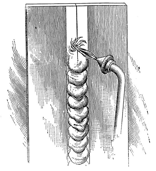
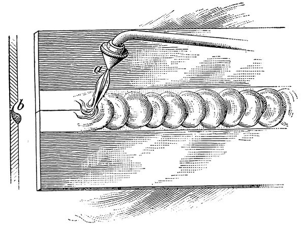
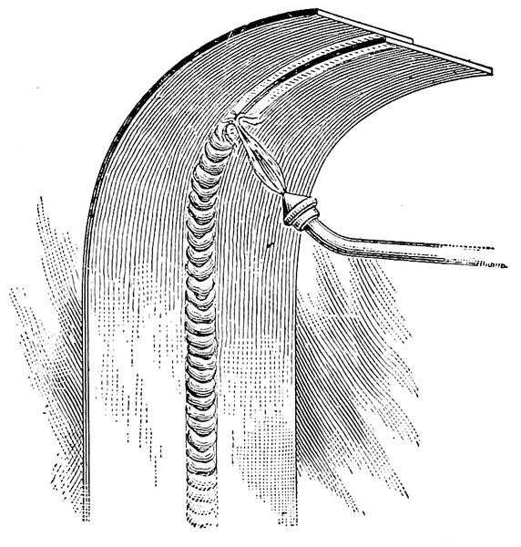
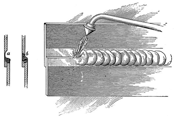
The Art of Lead Burning A PRACTICAL TREATISE EXPLAINING THE APPARATUS AND PROCESSES. 52 ILLUSTRATIONS.
Transcriber's Note:
The cover image was created by the transcriber and is placed in the public domain.
By C. H. FAY
Reprinted from
The Metal Worker, Plumber and Steam Fitter.
Published by
DAVID WILLIAMS COMPANY,
232-238 William St., New York,
1905.
Copyrighted, 1905.
By
David Williams Company.
PREFACE.
The mystery which has always surrounded
the work of the lead burner, like that of all other
handicrafts outside of ordinary occupations, dissolves
under the light of a full knowledge of
the causes and effects that have a bearing upon
it. While different works have treated on lead
burning, it is the object of this special treatise
to explain fully in detail every part of the apparatus
and fixtures in common use, as well as their
application, so that the careful reader may understand
and acquire the art of lead burning by
observing scrupulously the rules laid down and
devoting sufficient time to practice to master it.
This instruction, given by text and illustration,
is only presented after the dangerous power of
hydrogen gas when misused is thoroughly impressed
on the reader. It would be well for all
who hope to become lead burners to devote several
evenings, with an interval between, to a
thorough study of the chapters on hydrogen gas
and its properties before taking any further
steps. To those who have not had previous experience
with chemicals and gases this preliminary
study is indispensable for their own safety,
for the successful operation of the apparatus and
to insure satisfactory work. When fully familiar
with the properties of hydrogen gas and the
necessity of being careful when it is used little
difficulty will be experienced in acquiring a full
knowledge of the apparatus and fixtures. The
art of burning the lead can only be acquired by
practice, and either quickly or slowly, as the operator
may be quick and skillful in acquiring any
handicraft. In addition to describing what has
been common practice for many years, the treatise
contains a description of a new machine and
burner which has only recently become available
to lead burners. It also describes the method of
lead burning with the use of illuminating gas and
a soldering flux. A chapter is devoted to soft soldering
and Britannia metal work, which is
largely used in the equipment of bars and restaurants,
the various joints being more easily
made with a blow pipe than by any other method.
As the workman who hopes to profit by reading
this book can by a little negligence make a great
deal of trouble for himself and others, caution
and great care are advised whenever he is at
work.
CHAPTER I. INTRODUCTION. — Study the Chapter on Hydrogen Gas. — Lead Burning Explained. — Method of Making Lead Lined Tanks. — General Remarks.
9
In compiling a treatise on the subject of lead
burning too much stress cannot be laid upon the
fact that the greatest care must be taken to
observe the smallest details and to follow carefully
every suggestion in regard to safety. I am
aware of the responsibility resting upon me in
placing this article into hundreds of hands, comparatively
ignorant of the danger involved in
handling so much hydrogen, without thoroughly
instructing them in detail as to its use. I may
be excused, therefore, if, for that reason, some
of the explanations are so simple as to seem
ridiculous; but my aim is to present to the trade
a treatise that can be relied upon to be free from
theory that has not been thoroughly tried and
tested, so that the beginner can be sure that, if
he follows directions as printed, nothing but satisfaction
to him can result.
I cannot too strongly recommend that the
beginner study the chapter on hydrogen gas
until the main points are memorized and clearly
10understood. The experiments should be performed
and the result carefully noted for future
reference before attempting to use the generator.
It is time well spent to master the technical parts
thoroughly before attempting the mechanical
part. Then when a man takes up the mechanical
he will do so with an intelligent understanding
of what he is doing, and any little trouble
which may then arise can be quickly overcome.
Another thing to be observed is to avoid nervousness.
A nervous person cannot do this work
with any degree of satisfaction, as it requires a
cool head and a steady hand and a vast amount
of patience to burn the upright and inverted
seams.
Lead burning is the process of fusing two
pieces of lead together without the use of solder.
The process consists in melting the edges together,
a drop at a time, and when done with
hydrogen gas and the blow pipe is called the
“autogenous process.” Lead can be fused with
gasoline or illuminating gas by the use of the
compound blow pipe; but, as ordinary gases give
an oxidizing flame and require a flux, it is not
considered a practical method.
11
Fig. 1.—Lead Burning Apparatus.
12Lead is used extensively in lining tanks made
to contain pickle dips, hot cyanide solution, storage
batteries, acid tanks for manufacturing jewelry
and water closet tanks, as water in many
cases contains large quantities of lime and other
deposits which rapidly destroy the solder used
on copper linings. Tanks used for the above purposes
must be lined with lead and the seams
burned, as acids attack the tin in solders and
destroy them. The demand for the work is rapidly
increasing where it is introduced. I have
demonstrated to many manufacturers that this is
the cheapest method known, as it gives a permanent
solution of the problem how to keep a chemical
tank tight.
The most common method resorted to in
many large factories is to make the tanks out of
very heavy cypress lumber, free from any knots
or blemishes. The joints are carefully dovetailed
and fitted together, and long bolts are used to
draw the joints and keep them from leaking.
Usually it takes from three to four days to complete
one small tank, only to have it leak in a few
months; whereas the same tank can be built in a
few hours of any cheap lumber, and then, when
it is lined with lead of a proper thickness and the
13seams burned it will usually last for an indefinite
period, thereby saving floors and, many times,
costly plating solutions.
The most common argument put forth by
manufacturers is that the bottoms of lead lined
tanks are soon cut out, owing to dropping sharp
pieces of metal into them. This difficulty can be
best overcome by placing a slatted bottom of
wood in the tank, holding the same in place with
strips of sheet lead, one end of which has been
previously burned to the bottom of the tank.
These strips are to be brought up through the
slats and then bent over the top of them. This
will keep the wood from floating, and is the only
practical way to do it, as the false bottoms soon
decay, and can be easily removed and replaced
by simply bending back the strips of lead.
Soft solder, as referred to here, means solder
that melts at a temperature of 300 degrees
or less, and is so called because of the low heat
required to fuse the solder. It is used almost
exclusively on the quick melting metals and compositions,
such as block tin pipes and Britannia
metal. It is also used by pattern makers in soldering
white metal, as it requires but very little
14heat to sweat it through heavy articles. It should
not be used to join any pipes which convey hot
water or other hot liquids, as it is readily acted
upon and destroyed. (The composition of these
solders is explained in a special chapter.)
The chapters on blow pipe work, also on bar
work, will alone turn many dollars into the pockets
of the plumbers who have courage and ambition
to acquire this line of work. Many times
small leaks occur in difficult places that can be
readily repaired by the use of the blow pipe and
a common candle.
The lining of bars with Britannia metal is
coming more and more into general practice, and
it usually requires a specialist in this line to do
the work. The soldering of this metal with a
blow pipe and an alcohol torch is an easy matter,
and is described in a special chapter.
There is no reason why this work should not
be done by a plumber, particularly in small cities
and towns, and to aid such as have not had the
opportunity to familiarize themselves with such
work I append such diagrams as may seem useful
and necessary.
CHAPTER II. THE APPARATUS. — A Few Cautions.
15
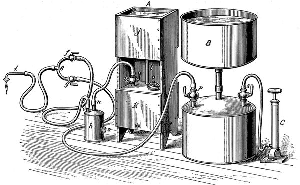
The apparatus used for lead burning is illustrated
in Fig. 1. It consists of a gas generator,
A; an air holder, B, and pump, C; mixing fork, e,
and necessary cocks, f and g; combined scrubbing
cup and fire trap, h; blow pipe and tips, i.
The generator consists of an acid chamber, j,
and a gas chamber, k. These are connected with
an acid supply pipe, l, which conducts the acid
from the acid chamber to the gas chamber, and
also serves as a balance pipe.
This feature makes the generator automatic
in its action, for as soon as the gas in the gas
chamber gets up sufficient pressure, the acid in
the gas chamber k is driven slowly back through
the acid supply pipe l and up into the acid chamber
j, where it is held until gas is used. When
the acid descends and submerges the zinc more
gas is generated, replacing that which has been
used. This form of generator will never blow
acid like the floating generator.
The requirements of a hydrogen generator
for lead burning are that it should be safe, economical
16and automatic in its action. It must be
so constructed that it will generate gas enough
to keep the supply constant, and deliver it at sufficient
pressure to keep the flame steady. It must
also be provided with a combination fire trap and
scrubbing cup. This will prevent the explosion
of the generator by firing the gas in the hose.
This trap must be partly filled with a solution of
blue vitriol to act as a precipitation cup. (This
is treated under the head of “Scrubbing Cup.”)
The chief danger with an apparatus of this
sort is its liability to accident by the careless use
of the gas, and, as a mixture of hydrogen and air
is very explosive, great care must be taken to
exhaust all the air in the generator and tubes
before attempting to light the gas at the blow
pipe. The only way to make sure that the air is
exhausted is to test the gas, as described under
the head of “The Flame and Its Management.”
It is a very sensible idea to keep spectators
away from the generator, as they are very apt
to strike matches or tread on the tubes, in spite
of warnings to be cautious, for if there should
be a leak, even so slight as to be hardly detected,
it would cause a violent explosion, and as hydrogen
17is both odorless and colorless, this could
easily happen without being noticed. This is
probably the origin of the apparent secrecy with
which a lead burner usually surrounds himself.
If an explosion should occur in the tubes and
they should catch fire, the operator must have
presence of mind enough to reach the gas cock
on the generator and close it. If gas explodes
in the generator, all that can be done is to dodge
the flying pieces and make a new generator. If
such an incident should occur and vitriol should
spatter on the person doing the work, or his assistant,
a solution of bicarbonate of soda or common
washing soda should be at once applied to
the wounds. If that cannot be procured, grease
or oil of some kind should be used without delay,
rubbing it on the spots where the acid burns, and
this will neutralize the acid and so prevent it doing
further damage. There should be no trouble
of this sort in the hands of a careful workman.
The watchword should be, “Test the gas before
using.” If this is done, explosions will never
occur.
This element was discovered by Cavendish in
1766, and was called by him inflammable air.
The name hydrogen is derived from two Greek
words, one signifying “water” and the other
“to generate,” on account of its forming water
when burnt. It occurs in its free state in the
bases of volcanoes, and by the aid of the spectroscope
has been detected in the sun and stars.
It chiefly exists in combination with oxygen as
water, and is an important constituent of all
vegetable and animal substances.
Hydrogen is obtained by the decomposition
of water in various ways. On a large scale,
nearly pure hydrogen may be prepared by passing
steam over charcoal, or coke, heated to a dull
redness. If the temperature be kept sufficiently
low hydrogen and carbon dioxide will be the sole
products, and the latter may be removed by causing
it to traverse a vessel filled with slaked lime,
but if the temperature be allowed to rise too high,
or an excess of air be admitted, carbon monoxide
19is also produced, and cannot be removed from
the mixture.
Pure hydrogen is a colorless, odorless, transparent
and tasteless gas, and has never been
liquefied. It is very slightly soluble in water. It
is the lightest of all known bodies and is not poisonous,
although it cannot support life, and if
mixed with a certain proportion of oxygen it can
be breathed for a considerable length of time
without inconvenience. It is highly inflammable,
and burns in the air with an almost colorless, nonluminous
flame, forming water. A burning taper
is extinguished when plunged into hydrogen, and
all bodies which burn in the air are incapable of
burning in hydrogen.
Hydrogen does not spontaneously enter into
reaction with any of the elements, although it has
a powerful affinity for several of them. Thus,
when hydrogen and oxygen are mixed nothing
occurs, but if a lighted splint is introduced a violent
explosion ensues, water being produced.
Similarly chlorine and hydrogen are without action
upon each other in the dark, but if the mixture
is exposed to a bright light, or if heated by
the passage of an electric spark, the gases are at
once combined with explosive violence, forming
hydrochloric acid.
20Hydrogen is usually prepared by the action of
zinc or iron on a solution of hydrochloric or sulphuric
acid. All metals which decompose water
when heated readily furnish hydrogen, on treatment
with hydrochloric or sulphuric acid. Many
other metals enter more or less readily (although
none so readily) into reaction with these acids.
Also, many other acids than sulphuric or hydrochloric
acids may be used, but none acts so quickly.
In all cases the action consists of the displacement
of the hydrogen of the acid by the metal employed,
and if the acid is not one which can enter
into reaction with the displaced hydrogen, the
latter is also evolved as gas.
If pure gas is required it is necessary to employ
pure zinc or iron, as the impurities in the
ordinary metal communicate an extremely disagreeable
odor to the gas.
The pure gas is not absolutely essential for
lead burning, and owing to their being much
cheaper, and also on account of their increased
quickness of action, the commercial qualities of
sulphuric acid and zinc are employed in the generator
described.
The commercial zinc is known as spelter and
is sold in pigs or blocks, which are easily broken
into fragments, like stove coal, with a heavy hammer.
21The commercial sulphuric acid is known as
oil of vitriol and is sold by the pound. The acid
cannot be employed in its pure state, but must be
reduced with water in the proportion of one part
of acid to seven parts of warm water. They must
be mixed by adding the acid slowly to the water;
never the water to the acid. The combination of
acid and water enters at once into reaction and
always generates heat, and the result of adding
water to acid would be small explosions. There
would be danger of the acid flying on one's
clothes or into the eyes. The mixture should
never be stronger than six parts of water to one
of acid.
The beginner will observe from the above
that the generator cannot be crowded by making
the acid solution strong. Hydrogen is a peculiar
gas and also a dangerous one for one ignorant
of its peculiarities to experiment with, and in
order to thoroughly understand it the following
experiments should be demonstrated, which can
be done with little expense. The beginner should
note the result of each experiment as demonstrated,
and carefully commit the same to memory
for future reference.
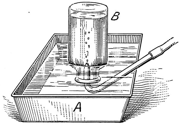
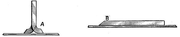
Test for Hydrogen.—Fill a small jar or wide
mouthed bottle with hydrogen. This is done by
22first filling the bottle with water, inserting the
end of the tube from the hydrogen generator,
having first exhausted the air in the tube, then
quickly inverting the bottle and placing the neck,
Fig. 2, in a pan of water (A); the water will stay
in the bottle. Now turn on the hydrogen. The
gas, being lighter than water, will rise to the top
of the bottle (B), drive out the water, and replace
it with pure hydrogen, which should be free from
air. Remove the bottle from the pan of water,
keeping it inverted. Thrust a lighted splint into
the bottle. The gas will light and burn at the
mouth of the bottle. If the splint is thrust far
into the bottle it will go out. Drops of water collect
in the bottle. Burning is a union with oxygen;
therefore, the burning of the hydrogen
shows that it has an affinity for oxygen. The
splint goes out because the hydrogen does not
support combustion. If no air is allowed to get
into it the gas cannot burn or explode.
Fig. 2.—Experiment No. 1.
23
Fig. 3.—Experiment No. 2.
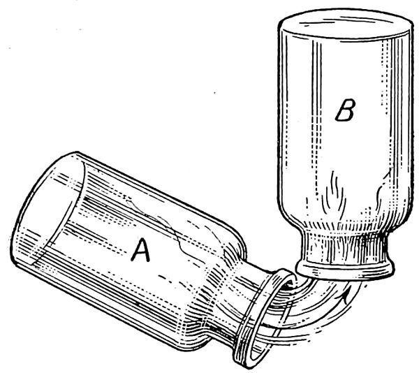
Proving That Hydrogen is Lighter Than Air.—Bring
an inverted bottle of hydrogen close to
an empty bottle, also inverted, Fig. 2. Gradually
tip the bottle containing hydrogen (A) until it is
brought to an upright position beneath the empty
bottle. Test the bottles for hydrogen. The hydrogen
will be found in the bottle (B) that was
at first empty, proving that hydrogen is lighter
than air, as it has risen in the empty bottle, displacing
the air that was in it. If the bottle of
24hydrogen is left in an upright position without
a cover for a few moments the gas will entirely
disappear.
Fig. 4.—Experiment No. 3.
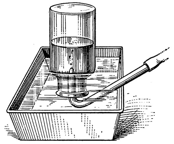
The Effect of Mixing Hydrogen and Air.—Half
fill a bottle with water and invert it in a pan
of water, Fig. 3, leaving the upper half filled with
air. Displace the air in the bottle with hydrogen,
then thrust a lighted splint into the bottle, and
the gas will light with an explosion. When the
bottle was half filled with water the other half
was air. The hydrogen took the place of the
water, so that the bottle contained equal quantities
of hydrogen and air. When the hydrogen
was lighted it combined with the oxygen in
the air. The union of the two gases caused the
25explosion, proving that the combined gases are
very explosive.
To Make Hydrogen From Water.—Drop a
piece of potassium into a little water and cover
it. The potassium floats on the water and soon
burns. Potassium acts vigorously on cold water,
setting free hydrogen, and unites with parts of
it to form “caustic potash.”
CHAPTER IV. THE CONSTRUCTION OF THE GENERATOR. — Making the Charging and Cleaning Screws. — Building the Frame.
26
The construction of the generator is the first
step in the mechanical part of the business, and
to simplify this a complete set of reference drawings
has been constructed and is herewith given.
The assembling of the parts should be clear, with
the assistance of the perspective drawing of the
completed apparatus, and any mechanic of ordinary
ability should be able to construct this generator
without any trouble. The following bill
of material should first be purchased:
One ⅞-inch whitewood board 10 inches wide and 8 feet 6
inches long.
One ½-inch whitewood board 12 inches wide and 4 feet 6
inches long.
One piece of 6-pound sheet lead 3 feet wide and 6 feet 6
inches long.
Three ⅛-inch female hose end gas cocks.
One piece of ⅛-inch brass tubing 2 feet long.
One foot of ¼-inch lead pipe.
One 4-inch charging screw.
One 1¼-inch cleaning screw.
These goods can be readily purchased from
dealers, with the exception of the charging and
27cleaning screws. They can be made in any brass
foundry. The only difference between the charging
and cleaning screws is the size. The charging
screw, Fig. 5, should be at least 4 inches in
diameter, or large enough to pass the hand
through, while the cleaning screw should be 1¼
inches in diameter, or large enough to pass over
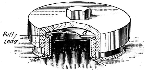
a 1-inch pipe. A piece of sheet lead is fitted into
the cover, as shown at a, to protect the metal from
the acid. Soft putty is used for a packing, as
shown in Fig. 5.
Fig. 5.—The Charging Screw.
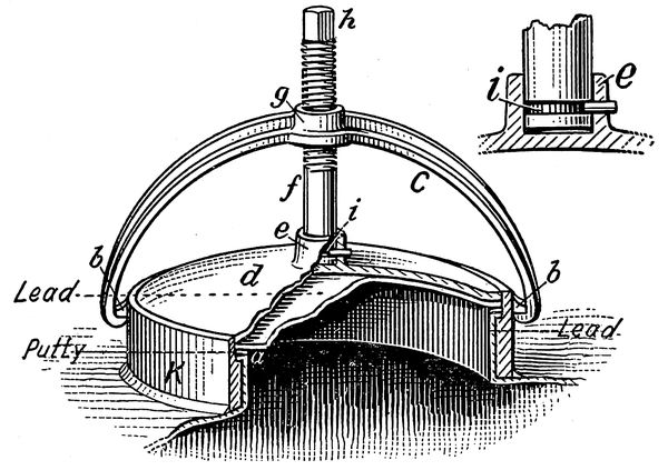
The best, although a more expensive, charging
screw is shown in Fig. 6. As will be seen
from the cut, it consists of a base, k; cover, d;
clamp, e, and screw, f. The base is simply a
plain iron or brass ring, 4 inches in diameter, ⅛
inch thick and 1 inch high. The bottom is to be
28faced smooth, while the top is recessed 3-16 inch
deep to receive the sheet lead and packing of
putty, as at a. Two nubs, b and b, are cast on
opposite sides, as shown, to act as grips for the
clamp c. These nubs are ¾ inch long and project
out from the body of the base ¼ inch, and are
made sufficiently strong to stand the strain of the
screw. The cover d is made of the same material
as the base, the center being raised, as shown,
to give it strength. Cast directly in the center
and on the top is the nub e, ⅝ inch high and ⅝
inch in diameter. This is drilled to receive the
⅜-inch screw f. A groove 1-16 inch wide and
1-16 inch deep is cut all around the bottom of
the screw, as shown at i. A hole is then drilled
through the side of the nub e, and in line with
the slot i. A pin can then be driven through the
hole and will pass through the slot i, making a
swivel joint that will connect the cover and screw
together. The screw f is made of ⅜-inch round
iron sufficiently long to give an action of about
1 inch. The top at n is filed square to receive a
wheel such as is used on a common gate valve. A
long thread should then be cut on this screw.
The clamp c is made a half circle in shape, so as
to clear the cover with ease. It should be ¾ inch
wide, flat on the under side, while the top side
29should have a rib cast on it to prevent springing.
The top at g should be reinforced with metal and
made heavy enough to stand drilling and tapping
to receive the screw f. A wood pattern can be
made for these parts, and they can then be
molded in any brass or iron foundry. In making
the patterns they should be cut down as much
as possible, so as to make the finished article as
light as is consistent with the strength required.
The same directions will answer for the cleaning
screw. The hole to receive the sheet lead
over the cleaning screw should not be over 1½
inches in diameter, and the rest of the screw
should be made in proportion to this hole. The
advantage of this screw over others is that it
does not wrench the sheet lead in making it up,
and, owing to its construction, it is always sure
to make a tight joint without straining the generator.
Fig. 6.—The Best Charging Screw.
30
The frame can be made of galvanized iron,
but wood is much superior, as it retains the heat
generated in the gas chamber much better. To
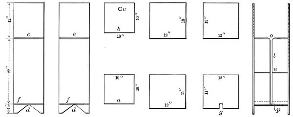
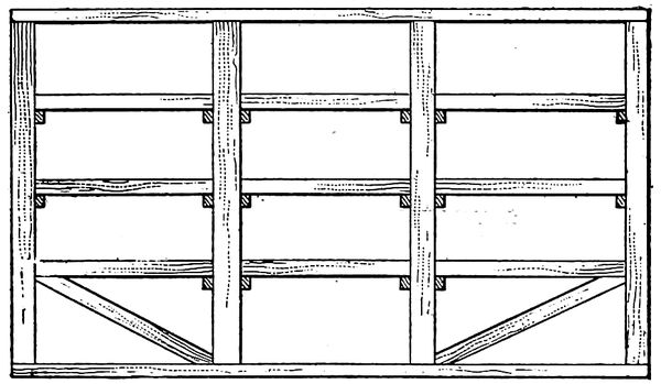
make the frame take the ⅞-inch board and cut
off two pieces, 10 inches square, A and B in Fig.
8; 5 inches from one side and 2 inches from the
back of one of these pieces bore a 1½-inch hole,
C, and countersink it. This is for the acid supply
pipe to pass through. These pieces are intended
for shelves upon which to rest the acid
and gas chambers. Cut the remaining board into
two pieces 38 inches long. Lay these two boards
together. Five inches from the side and 3 inches
from the bottom bore a 1½-inch hole, d. Then
saw out a V-shaped piece, Fig. 7. This will form
the legs of the generator.
31
Fig. 7.—Making the Acid Chamber.
32Take a square, and 12 inches from the top
of these boards draw the lines e and e. Twenty-two
inches below these lines draw the lines f and
f. These lines represent the tops of the shelves.
The shelves should be nailed or screwed into
place. The shelf B should be placed on the top,
keeping the hole C to the back. Take the ½-inch
board and cut two pieces to measure 12 × 13
inches and two pieces 11 × 12 inches. These
form the sides of the acid and gas chambers. The
two 12 × 13 inch boards form the sides of the
acid chamber and the 11 × 12 inch boards the
sides of the gas chamber.
Directly in the center and 1¾ inches from
the bottom of one of the 11 × 12 inch boards
bore a 1½-inch hole. The remaining piece
should be sawed out, leaving a hole at g. This
is so that the board can be removed in case of a
leak without disturbing the cleaning screw.
These pieces should be fitted to their places with
round head screws, and if properly done will
form an acid chamber which will measure 10 ×
10 × 12 inches, and the gas chamber will measure
10 × 10 × 10 inches. The acid chamber must
be larger than the gas chamber, to allow the full
charge of acid to be used without overflowing.
33
Fig. 8.—Making the Shelves and the Perforated Bottom.
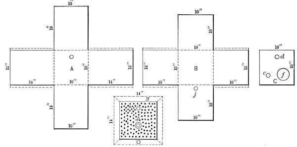
34Now fit the sheet lead. Six-pound is plenty
heavy for this generator and will last a lifetime.
Cut it as shown in Fig. 8, A and B. Form the
lead so that the seams when finished will come
on the outside, as in case of a leak in a seam it
can then be easily repaired by removing one of the
boards. The projecting edges of lead should be
dressed over the edges of the top to protect the
wood from the acid, but do not fasten them, as
the tanks will have to be removed and the seams
burned.
Now cut the piece of lead C to form the top
of the gas chamber. None is needed for the acid
chamber, as it must be left open so that no resistance
will be offered to the action of the gas
on the acid. Five inches from the side and 2
inches from the back of this piece cut a hole, d,
Fig. 8, 1¼ inches in diameter, and dress it up
with the bending iron to 1½ inches in diameter,
taking care to preserve the thickness of the metal.
This is for the acid supply pipe to pass through.
Three inches from the side and 3 inches from
the front cut a ⅛-inch hole, e. This is the gas
outlet. Three and one-half inches from the opposite
side and 4 inches from the front cut the
hole f, 2¾ inches in diameter. Dress this up and
over the flange of the charging screw a, Fig. 6.
This may seem a difficult thing to do, but lead
must be worked slowly. Heating the lead while
dressing it will help wonderfully. If it is not
possible to make a good job in this manner, then
cut the hole 4 inches in diameter and burn in a
35collar sufficiently big to dress over and cover the
flange of the screw. This is to prevent acid from
coming into contact with the screw and destroying
it. Treat the cleaning screw in the same
manner. The location of this screw is in the
center and as close as possible to the bottom of
the gas chamber, as shown in Fig. 8 at j.
Fig. 8½.—Showing the Perforated Spelter Shelf in Place in the Generator.
It is necessary to have a false perforated bottom
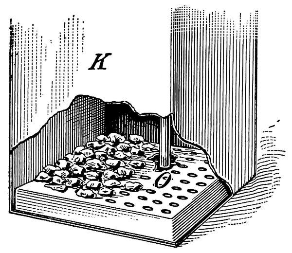
in the gas chamber to rest the zinc upon and
also to keep it above the solution. To make and
support this bottom take a piece of sheet lead
14 inches square, as shown in Fig. 8, and
form it in the shape of a pan, which will
drop easily into the gas chamber k, Fig.
8½. A piece of 1½ or 2 inch lead pipe, 2
inches long, n, should be burned on the center
36of the false bottom, to prevent the center from
sagging with the weight of zinc. Then punch
the bottom O, Fig. 8, full of ¼-inch holes. A
1½-inch hole, y, should also be cut in line with
the holes for the acid supply pipe.
Remove the tanks and burn the seams. Place
the tanks back in place. Then take a piece of
the ⅛-inch brass pipe, 1½ inches long. Cut a
thread on one end, tin the other end, and burn
it to the top of the gas chamber at e; also the
collar for the charging screw. Then place the
perforated bottom in the gas chamber, taking
care to keep the holes for the acid supply pipe
in line. Do not make any mistake in putting in
this bottom. Its use is to act as a shelf to hold
the zinc, and if put in properly it will hold
the zinc about 2 inches above the real bottom.
The top of the gas chamber c should then be
burned in. Now by measuring find the exact
length of the acid supply pipe, Fig. 7, i. This
pipe should extend from the bottom of the acid
chamber o to the bottom of the gas chamber p,
as shown in Fig. 7. From one end of this pipe
several V-shaped pieces should be cut, p, about
1 inch deep.
This is one of the most particular parts of
the apparatus, as this is where the automatic
37action comes in, and great care must be taken in
cutting these holes not to have any of them come
closer to the perforated bottom than 1 inch. If
this were not observed the acid would be constantly
in contact with the zinc, and would rapidly
get up pressure of gas sufficient to blow acid
out of the upper tank, and the extra gas would
escape through the acid supply pipe in blows. In
fact, it would make the generator useless. This
is the trouble with the French apparatus. The
acid, having no place to expand in, is constantly
coming into contact with the zinc, and unless the
gas is being used as fast as generated it will
blow acid out of the acid holder, making a bad
mess, besides being very wasteful.
Now flange the other end of this pipe to fit
the countersunk bottom of the acid chamber.
Place the pipe in position and burn it to the bottom
of the acid chamber and to the top of the
gas chamber n, Fig. 7. One of the ⅛-inch gas
cocks should be screwed on the brass nipple on
top of the gas chamber. This will complete the
gas generator. It will make a better job if the
back of the generator be boarded tight and a
door made to fit the space between the bottom
of the acid chamber and the top of the gas chamber
in front. It is very convenient to have it
38fixed in this manner, as in shipping it from one
point to another the tubes and other incidentals
can be placed in the space so made and shipped
with safety. There is no objection to the acid
and gas chambers being made in the shape of
cylinders, instead of square, if so desired, but if
made circular they should be made to fit the
frame tightly to prevent jarring and eventually
breaking the seams.
CHAPTER V. MAKING THE GAS TO BURN THE GENERATOR. — Air Holders. — Air Holder No. 1. — Air Holder No. 2. — Air Holder No. 3. — The Blow Pipe. — Burning with Illuminating Gas. — Making the Gasoline Gas for Burning the Generator.
39
In towns supplied with illuminating gas it is
a comparatively simple operation to burn the lead
lining for the generator, but for the convenience
of those who cannot obtain gas it is necessary
to give some method by which the generator can
be burned. The method described will answer
for illuminating gas as well as for gasoline.
To generate gas from gasoline is a simple
operation. To do this, take a common 1-gallon
oil can, remove the top of can screw and punch a
¼-inch hole in the center of it. Then make a
tube of tin that will pass through this hole, sufficiently
long to extend half way to the bottom and
project 2 inches outside of can screw, and solder
this tube in place. This projecting tube is for
the purpose of connecting to the air holder. Remove
the spout of the can and replace it with one
to which the hose can be connected. Now fill the
can two-thirds full of gasoline, but not full
enough to cover the gas outlet, else it would be
likely to force gasoline out instead of gas.
40After this is done, screw the can screw in
place, the long end of the tube extending into the
gasoline, as shown in j, Fig. 9. A hose connection
is now to be made with an air holder. As it
is necessary to have an air holder both for this
process and the hydrogen gas process, methods
will be described for making air holders which
can be used for either.
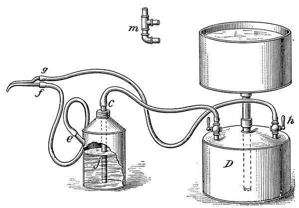
Fig. 9.—Gas Apparatus for Burning the Generator.
Different lead burners have different views
on this subject. Some prefer the bellows, with
41a contained air holder; some the air holder built
like a gasometer, while others use an air holder
similar to the generator in construction. These
all have their advantages. For my part, I own
and use all three.
The advantage of the bellows is that it can be
easily transported and does the work perfectly,
but it requires constant pumping, which soon
tires the helper, and for that reason could not
be used on jobs requiring more than four or five
hours' labor.
The gasometer style of air holder is the
easiest to use, if one does not employ a helper
and has a large amount of work to do. The
pressure can be regulated to suit the work by
placing one or more weights upon it until the desired
pressure is obtained. It does not require
pumping up more than three or four times a day,
which is its principal virtue. It is a perfect shop
apparatus. Its disadvantage is that it requires
a large quantity of water to fill it, which is not
always available, and when full it is so heavy
that it requires a truck to move it around.
By far the best air holder is the one shown as
part of the apparatus in Fig. 9, and illustrated
separately in Fig. 10. This only requires a few
pails of water to fill it, and the exact pressure of
42the gas can be had by building it the same hight
as the hydrogen gas generator. It does not
require constant pumping, and I recommend
this air holder for general use, as possessing
more advantages, with less trouble, than any
other air holder in use. However, all three will
be described, and the beginner can make the one
most suited to the material available.
The beginner will notice in Fig. 10 that this
air holder is so constructed that it gets its air
pressure direct from the head of water, and also
that this pressure can be varied by making the
connecting piece of pipe longer or shorter, as
may be desired. Of course, the pressure will
vary slightly as the water descends into the air
chamber, but not enough to make it objectionable,
as it will be the helper's duty to watch the
water line and renew pumping as often as the
water falls below a certain point.
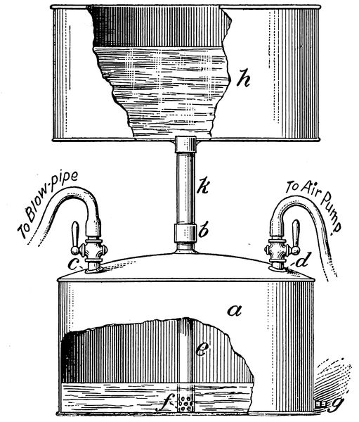
To make this holder, a tank, a, Fig. 10, 12
inches high and 18 inches in diameter, should be
constructed of galvanized sheet iron. On this
tank double seam a flat bottom. The top must
be raised slightly, as shown, to give it strength.
This can be done with the raising hammer, or it
43can be done by making the circle for the top ¾
inch larger than the bottom, then making a cut
to the center. It can then be drawn together and
riveted in any desired pitch. A hole must be
punched in the center of this top large enough to
receive a 1-inch galvanized pipe, b. Six inches
apart and 2 inches from the edge punch two
holes, c and d, large enough to receive pieces of
⅜-inch galvanized pipe. This top should then
be fitted and placed on the body of the tank.
Fig. 10.—Air Holder No. 1.
44Take a piece of 1-inch galvanized pipe, e,
sufficiently long to touch the bottom and projecting
1 inch out of the top of the tank, cut a
thread on the projecting end and drill the other
end full of ¼-inch holes, f, to the hight of 1 inch,
to allow the water to flow freely. This pipe rests
on the bottom of the lower tank and carries the
weight of the upper tank. Solder this pipe in
place. Then take two ⅜-inch nipples, 1 inch
long, and solder them into their places, and on
these nipples screw two ⅜-inch hose end gas
cocks, c and d. One of these cocks is for the purpose
of connecting to the air pump, and the other
to the mixing cock. As close as possible to the
bottom of the tank solder in a ½-inch coupling,
g. Into this coupling screw a plug. This is for
the purpose of draining the tank when out of
use.
Now make another tank, h, 19 inches in diameter
and 11 inches deep, the top to be left open
and wired with a heavy wire. Double seam a
flat bottom on this tank. Directly in the center
of this bottom punch a hole large enough to receive
a 1-inch coupling. Then cut a 1-inch coupling
in half and solder it into this hole, putting
45the thread side down and leaving it as near flush
with the outside of the tank as possible, so that
if it is desired to move the air holder to and from
a job it can be taken apart and the lower tank
nested in the upper tank, making a compact bundle
and reducing the danger of damage by careless
handling.
To connect these tanks, all that is required is
a piece of 1-inch iron pipe, h, 12 inches long, with
a coupling on one end. To operate this air
holder, close the two air cocks on the lower, or
air, tank; then fill the upper tank nearly full of
water, taking care not to put too much in it, or
it will overflow the lower tank and get into the
tubes, and if this happens the tubes will have to
be removed and hung up to dry, or drops of
water will be blown into the blow pipe and extinguish
the flame. It is then ready for use. The
air in the air chamber is compressed by the
weight of the water in the upper tank, and if the
water line is at the same hight as the acid line in
the hydrogen gas generator the pressure of air
must be the same as the pressure of gas. As air
is used the water descends through the pipe and
will gradually fill the lower chamber. It can then
be forced back into the water chamber by attaching
the air pump to the cock h in Fig. 9, or d in
46Fig. 10, without disturbing the gas or in any way
interfering with the operator. To connect with
the cock h in Fig. 9 it is only necessary to disconnect
one line of hose and connect the pump;
then close the other cock and work the pump until
air bubbles up in the upper tank; then shut the
cock, remove the pump and connect the hose to
the gasoline can, open the cocks and the apparatus
is ready for use.
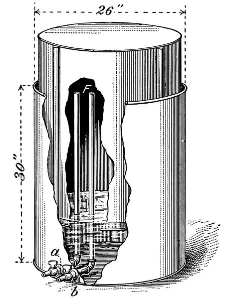
To make the air holder shown in Fig. 11, take
a sheet of No. 26 gauge galvanized iron 30 inches
wide. Make it into a cylinder 26 inches in diameter,
double seam a flat bottom on it, and wire
the top with ¼-inch iron rod, which will make it
stiff enough to withstand the pressure of water.
Close to the bottom and 3 inches apart punch
two holes, a and b, large enough to receive ⅜-inch
galvanized pipe couplings. Solder these
couplings in place.
On the inside of this tank and into these
couplings screw two pieces of ⅜-inch pipe 4
inches long with elbows pointing straight up.
Into these elbows screw two pieces of ⅜-inch
pipe long enough to come flush with the top of
the tank F. On the outside of the tank and into
47the ⅜-inch couplings screw two ⅜-inch nipples
2 inches long, and on these nipples screw
two ⅜-inch hose end gas cocks.
Fig. 11.—Air Holder No. 2.
Now, with the same sized sheet iron, make
another tank 2 inches smaller in diameter than
the first tank. This should have a flat bottom,
and be wired as previously described. Then take
four strips of sheet iron 30 inches long and 2
inches wide, and form each into V shape lengthwise.
48Lay off the circumference of this tank in
four equal spaces. One side of the V-shaped
pieces should then be soldered on at each space.
The other side should be left loose to allow for
adjustment. These pieces form the guides to the
upper tank and prevent it from tipping sideways
and binding. Two of the guides are shown in
the illustration, Fig. 11.
The lower tank should now be filled about
one-third full of water. The upper tank should
then be inverted and placed in it. The air pump
must then be connected to one of the ⅜-inch
cocks with a short piece of hose, and the air
should be pumped into it until the upper tank
rises to its highest level.
The pressure in this form of air holder must
be regulated by weights, and to secure 1 pound
of pressure it is necessary to place weights equal
to 1 pound for every inch in area contained in
the opening in the upper tank. Two drop handles,
such as are used on heavy milk cans, should
be riveted and soldered on the sides of the tank
to facilitate moving it about.
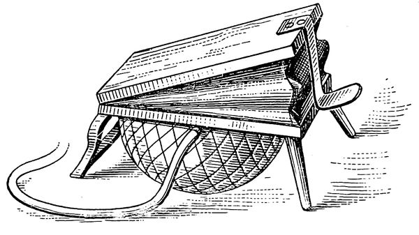
Fig. 12 is a cut of a bellows with a contained
air holder. It is not practical to try to make
this article, as it can be purchased from any
49plumbing supply house and is not expensive. It
is used principally by dentists, but it is also used
in laboratories to supply air to the compound
blow pipe. It consists of a small bellows held
from the floor on iron legs, with a spring inside
the bellows to hold them open, and has a rubber
bag fastened to the under side to hold a small
supply of air. The rubber bag is incased in a
string net to prevent it from becoming inflated
too much and bursting. This bag serves
to equalize the pressure. The size known as
No. 10 A will supply 75 cubic feet per hour at a
pressure of 1½ pounds to the square inch, which
is sufficient for lead as heavy as 24 pounds. For
the light weight leads the pressure can be reduced
by pumping lightly and not filling the bag
more than half full.
Fig. 12.—Air Holder No. 3, Combined with Bellows.
50Any of the three described air blast arrangements
will answer the purpose, so it is immaterial
which is used, and it is left to the discretion of
the beginner to obtain whichever is the most convenient.
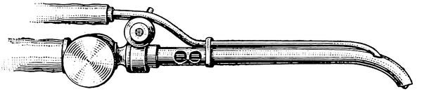
Next comes the blow pipe. The only practical
compound blow pipe on the market is shown
in Fig. 13, and is known as Walmsley's. This is
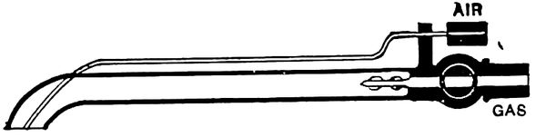
a modification of the Bunsen burner, and consists
of a bent blow pipe with the air tube in the
center, as shown in Fig. 14. It is a perfect working
blow pipe in every respect, and I should advise
every one interested in the work to purchase
one. For while seams cannot be burned with it
in any other position than horizontal, it will be
found useful in lengthening traps or lead bends,
for which purpose it is well adapted and can be
put into instant use, thereby saving its cost many
times over in wiping solders.
Fig. 13.—The Walmsley Compound Blow Pipe.
51
With illuminating gas it is only necessary to
connect the gas jet to the compound blow pipe
with the hose and regulate the supply of gas with
the gas cock. The air inlet is then connected to
the air holder, or air may be supplied with the
mouth, but good results are not obtained with
the mouth, as only a good blow pipe solderer can
keep up the blast necessary. To burn the seams
use the same flux and follow directions given
for gasoline gas.
Fig. 14.—Sectional View of Walmsley's Blow Pipe.
With a piece of ¼-inch hose connect the top
of the can C, Fig. 9, with the air holder D, then
connect the spout or gas outlet e of the can to
the gas end f of the compound blow pipe. The
air outlet g of the compound blow pipe should
then be connected to the remaining cock h, in the
air holder. If the bellows is used, it will be necessary
to connect the air with ¼-inch tee, m, in
52which three short nipples have previously been
screwed.
The apparatus is now ready for use. Gasoline
being really a liquid gas, it takes its first
opportunity to assume its natural shape. The
natural way to convert gasoline into gas is by
simple evaporation. So taking advantage of this
fact, the action will be thus: By forcing air into
and through a body of gasoline sufficient of the
gasoline is taken up to form a dense vapor, which
will light and burn at the jet, similar to illuminating
gas. With the admixture of air in the
compound blow pipe, it gives a flame of very intense
heat. But, in common with illuminating
gas, it is so rich in carbon that it gives an oxidizing
flame, and makes it necessary to use a flux,
which should be Yager's soldering salts mixed
as per the directions on the bottle. If this is difficult
to procure, a good substitute can be made
by mixing equal parts of powdered borax and sal
ammoniac in a little water.
To operate this device the air should be
turned on the gasoline and lighted at the jet.
The air should then be admitted gradually until
the flame is brought to the proper size and condition,
indicated by its being blue and pointed. If
too much gas is admitted the flame will be yellow
53and will blacken the work by depositing a
coat of soot on it. If too much air is admitted
the flame will be ragged and noisy, and the temperature
will be too low to heat the metal. The
flame is at its best heat when it burns with a
pale blue color which does not show any yellow
streaks.
Before attempting to burn the generator the
beginner should practice on pieces of sheet lead.
It is next to impossible to burn seams in any
other position than horizontal with this flame, as
it rapidly oxidizes the lead, and in spite of all
precaution the lead will become unmanageable
in upright seams, so that the beginner would
waste time in practicing on seams in any other
position than horizontal. If directions have been
followed in cutting the lead for the generator the
seams will occur only in that position.
To burn the generator the seams should be
shaved clean, both on the under and upper sides,
for a distance of ⅛ inch, making a seam ¼ inch
wide, taking care to have the lead seams lie close
to each other, for, if they do not, this flame will
cause the edges of the lead to spread away from
each other and leave a hole that is difficult to
patch.
Now apply the flux with a small brush. When
54the flame is in working order bring it quickly
to bear on the end of the seam nearest you to be
burned. When it starts to fuse draw the flame
as quickly away, always drawing it to one side,
and from the upper to the lower sheet. The
melted drop will follow the flame and unite with
the melted drop on the lower sheet.
It is necessary to have the shave hook near
at hand, so that, in case of oxidizing when fusing,
the melted drop can be broken up and allowed
to flow in place.
With a little practice and patience the generator
can be burned all right in this manner. This
gas is perfectly safe and can be handled with impunity.
This method would, of course, be impracticable
to use on a job of any size, but I have
used it several times where nothing else could
be obtained, and have always had very good success
with it.
CHAPTER VI. CONNECTING THE APPARATUS. — Testing the Apparatus. — The Mixing Fork and Blow Pipe.
55
We now assume that the generator is charged
and the rest of the apparatus is finished and
ready for use, so we will proceed to connect it
up ready for a trial.
About 30 feet of ¼-inch heavy rubber tubing
should be procured. This hose should be
heavy enough to allow of its being pulled around
without kinking and shutting off the supply of
gas. A piece of this hose 5 feet long should be
slipped on the gas cock M on the generator,
shown in Fig. 1, and then slipped over the gas
inlet tube of the scrubbing cup n. One must be
sure that this is connected to the gas inlet tube,
which is the tube that dips under the water in
the scrubbing cup.
With another 5-foot piece of hose connect the
gas outlet of scrubbing cup o to the right hand
cock on the mixing fork f. Always connect the
gas on the same side so as to avoid confusion
of cocks. Then with a 10-foot piece of hose connect
the air cock on the air holder p or bellows
56to the remaining cock on the mixing fork g. An
8-foot piece should be connected from the gas outlet
on mixing fork e to the blow pipe i.
These tubes must fit tight to prevent any possible
leak of gas, and if they do not they should
be tightened on with pieces of wire. The remaining
piece of hose can be used to connect the air
pump C to the air inlet cock s on the air holder,
but if the bellows are used this will not be needed.
Now place in the scrubbing cup a half dozen
pieces of blue vitriol, or copperas, as it is commonly
called. Then pour in clear water until it
flows out of the trap screw z. This screw can
be made tight by using for packing a piece of
wicking which has been saturated with tallow.
After preparing the apparatus as above, refer to
the cut of the complete apparatus and compare
the connections on the cut with those made from
the above directions, to make positive that they
are right. If they agree, the apparatus is now
ready for use.
It is necessary to test the generator for leaks,
as a small blow hole may sometimes be left in
some of the seams or the cocks or cleaning screws
become defective.
To do this, first close the gas cock on the top
57of the gas chamber and make up the cleaning and
charging screws, which must be set on a bed of
soft putty. Then fill the acid chamber full of
hot water, first measuring the water so as to ascertain
just how much solution is required in proportion
to the amount of water, as it takes the
same quantity at all times. Allow it to stand for
a few moments, then mark the water line with a
pencil or nail, when it should be left standing for
an hour. The water should stay at the mark indicated
for an indefinite time. If it sinks during
this test it shows that there is a leak in the generator
and it must be located and repaired.
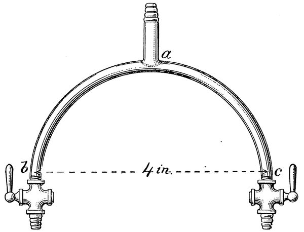
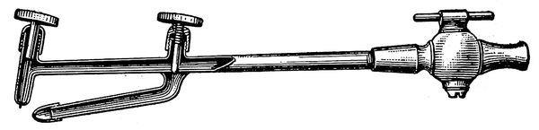
Fig. 15.—Mixing Fork.
To locate the leak the gas cock should be
58opened and the water allowed to run into the gas
chamber. If this does not show the leak, force
the water back into the acid chamber, which is
done by attaching the air pump to the gas cock.
Then taking a piece of soap and making a stiff
lather, daub it over the cocks and cleaning and
charging screw. When the leak is found the
escaping air will cause bubbles to be blown. If
the leak does not become apparent after the
above process, the side boards of the generator
should be taken off and the operation repeated
on the seams.
Under no circumstances must the apparatus
be left until there is absolutely no doubt as to its
being perfectly tight, as a slight leak would be
likely to cause a disastrous explosion and injure
or probably blind the operator. Flying vitriol is
not a very pleasant thing to get in one's eyes.
The apparatus should be frequently tested in
this manner: Before drawing off the water it is
desirable to learn what amount of gas pressure
there will be when the generator is charged, so
that the pressure of air and gas can be equalized.
The mathematical rule for this is to multiply the
head in feet by 0.434, and the result will be the
pressure in pounds; or an approximate way of
determining the pressure is to allow ½ pound
59pressure for every foot of head. For example:
The hight of liquid in the generator measured
from the bottom of the acid supply pipe to the
top of the water or acid line, when at its highest
level, would be 3 feet. Allowing ½ pound for
every foot in hight would give a pressure of 1½
pounds, which is slightly in excess of the mathematical
rule, which is 3 × 0.434 = 1.302, or 1
pound 4 ounces, but to be accurate it is well to
attach a mercury gauge to the gas cock. Note
the hight of the column of mercury. Then attach
the gauge to the blast apparatus, and if the
floating air holder is used, sufficient weight must
be put on the top of air holder to raise the column
of mercury to a point not quite as high as is
indicated by the generator. These weights can
then be weighed and a similar weight made of
lead to correspond, which can be kept for permanent
use. If the bellows are used, the size
specified should be obtained, and the pressure
will be all right for this size generator without
further trouble. If the air holder indicated by
Fig. 8 is used, all that is necessary is to make
the hights of the water line in both generator and
air holder equal, and the pressure must be the
same.
Fig. 16.
Fig. 17.
Mixing Forks.
60The reason that the air pressure should not
be heavier than the gas pressure is that if the
air were the stronger there would be danger of
the air working back into the gas tube and causing
an explosion in the tubes; consequently it is
well to note this point carefully. Many lead burners
will say that the pressure of air is of no consequence,
and all that is required is a sufficient
supply; but my experience and experiments have
convinced me that when the pressures of air and
gas are nearly equal the best results are obtained.
The mixing fork and blow pipe can be made
in any plumbing shop and should be made of the
smallest size pipe available.
61
Fig. 18.—Blow Pipe and Tip.
To make the mixing fork, purchase two ⅛-inch
female hose end gas cocks and 2 feet of ⅛-inch
iron pipe size brass tubing. Take a piece
of the tubing 12 inches long, cut a regular iron
pipe thread on each end, then bend it over a mandrel
stake or a piece of 4-inch soil pipe into a half
circle, as shown in Fig. 15, so that the ends will
come about 4 inches apart. In the center of this
piece drill a ⅛-inch hole, a. Then cut from the
remaining piece of tubing a piece 3 inches long.
Solder, or, better yet, have this piece brazed on
to the bent piece at a, taking care that no solder
can run in and partially stop the hole a. Then
screw the two ⅛-inch gas cocks on the ends b and
c. This will complete the mixing fork; or this
fork can be made by bending a piece of pipe at
an angle, as shown in Fig. 16; then cut another
piece equal in length to the bent piece from the
angle e to the end. One end of this piece must
be filed to fit the piece d. A hole can then be
drilled at e. Threads must be cut on these ends,
after which they can be brazed together. Or a
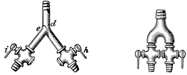
62good fork can be had by using a special casting.
This casting is used for and is known as a beer
switch, and can be purchased of any dealer in
bar supplies, Fig. 17. The same pattern and size
of cocks can be used for this fork as previously
described. Neither of these mixing forks has
any advantage over the other, but three styles
are given, as possibly one may be easier to make
than the other. Iron pipe may be used instead of
brass if desired.
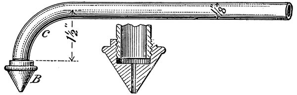
To make the blow pipe, take the remaining
piece of tubing and cut a thread on one end. As
the other end slips into the hose, it does not need
a thread. The thread end must then be bent at
right angles to the tubing, as c, Fig. 16. This
can be done by boring a hole in a block of hard
wood just large enough for the tubing to enter,
and 1½ inches deep. Trim off the sharp edge
of this hole so as not to kink the pipe in bending.
The end of the tube can then be inserted in this
hole and bent to the desired shape, as shown.
This completes the blow pipes with the exception
of the tips, of which you should have three sizes,
drilled as follows: One for heavy lead, 3-32; one
for medium weight, 2-32, and one for very light
sheets, 1-32. These tips are made of small pieces
of cast or turned brass, preferably with a milled
63shoulder, so as to facilitate removing with the
fingers. Probably the easiest way to get these
tips is to make a pattern out of wood and have
several of them cast. They can then be drilled
and tapped to any desired size, or they can be
cut from a round bar of brass or copper, filed or
turned to a point, then drilled and tapped. The
dimensions and particulars can be had from B in
Fig. 18 without further description being necessary.
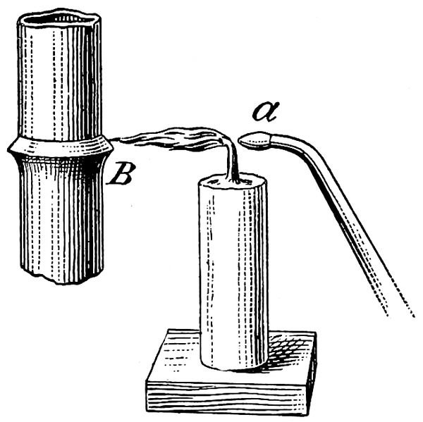
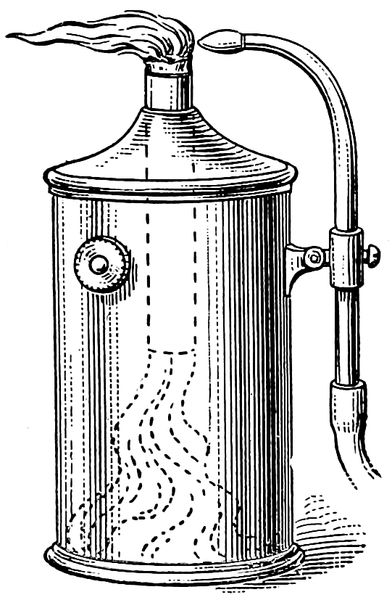
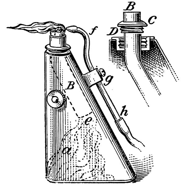
A common blow pipe, such as is used with
the alcohol torch, can be used for practicing on
light sheets. But the beginner is advised to procure
the blow pipe and a set of tips described in
Fig. 18 before attempting to burn any heavy
lead.
CHAPTER VII. CHARGING THE GENERATOR. — Automatic Action of the Generator. — Cleaning the Generator. — Fire Trap and Scrubbing Cup. — Directions for Making the Cup.
64
After making sure that the generator is perfectly
tight we will proceed to charge it. After
removing the 4-inch charging screw take 15
pounds of commercial spelter, which has been
broken up with a hammer into pieces about 2
inches square, and place this in the gas chamber,
distributing it as evenly as possible over the perforated
bottom. This is done so that the zinc
will expose all the surface possible to the action
of the acid, and must be observed in order to obtain
the best results. Do not put any pieces of
spelter into the generator that are small enough
to drop through the perforated bottom, for if
they do they will be likely to generate gas, which
will give overpressure and blow gas out through
the acid chamber. This can do no harm unless
close to a light, but it is very annoying to have
acid blown all over the generator. The charging
and cleaning screws must be screwed up
tight. After closing the gas cock on the generator
take the quantity of water (less one-seventh)
65that was found to be necessary when
testing the apparatus, and pour this into the acid
chamber.
Mark the water line and watch it for a few
moments to make sure that everything is tight.
Then take of sulphuric acid a quantity equal to
one-seventh of the water used, and pour that into
the water in the acid chamber. It will diffuse
itself through the water and thoroughly mix.
Experience has taught me that acid mixed in any
proportion stronger than seven parts of water to
one part of acid does not act as quickly as when
mixed in the proportion mentioned. The reason
for this is that the strong acid simply coats the
zinc with a deposit or scum of sulphate of zinc,
which is soluble in water, but is not soluble in
acid. Therefore, if the acid is diluted with water
to the above mentioned proportion the water
readily dissolves the sulphate and allows the acid
to act freely on the zinc.
This sulphate falls to the bottom of the gas
chamber and if allowed to accumulate causes the
clogging mentioned later. The beginner will observe
from the explanation that the generator
cannot be crowded by making the solution strong.
It sometimes occurs that the vitriol seems to be
stronger than usual, and then again the reverse
66is also true. Good vitriol should be almost as
thick as cutting oil, and will work very quickly.
Care must be taken in pouring it into the generator
to prevent spattering. This is best avoided
by having a quart measure made of lead for this
purpose. It should also be borne in mind that
the acid should always be added to the water,
never the water to the acid, as this mixture always
generates heat, and the result would be
similar to adding water to hot lead.
The generator works best while hot. The
gas cock on the generator should now be opened
and the mixture allowed to flow into the gas
chamber until it spurts out of the gas cock, which
must then be closed. By this action all the air
in the gas chamber is expelled, leaving it free to
generate pure gas at once. This is a sure method
of exhausting the air in the gas chamber. The
acid then attacks the zinc, causing it to decompose
the water and free the hydrogen contained
in the acid.
This gas, by reason of its lightness, will rise
to the surface of the acid, and as pressure increases
it will force the acid back up through the
acid supply pipe into the acid chamber, until the
67acid falls below the perforated bottom. When
the acid and zinc cease to come in contact with
each other the generation of gas stops until gas
is used, which relieves the pressure; then more
acid descends, and as it comes in contact with
the zinc more gas is generated, replacing that
which has been used. This action makes the
generator automatic, unless clogging with sulphate
of zinc takes place. This may happen at
any time if the apparatus is not cleaned after each
day's use.
To clean the generator in this case attach the
air pump to the gas cock on the generator and
force the acid up into the acid chamber by pumping
air slowly into the gas chamber until the acid
rises to the proper hight in the acid chamber,
where it can be held by forcing a long wooden
plug into the acid supply pipe. The pumping
must cease when the acid rises to the proper level,
or the excess pressure of air will work up through
the supply pipe and cause a blow of acid.
The charging screw can then be removed and
the zinc taken out and washed in hot water. Remove
the clean out screw and run one or two
pails of hot water through the gas chamber. This
will remove the deposits of sulphate paste. The
68zinc can then be replaced, the screws tightened
and the acid released again. Be sure and exhaust
the air in the gas chamber, as previously
described, by letting the air spurt out of the gas
cock before connecting it to the scrubbing cup.
Care must be taken not to have any lights near
the generator when blowing out this mixture of
gas and air, as it is very explosive.
The apparatus will never clog if cleaned after
each day's work, which should always be done.
The tubes should be removed and hung up over
night to dry. The acid, if not spent, can be
dipped out of the acid chamber and placed in
jugs. The generator can then be carried to a
drain and filled with hot water, which should be
allowed to flow out through the cleaning screw.
This will clean the zinc and wash out all the
sulphate deposit. The screws may then be tightened
and the apparatus left ready for the next
day's use.
One of the most essential parts of a lead burning
apparatus is a reliable fire trap and scrubbing
cup. This trap reduces to a minimum the
danger from explosion caused by neglecting to
free the gas from air. Its use as a scrubbing cup
is also of infinite value.
69The action of the vitriol on the zinc produces
a violent ebullition, and a small quantity of the
acid is carried in the form of spray from the generator
to the tubes, and, unless caught and removed,
will frequently get into the blow pipe tip
and extinguish the flame, making it necessary to
remove the hose and hang it up to drain and dry,
which oftentimes causes waste of time and annoyance.
Almost all spelter or zinc contains more or
less arsenic in a metallic state. It is also found
in sulphuric acid. This arsenic is released from
the acid or zinc as they decompose and is carried
by the force of the volume of gas to the blow
pipe tip, where, owing to it being necessary for
the operator to get his eyes close to the flames in
order to see the reducing flame, this poisonous
gas will be breathed into the lungs and oftentimes
cause a fatal illness. This fact has been disputed
by many, who say that it is impossible for the
unit of lightness—i. e., hydrogen gas—to pick
up and carry a heavy metal such as arsenic.
Arsenic does not form a chemical combination
with hydrogen, having a very slight affinity for
it, but is carried to the blow pipe solely by the
force of the volume of gas.
To prove the above assertion we will refer
70to Professor Marsh, who demonstrated the ability
of hydrogen to carry arsenic in the following
manner: If a solution containing arsenic be
added to a solution of sulphuric acid and zinc,
the resulting hydrogen will, upon ignition, deposit
a ring of metallic arsenic upon any cold surface
that the flame be directed upon. (Professor
Marsh's experiment.)
It will be seen from the above that it is imperative
that the operator use a scrubbing cup
and see that it is properly filled with a solution
of blue vitriol. The ordinary impurities of hydrogen
generated in this manner are sulphur and
carbon, which should be removed if possible.
The actual use of the scrubbing cup is to
catch the above mentioned spray and precipitate
to some extent all other impurities contained in
the gas, and produce gas sufficiently pure for lead
burning.
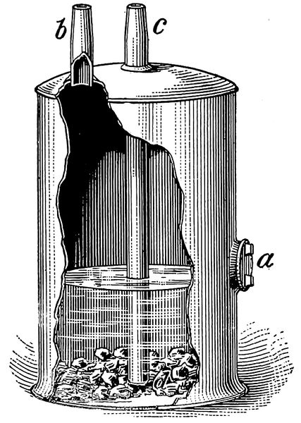
To make this cup take a piece of 4-inch lead
pipe 7 inches long (an ordinary piece of 4-inch
lead soil pipe will do); flange out one end and
burn in a flat bottom. Three inches from the
bottom, and in the side of this 4-inch pipe, burn
in a trap screw, a, Fig. 19, a screw taken from
an old lead trap being just the thing. This is
71to regulate the hight of the solution in the cup.
Now make a top by taking a piece of lead and
raising it about ¾ inch; punch two holes in this
top, b and c, large enough to let a ⅜-inch lead
pipe pass through; flange out the top of the cup
and fit and burn this top in place. Take two pieces
of ⅜-inch lead pipe, one to be 3 inches long and
the other to be 10 inches long, and with the
dresser draw one end of each to nearly a point,
so that the hose can be slipped on tight. The
long piece c should now be slipped through one
of the holes in the top of the cup, holding it ½
inch from the bottom d and burning it in. This
is the gas inlet and should be marked as such.
The short piece is then placed in the remaining
hole and burnt in place. The action will be thus:
The gas entering the gas inlet pipe is caused to
pass through a solution of blue vitriol 2½ inches
deep, when the acid is caught and the gas is
scrubbed and rendered as nearly pure as possible.
It then enters the outlet pipe and is ready
for use. If the directions have been followed the
cup will resemble the illustration Fig. 17. No
trouble will be experienced with this cup.
Fig. 19.—Fire Trap and Scrubbing Cup.
CHAPTER VIII. THE FLAME AND ITS MANAGEMENT. — Regulating Volume and Pressure. — Study the Flame Well. — Do Not Hurry.
73
Before attempting to light the gas the operator
must be sure that all the air is exhausted
from the tubes. Otherwise the flame will go back
and explode in the tubes or fire trap. To be sure
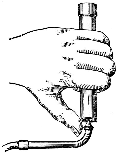
of this the beginner must test the gas. A handy
test tube can be made by capping one end of a
piece of ½-inch pipe, which should be about 6
inches long. To test the gas, first open wide the
gas cock M on the generator, Fig. 1. Then
open the gas cock f on the mixing fork and let
the gas displace the air in the tubes, which it will
do in about one minute. Then invert the test
tube, Fig. 20, and hold it over the blow pipe tip
for a moment until the gas has displaced the air
in the tube. Then quickly place your thumb over
the opening of the test tube, which will keep the
gas from escaping. Close the gas cock f on the
mixing fork, then take the test tube to one side
away from the generator, still keeping it inverted,
and bring it close to a lighted match or
candle. It will light with a pop, and if it is free
74from air it will burn quietly down in the tube
until the gas is exhausted. Continue to test the
gas in this manner until it burns as described,
when it may be safely lit at the jet without fear
of its burning back. This precaution is necessary
only after opening the generator for some
purpose.
Fig. 20.—Method of Testing Gas.
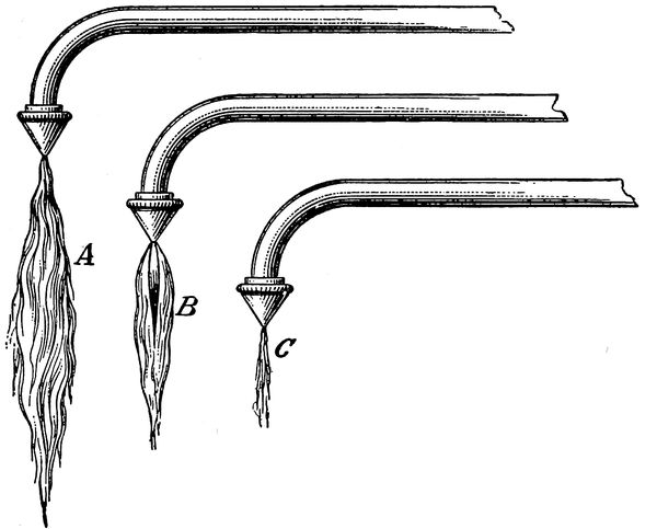
This generator evolves gas under a greater
pressure than can be used on most work, and for
this reason the flame will at first be long, noisy
and unsteady, as shown in A, Fig. 21, but, as
there are two cocks, the volume and pressure can
be regulated to the requirements of the work at
75hand. Now, to note the peculiarities of this
flame, we will close the gas cock f on the mixing
fork until the flame is about 3 inches long. It
will be of a pale reddish color and will burn steadily.
The inner flame is not as yet very well defined.
Then open the air cock g slowly, and
when sufficient air has been admitted the flame
will be seen to shoot out suddenly and then
shorten to about 1¾ or 2 inches in length. It
will be smooth, compact, and will have the appearance
of darting rapidly. If the correct quantity
of air has been admitted the inner flame, as
shown in B, Fig. 21, will then be plainly seen,
and its apex, which is the point of greatest heat,
will be blue. This inner flame is known as the
nonoxidizing flame, and is the flame with which
the fusing is done.
Fig. 21.—Flames Under Different Pressures.
76The outer flame will change to a bluish color.
Its temperature is low, and its effect on the lead
is to coat the metal with a heavy blue oxide, under
which the lead runs but does not unite. To demonstrate
this, bring the point of the inner or nonoxidizing
flame to bear on a piece of sheet lead.
It will fuse bright and clean and will have a circle
of gray oxide around it. Then quickly remove
the flame and the spot will remain bright.
Now, again bring the flame to bear on the same
piece of lead, keeping the point of the inner flame
at least ¾ inch away from the lead. It will melt
and flow together, but will be covered with a
coat of gray oxide and the union will not be
perfect. Slowly withdraw the flame, and before
the flame is entirely removed the spot will be
heavily coated with a thick blue oxide, under
which the lead will not unite. C, in Fig. 21,
shows the appearance of the flame when too
much air has been admitted and it is on the point
of going out from lack of gas.
The proper way to use the gas is to open wide
77the gas cock M on the generator, and do any
regulating of the flame with the gas cock f on
the mixing fork. These cocks should have pieces
of heavy wire brazed or soldered lengthwise of
the handles, Fig. 16, h and i, so as to form lever
handles. This will allow the gas and air cocks
to be closed or opened by gently tapping the levers
h and i, which is the only way that a slight
variation can be had, for if you try to regulate
them with the finger you will constantly open or
close them too much, and the result is that in adding
air too much is always admitted, which will
blow out the flame, making it necessary to turn
off the air and light the jet again, and many times
this operation will have to be repeated before the
flame is correctly adjusted.
It must be remembered to always turn on and
light the gas before admitting any air, and when
through with the flame the air must be turned off
first, then the gas. If this operation is reversed
an explosive mixture of gas and air would form
in the tube and would spoil the tube, if nothing
worse.
The beginner should study the flame until
perfectly familiar with the color and form of the
proper flame. One of the greatest troubles that
78the beginner will have with the blow pipe is the
inability to regulate the flame to the requirements
of the work. For instance: A flame that
would work nicely on 12-pound sheets would
burn holes in 4-pound sheets before you had time
to touch the lead with the inner flame. For that
reason three different sizes of tips should be
used. On a 2-pound sheet the smallest, or 1-32,
tip should be used, and the flame before reducing
should not be longer than ¾ inch, and when
reduced the inner flame can hardly be distinguished,
but you can easily tell when it touches
the lead by the metal fusing bright. If it is desired
to fuse 12-pound sheets the 2-32-inch tip
should be substituted, and it would be found necessary
to have the jet of gas about 3 inches long,
which, when reduced, would be about 2 inches
long and would show the inner flame very distinctly.
The only way to determine the size of the
flame necessary is by experimenting with it. It
will also come with experience. The flame should
be reduced to a size that will not melt the lead
as soon as it touches it. Rather, it should be in
such condition that the lead would have to be
heated first and let the fusing come gradually.
In that way it can be determined just what sized
79drop is required, and also plenty of time is allowed
to place it just where it is wanted—particularly
on upright seams and imperatively on
inverted seams.
It is not necessary to be so particular on horizontal
seams, as on seams in that position you are
assisted by gravity. The lead drop that is melted
from the upper lap cannot do otherwise than
unite with the under lap. It must be remembered
that in starting a seam you have cold lead
to fuse, and after the first drop is started the lead
in its vicinity will be heated almost to the melting
point, and you will probably be surprised to see
the lead run at the approach of the flame for the
next application.
The point to be taught here is that you must
not attempt to hurry this work or holes will
surely be burned in the sheets, which oftentimes
makes difficult work to patch. The old adage,
“haste makes waste,” can well be applied to lead
burning. Sufficient time must be allowed for one
drop to set before attempting to place the next
drop. Time spent on practicing at the bench is
time well spent, as many little details that cannot
be brought to the beginner's attention here
will be learned in that way and stored in his mind
for future application.
CHAPTER IX. THE DIFFERENT KINDS OF SEAMS. — Flat Butt Seam. — Upright Butt Seam. — Horizontal Butt Seam. — Inverted Butt Seam. — Lap Seams. — Horizontal Lap Seams. — Upright Lap Seams. — Inverted Lap Seam.
80
There are two kinds of seams proper, viz.:
The butt seam and the lap seam. The butt seam
is used principally for joining horizontal waste
pipes and in lengthening traps, or for any purpose
where it is desired not to have the point of
junction show. This form of seam can be burned
clear through—that is, the lead can be heated
until fusion takes place nearly through the entire
sheet. It is generally necessary to add lead to
the seam if it is desired to make the seam as
strong as the sheet it joins, unless the article to
be burned is of such a size as to be possible to
allow of its being burned on both sides, which
makes the strongest of seams. The lead for the
butt seams is prepared by rasping the edges of
the lead sheet to be joined straight and true, Fig.
22, so that when the edges of the lead are brought
together they will fit close its entire length. The
edges are then shaved for a distance of ⅛
inch each side of the edge, making a seam ¼
inch wide. On stock heavier than 12-pound
81sheets the edge should be shaved off, making a
deep V-shaped groove, and the seams must be
made by adding lead. This allows the fusion to
take place nearly through the sheet. The butt
seam is the simplest form to burn, no matter in
what position it is placed.
Fig. 22.—Rasping the Edges of the Lead Sheet Straight and True.
The lap seam is the seam commonly used, and
as between the butt seam and the lap seam the
latter is generally to be preferred. As it is not
necessary to cut and trim the edges true, it dispenses
with any additions of lead, except at rare
intervals; it leaves the left hand free to handle
the shave hook, and the lap can be dressed to fit
any uneven spots. It also makes the next best
seam to through fusing. By lap seaming a tank
can be lined in about half the time required to
82butt seam the same article, which is an important
item to the customer.
Fig. 23.—Burning a Lap Seam.
The lead for this form of seam is prepared,
as its name indicates, by lapping one sheet
½ to ¾ inch over the other sheet. The under
edges are to be shaved clean, as also the upper
edge. The lead required to make the seam is
melted from the upper lap and is fused on the
lower sheet. There is no reason why the lead at
the point of juncture cannot be made as thick as
the original lead. This is the point aimed at in
practicing, and the only accurate way to determine
the relative strength of the seams is to cut
squarely across a finished seam, then bend the
beam slightly. The thickness can then be noted.
A cross section of a perfect lap seam is shown
83at a in Fig. 23. The beginner should practice the
different seams until the thickness of the joint
can be told by the looks of the lead. A few days'
diligent practice at the bench will soon train the
eye to note any imperfection that may arise.
The different seams will be taken up serially.
A description of how the seams are prepared and
the several positions of the blow pipe, as well as
the little difficulties that may arise, is the extent
of the instruction that can be given. The rest
must come with practice and the application of a
little common sense. There is no royal road to
this business; but practice, and practice hard, is
the only way to satisfactorily master the blow
pipe and flame, and in practicing remember that
all this work has been done before, and can be
easily done again, and by you. Do not get discouraged
by failure to make a perfect seam at
the first application, but stick to it for a short
time and it will be found to be a most fascinating
pastime, for which the persistent student will
eventually be well repaid.
For practicing I would recommend the beginner
to use pieces of sheet lead about 12 inches
long, as strips of that length are much easier to
84prepare. The edges are straightened with a fine
rasp which is held lengthwise of and parallel to
the edge to be trued, in the manner shown in Fig.
22. The rasp must be used lightly, or it will be
apt to tear the lead and so leave it in worse condition
than before using it. The edge should then
be gone over with the shave hook and cleaned.
Then shave the top surface a distance of ⅛ inch
each way from the edge, which will make a seam
¼ inch wide when finished. Then butt the edges
together and secure the sheets firmly to a board
with a few tacks. The extra lead that is necessary
to add to make a butt joint full must be obtained
from a strip of lead, which should be
about ⅛ inch square and shaved clean.
After regulating the flame to the proper size
and shape the burning should be begun at the
end of the seam nearest the operator. With the
point of the inner flame melt off a drop from the
lead strip and have it fall squarely on the seam
just slightly in advance of the point of fusion.
Follow it up with the flame, placing the point of
the inner flame directly over the edges of the
seam, which is almost under the lead drop. As
soon as fusion commences on the lead seam the
melted drop will flow to the bright spot and immediately
unite with it. The flame must then
85be quickly removed and the drop be allowed to
set.
In order to avoid any misunderstanding regarding
the time required for the lead drop to
set I would say that the drop will cool immediately
upon the flame being removed from contact
with it. It is not necessary to wait for any
specified time, but if the flame is allowed to play
constantly on the sheet it is apt to get overheated,
and when in that condition it takes very little
heat to set the lead running like water. To avoid
this the flame should be lifted clear of the seam
for an instant after each drop has been fused
into place.
Fig. 24.—Burning a Flat Butt Seam.
These remarks apply to all seams that are
made by the blow pipe process and should be
86noted, as this particular point will not be referred
to again. Now melt off another drop and let it
fall as before, only it should lap on the previous
drop about one-half its diameter. Secure it to
the seam as before. This operation should be repeated
until the seam is completed, and if the
seam is correctly done a section will appear as a
in Fig. 24. This form of flat seam should be
practiced until perfectly familiar with the blow
pipe flame and until the beginner can approach
the lead with the flame without burning holes
through it, which will probably be the first thing
to happen.
The upright butt seam is seldom used on large
work, as it is a difficult matter to make an upright
butt seam that will stand the test, as, if a finished
seam is cut into short pieces, an examination of
the severed ends will show many weak places that
were previously thought to be very strong. The
reason of this is that the heat necessary to fuse
through the lead will cause the lead to run from
the seam and leave a hole.
The sheets for practice are prepared as described
for flat butt seams, and must be securely
tacked to a board which can be supported in an
upright position. The burning is begun at the
87bottom of the seam. The flame must be shortened
considerably, as the fusing must take place
somewhat slower than in flat seams, as in upright
or inverted seams the attraction of gravity
remains to be overcome, and the operator must
have plenty of time between the commencement
of brightening and the actual fusing to drive the
melting drop to the exact position desired.
Fig. 25.—Burning an Upright Butt Seam.
The blow pipe is held so that the flame strikes
the seam squarely and at about a right angle with
the sheet, as shown in Fig. 25. When fusion
starts the flame should be drawn quickly to one
88side, and if the lead is at the proper temperature
the melted drop will follow the point of flame,
and as it comes in contact with the adjoining edge
it will properly unite. It is not necessary to add
lead to these seams oftener than at intervals of
5 or 6 inches, or as often as the lead shows signs
of weakening, when it may be added by holding
the lead strip against the lead sheet and slightly
above the flame. The melted drop will unite with
the sheet and can then be driven to any desired
position. This seam will show the characteristic
beads, but they will lie nearly level with the lead
sheets, and if a scratch cloth be rubbed over the
seam all traces of the position of the seam will
be removed.
To make a really strong seam it must be gone
over with the flame at least twice, as after fusion
of the edges takes place the flame can be used
quite strong without fear of the lead running
from the seam. Do not leave this seam until you
are satisfied that it is nearly perfect. It is good
practice, and every hour spent only makes the
mastery of the next seam come so much more
quickly.
This form of seam cannot be used to any advantage
on general work, but, like seams in other
89positions, it cannot always be avoided. The practice
sheets are prepared and tacked securely to
the board, as previously described, and are then
placed in the position shown in Fig. 26. The
position of the blow pipe is as shown at a. The
flame should strike the sheet nearly square. The
edge of the upper sheet should be heated first, and
as it brightens the flame should be directed onto
the edge of the lower sheet. If properly done,
fusion will at once take place.
Fig. 26.—Burning a Horizontal Butt Seam.
The object sought is to get a light fusion between
the two sheets before attempting to burn
the lead clear through the seam. If this is not
done, the lead will run from the upper sheet and
cause holes, or at least will seriously weaken
90the upper sheet, as shown in cross section at b.
After fusion is once obtained it is a simple matter
to go over the seam a second time, which can
then be fused clear through without much danger
of burning holes through the sheet. Lead
can be added in the same manner as in upright
seams if necessary.
This seam is used extensively in joining waste
pipes which conduct the acid from tanks to the
drain. These pipes are usually in a horizontal
position and the seams must be burned in place.
The most difficult part of the seam is in starting
it. When fusion has once taken place the balance
of the seam is easy. The seam is prepared
the same as described for other butt seams. Care
must be taken to have the edges butt close. The
board can then be supported in the required position
by any convenient device.
The blow pipe flame must be made as short
as possible and still melt the lead. The point of
the inner flame is then placed squarely on the
seam. Both edges must be heated at once. If
the edges begin to brighten and do not show an
inclination to fuse, the flame should be drawn
quickly to one side, and the melted drop will follow
91the point of flame and unite with the adjoining
edge. This seam, in common with the other
butt seams, should be gone over the second time
to assure a perfect seam. It is difficult work to
add lead to the flat inverted seam. When necessary
to do so, however, it can be added by burning
the end of the lead strip to the seam. The
strip is then melted off, leaving a drop of lead
affixed to the seam, which can then be drawn to
the required spot with the flame.
The characteristic inverted seam shows pits
upon examination of the reverse side of the
sheets. These are caused by overheating. The
operator will often be surprised at the inverted
butt seam showing a remarkable fullness. This
is accounted for upon the examination above referred
to. The lead, upon the application of the
heat, runs from the upper or back side of the
sheet and forms a very full seam. For that reason
the inverted butt seams always appear
stronger than they really are. See inverted lap
seam, Fig. 27.
The lap seams are the seams commonly used on
all classes of work. When the beginner becomes
proficient with the blow pipe no trouble will be
experienced in making lap seams that will show
92when cut a joint equal in thickness to the sheets
that are joined. The lead sheets for the flat lap
seam are prepared by shaving clean the exposed
edge; also, shave the sheets where they touch
each other. The upper edges can then be shaved
for a distance of ⅛ inch each side of the lap,
which will make the finished seam ¾ inch wide,
as shown at a in Fig. 23. The sheets should be
lapped ½ to ¾ inch, according to the weight of
the stock. It is very evident that light weights
would not require as large a lap as would heavier
sheets, as the object of lapping the sheets is
to leave the sheets practically as one piece, and
the lead, to accomplish this object, is to be melted
from the upper sheet.
Fig. 27.—Burning an Inverted Lap Seam.
93From the foregoing it will be seen why a 12-pound
sheet requires a ½-inch lap, while a 24-pound
sheet would require a ¾-inch lap. The
flame, when regulated to the work, is brought to
bear squarely on the edge of the upper sheet,
slanting slightly in the direction of the lower
sheet, as shown. When the edge has brightened
almost to the fusing point the blow pipe should
be drawn quickly to one side and from the upper
sheet to the lower sheet. If the metal is sufficiently
hot the melted drop will follow the point
of the flame and instantly fuse with the lower
sheet, and if properly done the seam will resemble
b in Fig. 23. This process is repeated,
advancing about ⅛ to ¼ inch each time. Do
not attempt to fuse a large surface at a time.
Experts cannot do such a thing satisfactorily, so
why should a beginner try to? Rather, try to
fuse small surfaces quickly and strongly, as better
work and more of it can be accomplished in
that manner.
This seam is prepared precisely as described
for flat lap seams. The strips can be fastened to
a board with a few tacks. The strips can then
94be supported in the position shown in Fig. 28.
The burning is commenced, as before, at the side
nearest the operator. The flame must be made
as short as is consistent with the weight of the
stock. It will be found to the beginner's advantage
to have fusion take place slowly. The point
of the inner flame is brought to bear on the outer
edge of the lapped sheet and at an angle of 45
degrees. Both sheets should begin to brighten
at about the same time. The melted drop must
be driven against the back sheet by the force of
the jet of flame, and if the sheets are clean fusion
will take place quickly.
Fig. 28.—Burning a Horizontal Lap Seam.
The drops or beads of lead will appear very
95small on this form of seam, owing to that great
obstacle, gravity, which causes the drop when
melted to flow downward and so swell the seam.
The drops, in common with other forms of lap
seams, should be made short, letting each drop
overlap the previous drop as much as possible.
Great care must be taken not to weaken the seam,
as shown at a. The beginner should strive to
get the seams so that when cut into small sections
each section will resemble the result shown at b.
Prepare the sheets as for flat lap seams, fastening
the sheets securely to a board, as previously
described. The burning should be begun
at the lowest point of the seam. After regulating
the flame, the point of the inner flame is applied
to the edge of the outer sheet slightly above
the point decided upon as the starting point, and
at an angle of about 30 degrees, as shown at a
in Fig. 29. As the drop begins to melt it will
have a tendency to flow downward. By a quick
turn of the wrist the flame must then be directed
against the back sheet and slightly under the
melting drop.
The under sheet should brighten at once, and
the force of the flame, being partially directed
96against the melted drop, tends to force it against
the bright spot on the back sheet, with which it
instantly unites. The flame must then be withdrawn
for an instant, to give the fused drop time
to set. The operation must be repeated until the
seam is finished. Using ordinary language, it
may be said that the drop is cut from the upper
sheet, carried slightly downward and then stuck
against the back sheet by the force of the flame.
Fig. 29.—Burning an Upright Lap Seam.
This seam is the one most used, and the beginner
should practice it diligently. After mastering
it in the position shown in the cut, the
board should be fastened to the floor and the beginner
97should practice burning the upright seam
from above the work. This position occurs many
times in lining tanks, and the beginner who conquers
the upright seam in that position can consider
himself sufficiently proficient to attend to
any job of lead burning that may arise. The
beads of lead will appear more compact and regular
than in the flat seam, and if properly done will
upon cutting the sample show a very strong joint.
This seam should be attempted only after becoming
very proficient with the blow pipe and
flame, after which it becomes as easy to burn as
in any other position. In order to get the range
of the seam the sheets should be arranged in the
position shown in Fig. 27. The burning is begun
on the upright seam, and continued up and
over the curved portion and on to the inverted
seam. The graduation from the upright seam to
the inverted seam is simple and gradual, and is
hardly noticeable.
After accomplishing the inverted seam in this
manner, strips of lead should be prepared and
fastened to the board as described for upright
seams. The board should be supported in an inverted
position at a convenient hight over the
98operator's head. The flame should be shortened
as much as possible. The burning may be started
at any convenient point and continue in each
direction. The point of the inner flame is applied
to the seam at a slight angle, as a. The object is
to obtain a fusion between the back sheet and the
upper edge of the lap. When this is accomplished
fusion proceeds easily.
Fig. 30.—Burning an Inverted Corner Seam.
The hardest part of this seam is in starting
it, and when once started, with a little patience
and care, the balance of the seam can be fused
without any trouble. Fig. 30 shows an exercise
which the beginner should practice after having
99conquered Fig. 27, as it teaches the making of
an inverted corner seam. Of course, this position
seldom occurs in small work, but if the burning
of it is once accomplished it will give the
operator considerable confidence in his own ability.
CHAPTER X. PIPE SEAMS. — The Butt Seam on Round Pipe. — Through Seam on Round Pipe. — The Lap Seam on Round Pipe. — The Tee Joint on Round Pipe. — Lining Tanks.
100
Pipes that are placed in a horizontal position
are usually butt seamed, as a stronger seam can
be made in that manner. This form of seam is
also used in lengthening traps, bends, etc. To
prepare a round pipe for butt seaming, the ends
of the pipe should first be made perfectly round
by inserting a drift plug and dressing the lead up
close to it. The ends of the pipe should be rasped
true and then shaved clean. Also shave the pipe
for a distance of ⅛ inch each side of the edge.
A piece of stiff writing paper should then be
rolled up the size of the pipe and inserted in the
ends. This paper will prevent any lead from
running into the pipe and leaving rough edges,
as these afterward form an obstruction.
The burning should be commenced at the under
side of the pipe, Fig. 31, and proceed both
ways from the starting point and finish at the
top. If the beginner has successfully overcome
the difficulties of the seams preceding this he will
101find no trouble in making a strong and workmanlike
seam on this pipe. Pipes are seldom used
heavier than the grade known as D for this class
of work, and for that reason it is seldom necessary
to add lead to these seams. But if a hole
should be burned in the pipe on the under side,
lead should be added to the top side of the pipe
and then made to follow the flame to the desired
spot. This will be found a quicker and more certain
method than attempting to add lead directly
to the hole. A properly burned pipe should show
the full thickness of the pipe when cut with a saw.
Fig. 31.—Burning a Butt Seam on Round Pipe.
Where heavy pipe that is to be used under
pressure is to be joined it must be burned through
102to provide strength, and the ends prepared in the
same way as just described, but the ends must
also be trimmed off all the way around with a
slight bevel reaching from the outside almost to
the inside bore of the pipe. The bevel must stop
so as to allow a narrow square butt end on each
pipe. Then when a piece of paper has been
placed on the inside to prevent lead running into
the pipe, the two ends when butted will present
a V-shaped groove, as shown in Fig. 32, reaching
all around the pipe. The burning is commenced
at the bottom, as shown in Fig. 31, and
the two ends securely united. The groove is then
filled by burning on additional lead from a thin
cleaned strip until the groove is filled and the pipe
made as heavy and strong at this point as anywhere
on its entire length.
Fig. 32.—Joint Prepared for Through Burning.
103
Fig. 33.—Preparing for a Lap Seam.
Fig. 34.—Burning a Lap Seam on Round Pipe.
This seam is used almost exclusively on pipe
in a vertical position, and is similar to the horizontal
lap seam. The pipe is prepared by spreading
the lower piece of pipe with a drift plug one
size larger than the size of the pipe used. The
end of the pipe intended to enter this socket is
rasped to a bevel edge, as shown at a, Fig. 33.
This end is then shaved clean, as is also the inside
of the socket. The pipe is then placed into
the socket, which is then dressed up tight against
the inserted pipe, as shown in Fig. 34. The exposed
104edge is then cleaned and burned, as described
for horizontal lap seams.
Fig. 35.—Making a Tee Joint on Round Pipe.
With a pair of compasses set the diameter of
the pipe that it is desired to insert, and strike a
circle on the pipe which is to receive the tee.
With a tap borer, or any other device, cut out a
circle of lead, leaving about ¼ inch to turn up.
Then draw this remaining lead up by means of a
bending iron and a heavy piece of iron, such as
105a chisel, as shown at B in Fig. 35, until the hole
is large enough to receive the piece intended for
it, the end of which should be beveled with a fine
rasp, as shown at a. The lead should then be
dressed back against the pipe, after which remove
the piece and shave clean, and proceed to
burn as described for the lap seam on round pipe,
and as shown in Fig. 36. Care must be taken in
dressing up the lead flange to dress it slowly so
as to avoid weakening the lead.
The lining of chemical tanks being the principal
work of the chemical plumber, a description
of how this work is done will probably be of
some use to the beginner. In preparing lead
sheets for a tank the sheets should be cut so as
to give the most seams on the bottom, because
of the greater ease in making them. In large
tanks I find it convenient to put the bottom in
first, cutting it to make an easy fit, and then the
sides are put in. These are cut to allow ¾-inch
lap on the bottom.
The lead sheets are laid on the floor, or some
other smooth place, which has previously been
swept clean, and then dressed out smooth. This
can best be done by using the wooden dresser to
106take out the large wrinkles and then smoothing
with a lead flap. This flap is simply a piece of
sheet lead about 3 inches wide and 12 inches
long, one end of which is drawn into a roll to fit
the hand. Then mark the laps and bend them to
the desired position. The under side of the lap
should be shaved clean, as also the lead under the
lap, to facilitate fusion.
Fig. 36.—Burning in the Tee Joint.
If the tank is over 18 inches high the lead
must be fastened to the sides with bullseyes.
These are made by countersinking places in the
sides of the tank. The lead is then dressed into
these holes and it is held in place with large
headed brass screws, which are covered by burning
over the heads. Lead for the purpose is taken
from lead strips. The building up process is resorted
to in covering these screw heads.
107The lead should be arranged so as to avoid
corner seams as much as possible, as it is quite a
difficult job to get the proper thickness of lead
in such seams. No rule can be given for cutting
lead to fit a tank, as tanks are of such a variety
of sizes and shapes, and the lead is of so many
widths, that the mechanic must study how to cut
the stock without waste and have as few seams
as possible.
CHAPTER XI. ACID CHAMBER WORK.
108
It is not my intention to give an elaborate
description of how acids are made or to attempt
to describe all of the different fittings employed
in that work, because while all plants are similar
in construction no two are alike. For that reason
I will confine myself to the methods employed
in handling lead in large quantities, as the lead
used in this work ranges in weight from 18 to 24
pounds to the foot and is therefore very heavy to
handle. These chambers are known as condensing
chambers, and their use is to catch and condense
a mixture of sulphur and steam which is
blown into them through a large lead pipe. For
that reason they are usually built out of doors,
and sometimes have a sort of temporary roof
built over them. Consequently in repairing they
are easily gotten at, which, by the way, is seldom
necessary.
109
Fig. 37.—Method of Framing Chamber.
To begin with, the sheet lead should be purchased
of such a width as to make as few seams
as possible. The bottom of the chamber for this
lead to lie upon should be made of 2-inch cypress
plank, the same to be tongued and grooved as
for floors, and should be planed down, if necessary,
so that it will present a perfectly smooth
surface for the lead to rest upon, for if there are
any uneven spots that is where the lead will
eventually crack. The frame work for the sides
should also be put in place before the lead work
is started, or at least enough of it to prevent dirt
and other stuff from bothering the burner. One
end of the chamber, however, should be left open,
so as to enable the workmen to bring in the lead
or other material. The sides should not be closed
up, but should be framed, as shown in Fig. 37, so
as to allow the lead to be securely fastened to the
frame work, which should be made of heavy
stock, depending, of course, upon the depth and
110size of chamber, as they are in all sizes, from 10
feet to 60 feet long and longer.
After seeing that this part of the work is all
right, begin to place the bottom in position. This
lead should be cut large enough to allow of its
being turned up about 2 inches all around for
tight tanks. The sides are not burned to the bottoms
of some chambers, but the bottom lead is
turned up different hights, depending upon how
deep it is required to carry the acid in the chamber,
which is from 4 to 10 inches or deeper. The
studding should be notched out to allow the
turned up lead to face with the face of the studding,
otherwise there would be a bend in the side
lead where it overlaps the sides of the bottom.
The flat seams in the bottom should be butted
together, so as to give a perfectly smooth surface,
which will allow all the acid to be drawn off.
Fig. 38.—Chipping Knife.
111
Fig. 39.—(A) Strap Split and Bent in Alternate Directions. (B) Bevel End of Strap.
It is rather a difficult task for some men to
cut heavy lead straight. This is easily accomplished
by first marking a chalk line on the lead
where it is desired to cut it off; then, taking the
hammer and chipping knife, as shown in Fig. 38,
dip the blade of the knife in water, lay the blade
square on the line and strike the back of the blade
lightly with the hammer. Mark the sheet the
whole length in this manner. Then go over it
again and repeat the operation, making sure that
the knife is held straight. The blade of the knife
must be kept wet or it will stick in the lead and
cause it to glance off sideways. After it is cut
any uneven spots can be planed off smooth with
a small smoothing plane, set so as to take off a
very light chip. The lead should now be placed
in position and dressed smoothly by using a piece
of pine, or other soft board, as a dresser. This
must be laid on any uneven spots and then
pounded down smooth with a heavy wooden mallet,
after which the seams should be shaved and
burned at once; or if the seams are short and it is
desired to put in enough work one day to keep
the burner busy the next, strips of paper 6 inches
112wide should be pasted over the seams to keep the
dust out. Only the edges of the paper should
be pasted, so that when ready to burn all that will
be necessary is to take hold of one end of the
paper and strip it off, leaving the seam clean and
free from dust and paste and ready to shave and
burn.
Fig. 40.—Roll of Lead in Position.
After the bottom is finished the sides must be
put in, in such a manner as to have as few seams
in an upright position as possible, as it saves considerable
time to burn them when horizontal. On
small chambers or tanks not over 10 feet deep
the carpenter should make a staging wide enough
to receive two sheets of lead and as long as the
tank is deep. The bottom of the chamber should
then be covered with boards, so as to prevent
damage to the lead. The staging is then brought
113in and set up on horses, and the sheets of lead are
cut off and laid on the staging. The seams are
lapped, shaved and burned, after which the lead
tacks or straps are cut and burned on, to support
the lead when in position.
There are different ways of putting on these
straps. For side lead I use strips of the lead itself
about 3 inches wide and long enough to lap
well onto the studding. My way is to split this
strip about ½ inch deep and bend the ends in
alternate directions. The edges are then cut off,
as shown at A, Fig. 39, after which they are
burned in place. These straps should be spaced
not more than 15 inches apart, and should be
placed in such a manner as to come on the upper
side of the studding.
Fig. 41.—Clamp and Method of Applying.
Another method of putting on these tacks,
and one which is most commonly practiced, is to
trim the end of the strip of lead as shown at B,
114Fig. 39. The strip is laid flat on the lead sheet,
with the bevel end down, and is then burned onto
the sheet in that position, after which it is bent
over the studding and nailed. The exponents of
this method claim that a better job is done in that
manner, as there is always a lifting pull on the
strap. I claim for the first method that there is
more strength in the lead seam, and that as the
edge of the studding comes directly under the
strap it acts as a sort of shelf for the strap and
thereby becomes a strong brace. But it is probably
only a matter of habit, as they hold all right
either way.
Now, after having the seams burned and the
straps in place, the lead must be put in position.
This can be accomplished by any arrangement
of block and tackles, but if the chamber be very
large it will be found to be a saving of time and
labor to rig up a derrick. This is not such an expensive
thing to do, as a carpenter is always on
hand and most likely all the material needed is
already on the ground. This derrick should be
constructed with a swinging boom, so that it can
be raised, lowered or swung into any desired
position.
115
Fig. 42.—Showing Staging in Position.
Now to raise the side lead into position: The
derrick is hooked onto the hook or rope that is
on the upper end of the staging. It can then be
easily raised in position. If the tank be very
deep, or if it should be too narrow to follow this
method, the sheet lead should be rolled up on a
piece of 2, 3 or 4 inch iron pipe, depending upon
the weight of the lead. This pipe should be long
enough to project at least 6 inches from both ends
of the roll. Two timbers, long enough to cross
the frame work, should be obtained. About 18
inches from one end of each timber a notch
should be cut to prevent the pipe from rolling.
These timbers must now be placed across the
frame work just over the place that is intended
for the lead. The whole roll can now be raised
116with the derrick and the ends of the pipe placed
in the notches. The lead can then be pulled
down, similar to pulling down a window shade,
after which the tacks can be burned on in place.
This is shown at a, Fig. 40. Or if there be room
enough the piece of lead can be cut from the roll,
dressed smooth and have the tacks burned on
while on the floor. The upper end of the lead
can then be rolled over and nailed to a piece of
timber 2 × 6 inches or heavier, and the derrick
hooked onto this and raised in position. This is
the easiest method where there is room to do it.
These are a few of the methods used, but there
are numerous other ways.
To place the top lead in position requires a
staging, which can be built as follows: Enough
hooks should be made to properly support the
staging, shown at A, Fig. 41. Two timbers
should be laid across the top of the chamber, far
enough apart to allow two strips of lead to be
placed in position at once. The hooks are now
hooked over these timbers, while two pieces of
3 × 3 or 4 × 4 are placed in the other end of the
hook. Planks are now laid over these timbers
and the screws set up until the tops of the planks
come just level with the top of the lead—not
higher, or else they will prevent the joist from
being placed in position.
117The lead can now be cut off on the ground
and hoisted up to the top, where it becomes an
easy matter to place it in position. The lead tacks
can now also be cut and burned on. They should
be cut sufficiently long to allow them to lap over
the top of the joist, as shown at a, Fig. 42, where
they should be nailed with large headed nails. It
will be noticed that the tacks are doubled up on
the top lead and that they are not set opposite
each other. The joist can now be set and the
tacks nailed on, after which ropes can be tied onto
the projecting ends of the 4 × 4 timbers and the
whole staging be lowered to the floor at once.
This operation can be repeated until the whole
top is on.
Fig. 43.—Lead Headed Nail.
It will be necessary to leave small holes between
the lead seams at intervals for the hooks
to pass through. However, these can be burned
over at any time, and where the ends of the top
should overlap the end of the chamber the lead
can be left turned up until the staging is removed,
after which it can be turned over and
118burned. The hooks are made of ⅝ round iron
and have a long thread cut on one end, so as
to allow for adjustment. The details are shown
in Fig. 41. There are also numerous fittings
used in connection with these condensing chambers,
but they are all easily made and are too
simple to take up space here in explanation.
Should it be necessary to use nails for any purpose
on the inside of the chamber, the heads
should be dipped into a pot of melted lead that
has not quite set until the adhering ball of lead
is about ½ inch in diameter, as shown in Fig. 43.
These nails can be driven in place and the lead
burned to the sheet lead, which will prevent corrosion.
CHAPTER XII. SPECIAL HYDROGEN APPARATUS AND BURNER. — Construction of the Generator. — To Operate. — The Burner.
119
The articles on the universal method of lead
burning having been completed, I desire to call
attention to a new method and a new generator
recently patented and put on the market by the
Kirkwood & Herr Hydrogen Machine Company,
3129 South State street, Chicago, Ill. It is called
the Kirkwood generator and a general view of it
is given in Fig. 44. This generator is a radical
departure from the old style generator, as used
for the purpose of lead burning, inasmuch as it
dispenses with the air blast and consequently with
the mixing fork and tubes. The air required to
reduce the hydrogen gas to a working condition
is obtained by absorbing the air at the mouth of
the burner.
The new generator differs also in the amount
of pressure used on the gas. With the old style
generator, previously described, a pressure of
1½ to 2 pounds is used, whereas the Kirkwood
generator is used under a pressure varying from
8 to 30 pounds. At the higher pressure the maker
120claims the best results are obtained. The generator
is made in a size that enables the operator
to take it to a job on a street car or train, and
that while containing the full charge of acid and
zinc, as it weighs when charged about 50 pounds.
This is a very important advantage over the old
style machine.
The generator is constructed, so to speak,
just the reverse of the old style generator, inasmuch
as the lower chamber contains the charge
of acid, while the zinc is placed in the upper
chamber. The generator shown in the sectional
view, Fig. 45, is cylindrical in shape, 9 inches
in diameter and 30 inches high. A horizontal
partition, to which is burned a pipe long enough
to reach to a point about 1 inch above the bottom
of the acid chamber, is burned into the cylinder
at a point a little above the middle of the
cylinder, making the acid chamber larger than
the gas chamber. This arrangement allows the
back pressure of gas to force the acid down into
the acid chamber, compressing the air in the acid
chamber without permitting any gas to find its
way into the acid chamber and thus preventing a
waste of gas. In this horizontal partition and
over the pendent pipe a number of ¼-inch holes
121are drilled or punched. This enables the acid to
pass freely into the gas chamber, and prevents
any small particles of zinc from falling into the
acid chamber, which would generate gas in the
chamber. Connected to the top of this acid chamber
is a small pipe which runs up through the gas
chamber and terminates above it, as shown. This
pipe has an air inlet valve, or small hose end gas
cock, connected into the side of the pipe, to which
the hose from the force pump is attached when
supplying air to the acid chamber to force from
the acid chamber to the gas chamber in order to
start the generation of gas. A safety or blow
off valve is also attached to this pipe at the top,
and is set to an ordinary working pressure of 15
pounds, or to any pressure desired. If gas is being
generated faster than is required it gets up a
pressure in excess of 15 pounds. Then the safety
valve opens and allows the air in the acid chamber
to escape until the gas goes down to the desired
pressure again. This obviously allows a
portion of the acid to return to the acid chamber,
and later, as the acid becomes weaker, the air in
this chamber will have to be renewed by the admission
of a little more air.
Fig. 44.—General View.
Fig. 45.—Sectional View.
The Kirkwood Lead Burning Machine.
122
Fig. 46.—The Kirkwood Lead Burner.
A large charging screw is placed directly in
the top of the gas chamber. Into this is screwed
a tee and short nipple, or it may be a special fitting
123made for that purpose. On this tee or special
fitting a pressure gauge is screwed, and a
float valve is attached on the branch. Into the
gas chamber or as close to the partition as possible
an angle valve is placed.
To charge the apparatus the safety valve is
removed and the amount of the charge of acidulated
water having been previously ascertained,
the charge is poured into the acid chamber
through the air pipe. The charge of spelter or
zinc is placed in the gas chamber through the
charging screw on top of the gas chamber. The
pump is now attached to the air inlet cock with
a short hose, and a few strokes of the pump will
force the acid up into the gas chamber until the
zinc is completely submerged. The generation
of gas will begin at once.
The cock on the burner is then closed until
the necessary working pressure is obtained, when
it is ready for use. The pressure of gas can be
regulated by setting the safety valve to blow off
at a greater or less pressure, as desired. The
use of the float valve is to prevent acid from being
forced out of the gas chamber and into the
tube. If this happens, the valve floats up and instantly
124closes the outlet, in which condition the
valve remains until sufficient gas is generated to
force the acid back into the acid chamber. When
first charging the machine, acid should be forced
up into the gas chamber until this valve closes,
as that will force all of the air contained in the
gas chamber out through the tube, leaving only
pure gas in the generator. When the acid is
spent it is easily removed from the generator by
attaching the pump to the air inlet cock and forcing
the acid up into the gas chamber. The angle
valve is then opened, when the spent acid can be
drawn off into a pail or other receptacle. This
will not drain the acid chamber absolutely dry,
but practically so.
When the operator ceases work, as for dinner
or for any purpose, all that is necessary is to open
the air inlet cock and detach the hose from the
gas outlet. The acid will return by gravity to
the acid chamber when generation ceases. When
the operator is ready to resume work a few
strokes of the pump will start generation again.
The burner, shown in Fig. 46, which is the
most important part of the apparatus, is also constructed
on a principle not heretofore used on a
125lead burning apparatus. It consists of a small
tube, to one end of which is screwed a small cock,
similar to a pet cock. To the other end, at a convenient
angle, is brazed the burner proper. This
consists of a needle point valve. The needle point,
being about ½ inch long, is arranged so that the
point can pass through the gas outlet about 1-16
inch. This seems to spread the flame in such a
manner that it absorbs sufficient air to reduce
the flame. It can be regulated by drawing the
needle in or out, as the work requires. There is
also a tube arranged to act as a by-pass or subflame.
By opening the valve on this by-pass a
pilot or subflame is maintained, which does away
with the annoyance of having the flame pop out
or become extinguished, as it is instantly ignited
again by the subflame. In operating, the flame
is held at such a distance from the work as experience
will teach to be proper, or until the lead
starts to melt. It should fuse with that well-known
and instantly recognized bright appearance
which indicates the nonoxidizing flame.
Any one who is used to handling the blow
pipe can easily familiarize himself with this blow
pipe. The maker claims that 2 quarts of vitriol
will serve to operate the apparatus for a day of
8 hours on lead as heavy as 12-pound. I have no
126doubt that it will do even more than the makers
claim for it. The apparatus is made in three
sizes, adapted for different classes of work. After
the experience I have had with it, I feel sure that
any beginner can use this apparatus safely if he
uses ordinary judgment and care in handling a
gas apparatus that needs common sense treatment.
CHAPTER XIII. SOFT SOLDERING WITH THE MOUTH BLOW PIPE. — Kinds of Solder Used. — Practicing the Blowing. — Soldering Britannia Metal.
127
The common blow pipe is a simple little tool
that is used in connection with an alcohol torch
for soldering the finest and most delicate pieces
of jewelry, and constitutes the sole method of soldering
used by Britannia workers and jewelers,
and the fact that such a varied assortment of
articles are soldered by the blow pipe process
leads one to surmise that it can be used to advantage
on coarser work. Though it is a familiar
tool to gas fitters, plumbers as a rule are ignorant
of its use, and it is hard work to find one
who ever saw a blow pipe used on lead work. It
is an easy matter to become proficient in its use,
and the trick of keeping up a steady blast, and
breathing regularly at the same time, is soon
learned, and, when once acquired, stays with you
always. This trick consists of making a bellows
of your cheeks and using your tongue as a valve
to close the entrance to the throat, leaving the
passage from the nostrils to the lungs clear for
breathing purposes. The only things necessary
128to purchase for practice are a common bent blow
pipe, which can be had for about 15 cents, and a
common candle.
Fig. 47.—Position of Candle and Blow Pipe.
To operate: The candle should be lighted, and
when it burns well and freely the tip of the blow
pipe should be brought close to the flame and
slightly above the wick, a, Fig. 45. Then blow
lightly through the blow pipe, and a pointed clear
blue flame from 1 to 2 inches long, which will
burn paper or char wood at a distance of 6 or 8
inches from the flame, will be the result. The
flame is hottest and best when it shows a perfect
cone-shaped blaze, and is obtained by a very
moderate blast. The variation of the blaze can
be noted by commencing to blow very lightly and
increasing the pressure gradually. The flame
129will then show all stages from a smoky flame to
a long blaze that cannot be concentrated on any
small surface. The little sharp tip is where the
hydrogen burns, and is the hottest part of the
flame, being the part that is used for soldering.
Now, having noted these peculiarities, and
knowing the perfect flame by sight, we will proceed
to acquire the steady blast. The blow pipe
should be held between the lips, which will form
a tight packing around it, and must not come in
contact with the teeth. The cheeks are then inflated,
which will have a tendency to throw the
tongue back to the throat and prevent the air in
the mouth from blowing out through the nose.
Now, by contracting the cheeks, and throwing
the tongue slowly forward, the air will be forced
through the blow pipe. This action is assisted
when exhaling air by the pressure of the lungs,
but when inhaling air the muscular contraction
of the cheeks is depended upon entirely for the
blast.
The ability to keep up a steady blast is merely
a trick, or knack, and is learned with a few hours'
practice; when learned, the length of time that
the blast can be kept up depends solely upon the
strength of the muscles of the cheeks of the operator.
If these did not tire, the blast could be kept
130up for an indefinite time. Having learned to
keep up the steady blast and get a perfect flame,
the beginner will want to practice soldering. The
blow pipe method of soldering has for its range
of work everything that can be soldered, from
Britannia metal to platinum, but the only metals
that are used by the plumbers are tin and lead
and their several compositions, so we will confine
ourselves to the study of those metals.
In soldering any metal the solder should be
so proportioned that it will melt many degrees
lower in temperature than the metal to be soldered.
Otherwise it would be quite probable that
holes would be burned in the work before the
solder would melt. There are exceptions to this
rule, however; for example, lead burning, where
one piece of lead is fused to another. As also
with Britannia metal, it can be, and is, soldered
with its own material, but it would be likely to
have holes burned in it occasionally, and to avoid
this a solder mixed for that purpose should be
prepared. Two receipts are given here for quick
melting solders that are suitable for this work.
The first is preferred, but the second will answer
the purpose.
131Solder No. 1: Procure 4 ounces of pure lead,
4 ounces of pure tin, and 2 ounces of bismuth.
The lead should be melted first and thoroughly
stirred and cleaned. It should then be allowed to
cool to the melting temperature of the tin, which
should then be added. Lastly add the bismuth.
The whole should then be stirred and poured into
a suitable mold into very thin strips, about the
size of a No. 8 wire, making strips of solder that
can be rolled up and carried in the pocket.
Solder No. 2: This solder is composed of two
parts of tin and one part of lead. These should
be mixed as described above. To have success
in making solders several points must be observed.
The metal melting at the highest temperature
should be melted first, which must then
be allowed to drop to the melting temperature of
the next metal to be added, and when ready to
pour into molds the mixture must be stirred, as
the specific gravity of the several metals differs
considerably, and unless constant stirring is resorted
to the mixture will partially separate upon
cooling, and the result is an irregular solder that
will not do the work.
Now, for practice, take two pieces of ¼-inch
lead tubing and prepare them as for a cup joint,
132by spreading one end with the bending iron and
rasping the other end to fit the cup, as shown in
a, Fig. 33. Support them as you best can in an
upright position. Flux the joint with rosin.
Then take the solder in the left hand, set the
lighted candle at the right hight and distance
from the joint, as shown at B, Fig. 47, which
leaves the right hand free to manage the blow
pipe. Then heat the joint with the flame, and,
as it gets hot, touch the joint with the solder,
and when it reaches the melting temperature of
the solder a drop of it will detach itself and flow
clear around the joint, making a smooth, clean
joint that is stronger than the pipe itself.
Joints made in this manner present a handsome
and workmanlike appearance to the mechanical
eye. Practice diligently on the lead
pipe until you have become so proficient that you
can flow the solder all through the joint without
withdrawing the flame. Then procure some ⅜-inch
block tin pipe, and, when that can be soldered
perfectly, the beginner can consider himself
sufficiently proficient to practice on flat seams
on Britannia metal.
For working Britannia metal the candle cannot
be used, as the dripping grease will cover the
133work and seriously interfere with the flowing
solder. The beginner must provide himself with
an alcohol or kerosene torch. A good form of
torch, manufactured and sold for electricians'
use, is shown in Fig. 48. The alcohol gives a
clean flame, but by comparison is somewhat expensive.
The kerosene gives a flame that can be
concentrated on a small surface with fully as
much heat, and if care is taken to allow only the
blue flame to touch the work, it is fully as clean
and cheaper.
Fig. 48.—Alcohol or Kerosene Torch.
Fig. 49.—A Specially Constructed Torch.
The burning kerosene torch gives off a dirty
smell and smoke, which makes it disagreeable to
134handle, but this is a case of take your choice, and
it is left to the beginner to use either, as they will
both do the work satisfactorily. It is also necessary,
in doing this work, to have the blow pipe
attached to the torch and connected to the mouth
with a piece of very small rubber tube. This will
leave one hand free to apply the flux and hold the
solder. The flame can also be quickly placed in
any position or directed to any portion of the
work without allowing the work to cool. The
alcohol torch for this work should be so constructed
that it can be held in a horizontal or inverted
position without spilling the contents of
the torch.
The handiest, as also the cheapest, torch to
make is the one shown in Fig. 49. It consists of
a can 3 inches high made in the shape of a frustum
of a scalene cone. The tube B should be ¼
inch in diameter, and must run parallel with the
flaring side and extend half way to the bottom
of the can, as e. Then, when the torch is tipped
to solder horizontal work, the alcohol will flow
into the space a, leaving the alcohol to supply the
wick to be drawn up by capillary attraction. This
tube is made of ¼-inch brass tubing, bent to
form an angle with the can, as shown.
135
Fig. 50.—Using the Torch on a Flat Seam.
A screw and cap with a seat, such as is used
on brass lamps, is obtained, and a hole punched
in the cap c just large enough to receive the tube
B. The screw is soldered into the opening of the
can at D. The wick, which is formed of many
strands of candle wicking rolled tightly together,
is pulled through the tube by means of a wire
hook, and left sufficiently long to lie in the space
a, so that it will always lie in the alcohol. This
tube is placed through the hole at D, and allowed
to project about ¾ inch outside of the can. Wicking
is then wound around the tube and forced
into the socket formed in the screw D. The cap
is then slipped over the tube at c, and screwed
down tight on the wicking, which will make a
136tight joint at D, and will hold the tube firmly in
place.
When necessary to fill the torch the tube can
easily be removed and the torch filled. A separate
filling screw can be used if desired. Even
with this form of torch an excess of alcohol will
occasionally get into the wick when used in a
horizontal position and increase the size of the
blaze. But when this happens the torch can be
brought to an upright position for a moment,
which will drain the wick and bring the blaze to
its proper size.
The blow pipe for this torch is made from a
piece of very small copper or brass tubing. The
end intended for the tip should be bent to the
angle required, as shown at f, Fig. 49. It should
be fastened to the torch by means of a clamp, g,
soldered to the flaring side of the torch. This
clamp should be so arranged that the blow pipe
can be adjusted to the requirements of the blaze.
This clamp consists of a short piece of brass. A
hole is drilled in one end to allow the blow pipe
to pass through, while the other end is filed to fit
the bevel of the can to which it is soldered. The
blow pipe can be held in position with a wedge,
or a hole can be drilled and tapped and a small
screw inserted which will hold the blow pipe
137firmly in place. The tip of the blow pipe should
not be larger than 1-32 inch. The rubber tube
can then be attached to the projecting end of the
blow pipe at h, which is then ready for use.
Fig. 51.—Cutting Metal for a Butler's Pantry Sink.
Owing to the Britannia metal melting at such
a low temperature, it would be well for the beginner
to practice on pieces of 2-pound sheet lead.
Seams on this class of work are made by butting
the edges of the metal, as these seams are not
supposed to show. The seams are prepared by
truing the edges and then beveling the edges with
the shave hook so that when brought together a
V-shaped groove is formed. This is then fluxed
with a small amount of powdered rosin. A drop
of the quick melting solder is then melted from
the strip and allowed to drop on the seam. The
138flame is then applied to the sheets, and as the
solder flows the flame must be kept slightly in
advance of it, Fig. 50. Care must be taken to
heat the sheets only enough to cause the solder
to flow. Otherwise the seam will not appear full.
The beginner should experience no trouble in
soldering these lead seams, and when perfect control
of the torch and flame is had, pieces of Britannia
metal should be substituted for the lead.
These seams are prepared and fluxed just as for
lead.
Britannia metal is fast becoming the favorite
lining for splash and drip boards on butler's pantry
sinks, as also for lining the work benches in
saloons. It is soft enough to allow the most delicate
china to be laid on it without danger of chipping,
and is also very easy to keep clean. It takes
a high polish and always looks well. The method
of cutting the metal for a butler's pantry sink is
shown in Fig. 51, the dotted lines showing the
actual dimensions of the article to be covered,
while the full lines show the laps required to
cover the edges of the board. This metal is
harder than lead, and will not dress smooth with
the dresser. Any uneven spots must be pressed
down with a hot flatiron. The method of turning
the edges is shown at a. The bending iron is
heated and rubbed over the edge, gradually turning
139the edges until they are at their proper position.
The iron must be constantly heated to insure
the best results, and if properly done no
wrinkles will appear. A lined work bench is
also shown in Fig. 52, which shows the method
of putting in the bar washer. The sheet metal
must be cut and fitted to its place and all the
seams possible should be soldered before placing
the metal in position. The edges should be tacked
on the under side of the work, when practicable,
with copper tacks.
Fig. 52.—A Lined Work Bench, with Bar Washer.
140Sooner or later the blow pipe solderer will be
called upon to make repairs on Britannia metal,
and will be surprised to find that it will be impossible
to solder the metal, owing to the excess of
moisture under it. The best way to overcome
this, which is practically the only trouble that
occurs, is to cut out a small square patch. The
edge can be cleaned and a patch of new metal
carefully fitted into the hole. When ready to begin
soldering, a piece of blotting paper should be
inserted between the patch and board. This
paper will absorb all the moisture and allow the
seam to be neatly soldered. The man who makes
himself familiar with the blow pipe and torch
soon finds himself in a different class from the
ordinary everyday mechanic, and if mechanical
ability be accompanied with sobriety and stability,
the possessor will always command a good
steady income.