PART II. OF THE INSTRUMENTS NECESSARY. — THE MODELLING PRESS.
24
The first thing the artist must procure must
be a board of fine, close-grained wood, free from
knots, to prepare and cut the several parts of
his work upon. The best for this cutting-board
is beech, sycamore, or pear-tree wood; it should
be, at the least, one and a-half inch thick, by
twelve inches broad, and about eighteen inches
in length. I should prefer it even thicker than
stated, as continual planing of the surface to
erase the marks of the knife soon reduces its
thickness. Let it be squared perfectly every
way to allow the T square to work accurately
along its edge. As before stated, care must be
25taken, when the surface has become too much cut
up, to have it re-planed, or otherwise the knife
is apt to follow the marks in the board, and cut
the paper irregularly upon the under side. The
size of board mentioned will be found most useful
for all ordinary purposes; should the work
be of very large dimensions, of course another
must be procured, proportionally larger. Two or
three boards of close-grained deal will also be
found of service for cutting obliquely, &c., &c.
This apparatus will be found of essential
service to the artist, as by its aid he forms the
cardboard which is the basis of his model. It
may be either of iron or wood; the former is
lighter, and more elegant in appearance, but the
latter, though plain and homely, is in my opinion
preferable in many respects. A common copying
press may be used, care being taken not to place
26the damp paper between the iron, but between
two hard, close-grained pieces of wood. On
page 27 is an illustration of the press I use,
which any joiner can construct for a few shillings.
It consists of a cross-beam, A, through which
the screw passes; two uprights, B B; a bottom,
C, to which, and to the cross-beam, the uprights
must be firmly mortised. Between them is a
moveable top-piece, D, which by means of cord
running through two small pulleys, E E, keeps
it pressing continually against the screw; the
weight F, at the end of the cord being slightly
heavier than will balance the top-piece. By
these means, as you unwind the screw, either to
place under, or look at the progress of work
already there, the top-piece moves out of your
way. The sizes of the wood for the different
portions is given, and care must be observed in
not breaking it by too great a pressure of the
screw; as the object of the press is to keep
27the sheets flatly and firmly together, while the
adhesive material sets, no undue degree of force
is necessary; indeed it will, for reasons hereafter
to be described, be found a disadvantage to press
them too closely.
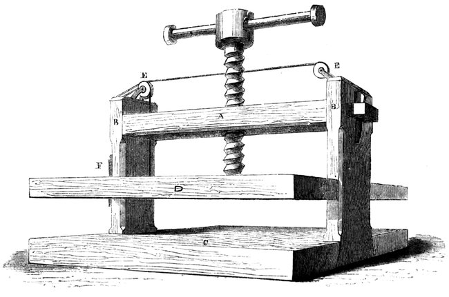
THE MODELLING PRESS.
SIZES.
| C |
Bottom piece |
18 |
inches |
by |
12 |
inches |
by |
2 |
inches. |
| B B |
Uprights |
12 |
do. |
— |
4 |
do. |
— |
1½ |
do. |
| A |
Cross beam |
15 |
do. |
— |
4 |
do. |
— |
2¼ |
do. |
| The screw 1⅜ths inch in diameter. |
29
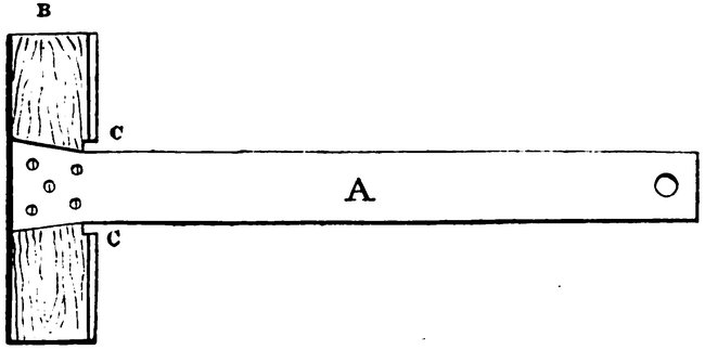
This square is formed like the ordinary
drawing-squares, with the exception that the
blade A is made of steel; this is firmly screwed to
a stock of hard wood, which has on each side of
the blade a small piece at C C cut out; the object of
this is to allow the knife to cut completely to the
edge of the paper. The advantage, in fact, the
30necessity for a steel blade, will be obvious; were
it of wood, the pressure of the knife along its
edge would indent, or cut it. This square will
be found adapted for every description of large
and small work, but should the cardboard be of
great thickness it is apt to stir, and by so doing
cause irregularity of line. To remedy this an
instrument is used, called an adjusting straight-edge.
A is a straight ruler of flat brass, or of
steel, like the blade of the T-square. It is contrived
to move to and from the surface of the
board upon the upright screws, B B, while a dovetail
groove is fitted with a piece of brass to run
along it, to allow of the horizontal movement of
the ruler. The paper (upon which the cutting-off
line has been previously marked) is placed upon
the board, the straight-edge adjusted to the
line; the straight-edge being then firmly screwed
down upon it by means of the two small thumb-screws,
3 3, it is rendered immoveable during the
31progress of the work, this will be better understood
from the annexed engraving.
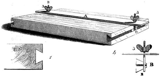
THE ADJUSTING STRAIGHT-EDGE.
No. 1 is a section of the cutting-board, showing
the groove in which the piece of brass runs.
2, The brass, to which is attached the thumb-screws,
by means of a screw through the eye at B.
3 3 3, Thumb-screws, to screw down the ruler upon
the paper. The brass rule should not be less
than an eighth of an inch in thickness, otherwise
it may bend; if steel it will do a little less.
This instrument will be found particularly
useful in cutting the necessary mitres for joining
together the edges of the work, or for any other
32work of similar description, such as the copings
to walls, mouldings of every description, &c., &c.
Having now described these very important
instruments in a way we hope may prove perfectly
intelligible, we proceed to state the requirements
in those necessary ones, knives. The
number of these the artist will use, is regulated
more by his own fancy than anything else; but
there are three shapes he will find absolutely
necessary. In modelling, as in painting, there are
numerous tricks and contrivances for producing
various effects; and as the painter will often value
a bit of old scrubby, worn-down brush, so the
modeller will find various cutting instruments
materially assist him, such as the broken blade
of a knife, a steel pen, a bradawl, &c., &c., many
of these producing effects that more elaborate
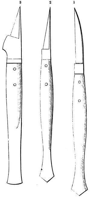
instruments would have failed doing. On page
33 will be found an engraving representing three
requisite varieties of knives. No. 1. This knife is
35long in the blade, and, as will be found in all the
others, is perfectly straight on the cutting edge;
this knife is used to cut straight lines in all
directions through strong work, cutting oblique
lines, mitres, splays, &c. No. 2. One for lighter
work used in forming or modelling ornaments,
or, in general, cutting work of a lighter and neater
character. No. 3. This blade is used solely for
cutting all descriptions of circular work, and
curves of every description. It may be useful to
remark that this is the only shape of blade that
will cut, with clearness and sharpness, curved
lines through thick cardboard. The instrument
next illustrated is called a knife compass, and is
extremely valuable for cutting out circular architraves,
&c., &c., doing its work in a way that the
hand and knife could not equal, and with the
least possible trouble. See illustration, page 36.
They resemble, in some respects, an ordinary pair
of compasses, but of a little stronger make than
36the common. A is a moveable sweep of brass,
to regulate the opening of the legs of the compasses,
which, being opened to the requisite
width, are firmly held by tightening the thumb-screw,
F. B, the moveable leg to which the
cutting-knife C is attached by means of a shoulder
to the blade at G, and a socket at H, into which
it fixes, and is secured by the screw at D. E and
I are two screws working on the rod, K, on each
side of the moveable bar, B.
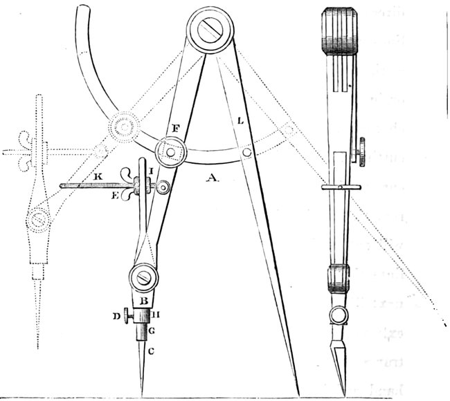
37By means of this contrivance the knife is
always kept perfectly upright, and in consequence
cuts perpendicularly through the cardboard.
There may be several knives to fit in
the socket for light and heavy work, but a blade
of the same shape as that shown in the engraving,
will be found sufficient for nearly every purpose.
The instrument might perhaps be more useful if
half as large again as represented. The dotted
lines are given to show the instrument open
wider, in order fully to illustrate the utility of
the moveable leg at B. The method of using
this instrument is this: Having a curve to cut,
and having found the centre of the arc, place the
point of the leg L within it, then adjusting the
38moveable leg to the perpendicular by means of
the screws I and E, stretch the legs to the
requisite radius, and by gradually increasing the
pressure on the blade, the curve may be cut with
the most perfect ease and truth.
PART III. THE COMMENCEMENT AND FINISH OF A MODEL.
39
Assuming that the student has now procured
the various instruments and materials for his
work, and that he has also determined upon the
design he intends in paper, the next thing necessary
is to give him as far as it is possible by a
book copiously illustrated, an exact description
of the method of proceeding. We will therefore
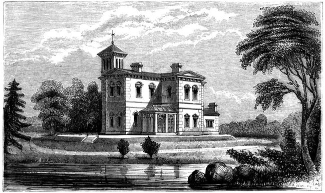
imagine a design which is to be modelled (see
frontispiece), a Villa, in the domestic Italian
style, for example; and taking it to pieces bit by
bit, endeavour to raise it up again in renewed
beauty and effect.
Having the four elevations, together with the
40ground and roof plans, the latter being essential
to show the position of the chimneys, skylights,
&c., we take a common drawing-board, about the
size of the intended model, and upon it strain as
for a drawing that size, a piece of drawing cartridge,
say an inch and a half wider all round
than the intended model is to be. Upon this,
when dry, draw an outline plan of the intended
building, not putting in any internal walls, for
these will not be required as this is only to form
lines whereon to erect the intended building.
To make it more readily to be understood we
have given a sketch of the outline plan on
page 45.
41
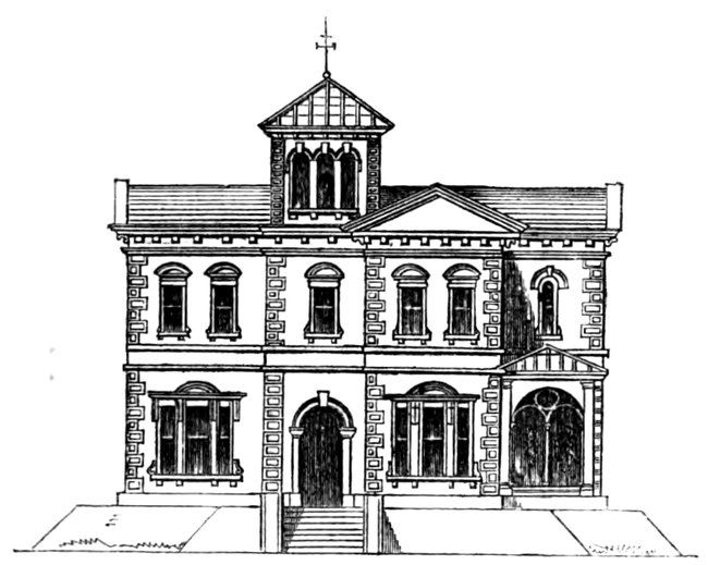
ELEVATIONS OF VILLA.
ELEVATION OF ENTRANCE.
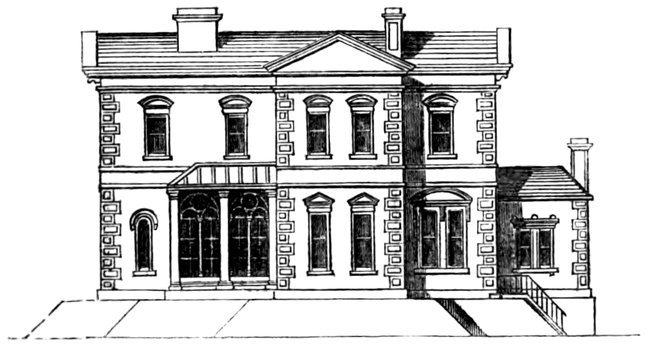
This being completed, we have now the edifice,
as it were, set out. The next matter for consideration
is the thickness of the walls; that is,
the requisite thickness of paper we shall require.
Suppose we take, as in the plan given, the outside
reveal or recess back of the window frame,
43at four inches and a half; this would require
four sheets of paper, but as it is always better to
exaggerate slightly in modelling both projections
and recesses, place six or even seven sheets
together; paste them together in twos, putting
them as pasted under the press, and afterwards,
when nearly dry, paste them the full thickness
required and subject them once more to the
action of the press. The most convenient size
of paper to work at for an ordinary-sized model
will be made by doubling a sheet of the paper
as first procured into four. On the paper
becoming perfectly dry, the student must carefully
draw each elevation of the building the full
height from the ground line to the top of the
blocking, being particular that every line both
perpendicular and horizontal is perfectly true
and square, and marking along faintly the lines
for the cornice, strings, &c., &c., that may occur.
This being done and the whole drawn in, of
44course not drawing in the window frames but
merely the outline of the square of the window,
the side will present the appearance shown in
the accompanying elevation, and which is merely
sketched and not drawn to any scale.
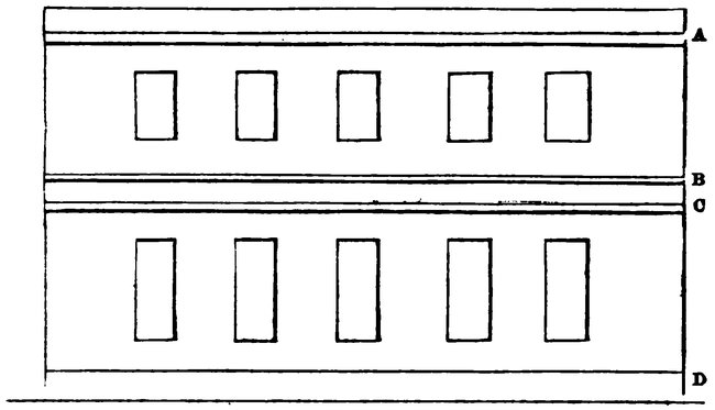
A Lines for cornice. B Lines of upper string. C Ditto lower cornice. D Ditto Plinth.
45
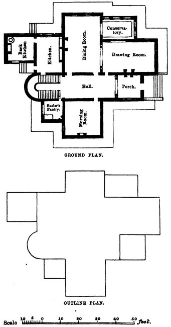
PLANS OF VILLA.
GROUND PLAN.
OUTLINE PLAN.
The four or more elevations having been
drawn, proceed to cut out all windows, doors, and
other openings cleanly and accurately. The
windows and their frames must now be made and
gummed at the back of the several openings;
where panels occur paper of the same tint must
be used, sometimes the pieces cut from the
47windows will form very good backing for such
parts. For the window frames take some large-sized
cream laid paper, and colour it to the tint
you wish your frames to be. Should a representation
of oak be preferred, it may be imitated
successfully thus: First paint your paper yellow,
gamboge and a little burnt sienna will do, and
then prepare a thick colour with Chinese white
and burnt sienna; when the first colour is dry
lay this last-mentioned on, and before it has
time to dry grain it by means of a fine comb;
a small tooth comb will answer best for this
purpose, and if skilfully performed a most
admirable imitation will be the result. Three
or four thicknesses of paper (cream laid or other
white paper) must then be pasted together, with
the oak-coloured one upon the top, and submitted
to the action of the press.
This paper being ready for use, take one of
the pieces cut from the windows, and mark by
48it the size of the window-opening, then lightly
draw the frames in and cut them out, if the
white paper of the under sheets should show
where cut through sectionally, touch it along
with a little burnt sienna or brown colour.
You must now tint another sheet of the same
description of paper blue or neutral, not in an
even tint, but carelessly and artistically leaving
bright lights; this when pasted as for
the oak-paper two or three thicknesses, will
form the backing to the frames. Then place
the frames face down, on them gummed a sheet
of mica; on that again the blue backing; the
whole then to be put in the press, care being
taken not exhibit too much pressure, otherwise
you will have the backing bulge out. It may,
perhaps, be thought that these thicknesses of
paper for the frames and backing are unnecessary,
and that one might serve as well; but from
experience I can assert, that unless this method
49be adopted, that flatness the work should have,
will not be obtained. It may also be as well
here to caution the reader against pressing with
too great a degree upon the cardboard when
it is under the action of the press. If too
great a pressure is given, the cardboard will
become so hard as to resist all efforts of the
knife to cut through it. The paper usually
presses to a little less than an inch, to a
scale of one-eighth of an inch to the foot; so
that six thicknesses or sheets of paper will
answer for four and a half of brickwork or
stonework. The doors will be formed first from
two thicknesses[1] and backed with the same.
This is for plainest description, but if mouldings
are inserted in the panels, adopt the
following:—
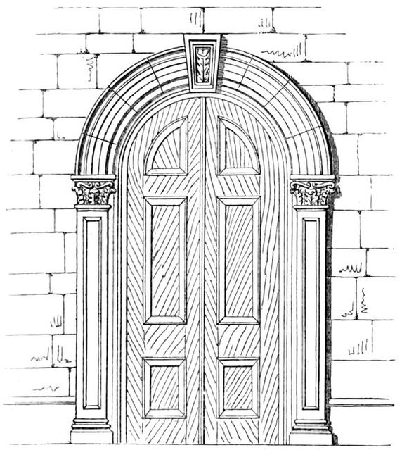
DETAILS No. 1.
ELEVATION OF ENTRANCE DOOR.
51First draw the door with the extreme size of
52the opening of each panel, on a two-thickness
sheet; on another two-thickness sheet, draw the
same panels a size smaller; on a third two-thickness
sheet, draw them a size smaller still;
these being cut out and placed behind one
another, and finally the backing; will admirably
represent mouldings: by producing three separate
lines round the inside of each panel. For work
to ⅛ scale no further trouble will be necessary;
but if larger, the mouldings must be formed
before the door is gummed together, as hereafter
described for the formation of mouldings in
general. The doors, windows, and backs to all
openings are now ready, but cannot be yet fixed
till all the necessary mitreing is completed, which
mitres will be wherever an outside angle occurs
thus, fig. 1. (See page 53, figs. 1 and 2.)
53
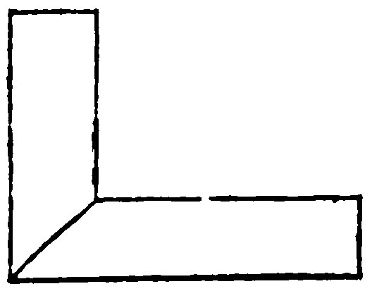
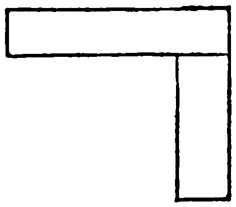
In the inner angle (see fig. 2) no mitre is
required; the end of one piece being cut square,
they may be made to overlap one another. Lay
the piece, whatever it may be you wish to mitre,
face down upon the cutting-board; and then at
a distance (equal to the whole thickness of the
cardboard) from the edge draw a line; and at a
short distance back from this line sufficient to
let the point of the knife touch it when held
slanting to the required angle, fix the adjusting
straight-edge previously described; screw firmly
upon it, and cut through the paper at an angle
of 45°, which will, of course, be by cutting from
the line on the top side of the paper, A, to the
extreme edge of the underside, B (see illustration
page 55), which represents the side of a building,
and the piece may be seen curling up as cut
from the mitre. Great steadiness of hand, and
54a few trials on waste cardboard are necessary
before the operator will perform this skilfully.
The straight-edge holding the paper firmly, it
may be cut through at two or three strokes,
observing to hold the knife always at the same
angle. All mitreing work finished, affix the
windows at the back, placing the whole under a
slight pressure.[2] Then the model must be blocked
up. First cut a number of squares, all sizes, from
waste or other cardboard; let them be perfectly
square; cut these diagonally, and they will form
the blocks to hold the work together at the angles.
Now take any two sides that are to be joined
at the mitred angle, and fix them accurately
together with gum pretty thick, so that it may
55dry while you hold each side in its place. When
set, lay them down and work the others in a
similar manner. Take now the outline plan,
and having previously numbered the sides to
correspond with the plan, fix them (by touching
slightly their under edge with gum) to it, and
when all are in their places fix, at a distance
apart of an inch and half or so, above one
another the previously described blocking pieces
with gum not so thick in consistency. To make
our meaning perfectly plain, we annex an engraving
of the appearance of an internal angle
when at this stage of the proceedings. A piece
of wood (deal) about ½ inch thick, should now be
56attached to the model from one side to the other
(see page 57). This is for the purpose of fastening
the model, when completed, to its stand; it may
be blocked with waste pieces, such as the cuttings
from doors, windows, &c., and gummed firmly.
Pieces or strips of cardboard should also be
gummed along in the inside, at the level of the
intended gutters of the house, to rest the roof
upon. All portions of the work completed, we will
now assume, are fitted together and in their places.
The student will now be able to form some idea
of the general effect his work will have when
finished; but there is yet more—much more—to
be done, and work requiring a still further amount
of skill, practice, and patience.
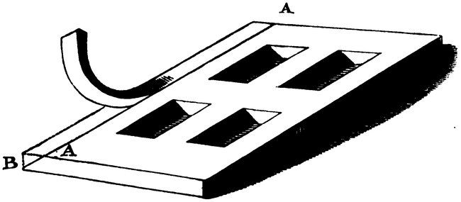
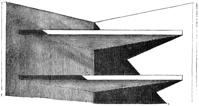
SKETCH SHOWING THE WAY THE BLOCKING PIECES ARE INSERTED IN AN INTERNAL ANGLE.
57
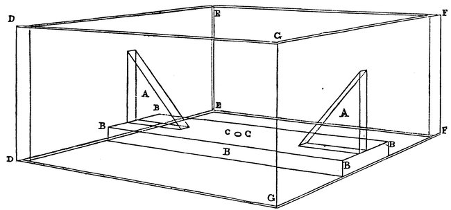
METHOD OF INSERTING THE WOOD STAY.
A A Cardboard angle stays. B B B B B Wood stay by which the model is affixed to its stand by a screw passing through at C C. D E F G Sides of model.
59The two principal elevations are given to the
same scale as the plan (page 41); but in order to
insure our being understood, the principal portions
of the details are given to a larger scale.
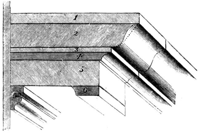
The cornice next demands our attention, a
detail of which is given on page 61, fig. 1, and in
order to model which we proceed thus, the numbers
indicating the various pieces of which it is
composed. No. 2 is a piece worked of the required
thickness demanded by the depth of the
cornice from A to B, and the necessary projection,
in a sufficient series of lengths to go entirely
round the building. Now, as this is to be cut
through the several thicknesses of paper required,
a method must be found out to hide the different
layers that would consequently be exposed to
60view; this is by cutting from one or two thicknesses
a piece the whole length of the cornice,
forming a facia, 8, and coming slightly below the
depth of the other under piece to 4; thus, while
at the same time it hides the layers of paper, it
forms the bed of the cornice.
The next members, Nos. 1, 3, 5, and 7, are
formed, first by preparing the size and length on
the square; secondly, by cutting off at any angle
necessary to get as near to the mould as possible;
and, lastly, forming the mould itself.
The manner of moulding being applicable to
every description of either Italian or Gothic
pattern, we proceed to describe it.
Procure from the comb-manufacturers some
pieces of ivory of various sizes, and with different
files, some round, some square, &c., file on one
end of a square piece the reverse of the mould
you require; smooth it well; and for greater
power and convenience, fix it in a handle of wood.
61
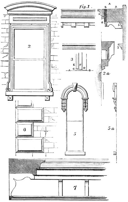
DETAILS No. 2.
1 Elevation and section of main cornice. 2 Elevation of window. 2a A detail of section through window. 3 Architrave mould. 5 Elevation of small window. 5a Section of small window. 6 Elevation of quoins. 7 Section and elevation of tower cornice.
63
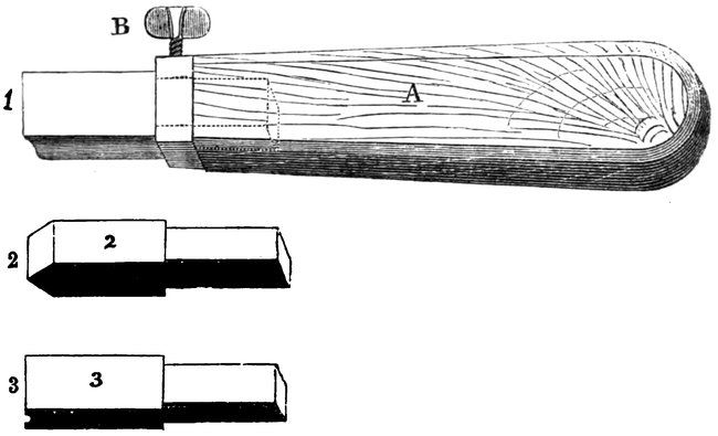
MOULDING TOOLS.
A, Handle with socket to secure the moulding tool (1). B, Thumb-screw. 1, 2, 3, Moulding tools.
Nos. 1, 2, 3, &c., &c., will be found generally
available and useful in the formation of all kinds
of mouldings, besides numbers of other shapes
that will occur to the artist. The method of
using the instrument is by indenting the pattern
along the edge of the cardboard, guided by
means of the straight-edge. The sharp arris
left from the file upon the edge of the ivory
mould, had better be slightly taken off, to prevent
the paper being torn in its passage.
64The circular pediment over windows (fig. 2,
page 61) must be modelled on the flat, and the
moulding returned at the ends. When each
member is finished, they must be gummed up
and bent to the required curve, over a circle
of cardboard or a cylinder of wood, separately.
The panels that occur form thus: Cut as before
directed for doors, the extreme size of the
opening, and at the back place the successive
sizes and thicknesses to form the mouldings,
indented into hollows or worked to rounds, &c.,
&c., by means of one or more of the moulding
tools; to be backed last of all.
Commence the preparation of the quoins (fig. 6,
p. 61) by cutting pieces the required thickness and
width of both long and short quoins, and in long
strips, with the height of each one marked up its
length previously by the dividers.[3] Cut first the
65requisite splay at the edge of the quoin, along the
whole length both sides. Cut where marked for
height, and splay top and bottom. They are then
finished, and may be at once fastened to the work.
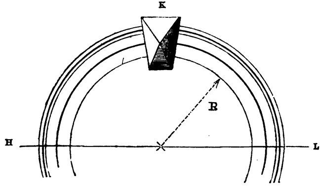
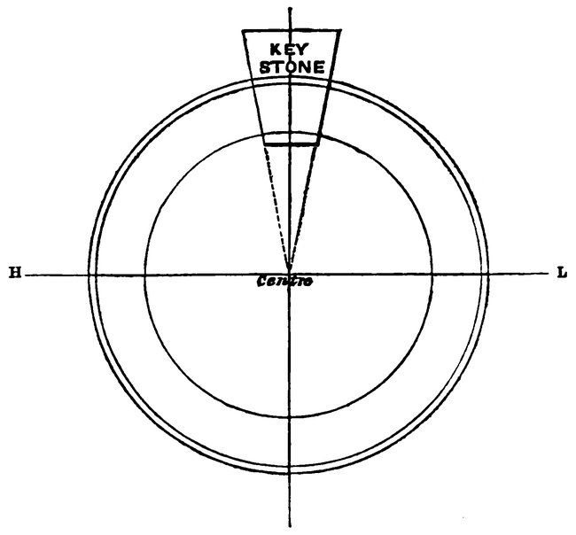
CIRCULAR ARCHITRAVES.
K Keystone. R Radius. H L Horizontal line.
The circular architraves must be formed by
cutting, with the little instrument previously
described as a knife-compass (page 36), circles of
different diameters and thicknesses of paper
suited to the mould to be represented; gum
together while in the circle, as shown below, the
horizontal divisional line being marked, and the
radiating lines for the insertion of the keystones.
66When dry cut off by the divisional line, and then
the segments, by the lines at each side of the
keystone. The key must be of paper sufficiently
thick to allow of the highest mould of the
architrave abutting against it, and either left
plain, cut diamond-wise, or carved, or any
other way the fancy may suggest or the design
demand.
The cantalivers in tower (fig. 7, page 61) and
main cornices (fig. 1, page 61) to be worked by
preparing paper the required thickness; then
procuring a piece of very thin copper or lead,
mark on it with considerable accuracy the design
of the cantaliver, and cut it out; you will thus
have prepared a mould or templet, which you
can place upon the cardboard, and by running
a hard pencil round it, mark each one precisely
the same in size.
Any portions of the dressings, &c., having
curves in them, had better be cut with knife
67No. 3[4]; in fact, this is the only shape of blade
which will leave the edge of a curved line after
cutting, what is technically called “sweet.”
The positions the cantalivers have to occupy
along the cornice, must be checked along and
regularly divided. Care must also be taken in
gumming them in their places, as one out of
place or leaning would immediately be detected
by a correct eye, and mar completely the effect
of the whole.
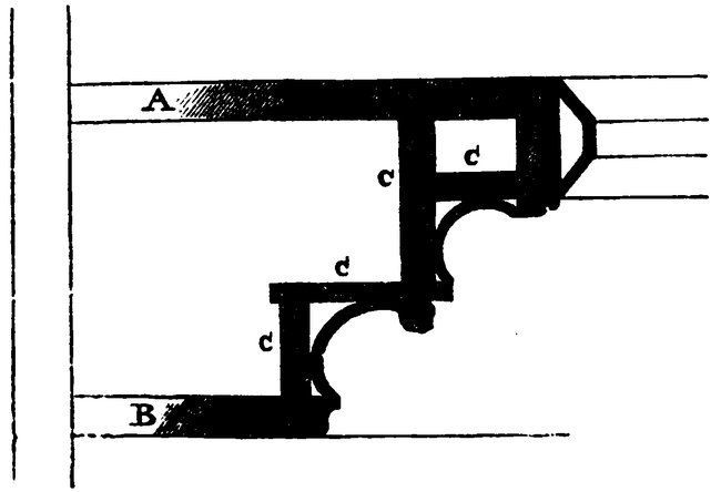
The architrave mould (fig. 3, page 61) next
demands our attention. It will from our
former description be readily understood that
all mouldings are formed by representing in
paper of various thicknesses their several component
parts. Thus, in the mould last named,
we have first the groundwork of or thickness
from A to B; another thickness, forming the
68sinking, from C to D; and finally, the mould,
E to F. Square first, the required slant next cut
from the edge, and lastly, the slant hollowed by
means of one of the ivory moulding tools. The
keystones and the blocks under the window sills
are cut from paper the thickness required, then
splayed down each way from the centre to the
sides at one cut, and with a sharp knife. This
operation must be performed with some dexterity,
as it is important that the edges should be sharp
and free from woolliness. This effect can only be
obtained by giving one cut or slice in the
direction required: for this purpose use
knife No. 1, which will be found the best for
this description of work. Some modellers use for
this purpose a thin chisel with a keen edge; and
of course all means in art are legitimate that
produce the desired end; but we would recommend
the use of the knife only, wherever possible,
the modeller’s object being to work with as few
69tools as possible, and to trust much to his knife
alone.
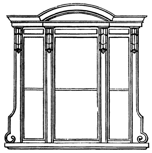
DETAILS OF WINDOWS. No. 3.
MORNING ROOM.
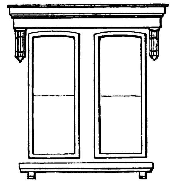
71We have, in describing the method of working
several important details connected with the
building, and illustrated on page 61, been, we
fear, somewhat premature, and have not sufficiently
urged upon the student the necessity of
preparing his groundwork for these details in a
perfectly accurate manner. For, as it is well
known, no colouring, however fine, will in a
picture make up for bad and incorrect drawing,
so in a model, walls out of square or windows
and other apertures ill-cut will not present the
wished-for appearance, though all the details be
most skilfully and beautifully modelled. Draw
in all doors, windows, &c., &c., with a very hard
pencil, in order that the lines may be as fine as
possible, and cut them out with knife No. 1,
or No. 2, whichever may be considered most
suitable to the size of opening it is required to
72cut; the knife No. 3, as before observed, being
used exclusively for curved and circular work.
In cutting out the windows, hold your knife perfectly
upright; and, as you arrive at the end of
the cut, let the edge of the blade be perpendicular,
thus avoiding cutting past the line. In cutting
through thick, or indeed even through one thickness
of paper, do not be too anxious to sever the
piece with one cut, as this way of proceeding is
almost sure to cause unevenness of line. But
commence by drawing a line, as it were, in the
required direction; that the rule may guide it
accurately, press but slightly at first; and as
the track of the knife gets deeper, exert more
pressure. Simple as this direction may appear,
it is nevertheless of the utmost practical utility,
as will readily be found upon trial, as it is only
by these means that the paper will be left at the
edge clean, sharp, and even.
73
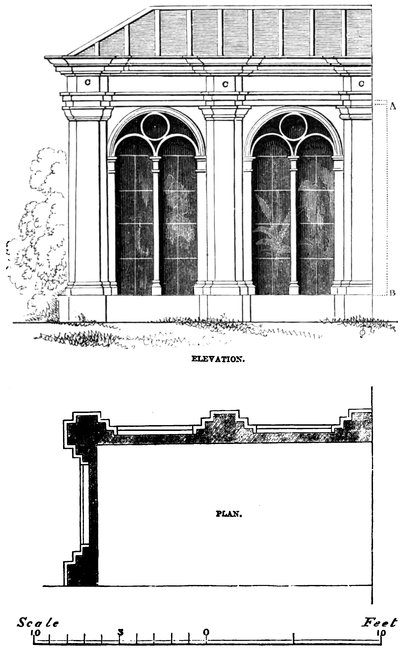
DETAILS OF GREENHOUSE. No. 1.
The next object we would call attention to is
75the Greenhouse, page 73, and state that there are
two ways of modelling this very general appendage
to a modern mansion. The first and the simplest
method is to form the backing of blue paper behind
the mica. The other, by doing away with
the blue backing, and allowing the mica to remain
transparent. The former method saves some
amount of labour; but the latter being in our
opinion the best and most artistic method, we
shall proceed to describe it: First form the pilasters
(you will require double the number than
for the opaque backing), and cut them in their
length from A to B (see elevation, page 73), from
the commencement of the base mouldings to the
underside of those of the cap. The way of
proceeding in modelling cap and base will be
readily understood from the accompanying
sketch, where it will at once be seen better than
we can describe. The best way to cut them is
as if they were a window or opening, cutting the
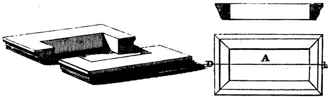
piece out of the centre at A, after having moulded
76the edge all round. Then dividing them into two
along the line D L as below, fix them in their
respective places. The angle ones must be double,
to avoid having to mitre them. A piece of mica
or thin glass cut to the size of the one side is
now taken, and the pilasters and other portions,
divisional bars, &c., are gummed to it, on both
sides; and when with the end it is finished, let
it occupy its intended position on the outline
plan.
Now proceed to the roof, to be constructed
really of iron and glass, to be modelled of paper
and mica: First, bend round a paper or other
cylinder the piece of mica for the roof, and proceed
to cut a number of strips of cardboard for
the ribs, which may be coloured any suitable tint.
77
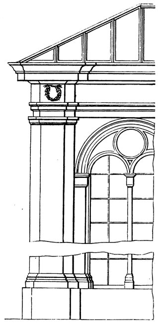
DETAILS OF GREENHOUSE. No. 2.
PART ELEVATION.
Scale ¼ inch one foot.
79These are then to be affixed in their places, as
shown upon the drawing, some in thicker, others
in thinner paper. A ledge of cardboard must be
left at the back of the blocking, and also on the
same level against the side of the house; this
will be for the purpose of resting the roof upon.[5]
The cornice will be constructed in the manner
described for the others; the pieces on the frieze
C, C, C (page 73) will be placed on the required
thickness for the return, but the return of the
cornice must be cut in it. The plinth must now be
moulded, cut, and fixed; and the whole is complete.
Chimneys, those great ornaments to a house,
at least they should be rendered so, but, alas!
for the taste of some of our modern architects,
are far more frequently the reverse, and what
in able hands and with judicious treatment
would prove a crowning feature and a material
80assistance to the design, becomes a glaring error
and ruins the whole. So much for the architect:
but should he fortunately possess the ability and
taste to produce those necessaries to our comfort,
with equal credit to himself and benefit to the
design, how often do we see his work marred by
the introduction of Messrs. Somebody’s patent
never-failing revolving smoke preventer; a hideous
monster of some seven feet high, whirling and
screeching upon the slightest appearance of wind.
As our little Handbook has its mission to instruct
in the Art of Modelling an architect’s production,
and as smoke-jacks are but little indebted to him
for their uneasy existence, we beg to apologise
for this digression, and resume our original topic.
Details of the chimneys will be found upon page
81 and 83; for the body of the chimney use two
thicknesses, and it will not be found necessary to
mitre the join; for, if even ordinary care be taken,
the union will be scarcely perceptible, while the
81labour will be considerably diminished. Form
any strings, cornices, &c., &c., that occur, by
cutting the piece flat, and then cutting the square
out of the middle to admit of the shaft, slip it
over the shaft or body of the chimney, till it
arrives at the position required by the design,
where it is at once to be secured in its place.
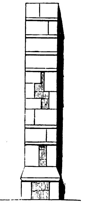
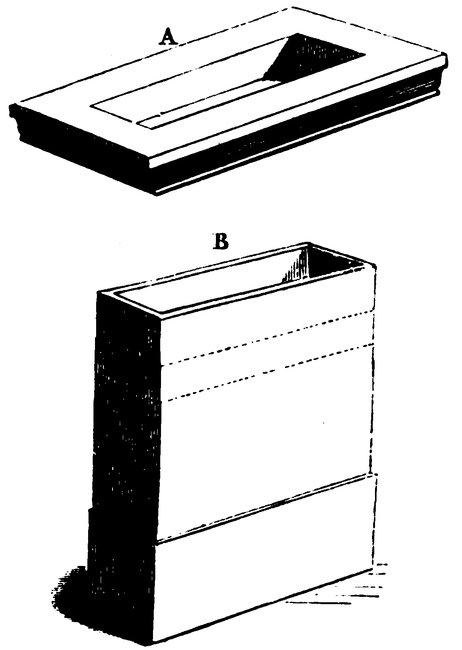
Perhaps our meaning may be rendered clearer by
the accompanying illustration. A represents the
cornice prepared in the manner described, and only
requiring to be fixed in its place. B, the shaft
or body of the chimney over which the cornice
is to be slipped till it arrives at the dotted lines;
the chimneys may be fixed to the roof (shortly to
be described) in the following manner: Should
the chimney come on the roof lower down than
the ridge, the bottom of the shaft will have to
be cut to the angle required by the rake of the
roof only; but should the chimney be cut into
by the ridge, then the angle will follow that of
the roof on both sides, diverging from the apex.
For illustration of this we give the annexed
sketches, page 83.
83
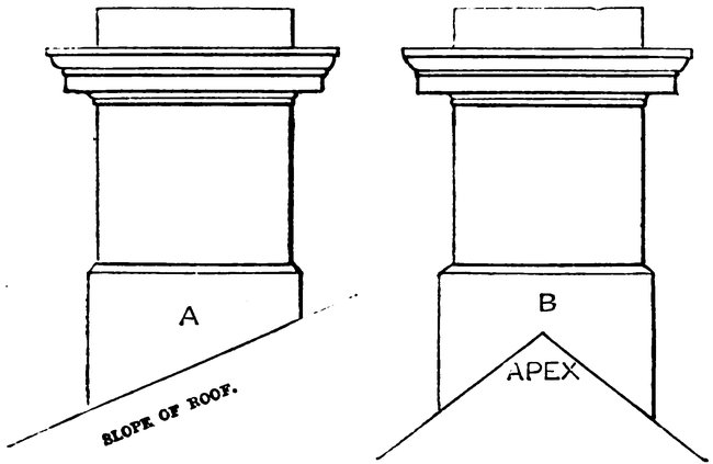
A represents a chimney, the base of which is
cut simply one way, to suit the slope of the roof.
B, a chimney into which the ridge cuts, and the
angle cut both ways from the apex. It will, as
a general rule, be found better to put chimneys
together with thin paper, even in the smallest
models, a squareness being thus produced not to
be obtained otherwise. The base to be formed
out of thickness equal to the projection, and
treated in (as regards fitting it to the roof) a similar
manner to the shaft, so that if the rake of shaft
had chanced not to have been truly cut, there is
no need to throw it away, as it could easily be
blocked under with small pieces till straight, the
base hiding all defects underneath. The method
of working the strings, cornices, &c., has already
84been fully described in those for the tower and
main building. Figs. 1 and 7, page 61.
Our model now draws near to its completion.
We had arrived at a stage ready for the roof,
but stopped for the preparation of the chimneys,
in order that when the roof was completed, they
might be at once fixed in their respective places.
The roof may be either scored, or gauged with
paper strips overlapped. The groundwork for
either method will be prepared in the same
manner. First cut, as if for a lid or top to fit
the inside of the model, a strong piece of cardboard;
let it be just so that it will slip into its
place between the walls, but be prevented slipping
down by the strips or ledge on the level of the
gutter, as described for Greenhouse, page 73.
85
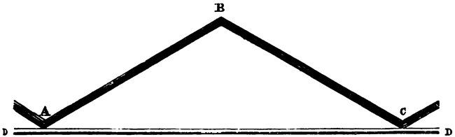
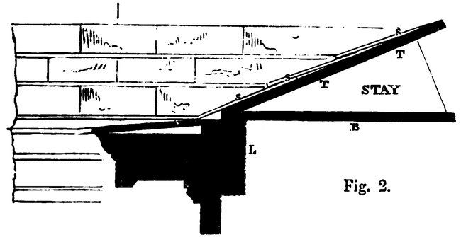
Fig. 2.
B Bottom piece. C Cornice. L Ledge. S S S Slates. T Top piece. W Wall.
The cross hatching shows the number of separate pieces the cornice is composed of.
Sections must now be taken in various parts,
through the roof, to ascertain the length of the
respective sides. Thus if the angle A B C (see fig. 1,
page 85) represents the rake of the roof, the length
87of the side will be found from A to B and B to C.
The sides thus formed must be splayed to fit at
the valleys, apex, &c., and at the base splayed
and fixed to the top piece on which the roof plan
has been drawn, observing to leave space enough
all round for the gutter. If the pieces on which
the sections have been drawn are cut out, they
will answer for internal stays to the roof.
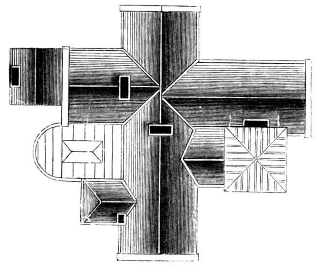
The roof plan is given upon page 85, fig. 3,
as also an outline section for the finishing of the
roof, fig. 2, page 85; it will explain itself. The
lead flat will be formed by the bottom piece,
but it must be covered by a paper resembling
in tint that of the lead itself. When the groundwork
of the roof is completed, it must be
covered in imitation of slates by one or other
of the previously-mentioned methods. We will,
however, describe both, leaving the reader to
use his own judgment as to which he may adopt,
our preference being for the strips of overlapping
88paper. In the simple scoring, proceed to cut out
of the slate tinted paper pieces accurately fitting
to the groundwork of the roof, then with the
knife handle score these sides along, as you
would ink in the roof lines in a drawing, closer
at the ridge, becoming wider at the base, and
parallel to each other. The latter by cutting
layers of paper, gauged decreasing in size as
before directed, fixing them to the groundwork of
the roof beginning at the base, and overlapping
them about 1⁄16th of an inch; after all, submitting
to the press. The roof assumed to be finished,
affix the chimneys, generally make good all
imperfections, &c., and the model is ready for
removal to its final destination; cut therefore
the paper it was built upon from the board, and
also tear from the bottom edges the paper that
may have adhered to it, holding it by the wood
stay.
Prepare a piece of dry wood about two or
89three inches wider all round than the building
itself, cover it with cloth or velvet, the latter
preferable, the best colour green, and cut a small
groove out of the upper edge; this is to receive the
glass shade, which construct thus: procure five
pieces of glass, the sizes rendered necessary by
your stand to form a square or oblong shade, and
fasten all together by means of strips of thin
paper and gum (the dull gold paper to be procured
in sheets at any of the artists’ repositories
will look best) at their edges. The model must
now be secured to the stand, for which purpose
the piece of wood mentioned at page 56 was
inserted, a hole is drilled through the bottom of
the stand, and a screw passed through it into
the wood stay. Do not screw the model down too
tightly upon the stand, or you may force away the
stay from its fastenings and destroy your work.
We have now described all the necessary materials
and manipulations to complete in every
respect a model similar to the mansion given in
90the illustrations, and which, though containing
the general detail of a building of that description,
was wanting in numerous varieties of detail
that will occur in many other buildings of the
same class more ornate and considerably more
elaborate in design than our example.
While all our attention is being turned towards
Italian architecture, Gothic must not be forgotten,
and though the general method of procedure
is the same for both, yet there are
numerous things which exist only in the latter
style, and in consequence demand separate
instructions. In order, therefore, that nothing
shall escape being described in the various styles,
that the student may have nothing to retard his
operations, we append the methods of working
the various details in the form of an illustrated
glossary, the alphabetical arrangement of which
will, we think, enable the student more readily
and quickly to find the particular information he
may require.
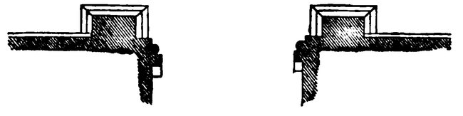
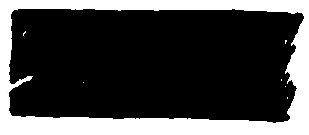 next bevel the edge thus
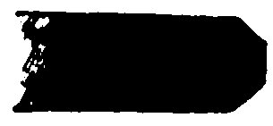 and then,
with one of the hollow ivory moulding tools run along
the edge by pressure, give the intended round.