The addition of distributing girders, described in the last
chapter, as a means of strengthening a bridge floor, while
sufficient in many cases so far as the cross-girders are concerned,
does not in any appreciable way assist the main
girders. When for a two-line bridge, having outer main
girders only, this result also is desired, together with a more
complete relief of the floor structure, centre main girders
may be used, placed either above or below the cross-girders,
on the centre line of the bridge.
There are two principal ways in which such a girder may
be brought into use; the easier, but generally less economical,
is by making a simple attachment to the cross-girders,
the old girder work still taking the whole dead load. By this
method the new girder does no work but carry itself till the
live load comes upon the bridge, and must be made very
stiff to take any sensible portion of the running load; the
second method is to make the connection adjustable, so that
a part of the floor weights may be imposed upon the new
girder as an initial load. In doing this the old outer girders
will rise slightly, being relieved of stress, and the cross-girders
also lifted at the middle, whilst the new girder is
depressed as the load is brought upon it. With some part
of the live load a very considerable proportion of the total
may in this way be carried by a centre girder of moderate
section. The whole question, by either method, turns upon
deflections; and it is in determining the relative movements
of the girders that the problem chiefly lies.
It is convenient first to determine the percentage of load
relief to be effected in the main girders, as to which it is to
be observed that as this relief (distributed) is induced by
the upward reaction of the new girder acting at the centre
of the cross-girders, the stress relief of these will, as a rule,
greatly exceed that of the outside girders. For the generality
of cases, it may be taken that the relief suitable for the
outside girders will be satisfactory in its effects upon the
cross-girders, even though it is desired to reduce the stress
in these to a greater degree.
If, however, it be thought desirable to check this, it may
be done by considering a cross-girder subject to its dead and
live loads acting downwards, and to reactions at the centre
and ends. At the centre the reaction will be the load of
which the two main girders are relieved on a length equal to
the pitch of the cross-girders, or as here given:—
c × t × P = reaction at centre
(1)
c being the percentage of relief; t the total load per foot run
of the bridge; and P the pitch of cross-girders. The live
loads carried by the cross-girders are for this purpose taken
at per foot run, as for the main girders. With these data
it will be easy to construct a diagram of moments, making
it evident whether the relief proposed for the main girders
will give a sufficient percentage of relief to the floor beams.
Granting that this proportion has been decided, and
dealing first with the case in which the centre girder is
simply attached to the cross-girders, and takes no dead load
other than its own weight, then the live load carried by the
outside girders, and previously borne wholly by them, will
be reduced by the amount it is intended to transfer to the
centre girder, and will become
Ll - (c × Lt) = live load on outer girders
(2)
Ll being the total live load, and Lt the total dead and live
load carried by the bridge. From this the deflection of the
outer girders corresponding to this modified live load may
be derived.
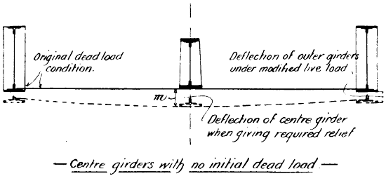
Fig. 70.
It is next necessary to ascertain the vertical movement,
commonly a depression, of the cross-girders at the centre
relative to their ends, when subject to the running load only,
and supported at the middle and ends, the centre reaction
being obtained as before indicated (1). This movement
will be the difference (if any) between the deflection on the
whole span of the cross-girder due to the live load, and the
upward flexure of the girder due to the centre reaction,
considered as separate effects. Stress values having been
estimated for the two conditions, these results may readily
be deduced by simple flexure formulæ, observing that while
the curve of moments due to live load sufficiently approximates
to that for a distributed load to justify, for this, the
use of a distributed load formula as given in the chapter
“Deflections,” the flexure due to the centre reaction will be
but 0·80 of that which corresponds to the same stress for
distributed loading. Or, the curve assumed by the girder
under live load may be plotted by a method to be later
explained.
The sum of the movements now determined—that is,
the live-load deflection of the outer girders, and depression,
as is commonly the case, of the cross-girders—will give the
extreme depression (marked m in Fig. 70), from the dead-load
condition of the middle cross-girders, when supported
to the extent desired by a centre girder whose proportions are
not yet known, but which, carrying the required percentage
of the total load, must, subject to a reservation presently
stated, deflect only this amount. The unit stress in the
flanges of the new girder, governed by this flexure, will for
a plate girder be
D × C × m
S2 = f, unit stress on gross section
(3)
D and S being, as before (see “Deflections”), the depth and
span respectively in feet, C a constant, m the deflection in
inches, and f the stress per square inch on the gross section
of flange.
The gross area A, of the flange, is given by
S × c × Lt
8 × D × f = gross area of flange(4)
c × Lt, being, as in (2), the load transferred to and carried
by the centre girder.
The actual stress in the flanges will, of course, be greater
by an amount due to the girder’s own weight; but this does
not affect the question of relief. For any ordinary case the
stress per square inch will be low; but it will manifestly be
useless to assume a greater stress with a view to economy, as
the effect of reducing the section will simply be to make the
girder too flexible, thus causing it to be less effective than
primarily intended. If, as is seldom the case, there is
freedom as to the depth of girder permissible, it is evident
the unit stress may be made a condition, and the depth
deduced by a suitable modification of formula (3); the
relief desired being in this way equally well assured. Indeed,
in the rare instances in which any depth may be
adopted, this method is—contrary to the general rule—distinctly
economical, particularly if the girder may be placed
below the cross-girders, which simply rest upon it, without
elaborate attachments.
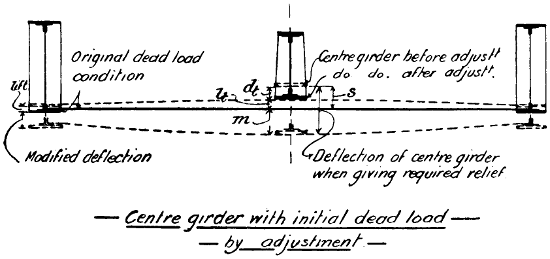
Fig. 71.
Considering now the second method of applying centre
girders by which the new girder is made initially to carry
part of the dead load, by adjustment, it will at once be
recognised as a more complex matter. The measure of
relief by which the old girderwork shall benefit need not
be affected by the method of applying the centre girder,
and may be decided on the principles already considered.
The outer girders carrying a reduced load, when the bridge
is fully loaded, and the cross-girders being in part supported
at their centres in the manner already described, will give a
resulting depression m (see Fig. 71) of the centre cross-girders,
below the original dead-load position, of a similar
amount determined in the same way. This extreme depression
determines also the lowest position of the new centre
girder, which may be designed to carry the required percentage
of the total bridge loads with the maximum stress
and depth, as conditions, leaving the initial dead load and
necessary adjustments to be ascertained. This is the common
case and will be here dealt with, it being assumed to avoid
ambiguity in description that the new girder lies above the
cross-girders.
The centre girder of fixed depth being then required to
carry a definite load at a definite flange stress, will deflect a
definite amount at this stress. If this deflection equalled
the extreme depression m of the old girder work, no adjustment
would be necessary, the centre girder then carrying no
initial dead load, as by the first method; but for centre
girders designed for economical flange stress the deflection will
in ordinary cases greatly exceed this, the depth generally
being small, and in order to ensure that the new girder shall
do its full work, some dead load must be put upon it. In the
act of adjustment the cross-girders must be lifted and the
centre girder depressed, till the joint movement equals the
excess s of the centre girder deflection over m, when the
new girder will carry the proper amount of initial load, and
upon further deflection under live load give the full measure
of relief. The amount of “lift” or upward flexure of the
old girder work, and the depression or “drop” of the new
girder, during adjustment, will depend upon relative stiffness,
and may be ascertained as follows:—
For unit reactions at the centre of the cross-girders the
upward flexure of these may be ascertained, as also the
upward flexure of the two outer girders when subject to
forces of the same total amount (one-half to each) applied
at the cross-girder ends. The sum of these movements will
give the total lift of the centre cross-girders, when all are
subject to unit lifting forces; similarly, the depression of
the centre girder for unit loads applied at the cross-girders
may be determined. There will then be known the movements
upwards and downwards of the old and new work
when being drawn together by unit forces applied as stated.
If
there will then be
d
l + d × s = dt,
total drop of centre girder under adjustment,
l
l + d × s = lt,
total lift of centre cross girders under adjustment,
dtd × unit load =
initial load put upon centre girder at each cross-girder.
The rise of the two outer girders for upward forces
together equal to those depressing the centre girder may
readily be deduced.
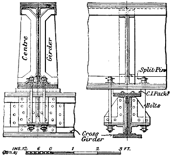
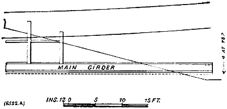
Fig. 72.
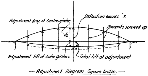
Fig. 73.
The act of adjustment may conveniently be effected by
the arrangement shown in Fig. 72, in which each cross-girder
is hung up at its centre by four bolts. At the middle of
the centre girder the total amount to be screwed up will be
that corresponding to the deflection excess s, but towards
the ends this amount decreases, and may advantageously be
represented by a diagram as Fig. 73, in which, if s represents
to scale the amount to be screwed up at a centre cross-girder,
the corresponding amounts for other girders may be read off
direct. It will be apparent that it must be necessary to
place the centre girder at such a height as to leave a space
between the old and the new work greater than the amount
to be screwed up, this excess clearance being ultimately filled
by a packing.
The precautions to be observed in carrying out this
kind of work, and the practical methods of adjustment
adopted by the author after some little experience, may here
be given.
Great care is necessary at the outset to ascertain the true
spacing of the cross-girders, to ensure that the bolt-holes in
the bottom flange of the centre girder shall come where
desired. The fixing of the cross-girder brackets also needs
close attention to avoid after trouble, the bolt-holes in the
brackets being preferably drilled on the site after fixing.
It will, for masonry abutments, be necessary to fix bedstones
to receive the new centre girder, which, being carried out
quite possibly under adverse traffic conditions, will perhaps
leave the stones liable to settle slightly when the full load
is carried. To eliminate the bad effect of this upon the
ultimate adjustment, and to take up any initial set of the
new girder work, which would be prejudicial in the same
way, it is desirable, the centre girder being in place, to screw
up the bolts temporarily and leave the work for a week
or two. To ensure regularity in the screwing up process, it
is convenient to prepare, for use at the bridge, a diagram
somewhat similar to Fig. 73, giving the amount by which
the new and old work are to be brought together at each
cross-girder, with the number of turns for each nut to effect
this. With a man at each side of the girder, the whole
length is traversed, giving a half-turn to each nut; this is
repeated as often as necessary, and so managed as to bring
all up proportionately to the final requirement, keeping tally
with chalk marks over each cross-girder as a check. The
preliminary screwing up should be conducted with little less
care than that adopted for the later adjustment, to avoid
damage to the old work. This later adjustment having in
due course been effected, it is then necessary to measure for
packings to fill the spaces remaining between the old cross-girders
and the new centre girder. These spaces should be
callipered at each of the four corners, care being taken to
avoid after-confusion. The measurements ascertained will,
however, be too great for the finished packings, as an allowance
of not less than 1⁄10 inch (total), will commonly be
wanted to cover irregularities in the surfaces. The packings,
having been prepared and checked, may be slipped into
place after slacking all the bolts a small amount to permit
this to be done, finally screwing up tight and securing
the nuts by split-pins, through holes drilled as the last
operation.
As a check upon the calculations and adjustment, the
“lift” of the outer girders and cross-girders, and the “drop”
of the centre girder may be observed by levelling. For this
purpose the author has used a staff of inches divided into
tenths, with which, and a good level, very accurate readings
may be taken for short distances.
No reference has been made to the effect of skew in a
bridge on the above methods, the explanation given applying
rather to bridges square on plan. The influence of skew on
the load distribution will largely be a matter of detailed
calculation. The flexure of the girders may also be sensibly
affected, but may be arrived at with sufficient accuracy
without any great trouble. The chief effect of skew is to
modify the amount of screwing up during adjustment, which
may be better understood by reference to Fig. 74, and comparing
it with Fig. 73, the adjustment diagram for a square
bridge.
To illustrate how these methods of strengthening work
out, and compare as to weights of centre girders required,
the case has been assumed of a wrought iron bridge of 60-feet
span, having outer girders 5 feet deep, of 39 square inches
gross flange area; and cross-girders, at 8-feet centres, 27-feet
span, 1 foot 9 inches deep, with a gross flange area of twenty
square inches. The dead load and live load on either road
are each 1·75 tons per foot run.
The stress in the outer girders previous to the alteration
being 6 tons per square inch gross, it is desired to relieve
this to the extent of 33 per cent. by a steel centre girder.
In the table here given the quantities given in italics are
fixed as primary conditions:—
Centre Strengthening Girders for 60-ft. Span.
| — |
Centre
Girder,
Stress
Unknown. |
Centre
Girder,
Depth
Unknown. |
Adjust-
ments
Unknown. |
| Outer Girder. |
|
|
|
| Deflection under modified live load |
·42 |
in. |
·42 |
in. |
·42 |
in. |
| Lift of adjustment |
nil |
nil |
·153 |
„ |
| Cross Girders. |
|
|
|
| Depression under live load—modified conditions of support |
·13 |
in. |
·13 |
in. |
·13 |
„ |
| Extreme depression (m) |
·55 |
„ |
·55 |
„ |
·55 |
„ |
| Lift of adjustment (cross-girder only) |
nil |
nil |
·095 |
„ |
| Total lift of adjustment (lt) |
nil |
nil |
·248 |
„ |
| Centre Girder. |
|
|
|
| Depth |
3·5 ft. |
8·2 ft. |
3·5 ft. |
| Unit stress on gross section (ex girder’s weight) |
2·14 tons |
5·0 tons |
5·0 tons |
| Total deflection (ex girder’s weight) |
·55 in. |
·55 in. |
1·28 |
in. |
| Deflection excess (s) |
nil |
nil |
·73 |
„ |
| Depression, or “drop” of adjustment (dt) |
nil |
nil |
·482 |
„ |
| Gross area of flange |
105 sq. in. |
19·2 sq. in. |
44·5 sq. in. |
| Weight |
20 tons |
10·4 tons |
11·4 tons |
| Net flange stress (including girder’s weight) |
3·19 tons |
6·87 tons |
6·94 tons |
Girders subject to distributed load are treated as having
uniform stress, but where this is not strictly the case, as in
some light girders, it will be necessary to take the fact into
account. For centre girders of wrought iron, and a unit
stress on the gross section of 4 instead of 5 tons, the girder
weights are between 9 and 10 per cent. greater.
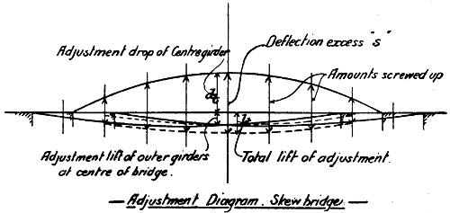
Fig. 74.
In the above treatment of the application of centre
strengthening girders there is a source of error which should
be touched upon. If, under live load, the centre girder
deflects more than the outer girders, as it commonly will,
there must be a want of uniformity in the behaviour of the
cross-girders, those near the abutments being more relieved
than the estimated amount of relief of those at the centre,
which will have less than that intended; but the reduction
of stress in the cross-girders will generally be so considerable
that any such ambiguity of excess or defect is commonly
unimportant; the effect of this also upon the main girders
is much less than might be supposed, being, for the third of
the cases just given, about 21⁄2 per cent. excess for the centre
girder, and generally a much smaller error. With this
qualification, the method can, however, be regarded as
approximate only. It is possible to eliminate some part of
the error by lifting the end cross-girders during adjustment,
a less amount than that given by the diagrams, Figs. 73 and
74, taking care that the centre girder is depressed its full
amount by lifting the centre cross-girders a little more; this
refinement is hardly necessary, and unless controlled by
calculation cannot be depended upon for precise results.
Particulars are here given of five ordinary cases, comparing
the calculated and observed results of adjustment. The
operation of levelling was conducted by a quick-eyed and
capable assistant, who was not made acquainted with the
results expected, in order to avoid any sub-conscious tendency
to match the calculated figures:—
Examples of Centre Girder Adjustments.
| — |
Calculated. |
Observed. |
| |
in. |
in. |
| No. 1.—56-Ft. Span. |
| Depression of centre girder |
·82 |
·84 |
| Lift of cross-girders at centre |
·23 |
·22 |
| Lift of outer girders |
·20 |
·10 and ·13 |
| No. 2.—57-Ft. Span. |
| Depression of centre girder |
·50 |
·50 |
| Lift of cross-girders at centre |
·18 |
·20 |
| Lift of outer girders |
·11 |
·08 and ·10 |
| No. 3.—67-Ft. Span. |
| Depression of centre girder |
·70 |
·75 |
| Lift of cross-girders at centre |
·15 |
·17 |
| Lift of outer girders |
·10 |
·09 |
| No. 4.—68-Ft. Span. |
| Depression of centre girder |
·70 |
·65 |
| Lift of cross-girders at centre |
·20 |
·18 |
| Lift of outer girders |
·13 |
·14 |
| No. 5.—52-Ft. and 28-Ft. Spans continuous. |
| |
Long
Span. |
Short
Span. |
Long
Span. |
Short
Span. |
| |
in. |
in. |
in. |
in. |
| Depression of centre girder |
·28 |
.. |
·29 |
.. |
| Lift of centre girder |
.. |
·04 |
.. |
·03 |
| Lift of cross-girders (centre of spans) |
·17 |
·09 |
·15 |
·13 |
| Lift of outer girders |
·08 |
.. |
·08 |
.. |
| Depression of outer girder |
.. |
·01 |
.. |
negli-
gible. |
The method of calculation adopted for these cases was
not precisely that given, though depending upon the same
broad principles. The first cannot be considered a good
example. The last, having continuous girders, of course
needed special treatment.
Of about seventeen bridges strengthened in the manner
described, the effect generally was satisfactory, in reducing
deflection and vibration; but in two cases of small span,
owing probably to settlement of bedstones, the results were
not so good.
From first to last the work of putting in a centre girder
takes some little time, owing to the slow progress generally
made in fixing the brackets, preparing packings, etc. The
cost of a typical case was about 23 per cent. of the cost of a
new superstructure, with a 30 per cent. relief of stress.
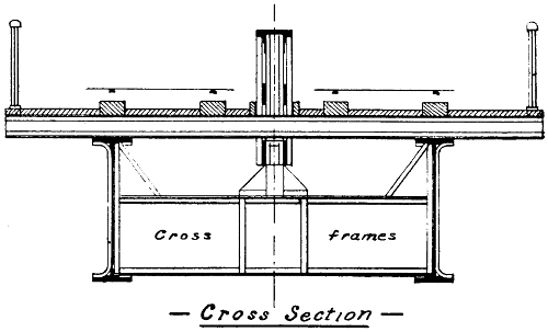
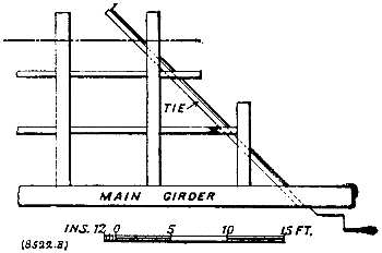
Fig. 75.
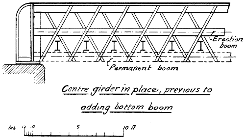
Fig. 76.
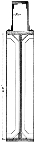
A special case of strengthening by a centre girder, having
considerable interest, may be here referred to. The primary
idea involved was not the author’s. The bridge dealt with
has already been noticed under “Bracing” and a section,
before alteration, shown in Fig. 26. The span being 85
feet, there was no room for a centre girder of sufficient depth
above the cross-girders and between the roads, nor was it
considered economical to place the girder wholly below the
floor, because of the costly staging this would have necessitated
for erection purposes, the height above ground level
being very great. A girder was therefore designed, having
open latticing at an angle of 60 degrees, with a bottom boom
to be below the cross-girders, the top being as high above
the rails as could be permitted (see Figs. 75 and 76). A
temporary boom was arranged at the intersection of diagonals,
the lower boom proper not being fixed till the girder
having been lifted into place, with the diagonal members
passing between the cross-girders, allowed this to be done.
The girder for some time carried itself from bearing to bearing,
with the temporary boom in tension, the deflection being
then 2 inches. The permanent boom was then put in place,
and the girder restored as nearly as was practicable to the
camber it was intended to have when complete, but without
throwing, during the process, any improper loads upon the
old work.
The lower boom being finally riveted up, the cross-girders
were made to bear upon it by suitable packings. There
were, in addition to the new girder, two stiff frames between
the old main girders, to which the new was secured.
The girder was designed with the intention that under
dead load only the cross-girders should just rest, but throw
no weight, upon the new work, the latter assisting to carry
live load only. The floor beams being of small span, and
securely riveted to the old girder tops, the centre girder was
required to deflect, under its share of live load, the same
amount as the old main girders under the remaining portion,
the three points of support of the cross-girders thus not
altering their relative levels. That this resulted was evident
from the fact that, previous to connecting the cross-frames
to the centre-girder, the work being otherwise complete, a
space between the two of about 1⁄2 inch, afterwards filled by
a packing, showed no alteration, the closest measurement
failing to disclose any relative movement upon the passage
of live load. The reduction of vibration was, as might be
expected, very marked.
In the conduct of that class of strengthening work which
has been dealt with in this chapter, it is essential, in the
author’s judgment, that the man responsible for the detailed
calculations and design should himself see the operations of
adjustment carried out, or delegate it only to one equally
familiar with the requirements.
Before dismissing the subject, it will be well to refer to
a method of approximately determining flexure curves, of
occasional use in dealing with centre girder or similar questions.
The figure assumed is plotted to an exaggerated scale,
with which object the actual radius of curvature at points
along the girder’s length are first ascertained by the formula
E × Df × 2 = R, radius of curvature in feet,
and the radius of curvature for the diagram by
12 × R × F2 = r, radius for plotting, in inches
(5)
E being the modulus of elasticity, D the girder’s depth in
feet, f the mean of the extreme flange stresses per square
inch of gross area, and F the fraction indicating scale as 1⁄48,
where 1⁄4 inch = 1 foot. The curve, being plotted, shows by
direct scaling the movement of any point relative to its
original position. Near the ends of the curve where the
radii may be of considerable length, the arcs may be drawn
with the help of template curves, or even set out as pieces of
“straight.”
When the curve is laid down so that its chord equals the
span to scale, the method involves an error of excess in the
resulting deflection or droop which is as much as 7 per cent.
when the mean radius for plotting equals the span as drawn,
or when the droop of curve approaches one-eighth of the
span. As the exaggeration of curvature is made less pronounced,
this error rapidly diminishes, till for a droop of
about one-sixteenth the percentage is one-fourth part of that
above given. This excess in the droop of curve may be
amended by the following expression:—
droop - (droop3chord2
× 3·73) = corrected droop, or deflection.
For some purposes it may be preferable to amend the
radii for plotting, so that the curve, as laid down, shall be
correct, which may be effected by the formula here given, to
be applied to each value of r, as first ascertained:—
r + (chord2
r × ·0625) = corrected plotting radius.
If, however, the length of curve is made equal to the
span (the chord then being less), and the radii for plotting
as given by (5) are used, the result will for most purposes
be sufficiently precise, though there will now be an error of
a contrary kind, which, for a curve having a droop of one-eighth,
will be about 2 per cent. too little. A somewhat
similar method of setting out deflection curves is described
by Professor Fleeming Jenkin in the article “Bridges” of
the “Encyclopædia Britannica,” but without corrections.
A careful comparison of results by the above means, with
those calculated, shows that with good draughtsmanship they
may be relied upon for considerable accuracy. Equally
applicable to girders of varying depth and flange stress,
they have also a limited use in cases of continuity.
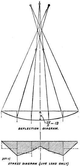
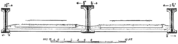
Figs. 77 and 78.
Figs. 77 and 78 illustrate the deflection and stress diagrams
for the cross-girders of the bridge supposed to have
been strengthened by a centre-girder, when under the
influence of live load and a centre reaction of a definite
amount. As a matter of convenience, each radius length
has been halved, before correction, so that the resulting
droop of the curve is twice the true amount.