The following very brief account of the mechanical characteristics
of tanks, it is hoped, will prove sufficiently simple
and complete to give to the non-mechanical reader some idea
of the tank as a machine.
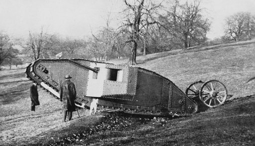
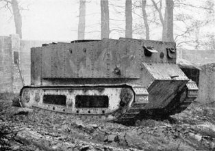
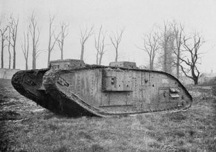
The first British tank made, and to be used, was the heavy
machine, already described in the previous chapter, the
Mark I tank, the general outline of which remained the
standard design for the hulls of all British heavy machines
up to the end of the war. As will be shown later, many
mechanical improvements, making for higher efficiency and
greater simplicity of control, were introduced from time to
time, but the fact remains that the profile of the Mark V
tank of 1918 was to all intents and purposes that of the
Mark I of 1916, and surely this is a striking tribute to the
genius of the designers who, without much previous data
upon which to base their work, produced the parent
weapon.
It is not proposed here to enter upon the general arrangement
of the Mark I tank, but reference to two important
points in design is of interest. The first is that this machine
was fitted with a “tail,” consisting of a pair of heavy large-diameter
wheels, mounted at the rear of the machine upon
a carriage, which was pivoted to the hull in such a manner
that the wheels were free to follow the varying contours of
the ground. A number of strong springs normally kept the
wheels bearing heavily upon the ground, whilst a hydraulic
ram, operated by an oil pump driven from the engine, was
intended to enable the carriage to be rocked upon its axis,
in order to raise the wheels well clear of the ground on
occasions when it was necessary to “swing” the tank.
The object of this “tail” device was to provide means of
steering the machine and, to this end, the driver was provided
with a steering wheel which, operating a wire cable
over a bobbin or drum, altered the path of the “tail”
wheels, and allowed the tank to be steered, under favourable
conditions, through a circle having a diameter of about sixty
yards. The disadvantages of this fitting far outweighed
any virtues it may have possessed. Countless troubles were
experienced with the ram and its pump; the wire steering
cable was constantly stretching or slipping through the
bobbin, thus affecting the “lock” of the tail wheels; the
driver was subjected to great physical strain in overcoming
the tremendous resistance offered by the road wheels; the
whole device was very prone to be damaged by shell-fire in
action. Against these indictments should be recorded the
fact that the possession of a “tail” enabled the Mark I
tank successfully to span and cross a wider trench than the
later “tailless” machines of the same dimensions could
negotiate, owing to the fact that as the wheels supported
the rear of the tank over the point of balance, the risk of
“tail dive” was considerably reduced. However, at the
close of the operations of 1916, all tanks were shorn of their
tails, and no subsequent models were fitted with them.
The second point of interest regarding this early machine
relates to its sponsons. These, on both the male and female
machines (armed with full length 6-pounder and Vickers
machine-guns respectively) were planted upon and bolted
to the walls of the hull and, for entraining purposes, these
had to be removed and carried upon special trolleys which
could be towed behind the tanks. It will readily be seen
that this arrangement involved a considerable amount of
labour, and rendered the process of entraining an extremely
lengthy one; this led to an improved form of sponson being
produced for the Mark IV machine.
The chief outstanding weaknesses of the Mark I machine,
disclosed during the first appearance in action, were:
That the engine was provided with no silencer, consequently
the noise, sparks, and even flames, which proceeded
from the open exhaust pipes, passing through the roof of
the tank, constituted a grave danger during the latter stages
of an approach march. Many ingenious tank crews fitted
to their machines crude types of silencers made out of oil
drums, or adopted the plan of damping out the sparks by
using wet sacks in relays, or covering the exhaust pipe with
clay and mud.
That the observation from the inside of the machine was
bad, and efficient fire control was, therefore, impossible.
That the means provided for entering and leaving the
tank were unsatisfactory, and, in the case of the female
machine, speedy evacuation in the event of fire was difficult.
That the whole of the petrol supply was carried inside
the machine, and in a vulnerable position—a circumstance
which added to the risk of fire in the event of a hit in the
petrol tank by armour-piercing bullet or shell. Furthermore,
gravity was the only means for transferring petrol
from the main petrol tanks in the front of the machine to
the carburetter, and, therefore, it frequently happened
that when a tank “ditched” nose downwards, the petrol
supply was cut off, and consequently the dangerous
practice of “hand-feeding” had to be resorted to.
These machines were produced in small numbers, and
their difference from Mark I lay in various minor improvements,
none of a radical nature.
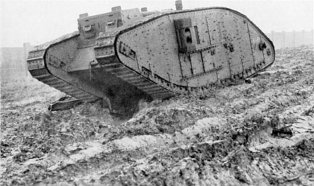
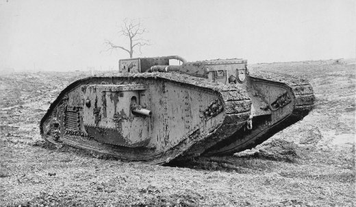
In 1917 this tank became the standard fighting machine
of the Tank Corps, and it was used in battle throughout this
year and the following. As already stated, in outline it
corresponded so closely with the Mark I machine that a study
here of the main features of this tank will serve generally
as an illustration of what had taken place in tank development
up to this date.
The machine was 26 ft. 5 in. long over all, whilst the width
of the female over its sponsons was 10 ft. 6 in., and of the
male, 13 ft. 6 in. The height of the machine was 8 ft. 2 in.,
and its weight, equipped, was 28 tons. The armament
consisted, in the case of the male, of two 6-pounder guns
and four machine-guns, and in that of the female of six
machine-guns; it was fitted with a 105 h.p. Daimler 6-cylinder
sleeve-valve engine which, at a later date, was replaced in a
limited number by one of 125 h.p. This increased power
was obtained by the use of aluminium pistons, twin carburetters,
and by speeding up the engine.
Generally speaking, these engines gave very little trouble,
although somewhat under-powered for the work they had
to perform. They were, it may be added, particularly
suitable from the maintenance point of view, owing to their
“fool-proof” nature, due chiefly to the absence of the usual
poppet-valve gear, with its attendant risk of maladjustment.
Power was transmitted from the engine flywheel, through
a cone-type clutch and a flexible coupling, to a two-speed
and reverse gear-box, known as the primary gear, this being
under the direct control of the driver, who could thus obtain
first and second speeds, or reverse, without other assistance.
The tail-shaft from the gear-box carried a worm which
drove the crown wheel of a large reduction gear, this gear
also serving as a differential to enable the track driving
wheels to rotate at different speeds, as when steering the
tank on its track brakes. A device was provided, under
the driver’s control, for locking the differential when it was
desired to steer a dead-ahead course, or when negotiating
a trench or other obstacle. With the differential locked,
the gear became, so to speak, “solid” and obviated the risk
of one of the tracks slipping in bad ground, a condition very
apt to cause a tank to slip sideways into a trench and become
ditched.
Some trouble was caused through breakages of this locking
muff in the earlier days, but latterly the arrangement was
considerably improved and strengthened.
The gear-box tail-shaft terminated in a brake drum, the
band of which was operated by means of a pedal at the
driver’s foot. It may be of interest to point out here that
the whole of the items so far referred to, i.e. engine, gear-box,
and differential, formed the standard power unit of the
pre-war Foster-Daimler tractor, and thus provided a known
quantity around which the rest of the detail was designed.
This greatly facilitated production.
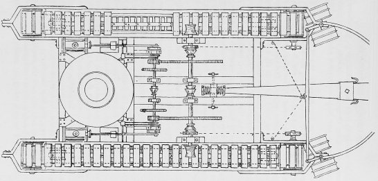
On either side of the differential case projected cross-shafts,
the outer ends of which were supported in bearings
mounted upon the outside wall of the tank, and, between
the inner and outer walls of the hull, two sliding pinions
were carried on a splined portion of the cross-shaft, one pair
of pinions on each of the right and left hand sides of the
tank.
In describing the remainder of the transmission, it will
suffice to deal only with one side of the machine, the detail
on either side being identical.
The sliding pinions, already alluded to, were operated by
means of short levers by two gearsmen, whose sole duty it
was to assist the driver, who signalled to them his requirements
from his seat in the front of the tank, the two gearsmen
being accommodated towards the rear of the machine on
seats placed over the primary gear-box. The sliding pinions
were of two sizes, known as the high-speed and low-speed
pinions, and immediately in their rear was mounted another
pinion assembly, also carrying two gear-wheels of different
dimensions, with which the sliding wheels could be engaged
at will—in other words, on each side of the tank there
existed what were known as secondary gear-boxes, each
offering a choice of two speeds.
Thus it will be seen that the whole arrangement provided
a range of four speeds. Assuming the secondary gears to
be at “low,” the driver had the option of using either first or
second speed by manipulating the control to the primary
gear-box, whilst in order to obtain third or fourth (top)
speed it was necessary for him to signal the gearsmen to alter
their gears to “high,” and to assist them in the process by
a great deal of intelligent clutch work. It need hardly be
pointed out that this arrangement was exceedingly clumsy,
and often involved much loss of time and temper. It might
also be mentioned here that the reverse gear, already alluded
to, was considerably higher than the lowest forward speed,
so that there was little possibility of driving backwards,
clear of any obstruction which might have ditched the tank.
Hand-operated brakes, under the control of the tank
commander in the front of the tank, alongside the driver,
were incorporated with the secondary gear-box. These
brakes, by checking one or other track, enabled the tank to
be steered in some measure with the differential unlocked,
whilst, by locking the differential and placing, say, the right-hand
secondary gear in “neutral,” the machine could be
swung to the right, practically upon its own axis, by applying
the right-hand brake. To swing to the left, the right-hand
secondary gear was engaged, the left-hand being placed
in “neutral,” the differential locked and the left-hand brake
applied.
From the secondary gear-box a Coventry chain transmitted
the power to an assembly, at the rear of the hull,
which carried, on either side of the chain sprocket, two
heavy pinion wheels, in constant mesh with the final sprocket
wheels, which in turn, engaging with the links of the track
plates, drove the hull along the track.
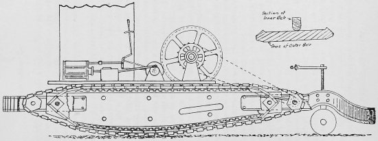
Each track was composed, normally, of ninety plates or
road shoes, the separate plates being coupled together by
means of links (two per plate) and link pins, the links themselves
being recessed so as to engage with the driving wheels
as shown above.
The weight of the machine was carried upon the track
by means of rollers, whilst the track was supported on the
top of the hull by skids or rails.
Adjustment of track was effected by the movement of
an “idler” wheel, which guided the track over the nose of
the hull.
Refinements to the transmission were introduced in the
shape of guards to protect the driving chains from mud,
and also means were provided to lubricate the secondary
gear-wheels with oil. It is recalled that, prior to the introduction
of the chain-guard, the inside deck of the tanks was
often covered with a layer of liquid mud, several inches
deep, carried in by the chains, and delivered through the
secondary gears.
Petrol was supplied to the engine in the earlier days of
the Mark IV machine by a pressure-fed system which gave
a great deal of trouble, and, being also considered dangerous,
was finally discarded in favour of the Autovac system,
which sucked the fuel from the main supply in a tank outside
of the machine and delivered it to the carburetter by gravity.
Cooling of the engine was primarily effected by a copper
envelope radiator, which gave some trouble and was finally
superseded by a tubular type.
An efficient silencer, with a long exhaust pipe carried
right to the rear of the machine, considerably reduced engine
noise and rendered the approach march a far less hazardous
undertaking than was the case with the earlier models.
Sponsons were designed to collapse into the interior of
the machine when necessary, and the cumbersome practice
of detaching them from the hull came to an end. Short
6-pounder guns were introduced to render this change
possible.
Detachable “spuds,” to provide a grip for the tracks on
difficult soil, were first introduced for this machine, as also
was a highly efficient unditching gear. The latter consisted
of a beam, rather longer than the overall width of the tank
hull, which was fastened by clips and chains to each track,
and, in passing round under the machine, actually took a
purchase from the obstruction under the belly of the tank.
Detail improvements to give easier entrance and more
rapid egress in case of emergency, as well as better and safer
vision and fire control, were also introduced.
With the introduction of the Mark V tank, which represents
the standard British heavy tank of to-day, great
progress was made in all-round speed, ease of manœuvre,
radius of action, simplicity of control and feasibility of
observation.
The dimensions and weight of this tank were approximately
the same as those of the Mark IV, whilst the design
of the hull still closely followed the lines of the original
Mark I. Equipped with the 150 h.p. Ricardo 6-cylinder
poppet-valved engine, specially designed for tank work,
the advent of the Mark V machine called for the introduction
of new courses of instruction for the personnel of the Corps,
very few of either officers or other ranks having, at this
time, any experience of the care and adjustment of the valve
gear.
This Ricardo engine, of somewhat unorthodox design,
was highly efficient and, with proper care and attention, gave
very little trouble. From the engine, power was transmitted
through a plate clutch in the flywheel to a four-speed
gear-box, immediately in rear of which was the reverse
gear, providing “reverse” on all speeds. The cross-shaft,
incorporated with the reverse gear, carried at either end
(in the same relative position as the secondary gears, explained
in dealing with the Mark IV machine) an epicyclic gear.
It is not within the scope of this chapter to describe this
gear in detail, but it may be regarded as serving the double
purpose of a reduction gear and clutch, combined in one
unit.
From these epicyclic gears, the transmission of the drive
through to the tracks followed the principle of the Mark IV
machine, except that there was no second-line pinion assembly
as in the secondary gear of the earlier tank, the Coventry
chain on the Mark V passing direct from the single-unit
epicyclic gear to the pinion assembly operating the track
driving wheels.
All the items enumerated above were under the direct
control of the driver, who was therefore enabled to perform,
single-handed, all the operations which previously required
the work of four men. Hand levers controlled the epicyclic
gears, primary gear-box, and reverse gear, whilst the clutch
and gear were foot-operated.
To steer the tank at any speed, the driver had merely
to raise the epicyclic gear lever on the side on which he wished
to turn. This had the effect of interrupting the drive to
that track, so that, being driven by the remaining track,
the machine would turn upon the “idle” side.
Where a sharp “swing” was necessary, application of the
foot brake would automatically check the “idle” track,
this being allowed for by means of a single compensating link
motion with which the controls were interconnected.
The engine was petrol-fed by the autovac system, as fitted
to the later Mark IV machines. Cooling of the engine was
effected by means of a tubular type radiator, the water
therein being itself cooled by air drawn from outside the
tank, through louvres in the left-hand wall of the hull, and
finally expelled through similar louvres in the right-hand wall.
Further, the engine was completely enclosed in a sheet-iron
casing, from which the hot foul air was exhausted through
the roof of the tank by means of a Keith fan.
The Mark V armament corresponded with that of the
Mark IV, whilst the sponsons were of similar design to those
fitted to the latter type.
The absence of the large differential gear, as fitted on the
earlier models, gave accommodation for a machine-gun in
the rear wall of the tank, and also allowed for large entrance
doors in the back portion of the roof.
A greatly improved type of rear cab was fitted, and thus
provided excellent all-round vision, and also rendered
possible the fitting of the unditching beam to the tracks
from the inside of the machine. This was accomplished
through the side flaps of the rear cab of the Mark V, whereas
on previous models it had been necessary for members of
the crew to expose themselves to hostile fire, in the event
of the tank becoming ditched in action, as the beam could
only be attached and detached from outside.
CHARACTERISTICS OF BRITISH TANKS USED DURING THE GREAT WAR
| Characteristics. |
Mark I. |
Mark IV. |
Mark V. |
Mark V star. |
Medium Mark A. |
Guncarrier. |
| Male. |
Female. |
Male. |
Female. |
Male. |
Female. |
Male. |
Female. |
| Length with Tail |
32′ 6″ |
32′ 6″ |
|
|
|
|
|
|
|
43′0″ |
| Length without Tail |
26′ 5″ |
26′ 5″ |
26′5″ |
26′5″ |
26′5″ |
26′5″ |
32′5″ |
32′5″ |
20′0″ |
30′0″ |
| Width |
13′ 9″ |
13′ 9″ |
13′6″ |
10′6″ |
13′6″ |
10′6″ |
13′6″ |
10′6″ |
8′7″ |
11′0″ |
| Height |
8′05″ |
8′05″ |
8′2″ |
8′2″ |
8′8″ |
8′8″ |
8′8″ |
8′8″ |
9′0″ |
9′4″ |
| Weight, equipped |
28 tons |
27 tons |
28 tons |
27 tons |
29 tons |
28 tons |
33 tons |
32 tons |
14 tons |
34 tons |
| Crew |
1 officer
7 O.R. |
1 officer
7 O.R. |
1 officer
7 O.R. |
1 officer
7 O.R. |
1 officer
7 O.R. |
1 officer
7 O.R. |
1 officer
7 O.R. |
1 officer
7 O.R. |
1 officer
2 O.R. |
1 officer
3 O.R. |
| Armament |
2 6-pdrs. and 4 Hotchkiss guns |
5 M.G.s and 1 Hotchkiss gun |
2 6-pdrs. and 4 Lewis guns |
6 Lewis guns |
2 6-pdrs. and 4 Hotchkiss guns |
6 Hotchkiss guns |
2 6-pdrs. and 4 Hotchkiss guns |
6 Hotchkiss guns |
4 Hotchkiss guns |
1 Lewis gun |
| Engine |
105 h.p. Daimler |
105 h.p. Daimler |
105 h.p. Daimler |
105 h.p. Daimler |
150 h.p. Ricardo |
150 h.p. Ricardo |
150 h.p. Ricardo |
150 h.p. Ricardo |
2 Tyler, 45 h.p. each |
105 h.p. Daimler |
| Maximum Speed |
3.7 m.p.h. |
3.7 m.p.h. |
3.7 m.p.h. |
3.7 m.p.h. |
4.6 m.p.h. |
4.8 m.p.h. |
4.0 m.p.h. |
4.0 m.p.h. |
8.3 m.p.h. |
3.0 m.p.h. |
| Average Speed |
2.0 m.p.h. |
2.0 m.p.h. |
2.0 m.p.h. |
2.0 m.p.h. |
3.0 m.p.h. |
3.0 m.p.h. |
2.5 m.p.h. |
2.5 m.p.h. |
5.0 m.p.h. |
1.75 m.p.h. |
| Radius of Action |
Hours 6.2, miles 12 |
Hours 6.2, miles 12 |
Hours 7.5, miles 15 |
Hours 7.5, miles 15 |
Hours 9.0, miles 25 |
Hours 9.0, miles 25 |
Hours 7.5, miles 18 |
Hours 7.5,miles 18 |
Hours 10.0, miles 40 |
Hours 7.5, miles 15 |
| Spanning Power |
11′6″ |
11′6″ |
10′0″ |
10′0″ |
10′0″ |
10′0″ |
14′0″ |
14′0″ |
7′0″ |
11′6″ |
Note.—(i) The Mark V star tank could carry twenty men in addition to its crew.
(ii) The Gun-carrier could carry 10 tons weight of stores.
(iii) Radii of Action are only approximate; they depend on the nature of the ground, efficiency of the crew, etc.
The Mark V star machine was 6 ft. longer than the Mark V,
and the weight of the male, equipped, was approximately
33 tons. There was no change in the nature of the armament,
or in the number of the crew, which consisted of eight
all told. In addition to the crew, the machine was capable
of carrying twenty to twenty-five other troops and would
cross a 14 ft. trench, as against 10 ft. for the Mark V.
The general mechanical arrangement of this tank corresponded
with that of the Mark V, the same engine and transmission
system being adopted, with the addition of a Cardan
shaft between the flywheel and gear-box, which was rendered
necessary by the additional length of the machine.
The Mark V star was relatively slow to manœuvre, owing
chiefly to the amount of track-bearing surface on the ground.
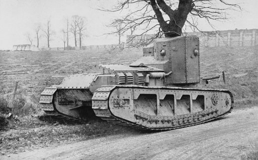
The Medium A tank, known also as the “Chaser” and
“Whippet,” was the British standard light-type machine,
and it differed altogether from its heavier relatives. Its
weight, equipped, was about 14 tons, whilst it was 20 ft.
long, 9 ft. high, and 8 ft. 7 in. wide, carrying a crew of three.
It could attain a maximum speed of about 8·3 m.p.h., and
could span a trench approximately 7 ft. in width.
On this machine the tracks were not carried “overhead”
as in the case of the heavy tanks, but the two trackways
existed as such only, and formed the road members of what
may be described as the chassis upon which the engine-room
and fighting cab were mounted. There were no
sponsons, and the tank was driven and fought from the cab
at the rear of the machine, provision being allowed for an
armament of three machine-guns.
Each machine was fitted with two 45 h.p. 4-cylinder
Tyler engines with an autovac petrol feed, and cooled by
means of a tubular radiator provided with two fans driven
by chains from each crankshaft.
The power of each engine was transmitted through separate
cone clutches, leather flexible couplings, and four-speed
and reverse gear-boxes, to a casing, at the rear of the machine,
containing two worm gears.
The two worm-wheel shafts of these gears were in line,
with their inner ends nearly touching, and each carrying
the keyed-on half of a jawed coupling, one of which could
be slid along at will, to engage with the other, thus locking
the two shafts together.
One of the shafts carried a friction-clutch arrangement,
designed to limit the power transmitted from one shaft to
the other to about 12 h.p.
It will be seen, therefore, that either worm-wheel shaft
could be driven independently by its own engine, or the
two could be locked together so as to rotate at the same
speed, driving the tank straight ahead, provided that there
was not more than 12 h.p. difference between the developed
powers of the engines. Extensions of each worm shaft
carried a band brake, as well as a fan for forcing air into the
cab of the machine.
Returning to the details of the transmission system,
each cross-shaft from the worm case terminated in a “driving
chain pinion shaft,” the outer ends of which were supported
by ball bearings mounted upon the sides of the track frames.
The chain pinion carried by this shaft transmitted the drive,
through a roller chain, to the final track-driving wheels,
which, engaging with the slots in the track links, drove
the tank along the track. Each track consisted normally
of sixty-seven plates or shoes, and rollers served to support
the weight of the tank upon the track, as well as to carry
the track over the top of the trackway. Adjustment of the
track was effected by movement of the front “idler” wheel
as in the case of the heavier machines.
The Whippet tank called for particular skill in driving, and
a great deal of practice was usually necessary to produce a
really efficient driver. “Stalling” of one or both engines
was a common occurrence during the earlier stages of training.
Steering was effected by varying the speed of either
engine, and the radius of movement was proportional to
the difference in the speed of the two engines, this difference
being controlled by means of a steering wheel connected to
the two carburetter throttles, movement of the wheel producing
acceleration of one engine and deceleration of the
other simultaneously.
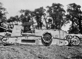
Originally designed for carrying a 60-pounder gun or 6-in.
howitzer and ammunition into action, these machines during
1918 were chiefly used for the transport of supplies across
country. The engine, a 6-cylinder 105 h.p. Daimler, was
placed right at the rear of the machine, and the general
lay-out of the transmission corresponded with that of the
Mark IV modified to suit the engine position, the primary
and secondary gears, etc., being mounted forward of the
engine in the case of this G.C. tank. The final drive to the
track was at the rear, and exactly followed the Mark IV
practice, whilst the track itself was carried on track frames,
in this respect somewhat resembling the Medium A machine.
Four men were required to control the G.C. tank, the
driver and brakesman being separately housed in two small
independent cabs mounted one over each track towards
the front of the machine, whilst the secondary gearsmen
travelled in the body of the machine.
A system of signalling by signs from driver to other members
of the crew was adopted.
Situated between the inner walls of the hull at the front
of the tank was a “skid” or platform which could be
drawn out, and its front lowered to the ground, forming an
inclined runway up which the gun was hauled, by means
of a winding gear operated from the engine, to its travelling
position on the machine.
Drums for carrying ammunition for the guns were supported
on platforms over the tracks immediately in rear
of the two control cabs.
The first G.C. tanks were fitted with “tails,” similar to
those on the Mark I machines, but these were later on discarded.
The above includes the brief mechanical summary of the
various types of British tanks used during the Great War,
and though, undoubtedly, the future will bring with it many
improvements and may radically change the whole form of
the present-day tank, it is doubted if ever, in the whole
history of mechanics—let alone warfare, a novel machine
has been produced which has proved so efficient on first use
and required in the long run of two years of war so few
changes.