While the steam turbine is simple in design and
construction and does not require constant tinkering
and adjustment of valve gears or taking up of wear
in the running parts, it is like any other piece of fine
machinery in that it should receive intelligent and
careful attention from the operator by inspection of
the working parts that are not at all times in plain
view. Any piece of machinery, no matter how simple
and durable, if neglected or abused will in time come
to grief, and the higher the class of the machine the
more is this true.
Any engineer who is capable of running and intelligently
taking care of a reciprocating engine can run
and take care of a turbine, but if he is to be anything
more than a starter and stopper, it is necessary that
he should know what is inside of the casing, what must
be done and avoided to prevent derangement, and to
keep the machine in continued and efficient operation.
In the steam turbine the steam instead of being
expanded against a piston is made to expand against
and to get up velocity in itself. The jet of steam is
then made to impinge against vanes or to react against
the moving orifice from which it issues, in either of
which cases its velocity and energy are more or less
completely abstracted and appropriated by the revolving
member. The Parsons turbine utilizes a
combination of these two methods.
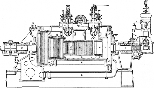
FIG. 34
Fig. 34 is a sectional view of the standard Westinghouse-Parsons
single-flow turbine. A photograph of
the rotor R R R is reproduced in Fig. 35, while in Fig.
36 a section of the blading is shown upon a larger
scale. Between the rows of the blading upon the
rotor extend similar rows of stationary blades attached
to the casing or stator. The steam entering at A
(Fig. 34), fills the circular space surrounding the rotor
and passes first through a row of stationary blades, 1
(Fig. 37), expanding from the initial pressure P to
the slightly lower pressure P1, and attaining by that
expansion a velocity with which it is directed upon
the moving blade 2. In passing through this row of
blades it is further expanded from pressure P1 to P2
and helps to push the moving blades along by the reaction
of the force with which it issues therefrom. Impinging
upon the second row of stationary blades 3,
the direction of flow is diverted so as to make it impinge
at a favorable angle upon the second row of
revolving blades 4, and the action is continued until
the steam is expanded to the pressure of the condenser
or of the medium into which the turbine finally
exhausts. As the expansion proceeds, the passages
are made larger by increasing the length of the blades
and the diameter of the drums upon which they are
carried in order to accommodate the increasing volume.
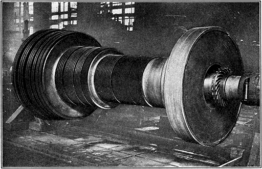
FIG. 35
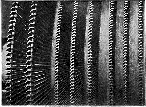
FIG. 36
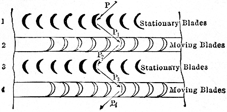
FIG. 37
It is not necessary that the blades shall run close
together, and the axial clearance, that is the space
lengthwise of the turbine between the revolving and
the stationary blades, varies from 1/8 to 1/2 inch; but in
order that there may not be excessive leakage over
the tops of the blades, as shown, very much exaggerated,
in Fig. 38, the radial clearance, that is, the clearance
between the tops of the moving blades and the
casing, and between the ends of the stationary blades
and the shell of the rotor, must be kept down to the
lowest practical amount, and varies, according to the
size of the machine and length of blade, from about
0.025 to 0.125 of an inch.
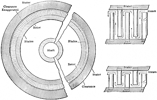
FIG. 38
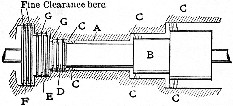
In the passage A (Fig. 34) exists the initial pressure;
in the passage B the pressure after the steam
has passed the first section or diameter of the rotor;
in the passage C after it has passed the second section.
The pressure acting upon the exposed faces
of the rows of vanes would crowd the rotor to the
left. They are therefore balanced by pistons or
"dummies" P P P revolving with the shaft and exposing
in the annular spaces B1 and C1 the same areas
as those of the blade sections which they are designed
to balance. The same pressure is maintained in B1
as in B, and in C1 as in C by connecting them with
equalizing pipes E E. The third equalizing pipe
connects the back or right-hand side of the largest dummy
with the exhaust passage so that the same pressure
exists upon it as exists upon the exhaust end of the
rotor. These dummy pistons are shown at the near
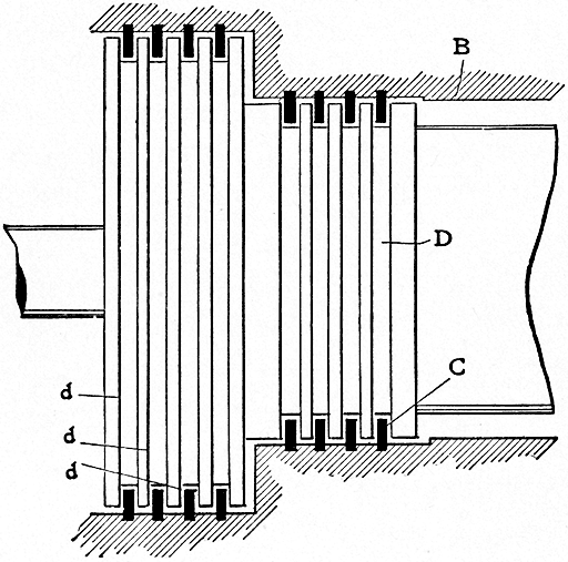
end of the rotor in Fig. 35. They are grooved so as
to form a labyrinth packing, the face of the casing
against which they run being grooved and brass strips
inserted, as shown in Fig. 39. The dummy pistons
prevent leakage from A, B1 and C1 to the condenser,
and must, of course, run as closely as practicable to
the rings in the casing, the actual clearance being
from about 0.005 to 0.015 of an inch, again depending
on the size of the machine.
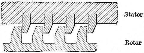
FIG. 39
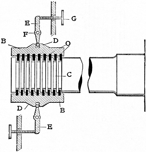
The axial adjustment is controlled by the device
shown at T in Fig. 34 and on a larger scale in Fig. 40.
The thrust bearing consists of two parts, T1 T2.
Each consists of a cast-iron body in which are placed brass
collars. These collars fit into grooves C, turned in
the shaft as shown. The halves of the block are
brought into position by means of screws S1 S2 acting
on levers L1 L2 and mounted in the bearing pedestal
and cover. The screws are provided with graduated
heads which permit the respective halves of the thrust
bearing to be set within one one-thousandth of an inch.
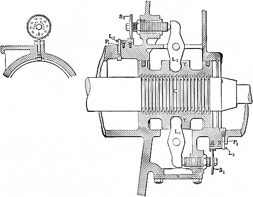
FIG. 40
The upper screw S2 is set so that when the rotor
exerts a light pressure against it through the thrust
block and lever the grooves in the balance pistons are
just unable to come in contact with the dummy strips
in the cylinder. The lower screw S1 is then adjusted
to permit about 0.008 to 0.010 of an inch freedom
for the collar between the grooves of the thrust bearing.
These bearings are carefully adjusted before the
machine leaves the shop, and to prevent either accidental
or unauthorized changes of their adjustment
the adjusting screw heads are locked by the method
shown in Fig. 40. The screw cannot be revolved
without sliding back the latch L3. To do this the pin
P4 must be withdrawn, for which purpose the bearing
cover must be removed.
In general this adjustment should not be changed
except when there has been some wear of the collars
in the thrust bearing; nevertheless, it is a wise precaution
to go over the adjustment at intervals. The
method of doing this is as follows: The machine should
have been in operation for some time so as to be well
and evenly heated and should be run at a reduced
speed, say 10 per cent. of the normal, during the actual
operation of making the adjustment. Adjust
the upper screw which, if tightened, would push
the spindle away from the thrust bearing toward the
exhaust. Find a position for this so that when the
other screw is tightened the balance pistons can just
be heard to touch, and so the least change of position
inward of the upper screw will cause the contact to
cease. To hear if the balance pistons are touching,
a short piece of hardwood should be placed against
the cylinder casing near the balance piston. If the
ear is applied to the other end of the piece of
wood the contact of the balance pistons can be very
easily detected. The lower screw should then be
loosened and the upper screw advanced from five
to fifteen one-thousandths, according to the machine,
at which position the latter may be considered to be
set. The lower screw should then be advanced until
the under half of the thrust bearing pushes the rotor
against the other half of the thrust bearing, and from
this position it should be pushed back ten or more
one-thousandths, to give freedom for the rotor between
the thrusts, and locked. A certain amount of
care should be exercised in setting the dummies, to
avoid straining the parts and thus obtain a false
setting.
The object in view is to have the grooves of the balance
pistons running as close as possible to the collars
in the cylinder, but without danger of their coming
in actual contact, and to allow as little freedom as
possible in the thrust bearing itself, but enough to be
sure that it will not heat. The turbine rotor itself
has scarcely any end thrust, so that all the thrust
bearing has to do is to maintain the above-prescribed
adjustment.
The blades are so gaged that at all loads the rotor
has a very light but positive thrust toward the running
face of the dummy strips, thus maintaining the proper
clearance at the dummies as determined by the setting
of the proper screw adjustment.
The bearings which support the rotor are shown
at F F in Fig. 34 and in detail in Fig. 41. The bearing
proper consists of a brass tube B with proper oil
grooves. It has a dowel arm L which fits into a corresponding
recess in the bearing cover and which prevents
the bearing from turning. On this tube are
three concentric tubes, C D E, each fitting over the
other with some clearance so that the shaft is free to
move slightly in any direction. These tubes are held
in place by the nut F, and this nut, in turn, is held by
the small set-screw G. The bearing with the surrounding
tubes is placed inside of the cast-iron shell A,
which rests in the bearing pedestal on the block and
liner H. The packing ring M prevents the leakage
of oil past the bearing. Oil enters the chamber at
one end of the bearing at the top and passes through
the oil grooves, lubricating the journal, and then out
into the reservoir under the bearing. The oil also
fills the clearance between the tubes and forms a
cushion, which dampens any tendency to vibration.
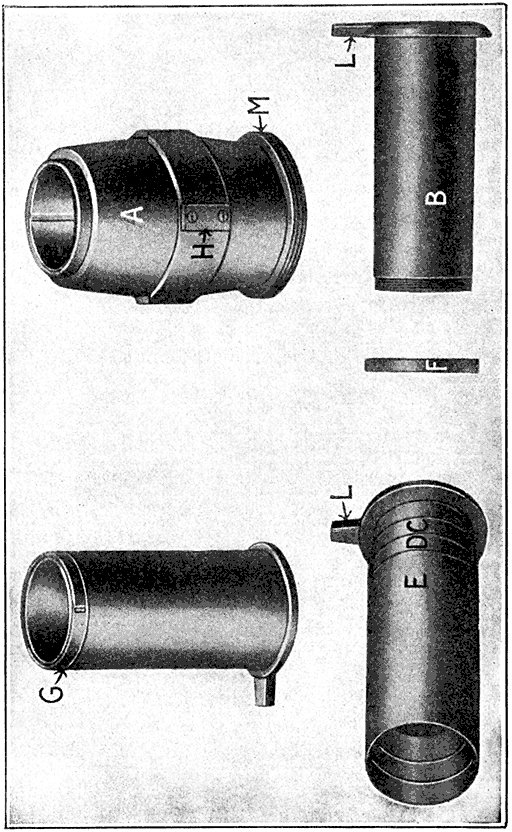
FIG. 41
The bearings, being supported by the blocks or
"pads" H, are self-alining. Under these pads are
liners 5, 10, 20, and 50 thousandths in thickness. By
means of these liners the rotor may be set in its proper
running position relative to the stator. This operation
is quite simple. Remove the liners from under
one bearing pad and place them under the opposite
pad until a blade touch is obtained by turning the
rotor over by hand. After a touch has been obtained
on the top, bottom, and both sides, the total radial
blade clearance will be known to equal the thickness
of the liners transferred. The position of the rotor
is then so adjusted that the radial blade clearance is
equalized when the turbine is at operating temperature.
On turbines running at 1800 revolutions per minute
or under, a split babbitted bearing is used, as shown in
Figs. 42a and 42b.
These bearings are self-alining and
have the same liner adjustment as the concentric-sleeve
bearings just described. Oil is supplied through
a hole D in the lower liner pad, and is carried to the
oil groove F through the tubes E E. The oil flows
from the middle of this bearing to both ends instead
of from one end to the other, as in the other type.
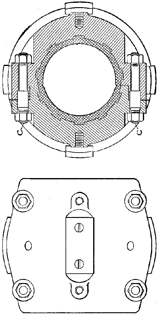
FIG. 42A
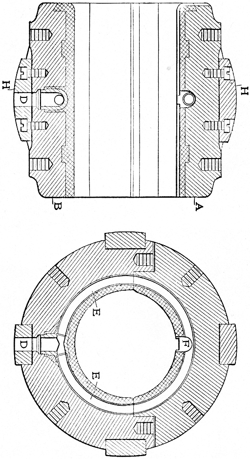
FIG. 42B
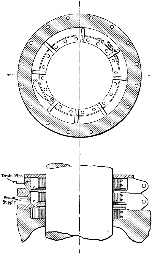
Where the shaft passes through the casing at either
end it issues from a chamber in which there exists a
vacuum. It is necessary to pack the shaft at these
points, therefore, against the atmospheric pressure,
and this is done by means of a water-gland packing
W W (Fig. 34). Upon the shaft in Fig. 35, just in
front of the dummy pistons, will be seen a runner of
this packing gland, which runner is shown upon a
larger scale and from a different direction in Fig. 43.
To get into the casing the air would have to enter
the guard at A (Fig. 44), pass over the projecting rings
B, the function of which is to throw off any water
which may be creeping along the shaft by centrifugal
force into the surrounding space C, whence it escapes
by the drip pipe D, hence over the five rings of the
labyrinth packing E and thence over the top of the
revolving blade wheel, it being apparent from Fig. 43
that there is no way for the air to pass by without
going up over the top of the blades; but water is
admitted to the centrally grooved space through the
pipe shown, and is revolved with the wheel at such
velocity that the pressure due to centrifugal force
exceeds that of the atmosphere, so that it is impossible
for the air to force the water aside and leak in over
the tips of the blades, while the action of the runner
in throwing the water out would relieve the pressure
at the shafts and avoid the tendency of the water
to leak outward through the labyrinth packing either
into the vacuum or the atmosphere.
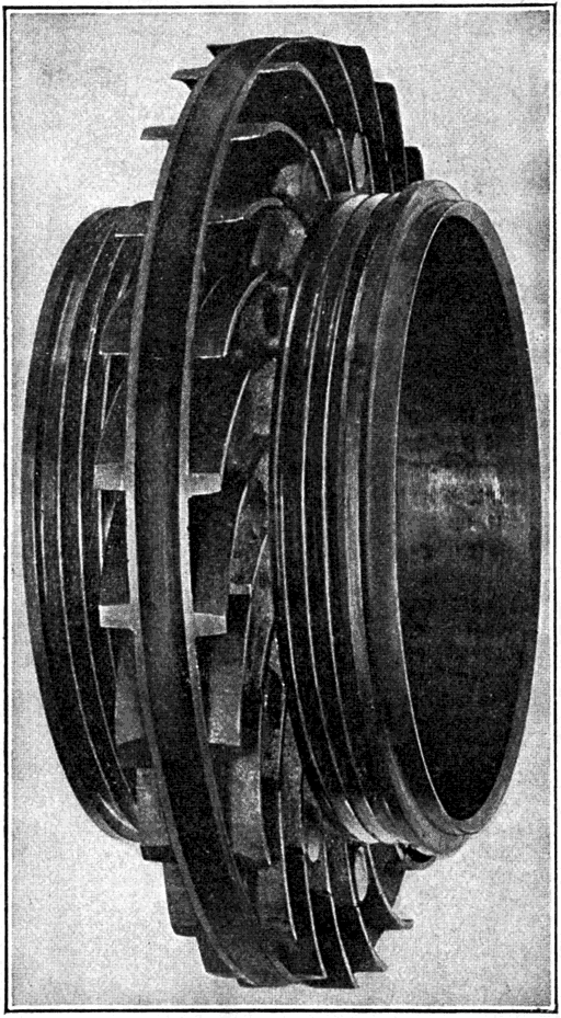
FIG. 43
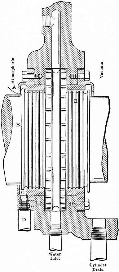
FIG. 44
The water should come to the glands under a head
of about 10 feet, or a pressure of about 5 pounds,
and be connected in such a way that this pressure
may be uninterruptedly maintained. Its temperature
must be lower than the temperature due to the
vacuum within the turbine, or it will evaporate readily
and find its way into the turbine in the form of steam.
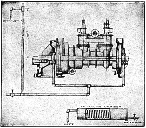
FIG. 45
In any case a small amount of the steaming water
will pass by the gland collars into the turbine, so that
if the condensed steam is to be returned to the boilers
the water used in the glands must be of such character
that it may be safely used for feed water. But
whether the water so used is to be returned to the
boilers or not it should never contain an excessive
amount of lime or solid matter, as a certain amount
of evaporation is continually going on in the glands
which will result in the deposit of scale and require
frequent taking apart for cleaning.
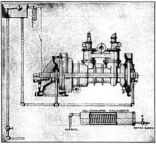
FIG. 46
When there is an ample supply of good, clean
water the glands may be packed as in Fig. 45, the
standpipe supplying the necessary head and the supply
valve being opened sufficiently to maintain a small
stream at the overflow. When water is expensive
and the overflow must be avoided, a small float
may be used as in Fig. 46, the ordinary tank used
by plumbers for closets, etc., serving the purpose
admirably.
When the same water that is supplied to the glands
is used for the oil-cooling coils, which will be
described in detail later, the coils may be attached to
either of the above arrangements as shown in Fig. 47.
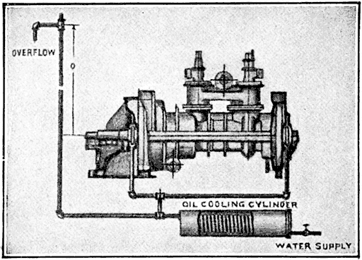
FIG. 47
When the only available supply of pure water is
that for the boiler feed, and the condensed steam is
pumped directly back to the boiler, as shown in Fig.
48, the delivery from the condensed-water pumps
may be carried to an elevation 10 feet above the axis
of the glands, where a tank should be provided of
sufficient capacity that the water may have time to
cool considerably before being used. In most of
these cases, if so desired, the oil-cooling water may
come from the circulating pumps of the condenser,
provided there is sufficient pressure to produce circulation,
as is also shown in Fig. 48.
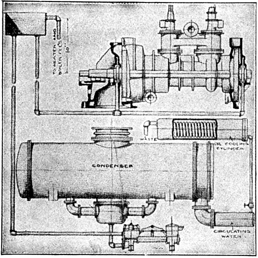
FIG. 48
When the turbine is required to exhaust against a
back pressure of one or two pounds a slightly different
arrangement of piping must be made. The water
in this case must be allowed to circulate through the
glands in order to keep the temperature below 212
degrees Fahrenheit. If this is not done the water
in the glands will absorb heat from the main castings
of the machine and will evaporate. This evaporation
will make the glands appear as though they were
leaking badly. In reality it is nothing more than
the water in the glands boiling, but it is nevertheless
equally objectionable. This may be overcome by
the arrangement shown in Fig. 49, where two connections
and valves are furnished at M and N, which
drain away to any suitable tank or sewer. These
valves are open just enough to keep sufficient circulation
so that there is no evaporation going on, which
is evidenced by steam coming out as though the
glands were leaking. These circulating valves may
be used with any of the arrangements above described.
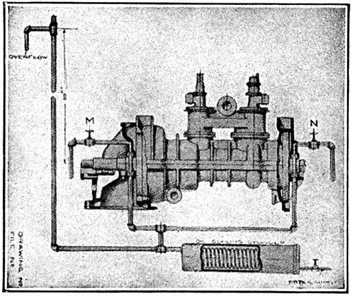
FIG. 49
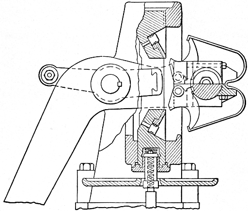
On the right-hand end of the main shaft in Fig. 34
there will be seen a worm gear driving the governor.
This is shown on a larger scale at A (Fig. 50). At
the left of the worm gear is a bevel gear driving the
spindle D of the governor, and at the right an eccentric
which gives a vibratory motion to the lever F.
The crank C upon the end of the shaft operates the
oil pump. The speed of the turbine is controlled by
admitting the steam in puffs of greater or less duration
according to the load. The lever F, having its
fulcrum in the collar surrounding the shaft, operates
with each vibration of the eccentric the pilot valve.
The valve is explained in detail later.
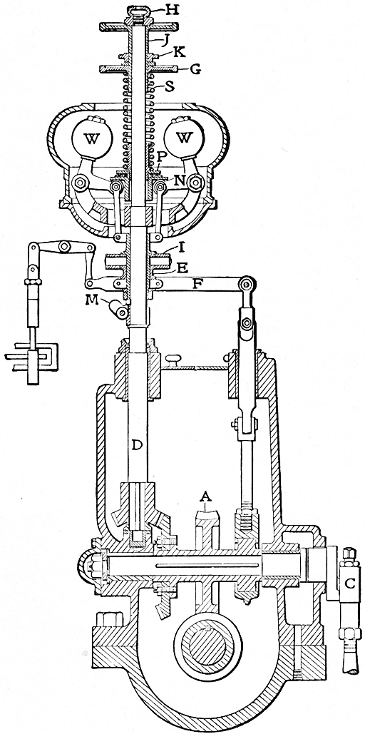
FIG. 50
This form of governor has been superseded by an
improved type, but so many have been made that it
will be well to describe its construction and adjustment.
The two balls W W (Fig. 50) are mounted
on the ends of bell cranks N, which rest on knife edges.
The other end of the bell cranks carry rollers upon
which rest a plate P, which serves as a support for
the governor spring S. They are also attached by
links to a yoke and sleeve E which acts as a fulcrum
for the lever F. The governor is regulated by means
of the spring S resting on the plate P and compressed
by a large nut G on the upper end of the governor
spindle, which nut turns on a threaded quill J, held
in place by the nut H on the end of the governor
spindle and is held tight by the lock-nut K. To
change the compression of the spring and thereby the
speed of the turbine the lock-nut must first be loosened
and the hand-nut raised to lower the speed or
lowered to raise the speed as the case may be. This
operation may be accomplished while the machine
is either running or at rest.
The plate P rests upon ball bearings so that by
simply bringing pressure to bear upon the hand-wheel,
which is a part of the quill J, the spring and lock-nut
may be held at rest and adjusted while the rest of
the turbine remains unaffected. Another lever is
mounted upon the yoke E on the pin shown at I, the
other end of which is fastened to the piston of a dash-pot
so as to dampen the governor against vibration.
Under the yoke E will be noticed a small trigger M
which is used to hold the governor in the full-load
position when the turbine is at rest.
The throwing out of the weights elevates the sleeve
E, carrying with it the collar C, which is spanned by
the lever F upon the shaft H. The later turbines are
provided with an improved form of governor operating
on the same principle, but embodying several important
features. First, the spindle sleeve is integral
with the governor yoke, and the whole rotates about
a vertical stationary spindle, so that two motions are
encountered—a rotary motion and an up and down
motion, according to the position taken by the governor.
This spiral motion almost entirely eliminates
the effect of friction of rest, and thereby enhances the
sensitiveness of the governor. Second, the governor
weights move outward on a parallel motion opposed
directly by spring thrust, thus relieving the fulcrum
entirely of spring thrust. Third, the lay shaft driving
the governor oil pump and reciprocator is located
underneath the main turbine shaft, so that the rotor
may be readily removed without in the least disturbing
the governor adjustment.
The valve-gear is shown in section in Fig. 51, the
main admission being shown at V1 at the right, and
the secondary V2 at the left of the steam inlet. The
pilot valve F receives a constant reciprocating motion
from the eccentric upon the layshaft of the turbine
through the lever F (Fig. 50). These reciprocations
run from 150 to 180 per minute. The space beneath
the piston C is in communication with the large steam
chest, where exists the initial pressure through the
port A; the admission of steam to the piston C being
controlled by a needle valve B. The pilot valve
connects the port E, leading from the space beneath
the piston to an exhaust port I.
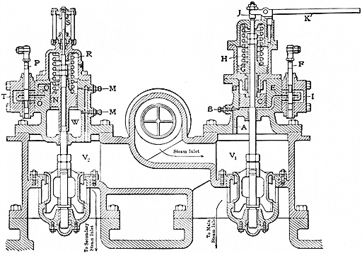
FIG. 51
When the pilot valve is closed, the pressures can
accumulate beneath the piston C and raise the main
admission valve from its seat. When the pilot valve
opens, the pressure beneath the piston is relieved and
it is seated by the helical spring above. If the fulcrum
E (Fig. 50) of the lever F were fixed the admission
would be of an equal and fixed duration. But
if the governor raises the fulcrum E, the pilot valve
F (Fig. 51) will be lowered, changing the relations
of the openings with the working edges of the ports.
The seating of the main admission valve is cushioned
by the dashpot, the piston of which is shown
in section at G (Fig. 51). The valve may be opened
by hand by means of the lever K, to see if it is
perfectly free.
The secondary valve is somewhat different in its
action. Steam is admitted to both sides of its actuating
piston through the needle valves M M, and the
chamber from which this steam is taken is connected
with the under side of the main admission valve, so
that no steam can reach the actuating piston of the
secondary valve until it has passed through the primary
valve. When the pilot valve is closed, the
pressures equalize above and below the piston N and
the valve remains upon its seat. When the load
upon the turbine exceeds its rated capacity, the pilot
valve moves upward so as to connect the space above
the piston with the exhaust L, relieving the pressure
upon the upper side and allowing the greater pressure
below to force the valve open, which admits steam
to the secondary stage of the turbine.
It would do no good to admit more steam to the
first stage, for at the rated capacity that stage is
taking all the steam for which the blade area will
afford a passage. The port connecting the upper
side of the piston N with the exhaust may be permanently
closed by means of the hand valve Q, to
be found on the side of the secondary pilot valve
chest, thus cutting the secondary valve entirely out
of action. No dashpot is necessary on this valve,
the compression of the steam in the chamber W by
the fall of the piston being sufficient to avoid shock.
The timing of the secondary valve is adjusted by
raising or lowering the pilot valve by means of the
adjustment provided. It should open soon enough
so that there will not be an appreciable drop in speed
before the valve comes into play. The economy of
the machine will be impaired if the valve is allowed
to open too soon.
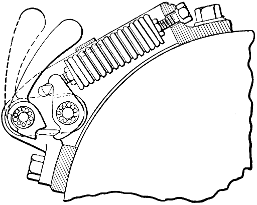
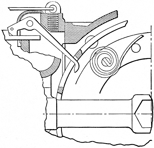
This device is mounted on the governor end of the turbine
shaft, as shown in Figs. 52 and 53.
When the speed
reaches a predetermined limit, the plunger A, having
its center of gravity slightly displaced from the center
of rotation of the shaft, is thrown radially outward
and strikes the lever B. It will easily be understood
that when the plunger starts outward, the resistance
of spring C is rapidly overcome, since the centrifugal
force increases as the square of the radius, or in this
case the eccentricity of the center of gravity relative
to the center of rotation. Hence, the lever is struck
a sharp blow. This releases the trip E on the outside
of the governor casing, and so opens the steam valve
F, which releases steam from beneath the actuating
piston of a quick-closing throttle valve, located in the
steam line. Thus, within a period of usually less than
one second, the steam is entirely shut off from the
turbine when the speed has exceeded 7 or 8 per cent
of the normal.
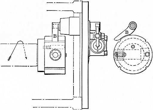
FIG. 52
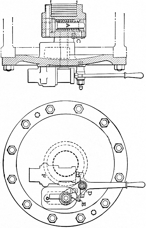
FIG. 53
Mounted on the end of the bedplate is the oil pump,
operated from the main shaft of the turbine as previously
stated. This may be of the plunger type
shown in Fig. 54, or upon the latest turbine, the
rotary type shown in Fig. 55. Around the bedplate
are located the oil-cooling coils, the oil strainer, the
oil reservoir and the oil pipings to the bearing.
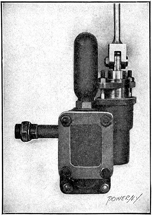
FIG. 54
The oil reservoir, cooler, and piping are all outside
the machine and easily accessible for cleaning. Usually
a corrugated-steel floor plate covers all this apparatus,
so that it will not be unsightly and accumulate dirt,
particularly when the turbine is installed, so that all
this apparatus is below the floor level; i.e., when the
top of the bedplate comes flush with the floor line.
In cases where the turbine is set higher, a casing is
usually built around this material so that it can be easily
removed, and forms a platform alongside the machine.
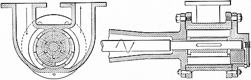
FIG. 55
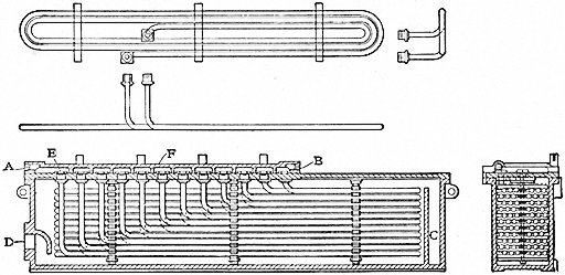
FIG. 56
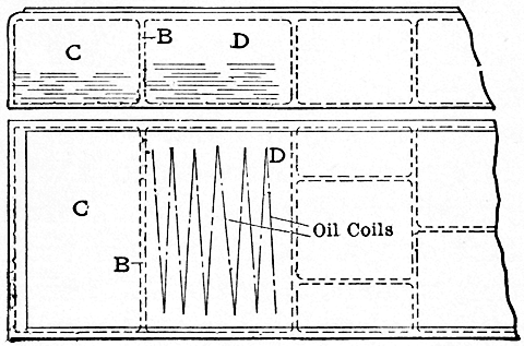
The oil cooler, shown in Fig. 56, is of the counter-current
type, the water entering at A and leaving at
B, oil entering at C (opening not shown) and leaving
at D. The coils are of seamless drawn copper, and attached
to the cover by coupling the nut. The water
manifold F is divided into compartments by transverse
ribs, each compartment connecting the inlet of
each coil with the outlet of the preceding coil, thus
placing all coils in series. These coils are removable
in one piece with the coverplate without disturbing
the rest of the oil piping.
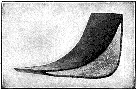
FIG. 57
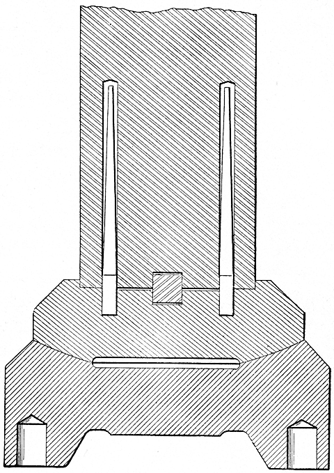
The blades are drawn from a rod consisting of a
steel core coated with copper so intimately connected
with the other metal that when the bar is drawn to
the section required for the blading, the exterior
coating drawn with the rest of the bar forms a
covering of uniform thickness as shown in Fig. 57.
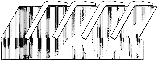
The bar after being drawn through the correct
section is cut into suitable lengths punched as at A
(Fig. 58), near the top of the blade, and has a groove
shown at B (Fig. 59), near the root, stamped in
its concave face, while the blade is being cut to length
and punched. The blades are then set into grooves
cut into the rotor drum or the concave surface of the
casing, and spacing or packing pieces C (Fig. 59)
placed between them. These spacing pieces are of
soft iron and of the form which is desired that the
passage between the blades shall take. The groove
made upon the inner face of the blade is sufficiently
near to the root to be covered by this spacing piece.
When the groove has been filled the soft-iron pieces
are calked or spread so as to hold the blades firmly
in place. A wire of comma section, as shown at A
(Fig. 59), is then strung through the punches near
the outer ends of the blades and upset or turned
over as shown at the right in Fig. 58. This upsetting
is done by a tool which shears the tail of the
comma at the proper width between the blades. The
bent-down portion on either side of the blade holds
it rigidly in position and the portion retained within
the width of the blade would retain the blade in its
radial position should it become loosened or broken
off at the root. This comma lashing, as it is called,
takes up a small proportion only of the blade length
or projection and makes a job which is surprisingly
stiff and rigid, and yet which yields in case of serious
disturbance rather than to maintain a contact which
would result in its own fusing or the destruction of
some more important member.
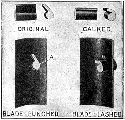
FIG. 58
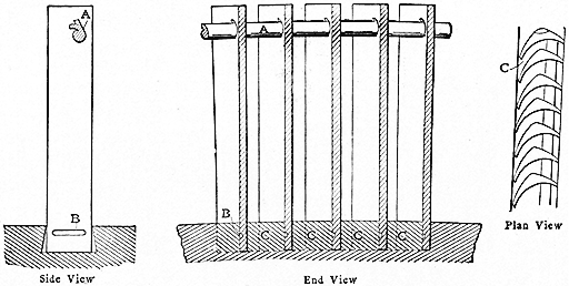
FIG. 59
When starting up the turbine for the first time, or
after any extended period of idleness, special care
must be taken to see that everything is in good condition
and that all parts of the machine are clean and
free from injury. The oil piping should be thoroughly
inspected and cleaned out if there is any accumulation
of dirt. The oil reservoirs must be very carefully
wiped out and minutely examined for the presence
of any grit. (Avoid using cotton waste for this, as
a considerable quantity of lint is almost sure to be
left behind and this will clog up the oil passages in
the bearings and strainer.)
The pilot valves should be removed from the barrel
and wiped off, and the barrels themselves cleaned out
by pushing a soft cloth through them with a piece of
wood. In no case should any metal be used.
If the turbine has been in a place where there was
dirt or where there has been much dust blowing around,
the bearings should be removed from the spindle and
taken apart and thoroughly cleaned. With care this
can be done without removing the spindle from the
cylinder, by taking off the bearing covers and very
carefully lifting the weight of the spindle off the bearings,
then sliding back the bearings. It is best to
lift the spindle by means of jacks and a rope sling, as,
if a crane is used, there is great danger of lifting the
spindle too high and thereby straining it or injuring
the blades. After all the parts have been carefully
gone over and cleaned, the oil for the bearing lubrication
should be put into the reservoirs by pouring it
into the governor gear case G (Fig. 34). Enough oil
should be put in so that when the governor, gear case,
and all the bearing-supply pipes are full, the supply
to the oil pump is well covered.
Special care should be taken so that no grit gets
into the oil when pouring it into the machine. Considerable
trouble may be saved in this respect by
pouring the oil through cloth.
A very careful inspection of the steam piping is
necessary before the turbine is run. If possible it
should be blown out by steam from the boilers before
it is finally connected to the turbine. Considerable
annoyance may result by neglecting this precaution,
from particles of scale, red lead, gasket, etc., out of the
steam pipe, closing up the passages of the guide blades.
When starting up, always begin to revolve the
spindle without vacuum being on the turbine. After
the spindle is turning slowly, bring the vacuum up.
The reason for this is, that when the turbine is standing
still, the glands do not pack and air in considerable
quantity will rush through the glands and down
through the exhaust pipe. This sometimes has the
effect of unequal cooling. In case the turbine is used
in conjunction with its own separate condenser, the
circulating pump may be started up, then the turbine
revolved, and afterward the air pump put in operation;
then, last, put the turbine up to speed. In
cases, however, where the turbine exhausts into the
same condenser with other machinery and the condenser
is therefore already in operation, the valve
between the turbine and the condenser system should
be kept closed until after the turbine is revolved, the
turbine in the meantime exhausting through the
relief valve to atmosphere.
Care must always be taken to see that the turbine
is properly warmed up before being caused to revolve,
but in cases where high superheat is employed always
revolve the turbine just as soon as it is moderately
hot, and before it has time to become exposed to
superheat.
In the case of highly superheated steam, it is not
undesirable to provide a connection in the steam line
by means of which the turbine may be started up with
saturated steam and the superheat gradually applied
after the shaft has been permitted to revolve.
For warming up, it is usual practice to set the governor
on the trigger (see Fig. 50) and open the throttle
valve to allow the entrance of a small amount of
steam.
It is always well to let the turbine operate at a reduced
speed for a time, until there is assurance that
the condenser and auxiliaries are in proper working
order, that the oil pump is working properly, and
that there is no sticking in the governor or the valve gear.
After the turbine is up to speed and on the governor,
it is well to count the speed by counting the strokes
of the pump rod, as it is possible that the adjustment
of the governor may have become changed while the
machine has been idle. It is well at this time, while
there is no load on the turbine, to be sure that the
governor controls the machine with the throttle wide
open. It might be that the main poppet valve has
sustained some injury not evident on inspection, or
was leaking badly. Should there be some such defect,
steps should be taken to regrind the valve to its
seat at the first opportunity.
On the larger machines an auxiliary oil pump is
always furnished. This should be used before starting
up, so as to establish the oil circulation before
the turbine is revolved. After the turbine has reached
speed, and the main oil pump is found to be working
properly, it should be possible to take this pump out
of service, and start it again only when the turbine
is about to be shut down.
If possible, the load should be thrown on gradually
to obviate a sudden, heavy demand upon the boiler,
with its sometimes attendant priming and rush of
water into the steam pipe, which is very apt to take
place if the load is thrown on too suddenly. A slug
of water will have the effect of slowing down the
turbine to a considerable extent, causing some annoyance.
There is not likely to be the danger of the damage
that is almost sure to occur in the reciprocating
engine, but at the same time it is well to avoid this
as much as possible. A slug of water is obviously
more dangerous when superheated steam is being employed,
owing to the extreme temperature changes possible.
While the turbine is running, it should have a certain
amount of careful attention. This, of course,
does not mean that the engineer must stand over it
every minute of the day, but he must frequently inspect
such parts as the lubricators, the oiling system,
the water supply to the glands and the oil-cooling
coil, the pilot valve, etc. He must see that the oil
is up in the reservoir and showing in the gage glass
provided for that purpose, and that the oil is flowing
freely through the bearings, by opening the pet cocks
in the top of the bearing covers. An ample supply of
oil should always be in the machine to keep the suction
in the tank covered.
Care must be taken that the pump does not draw
too much air. This can usually be discovered by the
bubbling up of the air in the governor case, when
more oil should be added.
It is well to note from time to time the temperature
of the bearings, but no alarm need be occasioned
because they feel warm to the touch; in fact, a bearing
is all right as long as the hand can be borne upon it
even momentarily. The oil coming from the bearings
should be preferably about 120 degrees Fahrenheit
and never exceed 160 degrees.
It should generally be seen that the oil-cooling coil
is effective in keeping the oil cool. Sometimes the
cooling water deposits mud on the cooling surface, as
well as the oil depositing a vaseline-like substance,
which interferes with the cooling effect. The bearing
may become unduly heated because of this, when the
coil should be taken out at the first opportunity and
cleaned on the outside and blown out by steam on the
inside, if this latter is possible. If this does not
reduce the temperature, either the oil has been in use
too long without being filtered, or the quality of the
oil is not good.
Should a bearing give trouble, the first symptom
will be burning oil which will smoke and give off dense
white fumes which can be very readily seen and
smelled. However, trouble with the bearings is one
of the most unlikely things to be encountered, and,
if it occurs, it is due to some radical cause, such as
the bearings being pinched by their caps, or grit and
foreign matter being allowed to get into the oil.
If a bearing gets hot, be assured that there is some
very radical cause for it which should be immediately
discovered and removed. Never, under any circumstances,
imagine that you can nurse a bearing, that
has heated, into good behavior. Turbine bearings
are either all right or all wrong. There are no halfway measures.
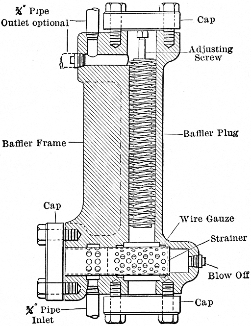
The oil strainer should also be occasionally taken
apart and thoroughly cleaned, which operation may
be performed, if necessary, while the turbine is in
operation. The screens should be cleaned by being
removed from their case and thoroughly blown out
with steam. In the case of a new machine, this may
have to be done every two or three hours. In course
of time, this need only be repeated perhaps once a
week. The amount of dirt found will be an indication
of the frequency with which this cleaning is necessary.
The proper water pressure, about five pounds per
square inch, must be maintained at the glands. Any
failure of this will mean that there is some big leak in
the piping, or that the water is not flowing properly.
The pilot valve must be working freely, causing
but little kick on the governor, and should be lubricated
from time to time with good oil.
Should it become necessary, while operating, to
shut down the condenser and change over to non-condensing
operation, particular care should be observed
that the change is not made too suddenly to
non-condensing, as all the low-pressure sections of the
turbine must be raised to a much higher temperature.
While this may not cause an accident, it is
well to avoid the stresses which necessarily result
from the sudden change of temperature. The same
reasons, of course, do not hold good in changing from
non-condensing to condensing.
When shutting down the turbine the load may be
taken off before closing the throttle; or, as in the case
of a generator operating on an independent load, the
throttle may be closed first, allowing the load to act
as a brake, bringing the turbine to rest quickly. In
most cases, however, the former method will have
to be used, as the turbine generally will have been
operating in parallel with one or more other generators.
When this is the case, partially close the throttle
just before the load is to be thrown off, and if the turbine
is to run without load for some time, shut off
the steam almost entirely in order to prevent any
chance of the turbine running away. There is no
danger of this unless the main valve has been damaged
by the water when wet steam has been used, or
held open by some foreign substance, when, in either
case, there may be sufficient leakage to run the turbine
above speed, while running light. At the same
time, danger is well guarded against by the automatic
stop valve, but it is always well to avoid a possible
danger. As soon as the throttle is shut, stop
the condenser, or, in the case where one condenser
is used for two or more turbines, close the valve between
the turbine and the condenser. Also open the
drains from the steam strainer, etc. This will considerably
reduce the time the turbine requires to come
to rest. Still more time may be saved by leaving the
field current on the generator.
Care should be taken, when the vacuum falls and
the turbine slows down, to see that the water is shut
off from the glands for fear it may leak out to such an
extent as to let the water into the bearings and impair
the lubricating qualities of the oil.
At regular intervals thorough inspection should be
made of all parts of the turbine. As often as it
appears necessary from the temperature of the oil,
depending on the quality of the oil and the use of the
turbine, remove the oil-cooling coil and clean it both
on the inside and outside as previously directed; also
clean out the chamber in which it is kept. Put in a
fresh supply of oil. This need not necessarily be new,
but may be oil that has been in use before but has
been filtered. We recommend that an oil filter be
kept for this purpose. Entirely new oil need only
be put into the turbine when the old oil shows marked
deterioration. With a first-class oil this will probably
be a very infrequent necessity, as some new oil
has to be put in from time to time to make up the
losses from leakage and waste.
Clean out the oil strainer, blowing steam through
the wire gauze to remove any accumulation of dirt.
Every six months to a year take off the bearing covers,
remove the bearings, and take them apart and clean
out thoroughly. Even the best oil will deposit more
or less solid matter upon hot surfaces in time, which
will tend to prevent the free circulation of the oil
through the bearings and effectively stop the cushioning
effect on the bearings. Take apart the main and
secondary valves and clean thoroughly, seeing that all
parts are in good working order. Clean and inspect
the governor and the valve-gear, wiping out any accumulation
of oil and dirt that may appear. Be sure to
clean out the drains from the glands so that any water
that may pass out of them will run off freely and will
not get into the bearings.
At the end of the first three months, and after that
about once a year, take off the cylinder cover and
remove the spindle. When the turbine is first started
up, there is very apt to be considerable foreign matter
come over in the steam, such as balls of red lead or
small pieces of gasket too small to be stopped by the
strainer. These get into the guide blades in the cylinder
and quite effectively stop them up. Therefore,
the blades should be gone over very carefully, and
any such additional accumulation removed. Examine
the glands and equilibrium ports for any dirt or
broken parts. Particularly examine the glands for
any deposit of scale. All the scale should be chipped
off the gland parts, as, besides preventing the glands
from properly packing, this accumulation will cause
mechanical contact and perhaps cause vibration of the
machine due to lack of freedom of the parts. The
amount of scale found after the first few inspections
will be an indication of how frequently the cleaning
should be done. As is discussed later, any water
that is unsuitable for boiler feed should not be used
in the glands.
In reassembling the spindle and cover, very great
care must be taken that no blades are damaged and
that nothing gets into the blades. Nearly all the
damage that has been done to blades has resulted
from carelessness in this respect; in fact, it is impossible
to be too careful. Particular care is also to be
taken in assembling all the parts and in handling
them, as slight injury may cause serious trouble. In
no case should a damaged part be put back until the
injury has been repaired.
If for any reason damaged blades cannot be repaired
at the time, they can be easily removed and the
turbine run again without them until it is convenient
to put in new ones; in fact, machines have been run
at full load with only three-quarters of the total number
of blades. In such an event remove the corresponding
stationary blades as well as the moving
blades, so as not to disturb the balance of the end
thrust.
In the operation of the turbine and the conditions
of the steam, both live and exhaust play a very
important part. It has been found by expensive
experimenting that moisture in the steam has a very
decided effect on the economy of operation; or considerably
more so than in the case of the reciprocating
engine. In the latter engine, 2 per cent. of moisture
will mean very close to 2 per cent. increase in the
amount of water supplied to the engine for a given
power. On the other hand, in the turbine 2 per cent.
moisture will cause an addition of more nearly 4 per
cent. It is therefore readily seen that the drier the
entering steam, the better will be the appearance of
the coal bill.
By judicious use of first-class separators in connection
with a suitable draining system, such as the
Holly system which returns the moisture separated
from the steam, back to the boilers, a high degree
of quality may be obtained at the turbine with practically
no extra expense during operation. Frequent
attention should be given the separators and traps
to insure their proper operation. The quality of the
steam may be determined from time to time by the
use of a throttling calorimeter. Dry steam, to a great
extent, depends upon the good and judicious design
of steam piping.
Superheated steam is of great value where it can be
produced economically, as even a slight degree insures
the benefits to be derived from the use of dry
steam. The higher superheats have been found to
increase the economy to a considerable extent.
When superheat of a high degree (100 degrees
Fahrenheit or above) is used special care must be
exercised to prevent a sudden rise of the superheat
of any amount. The greatest source of trouble in
this respect is when a sudden demand is made for a
large increase in the amount of steam used by the engine,
as when the turbine is started up and the superheater
has been in operation for some time before,
the full load is suddenly thrown on. It will be readily
seen that with the turbine running light and the
superheater operating, there is a very small amount
of steam passing through; in fact, practically none,
and this may become very highly heated in the superheater,
but loses nearly all its superheat in passing
slowly to the turbine; then, when a sudden demand
is made, this very high temperature steam is drawn
into the turbine. This may usually be guarded against
where a separately fired superheater is used, by keeping
the fire low until the load comes on, or, in the case
where the superheater is part of the boiler, by either
not starting up the superheater until after load comes
on, or else keeping the superheat down by mixing
saturated steam with that which has been superheated.
After the plant has been started up there is little
danger from this source, but such precautions should
be taken as seem best in the particular cases.
Taking up the exhaust end of the turbine, we have
a much more striking departure from the conditions
familiar in the reciprocating engine. Due to the
limits imposed upon the volume of the cylinder of
the engine, any increase in the vacuum over 23 or
24 inches, in the case, for instance, of a compound-condensing
engine, has very little, if any, effect on
the economy of the engine. With the turbine, on the
other hand, any increase of vacuum, even up to the
highest limits, increases the economy to a very considerable
extent and, moreover, the higher the vacuum
the greater will be the increase in the economy for a
given addition to the vacuum. Thus, raising the
vacuum from 27 to 28 inches has a greater effect
than from 23 to 24 inches. For this reason the
engineer will readily perceive the great desirability of
maintaining the vacuum at the highest possible point
consistent with the satisfactory and economical operation
of the condenser.
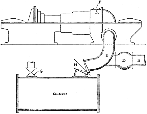
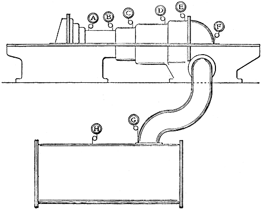
The exhaust pipe should always be carried downward
to the condenser when possible, to keep the
water from backing up from the condenser into the
turbine. If the condenser must be located above
the turbine, then the pipe should be carried first downward
and then upward in the U form, in the manner
of the familiar "entrainer," which will be found effectively
to prevent water getting back when the turbine
is operating.
As has been previously pointed out, the successful
and satisfactory operation of the turbine depends
very largely on the condenser. With the reciprocating
engine, if the condenser will give 25 inches
vacuum, it is considered fairly good, and it is allowed
to run along by itself until the vacuum drops to somewhere
below 20 inches, when it is completely gone
over, and in many cases practically rebuilt and the
vacuum brought back to the original 25 inches. It
has been seen that this sort of practice will never do
in the case of the turbine condenser and, unless the
vacuum can be regularly maintained at 27 or 28 inches,
the condenser is not doing as well as it ought to do,
or it is not of the proper type, unless perhaps the
temperature and the quantity of cooling water available
render a higher vacuum unattainable.
On account of the great purity of the condensed
steam from the turbine and its peculiar availability
for boiler feed (there being no oil of any kind mixed
with it to injure the boilers), the surface condenser
is very desirable in connection with the turbine. It
further recommends itself by reason of the high
vacuum obtainable.
Where a condenser system capable of the highest
vacuum is installed, the need of utilizing it to its
utmost capacity can hardly be emphasized too strongly.
A high vacuum will, of course, mean special care and
attention, and continual vigilance for air leaks in the
exhaust piping, which will, however, be fully paid
for by the great increase in economy.
It must not be inferred that a high vacuum is essential
to successful operation of this type of turbine,
for excellent performance both in the matter of steam
consumption and operation is obtained with inferior
vacuum. The choice of a condenser, however, is a
matter of special engineering, and is hardly within the
province of this article.
There are several oils on the market that are suitable
for the purpose of the turbine oiling system, but
great care must be exercised in their selection. In the
first place, the oil must be pure mineral, unadulterated
with either animal or vegetable oils, and must
have been washed free from acid. Certain brands
of oil require the use of sulphuric acid in their manufacture
and are very apt to contain varying degrees
of free acid in the finished product. A sample from
one lot may have almost no acid, while that from
another lot may contain a dangerous amount.
Mineral oils that have been adulterated, when
heated up, will partially decompose, forming acid.
These oils may be very good lubricants when first
put into use, but after awhile they lose all their good
qualities and become very harmful to the machine
by eating the journals in which they are used. These
oils must be very carefully avoided in the turbine, as
the cheapness of their first cost will in no way pay
for the damage they may do. A very good and simple
way to test for such adulterations is to take up a
quantity of the oil in a test tube with a solution of
borax and water. If there is any animal or vegetable
adulterant present it will appear as a white milk-like
emulsion which will separate out when allowed to
stand. The pure mineral oil will appear at the top
as a clear liquid and the excess of the borax solution
at the bottom, the emulsion being in between. A
number of oils also contains a considerable amount
of paraffin which is deposited in the oil-cooling coil,
preventing the oil from being cooled properly, and in
the pipes and bearings, choking the oil passages and
preventing the proper circulation of the oil and cushioning
effect in the bearing tubes. This is not entirely
a prohibitive drawback, the chief objection being
that it necessitates quite frequently cleaning the
cooling coil, and the oil piping and bearings.
Some high-class mineral oils of high viscosity are
inclined to emulsify with water, which emulsion appears
as a jelly-like substance. It might be added
that high-grade oils having a high viscosity might
not be the most suitable for turbine use.
Since the consumption of oil in a turbine is so very
small, being practically due only to leakage or spilling,
the price paid for it should therefore be of secondary
importance, the prime consideration being its suitability
for the purpose.
In some cases a central gravity system will be employed,
instead of the oil system furnished with the
turbine, which, of course, will be a special consideration.
For large installations a central gravity oiling system
has much to recommend it, but as it performs
such an important function in the power plant, and
its failure would be the cause of so much damage,
every detail in connection with it should be most
carefully thought out, and designed with a view that
under no combination of circumstances would it be
possible for the system to become inoperative. One
of the great advantages of such a system is that it
can be designed to contain very large quantities of
oil in the settling tanks; thus the oil will have quite
a long rest between the times of its being used in the
turbine, which seems to be very helpful in extending
the life of the oil. Where the oil can have a long rest
for settling, an inferior grade of oil may be used,
providing, however, that it is absolutely free of acid.