Class D.—Includes one set of Ship‘s Torpedoes, Service and
Exercise, one set of Boat‘s Torpedoes, Service and Exercise, and one
set of circuit-closers and appurtenances for the conversion of Service
into Contact Torpedoes.
Service and Exercise Torpedoes are to be used from ships and boats;
Contact Torpedoes from boats only.
Many articles in a Torpedo Outfit are common to the different sets
comprised in Class D, in which case similar articles are classed
together for convenience of stowage and transportation. If the whole of
Class D is not issued, then only a proportionate part of those articles
designated as “Spare” are issued. Articles that belong exclusively to
any one set are issued with that set only.
Pattern D.—Plate I.
(Twenty-four are issued.—Twelve for use from ships
and twelve from boats.)
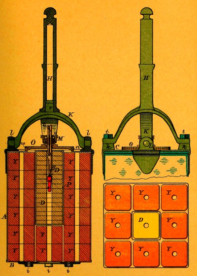
This torpedo, intended for use from either ships or boats, is 12⅜
inches long and 9 inches square, inside measurement, and is made of
sheet iron tinned inside and out, coated inside with shellac and
painted outside with asphaltum. Around a filling hole in the top is
soldered a brass ring having on its inner circumference, a screw-thread
for a brass screw-cover which bears a stuffing-box for the entrance
of the spar leading-wires. A rubber washer between the cover and ring
makes the case water-tight. Riveted to the top is a tinned malleable
iron frame fitted with four lugs. A handle secured to two of the
lugs forms a brace for the spindle that attaches the torpedo to the
secondary spar; this spindle has two curved arms at one end that
straddle the handle and secure to the other two lugs by screw-bolts, a
projection on the crown of the handle fitting into a recess in the stem
of the spindle. To the bottom of the case is riveted a tinned malleable
iron plate for attaching a circuit-closer.
The primer-case, 8⅛ inches long and 3 inches square, inside
measurement, is made of tin coated inside and out with shellac and is
closed at one end.
The torpedo-case, empty but complete except the spindle, weighs about
15 lbs. The charge of the torpedo, including the primer of 2½ lbs. of
dry gun-cotton, is equivalent to about 34 lbs. of dry gun-cotton.
When issued, the torpedo-cases are completely filled with wet
gun-cotton, the screw-cover is screwed down tight and the hole in the
stuffing-box is closed tight by screwing down the water-cap over the
spherical rubber packing placed sideways in its seat.
Pattern D.—Plate II.
(Twelve are issued, two of which are empty,
for use from ships or boats).
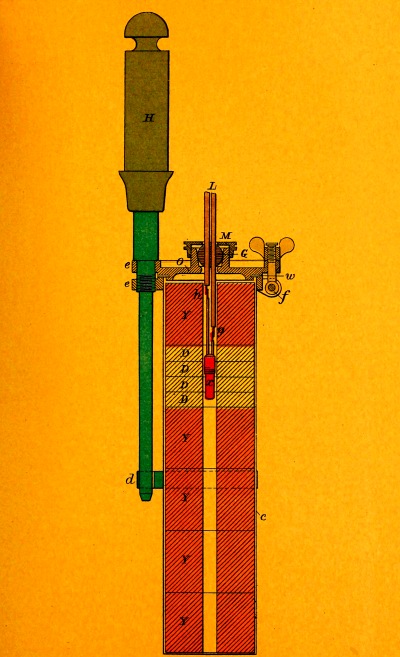
This torpedo, 12½ inches long and 3¹/₁₆ inches square, inside
measurement, is made of tin and is closed at the lower end. It is
coated inside and out with shellac. To the upper end is soldered a
brass flange having a loop on one side and a throw-back hinge on
the opposite side. The cover consists of a square brass plate with
two loops one of which rests over the loop on the flange, the other
receiving the lug of the throw-back hinge. A thumb-screw, fitted to
the end of the lug, secures one side of the cover and a transportation
thumb-screw, fitted to the loops, secures the other side. The cover
bears a stuffing-box for the entrance of the spar leading-wires. A
rubber washer between the cover and flange makes the case water-tight.
A loop is fitted to one side of the case to receive the lower end of
the spindle.
The weight of this torpedo, empty but complete, except the spindle, is
3¼ lbs. and its charge is equivalent to about 4 lbs. of dry gun-cotton.
When issued, all the exercise torpedo-cases, except two, are completely
filled with wet gun-cotton, the cover is closed tight and the hole in
the stuffing-box is closed tight by screwing down the water-cap over
the spherical rubber packing placed sideways in its seat.
Plates I. and II.
Stuffing-boxes provide a water-tight entrance for the
spar leading-wires through the covers of the torpedo-cases.
In the center of each cover, around the hole for the entrance of the
leading-wires, is a brass rim fitted with a screw-thread outside, and
bored out, inside, with a slightly conical taper, providing a seat for
the packing.
The packing is of partly vulcanized rubber, 1 inch in diameter,
spherical in shape, with two parallel holes, each ¼ inch in diameter,
for reeving the leading-wires.
The water-cap screws on the brass rim and compresses the packing in its
seat, a friction-ring in the top of the cap preventing twisting of the
packing when screwing down.
A hole, ⅝ inch in diameter, through the top of the water-cap, permits
reeving the spar leading-wires.
When rubber packing is to be left seated for a long time the seat for
the packing should be coated with shellac and the packing brushed with
black lead to prevent adhesion.
Pattern B.—Plate III.
(Four are issued, to convert Service Torpedoes into
Contact Torpedoes, for use from boats.)
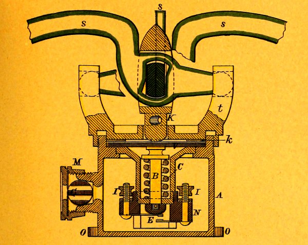
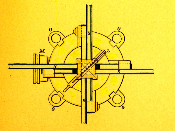
The circuit-closer consists of a cylindrical brass casting, having
one end closed, and on this end are four feet by which it is secured
to the lower head of the service torpedo by screws. The cylinder,
4¾ inches long and 5 inches in diameter, is closed at the open end
by a screw-cover, having four lugs that serve as bearings for the
contact-arms; these arms, four in number, work in slots cut in a
plunger that passes through the center of the cap, and they are held in
place by screws through the ends of two arms and their lugs. Inside the
cylinder are two insulated contact-springs secured to binding-posts in
an ebonite collar. This collar screws on the end of a short brass tube
that carries a plunger tipped on the inner end with ebonite. A stout
spiral spring in the tube through which passes this plunger, maintains,
normally, the end of the plunger clear of the contact-springs. A
rubber diaphragm separates the plunger in the cover from the plunger
in the tube, and also acts as a washer to the cover, making the
cylinder water-tight; a brass washer, laid on this diaphragm, acts as a
friction-plate for the cover to turn on when screwed up. A safety-pin
through the outer plunger prevents its being forced in accidentally.
When this pin is withdrawn, any pressure on the contact-arms tends to
force the inner plunger in against the action of the spiral spring and
to close the break between the contact-springs.
The break is ³/₁₆ inch and the tension of the spiral spring is 75 lbs.
On the side of the cylinder is fitted a stuffing-box furnishing a
water-tight entrance for the leading-wires to the binding-posts of the
contact-springs.
The circuit-closer, complete, weighs 7 lbs.
Pattern A.—Plate IV.
(One is furnished for each Service Torpedo.)
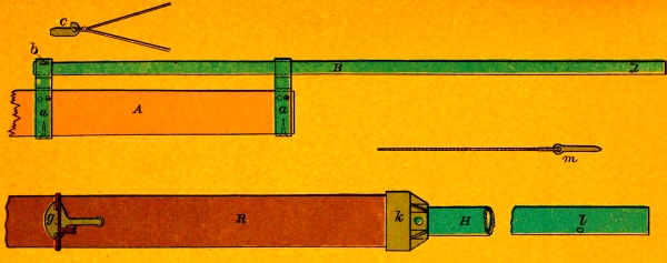
These are iron pipes, 8 feet long. Those for ships‘ use have a slot
cut in one end, for a key. Those for use in boats are fitted at one
end with an iron disc, called a butt, and at 2 feet 2 inches from the
butt an iron cap is riveted to the spar. All secondary spars have, at 5
inches from the outer end, a hole for the torpedo-pin. Secondary spars
are packed six in a box; those for ships having a key stopped to each
to be used in securing the secondary spar to the inner spar-band; those
for boats having a toggle stopped to each to be used in securing the
secondary spar to the boat spar.
Plate IV.
Torpedo pins are short iron pins with an eye in one end, to which a
spun-yarn tail is spliced, designed to secure torpedoes to secondary
spars. One is provided for each service and exercise torpedo. They are
packed, with the spindles, in Box 53.
This contains 300 feet of insulated double-conductor wire cable. The
inner ends of the cable are connected to binding-screws on the sides of
the reel, where short wires are to be attached, for making connections
with batteries, etc., after the requisite amount of cable has been
unreeled. A handle is becketed to the cover of the box, to be used in
reeling up the cable. The binding-screws must be kept free from rust
(no oil to be used in cleaning), and must be occasionally turned to
keep them from setting.
The cable, as now issued, consists of two cores, each core composed of
seven No. 22 A. W. G. copper wires of not less than 95% conductivity,
coated with tin and laid up in a strand. Each core is separately
insulated with okonite composition to an external diameter of ¼ inch
and is wrapped with tape soaked in okonite composition. The two
insulated cores, laid side by side, are covered with hemp braiding to
protect them from chafe.
The resistance of the core is 2.2 ohms per 1000 feet.
The cable in the reel box is for general use and to replace disabled
permanent wires. It must never be subjected to a strain of over 100
pounds, nor jerked or hauled in from any length, but under-run.
The cable must be stowed in a cool, dry place.
This box is marked “Wire-Box—Ship‘s.” It contains four spar
leading-wires of insulated double-conductor copper wire cable, 70 feet
each in length, precisely similar to that found in the reel box, and
two machine-connecting wires 12 feet each in length.
The spar leading-wires are to connect the torpedo with the terminals of
the permanent wires. To guard against mistakes in making connections
those for use on the starboard side are painted green and marked with
one knot and those for use on the port side are painted red and marked
with two knots.
The machine-connecting wires are insulated wires for connecting the D.
E. machine, Pattern A., with the firing-key and for general purposes.
This box is marked “Wire-Box—Boat‘s.” It contains the same articles as
“Wire-Box—Ship‘s,” similarly marked.
Pattern B.—Plate V.
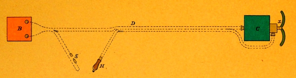
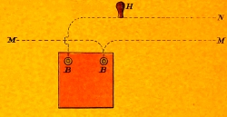
These consist, practically, of three insulated copper wire cables
which lead, in use, as follows:—1st. wire, from the detonator to one
terminal of the battery; 2nd. wire, from the circuit-closer to the
second terminal of the battery via the safety-break; 3rd. wire,
branching in two legs at its outer end, from the detonator and the
circuit-closer to the second terminal of the battery via the
hand-firing key and the safety-break.
The safety-break and the hand-firing key are connected to their proper
leads by wires of convenient length to permit placing the battery out
of the way when connected up.
The safety-break consists of two round, tapering pieces of brass each
fitted with a score and two small holes in the smaller end to which the
leading-wire is permanently secured. The larger ends, fitted to ship
together bayonet fashion, can be readily connected or disconnected at
pleasure.
Directions for using these wires are given in
“Preparation of Contact Torpedo.”
Plate IV.
These, of wrought iron, furnish a ready means of securing secondary
spars to the ordinary wooden torpedo-spars supplied to ships. These
bands, with loops on top, are secured to the end of the wood spar, 3
feet apart, with wood screws. The inner band has a key-way, to hold
the secondary spar in place. Care must be taken that the loops of both
bands are exactly in line.
This box, containing tools and small articles required in spar-torpedo
work, is marked on top, “Torpedo Supply-Box.” For contents see Box 3
“List of Articles in Outfit supplied from Torpedo Station.”
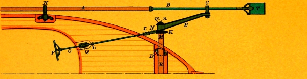
Pattern B.—Plate VI.
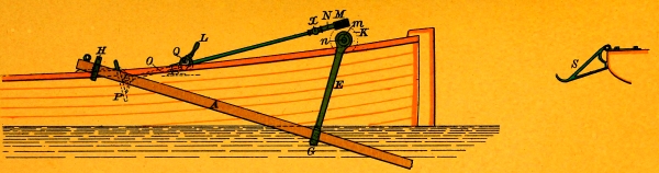
These, for the support and handling of the boat spars, consist of
bow-fittings, 2 swivel-crutches and 2 heel-rests.
The heel-rest is an iron crutch bolted to the rail well aft. A hinge
allows the rest to be laid inboard when not in use.
The swivel-crutch is a square iron collar fitted with a shank that
turns freely in a bearing firmly bolted to the rail, 9 feet abaft the
cross-beam. The collar is made in two parts, the upper one working on a
hinge, and has two rollers.
Bow-fittings consist of a cross-beam with its attachments. The
cross-beam, made of heavy wrought-iron tubing, is secured across the
bow to castings let into the rail. On sleeves, at the ends of the
cross-beam, are elevating-arms free to revolve in a vertical plane. At
the outer end of each arm a swivelled guide-ring is placed, projecting
at right angles to the arm in the direction of the beam of the boat.
In the lower part of this ring is a roller. Connected with the sleeve
of each arm is a gear moved by a worm on the forward end of a shaft
extending aft into the boat, an elevating-wheel being keyed to the
after end of the shaft.
The worm-shaft is in two lengths joined by a hook-coupling interposed
near the forward end of the shaft to allow the worm sufficient play to
engage the gear of the elevating-arm during the revolution of the shaft.
The worm-shaft is allowed a fore-and-aft motion such that, when
the shaft is forward, the worm is disengaged from the gear of the
elevating-arm, leaving it unsupported and free to drop and, when
the shaft is aft, the worm is engaged with the gear so that the
elevating-arm may be controlled by the elevating-wheel.
The shaft is held aft by a clutch placed just forward of the
elevating-wheel. The clutch consists of a sleeve, supported on
trunnions by a bearing bolted to a chock on the forward deck of the
boat, carrying a yoke-link, loosely bolted to two lugs on its forward
lower end and a detaching-lever, loosely bolted to two lugs on its
forward upper end. The worm-shaft, passing through this sleeve, bears a
rigid collar so placed that, when the shaft is aft, the collar is close
up against the forward end of the sleeve. The yoke-link, when swung up,
embraces the shaft and bears against the forward side of the collar,
holding the shaft aft. The yoke-link is held up by the detaching-lever
which is thrown forward between the upper ends of the yoke-link, a
transverse roller in the detaching-lever, with ends projecting on
either side, locking the yoke-link in place. A pin, passed through eyes
worked in the upper ends of the yoke-link, prevents accidental tripping
of the detaching-lever. When this pin is withdrawn and the
detaching-lever is pulled aft the yoke-link falls and the shaft is free
to move forward.
By the worm-shaft and its attachments the elevating-arm can be rotated
around the cross-beam, held in any position in its plane of rotation,
or released at any desired moment.
The gear and worm are protected by hoods.
Pattern A.—Plate VII.
The spar, made of steel, consists of two tubes, 18 and 15 feet long
respectively, one 4 inches and the other 3½ inches in diameter, joined
together with a telescopic joint. The tubes—with a lap of 2 feet—are
held together by two screws. At the larger end of the spar is an
eye-bolt for the heel-rope screwed in from the inside, and at 5 feet
from the smaller end is a hole for reeving the spar leading-wires.
This constitutes the main spar, which can readily be taken apart for
stowage by removing the screws. To assemble the spar, a feather fits
into a score on the end of the larger tube, bringing the screw-holes
opposite each other. Iron spar-clamps are furnished, to facilitate the
assembling of the spar.
The two tubes composing each spar are marked by similar letters or
numbers.
Note.—Spars must invariably be taken apart after use,
joints lubricated, and protected by a canvas cover.
Plate VIII.
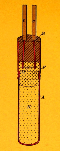
Detonators are cylindrical copper cases, closed at the bottom,
containing 35 grains of fulminate of mercury, primed on top with dry,
pulvurulent gun-cotton.
A plug, made of 1 part of ground glass and 2 parts of sulphur, melted
together, is cast around the detonator-legs:—tinned copper wires,
No. 20 A. W. G., 6 inches in length, insulated with a double layer of
cotton thread soaked in paraffine, the outer layer colored red.
The inner ends of the detonator-legs are bridged by a platinum-iridium
wire, 90% platinum, 10% iridium, ³/₁₆ inch long and 2 mils in diameter,
having a resistance of .65±.03 ohm.
The plug is inserted in a copper band; dry pulvurulent gun-cotton is
loosely packed about the bridge and on top of the fulminate of mercury
and the band is screwed on the upper end of the detonator-case, thus
closing it.
Detonators are painted red. They are supplied for use with gun-cotton
torpedoes.
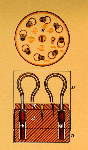
Plate VIII.
Wooden cylinders, with a cover that has a small circular motion. Each
block holds 8 detonators placed in holes around the circumference, the
cover locking them in. Each block is placed in a covered tin cylinder
painted red and marked “Dangerous.” These blocks will be placed in
different parts of the ship, never below the water-line. (See Ord. Inst.)
These are empty detonator-cases, with a hole bored in the bottom, for
use in making connections in practice. The detonator-legs are not
bridged but are cast in the plug on the bight.
Dummy detonators are painted white and the legs are insulated with
white cotton thread.
Igniters are cylindrical brass cases, closed at the lower end,
containing a charge of rifle gunpowder.
The upper end is closed by inserting a plug precisely similar to that
used in detonators, except that the igniter-legs are insulated with
white cotton thread instead of red.
The bridge is primed by twining about it a wisp of long-staple, dry
gun-cotton.
Igniters are coated with white shellac. They are supplied for use with
improvised gunpowder torpedoes.
These are stout, cylindrical, paper cases, closed at the lower end and
charged with rifle gunpowder. In the center of the charge is placed an
igniter the legs of which project on either side of a wooden plug which
is seized in the upper end of the case to close it.
Igniters are coated with orange shellac.
A rubber insulator, for preventing short-circuit between the splices
when the fuze is attached to leading-wires, is seized around the upper
end of the case.
Fuzes are supplied for use with improvised gunpowder torpedoes.
This is marked with a list of contents. It is packed in Box 7,
from which it is to be removed, when received aboard ship, and stowed in the
magazine or ammunition room.
Pattern B.
Glass cylindrical jars, fitted with cork covers, each having a capacity
for 6 two-inch, or 24 one-half inch blocks of gun-cotton. These
blocks of dry gun-cotton are tied together with boiled tape and have
litmus-paper between them. They are never to be stowed below, but
must be placed in different parts of the ship above the water-line.
Being glass, the jar, without being opened, renders the litmus-paper
readily discernible. Each jar is placed in a wooden case fitted with a
sliding cover, painted white, and is stencilled with contents, and with
precautions.
The dry primers, as used, are replaced by drying the wet blocks removed
from the torpedoes in priming them.
Plate XVIII.
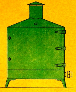
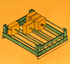
A steam-drier, for drying wet gun-cotton for use as primers, consists
of a sheet-iron box containing two removable galvanized-iron wire
baskets in which the blocks to be dried are supported, strung on rods.
The blocks are separated from each other by small iron washers, ¼ inch
thick, also strung on the rods, to permit free circulation of the air.
A door in the front of the box permits entering and withdrawing the
baskets.
In the bottom of the box is a flat of steam-pipe the two ends of which,
projecting from the side, are screw-threaded for ready connection
with steam-heating apparatus, or with any other convenient source of
low-pressure steam.
A wire-gauze bottom, below the flat of steam-pipe, permits the entrance
of air and serves to keep out dust and to prevent undue radiation of
heat toward the outside.
In the top of the box is a ventilating opening, with a rotary damper,
protected by a hood, and also a hole for the introduction of a thermometer.
This box is marked on top “Chemical Box.” For contents see Box 16,
“List of Articles in Outfit supplied from Torpedo Station.” For use of
contents see “Inspection of Gun-Cotton.”
The outfit includes a number of spare washers, spherical packings,
diaphragms, etc., to supply necessary waste.
In addition to the articles already mentioned, every vessel having a
“Ship‘s and Boat‘s” spar-torpedo outfit is supplied from the Torpedo
Station with the following articles, to be placed on board at the
navy yards, as permanent fittings; viz.:
Double-conductor insulated copper wire, incased in lead, in such
quantity as may be required for permanent wires; 2 electric switches;
13 terminal binding-screws.
Plate IX.
In order to do away with the inconvenience of leading out lengths of
wire from place to place, and to avoid injury to the wire, permanent
wires are put in place when the ship is fitted out. These wires are
led from terminals conveniently placed for battery connections via the
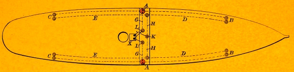
electric switches or firing apparatus to the terminals, abreast the
heels of the torpedo-spars.
Permanent wires should be protected from hostile fire, from chafe,
wear, and the sun; should never be taut; should never be led around
sharp angles; metal staples should never be used to hold the wires
in position, even temporarily; no part of the copper wire should be
exposed to the action of salt water; splices should be soldered and
carefully insulated; and the wires should be boxed in throughout their lengths.
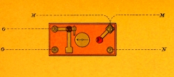
Plate X.
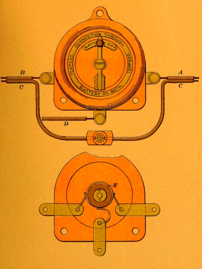
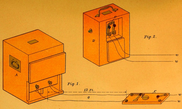
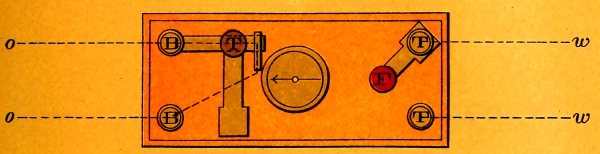
In connection with permanent wires electric switches are used, and are
permanently placed in a suitable position before a ship leaves the
navy-yard.
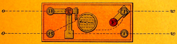
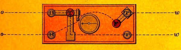
Their object is to connect the firing-battery or the firing-key of the
D. E. machine with any or all the torpedoes. The plate represents the
switch in position, on the starboard side, with the battery off, or
the wires from the firing-key disconnected from any permanent wire,
electrically. The switch should be protected from salt water and the
weather as much as possible. It is thought best to inclose it in a box,
as nearly water-tight as possible, provided with a door which opens in
front.
Note.—Where permanent firing apparatus is furnished, the
electric switches will not be issued.
Plate X.
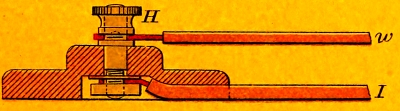
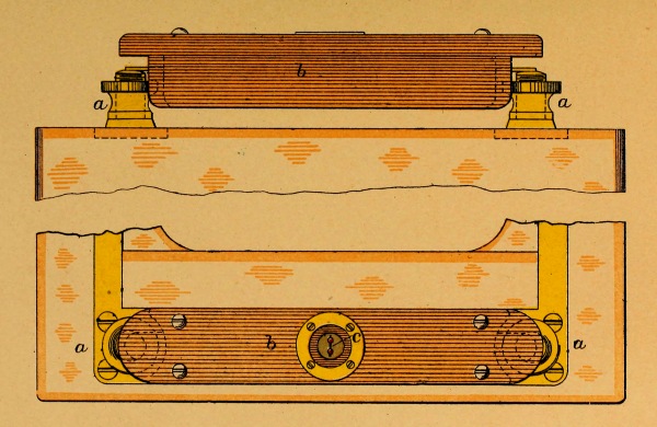
Terminals are ordinary brass binding-screws secured to base-pieces
of black walnut which are to be secured in position by screws. The
figure illustrates the manner of making permanent and temporary
connections with the terminals. The counter-sunk space in the back of
the base-piece is to be filled with melted wax, after the permanent
wire has been attached, before securing the terminal in place. The
binding-screws must be kept clean and free from paint.
Ship‘s Spars.—Such ship-rigged vessels as are now fitted for
spar-torpedoes are supplied with four torpedo-spars, fitted two on each
side, abreast the foremast and mizzenmast. Barque-rigged vessels are
supplied with but two spars, fitted one abreast the foremast on each
side. The present regulation spar is of hickory or oak, 45 feet long,
8 inches in diameter at the heel, and 6 inches at the outer end. It
should be of the best material, straight-grained, and as nearly as
possible a natural-growth pole. In working down a larger spar, care
should be observed to follow the grain of the wood. Yellow oak is
considered superior for torpedo-spars. Red oak is too brash.
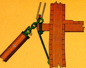
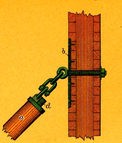
The Heel Fittings. (Plate XI.)—The
thrust-plate is placed at about the height of the channels, in accordance with
the regulations established by the Bureau of Ordnance. Discretion must be
used in so placing this as to allow the spar to come alongside, so that
the torpedo can be shipped from the rail or from a port. The elbow of
the heel-bolt transmits the recoil of the spar to the thrust-plate,
without injury to the bolt itself. Good results have been obtained by
using a lashing of 6 turns of 3½-inch manilla, in place of the shackle,
the elasticity of the rope serving to take up a portion of the thrust
of the spar. An excellent plan is to secure the heel of the spar to a
spare eye-bolt in the channels, as shown in Fig. 2.
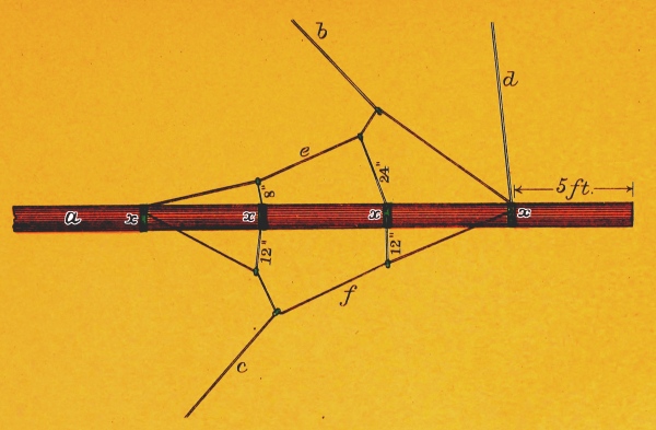
The Spar Fittings. (Plate XII.)—The most
approved method of fitting a torpedo spar with guys and topping lift is shown in
the plate. Spans are fitted to the spar on which the forward guy and
topping lift travel freely, and these spans are rove through lizards to
divide the strain along the spar and prevent vibrations. The forward
guy should be single, with as much drift as possible, and long enough
to let the spar trail aft, after the explosion. The forward guy, the
pendant of the topping lift, or that part of it secured to the span,
the spans and lizards should be of galvanized-iron wire rope, ⅝ inch in
diameter. The after guy may be a single part of small manilla rope, say
3-inch. The forward guy should be led from as near the water-line as
possible to keep the spar from rising.