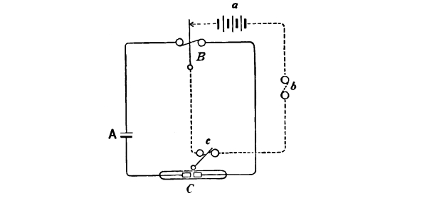
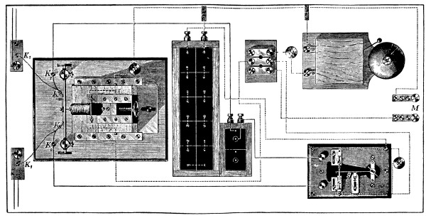
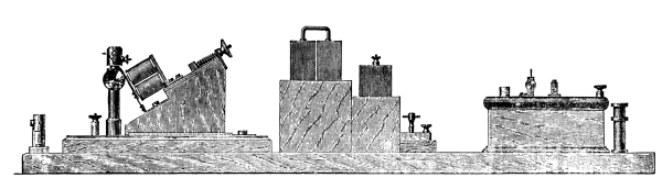
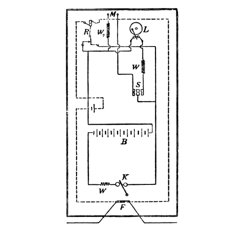
SIGNALLING THROUGH SPACE WITHOUT WIRES. — THE WORK OF HERTZ AND SOME OF HIS SUCCESSORS. — Introductory. —1894. — Sphere charged from Electrophorus. — Syntonic Leyden Jars. — Ordinary Size Hertz Vibrator. — Two Circular Vibrators Sparking in sympathy. — Holtz Machine, A and B Sparks; Glass and Quartz Panes in Screen. — Zinc discharging Negative Electricity in Light; Gold Leaf Electroscope; Glass and Quartz Panes; Quartz Prism. — Large Hertz Vibrator in action; Abel’s Fuse Detector; Vacuum Tube Detector; Striking of an Arc. — Specimens of Emitters and Receivers. — Various Detectors. — Air Gap and Electroscope charged by Glass Rod and discharged by the Wave Impulse from a moderately distant Sphere excited by Coil. — Microphonic Detectors. — Coherer in open, responding to Feeble Stimuli:— Small Sphere, Gas-lighter, Distant Sphere, Electrophorus. — Experiment showing Filings Tube responding to Sphere, to Electrophorus, and to a Quasi-“Spark” from the Discharge of an ordinary Gold-leaf Electroscope. — Electrical Theory of Vision. — Demonstration of Ordinary Holtz Machine Sparks not exciting Tube: except by help of a polished knob. — Receiver in Metallic Enclosure. — Optical Experiments. — Reflection. — Refracting Prism and Lens. — Arago Disc; Grating; and Zone-plate. — Polarising and Analysing Grids. — Reflecting Paraffin Surface; Direction of Vibrations in Polarised Light. — NOTE WITH REFERENCE TO ELECTRIC WAVES ON WIRES.
The following pages (up to page 42) are
the Notes of a Lecture delivered by Dr. O. J. Lodge before the Royal
Institution of Great Britain on Friday evening, June 1, 1894. These
notes have been revised by Dr. Lodge, and prepared for publication in
the form here presented. After page 42 an account is given of the later
applications of Hertzian wave experiments to wireless telegraphy, and a
series of Appendices are also given.
The untimely end of a young and brilliant career cannot fail to strike
a note of sadness and awaken a chord of sympathy in the hearts of his
friends and fellow-workers. Of men thus cut down in the early prime
of their powers there will occur to us here the names of Fresnel, of
Carnot, of Clifford, and now of Hertz. His was a strenuous and favoured
youth; he was surrounded from his birth with all the influences that
go to make an accomplished man of science—accomplished both on the
experimental and on the mathematical side. The front rank of scientific
workers is weaker by his death, which occurred on January 1, 1894, the
thirty-seventh year of his life. Yet did he not go till he had effected
an achievement which will hand his name down to posterity as the
founder of an epoch in experimental physics.
In mathematical and speculative physics others had sown the seed. It
was sown by Faraday, it was sown by Thomson and by Stokes, by Weber
also doubtless, and by Helmholtz; but in this particular department
it was sown by none more fruitfully and plentifully than by Clerk
Maxwell. Of the seed thus sown Hertz reaped the fruits. Through his
experimental discovery, Germany awoke to the truth of Clerk Maxwell’s
theory of light, of light and electricity combined, and the able army
of workers in that country (not forgetting some in Switzerland, France,
and Ireland) have done most of the gleaning after Hertz.
This is the work of Hertz which is best known, the work which brought
him immediate fame. It is not always that public notice is so well
justified. The popular instinct is generous and trustful, and it is
apt to be misled. The scientific eminence accorded to a few energetic
persons by popular estimate is more or less amusing to those working on
the same lines. In the case of Hertz no such mistake has been made. His
name is not over well-known, and his work is immensely greater in every
way than that of several who have made more noise.
His best known discovery is by no means his only one, and no less
than eighteen Papers were contributed to German periodicals by him,
in addition to the papers incorporated in his now well-known book on
electric waves.
In closing these introductory and personal remarks, I should like to
say that the enthusiastic admiration for Hertz’s spirit and character
felt and expressed by students and workers who came into contact with
him is not easily to be exaggerated. Never was a man more painfully
anxious to avoid wounding the susceptibilities of others; and he was
accustomed to deprecate the prominence given to him by speakers and
writers in this country, lest it might seem to exalt him unduly above
other and older workers among his own sensitive countrymen.
Speaking of the other great workers in physics in Germany, it is not
out of place to record the sorrow with which we have heard of the
recent death of Dr. August Kundt, Professor in the University of
Berlin, successor to Von Helmholtz in that capacity.
When I consented to discourse on the work of Hertz, my intention was to
repeat some of his actual experiments, and especially to demonstrate
his less-known discoveries and observations. But the fascination
exerted upon me by electric oscillation experiments, when I, too,
was independently working at them in the spring of 1888,[1]
resumed its hold, and my lecture will accordingly consist of experimental
demonstrations of the outcome of Hertz’s work rather than any precise
repetition of portions of that work itself.
In case a minority of my audience are in the predicament of not knowing
anything about the subject, a five minutes’ explanatory prelude may be
permitted; and the simplest way will be for me hastily to summarise our
knowledge of the subject before the era of Hertz.
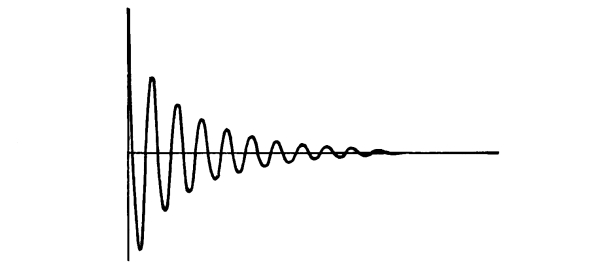
Fig. 1.—Oscillations
of Dumb-bell Hertz Vibrator (after Bjerknes).
Just as a pebble thrown into a pond excites surface ripples, which
can heave up and down floating straws under which they pass, so a
struck bell or tuning fork emits energy into the air in the form of
what are called sound waves, and this radiant energy is able to set up
vibrations in other suitable elastic bodies.
If the body receiving them has its natural or free vibrations violently
damped, so that when left to itself it speedily returns to rest (Fig. 1),
then it can respond fully to notes of almost any pitch. This is
the case with your ears and the tones of my voice. Tones must be
exceedingly shrill before they cease to excite the ear at all.
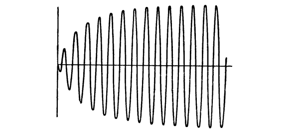
If, on the other hand, the receiving body has a persistent period of
vibration, continuing in motion long after it is left to itself (Fig. 2)
like another tuning fork or bell, for instance, then far more facility
of response exists, but great accuracy of tuning is necessary if it
is to be fully called out; for if the receiver is not thus accurately
syntonised with the source, it fails more or less completely to resound.
Fig. 2.—Oscillation
of Ring-shaped Hertz Resonator excited by Syntonic Vibrator (after Bjerknes).
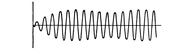
Fig. 3.—Oscillation of Ring Resonator not
quite syntonic with Radiator. (For method of obtaining these curves
see Fig. 14.)
Conversely, if the source is a persistent vibrator, correct
tuning is essential, or it will destroy at one moment (Fig. 3)
motion which it originated the previous moment. Whereas, if it is a dead-beat
or strongly-damped exciter, almost anything will respond equally well
or equally ill to it.
What I have said of sounding bodies is true of all vibrators in a
medium competent to transmit waves. Now a sending telephone or a
microphone, when spoken to, emits waves into the ether, and this
radiant energy is likewise able to set up vibration in suitable bodies.
But we have no delicate means of directly detecting these electrical or
etherial waves; and if they are to produce a perceptible effect at a
distance, they must be confined, as by a speaking-tube, prevented from
spreading, and concentrated on the distant receiver.
This is the function of the telegraph wire; it is to the ether what
a speaking-tube is to air. A metal wire in air (in function,
not in details of analogy) is like a long hollow cavity surrounded by
nearly rigid but slightly elastic walls.
Furthermore, any conductor electrically charged or discharged with
sufficient suddenness must emit electrical waves into the ether,
because the charge given to it will not settle down instantly, but will
surge to and fro several times first; and these surgings or electric
oscillations must, according to Maxwell, start waves in the ether,
because at the end of each half-swing they cause electrostatic, and at
the middle of each half-swing they cause electromagnetic effects, and
the rapid alternation from one of these modes of energy to the other
constitutes etherial waves.[2]
If a wire is handy they will run along it, and may be felt a long way
off. If no wire exists they will spread out like sound from a bell, or
light from a spark, and their intensity will decrease according to the
inverse square of the distance.
Maxwell and his followers well knew that there would be such waves;
they knew the rate at which they would go, they knew that they would
go slower in glass and water than in air, they knew that they would
curl round sharp edges, that they would be partly absorbed but mainly
reflected by conductors, that if turned back upon themselves they
would produce the phenomena of stationary waves, or interference, or
nodes and loops; it was known how to calculate the length of such
waves, and even how to produce them of any required or predetermined
wave length from 1,000 miles to a foot. Other things were known about
them which would take too long to enumerate; any homogeneous insulator
would transmit them, would refract or concentrate them if it were of
suitable shape, would reflect none of a particular mode of vibration at
a certain angle, and so on, and so on.
All this was known, I say, known with varying degrees of
confidence; but by some known with as great confidence as, perhaps
even more confidence than, is legitimate before the actuality of
experimental verification.
Hertz supplied the verification. He inserted suitable conductors in the
path of such waves, conductors adapted for the occurrence in them of
induced electric oscillations, and to the surprise of everyone, himself
doubtless included, he found that the secondary electric surgings thus
excited were strong enough to display themselves by minute electric sparks.
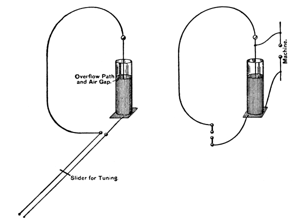
Fig. 4.—Experiment
with Syntonic Leyden Jars (cf. page 21).
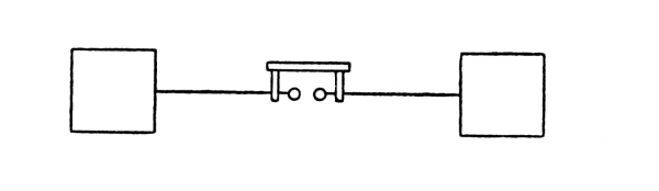
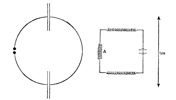
I shall show this in a form which requires great precision of tuning or
syntony, both emitter and receiver being persistently vibrating things
giving some 30 or 40 swings before damping has a serious effect. I take
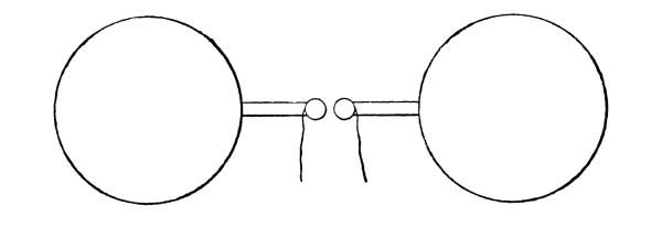
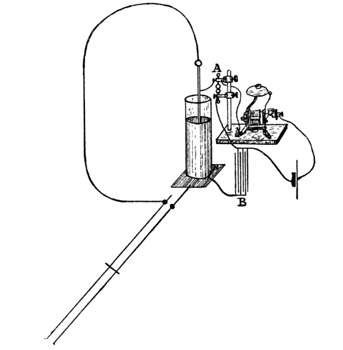
two Leyden jars with circuits about a yard in diameter, and situated
about two yards apart (Fig. 4). I charge and discharge one
jar, and observe that the surgings set up in the other can cause it to overflow
if it is syntonised with the first.[3]
A closed circuit such as this is a feeble radiator and a feeble
absorber, so it is not adapted for action at a distance. In fact, I
doubt whether it will visibly act at a range beyond the ¼λ at which
true radiation of broken-off energy occurs. If the coatings of the
jar are separated to a greater distance, so that the dielectric is
more exposed, it radiates better; because in true radiation the
electrostatic and the magnetic energies must be equal, whereas in a
ring circuit the magnetic energy predominates. By separating the coats
of the jar as far as possible we get a typical Hertz vibrator (Fig. 5),
whose dielectric extends out into the room, and thus radiates very powerfully.
Fig. 5.—
Standard Hertz Radiator.
In consequence of its radiation of energy, its vibrations are rapidly
damped, and it only gives some three or four good strong swings
(Fig. 1). Hence it follows that it has a wide range
of excitation; i.e., it can excite sparks in conductors barely
at all in tune with it.
The two conditions, conspicuous energy of radiation and persistent
vibration electrically produced, are at present incompatible. Whenever
these two conditions coexist, considerable power or activity will,
of course, be necessary in the source of energy. At present they only
coexist in the sun and other stars, in the electric arc, and in furnaces.
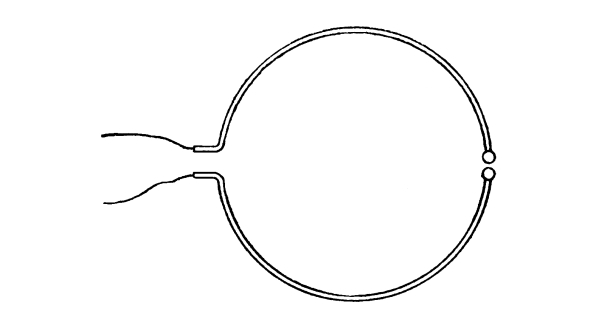
The receiver Hertz used was chiefly a circular resonator
(Fig. 6), not a good absorber but a persistent
vibrator, well adapted for picking up disturbances of precise and
measurable wave length. Its mode of vibration when excited by emitter
in tune with it is depicted in Fig. 2. I find that
the circular resonators can act as senders too; here is one exciting
quite long sparks in a second one.
Electric Syntony.—That was his discovery, but he did not stop
there. He at once proceeded to apply his discovery to the verification
of what had already been predicted about the waves, and by laborious
and difficult interference experiments he ascertained that the previously
calculated length of the waves was thoroughly borne out by fact. These
interference experiments in free space are his greatest achievement.
Fig. 6.—Circular
Resonator. (The knobs ought to nearly touch each other.)
Fig. 6a.—Any
circular Resonator can be used as a sender by bringing its knobs near the
sparking knobs of a coil; but a simple arrangement is to take two
semi-circles, as in above figure, and make them the coil terminals.
The capacity of the cut ends can be varied, and the period thereby
lengthened, by expanding them into plates.
He worked out every detail of the theory splendidly, separately
analysing the electric and the magnetic oscillation, using language
not always such as we should use now, but himself growing in theoretic
insight through the medium of what would have been to most physicists a
confusing maze of troublesome facts, and disentangling all their main
relations most harmoniously.
While Hertz was observing sparks such as these, the primary or exciting
spark and the secondary or excited one, he observed as a bye issue
that the secondary spark occurred more easily if the light from the
primary fell upon its knobs. He examined this new influence of light
in many ways, and showed that although spark light and electric brush
light were peculiarly effective, any source of light that gave very
ultra-violet rays produced the same result.
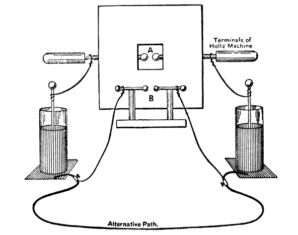
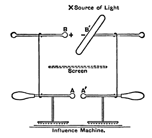
Fig. 7.—
Experiment arranged to show effect on one spark of light from another.
The B spark occurs more easily when it can see the A
spark through the window, unless the window is glazed with glass. A
quartz pane transmits the effect: glass cuts it off.
The above figure represents my way of showing the experiment. It will
be observed that with this arrangement the B knobs are at the
same potential up to the instant of the flash, and in that case the
ultra-violet portion of the light of the A spark assists the
occurrence of the B spark. But it is interesting to note what
Elster and Geitel have found (see Appendix IV., Fig. 59),
that if the B knobs were subjected to steady strain instead of to
impulsive rush—e.g., if they were connected to the inner
coats of the jars instead of the outer coatings—that then the effect
of ultra-violet light on either spark gap would exert a deterrent
influence, so that the spark would probably occur at the other, or
non-illuminated gap. With the altered connections it is, of course, not
feasible to illuminate one spark by the light of the other; the sparks
are then alternative, not successive.
Wiedemann and Ebert, and a number of experimenters, have repeated and
extended this discovery, proving that it is the cathode knob on which
illumination takes effect; and Hallwachs and Righi made the important
observation, which Elster and Geitel, Stoletow, Branly, and others have
extended, that a freshly-polished zinc or other oxidisable surface, if
charged negatively, is gradually discharged by ultra-violet light.
Fig. 8.—
Zinc Rod in Arc Light, protected by Glass Screen. The lenses are of
quartz, but there is no need for any lenses in this experiment; leakage
of electricity begins directly the glass plate is withdrawn.
It is easy to fail in reproducing this experimental result if the right
conditions are not satisfied; but if they are it is absurdly easy, and
the thing might have been observed nearly a century ago.
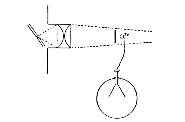
Take a piece of zinc, clean it with emery paper, connect it to a gold
leaf electroscope, and expose it to an arc lamp. (Fig. 8).
If charged positively nothing appears to happen, the action is very slow; but
a negative charge leaks away in a few seconds if the light is bright.
Any source of light rich in ultra-violet rays will do; the light from
a spark is perhaps most powerful of all. A pane of glass cuts off all
the action; so does atmospheric air in sufficient thickness (at any
rate, town air), hence sunlight is not powerful. A pane of quartz
transmits the action almost undiminished, but fluorspar may be more
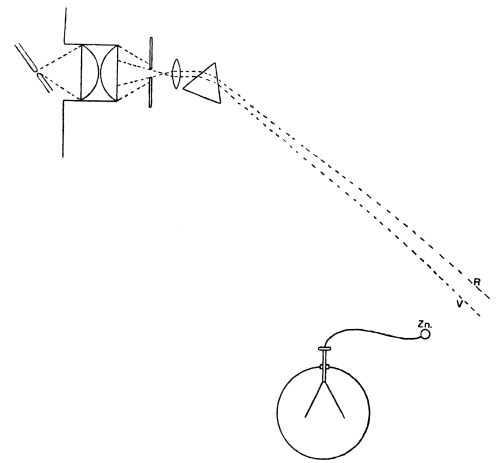
transparent still. Condensing the arc rays with a quartz lens and
analysing them with a quartz prism or reflection grating, we find that
the most effective part of the light is high up in the ultra-violet,
surprisingly far beyond the limits of the visible spectrum[4]
(Fig. 9, next page).
This is rather a digression, but I have taken some pains to show it
properly because of the interest betrayed by Lord Kelvin on this
matter, and the caution which he felt about accepting the results of
the Continental experimenters too hastily.
It is probably a chemical phenomenon, and I am disposed to express it
as a modification of the Volta contact effect[5]
with illumination.
Fig. 9.—
Zinc Rod discharging Negative Electricity in the very Ultra-violet
Light of a Spectrum formed by a Quartz Train. The best discharging
light is found far beyond the limits of the visible spectrum.
Return now to the Hertz vibrator, or Leyden jar with its coatings well
separated, so that we can get into its electric as well as its magnetic
field. Here is a great one giving waves 30 metres long, radiating while
it lasts with an activity of 100 h.p., and making ten
million complete electric vibrations per second. It is made of four large
copper sheets soldered together two and two, strung up by thin rope to
a gallery, and each pair connected with the other by several yards of
No. 0 pure copper rod, interrupted by a pair of sparking knobs (Fig. 10).
Its great radiating power damps it down very rapidly, so that it does
not make above two or three swings; but nevertheless, each time it is
excited, sparks can be drawn from most of the reasonably elongated
conductors in the theatre of this Institution, and indeed from wire
fencing and iron roofs outside this building.
A suitably situated gas leak can be ignited by these induced sparks.
An Abel’s fuse connecting the water pipes with the gas pipes will blow
off; vacuum tubes connected to nothing will glow (this fact has been
familiar to all who have worked with Hertz waves since 1889), electric
leads, if anywhere near each other, as they are in some incandescent
lamp-holders, may spark across to each other, thus striking an arc
and blowing their fuses. This blowing of fuses by electric radiation
frequently happened at Liverpool till the suspensions of the theatre
lamps were altered. They had at first been held in position by wire
guides, which served as collectors of the Hertz waves or impulses.
Fig. 10.—
Hertz Oscillator on reduced scale, ⅒th inch to a foot.
The striking of an arc by the little reverberating sparks between two
lamp-carbons connected with the 100-volt mains I incidentally now
demonstrate. An arc is started directly the large Hertz vibrator is
excited at a distance.
There are some who think that lightning flashes can do none of these
secondary things. They are mistaken.
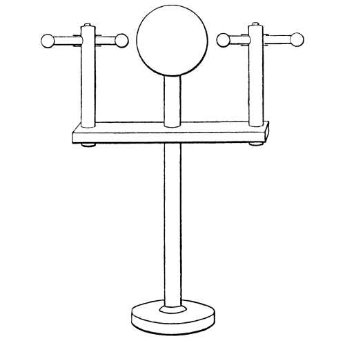
On the table are specimens of various emitters and receivers such
as have been used by different people; the orthodox Hertz radiator
(Fig. 5), and the orthodox Hertz receivers:—A circular
ring (Fig. 6) for interference experiments,
because it is but little damped, and a straight wire for receiving at
a distance, because it is a much better absorber. Beside these are the
spheres and ellipsoids (or elliptical plates), which I have myself
introduced and mainly used (Fig. 19),
because they are powerful radiators and absorbers, and because their
theory has been worked out by Horace Lamb and J. J. Thomson. Also
dumb-bells (Fig. 11) without air gap, which must be excited
by a positive spark at one end and a negative spark at the other, and many
other shapes, the most recent of mine being the inside of a hollow
cylinder with sparks at ends of a diameter (Fig. 12); this being a
feeble radiator, but a very persistent vibrator,[6]
and, therefore, well adapted for interference and diffraction
experiments. But, indeed, spheres can be made to vibrate longer than
usual by putting them into copper hats or enclosures, in which an
aperture of varying size can be made to let the waves out
(Figs. 20 and 21).
Fig. 11.—
A Small Dumb-bell Form of Radiator for Impulsive Rush.
Fig. 12.—
Dr. Lodge’s Hollow Cylindrical Radiator, arranged horizontally against
the outside of a Metal-lined Box containing the Spark-producing
Apparatus. Half natural size. Emitting 3 in. waves.
Many of these senders will do for receivers too, giving off sparks
to other insulated bodies or to earth; but besides the Hertz type of
receiver, many other detectors of radiation have been employed. Vacuum
tubes can be used, either directly or on the trigger principle, as by
Zehnder (Fig. 13),[7]
the resonator spark precipitating a discharge
from some auxiliary battery or source of energy, and so making a feeble
disturbance very visible. Explosives may be used for the same purpose,
either in the form of mixed water-gases or in the form of an Abel’s
fuse. FitzGerald found that a tremendously sensitive galvanometer could
indicate that a feeble spark had passed, by reason of the consequent
disturbance of electrical equilibrium which settled down again through
the galvanometer.[8]
This was the method he used in this theatre four years ago. Blyth used
a one sided electrometer, and V. Bjerknes has greatly developed this
method (Fig. 14), abolishing the need for a spark, and making the
electrometer metrical, integrating and satisfactory.[9]
With this detector many measurements have been made at Bonn by
Bjerknes, Yule, Barton and others on waves concentrated and kept from
space dissipation by guiding wires.
Fig. 13.—
Zehnder’s Trigger Tube. Half Natural Size. The two right-hand
terminals, close together, are attached to the Hertz receiver; another
pair of terminals are connected to some source just not able to make
the tube glow until the scintilla occurs and makes the gas more
conducting—as observed by Schuster and others.
Mr. Boys has experimented on the mechanical force exerted by electrical
surgings, and Hertz also made observations of the same kind.
Going back to older methods of detecting electrical radiation, we have,
most important of all, a discovery made long before man existed, by
a creature that developed a sensitive cavity on its skin; a creature
which never so much as had a name to be remembered by (though perhaps
we now call it trilobite). Then, in recent times we recall the
photographic plate and the thermopile, with its modification, the
radiomicrometer; also the so-called bolometer, or otherwise-known
Siemens’ pyrometer, applied to astronomy by Langley, and applied to the
detection of electric waves in wires by Rubens and Ritter and Paalzow
and Arons. The thermal junction was applied to the same purpose by
Kolacek, D. E. Jones and others.
And, before all these, the late Mr. Gregory, of Cooper’s Hill, made his
singularly sensitive expansion meter, whereby waves in free space could
be detected by the minute rise of temperature they caused in a platinum
wire, a kind of early and sensitive form of Cardew voltmeter.
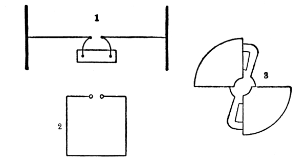
Fig. 14.—
Bjerknes’ Apparatus, showing (1) a Hertz vibrator connected to an
induction coil; (2) a nearly closed circuit receiver properly tuned
with the vibrator; and (3) a one sided electrometer for inserting
in the air gap of 2. The receiver is not provided with knobs, as
shown, but its open circuit is terminated by the quadrants of the
electrometer, which is shown on an enlarged scale alongside. The needle
is at zero potential and is attracted by both quadrants. By calculation
from the indications of this electrometer Bjerknes plotted
the curves 1, 2 and 3 on pages 4 and
5. Fig. 1 represents the
oscillations of the primary vibrator, rapidly damped by radiation of
energy. Fig. 2 represents the vibrations thereby
set up in the resonating circuit when the two are accurately in tune;
and which persist for many swings. Fig. 3 shows the
vibrations excited in the same circuit when slightly out of tune with
the exciter. A receiver of this kind makes many swings before it is
seriously damped, though the open plate radiator does not.
Going back to the physiological method of detecting surgings, Hertz
tried the frog’s leg nerve-muscle preparation, which to the steadier
types of electrical stimulus is so surpassingly sensitive, and to which
we owe the discovery of current electricity. But he failed to get any
result. Ritter has succeeded; but, in my experience, failure is the
normal and proper result. Working with my colleague, Prof. Gotch, at
Liverpool, I too have tried the nerve and muscle preparation of the
frog (Fig. 15), and we find that an excessively violent stimulus
of a rapidly alternating character, if pure and unaccompanied by secondary
actions, produces no effect—no stimulating effect, that is—even
though the voltage is so high that sparks are ready to jump between the
needles in direct contact with the nerve.
All that such oscillations do, if continued, is to produce a temporary
paralysis or fatigue of the nerve, so that it is unable to transmit
the nerve impulses evoked by other stimuli, from which paralysis it
recovers readily enough in course of time.
Fig. 15.—
Experiment of Gotch and Lodge on the physiological effect of rapid pure
electric alternations. Nerve-muscle preparation, with four needles, or
else non-polarisable electrodes applied to the nerve. C and D are the
terminals of a rapidly-alternating electric current from a conductor
at zero potential (namely, the terminals of a derived circuit from a
wire connecting the outer coats of a pair of discharging Leyden jars),
while A and B are the terminals of an ordinary very weak galvanic or
induction coil stimulus only just sufficient to make the muscle twitch.
The C D terminals do not stimulate the nerve, though at very high
alternative potentials, but they gradually and temporarily paralyse it,
so that the test terminals A B produce no effect for a time.
This has been expected from experiments on human beings, such
experiments as Tesla’s and those of d’Arsonval. But an entire animal is
not at all a satisfactory instrument wherewith to attack the question;
its nerves are so embedded in conducting tissues that it may easily be
doubted whether the alternating type of stimulus ever reaches them at
all. By dissecting out a nerve and muscle from a deceased frog after
the historic manner of physiologists, and applying the stimulus direct
to the nerve, at the same time as some other well known ¹/₁₀₀th a volt
stimulus is applied to another part of the same nerve further from the
muscle, it can be shown that rapid electric alternations, if entirely
unaccompanied by static charge or by resultant algebraic electric
transmission, evoke no excitatory response until they are so violent
as to give rise to secondary effects such as heat or mechanical shock.
Yet, notwithstanding this inaction, they gradually and slowly exert a
paralysing or obstructive action on the portion of the nerve to which
they are applied, so that the nerve impulse excited by the feeble just
perceptible ¹/₁₀₀th-volts stimulus above is gradually throttled on its
way down to the muscle, and remains so throttled for a time varying
from a few minutes to an hour after the cessation of the violence. [I
did not show this experiment at the lecture.]
Fig. 16.—
Air gap for Electroscope. Natural size. The bottom plate is connected
to, and represents, the cap of an electroscope; the “knob” above it,
mentioned in text, is the polished end of the screw, whose terminal is
connected with the case of the instrument or “earth.” The electroscope
being charged to the verge of overflow, the impact of weak electric
waves collected by a bit of wire sticking up from the left-hand binding
screw precipitates the collapse of the leaves.
Among trigger methods of detecting electric radiation, I have spoken
of the Zehnder vacuum tubes; another method is one used by
Boltzmann.[10]
A pile of several hundred volts is on the verge of charging an
electroscope through an air gap just too wide to break down. Very
slight electric surgings precipitate the discharge across the gap, and
the leaves diverge. I show this in a modified and simple form. On the
cap of an electroscope is placed a highly polished knob or rounded end
connected to the sole, and just not touching the cap, or, rather, just
not touching a plate connected with the cap (Fig. 16), the distance
between knob and plate being almost infinitesimal, such a distance as
is appreciated in spherometry. Such an electroscope overflows suddenly
and completely with any gentle rise of potential. Bring excited glass
near it, the leaves diverge gradually and then suddenly collapse,
because the air space snaps: remove the glass, and they rediverge
with negative electricity; the knob above the cap being then charged
positively, and to the verge of sparking. In this condition any
electrical waves, collected if weak by a foot or so of wire projecting
from the cap, will discharge the electroscope by exciting surgings in
the wire, and so breaking down the air gap. The chief interest about
this experiment seems to me the extremely definite dielectric strength
of so infinitesimal an air space. Moreover, it is a detector for Hertz
waves that might have been used last century; it might have been used
by Benjamin Franklin.
For to excite them no coil or anything complicated is necessary; it is
sufficient to flick a metal sphere or cylinder with a silk handkerchief
and then discharge it with a well-polished knob. If it is not well
polished the discharge is comparatively gradual, and the vibrations
are weak; the more polished are the sides of an air gap, the more
sudden is the collapse and the more vigorous the consequent radiation,
especially the radiation of high frequency, the higher harmonics of the
disturbance.
For delicate experiments it is sometimes well to repolish the knobs
every hour or so. For metrical experiments it is often better to let
the knobs get into a less efficient but more permanent state. This is
true of all senders or radiators. For the generation of the, so to
speak, “infra-red” long-period Hertz waves any knobs will do, but to
generate the “ultra-violet” short-period waves high polish is essential.
Receivers or detectors, which for the present I temporarily call
microphonic, are liable to respond best to the more rapid vibrations.
Their sensitiveness is to me surprising, though of course it does
not approach the sensitiveness of the eye; at the same time I am by
no means sure that the eye differs from them in kind. It is these
detectors that I wish specially to bring to your notice.
Prof. Minchin, whose long and patient work in connection with
photo-electricity is now becoming known, and who has devised
an instrument more sensitive to radiation than even Boys’
radiomicrometer, in that it responds to the radiation of a star while
the radiomicrometer does not, found some years ago that some of his
light-excitable cells lost their sensitiveness capriciously on tapping,
and later he found that they frequently regained it again while Mr.
Gregory’s Hertz-wave experiments were going on in the same room.
These “impulsion cells,” as he terms them, are troublesome things for
ordinary persons to make and work with—at least I have never presumed
to try—but in Mr. Minchin’s hands they are surprisingly sensitive to
electric waves.[11]
The sensitiveness of selenium to light is known to everyone, and Mr.
Shelford Bidwell has made experiments on the variations of conductivity
exhibited by a mixture of sulphur and carbon.
Nearly four years ago M. Edouard Branly found that a burnished
coat of porphyrised copper spread on glass or ebonite, diminished
its resistance enormously, from some millions to some hundreds of
ohms, when it was exposed to the neighbourhood, even the distant
neighbourhood, of Leyden jar or coil sparks. He likewise found that a
tube of metallic filings behaved similarly, and that both recovered
their original resistance on shaking or tapping. Mr. Croft exhibited
this fact recently at the Physical Society. M. Branly also made pastes
and solid rods of filings, in Canada balsam and in sulphur, and found
them likewise sensitive.[12]
With me the matter arose somewhat differently, as an outcome of the
air gap detector employed with an electroscope by Boltzmann (Fig. 16).
For I had observed in 1889 that two knobs sufficiently close together,
far too close to stand any voltage such as an electroscope can show,
could, when a spark passed between them, actually cohere; conducting an
ordinary bell-ringing current if a single voltaic cell was in circuit;
and, if there were no such cell, exhibiting an electromotive force of
their own sufficient to disturb a low resistance galvanometer
vigorously, and sometimes requiring a faintly perceptible amount of
force to detach them. The experiment was described to the Institution
of Electrical Engineers in 1890,[13]
and Prof. Hughes said he had observed the same thing.
Fig. 16a.—
Receiver in Syntonic Jar Experiment, with Knob Coherer
and Tapper-back (cf. Fig. 4).
The experiment of the syntonic Leyden jars can be conveniently shown
with the double-knob or 1889 coherer. The pair of knobs are arranged
to connect the coatings of the receiving jar (a large condenser being
interposed to prevent their completing a purely metallic circuit),
and in circuit with them is a battery and a bell. Every time the
receiving jar responds syntonically to the electric vibration of the
other jar, the knobs cohere (if properly adjusted) and the bell rings.
If the bell is free in air it continues ringing until the knobs are
gently tapped asunder; but if the bell stands on the same table as the
knobs, especially if it rests one foot on the actual stand, then its
first stroke taps them back instantly and automatically, and so every
discharge of the sending jar is signalled by a single stroke of the
bell. Here we have in essence a system of very distinctly syntonic
telegraphy, for the jars and their circuits must be accurately tuned
together, if there is to be any response. A very little error in
tuning, easily made by altering the position of the slider (Fig. 4),
will make them quite unresponsive, unless the distance between them is reduced.
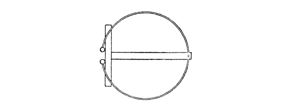
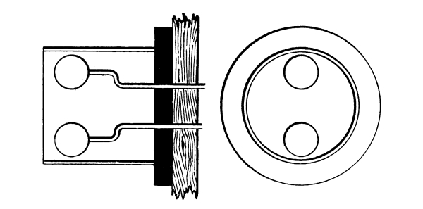
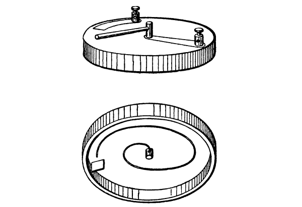
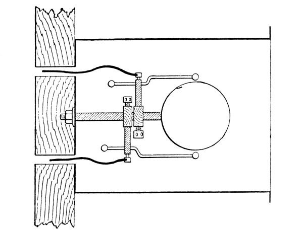
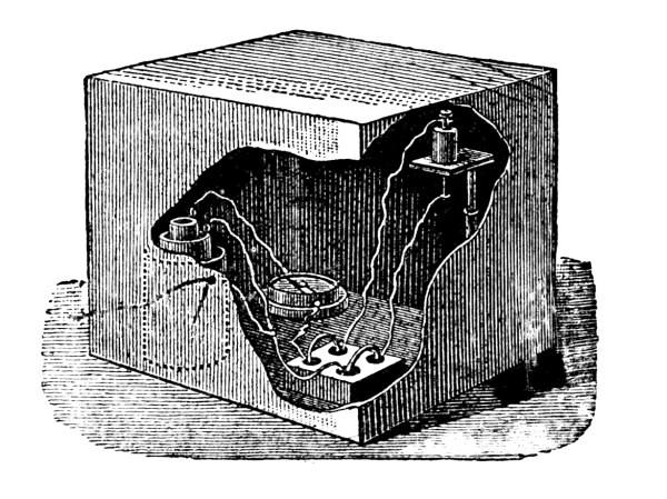
Fig. 17.—
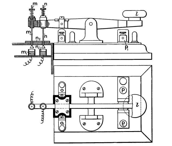
Early Form of Coherer, consisting of a spiral of thin iron wire mounted
on an adjustable spindle and an aluminium plate. When the lever is
moved clockwise the tip of the iron wire presses gently against the
aluminium plate, whose end is bent at right angles and passed through
into the hollow circular wooden box, of which the upper figure shows
the top and general appearance, and the lower figure shows the inside.
At the maximum distance of response the tuning required is excessively
sharp. But, certainly, for these closed and durably-vibrating circuits,
the distance of response is small, as has been said before. Fig.
16a shows the syntonic Leyden jar experiment
arranged with the double knob coherer, instead of with the spark gap of
Fig. 4.
Well, this arrangement, which I call a coherer, is the most
astonishingly sensitive detector of Hertz waves. It differs from an
actual air gap in that the insulating film is not really insulating;
the film breaks down not only much more easily, but also in a less
discontinuous and more permanent manner, than an air gap. Branly’s
tube of filings, a series of bad contacts, clearly works on the same
plan; and though a tube of filings is by no means so sensitive, yet it
is in many respects easier to work with, and except for very feeble
stimuli, is more metrical. If the filings used are coarse, say turnings
or borings, the tube approximates to a single coherer; if they are
fine, it has a larger range of sensibility. In every case what these
receivers feel are sudden jerks of current; smooth sinuous vibrations
are ineffective. They seem to me to respond best to waves a few inches
long, but doubtless that is determined chiefly by the dimensions of
some conductor with which they happen to be associated. (Figs. 17
and 18.)
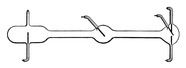
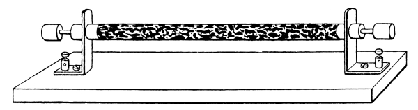
Fig. 18.—
Early Form of Iron Borings Tube. One-half natural size, with solid
brass cylinder terminals in each end of the tube, making contact with
the borings.
I picture the action as follows: Suppose two fairly clean pieces of
metal in light contact—say two pieces of brass or of iron—connected
to a single voltaic cell; a film of what may be called oxide intervenes
between the surfaces so that only an insignificant current is allowed
to pass, because a volt or two is insufficient to break down the
insulating film, except perhaps at one or two atoms.[14]
If the film is not permitted to conduct at all, it is not very
sensitive; the most sensitive condition is attained when an infinitesimal
current passes, strong enough just to show on a moderate galvanometer.
Now let the slightest surging occur, say by reason of a sphere being
charged and discharged at a distance of forty yards; the film at
once breaks down, perhaps not completely—that is a question of
intensity—but permanently. As I imagine, more molecules get within
each other’s range, incipient cohesion sets in and the momentary
electric quiver acts somewhat like a flux. It is a singular variety of
electric welding. A stronger stimulus enables more molecules to hold
on, the process is surprisingly metrical; and as far as I roughly know
at present, the change of resistance is proportional to the energy of
the electric radiation, from a source of given frequency.
It is to be specially noted that a battery current is not needed to
effect the cohesion, only to demonstrate it. The battery can be
applied after the spark has occurred, and the resistance will be found
changed as much as if the battery had been on all the time.
The incipient cohesion electrically caused can be mechanically
destroyed. Sound vibrations, or any other feeble mechanical
disturbances, such as scratches or taps, are well adapted to restore
the contact to its original high resistance sensitive condition.
The more feeble the electrical disturbance the slighter is the
corresponding mechanical stimulus needed for restoration. When working
with the radiating sphere (Fig. 19) at a distance of forty
yards out of window, I could not for this reason shout to my assistant to cause
him to press the key of the coil and make a spark, but I showed him
a duster instead, this being a silent signal which had no disturbing
effect on the coherer or tube of filings. I mention 40 yards, because
that was one of the first outdoor experiments; but I should think that
something more like half-a-mile was nearer the limit of sensitiveness
for this particular apparatus as then arranged. However, this is a rash
statement not at present verified.[15]
At 40 or 60 yards the exciting spark could be distinctly heard, and it
was interesting to watch the spot of light begin its long excursion and
actually travel a distance of 2 in. or 3 in. before the sound arrived.
This experiment proved definitely enough that the efficient cause
travelled quicker than sound, and disposed completely of any sceptical
doubts as to sound waves being, perhaps, the real cause of the
phenomenon. Signals were obtained across the full width of the college
quadrangle, and later, with larger apparatus, between the college tower
and another high building half-a-mile away.
Fig. 19.—
Radiator used in the library of the Royal Institution, exciting the
Coherer (Fig. 17) on the lecture table in the Theatre. I also
used a radiator with two or with three large spheres between two knobs, and
described it in Nature, Vol. 41, p. 462, 1890. This is the
radiator which Prof. Righi has improved and made in a compact form with
oil between the two middle spheres.
Invariably, when the receiver is in good condition, sound or other
mechanical disturbance acts one way, viz., in the direction of
increasing resistance, while electrical radiation or jerks act the
other way, decreasing it. While getting the receiver into condition,
or when it is getting out of order, vibrations and sometimes electric
discharges act irregularly; and an occasional good shaking does the
filings good. I have taken rough measurements of the resistance by the
simple process of restoring the original galvanometer deflection by
adding or removing resistance coils. A half-inch tube, 8 in. long, of
selected iron turnings (Fig. 18) had a resistance of 2,500
ohms in the sensitive state. A feeble stimulus, caused by a distant electrophorus
spark, brought it down 400 ohms. A rather stronger one reduced it by
500 and 600, while a trace of spark given to a point of the circuit
itself ran it down 1,400 ohms.
This is only to give an idea of the quantities. I have not yet done any
seriously metrical experiments.
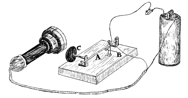
Added later.—My assistant, Mr. E. E. Robinson, early noticed
that when a telephone was used as receiver, say with a single-point
coherer (see illustration on opposite page),
which is a very sensitive arrangement, every disturbance of the coherer due
to received waves is accompanied by a crackle or tick in the telephone,
without any tapping back being necessary. This is, indeed, the
easiest mode of receiving signals, and we often practised it. If
a suitable, well-damped galvanometer, such as a Thomson marine
speaking-galvanometer, is included also in the circuit (a more
sensitive one is sometimes necessary—and we frequently used a
D’Arsonval—but it must be well damped), the meaning of these ticks
is recognised; each represents a minute change in the resistance of
the coherer—not at all the full change usually employed, but little
subsidiary changes, sometimes up and sometimes down, barely sufficient
to affect a galvanometer, but quite adequate (being so sudden) to
disturb a telephone. This method of receiving, which at first is very
sensitive, after a time becomes less so; the point shows signs of
fatigue, probably due to too perfect cohesion having been gradually
established, and a mechanical tap back is desirable to restore it to
its original condition.
If all the signals received were precisely of the same strength, I
doubt if these superposed crimples of resistance would occur; but
signals depending on quality of sending spark never are of the same
strength, and accordingly the sudden slight variations of resistance
do occur. Usually an ordinary high resistance telephone was employed,
and it was joined to the coherer circuit through one of the usual small
transformers—a plan which has many obvious advantages.
Simplest Receiving Arrangement: a Telephone in Circuit with
Single-point Coherer without Tapper-back. B a needle resting against a
watch-spring A adjusted by screw C.
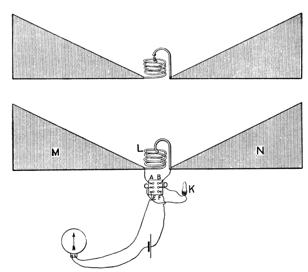
Syntonic Sender and Receiver used in the experiments plotted on page 28.
The switch enables the coherer K to be connected either to the
tuned resonator M L N or to the detecting circuit E F. Weak impulses
are felt when the switch is C E, D F; strong impulses when the switch
is C A, D B; provided the coil L is similar to the coil of the radiator
above. The impulses are plotted in the diagram Fig. 19A.
October 27, 1897.
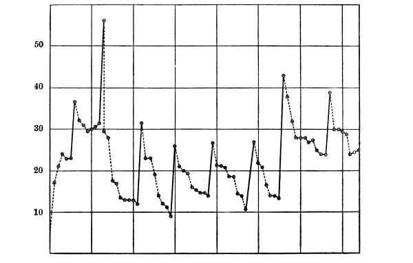
Fig. 19a.—
Current through Coherer after successive Electrical Stimuli, without
any mechanical tapping back. The sudden rises are obtained when the
circuits are syntonised. Weaker stimuli cause the descents.
The fluctuations of resistance of a coherer dependent on various
strengths of stimulus are instructively shown in some metrical
experiments made by Mr. Robinson, and a plotting of which I showed
to the Physical Society of London in 1897. This plotting is here
reproduced, and it shows the singular fact that, whereas a stronger
electrical stimulus usually decreases the resistance, as is natural,
a weaker subsequent stimulus usually increases it again: so that
alternately strong and weak stimuli send the curve zigzagging up and
down, until it gets into a condition demanding rejuvenation by a
mechanical tap back.
Sometimes a decidedly strong electrical stimulus knocks down the
conductivity of the coherer as if it had been tapped back. This is
almost certainly due to a burning of the delicate contacts—a blowing
of a fuse as it were,—and the effect of this electrical burn back is
quite different from the effect of a mechanical tap back, inasmuch as it
leaves the coherer insensitive. A shaking up is necessary to restore it.
I now call your attention to the Table on next page
of various kinds of detector for electric radiation distributed in groups.
Selenium is inserted in this table in the microphone column, because
it is a substance which in certain states is well known to behave to
visible light as these other microphonic detectors behave to Hertz
waves. It is inserted with a query, to indicate that its position in
the table is not certainly known. It may possibly belong to some
other column.
And I want to suggest that quite possibly the sensitiveness of the
eye is of the coherer kind. As I am not a physiologist, I cannot be
seriously blamed for making wild and hazardous speculations in that
region. I therefore wish to guess that some part of the retina is
an electrical organ, say like that of some fishes, maintaining an
electromotive force which is prevented from stimulating the nerves
solely by an intervening layer of badly conducting material, or of
conducting powder with gaps in it; but that when light falls upon the
retina these gaps become more or less conducting, and the nerves are
stimulated. I do not feel clear which part is taken by the rods and
cones, and which part by the pigment cells; I must not try to make the
hypothesis too definite at present, though I hope it is obvious what I
intend to suggest.
If I had to make a demonstration model of the eye on these lines,
I should arrange a little battery to excite a frog’s nerve-muscle
preparation through a circuit completed all except a layer of filings
or a single bad contact. Such an arrangement would respond to Hertz
waves. Or, if I wanted actual light to act, instead of grosser waves, I
would use a layer of selenium.
But the bad contact and the Hertz waves are the most instructive,
because we do not at present really know what the selenium is doing,
any more than what the retina is doing.
And observe that (to my surprise, I confess) the rough
outline of a theory of vision thus suggested is in accordance with some of the
principal views of the physiologist Hering. The sensation of light is
due to the electrical stimulus; the sensation of black is due to the
mechanical or tapping back stimulus. Darkness is physiologically not
the mere cessation of light. Both are positive sensations, and both
stimuli are necessary; for until the filings are tapped back vision is
persistent. In the eye model the period of mechanical tremor should be, say,
⅒th second, so as to give the right amount of persistence of impression.
Vacuum Tube. (Dragoumis.) Galvanometer. (Fitzgerald.)
Air-gap and Electroscope. (Boltzmann.) Trigger Tube.
(Warburg and Zehnder.)
Coherer. Hughes and Lodge.
˟ The cross against the frog’s leg indicates that it does not appear
really to respond to radiation, unless stimulated in some secondary
manner. The names against the other things are unimportant, but
suggest the persons who applied the detector to electric radiation.
The interrogation mark against Selenium indicates that its position
in the microphonic column may be doubtful.
No doubt in the eye the tapping back is done automatically by the
tissues, so that it is always ready for a new impression, until
fatigued. And by mounting an electric bell or other vibrator on the
same board as a tube of filings, it is possible to arrange so that
a feeble electric stimulus shall produce a feeble steady effect, a
stronger stimulus a stronger effect, and so on; the tremor asserting
its predominance, and bringing the spot back, whenever the electric
stimulus ceases.
An electric bell thus close to the tube is, indeed, not the best
vibrator; clockwork might do better, because the bell contains in
itself a jerky current, which produces one effect, and a mechanical
vibration, which produces an opposite effect, hence the spot of light
can hardly keep still. By lessening the vibration—say, by detaching
the bell from actual contact with the board, the electric jerks of
the intermittent current drive the spot violently up the scale;
mechanical tremor brings it down again. It must be clearly understood
that electric jerks, due to the make-and-break of an ordinary current,
are quite adequate to electrically stimulate a coherer in their
neighbourhood. It is constantly to be noticed that a coherer responds
best to excessively short sparks of a certain sharp quality.
You observe that the eye on this hypothesis is, in electrometer
language, heterostatic. The energy of vision is supplied by the
organism; the light only pulls a trigger. Whereas the organ of hearing
is idiostatic. I might draw further analogies between this arrangement
and the eye, e.g., about the effect of blows or disorder causing
irregular conduction and stimulation, of the galvanometer in the one
instrument, of the brain cells in the other.
A handy portable exciter of electric waves is one of the ordinary
hand electric gas-lighters, containing a small revolving
doubler—i.e., an inductive or replenishing machine. A coherer
can feel a gas-lighter across a lecture theatre. Minchin often used
them for stimulating his impulsion cells. I find that when held near
they act a little even when no ordinary spark occurs, plainly because
of the little incipient sparks at the brushes or tinfoil contacts
inside. A Voss machine acts similarly, giving a small deflection while
working up before it sparks: indeed, these small sparks are often more
effective than bigger ones.
And notice here that our model eye has a well-defined range of vision.
It cannot see waves too long for it. The powerful disturbance caused
by the violent flashes of a Holtz or Wimshurst or Voss machine it
is blind to. The loud sparks have no effect on it. They are like
infra-red radiation to the eye. If the knobs of the machine are well
polished the coherer begins to respond again, evidently by reason of
some high harmonics, due to vibrations in the terminal rods; and these
are the vibrations to which it responds when excited simply by an
induction coil. The coil should have knobs instead of points. Sparks
from points or dirty knobs hardly excite the coherer at all. But hold
a well-polished sphere or third knob between even the dirty knobs of a
Voss machine, and the coherer responds at once to the surgings got up
in that clean sphere.
Feeble short sparks again are often more powerful exciters than are
strong long ones. I suppose because they are more sudden. This is
instructively shown with an electrophorous lid. Spark it to a knuckle,
and it does very little. Spark it to a clean knob held in the hand and
it works well. But now spark it to an insulated sphere, there
is some effect. Discharge the sphere, and take a second spark, without
recharging the lid; do this several times; and at last, when the spark
is inaudible, invisible, and otherwise imperceptible, the coherer some
yards away responds more violently than ever, and the spot of light
rushes from the scale.
If a coherer be attached by a side wire to the gas pipes, and an
electrophorous spark be given to either the gas pipes or the water
pipes or even to the hot-water system in any other room of the
building, the coherer responds. It is surprising how far these impulses
can be felt along an ordinary uninsulated wire or other conductor.
In fact, when thus connected to gas pipes one day when I tried it, the
spot of light could hardly keep still five seconds. Whether there was
a distant thunderstorm, or whether it was only picking up telegraphic
jerks, I do not know. The jerk of turning on or off an extra Swan lamp
can affect it when sensitive. I hope to try for long-wave radiation
from the sun, filtering out the ordinary well-known waves by a
blackboard or other sufficiently opaque substance.
[I did not succeed in this, for a sensitive
coherer in an outside shed unprotected by the thick walls of a
substantial building cannot be kept quiet for long. I found its spot of
light liable to frequent weak and occasionally violent excursions, and
I could not trace any of these to the influence of the sun. There were
evidently too many terrestrial sources of disturbance in a city like
Liverpool to make the experiment feasible. I don’t know that it might
not possibly be successful in some isolated country place; but clearly
the arrangement must be highly sensitive in order to succeed.]
We can easily see the detector respond to a distant source of radiation
now, viz., to a 5 in. sphere placed in the library between secondary
coil knobs; separated from the receiver, therefore, by several walls
and some heavily gilded paper, as well as by 20 or 30 yards of space
(Fig. 19.)
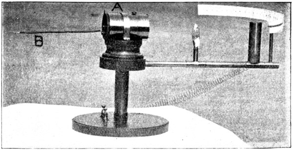
Fig. 19b.—
A Portable Detector, B the Collecting Wire.
Also I exhibit (Fig. 19b)
a small complete detector made by my assistant, Mr. Davies, which
is quite portable and easily set up. The essentials (battery,
galvanometer, and coherer) are all in a copper cylinder, A, three
inches by two. A bit of wire, B, a few inches long, pegged into it,
helps it to collect waves. It is just conceivable that at some distant
date, say by dint of inserting gold wires or powder in the retina, we
may be enabled to see waves which at present we are blind to.
Observe how simple the production and detection of Hertz waves are
now. An electrophorus or a frictional machine serves to excite them; a
voltaic cell, a rough galvanometer, and a bad contact serves to detect
them. Indeed, they might have been observed at the beginning of the
century, before galvanometers were known: a frog’s leg or an iodide of
starch paper would do almost as well.
A bad contact was at one time regarded as a simple nuisance,
because of the singularly uncertain and capricious character of the
current transmitted by it. Hughes observed its sensitiveness to
sound waves, and it became the microphone. Now it turns out to be
sensitive to electric waves, if it be made of any oxidisable medal
(not of carbon),[16]
and we have an instrument which might be called a micro-something, but
which, as it appears to act by cohesion, I at present call a coherer.
Perhaps some of the capriciousness of an anathematised bad contact was
sometimes due to the fact that it was responding to stray electric
radiation. (See Appendix III., pp. 109 and 111.)
The breaking down of cohesion by mechanical tremor is an ancient
process, observed on a large scale by engineers in railway axles and
girders; indeed, the cutting of small girders by persistent blows of
hammer and chisel reminded me the other day of the tapping back of our
cohering surfaces after they have been exposed to the uniting effect of
an electric jerk.
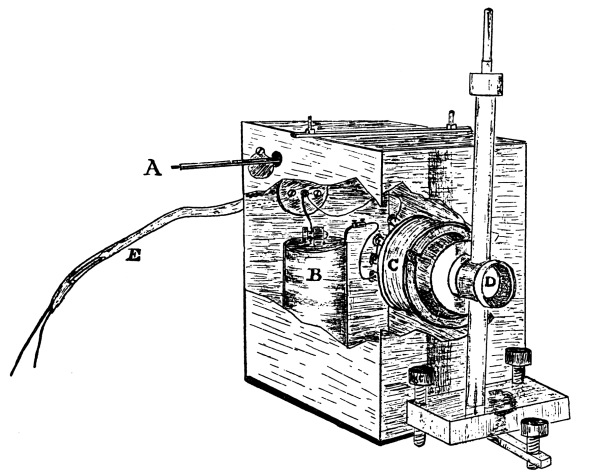
If a coherer is shut up in a complete metallic enclosure, waves
cannot get at it, but if wires are led from it to an outside ordinary
galvanometer, it remains nearly as sensitive as it was before (nearly,
not quite), for the circuit picks up the waves and they run along the
insulated wires into the closed box. To screen it effectively, it is
necessary to enclose battery and galvanometer and every bit of wire
connection; the only thing that may be left outside is the needle of
the galvanometer. Accordingly, here we have a compact arrangement of
battery and galvanometer coil and coherer, all shut up in a copper box
(Fig. 19c). The
galvanometer coil is fixed against the side of the box at such height
that it can act conveniently on an outside suspended compass needle.
The slow magnetic action of the current in the coil has no difficulty
in getting through copper, as everyone knows: only a perfect conductor
could screen off that; but the Hertz waves are effectively kept out by
the sheet copper.
Fig. 19c.—
Protected Detector. A is an occasional wire passing through shuttered
aperture. E is a lead tube enclosing leading wires, as in Fig. 21.
It must be said, however, that the box must be exceedingly well closed
for the screening to be perfect. The very narrowest chink permits their
entrance, and at one time I thought I should have to solder a lid on
before they could be kept entirely out. Clamping a copper lid on to a
flange in six places was not enough. But by the use of pads of tinfoil
and tight clamping, chinks can be avoided, and the inside of the box
becomes then electrically dark.
If even an inch of the circuit protrudes, it at once becomes slightly
sensitive again; and if a mere single wire protrudes through the box,
not connected to anything at either end, provided it is insulated where
it passes through, the waves will utilise it as a speaking-tube, and
run blithely in. And this happens whether the wire be connected to
anything inside or not, though it acts more strongly when connected.
In careful experiments, where the galvanometer is protected in one
copper box and the coherer in another, the wires connecting the two
must be encased in a metal tube (Figs. 19c
and 21), and this tube must be well connected with
the metal of both enclosures, if nothing is to get in but what is wanted.
Fig. 20.—
Spherical Radiator for emitting a Horizontal Beam, arranged inside
a Copper Hat, fixed against the outside of a metal-lined Box, which
contains induction coil and battery and key. One-eighth natural size.
The wires pass into the box through glass tubes not shown.
Similarly when definite radiation is desired, it is well to put the
radiator in a copper hat open in only one direction (Fig. 20),
and in order to guard against reflected and collateral surgings running along
the wires which pass outside to the exciting coil and battery, as they
are liable to do, I am accustomed to put all the sending apparatus in a
packing case lined with tinfoil, to the outside of which the sending
hat (Fig. 20) is fixed, and to pull the key of the primary
exciting circuit by a string from outside, so that not even key connections
shall protrude, else exact optical experiments are impossible.
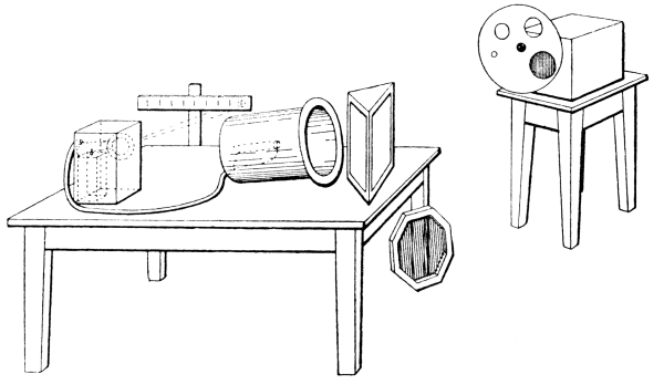
Fig. 21.—
General arrangement of experiments with the Copper “Hat,” showing Metal
Box on a Stool, standing outside the Theatre. The Box is not exactly
represented, but inside it the Radiators were fixed with a graduated
series of apertures; the Copper Hat containing the Coherer is seen
on the Table with the Metal Box on the left of the Table containing
Battery and Galvanometer Coil connected to it by a compo pipe conveying
the wires, as in Fig. 19c;
the Lamp and Scale barely indicated at one side of the Table; a Paraffin Prism;
and a Polarising Grid of copper wires stretched on a frame. (This figure is
from a thumbnail sketch by Mr. A. P. Trotter, taken at the Lecture in 1894.)
Even then, with the lid of the hat well clamped on, something gets
out, but it is not enough to cause serious disturbance of qualitative
results. The sender must evidently be thought of as emitting a
momentary blaze of light which escapes through every chink. Or, indeed,
since the waves are some inches long, the difficulty of keeping them
out of an enclosure may be likened to the difficulty of excluding
sound; though the difficulty is not quite so great as that, since a
reasonable thickness of metal is really opaque. I fancied once or twice
I detected a trace of transparency in such metal sheets as ordinary
tinplate, but unnoticed chinks elsewhere may have deceived me. It is a
thing easy to make sure of as soon as I have more time. (Tinplate is
quite opaque. Lead paper lets a little through.)
One thing in this connection is noticeable, and that is how little
radiation gets either in or out of a small round hole. A narrow
long chink in the receiver box lets in a lot; a round hole the size
of a shilling lets in hardly any, unless indeed a bit of insulated
wire protrudes through it like a collecting ear trumpet, as at A,
Fig. 19c.
It may be asked how the waves get out of the metal tube of an electric
gas-lighter. But they do not; they get out through the handle, which
being of ebonite is transparent. Wrap up the handle in tinfoil, and a
gas-lighter is powerless.
And now, in conclusion, I will show some of the ordinary optical
experiments with Hertz waves, using as source either one of two
devices: either a 5 in. sphere with sparks to ends of a diameter
(Fig. 19), an arrangement which emits 7 in. waves
but of so dead-beat a character that it is wise to enclose it in a
copper hat to prolong them and send them out in the desired direction,
or else a 2 in. hollow cylinder with spark knobs at ends of an internal
diameter (Fig. 12). This last emits 3 in. waves of a very
fairly persistent character, but with nothing like the intensity of one of the
outside radiators.
As receiver there is no need to use anything sensitive, so I employ a
glass tube full of coarse iron filings, put at the back of a copper hat
with its mouth turned well askew to the source, which is put outside
the door at a distance of some yards, so that only a little direct
radiation can reach the tube. Sometimes the tube is put lengthways
in the hat instead of crossways, which makes it less sensitive, and
has also the advantage of doing away with the polarising, or rather
analysing, power of a crossway tube.
The radiation from the sphere is still too strong, but it can be
stopped down by a diaphragm plate with holes in it of varying size
clamped on the sending box (right-hand side of Fig. 21).
Having thus reduced the excursion of the spot of light to a foot or
so, a metal plate is held as reflector, and at once the spot travels
a couple of yards. A wet cloth reflects something, but a thin glass
plate, if dry, reflects next to nothing, being, as is well known, too
thin to give anything but “the black spot.” I have fancied that it
reflects something of the 3 in. waves.
With reference to the reflecting power of different substances, it may
be interesting to give the following numbers showing the motion of the
spot of light when 8 in. waves were reflected into the copper hat, the
angle of incidence being about 45 deg., by the following mirrors:—
Sheet of window glass
0
or at most
1 division.
Human body
7
divisions.
Drawing board
12
”
Towel soaked with tap-water
12
”
Tea-paper (lead?)
40
”
Dutch metal paper
70
”
Tinfoil
80
”
Sheet copper
100
and up against stops.
A block of paraffin about a cubic foot in volume is cast into the shape
of a prism with angles 75 deg., 60 deg., and 45 deg. Using the large
angle, the rays are refracted into the receiving hat (Fig. 21),
and produce an effect much larger than when the prism is removed.
An ordinary 9 in. glass lens is next placed near the source, and by
means of the light of a taper it is focussed between source and
receiver. The lens is seen to increase the effect by concentrating the
electric radiation.
The lens helps us to set correctly an 18 in. circular copper disc in
position for showing the bright diffraction spot. Removing the disc,
the effect is much the same as when it was present, in accordance with
the theory of Poisson. Add the lens and the effect is greater. With a
diffraction grating of copper strips 2 in. broad and 2 in. apart, I have
not yet succeeded in getting good results. It is difficult to get sharp
nodes and interference effects with these sensitive detectors in a
room. I expect to do better when I can try out of doors, away from
so many reflecting surfaces; indoors it is like trying delicate
optical experiments in a small whitewashed chamber well supplied
with looking-glasses; nor have I ever succeeded in getting clear
concentration with this zone-plate having Newton’s rings fixed to it
in tinfoil. The coherer, at any rate in a room, does not seem well
adapted to interference experiments; it is probably too sensitive, and
responds even at the nodes, unless they are made more perfect than is
easily practicable. But really there is nothing of much interest now
in diffraction effects, except the demonstration of the waves and the
measure of their length. There was immense interest in Hertz’s time,
because then the wave character of the radiation had to be proved; but
every possible kind of wave must give interference and diffraction
effects, and their theory is, so to say, worked out. More interest
attaches to polarisation, double refraction, and dispersion experiments.
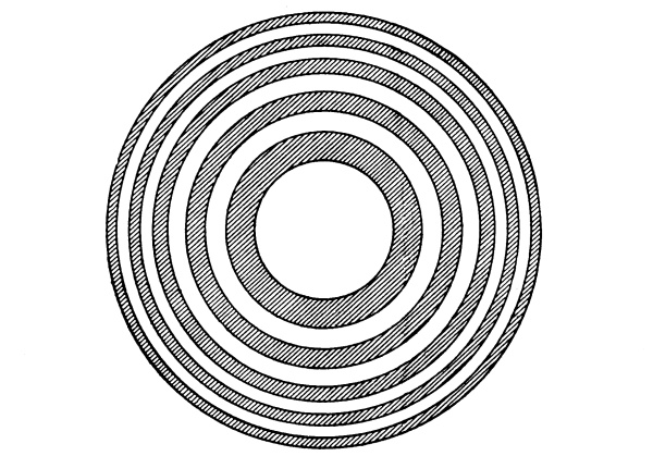
Fig. 22.—
Zone-plate of Tinfoil on Glass. Every
circular strip is of area equal to central space.
Polarisation experiments are easy enough. Radiation from a sphere, or
cylinder, or dumb-bell is already strongly polarised, and the tube acts
as a partial analyser, responding much more vigorously when its length
is parallel to the line of sparks than when they are crossed; but a
convenient extra polariser is a grid of wires something like what was
used by Hertz, only on a much smaller scale; say an 18 in. octagonal
frame of copper strip with a harp of parallel copper wires (see
Fig. 21, on floor). The spark-line of the radiator (Fig. 20)
being set at 45 deg., a vertical grid placed over the receiver reduces the
reflection to about one-half, and a crossed grid over the source
reduces it to nearly nothing.
Rotating either grid a little rapidly increases the effect, which
becomes a maximum when they are parallel. The interposition of a third
grid, with its wires at 45 deg., between two crossed grids, restores
some of the obliterated effect.
Radiation reflected from a grid is strongly polarised, of course, in a
plane normal to that of the radiation which gets through it. They are
thus analogous in their effect to Nicols, or to a pile of plates.
The electric vibrations which get through these grids are at right
angles to the wires. Vibrations parallel to the wires are reflected or
absorbed.
To demonstrate that the so-called plane of polarisation of the
radiation transmitted by a grid is at right angles to the electric
vibration,[17]i.e.,
that when light is reflected from the boundary of a transparent
substance at the polarising angle the electric vibrations of the
reflected beam are perpendicular to the plane of reflection, I use the
same paraffin prism as before; but this time I use its largest face as
a reflector, and set it at something near the polarising angle. When
the line of wires of the grid over the mouth of the emitter is parallel
to the plane of incidence, in which case the electric vibrations
are perpendicular to the plane of incidence, plenty of radiation is
reflected by the paraffin face. Turning the grid so that the electric
vibrations are in the plane of incidence, we find that the paraffin
surface set at the proper angle is able to reflect hardly anything. In
other words, the vibrations contemplated by Fresnel are the electric
vibrations; those dealt with by McCullagh are the magnetic ones.
Thus are some of the surmises of genius verified and made obvious to
the wayfaring man.
END OF LECTURE.
It may be well to explain that in my Royal Institution lecture I
made no reference to the transmission of waves along wires. I
regard the transmission of waves in free space as the special
discovery of Hertz; though undoubtedly he got them on wires too. Their
transmission along wires is, however, a much older thing. Von Bezold
saw them in 1870, and I myself got quantitative evidence of nodes and
loops in wires when working with Mr. Chattock in the session 1887-8
(see, for instance, contemporary reports of the Bath Meeting
of the British Association, 1888, in The Electrician), and I
exhibited them some time afterwards to the Physical Society, the wires
themselves becoming momentarily luminous at every discharge except
at the nodes, thus enabling the waves to be actually seen, having
been made stationary by reflexion as in the corresponding acoustic
experiment of Melde. This experiment does not appear to have been
properly known (p. 78).
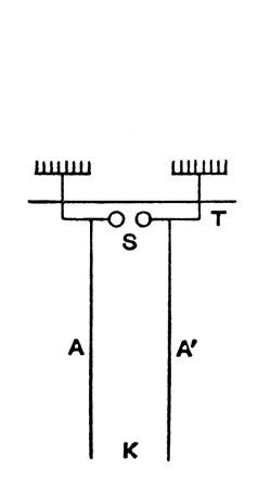
Fig. 23.
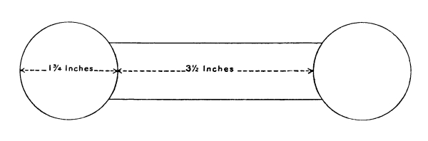
It may be worth mentioning that the arrangement frequently referred to
in Germany by the name of Lecher (viz., that shown in Fig. 23),
and on which a great number of experiments have been made, is nothing but
a pair of Leyden jars with long wires leading from their outer coats,
such as I constantly employed in these experiments. The wires from the
outer coat in my experiment were very long, sometimes going five or six
times round a large hall, like telegraph wires. And many measurements
of wave length were thus made by me at the same period as that in which
Hertz was working at Carlsruhe. The use of air dielectric instead of
glass permits the capacity to be adjusted, and also readily enables the
capacity to be small, and the frequency, therefore, high; but otherwise
the arrangement is the same in principle as had frequently been used
by myself in the series of experiments called “the recoil kick”
(Proc. Roy. Soc., June 1891, Vol. 50, pp. 23-39). For these and
other reasons no reference has been made in my lecture to the work done
on wires by Sarasin and De la Rive; nor to other excellent work done by
Lecher, Rubens, Arons, Paalzow, Ritter, Blondlot, Curie, D. E. Jones,
Yule, Barton, and other experimenters.
APPLICATION OF THIS METHOD OF SIGNALLING AT A DISTANCE TO ACTUAL TELEGRAPHY. — FURTHER DEVELOPMENTS IN THE TELEGRAPHIC DIRECTION. — SYNTONIC TELEGRAPHY. — Earlier Telegraphic Advances.
Although the method of signalling to a moderate distance through walls
or other non-conducting obstructions by means of Hertz waves emitted
from one station and detected by Branly filing tubes at another station
was practised by the author and by several other persons in this
country, it was not applied by them to actual telegraphy. The idea
of replacing a galvanometer, which was preferably a well-damped or
speaking galvanometer, by a relay working an ordinary sounder or Morse
was an obvious one, but so far as the present author was concerned he
did not realise that there would be any particular practical advantage
in thus with difficulty telegraphing across space instead of with
ease by the highly developed and simple telegraphic and telephonic
methods rendered possible by the use of a connecting wire. In this
non-perception of the practical uses of wireless telegraphy he
undoubtedly erred. But others were not so blind, though equally busy;
and notably Dr. Alexander Muirhead foresaw the telegraphic importance
of this method of signalling immediately after hearing the author’s
lecture on June 1st, 1894, and arranged a siphon recorder for the
purpose. Captain Jackson also, at Devonport, made experiments for the
Admiralty, and succeeded in telegraphing between ships in 1895 (or
1896). Prof. Popoff’s telegraphic application in 1895 is mentioned on
page 62.
By some chance a knowledge of the coherer method of detecting electric
waves did not spread fast in Germany, the many German workers in
Hertz waves continuing, for some time after 1894, the older and less
efficient, though for metrical purposes often more convenient, mode of
detecting them. But, in Italy, the work described in the preceding
lecture became well known, and the subject was developed largely,
especially by Prof. Righi, of Bologna, in the optical direction. It
was also developed in the same direction with many most interesting
results by Prof. Bose, of Calcutta, as mentioned in the text. Prof.
Righi made a large number of experiments, which he has since described
in an Italian treatise, “Opticé Elettrica,” and it appears that it was
from him that Signor Marconi learned about the subject, and immediately
conceived the idea of applying it to commercial telegraphy. He appears
to have worked at the subject for a short time in Italy, aiming at
getting the receiver to be more satisfactory and dependable, and
improving the early form of Branly filings tube depicted on page 23
by greatly diminishing its size, bringing the terminals closer together,
and replacing the coarse borings by fine filings. He also sealed them
up in a vacuum, just as the author did, as related on page 34.
The only differences, indeed, between his procedure and the author’s during this
time were that Signor Marconi preferred nickel filings with a little
mercury and a low vacuum, whereas the author adhered chiefly to iron
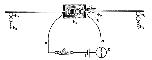
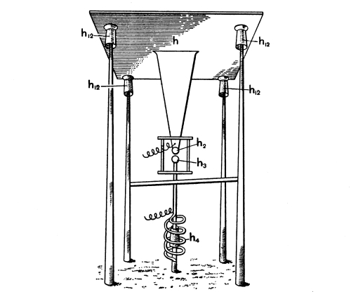
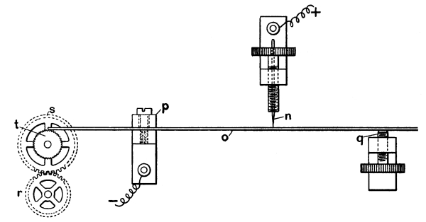
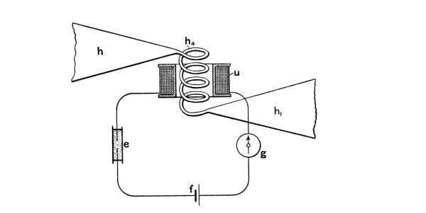
and brass filings and to high vacua. At last he brought it over to
Dublin, where he was advised to take it to the Chief of the Government
Telegraphs, Mr. Preece, and accordingly he took his, at that time,
crude apparatus to the Post Office in a sealed box. There was no point
of novelty in it at this stage.
With the powerful aid of the Post Office Signor Marconi proceeded to
develop his system of telegraphy on a large scale; and, sometimes
failing, sometimes succeeding, gradually increased the distance over
which signalling was possible, and especially began to develop from
unpromising beginnings his special method for long-distance, viz., the
employment of a sending and receiving conducting plate or other small
surface, at the top of a lofty pole, connected through what was at that
time supposed apparently to be the real radiator, with the earth. This
elevated plate, connected as it now is through a simple spark gap with
the earth, is an obvious modification of a Hertz vibrator; for it may
be regarded simply as a Hertz vibrator with its axis vertical, as Hertz
often used it, and with its lower plate replaced by the earth, so as
to double the available capacity; but the action of a pair of such
elevated plates, connected through the earth conductively and through
the air inductively, as now used by Marconi for sender and receiver
respectively, is not quite like that of a Hertz vibrator and a Hertz
receiver acting on one another by emitted radiation in the ordinary
way. If it were not the same earth to which the plates were connected,
they would have to act ordinarily by radiation, but since it is the
same earth, and that earth conducting (possibly, indeed, with a
submerged cable sheath connecting favourably-chosen stations), then the
two elevated plates are partially like the greatly separated terminals
of a single Hertz vibrator.
Only one of the plates is charged during a sending operation, the other
is at zero potential, but some trace of the electrostatic lines from
one plate may extend in curved lines to the other, just as they extend
to every elevated conductor within hail of the sender in any direction.
Then comes the snap of the spark gap and the sudden discharge,
equivalent to the rush of an opposite charge of electricity suddenly
into the sending plate, disturbing the electric equilibrium at a
distance—at any distance to which any trace of electrostatic field had
been able to reach—and giving a kind of what is called in lightning
a “return stroke.” The effect of this on the distant plate and
conductor must be almost infinitesimal; nevertheless, separating it
from the earth is the most sensitive detector to a minute sudden rush
or jerk of electricity that can be imagined, or that has hitherto
been invented,—the coherer. Accordingly, absurdly minute though
the disturbance is, the coherer feels it, instantly increases in
conductivity, works the relay, and gives the signal. Every spark at
the distant spark gap causes a similar rush in or out of the distant
elevated plate, and the receiving plate collects such a fraction of
this disturbance as to stimulate the coherer and give a signal every
time. Not that it is to be supposed never to miss fire. At the present
time a coherer is not a rough instrument that can be left free from
expert attention with safety for a long time. There are times when it
goes on working for days or even weeks, but there are other times when
it gives trouble and needs some form of attention. Let us hope that
these latter times will become less frequent, and that the whole thing
will become quite dependable before long. The pertinacious way in which
Mr. Marconi and his able co-operators have, at great expense, gradually
worked the method up from its early difficult and capricious stage to
its present great distances and comparative dependableness is worthy of
all praise.
Telegraphy by means of Hertz waves, though perhaps chiefly developed
in this country, has also been pursued successfully by Prof. Slaby in
Germany, who has attained considerable distance over land, with its
numerous obstacles, and has published an account of his researches in
a book called “Funkentelegraphie”; while like success over land has
been attained by M. E. Ducretet, M. Blondel and others in France. M.
Ducretet has, indeed, put on the market a compact apparatus whereby
beginners can readily try their hands at this mode of signalling; as
well as a large-scale apparatus like that employed by Lieutenant Tissot
for lighthouse signalling on the coast of Brittany.
The filings tube now chiefly employed by the author is of the following
form:—It is a sealed glass tube containing carefully selected iron
filings, and exhausted to the highest vacuum. Close together are two
little silver globes melted each on its own platinum wire terminal,
which are connected with convenient screws on an ebonite stand. The
filings are adjusted so as just to cover the two silver globes, and no
more; a pocket, or reservoir, however, is sometimes provided whereby
more or fewer filings can be easily introduced into the working
compartment for experimental purposes. This pocket serves to fix the
whole tube to its ebonite body, which is provided with a clamp to
attach it to the stiff spring, or movable lever, or other form of
support, through which it is to receive the mechanical shocks necessary
to restore or decohere it after an electrical stimulus.
The usual plan is to employ an electrical hammer to rap strongly on a
stiff brass spring to which the ebonite is clamped, but another plan is
to attach the coherer to a lever tilted strongly by an electromagnet
after the fashion of a sounder. A rapid succession of gentle taps is
often better than one violent one, but experience is the best test of
the kind of restoration wanted, for it depends a good deal on the
strength of the electrical stimulus. There are methods of dispensing
with this decohering operation altogether.
After a fairly strong electric stimulus all the filings are stuck
together into a sort of mat, and nothing but a thorough shaking up will
pull them asunder again. A still more violent electric shock may indeed
have a decohering effect, but it is not a plan to be recommended, for
it seems to be a heat effect, akin to the blowing of a fuse.
For protecting a coherer from undesired stimuli, e.g., from the
radiator at its own station, the general method is described on page
35, &c., and the details of it, with the necessary switch for
changing over from sending to receiving, are mentioned further on (page
60). But by referring to page 106 it will be seen that M. Branly
had already employed such a protecting case, and had worked details out admirably.
Recently Signor Tommasina has shown that, if one end of a short rod
or wire be dipped into filings while sparks are occurring in the
neighbourhood, the filings adhere to it and to each other, and with
care a long string of them can be picked up. The author has examined
the behaviour of filings under electrical influence on a glass plate in
a microscope, and their movements towards the formation of a complete
conducting bridge between the tinfoil terminals together with their
disjunctive behaviour when the electrical stimulus is too strong, the
thorough cohesion set up by a succession of electrical stimuli, and the
partial or complete disruption by an appropriate mechanical stimulus is
instructive.
An earlier and most important telegraphic application, based upon
information given in the preceding lecture, was made in 1895 by Prof.
Popoff, of Russia, and will be mentioned shortly (see page 62).
I now proceed to developments of syntonic or attuned telegraphy on the
true Hertz-wave principle, the preliminary experiments on which are
mentioned above in connection with the figures on page 27.
In the present state of the law in this country it appears to be
necessary for a scientific man whose investigations may have any
practical bearing to refrain from communicating his work to any
scientific society, or publishing it in any journal until he has
registered it and paid a fee to the Government under the so-called
Patent Law. This unfortunate system is well calculated to prevent
scientific men in general from giving any attention to practical
applications, and to deter them from an attempt to make their
researches useful to the community. If a scientific worker publishes
in the natural way, no one has any rights in the thing published; it
is given away and lies useless, for no one will care to expend capital
upon a thing over which he has no effective control. In this case
practical developments generally wait until some outsider steps in
and either patents some slight addition or modification, or else, as
sometimes happens, patents the whole thing, with some slight addition.
If a scientific worker refrains from publishing and himself takes out
a patent, there are innumerable troubles and possible litigation ahead
of him, at least if the thing turns out at all remunerative; but the
probability is that, in his otherwise occupied hands, it will not so
turn out until the period of his patent right has expired.
Pending a much-to-be-desired emendation of the law, whereby the courts
can take cognisance of discoveries or fundamental steps in an invention
communicated to and officially dated by a responsible scientific
society, and can thereafter award to the discoverer such due and
moderate recompense as shall seem appropriate when a great industry has
risen on the basis of that same discovery or fundamental
invention—pending this much-to-be-desired modification of the law,
it appears to be necessary to go through the inappropriate and repulsive
form of registering a claim to an attempt at a monopoly. The instinct
of the scientific worker is to publish everything, to hope that any
useful aspect of it may be as quickly as possible utilised, and to
trust to the instinct for fair play that he shall not be the loser when
the thing becomes commercially profitable. To grant him a monopoly is
to grant him a more than doubtful boon; to grant him the privilege of
fighting for his monopoly is to grant him a pernicious privilege, which will
sap his energy, waste his time, and destroy his power of future production.
Fig. 24
(Fig. 5 of Specification 11,575/97).—Syntonic
Radiator, adapted for sending and for receiving.
However, the author, in consultation with friends, decided that
registration was, under present conditions, necessary, and,
accordingly, for his attempt at syntony and other improvements in the
Hertz wave method of signalling, he can refer here to certain patents
taken out, in conjunction chiefly with Dr. Alexander Muirhead, his
co-worker, which are numbered respectively as follows:—
Fig. 25
(Fig. 13 of Specification 11,575/97).—Diagram
of connections for Syntonic Receiver; e being coherer and
w a non-inductive conducting or capacity shunt, to eliminate the
self-induction of the receiving instrument.
(1) 11,575 of 1897, wherein is described the general syntonic principle
and the mode of prolonging the duration of the vibrations emitted by a
radiator or by a receiver. This is done by adding to it electromagnetic
inertia (that is, a self-induction coil) in such a way as to lessen its
radiating power, converting its type of emission from something like
a whip-crack into something more like that of a struck string. (Not
pushing it so far as to make it like a fork, though that could
be done if desired: see Journal Inst.E.E., December, 1898.)
But too prolonged a duration of vibration is not desirable, for it
can only be obtained at the expense of radiating power. For the most
distant signalling the single pulse or whip-crack is the best, and
this is what in practice has hitherto always been employed; but, with
it, tuning is of course impossible. A radiator with several swings is
less violent at its first impulse than is a momentary emitter; but
then the lessened emitting power of a radiator is to be compensated by
a correspondingly prolonged duration of vibration on the part of the
receiver or absorber, thus rendering the radiator susceptible of tuning
to a special similarly-tuned receiver or resonator. The tuned resonator
is then to respond, not to the first impulse of the radiator, but to
a rapidly worked up succession of properly timed impulses; so that at
length, after an accumulation of two or three, or perhaps four,
swings, the electrostatic charges in its terminal plates become
sufficient to overflow and spit off into the coherer, thereby
effecting its stimulation and giving the signal. A resonator not
properly tuned—i.e., one tuned to some different frequency of
vibration—would not be able to accumulate impulses, and hence would
not respond, unless of course it were so much too near the radiator
that the very first swing stimulated it sufficiently to disturb the
coherer; in which case, again, there is no room for tuning. The two
points to attend to for syntonic discrimination are: (a) that
the receiver shall not be so near the emitter as to feel its impulses
too easily, i.e., without accumulation; (b) that the
properly tuned receiver shall be so arranged that it can work up and
accumulate the impulses of the radiator, and before attaining its
maximum swing can overflow into the coherer associated with it and thus
give the signal.
Fig. 26
(Fig. 10 of Specification 11,575/97).—Interchangeable
Self-Induction Coils for signalling to different stations.
Fig. 27
(Fig. 3 of Specification 11,575/97).—Diagrammatic
representation of Syntonic Radiator and Receiver. The middle spark
gap h2h3 is unnecessary, though
sometimes helpful. The main charging is done by impulsive rush at the
outside knobs.
Fig. 28
(Fig. 7 of Specification 11,575/97).—Syntonic
Radiator with earth connection arranged for sending.
The general appearance of a pair of signalling stations on this
plan is shown in Fig. 24, where the huts contain
the sending and receiving instruments. The self-induction coil joining
the two capacity-areas is better depicted in Fig. 25,
which also shows one mode of joining up the coherer to a
syntonic receiver. (The galvanometer and shunt are, of course,
merely typical of any kind of telegraphic instrument whatever.) Fig. 26 indicates one form of sender with three
alternative syntonising coils for speaking to three distant attuned
stations. Fig. 27 shows a radiator arranged
for receiving, but illustrates another method of charging, and one
frequently employed by the author, viz., the method by impulsive rush
(compare Figs. 11, 12 and
19, on pp. 14 and 25 of this book). The terminals
of the Ruhmkorff coil are here connected, not to the capacity-areas
direct, but to a pair of knobs near the centre of gravity of each
area, so that when the discharge occurs each area is suddenly charged
oppositely, and the two opposite charges are left to surge into one
another and set up the oscillations. This impulsive method of charging
is essentially that adopted in the spherical whip-crack emitter
depicted in Fig. 19 (p. 25, ante), the
two poles of the sphere having but small capacity and being joined
by as thick a conductor as the equator of the sphere. But for such
a radiator as is indicated in Fig. 24 or
Fig. 27 the author commonly found that a third
short spark gap in the middle was an improvement, and so, as is well
known, did Prof. Righi find it, and embodied it in his well-known
double-sphere double-knob emitter.
Fig. 29
(Fig. 12 of Specification 11,575/97).—Single-point
Coherer, with clockwork Tapper-back operating on the projecting
end of the spring clamped at P and lightly touching a needle point
n.
The specification also contains figures of earth-connected forms
of radiators, with or without self-induction coils, of which Fig. 28 may be here reproduced; and likewise a
modification of the point coherer depicted in Fig. 17,
on page 22 (see Fig. 29, and also
fig. on page 27), where the spiral wire spring
is replaced by a piece of straight watch-spring, clamped at one end,
adjusted by a screw at the other, and lightly touched by a needle point
at its middle; a very gentle tapping back stimulus being provided in
the form of a clockwork or other mechanically-driven motor grazing lightly
against one end of the spring protruding beyond the clamp for the purpose.
Fig. 30
(Fig. 14 of Specification 11,575/97).—Another
diagram of connections for Syntonic Receiver, with Coherer in a
secondary or transformer circuit; a conducting or a capacity shunt for
the telegraphic instrument being applicable as before.
Figs. 31 and 32
(Figs. 5 and 6 of Specification 18,644/97).—Modes
of connecting a Coherer to one or to a pair of Syntonic Radiators so
that it may feel their electrostatic disturbance.
Fig. 33
(Fig. 11 of Specification 18,644/97).—Actual
connections for a Sending and Receiving Station on the plan shown in
Fig. 37. Left-hand side shows spark sending,
right-hand side shows Coherer receiving.
Fig. 30 shows a coherer inserted in a secondary
or transformer circuit, and operated inductively by the oscillations of
the receiver, which are thus transformed up and raised in potential.
(2) No. 16,405, 1897, wherein are described chiefly various practical
methods of decohering, by means of cams and otherwise, which are
appropriate when working rapidly with automatic transmitter and siphon
recorder.
(3) No. 18,644, 1897, represents different ways of connecting up a
coherer to a syntonic resonator, so as to get the benefit of its
overflow without interfering with the working up of the electric
oscillations, e.g., Figs. 31,
32 and 33. It also shows a plan
for constantly decohering by a rapidly revolving cam a number of
coherers in parallel, so that one at least is always ready to receive
an impulse (Fig. 34). Further, it arranges to utilise the
earth or a cable sheath, or other uninsulated conductor, for the purpose of
conveying electric impulses to a distance (Figs. 35,
36, 37 and 38).
And next it is arranged to assist the coherer to feel the full effect
of any electric jerk by shunting out the battery and galvanometer,
which are necessarily in series with it, by means of a condenser of
moderate capacity (Fig. 35), which also shows a self-induction
mode of sending a stimulus along an uninsulated line. This condenser obstructs
all steady currents, such as give the signal, but it transmits freely
any momentary electric impulses, such as stimulate a coherer.
Fig. 34
(Fig. 1 of Specification 18,644/97).—Single-point
Coherers in parallel, with successive decoherence.
Fig. 35
(Fig. 3 of Specification 18,644/97).—A
self-induction method of sending jerks into a badly insulated line, and
arrangement for detecting such jerks by a single-point Coherer.
Fig. 36
(Fig. 4 of Specification 18,644/97).—Another
arrangement for sending jerks into a bare or badly insulated line, and
connections for Coherer detection.
Fig. 37
(Fig. 10 of Specification 18,644/97).—Another
mode of sending a jerk from a spark gap at j into a badly
insulated cable or other conductor, which is connected at the other end
to a Coherer, the circuit being completed inductively through the air
by means of the areas p, p1. The dotted lines
s represent the switch connection of Fig. 33.
38
(Fig. 13 of Specification 18,644/97).—Another
method of signalling through a pair of imperfect conductors, such as
gas and water pipes i, without the above elevated inductive
connection.
Fig. 39
(Fig. 3 of Specification 29,069/97).—Diagram
of Coherer connection to Syntonic Collector, with capacity shunt for
telegraphic instrument.
(4) No. 29,069, 1897. In this patent various methods of connecting
up the shunting condenser, whose object it is to transmit all jerks
undiluted to the coherer, are shown, all adapted to work with a
syntonic resonator (Fig. 39). There is also shown a complete
switch (Fig. 40) for effecting the transition from “sending”
to “receiving,” exposing the coherer to the full effect of the distant radiator,
and completely protecting and isolating it from its home radiator; the
switch being so arranged that signalling is impossible unless the
home coherer is protected. A rotating commutator is also shown, whose
object is to expose the coherer to the full influence of a receiver,
especially of a non-syntonic receiver or simple collector, without
its being shunted or otherwise interfered with by the telegraphic
apparatus; to which, however, immediately afterwards the rotating
commutator connects it, and then effects the tapping back.
Connections are shown (Fig. 41) for a complete sending and
receiving station on this plan with a syntonic radiator and resonator indicated
(though not to scale). But with syntonic resonators the revolving
commutator method is not found to be necessary; the sending and
receiving switch, together with the closed box for protecting the
coherer in an instantly accessible manner is therefore the chief
feature of this diagram.
Fig. 40
(Fig. 6 of Specification 29,069/97).—Switch
at a Sending and Receiving Station, to change all the connections with
a protected Coherer from receiving to sending by depressing the knob
l.
Fig. 41
(Fig. 7 of Specification 29,069/97).—Diagram
of connections at a protected Coherer Station with Syntonic Radiator
and Collector.
In April, 1895, a communication was made to the Russian Physical
Society by Prof. A. Popoff, of the Torpedo School, Cronstadt, Russia,
and appears in the Journal of that Society for January, 1896.
In this communication the use of an elevated wire and of a tapper-back
worked through a relay by the coherer current are clearly described,
and signalling was effected for a distance of 5 kilometres (3½ miles).
An extract from this communication is given in The Electrician
for December, 1897, Vol. XL., page 235, and from it we reproduce Fig. 42,
illustrating the tapping back arrangement.
The following extracts from this paper may also be quoted:—
“On using a sensitive relay in the circuit with the coherer tube,
and an ordinary electric bell in the other circuit of the relay, for
sound signals and as an automatic tapper for the coherer, I obtain
an apparatus which exactly answers every electric wave by a short
ring, and by rhythmical strokes if electric vibrations be excited
continuously.”
“On connecting an electromagnetic recorder in
parallel with the bell, tracing a straight line along the paper band
which is moved by a 12-hour clockwork cylinder, I obtain an instrument
registering by a
cross line on the moving band every electric wave that reaches the
coherer from across the atmosphere. Such an apparatus was placed at the
Meteorological Observatory at St. Petersburg in July, 1895, one of the
electrodes of the coherer being connected by an insulated wire with an
ordinary lightning conductor, the other electrode of the tube-coherer
being connected with the ground.”
Fig. 42
(Fig. 2 on p. 235 of The Electrician,
Vol. XL.).—Method of automatic tapping back by relay current
employed for telegraphy by Prof. Popoff in 1895.
Prof. Popoff then goes on to say that his apparatus works well as a
lightning recorder, and that he hopes it can be used for signalling to
great distances. He says:—
“I can detect waves at the distance of one kilometre if I employ as
sender a Hertz vibrator with 30 centimetre spheres, and if I use the
ordinary Siemens relay; but with a Bjerknes vibrator 90 centimetres
diameter, and a more sensitive relay, I reach five kilometres of good
working.”
Thus it is plain that Prof. Popoff employed the elevated wire as
receiver in 1895, but did not employ it as sender.
In 1897 Prof. Slaby, of Berlin, published (in German) a book called
“Spark Telegraphy,” in which he described his success in signalling
from 3 to 13 miles across land. From this book we take the following
illustrations of the coherer and its connections:—
Fig. 43 shows the coherer tied on to a glass tube,
by which it is supported.
Fig. 43
(Fig. 7 of Slaby’s book).
Fig. 44 shows the simplest form of its
connection to a one-cell battery A and a polarised relay B, which
switches on another battery of several cells a operating the
Morse instrument or electric bell or sounder b and also the
tapper-back c, the hammer of which raps gently on the coherer
tube at every signal.
Fig. 44
(Fig. 8 of Slaby’s book).—
Slaby’s arrangement of Coherer and of
tapper-back and relay connections.
The actual apparatus is depicted in two views, Figs. 45
and 46, where will be recognised on the left-hand
side the coherer and tapper-back; in the middle the batteries, both for
relay and for coherer circuits; and on the right-hand side a relay and
the signalling or calling instrument, in this case shown as an ordinary
electric bell.
Fig. 45
(Fig. 16 of Slaby’s book).—
View of Slaby’s Receiving Apparatus,
with call-bell rung by relay, or with Morse instrument joined on to
terminals M, and switch to change from Calling to Signalling.
K K are the terminals of elevated wire and earth, and the
Coherer and Tapper-back are close to them.
Fig. 46
(Fig. 17 of Prof. Slaby’s book).—
An elevation view of Prof. Slaby’s
same Apparatus, showing the electromagnet and hammer of the tapper-back
worked by relay current from local battery, as in Popoff’s plan of 1895.
A Morse instrument is to be connected to the terminals M, and either it
or the bell can be switched into the circuit at pleasure. The form of
relay depicted is special to Slaby, but the rest of the arrangements
are practically identical with those shown by Marconi at Dover.
Fig. 47 gives a diagram of the actual connections.
Fig. 48 is a picture of one of Slaby’s signalling
stations, showing the way the elevated wire enters the building.
Fig. 47
(Fig. 19 of “Spark Telegraphy”).—
Diagram of Slaby’s connections
in the above apparatus. F is the coherer and K the tapper-back.
During September, 1899, the Marconi method of signalling to
long distances was demonstrated before the British Association at Dover.
The chief feature of the installation was the elevated wire supported
by a mast, and terminating at the top in a small conductor, which is
usually made of wire netting, and is suspended from an insulating rod.
The lower end of this elevated wire passed into the building through
an aperture, and was connected to one terminal of the usual Ruhmkorff
coil, the other terminal of which was earthed. The signalling key was
of the simplest description, being nothing more than a well-insulated
Morse key worked by hand and causing a make-and-break in the primary
circuit of the coil. The ordinary trembling break of the induction
coil was at work in the usual way, so that while the signalling key
was depressed continuously there was a torrent of sparks between the
knobs of the secondary. This method of signalling was identical with
that employed by everyone since the time of Hertz, except that, instead
of connecting the secondary terminals to two insulated plates, one was
now connected to earth and the other to a small insulated conductor at
considerable elevation.
Fig. 48
(Fig. 11 of Prof. Slaby’s book on “Spark Telegraphy”).
Fig. 49
(p. 762, The Electrician, Vol. XLIII.).—
Marconi Signalling Mast at Dover Town Hall.
Fig. 50
(Fig. 1, p. 7, The Electrician, Vol. XLIII.).—
Mast at South Foreland; from which Signals went
to a similar Mast at Wimereux, near Boulogne.
From this mast in the town of Dover (Fig. 49)
signals could be sent to another loftier mast at the South Foreland
(Fig. 50), where it is itself elevated by chalk
cliffs far above the sea. From this South Foreland station, which was
similar in all essential respects to the Dover station, except that
its elevation was greater, messages could be sent and received to and
from a station near Boulogne, on the coast of France, and to and from
the East Goodwins lightship. The signalling was slow, but appeared
dependable, and the simplicity of all the arrangements was remarkable
(Fig. 51). Concerning the receiving apparatus
there is little to be said, since it is in essence the same as that
which has already been described. It consists of a coherer of the plug
tube pattern, something like that depicted on page 23,
but excessively reduced in size, the glass tube being the size
of a quill, the two silver plugs close together separated only by a
very few nickel filings. This tube is mounted so that it can be struck
after each signal by a light electric hammer worked by a current from
a local battery switched on by a Siemens’ polarised relay, which is
itself actuated by the coherer current. Whenever the coherer receives
a signal the same current that works the tapper works also the Morse
instrument standing on the table alongside, and records a short or a
long signal on the tape. The coherer with its tapper, the polarised
relay, and the battery (a few dry cells) are all enclosed in one oblong
iron box, through an aperture in which the lower end of the elevated
wire can be inserted and brought into direct connection with the
coherer.
To change from transmitting to receiving nothing is needed but the
detachment of this wire from the Ruhmkorff coil terminal and its
insertion through the aperture of the enclosing box so as to touch the
coherer circuit. The object of the box is, of course, the protection of
the coherer from undesired disturbances, exactly as described on page
34, and the collecting wire has the function there described likewise.
The electric tapper-back is also mentioned on page 31,
but not as being operated through a relay by the coherer circuit’s own current.
This last improvement seems to have been devised and employed by
Prof. Popoff at Cronstadt in 1895 (see Fig. 42).
No doubt it was arrived at independently again by Mr. Marconi and the
telegraph officials who assisted him in his early experiments in this country.
The other box shown in Fig. 51 is probably
a stand-by in case of accident.
It is difficult to imagine a simpler contrivance, and it appeared to
work at Dover dependably, the messages coming out slowly in ordinary
dots and dashes, the torrent of sparks being sufficiently rapid not
to necessitate the breaking up of the dash into a series of dots. The
sluggishness of the Morse instrument or the relay, or the circuit as a
whole, enabled this excellent result to be attained with apparent ease.
Fig. 51
(p. 761, The Electrician, Vol. XLIII.).—
Apparatus for Sending and Receiving,
shown by Prof. Fleming to the British Association at Dover.
A diagram of Marconi’s connection of sensitive tube to the relay and
tapper-back and Morse instrument, where W represents the elevated wire,
is given in Fig. 52.
Fig. 52
(Fig. 2, of p. 691, The Electrician, Vol. XLII.).—
Diagram of the connection of Relay
and Tapper-back and Morse Instrument, as given in Mr. Marconi’s Paper
in the Journal of the Inst. Elec. Engineers for April, 1899; the
relay being an ordinary Siemens polarised relay.
The mast at the South Foreland was stated to be 150 ft. high, but the
cliff on which it stands must be at a still greater elevation above
the sea. It was from this station that the real distant signalling was
performed, and probably not from the lower mast at Dover.
THE HISTORY OF THE COHERER PRINCIPLE.
The following, written by Dr. Oliver Lodge,
appeared in “The Electrician”
for November 12th, 1897:—
Probably the earliest discovery of cohesion under electric influence
was contained in that old, forgotten observation of Guitard in 1850,
that when dusty air was electrified from a point the dust particles
tended to cohere into strings or flakes. The same thing no doubt occurs
in the formation of snowflakes under the influence of atmospheric
electrification; and the cohesion of small drops into large ones in
the proximity of a charged cloud is exceedingly familiar, since it
results in the ordinary thunder-shower. Great light was thrown on these
meteorological phenomena by the discovery of Lord Rayleigh in 1879 of
the curious behaviour of a small fountain or vertical water-jet when
exposed to the neighbourhood of a stick of excited sealing-wax. A
smooth orifice being arranged to throw a jet of water about three or
four feet nearly vertically, the jet breaks into drops, and the drops
scatter in all directions, rebounding from one another and giving a
shower of fine spray; but if a stick of sealing-wax be rubbed on the
sleeve of a coat and brought within one or two yards of the place where
the jet breaks into drops, it will be found that the scattering ceases,
the fine spray is no longer formed, and the broken jet rises and
descends in great blobs of water. The rain-shower has, in fact, been
converted into a thunder-shower. Further experiments, conducted chiefly
with two jets, elucidated the phenomenon.[18]
Arranging two nearly parallel jets from neighbouring orifices so as
to impinge against each other, they were found ordinarily to rebound
after colliding, a sort of film or superficial layer appearing to
prevent amalgamation of the jets into one; but if a slight difference
of electric potential were maintained between the two jets, say by
connecting them to the terminals of a Leclanché cell, then the boundary
layer broke down,—the two colliding jets no longer separated with
a rebound, but amalgamated and became one.
Lord Rayleigh developed a similar explanation for the single jet. The
scattering of the jet in its ordinary state was due to the rebound of
colliding drops, as could be seen by examining it with a sufficiently
instantaneous or intermittent mode of illumination; but if an electric
charge were in the neighbourhood it must be supposed that a trace of
potential difference existed between the drops, which caused them to
amalgamate into one whenever they collided, and thus speedily to become
united into a comparatively few large drops, which then continued on
their parabolic way.
At first sight it would seem as if the neighbourhood of a negative
charge should charge all the drops positively at the place whence they
break off from the earth-connected parent jet, and should thus cause
them all to repel each other. And if the electrified sealing-wax is
held too close, this is exactly what happens. All the drops are then
similarly electrified, and scatter more violently than ever, never in
that case coming into any rebounding or other contact with each other.
But under a gentler electric influence the similar charging has a less
marked result, and a polarisation difference of potential of one or two
volts may without difficulty be supposed to exist in the air between
drops, partly because they are not all equally charged and partly
because each is a conductor acted on inductively by a neighbouring
electrified body. In this connection it must be remembered that rubbed
sealing wax is at a potential of several thousand volts, and therefore
can readily cause a potential gradient of two or three volts per
millimetre throughout a yard or two of space.
The next stage was the re-discovery, in 1883, of Guitard’s old
dust phenomenon by the present writer and the late J. W. Clark
(Nature, July, 1883; Phil. Mag., March, 1884), when they
were working together at the dust-free region seen over hot bodies when
strongly illuminated in dusty air. The fact of such dust-free spaces
was discovered by Tyndall, and they can readily be seen by placing a
lighted spirit lamp or a hot poker in the beam of an electric lamp.
Tyndall thought the dust was calcined or burnt up, and that thus the
air was freed from it; but this is an utterly erroneous explanation,
and the true explanation is of a more recondite character, being
connected with the bombarding effect of gas molecules as illustrated
in the Crookes radiometer. The dust particles are beaten away from
the hot body by a molecular bombardment, which manifests itself even
at ordinary pressures on bodies of sufficiently small size, as indeed
was also otherwise shown by Tait and Dewar and Osborne Reynolds in the
course of remarkable theoretical and practical
investigations.[19]
Before arriving at this explanation, however, we experimented to
see if the phenomenon was caused by the air having become slightly
electrified, perhaps by reason of its having streamed as an upward
convection current over the surface of the warm solid, at which we were
looking, in a thick smoky atmosphere, in the concentrated light of an
electric arc. We therefore purposely electrified the rod, to see what
that would do, and we found to our surprise, directly the electric
machine was turned, that the smoky atmosphere almost instantaneously
disappeared, and the box became quite clear.
This experiment, after development, though described in July, 1883,
was shown in public for the first time at the Dublin Royal Society
(Nature, April 24, 1884), and subsequently at the British
Association meeting in Montreal[20]
in 1884, and was applied to the experimental clearing of rooms from
dense smoke or fume. It has often been shown since, by Mr. Swan
and others, and has become fairly well known.[21]
The next observation of cohesion under electrical influence was made
by the writer in 1889, while working at the protection of telegraphic
instruments and cables from lightning,—a research which resulted in
the use of choke coils as supplementary to the air gaps of the ordinary
lightning guard, and thus to the forms of instrument constructed by
Dr. Alex. Muirhead for telegraphic work in this country, and to the
supplementary additions adopted by the Westinghouse Company for their
non-arcing guards adapted to electric light and power installations in
America. The observation of cohesion was a bye-issue, noticed when the
knobs of the lightning guard were brought too close together.[22]
When lightning itself strikes a guard, it has indeed often been found
that the opposite sides of the protective air gap are fused together.
This, no doubt, may be partly due to a straightforward melting or
welding by heat, but it is probably not solely that. Molten metals
without a flux do not so readily weld. It is almost certainly due to a
cohesive action also, the difference of potential between the molten
terminals resulting in adhesion and amalgamation, a phenomenon also
observed in the frequent locking of an electric arc formed between two
metallic electrodes. However this may be, certainly the phenomenon
occurs on a small scale, for if the pair of knobs or points placed
as a shunt to protect a galvanometer or other telegraphic instrument
from lightning (or what is easier experimentally and essentially the
same thing, from a Leyden jar discharge) be set too close together,
the galvanometer will be found to be short-circuited after a spark,
and the knobs will be found, both by mechanical and electrical tests,
to be feebly united at a single point.[23]
Not only, however, is the galvanometer short-circuited by the metallic
junction so formed, but at the instant of the formation of the joint it
experiences a very perceptible kick, indicating a momentary current,
coincident no doubt with the electric discharge, but one from which
it would have been protected had not the junction occurred. The
galvanometer kick is clearly an effect due to the uniting metals, but
it has not yet been fully elucidated; it seems to have been first
observed by Mr. Stroh in his excellent researches on microphonic
action, related in the Journal of the Society of Telegraph
Engineers, 1883 and 1887, and it may possibly be thermo-electric,
as Prof. Hughes, who also observed it, thinks likely; but it may be
electro-chemical, or it may be connected with an effect observed
later by FitzGerald in his galvanometer mode of detecting Hertzian
waves, which he published at the Royal Institution in 1890. The point
of present interest is the cohesion which sets in between the knobs
when the spark occurs: an extremely feeble spark was found sufficient
to produce the effect, provided the surfaces were already almost
infinitely close together, i.e., provided they were already
in what would be called contact, with the merest imperceptible film
of (probably) oxide separating them, just the kind of film which a
chemical flux is useful in removing. The electrical stimulus appears
to act as such a flux, and the adhesion of the two surfaces was
demonstrated by an electric bell and single cell in circuit. Every time
the spark occurred the bell rang, and continued ringing, until the
table, or some part of the support of the knobs, was tapped so as to
shake or jar them asunder again.[24]
The arrangement constitutes a convenient detector in the syntonic
Leyden jar experiment, depicted in Fig. 4, p. 6
(see also p. 21).
If the electric bell stands on the same table as the support of the
sparking knobs, or, still better, if it be put into mechanical contact
with them, its tremor is quite sufficient to break the contact asunder
again; unless the spark, and therefore the adhesion, has been too
strong. Raising the bell into the air, it ceases to interrupt the
spark-induced continuity, and in that case continues to ring; but
directly it is replaced so that its vibration can reach the cohered
surfaces through their solid supports it usually happens that a few
strokes—often, indeed, the first stroke—of the bell, sometimes
even the incipient movement of the hammer preparatory to a stroke, is
sufficient to break the circuit and suspend instantly the action,
restoring the gap to its original condition and leaving the circuit
ready to be completed again by another spark.
The spark in these early experiments was usually supplied from the
outer coats of a pair of oppositely-charged small Leyden jars, whose
knobs sparked into each other; the idea being to ascertain all the
conditions pertaining to the feeble residue of a lighting discharge
which is liable to be conducted by telegraph wires to a distance, and
there cause some damage to sensitive instruments not suitably protected
from sudden electric jerks, whose laws of flow are quite different from
those proper to steady currents.
Meanwhile, in 1887 and 1888, had been performed the great experiments
of Hertz on electric waves in free space. The writer, assisted by Prof.
Chattock, had also made some experiments concerning the production
and detection of waves on a system of long parallel wires stretched
on insulators across and around a large room, and excited by the
discharge of a pair of condensers, an arrangement very similar to that
now known under the name of Lecher; and clear experimental evidence of
the existence of nodes and loops on such wires, as well as a method
of approximately measuring the wave length, was given.[25]
The brush luminosity of the wires, afterwards observed more strikingly
by Tesla, was also seen and shown to the Physical Society. The interest
of these experiments was, however, altogether eclipsed by the brilliant
and masterly investigation at Carlsruhe by Hertz, who, as everyone
except the British public is aware, put into practice FitzGerald’s
1883 suggestion that Leyden jar discharges should emit Maxwellian
radiation, and conclusively demonstrated the existence and some of the
properties of such waves by this very means; using, however, Leydens
of small capacity, and with the coatings well separated, so that the
electrostatic energy of the charge should have an intensity comparable
with the magnetic energy of the discharge, even at some distance from
the circuit.
The whole subject of electric waves was thus laid open to physicists,
and many have been the workers in the field. Trouton, of Dublin,
worked long and successfully at their optical analogies, with the
very inadequate means of detection then known;[26] and since better
means have been known perhaps the most complete set of experiments
published, after Hertz himself, is that contained in the book “Optice
Elettrica,” by Prof. Righi, of Bologna; but some account of several
previous researches is contained in the second edition of “Modern Views
of Electricity,” in the chapter called “Recent Progress,” of date 1892.
The means used by Hertz and his immediate followers to detect the waves
was simply the little spark which they excited in conductors upon which
they fell; electric currents being set up in such conductors by the act
of reflection. The effect was often at that time attributed to electric
resonance or syntony, but there was very little true resonance in these
experiments; the first swing was usually much more powerful than any of
the succeeding ones, and was competent to cause the little spark; if it
failed the remainder of the swings had but a poor chance of success.
Consequently precision of tuning was not really important, though no
doubt it would help a little.
It is interesting to note that a magnetic needle detector not unlike
Rutherford’s had been used long ago by Joseph Henry at Washington,
and that minute induced sparks, identical in all respects with those
discovered by Hertz, had been seen in recent times both by Edison and
by Silvanus Thompson, being styled “etheric force” by the former; but
their theoretic significance had not been perceived, and they were
somewhat sceptically regarded. Yet Henry, even in those pre-Maxwellian
days, was led to an intuition concerning the spread of electrical
disturbance surprisingly near the truth. The truth indeed it was in
some sort, but it was not worked out or grasped in detail, and so
cannot be considered as more than a brilliant guess; but the fact that
an observation of the widespread surgings induced in the neighbourhood
of a primary discharge had been made by Henry, and had been seen by
others to be capable of giving actual sparks, before the time of Hertz,
although it has no real bearing on Hertz’s fresh discovery, and did not
lead those who, like the writer, had long been trying to think of a
detector for Maxwellian waves to discover one, nevertheless is
instructive as showing how frequently it happens that a fact is lying
ready to hand but is not taken up and appreciated until some special or
extra stimulus has been supplied.
After Hertz’s results had become well-known, the writer devised a
plan whereby real electric resonance could be demonstrated with a
pair of actual glass Leyden jars of ordinary pattern, by connecting
each to a discharge circuit, the one complete, the other with an
air gap, and providing the first or receiving jar with an overflow
path or bye-circuit provided with an air gap across which a visible
spark could occur whenever the induced oscillations or surgings
accumulated in its main circuit were sufficiently intense to make the
jar overflow.[27]
The air gap was most easily provided by a strip of tinfoil pasted
over the lip of the jar, but it served equally well if wires led from
the two coatings to a pair of adjustable knobs near together, like
a lightning guard, between which the overflow spark could pass. The
same knobs indeed were used as had already served for the lightning
experiments; and, as in that case, if the knobs are arranged very close
together and are put in circuit with a battery and a bell, cohesion
sets in and the bell rings whenever the overflow occurs. The bell
continues to ring until the stand is tapped, but if the bell itself
touches the stand or the table, it rapidly breaks contact by its
vibration, exactly as described, p. 77
(see also Fig. 16a,
p. 21). Closed Leyden jar circuits are not strong radiators, nor was this
resonance then observed excited by true waves. No attempt was at this
time made to apply the cohesion principle to the detection of true
Hertz waves such as could be felt at a considerable distance from a
strongly radiating source.
Before this time, FitzGerald and Trouton had hit upon their
galvanometer method of demonstrating to an audience the occurrence of
the minute scarcely-visible spark in the gap of a Hertz receiver.[28]
Prof. Minchin also, working at Cooper’s Hill with his sensitive
photo-electric cells, especially with some which he called “impulsion
cells,” that behaved abnormally when subjected to taps or other
mechanical vibrations, found that when Mr. Gregory was working a Hertz
radiator in another part of the same laboratory the electrometer
connected to his cells responded.[29]
Many other detectors have been devised and used, but this of Minchin’s
almost certainly depends on the cohesion principle, though its action
seemed paradoxical then. Moreover he was able, by its aid, to signal
without wires over a considerable number of yards, at that early date
(1890 and 1891).
About the same time, Prof. Boltzmann used a charged gold-leaf
electroscope for the same purpose, having it so arranged that the
electroscope was on the point of discharging across a minute air gap,
so that its leaves were dilated by a definite amount. The slightest
excess of charge would make it discharge and the leaves instantly
collapse. In this charged condition it was sensitive to very minute
electric surgings, and if Hertz waves were excited in another part
of the room, the wave disturbances caused the gap to break down and
the electroscope leaves to collapse.[30]
This method is not a cohesion method, but it led the writer, when
subsequently repeating Boltzmann’s results with modifications, to
realise that, if the gap were almost closed, cohesion could be made
to set in by the surgings induced by regular Hertz waves
(Fig. 16, p. 18).
The Boltzmann gap method was accordingly modified in several ways;
one way was to make it of carbon and to connect it, with its wave
collector, to the terminals of 110-volt electric light leads, so that
whenever a Hertz vibrator was discharged and induced a minute spark
across the gap, that same spark might close the circuit and establish
an arc. This plan forced itself on my attention by the behaviour of
sundry Swan lamps suspended with shades so as to illuminate my lecture
table, which became short-circuited whenever a large Hertz vibrator
was at work; for the lamps were at that time kept from rotation, and
thereby from glaring into the eyes of the audience instead of being
screened from them, by a couple of copper wires stretched across the
theatre. So long as those wires were there, the fuses used to blow
whenever a Hertz oscillator was started; an experiment which was
interesting enough, and was shown to several people, including, I
think, Prof. FitzGerald, but which was sufficiently a nuisance to
necessitate the wires, which were acting as collecting wires, being
taken down and replaced by stretched silk threads, which are there to
this day. Another modification was to connect the gap to an Abel’s
fuse or to a gas leak, which exploded or ignited under the influence
of a feeble spark. Yet another was to connect it to a single cell and
electric bell or galvanometer, as already explained.
Meanwhile, however, and well before these later experiments on the
detection of Hertz waves were in progress, certain discoveries had been
made by M. Branly, Professor of Physics in the Catholic Institute of
Paris, which were of the greatest interest and importance. Prof. Branly
had found that a coat or varnish of fine copper dust, porphyrised
copper or other such substance, though it could only conduct a current
very feebly, and much as a blacklead pencil trace conducts, under
ordinary conditions, yet fell in resistance enormously whenever an
electric spark occurred in its neighbourhood; somewhat in the fashion
that the resistance of selenium falls on exposure to light. It is not
clear that M. Branly recognised that he was dealing with Hertz waves or
true electrical radiation, but his observations were most satisfactory
and conclusive, and he measured the reduction of resistance caused in
a number of different substances, including an assemblage of metallic
filings, and conglomerates or paste of filings in various viscous
liquids and in dry powders. Moreover, he found that the spark was still
operative in reducing resistance even when it was several yards distant.
The account of Prof. Branly’s experiments is to be found in a couple
of short communications to the French Academy of Science (Comptes
Rendus, Vols. 111 and 112), and the writer had intended to
reproduce in abstract the gist of these memoirs; but to readers of
The Electrician this is unnecessary, as a descriptive article
from La Lumière Electrique has already been translated in full,
in July and August, 1891 (see The Electrician, Vol. XXVII., pp.
221 and 448, now reproduced as Appendix). Unfortunately
the writer, in common perhaps with others, must confess to having overlooked these
articles at the time, probably by reason of their coincidence with the
holiday season. In his second edition of “Modern Views of Electricity,”
published in 1892, though he refers on page 359 to the cohesion
principle in this connection, the writer is clearly ignorant of
Branly’s experiments.
The matter seems to have been ignored in this country till 1892, when
Dr. Dawson Turner described the experiments to the British Association
in Edinburgh, and even till 1893, when Mr. Croft brought them to the
notice of the London Physical Society. Prof. Minchin at once realised
that here was a phenomenon analogous to what he had been observing
with his impulsion cells, and after a few trials wrote a Paper to
the Physical Society recounting his repetitions and modifications of
Branly’s experiments.[31] This Paper, before it was read, was
circulated by the Society to its country members, and so came to the
eye of the writer, who at once wrote a short note summarising some of
his work in the same direction, and pointing out that this discovery of
Branly’s, thus made known to him, was another case of the electrical
cohesion phenomenon already observed by several experimenters. This is
published along with Prof. Minchin’s Paper in the Phil. Mag.
for January, 1894, and to it the friendly reader is referred. The
writer at once proceeded to try the Branly tube of filings, and found
it far superior in manageability to either the Boltzmann gap or his
own delicately adjusted cohering knobs; though immediately afterwards
he and FitzGerald together arranged a single-point coherer, of iron
and aluminium (point of sewing needle resting on aluminium foil), of
what was at that time extraordinary sensitiveness and of reasonable
manageability. A whole series of quasi-optical experiments were then
undertaken with the new detector, and were shown to students and to the
Liverpool Physical Society; moreover, before long, various improved
methods of arranging the filings were gradually adopted, especially by
sealing them up in vacuum or in an atmosphere of hydrogen (see
page 34) so as to protect them from continued oxidation by the air,
and to prevent the film which hypothetically separates the surfaces
from growing too thick. Indeed, brass filings in hydrogen speedily got
too clean, and became so sensitive that it was almost impossible
to restore the original high resistance by tapping. Consequently,
a perfect or Sprengel vacuum was preferred to hydrogen. Almost any
filings tube could detect signals from a distance of 60 yards, with
a mere six-inch sphere as emitter and without the slightest trouble,
but the single-point coherer was usually much more sensitive than any
filings tube. Mr. Shelford Bidwell has also worked with varieties of powder.
The tapping back was at first performed by hand, and for optical
experiments this is still, perhaps, the most convenient plan; but
automatic tappers were very soon arranged, just as with the old knobs;
an electric bell mounted on the base of a filings tube (see
page 31) was not found very satisfactory, however, because of the
disturbances caused by the little sparks at its contact-breaker, to
which the previous coarser knob-arrangements had failed to respond; so
a clockwork tapper, consisting of a rotating spoke wheel driven by the
clockwork of a Morse instrument, and giving to the filings tube or to
a coherer a series of jerks occurring at regular intervals, to imitate
what the writer supposed must occur in the eye, viz., a restoration to
sensitiveness after an interval corresponding to the persistence of
impression, was also employed. Many of these things were shown at a
Friday evening lecture at the Royal Institution on June 1, 1894, while
others were shown the same autumn at the B.A. meeting at Oxford. In
both cases signalling was easily carried on from a distance through
walls and other obstacles, an emitter being outside and a galvanometer
detector inside the room. Distance without obstacle was no difficulty
in these experiments, only free distance is not very easy to get in
a town, and stupidly enough no attempt was made to apply any but the
feeblest power so as to test how far the disturbance could really be
detected. Mr. Rutherford, however, with a magnetic detector of his own
invention, constructed on a totally different principle, and probably
much less sensitive than a coherer, did make the attempt and succeeded
in signalling across half-a-mile, full of intervening streets and
houses at Cambridge.[32]
Numbers of people have worked at the detection of Hertz waves with
filing tube receivers, and every one of them must have known that the
transmission of telegraphic messages in this way over moderate
distances was but a matter of demand and supply; Sir W. Crookes,
indeed, had already clearly stated this telegraphic application of
Hertz waves in the Fortnightly Review for February, 1892, and
refers to certain experiments already conducted in that direction,[33]
the details of which are unknown to the writer (but see Appendix I.).
There remained no doubt a number of points of detail, and considerable
improvements in construction, if the method was ever to become
practically useful; but these details could safely be left to those
who had charge of the Government monopoly of telegraphs, especially as
their eminent Head was known to be interested in this kind of subject.
Meanwhile the optical developments of the matter excited most interest
among physicists, both here and on the continent; the writer performed
some experiments of the kind, Prof. Righi at Bologna performed many
more, and Prof. Chunder Bose, of Calcutta, repeated several of them
with additions and improvements, using as detector a sort of half-way
house between a point coherer and a filings tube by squeezing a few
rolls or spirals of wire between a point and a micrometer screw.
Restoration to sensitiveness was in this case achieved by relaxing
the pressure of the screw, and the writer has not found Bose’s form
of coherer specially convenient; but Prof. Bose’s whole apparatus,
constructed as it was precisely on lines published by the writer, was
well designed in detail and exceedingly compact, being on the scale
of an ordinary goniometer; and with it many experiments familiar in
ordinary optics could readily be shown with electric radiation.
In all the optical experiments made by any of these observers it was
customary to place the axis of the emitter either horizontally, or
vertically, or inclined, in other words to emit radiation polarised in
any azimuth (or rather altitude), and to arrange the collecting part of
the receiver to correspond or otherwise, according as response or no
response was desired. In fact, observations on polarisation were the
easiest and the most instructive that could be made with the definite
kind of radiation now for the first time at command. The rotation of
the plane of polarisation, the conversion of plane into elliptical
polarisation, the amount of radiation reflected by substances at
different angles and different aspects with regard to the direction
of vibration, were readily observed. Furthermore, ever since Hertz’s
first discovery, whenever waves had to travel through a metal grid or
alongside a plane conductor, it was natural to arrange the electric
oscillations so as to be normal to the conducting lines or plane, for
if they were tangential they excited electric currents therein, and
their energy became wasted in the production of heat. So, in so far
as earth and water are conductors, it is desirable to use radiation
polarised in a horizontal plane, i.e., with the electric oscillations
vertical, if considerable distances are to be traversed by it.
With respect to an explanation why metallic cohesion is caused
under electrical influence, the following considerations are offered:—
Mr. Rollo Appleyard made a liquid coherer of two globules or pools of
mercury, side by side and touching, but kept apart by a thin film of
grease, such as is easily given by a coat of paraffin oil. Connecting
up a battery cell to these mercury pools through a key, he found that
every time the key is depressed the pools move together and become
one; he points out moreover that mercury globules shoot out a tentacle
towards the positive terminal (on the principle of the capillary
electrometer, of course), and this must be taken into account in any
coherer theory.[34]
Lord Rayleigh also devised and exhibited a liquid form of coherer. It
is interesting to observe, as he points out, that in a mercury form of
coherer an appreciable time interval occurs between the depression of
the key and the amalgamation of the mercury, the lag looking as if a
film had to be mechanically squeezed out between the oppositely-charged
mercury surfaces, and as if this took a perceptible fraction of a
second to accomplish. This experiment conveys the useful suggestion
that cohesion may in all cases be the result of electrostatic
attraction, and that the molecular films separating solids in contact
may thus also have to be squeezed out, though as they only touch at
single points such extrusion is almost instantaneously achieved.
This may very likely be the chief cause, for although a true
electro-chemical extension of the range of cohesion between polarised
molecules had seemed to the writer to be a possible explanation also,
he now perceives that the electrostatic force alone may be sufficient.
For it is easy to calculate the force of attraction between two
surfaces differing in potential by a volt, and separated from one
another by the smallest known thickness of thin film (which is 10⁻⁷
centimetre, or 1 millimicron, called μ μ by microscopists); such force
per unit area would be given by the square of the potential gradient
divided by 8π, that is, it would amount to
1
10⁷
2
dynes per square centimetre,
25
300
which equals 44 atmospheres, and is a very
considerable pressure. A hundred times this attractive pressure would
exist if the surfaces were within really molecular distance of
each other; in addition to the force of true cohesion which would then,
still more powerfully, operate; but the film thickness assumed above
is such as would just prevent the force of cohesion from effectively
acting across the gap, and would leave the electrical attraction due
to the one volt alone. Three and a half volts could therefore squeeze
metals together with a force equal to a ton load per square inch, and
might thus be sufficient to cause them to weld or unite, especially if
the electric stimulus simultaneously acted in any way as a flux, by
reducing the infinitesimal tarnish of oxide or other compound which
must be supposed normally to cover them.
In so far as the approximate contact is not between surfaces,
but between points consisting of relatively few molecules, the
attractive pressure is greater rather than less. Thus to take an
extreme case, the attraction between two oppositely-charged molecules
differing only by a volt from each other, and separated by a thin film
like the black spot of a soap-film whose thickness was so admirably
measured by Profs. Reinold and Rücker, is over 1,000 atmospheres in
intensity. These differences of potential across thin films cannot
continue for any time, unless a battery is used, for the films do not
really insulate; they are able however to act as dielectrics for an
instant, and to be burst with what we must be allowed to call a spark,
though an infinitesimally small one, if the momentary strain caused by
the impulsive rush of electricity is too great.
APPENDIX I.
PROF. HUGHES’S OBSERVATIONS.
An account of the history of the coherer principle would not be
complete without a reference to an interesting reminiscence of
early observations recently put on record by the discoverer of the
microphone. At each stage of his observations of electrical cohesion
between metals the author was confronted by a reference to some earlier
observations of Prof. Hughes, and he felt sure that during the work
on the microphone many or all of the phenomena he was then observing
must have been previously encountered by Prof. Hughes. No full account
was at that time available, however, but now it is clear that the
observations were made (like some of Edison’s on what he called etheric
force, and like the very remarkable still earlier ones of Joseph Henry)
before the time of Hertz, when the existence of electric waves able to
excite sparks or perform other energetic acts was unlooked for and not
clearly understood.
Nevertheless, at this early period it is clear that Prof. Hughes
observed, though he did not follow up the observation, not only the
occurrence of electric waves or impulses in space, but also the coherer
method of detecting them; in fact, that he unwittingly made the
earliest experiments on wireless telegraphy by this plan.
The simplest way is to quote Prof. Hughes’s
letter to Mr. J. J. Fahie from The Electrician, May 5, 1899,
p. 40, beginning with Mr. Fahie’s letter as an introduction:—
Extract from recent letter from Mr. J. J. Fahie to Prof. Hughes.
“Dear Prof. Hughes: I have now in
the press a history of Wireless Telegraphy from 1838 to 1899, and
in writing to Sir William Crookes for information he tells me that
many years ago he saw some experiments of yours with the microphone,
in which you signalled from one part of a house to another without
connecting wires, and he desires me to refer to you for particulars.
I think, with Sir William, that it is a pity you have not hitherto
published your results, and I sincerely hope you will now do so. If
also you would kindly favour me with a short account, I could find room
for it in my book, which is now in the printer’s hands.—Sincerely yours,
J. J. Fahie.
Claremont Hill, St. Helier’s, Jersey, April
26, 1899.”
Reply from Prof. D. E. Hughes:—
40, Langham-street, W., April 29, 1899.
Dear Sir: In reply to yours of the 26th
inst., in which you say that Sir William Crookes has told you “that he
saw some experiments of mine on aërial telegraphy, in about December,
1879, of which he thinks I ought to have published an account,” and of
which you ask for some information, I beg to reply with a few leading
experiments that I made on this subject from 1879 up to 1886:—
“In 1879, being engaged upon experiments with my microphone,
together with my induction balance, I remarked that at some time I
could not get a perfect balance in the induction balance, through
apparent want of insulation in the coils, but investigation showed me
that the real cause was some loose contact or microphonic joint excited
in some portion of the circuit. I then applied the microphone in the
circuit, and found that it gave a current or sound in the telephone
receiver, no matter if the microphone was placed direct in the circuit,
or placed independently at several feet distance from the coils,
through which an intermittent current was passing. After numerous
experiments, I found that the effect was entirely caused by the extra
current produced in the primary coil of the induction balance.
“Further researches proved that an interrupted current, in any
coil, through which an electric current was sent, gave out at each
interruption of the primary current, such intense extra currents,
that the whole atmosphere in the room (or in several rooms distant)
would have a momentary invisible charge, which became evident if a
microphonic joint was used as a receiver to a telephone. This led me
to experiment upon the best form of a receiver for these invisible
electric waves, which evidently permeated great distances, and
through all apparent obstacles, such as walls, &c. I found that
all microphonic contacts or joints were extremely sensitive. Those
formed of a hard carbon such as coke, or a combination of a piece of
coke resting upon a bright steel contact, were very sensitive and
self-restoring; whilst a loose contact between metals was equally
sensitive, but would cohere, or remain in full contact, after the
passage of an electric wave.
“The sensitiveness of these microphonic contacts in metals has since
been rediscovered by Mons. Ed. Branly, of Paris, and by Prof. Oliver
Lodge, in England, by whom the name of ‘coherer’ has been given to this
organ of reception; but, as we wish this organ to make a momentary
contact and not cohere permanently, the name seems to me ill-suited for
the instrument. The most sensitive and perfect receiver that I have
yet made does not cohere permanently, but recovers its original state
instantly, and, therefore, requires no tapping or mechanical aid to the
separation of the contacts after momentarily being brought into close union.
“I soon found that, whilst an invisible spark would produce a
thermo-electric current in the microphonic contacts (sufficient to be
heard in the telephone in its circuit), it was far better and more
powerful to use a feeble voltaic cell in the receiving circuit, the
microphonic joint then acting as a relay, by increasing and diminishing
the resistance at the contact, by the influence of the electric wave
received through the atmosphere.
“I will not describe the numerous forms of the transmitter, and
receiver, that I made in 1879, all of which I wrote down in several
volumes of manuscripts in 1879 (but these have never been published),
most of which can be seen here at my residence at any time; but I
will confine myself now to a few salient points. I found that very
sudden electric impulses, whether given out to the atmosphere through
the extra current from a coil, or from a frictional electric machine,
equally affected the microphonic joint, the effect depending more
on the sudden high potential effect than any prolonged action.
Thus, a spark obtained by rubbing a piece of sealing-wax was equally
as effective as a discharge from a Leyden jar battery of the same
potential. The rubbed sealing-wax, or charged Leyden jar, had no
effect, until they were discharged by a spark,—and it was evident
that this spark, however feeble, acted upon the whole surrounding
atmosphere in the form of waves, or invisible rays, of which I could
not at the time determine. Hertz, however, by a series of original
and masterly experiments, proved in 1887-9, that they were real
waves similar to light, but of a lower frequency, though of the
same velocity. In 1879, whilst making these experiments on aërial
transmission, I had two different problems to solve: 1st, What was
the true nature of these electric aërial waves, which seemed, whilst
not visible, to spurn all idea of insulation, and to permeate all
space to a distance undetermined. 2nd, To discover the best receiver
that could act upon a telephone or telegraph instrument, so as to be
able to utilise (when required) these waves for the transmission of
messages. The second problem came easy to me, when I found that the
microphone, which I had previously discovered in 1877-8, had alone the
power of rendering these invisible waves evident, either in a telephone
or galvanometer, and up to the present time I do not know of anything
approaching the sensitiveness of a microphonic joint as a receiver.
Branly’s tube, now used by Marconi, was described in my first Paper
to the Royal Society (May 8, 1878), as the microphone tube, filled
with loose filings of zinc and silver, and Prof. Lodge’s coherer is an
ordinary steel microphone, used for a different purpose from that in
which I first described it.
“During the long-continued experiments on this subject, between 1879
and 1886, many curious phenomena came out which would be too long to
describe. I found that the effect of the extra current in a coil was
not increased by having an iron core as an electromagnet—the
extra current was less rapid and, therefore, less effective. A similar
effect of a delay was produced by Leyden jar discharges. The material
of the contact-breaker of the primary current had also a great effect.
Thus, if the current was broken between two, or one, piece of carbon,
no effect could be perceived of aërial waves, even at short distances
of a few feet. The extra current from a small coil, without iron,
was as powerful as an intense spark from a secondary coil, and at that
time my experiments seemed to be confined to the use of a single coil
of my induction balance, charged by six Daniell cells. With higher battery
power, the extra current invariably destroyed the insulation of the coils.
“In December, 1879, I invited several persons to see the results
then obtained. Amongst others who called on me and saw my results
were:—
“December, 1879.—Mr. W. H. Preece, F.R.S.; Sir William
Crookes, F.R.S.; Sir W. Robert Austen, F.R.S.; Prof. W. Gryll Adams,
F.R.S.; Mr. W. Groves.
“February 20, 1880.—Mr. Spottiswoode, Pres.R.S.; Prof. Huxley,
F.R.S.; Sir George Gabriel Stokes, F.R.S.
“November 7, 1888.—Prof. Dewar, F.R.S.; Mr. Lennox, Royal
Institution.
“They all saw experiments upon aërial transmission, as already
described, by means of the extra current produced from a small coil
and received upon a semi-metallic microphone, the results being
heard upon a telephone in connection with the receiving microphone.
The transmitter and receiver were in different rooms, about 60 ft.
apart. After trying successfully all distances allowed in my residence
in Portland-street, my usual method was to put the transmitter in
operation and walk up and down Great Portland-street with the receiver
in my hand, with the telephone to the ear.
“The sounds seemed to slightly increase for a distance of 60 yards,
then gradually diminish, until at 500 yards I could no longer with
certainty hear the transmitted signals. What struck me as remarkable
was that, opposite certain houses, I could hear better, whilst at
others the signals could hardly be perceived. Hertz’s discovery of
nodal points in reflected waves (in 1887-9) has explained to me what
was then considered a mystery.
“At Mr. A. Stroh’s telegraph instrument manufactory, Mr. Stroh
and myself could hear perfectly the currents transmitted from the
third story to the basement, but I could not detect clear signals
at my residence about a mile distant. The innumerable gas and water
pipes intervening seemed to absorb or weaken too much the feeble
transmitted extra currents from a small coil.
“The President of the Royal Society, Mr. Spottiswoode, together with
the two hon. secretaries, Prof. Huxley and Prof. G. Stokes, called upon
me on February 20, 1880, to see my experiments upon aërial transmission
of signals. The experiments shown were most successful, and at first
they seemed astonished at the results, but towards the close of three
hours’ experiments Prof. Stokes said, ‘that all the results could be
explained by known electromagnetic induction effects, and therefore he
could not accept my view of actual aërial electric waves unknown up to
that time, but thought I had quite enough original matter to form a
Paper on the subject to be read at the Royal Society.’
“I was so discouraged at being unable to convince them of the truth
of these aërial electric waves, that I actually refused to write a
Paper on the subject, until I was better prepared to demonstrate the
existence of these waves; and I continued my experiments for some
years, in hopes of arriving at a perfect scientific demonstration of
the existence of aërial electric waves, produced by a spark from the
extra currents in coils, or from frictional electricity or secondary
coils. The triumphant demonstration of these waves was reserved to
Prof. Hertz, who by his masterly researches upon the subject in 1887-9
completely demonstrating not only their existence but their identity
with ordinary light, in having the power of being reflected and
refracted, &c., with nodal points, by means of which the length
of the waves could be measured, Hertz’s experiments were far more
conclusive than mine, although he used a much less effective receiver
than the microphone or coherer.
“I then felt it was now too late to bring forward my previous
experiments, and through not publishing my results, and means employed,
I have been forced to see others remake the discoveries I had
previously made as to the sensitiveness of the microphonic contact, and
its useful employment as a receiver for electric aërial waves. Amongst
the earliest workers in the field of aërial transmission I would draw
attention to the experiments of Prof. Henry, who describes in his work,
published by the Smithsonian Institute, Washington, D.C., U.S.A., Vol.
I., p. 203 (date unknown, probably about 1850), that he magnetised
a needle in a coil at 30 ft. distance, and magnetised a needle by a
discharge of lightning at eight miles distance.
“Marconi has lately demonstrated that by the use of the Hertzian
waves and Branly’s coherer he has been enabled to transmit and
receive aërial electric waves to a greater distance than previously
ever dreamed of by the numerous discoverers and inventors who have
worked silently in this field. His efforts at demonstration merit
the success he has received; and if (as I have lately read) he has
discovered the means of concentrating these waves on a single point
desired without diminishing its power, then the world will be right in
placing his name on the highest pinnacle in relation to aërial electric
telegraphy.—Yours, &c.,
D. E. Hughes.”
APPENDIX II.
VARIATIONS OF CONDUCTIVITY UNDER ELECTRICAL INFLUENCE.
The following is abstracted from an article by M.
E. Branly in La Lumière Electrique of May 16, 1891, and is taken
from The Electrician of June 26, 1891:—
The object of this article is to describe the first results obtained in
an investigation of the variation of resistance of a large number of
conductors under various electrical influences. The substances which up
to the present have presented the greatest variations in conductivity
are the powders or filings of metals. The enormous resistance offered
by metal in a state of powder is well known; indeed, if we take a
somewhat long column of very fine metallic powder the passage of
the current is completely stopped. The increase in the electrical
conductivity by pressure of powdered conducting substances is well
known, and has had various practical applications. The variations of
conductivity, however, which occur on subjecting conducting bodies to
various electrical influences have not been previously investigated.
The Effect of Electric Sparks.—Let us take a circuit comprising
a single cell, a galvanometer, and some powdered metal enclosed in an
ebonite tube of 1 square centimetre cross-section and a few centimetres
long. Close the extremities of the tube with two cylindrical copper
tubes pressing against the powdered metal and connected to the rest of
the circuit. If the powder is sufficiently fine, even a very sensitive
galvanometer does not show any evidence of a current passing. The
resistance is of the order of millions of ohms, although the same metal
melted or under pressure would only offer (the dimensions being the
same) a resistance equal to a fraction of an ohm. There being,
therefore, no current in the circuit, a Leyden jar is discharged at
some little distance off, and the abrupt and permanent deflection
of the galvanometer needle shows that an immediate and a permanent
reduction of the resistance has been caused. The resistance of the
metal is no longer to be measured in millions of ohms, but in hundreds.
Its conductivity increases with the number and intensity of the sparks.
Some 20 or 30 centimetres from a circuit comprising some metallic
filings contained in an ebonite cup, let us place a hollow brass
sphere, 15 to 20 centimetres in diameter, insulated by a vertical
glass support. The filings offer an enormous resistance and the
galvanometer needle remains at zero. But if we bring an electrified
stick of resin near the sphere, a little spark will pass between the
stick and the sphere, and immediately the needle of the galvanometer
is violently jerked and then remains permanently deflected. On some
fresh filings being placed in the ebonite cup, the resistance of the
circuit will again keep the needle at zero. If now the charged brass
sphere is touched with the finger, there is a minute discharge and
the galvanometer needle is again deflected. With a few accumulators
the experiment can easily be made without a galvanometer. The circuit
consists of the battery, some metallic powder, a platinum wire, and
a mercury cup. The resistance of the powder is so high that the
interruption of the circuit takes place without any sparking at the
mercury cup. If now a Leyden jar is discharged in the neighbourhood
of the circuit the powder is rendered conducting, the platinum wire
immediately becomes red hot, and a violent spark occurs on breaking
the circuit.
The influence of the spark decreases as the distance increases, but
its influence is observable several metres away from the powder,
even with a small Wimshurst machine. Repeating the spark increases
the conductivity; in fact, with certain substances successive sparks
produce successive jerks, and a gradually increasing and persistent
deflection of the galvanometer.
Influence of a Conductor traversed by Condenser
Discharges.—While using a Wimshurst machine it was noticed that
the reduction in the resistance of the filings frequently took place
before discharge. This led me to the following experiment: Take a
long brass tube, one end of which is close to the circuit containing
the metallic powder; its other end, several metres distant from the
circuit, is fairly close to a charged Leyden jar. A spark takes place
and the conductor is charged. At the same instant, the conductivity of
the metallic powder is greatly increased.
The following arrangement, owing to its efficacy, convenience, and
regularity of action was used by me in most of my researches, and I
shall briefly call it the A arrangement (see Fig. 53).
Fig. 53.
Fig. 54.
The source of electricity is a two-plate Holtz machine driven at from
100 to 400 revolutions. A sensitive substance is introduced into one
of the arms of a Wheatstone bridge, or into the circuit of a single
Daniell cell at a distance of some 10 metres (34ft.) from the Holtz
machine. Between the discharge knobs of the machine and the Wheatstone
bridge, and connected to the former, there are two insulated brass
tubes, A A′, running parallel to one another 40 centimetres apart. The
Leyden jars usually attached to a Holtz machine may be dispensed with,
the capacity of the long brass tubes being in some measure equivalent
to them. The knobs S were 1 mm., ·5 mm., or ·1 mm. apart. When the
plates were rotated sparks rapidly succeeded each other. Experiments
showed that these sparks had no direct effect at a distance of
10 metres. The two tubes A A′ are not absolutely necessary, the
diminution of resistance is easily produced if only one is employed,
and in some cases, indeed, a single conductor is more efficacious.
An increase in the speed of the machine increases its action to a
marked extent. The sparks at S may be suppressed by drawing the knobs
apart, but the conductor A will still continue to exert its influence,
especially if there is a spark gap anywhere about.
Effects of Induced Currents.—The passage of induced currents
through a sensitive substance produces similar effects to those
described above. In one instance an induction coil was taken, having
two similar wires. The circuit of the secondary wire was closed through
a tube containing filings, the galvanometer being also in circuit.
Care was taken to ascertain before introducing the filings into the
circuit that the currents on make-and-break gave equal and opposite
deflections. Filings were then introduced into the circuit, the primary
being made and broken at regular intervals. The following table gives
the results obtained in the case of zinc filings:—
Zinc Filings.
Galvanometer throws.
Galvanometer throws.
1st
closing
1°
1st
opening
18°
2nd
”
64°
2nd
”
100°
3rd
”
146°
3rd
”
140°
Effects of Passing Continuous Currents of High E.M.F.—If a
continuous current of high E.M.F. is employed, it renders a sensitive
substance conducting. The phenomenon may be shown in the following
manner. A circuit is made up consisting of a battery, a sensitive
substance, and a galvanometer. The E.M.F. of the battery is first one
volt, then 100 volts, then one volt. Below I give the galvanometer
deflections obtained with an E.M.F. of one volt for three different
substances before and after the application of the E.M.F. of 100 volts:—
Before application of current.
After application of current.
16
100
0
15
1
500
In the case of some measurements taken on a Wheatstone bridge a prism
of aluminium filings interposed between two copper electrodes offered a
resistance of several million ohms before a high E.M.F. was applied,
but only offered a resistance of 350 ohms after the application of
this pressure for one minute. The time during which the powder should
be interposed in the battery circuit should not be too short. Thus, in
one instance, the application for 10 sec. of 75 mercury sulphate cells
produced no effect, but their application for 60 sec. resulted in the
resistance being reduced from several megohms to 2,500 ohms.
It should be observed that the phenomenon of suddenly increased
conductivity occurs, even if the sensitive substance is not in circuit
with a battery at the time it is influenced. Thus, the metallic
filings, after having been placed in circuit with a Daniell cell, and
its high resistance observed, may then be completely insulated and
submitted in this condition to the action of a distant spark, or of a
charged rod, or of induced currents. If, after this, the filings are
replaced in their original circuit, the enormous increase in their
conductivity is immediately apparent.
The conductivity produced by these various methods takes place
throughout the whole mass of the metallic filings, and in every
direction, as the following experiment will show. A vertical ebonite
cup containing aluminium powder (see Fig. 54)
is placed between two metal plates, A, B; laterally the powder is in
contact with two short rods, C, D, which pass through the sides of the
ebonite cylinder. A and B can be connected to two terminals of one of
the arms of the Wheatstone bridge, C and D being free, and vice
versâ. Whatever arrangement is adopted, if a battery of 100 cells
is joined up for a few seconds with one or the other of the pairs of
terminals, the increase in the conductivity is immediately visible in
that direction, and is found to exist also in the direction at right
angles.
Substances in which Diminution of Resistance has been
Observed.—The substances in which the phenomenon of the sudden
increase of conductivity is most easily observed are filings of iron,
aluminium, copper, brass, antimony, tellurium, cadmium, zinc, bismuth,
&c. The size of the grains and their nature are not the only
elements to be considered, for grains of lead of the same size, but
coming from different quarters, offer at the same temperature great
differences in resistance (20,000 to 500,000 ohms). Extremely fine
metallic powder, as a rule, offers almost perfect resistance to the
passage of a current. But if we take a sufficiently short column and
exert a sufficiently great pressure a point is soon reached when the
electrical influence will effect a sudden increase in the conductivity.
Thus, a layer of copper reduced by hydrogen, which does not become
conducting under the influence of the electric spark or otherwise,
will become so on being submitted to a pressure of 500 grammes to the
square centimetre (7 lb. per square inch). Instead of using pressure,
I employed as a conductor in some experiments a very fine coating of
powdered copper spread on a sheet of unpolished glass or ebonite E
(Fig. 55), seven centimetres long and two centimetres
broad. A layer of this kind, polished with a burnisher, has a very
variable resistance. With a little care one can prepare sheets which
are more or less sensitive to electrical action.
Fig. 55.
Metal powder or metal filings are not the only sensitive substances, as
powdered galena, which is slightly conducting under pressure, conducts
much better after having been submitted to electrical influence.
Powdered binoxide of maganese is not very sensitive unless mixed with
powdered antimony and compressed.
Making use of the A arrangement, with very short sparks at S (Fig. 35),
the phenomenon of increased conductivity can be observed with
platinised and silvered glass, also with glass covered with gold,
silver and aluminium foil. Some of the mixtures employed had the
consistency of paste. These were mixtures of colza oil and iron,
or antimony filings, and of ether or petroleum and aluminium, and
plumbago, &c. Other mixtures were solid. If we make a mixture
of iron filings and Canada balsam, melted in a water bath, and pour
the paste into a little ebonite cup, the ends of which are closed by
metallic rods, a substance is obtained which solidifies on cooling. The
resistance of such a mixture is lowered from several megohms to a few
hundred ohms by an electric spark. Similar results are obtained with a
solid rod composed of fused flowers of sulphur and iron or aluminium
filings, also by a mixture of melted resin and aluminium filings. In
the preparation of these solid sensitive mixtures care must be taken
that the insulating substance should only form a small percentage of
the whole.
Some interesting results are also obtained with mixtures of sulphur and
aluminium, and with resin and aluminium, when in a state of powder.
When cold, these mixtures as a rule do not conduct either directly or
after they have been exposed to electrical influences, but they become
conducting on combining pressure with electrical influences. Thus, a
mixture of flowers of sulphur and aluminium filings in equal volumes
was placed in a glass tube 24 mm. in diameter. The weight of the mixture
was 20 grammes, and the height of the column 22 mm.; with a pressure of
186 grammes per square centimetre (2½ lb. per square inch). The mixture
is not conducting, but after exposure to electrical influence, obtained
by the A arrangement, the resistance falls to 90 ohms. In a similar
manner a mixture of selenium and aluminium, placed in a tube 99 mm.
long, was not conducting until after it was exposed to the combined
influence of pressure and electricity.
The following is one of the group of numerous experiments of a slightly
different character. A mixture of flowers of sulphur and fine aluminium
filings, containing two of sulphur to one of aluminium, is placed in
a cylindrical glass tube 35 mm. long. By means of a piston, a pressure
of 20 kilogrammes per square centimetre (284 lb. per square inch) was
applied. It was only necessary to connect the column for 10 sec. to the
poles of a 25 cell battery, for the resistance originally infinite to
be reduced to 4,000 ohms.
The arrangement shown in Fig. 56 illustrates another
order of experiment. Two rods of copper were oxidised in the flame of a Bunsen
burner, and were then arranged to lie across each other, as shown, and
were connected to the terminals of the arm of a Wheatstone bridge,
the high resistance of the circuit being due to the layers of oxide.
Amongst the many measurements made, I found, in one case, a resistance
of 80,000 ohms, which, after exposure to the influence of the electric
spark, was reduced to 7 ohms. Analogous effects are obtained with
oxidised steel rods. Another pretty experiment is to place a cylinder
of copper, with an oxidised hemispherical head, on a sheet of oxidised
copper. Before exposure to the influence of the electric spark, the
oxide offers considerable resistance. The experiment can be repeated
several times by merely moving the cylinder from one place to another
on the oxidised sheet of copper, thus showing that the phenomenon only
takes place at the point of contact of the two layers of oxide.
Fig. 56.
In conclusion, it may be worth noting that, for most of the substances
enumerated, an elevation of temperature diminishes the resistance, but
the effect of a rise of temperature is transient, and is incomparably
less than the effect due to currents of high potential. For a few
substances the two effects are opposed.
A second article by Mr. Branly in La Lumière Electrique was
abstracted in The Electrician for August 21, 1891, as follows:—
In a preceding article I showed that certain substances undergo an
increase in conductivity under various electrical influences, and that
these substances are numerous. The increase in conductivity varies with
the energy of the exciting source. If the electric influence is due to
the passage of a continuous current, the increase in conductivity is
greater the greater the electromotive force of the battery employed.
There is, however, no proportionality, the increased conductivity
growing more rapidly than the number of cells, and tending quickly to
a maximum. If the electric action consists in the passage of discharge
currents in metallic rods, as in arrangement A (Fig. 53, p. 97),
the conductivity increases with the length of spark at S, and it also
increases when the rods are brought nearer the sensitive substance.
Successive sparks are additive in their effects, although, if the
action of the first one has been very powerful, the resistance is
sometimes almost immediately reduced to a minimum.
Restoration of Original Resistance.—The conductivity causes
by the various electrical influences lasts sometimes for a long period
(24 hours or more), but it is always possible to make it rapidly disappear,
particularly by a shock.
The majority of substances tested showed an increase of resistance on
being shaken previous to being submitted to any special electrical
influence, but after having been influenced the effect of shock is much
more marked. The phenomenon is best seen with the metallic filings, but
it can also be observed with metalised ebonite sheets with mixtures of
liquid insulators and metallic powders, mixtures of metallic filings
and insulating substances (compressed or not compressed), and finally
with solid bodies.
I observed the return to original resistance in the following
manner:—The sensitive substance was placed at K (Fig. 53),
and formed part of a circuit which included a Daniell cell and galvanometer. At
first no current passes. Sparks are then caused at S, and the needle
of the galvanometer is permanently deflected. On smartly tapping the
table supporting the ebonite cap in which the sensitive substance is
contained, the original condition is completely restored. When the
electric action has been of a powerful character, violent blows are
necessary. I employed for the purpose of these shocks a hammer fixed on
the table, the blows of which could be regulated.
With some substances, when feebly electrified, the return seemed to be
spontaneous, although it was slower than the return of the galvanometer
needle to equilibrium. This restoration of the original resistance is
attributable to surrounding trepidations, as it was only necessary
to walk about the room at a distance of a few metres, or to shake a
distant wall. This spontaneous return to original resistance after weak
electrical action was visible with a mixture of equal parts of fine
selenium and tellurium powders. The restoration of resistance by shock
was not observable so long as the electrical influence was at work.
After having been submitted to powerful electric action, shock does not
seem to entirely restore substances to their original state, in fact,
the substances generally show greater sensitiveness to electric action.
Thus, a mixture of colza oil and antimony powder being exposed to the
influence of arrangement A, a spark of 5 mm. was at first necessary to
break down the resistance, but after the conductivity had been made to
disappear by means of blows, a spark of only 1 mm. was sufficient to
again render the substance conducting. Finely powdered aluminium has an
extremely high resistance. A vertical column of powdered aluminium 5 mm.
long of 4 sq. cms. cross-section, submitted to considerable pressure,
completely stopped the current from a Daniell cell. The influence of
arrangement A produced no effect, but, by direct contact with a Leyden
jar, the resistance was reduced to 50 ohms. The effect of shock was
then tried, and after this the sparks produced by arrangement A were
able to reduce the resistance.
The following experiment is also of the same kind. Aluminium filings
placed in a parallelipidic trough completely stopped the current from
a Daniell cell, and the resistance offered to a single cell remained
infinite after the trough had been placed in the circuit of 25 sulphate
of mercury cells for 10sec. The aluminium was next placed in circuit
with a battery of 75 cells; a single Daniell cell was then able to send
a current through the substance. The original resistance was restored
by shock, but not the original condition of things, since a single
cell was able to send a current after the aluminium had been circuited
for 10 sec. with a battery of only 25 cells. I may add that if the
restoration of resistance was brought about by a violent shock, it
was necessary to place the aluminium in circuit with 75 cells for one
minute before the resistance was again broken down.
It must be observed that electrical influence is not always necessary
to restore conductivity after an apparent return to the original
resistance, repeated feeble blows being sometimes successful in
bringing this about. Both in the case of slow return by time and
sudden return by shock, the original value of the resistance is often
increased. Rods of Carré carbon, 1 metre long and 1 mm. in diameter,
were particularly noticeable for this phenomenon.
Return to Original Resistance by Temperature Elevation.—A plate
of coppered ebonite rendered conducting by electricity, and placed
close to a gas jet, quickly regained its original resistance. A solid
rod of resin and aluminium, or of sulphur and aluminium, rendered
conducting by connection to the poles of a small battery will regain
its original resistance by shock; but if the conducting state has been
caused by powerful means, such, for instance, as direct contact with
a Leyden jar, shock no longer has any effect, at least such a shock
as the fragile nature of the material can stand. A slight rise of
temperature, however, has the desired result. By suitably regulating
the electric action it is possible to get a substance into such a
condition that the warmth of the fingers suffices to annul conductivity.
Influence of Surroundings.—Electric action gives rise to no
alteration of resistance when the substance is entirely within a closed
metal box. The sensitive substance, in circuit with a Daniell cell and
a galvanometer, is placed inside a brass box (Fig. 54,
p. 97). The absence of current is ascertained, the circuit broken, and the box
closed. A Wimshurst machine is then worked a little way off, and will
be found to have had no effect. The same result will be obtained if
the circuit is kept closed during the time the Wimshurst machine is in
operation. If a wire connected at some point to the circuit is passed
out through a hole in the box to a distance of 20 cm. to 50 cm., the
influence of the Wimshurst machine makes itself felt. On tapping the
lid to restore resistance the galvanometer needle remains deflected so
long as the sparks continue to pass. If, however, the wires are pushed
in so that they only project a few millimetres, the sparks still
passing, a few taps suffice to bring back the needle to zero. On
touching the end of the wire with the fingers or a piece of metal
conductivity is immediately restored. The movements of the galvanometer
needle were rendered visible in these experiments by looking through a
piece of wide mesh wire-gauze with a telescope. The respective position
of the things was also reversed; that is to say, a Ruhmkorff coil
and a periodically discharged Leyden jar were placed inside, and the
sensitive substance outside, the box, with the same results.
In some later experiments with a larger metallic case (Fig. 57),
and with the Daniel cell, sensitive substance, delicate galvanometer, and
Wheatstone Bridge placed inside, I found that a double casing was
necessary in order to absolutely suppress all effects. A glass covering
afforded no protection.
Fig. 57.
Considerations on the Mechanism of the Effects Produced.—What
conclusions are we to draw from the experiments described? The
substances employed in these investigations were not conductors, since
the metallic particles composing them were separated from each other in
the midst of an insulating medium. It was not surprising that currents
of high potential, and especially currents induced by discharges,
should spark across the insulating intervals. But as the conductivity
persisted afterwards, even for the weakest thermo-electric
currents, there is some ground for supposing that the insulating medium
is transformed by the passage of the current, and that certain actions,
such as shock and rise of temperature, bring about a modification of
this new state of the insulating body. Actual movement of the metallic
particles cannot be imagined in experiments where the particles, in a
layer a few millimetres thick, were fixed in an invariable relative
position by extreme pressures, reaching at times to more than 100
kilogrammes per sq. cm. (1,420 lb. to the square inch). Moreover, in
the case of solid mixtures, in which the same variations of resistance
were produced, displacement seems out of the question. To explain the
persistence of the conductivity after the cessation of the electrical
influence, are we to suppose in the case of metallic filings a partial
volatilisation of the particles creating a conducting medium between
the grains of metal? In the case of mixtures of metallic powders, and
insulating substances agglomerated by fusion, are we to suppose that
the thin insulating layers are pierced by the passage of very small
sparks, and that the holes left behind are coated with conducting
material? If this explication is admissible for induced currents, it
must hold good for continuous currents. If so, we must conclude that
these mechanical actions may be produced by batteries of only 10 to
20 volts electromotive force, and which only cause an insignificant
current to pass. The following experiment is worth quoting in this
connection:—
A circuit was formed by a Daniell cell, a sensitive galvanometer, and
some aluminium filings in an ebonite cup. The galvanometer needle
remained at zero. The filings were cut out of this circuit, and
switched for one minute into circuit with a battery of 43 sulphate of
mercury cells. On being replaced in the first circuit, the filings
exhibited high conductivity. The result was the same when 10 or 20
cells were employed, or when the current was diminished by interposing
in the circuit a column of distilled water, 40 cm. long and 20 mm. in
diameter. The cells used (platinum, sulphate of mercury, sulphate of
zinc, zinc) had a high internal resistance. Thus, 43 cells (60 volts),
when short-circuited, only gave a current of 5 milliamperes. The same
battery, with the column of distilled water in circuit only, caused
a deflection of 100 mm. on a scale one metre off, with an astatic
galvanometer wound with 50,000 turns. We can, therefore, see how
infinitesimally small the initial current must have been when the
filings were added to the circuit. The battery acted, therefore,
essentially by virtue of its electromotive force.
If mechanical displacement of particles or transportation of conducting
bodies seem inadmissible, it is probable that there is a modification
of the insulator itself, the modification persisting for some time
by virtue of a sort of “coercive force.” An electric current of high
potential, which would be completely stopped by a thick insulating
sheet, may be supposed to gradually traverse the very thin dielectric
layers between the conducting particles, the passage being effected
very rapidly if the electric pressure is great, and more slowly if the
pressure is less.
Increase of Resistance.—An increase of resistance was observed
in these investigations less often than a diminution; nevertheless,
a number of frequently repeated experiments enable me to say that
increase of resistance is not exceptional, and that the conditions
under which it takes place are well defined. Short columns of antimony
or aluminium powder when subjected to a pressure of about 1 kilogramme
per square centimetre (14·2 lb. per square inch), and offering but
a low resistance, exhibited an increase of resistance under the
influence of a powerful electrification. Peroxide of lead, a fairly
good conductor, always exhibited an increase; so also did some kinds of
platinised glass, while others showed alternate effects. For instance,
a sheet of platinised glass, which offered a resistance of 700 ohms,
became highly conducting after 150 sulphate of mercury cells had been
applied to it for 10sec. This condition of conductivity was annulled by
contact with a charged Leyden jar, and reappeared after again applying
150 cells for 10sec., and so on. Similar effects were obtained with a
thin layer of a mixture of selenium and tellurium poured, when fused,
into a groove in a sheet of mica placed between two copper plates.
These alternations were always observed several times in succession,
and at intervals of several days.
These augmentations and alternations are in no way incompatible
with the hypothesis of a physical modification of the insulator by
electrical influence.
APPENDIX III. — CURIOUS EFFECTS OF HERTZIAN WAVES. — HERTZIAN WAVES, CARBON MICROPHONES AND “COHERERS.”
In connection with the branch of the subject dealt
with on page 34, the following communications from Prof. Elihu
Thomson and Dr. William J. Morton, M.D., which appeared respectively in the
Electrical Engineer, of New York, July 4 and October 24, 1894,
will be read with interest. Prof. Thomson writes:—
In the issue of the London Electrician of June 8, 1894, under
the heading, “Hertzian Waves at the Royal Institution,” the following
remark occurs: “It is wholly probable, as Dr. Lodge suggests, that
Hertzian waves may often have manifested themselves in physical
laboratories to the annoyance of the workers, &c.”
I may mention in this connection that in 1877, if I remember the year
correctly, while working a Ruhmkorff induction coil, one terminal of
which was grounded and the other terminal of which was attached to an
insulated metallic body, Prof. Houston and I noticed that when the
sparks were passing between the terminals of the coil, it was possible
not only to obtain minute sparks from all metallic bodies in the
immediate neighbourhood, that is, in the same room, but that delicate
sparks could be taken by holding in the hand a small piece of metal
near metallic objects in many other rooms and on different floors in
the building, although the pieces were not connected to ground. These
could only have been Hertzian effects, but there was no recognition of
their true character at the time, though the effects were seen to be
connected with the very quick charging and discharging of the insulated
body. An account of these experiments was, I think, published in the
Journal of the Franklin Institute at the time. I desire also to
mention, as coming under my notice within the past year, a curious and
rather amusing illustration of the principle upon which the beautiful
instrument for detecting the presence of electric oscillations, devised
by Dr. Lodge and called by him the “coherer,” is based.
It was reported to me when in Philadelphia that a certain
electro-plater had found that he could not pursue his silver plating
operations during thunderstorms, and that if he left his plating over
night and a thunderstorm came up the work was invariably ruined. I was
disposed to be thoroughly sceptical, and expressed my disbelief in
any such effect. Being urged, however, I went to the silver-plater’s
shop, which was a small one, and questioned the silver-plater himself
concerning the circumstance which had been reported. While it was
evident that he was not a man who had informed himself electrically,
I could not doubt that, after conversing with him, he had indeed been
stating what was perfectly true, namely, that when his operations of
plating were going on and a thunderstorm arose, his batteries, which
were Smee cells, acted as though they were short-circuited, and the
deposit of metal was made at too rapid a rate. The secret came out on
an inspection of his connections. The connections of his batteries
to his baths were made through a number of bad contacts which could
not fail to be of high resistance under ordinary conditions. I could
readily see that virtually he was working through a considerable
resistance and that he had an excess of battery power for the work.
Under these circumstances a flash of lightning would cause coherence
of his badly contacting surfaces, and would improve the conductivity
so as to cause an excessive flow of current, give a too rapid deposit,
and—as he put it—“make the batteries boil.”
The incident suggests the use of Dr. Lodge’s ingenious instrument in
the study of the waves which are propagated during thunderstorms, of
which waves we have practically little or no information.
Dr. Morton’s communication is as follows:—
About 18 months ago I put into use in my office the Vetter method of
controlling the strength of the current derived from the Edison 110
volt system of electrical distribution. The controlling devices were
a 16 c.p. lamp and a pulverised carbon rheostat. By these means a
milliampere, or fraction thereof, up to 100 or more, if desirable, can
be administered to a patient (see diagram, Fig. 58,
on next page).
On several occasions when the electrodes of the system above described
were permanently attached to some part of a patient’s person and a
spark was being administered to another patient seated upon a platform
charged by an influence machine, some 15 ft. distant in the same
room, the first patient would exclaim and protest against receiving
a considerable shock. On one occasion, when the continuous current
electrode was in the neighbourhood of a patient’s temple, the patient
experienced the sensation of a flash of light; on other occasions
muscular contractions were produced, always simultaneously with the
spark. Also upon the occurrence of the spark and shock the needle of
the milliamperemeter, a vertical one and calibrated to a wide range of
movement over 5 milliamperes, flew across the scale from, for instance,
2 to 5 milliamperes and remained at the higher reading. That a spark
occurring 15 ft. away should cause a shock to a person in an independent
circuit excited my wonder; it was inexplicable and yet so certain
to occur that I was obliged to abandon the use of the two pieces of
apparatus at the same time.
At last, when time permitted, I set out to investigate. I sought for
an ordinary induction circuit of parallel wiring and found none. I
then suspected the microphonic rheostat of pulverised carbon and
having cut it out of circuit I substituted for it a water rheostat.
The phenomena now failed to occur. Replacing the carbon rheostat and
putting a telephone in circuit I adjusted the milliammeter to read 2
milliamperes, causing an assistant to evoke the distant spark. All
was now clear. At each spark the needle jumped forward and a distinct
telephone click was heard from the telephone receiver. I observed that
the first jump of the needle was the longest as well as the first
click in the receiver the loudest, both needle jump and click, dying
away gradually at each successive spark until they ceased at from the
twentieth to thirtieth. To turn the rheostat off and then on again
rendered the experiment repeatable. The reading of the meter, best
adapted to success, was about 5 milliamperes though 20 to 50 yielded
good results.
Fig. 58.
Unable to furnish any reason why the electric radiation of a distant
spark should reduce the resistance of pulverised carbon I refrained
from publishing the bare observation in the hopes of finding an
explanation by further experimentation, merely noting to friends the
delicacy of the pulverised carbon rheostat as a detector of Hertzian
waves and making some further experiments with it and a telephone
receiver in circuit in this direction.
The recent publication of the brilliant researches of Dr. Oliver J.
Lodge now makes the entire matter clear. Dr. Lodge describes a new
form of microphonic detector of Hertzian waves, consisting of two or
more pieces of fairly clean metal in light contact and connected to
a voltaic cell, a film of oxide of the metal intervening between the
surfaces, “so that only an insignificant current is allowed to pass.”
He writes: “Now let the slightest surging occur, say, by reason of a
sphere being charged and discharged at a distance of 40 yards; the film
at once breaks down—perhaps not completely, that is a question of
intensity—but permanently.”
This detector, Dr. Lodge terms a “coherer” because of the partial
metallic cohesion above described. Upon this point he says: “A
bad contact was at one time regarded as a simple nuisance.” ...
“Hughes observed its sensitiveness to sound waves, and it became the
microphone. Now it turns out to be sensitive to electric waves, if
it be made of any oxidisable metal (not of carbon) and we have an
instrument which might be called a micro-something but which, as it
appears to act by cohesion, I call at present a coherer.” The cohesive
result between the metallic surfaces is also referred to as a “welding
effect of an electric jerk.” In the volume just published, entitled
“The Work of Hertz and Some of His Successors,” reprinted from The
Electrician, London, this foot note is added on p. 30: “FitzGerald
tells me that he has succeeded with carbon also.”
My experiments would seem to fully demonstrate that carbon as well as
metals may act as coherers. At some recent trials the editors of the
Electrical Engineer were present and were fully satisfied as to
the swinging up of the needle of the milliamperemeter and the click in
the telephone receiver, by repeated tests.
The experimental side of the subject has been so exhaustively and
admirably presented by Dr. Lodge (detailed in the publications referred
to) that what is here said has no more than a secondary interest. But
it may not prove amiss to gather together all the evidence which tends
to demonstrate the influence of disruptive discharges upon neighbouring
bad contacts conveying currents. As Lodge points out, fuses may easily
be “blown out” in this manner. This has occurred to me on a number of
occasions with 10 ampere fuses. Under proper conditions of sparking
surfaces and circuit a short spark might suffice.
May it not also be the fact that the fuses melted during thunderstorms
in their neighbourhood are melted by reason of the effect of the
electric radiations or surgings of the lightning stroke throwing a rush
of the current already in the circuit through the fuse rather than
by the addition of any new current to the circuit by the atmospheric
electricity itself. In this connection Lodge writes: “There are some
who think that lightning flashes can do none of these secondary things.
They are mistaken.” In this as in other directions the new facts have
a practical bearing and a pursuit of further experiments may lead, as
often happens, to unexpected developments.
So far as carbon contacts are concerned and the fact that Hertzian
waves, like mechanical motion, reduce their resistance, a curious
problem is suggested as concerns the principle upon which some carbon
transmitters act. An exclusive monopoly of all carbon transmitters is
based upon the claim that the variations in resistance are produced by
variations in pressure due to a mechanical force, viz., sound
waves. If my experiments, above detailed, are exact, two facts appear:
1. That another form of motion, ether vibration, causes a variation of
resistance of carbon contacts.
2. That it remains to be proved that variation of pressure
is the only means of varying the current strength, for variation of
molecular contact occurs in the present instance without any evidence
that it is due to variation of pressure.
APPENDIX IV. — Wiedemann’s Annalen, 38, p. 40.— “On the Dissipation of Negative Electricity by Sun- and Daylight.” — Wied. Ann., 38, p. 497.— Continuation of Same Subject. — Wied. Ann., 39, p. 332.—On a Checking Action of Illumination on Electric Spark and Brush Discharge. — Wied. Ann., 41, p. 161.—On the use of Sodium-Amalgam in Photo-electric Experiments. — The Same, p. 166.—On a Checking Action of Magnetism on Photo-Electric Discharge in Rarefied Gases. — Weid. Ann. 42, p. 564.—Note on a New Form of Apparatus for Demonstrating the Photo-electric Discharging Action of Daylight. — Wied. Ann. 43, p. 225.—On the Dependence of the Discharging Action of Light on the Nature of the Illuminated Surface. — Wied. Ann. 44, p. 722.—On the Dissipation of Electric Charge from Mineral Surfaces by Sunlight. — Wied. Ann., 48, p. 338.—Experiments on the Gradient of Atmospheric Potential and on Ultra-Violet Solar Radiation. — Weid. Ann., 46, p. 281.—On the Behaviour of Alkali Metal Cathodes in Geissler Tubes; On Photo-Electric Discharge in a Magnetic Field; and On the Measure of Photo-Electric Currents in Potassium Cells by means of a Galvanometer. — Wied. Ann., 48, p. 625. On the Photo-Electric Comparison of Sources of Light. — Wied. Ann. 52, p. 433. Further Photo-Electric Experiments.
ON THE DISELECTRIFICATION OF METALS AND OTHER BODIES BY LIGHT.
Referring to a footnote to my Royal Institution lecture, on page 11,
Messrs. Elster and Geitel have been good enough to call my attention to
a great deal of work done by them in the same direction. To make amends
for my ignorance of this work at the time of my Royal Institution
lecture, and to make it better known in this country, I make abstract
of their Papers as follows:—
With a view to Arrhenius’ theory concerning atmospheric electricity,
we arranged experiments on the photo-electric power of sunlight and
diffuse daylight at Wolfenbüttel from the middle of May to the middle
of June, 1889. Hoor alone had observed the effect of sunlight; other
experimenters had failed to find it, but we find a discharging effect
even in diffuse daylight.
We take an insulated zinc dish, 20 cm. diameter, connect it to a
quadrant electrometer or an Exner’s electroscope, and expose it in
the open so that it can be darkened or illuminated at pleasure.
Sunlight makes it lose a negative charge of 300 volts in about 60
seconds. A positive charge of 300 volts is retained. The dissipation
of negative electricity ceases in the dark, and is much weakened by
the interposition of glass. But light from the blue sky has a distinct
effect. Fill the dish with water, or stretch a damp cloth over it, and
the action stops. A freshly-scrubbed plate acquires a positive charge
of 2½ volts, which can be increased by blowing.
With freshly-cleansed wires of zinc, aluminium, or magnesium attached
to the knob of the electroscope, a permanent negative charge is
impossible in open sunlight. Indeed, magnesium shows a dissipating
action in diffuse evening light. Such wires act like glowing bodies.
Exposing an electroscope so provided in an open space it acquires
a positive charge from the atmosphere. No abnormal dissipation of
positive electricity has been observed.
Our success last time was largely due to the great clearness of the sky
in June, and we wished to see if we could get the same effect at the
beginning of the winter.
The following is our summary of results:
Bright fresh surfaces of the metals zinc, aluminium, magnesium were
discharged by both sun- and daylight when they were negatively charged;
and they spontaneously acquired a positive charge, whose amount could
be increased by blowing.[35]
A still more notable sensitiveness to light is shown by the amalgams of
certain metals, viz., in the order of their sensitiveness, K, Na, Zn,
Sn. Since pure mercury shows no effect, the hypothesis is permissible
that the active agent is the metal dissolved in the mercury. If so, the
following are the most active metals:—
K, Na (Mg, Al), Zn, Sn.
All other metals tried, such as Sn, Cd, Pb, Cu, Fe, Hg, Pt, and gas
carbon, show no action. The same is true of nearly all non-metallic
bodies; but one of them—namely, the powder of Balmain’s luminous
paint—acted remarkably well in sunlight. Of liquids, hot and
cold water, and hot and cold salt solution were completely inactive;
consequently wetting the surface of metals destroys their sensibility
to light.
The illumination experiments can be arranged in either of two ways. For
experiments in free space we use zinc, aluminium, or magnesium wires,
or small amalgamated spheres of zinc provided with an iron rod. With
these it can be easily shown that the illuminated surface of certain
metals act in the same way as a flame collector.
For demonstration experiments the apparatus
described[36]
is better, and with this we show the following:—
Amalgamated zinc, negatively charged, discharges almost instantly in
sunlight; and if near a positively-electrified body charges itself positively.
The same thing happens, though more slowly, in diffuse daylight. Red
glass stops the action, but the following let some through:—Selenite,
mica, window glass, blue (cobalt) glass.
Fig. 59.
Explanation of Fig. 59.—B′
is a brightly polished amalgamated zinc plate attached to the negative
pole of a Holtz machine, with the positive knob from 6 to 10 centimetres
distant. The source of a light is a strip of burning magnesium ribbon
30 to 50 centimetres away. Whenever the spark is able just to choose
the path B B′, light shining on the zinc plate checks it and transfers
the spark to A A′.
If sparks are just able to occur between a brass knob and a clean
amalgamated zinc cathode, illumination of the latter by ultra-violet
light tends to check them. (This is a curious inversion of Hertz’s
fundamental experiment on the subject. It is an effect I have not yet
observed; but Elster and Geitel’s arrangement differs from mine[37]
in that the surfaces are at a steady high potential before the spark, so
that light can exert its discharging influence, whereas in mine the
surfaces were at zero potential until the spark-rush occurred. Hertz’s
arrangement was more like mine, inasmuch as he illuminated the knobs
of an induction coil on the verge of sparking. It appears, then, that
whereas the action of light in discharging negative electricity from
clean oxidisable metallic surfaces is definite enough, its influence
on a spark discharge differs according to the conditions of that
discharge—in cases of “steady strain” it tends to hinder the spark;
in cases of “sudden rush” it tends to assist it.—O. J. L.)
Elster and Geitel have repeated some of Righi’s experiments on the
discharge of negative electricity from metals in rarefied air, and
find, in agreement with him, that a reduction of pressure to about one
millimetre increases the discharge velocity about six or seven times.
They proceed to try sodium-amalgam exposed to daylight in exhausted
tubes, and describe apparatus for the purpose. Such an arrangement
simply cannot hold a negative charge in bright daylight, even although
it be unprovided with quartz windows. Even paraffin lamps and sodium
flames exert some action.
They observe that under the action of light the boundary surface of the
metal and glass changes, and the metal begins to cling to the glass.
They suppose that Warburg’s vacuum tubes of pure sodium may behave
similarly, and show photo-electric sensibility.
The authors point out analogies between the above effects and those
they had observed in the action of glowing bodies in air, and they
mention Lenard and Wolf’s experiments (Wied. Ann. XXXVII., p.
443), tending to show that the effect is due to a disintegrating
or evaporative effect of light on surfaces. Elster and Geitel had
observed that the discharging power of glowing bodies was diminished by
application of a magnetic field, the effect being the same as if the
temperature was lowered; and they proceed to try if the discharge of
negative electricity from illuminated surfaces in highly-rarefied gas
could also be checked or hindered by a magnetic field. They find that
it can.
Fig. 60.
Explanation of Fig. 60.—The
sodium and mercury are introduced through the tube S into the globe K.
The tube S is then closed, a pump applied to X, and exhaustion carried
on for some days. T is an open funnel sealed into the tube (as is
done in some vacuum tubes made by Holtz) to show a curious unilateral
conductivity of rarefied gas. The object of this funnel is to permit
metal from the interior, free from scum, to be introduced from K to D
when the whole is tilted. Thus a bright surface is exposed to the earth
ring R. It can be charged negatively, and its leak under illumination
be measured, through the terminal D. Sometimes the tube is inverted, so
that the active surface may be at D′, further from the earth wire.
Using the light from sparks admitted through a quartz window into the
vacuum tube when a negatively charged amalgamated zinc surface was
exposed near an earth-connected platinum ring, and between the poles of
a small electromagnet, they found that when the tube was full of air at
10 mm. pressure the magnet had but little effect, but that at 0·15 mm.,
whereas without the magnet the charge of -270 volts disappeared
completely in five seconds, when the magnet was excited it only fell
about half that amount in the same time. With hydrogen at 0·24 mm. the
result was much the same, and at either greater or less pressure in
both cases the magnet had less effect. In oxygen the loss of charge
was not quite so rapid; and, again, at a pressure of O·1mm., the
magnet more than halved the rate. But in CO₂ the rapidity of loss was
extreme.[38]
Either at 1·1 mm. or at 0·005 mm. the charge of 270 volts leaked away
completely in two seconds when the magnet was not excited; but in the
latter case (low pressure) exciting the magnet reduced the speed by
about one-half. At the pressure of 1·1 mm. the magnet did not seem to
produce an effect. With daylight the results are similar.
Fig. 61.
Explanation of Fig. 61.—P
is the plate of amalgamated zinc, and R is the earth ring, as before.
Ultra-violet light is introduced through a quartz window Q from a
spark gap r. The vessel has a joint at the middle, so that the
sensitive plate can be got at and changed. Magnet poles are applied
outside this vessel in various positions.
The authors then discuss the meaning of the result, and its bearing
on the opposition hypotheses of Lenard and Wolf and of Righi. Lenard
and Wolf’s view is that the loss of negative electricity is due to
dust disintegrated from the surface by the action of light, but whose
existence they consider is established by an observed effect on steam
jets. Righi, on the other hand, believes that gas molecules themselves
act the part of electric carriers. Elster and Geitel consider that the
magnetic effect observed by them supports this latter view, it being
known that a magnet acts on currents through gases; and they surmise
that the impact of light vibrations may directly assist electric
interchange between a gas molecule and the surface, by setting up in
them syntonic stationary vibrations, something like resonant Leyden
jars. It is to be remembered that phosphorescent substances, such as
Balmain’s paint powder, exhibit marked photo-electric effect in daylight.
Fig. 62.
Explanation of Fig. 62.—A
simpler arrangement, like the one above (Fig. 61),
whereby clean liquid alkali metals can be introduced into the
experimental chamber B, from the preliminary chamber A, through a
cleansing funnel, F, which dips its beak into the interior.
The unilateral character of the electric motion, and the charging of
neutral surfaces by light, require special hypotheses, concerning an
E.M.F. at the boundary of gases and conductors, such as Schuster and
Lehmann have made.
A vacuum tube suitable for experiments with sodium-amalgam or pure
sodium, or the liquid sodium-potassium alloy, is described, with the
aid of which a current (shown by the charge of an electroscope) can be
maintained by a dry pile through the rarefied gas above the metal when
it is illuminated from ordinary windows.
Experiments also on differently-coloured lights. Summary of results.
The photo-electrically active metals arrange themselves in the
following order—Pure K, alloys of K and Na, pure Na. Amalgams of Rb,
K, Na, Li, Mg (Tl, Zn); the same as their voltaic order. With the most
sensitive term of the series a candle six metres off can be detected,
and the region of spectral red is not inactive. The later terms of the
series demand smaller waves, and even for potassium blue light gives a
much greater effect than red. No discharge of positive electricity is
observable with these substances.
Hitherto only Balmain’s paint powder has been observed to be active
among non-metallic substances. Now they try other phosphorescent
bodies, and arrive at the following results:—
Fluorspar is conspicuously photo-electric, both in sunlight and
daylight, especially the variety of fluorite called stinkfluss.
Freshly-broken surfaces discharge much more rapidly than old surfaces.
Blue waves, and not alone the ultra-violet, have a perceptible effect
on fluorspar.
In a vacuum the mineral loses its photo-electric sensibility and its
conductivity too. Contact with damp air restores its sensibility.
Moistening with water weakens but does not destroy the sensitiveness.
On the other hand, igniting the mineral destroys both its
photo-electric power and its exceptional phosphorescent property.
Distinct traces of photo-electric power are shown by the following
minerals also: Cryolite, heavy spar, celestine, arragonite,
strontianite, calcspar, felspar and granite.
The hypothesis that the power of phosphorescing when illuminated is
approximately a measure of the discharging power of light has been
verified in many cases; the exceptions can probably be explained by
the influence which the electrical conductivity of the illuminated
substance exerts on the rate of discharge of electricity from its
surface. This agreement confirms the view expressed by us on the
occasion of experiments with Balmain’s paint, that, during electrical
discharge by light, actions take place which are analogous to those of
resonance. Messrs. Wiedemann and Ebert had previously been led by other
considerations to the same conclusion.
We are compelled by the results of the present experiments to conclude
that a more rapid discharge of electricity into the atmosphere takes
place in sunlight than in darkness from the surfaces of the earth,
which is composed of mineral particles charged, as the positive sign of
the slope of atmospheric potential indicates, with negative electricity.
Fig. 63.
Explanation of Fig. 63.—Arrangement
used by Elster and Geitel for exposing various phosphorescent minerals
to daylight, while under inductive charge. They were put in powder in
the tray P, and the transparent wire-gauze N above them was charged
positively from a battery. The metal cover M M′ could be removed
and replaced at pleasure, and the effect on a delicate quadrant
electrometer connected to P observed. By this method considerable
tension can be got up on the mineral surface, notwithstanding that it
is close upon zero potential. The light effect depends on tension, not
potential.
It seems to us evident that there exists a direct electric action of
sunlight upon the earth, and that we have given experimental evidence
in favour of the theory put forward by von Bezold and Arrhenius,
according to which the sun acts on the earth, not by electrostatic or
electro-dynamic action-at-a-distance, which would involve difficulties
of a theoretical character, but through the medium of the electrical
forces of light waves. We hope soon to establish the consequences of
this theory in meteorology in another Paper, giving the results of two
years’ observations on the intensity of the most refrangible rays of
sunlight and of the slope of atmospheric potential.
Elster and Geitel describe the observations they have made for two
years on solar radiation, at observing stations of low and high
altitude, as tested by its electrical discharging power; and they plot
curves of such effective radiation for days and months along with the
curves of atmospheric potential observed at the same places. These
curves are of much interest, and need study. Incidentally they find
that, of the whole effective solar radiation, 60 per cent. was absorbed
at altitudes above 3,100 metres; 23 per cent. of the remainder was
absorbed in the layer between this and a station at 1,600 metres; and
47 per cent. was absorbed between this and 80 metres above sea level.
Or, in other words, of 236 parts which enter the atmosphere 94 reach
the highest observing station (Sonnblickgipfel), 72 the middle one
(Kolm-Saigurn), and 38 the lowest (Wolfenbüttel). They discuss the
question as to how far the daily variation of terrestrial magnetism is
due to electrical currents in the atmosphere excited by sunshine and
other meteorological matters.
(The Paper and plates are worthy of reproduction in full in the
Philosophical Magazine.)
Results:—The resistance of a Geissler tube provided with a cathode
surface of pure alkali metal is diminished by the light from the sparks
of an induction coil; especially when the pressure is ·1 to ·01 mm.
of mercury. The resistance which rarefied gas opposes to an electric
current in a magnetic field is greatest in the direction normal to
the magnetic lines. The changes of resistance effected by any kind
of light in a vacuum tube with alkali metal cathode can be measured
galvanometrically. (A Daniell cell gives 100 divisions on a Rosenthal
galvanometer when coupled up through such an illuminated tube, each
division meaning about 10⁻¹⁰· ampere.)
Fig. 64.
Explanation of Fig. 64.—A
vacuum tube of rarefied hydrogen containing alkali metal as cathode,
say the liquid K-Na alloy, or solid K or Na. A spark gap at S serves
as alternative path, and a stream of sparks can occur to the plate
P in the dark. But when light falls on the surface A this stream of
sparks can cease, showing that the resistance of the vacuum tube is
diminished.
Fig. 65.
Explanation of Fig. 65.—Showing
position of magnetic poles with respect to the vacuum tube discharge.
With the poles across the line of discharge, as in Fig. on left,
excitation of the magnet opposes the leak from the surface. With the
poles as in Fig. on right, the discharge is not much affected, it is
even sometimes slightly increased.
Fig. 66.
Explanation of Fig. 66.—Potassium
vacuum bulbs containing ⅓ millimetre of hydrogen mounted and connected
to battery and galvanometer, and arranged as a photo-electric
photometer.
Attempts to make such a potassium cell into a photometer.
Plates of platinum, silver, copper need exceedingly ultra-violet light
before they show any photo-electric power; zinc, aluminium, magnesium
show it for visible violet and blue light; the alkali metals, in an
atmosphere of rarefied hydrogen, advance their range of sensibility
into the spectral red; while under the most favourable conditions they
show a sensibility only inferior to that of the eye itself. The authors
now use galvanometric methods of measuring the effect, instead of only
electrometers, and they arrive at the following results:—
(1) The three alkali metals Na, K, Rb, have different sensibility for
differently-coloured lights. For long waves their order of sensibility
is Rb, Na, K; though rhubidium is far exceeded by the other two metals
in white light.
(2) Illumination of a plane alkali metal cathode surface with polarised
light causes greatest discharge if the plane of polarisation is normal
to plane of incidence; and least, if the two coincide.
(This is a most remarkable observation. Its probable meaning is that
the electric oscillations of light are photo-electrically effective
in so far as they are normal to the surface on which they act; while
electric oscillations tangential to the surface are scarcely operative.
Different angles of incidence must be tried before the proof is
complete.—O. J. L.)
(3) Electric oscillations of very short period, such as are given by
a Hertz oscillator, are commutated by illumination in the presence of
alkali metals in rarefied gas, so as to be able to set up a constant
electric tension in the gas.
(A Zehnder tube[39]
was used, and the momentary phases of the oscillation during which the
metal is negatively charged are apparently taken advantage of by the
illumination.)
(4) The photo-electric dissipation showed by powdered fluorspar is
dependent on the colour of the mineral, in such a way that the deepest
blue, violet or green specimens are the most sensitive.
APPENDIX V.
PHOTO-ELECTRIC RESEARCHES OF M. AUGUSTE RIGHI.[40]
M. Righi has observed the following facts: (1) That ultra-violet rays
reduce to sensibly the same potential two metals placed near each other
(plate and gauze parallel and close); (2) That several photo-electric
couples of this kind can form a battery; (3) That a simple metallic
plate charges itself positively under the influence of radiation; (4)
That a voltaic arc formed with a zinc rod gives the strongest effect,
while the sun gives none.
Besides these facts he finds:—
(a) That certain gases and
vapours, such as coal-gas and CS₂, absorb the active rays strongly.
(b) That if the discharging body is easily movable it recedes
like an electric windmill.
(c) A film of gypsum interposed between gauze and plate charges
itself negatively on the side facing the negatively charged plate.
(d) Radiation produces its discharging effect even on
non-conductors (ebonite and sulphur). With glass, resin and varnishes
the action is feeble, or nearly nothing.
(e) If the experiment is made with a copper gauze and a zinc
plate, the phenomenon nearly disappears on varnishing the gauze.
His hypothesis is that radiation produces convection of negative
electricity, the carriers being molecules of air.
(f) The carrying molecules move along the lines of force, and
throw electric shadows. To show this he varnishes a zinc cylinder, all
except a generating line, charges it negatively to 1,000 volts with a
dry pile, and places it parallel to a large earth-connected plane,
which has a narrow rectangular portion insulated from the rest
and communicating with an electrometer. Light only acts on the
uncovered line of the cylinder, and on turning the cylinder round
the electrometer is only deflected when it is exposed to some of
the (circular) lines of force emanating from the active line of the
cylinder.
(g) Radiation charges positively an insulated metal, even when
it is an enclosure with walls of the same metal; the metal being
certainly uncharged at the beginning of the experiment. The same occurs
with sulphur and ebonite. If there is a feeble initial plus
charge, radiation increases it.
(h) While the discharging power of radiation for negative
electricity is strongest with zinc and aluminium, and slower with
copper and gold, following the Volta series; the E.M.F. set up by
radiation, when it charges things positively, is greatest with gold and
carbon, and less with zinc and aluminium; again following the Volta
series, but inversely.
(i) If radiation falls on an insulated metal plate connected
with an electrometer, in an enclosure of the same metal, the positive
electrification shown by the deflection of the electrometer is greater
as the plate is further from the walls of the enclosure. The action
stops when the metal has attained a certain electric density, constant
for a given metal; so the potential of a plate is naturally higher as
its capacity is less. It is thus established that radiation acts on
the particles of gas in contact with a conductor; they go away with
a negative charge, leaving plus on the conductor, until an
electric density sufficient to balance this action is attained.
(j) It is probable that if the solar rays do not produce an
effect it is because of the absorbing action of the atmosphere. In
fact, if one places a tube whose ends are glazed with selenite between
the source of light and the metals being experimented on, the effects
become sensibly stronger when the tube is exhausted.
APPENDIX VI.
ELLIPTICALLY POLARISED ELECTRIC RADIATION.
Since the delivery of my lecture to the Royal Institution, on June
1st, Herr Zehnder has published[41]
a mode of getting elliptically and circularly polarised electric
radiation. He takes a couple of plane polarising grids, such as are
depicted in Fig. 21, page 37, and places them parallel
to each other at a little distance apart with their wires crossed.
If the two grids are close together they will act like wire-gauze,
reflecting any kind of polarised radiation equally; but if the warp
and woof are an eighth-wave length apart, and the plane of the
incident radiation is at 45° to the wires, the reflected radiation
will be circularly polarised. A change in the circumstances will, of
course, make it elliptical. Such a pair of grids acts, in fact, like a
Babinet’s Compensator.
APPENDIX VII.
ON MAGNETISATION PRODUCED BY HERTZIAN CURRENTS;
A MAGNETIC DIELECTRIC:[42]
BY M. BIRKELAND.
“Two years ago[43]
it was proved by conclusive experiments that Hertzian waves travelling
along an iron wire magnetise transversely the very thin layer into
which the alternating current penetrates, and whose thickness does not
exceed some thousandths of a millimetre. Once proved that alternate
magnetisation can be produced with such rapidity, other questions
present themselves. One asks, for instance, if it is not possible to
demonstrate in magnetic cylinders stationary magnetic waves analogous
to the electric stationary waves along metallic wires.”
The author finds that the conductivity of massive iron makes it an
unsuitable substance, and uses instead a mixture of iron filings, or of
chemically-obtained iron powder, with paraffin, to which he sometimes
adds powdered quartz. This he moulds into cylinders, and inserts as the
core of a spiral in an otherwise ordinary Hertz resonator.
Fig. 67 shows emitter and receiver drawn to scale; the
magnetic cores are introduced into the spiral A, and their effect on the length
of the resonator spark is observed. With this arrangement of exciter the
electric effect of the spiral is negligible, since it is well
removed from electrostatic disturbance, and subject only to magnetic.
The spiral is of 12 well-insulated turns, the spark gap is a micrometer
with point and knob, and a pair of adjustable plates to vary the
capacity for purposes of tuning.
He employed 12 different types of cylinder, all about 20 centimetres
long, and 4 centimetres diameter.
1. A massive cylinder of soft iron.
2. A bundle of fine iron wires embedded in paraffin.
3-9. Six cylinders of the agglomerate of chemically-reduced iron in
powder and paraffin, containing respectively 5, 10, 15, 20, 25 and 50
per cent. of iron.
Then for control experiments:—
10. A cylinder of agglomerate of zinc powder in paraffin, with 40
per cent. of zinc.
11. A cylinder of brass filings in paraffin, 20 per cent. of
metal.
12. A tube of glass, 4·5 centimetres diameter, filled with various
electrolytes.
Fig. 67.
The manner of observing was as follows (the experiments were done in
the laboratory of Hertz):—
The resonator, with its spiral empty, was syntonised with the exciter,
and the maximum spark measured. It was between 4 and 9 millimetres long
in these experiments. Then one or other of the above cylinders was
introduced and the spark length measured afresh.
Cylinder 1 did not affect the maximum spark length. Cylinders 2-4
reduced the maximum spark to ⅒th of its former value; 7 and 8 to
¹/₁₀₀th, and No. 9 to ¹/₂₀₀th of its former value (viz., from 9
millimetres to ·05 millimetre). Nos. 10 and 11 had but a feeble action,
and reduced the spark from 8 to 7 millimetres.
Tube No. 12, filled with distilled water, scarcely affected the spark
length; the period of the secondary increases a little, but the maximum
spark is the same as before, once syntony is re-established. Filled,
however, with dilute sulphuric acid, containing 10, 20, or 30 per
cent., the tube reduced the spark considerably, in each case about
the same, viz., from 9 to 1·3 about. (Currents induced by Maxwellian
radiation in electrolytes had been already observed by J. J. Thomson.)
While trying to re-establish syntony between primary and secondary,
I found that the period of the resonator was considerably increased
by the cylinders 2-4, but that the maximum spark length was much
diminished. With the cylinders Nos. 5-9 in the spiral, it was no longer
possible to establish syntony, “a fact which is certainly due to their
considerable absorption of energy. Take, for example, cylinder 9:
electromagnetic energy must converge rapidly towards it in order to be
transformed, and the space finds itself empty of energy as air is
exhausted of vapour in presence of an absorbing substance.”
“This absorption is probably due to hysteresis in the ferruginous
cylinders; the development of Joulian heat, so typically shown by
cylinder 12, being undoubtedly of the same order in cylinders 3-9 as in
Nos. 10, 11.
“It is probably by reason of this absorption that I have not
succeeded in establishing stationary magnetic waves in a circuit of
ferro-paraffin.”
If one of the cylinders 2-9, is wrapped in tinned paper before
introducing it into the spiral A, its action is completely stopped.
(These conducting cores diminish the period of the resonator; it
is much as if the spiral A were partially shunted out; but the maximum
spark returns as soon as syntony is re-established.) To examine this
further he enclosed the cylinder in drums of cardboard having fine
wires either along generating lines, or along circular parallels. The
latter suspended the action of an interior ferruginous cylinder, the
former did not.
To find to what depths the magnetism penetrated, Birkeland inserted
hollow ferruginous drums into A, measured their effect, and then
plunged solid cylinders into them to see whether the effect increased.
He thus found that the magnetisation easily traversed 7 millimetres
thickness of the 10 per cent. ferro-paraffin, and 5 millimetres of the
25 per cent.
The substance is comparable to a dieletric on the theory of
Poisson-Mossotti.
“The results obtained with our magnetic dielectric invite to new
researches”—such as the mechanical force excited by electric waves
on a delicately-suspended ferro-paraffin needle, and the rate of
propagation of Maxwellian waves through such a substance.
Footnotes:
[1]Phil. Mag., XXVI., pp. 229, 230, August, 1888; or “Lightning
Conductors and Lightning Guards,” pp. 104, 105; also Proc. Roy.
Soc., Vol. 50, p. 27.
[2]
Strictly speaking, in the waves themselves there is no lag or
difference of phase between the electric and the magnetic vibrations;
the difference exists in emitter or absorber, but not in the
transmitting medium. True radiation of energy does not begin till about
a quarter wave length from the source, and within that distance the
initial quarter period difference of phase is obliterated.
[3]
See Nature, Vol. XLI., p. 368, where I first described this
experiment; or quotation in J. J. Thomson’s “Recent Researches,” p.
395.
[4]
While preparing for the lecture it occurred to me to try, if possible
during the lecture itself, some new experiments on the effect of light
on negatively charged bits of rock and ice, because if the effect
is not limited to metals it must be important in connection with
atmospheric electricity. When Mr. Branly coated an aluminium plate with
an insulating varnish, he found that its charge was able to soak in and
out of the varnish during illumination (Comptes Rendus, Vol.
CX., p. 898, 1890). Now the mountain tops of a negatively charged earth
are exposed to very ultra-violet rays, and the air is a dielectric in
which quiet up-carrying and sudden downpour of electricity could go on
in a manner not very unlike the well-known behaviour of water vapour;
and this perhaps may be the reason, or one of the reasons, why it is
not unusual to experience a thunderstorm after a few fine days. I
have now tried these experiments on such geological fragments as were
handy, and find that many of them discharge negative electricity under
the action of a naked arc, especially from the side of the specimens
which was somewhat dusty, but that when wet they discharge much less
rapidly, and when positively charged hardly at all. Ice and garden
soil discharge negative electrification, too, under ultra-violet
illumination, but not so quickly as limestone, mica schist, ferruginous
quartz, clay, and some other specimens. Granite barely acts; it seems
to insulate too well. The ice and soil were tried in their usual moist
condition, but, when thoroughly dry, soil discharges quite rapidly.
No rock tested was found to discharge as quickly as does a surface of
perfectly bright metal, such as iron, but many discharged much more
quickly than ordinary dull iron, and rather more quickly than when
the bright iron surface was thinly oiled or wetted with water. To-day
(June 5, 1894) I find that the leaves of Geranium discharge positive
electrification five times as quickly as negative, under the action
of an arc light, and that glass cuts the effect off while quartz
transmits it. (For Elster and Geitel’s experiments, and those of Righi,
see Appendices, p. 115 et seq.)
[5]See B. A. Report, 1884, pp. 502-519; or Phil.
Mag., Vol. XIX., pp. 267-352.
[12]
E. Branly, Comptes Rendus, Vol. CXI., p. 785; and Vol. CXII., p. 90.
[13]Journal Institution of Electrical Engineers, 1890, Vol. XIX., pp. 352-4;
or “Lightning Conductors and Lightning Guards,” pp. 382-4.
[14]
See Phil. Mag., Jan., 1894, p. 94, where this
explanation (whether true or not) was first given, and where the author
first published his fuller experience of coherer behaviour.
[15]
This statement has been absurdly misunderstood, as if it
was a prediction of what would always be the limit of sensitiveness for
any apparatus and any sized sender. Nothing of the kind was in my mind.
Such predictions are always preposterous, and I am not obliged to those
who imagined that I had been guilty of one of them.—O. J. L., 1899.
[16]
FitzGerald tells me that he has succeeded with carbon also. My
experience is that the less oxidisable the metal, the more sensitive
and also the more troublesome is the detector. Mr. Robinson has now
made me a hydrogen vacuum tube of brass filings, which beats the
coherer for sensitiveness. July, 1894.
[17]Cf. Trouton, in Nature, Vol. 39, p. 393; and many optical
experiments by Mr. Trouton, Vol. 40, p. 398. Since then the above
described and depicted apparatus for electro-optic experiments has been
imitated in a neat, compact form by Prof. J. Chunder Bose, of Calcutta,
and with it he has obtained many admirable and interesting optical
results. See Proc. Roy. Soc.
[19]
“Dimensional Properties of Matter,” Phil. Trans., 1879.
[20]
Evening Lecture on “Dust,” by the writer, see Nature, Vol. 31,
p. 265; also Journal of the Royal Institution, May, 1886.
[21]
Apparatus for the purpose is now in the catalogue of Messrs. Ducretet,
of Paris, but they supply a pair of combs of points. It makes a more
interesting experiment if only one point is used, in a moderate space,
and the electric supply regulated so as not to hurry the disappearance
of the smoke too quickly, but to exhibit the stages of aggregation
which precede the final disappearance by deposition. Any kind of smoke
serves, but a bit of magnesium ribbon burnt under a bell jar is cleanly
and effective. It should be looked at in a window or other good light,
of course.
[22]Journal of the Institution of Electrical Engineers for 1890, pp. 352-4.
[24]Journal of the Institution of Electrical Engineers, 1890,
p. 352. See also remarks by Mr. Stroh in two microphone
discussions, Journal of the Institution of Electrical Engineers,
1883 and 1887.
[25]
Verbally to Section A at Bath, 1888. See also Phil. Mag.,
August, 1888, p. 229; and The Electrician, Vol. 21, pp. 607-8.
[32]Phil. Trans., 1897, A., communicated to the Royal Soc., June, 1896.
[33]
Quoted in The Electrician “Notes,” October 1, 1897.
[34]Phil. Mag., May and July, 1897. He also shows electrical
cohesion by an emulsion of oil and water, the two liquids, thoroughly
shaken up, at once separating when exposed to strong electrical influence.
[36]
In this apparatus the mercury amalgams of K and Na are run through a
fine funnel, so that the freshly-formed surface of the drops may be
illuminated. Under these circumstances, while pure mercury fell from
-185 to -175 volts in 30sec., amalgam of zinc fell from -195 to -116 in
15sec., amalgam of sodium fell from -195 to 0 in 10sec., and an amalgam
of potassium fell from -195 to 0 in 5sec.
[38]
Corresponding to the activity of this gas as found by Wiedemann and
Ebert (Wied. Ann., XXXIII., p. 258), in their researches on the
influence of light on ease of sparking.
[41]Berichte der Naturforschenden Gesellschaft zu Freiburg
i. B., Bd. IX. Heft 2, June 21, 1894.
[42]
Abstracted from Comptes Rendus, June 11, 1894, and
communicated by Dr. Oliver Lodge.
[43]
Why two years ago? It was practically proved by Savart early in the
century, and has been observed over and over again since. However, it
is true that experiments have been more numerous and conclusive of
late, and have been pushed to very high frequencies.—O. J. L.
Transcriber’s Notes:
The illustrations have been moved so that they do not break up
paragraphs and so that they are next to the text they illustrate.
Typographical and punctuation errors have been silently corrected.