SHAFTING HINTS [1]
In the installation, maintenance and repair of shafting,
as in all other things, there is a right and a wrong
way; and though the wrong way ranges in its defects
from matters causing trivial inconvenience to absolute
danger, the right too often—owing to lack of knowledge
or discernment—finds but scant appreciation.
Where, as is often the case, the end of a shaft is
journaled to admit of the use of an odd, small-bore
pillow block or wall-box hanger, the journaled part
should equal in length twice the length of the hanger
bearing plus the length of the collar. The hanger can
thus readily be slid out of the wall box, and the necessity
of uncoupling this shaft length and removing it
before access to the bearing for purposes of cleaning
or repair is done away with.
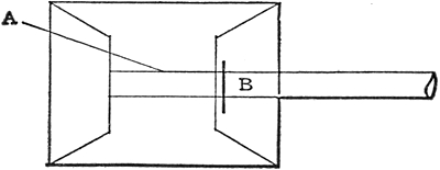
A plank or board A (Fig. 1), about ¼ to ½ inch longer
than the distance from the bottom of the shaft to the
floor, can be used to good advantage at such times to
free the hanger of the shaft's weight, and to prevent
the shaft's springing from its own weight and the pulleys
it may be carrying.
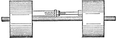
Should it become necessary to place a pulley with
half the hub on and half off the journaled part, this
can readily be done by the use of a split bushing, as
shown in sectional view of Fig. 1.
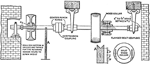
Fig. 1.
Very often a small-sized bearing is used and the shaft
journaled off to act as a collar. Of this procedure it
can only be said that if done with the idea of making a
"good job" it signally fails of its object; if of necessity
(a collar being insufficient), then the shaft is heavily
overloaded and serious trouble will result, because of it.
It is advisable to center punch, or otherwise mark,
the ends of both shafts held by a compression coupling
close up against the coupling, and both edges of the
coupling hub should have a punch mark just opposite
and close to the shaft punch marks. These marks will
serve at all times to show at a moment's glance any
end or circumferential slippage of the shafts within
the coupling. The same method can be resorted to
for proof of pulley slippage.
When a new line of shafting is put up, the foot position
of each hanger should be clearly marked out on
their respective timbers after the shaft has been brought
into alinement. Hangers can thus be easily put back
into their proper place should timber shrinkage or heavy
strains cause them to shift out of line. This idea can be
applied to good advantage on old lines also, but before
marking out the hanger positions the shaft should be
tried and brought into perfect alinement.
Hangers that do not allow of any vertical adjustment
should not be used in old buildings that are liable to
settle. Shafting so run pretty nearly always gets out
and keeps out of level.
In flanged bolt couplings (Fig. 1) no part of the bolt
should project beyond the flanges. And where a belt
runs in close proximity to such a coupling, split wood
collars should be used to cover in the exposed coupling
flanges, bolt heads and nuts. Countershafts have been
torn out of place times innumerable by belts getting
caught and winding up on the main line.
Whenever possible a space of 8 to 10 inches should
be left between the end of a shaft line and the wall.
A solid pulley or a new coupling can thus readily be
put on by simply uncoupling and pushing the two
shaft lengths apart without taking either down. Ten
inches does not represent the full scope of pulleys
admissible, for so long as the pulley hub does not exceed
a 10-inch length the pulley face (the more readily
in proportion to the larger pulley diameter) can be
edged in between the shafts.
Fig. 2 is an instance of bad judgment in locating the
bearings. In one case this bearing overheated; the
remedy is either to re-babbitt the old box or replace
it with a new one.
Both pulleys were solid and the keys—headless
ones—had been driven home to stay. The rims of
both pulleys almost touched the wall, and the circumferential
position on the shaft of both these pulleys
was such as to preclude the possibility (owing to an
arm of a being in a direct line with key B1 and arm
of b with key a1) of using anything but a side offset
key starting drift.
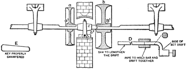
Fig. 2.
An effort was made to loosen b (which was farthest
from the wall) by sledge-driving it toward the wall,
hoping that the pulley might move off the key. The
key, as was afterward found out, not having been oiled
when originally driven home had rusted in place badly;
though the pulley was moved by sledging, the key,
secure in the pulley hub, remained there.
Ultimately one of us had to get into pulley b, and,
removing cap c, hold the improvised side offset, long,
starting drift D in place against B1 at b2 while the other
swung the hand sledge at a. The entering end of the
key, not having been file chamfered off, as it should
have been (see E), our starting drift burred it up; so,
after having started it, we had the pleasure of getting
into b to file the key end b2 into shape so as to admit
of getting it out.
The solid pulley b has since been replaced with a
split pulley.
By the arrangement, as shown in Fig. 3, of the rim-friction
clutch on the driven main shaft B and the
driving pulley on the engine-connected driving main
shaft A, no matter whether B shaft is in use or not—i.e.,
whether the clutch be in or out of engagement—so
long as A shaft is in motion the belt C is working.
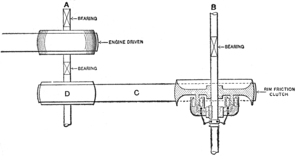
Fig. 3.
Main line belts come high, and the more they are
used the sooner will they wear out. By changing the
clutch from shaft B to A and the pulley D from A to B,
belt C will be at rest whenever B is not in use. Where,
however, these shafts are each in a separate room or
on a different floor (the belt running through the wall
or floor and ceiling, as the case may be) the clutch,
despite belt wear, should be placed directly on the
driven shaft (as B), so as to provide a ready means
for shutting off the power in cases of emergency.
Figs. 4, 5 and 6 represent a dangerous mode, much
in vogue, of driving an overhead floor. An extremely
slack belt connects the driving shaft A and the driven
shaft B; when it is desired to impart motion to the
driven shaft the belt tightener C is let down and belt
contact is thus secured.
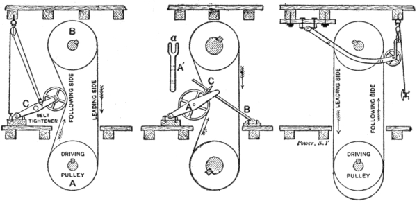
Fig. 4, Fig. 5, Fig. 6.
This tightener system is called dangerous advisedly,
for few are the shops employing it but that some employee
has good cause to remember it. Unlike a clutch—where
control of the power is positive, instantaneous
and simple—the tightener cannot be handled, as in
emergency cases it has to be.
In any but straight up and down drives with the
driven pulley equal to or larger (diametrically) than
the driver, unless the belt have special leading idlers
there is more or less of a constant belt contact with its
resultant liability to start the driven shaft up unexpectedly.
When the tightener is completely off, the
belt, owing to heat, weight or belt fault, may at any
time continue to cling and transmit power for a short
space, despite this fact.
These tighteners are usually pretty heavy—in fact,
much heavier than the unfamiliar imagines when on
the spur of emergency he grapples them, and trouble
results.
Tightener (in Fig. 5) A is held in place by two
threaded rods B—as shown by slot a in A1—and
regulated and tightened by ring-nuts C working along
the threaded portion of B. C (of Fig. 4) is also a
poor arrangement. Fig. 6 is the best of them all.
Apropos of clutches, great care must be exercised
in tightening them up while the shafting is in motion,
for if the least bit overdone the clutch may start up
or, on being locked for trial (according to the clutches'
structure), continue running without possibility of
release until the main source of power be cut off.
Nothing can exceed the danger of a clutch on a sprung
shaft.
Heavily loaded shafting runs to much better advantage
when center driven than when end driven, and
what often constitutes an overload for an end drive
is but a full load for a center drive. To illustrate,
here is one case of many: The main shaft—end driven—was
so overloaded that it could be alined and
leveled one week and be found out one way or the
other, frequently both ways, the next week. Being
tired of the ceaseless tinkering that the condition under
which that shaft was working necessitated, the proprietors
were given the ultimatum: A heavier line of
shafting which would be sure to work, or a try of the
center drive which, owing to the extreme severity of
this case, might or might not work.
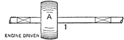
Fig. 7.
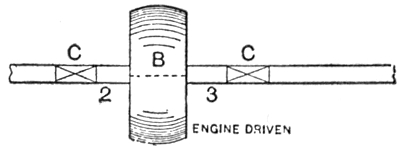
Fig. 8.
A center drive, being the cheapest, was decided upon.
Pulley A, Fig. 7, which happened to be a solid, set-screw
and key-held pulley, was removed from the end
of the shaft. The split, tight-clamping-fit pulley B,
Fig. 8, was put in the middle of the shaft length; the
gas engine was shifted to accommodate the new drive,
and hanger C1 was put up as a reinforcement to hanger
C and as a preventive of shaft springing. After these
changes the shaft gave no trouble, so that, as had been
hoped, the torsional strain that had formerly all been
at point 1 must evidently have been divided up between
points 2 and 3.
When a main shaft is belted to the engine and to a
countershaft, as shown in Fig. 9, the pulley A1 gets all
the load of main and countershafts. In the arrangement
shown in Fig. 10 point 1 gets A's load and 2 gets
B's load and is the better arrangement.
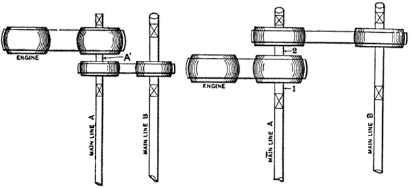
Fig. 9——Fig. 10.
Where a machine is situated close to one of the
columns or timber uprights of the building it is very
customary to carry the belt shifter device upon the
column, as in Fig. 11. The sudden stoppage of a
machine seldom does any damage, whereas an unexpected
starting may cause irreparable damage and
often even endanger the limb and life of the machine
operative.
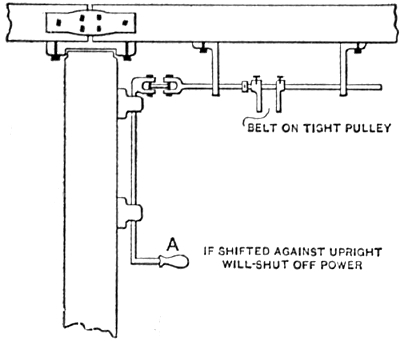
Fig. 11.
To avoid the possibility of some passing person
brushing up against the shifting lever and thus starting
the machine, the tight and loose pulleys of the countershaft
should be so placed that when A is exposed—that
is, away from the column—its accidental shifting
shall stop the machine. Fig 12 makes this point clear.
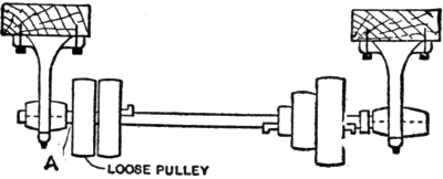
Fig. 12.
This arrangement is often used to save a collar (at
A). The oil runs out between the loose pulley and the
bearing, especially if the latter be a split bearing; the
loose pulley, instead of being totally free when the belt
is on the tight pulley, acts more or less, in proportion to
the end play of the shaft, as a buffer between the tight
pulley and the bearing; finally, the tight pulley is
deprived of the support (which, when under load, it
can use to good advantage) a nearer proximity to the
hanger would give it.
The shafts of light-working counters should not be
needlessly marred with spotting or flats for collar set-screws,
nor should cup or pointed set-screws (which
mar a shaft) be used. If the collar be sharply tapped
with a hammer, diametrically opposite the set-screw,
while it is being tightened up, all slack is taken out of
the collar; and the hold is such that, without resource
to the same expedient when loosening the collar, a
screwdriver will scarcely avail against a slotted set-screw.
When required to sink the head of a bolt into a
timber to admit of the timbers lying snug in or against
some spot, if allowable, the bolt's future turning can
be guarded against by cutting the hole square to fit
the bolt head. But where a washer must be used, the
only positive and practical way to prevent the bolt
from turning is to drive a nail (as shown) into A (Fig.
13) far enough for the nail head to flush B; now bend
the head down behind the bolt toward c. It is evident
that if the bolt tries to turn in the direction of 3 the nail
end (wood held) will prevent it; if toward 4, the nail
head will be forced against the wood and catch hold
of the bolt head.

Fig. 13.
Large belts of engines, dynamos, motors, etc., when
in need of taking-up are usually attended to when the
plant is shut down; that is, nights, Sundays or legal
holidays. At such times power is not to be had; and
if the spliced part of the belt, which must be opened,
shortened, scraped, re-cemented and hammered, happens
to be resting against the face of one of the pulleys,
is up between some beams or down in a pit, the chances
of the job, if done at all, being any good are very slim.
The spliced part of a large belt should be clearly
marked in some permanent and easily recognizable
way (a rivet, or where the belt is rivet-held at all its
joints some odd arrangement of rivets is as good a way
as any). This marking will minimize the possibility of
mistake and enable the engineer to place the belt splice
in the position most favorable for the belt-maker's
taking-up.
In wire-lacing a belt, very often, despite all efforts
and care, the edges of the belt (A, B) get out of line, as
shown in Fig. 14, and make the best of jobs look poor.
By securing the belt in proper position by two small
pieces of wire passed through and fastened at 1, 2, 3
and 4, Fig. 15, the lacing can be more conveniently
accomplished and the edge projection is avoided. When
the lacing has progressed far enough to necessitate the
removal of wires c d, the lacing already in place will
keep the belt in its original position.
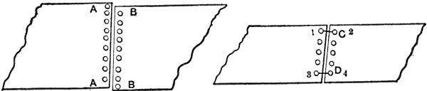
Fig. 14——Fig. 15.
A wire lacing under certain conditions will run a
certain length of time to a day. On expensive machinery
whose time really is money it pays to renew the
lacing at regular intervals so as to avoid the loss of
time occasioned by a sudden giving out of the lace.
Never throw a belt on to a rim-friction or other kind
of clutch while the shaft is in full motion. Belts, when
being thrown on, have a knack, peculiarly their own,
of jumping off on the other side of the pulley. And
should a belt jump over and off on the wrong side and
get caught in the clutch mechanism, as the saying
goes, "there will be something doing" and the show
usually comes high. It pays to slow down.
A mule belt (transmitting in the neighborhood of
or considerably over 25 horse-power) that runs amuck
through the breaking down of the mule can make
enough trouble in a short time to keep the most able
repairing for a long while.
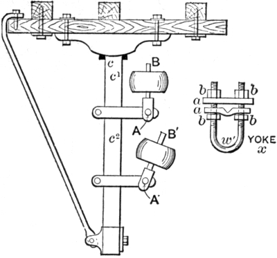
Fig. 16.
No matter what the pulley shafts holding arrangement
and adjusting contrivance may be, all of the
strain due to belt weight, tension, and the power
transmitted falls mainly at points A, A1, Fig. 16; and
it is here that, sooner or later, a pin, set-screw or bolt
gives way and the belt either gets badly torn up, rips
something out of place, or a fold of it sweeping to the
floor slams things around generally until the power
is shut off.
The remedy is obvious: Reinforce A, A' by securing
B, B' to the supporting shaft c at c1, c2. The yoke x
is a reliable and practical means to this end. Straps a
held by the nuts b hold the yoke securely on the supporting
shaft c, while the pulley-shaft ends B, B' are
held in the U of the yoke at w' at any desired distance
from c by means of the adjustment provided by the
nuts b.
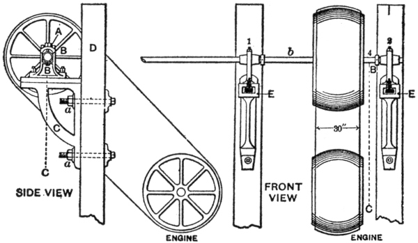
Fig. 17.
The end of a hanger bearing was badly worn (Fig.
17). The cap could be lifted out by removing bridge
A, but the shaft interfered with the lifting of the bottom
out, owing to its being held in the hanger slides. It
had to be removed and we were called upon to put it
into shape by re-babbitting.
Being a newspaper plant, money was no object;
the time limit, however, was three hours, or hands off.
Opening the 30-inch engine belt and removing the
interfering shaft length was out of the question in so
short a time. So the job was done as follows: The shaft
was braced against down sag and engine pull along the
line B C by a piece of timber at A, and against pull on
B D by timber arrangement X; timber y's points y1
and y2 resting against the uprights at 1 and 2, timber
z wedged in between y at y3 and the shaft at 4, thus
acting as the stay along line B D. The nuts and
washers a, a were removed; the bolts driven back out
of the bracket; the end of a rope was thrown over the
shaft at b, passed through the pulley and tied to the
bracket and hanger which, as one piece, were then
slid endways off the shaft and lowered to the floor.
The bearing was cleaned, re-babbitted and scraped,
everything put back, stays removed and the shaft
running on time with a half-hour to the good.
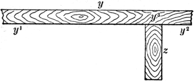
TIMBER ARRANGEMENT X
When desirable to keep a shaft from turning while
chipping and filing flats, spotting in set screws or
moving pulleys on it, it can be done by inserting a
narrow strip of cardboard, soft wood or several thicknesses
of paper between the bearing cap and the top
of the shaft and then tightening the cap down.
The packing, 1/16 to 3/16 inch thick and about as
long as the bearing, must be narrow; otherwise, as
may be deduced from Fig. 18 (which shows the right
way), by the use of a wide strip in the cap the shaft
is turned into a wedge, endangering the safety of the
cap when forced down. At point 3 packing does no
harm, but at 1 and 2 there is just enough space to allow
the shaft diameter to fit exactly, with no room to spare,
into the cap bore diameter.
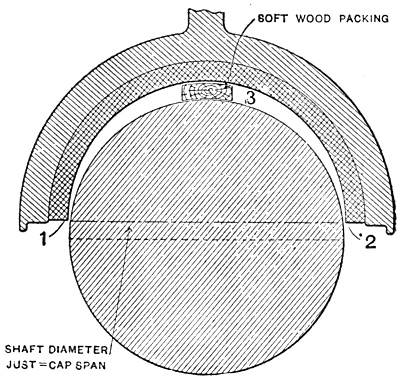
Fig. 18.
As a very little clamping will do a good deal of
holding the clamping need not be overdone. A shaft
can also be held from turning, or turned as may be
desired, by holding it with a screw (monkey) wrench
at any flat or keyway, as shown in sectional view,
Fig. 19.
When a shaft breaks it is either owing to torsional
strain caused by overload, springing through lack of
hanger support at the proper interval of shaft length,
the strain of imperfect alinement or level, or a flaw.
An immediate temporary repair may be effected
by taking some split pulley that can best be spared
from another part of the shaft and clamping it over the
broken part of the shaft, thus converting it, as it were,
into a compression coupling. The longer the pulley
hub the better the hold; spotting the set-screws—that
is, chipping out about 1/8-inch holes for their accommodation
into the shaft—is also a great help.
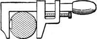
Fig. 19.
If when the shaft breaks it has not been sprung by
the sudden dropping of itself and the pulleys that were
on it, a permanent repair can be effected, after correcting
the cause of the break, by the use of a regular key-less
compression coupling.
If it has been sprung, a new length comes cheapest
in the wind-up; and if overload was the original cause
of the trouble, only a heavier shaft or a considerable
lightening of the load will prevent a repetition.
In Fig. 20 A shows how to drive to make belt weight
count in securing extra contact. In B this weight
causes a loss of contact. Bearing in mind that B is
not only a loss from the normal contact but also a loss
of the extra contact that A gives, it will readily be seen
how important a power-saving factor the right sort of
a drive is—especially on high-speed small-pulley machines,
such as dynamos, motors, fans, blowers, etc.
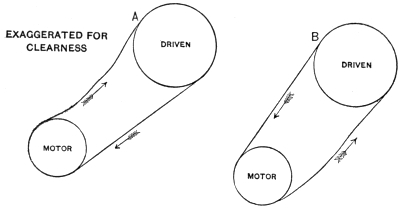
Fig. 20.
A good many electrical concerns mount some of their
styles of dynamos and motors (especially the light
duty, small size) upon two V-shaped rails, Fig. 21
(the bottom of the motor or dynamo base being V-grooved
for the purpose). The machine's weight and
the screws A are counted on to keep it in place. If
the machine be properly mounted on these rails, as
regards screws A in relation to its drive, the screws
reinforce the machine's weight in holding it down and
also permit a surer adjustment through this steady
holding of the machine.
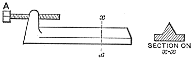
Fig. 21.
Fig. 22 shows the machine properly mounted. The
belt tension and pull tend to draw B corner of the
machine toward the shaft C; and screw B1 is there to
resist this pull. Owing to this resistance and the pull
along line D, E tends to lift and slew around in E1
direction; screw E2 is, however, in a position to overcome
both these tendencies. If the screws are both
in front, there is nothing but the machine's weight
to keep the back of it from tilting up. The absurdity
of placing the screws at F and G, though even this is
thoughtlessly done, needs no demonstration.
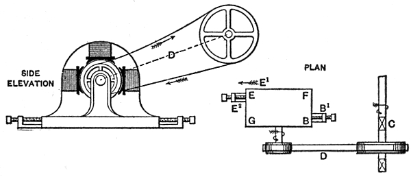
Fig. 22.
When putting a new belt on a motor or dynamo,
both the driver and the driven are often needlessly
strained by the use of belt-clamps, in the attempt to
take as much stretch out of the belt as possible. On
being loosely endlessed it soon requires taking up; and
if only laced, when the time for endlessing comes the
belt is botched by the splicing in of the piece which,
owing to the insufficiency of the original belt length,
must now be added to supply enough belt to go around,
plus the splice.
The proper mode of procedure is: Place the motor
on its rails or slides 5 inches away from its nearest
possible approach to the driven shaft or machine and
wire-lace it (wire-lacing is a very close second to an
endless belt). Let it run for a few days, moving the
motor back from the driven shaft as the belt stretches.
When all reasonable stretch is out, move the motor
back as close to the driven shaft as possible.
The 5 inches forward motion will give 10 inches of
belting, which will be amply sufficient for a good splice;
and, further, the machine will be in position to allow of
tightening the belt up, by simply forcing the motor
back, for probably the belt's lifetime.
SHAFTING HINTS [2]
The bolts, set-screws, pulleys, bearings, shafting and
clutches of a plant, although among the foremost
factors in its efficiency, are very often neglected until
they reach the stage where their condition absolutely
compels attention.
Very often this lack of proper attention is due to
surrounding difficulties of an almost insurmountable
and most discouraging nature. At other times it is
due to a lack of proper appreciation of the damage
resultant from seemingly insignificant neglects. How
to overcome some of these difficulties is the object of
this chapter.
Fig. 23 shows a case of a turning bolt. The head is
inaccessible and the bolt's turning with the nut, owing
to burrs or rust, prevents either the tightening or the
loosening of the nut. One to three fair-sized nails
driven through the timber as at C, hard up against, or,
better still, forced into a tangent with the bolt, will
often suffice to hold it while the nut is being turned. In
iron girders, beams, etc., the nail method being impossible,
a slot E can easily be cut with a hack-saw
through the lower end of both the nut and bolt, so
that the bolt may be held by a screwdriver while the
nut is turned with a wrench.
Where an extra strong screwdriver must be used,
the use of two blades at the same time in the hack-saw
frame will give a slot of the requisite width. Where
the bolt's end projects beyond the nut and it is desired
to tighten the nut, a Stillson wrench is often, though
inadvisedly, called into service. This tends to spoil the
lower threads of the bolt and thus prevents any future
loosening, except by the cutting off of the projecting end.
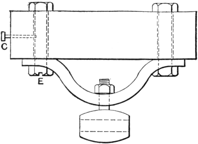
Fig. 23.
As the alinement and level of shafting depend on the
power of their hold, bolts, lag-bolts and set-screws
should, when they are tightened, be so in fact and not
in fancy.
The proper way to use a wrench, especially a screw
wrench, so as to avail yourself of every ounce of power,
not of your biceps only but of your whole body, is as
follows: Place your shoulders on a level with the object
to be tightened, secure the wrench jaws well upon it,
grasp the jaws with the left hand and the wrench handle
with the right, holding both arms straight and tense;
swing the upper part of the body to the right from the
hip, backing the force of your swing up with the full
force of your legs, steadying yourself the while with
your left-hand grip on the wrench jaws, which are the
center of your swing. Several such half turns, at
the wind-up, will cause an extremely hard jam with
comparative ease.
In tightening up a split-pulley, the expedient of
hammering the bolts tight, by means of an open-ended
bolt-wrench and a small sledge, is often resorted to.
If the head of the bolt be lightly tapped while the nut
is being tightened, even a light hammering, except
in the extremest cases, becomes unnecessary.
Split-pulleys are invariably better held in place by
a good clamping fit than by set-screws. It must also
be borne in mind that, for good holding, set-screws must
be spotted into the shaft, and this defaces and often
materially weakens the shaft. Split-pulleys, like solid
ones, are sometimes subject to stoppage, owing to
excessive strain. Set-screws, at such times, cut a shaft
up pretty badly; whereas, if clamped, only a few slight
scratches would result.
Where packing with paper, cardboard, emery cloth
or tin becomes necessary to secure a good clamping fit,
care should be taken to put an equal thickness of packing
into both halves of the pulley; otherwise it will
wabble and jump when running.
Emery cloth, on account of its grittiness, is preferable
for packing where the duty done by the pulley
is light. When the duty done is extra heavy, emery
cloth, despite its grittiness, will not do; tin or sheet
iron, owing to body, must be used.
The following is the most practical way of packing a
split-pulley to a good clamping fit, assuming that emery
cloth is to be used:
The thickness of the emery cloth to be used, and
whether to use one or more folds, can readily be ascertained
by calipering the shaft diameter and pulley
bore, or by trial-clamping the pulley by hand. In both
of these instances, however, due allowance must be
made for the compressiveness of the packing used.
If the packing be too thin, the pulley will not clamp
strongly enough; if too thick, the chances of breaking
the lugs when drawing the bolts up are to be apprehended.
Having determined the proper thickness of emery
cloth to be used, place the pulley on the shaft, as shown
in Fig. 24. Into the lower half C, in space A, which is
out of contact with the shaft, place a sheet of emery
with the emery side toward the hub and the smooth
side toward the shaft. The width of the emery should
be a little less than half of the shaft's circumference,
and it should be long enough to project about one-half
of an inch to an inch on each side of the hub.
Now turn the pulley on the shaft so that the position
of the halves shall become reversed (Fig. 25), C on top,
B on bottom. See that the emery cloth remains in its
proper position in half-hub, the smooth side being
toward the shaft; the projecting length beyond the
pulley hub will help you to do this.
Into half-hub B (space D) insert a similar sized piece
of emery cloth, smooth side toward the hub and the
emery side toward the shaft. Draw up on your bolts to
clamp the pulley into position. Be sure, however,
that no emery cloth gets in between the half-hubs or
lugs at points 1 and 2, Fig. 25, as this would prevent
their coming properly together; the width of the emery
being less than half of the shaft's circumference will
be a help to this end.
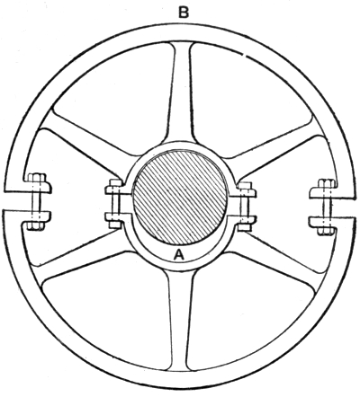
Fig. 24.
It often happens, owing to downright neglect or
unwitting neglect, through the oil hole or oiler being
blocked up, that a loose pulley, running unlubricated,
cuts, heats, and finally, through heat expansion, seizes.
It then becomes necessary to take the countershaft
down, force the loose pulley off and file and polish the
shaft up before it can be put back into place.
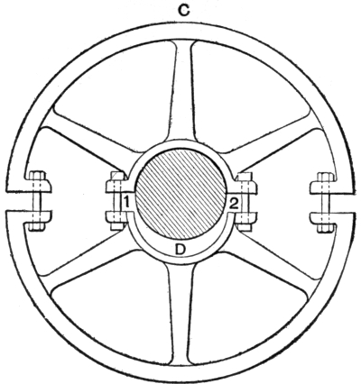
Fig. 25.
The following method avoids the taking down and
putting back, provides an easy means for loosening up
the pulley that has seized, and improvises, as it were,
a lathe for filing and polishing the shaft.
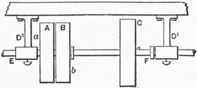
Fig. 26.
In Fig. 26, A is the loose pulley that has seized.
Throw off both the belt that leads from the main shaft
to pulleys A, B and the belt that leads to the driven
machine from the driving pulley C. Tie, or get somebody
to hold, an iron bar in pulley A at side a, as shown
in Fig. 27, over an arm of the pulley, under the shaft,
and resting against the timber, ceiling, wall or floor,
in such a way as to prevent the pulley from turning in
one direction, as shown in Fig. 27. Now, with another
bar, of a sufficient length to give you a good leverage,
take the grip under a pulley arm and over the shaft
in the tight pulley B at b, which will enable you to work
against the resistance of the bar in the loose pulley A.
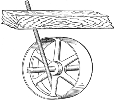
Fig. 27.
With enough leverage, this kind of persuasion will
loosen the worst of cases. Take the bars out and move
B sufficiently to the right to allow A to take B's former
position. Secure B by means of its set-screws in its
new position and, by means of a piece of cord, fasten
an arm of A to one of B's. It is evident that by throwing
the main-shaft belt on to A it will, through A's
cord connection with B, which is screwed to the shaft,
cause the shaft to revolve, thus enabling you to file
up and polish that portion of it formerly occupied by
A. To prevent the countershaft from side-slipping out
of hanger-bearing D1, get somebody to hold something
against hanger-bearing D2 at E; or fasten a piece of
wire or cord on the countershaft at F and the hanger
D1, so as to prevent side-slipping while not interfering
with revolution.
Filing, polishing, a cleaning out of the oil hole or
oiler, and the taking of proper precaution against
future failure of lubrication will put everything into
first-class order. When the loose pulley is, as it is best
for it to be, farthest away from the bearing, held in its
place by the tight pulley and a collar, not only is the
tight pulley better adapted for carrying its load, owing
to additional support resultant from its proximity
to the bearing, but such matters of small repair as
come up are much simplified.

Fig. 28.
Fig. 28 in some degree, aside from the cutting up and
heating of the bearings, illustrates the breaking strain,
in addition to the usual torsional strain, which becomes
enhanced in direct proportion with the increase of
breaking strain, to which an out-of-line or out-of-level
shaft is subject. The bends are exaggerated for
illustration.
In this instance, the fact of one hanger-bearing being
out of line or level subjects the shaft to a severe breaking
strain. The shaft being both out of line and level
does not, if both at the same point, aggravate matters,
as might at first be supposed.
It is true that the full torsional strength of a shaft
is only equal to the weakest portion of it, so that three
weak spots more or less can, theoretically, make no
difference one way or the other. But, practically,
there is the undue strain and wear of the bearings at
these points, and if a pulley transmitting any considerable
amount of power is situated anywhere along the
length A B it is sure to be unpleasantly in evidence at
all times.
Only an eighth or a quarter out, but oh, what shaft-breaking
stories that fraction could tell!
The following is a simple method for testing the alinement
and level of a line of shafting that is already up.
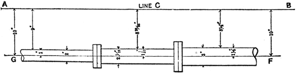
Fig. 29.
As in Fig. 29, stretch a line C so that it is exactly
opposite the shafting. Set it equidistant from the
shaft end centers G and F and free from all contact
along its entire length except at its retaining ends A and
B. Now, it is self-evident, as line C is straight and set
equidistant from the shaft end centers G and F, that
if you set the entire center line of the shafting at the
same distance from line C, as G and F, you are bound
to get your shafting into perfect alinement.
In leveling a line of shafting that is already up,
you can, by the use of a level and perseverance, get it
right.
Placing the level at A, you are just as likely to raise
the first hanger as to lower the middle one. Look
before you jump, even if compelled to climb to the top
of the fence to do so. When you find a length of shafting
out of level, try the two adjacent lengths before
acting, and your action will be the more intelligent
for it.
On exceptionally long lines of shafting the following
method, in which the level and a line constitute a check
upon and a guide for each other, can be used to great
advantage. Stretch a line so that it is exactly above,
or, if more convenient, below the shafting to be leveled.
With the level find a length of shafting that is level
and adjust your line exactly parallel with this length.
Your line now, free of contact except at its retaining
ends, and level owing to its parallelism to the level shaft
length, constitutes a safe hight level guide while the
level itself can serve to verify the accuracy of the
finished job.
In lining, whether for level or alinement, unless the
shafting line consists of the same diameter of shafting
throughout its entire length, though of necessity measuring
from the shaft circumference to the line, always
base your calculations on the shaft centers. The
figures in Fig. 29 will make this point clear.
The manner of securing the ends of the line under
different circumstances must be left to individual
ingenuity. Only be sure that the line is so placed that
the shafting adjustment shall not affect its original
position with reference to the end shaft centers.
Coupling clutches, i.e., those joining two lengths of
shafting into one at option, will fail, utterly or partially,
if the respective shafts which bear them are out of line
or level with each other. Such a condition should not
be tolerated on account of the danger entailed by the
inability to shut off the power in cases of emergency.
As a general rule, it is most advisable to set a clutch
to take as hard a grip as it can without interfering with
its releasing power. Where a clutch grips weakly,
it is subject to undue wear owing to slippage, whereas
a strongly regulated clutch absolutely prevents slippage
wear.
SHAFTING HINTS [3]
Engineers, machinists and general mechanics
are often called upon to turn their hands to a shafting
job. We recognize that all of the following cannot
prove new or even suggestive to most of our readers;
still, some of it for all, and, mayhap, all for some, may
not come amiss.
We all know that to have belting run rightly on
pulleys located upon parallel lines of shafting the
shafting must be in absolutely correct parallel. The
slightest deviation, even to a 1/16 inch, often imparts
a marring effect, through poorly running belts, to an
otherwise faultless job.
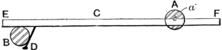
Fig. 30.
Fig. 30 shows how to line a countershaft as regards
parallelism with the driving shaft when the countershaft's
end-centers are availably situated for thus
measuring. A is the countershaft, B the main shaft,
C is a stick of proper length about 1½ inches in thickness
and width, D a heavy nail—about 20-penny will do—driven
into C far enough from its end E to allow of
C's resting squarely upon the top of the shaft B.
Rest the measuring rod upon the main shaft, keeping
the nail in touch with the shaft, so that when the F
end is in contact with the end of the countershaft the
stick shall be at right angles to the main shaft, and then
mark the exact location a of the countershaft's end-center
on the stick. Do the same at the other end of the
countershaft. If both marks come at the same spot,
your counter is parallel; if not, space between these
two marks will show you how much and which way the
counter is out.
It may only be necessary to shift one end in or out
a little; and then, again, it may be that to get into line
you will have to throw one end all the way in one direction
and the other all or some in the opposite direction.
But, whichever it be, do not rest content until you have
verified the correctness of your adjustment by a re-measurement.
The nail should be well driven into C, so that its
position will not readily change, and it should, preferably,
be slant driven (as shown in Fig. 30), as it thus
helps to keep the stick down in contact with the shaft.
Where an end-center is not available or where there
is no clear space on the main shaft, opposite a center,
the method shown in Fig. 31 can generally be used.
Rest C on top of both shafts and at right angles to
the driving shaft B. With D pressed against B, place
a square on stick C, as shown (stock in full contact with
the top of the rod, and the tongue running down the
side of it). Slide along C toward A until the side of
the tongue touches the shaft the other side of A. Now
mark a line on the stick down tongue. Do the same
at the other end of your countershaft and the two
resultant marks will be your parallel adjustment guides.
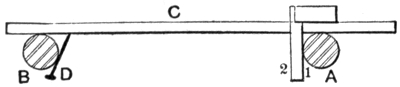
Fig. 31.
It often happens that a counter, or even line shaft,
is end driven from the extreme end of the main or jack
driving shaft with its other end running beyond the
reach of the driving shaft, as shown in Fig. 32.
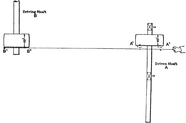
Fig. 32.
It is evident that neither method 1 nor 2 can here
be applied to solve the alinement problem. If the
driving pulley B and the driven pulley A are both in
place, the following method can be used to advantage.
Fasten, or let somebody hold, one end of a line against
pulley B's rim at B1; carry the line over to A at A2;
now sweep the loose A2 end of the line toward pulley A
until the line just touches pulley B's rim at B2. When
the line so touches—and it must just barely touch or
the measurement is worthless—A1 and A2 of pulley A
must be just touched by or (if B and A are not of a like
face width, as in Fig. 32) equidistant from the line.
A single, two-hanger-supported length of shafting
thus lined is bound to be in parallel; but where the so
adjusted shaft line consists of two or more coupling-joined
lengths supported by more than two hangers,
only pulley A's supporting portion of the shaft between
its immediate supporting hangers 1 and 2 is sure to be
lined; the rest may be more or less out.
To make a perfect job, fix a string in parallel with
shaft length 1 and 2, stretching along the entire length
of the adjusted shaft, and aline the rest of the shaft
length to it.
When there are no pulleys in place to go by, or when,
as occasionally happens, the wabbly motion of pulley
B (when running) indicates that, having been inaccurately
bored or bushed, or being located on a sprung
shaft length, its rim line is not at right angles to the
shaft line, the method shown in Fig. 33 can be resorted
to.
Instead of the nail used in methods 1 and 2, use a
board about 8 to 12 inches long and of a width equal
to considerably more than half of shaft B's diameter.
By nailing this board x to the measuring rod c at any
suitable angle, you will be enabled to reach from the
end a well into the shaft B, as at b, and from bâ² well into
A, as aâ². By keeping the board x along its entire length
in full contact with the shaft B at both 1 and 2, the
angular position of rod C is bound to be the same in
both instances, and you will thus (by the use of a square,
as in Fig. 31) be enabled to aline A parallel with B.
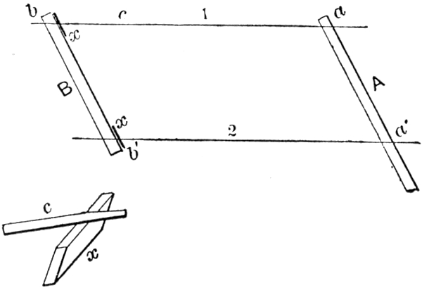
Fig. 33.
In all instances of parallel adjustment here cited it
is assumed that both the alined and the alined-to
shafts have been, as to secure accuracy of result they
must be, properly leveled before starting to aline.
The above methods apply to cases where the shafting
is already in place. Where, however, shafting is being
newly installed before the work can be proceeded with,
it is necessary, after determining on the location for the
shafting, to get a line on the ceiling in parallel with the
driving shaft to which to work to. Mark that point A
which you intend to be the center line for the proposed
shafting upon the ceiling (Fig. 34).
Rest your measuring rod upon the driving shaft and
at right angles to it, with the nail against it. Hold your
square with the stock below and the tongue against the
side of the measuring stick, so that its tongue extremity
touches the ceiling mark A, and then mark a line on the
rod along the tongue side A. Move your rod along
the driving shaft to the point where the other end of
the proposed shafting line is to be, and, squaring your
stick to the driving shaft with the tongue side A on the
marked line of the stick, mark your section point on the
ceiling. Draw a line or stretch a string between these
points, and you have a true parallel to work to.
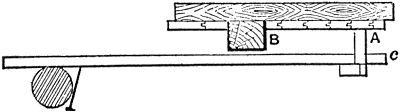
Fig. 34.
Owing to the supporting timber B's interference, a
square had to be used; but where the ceiling is clear
the rod can be cut to proper length or the nail be so
located as to allow of using the stick extremity C for a
marking point.
When a pulley is handily situated on the driving
shaft, the method shown in Fig. 35 can be used to
advantage.
Let somebody hold one end of a line at 1, and when
you have got its other end so located on the ceiling
that the line just touches the pulley rim at 2, mark that
ceiling point (we will call it 3). In the same way get
your marks 4 and 5, each farther back than the other
and, for the better assurance of accuracy, as to just
touching at 2, remove and readjust the line separately
each time. If now a straight line from 3 to 5 cuts 4,
your line 3, 4, 5 is at right angles to the driving shaft and
a line at right angles to this will be parallel to the shaft.
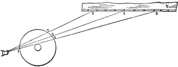
Fig. 35.
The plumb-bob method is so familiar and, where not
familiar, so easily thought out in its various applications,
that we deem it useless to touch upon it.
The stringers or supporting timbers of drop hangers
should be equal in thickness to about one-fifth of the
hanger drop.
Where the stringers run with the hangers and crosswise
of the shaft, both feet of a hanger base are bolted to
the same stringer, and this should be from 1¼ to 1½
times the width of the widest portion of the hanger base.
As the hanger is securely bolted to its stringer, this
extra width is in effect an enlargement of the hanger
base, and thus enables it the better to assist the shaft's
end motion.
Where the stringers run with the shaft and crosswise
of the hangers, the two feet of the hanger base are
each fastened to a separate timber, and these should
be equal in width to the length of one hanger foot, plus
twice the amount of adjustment (if there be any) the
hanger's supporting bolt slots will allow it. In reckoning
hanger adjustment, be sure to figure in the bolt's
diameter and to bear in mind that to get the utmost
adjustment for the countershaft the bolts should
originally be centered in the slot; thus a 13/16 à 1½-inch
slot, as it calls for a ¾-inch bolt, leaves a ¾-inch play,
and this play, with the bolt in the center of the slot,
allows of 3/8-inch adjustment either way. Without this
extra width addition any lateral adjustment of the
hanger would result in leaving a part of the hanger's
feet without stringer support. Such jobs look poorly,
and often run still more poorly. Fig. 36, in its two
views, will make the above points clear.
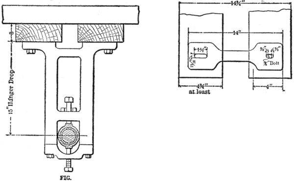
Fig. 36.
In the stringing of countershafts whose hangers
have no adjustment it often happens, despite all care
in the laying out, that they come 1/8 to ¼ inch out of parallel.
A very common and likewise very dangerous practice
at such times is to substitute a smaller diameter
supporting bolt instead of the larger size for which the
hanger foot is cored or drilled, and to make use of the
play so gained for adjustment.
That shafting so carried does not come down oftener
than it does is due solely to the foresight of the hanger
manufacturers. They, in figuring the supporting bolt's
diameter as against the strain and load to be sustained,
are careful to provide an ample safety margin for overload,
thus enabling the bolt substituted to just barely
come within the safety limit under easy working conditions.
The largest-sized bolt that a hanger will easily admit
should invariably be used, and for alinement purposes
either of the following slower but safer methods should
be used.
Rebore the hanger-supporting bolt holes in the
stringers to a larger size, and use the play so gained for
adjustment. It is not advisable, however, to rebore
these holes any larger than to one and three-quarter
times the diameter of the bolt to be used; and the
diameter of the washers to be used on top of the
stringers should be diametrically equal to at least
twice the size of the rebored holes. That the washers
used, under such conditions, must be of a good proportionate
thickness goes without saying.
When the reboring method cannot be used—as
when the hangers are carried by lag screws, lag-bolts,
bolts screwed directly into supporting iron girders,
etc.—it is evident that hanger adjustment can be
secured by packing down one foot of the hanger base,
as shown in Fig. 37.
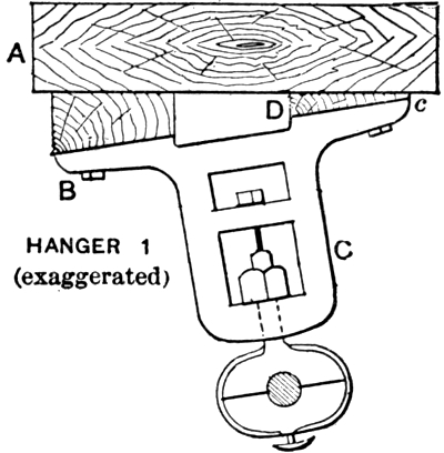
Fig. 37.
The piece of packing (necessarily wedge-shaped)
between the hanger foot B and the stringer A tilts
the bottom of the hanger forward. The size of the
wedge regulates the amount of adjustment. Wedge-shaped
space D, at foot C, should also be packed out
so as to avoid throwing undue strain upon C's extremity
c. If now, the foot c of the countershaft's
other supporting hanger (No. 2) be similarly and equally
packed, as B of No. 1 hanger, the shaft will have been
thrown forward at one end and back at the other, and
thus into line. The equal division of the adjusting
wedge packing between the opposite feet of the two
hangers enables a limited packing to do considerable
adjusting without any undue marring effect; and,
further, insures the shaft's remaining level, which evidently
would not be the case if only one hanger were
packed down.
After so adjusting, be sure to get your hangers
squarely crosswise of the shaft as readjusted, so that
the hanger bearings will lie in a true line with the shaft
and not bind it. At all times be sure to have your
hangers hang or stand plumb up and down; as, if the
bearings are not so pivoted as to be horizontally self-adjusting,
excessive friction will be the lot of one end
of the bearing with not even contact for the rest of it.
The bearing being self-adjusting all ways, square
crossing of the shaft line by the hanger line and plumb
still remain eminently desirable for appearance's sake.
Before a countershaft can be put up on a ceiling
whose supporting timbers are boarded over, or in a
modern fireproof structure whose girders and beams
are so bricked and plastered in as not to show, it is
necessary to positively locate those of them which
are to carry the stringers.
It is in the earnest endeavor to properly locate these
that the unaccustomed hand turns a wood ceiling into
a sieve and a brick one into a wreck. To avoid kitchen
and house razing effects, try the following recipe:
We will assume that line A B, Fig. 38, laid out by
one of the methods previously described, is the center
line of the proposed countershaft. The hanger's base
length, lateral adjustment and individual foot length
call for stringers 4¾ inches wide, placed 5¼ inches apart
or 14¾ inches outside (as per sketch). The floor position
of the machine to be driven, or the driving point of the
main shaft, is so located with reference to the countershaft
that one of the supporting hangers must go at or
very near C, and the countershaft's length brings the
other hanger at or very near D.
Now between points C D and with due reference to
the center line A B, lay out the position which your
stringers are to occupy. It is self-evident that by
confining your beam prospecting to the stringer
spaces E and F, ultimately, when the countershaft is
in place, all the cut-up portions of the ceiling will be
hidden from view.
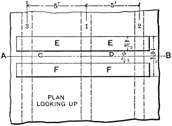
Fig. 38.
Generally the necessary supporting beams will not
all be found within the shaft's length distance C D;
in such cases continue your cutting in the same parallel
line to A B, as at E or F, going from C D outwardly
until you strike the sought-for beams. Having located
beams, say 1 and 2, we find by measurement that they
are 5 feet apart, and, as beams are generally uniformly
spaced, we may start 4 feet 6 inches (go 4 feet 6 inches
and not 5 feet, to make sure not to skip beam 3 and
thus make a cut that will not be covered by the stringers)
from 1 to cut outwardly for the location of beam 3.
Where the building's beams run parallel to the
shaft, Fig. 39, mark the counter's-center line A B, and
then mark the spaces—as determined by the countershaft
length, floor position of the driven machine or the
driving point on the main shaft—to be occupied by
the stringers C D, and, starting from the center line
A B, cut outwardly each way to the desired beams
1 and 2.
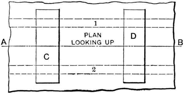
Fig. 39.
Where the center line as laid out (before the position
of the ceiling beams was known) brings it close to or
directly under a supporting beam, it is generally
advisable where possible to step the counter back or
forward to a central position between the beams.
Where shafting is already in place in a building, no
matter on what floor, valuable measurements as to
beam location can thus be had from the plainly in sight
and the reasonably deducible. Lacking in-place-shafting
to go by, the walls, columns and main girders always
clearly indicate the crosswise or parallel run of the
ceiling beams to the proposed shafting line.
In the usual method of locating the timbers of a
boarded-over ceiling, a brace and bit, or a nail, can be
used for the purpose. If shy of an awl, and in preference
the other two ways, force or drive a chisel (cold chisel
or wood) in between a tongue and groove of the ceiling
boards in stringer space (Fig. 38) E or F, and thus
spring the boards sufficiently apart to insert a compass
saw. With the extremity of a 12-inch saw a very little
cutting (along the tongue and groove, as this shows
least) will enable you to locate a beam, since they
generally run 8, 12, 16, 20, 24 and 30 inches apart.
Always, on locating your beam, run the point of
your compass saw down the whole of the timber's
width, so that any nailed-on pieces will not lead you
into a false estimate of the beam's thickness.
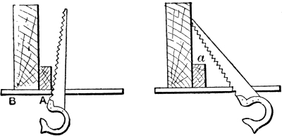
Fig. 40...........Fig 41.
Figs. 40 and 41 make this point and its object clear.
The saw, in Fig. 40, being stopped by A, naturally
leads to the inference that A B is the timber's thickness.
By running down the timber, as in Fig. 41, the saw's
point sticking at a acts as a sure detector. This precaution
should be taken on both sides (B and A) of
the timber, and then, when the lags are screwed in,
they can be sent home safe and true in the center of the
timber.
It often happens that in boring for the lag screws
the bit strikes a nail and further progress at that point
seems out of the question. When so situated, take your
bit out, and running the lag screw up as far as it will go,
by sheer force swing it three or four turns up further
than the point where your bit struck. Removing the
lag and replacing the bit, it will be found that the nail
has been forced aside and the way is now clear.
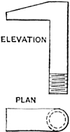
Fig. 42.
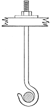
Hook bolts (Fig. 42) or—as our across-the-sea
cousins call them—"elbow bolts," despite all assertions
to the contrary, are an easy, safe and economical
stringer fastener or suspending device.
Figs. 43 and 44 illustrate two very common abuses
of the hook bolt. In the one (Fig. 43), instead of the
bolt proper lying snug up against the beam flange with
the whole of its hook resting squarely upon the beam's
flange, its supporting countershaft is turned into a
menace to limb and life by this "chance it" kind of
erection. In the other (Fig. 44), though the bolts
do lie snug against the flange, the hook being out of
sight and no means being provided for telling whether
the hook lies, as it should, at right angles to the web
of the beam, even if properly placed at installation,
timber shrinkage, vibration or a slight turn of the bolt
when tightening the nut, all constitute dangerous
factors tending to loosen or entirely loosen the hook's
grip upon the beam flange.
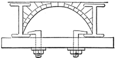
Fig. 43.
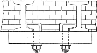
Fig. 44.
Fig. 43 suggests its own remedy. As to Fig. 44, a
screwdriver slot (made by a hacksaw) at the nut end
of the hook bolt and running in the same direction as
the hook, Fig. 45, will at all times serve to indicate the
hook's position and, allowing as it does of a combined
use of screwdriver and wrench, it can be used to prevent
the bolt's turning when being tightened.
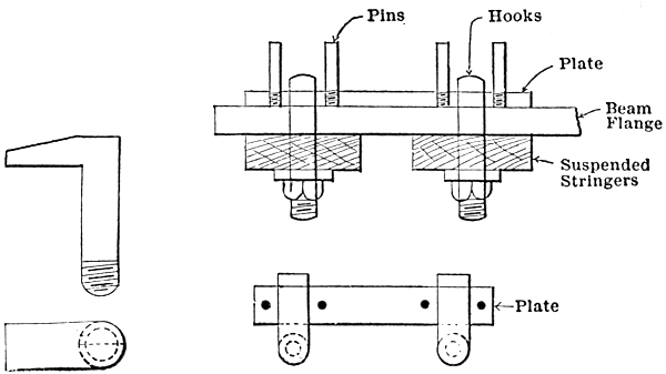
Fig. 45............Fig. 46.
Where two or more hook bolts are placed close together
on the same beam flange, a plate, preferably
wrought iron with properly spaced confining pins for
the hooks, may be placed between the beam flange and
the hooks as in Fig. 46. Its benefits are obvious and
so likewise is the use of a small, square, wrought-iron
plate with a bolt hole through its center instead of
hook bolts.
The various styles of beam clamps carried by the
hardware and supply trade all have their good points,
and though the C of their cost may seem to loom large,
it is not a whit more emphatic, taken all in all, than
the W of their worth.
TRUING UP LINE SHAFTING
It is assumed, for the purposes of this description,
that the modern style of shafting, increasing in diameter
by the ½ inch, is used, and that all pulleys and belts
are in place. We will take a line composed of sizes
ranging between 3 15/16 and 2 7/16 inches. This gives us
four sizes, 3 15/16, 3 7/16, 2 15/16 and 2 7/16 inches in the line.
We will first consider the plumb-bob. The accompanying
sketch, Fig. 47, illustrates a good one.
The ball is 1½ inches diameter, and the large end of
the tapered stem ½ inch in diameter, turned parallel
for a short distance at the lower end. The two thin
sheet-steel disks, 1 and 2 inches in diameter, are drilled
to fit snugly when pushed on to the ½-inch part of the
stem, and stay there until pulled off. These disks
are turned true. This arrangement of plumb-bob and
disks enables us to deal with five sizes on one line, and
there are not many lines that contain more.
Now having our plumb-bob ready, we will stretch
the line. The stretchers should be set horizontally
by nailing a strip of wood, say 1 à 1½ à 12 inches, with
a piece at each end to form a space between it and
the wall, or place of location in line with the edge of the
shaft, as in Fig. 48. The top of this stretcher should
be low enough to clear the largest pulley, and high
enough to clear the hat of your tallest man. You
would perhaps find it convenient to go between the
spokes of a large pulley.
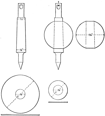
Fig. 47.
Now having located your stretcher, find approximately
the position of your line, and drive a nail a
foot or more below it in a vertical line, and another nail
anywhere for convenient winding. The advantage
of this plan is that the line can be easily adjusted as it
merely passes over the stretcher, and is free to respond
to movement either way; then when the final adjustment
is made, and is ready for its final stretch, it is
only necessary to pinch the line to the nail with one
hand, while the other is at liberty to unwind, stretch
and rewind the line without fear of its shifting.
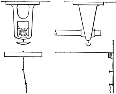
Fig. 48.
The line being adjusted over the stretchers, we will
now proceed to set it. Begin at the 2 7/16-inch end, by
throwing your plumb line over the shaft and setting
your line at that end, right with the center point of your
bob. Having done so, go to the other or 3 15/16 end of
your line, and set the line so that the edge of the ball
of your bob just touches it. Now go back to the 2 7/16
end and see that the necessary adjustment did not alter
it. Having proved this, give your line the final stretch
and try if it is right at both ends. You now have a
center line (though the edge instead of the center of the
shaft is used) that may remain up for days if necessary
without fear of disturbance.
It is best to go over the whole line first, before disturbing
anything; so starting at the first hanger at the
2 7/16-inch end, throw your plumb line over the shaft,
and record on the floor in chalk beneath it whether it
is O. K. or wants to go either way, and how much;
then go to the next hanger, and so on to the end. A
short study of the conditions enables one to correct
the faults, with a knowledge of the requirements, and
consequently in the least time and with the least
trouble.
Now suppose we start at the 2 7/16-inch end to inspect
the line, we use the center point of the bob on the line
so long as we are testing 2 7/16 inches.
When we get to the 2 15/16-inch part, which is ½ inch
larger, we use the half diameter of the stem, the edge
of which should just touch the line.
When we come to the 3 7/16-inch part, 1 inch larger
than 2 7/16, we use the 1-inch disk, slip it on to the stem,
and when it just touches the line with its edge it is
O. K.
The 3 15/16-inch, being 1½ inches larger than the 2 7/16-inch,
will be right when the ball of the bob is in light contact
with the line.
The 2-inch disk would be suitable for the next size,
and other disks or modifications of the bob proper
might be made to suit circumstances.
Now having straightened the line, the next process
is to level it. As in some cases your pulleys will be
too close to place your level where you want, make a
light iron frame as per Fig. 49, making the suspending
members of sufficient length to admit of your reading
the level conveniently when standing on the floor.
Hang your frame on the shaft, and put your level on
the straight-edge below; in this way travel along the
shaft, placing your frame where convenient. Be sure
that one end of your frame does not rest on a shaft
of different diameter, a key, keyseat, or anything to
distort the reading.
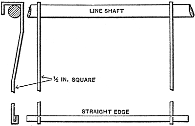
Fig. 49.
Never be content with trying your level, especially
an adjusting level, one way; always reverse it and try
again; for if it is out of truth at the start, you might
want to go through the roof or down cellar at the finish.
Get into a habit of reversing your level, and so prove
your work as you proceed.
APPARATUS FOR LEVELING AND LINING SHAFTING
The first apparatus explained in this chapter was
designed by the late Chas. A. Bauer, and is a highly
perfected instrument.
For those who have lined and leveled shafting with
an engineer's transit and level it is unnecessary to
say anything of the advantages of that method over
the cruder methods usually employed. It is not only
done much more rapidly and economically, but the
greater accuracy with which the work is done goes on
paying dividends in decreased friction and loss of power
and in lessening of wear.
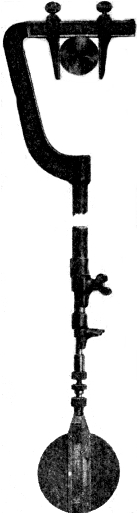
Fig. 50.
The apparatus we now illustrate (Fig. 50) has at
the top a hook, which is passed over the shaft, as indicated;
on the straight portion of this hook are two
sliding jaws which are so set that the shaft will just
pass between them. Set into the face of this hook is
a commercial 6-inch steel rule which facilitates the
setting of the jaws, and they are of course so set that
the tubular portion of the hook or leveling rod is centered
vertically under the shaft. Within the outer tube,
which is about 1 inch outside diameter and nicely
japanned, is another tube, and inside this a third tube,
these being arranged à la telescope slide, and clamps
being provided so that the length or distance from the
shafting to the target may be anything desired from
4 to about 10 feet. At the lower end of the third or
inner tube is a swiveling head to which the target is
attached, and nurled nuts at this point give means of
adjusting the sighting point of the target to the exact
hight of the transit or level sighting line.
The target is a brass plate 5½ inches diameter, on the
face of which is a recess milled for the reception of a
second commercial steel rule, which in this case is
vertical and can be moved vertically and clamped in
any desired position with reference to a line drawn upon
the target. At the center of this scale is a very small
hole through which the light of a hand flash lamp may
shine to form the sighting point. The slot through the
target at the right of the scale is provided with a single
thickness of white cloth, which permits enough light
to pass through it to help in finding the target in the
field of the telescope.
The object of providing a vertical adjustment for
the rule on the target is so that when passing from one
diameter of shafting to another in the same line, as
sometimes happens, the scale can be moved up or down
just half the difference of diameter and the sighting
point thus be kept at a constant hight.
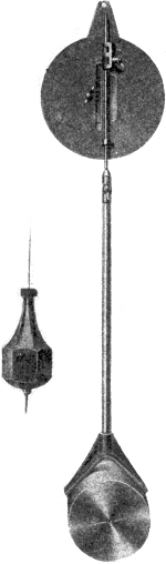
Fig. 51.
The target is readily detached from the rod, and may
then be placed upon the small standard (Fig. 51) which
has at its base a V adapted to go over the shaft. The
standard is tubular and the wire (about 1/8 inch diameter)
may be adjusted and clamped at the desired hight. The
target fits over the wire as shown (rear view of target)
for leveling lines of shafting that may be near the floor,
or, with the target removed, the V and wire form
a sort of length gage or caliper with which the shaft
may be made parallel to a line or wire stretched at the
side of it. Two different lengths of wire are provided
for this purpose.
The plumb-bob shown is part of the equipment and
is a very superior article. A new feature it possesses
is in having its larger portion hexagonal instead of
round, so when laid down upon a plank or scaffolding
it will lie there instead of promptly rolling off and
falling to the floor. The entire apparatus is, we think,
very well designed for its purpose.
Tool for Leveling Shafting
The instrument shown in Fig. 52 is a good one for use
in leveling up shafting. It can be made to fit several
sizes of shaft, or all the sizes ordinarily found in a factory.
When the instrument is placed on any piece of shaft
and leveled up with the attached level, the plumb
line will hang exactly the same distance from the
shaft center every time. In this case the distance
of line from center is 6 inches.
A handy apparatus for use in leveling up long lines
of shaft can be made as follows.
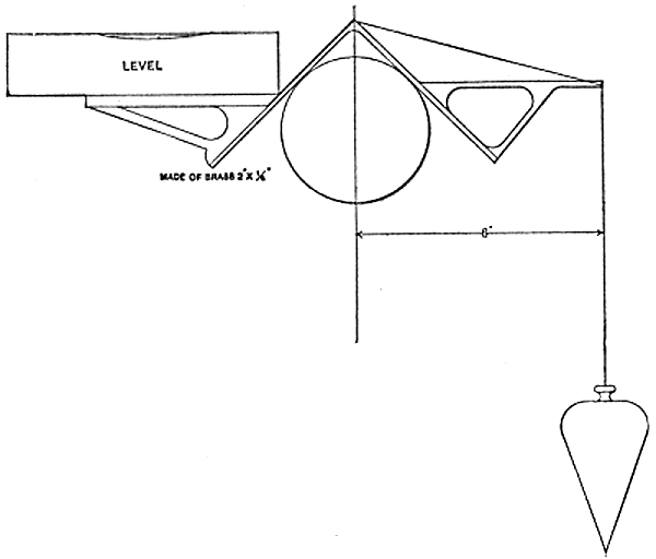
Fig. 52.
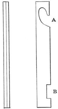
Fig. 53.......Fig. 54
Take two pieces of finished material, fasten together
as in Fig. 53 and cut out as shown at A and B in Fig.
54. The opening A is made so that the piece can be
hung over the shaft, and the opening B is made for
the reception of a wooden straight-edge.
Make the straight-edge out of 1¼-inch stuff. Be
sure that the edges are parallel, the width just enough
less than the width of opening B, Fig. 55, to enter it,
and the length 6 or 8 feet, to suit convenience. Use
the apparatus with a level, as in Fig. 55, taking care
that the suspension pieces are always on the same size
shaft.
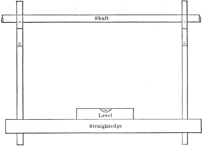
Fig. 55.
PRACTICAL METHODS OF LOOSENING PULLEYS
When a solid pulley is to be removed from a piece
of shaft for any reason, it is not good policy to use
sledge hammers on the spokes or hub to do it. Cast
iron in pulleys is too liable to break or crack under
repeated blows.
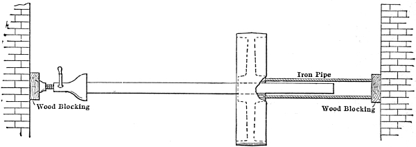
Fig. 59.
In Fig. 59 one ready method is illustrated by which
the pulley may be removed. When a place between
two walls can be found that will admit of this arrangement,
proceed as shown to force the shaft through
the pulley, substituting longer pieces of pipe as the
shaft is forced through farther.
In one case where a large pulley was stuck on a 7-inch
shaft and its removal was imperative, the shaft was
sawed off (with large hack-saws) close up to the pulley
hub and two 5/8-inch holes were drilled into the shaft
parallel to its axis, as shown in Fig. 60. These holes
were drilled so that they were 90 degrees apart and
came within 1/16-inch of the hub of the pulley. The
hub was 14 inches through and these holes were 8 inches
deep; but that was enough to loosen up the shaft
so that when the pulley was laid over on beams with
the shaft hanging through, a sledge hammer applied
on the shaft end soon drove it out.
Another way to remove a pulley is shown in Fig. 61,
where a ram is used. The ram is another piece of
old shaft. To prevent its damaging the pulley hub
and also to have its force applied most advantageously,
it should be used in a direct line with the direction
of removal. To do this, the method shown in Fig. 61
is self-explanatory.
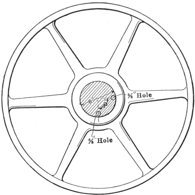
Fig. 60.
Another good method of removing an obdurate
pulley is illustrated in Fig. 62, where the bolts W, W
must have long threads and the work is done by pulling
up on the nuts A, A. This method can be used only
when the end of the shaft can be reached and used as
shown. In using this method, care must be exercised
in the pulling up on the bolts W, W, keeping the strain
equally divided between the two by pulling a little
at a time on each.
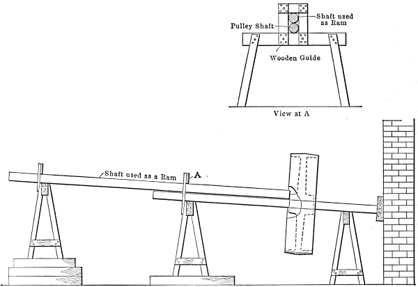
Fig. 61.
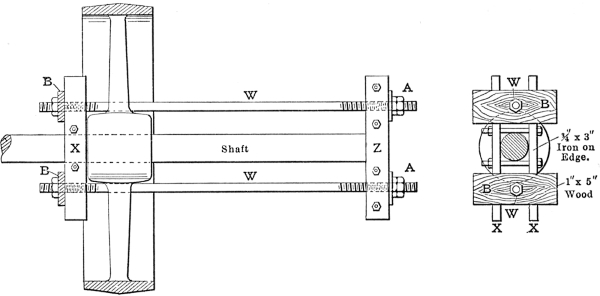
Fig. 62.
If the pulley comes extra hard, it can be assisted
when the strain is on the bolts by striking at X with
a sledge.
A good device for removing motor and generator
pulleys that are near the shaft end is shown in Fig. 63.
The arms Z, Z are adjustable to take hold of hub or
arms, and the screw applied to the shaft center will do
the rest.
To run a pulley off a shaft without injury to the
hands, use a monkey wrench on the rim of each pulley,
as shown in Fig. 64. One pulley on the shaft can be
selected for a hold-back; one monkey wrench there
will hold the shaft from turning, while the other will
turn around the shaft the pulley which it is intended
to remove.
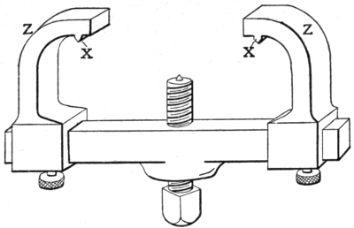
Fig. 63.
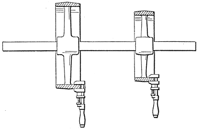
Fig. 64.
SPLICING LEATHER BELTS [5]
The first thing is the tools for the different kinds of
work. These may be usually changed somewhat to
suit the taste of the user, but in the main the style
and kind herein shown in attached drawings cannot
be very much improved upon.

Fig. 65........Fig. 66.
Figs. 65 and 66 show a splice opener for heavy belts.
It is made of ½-inch tool steel with the point spread out
about 2 inches wide and well tempered, after which it
is ground to a good sharp edge, and then an oil stone
run over the edge until it has been dulled so that it will
not cut. The right kind of an edge can only be secured
by trying; it is one of the tools that is very hard to
get just right. You will notice that the manner in
which this splitter is built may seem to be rather too
much work to bestow on such a simple tool, but the
reasons for so doing are as follows: in opening a 36-inch
belt an old splice opener that was driven into
the handle like an ordinary file was used and the
handle split; that sharp point came back through the
handle, and when it finally stopped it had gone about
2 inches into the palm of the operator's hand. Some
½-inch hexagon steel was turned down 6 inches, just
enough to round it up; then a solid brass washer was
turned out 1¼ inches in diameter and 1 inch thick,
a hole bored through it that was a driving fit on the
piece of steel and was driven down to the shoulder.
Washers were cut out of old pieces of belt and put on
with a liberal coat of glue on both sides; when the
handle was filled, a steel washer which was 1/2 inch
thick was screwed down hard on the leather washers,
and when it had dried well the whole was turned down
to size shown in the sketch. Two of these tools were
made, one for belts up to 18 inches, and another that
will reach through a 40-inch belt. The tool shown in
Fig. 67 is an ordinary heavy screwdriver with the point
rounded nicely, and it is used to raise the thin points
that the larger tool will sometimes tear.

Fig. 67.

Fig. 68.
Fig. 68 shows a handle made almost like the one in
Fig. 65, with the exception that the brass washer
referred to in Fig. 65 is here turned down to ¾ inch,
commencing ½ inch from the large end, which is 1 inch
in diameter. The leather washers are slipped on over
the small part until it is filled, and then a washer is
screwed on the small end and the whole turned as shown
in the sketch. A hole that will tap out 3/8 inch is bored
in the large end of the brass center, and then tools
made with threaded ends on them that will fit into it.
These tools are made of 3/8-inch tool steel with scraping
ends, as shown. These scrapers are used only for
removing glue that is too hard and too thick to be
removed by the scraper shown in Fig. 69.
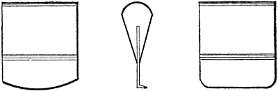
Fig. 69......Fig. 69a......Fig. 69b.
Figs. 69, 69a and 69b show views of the only tool
that is hardly worth being referred to as a leather-cutting
tool. It is made of a thin piece of steel, about 18
gage, or any old hand-saw will make the very best
scrapers that can be secured. They should be about
4 inches square, perhaps a little smaller, and fixed in a
hardwood handle (usually of hard maple), simply by
sawing about 2½ inches into the handle and then driving
the blade in. The saw cut should be just a trifle thinner
than the piece of steel. Should they get loose from use,
a piece of paper folded over the back of the blade and
forced back into the handle with the blade will usually
tighten it all right.
This is the tool that will ordinarily worry the novice
more than all the rest to keep in proper condition.
Fig. 70 shows an exaggerated view of how the blade
should look when properly finished. It should be
hooked considerably.

Fig. 70.
Fig. 71 shows a small steel for sharpening the scraper
after it is turned, and it should be absolutely smooth.
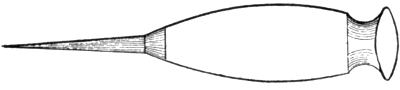
Fig. 71.
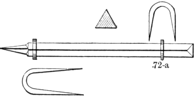
Fig. 72.
Fig. 72 shows the equipment for turning the edge
of the scrapers. A large three-cornered file, about 12
inches long, which has all the teeth ground carefully
off of it and then nicely polished, is fastened to a piece
of good clean belt leather by means of the staples
shown.
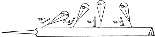
Fig. 73.
Fig. 73 shows the method employed in turning the
edge of the scraper, which is as follows: After the blade
has been set firmly in the handle, grind the edge rounding,
as is shown in Fig. 69; then grind sharp with a good
long taper of about 3/8, and grind from both sides just as
you would an ordinary axe. After you have a good
smooth edge on it, put it on an oil or water stone and
put as fine an edge as possible on it, then put on a
smooth piece of leather and hone it down until it
would shave you. You will then have a tool that will
do a world of work for you, "if you will turn it right."
The method shown in Fig. 73, if properly carried out,
will do the trick for you; the thing to be remembered
is that at no time in the turning of the scraper must
the cutting edge bear on the smooth file. The first
position is not shown right; the handle should be
allowed to touch the file the first few times it is passed
over, and then gradually raise the handle and keep on
passing the blade from side to side, as is shown in Fig.
74; allowing it to slip off on the leather every time
you cross the file; this is to keep the corners in proper
shape. Another thing to remember is to bear down on
the blade as it is passed over the file; you can't bear
too hard; the only thing to look out for is not to raise
the handle too fast. An ordinary blade can be turned
in about fifty strokes across the file. The edge turned
over should be at least 1/16 inch long and should be
well hooked, as is shown in Fig. 73.
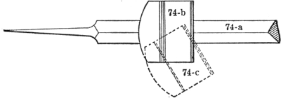
Fig. 74.
It is well to keep on hand about six of these scrapers,
and as they get too dull to cut leather use them on glue.
With one good scraper that is not too sharp all the glue
can be cleaned off of both points of a 36-inch belt in
from five to ten minutes. When the edge gets a trifle
dull, use the small steel on both sides of the edge; first
wet the steel with the lips, it makes a much better edge.
For the benefit of beginners who may attempt to splice
a belt for the first time, do not use a glue that will not
allow you to remove the clamps and put on the full
load in forty-five minutes after the glue has been
applied and well rubbed down. The time given here
applies only to clean belts that are absolutely free
from all oils, and does not include old oil-soaked leather
that no glue will ever dry on.
Fig. 75 shows the equipment necessary to do a good,
quick job on a belt, and most of them are required
to be done quickly and well. With such an outfit and
half-dozen sharp scrapers a joint in a 36-inch belt can
be made and run again in four hours after the engine is
stopped. This includes all the time consumed in putting
on and taking off the clamps, etc.
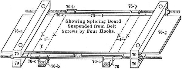
Fig. 75.
The top of the platform, 76d, is level with the bottom
of the belt and is held in position by the hooks, 76b,
which are shown in Figs. 75 and 76. These hooks slip
over the 2Ã4-inch pieces that project outside the platform
to which they are attached, and should be made
of three-quarter iron and not too long, or some difficulty
may be experienced in getting them on the two-by-fours.
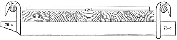
Fig. 76.
The rods should be long enough to take care of the
longest possible splice and still give plenty of room to
work. There should be about 2½ feet between the
inside ends of the threads and the threaded end should
be 3 feet long. This will make the rod 8 feet 6 inches
long, and it will be none too long at that. For instance,
in removing the glue from the splice, if the last end
point is very close to the clamp, there will be great
difficulty in cleaning it and also in fitting the leather
after the belt has been shortened. What is meant by
the head end splice is the one that is on the pulley
first—the arrows in Figs. 77 and 78 will make this
clear: they indicate the direction in which the belt
should run; therefore that end of the piece of leather
that is on the pulley first is the head end (or first end)
and the end that leaves the pulley last is the last end.
If the two belts shown in the sketch were reversed,
the points would be turned up by everything that
touched them; whereas, running in the direction that
they do, everything that touches them has a tendency
to rub them down.

Fig. 77.

Fig. 78.
We will suppose that the belt shown in Fig. 75 had
a "first end" point that opened on the top of the belt
instead of the bottom as this one does (see left-hand end
of belt between the clamps, on the lower side); one
can easily see how hard it would be to work if the clamp
were near the point. There should always be enough
room between the clamps to allow the splicer to take
the last end (which is always the forked end), carry
it entirely over the clamp toward the left in Fig. 75,
lay it down on that part of the belt that is outside the
clamp and slip an extra splicing board under it. Fasten
the two belts and splicing board all together by means
of a couple of 8-inch hand-screws (of which every belt
splicer should have at least six or eight); then clean
and shape it to suit the other end. It can be passed
back over the clamp from time to time and tried for a
fit.
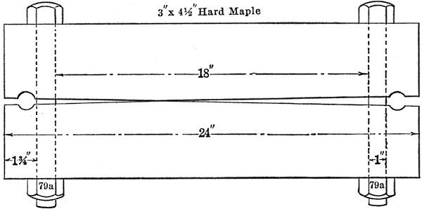
Fig. 79.
The proper mode of procedure in splicing a belt on
the pulleys is as follows: Decide on where the belt is
to be opened, and always open it in the worst place
in the belt for that is the place you certainly want to
fix. Pay no attention whatever to any former splicing
place that may be in the belt, but take it apart at any
place where you are sure repairs are actually necessary.
First put in the most convenient place possible the
point that you have decided to open and then put the
clamps in position. If you are sure that it is going to
require very hard pulling to get it as tight as you wish,
take a damp cloth, moisten the inside of the clamps
and then sprinkle powdered resin on both upper and
lower clamp. Put the "first end" clamp on first, as
this is always the easiest point to clean and fit; decide
how much you will have to take out, or as near as
possible, measure off this amount on the belt and place
the clamp this distance plus about 10 inches from the
"first end" point. This extra 10 inches will give
you plenty of room to clean the glue off and also to
shorten up the belt the right amount, for all the shortening
must be done on the "first end" point on account
of the ease with which the new scarf can be made.
Should you try to shorten up from the "last end"
point, by referring to Fig. 78, you can easily see the
amount of work you would be in for. There would be
two thin ends to scarf, and outside ends at that; whereas
if you shorten up from the "first end" you make only
one thin end and that one in the inside of the belt.
The first clamp, with the center mark of the clamp
coinciding with the center of the belt, should be very
tight; for should it slip when the load is put on, it will
very probably slip in the middle of the belt and may
not slip on the edges at all. Should you glue it in this
condition, the chances are very much in favor of the
outside edges giving away on a heavy load, due to the
middle being too long. After the first clamp is in
position and tightened, put on the second one and
leave the bolts loose, so that it can be slipped easily.
Then put the belt rods in position with just a "full
nut" on each end and tighten the clamp. Tighten the
rods enough to take most of the load, then get the large
splitter shown in Figs. 65 and 66 and open the joint.
The place to commence is between X X in Fig. 75;
this inclined point is about 4 inches long and must be
opened at both ends of the splice before the middle is
touched.
The tool should be entered at O, in Fig. 78, and
worked gradually toward A; when the point is raised
to A clear across the belt, open on down to C. After
both ends of the splice have been opened up in this way,
proceed to open the middle, which is now an easy task,
there being no thin stock that a separating tool will
pass through easily. After the belt is entirely apart
tighten up on the rods until the belt is the proper
tension and hang the hooks (76b, Fig. 75) on the belt
rods. Throw the two ends of the belt back over the
clamp and put the splicing board in position. After
this is in place, throw the two ends of the belt back on
the board and proceed to lay off the scarfs. To do
this, first take a square and get the two thin points
perfectly square, then put the "first end" point in
between them. This is shown very clearly in Fig. 77,
the shaded end being the last end. Of course the "first
end" point at C, Fig. 77, will have to be cut off before
the belt will lie down properly; the amount to cut off
of this end will be just as much as you have shortened
the distance between the clamps. After the point has
been cut to the right length, take the square and make
a mark across the belt, using the end of the thin point
as your measure for length; then without moving the
belt make a mark on the edge of the belt, showing just
where the lower thin point came on the bottom.
Throw the "last end" over the left-hand clamp out of
the way and scarf down the top of the "first end"
point, letting the scarf be about 4 inches long. Be
careful not to gouge a hole in the belt where the scarf
is started, but try to make the inclined plane from X
to X perfect; try to keep the whole surface of this
incline true and straight. After the short 4-inch scarf
is finished, clean the glue off of the inside of the "first
end"; lap up to where it enters the "last end"; then
turn it over by bringing it over the right-hand clamp,
place a scarfing board under it and make the scarf
shown at T, Fig. 75. Now clean all glue off the "last
end" lap and take a sharp scraper like the one shown
in Fig. 69 or 69b, place a piece of glass under the
points that have been previously squared up, and
scarf them down to a knife-edge.
After the thin points are properly scarfed, lay the
whole splice back on the splicing board just as it will
be when it is glued, and do any fitting that may be
necessary. Be very careful to get it thin enough, or it
will make a hammering noise when going over the pulleys.
When scarfing down the thin points with the
scrapers, be sure that they are very sharp; if not,
they will tear the point off when it gets down to an
edge; also give the blade a drawing motion in order
to facilitate cutting. It may seem to the novice that
to use a piece of glass to scarf on, when one is using a
tool with a razor edge, is a trifle inconsistent, but it is
not so in the least; if the blade is held well back at the
top and a considerable pressure applied to it, there will
be no danger in the edge actually touching the glass;
the edge is turned past a right-angular position, or
hooked, and the heel is all that touches the glass. A
good piece of plate glass about 12 Ã 18 inches is large
enough for any width of belt, although a piece much
smaller will do all right. Do not attempt to do any
scarfing on the board 76d, for if you do it will be so full
of holes that have been gouged by the scraper that it
will be ruined for any purpose.
This board must be kept smooth in order to be able
to do a good job of rubbing down when gluing. Never
hammer a glue joint in order to set it; it is just that
much unnecessary work and does absolutely no good;
simply get a smooth block of wood 2 Ã 6 Ã 8 inches and
rub hard and fast as soon as the glue is applied. Do
not try to glue more than 6 inches in length at one time.
Use a heavy brush—a high-priced paint brush is the
best; the regular glue brush is about the only thing in
existence that will not put on any glue at all—about
a 3-inch brush is the thing; have the glue just as hot
as it is possible to get it. Keep the brush in the pot all
the time the glue is heating; also have a strong stick
made somewhat like a three-cornered file, only larger,
in the glue—this last is used to scrape off the brush
all the glue that it is possible to get off without allowing
the glue to get too cold. When you take the brush out
of the pot, work fast; get all the glue possible off the
brush and get the rest on the belt at once. Make two
or three fast strokes across the belt and close down the
splice and rub for dear life. After the first brushful
has been applied (and rubbed for about two minutes),
have an assistant raise the point up until you can see
the glue breaking all across the whole width of the belt.
Then have a second brush ready and repeat the former
process, with the exception that you need not apply
the glue to both sides of the leather as in the first case;
for if you will keep the brush down in the fork between
the two laps you will give both sides a coat, and in
addition to the time saved by using this method you
will get the joint closed while the glue is hot. As fast
as you go across the belt with the brush, have the
assistant roll the belt together after you; when you
have used all the glue out of the brush, the joint is
closed and ready to rub. You will keep the glue much
hotter by immediately closing the splice after the
brush, and there is nothing else so important as using
hot glue; as soon as it commences to get shiny on the
surface the thing is all off and it will not hold anything.
You cannot do any quick work with water in your
glue—that is, unless it is old and has been heated up
several times. If this is the case, it will have to be
thinned with water. The proper consistency is about
that of a very heavy grade of cylinder oil; if it is too
thin, it will not dry in any reasonable time and it will
also cause pockets in the splice by opening up after the
joint has been rubbed, and the air in the pockets will
open the whole splice. In important work never use a
glue that will not stick so tightly between every application
belt that after rubbing down you can give it
a good, hard pull without its opening up. In all statements
regarding the time necessary for the joint to dry,
the belts are considered absolutely clean, dry and free
from all oils.
The most disagreeable portion of the belt repairer's
work is the splicing and repairing of oil-soaked belts.
It is a well-known fact that the action of oil and that
of glue are in direct opposition to each other: the oil
prevents sticking and the glue sticks, if it has a chance.
Such being the case, the first thing to do is to eliminate
the oil completely, and the efficiency of your joint will
be in direct proportion to your success in getting rid
of the oil. To this end secure a large gasoline blow
torch, such as painters use to burn off old paint. If
you are not used to it, be very careful; at all events,
have a bucket of dry sand to use in case of trouble.
Just throw the sand on the fire and the fire will go out—that
is, if you can get the sand in the right place.
The torch is to be used after the splice has been all
completed except the thin points. The flame will burn
them if finished, so leave them tolerably thick until
after the oil has been removed; then finish them as
directed before. When the scarfs have been made and
the old glue has been removed, turn the flame (which
should be an almost invisible blue if the torch is working
properly) directly on the leather and move it
over all the surface of the splice until the leather has
become thoroughly heated; never allow the flame
to remain directed at any point long enough to make
the oil in the leather boil. If you do, the belt is burned.
Continue to move the flame over the surface of the belt
until the leather is so hot that the hand can scarcely
be held on it. With one of the scrapers shown in Figs.
69 and 69b (69b preferred) scrape the oil off as the
heat raises it up. Turn the cutting edge of the scraper
up and wipe the oil off after every stroke; keep the
scraping process going right on after the torch; never
allow the leather to cool off until you can get practically
no oil and the leather begins to turn brown. By
heating the leather and bringing the oil to the surface
you do just what the glue does when you put it on an
oil-soaked belt without removing the oil. By means of
the heat contained in it, it brings up all the oil near
the surface to which it is applied and in consequence
does not take any hold on the leather.
It will take two men with all the necessary tools and
appliances at least six hours of good hard work to
remove the oil from a well-soaked 36-inch belt—that
is, to remove it to an extent sufficient to warrant the
gluing of it.
In case of overflows in which the wheel pits are liable
to be filled with water, pour cylinder oil on all belts
that are liable to get wet and then remove them from
pulleys if they will be covered for more than twenty-four
hours, clean them with gasoline and they will be
found to be all right and dry.
Hold a clean piece of waste against all belts at least
twice every twenty hours, and wipe them clean.
THE CARE AND MANAGEMENT OF LEATHER BELTS [6]
Outside of the direct care and management of high-pressure
boilers and the steam lines pertaining thereto,
there is no other part of a power or lighting plant, mill
or factory in which a large number of indirect connected
machines are used that is of such vital importance as
leather belting and rope drives. The subject under discussion
in this chapter will be the former, and the selection,
care and management thereof.
The first thing in order will be the selection of a
leather belt, and when we consider that all makers make
good belts, that there are no particular secrets in the
belt-making business, and that in order to get the very
best we must take every advantage of all small details
in construction, it stands every engineer and belt user
in hand to get all the information available; for we
must remember that the percentage of good hides
does not run very high, that all that are bought go into
belt stock of some kind or other, and that some one
must buy the goods that are not quite up to the
standard of belt excellence. It is very evident that no
man wants anything but the best when he is paying
for the best, and it is also evident that no maker is
going to say that he makes inferior goods; so therefore
we must read the quality by what is in sight, and in
the judging of leather that is already made up, the
proposition resolves itself into a very hard one.
The two principal things left for an opinion to be
based upon as to quality are the relation the pieces
that constitute the laps bear to the hide from which
they were cut. They should, in belts running from
18 to 36 inches, be cut from the center of the hides, or
should be what is known as "center stock." Of course
all belts should be "center stock," but where they are
very narrow or so wide that one hide will not be wide
enough to make a lap, then there is always a lot of
narrow stock worked in that cannot always be strictly
center. The next thing to look out for is brands that
are so deep that they destroy the life of the leather and
will cause it to break after being used. Then look out
for the length of lap. If this is too long, you will know
that it runs into the neck, for about all that it is possible
to get out of average hides and still leave nothing in
that is not first class is 54 or 56 inches. Ordinarily,
you can tell if a lap is "center stock" by the marks that
run down either side of the back bone; they will be
usually a little darker than the rest of the belt. These
marks or streaks should be in the center of the belt.
The principal objection to neck leather is that it is
liable to stretch excessively, and on this account it will
put too much load on the piece immediately opposite
it in a double-ply belt; for the point of one side is in the
middle of the lap on the other side. Next look out for
holes, which will usually be found so nicely plugged
as to escape detection unless subjected to the most careful
examination.
Next in importance is to buy a belt that has already
been filled with some good waterproof dressing. It is
quite likely that to buy a belt that has been filled means
to buy one that perhaps has some bad leather in it that
would be seen in a dry oak tan belt, and also that the
adhesive power of the filled belt is not quite equal to
the dry one; but the points that the filled one possesses
over the one not filled are, first and mainly, "it is filled
when you buy it with a preparation that does not
injure the leather in the least," and the preparation
you will fill it with, for it will be filled, will be engine
oil and water, a combination that will ruin any belt
made and also get it in six months into a condition
that will make a permanent repair with glue impossible,
for machine oil and moisture are strangers to glue and
will ever be. More good belts are ruined by being
soaked with engine oil until the points come loose and
then pulled out of shape than from any other cause. Of
course you may be able to keep a main engine belt that
runs through a damp wheel pit and basement, and
through a long damp tunnel to a main driven pulley
that has two big boxes that are just as close to the
pulley as a first-class machine designer could put them,
and never get a drop of oil or water on it. But this is
not likely.
One very common cause of trouble with engine belts
is the fact that such belts usually run under the floor,
where there is considerable moisture. Then the oil
table under the average large Corliss engine will leak
around dash-pots and rocker-arm shafts, and some oil
will fly from the eccentric oil cups, get into the wheel,
run around the rim and get to the belt; if the belt is
not filled a very few drops of oil will make a large spot
on it. Then, if an engine does not run the whole
twenty-four hours, while it is off, watch. A few drops
of water from a leaky valve stem whose bonnet drain is
stopped up, as it will sometimes be, has a way of getting
through the floor and falling on to the belt and running
down the inclined inside of it until it finally comes
to the flywheel, which, with the assistance of its crowning
face, very kindly makes a nice pocket for said water
and proceeds to drink it up. Result: the glue is
loosened and the belt may come apart in consequence.
Should there chance to be a point just at the bottom
of this pocket, it will get the glue soft enough to slip
but may not open up, which is much worse than if it
did open up; for it may slip away from the shoulder
of the splice for half an inch, and when the engine
is put to work it may close down by running under the
wheel and stick. If it does, the result is that at no
very distant day you will find a break at that particular
place, right across the face of the belt. The reason is
that the load was all taken off the inside half of the
belt by point slipping, thereby making the inside of the
belt too long and putting all the load on the outside.
The outside will continue to do all the work until it
stretches enough to bring the inside back into service
again. During this week or month you have been
pulling your load with a single belt, not a double one,
and after a short time you will find the break referred
to above in the shape of a clean, well-defined crack
extending across the belt parallel with the points of
the laps. Now of course you are going to send for the
man who sold you the belt and ask him to fix it. If he
is a wise man and understands his business, he won't
do a thing but show you right under that crack a point
that does not come up to where it should come. Then
the thing for you to do is to say to him that the belt is
examined every time it is put into service and that you
have noticed that the points he refers to all come loose
during a "run," that any one knows that a few drops
of water would not take any belt to pieces while it
was running, and if it was water, why did it not take
it apart everywhere, etc? And finally crush him completely
by telling him that your men have no time to put
a pair of clamps on a belt in order to pull back into its
proper position every point that comes loose; that if
they did do it they would have no time for anything else,
especially in the present case, and that if his people
had made the belt right the glue would have held, anyway.
After he has given you a new belt or repaired your
old one, just take my advice and box that flywheel up
above the top of the eccentric oil cup, at least 12 inches,
and get some good, heavy tin or zinc and put a tight
roof over the belt, under the floor.
First put in a ridge pole out of 1½-inch pipe, starting
at the face of the wheel and running in the direction of
the main driven pulley, holding it firmly in place at
each end with a strong iron clamp. Then solder into
each edge of the strip of tin, which should be long
enough to reach beyond any possible leak through the
floor or oil table, a piece of ½-inch pipe, and put the tin
over the ridge pole with a piece of small pipe on either
side. Ordinarily the belt goes out past the cylinder;
if it runs through a bricked-up runway on its route
to the main driven pulley, just fasten the two pieces
of 1/2-inch pipe to either wall and have the ridge about 6
inches higher than the outside ones. Then every drop
of oil or water that comes through the floor will fall
on to the roof and run down to the walls and be carried
down to the floor of the pit and have no chance to
touch the belt.
One of the most difficult things in the operation of
large stations where a large number of belts are used is
to keep them thoroughly clean and free from moisture
and machine oil, the latter especially. One very hard
problem that confronts all designers of machinery is
the prevention of oil leakage from boxes. In several
plants with as many as six dynamos of the same kind
and the same design, at least four of the six have leaked
oil every time they were run. The others did not leak
as a usual thing, and all were equipped with the most
modern methods of holding oil.
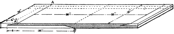
Fig. 80.
Now we come to the building of the belt, and we will
notice only such points as interest the engineer or buyer.
The first thing is to see that the laps are of uniform
thickness, so that the belt will run quietly; and it
should be absolutely straight when unrolled on the floor.
If it has a long, graceful curve in it, look out; for it will
not run straight on the pulleys until it has stretched
straight, and by that time one of its edges may be
ruined by coming in contact with the floor or some
other obstacle. Next notice how long the leather is
from which it is made. It should not show more than
52 inches, and then there will be 4 inches hidden by
the point that is out of sight. Then see that the joints
are broken properly. For instance, find the center of
any piece of leather on one side of the belt, and then
look on the opposite side and see if the joint is right
under your center mark. It should be by all means,
for right here lies the most important thing about the
construction of leather belts. A belt whose laps are
all the same length, and which has all its joints broken
correctly, will put the same load on the glue throughout,
and that is what must be done in order to get
the best results. See Fig. 80. Here we have a belt
that is 36 inches in width and a double ply. Now
suppose there is a draft of 9360 pounds on this belt,
that from point A to point B is 26 inches, and that
the points are 4 inches long. Now we have 26 inches
plus 4 inches plus 4 inches times 36 inches for the
number of square inches in the glued joint. This
equals 1224 square inches; the total pull on the belt
divided by 1224 will equal the load on each square
inch of glued joint, and will equal in this case 7.65
pounds. Now instead of assuming distance A—B
in Fig. 80 to be 26 inches, let the lower joint get out
of step with the upper ones, and conditions get vastly
different. We will suppose that the dimensions are as
given in Fig. 81, as was the case with a new belt that
was measured less than one month before the observation
was made and we have the following: Joint A B
is now only 10 inches, and we have 10 inches plus 4
inches plus 4 inches times 36 inches which equals 648
square inches, and the lead on the joint is now 14.44
pounds. You will readily perceive what an important
part in the life of the belt, and the life of everything
around the belt as far as that goes, the proper breaking
of the upper and lower joints is. Of course the belt
maker will tell you that his glue is just as strong as the
leather itself, and he is about right as long as you keep
the belt free from oil and water; but when the belt becomes
filled with oil the glue rots and loses its strength
much faster than does the leather.
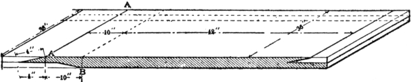
Fig. 81.
No good belt needs any posts along the sides to make
it run straight and stay on the pulleys. If the pulleys
are in line and the belt straight, it will run straight.
All belts should be made to run perfectly straight on
pulleys, first on account of the local advertisement
that it gives to the man who has charge of them;
second, if they do not run true, they will be on the floor
or wrapped around the shaft in a very few minutes,
should they ever slip. Another very important thing in
the care of belts that carry heavy loads is that if any of
the points do come loose so far back that they will not
return to place without putting on the clamps, put them
on by all means; as the restoring of this point to place
means that you will still retain in service all of your
belt, as you will not do if you glue it down where it is
and thereby cut one side completely out of service.
How to Clean Belting
We submit the following as the best and proper way
of cleaning a leather belt. It may seem simple, but it
is safe and effective, as has been proved by many people
who have thus restored old and dirty belting which
had become almost or quite unfit for use.
Coil the belt loosely and place it on edge in a tank
in which it may be covered with naphtha; a half barrel
makes a good receptacle, but something with a tight
cover would save the loss by evaporation. Put in
enough naphtha to cover the belt completely and allow
it to remain for ten or twelve hours; then turn the belt
over, standing it upon the other edge. The vertical
position of the belt surfaces allows the dirt to settle
to the bottom of the receptacle as it is washed out,
and permits naphtha to get at all the parts.
After the belt has remained in the naphtha another
ten or twelve hours, or until sufficiently clean, raise it
and allow the naphtha to drip back into the tank. Then
lay the belt flat, stretching or shaking it until almost
dry. You will find that the naphtha will not affect the
leather nor the cement in the center of the belt, but may
open the joints at the edges; in which case the old
cement should be scraped off and the edges recemented.
Your belt man will know how to do this. The belt will
now be somewhat hard, and should be treated with a
reliable belt dressing before being replaced on the
pulleys.
BELTING, ITS USE AND ABUSE [7]
There is no class of appliances so little understood
by the ordinary steam engineer and steam user as belts,
which may be seen by the quantity of belting sold annually.
Where one can point to a belt that has been in
continuous use for twenty years, you can find hundreds
that do not last one-fourth as long. Why? Not always
because the buyer has tried to get something for nothing,
but as a rule, when they do, they get nothing for
something.
The average belt is a poor one, and the average
buyer will not find it out till he has used it for some
time. If you weigh the belt dealer up as a man who
is trying to rob you, beat him down in price, then get
him to give from 5 to 40 per cent. off, he will enter
a protest, and, after some explanation, will come to
some terms with you. Have you gained anything by
your cleverness? Well, hardly. Belt dealers and
makers, like almost all other dealers in supplies, aim
to get nothing but first-class goods; but second and
third, and even fourth-class goods, are made, and you
get the quality you pay for. In the second place, belts
wear out quickly because they do not get proper care.
To let a belt run one moment after it gets too slack
is bad practice, for it is apt to slip and burn all the
staying qualities out of it. Another good reason why
it should not be run slack is that the engineer or belt
man, to save work, would be tempted to put on a dressing
or, worse yet, put on resin to make it pull, and, in
the language of Rex, "the man who will put resin on
his belts is either a fool or a knave," for it is sure to
spoil his belt if continued for any length of time.
In an emergency, as when some unforeseen substance
has found its way to the belt, it may be necessary, to
keep from shutting down between hours, to use some
of the so-called dressing. We know from experience
that engineers will go to almost any extreme to get out
of a tight place—circumstances sometimes make it
necessary to keep a belt running when it should not—but
this should not be allowed to any extent. To allow
a belt to run too tight is just as bad, for it will make
short life for the belt, hot boxes and scored shafting.
There is not one in twenty who takes the time or can
splice a belt properly; it is generally done in a hurry,
any way to make it hold together, with the understanding
that it cannot talk; but it does. How often we see
boards nailed up or rims tacked on to keep belts from
getting off the pulleys. All of this is good for the belt
dealers.
This is not all the fault of the engineer or the belt
manufacturer. Often belts are made uneven, and soon
get out of shape, even with the best of care. We sometimes
find a belt that ordinarily runs easy on the pulleys
and does its work with ease suddenly inclined to run
to either one side or the other of the driven pulley.
This is caused by one of two things—either the belt
has been too slack, or the load increased for want of
lubrication, or other causes. In either case it will run
off if you insist on applying the power. The remedy
would be to take up the belt, thoroughly oil the journals,
or take off the extra load—maybe a combination of
all. Still a little extra work making the belt tighter
will enable it to run well and do the extra work just as
long as the extra tension can be maintained. Then it
may appear perplexing and run to one side of the driven
pulley when the driven shaft gets out of line with the
driving shaft. In a case of this kind the belt does not
run to what is called the high side of the pulley, but
to the low side. Another peculiar indication: If two
shafts are parallel and there is a high place on the
pulley, then a belt will run to the high place; but if
the shafts are out of line, or, in other words, are not
parallel, and the face of the pulley straight, then the
belt will run to the low side or that closest to the
driving shaft. The remedy would be to line up your
shafting.
The object of this chapter is not to say how belts
are made, but to impress upon the minds of belt users
that to get the best results, belts, like all good servants,
must be well cared for, and all responsibility should
rest with one man, just as with your engine or any
high-priced machine.
A COMPARATIVE TEST OF FOUR BELT DRESSINGS [8]
During January, 1905, a comparative test of the
working efficiency of four belt dressings and preservatives
was made by T. Farmer, Jr., and the writer. The
test was made on the regular belt-testing machine of
Sibley College, Cornell University, a full description of
which appeared on pages 705-707 of Vol. 12, Trans.
A. S. M. E. This machine tests the belt under actual
running conditions, though our belts were in somewhat
better than average condition. The four belts were
new 4-inch Alexander No. 1 oak-tanned single-ply,
and were 30 feet long. Particular care was taken to
keep them free from oil and dirt. The belts were first
tested as received from the manufacturer, after which
each belt was treated with one of the dressings and
again tested.
The dressings were two semi-solids, designated No. 1
and No. 2; a bar, No. 3, and neatsfoot oil, No. 4.
As the first three are proprietary articles, it was not
thought best to give their names, though any one
familiar with the actions of belt dressings will readily
recognize No. 1 from its peculiar curve. In applying
the dressings, we followed directions carefully, and in
the case of Nos. 2 and 3 exceeded them. The belt was
given a five-hour run, during which two or three applications
of the dressing were given, and then it was set
aside in a warm place to allow it to absorb the applied
dressing. After thus "soaking" for at least forty-eight
hours, the belt was again run, this time for three hours,
with one more application of the dressing. As No. 3
was a bar of sticky dressing, it will readily be seen that
this precaution was not really necessary. No. 4, the
neatsfoot oil, was not applied during the last run, as
we were afraid of getting too much oil in the belt. As
this oil is so extensively used by engineers for dressing
belts, special care was taken to get the best possible
results with it.
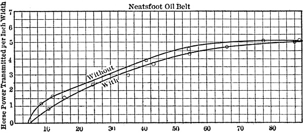
Fig. 82.
In Fig. 82, the result of the test with the neatsfoot
oil is shown graphically. This curve is platted to show
the relation between initial tension per inch of width
and horse-power per inch of width. One reason for the
drop in horse-power in the treated belt is that the slip
was materially increased; in the lowest tension at which
any power at all was transmitted, about 15 pounds
per inch of width, the slip ran up as high as 25 per cent.
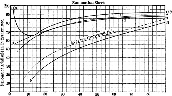
Fig. 83.
In Fig. 83, which shows the comparative value of the
four dressings, the highest horse-power delivered to the
belt was taken as the standard. The horse-power
delivered by the belt was divided by this standard,
and the result, expressed in percentage, was used as the
percentage of available horse-power transmitted. This
comparison shows the great superiority of dressing No.
1 at all times, and especially at low tensions. In looking
at this chart, it is well to remember that No. 3 is a
sticky dressing.
As the time of the test was so short, we were unable
to determine the ultimate effect of the dressings on the
leather of the belts. We could only approximate this
by a chemical test and a close examination of the belts
at the end of each test. The chemical analysis showed
no ammonia or rosin in any of the dressings; No. 2 had
a trace of mineral acid, and all had oleic acid as
follows: No. 1, 0.27 per cent; No. 2, 29.85 per cent;
No. 3, 3.5 per cent; No. 4, 0.7 per cent.
The practical test showed no ill effects except from
No. 3, the sticky dressing, which ripped and tore the
surface of the belt. The high initial tensions caused
overheating of the journals, even though we kept them
flooded with oil. On the low initial tensions there was
no tendency to heat, even when the maximum horse-power
was being transmitted by dressing No. 1. In
the latter case we oiled the bearings once in every two
or three runs (a "run" comprised all the readings for
one initial tension), while in the former we oiled the
bearings after each reading and sometimes between
them; even then we were afraid that the babbitt would
get hot enough to run. The readings for each run
varied in number from two to a dozen, but only the
one giving the maximum horse-power was used in drawing
the curves. The belt speeds during the tests varied
between 2000 and 2500 feet per minute, most of the
tests being made at about 2200 feet per minute.
ROPE DRIVES [9]
There seems to be considerable difference in opinion
regarding the various ways of applying rope to the
sheaves in rope driving, viz., multiple- or separate-rope
system, continuous-wrap or single-rope system with the
rope from one of the grooves running on a traveling
take-up device, continuous-wrap or single-rope system
with the take-up working directly on all the wraps.
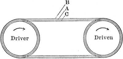
Fig. 85.
The multiple- or separate-rope system on a horizontal
drive where the distance between centers is great
enough so that the weight of the rope will give the
required tension, having the tight or pulling part on
the lower side and the sheaves of the same diameter, as
in Fig. 85, should be very satisfactory, as old or worn
ropes may be replaced by new ones of larger diameter,
or some of the ropes may be tighter than others and still
not alter the efficiency of the drive. It will be noticed
in this case that a larger rope does not alter the proportional
pitch diameters of the rope on the driving and
driven sheaves; but if one of the sheaves is larger than
the other, as in Figs. 86 and 87, and a new or larger
rope is substituted for a worn or smaller one, or if some
of the ropes are a great deal tighter than others, a
differential action will be produced on the ropes owing
to the fact that the larger or slack rope will not go as
deeply into its grooves as the smaller or tight one.
Consequently the proportionate pitch diameter on the
rope on the driver and driven sheave will be changed.
The action will depend upon whether the large or the
small sheave is the driver. If the driver is the larger,
and of course assuming that the slack or large rope is
weaker than the combined tight or smaller ones, then
it will have less strain on the pulling side; but if the
driver is smaller, then the new or large rope will have
greater strain on the pulling side. Whether the driver
is larger or smaller, a large or slack rope affects the
action oppositely to a small or tight rope. Fig. 87
shows how the action is reversed from Fig. 86.
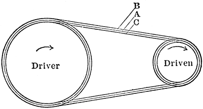
Fig. 86.
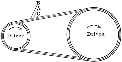
Fig. 87.
For clearness we will exaggerate the differences in
diameter in the sketches and figure the speeds that
the different size ropes would produce. We will take
A as normal, B 1 inch farther out of the groove, producing
a difference in diameter of 2 inches; C 1 inch
deeper in the groove, producing a difference in diameter
of 2 inches. In Fig. 85 assume for the normal diameter
of driver and driven 40 inches, 42 inches for B and
38 inches for C, with a speed of 200 revolutions per
minute for the driver. Either A, B or C will give
200 revolutions per minute for the driven sheave,
omitting slippage, of course. In Fig. 86 say the normal
diameter of the driver for rope A is 60 inches and of the
driven 30 inches, a speed of the driver of 200 revolutions
per minute will give the driven sheave a speed of 400
revolutions per minute; B, with the driver 62 inches
and the driven sheave 32 inches diameter, will give
the latter a velocity of 387½ revolutions per minute.
With C the driver is 58 inches, the driven 28 inches, and
the speed given the latter 414 2/7 revolutions per minute.
In Fig. 87, the normal diameter of the driving sheave
being 30 inches and the driven 60 inches, a speed of the
driver of 200 revolutions per minute will give a speed
of the driven member of 100 revolutions per minute.
With B, if the driver is 32 and the driven 62 inches,
the driven sheave will have a speed of 103 7/31 revolutions
per minute; C, with the driver 28 inches and the driven
sheave 58 inches, will give the latter a speed of 96 16/29
revolutions per minute. So it will be readily seen what
effect a large or a small rope would have.
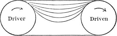
Fig. 88.
There are some who claim that slack ropes will transmit
more power owing to more wrap on the sheaves,
while others claim that tight ropes are better. If a
drive with all the ropes slack gave trouble by the ropes
slipping, the first remedy tried would be tightening the
ropes. But if the conditions were like Fig. 87, it would
not be particularly harmful to have some of the ropes
longer than others; in fact, it might be well, as the
longer ropes would not make a complete circuit as
quickly as the shorter ones; consequently the position
of the splices would be continually changing. However,
it seems more natural to have about the same pull on
all the ropes, that is, not have them as shown in Fig. 88.
In conclusion for the system, it should be noted that
it has no means of tightening the ropes except by resplicing;
it is not as well adapted to various conditions
as the other forms; it is the cheapest form to
install and in some cases should give excellent satisfaction.
With the continuous-wrap system having the rope
from one of the grooves pass over a traveling take-up,
the latter has a tendency to produce an unequal strain
in the rope. In taking up, or letting out, the rope must
either slide around the grooves, or the strands having
the greatest pull will wedge themselves deeper into the
grooves, producing a smaller pitch diameter than the
ones having less pull, making a differential action on
the ropes. It is therefore probable that it is the differential
action that takes up or lets out the ropes, the
take-up merely acting in a sense as an automatic
adjustable idler. In tightening, when the rope stretches
or dries out, or even in running normal, the greatest
pull will be near the take-up, but if the drive is exposed
to moisture, and the rope shortens, it will be farthest
from the take-up, depending proportionately on the
number of grooves the take-up controls; so in large
drives it is best to have more than one take-up.
If one should use an unyieldable substance, as, for
experiment, a plain wire on two drums wrapped a
number of times around and also over a take-up, and
the drums were moved together or apart, he would find
that the wire would have to slide around the drum;
but, of course, with a rope in a groove it is different.
The rope will yield some. It will also go deeper into
the groove. This system costs more than the preceding
form, owing to extra expense for the traveling take-up,
but may be applied readily to different conditions and
will be quite satisfactory in general, if properly designed
and installed.
The continuous-wrap system with a take-up or tightener
acting directly on all the wraps has practically
none of the objectionable features mentioned in the
other two forms, and is quick in action, making it
applicable where power is suddenly thrown on or off.
If the tightener is made automatic, it may be controlled
in numerous ways, as with a weight or weight and lever
or tackle blocks and weight, etc. It also may be fitted
with a cylinder and piston, with a valve to prevent too
quick action if power is suddenly thrown off or on.
There is ordinarily practically no unequal strain on the
rope. This system may be applied to different conditions
as readily as the preceding form. Its cost is more
than that of either of the others, as the tightener must
have as many grooves as there are wraps. It must also
have a winder to return the last wrap to the first groove,
and to give its highest efficiency it must be properly
designed and installed.
In either of the continuous-wrap systems, if a portion
of larger rope is used, it will produce a greater strain
directly behind the large rope, owing to its traveling
around the sheave quicker. In angle work there is always
extra wear on the rope in the side of the groove,
as only the center or one rope may be accurately lined;
so it is not advisable to crowd the centers in angular
drives, as the shorter the centers and wider the sheaves
the greater the wearing angle. It must be remembered
that the foregoing applies to ordinary simple
drives as shown in the sketches; where the drive is
complicated, it may be necessary to make other allowances.
A NEW SCHEME IN ROPE TRANSMISSION [10]
The use of manila rope for transmitting power is
becoming so common as to attract no comment, and it
possesses so many advantages in its own field over any
other method of conveying power that some objections
really existing are overlooked. When a rope drive is
installed according to modern practice, it is generally so
successful and furnishes such an agreeable and smooth
running drive that any possible objection is silenced by
the many good qualities it evidently has. But, as a
matter of fact, the American continuous method of
installing a rope drive has a few serious drawbacks.
Were it possible to install a drive of say thirty ropes
in such a manner that each one of the ropes had exactly
the same strain on it that each other rope had, and this
under varying conditions of speed and load, it is evident
that the thirty ropes would work exactly as a belt of
proper width to carry the load would, that the ropes
would be running with exactly the same tension clear
across the width of the drive, like the belt. But according
to the best authorities on rope transmission, this
ideal condition is impossible to obtain.
It is given as desirable, by writers on rope transmission
problems, to use a take-up sheave for every
twelve ropes, while ten is considered even better.
The best results have been secured by using a take-up
sheave for not more than eight ropes. But in any case
the evil of differential driving still exists.
In truth, the only drive in which perfect conditions
can exist, according to present practice, is one using
but a single rope.
It is evident that when the load comes on the ropes,
the entire number of ropes in use are only able to
ultimately reach the same tension from the elasticity
of the ropes themselves, as slipping in the grooves rarely
occurs. But there is a continued and uneven strain
on the ropes until the load becomes divided between
them, and where ropes are used to drive a varying load,
this strain must and does reduce the life of the ropes
materially.
Many rope transmissions have been unsatisfactory
because of this, and when these drives have been so
badly designed as to use one take-up sheave for more
than ten ropes, they are apt to be more expensive and
troublesome than could have been anticipated.
One rope drive is known where thirty ropes are used,
with only one take-up sheave. It has been a source of
continual trouble and expense, and has been replaced
by the English system of multiple ropes. The inherent
troubles of this system have made the changed drive
even worse than the original. It will now be replaced
by the system here illustrated.
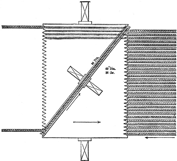
Fig. 89.
In Fig. 89 is shown a plan view of the tighteners for
a thirty-one rope drive. As the ropes shown are 1½
inches in diameter the main tightener sheave is shown
60 inches in diameter or forty times the diameter
of the rope used. Mounted above the thirty-two groove
sheave, and in the same frame, is a single groove sheave
of the right diameter to reach the two outside ropes
as shown, in this case 86 inches in diameter. Further
details are shown in the end elevation, Fig. 90, and in
the side elevation, Fig. 91. Allowing a working strain
of say 250 pounds to each strand of the thirty-one
ropes, we have a total weight of 15,500 pounds which
these two idler sheaves should weigh, including the
frame holding them.
These sheaves and the frame are mounted directly
upon the ropes, on the slack side of course, and just
as a tightener is mounted on a belt. The first rope
passes around the thirty-two-groove sheave, on up
over the single-groove sheave, and back under the
multiple-groove sheave again, and is thus crossed over.
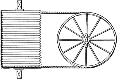
Fig. 90.
It is evident that a rope threaded on this drive
would, by the time it had run ten minutes or so, have
every strand in exactly the same tension every other
strand was in, and that the ropes would remain in this
condition in spite of variation of load and speed, as
long as they lasted.
The initial expense, including the erection, would
probably be no more than that for the necessary six
or eight single-groove idlers, with their shafts and
boxes, tracks, etc., which would be necessary according
to established practice. The room taken up would
evidently be much less.
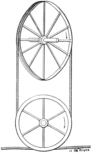
Fig. 91.
In Fig. 92 an assembled drive of this character is
shown. In Fig. 93 is shown a reverse drive, common in
sawmill practice, where the two sheaves described
would preferably be mounted on a car, with the proper
weight to give the desired tension.
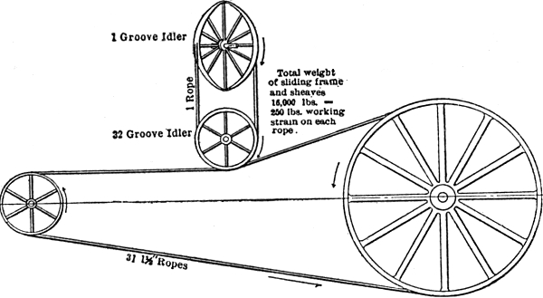
Fig. 92.
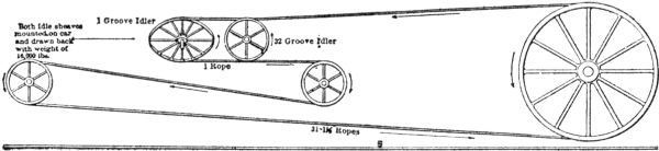
Fig. 93.
In a recent design is shown a cylinder with about
6 feet of piston travel, provided with a reducing valve,
so that the steam pressure would remain constant at
about 40 pounds. The cylinder is bolted to the mill
frame, while the piston rod is connected to the car
carrying the tightener sheaves. The cylinder is of the
proper area, when furnished with steam at 40 pounds
pressure, to put the correct strain on the ropes. A
small steam trap is part of the equipment. This should
give a very elastic tension, and so long as steam
pressure was at 40 pounds or over, the tension would
remain constant. With 6 feet piston travel, it is evident
that 372 feet of stretch could be taken out of the
rope, an amount entirely out of the question. A dog,
or buffer, can be so located as to prevent excessive
back travel of the piston and car when steam pressure
is taken off.
It is evident that this method can be applied to a
drive using any number of ropes.
HOW TO ORDER TRANSMISSION ROPE [11]
It is probable that more different and erroneous
terms are used by purchasing agents and engineers
when writing orders for transmission rope than are used
to describe any other article needed about a mill.
A knowledge of how to order clearly just the kind
of rope wanted would prevent delays and expense to
many plants. Manufacturers of transmission rope
constantly receive orders so peculiar in their wording
that they dare not venture an immediate shipment,
but must first resort to the mails, telegraph or telephone
to find out what is really desired, and, of course, these
mistakes, following the law of "the general cussedness
of things," usually occur after a breakdown at the
very time when every minute's delay means a considerable
sum of money lost.
There are in this country two manufacturers of
cordage who make a specialty of transmission rope,
and the names under which their rope is sold are fairly
well known to all users of rope drives. In addition to
these two concerns, there are, perhaps, three or four
other cordage mills which make this grade of rope to
some extent. From this comparatively small source
many different brands have sprung which, rechristened,
find their way to the market under a variety of names,
both poetic and classic. These many names lead to
frequent delays in ordering. The man who does the
splicing at the mill has, at one time or another, heard
of a rope glorying in the possession of some fancy title.
It is more than probable that some salesman has told
him most wonderful stories of what this particular rope
can do; consequently when the time comes for a new
rope, the splicer goes to the office and asks that so
many feet of such and such a rope be ordered. The
purchasing agent makes out the order, using this name,
and sends it to the manufacturer, who in all probability
has never heard of the rope and knows for a fact
that it is not the brand under which any of his fellow
manufacturers are selling rope. Before the order can
be filled, two or more letters or telegrams must be
sent and received.
It frequently occurs that manufacturers receive
orders specifying brands which never had existence
at all, so far as their knowledge goes. One firm recently
found in the same mail requests for "Fern," "Juno,"
and "Elephant" transmission rope, though no such
brands have ever been on the market.
Another familiar mistake is the ordering of a certain
color yarn in the rope, as if this decoration possessed
some peculiar virtue. These colored yarns are simply
a question of dye, and the rope in all probability would
be better and stronger were they left out.
Then again, we find peculiar wording as to the
lubrication of a rope. Some people insist that the rope
shall be "tallow inlaid"; others call for an "absolutely
dry" rope or for a "water-laid" rope. All transmission
rope, to be of any service whatsoever, must be lubricated
and such a thing as a "dry" transmission rope or a
"water-laid" one, whatever that term might mean,
would be of but small service to the user. Each manufacturer
has his own method or formula for lubricating,
and if this be a plumbago or graphite-laid rope, and he
is asked for an old-fashioned tallow-laid rope, he cannot
fill orders directly from stock.
It is unnecessary to name the number of strands,
unless you wish a three- or six-strand rope, for a four-strand
transmission rope is always sent, unless otherwise
specified. It is also unnecessary to say anything
about the core, as the rope is always supplied with one,
and generally it is lubricated. Frequently five-strand
rope is ordered. This is very confusing, as there is
such a thing as a five-strand rope, but it is very rarely
made. Ordering a five-strand rope is usually brought
about through the error of considering the core as a
fifth strand.
It is better, though not necessary, to order by the
diameter instead of the circumference, as transmission
rope is made and usually sold upon diameter specification.
By far the most frequent specifications received call
for "long-fiber, four-strand rope with core," and having
done this, the purchaser considers he has named all
necessary requirements. At the present price of manila
hemp, which varies from 7 cents per pound for the
poorer grades to 12½ cents per pound for the best, he
may be quoted for such a rope, with entire honesty,
anywhere from 11 to 17 cents per pound. To procure
long-fiber manila hemp, and twist it into four strands
about a core, does not make a proper transmission rope.
As the rope will probably be required to run at a speed
of from 3000 to 5000 feet per minute and be subjected
to rapid and constant bending throughout its entire
length, the fiber should not only be long, but the rope
should be soft and pliable. Further than this, as the
fiber, yarns and strands must slip one upon another
during the bending, the rope should be so lubricated as
to reduce to a minimum the frictional wear from such
slipping and rubbing, which is a much larger factor
than is generally supposed. Again, the unusual
strength of manila fiber is shown only when subjected
to a longitudinal strain. Transversely, owing to the
cellular formation, the fiber is relatively weak; therefore,
in manufacturing transmission rope, the greatest
care is necessary to secure such proportion of twist in
both yarns and strand as to render the rope least
vulnerable to crosswise strain. Nor will the term
"long fiber" insure the purchaser obtaining the proper
material in his rope, for the longest manila fiber, contrary
to general belief, is not always the best from
which to make a transmission rope. Some of the extremely
long variety is coarse and brittle. The best
fiber for transmission rope is a particular grade of manila
hemp known as Zebu, Fig. 94, which is light in color,
silky to the touch and exceedingly strong and flexible.
Fig. 94.
Fig. 95.
Fig. 96.
The accompanying illustration, Fig. 95, shows a close
view of two grades of hemp, that on the left being
known in the trade as "Superior 2ds," while the fiber
to the right of the cut is "Zebu." Fig. 96 shows
a more distant view of the same two "heads" of hemp,
and the reader will see that in both the fiber is exceeding
long, and if anything, that of the Superior 2ds
is longer than in the Zebu. A transmission rope made
from the latter, however, will cost the manufacturer
from 3½ to 4 cents more per pound than if he had used
Superior 2ds, and will outlast two ropes made from
the longer though coarser fiber.
The reader, if he has perused this chapter to the present
point, is doubtless now asking himself: "How shall
I word my order when I want a first-class driving
rope?" The safest road to follow is to write to some
manufacturer or firm whom you know to be reliable,
and ask for so many feet of their transmission rope,
giving the name, if you are certain on that point, and,
of course, being sure to mention the diameter. In
case you do not know the name of his rope, word your
order as simply and briefly as possible; for example:
"One thousand feet 1½ inches diameter first quality
manila transmission rope," and if the concern to which
you write is a reputable one, you will receive a four-strand
rope, made from Zebu manila hemp, put together
with proper twist and lay for the service
required.
A BELTING AND PULLEY CHART [12]
Rule 1. Pulley Speed.—When the diameter of
both pulleys and the speed of one is given, to find the
speed of the other: Place the points of spacing dividers
upon the two given diameters in inches upon the scale
(Fig. 97); then raise the dividers, keeping the space
obtained, and place one point on the given speed and
the other above it for speed of S, or below it for speed
of L (S and L meaning smaller and larger pulley, respectively).
This point will fall upon the required
speed.
Example: If the two pulley diameters are 10 and
25 inches and speed of larger pulley is 120 revolutions
per minute, what is speed of small pulley?
Place the points of dividers on 10 and 25 on scale A,
then lift the dividers and place one point on 120 and
the other above it upon the scale; the other point now
rests on 300 as the speed of S. If the speed of S had
been given, one point would have been placed at 300
and the other below it, falling upon 120, the required
speed of L.
Note.—In applying this rule, if the speed comes
beyond the range of scale A, the result may be read
by carrying the space to the revolution scale on scale
B, and proceeding in the same way.
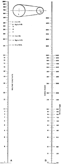
Fig. 97.
Example: Diameter of pulleys 12 and 36 inches
and speed of L 500, what is speed of S? Place points
of dividers on 12 and 36. Now, if dividers are raised
and one point placed on 500 and the other above it
on scale A, it will come beyond the top of the scale.
Hence go to scale B, placing lower point on revolution
scale at 500 and the other point above, which will fall
upon 1500, the answer.
Rule 2. Pulley Diameters.—When the speed of
both pulleys and the diameter of one is given, to find
diameter of the other: Place points of dividers on the
two speeds on scale A or revolution scale B. Then
place one point of dividers on given diameter and the
other above it to find diameter of L, or below it for
diameter of S. The figure thus indicated is the required
diameter.
Example: Speeds 180 and 450 and diameter of
smaller pulley 20. What must be diameter of L?
Place points of dividers on 180 and 450 on scale A.
Then place one point on 20 (the given diameter). The
other point falls at 50, the required diameter of L.
If the point falls between two graduations in any
problem, the result can be closely judged by the relative
position.
The other and more labor-saving use for this chart
is its application to belting problems. It is generally
conceded that there is no subject of more general interest
in practical mechanics and none on which there is a
greater difference of opinion than the proper allowance
to be made in the selection of belt sizes for given requirements.
The general formula for the horse-power
transmitted by belting is
HP = WS/C in which HP = horse-power,
W = width of belt in inches, S = speed of belt in
feet per minute, and C = constant.
The proper values of this constant, or the feet per
minute that each inch of width must run to transmit
a horse-power, under certain conditions, is the point
in question.
On the right-hand side of line A on the chart is a
series of lines representing different values for this
constant. The lower one, marked 4, represents 400
feet belt speed per minute, the next above is for 500,
and so on. Against some of these values are suggestions
as to belts often recommended in connection with
these constants. For instance, 2 to 6 S suggests the
constant 1100 to be used for 2- to 6-inch single leather
belt, 1000 for 6½- to 10-inch single, 600 for 2- to 6-inch
double, etc.
These suggestions practically agree with the advice
of the Geo. V. Cresson Company's catalog and the
deductions of Kent's Handbook.
More power may be transmitted than these suggestions
will allow, by increasing the tension, but this is
accompanied by the disadvantage of requiring extra
attention and undue pressure upon bearings.
The use of the chart for horse-power and width of
belting is explained by the following rules:
Rule 3. Horse-power of Belting.—To find the
horse-power that can be transmitted when diameter
and speed of pulley and width of belt are given: Place
one point of dividers on scale A at the width of belt
in inches and the other point at the bottom of the
line (at 1). Next add this space to the hight representing
diameter of pulley by placing lower point of
dividers upon the given diameter and allowing the other
point to rest upon the scale above. Then holding the
upper point stationary, open or close dividers until the
other point falls upon the proper constant on the scale
at right-hand side of line A. Now transfer this space
last obtained to the scale B by raising the dividers,
carrying them square across to B and placing the point
that was on the constant upon the given speed on the
revolution scale. Note the location of the other point
of dividers upon the horse-power scale, which indicates
the horse-power that can be transmitted under the
given conditions.
Example: What horse-power can be transmitted
by an 8-inch double belt running on a 40-inch pulley
at 500 feet per minute? Place one point of dividers
on line A at 8 (width of belt) and the other point at
bottom of line. Next raise dividers and place lower
point on 40 (diameter of pulley) and let the other point
fall above upon the scale. Then close dividers until
lower point comes to the constant for 6½ to 10 double.
Carry this space to scale B with lower point on 500 on
revolution scale. Under point now falls upon 84 on
horse-power scale, which is the required horse-power.
Rule 4. Width of Belting.—To find the necessary
width of belting when size and speed of pulley and the
horse-power are given: Place one point of dividers
on scale B upon the horse-power and the other point
upon the revolutions. Next transfer this space to scale
A by raising the dividers, carrying them square across
and placing the point that was on revolutions upon the
constant. Then holding the other point stationary,
raise the point that was on the constant and open
dividers until this point falls upon the given diameter.
Now lift the dividers and carry the lower point down
to bottom of line (the point 1). The upper point will
now indicate the required width of belt.
Note.—If, in finding width of belt, there is doubt
about the proper constant to take, a medium value,
say 6, may be assumed and a hasty "cut and try"
will show in what classification the required belt will
come.
Example: What width of belt for 100 horse-power
with 40-inch pulley at 500 revolutions?
Place point of dividers on scale B upon 100 on horse-power
scale and the other upon 500 on the revolution
scale. Then carry the space to scale A with lower
point on constant 5. Then resting dividers upon
upper point open them until lower point is at 40 (diameter).
Finally, raise dividers and place lower point
at bottom of line. Upper point is now at 9½, indicating
the nearest even width 10 as the answer.
A little practice will make one familiar with these
rules, and it will be seen that in the belting rules the
four motions perform two multiplications and a division.
SPLICING ROPE
The splicing of a transmission rope is an important
matter; the points on which the success of the splice,
and incidentally the drive, depend being the length
of the splice, which in turn depends upon the diameter
of the rope and which is given in the table (Fig. 97a);
the diameter of the splice, which should be the same
as the diameter of the rope; the securing of the ends
of the strands of the splice, which must be so fastened
that they will not wear or whip out or cause the overlying
strands to wear unduly; and the workmanship
of the splice, which should be the best it is possible to
secure. When splicing an old and a new piece of
rope, the new piece should be thoroughly stretched,
for, at best, it is an exceedingly difficult task on
account of the stretch and difference in diameter of
the rope.
Data Relative to Manila Transmission Rope and Sheaves
| | | | | Length of Splice
in Feet | | |
| A | B | C | D | E | F | G | H | I | J |
| 1/2 | .25 | .12 | 1750 | 50 | 6 | | | 20 | 1060 |
| 5/8 | .2906 | .16 | 2730 | 80 | 6 | | | 24 | 970 |
| 3/4 | .5625 | .20 | 3950 | 112 | 6 | 8 | | 27 | 760 |
| 7/8 | .7656 | .26 | 5400 | 153 | 6 | 8 | | 32 | 650 |
| 1 | 1. | .34 | 7000 | 200 | 7 | 10 | 14 | 36 | 570 |
| 1 1/8 | 1.2656 | .43 | 8900 | 253 | 7 | 10 | 16 | 40 | 510 |
| 1 1/4 | 1.5625 | .63 | 10,900 | 312 | 7 | 10 | 16 | 45 | 460 |
| 1 1/2 | 2.25 | .77 | 15,700 | 450 | 8 | 12 | 18 | 54 | 380 |
| 1 3/4 | 3.0625 | 1.04 | 21,400 | 612 | 8 | 12 | 18 | 63 | 330 |
| 2 | 4. | 1.36 | 28,000 | 800 | 9 | 14 | 20 | 72 | 290 |
| 2 1/4 | 5.0625 | 1.73 | 35,400 | 1012 | 9 | 14 | 20 | 81 | 255 |
| 2 1/2 | 6.25 | 2.13 | 43,700 | 1250 | 10 | 16 | 22 | 90 | 230 |
Fig. 97a.
Key to above table
| A | Diameter of Rope in Inches |
| B | Square of Diameter |
| C | Approximate Weight per Foot, Pounds |
| D | Breaking Strength, Pounds |
| E | Maximum Allowable Tension, Pounds |
| F | 3-Strand |
| G | 4-Strand |
| H | 6-Strand |
| I | Smallest Diameter of Sheaves in Inches |
| J | Maximum Number of Revolutions per Minute |
The illustrations and instructions for making standard
rope splices are taken, by the courtesy of the
American Manufacturing Company, from their "Blue
Book of Rope Transmission."
There are many different splices now in use, but the
one that experience has proved best is what is known
as the English transmission splice. In describing this
we take for our example a four-strand rope, 1¾ inches
in diameter, as spliced on sheaves in the multiple
system. The rope is first placed around sheaves, and,
with a tackle, stretched and hauled taut; the ends
should pass each other from six to seven feet, the passing
point being marked with twine on each rope.
The rope is then slipped from the sheaves and allowed
to rest on shafts, to give sufficient slack for making
the splice.
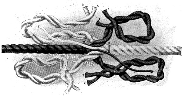
Fig. 98.
Unlay the strands in pairs as far back as the twines
M, Mâ², crotch the four pairs of strands thus opened
(Fig. 98), cores having been drawn out together on
the upper side. Then, having removed marking
twine M, unlay the two strands 6 and 8, still in pairs,
back a distance of two feet, to A; the strands 1 and 3,
also in pairs, being carefully laid in their place. Next
unlay the strands 5 and 7 in pairs, to Aâ², replacing
them as before with 2 and 4. The rope is now as
shown in Fig. 99. The pair of strands 6 and 8 are
now separated, and 8 unlaid four feet back to B, a
distance of six feet from center, strand 6 being left at
A. The pair of strands 1 and 3 having been separated,
3 is left at A, as companion for 6, strand 1 being carefully
laid in place of strand 8 until they meet at point
B. The two pairs of strands 2-4 and 5-7 are now
separated and laid in the same manner, every care
being taken, while thus putting the rope together,
that original twist and lay of strand is maintained.
The protruding cores are now cut off so that the ends,
when pushed back in rope, butt together.
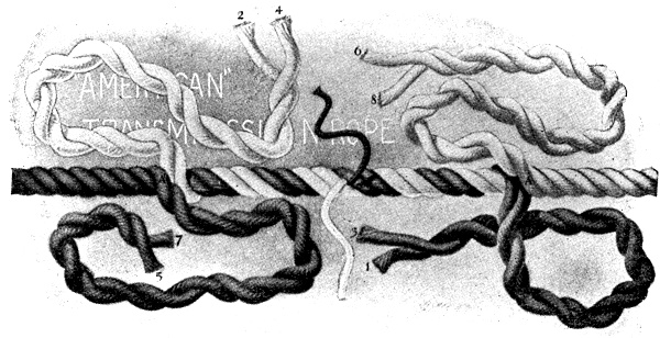
Fig. 99.
The rope now appears as shown in Fig. 100, and
after the eight strands have been cut to convenient
working lengths (about two feet), the companion
strands are ready to be fastened together and
"tucked"; this operation is described for strands 2
and 7, the method being identical for the other three
pairs. Unlay 2 and 7 for about twelve to fourteen
inches, divide each strand in half by removing its
cover yarns (see Fig. 101), whip with twine the ends
of interior yarns 2â² and 7â²; then, leaving cover 2, relay
2â² until near 7 and 7â², here join with simple knot 2â²
and 7â², Fig. 102. Divide cover yarns 7, and pass 2â²
through them, continuing on through the rope under
the two adjacent strands, avoiding the core, thus
locking 2â², Fig. 103. In no event pass 2â² over these or
any other strands. Half-strand 7â² must now be taken
care of; at the right of the knot made with 2â² and 7â²,
2â² is slightly raised with a marlin spike, and 7â² passed
or tucked around it two or three times, these two
half-strands forming in this way a whole strand.
Half-strand 7â² is tucked until cover 2 is reached,
whose yarns are divided and 7â² passed through them
and drawn under the two adjacent strands, forming
again the lock. The strand ends at both locks are
now cut off, leaving about two inches, so that the
yarns may draw slightly without unlocking. This
completes the joining of one pair of strands, Fig. 104.
The three remaining pairs of strands are joined in the
same manner.
Fig. 100.
Fig. 101.
Fig. 102.
Fig. 103.
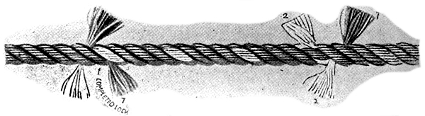
Fig. 104.
After the rope has been in service a few days, the
projecting ends at locks wear away, and if tucks have
been carefully made, and the original twist of yarns
preserved, the diameter of the rope will not be increased,
nor can the splice be located when the rope
is in motion.
WIRE ROPE TRANSMISSION [13]
Wire ropes are extensively and successfully used
in the horizontal and inclined transmission of great
power of unlimited amount, the advantages over hemp
rope belting being: driving at very long distances,
comparatively small loss through slipping and the
possibility of driving in the open air.
Vertical transmission of power, on account of the
weight of the rope, is excluded.
Formerly the material used in the manufacture
of the wires was best charcoal iron, but now almost
exclusively tough crucible-steel wires are used, as steel
wire ropes are stronger, do not stretch as much, and last
longer than iron ropes.
The wire ropes consist of six strands of from six to
twenty wires each, and the strands to form the rope
are woven in the opposite direction to the wires in the
strand. In the center of each strand and in the center
of the rope a cotton core is placed. These cores are of
the greatest importance, for by reducing the friction
of the wires against each other, they serve to increase
the lifetime of the rope, which, according to the strain
on the rope and the size of the smallest pulley, is from
one to three years.
To prevent rusting, the wire ropes receive a coat
of boiled linseed oil, or a hot mixture consisting of
three parts of drip oil and one part of resin is applied.
This latter mixture at the same time improves the adhesion
between the rope and the lining placed in the
bottom of the pulleys, thus reducing the loss caused by
slipping of the rope. Wire ropes used for the transmission
of power should never be galvanized.
The ends of the rope are spliced together, from 10
to 20 feet being necessary for a good splice; great care
should be taken that the splice is made by experienced
men, and that the rope is made long enough. A rope
stretches constantly from the time when placed on the
pulleys, the more so when placed on the pulleys tightly.
Therefore it has to be made long enough to transmit
power without undue tension, and for this reason the
distance between the two pulleys has to be long enough
and the working strain per square inch of section low
enough to allow sufficient deflection in the rope. As
a guidance to the amount of deflection necessary, be
it said that even in a short drive the deflection of the
rope, when not running, should not be less than 2 feet;
and for a distance of 400 feet between pulley centers,
the deflection of the rope when running should be 5 feet
in the driving rope and 10 feet in the driven rope.
Either the top or the bottom rope may be the driving
one, the former being preferable; but the ropes should
never be crossed.
Power can be transmitted to a distance of 6000 feet
and more without great loss; but as two pulleys
should on no account be more than 500 feet apart,
intermediate stations are placed along the road.
Precautions should be taken against the possibility
of the rope swaying. This may be caused either by the
influence of the wind, by a bad splice, by the rope
wearing too much, by the pulleys not being balanced
well or by the pulleys not being in the same plane. It
is of importance that the pulleys be exactly in line,
and careful attention should be given to the construction
and placing of the bearings. Although the bearings
are not strained excessively, the steps are usually
made long and movable. The connection between the
shaft and the pulley is best made by means of tangential
keys.
Some engineers, when two ropes are found necessary
for the transmission of the power in question, use
pulleys containing two grooves each, and make the
same kind of pulleys for the intermediate stations of
long-distance driving; whereas others advise a separate
pulley for each rope, both being connected with each
other by a clutch.
The diameter of the smallest pulley has to be large
enough in comparison with the diameter of the rope
or the thickness of the single wires used to easily overcome
the stiffness in the rope. The larger the pulleys,
the longer the rope will last.
The rim of the pulley is V-shaped, and the bottom of
the groove is dovetailed to receive a lining of wood, rubber
or leather, on which the rope rests. The lining increases
the friction and reduces the loss caused by slipping of
the rope. Leather is the best lining and lasts about
three years. Either old belt leather, well saturated
with oil, or new leather, boiled in fish oil, can be taken.
It is cut in pieces of the same size as the dovetailed
part of the groove, and then placed on and pressed together
in the latter. The pressing is done by means
of a piece of wood. The last remaining small space in
the groove is filled with soft rubber. If the lining has
to consist of rubber, this is softened and hammered
into the groove. For wood lining, thin blocks of the
required size are placed into the groove through a hole
provided in the bottom of the rim. This slot is closed
by a plate and fastened to the bottom of the rim by
means of screws after all blocks have been inserted.
The lining has to be turned absolutely true, for which
reason the filling is done while the pulley is still in the
lathe.
Pulleys up to 3 feet in diameter are built with cast-iron
arms; whereas larger pulleys have wrought-iron
arms made of round iron, cast in the rim and boss.
Pulleys under 8 feet 6 inches in diameter are made in
one piece, if for other reasons it is not necessary to have
them in halves.
Guide pulleys are used for long ropes, especially
if there is not sufficient hight above the ground. The
guide pulleys are of the same construction as the main
pulleys, and for the driving rope they are also made of
the same diameter. The diameter of the guide pulleys
for the driven rope can be made from 20 to 25 per cent.
smaller.
The breaking strength of unannealed wires per square
inch of section and according to thickness and quality
is: For iron wires from 70,000 to 110,000 pounds,
and for steel wires from 110,000 to 130,000 pounds.
For thinner wires a higher value is taken than for thick
ones.
The diameter of the wires used for making ropes for
transmitting power is from 0.02 to 0.1 inch, and on
account of the stiffness, no wires above the latter size
should be used. A rope consisting of a greater number
of thin wires, besides being stronger is more pliable
and lasts longer than a rope of the same area consisting
of a less number of thicker wires.