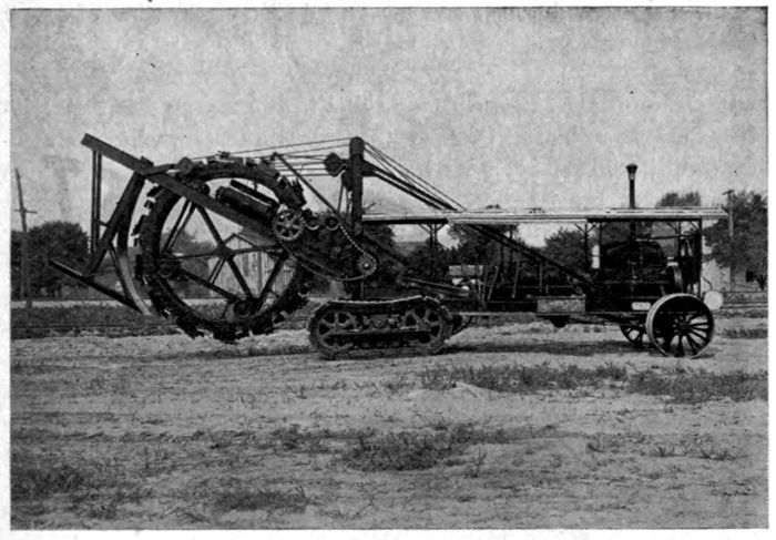
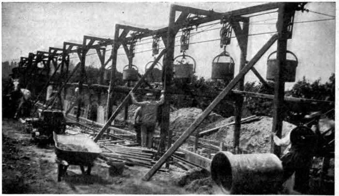
The cover image was created by the transcriber and is placed in the public domain.
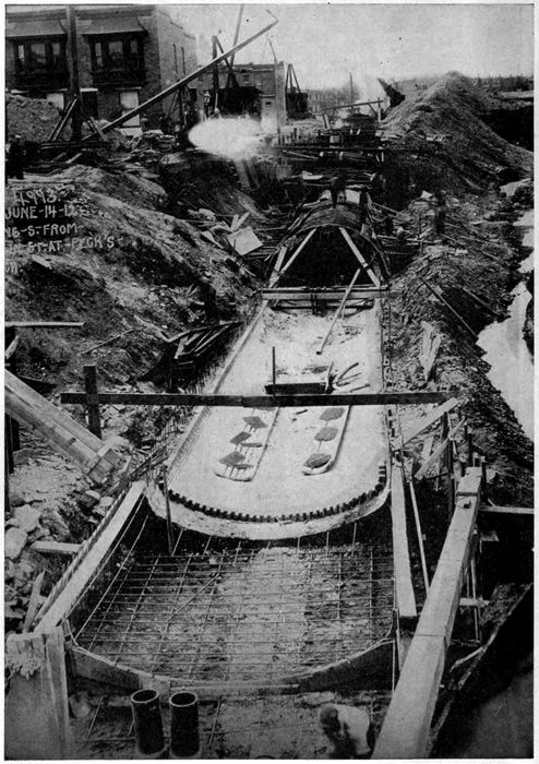
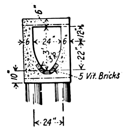
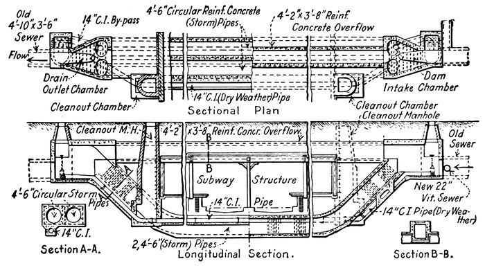
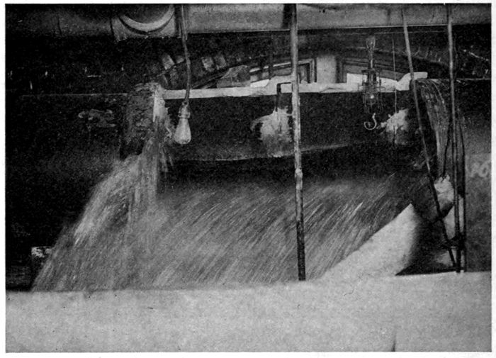
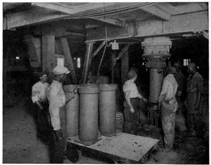
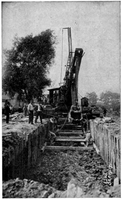
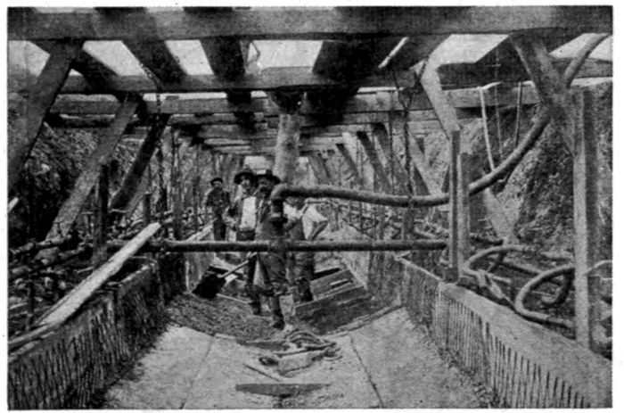
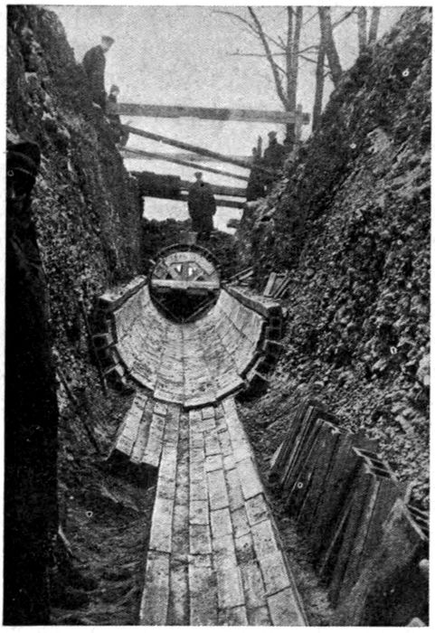
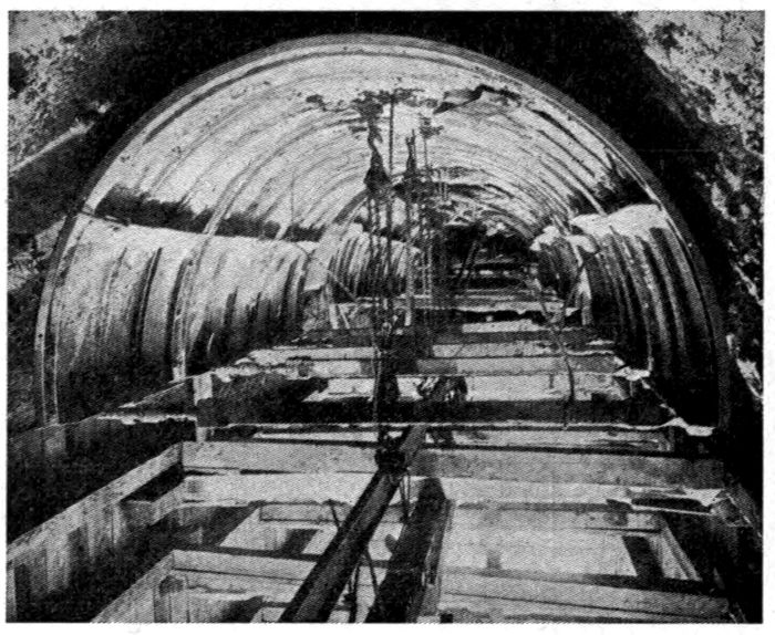
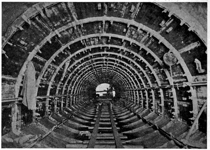
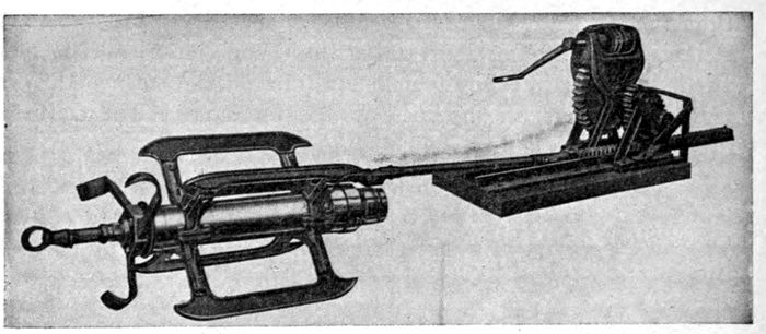
Fig. 1.—Construction of Peck’s Run Sewer, Baltimore, Maryland.
Frontispiece.
BY
HAROLD E. BABBITT, M.S.
Assistant Professor, Municipal and Sanitary Engineering, University of Illinois; Associate Member American Society of Civil Engineers
NEW YORK
JOHN WILEY & SONS, Inc.
London: CHAPMAN & HALL, Limited
1922
Copyright, 1922, by
HAROLD E. BABBITT, M.S.
PRESS OF
BRAUNWORTH & CO.
BOOK MANUFACTURERS
BROOKLYN, N. Y.
PREFACE
v
This book is a development of class-room and lecture notes
prepared by the author for use in his classes at the University
of Illinois. He has found such notes necessary, since among
the many books dealing with sewerage and sewage treatment
he has found none suitable as a text-book designed to cover the
entire subject. The need for a single book of the character
described has been expressed by engineers in practice, and by
students and teachers for use in the class-room. This book
has been prepared to meet both these needs. It is hoped that
the searching questions propounded by students in using the
original notes, and the suggestions and criticisms of engineers
and teachers who have read the manuscript, have resulted in a
text which can be readily understood.
The ground covered includes an exposition of the principles
and methods for the designing, construction and maintenance of
sewerage works, and also of the treatment of sewage. In covering
so wide a field the author has deemed it necessary to include some
chapters which might equally well appear in works on other
branches of engineering, such as the chapter on Pumps and
Pumping Stations. Special stress has been laid on the fundamentals
of the subject rather than the details of practice, although
illustrations have been drawn freely from practical work. The
quotation of expert opinions which may be in controversy, or the
citation of examples of different methods of accomplishing the
same thing, has been avoided when possible in order to simplify
explanations and to avoid confusing the beginner.
The work is to some extent a compilation of notes and quotations
which have been collected by the author during years
of study and teaching the subject. Credit has been given
wherever due, and at the same time references have pointed out
the original sources whenever possible. These references, which
vihave been supplemented by brief bibliographies at the end of
certain chapters, will be useful to the student and engineer interested
in further study. Occasionally the original reference has
been lost or the phraseology of a quotation has been so altered
by class-room use, as to make it impossible to trace the original
source, so that in some few instances full credit may be lacking.
The author is indebted to many of his friends for their criticisms
and suggestions in the preparation of the manuscript;
but he desires particularly to acknowledge the assistance of
Professor A. N. Talbot, Professor of Municipal and Sanitary
Engineering at the University of Illinois, and of Professor M. L.
Enger, Professor of Mechanics and Hydraulics at the University
of Illinois, in the entire work; also that of Mr. T. D. Pitts, Principal
Assistant Engineer of the Baltimore Sewerage Commission
during the construction of the Baltimore sewers, for his
suggestions on the first half of the book; and to Mr. Paul Hansen,
consulting engineer, of Chicago, and to Mr. Langdon Pearse,
Sanitary Engineer of the Sanitary District of Chicago, for
their help on the section covering the treatment of sewage; and
to Professor Edward Bartow, Professor of Chemistry at the
University of Iowa, for his review of the chapter on Activated
Sludge; in general his thanks are due to all others who have
furnished suggestions, illustrations, or quotations, acknowledgments
of which have been included in the text.
H. E. B.
Urbana, Illinois, 1922.
TABLE OF CONTENTS — CHAPTER I INTRODUCTION
vii
CHAPTER I
Introduction
PAGES
1. Sewerage and the Sanitary Engineer. 2. Historical. 3. Methods of Collection. 4. Methods of Disposal. 5. Methods of Treatment. 6. Definitions.
17. Dry Weather Flow. 18. Methods for Predicting Population. 19. Extent of Prediction. 20. Sources of Information on Population. 21. Density of Population. 22. Changes in Area. 23. Relation between Population and Sewage Flow. 24. Character of District. 25. Fluctuations in Rate of Sewage Flow. 26. Effect of Ground Water. 27. Résumé of Method for Determination of Quantity of Dry weather Sewage. Quantity of Storm Water. 28. The Rational Method. 29. Rate of Rainfall. 30. Time of Concentration. 31. Character of Surface. 32. Empirical Formulas. 33. Extent and Intensity of Storms.
34. Principles. 35. Formulas. 36. Solution of Formulas. 37. Use of Diagrams. 38. Flow in Circular Pipes Partly Full. 39. Sections Other than Circular. 40. Non-Uniform Flow.
41. The Plan. 42. Preliminary Map. 43. Layout of the Separate System. 44. Location and Numbering of Manholes. 45. Drainage Areas. 46. Quantity of Sewage. 47. Surface Profile. 48. Slope and Diameter of Sewers. 49. The Sewer Profile. Design of a Storm-water Sewer System. 50. Planning the System. 51. Location of Street Inlets. 52. Drainage Areas. 53. Computation of Flood Flow by McMath Formula. 54. Computation of Flood Flow by Rational Method.
ix68. Need. 69. Reliability. 70. Equipment. 71. The Building. 72. Capacity of Pumps. 73. Capacity of Receiving Well. 74. Types of Pumping Machinery. 75. Sizes and Descriptions of Pumps. 76. Definitions of Duties and Efficiency. 77. Details of Centrifugal Pumps. 78. Centrifugal Pump Characteristics. 79. Setting of Centrifugal Pumps. 80. Steam Pumps and Pumping Engines. 81. Steam Turbines. 82. Steam Boilers. 83. Air Ejectors. 84. Electric Motors. 85. Internal Combustion Engines. 86. Selection of Pumping Machinery. 87. Costs of Pumping Machinery. 88. Cost Comparisons of Different Designs. 89. Number and Capacity of Pumping Units.
106. Importance of the Subject. 107. Scope of the Subject. 108. Types of Contracts. 109. The Agreement. 110. The Advertisement. 111. Information and Instructions for Bidders. 112. Proposal. 113. General Specifications. 114. Technical Specifications. 115. Special Specifications. 116. The Contract. 117. The Bond.
x118. Elements. Work of the Engineer. 119. Duties. 120. Inspection. 121. Interpretation of Contract. 122. Unexpected Situations. 123. Cost Data and Estimates. 124. Progress Reports. 125. Records. Excavation. 126. Specifications. 127. Hand Excavation. 128. Machine Excavation. 129. Types of Machines. 130. Continuous Bucket Excavators. 131. Cableway and Trestle Excavators. 132. Tower Cableways. 133. Steam Shovels. 134. Drag Line and Bucket Excavators. 135. Excavation in Quicksand. 136. Pumping and Drainage. 137. Trench Pump. 138. Diaphragm Pump. 139. Jet Pump. 140. Steam Vacuum Pumps. 141. Centrifugal and Reciprocating Pumps. 142. Well Points. 143. Rock Excavation. 144. Power Drilling. 145. Steam or Air for Power. 146. Depth of Drill Hole. 147. Diameter of Drill Hole. 148. Spacing of Drill Holes. Sheeting and Bracing. 149. Purposes and Types. 150. Stay Bracing. 151. Skeleton Sheeting. 152. Poling Boards. 153. Box Sheeting. 154. Vertical Sheeting. 155. Pulling Wood Sheeting. 156. Earth Pressures. 157. Design of Sheeting and Bracing. 158. Steel Sheet Piling. Line and Grade. 159. Locating the Trench. 160. Final Line and Grade. 161. Transferring Grade and Line to the Pipe. 162. Line and Grade in Tunnel. Tunnelling. 163. Depth. 164. Shafts. 165. Timbering. 166. Shields. 167. Tunnel Machines. 168. Rock Tunnels. 169. Ventilation. 170. Compressed Air. Explosives and Blasting. 171. Requirements. 172. Types of Explosives. 173. Permissible Explosives. 174. Strength. 175. Fuses and Detonators. 176. Care in Handling. 177. Priming, Loading, and Firing. 178. Quantity of Explosive. Pipe Sewers. 179. The Trench Bottom. 180. Laying Pipe. 181. Joints. 182. Labor and Progress. Brick and Block Sewers. 183. The Invert. 184. The Arch. 185. Block Sewers. 186. Organization. 187. Rate of Progress. Concrete Sewers. 188. Construction in Open Cut. 189. Construction in Tunnels. 190. Materials for Forms. 191. Design of Forms. 192. Wooden Forms. 193. Steel-lined Wooden Forms. 194. Steel Forms. 195. Reinforcement. 196. Cost of Concrete Sewers. Backfilling. 197. Method.
xi208. Physical Characteristics. 209. Chemical Composition. 210. Significance of Chemical Constituents. 211. Sewage Bacteria. 212. Organic Life in Sewage. 213. Decomposition of Sewage. 214. The Nitrogen Cycle. 215. Plankton and Macroscopic Organisms. 216. Variations in the Quality of Sewage. 217. Sewage Disposal. 218. Methods of Sewage Treatment.
228. Purpose. 229. Types of Screens. 230. Sizes of Openings. 231. Design of Fixed and Movable Screens. Plain Sedimentation. 232. Theory of Sedimentation. 233. Types of Sedimentation Basins. 234. Limiting Velocities. 235. Quantity and Character of Grit. 236. Dimensions of Grit Chambers. 237. Existing Grit Chambers. 238. Number of Grit Chambers. 239. Quantity and Characteristics of Sludge from Plain Sedimentation. 240. Dimensions of Sedimentation Basins. Chemical Precipitation. 241. The Process. 242. Chemicals. 243. Preparation and Addition of Chemicals. 244. Results.
245. The Process. 246. The Septic Tank. 247. Results of Septic Action. 248. Design of Septic Tanks. 249. Imhoff Tanks. 250. Design of Imhoff Tanks. 251. Imhoff Tank Results. 252. Status of Imhoff Tanks. 253. Operation of Imhoff Tanks. 254. Other Tanks.
283. Types. 284. Operation. 285. Three Alternating Siphons. 286. Four or More Alternating Siphons. 287. Timed Siphons. 288. Multiple Alternating and Timed Siphons.
1. Sewerage and the Sanitary Engineer.—Present day conceptions
of sanitation are based on the scientific discoveries which
have resulted so much in the increased comfort and safety of
human life during the past century, in the increase of our material
possessions, and the extent of our knowledge. The danger to
health in the accumulation of filth, the spreading of disease by
various agents, the germ theory of disease, and other important
principles of sanitation can be counted among the more recent
scientific discoveries and pronouncements. Experience has shown,
and continues to show, that the increase of population may be
inhibited by accumulations of human waste in populous districts.
The removal of these wastes is therefore essential to the existence
of our modern cities.
The greatest need of a modern city is its water supply. Without
it city life would be impossible. The next most important
need is the removal of waste matters, particularly wastes containing
human excreta or the germs of disease. To exist without
street lights, pavements, street cars, telephones, and the many
other attributes of modern city life might be possible, although
uncomfortable. To exist in a large city without either water or
sewerage would be impossible. The service rendered by the sanitary
engineer to the large municipality is indispensable. In
addition to the service necessary to the maintenance of life in
large cities, the sanitary engineer serves the smaller city, the
rural community, the isolated institution, and the private estate
with sanitary conveniences which make possible comfortable
2existence in them, and which are frequently considered as of
paramount necessity. Training for service in municipal sanitation
is training for a service which has a more direct beneficial
effect on humanity than any other engineering work, or any
other profession. W. P. Gerhard states:
A Sanitary Engineer is an engineer who carries out those
works of civil engineering which have for their object:
(a) The promotion of the public and individual health;
(b) The remedying of insanitary conditions;
(c) The prevention of epidemic diseases.
A well-educated sanitary engineer should have a
thorough knowledge of general civil engineering, of architecture,
and of sanitary science. The practice of the sanitary
engineer embraces water supply, sewerage, and
sewage and garbage disposal for cities and for single buildings;
the prevention of river pollution, the improvement
of polluted water supplies; street paving and street cleaning,
municipal sanitation, city improvement plans, the
laying out of cities, the preparation of sanitary surveys,
the regulation of noxious trades, disinfection, cremation,
and the sanitation of buildings.
The need of the work of the sanitary engineer in the provision
of sewers and drains is thrust upon us in our daily experience by
the clogging of sewers, the flooding of streets by heavy rains,
filthy conditions in unsewered districts, increased values of property
and improved conditions of living in sewered districts, and
in many other ways. The increasing demand for sewerage and
the amount of money expended on sewer construction is indicated
by the information given in Table I.
2. Historical.—An ordinance passed by the Roman Senate in
the name of the Emperor about A.D. 80, states:
I desire that nobody shall conduct away any excess
water without having received my permission or that of my
representatives; for it is necessary that a part of the supply
flowing from the delivery tanks shall be utilized not only for
cleaning our city, but also for flushing the sewers.[1]
Neither the sewers mentioned nor the distributing pipes of
the public water supply were connected to individual residences.
The contributions to the sewers came from the ground and the
street surface. The streets were the receptacles of liquid and
3solid wastes and were often little more than open sewers. A
promenade after dark in an ancient, medieval, or early modern
city was accompanied not only by the underfoot dangers of an
uneven pavement or an encounter with a footpad, but with the
overhead danger from the emptying of slops into the streets from
the upper windows. Sewers were used for the collection of surface
water; the discharge of fecal matter into them was prohibited.
The problem of the collection of sewage remained
unsolved until the Nineteenth Century.
Population discharging raw sewage into the sea or tidal estuaries
6,500,000
8,500,000
Population discharging raw sewage into inland streams or lakes
20,400,000
26,400,000
Population connected to systems where sewage is treated in some way
1,100,000
6,900,000
Population connected with sewerage systems
28,000,000
41,800,000
46,300,000
The development of the London sewers was commenced
early in the Nineteenth Century. The sewerage system of Hamburg,
Germany, was laid out in 1842 by Lindley, an English
engineer who with other English engineers performed similar
work in other German cities because of their earlier experience
in English communities. Berlin’s present system dates from 1860.
The construction of storm-water drains in Paris dates from 1663.[5]
They were intended only as street drains but are now included in
the comprehensive system of the city. The first comprehensive
sewerage system in the United States was designed by E. S.
Chesbrough for the City of Chicago in 1855. Previous to this
4time sewers had been installed in an indifferent manner and without
definite plan. The installation of a comprehensive sewerage
system in Baltimore in 1915 marks the completion of installation
of sewerage systems in all large American cities.
In the early days of sewerage design it was considered unsafe
to discharge domestic wastes into the sewers as the concentration of
so much sewage was expected to create great nuisances and
dangers to health. That the fear that the concentration of large
quantities of sewage would create a nuisance was not ill founded
is proven by the conditions on the Thames at London in 1858–59.
Dr. Budd states:[6]
For the first time in the history of man, the sewage
of nearly three millions of people had been brought to
seethe and ferment under a burning sun in one vast open
cloaca lying in their midst.
The result we all know. Stench so foul we may well
believe had never before ascended to pollute this lower
air. Never before at least had a stink risen to the height
of an historic event.... For months together the topic
almost monopolized the public prints.... ‘India is in
revolt and the Thames stinks’ were the two great facts
coupled together by a distinguished foreign writer, to mark
the climax of a national humiliation.[7]
The problem of sewage disposal followed the more or less
successful solutions of the problem of sewage collection. In
England the British Royal Commission on Sewage Disposal was
appointed in 1857 and issued its first report in 1865. The first
studies in the United States were started in 1887 by the establishment
of an experiment station at Lawrence, Massachusetts, where
valuable work has been done. The station is under the State
Board of Health, which issued its first report containing the
results of the work at the station, in 1890.
Various methods of sewage treatment preparatory to disposal
have been devised from time to time. Some have fallen into
disuse, such as the A. B. C. (alum, blood and clay) process, and
others have taken a permanent place, such as the septic tank.
The unsolved problems of sewage collection, and the number of
5persons still unserved by sewerage and sewage disposal opens a
wide field to the study and construction of sewerage works.
3. Methods of Collection.—The method of collection which
involves the removal of night soil from a privy vault, the pail
system which involves the collection of buckets of human excreta
from closets and homes, indoor chemical closets, and other makeshift
methods of collection are of extreme importance where no
sewers exist, but they are not properly considered as sewerage
systems or sewerage works. These methods of collection are
generally confined to rural districts and to outlying parts of
urban communities. They require constant attention for their
proper conduct and little skill for their installation, the principal
requirements being to make the receptacles fly-proof.
The pneumatic system was introduced by Liernur, a Dutch
engineer.[8] It is used in parts of a few cities in Europe, but it is
not capable of use on a large scale. It consists of a system of
air-tight pipes, connecting water closets, kitchen sinks, etc., with
a central pumping station at which an air-tight tank is provided
from which the air is partly exhausted. As little water as possible
is allowed to mix with the fecal matter and other wastes in order
not to overtax the system. Solid and liquid wastes are drawn
to the central station when the waste valve on the plumbing
fixture is opened.
The collection of sewage in a system of pipes through which it
is conducted by the buoyant effect and scouring velocity of water
is known as the water-carriage system. This is the only method
of sewage collection in general use in urban communities. In
this system solid and liquid wastes are so highly diluted with
water as either to float or to be suspended therein. The mixture
resulting from this high dilution follows the laws of hydraulics as
applied to pure water, or water containing suspended matter.
It will flow freely through properly designed conduits and will
concentrate the sewage wastes at the point of ultimate disposal.
4. Methods of Disposal.—Sewage is disposed of by dilution in
water, by treatment on land, or occasionally by discharging it
into channels that contain no diluting water. Some form of treatment
to prepare sewage for ultimate disposal is frequently necessary
and will undoubtedly be required in a comparatively short
time for all sewage discharged into watercourses. The solid
6matters removed by treatment may be buried, burned, dumped
into water, or used as a fertilizer.
If the volume of diluting water, or the area and character of
land used for disposal are not as they should be, a nuisance will
be created. The aim of all methods of sewage treatment has so
far been to produce an effluent which could be disposed of without
nuisance and in certain exceptional cases to protect public water
supplies from pollution. Financial returns have been sought
only as a secondary consideration. A few sewage farms and irrigation
projects might be considered as exceptions to this as the
value of the water in the sewage as an irrigant has been the primary
incentive to the promotion of the farm.
It is to be remembered that since the aim of all sewage treatment
is to produce an effluent that can be disposed of without
causing a nuisance, the simplest process by which this result can
be attained under the conditions presented is the process to be
adopted. No attempt is made to purify sewage completely, or
on a practical scale to make drinking water.
5. Methods of Treatment.—Screening and sedimentation
are the primary methods for the treatment of sewage. By these
methods a portion of the floating and settleable solids are removed,
preventing the formation of unsightly scum and putrefying sludge
banks. Chemicals are sometimes added to the sewage to form a
heavy flocculent precipitate which hastens sedimentation of the
solid matters in the sewage. The process in these methods is
mechanical and the solid matters removed from the sewage must
be disposed of by other methods than dilution with the sewage
effluent. More complete methods of treatment are dependent on
biologic action. Under these methods of treatment complete
stabilization of the effluent is approached, and in the most complete
treatment an effluent is produced which is clear, sparkling,
non-odorous, non-putrescible, and sterile. Sterilization of sewage,
usually with chlorine or some of its compounds, has been used, not
to reduce the amount of diluting water necessary, but to reduce
the number of pathogenic germs and to minimize the danger of
the transmission of disease.
6. Definitions.—Sewage and sewerage are not synonymous
terms although frequently confused. Sewage is the spent water
supply of a community containing the waste from domestic,
industrial or commercial use, and such surface and ground water
7as may enter the sewer.[9] Sewerage is the name of the system of
conduits and appurtenances designed to carry off the sewage.
It is also used to indicate anything pertaining to sewers.
A difference is made between sanitary sewage, storm sewage,
and industrial wastes. Sanitary sewage, sometimes called
domestic sewage, is the liquid wastes discharged from residences
or institutions, and contains water closet, laundry and kitchen
wastes. Storm sewage is the surface run-off which reaches the
sewers during and immediately after a storm. Industrial wastes
are the liquid waste products discharged from industrial
plants.
A sewer is a conduit used for conveying sewage.
The names of the conduits through which sewage may flow
are:
Soil Stack.—A vertical pipe in a building through which waste
water containing fecal matter or urine is allowed to flow.
Waste Pipe.—A vertical pipe in a building through which
waste water containing no fecal matter is allowed to flow.
House Drain.—The approximately horizontal portion of a
house drainage system which conveys the drainage from the soil
stack or waste pipe to the point of discharge from the building.
House Sewer.—The pipe which leads from the outside wall of
the building to the sewer in the street.
Lateral Sewer.—The smallest branch in a sewerage system,
exclusive of the house sewers.
Sub-main or Branch Sewer.—A sewer from which the sewage
from two or more laterals is discharged.[10]
Main or Trunk Sewer.—A sewer into which the sewage from
two or more sub-main or branch sewers is discharged.[11]
Intercepting Sewer.—A sewer generally laid transversely to a
sewerage system to intercept some portion or all of the sewage
collected by the system.
Relief Sewer.—A sewer intended to carry a portion of the flow
from a district already provided with sewers of insufficient capacity
and thus preventing overtaxing the latter.[12]
8Outfall Sewer.—That portion of a main or trunk sewer below
all branches.
Flushing Sewer.—A conduit through which water is conveyed
for flushing portions of a sewerage system.
Force Main.—A conduit through which sewage is pumped
under pressure.
CHAPTER II WORK PRELIMINARY TO DESIGN — Methods of Financing — Preliminary Work
9
7. Division of Work.—Engineering work on sewerage can be
divided into four parts, namely: preliminary, design, construction
and maintenance. An engineer may be engaged during
any one or all of these periods on the same sewerage system, and
should therefore be acquainted with his duties during each period.
8. Preliminary.—The demand for sewerage normally follows
the installation or extension of the public water supply. It may
be caused by: a lack of drainage on some otherwise desirable
tract of real estate; from a public realization of unpleasant or
unhealthful conditions in a built-up district; or through the
realization by the municipal administration of the necessity for
caring for the future. In whatever way the demand may be
created the engineer should take an active part in the promotion
of the work.
The engineer’s duties during the preliminary period are: to
make a study of the possible methods by which the demand for
sewerage can be satisfied; to present the results of this study in
the form of a report to the committee or organization responsible
for the promotion of the work; and so to familiarize himself with
the conditions affecting the installation of the proposed plans
as to be able to answer all inquiries concerning them. This work
will require the general qualities of character, judgment, efficiency
and the understanding of men in addressing interested persons
individually and collectively on the features of the proposed
plans, and the exercise of engineering technique in the survey
and the drawing of the plans. The engineer should assure himself
that all legal requirements in the drawing of petitions, advertising,
permits, etc., have been complied with. This requires
some knowledge of national, state, and local laws. Although
none the less essential their description is not within the scope of
this book.
10The engineer’s preliminary report should contain a section
devoted to the feasibility of one or more plans which may be
explained in more or less detail with a statement of the cost and
advantages of each. A conclusion should be reached as to the
most desirable plan and a recommendation made that this plan be
installed. Other sections of the report may be devoted to a history
of the growing demand, a description of the conditions necessitating
sewerage, possible methods of financing, and such other subjects
as may be pertinent. The making of the preliminary plan
and the design of sewerage works are described in subsequent
chapters.
9. Estimate of Cost.—In making an estimate of cost the
information should be presented in a readable and easily comprehended
manner. It is necessary that the items be clearly defined
and that all items be included. The method of determining the
costs of doubtful items such as depreciation, interest charges,
labor, etc., and the probability of the fluctuation of the costs of
certain items should be explained.
The engineer’s estimate may be divided somewhat as follows:
Labor.
Material.
Overhead. This may include construction plant,
office expense, supervision, bond, interest on borrowed
capital, insurance, transportation, etc. The amount of
the item is seldom less than 15 per cent and is usually
over 20 per cent of the contract price.
Contingencies. This allowance is usually 10 to 15 per
cent of the contract price.
Profit. This should be from 5 to 10 per cent of the
sum of the four preceding items.
The contract price is the sum of these items. To this may be
added:
Engineering. 2 to 5 per cent of the contract price.
Extra Work. Zero to 15 per cent of the contract price;
dependent on the character of the work, the completeness
of the preliminary information, the completeness of the
plans, etc.
Legal expense.
Purchase of land, rights of way, etc., etc.
The cost of the sewer may be stated as so much per linear
foot for different sizes of pipe, including all appurtenances
11such as manholes, catch-basins, etc., or the items may be separated
in great detail somewhat as follows:
Earth excavation, per cu. yd.
Rock excavation, per cu. yd.
Backfill, per cu. yd.
Brick manholes, 3 feet by 4 feet, per foot of depth.
Vitrified sewer pipe with cement joints, in place,
... inches in diameter, 0 to 6 feet deep
6 to 8 feet deep
8 to 10 feet deep
Repaving, macadam per sq. yd.
asphalt per sq. yd.
Flush-tanks, ... gal. capacity, per tank.
Service pipes to flush-tanks, per linear foot., etc., etc.
These methods represent the two extremes of presenting cost
estimates. Each method, or modification thereof, may have its
use, dependent on circumstances.
Reliable cost data are difficult to obtain. Lists of prices of
materials and labor are published in certain engineering and trade
periodicals. The Handbook of Cost Data by H. P. Gillette
contains lists of the amount of material and labor used on certain
specific jobs and types of construction. The price of labor and
materials on the local market can be obtained from the local
Chamber of Commerce, contractors and other employers of labor,
and dealers in the desired commodities. Contract prices for
sewerage work published in the construction news sections of
engineering periodicals may be a guide to the judgment of the
probable cost of proposed work, but are generally dangerous to
rely upon as full details are lacking in the description of the work.
A wide experience in the collection and use of cost data is the
desirable qualification for making estimates of cost. It is possessed
by few and is not an infallible aid to the judgment.
Having completed the design and summary of the bills of
material and labor necessary for each structure or portion of the
sewerage system, the product of the unit cost and the amount
of each item plus an allowance for overhead will equal the cost
of the item. The total cost will be the sum of the costs of each
item. The items should be so grouped that the cost of the different
portions of the system are separated in order that the effect
on the total cost resulting from different combinations of items
or the omission of any one item may be readily computed.
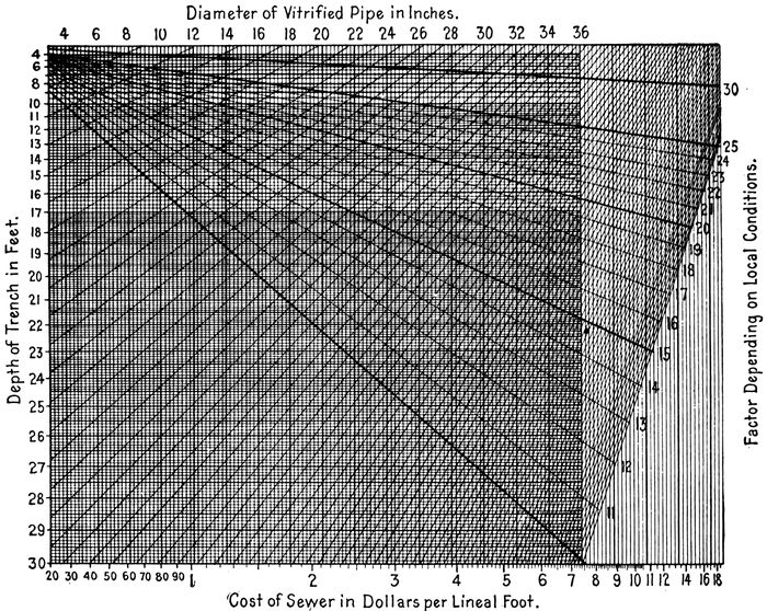
12A method for estimating the approximate cost of sewers,
devised by W. G. Kirchoffer[13] depends upon the use of the diagram
shown in Fig. 2. The factors for local conditions are shown in
Table 2. For example, let it be required to find the cost of a
15–inch vitrified pipe sewer at a depth of 9 feet, if the unit costs
of labor and material and the conditions are the same as shown
in Table 3.
Fig. 2.—Diagram for Estimating the Cost of Sewers.
Eng. News, Vol. 76, p. 781.
Solution
First: To find the factor depending on local conditions,
enter the diagram at the 10–inch diameter and
continue down until the intersection with the depth of
trench at 8.2 feet is found. Now go diagonally parallel
to lines running from left to right upwards to the intersection
13with the vertical line through a cost of 45 cents
per foot. The diagonal line running from left to right
downwards through this intersection corresponds to a
factor of about 11.
TABLE 2
Factors for Costs of Sewers to be Used with Figure 2
Character of Material
Factor
Clay, gravel and boulders, Medford
22–26
Mostly sand, deep trenches sheeted. Wages medium. Richland Center.
21–22
Sandy clay. Wages medium. Labor conditions good at Kiel.
15–20
Sand. Sandy clay, some water. Labor conditions good. Pipe prices medium at Manston.
14–20
Gravelly clay, ⅒th laid in concrete at Burlington.
13–22
Sandy clay, some water, sheeting at La Farge.
17–23
Sand with water.
20
Gravel and boulders. High wages.
26
Clay soil. Good digging.
17
Sandy clay. Some water.
23
Clay 2 miles inland. Laborers boarded at sanitarium, Wales
35
Clay, gravel and boulders at Plymouth.
20–27
Sand, clay and good digging at Lake Mills.
16–19
Red clay. Machine work at North Milwaukee.
20–24
Good digging. Wages medium at West Salem.
17–19
Sandy soil, bracing only required. No water. Wages and pipe medium.
14
Red sticky clay.
24
Good digging in any soil. Work scarce.
15
Red clay. No bracing.
20
Work inland from railroad. Boarding laborers and other expenses.
35
Second: To find the cost of 15–inch pipe at a depth of
9.0 feet, enter the diagram at a diameter of 15 inches
and continue down until the intersection with a depth of
trench at 9 feet is found. Now go diagonally parallel to
lines running from left to right upwards to the intersection
with the diagonal line running from left to right downwards
corresponding to the factor of 11 found above. The
vertical line passing through this point shows the cost to
be 67 cents per foot.
14
TABLE 3
Cost of Sewer Construction at Atlantic, Iowa
(From Gillette’s Handbook of Cost Data)
Material: Clay, not difficult to spade and requiring little or no bracing and practically no pumping. All hand work except backfill which was done by team and scraper. Depth of trench averaged 8.2 feet; width 30 inches. Diameter of pipe 10 inches.
Item
Wage, Cents per Hour
Cost, Cents per Foot.
Pipe.
0.20
Hauling team and driver.
30
.003
Hauling. Man helping.
17
.001
Cement and sand.
.006
Pipe layers.
22
.014
Pipe layer’s helper.
17
.014
Trenching. Top men.
17
.027
Trenching. Bottom men.
17
.130
Trenching. Scaffold men.
17
.002
Trenching. Bracing men.
17
.002
Backfilling. Shovel.
17
.010
Backfilling. Team and scraper.
30
.008
Backfilling. Man and scraper.
17
.005
Water boy.
10
.006
Foreman.
30
.022
Total.
.450
The construction of sewerage works may be paid for by the
issue of municipal bonds, by special assessment, by funds available
from the general taxes, or by private enterprise.
10. Bond Issues.—A municipal bond is a promise by the
municipality to pay the face value of the bond to the holder at a
certain specified time, with interest at a stipulated rate during
the interim. The security on the bond is the taxable property
in the municipality. The legal restrictions thrown around municipal
bond issues, the value of the taxable property in the municipality,
all of which may be used as security for municipal bonds,
and the fact that a municipality can be sued in case of default,
make municipal bonds desirable and provide a good market for
15their sale. The funds available from a municipal bond issue are
limited by the amount that the legal limit is in excess of the outstanding
issues. The legal limit varies in different states from
about 5 to 15 per cent of the assessed value of the property in
the municipality. In some cases the amount available from
municipal bonds has been increased by forming a municipality
within a municipality such as a sanitary district, a park district,
a drainage district, etc., which comprises a large portion or all
of an existing municipal corporation. This case is well illustrated
in some parts of the City of Chicago where the municipal taxing
powers are shared by the City government, the Sanitary District,
and Park Commissioners. The right to create a new municipal
corporation must be granted by the state legislature. Knowledge
of fixed bonds, serial bonds, life of bonds, sinking funds, etc. is an
important part of an engineer’s education.[14]
Bond issues must usually be presented to the voters for approval
at an election. If approved, and other legal procedure has been
followed, the bonds may be bought by some of the many bonding
houses, or by private individuals, and the money is immediately
available for construction. The bonds are redeemed by general
taxation spread over the period of the issue.
11. Special Assessment.—A special assessment is levied against
property benefited directly by the structure being paid for.
Special assessments are used for the payment for the construction
of lateral sewers which are a direct benefit to separate districts
but are without general benefit to the city. In case the construction
of an outfall sewer or the erection of a treatment plant,
which may be of some general benefit, is necessary to care for a
separate district, a part of the expense may be borne by funds
available from general taxation. The legal procedure for the
raising of funds by special assessment and the purpose to which
the funds so raised may be applied are stipulated in great detail
in different states and their directions must be followed implicitly.
Illinois procedure, which is similar to that in some other states,
is as follows: a meeting of the interested property owners is called
by a committee or board of the municipal government, as the
result of a petition by interested persons or through the independent
action of the Board. At this preliminary meeting or
16public hearing arguments for and against the proposed improvement
are heard. The engineer is present at this meeting to
answer questions and to advise concerning the engineering
features of the plan. If approval is given by the Board the plan
and specifications are prepared complete in every detail and
incorporated in an ordinance which is presented to the legislative
branch of the city government for passage. If the project is
adopted it is taken to the county court. An assessment roll is
prepared by a commissioner appointed by the court. This roll
shows the amount to be assessed against each piece of property
benefited. A hearing is then held in the county court at which
the owner of any assessed property may voice objections to the
continuation of the project. The project may be thrown out of
court for many different reasons, such as the misspelling of a street
name, an error in an elevation, an error in the description of a
pavement, but most important of all is definite proof that the
benefit is not equal to the assessment. The many minor irregularities
which may nullify the procedure in a special assessment
differ in different states and in different courts in the same state,
but in general no court can approve an assessment greater than
the benefits given. After the project has passed through the
county court and the assessment roll has been approved, bonds
may be issued for the payment of the contractor. Special assessment
bonds are liens against the property assessed and have not
the same security as a general municipal bond. For this reason
a city which has reached its legal limit of municipal bond issues
can still pay for work by special assessment.
The funds available from special assessments are limited only
by the benefit to the property assessed. The amount of the
benefit is difficult to fix and may lead to much controversy. It
should not exceed the amount demanded for similar work in other
localities, unless unusual and well-understood reasons can be
given.
12. General Taxation.—In paying for public improvements
by general taxation the money is taken from the general municipal
funds which have been apportioned for that purpose by the
legislative department of the municipal government. This
method of raising funds for sewerage construction is seldom used
unless the political situation is unfavorable to the success of a
bond issue or special assessment and the need for the improvement
17is great. It is usually difficult to appropriate sufficient funds for
new construction as the general tax is apportioned to support
only the operating expenses of the city, and statutory provisions
limit the amount of tax which can be levied.
13. Private Capital.—Private capital has been used for financing
sewerage works in some cases because of the aversion of the
public in some cities to the payment of a tax for the negative
service performed by a sewer. Sewers are buried, unseen, and
frequently forgotten, but knowledge of their necessity has spread
and the number of privately owned sewerage works is diminishing
because of the better service which can be provided by the municipality.
Franchises are granted to private companies for the construction
of sewers only after the city has exhausted other methods for
the raising of capital. The return on the private capital invested
is received from a rental paid by the city, or paid directly by the
users of the system, an initial payment usually being demanded
for connection to the system. To be successful the enterprise
must be popular and must fill a great need. This method of
financing sewerage works is seldom employed as favorable conditions
are not common.
14. Preparing for Design.—Methods for the design of sewerage
systems are given in Chapter V. Before the design is made
certain information is essential. A survey must be made from
which the preliminary map can be prepared as described in Art.
42. Other necessary information which is the basis of subsequent
estimates of the quantity of sewage to be cared for must be obtained
by a study of rates of water consumption and the density and
growth of population, the measurement of the discharge from
existing sewers, and the compilation of rainfall and run-off data.
If no rainfall data are available estimates must be made from
the nearest available data. Observations of rainfall or run-off
for periods of less than 10 to 20 years are likely to be misleading.
Methods for gathering and using this information are explained
in subsequent chapters.
Underground surveys are desirable along the lines of the
proposed sewers to learn of obstructions, difficult excavation
18and other conditions which may be met. All such data are seldom
gathered except for sewerage systems involving the expenditure
of a large amount of money. For construction in small towns
or small extensions to an existing system the funds are usually
insufficient for extensive preliminary investigation. The saving
in this respect is paid unknowingly to the contractor as compensation
for the risk in bidding without complete information.
15. Underground Surveys.—These may be more or less extensive
dependent on the character of the district in which construction
is to take place. In built-up districts the survey should be
more thorough than in sparsely settled districts where only the
character of the excavated material is of interest and no obstructions
are to be met.
Underground surveys furnish to the engineer and to prospective
bidders on contract work information on which the design
and estimate of cost and the contractor’s bid may be based and
without which no intelligent work can be done. By removing
much of the uncertainty of the conditions to be met in the construction
of the sewer, the design can be made more economical
and the contractor’s bid should be markedly lower, sufficiently
so to repay more than the expense of the survey. The information
to be obtained consists of the location of the ground-water level,
and the location and sizes of water, gas, and sewer pipes, telephone
and electric conduits, street-car tracks, steam pipes, and all
other structures which may in any way interfere with subsurface
construction. These structures should be located by reference
to some permanent point on the surface. The elevation of the
top of the pipes, except sewers, rather than the depth of cover
should be recorded, as the depth of cover is subject to change.
The elevation of sewers should be given to the invert rather than
to the top of the pipe.
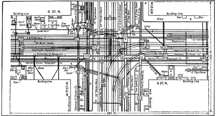
A portion of the map of the subsurface conditions at Washington,
D. C., is shown in Fig. 3. Many of the dimensions and
notations are not shown to avoid confusion on this small reproduction.[15]
Colors are generally used instead of different forms of
cross hatching to show the different classes of pipe and structures.
In addition to a record of the underground structures the character
of the ground and the pavement should be recorded. A
comprehensive underground survey is seldom available nor does
time usually permit its being made preliminary to the design of a
sewerage system. The character of the material through which
the sewer is to pass should be determined in all cases.
19
Fig. 3.—Record Map of Underground Structures, Washington, D. C.
Eng. Record, Vol. 74, p. 263.
The various subsurface lines are differentiated by colors as follows: A—Sewers, vermilion. B—Water mains, blue. C—Potomac Electric Power Co., carmine. D—Washington Railway and Electric Co., carmine. E—Capital Traction Co., violet. F—Chesapeake and Potomac Telephone Co., green. G—Washington Gas Light Co., green. H—Western Union Telegraph Co., orange. I—Postal Telegraph Co., orange. K—Private vaults, black. L—City Electric Co., yellow.
20
Fig. 4.
Punch Drill.
Underground pipes and structures are located by excavations,
which may be quite extensive in some cases. Their position is
fixed by measurements referred to manholes and other underground
structures which are somewhat permanent
in position. A city engineer should grasp every
opportunity to record underground structures when
excavations are made in the streets. The character
of the material through which the sewer is to pass is
determined by borings.
16. Borings.—Methods used for the investigation
of subsurface conditions preliminary to sewer construction
are: punch drilling, boring with earth
auger, jet boring, wash boring, percussion drilling,
abrasive drilling, and hydraulic drilling. The last
three methods named are used only for unusually
deep borings or in rock.
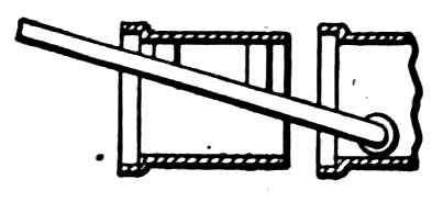
Punch drills are of two sorts. The simplest punch
drill consists of an iron rod ⅞ of an inch to 1 inch in
diameter, in sections about 4 feet long. One section
is sharpened at one end and threaded at the other
so that the next section can be screwed into it without
increasing the diameter of the rod, as shown in
Fig. 4. The drill is driven by a sledge striking upon
a piece of wood held at the top of the drill to prevent
injury to the threads. The drill should be turned as it is
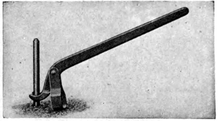
driven to prevent sticking. It is pulled out by a hook and lever as
shown in Fig. 5. It is useful in soft ground for soundings up to
8 to 12 feet in depth. Another form of punch drill described
by A. C. Veatch[16] consists of a cylinder of steel or iron, one
to two feet long split along one side and slightly spread. The
lower portion is very slightly expanded and tempered into a
cutting edge. In use it is attached to a rope or wooden poles
and lifted and dropped in the hole by means of a rope given a few
turns about a windlass or drum. By this process the material
is forced up into the bit, slightly springs it, and so is held. When
the bit is filled it is raised to the surface and emptied. Much
21deeper holes can be
made with this than
with the sharpened
solid rod.
Fig. 5.—Lever for Pulling Punch Drill.
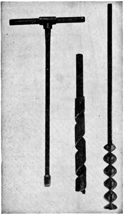
Fig. 6.—Earth Augers.
Types of earth
augers about 1½-inches
in diameter
are shown in Fig. 6.
They are screwed
on to the end of
a section of the
pipe or rod and as the hole is deepened successive lengths of pipe
or rod are added. The device is operated by two men. It is
pulled by straight lifting or with the assistance of a link and
lever similar to that shown
in Fig. 5. The device is
suitable for soft earth or
sand free from stones, and
can be used for holes 15
to 25 feet in depth. For
deeper holes a block and
tackle should be used for
lifting the auger from the
hole. It is not suitable
for holes deeper than about
35 feet.
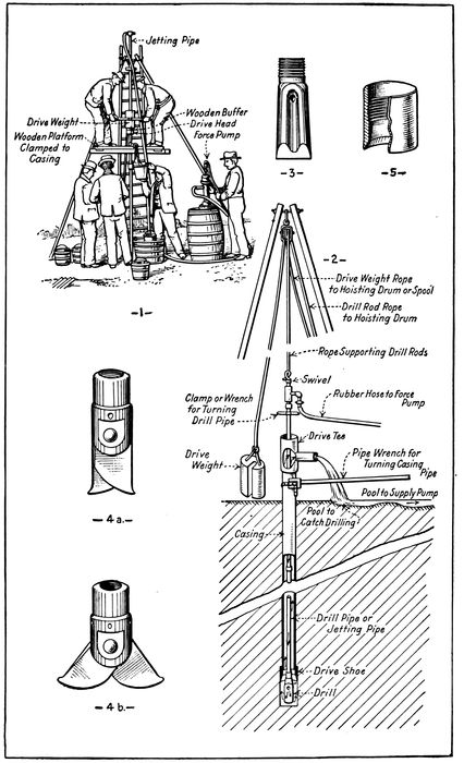
In the jetting method
water is led into the hole
through a ¾-inch or 1–inch
pipe, and forced downward
through the drill bit
or nozzle against the bottom
of the hole. The
complete equipment is
shown in Fig. 7.[17] It is
not always necessary to
case the hole as shown in
the figure as the muddy
water and the vibration
of the pipe puddle the sides so that they will stand alone. The
jet pipe may be churned in the hole by a rope passing over a block
and a revolving drum. In suitable soft materials such as clay,
sand, or gravel, holes can be bored to a depth of 100 feet and
samples collected of the material removed. An objection to the
method is the difficulty of obtaining sufficient water.
22
Fig. 7.—Jetting Outfit.
U. S. Geological Survey, Water Supply Paper, No. 257
1. Simple Jetting Outfit. 2. Jetting Process. 3. Common Jetting Drill. 4a and 4b. Expansion Bit or Paddy. 5. Drive Shoe.
23Methods of drilling in rock up to depths of 20 feet are described
in Chapter XI under Rock Drilling. For deeper holes percussion,
abrasive, or hydraulic methods as used for deep well drilling must
be employed.
CHAPTER III QUANTITY OF SEWAGE — Quantity of Storm Water
24
17. Dry weather Flow.—Estimates of the quantity of
sewage flow to be expected are ordinarily based on the
population, the character of the district, the rate of water consumption,
and the probable ground-water flow. Future conditions
are estimated and provided for, as the sewers should have
sufficient capacity to care for the sewage delivered to them during
their period of usefulness.
18. Methods for Predicting Population.—Methods for the
prediction of future population are given in the following paragraphs.
The method of graphical extension. This is the quickest and
most simple of all. In this method a curve is plotted on rectangular
coordinates to any convenient scale, with population as
ordinates and years as abscissas. The curve is extended into
the future by judgment of its general tendency. An example is
given of the determination of the population of Urbana, Illinois,
in 1950. Table 4 contains the population statistics which have
been plotted on line A in Fig. 8 and extended to 1950. The
probable population in 1950 is shown by this line to be about
21,000.
The method of geometrical progression. In this method the
rate of increase during the past few years or decades is assumed
to be constant and this rate is applied to the present population
to forecast the population in the future. For example the rate
of increase of population in Urbana for the past 7 decades has
varied widely, but indications are that for the next few decades
it will be about 20 per cent. Applying this rate from 1920 to
1950 the population in 1950 is shown to be about 17,800. It is
evident that this method may lead to serious error as insufficient
information is given in the table to make possible the selection of
the proper rate of increase.
25
TABLE 4
Population Studies
Year
Urbana, Illinois
Population of
Population
Absolute Increase for Each Decade
Per Cent Increase for Each Decade
Decatur
Danville
Champaign
Kankakee
Peoria
Bloomington
Ann, Arbor Michigan
1850
210
736
5,095
1,594
1860
2,038
1828
85.6
3,839
1,632
1,727
2,984
14,045
7,075
5,097
1870
2,277
239
10.5
7,161
4,751
4,625
5,189
22,849
14,590
7,368
1880
2,942
665
22.6
9,547
7,733
5,103
5,651
29,259
17,180
8,061
1890
3,511
569
16.2
16,841
11,491
5,839
9,025
41,024
20,484
9,431
1900
5,728
2217
38.7
20,754
16,354
9,098
13,595
56,100
23,286
14,509
1910
8,245
2517
30.5
31,140
27,871
12,421
13,986
66,950
25,786
14,817
1920
10,230
1985
19.4
43,818
33,750
15,873
16,721
76,121
28,638
19,516
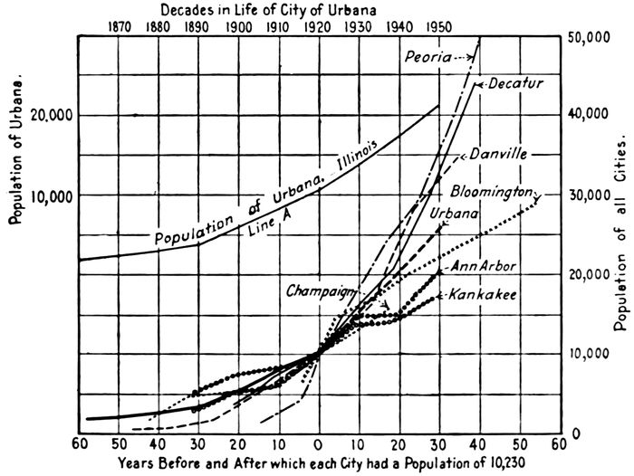
Fig. 8.—Diagram Showing Methods for Estimating Future Population.
26The method of utilizing a decreasing rate of increase. This
method attempts to correct the error in the assumption of a constant
rate of increase. After a certain period of growth, as the
age of a city increases its rate of increase diminishes. In applying
this knowledge to a prediction of the future population of a city
the population curve is plotted, as in the graphical method and a
straight line representing a constant rate or increase is drawn
tangent to the curve at its end. The curve is then extended at a
flatter rate in accordance with the rate of change of a similar
nearby larger city. This method has not been applied to any of
the cities included in Table 4, as none has reached that limiting
period where the rate of increase has begun to diminish.
The method of utilizing an arithmetical rate of increase. This
method allows for the error of the geometrical progression which
tends to give too large results for old and slow-growing cities.
This method generally gives results that are too low. The absolute
increase in the population during the past decade or other
period is assumed to continue throughout the period of prediction.
Applying this method to the same case, the increase in the population
during the past decade was 2,000. Adding three times this
amount to the population in 1920, the population of Urbana in
1950 will be about 16,000.
The method involving the graphical comparison with other
cities with similar characteristics. In this method population
curves of a number of cities larger than Urbana but having
similar characteristics, are plotted with years as abscissas and
population as ordinates, with the present population of Urbana
as the origin of coordinates. The population curve for Urbana
is first plotted. It will lie entirely in the third quadrant as shown
by the heavy full line in Fig. 8. The population curves of some
larger cities are then plotted in such a manner that each curve
passes through the origin at the time their population was the
same as that of the present population of Urbana. These curves
lie in the first and third quadrants. The population curve of the
city in question is then extended to conform with the curves of
older cities in the most probable manner as dictated by judgment.
Such a series of plots has been made in Fig. 8. The results indicate
that the population of Urbana in 1950 will be about 25,500.
The last method described will give the most probable result
as it is the most rational. For quick approximations the geometrical
27progression is used. The arithmetical progression is
useful only as an approximate estimate for old cities.
19. Extent of Prediction.—The period for which a sewerage
system should be designed is such that each generation bears its
share of the cost of the system. It is unfair to the present generation
to build and pay for an extensive system that will not be
utilized for 25 years. It is likewise unfair to the next generation to
construct a system sufficient to comply with present needs only,
and to postpone the payment for it by a long term bond issue.
An ideal solution would be to plan a system which would satisfy
present and future needs and to construct only those portions
which would be useful during the period of the bond issue.
Unfortunately this solution is not practical, because, 1st, it is less
expensive to construct portions of the system such as the outfall,
the treatment plant, etc., to care for conditions in advance of
present needs, and 2nd, the life of practically all portions of a
sewerage system is greater than the legal or customary time limit
on bond issues.
A compromise between the practical and the ideal is reached
by the design of a complete system to fulfill all probable demands,
and the construction of such portions as are needed now in accordance
with this plan. The payment should be made by bond
issues with as long life as is financially or legally practical, but
which should not exceed the life of the improvement.
The prediction of the population should therefore be made
such that a comprehensive system can be designed with intelligence.
Practice has seldom called for predictions more than 50
years in the future.
20. Sources of Information on Population.—The United
States decennial census furnishes the most complete information
on population. Unfortunately it becomes somewhat old towards
the end of a decade. More recent information can be obtained
from local sources. Practically every community takes an annual
school census the accuracy of which is fairly reliable. The general
tendencies of the population to change can be learned by a
study of the post office records showing the amount of mail matter
handled at various periods. Local chambers of commerce and
newspapers attempt to keep records of population, but they are
often inaccurate. Another source of information is the gross
receipts of public service companies, such as street railways, water,
28gas, electricity, telephone, etc. The population can be assumed
to have increased almost directly as their receipts, with proper
allowance for change in rates, character of management, and other
factors.
21. Density of Population.—So far the study of population
has been confined to the entire city. It is frequently necessary
to predict the population of a district or small section of a city.
A direct census may be taken, or more frequently its population
is determined by estimating its density based on a comparison
with similar districts of known density, and multiplying this
density by the area of the district. In determining the density,
statistics of the population of the entire city will be helpful but
are insufficient for such a problem. A special census of the area
involved would be conclusive but is generally considered too expensive.
A count of the number of buildings in the district can be
made quickly, and the density determined by approximating the
number of persons per building. Statistics of the population of
various districts together with a description of the character of
the district are given in Table 5.
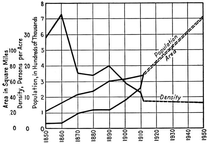
Fig. 9.—Density, Area, and Population, Cincinnati, Ohio. 1850 to 1950.
29
TABLE 5
Densities of Population
City
Character of District
Area, Acres
Density per Acre
Philadelphia
Thomas Run. Residential. Mostly pairs of two and three-story houses. 1204 acres settled.
1,840
59
Pine Street. Residential. Mostly solid four to six-story houses. 156 acres settled.
160
97
Shunk Street. Residential. Mostly pairs of two and three-story houses. 539 acres settled.
539
119
Lombard Street. Tenements and hotels, 145 acres settled.
147
113
York Street. Residential and manufacturing. 354 acres settled.
358
94
New York City
Residential. Three-story dwellings with 18–foot frontage, and four-story flats with 20–foot frontage.
100
Residential. Five-story flats.
520–670
Residential. Six-story flats.
800–1000
Residential. Six-story apartments. High class.
300
Chicago
1st Ward. Retail and commercial. The “Loop”.
1,440
20.5
2d Ward. Commercial and low-class residential solidly built up.
800
53.5
3d Ward. Low-class residential.
960
48.1
5th Ward. Industrial. Some low-class residences. Not solidly built up.
2,240
25.51
6th Ward. Residential. Four and five-story apartments. A few detached residences.
1,600
47.0
7th Ward. Same as Ward 6. Not solidly built up. Contains a large park.
4,160
21.7
8th Ward. Industrial. Sparsely settled.
13,624
4.8
9th Ward. Industrial and low-class residential. Solidly built up.
640
70.0
10th Ward. Same as Ward 9.
640
80.8
13th Ward. Low-class residential. Solidly built with three and four-story flats.
6,100
36.7
30
16th Ward. Middle-class residential. Some industries. Well built up.
800
81.5
19th Ward. Industrial and commercial. Some low-class residences.
640
90.7
20th Ward. Low-class residential. Some industries. Entirely built up.
800
77.1
21st Ward. Industrial. Entirely built up.
960
49.9
23d Ward. Industrial and residential.
800
55.4
24th Ward. Residential apartment houses and middle-class residences.
1,120
46.8
25th Ward. Residential. High-class apartments. Wealthy homes. Contains a large park.
4,160
24.0
26th Ward. Residential. Middle-class homes and apartments. Fairly well built up.
4,640
16.1
27th Ward. Residential. Sparsely settled.
20,480
5.5
29th Ward. Low-class residential. Two-story frame houses. “Back of the Yards”.
6,400
12.8
30th Ward. The Stock Yards.
1,280
40.1
32d Ward. Scattered residences.
8,480
8.3
33d Ward. Scattered residences.
12,944
5.5
35th Ward. Scattered residences.
4,960
12.0
General average
The most crowded conditions with five-story and higher, contiguous buildings in poor class districts.
750–1000
Five and six-story contiguous flat buildings.
500–750
Six-story high-class apartments.
300–500
Three and four-story dwellings, business blocks and industrial establishments. Closely built up.
100–300
Separate residences, 50 to 75–foot fronts, commercial districts, moderately well built up.
50–100
Sparsely settled districts and scattered frame dwellings for individual families.
0–50
31The density of population in Cincinnati from 1850 to 1913 with
predictions to 1950 is given in Fig. 9.[18] This shows the densities
for the entire city and is illustrative of the manner in which future
conditions were predicted for the design of an intercepting sewer.
The data given in Table 5 are of value in estimating the densities
of population in various districts. The Committee on City Plan
of the Board of Estimate and Apportionment of New York City
obtained some valuable information on this point, especially in
Manhattan. Three-story dwellings with 18–foot frontage, or four-story
flats with 20–foot frontage, presumably contiguous, were
found to hold 100 persons to the acre. Five-story flats held 520
to 670 persons per acre. Six-story flats held 800 to 1,000 persons
per acre, and high-class six-story apartments held less than 300
per acre.
22. Changes in Area.—In order to determine the probable
extent of a proposed sewerage system it is important to estimate
the changes in the area of a city as well as the changes in the
population. With the same population and an increased area
the quantity of sewage will be increased because of the larger
amount of ground water which will enter the sewers. Predictions
of the area of a city are less accurate than predictions of population
because the factors affecting changes cannot be so easily
predicted. An area curve plotted against time would be helpful
in guiding the judgment, but its extension into the future based
on past occurrences would be futile. A knowledge of the city,
its political tendencies, possibilities of extension, and other factors
must be weighed and judged. The engineer, if he is ignorant of
the city for which he is making provision, is dependent upon the
testimony of real estate men, business men and others acquainted
with the local situation.
23. Relation between Population and Sewage Flow.—The
amount of sewage discharged into a sewerage system is generally
equal to the amount of water supplied to a community, exclusive
of ground water. The entire public water supply does not reach
the sewers, but the losses due to leakage, lawn sprinkling, manufacturing
processes, etc., are made up by additions from private
water supplies, surface drainage, etc. The estimated quantity
of water used but which did not reach the sewers in Cincinnati
is shown in Table 6. The amount shown represents 38 per cent
of the total consumption. Unless direct observations have been
made on existing sewers or other factors are known which will
affect the relation between water supply and sewage, the average
sewage flow exclusive of ground water, should be taken as the
32average rate of water consumption. Experience has shown that
water consumption increases after the installation of sewers.
TABLE 6
Estimated Quantity of Water Used but not Discharged into the Sewers in Cincinnati
Expressed in gallons per capita per day, and based on a total consumption of 125 to 150 gallons per capita per day.
Steam railroads.
6 to 7
Street sprinklers.
6 to 7
Consumers not sewered.
9 to 10½
Manufacturing and mechanical.
6 to 7
Lawn sprinklers.
3 to 3½
Leakage.
18 to 21
The public water supply is generally installed before the sewerage
system. By collecting statistics on the rate of supply of
water a fair prediction can be made of the quantity of sewage
which must be cared for. The rate of water supply varies widely
in different cities. It is controlled by many factors such as meters,
cost and availability of water, quality of water, climate, population,
etc. In American cities a rough average of consumption is
100 gallons per capita per day. Other factors being equal the
rate of consumption after meters have been installed will be
about one-half the rate before the meters were installed. Low
cost, good quantity and good quality will increase the rate of
consumption, and the rate will increase slowly with increasing
population. Statistics of rates of water consumption are given
in Table 7.
24. Character of District.—The various sections of a city are
classified as commercial, industrial, or residential. The residential
districts can be subdivided into sparsely populated, moderately
populated, crowded, wealthy, poor, etc. Commercial districts
may be either retail stores, office buildings, or wholesale houses.
Industrial districts may be either large factories, foundries, etc.,
or they may be made up of small industries housed in loft buildings.
In cities of less than 30,000 population the refinement of such
subdivisions is generally unnecessary in the study of sewage flow,
all districts being considered the same. The data given in Tables
8 and 9 indicate the difference to be found in different districts of
33large cities. The Milwaukee data are presented in a form available
for estimates on different bases. These data are shown in
Table 10.
TABLE 7
Rates of Water Consumption
From Journals of American and New England Water Works Associations
City
Population in Thousands
Per Cent Metered
Consumption, Gal. per Capita per Day
Tacoma, Wash.
100
11.6
460
Buffalo, N. Y.
450
4.9
310
Cheyenne, Wyo.
13
270
Erie, Pa.
72
3.0
198
Philadelphia, Pa.
1611
4.6
180
St. Catherines, Ont.
17
3.2
160
Port Arthur, Ont.
18
14.7
145
Ogdensburg, N. Y.
18
0.2
140
Los Angeles, Cal.
516
77.9
140
Wilmington, Del.
92
43.7
125
Lancaster Pa.
60
34.6
120
Richmond, Va.
120
75.2
115
St. Louis, Mo.
730
6.7
110
Springfield, Mass.
100
94.4
110
Keokuk, Ia.
14
64.5
105
Jefferson City, Mo.
13.5
34.4
100
Muncie, Ind.
30
23.8
95
Burlington, Ia.
24
4.5
90
Council Bluffs, Ia.
32
75.5
80
San Diego, Cal.
85
100
80
Monroe, Wis.
3
100
80
Yazoo City, Miss.
7
84.1
75
Oak Park, Illinois.
26
100
70
Portsmouth, Va.
75
8.1
65
New Orleans, La.
360
99.7
60
Rockford, Ill.
53
93.0
55
Fort Dodge, Ia.
20
96.0
50
Manchester, Vt.
1.5
69.0
45
Woonsocket, R. I.
47.5
95.6
35
Attempts have been made to express the rate of sewage flow
in different units other than in gallons per capita per day. A unit
in terms of gallons per square foot of floor area tributary has been
suggested for commercial and industrial districts. It has not
been generally adopted. The rates of flow in New York City as
reported in this unit by W. S. McGrane are given in Table 11.
The most successful way to predict the flow from commercial
or industrial districts is to study the character of the district’s
activities and to base the prediction on the quantity of water
demanded by the commerce and industry of the district affected.
25. Fluctuations in Rate of Sewage Flow.—The rate of flow
of sewage from any district varies with the season of the year,
the day of the week, and the hour of the day. The maximum
and minimum rates of sewage flow are the controlling factors in
the design of sewers. The sewers must be of sufficient capacity
34to carry the maximum load which may be put upon them, and
they must be on such a grade that deposits will not occur during
periods of minimum flow. The maximum and minimum rates of
flow are usually expressed as percentages of the average rate of
flow.
TABLE 8
Sewage Flow from Different Classes of Districts
Arranged from data by Kenneth Allen in Municipal Engineer’s Journal, Feb., 1918.
District
Gallons per Capita per Day
Gallons per Acre per Day
Buffalo, N. Y. From Report of International Joint Commission on the Pollution of Boundary Waters:
Industrial: Metal and automobile plants. Maximum.
13,000
Industrial: Meat packing, chemical and soap.
16,000
Commercial: Hotels, stores and office buildings.
60,000
Domestic: Average.
80
Domestic: Apartment houses.
147
Domestic: First-class dwellings.
129
Domestic: Middle-class dwellings.
81
Domestic: Lowest-class dwellings.
35.5
Cincinnati, Ohio. 1913 Report on Sewerage Plan:
Industrial, in addition to residential and ground water.
9,000
Commercial, in addition to residential and ground water.
40,000
Domestic.
135
Detroit, Mich.:
Domestic.
228
Industrial, in addition to residential and ground water.
12,000
Commercial, in addition to residential and ground water.
50,000
Milwaukee, Wis. 1915 Report of Sewerage Commission:
Industrial, maximum.
81
16,600
Industrial, average.
31
8,300
Commercial, maximum.
60,500
Commercial, average.
37,400
Wholesale commercial, maximum.
20,000
Wholesale commercial, average.
9,650
35
TABLE 9
Observed Water Consumption in Different Classes of Districts in New York City
From data by Kenneth Allen in Municipal Engineers Journal, for 1918
Sewage Flow from Different Classes of Districts Based on 1915 Report of Milwaukee Sewerage Commission
Ratio of maximum to average rate for department store district.
1.755
Ratio of maximum to average rate for hotel district.
1.65
Ratio of maximum to average rate for office building district.
1.51
Ratio of maximum to average rate for wholesale commercial district.
2.1
Average and maximum gallons per thousand square feet of floor area:
Avg.
Max.
For department store district.
232
407
For office building district.
541
891
For wholesale commercial district.
164
344
For all districts except wholesale commercial.
381
618
Average and maximum gallons per day:
For all districts except wholesale commercial.
17,700
29,800
For wholesale commercial district.
9,650
20,000
36
TABLE 11
Rates of Consumption Predicted for Different Districts in New York City
District
Net Bldg. Area in Sq. Ft. per Acre for Ultimate Consumption
Avg. Number of Floors
Observed Cons. in g.p.d. per 1000 Sq. Ft. Max.
Observed Cons. in g.p.d. per 1000 Sq. Ft. Avg.
Predicted Mean Cons.
Predicted Mean in Million Gals. per Acre per Day
Predicted Dry Weather Flow, c.f.s. per Acre
Predicted Max. Dry Weather Flow, c.f.s. per Acre
Measured Avg. Dry Weather Flow, c.f.s. per Acre
Measured Max. Dry Weather Flow, c.f.s. per Acre
Hotel and midtown.
24,800
15
634
526
500
.20
.29
.34
1.04
.146
Midtown and financial.
24,800
15
338
219
300
.12
.18
.23
.078
.110
East and West of midtown.
24,800
10
297
230
300
.074
.12
.15
.057
.097
Apartment, 59th to 155th Sts.
20,400
7
230
300
.043
.06
.09
Manhattan north of 155th St.
20,400
5
230
300
.031
.05
.08
Midtown district consists of department stores, large railroad terminals, industrial and loft buildings, and sky-scraper office building.
It is difficult to set any definite figure for the percentage which
the maximum rate of flow is of the average. Fluctuations above
and below the average are greater the smaller the tributary
population. This relation can be expressed empirically as
M = 500 P⅕,
in which M represents the per cent which the maximum flow is
of the average, and P represents the tributary population in
thousands. The expression should not be used for populations
below 1,000 nor above 1,000,000. Having determined the expected
average flow of sewage by a study of the population, water consumption,
etc., the maximum quantity of sewage is determined
by multiplying the average flow by the per cent which the maximum
is of the average. In this connection W. G. Harmon[20] offers
the relation
M = 1 + 14 4 + √P,
which was used in the design of the Ten Mile Creek intercepting
sewer at Toledo, Ohio. For rough estimates and for comparative
purposes the ratio of the average to the minimum flow can be
37taken the same as the ratio of the maximum to the average flow,
unless direct gaugings or other information show it to be otherwise.
Fig. 10.—Daily and Hourly Variations of Sewage Flow.
1.
Toledo, O.; Manufacturing average.
2.
Toledo, O.; Manufacturing, Monday.
3.
Toledo, O.; Manufacturing, Sunday.
4.
Toledo, O.; Residential, average.
5.
Toledo, O.; Residential, Monday.
6.
Toledo, O.; Residential, Sunday.
7.
Cincinnati, O., Industrial, average.
8.
Cincinnati, O.; Residential, average.
9.
Cincinnati, O.; Commercial, average.
10.
Average of 7 cities.
The fluctuations of flow in commercial and industrial districts
are so different from those in residential districts that the formulas
given should not be used in the design of sewers other than those
draining residential areas. It is reasonable to suppose that
fluctuations in rates of flow from industrial districts are dependent
38upon the character of the tributary industries. A study of these
industries will give valuable light on the maximum and minimum
rates at which sewage will be delivered to the sewers.
Hourly, daily, and seasonal fluctuations in rates of sewage
flow are of interest in the design of pumping stations to give
knowledge of the rates at which the pumps must operate at
various periods. The fluctuations in rates of sewage flow during
various hours and days in different cities and districts are shown
in Fig. 10. Fluctuations in rate of flow of sewage lag behind
fluctuations in rate of water consumption, the time being dependent
on the distance through which the wave of change must
travel in the sewer.
26. Effect of Ground Water.—Sewers are seldom laid with
water-tight joints. Since they usually lie below the ground
water level it is inevitable that a certain amount of ground water
will enter. Various units have been suggested for the expression
of the inflow of ground water in an attempt to include all of the
many factors. Some of these units are: gallons per acre drained
by the sewer per day, gallons per mile of pipe per day, gallons per
inch diameter per mile of pipe per day, etc. Since the ground
water enters pipe sewers at the joints, the longer the joints the
greater the probability of the entrance of ground water. The
last unit is therefore the most logical but the accuracy of the
result is scarcely worthy of such refinement and the unit usually
adopted is gallons per mile of pipe per day.
No definite figure can be given for the amount of ground
water to be expected in sewers since the character of the soil and
the ground water pressure must be considered. Relatively
normal infiltration may be found from 5,000 to 80,000 gallons per
mile of pipe per day. The minimum is seldom reached in wet
ground and the maximum is frequently exceeded. Table 12
shows the amount of ground water measured in various sewers
as given by Brooks.[21]
27. Résumé of Method for Determination of Quantity of Dry weather
Sewage.—The steps in the determination of the quantity
of sewage are: determine the period in the future for which the
sewers are to be designed; estimate the population and tributary
area at the end of this period; estimate the rate of water consumption and assume the sewage flow to equal the water consumption;
determine the maximum and minimum rates of sewage flow;
and finally, estimate the maximum rate of ground water seepage
and add it to the maximum rate of sewage flow to give the total
quantity of sewage to be carried by the proposed sewers.
39
TABLE 12
Data on the Infiltration of Ground Water into Sewers
Abstracted from paper by J. N. Brooks in Transactions Am. Society of Civil Engineers, Vol. 76, p. 1909.
Place
Shape
Diameter or Dimensions in Inches
Material
Wet Trench, Per Cent of Total Length
Avg. Head of Ground Water, Fee
Character of Subgrade
Gallons per 24 Hours
Per Foot of Joint
Per Inch Diameter Per Mile of Pipe
Per Mile of Pipe
Boston, Mass.
Circ.
8 to 36
V.P.
2.6
1,818
40,000
East Orange, N. J.
10
Q.
22,400
East Orange, N. J.
8 to 24
V.P.
0.8
540
8,650
Joint trunk sewer, New Jersey
G. & Q.
25,000
Rogers Park, Ill.
6
0.3
207
1,240
Altoona, Pa.
30
5.0
2,890
86,592
Concord, Mass.
18
8
43,000
Malden, Mass.
Circ.
V.P.
60
50,000
Westboro, Mass.
15
V.P.
100
88,100
1,320,300
Fond du Lac, Wis.
Circ.
24
V.P.
100
5
C.
1.5
1,010
24,370
East Orange, N. J.
Circ.
10 to 24
V.P.
100
4.7
2,540
43,250
Ocean Grove, N. J.
Circ.
4 to 12
V.P.
100
3
S.C.
2.7
1,890
15,126
Ocean Grove, N. J.
Circ.
4 to 12
V.P.
100
4
S.C.
7.9
5,480
43,764
East Orange, N. J.
Rect.
24 × 36
Brick
100
570,000
Westboro, Mass.
Brick
415,850
Altoona, Pa.
Rect.
33 × 44
B. & C.
5,390
264,000
Columbus, Ohio.
H.S.
42 × 42
Concrete
120
6,340
Bronx Valley, N. Y.
Circ.
44 to 72
Concrete
G.
123
7,266
Cincinnati, Ohio.
Estimated in design. Data not from Brooks
67,500
Milwaukee, Wis.
Residential districts, gals. per acre per day. Not taken from Brooks
1460 to 2200
Abbreviations: H.S. = horseshoe shaped; B. & C = Brick and concrete; V.P. = vitrified pipe; G. = gravel; Q. = quicksand; S. C. = sand clay; C. = clay.
40
28. The Rational Method.—The water which falls during a
storm must be removed rapidly in order to prevent the flooding
of streets and basements, and other damages. The quantity of
water to be cared for is dependent upon: the rate of rainfall, the
character and slope of the surface, and the area to be drained.
All methods for the determination of storm-water run-off, whether
rational or empirical, depend upon these factors.
The so-called Rational Method can be expressed algebraically,
as,
Q = AIR,
in which Q =
rate of run-off in cubic feet per second;
A =
area to be drained expressed in acres;
I =
percentage imperviousness of the area;
R =
maximum average rate of rainfall over the entire drainage area, expressed in inches per
hour, which may occur during the time of concentration.
The area to be drained is determined by a survey. A discussion
of R and I follows in the next two sections. An example of the
use of the Rational Method is given on page 95.
29. Rate of Rainfall.—Rainfall observations have been made
over a long period of time by United States Weather Bureau
observers and others. Continuous records are available in a few
places in this country showing rainfall observations covering
more than a century. Such records have been the bases for a
number of empirical formulas for expressing the probable maximum
rate of rainfall in inches per hour, having given the duration of
the storm. Table 13 is a collection of these formulas with a
statement as to the conditions under which each formula is applicable.
The formula most suitable to the problem in hand should
be selected for its solution.[22]
41
TABLE 13
Rainfall Formulas
Name of Originator
Conditions for which Formula is Suitable
Formula
E. S. Dorr
i = 150 t + 30
A. N. Talbot
Maximum storms in Eastern United States
i = 360 t + 30
A. N. Talbot
Ordinary storms in Eastern United States
i = 105 t + 15
Emil Kuichling
Heavy rainfall near New York City
i = 120 t + 20, etc.
L. J. Le Conte
For San Francisco. See T. A. S. C. E. v. 54, p. 198
i = 7 t½
Sherman
Maximum for Boston, Mass.
i = 25.12 t.687
Sherman
Extraordinary for Boston, Mass.
i = 18 t½
Webster
Ordinary for Philadelphia, Pa.
i = 12 t0.6
Hendrick
Ordinary storms for Baltimore. Eng. & Cont., Aug. 9. 1911
i = 105 t + 10
J. de Bruyn-Kops
Ordinary storms for Savannah, Ga.
i = 163 t + 27
C. D. Hill
For Chicago, Ill.
i = 120 t + 15
Metcalf and Eddy
Louisville, Ky. Am. Sew. Prac., Vol I.
i = 14 t½
W. W. Horner
St. Louis, Mo. Eng. News, Sept. 29, 1910
i = 56 (t + 5).85
R. A. Brackenbuy
For Spokane, Wash. Eng. Record, Aug. 10, 1912
i = 23.92 t + 2.15 + 0.154
Metcalf and Eddy
New Orleans
i = 19 t½
Metcalf and Eddy
For Denver, Colo.
i = 84 t + 4
Kenneth Allen
Central Park, N. Y. 51–Year Record. Eng. News-Record, April 7, 1921, p. 588
30. Time of Concentration.—By the time of concentration is
meant the longest time without unreasonable delay that will be
required for a drop of water[24] to flow from the upper limit of a
drainage area to the outlet. Assuming a rainfall to start suddenly
42and to continue at a constant rate and to be evenly distributed
over a drainage area of 100 per cent imperviousness and
even slope towards one point, the rate of run-off would increase
constantly until the drop of water from the upper limit of the area
reached the outlet, after which the rate of run-off would remain
constant. In nature the rate of rainfall is not constant. The
shorter the duration of a storm the greater the intensity of rainfall.
Therefore the maximum run-off during a storm will occur
at the moment when the upper limit of the area has commenced
to contribute. From that time on the rate of run-off will decrease.
The time of concentration can be measured fairly well by
observing the moment of the commencement of a rainfall, and the
time of maximum run-off from an area on which the rain is falling.
A prediction of the time of concentration is more or less guess
work. As the result of measurements some engineers assume the
time of concentration on a city block built up with impervious
roofs and walks, and on a moderate slope, is about 5 to 10 minutes.
This is used as a basis for the judgment of the time of concentration
on other areas. For relatively large drainage areas such a
method cannot be used. The procedure is to measure the length
of flow through the drainage channels of the area, to assume the
velocity of the flood crest through these channels and thus to
determine the time of concentration. Table 14 shows the flood
crest velocities in various streams of the Ohio River Basin under
flood conditions. The velocity over the surface of the ground
may be approximated by the use of the formula[25]
V = 2,000I√S,
in which V =
the velocity of flow over the surface of the ground in feet per minute;
I =
the percentage imperviousness of the ground;
S =
the slope of the ground.
For areas up to 100 acres where natural drainage channels are not
existent this formula will give more satisfactory results than guesses
based on the time of concentration of certain known areas.
Having determined the time of concentration, the rate of rainfall
R to be used in the Rational Method is found by substitution
in some one of the rainfall formulas given in Table 13.
43
TABLE 14
Flood Crest Velocities in Ohio River Basin in March, 1913
From Table 12. U. S. G. S., Water Supply Paper. No. 334
River
Stations
Distance between Stations in Miles
Distance to Mouth of River, Miles
Distance of Lower Station below Starting-point, Miles
Velocity between Stations, Miles per Hour
Velocity from Pittsburgh, Miles per Hour
Time between Stations in Hours
Ohio
Pittsburgh, Pa., to Wheeling, W. Va.
90
967
90
9.0
9.0
10.0
Ohio
Wheeling, W. Va., to Marietta, Ohio
82
877
172
5.9
7.2
14
Ohio
Marietta, Ohio, to Parkersburg, W. Va.
12
795
184
0.9
4.8
14
Ohio
Parkersburg to Point Pleasant, W. Va.
80
783
264
6.7
5.3
12
Ohio
Point Pleasant to Huntington, W. Va.
44
703
308
11.0
5.7
4
Ohio
Huntington to Catlettsburg, W. Va.
9
659
317
0.8
4.1
11
Ohio
Catlettsburg, W. Va., to Portsmouth, Ohio
38
650
355
5.0
Ohio
Portsmouth Ohio, to Maysville, Ky.
52
612
407
5.2
5.0
10
Ohio
Maysville, Ky., to Cincinnati, Ohio
61
560
468
6.8
5.2
9
Ohio
Cincinnati, Ohio, to Louisville, Ky.
136
499
604
11.4
5.9
12
Ohio
Louisville, Ky., to Evansville, Ind.
183
363
787
1.9
5.3
96
Ohio
Evansville, Ind., to Mt. Vernon Ind.
36
180
823
9.0
5.3
4
Ohio
Mt. Vernon, Ind., to Paducah, Ky.
101
144
924
2.1
4.6
48
Ohio
Paducah, Ky. to Cairo, Ill.
43
43
967
2.9
4.2
15
Monongahela
Fairmont, W. Va., to Lock No. 2 Pa. (Upper)
107
119
107
6.7
16
Little Kanawha
Creston, W. Va., to Dam. No. 4 W. Va. (Upper)
16
48
16
16.0
1
New
Radford, W. Va., to Hinton, W. Va.
78
139
78
3.0
26
Kanawha
Kanawha Falls, W. Va. to Charleston, W. Va.
37
95
37
2.6
14
Scioto
Columbus, Ohio, to Chillicothe, Ohio
52
110
52
4.7
11
Miami
Dayton, Ohio, to Hamilton, Ohio
44
77
44
14.7
3
Kentucky
Highbridge, Ky., to Frankfort, Ky.
52
117
52
5.2
10
Cumberland
Celina, Tenn. to Nashville, Tenn.
190
383
190
2.9
64.5
Tennessee
Knoxville to Chattanooga, Tenn.
183
635
183
3.2
57
Note.—The velocities shown are the velocities of the crest of the flood wave and are not the average velocity of the flow of the river. The velocity of the crest of the flood wave should be used in determining the time of concentration. The flood crest velocity is slower then that of the river because of the storage in the river basin.
4431. Character of Surface.—The proportion of total rainfall
which will reach the sewers depends on the relative porosity, or
imperviousness, and the slope of the surface. Absolutely impervious
surfaces such as asphalt pavements or roofs of buildings will
give nearly 100 per cent run-off regardless of the slope, after the
surfaces have become thoroughly wet. For unpaved streets,
lawns, and gardens the steeper the slope the greater the per cent
of run-off. When the ground is already water soaked or is frozen
the per cent of run-off is high, and in the event of a warm rain on
snow covered or frozen ground, the run-off may be greater than the
rainfall. The run-off during the flood of March, 1913, at Columbus,
Ohio, was over 100 per cent of the rainfall. Table 15[26] shows the
relative imperviousness of various types of surfaces when dry
and on low slopes. The estimates for relative imperviousness
used in the design of the Cincinnati intercepter are given in
Table 16.
TABLE 15
Values of Relative Imperviousness
Roof surfaces assumed to be water-tight
0.70–
0.95
Asphalt pavements in good order
.85–
.90
Stone, brick, and wood-block pavements with tightly cemented joints
.75–
.85
The same with open or uncemented joints
.50–
.70
Inferior block pavements with open joints
.40–
.50
Macadamized roadways
.25–
.60
Gravel roadways and walks
.15–
.30
Unpaved surfaces, railroad yards, and vacant lots
.10–
.30
Parks, gardens, lawns, and meadows, depending on surface slope and character of subsoil
.05–
.25
Wooded areas or forest land, depending on surface slope and character of subsoil
.01–
.20
Most densely populated or built up portion of a city
.70–
.90
45
TABLE 16
Coefficients of Imperviousness Used in the Design of the Cincinnati Sewers
Character of Improvement
Typical Commercial Area, 30.4 A. None Undeveloped. Sand and Gravel
Combined Tenement and Industrial. 35.6 A., 55 per Acre. Clay, Sand and Gravel
Residential, 291.1 A. 20 per Acre, Middle Class, Detached Dwellings, Yellow and Blue Clay Overlying Beds of Shale and Sandstone
Area in 1000’s Square Feet
Per Cent Total Area
I, Estimated
Equivalent Imp. Area, 1000’s Square Feet
Area in 1000’s Square Feet
Per Cent Total Area
I, Estimated
Per Cent of Total Area
I, Estimated
Roofs:
Public and commercial
881.2
66.5
0.90
793.0
66.8
4.3
0.40
4.8
0.40
Residences
289.2
18.6
.90
13.1
.90
Barns and sheds
79.2
5.1
.75
1.4
.75
Interior Walks:
Brick
7.5
0.6
.40
3.0
35.6
2.3
.40
0.6
.40
Cement
10.0
0.7
.75
7.5
22.6
1.5
.75
2.6
.75
Street Walks:
Brick
6.1
0.5
.40
2.4
48.2
3.1
.40
1.0
.40
Cement
139.3
10.5
.75
104.5
78.1
5.0
.75
3.4
.75
Street Pavements:
Asphalt, brick, wood block
145.5
11.0
.85
123.7
5.0
.85
Granite block
111.4
8.4
.75
83.6
1.0
.75
Macadam and cobble
23.2
1.8
.40
9.3
238.6
15.4
.40
4.8
.40
Granite and poor macadam
0.4
.20
Unimproved yards and lawns:
692.4
44.7
.15
Tributary to paved gutters
57.1
.15
Not tributary to paved gutters
7.9
.10
Total
1324.2
100.0
1127.0
1550.7
100.0
100.0
Impervious coefficient for the district
85.1
44.4
35.9
46C. E. Gregory[27] states that I, in the expression Q = AIR is a
function of the time of concentration or the duration of the storm.
If t represents the time of concentration and T represents the
duration of the storm, then when T is less than t
I = 0.175t⅓,
but when T is greater than t,
I = 0.175 t(T4 3 − (T − t)4 3).
Gregory condenses Kuichling’s rules with regard to the per cent
run-off, as follows:
1. The per cent of rainfall discharged from any given
drainage area is nearly constant for heavy rains lasting
equal periods of time.
2. This per cent varies directly with the area of impervious
surface.
3. This per cent increases rapidly and directly or uniformly
with the duration of the maximum intensity of the
rainfall until a period is reached which is equal to the time
required for the concentration of the drainage waters from
the entire area at the point of observation, but if the rainfall
continues at the same intensity for a longer period this
per cent will continue to increase at a much smaller rate.
4. This per cent becomes larger when a moderate rain
has immediately preceded a heavy shower on a partially
permeable territory.
Gregory’s formulas have not been generally accepted and are
not widely used in practice. Marston stated:[28]
All that engineers are at present, warranted in doing is
to make some deduction from 100 per cent run-off ... the
deduction ... being at present left to the engineer in
view of his general knowledge and his familiarity with local
conditions.
In its application there will usually be as many results
(differing widely from each other) as the number of men
using it.
In spite of these objections the Rational Method is in more favor
with engineers than any other method.
32. Empirical Formulas.—The difficulty of determining run-off
with accuracy has led to the production by engineers of many
empirical formulas for their own use. Some of these formulas
have attracted wide attention and have been used extensively,
47in some cases under conditions to which they are not applicable.
In general these formulas are expressions for the run-off in terms
of the area drained, the relative imperviousness, the slope of the
land, and the rate of rainfall.
The Burkli-Ziegler formula, devised by a Swiss engineer for
Swiss conditions and introduced into the United States by Rudolph
Hering, was one of the earliest of the empirical formulas to attract
attention in this country. It has been used extensively in the
form
in whichQ =
the run-off in cubic feet per second;
i =
the maximum rate of rainfall in inches per hour over the entire area. This is determined
only by experience in the particular locality, and is usually taken at from 1 to 3 inches
per hour;
S =
the slope of the ground surface in feet per thousand,
A =
the area in acres;
C =
an expression for the character of the ground surface, or relative imperviousness. In
this form of the expression C is recommended as 0.7.
The McMath formula was developed for St. Louis conditions
and was first published in Transactions of the American Society
of Civil Engineers, Vol. 16, 1887, p. 183. Using the same notation
as above, the formula is,
McMath recommended the use of C equal to 0.75, i as 2.75 inches
per hour, and S equal to 15. The formula has been extended
for use with all values of C, i, S, and A ordinarily met in sewerage
practice. Fig. 11 is presented as an aid to the rapid solution of
the formula.
48
Fig. 11.—Diagram for the Solution of McMath’s Formula,
49Other formulas have been devised which are more applicable
to drainage areas of more than 1,000 acres.[30] Such areas are met
in the design of sewers to enclose existing stream channels draining
large areas. Kuichling’s formulas, published in 1901 in the
report of the New York State Barge Canal, were devised for areas
greater than 100 square miles. The following modification of
these formulas for ordinary storms on smaller areas was published
for the first time in American Sewerage Practice, Volume I, by
Metcalf and Eddy:
Q = 25,000 A + 125 + 15.
Fig. 12.—Comparison of Empirical Run-off Formulas.
It is to be noted that the only factor taken into consideration is
the area of the watershed. It is obvious that other factors such
as the rate of rainfall, slope, imperviousness, etc., will have a
marked effect on the run-off.
There are other run-off formulas devised for particular conditions,
some of which are of as general applicability as those
quoted. Two formulas which are frequently quoted are: Fanning’s,
Q = 200M⅝ and Talbot’s Q = 500M¼, in which M is the area
of the watershed in square miles. A comprehensive treatment
of the subject is given in American Sewerage Practice, Vol. I,
by Metcalf and Eddy.
A comparison of the results obtained by the application of a
few formulas to the same conditions is shown graphically in Fig.
12. It is to be noted that the divergence between the smallest
50and largest results is over 100 per cent. As these formulas are
not all applicable to the same conditions, the differences shown are
due partially to an extension of some of them beyond the limits
for which they were prepared.
33. Extent and Intensity of Storms.—In the design of storm
sewers it is necessary to decide how heavy a storm must be provided
for. The very heaviest storms occur infrequently. To
build a sewer capable of caring for all storms would involve a
prohibitive expense over the investment necessary to care for the
ordinary heavy storms encountered annually or once in a decade.
This extra investment would lie idle for a long period entailing a
considerable interest charge for which no return is easily seen.
The alternative is to construct only for such heavy storms as are
of ordinary occurrence and to allow the sewers to overflow on
exceptional occasions. The result will be a more frequent use of
the sewerage system to its capacity, a saving in the cost of the
system, and an occasional flooding of the district in excessive
storms. The amount of damage caused by inundations must be
balanced against the extra cost of a sewerage system to avoid the
damage. A municipality which does not provide adequate
storm drainage is liable, under certain circumstances, for damages
occasioned by this neglect. It is not liable if no drainage exists,
nor is it liable if the storm is of such unusual character as to be
classed legally as an act of God.
Kuichling’s studies of the probabilities of the occurrence of
heavy storms are published in Transactions of the American
Society of Civil Engineers, Vol. 54, 1905, p. 192. Information
on the extent of rain storms is given by Francis in Vol. 7, 1878,
p. 224, of the same publication. Kuichling expresses the intensity
of storms which will occur,
once in 10 years as i = 105 t + 20,
once in 15 years as i = 120 t + 20,
in which i is the intensity of rainfall in inches per hour and t is
the duration of the storm in minutes.
CHAPTER IV THE HYDRAULICS OF SEWERS
51
34. Principles.—The hydraulics of sewers deals with the
application of the laws of hydraulics to the flow of water through
conduits and open channels. In so far as its hydraulic properties
are concerned the characteristics of sewage are so similar to
those of water that the same physical laws are applicable to both.
In general it is assumed that the energy lost due to friction between
the liquid and the sides of the channel varies as some function of
the velocity, usually the square, and that the total energy passing
any section of the stream differs from the energy passing any
other section only by the loss of energy due to friction.
The general expression for the flow of sewage would then be,
h = (f)Vn,
in which h is the head or energy lost between any two sections,
and V is the average velocity of flow between these sections.
It is to be noted in this general expression that the quantity and
rate of flow past all sections is assumed to be constant. This
condition is known as steady flow. Problems are encountered
in sewerage design which involve conditions of unsteady flow,
and methods of solution of them have been developed based on
modifications of this general expression. The average velocity
of flow is computed by dividing the rate (quantity) of flow past
any section by the cross-sectional area of the stream at that
section. This does not represent the true velocity at any particular
point in the stream, as the velocity near the center is faster
than that near the sides of the channel. The distribution of
velocities in a closed circular channel is somewhat in the form of
a paraboloid superimposed on a cylinder.
The laws of flow are expressed as formulas the constants of
which have been determined by experiment. It has been found
that these constants depend on the character of the material
52forming the channel and the hydraulic radius. The hydraulic
radius is defined as the ratio of the cross-sectional area of the
stream to the length of the wetted perimeter, or line of contact
between the liquid and the channel, exclusive of the horizontal
line between the air and the liquid.
35. Formulas.—The loss of head due to friction caused by
flow through circular pipes flowing full as expressed by Darcy is,
h = fl dV2 2g,
in which h is the head lost due to friction in the distance l, V is
the velocity of flow, g is the acceleration due to gravity, and f is a
factor dependent on d and the material of which the pipe is made.
A formula for f expressed by Darcy as the result of experiments
on cast-iron pipe is,
f = 0.0199 + 0.00166 d,
in which d is the diameter in feet. In using the formula with
this factor the units used must be feet and seconds.
Another form of the same expression is known as the Chezy
formula. It is an algebraic transformation of the Darcy formula,
but in the form shown here, by the use of the hydraulic radius,
it is made applicable to any shape of conduit either full or partly
full. The Chezy formula is,
V = C√RS,
in which R is the hydraulic radius, S the slope ratio of the hydraulic
gradient, and C a factor similar to f in the Darcy formula.
Kutter’s formula was derived by the Swiss engineers, Ganguillet
and Kutter, as the result of a series of experimental observations.
It was introduced into the United States by Rudolph
Hering and its derivation is given in Hering and Trautwine’s
translation of “The Flow of Water in Open Channels by Ganguillet
and Kutter.” In English units it is,
53in which n is a factor expressing the character of the surface of
the conduit and the other notation is as in the Chezy formula.
V is the velocity in feet per second, S is the slope ratio, and R the
hydraulic radius in feet. The values of n to be used in all cases
are not agreed upon, but in general the values shown below are
used in practice.
Values ofnin Kutter’s Formula
n
Character of the Materials
0.009
Well-planed timber.
0.010
Neat cement or very smooth pipe.
0.012
Unplaned timber. Best concrete.
0.013
Smooth masonry or brickwork, or concrete sewers under ordinary conditions.
0.015
Vitrified pipe or ordinary brickwork.
0.017
Rubble masonry or rough brickwork.
0.020 0.035
}
Smooth earth.
0.030 0.050
}
Rough channels overgrown with grass.
Kutter’s formula is of general application to all classes of material
and to all shapes of conduits. It is the most generally used formula
in sewerage design.
The cumbersomeness of Kutter’s formula is caused somewhat
by the attempt to allow for the effect of the low slopes of the
Mississippi River experiments on the coefficients. The correctness
of these experiments has not been well established and the
slopes are so flat that the omission of the term 0.0028 S will have
no appreciable effect on the value of V ordinarily used in sewer
design. The difference between the value of V determined by
the omission of this term and the value of V found by including
it is less than 1 per cent for all slopes greater than 1 in 1,000
for 8 inch pipe (R = 0.167 feet). As the diameter of the pipe or
the hydraulic radius of the channel increases up to a diameter of
13.02 feet (R = 3.28 feet), the difference becomes less and at this
value of R there is no difference whether the slope is included or
not. For larger pipes the difference increases slowly. For a
16 foot pipe (R = 4 feet) on a slope of 1 in 1,000 the difference is
less than 0.2 per cent, and on a slope of 1 in 10,000 the difference
is approximately 1 per cent. Flatter slopes than these are
54seldom used in sewer design, except for very large sewers where
careful determinations of the hydraulic slope are necessary. It
is therefore safe in sewer design to use Kutter’s formula in the
modified form shown below in which the term .0028 S has been
omitted.
Bazin’s formula is
in which α and β are constants for different classes of material.
For cast-iron pipe α is 0.00007726 and β is 0.00000647. This
formula is seldom used in sewerage design.
Exponential formulas have been developed as the result of
experiments which have demonstrated that V does not vary
as the one-half power of R and S but that the relation should be
expressed as,
V = CRpSq,
in which p and q are constants and C is a factor dependent on
the character of the material. The various formulas coming
under this classification have been given the names of the experimenters
proposing them. Examples of these formulas are:
Flamant’s, in English units, for new cast-iron pipe, which is,
V = 232R.715S.572,
and Lampé’s for the same material which is,
V = 203.3R.694S.555.
These formulas are useful only for the material to which they
apply, but they can be used for conduits of any shape. A. V.
Saph and E. W. Schoder have shown[31] that the general formula
for all materials lies between the limits,
V = (93 to 142)S.50 to .55R.63 to .69.
55Hazen and Williams’ formula is in the form,
V = 1.31CR.63S.54,
in which C is a factor dependent on the character of the material
of the conduit. The values of C as given by Hazen and Williams
are,
C
Character of Material
95
Steel pipe under future conditions. (Riveted steel.)
100
Cast iron under ordinary future conditions and brick sewers in good condition.
110
New riveted steel, and cement pipe.
120
Smooth wood or masonry conduits under ordinary conditions.
130
Masonry conduits after some time and for very smooth pipes such as glass, brass, lead, etc., when old, and for new cast-iron pipe under ordinary conditions.
This formula is of as general application as Kutter’s formula and
is easier of solution, but being more recently in the field and
because of the ease of the solution of Kutter’s formula by diagrams
it is not in such general use. Exponential formulas are
used more in waterworks than in sewerage practice.
Manning’s formula is in the form,
V = 1.486 nR⅔S½
in which n is the same as for Kutter’s formula. Charts for the
solution of Manning’s formula are given in Eng. News-Record,
Vol. 85, 1920, p. 837.
36. Solution of Formulas.—The solution of even the simplest
of these formulas, such as Flamant’s, is laborious because of the
exponents involved. Darcy’s and Kutter’s formulas are even
more cumbersome because of the character of the coefficient.
The labor involved in the solution of these formulas has resulted
in the development of a number of diagrams and other short cuts.
Since each formula involves three or more variables it cannot be
represented by a single straight line on rectangular coordinate
paper. The simplest form of diagram for the solution of three
or more variables is the nomograph, an example of which is shown
56in Fig. 13 for the solution of Flamant’s formula. A straight-edge
placed on any two points of
the scales of two different vertical
lines will cross the other
line at a point on the scale corresponding
to its correct value
in the formula. Such a diagram
is in common use for the
solution of problems for the
flow of water in cast-iron
pipe.
Fig. 13.—Diagram for the Solution of Flamant’s Formula for the Flow of Water in Cast-iron Pipe.
Fig. 14 has been prepared
to simplify the solution of
Hazen and Williams’ formula.
The scales of slope for
different classes of material
are shown on vertical lines
to the left of the slope line.
For use these scales must be
projected horizontally on the
slope line. The scales for other factors are shown on independent
reference lines.
For example let it be required to find the loss of head in
a 12 inch pipe carrying 1 cubic foot per second when the
coefficient of roughness is 100. A straight-edge placed
at 1.0 cubic feet per second on the quantity scale, and 12
inches on the diameter scale crosses the slope line at .00092
opposite the slope scale for c = 100. It crosses the velocity
line at 1.31 feet per second.
Kutter’s formula is the most commonly used for sewer design
and has been generally accepted as a standard in spite of its
cumbersomeness. Fig. 15 is a graphical solution of Kutter’s
formula for small pipes, and Fig. 16 for larger pipes. The diagrams
are drawn on the nomographic principle and give solutions
for a wide range of materials, but they are specially prepared for
the solution of problems in which n = .015. In their preparation
the effect of the slope on the coefficient has been neglected. Fig.
17 is drawn on ordinary rectangular coordinate paper and can be
used only for the solution of problems in which n = .015. Both
diagrams are given for practice in the use of the different types.
57
Fig. 14.—Diagram for the Solution of Hazen and Williams’ Formula.
58
Fig. 15.—Diagram for the Solution of Kutter’s Formula.
For values of n between 0.010 and 0.020. Specially arranged for n = 0.015. Values of Q from 0.1 to 10 second-feet.
59
Fig. 16.—Diagram for the Solution of Kutter’s Formula.
For values of n between 0.010 and 0.020. Specially arranged for n = 0.015. Values of Q from 10 to 1,000 second-feet.
60
Fig. 17.—Diagram for the Solution of Kutter’s Formula.
61
Fig. 18.—Conversion Factors for Kutter’s Formula.
In Figs. 15 and 16 the diameter scales are varied for different
values of the roughness coefficient n. The velocity scale is shown
only for a value of n = .015.
The velocity for other values
of n can be determined by the
method given in the following
paragraphs.
37. Use of Diagrams.—There
are five factors in
Kutter’s formula: n, Q, V, d
(or R), and S. If any three of
these are given the other two
can be determined, except when
the three given are Q, V, and d.
These three are related in the
form Q = AV, which is independent
of slope or the character
of the material. There
are only nine different combinations
possible with these
five factors, which will be met
in the solution of Kutter’s formula. The solution of the
problems by means of the diagrams is simple when the data
given include n = .015. For other given values of n the solution
is more complicated. Results of the solution of types of
each of the nine problems are given in Table 17 and the
explanatory text below.
If n is given and is equal to .015, the solution is simple.
For example in Table 17 case 1, example 1; to be solved
on Fig. 15. Place a straight-edge at 1.0 on the Q line and
at 6 inches on the diameter line for n = .015. The slope
and the velocity will be found at the intersection of the
straight-edge with these respective scales.
All problems in which n is given as .015 and the solution for which
falls within the limits of Fig. 15 or 16 should be solved by placing
a straight-edge on the two known scales and reading the two
unknown results at the intersection of the straight-edge and the
remaining scales.
For example in case 1, example 2 find the intersection
of the horizontal line representing Q = 100 with the sloping
62diameter line representing d = 48 inches. The vertical
slope line passing through this point represents S = .0065
and the sloping velocity line passing through this point
represents 8.5 feet per second.
In general problems in which n = .015, can be solved on Fig. 17
by finding the intersection of the two lines representing the given
data, and reading the values of the remaining variables represented
by the other two lines passing through this point.
TABLE 17
Solutions of Problems by Kutter’s Formula
Case
Example
Given
Found
n
Q
V
d
S
n
Q
V
d
S
1
1
0.015
1.0
2.5
6
5.0
0.0575
1
2
.015
100.0
8.5
.0065
1
3
.020
1.0
6
5.0
.13
1
4
.020
100.0
48
8.5
.0125
2
1
.015
5.0
0.0003
1.2
28
2
2
.010
5.0
.0003
1.7
23.5
3
1
.015
18
.002
4.0
2.25
3
2
.018
18
.0008
2.0
1.1
4
1
.015
2.0
2.5
12
.00475
4
2
.011
2.0
2.5
12
.0022
5
1
.015
5.0
36
35.0
.0038
6
1
.018
5.0
.001
185.0
80
7
1
3.0
18
.002
0.019
1.7
7
2
50.0
36
.005
.012
7.0
8
1
6.0
2.5
.003
.018
21
9
1
4.2
66
.00059
.011
100.0
If n is given and is not equal to .015 the solution is not so simple.
In Fig. 15 and 16 the diagram is so drawn that the position of
the diameter scales for all values of n is fixed on the vertical
“diameter” line. The scales of diameter change for each value
of n. These scales of diameter are shown for each value of n
from .010 to .020 on vertical lines to the left of the “diameter”
line. For use, the proper diameter scale for any given value of n
must be projected horizontally upon the vertical “diameter”
line. The velocity can be determined on Fig. 15 and 16, only
63when the diameter has been determined and then only when the
diameter scale for n equal .015 is used, since the only scale shown
for velocity is for n = .015.
For example, in Case 1, Example 3 there are given
n = .020, Q, and d. Find the intersection of the vertical
line for n = .020 with the sloping diameter line for d = 6
inches. Project the intersection horizontally to the right
to the vertical “diameter” line. Place a straight-edge at
this point and at Q = 1.0 on the quantity scale. The
required value of S is read at the intersection of the straight-edge
and the slope scale and is equal to 0.13. The intersection
of the straight-edge in this position with the velocity
scale is not the required value of the velocity since the
velocity scale is made out for n = .015 and not .020. It is
necessary to change the position of the straight-edge so that
it may lie on Q equal 1.0 and on d equal 6 inches for n
equal .015. The value of V is shown in this position as 5
feet per second.
The reverse process for Fig. 15 and 16 is illustrated
by Case 4, Example 2 in which n = .011 and Q and V are also
given. When Q and V are given the value of d is fixed
independent of all other factors. Therefore the value of d
can be read from the scale with n = .015 and is found to be
12 inches. Now find the value of d = 12 inches on the scale
for n = .011 and project on to the “diameter” line. Place
the straight-edge at this point and at Q = 2. The required
slope is read as .0022.
Fig. 17 is prepared for the solution of problems in which
n = .015 only. For problems in which n has some other value it
is necessary to transform the data to equivalent conditions in
which n = .015. This is done by means of the conversion factors
shown in Fig. 18. The given slope or velocity is multiplied by
the proper factor to convert from or to the value of n = .015.
For example in Case 1, Example 4 there are given
n = .020, Q, and d. With Q and d given the value of V can
be read from Fig. 17 without conversion. The corresponding
value of S for n = .015 is .0065. It is now necessary to
use the transformation diagram Fig. 18. The hydraulic
radius of the given pipe is one foot. On Fig. 18 at the intersection
of the slope line for R = 1.0 foot and n = .020 the
value of the factor is read as 1.92. Since the given n is
for rougher material than that represented by n = .015 the
required slope must be greater than for n = .015 to give the
64same velocity. It is therefore necessary to multiply
.0065 × 1.92 and the required slope is .0125.
In Case 6, Example 1 there are given n = .018, d, and S.
The remaining factors are to be solved by Fig. 17. Solve
first as though n = .015 in order to find an approximate
value of d or R. In this case it is evident that d is greater
than 57 inches. The value of R is therefore about 1.25.
Referring to Fig. 18 the conversion factor for the slope for
n = .018 is about 1.52. Since the given slope for n = .018
is .001, for an equal velocity and for n = .015 the slope
should be less. Therefore in reading Fig. 17 it is necessary
to use a slope of .001 1.52 = .00066. The diameter is found to
be about 80 inches. Since this is nearer to the correct
diameter the value of the conversion factor must be corrected
for this approximation. The hydraulic radius for an
80 inch pipe is 1.67 feet, and the conversion factor from
Fig. 18 is about 1.48. The slope for n = .015 should be
therefore .001 1.48 = .000675 and from Fig. 17 the required
diameter and quantity are read as 80 inches and 185 second-feet, respectively.
If n is not given but must be solved for, the solution on Fig.
15 and 16 is relatively simple. The desired value of n is read at
the intersection of the sloping diameter line representing the
known diameter and the horizontal projection of the intersection
of the straight-edge with the vertical “diameter” line.
For example in Case 7, Example 1 there are given Q,
d, and S. Lay the straight-edge on the given values of
Q = 3 and S = .002. At the point where the straight-edge
crosses the vertical “diameter” line project a horizontal
line to the sloping diameter line for d = 18 inches. The
vertical line passing through this point represents a value of
n = .019. In order to find the value of V lay the straight-edge
on Q = 3 and d = 18 inches for n = .015. The value of
V is read as 1.7.
A slightly different condition is illustrated in the solution
of Case 8, Example 1 in which Q, V and S are given.
Determine first the value of d as though n = .015. Then
proceed to determine n as in the preceding examples.
The solution for an unknown value of n on Fig. 17 is not so
simple. It must be determined by working backwards from the
conversion factor.
65For example in Case 7, Example 2 there are given Q,
d, and S. The value of V is read directly as though n = .015
as 7 feet per second. The value of S read for n = .015
is .0075. But the given slope is .005. Since the given
slope is flatter than that for n = .015 the conversion factor
is less than unity and is therefore .005 .0075 = 0.67. With this
value of the conversion factor and the value of R given as
0.75 the value of n is read from Fig. 18 as slightly greater
than .012.
38. Flow in Circular Pipes Partly Full.—The preceding
examples have involved the flow in circular pipes completely
filled. The same methods of solution can be used for pipes
flowing partly full except that the hydraulic radius of the wetted
section is used instead of the diameter of the pipe. Diagrams
are used to save labor in finding the hydraulic radius and the
other hydraulic elements of conduits flowing partly full.
The hydraulic elements of a conduit for any depth of flow are:
(a) The hydraulic radius, (b) the area, (c) the velocity of flow,
and (d) the quantity or rate of discharge. The velocity and
quantity when partly full as expressed in terms of the velocity
and quantity when full as calculated by Kutter’s formula will
vary slightly with different diameters, slopes and coefficients of
roughness. The other elements are constant for all conditions
for the same type of cross-section. The hydraulic elements for
all depths of a circular section for two different diameters and
slopes are shown in Fig. 19. The differences between the
velocity and quantity under the different conditions are shown
to be slight, and in practice allowance is seldom made for this
discrepancy.
In the solution of a problem involving part full flow in a circular
conduit the method followed is to solve the problem as
though it were for full flow conditions and then to convert to
partial flow conditions by means of Fig. 19, or to convert from
partial flow conditions to full flow conditions and solve as in the
preceding section.
For example let it be required to determine the quantity
of flow in a 12–inch diameter pipe with n = .015 when on a
slope of .005 and the depth of flow is 3 inches. First find
the quantity for full flow. From Fig. 15 this is 2.0 cubic
feet per second. The depth of flow of 3 inches is one-fourth
66or 0.25 of the full depth of 12 inches. From Fig. 19, running
horizontally on the 0.25 depth line to meet the quantity
curve, the proportionate quantity at this depth is found to
be on the 0.13 vertical line, and the quantity of flow is
therefore 2 × 0.13 = 0.26 cubic feet per second.
Fig. 19.—Hydraulic Elements of Circular Sections.
d = 12′ 0″
s = .0004
n = .015
d = 1′ 0″
s = .01
n = .013
Another problem, involving the reversal of this process is
illustrated by the following example:
Let it be required to determine the diameter and full
capacity of a vitrified pipe sewer on a grade of 0.002 if the
velocity of flow is 3.0 feet per second when the sewer is
discharging at 30 per cent of its full capacity, the depth of
flow being 12 inches. From Fig. 19 the depth of flow when
the sewer is carrying 30 per cent of its full capacity is 0.38
of its full depth. Since the partial depth is 12 inches
the full diameter is 12 .038 = 31.6 inches. The velocity of
flow at 38 per cent depth is 86 per cent of the full velocity.
Since the velocity given is 3.0 feet per second, the full
velocity is 3.0 .86 = 3.5 feet per second. With a full velocity
of 3.5 feet per second and a diameter of 31.6 inches
from Fig. 16 the full capacity of the sewer is 18 cubic feet
per second.
6739. Sections Other than Circular.—The ordinary shape used
for small sewers is circular. The difficulty of constructing large
sewers in a circular shape, special conditions of construction such
as small head room, soft foundations, etc., or widely fluctuating
conditions of flow have led to the development of other shapes.
For conduits flowing full at all times a circular section will carry
more water with the same loss of head than any other section
under the same conditions. In any section the smaller the flow
the slower the velocity, an undesirable condition. The ideal
section for fluctuating flows would be one that would give the
same velocity of flow for all quantities. Such a section is yet to
be developed. Sections have been developed that will give relatively
higher velocities for small quantities of flow than are given
by a circular section. The best known of these sections is the
egg shape, the proportions and hydraulic elements of which are
shown in Fig. 20. Other shapes that have the same property,
but which were not developed for the same purpose are the rectangular,
the U-shape, and the section with a cunette. The egg-shaped
section has been more widely used than any other special
section. It is, however, more difficult and expensive to build
under certain conditions, and has a smaller capacity when full
than a circular sewer of the same area of cross-section. Various
sections are illustrated in Fig. 22 and 23.
The U-shaped section is suitable where the cover is small, or
close under obstructions where a flat top is desirable and the
fluctuations of flow are so great as to make advantageous a special
shape to increase the velocity of low flows. The proportions of a
U-shaped section are shown in Fig. 23 (6). Other sections used
for the same purpose are the semicircular and special forms of
the rectangular section.
The proportions and the hydraulic elements of the square-shaped
section are shown in Fig. 21. This is useful under low
heads where a flat roof is required to carry heavy loads, and the
fluctuations of flow are not large.
Sections with cunettes have not been standardized. A cunette
is a small channel in the bottom of a sewer to concentrate the low
flows, as shown in Fig. 22 (7). A cunette can be used in any
shape of sewer.
68
Fig. 20.—Hydraulic Elements of an Egg-shaped Section.
d = 6′ 0″ s = .00065 n = .015
Fig. 21.—Hydraulic Elements of a Square Section.
d = 10′ 0″ s = .0004 n = .015
69Sections developed mainly because of the greater ease of construction
under certain conditions are the basket handle, the gothic,
the catenary, and the horse shoe. Some of these shapes are shown
in Fig. 22 and 23. They are suitable for large sewers on soft
foundations, where it is desirable to build the sewer in three
portions, such as invert, side walls, and arch. They are also
suitable for construction in tunnels where the shape of the sewer
conforms to the shape of the timbering, or in open cut work where
the shape of the forms are easier to support.
Problems of flow in all sections can be solved by determining
the hydraulic radius involved, and substituting directly in the
desired formula, or by the use of one of the diagrams after converting
to the equivalent circular diameter. The determination
of the hydraulic radius of these special sections is laborious,
and hence other less difficult methods are followed. Problems
are more commonly solved by converting the given data into an
equivalent circular sewer, solving for the elements of this circular
sewer and then reconverting into the original terms, or by
working in the other direction. The hydraulic elements of various
sections when full are given in Table 18.
TABLE 18
Hydraulic Elements of Sewer Sections. Sewers Flowing Full.
Section
Area in Terms Vertical Diameter Squared D2
Hydraulic Radius in terms of Vertical Dia. D
Vert. Dia. D in Terms of Dia. d of Equivalent Circular Section
Source
Circular
0.7854
0.250
1.000
Egg
0.5150
.1931
1.295
Eng. Record, Vol. 72: 608
Ovoid
0.5650
.2070
1.208
Eng. Record, Vol. 72: 608
Semi-elliptical
0.8176
.2487
1.041
Eng. News, Vol. 71: 552
Catenary
0.6625
.2237
1.1175
Eng. Record, Vol. 72: 608
Horseshoe
0.8472
.2536
0.985
Eng. Record, Vol. 72: 608
Basket handle
0.8313
.2553
0.979
Eng. Record, Vol. 72: 608
Rectangular
1.3125
.2865
0.7968
Hydraulic Dgms. and Tbls. Garrett
Square (3 sides wet)
1.0000
.333
0.7500
Eng. Record, Vol. 72: 608
Square (4 sides wet)
1.0000
.250
1.0000
Eng. Record, Vol. 72: 608
70
1. Standard Egg-shaped Section, North Shore Intercepter, Chicago, Illinois.
5. Reinforced Concrete Sewer, Harlem Creek, St. Louis, Eng. News, Vol. 60, p. 131.
6. U-Shaped Section, San Francisco, Eng. News, Vol. 73, p. 310.
Fig. 23.
72Equivalent sections are sections of the same capacity for the
same slope and coefficient of roughness. They have not necessarily
the same dimensions, shape, nor area. The diameter of
the equivalent circular section in terms of the diameter of each
special section shown is given in Table 18. The inside height of
a sewer is spoken of as its diameter.
For example let it be required to determine the rate of
flow in a 54–inch egg-shaped sewer on a slope of 0.001 when
n = .015. First convert to the equivalent circle. From
Table 18 the diameter of the equivalent circle is 1 1.295 times
the diameter of the egg-shaped sewer, which becomes in
this case 43 inches. From Fig. 16 the capacity of a circular
sewer of this diameter with S = 0.001 and n = .015 is 28
cubic feet per second, which by definition is the flow in the
egg-shaped sewer.
As an example of the reverse process let it be required
to find the velocity of flow in an egg-shaped sewer flowing
full and equivalent to a 48–inch circular sewer. Both sewers
are on a slope of 0.005 and have a roughness coefficient of
n = .015. It is first necessary to find the quantity of flow
in the circular sewer, which by definition is the quantity of
flow in the equivalent egg-shaped sewer. The velocity of
flow in the egg-shaped sewer is found by dividing this
quantity by the area of the egg-shaped section. As read
from the diagram the quantity of flow is 90 cubic feet per
second. From Table 18 the area of the egg-shaped sewer is
0.51D2 where D is the diameter of the egg-shaped sewer, and
D = 1.295d where d is the diameter of the equivalent circular
sewer. Therefore the area equals (0.51) × (1.295 × 4)2
= 13.5 square feet and the velocity of flow is 90 13.5 = 6.7
feet per second. This is slightly less than the velocity
in the circular section.
Some lines for egg-shaped sewers have been shown on Fig. 17
by which solutions can be made directly. For other shapes, and
for sizes of egg-shaped sewers not found on Fig. 17 the preceding
method or the original formula must be used for solution. Problems
in partial flow in special sections are solved similarly to
partial flow in circular sections, by converting first to the conditions
of full flow or by working in the opposite direction.
40. Non-uniform Flow.—In the preceding articles it is assumed
that the mean velocity and the rate of flow past all sections are
73constant. This condition is known as steady, uniform flow. In
this article it will be assumed that conditions of steady non-uniform
flow exist, that is, the rate of flow past all sections is
constant, but the velocity of flow past these sections is different
for different sections. Under such conditions the surface of the
stream is not parallel to the invert of the channel. If the velocity
of flow is increasing down stream the surface curve is known as
the drop-down curve. If the velocity of flow is decreasing down
stream the surface curve is known as the backwater curve. The
hydraulic jump represents a condition of non-uniform flow in
which the velocity of flow decreases down stream in such a manner
that the surface of the stream stands normal to the invert of the
channel at the point where the change in velocity occurs. Above
and below this point conditions of uniform flow may exist.
Conditions of non-uniform flow exist at the outlet of all sewers,
except under the unusual conditions where the depth of flow in
the sewer under conditions of steady, uniform flow with the given
rate of discharge would raise the surface of water in the sewer, at
the point of discharge, to the same elevation as the surface of the
body of water into which discharge is taking place. By an application
of the principles of non-uniform flow to the design of outfall
sewers, smaller sewers, steeper grades, greater depth of cover,
and other advantages can be obtained.
The backwater curve is caused by an obstruction in the sewer,
by a flattening of the slope of the invert, or by allowing the sewer
to discharge into a body of water whose surface elevation would
be above the surface of the water in the sewer, at the point of
discharge, under conditions of steady, uniform flow with the given
rate of discharge.
The drop-down curve is caused by a sudden steepening of the
slope of the invert; by allowing a free discharge; or by allowing a
discharge into a body of water whose surface elevation would be
below the surface of the water in the sewer, at the point of discharge,
under conditions of steady, uniform flow with the given
rate of discharge. The last described condition is common at
the outlet of many sewers, hence the common occurrence of the
drop-down curve.
The hydraulic jump is a phenomenon which is seldom considered
in sewer design. If not guarded against it may cause trouble
at overflow weirs and at other control devices, in grit chambers,
74and at unexpected places. The causes of the hydraulic jump
are sufficiently well understood to permit designs that will avoid
its occurrence, but if it is allowed to occur the exact place of the
occurrence of the jump and its height are difficult, if not impossible,
to determine under the present state of knowledge concerning
them. The hydraulic jump will occur when a high velocity
of flow is interrupted by an obstruction in the channel, by a
change in grade of the invert, or the approach of the velocity to
the “critical” velocity. The “critical” velocity is equal to
√(gh), where h is the depth of flow and g is the acceleration due to
gravity. The velocity in the channel above the jump must be
greater than √(gh1), where h1 is the depth of flow in the channel
above the jump. The velocity in the channel below the jump
must be greater than √(gh2), where h2 is the depth of flow below
the jump. The jump will not take place unless the slope of the
invert of the channel is greater than g C2,in which C is the coefficient
in the Chezy formula. With this information it is possible
to avoid the jump by slowing down the velocity by the installation
of drop manholes, flight sewers, or by other expedients.
The shape of the drop-down curve can be expressed, in some
cases, by mathematical formulas of more or less simplicity,
dependent on the shape of the conduit. The formula for a circular
conduit is complicated. Due to the assumptions which must be
made in the deduction of these formulas, the results obtained by
their use are of no greater value than those obtained by approximate
methods. A method for the determination of the drop-down
curve is given by C. D. Hill.[32] In this method it is necessary
that the rate of flow past all sections shall be the same; that the
depth of submergence at the outlet shall be known; and that the
depth of flow at some unknown distance up the stream shall be
assumed. The shape and material of construction of the sewer
and the slope of the invert should also be known. The problem is
then to determine the distance between cross-sections, one where
the depth of flow is known, and the other where the depth of flow
has been assumed. This distance can be expressed as follows:
L = (d2 − d1) − (H1 − H2) S − S1 = d′ − H′ S′,
in which L =75
the distance between cross-sections;
d1 =
the depth of flow at the lower section;
d2 =
the depth of flow at the upper section;
H1 =
the velocity head at the lower section;
H2 =
the velocity head at the upper section;
S =
the hydraulic slope of the stream surface;
S1 =
the slope of the invert of the sewer.
In order to solve such problems with a satisfactory degree of
accuracy the difference between d1 and d2 should be taken sufficiently
small to divide the entire length of the sewer to be investigated
into a large number of sections. The solution of the problem
requires the determination of the wetted area, the hydraulic
radius, and other hydraulic elements at many sections. The
labor involved can be simplified by the use of diagrams, such as
Fig. 19, or by specially prepared diagrams such as those accompanying
the original article by C. D. Hill. The solution of the
problem can be simplified by tabulating the computations as
follows:
Drop-down Curve Computation Sheet
Uniform discharge. Varying depth
D = Q = A = V = Q A = S1 = L = d1 − H1) S1
1
2
3
4
5
6
7
8
9
10
11
12
13
Depth
R
H
H1
d1 − H1
V
S
S1
L
Elevation
D
d
d1
Sewer
W. L.
At the head of the computation sheet should be recorded the
diameter of the sewer in feet, the assumed volume of flow, the
area of the full cross-section of the sewer, the velocity of the
assumed volume flowing through the full bore of the sewer, and
the gradient or slope of the invert. In the 1st column enter the
76assumed depth in decimal parts of the diameter for each cross-section;
in the 2nd column enter the same depth in feet; in the
3rd column enter the difference in feet between the successive
cross-sections; in the 4th column enter the hydraulic radius
corresponding to the depth at each cross-section; in the 8th column
enter the velocity, equal to the volume divided by the wetted
area, for each cross-section; in the 5th column enter the corresponding
velocity head; in the 6th column enter the difference
between the velocity heads at successive cross-sections; in the
7th column enter the difference between the quantities in the
third and in the sixth columns; in the 9th column enter the hydraulic
slope corresponding to the velocity and hydraulic radius of
each cross-section; in the 10th column enter the difference between
the hydraulic slope and the slope or gradient of the sewer; in the
11th column enter the computed distance between successive
cross-sections; in the 12th column enter the elevation of the
bottom of the sewer at each cross-section; and in the 13th column
enter the corresponding elevation of the surface of the water.
The table should be filled in until the distance to the required
section is determined, or if the distance is known, it should be
filled in until the depth of flow with the assumed rate of discharge
has been checked.
If only the depth of flow at some section is known and it is
required to know the maximum rate of flow with a free discharge,
or a discharge with a submergence at the outlet less than the
depth of flow with the maximum rate of discharge, it is necessary
to make a preliminary estimate of the maximum rate of flow in
order to fill in the quantity Q at the head of the table. The
procedure should be as follows:
1st.
Assume a depth of flow at the outlet.
2nd.
Compute the area (A) and the hydraulic radius (R) at the known section and
at the outlet.
3rd.
Determine the area and the hydraulic radius half way between these two sections as the
mean of the areas and the hydraulic radii of the two sections.
4th.
Determine the rate of flow through the sewer from the condition that the difference in
head at the two sections is the head lost due to friction caused by the average velocity
of flow between the sections (equals lV2 C2R) plus the gain in velocity head
(equals 77V22 − V12 2g), which then combined and transposed result in
the expression:
in which Q =
rate of flow;
A =
the area determined in the 3rd step;
A1 =
the area at the upper cross-section;
A2 =
the area at the lower cross-section;
C =
the coefficient in the Chezy formula;
g =
the acceleration due to gravity;
h =
the difference in elevation of the surface of the stream at the two cross-sections;
l =
the distance between the cross-sections;
R =
the hydraulic radius determined in the third step.
5th.
Continue this process by assuming different depths at the outlet until the maximum rate
of discharge has been found by trial.
With this rate of discharge and depth of flow at the outlet, the
depth of flow at the known section can be checked. If appreciably
in error a correction should be made by the assumption of
a different depth of flow at the outlet. The approximate character
of the method is scarcely worthy of the refinement in the results
which will be obtained by checking back for the depth of flow at
the known section. It will be sufficiently accurate to assume
the rate of flow obtained by trial from the preceding expression,
as the maximum rate of discharge from the sewer.
CHAPTER V DESIGN OF SEWERAGE SYSTEMS — Design of a Storm Water Sewer System
78
41. The Plan.—Good practice demands that a comprehensive
plan for a sewerage system be provided for the needs of a
community for the entire extent of its probable future growth,
and that sewers be constructed as needed in accordance with
this plan.
Sewerage systems may be laid out on any one of three systems:
separate, storm, or combined. A separate system of sewers is
one in which only sanitary sewage or industrial wastes or both
are allowed to flow. Storm sewers carry only surface drainage,
exclusive of sanitary sewage. Combined sewers carry both
sanitary and storm sewage. The use of a combined or a separate
system of sewerage is a question of expediency. Portions of the
same system may be either separate, combined, or storm sewers.
Some conditions favorable to the adoption of the separate
system are where:
a. The sanitary sewage must be concentrated at one
outlet, such as at a treatment plant, and other outlets
are available for the storm drainage.
b. The topography is flat necessitating deep excavation
and steeper grades for the larger combined sewers.
c. The sanitary sewers must be placed materially deeper
than the necessary depth for the storm-water drains.
d. The sewers are to be laid in rock, necessitating more
difficult excavation for the larger combined sewers.
e. An existing sewerage system can be used to convey
the dry weather flow, but is not large enough for the storm
sewage.
f. The city finances are such that the greater cost of the
combined system cannot be met and sanitary drainage is
imperative.
g. The district to be sewered is an old residential section
where property values are not increasing and the assessment
must be kept down.
79Some additional points given in a report by Alvord and Burdick
to the city of Billings, Montana, are:
The separate system of sewerage should be used, where:
1st. Storm water does not require extensive underground
removal, or where it can be concentrated in a few
shallow underground channels.
2nd. Drainage areas are short and steep facilitating
rapid flow of water over street surfaces to the natural water
courses.
3rd. The sanitary sewage must be pumped.
4th. Sewers are being built in advance of the city’s
development to encourage its growth.
5th. The existing sewer is laid at grades unsuitable for
sanitary sewage, it can be used as a storm sewer.
A combined system must be relatively larger than a
separate storm sewer as the latter may overflow on exceptional
occasions, but the former never.
A combined system of sewerage should be used where:
1st. It is evident that storm and sanitary sewerage
must be provided soon.
2nd. Both sanitary and storm sewage must be pumped.
3rd. The district is densely built up.
42. Preliminary Map.—The first step in the design of a sewerage
system is the preparation of a map of the district to be served
within the limits of its probable growth. The map should be on
a scale of at least 200 feet to the inch in the built up sections or
other areas where it is anticipated that sewers may be built, and
where much detail is to be shown a scale as large as 40 feet to the
inch may have to be used. The adoption of so large a scale will
usually necessitate the division of the city or sewer district into
sections. A key map should be drawn to such a scale that the
various sections represented by separate drawings can all be
shown upon it. In preparing the enlarged portions of the map
it is not necessary to include these portions of the city in which
it is improbable that sewers will be constructed, such as parks and
cemeteries.
The contour interval should depend on the character of the
district and the slope of the land. In those sections drawn to a
scale of 200 feet to the inch for slopes over 5 per cent, the contour
interval need not be closer than 10 feet. For slopes between 1 and
5 per cent the contour interval should be 5 feet. For flatter
80slopes the interval should not exceed 2 feet, and a one foot interval
is sometimes desirable. In general the horizontal distances
between contours should not exceed 400 feet and they should be
close enough to show important features of the natural drainage.
Elevations should also be given at street intersections, and at
abrupt changes in grade. For portions of the map on a smaller
scale the contours need be sufficiently close to show only the
drainage lines and the general slope of the land.
The following may be shown on the preliminary map: the
elevation of lots and cellars; the character of the built up districts,
whether cheap frame residences, flat-roof buildings, manufacturing
plants, etc.; property lines; width of streets between property
lines and between curb lines; the width and character of the
sidewalks and pavements; street car and railroad tracks; existing
underground structures such as sewers, water pipes, telephone
conduits, etc.; the location of important structures which may
have a bearing on the design of the sewers such as bridges, railroad
tunnels, deep cuts, culverts, etc.; and the location of possible
sewer outlets and the sites for sewage disposal plants.
Fig. 24 shows a preliminary map for a section of a city, on
which the necessary information has been entered. The map is
made from survey notes. All streets are paved with brick. The
alleys are unpaved. The entire section is built up with high-class
detached residences averaging one to each lot. The lots vary from
1 to 3 feet above the elevation of the street.
43. Layout of the Separate System.—Upon completion of the
preliminary map a tentative plan of the system is laid out. The
lines of the sewer pipe are drawn in pencil, usually along the center
line of the street or alley in such a manner that a sewer will be
provided within 50 feet or less of every lot. The location of the
sewers should be such as to give the most desirable combination
of low cost, short house connections, proper depth for cellar drainage,
and avoidance of paved streets. Some dispute arises among
engineers as to the advisability of placing pipes in alleys, although
there is less opposition to so placing sewers than any other utility
conduit. The principal advantage in placing sewers in alleys is
to avoid disturbing the pavement of the street, but if both street
and alley are paved it is usually more economical to place the
sewer in the street as the house connections will be shorter. On
boulevards and other wide streets such as Meridian Avenue in
81Fig. 24, the sewers are placed in the parking on each side of the
street, rather than to disturb the pavement and lay long house
connections to the center of the street.
All pipes should be made to slope, where possible, in the direction
of the natural slope of the ground. The preliminary layout
of the system is shown in Fig. 24. The lowest point in the portion
of the system shown is in the alley between Alabama and Tennessee
Streets. The flow in all pipes is towards this point, and only
one pipe drains away from any junction, except that more than
one pipe may drain from a terminal manhole on a summit.
44. Location and Numbering of Manholes.—Manholes are
next located on the pipes of this tentative layout. Good practice
calls for the location of a manhole at every change in direction,
grade, elevation, or size of pipe, except in sewers 60 inches in diameter
or larger. The manholes should not be more than 300 to 500
feet apart, and preferably as close as 200 to 300 feet. In sewers
too small for a man to enter the distance is fixed by the length of
sewer rods which can be worked successfully. In the larger
sewers the distances are sometimes made greater but inadvisedly
so, since quick means of escape should be provided for workmen
from a sudden rise of water in the sewer, or the effect of an asphyxiating
gas. In the preliminary layout the manholes are located
at pipe intersections, changes in direction, and not over 300 to
500 feet apart on long straight runs at convenient points such as
opposite street intersections where other sewers may enter.
No standard system of manhole numbering has been adopted.
A system which avoids confusion and is subject to unlimited
extension is to number the manholes consecutively upwards from
the outlet, beginning a new series of numbers prefixed by some
index number or letter for each branch or lateral. This system
has been followed with the manholes on Fig. 24.
82
Fig. 24.—Typical Map Used in the Design of a Separate Sewer System.
83
Fig. 25.—Typical Map Used in the Design of a Storm Sewer System.
8445. Drainage Areas.—The quantity of dry weather sewage is
determined by the population rather than the topography. Lot
lines and street intersections or other artificial lines marking the
boundaries between districts are therefore taken as watershed
lines for sanitary sewers. The quantity of sewage to be carried
and the available slope are the determining factors in fixing the
diameter of the sewer. Since there may be no change in diameter
or slope between manholes the quantity of sewage delivered by a
sewer into any manhole will determine the diameter of the sewer
between it and the next manhole above. In order to determine
the additional amount contributed between manholes a line is
drawn around the drainage area tributary to each manhole.
This line generally follows property lines and the center lines of
streets or alleys, its position being such that it includes all the
area draining into one manhole, and excludes all areas draining
elsewhere. An entire lot is usually assumed to lie within the
drainage area into which the building on the lot drains. In
laying out these areas it is best to commence at the upper end of a
lateral and work down to a junction. Then start again at the
upper end of another lateral entering this junction, and continue
thus until the map has been covered.
The areas are given the same numbers as the manholes into
which they drain. The dividing lines for the drainage areas on
Fig. 24 are shown as dot and dash lines, and the areas enclosed are
appropriately numbered. If more than one sewer drains into
the same manhole the area should be subdivided so that each
subdivision encloses only the area contributing through one
sewer. Such a condition is shown at manhole C2. The areas
are designated by subletters or symbols corresponding to the
symbol used for the sewer into which they drain. For example,
the two areas contributing to manhole C2 are lettered C2K and
C2D. The sewer from manhole C3 to C2 receives no addition, it
being assumed that all the lots adjacent to it drain into the sewer
on the alley. There is therefore no area C2. Likewise there is
no area A1C.
46. Quantity of Sewage.—The remaining work in the computation
of the quantity of sewage is best kept in order by a tabulation.
Table 19 shows the computations for the sewers discharging
from the east into manhole No. 142. The computation should
begin at the upper end of a lateral, continue to a junction, and then
start again at the upper end of another lateral entering this junction.
Each line in the table should be filled in completely from
left to right before proceeding with the computations on the next
line. In the illustrative solution in Table 19, computations for
quantity have not been made between manholes where it was
apparent that there would be an insufficient additional quantity
to necessitate a change in the size of the pipe.
In making these computations the assumptions of quantity
and other factors given below indicate the sort of assumptions
85which must be made, based on such studies as are given in Chapter
III. The density of population was taken as 20 persons per acre,
the assumption being based on the census and the character of
the district. The average sanitary sewage flow was taken as
100 gallons per capita per day. The per cent which the maximum
dry weather flow is of the average was taken as M = 500 P⅕, in which
P is the population in thousands. The per cent is not to exceed
500 nor to be less than 150. The rate of infiltration of ground
water was assumed as 50,000 gallons per mile of pipe per day.
In the first line of Table 19, the entries in columns (1) to (6)
are self-explanatory. There are no entries in columns (7) to (10),
as no additional sewage is contributed between manholes 3.5 and
3.4. In column (11), 2250 persons are recorded as the number
tributary to manhole No. 3.5 in the district to the north and west.
These people contribute an average of 100 gallons per person per
day, or a total of 0.346 second foot. This quantity is entered in
column (13). The figure in column (14) is obtained from the
expression M = 500 P⅕. Column (15) is .01 of the product of columns
(13) and (14). Column (16) is the product of the length of pipe
between manholes 3.5 and 3.4, and the ground water unit reduced
to cubic feet per second. Column (17) is the sum of column (16),
and all of the ground water tributary to manhole 3.5, which is
not recorded in the table. Column (18) is the sum of columns
(15) and (17).
No new principle is represented in the second and third lines.
In the fourth line the first 10 columns need no further explanation.
The (11th) column is the sum of the (10th) column, and the
(11th) column in the third line. It represents the total number
of persons tributary to manhole 3.4 on lateral No. 8. Column
(13) in the fourth line is the sum of column (13) in the third line
and the (12th) column in the fourth line, and the (15th) column
in the fourth line is the product of the 2 preceding columns in the
fourth line. Note that in no case is the figure in column (15)
the sum of any previous figures in column (15). With this introduction
the student should be able to check the remaining figures
in the table, and should compute the quantity of sewage entering
manhole No. 142 from the west, making reasonable assumptions
for the tributary quantities from beyond the limits of the map.
86
TABLE 19
Computations for Quantity of Sewage For a Separate Sewerage System
Computations for Slope and Diameter of Pipes for a Separate Sewerage System
On Street
From Street
To Street
From Manhole
To Manhole
Length Feet
El. of Surface
Total Flow, C.F.S.
Slope
Dia. of Pipe, Inches
Velocity when Full, Ft. per Second
Capacity when Full, Second-Feet
El. of Invert
Line Number
Upper Manhole
Lower Manhole
Upper Manhole
Lower Manhole
Nebraska St.
Map margin
Alley S. Grant St.
3.5
3.4
338
105.8
102.4
1.66
0.0108
10
3.25
1.78
97.80
94.40
1
Alley S. of Grant St.
Railroad
E. of Missouri St.
8.3
8.2
328
113.5
112.0
0.046
.00575
8
2.00
0.71
105.50
103.62
2
Alley S. of Grant St.
E. of Missouri St.
E. of Kansas St.
8.2
8.1
355
112.0
107.7
0.105
.0110
8
2.78
0.98
103.61
99.70
3
Alley S. of Grant St.
E. of Kansas St.
Nebraska St.
8.1
3.4
340
107.7
102.4
0.152
.0156
8
3.27
1.18
99.69
94.40
4
Nebraska St.
Alley S. of Grant St.
Alley S. of Meridian
3.4
3.3
380
102.4
100.7
1.79
.00385
12
2.28
1.79
94.07
92.61
5
Alley S. of Meridian
Railroad
Kansas St.
7.2
7.1
400
111.8
107.0
.0120
8
2.90
1.03
103.80
99.00
6
Alley S. of Meridian
Kansas St.
Nebraska St.
7.1
3.3
400
107.0
100.7
0.123
.0157
8
3.28
1.18
98.99
92.70
7
Nebraska St.
Alley S. of Meridian
Alley S. of Smith Av.
3.3
3.2
304
100.7
99.3
1.85
.0042
12
2.36
1.85
92.37
91.09
8
Alley S. of Smith Ave.
Railroad
East of Kansas St.
6.2
6.1
305
109.3
105.3
.0131
8
3.00
1.08
101.30
97.30
9
Alley S. of Smith Ave.
East of Kansas St.
Nebraska St.
6.1
3.2
304
105.3
99.3
0.069
.0197
8
3.70
1.32
97.29
91.30
10
Nebraska St.
Alley S. of Smith Ave.
S. of Cordovez St.
3.2
3.1
300
99.3
101.1
1.92
.00213
15
2.00
2.45
90.84
90.20
11
S. of Cordovez St.
Railroad
Nebraska St.
4.1
3.1
410
100.8
101.1
.00574
8
2.00
0.71
92.80
90.62
12
S. of Cordovez St.
Map margin
Nebraska St.
5.1
3.1
380
104.6
101.1
0.054
.00854
8
2.46
0.87
96.60
93.10
13
Nebraska St.
S. of Cordovez St.
Long St.
3.1
148
172
101.1
98.7
1.99
.00213
15
2.00
2.45
90.04
89.87
14
Long St.
Map margin
Nebraska St.
149
148
380
103.8
98.7
0.030
.0134
8
3.04
1.08
95.80
90.70
15
Long St.
Nebraska St.
N. Carolina St.
148
147
492
98.7
103.8
2.02
.00213
15
2.00
2.45
89.86
88.94
16
Long St.
N. Carolina St.
Georgia St.
147
146
430
103.8
99.1
3.03
.0016
18
2.00
3.50
88.69
88.00
17
Long St.
Georgia St.
Harris St.
146
145
419
99.1
96.9
3.04
.0016
18
2.00
3.50
87.99
87.32
18
Alley S. of Janis St.
End of Janis St.
Harris St.
2.2
2.1
350
105.2
98.1
.0203
8
3.78
1.35
97.20
90.10
19
Harris St.
Alley N. of Janis St.
Long St.
2.1
145
135
98.1
96.9
.0088
8
2.53
0.89
90.09
88.90
20
Long St.
Harris St.
Kentucky St.
145
144
258
96.9
94.4
.00353
18
2.98
5.20
87.31
86.40
21
Long St.
Kentucky St.
Tennessee St.
144
143
282
94.4
93.6
.00635
18
4.00
7.00
86.39
84.60
22
Tarbell Ave.
Harris St.
Long St.
1.1
143
417
98.7
92.6
.0146
8
3.18
1.14
90.70
84.60
23
Long St.
Tennessee St.
Alley W. of Tenn. St.
143
142
185
92.6
92.3
3.13
.0016
18
2.00
3.50
83.77
83.47
24
Column No. (1)
(2)
(3)
(4)
(5)
(6)
(7)
(8)
(9)
(10)
(11)
(12)
(13)
(14)
(15)
8847. Surface Profile.—A profile of the surface of the ground
along the proposed lines of the sewers should be drawn after the
completion of the computations for quantity. An example of a
profile is shown in Fig. 26 for the line between manholes No. 3.5
and No. 147. The vertical scale should be at least 10 times the
horizontal. A horizontal scale of 1 inch to 200 feet can be used
where not much detail is to be shown, but a scale of one 1 to
100 feet is more common and more satisfactory and even one inch
to 10 feet has been used. The information to be given and the
method of showing it are illustrated on Fig. 26. The profile
should show the character of the material to be passed through
and the location of underground obstacles which may be encountered.
The method of obtaining this information is taken up in
Chapter II. The collection of the information should be completed
as far as possible previous to design, and borings and other
investigations made as soon as the tentative routes for the sewers
have been selected.
48. Slope and Diameter of Sewers.—After the quantity of
sewage to be carried has been determined, and the profile of the
ground surface has been drawn, it is possible to determine the
slope and diameter of the sewer. A table such as No. 20 is made
up somewhat similar to No. 19, or which may be an extension of
Table 19 since the first 6 columns in both tables are the same.
The elevation of the surface at the upper and lower manholes is
read from the profile.
The depth of the sewer below the ground surface is first
determined. Sewers should be sufficiently deep to drain cellars
of ordinary depth. In residential districts cellars are seldom more
than 5 feet below the ground surface. To this depth must be
added the drop necessary for the grade of the house sewer. Six-inch
pipe laid on a minimum grade of 1.67 per cent is a common
size and slope restriction for house drains or sewers. An additional
12 inches should be allowed for the bends in the pipe and
the depth of the pipe under the cellar floor. Where the elevation
of the street and lots is about the same, and the street is not
over 80 feet in width between property lines, a minimum depth
of 8 feet to the invert of sewers, 24 inches or less in diameter is
satisfactory. This is on the assumption that the axes of the
house drain and the sewer intersect. For larger pipes the depth
should be increased so that when the street sewer is flowing full,
sewage will not back up into the cellars or for any great distance
into the tributary pipes.
89
Fig. 26.—Typical Profile Used in the Design of a Separate Sewer System.
90The grade or slope at which a sewer shall be may be fixed by:
the slope of the ground surface; the minimum permissible self-cleansing
velocity; a combination of diameter, velocity, and
quantity; or the maximum permissible velocity of flow. Sewers
are laid either parallel to the ground surface where the slope is
sufficient or where possible without coming too near the surface
they are laid on a flatter grade to avoid unnecessary excavation.
The minimum permissible slope is fixed by the minimum permissible
velocity.
The velocity of flow in a sewer should be sufficient to prevent
the sedimentation of sludge and light mineral matter. Such a
velocity is in the neighborhood of 1 foot per second. Since
sewers seldom flow full this velocity should be available under
ordinary conditions of dry weather flow. The minimum velocity
when full should therefore be about 2 feet per second. Under
this condition, the velocity of 1 foot per second is not reached
until the sewer is less than 18 per cent full. The velocity in small
sewers should be made somewhat faster than in large sewers
since the velocity of flow for small depths in small pipes is less
than for the same proportionate depth in large pipes. The
maximum permissible velocity of flow is fixed at about 10 feet
per second in order to avoid excessive erosion of the invert. If the
sewer is carefully laid this limit may be exceeded in sanitary sewers.
The method for determining the grade and diameter of sewers
is best explained through an illustrative problem which is worked
out in Table 20 for the profile shown on Fig. 26. The figures
are inserted in the table from left to right in each line, one line
being completed before the next one is commenced. The headings
in the first 6 columns are self-explanatory. The elevations
of the surface at the upper and lower manholes are read from the
profile. The total flow is read from column (18) in Table 19.
The slope of the ground surface is then computed, and with the
quantity, slope, and coefficient of roughness, the diameter of the
pipe and the velocity of flow are read from Fig. 15.
The following conditions may arise:
(1) The diameter required is less than 8 inches. Use a
diameter of 8 inches as experience has shown that the use of
smaller diameters is unsatisfactory.
91(2) The velocity of flow when the sewer is full is less than
2 feet per second. Increase the slope until the velocity
when full is 2 feet per second.
(3) The diameter of the pipe required is not one of the
commercial sizes shown in Fig. 15. Use the next largest
commercial size.
(4) The slope of the ground surface is steeper than
necessary to maintain the required minimum velocity
and the upper end of the sewer is deeper than the required
minimum depth. Place the sewer on the minimum permissible
grade, or upon such a grade that its lower end
will be at the minimum permissible depth.
(5) The slope of the ground surface is so steep as to
make the velocity of flow greater than the maximum rate
permissible. Reduce the grade by deepening the sewer at
the upper manhole and using a drop manhole at this point.
It is not permissible to use a pipe larger than that called for
by the above conditions. This is attempted sometimes in order
to reduce the grade and thereby save excavation, under the rule
of a minimum velocity of 2 feet per second when full. It is
better to use the smaller pipe on the flat grade as the quantity of
sewage is insufficient to fill the larger sewer and the minimum
permissible velocity is more quickly reached.
Having determined the slope, the diameter, and the capacity
of the pipe to be used, these values are entered in the table.
The elevations of the invert of the pipe at the upper and lower
manholes are next computed and entered in the table. This
method is followed until all of the diameters, slopes, and elevations
have been determined.
The slopes are computed from center to center of manholes,
but an extra allowance of 0.01 of a foot is allowed by some designers
for the increased loss in head in passing through the manhole.
When it becomes necessary to increase the diameter of the sewer
the top of the outgoing sewer is placed at the same elevation or
below the top of the lowest incoming sewer. No extra allowance
is made to compensate for loss in head in the manhole in this
case. This case is illustrated in columns (14) and (15) in lines
(16) and (17) of Table 20. All of the conditions listed above are
illustrated in Table 20, except the condition for a velocity greater
than 10 feet per second.
The first condition is met at the head of practically every
lateral, and is illustrated in the second line.
92The second condition is also illustrated in the second line.
The slope of the ground surface is 0.0046, which gives a velocity
of only 1.8 feet per second in an 8–inch pipe. The slope is therefore
increased to 0.00575, on which the full velocity is 2 feet per
second.
The third condition is met in the first line. The diameter
called for to carry 1.66 cubic feet per second on a slope of 0.0108
is slightly less than 10 inches. A 10–inch pipe is therefore used
and its full capacity and velocity are recorded.
The fourth condition is illustrated in the fourteenth line.
The cut at manhole No. 3.1 is 11.1 feet. The slope of the ground
is 0.014, much steeper than is necessary to maintain the minimum
velocity in a 15–inch pipe. The pipe is therefore placed on the
minimum permissible slope, and excavation is saved. The student
should check the figures in Table 20 and be sure that they are
understood before an attempt is made to make a design independently.
49. The Sewer Profile.—The profile is next completed as
shown in Fig. 26, the pipe line being drawn in as the computations
are made. The cut is recorded to the nearest ⅒th of a foot
at each manhole, or change in grade. It should not be given elsewhere
as it invites controversy with the contractor. The cut is
the difference of the elevation of the invert of the lowest pipe in
the trench at the point in question, and the surface of the ground.
The stationing should be shown to the nearest ⅒th of a foot.
It should commence at 0 + 00 at the outlet and increase up the
sewer. The station of any point on the sewer may show the distance
from it to the outlet, or a new system of stationing may be
commenced at important junctions or at each junction.
Elevations of the surface of the ground should be shown to
the nearest ⅒th of a foot, and the invert elevation to the nearest
1 100th of a foot.
Only the main line sewer is shown in profile in Fig. 26. The
profiles of the laterals computed in Table 20, have not been shown.
The approximate location of all house inlets are shown on the
profile and located exactly, and are made a matter of record
during construction.
93
50. Planning the System.—Storm sewer systems are seldom
as extensive as separate or combined sewer systems, since storm
sewage can be discharged into the nearest suitable point in a
flowing stream or other drainage channel, whereas dry weather
or combined sewage must be conducted to some point where its
discharge will be inoffensive. The need of a comprehensive
general plan of a storm sewer system is quite as great, however,
as for a separate system. The haphazard construction of sewers
at the points most needed for the moment results in the duplication
of forgotten drains, expense in increasing the capacity of
inadequate sewers, and difficult construction due to underground
structures thoughtlessly located. A comprehensive plan permits
the construction of sewers where they are needed as they are
required, and enables all probable future needs to be cared for at a
minimum of expense.
The same preliminary survey, map, and underground information
are necessary for the design of a storm sewer system as for a
separate sewer system. The map shown on Fig. 25 has been used
for the design of a storm-water sewer system.
The steps in the design of a storm-water sewer system are:
1st. Note the most advantageous points to locate the inlets
and lay out the system to drain these inlets. 2nd. Determine
the required capacity of the sewers by a study of the run-off from
the different drainage areas. 3rd. Draw the profile and compute
the diameter and slope of the pipes required.
51. Location of Street Inlets.—The location of storm sewers
is determined mainly by the desirable location of the street inlets.
The inlets must therefore be located before the system can be
planned. In general the inlets should be located so that no water
will flow across a street or sidewalk, in order to reach the sewer.
This requires that inlets be placed on the high corners at street
intersections, in depressions between street intersections, and at
sufficiently frequent intervals that the gutters may not be overloaded.
City blocks are seldom so long as to necessitate the location
of inlets between crossings solely on account of inadequate
gutter capacity. The capacity of a gutter can be computed
approximately by the application of Kutter’s formula. Inlet
capacities are discussed in Chapter VI. When the area drained
94is sufficiently large to tax the capacity of the gutter or inlet, an
inlet should be installed regardless of the location of the street
intersections.
The street inlets are located on the map as shown in Fig. 25.
The sewer lines are then located so as to make the length of pipe
to pass near to all inlets a minimum. Storm sewers are seldom
placed near the center of a street because of the frequent crowded
condition on this line.
52. Drainage Areas.—The outline of a drainage area is drawn
so that all water falling within the area outlined will enter the
same inlet, and water falling on any point beyond the outline will
enter some other inlet. This requires that the outline follow
true drainage lines rather than the artificial land divisions used
in locating the drainage lines in the design of sanitary sewers.
The drainage lines are determined by pavement slopes, location
of downspouts, paved or unpaved yards, grading of lawns and
the many other features of the natural drainage which are altered
by the building up of a city. The location of the drainage lines
is fixed as the result of a study of local conditions.
The watershed or drainage lines are shown on Fig. 25 by means
of dot and dash lines. A drainage line passes down the middle of
each street because the crown of the street throws the water to either
side and directs it to different inlets. A watershed line is drawn
about 50 feet west of such streets as Kentucky St., Florida St., etc.,
because the downspouts from the houses on those streets discharge
or will discharge into the street on which they face. The location
of any watershed line within 20 feet more or less is, in most
cases, a matter of judgment rather than exactness. Each area
is given an identifying number or mark which is useful only in
design. It usually corresponds to the inlet number.
53. Computation of Flood Flow by McMath Formula.—McMath’s
Formula is used as an example of the method pursued
when an empirical formula is adopted for the computation of
run-off, and because of its frequent use in practice. Other formulas
may be more satisfactory under favorable conditions.
Computations should be kept in order by a tabulation such as
is shown in Table 21, in which the quantity of storm flow discharged
from the sewer at the foot of Tennessee St., on Fig. 25, has been
computed by means of the McMath Formula, using the constants
suggested for St. Louis conditions, i = 2.75, and c = 0.75. The
95solutions of the formula have been made by means of Fig. 11.
The column headings in the Table are explanatory of the figures
as recorded. The computation should begin at the upper end
of a lateral, proceed to the first junction and then return to the
head of another lateral tributary to this junction. They should
be continued in the same manner until all tributary areas have
been covered. Special computations will be necessary for the
determination of the maximum quantity of storm water entering
each inlet to avoid the flooding of an inlet or gutter. These
computations have not been shown as they are so easily made by
the application of McMath’s Formula to each area concerned.
The determination of the average slope ratio is a matter of
judgment, based on the average natural slope of the surface of
the ground and an estimate of the probable future conditions.
54. Computation of Flood Flow by Rational Method.—The
rational method for the computation of storm-water run-off is
described in Chapter III. An example of its application to storm
sewer design is given here for the district shown in Fig. 25.[34]
The computations are shown in Table 21. As in the preceding
designs the table has been filled in from left to right and line by
line. Computations have started at the upper end of laterals
tributary to each junction. The column headed I represents the
imperviousness factor in the expression Q = AIR. It is based on
judgment guided by the constants given in Chapter III concerning
imperviousness. The column headed “Equivalent 100 per
cent I acres” is the product of the two preceding columns. It
reduces all areas to the same terms so that they can be added for
entry in the column headed “Total 100 per cent I acres.” It
may be necessary to record the values for this column on several
lines where the imperviousnesses of the tributary areas are different.
This condition is illustrated in the last line of the table,
for the length of sewer nearest the outlet. In the preceding lines
the imperviousness recorded represents an average for all the
tributary areas.
96
TABLE 21
Computations for the Quantity of Storm Sewage at the Foot of Tennessee Street on Figure 25
On Street
From Street
To Street
Identifying Number of Acres Drained
By McMath’s Formula
By Rational Method
Line Number
Additional Acres Drained
Total Acres Drained
Slope of Surface
Run Off in C.F.S.
Area, Acres
I
Equivalent 100 Per Cent I Acres
Total 100 Per Cent I Acres
Time of Concentration, Minutes
R
Q
S
V
Sewer Length, Feet
Time in Sewer
State
N. Carolina
S. Carolina
91 and 92
2.35
2.35
0.005
5.5
2.35
0.50
1.17
1.17
7.0
4.8
5.6
0.011
4.6
300
1.1
1
State
S. Carolina
Georgia
88, 89 and 90
3.0
5.35
.005
10.8
3.00
.50
1.50
2.67
8.1
4.6
12.2
.010
5.5
300
0.9
2
State
Georgia
Florida
85, 86 and 87
3.0
8.35
.007
16.5
3.00
.50
1.50
4.17
9.0
4.4
18.3
.012
5.8
300
0.9
3
State
Florida
Kentucky
81, 83 and 84
3.0
11.35
.009
22.0
3.00
.50
1.50
5.67
9.9
4.2
23.9
.009
6.0
300
0.8
4
State
Kentucky
Tennessee
79, 80 and 82
3.0
14.35
.010
28.0
3.00
.50
1.50
7.17
10.7
4.1
29.3
.009
6.2
300
0.8
5
State
Texas
Louisiana
76 and others
3.8
3.8
.005
8.3
3.80
.35
1.33
1.33
10.0
4.2
5.6
.009
3.2
370
1.9
6
State
Louisiana
Alabama
73, 74 and 75
3.7
7.5
.007
15.0
3.70
.40
1.48
2.81
11.9
3.9
11.0
.011
5.2
300
1.0
7
State
Alabama
Tennessee
70, 71 and 72
3.0
10.5
.006
19.0
3.00
.45
1.35
4.16
12.9
3.8
15.8
.002
3.2
300
1.6
8
Tennessee
State
Talon
68, 69, 77 and 78
4.3
29.15
.15
52
4.30
.50
2.15
13.48
14.5
3.6
48.5
.019
9.8
450
0.8
9
Talon
Albemarle
Tennessee
65, 66 and 67
2.8
2.8
.018
8.4
2.80
.40
1.12
1.12
8.0
4.6
5.2
.004
3.0
210
1.2
10
Tennessee
Talon
Burnside
64 and 64a
0.7
29.85
.15
55
0.70
.20
0.14
14.74
15.3
3.5
51.5
.006
5.0
120
0.4
11
Burnside
N. Carolina
S. Carolina
57, 58 and 59
2.84
2.84
.008
7.2
2.84
.55
1.56
1.56
10.0
4.2
6.5
.008
4.5
300
1.1
12
Burnside
S. Carolina
Georgia
54, 55 and 56
3.88
6.72
.010
14.9
3.88
.55
2.13
3.69
11.1
4.0
14.8
.007
4.7
300
1.1
13
Burnside
Georgia
Florida
50, 52 and 53
3.88
10.60
.012
22
3.88
.55
2.13
5.82
12.2
3.9
22.7
.011
5.8
300
0.9
14
Burnside
Florida
Kentucky
47, 48 and 51
3.88
14.48
.013
30
3.88
.55
2.13
7.95
13.1
3.7
29.4
.016
7.5
300
0.7
15
Burnside
Kentucky
Tennessee
44, 45 and 46
3.88
18.36
.013
36
3.88
.55
2.13
10.08
13.8
3.7
37.3
.019
9.2
300
0.5
16
Tennessee
Burnside
Elm
42 and 43
2.84
51.05
.015
82
2.84
.45
2.28
26.10
15.7
3.4
88.8
.015
10.2
280
0.5
17
Elm
Above Chetwood
Chetwood
Included in next line below
18
Elm
Chetwood
Albemarle
31, 32 and 33
2.75
2.75
.007
7.0
2.75
.40
1.10
1.10
8.0
4.6
5.1
.020
5.3
480
1.5
19
Elm
Albemarle
Tennessee
27, 28, 29 and 30
5.75
8.50
.016
20
5.75
.45
2.59
3.69
9.5
4.3
15.8
.012
6.1
410
1.1
20
Tennessee
Elm
Varennes
25, 26 and 41
2.62
62.17
.017
100
2.62
.50
1.31
30.00
16.2
3.4
102
.012
10.2
180
0.3
21
Varennes
S. Carolina
Georgia
17, 18 and 19
3.17
3.17
.010
8.3
3.17
.55
1.74
1.74
9.0
4.4
7.7
.012
5.2
270
0.9
22
Varennes
Georgia
Florida
14, 15 and 16
3.17
6.34
.011
14.5
3.17
.55
1.74
3.48
9.9
4.2
14.5
.010
5.7
300
0.9
23
Varennes
Florida
Kentucky
11, 12 and 13
3.17
9.51
.013
21
3.17
.55
1.74
5.22
10.8
4.1
21.4
.017
7.7
300
0.6
24
Varennes
Kentucky
Tennessee
8, 9 and 10
3.17
12.68
.013
26
3.17
.55
1.74
6.96
11.4
4.0
27.8
.015
7.8
300
0.6
25
Tennessee
Varennes
Boulevard
6 and 7
2.32
77.17
.017
120
2.32
.55
1.28
32.84
16.5
3.3
108
.012
10.2
230
0.4
26
Tennessee
Boulevard
Outlet
1, 2, 3, 4, and 5
4.72
81.89
.017
122
0.18
.80
0.14
Area No. 1
27
1.38
.50
0.69
Area No. 2
28
2.80
.55
1.54
Areas No. 3 and 4
29
0.36
.75
0.27
35.48
16.9
3.3
117
Areas No. 1–5 inclusive
30
The time of concentration in minutes is assumed by judgment
for the first area. For all subsequent areas it is the sum of the
time of concentration for the area or areas tributary to the inlet
next above and the time of flow in the sewer from the inlet next
above to the inlet in question. For example, in line 2 the time
8.1 minutes is the sum of 7.0 minutes time of concentration to
the inlet at the corner of State and North Carolina St., and the
time of flow of 1.1 minute in the sewer on State St. from North
Carolina St. to South Carolina St. Where two sewers are converging
as at the corner of Varennes Road and Tennessee St. the
longest time is taken. For example, the time of concentration
97down Varennes Road to Tennessee St. is shown in line 25 as
11.4 + 0.6 = 12.0 minutes. The time to the same point down Tennessee
St. is shown in line 21 as 16.2 + 0.3 = 16.5 minutes. This
time is therefore used in line 26.
R, the rate of rainfall in inches per hour is determined by
Talbot’s formula.
Q, is in cubic feet per second and is the product of the 8th
98and 10th columns. Since the 8th column is the sum of the products
of the 5th and the 6th columns for the lines representing
tributary areas, then the 11th column is the product of A, I, and R.
S, is the slope on which it is assumed that the sewer will be
laid. It is usually assumed as parallel to the ground surface
unless the velocity for this slope becomes less than 2 feet per second.
In such a case the slope is taken as one which will cause
this velocity.
V, the velocity in feet per second, is computed from diagrams
for the solution of Kutter’s formula. The length in feet is scaled
from the map as the distance between inlets or groups of inlets,
and the time is the length in feet divided by the velocity in feet
per minute.
Having computed the quantity of flow to be carried in the
sewer, the design is completed by drawing the profile and computing
the diameters and slopes by the same method as used in
the design of separate sewers.
CHAPTER VI APPURTENANCES
99
55. General.—The appurtenances to a sewerage system are
those devices which, in addition to the pipes and conduits, are
essential to or are of assistance in the operation of the system.
Under this heading are included such structures and devices
as: manholes, lampholes, flush-tanks, catch-basins, street inlets,
regulators, siphons, junctions, outlets, grease traps, foundations
and underdrains.
56. Manholes.—A manhole is an opening constructed in a
sewer, of sufficient size to permit a man to gain access to the sewer.
Manholes are the most common appurtenances to sewerage systems
and are used to permit inspection and the removal of obstructions
from the pipes. The details of the Baltimore standard
manholes are shown in Fig. 27 and a manhole on a large sewer in
Omaha is shown in Fig. 28. The features of these designs which
should be noted are the size of the opening and working space,
and the strength of the structure. Manhole openings are seldom
made less than 20 inches in diameter and openings 24 inches in
diameter are preferable. A man can pass through any opening
that he can get his hips through provided he can bend his knees
and twist his shoulders immediately on passing the hole. For this
reason the manhole should widen out rapidly immediately below
the opening, as shown in Fig. 27 and 38.
The walls of the manhole may be built either of brick or of
concrete. Brick is more commonly used, as the forms necessary
for concrete make the work more expensive unless they can be
used a number of times. The walls of the manhole should be at
least 8 inches thick. Greater thicknesses are used in treacherous
soils and for deep manholes, or to exclude moisture. A rough
expression for the thickness of the walls of a brick manhole more
than 12 feet deep in ordinary firm material is t = d 2 + 2, in which t100is the thickness in inches and d is the depth in feet. The thickness
of brick walls may be changed every 5 to 10 feet or so. Concrete
walls may be built thinner than brick walls.
Fig. 27.—Baltimore Standard Manhole Details.
The bottoms of brick manholes are frequently made of concrete
as shown in Fig. 27. The floor slopes towards the center
and is constructed so that the sewage flows in a half round or
U-shaped channel of greater capacity than the tributary sewers.
The sides of the channel should be high enough to prevent the
overflow of sewage onto the sloping floor, which should have a
pitch of about one vertical to 10 or 12 horizontal. In manholes
where two or more sewers join at approximately the same level
the channels in the bottom should join with smooth easy curves.
Where the inlet and outlet pipes are not of the same diameter
the tops of the pipes should ordinarily be placed at the same
elevation to prevent back flow in the smaller pipes when the
larger pipes are flowing full.
The dimensions of the manhole should not be less than 3 feet
wide by 4 feet long for a height of at least 4 feet, when built in
the form of an ellipse, or 4 feet in diameter when built circular.
No standard method for the reduction of the diameter of the manhole
near the top is observed, the rate being more or less dependent
101on the depth of the manhole. The use of sloping sides above the
frost line is desirable as such a form is more resistant to heaving
by frost action.
For sewers up to 48 inches in diameter the manhole is usually
centered over the intersection of the pipes and has a special foundation.
For larger sewers the manhole walls spring from the walls
of the sewer as shown in Fig. 28.
Fig. 28.—Details of a Manhole and a Well Hole.
In the case of a decided drop in the elevation of a sewer, or of
a tributary sewer appreciably higher than an outlet in any manhole,
the sewage is allowed to drop vertically at the manhole,
hence the name drop manhole. The Baltimore standard drop
manhole is shown in Fig. 27. A well hole is an unusually deep
drop manhole in which the force of the vertical drop of sewage
is broken by a series of baffle plates, or by a sump at the bottom
of the well hole. Fig. 28 shows a well hole at St. Paul, Minn.
The use of drop manholes can be avoided in large sewers by the
construction of a flight of steps or flight sewer as shown in Fig. 29,
which allows the use of a steep grade and serves to break the
velocity of the sewage.
The specifications of the Sanitary District of Chicago, covering
the construction of manhole covers and frames are:
All castings shall be of tough, close grained, gray iron,
free from blow holes, shrinkage and cold shuts, and sound,
smooth, clean and free from blisters and all defects.
102All castings shall be made accurately to dimensions to
be furnished and shall be planed where marked or where
otherwise necessary to secure perfectly flat and true surfaces.
Allowance shall be made in the patterns so that the
specified thickness shall not be reduced.
All castings shall be thoroughly cleaned and painted
before rusting begins and before leaving the shop with
two coats of high grade asphaltum or any other varnish
that the Engineer may direct. After the castings have
been placed in a satisfactory manner, all foreign adhering
substances shall be removed and the castings given one
additional coat of asphaltum. No castings shall be
accepted the weight of which shall be less than that due to
its dimensions by more than 5 per cent.
Fig. 29.—Flight Sewer at Baltimore.
Eng. Record, Vol. 59, p. 161.
Fig. 30.—Baltimore Standard Manhole Frame and Cover.
The weights of frames and covers in use vary from 200 to 600
pounds, the weight of the frame being about 5 times that of the
cover. The lightest weights are used where no traffic other than
an occasional pedestrian will pass over the manhole. Frames
and covers weighing about 400 pounds are commonly used on
residential streets, whereas 600 pound frames and covers are
desirable in streets on which the traffic is heavy. The frames
should be so designed that the pavement will rest firmly against
it and wear at the same rate as the surrounding street surface.
Experience has shown that vertical sides should be used for the
outside of the frame to approach this condition, and that the frame
should not be less than 8 inches high. The cover should be roughened
in some desirable pattern as shown in Fig. 30. Smooth
covers become dangerously slippery. Where the ventilation of
103the sewers is not satisfactory the manhole covers are sometimes
perforated. This is undesirable from other points of view as the
rising odors and vapors are
obnoxious at the surface and
the entering dirt and water are
detrimental to the operation
of the sewer. The stealing
and destruction of manhole
covers and the unauthorized
entering of sewers has occasionally
required the locking
of the covers to the frame when
in place. The locks commonly
used consist of a tumbler which
falls into place when the manhole
is closed, and which can be
opened only by a special wrench
or hook. Adjustable frames
are sometimes used where the
street grade is settling, or may
be raised in order that the
elevation of the top of the cover may be made to conform to that
of the street surface, without reconstructing the top of the manhole.
One type of adjustable cover is shown in Fig. 31. Manhole
covers should be so marked that the sanitary sewer can be
distinguished from the storm-water sewer, and both from the
telephone conduit, etc.
Fig. 31.—Adjustable Manhole Frame and Cover.
Iron steps are set into the walls of the manhole about 15
inches apart vertically to allow entrance and exit to and from the
manhole. Galvanized iron is preferable to unprotected metal as
the action of rust is particularly rapid in the moist air of the sewer.
104One type of these manhole steps is shown in Fig. 27. The steps
should have a firm grip in the wall as a loose step is a source of
danger.
Fig. 32.—Baltimore Standard Lamphole.
57. Lampholes.—A lamphole is an opening from the surface
of the ground into a sewer, large enough to permit the lowering
of a lantern into the sewer. Lampholes are used in the place of
manholes to permit the inspection
or the flushing of sewers,
and to avoid the expense of a
manhole. They are located
from 300 to 400 feet from
the nearest manhole in such
a manner that a lamp lowered
in the lamp hole can be seen
from the two nearest manholes.
Lampholes should be constructed
of 8– to 12–inch tile
or cast-iron pipe. The lower
section should be a cast-iron
T on a firm foundation, but
if constructed of tile it should
be reinforced with concrete
to take up the weight of the
shaft. The details of the
Baltimore standard lamphole
are shown in Fig. 32.
Lampholes are not commonly
used on sewerage systems
on account of their
lack of real usefulness and
the troubles encountered by
breaking of the pipe below the shaft.
58. Street Inlets.—A street inlet is an opening in the gutter
through which storm water gains access to the sewer. The types
used in different cities vary widely. Details of an inlet in successful
use are shown in Fig. 33. The figure shows also a common
form of connection to the sewer. A water-seal trap is sometimes
used to prevent the escape of odors from the sewer. Care must
be taken in design that such traps do not freeze in winter nor dry
105out in summer, although it is not always possible to prevent
these contingencies.
Fig. 33.—Details of an Untrapped Street Inlet, without Catch-Basin.
The important features to be observed in the design of a street
inlet are: height and length of opening, character of grating, and
location. The general location of inlets is discussed in Chapter V.
The clear height of opening commonly used is from 5 to 6 inches,
with a clear length of 24 to 30
inches or longer. Inlets of this
size have given satisfaction on
paved streets with moderate slopes,
where the drainage area is not
greater than 10,000 to 12,000
square feet of pavement. W. W.
Horner states:[35]
The St. Louis type of inlet
“old” style was a vertical
opening in the curb 8 inches
high and 4 feet in length
with a horizontal bar making
the net opening about
5 inches. It has a broad
sill extending under the
sidewalk. The “new” style
inlet is 4½ feet long with a
clear opening of 6 inches
and no bar. The sill is done
away with and the opening
drops down directly from
the curb. Tests were made
of the capacity of this inlet
on pavements on different
slopes with sumps of depths
varying from 0 to 6 inches
in front of the inlet, extending
out 3 feet from the gutter,
and returning to the elevation of the gutter at a slope of 3
inches to the foot. The results of these tests are shown in
Table 22. The capacity of the inlet is expressed as the
amount of water entering just before some water begins to
lap past. If a large amount of water is allowed to flow past
much more water will enter the inlet thus furnishing a
factor of safety for large storms. It was noted that by
beginning the rise in the pavement about opposite the
106middle of the inlet the capacity of the inlet was increased
from 20 to 50 per cent.
TABLE 22
Capacities of St. Louis Street Inlets
From tests by W. W. Horner. Cubic feet per second
Slope in Per Ct.
0.42
1.5
2.85
4.5
Depth of Sump, Inches
0.0
2
4
6
0
2
4
6
0
2
4
6
0
2
4
6
Capacity, old style
1.27
0.03
0.25
0.78
1.49
Capacity, new style
0.1
0.5
1.5
2.5
0.08
0.4
1.1
2.1
0.03
0.28
0.87
1.62
0.02
0.15
0.45
1.0
Gratings with horizontal bars will admit more water than
gratings with vertical bars, but they will also admit more rubbish
such as sticks, papers, leaves, etc., which serve to clog the sewers.
Vertical barred gratings and gratings in the bottom of the gutter
clog more quickly than other types. In the selection of the type
of grating to be used a decision must be made as to whether it is
more desirable to clean the sewer or catch-basin, or to flood the
street as a result of clogged inlets. Where catch-basins are used
or the sewers are large, horizontal bars are more satisfactory.
The openings between bars should be small enough to prevent
the entrance of a horse’s hoof or objects of sufficient size to clog
the sewer. Four inches in the clear for vertical openings and 6
inches for horizontal openings are reasonable sizes.
The location of the inlets at the intersection of the two curb
lines at a corner results in a lower first cost but on heavily traveled
streets this may result in a higher maintenance cost than for other
locations because of the concentration of traffic at street corners,
hammering the inlet casting out of shape or position. Vehicles
making short turns will tend to climb the curb and will intensify
the wear upon the inlet. These objections can be overcome by
the use of two inlets at each corner, set back far enough from the
curb intersection to avoid interference with the cross-walks.
This also makes it possible to raise the cross-walks without the
use of gutters under them.
The size of the pipe from the inlet to the catch-basin or sewer
should be large enough to care for all of the water which may enter
107the inlet. As the capacity of the inlet is seldom known with accuracy
and the capacity of the pipe is difficult of determination, it
has become customary to use a 10–inch or a 12–inch connecting
pipe for each ordinary independent inlet.
59. Catch-basins.—Catch-basins are used to interrupt the
velocity of sewage before entering the sewer, causing the deposition
of suspended grit and sludge and the detention of floating
rubbish which might enter and clog the sewer. A separate catch-basin
may be used for each inlet, or to save expense, the pipes from
several inlets may discharge into one catch-basin.
Fig. 34.—Catch-basin.
Outlets are not always trapped.
The types in successful use are extremely varied, but the distinguishing
feature of all is an outlet located above the floor of
the basin. A common form of catch-basin is shown in Fig. 34.
It is constructed similar to a manhole with a diameter of about
4 or 4½ feet and a depth of retained water from 3 to 4 feet. Catch-basins
of this size will care for the sewage from the inlets at the
four corners of a street intersection, each draining a city block.
108In unusual situations it may be necessary to install a larger basin,
but too large a catch-basin is less desirable than one which is too
small, as the former stinks and the latter is useless. Traps are
sometimes used to prevent the escape of odors from the sewer
into the street, but odors are often created in the catch-basins
themselves. Some engineers arrange the trap so that it can be
opened for observation down the sewer as in Fig. 34, thus combining
the advantages of a manhole with the catch-basin.
The use of catch-basins is objectionable because: they furnish
a breeding place for mosquitoes and other flying insects; the
septic action in them produces offensive odors; if on a combined
sewer they permit the escape of offensive odors in dry weather
when the water seal in the trap has evaporated; and the freezing
of the water seal in the trap prevents the entrance of water to
the sewer. The sole advantage lies in the prevention of the
clogging of the sewers, but this may be sufficient to overbalance
all of the disadvantages. In general catch-basins should be
provided on paved streets which are cleaned by flushing the
material into the sewers, or where the drainage is from an unimproved
or macadamized street, sandy country, or into sewers in
which the velocity of flow is less than 2 feet per second.
Fig. 35.—Diagrammatic Section through a Grease Trap.
60. Grease Traps.—The presence of grease in sewers results
in the formation of incrustations which are difficult to remove
and which cause a material loss in
the capacity of the sewer. The
presence of oil and gasoline has resulted
in violent and destructive explosions
as is described in Chapter
XII. A type of grease trap used on
the drains from hotels, restaurants,
or other large grease producing industries
is shown in Fig. 35. The trap
is similar to a catch-basin except
that it is too small for a man to
enter, and the outlet is necessarily trapped in order to prevent
the escape of grease. The details of a gasoline and oil
separator approved by the New York City Fire Department are
shown in Fig. 36.[36]
109
Fig. 36.—Gasoline and Oil Separator.
61. Flush-Tanks.—These are devices to hold water used in
flushing sewers. They are required only on sanitary and combined
sewers. Their use tends to prevent the clogging of sewers
laid on flat grades and permits
flatter grades in construction
than could otherwise be adopted.
Flush-tanks may be operated
either by hand or automatically.
Automatic operation
is more common than hand
operation. The hand-operated
tanks are similar to manholes
so arranged that the inlet and
outlet sewers can be plugged
while the manhole or tank is
being filled with water either
from a hose or a special service
connection. When sufficient
water has been accumulated
the outlet is opened and
the sewer is flushed by the rush of water. A sluice gate, flap
valve, or a specially fitted board is sufficient to fit over the mouth
of the inlet and outlet during the filling of the tank. Such an
arrangement has the advantage of being cheap, simple, and
satisfactory, though somewhat crude. In some cases water is
run into the tank at the same rate that it is discharged through
the open outlet, maintaining a depth of 4 or 5 feet in the tank
until the water passing the manhole below runs clean. The
volume of water required by this method is large. Flushing
water under a relatively high head is sometimes obtained by the
use of tank wagons which are quickly emptied into the sewer
through a canvas pipe dropped down a manhole. In all such
cases if not well constructed the manhole is subject to caving due
to the rush of water around the outlet. Precautions should be
taken to minimize this danger by limiting the depth of water
which may be accumulated. This can be done by constructing
an overflow at a height of 4 or 5 feet above the bottom of the manhole,
discharging into the sewer through an outside drain.
Automatic flush-tanks are constructed similar to a manhole,
but special care should be taken to make them water-tight. The
110apparatus for providing the automatic discharge may operate
either with or without moving parts, the latter being preferable
as they require less attention and are not so liable to get out of
order. An automatic flush-tank of the Miller type is shown in
Fig. 37. It is a patented device manufactured by the Pacific
Flush Tank Company. The
small pipe at the left is a
service connection to the water
main. Water is allowed to flow
continuously into the tank at
such a rate as to fill it in the
required interval between discharges.
The tanks are discharged
as nearly once a day
as it is practicable to regulate
them. The rate of flow into
the tank is determined by trial
and varies to some extent with
the water pressure. The regulator
shown in the figure is
desirable as the continuous flow
through the ordinary cock soon wears it away. Some waters
will cause deposits to form in the small passages of the cocks or
regulators, thus cutting off the flow.
Fig. 37.—Automatic Flush-Tank.
Pacific Flush Tank Co.
The tank operates as follows: when the water rising in the
tank reaches the bottom of the bell, air is trapped in the bell and
prevented from escaping through the main trap by the water at A.
As the water continues to rise in the tank the air in the bell is
compressed, the water level at A is driven down and water trickles
from the siphon at C. The height of the water in the tank above
the level of the water in the bell is equal at all times to the height
of C above the lowering position of A. When A reaches the
position of B a small amount of air is released through the short
leg of the trap and a corresponding volume of water enters the
bell. The head of water above the bell then becomes greater
than the head of water in the short leg of the trap, which results
in the discharge of all of the air in the long leg of the trap and
the rapid discharge of the water in the tank through the siphon.
The discharge is continued until the siphonic action is broken by
the admission of air when the water level in the tank is lowered
111to the bottom of the bell. The size of the siphons is fixed by the
diameter of the leg of the siphon. Table 23 shows the capacity
and size of sewers for which the different sizes of siphons are
recommended by the manufacturers.[37]
TABLE 23
Sizes of Siphons to be Used with Automatic Flush-Tanks
Diameter of Siphon in Inches
Diameter of Tank at the Discharge Line in Feet
Total Discharge for One Flush in Gallons
Average Rate of Discharge in Sec.-ft.
Diameter of Sewer in Inches
Height of the Discharge Line above the Edge of the Bell
4
3
60
0.35
4 to 6
1 ft. 2 in.
5
3
100
0.73
6 to 8
1 ft. 11 in.
6
4
240
1.06
8 to 10
2 ft. 6 in.
8
4
280
2.12
12 to 15
2 ft. 11 in.
When flush-tanks are placed at the upper end of laterals
provision should be made for inspecting and cleaning the sewer
by the construction of a separate manhole, or by combining the
features of a manhole and a flush-tank in the same structure.
Such a combination is shown in Fig. 38 from a design by Alexander
Potter.
Except under unusual conditions flush-tanks are used only on
separate sewers. They should be placed at the upper end of
laterals in which the velocity of flow when full is less than 2 to
4 feet per second. The capacity of the tank or the volume of the
dose is dependent on the diameter and slope of the sewer. The
most effective flush is obtained by a volume of water traveling
at a high velocity and completely filling the sewer. A large
volume allowed to run slowly through the sewer will have but
little if any flushing action. Data on the quantity of flushing
water needed are given in Table 24.[38] As the result of a series of
experiments conducted by Prof. H. N. Ogden on the flushing of
sewers,[39] the conclusion was reached that the effect of a flush of
about 300 gallons in an 8–inch sewer on a grade less than 1 per
cent would not be effective beyond 800 to 1,000 feet, but that on
steeper grades much smaller quantities of water would produce
equally good results.
112
Fig. 38.—Automatic Flush-Tank and Manhole.
Miller-Potter Design. Pacific Flush Tank Co.
TABLE 24
Gallons of Water Needed for Flushing Sewers
Slope
Diameter of Sewer in Inches
8
10
12
0.005
80
90
100
.0075
55
65
80
.01
45
55
70
.02
20
30
35
.03
15
20
24
113Engineers do not agree upon the advisability of the use of
automatic flush-tanks, some believing that they are a needless
expense that can be avoided by hand flushing, and others feeling
that a flush-tank should be placed at the upper end of every lateral.
These diverse opinions are the result of different experiences in
different cities.
62. Siphons.—There are two forms of siphons used in sewerage
practice, a true siphon and an inverted siphon. A true siphon
is a bent tube through which liquid will flow at a pressure less
than atmospheric, first upwards and then downwards, entering
and leaving at atmospheric pressure. An inverted siphon is a bent
tube through which liquid will flow at a pressure greater than
atmospheric first downwards and then upwards, entering and
leaving at atmospheric pressure.
In sewerage practice the word siphon refers to an inverted
siphon unless otherwise qualified. Siphons, both true and
inverted, are used in sewerage systems to pass above or below
obstacles. True siphons are seldom used as they must be kept
constantly filled with liquid.[40] Accumulated gas must be removed
in order to prevent the breaking of the siphon which results in the
cessation of flow. By the breaking of a true siphon is meant the
stoppage of siphonic action due to the accumulation of air or gas
at the peak of the siphon. Since the rate of flow of sewage fluctuates
widely it is extremely difficult to control the flow so that a
true siphon may be completely filled with liquid at all times.
In the design of inverted siphons care must be taken to prevent
sedimentation, and to permit inspection and cleaning.
Sedimentation is prevented by maintaining a velocity greater
than a fixed minimum, usually taken at about 2 feet per second.
This minimum is attained by providing a number of channels.
The smallest channel is designed to convey the least expected
flow at the minimum velocity. Each of the other channels is
made as small as possible, within the limits of economy and simplicity,
114in order that the minimum velocity shall be exceeded
quickly after flow has commenced in them. The last channel or
channels to be filled are made somewhat larger, because the
sewage conveyed in them contains less settleable matter than is
contained in the more concentrated dry weather flow. The type
of siphon used in New York to pass under the subway is shown in
Fig. 39. Note should be taken of the clean-out manhole provided
on the 14–inch pipe. The other pipes are large enough for a man
to enter and clean.
Fig. 39.—Sewer Siphon under New York Subway.
Eng. News Vol. 76, p. 443.
The computations involved in the design of a siphon are
illustrated in the following example, in which it is desired to construct
a siphon to pass under the railway cut shown in Fig. 40.
The first step is to determine the limiting diameter and slope of
the smallest pipe in the siphon. One-sixth of the capacity of the
6–foot approach sewer or 19 cubic feet per second will be assumed
as the minimum flow. The diameter of the pipe necessary to
carry 19 cubic feet per second at a velocity of 2 feet per second is
42 inches. The hydraulic gradient should have a slope of 0.0005
if the material used has a roughness coefficient of .015. This is
the minimum permissible slope of the siphon. The selection of a
steeper slope will necessitate the laying of the sewer at a greater
depth, and will permit the use of smaller pipes for the siphon.
115The selection of the exact slope must then be based on judgment
with the minimum limitation above placed. The slope will be
arbitrarily selected as 0.001, the same as that of the approach
sewer. The diameter of the dry weather pipe will therefore be
36 inches, with a capacity of 18 second-feet, which is approximately
the assumed dry weather flow. The velocity of flow will be
2.5 feet per second. The length of flow along the siphon is 150 feet.
Fig. 40.—Diagram for the Design of an Inverted Siphon.
The next step should be the determination of the elevation at
the lower end of the 36–inch pipe. This is done by multiplying
the assumed grade by the equivalent length of straight pipe, and
subtracting the product from the elevation at the upper end.
The length of straight pipe which will give the same loss of head
as the siphon is called the equivalent pipe. It is determined as
follows:
First, determine the head loss at entrance. This will vary
between nothing and one velocity head, dependent on the arrangement
at the entrance.[41] The length of straight pipe which will
116give this same loss can be computed from the expression l = h S,
using for S the assumed slope of the hydraulic gradient.
Second, determine the head loss due to the bends, This is
determined from the expression
h = fl dV2 2g
in which h =
the head loss in the bend;
l =
the length of the bend;
d =
the diameter of the pipe;
v =
the average velocity of flow;
g =
the acceleration due to gravity;
f =
a factor dependent on the radius (R) of the bend and d.
The relation between f, R, and d, for 90° bends is shown as
follows:[42]
R d
24
16
10
6
4
2.4
f
0.036
0.037
0.047
0.060
0.062
0.072
After the head loss has been determined, the equivalent length of
straight pipe is determined as above.
Third. The equivalent length of pipe will be the sum of the
actual length of pipe and the equivalent lengths as found above.
In the problem in hand the head lost at the entrance will be
assumed as one-third of a velocity head, or 0.0324 foot. With
the assumed slope of 0.001 this is equivalent to 32 feet of pipe.
The radius of the bend is about 20 feet and the length for a 45°
central angle is about 16 feet. The head loss for this angle will
probably be a little more than one-half that for a 90° angle. The
expression will therefore be taken as about 0.2V2 2g and for two
bends is equivalent to about 40 feet of pipe. The equivalent
length of pipe is therefore 150 + 32 + 40 = 222 feet. The elevation
at the lower end should therefore be: the elevation at the upper
end, 92.07 − 222 × .001 = 91.85.
The diameters of the remaining pipes in the siphon are
determined so that the sewage in the approach sewer is backed
up as little as is consistent with good judgment before each pipe
comes into action. This is done satisfactorily by a method of
117cut and try. Let it be assumed that the siphon will be composed
of three pipes: the dry weather pipe taking 18 second-feet, the
second pipe taking 28 second-feet, and the third pipe taking the
remaining 70 second-feet. The diameters of the two larger pipes
on the assumed slope of 0.001 will therefore be 42 inches and 60
inches respectively. Other combinations might be used which
would be equally satisfactory. There are many methods by which
the sewage can be diverted into the different channels of the
siphon. For example, the openings into the different pipes may
be placed at the same elevation, and the sewage allowed to enter
them in turn through automatically or hand-controlled gates, or
in another method of control the openings may be placed at such
elevations that when the capacity of one pipe has been exceeded
the sewage will flow into the next largest pipe as shown in Fig. 40.
The outlets from the different pipes are ordinarily placed at the
same elevation, thus leaving each pipe standing full of sewage.
Stop planks should be provided at the outlet in order that the
pipes may be pumped out for cleaning. The objection to this
arrangement is that the larger pipes may operate at a velocity
less than 2 feet per second, and they will be standing full of
sewage which might become septic. However, as they will take
nothing but the storm flow near the top of the sewer no difficulty
should be encountered from sedimentation in them, and all are
large enough for a man to enter for inspection or cleaning.
Fig. 41.—Coffin Sewer Regulator.
63. Regulators.—Regulators are commonly used to divert the
direction of flow of sewage in order to prevent the overcharging
of a sewer or to regulate the flow to a treatment plant. Sewer
regulators are of two types, those with moving parts and those
without moving parts. An example of the moving part type is
shown in Fig. 41. In this type as the sewage rises the float closes
the gate to the inlet sewer, thus preventing the entrance of sewage
under head from the larger sewer. There are many variations in
the details of float controlled regulators, but the principle of operation
is similar in all. These regulators can be adjusted to fix the
maximum rate of flow to a relief channel or sewage treatment
plant, or during times of storm to cut off the outlet to the dry
weather channel. Another form of the moving part type is shown
in Fig. 42.[43] It has been used extensively by the Milwaukee
118Sewerage Commission. In its operation the dry weather flow is
diverted by the dam into the intercepter. It passes under the
movable gate on its way to the treatment plant. As the flow
increases the dam is
overtopped and flood
waters are discharged
down the storm channel.
The movable gate
is hung on a pivot
placed below center.
As the water rises in
the intercepter, the
pressure against the
upper portion of the
gate becomes greater
than that against the
lower portion, and
the gate closes. An
opening is left at the bottom to allow an amount of sewage equal
to the dry weather flow to escape beneath the gate to prevent
clogging or sedimentation in the intercepter channel.
Objections to all moving part regulators are their need of
attention and liability to become clogged.
Fig. 42.—Moving Part Regulator without Float.
119
Fig. 43.—Leaping Weir at Danville, Illinois.
Fig. 44.—Overflow Weir at San Francisco.
Eng. News, Vol. 73, p. 307.
120
Fig. 45.—Overflow Weir in Action.
Shadow of steel knife edge which forms the lip of the weir can be seen through the falling sewage.
The overflow weir and the leaping weir have no moving parts
and are used for the regulation of the flow in sewers. A leaping
weir is formed by a gap in the invert of a sewer through which
the dry weather flow will fall and over which a portion or all of
the storm flow will leap. One form of leaping weir is shown in
Fig. 43. An overflow weir is formed by an opening in the side of
a sewer high enough to permit the discharge of excess flow into a
relief channel. A weir at San Francisco is shown in Fig. 44. A
series of tests were run on leaping weirs and overflow weirs in the
hydraulic laboratory of the University of Illinois. The type of
leaping weir tested was formed by the smooth spigot end of a standard
vitrified sewer pipe. The overflow weirs were formed by a
steel knife edge in the side of the pipe parallel to its axis as shown
in Fig. 45. Tests were made in 18–inch and 24–inch pipes on various
slopes from 0.018 to 0.005, for both leaping weirs and overflow
weirs. The overflow weirs were varied in length from 16 inches
to 42 inches and were placed at various heights from 25 per cent
to 50 per cent of the diameter above the invert of the sewer. As
the result of the observations the following formulas were
developed. For the leaping weir the expressions for the coordinates
of the curve of the surfaces of the falling stream, are:
For the outside surface x = 0.53V⅔ + y
For the inside surface x = 0.30V + y¾
in which x and y are the coordinates. The origin is in the upper
surface of the stream vertically above the end of the invert of the
pipe. The ordinate y is measured vertically downwards. V is
the velocity of approach in feet per second. These expressions
are applicable to any diameter of sewer up to 10 or 15 feet. They
should not be used for depths of flow greater than about 14 inches;
nor for slopes of more than 25 per 1,000; nor for velocities less
than 1 foot per second nor more than 10 feet per second. The
expression for the ordinate of the inside curve is not good for less
121than 6 inches nor more than 5 feet. The expression for the ordinate
of the outside curve is limited to values between the origin
and 5 feet below it.
The expression for the length of an overflow weir of the type
shown in Fig. 45, necessary to discharge a given quantity, is in the
form,
l = 2.3Vd log h1 h2
in which l =
the length of the weir in feet;
V =
the velocity of approach in feet per second;
d =
the diameter of the pipe in feet;
h1 =
the head of water on the upper end of the weir;
h2 =
the head of water on the lower end of the weir.
In the design of an overflow weir by this formula the height of the
weir above the invert of the sewer and the flow over the weir
should be determined arbitrarily. The height should be subtracted
from the computed depth of water above the weir to
determine the value of h1. The difference between the flow over
the weir and the flow above the weir will represent the rate of
flow in the sewer below the weir. The value of h2 can then be
computed as the difference in the depth of flow below the weir
and the height of the weir above the invert. The value of V is
computed from Kutter’s formula. The length of the weir is
determined by substituting these values in the formula.
64. Junctions.—At the junction of two or more sewers the
elevation of the inverts should be such that the normal flow lines
are at the same elevation in all sewers. The sewers should
approach the junction on a steep grade to prevent sewage backing
up in one when the other is flowing full. The velocity of flow at
the junction should not be decreased and turbulence should be
avoided in order to prevent sedimentation and loss of head.
The junction should be effected on smooth easy curves with radii
at least five times the diameter of the sewer where possible.
Curves with short radii cause backing up of sewage thus reducing
the capacity of the sewers.
The terms bellmouth or trumpet arch are sometimes applied
to the junction of sewers large enough to be entered by a man.
In small sewers the Y branches and special junctions are manufactured
so that the center lines of the pipes intersect, and the
122junctions of mains and laterals are made in manholes. In the
construction of a bellmouth the arch is carried over all the sewers.
A manhole should be constructed at these junctions as clogging
frequently occurs there, due to swirling and back eddies which
cannot be avoided.
65. Outlets.—The outlets to a sewerage system discharging
into a swiftly running stream must be protected against wash
and floating debris. In a stream or other body of water subject
to wide variations in elevation the backing up of the sewage during
high water should be avoided. Where tidal flats or low ground
about the outlet may be alternately submerged and uncovered
the discharge should always be into swiftly running water. In
quiescent bodies of water such as lakes and harbors, and in rivers
where the dilution is low, and in many other cases, the sewer
outlet should be submerged.
Fig. 46.—Tide Gate.
Outlets are protected against wash and the impact of debris
by the construction of deep foundations and heavy protecting
walls. Although the construction of an outlet in a slow current
or a back eddy would avoid danger from wash and debris, the
discharge of the sewage into the most rapid current possible aids
in the prevention of a local nuisance. A row of batter piles on
the upstream or exposed side of the sewer is desirable, or it may
be necessary to construct a break-water to prevent the wash of
the current from dislodging the pipe. These break-waters are
low dams of wood or broken
stone, more or less loosely
thrown together. The backing
up of water into the
sewer can be prevented by
constructing the sewer above
the outlet on a steep grade.
Where this is not possible
the use of tide gates will be helpful. A tide gate, one form of
which is shown in Fig. 46, is a special form of check valve placed
on the end of the sewer.
123
Fig. 47.—Sewer Outlet on a Trestle.
Eng. News, Vol. 49, p. 9.
Sewer outlets are sometimes constructed on long trestles in
order to reach deep or running water. Such a trestle is shown
in Fig. 47. In Boston the outlet sewers are submerged under the
harbor and discharge through outlets well out in the tidal currents.
The sewage is discharged under pressure and the pumps are
operated at some of the stations only at such times as the tidal
currents will carry the sewage away from the harbor. It is not
always necessary in a combined sewerage system to carry the
storm flow to a distant submerged outlet. A double outlet can
be constructed as shown in Fig. 48 in which the dry weather flow
is carried to the channel in a submerged sewer and the storm
124flow is discharged on the bank.[44] Cast-iron pipe should be used
for submerged outlets as the sewer is subject to disturbance by
the currents, anchors, ice, and other causes.
Fig. 48.—Dry Weather and Storm Sewer Outlet at Minneapolis, Minnesota.
Eng. Record, Vol. 63, p. 383.
66. Foundations.—Sewers constructed in firm dry soil require
no special foundation to distribute
the weight over the supporting
medium. In soft materials
the lower half of the
sewer ring may be spread
as shown in Fig. 22, and in
rock the pressures on sewer
pipes are evenly distributed
by a cushion of sand. In
wet ground such as quicksand,
mud, swamp land, etc.,
a foundation must be constructed
if the water cannot be
drained off.
The permissible intensities of pressure on foundations in
various classes of material allowed by the building codes in different
cities are given in Table 25. These figures are based on the
assumption that the material is restrained laterally, which is
generally the condition in sewer construction. In the softer
materials it becomes necessary to spread the foundations not
only to reduce the intensity of pressure, but also to care for the
thrust of the sewer arch. The arch thrust may be found by one
of the methods of arch analysis, and the haunches spread to care
for this, or the sewer invert may be transversally reinforced to
assist in caring for this action. Some sewer sections in hard and
soft material are shown in Fig. 22 and 23.
125
TABLE 25
Allowable Bearing Value on Soils in Various Cities
From Proc. Am. Soc. Civil Engrs., Vol. 46, 1920, p. 906
Quicksand and alluvial soil
½ to 1 ton per sq. ft. for Providence, R. I., ½ ton per sq. ft. for 6 cities
Soft clay
1 ton per sq. ft. for 27 cities, ¾ ton per sq. ft. for New Orleans, 2 to 3 tons for Providence, R. I.
Moderately dry clay and fine sand, clean and dry
2 tons for 7 cities, 1¾ to 2¼ for Chicago, 2½ tons for Louisville, 2 to 4 tons for Providence, 3 tons for Grand Rapids and Los Angeles
Clay and sand in alternate layers
2 tons for 19 cities, 1¾ to 2¼ for Chicago, 3 to 5 tons for Providence
Firm and dry loam or clay, or hard dry clay or fine sand
3 tons for 24 cities, 2½ tons for 2 cities, 2 to 3 tons for Atlanta, 3½ tons for Philadelphia, 4 tons for 6 cities
Compact coarse sand, stiff gravel or natural earth
4 tons for 25 cities, 3½ tons for Buffalo, 3 to 4 tons for Atlanta, 4 to 5 tons for Cincinnati, 5 tons for Denver, 4 to 6 tons for 3 cities, 6 tons for Rochester, N. Y.
Coarse gravel, stratified stone and clay, or rock inferior to best brick masonry
6 tons for 3 cities, 5 tons for 2 cities, 8 tons for 1 city
Gravel and sand well cemented
8 tons for 5 cities, 6 tons for 2 cities, 8 to 10 tons for 1 city
Good hard pan or hard shale
10 tons for 4 cities, 6 tons for 2 cities, 8 tons for 1 city
Good hard pan or hard shale unexposed to air, frost or water
8 tons for 1 city, 10 to 15 tons for 1 city, 12 to 18 tons for 1 city
Very hard native bed rock
20 tons for 5 cities, 15 tons for 1 city, 10 tons for 1 city, 25 to 50 tons for 1 city
Rock under caisson
24 tons for Baltimore, 25 tons for Cleveland
On soft foundations such as swamps or for outfalls on the muck
bottom of rivers the sewer may be carried on a platform. For
small sewers 2–inch planks, 2 to 4 feet longer than the diameter
of the pipe are laid across the trench, and the sewer rests directly
upon them. For large sewers imposing a heavy concentrated
load, a pile foundation should be constructed. The foundation
may consist of piles alone, pile bents, or a wooden platform supported
on pile bents. The load which can be carried by a pile is
determined with accuracy only by driving a test pile and placing
a load on it. Where piles do not penetrate to a firm stratum the
load they will support can be determined by any one of the various
formulas, either theoretical or empirical, which have been devised.
Probably the best known of these formulas are the so-called
Engineering News formulas one of which is:
P = 2Wh S + 1 for a pile driven by a drop hammer,
in which P =126
the safe load on the pile in pounds. The factor of safety is 6;
W =
the weight of the hammer in pounds;
h =
the fall of the hammer in feet;
S =
the penetration of the pile in inches at the last driving blow. The blow is assumed to be
driven on sound wood without rebound of the hammer.
Reference should be made to engineering handbooks for other
forms of pile formulas. The accuracy of all of these formulas is
not of a high degree.
The piles are driven at about 2 to 4 feet centers, to a depth of
from 8 to 20 feet, unless hard bottom is struck at a lesser depth.
The butt diameter of the piles used for the smallest sewers is
about 6 to 8 inches. If bents are used, 2 or 3 piles are driven in a
row across the line of the sewer and are capped with a timber.
For brick, block, pipe, and some concrete sewers, a wooden platform
must be constructed between the pile bents for the support
of the sewer.
67. Underdrains.—The construction of special foundations
can sometimes be avoided by laying drains under the sewers,
thus removing the water held in the soil. The laying of the underdrains
facilitates the construction of the sewer and reduces the
amount of ground water entering the sewer. The underdrains
usually consist of 6– or 8–inch vitrified tile laid with open joints
from 1 to 2 feet below the bottom of the sewer as shown in Fig. 1.
If the sewers are large, parallel lines of drains may be laid beneath
them. An observation hole should be constructed from the bottom
of the manhole to each underdrain. This hole usually consists
of a 6– or 8–inch pipe, embedded in concrete, connected to the
drain and open at the top. It is too small to permit effective
cleaning of the underdrains, which are usually neglected after
construction, and which as a result clog and cease to function.
Since the principal period of usefulness of the drains is during
construction, their stoppage after the work is completed is not
serious. The hollow tile used in vitrified block sewers serve as
underdrains after construction, but are of little or no assistance
to the draining of the trench during construction.
CHAPTER VII PUMPS AND PUMPING STATIONS
127
68. Need.—In the design of a sewerage system it is occasionally
necessary to concentrate the sewage of a low-lying district at
some convenient point from which it must be lifted by pumps.
In the construction of sewers in flat topography the grade
required to cause proper velocity of sewage flow necessitates deep
excavation. It is sometimes less expensive to raise the sewage
by pumping than to continue the construction of the sewers with
deep excavation.
In the operation of a sewage-treatment plant a certain amount
of head is necessary. If the sewage is delivered to the plant at a
depth too great to make possible the utilization of gravity for the
required head, pumps must be installed to lift the sewage. In
the construction of large office buildings, business blocks, etc.,
the sub-basements are frequently constructed below the sewer
level. The sewage and other drainage from the low portion of
the building must therefore be removed by pumping. Because
pumps are often an essential part of a sewerage system, their
details should be understood by the engineer who must write the
specifications under which they are purchased and installed.
69. Reliability.—If the only outlet from a sewerage system is
through a pumping station, the inability of the pumps to handle
all of the sewage delivered to them may so back up the sewage as
to flood streets and basements, endangering lives and health and
destroying property. Such an occurrence should be guarded
against by providing sufficient pumping capacity and machinery
of the greatest reliability.
70. Equipment.—The equipment of a sewage pumping station,
in addition to pumping machinery, may include a grit chamber, a
screen, and a receiving well. The grit chamber and screen are
necessary to protect the pumps from wear and clogging. Grit
chambers are not necessary in sewage devoid of gritty matter,
128such as the average domestic sewage, unless reciprocating pumps
are used. Sufficient gritty matter is found in average domestic
sewage to have an undesirable effect on reciprocating pumps.
Receiving wells are used in small pumping stations where the
capacity of the pumps is greater than the average rate of sewage
flow. The pumps are then operated intermittently, the pumps
standing idle during the time that the receiving well is filling.
Except for a few types of pumps of which the valve openings
are unsuitable, any machine capable of pumping water is capable
of pumping sewage which has been properly screened. The
principles of sewage pumps are then similar to principles of water
pumps. The conditions under which these principles are applied
differ but slightly in the character of the liquid, and a smaller
range of discharge pressures. Pumps with large passages, discharging
under low heads are more commonly found among
sewage pumps.
71. The Building.—The pumping station should, if possible,
be of pleasing design and should be surrounded by attractive
grounds. The Calumet Sewage Pumping Station in Chicago is
shown in Fig. 49. Its architecture is pleasing particularly in
contrast with its location and immediate surroundings. Such
structures tend to remove the popular prejudice from sewerage
and to arouse interest in sewerage questions. Service to the
129public is of value. It can be rendered more easily by arousing
public interest and cooperation by the erection of attractive
structures, than by feeding popular prejudice by the construction
of miserable eyesores.
72. Capacity of Pumps.—The capacity of the pumping equipment
should be sufficient to care for the maximum quantity of
sewage delivered to it, with the largest pumping unit shut down,
and the provision of such additional capacity as, in the opinion
of the designer, will provide the necessary factor of safety.
Pumps can usually be operated under more or less overload.
Power pumps and centrifugal pumps driven by constant speed
electric motors have no overload capacity. A power pump or a
centrifugal pump may be overloaded up to the maximum horse-power
of any variable speed motor or steam engine driving it,
provided the pump has been designed to permit it. Direct-acting
steam pumps which are designed for proper piston speed and
valve action at normal loads, can carry a 50 per cent overload for
short periods, although the strain on the pump is great. They
will carry a 20 to 25 per cent overload for about eight hours with less
vibration and strain. The use of pumps capable of working at
an appreciable overload is somewhat of an additional factor of
safety, but the overload factor should not be taken into consideration
in determining the capacity of the pumping equipment.
The load on a pumping station consists of the quantity of
sewage to be pumped and the height it must be lifted. Variations
in the quantity are discussed in Chapter III. The head against
which the pumps must operate fluctuates with the level in the
tributary sewer or pump well, and in the discharge conduit.
For a free discharge or discharge into a short force main the greater
the rate of sewage flow the smaller the lift, as the depth of flow
in the tributary sewer increases more rapidly than that in the
discharge conduit. If the discharge is into a large body of water
or under other conditions where the discharge head is approximately
constant, the fluctuations in total head should not exceed
the diameter of the tributary sewer. Such fluctuations are of
minor importance in the operation of direct-acting steam pumps,
but may be of great importance in the operation of centrifugal
pumps, as is brought out in Art. 78.
73. Capacity of Receiving Well.—The use of receiving wells
is restricted to small installations which require, in addition to
130the standby unit, only one pump, the capacity of which is equal
to the maximum rate of sewage flow. When the receiving well
has been pumped dry the pump stops, allowing the well to fill
again. Although the use of a large receiving well, or an equalizing
reservoir, for a large pumping station would permit the operation
of the pumps under more economical conditions, the storage
of sewage for the length of time required would not be feasible.
The sewage would probably become septic, creating odors and
corroding the pumps. The extra cost of the reservoir might not
compensate for the saving in the capacity and operation of the
pumps.
The capacity of the receiving well should be so designed that
the pump when operating will be working at its maximum capacity,
and the period of rest during conditions of average rate of flow
should be in the neighborhood of 15 to 20 minutes. For example,
assume an average rate of flow of 2 cubic feet per second, with a
maximum rate of double this amount. The pump should have a
capacity of 4 cubic feet per second, and if the receiving well is to
be filled in 15 minutes by the average rate of sewage flow its capacity
should be 15 × 5 × 60 × 7.5 or 14,000 gallons. Under these
circumstances the pump will operate 15 minutes and rest 15
minutes, during average conditions of flow.
74. Types of Pumping Machinery.—The two principal types
of pumping machines for lifting sewage are centrifugal pumps and
reciprocating pumps. A centrifugal pump is, in general, any
pump which raises a liquid by the centrifugal force created by a
wheel, called the impeller, revolving in a tight casing, as shown in
Fig. 50. A reciprocating pump is one in which there is a periodic
reversal of motion of the parts of the pump.
Centrifugal pumps are sometimes classified as volute pumps
and turbine pumps. A volute pump is a centrifugal pump with a
spiral casing into which the water is discharged from the impeller
with the same velocity at all points around the circumference, as
shown in Fig. 51. A turbine pump is a centrifugal pump in which
the water is discharged from the impeller through guide passages
into a collecting chamber, in such a manner as to prevent loss of
energy in changing from kinetic head to pressure head. A turbine
pump is shown in section in Fig. 51. Centrifugal pumps are
sometimes classified as single stage and multi-stage. A centrifugal
pump from which the water is discharged at the pressure
131created by a single impeller is called a single-stage pump. If the
water in the pump is discharged from one impeller into the suction
of another impeller the pump is known as a multi-stage pump.
The number of impellers operating at different pressures determines
the number of stages of the pump. A three-stage pump is
shown in Fig. 52.
Fig. 50.—Section through de Laval Single-Stage, Double Suction Centrifugal Pump.
375
Lubricating ring.
380
Oil hole cap.
383
Oil drain tube.
404
Shaft sleeve lock nut.
440
Driving coupling.
441
Driven coupling.
443
Coupling check nut.
450
Coupling bolt.
451
Coupling bolt nut.
452
Coupling rubber.
453
Coupling rubber steel tube.
500
Pump case.
550
Bearing bracket cap.
551
Bearing.
552
Shaft.
553
Shaft sleeve, right hand thread.
PW
Impeller.
554
Shaft sleeve, left hand thread.
555
Shaft stop collar, inner.
555–1
Shaft stop collar, outer.
556
Guide ring.
560
Packing gland.
563
Bearing.
567R
Impeller protecting ring, right hand thread.
567L
Impeller protecting ring, left hand thread.
583
Pump case protecting ring.
567
Labyrinth packing.
583
Labyrinth packing.
600
Pump case cover.
692
Impeller key.
815
Bearing bracket, outer.
815–1
Bearing bracket, inner.
132
Fig. 51.—Types of Centrifugal Pumps.
Fig. 52.—Section of a Multi-Stage Centrifugal Pump.
Courtesy DeLaval Steam Turbine Co.
Reciprocating pumps are generally driven by steam and are
either direct-acting, or of the crank-and-fly-wheel type. Power
pumps are reciprocating machines which may be driven by any
form of motor, to which they are connected by belt, chain or shaft.
A Deming triplex power pump is shown in Fig. 53. Power
pumps can be used only where the character of the sewage will
not clog the valves nor corrode the pump. A direct-acting steam
pump is one in which the steam and water cylinders are in the
same straight line and the steam is used at full boiler pressure
throughout the full length of the stroke. The crank-and-fly-wheel
type of pumping engine permits the use of steam expansively
during a part of the stroke, the energy stored in the flywheel
carrying the machine through the remainder of the stroke.
Reciprocating pumps are sometimes classified as plunger pumps
and piston pumps. In the action of a plunger pump the water is
expelled from the water cylinder, by the action of a plunger
133which only partly fills the water cylinder, as shown in Figs. 54
and 55. In a piston pump the water is expelled from the water
cylinder by the action of a piston which completely fills the water
cylinder, as shown in Fig.
63, which illustrates a direct-acting
piston pump.
Fig. 53.—Triplex Power Pump.
Courtesy, The Deming Co.
Plungers are better than
pistons for pumping sewage
as the wear between the pistons
and the inside face of
the cylinder soon reduces the
efficiency of the pump. Outside
packed plungers are
better than the inside packed
type because the packing can
be taken up without stopping
the pump and the leakage
from the pump is visible at all times. Outside packed pumps
are more expensive in first cost, but are easier to maintain and
have a longer life than piston pumps.
Fig. 54.—Water End of Inside Center-Packed Plunger Pump.
In selecting a pump to perform certain work the size of the
water cylinder and the speed of the travel of the piston should be
investigated to insure proper
capacity. The average linear
travel of the piston for slow
speed pumps is estimated at
about 100 feet per minute,
dependent on the length of
stroke and the valve area.
For short strokes and small
valve areas the speed may
be as low as 40 feet per minute,
and for long stroke fire
pumps with large valves
the piston can be operated
at a speed of 200 feet per
minute.[45] Vertical, triple-expansion, crank-and-fly-wheel, outside packed
plunger pumps with flap valves can be operated at speeds
of 200 feet per minute when lifting sewage, and when equipped
134with mechanically operated valves and lifting water they can be
run at speeds of 400 to 500 feet per minute. The speed of travel
multiplied by the volume of piston or plunger displacement, with
proper allowance for slippage, will give the capacity of the pump.
The slippage allowance may be from 3 to 8 per cent for the best
pumps, and for pumps in poor conditions it may be a high as 30 to
40 per cent.
Fig. 55—Water End of Outside Center-Packed Plunger Pump.
Courtesy Allis-Chalmers Co.
There are two types of ejector pumps used for lifting sewage.
One of these depends on the vacuum created by the velocity of a
stream of water or steam passing through a small nozzle. The
operation of this pump is described in Art. 139 and it is illustrated
in Fig. 97. The other type of ejector pump is known as the compressed-air
ejector. It is operated by means of compressed air
which is turned into a receptacle containing sewage. The details
of this type are explained in Art. 83 and are illustrated in Fig. 68.
13575. Sizes and Description of Pumps.—The size of a centrifugal
pump is expressed as the diameter of the discharge pipe in
inches. It has nothing to do with the head for which the pump
is suited. On the assumption of a velocity of flow of 10 feet per
second through the discharge pipe the capacity of the pump can be
approximated.
The size of a reciprocating pump involves the expression of the
diameters of the steam cylinders, the water cylinder, and the length
of the stroke in inches, in the order named, beginning with the
steam cylinder with the highest pressure. A complete description
of a steam pumping engine might be; compound, duplex,
horizontal, condensing, crank-and-fly-wheel, outside-center-packed,
12″ × 24″ × 18″ × 24″ pump. The word compound
means that there are a high-pressure and a low-pressure steam
cylinder; the word duplex means that there are two of each of
these cylinders; the word horizontal means that the axes of these
cylinders are in a horizontal plane; the word condensing means
that the steam is discharged from the low-pressure cylinders into a
condenser; the name crank-and-fly-wheel is self-explanatory;
the name outside-center-packed means that the water cylinder is
divided into two portions between which the plunger is exposed
to the atmosphere, and that the packing rings are on the outside
of the two portions of the cylinder as shown in Fig. 55; the figures
shown mean that the high-pressure steam cylinder is 12 inches in
diameter, the low-pressure 24 inches in diameter, the water cylinder
is 18 inches in diameter, and the stroke of the pump is 24
inches.
76. Definitions of Duty and Efficiency.—The duty of a pump
is the number of foot-pounds of work done by the pump per
million B.T.U., per thousand pounds of steam, or per hundred
pounds of coal, consumed in performing the work. These units
are only approximately equal as 100 pounds of coal or 1,000 pounds
of steam do not always contain the same number of B.T.U. and
may only approximately equal 1,000,000 B.T.U.
Since 1,000,000 B.T.U. are equal to 778,000,000 foot-pounds
of work, a pump with a duty of 778,000,000 will have an efficiency
of 100 per cent. The efficiency of a pump is therefore its
duty based on B.T.U. divided by 778,000,000. The efficiencies
or duties of various types of pumps are given in Table 26.[46]
136
TABLE 26
Approximate Duties of Steam Pumps
Small duplex, non-condensing
10,000,000
Large duplex, non-condensing
25,000,000
Small simple, flywheel, condensing
50,000,000
Large simple, flywheel, condensing
65,000,000
Small compound, flywheel, condensing
65,000,000
Large compound, flywheel, condensing
120,000,000
Small triple, flywheel, condensing
150,000,000
Large triple, flywheel, condensing
165,000,000
77. Details of Centrifugal Pumps.—A section of a centrifugal
pump with the names of the parts marked thereon is shown in
Fig. 50. Among the important parts which require the attention
of the purchaser are: the impeller (PW), the impeller packing
rings (567 R & L), the bearings (551, 563), the thrust bearings
(555–1), the shaft (552), and the shaft coupling (440).
The impeller should be of bronze, gun metal, or other alloy,
because there is no rusting or roughening of the surface, and the
efficiency does not fall with age. Normal fresh sewage is not
corrosive, but septic sewage and sludge are usually so corrosive
that iron parts cannot be used with success in contact with them.
The impeller should be machined and polished to reduce the friction
with the liquid. Impellers are made either closed or open,
i.e., either with or without plates on the sides connecting the
blades to avoid the friction of the liquid against the side of the
casing. The closed type of impeller is shown in Fig. 50. Closed
impellers are slightly more expensive, but generally give better
service and higher efficiencies than the open type. Single impeller
pumps should have an inlet on each side of the impeller to aid in
balancing the machine, unless the plane of the impeller is to be
horizontal when operating. Multi-impeller pumps usually have
single inlet openings for each impeller. Vibration in the pump is
sometimes caused by an unbalanced impeller. The moving parts
may be balanced at one speed and unbalanced at another. To
determine if the moving parts are balanced the pump should be
run free at different speeds and the amount of vibration observed.
If the impeller is removed from the pump its balance when at
rest can be studied by resting it on horizontal knife edges. If
there is a tendency to rotate in any direction from any position
the impeller is not perfectly balanced.
137Packing rings are used to prevent the escape of water from
the discharge chamber back into the suction chamber. These
rings should be made of the same material as the impeller.
Labyrinth type rings, as shown in Fig. 50, are sometimes used as
the long tortuous passages are efficient in preventing leakage.
The bearings must be carefully made because of the high speed
of the pump. They are usually made of cast iron with babbitt
lining. They should be placed on the ends of the shaft on the
outside of the pump casing, as shown in Fig. 50, and should be
split horizontally so as to be easily renewed. Exterior bearings
are oil lubricated by means of ring or chain oilers with deep oil
wells. Where interior bearings are necessary, because of the length
of the shaft, they should be made of hard brass and should be
water lubricated.
Fig. 56.—Marine Type Thrust Bearing.
Courtesy, DeLaval Steam Turbine Co.
Thrust bearings or thrust balancing devices are used to take
up the end thrust which occurs in even the best designed pumps.
To overcome this pumps are designed with double suction,
opposed impellers, or two pumps with their impellers opposed
may be placed on the same shaft. Due to inequalities in wear,
workmanship or other conditions, end thrust will occur and must
be cared for. Various types of thrust bearings are in successful
use, such as: the piston, ball, roller or marine types. The marine
type thrust bearing is shown in Fig. 56. The piston type of
hydraulic balancing device is shown in Fig. 57. In the figure A
represents the impeller, and B a piston fixed to the shaft and
revolving with it. There is a passage for water through the openings
(1), (2), and (3) leading from the impeller chamber to the
atmosphere or to the suction of the pump. If the impeller tends
to move to the right opening (1) is closed resulting in pressure on
138the right of the impeller forcing it to the left. If the impeller
moves to the left (1) is opened thus transmitting pressure to the
piston B forcing the impeller to the right. The flange C is not
essential, but is advantageous in pumps handling gritty matter.
As the channel (2) wears larger the pressure against the piston
decreases allowing it to move to the left. This partially closes
(3) building up the pressure again.
Fig. 57.—Piston Type of Thrust Balancing Device.
Flexible shaft couplings should be used if the shaft of the
driving motor and the pump are in the same line, as direct alignment
is difficult to obtain or to
maintain. Where connected to steam
turbines, reduction gearing and rigid
couplings are usually used on sewage
pumps to obtain slow speed and permit
large passages. Flexible couplings
are of various types, one of which
is shown in Fig. 50. A rigid coupling
would be formed by bolting
the flanges firmly together. Shaft couplings are usually not
necessary where the pump is driven by belt connection to the
engine or motor, or where the pump and pulley rest on only two
bearings.
The stuffing box shown in Fig. 50 is packed loosely with two
layers of hemp between which is a lantern gland, in order to permit
a small amount of leakage. A drip box is placed below this gland
to catch the leakage and return it to the pump. The leakage is
permitted as it aids in lubrication and the tightening of the gland
will cause binding of the shaft. The gland on the suction side of
the pump should be connected by a small pipe to the discharge
chamber in order to keep a constant supply of water for lubrication
and to prevent the entrance of air to the suction end of the
pump.
78. Centrifugal Pump Characteristics.—The capacity of a
centrifugal pump is fixed by the size and type of its impeller and
by the speed of revolution. Roughly, the capacity of a pump,
for maximum efficiency, varies directly as the speed of revolution,
the discharge pressure varies as the square of the speed, and the
power varies as the cube of the speed. These relations are found
not to hold exactly in tests because of internal hydraulic friction
in the pump.
139The characteristic curves for a centrifugal pump, or the so-called
pump characteristics, are represented graphically by the
relation between quantity and efficiency, quantity and power
necessary to drive, and quantity and head, all at the same speed.
The quantities are plotted as abscissas in every case. The curve
whose ordinates are head and whose abscissas are quantities is
known as “the characteristic.” The curve showing the relation
between quantities and speeds is sometimes included among the
characteristics. Characteristics of pumps with different styles
of impellers are shown in Fig. 58. Fig. 59 shows the characteristics
of a pump run at different speeds, the efficiencies at these
speeds when pumping at different rates, and the maximum efficiency
at different speeds. It is to be noted that the information
given in this figure is more extensive than that in Fig. 58.
The operating conditions under any head, rate of discharge, and
speed are given. The curves of constant speed are parallel, and
their distances apart vary as the square of the speed. The
line of maximum efficiency is approximately a parabola.
Fig. 58.—Characteristics of Centrifugal Pumps with Different Styles of Impellers at Constant Speed.
A study of the characteristics of any particular pump should be
made with a view to its selection for the load and conditions under
which it is to be used. Among the important things to be considered
in the selection of a centrifugal pump for the expected
conditions of load are: the capacity required, the maximum and
minimum total head to be pumped against, the maximum variations
in suction and discharge heads, and the nature of the drive.
For example, the pump, whose characteristics are shown in Fig.
14059, should be operated at about 800 revolutions per minute.
Under total heads between 40 and 50 feet, the discharge for the
best efficiency will vary between 600 and 670 gallons per
minute.
Fig. 59.—Efficiency and Characteristic Curves of a Centrifugal Pump at Different Speeds.
Fig. 60.—Efficiencies of Centrifugal Pumps.
The efficiencies of centrifugal pumps increase with their
capacities as is shown approximately
in Fig. 60.
79. Setting of Centrifugal Pumps.—In
setting a centrifugal pump, care
should be taken to provide a firm
foundation to hold the shafts of the
pump and the electric motor or the
reduction gearing in good alignment,
or to prevent the pump from being
displaced by the pull of a belt. It is
desirable that the foundation be level.
Centrifugal pumps should be set submerged
for small pumping stations
automatically controlled. Sludge pumps must be set submerged
as otherwise they will not prime successfully. Provision should be
141made by which the pump can be lifted from the sewage, or sludge,
for inspection and repair. In many cases the pump can be made
self-priming by setting it in a dry, water-tight vault below the low
level of sewage flow. Where possible it is desirable not to set the
pump submerged as it will receive better care when easily accessible.
Fig. 61.—Centrifugal Pump in Manhole at Duluth, Minn.
Eng. Contracting, Vol. 43, 1915, p. 310.
The suction pipe should be free from vertical bends where air
might collect and should be straight for at least 18 to 24 inches
from the pump casing. An elbow on the suction pipe, attached
directly to the casing of the pump gives a lower efficiency than a
suction pipe with a short straight run. Centrifugal pumps will
operate with as high a suction lift as reciprocating pumps, but at
the start they must be primed and some provision must be made
for priming them. The suction pipe should be equipped with
foot valves to hold the priming, or some method may be provided
for exhausting the air from the suction pipe. The foot valves
should be so installed as to form no appreciable obstruction to the
flow of water. They should have an area of opening at least 50
per cent greater than the cross-section of the suction pipe. A
strainer on the suction pipe is undesirable
as it becomes clogged
and is usually in an inaccessible
position for cleaning. A screen
should be placed at the entrance
to the suction well to
prevent the entrance of objects
that are likely to clog the pump.
A gate-valve and a check-valve
should be provided on the discharge
pipe, the former to assist
in controlling the rate of discharge
and the latter to prevent
back flow into the pump when
it is not operating.
Centrifugal pumps are well
adapted to service in either large
or small units. An installation
in a manhole at Park Point,
Duluth, is shown in Fig. 61. This station is controlled by an
automatic electric device which is operated by a float in the suction
142pit. Such automatic control is an added advantage of the
use of electrically driven centrifugal pumps. The Calumet
Pumping Station in Chicago, shown in Fig. 49, has a capacity of
approximately 1,000 cubic feet per second. The simplicity of the
layout of this station is shown in Fig. 62.
Fig. 62.—Interior Arrangement of the Calumet Sewage Pumping Station, Chicago.
Eng. News-Record, Vol. 85, 1920, p. 872.
80. Steam Pumps and Pumping Engines.—The direct-acting
steam pump, one type of which is shown in Fig. 63, is adapted to
pumping sewage the character of which will not corrode or clog
the valves. In this form of pump it is necessary to utilize the
steam at full pressure throughout the entire length of the stroke,
which results in high steam consumption. A flywheel permits
the use of steam expansively during a part of the stroke, thus
increasing the economy of operation. Other devices used for the
same purpose are known as compensators. They are not in
general use.
Steam engines are classified in many different ways, for
example; according to the type of valve gear, as, plain slide valve,
Corliss, Lentz, etc.; or according to the number of steam expansions,
143as, simple, compound, triple-expansion, etc.; or according
to the efficiency of the machine as low duty or high duty; or as
Fig. 63.—Section of Duplex Piston Steam Pump.
Courtesy, The John H. McGowan Co.
STEAM END
2
Steam cylinder and housing combined.
8
Steam piston head.
9
Steam piston follower.
10
Steam piston inside ring.
11
Steam piston outside ring (2).
12
Steam cylinder head.
14
Steam chest.
16
Steam chest cover.
17
Steam slide valve.
18
Steam valve rod.
20
Steam valve rod, pin and nut.
22
Steam valve rod, collar and set screw.
23
Steam valve rod, stuffing box.
24
Steam valve rod, stuffing box, nut and gland.
38
Piston rod.
47
Piston rod stuffing box.
48
Piston rod, stuffing box, nut and gland.
49
Valve gear stand.
51
Long valve crank and shaft.
52
Short valve crank and shaft.
PUMP END
115
Pump body.
127
Brass liner.
129
Water piston head.
130
Water piston follower.
137
Cylinder head.
139
Valve plate.
140
Cap.
152
Suction flange.
161
Discharge flange.
162
Valve seat, suction or discharge.
163
Valve, suction or discharge.
164
Suction valve spring.
167
Discharge valve spring.
168
Valve plate, suction or discharge.
169
Valve stem, suction or discharge.
STEAM END
55
Crank pin.
56
Valve rod link.
61
Long rocker arm.
62
Short rocker arm.
63
Rocker arm wiper.
69
Cross head.
condensing or non-condensing, etc. Throttling engines or automatic
engines refer to the method of control of the steam by the
governor. In throttling engines the governor controls the amount
144of opening of the throttle valve, in automatic engines the governor
controls the position of the cut-off.
The simple slide valve, low-duty, non-condensing, throttling
engine, is the lowest in first cost and the most expensive in the
consumption of fuel. The triple-expansion Corliss, or the non-releasing
Corliss, high-duty pumping engine is the most expensive
in first cost but consumes less steam for the power delivered than
any other form of reciprocating engine. For pumps of very small
capacity the cost of fuel is not so important an item as the first
cost of the machine. For this reason and because of the lower
cost of attendance low-duty pumps are more frequently found in
small pumping stations.
Fig. 64.—Diagram Showing Rates of Steam Consumption for Different Size Units under Different Loads.
145
TABLE 27
Water Rates of Prime Movers at Full and Part Loads
Type of Engine
Power, K.W.
Per Cent of Full Load
Boiler Press. Lbs.
25
50
75
100
125
Single cylinder, high speed, non-condensing
25
33
27
26.3
27.0
27.5
100 to 150
250
42
37.5
35
34.0
34.0
Automatic, flat four valve, high speed
150
32
30
26.5
29.0
100 to 125
250
33
31
28
30.0
Tandem compound condensing, high speed
125
23
19
17
18
100 to 150
25
20
19.5
21
Cross compound, condensing, high speed
30
26
24
23
23.5
125
Cross compound, non-condensing, high speed
39
31
27
26
27.5
125
Single cylinder Corliss, condensing
120
23.7
20.4
19
18.5
19.0
100
500
26.3
22.8
21.3
20.8
21.3
125
Compound Corliss, condensing
16.5
14
12.5
12.1
12.5
100
22.2
19
17.0
16.5
17.0
150
Single cylinder, rotary four valve, non-condensing
75
26.2
22.3
21.3
21.6
22.8
100
400
35.0
27.2
26.4
26.0
26.8
180
Rotary four valve, tandem compound non-condensing
125
32.0
22.0
20
18.25
18.5
100
600
40.0
28.3
23.2
22.5
22.7
150
Cross compound, non-condensing rotary four valve
125
25
21
19.1
18.5
19.0
100
600
39.4
28
22.3
20.6
20.7
150
Single cylinder, poppett valve, non-condensing
120
22.7
20.5
19.7
19.1
20.1
100
600
28.5
26.0
25.0
24.3
25.5
150
Single cylinder, poppett valve, condensing
120
18.5
16.7
16.1
15.6
16.4
100
600
24.6
22.3
21.4
20.8
21.9
150
Compound condensing, poppett valve
200
14.2
13.0
12.5
12.2
12.9
100
1200
18.4
16.9
16.3
15.9
16.8
150
Uniflow
125
14.6
13.7
13.4
13.4
13.3
150
600
15.0
14.3
13.7
13.5
14.0
Steam turbines, condensing, Allis-Chalmers
300
24
17
160
16.5
125
2000
31.9
26.3
23.8
23.0
175
Steam turbines, condensing, Westinghouse
300
13.7
12.8
12.2
12.6
125
2000
18.2
16.9
16.2
16.8
175
Steam turbines, high pressure, non-con., 12″ to 36″ wheel, 1000 to 3600 R.P.M.
4 to 8 stages
28 5
116.5
Ditto. Condensing, 26–inch
17 3
112.0
146The steam consumption per indicated horse-power, better
known as the water rate of the engine, for various types of engines
at full and at part load is shown in Fig. 64. The steam consumption
of other types at full load is shown in Table 27. The indicated
horse-power (I.H.P.) of a steam engine is the product of
the mean effective pressure (M.E.P.), the area of the steam
pistons, the length of the stroke, and the number of strokes per
unit of time. A common form of this expression is,
I.H.P = PLAN 33,000,
in which P =
the M.E.P. in pounds per square inch;
L =
the length of the stroke in inches;
A =
the sum of the areas of the pistons in square inches;
N =
the number of revolutions per minute.
The I.H.P. multiplied by the mechanical efficiency of the machine
will give the brake or water horse-power, that is, the horse-power
delivered by the machine. The product of the M.E.P., the sum
of the areas of the steam pistons and the mechanical efficiency of
the machine, should equal the product of the total head of water
pumped against expressed in pounds per square inch and the sum
of the areas of the water pistons or plungers. The M.E.P. is
determined from indicator cards taken from the steam cylinders
during operation. These cards show the steam pressure on the
head and crank ends of each cylinder at all points during the stroke.
81. Steam Turbines.—Among the advantages in the use of
steam turbines as compared with reciprocating steam engines for
driving centrifugal pumps are their simplicity of operation, the
small floor space needed, their freedom from vibration requiring a
relatively light foundation, and their ability to operate successfully
and economically either condensing or non-condensing
under varying steam pressure. They can be operated with steam
at atmospheric or low pressure, thus taking the exhaust from
other engines. The greatest economy of operation for the turbine
alone will be obtained by operating with high pressure, superheated
steam and with a vacuum of 28 inches. In large units
the economy of operation of steam turbines is equal to that of the
best type of reciprocating engines. In order to develop the highest
economy turbines are operated at speeds from about 3,600 to
10,000 r.p.m. or greater, the smaller turbines operating at the
higher speeds. As these speeds are usually too great for the
operation of centrifugal pumps for lifting sewage, reduction gears
must be introduced between the turbine and the pump. Although
the best form of spiral-cut reduction gears may obtain efficiencies
of 95 to 98 per cent, or even higher, their use, particularly in small
147units, is an undesirable feature of the steam turbine for driving
pumps.
The steam consumption of DeLaval turbines of different
powers, and the steam consumption of a 450 horse-power DeLaval
turbine at different loads are shown in Fig. 64. Some steam consumptions
of other turbines are recorded in Table 27. It is to be
noted that the steam consumption of the 450 horse-power turbine
at part loads is not markedly greater than that at full loads.
This is an advantage of steam turbines as compared with reciprocating
engines. The steam consumption of any turbine is dependent
on the conditions of operation and is lower the higher the
vacuum into which the exhaust takes place.
Fig. 65.—The DeLaval Trade Mark, Illustrating the Principle of the DeLaval Steam Turbine.
Courtesy, DeLaval Steam Turbine Co.
There are two types of turbines in general use, the single stage
or impulse machines, and the compound or reaction type. The
DeLaval is a well-known make
of the single stage or impulse type.
The principle of its operation is
indicated in Fig. 65, which is the
trade mark of the DeLaval Steam
Turbine Co. The energy of the
steam is transmitted to the wheel
due to the high velocity of the
steam impinging against the
vanes. In the compound or reaction
type of machine the steam
expands from one stage to the
next imparting its energy to the
wheel by virtue of its expansion
in the passages of the turbine.
For this reason the single-stage
or impulse type is operated at higher speeds than the compound
or reaction machines.
82. Steam Boilers.—Among the important points to be considered
in the selection of a steam boiler for a sewage pumping
station are: the necessary power; the quality of the feed water;
the available floor space; the steam pressure to be carried; and
the quality and character of the fuel. Tubular boilers of the
type shown in Fig. 66, are lower in first cost than other types of
boilers. They are not ordinarily built in units larger than 250 to
300 horse-power and where more power is desired a number of
148units must be used. They are objectionable because of the
relatively large floor space
required, and because of their
relatively poor economy of
operation. The efficiencies
of water-tube boilers of different
types are given in
Table 28. Large power units
of the water-tube type, as
shown in Fig. 67, although
more expensive in first cost,
require less floor space. Almost
any desired steam
pressure can be obtained
from either type but water-tube
boilers are more commonly
used for high pressures.
The grate or stoker
can be arranged to burn almost any kind of fuel under either
water-tube or fire-tube boilers. The use of poor quality of water
in water-tube boilers is undesirable
as the tubes are
more likely to become clogged
than the larger passages of
the fire-tube boilers. If necessary,
a feed-water purification
plant should be
installed, as it is usually
cheaper to take the impurities
out of the water than to take
the scale out of the boiler.
Fig. 66.—Horizontal Fire-tube Boiler.
Fig. 67.—Babcock and Wilcox Water-tube Boiler.
Not less than two boiler
units should be used in any
power station, regardless of
the demands for power, and
if the feed water is bad, three
or even four units should
be provided, as two units
may be down at any time. An appreciable factor of safety is
provided by the ability of a boiler to be operated at 30 to 50 per
149cent overload, if sufficient draft is available, but with resulting
reduction in the economy of operation. The number of units
provided should be such that the maximum load on the pumping
station can be carried with at least one in every 6 units or less,
out of service for repairs or other cause.
TABLE 28
Efficiencies of Steam Boilers
From Marks’ Mechanical Engineer’s Handbook
Type
Horse-power
Furnace
Sq. Ft. Grate Area
Per Cent of Rated Capacity D’v’l’d
B.T.U. per Lb. Dry Coal
Evap. from and at 212° per Lb. Dry Coal
Combined Efficiency of Boiler and Furnace
Babcock & Wilcox
300
Hand-fired
84
118.7
11,912
8.81
71.8
Babcock & Wilcox
640
Hand-fired
118
121.5
14,602
10.83
72.0
Stirling
1128
B. & W. chain grate
187
198.3
12,130
9.51
76.1
Rust
335
Hand-fired
68
210.5
13,202
9.42
68.9
Heine
400
Green chain grate
83.5
123.8
11,608
8.79
73.5
Maximum efficiency recorded
83
The steam delivered by a boiler is the basis of the measurement
of its capacity or power. A boiler horse-power is the delivery of
33,320 B.T.U. per hour. It is approximately equal to the raising
of 30 pounds of water per hour from a temperature of 100°
Fahrenheit, to steam at a pressure of 70 pounds per square inch,
or to 34 pounds of water per hour changed to steam from and at
212° Fahrenheit, at atmospheric pressure. The horse-power of a
boiler is sometimes approximated by the area of its grate or heating
surface. Such a method of measuring has a low degree of
accuracy on account of the variations in the quality of the fuel,
and the rate of combustion. For example, the rate of combustion
under a locomotive boiler is high and there is less than ⅒th of a
square foot of grate area and about 4.5 square feet of heating
surface per boiler horse-power. The Scotch Marine type of boiler
used on steam ships, has slightly more grate area and slightly less
heating surface than the locomotive type of boiler, because the
rate of combustion is lower. Stationary water-tube boilers may
have 2 to 3 times as much grate area and heating surface per
150horse-power as is found in locomotive boilers. If a poor type of
fuel is to be used the area of the grate should be increased about
inversely as the heat content of the fuel. The approximate heat
content of various types of fuels is shown in Table 29.
TABLE 29
Approximate Heat Value of Fuels
Fuel
B.T.U. per Pound
Pounds of Water Evaporated from and at 212° F. All heat utilized
Anthracite
13,500
14.0
Semi-bituminous, Pennsylvania
15,000
15.5
Semi-bituminous, best, West Virginia
15,000
15.8
Bituminous, best, Pennsylvania
14,450
15.0
Bituminous, poor, Illinois
10,500
10.9
Lignite, best, Utah
11,000
11.4
Lignite, poor, Oregon
8,500
8.8
Wood, best oak
9,300
9.6
Wood, poor ash
8,500
8.8
83. Air Ejectors.—The Ansonia compressed-air sewage ejector
is shown in Fig. 68. In its operation, sewage enters the reservoir
through the inlet pipe at the right, the air displaced being expelled
slowly through the air valve marked B. The rising sewage lifts
the float which actuates the balanced piston valve in the pipe
above the reservoir when the reservoir fills. The lifting of the
valve admits compressed air to the reservoir. The air pressure
closes valve A and the inlet valve at the right, and ejects the
sewage through the discharge pipe at the left. As the float drops
with the descending sewage it shuts off the air supply and opens
the air exhaust through the small pipe at the top center. Sewage
is prevented from flowing back into the reservoir by the check
valve in the discharge pipe. Other ejectors operating on a similar
principle are the Ellis, the Pacific, the Priestmann and the Shone.
84. Electric Motors.—The most common form of alternating
current electric motor used for driving sewage pumps where continuous
operation and steady loads are met is the squirrel-cage
polyphase induction motor. These motors operate at a nearly
151constant speed which should be selected to develop the maximum
efficiency of the pump and motor set. While Fig. 59 shows the
best efficiency under varying heads to be obtained with variable
speed, the advantages of cost, attention, and availability make
the use of a constant speed motor common.[47] This type of motor
is undesirable where stopping and starting are frequent because
it has a relatively small starting torque and it requires a large
starting current. Such motors can be constructed in small sizes
for high starting torques by increasing the resistance of the rotor,
but at the expense of the efficiency of operation.
Fig. 68.—Ansonia Compressed-Air Sewage Ejector.
Alternating current motors are more generally used than direct-current
motors because of the greater economy of transmission of
alternating current, but where direct current is available constant
speed shunt wound motors should be adopted.
152In the selection of a motor to drive a centrifugal pump it is
important that the motor have not only the requisite power, but
that its speed will develop the maximum efficiency from the pump
and motor combined. If the pump and motor operate on the
same shaft the speed of the two machines must be the same. If
the two are belt connected, the size of the pulleys may be selected
so as to give the required speed. If the motor is to be connected
to a power pump an adequate automatic pressure relief valve
should be provided on the discharge pipe from the pump, to prevent
the overloading of the motor or bursting of the pump in case
of a sudden stoppage in the pipe. The motor must be selected to
suit the conditions of voltage, cycle, and phase on the line. Transformers
are available to step the voltage up or down to practically
any value. Rotary converters are used to change direct to alternating
current or vice versa.
85. Internal Combustion Engines.—Internal combustion
engines are used for driving pumps. Units are available in size
from fractions of 1 horse-power to 2,000 horse-power or more,
although the use of the larger sizes is exceptional. These engines
are not commonly used for sewage pumping but when used they
are ordinarily belt connected to a centrifugal pump, or to an
electric generator which in turn drives electric motors which
operate centrifugal pumps. This type of engine is more commonly
adapted to small loads, although not entirely confined to
this field, as they serve admirably as emergency units to supplement
an electrically equipped pumping station. The fuel efficiency
of internal combustion engines is higher than for steam
engines as is indicated in Table 30, but the fuel is more expensive.
The four-cycle gas engine shown in Fig. 69 is the type most
commonly used. Its horse-power is the product of: the mean
effective pressure, the length of the stroke, the area of the piston,
and the number of explosions per second divided by 550. The
M.E.P. is dependent on the character of the fuel used and the
compression of the gas before ignition. Producer gas will furnish
mean effective pressures between 60 and 70 pounds per square
inch, natural gas and gasoline, 85 to 90 pounds per square inch,
and alcohol from 95 to 110 pounds per square inch.
153
TABLE 30
Comparative Fuel Costs for Prime Movers
Type of Engine
Quantity of Fuel per H.P. Hour
Cost of Fuel in Cents per Horse-power Hour
Reciprocating steam engines, simple, non-condensing, 25 to 200 H.P.
21 to 8 lb. coal
4.2 to 1.6
Triple condensing, 2000 to 10,000 H.P.
2.3 to 1.9 lb. coal
0.46 to 0.37
Steam turbines, high pressure, non-condensing,
200 to 500 K.W.
6.5 to 4.2 lb. coal
1.3 to 0.86
500 to 3000 K.W.
2.6 to 1.9 lb. coal
0.52 to 0.37
Condensing 5000 to 20,000 K.W.
1.8 to 1.43 lb. coal
0.36 to 0.28
Gas engines
Natural gas, 50 to 200 H.P.
19 to 11 cu. ft.
Producer gas, 50 to 200 H.P.
2 to 1.5 cu. ft.
Illuminating gas, 10 to 75 H.P.
26 to 19 cu. ft.
2.1 to 1.5
Gasoline, 10 to 75 H.P.
1.5 to 0.8 pints
5.6 to 3.0
Oil engines, 100 to 500 H.P.
1.1 to 0.75 lb. oil
Note.—Coal assumed at $4.00 per ton, illuminating gas at 80 cents per thousand cubic feet, and gasoline at 30 cents per gallon.
154The Diesel Engine is the most efficient of internal combustion
engines. The original aim of the inventor, Dr. Rudolph Diesel,
was to avoid the explosive effect of the ordinary internal combustion engine by injecting a fuel into air so highly compressed
that its heat would ignite the fuel, causing slow combustion of
the fuel thus utilizing its energy to a greater extent. The fuel
and air were to be so proportioned as to require no cooling.
Although the ideal condition has not been attained, the heat
efficiency of Diesel engines is high. They will consume from
0.3 to 0.5 of a pound of oil (containing 18,000 B.T.U. per pound)
per brake horse-power hour, giving an effective heat efficiency of
25 to 30 per cent. Although not now in extensive use in the
United States it is probable that this engine will be more generally
adopted for conditions suitable for internal combustion engines.
86. Selection of Pumping Machinery.—Centrifugal pumps
are particularly adapted to the lifting of sewage because of their
large passages, and their lack of valves. The low lifts, nearly
constant head, and the possibility of equalizing the load by
means of reservoirs are particularly suited to efficient operation
of centrifugal pumps. They require less floor space than reciprocating
pumps of the same capacity, and because of their freedom
from vibration they do not demand so heavy a foundation. The
discharge from the pump is continuous thus relieving the piping
from vibration. In case of emergency the discharge valve can
be shut off without shutting down the pump, an important point
in “fool proof” operation.
Volute pumps are better adapted to pumping sewage as their
passages are more free and they are better suited to the low lifts
met. Gritty and solid matter will cause wear on the diffusion
vanes of turbine pumps in spite of the most careful design.
Although turbine pumps can possibly be built with higher efficiency
than volute pumps, their efficiency at part load falls rapidly
and the fluctuations of sewage flow are sufficient to affect the
economy of operation. Turbine pumps are more expensive and
heavier than volute pumps on account of the increased size necessitated
by the diffusion vanes.
Multi-stage pumps are used for high lifts and are seldom if
ever required in sewage pumping. As ordinarily manufactured,
each stage is good for an additional 40 to 100 pounds pressure,
but wide variations in the limiting pressures between stages are
to be found.
Reciprocating plunger pumps are sometimes used for sewage
pumping where the character of the sewage is such that the
155valves will not be clogged nor parts of the pump corroded. These
pumps are seldom used in small installations or for low lifts.
They are not adapted to automatic or long distance control as
are electrically driven centrifugal pumps. The use of reciprocating
pumps for sewage pumping is practically restricted to very
large pumping stations with capacities in the neighborhood of
50,000,000 gallons per day or more. Steam-driven pumps are
the most common of the reciprocating type, but power pumps are
sometimes used in special cases for small installations and may be
driven by either a steam or gas engine or an electric motor.
Compressed air ejectors, as described in Art. 83 are used for
lifting sewage and other drainage from the basement of buildings
below the sewer level.
Centrifugal pumps electrically driven are, as a rule, the most
satisfactory for sewage pumping. Electric drive lends itself to
control by automatic devices, which are particularly convenient
in small pumping stations. The control can be arranged so that
the pump is operated only at full load and high efficiency, and
when not operating no power is being consumed, as is not the
case with a steam pump where steam pressure must be maintained
at all times. The electric driven pump is thrown into operation
by a float controlled switch which is closed when the reservoir
fills, and opens when the pump has emptied the reservoir. The
choice between steam and electric power for large pumping stations
is a matter of relative reliability and economy.
The selection of the proper type of pump, whether reciprocating
or otherwise, requires some experience in the consideration
of the factors involved. Fig. 70 is of some assistance. In discussing
this figure, Chester states:
“Fig. 70 attempts to represent graphically, the writer’s
ideas under general conditions, of the machines that should
be selected for certain capacities for both principal engine
and alternate and the station duty they may be expected
to produce, but you must realize that this intends the
principal engine doing at least 90 per cent of the work and
that the head, the cost of coal, the load factor, the cost
of real estate ... the boiler pressure, and the space available,
and finally ... the funds available, are factors which
may shift both the horizontal and curved lines. In the
field of low service pumps of 10,000,000 capacity or over,
the centrifugal pump reigns supreme, and for constant
156low heads of 20,000,000 capacity or over the turbine driven
centrifugal usurps the field.”
A reciprocating pump of any type would have to be specially
built for pumping sewage not carefully screened or otherwise
treated, as the valves, ordinarily used in such pumps for lifting
water, would clog. The vertical triple-expansion pumping
engine with special valves and for large installations, and the
centrifugal pump for large or small installations are the only suitable
types for pumping sewage. With steam turbine or electric
drive the centrifugal has the field to itself.
Fig. 70.—Expectancy Curves for Pumping Engines Working against a Pressure of 100 Pounds per Square Inch.
J. N. Chester, Journal Am. Water Works Ass’n, Vol. 3, 1916, p. 493.
87. Costs of Pumping Machinery.—The cost of pumping
machinery can not be stated accurately as the many factors
involved vary with the fluctuations in the prices of raw materials,
transportation, labor, etc. The actual purchase price of machinery
can be found accurately only from the seller. The costs given in
this chapter are useful principally for comparative purposes and
for exercise in the making of estimates. The costs of complete
pumping stations are shown in Table 31.[48] These figures represent
costs in 1911.
157
TABLE 31
Costs of Complete Pumping Stations
These costs include the best type of triple-expansion engines, high-pressure boilers, brick or inexpensive stone building with slate roof, chimney and intake. Cost of land is not included.
Discharge Pressure, Lbs. per Sq. In.
Horse-power per Million Gals. Pumped
Cost, Dollars per Horse-power
Cost, Dollars per Million Gallons
30
12
562
6,750
40
16
438
7,000
50
20
362
7,250
60
24
312
7,500
70
28
277
7,750
80
32
250
8,000
90
36
229
8,250
100
40
213
8,500
110
44
200
8,750
120
48
187
9,000
130
52
192
10,000
88. Cost Comparisons of Different Designs.—In the design of
a pumping station and its equipment the relative costs of different
designs should be compared, and the least expensive design
selected, due consideration being given to serviceability, reliability,
and other factors without definite financial value. In comparing
the costs of different types of machinery, all items in connection
with the pumping station should be considered. For example,
the cost of an electrically driven centrifugal pump and equipment
may be less than the total cost of a steam driven reciprocating
pump and equipment because of the saving in the cost of boilers,
boiler house, etc., but a comparison of the capitalized cost of the
two might show in favor of the reciprocating steam pump because
of the lower cost of operation.
The total cost of a plant, or any portion thereof, may be
considered as made up of three parts: (1) The first cost, (2) operation
and maintenance and, (3) renewal. The total cost S can be
expressed as
S = C + O r + R,
in which C =
the first cost;
O =
the annual expenditure for operation and maintenance;
R =
the amount set aside to cover renewal;
r =
the rate of interest.
158S is called the capitalized cost of a plant. The annual payment
necessary to perpetuate a plant is
A = Sr = Cr + O + Rr.
The value of R is useful when expressed in terms of the life of the
plant or machine and the current rate of interest. It is sometimes
called the depreciation factor or capitalized depreciation. If it
is borne in mind that R is the amount to be set aside at compound
interest for the life of the plant, at the end of which time the
accrued interest should be sufficient to renew the plant, it is evident
that
R(1 + R)n − R = C
or R = C (1+r)n − 1
in which n is the period of usefulness, or life of the plant, expressed
in years, no allowance being made for scrap value.
A comparison of the annual expense of three different plants is
shown in Table 32. It is evident from this comparison that the
machinery with the least first cost is not always the least expensive
when all items are considered.
A sinking fund is a sum of money to which additions are made
annually for the purpose of renewing a plant at the expiration of
its period of usefulness. The annual payment into the sinking
fund is equivalent to the term Rr in the expression for annual
cost, or in terms of C, r, and n, the annual payment is
Cr (1 + r)n − 1.
It is the same as the capitalized depreciation multiplied by the
rate of interest. The expression r (1 + r)n − 1 is sometimes called
the rate of depreciation.
The present worth of a machine is the difference between its
first cost and the present value of the sinking fund. If m represents
the present age of a plant in years, then the present worth is
P = C(1 – (1 + r)n − 1 (1 + r)m − 1).
159
TABLE 32
Comparison of Costs of Three Different Pumping Stations. Nominal Capacity Thirty Million Gallons per Day Raised Thirty Feet
Equipment
Plant A
Plant B
Plant C
One Acre of Land. Brick Building, Steel Trussed Roof, Slate Covered. Cross Compound Condensing Horizontal Pumping Engine
One Acre of Land. Brick Building. Steel Trussed Roof, Slate Covered. Compound Condensing Low Duty Horizontal Pumping Engine
One Acre of Land. Frame Building, Shingle Roof. Compound Duplex Non-Condensing Pumping Engine.
160Where straight-line depreciation is spoken of it is assumed that
the worth of a machine depreciates an equal part of its first cost
each year. For example, if the life of a plant is assumed to be
20 years, straight-line depreciation will assume that the plant
loses 1 20 of its original value annually. The present worth of a
plant under this assumption would be the product of its first cost
and the ratio between its remaining life and its total life. This
method of estimating depreciation and worth is frequently used,
particularly for short-lived plants and for simplicity in bookkeeping,
but it is less logical than the method given above.
89. Number and Capacity of Pumping Units.—In order to
select the number and capacity of pumping units for the best
economy, a comparison of the costs of different combinations of
units should be made and the most economical combination
determined by trial. The principles outlined in the preceding
articles should be observed in making these comparisons. In a
steam pumping station, when the number of units operating is
less than the average daily maximum for the period, steam must
nevertheless be kept on a sufficient number of boilers to operate
the maximum number of pumps. This, and corresponding
standby losses must not be overlooked, as they may show that a
smaller number of larger units is ultimately more economical.
TABLE 33
Summary of Fluctuations of Sewage Flow at a Proposed Pumping Station
Number of Days Loads Occurred in One Year
Flow in Thousand Gallons per Minute
Lift in Feet
Horse-power
1
293
6.0
450
8
163
8.6
354
15
119
10.0
300
18
106
10.6
284
23
88
11.2
249
31
69
12.2
211
32
65
12.4
204
45
51
13.4
173
41
50
13.5
169
30
45
13.8
158
28
44
13.9
154
23
40
14.2
143
21
38
14.4
137
18
35
14.6
129
12
29
15.0
111
8
24
15.6
95
5
20
16.0
79
3
16
16.5
65
2
14
16.8
58
1
6.5
18.0
29
Total horse-power days for one year, 102,000.
Average load in horse-power, 280.
161
TABLE 34
Possible Combinations of Five Pumping Units to Care for the Loads Shown in Table 33[50]
The loads to be cared for are shown in Table 34. An emergency unit is supplied to bring the overload capacity of the plant, less the largest unit, equal to the maximum load on the plant. No unit will be overloaded more than fifty per cent of its rated capacity.
Number of Units Exclusive of Emergency Unit
5
4
3
2
1
Capacity and Type of Units
40 h.p., Type 1 50 h.p., Type 1 60 h.p., Type 1 100 h.p., Type 4 200 h.p., Type 5
50 h.p., Type 1 100 h.p., Type 4 125 h.p., Type 4 175 h.p., Type 5
50 h.p., Type 1 150 h.p., Type 5 250 h.p., Type 6
200 h.p., Type 5 250 h.p., Type 6
450 h.p., Type 7
Emergency Unit, Capacity and Type
200 h.p., Type 5
175 h.p., Type 5
250 h.p., Type 6
250 h.p., Type 6
450 h.p., Type 7
Annual payments, Dollars
First cost of pumps
1,560
1,660
1,480
1,440
1,500
Renewal of pumps
1,340
1,430
1,270
1,240
1,290
First cost, boilers
1,024
1,089
1,125
1,115
1,410
Renewal, boilers
800
935
966
958
1,210
Fuel
13,140
11,860
10,490
9,420
9,400
Repairs, oil, etc.
2,000
1,800
1,500
1,300
1,200
Labor
35,000
31,500
29,500
27,000
27,000
Emergency unit. First cost
640
560
800
800
1,500
Emergency unit. Renewal
550
480
690
690
1,290
Total
56,134
51,314
47,821
43,963
45,800
Type 1.
Simple duplex, non-condensing, horizontal.
Type 4.
Compound condensing low duty horizontal.
Type 5.
Low duty, triple, condensing, horizontal.
Type 6.
Cross compound, condensing, horizontal.
Type 7.
High duty, triple, condensing, vertical.
163For example, the sewage flow expected at a proposed pumping
station is shown in Table 33. The steps involved in the selection
of the number and capacity of pumping units to care for these
quantities are as follows: (1) Determine the rated capacity of
the equipment to be provided. In this case the capacity will be
taken as 450 horse-power, which is the maximum load to be placed
on the pumps. (2) Select any number of units of such different
types and capacities as are available for comparison, and arrange
them in different combinations so that each unit will operate as
nearly as possible at its rated capacity. The work involved in
such a study for 5 units is shown in Table 34. The weight of
steam consumed per indicated horse-power hour corresponding
to the per cent of the rated capacity at which the unit is operating
is read from Fig. 64 or other data. (3) Repeat this step for other
numbers and types of units. (4) Prepare a table showing the
annual costs of combinations of different numbers and types of
units as shown for this example in Table 35. The figures in Table
35 show that the least expensive of the combinations of the units
studied is one 200 horse-power unit, and one 250 horse-power
unit, with a 250 horse-power unit in reserve. It is to be noted
that a reserve unit has been provided in each combination, the
capacity of which is equal to that of the largest unit of the combination.
CHAPTER VIII MATERIALS FOR SEWERS — Workmanship and Finish — Placing Concrete
164
90. Materials.—The materials most commonly used for the
manufacture of sewer pipe are vitrified clay and concrete. Cast
iron, steel, and wood are also used, but only under special conditions.
For pipes built in the trench, concrete, concrete blocks,
brick, and vitrified clay blocks are used. Concrete is being used
to-day more than bricks or blocks because it is cheaper. A decade
or more ago all large sewers were built of bricks. Vitrified clay
and concrete are used for manufactured pipe 42 inches and less in
diameter. Concrete is used almost exclusively for larger sizes of
pipe, particularly for pipe constructed in place, although a brick
invert lining is advisable when high velocities of flow are expected.
The character of the external load, the velocity of flow and the
quality of sewage are important factors in determining the material
to be used in the construction of sewers. Reinforced concrete
should be used for large sewers near the surface subjected to
heavy moving loads. A high velocity of flow with erosive suspended
matter demand a brick wearing surface on the invert.
Many engineers consider concrete less suitable than vitrified clay
or brick for conveying septic sewage or acid industrial wastes, as
concrete deteriorates more rapidly under such conditions. Concrete
should be used on soft yielding foundations, whereas a hard
compact earth, which can be cut to the form of the sewer, is suitable
to the use of brick or concrete.
Cast-iron pipe with lead joints is used for sewers flowing under
pressure, or where movements of the soil are to be expected. If
the sewage is not flowing under pressure, cement joints are sometimes
used in the cast-iron pipe. Movements of the soil are to
be expected on side hills, under railroad tracks, etc. Steel pipe
is used on long outfalls or under other conditions where external
loads are light and the cost is less than for other materials.
Because of the thin plates used and the liability to corrosion steel
is not frequently used. It should never be deeply buried nor
165externally loaded because of its weakness in resisting such forces.
Like wood pipe, its lightness is favorable to use on bridges, but the
greater heat conductivity of steel than wood necessitates protection
against freezing in exposed positions. Wood is preferable only where
the economy of its use is pronounced and the pipe is running full
at all times. It is desirable that the wood pipe should be always
submerged as the life of alternately wet and dry wood is short.
Corrugated galvanized iron and unglazed tile have been used for
sewers, but usually only in emergencies or as a makeshift. Corrugated
iron is not suitable on account of its roughness and liability
to corrosion, and unglazed tile because of its lack of strength.
Fig. 71.—Diagrammatic Section through Clay-pipe Press.
91. Vitrified Clay Pipe.—In general the physical and chemical
qualities of clays before burning are not sufficient to cause their
condemnation or approval by
the engineer, as their behavior in
the furnace is quite individual
and depends greatly on the manner
in which they are fired. The
engineer is interested in the result
and writes his specifications
accordingly.
In the manufacture of clay
pipe, the clay as excavated is taken
to a mill and ground while dry, to
as fine a condition as possible. It
is then sent to storage bins from
which it is taken for wet grinding
and tempering. In this process
the clay is mixed with water
to the proper degree of plasticity.
A variation of 1 to 1½ per
cent in the moisture content will
mean failure. Too wet a mixture
will not have sufficient
strength to maintain its shape
in the kiln. Too dry a mixture
will show laminations as it is
pressed through the discs.
A press used in the manufacture of clay pipe is shown in
cross-section in Fig. 71. With the piston heads in the steam and
166mud cylinders at their extreme upward positions, the mud cylinder
is filled with clay of the proper consistency. Steam is then turned
into the steam cylinder under pressure and the clay is squeezed
into the space between the inner and outer shells of the die and
mandrel to form the hub of the pipe. The pressure on the clay
may be from 250 to 600 pounds per square inch. When clay
appears at the holes, marked hh at the bottom of the mud cylinder,
the bottom plate and the center portion of the die are removed
and the remainder or straight portion of the pipe is formed by
squeezing the clay between the mandrel and the outer wall of the
die. A completely formed pipe can be seen issuing from the press
in Fig. 72. Any sized pipe that is desired can be formed from the
same press by changing the size of the dies and mandrel.
Fig. 72.—Clay-pipe Press.
Courtesy, Blackmer and Post Manufacturing Co.
Curved pipes are made in two ways—by bending directly as
they issue from the press, or by shaping by hand in plaster of
paris molds. Junctions are made by cutting the branch pipe to
the shape of the outside of the main pipe, fastening the branch
167in place with soft clay and then cutting out the wall of the main
pipe the size of the branch. Special fittings are usually made by
hand in plaster molds.
After being pressed into shape the pipes are taken to a steam-heated
drying room where a constant temperature is maintained
in order to prevent cracking of the pipes. They remain in the
drying room from 3 to 10 days until dry, when they are taken to
the kilns. If taken to the kilns when moist blisters will be produced.
The dried pipes are piled carefully in the kiln so that heat and
weight may be as evenly distributed as possible, and the fire is
then started in the kiln. The process of burning can be roughly
divided into five stages:
1st. Water smoking, which lasts about 72 hours during which
the temperature is raised gradually to 350 degrees Fahrenheit.
2nd. Heating, during which the temperature is raised to 800
degrees Fahrenheit in 24 hours.
3rd. Oxidation, during which the temperature is raised to
1,400 degrees Fahrenheit in 84 hours.
4th. Vitrification, in which the temperature is raised to 2,100
degrees Fahrenheit in 48 hours, and finally,
5th. Glazing, during which the temperature is unchanged but
salt (NaCl) is thrown in and allowed to burn.
Oxidation must be complete before vitrification is started as
otherwise blisters will be raised due to imprisoned carbon dioxide.
The important points in vitrification are to make the required
temperature within a reasonable time and to maintain a uniform
distribution of heat throughout the kiln. When vitrification is
complete as shown by a glassy fracture of a broken sample taken
from the kiln, glazing is accomplished by throwing a shovelful of
salt on the hottest part of the fire. About five to six applications
of salt from two to three hours apart may be needed. The kiln
is then allowed to cool and the manufacture of the pipe is complete.
The completeness of vitrification is indicated by the
amount of water that the finished pipe will absorb. Completely
vitrified pipe will absorb no moisture. Soft-burned pipe may
absorb as much as 15 per cent moisture.
Vitrified clay blocks are made of the same material and in the
same manner as vitrified clay pipe.
The following data on vitrified pipe have been abstracted from
168the specifications for vitrified pipe adopted by the American
Society for Testing Materials.
Pipes shall be subject to rejection on account of the following:
(a) Variation in any dimension exceeding the permissible
variations given in Table 36.
(b) Fracture or cracks passing through the shell or
hub, except that a single crack at either end of a pipe not
exceeding 2 inches in length or a single fracture in the hub
not exceeding 3 inches in width nor 2 inches in length will
not be deemed cause for rejection unless these defects
exist in more than 5 per cent of the entire shipment or
delivery.
(c) Blisters or where the glazing is broken or which
exceed 3 inches in diameter, or which project more than
⅛ inch above the surface.
(d) Laminations which indicate extended voids in the
pipe material.
(e) Fire cracks or hair cracks sufficient to impair the
strength, durability or serviceability of the pipe.
(f) Variations of more than ⅛ inch per linear foot in
alignment of a pipe intended to be straight.
(g) Glaze which does not fully cover and protect all
parts of the shell and ends except those exempted in Sect.
31. Also glaze which is not equal to best salt glaze.
(h) Failure to give a clear ringing sound when placed
on end and dry tapped with a light hammer.
(i) Insecure attachment of branches or spurs.
(29) Pipes shall be substantially free from fractures,
large or deep cracks and blisters, laminations and surface
roughness.
(31) The glaze shall consist of a continuous layer of
bright or semi-bright glass substantially free from coarse
blisters and pimples.... Not more than 10 per cent
of the inner surface of any pipe barrel shall be bare of
glaze except the hub, where it may be entirely absent.
Glazing will not be required on the outer surface of the
barrel at the spigot end for a distance from the end equal
to ⅔ the specified depth of the socket for the corresponding
size of pipe. Where glazing is required there shall be
absence of any well defined network of crazing lines or
hair cracks.
(32) The ends of the pipe shall be square with their
longitudinal axis.
(33) Special shapes shall have a plain spigot end and
a hub end corresponding in all respects with the dimensions
specified for pipes of the corresponding internal diameter.
169
TABLE 36
Properties of Clay Sewer Pipe
Abstracts from Tentative Specifications of the American Society for Testing Materials
Internal Diameter, Inches
Minimum Crushing Strength, Pounds per Linear Foot. See Note 2
Maximum Absorption, Per Cent
Laying length, Feet
Diameter of Inside of Socket, Inches
Depth of Socket Inches
Taper of Socket
Minimum Thickness of Barrel. Inches
Permissible Variations
Number of Scorings on Spigot and Socket ⅛ Inch Deep
Length, Inches (-), per Foot
Internal Diameter, Inches
Length of Two Opposite Sides, Inches
Depth of Socket, Inches (-)
Thickness of Barrel, Inches (-)
Spigot (±)
Socket (±)
6
1430
5
2, 2½, 3
8¼
2
1 : 20
⅝
¼
3 16
¼
⅛
¼
1 16
2
8
1430
5
2, 2½, 3
10¾
2¼
1 : 20
¾
¼
¼
5 16
⅛
¼
1 16
2
10
1570
5
2, 2½, 3
13
2½
1 : 20
⅞
¼
¼
5 16
⅛
¼
1 16
2
12
1710
5
2, 2½, 3
15¼
2½
1 : 20
1
¼
5 16
⅜
⅛
¼
1 16
2
15
1960
5
2, 2½, 3
18¾
2½
1 : 20
1¼
¼
5 16
⅜
⅛
¼
3 32
3
18
2200
5
2, 2½, 3
22¼
3
1 : 20
1½
¼
⅜
7 16
3 16
¼
3 32
3
21
2590
5
2, 2½, 3
26
3
1 : 20
1¾
¼
7 16
½
3 16
¼
⅛
3
24
3070
5
2, 2½, 3
29½
3
1 : 20
2
⅜
½
9 16
¼
¼
⅛
4
27
3370
5
3
33¼
3½
1 : 20
2¼
⅜
⅝
11 16
¼
¼
⅛
4
30
3690
5
3
37
3½
1 : 20
2½
⅜
⅝
11 16
¼
¼
⅛
4
33
3930
5
3
40¼
4
1 : 20
2⅝
⅜
¾
13 16
¼
¼
3 16
5
36
4400
5
3
44
4
1 : 20
2¾
⅜
¾
13 16
⅜
¼
3 16
5
39
4710
5
3
47¼
4
1 : 20
2⅞
⅜
¾
13 16
⅜
¼
3 16
5
42
5030
5
3
51
4
1 : 20
3
⅜
¾
13 16
⅜
¼
3 16
5
Note 1. For methods of making tests see Proc. Am. Soc. for Testing Materials.
Note 2. Concentrated load at end of vertical diameter.
170(a) Slants shall have their spigot ends cut at an angle
of approximately 45 degrees with the longitudinal axis.
(b) Curves shall be at angles of 90, 45, 22½, and 11¼
degrees as required. They shall conform substantially to
the curvature specified.
(c) ... All branches shall terminate in sockets.
Fig. 73.—Standard Clay Pipe Specials.
Courtesy, Blackmer and Post Manufacturing Co.
In Fig. 73 are shown the various forms of vitrified pipe and
specials which are ordinarily available on the market.
171The life of vitrified clay sewers and some observations on the
results of the inspection of the sewers in Manhattan are discussed
in Chapter XII. The strength of vitrified sewer pipes is shown
in Table 37.
TABLE 37
Strength of Sewer Pipe
Strength in pounds per linear foot to carry loads from ditch filling material such as ordinary sand and thoroughly wet clay, with the under side of the pipe bedded 60° to 90° by ordinary good methods. From Proc. Am. Society for Testing Materials, Vol. 20, 1920, page 604.
Height of Fill Above Top of Pipe, Feet
Breadth of the Ditch a Little Below the Top of the Pipe
1 Foot
2 Feet
3 Feet
4 Feet
5 Feet
Ditch Filling Material
sand
clay
sand
clay
sand
clay
sand
clay
sand
clay
2
265
280
615
635
970
990
1330
1,350
1,690
1,710
4
400
450
1055
1125
1745
1825
2455
2,535
3,165
3,250
6
470
545
1370
1500
2370
2525
3405
3,575
4,460
4,740
8
505
605
1600
1790
2875
3115
4215
4,495
5,595
5,890
10
525
640
1765
2015
3275
3610
4900
5,295
6,590
7,020
12
535
660
1880
2185
3600
4030
5485
6,000
7,460
8,035
14
540
675
1965
2320
3855
4380
5975
6,620
8,225
8,950
16
545
680
2025
2425
4065
4675
6395
7,165
8,890
9,775
18
545
685
2070
2505
4230
4920
6750
7,630
9,480
10,520
20
545
690
2100
2565
4365
5130
7050
8,060
9,995
11,190
22
545
690
2125
2610
4470
5305
7305
8,425
10,445
11,795
24
545
690
2140
2645
4560
5445
7525
8,750
10,840
12,340
26
545
690
2150
2675
4630
5575
7705
9,035
11,185
12,830
28
545
690
2160
2695
4685
5680
7860
9,280
11,490
13,270
30
545
690
2165
2715
4725
5765
7990
9,500
11,755
13,670
Very great
545
690
2180
2770
4910
6230
8725
11,075
13,635
17,305
92. Cement and Concrete Pipe.—Although there is no general
recognition of a difference between cement and concrete pipe,
there is a tendency to term manufactured pipe of small diameter
cement pipe, and large pipes or pipes constructed in place, concrete
pipe. Cement, unlike clay, is used in the manufacture of
172pipe in the field or by more or less unskilled operators in “one
man” plants. Great care should be used in the selection of
cement, aggregate, and reinforcement for precast cement pipe
since the shocks to which it is subjected in transit are more liable
to rupture it than the heavier but steadier loads imposed on it in
the trench.
The United States Government, various scientific and engineering
societies, and other interested organizations have collaborated
in the preparation of specifications for cement and
cement tests. These specifications can be found in Trans. Am.
Soc. Civil Engineers, Vol. 82, 1918, p. 166, and in other publications.
The following abstracts have been taken from the proposed
tentative specifications for Concrete Aggregates, of the Am.
Society for Testing Materials, issued June 21, 1921:
1. Fine aggregate shall consist of sand, stone screenings,
or other inert materials with similar characteristics,
or a combination thereof, having clean, hard, strong,
durable uncoated grains, free from injurious amounts of
dust, lumps, soft or flaky particles, shale, alkali, organic
matter, loam or other deleterious substances.
2. Fine aggregates shall preferably be graded from
fine to coarse, with the coarser particles predominating,
within the following limits:
Passing No. 4 sieve
100 per cent
Passing No. 50 sieve, not more than
50 per cent
Weight removed by elutriation test, not more than
3 per cent
Sieves shall conform to the U. S. Bureau of Standards
specifications for sieves.
3. The fine aggregate shall be tested in combination
with the coarse aggregate and the cement with which it
is to be used and in the proportions, including water, in
which they are to be used on the work, in accordance with
the requirements specified in Section 6....
7. Coarse aggregate shall consist of crushed stone,
gravel or other approved inert materials with similar
characteristics, or a combination thereof, having clean,
hard, strong, durable, uncoated pieces free from injurious
amounts of soft, friable, thin, elongated or laminated pieces,
alkali, organic or other deleterious matter.
The following Table indicates desirable gradings, in percentages,
for coarse aggregate for certain maximum sizes.
173
Gradings of Coarse Aggregates
Maximum Size of Aggregate Inches
Circular Openings, Inches
Passing Screen Having Circular Openings ¼ Inch in diameter, not more than
3
2½
2
1½
1¼
1
¾
½
3
100
40–75
15 per cent
2½
100
40–75
15 per cent
2
100
40–75
15 per cent
1½
100
40–75
15 per cent
1¼
100
35–70
15 per cent
1
100
40–75
15 per cent
¾
100
15 per cent
The manufacture of small size cement pipe requires relatively
more skill than equipment. As a result great care must be
observed in the inspection of cement pipe and in the enforcement
of specifications. For large size concrete pipe and reinforced
concrete pipe the difficulty of holding the pipe together during
transportation and lowering into the trench aid in insuring a good
product.
Cement pipe is made by ramming a mixture of cement, sand,
and water into a cylindrical mold and allowing it to stand until set.
The mold is then removed and the pipe stands for a further period
of time to become cured. The selection and proportion of
materials, the amount of water, the method of ramming, the
period of setting, the length of time of curing, and the control of
moisture and temperature during this period are of great importance
in the resulting product. E. S. Hanson[52] states that the
most conservative engineers recommend a mixture of one sack of
cement to 2½ cubic feet of aggregate measured as loosely thrown
into the measuring box. In making up the aggregate, clean gravel
or broken stone up to ¼ inch in size is used. The American Concrete
Institute recommends that 100 per cent pass a ½-inch screen,
70 per cent a ¼-inch screen, 50 per cent a No. 10, 40 per cent a
No. 20, 30 per cent a No. 30, and 20 per cent a No. 40. The
materials should be carefully graded by experiment and not
guessed at, as the behavior of all aggregates is not the same.
Too coarse an aggregate is difficult to handle in manufacturing.
174It causes loss of pipe when the jacket or mold is removed and
results in rough pipe, stone pockets, and pin holes through which
water spurts when pressure tests are applied. Too fine an aggregate
causes loss of strength and with ordinary mixtures tends to
produce a pipe which will show seepage under internal pressure
tests. The amount of water in the mixture will vary, from 15 to
20 per cent. The mixture should appear dry but should ball in
the hand under some pressure.
Fig. 74.—Details of 24–Inch Concrete Pipe Form.
The mixture can be rammed into the molds by hand or machine.
A machine-made pipe is preferable as it produces a more even and
stronger product. There are two types of machines for this
purpose. One type consists of a number of tamping feet which
deliver about 200 blows to the minute with a pressure of about
800 pounds per square inch of area exposed. In the other type a
revolving core is drawn through the pipe, packing and polishing
the concrete as it is pulled through, with special provision for
packing the bell of the pipe.
The tamping machines can
make 1,500 feet of small size
pipe to 300 feet of 24–inch
pipe in a day. Machines of
the second type can make 750
feet of 8–inch to 200 feet of
30–inch pipe in 30–inch lengths
in 9 hours. The inside and
outside forms for a 24–inch
pipe are shown in Fig. 74 as
used with the tamping machines.
The forms are swabbed
with oil before being filled
in order to facilitate their
removal. In making a Y-branch
or other special, a
hole is cut in the pipe or
mold the size of the joining
pipe which is then set in place
and the joint wiped smooth
with cement.
175
TABLE 38
Properties of Cement Concrete Sewer Pipe
1917 Specifications of American Society for Testing Materials, with Subsequent Revisions
Internal Diameter, Inches
Laying Length, Feet
Diameter at Inside of Socket, Inches
Normal Annular Space, Inches
Depth of Socket, Inches
Taper of Socket
Minimum Thickness of Barrel, Inches
Limits of Permissible Variations
Minimum Crushing Strength, Pounds per Linear Foot at End of Diameter
Maximum Absorption, Per Cent
Length, Inch per Foot (-)
Internal Diameter, Inches
Depth of Hub (-) Inches
Thickness of Barrel (-) Inches
Spigot (±)
Socket (±)
6
2, 2½, 3
8¼
½
2
1 : 20
⅝
¼
3 16
3 16
¼
1 16
1430
8
8
2, 2½, 3
11
⅝
2¼
1 : 20
¾
¼
¼
¼
¼
1 16
1430
8
10
2, 2½, 3
13¼
⅝
2½
1 : 20
⅞
¼
¼
¼
¼
1 16
1570
8
12
2, 2½, 3
15⅝
⅝
2½
1 : 20
1
¼
¼
¼
¼
1 16
1910
8
15
2, 2½, 3
19¼
⅝
2½
1 : 20
1¼
¼
¼
¼
¼
3 32
1960
8
18
2, 2½, 3
22¾
⅝
2¾
1 : 20
1½
¼
¼
¼
¼
3 32
2200
8
21
2, 2½, 3
26½
¾
2¾
1 : 20
1¾
¼
5 16
5 16
¼
⅛
2590
8
24
2, 2½, 3
30¼
¾
3
1 : 20
2⅛
⅜
5 16
5 16
¼
⅛
3070
8
27
3
34
⅞
3¼
1 : 20
2¼
⅜
5 16
⅜
¼
⅛
3370
8
30
3
38
1
3½
1 : 20
2½
⅜
⅜
⅜
¼
⅛
3690
8
33
3
41½
1
4
1 : 20
2¾
⅜
⅜
⅜
¼
3 16
3930
8
36
3
45½
1¼
4
1 : 20
3
⅜
½
½
¼
3 16
4400
8
39
3
49
1¼
4
1 : 20
3¼
⅜
½
½
¼
3 16
4710
8
42
3
53
1½
4
1 : 20
3½
⅜
½
½
¼
3 16
5030
8
176After the removal of the mold the pipe may be cured by the
water or the steam process. Hanson states:
By the former the pipe are simply set on the floor of
the plant and as soon as they are sufficiently strong so
that they can be sprinkled with water without falling
down; sprinkling is commenced and continued at such
intervals for 6 or 7 days that the pipe will be moist at all
times. This is a slower process than steam curing. It is
also less uniform and less subject to control than where
the product is cured by steam.
In the steam process the pipe is exposed to low-pressure steam
with plenty of moisture in a closed receptacle for 24 hours, or
until hardened. It has been found by tests that pipes sprinkled
for 28 days are as strong as steam-cured pipes.
The dimensions of cement concrete sewer pipe as recommended
by the Am. Society for Testing Materials are shown in Table 38.
The following has been abstracted from the description of the
manufacture of one form of concrete pipe by G. C. Bartram.[53]
All pipe are manufactured in 4–foot lengths near the site at which
they are to be installed because of their great weight, for example,
36–inch pipe weighs one ton. The plant for the manufacture of
the pipe consists of cast-iron bottom and top rings for each size
to be used on the job, and inside and outside steel casings.
There are three bases for each steel casing as the pipes stand on
the bases for 72 hours and the steel casing remains on for only
24 hours after the concrete has been poured. The pipes are then
lifted off the bases and stored for aging. The pipes are cast with
the spigot end up.
The concrete is ordinarily mixed in the proportions of 1 : 2 : 4.
The materials are placed in the mixer in the following order:
first, the stone, then the sand, then the cement, and finally the
water. Sufficient water is added to make the concrete flow freely.
In cold weather or for a hurry-up job the molds are covered with
canvas and are steamed for 2 or 3 hours immediately after the
concrete is poured. The molds are then removed but the pipe
should be steamed before use. Otherwise they are allowed to
stand 72 hours, as explained above. In cold weather the steam is
used to prevent freezing and not to hasten the completion of the
pipe.
177
Fig. 75.—Triangle Mesh Reinforced Concrete Pipe.
As made by the Am. Concrete Pipe and Pile Co., Chicago.
Fig. 76.—Methods of Joining and Reinforcing Concrete Pipe.
One layer or ring of reinforcement is used for sizes from 24 to
48 inches and two layers or rings for larger pipe. A type of reinforcement sometimes used is the American Steel and Wire Company’s
Triangular Mesh, an illustration of which is shown in
Fig. 75. The wire mesh is cut to fit and is placed in a slot in the
cast-iron base. The slot is then filled with sand so that the concrete
cannot enter, thus leaving a portion of the reinforcement
exposed. The inside reinforcement extends through and out of
the spigot of the completed pipe. In the trench the two reinforcements
overlap in the key-shaped space left on the inside of
178the pipe by the design of the bell and spigot. This space is shown
in Fig. 76 A. When the pipe is placed in the trench the key-shaped
space is plastered with mortar and a piece is knocked out of the
bell to receive the grout with which the joint is closed. A spring
steel band is then put on the outside of the joint and grout poured
into the hole at the top. The band is removed as soon as the
joint materials have set.
The rules for the reinforcement of concrete pipe recommended
in Volume XV, 1919, of the Transactions of the Concrete Institute
are as follows:
No reinforcement is approved for pipe between 30 and
60 inches in diameter or in rock or hard soils. For pipe
36 inches in diameter or less the minimum thickness of
shell shall be 5 inches. For 60–inch pipe the minimum
thickness shall be 7 inches with intermediate sizes in proportion.
Reinforcement for circular pipe shall consist of
one or two rings of circular wire fabric or rods of the areas
shown in Table 39. All sewers near the surface and subject
to vibration should be reinforced. For sewers 6 feet
or less in diameter the reinforcement should consist of
at least ½ of 1 per cent of the area of the concrete. It
should be placed near the inside at the crown and near
the outside at the haunches. If large horizontal pressures
are expected the pipe should be reinforced for these reverse
stresses, which involves placing the reinforcement near
the outside at the crown and near the inside at the
haunches. The minimum thickness of the walls of sewers
greater than 6 feet in diameter with flat bottom and arch,
with or without side walls, should be 8 inches.
TABLE 39
Reinforcement for Circular Concrete Sewer Pipe
(See Vol. XV, Proceedings Am. Concrete Institute)
Diameter in Inches
Minimum Thickness of Shell in Inches
Number of Rings
Cross Sectional Area of Each Ring
24
3
1
.058
27
3
1
.068
30
3½
1
.080
33
4
1
.107
36
4
1
.146
39
4
1
.146
42
4½
1
.153
48
5
2
.107
54
5½
2
.123
60
6
2
.146
66
6½
2
.168
72
7
2
.180
84
8
2
.208
96
9
2
.245
179Three methods for the reinforcement of concrete sewers are shown
in Fig. 76 B.
93. Proportioning of Concrete.—In the proportioning of concrete
questions of strength, of permeability, and of workability[54]
may need consideration. All of these qualities are affected by
the amount of cement, the nature and gradation and relative
proportions of the fine and the coarse aggregate, and the amount
of mixing water used.
Other things being equal the strength varies with the amount
of cement put into the concrete. For the same amount of cement
and the same consistency of the mixture, the strength increases
with increased density of concrete (that is, with decreased voids),
and the effort should be made so to proportion the fine and coarse
aggregates as to produce the densest concrete (least voids) with
the aggregates available. For the same consistency, the strength
then will vary with the ratio of the amount of cement to the
amount of the voids.
So far as the mixing water is concerned, the greatest strength
in the concrete will be attained at a rather dry mix; that which
produces the least volume of concrete. The addition of more
water results in a concrete of less strength; 40 per cent more
water may give a concrete of less than half the normal strength.
The reduction in strength is then very marked for the wetter
mixes, and the water content used is a feature of considerable
importance in the design of concrete mixtures.
Permeability is affected by the same elements as strength,
but the size and discontinuity of the pores have a greater influence.
Workability is an important quality; in some respects it will
have to be obtained at the expense of strength. Increasing the
amount of mixing water increases the workability of the mixtures,
with a resulting decrease in strength which may have to be
accepted or else overcome by increasing the cement in the mix.
180An excess of water is often used unnecessarily through ignorance
of the injurious results. A high proportion of coarse aggregate,
up to a certain limit, will give concrete of high strength, but the
mixture will be harsh-working and not easy to place. Lower
proportions of coarse aggregate will give greater workability and
better uniformity of product, the latter being an important
matter. It is apparent that the degree of workability of the mixture
needed will depend upon the nature of the construction—for
a pavement where the concrete will receive substantial tamping
or working the water content may be much less than that which
may need to be used in placing concrete around reinforcement in
narrow members, or where little tamping or spading can be done.
The nature of the work will affect the standard of consistency to be
specified.
The proportioning of the concrete should then be dependent
upon the needs of the structure and the manner of placing the
concrete. The proportions selected should be carefully adhered
to and especially should care be taken to see that the right quantity
of mixing water is used.
The materials are commonly measured volumetrically (by
bulk). Because of the variations which are introduced by volumetric
measurement of the materials by the presence of varying
degrees of moisture, measurements by weight would be more
accurate, but these would also be affected by differences in the
specific gravity of the materials. The methods of measuring,
the allowance for moisture, as well as the proportions of the
materials, should be specified.
The methods for proportioning concrete are:
(1) Arbitrarily selected proportions.
(2) Proportions based on minimum voids.
(3) Proportions based on trial mixtures.
(4) Proportions based on a sieve analysis curve.
(5) Proportions based on the surface area of the aggregates.
(6) Proportions based on the water-cement ratio and
the fineness modulus.
(7) Proportions based on mortar-voids and cement-voids
ratio.
Arbitrarily selected proportions are in quite general use;
they are intended to apply to the materials most commonly used
181in the vicinity of the work. The most common practice is to
use twice as great a volume of coarse aggregate as fine aggregate,
as for instance 1 part cement, 2 parts fine aggregate, and 4 parts
coarse aggregate. Decreasing the ratio of coarse aggregate to
fine aggregate may give a more easily worked mix or require
relatively less water for a given workability, and in some cases it
will be proper to increase this ratio and thus secure an increase of
strength. Judgment and experience with given materials may
warrant changes from a stated ratio. The proportions are now
frequently given as one part cement to a certain number of parts
of the mixed aggregate, leaving the proportions of the fine to
coarse to be determined otherwise, since small variations in the
relation of these will not greatly affect the strength. Proportions
in common use are:[55]
Mortar for
Laying brick and stone masonry
from
1 : 0 to 1 : 3
Filling joints in sewer pipe
1 : 0 to 1 : 2
Surfaces, floors, sidewalks, pavements
1 : 0 to 1 : 2
Waterproof linings
1 : 0 to 1 : 2
Cement, bricks, and blocks
1 : 2½ to 1 : 4
Concrete for
Gravity retaining walls, heavy foundations, structures needing mass more than strength
from
1 : 3 : 6 to 1 : 4 : 8
Retaining walls, piers, sewers, pavements, foundations, and work requiring strength. (Compressive strength in 28 days, 1,500 to 2,000 pounds per square inch)
from
1 : 2 : 4 to 1 : 3 : 6
Floors, beams, pavements, reinforced concrete, arch bridges, low-pressure tanks. (Compressive strength in 28 days, 2,000 to 3,000 pounds per square inch)
from
1 : 1½ : 3 to 1 : 2½ : 4½
Reinforced concrete columns, conduit pipe, impervious concrete. (Compressive strength in 28 days, 3,000 to 4,000 pounds per square inch)
from
1 : 1 : 2 to 1 : 1½ : 3
The usual method of proportioning based on minimum voids
is to assume that the particles of fine aggregate should fill the
voids in the coarse aggregate and that the particles of the cement
will fill the voids in the fine aggregate. About 5 to 10 per cent
182additional fine aggregate is generally added to push the particles
of the coarse aggregate apart and thus give a more easily worked
concrete and one freer from void spaces. This method is inaccurate,
principally because of the effect of the moisture on the volume
of the voids, and because the effect on the volume by the addition
of water is unknown.
Trial mixtures may be made by carefully weighing each of the
ingredients and then combining them to give a workable concrete.
Using a given amount of cement, the proportion of ingredients, of
the same total weight, which will give the least volume and therefore
the densest concrete is adopted. When making the comparison
the consistency of the mixes must be maintained constant.
Proportioning may be based on an ideal sieve analysis curve
of the mixed cement and aggregates. The sieve analysis of the
aggregates is made by screening a predetermined weight of the
sample through a series of 5 to 8 sieves graded in size from slightly
below the size of the largest particle to slightly above the smallest
particle of the aggregate. The analysis is then expressed in the
form of a curve. The ideal curve, according to Fuller,[56] is shown
in Fig. 77.
Fig. 77.—Gravel Analysis.
The dotted line indicates the ideal combination of the coarse and fine portions. The heavy full line indicates the combination attained.
183The method of proportioning concrete by surface areas is
based on the theory that the strength of a concrete depends on the
amount of cement used in proportion to the surface area of the
aggregates.[57]
The proportioning of concrete on the basis of a water-cement
ratio and a fineness modulus was introduced by Prof. D. A.
Abrams.[58] It is based on the theory that with fixed conditions
of aggregate, moisture, etc., the ratio of water to cement determines
the strength of the concrete.
A method of proportioning concrete by determining experimentally
the voids in mortars made up with a given amount of
sand and definite proportions of cement, and then calculating
the voids in the concrete made up by adding a definite amount
of coarse aggregate to the mixture, has been developed.[59] The
method is based on the theory that the strength of the concrete
is a known function of the ratio of the volume of cement to the
volume of the voids in the concrete. The effect of varying the
proportion of the ingredients, including an increase in the amount
of mixing water beyond that required to give the densest mixture,
may be found by the method, and a comparison may be made of
results obtainable with different classes of fine and coarse aggregates.
Arbitrarily selected proportions, proportions based on voids,
and proportions based on trial mixtures are usually satisfactory
for small jobs where the amount of materials involved is not large.
Where the saving in materials will permit, more accurate methods
should be used. The methods can be studied more fully by
reference to the original articles quoted in the footnotes, or to the
following texts:
Materials of Construction, Johnson, 5th Edition, 1918.
Materials of Engineering, H. F. Moore, 2d Edition, 1920.
Masonry Construction, I. O. Baker, 10th Edition, 1912.
Concrete Engineer’s Handbook, Hool and Johnson, 1918.
Concrete, Plain and Reinforced, Taylor and Thompson, 1916.
18494. Waterproofing Concrete.—The waterproofing of concrete
is most satisfactorily done by making dense mixtures. In practice
such substances as hydrated lime, clay, alum and soap, and proprietary
compounds such as Ceresit, Medusa, etc., are frequently
mixed with the concrete under the theory that these very fine
substances will fill any remaining voids and render the concrete
impervious. The specifications of the Joint Committee issued on
June 4, 1921, are much briefer and contain less detailed instruction
than those issued earlier.[60] The earlier instructions follow.
Many expedients have been resorted to for making
concrete impervious to water. Experience shows, however,
that when mortar or concrete is proportioned to obtain
the greatest practicable density and is mixed to the proper
consistency, the resulting mortar or concrete is impervious
under moderate pressure.
On the other hand concrete of dry consistency is more
or less pervious to water, and, though compounds of various
kinds have been mixed with the concrete or applied
as a wash to the surface, in an effort to offset this defect,
these expedients have generally been disappointing, for
the reason that many of these compounds have at best
but temporary value, and in time lose their power of imparting
impermeability to the concrete.
In the case of subways, long retaining walls, and reservoirs,
provided the concrete itself is impervious, cracks
may be so reduced, by horizontal and vertical reinforcement
properly proportioned and located, that they will be too
minute to permit leakage, or will be closed by infiltration
of silt.
Asphaltic or coal tar preparations applied either as a
mastic or as a coating on felt cloth or fabric, are used for
waterproofing, and should be proof against injury by liquids
or gases.
For retaining and similar walls in direct contact with
the earth, the application of one or two coatings of hot
coal tar pitch, following a painting with a thin wash of
coal tar dissolved in benzol, to the thoroughly dried surface
of concrete is an efficient method of preventing the
penetration of moisture from the earth.
Tar paper and asphaltic compounds are not often used in
sewer work as absolute imperviousness is seldom necessary.
95. Mixing and Placing Concrete.—Careful workmanship is
desirable in the mixing and placing of concrete in sewers since
185water-tight construction is desired. Because of the difficulty of
inspecting concrete in wet, dark and crowded excavations, and
the careless habits of workmen experienced in concrete sewer
construction, the highest class of concrete work cannot be expected.
The situation is met by designing thick walls as shown in the
sections illustrated in Fig. 22 and 23.
In the report of the Joint Committee on Concrete and Reinforced
Concrete in Transactions of the American Society of
Civil Engineers for 1917, on page 1101 the recommendation
is made concerning the mixing and placing of concrete as
follows:[61]
The mixing of concrete should be thorough and should
continue until the mass is uniform in color and is homogeneous.
As the maximum density and greatest strength
of a given mixture depends largely on thorough and complete
mixing, it is essential that this part of the work
should receive special attention and care.
Inasmuch as it is difficult to determine by visual
inspection whether the concrete is uniformly mixed, especially
where aggregates having the color of cement are used,
it is essential that the mixing should occupy a definite
period of time. The minimum time will depend on whether
the mixing is done by machine or hand.
(a) Measuring Ingredients: Methods of measurement
of the various ingredients should be used which will secure
at all times separate and uniform measurements of cement,
fine aggregate, coarse aggregate and water.
(b) Machine Mixing: The mixing should be done in
a batch machine mixer of a type which will insure the
uniform distribution of the materials throughout the mass,
and should continue for the minimum time of 1½ minutes
after all the ingredients are assembled in the mixer. For
mixers of 2 or more cubic yards capacity, the minimum
time of mixing should be 2 minutes. Since the strength
of the concrete is dependent on thorough mixing, a longer
time than this minimum is preferable. It is desirable
to have the mixer equipped with an attachment for automatically
locking the discharging device so as to prevent
the emptying of the mixer until all the materials have been
mixed together for the minimum time required after they
are assembled in the mixer. Means should be provided
186to prevent aggregates being added after the mixing has
commenced. The mixer should also be equipped with
water storage, and an automatic measuring device which
can be locked if desired. It is also desirable to equip
the mixer with a device recording the revolutions of the
drum. The number of revolutions should be so regulated
as to give at the periphery of the drum a uniform speed.
About 200 feet per minute seems to be the best speed in
the present state of the art.
(c) Hand Mixing: Hand mixing should be done on
a water-tight platform and especial precautions taken
after the water has been added, to turn all the ingredients
together at least 6 times, and until the mass is homogeneous
in appearance and color.
(d) Consistency: The materials should be mixed wet
enough to produce a concrete of such a consistency as will
flow sluggishly into the forms and about the metal reinforcement
when used, and which at the same time can be conveyed
from the mixer to the forms without separation
of the coarse aggregate from the mortar. The quantity
of water is of the greatest importance in securing concrete
of maximum strength and density; too much water is as
objectionable as too little.
(e) Retempering: The remixing of concrete and mortar
that has partly reset should not be permitted.
(a) Methods: Concrete after the completion of the
mixing should be conveyed rapidly to the place of final
deposit; under no circumstances should concrete be used
that has partly set.
Concrete should be deposited in such a manner as will
permit the most thorough compacting such as can be
obtained by working with a straight shovel or slicing tool
kept moving up and down until all the ingredients are in
their proper place. Special care should be exercised to
prevent the formation of laitance; where laitance has
formed it should be removed, since it lacks strength and
prevents a proper bond in the concrete.
Care should be taken that the forms are substantial
and thoroughly wetted (except in freezing weather) or
oiled, and that the space to be occupied by the concrete
is free from all debris. When the placing of concrete
is suspended, all necessary grooves for joining future work
should be made before the concrete has set.
When work is resumed concrete previously placed
should be roughened, cleansed of foreign material and
187laitance, thoroughly wetted and then slushed with a mortar
consisting of one part Portland cement and not more than
2 parts of fine aggregate.
The surfaces of concrete exposed to premature drying
should be kept covered and wet for at least 7 days.
Where concrete is conveyed by spouting, the plant
should be of such a size and design as to insure a practically
continuous stream in the spout. The angle of the spout
with the horizontal should be such as to allow the concrete
to flow without separation of the ingredients; in general
an angle of about 27 degrees or 1 vertical to 2 horizontal
is good practice. The spout should be thoroughly flushed
with water before and after each run. The delivery from the
spout should be as close as possible from the point of deposit.
Where the discharge must be intermittent, a hopper should
be provided at the bottom. Spouting through a vertical
pipe is satisfactory when the flow is continuous; when it
is checked and discontinuous it is highly objectionable unless
the flow is checked by baffle plates.
(b) Freezing Weather: Concrete should not be mixed
or deposited at a freezing temperature, unless special
precautions are taken to prevent the use of materials
covered with ice crystals or containing frost, and to prevent
the concrete from freezing before it has set and sufficiently
hardened.
As the coarse aggregate forms the greater portion of
the concrete, it is particularly important that this material
be warmed to well above the freezing point.
The enclosing of a structure and the warming of a space
inside the enclosure is recommended, but the use of salt
to lower the freezing point is not recommended.
(c) Rubble Concrete: Where the concrete is to be
deposited in massive work, its value may be improved
and its cost materially reduced by the use of clean stones
saturated with water, thoroughly embedded in and completely
surrounded by concrete.
(d) Under Water: In placing concrete under water, it is
essential to maintain still water at the place of deposit.
With careful inspection the use of tremies, properly designed
and operated, is a satisfactory method of placing concrete
through water. The concrete should be mixed very wet
(more so than is ordinarily permissible) so that it will flow
readily through the tremie and into place with practically
a level surface.
The coarse aggregate should be smaller than ordinarily
used and never more than one inch in diameter. The
use of gravel facilitates the mixing and assists the flow.
The mouth of the tremie should be buried in the concrete
188so that it is at all times entirely sealed and the surrounding
water prevented from forcing itself into the tremie. The
concrete will then discharge without coming in contact
with the water. The tremie should be suspended so that
it can be lowered quickly when it is necessary either to
choke off or to prevent too rapid flow. The lateral flow
preferably should not be over 15 feet.
The flow should be continuous in order to produce a
monolithic mass and to prevent the formation of laitance
in the interior.
In case the flow is interrupted it is important that all
laitance be removed before proceeding with the work.
In large structures it may be necessary to divide the
mass of concrete into several small compartments or units
to permit the continuous filling of each one. With proper
care it is possible in this manner to obtain as good results
under water as in the air.
A less desirable method is the use of the drop bottom
bucket. Where this method is used the bottom of the
bucket should be released when in contact with the surface
of the place of deposit.
Concrete sewers should be constructed in longitudinal sections
in a continuous operation without interruption for the entire
invert, side walls, or arch. In pouring the concrete it should be
kept level in the forms and should rise evenly on each side of the
sewer. All rough places in the concrete should be finished smooth
by brushing with a grout of neat cement and water and honeycombs
should be filled with neat cement or a one-to-one mortar.
96. Sewer Brick.—The quality of brick used in sewers is
seldom specified with the minute care that is taken in the specifications
for concrete, iron, and certain other materials of construction,
as inferior materials in brick are more easily detected.
The specifications of the Baltimore Sewerage Commission for
sewer brick are:
Sewer brick shall be whole, new bricks of the best
quality, of uniform standard size, with straight and parallel
edges and square corners: they shall be of compact texture,
burned hard and entirely through, free from injurious
cracks and flaws, tough and strong, and shall have a clear
ring when struck together. The sides, ends and faces of
all bricks shall be plane surfaces at right angles and parallel
to each other. Bricks of any one make shall not vary
more than 1 16th of an inch in thickness, nor more than
1891⅛th of an inch in width or length, from the average of the
samples submitted for approval.
The truest bricks shall be used in the face of the masonry
and the exposed surfaces shall be true and smooth planes.
All bricks delivered for use shall be culled by the Contractor
when required. No brick thrown out in the culling
shall be used in any work done under any contract of the
Sewerage Commission, except that the best of the culls
may be used in manholes, above the level of the top of
the sewer, if permitted by the Engineer.
The average amount of water absorbed by the bricks,
after being thoroughly dried and then immersed for 24
hours, shall not exceed 6 per cent. All bricks shall be
uniform in quality and percentage of absorption.
Whenever vitrified bricks are required in the invert
of the sewer, they shall be smooth, hard, tough, and of
such durability as will fit them for this use. They shall
be of standard size, well and uniformly burned, thoroughly
vitrified throughout, and free from warps, cracks, and
other defects. The surfaces and edges shall be true and
straight and the corners sharp and square. They shall
be in every respect satisfactory to the Engineer, and in all
respects equal to the sample in the office of the Engineer.
The remaining paragraphs of the specifications deal with the
manner in which samples shall be submitted and the necessity for
conformity between the samples submitted and the bricks used.
A common size of brick in use for sewers is 2¼ × 4 × 8¼ inches,
but the variations in size are many. The bricks in use on any
one job should be as near the same size as possible as the extra
mortar filling necessary to make up for small brick detracts from
the strength of the sewer. Small brick are undesirable as the
cost of laying small and large bricks is the same, but the thickness
of the finished sewer is less. Sewer brick should not absorb
more than 10 to 20 per cent moisture by volume, in 24 hours;
except the special paving brick used to prevent erosion at the
invert which should absorb less than 5 per cent moisture.
97. Vitrified Sewer Block.—Blocks and bricks are manufactured
in a manner similar to the manufacture of vitrified sewer
pipe described in Art. 91. J. M. Egan describes two types of
sewer blocks[62] as follows:
There are on the market two designs of blocks, one
being a single-ring block and the other a double-ring block.
190The former has a ship-lap joint on the ends and a tongue-and-groove
joint on the sides. In the double block the laps
and joints are made in the construction of the sewer and
the blocks are placed one on top of the other as in a two ring
brick sewer. The blocks are hollow longitudinally
with web braces. They are made for sewers from 30 inches
to 108 inches in diameter and weigh from 40 to 120 pounds.
They are 18 inches to 24 inches long, 9 to 15 inches wide,
and 5 to 10 inches thick. Short lengths are made for
convenience in construction and for use on sharp curves.
Special blocks are made for connections and junctions.
A special block is also made for inverts, which has occasionally
been used with brick sewers to avoid the difficulty of constructing
with brick at this point. Such blocks are objectionable, as they
leave a line of weakness along the longitudinal joint so formed.
They are not used frequently in present day practice.
Vitrified blocks are generally cheaper than bricks, but they
do not make so strong a structure. In some cases it is possible to
lay vitrified block without the expense of high-priced bricklayers,
thus saving on the cost of the sewer and obtaining a conduit with
a smoother interior finish.
98. Cast Iron, Steel, and Wood.—Cast iron, steel, and wood
pipe belong more to the field of waterworks than of sewerage, as
they are not extensively used in the construction of sewers.
There are, however, some special conditions under which these
materials may be serviceable.
The iron used in cast-iron pipe for sewers, and in castings for
manhole covers, inlet frames, etc., is seldom carefully or definitely
specified. The standard specifications of the American Water
Works Association with regard to the quality of iron for water
pipe are:
All pipe and special castings shall be made of cast iron
of good quality and of such character as shall make the
metal of the castings strong, tough, and of even grain and
soft enough to satisfactorily admit of drilling and cutting.
The metal shall be made without the admixture of cinder
iron or other inferior metal, and shall be remelted in a
cupola or air furnace.
The specifications of the Sanitary District of Chicago for the
quality of iron to be used in manhole covers, etc., are given on
page 101.
191Although sewer pipes are not ordinarily subjected to internal
pressure, cast-iron pipe for sewers should be as heavy or heavier
than water pipe to resist the corrosive action of the sewage and
the external stresses that are to be imposed upon it. The sizes
and details of standard cast-iron pipe used for both water works
and sewerage can be found in specification of the American and
New England Water Works Associations.
The quality of steel used for reinforcing concrete should be
carefully specified because of the possibility of the substitution of
inferior material. The specifications for “Billet Steel Concrete
Reinforcement Bars,” of the American Society for Testing
Materials[63] are the standard for engineering practice, or the following
specifications may be used:
All reinforcement shall be free from excessive rust,
scale, paint, or coatings of any character which will tend
to destroy the bond. The bars shall be rolled from new
billets. No rerolled material will be accepted. All reinforcement
bars shall develop an ultimate tensile strength
of not less than 70,000 pounds per square inch. The test
specimen shall bend cold around a pin, whose diameter
is two times the thickness of the bar, 180 degrees without
cracking on the outside portion. The reinforcing bars
shall in all respects fulfill the requirements of the standard
specifications of the American Society for Testing Materials
for Billet Steel Concrete Reinforcing Bars serial designation
A 15–14.
The steel used in pipe should be a soft, open-hearth steel with
an ultimate tensile strength of 60,000 pounds per square inch, an
elastic limit of 30,000 pounds per square inch, an elongation in
8 inches before fracture between 22 and 25 per cent, and a reduction
in area before fracture of 50 per cent. The working strength
of the steel is taken at 16,000 to 20,000 pounds per square inch in
tension, 10,000 to 12,000 pounds per square inch in shear, and
20,000 to 24,000 pounds per square inch in bearing. A liberal
allowance should be made for corrosion. The standard specifications
for Open-Hearth Boiler Plate and Rivet Steel of the American
Society for Testing Materials, Aug. 16, 1919, include “flange
steel,” which is suitable for the manufacture of plates, and extra
soft steel which is suitable for rivets.
Steel pipe should be coated both inside and out to protect it
192against corrosion. The various proprietary coatings are mainly
coal tar pitches, or mixtures of coal tar pitch and asphalt. A
coal tar pitch is a distillate of coal tar from which the naphtha has
been removed and to which about one per cent of heavy linseed oil
has been added. The coating is applied to the pipe at a temperature
of about 300 degrees Fahrenheit, by dipping hot pipe in the
heated coating material. The pipe should be carefully cleaned
and all rust and scale removed before it is dipped. In some
cases the steel is pickled before dipping. This consists in rolling
the cold plates to a short radius to loosen the scale, heating them
to about 125 degrees, and dipping them in a warm 5 per cent acid
solution for about 3 minutes, and finally rinsing in a weakly basic
wash water.
The woods commonly used for the manufacture of wood pipe
are spruce, Oregon fir, Douglas fir, and California redwood.
Wood pipe lines have been constructed of other kinds of lumber
but only in more or less unusual conditions. The following has
been abstracted from the specifications for California redwood
given by J. F. Partridge.[64]
The staves shall be of clear, air-dried, California redwood,
seasoned at least one year in the open air, and shall
be free from knots (except small knots appearing on one
face only), sap, dry rot, wind shakes, pitch, pitch seams,
pitch pockets, or other defects which would materially
impair their strength or durability. The sides of the
staves shall be milled to conform to the inside and outside
radii of the pipe; and the edges shall be beveled to true
radial planes. The staves shall be milled from stock sizes
of lumber, the net finished thickness of the stave, for the
various diameters of pipe, shall be as given in Table 40.
The ends shall be cut square and slotted to receive the
metallic tongues which form the butt joints. The slots
shall appear in the same position on each stave, and shall
be cut to make a tight fit with the tongues in all directions.
The staves shall have an average length of at least 15 ft.
6 in. and not more than one per cent shall have a length
of less than 9 ft. 6 in. Staves shorter than 8 ft. will not
be accepted.
The bands shall be spaced on the pipe with a factor of
safety of at least four, and shall consist of round, mild
steel rods, connected with malleable iron shoes. Either
193open-hearth or Bessemer steel may be used.... The ultimate
strength shall be from 55,000 to 65,000 lb. per sq. in.
The original reference should be consulted for complete details
and for specifications for various kinds of wood and classes of
pipe. The discussion following the specifications is of value.
Machine-made wood pipe is superior to stave pipe put together
in the field. It is seldom manufactured in sizes large enough for
use in sewers, which results in the almost exclusive use of field
constructed stave pipe. The steel bands used to hold the staves
together should be coated similarly to steel plates. All lumber,
except California redwood should receive a preservative coating
of creosote[65] or other material. One of the best methods of preserving
the wood is to keep it submerged and to maintain the
pipe under internal pressure.
TABLE 40
Details of Design for Continuous Stave Wood Pipe
Classes A, B, and C
(By J. F. Partridge, Trans. A. S. C. E., Vol. 82, page 461)
Diameter, Inches
Stave Thickness, Standard, Inches
Stock Size of Lumber, Inches
Size of Band, Inches
Top Width of Staves, Standard, Inches
Spacing of Bands for 100 Feet Head
12
1⅜
2 × 4
⅜
3.56
6.38
18
1–7 16
2 × 4
7 16
3.66
5.76
24
1–7 16
2 × 4
7 16
3.70
4.34
30
1½
2 × 6
½
5.48
4.53
36
1–9 16
2 × 6
½
5.62
3.77
42
1⅝
2 × 6
½
5.51
3.23
48
1⅝
2 × 6
½ or ⅝
5.60
2.84 or 4.41
60
2½
3 × 6
⅝
5.56
3.54
72
3½
4 × 6
⅝ or ¾
5.69
2.95 or 4.24
84
3½
4 × 6
¾
5.65
3.63
120
3⅝
4 × 6
¾
5.68
2.54
144
3⅝
4 × 6
¾ or ⅞
5.64
2.12 or 2.89
CHAPTER IX DESIGN OF THE SEWER RING
194
99. Stresses in Buried Pipe.—The stresses which sewer pipe
should be designed to resist are: internal bursting pressure, for
sewers flowing under pressure; stresses due to handling, for
precast pipe; temperature stresses; and external loads. The
latter is by far the most important and frequently is the only
stress considered in design.
The thickness of a pipe to resist internal stress should be
PR ft,
in which P =
the intensity of internal pressure;
R =
the radius of the inside of the pipe, and
ft =
the unit-strength of the material in tension
The derivation of this expression is simple. The stresses due
to handling cannot be computed and are cared for by a thickness
of material dictated by experience. These thicknesses are given
for vitrified clay and cement pipe in the specifications in the preceding
chapter. Temperature stresses are not allowed for in the
design of the pipe ring, but allowance must be made for them in
long rigid pipe lines exposed to wide variations in temperature.
Such a condition seldom exists in sewerage works.
The external forces are ordinarily the controlling features in
the design of sewer rings. The simplest problems arise in the
design of a circular pipe. If the external loading is uniform about
the circumference of the pipe the internal stresses will all be compression.
Almost all other forms of loading will cause bending
moments resulting in tension and compression in different parts
of the pipe. The maximum bending is caused by two concentrated
loads diametrically opposed. As such a condition is
extreme it is not cared for in ordinary design, but a loading between
195this condition and perfect distribution is assumed, as explained
in Art. 103.
100. Design of Steel Pipe.—The stresses which may occur in
steel sewer pipes are commonly caused by the internal or bursting
pressure of the contained liquid. Occasionally a steel pipe may
be used as a bridge or as a stressed member of a bridge, but steel
pipes should not be used to withstand compression normal to the
axis. In order to avoid such stresses the bursting tensile stresses
should exceed the external compressive stresses. Such a condition
in design requires that buried pipes shall never be emptied, a
condition that cannot always be fulfilled. Precaution should be
taken, by the installation of proper valves, to prevent the emptying
of the pipe at so rapid a rate that a vacuum is created resulting
in the collapse of the pipe.
Steel pipes are ordinarily made of plates curved to the proper
diameter, the edges being held together by rivets. The design of
the pipe consists in the determination of the thickness of the plate
and the design of the riveted joint. The longitudinal joint and
the thickness of the plate are first designed. The design of the
joint consists in determining the diameter and pitch of the rivets
and the thickness of the plate so that the full strength of the uncut
metal shall be developed as nearly as possible under bearing,
tearing, and shearing. This is done by making the efficiency of
the joint the same under all stresses. The efficiency of the joint
is the ratio of the strength of the joint under any kind of stress to
the strength in tension of the unpunched plate. Properties of
riveted joints are given in Table 41.
The diameter of the rivet holes should be computed as 1 16 of
an inch larger than the diameter of the rivets. Rivets and plates
should be designed for the nearest or next largest commercial
size, and a generous allowance for corrosion should be made in
determining the thickness of the plate. The distance from the
edge of the plate to the side of the rivet should not be less than
1½ times the diameter of the rivet. The unit-strengths of the
metal are given in the preceding chapter.
The transverse joint must be designed empirically as the
stresses in it are indeterminate. The common form of joint for
pipes less than 48 inches in diameter is a single-riveted lap joint,
and for larger pipes or for pipes exposed to unusual stresses, a
double riveted lap joint is used. The same size rivets are used as
196in the longitudinal joint. The maximum permissible distance
between rivets should be used in the transverse joint.
TABLE 41
Properties of Riveted Joints
(Chicago Bridge and Iron Works)
Type of Joint
Thickness Plate, Inch
Diameter of Rivet, Inch
Pitch, Inches
Efficiency of Joint, Per Cent
Thickness Butt Plate, Inches
Single-riveted lap
¼
⅝
1.88
49
¼
¾
2.25
50
5 16
⅞
2.63
50
Double riveted lap
¼
⅝
2.50
70
5 16
¾
3.00
71
⅜
⅞
3.40
71
Triple riveted lap
¼
½
2.39
74
5 16
⅝
2.96
74
⅜
¾
3.53
75
7 16
⅞
4.09
76
Quadruple riveted lap
⅜
⅝
3.20
77
7 16
¾
3.90
78
Double riveted butt
½
⅞
3.62
72
⅜
9 16
⅞
3.62
72
⅜
⅝
⅞
3.62
72
⅜
11 16
⅞
3.62
72
7 16
¾
1
4.12
73
7 16
⅞
1
3.82
71
½
1
1
3.48
68
9 16
Triple riveted butt
⅝
⅞
4.94
80
½
¾
1
5.62
80
9 16
⅞
1
5.16
78
9 16
1
1
4.66
76
9 16
Quadruple riveted butt
¾
1
7.13
84
¾
⅞
1
6.51
83
11 16
1
1
5.84
81
⅝
197Pipes used as compression members of a bridge are stiffened
by riveting standard rolled steel sections longitudinally on the
pipe.
Fig. 78.—Lock Bar Pipe.
Lock Bar Pipe is a steel pipe with a special form of joint made
by the East Jersey Pipe Corporation. It is arranged as shown
in Fig. 78 and has the advantage
of developing the
full strength of the plate.
It is equivalent to a joint
with 100 per cent efficiency,
which permits the use
of thinner plates.
101. Design of Wood
Stave Pipe.—In the design
of wood stave pipe[66]
the entire bursting pressure
is taken up by steel
bands wrapped around the outside of wood staves which make
up the shell of the pipe. The pipe is not designed to resist external
loads except those which may be overcome by the internal pressure
in the pipe. The thickness of the staves is fixed by experience.
The sizes of staves and bands recommended by J. F. Partridge[67]
are given in Table 40. The size of the steel bands can be determined
from the expression;
S = Cr(R + t)
in which S =
the total stress in the band;
R =
the radius of the inside of the pipe;
t =
the thickness of the stave;
r =
the area of bearing per unit length of the band on the wood. For circular bands it is
assumed as the radius of the band;
C =
the crushing strength of wood, usually taken at 650 pounds per sq. in.
The preceding expression can be derived easily by the
application of the laws of mechanics, and from it the
198expression for the distance between bands follows logically.
It is,
p = S PR + kt
in which S =
the strength of the band;
p =
the distance between bands;
P =
the intensity of bursting pressure in the pipe;
R =
the radius of the inside of the pipe;
t =
the thickness of the staves;
k =
the swelling strength of wood, usually taken at 100 pounds per sq. in.
Fig. 79.—Shoe for Wood Stave Pipe.
Transverse joints between staves are closed by inserting
metal strips between them, or by shaping the edges irregularly
so that they fit closely together
with an irregular joint. Transverse
joints between all staves
at any one point are avoided by
splitting the joints between staves.
Longitudinal joints between
staves are usually made smooth
and are closed by steel bands
which are drawn tight about the
pipe by inserting the ends in coupling shoes as shown in Fig. 79.
Fig. 80.—B in Formula W = CwB2
102. External Loads on Buried Pipe.—Prof. Anston Marston
and H. C. Anderson published[68] the results of a series of experiments
on the loads on buried pipes which are
of extreme value in the design of sewer
pipe. The load on the pipe is given by
the empirical expression W = CwB2, in
which w is the weight of the backfilling
material in pounds per cubic foot, B is
the width of the trench in feet at the
elevation of the end of a radius making
an angle of 45 degrees upwards with the
horizontal diameter of the pipe as illustrated
in Fig. 80, and C is a coefficient
dependent on the character of the backfill and the ratio of the
199width to the depth of the trench. Values of C are given in
Table 42. The weights of various classes of backfilling are given
in Table 43.
TABLE 42
Approximate Safe Working Values ofCin the ExpressionW = CwB2
From Bulletin No. 31 of the Engineering Experiment Station, Iowa State College of Agriculture.
Ratio of Depth to Width
Approximate Values of C
Damp Top Soil and Dry and Wet Sand
Saturated Top Soil
Damp Yellow Clay
Saturated Yellow Clay
0.5
0.46
0.47
0.47
0.48
1.0
0.35
0.86
0.88
0.90
1.6
1.16
1.21
1.25
1.27
3.0
1.47
1.51
1.56
1.62
2.6
1.70
1.77
1.83
1.91
3.0
1.90
1.99
2.08
2.19
3.6
2.08
2.18
2.28
2.43
4.0
2.22
2.35
2.47
2.65
4.6
2.34
2.49
2.63
2.85
6.0
2.45
2.61
2.78
3.02
6.5
2.54
2.72
2.90
3.18
6.0
2.61
2.81
3.01
3.32
6.6
2.68
2.89
3.11
3.44
7.0
2.73
2.95
3.19
3.55
7.5
2.78
3.01
3.27
3.66
8.0
2.82
3.06
3.33
3.74
8.5
2.85
3.10
3.39
3.82
9.0
2.88
3.14
3.44
3.89
9.5
2.90
3.18
3.48
3.96
10.0
2.92
3.20
3.52
4.01
11.0
2.95
3.25
3.58
4.11
12.0
2.97
3.28
3.63
4.19
13.0
2.99
3.31
3.67
4.25
14.0
3.00
3.33
3.70
4.30
15.0
3.01
3.34
3.72
4.34
∞
3.03
3.38
3.79
4.50
TABLE 43
Approximate Weights of Ditch Filling Material to be Used in the ExpressionW = CwB2[69]
Ditch Filling
Pounds per Cubic Foot
Partly compacted top soil (damp)
90
Saturated top soil
110
Partly compacted damp yellow clay
100
Saturated yellow clay
130
Dry sand
100
Wet sand
120
200Where surface loads are to be carried on the sewer trench the
proper proportion of the load to be carried by the sewer is determined
by the expression Lp = CL, in which Lp is the equivalent
backfill load per unit length of the trench, L is the surface load
per unit length of the trench, and C is a coefficient in which allowance
is made for the character of the backfilling, the ratio of depth
to width of trench, and the character of the load, whether long or
short. A long load is a load extending along the length of the
trench such as a pile of building material. A short load is one
extending across the trench and for only a short distance along it,
such as that caused by a street car or road roller crossing the trench.
Values of C are given in Table 44 for long loads, and in Table 45
for short loads. Values of long and short loads occasionally met
in practice are given in Tables 46 and 47 respectively.
For example, let it be desired to determine the load
on a 72–inch concrete sewer with a 9–inch shell under the
following conditions: depth of backfill over the top of
the pipe, 15 feet; character of backfill, saturated yellow
clay; superimposed load, pile of building brick 6 feet
high. The ratio of the depth of backfill to the width of
the trench is 15 ÷ 9 or 1.67. The coefficient in the expression
CwB2 is 1.39, from Table 42. The weight of saturated
yellow clay is 130 pounds per cubic foot, from Table 43.
Therefore the load per foot length of the sewer due to the
backfill is:
Weights or Common Building Material When Piled for Storage. Pounds per Cubic Foot
Brick
120
Cement
90
Sand
90
Broken stone
150
Lumber
35
Granite paving
160
Coal
50
Pig iron
400
The pressure of the pile of brick per square foot of trench
area is, from Table 46, 120 × 6 = 720 pounds per square
foot. The value of C from Table 44, is about 0.70. Therefore
Lp is 0.7 × 9 × 720 = 4536 pounds. The equivalent
depth of backfill weighing 130 pounds per cubic foot is
4536 130 × 9 = 3.88 foot. The total equivalent depth of backfill
202is therefore 3.88 + 15 = 18.88 feet. The ratio of depth
to width is 18.88 9 = 2.98. The coefficient C in the expression
W = CwB2 is 2.17. The total load per foot length of
sewer is therefore W = 2.17 × 130 × 81 = 22,800 pounds.
TABLE 47
Weights of Short Loads on Sewer Trenches
(Adapted from Specifications of the American Bridge Company for Bridges)
Street railways, heavy
A load of 24 tons on 2 axles on 10 foot centers.
Street railways, light
A load of 18 tons on 2 axles on 10 foot centers.
For city streets, heavy traffic
A load of 24 tons on 2 axles 10 feet apart and 5 foot gage.
For city streets, moderate traffic
A load of 12 tons on 2 axles 10 feet apart and 5 foot gage.
For city streets, light traffic or country roads
A load of 6 tons on 2 axles 10 feet apart and 5 foot gage.
Road rollers
Total weight 30,000 pounds. Weight on front wheel, 12,000 pounds, and on each of two rear wheels, 9,000 pounds. Width of front wheel, 4 feet and of each of two rear wheels 20 inches. Distance between front and rear axles 11 feet. Gage of rear wheels, 5 feet, c. to c.
103. Stresses in Circular Ring—In Fig. 81a the loads shown
indicate the distribution ordinarily assumed in sewer design, the
forces being uniformly distributed across the diameter. To find
the bending moment in the pipe caused by this loading, let ab in
Fig. 81b represent a section of a pipe loaded with equally distributed
horizontal and vertical forces. Then the vertical component
on a strip of differential length ds is wds cos Θ and the
horizontal component is wds sin Θ and resolving, the resultant
normal to the surface is wds, in which w is the intensity per unit
length of the horizontal and vertical forces and Θ is the angle
which the tangent to ds makes with the horizontal. Thus the loading
of the nature shown in Fig. 81b is equivalent to a loading of
equally distributed normal forces which give no moment in the ring.
203
Fig. 81.—Distribution of Stresses on Buried Pipe.
Considering a ring subjected to vertical forces only, the
moments will be as shown in Fig. 81c and if loaded with horizontal
forces only, the moments will be as shown in Fig. 81d. Because
of the symmetry of the figure, moment (1) equals moment (4)
but is opposite in direction and moment (2) equals moment (3)
but is opposite in direction. When the horizontal and vertical
forces are combined on the same ring as in Fig. 81b these moments
cancel each other as has been proven. Therefore moment (1)
equals moment (2) and moment (3) equals moment (4). Then
in Fig. 81e, Ma = Mb. Now ∑M = O for conditions of equilibrium,
therefore Ma + Mb + (W 2)(d 4) = O and solving Ma = Wd 16. This
moment occurs at the ends of the horizontal and vertical diameters
and causes tension on the inside of the pipe at the top and on the
outside at the ends of the horizontal diameter. There will also
be compression at each end of the horizontal diameter equal to
one-half of the total load on the pipe. If the material of the
pipe is homogeneous, the maximum fiber stress f can be found
through the expression f = My I ± P A in which M is the bending
moment, y is the distance from the neutral axis to the extreme
fiber of a cross-section of the shell of the pipe of unit length, I is the
moment of inertia of this cross-section about its neutral axis, P is
one-half the total load on the pipe, and A is the area of the cross-section.
For reinforced concrete, the standard formulas should
be used with this expression for M. The stresses in a circular
ring subjected to other distributions of loads are shown in Table
48. An exhaustive study of the stresses in circular rings was
published by Prof. A. N. Talbot in Bulletin No. 22 of the Engineering
Experiment Station at the University of Illinois, 1908.
204
TABLE 48
Maximum Stress in Flexible Rings Due to Different Loadings
(From Marston)
Symmetrical Vertical Loadings
Moment at Crown of Sewer
Moment at End of Horizontal Diameter
Compressive Thrust at Crown
Compressive Thrust at End of Horizontal Diameter
Shear at Crown
Shear at End of Horizontal Diameter
Character
Width
Concentrated
0°
+ .318RW 12
- .182RW 12
0.000
+ .500W 12
0.500W 12
0.000
Uniform
60°
+ .207RW 12
- .168RW 12
0.000
+ .500W 12
0.000W 12
0.000
Uniform
90°
+ .169RW 12
- .154RW 12
0.000
+ .500W 12
0.000W 12
0.000
Uniform
180°
+ .125RW 12
- .125RW 12
0.000
+ .500W 12
0.000W 12
0.000
R = the radius of the pipe, W = total weight of ditch filling and superimposed load plus ⅝ of the weight of the pipe itself (usually neglected), expressed in pounds per foot length of pipe. Moments are inch-pounds per inch length of pipe. Shears and thrusts are in pounds per inch length of pipe.
104. Analysis of Sewer Arches.—The preceding method for
the determination of the stresses in a sewer ring has referred only
to a circular pipe uniformly loaded. Other methods must be
used if the pipe is not circular or the load is not uniformly distributed.
The simplest method, is the static or so-called vouissoir
method. In this method the arch is assumed to be fixed at
both ends, presumably at the springing line or line of intersection
between the inside face of the arch and the abutment, and it is so
designed that the resultant of all the forces acting on any section
shall lie within the middle third of that section.
205
Fig. 82.—Voussoir Arch Analysis.
Fig. 83.—Force Polygon for Voussoir Arch Analysis.
To design an unreinforced sewer arch by the vouissoir method,
a desired arch is drawn to scale in apparently good proportions
for the loadings anticipated. The arch is then divided into any
number of sections of equal or approximately equal length called
vouissoirs, and the line of action of the resultant load, including
the weight of the vouissoir is drawn above each vouissoir as shown
in Fig. 82. The forces are assumed to act as shown in the figure.
In symmetrically loaded sewer arches there is no vertical reaction
at the crown. The resultant R is assumed to act at the lower
middle third of the skewback, which is the inclined joint between
the arch and the abutment. The upper horizontal force H is
assumed to act at the upper middle third of the middle or crown
section. The magnitude of H is computed by equating the sum
of the moments of all forces about the point of application of R
at the skewback to zero, and solving. The force polygon is then
drawn as shown in Fig. 83, and the equilibrium polygon is completed
in Fig. 82 with its rays parallel to the corresponding strings
drawn from the end of H as origin in Fig. 83. If the equilibrium
polygon line, called the resistance line, lies wholly within the
middle third of each vouissoir, the arch is satisfactory to support
the assumed load without reinforcement. If any portion of the
resistance line lies outside of the middle third, an attempt should
be made to find a resistance line which lies wholly within the
middle third. The true resistance line is that which deviates the
least from the neutral axis of the arch. To approximate more
nearly the true resistance line find two points at which the resistance
line already drawn deviates the most from the neutral axis
of the arch. Select points M and N on these joints, M being
nearer the crown than N. Then let W1 and W2 be the sum of all
the loads between the crown and M and N respectively, y represent
the vertical distance from the crown to N, and y′ represent
the vertical distance between M and N, and x1 and x2 represent
the horizontal distance from W1 and W2 to M and N respectively.
Then the horizontal thrust, H, and a, the distance from the crown
to the point of application of H, are,
206A resistance line should be drawn with this new horizontal thrust.
If no resistance line can be found lying wholly within the middle
third, new sections should be designed until a resistance line can be
drawn lying wholly within the middle third—unless the arch is to
be reinforced. A number of satisfactory arches should be designed
and the easiest one to build should be selected. This method is
limited in its application to sewer arches with rigid side walls and
it cannot be extended to include the invert. Although an approximate
method it is accurate within less than 10 per cent of the true
stresses and is usually quite close.
Fig. 84.—Method for Dividing Arch into Proportion I S.
The elastic method for the design of arches locates the true
line of resistance without approximations and is more accurate
though not so simple to apply as the static or vouissoir method.
In this method a desired form of arch is drawn as in the static
method and subdivided into vouissoirs so that the distance S
along the neutral axis between joints is such that the ratio I S
shall be the same for all vouissoirs. I is the average of the
moments of inertia of the surfaces of the two limiting joints about
the neutral axis. If the thickness of the arch is constant the
distance between joints will be the same. The method for dividing
the arch into sections such that the ratio I S shall be a constant[73]
is as follows: divide the half arch axis into any number of
equal parts; measure the radial depth at each point of division;
lay off the length of the arch axis to scale on a straight line;
divide this line into the same number of equal parts as the half
arch, as shown in Fig. 84; at each point erect a perpendicular
207equal in length by scale to the moment of inertia at the corresponding
point on the arch section; draw a smooth curve through the
tops of these lines; draw a line ab at any slope from the center of
the original straight line to the curve, and then a line bc back to
the straight line to form an isosceles triangle abc; continue forming
these triangles in a similar manner thus dividing the original
straight line in the required ratio. The distance between joints
is represented by the bases of the triangles. By construction the
altitude of the triangle represents the average moment of inertia
between the two limiting joints. The base of each isosceles
triangle is S, and I S = ½ tan α in which α is the base angle of all
the isosceles triangles.
Fig. 85.—Elastic Arch Analysis.
The following steps in the procedure are taken from the second
edition of the American Civil Engineers Pocket Book, p. 634:
In Fig. 85 let the middle points of the joints be marked
1, 2, 3, etc. and the coordinates x and y from the crown
be found for each by computation or measurement. For
a load W placed at one of these points, let z denote the
distance from it, toward the nearest skewback, to another
middle point. Let ∑zx be the sum of the products of all
the values of z by the corresponding x, and ∑zy be the sum
of all the products of z by the corresponding y; that is,
each z in the last two summations is multiplied by the x
or y of the point back of W which corresponds to z.
For a single load W on the left semi-arch of Fig. 85
the following formulas are deduced from the elastic theory,
208n being the number of parts into which the semi-arch is
divided.
Horizontal thrust, H = (W 2)n∑zy − ∑y·∑z n∑y2 − (∑y)2 (1)
Moment at Crown, M0 = ½W∑z − H∑y n (2)
Shear at Crown, V0 = ½W∑zx ∑x2 (3)
For symmetrical loading such as W on the left and W on
the right the horizontal thrust and crown moment due
to both loads are double those found by the above formulas,
while the crown shear V0 is zero. For several loads unsymmetrically
placed the formulas are to be applied to each
in succession and the results added algebraically, the
value of V0 being taken as negative for the left semi-arch
and positive for the right semi-arch.
For any joint whose middle point is at a distance x
from the crown
M = M0 + Hy + V0x − ∑Wz,
V = V0 − ∑W,
where ∑W is the sum of all the loads between the joint
and the crown and ∑Wz is the sum of the moments of
those loads with respect to the middle of the joint. The
components of the resultant thrust normal and parallel
to the joints are,
N = H cos θ − V sin θ,
F = H sin θ + V cos θ,
in which θ is the angle which the plane of the joint makes
with the vertical.
The distances from the neutral axis to the resistance
line are,
at the crown, e0 = M0 H,
at the joint, e = M N.
The resistance line should be located as in the vouissoir
method and if not within the middle third a new design should be
studied.
209105. Reinforced Concrete Sewer Design.—The method to be
followed in the design of reinforced concrete arches is similar
except that the moment of inertia should include both the concrete
and the steel, that is,
I = Ic + nIs,
in which I is the moment of inertia to be employed, Ic is the
moment of inertia of the concrete, Is is the moment of inertia of
the steel, and n is the ratio of their moduli of elasticity, generally
taken as 15. All of the moments of inertia are referred to the
neutral axis of the beam. The reinforcement called for in precast
circular pipes is given in Table 39. Sewers cast in place are
ordinarily designed to avoid reinforcement, except where the
depth of cover is small and the sewer may be subjected to superimposed
loads.
Concrete sewers are sometimes reinforced longitudinally, with
expansion joints from 30 to 50 feet apart. This reinforcement is
to reduce the size of expansion and contraction cracks by distributing
them over the length of a section. The pipe is divided
into sections to concentrate motion due to expansion or contraction
at definite points where it can be cared for.
The amount of longitudinal reinforcement to be used is a
matter of judgment. It varies in practice from 0.1 to 0.4 per
cent of the area of the section. Since the coefficients of expansion
of concrete and of steel are nearly the same, movements of
the structure are as important as the stresses due to changes in
temperature.
Because of the uncertain and difficult conditions under which
concrete sewers are frequently constructed it is advisable to
specify the best grade of concrete and not to stress the concrete
over 450 pounds per square inch in compression, with no allowable
stress in tension. The concrete covering of reinforcing steel
should be thicker than is ordinarily used for concrete building
design, because of the possibility of poor concrete allowing the
sewage to gain access to the steel, resulting in more rapid deterioration
than would be caused by exposure to the atmosphere. A
minimum covering of about 2 inches is advisable, except in very
thin sections not in contact with the sewage. A minimum thickness
of concrete of about 9 inches is frequently used in design,
although crown thicknesses of 4½ inches have been used with
210success. Greater thicknesses should be used near the surface,
particularly in locations subjected to heavy or moving loads.
Brick linings are often provided for the invert where moderately
high velocities of about 10 feet per second when flowing full
are to be expected. For velocities in the neighborhood of 20 feet
per second the invert should be lined with the best quality vitrified
brick. Although concrete may erode no faster than brick
under the same conditions, brick linings are more easily replaced
and at a smaller expense.
CHAPTER X CONTRACTS AND SPECIFICATIONS — PROPOSAL — CONTRACT
211
106. Importance of the Subject.—Sewers may be constructed
by day labor or by contract. Under the day labor plan a city
official or commission is charged with the purchase of material,
the hiring and firing of employees, and the management of the
work. Under the contract system a private individual or company
contracts to supply all the material and labor necessary for
the completion of the work.
Under the day labor plan all persons engaged are “working
for the City.” There is not the same sense of individual responsibility,
the same incentive to economize, the same feeling of loyalty
that is inspired by work under the personality of a contractor.
Under either the day labor or contract plan unscrupulous politics
are likely to enter into the relations of the employees of the city
and the city officials or between the contractor and the city
officials. Neither the day labor nor the contract plan offer a sure
cure for unscrupulous political misdealings. Under the contract
plan the contractor is led to keep his bid as low as possible, realizing
the competition of other bidders, and during construction he
will obtain greater efficiency from his labor because of their
realization of the different conditions under which they are working.
In some states and cities it is illegal for the municipality to
do sewer construction except under the contract method.
The contract method is therefore used in the majority of
cases, and it is to the interest of the engineer that he be acquainted
with the essentials of contracts and specifications necessary for
the proper prosecution of sewer construction.
107. Scope of Subject.—The making of a contract is one of
the most common episodes of every day life. The contract may
be an informal verbal agreement to meet at a certain place at a
certain time, or it may be a formal document hedged about by
confusing legal phraseology and bearing varieties of penalties and
212dire consequences in the event of its breach. The purpose of this
chapter is to explain only those general features of an engineering
contract which have particular bearing upon sewerage construction.
Only the most essential points can be touched in the limited
space available to this subject, it being presumed that the engineer
is previously grounded in the principles of business law.[74]
108. Types of Contracts.—Contracts are known as lump sum,
cost-plus, unit-price, and by other titles indicating the method of
payment.
A lump sum contract is one in which a stated amount is fixed
upon, before the execution of the contract, to be paid for all the
work to be done and materials to be furnished under the contract.
Such an arrangement is not advisable for a sewer contract, as the
cautious contractor will bid high enough to protect himself in the
event of any probable emergency. The principal must therefore
pay whether the emergency or unforeseen difficulty is met or not.
The advantage of this type of payment is that the principal
knows exactly the cost of the work to him before construction is
commenced.
Cost-plus contracts are those in which the cost of the work to
the contractor is to be paid by the principal, plus, (a) a fixed sum
of money, (b) a percentage of the cost of the work, (c) a percentage
of the cost of the work but with a fixed limit, (d) a percentage
of the difference between the cost of the work and some
fixed sum, or other variations of this principle. Such contracts
have the advantage that the principal assumes all the risk in construction
and therefore pays for only those contingencies which
actually arise. Except for the last named form, they have the
disadvantage that there is little or no incentive for the contractor
to keep the cost of the work down. They are most successful
where the contractor can be selected by the principal, but where
213it is necessary to let contracts to the lowest bidder, the “cost-plus”
contract is not easily managed. In most states a municipality
cannot make a cost-plus contract.
A unit-price contract is one in which the amount to be paid is
fixed in proportion to the amount of work done or materials supplied.
This type of contract is the most suitable for sewer construction
for a municipality where the contract must be let to the
lowest bidder. The contractor is protected in the event of many
unforeseen emergencies and the principal is protected against a
raise in bids to cover such emergencies and against increase in the
cost of the work in order to increase the profits under a “cost-plus”
contract.
It is sometimes desirable for the principal to furnish a portion
of the materials, the bidders being notified beforehand that this
material will be furnished. In this manner the quality of material
is assured, contractors with the necessary skill but small capital
may be attracted to bid, and uncertainties in the procuring of
materials is eliminated.
109. The Agreement.—A contract is an agreement between
two or more interested parties to do a certain thing. A contract
for the construction of a sewer is an agreement between a municipality
or individual desiring sewerage facilities and a company or
individual engaged in the construction of sewers. The latter
promises to construct a sewer in return for which the former
promises to pay a certain amount of money.
The various portions of the agreement which are bound
together as the complete contract are: I. The Advertisement,
II. Information and Instructions for Bidders, III. Proposal,
IV. General Specifications, V. Technical Specifications, VI.
Special Specifications, VII. Contract, VIII. Bond, and IX.
Contract Drawings. These should be fastened together in pamphlet
form and constitute the complete instrument called the contract.
No binding contract and specifications can be drawn upon
logical deductions alone as legal precedent and tried methods
must be followed to insure success. To draw up an original contract
requires the combined knowledge of an engineer and a
lawyer. The engineer of to-day writes his specifications by copying
copiously from specifications used on work which has been
completed successfully. In order that selections may be made
with judgment and discrimination some examples have
214been selected from existing published specifications and contracts.
110. The Advertisement.—This should contain: (1) A heading
indicating the type of work, (2) A statement as to when,
where and how bids will be received and opened, (3) A brief
description of the character and amount of work to be done, (4)
The method of payment, (5) The conditions under which further
information can be obtained, (6) A statement as to the amount
of money which must be deposited with the bid, and (7) Any
other pertinent facts concerning the work.[75] An example of an
advertisement follows;
Sewer Construction
Construction Turkey Creek Sewer
Kansas City, Missouri.
Bids for the construction of the Turkey Creek Sewer, two sewage
pumping stations to be used in connection therewith, and certain
laterals and extensions of existing sewers thereto, for Kansas City,
Missouri, will be received up to 2 p.m. August 19, 1919, at the office
of the Board of Public Works, City Hall, Kansas City, Missouri.
The main sewer will be about one and one-fifth miles long, and the
laterals and extensions about three and one-half miles: the main
sewer will be constructed of reinforced concrete, the laterals and
extensions will consist of concrete, segment blocks, and clay pipe.
This work is estimated to cost from $1,500,000 to $1,750,000.
Payment for the work will be made in four year special tax bills,
bearing 7 per cent interest, payable one-fourth each year. Time
600 working days, barring strikes, bad weather, etc.
Bidders are required to deposit $15,000 in cash or a certified check
with bid, to insure signing of contract when let. Same to be returned
on execution of the contract or rejection of bid.
Complete plans and specifications for the work may be had and
all information obtained by seeing or writing to A. D. Ludlow,
Engineer of Sewers, City Hall, Kansas City, Missouri. Twenty-five
($25.00) Dollars will be required to be deposited for a set of the plans,
but $20.00 thereof will be refunded upon return of the plans in good
condition.
BOARD OF PUBLIC WORKS,
Kansas City, Missouri,
by F. E. McCabe, Secretary.
There are usually legal restrictions which require that the
advertisement be inserted a certain number of times in specified
newspapers or other advertising mediums before the opening of
bids. If the contract is of sufficient size to attract outside contractors,
215the advertisement should be inserted in engineering and
contracting journals of wide circulation. Although the advertisement
appears separately from the other portions of the contract,
a copy is usually bound in as the first page of the pamphlet
containing the contract and specifications and is made an integral
part thereof.
111. Information and Instructions for Bidders.—This is somewhat
on the order of an introduction to the pamphlet in which the
specifications, contract, and contract drawings are published.
As examples of the type of information and instructions given to
prospective bidders the abstracts below have been taken from the
“Contract, Specifications, Bond, and Proposal for the North
Shore Sanitary Intercepting Sewer” by the Sanitary District of
Chicago. The information and instructions to bidders can be
divided into the following sections: 1st. Examination of Site,
2nd. Character and Quantity of Work, 3rd. Qualification for
Bidding, 4th. Instructions for Making out Proposal, 5th. Certified
Check, and 6th. Rejection of Bids.
Requirements for Bidding and Instructions To Bidders
Bidders are required to submit their bids upon the following
express conditions:
Bidders must carefully examine the entire sites of the
work and the adjacent premises, and the various means
of approach to the sites, and shall make all necessary
investigations to inform themselves thoroughly as to the
facilities for delivering and handling materials at the sites
and to inform themselves thoroughly as to all the difficulties
that may be involved in the complete execution of all work
under the attached contract in accordance with the specifications
hereto attached.
Bidders are also required to examine all maps, plans,
and data mentioned in the specifications, contract or proposal
as being on file in the office of the Chief Engineer,
for examination by bidders. No plea of ignorance of
conditions that exist or that may hereafter exist or of
conditions or difficulties that may be encountered in the
execution of the work under this contract, as the result
of a failure to make the necessary examinations and investigations,
will be accepted as an excuse for any failure or
omission on the part of the Contractor to fulfill in every
detail all of the requirements of said contract, specifications
216and plans, or will be accepted as a basis for any
claims whatsoever for extra compensation. Upon application
all information in the possession of the Chief Engineer
will be shown to bidders, but the correctness of such
information will not be guaranteed by the Sanitary District.
The following schedule of quantities, although stated
with as much accuracy as is possible in advance, is approximate
only, and is assumed solely for the purpose of comparing
bids.
Then follows an itemized schedule of the quantity of work to be
done after which comes the following:
Bidders must determine for themselves the quantities
of work that will be required, by such means as they may
prefer, and shall assume all risks as to variations in the
quantities of the different classes of work actually furnished
under the contract. Bidders shall not at any time after
the submission of this proposal, dispute or complain of
the aforesaid schedules of quantities or assert that there
was any misunderstanding in regard to the amount or the
character of the work to be done, and shall not make any
claims for damages or for loss of profits because of a difference
between the quantities of the various classes of
work assumed for comparison of bids and the quantities
of work actually performed.
Proposals that contain any omissions, erasures, or
alterations, conditions or items not called for in the contract
and plans attached hereto, or that contain irregularities
of any kind, will be rejected as informal.
Bids manifestly unbalanced will not be considered in
awarding the contract.[76]
No bid will be accepted unless the party making it
shall furnish evidence satisfactory to the Board of Trustees
of the Sanitary District of Chicago of his experience and
familiarity with work of the character specified and of
his financial ability to successfully and properly prosecute
the proposed work to completion within the specified time.
Each bid shall be accompanied by a certified check,
or cash, to the amount of ten (10) per cent of the total
amount of said bid figured on the quantities given herewith,
217the lowest alternative total being allowed. Said
amounts deposited with bids, shall be held until all of the
bids have been canvassed and the contract awarded and
signed. The return of said check or cash to the bidder to
whom the contract for said work is awarded will be conditioned
upon his appearing and executing a contract for
the work so awarded and giving bond satisfactory to said
Board of Trustees, for the fulfillment of each contract in
the amount of fifty (50) per cent of the amount of each
contract.
The said Board of Trustees reserves the right to reject
any or all bids.
Accompanying the contract form are plans which,
together with the specifications, show the work on which
said tenders are to be made.
The proposal must not be detached herefrom or from
the contract by any bidder when submitting a bid.
112. Proposal.—The proposal is a blank printed form on
which the bidder is required to enter the prices for which he
proposes to do the work. The proposal blank is necessary in
order that the bids may be sufficiently uniform for proper comparison.
Sewers are often paid for, particularly for small sizes,
per foot of completed sewer as measured along the center line of
the pipe parallel to the surface of the ground with the exterior
length of manholes and other structures deducted. Sometimes,
under other conditions, a different rate is allowed for each additional
two feet of depth of sewer, and special structures, such as
manholes, catch-basins, flush-tanks, etc., are paid for at a unit
price according to the depth. Water connections to flush-tanks
are paid for per foot of length of service pipe laid. In especially
large or difficult work, materials are paid for at a unit-price, for
example, per cubic yard of excavation, per cubic yard of concrete,
per thousand feet board measure of lumber, etc.
The following example is taken from the contract for the
North Shore Intercepting Sewer previously quoted, to indicate
the type of Proposal used:
218
For the Construction of the North Shore
Intercepting Sewer
To the Honorable, the President and the Board of Trustees
of the Sanitary District of Chicago:
Gentlemen:__The undersigned hereby certi____
that ____ ha____ examined the specifications and form
of contract and the accompanying plans for the construction
of the North Shore Intercepting sewer, and ha____
also examined the premises at and adjacent to the sites
of the proposed work, as herein described, and the means
of approach to the said sites.
The undersigned ha____ also examined the foregoing
“Requirements for Bidding and Instructions to
Bidders” and propose ____ to do all the work called for in
said specifications and contract, and shown on said plans,
and to furnish all materials, tools, labor and all appliances
and appurtenances necessary to the full completion of
said work at the rates and prices for said work as follows,
to_wit:
(1a) For six (6) by nine (9) foot concrete sewer, complete
in place, as specified, the sum of
____ Dollars and
____ cents ($ ____ ) per linear foot.
(6a) For manholes, concrete, complete in place, as
specified the sum of
____ Dollars
and ____ cents ($ ____ ) each.
The following plans showing the work to be performed
in accordance with the attached specifications, have been
examined by the undersigned in preparing the foregoing
proposal, to-wit:
____
____
In accordance with the requirements set forth in the
attached Information and Instructions for Bidders, there
is deposited herewith the sum of ____
____ Dollars and
____ cents ($ ____ ) which
under the terms therein mentioned entitle ____
to bid on said work, the said sum to be refunded to ____
____
upon the faithful performance of all conditions set forth
in the Information and Instructions for Bidders.
Name ____
Address ____
219Blanks are provided for each item. No place is left at the
end for a summary. The proposal ends with an acknowledgment
that the contract has been examined completely and all preliminary
directions therein have been complied with. A blank is
prepared for inserting the amount of the required certified check,
and finally for the signature of the bidders.
113. General Specifications.—The specifications, both general
and technical, are occasionally incorporated in the contract form,
but more frequently they are printed separately and are bound in
the pamphlet preceding the contract. The general specifications
relate to the conditions under which all work must be performed
and are as applicable to the construction of a pumping station as
to the smallest lateral, unless otherwise specified. It is not possible
to include a complete set of General Specifications in the
limited space of this text, but the more important specifications
will be emphasized by examples taken from specifications in use.[77]
The subjects covered in General Specifications are:
(1)
Definitions of doubtful terms.
(2)
The Engineer to settle disputes.
(3)
Duties of the Engineer.
(4)
Duties of the Contractor.
(5)
Hours and days of work.
(6)
No work to be done in the absence of an inspector.
(7)
Contractor to be represented at all times.
(8)
Time of commencing and completing the work.
(9)
Liquidated damages for delay in completion.
(10)
The City may change the plans.
(11)
The City may increase the amount of the work.
(12)
Inspection and its conduct.
(13)
The Contractor to be acquainted with laws relating to the work.
(14)
Contractor responsible for damages to persons or property.
(15)
City to be protected against patent claims.
(16)
Abandonment of contract and its remedy.
(17)
Estimates of work done and moneys due.
(18)
Payments for extra work.
(19)
Character of workmen to be employed.
220
(20)
City may reserve a sum for repairs during stipulated term after completion.
(21)
City may use money due Contractor to pay claims for labor or materials used on
the work and not paid for by the Contractor.
(22)
The Contractor shall have no claim for damages on account of delay or unforeseen
difficulties.
(23)
The Contractor may not assign nor sublet the contract without the City’s consent.
(24)
Cleaning up after completion.
(25)
The Contractor’s relations to other contractors.
(26)
The portions composing the contract.
The following examples cover the subjects named in the preceding
titles:
1. Definitions. The word Engineer whenever not
qualified shall mean the Chief Engineer of the Commission,
acting either directly or through his properly authorized
agents, such agents acting severally within the scope of
the particular duties entrusted to them.
This article may include words that may be in dispute or ambiguous
such as: Board of Trustees, Elevation, City, Contractor,
Rock, Earth, etc., etc.
2. Disputes. To prevent disputes and litigations, the
Engineer shall in all cases determine the amount, quality,
and acceptability of the work which is to be paid for under
the contract; shall decide all questions in relation to said
work and the performance thereof, and shall in all cases
decide every question which may arise relative to the fulfillment
of the contract on the part of the Contractor.
His determination, decision and estimate shall be final
and conclusive, and in case any question shall arise between
the parties touching the contract, such determination,
decision, and estimate shall be a condition precedent to
the right of the Contractor to receive any moneys under
the contract.
3. Duties of the Engineer. The Engineer shall make
all necessary explanations as to the meaning and intentions
of the specifications and shall give all orders and directions,
either contemplated therein or thereby, or in every case
in which a difficulty or unforeseen condition shall arise in
the performance of the work. Should there be any discrepancies
in or between, or should any misunderstanding
arise as to the import of anything contained in the plans
and specifications, the decision of the Engineer shall be
final and binding. Any errors or omissions in plans and specifications
may be corrected by the Engineer, when such
corrections are necessary for the proper fulfillment of their
intentions as construed by him.
2214. Duties of the Contractor. The Contractor shall
do all the work and furnish all the labor, materials, tools
and appliances necessary or proper for performing and completing
the work required by the contract, in the manner
called for by the specifications, and within the contract
time. He shall complete the entire work at the prices
agreed upon and fixed therefor to the satisfaction of the
Commission and its Chief Engineer and in accordance
with the specifications, the drawings, and such detailed
drawings as may be furnished from time to time, together
with such extra work as may be required for the performance
of which written orders may be given and received
as hereinafter provided.
The Contractor shall place sufficient lights on or near
the work and keep them burning from twilight to sunrise;
shall erect suitable railings, fences or other protections
about all open trenches, and provide all watchmen on the
work, by day or night, that may be necessary for the public
safety. The Contractor shall, upon notice from the Engineer
that he has not satisfactorily complied with the foregoing
requirements, immediately take such methods and
provide such means and labor to comply therewith as the
Engineer may direct, but the Contractor shall not be
relieved of this obligation under the contract by any such
notice or directions given by the Engineer, or by neglect,
failure, or refusal on the part of the Engineer to give such
notice and directions.
The Contractor shall furnish such stakes and the necessary
labor for driving them as may be required by the
Engineer. He shall maintain the stakes when set, with
reasonable diligence, and stakes misplaced due to the carelessness
of the Contractor or his workmen shall be reset under
the direction of the Engineer, at the Contractor’s expense.
5. Night, Sunday, and Holiday Work:[78] No night,
Sunday, nor holiday work requiring the presence of an
engineer or inspector will be permitted except in case of
emergency, and then only to such an extent as is absolutely
necessary and with the written permission of the Engineer;
provided that this clause shall not operate in the case of
a gang organized for regular and continuous night, Sunday,
or holiday work.
6. Absence of Engineer or Inspector. Any work done
without lines, levels, and instructions having been given
by the Engineer or without the supervision of an assistant
222or inspector, will not be estimated or paid for except when
such work is authorized by the Engineer in writing. Work
so done may be ordered removed and replaced at the
Contractor’s sole cost and expense.
7. Absence of Contractor. During the absence of the
Contractor he shall at all times have a duly authorized
representative on the work. The Contractor shall give
written notice to the Commission of the name and address
of said representative and shall state where and how such
representative can be reached, at any and all hours, whether
by day or night.
Whenever the Contractor or his representative is not
present at any place on the work where it may be necessary
to give orders or directions, such orders or directions will
be given by the Engineer and they shall be received and
promptly obeyed by the superintendent or foreman who
may have immediate charge of the particular work in relation
to which the order may be given.
8. Commencing Work. The Contractor agrees to
begin the work covered by this contract within ——
days of the execution of the contract and to prosecute the
same with all due diligence and to entirely complete the
work within —— days.
It is understood and agreed that time is of the essence
of this contract, and that a failure on the part of the Contractor
to complete the work herein specified within the
time specified will result in great loss and damage to said
Sanitary District and that on account of the peculiar
nature of such loss it is difficult, if not impossible, to accurately
ascertain and definitely determine the amount
thereof.
9. Liquidated Damages. It is therefore covenanted
and agreed that in case the said Contractor shall fail or
neglect to complete the work herein specified on or before
the date hereinbefore fixed for completion, the said Contractor
shall and will pay the said Sanitary District the
sum of —— Dollars for each and every day the Contractor
shall be in default in the time of completion of
this contract.
Said sum of —— Dollars per day is hereby agreed
upon, fixed and determined by the parties hereto as the
liquidated damages which said Sanitary District will
suffer by reason of such defaults, and not by way of a
penalty.
10. Changes in Plans. The Board reserves the right
to change the alignment, grade, form, length, dimensions
or materials of the sewers or any of their appurtenances,
whenever any condition or obstructions are met that
223render such changes desirable or necessary. In case the
alterations thus ordered make the work less expensive to
the Contractor a proper deduction shall be made from
the contract prices and the Contractor shall have no claim
on this account for damages or for anticipated profits on
the work that may be dispensed with. In case such
alterations make the work more expensive, a proper addition
shall be made to the contract prices. Any deduction
or addition as aforesaid shall be determined and fixed by
the Engineer.
11. Extensions and Additions. In the event that any
material alterations or additions are made as herein specified
which in the opinion of the Engineer will require
additional time for execution of all the work under this
contract, then, in that case the time of completion of the
work shall be extended by such a period or periods of time
as may be fixed by said Engineer and his decision shall be
final and binding upon both parties hereto, provided that
in such case the Contractor, within four (4) days after
being notified in writing of such alterations and additions,
shall request in writing an extension of time, but the
provisions of this paragraph shall not otherwise alter the
provisions of this contract with reference to liquidated
damages, and the said Contractor shall not be entitled to
any damages or compensation from the said Sanitary
District on account of such additional time required for
the execution of the work.
12. Inspection. All materials of whatsoever kind to
be used in the work shall be subject to the inspection and
approval of the Engineer and shall be subject to constant
inspection before acceptance. Any imperfect work that
may be discovered before its final acceptance shall be corrected
immediately, and any unsatisfactory materials used
in the work or delivered at the site shall be rejected and
removed on the requirement of the Engineer. The inspection
of any work shall not relieve the Contractor of any
of his obligations to perform proper and satisfactory work
as herein specified, and all work which, during the progress
and before the final acceptance, may become damaged
from any cause, shall be removed and replaced by good
and satisfactory work without extra charge therefor. The
Engineer and his assistants shall have at all times free
access to every part of the work and to all points where
material to be used in the work is manufactured, procured
or stored and shall be allowed to examine any material
furnished for use in the work under this contract.
All inspection of any and all material furnished for use
in work to be performed under this contract shall be made
224at the site of the work after the delivery of the material,
provided, that, if requested by the Contractor the Engineer
may at his option perform, or have performed, inspection
of materials at points other than the site of the work.
In any such case the Contractor shall pay the Sanitary District
the extra cost of such inspection, including the necessary
expenses of the inspector for the extra time expended
in performing any such inspection at said other points.
13. Legal Requirements. The Contractor shall keep
himself fully informed of all existing and future national
and state laws and local ordinances and regulations in
any manner affecting those engaged or employed in the
work, or the materials used in the work, or of all such
orders and degrees of bodies or tribunals having any jurisdiction
or authority over the same, and shall protect and
indemnify the party of the first part against any claim
or liability arising from or based on the violation of such
law, ordinance, regulation, order or decree, whether by
himself or his employees.
14. Damages. If any damage shall be done by the
Contractor or by any person or persons in his employ to
the owner or occupants of any land or to any real or personal
property adjoining, or in the vicinity of the work
herein contracted to be done or to the property of a neighboring
contractor the Engineer shall have the right to estimate
the amount of said damage and to cause the Sanitary
District to pay the same to the said owner, occupant, or
contractor, and the amount so paid shall be deducted
from the money due said Contractor under this contract.
Said Contractor covenants and agrees to pay all damages
for any personal injury sustained by any person growing
out of any act or doing of himself or his employees that
is in the nature of a legal liability, and he hereby agrees
to indemnify and save the Sanitary District harmless
against all suits or actions of every name and description
brought against said Sanitary District, for or on account
of any such injuries, or such damages received or sustained
by any person or persons; and the said Contractor further
agrees that so much of the money due to him under this
contract, as shall be considered necessary by the Board of
Trustees of said Sanitary District, may be retained by the
Sanitary District until such suit or claim for damages
shall have been settled, and evidence to that effect shall
have been furnished to the satisfaction of said Board of
Trustees.
15. Patents. It is further agreed that the Contractor
shall indemnify, keep and save harmless said Sanitary
District from all liabilities, judgments, costs, damages and
225expenses which may in any wise come against said Sanitary
District, or which may be the result of an infringement
of any patent by reason of the use of any materials, machinery,
devices, apparatus, or process furnished or used in
the performance of this contract, or by reason of the use
of designs furnished by the Contractor and accepted by
the Sanitary District, and in the event of any claim or
suit or action at law or in equity of any kind whatsoever
being made or brought against said Sanitary District, then
the Sanitary District shall have the right to retain a sufficient
amount of money in the same manner and upon the
conditions as hereinafter specified.
16. Abandonment of Contract. If the work to be done
under the contract shall be abandoned by the Contractor,
or if at any time the Engineer shall be of the opinion, and
shall so certify, in writing, to the Commission, that the
performance of the contract is unnecessarily or unreasonably
delayed, or that the Contractor is willfully violating
any of the conditions of the specifications, or is executing
the same in bad faith, or not in accordance with the terms
thereof, or if the work be not fully completed within the
time named in the contract for its completion, the Commission
may notify the Contractor to discontinue all
work thereunder, or any part thereof, by a written notice
served upon the Contractor, as herein provided; and
thereupon the Contractor shall discontinue the work, or
such part thereof, and the Commission shall thereupon
have the power to contract for the completion of said work
in the manner prescribed by law, or to procure and furnish
all necessary materials, animals, machinery, tools and
appliances, and to place such and so many persons as it
may deem advisable to work at and complete the work
described in the specifications, or such part thereof, and
to charge the entire cost and expense thereof to the Contractor.
And for such completion of the work or any part
thereof, the Commission may for itself or its contractors,
take possession of and use or cause to be used any or all
such materials, animals, machinery, tools and implements
of every description as may be found on the line of the said
work. The cost and expense so charged shall be deducted
from, and paid by the City out of such moneys as may be
due or may become due to the Contractor, under and by
virtue of the contract. In case such expense shall exceed
the amount which would have been payable under the contract,
if the same had been completed by the Contractor,
he shall pay the amount of such excess to the City. When
any particular part of the work is being carried on by the
Commission, by contract or otherwise, under the provisions
226of this clause of the contract, the Contractor shall continue
the remainder of the work in conformity with the terms
of his contract, and in such manner as in no wise to hinder
or interfere with the persons or workmen employed by the
Commission by contract or otherwise as above provided,
to do any part of the work or to complete the same under
the provisions hereof.
17. Estimates. The Engineer shall from time to time
as the work progresses, on or about the last day of each
month, make in writing an estimate, such as he shall believe
to be just and fair, of the amount and value of the work
done and the materials incorporated into the work by the
Contractor under the specifications, provided however that
no such estimate shall be required to be made when, in the
judgment of the Engineer the total value of the work done
and the materials incorporated into the work since the last
preceding estimate is less than —— dollars. Such
estimates shall not be required to be made by strict measurements,
but they may be approximate only.
The Contractor shall not be entitled to demand from
the Commission as a right, a detailed statement of the
measurements or quantities entering into the several items
of the monthly estimates, but he will be given such opportunities
and facilities to verify the estimates as may be
deemed reasonable by the Commission.
When in the opinion of the Engineer, the Contractor
shall have completely performed the contract on his part,
the Engineer shall make a final estimate, based on actual
measurements, of the whole amount of the work under
and according to the terms of the contract, and shall certify
to the Commission in writing, the amount of the final
estimate at the completion of the work. After the completion
of the work the City shall pay to the Contractor
the amount remaining after deducting from the total
amount or value of the work, as stated in the final estimate,
all such sums as have theretofore been paid to the Contractor
under any of the provisions of the contract, except
such sums as may have been paid for extra work, and also
any sum or all sums of money which by the terms thereof
the City is or may be authorized to reserve or retain;
provided that nothing therein contained shall affect the
right of the City, hereby reserved, to reject the whole
or any portion of the aforesaid work, should the said
certificate be found or known to be inconsistent with the
terms of the contract or otherwise improperly given. All
monthly estimates upon which partial payments have been
made, being merely estimates, shall be subject to correction
in the final estimate, which final estimate may be
227made without notice thereof to the Contractor, or of the
measurements upon which it is based.
18. Extra Work. The Contractor shall do any work
not herein otherwise provided for, when and as ordered
in writing by the Engineer or his agents specially authorized
thereto in writing, and shall when requested by the Engineer
so to do, furnish itemized statements of the cost of
the work ordered and give the Engineer access to accounts,
bills, vouchers, etc. relating thereto. If the Contractor
claims compensation for extra work not ordered as aforesaid,
or for any damages sustained, he shall within one week
after the beginning of any such work or the sustaining
of any such damage, make a written statement of the
nature of the work performed or the damage sustained,
to the Engineer, and shall, on or before the fifteenth day
of the month succeeding that in which any such extra
work shall have been done or any such damage shall have
been sustained, file with the Engineer an itemized statement
of the details and amount of any such work or damage; and
unless such statement shall be made as so required, his claim
for compensation shall be forfeited and he shall not be entitled
to payment on account of any such work or damage.
For all such extra work the Contractor shall receive
the reasonable cost of said work, plus fifteen (15) per cent
of said cost.
19. Competent Employees. The Contractor shall
employ only competent skillful men to do the work; and
whenever the Engineer shall notify the Contractor, in
writing, that any man employed on the work is, in his
opinion unsatisfactory, such man shall be discharged from
the work and shall not again be employed on it, except
with the consent of the Engineer.
20. Money Retained. Upon the completion of the
work and its acceptance by the City, the City shall reserve
and retain five (5) per cent of the total value of the work
done under the contract as shown by the final estimate,
over and above any and all other reservations which the
city by the terms thereof is entitled or required to retain
and shall hold the said five (5) per cent for a period of nine
(9) months from and after the date of completion and
acceptance, and the City shall be authorized to apply
such part of said five (5) per cent so retained to any and
all costs of repairs and renewals as may become necessary
during such period of nine (9) months, due to improper
work done or materials furnished by the Contractor, if
the Contractor shall fail to make such repairs or renewals
within twenty-four (24) hours after receiving notice from
the City so to do.
228Upon the expiration of said nine (9) months from and
after the completion and acceptance of the work, the City
shall pay to the Contractor the said five (5) per cent hereby
retained, less such sums as may have been retained hereunder.
21. Unpaid Claims against Contractor. The Contractor
shall furnish the City with satisfactory evidence
that all persons who have done work or furnished materials
under the contract, and have given written notices to the
City, before and within ten (10) days after the final completion
and acceptance of the whole work under the contract,
that any balance for such work or materials is due
and unpaid, have been fully paid or satisfactorily secured.
And in case such evidence is not furnished as aforesaid,
such amount as may be necessary to meet the claims of
the persons aforesaid shall be fully discharged or such
notices withdrawn.
22. Delays and Difficulties. The Contractor shall not
be entitled to any claims for damages on account of postponement
or delay in the work occasioned by forces beyond
the control of the City, nor for postponement or delay in
the work where ten (10) days written notice has been given
the Contractor of such postponement or delay, nor where
unforeseen difficulties are encountered in the prosecution
of the work. In the event of a postponement or delay
ordered in writing by the City the time of completion of
the contract shall be extended a number of days equal to
the number of days that the work has been postponed or
delayed.
23. Assignment of Contract. The Contractor shall not
assign by power of attorney or otherwise, nor sublet the
work or any part thereof, without the previous written
consent of the party of the first part, and shall not either
legally nor equitably assign any of the moneys payable
under this agreement or his claim thereto unless by and
with the consent of the party of the first part.
24. Cleaning Up. On or before the completion of the
work, the Contractor shall, without charge therefor, tear
down and remove all buildings and other structures built
by him, shall remove all rubbish of all kinds from any
grounds which he has occupied, and shall leave the line
of the work in a clean and neat condition.
25. Access to Work and Other Contractors. The Commission
and its engineers, agents and employees may at
any time and for any purpose enter upon the work and the
premises used by the Contractor, and the Contractor shall
provide proper and safe facilities therefor. Other contractors
of the Commission may also when so authorized
229by the Engineer, enter upon the work and the premises
used by the Contractor for all the purposes which may
be required by their contracts. Any differences or conflicts
which may arise between this Contractor and other
contractors of the Commission in regard to their work
shall be adjusted and determined by the Engineer.
26. The Contract. It is understood and agreed by
the City and the Contractor that the terms of this contract
are embodied and included in the Advertisement, Information
and Instructions to Bidders, Proposal, Specifications
of every nature, the Bond and the contract drawings
hereto attached.
These few articles have been given as examples of some of the
essential subjects to be treated in general specifications. It is to
be understood that these examples do not represent a complete
set of general specifications and items have been omitted the
absence of which in a complete contract might be injurious to
the successful completion of the work.
114. Technical Specifications.—These ordinarily follow the
general specifications and have to do with the quality of materials,
the manner of putting them together, and the method of doing
the work. The subject headings in the Technical Specifications
on the Baltimore Sewerage Commission are:
Excavation
Tunneling
Rock Excavation
Sheeting
Sheet Piling
Sheeting and Bracing
Piles
Blasting
Pumping and Drainage
Foundations
Refilling
Repaving
Underdrains
Buildings
Inlets and Catch-Basins
Cement
Mortar
Concrete
Brick
Masonry
Reinforced Concrete
Vitrified Pipe
Concrete and Brick Sewers
Vitrified Pipe Sewers and Drains
Manholes
Iron Castings
House Connections
Obstructions
Fences
Flush-Tanks
Each of these subjects is treated in the appropriate section of
this book.
An important part of each section of the technical specifications
is the clause providing for the method of payment for the
work specified. This is usually the last clause in the section.
230For example, the last clause in the Baltimore Specifications
relating to Rock Excavation, is:
“Payment will be made for the number of cubic yards
of rock measured and allowed as above specified at the
price of four dollars and fifty cents ($4.50) per cu. yd., measured
in place. Payment for rock excavation will be made
in addition to the prices bid for excavation.”
115. Special Specifications.—These have to do with problems,
methods of construction, or materials peculiar to certain contracts
or certain portions of the work. It frequently occurs that the
construction of sewerage works will be let out under a number of
contracts, or bids will be called for on different alternatives to
which the entire Advertisement, Information and Instructions
for Bidders, Proposal, and General Specifications are applicable.
The special specifications will apply only to the contract in question,
e.g., in some work done under the direction of the author,
the sewer on one contract came within twelve inches of the surface
of a highway. The special specification relating to this piece of
construction, was:
“Where crossing under the Chicago Road the pipe sewer
shall be embedded in concrete as shown on the contract
drawings. The concrete for this purpose shall be mixed
in the proportions of one (1) part cement, three (3) parts
fine aggregate, and six (6) parts coarse aggregate. Payment
for the concrete so used will be made at the unit
price stated in the accompanying Proposal.”
In order to avoid confusion the special specifications are either
incorporated directly in the Contract form, or follow the Technical
Specifications and are grouped according to the contracts to which
they apply.
116. The Contract.—The contract is a brief instrument which
includes a simple statement of the obligations of each party
involved. The following is an example of a form in successful use:
This agreement made and entered into this ____
day of ____ in the year one thousand nine
hundred and ____ by and between the City of ____
by its duly constituted or elected authorities herein acting
for the City of ____ without personal liability
to themselves, party of the first part, hereinafter designated
231as the City, and ____
party of the second part hereinafter designated as the
Contractor.
Witnesseth, that the parties to these presents each
in consideration of the undertakings, promises and agreements
on the part of the other herein contained, have
undertaken, promised and agreed, and do hereby undertake,
promise and agree, the party of the first part for
itself, its successors and assigns, and the part ____ of
the second part for ____ and ____ heirs, executors,
administrators and assigns as follows, to-wit:
Art. I. To be bounden by all the articles of the General,
Technical, and Special Specifications applicable, and by
the terms of the Advertisement, Information and Instructions
for Bidders, Proposal and Contract Drawings hereto
attached, and which are understood and acknowledged
to be an integral part of this contract.
Art. II. The work to be completed under this contract
is ____
Art. III. The City shall pay and the Contractor shall
receive as full compensation for everything furnished and
done by the Contractor under this contract, including all
work required but not specifically mentioned in the following
items, and also for all loss or damage arising from the
nature of the work aforesaid, or from the action of the
elements, or from any unforeseen obstruction or difficulty
encountered in the prosecution of the work and for well
and faithfully completing the work as herein provided,
as follows:
Then follows a copy of the Proposal with the prices bid. The
contract closes with the final clause:
In witness whereof the said City of ____, party
of the first part have hereunto set their hands and seals,
and the Contractor has also hereunto set his hand and
seal and the party of the first part and the Contractor
have executed this agreement in duplicate, one part to
remain with the party of the first part and one to be delivered
to the Contractor this ____ day of ____
in the year one thousand nine hundred and ____
City of ____
____
____
Contractor ____
____
____
232117. The Bond.—The bond called for in the Information and
Instructions for Bidders is bound in the pamphlet following the
Contract. No uniform practice is followed in the amount of the
bond required. It varies from 50 to 100 per cent of the contract
price and may be stated as a lump sum before the contract price
is known. There is a possibility that the Contractor may fail
before he has commenced work and the City may be unable to
procure another contractor to take up the work. The City should
then be protected by a 100 per cent bond. Such a contingency is
remote. The Contractor seldom fails until work is well under
way, and other contractors are usually available, although the
failure of one contractor tends to increase the bids of other contractors
for the same work. In fixing the amount of the bond
the judgment of the Engineer is called into play in order that the
amount may be as low as possible in fairness to the Contractor,
and high enough to protect the interests to the City. By reducing
the amount of the bond the expense to the City is also reduced
as the City ultimately must pay its cost.
Upon the acceptance of the bond and the execution of the
Contract, the Engineer’s duties take him out of the designing
office and into the construction field.
CHAPTER XI CONSTRUCTION — Work of the Engineer — Excavation — Sheeting and Bracing — Line and Grade — Tunneling — Explosives and Blasting [97] — Pipe Sewers — Brick and Block Sewers — Concrete Sewers — Backfilling
233
118. Elements.—The principal elements in construction are:
labor, materials, tools, and transportation. The lack of or
inadequateness of any one of these detracts from the effectiveness
of the others. The engineer should assure himself of the completeness
of his plans or those of the contractor on each of these
points. The disposition of labor and the handling of materials
to obtain the largest amount of good with the least expenditure
of money and effort are problems which must be solved by the
engineer or the contractor during construction.
119. Duties.—The duties of the engineer during construction
consist in giving lines and grades; inspecting materials; interpreting
the contract, specifications and drawings; making decisions
when unexpected conditions are encountered; making estimates
of work done; collecting cost data; making progress reports;
keeping records; and in guarding the interests of the City.
120. Inspection.—In the inspection of workmanship and
materials, the engineer is assisted by a corps of inspectors and
assistants who act under his direction. The duties of the inspector
are to be present at all times that work is in progress and to act
for the engineer in enforcing the terms of the contract, the
details of the drawings, and the tests applicable to the workmanship
and materials that he is delegated to inspect. He should
have a copy of the contract, or that portion of it which pertains
to his work, available at all times. He should examine all
materials as they are delivered on the job and see that rejected
materials are removed at once. An ordinary recourse of some
foremen will be to place rejected material to one side until a brief
absence of the inspector will present the opportunity for the use
234of the rejected material. The methods to be followed in the
inspection of materials and workmanship should be such as to
discover discrepancies between the specifications and the materials
delivered or the work done. Other duties of the inspector are:
to record the location of house connections or to drive a stake
over them for subsequent location by the engineer; to see that
plugs are put in the branches left for future house connections;
to inspect the workmanship in the making of joints in pipe sewers;
to protect the line and grade stakes from displacement; to check
the size, depth, and grade of sewers and elevations of special
structures, etc.
Dishonest and unscrupulous workmen have many tricks to
get by the inspector. These tricks are best learned by experience
as no academic list can impress them properly on the memory.
The position of the inspector is not always enviable. He must
hold the respect of the workmen, of the contractor, and of the
engineer. To do this he must not be unreasonable or arbitrary
in his decisions, but when a decision is once made he must be
firm in following up its enforcement. He must be careful not to
give directions whose fulfillment he cannot enforce, nor for which
he cannot give adequate reason to his superiors. His integrity
must never be questioned. He must not allow himself to become
under obligations to the contractor by the acceptance of favors
he cannot return except at the expense of his employer, yet at
the same time he must not appear priggish by the refusal of all
favors or social invitations. In brief he must be friendly without
being intimate, independent without being aloof, and firm without
being arbitrary.
The engineer must support his inspectors in their decisions or
discharge them if he cannot.
121. Interpretation of Contract.—In interpreting the contract,
specifications and drawings, the engineer is supposedly an
impartial arbiter between the interests of the city and the contractor.
His decisions, as to the meaning of the contract, must
be founded on his engineering judgment, and should aim to produce
the best results without demanding more from the contractor
than, in his honest opinion, it is the intention of the contract to
demand. However conscientiously he may attempt to remain
impartial, and in spite of the honesty of the contractor, his position,
as an employee of the city will almost invariably cause him
235to favor the city in his decisions on close points. The experienced
contractor knows this and fixes his bid accordingly, the
personality of the engineer sometimes acting as an important
factor in the amount of the bid. The situation arises through
the character of the contract, and not through a lack of moral
integrity on the part of anyone concerned.
122. Unexpected Situations.—When unexpected or uncertain
conditions are encountered in construction the engineer should
visit the spot at once and should advise or direct, according to the
terms of the contract, the procedure to be followed. Such conditions
may be the encountering of other pipes, quicksand, rock, etc.
Each case is a problem in itself. Water, gas, telephone and electric
wire conduits can be moved above or below the sewer being
constructed with comparative ease. Other sewers, if smaller,
may be permitted to flow temporarily across the line of the sewer
under construction and finally discharge into the completed sewer,
or one sewer must be made to pass under the other, either as an
inverted siphon or by changing the grade of one of the sewers.
Rock, or other material for which a special rate of payment is
allowed, must be measured as soon as uncovered in order to avoid
delaying the work or losing the record of the amount removed.
When quicksand is met special precautions must be taken to
safeguard the sewer foundation and to insure that the sewer will
remain in place until after the backfilling is completed. These
precautions are described in Art. 135.
123. Cost Data and Estimates.—Cost account keeping and
the making of monthly or other estimates are closely connected.
Cost accounts are of value in estimating the amount of work done
to date, and in making preliminary estimates of the cost of similar
work. Although the engineer is not always required to keep such
accounts, they are usually of sufficient value to pay for the labor
of keeping them. Under some contracts the contractor’s accounts
are open to examination by the engineer. Usually, however, he
must depend on reports from the inspectors for information concerning
the man-hours required on different pieces of work, and
on his own measurements of materials used and his knowledge of
their unit costs, in order to make up an estimate of total cost.
The measurement of a completed structure and a summary of
the materials used in its construction may act as a check on the
use of proper materials as called for in the contract. For example,
236if it is known that 2,000 bricks are required for the construction
of a manhole and if only 15,000 have been used in the construction
of ten manholes, it is probable that some or all of the manholes
have been skimped. Similar conditions may show in the proportions
of concrete, backfilling in tunnels, sheeting to be left in
place, etc.
The statement of a few principles of cost accounting, and the
illustration of a few blanks in use should be sufficiently suggestive
to lead a resourceful engineer in the right direction.[79] Costs should
be divided into four general classifications: labor, materials,
equipment, and overhead. Labor should be subdivided under
its several different classifications arranged in accordance with
rates of pay. The number of laborers under each classification
and the amount of work done per day should be recorded. Fig. 86
is an example of a form which may be used for such a purpose.
Fig. 86.—Foreman’s Daily Payroll Report.
From Engineering and Contracting, 1907.
Materials may be recorded as they are delivered on the job, as
they are used, or in both cases. Measurements are usually easier
to make at the time of delivery, but records made at the time
237materials are used are more serviceable. For example, 100
barrels of cement may be delivered on a job in November, 50 of
them are used before the job freezes up and the other 50 are held
over until spring. It would be misleading to charge 100 barrels
used in November. Fig. 87 is a form in use for an inspector’s
report on materials. The total cost must be made up in the
office from these records and a knowledge of unit costs.
Fig. 87.—Foreman’s Daily Material Report.
From Engineering and Contracting, 1907.
Equipment consists of tools, animals, machinery, and apparatus
used in construction. Only equipment that is actually used
should be charged to the job and a credit should be made at the
completion of the job for the fair value of the equipment remaining
after the completion of the work.
Overhead charges include the expense of the office force,
superintendence, and miscellaneous items such as insurance, rent,
238transportation, etc., which cannot be charged to any particular
portion of the work but are equally applicable to all portions. It
happens frequently that many jobs are handled in the same main
office. The division of overhead becomes more difficult and is
frequently arranged on an arbitrary basis, e.g., each job may be
charged the proportion of overhead that its contract price bears
to the total contract prices being performed under that office.
This rule may be modified when it becomes evident that some job
is taking distinctly more than its share of the overhead.
Estimates of work done in any period can be made with the
above data in hand by subtracting the total costs of the work up
to the beginning of the period from the total costs up to the end
of the period. Fig. 88 shows a sample blank from the final estimate
sheets used at Scarsdale, N. Y.
124. Progress Reports.[80]—These are kept by the engineer in
order that he may see that the work is progressing as called for in
the contract, and any portion which is lagging behind without
reason may be pushed. Such reports are most useful when the
information is expressed graphically, as the eye quickly catches
points where the work is falling behind schedule.
125. Records.—The contract drawings are supposed to show
exactly where and how construction is to be done. Due to
unexpected contingencies changes occur, of which a record should
be made and preserved. These records may be kept in a form
similar to the contract drawings, or if the changes are not extensive,
they can be recorded on the original contract drawings.
The location of house and other connections should be recorded
in a separate note book available for immediate consultation.
The engineer should keep a diary of the work in which are recorded
events of ordinary routine as well as those of special interest and
importance. This diary should be illustrated by photographs
showing the condition of the streets before and after construction,
methods of construction, accidents, etc. Such accounts are of
great value in defending subsequent litigation and their existence
sometimes prevents litigation. A contractor may wait a year or
so after the completion of a piece of work until the engineer and
other city officials have broken their connection with the city.
Suit is then brought against the city and unless good records are
available the administration may be forced to buy the claimant
off or may elect to enter court, only to be beaten.
239
Fig. 88.—Samples of Cost Record Forms.
From Engineering and Contracting, 1909.
240
126. Specifications.—The following abstracts have been taken
from the specifications on Excavation by the Baltimore Sewerage
Commission as illustrative of good practice. In conducting the
work the contractor shall:
... remove all paving, or grub and clear the surface
over the trench, whenever it may be necessary and shall
remove all surface materials of whatever nature or kind.
He shall properly classify the materials removed, separating
them as required by the Engineer; and shall properly
store, guard, and preserve such as may be required for
future use in backfilling, surfacing, repaving or otherwise.
All macadam material removed shall be separated and
graded into such sizes as the Engineer may direct and
materials of different sizes shall be kept separate from each
other and from any and all other materials.
All the curb, gutter, and flag-stones and all paving
material which may be removed, together with all rock,
earth and sand taken from the trenches shall be stored in
such parts of the carriageway or such other suitable place,
and in such manner as the Engineer may approve. The
Contractor shall be responsible for the loss of or damage
to curb, gutter and flag-stones and to paving material
because of careless removal or wasteful storage, disposal,
or use of the same.
... When so directed by the Engineer the bottom of
the trench shall be excavated to the exact form of the
lower half of the sewer or of the foundation under the
sewer.
The bottom width of the trench for a brick or concrete
sewer shall be ... not less in any case than the overall
width of the sewer, as shown on the plans. In case the
trench is sheeted this minimum width will be measured
between the interior faces of the sheeting as driven, but in
no case shall bracing, stringers, or waling strips be left
within any portion of the masonry of the sewer except by
permission of the Engineer; and such braces, stringers
and waling strips shall not, in any case, be allowed to
remain within the neat lines of the masonry as shown on
the plans. In case that the distance between faces of the
sheeting is less than that called for by the width of the
241sewer to be laid in the trench, the Engineer may direct the
sheeting to be drawn and redriven, or otherwise changed
and altered; or he may direct that the sewer be reinforced
in such manner and to such an extent as he may deem
necessary without compensation to the Contractor, even
though such narrower trench was not caused by negligence
or other fault on the part of the Contractor.
Trenches for vitrified pipe shall be at all points at least
six inches wider in the clear on each side than the greatest
external width of the sewer, measured over the hubs of the
pipe.... Bell holes shall be excavated in the bottoms of
trenches for vitrified pipe sewers wherever necessary.
Not more than three hundred feet of trench shall be
opened at any one time or place in advance of the completed
building of the sewer, unless by written permission
of the Engineer and for a distance therein specified....
The excavation of the trench shall be fully completed
at least twenty feet in advance of the construction of the
invert, unless otherwise ordered.
During the progress of construction the Contractor will
be required to preserve from obstruction all fire hydrants
and the carriageway on each side of the line of the work.
The streets, cross-walks, and sidewalks shall be kept
clean, clear, and free for the passage of carts, wagons, carriages
and street or steam railway cars, or pedestrians,
unless otherwise authorized by special permission in writing
from the Engineer. In all cases a straight and continuous
passageway on the sidewalks and over the cross
walks of not less than three feet in width shall be preserved
free from all obstruction.
Where any cross walk is cut by the trench it shall be
temporarily replaced by a timber bridge at least three feet
wide, with side railings, at the Contractor’s expense. The
placing of planks across the trench without proper means
of connection or fastenings, or pipe or other material, or
the using of any other makeshift in place of properly constructed
bridges, will not be permitted.
This is equally applicable to certain wagon bridges to be fixed
upon by the Engineer, on the basis of traffic requirements.
In streets that are important thoroughfares or in narrow
streets the material excavated from the first one hundred
feet of any opening or from such additional length as may
be required, shall upon the order of the Engineer, be
removed by the Contractor, as soon as excavated. The
material subsequently excavated shall be used to refill the
trench where the sewer has been built.
242The preceding specifications are applicable to open-trench
excavation. Rigid restrictions are placed about tunneling
because of the greater difficulty of doing good work, the greater
danger to life and property and the possibility of later surface
subsidence if the backfilling is done improperly. A common
clause in specifications is:
All excavations for sewers and their appurtenances
shall be made in open trenches unless written permission
to excavate in tunnel shall be given by the Engineer.
127. Hand Excavation.—Earth excavation by pick and shovel
is the simplest and most primitive mode of excavation. Only
small jobs are handled in this manner in order to save the investment
necessary in machines or the expense of hiring and moving
one to the work. The tools used in the hand excavation of trenches
are: picks, pickaxes, long-handled and short-handled pointed
shovels, square-edged long- and short-handled shovels, scoop
shovels, axes, crowbars, rock drills, mauls, sledges, etc. The
excavating gangs are divided up into units of 20 to 50 men under
one foreman or straw boss, and among the men may be a few
higher priced laborers who set the pace for the others. Each
laborer on excavation should be provided with a shovel, the
style being dependent on the character of the material being
excavated and the depth of the trench. In stiff material and
deep trenches requiring the lifting of the material in the shovel,
long-handled pointed shovels should be used. In loose sandy
material loaded directly into buckets short-handled, square
pointed shovels are satisfactory. Picks are used in cemented
gravels or where hard obstructions prevent cutting down with
the edge of the shovel. Very stiff but not hard material can be
cut out in chunks with a pickaxe and thrown from the trench or
into a bucket with a scoop shovel. Scoop shovels are also useful
in wet running quicksand. The number of picks, axes, crowbars,
and other tools must be proportioned according to the material
being excavated. Under the worst conditions of excavation in a
hard cemented gravel it may be necessary to provide each man
with a pick as well as a shovel, whereas in sand only a shovel is
necessary. Two or three crowbars, axes, a length of chain, two
or three screw jacks, etc., are provided per gang in case of an
unexpected encounter with an obstruction in the trench, such as
a boulder, a tree stump, a length of pipe, etc.
243In laying out the work the foreman marks the outlines of the
trench on the ground by means of a scratch made with a pick,
chalk marks, tape, or other devices. These marks are measured
from offset or center stakes set by the engineer. Center stakes
are less conducive to error but are more likely to be disturbed
before use than are offset stakes, but careless foremen make more
errors with offset than with center stakes. The inspector should
assist or be present at the laying out of the trench. After the
trench has been laid out each laborer should be given a certain
specific portion of it to dig and this portion is marked out on the
ground. In this way a check can be kept upon the performance
of each laborer and the knowledge of this fact tends to a uniformly
better performance. The amount of work that can be
performed by one man with a pick and shovel is as shown in
Table 49. Some men may exceed these rates, many will not
attain them. The allotted task must be gaged on the character
of the ground in order that the tasks may be equal and a spirit of
competition fostered. The hard worker will set the pace for the
lazy man. Some contractors have adopted the expedient of dismissing
laborers for the day as soon as the allotted task is done.
TABLE 49
Amount of Material Moved by One Man with a Pick and Shovel
(From H. P. Gillette)
Material
Cubic Yard per hour
Hardpan
0.33
Common earth
0.8 to 1.2
Stiff clay
0.85
Clay
1.00
Sand
1.25
Sandy soil
0.8 to 1.2
Clayey earth
1.3
Sandy soil (frozen)
0.75
The opening of the trench may be facilitated by breaking
ground with a plow. In hard ground or on paved roads it may
be necessary to cut through the surface crust with a hammer and
drill, although in some cases a plow can be used successfully.
Frozen ground can be thawed by building fires along the line of
the trench, or greater economy may be achieved by placing steam
pipes along the surface with perforations about every 18 inches
244and either boxing them on the top and sides or burying them in
the frozen earth with a covering of sand. Another arrangement
is to blow steam into a line of bottomless boxes in which each box
is about 8 feet long. Holes are left in the top of the boxes into
which the pipe is shoved, and after its withdrawal the holes are
covered. Blasting of frozen earth is sometimes successful but
cannot be resorted to in built up districts where it is unsafe unless
properly controlled. Once the frost crust is broken through it
can be attacked from below and frequently broken down by
undermining.
A laborer cannot dig and raise the earth much more than to
the height of his head, and preferably not quite so high, without
tiring quickly. After the trench has passed a depth of 4 feet he
cannot throw the earth clear of the trench. An additional laborer
is needed then at the surface to throw the earth back. He should
shovel the earth from a board platform placed at the edge of the
trench as a protection to the bank. When the trench passes the
6–foot depth a staging is put in about 4 feet from the top on which
the lowest laborer piles his materials. It is then passed up to the
surface by a second laborer on the staging, and a third laborer on
the surface throws the material back clear of the trench. Stagings
are put in about every 5 or 6 feet for the full depth of the
trench.
When the trench has come within half the diameter of the
pipe of the final grade, if the material is sufficiently firm, the
remainder of the trench should be cut to conform to the shape of
the lower half of the outside of the pipe, with proper enlargements
for each bell.
128. Machine Excavation.—On work of moderately large
magnitude excavation by machine is cheaper than by pick and
shovel alone. In comparing the cost of excavation by the two
methods all items such as sheeting, pipe laying, backfilling, etc.,
should be included, since these items will be affected by the method
of excavation. The cost of setting up and reshipping the machine
must be included as this is frequently the item on which the use
of the machine depends. Because of the cost of setting up and
shipping, which must be distributed over the total number of
yards excavated, the cost per cubic yard of excavating by machine
varies with the number of cubic yards excavated. The point of
economy in the use of a machine is reached when the cost by hand
245and by machine are equal. For all work of greater magnitude,
excavation by machine will prove cheaper.[81] Items favoring the
use of machinery which may cause its adoption for small jobs are:
its greater speed, reliability, ease in handling, economy in sheeting,
economy in labor, and small amount of space needed making
it useful in crowded streets. Continuous bucket machines, drag
lines, and occasionally steam shovels are not adapted to conditions
where rocks, pipes and other underground obstacles are frequently
met.
The following problem is an example of the work necessary in
making a comparison of the relative economy of machine and
hand excavation:
It is assumed that a man can excavate 15 feet of trench
30 inches wide and 8 feet deep in 10 hours. He receives
55 cents per hour for his work. A machine costing $10,000
has a life of 6 years. It can be kept busy 150 days in the
year. When operating it costs $1.25 per hour for the
operator, fuel and repairs. It will excavate 800 linear feet
of 30 inch trench to a depth of 8 feet in 10 hours. It is
assumed that capital is worth 10 per cent on such a venture
and that the sinking fund will draw 10 per cent. If the
cost of moving and setting up the machine is $1,800, how
many cubic yards of excavation must there be to make
excavation by machine economical? Costs of sheeting,
pumping, etc., are assumed to be the same for machine or
hand work.
Solution.—For hand work the man excavated 1.11
cubic yard per hour at 55 cents. The relative cost of hand
excavation is then 50 cents per cubic yard.
The cost of machine work will be divided into: interest
on first cost; operation and repairs; and sinking fund for
renewal. The interest on the first cost of $10,000 at
10 per cent is $1,000 per year. The machine works 1,500
hours in the year. Therefore the cost per hour is $0.67.
The sinking fund payment, as found from sinking fund
tables or the accumulation of $10,000 in. 6 years, is $1,300
per year or per hour for 1,500 hours is $0.87.
The cost of operation per hour is given as $1.25.
The total cost per hour is therefore $2.79.
The machine excavated 59.3 cubic yards per hour
which makes the cost, exclusive of moving, equal to $0.47
246per cubic yard. In order to equalize the cost of machine
and hand excavation the cost of moving the machine must
be divided among a sufficient number of cubic yards so that
the cost per cubic yard shall be 3 cents. The cost of moving
is given as $1,800. This amount divided among 60,000
cubic yards equals 3 cents per cubic yard. Therefore the
job must provide at least 60,000 cubic yards of excavation
in order that the use of the machine shall be justifiable
from the viewpoint of economy alone.
129. Types of Machines.—Machines particularly adapted to
the excavation of sewer and water pipe trenches are of four types:
(1) continuous bucket excavators; (2) overhead cableway or track
excavators; (3) steam shovels; and (4) boom and bucket excavators.
Other types of excavating machinery can be used for
sewer trenches under special conditions. Machines are ordinarily
limited to a minimum width of trench of 22 inches. Between
widths of 22 inches and 36 inches the limit of depth for the first
class of machines is about 25 feet. For other types of machines
there is no definite limit, though the economical depth for open
cut work seldom exceeds 40 feet.
130. Continuous Bucket Excavators.—Continuous bucket
excavators are of the types shown in Figs. 89 and 90. The
buckets which do the digging and raising of the earth may be
supported on a wheel as in Fig. 89 or on an endless chain as in
Fig. 90. The support of the wheel or endless chain can be raised
or lowered at the will of the operator so as to keep the trench as
close to grade as can be done by hand work. In some machines
the shape of the buckets can be made such as to cut the bottom of
the trench, in suitable material, to the shape of the sewer invert.
In operation, the buckets are at the rear of the machine and
revolve so that at the lowest point in their path they are traveling
forward. The excavated material is dropped on to a continuous
belt which throws it on the ground clear of the trench, into dump
wagons, or on to another continuous belt running parallel with the
trench to the backfiller, by means of which the excavated material
is thrown directly into the backfill without rehandling. The
body of the machine supporting the engine travels on wheels
ahead of the excavation and is kept in line by means of the pivoted
front axle. When obstacles are encountered the excavating
wheel or chain is raised to pass over the obstacle, and allowed to
dig itself in on the other side.
247
Fig. 89.—Buckeye Wheel Excavator.
Courtesy, Buckeye Traction Ditcher Co.
Fig. 90.—Buckeye Endless-chain Excavator.
Courtesy, Buckeye Traction Ditcher Co.
248
Fig. 91.—Movable Sheeting Fastened to Traction Ditcher.
From Eng. News-Record, Vol. 82, 1919, p. 740.
Wheel excavators are not adapted to the excavation of sewer
trenches over 3 to 4 feet in width and 6 to 8 feet in depth. The
endless-chain excavators are suitable for depths of 25 feet with
widths from 22 to 72 inches, and due to the arrangement permitting
buckets to be moved sideways they will cut trenches of different
widths with the same size buckets. This is an advantage
where there are to be irregularities in the width of the trench
such as for manholes or changes in size of pipe. With excavating
machines pipe can be laid
within 3 feet of the moving
buckets and the trench backfilled
immediately, thus making
an appreciable saving
in the amount of sheeting.
In the construction of
trenches for drain tile at
Garden Prairie, Illinois, the
sheeting was built in the
form of a box or shield
fastened to the rear of the
machine and pulled along
after it as is shown in Fig. 91.
The performance of this type of excavating machine under
suitable conditions is large. A remarkable record was made by
Ryan and Co. in Chicago,[82] with an excavating machine. 1338
feet of 32–inch trench were excavated to an average depth of 8½
feet in 7 hours, or an average of 160 cubic yards per hour. More
could have been accomplished if it had not been for delays in
supplies. Another crew at Greeley, Colorado,[83] with a Buckeye
endless-chain ditcher weighing 17 tons and costing $5200, averaged
232 cubic yards per day for 300 days, and the cost was 10.7 cents
per cubic yard. A 15–ton Austin excavator can be expected to
remove 300 to 500 cubic yards per day.
The cost of operation of the machines is made up of items
listed in Table 50. The figures given are merely suggestive.
249
TABLE 50
Cost of Operating Ditching Machine
Per Day
Total
Labor:
1 Operator at $150 per month
$6.00
1 Assistant Operator at $120 per month
4.00
4 laborers at 4.00 per day
16.00
$26.00
Fuel:
20 Gallons of gasoline at 28 cents
5.60
5.60
Miscellaneous:
Oil, waste, etc.
1.20
Repairs and maintenance
10.00
Interest, 6 per cent on $10,000 for 150 days
4.00
Depreciation, 200 working days per year and an 8 year life
11.11
26.31
Total cost per day
$57.91
TABLE 51
Comparison of Cost of Hand Excavation and Machine Excavation with Continuous-bucket Excavator
Hand Work
Per Day, Dollars
Machine Work
Per Day, Dollars
Foreman
4.00
Engineer
4.00
Timberman
3.00
Fireman
2.50
Helper
2.50
Coal
5.00
4 Laborers at $2.00
80.00
Team
4.00
Foreman
4.00
Pipe layer
3.00
Helper
2.50
2 Teams backfilling
8.00
2 Helpers
4.00
Interest, depreciation and repairs
10.00
Total
95.00
Total
54.50
250In making a comparison of the cost of hand and machine
excavation the figures given in Table 51 are from “Excavating
Machinery” by McDaniel, who quotes the cost of machine excavation
from the manufacturers of the Parsons machine issued as
the result of several years’ experience with their excavator. In
the comparison the hand crew is assumed to dig 315 linear feet
of trench 28 inches wide by 12 feet deep in a day of 10 hours.
This assumes that each man will excavate 7 cubic yards per day.
The machine is assumed to excavate 250 feet of the same trench.
The comparison indicates that an excavator will work at about
50 per cent of the cost of hand excavation, if the cost of moving
the machine is not included.
Fig. 92.—Carson Excavating Machine on Trench Excavation in South Milwaukee.
Courtesy, Mr. C. F. Henning.
131. Cableway and Trestle Excavators.—Cableway and
trestle excavators are most suitable for deep trenches and crowded
conditions. They should not be used for trenches much less than
8 feet in depth. They differ from the continuous bucket excavators
in that the actual dislodgment of the material is done by pick
and shovel, the excavated material being thrown by hand into the
buckets of the machine. A machine of the Carson type is shown
in Fig. 92. The machine consists of a series of demountable
frames held together by cross braces and struts to form a semirigid
structure. An I beam or channel extending the length of
251the machine is hung closely below the top of the struts. The
lower flange of this beam serves as a track for the carriages which
carry the buckets. All the carriages are attached to each other
and to an endless cable leading to a drum on the engine. This
cable serves to move the buckets along the trench. The buckets
are attached to another cable which is wound around another
drum on the engine and serves to lower or raise all the buckets at
the same time. In operation there are always at least two buckets
for each carriage, one in the trench being filled and the other on
the machine being dumped. There should be a surplus of buckets
to replace those needing repairs.
The machines may be from 200 to 350 feet in length, and the
number of buckets which can be lifted at one time varies from
one to a dozen or more. On trenches over 5 to 6 feet in width a
double line of buckets is sometimes used. The entire machine
rests on rollers and straddles the trench. It is moved along the
trench by its own power, either by gearing or chains attached to
the wheels, or by a cable attached to a dead-man ahead.
The Potter trench machine differs from the Carson in that
only 2 buckets are used at a time and these are carried on a car
which travels on a track on top of the trestle. The movement of
the buckets and the car are controlled by 2 dump men who
ride on the car and who can raise or lower the buckets independently.
The organization needed to operate these machines is: a
lockman who locks and unlocks the buckets on the cable, a
dumper, as many shovelers as there are buckets on the machine,
and an engineman who is usually his own fireman. From 50 to
400 cubic yards of material can be excavated in a day with one of
these machines, dependent on the character of the material and
the depth of the trench. H. P. Gillette in his Handbook of Cost
Data reports that about 190 cubic yards were excavated per day
with a Potter machine. The machine was 370 feet long. Six
¾-yard buckets were used, 4 in the trench and 2 on the carrier.
The trench was 10½ feet wide and 18 feet deep in wet sand and
soft blue clay. The organization consisted of an engineman, a
fireman, 2 dumpmen on the carrier, and from 17 to 21 excavating
laborers depending on the kind and the amount of the excavation.
In general the capacity of such machines is limited by the amount
of material which can be shoveled into them by hand.
252132. Tower Cableways.—These are essentially of the same
class as the trestle cableway machines. They differ in that the
carriage supporting the buckets travels on a cable suspended
between 2 towers instead of on a track supported on a trestle.
As a rule only one bucket is handled in the machine at a time.
They are used in sewer work only in exceptional cases as the
towers must be taken down and re-erected each time that there
is an advance in the trench greater than the distance between the
towers.
133. Steam Shovels.—The use of steam shovels for the excavation
of sewer trenches is becoming more prevalent because of
their growing dependability and durability as compared with other
machines, their adaptability for small trenches, and the relatively
large number of widely different uses to which they can be put.
In excavating a trench the shovel straddles the trench and runs on
tractors, wheels, or rollers on either side of it. The shovel cuts
the trench ahead of it. As a result it is difficult to set sheeting
and bracing close to the end of the trench while the shovel is
operating. Steam shovels are therefore not suitable for excavation
in unstable material, unless the sheeting is driven ahead of
the excavation. It is only in the softest ground that ordinary
wood sheeting can be driven ahead of the excavation. Steel
sheet piling is more suitable for such use. Fig. 93[84] shows a shovel
at work on a trench in Evanston, Illinois.
Shovels are equipped with extra long dipper handles to adapt
them to trench excavation. The dipper handle in the picture is
longer than the standard for this type of machine. The method
of supporting the shovel can be seen in the picture under the
machine and the method of bracing and of finishing the trench
by hand work are also shown. The excavated material is taken
out in the shovel and dropped on the bank or into wagons.
The limiting depth to which trenches can be excavated by
steam shovels is about 20 to 25 feet, where the trench is too narrow
for the shovel to enter. Wider trenches are cut in steps of
about 15 feet, the shovel working in the trench for additional
depths. Shovels are now made to cut trenches as narrow as a
man can enter to lay pipe. The greatest width that can be cut
from one position of the shovel is from 15 to 40 feet, dependent on
the size of the shovel. Occasionally a combination of a drag line
253and a steam shovel can be used, as on the construction of the
Calumet sewer in Chicago. On this work the first step was cut
by a steam shovel. It was followed by a drag line resting on the
step thus prepared, and excavating the remaining distance to
grade. The depth of
the trench in this work
averaged about 25 to
30 feet.
Fig. 93.—Steam Shovel at Work on Sewer Trench for North Shore Intercepting Sewer, Evanston, Illinois.
Steam shovels are
rated according to
their tonnage and the
capacity of the dipper
in cubic yards. Both
are necessary as the
size of the dipper is
varied for the same
weight of machine,
dependent on the character
of the material
being excavated. For
rock the dipper is
made smaller than
for sand. Gillette in
his Hand Book of
Cost Data gives the
coal and water consumption
of steam
shovels as shown in
Table 52. The performance
of steam
shovels is recorded
in Table 53. The
conditions of the
work have a marked effect on the output of the shovel. A
shovel in a thorough cut, i.e., in a trench just wide enough
for the shovel to turn 180 degrees but too narrow to run
cars or wagons along side of it, will perform less than one-half
of the work that it can perform in a side cut, i.e., where
the cars can be run along side the shovel which turns less than
90 degrees.
254
TABLE 52
Coal and Water Consumption by Steam Shovels
(From Handbook of Cost Data, by H. P. Gillette)
Weight in tons
35
45
55
65
75
90
Dipper, cubic yards
1¼
1½
1¾
2
2½
3
Coal, tons per 10 hour day
¾
1
1¼
1½
2
2¼
Water, gallons per 10 hour day
1500
2000
2500
3000
4000
4500
TABLE 53
Performance by Steam Shovels
Weight in Tons
Dipper Cubic Yards
Depth of Cut, Feet
Width of Cut
10–Hour Performance
Cost in Cents, per Cubic Yard
Authority
Remarks
25
1
9
36 in.
85
22.6
R. T. Dana Eng. Rec., 69:581
1
25
1
8
35 in.
96
23.5
do.
2
70
2
26
16 ft.
569
6.7
do.
3
30
1
15–18
60 in.
300
A. B. McDaniel Excavating Machinery
4
15
⅝
14
134 ft.
400
Eng. Cont’r, 8–25–09
5
8
36
Very wide
16 yd. cars
Marion Steam Shovel Co.
6
55
296
H. P. Gillette’s Cost Data
7
65
2¼
280
do.
Greater than 78 in.
700
30.6
G. C. D. Lenth, Eng. News-Record, 85:22
8
Remarks:
1.
One runner at $5.00, one fireman at $2.31, two laborers at $1.70 each, supplies at $4.50,
and interest and depreciation on 200 days per year, $4.00. Total per day, $19.21.
Material, clay and gravel.
2.
Average of 11 jobs with the same shovel.
3.
Cost per day, one runner at $5.00, one crane-man at $3.60, one fireman at $2.00, 7
roller men at $1.50 each, supplies $9.00 and interest and depreciation on $9000 at
200 days per year $8.00. Total, $38.10.
4.
Hard clay.
5.
Stiff clay for the basement of a building in Chicago.
6.
Stripping ore. This is a maximum record. The average was about three hundred and
twenty 16 cubic yard cars per day.
7.
Blasted mica-schist.
8.
General average.
255134. Drag Line and Bucket Excavators.—A drag line excavator
is shown in Fig. 94. The back of the bucket is attached to
a drum on the engine by means of a cable passing over the wheel
in the end of the long boom. The front of the bucket is attached
by another cable directly to another drum on the engine. In
operation the bucket is raised by its rear end and dropped out to
the extremity of the boom. It is then dragged over the ground
towards the machine, digging itself in at the same time. When
filled the bucket is raised by tightening up on the two cables,
swung to one side by means of the movable boom, and dumped.
Fig. 94.—Drag Line at Work on Trench for Drain Tile.
Drag line excavators will perform as much work as steam
shovels under favorable conditions. They are less expensive in
first cost and operation, and are equally reliable but they are not
adapted to the more difficult situations where steam shovels can
be used to advantage. Drag lines are suitable only for relatively
wide trenches in material requiring no bracing, and in a locality
where relatively long stretches of trench can be opened at one
time.
The bucket excavator differs from the drag line in that the
bucket can be lifted vertically only and the types of buckets used
in the two types of machine are different. The bucket may be
self filling of the orange-peel or clam-shell type, or a cylindrical
container which must be filled by hand. A drag line can be
256easily converted into a boom and bucket excavator. Boom and
bucket excavators are well adapted to use in deep, closely braced
trenches and shafts.
135. Excavation in Quicksand.[85]—A sand or other granular
material in which there is sufficient upward flow of ground water
to lift it, is known as quicksand. Its most important property,
from the viewpoint of sewer construction, is its inability to support
any weight unless the sand is so confined as to prevent flowing
of the sand, or unless the water is removed from the sand.
Excavation in quicksand is troublesome and expensive and is
frequently dangerous. The material will flow sluggishly as a
liquid, it cannot be pumped easily, and its excavation causes the
sides of the trench to fall in or the bottom to rise. The foundations
of nearby structures may be undermined, causing collapse
and serious damage. These conditions may arise even after the
backfilling has been placed unless proper care has been taken.
The greatest safeguard against such dangers is not only to exercise
care in the backfilling to see that it is compactly tamped and
placed, but to leave all sheeting in position after the completion of
the work.
The ordinary method of combating quicksand and in conducting
work in wet trenches is to drive water-tight sheeting 2 or 3 feet
below the bottom of the trench, and to dewater the sand by pumping.
When dry it can be excavated relatively easily. A more
primitive but equally successful method is to throw straw, brickbats,
ashes, or other filling material into the trench in order to
hold the excavation once made, or this may supplement the
attempts at pumping, or the wet sand may be bailed out in buckets.
Successful excavation in quicksand requires experience, resourcefulness.
and a careful watch for unexpected developments. The
well points described in Art. 142 are used for dewatering quicksand.
136. Pumping and Drainage.—Ground water is to be expected
in nearly all sewer construction and provision should be made for
its care. Where geological conditions are well known or where
previous excavations have been made and it is known that no
ground water exists it may be safe to make no provision for
encountering ground water. Where ground water is to be expected
257the amount must remain uncertain within certain rather wide
limits until actually encountered.
In order to avoid the necessity for pumping, or working in wet
trenches it is sometimes possible to build the sewer from the low
end upwards and to drain the trench into the new sewer. The
wettest trenches are the most difficult to drain in this manner as
the material is usually soft and the water so laden with sediment
as to threaten the clogging of the sewer. It is undesirable to run
water through the pipes until the cement in the joints has set.
This necessitates damming up the trench for a period which may
be so long as to flood the trench or delay the progress of the work.
If it is not possible to drain the trench through the sewer already
constructed the amount of water to be pumped can be reduced
by the use of tight sheeting.
Fig. 95. Improvised Trench Pump.
Pumps for dewatering trenches must be proof against injury
by sand, mud, and other solids in the water. For this purpose
pumps with wide passages and without valves or
packed joints are desirable. The types of pumps
used are: simple flap valve pumps improvised on
the job, diaphragm pumps, jet pumps, steam
vacuum pumps, centrifugal pumps, and reciprocating
pumps. All are of the simplest of their
type and little attention is paid to the economy of
operation because of the temporary nature of their
service.
137. Trench Pump.—A simple pump which can
be improvised on the job is shown in section in
Fig. 95. Its capacity is about 20 gallons per
minute but its operation is backaching work. It is
inexpensive, quickly put together and may be a
help in an emergency. It is to be noted that the
passages are large and straight, that there are no
packed joints, and that the velocity of flow is so
small that it is not liable to clogging by picking up
small objects.
258
Fig. 96.—Diaphragm Pump
Courtesy, Edson Manufacturing Co.
138. Diaphragm Pump.—The type of pump shown in Fig. 96
is the most common in use for draining small quantities of water
from excavations. It is known as the diaphragm pump from the
large rubber diaphragm on which the operation depends. The
pump is made of a short cast-iron cylinder, divided by the rubber
diaphragm or disk to the center of which the handle is connected.
The valve is shown at the center of the disk. As the diaphragm
is lifted the valve remains closed, creating a partial vacuum in the
suction pipe and at the
same time discharging
the water which passed
through the valve on the
previous down stroke.
When the valve is
lowered the foot valve
on the suction pipe
closes, holding the water
in place, and the valve
in the pump opens
allowing the water to
flow out on top of the
disk to be discharged
on the next up stroke.
Table 54 shows the
capacities of some diaphragm
pumps as rated
by the manufacturers. The smaller sizes are the more frequently
used and are equipped with a 3–inch suction hose with strainer and
foot valve. They are not adapted to suction lifts over 10 to 12
feet. Where greater lifts are necessary one pump may discharge
into a tub in which the foot valve of a higher pump is submerged.
139. Jet Pump.—The simplicity of the parts of the jet pump
is shown in Fig. 97. It has a distinct advantage over pumps
containing valves and moving
parts in that there are no obstructions
offered to the passage of
solids as well as liquids through
the pump. It is not economical
in the use of steam, however. It
operates by means of a steam jet
entering a pipe at high velocity
through a nozzle. This action
causes a vacuum which will lift
water from 6 to 10 feet. The
lower the suction lift, however,
the greater the efficiency of the
work. The sizes and capacities
of jet pumps as manufactured by
the J. H. McGowan Co. are shown
in Table 55.
TABLE 55
Capacities of Jet Pumps
(J. H. McGowan Co.)
Size of Pump and Suction Pipe, Inches
Discharge Pipe, Inches
Steam Pipe, Inches
Capacity, Gallons per Minute
Approximate Horse-power Required
¾
½
⅜
8
2
1
¾
½
15
3
1¼
1
½
20
4
1½
1¼
¾
30
6
2
1½
¾
40
8
2½
2
1
50
10
3
2½
1
60
15
4
3½
1¼
85
25
140. Steam Vacuum Pumps.—This type of pump depends on
the condensation of steam in a closed chamber to create a vacuum
which lifts water into the chamber previously occupied by the
260steam and from which the water is ejected by the admission of
more steam. The best known pumps of this type are the Pulsometer,
manufactured by the Pulsometer Steam Pump Co., the
Emerson, manufactured by the Emerson Pump and Valve Co.,
and the Nye Pump, manufactured by the Nye Steam Pump and
Machinery Co.
Fig. 98.—Pulsometer Steam Vacuum Pump.
A section of a Pulsometer is shown in Fig. 98. It consists of
two bottle-shaped chambers A and B with their necks communicating
at the top and each opening into the outlet chamber O
through a check valve. Steam is admitted at the top and enters
chamber A or B according to the position of the steam valve C
as shown. This steam valve is a ball which is free to roll either
to the right or left and forms a steam-tight joint with whichever
seat it rests upon. In normal operation chamber A would be
filled with water as the steam enters the cylinder. At the same
time a check valve at the top opens to admit a small quantity of
air which forms a cushion insulating the steam from the water,
reduces the condensation of the steam, and serves as a cushion
261for the incoming water on the opposite stroke. The pressure of
the steam depresses the surface of the water without agitation
and forces the water through the check valve F into the discharge
chamber O. When the water falls to the level of the discharge
chamber the even surface is broken up and the intimate contact
of the steam and water condenses the former instantaneously.
This forms a vacuum in chamber A which, assisted by a slight
upward pressure in chamber B
caused by the incoming water,
immediately pulls the ball C
over to the other seat and
directs the steam into chamber
B. The vacuum in chamber A
now draws up a new charge of
water through the suction pipe
into the chamber.
Fig. 99.—Emerson Steam Vacuum Pump.
A section of the Emerson
pump is shown in Fig. 99. The
pump consists of two vertical
cylinders B and C. Each
chamber has a suction valve
L at the bottom, opening upward
from a common chamber
from which the discharge pipe
U extends. On the top of
each chamber is a baffle plate
G which operates to distribute
the steam evenly to the two
chambers and to prevent it
from agitating the surface of
the water in the chambers.
A condenser nozzle F is connected
with the bottom of the opposite chamber by a pipe
into which a check valve opens upward. As the pressure in
the chamber alternates water will be injected through F into the
opposite chamber and condense the steam therein, promptly
forming a vacuum. An air valve P admits a small quantity of
air while the chamber is filling with water, the air acting as an
insulating cushion as in the Pulsometer. Valve O, just above the
top connection S is used to regulate the amount of steam that
262enters the pump. The top connection S has two ports, one leading
to each chamber. An oscillating valve enclosed in it admits the
steam through these ports to the two chambers alternately. This
valve is driven by a small three-cylinder engine, the crank shaft of
which extends into the top connection in the center of the bearing
on which the valve oscillates. A positive geared connection is
made between the valve and the engine and so arranged that the
engine will run faster than the valve.
The action of these pumps consists of alternately filling and
emptying the two chambers. They will continue operation without
attention or lubrication so long as the steam is turned on. In
view of the simplicity of their operation and make-up, their ability
to handle liquids heavily charged with solids, and their reasonable
steam consumption these pumps are widely used for pumping
water in construction work. They have an added advantage
that no foundation or setting is required for them as they can be
hung by a chain from any available support.
These pumps are manufactured in sizes varying from 25 to
2500 gallons per minute at a 25–foot head, and with a steam consumption
of about 150 pounds per horse-power hour. They
reduce about 4 per cent in capacity for each 10 feet of additional
lift. They will operate satisfactorily between heads of 5 to 150
feet, with a suction lift not to exceed 15 feet. Lower suction lifts
are desirable and the best operation is obtained when the pump is
partly submerged. The steam pressure should be balanced against
the total head. It varies from 50 to 75 pounds for lifts up to
50 feet, and increases proportionally for higher lifts. The dryer
the steam the lower the necessary boiler pressure.
141. Centrifugal and Reciprocating Pumps.—The details of
these pumps, their adaptability to various conditions, and their
capacities are given in Chapter VII. The centrifugal is better
adapted to trench pumping as it is not so affected by water containing
sand and grit, but for clear water, high suction lifts and
fairly permanent installations, reciprocating pumps can be used
with satisfaction.
142. Well Points.—In dewatering quicksand a method frequently
attended with success is to drive a number of well points
into the sand and connect them all to a single pump. Figure 100
shows a well point system used on sewer work in Indiana. The
well points are 3 feet apart and are connected to a 2½-inch header
263which in turn is connected to six Nye pumps, each with a capacity
of 200 gallons per minute for a lift of 50 feet. The number and
size of well points and pumps to use will depend on conditions as
met on the job. On a piece of work in Atlantic City[88] the equipment
consisted of two complete outfits each comprising one hundred
1½ inch by 36–inch No. 60 well points, one hundred 6–foot lengths
of rubber hose, about 600 feet of suction main, one hundred
valved T connections, and a 7 × 8–inch Gould Triplex Pump with
a capacity of 200 gallons per minute, belted to a 7½ horse-power
motor.
Fig. 100.—Well Points Pumped by Nye Steam Vacuum Pump.
143. Rock Excavation.—A common definition of rock used in
specifications is: whenever the word Rock is used as the name of
an excavated material it shall mean the ledge material removed
or to be removed properly by channeling, wedging, barring, or
blasting; boulders having a volume of 9 (this volume may be
varied) cubic feet or more, and any excavated masonry. No soft
disintegrated rock which can be removed with a pick, nor loose
shale, nor previously blasted material, nor material which may
have fallen into the trench will be measured or allowed as rock.
Channeling consists in cutting long narrow channels in the
rock to free the sides of large blocks of stone. The block is then
loosened by driving in wedges or it is pried loose with bars. It is
a method used more frequently in quarrying than in trench excavation
264where it is not necessary to preserve the stone intact. In
blasting, a hole is drilled in the rock, and is loaded with an explosive
which when fired shatters the rock and loosens it from its position.
Fig. 101.—Plug and Feathers for Splitting Rock.
In drilling rock by hand the drill is manipulated by one man
who holds it and turns it in the hole with one hand while striking
it with a hammer weighing about 4 pounds held in the other hand,
or one man may hold and turn the drill while one or two others
strike it with heavier hammers. In churn drilling a heavy drill
is raised and dropped in the hole,
the force of the blow developing
from the weight of the falling
drill. Hand drills are steel bars
of a length suitable for the depth
of the hole, with the cutting edge
widened and sharpened to an
angle as sharp as can be used
without breaking. The drill bar
is usually about ⅛th of an inch
smaller than the diameter of the
face of the drill.
Wedges used are called plugs
and feathers. They are shown
in Fig. 101 which shows also the
method of their use. The feathers
are wedges with one round and
one flat face on which the flat
faces of the plug slide.
144. Power Drilling.—In power drilling the drill is driven by a
reciprocating machine which either strikes and turns the drill in
the hole, or lifts and turns it as in churn drilling, or the drill may
be driven by a rotary machine which is revolved by compressed
air, steam, or electricity. There are many different types of
machines suitable for drilling in the different classes of material
encountered and for utilizing the various forms of power available.
A jack hammer drill is shown in Fig. 102. In its lightest
form the drill weighs about 20 pounds and is capable of drilling
⅞-inch holes to a depth of 4 feet. Heavier machines are available
for drilling larger and deeper holes. The same machine can be
adapted to the use of steam or compressed air. When in use the
point of the drill is placed against the rock and a pressure on the
265handle opens a valve admitting air or steam. The piston is caused
to reciprocate in the cylinder, striking the head of the drill at
each stroke. The drill is revolved in the hole by hand or by a
mechanism in the machine. A hollow drill can be used by means
of which the operator admits air or steam to the hole, thus blowing
it out and keeping it clean. These machines have the advantage
of small size, portability and simplicity. They can be easily
and quickly set up and the drills can be changed rapidly. Their
undesirable features are the vibration transmitted to the operator
and the dust raised in the trench.
Fig. 102.—Jack Hammer Rock Drill.
Fig. 103.—Tripod Drill.
A type of drill heavier and larger than the jack hammer drill
is shown in Fig. 103. It requires some form of support such as a
tripod, or in tunnel work it can be braced against the roof or sides.
Some data on steam and air drills are given in Table 56. The
effect of the length of the transmission pipe, temperature of the
outside air, pressure at the boiler or compressor, etc., will have a
marked effect on the amount of steam or air to be delivered to the
drill. Compressed air is affected more than steam by these outside
factors, but it has an advantage in that as it loses in pressure
it increases in volume so that the loss of power is not so marked.
Gillette states:
266We may assume that a cubic foot of steam will do
practically the same work in a drill as a cubic foot of compressed
air at the same pressure, because neither the steam
nor the air acts expansively to any great extent in a drill
cylinder, due to the late cut-off. This being so ... one
pound of steam is equivalent to nearly 30 cubic feet of
free air ... all at the same pressure of 75 pounds per
square inch. If a drill consumes at the rate of 100 cubic
feet of free air per minute ... it would therefore consume
240 pounds of steam (at 75 pounds pressure) per hour....
Where not more than three or four drills are to be
operated, probably no power can equal compressed air
generated by gasoline. It will require 12 horse-power to
compress air for each drill, hence 1½ gallons of gasoline will
be required per hour per drill while actually drilling.
TABLE 56
Data on Rock Drills
(From H. P. Gillette)
Diameter of cylinder in inches
2¼
2½
2¾
3⅛
3¼
3⅜
Length of stroke in inches
5
6
6½
6⅝
6⅝
7¼
Length of drill from end of crank to end of piston
36
43
50
50
50
52
Depth of hole drilled without change of bit, inches
15
20
24
24
24
24
Diameter of supply inlet. Standard pipe, inches
¾
¾
¾
1
1
1¼
Approximate strokes per minute with 60 pound pressure at the drill
500
450
375
350
325
300
Depth of vertical hole each machine will drill easily, feet
6
8
10
14
16
20
Diameter of holes drilled, inches
¾ to 1½ as desired
Diameter of octagon steel, inches
¾ to ⅞
⅞ to 1
1 to 1⅛
1⅛ to 1¼
1⅛ to 1¼
1¼ to 1⅜
Best size of boiler to give plenty of steam at high pressure, horse-power
6
8
8
9
10
12
Best size of supply pipe to carry steam 100 to 200 feet, inches
¾
¾
¾
1
1
1¼
Weight of drill unmounted, with wrenches and fittings, hot boxed, pounds
128
190
265
315
385
390
Weight of tripod, without weights, not boxed, pounds
80
160
160
160
210
275
Weight of holding down weights, not boxed, pounds
120
270
270
285
330
375
Cubic feet of free air per minute required to run one drill at 100 pounds
92
104
126
146
154
160
For more than one drill, multiply the value in the above line by the following factors: For 2 drills, 1.8; 5 by 4.1; 10 by 7.1; 15 by 9.5; 20 by 11.7; 30 by 15.8; 40 by 21.4; 70 by 33.2.
267Since gasoline air compressors are self regulating, when the
drill is not using air very little gasoline is burned by the
gasoline engine driving the compressor. A gasoline compressor
possesses other very important economic advantages
over a small steam-driven plant. First, there is the
saving in wages of firemen and second, there is the saving in
hauling and pumping of water and the hauling of fuel.
The cost of gasoline is often less than the cost of coal for
operating a small plant.
An electric drill[89] operated on the principle of the solenoid
does away with motor, valves, pipes, vapor, freezing, and other
difficulties attendant on the use of steam or air.
The rates of drilling in different classes of rock are shown in
Table 57. Frequent changes of drills and relocation of tripods
will materially reduce the performance of a drill, for as much as
45 minutes may be lost in making a new set up. In this the jack
hammer drills show their advantage as no time is lost in a set up.
TABLE 57
Rates of Rock Drilling
Rates in Feet per Ten-hour Shift. Vertical Holes 10–20 Feet Deep.
(From Gillette)
Hard Adirondack granite
48
Maine and Massachusetts granite
45–50
Mica-schist of New York City. Possible
60–70
Mica-schist of New York City. Average
40–50
Hard, Hudson River trap rock 40
Soft red sand stone of Northern New Jersey
90
Hard limestone near Rochester, N. Y
70
Limestone of Chicago Drainage Canal
70–80
Douglass, Indiana, syenite. Difficult set ups
36
Canadian granite on Grand Trunk R. R
30
Windmill point, Ontario limestone:
3⅝-inch drills
75
2¾-inch drills
60
2¼-inch drills
37
145. Steam or Air for Power.—The choice between steam or
air is dependent on the conditions of the work. Steam is undesirable
in tunnels on account of the heat produced. In open cut
268work it is at a disadvantage because of the loss of power due to
radiation from the hose or pipe. The life of the hose is not so
long as when air is used, escaping steam causes clouds of vapor
which obscure the work, and serious burns may occur due to hot
water thrown from the exhaust. It is advantageous since leaks
may be easily discovered and remedied, it requires less machinery
than air, and it is sometimes less expensive. With compressed
air, gasoline or electric motors can be used for operating the compressors.
TABLE 58
Rock Blasting
(From Gillette)
Character of Material
Powder Used per Hole
Depth of Hole, Feet
Distance Back of Face, feet
Distance Hole to Hole, feet
Limestone of Chicago Drainage Canal
40 per cent dynamite
12
8
8
Sandstone
200 pounds black powder
20
18
14
Granite
2 pounds 60 per cent dynamite
12
1½
4½ to 5
Pit mining, Treadwell, Mine, Alaska
12
2½
6
146. Depth of Drill Hole.—The depth of the hole is dependent
on the character of the work. The deepest holes can be used in
open cut work where the shattered rock is to be removed by steam
shovel. The face can be made 10 to 15 feet high. The depth of
the hole in center cut tunnel facings are from 6 to 10 or even 12
feet. In the bench the depth is equal to the height of the bench.
In narrow trenches where the rock is to be removed by derrick or
thrown into a bucket by hand, the hole should be sufficiently deep
to shatter the rock to a depth of at least 6 inches below the
finished sewer. Frequently shooting to this depth at one shot
cannot be done due to the built up condition of the neighborhood
or other local factors. The depth of the hole in trench work
should not much exceed the distance between holes. Deep holes
269are usually desirable as a matter of economy in saving frequent
set ups, but the holes cannot be made much over 20 feet in depth
without increasing the friction on the drill to a prohibitive amount.
147. Diameter of Drill Hole.—The diameter of the hole should
be such as to take the desired size of explosive cartridge. The
common sizes of dynamite cartridges are from ⅞ inch to 2 inches in
diameter. In drilling, the diameter of the hole is reduced about one-eighth
of an inch at a time as the drill begins to stick. This reduction
should be allowed for, and experience is the best guide for the
size of the hole at the start. In general the softer or more faulty
or seamy the rock, the more frequent the necessary reductions in
size of bit.[90] For hard homogeneous rock the holes can be drilled
10 feet or more without changing the size of the drill bit.
148. Spacing of Drill Holes.—The spacing of holes in open
cut excavation is commonly equal to the depth of the hole. The
character of the material being excavated has much to do with the
spacing of the holes. The spacing, diameter and depth of holes
used on some jobs is shown in Table 58. Gillette states:
It is obviously impossible to lay down any hard and
fast rule for drill holes. In stratified rock that is friable,
and in traps that are full of natural joints and seams, it is
often possible to space the holes a distance apart somewhat
greater than their depth, and still break the rock to comparatively
small sizes upon blasting. In tough granite,
gneiss, syenite, and in trap where joints are few and far
between, the holes may have to be spaced 3 to 8 feet apart
regardless of their depth for with wider spacing the blocks
thrown down will be too large to handle with ordinary
appliances. Since in shallow excavations the holes can
seldom be much further apart than one to one and one-half
times their depth we see that the cost of drilling per cubic
yard increases very rapidly the shallower the excavation.
Furthermore the cost of drilling a foot of hole is much
increased where frequent shifting of the drill tripod is
necessary.
The common practice in placing drill holes is to put
down holes in pairs, one hole on each side of the proposed
trench; and if the trench is wide one or more holes are
drilled between these two side holes[91] but in narrow trench
270work, such as for a 12–inch pipe, one hole in the middle of
the trench will usually prove sufficient.
The holes are spaced about 3 feet apart longitudinally. After
the holes have been completed they should be plugged to keep
out dirt and water.
149. Purposes and Types.—Sheeting and bracing are used in
trenching to prevent caving of the banks and to prevent or retard
the entrance of ground water. The different methods of placing
wooden sheeting are called stay bracing, skeleton sheeting, poling
boards, box sheeting, and vertical sheeting. Steel sheeting is
usually driven to secure water-tightness and if braced the bracing
is similar to the form used for vertical wooden sheeting.
150. Stay Bracing.—This consists of boards placed vertically
against the sides of the trench and held in position by cross
braces which are wedged in place. The purpose of the board
against the side of the trench is to prevent the cross brace from
sinking into the earth. The boards should be from 1½ × 4 inches
to 2 × 6 inches and 3 to 4 feet long. The cross braces should not
be less than 2 × 4 inches for the narrowest trenches and larger
sizes should be used for wider trenches. The spacing between the
cross braces is dependent on the character of the trench and the
judgment of the foreman. Stay bracing is used as a precautionary
measure in relatively shallow trenches with sides of stiff clay or
other cohesive material. It should not be used where a tendency
towards caving is pronounced. Stay bracing is dangerous in
trenches where sliding has commenced as it gives a false sense of
security. The boards and cross braces are placed in position
after the trench has been excavated.
151. Skeleton Sheeting.—This consists of rangers and braces
with a piece of vertical sheeting behind each brace. A section of
skeleton sheeting is shown in Fig. 104 with the names of the different
pieces marked on them. This form of sheeting is used in
uncertain soils which apparently require only slight support, but
may show a tendency to cave with but little warning. When the
warning is given vertical sheeting can be quickly driven behind
the rangers and additional braces placed if necessary. The sizes
of pieces, spacing and method of placing should be the same as
271for complete vertical sheeting in order that this may be placed if
necessary.
152. Poling Boards.—These are planks placed vertically
against the sides of the trench and held in place by rangers and
braces. They differ from vertical sheeting in that the poling
board is about 3 or 4 feet long. It is placed after the trench has
been excavated; not driven down with the excavation like vertical
sheeting. An arrangement of poling boards is shown in Fig. 105.
This type of support is used in material that will stand unsupported
for from 3 to 4 feet in height. Its advantages lie in that no
driving is necessary, thus saving the trench from jarring; no
sheeting is sticking above the sides of the trench to interfere with
the excavation; and only short planks are necessary.
Fig. 104.—Skeleton Sheeting.
Fig. 105.—Poling Boards.
Showing Different Types of Cross Bracing.
The method of placing poling boards is as follows: Excavate
the trench as far as the cohesion of the bank will permit. Poling
boards, 1½ inch to 2 inch planks, 6 inches or more in width, are
then stood on end at the desired intervals along each side of the
trench for the length of one ranger. The poling boards may be
held in place by one or two rangers. Two are safer than one but
may not always be necessary. If one ranger is to be used it is
placed at the center of the poling board. After the poling boards
are in position the rangers are laid in the trench and the cross
272braces are cut to fit. If wedges are to be used for tightening the
cross braces, the cross braces are cut about 2 inches short. If
jacks are to be used the braces are cut short enough to accommodate
the jacks when closed, or adjustable trench braces may be used
as shown in Fig. 106. The use of extension braces saves the labor
of fitting wooden braces. With everything in readiness in the
trench, the cross brace is pressed against the ranger which is thus
held in place. The wedge or jack is then tightened holding the
poling boards and cross brace in position.
Fig. 106.—Box Sheeting.
Showing Different Types of Cross Bracing.
153. Box Sheeting.—Box sheeting is composed of horizontal
planks held in position against the sides of the trench by vertical
pieces supported by braces extending across the trench. The
arrangement of planks and braces
for box sheeting is shown in Fig.
106. This type of sheeting is
used in material not sufficiently
cohesive to permit the use of
poling boards, and under such
conditions that it is inadvisable
to use vertical sheeting which
protrudes above the sides of the
trench while being driven. This
sheeting is put in position as the
trench is excavated. No more
of the excavation than the width
of three or four planks need be
unsupported at any one time. In
placing the sheeting the trench
is excavated for a depth of 12 to
24 inches. Three or four planks are then placed against the sides
of the trench and are caught in position by a vertical brace which
is in turn supported by a horizontal cross brace.
Fig. 107.—Vertical Sheeting.
154. Vertical Sheeting.—This is the most complete and the
strongest of the methods for sheeting a trench. It consists of a
system of rangers and cross braces so arranged as to support a
solid wall of vertical planks against the sides of the trench. An
arrangement of complete vertical sheeting is shown in Fig. 107.
This type can be made nearly water-tight by the use of matched
boards, Wakefield piling, steel piling, etc. Wakefield piling is
made up of three planks of the same width and usually the same
273thickness. They are nailed together so that the two outside planks
protrude beyond the inside one on one side, and the inside one
protrudes beyond the two outside
ones on the other side as
shown in Fig. 108. The protruding
inside plank forms a
tongue which fits into the groove
formed by the protruding outside
planks of the adjacent pile.
Fig. 108.—Wakefield Sheet Piling.
Fig. 109. Section through Malleable Steel Driving Cap.
In placing vertical sheeting
the trench is excavated as far
as it is safe below the surface.
Blocks of the same thickness
as the sheeting are then placed
against the bank at the middle
and at the ends of two rangers
on opposite sides of the trench.
The ranger rest against blocks,
and are held away from the sides of the trench by them. Cross
braces are next tightened into position opposite the blocks to
hold the rangers in place. After the
skeleton sheeting is in place the planks
forming the vertical sheeting are put in
position with a chisel edge cut on the
lower end of the plank, with the flat side
against the bank. The planks should be
driven with a maul, the edge of the plank following closely behind
the excavation. In relatively dry work the driving of the plank
is facilitated by excavating beneath the edge as
it is driven. The upper end of the sheeting should
be protected by a malleable steel or iron cap to
prevent brooming of the lumber. A cap is shown
in Fig. 109. A sledge hammer may be used for
driving when the lumber is protected. If the
sheeting is to start at the surface and is to be
driven by hand, the first length should not exceed
4 feet unless a platform is erected for the driver.
Succeeding lengths may be longer, the driver standing
on planks supported on the cross braces in the trench. Steam
hammers and pile drivers are sometimes used for driving sheeting.
274The framework of the sheeting should be placed with a cross
brace for each end of each ranger and a cross brace for the middle
of each ranger. If the ends of two rangers rest on the same cross
brace an accident displacing one ranger will be passed on to the
next and might cause a progressive collapse of a length of trench,
whereas the movement of an independently supported ranger
should have no effect on another ranger. The cross braces
should have horizontal cleats nailed on top of them as shown in
Fig. 107 to prevent the braces from being knocked out of place by
falling objects. In driving vertical sheeting a vacant place will
be left behind each cross brace corresponding to the original block
placed to hold the ranger away from the bank. This is an undesirable
feature in the use of vertical sheeting. It is ordinarily
remedied by slipping in planks the width of the slot and wedging
or nailing them against the convenient cross bracing. In extremely
wet trenches, after all other pieces of vertical sheeting are in place,
the original cleat behind the cross brace can be knocked out and a
piece of sheeting slipped into this opening and driven. Care
must be taken in this event not to drive the rangers down when
driving the sheeting. If the bracing begins to drop, it should be
supported by vertical pieces between the rangers and resting on a
sill at the bottom of the trench.
Fig. 110.—Steel Clamp for Pulling Wood Sheeting.
155. Pulling Wood Sheeting.—Wood sheeting is pulled after
the completion of the trench by a device shown in Fig. 110. In
wet trenches where the removal of the sheeting
would permit a movement of the banks, resulting
in danger to the sewer or other structures,
the sheeting should be left in place in the trench.
If sufficient saving can be made the sheeting is
cut off in the trench immediately above the danger
line, usually the ground water line. The cutting
is done with an axe or by a power driven saw
devised for the purpose.
156. Earth Pressures.[92]—The various theories
of earth pressure are so conflicting in their
conclusions as to be confusing. Rankine’s
theory, the most frequently used, assumes that the pressure
increases with the depth, whereas Meem’s theory[93] leads
275to an opposite conclusion. The discussion following Meem’s
article is very illuminating. It indicates that no matter how
good the theory, practical experience together with the use of
generous sizes and close spacing are the best guides for bracing
trenches and coffer dams. All are not possessed with the desired
practical experience and some basis on which to commence work
is essential. Another factor affecting computations of sizes
based on theory is the tendency in practice to use the same size
material for rangers and braces on any one job for all except very
deep trenches and other special cases. Occasionally where there
is an independent brace for each end of each ranger, the brace is
made thinner, but is of the same depth as the ranger.
The application of Rankine’s theory of earth pressure to the
computation of the sizes of rangers and braces will be shown.
His formula for the active earth pressure against a retaining
wall is:
P = wh cosθ cos θ − √cos2 θ − cos2 φ cos θ + √cos2 θ − cos2 φ
in which w =
the weight of earth in pounds per cubic foot;
h =
depth in feet at point at which pressure is to be determined;
θ =
the angle of surcharge, or the angle which the surface makes with the horizontal;
φ =
the angle of repose of the earth. Usually taken as 33°–41′ = 1½ horizontal to 1 vertical;
P =
the intensity of pressure in pounds per square foot on a vertical plane in a direction
parallel to the surface of the ground.
In studying the pressures for trenches the surface of the ground
will be assumed as horizontal and the formula reduces to
P = 1 − sin φ 1 + sin φwh.
157. Design of Sheeting and Bracing.—The trench shown in
Fig. 111 is assumed to be constructed in moist sand weighing 110
pounds per cubic foot, with an angle of repose of 30 degrees. The
material used for sheeting and bracing is yellow pine. The steps
276taken in the design of the sheeting and bracing for this trench are
as follows:
Fig. 111.—Diagram for the Design of Wood Sheeting.
1. Earth Pressure.—Substituting the units given in the data,
in Rankine’s formula for earth pressures,
P = 36.7h.
Because the earth has been freshly cut and will not be kept open
long enough to break up the cohesiveness of the banks it is customary
to reduce the assumed
pressure by dividing by 2, 3, or
4, according to the natural
cohesiveness of the material.
The cohesiveness of sand is not
great, therefore the pressure
will be assumed as one-half of
the amount given by the formula,
or
p = 18h.
2. Thickness of Sheeting and
Spacing of Rangers.—It is desirable
to use the same thickness
of sheeting throughout the depth
of the trench. Computations
should therefore be commenced
at the bottom of the trench
where the pressures are the
greatest and the thickest
sheeting will be required. It
is necessary to determine by
trial a spacing for the rangers
and a thickness of sheeting
so that the sheeting is stressed
to its full working strength.
Having determined the thickness of the sheeting at the bottom,
the remainder of the computations consists in determining the
spacing of the rangers.
In the example the lower ranger will be assumed as 3 feet from
the bottom of the trench and the distance to the next ranger as
4 feet.
277The intensity of pressure at 22 feet 9 inches is 409.5
pounds per square foot.
The intensity of pressure at 26 feet 9 inches is 481.5
pounds per square foot.
The distribution of pressures is shown by the diagram on Fig. 111.
The maximum bending moment is slightly below the point midway
between the rangers and for a 12–inch strip is 10,500 inch-pounds.
Assuming 3 inch sheeting the maximum fiber stress is:
f = Mc I = 10,400 × 1.5 × 12 12 × 27 = 568 pounds per square inch.
The working strength of yellow pine as given in Table 59, is
1200 pounds per square inch. Thinner sheeting should therefore
be used.
TABLE 59
Working Unit Stresses for Timber
The most used value in the Building Codes of Baltimore, Boston, Cincinnati, Chicago, District of Columbia, and New York City
Wood
Tension, lb. sq. in.
Compression With Grain, lb. sq. in.
Compression Across Grain, lb. sq. in.
Transverse Bending, lb. sq. in.
Shear With Grain, lb. sq. in.
Shear Across Grain, lb. sq. in.
Yellow pine
1200
1000
600
1200
70
500
White pine
800
800
400
800
40
250
Spruce and Va. pine.
800
800
400
800
50
320
Oak
1000
900
800
1000
100
600
Hemlock
600
500
500
600
40
275
Chestnut
600
500
1000
800
150
Locust
1200
1000
1200
100
720
As published in American Civil Engineers Pocket Book.
Assuming 2–inch sheeting, the fiber stress is 1,300 pounds per
square inch. This stress is too large. By reducing the ranger
spacing slightly the stress can be brought within the required
limits.
Assuming a ranger spacing of 3 feet 9 inches the depth to the
upper ranger is changed to 23 feet and the maximum stress in the
2782–inch sheeting becomes 1,140 pounds per square inch, a satisfactory
result. The results for the computations for the other
ranger spacings are shown in Table 60. The spacing of the
rangers at the sheeting junctions is controlled by convenience
and is not computed so long as it is obviously safe.
3. Size of Rangers.—The rangers will be assumed as 16 feet
long with two end cross braces and one intermediate cross brace
for each ranger. Starting as before at the bottom of the trench.
The area of the panel below the ranger and between
cross braces is 24 square feet.
The average intensity of pressure is 28.25 × 18 = 508.5
pounds per square inch.
The load transmitted to the ranger is 6,000 pounds.
Similarly the load transmitted to the ranger from the
panel above is 6,890 pounds.
The total distributed load on the ranger is 12,890 pounds.
If b is the vertical dimension of the ranger and d is the horizontal
dimension in inches, then from the beam theory, using f as
1,200 pounds per square inch, bd2 = M 200, in which M is expressed
in inch-pounds. The maximum bending moment is
Wl 8 = 12,200 × 8 × 12 8 = 155,000 inch-pounds
Therefore, bd2 = 775.
An 8 × 10 inch beam will fulfill the conditions closely. Substituting
these dimensions in the beam formula
f = Mc I = 155,000 × 5 × 12 8 × 1000
= 1,160 pounds per square inch tension in outer fiber. The results
of the computations for other rangers are shown in Table 60.
4. Size of Cross Braces.—The cross braces act as columns.
The dimensions of the cross braces are determined by trial in such
a manner that the vertical dimension of the brace is equal to the
vertical dimension of the ranger and the compressive stress in
pounds per square inch is computed from the expression,
Computations for Sheeting and Bracing for Trench Shown in Fig. 111
Material is moist sand weighing 110 pounds per cubic foot, with an angle of repose of 30°. Lumber is yellow pine, with working stress as given in Table 59. Working stresses for columns given as S(1 − l 60d).
Sheeting 2 inches × 12 Inches
Cross Braces
Depth
Maximum Bending Moment, Inch-Pounds
Maximum Fiber Stress, Pounds per Square Inch
Depth and Description
Total Load, Pounds
Size, Inches
Actual Intensity, Pounds per Square Inch
Allowable Intensity, Pounds per Square Inch
23′–26.75′
9100
1140
end at 26′ 9″
6,445
4 × 8
202
784
19′–23′
8800
1100
int. at 26′ 9″
12,890
4 × 8
403
784
13′–17.5′
8550
1070
end at 23′ 0″
6,393
4 × 8
200
784
8′–13′
7160
900
int. at 23′ 0″
12,785
4 × 8
400
784
0′–6′
3000
375
end at 19′ 0″
3,930
4 × 8
123
784
int. at 19′ 0″
7,860
4 × 8
240
784
end at 17′ 6″
3,566
4 × 8
112
684
int. at 17′ 6″
7,132
4 × 8
224
684
end at 13′ 0″
4,385
4 × 8
137
684
int. at 13′ 0″
8,770
4 × 8
274
684
end at 8′ 0″
2,270
4 × 6
96
687
int. at 8′ 0″
4,540
4 × 6
189
667
end at 6′ 0″
1,344
4 × 6
60
584
int. at 6′ 0″
2,687
4 × 6
112
584
end at 0′ 0″
432
4 × 6
18
584
int. at 0′ 0″
863
4 × 6
36
584
Rangers
Depth
Area of Panel Below this Depth, Square Feet
Intensity of Pressure, Pounds per Square Inch
Total Load in Pounds
Load Transmitted to the Ranger from the
Size, Inches
Maximum Bending Moment in Thousand Inch-Pounds
Maximum Stress Pounds per Square Inch
Panel Below
Panel Above
Both Panels
26′ 9″
24
508.5
12,200
6000
6890
12,890
8 × 10
155
1160
23′ 0″
30
448
13,440
6545
6240
12,785
8 × 10
153
1150
19′ 0″
32
378
12,100
5860
2000
7,860
8 × 10
94.3
708
17′ 6″
12
328.5
3,942
1942
5190
7,132
8 × 10
85.6
636
13′ 0″
36
274.5
9,880
4690
4080
8,770
8 × 10
105
790
8′ 0″
40
189
7,560
3480
1060
4,540
6 × 8
54.4
850
6′ 0″
16
126
2,020
960
1727
2,687
6 × 8
32.2
503
0′ 0″
48
54
2,590
863
0
863
6 × 8
10.4
161
in which S =280
permissible crushing across the grain in a column whose length is greater than 15
diameters;
S1 =
unit working compressive strength of wood;
l =
length of the column;
d =
smallest dimension of the column;
l and d are in the same units.
The lower intermediate cross brace supports a length of 8 feet of
the lower ranger on which the load has been found to be 12,890
pounds. The load on the end cross brace for the same ranger is
one-half of this or 6,445 pounds. The length of each brace is
4 feet 4 inches. From Table 59, S1 is 1,000 pounds per square
inch. From the column formula, S is 784 pounds per square
inch.
A 4 × 8 inch cross brace is the smallest that is feasible. This
is stressed only 12,890 pounds or 403 pounds per square inch,
which is well within the permissible limits. The results of the
other computations for cross braces are shown in Table 60.
158. Steel Sheet Piling.—This is coming into more general
use with the increased cost of lumber and better acquaintance
with its superiority over wood under many conditions. Although
its first cost is higher than that of wood, the fact that with proper
care it can be used almost an indefinite number of times renders
it economical to contractors who may have an opportunity to
make repeated use of it. The life of good yellow pine sheeting
with the best of care may be as much as three or four seasons.
With no particular care it will be destroyed at the first using.
Fig. 112 shows various sections of steel piling used for trench
sheeting. These forms are practically water-tight and aid materially
in maintaining dry trenches. The piling can be made water
tight by slipping a piece of soft wood between the steel sections
when they are being driven, or by pouring in between the piles
some dry material which will swell when wet. The piling is generally
driven by a steam hammer and is pulled by attaching a
ring through a bolt hole in the pile, or by grasping the pile with a
clutch that tightens its grasp as the pull increases. An inverted
steam hammer attached to the pile is sometimes used in pulling
it. The impulses of the hammer together with a steady pull on
the cable serve to drag out the most stubborn piece of piling.
281
Fig. 112.—Sections of Lackawanna Steel Sheet Piling.
159. Locating the Trench.—In order to locate a trench a line
of stakes should be driven at about 50–foot intervals along the
center line of the proposed sewer before excavation is commenced.
Reference stakes or reference points to this line are located at
some fixed offset or easily described point, or the stakes marking
the center line of the trench may be driven at some constant
offset distance one side of the trench, in order to avoid danger of
loss or disturbance of the stakes. Grade or cut is seldom marked
on the line of preliminary stakes, although the approximate cut
may be indicated.
For hand excavation the foreman lays out the trench from
these stakes. In machine work the operator guides the machine
so as to follow the line of the stakes.
282160. Final Line and Grade.—After the excavation of the trench
has proceeded to within a foot or two of the final depth, the grade
and line are transferred to markers supported over the center of
the trench. The markers are horizontal boards spanning the
trench and held in position either by nails driven into stakes at
the side of the trench, by nails driven into the sheeting, or by
weights holding the boards on the ground. Two stakes driven in
the ground at the side of the trench as shown in Fig. 113 are the
common method of support. If the banks are too weak to stand
under the jarring of the driving of the stakes, or pavement or
other causes prevent their use the horizontal cross piece may be
weighted down by bricks or a bank of earth. The cross pieces
are located about every 25 feet along the trench and at any convenient
distance above the surface of the ground. The nearer
the ground the stronger the support but the greater the interference
with work in the trench. The center line of the sewer is
marked on the cross pieces after they are set, and vertical struts
are nailed on them with one edge of the strut straight, vertical,
and on the center line as shown in Fig. 1. The corresponding
edge should be used on all struts in order to avoid confusion.
The edge is placed in a vertical position by means of a plumb
bob or carpenter’s level.
Fig. 113.—Methods for the Support of the Grade Line.
The cut to the invert of the sewer is recorded to an even
number of feet where practicable by driving a nail in the upright
strut so that the top edge of the nail is at the desired elevation
above the sewer, or the upright is nailed with its top at the proper
number of feet above the sewer invert. The cut is marked on
the upright in feet, tenths, and hundredths from the recorded
point to the elevation of the invert.
The inspector should watch these grade markers with care by
sighting back along them to see that they are in line and have not
283moved. In quicksand or caving material the marks may move
during the setting of the pipes and the levelman should be on the
job constantly.
When excavation is being done by machine the depth of the
excavation is controlled by the operator who maintains a sighting
rod on the machine in line with the grade marks on the uprights.
Fig. 114.—Diagram Showing the Use of the Grade Rod for Fixing the Elevation of a Sewer.
161. Transferring Grade and Line to the Pipe.—In transferring
grade and line to the sewer a light strong string is stretched
tightly from nail to nail on the
uprights marking the line and
grade. A rod with a right angle
projection at the lower end, as
shown in Fig. 114, is marked
with chalk or a notch at such
a distance from the end that
when the mark is held on the
grade cord the lower portion of
the rod which projects into the
pipe will rest on the invert. The
pipe is placed in line by hanging
a plumb bob so that the
plumb bob string touches the
grade and center line cord. These
marks are taken only as frequently
as may be necessary to
keep the sewer in line. An experienced workman can maintain
the line by eye for considerable distances. Measurements should
never be taken to the top of the pipe in order to determine position
and grade as the variations in the diameter of the pipe may cause
appreciable errors.
The position and elevation of the forms for brick, concrete,
and unit block sewers are located by reference to the grade line,
or they may be placed under the immediate direction of the survey
party, or by specially located stakes. For large sewers requiring
deep and wide excavation the grade and line stakes are driven in
the bottom of the trench about a foot above the finished grade.
This requires the constant presence of an engineer who is usually
available on work of such magnitude.
162. Line and Grade in Tunnel.—In tunnels, line and grade
are given by nails driven in the roof, the progress of excavation or
284the shield being followed by eye and the forms set by direct
measurement to the nails.
163. Depth.—The depth at which it becomes economical to
tunnel depends mainly upon the character of the material to be
excavated and on the surface conditions. In soft dry material
with unobstructed working space at the surface, open cut may be
desirable to depths as great as 35 or 40 feet. Tunnels are cut in
rock at depths of 15 feet or less. In some very wet and running
quicksand encountered in the construction of sewers for the Sanitary
District of Chicago it was found economical to tunnel at depths
of 20 feet and less. Crowded conditions on the surface, expensive
pavements, or extensive underground structures near the surface
may make it advantageous to tunnel at shallower depths than
would otherwise be economical. Winter is the best season for
tunneling as the workmen are protected from the elements and
labor is more plentiful.
164. Shafts.—In sinking a shaft in soft material, the excavation
is usually done by hand, the material being thrown into a
bucket which is hoisted to the surface and dumped. The size of
the shaft is independent of the size of the sewer and depends principally
on the machinery which it is necessary to lower into the
tunnel. Ordinarily a shaft 6 feet in the clear is satisfactory. A
method of timbering a shaft is shown in Fig. 115. Because of
the timbering the shaft must be started sufficiently large at the
top to finish with the desired dimensions at the bottom. This
excess size is sometimes obviated by driving the sheeting at an
angle to maintain the same size of shaft from top to bottom.
In timbering a shaft as shown in Fig. 115 the upper frame is
staked securely in position at the surface of the ground. This
frame is composed of timbers fastened together in the form of a
square with the ends of the timbers extending about 12 inches on
all sides. The protruding ends are used to hold the frame in
position. Excavation is begun inside the frame, and sheeting is
driven around the outside of it as excavation progresses. Only
two or three men can work advantageously at one time in these
small shafts. The second frame is made up of the same size timbers,
but all are cut off flush with the outside of the square. The
285outside dimensions of this frame are such as to allow sheeting to be
slipped in between it and the sheeting already driven. The frame
is lowered into position and supported from the upper frame by
vertical struts nailed to it. The lower end of the sheeting already
driven is held out from the lower frame by blocks of the thickness
of the next length of sheeting. These blocks are removed as the
next length of sheeting is placed
and driven. The driving of the
sheeting is facilitated by excavating
beneath it as it descends.
Fig. 115.—Section of Shaft Timbering.
Abbot, Journal Western Society of Engineers, Vol. 22.
The sizes of sheeting and timbering
should be computed on the same
basis as that for trench sheeting
except that for depths greater than
30 to 35 feet Rankine’s Theory is
not applicable and judgment must
be relied on for computing the sizes
for deep shafts. In stiff dry material
the pressures will change very
little as the depth increases. Sheeting
is needed in shaft excavation
in rock only to protect the workmen
from falling fragments, but in
sand, particularly in quicksand
and in wet ground, the pressures
increase directly with the depth and
the sheeting should be computed
accordingly. Care must be taken
to prevent the formation of cavities
behind the sheeting, to fill them if
formed, and to see that all pieces
of the sheeting and bracing have a
firm bearing. It is difficult to prevent the collapse of the shaft
once the movement of earth against the sheeting has commenced.
Shafts are also sunk in soft ground by constructing a concrete
or metal shell resting on a cutting shoe on the surface. The
material inside is dug out and the shell sinks of its own or added
weight. The first section of the shell may be from 5 to 10 feet
long. As this section sinks other sections are added. This is
called the caisson method. It is advantageous in wet ground and
286when the shafts are to be left as a permanent manhole. If a
permanent shaft is to be left in an excavation being braced with
wood, the permanent lining should follow within 20 to 30 feet of
the shaft excavation. This is done to avoid the difficulty of
maintaining a great length of temporary wood shaft with the
danger of collapse, or of blocks or other objects falling on the
workers below.
The distance between shafts is controlled by the depth and
size of the tunnel, surface conditions, and the character of the
material being tunneled. Except where surface conditions are
crowded the shallower the cover to the tunnel the more frequent
the shafts. The advantage of frequent shafts lies in the possibility
of removing excavated material from the tunnel promptly,
and in making ventilation of the tunnel easier. The saving made
by the construction of numerous shafts must be balanced against
the extra cost of the shafts. For the shallowest tunnels the
shafts are seldom placed closer than every 500 feet.
165. Timbering.—After the shaft has been excavated to the
proper grade the tunnel is struck out either by cutting through
the wooden sheeting or by removing portions of the caisson
lining. Practically all tunnels except those in solid rock must be
framed to some extent. Some of the types of frames used in
tunnel construction are shown in Fig. 116. Different combinations
of these may be used in different classes of materials. In
solid rock which remains firm on exposure no timbering is necessary.
Where the roof only need be supported and the sides are
strong enough to be used for support, a timber “hitch” or frame
supported on the sides of the tunnel may be used. This is suitable
for loose rock roofs with solid rock sides. Timbering such as
is shown in the lower left hand corner of Fig. 116 becomes necessary
in extremely soft, wet, or swelling material, where the bottom
and sides as well as the roof tend to push in. The remaining
frame in Fig. 116 shows a form frequently used and lying
between the two extremes indicated. In wet tunnels a channel
may be cut in the bottom below the sill for drainage purposes as
shown in this form. The needle beam method of timbering is
also shown in Fig. 116. This method of timbering is used mainly
near the heading because of the speed and ease with which it can
be installed, but it is undesirable because of the space occupied.
The distance between frames is dependent on the size of the
287tunnel and the character of the material. It is seldom greater
than 6 feet and the frames are sometimes placed touching each
other. The size of the timbering is a matter of experience and is
generally determined by the judgment of the responsible person
in charge of the construction as the result of observation during
the progress of the work.
The sheeting between frames is called poling boards, or spiling
or lagging according as it is sharpened and driven ahead of the
excavation or placed after the excavation has progressed. The
horizontal strips placed between the frames to keep them apart
are called wales.
Fig. 116.—Types of Frames and Timbering for Tunnels.
In cutting out from the shaft in soft materials requiring support,
where the width of the tunnel is the same or smaller than
that of the shaft, a frame with a maximum width four thicknesses
of sheeting less than the width of the tunnel is set up against the
lining of the shaft. The vertical side pieces of the tunnel frame
rest on the bottom frame of the shaft as a sill and are securely
wedged into position. As the lining of the shaft at the top is cut
away the top poling boards of the tunnel are slipped in between the
cap of the first tunnel frame and the shaft frame immediately above
288it. The poling boards are driven with an upward pitch so that
there may be room to slip the second length of boards between the
next tunnel frame and the first length of boards. The placing of
the side sheeting follows in a similar manner. Excavation is then
started and the poling boards driven to keep pace with it. The
next frame is placed in position and the previous sheeting or
boards wedged out a sufficient distance to allow the advance
lining to be slipped in when the wedges are removed. Waling
pieces are nailed firmly between the frames to hold them in position.
The various phases in the driving of a 12–foot sewer tunnel
in Seattle are shown in Fig. 117.
Fig. 117.—Stages of Sewer Tunneling.
Eng. Record, Vol. 69, 1914, p. 195.
In soft or running material it may be necessary to protect the
face of the tunnel by horizontal boards, called breast boards,
wedged back to the last frame placed. The excavation is performed
by removing one board at a time, excavating behind it
and then replacing it in the advance position. The advance is
made from the top downwards. This represents the method
pursued in the most difficult material where wooden sheeting
without a shield is used. The timbering during the advance may
be modified in any manner that the character of the material will
permit. The timbering may lag behind the excavation a distance
of two or more frames, or it may be omitted altogether.
Heavier timbering may be necessary in soft, slipping or shattered
rock.
289
Fig. 118.—Shield for Driving Milwaukee Sewer Tunnel.
Eng. News-Record, Vol. 80, 1918, p. 669.
166. Shields.—Shields are used in tunneling in soft wet
material and are particularly suitable for work under air pressure.
They are used in rock tunnels where water is anticipated or air
pressure is used. The shields often save the expense and difficulty
of timbering as the masonry of the sewer follows closely
behind the shield. Fig. 118 shows the arrangement for a shield
for tunneling in soft material in the construction of the Milwaukee
sewers. The shield has an exterior diameter of 9 feet 4 inches
and an overall length of 9 feet 8⅛ inches. The cutting edge section
is 20 inches long. The shell is made of one inch plate to the
back of the jack chambers and one-half inch plate in the tail.
The shield is driven by ten 60–ton hydraulic jacks. The jacks
290are shown in position in the figure. These jacks rest against the
finished tunnel lining and serve to consolidate it at the same time
that they push the shield into the material to be excavated. The
face of the tunnel is cut with a pick and shovel while the jacks
are removed one at a time and a new ring of lining is put in place.
The lining may be temporary timbering to receive the thrust of
the jacks, but it is usually desirable that the permanent lining
follow immediately behind the shield. Since the shield is larger
than the outside of the lining the space left by its passage should
be grouted immediately after it has passed.
167. Tunnel Machines.—Tunnel machines have been used
successfully on sewer tunnels in soft materials, but not in rock.[95]
The machines are of different types, but in general consist of a
revolving cutting head, equipped with knives, and driven by an
electric motor. The bearing on which the shaft for the cutting
head rests is supported against the sides of the tunnel. The muck
is carried away by means of a conveyor and dumped into muck
cars without rehandling. Rapid progress can be made with these
machines in suitable conditions.
Fig. 119.—Method of Drilling and Loading Rock Tunnel Face.
Courtesy, Aetna Power Co.
168. Rock Tunnels.—Tunnels in rock are advanced by drilling
into the face as shown in diagrammatic form in Fig. 119. The
291holes near the center are driven in at an angle towards the center
and to depths from 6 to 15 feet. The harder the rock the greater
the angle with the tunnel. This is called the center cut. Other
holes are driven near the outer edge of the tunnel and parallel to
its axis. When fired, the wedge of rock between the center cut
holes is thrown back into the tunnel and a delayed explosion
then throws the sides into the hole thus made. A final delay
thrusting shot throws the muck so formed away from the face of
the tunnel. For tunnels up to 6 or 8 feet in height the entire bore
is cut out in this fashion. For larger tunnels, the upper portion
called the heading, is taken out in this way, and the remainder,
called the bench, is taken out by drilling and blowing holes normal
to the axis of the tunnel. The amount of powder necessary in
the bench holes is much less than that required in the heading.
169. Ventilation.—No tunnel more than 50 feet long should
be built without ventilation. A fair amount of air for ordinary
conditions is 75 cubic feet of free air per minute per person in the
tunnel, and double this amount for each animal. Where explosive
gases are met, or under conditions where the tunnel is hot, five or
six times as much air may be needed in order to cool the tunnel or
to dilute the gases. In order that the air may be fresh and cool
at the face of the tunnel where work is going on it should be conducted
to the tunnel face in a pipe and blown out into the tunnel.
Immediately following a blast at the face the current should be
reversed so as to draw the poisonous gases out of the tunnel
through the duct. The high pressure air line leading to the drills
should be opened at the same time to create a current towards the
face in order to accelerate the clearing of the air at the heading.
The capacity of the air machines should be sufficient to exhaust
four times the volume of the gases created by the explosion, in 15
minutes. This will ordinarily call for a capacity of about 4,000
cubic feet of free air per minute. If the same blower is to be
used for exhausting the gases as for ventilation while work is going
on, it should have a high overload capacity to care for this situation.
The air line should be arranged to allow for reversal of flow.
The diameter of the air pipe should be determined by a study
of the saving of the cost and operation of the air equipment compared
to the increased cost of a larger pipe line. Other factors
affecting the size of the pipe line to be used are: the available
space in the tunnel, the temporary character of the installation,
292the use of the exhaust from high-pressure air machines for the
purpose of ventilation, etc. Cast-iron, spiral-riveted galvanized
sheet iron, and canvas pipes have been used for conducting low-pressure
ventilating air.
Ventilation in tunnels working under air pressure is supplied
from the compressors, and the air is delivered near the face of
the heading, except that being used in the locks. In tunnels
using air drills, the air for the drills is conducted through a separate
pipe as it is not economical to compress the ventilating air
to the pressure necessary to operate the drills.
170. Compressed Air.—Compressed air is used in tunnel work
to prevent the entrance of water into the tunnel and to keep the
work dry. The pressure of air used is closely that of the pressure
of the ground water but in a large tunnel or a tunnel with a weak
roof the pressure may be somewhat lower on account of the danger
of blowing through the roof. It is evident that the water pressure
cannot be balanced at the top and the bottom of the tunnel.
To balance it at the bottom makes a blow out near the top more
probable. To balance the pressure at the top may leave the
bottom wet. Judgment and care must be exercised during construction
and if the pressure is balanced at or near the bottom the
roof must be carefully guarded by grouting and puddling with
clay, or the surface, particularly if under water, may be covered
with a clay bank. If the cavities in the tunnel lining are large,
sawdust can be mixed with the grout to advantage, the mixture
being pumped through holes in the roof by hand or power operated
force pumps. “Blows” must be carefully guarded against as
they endanger the lives of the workmen and threaten the loss of
the tunnel. The pressure and volume of air supplied for some
large subaqueous tunnels is shown in Table 61.
Labor under compressed air is arduous and dangerous with
the best of safeguards.[96] Pressure more than about 43 pounds
per square inch cannot be used and at this high pressure men cannot
work more than four hours at a time. Little or no distress
is noted at pressures less than 15 pounds.
293
TABLE 61
Volume and Pressure of Compressed Air in Tunnels
(American Civil Engineers Pocket Book)
Tunnel
Maximum Distance High Water to Invert, Feet
Minimum Cover in Feet
Maximum Air Pressure, Pounds per Square Inch
Average Air Pressure, Pounds per Square Inch
Conditions and Cubic Feet of Free Air per Minute
City and South London
34
42
15
In water bearing-sand. 1660 cubic feet per minute per face. When grouted 1000 to 1300 cubic feet per minute per face
Blackwall
80
5
37
35
10,000 cubic feet per minute per face in open ballast for some time
Baker St. and Waterloo
70
18
35
28
In gravel, 3300 cubic feet of air per minute per face. Parallel tunnel 1650 cubic feet per min. per face
Greenwich
70
30
28
20
Average 83.5 per man per minute. Never less than 66.7
Battery, East River. N. Y.
94
12
42
26
In sand. Two working faces. Maximum 32,000
East River, N. Y., Penn. R.R.
93
8
42
27
Maximum for one face 25,000 cubic feet per minute for 24 hours. Capacity of plant for 8 faces, 80,400 cubic feet per minute
North River, N. Y., Penn. R.R.
98
20
37
26
Maximum in gravel 10,000 cubic feet per man per hour. Generally ranged between 1500 and 5000
Entrance and exit to the tunnel are gained through air locks.
These are sheet iron cylinders concreted into the lining of the
tunnel or shaft. Air-tight iron doors are provided at both ends,
which open inwards towards the tunnel. On entering the lock
from the outside the door to the tunnel is found tightly closed.
The outside door is then closed by hand, the air valve is opened
and air is admitted to the lock until the pressure on the lock side
of the tunnel door equalizes that on the tunnel side and the tunnel
door is swung open by hand. When the lock is open to the
tunnel the pressure in the tunnel keeps the outside door closed.
In order to leave the tunnel the process is reversed. Materials
294are passed through the lock by the lock tender or tenders who
pass through the lock with the material if the pressure is low, or
who manipulate the air outside of the lock if the pressure is high.
If pressures of 30 to 40 pounds are being used, two or even three
locks may be necessary.
171. Requirements.—The desirable features in an explosive
to be used in trenching and tunneling in rock are: (1) stability
in make up so as not to deteriorate in strength or to become
dangerous during storage, (2) imperviousness to ordinary variations
in temperature and moisture, (3) insensibility to ordinary
shocks received in transportation and handling, (4) not too difficult
of detonation, (5) convenient form for transportation and
loading and for making up charges of different weights, (6) the
non-formation of poisonous gases when fired, (7) imperviousness
to water and usefulness in wet holes, (8) power without bulk, etc.
172. Types of Explosives.—Explosives which fill some or all
these requirements can be divided into two classes, deflagrating
and detonating. A deflagration is an explosion transmitted
progressively from grain to grain. A detonation is a sudden disruption
caused by synchronous vibrations of a wave-like character.
The deflagrating explosives are represented by gun-powders
and contractors’ powders. They must be carefully
tamped in the hole to develop their full power and they must be
ignited by a fuse or flame. They are valueless in water or moist
holes. These powders are used mainly for loosening frozen earth,
soft sandstone, cemented gravels and similar materials where a
thrusting action rather than a disruption is desired. The detonating
explosives are most commonly represented by the dynamites.
These are exploded by a shock usually caused by another explosive
which has been ignited by a fuse or electric spark, and which is
known as the “detonator.” Detonating explosives are more
powerful than deflagrating explosives and are used in all but the
softest materials.
295Gunpowder.—This is a mechanical mixture of sulphur, charcoal,
and saltpeter generally in the proportions of 10 parts sulphur,
15 parts charcoal, and 75 parts saltpeter (sodium nitrate). It
weighs about 62½ pounds per cubic foot and produces about 280
times its own volume in gas at a pressure of 4.68 tons per square
inch at a temperature of 32 degrees F., which amounts to a pressure
of approximately 38 tons per square inch at the temperature
of explosion of 4,000 degrees F.
Blasting Powder.—This is a mixture of 19 parts sulphur, 15
parts charcoal, and 66 parts saltpeter. These powders are made
in different size angular polished grains, from the size of a pin
head to sizes just passing a ⅜ to ½ inch hole. The larger the grains
the slower the action of the powder.
Nitro-Substitution Compounds.—These compounds are formed
by the action of nitric acid on hydrocarbons. Triton, T.N.T.,
or trinitrotoluene, made famous during the war, is an example of
these compounds. It is made by the successive nitration of
toluene, a coal tar derivative. It melts at 80 degrees C., is very
stable, and is of great explosive strength. It is manufactured in
a convenient form, being compressed into blocks about 2 inches
square by about 4 inches long with a specific gravity of about 1.5.
The blocks are usually copper plated to protect the T.N.T. from
moisture. The more dense it is the less its sensitiveness. It is
also put up in crystalline form in cartridges like dynamite, in
which condition it is practically equal to 40 per cent dynamite.
It can be cut with a knife, pounded with a hammer, and will burn
freely and slowly in small quantities in the open air without
exploding. It is suitable for all but the hardest rocks. It creates
poisonous gases on detonation which are quickly dissipated in the
open air but which render it unsuitable for use in tunnel work.
Nitro-glycerine.—This is formed by the action of nitric and
sulphuric acids on animal compounds such as gelatine or glycerine.
Nitro-glycerine is a yellowish, oily, highly unstable explosive
liquid with a specific gravity of about 1.6. It will burn quietly
when ignited in the open air. It will freeze at 41 degrees F., and
will explode at 388 degrees F., or on concussion at a lower temperature.
It develops about 1,500 times its volume in gas, which due
to the heat of combustion is increased to about 10,000 times its
volume. It is a very dangerous explosive to handle, and is unsuitable
for use in the liquid form.
296Blasting Gelatine.—This is made by soaking guncotton in
nitro-glycerine. Gelatine dynamite is a combination of blasting
gelatine and an absorbent. Forcite is a gelatine dynamite in
which the blasting gelatine, forming 50 per cent of the compound,
contains 90 per cent nitro-glycerine and 2 per cent guncotton;
and the absorbent, forming the other 50 per cent of the compound,
contains 76 per cent of sodium nitrate, 3 per cent sulphur, 20 per
cent of wood tar, and 1 per cent of wood pulp.
Blasting gelatine is packed in a jelly-like mass in metal lined
wooden boxes. It is less sensitive than straight dynamite and is
one of the most powerful explosives known. It can be made up
to equal 100 per cent dynamite. It is suitable for use in the hardest
rocks and for subaqueous work as it is not affected by moisture.
It is suitable for use in tunnels as the amount of carbon monoxide,
peroxide of nitrogen, hydrogen sulphide and other dangerous
gases is comparatively low when fully detonated. Gelatine
dynamite[98] is sold as 30 per cent to 70 per cent dynamite, the
actual percentage of nitro-glycerine being less than the nominal
quantity given.
Dynamite.—The dynamites are made by soaking nitro-glycerine
in some absorbent. If the absorbent is some neutral substance
such as infusorial earth the combination is known as a true dynamite.
The false or active dynamites are those in which the absorbent
is also an explosive compound. The false dynamites form the
best known contractors’ explosives. Among the materials mixed
with the nitro-glycerine are: magnesium carbonate, sulphur,
wood meal, wood pulp, wood fiber, wood tar, nut galls, kieselguhr,
sawdust, resin, pitch, sugar, charcoal, and guncotton. The
strength of dynamites is noted by the per cent of nitro-glycerine
and nitro substitutes contained. Dualin and Hercules powder
both contain 40 per cent nitro-glycerine. Dualin contains 30
per cent sawdust and 30 per cent potassium nitrate, but the
Hercules powder, which is stronger, contains 16 per cent sugar,
3 per cent potassium chlorate, 31 per cent potassium nitrate, and
10 per cent magnesium carbonate.
Dynamite is the most common explosive used on construction
work. It is supplied in cylindrical sticks wrapped in paper, the
diameter of the sticks varying between ⅞ and 2 inches. They are
about 8 inches long. Forty per cent dynamite is the common
297strength found on the market. It is suitable for ordinary work
in all but very hard rocks or very soft material. Direct contact
with water separates the nitro-glycerine from the base and is
dangerous when the explosive is used in wet places unless it is
fired immediately after the hole is loaded. It freezes at about 42
degrees F., or at even higher temperatures and in the frozen state
it is highly dangerous, requiring powerful detonators for firing,
but exploding spontaneously from a slight jar, or the breaking of
the stick. Special low-freezing dynamites are made that will not
freeze above 35 degrees F.
Ammonia Compounds.—Ammonia dynamite is a combination
of nitro-glycerine, ammonium nitrate and such other ingredients
as sodium nitrate, calcium carbonate and combustible material.
This form of explosive is advantageous for underground work
because, like gelatine dynamite, its explosion does not create large
quantities of poisonous gases. It has a low freezing point and is
relatively low in cost. It is seriously affected by moisture, however,
and can not be used in wet places. Ammonium nitrate explosives
which do not contain nitro-glycerine include 70 per cent to 95 per
cent ammonium nitrate and some combustible material. Ammonal
is a special type of this class formed by a mixture of ammonium
nitrate, aluminum, and triton. All of these explosives are
deliquescent, insensitive to shock, and are cheaper than the dynamites.
173. Permissible Explosives.—As specified by the United
States Bureau of Mines explosives whose rapidity, detonation,
and temperature of explosion will not ignite explosive mixtures
of pit gases and air are known as permissible explosives. They
include nitrate explosives, ammonia dynamite, and others.
Gunpowder, triton, picric acid, blasting gelatine, dynamite,
guncotton, etc., are not classed as permissible explosives.
174. Strength.—The relative weights for equal strength of
various explosives are given in Table 62.
298
TABLE 62
Relative Weights of Explosives with the Same Strength as a Unit Weight of 40 Per Cent Dynamite
Explosive
Relative Weight
Picric acid
0.86
Gun powder (well tamped)
3.10
Straight dynamite, 15%
1.45
Straight dynamite, 20
1.33
Straight dynamite, 25
1.28
Straight dynamite, 30
1.18
Straight dynamite, 35
1.07
Straight dynamite, 40
1.00
Straight dynamite, 45
0.93
Straight dynamite, 50
0.86
Straight dynamite, 55
0.83
Straight dynamite, 60
0.78
Low-freezing dynamites are the same as straight dynamites
Smokeless powder, well tamped
0.74
Triton
0.86
Blasting gelatine
0.43
Gelatine dynamite, 30%
1.28
Gelatine dynamite, 35
1.21
Gelatine dynamite, 40
1.14
Gelatine dynamite, 50
1.04
Gelatine dynamite, 55
0.97
Gelatine dynamite, 60
0.90
Gelatine dynamite, 70
0.83
Ammonia dynamites are the same as gelatine dynamites.
Chlorates (sprengle) Rack-a-rock
1.33
Guncotton
0.72
175. Fuses and Detonators.—The explosion of gunpowder and
other deflagrating explosives is caused by the direct application
of a flame led to the charge by a powder fuse, or they may be
fired by a blasting cap which is itself exploded by the heat from
a fuse or an electric spark. The powder fuse is a cord made up of
a train of powder securely wrapped in a number of thicknesses of
woven cotton or linen threads and usually made waterproof.
Ordinary fuse burns at about 2 feet per minute but there may be
wide variations from this rate due to the quality of the fuse,
moisture, temperature, or pressure. Moisture tends to retard the
rate, pressure to increase it. Instantaneous fuse will burn at
about 120 feet per second. It is distinguished from the ordinary
safety fuse both by eye and touch due to the rough red braid with
which it is covered. It is used in firing a number of charges
simultaneously. Powder fuses are lighted by the application of a
flame or smoldering torch to the freshly cut or opened end exposing
the powder grains. Cordeau Bickford is lead tubing filled with
triton, in which the flame travels at about 17,000 feet per second.
This is also used for igniting charges simultaneously.
The detonation of an explosive is caused by the shock or heat
of the explosion of a more sensitive substance which has been
exploded by a powder fuse or electric spark. The common
method of detonating explosive charges is by the firing of a blasting
299cap. These caps are copper cylinders, closed at one end,
about 1½ inches long and ¼ to ⅜ of an inch in diameter, or larger.
They contain a mixture of about 85 per cent fulminate of mercury
and 15 per cent potassium chlorate held in place by a wad of
shellac, collodion, or paper. The strength of detonators is based
on the weight of fulminate of mercury and is designated as shown
in Table 63.
TABLE 63
Strength of Blasting Caps
Blasting Cap, Commercial Grade
Grains Fulminate of Mercury
3X or Triple
8.3
4X or Quadruple
10.0
5X or Quintuple
12.3
6X or Sextuple
15.4
7X or Number 20
23.1
8X or Number 30
30.9
Single strength
12.3
Double strength
15.4
Triple strength
23.1
Quadruple strength
30.9
The force of the explosion is markedly affected by the strength
of the caps, the effect being greater for low-grade powders. For
40 per cent dynamite the explosion caused by a 5X cap is 15 per
cent stronger than that caused by a 3X cap. For 60 per cent
dynamite the difference is only 6 per cent. The deterioration of
the caps will reduce the strength of an explosion noticeably.
With straight dynamite, 3X caps are generally used, but with
gelatine dynamite 6X or heavier caps must be used. Caps may
be tested by exploding them in a confined space and noting the
report and the effect on the shell. A full strength cap will tear
the shell into minute pieces, while a deteriorated cap will merely
tear it into three or four large pieces. An ordinary blasting cap is
shown in Fig. 120 together with other equipment for blasting.
Firing by electricity is generally safer and more satisfactory
than by the use of ordinary caps and powder fuses. The explosion
is more certain and its exact time is under the control of the operator.
Fig. 121 shows a section through an electric blasting cap or
300detonator, commonly called an electric fuse. Delayed action
electric detonators are made by inserting a slow-burning substance
between the platinum bridge and the detonating substance.
The time of delay is controlled by the depth of the slow-burning
substance. Delayed action detonators are useful in tunnel work
where it is desired to explode the charge in three or four stages
in order that the debris from one charge may be out of the
way of the following, and that the forces of the explosions may
not serve to nullify each other.
Fig. 120.—Blasting Supplies.
Courtesy, Aetna Powder Co.
176. Care in Handling.—Some of the don’ts in the handling
of explosives recommended by the U. S. Army Engineer Field
Manual are: in the use of nitro-glycerine explosives of all kinds—
(a) Don’t store detonators with explosives. Detonators
should be kept by themselves.
(b) Don’t open packages of explosives in a store house.
(c) Don’t open packages of explosives with a nail puller,
pick or chisel. Packages should be opened with a hard
wood wedge and mallet, outside of the magazine and at
some distance from it.
(d) Don’t store explosives in a hot or damp place. All
explosives spoil rapidly if so stored.
(e) Don’t store explosives containing nitro-glycerine so
that the cartridges stand on end. The nitro-glycerine is
more likely to leak from the cartridges when they stand on
end than it is when they lie on their sides.
301(f) Don’t use explosives that are frozen or partly
frozen. The charge may not explode completely and serious
accidents may result. If the explosion is not complete
the full strength of the charge is not exerted and larger
quantities of harmful gases are given off.
Fig. 121.—Electric Fuse.
Full size.
(g) Don’t thaw frozen explosives
in front of an open fire, nor in
a stove, nor over a lamp, nor near
a boiler, nor near steam pipes, nor
by placing cartridges in hot water.
Use a commercial or improvised
thawer.
(h) Don’t put hot water or
steam pipes in a magazine for
thawing purposes.
(i) Don’t carry detonators and
explosives in the same package.
Detonators are extremely sensitive
to heat, friction, or blows of any
kind.
(j) Don’t handle detonators or
explosives near an open flame.
(k) Don’t expose detonators or
explosives to direct sunlight for
any length of time. Such exposure
may increase the danger in their
use.
(l) Don’t open a package of explosives until ready to
use the explosive, then use it promptly.
(m) Don’t handle explosives carelessly. They are all
sensitive to blows, friction, and fire.
(n) Don’t crimp a detonator (blasting cap) around a
fuse with the teeth. Use a cap crimper, which is supplied
for this purpose.
(o) Don’t economize by using a short length of fuse.
(p) Don’t return to a charge for at least one-half hour
after a miss fire. Hang fires are likely to happen.
(q) Don’t attempt to draw nor to dig out the charge in
case of a miss fire.
Some of the positive rules in connection with the handling of
explosives are: build the magazine on an earth foundation remote
from any other structures, protect it with earth embankments
that will direct the force of the explosion upwards, and build it
of materials that will supply as few missiles as possible. Hollow
tile brick, double-walled galvanized iron filled with sand, and
similar constructions are satisfactory. The magazine may be
302heated by steam or hot-water pipes so located that explosives cannot
come in contact with them, or by a cluster of incandescent
bulbs, but if the explosives become frozen they must not be thawed
out by turning on the steam or hot water. If powder or nitro-glycerine
is dropped on the floor the magazine should be emptied,
washed out with a hose and spots of nitro-glycerine scrubbed with
a brush and a mixture of ½ gallon of wood alcohol, ½ gallon of
water and 2 pounds of sodium sulphide. Frozen explosives may
be thawed by spreading out on special shelves in a warm thaw
house—not in the magazine proper, by burying in a manure pile
so that the explosive may not become moistened, or more commonly
by heating slowly in a water bath. This is a dry kettle in
which the explosives are placed and covered. The kettle is then
put in another containing water which is heated gently to about
120 degrees F. It should not be boiled.
In case of a miss fire, instead of digging out the old charge put
a new charge on top of the old and fire the two
simultaneously.
177. Priming, Loading, and Firing.—Priming is
the act of placing the cap or detonator in the cartridge
of explosive. The primer is either the cap or
the cap and cartridge which are to be detonated by
the fuse. If a cap and safety fuse are to be used the
paper at the upper end of the cartridge is opened, a
hole is poked in the explosive with the finger or a
piece of wood, the cap and the attached fuse are
pushed into the hole and gently embedded in the
explosive so that the end of the cap is exposed
sufficiently to prevent the fuse from igniting the
dynamite directly. The paper is then folded up
and tied firmly around the fuse with a piece of
string. The result is shown in Fig. 122.
Fig. 122.—Dynamite Cartridge, Safety Fuse, and Cap.
In placing the fuse in the cap the end of the
fuse is cut off square, and inserted in the open
end of the cap, care being taken not to spill the
loose grains of powder or to grind the fuse down
on top of the cap. When the fuse is shoved
firmly into place the upper portion of the copper
cap is pressed or crimped with the cap crimpers shown in Fig. 120.
The number of primers to be used is dependent on the size
303and location of the charge, but in practically all sewer work only
one primer is used to each hole. In bulky charges the primer
should be placed near the center of the charge and the fuse so
protected that it will not ignite the charge prematurely. In drill
holes the primer is put in last with the cap end down.
In loading a hole, it is first pumped and cleaned out. This
can be done satisfactorily with the end of a stick frayed out into a
broom. Cartridges which very nearly fill the hole are dropped in
one at a time and are pressed firmly together, with a light wooden
tamping bar. They should not be pounded. After the primer
is placed, a wad of clay or similar material is pressed gently into
the hole against it and the hole is then filled with well-tamped clay.
In tunnel work tamping is not so essential as an overcharge of
powder is usually used and the time of tamping, which is worth
more than two or three sticks of dynamite, is saved. In handling
bulk explosives, such as gunpowder, they are poured into the hole,
the fuse is set in the upper portion and the remainder of the hole
is tamped with clay as for dynamite cartridges.
Fig. 123.—Methods for Cutting Safety Fuse for Splicing.
If a large number of charges are to be fired simultaneously
with a safety fuse, the length of the fuse to each charge should be
made equal or a safety
fuse used to a common
center and approximately
equal lengths
of instantaneous fuse
or Cordeau Bickford
used from there to
the charge. In splicing
the fuses for such
connections they are cut diagonally as shown in Fig. 123 and bound
together firmly with tape. Electric connections are particularly
advantageous under such conditions as they avoid the dangers
incidental to spliced fuses and are less expensive. In tunnel
work simultaneous electric detonation is not desirable as the holes
should be fired progressively: 1st, the cuts; 2nd, the relievers;
3rd, the backs; 4th, the sides; and 5th, the lifters. Different
lengths of safety fuse, or delayed action electric fuses can be used
for these delay shots.
In igniting a safety fuse an open flame such as that furnished
by a match or candle is the most satisfactory. For electric fuses
304the current is generated by a magneto shown in Fig. 120.
Pressing vigorously down on the handle closes the circuit and
generates an electric current which heats the platinum bridges
and explodes the charges. For the small number of charges used
in ordinary construction they are connected in series so that if
there is a broken connection anywhere no charge will be exploded.
If many charges are to be fired and a line circuit is to be used, the
final connection should not be made until just before the charge
is to be fired in order to obviate the danger of stray currents firing
the charge prematurely. Care should be taken to see that all
connections are good and that there are no broken wires on the line.
178. Quantity of Explosive.—The quantity of explosive to
be used can be determined satisfactorily only by experience on
the job in question, as the factors affecting the necessary quantity
are so diverse. The figures in Table 64 indicate the relative
amounts needed under different conditions.
179. The Trench Bottom.—It is customary to dig the bottom
of the trench to conform to the shape of the lower 45 degrees
to 90 degrees of the sewer if the character of the material will
allow such construction. In soft material which will not hold
its shape the sewer may be encased in concrete or a concrete
cradle may be prepared for the pipe. In rock the trench is
excavated to about 6 inches below grade and refilled with well-tamped
earth so as to form a cradle giving bearing to 60 to 90
degrees of the pipe circumference. For large sewers to be constructed
in the trench special foundations are sometimes built.
180. Laying Pipe.—Before the pipe is lowered into the trench
the sections which are to be adjacent should be fitted together
on the surface and the relative positions marked by chalk so that
the same position can be obtained in the trench.
Small pipes are lowered into the trench and swung into position
on a hook as shown in Fig. 124. Pipes up to 15 or 18 inches
in diameter can be handled by the pipe layer and helper in the
trench without assistance. Heavier pipes may be lowered into
the trench by passing ropes around each end of the pipe. One
end of the rope is fastened at the surface and the ropes are paid
out by the men at the surface as the pipe is lowered. If the pipes
have been fitted together and marked at the surface it is undesirable
to use this method of lowering as the position in which the
pipes arrive in the bottom of the trench can not be easily predicted.
A cradle may be used for shoving the pipe into position
as is shown in Fig. 125.
306
Fig. 124.—Hook for Lowering and Placing Sewer Pipe.
Fig. 125.—Cradle for Placing Sewer Pipe.
Pipes above 24 to 27 inches in diameter are too large to be
handled from the side of the trench. A hook as shown in Fig.
124 is placed in the pipe so that it will be in the proper position
when lowered. It is raised by a rope passing through a block
at the peak of a stiff-legged derrick which spans the trench, or
by a crane. If a derrick is used the rope passes to a windlass
on the opposite side of the trench from the pipe. Mechanical
power may be used for raising pipes too heavy to be raised by hand.
The pipe is then lowered and swung into position while supported
from the derrick. Excessive swinging is prevented by
holding back on the guide rope as the pipe is raised and lowered.
Pipes are usually laid with the bell end up grade as it is easier
to fit the succeeding pipe into the bell so laid and to make the
joint, particularly on steep grades. The Baltimore specifications
state:
The ends of the pipe shall abut against each other in
such a manner that there shall be no shoulder or unevenness
of any kind along the inside of the bottom half of the
sewer or drain. Special care should be taken that the
pipe are well bedded on a solid foundation.... The
trenches where pipe laying is in progress shall be kept dry,
and no pipe shall be laid in water or upon a wet bed unless
especially allowed in writing by the Engineer. As the
pipe are laid throughout the work they must be thoroughly
cleaned and protected from dirt and water, no water being
allowed to flow in them in any case during the construction
except such as may be permitted in writing by the Engineer.
No length of pipe shall be laid until the preceding length
has been thoroughly embedded and secured in place, so as
to prevent any movement or disturbance of the finished
joint.
307The mouth of the pipe shall be provided with a board
or stopper, carefully fitted to the pipe, to prevent all earth
and any other substances from washing in.
181. Joints.—Pipes may be laid with open joints, mortar
joints, cement joints, or poured joints. Open joints are used for
storm sewers in dry ground close to the surface. Mortar and
cement joints are commonly used on all sewers except in special
cases. Cement joints are more carefully made than mortar
joints and result in a greater percentage of water-tight joints.
Poured joints are used in wet trenches where it is necessary to
exclude ground water from the sewer.
A specification used in some cities for open joints is:
Pipes laid with open joints are to be laid with their
inverts in the same straight line and shall be firmly bedded
throughout their length on the bottom of the trench. No
cement or mortar is to be used in the joints. Not more
than ⅛ inch shall be left between the spigot end of the pipe
and the shoulder of the hub of the pipe into which it fits.
The joints shall be surrounded with cheese cloth, burlap,
broken pipe, gravel or broken stone.
The purpose of the cheese cloth, etc., is to prevent fine earth
from sifting into the pipe until the cheese cloth or other material
has rotted away, by which time the earth has become arched over
the opening.
Mortar joints are specified by Metcalf and Eddy as follows:
Before a pipe is laid the lower part of the bell of the
preceding pipe shall be plastered on the inside with stiff
mortar of equal parts of Portland cement and sand, of
sufficient thickness to bring the inner bottoms of the
abutting pipe flush and even. After the pipe is laid the
remainder of the bell shall be thoroughly filled with similar
mortar and the joint wiped inside and finished to a smooth
bevel outside.
In some work a wood block or a stone is embedded in the mortar
at the bottom of the joint to bring the spigot in place concentric
with the next pipe.
Cement joints are specified in the Baltimore specifications as
follows:
Cement joints shall be made with a narrow gasket of
hemp or jute and cement mortar, and special care shall be
taken to secure tight joints. The gasket shall be soaked
308in Portland cement grout and then carefully inserted
between the bell and the spigot, and well calked with
suitable hardwood or iron calking tools. It shall be in
one continuous piece for each joint, and of such thickness
as to bring the inverts of the two pipes smooth and even.
The remainder of the joint shall be filled with cement mortar
all around, on the bottom, top and sides, applied by hand
with rubber mittens, well pressed into the annular space
and beveled off from the outer edge of the bell to a distance
of two inches therefrom, or to an angle of 45 degrees.
The inside of each joint shall be thoroughly cleansed of all
surplus mortar that may squeeze out in making the joint;
and to accomplish this some suitable scraper or follower,
or form shall be provided and always used immediately
after each joint is finished.
Cement joints so made, form the most satisfactory joint
for ordinary conditions and are the most frequently used. They
are not always water-tight and can be penetrated by roots. Some
roots are able to penetrate holes of almost microscopic size and
to form growths in the sewer or to split the joints.
Poured joints are made by pouring some jointing compound,
while in a fluid state, into the joint in which it hardens, thus sealing
the joint. Water-tightness in sewer lines to exclude ground
water has also been attempted by using the ordinary cement joint
and surrounding the pipe with a layer of cement or concrete.
This has not always been successful as it is difficult to obtain the
proper class of workmanship in wet sewer trenches.
The requisite qualities of a poured jointing material are:
(1) It should make a joint proof against the entrance
of water and roots.
(2) It should be inexpensive.
(3) It should have a long life.
(4) It should not deteriorate in sewage which may be
either acid or alkaline.
(5) It should adhere to the surface of the pipe.
(6) It should run at a temperature below about 400° F.,
as too high temperatures will crack the pipe.
(7) It should neither melt nor soften at temperatures
below 250° F. in order to maintain the joint if hot liquids
are poured into the sewer.
(8) It should be elastic enough to permit slight movements
of the pipes.
(9) It should not require great skill in using as it must
be handled ordinarily by unskilled workers.
309The materials used for poured joints are: cement grout;
sulphur and sand; and asphalt or some bituminous compound
made of vulcanized linseed oil, clay, and other substances the
resulting mixture having the appearance of vulcanized rubber
or coal tar. The bituminous materials most nearly approach
the ideal conditions.
Cement grout is made up of pure cement and water mixed
into a soupy consistency. Its main advantages are its cheapness
and ease in handling in wet trenches or difficult situations. The
result is no better than a well made cement joint. There is no
elasticity to the joint and a movement of the pipe will
break it.
Sulphur and sand are inexpensive, comparatively easy to
handle, and make an absolutely water-tight and rigid joint which
is stronger than the pipe itself. It frequently results in the cracking
of the pipe and is objected to by some engineers on that
account. In making the mixture, powdered sulphur and very
fine sand are mixed in equal proportions. It is essential that the
sand be fine so that it will mix well with the sulphur and not
precipitate out when the sulphur is melted. Ninety per cent
of the sand should pass a No. 100 sieve and 50 per cent should pass
a No. 200 sieve. The mixture melts at about 260° F. and does
not soften at lower temperatures. For making a joint in an 8
inch pipe about 1½ pounds of sulphur, 1½ pounds of sand, ½
pound of jute, and 0.4 pound of pitch are used. The pitch is
used to paint the surface of the joint while still hot in order to
close up any possible cracks.
Among the better known of the bituminous joint compounds
are: “G.K.” Compound made by the Atlas Company, Mertztown,
Pa., Jointite and Filtite, manufactured by the Pacific Flush
Tank Co., Chicago and New York, and some of the products of
the Warren Brothers Co., Boston. These compounds fill nearly
all of the ideal conditions except as to cost and ease in handling.
They are somewhat expensive and if overheated or heated too
long become carbonized and brittle. In cold weather they do
not stick to the pipe well unless the pipe is heated before the
joint is poured. On some work joints have been poured under
water with these compounds, but success is doubtful without
skillful handling. An overheated compound will make steam
in the joint causing explosions which will blow the joint clean,
310and an underheated compound will harden before the joint is
completed.
The materials should be heated in an iron kettle over a gasoline
furnace or other controllable fire, until they just commence
to bubble and are of the consistency of a thin sirup. Only a
sufficient quantity of material for immediate use should be prepared
and it should be used within 10 to 15 minutes after it has
become properly heated. The ladle used should be large enough
to pour the entire joint without refilling. There are other
important points to be considered in pouring joints which can be
learned best by experience.
The quantity of material necessary for making these joints,
as announced by the manufacturers, is shown in Table 65.
TABLE 65
Quantity of Compound Needed for Poured Joints
Diameter of Pipe, in Inches
Quantity of Material in Pounds per Joint
Standard Socket
Deep and Wide Socket
Jointite
Filtite
G. K.
Jointite
Filtite
G. K.
6
0.82
0.72
0.42
1.46
1.28
0.72
8
1.06
0.95
0.73
1.82
1.60
1.25
10
1.30
1.15
0.89
2.26
1.98
1.52
12
2.08
1.82
1.42
2.65
2.32
1.80
15
2.52
2.20
1.74
3.20
2.80
2.20
18
3.02
2.64
2.58
3.75
3.29
3.25
20
3.44
3.00
2.86
4.30
3.78
3 60
22
3.62
3.16
3.13
4.62
4.07
3.97
24
4.03
3.50
3.41
4.91
4.31
4.27
In making a poured joint the pipes are first lined up in position.
A hemp or oakum gasket is forced into the joint to fill a
space of about ¾ of an inch. An asbestos or other non-combustible
gasket such as a rubber hose smeared with clay is forced about
½ inch into the opening between the bell and the spigot and the
compound is poured down one side of the pipe through a hole
broken in the bell, until it appears on the other side, and the hole
311is filled. Occasionally the non-combustible gasket is wrapped
tightly around the spigot of the pipe and pressed or tied firmly
to the bell. In pouring cement grout joints a paper gasket
is used which is held to the bell and spigot by draw strings.
Greater speed in construction and economy in the use of materials
are obtained by joining two or three lengths of pipe on the bank
and lowering them into the trench as a unit. The pipes are set in
a vertical position on the bank with the bell end up, one length
resting in the other. The joint is calked with hemp and poured
without the use of the gasket. The joint should always be poured
immediately after being calked so that the hemp can not become
water soaked. The asbestos gasket should be removed as soon
as possible after the joint is poured in order to prevent sticking
with resultant danger of breaking of the joint when attempting
to pull the gasket free.
One man can pour about 33 eight-inch joints, and two men
can complete about 26 twelve-inch joints per hour on the bank
where conditions are more or less fixed.
182. Labor and Progress.—The labor required for the laying
of pipe sewers, exclusive of excavation, bracing and backfilling,
consists of pipe layers and helpers. For pipes 24 to 27 inches
in diameter or smaller one pipe layer and one or more helpers
are necessary, dependent on the size of the pipe and the depth
of the trench. For larger pipes two pipe layers can work economically
each working on one-half of the pipe and making half of
the joint. The speed of pipe laying is ordinarily limited by the
speed of the excavation, but on a job in Topeka, Kan.,[100] where
the average day’s progress with a machine excavator was 200
to 500 feet of trench per day, the pace was limited by the speed
of the pipe laying gang. This gang consisted of two pipe layers
in the trench and two helpers on the surface. The sizes of pipes
handled were from 8 to 27 inches.
183. The Invert.—In good firm ground the excavation is
cut to the shape of the sewer and the bricks are laid directly on
the ground, being embedded in a thick layer of mortar. After
the foundation has been prepared and before the bricks are laid,
312two wooden templates, called profiles, are prepared, similar to that
shown in Fig. 126, to conform to the shape of the inside and
outside of the sewer. Each course of bricks is represented by
a row of nails in the profile and each nail corresponds to a joint
in the row. The two profiles are set true to line and grade. A
cord is stretched tightly between the two lowest nails on opposite
templates and a row of bricks is laid. The bricks are laid
radially and on edge with their long dimension parallel to the
axis of the sewer and with one edge just touching the string.
As each one or two or three rows are completed the guide line is
moved up to the next nails. When the bricks are laid on the
ground all but large depressions are filled in with tamped sand or
mortar by the masons. Approximately the
same number of rows of bricks is kept completed
on either side of the center line. The
succeeding courses follow within three to five
rows of each other, the only bond between
courses being the mortar joint. This is
called row lock bond and with few exceptions has been used on
all brick sewers in the United States. As the sides of the sewer
become higher during the construction, platforms must be built
for the masons. These platforms are built of wood and rest
directly on the green brickwork. They should be designed to
spread the load as much as possible. The brickwork of the invert
is continued up in this way to the springing line. As soon as
one section is completed one profile is moved 10 to 20 feet ahead
along the trench according to the standard length of sections,
and set in position. The line is then strung from it to nails
driven or pushed into the cement joints of the last completed
section. Between work done on separate days the bricks are
racked back in courses to provide a satisfactory bond.
Fig. 126.—Profile for Brick Sewers.
In ground too soft to support the brickwork directly a cradle
is prepared by placing profiles in position in the sewer and nailing
2–inch planks to these profiles, first firmly tamping earth under
the planks. The bricks are laid in this cradle in a manner
similar to that explained for sewers with a firm foundation. In
still softer ground it may be necessary to construct a concrete
cradle to support the bricks.
184. The Arch.—The arch centering consists of a wooden
form made up of wooden ribs as shown in Fig. 127. The center
313conforms to the shape of the inside of the arch with allowance
for the thickness of the lagging. The lagging is nailed on the ribs
in straight strips parallel to the axis of the sewer. The center
is supported on triangular struts resting against the sides and on
the bottom of the sewer and is lifted into position by wedges
driven between it and the support. The centers may be placed
immediately after the completion of the invert, or a day or two
may be allowed to pass to give the invert an opportunity to set.
After the centers are fixed in place the arch brick are carried up
evenly on each side and are pounded firmly into place. The center
is usually, but not always
“struck” immediately, and
the arch brick are cleaned
and pointed up from the
inside. The outside is covered
with a layer of ¼ to ¾
of an inch of cement mortar
and may be backfilled to the
top of the arch in order to
maintain the moisture of the
mortar during setting and to
press the bricks of the arch together firmly. The centers are sometimes
made collapsible so that they can be carried or rolled through
the finished brickwork to the advanced position. In “striking”
the centers the wedges are removed and the wings folded in.
Fig. 127.—Centering for Brick Sewer.
In tunneling, the invert of the sewer is constructed in the same
fashion as for open cut work. The arch centering is made in
short sections and the bricks are put in position by reaching in
over the end of the centering. All of the timbering of the tunnel
is removed except the poling boards or lagging against which
the bricks or mortar are tightly pressed, the boards being bricked
in permanently.
185. Block Sewers.—Sewers made of unit blocks of concrete
or vitrified clay are constructed in a similar manner to brick
sewers. Fig. 128 shows the construction of a block sewer at
Clinton, Iowa. In this sewer there are two rings; an inside one of
solid blocks and an outside one of hollow blocks. Block sewers
do not demand the skill in construction that is demanded by
brick sewers, as the blocks are so cast that the joints are radial,
whereas only experienced masons can lay bricks radially.
314
Fig. 128.—Segmental Block Sewer at Clinton, Iowa.
186. Organization.—The number of men employed on a
brick or block sewer is proportioned according to the size of the
sewer and the working conditions. The number of men working
on different tasks usually bears the same ratio to the number
of masons employed, regardless of the size of the work. These
proportions are shown
for different jobs, in
Table 66.
TABLE 66
Organizations for the Construction of Brick and Block Sewers
Type of Work
General Ratio on Basis of Four Brick Layers
15–foot, 5–ring Brick, Chicago
66–inch Circular Brick, Gary
84–inch Circular Brick, Gary
84– to 108–inch Sewer Brick in Detroit Tunnel
42–inch Lock-Joint Tile Block
Foreman
1
1
1
1
1
1
Brick layers
4
12
6
6
5
2
Helpers
2
11
3
3
1
Scaffold men
2
21
3
Brick tossers
2
7
15
2
Brick carriers
2
2
2
Cement mixers
2
6
6
5
1
Cement carriers
2
10
8
Form setters
1
3
3
Laborers
1
8
19
3
14
7
Source of Information
Municipal Engineering, Vol. 54, p. 228
H. P. Gillette, Handbook of Cost Data
187. Rate of Progress.—In
a general way it can
be assumed that the laying
of 1,000 bricks will
require 3⅓ hours of the
time of one mason, 10
man-hours for helpers
and laborers, 2 barrels of
cement, 0.6 cubic yard of
sand, and about 10 feet
board measure of centering.
One thousand bricks
will make about 2 cubic
yards of brickwork. To
the costs, as estimated
on the basis of materials
and labor, must be added
about 15 per cent for
overhead and an additional
amount for the
contractor’s profit. The number of bricks required in various
size sewers is shown in Table 67. A mason can lay more bricks
per hour in a large sewer than in a small one as there is a smaller
percentage of face work, there is more room to work, and it is
easier to lay the bricks radially. The number of bricks laid and
the rate of progress on various jobs are shown in Table 68.
TABLE 67
Brick Masonry in Circular Sewers. Cubic Yards per Linear Foot
(From H. P. Gillette)
Diameter, Feet and Inches
One Ring (4½ Inches)
Two Ring (9 Inches)
Three ring (13½ Inches)
2
0
0.103
0.240
2
6
0.125
0.280
3
0
0.147
0.327
3
6
0.169
0.371
4
0
0.191
0.415
4
6
0.213
0.458
5
0
0.234
0.501
0.802
5
6
0.256
0.545
0.867
6
0
0.278
0.589
0.933
6
6
0.633
1.000
7
0
0.677
1.063
7
6
0.720
1.128
8
0
0.763
1.193
8
6
0.807
1.260
9
0
0.851
1.325
9
6
0.895
1.390
10
0
0.938
1.456
188. Construction in Open Cut.—In the construction of sewer
pipe of cement and concrete one of two methods may be employed;
1st, to manufacture the pipe in a plant at some distance
315from the place of final use, or 2nd, to manufacture the pipe in
place. The methods of the manufacture of cement and concrete
pipe which are to be transported to the place of use are treated
in Chapter VIII. The process of constructing the pipes in place
is ordinarily used for pipes 48 inches or more in diameter. For
smaller sizes, brick, vitrified clay, and precast cement pipes are
usually more economical.
The preparation of the foundation of a concrete sewer is
similar to that for a brick sewer. If the ground is suitable the
trench is shaped to the outside form of the sewer and the concrete
poured directly on it. In soft material which would give
poor support to a sewer with a rounded exterior, the bottom of
the trench is cut horizontal and a concrete cradle of poorer quality
than that in the finished sewer is poured on the soft ground, on a
board platform, on piles, or on cribbing supported on piles.
If the invert of the sewer is so flat that the concrete will
stand without an inside form the shape of the invert is obtained
316by a screed or straight-edge which is passed over the surface of
the concrete and guided on two centers, or on one center and the
face of the finished work. The construction of a flat invert
sewer at Baltimore is shown in Fig. 1. The center for the concrete
is shown in the foreground. When the concrete for the
next section is poured it will be smoothed to shape by a screed or
straight-edge resting on the face of the finished concrete and the
center. The center is shaped to conform to that of the finished
concrete. It is firmly staked in position and acts as a bulkhead
for the concrete as it is poured, as well as a guide for the
screed.
317
TABLE 68
Rate of Progress on Brick Sewer Construction
(Based on 8–hour day)
Diameter of Sewer
Shape
Number Rings, Brick
Number Masons
Bricks per Mason per Day
Number Laborers
Feet Progress per Day
Location
Authority
Remarks
7′ 0″ 8′ 11″
Circular and Oval
2½
6
4710
39
60
Gary
Gillette
9–hour day
4′ 0″
Circular
2
3
2500
36
Metcalf and Eddy
General average
6′ 8″
Circular
3 arch 1 invert
18
62
Denver
Gillette
Concrete invert
2′ 9″
Egg
1 arch 2 invert
2
3
Springfield, Mass.
Eng. Con., Jan. 16, 1907
5′ 6″
Circular
2
6
4570
35
110
Gary
Gillette
6′ 6″
Circular
4
4800
Gillette
Exceptional speed
2′ 9″
Circular
2
2
2080
5
13.9
Syracuse
Gillette
Tunnel 12–hour day
16′ 0″
Circular
5
8
5 cu. yd.
22
Chicago
Gillette
First year
16′ 0″
Circular
5
12
70–75
35
Chicago
Gillette
Second year
3′ 6″
Egg
2300
St. Louis
Gillette
9′ 6″
Circular
3000
12.5
Chicago
H. R. Abbott
3′ 6″
Circular
blocks
2
13
30
Lock joint and tile. 10–hour day
318If inside forms are to be used they are made as units in lengths
of 12 or 16 feet for wooden forms, and 5 feet for steel forms.
The inside form is supported by precast concrete blocks placed
under it and which are concreted into the sewer. It is held in
position by cleats nailed to the outside form, to the sheeting, or
wedged against the outside of the trench. In some cases,
particularly where steel forms are used, the inside form is hung
by chains from braces across the trench as is shown in Fig. 129.
The form is easily brought to proper grade by adjustment of the
turnbuckles and is then wedged into position to prevent movement
either sideways or upwards during the pouring of the
concrete. It may be necessary to weight the forms down to
prevent flotation. Cross bracing in the trench which interferes
with the placing of the form is removed and the braces are placed
against the form until the concrete is poured. They are removed
immediately in advance of the rising concrete.
Fig. 129.—Blaw Standard Half Round Sewer Form, Suspended from Overhead Support.
Courtesy, Blaw Steel Form Co.
The sewer section may be built as a monolith, in two parts, or
in three parts. In casting the sewer as a monolith the complete
full round inside form is fixed in place by concrete blocks and
wires. The full round outside form is completed as far as possible
without interfering too much with the placing and tamping
of the concrete. The concrete is poured from the top, being
kept at the same height on each side of the form, and tamped
while being poured. The remaining panels of the outside form
are placed in position as the concrete rises to them. An opening
is left at the top of the outside arch forms which is of such a
319width that the concrete will stand without support. The casting
of sewers as a monolith is difficult and is usually undesirable because
of the uncertainty of the quality of the work. It has the
advantage, however, of eliminating longitudinal working joints
in the sewers which may allow the entrance of water or act as a
line of weakness.
Fig. 130.—Construction Joints for Concrete Sewers.
If the sewer is to be cast in two sections the invert is poured
to the springing line or higher. A triangular or rectangular
timber is set in the top of the
wet concrete as shown in Fig.
130. When the concrete has set
the timber is removed and the
groove thus left forms a working
joint with the arch. After
the invert concrete has set, the
arch centering is placed and the arch is completed. This is the
most common method for the construction of medium-sized
circular sewers.
Large sewers with relatively flat bottoms are poured in two or
three sections. First the invert is poured without forms and is
shaped with a screed. About 6 inches of vertical wall is poured
at the same time. This acts as a support for the side-wall forms.
The side walls reach to the springing line of the arch and are
poured after the invert has set. At the third pouring the arch
is completed. The sewer shown in Fig. 1 is being poured in two
steps, as the side walls are so low that they are poured at the
same time as the invert. A transverse working joint similar to
one of the types used in Fig. 130 is set between each day’s work.
The length of the form used and the capacity of the plant
should be adjusted so that one complete unit of invert, side wall,
or arch can be poured in one operation. The forms are left in
place until the concrete has set. Invert and side-wall forms are
generally left in position for at least two days, and in cold weather
longer. The arch forms are left in place for double this time.
For example if 20 feet of invert and arch can be poured in a day,
60 feet of invert form and 100 feet of arch form will be required.
As the forms are released they must be moved forward through
those in place. For this reason collapsible or demountable
forms are necessary and steel forms are advantageous. Wooden
arch forms are sometimes dismantled and carried forward in
320sections, but are preferably designed to collapse as shown in
Fig. 131, so that they can be pulled through on rollers or a carriage.
189. Construction in Tunnels.—In tunnels the invert and
side walls are constructed in the same manner as for open cut
work. The tunneling, which acts as the outside form, is
concreted permanently in place. The concreting of a tunnel
by hand is shown in Fig. 132. If the work is to be done by hand
the concrete is thrown in between the ribs of the arch centering
and behind the plates or lagging, which are set in advance of the
rising concrete. The lagging plates are 5 feet long which makes
it possible to throw the concrete in place at the arch, and to tamp
it in place from the end. A bulkhead and a well-greased joint
timber are placed in position as the concrete rises.
Fig. 131.—Section through a Collapsible Wood Form.
Pneumatic transmission of concrete is also used for filling
the arch forms as well as the side walls and invert forms. In
using this method the mixer may be placed at the surface or at
the bottom of the shaft or other convenient permanent location
which may be some distance from the form. The mixture is
discharged into a pipe line through which it is blown by air to
the forms. The starting pressure of about 80 pounds per
square inch can be reduced after flow has commenced. In constructing
the St. Louis Water Works tunnel the compressor
equipment for moving the concrete had a capacity of 1,600
321cubic feet per minute at a pressure of 110 pounds. The tunnel
is horseshoe shaped, 8 feet in height and with walls varying from
9 to 20 inches in thickness. The extreme travel of the concrete
was 1,100 feet in an 8 inch pipe. The amount of air consumed at
110 pounds varied from 1.2 to 1.7 cubic feet of free air per linear
foot of pipe. By the time the batch had been discharged the
pressure had reduced to 25 to 40 pounds, depending on the length
of the pipe. It is reported that a 6–inch pipe line would probably
have given better results.
Fig. 132.—Ogier’s Run Intercepting Storm-Water Drain, Baltimore, Maryland.
Placing concrete in Arch. The steel lagging of the forms is carried up in sections as the concrete is deposited. The drain is horseshoe shaped, and is 12 feet 3 inches high and 12 feet 3 inches wide.
The end of the concrete conveying pipe is provided with a
flexible joint the simplest form of which can be made by slipping
a section of pipe of larger diameter over the end of the transmission
line. The concrete is deposited directly on the invert
or into the side-wall forms and can be blown into the arch forms
for 20 to 25 feet.
190. Materials for Forms.—The materials used in forms for
concrete sewers are: wood, wood with steel lining, and steel
alone. The first cost of wood forms is lower than that of steel
but their life is relatively short. If the forms are to be used
a number of times steel is more economical. With proper care
322and repairs steel forms will outlast any other material. Because
of the increasing price of lumber and improvements in steel
forms, wood forms are not frequently used. A common type
of specification under which forms are used is:
The material of the forms shall be of sufficient thickness
and the frames holding the forms shall be of sufficient
strength so that the forms shall be unyielding during the
process of filling. The face of the form next to the concrete
shall be smooth. If wooden forms are used the planking
forming the lining shall invariably be fastened to the studding
in horizontal lines, the ends of these planks shall be
neatly butted against each other, and the inner surface of
the form shall be as nearly as possible perfectly smooth,
without crevices or offsets between the ends of adjacent
planks. Where forms are used a second time, they shall
be freshly jointed so as to make a perfectly smooth finish
to the concrete. All forms shall be water-tight and shall
be wetted before using.
Any material in contact with wet concrete should be oiled or
greased beforehand in order to prevent adherence to the concrete.
191. Design of Forms.—The design of forms for reinforced
concrete work requires some knowledge of the strength of materials
and the theories of beams, columns, and arches. Forms can be
constructed without such knowledge but that they will be both
economical and adequate is an improbability. The ordinary
beam and column formulas are applicable to the design of forms.
The maximum bending moment for sheeting and ribs is taken as
wl2 8, where w is the load per unit length, and l is the length between
supports. Sanford Thompson recommends that the deflection be
calculated as wl3 128EI, in which E is the modulus of elasticity of
the material, and I is the moment of inertia of the cross-section
referred to the neutral axis. The horizontal pressure of the concrete
against the forms has been expressed empirically by E. B.
Smith,[101] as
P = H0.2R0.3 + 120C − 0.3S
in which P =323
lateral pressure in pounds per square inch;
R =
rate of filling forms in feet per hour;
H =
head of fill. Ordinarily taken as ½R, but in cold weather or when continuously
agitated it may be as high as ¾R;
C =
ratio, by volume, of cement to aggregate;
S =
consistency in inches of slump.
Earlier investigators have usually concluded that the pressures
were equal to those caused by a liquid weighing 144 pounds
per cubic foot, but the tests of the United States Bureau of
Public Roads, from which the above formula was devised, show
the pressures to be decidedly below this amount under certain
conditions.
Fig. 133.—Centering for Large Forms.
With these units and formulas the design of the lagging becomes
a matter of substitution in, and the solution of, the equations
produced.[102] The forces acting on the ribs are indeterminate.
No more satisfactory design can be made
for the ribs than to follow successful practice,
or what is seldom done, to determine
the stresses in the forms by the application
of one of the theories for the solution of
arch stresses. The sizes of the lumber
used in the ribs varies from 1½ × 6 inches
to 2 × 10 inches, depending on the size
of the sewer. If vertical posts are used
at the ends to support the arch forms
they are computed as columns taking the
full weight of the arch. If the span is
so wide that radial supports are used as shown in Fig. 133
the load at the center is assumed as one-fourth of the weight of
the arch.
192. Wooden Forms.—Norway and Southern pine, spruce,
and fir are satisfactory for form construction. White pine is
satisfactory but is generally too expensive. The hard woods
are too difficult to work. The lumber should be only partly
dried as kiln-dried lumber swells too much when it is moistened,
warping the forms out of shape or crushing the lagging at the
324joints. Green lumber must be kept moist constantly to prevent
warping before use and when it is used it does not swell enough
to close the cracks. The lumber should be dressed on the face
next to the concrete and at the ends. Either beveled or matched
lumber may be used for lagging. The joint made by beveled
lumber shown in Fig. 134 is cheaper but less satisfactory than a
tongued and grooved joint.
Fig. 134.—Beveled Joint for Wood Fords.
Fig. 135.—Collapsible Wooden Invert Form for Concrete Sewers.
Fig. 136.—Support for Arch Centering.
Fig. 137.—Wooden Forms Used in Tunnel, North Shore Sewer, Sanitary District of Chicago.
Journal Western Society of Engineers, Vol. 22, p. 385.
Types of wooden forms are shown in Figs. 135 and 136 for
use in sewers to be built as monoliths or in two portions. Fig.
137 shows the details of a built-up wooden form used in tunnel
work for a 42½ inch egg-shaped sewer.
325193. Steel-lined Wooden Forms.—Sheet metal linings are
sometimes used on wooden forms. They permit the use of
cheaper undressed lumber, demand less care in the joining of the
lagging, and when in good condition give a smooth surface to
the finished concrete. Their use has frequently been found
unsatisfactory and more expensive than well-constructed wooden
forms because of the difficulty of preventing warping and
crinkling of the metal lining and in keeping the ends fastened
down so that they will not curl. Sheet steel or iron of No. 18 or
20 gage (0.05 to 0.0375 of an inch) weighing 2 to 1½ pounds
per square foot is ordinarily used for the lining.
Fig. 138.—Blaw Standard Full Round Telescopic Sewer Forms, Showing Knocked-Down Sections Loaded on a Truck.
Courtesy, Blaw Steel Form Co.
194. Steel Forms.—These are simple, light, durable, and easy
to handle. The engineer is seldom called upon to design these
forms as the types most frequently used are manufactured by the
patentees and are furnished to the contractor at a fixed rental
per foot of form, exclusive of freight and hauling from the point
of manufacture. The forms can be made in any shape desired,
the ordinary stock shapes such as the circular forms being the
least expensive. The smaller circular forms are adjustable
within about 3 inches to different diameters so that the same
form can be used for two sizes of sewers. The same form can be
used for arch and invert in circular sewers. Fig. 138 shows the
326collapsible circular forms and the manner in which they are
pulled through those still in position. Fig. 129 shows a half
round steel form swung in position by chains and turnbuckles
from the trench bracing, and Fig. 139 shows the free unobstructed
working space in the interior of some large steel forms.
Fig. 139.—Interior of Steel Forms for Calumet Sewer, Chicago.
Sewer is 16 feet wide. Note absence of obstructions. Courtesy, Hydraulic Steelcraft Co.
195. Reinforcement.—It is essential that the reinforcement
be held firmly in place during the pouring of the concrete. A
section of reinforcement misplaced during construction may
serve no useful purpose and result in the collapse of the sewer.
In sewer construction a few longitudinal bars may be laid in
order that the transverse bars may be wired to them and held
in position by notches in the centering and in fastenings to bars
protruding from the finished work. This construction is shown
in Fig. 1. The network of reinforcement is held up from the
bottom of the trench by notched boards which are removed as
the concrete reaches them, or better by stones or concrete
blocks which are concreted in. Sometimes the reinforcement
is laid on top of the freshly poured portion of the concrete the
surface of which is at the proper distance from the finished face
327of the work. This method has the advantage of not requiring
any special support for the reinforcement, but it is undesirable
because of the resulting irregularity in the reinforcement spacing
and position.
In the side walls the position of the reinforcement is fixed by
wires or metal strips which are fastened to the outside forms or
to stakes driven into the ground. Wires are then fastened to the
reinforcement bars and are drawn through holes in the forms
and twisted tight. When the forms are removed the wires or
strips are cut leaving a short portion protruding from the face
of the wall. The reinforcing steel from the invert should protrude
into the arch or the side walls for a distance of about 40
diameters in order to provide good bond between the sections.
The protruding ends are used as fastenings for the new reinforcement.
The arch steel may be supported above the forms by
specially designed metal supports, by small stones or concrete
blocks which are concreted into the finished work; or by notched
strips of wood which are removed as the concrete approaches
them. Strips of wood are not satisfactory because they are
sometimes carelessly left in place in the concrete resulting in a
line of weakness in the structure. Metal chairs are the most
secure supports. They are fastened to the forms and the bars
are wired to the chairs. In some instances the entire reinforcement
has been formed of one or two bars which are fastened
into position as a complete ring. This results in a better bond in
the reinforcement, requires less fastening and trouble in handling,
but is in the way during the pouring of the concrete and interferes
with the handling of the forms.
196. Costs of Concrete Sewers.—Under present day conditions
a general statement of the costs of an engineering structure can
not be given with accuracy. Only the items of labor, materials,
and transportation that go to make up the cost can be estimated
quantitively, and the total cost computed by multiplying the
amount of each item by its proper unit cost obtained from the
market quotations.
A summary of some of the items that go to make up the cost
of a concrete sewer and the relative amount of these items on
different jobs is given in Tables 69 and 70.
328
TABLE 69
Division of Labor Costs For the Construction of 96–inch Circular Concrete Sewer
Classification of Labor
Classification of Work
Task or Title
Number of men
Total dollars per day
Type of Work
Dollars per foot
Superintendent
1
6.00
Excavation
1.80
Engineman
1
3.50
Sheeting and bracing
0.58
Hoister (engineman)
1
2.00
Bottom plank
0.17
Tag-men
2
3.30
Pulling sheeting
0.45
Earth diggers
10
16.50
Backfilling
0.33
On dump cars
2
3.30
Making and placing invert
1.17
Carpenter on bracing
2
3.00
Making and placing arch
1.54
Carpenters’ helpers
2
3.30
Laying brick in invert
0.29
Laying bottom
2
3.30
Moving pumps, etc.
2
3.30
Bending and placing steel in arch
0.20
Pulling sheeting
3
5.25
Mixing and placing concrete
16
26.40
Bending and placing steel in invert
0.09
On steel forms
3
5.25
Moving forms and centers
0.62
Water boy
1
1.00
Watchmen, water boy, etc.
0.62
Coal and oil
5.00
Total
90.40
Total
7.86
Notes.—Trench was 12½ feet wide and of various depths. At depth of 12 feet the cost of excavation was $1.61 per foot. From Engineering and Contracting, Vol. 47, p. 157.
197. Methods.—Careful backfilling is necessary to prevent the
displacement of the newly laid pipe and to avoid subsequent
settlement at the surface resulting in uneven street surfaces and
dangers to foundations and other structures.
The backfilling should commence as soon as the cement in the
joints or in the sewer has obtained its initial set. Clay, sand,
rock dust, or other fine compactible material is then packed by
hand under and around the pipe and rammed with a shovel and
light tamper. This method of filling is continued up to the top
of the pipe. The backfill should rise evenly on both sides of the
pipe and tamping should be continuous during the placing of the
backfill. For the next 2 feet of depth the backfill should be placed
with a shovel so as not to disturb the pipe, and should be tamped
while being placed, but no tamping should be done within 6
inches of the crown of the sewer. The tamping should become
329progressively heavier as the depth of the backfill increases.
Generally one man tamping is provided for each man shoveling.
TABLE 70
Division of Costs For the Construction of Concrete Sewers
Above a point 2 feet above the top of the sewer the method
pursued and the care observed in backfilling will depend on the
character of the backfilling material and the location of the
sewer. If the sewer is in a paved street the backfill is spread in
layers 6 inches thick and tamped with rammers weighing about
40 pounds with a surface of about 30 square inches. One man
tamping for each man shoveling is frequently specified. If no
pavement is to be laid but it is required that the finished surface
shall be smooth, slightly less care need be taken and only one
man tamping is specified for each two men shoveling. On paved
streets a reinforced concrete slab with a bearing of at least 12
inches on the undisturbed sides of the trench may be designed
330to support the pavement and its loads. This is of great help
in preventing the unsightly appearance and roughness due to
an improperly backfilled trench. On unpaved streets the
backfill is crowned over the trench to a depth of about 6 inches
and then rolled smooth by a road roller. In open fields, in side
ditches, or in locations where obstruction to traffic or unsightliness
need not be considered, after the first 2 feet of backfill have
been placed with proper care, the remainder is scraped or thrown
into the trench by hand or machine, care being taken not to
drop the material so far as to disturb the sewer.
If the top of the sewer, manhole, or other structure comes
close to or above the surface of the ground, an earth embankment
should be built at least 3 feet thick over and around the
structure. The embankment should have side slopes of at least
1½ on 1 and should be tamped to a smooth and even finish.
If sheeting is to be withdrawn from the trench it should be
withdrawn immediately ahead of the backfilling, and in trenches
subject to caving it may be pulled as the backfilling rises.
Puddling is a process of backfilling in which the trench is
filled with water before the filling material is thrown in. It
avoids the necessity for tamping and can be used satisfactorily
with materials that will drain well and will not shrink on drying.
Sand and gravel are suitable materials for puddling, heavy
clay is unsatisfactory. Puddling should not be resorted to before
the first 2 feet of backfill has been carefully placed. More
compact work can be obtained by tamping than with puddling.
Frozen earth, rubbish, old lumber, and similar materials
should not be used where a permanent finished surface is desired
as these will decompose or soften resulting in settlement. Rocks
may be thrown in the backfill if not dropped too far and the
earth is carefully tamped around and over them. In rock
trenches fine materials such as loam, clay, sand, etc., must be
provided for the backfilling of the first portion of the trench for
2 feet over the top of the pipe. More clay can generally be packed
in an excavation than was taken out of it, but sand and gravel
occupy more space than originally even when carefully tamped.
Tamping machines have not come into general use. One
type of machine sometimes used consists of a gasoline engine
which raises and drops a weighted rod. The rod can be swung
back and forth across the trench while the apparatus is being
331pushed along. It is claimed that two men operating the machine
can do the work of six to ten men tamping by hand. The machine
delivers 50 to 60 blows per minute, with a 2 foot drop of the 80
to 90 pound tamping head.
Backfilling in tunnels is usually difficult because of the small
space available in which to work. Ordinarily the timbering is
left in place and concrete is thrown in from the end of the pipe
between the outside of the pipe and the tunnel walls and roof.
If vitrified pipe is used in the tunnel, the backfilling is done with
selected clayey material which is packed into place around the
pipe by workmen with long tamping tools. The backfilling
should be done with care under the supervision of a vigilant
inspector in order that subsequent settlement of the surface may
be prevented.
CHAPTER XII MAINTENANCE OF SEWERS
332
198. Work Involved.—The principal effort in maintaining
sewers is to keep them clean and unobstructed. A sewerage
system, although buried, cannot be forgotten as it will not care
for itself, but becoming clogged will force itself on the attention
of the community. Besides the cleaning and repairing of
sewers and the making of inspections for determining the necessity
for this work, ordinances should be prepared and enforced
for the purpose of protecting the sewers from abuse. Inspections
to determine the amount of the depreciation of sewers
with a view towards possible renewal, or to determine the
capacity of a sewer in relation to the load imposed upon it are
sometimes necessary. The valuation of the sewerage system
as an item in the inventory of city property may be assigned to
the engineer in charge of sewer maintenance.
The work involved in the inspection and cleaning of sewers
in New York City for the year ending May, 1914, included the
removal of 22,687 cubic yards of material from catch-basins,
and 14,826 catch-basin cleanings. This made an average of
two and one-half cleanings per catch-basin per year, or 1½ cubic
yards removed at each cleaning. The 6,432 catch-basins were
inspected 71,890 times. There were 4,112 cubic yards of material
removed from 517 miles of sewers, or about 8 cubic yards per
mile. Inspection of 194 miles of brick sewers were made, 4.4
miles were flushed, and 27 miles were cleaned. Inspections of 198
miles of pipe sewers were made, 80 miles were examined more
closely, 37 miles were flushed, and 91 miles were cleaned. The
field organization for this work consisted of 17 foremen, 8
assistant foremen, 29 laborers, 71 cleaners, 13 mechanics, 7
inspectors of construction, 3 inspectors of sewer connections,
13 horses and wagons, and 28 horses and carts.[105]
333199. Causes of Troubles.—The complaints most frequently
received about sewers are caused by clogging, breakage of pipes,
and bad odors. Sewers become clogged by the deposition of sand
and other detritus which results in the formation of pools in
which organic matter deposits, aggravating the clogged condition
of the sewers and causing the odors complained of. Grease
is a prolific cause of trouble. It is discharged into the sewer
in hot wastes, and becoming cooled, deposits in thick layers
which may effectively block the sewer if not removed. It can
be prevented from entering the sewers by the installation of
grease traps as described in Chapter VI. The periodic cleaning
of these traps is as important as their installation.
Tree roots are troublesome, particularly in small pipe sewers
in residential districts. Roots of the North Carolina poplar,
silver leaf poplar, willow, elm, and other trees will enter the
sewer through minute holes and may fill the sewer barrel completely
if not cut away in time. Fungus growths occasionally
cause trouble in sewers by forming a network of tendrils that
catches floating objects and builds a barricade across the sewer.
Difficulties from fungus growths are not common, but constant
attention must be given to the removal of grit, grease, and roots.
Tarry deposits from gas-manufacturing plants are occasionally
a cause of trouble, as they cement the detritus already deposited
into a tough and gummy mass that clings tenaciously to the
sewer.
Broken sewers are caused by excessive superimposed loads,
undermining, and progressive deterioration. The changing character
of a district may result in a change of street grade, an increase
in the weight of traffic, or in the construction of other structures
causing loads upon the sewer for which it was not designed.
The presence of corrosive acids or gases may cause the deterioration
of the material of the sewer.
200. Inspection.—The maintenance of a sewerage system
is usually placed under the direction of a sewer department. In
the organization of the work of this department no regular
routine of inspection of all sewers need be followed ordinarily.
Attention should be given regularly to those sewers that are
known to give trouble, whereas the less troublesome sewers
need not be inspected more frequently than once a year, preferably
during the winter when labor is easier to obtain.
334The routine inspection of sewers too small to enter is made by
an examination at the manhole. If the water is running as freely
at one manhole as at the next manhole above, it is assumed
that the sewer between the manholes is clean and no further
inspection need be given unless there is some other reason to
suspect clogging between manholes. If the sewage is backed
up in a manhole it indicates that there is an obstruction in the
sewer below. If the sewage in a manhole is flowing sluggishly
and is covered with scum it is an indication of clogging, slow
velocity and septic action in the sewer. Sludge banks on the sloping
bottom of the manhole or signs of sewage high upon the
walls indicate an occasional flooding of the sewer due to inadequate
capacity or clogging.
Fig. 140.—Inspecting Sewers with Reflected Sunlight.
If any of the signs observed indicate that the sewer is clogged,
the manhole should be entered and the sewer more carefully
inspected. Such inspection may be made with the aid of mirrors
as shown in Fig. 140 or with a periscope device as shown in Fig.
141. Sunlight is more brilliant than the electric lamp shown
in Fig. 141, but the mirror in the manhole directs the sunlight
into the eyes of the observer, dazzling him and preventing a good
view of the sides of the sewer. The observers’ eyes can be protected
against the direct rays of the electric light, which can be
projected against the sides of the pipe by proper shades and
reflectors. It is possible with this device to locate house connection,
335stoppages, breaks of the pipe, and to determine fairly
accurately the condition of the sewer without discomfort to the
observers.
Sewers that are large enough to enter should be inspected by
walking through them where possible. The inspection should be
conducted by cleaning off the sewer surface in spots with a
small broom, and examining the brick wall for loose bricks, loose
cement or cement lost from the joints, open joints, broken bond,
eroded invert, and such other items as may cause trouble. An
inspection in storm sewers is sometimes of value in detecting the
presence of forbidden house connections.
Fig. 141.—Inspecting Sewers with Periscope and Electric Light. The G-K System.
Certain precautions should be taken before entering sewers
or manholes. If a distinct odor of gasoline is evident the sewer
should be ventilated as well as possible by leaving a number of
manhole covers open along the line until the odor of gasoline
has disappeared. The strength of gasoline odor above which
it is unsafe to enter a sewer is a matter of experience possessed
by few. A slight odor of gasoline is evident in many sewers
and indicates no special danger. A discussion of the amount of
gasoline necessary to create explosive conditions is given in
Art. 206. In making observations of the odor it should also be
noted whether air is entering or leaving the manhole. The
presence of gasoline cannot be detected at a manhole into which
air is entering.
336As soon as it is considered that the odors from a sewer indicate
the absence of an explosive mixture, a lighted lantern or other
open flame should be lowered into the manhole to test the
presence of oxygen. Carbon monoxide or other asphyxiating
gases may accumulate in the sewer, and if present will extinguish
the flame. If the flame burns brilliantly the sewer is probably
safe to enter, but if conditions are unknown or uncertain, the man
entering should wear a life belt attached to a rope and tended
by a man at the surface. Asphyxiating or explosive gases are
sometimes run into without warning due to their lack of odor,
or the presence of stronger odors in the sewer. Breathing masks
and electric lamps are precautions against these dangers, the
masks being ready for use only when actually needed. More
deaths have occurred in sewers due to asphyxiating gases than
by explosions, as the average sewer explosion is of insufficient
violence to do great damage, although on occasion, extremely
violent explosions have occurred. During inspections of sewers
there should always be at least one man at the surface to call
help in case of accident and the inspecting party should consist
of at least two men.
It must not be felt that entering sewers is fraught with great
danger, as it is perfectly safe to enter the average sewer. The
air is not unpleasant and no discomfort is felt, but conditions
are such that unexpected situations may arise for which the man
in the sewer should be prepared. It is therefore wise to take
certain precautions. These may indicate to the uninitiated, a
greater danger than actually exists.
The inspection of sewers should include the inspection of the
flush-tanks, control devices, grit chambers, and other appurtenances.
A common difficulty found with flush-tanks is that the
tank is “drooling,” that is to say the water is trickling
out of the siphon as fast as it is entering the tank, and the intermittency
of the discharge has ceased. If, when the tank is first
inspected the water is about at the level of the top of the bell it
is probable that the siphon is drooling. A mark should be made
at the elevation of the water surface and the tank inspected again
in the course of an hour or more. If the water level is unchanged
the siphon is drooling. This may be caused by the clogging of
the snift hole or by a rag or other obstacle hanging over the siphon
which permits water to pass before the air has been exhausted,
337or a misplacement of the cap over the siphon, or other difficulty
which may be recognized when the principle on which the siphon
operates is understood. Occasionally it is discovered that an
over zealous water department has shut off the service.
Control devices, such as leaping or overflow weirs, automatic
valves, etc., may become clogged and cease to operate satisfactorily.
They should be inspected frequently, dependent upon
their importance and the frequency with which they have been
found to be inoperative. An inspection will reveal the obstacle
which should be removed. Floats should be examined for loss
of buoyancy or leaks rendering them useless. Grit and screen
chambers should be examined for sludge deposits.
Catch-basins on storm sewers are a frequent cause of trouble
and need more or less frequent cleaning. Cleanings are more
important than inspections for catch-basins for if they are
operating properly they are usually in need of cleaning after every
storm of any magnitude, and a regular schedule of cleaning should
be maintained.
A record should be kept of all inspections made. It should
include an account of the inspection, its date, the conditions
found, by whom made and the remedies taken to effect repairs.
201. Repairs.—Common repairs to sewerage systems consist
in replacing street inlets or catch-basin covers broken by traffic;
raising or lowering catch-basin or manhole heads to compensate
for the sinking of the manhole or the wear of the pavement;
replacing of broken pipes, loosened bricks or mortar which has
dropped out; and other miscellaneous repairs as the necessity
may arise. Connections from private drains are a source of
trouble because either the sewer or the drain has broken due
to careless work or the settlement of the foundation or the
backfill.
202. Cleaning Sewers.—Sewers too small to enter are cleaned
by thrusting rods or by dragging through them some one of the
various instruments available. The common sewer rod shown
in Fig. 142 is a hickory stick, or light metal rod, 3 or 4 feet long,
on the end of which is a coupling which cannot come undone in
the sewer. Sections of the rod are joined in the manhole and
pushed down the sewer until the obstruction is reached and
dislodged. Occasionally pieces of pipe screwed together are
used with success. The end section may be fitted with a special
338cutting shoe for dislodging obstructions. In extreme cases these
rods may be pushed 400 to 500 feet, but are more effective at
shorter distances. Obstructions may be dislodged by shoving a
fire hose, which is discharging water under high pressure through
a small nozzle, down the sewer toward the obstruction. The
water pressure stiffens the hose, which, together with the support
from the sides of the conduit, make it possible to push the hose
in for effective work 100 feet or more from the manhole. A
strip of flexible steel about ½ inch thick and 1½ to 2 inches wide
is useful for “rodding” a short length of crooked sewer.
Fig. 142.—Sewer Rods
Sewers are seldom so clogged that no channel whatever remains.
As a sewer becomes more and more clogged, the passage becomes
smaller, thereby increasing the velocity of flow of the sewage
around the obstruction and maintaining a passageway by erosion.
This phenomenon has been taken advantage of in the cleaning of
sewers by “pills.” These consist of a series of light hollow balls
varying in size. One of the smaller balls is put into the sewer
at a manhole. When the ball strikes an obstruction it is caught
and jammed against the roof of the sewer. The sewage is backed
up and seeks an outlet around the ball, thus clearing a channel
and washing the ball along with it. The ball is caught at the
next manhole below. A net should be placed for catching the ball
and a small dam to prevent the dislodged detritus from passing
down into the next length of pipe. The feeding of the balls into
the sewer is continued, using larger and larger sizes, until the sewer
is clean. This method is particularly useful for the removal of
sludge deposits, but it is not effective against roots and grease.
339The balls should be sufficiently light to float. Hollow metal
balls are better than heavier wooden ones.
Fig. 143.—Cable and Windlass Method of Cleaning Sewers.
The cable is held to the bottom of the sewer by bracing a 2 x 4 upright in the sewer, with a snatch block attached. A trailer is attached to the scoop to prevent loss of material.
Plows and other scraping instruments are dragged through
pipe sewers to loosen banks of sludge and detritus and to cut
roots or dislodge obstructions. One form of plow consists of
a scoop[106] similar to a grocer’s sugar scoop, which is pushed or
dragged up a sewer against the direction of flow. As fast as the
scoop is filled it is drawn back and emptied. The method of
dragging this through a sewer is indicated in Fig. 143. At
Atlantic City the crew operating the scoop comprises five men,
two are at work in each manhole and one on the surface to warn
traffic and wait on the men in the manholes. The outfit of
tools is contained in a hand-drawn tool box and includes sewer
rods, metal scoops for all sizes of sewers, picks, shovels, hatchets,
chisels, lanterns, grease and root cutters, etc., and two winches
with from 400 to 600 feet of ⅜-inch wire cable.
Fig. 144.—Sewer Cleaning Device.
Eng. News, Vol. 42, 1899, p. 328.
340
Fig. 145.—Tools for Cleaning Sewers.
Fig. 146.—Turbine Sewer Machine Connected to Forcing Jack.
The forcing jack is used when windlass and cable cannot be used.
Courtesy, The Turbine Sewer Machine Co.
Another form of plow or drag consists of a set of hooks or
teeth hinged to a central bar as shown in Fig. 144. A root cutter
and grease scraper in the form of a spiral spring with sharpened
edges, and other tools for cleaning sewers are shown in Fig. 145.
A turbine sewer cleaner shown in Fig. 146 consists of a set of
cutting blades which are revolved by a hydraulic motor of about
3 horse-power under an operating pressure of about 60 pounds
per square inch. The turbine is attached to a standard fire
hose and is pushed through the sewer by utilizing the stiffness
of the hose, or by rods attached to a pushing jack as shown in
the figure. This machine was invented and patented by W. A.
Stevenson in 1914. Its performance is excellent. The blades
revolve at about 600 R.P.M., cutting roots and grease. The
revolving blades and the escaping water also serve to loosen
and stir up the deposits and the forward helical motion imparted
to the water is useful in pushing the material ahead of the machine
341and in scrubbing the walls of the sewer. In Milwaukee four men
with the machine cleaned 319 feet of 12–inch sewer in 16 hours,
and in Kansas City 7,801 feet of sewers were cleaned in 14 days.
Sewers large enough to enter may be cleaned by hand. The
materials to be removed are shoveled into buckets which are
carried or floated to manholes, raised to the surface and dumped.
In very large sewers temporary tracks have been laid and small
cars pushed to the manhole for the removal of the material.
Hydraulic sand ejectors may also be used for the removal of
deposits, similar to the steam ejector pump shown in Fig. 97.
The water enters the apparatus at high velocity, under a pressure
of about 60 pounds per square inch, leaps a gap in the machine
from a nozzle to a funnel-shaped guide leading to the discharge
pipe. The suction pipe of the machine leads to the chamber
in which the leap is made. In leaping this gap the water creates
a vacuum that is sufficient to remove the uncemented detritus
large enough to pass through the machine, and will lift small
stones to a height of 10 to 12 feet. Occasionally barricades of
logs, tree branches, rope, leaves, and other obstructions which have
piled up against some inward projecting portion of the sewer,
must be removed by hand either by cutting with an axe or by
pulling them out. Projections from the sides of sewers are
objectionable because of their tendency to catch obstacles and
form barricades.
Little authentic information on the cost of cleaning sewers
is available. A permanent sewer organization is maintained
by many cities. The division of their time between repairs,
cleaning, and other duties is seldom made a matter of record.
From data published in Public Works[107] it is probable that the
cost varies from $3 to $15 per cubic yard of material removed.
From the information in Vol. II of “American Sewerage Practice”
by Metcalf and Eddy the combined cost of cleaning and flushing
will vary between $10 and $40 per mile; the expense of
either flushing or cleaning alone being about one-half of this.
203. Flushing Sewers.—Sewers can sometimes be cleaned or
kept clean by flushing. Flushing may be automatic and frequent,
or hand flushing may be resorted to at intervals to remove
accumulated deposits. Automatic flush-tanks, flushing manholes,
a fire hose, a connection to a water main, a temporary
342fixed dam, a moving dam, and other methods are used in flushing
sewers. The design, operation, and results obtained from the
use of automatic flush-tanks and flushing manholes are discussed
in Chapter VI.
The method in use for cleaning a sewer by thrusting a fire
hose down it can also be used for flushing sewers. It is an
inexpensive and fairly satisfactory method. There is, however,
some danger of displacing the sewer pipe because of the high
velocity of the water. An easier and safer but less effective
method is to allow water to enter at the manhole and flow down
the sewer by gravity. Direct connections to the water mains
are sometimes opened for the same purpose.
Sewers are sometimes flushed by the construction of a temporary
dam across the sewer, causing the sewage to back up. When
the sewer is half to three-quarters full the dam is suddenly removed
and the accumulated sewage allowed to rush down the sewer, thus
flushing it out. The dam may be made of sand bags, boards fitted
to the sewer, or a combination of boards and bags. The expense of
equipment for flushing by this method is less than that by any
other method, but the results obtained are not always desirable.
Below the dam the results compare favorably with those obtained
by other methods, but above the dam the stoppage of the flow
of the sewage may cause depositions of greater quantities of
material than have been flushed out below. A time should be
chosen for the application of this method when the sewage is
comparatively weak and free from suspended matter. The
most convenient place for the construction of a dam is at a manhole
in order that the operator may be clear of the rush of sewage
when the dam is removed.
Movable dams or scrapers are useful in cleaning sewers of a
moderate size, but are of little value in small sewers. The
scraper fits loosely against the sides of the sewer and is pushed
forward by the pressure of the sewage accumulated behind it.
The iron-shod sides of the dam serve to scrape grease and
growths attached to the sewer and to stir up sand and sludge
deposited on the bottom. The high velocity of the sewage
escaping around the sides of the dam aids in cleaning and
scrubbing the sewer.
A natural watercourse may be diverted into the sewer if
topographical conditions permit, or where sewers discharge
343into the sea below high tide a gate may be closed during the
flood and held closed until the ebb. The rush of sewage on the
opening of the gate serves to flush the sewers and stir up the
sludge deposited during high tide. Other methods of flushing
sewers may be used dependent on the local conditions and the
ingenuity of the engineer or foreman in charge.
In some sewers it is not necessary to remove the clogging
material from the sewer. It is sufficient to flush and push it
along until it is picked up and carried away by higher velocities
caused by steeper grades or larger amounts of sewage.
204. Cleaning Catch-basins.[108]—Catch-basins have no reason
for existence if they are not kept clean. Their purpose is to
catch undesirable settling solids and to prevent them from
entering the sewers, on the theory that it is cheaper to clean a
catch-basin than it is to clean a sewer. If the cleaning of storm
sewers below some inlet to which no catch-basin is attached
becomes burdensome, the engineer in charge of maintenance
should install an adequate catch-basin and keep it clean. Catch-basins
are cleaned by hand, suction pumps, and grab buckets.
In cleaning by hand the accumulated water and sludge are
removed by a bucket or dipper and dumped into a wagon from
which the surplus settled water is allowed to run back into the
sewer. The grit at the bottom of the catch-basin is removed
by shoveling it into buckets which are then hoisted to the
surface and emptied.
Suction pumps in use for cleaning catch-basins are of the
hydraulic eductor type. The eductor works on the principle of
the steam pump shown in Fig. 97, except that water is used
instead of steam. The material removed may be discharged
into settling basins constructed in the street, or may be discharged
directly into wagons.[109] In Chicago a special motor-driven
apparatus is used. This consists of a 5–yard body on a
5–ton truck, and a centrifugal pump driven by the truck motor.
In use, the truck, about half filled with water, drives up to the
catch-basin, the eductor pipe is lowered and water pumped from
the truck into the eductor and back into the truck again, together
with the contents of the catch-basin. The surplus water drains
344back into the sewer. The Chicago Bureau of Sewers reports
a truck so equipped to have cleaned 1013 catch-basins, removing
1763 cubic yards of material, and running 1380 miles, during the
months of August, September and October, 1917. The cost,
including all items of depreciation, wages, repairs, etc., was
$1,393.89. Orange-peel buckets, about 20 inches in diameter,
operated by hand or by the motor of a 3½ to 5–ton truck with a
water-tight body, are used for cleaning catch-basins in some cities.
Catch-basins in unpaved streets and on steep sandy slopes
should be cleaned after every storm of consequence. Basins
which serve to catch only the grit from pavement washings
require cleaning about two or three times per year, and from one to
three cubic yards of material are removed at each cleaning. The
cost of cleaning ordinary catch-basins by hand may vary from $15
to $25, but with the use of eductors or orange-peel buckets the
cost is somewhat lower. In Seattle the cost of cleaning large
detritus basins by hand is said[110] to vary from $45 to $60. With
the use of eductors this cost has been reduced to one-third or
one-fifth the cost of cleaning by hand.
205. Protection of Sewers.[111]—City ordinances should be
wisely drawn and strictly enforced for the protection of sewers
against abuse and destruction. The requirements of some
city ordinances are given in the following paragraphs.
Washington, D. C.,[112] sewer ordinances provide that:
No person shall make or maintain any connection with
any public sewer or appurtenance thereof whereby there
may be conveyed into the same any hot, suffocating,
corrosive, inflammable or explosive liquid, gas, vapor,
substance or material of any kind ... provided that
the provisions of this act shall not apply to water from
ordinary hot water boilers or residences.
The following extracts from the ordinances of Indianapolis
are typical of those from many cities:
2950. No connection shall be made with any public
sewer without the written permission of the Committee
on Sewers and the Sewerage Engineer.
3452953. No person shall be authorized to do the work
of making connections until he has furnished a satisfactory
certificate that he is qualified for the duties. He shall
also file bond for not less than $1,000 that he will indemnify
the City from all loss or damage that may result from his
work and that he will do the work in conformity to the
rules and regulations established by the City Council.
2955. It shall be unlawful for any person to allow
premises connected to the sewers or drains to remain
without good fixtures so attached as to allow a sufficiency
of water to be applied to keep the same unobstructed.
2956. No butcher’s offal or garbage, or dead animals,
or obstructions of any kind shall be thrown in any receiving
basin or sewer in penalty not greater than $100. Any
person injuring, breaking, or removing any portion of
any receiving basin, manhole cover, etc., shall be fined
not more than $100.
2962. No person shall drain the contents of any cesspool
or privy vault into any sewer without the permission
of the Common Council.
The Cleveland ordinances are similar and contain the
following in addition:
1251. Rule 4. All connections with the main or branch
sewers shall be made at the regular connections or junctions
built into the same, except by special permit.
Rule 16. No steam pipe, nor the exhaust, nor the blow
off from any steam engine shall be connected with any
sewer.
Evanston, Illinois, protects its sewers against the additions of
grease and other undesirable substances as follows:
1444. It is unlawful for any person to use any sewer
or appurtenance to the sewerage system in any manner
contrary to the orders of the Commissioner of Public Works.
1446. Wastes from any kitchen sinks, floor drains, or
other fixtures likely to contain greasy matter from hotels,
certain apartment houses, boarding houses, restaurants,
butcher shops, packing houses, lard rendering establishments,
bakeries, laundries, cleaning establishments, garages,
stables, yard and floor drains, and drains from
gravel roofs shall be made through intervening receiving
basins constructed as prescribed in par. VIII of this code.
Receiving basins suitable for the work required in the code
are illustrated in Chapter VI.
346206. Explosions in Sewers.—Disastrous explosions in sewers
were first recorded about 1886.[113] Up to about 1905 explosions
were infrequent and were considered as unavoidable accidents
and so rare as to be unworthy of study. For a decade or more
after 1905 explosions occurred with increasing violence and
frequency causing destruction of property, but by some freakish
chance, but little loss of life. A violent and destructive explosion
occurred in Pittsburgh on Nov. 25, 1913,[114] and another on March
12, 1916. The property damage amounted to $300,000 to
$500,000 on each occasion, but there was no loss of life. Two
miles of pavement were ripped up, gas, water, and other sewer
pipes were broken, buildings collapsed and the streets were
flooded. The streets were rendered unserviceable for long
periods during the expensive repairs that were necessary. In
recent years the number of explosions in sewers has been smaller,
due probably to the gain in knowledge of the causes and intelligent
methods of prevention.
The three principal causes of explosions in sewers are: gasoline
vapor, illuminating gas, and calcium carbide. It is probable
that gasoline vapor is by far the most troublesome. Explosions
caused by these gases are not so violent as those caused
by dynamite or other high explosives, as the volume of gas and
the temperature generated are much less. The violence of sewer
explosions may be increased somewhat by the sudden pressures
that are put upon them.
Gasoline finds its way into sewers from garages and cleaning
establishments. A mixture of 1½ per cent gasoline vapor and
air may be explosive. It needs only the stray spark of an
electric current, a lighted match, or a cigar thrown into the sewer
to cause the explosion. As the result of a series of experiments
on 2,706 feet of 8–foot sewer, Burrell and Boyd conclude.[115]
One gallon of gasoline if entirely vaporized produces
about 32 cubic feet of vapor at ordinary temperature
and pressure. If 1½ per cent be adopted as the low explosive
limit of mixtures of gasoline vapor and air, 55 gallons
or a barrel of gasoline would produce enough vapor to
render explosive the mixture in 1,900 feet of 9 foot sewer
347provided the gasoline and the air were perfectly mixed.
Many different factors, however, govern explosibility,
such as: size of the sewer, velocity of the sewage, temperature
of the sewer, volatility and rate of inflow of the
gasoline. Only under identical conditions of tests would
duplicate results be obtained. A large amount of gasoline
poured in at one time is less dangerous than the same
amount allowed to run in slowly. With a velocity of
flow of about 6½ feet per second it was evident that 55
gallons of gasoline poured all at once into a manhole
rendered the air explosive only a few minutes (less than
10) at any particular point. With the same amount of
gasoline run in at the rate of 5 gallons per minute, an
explosive flame would have swept along the sewer if ignited
15 minutes after the gasoline had been dumped. With
a slow velocity of flow and a submerged outlet the gasoline
vapor being heavier than air accumulated at one point
and extremely explosive conditions could result from a
small amount of gasoline. Comparatively rich explosive
mixtures were found 5 hours after the gasoline had been
discharged. High-test gasoline is much more dangerous
than the naphtha used in cleaning establishments, yet
on account of the large quantity of waste naphtha the
sewage from cleaning establishments may be very dangerous.
Illuminating gas is not so dangerous as gasoline vapor as it is
lighter than air and it is more likely to escape from the sewer
than to accumulate in it. It requires about one part of
illuminating gas to seven parts of air to produce an explosive
mixture.
Calcium carbide is dangerous because it is self igniting. The
heat of the generation of gas is sufficient to ignite the explosive
mixture. The gases are highly explosive and cause a relatively
powerful explosion. Fortunately large amounts of this material
seldom reach a sewer, the gas being generated in garage drains
or traps and escaping in the atmosphere.
A hydrocarbon oil used by railroads in preventing the freezing
of switches, if allowed to reach the sewers, may cause explosions
therein.[116] The oil crystallizes and in this form it is soluble in
water. It will thus pass traps and on volatilization will produce
explosive mixtures.
Methane, generated by the decomposition of organic matter,
348is a feebly explosive gas occasionally found in sewers. Its
presence may add to the strength of other explosive mixtures.
Sewer explosions may be prevented by the building of proper
forms of intercepting basins to prevent the entrance of gasoline
and calcium carbide gases, and by ventilation to dilute the
explosive mixtures which may be made up in the sewer. There
are no practical means to predict when an explosion is about to
occur, and after an explosion has occurred it is difficult to determine
the cause as all evidence is usually destroyed.
207. Valuation of Sewers.—The necessity for the valuation
of a sewerage system may arise from the legal provisions in some
states limiting the amount of outstanding bonds which may be
issued by a municipality to a certain percentage of the present
worth of municipal property. The investment in the sewerage
system is usually great and forms a large portion of the City’s
tangible property. It may be desirable also to determine the
depreciation of the sewers with a view towards their renewal.
The most valuable work on the valuation of sewers has been
done in New York City[117] by the engineers of the Sewer Department.
The committee of engineers appointed to do the work
recommended: (1) that the original cost be made the basis of
valuation, and that (2), in fixing this cost the cost of pavement
should be omitted or at most the cost of a cheap (cobblestone)
pavement should be included. Trenches previously excavated
in rock were considered as undepreciated assets.
The present worth of sewers depends on many factors aside
from the effects of age, such as the care exercised in the original
construction, the material used, the kind and quantity of sewage
carried, the care taken in maintenance, and finally the injury
caused by the careless building of adjoining substructures. During
the progress of the inspections the examination of brick sewers,
due to their accessibility, yielded better results than the examination
of pipe sewers. The routine of the examination of the
brick sewers consisted in cleaning off the bricks with a short
broom, tapping the brick with a light hammer to determine
solidity, and testing the cement joints by scraping with a chisel.
In addition, measurements of height and width were taken every
30 feet. The bricks in the invert at and below the flow line
were examined for wear.
349A study of the reports of these examinations disclosed that the
following defects were noticeable:
1.
Cement partly out at water line.
2.
Cement partly out above water line.
3.
Depressed arch and sewer slightly spread.
4.
Large open joints.
5.
Loose brick.
6.
Bond of brick broken.
7.
Distorted sides, uneven bottom, joints out of line.
Fig. 147.—Diagrams used in Estimating Depreciation of Brick Sewers Due to Age, Manhattan Borough, New York City.
a. Proportionate deterioration from various causes.
b. Percentage of depreciation based on examination of sewers, use of deterioration curve (Fig. a), and age of sewers examined.
Eng. News, Vol. 71, p. 84.
Inspection of pipe sewers from manholes, the pipe being illuminated
by floating candles, was found to be unsatisfactory.
Reliance was placed on the reports of men experienced in making
connections and repairs to the sewers. Early pipe sewers in New
York were laid directly on the bottom of the trench. Under these
circumstances a small leak at a joint was sufficient to wash the
earth away and to drop the pipe, causing serious conditions
along the line. No wear or deterioration of pipe sewers were
noted, the only defects being cracking of the pipes at the center
line due to poor foundation and to defects in the pipe itself.
350
Fig. 148.—Diagram Showing Rate of Depreciation of Pipe Sewers.
Eng. News, Vol. 71, p. 86.
The depreciation of brick sewers as studied in New York,
is shown graphically in Fig. 147. At zero the sewer is in good
condition and at 100 it is in such a state of dilapidation as to
require instant rebuilding. Repairs are not considered economical
in this condition. In the preparation of this diagram each
condition on the list above was given a certain number of points,
which when added together represented the state of depreciation
of the sewer. These sums were plotted as ordinates and the
corresponding ages of the sewer were plotted as abscissas. The
various points were taken cumulatively, and where the bond
of the brickwork was broken (given a value of 72) plus other
defects gave a total of 164 the sewer was considered as valueless
and not worth repair. The scale of 164 was later reduced to
a percentage basis as shown on the right of the figure. Fig.
148 shows a similar diagram for the depreciation of pipe sewers.
351It was concluded that the life of a brick sewer in New York
is 64 years. Some of the sewers examined were over 200 years
old. The total original cost of 483 miles of brick, pipe and wood
sewers was figured as $23,880,000 with a present worth of
$18,665,000 and an average annual depreciation of 2.2 per cent.
In figuring these amounts no account was taken of obsolescence.
The deterioration of catch-basins proceeded at about the same
rate as for brick sewers.
CHAPTER XIII COMPOSITION AND PROPERTIES OF SEWAGE
352
208. Physical Characteristics.—Sewage is the spent water
supply of a community containing the wastes from domestic,
industrial, or commercial use, and such surface and ground water
as may enter the sewer.[118] Sewages are classed as: domestic
sewage, industrial waste, storm water, surface water, street
wash, and ground water. Domestic sewage is the liquid discharged
from residences or institutions and contains water
closet, laundry, and kitchen wastes. It is sometimes called sanitary
sewage. Industrial sewage is the liquid waste resulting
from processes employed in industrial establishments. Storm
water is that part of the rainfall which runs over the surface of
the ground during a storm and for such a short period following
a storm as the flow exceeds the normal and ordinary run-off.
Surface water is that part of the rainfall which runs over the
surface of the ground some time after a storm. Street wash
is the liquid flowing on or from the street surface. Ground
water is water standing in or flowing through the ground below
its surface.
Ordinary fresh sewage is gray in color, somewhat of the appearance
of soapy dish water. It contains particles of suspended
matter which are visible to the naked eye. If the sewage is
fresh the character of some of the suspended matter can be distinguished
as: matches, bits of paper, fecal matter, rags, etc.
The amount of suspended matter in sewage is small, so small as
to have no practical effect on the specific gravity of the liquid
nor to necessitate the modification of hydraulic formulas
developed for application to the flow of water. The total
suspended matter in a normal strong domestic sewage is about
500 parts per 1,000,000. It is represented graphically in Fig.
149. The quantity of organic or volatile suspended matter
353is about 200 parts per 1,000,000. It is shown graphically in the
smaller cube in Fig. 149.
Fig. 149.—Graphical Representation of Relative Volumes of Liquids and Solids in Sewage.
The odor of fresh sewage is faint and not necessarily unpleasant.
It has a slightly pungent odor, somewhat like a damp unventilated
cellar. Occasionally the odor of gasoline, or some other
predominating waste matter may hide all other odors. Stale
sewage is black and gives off
nauseating odors of hydrogen
sulphide and other gases. If
the sewage is so stale as to
become septic, bubbles of gas
will be seen breaking the surface
and a black or gray scum
may be present. Before the
South Branch of the Chicago
River was cleaned up and
flushed this scum became so
thick in places, particularly in
that portion of the Stock Yards
where the river became known
as Bubbly Creek, that it is said
that weeds and small bushes
sprouted in it, and chickens
and small animals ran across
its surface.
A physical analysis of sewage should include an observation
of its appearance, and a determination of its temperature, turbidity,
color, and odor, both hot and cold. The temperature is
useful in indicating certain of the antecedents of the sewage,
its effect on certain forms of bacterial life, and its effect on the
possible content of dissolved gases. Temperatures higher than
normal are indicative of the presence of trades wastes discharged
while hot into the sewers. A low temperature may indicate
the presence of ground water. If the temperature is much over
40° C. bacterial action will be inhibited and the content of dissolved
gases will be reduced. Turbidity, color, and odor determinations
may be of value in the control of treatment devices,
or to indicate the presence of certain trades wastes, which give
typical reactions. Since all normal sewages are high in color
and turbidity, the relative amounts of these two constituents
354in two different sewages has little significance regarding the
relative strengths of the two sewages or the proper method of
treating them. A fresh domestic sewage should have no highly
offensive odor. The presence of certain trades wastes can be
detected sometimes in fresh sewages, and a stale sewage may
sometimes be recognized by its odor.
Sewage is a liability to the community producing it. Although
some substances of value can be obtained from sewage[119] the cost
of the processes usually exceed the value of the substances
obtained. Where it becomes necessary to treat sewage the value
of these substances may be helpful in defraying the cost of
treatment.
209. Chemical Composition.—Sewage is composed of mineral
and organic compounds which are either in solution or are suspended
in water. In making a standard chemical analysis of
sewage only those chemical radicals and elements are determined
which are indicative of certain important constituents. Neither
a complete qualitative nor quantitative analysis is made. A
sewage analysis will not show, therefore, the number of grams of
sodium chloride present or any other constituent. A complete
standard sanitary chemical analysis will report the constituents
as named in the first column of Table 71. The quantities of
these materials found in average strong, medium and weak
sewages are also shown in this table. These values are not
intended as fixed boundaries between sewages of different
strengths. They are presented merely as a guide to the interpretation
of sewage analyses.
The principal objects of a chemical analysis of sewage are to
determine its strength and its state of decomposition. The
influents and effluents of a sewage treatment device are analyzed
to aid in the control of the device and to gain information concerning
the effect of the treatment. Chemical and other analyses,
in connection with the desired conditions after disposal, will
indicate the extent of treatment which may be required. The
standard methods of water and sewage analysis adopted by the
American Public Health Association have been generally accepted
by sanitarians. These uniform methods make possible comparisons of the results obtained by laboratories working according
to these standards.
355
TABLE 71
Chemical Analysis of Sewages
(Parts per million)
From Report on Industrial Wastes from the Stock Yards and Packingtown, Chicago by the Sanitary District of Chicago in 1921, page 231.
Typical Analyses
Boston 1905–7
Columbus 1904–5
Waterbury, Conn. 1905–6
Gloversville, N. Y. 1908–9
Worcester, Mass. 1908
Chicago, 39th St. Residential 1909–12
Chicago, Center Avenue. Industrial. Day Sewage 1913
356210. Significance of Chemical Constituents.—Organic nitrogen
and free ammonia taken together are an index of the organic
matter in the sewage. Organic nitrogen includes all of the
nitrogen present with the exception of that in the form of ammonia,
nitrites, and nitrates. Free ammonia or ammonia nitrogen is
the result of bacterial decomposition of organic matter. A fresh
cold sewage should be relatively high in organic nitrogen and
low in free ammonia. A stale warm sewage should be relatively
high in free ammonia and low in organic nitrogen. The sum of
the two should be unchanged in the same sewage.
Nitrites (RNO2) and nitrates (RNO3)[124] are found in fresh
sewages only in concentrations of less than one part per million.
In well-oxidized effluents from treatment plants the concentration
will probably be much higher. Nitrates contain one more
atom of oxygen than nitrites. They represent the most stable
form of nitrogenous matter in sewage. Nitrites are not stable
and are reduced to ammonias or are oxidized to nitrates. Their
presence indicates a process of change. They are not found in
large quantities in raw sewage because their formation requires
oxygen which must be absorbed from some other source than
the sewage. In an ordinary sewer or sluggishly flowing open
stream this absorption cannot take place from the atmosphere
with sufficient rapidity to supply the necessary oxygen.
Oxygen consumed is an index of the amount of carbonaceous
matter readily oxidizable by potassium permanganate. It does
not indicate the total quantity of any particular constituent,
but it is the most useful index of carbonaceous matter. Carbonaceous
matter is usually difficult of treatment and a high
oxygen consumed is indicative of a sewage difficult to care for.
The amount of oxygen consumed, as expressed in the analysis,
is dependent on the amount of oxidizable carbonaceous matter
present, the oxidizing agent used, and the time and temperature
of contact of the sewage and the oxidizing agent. It is essential
therefore that the test be conducted according to some standard
method, since the results are of value only as compared with
results obtained under similar conditions.
Total solids (residue on evaporation) are an index of the
357strength of the sewage. They are made up of organic and
inorganic substances. The inorganic substances include sand,
clay, and oxides of iron and aluminum, which are usually insoluble,
and chlorides, carbonates, sulphates and phosphates, which
are usually soluble. The insoluble inorganic substances are
undesirable in sewage because of their sediment forming properties
which result in the clogging of sewers, treatment plants,
pumps, and stream beds. The soluble inorganic substances are
generally harmless and cause no nuisance, except that the
presence of sulphur may permit the formation of hydrogen
sulphide, which has a highly offensive odor. The organic substances
are: carbohydrates, fats, and soaps, which are carbonaceous
and are difficult of removal by biological processes;
and the nitrogenous substances such as urea, proteins, amines,
and amino acids. The inorganic and organic substances may be
either in solution or suspension or in a colloidal condition.
Volatile solids are used as an index of the organic matter
present, as it is assumed that the organic matter is more easily
volatilized than the inorganic matter. The amount of volatile
inorganic matter present is usually so small as to be negligible.
Fixed solids are reported as the difference between the total
and volatile solids. They are therefore representative of the
amount of inorganic matter present.
Suspended matter is the undissolved portion of the total
solids. High volatile suspended matter is an indication of
offensive qualities in the nature of putrefying organic matter,
whereas fixed suspended matter is indicative of inoffensive
inorganic matter. It is difficult to obtain a sample of sewage
which will represent the amount of suspended matter in the
sewage, since a sample taken from near the surface will contain
less inorganic matter and grit than a sample taken near the bottom.
Settling solids are indicative of the sludge forming properties
of the sewage and of the probable degree of success of treatment
by plain sedimentation. Volatile settling solids indicate the
property of the formation of offensive putrefying sludge banks.
There is no chemical test which will indicate the scum-forming
properties of sewage. Fixed settling solids indicate the presence
of inorganic matter, probably gritty material such as sand, clay,
iron oxide, etc.
Colloidal matter is material which is too finely divided to be
358removed by filtration or sedimentation, yet is not held in solution.
It can sometimes be removed by violent agitation in the
presence of a flocculent precipitate, as in the treatment with
activated sludge, or by the flocculent precipitate alone, as in
chemical precipitation, or by the acidulation of the sewage so
as to precipitate the colloids. Colloidal matter is probably the
result of the constant abrasion of finely divided suspended matter
while flowing through the sewer or other channel. High colloidal
matter may therefore indicate a stale sewage, or the presence of a
particular trades waste. Colloids are difficult of removal. For
this reason, where sewage is to be treated, turbulence in the
tributary channels should be avoided.
Alkalinity may indicate the possibility of success of the
biologic treatment of sewage, since bacterial life flourishes better
in a slightly alkaline than in a slightly acid sewage. Within
the normal limits of the amount of alkalinity in sewage the exact
amount has little significance in sewage analyses. Sewages are
normally slightly alkaline. An abnormal alkalinity or acidity
may indicate the presence of certain trades wastes necessitating
special methods of treatment. A method of sewage treatment
may be successful without changing the amount of alkalinity
in the sewage since the amount of alkalinity is not inherently
an objection.
Chlorine, in the form of sodium chloride, is an inorganic substance
found in the urine of man and animals. The amount of
chlorine above the normal chlorine content of pure waters in the
district is used as an index of the strength of the sewage. The
chlorine content may be affected by certain trades wastes such
as ice-cream factories, meat-salting plants, etc., which will increase
the amount of chlorine materially. Since chlorine is an inorganic
substance which is in solution it is not affected by biological
processes nor sedimentation. Its diminution in a treatment
plant or in a flowing stream is indicative of dilution and the
reduction of chlorine will be approximately proportional to the
amount of dilution.
Fats have a recoverable market value when present in
sufficient quantity to be skimmed off the surface of the sewage.
Ordinarily fats are an undesirable constituent of sewage as they
precipitate on and clog the interstices in filtering material, they
form objectionable scum in tanks and streams, and they are acted
359on very slowly by biological processes of sewage treatment.
Although fats are carbonaceous matter they are not indicated
by the oxygen consumed test because they are not easily oxidized.
They are therefore determined in another manner; by evaporation
of the liquid and extracting the fats from the residue by
dissolving them in ether.
Relative stability and bio-chemical oxygen demand are
the most important tests indicating the putrefying characteristics
of sewage. Since stability and putrescibility have opposite
meanings the relative stability test is sometimes called the
putrescibility test. The relative stability of a sewage is an
expression for the amount of oxygen present in terms of the
amount required for complete stability.
A relative stability of 75 signifies that the sample
examined contains a supply of available oxygen equal
to 75 per cent of the amount of oxygen which it requires
in order to become perfectly stable. The available
oxygen is approximately equivalent to the dissolved oxygen
plus the available oxygen of nitrate and nitrite.[125]
360The relative stability numbers, given in Table 72, are computed
from the expression, S = 100(1 − 0.794t) in which S is the
stability number and t is the time in days that the sample has
been incubated at 20° C. The bio-chemical oxygen demand is
more directly an index of the consumption of available oxygen
by the biological and chemical changes which take place in the
decomposition of sewage or polluted water. As such it is a
more valuable, though less easily performed test than the test
of relative stability.
The methods for the determination of the relative stability
and the bio-chemical oxygen demand are given to show more
clearly what these tests represent. The procedure in the
relative stability test is to add 0.4 c.c. of a standard solution
of methylene blue to 150 c.c. of the sample. The mixture is then
allowed to stand in a completely filled and tightly stoppered bottle
at 20° C. for 20 days or until the blue fades out due to the exhaustion
of the available oxygen. There are three methods
in use for the determination of the bio-chemical oxygen demand;[127]
the relative stability method, the excess nitrate method, and the
excess oxygen method. In the relative stability method the
sample to be treated should have a relative stability of at least
50. If it is lower than this the sample should be diluted with
water containing oxygen until the relative stability has been
raised to or above this point. The oxygen demand in parts
per million is then expressed as
in which O′ is the oxygen demand, O is the initial oxygen in parts
per million (p.p.m.) in the diluting water or sewage, P is the
proportion of sewage in the mixture expressed as a ratio, and
R is the relative stability of the mixture expressed as a decimal.
For the effluents from sewage treatment plants, polluted waters,
and similar liquids, the total available oxygen expressed as the
sum of the dissolved oxygen, nitrites, and nitrates, divided by
361the relative stability expressed as a decimal will give the bio-chemical
oxygen demand. The excess nitrate method requires
the determination of the total oxygen available as dissolved
oxygen, nitrites, and nitrates and the addition of a sufficient
amount of oxygen in the form of sodium nitrate to prevent the
exhaustion of oxygen during a 10–day period of incubation. At
the end of the period the total available oxygen is again determined.
The difference between the original and the final oxygen
content represents the bio-chemical oxygen demand. The
excess oxygen test requires the determination of the total available
oxygen as before, and the addition of a sufficient amount of
oxygen, in the form of dissolved oxygen in the diluting water,
to prevent exhaustion of the oxygen in a 10–day period of incubation.
The difference between the original and final oxygen
content represents the bio-chemical oxygen demand. Theriault
concludes as a result of his tests, that the relative stability and
excess nitrate methods are open to objections but that the excess
oxygen method yields very accurate and consistent results with
as little or less labor than is required by other methods.
Dissolved oxygen represents what its name implies, the
amount of oxygen (O2) which is dissolved in the liquid. Normal
sewage contains no dissolved oxygen unless it is unusually fresh.
It is well, if possible, to treat a sewage before the original dissolved
oxygen has been exhausted. Normal pure surface water
contains all of the oxygen which it is capable of dissolving, as
shown in Table 73. The presence of a smaller amount of oxygen
than is shown in this table indicates the presence of organic
matter in the process of oxidation, which may be in such quantities
as ultimately to reduce the oxygen content to zero. Normal
pure ground waters may be deficient in dissolved oxygen because
of the absence of available oxygen for solution. The presence
of certain oxygen-producing organisms in polluted or otherwise
potable surface waters may cause a supersaturation with oxygen
however.
The dissolved-oxygen test for polluted water is probably the
most significant of all tests. If dissolved oxygen is found in a
polluted water it means that putrefactive odors will not occur,
since putrefaction cannot begin in the presence of oxygen. It
is possible for different strata in a body of water to have different
quantities of dissolved oxygen, and putrefaction may be proceeding
362in the lower strata before the oxygen is exhausted from the upper
strata. The oxygen content of a river water will indicate the
ability of the river to receive sewage without resulting in a
nuisance.
TABLE 73
Solubility of Oxygen in Water
Under an atmospheric pressure of 760 mm. of mercury, the atmosphere containing 20.9 per cent of oxygen.
Temperature, degrees C
Oxygen in parts per million
0
14.62
1
14.23
2
13.84
3
13.48
4
13.13
5
12.8
6
12.48
7
12.17
8
11.87
9
11.59
10
11.33
11
11.08
12
10.83
13
10.6
14
10.37
15
10.15
16
9.95
17
9.74
18
9.54
19
9.35
20
9.17
21
8.99
22
8.83
23
8.68
24
8.53
25
8.38
26
8.22
27
8.07
28
7.92
29
7.77
30
7.63
211. Sewage Bacteria.—A slight knowledge of the nature
of bacteria is necessary in order that the biological changes
which occur in the treatment of sewage may be understood.
Bacteria are living organisms which are so small that it is difficult
or impossible to study them either with the eye alone or with
the aid of powerful microscopes. They are studied by means
of cultures, stains, and certain characteristic phenomena such
as the production of a gas, the production of a red colony on
litmus lactose agar, etc. Bacteria occur in three forms:
spherical, called coccus; cylindrical, called bacillus; and spiral,
called spirillum. In size they vary from the largest at about
1 10,000 of an inch to sizes so small as to be invisible under the
most powerful microscope. An ordinary size is 1 25,000 of an
inch. The cylindrical or rod bacteria are about four times as long
as they are wide. Some bacteria possess the power of motion
due to the presence of flagella or hairs which can be moved and
363cause the cell to progress at a rate as high as 18 cm. per hour,
but usually the rate is very much less than this. The composition
of the bacterial cell has never been definitely determined.
Bacteria are unicellular plants. They possess no digestive
organs and apparently obtain their food by absorption from the
surrounding media. Reproduction is by the division of the cell
into two approximately equal portions. This reproduction may
occur as frequently as once every half hour and if unchecked
would quickly mount to unimaginable numbers. The natural
cause limiting the growth of bacteria is the generation by the
bacterium of certain substances such as the amino acids, which
are injurious to cell life. The exhaustion of the food supply is
not considered as an important cause of inhibition of multiplication.
The products of growth of one species of bacteria may be
helpful or harmful to other forms. Where the products are
helpful the effect is known as symbiosis, and where harmful the
effect is known as antibiosis. In sewage the presence of both
aërobic and anaërobic bacteria is usually mutually helpful and
the condition is an example of symbiosis. The aërobes, sometimes
called obligatory aërobes, are bacteria which demand
available oxygen for their growth. The anaërobes, or obligatory
anaërobes, can grow only in the absence of oxygen. There are
other forms that are known as facultative anaërobes (or aërobes)
whose growth is independent of the presence or absence of
oxygen.
Spores are formed by some bacteria when they are subjected
to an unfavorable environment such as high temperatures, the
absence of food, the absence of moisture, etc. Spores are cells
in which growth and animation are suspended but the life of
the cell is carried on through the unsuitable period, somewhat
similar to the condition in a plant seed.
212. Organic Life in Sewage.—Living organisms, both plants
and animals, exist in sewage. Bacteria are the smallest of these
organisms. Others, which can be studied easily under the
microscope or can be seen with difficulty by the naked eye but
which do not require special cultures for their study, are classed
as microscopic organisms or plankton. Organisms which are
large enough to be studied without the aid of a microscope or
special cultures are classed as macroscopic. The part taken in
the biolysis of sewage by macroscopic organisms belonging to
364the animal kingdom, such as birds, fish, insects, rodents, etc.,
which feed upon substances in the sewage is so inconsequential
as to be of no importance. Both plants and animals are found
among the macroscopic organisms.
Organisms in sewage may be either harmful, harmless, or
beneficial. From the viewpoint of mankind the harmful organisms
are the pathogenic bacteria. Their condition of life in sewage
is not normal and in general their existence therein is of short
duration. It may be of sufficient length, however, to permit
the transmission of disease. The diseases which can be transmitted
by sewage are only those that are contracted through
the alimentary canal, such as typhoid fever, dysentery,
cholera, etc. Diseases are not commonly contracted by contact
of sewage with the skin nor by breathing the air of sewers. It
is safe to work in and around sewage so long as the sewage is
kept out of the mouth, and asphyxiating or toxic gases are
avoided.
The beneficial organisms in sewage are those on which
dependence is placed for the success of certain methods of treatment.
These organisms have not all been isolated or identified.
The total number of bacteria in a sample of sewage has little
or no significance. In a normal sewage the number may be
between 2,000,000 and 20,000,000 per c.c. and because of the
extreme rapidity of multiplication of bacteria a sample showing
a count of 1,000,000 per c.c. on the first analysis may show 4 to
5 times as many 3 or 4 hours later. A bacterial analysis of
sewage is ordinarily of little or no value, since pathogenic organisms
are practically certain to be present, there is no interest
in the harmless organisms, and the helpful nitrifying and aërobic
bacteria will not grow on ordinary laboratory media. Occasionally
the presence of certain bacteria may indicate the presence
of certain trades wastes. In general, the total bacterial count,
as sometimes reported, represents only the number of bacteria
which have grown under the conditions provided. It bears no
relation to the total number of bacteria in the sample.
The presence of bacteria in sewage is of great importance
however, as practically all methods of treatment depend on
bacterial action, and all sewages which do not contain deleterious
trades wastes, contain or will support the necessary bacteria
for their successful treatment, if properly developed.
365213. Decomposition of Sewage.—If a glass container be filled
with sewage and allowed to stand, open to the air, a black sediment
will appear after a short time, a greasy scum may rise to
the surface, and offensive odors will be given off. This condition
will persist for several weeks, after which the liquid will become
clear and odorless. The sewage has been decomposed and is
now in a stable condition. The decomposition of sewage is brought
about by bacterial action the exact nature of which is uncertain.
It[129] is well established that many of the chemical
effects wrought by bacteria, as by other living cells, are
due, not to the direct action of the protoplasm, but to
the intervention of soluble ferments or enzymes.
Enzymes are soluble ferments produced by the growth of the
bacterial cell.
In[130] many cases the enzymes diffuse out from the
cell and exert their effort on the ambient substances ...
in others the enzyme action occurs within the cell and
the products pass out, (for example) ... the alcohol-producing
enzymes of the yeast cell act upon sugar within
the cell, the resulting alcohol and carbon dioxide being
ejected.
Other chemical effects may be brought about by the direct action
of the living cells, but this has never been well established.
Metabolism is the life process of living cells by which they
absorb their food and convert it into energy and other products.
It is the metabolism of bacterial growth that in itself or by the
production of enzymes hastens the putrefactive or oxidizing
stages of the organic cycles in sewage treatment. Bacteria can
assimilate only liquid food since they have no digestive tract
through which solid food can enter. The surrounding solids
are dissolved by the action of the enzymes, the resulting solution
diffusing through the chromatin or outer skin, and being digested
throughout the interior cytoplasm.
Bacteria are sometimes classified as parasites and saprophytes.
The parasites live only on the growing cells of other plant or
animal life. The saprophytes obtain their food only from the
366life products of living organisms and do not exist at the expense
of the organisms themselves. Facultative saprophytes (or
parasites) may exist on either living or dead tissue.
The decomposition of sewage may be divided into anaërobic
and aërobic stages. These conditions are usually, but not
always, distinctly separate. The growth of certain forms of
bacteria is concurrent, while the growth of other forms is dependent
on the results of the life processes of other bacteria in the early
stages of decomposition.
When sewage is very fresh it contains some oxygen. This
oxygen is quickly exhausted so that the first important step in
the decomposition of sewage is carried on under anaërobic conditions.
This is accompanied by the creation of foul odors of
organic substances, ammonia, hydrogen sulphide, etc.; other
odorless gases such as carbon dioxide, hydrogen, and marsh
gas, the latter being inflammable and explosive; and other complicated
compounds. An exception to the rule that putrefaction
takes place only in the absence of oxygen is the production
of other foul-smelling substances by the putrefactive activity
of obligatory and facultative aërobes. Hydrogen sulphide may
be produced apparently in the presence of oxygen the action
which takes place not being thoroughly understood.
The biolysis of sewage is the term applied to the changes
through which its organic constituents pass due to the metabolism
of bacterial life. Organic matter is composed almost
exclusively of the four elements: carbon, oxygen, hydrogen,
and nitrogen (COHN) and sometimes in addition sulphur and
phosphorus. The organic constituents of sewage can be divided
into the proteins, carbohydrates, and fats. The proteins are
principally constituents of animal tissue, but they are also found
in the seeds of plants. The principal distinguishing characteristic
of the proteins is the possession of between 15 and 16 per cent
of nitrogen. To this group belong the albumens and casein.
The carbohydrates are organic compounds in which the ratio
of hydrogen to oxygen is the same as in water, and the number
of carbon atoms is 6 or a multiple of 6. To this group belong
the sugars, starches and celluloses. The fats are salts formed,
together with water, by the combination of the fatty acids with
the tri-acid base glycerol. The more common fats are stearin,
palmatin, olein, and butyrine. The soaps are mineral salts of the
367fatty acids formed by replacing the weak base glycerol with some
of the stronger alkalies.
The first state in the biolysis of sewage is marked by the
rapid disappearance of the available oxygen present in the water
mixed with organic matter to form sewage. In this state the
urea, ammonia, and other products of digestive or putrefactive
decomposition are partially oxidized and in this oxidation the
available oxygen present is rapidly consumed, the conditions
in the sewage becoming anaërobic. The second state is putrefaction
in which the action is under anaërobic conditions. The
proteins are broken down to form urea, ammonia, the foul-smelling
mercaptans, hydrogen sulphide, etc., and fatty and
aromatic acids. The carbohydrates are broken down into their
original fatty acid, water, carbon dioxide, hydrogen, methane,
and other substances. Cellulose is also broken down but much
more slowly. The fats and soaps are affected somewhat similarly
to the hydrocarbons and are broken down to form the original
acids of their make up together with carbon dioxide, hydrogen,
methane, etc. The bacterial action on fats and soaps is much
slower than on the proteins, and the active biological agents
in the biolysis of the hydrocarbons, fats, and soaps are not so
closely confined to anaërobes as in the biolysis of the proteins.
The third state in the biolysis of sewage is the oxidation or
nitrification of the products of decomposition resulting from
the putrefactive state. The products of decomposition are
converted to nitrites and nitrates, which are in a stable condition
and are available for plant food. It must be understood that
the various states may be coexistent but that the conditions
of the different states predominate approximately in the order
stated. In the biolysis of sewage there is no destruction of matter.
The same elements exist in the same amount as at the start of the
biolytic action.
214. The Nitrogen Cycle.—Nitrogen is an element that is
found in all organic compounds. Its presence is necessary to all
plant and animal life. The nitrogenous compounds are most
readily attacked by bacterial action in sewage treatment. The
non-nitrogenous substances such as soaps and fats, and the inorganic
compounds are more slowly affected by bacterial action
alone. The element nitrogen passes through a course of events
from life to death and back to life again that is known as the
368Nitrogen Cycle. It is typical of the cycles through which all
of the organic elements pass.
Upon the death of a plant or animal, decomposition sets in
accompanied by the formation of urea which is broken down
into ammonia. This is known as the putrefactive stage of the
Nitrogen Cycle. The next state is nitrification in which the
compounds of ammonia are oxidized to nitrites and nitrates,
and are thus prepared for plant food. In the state of plant life
the nitrites and nitrates are denitrified so as to be available as a
plant or animal food. The highest state of the Nitrogen Cycle
is animal life, in which nitrogen is a part of the living animal
substance or is charged from protein to urea, ammonia, etc., by
the functions of life in the animal. Upon the death of this
animal organism the cycle is repeated. The Nitrogen Cycle,
like the cycle of Life and Death, is purely an ideal condition as
in nature there are many short circuits and back currents which
prevent the continuous progression of the cycle. The conception
of this cycle is an aid, however, in understanding the
processes of sewage treatment.
215. Plankton and Macroscopic Organisms.—In general
the part played by these organisms in the biolysis of sewage is
not sufficiently well understood to aid in the selection of methods
of sewage treatment involving their activities. The presence
in bodies of water receiving sewage, of certain plankton which
are known to exist only when putrefaction is not imminent,
indicates that the body of water into which the discharge of
sewage is occurring is not being overtaxed. The control of sewage
treatment plant effluents so as to avoid the poisoning of fish life
or the contamination of shell fish is likewise important. The
study of plankton and macroscopic life in the treatment of sewage
is an open field for research.
216. Variations in the Quality of Sewage.—The quality of
sewage varies with the hour of the day and the season of the
year. Some of the causes of these variations are: changes in the
amount of diluting water due to the inflow of storm water or
flushing of the streets or sewers; variations in domestic activities
such as the suspension of contributions of organic wastes during
the night, Monday’s wash, etc.; characteristics of different
industries which discharge different kinds of wastes according
to the stage of the manufacturing process, etc. In general
night sewage is markedly weaker than day sewage in both domestic
and industrial wastes, but in specific cases the varying strength
depends entirely upon the characteristics of the district. Some
analyses are given in Table 74, which emphasize these
points.
369
TABLE 74
Sewage Analyses Showing Hourly, Daily, and Seasonal Variations in Quality
Place
Time Nitrogen
Total
Chlorine
Suspended Matter
Remarks
Reference
Marion, Ohio
Mid’t-noon, 5–21–06.
45
53
190
Industrial
1
Noon-mid’t 5–21–06.
37
94
133
Domestic
1
Westerville, Ohio
Day
10.2
76
118
college town
1
Night
2.6
74
41
1
Columbus, Ohio
1904–1905
Mid’t to 2 a.m.
4.6
50
131
2
2 a.m. to 4 a.m.
3.0
52
95
2
4 a.m. to 6 a.m.
2.3
51
83
2
6 a.m. to 8 a.m.
2.7
48
83
2
8 a.m. to 10 a.m.
16.3
66
476
2
10 a.m. to noon
11.4
100
324
2
Noon to 2 p.m.
11.3
86
246
2
2 p.m. to 4 p.m.
12.3
78
246
2
4 p.m. to 6 p.m.
22.0
78
368
2
6 p.m. to 8 p.m.
8.2
71
209
2
8 p.m. to 10 p.m.
7.8
80
120
2
10 p.m. to mid’t
6.2
56
117
2
Center Ave., Chicago.
Mid’t to 3 a.m.
123
3
4 a.m. to 7 p.m.
316
3
8 a.m. to 11 p.m.
608
3
Noon to 3 p.m.
785
3
4 p.m. to 7 p.m.
717
3
8 p.m. to 11 p.m.
287
3
Columbus, Ohio
Sunday
6.7
55
858
2
Monday
9.1
66
1048
2
Tuesday
9.4
69
1024
2
Wednesday
9.6
68
1005
2
Thursday
9.2
66
990
2
Friday
9.2
67
1018
2
Saturday
9.3
67
1016
2
Baltimore, 1907–1908
Aug. 1 to Sept. 1
16.0
246
4
Sept. 4 to Oct. 3
19.0
190
4
Oct. 6 to Nov. 4
20.0
188
4
Nov. 15 to Nov. 29
20.0
164
4
Dec. 3 to Dec. 29
20.0
123
4
Jan. 6 to Jan. 21
19.0
127
4
Feb. 2 to Feb. 26
20.0
149
4
Feb. 29 to Mar. 24
28.0
274
4
Mar. 27 to April 29
25.0
165
4
April 30 to May 26
19.0
104
4
June 8 to July 11
15.0
88
4
July 13 to Aug. 8
9.5
124
4
References:
1.
1908 Report of the Ohio State Board of Health.
2.
Report on Sewage Purification at Columbus, Ohio, by G. A. Johnson, 1905.
3.
Report on Industrial Wastes from the Stock Yards and Packingtown in Chicago, by the
Sanitary District of Chicago. 1921.
4.
Report of the Baltimore Sewerage Commission, 1911.
370217. Sewage Disposal.—Previous to the development of the
water-carriage method for removing human excreta and other
liquid wastes the solid matter was disposed of by burial and the
liquid wastes were allowed to seep into the ground or to run
away over its surface. Following the development of the water-carriage
system, which necessitated the development of sewers,
the problem of ultimate disposal was rendered more serious by
the concentration of human excreta together with a large volume
of water. The unthinking citizen believes the problem of sewage
disposal is solved when the toilet is flushed or the bath tub is
drained. The problem may more truly be said to commence
at this point.
It would appear that the simplest method of disposal of
sewage would be to discharge it into the nearest water course.
Unfortunately the nature of sewage is such that it may be either
highly offensive to the senses or dangerous to health or both,
when discharged in this manner. Only the most fortunate
communities are favored with a body of water of sufficient size
to receive sewage without creating a nuisance.
The problems of sewage disposal are to prevent nuisances
causing offense to sight and smell; to prevent the clogging of
channels; to protect pumping machinery; to protect public
water supplies; to protect fish life; to prevent the contamination
of shell fish; to recover valuable constituents of the sewage;
to enrich and to irrigate the soil; to safeguard bathing and boating;
for other minor purposes; and in some cases to comply with
the law. Sewage may be treated to attain one or more of these
objects by methods of treatment varying as widely as the objects
to be attained.
218. Methods of Sewage Treatment.—In studying the subject
of sewage treatment it must be borne in mind that it is
impossible to destroy any of the elements present. They may be
removed from the mixture only by gasification, straining or
sedimentation. Their chemical combinations may be so changed,
however, as to result in different substances than those introduced
371to the treatment plant. It is with these chemical changes
that the student of sewage treatment is interested.
The methods of sewage treatment can be classified as mechanical,
chemical and biological. These classifications are not separated
by rigid lines but may overlap in certain treatment devices
or methods. Mechanical methods of treatment are exemplified
by sedimentation, and screening. Chemical precipitation and
sterilization are examples of chemical methods. The biological
methods, the most important of all, include dilution, septicization,
filtration, sewage farming, activated sludge, etc. If for
any reason it is desired to treat sewage by more than one of these
methods the procedure should follow as nearly as possible the
order of the occurrence of the phenomena in the natural biolysis
of sewage. For example, in one treatment plant the sewage
would first pass through a grit chamber where the coarse sediment
would be removed, then through a screen where the floating
matter and coarse suspended matter would be removed, then
to a sedimentation basin where some finer suspended matter
might settle out, then to a digestive tank where the solid matter
deposited would be worked upon by bacterial action and partially
liquefied. Simultaneous to the liquefaction of the deposited
solid matter the liquid effluent from the digestive tank might
proceed to an aërating device to expedite oxidation, then to an
aërobic filter, and finally to disposal by dilution.
CHAPTER XIV DISPOSAL BY DILUTION
372
219. Definition.—Disposal of sewage by dilution is the discharge
of raw sewage or the effluent from a treatment plant into
a body of water of sufficient size to prevent offense to the senses
of sight and smell, and to avoid danger to the public health.
220. Conditions Required for Success.—Among the desired
conditions for successful disposal by dilution are: adequate
currents to prevent sedimentation and to carry the sewage
away from all habitations before putrefaction sets in, or sufficient
diluting water high in dissolved oxygen to prevent putrefaction;
a fresh or non-septic sewage; absence of floating or rapidly
settling solids, grease or oil; and absence of back eddies or
quiet pools favorable to sedimentation in the stream into which
disposal is taking place. The conditions which should be prevented
are: offensive odors due to sludge banks, the rise of septic
gases, and unsightly floating or suspended matter. In some
instances the pollution of the receiving body of water is undesirable
and the sewage must be freed from pathogenic organisms and the
danger of aftergrowths minimized before disposal. Such conditions
are typified at Baltimore, where the sewage is discharged
into Back Bay, an arm of Chesapeake Bay. One of the important
industries of the state of Maryland is the cultivation of oysters.
The pollution of the Bay was therefore so objectionable that careful
treatment of the Baltimore sewage has been a necessary
preliminary to final disposal by dilution. It is unwise to draw
public water supplies, without treatment, from a stream receiving
a sewage effluent, no matter how careful or thorough the treatment
of the sewage. The treatment of the sewage is a safeguard,
and lightens the load on the water purification plant,
but under no considerations can it be depended upon to protect
the community consuming the diluted effluent.
373The sewer outlet should be located well out in the current of
the stream, lake, or harbor. Deeply submerged outlets are
usually better than an outlet at the surface, as a better mixture
of the sewage and water is obtained. The discharge of sewage
into a body of water of which the surface level changes, alternately
covering and exposing large areas of the bottom is unwise, as the
sludge which is deposited during inundation will cause offensive
odors when uncovered. Such conditions must be carefully
guarded against when selecting a point of disposal in tidal
estuaries because of the frequent fluctuations in level.
221. Self-Purification of Running Streams.—The self-purification
of running streams is due to dilution, sedimentation, and
oxidation. The action is physical, chemical, and biological.
When putrescible organic matter is discharged into water the
offensive character of the organic matter is minimized by dilution.
If the dilution is sufficiently great, it alone may be sufficient to
prevent all nuisance. The oxidation of the organic matter
commences immediately on its discharge into the diluting water
due to the growth and activity of nitrifying and other oxidizing
organisms and to a slight degree to direct chemical reaction.
So long as there is sufficient oxygen present in the water septic
conditions will not exist and offensive odors will be absent.
When the organic matter is completely nitrified or oxidized
there will be no further demand on the oxygen content of the
stream and the stream will be said to have purified itself. At
the same time that this oxidation is going on some of the organic
matter will be settling due to the action of sedimentation. If
oxidation is completed before the matter has settled on the
bottom the result will be an inoffensive silting up of the river.
If oxidation is not complete, however, the result will be offensive
putrefying sludge banks which may send their stinks up through
the superimposed layers of clean water to pollute the surrounding
atmosphere.
The most important condition for the successful self-purification
of a stream is an initial quantity of dissolved oxygen to
oxidize all of the organic matter contributed to it, or the addition
of sufficient oxygen subsequent to the contribution of sewage to
complete the oxidation. Oxygen may be added through the dilution
received from tributaries, through aëration over falls and
rapids, or by quiescent absorption from the atmosphere. The
374rapidity of self-purification is dependent on the character of the
organic matter, the presence of available oxygen, the rate of
reaëration, temperature, sedimentation, and the velocity of the
current. Sluggish streams are more likely to purify themselves
in a shorter distance and rapidly flowing turbulent streams
are more likely to purify themselves in a shorter time, other
conditions being equal. Although the absorption of oxygen by
a stream whose surface is broken is more rapid than through a
smooth unbroken surface, the growth of algæ, biological activity,
the effect of sunlight, and sedimentation are more potent factors
and have a greater effect in sluggish streams than the slightly
more rapid absorption of oxygen in a turbulent stream. It is
frequently more advantageous to discharge sewage into a
swiftly moving stream, however, regardless of the conditions
of self-purification, as the undesirable conditions which may
result occur far from the point of disposal and may be offensive
to no one.
The sewage from a population of about 3,000,000 persons
residing in and about Chicago is discharged into the Chicago
Drainage Canal. It ultimately reaches tide water through
the Des Plaines, the Illinois, and the Mississippi Rivers. The
action occurring in these channels is one of the best illustrations
known of the self-purification of a stream. In Table 75 are
shown the results of analyses of samples taken at various points
below the mouth of the Chicago River where the diluting water
from Lake Michigan enters, to Grafton, Illinois, at the junction
of the Illinois and Mississippi Rivers about 40 miles above St.
Louis. The effect of the physical characteristics of the stream
on its chemical composition is well illustrated in this table.
The rise in the chlorine content between Lake Michigan and the
entrance to the Drainage Canal is a measure of the addition
of sewage. Since the chlorine is an inorganic substance which
is not affected by biologic action, its loss in concentration in the
lower reaches of the rivers is due to dilution by tributaries and
sedimentation, e.g., between the end of the canal at Lockport
and the sampling point at Joliet, the entrance of the Des Plaines
River reduces the concentration of chlorine from 124.5 to 41.5
parts per million. The entrance of the Kankakee River at
Dresden Heights further reduces the chlorine to 24.5 p.p.m.
The increase of albuminoid and ammonia nitrogen accompanied
by a decrease in nitrites and nitrates, between the upper end
of the canal at Bridgeport and its lower end at Lockport indicates
the reducing action proceeding therein. The oxidizing action
over the various dams and the effect of dilution with water
containing oxygen is shown between miles 34 and 38, at mile 79,
and at mile 294. The excellent effect of quiescent sedimentation
and aëration in Peoria Lakes is shown between miles 145, 161 and
165.
375
TABLE 75
Analyses of Chicago, Des Plaines and Illinois Rivers
(Parts per million)
Sampling Point
Distance in Miles from Lake Michigan
January-June, 1900, from “Sewage Disposal,” by Kinnicutt, Winslow and Pratt
Dissolved Oxygen
Remarks
Chlorine
Ammonia Nitrogen
Albuminoid Nitrogen
Nitrates
Nitrates
Jan. 30–Feb. 2, 1912
July 8–15 1912
Nov. 12–19, 1912
Lake Michigan
0
3.0
0.03
60.13
0.002
0.008
14.1
10.8
Typical chemical analysis
Canal, Bridgeport
5
96.6
8.05
2.05
.021
.074
6.9
Kedzie Avenue
Canal, Lockport
34
124.5
10.90
2.07
.013
.066
9.9
1.7
Above dam
Joliet
38
41.5
4.22
0.83
.021
.086
1.4
5.6
Aëration over dam. Dilution
by Des Plaines River
Dresden Heights
52
1.0
4.1
Des Plaines River
Dresden Heights
52
10.4
Kankakee River
Morris
62
24.5
2.46
.60
.075
.424
7.8
5.7
Illinois River
Marseilles
79
5.7
0.6
6.8
Above dam
Marseilles
79
8.2
4.5
9.3
Below dam
Ottawa
85
15.3
1.55
.41
.197
.966
10.0
8.1
La Salle
100
17.5
1.05
.43
.109
.979
5.4
7.8
Henry
129
13.3
.92
.38
.102
.800
7.9
Chillicothe
145
3.4
1.5
5.9
Above Peoria Lakes
Averyville
161
13.5
.81
.37
.004
1.150
3.3
8.2
8.9
Below Peoria Lakes
Wesley
165
12.0
.57
.41
.083
1.03
7.1
Below Peoria
Pekin
175
12.3
.70
.43
.060
.990
4.9
3.2
8.9
Havana
205
11.2
.60
.36
.065
.570
4.8
8.8
Beardstown
237
10.7
.69
.44
.106
.685
6.5
9.1
La Grange
249
4.1
9.4
Below dam
Kampsville
294
11.3
.66
.44
.044
.870
4.1
10.0
Above dam
Kampsville
294
4.6
10.0
Below dam
Grafton
325
9.8
.46
.42
.031
1.06
6.6
4.7
10.4
Illinois River
Grafton
325
7.3
12.0
Mississippi River
376222. Self-Purification of Lakes.—Sewage may be disposed of
into lakes with as great success as into running streams if conditions
exist which are favorable to self-purification. Lakes and
rivers purify themselves from the same causes; oxidation, sedimentation,
etc., but in the former the currents are much less
pronounced and may be entirely absent. In shallow lakes
(20 feet or less in depth) dependence must be placed on horizontal
currents and the stirring action of the wind to keep the water
in motion in order that the sewage and the diluting water may
be mixed. In deeper bodies of water, currents induced by the
wind are helpful but entire dependence need not be placed upon
them. Vertical currents, and the seasonal turnovers in the spring
and fall completely mix the waters of the lake above those layers
of water whose temperature never rises higher than 4° C.
In the early winter the cold air cools the surface waters of
a lake. The cooling increases the density of the surface water
causing it to sink, and allowing the warmer layers below to rise
and become cooled. After the temperature of the entire lake
has reached 4° C. the vertical currents induced by temperature
cease, as continued cooling decreases the density of the surface
water maintaining the same layer at the surface. In the spring
as the temperature of the surface water rises to 4° C. and above
it becomes heavier and drops through the colder water below
causing vertical currents. These phenomena are known as the
fall and spring turnovers. The former is more pronounced.
These turnovers are effective in assisting in the self-purification
of lakes.
223. Dilution in Salt Water.—The oxygen content in salt
water is about 20 per cent less than in fresh water at the same
temperature. The greater content of matter in solution in
salt water reduces its capacity to absorb many sewage solids.
This, together with the chemical reaction between the constituents
377of the salt water and those of the sewage serve to precipitate
some of the sewage solids and to form offensive sludge banks.
The evidence of the action which takes place in the absorption
of oxygen from the atmosphere by salt water and its effect on
dissolved sewage solids is conflicting, but in general fresh water
is a better diluting medium than salt water.
Black and Phelps have made valuable studies of the relative
rates of absorption of oxygen from the air by fresh and salt water.
The results of their experiments are published in a Report to the
Board of Estimate and Apportionment of N. Y. City, made
March 23, 1911.[131] Concerning these rates they conclude:
Therefore there is no reason to believe that the
reaëration of salt water follows any other laws than
those we have determined mathematically and experimentally
for fresh water. In the absence of fuller information
on the effect of increased viscosity upon the
diffusion coefficient, it can only be stated that the rate
of reaëration of salt water is less than that of fresh water,
in proportion to the respective solubilities of oxygen in
the two waters, and still less, but to an unknown extent,
by reason of the greater viscosity and consequent small
value of the diffusion coefficient.
224. Quantity of Diluting Water Needed.—In a large majority
of the problems of disposal of sewage by dilution it is not necessary
to add sufficient diluting water to oxidize completely all
organic matter present. Ordinarily it is sufficient to prevent
putrefactive conditions until the flow of the stream, lake, or
tidal current, has reached some large body of diluting water
or where putrefaction is no longer a nuisance. It is never desirable
to allow the oxygen content of a stream to be exhausted as putrescible
conditions will exist locally before exhaustion is complete.
The exact point to which oxygen can be reduced in safety is in
some dispute. Black and Phelps have assumed 70 per cent of
saturation as the allowable limit; Fuller has placed it at 30
per cent; Kinnicutt, Winslow, and Pratt have placed it at 50
per cent. Since the reaction between the oxygen and the organic
matter is quantitative, others have placed the limit in terms of
parts per million of oxygen. Wisner,[132] has recommended a minimum
378of 2.5 p.p.m. as the limit for the sustenance of fish life,
which is not far from Fuller’s limit for hot-weather conditions.
Formulas of various types have been devised to express the
rate of absorption of oxygen with a given quantity of diluting
water which is mixed with a given quantity and quality of sewage.
The quantity of sewage is sometimes expressed in terms of the
tributary population or in other ways. Knowing the rate at
which oxygen is exhausted and the velocity of flow of the stream,
the point at which the oxygen will be reduced to the limit allowed
is easily determined. The accuracy of none of these formulas
has been proven, and their use, without an understanding of the
effect of local conditions, may lead to error. They may be used
as a check on the bio-chemical oxygen demand determinations,
which should be conclusive.
The following formula, based on the work of Black and
Phelps, is a guide to the amount of sewage which can be added
to a stream without causing a nuisance. It is:
in which C =
per cent of sewage allowed in the water;
O′ =
per cent of saturation or the p.p.m. of oxygen in the mixture at the time of
dilution;
O =
per cent of saturation or the p.p.m. of oxygen in the stream after period of flow
to point beyond which no nuisance can be expected;
t =
time in hours required for the stream to flow to this point;
k =
constant determined by test determinations of the factors in the following
expression:
in which O′1 =
per cent of saturation or the p.p.m. of oxygen in the diluting water before
mixing with the sewage;
379
O1 =
per cent of saturation or the p.p.m. of oxygen in an artificial mixture made
in the laboratory, after t1 hours of incubation;
C1 =
per cent of sewage in the mixture;
t1 =
number of hours of incubation of the mixture of sewage and diluting water
under laboratory conditions.
In the solution of these formulas it is desired to determine
the permissible amount of sewage to discharge into a given
quantity of diluting water. This value is expressed by C in the
first equation. In solving this equation:
O′
is determined by laboratory tests and should represent the conditions to be expected
during various seasons of the year;
O
is determined by judgment. It may be 30 per cent or 50 per cent or more as previously
explained;
t
is determined by float tests or other measurements of the stream flow;
k
is determined by laboratory tests in which mixtures of various strengths are
incubated for various periods of time. Different values of k will be
obtained for different characteristics of the sewage; but for the same sewage the
value of k should be unchanged for different periods of incubation.
grams of oxygen required to consume the organic matter in one cubic foot of diluted
sewage as determined by the permanganate test with 4 hours boiling;
N =
grams of oxygen available in the nitrites and nitrates in one cubic foot of diluted
sewage;
C =
ratio between the amount of oxygen in the stream and that required to prevent
putrefaction. Where C is equal to or greater than one, satisfactory
conditions have been attained.
380In using this formula it is necessary to make analyses of trial
mixtures of sewage and water until the correct mixture has been
found.
result of the oxygen consumed test expressed in p.p.m. after 5 minutes, boiling with
potassium permanganate;
O =
amount of dissolved oxygen in the diluting water expressed in p.p.m.
For comparison with Rideal’s formula the factor of 7 should be
used instead of 4 to allow for the increased time of boiling.
Since the amount of oxygen needed is dependent on the amount
of organic matter in the sewage rather than the total volume of
the sewage, and since the amount of organic matter is closely
proportional to the population, the amount of diluting water has
sometimes been expressed in terms of the population. Hering’s
recommendation for the quantity of diluting water necessary for
Chicago sewage was 3.3 cubic feet of water per second per
thousand population. Experience has proven this to be too small.
Between a minimum limit of 2 second-feet and a maximum of 8
second-feet of diluting water per thousand population the success
of dilution is uncertain. Above this limit success is practically
assured and below this limit failure can be expected.
Even with these carefully devised formulas and empirical
guides, the factors of reaëration, dilution, sedimentation, temperature,
etc., may have so great an effect as to vitiate the conclusions.
As shown in Table 75 dilution in winter is far more
successful than in summer. The lower temperatures so reduce
the activity of the putrefying organisms that consumption of
oxygen is greatly retarded.
225. Governmental Control.—A comprehensive discussion
of the legal principles governing the pollution of inland waters
381is contained in “A Review of the Laws Forbidding the Pollution
of Inland Waters,” by E. B. Goodell, published by the United
States Geological Survey in 1905, as Water Supply Paper No. 152.
The disposal of sewage by dilution is subject to statutory
limitations in many states. The enforcement of these laws is
usually in the hands of the state board of health, which is frequently
given discretionary powers to recommend and sometimes
to enforce measures for the abatement of an actual or
potential nuisance. Such recommendations usually take the
form of a specification of certain forms of treatment preliminary
to disposal by dilution. No project for the disposal of sewage
by dilution should be consummated until the local, state,
national, and in the case of boundary waters, international laws
have been complied with. The attitude of the courts in different
states has not been uniform. Little guidance can be taken
from the personal feeling of the persons immediately interested.
The opinion of the riparian owner 5 miles down stream may differ
materially from the popular will of the voters of a city, and it is
likely to receive a more favorable hearing from the court.
Statutes and legal precedents are the safest guides.
226. Preliminary Treatment.—If the sewage to be disposed
of by dilution contains unsightly floating matter, oil, or grease,
no amount of oxygen in the diluting water will prevent a nuisance
to sight, or the formation of putrefying sludge banks. Under
such conditions it will be necessary to introduce screens or sedimentation
basins, or both, in order to remove the floating and the
settling solids. Biologic tanks, filtration, or other methods of
treatment may be necessary for the removal of other undesirable
constituents.
227. Preliminary Investigations.—Before adopting disposal
of sewage by dilution without preliminary treatment, or before
considering the proper form of treatment necessary to render
disposal by dilution successful, a study should be made of the
character of the body of water into which the sewage or effluent
is to be discharged. This study should include: measurements
of the quantity of water available at all seasons of the year;
analyses of the diluting water to determine particularly the
available dissolved oxygen; observations of the velocity and
direction of currents, and the effect of winds thereon; a study
of the effect on public water supplies, bathing beaches, fish life,
382etc. Good judgment, aided by the proper interpretation of
such information should lead to the most desirable location for
the sewer outlet. If preliminary treatment is found to be necessary
tests should be made to determine the necessary extent and
thoroughness of the treatment.
CHAPTER XV SCREENING AND SEDIMENTATION — Plain Sedimentation — Chemical Precipitation
383
228. Purpose.—The first step in the treatment of sewage
is usually that of coarse screening in order to remove the larger
particles of floating or suspended matter. Screens and sedimentation
basins are used to prevent the clogging of sewers,
channels, and treatment plants; to avoid clogging of and injuries
to machinery; to overcome the accumulation of putrefying
sludge banks; to minimize the absorption of oxygen in diluting
water; and to intercept unsightly floating matter.
By the plain sedimentation of sewage is meant the removal
of suspended matter by quiescent subsidence unaffected by
septic action or the addition of chemicals or other precipitants.
In order to prevent septic action plain sedimentation tanks must
be cleaned as frequently as once or twice a week in warm weather
but not quite so often in cold weather.
Fine screening may take the place of sedimentation where
insufficient space is available for sedimentation tanks, and it is
desired to remove only a small portion of the suspended matter.
Recent American practice has tended to restrict the field of fine
screening to treatment requiring less than 10 per cent removal
of suspended matter, thus eliminating screens from the field
covered by plain sedimentation tanks. The practice is well
expressed by Potter, who states:[135]
Where a high degree of purification is sought, the use
of fine screens is of doubtful value. A modern settling
tank will give better results and at a less cost for a given
degree of purification. A settled liquid is also superior
to a screened liquid for subsequent biological treatment
in filters.... Again the storing of large quantities of
screenings must necessarily be more objectionable than
the storing of the digested sludge of a modern settling
tank.
384
Fig. 150.—Types of Moving Screens.
Trans. Am. Society Civil Engineers, Vol. 78, 1915, p. 893.
229. Types of Screens.—The definitions of some types of
screens as proposed by the American Public Health Association
follow: A bar screen is composed of parallel bars or rods. A
mesh screen is composed of a fabric, usually wire. A grating
consists of 2 sets of parallel bars in the same plane in sets intersecting
at right angles. A band screen consists of an endless
perforated band or belt which passes over upper and lower
rollers. A perforated plate screen is made of an endless band
of perforated plates similar to a band screen. A wing screen
has radial vanes uniformly spaced which rotate on a horizontal
axis. A disc screen consists of a circular perforated disc with
or without a central truncated cone of similar material mounted
in the center. The Reinsch Wurl screen is the best known type
of disc screen. A cage screen[136] consists of a rectangular box
made up of parallel bars with the upstream side of the box or cage
omitted. Allen[137] gives the following definitions: A drum
screen is a cylinder or cone of perforated plates or wire mesh
which rotates on a horizontal axis. A shovel vane screen is
similar to a wing screen with semicircular wings and a different
method of removing the screenings. Examples of a band screen,
a wing screen, a shovel vane screen, a drum screen and a disc
385screen are shown in Fig. 150. A bar screen is shown in Fig.
151 and a cage screen is shown in Fig. 152.
Fig. 151.—Sketch of a Bar Screen.
Fig. 152.—Sketch of a Cage Screen.
Screens can be classed as fixed, movable, or moving. Fixed
screens are permanently set in position and must be cleaned
by rakes or teeth that are pulled between the bars. Movable
screens are stationary when in
operation, but are lifted from
the sewage for the purpose of
cleaning. Moving screens are
in continuous motion when in
operation and are cleaned while
in motion. Fixed bar screens
may be set either vertical, inclined,
or horizontal.
Movable screens with a
cage or box at the bottom
are sometimes used. The box
should be of solid material
to prevent the forcing of
screenings through it when
the screen is being raised for
cleaning. A mesh screen should be used only under special
circumstances because of the difficulty in cleaning. Screens
which must be raised from the sewage for cleaning should be
386arranged in pairs in order that one may be working when the
other is being cleaned. Movable screens are undesirable for
small plants because the labor involved in raising and lowering
is greater than in cleaning with a rake and the screens are more
likely to be neglected. In a large plant rakes operated by hand
are too small for cleaning the screens. A fixed screen is sometimes
used with moving teeth fastened to endless chains. The teeth
pass between the parallel bars and comb out the screenings. If
the screen chamber in a small plant is too deep for accessibility
a movable cage or box screen may be desirable.
Moving screens are generally of fine mesh or perforated plates.
They are kept moving in order to allow continuous cleaning.
They are cleaned by brushes or by jets of air, water, or steam.
230. Sizes of Openings.—The area or size of the opening of
a screen is dependent upon the character of the sewage to be
treated and upon the object to be attained.
Large screens, with openings between 1½ inches and 6 inches
are used to protect centrifugal pumps, tanks, automatic dosing
devices, conduits, and gate valves from large objects such as
pieces of timber, dead animals, etc., which are found in sewage.
The quantity of material removed is variable, and is usually
small.
Medium-size screens with openings from ¼ inch to 1½ inches
are used to prepare sewage for passage through reciprocating
pumps, complex dosing apparatus, contact beds, and sand filters.
The amount of material removed varies from 0.5 to 10 cubic
feet per million gallons of sewage treated, dependent on the
character of the sewage and the size of the screen. Screenings
before drying contain 75 to 90 per cent moisture and weigh
40 to 50 pounds per cubic foot. At times the amount removed
may vary widely from the limits stated. Schaetzle and Davis[138]
state:
Screenings differ greatly both in amount and character....
The amount varies with the days of the week as
well as during the course of the day. It reaches its
maximum about noon or shortly before and commences
to disappear about midnight, reaching a minimum about
4 or 5 a.m. The material is almost wholly organic and
387consists of scraps of vegetables or fruit, cloth, hair, wood,
paper and lumps of fecal matter. The amount varies so
widely that it is impossible to state just what to expect
any definite size screen to remove. The amount of
water contained is small compared with that in the
sludge in sedimentation basins and amounts to from 70
per cent to 80 per cent. On account of its organic origin
it is highly putrescible.
Medium-size screens are sometimes placed close together with
the bars of the one opposite the openings in the other, thus
approaching a fine screen.
Fine screens vary in size of opening from ¼ inch to 50 openings
per linear inch or 2,500 per square inch. They are used for
removing solids preparatory to disposal by dilution, to protect
sprinkling filters, complex dosing apparatus, sand filters, sewage
farms, and to prevent the formation of scum in subsequent
tank treatment. In general, fine screens will remove from 0.1
to 1 cubic yard of wet material per million gallons of sewage
treated. The wet screenings will contain about 75 per cent
moisture and will weigh about 60 pounds per cubic foot. The
dry weight of the screenings will therefore be about 10 to 400
pounds per million gallons of sewage treated. The effect of the
removal of this amount of material is usually not detectable by
methods of chemical analysis, the amount of suspended matter
before and after screening being found unchanged.
In his conclusions on the discussion of the results to be
expected from fine screens, Allen states:[139]
With openings not more than 0.1 inch in size, fine
screening should remove at least 30 per cent of the suspended
solids and 20 per cent of the suspended organic
solids from ordinary domestic sewage, or 0.1 cubic yard
of screenings, containing 75 per cent water per thousand
population daily.
The effect of the use of different size openings under the same
conditions is shown in Fig. 153.[140] Some data covering the amount
of material removed by screening are given in Table 76. More
extensive data are given in Volume III of “American Sewerage
Practice” by Metcalf and Eddy.
388
TABLE 76
Data on Screens
(Trans. Am. Society Civil Engineers, Vol. 78, Page 942)
Type of Screen
Location
Clear Opening, in Inches
Screenings
Per Cent Moisture
Horse-Power Per Screen
Cost of Operation Per Million Gallons, Dollars
Remarks
Per Million Gallons, y = Cubic Yard t = Tons
Per 1000 Population Daily, y = Cubic Yard t = Tons
Including 0.6 cubic yard grit per million gallons.
4.
After passing 1.6 inch bar screen.
5.
After removal of 0.132 cubic yard grit and coarse screenings per 1000 population.
6.
0.12, 0.04–0.08.
7.
Before removal of 0.4 cubic yard grit per million gallons.
389
Fig. 153.—Screenings Collected on Different Sized Openings.
1921 Report on Industrial Wastes Disposal, Union Stock Yards District, Chicago, Illinois, to the Sanitary District of Chicago.
231. Design of Fixed and Movable Screens.—The determination
of the size of the opening is the first step in the design of
a sewage screen. This is followed by the computation of the net
area of openings in the screen. The final steps are the determination
of the overall dimensions of the screen; the size of the
bar, wire, or support; and the dimensions of the screen chamber.
The net area of openings is fixed by the permissible velocity of
flow through the screen and the quantity of sewage to be treated.
In determining the velocity of flow the general principle should
be followed that the velocity should not be reduced sufficiently
390to allow sedimentation in the screen chamber. The velocity
of grit bearing sewage in passing through coarse screens should
not be reduced below 2 or 3 feet per second. If the sewage contains
no grit, or the screen is placed below a grit chamber the
velocity through a medium or fine screen should be from ½ to 1½
feet per minute. The velocity through the screen in a direction
normal to the plane of the screen can be reduced without reducing
the horizontal velocity of the sewage by placing the screen in a
sloping position.
The final steps are the design of the screen bar and the determination
of the dimensions of the screen and of the screen chamber.
The size of the bar in a bar screen, or as a support to a wire mesh,
is dependent on the unsupported length of the bar. The stresses
in the bars are the results of impact and bending, caused by cleaning,
and of the load due to the backing up of the sewage when the
screen is clogged. Allowance should be made for a head of
2 or 3 feet of sewage against the screen. A generous allowance
should be made in addition for the indeterminate stresses due to
cleaning. The screen should be supported only at the top and
bottom, as intermediate supports in a bar screen are undesirable
unless they are so arranged as not to interfere with the teeth
of the cleaning devices.
Fixed screens should be placed at an angle between 30° and
60° with the horizontal, with the direction of slope such that the
screenings are caught on the upper portion of the screen. A
small slope is desirable in order to obtain a low velocity through
the screen. The slope is limited since the smaller the slope the
longer the bars of the screen and the greater the difficulty of hand
cleaning. Small slopes will tend to make the screens self cleaning.
As the screen clogs, the increasing head of sewage will push the
accumulated screenings up the screen. The use of flat screens
in a vertical position is not desirable because of the difficulty of
cleaning and the accumulation of material at inaccessible points.
If a flat screen is placed in a horizontal position with the flow of
sewage downward difficulties are encountered in cleaning and
solid matter is forced through the screen as clogging increases.
An upward flow through a horizontal screen is undesirable as the
material is caught in a position inaccessible for cleaning. Movable
screens are more easily handled when placed in a vertical position.
In the construction of small screens, round bars are sometimes
391used where the unsupported length of the bar is less than 3 or
4 feet. They are not recommended, however, as the efficient
area and the amount of material removed by the screen are
diminished. Bars which produce openings with the larger
end upstream are undesirable as particles become wedged in
the screen, and are either forced through or become difficult
to remove.[142] Rectangular bars are easily obtained and give
satisfactory service except where they are of insufficient strength
laterally. For greater lateral thickness a pear-shaped bar is
sometimes used, with the thicker side upstream. Fine mesh
screens or perforated plates are supported on grids or parallel
bars of stronger material designed to take up the heavy stresses
on the screen.
The dimensions of the bar may be selected arbitrarily. The
length and width of the screen are fixed to give desirable dimensions
to the screen chamber and to give the necessary net opening
in the screen. The width of the screen chamber and the screen
should be the same. The screen chamber should be sufficiently
long to prevent swirling and eddying around the screen. If the
dimensions thus fixed permit an undesirable, velocity in the screen
chamber they should be changed. A sufficient length of screen
should be allowed to project above the sewage for the accumulation
of screenings. The bars may be carried up and bent over at
the top as shown in Fig. 151 to simplify the removal of screenings.
Coarse screens are usually placed above all other portions
of a treatment plant. They may be followed by grit chambers
or finer screens. Coarse screens are occasionally placed as a
protection above medium or fine screens. In sewage containing
grit the smaller screens are sometimes placed below the grit chamber.
It is desirable to provide some means of diverting the sewage
from a screen chamber to allow of repairs to the screen and the
cleaning of the chamber. Screen chambers are sometimes
designed in duplicate to allow for the cleaning of one while the
other is operating.
232. Theory of Sedimentation.—Sedimentation takes place in
sewage because some particles of suspended matter have a
greater specific gravity than that of water. All particles do
392not settle at the same rate. Since the weights of particles vary
as the cubes of their diameters, whereas the surface areas (upon
which the action of the water takes place) vary only as the
squares of the diameters, the amount of the skin friction on
small particles is proportionally greater than that on large
particles, because of the relatively greater surface area compared
to their weight. As a result the smaller particles settle more
slowly. The velocity of sedimentation of large particles has
been found to vary about as the diameter and of small particles
as the square root of the diameter. The change takes place at
a size of about 0.01 mm.
Sedimentation is accomplished by so retarding the velocity
of flow of a liquid that the settling particles will be given the
opportunity to settle out. The slowing down of the velocity
is accomplished by passing the sewage through a chamber of
greater cross-sectional area than the conduit from which it came.
The time that the sewage is in this chamber is called the period
of retention. Although the shape of a basin, the arrangement
of the baffles and other details have a marked effect on the
results of sedimentation, the controlling factors are the period
of retention and the velocity of flow. Another factor affecting
the efficiency of the process is the quality of the sewage. Usually
the greater the amount of sediment in the sewage the greater the
per cent of suspended matter removed. A method for the
determination of the proper period of sedimentation has been
developed by Hazen in Transactions of the American Society of
Civil Engineers, Volume 53, 1904, page 45. The results of
his studies are summarized in Fig. 154 which shows the per cent
of sediment remaining in a treated water after a certain period
of retention. This period of retention is expressed in terms of
the hydraulic coefficient[143] of the smallest size particle to be
removed. Table 77 shows the hydraulic coefficients of various
particles. In Fig. 154 a represents the period of retention and
t the time that it would take a particle to fall to the bottom of
the basin. The different lines of the diagram represent the
results to be expected by various arrangements of settling basins.
The meaning of these lines is given in Table 78.
393
TABLE 77
Hydraulic Values of Settling Particles in Millimeters per Second
Diameter in mm.
Hydraulic Value
1.00
100
0.80
83
0.60
63
0.50
53
0.40
42
0.30
32
0.20
21
0.15
15
0.10
8
0.08
6
0.06
3.8
0.05
2.9
0.04
2.1
0.03
1.3
0.02
0.62
0.015
0.35
0.010
0.154
0.008
0.098
0.006
0.055
0.005
0.0385
0.004
0.0247
0.003
0.0138
0.002
0.0062
0.0015
0.0035
0.001
0.00154
0.0001
0.0000154
An example will be given to illustrate the method of using the
diagram and tables to determine the size of a sedimentation
basin to perform certain required work.
Let it be required to determine the period of retention
in a continuously operated sedimentation basin with good
baffling, corresponding to two properly baffled sedimentation
basins in series. The basins are to remove 60 per cent of
the finest particles which are to have a size of .01 mm.
The quantity to be treated daily is 3,000,000 gallons.
1st. Entering Table 77, we find that the hydraulic
value of the finest particles is .154 mm. per second.
2d. Since we wish to remove 60 per cent of the finest
particles, 40 per cent will remain. Since Fig. 154 shows
the per cent remaining after the time a t we enter Fig.
154 at 40 per cent on the ordinates and run horizontally
until we encounter Line 4 corresponding to good baffling
in Table 78. We then run down vertically from this
intersection and find that the ratio of a t is 1.0.
Then a equals t, which means that the period of retention
should equal the time that it takes a particle 0.01 mm.
in diameter to drop from the top to the bottom of the
basin. Since this depends on the depth of the basin it
is necessary to determine the depth before the other
dimensions of the basin can be fixed.
Although this method is seldom used in practice for the final
design of a sedimentation basin, it is a guide to judgment and
can be used to supplement the data obtained from tests.
394
Fig. 154.—Hazen’s Diagram, Showing the Relation between the Time of Settling and the Period of Retention in Various Types of Sedimentation Basins.
Trans. Am. Society Civil Engineers, Vol. 53, 1904, p. 45.
TABLE 78
Comparison of Different Arrangements of Settling Basins
(From Hazen)
Description of Basins
Line in Fig. 154
Values of a t.
Per Cent of Matter Removed
50
74
87.5
Theoretical maximum. Cannot be reached.
A
0.50
0.75
0.875
Surface skimming. Rockner Roth system.
B
0.54
0.98
1.37
Intermittent basins, reckoned on time of service only.
C
0.63
1.26
1.89
Continuous basin. Theoretical limit.
D
0.69
1.38
2.08
Close approximation to the above.
16
0.71
1.45
2.23
Very well baffled basin.
8
0.73
1.62
2.37
Good baffling.
4
0.76
1.66
2.75
Two basins, tandem.
2
0.82
2.00
3.70
One long basin, well controlled.
1.5
0.90
2.34
4.50
Intermittent basin in service half time.
E
1.26
2.50
3.80
One basin, continuous.
1
1.0
3.00
7.00
395The design of sedimentation basins should be based on
experimental observations made upon the quantity of sediment
removed at certain rates of flow and periods of retention in
different types of basins. Hazen’s mathematical analysis is serviceable
in making preliminary estimates and in checking the results.
The shape of the tank, period of retention and rate of flow producing
the most desirable results should be duplicated with the
expectation of obtaining similar results or results but slightly
modified from those obtained in the tests. This is the most
satisfactory method of determining the proper period of retention.
233. Types of Sedimentation Basins.—A sedimentation basin
is a tank for the removal of suspended matter either by quiescent
settlement or by continuous flow at such a velocity and time of
retention as to allow deposition of suspended matter.[144] The
difference between sedimentation tanks and other forms of tank
treatment is that no chemical or biological action is depended
on for the successful operation of the tank. Sedimentation
tanks may be divided into two classes, grit chambers and plain
sedimentation basins.
A grit chamber is a chamber or enlarged channel in which the
velocity of flow is so controlled that only heavy solids, such as
grit and sand, are deposited while the lighter organic solids are
carried forward in suspension. If the velocity of flow is more
than about one foot per second, the tank is a grit chamber and
below this velocity it is a plain sedimentation basin.
There are six general types of plain sedimentation
basins:
1st. Rectangular flat-bottom tanks operated on the
continuous-flow principle.
2nd. Rectangular flat-bottom tanks operated on the
fill and draw principle.
3rd. Rectangular or circular hopper-bottom tanks
operated on the continuous-flow principle, with horizontal
flow.
4th. Rectangular or circular hopper-bottom tanks
operated on the fill and draw principle, with horizontal
flow.
5th. Rectangular or circular hopper-bottom tanks
operated on the continuous-flow principle with vertical flow.
6th. Circular hopper-bottom tanks operated on the
continuous-flow principle with radial flow.
396
TABLE 79
Critical Velocities for the Transportation of Debris
Sedimentation will not Occur at Higher Velocities
Diameter of Particle in Millimeters
Critical Velocity, Feet per Second.
Size of Screen or Number of Meshes per Inch
Specific Gravity
1.5
2.0
3.0
5.0
0.010
0.13
0.20
0.22
0.28
0.050
0.23
0.34
0.39
0.50
More than 200
0.100
0.30
0.42
0.50
0.65
More than 150
0.500
0.55
0.73
0.91
1.15
More than 28
1.0
0.71
0.92
1.18
1.50
More than 14
1.25
0.77
1.00
1.30
1.60
2.0
0.92
1.20
1.50
1.90
More than 10
5.0
1.30
1.70
2.20
2.60
More than 4
10
1.70
2.20
2.8
3.4
Diameter in Millimeters for a Velocity of 1 Foot per Second
2.5
1.25
0.65
0.32
234. Limiting Velocities.—Sand, clay, bits of metal and other
particles of mineral matter will commence to deposit in appreciable
quantities when the velocity of flow falls below 3 feet per
second. The amount deposited will increase as the velocity
decreases. In Table 79 are given the approximate horizontal
velocities at which certain size particles of mineral matter will
deposit. At a velocity of about one foot per second organic
matter will commence to deposit. It will be noticed by interpolation
in Table 79,[145] that particles with the same specific
gravity as sand (2.6), larger than one mm. in diameter will
deposit at a velocity of about one foot per second or less, and
that smaller and lighter particles will not deposit at velocity
of one foot per second or greater. It will also be noticed that a
397velocity of one foot per minute is sufficiently slow to permit the
deposit of the smallest and lightest particles. For this reason
velocities of 1 or 2 or even 3 feet per second have been adopted
as the velocities in grit chambers and velocities less than 1 foot
per minute in plain sedimentation basins.
235. Quantity and Character of Grit.—The amount of
material deposited in grit chambers varies approximately between
0.10 and 0.50 cubic yard per million gallons. It is to be noted
that grit chambers are used only for combined and storm sewage
and for certain industrial wastes. They are unnecessary for
ordinary domestic sewage. The material deposited in grit chambers
operating with a velocity greater than one foot per second
is non-putrescible, inorganic, and inoffensive. It can be used for
filling, for making paths and roadways, or as a filtering material
for sludge drying beds. An analysis of a typical grit chamber
sludge is shown in Table 80.
TABLE 80
Analysis of Grit Chamber Sludge
Velocity Feet per Second
Specific Gravity
Per Cent Moisture
Calculated to Dry Weight, Per Cent
Nitrogen
Fixed Matter
Miscellaneous
1.0
1.5
45
20
78
2
236. Dimensions of Grit Chambers.—The quantity of sewage
to be treated and the amount and character of the settling solids
which it contains should be determined by measurement and
analysis, and the amount of settling solids to be removed should be
determined by a study of the desired conditions of disposal, in
order that a grit chamber that will accomplish the desired results
may be designed. The period of retention and the velocity of
flow are the controlling features in the successful operation of
any grit chamber. These should be determined by experiment
or as the result of experience. Where neither are available,
Hazen’s method can be followed or a decision made based on a
study of other grit chambers. In general, the period of retention
398in grit chambers is from 30 to 90 seconds, and the velocity of flow
is about one foot per second.
After having determined the quantity of sewage to be treated,
the quantity of grit to be stored between cleanings, the period
of retention, the arrangement of the chambers, and the velocity
of flow to be used, the overall dimensions of the chambers are
computed. The capacity of the chamber is fixed as the sum of
the quantity of sewage to be treated during the period of retention
and the required storage capacity for grit accumulated
between cleanings. The length of the chamber is fixed as the
product of the velocity of flow and the period of retention. The
cross-sectional area of the portion of the chamber devoted to
sedimentation is fixed as the quotient of the quantity of flow of
sewage per unit time and the velocity of flow. Only the relation
between the width and depth of the portion devoted to sedimentation
and the portion devoted to the storage of grit remain
to be determined. These should be so designed as to give the
greatest economy of construction commensurate with the required
results. They will be affected by the local conditions such as
topography, available space, difficulties of excavation, etc. Common
depths in use lie between 8 and 12 feet, although wide variations
can be found. A study of the proportions of existing
grit chambers will be of assistance in the design of other
basins.
237. Existing Grit Chambers.—The details of some typical
grit chambers are shown in Figs. 155 and 156. The grit chamber
at the foot of 58th Street, in Cleveland, Ohio, is shown in Fig.
155. The special feature of this structure is the shape of the
sedimentation basin, the bottom of which is formed by sloping
steel plates forming a 6–inch longitudinal slot above the grit
storage chamber. Flows between 8,000,000 and 16,000,000
gallons per day are controlled by the outlet weir so that the
velocity of flow remains at one foot per second. This is accomplished
by increasing the depth of flow in the same ratio as the
increase in the rate of flow. The bottoms of the two chambers
differ, one having a special hopper for grit and the other a flat
bottom. This is due to the method of cleaning the chambers,
it being necessary in the one with a flat bottom to shut off the
flow when removing the grit while in the one with the hopper
bottom it is hoped to remove the grit by the use of sand ejectors
without stopping the sewage flow. The details of the chamber
at Hamilton, Ontario, are shown in Fig. 156. In studying these
drawings the following features should be noted: 1st, the smooth
curves in the channel to prevent eddies, undue deposition of
organic matter, and difficulties in cleaning; 2nd, the hopper in the
upper end of the grit storage chamber and the slope of the bottom
of at least 1:20; and 3rd, the simplicity of the inlet and outlet
devices which may be either stop planks or cast-iron sluice
gates.
399
Fig. 155.—Grit Chamber at Cleveland, Ohio.
Eng. Record, Vol. 73, 1916, p. 409.
Fig. 156.—Grit Chamber at Hamilton, Ontario.
Eng. News, Vol. 73, 1915, p. 425.
400The drawings shown are merely representative of some satisfactory
types. The number and variety of grit chambers
in existence is great. In designing grit chambers consideration
must be given to the method of cleaning. They are ordinarily
cleaned by such methods as have been described for the cleaning
of catch-basins in Chapter XII. Continuous bucket scrapers
similar to excavating machines are sometimes used for the cleaning
of large grit chambers. The period between cleanings is
variable. The design should be such as not to require more
frequent cleanings than twice a month under the worst conditions.
The fluctuations in quality and quantity of grit will vary the period
between cleanings.
238. Number of Grit Chambers.—The period of retention
in grit chambers is so short and the velocity of flow so near the
maximum and minimum limitations that the wide fluctuations
in the rate of discharge in storm and combined sewers necessitates
the construction of a number of chambers which should
be operated in parallel in order to maintain the velocity between
the proper limits. Unless arrangements are made permitting
the cleaning of grit chambers during operation, more than one
grit chamber should be installed in order that when one is being
cleaned the others may be in operation. The number of grit
chambers must be determined by the desired conditions of
operation and the cost of construction. The larger the number
of basins the more nearly the flow in any one basin can be
maintained constant, but the more expensive the construction.
The increase in velocity of flow with increasing quantity is
dependent on the outlet arrangements. In a shallow chamber
with vertical sides and a standard sharp-crested rectangular
weir at the outlet the velocity will vary approximately as the cube
root of the rate of flow. Similarly if the outlet is a V notch the
401velocity will vary as the fifth root of the rate of flow. In all
cases the deeper the basin the more nearly the velocity varies
directly as the rate of flow. The outlet weir can be arranged
as at Cleveland, so that the velocity remains constant for all
rates of flow within certain limits. It is seldom that more than
three grit chambers are necessary to care for the fluctuations
in flow.
239. Quantity and Characteristics of Sludge from Plain
Sedimentation.—The sludge removed from plain sedimentation
basins is slimy, offensive, not easily dried, and is highly putrescible
and odoriferous. It contains about 90 per cent moisture
and has a specific gravity from 1.01 to 1.05. The amount
removed varies between 2 and 5 cubic yards per million gallons
of sewage. The percentage of suspended matter removed
varies between 20 and 60. The total amount removed and the
percentage removal depend on the character of the sewage,
the type of basin, and the period of detention.
240. Dimensions of Sedimentation Basins.—The dimensions
of a sedimentation basin are determined by a method similar
to the one given for the determination of the dimensions of a
grit chamber in Art. 236. The capacity of the basin is first
fixed upon to give the required period of sedimentation and
sludge storage capacity. The length of the basin is the product
of the velocity and the period of retention. The length, width,
and depth of the basin are normally fixed by considerations of
economy and the limitations of the local conditions, such as
available area, topography, foundations, etc., and examples of
good practice. A study of basins in use shows the relation
between length and width to vary normally between 2:1 and 4:1.
Widths greater than 30 to 50 feet are undesirable because of the
danger of cross currents and back eddies which will reduce the
efficiency of the sedimentation. Depths used in practice vary
too widely to act as guides for any particular design. Theoretically
the shallower the basin the better the result. Tanks
abroad have been built as shallow as 3 feet and some in this
country as deep as 16 feet. The economical dimensions can be
determined by trial or by calculus. They will serve as a guide
in the adoption of the final dimensions.
The method to be pursued in determining the economical
dimensions of any engineering structure are:
402I. Express the total cost of the structure in terms of
as few variables as possible.
II. Express all of the variables in terms of any one and
rewrite the expression for the total cost in terms of this
one variable.
III. Equate the first derivative of the expression with
regard to this variable to zero and solve for the variable.
The result will be the economical value of the variable.
The values of the other variables can be computed from the
relations already expressed.
Fig. 157.—Diagram for the Computation of Economical Basin Dimensions.
For example, let it be desired to determine the dimensions
of two continuous-flow sedimentation basins as shown
in Fig. 157, in which the
period of retention in each
is to be 2 hours, the velocity
of flow is not to exceed
one foot per second,
and the sludge accumulated
will be 3 cubic yards
per million gallons of sewage
treated. The quantity
of sewage to be treated
is 18,000,000 gallons per
day. The shortest time
between cleanings will be
2 weeks.
The capacity of each basin must be 2 24 of 18,000,000
gallons, or 200,000 cubic feet in order to allow a period
of retention of 2 hours. To this volume should be added
sufficient capacity to allow for the 2 weeks of sludge storage
between cleanings. When a basin is being cleaned
the load must be put on the remaining basins. Then if
Q represents the rate of accumulation of sludge per day,
n represents the number of days between cleanings, m
represents the number of basins, and S the sludge capacity
of one basin, then
S = Q(n − 1) m + Q m − 1
The sludge storage capacity for the example given
will be approximately 11,000 cubic feet.
In expressing the total cost of the basins let
h = the depth in feet.
l = the length in feet.
b = the width in feet.
403
The cost of land, floor, etc., per square foot
= p dollars.
The cost of wall per foot length
= qh2 dollars.
The cost of pipes, valves and appurtenances
= P dollars.
Then the total cost C = (3l + 4b)qh2 + 2plb + P.
It is now necessary to express the three variables b, l,
and h, in terms of one of them. From the relation Q =
2blh it is possible to rewrite the expression for the total
cost as:
C = (3Q 2bh + 4b)qh2 + pQ h + P.
C = (3l + 2Q lh)qh2 + pQ h + P.
Holding h constant and differentiating with regard to
b in the first expression and with regard to l in the second
expression, equating to zero and solving we get:
b = √3Q 8h and l = √2Q 3h.
The economical relation between b and l is therefore
b = 0.75l
regardless of the value of h.
Substituting these values of l and b in the original
expression for the total cost, it becomes
C = (3√2Q 3h + 4√3Q 8h)qh2 + pQ h + P.
Differentiating with regard to h, equating to zero, and
solving
h = 0.45(pQ½ q)⅔.
In the example given if q = 0.2 and p = 1.0 then
h = 11.6 feet, b = 120 feet and l = 160 feet.
Since these are reasonable dimensions and in accord with good
practice they should be used, unless other conditions are unsuitable
or the velocity of flow is too great. A width of channel of
120 feet as compared to a length of 160 feet is conducive to a
poor distribution of velocity across the basin. A ratio of width
to length of about 1:4 is desirable. In this case, by the use
of three baffles parallel to the length of the basin, thus dividing
it into channels 40 feet wide and 11.6 feet deep, the ratio of
width to length is changed to 1:4 and the velocity will be
404increased only to 0.06 foot per second or 3.6 feet per minute,
which is a reasonable velocity. It could be reduced by increasing
the spacing of the baffles or the depth of the chamber.
Complicated baffling is undesirable. Two or three overflow
baffles may be used to permit quiescent sedimentation in the
space thus formed, and hanging baffles may be placed before
the inlet and outlet to break up surface currents, or to prevent
the movement of scum. The hanging baffles should not extend
more than 12 to 18 inches below the water surface. The inlet
and outlet are sometimes arranged to permit the reversal of flow,
and the connecting channels between basins to allow the operation
of any number of basins in series or in parallel, although
such arrangements are more important in water purification.
Sewage should enter and leave at the top of the basin.
Fig. 158.—Section through a Dortmund Tank.
Depth 20 to 30 feet.
Cleaning is facilitated by the location of a central gutter in
the bottom of the basin with the slope of the bottom of the basin
towards the gutter from 1:25 to 1:80 or steeper. A pipe,
2 inches or larger in diameter, containing water under pressure
with connections for hose placed at frequent intervals is a
useful adjunct in flushing the sludge from the sedimentation
basins. For equal capacity, deep vertical flow tanks are more
expensive and difficult to construct
than the shallower rectangular
type. Deep tanks are
advantageous, however, in that
sludge can sometimes be removed
by gravity or by pumping
without stopping the operation
of the tank. They will
also operate successfully with
shorter periods of detention
and higher velocities. The upward
velocity should not be
greater than the velocity of
sedimentation of the smallest
particle to be removed. The
efficiency of sedimentation in them will be increased by the
sedimentation of the larger particles which drag some of the
smaller particles down with them. The Dortmund tank shown
in Fig. 158 is an example of this type.
405Ordinarily it is not necessary to roof sedimentation basins
as the odors created are not strong, and difficulties with ice are
seldom serious.
241. The Process.—Chemical precipitation consists in adding
to the sewage such chemicals as will, by reaction with each other
and the constituents of the sewage, produce a flocculent precipitate
and thus hasten sedimentation. The advantages of this
process over plain sedimentation are a more rapid and thorough
removal of suspended matter. Its disadvantages include the
accumulation of a large amount of sludge, the necessity for
skilled attendance, and the expense of chemicals. The process
is not in extensive use as the conditions under which the
advantages outweigh the disadvantages are unusual. Sewage
containing large quantities of substances which will react with a
small amount of an added chemical to produce the required
precipitate are the most favorable for this method of treatment.
Chemical precipitation accomplishes the same result as plain
sedimentation, although the effluent from the chemically precipitated
sewage may be of better quality than that from a plain
sedimentation basin.
242. Chemicals.—Lime is practically the only chemical used
for the precipitation of the solid matter in sewage. Commercial
lime used for precipitation consists of calcium oxide (CaO),
with large quantities of impurities. It should be stored in a dry
place and protected from undue exposure to the air to prevent
the formation of calcium carbonate (CaCO3), the formation of
which is commonly known as air slacking. The active work
in the formation of the precipitate is performed by the lime (CaO)
or calcium hydroxide (Ca(OH)2). The lime should therefore
be purchased on the basis of available CaO, which may be as
low as 10 to 15 per cent in some commercial products. The
amount of lime necessary depends on the quality of the sewage,
the period of retention in the sedimentation basin, the method
of application, the required results, and other less easily measured
factors. Full scale tests for the amount of lime needed to
produce certain results are the most satisfactory. In practice
the amount of lime necessary when lime alone is used as a precipitant
406has been found to be about 15 grains per gallon. This
may be markedly different, dependent on the quality of the
sewage. For acid sewages, lime alone is not suitable as a precipitant
since it is necessary to add sufficient lime to neutralize
the sewage before the calcium carbonate will be precipitated.
The use of copperas (FeSO4) together with lime, leads to
economy in the use of chemicals as the flocculent precipitate of
ferrous hydroxide (Fe(OH)2) is more voluminous than the
precipitate of calcium carbonate. This is commonly known as
the lime and iron process. The presence of iron in certain trade
wastes may reduce the cost of chemical precipitation, as the
necessary amount of copperas is reduced. Where 15 grains of
lime alone will be needed per gallon of sewage, the total amount
of chemicals used will be reduced to 8 to 10 grains per gallon
with the use of lime and iron. This combination is less expensive
than the use of lime alone, and is even cheaper where the iron is
already present in the sewage. Such a condition is well illustrated
by the sewage at Worcester, Mass., where the oldest and
best known chemical precipitation plant in the United States is
located. The amount of lime used at this plant has varied between
6 and 10 grains per gallon of sewage, the normal amount being
about 7 grains. No iron is added because of the amount already
in solution.
The results of a series of experiments on the chemical precipitation
of sewage by Allen Hazen, are given in the 1890 Report
of the Massachusetts State Board of Health, on p. 737 of the
volume on the Purification of Water and Sewage. Hazen concludes
as the result of his experiments: concerning lime,
There is a certain definite amount of lime ...
which gives as good or better results than either more or
less. This amount is that which exactly suffices to form
normal carbonates with all the carbonic acid of the
sewage. This amount can be determined in a few minutes
by simple titration.
Concerning lime and iron (copperas) he states:
Ordinary house sewage is not sufficiently alkaline
to precipitate copperas, and a small amount of lime must
be added to obtain good results. The quantity of lime
required depends both upon the composition of the sewage
and the amount of copperas used, and can be calculated
407from titration of the sewage. Very imperfect results are
obtained from too little lime, and, when too much is
used, the excess is wasted, the result being the same as
with a smaller quantity.
In precipitation by ferric sulphate and crude alum,
the addition of lime was found unnecessary, as ordinary
sewage contains enough alkali to decompose these salts.
Within reasonable limits the more of these precipitants
used the better is the result, but with very large quantities
the improvement does not compare with the increased
cost.
Using equal values of different precipitants, applied
under the most favorable conditions for each, upon the
same sewage, the best results were obtained from ferric
sulphate. Nearly as good results were obtained from
copperas and lime used together, while lime and alum
each gave somewhat inferior effluents.... When lime
is used there is always so much lime left in solution that
it is doubtful if its use would ever be found satisfactory
except in case of an acid sewage.
It is quite impossible to obtain effluents by chemical
precipitation which will compare in organic purity with
those obtained by intermittent filtration through sand.
It is possible to remove from one-half to two-thirds
of the organic matter by precipitation ... and it seems
probable that ... a result may be obtained which will
effectually prevent a public nuisance.
243. Preparation and Addition of Chemicals.—Lime is not
readily soluble in water. Therefore, it is not best to add the lime
as a powder to the sewage, but to form a milk of lime, that is,
a supersaturated solution containing from 2,000 to 4,000 grains
per gallon, although dry slaked lime has sometimes been applied
directly. The solution is prepared in tanks in a quantity sufficient
for some part of the day’s run, commonly sufficient to last through
one shift of 8 or 10 hours. The lime is prepared by placing the
amount necessary to fill one storage tank into a slaking tank
containing some cold water. Sufficient water is added to keep
the solution just at the boiling point, or steam may be added to
make it boil. After slaking, it is run into the milk-of-lime solution
tank and sufficient water added to bring to the proper
strength. The milk of lime is added in measured quantities,
being controlled by a variable head on a fixed orifice or weir,
so that it may be varied with the amount of sewage flowing through
the plant. The amount of lime to be added is determined by
408titration with phenolphthalein, experience indicating the color
to be obtained when the proper amount of lime has been added.
The use of either copperas or alum has been so rare, for the
precipitation of sewage, that a description of the methods of
handling these chemicals as a sewage precipitant is not warranted.
An excellent description of the methods of handling
these chemicals in water purification will be found in “Water
Purification” by Ellms.
TABLE 81
Results of Chemical Precipitation at Worcester, Massachusetts[146]
1900
1910
1920
Amount of sewage treated, million gallons
4,781
5,317
8,893
Amount of sewage chemically treated, million gallons
3,650
3,574
7,300
Gallons of wet sludge per million gallons of sewage treated
244. Results.—The results of Hazen’s experiments indicate
that a greater amount of suspended matter can be removed in
the same time by chemical precipitation than by plain sedimentation.
The percentage of removal of suspended matter may be
as high as 80 to 90 per cent with a period of retention of 6 to 8
hours and the addition of a proper amount of chemical. That
409the method is not always a success is shown by the results of
some tests at Canton, Ohio.[150] The report states:
... lime treatment removes about 50 per cent of
the suspended matter, and in the main about 50 per cent
of the organic matter.... These data are instructive
as indicating that the addition of lime to the Canton
sewage in quantities as previously stated does not materially
improve the character of the resulting effluent over
and above that which could be produced by plain sedimentation
alone.
The plant at Worcester, Mass., is the largest in the United
States and information from it is of value. A summary of the
results at Worcester for 1900, 1910, and 1920 are shown in Table
81.
CHAPTER XVI SEPTICIZATION
410
245. The Process.—Septic action is a biological process caused
by the activity of obligatory or facultative anaërobes as the result
of which certain organic compounds are reduced from higher to
lower conditions of oxidation, some of the solid organic substances
are rendered soluble, and a quantity of gas is given off. Among
these gases are: methane, hydrogen sulphide, and ammonia.
The biologic process in the septic tank represents the downward
portion of the cycle of life and death, in which complex organic
compounds are reduced to a more simple condition available
as food for low forms of plant life. The disposal of sewage by
septic action, when introduced, promised the solution of all
problems in sewage treatment. Septic action is now better
understood, and it is known that some of the early claims were
unfounded.
The principal advantage of septic action in sewage treatment
is the relatively small amount of sludge which must be cared
for compared to that produced by a plain sedimentation tank.
The sludge from a septic tank may be 25 to 30 per cent and in
some cases 40 per cent less in weight, and 75 to 80 per cent less
in volume than the sludge from a plain sedimentation tank.
The most important results of septic action and the greatest
septic activity occur in the deposited organic matter or sludge.
The biologic changes due to septic action which occur in the
liquid portion of the tank contents are of little or no importance.
The installation of a septic tank, although it may fail to prevent
the nuisance calling for abatement, has a remarkable psychological
effect in stilling complaints. Among other advantages
are the comparative inexpensiveness of the tanks and the small
amount of attention and skilled attendance required. The
tanks need cleaning once in 6 months to a year. If properly
designed no other attention is necessary.
411The septic tank has fallen into some disrepute because of the
better results obtainable by other methods, the occasional discharge
of effluents worse than the influent, the occasional discharge
of sludge in the effluent caused by too violent septic boiling,
and on account of patent litigation. This last difficulty has been
overcome as the Cameron patents expired in 1916. Occasionally
the odors given off by the septic process are highly objectionable
and are carried for a long distance. These odors can be controlled
to a large extent by housing the tanks. Over-septicization must
be guarded against as an over-septicized effluent is more difficult
of further treatment or of disposal than a comparatively fresh,
untreated sewage. An over-septicized or stale sewage is indicated
by the presence of large quantities of ammonias, either
free or albuminoid, frequently accompanied by hydrogen sulphide
and other foul-smelling gases. The oxygen demand in
an over-septicized sewage is greater than that in a fresh or more
carefully treated sewage.
246. The Septic Tank.—A septic tank is a horizontal, continuous-flow,
one-story sedimentation tank through which sewage
is allowed to flow slowly to permit suspended matter to settle
to the bottom where it is retained until anaërobic decomposition
is established, resulting in the changing of some of the suspended
organic matter into liquid and gaseous substances, and a consequent
reduction in the quantity of sludge to be disposed of.[151]
It is to be noted that a continuous flow is essential to a septic tank.
Small tanks containing stagnant household sewage are called cesspools,
although sometimes erroneously spoken of as septic tanks.
Septic and sedimentation tanks differ in their method of operation
only in the period of storage and the frequency of cleaning.
The period of flow in a septic tank is longer and it is cleaned less
frequently. The results obtained by the two processes differ
widely. A septic tank can be converted into a sedimentation
tank, or vice versa, by changing the method of operation, no
constructional features requiring alteration. The purpose of
the tank is to store the sludge for such a period of time that
partial liquefaction of the sludge may take place, and thus
minimize the difficulty of sludge disposal. For this reason the
sludge storage capacity of a septic tank is sometimes greater
than would be necessary for a plain sedimentation tank.
412
TABLE 82
Efficiencies and Performance of Septic Tank at Columbus, Ohio
(Report of Sewage Purification, by G. A. Johnson, Nov. 10, 1905)
Month, 1904–1905
Aug.
Sept.
Oct.
Nov.
Dec.
Jan.
Feb.
March
April
May
June
Avg.
Temperature, degrees F.
Influent
69
70
65
60
54
51
48
50
57
61
67
Effluent
69
68
64
59
52
48
45
49
57
62
68
Oxygen consumed, parts per million:
Influent
49
50
52
47
43
51
44
47
53
33
40
47
Effluent
40
36
40
39
37
35
37
39
50
34
33
38
Per cent removal
18
28
23
15
16
31
16
17
6
–3
18
19
Organic nitrogen, parts per million:
Influent
6.5
8.2
9.3
8.4
8.8
8.5
6.7
6.4
7.9
6.1
6.7
7.8
Effluent
7.3
5.5
6.0
7.4
8.2
7.0
5.4
5.5
5.2
Per cent removal
–12
32
35
12
7
18
19
14
25
30
19
19
Free ammonia, parts per million:
Influent
9.7
12.2
12.4
16.3
14.7
10.8
8.3
9.9
12.3
6.9
8.3
11.7
Effluent
10.5
11.5
12.4
17.2
14.3
11.1
8.9
10.7
14.9
9.0
8.7
12.1
Per cent removal
–8
6
0
–6
3
–3
–7
–8
–21
–23
–5
–3
Residue on Evaporation, parts per million:
Total:
Influent
990
952
993
961
989
949
890
850
1067
912
945
946
Effluent
935
891
893
916
925
886
843
782
895
800
835
873
Per cent removal
6
6
10
5
6
6
5
8
16
12
12
8
Volatile:
Influent
231
184
162
175
156
167
156
168
212
122
162
166
Effluent
206
160
129
148
137
137
134
137
147
103
144
139
Per cent removal
11
13
20
15
12
18
14
18
31
16
11
16
Mineral:
Influent
759
768
831
786
833
782
734
682
855
700
783
780
Effluent
729
731
764
768
788
749
709
645
748
697
691
734
Per cent removal
4
5
8
2
5
4
3
5
11
1
12
6
Cubic yards wet sludge per million gallons:
0.10
1.24
1.09
1.17
0.65
0.63
0.57
1.34
Per cent removal of suspended matter:
Total
59
54
56
51
42
48
32
47
56
67
53
50
Volatile
60
41
48
52
44
55
47
47
62
80
15
48
Fixed
75
65
60
51
40
38
19
48
53
64
67
51
Gas evolved, cubic feet per day:
29
14
41
50
413247. Results of Septic Action.—The results obtained from
the septic tanks at the Columbus Sewage Experiment Station
are given in Table 82. The effluent is higher than the influent
in free ammonia, but the reduction of other constituents, particularly
suspended matter, is marked.
Septic action is sensitive to temperature changes, and to certain
constituents of the incoming sewage. Cold weather or an
acid influent will inhibit septicization. In winter the liquefaction
of sludge may practically cease, whereas in summer liquefaction
may exceed deposition. The amount of gas generated is a
measure of the relative amount of septic action. The rapid
generation of gas in warm weather disturbs the settled sludge
and may cause a deterioration of the quality of the effluent because
of the presence of decomposed sludge. The results in Table 82
show the effect of cold weather on the process. In warm weather
the violent ebullition of gas sometimes causes the discharge of
sludge in the effluent, resulting in a liquid more difficult of
disposal than the incoming sewage. Since septic action is
dependent on the presence of certain forms of bacteria, where
these are absent there will be no septic action. Sewage generally
contains the forms of bacteria necessary for this action but it
has occasionally been found necessary to seed new tanks in order
to start septic action.
The sludge from septic tanks is usually black, with a slight
odor, though in some cases this odor may be highly offensive.
The sludge will flow sluggishly. It can be pumped by centrifugal
pumps and it will flow through pipes and channels. It
has a moisture content of about 90 per cent and a specific gravity
of about 1.03. It is dried with difficulty on open-air drying beds,
and it is worthless as a fertilizer. The composition of some
septic sludges are shown in Table 83.
248. Design of Septic Tanks.—The sedimentation chambers
of a septic tank are designed on the same principles as the sedimentation
basins described in Art. 240. The velocity of flow
should not exceed one foot per minute. The channels should be
straight and free from obstructions causing back eddies. The
ratio of length to width of channel should be between 2 : 1 to 4 : 1
with a width not exceeding 50 feet, and desirably narrower.
The depths used vary between 5 and 10 feet, exclusive of the
sludge storage capacity. Hanging baffles should be placed, one
414before the inlet and the other in front of the outlet, so as to
distribute the incoming sewage over the tank, and to prevent
scum from passing into the outlet. The baffles should hang
about 12 inches below the surface of the sewage. Intermediate
baffles are sometimes desirable to prevent the movement of
sludge or scum towards the outlet. The placing of baffles must
be considered carefully as injudicious baffling may lessen the
effectiveness of a tank by so concentrating the currents as to prevent
sedimentation or the accumulation of sludge. Baffles
should be built of concrete or brick, as wood or metal in contact
with septic sewage deteriorates rapidly. In designing the sludge
storage chambers it may be assumed that one-half of the organic
matter and none of the mineral matter will be liquefied or gasified.
The net storage volume allowed is about 2 to 3 cubic yards
per million gallons of sewage treated. Variations between 0.1
and 10.0 cubic yards have been recorded, however. If grit is
carried in the sewage to be treated, it should be removed by
the installation of a grit chamber before the sewage enters the
septic tank.
TABLE 83
Analysis of Tank Sludges
Place
Specific Gravity
Per Cent Moisture
Per Cent in Terms of Dry Matter
Cubic Yard per Million Gallons, Wet
Pounds per Million Gallons, Dry
Kind of Sludge
Reference
Volatile
Fixed
Nitrogen
Fat
Mansfield, O.
1.11
80.8
Septic
1908 Report, State Board of Health
Chicago, Ill.
1.03
90
40
60
1.9
7.0
1.0
200
Septic
1.5
300
Columbus, O.
1.09
83.3
4.4
16.7
0.25
0.94
Septic
G. A. Johnson 1905 Report
Atlanta, Ga.
1.02
87.1
39.1
60.9
1.25
6.11
Imhoff
Eng. Rec., V. 72, 1915, p. 4
Baltimore, Md.
1.02
91.9
66.2
2.45
4.02
Digestion Tank
Eng. News-Rec., V. 87, 1921, p. 98
Baltimore, Md.
1.02
92.4
62.7
2.75
Imhoff
do.
Baltimore, Md.
79.2
73.8
2.64
9.00
Raw Sludge
do.
Baltimore, Md.
92.4
58.0
3.19
Settling Basin
do.
415Two or more tanks should be constructed to allow for the shut
down of one for cleaning and to increase the elasticity of the
plant. The number of tanks to be used is dependent on the
total quantity of sewage and the fluctuations in rate of flow. An
average period of retention of about 9 to 10 hours with a minimum
period of 6 hours during maximum flow is a fair average
to be assumed for design. The period of retention should not
exceed about 24 hours, as the sewage may become over-septicized.
The sludge storage period should be from 6 to 12 months.
A cover is not necessary to the successful operation of a septic
tank. Covers are sometimes used with success, however, in
reducing the dissemination of odors from the tank. They are
also useful in retaining the heat of the sewage in cold weather
and thus aid in promoting bacterial activity. Types of covers
vary from a building erected over the tank to a flat slab set close
to the surface of the sewage. In the design of a cover, good
ventilation should be provided to permit the escape of the gases,
and easy access should be provided for cleaning. Tightly
covered tanks or tanks with too little ventilation have resulted
in serious explosions, as at Saratoga Springs in 1906 and at
Florenceville, N. C., in 1915.[152]
The sludge may be removed through drains in the bottom of
the tank as described for sedimentation basins, or where such
drains are not feasible the sludge and sewage are pumped out.
For this purpose a pump may be installed permanently at the
tank, or for small tanks portable pumps are sometimes used.
Septic tanks should be cleaned as infrequently as possible without
permitting the overflow of sludge into the effluent. The less
frequent the cleaning the less the amount of sludge removed
since digestion is continuous throughout the sludge. It is
necessary to clean when the tank becomes so filled with sludge,
that the period of retention is materially reduced, or sludge is
being carried over into the effluent.
The details of the septic tank at Champaign, Illinois, are
shown in Fig. 159. This tank was designed by Prof. A. N.
Talbot, and was put in service on Nov. 1, 1897. It was among
the first of such tanks to be installed in the United States. The
tank shown in Fig. 159 is an example of present day practice
in single-story septic tank design.
416
Fig. 159.—Septic Tank at Champaign, Illinois.
Fig. 160.—Design for a Residential Septic Tank for a Family of Ten. Illinois State Board of Health.
417Small septic tanks for rural homes of 5 to 15 persons, or on
a slightly larger scale for country schools and small institutions,
are little more than glorified cesspools. Nevertheless much
attention has been given to the construction of such tanks by
the National Government and by state boards of health.[153] The
recommendations of some of these boards have been compiled
in Table 84. A typical method for the construction of such tanks,
as recommended by the Illinois State Board of Health, is shown
in Fig. 160. A subsurface filter, into which the effluent is discharged,
is an important adjunct where no adequate stream is
available to receive the discharge from the tank.
TABLE 84
Capacities of Septic Tanks for Small Installations
Rule Recommended by State Board of Health
Number, Persons
Capacity, Gallons per Person
Period of Retention
Remarks
Wisconsin
30
24 hours
Ohio
4 to 10
50
Not less than 560 gallons
Kentucky
24 to 48 hours
Not more than 5 feet deep
Texas
24 hours
Illinois
45
24 hours
U.S. Dept. Agriculture.
40
24 hours
25 per cent additional
capacity for sludge
North Carolina
Large Schools
15
Not less than 500 gallons
North Carolina
20 pupils
25
North Carolina
Medium School
20
North Carolina
Homes
25 to 30
249. Imhoff Tanks.—In the discussion of septic tanks it has
been brought out that one of the objections to their use is the
unloading of sludge into the effluent which occasionally causes
a greater amount of suspended matter in the effluent than in the
influent. The Imhoff tank is a form of septic tank so arranged
that this difficulty is overcome. It combines the advantages
of the septic and sedimentation tanks and overcomes some of their
disadvantages. An Imhoff tank is a device for the treatment
of sewage, consisting of a tank divided into 3 compartments.
The upper compartment is called the sedimentation chamber. In
418it the sedimentation of suspended solids causes them to drop
through a slot in the bottom of the chamber to the lower compartment
called the digestion chamber. In this chamber the solid
matter is humified by an action similar to that in a plain septic
tank. The generated gases escape from the digestion chamber to
the surface through the third compartment called the transition or
scum chamber. Sections of Imhoff tanks are shown in Fig. 161.
It is essential to the construction of an Imhoff tank that the slot
in the bottom of the sedimentation chamber does not permit
the return of gases through the sedimentation chamber, and
that there be no flow in the digestion chamber.
Fig. 161.—Typical Sections through Imhoff Tanks.
Eng. News, Vol. 75, p. 15.
The Imhoff tank was invented by Dr. Karl Imhoff, director
of the Emscher Sewerage District in Germany. Its design is
patented in the United States, the control of the patent being
in the hands of the Pacific Flush Tank Co. of Chicago, which
collects the royalties which are payable when construction work
begins. The fee for a tank serving 100 persons is $10, for 1,000
persons is $80 and for 100,000 persons is $2550. The rate of
the royalty reduces in proportion as the number of persons served
increases.[154] As designed by Imhoff and used in Germany the tanks
were of the radial flow type and quite deep. The depth, as
419explained by Imhoff, is one of the chief requirements for the
successful operation of the tank. As adapted to American
practice the tanks are generally of the longitudinal flow type
and are not made so deep. An isometric view of a radial flow
Imhoff tank is shown in Fig. 162. The sewage enters at the
center of the tank near the surface and flows radially outward
under the scum ring and over a weir placed near the circumference
of the tank. One type of longitudinal flow tank is shown
in isometric view in Fig. 163.
Fig. 162.—Sketch of Radial Flow Imhoff Tank at Baltimore, Maryland.
Eng. Record, Vol. 70, p. 5.
420
Fig. 163.—Isometric View of Longitudinal Flow Imhoff Tank at Cleburne, Texas.
Eng. News, Vol. 76, p. 1029.
250. Design of Imhoff Tanks.—The velocity of flow, period
of retention, and the quantity of sewage to be treated determine
the dimensions of the sedimentation chamber as in other forms
of tanks. The velocity of flow should not exceed one foot per
minute, with a period of retention of 2 to 3 hours. A greater
velocity than one foot per minute results in less efficient sedimentation.
A longer period of retention than the approximate
limit set may result in a septic or stale effluent, and a shorter
period may result in loss of efficiency of sedimentation. The
bottom of the sedimentation chamber should slope not less
than 1½ vertical to 1 horizontal, in order that deposited material
will descend into the sludge digestion chamber. Provision
should be made for cleaning these sloping surfaces by placing
a walk on the top of the tank from which a squeegee can be
handled to push down accumulated deposits. It is desirable
to make the material of the sides and bottom of the sedimentation chamber as smooth as possible to assist in preventing the
retention of sludge in the sedimentation chamber. Wood, glass,
and concrete have been used. The latter is the more common
and has been found to be satisfactory. The length of the sedimentation
chamber is fixed by the velocity of flow and the
period of retention. Tanks are seldom built over 100 feet in
length, however, because of the resulting unevenness in the accumulation
of sludge. Where longer flows are desired two or more
tanks may be operated in series. The width of the chamber
is fixed by considerations of economy and convenience. It
should not be made so great as to permit cross currents. In
general a narrow chamber is desirable. Satisfactory chambers
have been constructed at depths between 5 and 15 feet. The
421depth of the sedimentation chamber and the depth of the digestion
chamber each equal about one-half of the total depth of the
tank. This should be made as deep as possible up to a limit
of 30 to 35 feet, with due consideration of the difficulties of
excavation. C. F. Mebus states:[155]
In 9 of the largest representative United States
installations, the depth from the flow line to the slot
varies from 10 feet 10 inches to 13 feet 6 inches.
Imhoff states, concerning the depth of tanks:
Deep tanks are to be preferred to shallow tanks
because in them the decomposition of the sludge is
improved. This is so because in the deeper tanks the
temperature is maintained more uniformly and because
the stirring action of the rising gas bubbles is more
intense.
The stirring action of the gas bubbles is desirable as it brings the
fresh sludge more quickly under the influence of the active bacterial
agents. The greater pressure on the sludge in deep tanks
also reduces its moisture content.
Two or more sedimentation chambers are sometimes used over
one sludge digestion chamber in order to avoid the depths called
for by the sloping sides of a single sedimentation chamber. An
objection to multiple-flow chambers is the possibility of interchange
of liquid from one chamber to another through the common
digestion chamber.
The inlet and outlet devices should be so constructed that
the direction of flow in the tank can be reversed in order that the
accumulated sludge may be more evenly distributed in the hoppers
of the digestion chamber. The sewage should leave the
sedimentation chamber over a broad crested weir in order to
minimize fluctuations in the level of sewage in the tank. The
gases in the digesting sludge are sensitive to slight changes in
pressure. A lowering of the level of sewage will release compressed
gas and will too violently disturb the sludge in the
digestion chamber. Hanging baffles, submerged 12 to 16 inches
and projecting 12 inches above the surface of the sewage, should
be placed in front of the inlet and outlet, and in long tanks intermediate
baffles should be placed to prevent the movement of
422scum or its escape into the effluent. An Imhoff tank which is
operating properly should not have any scum on the surface of
the sewage in the sedimentation chamber.
The slot or opening at the bottom of the sedimentation
chamber should not be less than 6 inches wide between the lips.
Wider slots are preferable, but too wide a slot will involve too
much loss of volume in the digestion chamber. One lip of the
slot should project at least 3 inches horizontally under the other
so as to prevent the return of gases through the sedimentation
chamber. A triangular beam may be used as shown in Fig. 161 A.
This method of construction is advantageous in increasing the
available capacity for sludge storage.
The digestion chamber should be designed to store sludge from
6 to 12 months, the longer storage periods being used for smaller
installations. In warm climates a shorter period may be used
with success. The amount of sludge that will be accumulated
is as uncertain as in other forms of sewage treatment. A widely
quoted empirical formula, presented in “Sewage Sludge” by
Allen, states:
C = 10.5 PD for combined sewage;
C = 5.25 PD for separate sewage,
in which C =
the effective capacity of the digestion chamber in cubic feet;
P =
the population served, expressed in thousands;
D =
the number of days of storage of sludge.
The effective capacity of the chamber is measured as the entire
volume of the chamber approximately 18 inches below the
lower lip of the slot. The capacity as computed from the above
formula is assumed as satisfactory for a deep tank. Frank
and Fries[156] recommend the increase of the capacity for shallow
tanks to compensate for the decreased hydrostatic pressure.
In any event the formula can be no more than a guide to design.
No formula can be of equal value to data accumulated from
tests on the sewage to be treated. The Illinois State Board of
Health requires 3 cubic yards of sludge digestion space per
million gallons of sewage treated. Frank and Fries recommend
an allowance of 0.007 cubic foot of storage per inhabitant per day
for combined sewage and one-half that amount for separate
423sewage. If this is based on 80 per cent moisture content, the
volume for other percentages of moisture can be easily computed.
An average figure used in the Emscher District is one
cubic foot capacity for each inhabitant for the combined system,
and three-fourths of this for the separate system. Metcalf
and Eddy[157] recommend the following method for the determination
of the sludge storage capacity: (1) From analyses of
the sewage or study of the sources ascertain the amount of suspended
matter. (2) Assume, or determine by test, the amount
which will settle in the period of detention selected, say 60 per
cent in 3 hours. (3) Estimate the amount which will be digested
in the sludge chamber at about 25 per cent, leaving 75 per cent
to be stored. (4) Estimate the percentage moisture in the sludge
conservatively, say 85 per cent. The total volume of sludge
can then be computed. This method is more rational than
the use of empirical formulas, but because of the estimates
which must be made its results will probably be of no greater
accuracy than those obtained empirically.
The digestion chamber is made in the form of an inverted
cone or pyramid with side slopes at most about 2 horizontal to
1 vertical and preferably much steeper without necessitating too
great a depth of tank. The purpose of the steep slope is to concentrate
the sludge at the bottom of the hopper thus formed.
Concrete is ordinarily used as the material of construction as
a smooth surface can be obtained by proper workmanship.
Where flat slopes have been used, a water pipe perforated at
intervals of 6 to 12 inches may be placed at the top of the slopes,
and water admitted for a short time to move the sludge when the
tank is being cleaned.
A cast-iron pipe, 6 to 8 inches in diameter, is supported in an
approximately vertical position with its open lower end supported
about 12 inches above the lowest point in the digestion chamber.
This is used for the removal of sludge. A straight pipe from the
bottom of the tank to a free opening in the atmosphere is desirable
in order to allow the cleaning of the pipe or the loosening
of sludge at the start, and to prevent the accumulation of gas
pockets. The sludge is led off through an approximately horizontal
branch so located that from 4 to 6 feet of head are available
for the discharge of the sludge. A valve is placed on the horizontal
424section of the pipe. A sludge pipe is shown in Fig. 162
and 163. Under such conditions, when the sludge valve is opened
the sludge should flow freely. The hydraulic slope to insure
proper sludge flow should not be less than 12 to 16 per cent.
Where it is not possible to remove the sludge by gravity an air
lift is the best method of raising it.
The volume of the transition or scum chamber should equal
about one-half that of the digestion chamber. The surface area
of the scum chamber exposed to the atmosphere should be 25
to 30 per cent of the horizontal projection of the top of the
digestion chamber. Some tanks have operated successfully
with only 10 per cent, but troubles from foaming can usually
be anticipated unless ample area for the escape of gases has
been provided.
All portions of the surface of the tank should be made
accessible in order that scum and floating objects can be broken
up or removed. The gas vents should be made large enough
so that access can be gained to the sludge chamber through
them when the tank is empty.
Precautions should be taken against the wrecking of the tank
by high ground water when the tank is emptied. With an empty
tank and high ground water there is a tendency for the tank to
float. The flotation of the tank may be prevented by building
the tank of massive concrete with a heavy concrete roof, by
underdraining the foundation, or by the installation of valves
which will open inwards when the ground water is higher than
the sewage in the tank. Dependence should not be placed on the
attendant to keep the tank full during periods of high ground
water.
Roofs are not essential to the successful operation of Imhoff
tanks. They are sometimes used, however, as for septic tanks,
to assist in controlling the dissemination of odors, to minimize
the tendency of the sewage to freeze, and to aid in bacterial
activity. In the construction of a roof, ventilation must be
provided as well as ready access to the tank for inspection,
cleaning, and repairs.
251. Imhoff Tank Results.—The Imhoff tank has the
advantage over the septic tank that it will not deliver sludge
in the effluent, except under unusual conditions. The Imhoff
tank serves to digest sludge better than a septic tank and it
425will deliver a fresher effluent than a plain sedimentation tank.
Imhoff sludge is more easily dried and disposed of than the
sludge from either a septic or a sedimentation tank. This is
because it has been more thoroughly humified and contains
only about 80 per cent of moisture. As it comes from the tank
it is almost black, flows freely and is filled with small bubbles
of gas which expand on the release of pressure from the bottom
of the tank, thus giving the sludge a porous, sponge-like consistency
which aids in drying. When dry it has an inoffensive odor
like garden soil, and it can be used for filling waste land, without
further putrefaction. It has not been used successfully as a
fertilizer.
Offensive odors are occasionally given off by Imhoff tanks,
even when properly operated. They also have a tendency to
“boil” or foam. The boiling may be quite violent, forcing scum
over the top of the transition chamber and sludge through the
slot in the sedimentation chamber, thus injuring the quality
of the effluent. The scum on the surface of the transition chamber
may become so thick or so solidly frozen as to prevent the escape
of gas with the result that sludge may be driven into the sedimentation
chamber.
Some chemical analyses of Imhoff tank influents and effluents
are given in Table 86 and the analyses of some sludges from
Imhoff tanks are given in Table 83. It is to be noted that the
nitrites and nitrates are still present in the effluent, whereas
they are seldom present in the effluent from septic tanks. The
per cent of moisture in the Imhoff sludge is less than that in the
septic tank sludge, and its specific gravity is higher. It is heavier
and more compact because of the longer time and the greater
pressure it has been subjected to in the digestion chamber of the
Imhoff tank.
252. Status of Imhoff Tanks.—The introduction of the
Imhoff tank into the United States, like the introduction of the
Burkli-Ziegler Run-Off Formula, and Kutter’s Formula, is to be
credited to Dr. Rudolph Hering. He advised Dr. Imhoff to
come to the United States to introduce his tank and gave him
material aid through recommendations and introductions to
engineers. Shortly after its introduction, in 1907, the tank
became very popular and installations were made in many
cities. This popularity was caused by a growing dissatisfaction
426with the septic tank, the litigation then progressing over septic
patents, the production of inoffensive sludge, and the promising
results which had been obtained in Germany. As a result of the
extended experience obtained in the use of Imhoff tanks American
engineers have learned that, like all other sewage treatment
devices introduced up to the present time, the Imhoff tank
requires experienced attention for its successful operation. These
tanks are now being installed in the place of septic tanks, and
they are frequently used in conjunction with sprinkling filters.
253. Operation of Imhoff Tanks.—The important feature
in the successful operation of an Imhoff tank is the proper
control of the sludge and transition chambers. During the
ripening process, which may occupy 2 weeks to 3 months after
the start of the tank, offensive odors may be given off, the tank
may foam violently, and scum may boil over into the sedimentation
chamber. This is usually due to an acid condition
in the digestion chamber which may possibly be overcome by
the addition of lime. A very fresh influent will have a similar
effect. Too violent boiling is not likely to occur where the
area for the escape of gas has been made large and the gas is
not confined. Any accumulation of scum should be broken up
and pushed down into the digestion chamber, or removed from
the tank. The stream from a fire hose is useful in breaking up
scum. The side walls of the sedimentation chamber should be
squeegeed as frequently as is necessary to keep them free from
sludge, which may be as often as once or twice a week. Material
floating on the surface of the sedimentation chamber should be
removed from the tank or sunk into the digestion chamber
through the gas vents in the transition chamber.
No sludge should be removed, except for the taking of samples,
until the tank is well ripened. The ripening of the sludge can be
determined by examining a sample and observing its color and odor.
An odorless, black, granular, well humified sludge is indicative
of a ripened tank. After the tank has ripened, sludge should be
removed in small quantities at 2 to 3–week intervals, except in
cold or rainy weather. The sludge should be drawn off slowly
to insure the removal of the oldest sludge at the bottom of the
digestion chamber. After the drawing off of the sludge has
ceased the pipe should be flushed with fresh water to prevent
its clogging with dried sludge in the interim until the next
427removal. Under no circumstances should all the sludge in the
tank be removed at any time. The removal of some sludge
during foaming after ripening may reduce or stop the foaming.
The ripening of a tank can be hastened by adding some sludge
from a tank already ripened.
Sludge should not be allowed to accumulate within 18 inches
of the slot at the bottom of the digestion chamber. The elevation
of the surface of the sludge can be located by lowering into the
tank, a stoppered, wide-mouthed bottle on the end of a stick.
The stopper is pulled out by a string when the bottle is at some
known elevation. The bottle is then carefully raised and
observed for the presence of sludge. The process is repeated
with the bottle at different elevations until the surface of the
sludge has been discovered. Another method is to place the
suction pipe of a small hand pump at known points, successively
increasing in depth, and to pump in each position until one position
is found at which sludge appears in the pump. When the
sludge in one portion of the digestion chamber has risen higher
than in another portion, the direction of flow in the sedimentation
chamber should be reversed if possible. In the ordinary routine
of operation it is never necessary to shut down an Imhoff tank.
Sludge is removed while the tank is operating. The shut down
of a tank will be caused by accidents and breaks to the structure
or control devices.
254. Other Tanks.—The Travis Hydrolytic Tank represents
a step in the development from the septic tank to the Imhoff
tank. The Doten tank and the Alvord tank are recent developments,
and are somewhat similar in operation to the Imhoff
tank.
The Travis Hydrolytic Tank when first designed differed
from the later design of the Imhoff tank in the slot between
the sedimentation chamber and the digestion chamber which
was not trapped against the escape of gas from the latter to the
former, and in operation a small quantity of fresh sewage was
allowed to flow through the digestion chamber. The tank is
called a hydrolytic tank because some solids are liquefied in it.
The tank is mainly of historic interest as designs similar to it are
rarely made to-day. Better results are obtained from the use
of the Imhoff tank. Recent developments have altered the
original design of the Travis tank so that it is hardly recognizable.
428The Travis tank at Luton, Eng., is shown in Fig. 164. The
detailed description given in the Engineering News in connection
with this illustration shows that the governing object of the
design is to separate as quickly as possible the sludge deposited
by the sewage without septic action being set up. To aid in the
collection and settlement of flocculent matter vertical wooden
grids or colloiders are used. The suspended matter strikes these
and forms a slimy deposit on them that in a short time slips off
in pieces large enough to settle readily.
Fig. 164.—Plan and Section of Hydrolytic Tank at Luton, England.
Eng. News, Vol. 76, 1916, p. 194.
429
Fig. 165.—Doten Tank for Army Cantonment Sewage Disposal.
Eng. News-Record, Vol. 79, 1917, p. 931.
The Doten tank[158] is a single-storied, hopper-bottomed septic
tank, views of which are shown in Fig. 165. It was devised by
L. S. Doten for army cantonments during the War. Its chief
purpose was to avoid the foaming and frothing so common to
Imhoff tanks when overdosed with fresh sewage. The first
Alvord tank was constructed in Madison, Wis., in 1913.[159] As
now constructed the tank consists of three deep, single-story compartments
with hopper bottoms. These compartments are
arranged side by side in any one unit. Sewage enters at the surface
of one of the compartments and is retained here during
one-half of the total period of retention. It leaves the first
compartment over a weir and passes in a channel over the top
of the intermediate compartment to the third or effluent compartment,
where it is held for the remainder of the period of
detention. Accumulated scum and sludge are drawn off into the
intermediate compartment at the will of the operator, this
430compartment being used for sludge digestion only. Such tanks
as the Doten and the Alvord have been used for plants receiving
very fresh sewages such as is discharged from military cantonments,
in order to assist in the prevention of the foaming to be
expected from an Imhoff tank receiving such a fresh influent.
The tanks are suitable for small installations, or where excavation
to the depth required for an Imhoff tank is not practicable.
CHAPTER XVII FILTRATION AND IRRIGATION — Irrigation
431
255. Theory.—The cycle through which the elements forming
organic matter pass from life to death and back to life again
has been described in Chapter XIII. It has been shown in
Chapter XVI that septic action occupies that portion of the
cycle in which the combinations of these elements are broken
down or reduced to simpler forms and the lower stages of the cycle
are reached. The action in the filtration of sewage builds up
the compounds again in a more stable form and almost complete
oxidation is attained, dependent on the thoroughness of the
filtration. In the filtration of sewage only the coarsest particles
of suspended matter are removed by mechanical straining. The
success of the filtration is dependent on biologic action. The
desirable form of life in a filter is the so-called nitrifying bacteria
which live in the interstices of the filter bed and feed upon the
organic matter in the sewage. Anything which injures the
growth of these bacteria injures the action of the filter. In a
properly constructed and operated filter, all matter which enters
in the influent, leaves with the effluent, but in a different molecular
form. A slight amount may be lost by evaporation and
gasification but this is more than made up by the nitrogen and
oxygen absorbed from the atmosphere. The nitrifying action
in sewage filtration is shown by the analysis of sewage passing
through a trickling filter, as given in Tables 86 and 87. It is
shown by the reduction of the content of organic nitrogen, free
ammonia, oxygen consumed, and the increase in nitrites, nitrates,
and dissolved oxygen. The reduction of suspended matter is
interrupted periodically when the filter “unloads.” The suspended
matter in the effluent is then greater than in the influent.
The nitrifying organisms have been isolated and divided
into two groups—nitrosomonas, the nitrite formers, and nitrobacter,
the nitrate formers. Experiments indicate that the growth of the
432nitrobacter organisms is dependent on the presence of the
nitrosomonas organisms, which are in turn dependent on the
presence of the putrefactive compounds resulting from the action
of putrefying bacteria. The existence of these organisms is an
example of symbiotic action in bacterial growth. The organisms
have been found to grow best on rough porous material on which
their zoögleal jelly can be easily deposited and affixed. Sewage
filters were constructed to provide these ideal conditions before
the action of a filter was thoroughly understood.
The action in irrigation is similar to that in filtration.
Although more strictly a method of final disposal rather than
preliminary treatment, the similarity of the actions which take
place, and the grading of sand filtration into broad irrigation
with no distinct line of difference has resulted in the inclusion of the
discussion of irrigation in the same chapter with filtration.
256. The Contact Bed.—A contact bed is a water-tight basin
filled with coarse material, such as broken stone, with which
sewage and air are alternately placed in contact in such a manner
that oxidation of the sewage is effected. A contact bed has some
of the features of a sedimentation tank and an oxidizing filter.
As such it marks a transitory step from anaërobic to aërobic
treatment of sewage. A plan and a section of a contact bed are
shown in Fig. 166.
Because of its dependence on biologic action a contact bed
must be ripened before a good effluent can be obtained. The
ripening or maturing occurs progressively during the first few
weeks of operation, the earlier stages being more rapidly
developed. The time required to reach such a stage of maturity
that a good effluent will be developed will vary between one and
six or eight weeks, dependent on the weather and the character
of the influent. During the period of maturing the load on the
bed should be made light.
The use of contact beds has been extensive where a more
stable effluent than could be obtained from tank treatment has
been desired, yet the best quality of effluent was not required.
The sewage to undergo treatment in a contact bed should be given
a preliminary treatment to remove coarse suspended matter.
The efficiency of the contact treatment can be increased by
passing the sewage through two or three contact beds in series.
In double contact treatment the primary beds are filled with
433coarser material and operate at a more rapid rate than the
secondary beds. Double contact gives better results than
single contact, but triple contact treatment, though showing
excellent results, is hardly worth the extra cost. An advantage
which contact treatment has over all other methods of sewage
filtration is that the bed can be so operated that the sewage is
never exposed to view. As a result the odors from well-operated
contact beds are slight or are entirely absent and there should be
no trouble from flying insects. Such a method of treatment is
favorable to plants located in populous districts and to the fancies
of a landscape architect. Another advantage of the contact
bed is the small amount of head required for its operation,
which may be as low as 4 to 5 feet. This low head consumption
by a sewage filter is equaled only by the intermittent sand
filter.
Fig. 166.—Plan and Section of Treatment Plant at Marion, Ohio, Showing Septic Tank, Contact Bed, and Sand Filter.
1908 Report Ohio State Board of Health.
The quality of the effluent from some contact beds is shown
in Table 85. It is to be noted that nitrification has been carried
to a fair degree of completion, and that the reduction of oxygen
consumed has been marked. In comparison with the effluent
434from filters, contact effluent contains a smaller amount of nitrogen
as nitrites and nitrates, and suspended solids. Contact
effluent is usually clear and odorless, but it is not stable without
dilution. The absence of nitrites and nitrates is sometimes
advantageous as the effluent will not support vegetable growths
dependent on this form of nitrogen. The absence of suspended
solids obviates the use of secondary sedimentation basins which
are needed with trickling filters. The head of 5 to 8 feet
required for contact treatment is low in comparison to the 10
to 15 feet required for trickling filters, but is slightly higher than
the head required for intermittent sand filtration. The cost
of contact treatment is higher than the cost of trickling filters
but is lower than the cost of intermittent sand filtration, as
shown in Table 90.
TABLE 85
Quality of Effluents from Contact Beds
Report on Sewage Purification at Columbus, Ohio, by G. A. Johnson, 1905.
Filter
Depth, Feet
Size of Material in Inches
Rate, Million Gallons per Acre per Day
Oxygen Consumed
Nitrogen as
Suspended Matter
Dissolved Oxygen
Organic
Free Ammonia
Nitrites
Nitrates
Total
Volatile
Fixed
Parts per Million
A
5
0.25–1.00
0.953
23
3.5
8.7
0.20
1.6
832
94
737
0.3
B
5
0.25–2.00
1.514
21
4.0
8.4
0.15
1.4
831
85
746
0.1
C
5
0.25–1.50
1.222
24
3.5
10.8
0.11
0.6
826
92
734
0.8
D
5
0.50–1.50
1.405
22
3.3
9.5
0.13
0.9
810
91
717
0.9
Per Cent Removal of Constituents of Applied Sewage
A
5
0.25–1.00
0.953
48
49
10
73
70
76
B
5
0.25–2.00
1.514
52
40
11
80
77
83
C
5
0.25–1.50
1.222
47
31
12
70
70
70
D
5
0.50–1.50
1.405
46
37
19
67
61
72
The depth of the contact bed is generally made from 4 to
6 feet. The deeper beds are less expensive per unit of volume,
to construct, as the cost of the underdrains and the distribution
system is reduced in relation to the capacity of the filter. The
increased depth reduces the aëration, and the periods of filling
435and emptying are so increased as to limit the depths to the figures
stated. The other dimensions of the bed are controlled by
economy and local conditions, as the success of the contact
treatment is not affected by the shape of the bed. Contact
units are seldom constructed larger than one-half an acre in area,
as larger beds require too much time for filling and emptying.
A large number of small units is also undesirable because of the
increased difficulty of control. In general it is well to build as
large units as are compatible with efficient operation, elasticity
of plant, and which can be filled within the time allowed at the
average rate of sewage flow, or from dosing tanks in which the
storage period is not so long as to produce septic conditions.
The interstices in a contact bed will gradually fill up, due to
the deposition of solid matter on the contact material, the disintegration
of the material, and the presence of organic growths.
The period of rest allowed every five or six weeks tends to restore
partially some of this lost capacity through the drying of the
organic growths. It is occasionally necessary to remove the
material from the bed and wash it in order to restore the original
capacity. It may be necessary to do this three or four times a
year, in an overloaded plant, or as infrequently as once in five or
six years in a more lightly loaded bed. The period is also
dependent on the character of the contact material and the quality
of the influent. This loss of capacity may reduce the voids from an
original amount of 40 to 50 per cent of voids to 10 to 15 per
cent. If the bed is not overloaded the loss of capacity will not
increase beyond these figures.
The rate of filtration depends on the strength of the sewage,
the character of the contact material, and the required effluent.
It should be determined for any particular plant as the result
of a series of tests. For the purposes of estimation and comparison
the approximate rate of filtration should be taken at
about 94 gallons per cubic yard of filtering material per day on
the basis of three complete fillings and emptyings of the tank.
This is equivalent to 150,000 gallons per acre foot of depth per
day, or for a bed 5 feet deep to a rate of 750,000 gallons per acre
per day. The net rate for double or triple filtration is less than
these figures, but on each filter the rates are higher.
The material of the contact bed should be hard, rough, and
angular. It should be as fine as possible without causing clogging
436of the bed. Materials in successful use are: crushed trap rock
or other hard stone, broken bricks, slag, coal, etc. Soft crumbling
materials such as coke are not suitable as the weight of the
superimposed material and the movement of the sewage crushes
and breaks it into fine particles which accumulate in the lower
portion of the filter and clog it. Roughness, porosity, and small
size are desirable, as the greater the surface area the more rapid
the deposition of material. After a short time, however, the
advantages of roughness and porosity are lost, as the sediment
soon covers all unevenness alike. The minimum size of the
material is limited by the tendency towards clogging. The sizes
in successful use vary between ¼ and ¾ of an inch, ½ inch being
a common size. The same size of material is used throughout
the depth of the bed except that the upper 6 inches may be
composed of small white pebbles or other clean material, which
does not come in contact with the sewage and which will give
an attractive appearance to the plant. In double or triple contact
beds 3 or 4–inch material is sometimes used for the primary
beds, and ¼-inch material in the final bed.
Sewage may be applied at any point on or below the surface.
The sewage is withdrawn from the bottom of the bed. It is
undesirable to have too few inlet or outlet openings as the
velocity of flow about the openings will be so great as to disturb
the deposit on the contact material. The distribution system
and the underdrains for the bed at Marion, Ohio, are shown in
Fig. 166.
The cycle of operation of a contact bed is divided into four
periods. A representative cycle might be: time of filling, one
hour; standing full, 2 hours; emptying, one hour; standing
empty, 4 hours. The length of these periods is the result of long
experience based on many tests and are an average of the conclusions
reached. Wide variations from them may be found in
different plants, and tests may show successful results with
different periods. The combination of these four periods is known
as the contact cycle.
The period of filling should be made as short as possible
without disturbing the material of the bed nor washing off the
accumulated deposits. The sewage should not rise more rapidly
than one vertical foot per minute. During the contact or standing
full period sedimentation and adsorption of the colloids are
437occurring on the area of surface exposed to the sewage. This
period should be of such length that septic action does not become
pronounced, and long enough to permit of thorough sedimentation.
The period of emptying should be made as short as possible
without disturbing the bed, on the same basis that the period
of filling is determined. During the period of standing empty,
air is in contact with the sediment deposited in thin layers on the
contact material, and the oxidizing activities of the filter are taking
place. The filter is given a rest period of one or two days
every five or six weeks, in order that it may increase its
capacity and its biologic activity.
The control of a contact bed may be either by hand or automatic,
the latter being the more common. Hand control requires
the constant attention of an operator and results in irregularity
of operation, whereas automatic control will require inspection
not more than once a day and insures regularity of operation.
A number of automatic devices have been invented which give
more or less satisfaction. The air-locked automatic siphons,
without moving parts, have proven satisfactory and are practically
“fool-proof.” The operation of these devices is explained
in Chapter XXI.
257. The Trickling Filter.—A trickling or sprinkling filter
is a bed of coarse, rough, hard material over which sewage is
sprayed or otherwise distributed and allowed to trickle slowly
through the filter in contact with the atmosphere. A general
view of a trickling filter in operation at Baltimore is shown in
Fig. 167. The action of the trickling filter is due to oxidation
by organisms attached to the material of the filter. The solid
organic matter of the sewage deposited on the surface of the
material, is worked over and oxidized by the aërobic bacteria,
and is discharged in the effluent in a more highly nitrified condition.
At times the discharge of suspended matter becomes
so great that the filter is said to be unloading. The action differs
from that in a contact bed in that there is no period of septic
or anaërobic action and the filter never stands full of sewage.
The effluent from a trickling filter is dark, odorless, and is
ordinarily non-putrescible. Analyses of typical effluents are
given in Tables 86 and 87. The unloading of the filter may occur
at any time, but is most likely to occur in the spring or in a
warm period following a period of low temperatures. It causes
438higher suspended matter in the effluent than in the influent
and may render the effluent putrescible. The action is marked
by the discharge of solid matter which has sloughed off of the
filter material and which increases the turbidity of the effluent.
Where the diluting water is insufficient to care for the solids so
carried in the effluent, they can be removed by a 2–hour period
of sedimentation. The effluent may become septic during this
time, however. The nitrogen in the effluent is almost entirely
in the form of nitrates, and the percentage of saturation with
dissolved oxygen is high. The effluent is more highly nitrified
than that from a contact bed, and its relative stability is also
higher, thus demanding a smaller volume of diluting water.
Fig. 167.—Sprinkling Filter in Operation in Winter at Baltimore.
The principal advantage of a trickling filter over other methods
of treatment is its high rate which is from two to four times faster
than a contact bed, and about seventy times faster than an intermittent
sand filter. The greatest disadvantage is the head of 12 to
15 feet or more necessary for its operation. Sedimentation of the
effluent is usually necessary to remove the settleable solids.
During the period of secondary sedimentation the quality of the
filter effluent may deteriorate in relative stability. In winter the
formation of ice on the filter results in an effluent of inferior
quality, but as the diluting water can care for such an effluent
at this time the condition is not detrimental to the use of the
trickling filter. In summer the filters sometimes give off offensive
odors that can be noticed at a distance of half a mile, and
flying insects may breed in the filter in sufficient quantities to
439become a nuisance if preventive steps are not taken. The dissemination
of odors is especially marked when treating a stale
or septic sewage. The treatment of a fresh sewage seldom results
in the creation of offensive odors.
TABLE 86
Analysis of Crude Sewage, Imhoff Tank, and Sprinkling Filter Effluents at Atlanta, Georgia
(Engineering Record, Vol. 72, p. 4)
Temperature Fahrenheit
Parts per Million
Per Cent Saturation Dissolved Oxygen
Relative Stability
Nitrogen as
Oxygen Consumed
Suspended Matter
Organic
Free Ammonia
Nitrites
Nitrates
Total
Volatile
Fixed
Crude Sewage
1913
Maximum
77
15.6
21.8
0.1
3.0
100.0
371
154
163
47
Minimum
61
10.4
16.5
0.1
1.4
78.3
222
98
112
11
Average
70
12.8
18.8
0.1
2.2
90.6
285
126
138
28
1914 (7 months)
Maximum
74
16.0
33.4
2.3
431
48
Minimum
60
9.5
18.1
1.6
279
12
Average
66
13.4
27.1
2.0
351
30
Imhoff Effluent
1913
Maximum
78
13.2
21.9
0.2
3.1
68.0
90
50
41
Minimum
58
6.5
16.8
0.1
1.1
53.1
35
42
21
Average
68
9.0
20.0
0.2
2.1
60.1
68
46
33
1914 (7 months)
Maximum
77
10.3
30.3
2.0
73
48
Minimum
59
4.1
18.0
1.5
49
34
Average
65
7.7
25.9
1.8
65
43
Sprinkling Filter Effluent
1913
Maximum
79
5.6
14.2
0.8
11.3
32.1
60
31
28
76
99
Minimum
55
2.6
6.2
0.5
5.8
23.6
33
26
28
52
88
Average
66
3.8
9.9
0.7
8.2
28.2
49
28
28
64
89
1914 (7 months)
Maximum
77
8.5
20.7
11.2
106
79
99
Minimum
55
4.4
8.8
3.6
40
55
89
Average
63
5.7
15.2
7.2
62
65
95
440
TABLE 87
Efficiency of Sprinkling Filter Chicago, Illinois
Depth of Filter 9 feet. Size of stone 2 in. to 3 in.
Month
Organic Nitrogen
Free Ammonia
Oxygen Consumed
Nitrites
Nitrates
Dissolved Oxygen
Per Cent Putrescible
Suspended Matter
Total
Volatile
Fixed
Influent, Parts per Million
Effluent, Parts per Million
Per Cent Removed
Influent, Parts per Million
Effluent, Parts per Million
Per Cent Removed
Influent, Parts per Million
Effluent, Parts per Million
Per Cent Removed
Influent, Parts per Million
Effluent, Parts per Million
Per Cent Removed
Influent, Parts per Million
Effluent, Parts per Million
Per Cent Removed
Influent, Parts per Million
Effluent, Parts per Million
Per Cent Removed
Influent, Parts per Million
Effluent, Parts per Million
Per Cent Removed
Influent, Parts per Million
Effluent, Parts per Million
Per Cent Removed
Influent, Parts per Million
Effluent, Parts per Million
Per Cent Removed
1910
October
5.1
2.8
45
12.0
4.6
62
30
15
50
.90
7.8
0.0
8.5
∞
0
75
40
47
54
25
54
21
15
29
November
5.9
2.5
58
12.0
5.9
51
35
15
57
.76
5.9
0.0
8.1
∞
5
61
16
74
52
15
71
9
1
89
December
4.6
3.0
35
12.0
6.9
42
39
20
49
.07
.45
6.4
.15
2.6
17
2.0
8.4
4.2
35
85
40
53
60
26
57
25
14
44
1911
January
6.3
4.8
24
11.0
7.0
36
42
20
52
.08
.15
1.9
.27
2.2
8.2
3.0
7.8
2.9
38
112
43
63
68
29
57
44
13
70
February
9.0
4.8
47
10.0
7.2
28
46
20
56
.09
.15
1.7
.50
2.6
5.2
2.6
8.0
3.1
29
100
49
51
64
32
50
37
17
53
March
8.3
3.5
58
9.9
6.4
35
47
21
56
.09
.15
1.7
.34
3.2
9.4
2.2
6.6
3.0
28
106
37
65
63
22
65
43
15
65
April
6.4
4.0
37
8.3
3.6
69
38
21
45
.16
.21
1.3
.53
4.5
8.5
2.1
7.1
3.4
9
113
68
40
59
35
41
54
33
39
May
7.6
5.4
29
9.2
2.4
74
33
31
6
.08
.38
4.8
.15
7.5
4.3
0.1
7.7
77
6
88
150
1.7
54
70
1.3
34
80
2.4
June
5.9
3.2
46
11.0
0.6
95
28
16
43
.00
.30
∞
.16
8.3
5.2
0.0
7.6
∞
1
92
77
18
56
36
36
36
41
1.1
July
6.2
4.2
32
11.0
1.3
88
34
26
24
.00
.36
∞
.09
7.7
8.0
0.0
6.5
∞
4
155
130
16
74
61
18
81
69
15
Note.—Italic figures represent increases.
441Raw sewage cannot be treated successfully on a trickling
filter. Coarse solid particles should be screened and settled out,
in order that the distributing devices or the filter may not become
clogged. The effluent from an Imhoff tank has proven to be a
satisfactory influent for a trickling filter. A septic tank effluent
may be so stale as to be detrimental to the biologic action in the
filter.
In the operation of a trickling filter the sewage is sprayed
or otherwise distributed as evenly as possible in a fine spray or
stream, over the top of the filtering material. The sewage then
trickles slowly through the filter to the underdrains through
which it passes to the final outlet. The distribution of the
sewage on the bed is intermittent in order to allow air to enter
the filter with the sewage. The cycle of operation should be
completed in 5 to 15 minutes, with approximately equal periods
of rest and distribution. Cycles of too great length will expose
the filter to drying or freezing and will give poorer distribution
throughout the filter. Cycles which are too short will operate
successfully only with but slight variation in the rate of sewage
flow. In some plants it has been found advantageous to allow
the filters to rest for one day in 3 to 6 weeks or longer, dependent
on the quality of the effluent.
The rate of filtration may be as high as 2,000,000 gallons per
acre per day, which is equivalent to 200 gallons per cubic yard
of material per day in a bed 6 feet deep. This is more than
double the rate permissible in a contact bed. The exact rate
to be used for any particular plant should be determined by
tests. It is dependent on the quality of the sewage to be treated,
on the depth of the bed, the size of the filling material, the
weather, and other minor factors.
The filtering material is similar to that used in a contact bed.
It should consist of hard, rough, angular material, about 1 to
2 inches in size. Larger sizes will permit more rapid rates of
filtration, but will not produce so good an effluent. Smaller
sizes will clog too rapidly.
The depth of the filter is limited by the possibility of ventilation
and the strength of the filtering material to withstand crushing.
The deeper the bed the less the expense of the distribution
and collecting system for the same volume of material, and the
more rapid the permissible rate of filtration. The depths in
442use vary between 6 and 10 feet, with 6 to 8 feet as a satisfactory
mean. From a biologic standpoint the action of the filter seems
to be proportional to the volume of the filtering material and
therefore proportional to the depth of the bed, being limited to
a minimum depth of about 5 feet, below which sewage may pass
through the filter without treatment. The shape and other
dimensions of the filter depend on the local conditions and the
economy of construction. The filters need not be broken up
into units by water-tight dividing walls. One filter can be
constructed sufficient for all needs and various portions of it can
be isolated as units by the manipulation of valves in the distribution
system. Ventilation is provided by the air entrained
with the sewage as it falls upon the surface. If the sides of the
filter are built of open stone crib work the ventilation will be
greatly improved, but it will not be possible to flood the filters
to keep down flies, and in cold climates these openings must be
covered in winter to prevent freezing. Filters have been constructed
without side walls, the filtering material being allowed
to assume its natural angle of repose. This has usually been
found to be more expensive than the construction of side retaining
walls, due to the unused filling material and the extra underdrains
required.
The distribution of sewage is ordinarily effected by a system
of pipes and spray nozzles as shown in Fig. 168 and 169. Other
methods of distribution have been used. At Springfield, Mo.,[160]
a moving trough from which the sewage flows continuously is
drawn back and forth across the bed by means of a cable. In
England circular beds have been constructed and the sewage
distributed on them through revolving perforated pipes. At
the Great Lakes Naval Training Station[161] the distributing pipes
in the plant, now abandoned, were supported above the surface
of the filter. The sewage fell from holes in the lower side of these
pipes on to brass splash plates 14 inches above the filter. It
was deflected horizontally from these plates over the filter surface.
Pipes and spray nozzles have been adopted almost universally
in the United States. Splash plates, traveling distributors,
and other forms of distribution have been used only in exceptional
443cases. In a distributing system consisting of pipes and
nozzles, a network of pipes is laid out somewhat as shown in
Fig. 168, in such a manner that the head loss to all points is
approximately equal. The number of valves required should
be reduced to a minimum. The pipes may be laid out with the
main feeders leading from a central point and branches at right
angles to them, somewhat on the order of a spider’s web, or they
may be laid out on a rectangular or gridiron system. The
radial system is advantageous because of the central location
of the control house, but it does not always lend itself favorably
to the local conditions, and the piping and nozzle location are
not so simple. The gridiron system lends itself favorably to
the equalization of head losses. The pipes used should be larger
than would be demanded by considerations of economy alone,
both for the purpose of reduction of head loss and ease in cleaning.
No pipe less than 6 inches in diameter should be used, and the
average velocity of flow should not exceed one foot per second.
Cast-iron, concrete, or vitrified clay pipe may be used, but cast
iron is the material commonly used. The system should be
arranged for easy flushing and cleaning and the pipes so sloped
that the entire system can be drained in case of a shut down
in cold weather.
Fig. 168.—Section through Sprinkling Filter at Fitchburg, Mass., Showing Distribution System.
Eng. Record, Vol. 67, p. 634.
444The pipes are placed far enough below the surface of the
filling material so that the top of the spraying nozzle is 6 to
12 inches above the surface of the filter. If the pipes are placed
near the surface they are accessible for repairs, but are exposed
to temperature changes. If the pipes are large their presence
near the surface of the filter may seriously affect the distribution
of the sewage through the filter. If the distributing pipes are
placed near the bottom of the filter they are inaccessible for
repairs and the nozzles must be connected to them by means
of long riser pipes. The distributing pipes should be supported
by columns extending to the foundation of the filter bed, there
being a column at every pipe joint with such intermediate supports
as may be required. In some plants the pipes have been
supported by the filtering material. Although slightly less
expensive in first cost the practice of so supporting the pipes is
poor, as settling of the material may break the pipe or cause
leaks, and if the bed becomes clogged, removal of the material
is made more difficult. Valves should be placed in the distributing
system in such a manner that different sets of nozzles can
be cut out at will, thus resting those portions of the filter
and permitting repairs without shutting down the entire
filter.
The spacing of the nozzles is fixed by the type and size of the
nozzle, the available head, and the rate of filtration. Various
types of sprinkler nozzles are shown in Fig. 169 and the discharge
rates, head losses, and distances to which sewage is
thrown for the Taylor nozzles, are shown in Fig. 170. Nozzles
are available which will throw circular, square, or semicircular
sprays. In the use of circular sprays there is necessarily some
portion of the filter which is underdosed if the nozzles are placed
at the corners of squares with the sprays tangent, and there is
an overdosing of other portions if the sprays are allowed to
overlap so that no portion of the filter is left without a dose.
Rectangular sprays will apparently overcome these difficulties,
but studies have shown that circular sprays with some overlapping,
and the nozzles placed at the apexes of equilateral triangles as shown in Fig. 172 will give as satisfactory distribution
as other forms.
Fig. 170.—Diagram Showing the Discharge and Spacing of Taylor Nozzles.
446The nozzles should be selected to give the best distribution,
to consume all of the head available, and to give the proper
cycle of operation. The entire head available should be consumed
in order that the fewest number of nozzles may be used. An
excellent study of the characteristics of various types of nozzles
has been published in Bulletin No. 3 of the Engineering Experiment
Station at Purdue University, 1920. As a result of the
tests on the nozzles shown in Fig. 169, it was determined for all
nozzles, except No. 8, that
Q = Ca√(2gh);
in which Q =
the rate of discharge in cubic feet per second;
C =
a coefficient shown in Table 88;
a =
the net cross-sectional opening of the nozzle in square feet;
h =
the pressure on the nozzle in feet of water.
TABLE 88
Coefficients of Discharge for Sprinkler Nozzles Shown in Fig. 169
Nozzle Number
1
2
3
4
5
6
7
Coefficient
.648
.756
.696
.666
.675
.598
.569
It is evident that if the head on the nozzles is constant and the
nozzle throws a circular spray, the intensity of dosing at the
circumference will be greater than nearer the center. This
difficulty is overcome by so designing the dosing tank from which
the sewage is fed that the head on the nozzle and the quantity
thrown will vary in such a manner that the distribution over
the bed is equalized. Intermittent action is obtained by an
automatic siphon which commences to discharge when the tank
is full and empties the tank in the period allowed for dosing.
Under such conditions the tank should discharge for a longer
time at the higher heads than at the lower heads as there is
more territory to be covered at the higher heads. The design
of the tank to do this with exactness is difficult, and the construction
of the necessary curved surfaces is expensive. Where
447a dosing tank is used for such conditions it has been found satisfactory
to construct the tank with plane sides sloping at approximately
45 degrees from the vertical (or horizontal). A tank
with curved surfaces is shown in Fig. 171. The dosing siphon
is usually placed in the tank as shown in the figure. The head
and quantity of discharge through the nozzles can be varied
also by maintaining a constant depth in a dosing tank by means
of a float feed valve, and varying the head and quantity discharged
to the nozzles by a butterfly valve in the main feed line,
or by the use of a Taylor undulating valve designed for this
purpose. The butterfly valve is opened and closed by a cam
so designed and driven at such a rate that the required distribution
is obtained. The Taylor undulating valve is opened and
closed at a constant rate, the shape of the valve giving the
required variations in head and discharge. Other methods
of control have been attempted but have not been used extensively.
Fig. 171.—Section of 12–inch Siphon and Dosing Tank, for King’s Park, Long Island.
An example of the design of the nozzle layout and dosing
tank for a sprinkling filter follows:
448Let it be required to determine the nozzle layout
for one acre of sprinkling filters with 5 feet available head
on the nozzles.
The selection of the type of nozzle and the size of
opening is a matter of judgment and experience. Nozzles
with large openings are less liable to clog and fewer
nozzles are needed than where small nozzles are used,
but the distribution of sewage is not so even as with the
use of small nozzles. In this example Taylor circular
spray nozzles will be selected. Fig. 170 shows that a
Taylor circular spray nozzle will discharge 22.3 g.p.m.
under a head of 5 feet, and that the economical nozzle
spacing will be 15.3 feet. The least number of nozzles
at this spacing required for a bed of one acre in area is
found as follows: In Fig. 172, let n equal the number of
nozzles in a horizontal row, counting half-spray nozzles as ½,
and let m equal the number of rows counting rows of half-spray
nozzles as half rows.[162] Then the number of nozzles,
N, equals mn, and 15.3m × 13.2n equals 43,560 or mn
equals 215.
Fig. 172.—Typical Sprinkler Nozzle Layout.
The next step should be the design of the dosing tank and
siphon. It is possible to design a tank which will give equal
distribution over equal areas of filter surface. It has been
449found, however, that the expense of this refinement is unwarranted
as there are a number of outside factors which tend to
overcome the theoretical design. The effect of wind, unequal
spacing, and irregularities in the elevation of the nozzles have a
tendency to offset refinements in the design of a dosing tank.
It is therefore the general practice to slope the sides of the tank
at an angle of about 45 degrees as previously stated. The
dosing tank is generally designed to have a capacity which will
give a complete cycle of operation once in 15 minutes. In the
ordinary design the factors given are the rate of inflow and the
given time of filling. In the following example the time of filling
will be taken as 10 minutes, the time of emptying as 5 minutes,
and the rate of flow as 1,000,000 gallons per day. The capacity
of the tank will therefore be 1,000,000 24 x 6 = 7,000 gallons. The
diameter of the siphon to be selected can be computed as follows:
Let
Q
= the capacity of the tank in cubic feet;
q1
= the rate of discharge of the siphon in cubic feet per second;
q2
= the rate of inflow to the tank in cubic feet per second;
q
= the rate of emptying the tank in cubic feet per second = (q1 − q2);
A
= the cross-sectional area of the free surface of the water in the tank at any instant, in square feet;
a
= the cross-sectional area of the siphon in square feet;
b
= the small dimension of the base of the tank in feet;
h
= the head of water, in feet, on the discharge siphon;
h1
= the initial head of water, in feet, on the siphon;
h2
= the final head of water in feet, on the siphon;
t
= the time, in seconds, required to empty the tank,
450The integration of this expression is tedious. Its solution
for siphons between 6 inches and 12 inches operating under
heads commencing from 3 feet to 6 feet, with a time of emptying
of 5 minutes and time of filling of 10 minutes is given in Fig.
173. In the example given the rate of inflow is 1.55 sec. feet
and the head is 5 feet. Then from Fig. 173 the size of the siphon
to be used is 12 inches. Where a siphon of the size required
to empty the tank in the time fixed is not available, combinations
of available sizes can sometimes be used.
Fig. 173.—Diagram for the Determination of the Capacities of Dosing Tanks for Trickling Filters.
Time of emptying, 5 minutes. Time of filling, 10 minutes. Shape of tank is a right pyramid or a truncated right pyramid with all four sides making an angle of 45 degrees with the vertical. All horizontal cross-sections are squares.
For example, if the given head is 6 feet, and the rate
of inflow is 1.4 sec. feet, it is evident from Fig. 173 that
a 6,300–gallon dosing tank and two 8–inch siphons will
give the required cycle.
The method used for the design of the setting of Taylor
nozzles by the Pacific Flush Tank Co., is less rational but more
simple and probably as satisfactory. In this method the steps
are as follows:
(1) Divide the maximum daily rate of sewage flow by
1,000 to get the maximum minute inflow.
451(2) The number of nozzles required is determined by
dividing the preceding figure by 6. Generally a Taylor
nozzle with an orifice of ⅞ of an inch will discharge about
20 g.p.m. at the high head and about 8 g.p.m. at the low
head, and as the nozzles must have a capacity which
will take care of the inflow at the low head, the divisor 6
is used as a factor of safety instead of using 8 as the
divisor.
(3) The type of nozzle to be used is selected from
experience or as a matter of judgment. Circular-spray
nozzles are more generally used.
(4) The spacings are determined from Fig. 170.
(5) The dosing tank of the shape described is then
designed. The capacity is such as to give a complete
cycle once every 15 minutes. The method of this design
is similar to that followed previously.
(6) The dosing siphons are designed so that they will
have a capacity at the minimum head of from 40 to 50
per cent in excess of the maximum minute inflow, and the
draining depth of the siphon will be limited to a maximum
of 5 to 5½ feet. The siphons are all made adjustable with
a variation of 6 inches or more on either side of the normal
discharge line so that the spraying area and cycle can be
varied to secure the best results.
The underdrainage of a trickling filter should consist of some
form of false bottom such as the types shown in Fig. 174. Where
possible the underdrains should be open at both ends for the
purpose of ventilation and flushing. It is desirable that the
drains be so arranged that a light can be seen through them in
order that clogging can be easily located. The drains should be
placed on a slope of approximately 2 in 100 towards a main
collector. The length of the drains is limited by their capacity
to carry the average dose from the area drained by them.
The main collecting conduits must be designed in accordance
with the hydraulic principles given in Chapter IV. No valves,
or other controlling apparatus, are placed on the underdrains
or outlets from the filter.
Covers have been provided in winter for some trickling
filters in cold climates. The Taylor sprinkling nozzle has been
found to work successfully in extremely cold weather, and it is
generally accepted that the covering of filters is unnecessary, if
the filter is not to be shut down for any length of time in cold
weather.
452The operation of devices for automatically controlling the
operation of a trickling filter is explained in Chapter XXI.
Fig. 174.—Types of False Bottoms for Trickling Filters.
Eng. News, Vol. 74, p. 5.
258. Intermittent Sand Filter.—An intermittent sand filter
is a specially prepared bed of sand, or other fine grained material,
on the surface of which sewage is applied intermittently, and
from which the sewage is removed by a system of underdrains.
It differs from broad irrigation in the character of the material,
the care and preparation of the bed, and the thoroughness of the
underdrainage. A distinctive feature of the intermittent sand
filter is the quality of the effluent delivered by it. In a properly
designed and operated plant the effluent is clear, colorless, odorless,
and sparkling. It is completely nitrified, is stable and contains
a high percentage of dissolved oxygen. It contains no
settleable solids except at widely separated periods when a small
quantity may appear in the effluent. The percentage removal
of bacteria may be from 98 to 99 per cent. Some analyses of
sand filter effluents are given in Table 89. The dissolved solids,
the remaining bacteria, and the antecedents of the effluent are
the only differences between it and potable water. An effluent
from an intermittent sand filter is the most highly purified
effluent delivered by any form of sewage treatment. The
effluent can be disposed of without dilution, on account of its
high stability. The treatment of sewage to so high a degree is
seldom required, so that the use of intermittent filters is not
common. Other drawbacks to their use are the relatively large
area of land necessary and the difficulty of obtaining good filter
sand in all localities.
453
TABLE 89
Quality of Effluents from Sand Filters
(Report on Sewage Purification at Columbus, Ohio, by G. A. Johnson, 1905)
Source of Sample
Parts per Million
Rate of Filtration Gallons per Acre, per Day
Nitrogen as
Oxygen Consumed
Oxygen Dissolved
Free Ammonia
Albuminoid Ammonia
Nitrites
Nitrates
Filter influent from grit chamber
11.0
8.6
59.
Filter effluent
1.12
0.88
0.08
11.5
6.9
6.3
0.081
Filter effluent
0.81
0.88
0.10
12.6
6.5
6.2
0.118
Filter influent from plain settling tank
9.7
5.4
33.
Filter effluent
0.62
0.77
0.11
14.9
6.0
8.2
0.139
Filter effluent
0.99
1.10
0.10
12.6
7.8
6.5
0.274
Filter effluent
2.61
1.39
0.09
9.0
9.7
3.9
0.357
Filter influent from septic tank
10.7
5.6
38.
Filter effluent
1.63
1.16
0.09
11.2
8.0
5.8
0.357
Filter influent from coke strainer
13.4
4.7
40.
Filter effluent
2.24
1.35
1.03
14.6
10.1
6.9
0.372
Filter influent from contact bed
8.6
3.6
0.19
1.6
24.
0.3
Filter effluent
2.62
1.35
0.31
8.1
8.3
5.8
0.516
Filter effluent
2.44
2.41
0.16
9.4
12.5
5.0
0.525
Filter effluent
3.40
1.15
0.20
10.9
9.7
5.2
0.525
Filter influent from sprinkling filter after sedimentation
9.0
4.8
0.42
1.3
27.
3.4
Filter effluent
2.95
1.25
0.19
7.0
8.8
3.8
0.675
Filter effluent
4.77
2.63
0.51
4.6
11.8
2.5
0.749
Filter effluent
3.47
1.61
0.31
7.2
11.9
3.7
1.129
454The action in an intermittent sand filter is more complete
than in other forms of filters because a greater surface is exposed
to the passage of sewage by the fine sand particles, and the
sewage is in contact with the filtering material a longer time
due to the lower rate of filtration and the slow velocity of flow
through the filter. It is essential that the sewage be applied
to the bed intermittently in order that air shall be entrained in
the filter. The period between doses should not be so long that
the filter becomes dry.
In the operation of an intermittent sand filter one dose per
day is considered an ordinary rate of application, although
some plants operate with as many as four doses per day per filter,
and others on one dose at long and irregular intervals. It is
not always necessary to rest the filter for any length of time unless
signs of overloading and clogging are shown. The intermittent
dosing action may be obtained by the action of an automatic
siphon as is described in Chapter XXI. The sewage is distributed
on the beds through a number of openings in the sides of distributing
troughs resting on the surface of the filter. The sewage is
withdrawn from the bottom of the filter through a system of
underdrains, into which it enters after its passage through the
bed. There are no control devices on the outlet, as the rate of
filtration is controlled by the action of the dosing apparatus
and the rate at which sewage is delivered to it. The action
of the dosing apparatus should respond quickly to variations
in sewage flow. As the doses are applied to a sand filter, a mat
of organic matter or bacterial zoöglea is formed on the surface
of the bed. The mat is held together by hair, paper, and the
tenacity of the materials. It may attain a thickness of ¼ to ½
an inch before it is necessary to remove it. So long as the filter
is draining with sufficient rapidity this mat need not be removed,
but if the bed shows signs of clogging, the only cleaning that
may be necessary will be the rolling up of this dried mat. It
455is believed that the greater portion of the action in the filter
occurs in the upper 5 to 8 inches of the bed, but occasionally the
beds become so clogged that it is necessary to remove ¾ of an
inch to 2 inches of sand in addition to the surface mat, or to
loosen up the surface by shallow plowing or harrowing. The
necessity for such treatment may indicate that the filter is being
overloaded as a result of which the rate of filtration should be
decreased or the preliminary treatment should be improved.
The plowing of clogging material into the bed should be avoided
as under these conditions the final condition of the bed will be
worse than its condition when trouble was first observed.
In winter the surface of the bed should be plowed up into
ridges and valleys. The freezing sewage forms a roof of ice
which rests on the ridges and the subsequent applications of
sewage find their way into the filter through the valleys under
the ice. In a properly operated bed the filtering material will
last indefinitely without change. If a filter is operated at too
high a rate, however, although the quality of the effluent may be
satisfactory, it will be necessary at some time to remove the sand
and restore the filter.
The rate of filtration depends on the character of the influent,
the desired quality of the effluent, and the depth and character
of the filtering material. Filters can be found operating at rates
of 50,000 gallons per acre per day and others at eight times this
rate. For sewage which has had some preliminary treatment, the
rate should not exceed 100,000 gallons per acre per day, whereas
the rate for raw sewage should be less than this. For rough
estimates made without tests of the sewage in question, the rate
should not be taken at more than 1,000 persons per acre. If the
preliminary treatment of the sewage has been thorough and the
material of the sand filter is coarser than ordinary the rate of
filtration can be high. For less careful preliminary treatment
and fine filtering material the rates must be reduced. The
sewage must undergo sufficient preliminary treatment to remove
large particles of solid matter which would otherwise clog the
dosing apparatus and the filter. This treatment should include
grit removal, screening, and some form of tank treatment.
Some plants have operated successfully with a stale sewage and
no preliminary treatment, as at Brockton, Mass. Septic tank
effluent can be treated successfully on an intermittent sand
456filter, but not so satisfactorily as the effluent from a tank
delivering a fresh sewage.
The material of the filter should consist of clean, sharp,
quartz or silica sand with an effective size[164] of 0.2 to 0.4 mm.,
preferably about 0.25 to 0.35 mm., and a uniformity coefficient[165]
of 2 to 4. Within the limits mentioned no careful attention
need be given to the size of the material. Natural sand found
in place has been underdrained and used successfully for sewage
treatment. The size of the sand is fixed by the rate of filtration
rather than the bacteriological action of the filter. A
coarse sand will permit the sewage to pass through the bed too
rapidly, and a fine sand will hold it too long or will become
clogged. The same size of material should be used throughout
the bed, except that a layer of gravel from 6 to 12 inches thick,
graded from very small sizes to stones just passing a 2–inch
ring should be placed at the bottom to facilitate the drainage of
the bed.
The thickness of the sand layer should not be less than 30
inches to insure complete treatment of the sewage. In shallower
beds the sewage might trickle through without adequate treatment.
Beds are ordinarily made from 30 to 36 inches deep,
but when deeper layers of sand are found in place there is no set
limit to the depth which may be used. The shape and overall
dimensions of the bed should conform to the topography of the
site and the rate of filtration adopted. A plan and cross-section
of an intermittent sand filter showing the distribution and
under drainage systems are given in Fig. 166 and 175.
The distribution system consists of a system of troughs on
the surface of the filter, laid out in a branching form, as shown
in the figure. The openings in the troughs should be so
located that the maximum distance from any point on the bed
to the nearest opening should not exceed 20 to 30 feet. If the
filters are small enough, troughs need not be used, the sewage
being distributed from one corner, or from mid-points on the
sides. Where troughs are used they should be supported from
457the bottom of the filter in order to prevent uneven settling due
to the washing of the sand. The openings in the troughs are made
adjustable by swinging gates as shown in Fig. 176, or by other
means so that after the filter is in operation the intensity of the
dose on any portion of the filter can be changed. The troughs
may be placed with their bottoms level with the surface of the
sand and with sides of sufficient height to give the required gradient
to the water surface, or they may be built up above the surface
of the filter and given the required slope so that the surface
of the flowing water is parallel to the bottom of the trough.
In either case a splash plate should be placed at each opening,
so that not less than 2 feet of the surface of the sand is protected
in all directions from the opening. A stone or concrete slab
2 to 4 inches thick makes a satisfactory splash plate. Either
wood or concrete may be used for the construction of the
troughs. The former is less durable, but also less expensive
in first cost. The capacity of the troughs may be computed
by Kutter’s formula with the quantity to be carried equal to the
maximum rate of discharge of the feeding siphon, with a reduction
in size below each branch or outlet proportional to the
amount which will be discharged above this point.
Fig. 175.—Plan and Section of an Intermittent Sand Filter Showing Central Location of Control House.
458The operation of automatic devices for dosing the bed is
explained in Chapter XXI. The dosing tank should have a
capacity sufficient to cover the bed to a depth of about 1 to 3
inches at one dose, and the siphon should discharge at a rate of
about one second-foot for each 5,000 square feet of filter area.
A dose should disappear within 20 minutes to half an hour after
it is applied to the filter. With the rate stated and four applications
per day to a depth of 1 inch at each dose, the rate per
acre per day will be 109,000 gallons.
Fig. 176.—Distributing Trough with Adjustable Openings.
The filtration of sewage through sand in a manner similar
to the rapid sand filtration of water is being attempted at the
Great Lakes Naval Training Station. No results of this treatment
have been published and the practical success of the method
has not been assured.
259. Cost of Filtration.—Only comparative figures can be
given in stating the costs of filtration, as most data available
are based on pre-war conditions, and are therefore unreliable
for present conditions. The variations from the figures given
may be very large but in general the relative costs have not
changed. The figures given in Table 90 are suggestive of the relative
costs of the different forms of filtration.
459
TABLE 90
Relative Costs of Different Methods of Sewage Treatment
260. The Process.—Broad irrigation is the discharge of
sewage upon the surface of the ground, from which a part of
the sewage evaporates and through which the remainder percolates,
ultimately to escape in surface drainage channels. Sewage
farming is broad irrigation practiced with the object of raising
crops. Broad irrigation can be accomplished successfully without
the growing of crops, but it is seldom attempted as some
return and sometimes even a profit can be obtained from the
crops raised. Broad irrigation and sewage farming differ from
intermittent sand filtration in the intensity of the application
of the sewage, the method of preparing the area on which the
sewage is to be treated, and the care in operation. In broad
irrigation and intermittent sand filtration the paramount consideration
is successful disposal of the sewage. In sewage farming
the paramount consideration is the growing of crops. The
growing of crops may be combined with irrigation and filtration,
however, but the crop should be sacrificed to the successful
disposal of the sewage.
460The change which occurs in the characteristics of the sewage
due to its filtration through the ground is the same as occurs in
aërobic filtration. The effect on the crops is mainly that of an
irrigant, as the manurial value of the sewage is small.
261. Status.—The disposal of sewage by broad irrigation was
practiced in England previous to the development of any of the
more intensive biologic methods of treatment. It was considered
the only safe and sanitary method for the disposal of
sewage, and as a result, areas irrigated by sewage were common
throughout England. Crops were grown on these areas as a
minor consideration, and sewage farming gained some of its
popularity from the apparent success of these disposal areas.
The success of sewage farms is due more to generous irrigation
in dry years than to fertilization by sewage.
The sewage farms of Paris and Berlin are frequently cited
as examples of the successful and remunerative disposal of
sewage by farming in connection with broad irrigation. Kinnicutt,
Winslow, and Pratt[169] state:
The Berlin Sewage farms offer examples of broad
irrigation under better conditions ... of 21,008 acres
receiving sewage, 16,657 acres were farmed by the city,
3,956 acres were leased to farmers, and only 395 acres
were unproductive. The contributing population at this
time was 2,064,000 and the average amount of sewage
treated was 77,000,000 gallons, giving a daily rate of
treatment of about 3,700 gallons per acre of prepared
land. The soil is sandy and of excellent quality. A quarter
of the area operated by the authorities is devoted to
pasturage, and about a third to the cultivation of cereals,
of which winter rye and oats are the most important.
Potatoes and beets are grown in considerable amounts
and a wide variety of other crops in smaller proportions....
Even fish ponds are made to yield a part of the
revenue, and the drains on some of the farms have been
successfully stocked with breed trout.
The cost of the Berlin farms to March 31, 1910,
was $17,470,000, somewhat more than half being the
purchase price of the land. The expenses for this year
amounted to $1,300,385 for maintenance, and $741,818
for interest charges. The receipts were $1,240,773 and
there was an estimated increase of $122,593 in value
of live stock and other property.
461The conditions at Berlin are quoted at length to indicate the
success which can accompany broad irrigation, and as an
example of what is being done abroad, where the rainfall is light
and the soil is suitable.
In the United States success in sewage farming has not been
marked. This may be due partially to the relative weakness of
American sewages, to the cost of labor, to lack of satisfactory
irrigation areas, and to inattention to details. An attempt was
made to grow crops on the sand filters at Brockton, Mass., but
it was finally abandoned as the interests of the crops and the
successful treatment of the sewage could not both be satisfied.
At Pullman, Illinois,[170] in 1880, there was commenced probably
the most extensive attempt at sewage farming in eastern
United States. The farm was a failure from the start, because
of the clay soil, and it was subsequently abandoned. Sewage
farming, mainly as a subsidiary consideration to the filtration
of sewage, is practiced in a few cities in the eastern portion of
the United States to-day. Among the cities mentioned by
Metcalf and Eddy[171] are Danbury, Conn., and Fostoria, Ohio.
In the western portion of the United States where water is
scarce and the ground is porous, sewage has been used as an irrigant
with some success. Such use of sewage cannot be considered
as a method of treatment since the prime consideration is the
growing of crops. In this process all sewage not used as an
irrigant is discharged without treatment into water courses.
According to Metcalf and Eddy there were 35 cities in California
in 1914 that were operating sewage farms. Among
these are Pasadena, Fresno, and Pomona. Other farms, notably
the pioneer farm at Cheyenne, Wyo., have been abandoned
because of the local nuisance created and the lack of financial
success.
262. Preparation and Operation.—A porous sandy soil on
a good slope and with good underdrainage is most suitable for
broad irrigation. Impervious clay or gumbo soils are unsuitable
and should not be used. They become clogged at the surface,
forming pools of putrefying sewage, or in hot weather form cracks
which may permit untreated sewage to escape into the underdrains.
The sewage may be distributed to the irrigated area in any
462one of five ways which are known as: flooding, surface irrigation,
ridge and furrow irrigation, filtration, and subsurface
irrigation. In flooding, sewage is applied to a level area
surrounded by low dikes. The depth of the dose may be from
1 inch to 2 feet. In surface irrigation the sewage is allowed to
overflow from a ditch over the surface of the ground into which
it sinks or over which it flows into another ditch placed lower
down. This ditch conducts it to a point of disposal or to another
area requiring irrigation. Ridge and furrow irrigation consists
in plowing a field into ridges and furrows and filling the furrows
with sewage while crops are grown on or between the ridges.
In filtration the sewage is distributed in any desired fashion on
the surface and is collected by a system of underdrains after it
has filtered through the soil. In subsurface irrigation the sewage
is applied to the land through a system of open-joint pipes laid
immediately below the surface, similarly to a system of underdrains.
Combinations of and modifications to these methods
are sometimes made. Underdrains may be used in connection
with any of these forms of distribution.
The preparation of the ground consists in: the construction
of ditches or dikes to permit of any of the above described
methods of application, grading of the surface to prevent
pooling, the laying of underdrains, and the grubbing and clearing
of the land. The main carriers may be excavated in open earth
or earth lined with an impervious material. The distribution
of the sewage from the main carriers to groups of laterals may
be controlled by hand-operated stop planks. If the soil has a
tendency to become waterlogged it may be relieved by installing
underdrains at depths of 3 to 6 feet, and 40 to 100 feet
apart. The tile underdrains may discharge into open ditches
excavated for the purpose which serve also to drain the land.
Drains should be used where the ground water is within 4 feet
of the surface, and the open ditches should be cut below the
drains to keep the ground water out of them. Four or 6–inch
open-joint farm tile may be used for underdrains. The porosity
of the soil will be increased by cultivation. Where particular
care is taken in the cultivation of the soil so that sewage can
be applied at a high rate, broad irrigation merges into the more
intensive intermittent filtration through sand.
Before being turned on to the land, sewage should be screened
463and heavy-settling particles should be removed. The rate of
application may be increased as the intensity of the preliminary
treatment is increased. The rate at which sewage may be
applied is dependent also on the character of the soil, and may
vary between 4,000 and 30,000 gallons per acre per day, although
higher rates have been used with the effluent from treatment
plants and on favorable soil. The sewage should be applied
intermittently in doses, the time between doses varying between
one day and two or three weeks or more, dependent on the
weather and the condition of the soil. The methods of dosing
vary as widely as the rates. The dose may be applied continuously
for one or two weeks with correspondingly long rests,
or it may be applied with frequent intermittency alternated
with short rests, interspersed with long rest periods at longer
intervals of time. When applying the sewage to the land the
rate of application of the dose is about 10,000 to 150,000 gallons
per acre per day. The area under irrigation at any one time
may be as much as 10 to 15 acres. The rate of the application
of the sewage is also dependent on the weather and may vary
widely between seasons. It is obvious that a rain-soaked
pasture cannot receive a large dose of sewage without danger
of undue flooding. One of the principal difficulties with the
treatment or disposal of sewage by broad irrigation is that the
greatest load of sewage must be cared for in wet seasons when the
ground is least able to absorb the additional moisture.
263. Sanitary Aspects.—A well-operated sewage farm should
cause no offense to the eye or nose, and is not a danger to the
public health. In Berlin, a portion of the sewage farms are
laid out as city parks. The liquid in the drainage ditches or
underdrains may be clear, odorless, and colorless, high in nitrates
and non-putrescible. Where the farm has been improperly
managed or overdosed the condition may be serious from both
esthetic and health considerations. Sewage may be spread
out to pollute the atmosphere and to supply breeding places for
flying insects which will spread the filth for long distances surrounding
the farm. The character of the crop is also a sanitary
consideration.
264. The Crop.—From a sanitary viewpoint no crops which
come in contact with the sewage should be cultivated on a
sewage farm. Such products as lettuce, strawberries, asparagus,
464potatoes, radishes, etc., should not be grown. Grains, fruits,
and nuts are grown successfully and as they do not come in contact
with the sewage there is no sanitary objection to their
cultivation in this manner. Italian rye grass and other forms
of hay are grown with the best success as they will stand a
large amount of water without injury. The raising of stock
is also advisable for sewage farms where hay and grain are cultivated.
The stock should be fed with the fodder raised on the
irrigated lands and should not be allowed to graze on the crops
during the time that they are being irrigated. This is due as
much to the danger of injury to the distributing ditches and
the formation of bogs by the trampling of the cattle, as to the
danger to the health of the cattle.
CHAPTER XVIII ACTIVATED SLUDGE — REFERENCES AND BIBLIOGRAPHY ON ACTIVATED SLUDGE
465
265. The Process.—In the treatment of sewage by the
activated sludge process the sewage enters an aëration tank after
it has been screened and grit has been removed. As it enters
the aëration tank it is mixed with about 30 per cent of its
volume of activated sludge. The sewage passes through the
aëration tank in about two to four hours during which time air
is blown through it in finely divided bubbles. The effluent
from the aëration tank passes to a sedimentation tank where it
remains for one-half an hour to an hour to allow the sedimentation
of the activated sludge. The supernatant liquid from the
sedimentation tank is passed to the point of final disposal. A
portion of the sludge removed from the tank is returned to the
influent of the aëration tank. The remainder may be sent to
any or all of the following: the sludge drying process, the reaëration
tanks, or to some point for final disposal. Sections of the
activated sludge plant at Houston, Texas, are shown in Fig. 177.
The biological changes in the process occur in the aëration
tank. These changes are dependent on the aërobic organisms
which are intensively cultivated in the activated sludge. When
placed in intimate contact with fresh sewage, brought about by
the agitation caused by the rising air, and in the presence of an
abundance of oxygen, the organic matter is partially oxidized.
The putrefactive stage of the organic cycle is avoided. Colloids
and bacteria are partially removed probably by the agitation
effected in the presence of activated sludge but the exact
action which takes place is not well understood.
466
Fig. 177.—Activated Sludge Plant at Houston, Texas.
Eng. News, Vol. 77, p. 236.
266. Composition.—Activated sludge is the material obtained
by agitating ordinary sewage with air until the sludge has assumed
a flocculent appearance, will settle quickly, and contain
aërobic and facultative bacteria in such numbers that similar
characteristics can be readily imparted to ordinary sewage
sludge when agitated with air in the presence of activated sludge.
Copeland described activated sludge as follows:[172]
The sludge embodied in sewage and consisting of
suspended organic solids, including those of a colloidal
nature, when agitated with air for a sufficient period
assumes a flocculent appearance very similar to small
pieces of sponge. Aërobic and facultative bacteria gather
in these flocculi in immense numbers—from 12 to 14
million per c.c.—some having been strained from the
sewage and others developed by natural growth. Among
the latter are species that have the power to decompose
organic matter, especially of an albuminoid or nitrogenous
nature, setting the nitrogen free; and others
absorbing the nitrogen convert it into nitrites and
nitrates. These biological processes require time, air,
and favorable environment such as suitable temperature,
467food supply and sufficient agitation to distribute them
throughout all parts of the sewage.
Ardern states that the sludge differs entirely from the usual
tank sludge. It is inoffensive and flocculent in character. The
percentage of moisture is from 95 to 99 per cent. American
experience has generally been that the sludge does not readily
separate from its moisture by treatment on fine-grain filters,
but the results in England and at Milwaukee, Wisconsin, are in
conflict with this general experience. Upon standing 24 hours
or more partially dried activated sludge may start to decompose
accompanied by the production of offensive odors.
Duckworth states:
The activated sludge at Salford contained three times
as much nitrogen, twice as much phosphoric acid and
one-half as much fatty matter as ordinary sludge.
TABLE 91
Composition of Sewage, Imhoff Sludge, and Activated Sludge and Effluent at Milwaukee
(W. R. Copeland, Eng. News, Vol. 76, p. 665)
Period of Test
Source of Sample
Parts per Million
Suspended Matter
Nitrogen as
Nitrogen Reported as Ammonia on a Basis of Sludge Dried to 10 Per Cent Moisture. Three samples of Sludge
Free Ammonia
Albuminoid Ammonia
Organic Nitrogen
Nitrites
Nitrates
Aug., 1915
Sewage
253
14.6
7.88
29
0.15
0.13
Imhoff effluent
105
16.2
6.10
27
0.19
0.13
2.87
3.82
Activated sludge effluent
14
3.8
3.19
6
0.29
6.00
5.71
4.97
7.04
Sept., 1915
Sewage
300
13.5
8.81
29
0.25
0.14
Imhoff effluent
116
15.4
7.10
27
0.12
0.09
3.88
Activated sludge effluent
8
5.7
2.22
9
0.24
5.01
8.69
9.00
These results have been roughly checked by American experimenters
as shown in Table 91.[173] In the recovery of nitrogen
from sewage the activated sludge process is the most promising
for satisfactory results. In all other processes of sewage treatment
468the sludge is digested to some extent and nitrogen lost in
the gases or in the soluble matter which passes off with the
effluent. In the activated sludge process a negligible amount
of gasification and liquefaction take place and only a small
amount of nitrogen passes off with the effluent as compared with
the loss from the Imhoff process as shown in Table 91. The
percentage of nitrogen in dried activated sludge is shown in
Table 92.
TABLE 92
Nitrogen Content of Dry Activated Sludge and Sludge from Other Processes
(G. W. Fuller, Eng. News, Vol. 76, p. 667)
Source
Per Cent Nitrogen
Milwaukee (Copeland)
4.40
Manchester, England (Ardern)
4.60
Salford, England (Melling)
3.75
Urbana, Illinois (Bartow)
3.5 to 6.4
Armour and Co. (Noble)
4.6
Approximate range of all other processes
1.0 to 3.0
These figures are expressed in terms of nitrogen and not of ammonia. Nitrogen is only 82 per cent of the ammonia content.
Nitrifying bacteria and other species which have the power
of destroying organic matter have been isolated from the sludge.
An analysis of the dried sludge at Urbana[174] showed the following
results after the weight had been reduced 95.5 per cent by drying:
6.3 per cent nitrogen, 4.00 per cent fat, 1.44 per cent phosphorus,
and 75 per cent volatile matter or loss on ignition. Analyses
of other domestic sewages have not shown such high contents
of these desirable constituents.
The dewatering of activated sludge is a problem which offers
serious obstacles to the successful operation of the process. It
is its greatest disadvantage. Five to ten times the volume of
sludge may be produced by the activated sludge process as by
an Imhoff tank, and the activated sludge contains a greater
percentage of water. According to Copeland:
469The best information now available points to a
combination of settling and decantation as a preliminary
dewatering process. By this means the water will be
cut down from about 99 per cent to 96 per cent. On
passing the concentrated residue through a pressure
filter the moisture can be cut down to 75 per cent. The
press cake can be dewatered in a heat drier to 10 per cent
moisture or less.[175]
The quantity of sludge produced at Milwaukee[176] is about 15
cubic yards per million gallons of sewage, the sludge having
about 98 per cent moisture. On the basis of 10 per cent moisture
it produces ½ ton of dry sludge per million gallons of sewage
treated. At Cleveland,[177] 20 cubic yards per million gallons
at 97.5 per cent moisture are produced. Methods of drying
sludge are discussed in Chapter XX.
Chemical analyses and biological tests indicate that the
fertilizing value of the sludge is appreciable. Professor C. B.
Lipman states, as the result of a series of tests in which a sludge
and a soil were incubated for one month, as follows:[178]
The amounts of nitrates produced in one month’s
incubation from the soil’s own nitrogen and from the
nitrogen from the sludge mixed with the soil in the ratio
of one part of sludge to 100 of soil is, in milligrams of
nitrate, as follows: Anaheim soil without sludge 6.0,
with sludge 10.0; Davis soil without sludge 4.2, with
sludge 14.0; Oakley soil without sludge 2.2, with sludge
4.0.
The effect of the sludge on plant growth is shown in Table 93.[179]
The results represent the growth obtained after fifteen weeks
from the planting of 30 wheat seeds in each pot.
267. Advantages and Disadvantages.—Some of the advantages
of the process are: a clear, sparkling, and non-putrescible effluent
is obtained; the degree of nitrification is controllable within
certain limits; the character of the effluent can be varied to
accord with the quantity and character of the diluting water
470available; more than 90 per cent of the bacteria can be removed;
the cost of installation is relatively low; and the sludge has some
commercial value.
TABLE 93
Fertilizing Value of Activated Sludge
(E. Bartow, Journal Am. Water Works Ass’n, Vol. 3, p. 327)
Cultivating Medium
Grams Contained in Experimental Pot
1
2
3
4
White sand
19,820
19,820
19,820
19,820
Dolomite
60
60
60
60
Bone meal
6
6
6
6
Potassium sulphate
3
3
3
3
Activated sludge
0
0
20
0
Activated sludge extracted with Ligroin
0
0
0
20
Dried blood
0
8.61
0
0
Number of heads of wheat
14
15
22
23
Number of seeds
85
189
491
518
Weight of seeds, grams
2.38
5.29
13.748
14.504
Bushels per acre, calculated
6.20
13.6
35.9
38.7
Average length of stalk, inches
19.40
23.0
35.4
37.1
Weight of straw, grams
2.25
8.25
26.75
26.21
Tons per acre, calculated
0.18
0.68
2.23
2.18
Among the disadvantages of the process can be included,
uncertainty due to the lack of information concerning the
results to be expected under all conditions, high cost of operation
under certain conditions, the necessity for constant and skilled
attendance, and the difficulty of dewatering the sludge.
268. Historical.—The most notable work in the aëration of
sewage within recent years was that performed by Black and
Phelps for the Metropolitan Sewerage Commission of New York,
in 1910,[180] and by Clark and Gage at the Lawrence, Massachusetts,
Sewage Experiment Station in 1912 and 1913.[181] The results of
471these investigations showed that the treatment of sewage by
forced aëration might give a satisfactory effluent, but that the
time and expense in connection thereto rendered the method
impractical.
It remained for Messrs. Ardern and Lockett of Manchester,
England, to introduce the process of the aëration of sewage in
the presence of activated sludge, as a result of their connection
with Dr. Fowler, who attributes his inspiration to his visit to
the Lawrence Experiment Station and observing the work of
Clark and Gage. Ardern and Lockett commenced their experiments
in 1913. Their results were published in the Journal
of the Society of Chemical Industry, May 30, 1914, Vol. 33, p. 523.
Shortly thereafter experiments were started at the University
of Illinois by Dr. Edw. Bartow and Mr. F. W. Mohlmann of the
Illinois State Water Survey. At about the same time an experimental
plant was started at Milwaukee, by T. C. Hatton, Chief
Engineer of the Milwaukee Sewerage Commission. The United
States Public Health Service became actively interested in
December, 1914, and on February 20, 1915, announced its
intention to co-operate with the Baltimore Sewerage Commission
in the conduct of experiments. In May, 1915, patent number
1,139,024 was granted to Leslie C. Frank, Sanitary Engineer
of the U. S. Public Health Service, covering certain features of
the process. Mr. Frank generously donated this patent to the
public for the use of municipalities.
The first full sized plant for the treatment of sewage by
this method was erected in Milwaukee in December, 1915. This
plant had a capacity of 1,600,000 gallons per day. It was used
for experimental purposes and is not now in use. The Champaign,
Illinois, septic tank, among the first of its kind in the country,
was converted into an activated sludge tank on April 13, 1916.
The changes, developments, and the results obtained from these
and other plants have been reported in the technical press from
time to time.
269. Aëration Tank.—The sewage on leaving the screen and
grit chamber enters the aëration tank, which is usually operated
on the continuous-flow principle, although in the early days of
experimentation the fill and draw method was practiced. This
tank should be rectangular with a depth of about 15 feet and a
width of channel not to exceed 6 to 8 feet. Such proportions
472allow better air and current distribution than larger tanks.
The bottom should be level to insure an even distribution of
air. The velocity of flow of sewage through the tank is usually
in the neighborhood of 5 feet per minute, dependent on the
length of the tank and the period of retention. The period of
retention is in turn dependent on the desired quality of the
effluent. The process is flexible and the quality of the effluent
can be changed by changing the period of retention or by changing
the rate of application of the air, or both. The period of retention
in the aëration tank is usually about 4 hours.
The bottom of the aëration tank is usually made of concrete
arranged in ridges and valleys, or small shallow hoppers, at the
bottom of which the air-diffusing devices are located, as shown
in Fig. 177. The inlet and outlet devices are similar to those
in a plain sedimentation tank.
270. Sedimentation Tank.—It is evident that as no sedimentation
is permitted in the aëration tank, the settleable particles
will be discharged in the effluent unless some provision is
made for their detention. The effluent from the aëration tank
is therefore run through a plain sedimentation tank, usually
with a hopper bottom, which has been arranged to permit frequent
and easy cleaning. An air lift or a centrifugal sludge
pump is satisfactory for this purpose. Another type of sedimentation
tank which has been used has a smooth bottom with
a slight slope towards the center. A revolving scraper collects
the sludge continuously, scraping it towards the center of the
tank. Although this arrangement gives better results than the
hopper-bottom tank, its expense has usually prevented its installation.[182]
The period of sedimentation in different plants varies from
30 minutes to one hour, although the longer periods usually give
the better results. Approximately 65 per cent of the sludge will
settle in the first 10 minutes, 80 per cent in the first 30 minutes,
and about 5 per cent more in the next half hour.
The effluent from the sedimentation tank is ready for final
disposal or if desired, for further treatment by some other
method. The sludge, or a portion of it, is pumped back into the
influent of the aëration tank, provided the sludge is in a satisfactory
state of nitrification. Otherwise it should be pumped
473to the reaëration tanks. The remainder of the sludge which is
not to be used in the process is ready for drying and final
disposal.
271. Reaëration Tank.—The purpose of the reaëration or
sludge aëration tank is to reactivate the sludge which has gone
through the aëration tank. During the process of the aëration
of the sewage in the aëration tank the activated sludge may lose
some of its qualities because of the deficiency of oxygen to
maintain aërobic conditions. By blowing air through the sludge
in the reaëration tank these properties are returned and the sludge
made available to be pumped back into the aëration tank. The
reactivation of the sludge obviates the necessity for supplying
sufficient air to the entire mass of the sewage to maintain aërobic
conditions, and results in an economy in the use of air. The
use of mechanical agitators has also been attempted both in the
reaëration and the aëration tanks with the expectation of saving
in the use of air, but with indifferent success.
It is difficult to say, without experimentation, what the size
of the reaëration tank should be, as the necessary amount or
reactivation is uncertain. In the experimental plant at Milwaukee,
there were eight units of aëration tanks, one sedimentation
tank, and two reaëration tanks, all of the same capacity and
general design. This represents a ration of about one reaëration
tank to four aëration tanks.
272. Air Distribution.—Air is applied to the sewage at the
bottom of the aëration tank at a pressure in the neighborhood
of 5.5 to 6.0 pounds per square inch, dependent on the depth of
the sewage, the loss of head through the distributing pipes,
and the rate of application. In different experimental plants
the pressure has varied from 3 to 30 pounds per square inch.
Such pressures are on the line which divides the use of direct
blowers for low pressures from turbo and reciprocating pressure
machines for pressures above 10 pounds per square inch. Positive-pressure
blowers or direct blowers operate on the principle
of a centrifugal pump and because of the lighter specific gravity
of air they rotate at a very high speed. The Nash Hytor Turbo
Blower consists of a rotor with a large number of long teeth
slightly bent in the direction of rotation. The rotor, which has
a circular circumference, revolves in an elliptical casing. At
the commencement of operation the rotor and casing are partially
474filled with water. The revolution of the rotor throws the water
to the outside of the elliptical casing thus forming a partial
vacuum between any two teeth as the water is thrown from near
the center of the short diameter of the casing to the extremity
of the long diameter of the casing. Air is allowed to enter
through the inlet port to relieve the vacuum. As the teeth pass
from the long diameter to the short diameter of the ellipse, the
water again approaches the center of the rotor compressing the
air trapped between the
teeth and forcing it out
under pressure into the exhaust
pipe. Among the advantages
of this compressor
are the washing of the air,
cooling, and ease in operation.
Reciprocating air compressors
operate similarly to
direct-acting steam pumps
or crank-and-fly-wheel
pumps but at much higher
speeds, and they require
more floor space than either
of the other types. Fig.
178 shows the field of
serviceability of various
types of air compression
machinery.
Fig. 178.—Economic Range of Air Compressors.
From Eng. News, Vol. 74, p. 906.
For pressures up to about 10 pounds per square inch the positive
blower seems most desirable. It has a low first cost and a
relatively high efficiency of about 75 to 80 per cent of the power
input. No oil or dirt is added to the air to clog the distributing
plates, as in the reciprocating machine. A disadvantage is the
difficulty of varying the pressure or quantity of the output of
the machine. As the required pressure and volume of air
increases the turbo blower becomes more and more desirable
within the limits of pressure which are ordinarily used in this
process. For small installations the best form of power is
probably the electric drive, but when the capacity becomes
such as to make turbo blowers advisable they should be driven
by directly connected steam turbines.
475The quantity of air required varies between 0.5 to 6.0 cubic
feet per gallon of sewage, with from 3 to 6 hours of aëration.
The quantity of air depends on the degree of treatment required,
the strength of the sewage, the depth of the tank, and the period
of aëration. The deeper the tank the less the amount of air
needed because of the greater travel of the bubble in passing
through the sewage, but the higher the pressure at which the
air must be delivered. Shallow tanks usually require a longer
period of retention. The depth of the tank then has very little
to do with economy in the use of air. Hatton states:[183]
The purification of sewage obtained varies decidedly
with the volume of air applied. Small volumes applied
for 5 or 6 hours do as well as larger volumes applied for
3 or 4 hours, but the time of aëration required to obtain
a like effluent does not vary directly with the volume of
air applied per unit of time. For instance air applied
at a rate of 2 cubic feet per minute purifies the sewage
in less time than one cubic foot of air per minute, but will
not accomplish an equal degree of purification in half the
time.
It has been found that although a low temperature has a deleterious
effect on the process, by the use of an additional quantity
of air good results can be maintained. The effect of changing
the quantity of air and the period of aëration are shown in Table
94 taken from Hatton.
The velocity of the air in the pipes should be about 1,000
feet per minute. There should be relatively few sharp turns
in the line, and the distributing mains should be arranged without
dead ends. It is desirable to use as little piping as possible
and at the same time to make the travel of the sewage long in
order to maintain a non-settling velocity and intimate contact
with the air. The piping should be accessible and well provided
with valves. It should be non-corrodible, particularly on the
inside, as flakes of rust will quickly clog the air diffusers. It
should drain to one point in order that it can be emptied when
flooded, as occasionally happens.
476
TABLE 94
Effect of Various Rates and Periods of Application of Air on the Results Obtained from the Treatment of Sewage by the Activated Sludge Process
(Milwaukee Results)
Time of Aëration, Hours
Cubic Feet Free Air Per Minute
Cubic Feet Air per Gallon of Sewage
Appearance of Settled Liquid
Per Cent Removal Bacteria
Parts per Million
Stability, Hours
Nitrogen as
Dissolved Oxygen
Suspended Matter
Free Ammonia
Nitrites
Nitrates
Organic
0
0
0.0
Turbid
0
22
0.08
0.08
0.00
000
1
160
0.67
Clear
52
17
0.00
0.04
0.30
2
2
160
1.32
Clear
81
15
0.95
0.70
1.90
33
3
160
1.98
Clear
92
11
1.75
2.80
4.30
120
4
160
2.64
Clear
94
7
2.20
5.60
5.90
120
5
160
3.31
Clear
98
5
2.50
8.20
6.70
120
2.5
90
1.07
92
11
0.05
2.00
69
3
90
1.28
96
9.9
0.12
2.9
95
4
90
1.71
98
1.8
0.14
5.2
120
4
80
1.82
97.7
1.95
0.08
8.5
120
4
70
1.60
99.6
5.79
0.14
9.0
120
4
46
1.67
88.3
7.90
0.02
2.0
61
4
105
1.75
92.7
4.86
0.36
4.9
120
3
140
1.75
91.2
9.39
0.60
3.0
120
2.5
168
1.74
96.7
11.2
0.36
1.1
84
1.80
98.1
8.5
4
11
120
1.53
99
5.79
9.0
8
9
120
1.12
91
10.1
2.3
14
42
73
TABLE 95
Comparative Results from the Aëration of Sewage in the Presence of Activated Sludge with the Use of Different Distributing Media
(T. C. Hatton, Eng. Record, Vol. 73, p. 255)
Diffusers
Months in 1915
Pounds per Square Inch
Air, Cubic Feet per Gallon
Per Cent Bacteria Removed
Nitrates, Parts per Million
Stability Effluent in Hours
Filtros plate
June 1 to Aug. 15
4.3
2.06
91
3.4
78
Air jet
June 1 to Aug. 15
3.5
1.94
91
2.2
52
Filtros plate
Nov. 18 to Dec. 7
4.6
1.71
90
0.3
113
Monel metal
Nov. 18 to Dec. 7
3.0
1.71
80
0.2
63
It is desirable to diffuse the air in small bubbles as by this
means the greatest efficiency seems to be obtained from the
amount of air added. A diameter 1 16 to ⅛ of an inch is approximately the maximum limit for the size of an effective bubble.
Monel metal cloth, porous wood blocks, open jets, paddles, and
other forms of diffusers have been tried, but none have given
the satisfaction of the filtros plate. The relative value of different
types of diffusers is shown in Table 95 taken from Hatton.[184]
The Filtros plates are a proprietary article manufactured by
the General Filtration Company of Rochester, N. Y. They
are made of a quartz sand firmly cemented together and can be
obtained with practically any degree of porosity, size of pore
opening or dimension of plate, but they are made in a standard
size 12 inches square by 1½ inches thick. The frictional loss
through the plate is not very great for the amount of air ordinarily
used. The plates are classified in accordance with the
volume of air which will pass through them, when dry, per
minute when under a pressure of 2 inches of water. These
classes run from ½ to 12 cubic feet of air per minute. The type
usually specified passes about 2 cubic feet of air per minute.
The loss of head through these plates as tested at Milwaukee
showed an initial loss of ¾ of a pound and an additional loss
of about ¼ of a pound for every cubic foot of air per minute per
square foot of surface. It is necessary to screen and wash the
air before blowing it through the filtros plate as ordinary air
is so filled with dirt as to clog the pores of the diffuser quite
rapidly.
478The area of filtros plates required in the bottom of the tank
is usually expressed in terms of the free surface of the tank or
as a ratio thereto. In the Urbana tests the best ratio was
found to be less than 1 : 3 and more than 1 : 9. In Milwaukee[185]
the ratio adopted is in the neighborhood of 1 : 4 or 1 : 5. At
Fort Worth the ratio will be about 1 : 7 and at Chicago it will
be 1 : 8. The exact ratio should be determined by experiment
and will depend on the construction of the tank and the character
of the raw sewage and the desired effluent. It is essential
that the filtros plates be placed level and at the same elevation
as otherwise the distribution of air will be uneven.
273. Obtaining Activated Sludge.—After a plant is once
started activated sludge is generated during the process of treatment
and with careful management a stock of activated sludge
can be kept on hand. When a plant is new, or if shut down for
such a length of time that the sludge loses its activation, it is
necessary to activate some new sludge. This is done by blowing
air continuously through sewage either on the fill and draw
method with periodic decantations of the supernatant liquid,
or by the continuous-flow process, but more preferably by the
latter. Where activated sludge is to be obtained from fresh
sewage alone the time required is in the neighborhood of 10 to
14 days, and purification begins at the start. An estimate of
the quantity which will be obtained can not be made with
accuracy. After the initial quantity of sludge has been obtained
activated sludge can be maintained during the process of aëration
of the raw sewage, or by means of the reaëration tanks previously
described.
The volume of activated sludge present in the aëration tank
should be about 25 per cent of the volume of the tank. The
volume of the sludge is measured in a somewhat arbitrary manner
as the amount by volume which will settle in 30 minutes in an
ordinary test tube. It is found that this is almost 90 per cent
of the solids settling in 4 to 6 hours.
274. Cost.—The available information on the cost of the
activated sludge process is meager and unreliable. The factors
entering into the cost are: the price of fuel, the size of the plant,
the period of sedimentation, the amount of air per gallon of sewage,
the air pressure, and the percentage of sludge to be aërated in the
479mixture. In Milwaukee[186] the cost of construction is estimated
at $44,000 per million gallons, and $4.75 per million gallons for
operation. At Houston, Texas, the cost is estimated at $24,000
per million gallons, exclusive of the sludge drying plant, which
may cost $40,000 per million gallons. At Milwaukee, the cost
of pressing the sludge is $4.82 per dry ton and of drying is $3.93
per dry ton. The sludge may be sold at the normal rate of $2.50
per unit of nitrogen. Based on the normal value the evident
profit will be $3.75 per ton. The net cost of disposing of Milwaukee
sewage is estimated at $9.64 per million gallons of which
$4.89 is chargeable to overhead and $4.75 to repairs, operation
and renewal. In a comparison of the costs of activated sludge
and Imhoff tanks with sprinkling filters,[187] the information given
by Eddy has been summarized in Table 96. In comparing the
relative areas required for different methods of sewage treatment,
activated sludge should be allowed about 15 million gallons
per acre per day on the basis of aëration tanks 15 feet deep.
This figure represents approximately the gross area of the plants
at Milwaukee and at Cleveland.
TABLE 96
Comparative Costs of Activated Sludge, and of Imhoff Tanks Followed by Sprinkling Filters
(H. P. Eddy, Eng. Record, Vol. 74, p. 557)
Process
First Cost per Million Gallons, Dollars
Operation per Million Gallons, Dollars
Total Annual Cost at 4 Per Cent with Sinking Fund at 2.5 Per Cent per
Million Gallons, Dollars
Capita, Dollars
Activated sludge
57,100
20.00
29.85
1.09
Imhoff tank and sprinkling filter
78,500
8.50
21.84
0.80
480
The following abbreviations will be used: A.S. for Activated Sludge,
E.C. for Engineering and Contracting, E.N. for Engineering News, E.R.
for Engineering Record, E.N.R. for Engineering News-Record, p. for page,
and V. for volume.
No.
1.
Cooperation Sought in Conducting A.S. Experiments at Baltimore, by Franks and Hendrick.
E.R. V. 71, 1915, pp. 521, 724, and 784. V. 72, 1915, pp. 23, and 640.
2.
Sewage Treatment Experiments with Aëration and A.S., by Bartow and Mohlman. E.N. V. 73,
1915, p. 647, and E.R. V. 71, 1915, p. 421.
3.
A.S. Experiments at Milwaukee, Wisconsin, by Hatton. E.N. V. 74, 1915, p. 134.
4.
A.S. in America, An Editorial Survey, by Baker. E.N. V. 74, 1915, p. 164.
5.
Choosing Air Compressors for A.S., by Nordell, E.N. V. 74, 1915, p. 904.
6.
A Year of A.S. at Milwaukee, by Fuller. E.N. V. 74, 1915, p. 1146.
7.
A.S. Experiments at Urbana. E.N. V. 74, 1915, p. 1097.
8.
Experiments on the A.S. Process, by Bartow and Mohlman. E.C. V. 44, 1915, p. 433.
9.
Milwaukee’s A.S. Plant, the Pioneer Large Scale Installation, by Hatton. E.R. V. 72,
1915, p. 481 and E.C. V. 44, 1915, p. 322.
10.
A.S. Experiments at Milwaukee, by Hatton. Journal American Waterworks Association and
Proceedings Illinois Society of Engineers, 1916. Also E.R. V. 73, 1916, p. 255. E.C. V.
45, 1916, p. 104, and E.N. V. 75, 1916, pp. 262 and 306.
11.
A.S. Defined. E.N. V. 75, 1916, p. 503, and E.N.R. V. 80, 1918, p. 205.
12.
Status of A.S. Sewage Treatment, by Hammond. E.N. V. 75, 1916, p. 798.
13.
Trial A.S. Unit at Cleveland, by Pratt. E.N. V. 75, 1916, p. 671.
14.
Air Diffuser Experience with A.S. E.N. V. 76, 1916, p. 106.
15.
Nitrogen from Sewage Sludge, Plain and Activated, by Copeland, Journal American Chemical
Society, Sept. 28, 1916. E.N. V. 76, 1916, p. 665. E.R. V. 74, 1916, p. 444.
16.
Tests Show A.S. Process Adapted to Treatment of Stock Yards Wastes. E.R. V. 74, 1916, p.
137.
17.
Aëration Suggestions for Disposal of Sludge, by Hammond. Journal American Chemical
Society, Sept. 25, 1916. E.R. V. 74, 1916, p. 448.
18.
Cost Comparison of Sewage Treatment. Imhoff Tank and Sprinkling Filters vs. A.S., by
Eddy. E.R. V. 74, 1916, p. 557.
19.
Large A.S. Plant at Milwaukee. E.N. V. 76, 1916, p. 686.
20.
A.S. Novelties at Hermosa Beach, Cal. E.N. V. 76, 1916, p. 890.
21.
A.S. Experiments at University of Illinois, by Bartow, Mohlman, and Schnellbach. E.N. V.
76, 1916, p. 972.
481
22.
A.S. Results at Cleveland Reviewed, by Pratt and Gascoigne. E.N. V. 76, 1916, pp. 1061
and 1124.
23.
Sewage Treatment by Aëration and Activation, by Hammond. Proceedings American Society
Municipal Improvements, 1916.
24.
A.S., by Bartow and Mohlman, Proceedings Illinois Society of Engineers, 1916.
25.
The Latest Method of Sewage Treatment, by Bartow. Journal American Waterworks
Association, V. 3, March, 1916, p. 327.
26.
Winter Experiences with A.S., by Copeland. Journal American Society of Chemical
Engineers, April 21, 1916. E.C. V. 45, 1916, p. 386.
27.
A.S. Process Firmly Established, by Hatton. E.R. V. 75, 1917, p. 16.
28.
Operate Continuous Flow A.S. Plant, by Bartow, Mohlman, and Schnellbach. E.R. V. 75,
1917, p. 380.
29.
Chicago Stock Yards Sewage and A.S., by Lederer. Journal American Society of Chemical
Engineers, April 21, 1916. E.C. V. 45, 1916, p. 388.
30.
The Patent Situation Concerning A.S. E.C. V. 45, 1916, p. 208.
31.
“Sewage Disposal” by Kinnicutt, Winslow, and Pratt, published by John Wiley & Sons. 2d
Edition, Chapter 12.
32.
A.S. Tests Made by California Cities. E.N.R. V. 79, 1917, p. 1009.
33.
Conclusions on the A.S. Process at Milwaukee. Journal American Public Health Association,
1917. E.N.R. V. 79, 1917, p. 840.
34.
Dewatering A.S. at Urbana, by Bartow. Journal American Institute of Chemical Engineers,
1917. E.N.R. V. 79, 1917, p. 269.
35.
Milwaukee Air Diffusion Studies in A.S. E.N.R. V. 78, 1917, p. 628.
36.
A.S. Bibliography (up to May 1, 1917) by J. E. Porter.
37.
Air Diffusion in A.S. E.N.R. V. 78, 1917, p. 255.
38.
A.S. Plant at Houston, Texas. E.N. V. 77, 1917, p. 236, E.N.R. 83, 1919, p. 1003, and V.
84, 1920, p. 75.
39.
A.S. Power Costs, by Requardt. E.N. V. 77, 1917, p. 18.
40.
A.S. at San Marcos, Texas, by Elrod. E.N. V. 77, 1917, p. 249.
41.
Filtros Plates Made the Best Showing in Air Diffuser Tests. E.N.R. V. 79, 1917, p. 269.
42.
Results of Experiments on A.S., by Ardern and Lockett. Journal Society for Chemical
Research, V. 33, May 30, 1914, p. 523.
43.
Final Plans at Milwaukee. E.N.R. V. 84, 1920, p. 990.
44.
A.S. Bibliography, published by General Filtration Co., Rochester, N. Y., 1921.
45.
A.S. at Manchester, Eng. by Ardern. Journal Society Chemical Industry, 1921. E.C. V. 55,
1921, p. 310.
46.
The Des Plaines River A.S. Plant, by Pearse. E.N.R. V. 88, 1920, p. 1134.
47.
Sewage Treatment by the Dorr System, by Eagles. Proceedings, Boston Society of Engineers,
1920. Public Works V. 50, 1920, p. 53.
CHAPTER XIX ACID PRECIPITATION, LIME AND ELECTRICITY, AND DISINFECTION — Electrolytic Treatment — Disinfection — REFERENCES
482
275. The Miles Acid Process.—The Miles Acid Process for
the treatment of sewage was devised and patented by G. W.
Miles. It was tried experimentally at the Calf Pasture sewage
pumping station, Boston, Mass., 1911 to 1914. In 1916 it was
tried experimentally at the Massachusetts Institute of Technology,
and it has been tested subsequently at other places, notably
at New Haven, Conn., in 1917 and 1918. It is one of the
most recent developments in sewage treatment and no extensive
experience has been had with it. The process consists in the
acidification of sewage with sulphuric or sulphurous acid, as the
result of which the suspended matter and grease are precipitated
and bacteria are removed. The equipment required for the
process consists of devices for the production of sulphur dioxide
(SO2), and for feeding niter cake or other forms of acid; subsiding
basins; sludge-handling apparatus; sludge driers; grease
extractors; grease stills; and tankage driers and grinders.
The first step is the acidification of the sewage. The period
of contact with the acid is about 4 hours. Sulphurous acid
seems to give better results than sulphuric because of the ease
in which it can be manufactured on the spot. It seems also to
be more virulent in attacking bacteria than an equal strength
of sulphuric acid. In experimental plants the acidulation has
been accomplished in different ways such as: by the addition
of compressed sulphur dioxide from tanks; by the addition of
sulphur dioxide made from burning sulphur; or by the roasting
of iron pyrite (FeS2). The acidulation precipitates most of the
grease as well as the suspended matter and results in a sludge
which gives some promise of commercial value. In referring
to the process R. S. Weston states:[188]
483(1) It disinfects the sewage by reducing the numbers
of bacteria from millions to hundreds per c.c.
(2) If the drying of the sludge and the extraction of
the grease can be accomplished economically, it is possible
that a large part, if not all, of the cost of the acid treatment
may be met by the sale of the grease and fertilizer
recovered from the sewage.
(3) The use of so strong a deodorizer and disinfectant
as sulphur dioxide would prevent the usual nuisances of
treatment works.
(4) The addition of sulphur dioxide to the sewage
also avoids any fly nuisance, which is a handicap to the
operation of Imhoff tanks and trickling filters.
The amount of acid used varies with the quality of the
sewage and the desired character of the effluent. At Bradford,
England,[189] 5,500 pounds of sulphuric acid are used per million
gallons, producing about 2,340 pounds of grease or 0.43 pound of
grease per pound of sulphuric acid. At Boston only 0.215 pound
of grease were produced per pound of sulphuric acid. The difference
is probably due to the great difference in the amount of
grease in the raw sewage. In the East Street sewer at New Haven,
Conn.,[190] only 700 pounds of acid are used per million gallons of
sewage as the alkalinity is only 50 p.p.m. This amount of acid
secures an acidity of 50 p.p.m. whereas in the Boulevard sewer
1,130 pounds of acid had to be added to produce the same result.
The results obtained by the experiments conducted by the
Massachusetts State Board of Health in 1917 are shown in
Table 97. The character of the sludge from the same tests
is shown in Table 98. After acidification[191] the sewage contains
bisulphites and some free sulphurous acid, with some lime and
magnesium soaps which are attacked by the acid liberating the
free fatty acids. Part of the bisulphites and sulphurous acid
are oxidized to bisulphates and sulphuric acid. It was found
as a result of the New Haven[191] experiments that the presence
of sulphur dioxide in the effluent caused an abnormal oxygen
demand from the diluting water and that this difficulty could be
partly overcome by the aëration of the effluent after acidulation
and sedimentation, without prohibitory expense. The effluent
and sludge are both stable for appreciable periods of time and
are suitable for disposal by dilution. The character of the
484sludge as determined by the New Haven tests[192] is shown in Table
99.
TABLE 97
Average Analysis of Sewage Entering Boston Harbor, before and after Treatment, July 17 to September 27, 1917
(Eng. News-Record, Vol. 80, p. 319)
Sample
Parts per Million
Bacteria, Millions
Ammonia
Kjeldahl Nitrogen
Chlorine
Oxygen Consumed
Free
Albuminoid
Total
Total
Diss.
Total
Diss.
20°
37°
Paddock’s Island
Raw sewage
14.0
3.3
1.8
6.8
3.6
134
23.1
1.86
4.15
Settled Sewage
12.2
1.6
1.1
3.5
2.2
15.4
Acidified and settled sewage
20.9
5.2
3.9
10.0
7.5
units 94
units 91
Deer Island
Raw sewage
23.3
8.2
4.8
16.8
8.9
3100
87.3
2.63
1.50
Settled sewage
21.1
5.6
3.9
10.7
7.3
62.2
Acidified and settled sewage
20.9
5.2
3.9
10.0
7.5
units 147
units 85
Calf Pasture
Raw sewage
18.0
4.5
2.0
9.7
4.1
3254
41.2
1.89
0.98
Settled sewage
19.1
2.3
1.4
4.9
3.3
25.8
Acidified and settled sewage
17.8
2.4
1.6
4.9
3.3
units 277
units 149
The success of the Miles Acid Process in comparison with other
processes is dependent on the commercial value of the sludge
produced. The New Haven experiments indicate that 16 to 21
per cent of the grease in the sludge is unsaponifiable and seriously
impairs the value of the process.
485
TABLE 98
Average Amount of Sludge and Fats Obtained from Sewage Entering Boston Harbor after Eighteen Hours Sedimentation With and Without Acidification
(Eng. News-Record, Vol. 80, p. 319)
Paddock’s Island
Deer Island
Calf Pasture
Sedimentation
Sedimentation
Sedimentation
Plain
Acidulated
Plain
Acidulated
Plain
Acidulated
Pounds of SO2 used per million gallons of sewage treated
818
1513
1189
Dry sludge per million gallons
782
959
1709
1939
1208
1427
Per cent Nitrogen in sludge
3.10
3.38
3.57
3.45
3.18
2.83
Per cent fats in sludge
27.30
27.30
24.60
19.40
24.30
26.30
TABLE 99
Character of Miles Acid Sludge at New Haven
(Eng. News-Record, Vol. 81, p. 1034)
East Street Sewer
Boulevard Sewer
Length of run in days
25
24
44
70
29
Total sewage treated, thousand gallons
260
239.4
407.8
602.2
145.5
Gallons wet sludge per million gallons sewage
3750
4025
3200
2600
5375
Specific gravity
1.067
1.048
1.054
1.061
Per cent moisture
86.6
88
86.3
85.7
92.5
Pounds of dry sludge per million gallons sewage
503
483
439
368
403
Ether extract, per cent dry sludge
23.7
24.0
29
32.6
30.9
Ether extract, pounds per million gallons
119
116
127
120
124
Volatile matter, per cent dry sludge
47.2
51.2
57.3
63.8
78.5
Nitrogen, per cent dry sludge
1.6
1.6
2.4
2.0
3.0
486The conclusions reached as a result of the New Haven experiments
are:[193]
Our experience with New Haven sewage lends no
color to the hope that a net financial profit can be obtained
by the use of the Miles Acid Process, except with sewage
of exceptionally high grease content and low alkalinity.
They do, however, suggest that for communities where
clarification and disinfection are desirable—where screening
would be insufficient and nitrification unnecessary—the
process of acid treatment comes fairly into competition
with the other processes of tank treatment, and that it
is particularly suited to dealing with sewages that contain
industrial wastes, and to use in localities where local
nuisances must be avoided at all costs and where sludge
disposal could be provided for only with difficulty.
The conclusions reached as a result of the Chicago experiments
are:[194]
The results on hand indicate that treatment of this
sewage with acid results in a somewhat greater retention
of fat. An apparent reduction in the oxygen demand
over that resulting from plain sedimentation, while remarkable,
is probably not real, being simply due to a retardation
of decomposition by the sterilization of the bacteria
present, the organic matter being left in solution....
However, there appears the added cost of acid treatment
and the cost of recovery of the grease, as well as the
uncertainty of the price to be received for the grease
recovered.
The cost of the treatment is estimated by Dorr to be $18 per
million gallons, and the value of the sludge obtained from the
Boston sewage as $24 per million gallons, giving a net margin
of profit of $6 per million gallons. At New Haven, the total
return is estimated at $7.09 per million gallons. Based on the
production of sulphur dioxide by burning sulphur (assumed to
cost $36 per long ton) and on drying from 85 per cent to 10
per cent moisture with coal assumed to cost $7.50 per ton, it
appears that the acid treatment of sewage should be materially
cheaper than either the Imhoff treatment or fine screening under
the local conditions. A comparison of the cost of the treatment
of the East Street and the Boulevard sewage at New Haven
487and the Calf Pasture sewage in Boston is given in Table 100.
The cost of construction was estimated by Dorr and Weston
in 1919 as greater than $15,000 per million gallons of sewage
per day capacity.
TABLE 100
Estimated Cost of Sewage Treatment at New Haven and Boston by Three Different Processes
Cost in Dollars per Million Gallons Treated
(Engineering and Contracting, Vol. 51, p. 510)
Miles Acid Process
Imhoff Tank and Chlorination
Fine Screens and Chlorination
East Street
Boulevard
Calf Pasture
East Street
Boulevard
Calf Pasture
East Street
Boulevard
Tanks and Buildings Int. and Dep.
2.47
2.47
2.47
5.28
4.44
4.60
4.60
Acid treatment
6.93
10.74
18.65
Drying sludge
2.09
2.04
10.34
Degreasing sludge
1.78
1.91
9.12
Superintendence
1.06
2.65
1.06
0.46
1.15
0.47
1.15
Labor on tanks and screens
1.00
1.00
1.00
1.20
1.50
1.42
2.05
Disposal of sludge or screenings
1.00
1.00
0.50
0.50
Chlorination
4.05
4.05
4.05
4.05
Gross cost
15.50
20.98
42.75
11.99
12.14
11.03
12.35
Revenue
6.57
10.66
47.59
Net cost
8.93
10.32
4.84
11.99
12.14
11.03
12.35
276. The Process.—This process has been generally unsuccessful
in the treatment of sewage and has grown into disrepute.
In the words of the editor of the Engineering News-Record:[195]
Thirty years of experiments and demonstrations with
only a few small working plants built and most of them
abandoned—such in epitome is the record of the electrolytic
process of sewage treatment.
It is probably true that the process has never received a thorough
and exhaustive test on a large scale, but the small-scale tests have
488not been promising of good results. Among the most extensive
tests have been those at Elmhurst, Long Island,[196] Decatur, Ill.,[197]
and Easton, Pa.[198]
Whatever degree of popularity the method has possessed
has been due possibly to the mystery and romance of “electricity”
and to the personality of its promoters. The process
should, nevertheless, be understood by the engineer in order
that it may be explained satisfactorily to the layman interested
in its adoption.
In this process, sometimes called the direct-oxidation process,
all grit is removed and the sewage is passed through fine screens
before entering the electrolytic tank. In the electrolytic tank
the sewage passes in thin sheets between electrodes and an
electric current is discharged through it. A recent development
has been the addition of lime to the sewage at some point
in its passage through the electrolytic tank. From the electrolytic
tank the sewage flows to a sedimentation tank, where
sludge is accumulated, and from which the liquid effluent is
finally disposed of.
It is claimed that the action of the electricity electrolyzes
the sewage, releasing chlorine, which acts as a powerful disinfectant.
The constituents of the sewage are oxidized so that
the dissolved oxygen, nitrates, and relative stability are increased
and the sludge is rendered non-putrescible. It is said that the
addition of lime increases the efficiency of sedimentation and
enhances the effect of the electric current. The results obtained
by tests at Easton, Pa., are shown in Table 101. It will be
observed from this table that the combination of lime and
electricity does not have a more beneficial effect than either one
of them alone. The amount of sludge produced by the combination
is about the same as by chemical precipitation alone,
but the character of the sludge produced with electricity is less
putrescible. The cost of the treatment as estimated at Elmhurst
is shown in Table 102.
As a result of the tests at Decatur, comparing lime alone
with lime and electricity together, Dr. Ed. Bartow stated:
The purification by treatment with lime alone was
greater than that obtained in several of the individual
samples treated with lime and electricity.
489
TABLE 101
Comparative Results Obtained from the Treatment of Sewage by Lime Alone, Electricity Alone, and Lime and Electricity Combined
(Creighton and Franklin, Journal of the Franklin Institute, August, 1919)
Lime and Electricity
Lime Alone
Electricity Alone
Change, Parts per Million
Change, Per Cent
Change, Parts per Million
Change, Per Cent
Change, Parts per Million
Change, Per Cent
Chlorine
+1.2
+1.9
+12.3
+18.2
+1.6
+2.2
Nitrites
+0.014
+58.3
-.005
–10.0
–0.01
–20.0
Nitrates
+0.13
+23.6
+.005
+0.8
–0.15
–20.0
Ammonia
–3.3
–18.3
+0.2
+1.3
+0.9
+6.6
Albuminoid ammonia
–3.6
–12.1
–0.4
–1.7
–0.5
–2.3
Oxygen demand
–13.0
–20.5
–7.7
–8.9
–6.5
–10.0
Dissolved oxygen
+1.78
+40.9
–0.93
–19.1
+1.61
+40.1
Total bacteria at 37° (Thousands)
–343
–92.7
–373
–82.4
–165
–37.8
Total bacteria at 20° (Thousands)
–688
–92.7
–1074
–90.1
–635
–70.0
B. Coli (Thousands)
–77.9
–99.85
–96.3
–92.3
–45
–81.8
Oxygen absorbed in 5 days
–3.40
–81.6
–1.03
–21.
+1.24
+31
277. Disinfection of Sewage.—Sewage is disinfected in order
to protect public water supplies, shell fish, and bathing beaches;
to prevent the spread of disease; to keep down odors, and to
delay putrefaction. Disinfection is the treatment of sewage
by which the number of bacteria is greatly reduced. Sterilization
is the destruction of all bacterial life, including spores.
Ordinarily even the most destructive agents do not accomplish
complete sterilization. Chlorine and its compounds are practically
the only substances used for the disinfection of sewage.
The lime used in chemical precipitation, the acid used in the Miles
490Acid Process, the aëration in the activated sludge process, all
serve to disinfect sewage, but are not used primarily for that
purpose. Copper sulphate has been used as an algaecide but
never on a large scale as a bactericide.[199] Heat has been suggested,
but its high cost has prevented its practical application to the
disinfection of sewage.
TABLE 102
Cost of Electrolytic Treatment, Elmhurst, Long Island, and Easton, Pennsylvania
Item
One Million Gallon
Three Million Gallon
unit at Easton, Dollars
unit at Elmhurst, Dollars
unit at Elmhurst, Dollars
Hydrated lime: Elmhurst, 1300 pounds at $7.90 ton. Easton, 3720 pounds at $6.75 ton.
12.56
5.14
15.42
Electric power electrolysis: Elmhurst, 85 kw-h. at 4 cents Easton, 6.25 kw-h. at 8.05 cents
4.19
3.40
9.60
Electric power, light and agitation: Elmhurst, 60 kw-h. at 4 cents Easton, 6.25 kw-h at 8.05 cents
0.50
2.40
7.20
Heating
1.25
Labor and supervision
15.00
12.50
15.00
Maintenance, repairs and supplies
1.50
1.00
3.00
Sludge pressing and removal
5.11
15.33
Total
35.00
29.55
65.55
Cost per million gallons
35.00
29.55
21.85
The action which takes place on the addition to sewage of
chlorine or its compounds is not well understood. The idea that
the bacteria are burned up with “nascent” or freshly born
oxygen, has been exploded.[200] Likewise the idea that the toxic
properties of chlorine have no effect has not been borne out by
491experiments. It has been demonstrated, particularly by tests
on strong tannery wastes, that the action of chlorine gas is more
effective than the application of the same amount of chlorine
in the form of hypochlorite. All that we are certain of at present
is that the greater the amount of chlorine added under the same
conditions, the greater the bactericidal effect.
Chlorine is applied either in the form of a bleaching powder
or a gas. In ordinary commercial bleach (calcium hypochlorite)
the available chlorine is about 35 to 40 per cent by weight. In
order to add one part per million of available chlorine to sewage
it is necessary to add about 25 pounds of bleaching powder or
8½ pounds of liquid chlorine per million gallons of sewage. This
can be computed as follows:
The molecular weight of calcium hypochlorite is
127.0. This reacts to produce two atoms of available
chlorine with a molecular weight of 70.9. If the bleaching
powder were pure the available chlorine would therefore
represent 70.9 ÷ 127, or 56 per cent of its weight.
Then to obtain one pound of chlorine it would be necessary
to have 1.79 pounds of pure bleaching powder.
Since 1,000,000 gallons of water weigh approximately
8,300,000 pounds, in order to apply one part per million of
chlorine to 1,000,000 gallons of sewage it is necessary to
apply 1.79 × 8.3 or 14.9 pounds of pure bleaching powder.
Commercial bleaching powder is only about 60 per cent
calcium hypochlorite. It is therefore necessary to add
14.9 ÷ 0.60 or about 25 pounds of commercial bleach.
Since liquid chlorine is very nearly pure, approximately
8½ pounds of it applied to 1,000,000 gallons of
sewage are equivalent to a dose of one part per million.
Commercial bleaching powder is a dry white powder which
absorbs moisture slowly, and which loses its strength rapidly
when exposed to the air. It is packed in air-tight sheet iron
containers, which should be opened under water, or emptied
into water immediately on being opened. The strength of the
solution should be from ½ to 1 per cent. The rate of the application
of the solution to the sewage may be controlled by automatic
feed devices, or by hand-controlled devices.
Commercial liquid chlorine is sold in heavy cast steel containers,
which hold 100 to 140 pounds of liquid chlorine under a
pressure of 54 pounds per square inch at zero degrees C. or 121
pounds per square inch at 20 degrees.
492The amount of chlorine used is dependent on the character
of the sewage to be treated, the stage of decomposition of the
organic matter, the desired degree of disinfection, the period of
contact, and the temperature. The amount of chlorine is
expressed in parts per million of available chlorine, regardless of
the form in which the chlorine is applied. In general about 15
to 20 parts per million of available chlorine with 30 minutes’
contact at a temperature of about 15° C. will effect an apparent
removal of 99 per cent of the bacteria from the raw sewage.
The effect is only apparent because many of the bacteria encased
in the solid matter of the sewage escape the effect of the chlorine,
or detection in the bacterial analysis. Stronger and older
sewages, higher temperatures, and shorter periods of contact
will demand more chlorine to produce the same results. A
septic effluent will require more chlorine than a raw sewage
because of the greater oxygen demand by the septic sewage.
The results of experiments on disinfection made at different
testing stations have shown such wide variations in the amount
of chlorine necessary, as to demonstrate the necessity for independent
studies of any particular sewage which is to be chlorinated.
For instance, at Milwaukee approximately 13 p.p.m.
of available chlorine applied to an Imhoff tank effluent effected
a 99 per cent removal of bacteria, whereas the same result was
obtained at Lawrence, Mass., on crude sewage with only 6.6
p.p.m. and at Marion, Ohio, only 9 per cent removal of bacteria
was obtained by the addition of 4,815 p.p.m. to crude sewage.
The Ohio and Massachusetts reports show irrational variations
among themselves. For instance, 6.2 p.p.m. applied to a septic
effluent effected 88 per cent removal whereas in another case
7.6 p.p.m. effected only 36 per cent removal. At Lawrence in
one case it took 8.6 p.p.m. to remove 99 per cent from a sand
filter effluent, but only 6.3 p.p.m. to effect the same result in the
effluent from a septic tank. The most consistent results are
those found at Milwaukee which show a steadily increasing
percentage removal with increasing amounts of chlorine.
Some time after sewage has received its dose of chlorine the
number of bacteria may be greater than in the raw sewage.
Such bacteria are called aftergrowths. Certain forms of bacteria,
particularly the pathogenic or body temperature types,
are most susceptible to disinfecting agents. These are killed
493off and leave the sewage in a condition more favorable to the
growth of more resistant forms of bacteria. As the latter are
non-pathogenic and are generally aërobic their presence is
usually more beneficial than detrimental, as they hasten the action
of self-purification.
The following abbreviations will be used: E.C. for Engineering and
Contracting, E.N. for Engineering News, E.R. for Engineering Record,
E.N.R. for Engineering News-Record, M.J. for Municipal Journal, p. for
page, and V. for volume.
No.
1.
Grease and Fertilizer Base for Boston Sewage, by Weston, E.N. V. 75, 1916, p. 913 and
Journal American Public Health Association, April, 1916.
2.
Getting Grease and Fertilizer from City Sewage, by Allen. E.N. V. 75, 1916, p. 1005.
3.
New Haven Tests Five Processes of Sewage Treatment. E.N.R. V. 79, 1917, p. 829.
4.
Recovery of Grease and Fertilizer from Sewage Comes to the Front. E.N.R. V. 80, 1916, p.
319.
5.
Miles Acid Process may Require Aëration of Effluent, by Mohlman. E.N.R. V. 81, 1918, p.
235.
6.
Promising Results with Miles Acid Process in New Haven Tests. E.N.R. V. 81, 1918, p. 1034.
7.
Baltimore Experiments on Grease from Sewage. E.N. V. 75, 1916, p. 1155.
8.
Report on Industrial Wastes from the Stock Yards and Packingtown in Chicago to the
Trustees of the Sanitary District of Chicago, 1914, pp. 187–195.
9.
The Separation of Grease from Sewage, by Daniels and Rosenfeld. Cornell Civil Engineer.
V. 24, p. 13.
10.
The Separation of Grease from Sewage Sludge with Special Reference to Plants and Methods
Employed at Bradford and Oldham, England, by Allen. E.C. V. 40, 1913, p. 611.
11.
Acid Treatment of Sewage, by Dorr and Weston. Journal Boston Society of Civil Engineers,
April, 1919. E.C. V. 51, 1919, p. 510. M.J. V. 46, 1919, p. 365.
12.
The Miles Acid Process for Sewage Disposal. Metallurgical and Chemical Engineering, V.
18, p. 591.
13.
Miles Acid Treatment of Sewage, by Winslow and Mohlman. Journal American Society
Municipal Improvements, Oct., 1918. M.J. V. 45, 1918, pp. 280, 297, and 321.
14.
New Electrolytic Sewage Treatment. M.J. V. 37, 1914, p. 556.
494
15.
Electrolytic Sewage Treatment. M.J. V. 47, 1919, p. 131.
16.
Electrolytic Treatment of Sewage at Durant, Oklahoma, by Benham. E.N. V. 76, 1916, p.
547. Municipal Engineering, V. 49, 1916, p. 141.
17.
Electrolytic Treatment of Sewage at Elmhurst, Long Island, by Travis. Report to the
President of the Borough of Queens, Aug. 31, 1914. E.R. V. 70, 1914, pp. 292, 315, and
429. M.J. V. 39, p. 551. Municipal Engineering, V. 47, p. 281.
18.
Tests of the Electrolysis of Sewage at Toronto, by Nevitt. E.N. V. 71, 1914, p. 1076.
19.
Electrolytic Treatment of Sewage Little Better than Lime Alone, by Bartow. E.R. V. 74,
1916, p. 596.
20.
Electrolytic Sewage Treatment Not Yet an Established Process. E.N.R. V. 83, 1919, p. 541.
21.
Tests of Electrolytic Sewage Treatment Process at Easton, Pa. Journal of the Franklin
Institute, Aug., 1919. E.N.R. V. 83, 1919, p. 569.
22.
The Disinfection of Sewage. U. S. Geological Survey, Water Supply Paper, No. 229.
23.
Sewage Disinfection in Actual Practice, by Orchard. E.R. V. 70, 1914, p. 164.
24.
Water and Sewage Purification in Ohio. Report of the Ohio State Board of Health, 1908,
pp. 738–762.
25.
Water Purification, by Ellms. Published in 1917 by McGraw-Hill Book Co.
26.
Electrolytic Sewage Treatment, A Half Century of Invention and Promotion. E.N.R. V. 86,
1921, p. 25.
CHAPTER XX SLUDGE
495
278. Methods of Disposal.—Sludge is the deposited suspended
matter which accumulates as the result of the sedimentation
of sewage. The methods for the disposal of sludge as discussed
herein will include the disposal of scum. Scum is a floating
mass of sewage solids buoyed up in part by entrained gas or
grease, forming a greasy mat which remains on the surface of the
sewage.[201] The sludges formed by different methods of sewage
treatment are described in the chapter devoted to the particular
method. The disposal of sludge is a problem common to all
methods of sewage treatment involving the use of sedimentation
tanks.
Sludge is disposed of by: dilution, burial, lagooning, burning,
filling land, and as a fertilizer or fertilizer base. Certain methods
of disposal, such as burning or as a fertilizer, demand that the
sludge be dried preparatory to disposal. Sludge is dried on drying
beds, in a centrifuge, in a press, in a hot-air dryer, or by
acid precipitation.
279. Lagooning.—This is a method of sludge disposal in
which fresh sludge is run on to previously prepared beds to a
depth of 12 to 18 inches or more, and allowed to stand without
further attention. The preparation of the lagoons requires
leveling the ground, building of embankments, and, if the
ground is not porous, the placing of underdrains laid in sand
or gravel. At Reading, Pa.,[202] approximately one acre was
required for 1,700 cubic yards of wet sludge. The results of
lagooning at Philadelphia are given in Table 103.[202]
496
TABLE 103
Results of Drying Sludge in Lagoons at Philadelphia
(“Sewage Sludge” by Allen)
Treatment
Days
Depth, Inches
Per Cent, Moisture
Rainfall, Inches
Cubic Yards per Acre
Screened
0
12.20
82.8
0
1600
Screened
26
7.67
57.0
0
1000
Screened
49
3.50
51.6
0.43
470
Screened
0
13.50
90.1
0
1800
Screened
62
7.00
61.0
3.14
950
Crude
0
12.00
88.7
0
1600
Crude
59
4.70
62.8
2.59
640
During the period of standing in the lagoon the moisture
drains out and evaporates and the organic matter putrefies,
giving off gases and foul odors. In the course of three to six months,
biological action ceases and the sludge has become humified and
reduced to about 75 per cent moisture. In the utilization of
this method of disposal the lagoons must be removed from
settled districts and should occupy land of little value for other
purposes. The odors created at the lagoons may be intense
and offensive. The land so used is rendered unfit for other purposes
for many years.
The digestion of sludge in special tanks is a form of lagooning
in which an attempt is made to maintain septic action as a result
of which a portion of the sludge is gasified or liquefied, leaving
less to be cared for by some of the other methods of treatment
or disposal. The results obtained by digestion tanks have not
been entirely satisfactory. A partial drying and consolidation
of the sludge may be effected, however, by the process of decantation,
in which the supernatant liquid is run off, followed by further
sedimentation, rendering the final product more compact.
280. Dilution.—In the disposal of sludge by dilution, as in
the disposal of sewage by dilution, there must be sufficient
oxygen available in the diluting water to prevent putrefaction,
and a swift current to prevent sedimentation. Such conditions
exist in localities along the sea coast, and in communities
497situated near rivers, when the rivers are in flood. In some seacoast
towns, for example at London and Glasgow, the sludge is
taken out to sea in boats, and dumped. Since it is not necessary
to discharge sludge continuously, it can be stored to advantage
in the digestion chamber of a tank, until the conditions in the
body of diluting water are suitable to receive it.
The amount of diluting water to receive sewage sludge has not
been sufficiently well determined to draw reliable general conclusions.
A dilution of 1,500 to 2,000 volumes may be considered
sufficiently safe to avoid a nuisance provided there is a sufficient
velocity to prevent sedimentation. Johnson’s Report on Sewage
Purification at Columbus, Ohio (1905), states that a dilution
of 1 to 800 is sufficient to avoid a nuisance. The character
of the sludge has a marked effect on the proper ratio of dilution,
the sludge from septic and sedimentation tanks requiring a
greater dilution than that from Imhoff tanks.
281. Burial.—Sludge can be disposed of by burial in trenches
about 24 inches deep with at least 12 inches of earth cover,
without causing a nuisance. The ground used for this purpose
should be well drained. This method of disposal is generally
used as a makeshift and has not been practiced extensively
because of the large amount of land required. Insufficient information
is available to generalize on the amount of land required
or the time before the land can be used for further sludge burial,
or for other purposes. Indications are that the sludge may
remain moist and malodorous for years and that the land may be
rendered permanently unfit for further sludge burial. Under
some conditions the land may be used again for the same or
other purposes. For example, Kinnicutt, Winslow and Pratt[203]
state that 500 tons of wet sludge can be applied per acre and:
The same land, it is claimed, can be used again after
a period of a year and a half to two years, if in two months
or so after covering the sludge with earth, the ground is
broken up, planted, and, when the crop is removed, again
plowed and allowed to remain fallow for about a year.
282. Drying.—Before sludge can be disposed of to fill land,
by burning, or for use as a fertilizer filler it must be dried to a
suitable degree of moisture. The removal of moisture from the
498sludge decreases its volume and changes its characteristics so
that sludge containing 75 per cent moisture has lost all the characteristics
of a liquid. It can be moved with a shovel or fork,
and can be transported in non-watertight containers. A reduction
in moisture from 95 to 90 per cent will cut the volume in half.
The change in volume on the removal of moisture can be
represented as:
V1 = V(100 − P) (100 − P1),
in which P =
the original percentage of moisture;
P1 =
the final percentage of moisture;
V =
the original volume;
V1 =
the final volume.
The drying of sludge on coarse sand filter beds is more
particularly suited to sludge from Imhoff tanks. This sludge
does not decompose during drying, and is sufficiently light and
porous in texture to permit of thorough draining. The sludge
from plain sedimentation or chemical precipitation tanks is
high in moisture, putrescible, and when placed on a filter bed
it settles into a heavy, compact, impervious mass which dries
slowly. In order to avoid this condition the sludge is run on to
the beds as quickly as possible, to a depth of not more than 6
to 10 inches. Lime is sometimes added to the sludge at this
time as it aids drying by assisting in the maintenance of the
porosity of the sludge, and it is advantageous in keeping down
odors and insects.
Sludge filter beds are made up of 12 to 24 inches of coarse
sand, well-screened cinders, or other gritty material, underlaid
by 6 inches of coarse gravel and 6 or 8–inch open-joint tile
underdrains, laid 4 to 10 feet apart on centers, dependent on the
porosity of the subsoil. The side walls of the filters are made of
planks or of low earth embankments. The sludge filters at
Hamilton, Ontario, are shown in Fig. 179.
499
Fig. 179.—Sludge drying Beds at Hamilton, Ontario.
Eng. News, Vol. 73, p. 426.
The size of the bed is dependent mainly upon the characteristics
of the sludge. For Imhoff tank sludge which comes from
the tank with about 85 per cent moisture, the practice is to
allow about 350[204] square feet of filter surface per 1,000 population contributing sludge. For other types of sludge the area
varies from 900 to 9,000 square foot per 1,000 population contributing
sludge, and only experiments with the sludge in hand
can determine the proper allowance. Imhoff recommends 1,080
square feet per 1,000 population for septic tank sludge, and
6,480 square feet for sludge from plain sedimentation tanks.[205]
Kinnicutt, Winslow, and Pratt in their book on Sewage Disposal
state:
With an average depth of 10 inches per dose of sludge
of 87 per cent water content, one square foot of covered
(glass) bed should dry to a spadable condition one cubic
yard of sludge per year.
500The sludge is run on the bed in small quantities at periods from
two weeks to a month apart. In favorable weather Imhoff
sludge will dry in two weeks or less to approximately 50 to 60
per cent moisture. It is then suitable for use as a filling material
on waste land, for burning, or for further drying by heat. Glass
roofs, similar to those used on green-houses, have been used to
speed the drying process by preventing the moistening of partly
dried sludge during rainy weather. In some instances sludge
has dried to 10 per cent moisture on such beds. Imhoff sludge
can be removed from the drying beds with a manure or hay
fork. It has an odor similar to well-fertilized garden soil. It
is stable, dark brownish-gray in color, is of light coarse material,
and is granular in texture.
Sludge presses are suitable for removing moisture from the
bulky wet sludge obtained from plain sedimentation, chemical
precipitation, and the activated sludge process. The details
of a typical sludge press are shown in Fig. 180. The press
shown is made up of a number of corrugated metal plates about
30 inches in diameter with a hole in the center about 8 inches
in diameter. The corrugations run vertically except for a distance
about 3 inches wide around the outer rim, which is smooth. To
this smooth portion is fastened, on each side of the plate, an
annular ring about an inch thick and 2 to 3 inches wide,
of the same outside diameter as the plate. A circular piece
of burlap, canvas, or other heavy cloth is fastened to this
ring, covering the plate completely. A hole is cut in the center
of the cloth slightly smaller in diameter than the center hole
in the plate, and the edges of the cloth on opposite sides of
the plate are sewed together. The plates are then pressed
tightly together by means of the screw motion at the left end
of the machine, thus making a water-tight joint at the outer
rim. Sludge is then forced under pressure into the space
between the plates, passing through the machine by means of
the central hole. The pressure on the sludge may be from 50
to 100 pounds per square inch. This pressure forces the water
out of the sludge through the porous cloth from which it escapes
to the bottom of the press along the corrugations of the separating
plate. After a period of 10 to 30 minutes the pressure
is released, the cells are opened, and the moist sludge cake is
501removed. The liquid pressed from the sludge is highly putrescible
and should be returned to the influent of the treatment
plant. The pressing of wet greasy sludges is facilitated by the
addition of from 8 to 10 pounds of lime per cubic yard of sludge.
The cake thus formed is more cohesive and easy to handle. The
output of the press depends so much on the character of the
sludge that a definite guarantee of capacity is seldom given by
the manufacturer.
Fig. 180.—Filter Press.
The simplest form of centrifugal sludge dryer is a machine
which consists of a perforated metal bowl lined with porous
cloth in which the sludge is placed. Surrounding this bowl is
a second water-tight metal bowl so arranged as to intercept the
water thrown from the sides of the inner bowl as it revolves.
The peripheral velocity of the inner bowl is about 6,000 feet per
minute, which makes the effective weight of each particle about
250 times its normal weight when at rest. Very few data are
available on the operation of such machines, and their use has
not been extensive because of the difficulty of starting and
stopping the machine at each filling, and the difficulty of removing
the partially dried sludge from the inner basket. The Besco-ter-Meer
centrifuge, manufactured by the Barth Engineering
and Sanitation Co., can be operated continuously and the difficulties
of removing the dried sludge from the machine have
502been overcome. According to the manufacturers the centrifuge
has been operated very successfully in Germany on plain
septic tank sludge. A removal of 70 per cent of suspended solids
in the raw sludge and a production of 3,600 pounds of sludge
per hour, containing 60 to 70 per cent of moisture, can be obtained
at less than 900 r.p.m. with a consumption of 15 horse-power.
Extensive tests of the machine were made at Milwaukee
from October, 1920, to September, 1921, on activated sludge,
but results of these tests are not as yet available. Indications
are that the centrifuge has acted as a classifier. The coarser
particles of sludge have been removed but the finer particles
have been continuously returned with the liquid to the
sedimentation tank, ultimately filling this tank with fine
particles of sludge. An illustration of the unit tested at Milwaukee
is shown on this page.
Besco-ter-Meer Sludge Drying Centrifuge at Milwaukee, Wisconsin Courtesy, Barth Engineering and Sanitation Co.
503Experiments on the drying of sludge by acid flotation have
not progressed sufficiently to allow the installation of a working
unit. The method, which has been applied principally to
activated sludge, consists in adding a small amount of sulphuric
acid to the sludge as it leaves the storage tank. The sludge is
coagulated by this action, the coagulated material rising to the
surface as a scum containing about 86 per cent moisture. The
consistency is such that it can be removed with a shovel. The
liquid can be withdrawn continuously from below the scum.
Fig. 181.—Direct-Indirect Sludge Dryer.
Courtesy, the Buckeye Dryer Co.
The moisture content of sludge to be used in the manufacture
of fertilizer must be reduced to 10 per cent or less. None of
the methods of drying described so far can be relied upon for
such a product and it becomes necessary to use direct or indirect
heat dryers. There are various types of dryers on the market.
The details of a Buckeye dryer are shown in Fig. 181. In the
operation of this machine moist sludge is fed in at the left end
at the point marked “feed.” The hot gases pass from the fire box
up and around the cylinder which revolves at about eight r.p.m.
The gases are drawn into the inner cylinder through the openings
marked A which revolve with the two cylinders. The gases
escape from the inner cylinder through the openings to the
right and flow towards the left in the outer cylinder. They come
504in contact with the sludge at this point. The gases then pass
off through the fan at the left. The sludge is lifted by the small
longitudinal baffles fastened to the outer cylinder, as the drying
cylinders revolve. The right end of the cylinder is placed lower
than the left so that the drying sludge is lifted and dropped
through the cylinder at the same time that it moves slowly
toward the right hand end of the cylinder. These dryers
require about one pound of fuel for 10 pounds of water evaporated.
The odors from the dryer can be suppressed by passing the gases
through a dust chamber and washer.
A summary of the results from methods of sludge drying
at Milwaukee[206] follows:
Excess sludge produced, 12,100 gallons, having 97.5
per cent moisture, per million gallons of sewage treated.
Sludge cake produced (by presses), 10,083 pounds
having 80.3 per cent moisture, per million gallons of
sewage treated.
Dried sludge (from heat driers) produced, 2,521 pounds
having 10 per cent moisture, per million gallons of sewage
treated.
Press will produce 3 pounds of cake per square foot of
filter cloth in four and a half hours, or five operations per
twenty-four hours.
Dryers will reduce 6,700 pounds of sludge cake at
80 per cent moisture to 10 per cent moisture, and will
evaporate 8 pounds of water per pound of combustible.
Thickening devices known as Dorr thickeners, patented and
manufactured by the Dorr Co. and originally intended for
metallurgical purposes, have been adapted to the thickening
of sewage sludge. These thickeners are circular sedimentation
tanks, from 8 to 12 feet deep, more or less, and are made in any
diameter up to 200 feet or more. An arm, pivoted in the center
and extending to the circumference, is provided at the bottom
with a number of baffles or squeegees set at an angle with the
arm. The arm revolves at from one to fifteen revolutions per
hour, and the squeegees, in contact with the bottom of the tank,
scrape the deposited sludge towards a central sump, from which
505it is removed by a pump or by gravity, without interrupting
the operation of the thickener. The sludge so thickened may be
reduced to 95 or 96 per cent moisture. These devices are ordinarily
used only in the activated sludge process in which they
have been a pronounced success.
CHAPTER XXI AUTOMATIC DOSING DEVICES
506
283. Types.—Automatic dosing devices are used to apply
sewage to contact beds, trickling filters, and intermittent sand
filters. These devices can be separated into two classes; those
with moving parts and those without moving parts. The latter
are better known as air-locked dosing devices. Simple devices
without moving parts are less liable to disorders and are nearer
“fool-proof” than any device depending on moving parts for
its operation.
No one type of moving part device has been used extensively
in different sewage treatment plants. Designing engineers have
exercised their ingenuity at different plants, resulting in the
production of different types.[207] Among the best known forms
is the apparatus designed by J. W. Alvord for the intermittent
sand filters at Lake Forest, Illinois.[208] In its operation....
A float in the dosing chamber lifts an iron ball in one
of a series of wooden columns, and at a certain height
the ball rolls through a trough from one column to the
next, in its passage striking a catch, which opens an air
valve attached to one of ten bell-siphons in the dosing
chamber. Each of the siphons discharges on one of the
ten sand beds, which are thus dosed in rotation.
Since air-locked dosing devices are in more general use their
operation will be explained in greater detail.
284. Operation.—The simplest form of these devices is the
automatic siphon used for flush-tanks, the operation of which
is described in Art. 61.
In the operation of sand filters, sprinkling filters, or other
forms of treatment where there are two or more units to be dosed
507it is desirable that the dosing of the beds be done alternately.
A simple arrangement for two siphons operating alternately is
shown in Fig. 182. They operate as follows: with the dosing
tank empty at the start water will stand at bb′ in siphon No. 2
and at aa′ in siphon No. 1. As the water enters through the
inlet on the left the tank fills. When the water rises sufficiently,
air is trapped in the bells, and as the water continues to rise in
the tank, surfaces a and b are depressed an equal amount. When
b has been depressed to d, a has been depressed to c. Air is
released from siphon No. 2 through the short leg, and siphon
No. 2 goes into operation. Surface c rises in siphon No. 1 as
the tank empties and when the action of Siphon No. 2 is broken
by the admission of air when the bottom of the bell is uncovered
the water in siphon No. 1 has assumed the position of bb′ and that
in No. 2 is at aa′. The conditions of the two siphons are now
reversed from that at the beginning of the operation and as the
tank refills siphon No. 1 will go into operation. It is to be
noted that these siphons are made to alternate by weakening
the seal of the next one to discharge and by strengthening the
seal of the one which has just discharged.
Fig. 182.—Diagram Showing the Operation of Two Alternating Siphons.
508
Fig. 183.—Diagram Showing the Operation of Three Alternating Siphons.
285. Three Alternating Siphons.—This principle can be
extended to the operation of three alternating siphons as shown
in Fig. No. 183. These operate as follows: with the dosing
tank empty at the start and water at aa′ in siphons 1 and 2,
and at bb′ in siphon No. 3, the dosing tank will be allowed to
fill. As the water rises in the tank air is trapped in all the bells
and surfaces a and b are depressed. When surface b has been
depressed to d, a has been depressed to c. Air is released from
siphon No. 3 and this siphon goes into action. Surface c rises
in siphons 1 and 2 to the position b, as the dosing tank is emptied.
At the same time a small amount of water is passed from siphon
No. 3 to the short leg of siphon No. 1, through the small pipes
shown, thus filling this leg so that when siphon No. 3 ceases to
operate the water in siphons 1 and 3 stands at aa′ and that in
No. 2 stands at bb′. Siphon No. 2, having the weaker seal,
will be the next to operate. During its operation it will fill
siphon No. 3, leaving No. 1 weak. When No. 1 operates it will
refill No. 2, leaving No. 3 weak, thus completing a cycle for the
three siphons. This principle has not been applied to the operation
509of more than three alternating siphons and is seldom used on recent
installations.
Fig. 184.—Miller Plural Alternating Siphons.
Courtesy, Pacific Flush Tank Co.
286. Four or More Alternating Siphons.—An arrangement
for the alternation of four or more siphons is illustrated in Fig. 184.
At the commencement of the cycle it will be assumed that all
starting wells are filled with water except well No. 1, and that all
main and all blow-off traps are filled with water. The following
description of the operation of the siphons is taken from the
catalog of the Pacific Flush Tank Company:
The liquid in the tank gradually rises and finally
overflows into the starting well No. 1 and the starting
bell being filled with air, pressure is developed which is
transmitted, as shown by the arrows, to the blow-off
trap connected with siphon No. 2. When the discharge
line is reached, sufficient head is obtained on the starting
bell to force the seal in blow-off trap No. 2, thus releasing
the air confined in siphon No. 2 and bringing it into full
operation.
510During the time that siphon No. 2 is operating,
siphonic action is developed in the draining siphon connected
with starting well No. 2 and as soon as the level
in the tank is below the top of the well it is drained down
to a point below the bottom of starting well No. 2. It
can now be seen that after the first discharge starting well
No. 2 is empty, whereas the other three are full.... Therefore
when the tank is filled the second time, pressure is
developed in starting bell No. 2, which forces the seal of
blow-off trap No. 3, thus starting siphon No. 3....
This alternation can be continued for any number of siphons.
Other arrangements have been devised for the automatic control
of alternating siphons, but these principles of the air-locked
devices are fundamental.
287. Timed Siphons.—In the operation of a number of
contact beds not only must the dosing of the tanks be alternated,
but some method is needed by which the beds shall be automatically
emptied after the proper period of standing full. To fulfill
this need the principle of the timed siphon must be employed
in conjunction with the alternating siphons. Fig. 185 illustrates
the operation of the Miller timed siphon. Its operation is as
follows: water is admitted to the contact bed and transmitted
to the main siphon chamber through the “opening into bed.”
Water flows from the main siphon chamber into the timing
chamber at a rate determined by the timing valve. The contact
bed is held full during this period. As the timing chamber
fills with water air is caught in the starting bell and the pressure
is increased until the seal in the main blow-off trap is blown and
the main siphon is put into operation. As the water level in the
main siphon chamber descends, water flows from the timing
chamber into the main siphon through the draining siphon
and the timing chamber is emptied, ready to commence another
cycle.
288. Multiple Alternating and Timed Siphons.[209]—The alternating
and timing of a number of beds is more complicated.
The arrangement necessary for this is shown in Fig. 186. It
will be assumed at the start that all beds are empty and that all
feeds are air locked as shown in Section AB except that to bed
No. 4 into which sewage is running. As bed No. 4 fills, sewage
511is transmitted through the opening in the wall into the timed
siphon chamber No. 4. When the level of the water in the bed
and therefore in this chamber has reached the top of the withdraw
siphon leading to the compression dome chamber No. 4,
this latter chamber is quickly filled. The air pressure in starting
bell No. 4a is transmitted to blow-off trap No. 1a. The seal
of this trap is blown, releasing the air lock in feed No. 1 and the
flow into bed No. 1 is commenced. At the same time the air
pressure in compression dome No. 4 is transmitted to feed No. 4,
air locking this feed and stopping the flow into bed No. 4. The
alternation of the feed into the different beds is continued in this
manner.
Fig. 185.—Miller Timed Siphon.
Courtesy, Pacific Flush Tank Co.
Bed No. 4 is now standing full and No. 1 is filling. When
compression dome chamber No. 4 was filled, water started
flowing through timing siphon valve No. 4 into timing chamber
512No. 4 at a rate determined by the amount of the opening of the
timing valve. As this chamber fills compression is transmitted
to blow-off trap 4b and when sufficiently great this trap is blown
and timed siphon No. 4 is put into operation. Bed No. 4 is
emptied by it, and compression dome chamber No. 4 is emptied
through the withdraw siphon at the same time. This completes
a cycle for the filling and emptying of one bed and the
method of passing the dose on to another bed has been explained.
The principle can be extended to the operation of any number
of beds.
Fig. 186.—Plural Timed and Alternating Siphons for Contact Bed Control.
1. Frontinus and the Water Supply of Rome, p. 81, by Clemens Herschel.
2. Estimated by G. W. Fuller, Trans. Am. Society of Civil Engineers, Vol. 44, 1905,
p. 148. The total population connected with sewerage systems was assumed to be the
total population in the United States in cities over 4000 in population.
3. Estimated by Metcalf and Eddy, American Sewerage Practice, Vol. III, p. 240.
4. Computed from report of the United States Census, 1920, on the same basis as
Fuller’s estimate for 1905.
7. No detrimental effect on the public health was noted as a result of this
condition however. It has never been conclusively proven that such nuisances
are detrimental to the public health.
8. Moore and Silcock, Sanitary Engineering, p. 67, 1909.
9. Similar to the definition proposed by the Am. Public Health Assn.
10. Definition recommended by Am. Public Health Assn.
34. For diagrams for the Solution of the Rational Method, see Eng. News-Record,
Vol. 83, 1919, p. 868 and Vol. 85, 1920, p. 151.
35. Municipal and County Engineering, October, 1909.
36. “Cleaning and Flushing Sewers.” Journal of the Association of Engineering
Societies, Vol. 33, 1904, p. 212.
37. Notes on the Design and Principles of Sewage Siphons, Eng. News-Record,
Vol. 85, 1920, p. 1041.
38. From A. E. Phillips, Trans. Am. Society of Municipal Improvements,
1898, p. 70.
39. Trans. Am. Society of Civil Engineers, Vol. 15, 1886.
40. True Siphon at East Providence, Eng. News-Record, Vol. 85, 1920, p. 862.
41. “The Effect of Mouthpieces on The Flow of Water Through a Submerged
Short Pipe,” by F. B. Seely. Bulletin No. 96, 1917, of the Eng’g.
Experiment Station of the University of Illinois.
42. Trans. Am. Society of Civil Engineers, Vol. 49, 1902.
43. Described by W. L. Stevenson before the Boston Society of Civil Engineers
in 1916.
44. Multiple Outlet for Calumet Intercepting Sewer, by S. T. Smetters, Eng.
News-Record, Vol. 83, 1919, p. 728.
45. “Direct Acting Steam Pumps,” by F. R. Nickel, 1915.
47. “The Economy Resulting from the Use of Variable Speed Induction
Motors for Driving Centrifugal Pumps” by M. L. Enger and W. J. Putnam.
Journal Am. Water Works Ass’n., 1920, Vol. 7, p. 536.
48. C. A. Hague in Trans. Am. Society of Civil Engineers, Vol. 74, 1911,
p. 20.
49. Includes screen chamber, collecting reservoir, and building.
50. Computed on the assumption that the pumps may be operated at 50 per cent overload for short periods, the rated capacity being equal to the
loads given in Table 33.
51. For description of type see note under Table 35.
52. Proceedings Illinois Society of Engineers, 1916, page 81.
54. Workability involves ease in placing and smoothness of working.
55. Johnson’s Materials of Construction, 5th Edition, 1918, p. 432.
56. Trans. Am. Society of Civil Engineers, Vol. 59, 1907, p. 146.
57. L. N. Edwards, Trans. Am. Society Testing Materials, 1918, and R. B.
Young, Eng. News-Record, Vol. 82, 1919, p. 33.
58. Bulletin No. 1, Structural Materials Research Laboratory, Lewis Institute,
Chicago, Illinois.
59. Proportioning Concrete by Voids in the Mortar, A. N. Talbot, read
before Am. Society Testing Materials, June 22, 1921. Abstract in Eng.
News-Record, Vol. 87, 1921, p. 147.
60. Trans. Am. Society of Civil Engineers, Vol. 81, 1917, p. 1122.
61. See also Tentative Specifications for Concrete and Reinforced Concrete
submitted by the Joint Committee to its Constituent Organizations, June
4, 1921.
62. Journal Illinois Society of Engineers for 1916, p. 75.
74. Business Law for Engineers, C. Frank Allen, McGraw-Hill, 1917; Engineering
Contracts and Specifications, J. B. Johnson, McGraw-Hill, 1904;
Contracts in Engineering, J. I. Tucker, McGraw-Hill, 1910; The Law Affecting
Engineers, W. V. Ball, Archibald Constable, 1909; Law and Business
of Engineering and Contracting, C. E. Fowler, McGraw-Hill, 1909; The
Economics of Contracting, D. J. Hauer, E. H. Baumgartner, 1915; The
Elements of Specification Writing, R. S. Kirby, John Wiley & Son, 1913;
Contracts, Specifications and Engineering Relations, D. W. Mead, McGraw-Hill,
1916; Engineering and Architectural Jurisprudence, J. C. Wait, John
Wiley, 1912.
75. See article by E. W. Bush in Eng. News-Record, Vol. 85, 1920, p. 122.
76. An unbalanced proposal is one in which the bids on some of the items
are obviously low and on other items are obviously or suspiciously high.
The purpose of submitting unbalanced bids is to keep secret the true or
supposed cost of the work to the contractor or to obtain more money by bidding
high on those items which are believed to have been underestimated
by the Engineer. A low bid is made on other items in order to keep down
the total amount of the bid.
77. Taken mainly from specifications of the Sanitary District of Chicago
and the Baltimore Sewerage Commission, with miscellaneous selections
from other sources.
78. Restrictions are placed on work done outside of ordinary working hours
in order that the Contractor may not perform work in the absence of an
engineer or inspector.
79. Cost Keeping and Management, by Gillette and Dana. Practical Cost
Keeping for Contractors, by F. R. Walker. Cost Keeping in Sewer Work,
by K. O. Guthrie in Eng. Contracting, Vol. 28, p. 238, 1905. Sewer Construction
Records at Scarsdale, Eng. News-Record, Vol. 83, p. 111, 1919.
80. See Planning and Progress on a Big Construction Job, by Chas. Penrose,
Eng. News-Record, Vol. 84, 1920, pp. 554 and 627.
81. See also “Ownership and Operation of Trench Excavators by the
Water Department of Baltimore,” by V. B. Seims, presented before Am.
Water Works Association, June 9, 1921.
90. For types of drill bits see article by T. H. Proske, Mining and Scientific
Press, March 5, 1910.
91. These intermediate holes are seldom more than 3 feet apart.
92. Earth Pressures, Old Theories and New Test Results, Eng. News-Record,
Vol. 85, 1920, p. 632.
93. Trans. Am. Society Civil Eng’rs, Vol. 60, 1908.
94. Adopted by the Am. Ry. and Maintenance of Way Ass’n in 1907.
95. Tunneling Machines Successful on Detroit Sewers, Eng. News-Record,
Vol. 84, 1920, p. 329.
96. Rules on Compressed-Air Work of N. Y. State Industrial Commission,
Eng. News-Record, Vol. 85, 1920, p. 1225.
97. Taken mainly from the Engineer Field Manual of the U. S. Army;
Safety Factors in the Use of Explosives by W. O. Snelling, Technical Paper
No. 18, U. S. Bureau of Mines; and an article in Eng’g and Contracting,
Vol. 52, 1919, p. 585.
98. See paper by C. T. Hall before Am. Inst. Chemical Engineers.
101. Pressure of Concrete on Forms Measured in Tests, by E. B. Smith,
before Am. Concrete Institute, Feb. 15, 1920. Abstracted in Eng. News-Record,
Vol. 84, 1920, p. 665.
102. See, also, Concrete Form Design, by E. F. Rockwood, Eng. and Contracting,
Vol. 55, 1921, p. 528.
103. Includes 6 cents per foot for excavation. Labor for this was 58 per cent of the total
labor cost.
118. Similar to definition proposed by the Am. Public Health Ass’n.
119. Economic Values in Sewage and Sewage Sludge, by Raymond Wells,
Proceedings Am. Society Municipal Improvements, Nov. 12, 1919. Eng.
News-Record, Vol. 83, 1919, p. 948.
124. R represents any chemical element such as K, Na, etc.
125. Standard Methods of Water Analysis, American Public Health Association,
1920.
126. Routine tests are ordinarily incubated for this period only, and if not decolorized in
this time are recorded as stable.
127. Determination of the Biochemical Oxygen Demand of Sewage and
Industrial Wastes, by E. J. Theriault, Report of the U. S. Public Health
Service, Vol. 35, May 7, 1920, No. 19, p. 1087.
128. Standard Methods of Water Analysis, American Public Health Association,
1920.
142. See article by Henry Ryon in Cornell Civil Engineer, 1910.
143. The hydraulic coefficient is defined as the rate of settling in mm. per
second.
144. Definition suggested by the American Public Health Association.
145. Computed from formula by Gilbert in “Transportation of Debris by
Running Water,” U. S. Geological Survey, Professional Paper No. 86, 1914.
Diameter in mm. = 1.28 (velocity)2.7 Sp. gv. − 1.
146. Computed from Annual Report of the Superintendent of Sewers, Nov. 30, 1919,
and 1920.
162. The use of half-spray nozzles is not always advocated as it is considered
that their use does not markedly improve the distribution. Where half
nozzles are used, a margin of 18 inches to 2 feet should be allowed between
the edge of the filter and the nozzle, to prevent the blowing of raw sewage
from the filter.
163. From paper by E. G. Bradbury in Proceedings of the Ohio Eng. Society,
1910, p. 79.
164. The effective size of sand is the diameter in millimeters of the largest
grain in that 10 per cent, by weight, of the material which contains the
smallest grains.
165. The uniformity coefficient is the ratio of the diameter of the largest
particle of the smallest 60 per cent, by weight, to the effective size.
180. See Report by Black & Phelps of Metropolitan Sewerage Commission,
1911, reprinted as Vol. VII of Contributions from the Sanitary Research
Laboratory of the Massachusetts Institute of Technology.