Preface.
It is because of a personal and practical experience of the advantage to be gained by the
possession of a knowledge of drawing, that the author is prompted to undertake the rather pleasant
task of producing a self-help book relating to the subject.
Since the days of youthful endeavor, the author has passed through an extended experience
of mechanical life, and scarcely ever without chalk, pencil or instrument in hand, to illustrate by
sketch or drawing, the tools to be employed, or to picture the finished product; accordingly,
throughout this work, words of explanation and the drawings will go together to aid the diligent
student.
It has been said by an eminent writer, that “one workman is superior to another—other
circumstances being the same—directly in proportion to his knowledge in drawing, and those who
are ignorant of it must in many respects be subservient to others who have obtained that knowledge.”
It has been also said that no man is fitted to be foreman of a shop who cannot draw, and
it is generally true that no one will be appointed to that position, except temporarily, who does
not possess some knowledge of the art, either “freehand” or instrumental.
It is a question how far a good working knowledge of drawing can be attained without a
teacher; it is true that but few have become proficient without such aid, but it is equally true
that “self-help” has been the key note to all advancement.
The author received personal instruction in several ways and times, at home, in school, in
an architect’s office, and under an experienced mechanical engineer, but it was in the early morning
hours of a bright summer time—lang syne—that he made his first serious attempt to master the
art of mechanical drawing. It was a struggle and a battle to hold himself down to “the board”
to the finish, but it was a victory—one, won over slothfulness and impatience, and of such a
nature as to warrant the use of the term “self-help” to the encouragement of others.
In conclusion two sentiments may be added; if a good working knowledge of drawing is
“worth the while” then, 1, the student should be thoroughly in earnest in acquiring it; 2, he
should be willing to take sufficient time and give much hard study to gain the skill necessary for
success.
This persistence is not irksome. It carries its own reward, and the results are definite
and sure.
“One step and then another, and the longest walk is ended;
One stitch and then another, and the largest rent is mended.
One brick upon another, and the highest wall is made;
One flake upon another, and the deepest snow is laid.”
Introduction.
Drawing is one of the arts; art relates to something to be done, and art in the industrial and mechanical
sense aims chiefly at utility, and is governed by exact rules; hence mechanical drawing—so-called—tends first to
be useful and helpful, and second to accuracy in execution, including most minute details; it aspires to the
perfection of nature in adaptability of the means to the end.
Drawing constitutes a universal language, to acquire which is a matter of importance, for by its use one is
able to illustrate the form and dimensions of an object, device, or utility, in very much less time, and far more
clearly, than by a verbal description.
To a person who may not be able perfectly to understand the language of a country, to be able to draw is
an aid and a safeguard; to use the words of Sir Joshua Reynolds, “the pencil speaks the language of every land.”
In extensive iron works and metal-working establishments the designer and draughtsman is always in
demand. His services are indispensable and his position is a highly responsible one. It becomes his
pecial
province to design improvements, to furnish sketches and to make finished drawings; to calculate strains, strength,
power, motion, weight, friction and durability. All this and much more is the professional draughtsman’s work.
In “directory” classification, he who accomplishes such comprehensive results as above described is termed
a “Draughtsman,” but the word has as wide a meaning as “Engineer,” which takes in civil, mechanical, naval,
sanitary, steam and other engineering specialists. So, in drafting, it includes the office boy employed in making
blue prints, it embraces the copyists, tracers and assistants, as well as the head draughtsman and chief engineer.
Consequently the range is wide, and the line hard to draw between draughtsmen who work with their
hands, and those who work with their brains. It may be added that the best men are too frequently undervalued,
owing to the unavoidable difficulty in distinguishing the difference in true worth, between the two widely separated
classes.
It may be remarked that they only draw well who draw intelligently; aptness in this, as in many other
virtues, is a matter of slow growth, “here a line and there a line”—it’s the proper direction, not the rate of
progress, that counts in the end.
There are several methods of drawing—1, Free-hand; 2, Instrumental; 3, Geometrical; 4. Perspective.
In the first the work, also termed sketching, is executed by pencil, pen, crayon, or even paint-brush; in the second
the result is attained by the use of rule, tee-square, drawing pen, etc.; this method is also denominated
mechanical drawing, and suggests the title of this volume.
The great usefulness, not to say necessity, of readiness in executing accurately, drawings “to scale,”
is
emphasized by the fact that now, more than ever, is all machinery designed, and it may almost be said, is “built,”
in the draughting room—this is a valuable hint relating to “reading” drawings.
It is wise, as well as easy, to begin at the beginning of things; thus, it is altogether the good part to mount
a ladder by the first and second rounds rather than to attempt it by taking the third, sixth, ninth, etc.—especially
are first and second rounds the very best to start upon; “Chalk-work,” is the first subject introduced,
next, that of “Free-hand.” These are the first steps leading upward in this most agreeable attainment—skill
in illustrating and designing of objects, tools, and utilities.
A single word of advice before introducing the elementary work connected with mechanical drawing: if
the student should experience difficulty in mastering the diagrams and curves abounding in this book, let him
consult an experienced draughtsman or teacher, who, by a few strokes of a lead pencil, can easily make them plain;
that knowledge—which cannot be printed or self-taught—termed the Craftsman’s Art, is communicated largely by
personal telling and showing, from man to man; in drawing, this help should be thankfully availed of, when
necessity arises.
Note.—Sketching is often in demand because there is no time for finished or careful drawings, and the one who can draw a few
lines in a moment to let a sudden necessity be known, is the man of the hour. All candidates for First Class Engineer’s Certificates in
marine service in the navy have to undergo an examination in rough drawing; this is intended not so much as a proof of the applicant
possessing the capability of a draughtsman, but in the event of any injury to the engines in his charge, so that he may be able to send to
his Superintendent a rough drawing of the particular part, properly dimensioned, so that it could be worked from, and time saved on the
arrival of the ship at the port where the repairs are to be done.
“No matter how thorough our education may have been
at the first, rules and formulas will slip from the
memory, and every day’s experience gives additional
evidence of the truth of the old adage that ‘THE
KEY THAT RESTS, RUSTS.’”—Simpson Ballard.
The Plan of the Work.
The purpose or scope of this work may be briefly stated: It is to aid the aspiring student in making the first
advance towards a thorough and useful knowledge of drawing in its several divisions, as elsewhere defined.
The method to be followed in presenting the subject will be the natural order clearly and simply defined,
as “from the less to the greater.”
The first subject to be discussed comes under the heading of chalk-work, i. e., such drawings as can be
executed on a blackboard, a floor, or even on more primitive surfaces, such as a smooth stone or board.
This is indeed a lowly beginning, but the author is quite confident it will awaken as much interest as any part
of the book—even in the most experienced in the art of drawing, as to them it will revive the ambitions and first
crude attempts made in the golden days of their youth.
Let it be clearly understood by all, and especially by those who wish to learn drawing, that the study of this
delightful art does not require any special qualification. We need only ask one question: Have you learned to
write? If so, be assured you may learn to draw, but to all the same rule applies, first the elements of the art, and
afterwards the more advanced study.
It is not expected that all should exhibit a decided taste for drawing, for the possession of this is rather a gift
of nature than the result of education; but a knowledge of principles and a certain amount of executive ability
may be obtained by every one of average capacity, and whatever the natural power may be, it will be increased
and developed by exercise; if the progress is steady and continuous and in the right direction, success is sure to
crown the work.
The second division of the book will be free-hand drawing, i. e., that which is executed without instruments.
Nothing to instruct has been spared in this important step in the path of advancement.
The illustrations accompanying the two opening sections have been made designedly elementary, for there
are many who have a taste for drawing and who have a desire to learn, who from place of residence or other
circumstances have not the opportunity of receiving the assistance of a master. To such this book presents itself
as a friend directing to the right road, talking, reasoning, and explaining by the way.
The “chalk-work” and “free-hand” sections of the book relate to the foundations upon which all must rest
who seek the aid to be derived from the art; hence, the following pages are written with a view to encourage all,
and those who are prepared to follow the directions given in them may look forward to the possession of sufficient
drawing power to add to their usefulness in after life.
At this point of attainment there arises a need to know the meaning of many words and phrases used by
draughtsmen; these are grouped alphabetically from A to Z under the heading of,——
Useful Terms and Definitions: Memorizing these few pages will be of benefit, as an intimate knowledge
of the language of the drawing office stamps a man as worthy of a hearing, and assures attention to anything
which he may write or say pertaining to the art.
After the Definitions the subject explained will be the Instruments and Materials used in mechanical
drawings; following in due course appear Geometrical and Mechanical Drawing, Gearing, Linear Perspective, Projection,
Shading, Tracing, Lettering, Drawing Office Rules, Reading Drawings, Useful Tables and a General Index,
to which the student is referred. A careful reading is requested to the following helpful note.
Grateful acknowledgment is made to George Perrott, Esq., M. E., for practical and technical assistance
throughout the work, and to Theo. Lucas, Engineer, for text and illustrations in the portions of the book relating
to Linear Perspective and Projection.
Note.—In Machinery Prof. Chas. H. Benjamin says, referring to drawing, under heading “How and what to study,” “... I have
so far said nothing about drawing, for I do not think it of much use to learn that, until you know what you want of it. All this time that
you have been studying mechanism you should have had a sketch book or pad of note paper, and made free hand sketches of mechanical
movements which interested you and of various machine details. You should accustom yourself to use drawing as a means of expressing
ideas, just as you use written words, so that it becomes a second nature to you to sketch anything you wish to remember or describe. If
you work from blue-prints in the shop, or if you can borrow some to study, this will help you to understand how a drawing is made. You
can get some drawing instruments at any time and begin to practice on drawing straight lines and circles, so as to become familiar with
the instruments. And here it will be of great benefit to you if you can attend an evening drawing school for one night in the week
at least.
“When you have become sufficiently familiar with the principles of drawing, a book on mechanism will tell you how to draw gear
teeth and cams, and how to design various link motions. Make up your own problems from what you see in the shop and make your drawing
a means to an end and not the principal thing; it is of little use to be able to make a nice drawing unless you know what to draw and why.
“Drawing is a convenient tool as an aid in expressing to others the ideas which you wish to convey; in all cases take the problems
and the ideas from your every-day work and that which is around you; your success will depend upon the close connection which you
keep at all times between your acquired knowledge and your practical work.”
Chalk Work. — PREPARATORY PRACTICE IN DRAWING. — PERPENDICULAR LINES. — HORIZONTAL LINES. — OBLIQUE LINES. — BROKEN LINES. — CURVED LINES.
The blackboard has been well called the great
weapon of the modern educator; this is especially true
in reference to instruction in an art dealing with lines,
curves and figures.

Fig. 6.
Many a man can chalk out on a blackboard, or on
a piece of sheet-iron, or on the floor, just what he wants
to show, and make his meaning very plain; hence, in
every workshop, and many other places, a blackboard
is more than useful, and it has been said that no
draughting office is complete without one.
Fig. 6 represents a chalk-crayon.
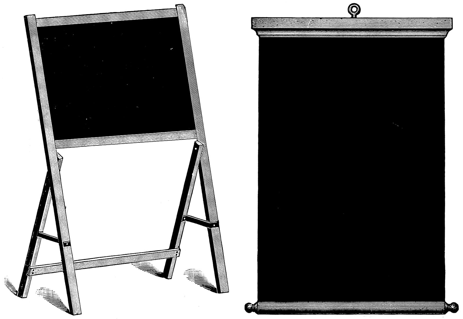
Figs. 7 and 8 need no explanation, as they represent
two forms of the well-known blackboard.
Chalk lines have this advantage—they are easily
altered or rubbed out when not needed any longer.
The work executed upon a blackboard is mostly
done by hand, without aid from instruments; a few
tools, however, are useful—such as, 1, large wooden
blackboard compasses holding a crayon, which are made
and sold by the trade in size twelve inches to thirty
inches in length; 2, a straight-edge; and 3, some crayons.
With the compasses circles and part of the circle
can be made, and with the straight-edge the larger
lines can be drawn.
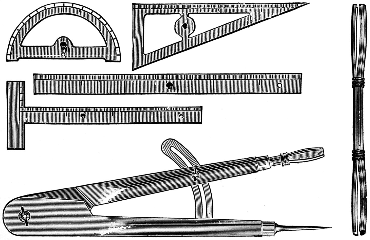
These instruments are shown on page 29, and are,
1, compasses, for holding chalk for making circles; 2, a
tee-square; 3, a straight-edge; 4, a protractor for measuring
angles; 5, a triangle 60° and 30°; 6, a brass
holder for crayons.
Blackboard Drawing.—The use of a blackboard
comes principally and properly under the head of
free-hand drawing, but its importance is such that a
separate division of the volume is assigned to it.
Thus, chalk-work may be considered the first lesson
in “free-hand,” as all the examples can also be most
profitably practiced with pencil and paper.
Very rapid drawing upon the board should not be
encouraged, as it is likely not to be accurate enough;
again, the board should be entirely free from grease.
Cloths, sponges or chamois skin rubbers may be used
to erase or change the chalk marks. Vertical lines
should be drawn from above downward; short lines
should be drawn with the fingers alone, those somewhat
longer with the hand, using the wrist-joint; the still
longer lines with the forearm, using the elbow-joint;
those longer yet with the whole arm, using the
shoulder-joint; lines should always be drawn with a
uniform motion, slow enough for the eye to follow.
Practice in chalk-work should alternate with
sketching in a sketchbook and with geometrical drawing—to
be hereafter described. The student should
practice a short time on the board, at least once a week;
large sizes are the most profitable for the representations
to be made; when drawing in different directions the
hand should be turned, not the paper or board; the
hand should never be allowed to obstruct the sight,
hence the hand and fingers should be held in a position
of freedom—with fingers not nearer than 11⁄2 or 2
inches from the board.
Note.—The first lesson of any kind the author received in
drawing was to make a straight line; this was effected by holding
the pencil nearly erect and guiding it along by the aid of the little
finger held pressed against the edge of a board; this was a useful
item of knowledge, as proved by passing years.
A well-known artist, in telling his early experience, said:
“The first thing I was taught was to draw a line, divide it, erect
a perpendicular from its center, and afterwards to divide the angle
made by the perpendicular.” In answer to a question asking how
long he was kept at the lines, he replied, “about two months—or
a month or two,” indicating that even the longer time would have
been well spent in learning to draw a straight line.
Every visible object is bounded by lines which
enable the observer to determine its shape. If these
lines are straight or curved, the shape of the object is
regular; if broken, the shape of the object is irregular.
The elements, then, of form are lines, straight,
curved, or broken, and these, therefore, furnish the
beginning of all instruction in free-hand or mechanical
drawing.
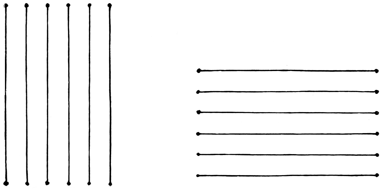
Fig. 15 shows six lines—upright and perpendicular,
with points or “dots” indicated at the top and bottom
of each line; to draw these, proceed thus:
The learner should stand with his right shoulder
opposite the board, and the weight of the hand and the
arm should be allowed to fall naturally; now, make on
the board two points, one being six inches above the
other, these being merely “dots,” shown at the ends of
the lines, figs. 15, etc., and made with two motions;
the line between the points should now be drawn
not too quickly from the upper to the lower point;
three movements of the hand and arm complete the
line; to draw the other five lines the movements have
simply to be repeated.
If the student pronounces to himself “one,”
“two,” “three,” at each motion, it will be helpful; in
this exercise, fig. 15, the aim is to make six lines, each
line being parallel to the first. Again, in the example,
it is intended that the lower point should be made
first, next the upper, and lastly the line drawn from the
upper to the lower point, but the order may be reversed;
at one the upper point, at two the lower, at
three the stroke upwards to complete the line.
To make these as shown in fig. 16, proceed as
follows: With the word one make a point, with two
another point six inches at the left, with three draw a
straight line from the left point to the right. All added
lines should be parallel: for practice, reverse the process
thus, one, make a “point,” at two another point at the
right, at three draw line to the left.
The student will note that the two motions—at
the words one and two—are to fix the positions of the
ends of the lines; this practice will be found useful in
the most advanced examples and an item of elementary
practice never to be forgotten—like the help to be
derived by the first round of a ladder.
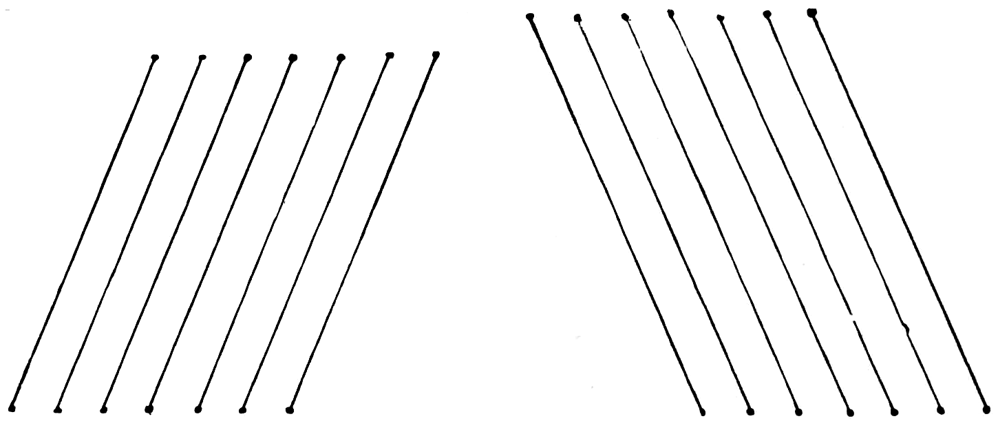
In drawing oblique straight lines as shown in fig.
17, at the word one let the student make the lower
point; at the word two the upper, a little to the
right of the lower; at the word three draw a line
quickly from the upper to the lower point. In pronouncing
the words one, two, three, let the student
make the additional parallel lines.
As shown in fig. 18, at the word one make the lower
point; at the word two the upper point, a little to the
left; at the word three draw a line rapidly from the
upper to the lower point, and “timing” the process
by repeating one, two, three, make the additional parallel
lines.
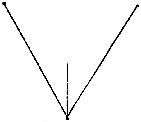
Fig. 19.
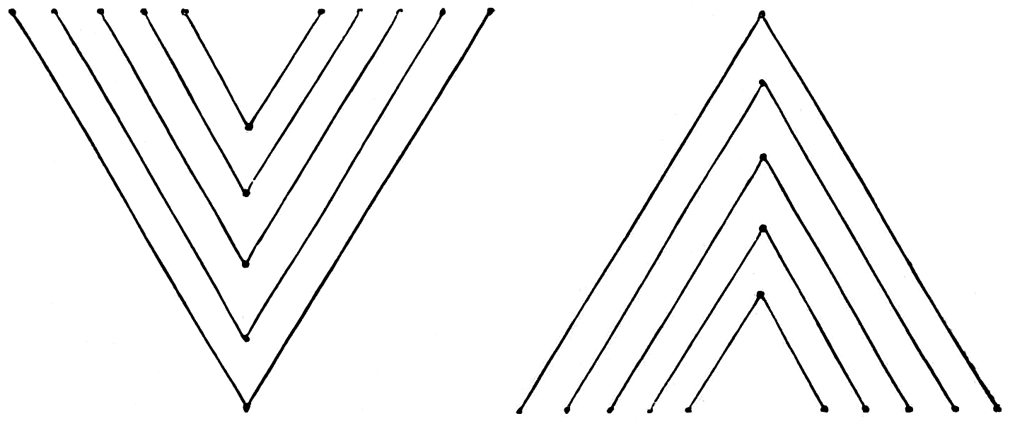
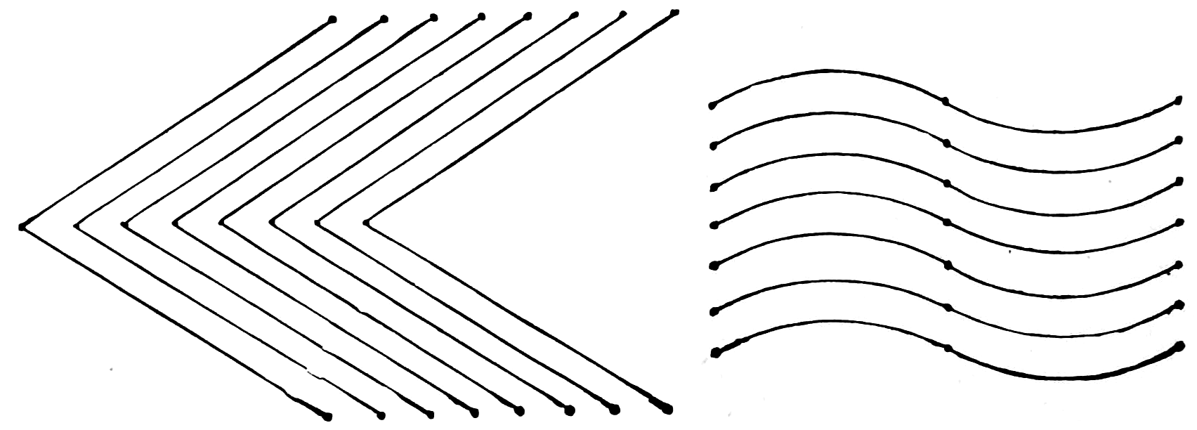
A broken line is composed of two or more straight
lines at angles to each other (see fig. 19). To draw
them begin (saying) one, make a point; two a point
below at the left; three, a point above at the left;
four, draw a line from the left hand point to the lower
point; at the word five, from the lower point to the
upper right hand point. For practice draw numerous
lines in the same way, keeping them parallel to each
other, as shown in fig. 20.
In example, fig. 21, the arrangement of the points
is changed—let the student draw at the words, as
follows: One, a point; two, a point above at the left;
three, a point below at the left; four, draw from the
point at the left to the upper point; five, from the
upper point to the lower right hand point; continue
to add parallel lines to complete the figure as shown.
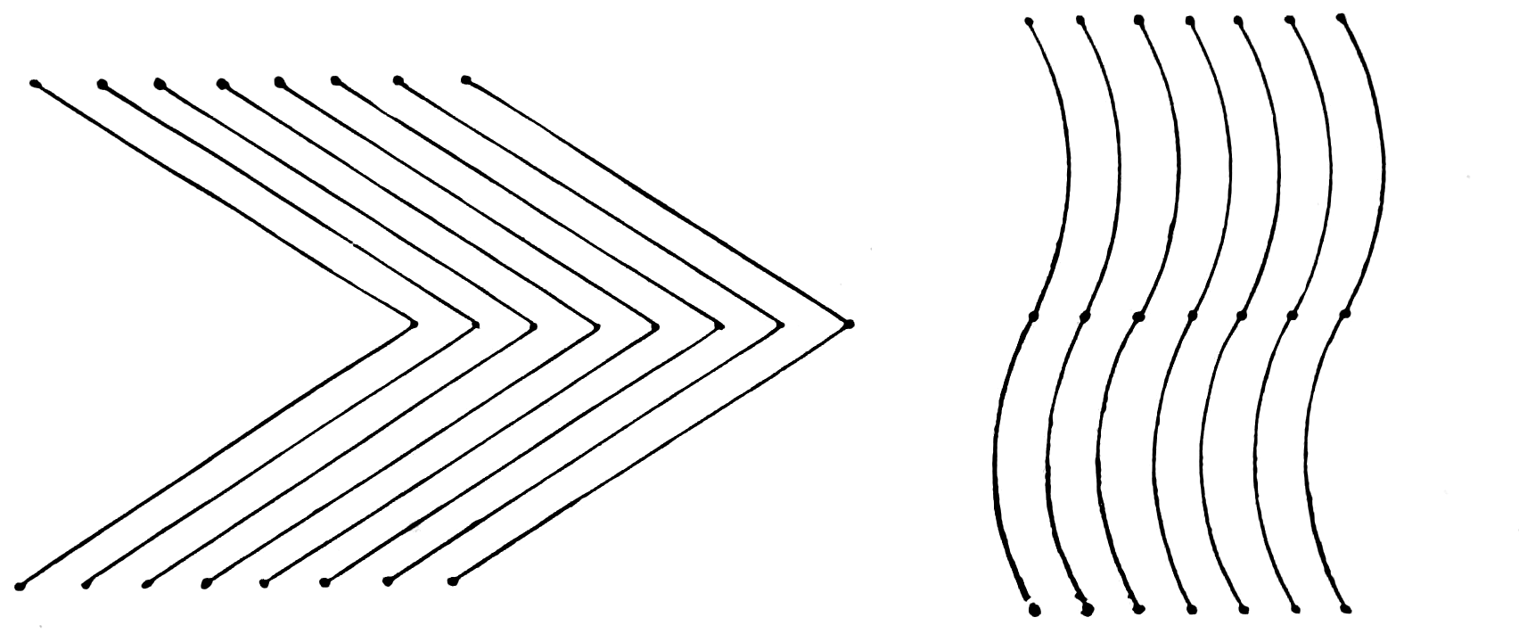
Figs. 22 and 23 are given as examples to practice,
making first the points and then the connecting
lines and afterward the parallel lines to complete the
figures.
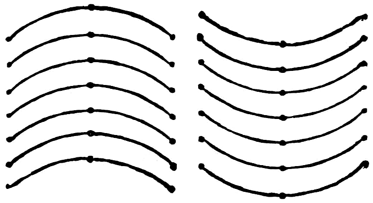
To draw curved lines, as shown in fig. 24. At the
word one, point; at the word two, point three inches
directly above; three, at the same distance above again
make a point; now draw a curve as shown, joining the
middle point and the upper point; now draw the
curve as shown below it; finally complete figure
as shown.
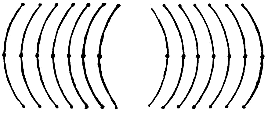
Fig. 28.
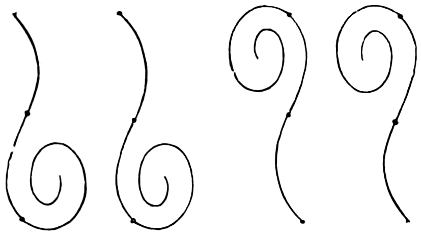
Figs. 25 to 30 are to be practiced, making first the
points and then connecting them by the curves to
complete the figures.
When two or more students are working together,
with each having a blackboard, the counting may be
in concert—or a teacher could count for a class. In
these line examples care should be used in making
them of uniform length. There is a difference to be
noted between a crooked line and a broken line, the
latter being a straight line and the former deviating
from it.
Square chalk crayons are the best for hand work,
as lines of an even or uniform width can be drawn with
them.
A very fine effect is produced by using two thicknesses
of chalk, one being double the thickness of the
other; the heavy lines being used on the shade side of
objects will produce a good effect, giving thickness and
body to the object.
Round chalk crayons are used in the compasses to
draw circles, but hand lines drawn with them are not so
neat as those produced with the square-shaped chalk.
To obliterate or remove the construction, or false
lines made on the blackboard, a wooden handle two
inches in diameter with a cone end 3 or 4 inches long,
covered with chamois skin or soft cloth tightly wrapped
round the cone and fastened with a tack or drawing
pin, makes the best implement to erase lines not
required, the point of the cone will remove these without
destroying the lines or curves which meet them.
Sponges, chamois skin or cloth rubbers are used
to rub out the chalk drawings and clean the blackboard.
The best height for a diagram on the blackboard
is not higher than the head, nor lower than the elbow.
Horizontal lines should be made from the left to
the right; the body and arm being moved with the
hand, and kept in the same relative position with it,
will steady the hand.
Curved lines to the left should be drawn first,
enabling the eye to take in not only the curve in process
of formation but that already made.
Passing the crayon in the hand, over the intended
curve previous to marking it, will guide the eye and
give confidence to the hand in chalking the curve.
A proper distance from the blackboard is essential,
the face being about two feet away from it.
Draw with the whole arm extended from the
shoulder-joint, not from the elbow or wrist.

Fig. 31.
| |
| |
“There are more ways than one of telling
things: by speech, by writing, by printing,
also by pictures and drawings.” Knowles |
|
| |
ELECTRA.
Preliminary Terms and Definitions.
Like all the arts, drawing has a nomenclature of its
own, and nothing can be more helpful to the beginner
than to know the name of things relating to the art
of drawing. This is a language almost peculiar to
itself, and used daily and hourly by many thousands
of superintendents, foremen and master mechanics, as
well as by owners, designers and draughtsmen, hence
its introduction at this early stage.
ALTITUDE.—This is the elevation of an object above
its base, or the perpendicular distance between
the top and bottom of a figure.
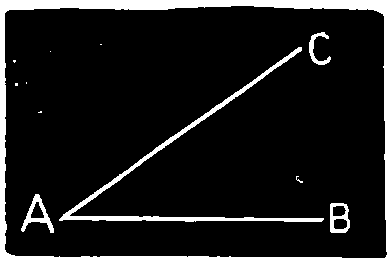
Fig. 33.
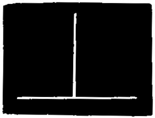
Fig. 34.
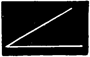
Fig. 35.
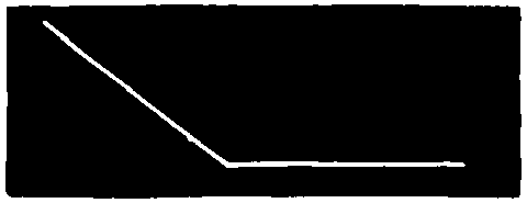
Fig. 36.
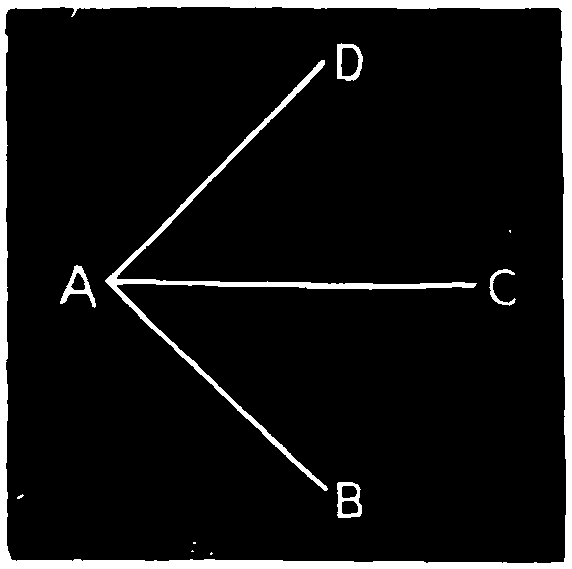
Fig. 37.
ANGLE is the difference in the direction of two lines
which meet or tend to meet. The lines are called
the sides and the point of meeting, the vertex of
the lines.
To make an angle apparent,
the two lines must meet in a
point, as A B and A C, which
meet in the point A, as shown
in fig. 33.
Angles are measured by degrees.
A Degree is one of the three hundred and
sixty equal parts of the space about a point in a
plane.
Angles are distinguished in respect to magnitude
by the terms Right, Acute and Obtuse
Angles.
A Right Angle is that formed
by one line meeting another, so as
to make equal angles with that
other.
The lines forming a right angle are perpendicular
to each other.
An Acute Angle is less than
a right angle. See Fig. 35.
An Obtuse Angle is greater
than a right angle. See Fig. 36.
Obtuse and acute angles are also called oblique
angles; and lines which
are neither parallel nor
perpendicular to each other
are called oblique lines.
The Vertex or Apex of an angle is the point
in which the including lines meet.
An angle is commonly designated by a letter
at its vertex; but when two or more angles have
their vertices at the same point, they cannot be
thus distinguished.
For example,
when the three lines
A B, A C, and A D in
fig. 37 meet in the
common point A, we
designate either of the
angles formed, by
three letters, placing
that at the vertex
between those at the opposite extremities of the
including lines. Thus, we say, the angle B A C, etc.
APEX.—The summit or highest point of an object.
ARC.—See circle.
AXIS OF A SOLID.—An imaginary straight line passing
through its center.
AXIS OF A FIGURE.—A straight line passing through
the center of a figure, and dividing it into two
equal parts.
BASE.—The base of a solid figure is that on which it
stands—the lowest part.
BISECT.—To divide into two equal parts.
BISECTOR.—A line which bisects.
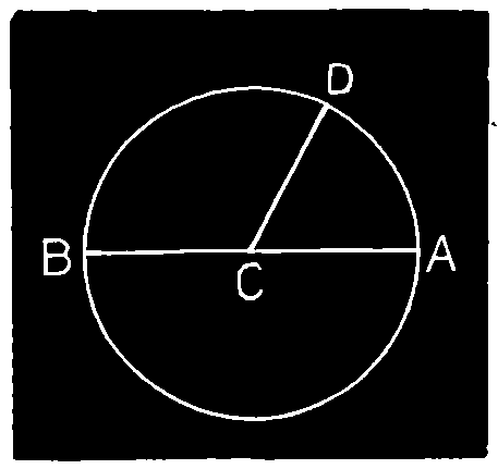
Fig. 38.
CIRCLE.—A Circle is a plane
figure bounded by one uniformly
curved line, all of the
points in which are at the
same distance from a certain
point within, called the
Center.
The Circumference of a circle is the curved
line that bounds it.
The Diameter of a circle is a line passing
through its center, and terminating at both ends
in the circumference, as A C B.
The Radius of a circle is a line extending
from its center to any point in the circumference.
It is one-half of the diameter. All the diameters
of a circle are equal, as are also all the radii C D,
C B and C A.
An Arc of a circle is any portion of the circumference,
as B D and A D.
Semi-Circle.—Half a circle formed by bisecting
it with a diameter, as A C B. Fig. 38.
An angle having its vertex at the center of a
circle is measured by the arc intercepted by its
sides. Thus, the arc A D measures the angle
A C D, and in general, to compare different angles,
we have but to compare the arcs, included by their
sides, of the equal circles having their centers at
the vertices of the angles.
CIRCUMSCRIBE.—To draw a line of figures about or
outside, such as a circle drawn around a square
touching its corners or angles.
Inscribe.—To draw a line or figure inside or
on the interior, such as a circle drawn within a
square touching its sides.
CONCAVE.—Curving inwardly.
CONE.—A solid body or figure having a circle for its
base, and its top terminated in a point or vertex.
CONSTRUCTION.—The making of any object.
CONTOUR.—The outline of the general appearance of
an object.
CONVERGENCE.—Lines extending towards a common
point.
CONVEX.—Rising or swelling into a round form—the
opposite to concave.
CORNER.—The point of meeting of the edges of a
solid, or the two sides of a plane figure.
CROSS-HATCHES.—In free-hand drawing the use of
lines crossing each other to produce light and
shade effects.
CURVE.—A line of which no part is straight.
Reversed Curve.—One whose curvature is first
in one direction and then in the opposite direction.
Spiral Curve.—A plain curve which winds
about and recedes, according to some law, from its
point of beginning, which is called its center.
CYLINDER.—A solid bounded by a curved surface and
by two opposite faces called bases; the bases may
be any curved figures and give the name to the
cylinder; thus a circular cylinder is one whose
bases are circles.
CYLINDRICAL.—Having the general form of a cylinder.
DEGREE.—The 360th part of a circle.
DESCRIBE.—To make or draw a curved line; to draw
a plan.
DESIGN.—Any arrangement or combination to produce
desired results in industry or art. To
delineate a form or figure by drawing the outline—a
sketch.
DEVELOP.—To unroll or lay out.
DIAGONAL.—A right line drawn from angle to angle
of a quadrilateral or many angled figure and
dividing it into two parts.
DIAMETER.—A right line passing through the center
of a circle or other round figure terminated by the
curve and dividing the figure symmetrically into
two equal parts.
EDGE.—The intersection of any two surfaces.
ELEVATION.—The term elevation, vertical projection
and front view—applied to drawings—all have the
same meaning.
FACE.—One of the plane surfaces of a solid; it may
be bounded by straight or curved edges.
FINISHING.—Completing a drawing whose lines have
been determined by erasing unnecessary lines and
strengthening and accentuating where this is
needed.
FORESHORTENING.—Apparent decrease in length,
owing to objects being viewed obliquely; thus a
wheel, when seen obliquely, instead of appearing
round, presents the appearance of an ellipse.
FREE-HAND.—Executed by the hand unaided by
instruments.
GENERATED.—Produced by.
GEOMETRIC.—According to geometry.
HALF-TINT.—The shading produced by means of
parallel equidistant lines.
HEMISPHERE.—Half a sphere obtained by bisecting
a sphere by a plane.
HORIZONTAL.—Parallel to the surface of smooth
water. In drawing, a line drawn parallel to the
top and bottom of the sheet is called horizontal.
INSCRIBE.—See circumscribe—its opposite.
INSTRUMENTAL.—By the use of instruments.
LINE.—A line has length, only, as A C; a right line is
a straight line, the shortest line that can be drawn
between two points, A——C.
Straight. One which has the same direction
throughout its entire length.
Curved. One no part of which is straight.
Broken. One composed of different successive
straight lines.
Mixed. One of straight and curved lines.
Center. A line used to indicate the center of
an object.
Construction. A working line used to obtain
required lines.
Dotted. A line composed of short dashes. - - - - - -
Dash. A line composed of long dashes. — — —
Dot and Dash. A line composed of dots and
dashes alternating. — · — · —
Dimension. A line upon which a dimension
is placed.
Full. An unbroken line, usually representing
a visible edge. ———
Shadow. A line about twice as wide as the
ordinary full line.
A straight line is often called simply a line,
and a curved line a curve.
LONGITUDINAL.—In the direction of the length of an
object.
MODEL.—A form used for study.
OBLIQUE.—Neither horizontal nor vertical.
OBLONG.—A rectangle with unequal sides.
OVAL.—A plane figure resembling the longitudinal
section of an egg; or elliptical in shape.
OVERALL.—The entire length.
PARALLEL.—Having the same direction and everywhere
equally distant.
PATTERN.—That which is used as a guide or copy in
making things.
Flat. One made of paper or other thin material.
Solid. One which reproduces the form
and size of the object to be made.
PERIMETER.—The boundary of a closed plane figure.
PERPENDICULAR.—At an angle of 90°.
PERSPECTIVE.—View; drawing objects as they appear
to the eye from any given distance and situation,
real or imaginary.
PLAN.—Plan, horizontal projection and top view have
the same meaning.
PLANE FIGURE.—A part of a plane surface bounded
by straight or curved lines, or by both combined.
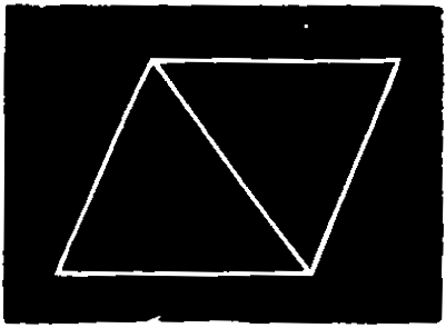
Fig. 39.
POLYGON.—A plane figure bounded by straight lines
called the sides of the polygon.
The least number of
sides that can bound a
polygon is three. Polygons
bounded by a greater number
of sides than four are
denominated only by the number of sides.
A polygon of five sides is called a Pentagon;
of six, a Hexagon; of seven, a Heptagon;
of eight, an Octagon; of nine, a Nonagon, etc.
Diagonals of a polygon are lines joining the
vertices of angles not adjacent.
The Perimeter of a polygon is its boundary
considered as a whole.
The Base of a polygon is the side upon which
the polygon is supposed to stand.
The Altitude of a polygon is the perpendicular
distance between the base and a side or angle
opposite the base.
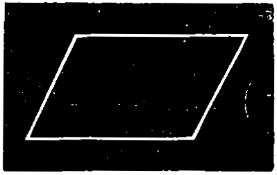
Fig. 40.
A Quadrilateral is a polygon having four sides
and four angles.
A Parallelogram is a
quadrilateral which has its
opposite sides parallel.
The side upon which a
parallelogram stands and the opposite side are
called respectively its lower and upper bases.
A Rectangle is a parallelogram
having its angles right
angles.
A Square is an equilateral
rectangle, fig. 41.
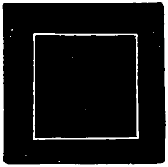
Fig. 41.
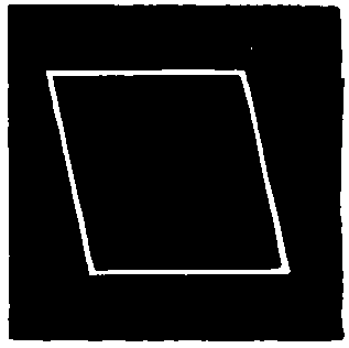
Fig. 42.
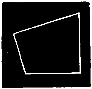
Fig. 43.
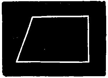
Fig. 44.
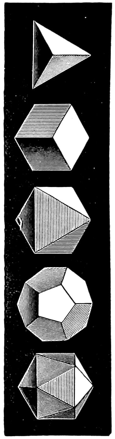
Figs. 45-49.
A Rhomboid is an oblique-angled
parallelogram.
A Rhombus is an equilateral
rhomboid, fig. 42.
A Trapezium is a quadrilateral
having no two sides parallel,
fig. 43.
A Trapezoid is a quadrilateral
in which two opposite sides
are parallel, and the other two
oblique, fig. 44.
A POLYHEDRON is a solid bounded
by planes. There are five regular
solids which are shown in
figs. 45, 46, 47, 48 and 49. A
regular solid is bounded by
similar and regular plane figures.
Fig. 45.—The tetrahedron,
bounded by four equilateral
triangles.
Fig. 46.—The hexahedron,
or cube, bounded by six squares.
Fig. 47.—The octahedron,
bounded by eight equilateral
triangles.
Fig. 48.—The dodecahedron,
bounded by twelve pentagons.
Fig. 49.—The icosahedron,
bounded by twenty equilateral
triangles.
PRISM.—A solid whose bases or ends are very similar
plane figures, and whose sides are parallelograms;
prisms are called triangular, square, etc., according
as the bases are triangles, squares, etc.
PRODUCE.—To continue or extend.
PROFILE.—An outline or contour.
PROJECTION.—The view of an object obtained upon
a plane by projecting lines perpendicular to the
plane.
QUADRANT.—The fourth part; a quarter; the quarter
of a circle.
QUADRISECT.—To divide into four equal parts.
SECTION.—A projection upon a plane parallel to a
cutting plane which intersects any object. The
section generally represents the part behind the
cutting plane, and represents the cut surfaces by
diagonal lines.
SECTIONAL.—Showing the section made by a plane.
SHADOW.—Shade and shadow have about the same
meaning.
SOLID.—A solid has three dimensions—length, breadth
and thickness.
SPHERE.—A solid bounded by a curved surface every
point of which is equally distant from a point
within called the center.
SURFACE.—The boundary of a solid. It has but two
dimensions—length and breadth. Surfaces are
plane or curved.
A Plane Surface is one upon which a straight
line can be drawn in any direction.
A Curved Surface is one no part of which is
plane.
The surface of the sphere is curved in every
direction, while the curved surfaces of the cylinder
and cone are straight in one direction.
The surface of a solid is no part of the solid,
but is simply the boundary of the solid. It has
two dimensions only, and any number of surfaces
put together will give no thickness.
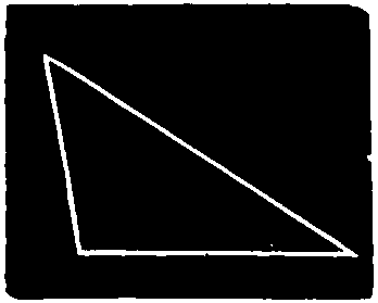
Fig. 50.
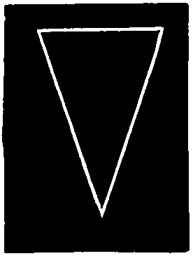
Fig. 51.
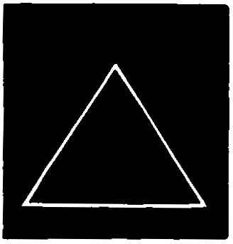
Fig. 52.
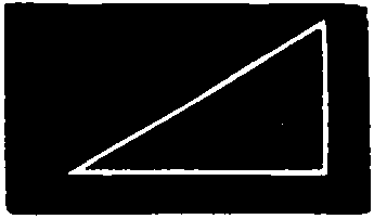
Fig. 53.
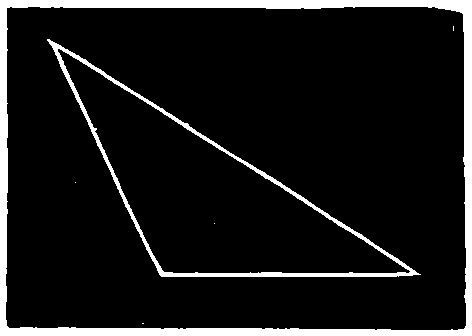
Fig. 54.
SYMMETRY.—Design. A proper adjustment or adaptation
of parts to one another and to the whole.
TRISECT.—To divide into three equal parts.
TRIANGLE.—A triangle is a polygon having three
sides and three angles. Tri is a Latin prefix signifying
three; hence a Triangle is literally a figure
containing three angles.
A Scalene Triangle is one
in which no two sides are equal.
See fig. 50.
An Isosceles Triangle is one
in which two of the sides are
equal. See fig. 51.
An Equilateral Triangle is
one in which the three sides are
equal. An Equiangular Triangle
is one having its three angles
equal. An Acute-Angled Triangle
is one in which each angle is acute.
A Right-Angled Triangle is
one which has one of the angles a
right angle. See fig. 53.
An Obtuse-Angled Triangle
is one having an
obtuse angle. Fig. 54.
Equiangular triangles are also equal sided,
and vice versa.
VERTICAL.—Upright or perpendicular. Vertical and
perpendicular are not synonymous terms.
VERTEX.—See Angle,
Quadrilateral, Triangle. The
vertex of a solid is the point in which its axis intersects
the lateral surface.
VIEW.—See Elevation. Views are called front, top,
right or left side, back, or bottom, according as
they are made on the different planes of projection.
They are also sometimes named according to the
part of the object shown, as edge view, end view,
or face view.
WORKING DRAWING.—One which gives all the information
necessary to enable the workman to
construct the object.

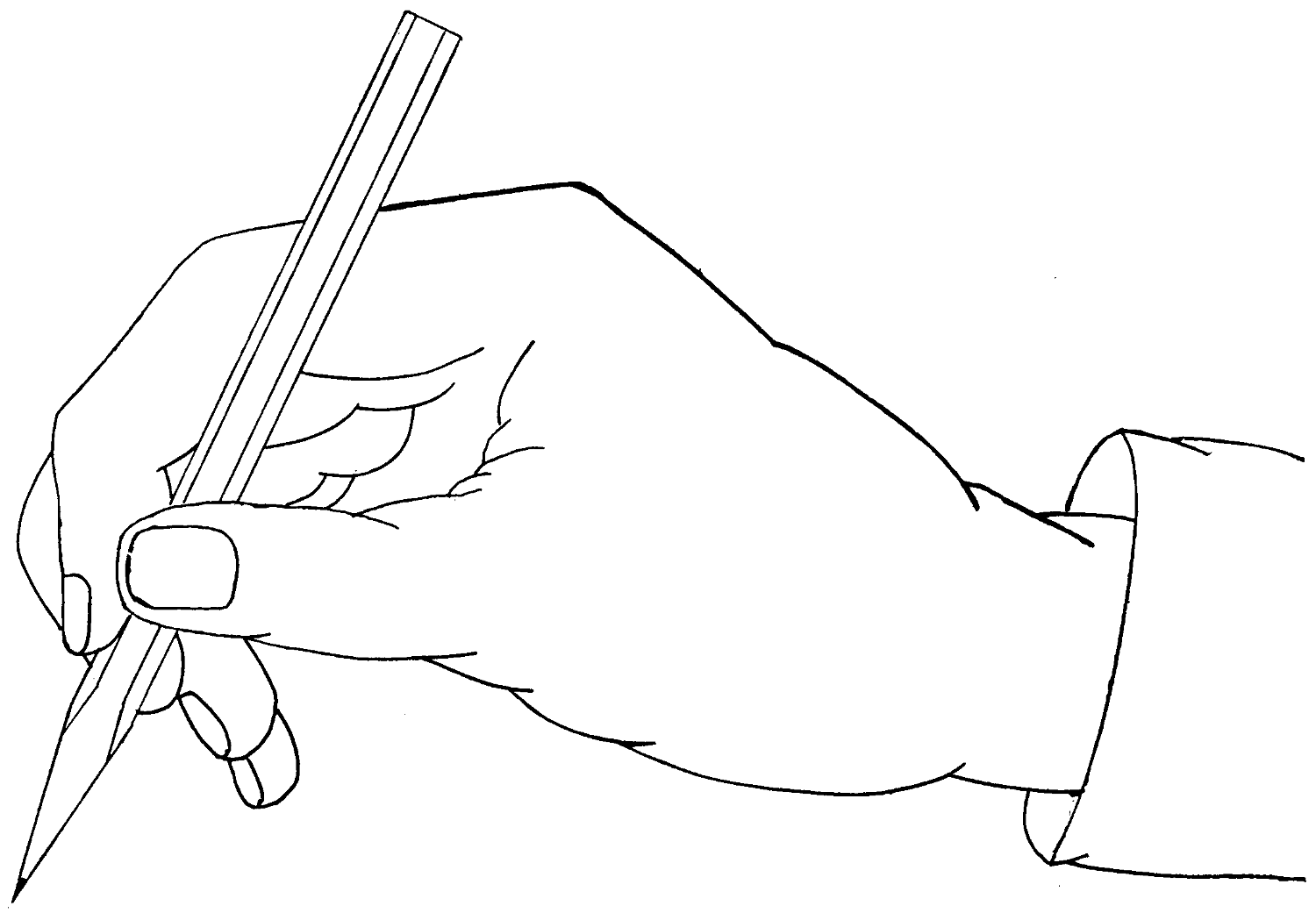
Fig. 55.
Free-Hand Drawing. — POSITION. — HOW TO CUT A PENCIL. — HOW TO DRAW STRAIGHT LINES. — TO DRAW THE FIRST OBLIQUE LINE. — TO DRAW THE UPRIGHT OR PERPENDICULAR LINE. — TO DRAW THE SECOND OBLIQUE LINE. — ON FIGURES FORMED OF STRAIGHT LINES. — ON CURVED LINES. — EXAMPLES FOR PRACTICE.
A free-hand drawing is executed with the unaided
hand and eye, without guiding instruments or other
artificial help. It is necessary to be known that all
drawing required cannot possibly be done by rule and
compass, but that some portions must be drawn “free-hand,”
trusting to the eye alone.
Hence, it is important that the student should be
able to sketch at sight from objects he may see, or to
draw roughly, with a piece of chalk or a pencil, pieces
of mechanism required to be represented.
Practice in free-hand should go along with mechanical
drawing as progress is made, and thus cultivating
both branches equally.
“A simple sketch will often,” as has been rather
roughly said, “express more than yards of talk.”
Even a slight sketch refreshes the memory, and in
the case of the preparation of a complete set of drawings,
with a view to the making of a thoroughly finished
mechanical drawing, the proper course to pursue is, to
make a general sketch, letter the various parts for
reference, and then prepare a series of detailed sketches,
similarly lettered, and diffuse with dimensions.
Everyone, whatever his specialty, feels to-day that
the ability to sketch rapidly and clearly is among the
absolute necessities for correct and prompt transactions
of business, in giving and executing orders and doing
business with persons outside his profession.
Mistakes and misunderstandings may be averted
by means of rough sketches taken at the time and
shown for confirmation; this also saves assistants from
getting into trouble, especially if they pin the sketch
to the order, for reference, in case of the arising of
any dispute. These are a few of the advantages of
knowing how to sketch quickly and correctly.
In “free-hand” any sort of pencil is better than
none, but there is a considerable advantage in having a
good serviceable article—a pencil not too soft nor too
hard, and one which will retain its point for some little
time.
Fig. 55 shows the approved position in which the
pencil should be held while sketching. The pencil
should be held firmly between the thumb and first
finger of the right hand; press the second finger against
the pencil at the opposite side to the thumb pressure,
so that the pencil is firmly held by the contact of the
thumb and two fingers—the third and fourth fingers
just coming into easy reach of the paper surface—the
wrist or ball of the hand resting lightly on the surface
of the work—the arm resting on the desk or drawing-board
for steadiness.
The motion of the pencil is produced from the
movement of the fingers and thumb, principally in the
vertical strokes, and the horizontal strokes are produced
by fingers and thumb, combined with a wrist or
elbow motion; the oblique lines and curves are produced
with a free movement, with nothing cramped or
confined about the finger joints.
It should be observed that nothing is more prejudicial
to good execution than the habit of leaning over
the paper, which ought to be placed on a surface sufficiently
inclined to bring every portion equally under
the eye, thus obviating the necessity of leaning forward.
All support to the figure should be obtained by resting
on the left arm, the right being left free for work. By
attention to these rules that awkwardness of position,
so detrimental to a good figure, will be avoided. It is
better to have the light on the left hand, as in this direction
the shadow of the pencil does not interfere with
the view of the drawing.
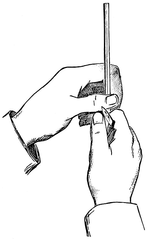
Fig. 56.
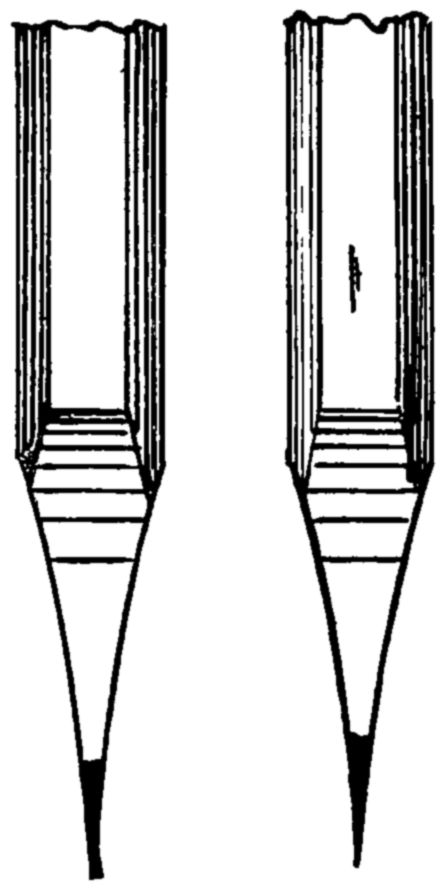
Hold the pencil firmly in the
left hand, as in the drawing,
allowing about an inch to project
beyond the fingers, and
turn it gradually as the knife
removes the wood. The knife
should be held so that the blade
alone projects beyond the
fingers, and the part of it
nearest the handle used for cutting.
The pencil should be
placed against the inside of the
thumb of the right hand, as in
the drawing (fig. 56), and the wood removed by slight
shaving. The lead should not be cut at the same time
as the wood, but rested on the thumb and pared
gently afterwards; by attention to these directions the
pencil will be economized.
Before a line is drawn, the point at which it is to
commence and the point where it is to end, should be
known; and let it be distinctly understood that this
judgment of the eye, and placing of points, should invariably
precede the drawing of every line.
The first effort should, therefore, be to produce a
line of points exactly parallel with the upper edge of
the paper, and at equal distances from each other.
Commence with point A and place the point B carefully
level with it, now place a slip of paper against
these points in the original, mark their distance apart,
and see if the same proportion has been given in your
copy; if not, make the necessary correction. Proceed
with the next point, examine it, and so on to the end of
the line. When this is complete, examine each point
in succession, to try if it is at the same distance from
the top of the paper; when this is correct, proceed to
draw the first level line. Hold the pencil as in the
drawing, fig. 57, keeping the elbow near the side;
join A to B by one light, steady stroke, produced by a
movement of the wrist, and add stroke upon stroke
until the line is of the required depth. Continue this
process to the end of the line of points. Now place
the point D at the right distance below the A, proceed
with the points for another line as before, and continue
the lines until the paper is covered. In producing the
stroke the pencil should not be jerked, or any stop be
made between the points, but the movement should be
even throughout, and it is much better to produce each
line by several soft strokes, as the repetition of delicate
lines induces lightness of touch and freedom of hand;
and it is also no small advantage that lines thus produced
are more easily removed by the India rubber,
should they require correction.
Prepare three rows of points down the side of the
paper, on the left hand; examine them to see that they
are at equal distances from the side and from each
other; hold the pencil as in the drawing, fig. 58, move
the elbow a little from the side, and join the points A
and B with one light line, produced by a movement of
the fingers and thumb, repeating the strokes until the
line is of the requisite depth; proceed to join B to C,
taking care previously to bring the hand a little down
the paper, as the line from A to C is too long to be
produced from one position. When the three rows of
points are filled, make another set, examine them and
proceed as before. By these means the paper will be
covered with oblique lines, and if the points have been
placed exactly, the sheet will have a neat and regular
appearance.
Note.—The drawings of hands are introduced to show the
positions for holding the pencil, and are not intended for copying.
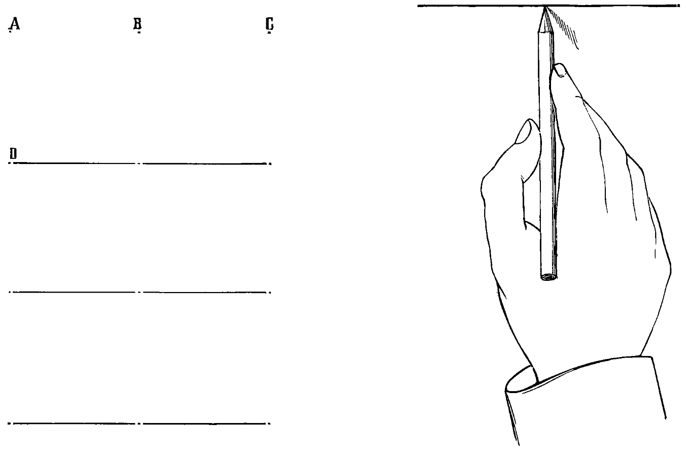
Fig. 57.
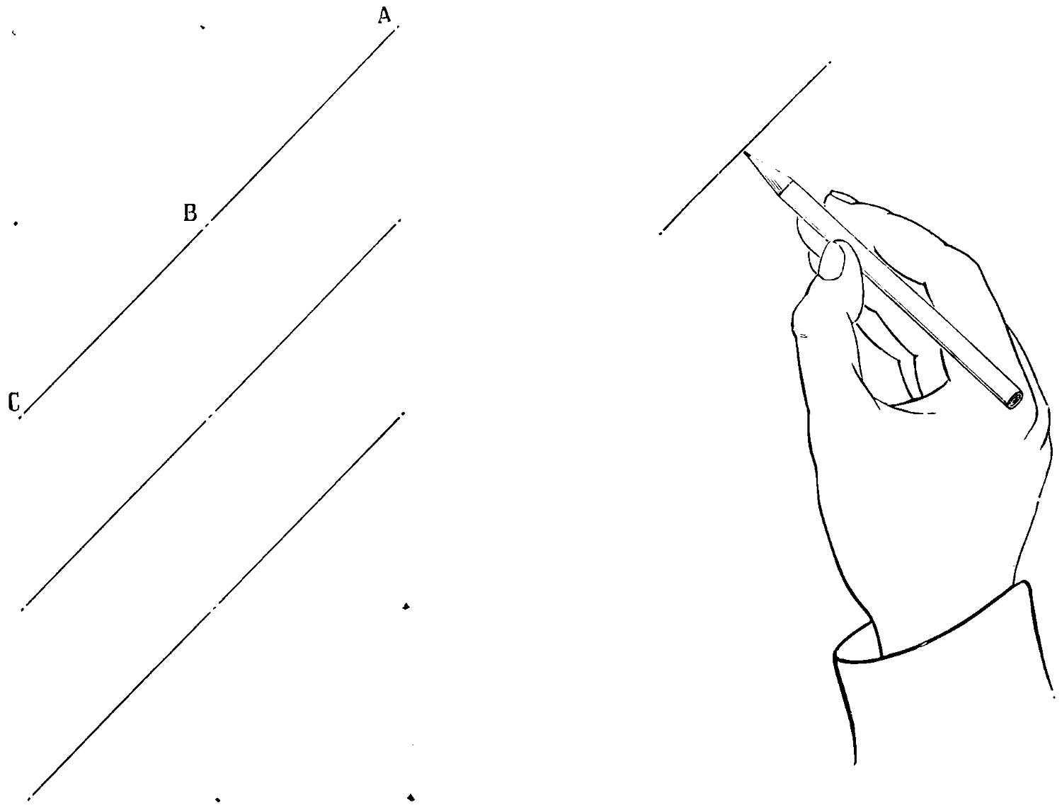
Fig. 58.
It is a common, and at the same time highly injurious
habit, to draw this line by a movement of the
wrist, the fingers remaining rigid. This may be detected
by watching the action of the thumb; if it bends
as the line is produced, all is right; but if it does not
the wrist is at work.
This line demands the greatest attention, and any
care bestowed upon it will be amply repaid in the after
studies.
Commence by placing a line of points down the
side of the paper, examine them very carefully to see
that they are all the same distance from its edge, hold
the pencil as in the drawing, fig. 59, move the elbow
well out from the side, and join the points by a movement
of the fingers and thumb. When one line is
complete, place the points for the next, and examine
them from the edge of the paper, not from the line just
drawn. Proceed in this manner until the paper is covered.
There is in most cases a tendency to place the
points for this line in a slightly inclined direction, as in
writing, though in some instances the tendency is the
opposite, a thoroughly correct eye in this respect being
a rare gift: and it may be useful to suggest that the
paper be so placed that the line of points to be produced
may be exactly in front of the eye.
Prepare three rows of points down the side of the
paper, examine them for correctness of position, hold
the pencil as in the drawing, fig. 60, remove the elbow
as far as possible from the side, and join the points by
a movement of the fingers and thumb, and continue the
exercise until the paper is covered.
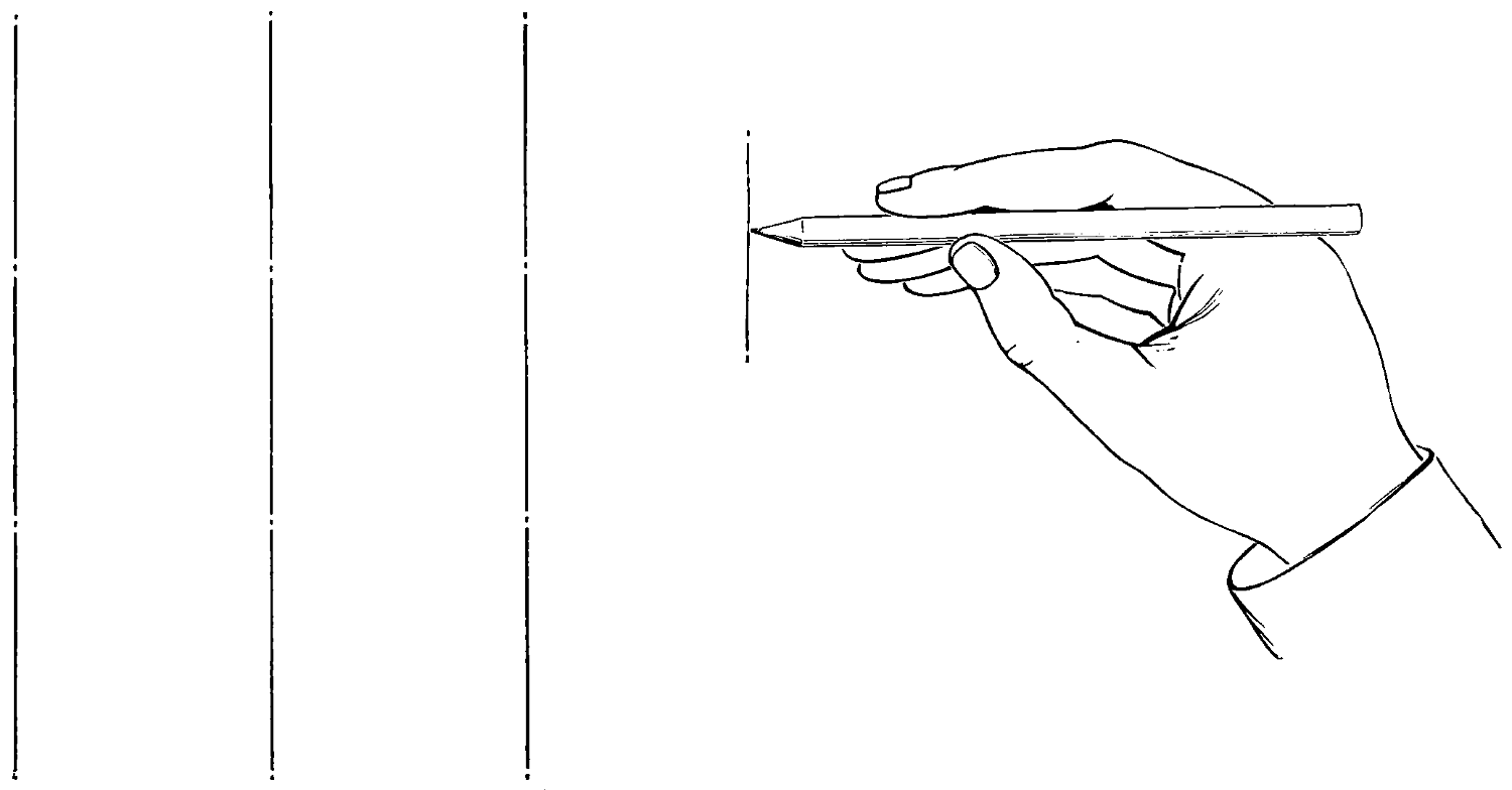
Fig. 59.
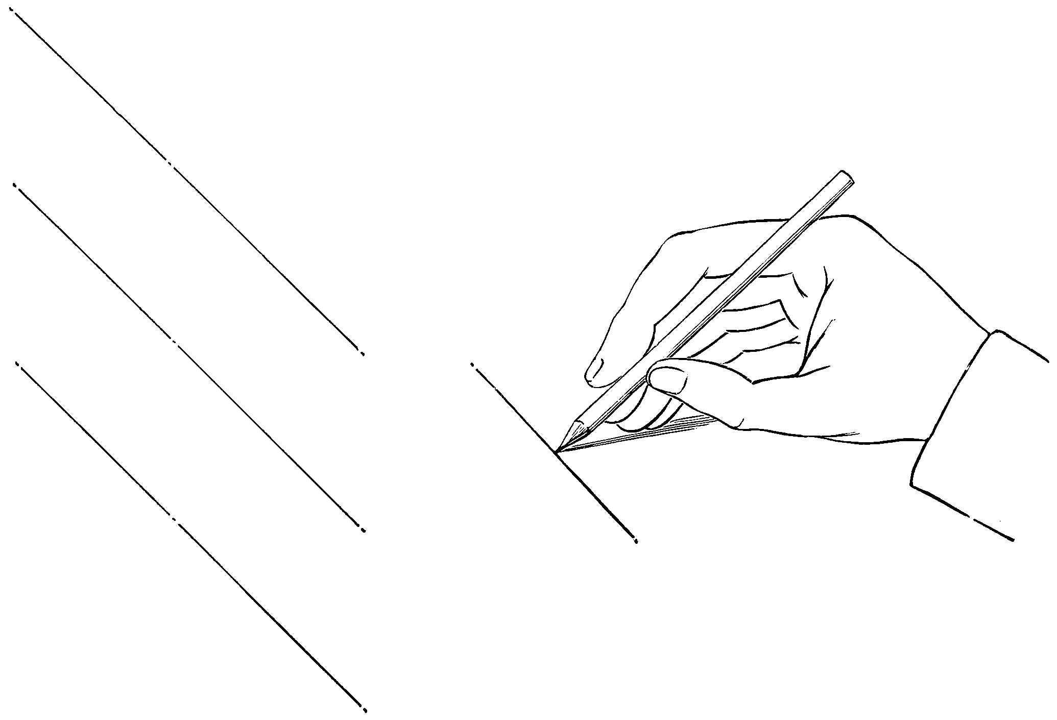
Fig. 60.
It will be noticed that each change in direction
of the line to be drawn, has been accompanied with a
corresponding change in the position of the elbow and
wrist. The following simple rule will assist the memory
when placing the hand for any given line; the
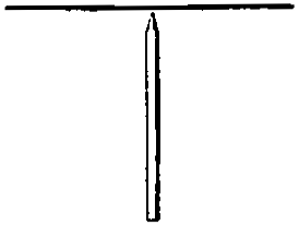
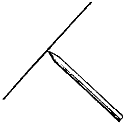
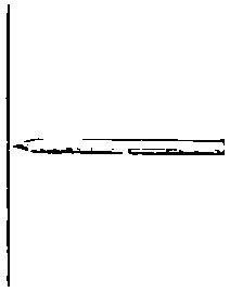
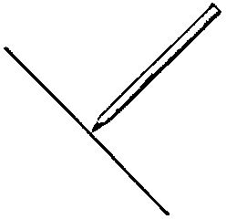
pencil should be held so that it may form a T with the
line to be drawn:
For the horizontal line, elbow near
the side.
For the first oblique, elbow a little
removed.
For the perpendicular, elbow more
removed.
For the second oblique, elbow most
removed.
Finger and thumb lines.
Finger and thumb lines.
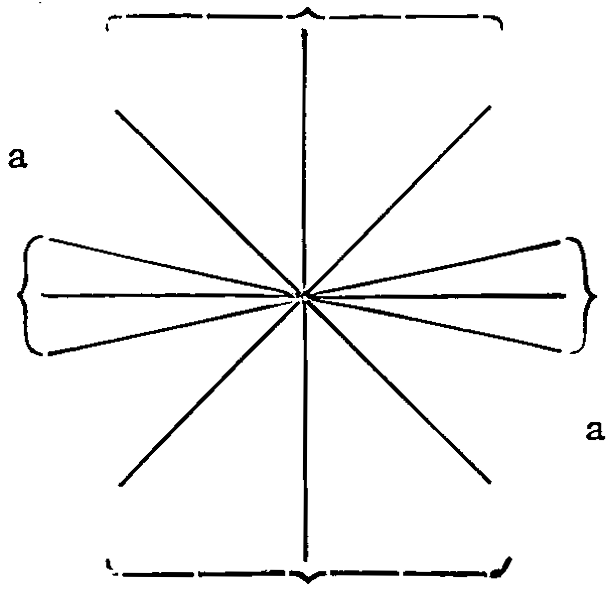
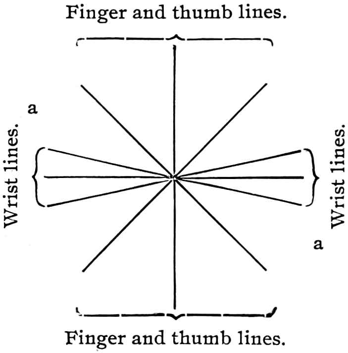
It may also be interesting to notice, with regard to
the movements by which lines are produced, that they
are divided into two systems; the first is that of the
wrist, which includes the horizontal, and lines in nearly
the same direction;
the second is that of
the fingers and
thumb, by which all
other lines are
formed. The following
diagram exhibits
the two systems and
their various lines
grouped, and it will
be observed that
there is a space marked (a) between the two sets, which
may be considered neutral ground. Lines in this
direction may be produced by either movement, as
may be most convenient, but it will always be found
that these lines are the most trying to the hand.
Before commencing this subject, let it be clearly
understood that future success will, in a great measure,
depend upon the amount of care bestowed upon it.
The aim should be to obtain absolute accuracy, and for
this end the copies should be tested by the most careful
measurements, and corrected until they are true
with the originals, but it should be distinctly understood
that these measurements are only to be made
after the eye and hand have done their best.
Note.—To some it may appear that too much time and care
has been bestowed on mere lines, but let it be understood that a
good system of line drawing is the basis of all education—the
slightest outline by a hand thus trained has a bold, free and
masterly character; and with regard to shading, which is simply
an aggregation of good lines, it is only by such a practiced hand
its most charming effects can be produced.
Fig. 66: Place the points A, B. Examine them
to see that they are the same distance apart as in the
original, and that they are level; place the point C exactly
under A, and make A C equal in distance to A B;
now place the point D opposite C and under B; try
the distances between each point to see that they are
the same; divide each side by a point half way, and
then draw the lines.
Fig. 67: Repeat the last figure and add the
lines A and B, taking great care that the points for
them are correctly placed.
Fig. 68: Commence with the square as before;
then join the half-way points.
Fig. 69: After the square is drawn, place the
points A and B at the right height above the half-way
points, and C, D at the proper distance from the corners,
then draw the figure.
Fig. 70: The greatest care should be taken with
the squares for this and the following figure, as the
slightest error in them will destroy the symmetry of
the drawing within; when the square is completed, join
the opposite corners, and place on the crossed lines the
points B, C, D, E; examine these to see that they are
each at the same distance from the centre A, and that
this distance is equal to the space from A to the sides
of the square; when all are proved to be correct, complete
the figure.
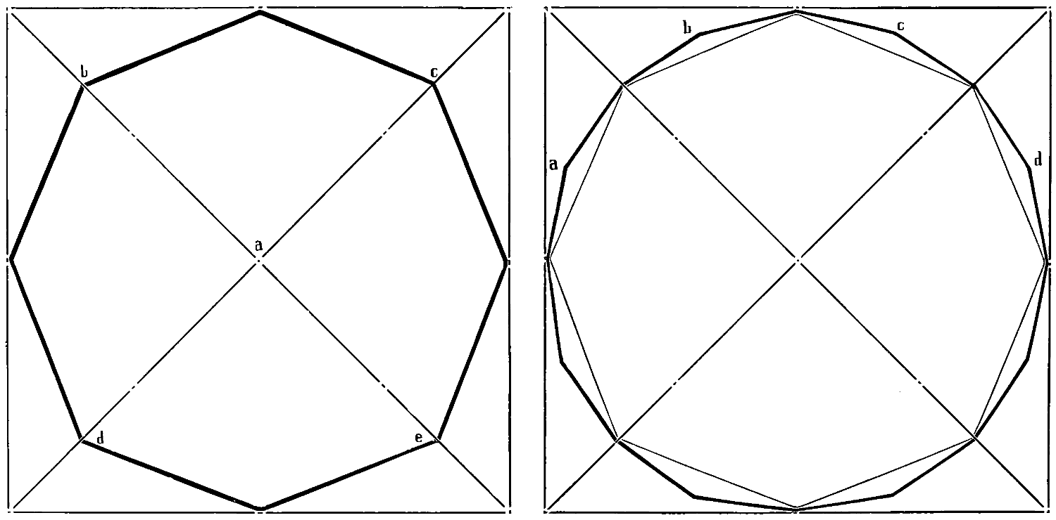
Fig. 71: Repeat the last drawing with, if possible,
greater exactness, and outside the octagon place
the points A, B, C, D, etc.; examine each of these
points to see that they are all at the same distance
from the centre, and then complete the figure.
The right position of the hand for drawing any
curved line is that required for a straight line which
would touch the extremities of
the curve. The straight lines
given in the exercises are valuable,
not only as a guide to the
position of the hand, but as an assistance to the eye
when forming the curves or examining them after they
are produced.
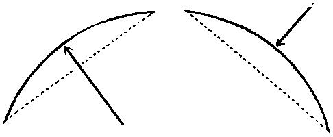
The direction given for drawing a straight line was
to form it by one steady movement from point to point,
without any jerk or stop by the way. This instruction
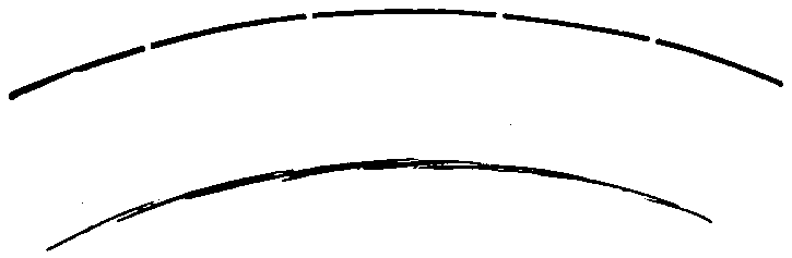
requires to be changed for the curve, which is better
produced by several short strokes, thus:
or by overlapping
lines, any outside bits
being cleared away
with India rubber.
These exercises will test the drawing power and
try the patience of the pupil, but they are worthy of all
the care which can be bestowed, which in future efforts
will meet with its full reward.
Fig. 76: Draw first the square as directed in the
previous lesson, join the points A, B, C and add the
short lines at E and F, proceed with the curve A B,
drawing it with faint lines at first, and adding stroke
upon stroke until the required depth is obtained; the
curve A C is more difficult to produce, in consequence
of the formation of the hand; it should, therefore, be
drawn in shorter pieces, joining them together afterwards
by over strokes.
Fig. 77: Draw the square and straight
lines first, then add the curves, taking
care to give the greatest fullness at the
right place.
Fig. 78: Draw the square and straight
lines, proceed with the curves, taking care
to make each of the same proportion.
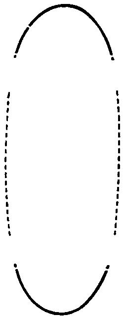
Figs. 79 and 80: The ovals contained
in these figures are simply foreshortened
circles, and as such forms are of frequent
occurrence in sketching from objects, in bridges,
wheels, ends of timber, etc., they should be carefully
studied; the greatest difficulty is to turn the narrow
ends, and prevent their looking like corners. For this
purpose it is better to draw the short curves first, thus:
and then join the longer sides to them.
Fig. 81: If this figure can be drawn correctly, a
great success has been achieved; the circle is a most
difficult form to delineate, and without system could
not be accomplished. Draw the square and straight
lines within it with great care, examine each point of
the octagon to see that it is at the same distance from
the centre, and then draw the circle.
Several figures, 83 to 96, representing more or less
familiar parts of machines, utilities, etc., are introduced
for practice in free-hand, but—
It must be noted that even in free-hand the wise
student will occasionally use the straight edge and
compasses, so as to make his first attempts fairly creditable.
Many good draughtsmen have begun by simply
copying such figures and illustrations as are used
throughout this volume and other similar sources;
perhaps there is nothing better for practice or training
than the copying and reproducing of samples of good
mechanical drawings, yet it must always be remembered
that advancement in free-hand must be made in
the line of less to greater efforts, and that the why and
wherefore will be constantly asked by the aspiring student;
that good and correct drawings are to be aimed
for at all times in every line and dimension—never
forgetting the law of proportion in the smallest outlines
of objects to be represented.
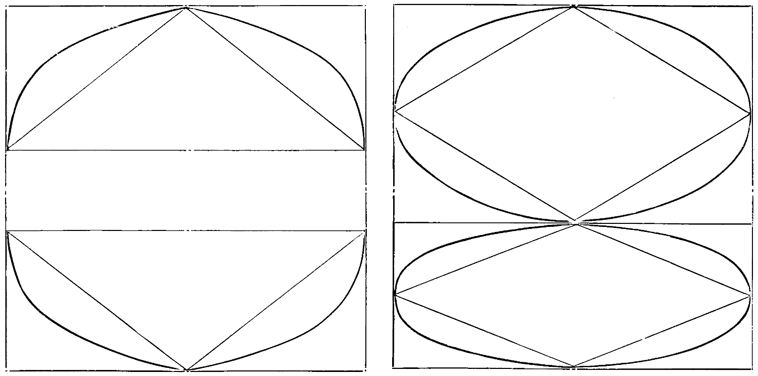
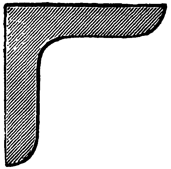
Fig. 83 is a section, or end view of a bar of angle
iron; the student will find helpful practice in attempting
this figure; he may be allowed to use a straight-edge
in drawing the lines, but no measurements; the
work should be tested on completion by a rule, or
better by penciling from the original on tracing paper,
and comparing the free-hand with the copy, when the
defective proportions, if any, will be clearly exhibited.
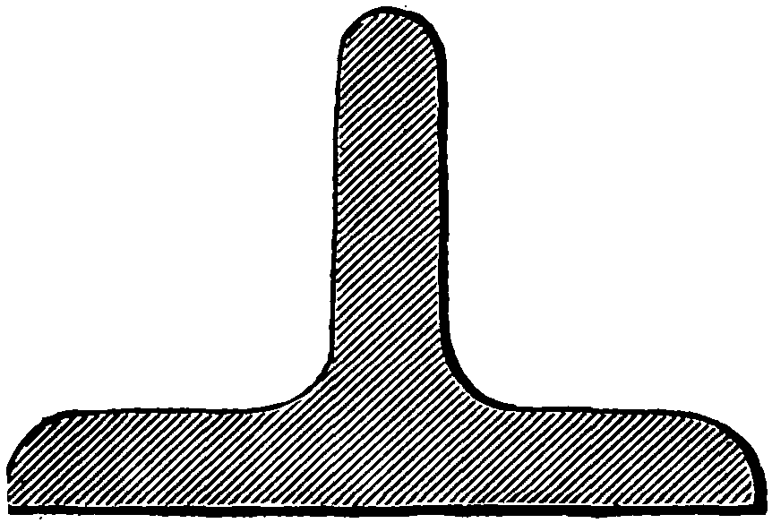
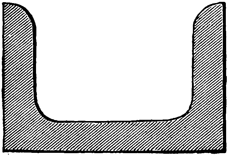
Fig. 84 is a section of tee iron, and fig. 85 is a
section of channel iron. These three figures on page
75 should be practiced alternately, although seeming
similar in shape.
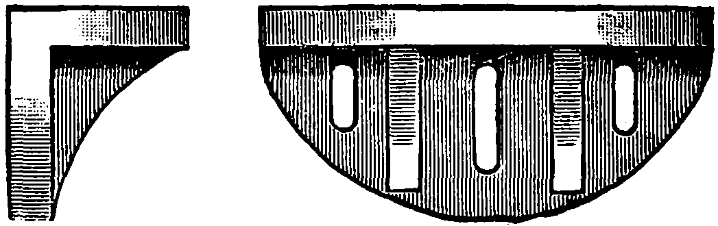
Fig. 86 is a side and end view of an angle plate
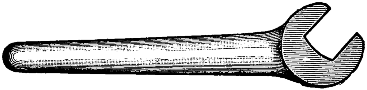
shaded. Fig. 87 is a wrench shaded.
Examples of bolt ends are shown in the two next
numbers; fig. 88 exhibits the common square-head
bolt, and fig. 89 the hexagon or six-sided bolt-head;
these are also examples of straight-line shading. Fig.
90 is a lathe-dog, and shows an example of curved
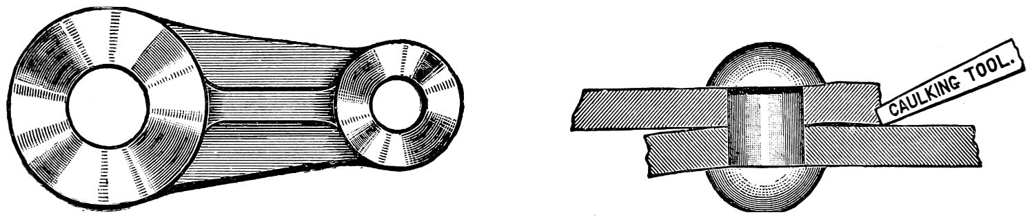
shading; fig. 92 is an engine crank, and an example of
straight and curved shading; fig. 91 is a screw clamp.
Fig. 93 is a section of boiler plates riveted together;
a caulking tool is also shown.
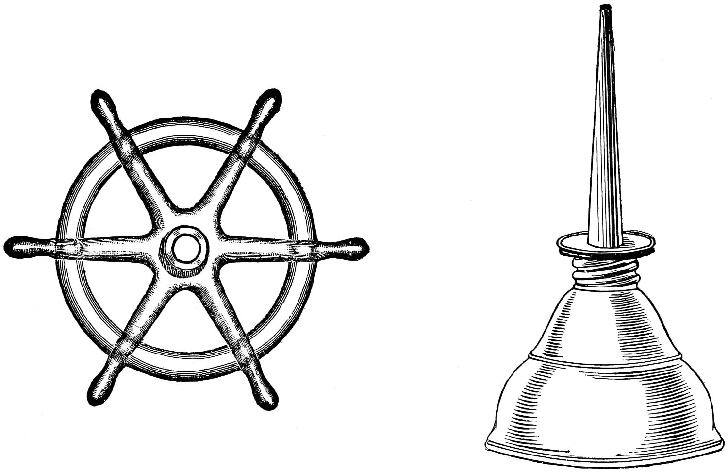
In the example, fig. 94—a hand-wheel—the principal
difficulty, even for the most advanced student
in free-hand, will be in drawing the circles; a coin, if
convenient, can be used to scribe about, in drawing
these; the other parts can afterwards be filled in around
the circle. Fig. 96 is introduced for practice in penciling
and shading; the figure represents a water-wheel
on a stone pier.
The familiar oil can is shown in fig. 95. These all
are excellent objects for practice.
Fig. 83.—Fig. 84.—Fig. 85.

Fig. 88.—Fig. 89.—Fig. 90.—Fig. 91.
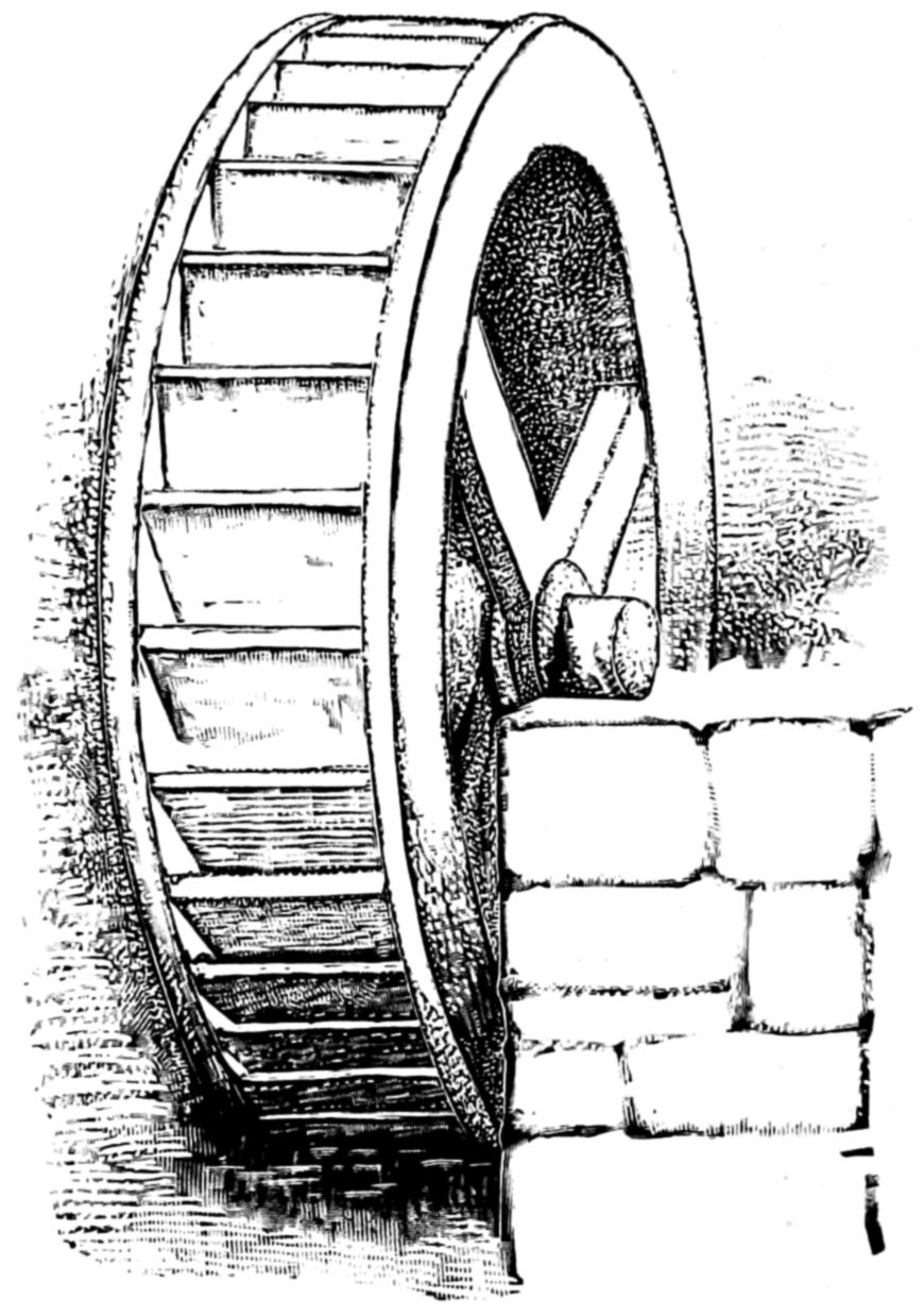
Fig. 96.
Geometrical Drawing. — GEOMETRICAL AXIOMS.
Geometry is the science of measurement; it has
been known for more than three thousand years;
many lives have been devoted to its development, and
it exists to-day as the foundation of all mathematics.
Geometrical drawing is the art of representing, to
the eye, the problems “worked out” by geometricians,
and the importance of a knowledge of geometrical
drawing is paramount. The student will find that the
figures delineated and explained in the next few pages
constantly occur in mechanical drawing. Says Walter
Smith, State Director of Art Education in Massachusetts,
“I have never known a case where a student did
not progress more satisfactorily in his studies after a
course of practical geometry.”
The elementary conceptions of geometry are few:
1.—A point.
2.—A line.
3.—A surface.
4.—A solid, and
5.—An angle.
All of which elements are used in mechanical drawings.
From these, as data, a vast number of mathematical
problems have been deduced; of which a few of
the most elementary will be illustrated in this work;
but these few will repay the attention of the student.
In “freehand” drawing the crayon and pencil
are used; in geometrical drawings the dividers, as
shown in illustration, fig. 97, together with a rule, are
all that is necessary to accomplish the work.
A problem is something to be done, and geometry
has been defined as the science of measurement; the
relation between geometry and mechanical drawing
is very close, hence the term “geometrical problem.”

Fig. 97.

Fig. 98.
Before proceeding with the examples, a few
elementary statements belonging to the science of
geometry are presented; these will be useful to the
student, not only while “doing” the problems, but in
many cases of every-day—future—experience.
Geometry is one of the oldest and simplest of
sciences; it may be defined as the science of measurement;
geometry is the root from which all regular
mathematical calculations issue. It has claimed the
best thought of practical men from the times of the
Greeks and Romans two thousand years ago; they
derived their knowledge of the science from the Egyptians,
who in turn were indebted to the Chaldeans and
Hindoos in times beyond any authentic history;
hence it was under the operations of
the laws explained in geometry, that the pyramids
of Egypt and the temples of Greece were
constructed, as well as the engines of war and
appliances of peace of ancient times.
A point is mere position, and has no magnitude.
A line is that which has extension in length only.
The extremities of lines are points.
A surface is that which has extension in length
and breadth only.
A solid is that which has extension in length,
breadth and thickness.
An angle is the difference in the direction
of two lines proceeding from the same
point.
Lines, Surfaces, Angles and Solids constitute the
different kinds of quantity called geometrical magnitudes.
Parallel lines are lines which have the
same direction; hence parallel lines can
never meet, however far they may be produced; for
two lines taking the same direction cannot approach or
recede from each other.
An Axiom is a self-evident truth, not only too
simple to require, but too simple to admit of demonstration.
A Proposition is something which is either proposed
to be done, or to be demonstrated, and is either a
problem or a theorem.
A Problem is something proposed to be done.
A Theorem is something proposed to be demonstrated.
A Hypothesis is a supposition made with a view to
draw from it some consequence which establishes the
truth or falsehood of a proposition, or solves a problem.
A Lemma is something which is premised, or
demonstrated, in order to render what follows more
easy.
A Corollary is a consequent truth derived immediately
from some preceding truth or demonstration.
A Scholium is a remark or observation made upon
something going before it.
A Postulate is a problem, the solution of which is
self-evident.
Let it be granted—
III. That a straight line can be drawn from any
one point to any other point;
III. That a straight line can be produced to any
distance, or terminated at any point;
III. That the circumference of a circle can be
described about any center, at any distance from that
center.
The common algebraic signs are used in Geometry,
and it is necessary that the student in geometry should
understand some of the more simple operations of
algebra. As the terms circle, angle, triangle, hypothesis,
axiom, theorem, corollary and definition are constantly
occurring in a course of geometry, they are
abbreviated as shown in the following list:
| Addition is expressed by |
+ |
| Subtraction is expressed by |
- |
| Multiplication is expressed by |
× |
| Equality and Equivalency are expressed by |
= |
| Greater than, is expressed by |
> |
| Less than, is expressed by |
< |
| Thus B is greater than A, is written |
B > A |
| Thus B is less than A, is written |
B < A |
| A circle is expressed by |
O |
| An angle is expressed by |
L |
| A right angle is expressed by |
R. L |
| Degrees, minutes and seconds are expressed by |
° ′ ″ |
| A triangle is expressed by |
△ |
| The term Hypothesis is expressed by |
(Hy.) |
| The term Axiom is expressed by |
(Ax.) |
| The term Theorem is expressed by |
(Th.) |
| The term Corollary is expressed by |
(Cor.) |
| The term Definition is expressed by |
(Def.) |
| The term Perpendicular is expressed by |
⊥ |
| The difference of two quantities, when it is not known which is the greater, is expressed by the symbol |
~ |
| Thus, the difference between A and B is written |
A ~ B |
1. Things which are equal to the same thing are
equal to each other.
2. When equals are added to equals the wholes are
equal.
3. When equals are taken from equals the remainders
are equal.
4. When equals are added to unequals the wholes
are unequal.
5. When equals are taken from unequals the
remainders are unequal.
6. Things which are double of the same thing, or
equal things, are equal to each other.
7. Things which are halves of the same thing, or
of equal things, are equal to each other.
8. The whole is greater than any of its parts.
9. Every whole is equal to all its parts taken
together.
10. Things which coincide, or fill the same space,
are identical, or mutually equal in all their parts.
11. All right angles are equal to one another.
12. A straight line is the shortest distance between
two points.
13. Two straight lines cannot enclose a space.
Problems in Geometrical Drawing.
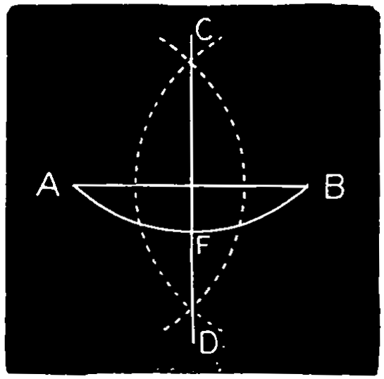
Fig. 99.
Example 1.—To bisect
(cut in two) a straight line or
an arc of a circle, Fig. 99.
From the ends of A B as
centers, describe arcs cutting
each other at C and D, and
draw C D, which cuts the
line at E or the arc at F.
Ex. 2.—To draw a perpendicular to a straight line,
or a radial line to a circular arc, Fig. 99. Operate as
in the foregoing problem. The line C D is perpendicular
to A B; the line C D is also radial to the arc
A B.
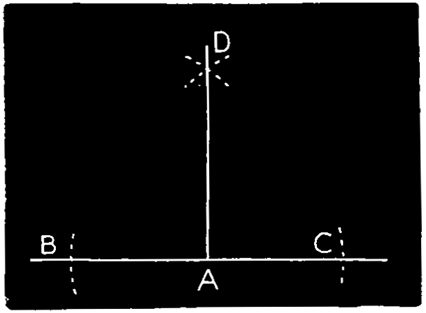
Fig. 100.

Fig. 101.
Ex. 3.—To draw a
perpendicular to a straight
line, from a given point in
that line, Fig. 100. With
any radius from any given
point A in the line B C,
cut the line at B and C.
Next, with a longer radius,
describe arcs from B and C, cutting each other at D,
and draw the perpendicular D A.
Second Method, Fig.
101. From any center F
above B C, describe a circle
passing through the
given point A, and cutting
the given line at D; draw
D F, and produce it to cut
the circle at E; and draw
the perpendicular A E.
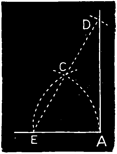
Fig. 102.
Third Method, Fig. 102. From
A describe an arc E C, and from E,
with the same radius, the arc A C
cutting the other at C; through C
draw a line E C D and set off C D
equal to C E, and through D draw
the perpendicular A D.
Fig. 103.
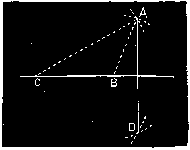
Fig. 104.
Ex. 4.—To draw a perpendicular
to a straight line from
any point without it, Fig. 103.
From the point A with a sufficient
radius cut the given line at
F and G; and from these points
describe arcs cutting at E. Draw
the perpendicular A E.
If there be no room below the line, the intersection
may be taken above the line; that is to say, between
the line and the given point.
Second Method,
Fig. 104. From any two
points B C at some distance
apart, in the given
line, and with the radii
B A, C A, respectively,
describe arcs cutting at
A D. Draw the perpendicular
A D.
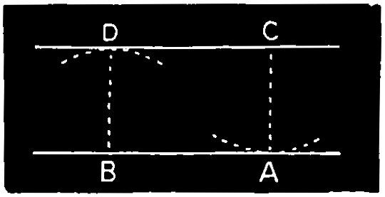
Fig. 105.
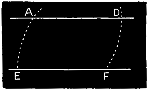
Fig. 106.
Ex. 5.—To draw a parallel
line through a given
point, Fig. 105. With a radius
equal to the given point C
from the given line A B,
describe the arc D from B, taken considerably distant
from C. Draw the parallel through C to touch the
arc D.
Second Method, Fig. 106.
From A, the given point,
describe the arc F D, cutting
the given line at F; from F,
with the same radius, describe
the arc E A, and set off F D,
equal to E A. Draw the parallel through the points A D.
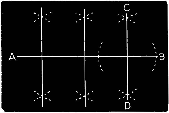
Fig. 107.
When a series of parallels are required perpendicular
to a base line A B, they may be drawn as in fig.
107 through points in
the base line set off at
the required distances
apart. This method is
convenient also where
a succession of parallels
are required to a
given line C D, for the
perpendicular may be
drawn to it, and any number of parallels may be drawn
on the perpendicular.
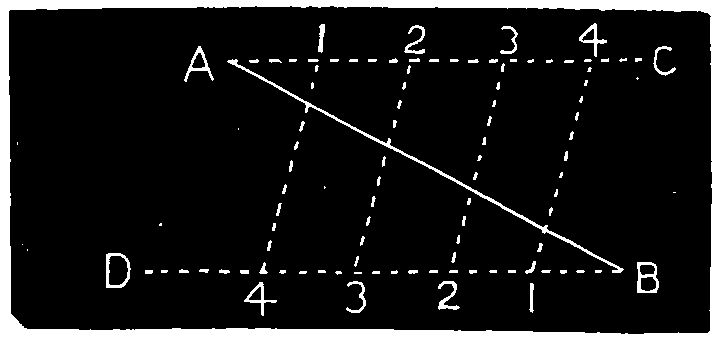
Fig. 108.
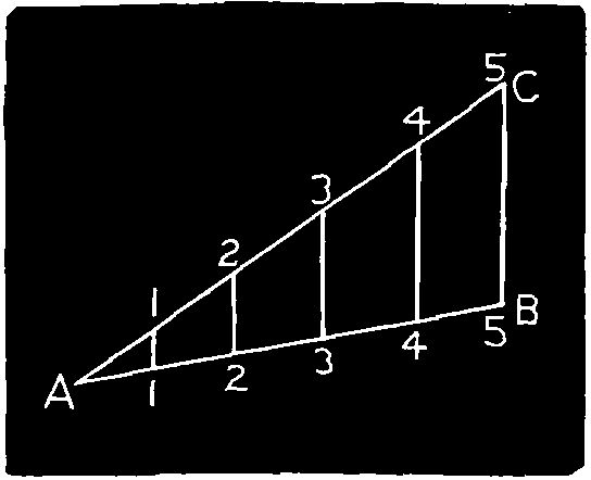
Fig. 109.
Ex. 6.—To divide a line into a number of equal
parts, Fig. 108.
To divide the
line A B into, say,
five parts. From A
and B draw parallels
A C, B D on opposite
sides; set off any
convenient distance four times (one less than the given
number), from A on A C, and on B on B D; join the
first on A C to the fourth on B D, and so on. The
lines so drawn divide A B as required.
Second Method, Fig. 109.
Draw the line at A C, at an
angle from A, set off, say, five
equal parts; draw B 5, and
draw parallels to it from the
other points of division in A
C. These parallels divide A
B as required.
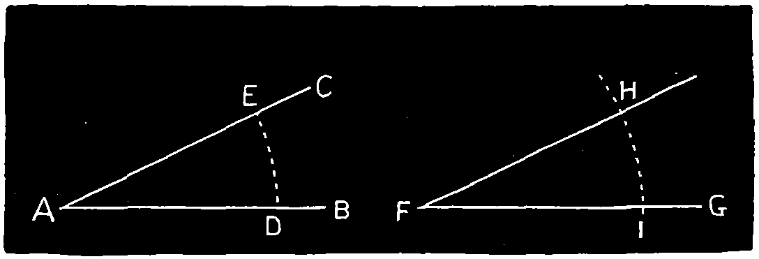
Fig. 110.
Ex. 7.—Upon a straight line to draw an angle
equal to a given angle, Fig. 110. Let A be the given
angle and F G the line. With any radius from the
points A and F, describe arcs D E, I H, cutting the
sides of the angle A and the line F G.
Set off the arc I H, equal to D E and draw F H.
The angle F is equal to A
as required.
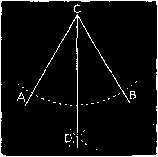
Fig. 111.
Ex. 8.—To bisect an angle,
Fig. 111. Let A C B be
the angle; on the center C
cut the sides at A B. On A
and B as centers describe arcs
cutting at D dividing the
angle into two equal parts.
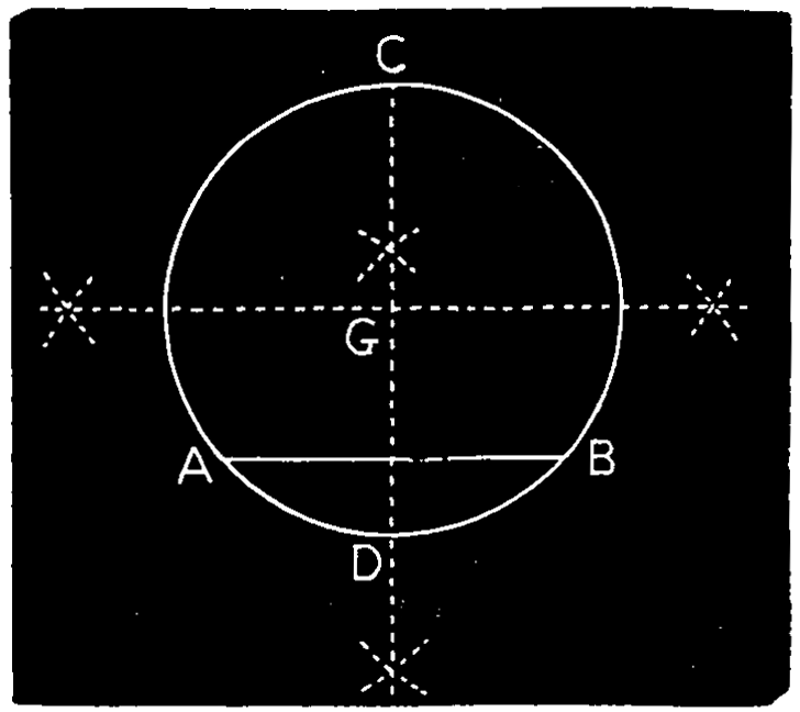
Fig. 112.
Ex. 9.—To find
the center of a circle
or of an arc of a circle.
Fig. 112. Draw
the chord A B, bisect
it by the perpendicular
C D, bounded
both ways by the circle;
and bisect C D
for the center G.
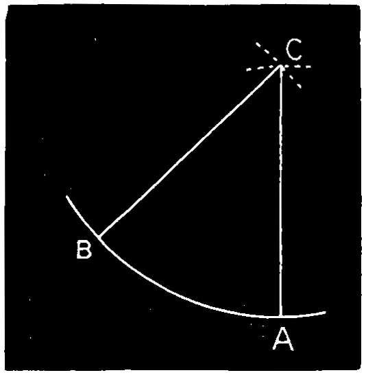
Fig. 113.
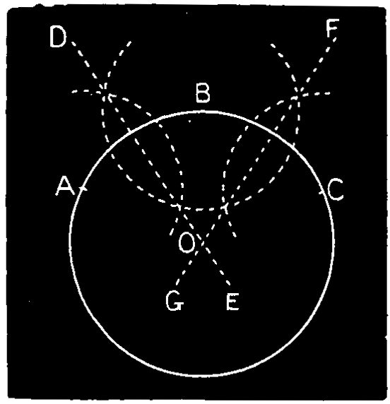
Fig. 114.
Ex. 10.—Through two
given points to describe an
arc of a circle with a given
radius, Fig. 113. On the
points A and B as centers,
with the given radius, describe
arcs cutting at C; and
from C, with the same radius,
describe an arc A B as required.
Second, for a circle or
an arc, Fig. 114. Select three
points A, B, C in the circumference,
well apart; with
the same radius describe
arcs from these three points
cutting each other, and draw
two lines D E, F G, through
their intersections according
to Fig. 107. The point where
they cut is the center of the circle or arc.
Ex. 11.—To describe a circle passing through three
given points, Fig. 114. Let A, B, C be the given points
and proceed as in last problem to find the center O,
from which the circle may be described.
This problem is variously useful; in finding the
diameter of a large fly-wheel, or any other object of
large diameter when only a part of the circumference
is accessible; in striking out arches when the span and
rise are given, etc.
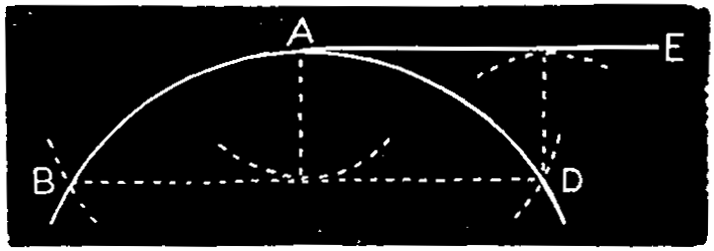
Fig. 115.
Ex. 12.—To draw a tangent to a circle from a given
point in the circumference, Fig. 115. From A set off
equal segments A B,
A D, join B D and
draw A E, parallel to
it, for the tangent.
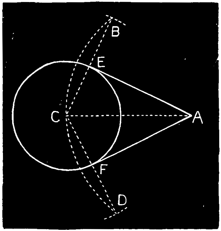
Fig. 116.
Ex. 13.—To
draw tangents to a
circle from points
without it, Fig. 116.
From A with the
radius A C describe
an arc B C D, and
from C with a radius
equal to the diameter
of the circle,
cut the arc at B D,
join B C, C D, cutting
the circle at E F, and draw A E, A F, the tangents.
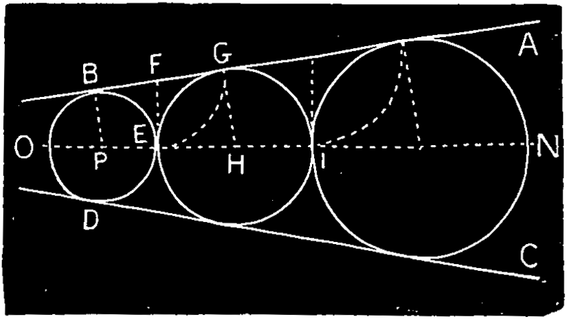
Fig. 117.
Ex. 14.—Between two inclined lines to draw a series
of circles touching these lines and touching each other,
Fig. 117. Bisect the inclination of the given lines A B,
C D by the line N O. From a point P in this line draw
the perpendicular P B to the line A B, and on P describe
the circle B D, touching the lines and cutting the
center lines at E. From E draw E F perpendicular to
the center line, cutting A B at F, and from F describe
an arc E G, cutting A B at G. Draw G H parallel to
B P, giving H, the center of the next circle, to be described
with the radius H E, and so on for the next
circle, I N.
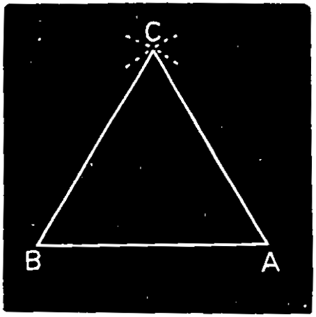
Fig. 118.
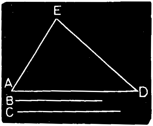
Fig. 119.
Ex. 15.—To construct a triangle
on a given base, the sides
being given.
First. An equilateral triangle,
Fig. 118. On the ends of a given
base A B, with A B as a radius
describe arcs cutting at C, and
draw A C, C B.
Second. Triangle of unequal sides, Fig. 119. On
either end of the base A D, with the side B as a radius
describe an arc; and with the side C as a radius, on
the other end of the base as a center, describe arcs cutting
the arc at E; join A E,
D E.
This construction may be
used for finding the position
of a point C or E at given
distances from the ends of a
base, not necessarily to form
a triangle.
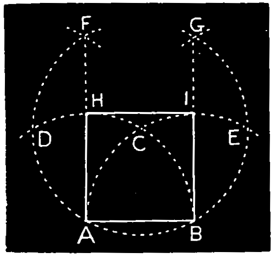
Fig. 120.
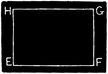
Fig. 121.
Ex. 16.—To construct a
square rectangle on a given
straight line.
First. A square, Fig.
120. On the ends B A as
centers, with the line A B
as radius, describe arcs cutting
at C; on C describe
arcs cutting the others at
D E; and on D and E cut these at F G. Draw
A F, B G and join the intersections H I.
Second. A rectangle, Fig.
121. On the base E F draw the
perpendiculars E H, F G, equal
to the height of the rectangle,
and join G H.
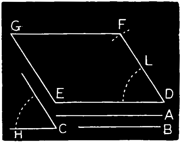
Fig. 122.
Ex. 17.—To construct a
parallelogram of which the
sides and one of the angles
are given, Fig. 122. Draw
the side D E equal to the
given length A, and set off
the other side D F equal to
the other length B, forming
the given angle C. From E with D F as radius,
describe an arc, and from F, with the radius D E cut
the arc at G. Draw F G, E G. Or, the remaining
sides may be drawn as parallels to D E, D F.
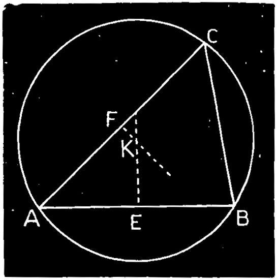
Fig. 123.
Ex. 18.—To describe a
circle about a triangle, Fig.
123. Bisect two sides A B,
A C of the triangle at E F,
and from these points draw
perpendiculars cutting at K.
On the center K, with the
radius K A draw the circle
A B C.
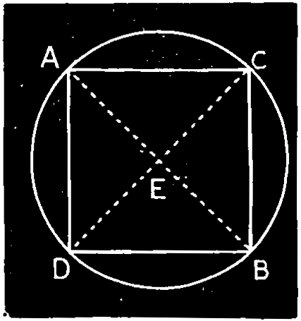
Fig. 124.
Ex. 19.—To describe a circle about a square, and
to inscribe a square in a circle, Fig. 124.
First. To describe the circle.
Draw the diagonals A B, C D of
the square, cutting at E; on the
center E with the radius E A
describe the circle.
Second. To inscribe the square. Draw the two
diameters A B, C D at right angles and join the points
A B, C D to form the square.
In the same way a circle may be described about a
triangle.
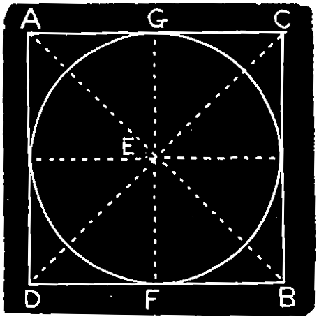
Fig. 125.
Ex. 20.—To inscribe a circle on a square, and to
describe a square about a circle, Fig. 125.
First. To inscribe the circle. Draw the diagonals
A B, C D of the square, cutting at E; draw the perpendicular
E F to one side, and with the radius E F
describe the circle.
Second. To describe the square. Draw two diameters
A B, C D at right angles, and produce them;
bisect the angle D E B at the center by the diameter
F G, and through F and G draw perpendiculars A C,
B D, and join the points A D and B C where they
cut the diagonals to complete the square.
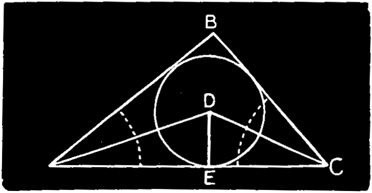
Fig. 126.
Ex. 21.—To inscribe
a circle in a
triangle, Fig. 126.
Bisect two of the
angles A C of the
triangle by lines
cutting at D; from
D draw a perpendicular D E to any side, and with
D E as radius describe a circle.
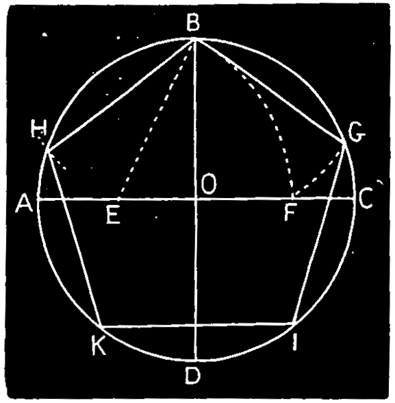
Fig. 127.
Ex. 22.—To inscribe a pentagon in a circle, Fig. 127.
Draw two diameters A C,
B D at right angles cutting
at O; bisect A O at
E, and from B with radius
B E cut the circumference
at G H and with the same
radius step round the circle
to I and K; join the points
to form the pentagon.
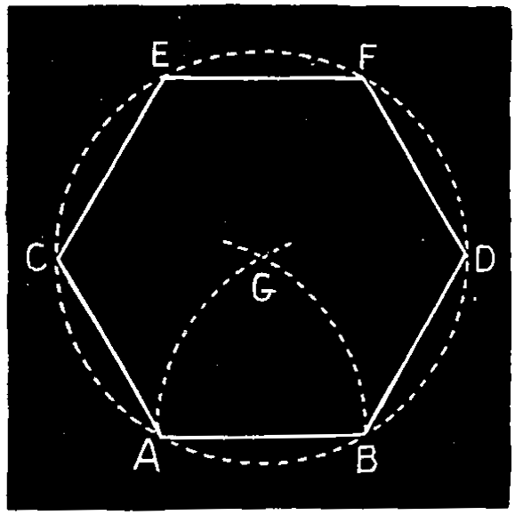
Fig. 128.
Ex. 23.—To construct
a hexagon upon a given
straight line, Fig. 128.
From A and B, the ends
of the given line, describe
arcs cutting at G; from G
with the radius G A describe
a circle. With the
same radius set off the
arcs A C, C F and B D,
D E; join the points so found to form the hexagon.
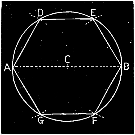
Fig. 129.
Ex. 24.—To inscribe a hexagon in a circle, Fig. 129.
Draw a diameter A C B;
from A and B as centers,
with the radius of the circle
A C cut the circumference
at D, E, F, G, and
draw A D, D E, etc., to
form the hexagon. The
points D E, etc., may be
found by stepping the
radius (with the dividers)
six times round the circle.
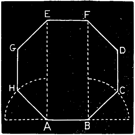
Fig. 130.
Ex. 25.—To describe an
octagon on a given straight
line, Fig. 130. Produce the
given line A B both ways
and draw perpendiculars
A E, B F; bisect the external
angles A and B by
the lines A H, B C, which
make equal to A B. Draw
C D and H G parallel to
A E and equal to A B;
from the center G D, with the radius A B, cut the perpendiculars
at E F, and draw E F to complete the hexagon.
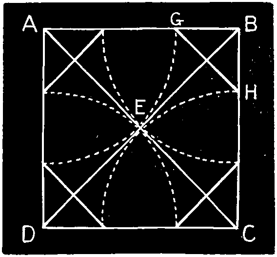
Fig. 131.
Ex. 26.—To convert a
square into an octagon, Fig.
131.—Draw the diagonals
of the square cutting at E;
from the corners A, B, C, D,
with A E as radius, describe
arcs cutting the
sides at G, H, etc., and
join the points so found
to complete the octagon.
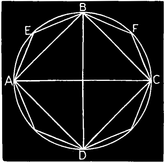
Fig. 132.
Ex. 27.—To inscribe
an octagon in a circle, Fig.
132. Draw two diameters
A C, B D, at right angles;
bisect the arcs A B, B C,
at E, F, etc., to form the
octagon.
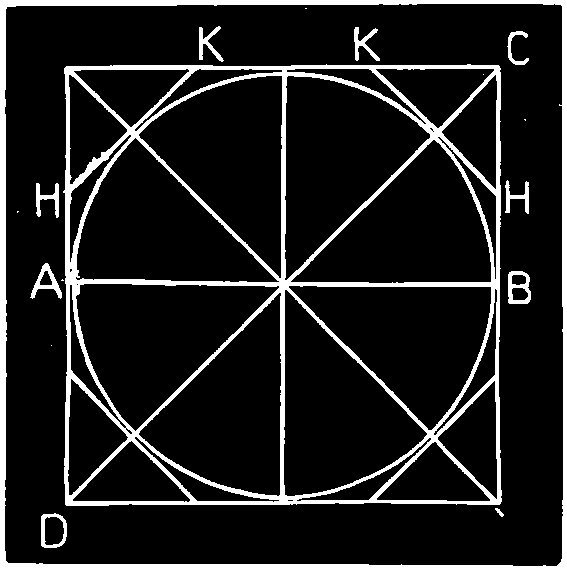
Fig. 133.
Ex. 28.—To describe
an octagon about a circle, Fig. 133. Describe a square
about the given circle A B,
draw perpendiculars H
and K, to the diagonals,
touching the circle to form
the octagon. Or, the points
H, K, etc., may be found
by cutting the sides from
the corners, by lines parallel
to the diagonals.
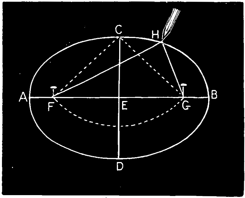
Fig. 134.
Ex. 29.—To describe an ellipse when the length and
breadth are given, Fig. 134. On the center C, with A E
as radius, cut the axis A B at F and G, the foci, fix
a couple of pins into the axis at F and G, and loop on a
thread or cord
upon them
equal in length
to the axis A B,
so as when
stretched to
reach the extremity
C of
the conjugate
axis, as shown
in dot-lining.
Place a pencil
or drawpoint
inside the cord, as at H, and guiding the pencil in this
way, keeping the cord equally in tension, carry the
pencil round the pins F, G, and so describe the ellipse.
Note.—The ellipse is an oval figure, like a circle in perspective.
The line that divides it equally in the direction of its
great length is the transverse axis, and the line which divides the
opposite way is the conjugate axis.
Second Method. Along the straight edge of a
piece of stiff paper mark off a distance a c equal to
A C, half the transverse axis; and from the same point
a distance a b equal to C D, half the conjugate axis.
Place the slip so as to bring the point b on the line A B
of the transverse axis, and the point c on the line
D E; and set off on the drawing the position of
the point a. Shifting the slip, so that the point
travels on the transverse axis, and the point c on
the conjugate axis, any number of points in the curve
may be found, through which the curve may be traced.
See fig. 135.
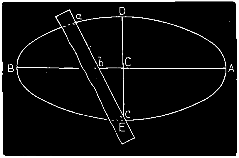
Fig. 135.
Trigonometry. — DEFINITIONS.
Trigonometry is that portion of geometry which
has for its object the measurement of triangles. When
it treats of plane triangles, it is called Plane Trigonometry;
and as the engineer will continually meet
in his studies of higher mathematics the terms used
in plane trigonometry, it is advantageous for him
to become familiar with some of the principles and
definitions relating to this branch of mathematics.
The circumferences of all circles contain the same
number of degrees, but the greater the radius the
greater is the absolute measures of a degree. The
circumference of a fly wheel or the circumference of
the earth have the same number of degrees; yet the
same number of degrees in each and every circumference
is the measure of precisely the same angle.
The circumference of a circle is supposed to be
divided into 360 degrees or divisions, and as the total
angularity about the center is equal to four right
angles, each right angle contains 90 degrees, or 90°,
and half a right angle contains 45°. Each degree is
divided into 60 minutes, or 60′; and for the sake of still
further minuteness of measurement, each minute is
divided into 60″. In a whole circle there are, therefore,
360 × 60 × 60 = 1,296,000 seconds. The annexed diagram,
fig. 136, exemplifies the relative positions of the
Sine,
Co-sine,
Versed Sine,
Tangent,
Co-Tangent,
Secant and
Co-secant
of an angle.
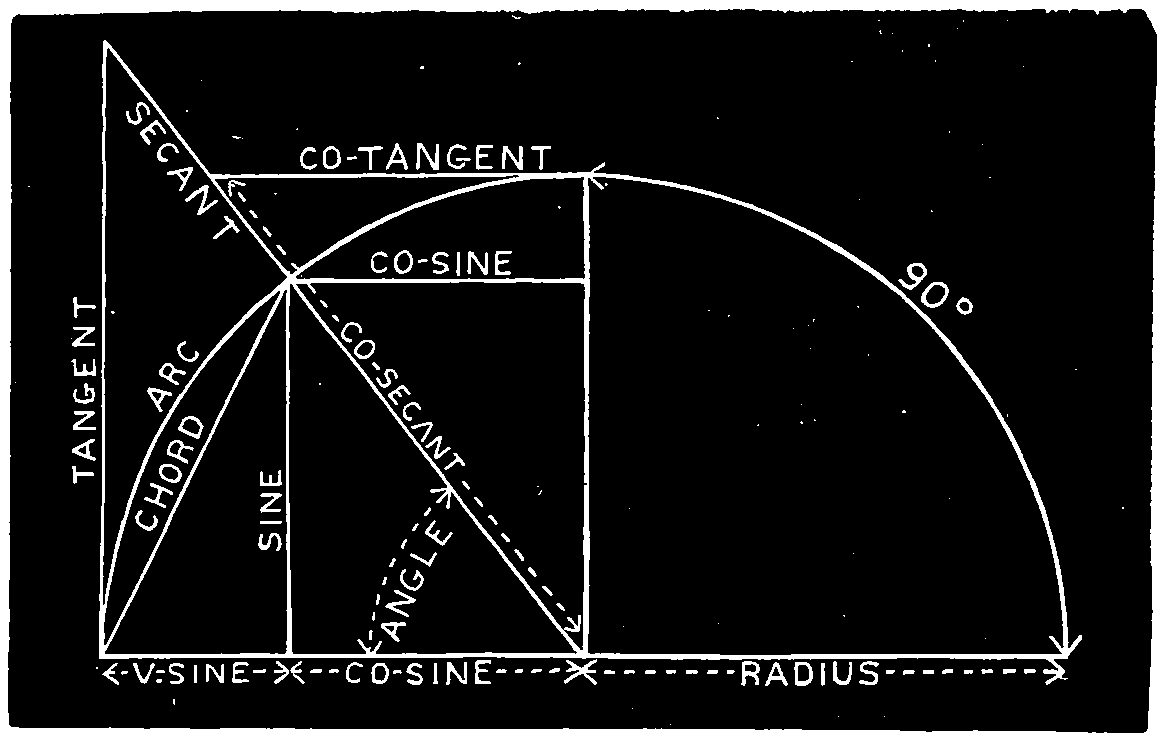
Fig. 136.
These may be defined thus:
1. The Complement of an arc is 90° minus the arc.
2. The Supplement of an arc is 180° minus the arc.
3. The Sine of an angle, or of an arc, is a line
drawn from one end of an arc, perpendicular to a diameter
drawn through the other end.
4. The Cosine of an arc is the perpendicular distance
from the center of the circle to the sine of the
arc; or, it is the same in magnitude as the sine of the
complement of the arc.
5. The Tangent of an arc is a line touching the
circle in one extremity of the arc, and continued from
thence, to meet a line drawn through the center and
the other extremity.
6. The Cotangent of an arc is the tangent of the
complement of the arc. The Co is but a contraction of
the word complement.
7. The Secant of an arc is a line drawn from the
center of the circle to the extremity of the tangent.
8. The Cosecant of an arc is the secant of the
complement.
9. The Versed Sine of an arc is the distance from
the extremity of the arc to the foot of the sine.
For the sake of brevity, these technical terms are
contracted thus: for sine A B, we write sin. A B; for
cosine A B, we write cos. A B; for tangent A B, we
write tan. A B, etc.
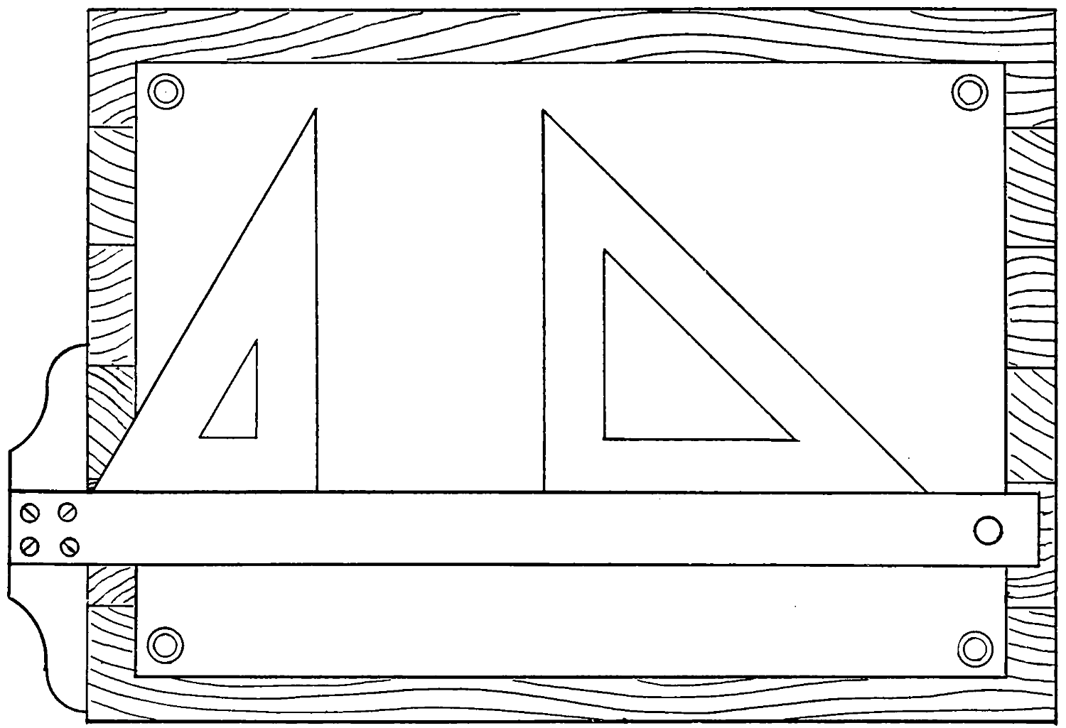
Fig. 137.
Drawing Materials and Instruments. — THE DRAWING BOARD. — THE TEE-SQUARE. — ADJUSTABLE BLADED SQUARE. — TRIANGLES, OR SET-SQUARES. — PARALLEL RULE. — SECTION LINER. — IRREGULAR CURVE OR SCROLL. — ELLIPSES. — DRAWING PENCILS. — DIVIDERS AND COMPASSES. — PROPORTIONAL DIVIDERS. — COMPASSES. — SPRING BOWS. — BEAM COMPASSES AND TRAMMELS. — DRAWING SCALES. — DRAWING-PENS. — DRAWING PAPER.
Drawing tools or instruments are contrived solely
for mechanical drawing; aside from this use they are
perfectly worthless, hence the quality of these special
utensils is a matter of the first consideration to the earnest
student.
There are several degrees of excellence to be found
in the make-up of drawing instruments and materials;
it may be remarked with truth that “any kind are good
enough, and the best none too good,” i. e., a learner in
this delightful art should not stop at the lack of goodness
or the low grade existing in his “tools,” but
rather do the best work possible with the means at
hand.
However, in order that acceptable work may be
accomplished, fairly good instruments should be procured.
The advice of some one experienced in the use
and care of draughting tools should be sought before
purchasing. A drawing board, a single sheet of paper
and a pencil is the simplest “outfit” to be thought of;
to this small beginning may be added, soon afterwards,
an inexpensive pair of compasses, a T-square and a
couple of triangles; a vast range of work can be executed
with these few tools.
Nothing else will be needed to do fine work
except, perhaps, one or two pairs of better compasses
and a few sweeps or means of drawing irregular
curves; all these had best be purchased separately; for
in buying a “box of instruments,” it may contain some
articles which are not desired, or that are of a wrong
size, or even duplicates of those already possessed.
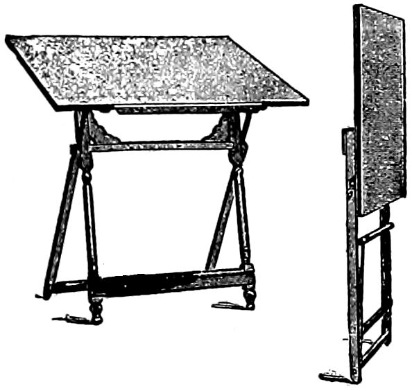
Fig. 138.
An outfit recommended by the author of “Reed’s
Hand Book” is as follows.
Large compasses with
movable leg.
A pair of dividers.
Bow pencil.
Bow pen.
Pencil leg for large compasses.
Pen leg for large compasses.
Drawing pen.
Louis Rouillon, B. S., Instructor of Drawing in
Pratt Institute, New York, recommends the following:
Compasses, 51⁄2 inches, with needle point; pen
pencil and lengthening bar.
Drawing pen, 41⁄2 inches.
T-square, 24-inch blade.
45-degree triangle, 9 inches.
30 and 60 degree triangle, 9 inches.
1 Scroll.
Dixon’s V. H. pencil.
12-inch boxwood scale, flat, graduated 1⁄16 inch
the entire length.
Bottle of liquid India ink, four thumb-tacks, pen
and ink eraser.
20 sheets drawing paper, 11 × 15 inches, and a
drawing-board about 16 × 23 inches will also be necessary;
students can usually make the board themselves
for less money than it can be bought.
Note.—The purchasing of drawing tools is one of the most
difficult points to settle that can present itself to a person about to
buy a drawing outfit for the first time. Nothing can be so productive
of distress to a person drawing as to have his tools getting out
of order, joints one day too tight, next day too slack, points getting
blunt or perhaps turning up altogether; if needle points, then
the needles slip up, and drawing spoiled; in fact, the purchaser
can be annoyed in numberless different ways.—W. H. Thorn.
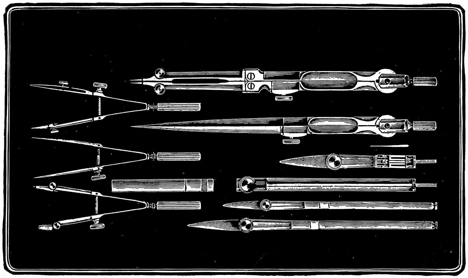
Fig. 139.
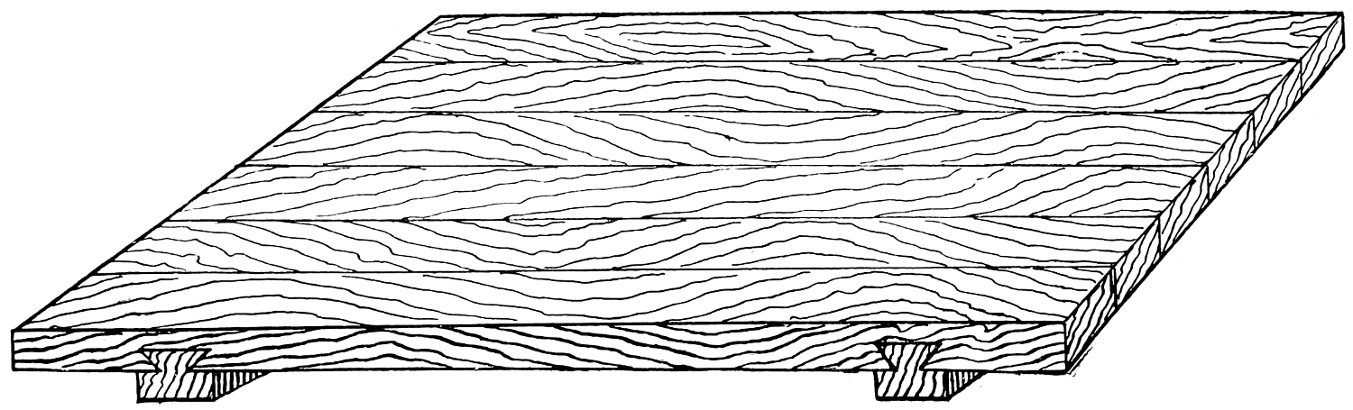
Fig. 140.
A drawing-board should be made of well seasoned
pine of a convenient size, say 23 × 16, which will take
half a sheet of imperial paper, leaving 1⁄2-inch margin
all around.
The working surface of the board—or its front
side—should be perfectly smooth, but instead of being
flat it should have a very slight camber, or rounding,
breadthways, this latter feature in its construction
being to prevent the possibility of a sheet of paper
when stretched on its surface having any vacuity
beneath it.
The four edges of the board need not form an
exact rectangle, as much valuable time is often wasted
in the attempts to produce such a board; but it will
answer every purpose of the draughtsman so long as
the adjacent edges at the lower left-hand corner of it
are at right angles, or square to each other.
An English authority recommends the use of two
drawing-boards, 42 inches long and 30 inches wide,
made of plain stuff, without cleets, 11⁄4 inches thick—seasoned—with
edges perfectly straight and at right
angles to each other. With two boards, one may be
used for sketching and drawing details and the other for
the finished drawing.
The board should be 3⁄4 inch in thickness, and
fitted at the back, at right angles to its longest side,
with a couple of hardwood battens, about 2 inches wide
and 3⁄4 inch thick; the use of these battens being to
keep the board from casting or winding and to allow
of its expansion or contraction through changes of
temperature. This latter purpose, however, is only
effected by attaching the battens to the back of the
board in the following manner: ... At the middle
of the length of each batten—which should be one
inch less than the width of the board—a stout, well-fitted
wood screw is firmly inserted into it, and made to
penetrate the board for about 1⁄2 inch, the head of the
screw being made flush with the surface of the batten;
on either side of the central screw, two others, about
31⁄2 inches apart, are passed through oblong holes in
the battens, and screwed into the body of the board
until their heads are flush with the central one; fitted
in this way the board itself can expand or contract
lengthwise or crosswise, while its surface is prevented
from warping or bending.
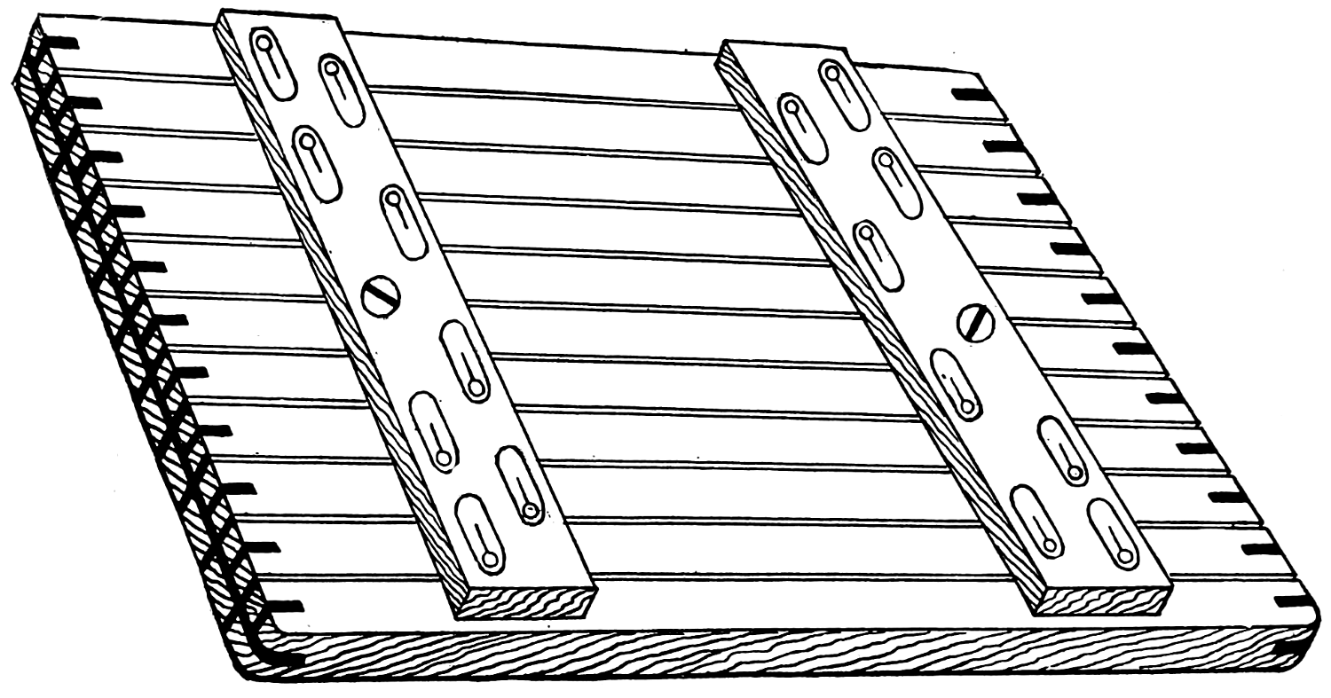
Fig. 141.
A further improvement in such a drawing board
as above shown is made by cutting lengthwise along its
ends a narrow groove and inserting an ebony or hardwood
strip; this is cut or sawn apart at about every
inch to admit of contraction; this strip serves as a guide
to the stock of the drawing square, allowing an easy
sliding movement.
To produce really good work in the shape of a
mechanical drawing, one perfect straight edge only is
required on a drawing board, and that the left one,
which is always known as the working-edge; but for
the convenience of being able to draw a long line across
the board at right angles to its lower edge, this edge is
made truly square with that on the left side of the
board.
The details for building these drawing boards are
given, because they are easy to be made by one who
understands the use of a few wood-working tools; while
the boards themselves are difficult of transportation—in
case of the change of residence of their owners—quite
unlike the instruments which are to accompany
them.
Fig. 141 represents the board which has been described
in the text, with provisions for the contraction
and expansion; the very dark lines are intended to
represent the ebony insertions—as described. Fig. 140
represents a plain pine board with dovetailed battens.
Fig. 142.
Fig. 142 represents the common means used to attach
or secure slightly or temporarily the drawing paper
to the drawing board; these are called thumb-tacks,
and are usually forced through the paper into the wood
by the hand, whence they are easily detached. These
are made to have as slight a projection as may be, so as
not to interfere with the free movement of the tee-square.
For mechanical drawing the invariable practice is
to secure the paper on which the drawing is to be made
to the drawing board by pinning it; this is effected by
various kinds of drawing pins or thumb-tacks.
The best kind for this purpose have a head as
thin as possible without cutting at its edges, slightly
concave on the under side next the paper, and only so
much convex on its upper side as will give it sufficient
thickness to enable the pin to be secured to it; better
use four or more small pins along the edge of a sheet
of paper, than use one clumsy, badly made pin at each
end.
Fig. 143 and fig. 144 represent a pair of plain
trestles or horses in common use for supporting large
size drawing boards. This pattern is found frequently
in the laying-out shop. Fig. 145 and fig. 146 represent
adjustable horses or trestles—these are designed,
primarily, for office use. As will be seen by viewing the
illustration, the upper part is supported by two hard-wood
sliding pieces; these are provided with strong
pins and numerous holes, and pass through the frame
of the trestle, as shown, so that the upper portions can
be arranged at any angle convenient to the draughtsman,
as he lies over his work or stands by it.
Fig. 137 is introduced to exhibit the paper attached
to the drawing board with the thumb-tacks, and with
the T-square and set-squares arranged to commence
work; the paper should not extend to the edges of the
board; three, four or more tacks may be used on
each edge of the sheet of paper, instead of two, as shown
in illustration.
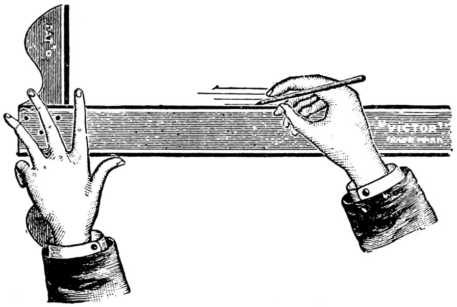
Fig. 147.
A most convenient—and except for its extreme
lightness, which is not good in a drawing stand—a
most admirable device is shown in fig. 138. The drawing
table is simply a drawing board with folding legs;
these are made from hard-wood, while the top is made
of soft, seasoned pine, with square corners; while the
device is strong and well braced, it can be folded and
easily carried about—all as shown in the illustration.
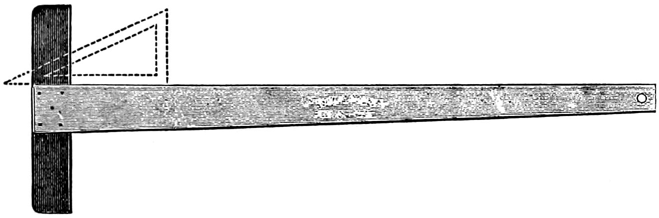
Fig. 148.
This is an instrument in the form of a letter T, as
shown in the figures 149 and 150; the two parts are
known as stock and blade; the horizontal part of the
letter (T) is the stock, and the vertical part the blade—hence
the name, T-square; to form the square,
the two parts are joined together in such a way as to
make them exactly at right angles to each other; the
stock, which is applied to the working edge of the
drawing board, being about one-third the length of the
blade, and about three times its thickness.
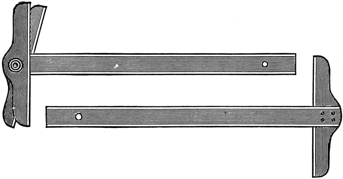
Figs. 149 and 150.
To be perfect in construction, a tee-square should
be as light as is consistent with its necessary strength
and stiffness of parts; it should be made of suitable
material easily manufactured, put together, and repaired,
and withal as truly correct as is possible to be
made. Such a square is represented in fig. 148; it
has a taper blade, which is generally about double
the width where secured to the stock as it is at the
end.
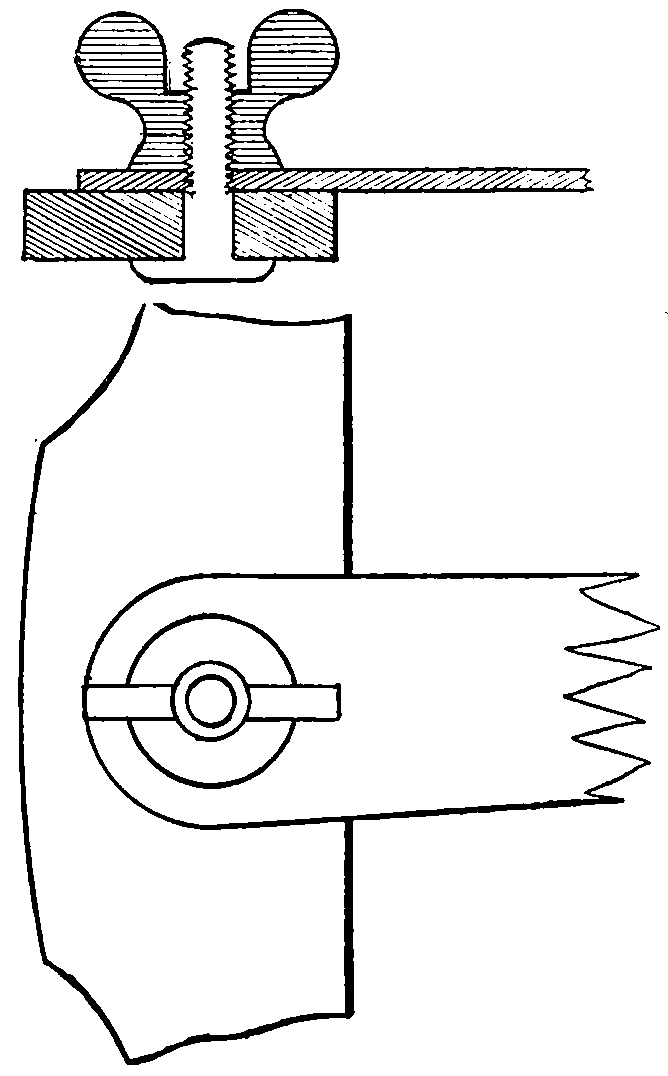
Figs. 151 and 152.
The manner in which the stock is united to the
blade determines its adaptability or otherwise to the
use made of it; in some the stock is rectangular in section,
and the blade mortised into it; in others the
blade is dovetailed and let into the stock for the whole
of its thickness.
In cases where many parallel lines have to be
drawn, of lengths beyond the capabilities of ordinary
set-squares, and in directions other than square with or
parallel to the working edge of the drawing board it is
convenient to have for use an adjustable bladed tee-square,
or one whose blade can be set at any desired
angle. The blade of such a square should be tapered
as in illustration, but shaped at its wide end as shown,
and having a stock wide enough to allow for the surface
required in the washers of the fittings necessary to
make the blade adjustable. These fittings, though requiring
to be well made and neatly finished, are not
expensive or difficult to make, as they consist merely
of two washers, a square-necked bolt, and a fly nut.
The tee-square, as
shown, has four parts: 1,
blade; 2, fixed head; 3,
shifting head; 4, swivel.
The head is held firmly
by the left hand to the left
edge of the drawing board,
and the blade serves as a
straight-edge for horizontal
lines that may extend
the whole length of the
paper. It can be used for
either horizontal, or, by
reversing to the bottom of
the board, for vertical
lines; and, by turning it
over, so that the shifting
head is against the edge of the drawing board instead
of the fixed head, lines at different angles may
be drawn. The length of the blade should be the length
of the drawing board; if it is shorter, inconvenience will
be experienced when lines the whole length of the
board are wanted.
Set-squares are invariably used in connection with
the tee-square, as shown in fig. 148. The illustrations
below show several patterns of the device; by these,
vertical lines, triangles, squares and hexagonal, octagonal
and twelve-sided figures, diagonal section lines,
etc., can be easily drawn. For ordinary purposes, a
triangle or set-square with angles of 45° may be 4
inches long and the other 8 inches in length, but a
six-inch set-square having angles 90°, 45° and 45°,
and an eight-inch one having angles of 90°, 60° and
30°, will be found sufficient for all purposes; there are
other triangles used specially for making letters.
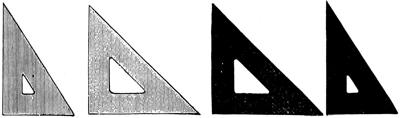
Fig. 153.—Fig. 154.—Fig. 155.—Fig. 156.
In practice the triangles or set-squares are slid
along the edge of the blade, and need not be any
thicker than it.
Fig. 157.
This instrument is used to mark lines which are
neither horizontal nor vertical (usually these are drawn
by the square and set-square), and which are parallel
to one another; by adjusting the edge of the parallel
ruler to a line, it can be extended or opened out (or
vice-versa closed), and the line or lines drawn will be
parallel or equally distant from the base or first line it
was set by. See fig. 157.
Fig. 158 is a parallel ruler, constructed with two
rollers fixed on a rod so that they move the same
distance, carrying the ruler parallel to the starting line.

Fig. 158.
Note.—It has been said that “a workman may be known by his tools,” but the statement must be taken with a good deal of allowance.
Some workmen may possess a very fine set of tools and never use them, because they have not the ability or inclination to learn
how; especially is this the case with drawing instruments.
If all the fine sets of drawing instruments that are owned by workmen were put to frequent use the owners would find a marked improvement
in their abilities in other lines as well as drawing; for it is a noticeable fact that when a person’s mind has been trained in a
business that requires close calculation and a knowledge of materials, he is capable of showing good qualifications in other lines, and the
more skilled he is in one the easier can he acquire skillfulness in another, if he applies the same amount of energy, thought and interest
as he did to acquire skill in the first.
Fig. 159 shows an improved section liner which can
be adjusted to any angle, and will space the parallel
lines at any desired regular distance.
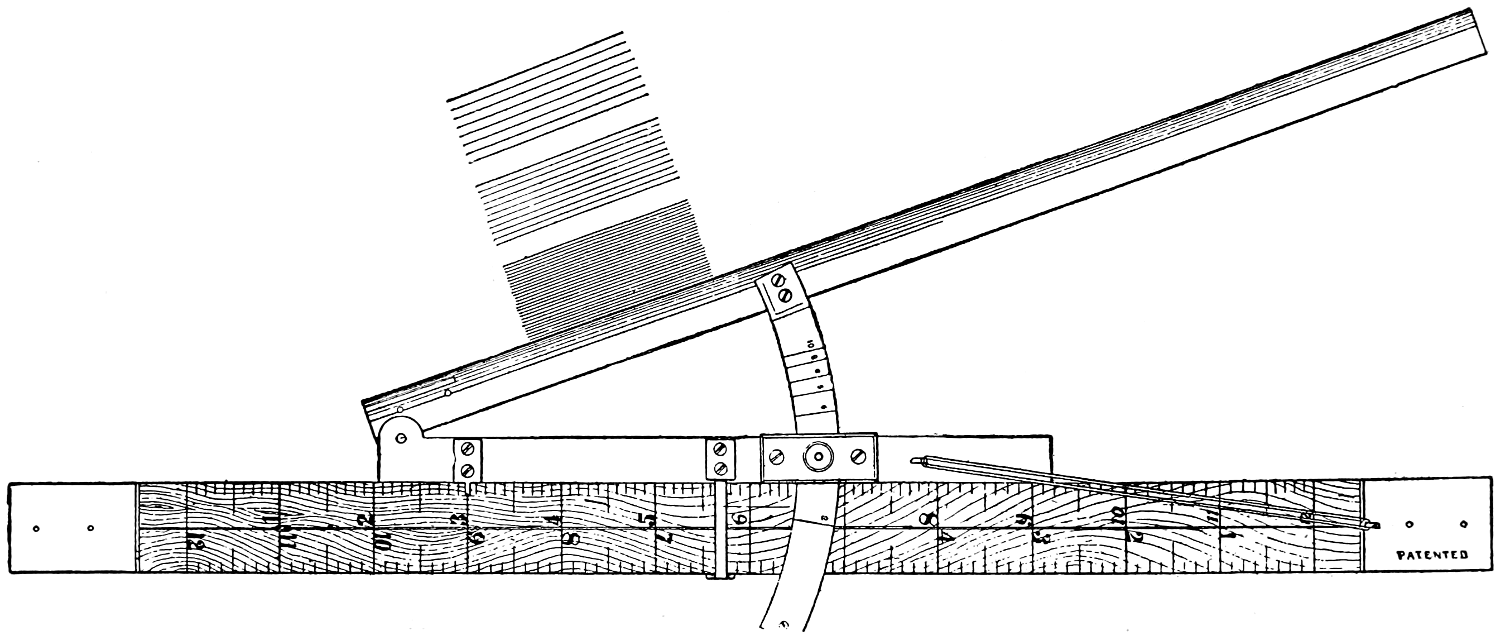
Fig. 159.
Irregular curves, or, as they are sometimes termed,
sweeps, represented by figs. 160-166, are used for curves
that cannot be put in by the other instruments. They
are very useful when elliptical or parabolic curves are
desired, in preference to circles or arcs of a circle.
They are much used in design and architectural drawing.
They are made of thin hardwood or rubber, and
sometimes of horn.
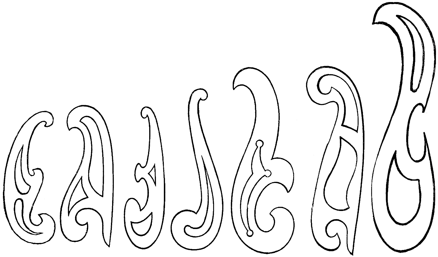
Figs. 160-166.
Curves are irregular lines; a circle is a regular line.
If a curve is to be passed through a number of predetermined
points it should be first sketched in lightly,
free-hand; a section of the scroll is then applied to the
curve so as to embrace as many points as possible;
only the central points of those thus embraced should
be inked in; this process is continued until the desired
curve is completed.
Curves are made of various material, pearwood,
cardboard, xylonite, hard rubber, and a strip of soft
lead is sometimes used, which may be easily adjusted
to the curve required.
The curves generally used in mechanical drawing
are shown on previous page.
Fig. 208, page 134, is a logarithmic spiral curve.
It is mathematically constructed and contains every
curve within the limit of its size.
An ellipse is a geometrical figure, and can be
drawn as described in geometrical problem 29, page
96; many drawing offices keep sets of hard rubber
ellipses, to economize time constructing them.
These are instruments for marking, drawing or
writing, formed of graphite, colored chalk or materials
of similar properties, and having a tapering end,
inclosed, generally, in a cylinder of
softwood. Fig. 167 represents a
ruling pencil; its point is a parallelogram
or of a wedge shape. In
ruling, the length view rests against
the square; its shape gives considerable
strength to the lead and
allows the making of a very fine
line. Fig. 168 differs in the point
of the pencil shown, as may be
observed in the illustration.
A pencil that is hard is best
for mechanical drawing; one that
will retain a good point for some
considerable time. Pencil lines
should be made as light as possible;
the presence of lead on the surface
of the paper tends to prevent
the ink passing to the paper, and
in rubbing out pencil lines the ink
is reduced in blackness, and the
surface of paper is roughened,
which is a disadvantage. As little
erasing or rubbing out as possible
should be done.
These instruments, while they
appear alike, have a separate use:
the dividers are used to space off
distances and dimensions; especially
are they necessary in reading
drawings made to scale. Compasses
are used for describing circles, curves, etc., dividers
are used for marking out spaces.
Two forms of the dividers are shown in figs. 169
and 170; the simplest, plainest form is shown in fig.
169; these are used for rough spacings; fig. 170 represents
a pair of dividers fitted with an adjustable screw
controlled by a steel spring in one leg; by this a very
exact measurement can be made. Fig. 170 is intended
to exhibit what is called a “hair-spring divider.”
These dividers differ from the ordinary ones
shown in figs. 169 and 170 in that they are provided
with four steel points, one pair of which being set to
the full dimension will be reproduced by the other
pair, but in a smaller, or reduced size.
Fig. 171 are “bisecting” dividers, being proportional
dividers, which, when open, one end measures
double the distance of the other.
Fig. 172 are proportional dividers; the points at
one end are capable of being changed,
to measure practically any desired
proportion at the other end, by
altering the position of the pivot
where the legs cross one another.
The lower connecting link is a
micrometer adjustment, for minute
measurements.
Fig. 173 are proportional dividers
which are marked for the proportions
of lines and radii of circles, being
provided with a rack movement for
adjustment.
Fig. 174 represents three-leg dividers,
used for taking the position of
three points; this instrument is very
useful in finding the position of a point in a
figure.
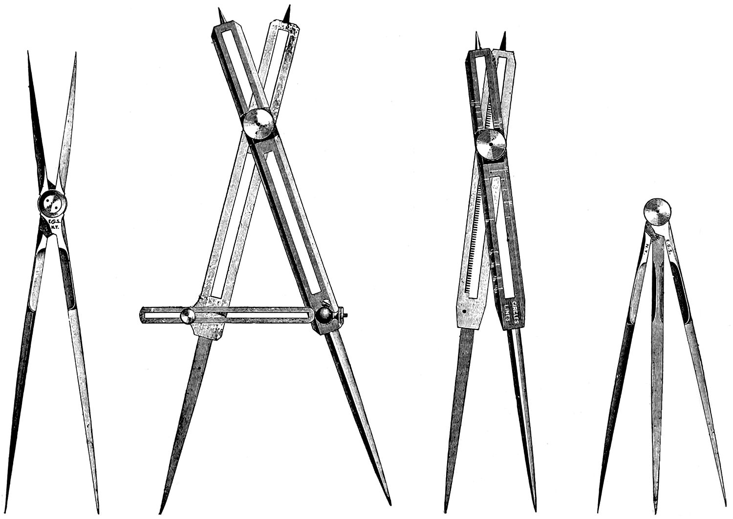
Fig. 171.—Fig. 172.—Fig. 173.—Fig. 174.
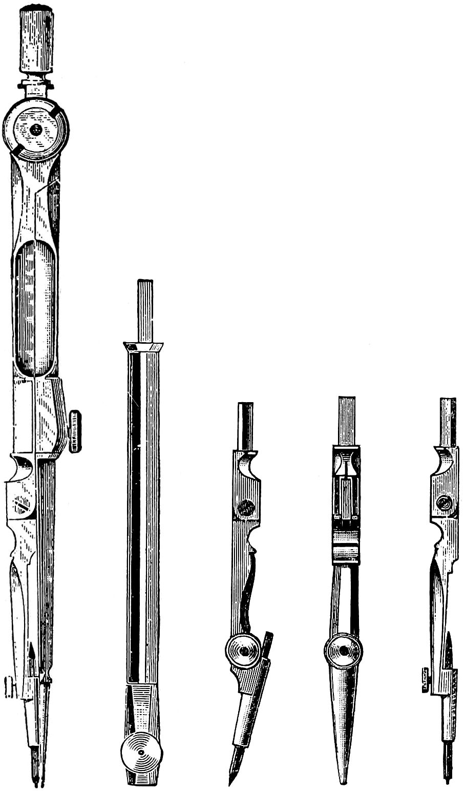
Fig. 175.—Fig. 176.—Fig. 177.—Fig. 178.—Fig. 179.
Compasses consist of two
pointed legs; they are instruments
for describing circles or for—sometimes—measuring
figures, in
absence of dividers. Fig. 175
represents compasses fitted as
dividers.
Compasses should have jointed
legs, which will allow the points
to be placed at right angles to the
paper, whatever the size of the
circle to be drawn. Compasses
should not be used for circles
which are too large to allow the points to be thus
placed; a lengthening bar is generally provided, which
greatly increases the diameters of circles which may be
drawn by this attachment; it is shown in fig. 176.
One leg of the compasses is usually provided with
a socket to which are fitted three points: a divider
point, fig. 179; a pencil point, fig. 177;
and a point,
fig. 178, carrying a special pen for the inking of circles.
Each of these points is generally provided with a joint,
so that it may be placed at right angles to the paper.
The other leg should be jointed; it is often provided
with a socket which receives
two points, one a divider point, and
the other carrying a needle point.
Such an instrument may be used as
dividers for spacing, or as compasses
for penciling or inking circles.
The joint at the head of the
compasses (see fig. 175) is the most
important feature. It should hold the
legs firmly in any position, so that in
going over a circle several times only
one line will result. It should allow
the legs to move smoothly and evenly,
and should be capable of adjustment.
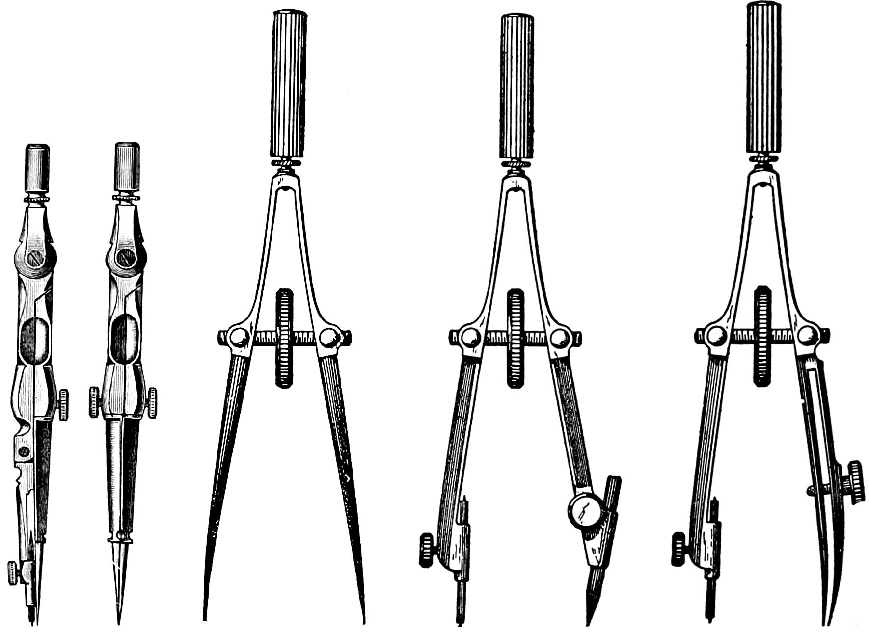
Fig. 180.—Fig. 181.—Fig. 182.—Fig. 183.—Fig. 184.
As shown in fig. 174, one leg has
a hinge or joint, and a needle point,
which can be regulated by a thumb screw; the other
leg has a socket or recess into which interchangeable
parts can be inserted. The four figures to the right of
the compasses show the parts which are provided with
shanks or insertion pieces. Fig. 180 and fig. 181 represent
compasses specially used for making small circles,
and work too minute for the larger instruments described
above.
To do work of this nature easily a pair of spring
dividers are frequently used. This instrument has one
point attached to a spring, which is regulated by a
screw, so that very slight changes in the space may be
made with ease.
Compasses specially used for putting in fine circles
and dimensions are called “bows.” When a pen point
it is a “bow pen,” with a pencil point a “bow pencil,”
and if with needle point a “bow dividers.” Fig. 180
is a “bow dividers”, this fitted with screw for fine adjustment
in one leg, fig. 181, is called a “hair-spring
bow dividers”; for small details, bows with steel spring
legs without any joint are used; these are called “steel-spring
bows.”
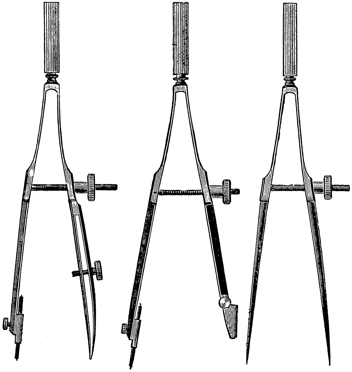
Fig. 185.—Fig. 186.—Fig. 187.
These were originally developed from the common
form of compasses, with a single spring leg; later, the
demand for smaller sizes made changes necessary, and
spring bows are now made symmetrical, both sides of
the bow being made to “spring.”
Fig. 182 are spring dividers.
Fig. 183 is a spring pencil.
Fig. 184 is a spring pen.
In these figures it will be seen that the two
threads, a right and a left, are moved with one central
thumbscrew; in the figs. 185 to 187 a single screw is
used.
In choosing spring bows, care must be exercised
to select a sufficiently strong, stiff spring, as the relation
between spring pressure and thumbscrew is important.
In fig. 188 is shown a set of beam compasses,
together with a portion of the wooden rod or beam
on which they are used.
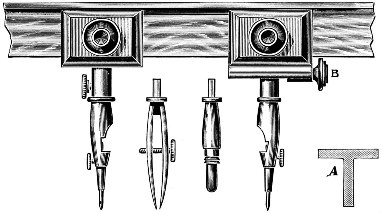
Fig. 188.
The latter, as will be seen by the section drawn
to one side, A, is in the shape of a T. This form has
considerable strength and rigidity. Beam compasses
are provided with extra points for pencil or ink work,
as shown.
While the general adjustment is effected by means
of the clamp against the wood, minute variations are
made by the screw, B, shifting one of the points, as
shown in the figure.
This instrument is quite delicate, and, when in
good order, is very accurate. It should be used only
for fine work on paper, and never for scribing on
metal.
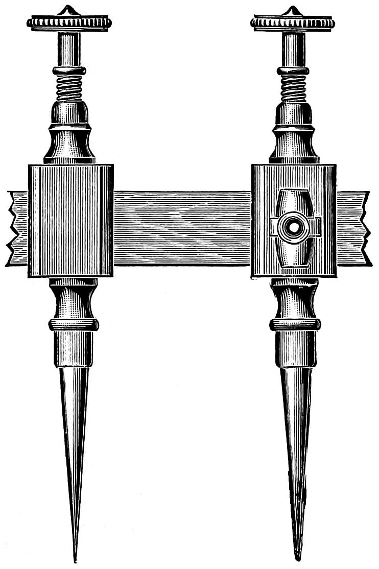
Fig. 189.
A coarser instrument, and one especially designed
for use upon metal, is shown in fig. 189, and is called a
trammel. There are various forms of this instrument,
all being the same in principle. The engraving shows
a form in common use. A heavier stick is used with
it than with the beam compasses, and no other adjustment
is provided than that which is afforded by clamping
against the stick.
In the illustration, a carrier at the side is shown,
in which a pencil may be placed. Some trammels are
arranged in such a manner, that either of the points
may be detached and a pencil substituted.
A trammel, by careful arrangement, can be made
to describe very accurate curves, and hence can be
used in place of the beam compasses in many instances.
For all coarse work it is to be preferred to beam compasses.
It is useful for all short sweeps upon sheets of
metal, but for curves of a very long radius a strip of
sheet iron or a piece of wire will be found of a more
practical service than even this tool.
The length of rods for both beam compasses and
tramels, up to certain limits, is determined by the
nature of the work to be done. The extreme length
is determined by the strength and rigidity of the rod
itself. It is usually convenient to have two rods for
each instrument, one about 11⁄2 or 2 feet in length and
the other considerably longer—as long as the strength
of the material will admit.
Scales are proportioned rules or mathematical instruments
of wood, metal, etc., on which are marked
lines and figures for the purpose of measuring sizes and
distances. It is usual to make scales in the proportion
of parts of an inch equalling a foot; the most generally
adopted scale for machine drawing is one and a half
inches, equalling one foot; that is, twelve-eighths of an
inch (each eighth of an inch representing one inch);
there is no fixed rule in the choice of a scale, as they
are varied according to the coarseness or fineness of the
parts of the machine to be drawn and the space or surface
of paper to be utilized.
When objects are of moderate proportions they
may be represented full size; but when large, the
drawings must be smaller. Standard scales for mechanical
drawings are 1⁄2, 1⁄4,
1⁄8 and 1⁄16 full size. These
scales are often written 6″ = 1 ft.; 3″ = 1 ft.; 11⁄2″ = 1 ft.,
and 3⁄4″ = 1 ft.
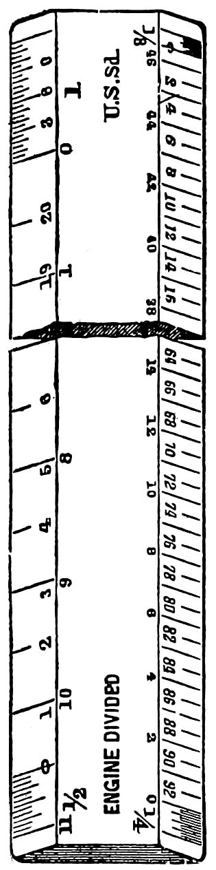
Fig. 190.
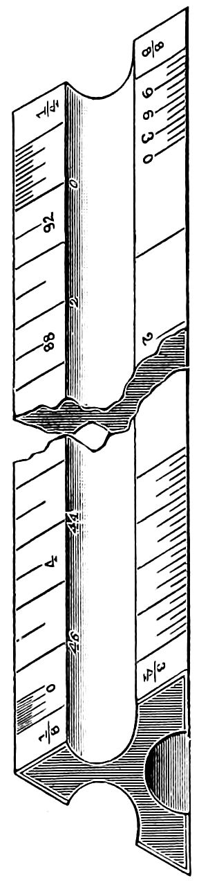
Fig. 191.
Instead of selecting one of the scales named or one
found upon the ordinary scales used by draughtsmen,
drawings may be made to any scale whatever. Thus,
if any object is to be represented in a certain space, a
scale should be constructed which will cause the whole
of the object to be shown.
Drawing to Scale.—The meaning of this is, that
the drawing when done bears a definite proportion to
the full size of the particular part, or, in other words,
is precisely the same as it would appear if viewed
through a diminishing glass.
The two-foot rule shown in fig. 192 is the most
useful instrument for the comparison of linear dimensions—it
can be used as a scale of one-twelfth, or 1
inch equal to a foot, 12 inches = 12 feet, it being divided
into portions or spaces, each of which is subdivided
into halves, quarters, eighths and sixteenths;
frequently in the latter class of two-foot rules there are
graduations of scales, and it is then also called a
draughting scale.
Fig. 190 represents a flat scale, graded so that one
inch represents a foot—1⁄12th size—etc., as shown.
Fig. 191 represents a triangular scale (broken).
The triangular scale should read on its different edges
as follows: Three inches and 11⁄2″ to one foot, 1″ and
1⁄2″ to one foot, 3⁄4″
and 3⁄8″ to one foot, 1⁄4″ and 1⁄8″ to one
foot, 3⁄16″ and 3⁄32″ to one foot, and one edge read sixteenths
the whole 12″ of its length.
Fig. 190 shows such a scale broken. An explanation
of the 1″ and 1⁄2″ side will suffice for all. Where
it is used as a scale of 1″ to one foot, each large space,
as from 0 to 12 or 0 to 1, represents a foot, and is a
foot at that scale. There being 12″ in one foot, the
twelve long divisions at the left represent inches; each
inch is divided into two equal parts, so from 0 to one
division at the left of 9 is 91⁄2″ and so on. The 1″ and
1⁄2″ scales being at opposite ends of the same edge, it
is obvious that one foot on the 1″ scale is equal to two
feet on the 1⁄2″ scale, and conversely, one foot on the 1⁄2″
scale is equal to six inches on the 1″ scale; and 1″
being equal to one foot, the total feet in length of scale
will be 12; at 1⁄2″ to 1 foot the total feet will be 24.
In working to regular scales, such as 1⁄2,
1⁄8, or 1⁄16
size, a good plan is to use a common rule, instead of a
graduated scale. There is nothing more convenient for
a mechanical draughtsman than to be able to readily
resolve dimensions into various scales, and the use of a
common rule for fractional scales trains the mind, so
that computations come naturally, and after a time
almost without effort.
The protractor shown in fig. 193 is an instrument
for laying down and measuring angles on paper; it is
used in connecting with a scale to define the inclination
of one line to another.
Protractors have the degrees of a half circle
marked upon them; as the whole circle contains 360
degrees, half of it will contain 180, one-quarter 90, etc.
Hence, protractors showing 180° exhibit all that is
needed. To protract means to extend, so this instrument
is also useful in “extending” the lines of inclination
at the circle.
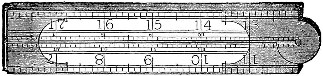
Fig. 192.
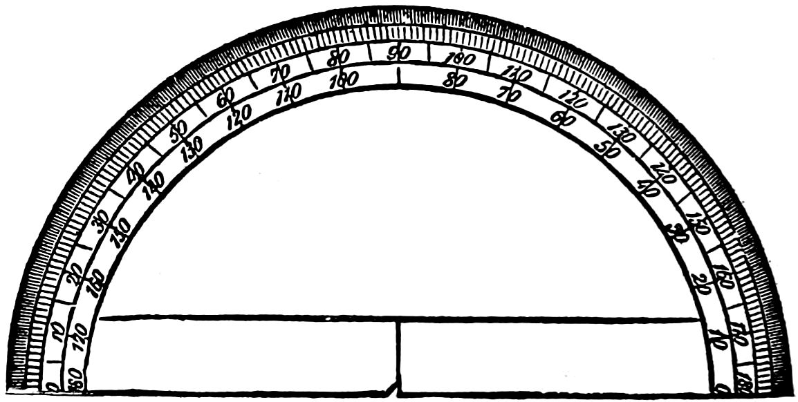
Fig. 193.
A special pen called a drawing-pen, and also special
ink, are required to ink a drawing; figs. 194 and 195 represent
two sizes of drawing-pens—one being best adapted
for fine work, and the other for coarse or heavy line
work. The points, as will be observed in the illustration,
are made of two steel blades which open and close
as required for thickness of lines by a regulating screw.

Fig. 194.

Fig. 195.
A good drawing pen should be made of properly
tempered steel, neither too soft nor hardened to brittleness.
The nibs should be accurately set, both of
the same length, and both equally firm when in contact
with the drawing paper. The points should be so
shaped that they are fine enough to admit of absolute
control of the contact of the pen in starting and ending
lines, but otherwise as broad and rounded as possible,
in order to hold a convenient quantity of ink without
dropping it. The lower (under) blade should be sufficiently
firm to prevent the closing of the blades of the
pen, when using the pen against a straightedge.
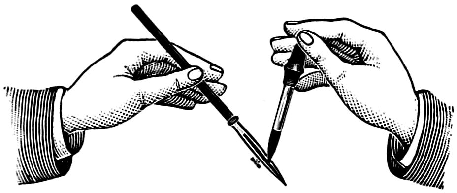
Fig. 196.
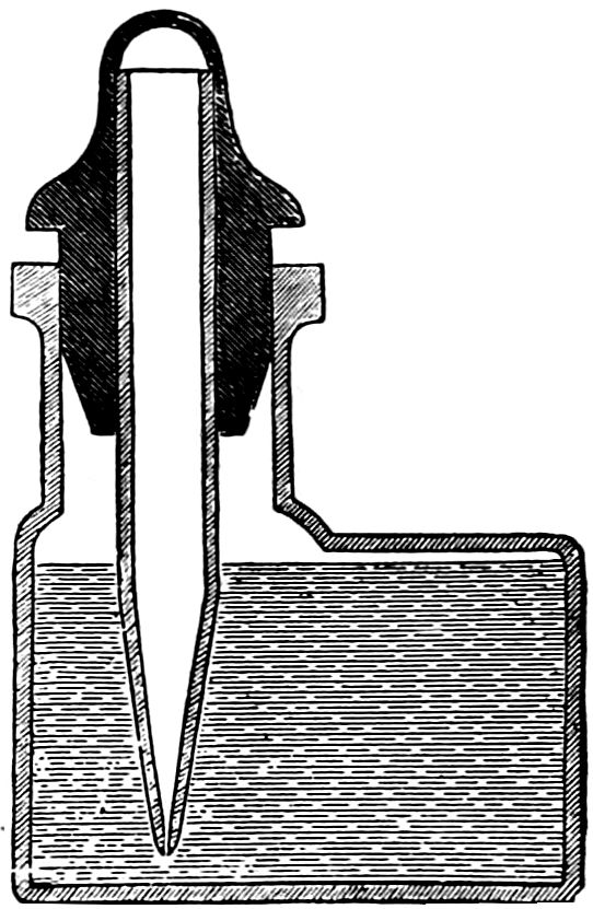
Fig. 197.
The spring of the pen, which separates the two
blades, should be strong enough to hold the upper
blade in its position, but not so strong that it would
interfere with easy adjustment by the thumbscrew.
The thread of the thumbscrew must be deeply and
evenly cut so as not to strip.
An important requisite after the pencil lines have
been put in is ink, with which to line the drawing.
This should be of the best that can be procured. The
pen is filled by dropping the ink between the blades, or
nibs, while held in a nearly vertical position, as shown
in fig. 196.
Liquid India ink can be procured in bottles with
glass tube feeders, which are very good, and keep the
hands and fingers free of
the ink. Fig. 197 is a sectional
view of such a bottle
and “filler,” or feeder. This
generally answers all requirements,
but the dry ink
of good quality, in sticks or
bars, cannot be surpassed,
although it requires skill for
its preparation. Fig. 198
represents a sloping dish or
“tile” for mixing, which
should be done with little
pressure, in clean, filtered or
distilled water, care being taken to keep the liquid free
of dust, which obstructs the free flow of the ink in
the pens.
Fig. 198.
The bars of India ink are shown, as they are imported,
in figs. 199 to 202.
Pure India or China ink is only made in those
countries, because the special wood from which it is
prepared is found only in those regions. So-called
India inks, made of lampblack and animal glue, are
only imitations; therefore India ink should be purchased
from a reliable importing house—shape is little
guarantee of quality.
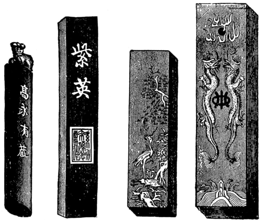
Fig. 199.—Fig. 200.—Fig. 201.—Fig. 202.
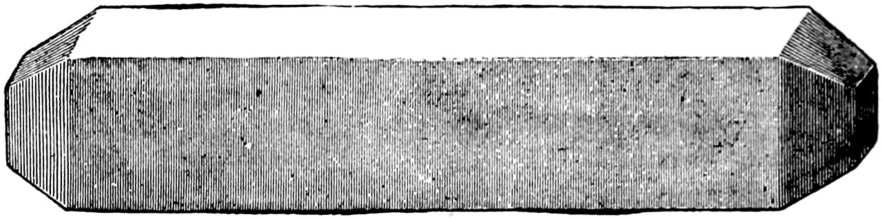
Fig. 203.
Soft gray vulcanized rubber (fig. 203) should be
used for cleaning drawing paper; for erasing any portion
of a line in pencil, a piece of prepared white vulcanized
rubber is the best, small in size and of rectangular
shape (see fig. 205).
An ink eraser is made of a composition of rubber
and ground glass, and it should be used as sparingly as
possible on drawings, as it roughens the paper and removes
the gloss from its surface (see fig. 204). Steel
ink erasers are useful in removing defects, overrun
lines, joint of lines if swollen, etc.; they have a fine
point and can be used to advantage with a little practice;
they are used with a scratching, not a cutting,
motion (see figs. 206, 207).
The first thing to be considered in selecting drawing
paper is the kind most suitable for the proposed
plan. Paper may be purchased in sheets 22 × 30
inches, that make four exercise sheets 11 × 15 inches;
this may be of several grades and tints.
The qualities that constitute good paper are
strength, uniformity of thickness and surface, neither
repelling nor absorbing liquids, admitting of considerable
erasing without destroying the surface, not becoming
brittle nor discolored by reasonable exposure or age,
and not buckling when stretched, or when ink or color
is applied.
The sizes and names of paper made in sheets is
as follows:
| Cap |
13×17 |
ins. |
| Demy |
15×20 |
„ |
| Medium |
17×22 |
„ |
| Royal |
19×24 |
„ |
| Super Royal |
19×27 |
„ |
| Imperial |
22×30 |
„ |
| Atlas |
26×34 |
„ |
| Double Elephant |
27×40 |
„ |
| Antiquarian |
30×53 |
„ |
For large drawings paper is made in rolls. “Detail
paper” is especially made for marking out new
designs; it is made in rolls 36, 42 and 54 inches wide;
it has excellent erasing qualities and takes ink and
color with facility.
When working by artificial light it is desirable that
the paper be of a light-brown color, which is less trying
to the eyes than a pure white.
If it is a shop drawing or sketch not to be preserved,
use detail paper, which is the most economical
and will stand a great deal of handling without becoming
soiled. If it is a detailed plan, finished drawing
or a picture, use the best white drawing paper to be
obtained, so that your drawings can be preserved
indefinitely without danger of fading, which is due
either to the paper being poorly made and discoloring
with age, or being of poor fiber and absorbing the ink
or color, and the drawing consequently losing its
brightness.
After deciding on the size of paper most suitable
for the work, then carefully select the paper
embracing the most qualities of value for the proposed
drawing.
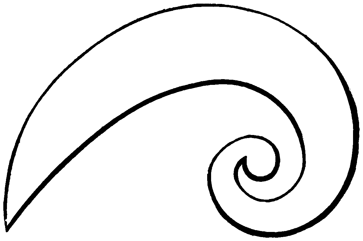
Fig. 208.
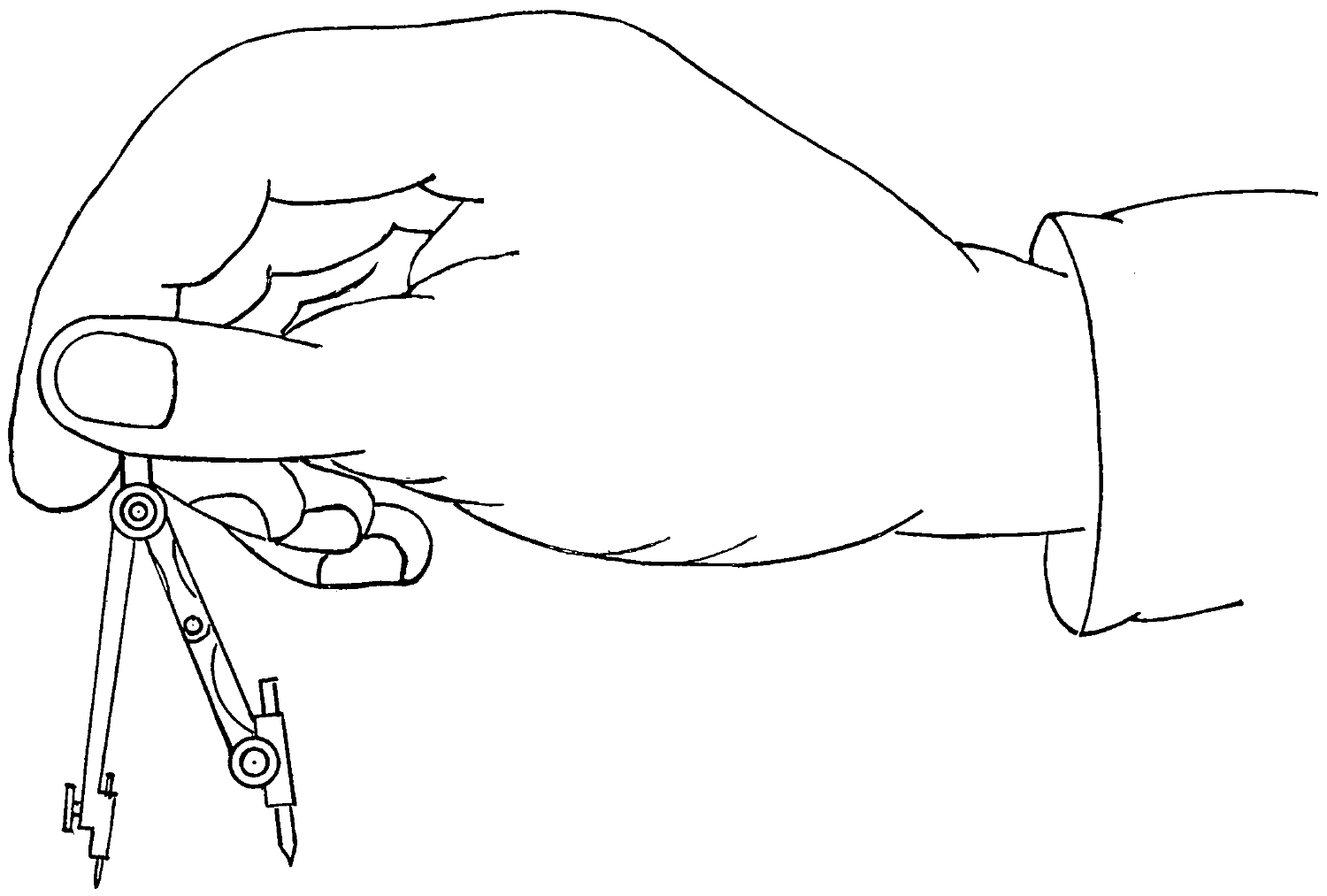
Fig. 209.
Mechanical Drawing.
In distinction to “free-hand,” mechanical drawing
is executed almost entirely by the use of the instruments
previously described; hence its other term,
instrumental drawing. To define it particularly it may
be said that,—
Mechanical drawing is the correct reproduction of
any figure or part of a machine, whether of full size or
reduced in the proportion of one part to another; it
also comprises the art of delineating the interior parts
which are hidden from view in solid bodies.
A mechanical drawing is the vehicle for conveying
the ideas of the designer to those who are to embody
them in wood and metal, and the considerations which
should govern its production are those which affect its
clearness and legibility or those which facilitate reference
to it.
Drawings consist of plans, elevations and sections;
plans being views on the top of the object in a
horizontal plane; elevations, views on the sides of the
object in vertical planes; and sections, views taken on
bisecting planes, at any angle through an object.
Drawings in true elevation or in section are based
upon flat planes, and given dimensions parallel to the
planes in which the views are taken.
Two elevations taken at right angles to each other
fix all points, and give all dimensions of parts that have
their axis parallel to the planes on which the views are
taken; but when a machine is complex, or when several
parts lie in the same plane, three and sometimes four
views are required to display all the parts in a comprehensive
manner.
A man must have either a natural talent for hand-drawing
or years of experience, before he can produce
a sketch and “dimension” it, fit to work from; hence
the elementary character of the examples given for
practice. A “pretty” drawing is not expected from
a beginner; it should always be borne in mind, that
correctness of dimensions and general clearness, rather
than elaborate finish, are what will save the battle in
the days of competition.
Mechanical drawings should be made with reference
to all the processes that are required in the construction
of the work, and the drawings should be
responsible, not only for dimensions, but for adaptation
to fitting, forging, pattern-making, moulding, and so on.
Every part laid down should have something to
govern it that may be termed a “base”—some position
which, if understood, will suggest size, shape and relation
to other parts. Searching after a base for each
and every part and detail, the draughtsman should proceed
upon a regular system, continually maintaining a
test of what is done.
A mechanical drawing consists chiefly of three
views:
1. The plan or top view.
2. The side elevation.
3. The end elevation.
In addition to the above, drawings are used to
show interior portions of the figure; these are termed
“sections,” and they may be taken where any plane
crosses another.
Note.—The word elevation, as applied to mechanical drawings,
means simply a view; hence a side elevation is a side view,
or an end elevation is an end view.
The word plan is employed in place of the word top; hence
a plan view is a top view or a view looking down upon the top of
the piece.
A general view means a view showing the machine put together
or assembled, while a detail drawing is one containing a
detail, as a part of the machine or a single piece disconnected
from the other parts of the whole machine.
Penciling. — POINTS TO BE OBSERVED IN SKETCHING.

Fig. 211.
It is very nearly true, as has been said, that every mechanical drawing is, in the first instance,
penciled; if this is so, then more work is done with the pencil than with the pen; therefore the
first attention of the student of mechanical drawing should be directed to the following instructions
for penciling a drawing.
With all necessary materials in hand, and in good order for the beginning of a drawing, the
first thing to do is to pin the paper on the board quite square.
To do this effectively, lay the paper flat and put on the T-square with its head at the left
side of the board; slide the square up nearly to the top, and arrange the paper level with the
blade; with the right hand hold the paper still and move the square down a little; now, pin the
top of the paper with thumb-tacks.
Next, pressing the square lightly to the paper,
slide it down to the bottom and pin that part of the
paper to the board. The paper must not project outside
or over the edges of the board, and the pins or
tack-heads should be forced down flush with the paper,
so as not to interfere with the free movement of the
tee-square up and down the board as occasion may
require.
The accuracy of the work depending upon their
condition, it is first needful to see that the pencil and
pencil compasses are properly sharpened. Reference
is made to valuable directions contained on pages beginning
with 55, under the heading of “Free-hand
Drawing,” to which may be added that—
All lines should be drawn with the pencil slightly
inclined in the direction in which it is moved.
Any and all lines not needed in the finished drawing
should be erased at one time after the final lines
have been determined, for the surface of the paper is
soiled very quickly when worked upon after erasures
have been made.
The working lines and other lines that are to be
removed should be erased when the drawing is ready
to finish and before its outlines have been strengthened,
in order that the final lines may be left in perfect
condition.
To show where the lines meet or terminate it is
needful that all pencil lines pass the actual ending
place, making a distinct intersection. This does not
apply to “inking in” the lines, but rather to prevent
the over-drawing of the ink lines, because the edge of
the rule and the pen itself obstruct or partly cover the
view of the line, it is very liable to pass over or beyond
the required point in inking the lines, which must
not occur.
In the preliminary operation of producing a regular
mechanical or instrumental drawing, it is necessary
to make a “sketch,” in pencil, of the object to be
represented. The American Machinist has given in
a few words the order to be followed, in effecting the
best results; we quote, as follows:
“In making a free-hand sketch of an object from
the model it is well to observe the following order:
Look the model over carefully and determine the
number of views necessary to illustrate it fully, drawing
the same, free-hand, in their proper relation to each
other, on sketching paper. Look the sketch over
carefully to see that nothing has been omitted, and put
on dimension lines, after which scale the model carefully
and put on dimensions. Do not put in the
dimensions at the same time the dimension lines are
drawn; have all the dimension lines in place before
attempting to insert dimensions.
“Follow the same order in making the drawing
with instruments as was used in making the sketch;
that is, draw the views in their proper relation to each
other, put in dimension lines, then dimensions, and
lastly notes and title. If section drawing is made, do
not draw section lines in pencil.”
1. Especial attention is to be paid to outlines—edges
of plane surfaces are lines; when a line is made
it represents the edge or outside of something.
2. Learn to be accurate before being rapid.
3. A sketch should be intelligible to any one,
even if they are unacquainted with drawing.
4. Horizontal and vertical lines and a few curves
will enable one to make almost any simple sketch.
5. It must be also remembered in making drawings
from actual measurement that the instruments are
not in the first place employed; the rough sketch is
first made and then it is converted into a drawing.
The draughtsman makes a rough sketch entirely by
the hand and eye, measures the various parts, and jots
down the measurements in his sketch; after this he
reduces the whole to the desired scale, and proceeds to
make his mechanical drawing.
6. Let the sketch book be the constant companion
of the student; it may be advantageously
filled with outlines of machine or other work suitable
for preservation, to be made into finished drawings, or
for reference. Sketches are often valuable for reference
as aids in originating new designs.
7. A sketch, when possible, should have all the
dimensions written upon it, but—
8. Sketches in shop practice should not take the
place of working-drawings; the latter have a check
upon them in being drawn to a scale—hence the
figures written upon them and dimensions by scale
must agree.
9. Place title and date on each sketch—no matter
how seemingly unimportant—for future reference.
10. Practice sketching at every favorable opportunity.
There is no necessity for detail at first—simply
the outlines of the article and its parts.
11. Sketch-books, with paper bound in cloth
covers, are utilized for bold, off-hand sketches by
experienced draughtsmen, but a single sheet of paper,
used on both sides, is not unworthy of service in an
emergency—or even the blank side of a letter may be
available. Sketching-blocks, or paper “pads,” 4 × 6, or
more, in size, and containing 48 sheets, are sold by
stationers, and are found to be most convenient to
have in hand and for practical use. Portfolio-envelopes,
made of extra length paper (manila) are
useful in filing away sketches and drawings. The size
101⁄2 × 15 is used for United States Patent Office
drawings.
The function of the pencil—in mechanical drawing—is
to make a path for the pen to follow. If it were
possible to make a drawing with all its lines ending at
the proper place, at the first time, there would be no
necessity for using the pencil. One is obliged, however,
so to use the pencil that all lines pass beyond the
actual ending place, thus making a distinct point for
the drawing pen to stop at.
The pencil should be pressed to the paper just
enough to make a clean, fine line, and no more; once
over the path is sufficient, if the line is visible and true.
To sharpen drawing pencils, 1, use a fine file, after
taking off enough of the wood with a knife; 2, make a
conical point for the free-hand drawing pencils and a
chisel point for ruling and marking distances.
Pencil compasses are instruments where one leg is
provided with a pencil point. Fig. 209 shows the mode
of manipulation of those shown in fig. 180 and fig. 181.
The pencil compass is held by the projection
above the joint between the thumb and first finger,
which enables it to be rotated by a movement of the
finger without causing any undue pressure on the points.
Should much pressure be applied, there is a tendency
to force the point or center through the paper, making
an ugly center mark; at the same time the pressure
tends to break off the pencil point.
These few illustrations from fig. 212 to fig. 219 are
made designedly simple, so that they may be utilized
in “free-hand” work, for which they are good practice,
as well as serving for examples in mechanical
drawing.
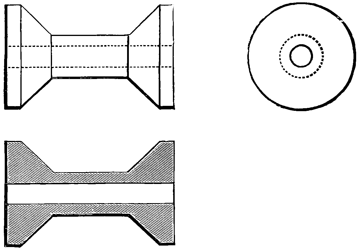
Figs. 212.
Figs. 212, showing a spool or bobbin, exhibit three
views, viz.: front elevation or plan, and section; both
are drawn with simple lines, the end elevation by
circles.
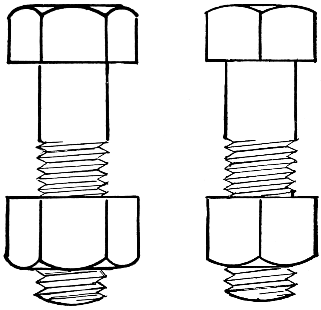
Fig. 213.—Fig. 214.
Figs. 213 and 214 are two side views of a hexagon
head bolt. Figs. 216 and 217 are a square head bolt—two
side views and end view. Figs. 218 and 219 are
a front and edge view of a forked or double joint.
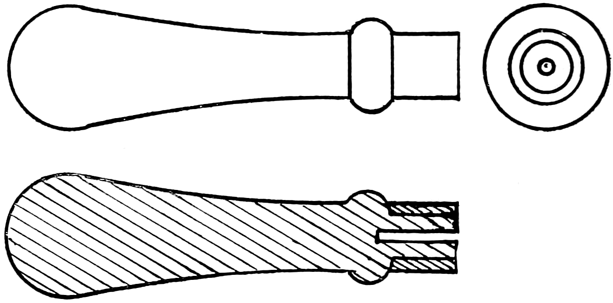
Figs. 215.
Figs. 215 show three views of a file handle;
the front view and section are practice for compound
curves and curved lines meeting straight ones; all
these are capable of being produced by instruments.
Moreover, many of the views and illustrations used
to instruct and explain machine tools and other devices
in other parts of the volume, are drawn so that they
may be used also as examples in advanced instrumental
practice. This is a “hint” to the diligent and painstaking
student worthy of remembering.

Fig. 216.—Fig. 217.—Fig. 218.—Fig. 219.
The designing and drawing of arcs and whole circles
occupy a large proportion of space in nearly all
mechanical drawings. The making of a complete circle
is a matter of no great difficulty, but the beginning
and termination of parts of circles require both judgment
and considerable practice.
To aid the student these two illustrations of circles
are introduced. To draw fig. 220 with a pencil,
using the upper edge of the blade of the T-square
as a guide, draw a center line, A B, mark on it a distance
of 4 inches, space this into half inches, using the
dividers and making the points with it; then with the
pencil compasses or bow pencil, which must be held as
shown on page 209, and rotated from left to right, or
clockwise, draw a series of circles through these points,
tangent to one another or all touching at A, care being
taken that the pencil lines exactly meet at A, and
also cut the divided points as shown in the illustration.
For fig. 221 divide the center line as before, and draw
the semi-circles on it A B, B C, meeting at B, and
C D, D E, etc.
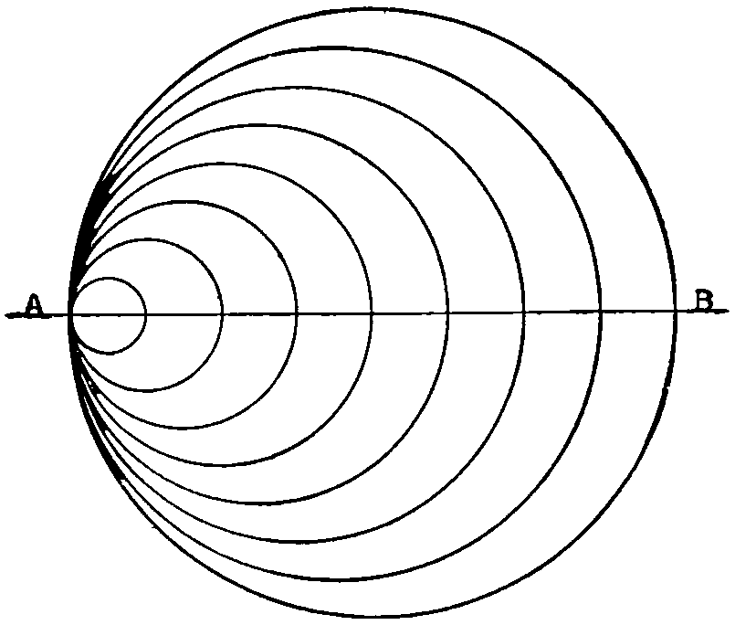
Fig. 220.
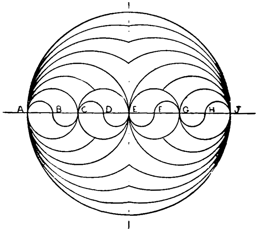
Fig. 221.
Now from center B draw circles A C, C E, meeting
in C, and so on with the circles, arcs or segments;
success in drawing this figure depends on the correct
spacing of the center line in the first instance into
equal parts.
The T-square should be used for drawing horizontal
lines only. Its head should always be placed upon
the left edge of the board. Vertical lines should be
drawn by the use of a triangle placed upon the T-square
and not by means of the T-square only; because
the edges of a board are seldom at right angles to each
other, and the blade of the T-square is often not at
right angles to the head, so that lines at right angles to
each other will not result from the use of the T-square
upon all edges of the board. Only the upper edge of
the T-square should be used, as the edges are often not
quite straight or parallel.
The 45° triangle has two angles of 45° and one of
90°. The 30° and 60° triangle has an angle of 30°, one
of 60°, and one of 90°. By placing these triangles upon
the T-square, lines at any of these angles with a vertical
or horizontal line may be drawn.
Drawings finished in ink are much more effective
and desirable than pencil drawings; but as a good inked
drawing cannot be made except upon an accurate pencil
drawing, students should begin with the pencil, and
should not use ink until they are able to produce satisfactory
results in pencil.
Projection.
The word projection means to throw forward, and in ordinary machine drawing it is the projecting or
throwing forward of one view from another view.
In drawings the lines in one view or plan may be availed of to find those of others of the same object,
and also to find their shape or curvature as they would appear in the other representations; this is called
projection-drawing.
Fig. 222 is the illustration as shown in fig. 212 on
page 143, with the addition of dotted projection line,
which illustrates the method of throwing forward the
section and the end view of the object; these two
views are procured from the plan or first figure, as
shown in fig. 222.
Fig. 224 represents the square bolt and nut shown
in fig. 216, and the mode of projecting is similarly
shown by dotted lines.
Fig. 223 shows file handle shown in fig. 215 and
the mode of projecting.
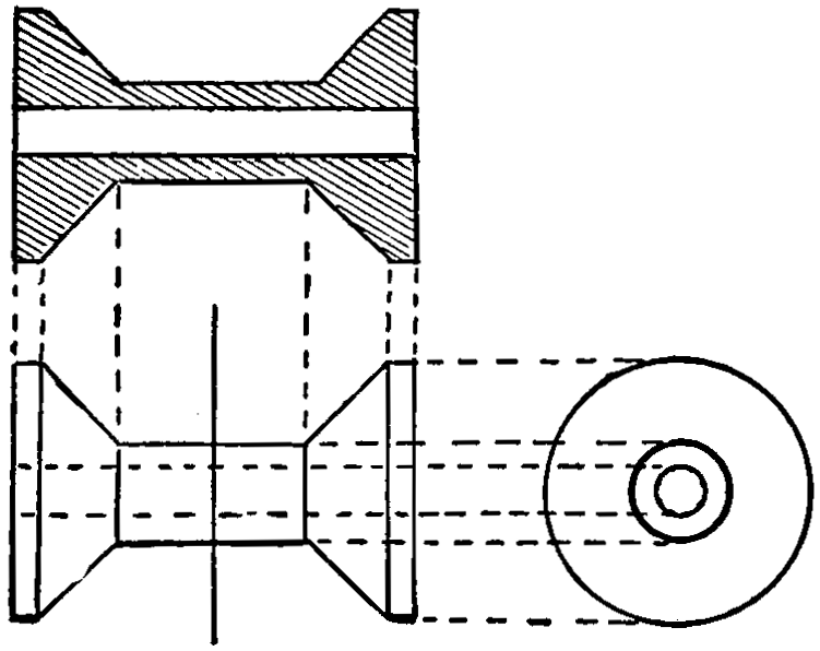
Fig. 222.
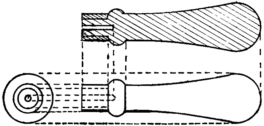
Fig. 223.
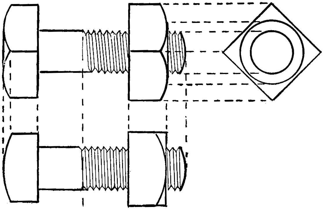
Fig. 224.
The principles upon which “projection” in drawing
is based, are illustrated in the following examples
and text: As a real object can be scaled with a foot
rule, so a drawing must permit of scaling and measuring.
This measuring may take place as with the real
object in full size or the drawing may, for the sake of
convenience, be reproduced and measured in a reduced
scale, as half, or in still smaller sizes. Sometimes it
may prove convenient to enlarge the drawing to twice
the natural size of the object, as a means of making it
stand out more clearly than the real size would
accomplish.
For practical purposes, it is productive of economy
of time to mark the dimensions of height and width
or depth on the drawing in figures, to avoid the scaling.
This marking of the dimensions is best done at the
time of making the drawing, while the conception of
the object is clear.
To convey a correct impression of the object, all
lines that are marked to be of equal length should appear
equally long on the drawing and be capable of being
scaled to such equal length; for this, it must be assumed
that the eye of the observer is equally distant
from all points of a plane through the nearest point, or
one of the axes of the object, and that the lines
of sight are all parallel to each other and square to
this plane.
In fig. 225 these lines of sight are seen as directed
toward one side of a cube or block; it will be readily
understood, however, that in this way nothing is visible
and accessible for scaling and dimensioning except
this front face of the block, thus, a determination of
the dimensions of only height and width would be possible,
while the dimension of depth is entirely undetermined.
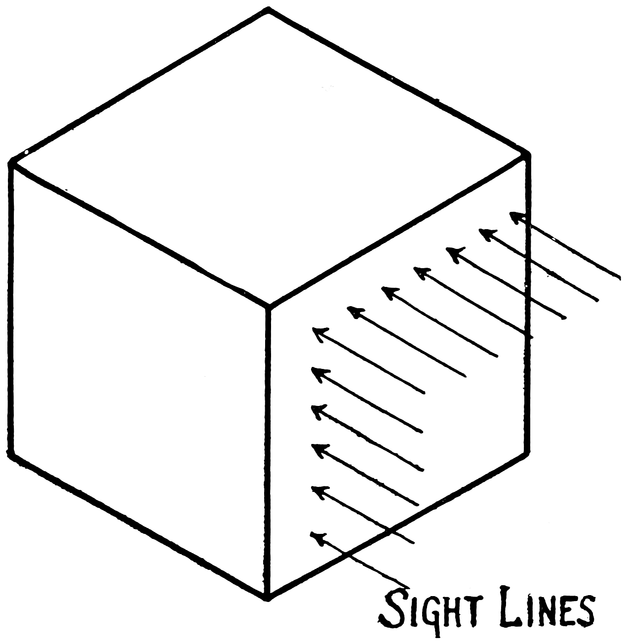
Fig. 225.
It is thus necessary to get a view of the block from
another side; the direction in which it will be most
instructive to obtain additional views is in the direction
of the breadth and of the length and square to the
lines of sight of the first view.
Fig. 226 shows how the lines of sight would strike
the object in the three directions. If these lines should
be rays of light, some of them would pass by the body
until they squarely strike the large plane surfaces,
I, II, III; naturally the rays of light on the faces of
the object will be retained, and cannot strike the plane
surfaces, thus leaving dark shadows of exactly the same
outlines as the block; these would be exact drawings
of the faces, and if by some means they can be fixed
and retained on the plane they can be completely
measured and dimensioned.
This throwing forward of the outline of the object
in different views on the planes is called projection of
the object, and furnishes a highly important means of
fixing the outlines and dimensions in the three main
directions of height, width and depth; evidently, the
light rays passing by the front face may not all reach
the plane of projection, but they may be retained by
protruding parts of the object behind the front face.
These protruding parts naturally would also be projected
on the plane in the same manner as the main
body of the block.
These projections of the protruding part are plainly
visible in plane II and plane III, while the part would
not be drawn in outline in plane I. It may be imagined,
however, that the greater thickness of the body
in the direction of the protruding part would intensify
also the shadow, thus outlining the face of the protruding
part in plane I.
It is apparent that these three projections are all
needed, but as drawing is all done in one single plane,
the three projections will for the sake of convenience
have to be brought into a single plane. This can be
realized if plane II is swung around axis O Z and
plane III around axis O Y, until all three surfaces are
in one single plane, which would then appear as shown
in fig. 227.
It is also possible to assume transparent planes in
front of the body and extend the parallel lines of sight
forward instead of backward. Thus an outline picture
will be created on each of the three planes I, II, III in
fig. 228, in a manner similar to fig. 226. For drawing
purposes, all three views again have to be brought into
a single plane, which is done by swinging II around
O Z, and III around O Y in the same manner as fig. 227
was evolved from fig. 226.
It will be noted that in fig. 229 plane III is now
above I and plane II on the left-hand side of I, while
in fig. 227 they were below and at the right-hand side
of plane I. As the swinging of the top and side planes
takes place around the edges of the front plane I two
systems may thus be distinguished, according to the
position of plane I in regard to the object. Fig. 226
thus represents the system of backward projection,
while fig. 228 represents the system of forward projection.
Either system can have, however, the plane II at
the right- or left-hand side edge, while plane III may
be attached to the top or bottom edge of plane I; it
is readily understood that a number of combinations
are possible for each system, as it is not necessary to
adhere absolutely to one rule. The system of forward
projection is the one generally practiced and further
examples are all executed by this system, meaning that
the planes are always between the observer and the object.
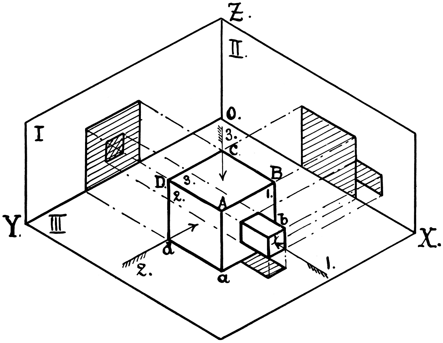
Fig. 226.
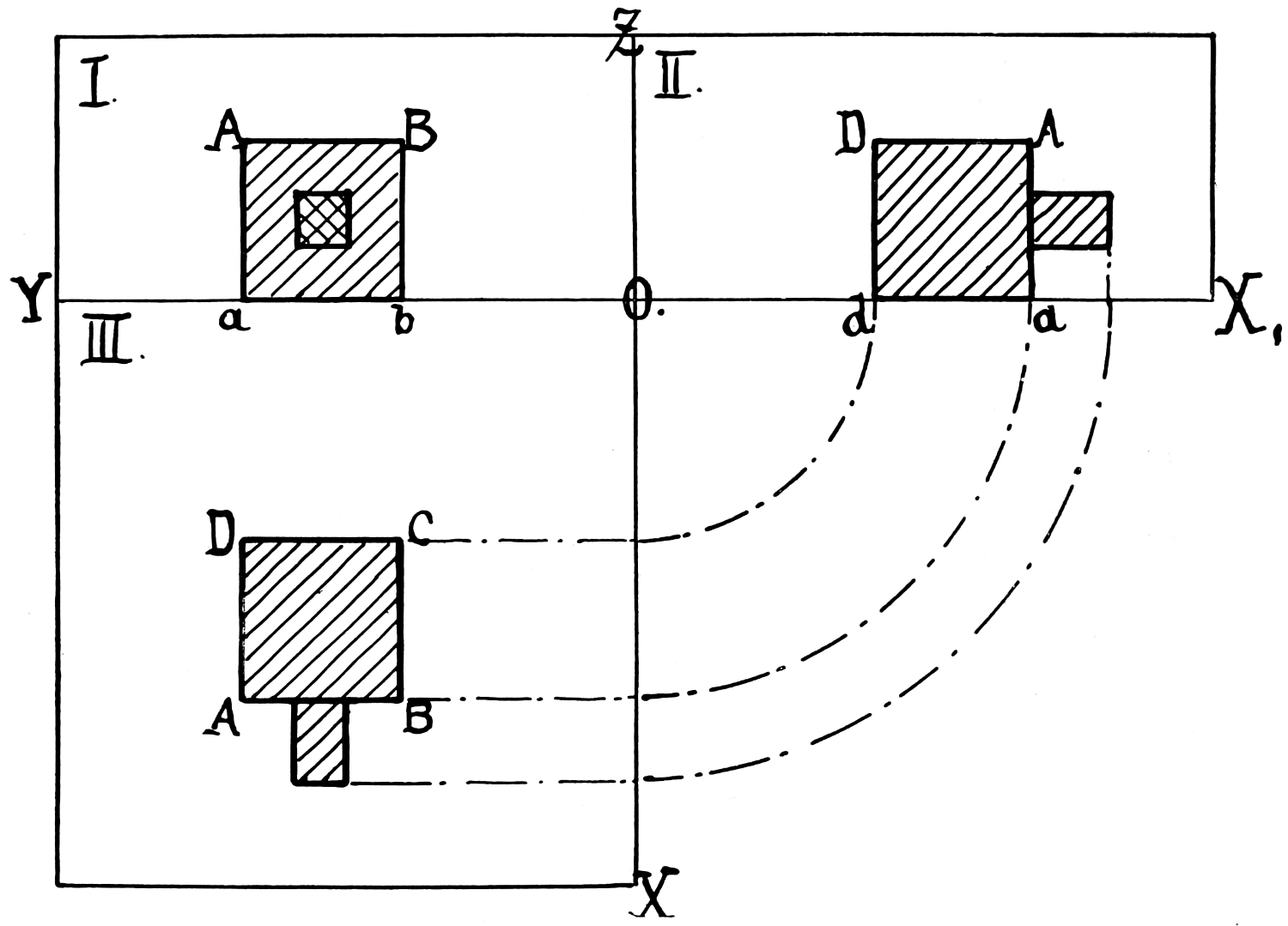
Fig. 227.
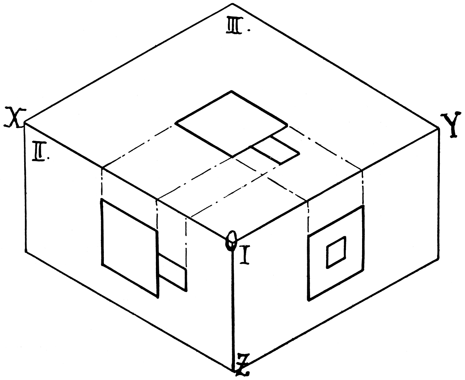
Fig. 228.
For the clearness of the drawing, it is desirable to
have all corners, edges and outlines appear in such
solid lines as they appear to the eye. If, therefore,
certain sharply defined outlines occur on one side more
than on the opposite one, it is most desirable to take the
view against the side that has the most definitely
marked outlines.
If the opposite side should show a number of
wholly different features, it may prove even desirable
to show this side also, thus gaining four views instead
of the usual three, and so obtain a more complete
understanding of the shape of the object, besides
giving increased facilities for dimensioning each part of
the body.
This additional view may be taken from the sides,
as well as up or down, thus making a maximum of five
views possible by which the outside of the object may
be delineated.
Fig. 230 shows why it may be desirable to take
five views of a block that has a receding space of different
outlines in each of the side and top and bottom
faces.
It is not necessary, however, to resort to five
views in such a case as is represented in fig. 230, as the
only differing feature, the circular space in III bottom,
might be shown in III top by dotted lines, and the
difference of II right might be shown in II left, also by
dotted lines. It is desirable to show four or five views
only where great complication and consequent lack of
clearness through numerous dotted lines would result
from having a less number of views.
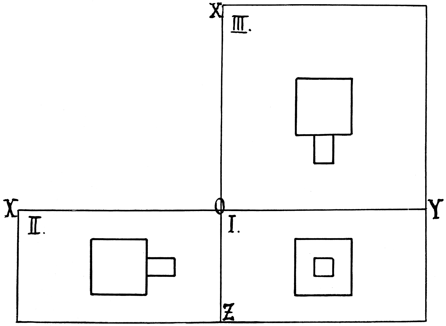
Fig. 229.
So far the projections and views have only represented
the outlines of the object; it may often be
desirable, however, to show central holes or other perforations
or variations of sections; in this case it is
possible to imagine the object cut in slices, by planes,
through certain well defined axes, or other lines of
distinctive importance, and then take a view of this
sectional plane with its newly created intersections or
sharply marked outlines; thus, a section may often
take the place of the third, fourth or fifth view to great
advantage.
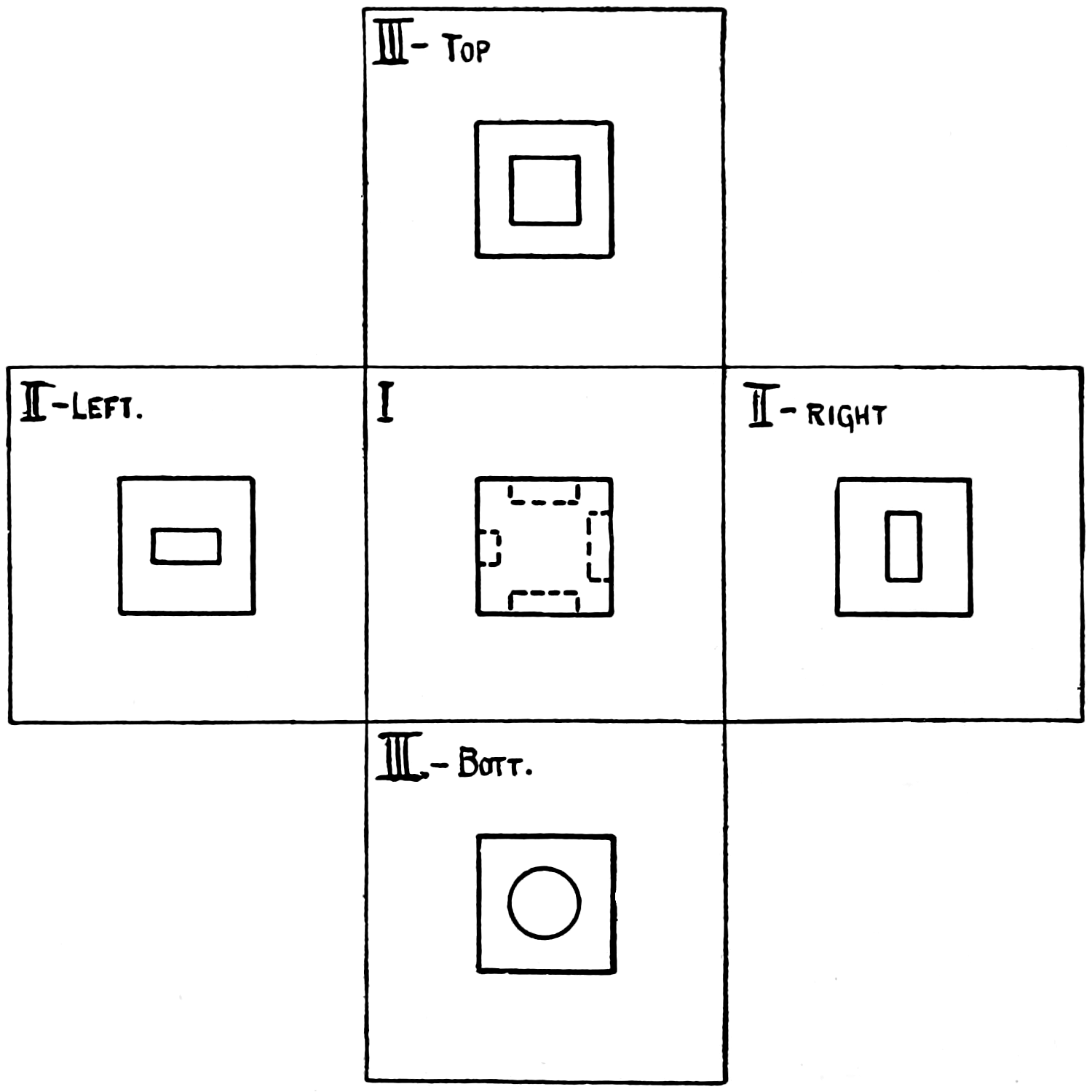
Fig. 230.
It is not always possible to get a view against a
face or side of the object, but, with irregularly shaped
bodies or under special conditions, it may be necessary
to take a view of corners, sloping planes, curved
or irregularly shaped surfaces.
Fig. 231 shows a hexagonal nut in the three normal
projections; from the top view it is readily seen
that the front view shows the side of the hexagon in a
contracted scale, and that therefore the scaling and
dimensioning for the horizontal direction have all to be
done in the top or plan view; the front and side views
convey, however, the dimension of height correctly,
and these are therefore the right places for scaling and
dimensioning in the vertical direction.
Fig. 231 shows how a cylindrical outline appears
in the three views; the hole in the nut presents itself
as circular in the top view, while it appears in the front
and side views as a rectangle. For simple objects, it
is unnecessary to show the edges of the planes, and the
three views are grouped, as regards distances and positions,
as most convenient for the execution of the
drawing.
Where sloping surfaces are of irregular form, it
may be necessary to employ help lines for their full determination
in the three views. Fig. 232 shows how
the surface that is produced by a slanting cut through
a cylinder would appear in the three views. The help
lines are placed in the top view in eight equal divisions
around the circumference of the cylinder. These division
lines are shown by dotted lines on the cylinder in
the front and side views. Their intersections, with the
sloping cut in the front view, furnish also the height
of the corresponding points for the side view.
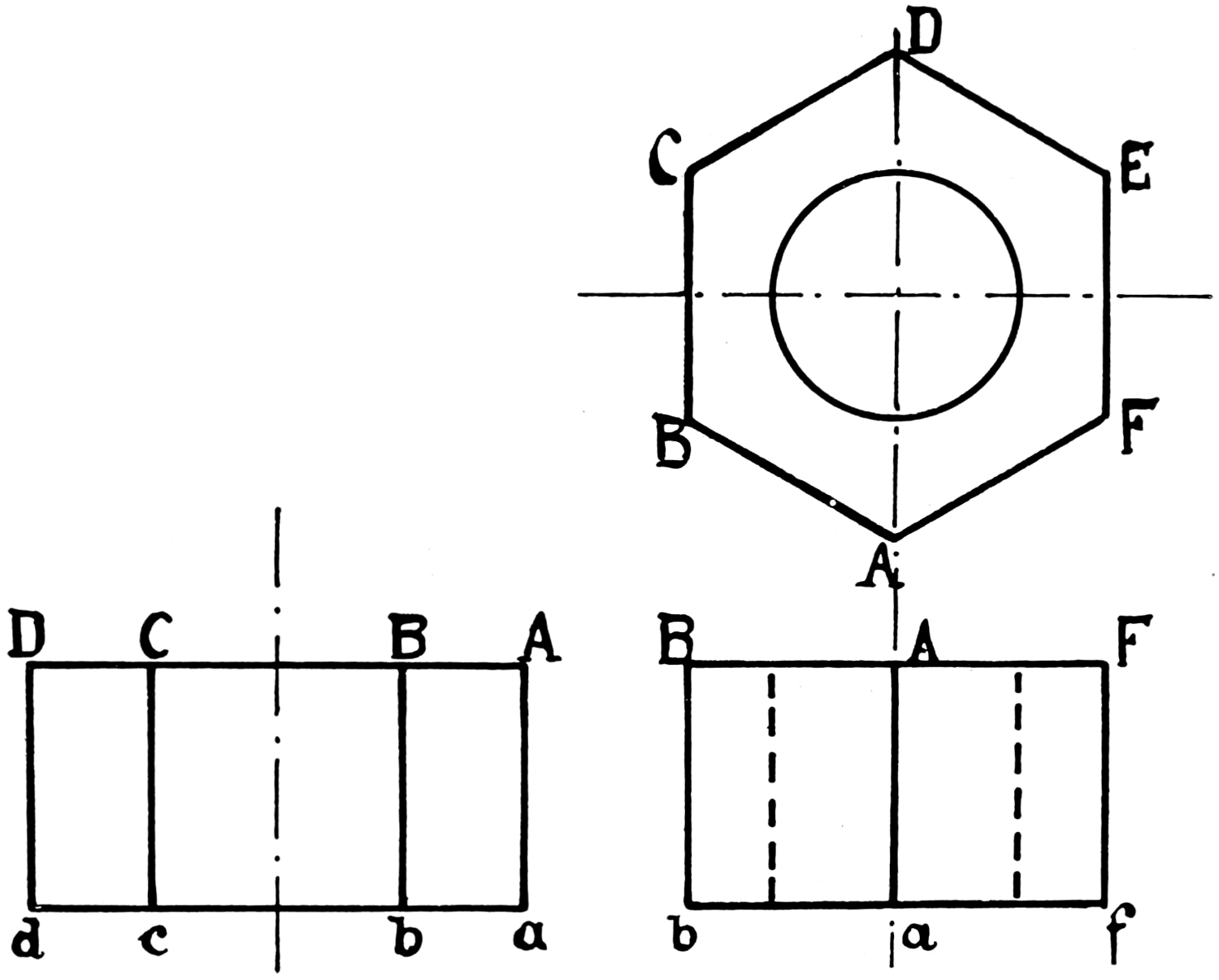
Fig. 231.
By progressive determination of points, lines and
surfaces, even the most complicated bodies can be
completely represented for their reproduction in any
application to mechanical or industrial purposes.
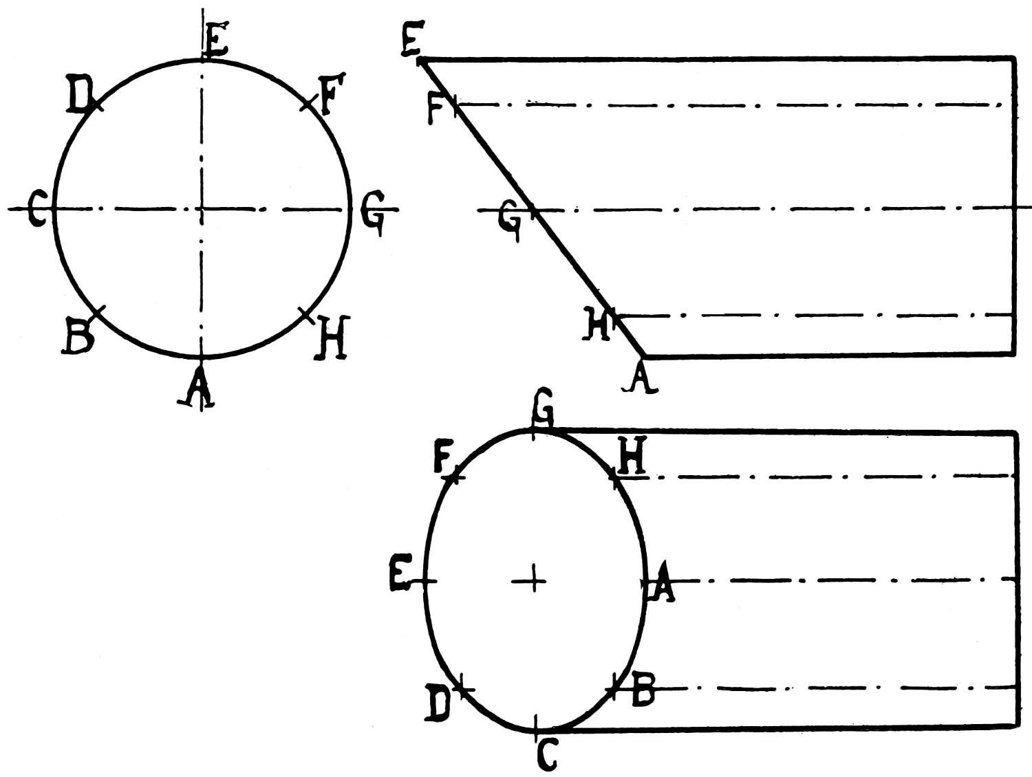
Fig. 232.
The spur wheel shown on page 163 is an example
of projection drawing.
The wheel is illustrated in three views: fig. 235 is
a side view, or elevation; fig. 234 is a front elevation;
fig. 233 is a section view on C D. The section is projected
from the front elevation by drawing parallel
lines from the points in front elevation where the lines
are intersected by the center line C D, cutting the
plane of view and showing the interior shape at C D.
The side elevation, fig. 235, is projected from the
front elevation, fig. 234, by drawing parallel lines
from the edges in the front view across its face.
In actual drawing practice the figures should be
made about three times larger than the example, and
as follows:
For the front elevation draw the center lines A B,
C D, and from their point of intersection as a center,
with the compasses draw the inner circle or hole, also
the pitch line E E. With the dividers space this line
into nineteen equal divisions; each point on this line
will be the center of a tooth, and the distance from one
point to the next one is the pitch of the tooth.
Now, with the dividers mark off the thickness of
tooth at each side of these points on pitch line; with
the compasses draw the outer circle for points of teeth,
the inner circle for the root of teeth, and circles for
thickness of rim and hub; also circles representing the
fillets at rim and hub. For clearness and to prevent
confusion these lines are shown on one-half the wheel
only, terminating in center line C D; all the lines of
the front elevation are now complete excepting the
teeth.
In the drawing office it is unusual to delineate all
the teeth in a gear wheel, the lines without the teeth
as now completed being deemed sufficient, giving all
particulars; however, to prevent the error of mistaking
the circles it is well to represent one or two teeth on
the drawing.
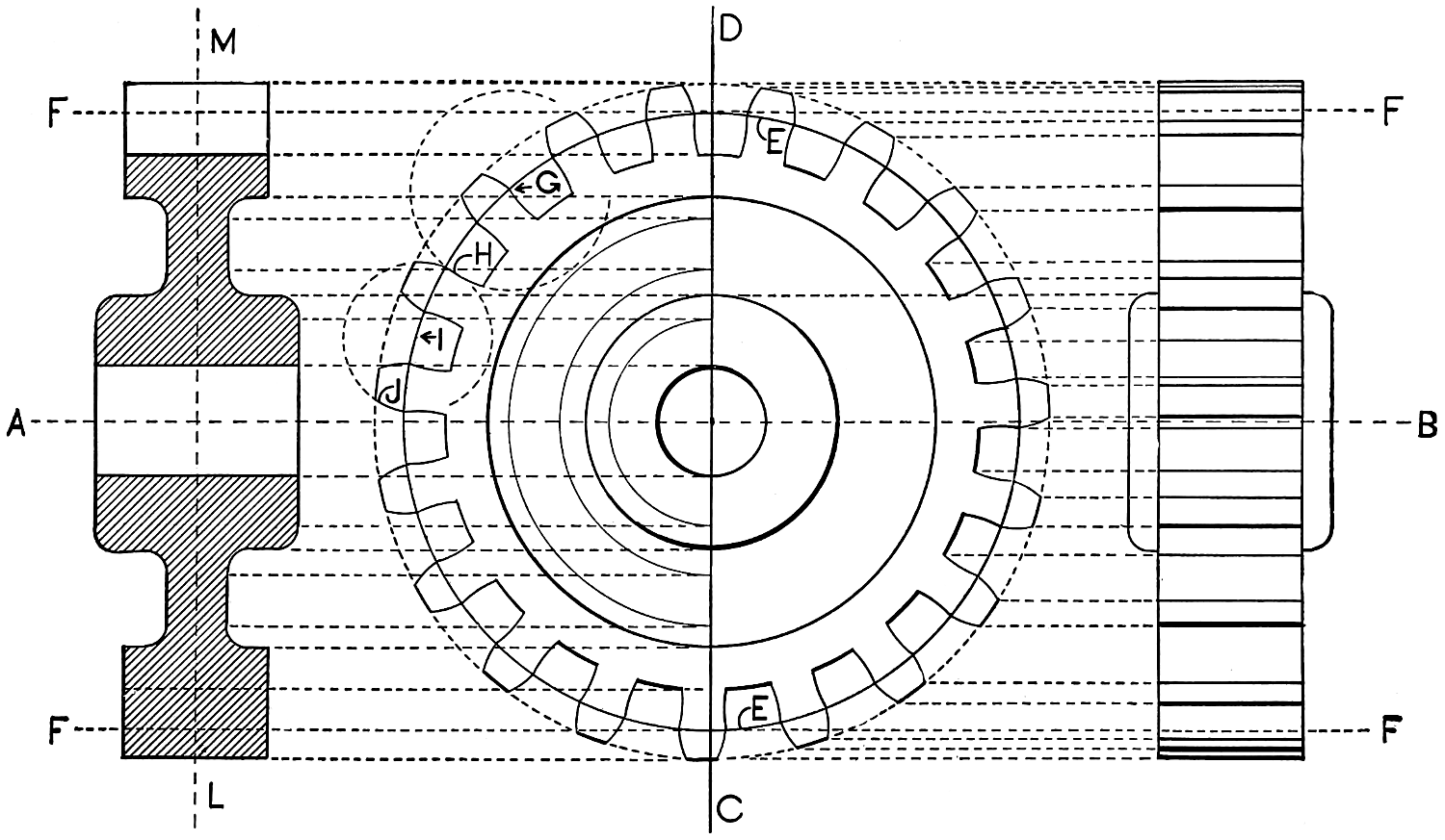
Fig. 233.—Fig. 234.—Fig. 235.
In the example, proceed and complete the entire
wheel, taking on the compasses a radius equal to the
pitch of the tooth; set them on the pitch line at the
point G, already spaced for thickness of tooth, draw
line H from pitch line to root of tooth; proceed similarly
all around the circle, completing one side. Next,
reverse the operation and draw the corresponding side
of the root of tooth. Now take a radius equal to half
the space between teeth and the thickness of tooth on
pitch line, and, with center in pitch line, as shown at
I, draw the outside or addendum of tooth, J; it will be
apparent that the reverse addendum of the tooth next
adjoining can be formed at the same time, with one
setting of the compasses; finish all the teeth similarly;
the front elevation will thus be completed.
Fig. 233 is an excellent example of sectional drawing,
to be executed as follows:
First draw the center line L M of fig. 233, lay off
at each side of it half the breadth of face and of the
hub; now project, from center line C D, in the front
elevation, fig. 234, with the T-square the upper and
lower teeth, the fillets, the chamfers, the hub and center
hole, also dot in the pitch line F F, take the radii
and draw the fillets and chamfers; draw section lines
and the view will appear as shown in fig. 233.
Fig. 235 is a side elevation of fig. 234, and is a fine
sample of projection, to be executed as follows:
Proceed similarly as for fig. 233, projecting the
lines from the outside edges of the front elevation, instead
of from the center line C D as in last figure, and
the end elevation will be as shown in fig. 235.
The student will be assisted in understanding this
working drawing by consulting the pages under the
heading of “Gearing.”
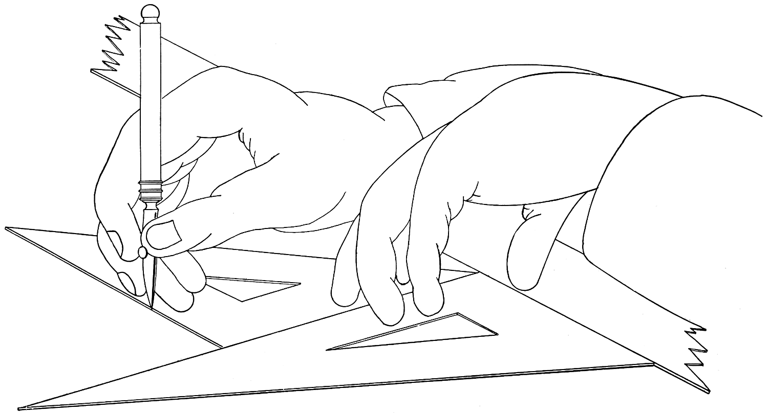
Fig. 236.
“Inking In” Drawings.
When a drawing is completely finished in penciling,
it should next be “inked in” for preservation.
Care should be used that the pen may be perfectly
clean; the pen should be held nearly vertical, leaning
just enough to prevent it from catching on the paper;
the pen should be held between the thumb and first
and second fingers, the knuckles being bent, so that it
may be at right angles with the length of the hand.
The ink should be rubbed up fresh whenever it is
about to be used, for it is better to waste a little time
in preparing ink slowly than to be at a continual
trouble with pens, which will occur if the ink is ground
too rapidly or on a rough surface.
To test ink, a few lines can be drawn on the
margin of a sheet, noting the shade, how the ink flows
from the pen, and whether the lines are sharp. After
the lines have dried, cross them with a wet brush; if
they wash readily, the ink is too soft; if they resist the
water for a time and then wash tardily, the ink is
good.
Care must be exercised not to overload the pen
with ink, and, like the pencil, the pen should always
be moved from left to right and from the bottom to
the top of the board. When inking, both “nibs” of
the pen point must rest evenly on the paper and the
pen be pressed only lightly against the T-square.
Never ink any portion of a drawing until the penciling
is complete.
In inking long, fine lines it is well to go over each
line twice, without moving the T-square, trying not to
widen the line on the second passage; also see that
the pen contains ink enough to finish a line, as it is
difficult to continue with the same width of line after
re-filling.
To produce finished drawings, it is necessary that
no portion should be erased, otherwise the color applied
will be unequal in tone; thus, when highly finished
mechanical drawings are required, it is usual to draw
an original and to copy it. Where sufficient time cannot
be given to draw and copy, a very good way is to
take the surface off the paper with fine sand-paper
before commencing the drawing; if this be done, the
color will flow equally over any erasure it may be
necessary to make afterwards.
The rules of procedure in drawing the lines in
“inking” are, 1, ink in the small circles and curves;
2, ink in the larger circles and curves; 3, then all
the horizontal lines, beginning at the top of the
drawing and working downward; 4, next ink in all the
vertical lines, commencing at the left and moving back
to the right; 5, draw in the oblique lines; 6, all the
center lines and dimension and reference lines. The figuring
and lettering should be always done with India
ink, thoroughly black; the last lines to be drawn are
the section lines. The reason why irregular curves
and arcs of circles are inked in first is, that it is easier
to draw a straight line up to a curve than to take a
curve up to a straight line.
In practice, the flat side of the drawing-pen is laid
against the tee-square or ruler; the taper of the blade
of the pen is sufficient to throw the point enough away
from the edge to prevent blotting; the pen is drawn
from left to right and from the bottom to the top of
the board.
This is shown in fig. 237, intended to represent
“short work” with the drawing-pen. The wrist is
shown resting upon the blade of the square.
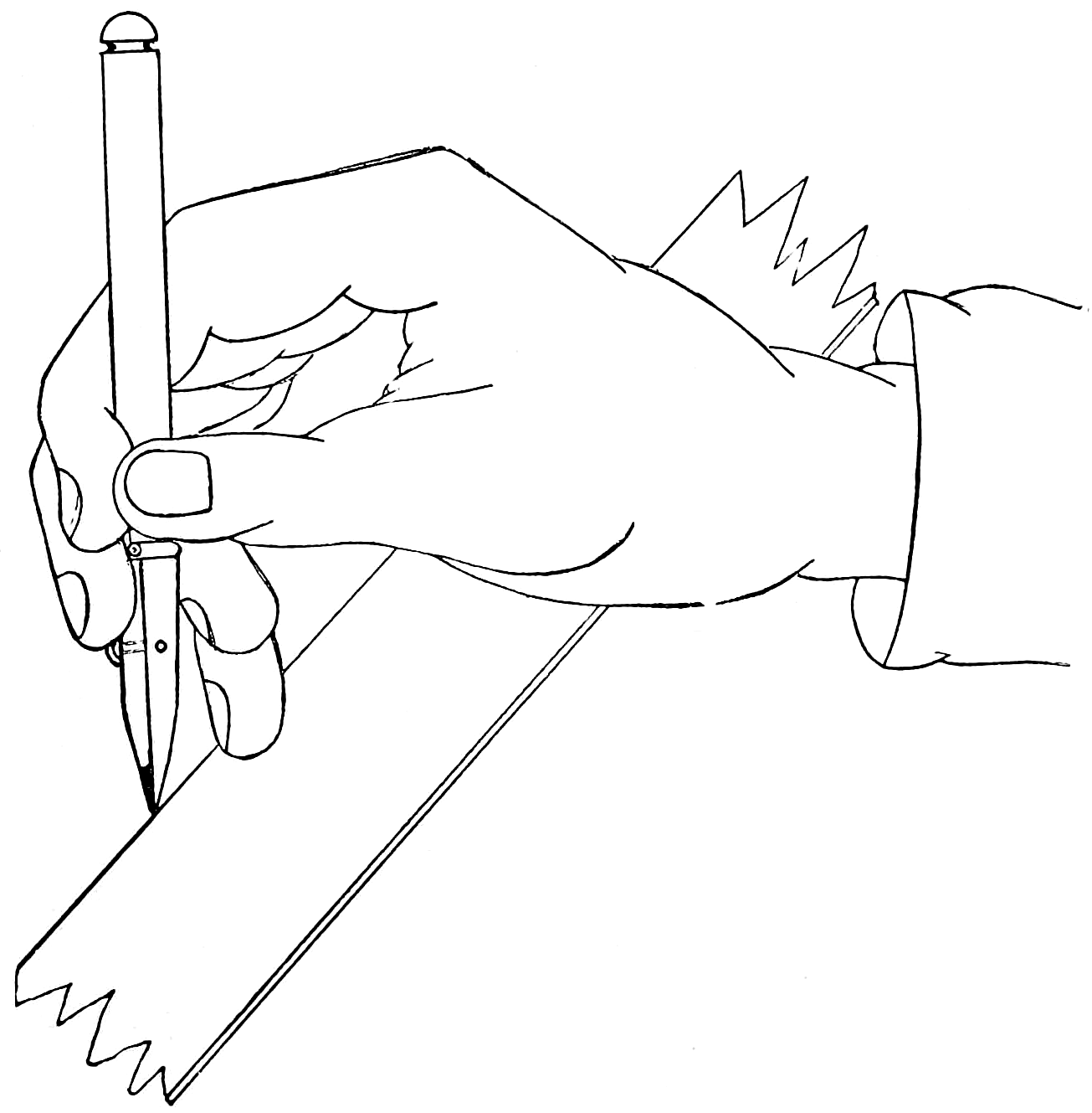
Fig. 237.
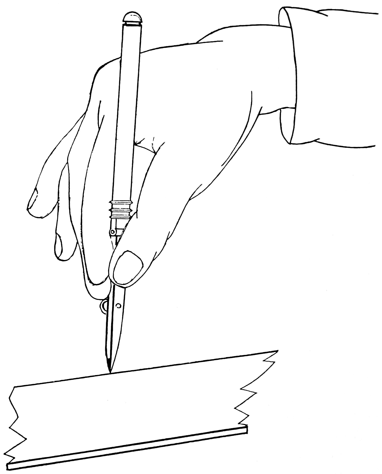
Fig. 238.
In a similar figure, 238, the position of the hand
holding the pen indicates the best relative posture for
inking long lines. In one of these illustrations the
work is executed principally by the wrist—in the other
by the arms and fingers working together.
The pen should be held with even pressure against
the straight-edge or curve. If the pressure varies, the
blades will spring and the width of the line will change.
The blades should be of such length that both will
bear equally upon the paper when the pen is inclined
slightly, so as to bring the inner blade near the straight-edge;
the angle of the pen should not be changed
while drawing any line.
When the inking is finished, the whole drawing
may be cleaned by rubbing it with bread which is not
greasy or so fresh as to stick to the paper. If the
paper is much soiled it may be necessary to use an
eraser. A soft pencil eraser should be used and great
care taken that the ink lines are not lightened and
broken by it.
To avoid the necessity of using an eraser upon a
finished drawing, instruments and paper must be kept
free from dust and dirt. The triangles and T-square
should be cleaned often, by rubbing them vigorously
upon rough, clean paper.
Pounce is a powder used to prevent blotting in
rewriting over erasures; it is held in a bag or small
box with a perforated lid for convenience in sprinkling
on paper; when used it should be distributed evenly
with a piece of chamois, and the surplus or loose particles
removed before applying the ink.
A drawing is made to be read, and the skill in inking,
as in “free-hand” and in penciling, does not consist
so much in the fineness of the lines as in their
clearness.
Lettering Drawings.
Lettering is an important part of making drawings,
the object aimed at being to identify any portion
by reference letter or letters; thus in fig. 239 the line
A C describes the
line extending from
 Fig. 239.
Any information which cannot be expressed in the
drawing is always expressed by lettering, and it is desirable
to confine the lettering of drawings to one or
two standard alphabets that are plain and distinct, and
the principles of which are easily acquired. These conditions
are fulfilled in the Gothic fonts shown on page 173.
Both letters and figures must be carefully made
and of uniform proportion; it is well to “lay out”
these by regular measurement before permanently
inking them. Letters should not be less than one-eighth
of an inch in height and penciled carefully
before inking.
On page 173 are printed two forms of numerals and
letters of the alphabet; it is recommended that these
be used both for practice in free-hand and for regular
office work.
For easy reference, letters should not be crowded
nor allowed to interfere with one another; they should
be drawn neatly, avoiding all lines of the drawing;
plain letters are always used on mechanical drawings,
whether for title, scale, reference, etc.
Arrow-heads, figures and letters should be in black,
and made with a writing pen. A pen with a ball point
is preferable, giving an equal thickness of line, no matter
in which direction the stroke is made.
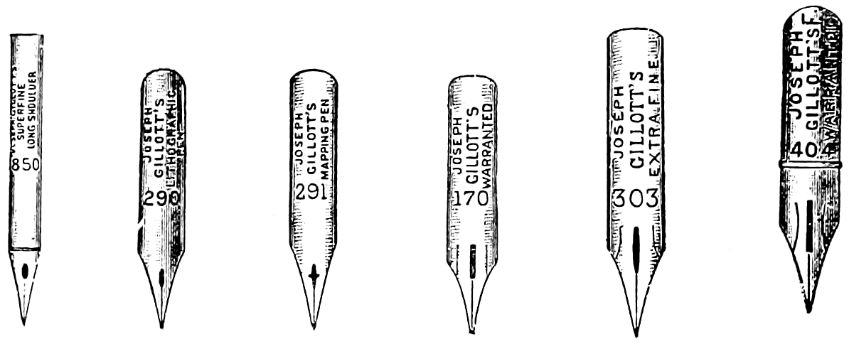
Fig. 240.
Neat, well-lettered drawings go far towards establishing
a high standing for the aspiring draughtsman.
All lettering should be done free-hand, first with the
pencil, sharpened to a fine round point, and afterwards
written in ink. For this purpose common writing pens
are best to be used; fig. 240 represents the several
numbers of the approved Gillott’s pens adapted to this
purpose.
In lettering, it is well, for a guide for size and
location, to draw, with a round-pointed pencil, two
horizontal lines just the height the letters are to be;
the letters are also best made with careful use of the
instruments, rather than free-hand.
In order to letter systematically, it is a good plan
to start with the middle letter of the inscription and
work in both directions; making too prominent letters
should be avoided, plain and distinct letters being most
desirable.
Finally, with an ordinary writing pen, trace over
the penciling in ink; the pencil guide lines being
erased after the letters are inked in completes the
operation.
An important matter in connection with lettering
a drawing is the location of the letters; these should
be so placed as not to interfere with the lines of the
drawing and should clearly point out the part intended
to be described. When single letters are used, they
should be inked in before the shade or section lines are
drawn.
Fig. 241 is an example introduced to show the
method of lettering a descriptive mechanical drawing.
The figure shows a “blow-off valve” of approved
design drawn in section; the letters designate the
several parts; the reading to accompany the lettering
is as follows:
A—Inlet communicating with annular passage (C) to
admit steam, which blows off scale and sediment
from seat (E) before disc (L) comes in contact
with same.
B—Plug to permit passage of rod to clean out blow-off
pipe.
C—Annular steam passage around casing (D) and communicating
with inlet (A).
D—Removable bronze casing, in which plug (L) fits
snugly.
E—Removable bronze seat ring, which also holds casing
(D) in place.
J—Slot in casing (D) arranged to discharge sheet of
steam from C, which, blowing across seat (E),
cleans off scale and sediment before contact with
disc (L).
K—Non-rotating washer to prevent loosening of locknut
(H) when opening valve.
L—Reversible disc, having two Babbitt-metal seating
faces (F) (F).
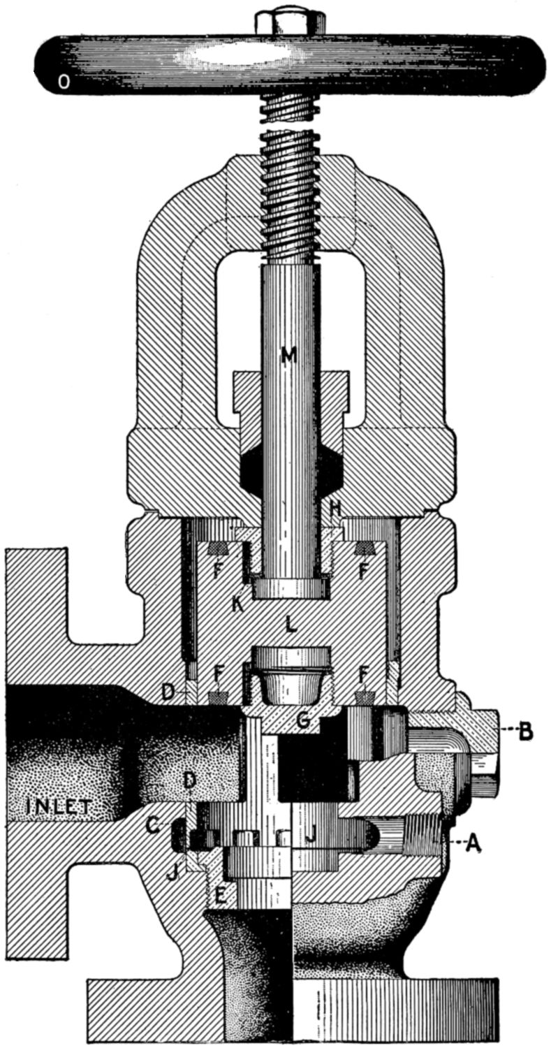
Fig. 241.
Dimensioning Drawings.
To “dimension” working drawings is to place
measurements upon the parts represented, to enable
the workman to proceed without measuring the drawing
itself.
These dimensions should be placed so as not to interfere
with nor crowd the lines of the drawing, nor yet
interfere with one another.
Arrow-heads are used at the extreme points of
measurement, the figures are generally inserted midway
between the arrows; a dot and dash line reaches
from the figure to the arrow-heads, as shown below.
When the dimension is short these lines are
omitted and the dimension is
placed outside the drawing, thus
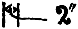 and connected by a curved line; at other times it is
found needful to place arrow-heads outside
the drawing and the measurement inside.
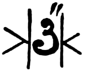
When the dimension is long and narrow it is
usual to carry the dimensions under the drawing by
dotted and dash lines, as shown below.
Arrow-heads and figures should be drawn free-hand
with a common writing pen.
Usually dimensions are given in inches, up to 24
inches, as it is found less confusing; for instance, if
written 1′ 1″ it may be mistaken for 11″; if written 13″
no mistake could be made.
Again, 1′ 0″ may be mistaken for 10″; if written
12″ it would not; in addition to being more
distinct, it occupies less space on the drawing. In
large measurements there is more room for the
figures, and, therefore, they can be spaced
further apart—in feet and inches.
All figures should be made of a fairly
large size. Vertical dimensions should read
from the right hand, thus, as shown:
Measurements of importance, such as
the diameter of a circle, the pitch or distance
apart of rivets and bolts, etc., should
be marked in figures on the drawing. When
rough or unfinished work is mixed with
machined or finished portions, it is usual to mark F,
or “fin.,” after the latter dimension.
In practice, at times, instead of dimensions reference
letters are used, thus:
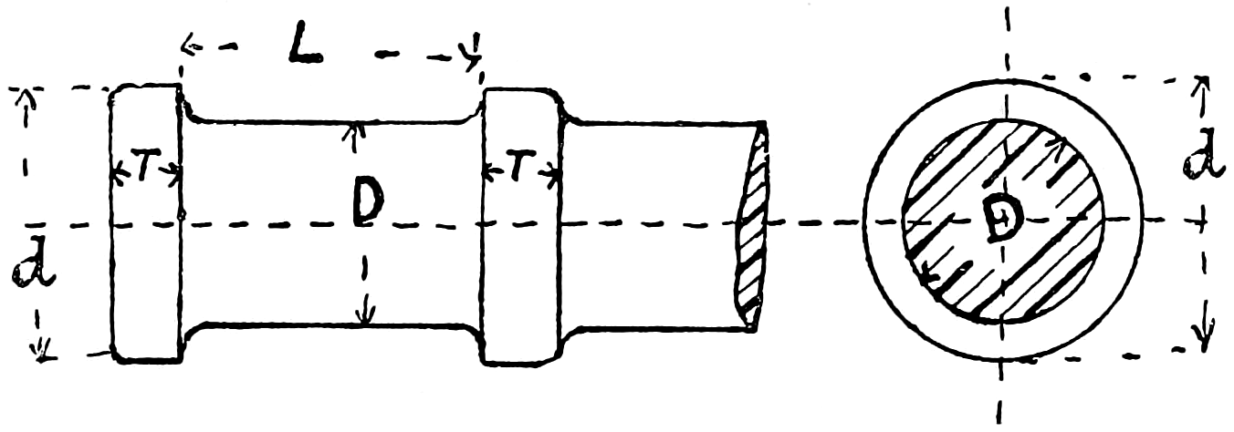
D = diam. of shaft, 21⁄2 inches.
L = length of bearing, 33⁄4 inches.
T = thickness of collar, 7⁄8 inch.
d = diam. of collar, 31⁄2 inches.
Generally it is preferable to give the diameters of
turned and bored work on a section, instead of an end
drawn separately; confusion is sometimes caused by a
number of radial dimensions.
Fig. 242 and fig. 243 are introduced to show the
principal measurements required in practical work, and
the usual way in which such dimensions are marked
when ordering parts of machinery.
Fig. 242 is a pedestal, or metal frame; three views
are shown, the center figure being an elevation, the
lower figure is the plan of the base, the upper figure is
a view of the top, on which is bolted the bearing block,
it being on the outside of the center figure. The
essential measurements are marked by letters. H is
the vertical height from base to the seat of bearing
block: L being the length, and W the width of the
base; P is the length between checks, and B the width
of seat for bearing block; C is the distance from center
to center of the holding down bolt holes, and T is the
depth of the holes in the base; K is the distance from
center to center of the bolt holes in the top for bearing
block.
Fig. 243 is a hanger, or metal bracket, and shows
the center figure or elevation, the plan of the top and
the plan of the seat for bearing block, which is bolted
on the interior of the center figure. H is the vertical
distance from the top to the seat for bearing block;
the other measurements required are marked by letters
similar to figure 242.
Now, one of the important matters in connection
with dimensioning a drawing is the location of the figures.
One rule, whose utility cannot be gainsaid, is
that they should be so located that they can be altered
or erased without damage to the lines of the drawing,
as changes may be necessitated either by original errors
in writing down the figures or by changes in the design
being found desirable during the construction of
the machine.
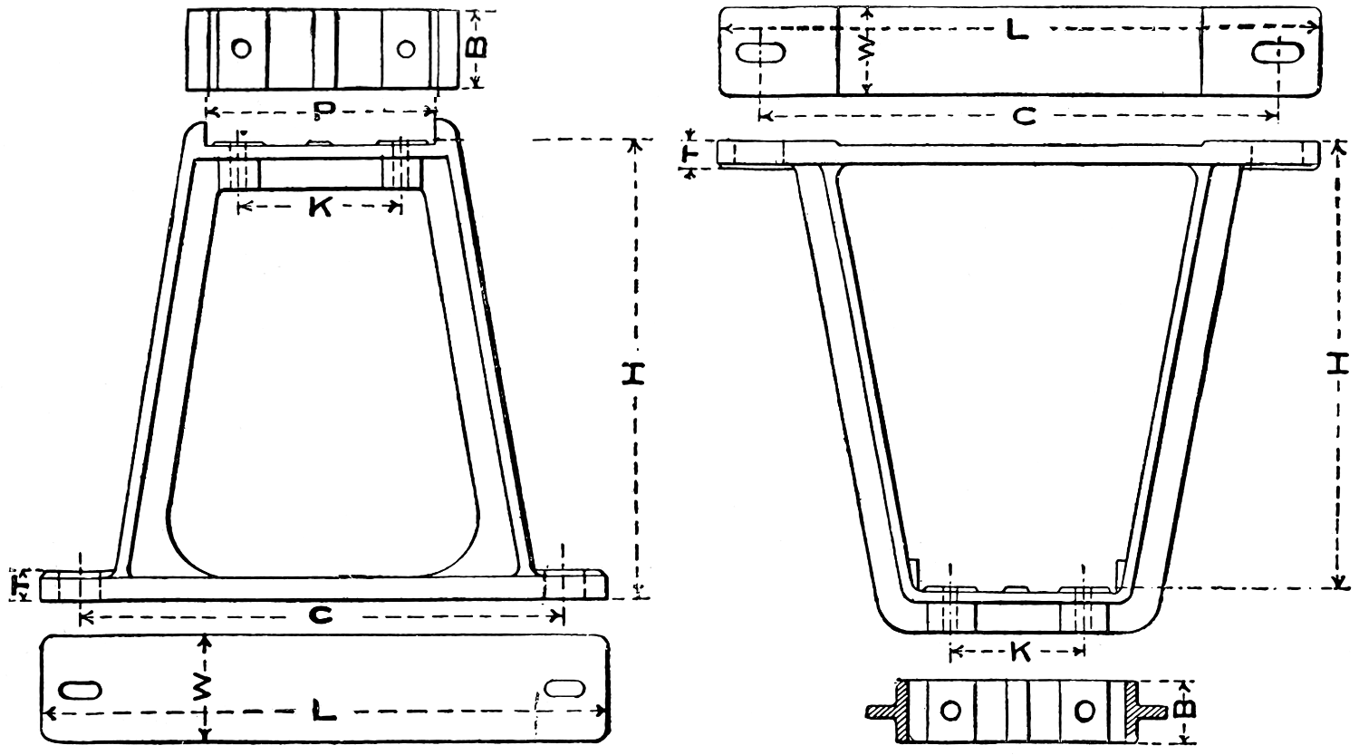
Fig. 243.—Fig. 244.
Shading Drawings.
To produce an effect, drawings are shaded; that
is, shadow lines about twice the width of the regular
line are drawn according to a recognized rule, which
always represents the same peculiarity of form in the
same way.
In working drawings light lines only are permitted;
shade lines are wider than the working lines, and in
reading scale measurements the extra thickness of line
would make a difference.
Instead of representing the shadow as it is really
cast by the object, the edges which cast the shadow
are determined, and all the views are treated as if the
light came from behind and from the left, downwards,
at an angle of 45° to the horizontal line, as shown by
the arrows in figs. 245 to 248.
Fig. 245.—Fig. 246.—Fig. 247.—Fig. 248.
The lower and right-hand outlines of projecting
parts will cast shadows, and the student should make
them of extra width.
Fig. 249: In shading curves, divide the center line as
before (see page 146) and describe circles from center, D;
these lines are not to be shaded in penciling, but when
inking. The figures represent two rings, A and C, and
spaces, B and D. The outside of a surface is shaded
according to circle 1, and the inside surface according
to circle 2. This will give the desired shading, but it
makes a drawing incorrect, and therefore shading is not
used in working drawings.
This shading is accomplished by inking the circle
first with regular width of line; then with the same radius
remove the point of compasses from the true center,
placing it outside, according to the desired position
of the shaded line, and describe an arc of a circle.
In fig. 250 divide center line as before; with the
45° triangle or set square, draw through the center the
diagonals shown by dotted lines; and through the
points A, B, C, etc., draw the perpendiculars, cutting
the diagonals; from the points of intersection draw the
horizontal lines, completing the squares.
Fig. 249.
Fig. 250.
Now, take a radius
of half an inch,
and in the corner of
each square draw
with the bow-pencil
a circular arc meeting
the pencil lines
exactly; with the
bow-pen ink in the
arcs first, then ink
carefully the lines
joining with the
arcs; all lines must
be of the same
width; put in the
shade on arcs and
lines as in fig. 249;
and, finally, erase
the pencil lines at
corners, etc.
Section-Lining. — TINTS AND COLORS.
Cross-hatching has been defined in the “preliminary
definitions” to drawing; this term represents the
practice of drawing diagonal lines representing the interior
of an object, shown as a piece cut in half or
when a piece is broken away. This is done to make
more of the parts show, or to exhibit more clearly the
nature of the materials; hence section lining and cross-hatching
tell the same thing, i. e., the drawing of diagonal
lines, usually at an angle of 45°, to show that the
object is broken away and the interior designed to be
represented.
Cast iron.
Fig. 251.
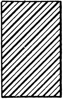
Wrought iron.
Fig. 252.
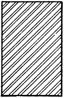
Steel.
Fig. 253.
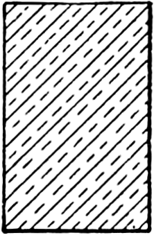
Composition.
Fig. 254.
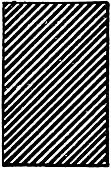
Vulcanite.
Fig. 255.
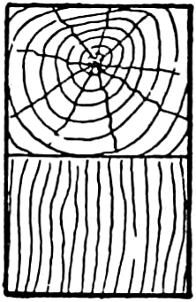
Wood.
Fig. 256.
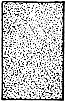
Leather.
Fig. 257.
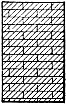
Brick.
Fig. 258.
Cast iron.
Fig. 251.
Wrought iron.
Fig. 252.
Steel.
Fig. 253.
Composition.
Fig. 254.
Vulcanite.
Fig. 255.
Wood.
Fig. 256.
Leather.
Fig. 257.
Brick.
Fig. 258.
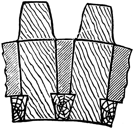
Fig. 259.
Figs. 251 to 258, inclusive, show the section lining
and cross-hatching by which it is customary to represent
the various materials entering into a construction.
In fig. 259 is outlined a
representation of a section of
a cog-wheel; section 1 being
the wood cogs; 2, the iron
wheel, and 3 the wedges at
the root of the gear. It would
be impossible to convey the
same ideas by ordinary plan
or elevation drawing; all the objects on the same page
are more clearly represented by the use of section
lines or cross-hatching.
Sectioning is executed by drawing a series of parallel
lines about 3⁄32 inches apart. Lay the 45° triangle
on the upper edge of the T-square and draw the top-most
line of the sectioning. Then slide the triangle
along the T-square for each successive line. The sectioning
should be inked in without previous penciling
and the lines should be finer than the lines of the general
drawing.
Various devices are in use for mechanically equalizing
the distances in section lining, but the trained
eye is the most practical method. When two abutting
pieces are sectioned, the section lining on one piece
slants in an opposite direction to that on the other.
To draw an object to be sectioned on both sides
of its center line, only one side is sectioned, while the
other side is drawn in full.
Sections are necessary in nearly all machine drawings;
they are usually taken horizontally or vertically,
but they may be taken in any direction; the position
of a section should be shown by a line upon the object;
this line is called the cutting plane.
In fig. 261 is shown the hub of a wheel, it is also a
sample of work for practice.
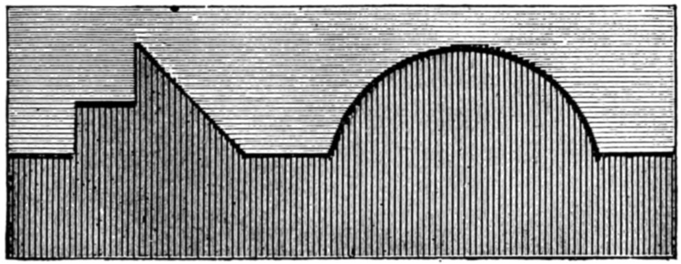
Fig. 260.
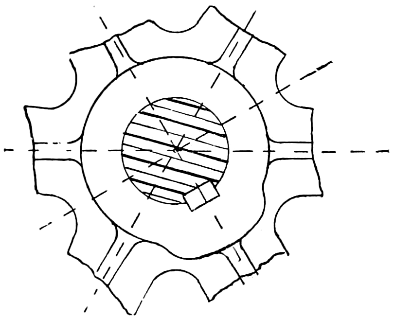
Fig. 261.
Fig. 260 shows the mode of representing two
different materials in one plane, or a section may be
represented by the darker portion, and the lighter
shaded portion being a surface resting on the section.
Fig. 261 shows the section of a shaft surrounded
by the surface of a wheel.
For special purposes of illustration drawings are
made which must be tinted. In such cases the paper
must be expanded and stretched evenly all over its
surface; otherwise when the moist tint is applied the
paper will wrinkle and get out of shape; to do this
cut the paper at least half an inch less in size than the
drawing board; lay the paper face down, turn up a
margin or edge of about three-fourths of an inch all
round, then dampen the paper with a sponge and clean
water; allow it to soak for a few minutes until it is
evenly dampened or moistened all over, turn the paper
upside down (face up).
Apply strong paste to the under side of the margin
all round; rub down, on the drawing-board, working
from the center of the board outwards so as to exclude
the air and prevent creases or furrows. The board is
then inclined and left to dry slowly; make sure that the
paper is all well pasted and every part of the edges
attached to the board.
If tracings are required to be tinted or shaded,
the color may be applied before the tracing is cut off,
or what is more usual, the color may be applied on the
back of the tracing; then there is no liability to wash
out the lines.
Mechanical drawings are seldom tinted, but are
mainly produced in India ink. Where, however, a fine
effect is desired, working drawings are colored, so as to
show at a glance the material of which the different
parts are to be made.
The colors required are few but should be of the
best quality. Besides India ink the following water-colors
are generally used:
1, Neutral-tint. 2, Prussian Blue. 3, Chrome
Yellow. 4, Gamboge. 5, Raw Sienna. 6, Carmine.
7, Vermillion. 8, Venetian Red. 9, Sepia. 10, Indigo.
These come in hard cakes.
Certain colors and tints represent different metals
and materials as follows:
Wrought Iron—Prussian Blue.
Steel—Carmine and Prussian Blue, mixed to give
a purple shade.
Steel Casting—Same as the above darkened by
Venetian Red.
Cast-Iron—Neutral Tint made of India Ink, indigo,
mixed with a little carmine.
Brass—Gamboge or Chrome Yellow.
Babbitt—Emerald Green; sometimes light mixture
of India Ink.
Copper—Purple Lake.
It is sometimes found necessary to prepare a highly
finished and shaded drawing of the work in hand.
Such elaborations, in fact, are much admired by the
uninitiated, although the complete shading of the
drawing is no criterion as to the scientific value of the
machine. An illustration of this is told in the note.
Note.—A consulting engineer had to lay before a board of
directors plans of horizontal engines for their consideration. One
of these drawings was of a very superior machine, but being only
depicted lineally was at once rejected by them, for a highly
finished representation of a very inferior apparatus. The engineer,
wishing to induce the board to decide for the best, suggested that
the matter should be postponed to a future day, and in the meantime
had the drawing of the superior machine highly colored and
finished. At the next meeting the directors unanimously decided
that this was the very one which they preferred and had chosen.
Reproducing Drawings. — BLUE PRINTING. — TEST-PIECES. — BLACK PROCESS COPYING.
When once finished, one or more copies of drawings
are frequently required; these are produced, 1, by
blue printing, as described before; 2, by tracing. A
tracing is a mechanical copy of a design or drawing,
made by reproducing its lines as seen through a transparent
medium—as tracing-cloth or tracing-paper.
Tracing-cloth is a thin linen fabric, coated with
size; this is called tracing-lines; tracing-paper is so
prepared as to be transparent, so that it will receive
marks either in pencil or with pen and ink.
Tracing-cloth must be fastened to the board, over
the drawing, by pins or other tacks; moisture or dampness
should be carefully avoided and the drawing done
on the smooth side of the cloth.
When tracing cloth will not take ink readily a
small quantity of pounce may be applied to the surface
of the cloth and distributed evenly with a piece
of cotton waste, chamois, or similar material, but the
pounce should be thoroughly removed—by washing—before
applying the ink.
In making tracings the same order is followed as
described under the section “Inking”—to repeat:
1, ink in the small circles and curves; 2, ink in the
larger circles and curves; 3, then all the horizontal
lines, beginning at the top of the drawing and working
downward; 4, next ink in all the vertical lines, commencing
at the left and moving back to the right;
5, draw in the oblique lines; 6, all the center lines red
(carmine), and dimension and reference lines in blue
(Prussian blue) or vice versa. The figuring and lettering
should always be done with India ink, thoroughly
black.
Copies of drawings or parts representing details
and measurements are frequently needed for the office,
pattern shop, machine and blacksmith shop, etc. These
copies are best made by printing on sensitized or
specially prepared paper, from tracings drawn on transparent
cloth or paper, as hereabove described. The
original design may be guarded with the utmost care
for long preservation, but the blue prints, so called, are
for ready reference and use without much regard to
the length of time they are to be in existence.
The usual practice is to carefully trace from the
drawing on transparent cloth or paper an exact reproduction
of it, filling in all detail lettering and sizes or
figured dimensions.
This tracing is fixed in a frame similar to a picture
frame, with the side on which the drawing is made
next to the glass: 1, place the sensitized side of the
paper (which has been prepared previously) against the
back of the tracing; 2, fix soft padding against the
back of the paper and fasten it up so that both paper
and tracing are compressed firmly against the glass,
permitting no creases or air spaces between them.
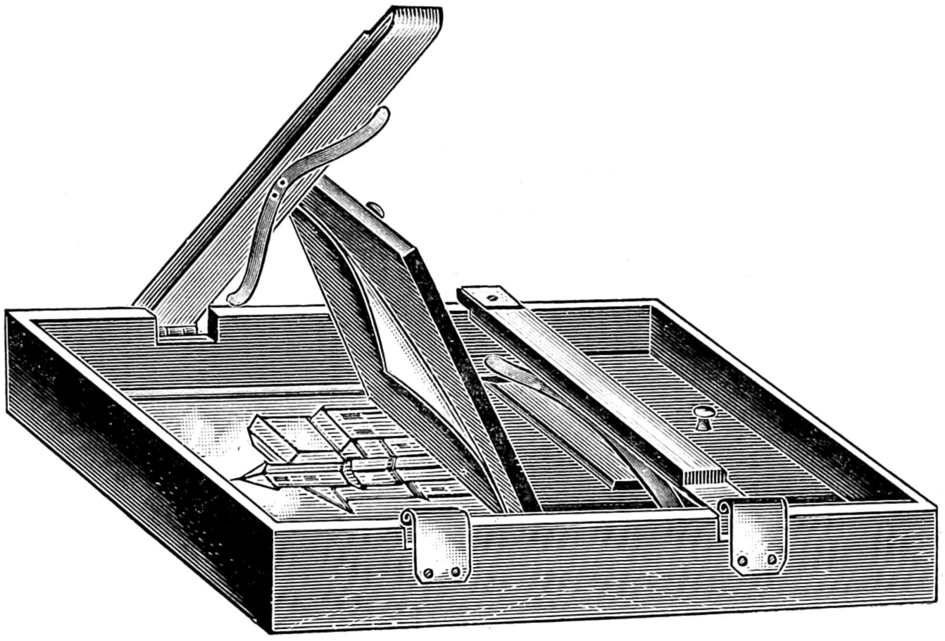
Fig. 262.
This should be done in a darkened room; 3, expose
for three to six minutes, according to the intensity
of the sun; 4, take the sensitized paper out of the
frame and quickly wash well in clean running cool
water, and the drawing will appear in white lines on
blue ground; 5, hang the print up by one edge so that
the water will run off and the print will soon dry and
be ready for use.
To make good blueprints, being guided only by
the appearance of the exposed edge of sensitized
paper, requires considerable experience. Very often,
especially on a cloudy day, the edge looks just about
right, but when taken out of the frame and given a
rinsing, it is only to find that the print looks pale
because it should have been allowed to remain exposed
for a longer period.
Now simply take a small test-piece of the same
paper (say about 4 inches square) and a piece of
tracing cloth with several lines on its surface and
lay these small pieces out at the same time the real
print is being exposed, and cover these samples
with a piece of glass about 4 inches square. As a
general rule, we can find a place on top of the frame
for the testing-piece, and by having a small dish of
water at hand for testing the print by tearing off a
small bit and washing same to note its appearance,
the novice can get just as good results as the experienced
hand without danger of failure.
This is accomplished by specially sensitized paper
by which a fac-simile of the original drawing can be
made; that is, black lines upon white ground. It also
avoids the objection to the blue print paper of shaded
drawings which show light and shade reversed.
The prints made by the process are said to be
absolutely permanent and can be altered, added to or
colored the same as original drawings.
The sensitized paper is sold ready for use, but it
can be prepared by dissolving two ounces of citrate of
iron and ammonium in eight ounces of soft water;
keep in a dark bottle, also, one and one-third ounces of
red prussiate of potash in eight ounces of water; keep
in another dark bottle; when about to use mix an
equal quantity of each in a cup and apply in a dark
room with a soft brush or sponge to one side of white
rag paper, similar to envelope paper, let it dry and put
away in a dark place until required for use.
Drawing Office Rules. [1] — SIZE OF DRAWINGS. — CHARACTER OF DRAWINGS. — DRAWING SYMBOLS. — STANDARDS. — NUMBERING OF DRAWINGS. — CHECKING. — PATTERNS. — SKETCH BOOKS. — IN GENERAL. — NUMBERING WORKING DRAWINGS.
There are drawing offices where from ten to nearly one hundred people are busily employed in making
new plans and sketches by the hundreds, and where thousands of completed drawings are filed for reference
or for changes, as these are needed in the shop management.
To be introduced for the first time into such a company is a trial for the “new man” both of nerve and
manners, and a test as well of skill; nothing helps more at such a time than an acquaintance with the rules
and routine of the office, for the old saying holds good in a drawing office, of “doing in Rome as the Romans
do.” The author of this book has felt this strangeness in a new position and so adds the following model-rules
for the guidance of the student when first entering a regular position in an office where many are employed
and where success depends upon a systematic ordering of the work in hand.
1. The standard size shall be 23 inches by 36
inches, subdivided into half, quarter and eighth sheets.
2. Full-size drawings shall be reserved, as far as
possible, for general views and parts not capable of
being shown on smaller sheets.
3. All shop detail shall, as far as possible, be
shown on quarter and eighth sheets.
4. Detail drawings shall, as far as possible, classify
the different kinds of works, such as castings, forgings,
shafts, levers, piping, etc. Different kinds of work
shall not be shown on the same detail drawing.
5. All shop drawings liable to repetition shall be
traced and blue-printed. All temporary details, requiring
only one copy, may be made on sketch sheets
and press copied.
6. A shop drawing is to be considered as an order
or instruction to the shop, and not merely as a statement
or illustration. For this purpose it must convey
clearly and distinctly all the information necessary
to make the article.
7. Every dimension necessary to the execution
of the work is to be clearly stated by figures on the
drawing, so that no measurements need to be taken in
the shop by scale. All measurements to be given with
reference to the base or starting point from which the
work should be laid out, and also with reference to
center lines.
8. All figured dimensions on drawings to be
plain, round vertical figures, not less than one-eighth
inch high, and formed by a line of uniform width and
sufficiently heavy to insure printing well. No thin,
sloping, or doubtful figures, or diagonal-barred fractions
will be tolerated. All figured dimensions below two
feet to be expressed in inches.
9. All center lines to be alternate dot and dash
in fine black line. All dimension lines to be double
dot and dash, with a central space for the figure, and of
such strength as to show on blue-print more faintly than
lines of drawing. Lines of drawing to be bold and
clearly defined in proportion to the scale, and may be
shade-lined by making the right-hand and bottom lines
heavier. No ornamental shading or other “frills”
allowed on shop drawings.
10. Every drawing, whether whole or half-sheet,
shall have the title, date, scale and number of the sheet
stamped in lower right-hand corner, and the quarter
and eighth sheets printed on top.
11. The name of the drawing, as given in the
title, is invariably to consist of two divisions in one
line separated by a hyphen. The first division is to
state the general name of the thing or machine, and
the second name is to clearly designate the part or
parts represented (or if a general view should so state).
The wording of titles should be submitted to the chief
engineer or head draughtsman for approval.
12. Each drawing shall bear the name of the
draughtsman and examiner, the surname being used
without initials.
13. Drawings of piping details shall be made in
diagram form, using standard symbols.
14. All detail parts for standard or repetition
work shall be shown unassembled as far as possible.
15. Detail shop drawings should state:
(a) The pattern number of every casting in plain
figures of larger size than the dimension figures.
(b) The material of which the parts are made,
using symbols as follows: C.I.—Cast iron. W.I.—Wrought
iron. M.S.—Machinery steel. H.S.—Hammered
steel. Bs.—Brass. Bbt.—Babbitt. Bz.—Bronze.
C.R.S.—Cold rolled steel.
Other materials write full name.
(c) Finished surfaces will be indicated by “f”
written on the line or surface to be finished. When
not so marked it is understood that the part is to be
left black or rough. In cases where finish might be
presumed but not required, follow the figured dimensions
by the word “cast,” if a casting, and “rough,” if
a forging.
16. The following standards shall be strictly
adhered to as given in the tables noted:
(1.) Table of standard diameters of shafting and
key seats.
(2.) Table of standard stock sizes of rounds.
(3.) Table of standard stock sizes of flat steel.
(4.) Table of standard clearance fits.
(5.) Table of standard symbols for notation of
riveting.
(6.) Table of standard symbols for pipe fittings.
Also such other standards as may be adopted from
time to time.
17. Drawers and filing cases shall be numbered
consecutively. Drawers shall contain 100 sheets each,
and filing cases 200 sheets each, and to be fully indexed.
Drawings shall be numbered by a number indicating
both drawer number and serial number in the
drawer—thus, 7,604 is the fourth sheet in drawer 76, etc.
18. Drawing numbers shall be checked off the
index as required, and the index posted up in uniform
handwriting by the clerk.
19. Standard size drawings shall be kept in
drawers and quarter and eighth sheets in filing cases.
All drawings shall be indexed by an index sheet kept
in each drawer or case.
20. All drawings must be approved before being
traced. When tracing is completed it will be given
immediately to the chief draughtsman, who will have
a preliminary print made and carefully checked, before
being used.
21. All patterns shall bear the number of the
drawing on which they are first detailed, followed by a
serial letter, according to the number of patterns on
the drawing.
22. Standard patterns used repeatedly and liable
to be ordered from in repairs must not be changed.
Other patterns may only be changed when absolutely
necessary and by order. When so changed they will
bear the original number and letter, followed by A for
the first change, B for the second change, and so on
thus: 4860 AB is the second change in pattern 4860 A.
23. Each draughtsman will be supplied with a
sketch book by the company, in which he shall make
all his notes, calculations and data referring to his
work, and under no circumstances shall notes of value
be made on loose sheets. Each entry should invariably
be commenced with the subject and date, and full
notes made of data on which the calculations were
based, and the results obtained clearly stated. These
books are to remain the property of the company.
24. Changes in drawings, sketches or order lists
issued to the shop shall only be made when authorized
by the chief engineer, or, in his absence, by the chief
draughtsman, and when so authorized shall be made by
the order clerk.
25. The names of all similar parts in order lists
and drawings are to be uniform.
26. Tracings must be kept in safe, for blue-printing
purposes only. Office copies of blue-prints must
be used for references.
27. No drawing, print or photograph shall be
taken from office without permission.
There are a great many different systems used in
indexing drawings, most of which have some good
points, but very few are sufficiently elastic to cover a
wide field. A plan based upon the decimal system of
notation is very simple, and, as there is no practical
limit to the number of subdivisions, it can be expanded
indefinitely. Following are the main outline
features of the system as adapted to the needs of
drawing offices belonging to large works.
The main division numbers, 000, 100, 200, 300, etc.,
are used respectively for all plans and general sheets
referring to the division concerned. 100 includes
general plans covering more than one department,
and all small-scale plans with cross references to departments
covered.
The class or tens divisions contain general
drawings of the subdivisions, the subclasses or units
divisions being limited to details only. Further subdivisions
would probably be necessary in some cases.
A card index with cross references and written by
someone who knew what to do is an essential part
of the system.
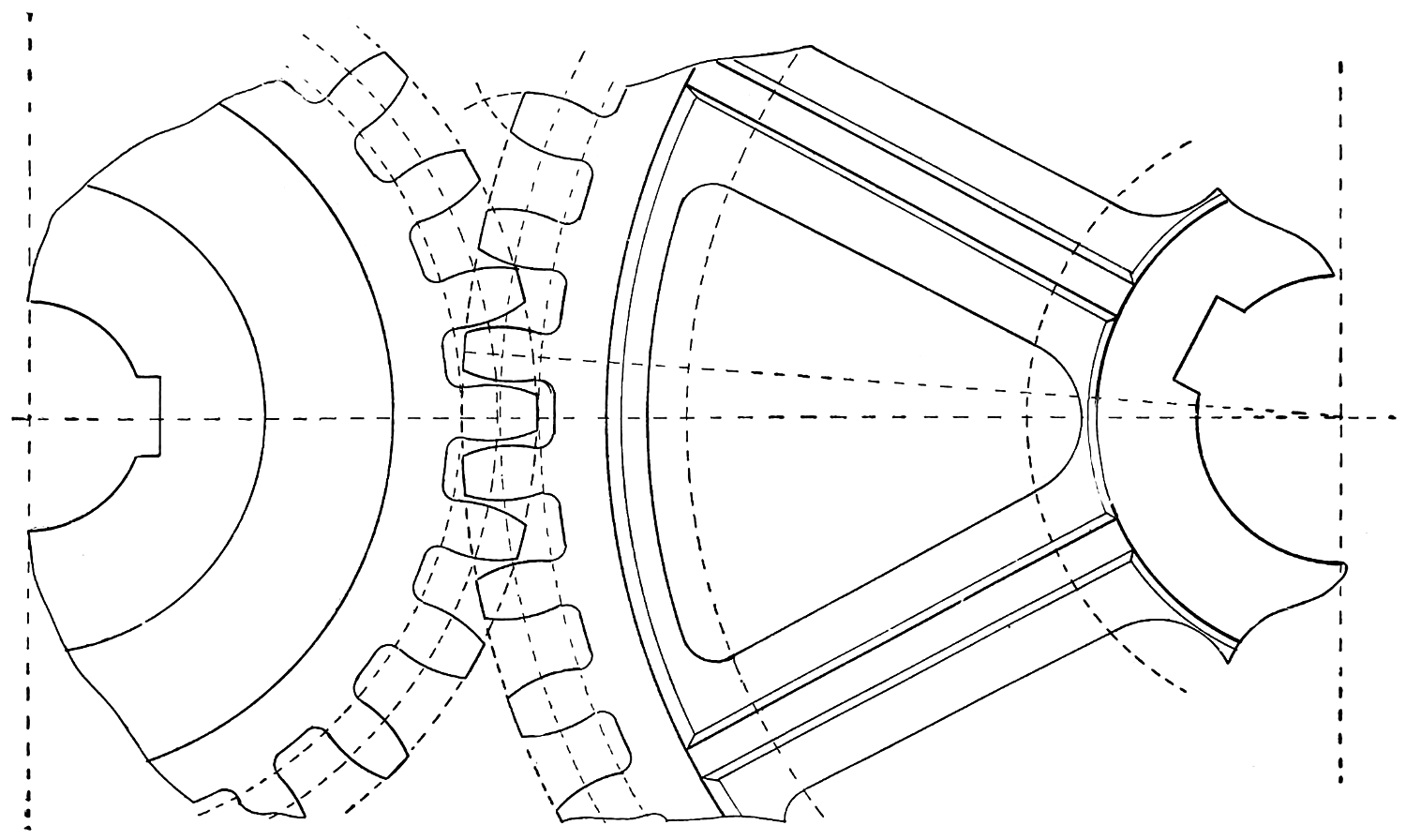
Fig. 263.
Gearing.
Under this heading the author has grouped some information relating to a subject of wide interest and one
sure to interest a student of mechanical drawing.
The diagrams are intended for exercises in drawing, i. e., to be redrawn as parts of practice; the text is to be
studied not only for the good to be gained from the study of gearing, but as an example of the way in which
written or printed descriptions are necessary to explain a subject illustrated by drawings.
A gear is primarily a toothed wheel; gearing is a
train of toothed wheels for transmitting motions; there
are two chief sorts of toothed gearing, viz., spur gearing
and bevel gearing.
A spur wheel has teeth around the edge pointing
to the center; commencing at the center, a spur wheel
may be said to consist of a hole, square, octagonal or
round, for its axle or shaft; a hub; the web, body or
arms; a rim, and the teeth; see fig. 263.
A spur wheel has teeth on its circumference which
run parallel to its shaft; wheels as shown in fig. 271 are
termed helical wheels; these are similar to spur wheels
except their teeth are arranged upon different angles
to the shaft.
A bevel is a slant or inclination of a surface from a
right line, hence a bevel wheel is one whose teeth stand
beveling or at an oblique angle to the shaft, or towards
the center; see fig. 267.
Miter wheels are bevel wheels of the same size,
working at right angles with one another; see fig. 268.
The diameter of both spur and bevel wheels is
measured and calculated neither from the outside nor
from the bottom of the teeth, but on the pitch circle.
When we speak of the diameter of a spur or bevel
wheel, we mean the diameter of the pitch circle, without
any reference to the form of tooth.
The addendum circle of a toothed wheel is as
shown in illustration, fig. 264; addendum means “something
added,” and, as shown in the figure, it is the part
added beyond the pitch “line” or circle.

Fig. 264.
The pitch line is the most important one in gearing;
the “pitch line” or “pitch circle” is supposed to be
the working circle. This is shown in P—P in fig. 274.
The periphery of a wheel is the extreme circumference,
as N in fig. 274.
All parts of gear-wheels consist of portions, to
which have been given generally accepted names.
Fig. 264 shows the “addendum circle” and the “pitch
line” as marked. The teeth and rim are shown in
white, and the other portions are indicated by the names.
The circular pitch line, as opposed to the diametral
pitch, is the same as the pitch circle. It is a line which
bisects all the teeth of a toothed wheel.
The rolling circle is the same as the circular
pitch line.
Diametral means pertaining to a diameter or the
length of a diameter; hence a diametral pitch is a
system of measures or enumeration based upon the
diameter instead of the circular pitch line; it is used
very generally in spacing for fine tooth gear. Wheels
of this description usually have their teeth cut in a
gear-cutting machine, i. e., medium and fine tooth
gears.
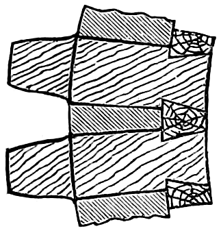
Fig. 265.
A cog wheel is the general name for any wheel
which has a number of cogs placed around its circumference.
When the teeth of a wheel are
made of the same material and
formed of the same piece as the
body of the wheel, they are called
teeth; when they are made of wood
or some other material and fixed to
the circumference of the wheel, they
are called cogs; see fig. 265.
A pinion is a small wheel. When two toothed
wheels act upon one another, the smaller is generally
called the pinion. The terms trundle and lantern are
applied to small wheels having cylindrical bars instead
of teeth. The teeth in pinions are sometimes termed
leaves; in a trundle, staves. See fig. 273.
The wheel which acts is called a leader or driver;
and the wheel which is acted upon by the former is
called a follower or the driven. When a screw or worm
revolves in the teeth of a wheel, the latter is termed a
worm wheel or worm gear; see fig. 270. When a
pinion acts with a rack having teeth, we speak of rack
and pinion. When the teeth are on the inside of the
rim, and not on the periphery, the wheel is termed an
internal gear; see fig. 272.
Two wheels acting upon one another in the same
plane are called spur gear; the teeth are parallel with
the axis. When wheels act at an angle, they are
called bevel gear.
Friction gear-wheels are those which communicate
motion one to the other by the simple contact of
their surfaces.
In frictional gearing the wheels are toothless and
one wheel drives the other by means of the friction
between the two surfaces which are pressed together.
Grooved friction wheels are used to give greater
cohesion than can be obtained by the plain surface.
Fig. 263 shows a pair of spur-wheels in
gear. The dotted circles which meet are
the rolling circles, called the “pitch line”
or “pitch circle.”
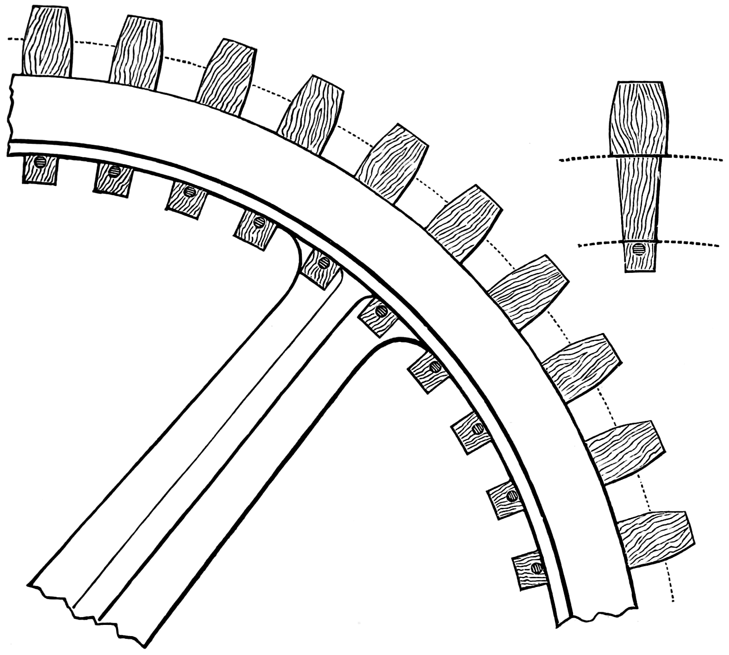
Fig. 266.
A spur mortise wheel is similarly
shown in fig. 266; it is very like in appearance
to a spur wheel; it differs essentially
in that the teeth are separate cogs,
fixed in singly to the rim; see also fig. 265,
page 201.
Note.—The teeth of spur wheels cast from a
pattern must of necessity be larger at one side than
at the other, because the teeth must have taper to
permit the extraction of the pattern from the
mould; therefore, in fixing wheels to gear, the
large side of one should meet the smaller side of
the other; should the two large sides come together
the teeth will meet only at the large side,
and the teeth will probably break away from the
excessive strain on that point.
Skew gearing are bevel wheels working out of
center; the teeth do not form radial lines from the
wheel center.
Fig. 267 shows a pair of bevel wheels in gear as
described on page 199. A bevel mortise wheel, i. e.,
one having cogs inserted in its rim instead of teeth.
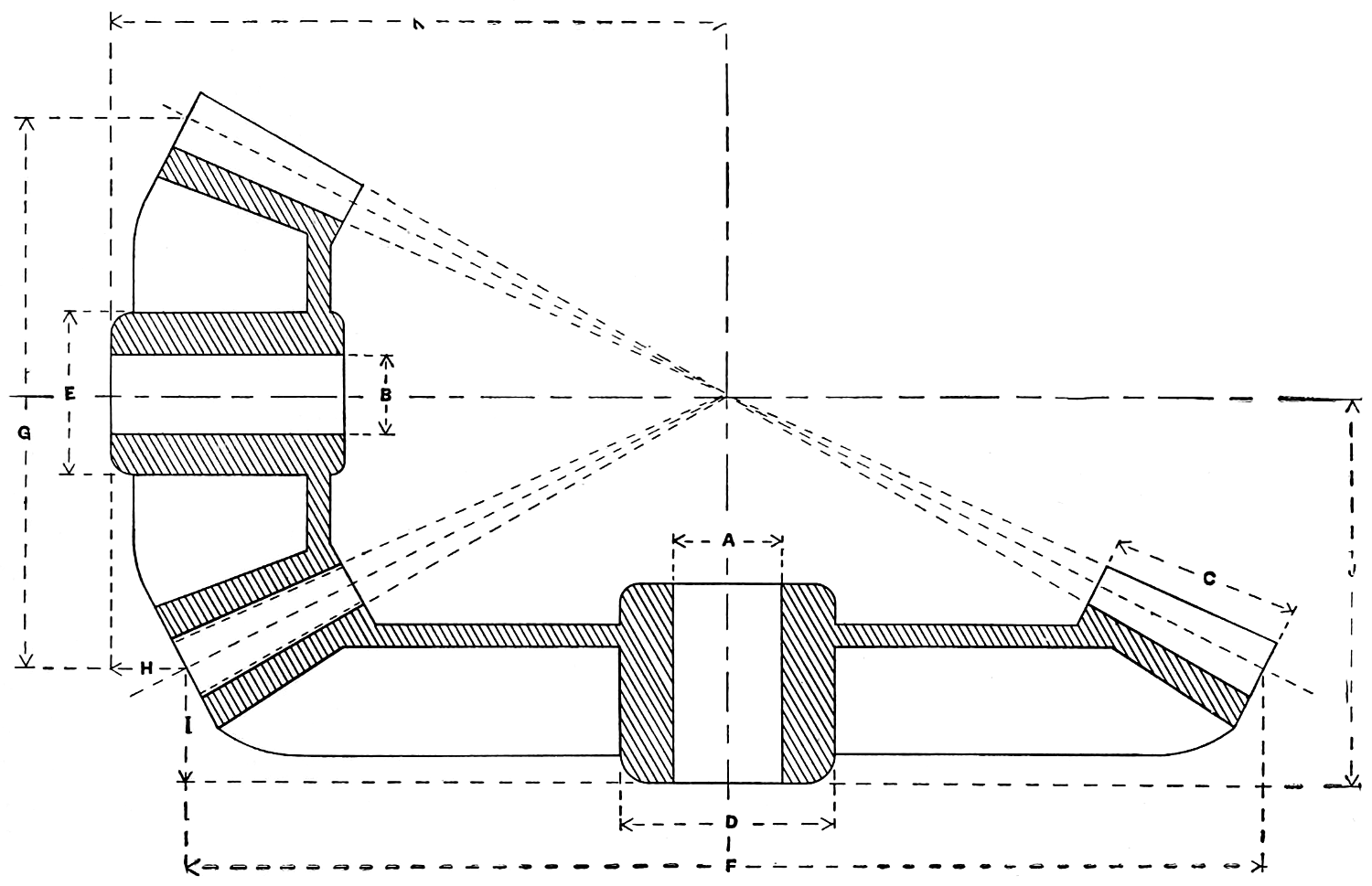
Fig. 267.
A bevel wheel and pinion must be made to suit
one another by both having teeth forming together an
angle of 90°, therefore they are pairs, or proportioned
in the number of teeth one to the other. Any other
proportion used would not exactly gear and would be
termed a “bastard” gear.
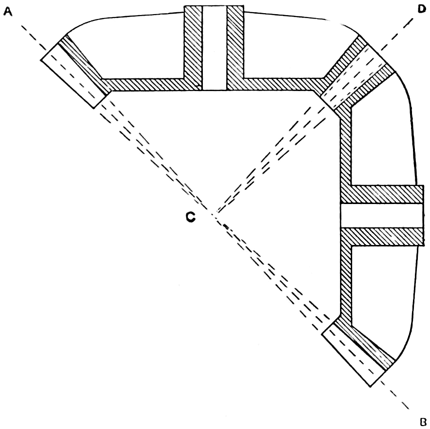
Fig. 268.
Fig. 268 represents a pair of miter wheels in gear;
it will be noted that the shafts, when connected, will
be at right angles to each other, the wheels being in
all particulars of the same dimensions; the figure
answers the purpose of a much longer description, if
given in words.
A miter-wheel can easily be known by putting
a square upon the face of the teeth, which are always
at an angle of 45° with one another, irrespective
of size.
A miter-wheel is a particular kind of bevel-wheel,
the bevel being limited to an angle of 45° in each
wheel.
The curve of the teeth in bevel-gears, when correctly
formed, changes constantly from one end of the
tooth to the other, therefore bevel-gears whose teeth
are produced with a forced cutter are not theoretically
correct.
Fig. 269
represents a
rack and pinion:
the teeth
in this form of
gear are shaped
similarly to
those in the spur
wheel, shown on
page 198, with
the difference
that the teeth
of one are on a circle and
on the rack are made on
a straight line.
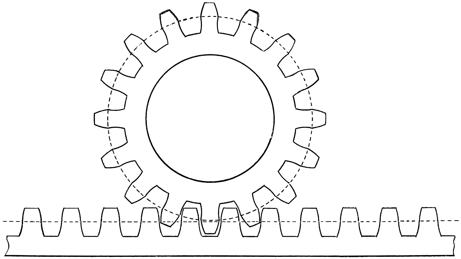
Fig. 269.
A flange or addition
to the end of a tooth and
the rim connecting them
together is used to
strengthen the teeth. This
extends from the root to
pitch line when the wheel
and pinion are both
flanged: if only one is
flanged it extends from
the root to the addendum.
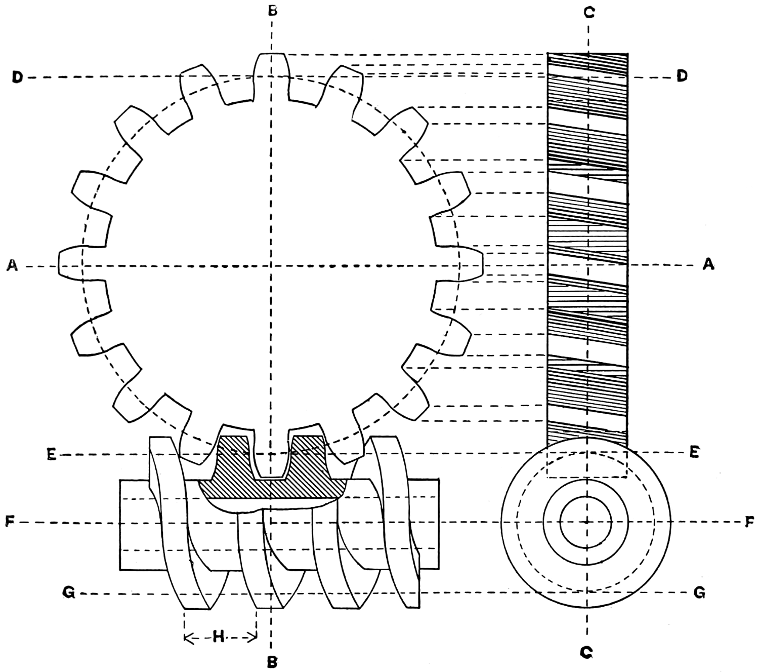
Fig. 270.
Fig. 270 illustrates a worm and
a worm wheel, sometimes called
screw gears. This is a slow but
powerful method of transmitting
power, one revolution of the worm
only moving the wheel the distance
of one tooth and space.
A worm gear is a spur wheel
with teeth at an angle to the axis,
so as to work with a worm which
is a screw, or has teeth shaped in
the form of a spiral wound round
its circumference; the screw or
worm is called an endless screw,
because it never comes to a stopping
place in the circumference of
the wheel.
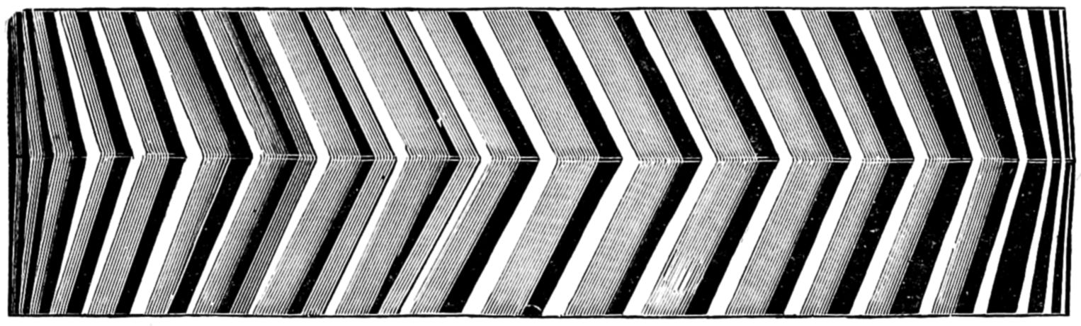
Fig. 271.
Fig. 271 represents a gear with helical teeth. It is similar to a spur wheel, and is used
in place of same in heavy and slow moving machinery, the formation of teeth preventing—in
large measure—the jar or concussion noticeable in common spur gears.
In recent years the speed at which gearing is run has been greatly increased. A
striking instance is that of a pair of cast-iron helical wheels, 6 ft. 3 in. diameter, 12 in.
wide, making 220 revolutions
per minute, the speed of the
pitch line being 4,319 feet per
minute; these wheels are running
continuously and with
little noise. There is also a cut
gear in a mill in Massachusetts,
30 feet in diameter, and the
speed of pitch line is 4,670 feet
per minute.
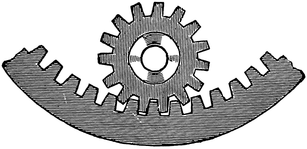
Fig. 272.
An internal or annular gear wheel is one in which the faces of the teeth are within
and the flank without the pitch circle, hence the pinion operates within the wheel.
See fig. 272.
In internal geared wheels there is almost an entire absence of friction and consequent
wear of the teeth, as compared to ordinary spur gearing.
Fig. 273 shows a crown-wheel which has pin teeth
which are fixed by one end only, on its side face and
gear into a trundle wheel.
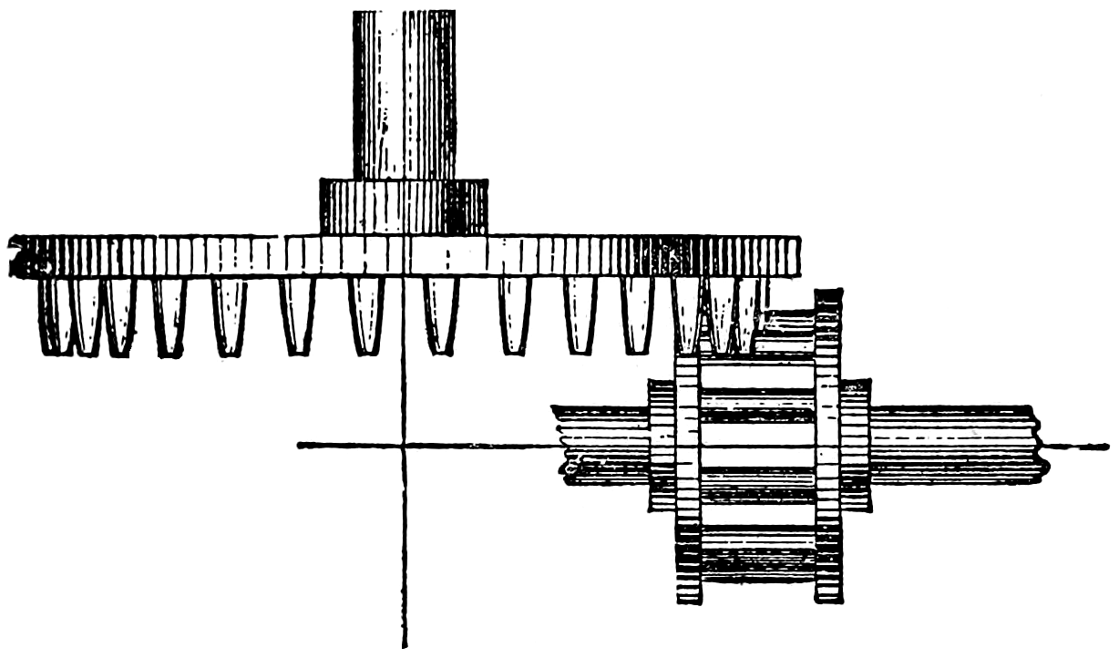
Fig. 273.
A trundle wheel has no teeth, properly speaking.
Instead of teeth, it has pins as shown on illustration,
fig. 273, arranged like the rungs of a ladder between
two walls. See page 201.
Trains of Gears.—When two wheels mesh—that
is, engage with each other—as in fig. 263, one axle
revolves in the opposite direction to the other; but
when internal gears mesh as shown in fig. 272, the shafts
revolve in the same direction; three or more gears running
together are often called a train of gears.
Maximum speed of gears under favorable conditions
for safety is comparatively—
| Ordinary cast-iron wheels, |
1,800 |
feet per minute. |
| Helical cast-iron wheels, |
2,400 |
feet per minute. |
| Mortise wood cog wheels, |
2,400 |
feet per minute. |
| Ordinary cast-steel wheels, |
2,600 |
feet per minute. |
| Helical cast-steel wheels, |
3,000 |
feet per minute. |
| Cast-iron machine cut wheels, |
3,000 |
feet per minute. |
It is not, however, advisable to run gears at their
maximum speeds, as great noise and vibration are
caused.
Designing Gears.
This section is introduced into the work for a double purpose; 1, as an exercise in drawing; 2, as a study in
accurate measurements. It is a sample of the work that the advanced student in mechanical drawing will be
confronted with as he puts in practice the theory of the art of drawing.
Some sample rules are given in the following pages to aid in calculations relating to gears, and still others are
given under the section “Useful Rules and Tables” at the end of the volume; these are to be carefully studied.
To accurately divide the pitch circle of a gear
wheel by hand requires both patience and skill. On
the accuracy of spacing lies the essential requisite of a
good gear wheel.
The drawing in plate, fig. 274, illustrates a pair
of spur wheels, shown in gear, the office instructions
for which being:
“Required, a detail plan of a pair of spur wheels;
dimensions: wheel, 76 teeth, 31⁄2 inches pitch, 7-inch
eye, 6 arms; pinion, 19 teeth; scale, 11⁄2 inches = 1
foot.”
The drawing, as illustrated, is the result of the
above instructions, all pencil lines being removed, and
this result is worked out as follows:
76 teeth × 31⁄2 inches, pitch = 266 inches in circum.
= 7 ft. 011⁄16 in. diam. = 3 ft. 611⁄32 in. radius; with this
measurement as represented on scale, draw line P P on
drawing. This is called the pitch line.
Draw next diameter line, produce or extend this
diameter line for pinion, and with radius of 1019⁄32 (19
teeth × 31⁄2) from pitch line of wheel, draw pitch line of
pinion.
Take any point in this pitch line of wheel, mark
off 31⁄2 inches as represented on scale, mark this around
the pitch line, it will be the center of each of the 76
teeth; then the breadth of thickness of each tooth
(= pitch × 0.475) must be marked from these centers,
then mark from P L, length of tooth to point (= pitch
× 0.35) and P L to root (= pitch × 0.4), draw circles for
outside of teeth N and root of tooth O; now with
compass set to the pitch (31⁄2) of the wheel, draw the
outer portion from pitch line of tooth.
The radius will center in the pitch line of next
tooth where thickness of tooth has been marked; after
finishing outer portion of both sides of teeth, set the
compass from center of tooth with radius to the thickness
marked on pitch line and draw the portion of tooth
from pitch line to root.
Now mark off with dividers and draw thickness of
rim (= pitch × 0.5), divide this line into six parts, draw
radii for centers of arms; draw the bore hole 7″ and
the thickness of metal for hub same as pitch.
On radii lines of arms, draw the breadth of arm at
rim (= pitch and thickness of tooth), increase in breadth
approaching the center (1″ per foot), draw the thickness
of feather of arm (= pitch × 0.35); draw web on
inside of rim (= pitch × 0.375); fill in arcs for the joining
of arms in rim and hub (radii = pitch × 0.8) and
feather to rim and hub (radii = pitch × 0.37).
Proceed in similar manner, completing the teeth
of pinion, and when pencil lines are all in, ink the drawing,
erasing all needless lines.
P P shows the pitch line; B, thickness of tooth;
c, breadth of space; A, the pitch; E, clearance at root;
N, the addendum of tooth; O, the root of tooth; H,
length of tooth from pitch line to point; I, length of
tooth pitch line to root; G, whole length of tooth; F,
thickness of rim; J, web or feather on rim; K, breadth
of arm; L, thickness of feather; M, hub, or thickness
round the eye.
Note.—It must be remembered that no fixed standard has
ever been agreed upon for these proportions, and workshops differ
considerably in practice.
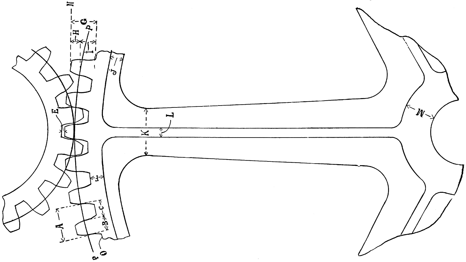
Fig. 274.
The number of teeth, their
proportions, pitch and diameter of
pitch circle are frequently determined
on the “Manchester” principle.
This system originated in
Manchester (Eng.), and is now
generally used in the United States
for determining diameters and
number of teeth, which, of course,
regulate speeds. The principle is
not applicable to large wheels, but
is limited in its application to small
wheels, or wheels having “fine
pitch,” as will be seen in the following
explanation, which is introduced
as very useful and indispensable
knowledge for the acquisition
of the student in mechanical
drawing.
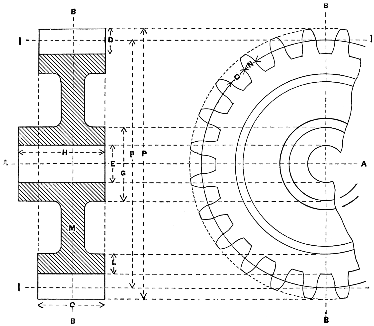
Fig. 275.
The “pitch” of teeth has
already been stated to be the distance
from center of one tooth to
the center of another on the “pitch
line,” measured on the chord of
the arc. In determining the number of teeth or pitch
of wheels on this principle, the pitch is reckoned
on the diameter of the wheel, in place of the circumference,
and distinguished as wheels of “4 pitch,” “6
pitch,” “8 pitch,” etc. In other words, this means
that there are four, six, or eight teeth in the circumference
of the wheel for every inch of diameter.
In designing gears to transmit power the stress on
a tooth is calculated; it determines the breadth or
width and also the thickness of the tooth on pitch line;
the space between the teeth is in proportion to the
thickness of tooth, and the thickness of both combined
(one tooth and one space), measured on the pitch line
or circle, is the pitch of the wheel.
From the pitch all the proportions and measurements
for the sizes and strength of the parts of the wheel
are taken by rule, and a symmetrical form is produced.
In machine drawing the practice is to represent
wheels by circles only; the teeth are never shown
except on enlarged details and then only in very rare
instances; the circles drawn are always the pitch lines
or the rolling points of contact of the wheels.
The addendum circle is seldom if ever used in
practical drawing. Should it be necessary to show it
in an exceptional case, the circle would be represented
by “dotted” line.
The shape of tooth and mode of constructing it,
as practiced in drawing offices, differs from the true
theoretical curve of the tooth, although very minutely.
In all calculations for the speed of toothed gears the
estimates are based upon the pitch line, the latter standing
in the same place as the circumference of a pulley.
To find the diameter of a gear-wheel multiply the
number of teeth by the pitch, divide by 3.1416.
To find the pitch of a gear-wheel multiply the diameter
by 3.1416 and divide by the number of teeth.
To find the number of teeth in a gear-wheel multiply
the diameter by 3.1416 and divide by the pitch.
The breadth of wheels, where practicable, should be
at least three times the pitch.
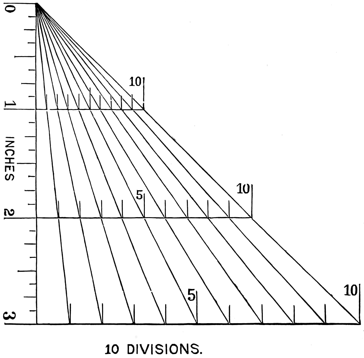
Fig. 276.
Fig. 276 shows a scale for proportions of teeth; it
is divided into tenths and used thus:
Say wheel is 2″ pitch, then from pitch circle to
addendum will be 31⁄2 tenths, and from pitch circle to
root of tooth will be 4 tenths measured at the 2″ line
on scale, and so on.
The decimal proportions already given in example,
page 210, are adopted in many workshops. Many
others use the proportions approved of by Sir William
Fairbairn, which are:
Table of proportion of gears:
| Depth of tooth above pitch line |
.35 |
of the pitch. |
| Depth of tooth below pitch line |
.40 |
of the pitch. |
| Working depth of tooth |
.70 |
of the pitch. |
| Total depth of tooth |
.75 |
of the pitch. |
| Clearance at root |
.05 |
of the pitch. |
| Thickness of tooth |
.45 |
of the pitch. |
| Width of space |
.55 |
of the pitch. |
The diameter of a wheel or pinion is invariably the
diameter measured on pitch circle, except it is specially
described otherwise, thus the diameter “over all,” etc.
The shape of the curved face of the teeth of gears
extending from the root to the addendum is the curve
conforming to the passage of the teeth described on
its fellow entering and leaving, as they rotate or roll
together on their pitch circles.
The curve of teeth outside the pitch circle is called
“the face,” and the curve from pitch circle to root is
called “the flank.”
The difference between the width of a space and
the thickness of a tooth is called clearance or side
clearance.
The play or movement permitted by clearance is
called the backlash; clearance is necessary to prevent
the teeth of one wheel becoming locked in the spaces
of the other.
Wheels are in gear or geared together when their
pitch lines engage, i. e., when the pitch circles meet.
Wheels to be geared together must have their
teeth spaced the same distance apart, or in other
words, of the same pitch.
The teeth of spur wheels are arranged on its
periphery parallel to the wheel axis, or shaft on which
it is hung.
The teeth of a bevel wheel or bevel gears are
always arranged at an angle to the shaft.
When the teeth of bevel gears form an angle of
45° they are called miter wheels.
Miter wheels to gear must be of equal sizes.
A crown wheel is a disc that has teeth which are
on its side face; that is, teeth on a flat circular
surface all parallel to the axis of the wheel.
A rack has teeth on a flat surface or plane all
parallel to one another.
A gear cut by machine is called a cut gear. It has
teeth with less clearance than cast wheels, which are
not so true or perfect, and therefore require more
clearance.
A worm with even a light load is liable to heat
and cut if run at over 300 feet of rubbing surface
travel. The wheel teeth will keep cool, as they form
part of a large radiating surface; the worm itself is so
small that its heat is dissipated slowly.
A worm throws a severe end thrust or strain on
its shaft.
Steel Gears.—There is great economy in the use
of cast-steel over cast-iron in gears; the average life of
the former is nearly twice as great as of cast-iron gears.
And, apart from their longer life and efficiency, there
is less danger of breaking.
The most accurate teeth, strongest and most
uniform in wearing, are to be found in steel gears cut
from solid stock, or made by cutters of proper shape.
Fig. 275 shows an elevation and a vertical section
of a spur wheel. From these views the various parts
in spur gears can be better understood, as they are
represented here in combination, and the wheel in its
entirety.
AA is the horizontal center line, BB, BB the vertical
center lines, II and II the pitch lines, N thickness
of tooth, O space of tooth, D total depth of tooth,
C breadth of face, F diameter on pitch line, P diameter
over all, G diameter of hub, E diameter of hole, H depth
of hole, L thickness of rim, M thickness of web.
Much has been and still is being written on gearing.
No general rule is followed by the writers; the elementary
principles given will enable the student to master
spur gearing, and bevel and combinations of many
kinds of wheels will afterwards be found easier to
delineate than the numerous lines seem to indicate.
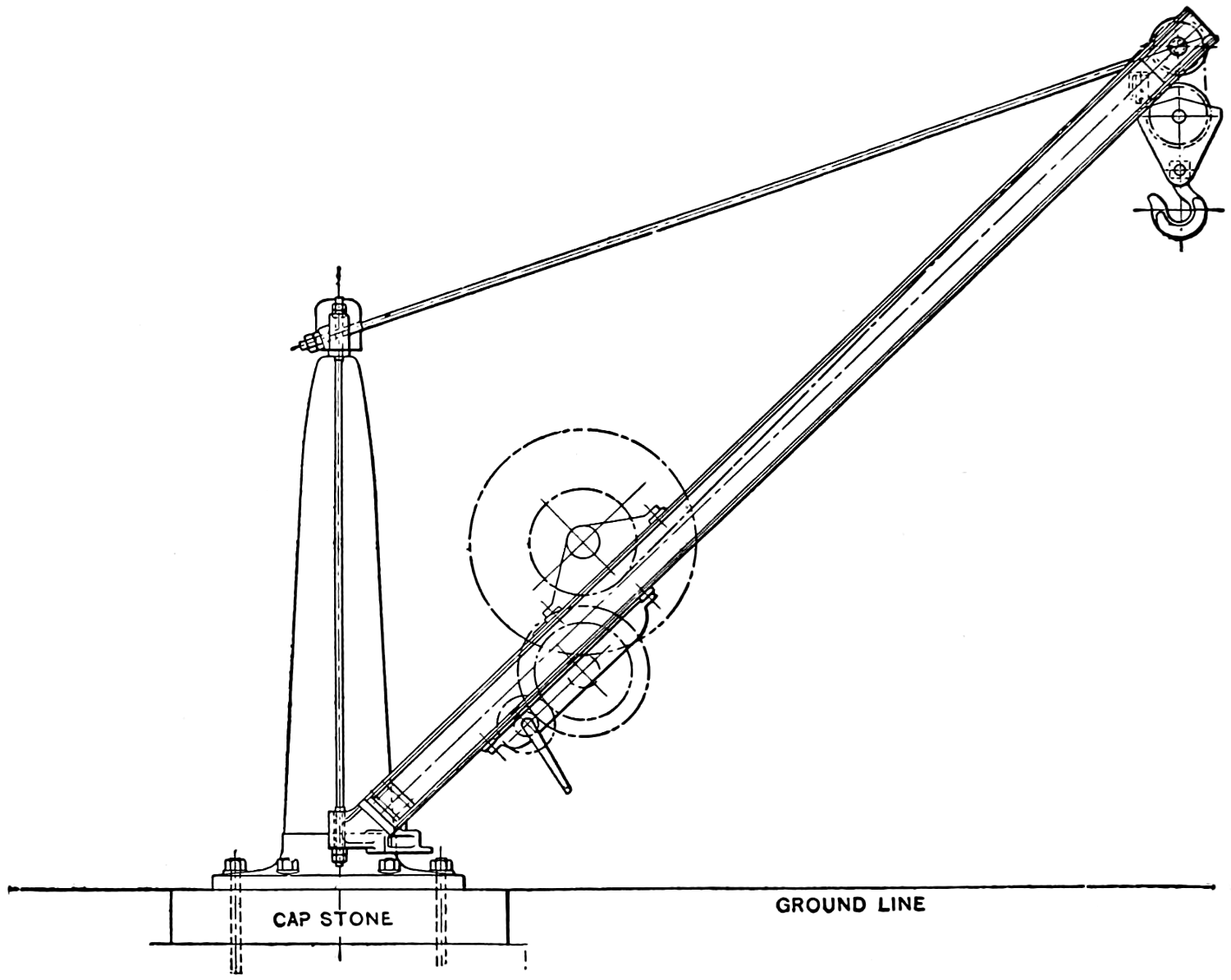
Fig. 277.
Working Drawings. — BUMPING POST FOR RAILWAY TRACKS.
From the “plans” made in the office are produced “working drawings”—which represent in detail the work
to be done to exact measurement and of material, as indicated, by the pattern-maker, the foundry, the forge, the
shop, and finally, by the erector of the completed mechanism.
How to satisfactorily fulfill the directions contained in these drawings, representing only a part of the work, so
that it will fit, with needed accuracy, to all other parts of the design, is the task before each separate worker.
It is by means of this division of the process of
manufacture through these drawings, that scores and
hundreds of men can be employed at the same time
upon a single engine or machine; thus, while handwork
has been superseded by machines in many quarters,
the art of drawing has not been narrowed nor
diminished, for no drawings or designs have yet been
made by machinery, nor are they likely to be.
It is thus that a good designer and draughtsman
“projects” or extends himself, to the advantage of
many fellow workers.
The drawing, fig. 277, shows a simple form of pillar
crane: it consists of an upright cast-iron pillar, which is
bolted on a cap stone, under which is the foundation plate
not shown in the drawing; the boom is of rolled steel,
supported by steel tie rods, and provided with rollers
at the base; the hoisting gear is shown in broken
lines and circles; all as seen in the drawing.
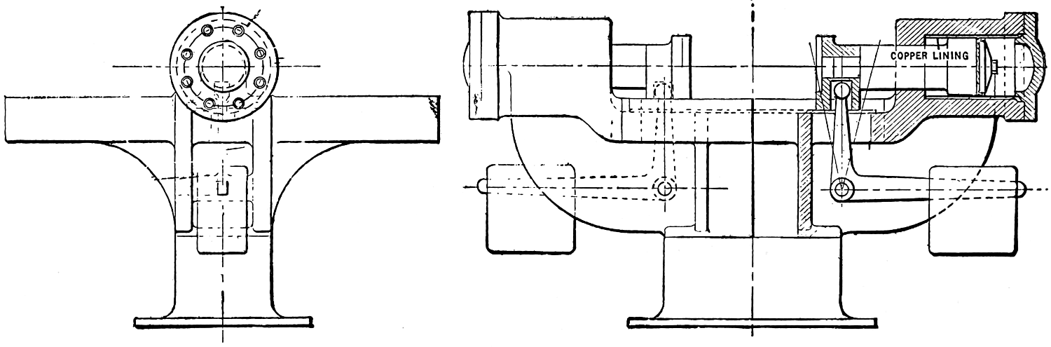
Fig. 278.—Fig. 279.
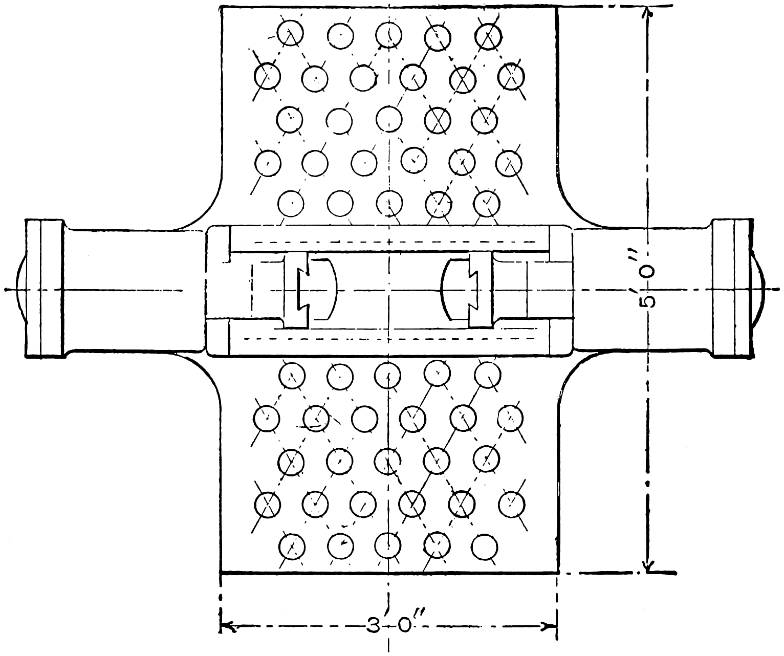
Fig. 280.
Figs. 278, 279 and 280 show a drawing
of a “hydraulic beam bending machine” in
three views; fig. 280 is a plan, fig. 278 is an
end elevation, and fig. 279 a side elevation,
and a portion of the latter in section shows
the interior construction.
Note.—These three views are a practical illustration
of drawings for a machine of the following
dimensions: this machine has a bed 3 × 5 feet in area,
with 27 holes in each side for the bending pins. The
frame and cylinders are made of cast iron, the rams of
machinery steel, and the slides for holding the bending
blocks, of steel casting. The distance between
the bending blocks is 17 inches. The cylinders are
copper lined, 8 inches diameter, and the rams have
a 6-inch stroke. The rams, which are independent
and single acting, are returned by counterweights
placed as shown under the table. The cylinders can
be operated independently from either side of the
machine by an arrangement of valves and levers.
The machine complete weighs about 7,500 lbs.
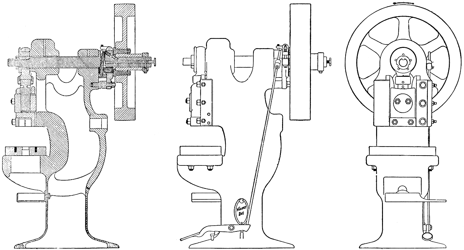
Fig. 281.—Fig. 282.—Fig. 283.
The drawing, page 222, shows three views of a
power punching press.
Fig. 282 is a side elevation.
Fig. 283 a front elevation.
Fig. 281 a vertical sectional view; from these views
the proportion, general arrangement and disposition of
the automatic devices can be easily understood; it may
be well to call particular attention to the automatic
clutch on the top shaft and the tripping device.
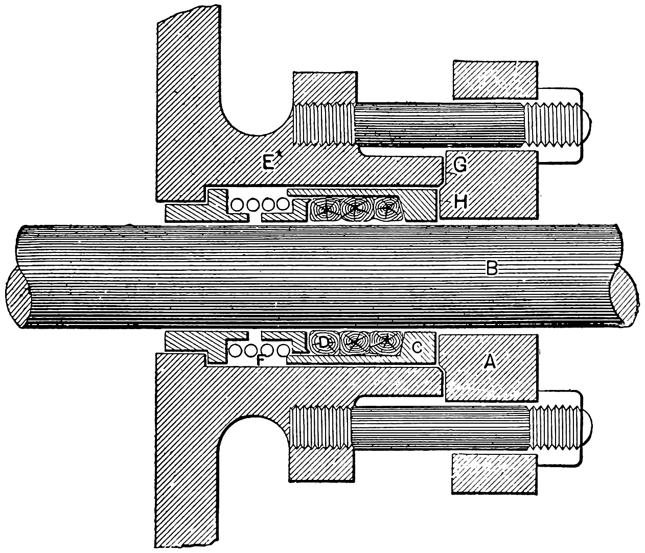
Fig. 284.
This drawing, fig. 284, shows a side elevation in
section of a self-adjusting piston-rod packing.
A is the gland, B is the piston rod, C is a brass
sleeve which contains the packing D, E is the cylinder
cover, F is a coil spring. It will be seen that the spring
F abuts on a bushing in the bottom of the stuffing box
and is prevented from scoring the piston rod by stepping
over the ends of the bushing and follower. All
as shown in the drawing.
The drawing, fig. 285, shows a sectional view of a
large pulley fixed on a “quill,” or hollow shaft: the
driving shaft passes through the hollow shaft and is
attached to the friction clutch shown at the right-hand
end; this friction clutch drives the hollow shaft and
pulley.
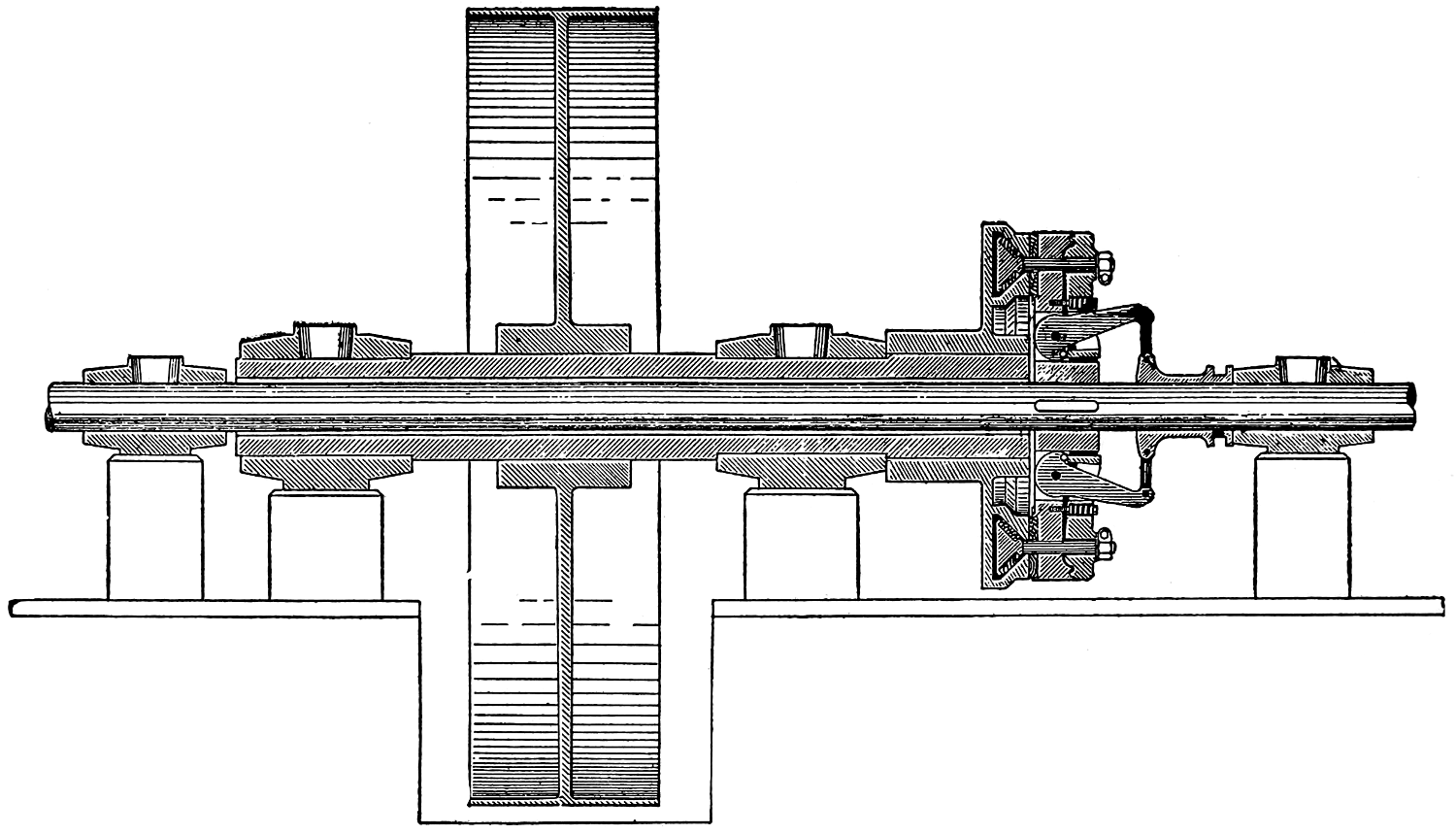
Fig. 285.
Fig. 286 shows the mechanism, called the link-motion, employed to reverse an engine, or to enable it to be
run in either direction. Many forms of link-motion have been devised, but the Stephenson form, as shown in the
figure, is, however, the one in almost universal use.
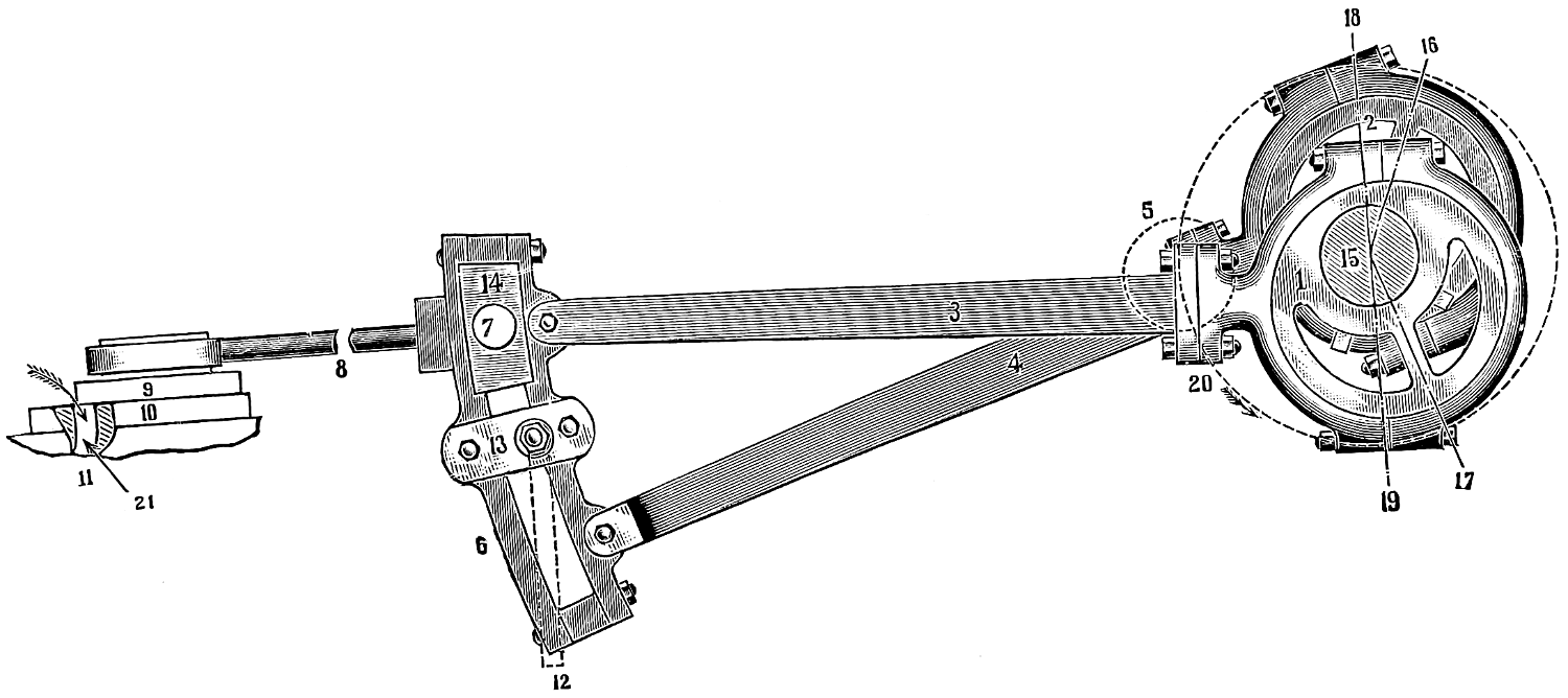
Fig. 286.
This drawing shows shading and the mode of figuring the parts for identification.
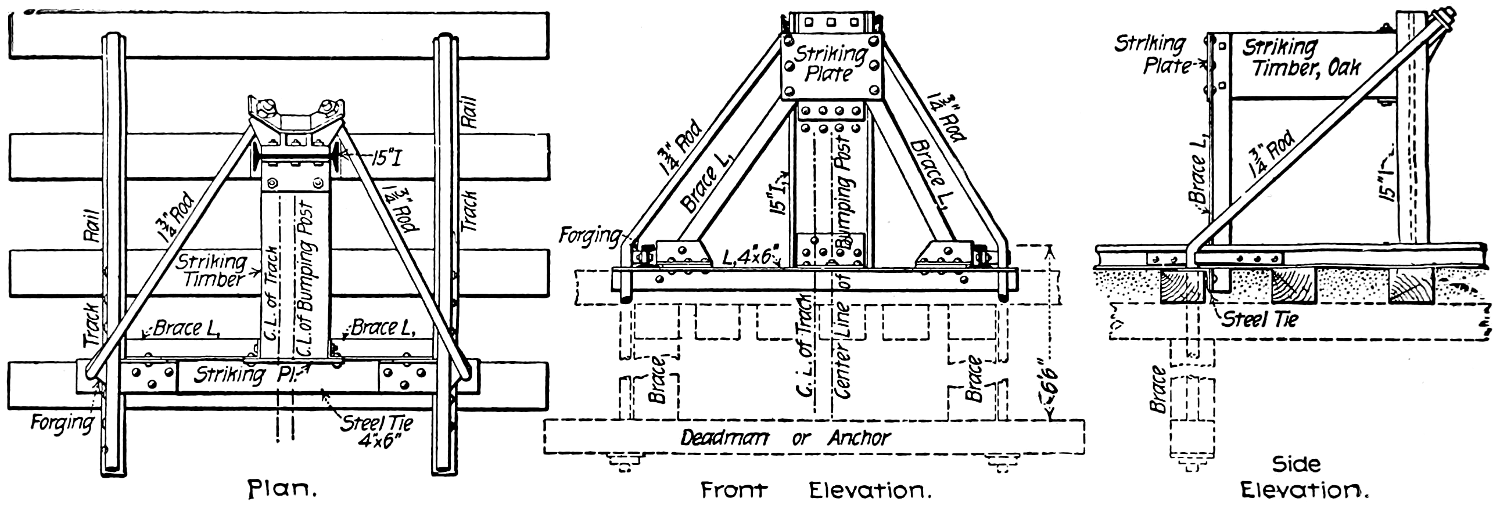
Fig. 287.—Fig. 288.—Fig. 289.
Figs. 287 to 289 represent a bumping-post for
the end of railway tracks, reproduced on an enlarged
scale from the columns of the Engineering News.
In addition to the lettering and dimensions, admirably
shown in the drawings, the following description
is appended to show how printed text and mechanical
drawings mutually aid in practical—or commercial—usage.
The unique feature of the arrangement shown,
is that the center line of the post does not coincide
with the track, thus adapting itself to the nature of
the blows of a car-bumper, as received in the single-post
style of the mechanism.
The post is a 15-in. steel I-beam, resting on a base
plate 3⁄4-in. thick, and supported by anchor rods 13⁄4 ins.
diameter, with upset ends held by nuts on a heavy
forging bolted to the top of the post. These rods
extend forward and outward to clear the rails, and then
pass vertically through a 4 × 6-in. angle iron crosstie,
and an ordinary wooden tie, extending down to an
anchor block or deadman buried in the ground 61⁄2 ft.
below the top of the rail.
Vertical braces or spreaders are fitted between the
anchor timber and a longitudinal timber under the ties,
so as to prevent the loosening of the anchor rods when
the post is struck. The rods are held in position
against the rails by steel forgings bolted to the rail
with 1-in. turned bolts. An oak striking block, 12 × 12
ins., 3 ft. long, is bolted between angle iron brackets
on the face of the post.
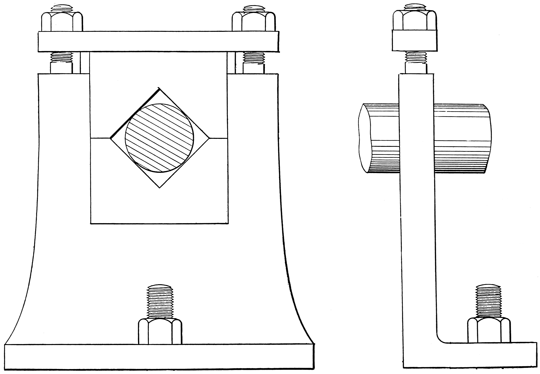
Scale, 3 in. = 1 ft.
To Read Working Drawings.
One of the advantages resulting from a knowledge of practical draughting is, that it enables a mechanic to
read a drawing when given him as a guide for his work. It is getting every day more general among draughtsmen
to figure exactly and minutely every part of their drawings which are made to a scale.
Drawings are almost always made “finished size,”
that is, the dimensions are for the work when it is
completed. Consequently all the figures written on
the different parts indicate the exact size of the work
when finished, without any regard to the size of the
drawing itself, which may be made to any reduced and
convenient scale.
Even in full size drawings this system of figuring
is not objectionable. It is a system which should be
followed whenever a drawing is made “to work to,”
for it allows the workman to comprehend at a glance
the size of his work and the pieces he has to get made.
Figuring makes a drawing comprehensible even to
those who cannot make drawings.
A working drawing should be made, primarily, as
plain as possible by the draughtsman; second, the
workman should patiently and carefully study it, so
that it is thoroughly understood.
In studying a drawing, the object it is intended to
represent should be made as familiar as possible to the
mind of the student, so that he may fill out in imagination
the parts designedly left incomplete—as in a
gear wheel where only two or three teeth are drawn in,
that he may see, mentally, the whole.
The following is a description of reading drawings
when dimensions are not figured. Here we have a
piece of machinery represented by fig. 290, and the
information we have is that it is to scale, three inches
= one foot. Now, with scale and dividers, we can
arrive at its actual dimensions.
Measurements should be first taken with the
dividers from the drawing, and then the dividers
applied to the scale to which the drawing is made;
this scale is always marked on the working drawing; if
the dividers are set to the length of the base of the
example, fig. 290, they will measure, on an ordinary
two-foot rule, three and three-fourths inches, but if
applied to the three-inch scale they will read one foot
three inches, the actual length of the part; the “reading”
is from the scale; thus, in both figures the drawings
are “three-inch scale.”
Now, 3 inches is one-fourth of a foot, hence
33⁄4 × 4 = 1 ft. 3 in., the full size, and so on for all
parts of the drawing.
Fig. 291 shows a side view of the “steady rest,”
illustrated in front elevation, fig. 290; from the scale
as before we get the sizes; the two views combined
give length, breadth and thickness of the parts.
In some figures it is necessary to show end views,
also section views, to enable all measurements to be
read from the drawing.
Patent Office Drawing Rules. — U. S. PATENT OFFICE RULES. — AS APPLIED TO PREPARATION OF DRAWINGS. — ENGLISH PRACTICE.
Each applicant for a patent is required by law to
furnish a drawing of his invention whenever the nature
of the case admits of it. The drawing must be signed
by the inventor or the name of the inventor may be
signed on the drawing by his attorney-in-fact, and in
either case must be attested by two witnesses. The
drawing must show every feature of the invention
covered by the claims.
When the invention consists of an improvement
on an old machine, the drawing must exhibit, in one or
more views, the invention proper, disconnected from
the old structure, and also, in another view, so much
only of the old structure as will clearly show the connection
of the invention with the old machine.
Several editions of the patent-drawings are printed,
the smallest of which is about 3 × 43⁄4 inches, so that the
drawing must be so made that it will stand a reduction
of about one-fourth. This work is done by the photo-lithographic
process, and therefore the character of the
original drawing must be brought as nearly as possible
to a uniform standard of excellence suited to the
requirements of the process.
Note.—These rules will be found most useful to many
readers of this work—hence their introduction at this point.
Nearly 50,000 patents are “applied for” in the United States
every year.
The following rules are given by the Patent Office
for guidance:
1. Drawings must be made upon pure white
paper of a thickness corresponding to three-sheet
Bristol board. The surface of the paper must be
calendered and smooth. India ink alone must be used,
so as to secure perfectly black and solid lines.
2. The size of a sheet on which a drawing is
made must be exactly 10 × 15 inches. One inch from
its edges a single marginal line is to be drawn, leaving
the “sight” precisely 8 × 13 inches. Within this margin
all work and signatures must be included. One of the
shorter sides of the sheet is regarded as its top, and
measuring downwardly from the marginal line, a space
of not less than 11⁄4 inches is to be left blank for the
heading of title, name, number and date.
3. All drawings must be made with the pen only.
Every line and letter, signature included, must be
absolutely black. This direction applies to all lines,
however fine, to shading, and to lines representing cut
surfaces in sectional views. All lines must be clean,
sharp, and solid, and they must not be too fine or
crowded. Surface shading, when used, should be open.
Sectional shading should be made by oblique parallel
lines about 1⁄20 of an inch apart. Solid black should not
be used for sectional or surface shading.
4. Drawing must be made of the fewest lines
possible, consistent with cleanness. The plane upon
which a sectional view is taken should be indicated by
a broken or dotted line. Heavy lines on the shade
side of objects should be used, except where they tend
to thicken the work and obscure letters of reference.
The light is always supposed to come from the upper
left hand corner at an angle of 45 degrees.
5. The scale to which a drawing is made should
be large enough to show the mechanism without
crowding. The number of sheets used must never be
more than is absolutely necessary.
Fig. 292.
6. The different views should be consecutively
numbered. Letters and figures of reference must be
carefully formed. They should, if possible, measure
at least one-eighth of an inch in height.
If the same part of an invention appears in more
than one view of the drawing it must always be represented
by the same character.
7. The signature of the inventor is to be placed
in the lower right-hand corner of each sheet, and those
of the witnesses at the lower left-hand corner.
The title should be written with pencil on the back
of the sheet.
Drawings should be rolled for transmission, never
folded.
On page 235, fig. 292 exhibits a reproduction of a
patent office drawing, used in connection with specification
papers in an application for a United States
patent.
The rules for patent drawings in England are
practically the same as in the United States; the
paper sizes are, however, different. They must be on
sheets of one of the two following sizes (the smaller
being preferable), 13 inches at the sides by 8 inches
at the top and bottom, or 13 inches at the sides by 16
inches at the top and bottom, including margin, which
must be one-half an inch wide.
If there are more figures than can be shown on
one of the smaller-sized sheets, two or more of these
sheets should be used in preference to employing the
large size. When an exceptionally large drawing is
required, it should be “continued” on subsequent
sheets. There is no limit to the number of sheets that
may be sent in.
Useful Hints and “Points.”
Many of these “points” are repetitions, with but little variation from the way they have been previously
stated; they are thus repeated to emphasize their practical worth.
A good draughtsman leaves his work in such a
state that any competent person can without difficulty
ink in what he has drawn.
The criterion of a good set of drawings is that
with a properly prepared specification they are complete
in themselves and require no explanation.
A “break” in a figure or object in a drawing is
shown in rough irregular lines, as in fig. 134, on page
131; this is useful when the paper is not large enough
to show the whole.
Never use a sloping line in writing fractions on a
drawing. The objection arises from the fact that such
a dimension as 13⁄16, if written with the inclined line,
unless very distinctly executed, may be read as 13⁄16.
In inking do not draw the lines further than you
wish them to go, but in penciling it is well to extend
the lines, free up.
Never use a scale for a ruler.
Do not overload the pen with ink.
Having filled the pen, nearly close the nibs and
try the width of the line on a piece of paper or the
margin of the drawing.
Never refill or lay the pen aside without first cleaning
it.
The application of the science of geometry to the
drawing-board is absolutely necessary to success, for
the reason that the whole fabric of mechanical drawing
rests on the principles of geometry, which is well
termed the science of measurements.
Section lines should be the last inked and always
without previous penciling.
Center lines are necessary in working drawings.
In choosing T-squares, care should be exercised to
see that the head slides up and down the left-hand side
of the board easily, and that when pressed against the
board with the left hand there is no “slogging” of the
blade up or down, or in other words, that the head is
bearing firmly for its whole length against the board.
The best place for the title of a drawing is said to
be the upper left-hand corner; this facilitates the filing
of the sheet.
Never use a soft pencil except for finishing in
shadow lines.
The rubber should always be kept clean.
Great care should be taken to keep drawing boards
out of the way of heat or damp, as these cause the
wood to warp.
Circles and curves are to be “inked in” before
straight lines. First ink the smallest and afterwards
the larger curves.
Do not press heavily on the pencil so as to cut the
paper, but draw lightly, so that the mark can be erased
and leave no trace, especially if the drawing is to be
inked.
The draughtsman should commence his work at
the top of the paper, keeping the lower part covered
over until he needs to use it.
Shade lines should be avoided in all working
drawings, as their use interferes with accurate measurements.
To make ink stick to the tracing cloth, with a
woolen cloth rub some powdered chalk or pounce over
the surface on which the ink lines are to be drawn, then
wipe the surface clean and use a good quality of ink.
For striking small circles a small bow pen should
be used.
To fix lead pencil marks on sketches so that they
cannot be readily erased, sponge them with milk carefully
skimmed, then lay blotting paper over them and
iron with a hot flat-iron.
To have the ink preserve its fluidity and to keep
out all dirt and dust, keep the cover on the ink slab;
the mistake is often made of putting too liberal a supply
of water in ink well, which causes a waste of both
time and ink; no more should be prepared than to
meet immediate requirements.
Always draw on the right side of the sheet, which
can be found by holding the sheet up to the light and
looking across its surface with the eye nearly in the
same plane as the paper; note which side is the smoothest
and has the least number of blemishes on it; this is
the right side to draw on.
As to sharpening pencils, it is always best to cut a
chisel point on the pencil used for drawing, and put a
circular point on the pencils in the bow pencil and
pencil leg. The chisel point makes a finer line and
lasts much longer than a round point.
The varnish used in many large drawing-rooms is
simply white shellac dissolved in alcohol; it requires a
little experience to mix these to a proper consistency,
but this is soon acquired.
Never sharpen your pencil over the drawing.
A center line of a drawing is the line upon which
the figure is to be constructed; the center line is the
first line to be drawn.
The T-square belongs to the left side of the drawing-board,
and is operated by the left hand. The right
hand should be kept free for the purpose of picking up
pencil, pen and bows, adjusting and marking off. The
left hand controls the T-square and the triangle that
slides along the upper edge of the square; the right
hand is for the instruments.
The advantage of a paper rule or scale is that the
paper will expand and contract under varying degrees
of atmospheric moisture the same as the drawing does.
Avoid rubbing out and constantly cleaning the
drawing with India rubber; if wrong lines are made or
it is desired to make alterations, the part to be changed
should be rubbed out and completely re-drawn.
When using the bows see to it that the steel-pointed
leg that is put down first on the paper, to
secure a center for a curve or a circle, is a trifle longer
than the pencil or pen leg.
To clearly indicate the position of a center which
is to be used again, lightly pencil a small circle about
it; never put the point of a pencil in the center hole
to enlarge or blacken it; the prick point made by the
dividers and needle points should be no more than can
be just seen, hence the circle to be made as advised
above.
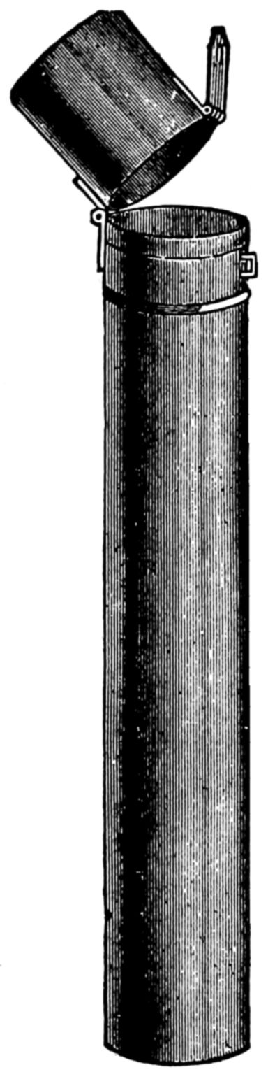
Fig. 294.
Be particular in having the legs of the dividers
exactly the same length, and sharp, so that in pricking
off distances, and dimensions, and centers, the indent
or hole made in the paper is as small as possible.
The term “plane” means a perfectly flat surface;
that is, something which has length and breadth but
no thickness.
The best way to indicate on the drawing the surfaces
which are to be finished is to write on the lines
which represent the finished surfaces “finished,” tool-finish,
or “faced,” according to the degree of finish required.
The single letter f is frequently used.
Avoid fingering the drawing sheet as much as possible;
in pointing to any part of the drawing use a
pencil and not the finger.
Remember that a drawing is made to be read.
The skill in inking does not depend on the fineness
of the line, but on its clearness.
A soft pencil should never be used on a mechanical
drawing unless in rare cases when it is used for pencil
shading; the hardness or softness of pencils is denoted
by letters.
Never ink any portion of a drawing until the
penciling is entirely finished.
Stretching or pasting the paper to the board is
very seldom resorted to, for the reason that the
mechanical drawings are to scale and the paper is
natural when pinned to the board and more correct
than if under a strain. Mechanical drawings are
always required in practice right away, and time would
be wasted and lost in damping and pasting and drying
again.
A working drawing, whether made to a scale or
not, must have all the dimensions plainly written upon
it, for a workman should never be compelled to measure
a drawing.
In marking off distances, centers, etc., a fine needle
point is useful; the hole should not be punctured
through the paper, merely a prick point, so that it
will leave an impression, which will not be obliterated
by the use of rubber; drawing-pens are often equipped
with such a needle point in the end of the handle,
that is visible only when the pen is unscrewed from
the handle; but in the absence of one of this kind the
point of the divider leg will be of use.
Mechanical construction drawings represent a large
amount of mental and manual work, as well as a considerable
cost in money; hence, they are of value quite
as much as property which has been acquired by the
expenditure of either labor or capital. It is wise to
keep copies of original designs and sketches, as well as
data and formulæ, for record and comparison.
The best system for keeping drawings is to make
them of certain standard sizes, and to keep them flat,
unrolled, in drawers, numbered, lettered and labeled.
In an office where space is limited and drawings
have to be rolled it is well to use a number of pasteboard
cases about three feet long and three inches in
diameter. These are shown in fig. 294.
A puncture can be made near the top and, when a
new drawing or blue-print is inserted in this cylindrical
case, a cardboard tag can be looped through the puncture.
This label will give the title and number of
drawings in that case.
A manuscript book methodically and neatly kept
should tell immediately the number of the drawing
and the case.
Fig. 293 is good for practice in line drawing and
also as an optical illusion. “You look and are deceived.
At first glance you say, ‘Of course, those two
lines are curved.’ You are mistaken. They are exactly
parallel. In order to prove this hold them up edgewise
to the eye. It is, of course, the subsidiary lines which
lead the vision astray. It is a case of first impressions
being quite wrong.”
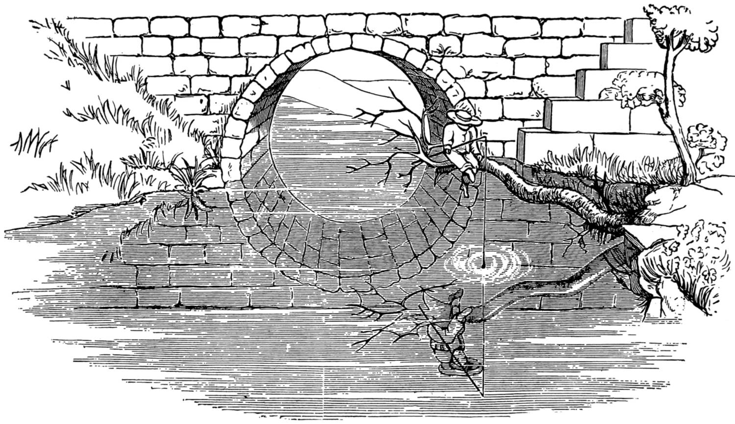
Fig. 295.
Linear Perspective.
It should be mentioned that this subject is outside
the limits of mechanical drawing, which only deals
with objects that can be measured, projected or
dimensioned to an accurate scale.
But, in rounding out the more formal subjects it
is well to look a little outside the rigid lines of mechanics
into the methods of nature, for no system of
teaching drawing is complete that does not include
some explanations for sketching from nature—the
objects being always around the student, the eye
always clear to see and the hand only needing
the training to make permanent the impressions received.
The word perspective means to see through; the
word perspective being derived from the Latin word
perspicere, to look through, hence, perspective is a
science which teaches us to see correctly and enables
us to represent the appearance of anything we may
wish to draw; care should be taken in perspective
drawing, to select objects interesting in themselves, and
the best specimens of their class, so as to cultivate
taste, while they at the same time afford useful and
instructive drawing lessons.
The meaning of the term linear perspective is a
line view; the previous examples have been composed
of surfaces placed fronting the eye; perspective is the
science which treats of the changes of form produced
by viewing them in various oblique positions.
The slightest alteration of position
will change the appearance
of an object; this can be easily
shown—for illustration take a coin,
the actual shape of which is a
perfect round; or, strictly speaking,
a circle. If we take the coin
between the thumb and the first
finger, holding it in an upright
position, and exactly facing the
eyes, as in Fig. 296, it appears of its true form, viz., a
circle. If we alter its position, balancing it upon the
thumb, in a level position, with its edge directly opposite
the eye, as in Fig. 297, its appearance is changed,
and what we know to be really a circle, appears to us
as a straight line.
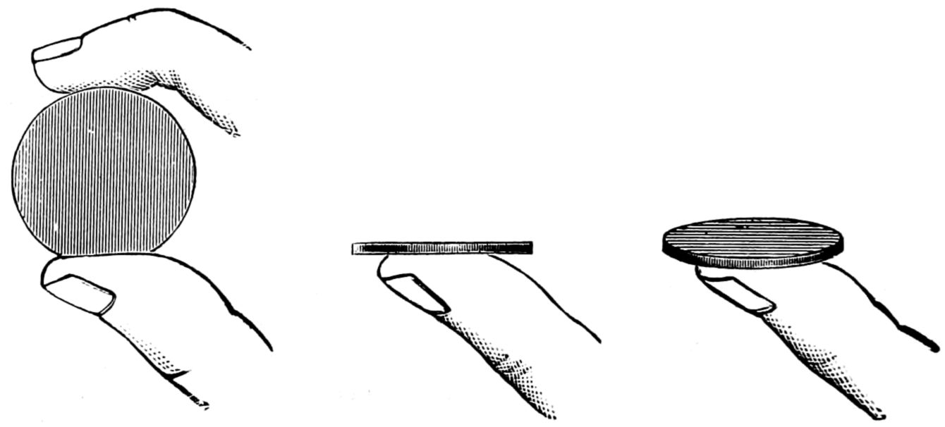
Fig. 296.—Fig. 297.—Fig. 298.
Now, still balancing the coin upon the thumb, but
changing its position with regard to the eye, by holding
it a little lower than in the last position, that is slightly
beneath the level of the eye, as in fig. 298, we see both
the edge and the surface, the coin now appearing
neither a circle nor a straight line, but a curved figure
of an elliptical form. Thus the same coin held in three
different positions has assumed three different shapes.
Let us take two coins of the same size, holding (in
the position shown at fig. 296) one in each hand. Now,
closing one eye, (which will make the experiment more
clear), hold one coin out
at arm’s length, and the
other at about the distance
of a foot from the eye.
On comparing them, we
find that the coin which
is further from the eye
appears less than the
nearer one. We know that
the coins are really equal
in size, yet one appears
smaller than the other.
We thus see that when we change the position of
an object, we have as a consequence a change of
appearance; also that the change of appearance may
affect both the shape and the size of the object.
These diversities of appearance may be remarked
in everything around us. We can observe them in the
street by looking at a building from different points of
view, or by comparing the apparent sizes of the street
lamps; in the railway station, by watching the arriving
or departing train; and at sea, by noticing the vessels
as they approach, or as they retire, ultimately vanishing
from our sight in that line where the sea and sky
appear to meet.
All these interesting variations of appearance are
in strict accordance with the laws of GEOMETRY and
OPTICS. The former subject has been enlarged upon
beginning with page 81 of this work, where a line, a
point, an angle, etc., are defined; other terms are
explained at page 41 and the following pages; to these
we add a few definitions essential to the subject.
A PLANE is a surface which is perfectly even and
flat; to use a familiar illustration, a plane is like the
surface of a sheet of plate glass; recollect particularly,
that a surface which is at all curved, is not a plane.
The GROUND-PLANE is the plane on which we
stand; the base-line is an imaginary line passing
through the middle of the feet as we stand square and
erect; and the vertical plane is supposed to stand
on the base-line and perpendicular to it.
Planes are parallel to each other when they are
throughout their entire surfaces the same distance
apart.
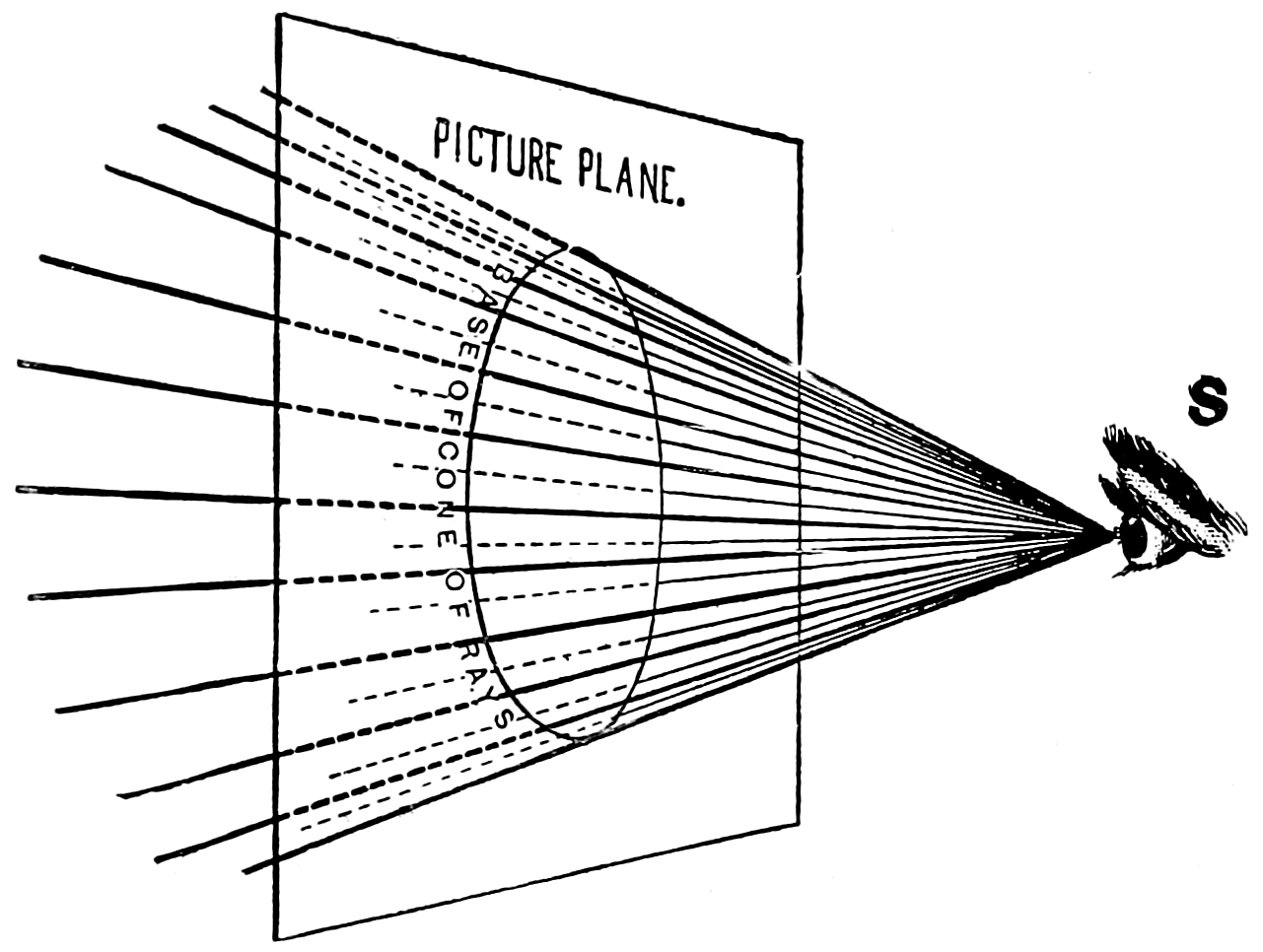
Fig. 300.
THE PERSPECTIVE PLANE is an upright square
of glass, usually framed like a picture, with a base, so that
it can stand up alone. This is placed between the eye
of the spectator and the subject to be drawn, and as
the drawing is sometimes made directly upon it, it is
sometimes called the Picture or the Plane of the
Picture.
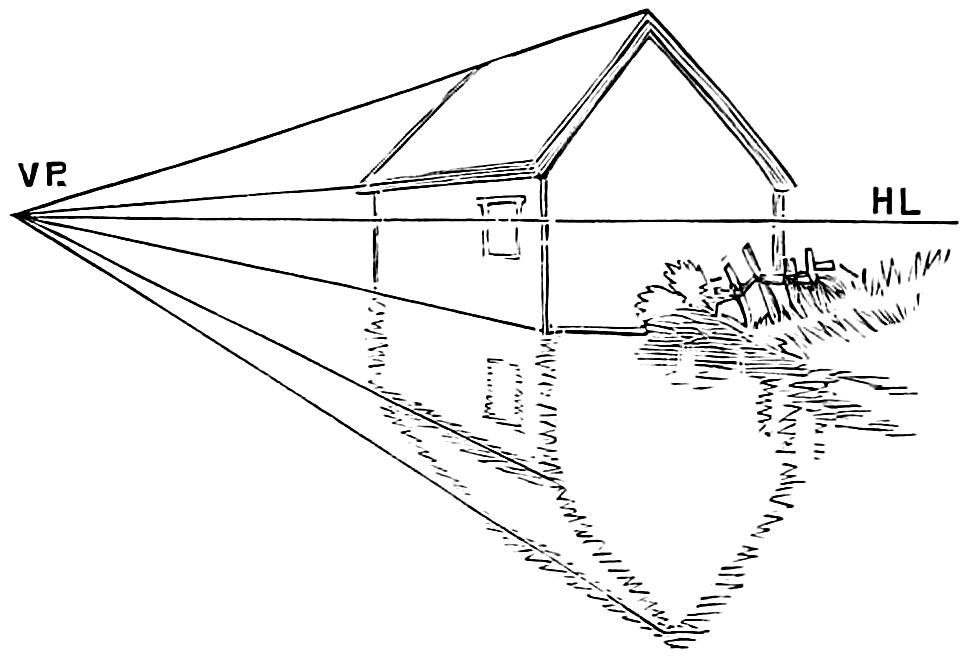
Fig. 301.
HORIZONTAL means perfectly level, like the surface
of still water. We must be careful to understand
perfectly the difference between the terms “level” and
“even” or “flat.” A surface may be even or flat,
without being level. Thus the wall is even and flat,
but it is upright, not level; level means a fixed, constant
position.
In fig. 301 a house is shown in perspective in
which the line H L is the line of the horizon and V P
is the,—
VANISHING POINT.—The vanishing point is familiarly
represented by the rails on a trolley track on a
straight road, which seem to approach each other in the
distance, as shown in fig. 302 at V P.
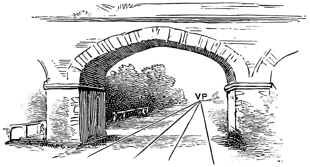
Fig. 302.
All parallel lines seen in perspective appear to meet
in the same vanishing point.
The value of the vanishing point may be seen in
the view of a wooden house, fig. 303, where it (V P)
gives direction to the retiring lines of the roof, side
planks and door.
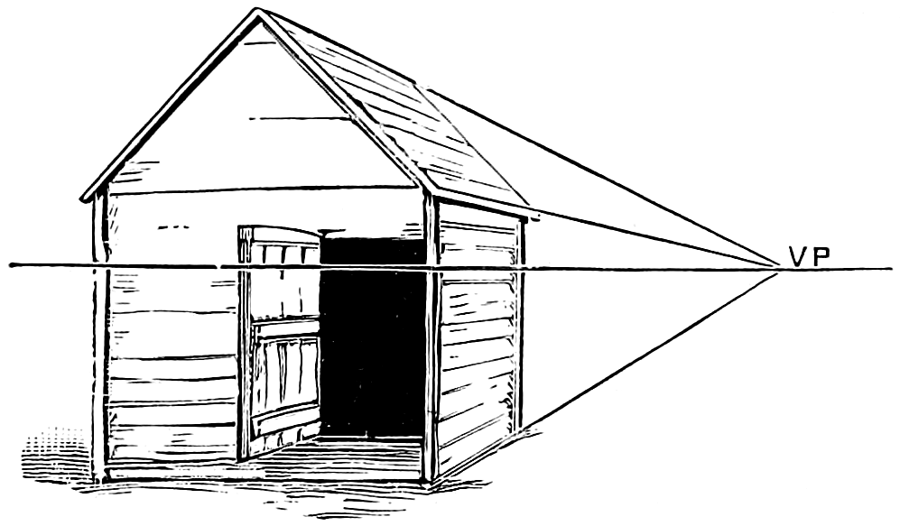
Fig. 303.
POINT OF SIGHT.—This is that point in the eye
where the lines or rays from the object cross each
other, as shown at P in fig. 305, also in fig. 299 at S.
VERTICAL means perfectly upright. If we attach
a piece of thread to a weight, a small piece of lead for
example, and hold the thread with the lead hanging
downwards, the thread will fall in an upright or vertical
position.
PARALLEL lines are said to be parallel to each
other when they are throughout their whole lengths
the same distance apart.
PERPENDICULAR. When one straight line, meeting
another, makes the angles at the point of contact
equal, each of the angles is called a right angle, and
the lines are said to be perpendicular to each other.
Remember especially that perpendicular and vertical
have not the same meaning. Vertical means an unvarying
upright position. Perpendicular means that
one line or plane meets another line or plane at right
angles.
The fig. 295 on page 246 is a study in perspective,
showing a water reflection. As rays from every visible
part of the object are reflected, all following the same
law, the reflection will appear to the eye inverted, and
of the same size as the object. The arch itself forms
the upper half of a hollow cylinder, and the reflection
forms the lower half. The reflection shows much
more of the interior of the arch than can be seen
directly. The leaning tree, the boy fishing, and the
receding banks, all are seen in accordance with the laws
of reflection and perspective.
THE HORIZONTAL LINE, THE POINT OF
SIGHT AND THE VANISHING POINTS are the principal
items. These should be studied in every room
and during every walk, and the more pleasing accidents
of form stored in the mind or committed to paper for
future use.
Fig. 304.
OPTICS, the science of sight, gives us the following
laws:
1. That we see by the agency of light.
2. That light passes from objects to our eyes.
3. That light travels in straight lines, which are
called Visual Rays.
The human eye may be briefly described as a
chamber of a spherical or globular form, with a circular
opening in front. This circular
opening is called the pupil, and
through it the visual rays pass to
the interior of the eye. The visual
rays, passing from space in all directions
through the small pupil, are
received upon what may be called the interior wall of
the globular chamber forming the eye (see fig. 305).
This interior wall is called the retina, and upon it the
impressions of external objects are received, just as
they are received upon a screen in a dark chamber.
These impressions are conveyed by the optic nerve
from the retina to the brain.
In front of the pupil is a segment of a small
sphere, composed of the cornea and the aqueous
humor, both of which are transparent, and from their
shape and density have a convergent effect upon the
rays passing through them.
Behind the pupil is the transparent crystalline lens,
which, from its shape and its elasticity, is a powerful
agent in aiding the convergence of the rays, and in
bringing objects at various distances to a clear focus
upon the retina.
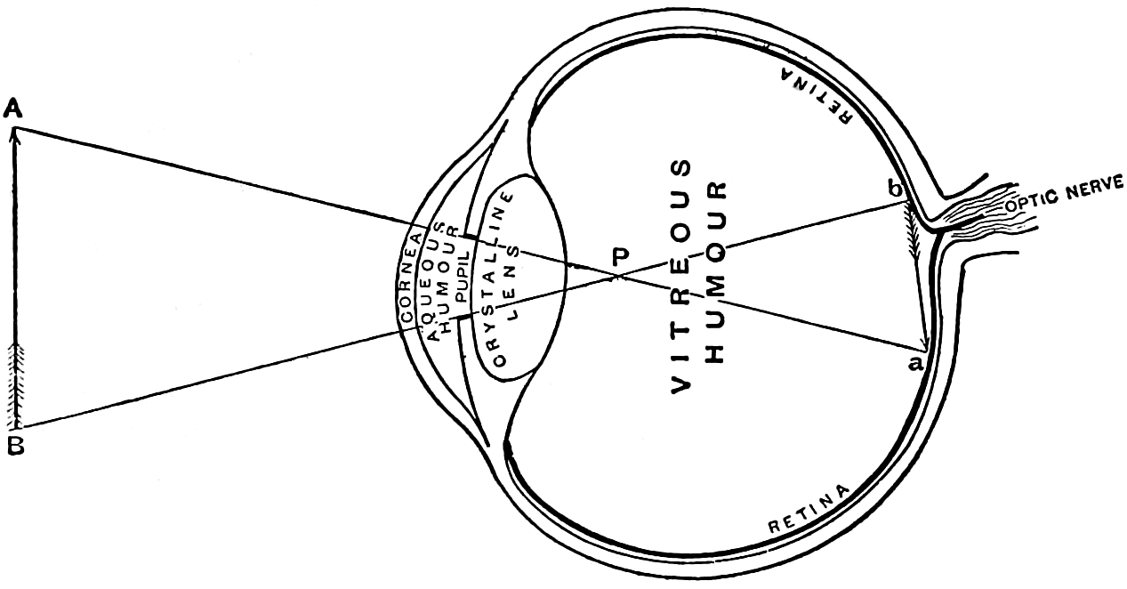
Fig. 305.
The pupil has the power of contraction and dilation,
which is influenced by the quantity of light entering
the eye, but when it is dilated to the utmost its
size is very small in comparison with the great chamber
forming the body of the eye.
In fig. 305 we have a rough sectional diagram of
the eye and an object in front of it. This object, an
arrow, is seen by means of the visual rays proceeding
from it, the principal two of which are shown. The
visual ray from A passes through the pupil and is
received upon the retina at a. In the same way the
visual ray from B passes through the pupil and is
received upon the retina at b. It will thus be seen
that the impressions or images received upon the
retina are inverted; but, by long reason and experience,
the mind has acquired the habit of determining
the real positions of objects, and does not, though
the image is so received, imagine them to be upside
down.
It will also be observed, in the same way, that that
portion of an object which is upon the right will be
pictured upon the retina upon the left, and vice versa,
but the mind, for the reasons before stated, never
imagines the object to be reversed. This fact is
another proof that, as mentioned at the commencement
of our study, to see accurately is a matter of education
and practice.
And first of Optics; it was asserted, page 252, that
we see by the agency of light which passes from objects
to our eyes in straight lines which are called Visual
Rays.
We see by the agency of light, as all objects,
except such as may be styled self-luminous, when
placed in a dark chamber are not perceivable by us,
except by touch, smell or hearing; we cannot see
them; they are invisible. But when, by removing a
shutter or igniting a flame, we introduce something to
the chamber which was not present when the chamber
was dark, we become at once conscious of the appearance
of the object, we perceive it by the sense of sight.
This something which must always be present to
enable us to see, is called Light; all objects are made
visible to the sense of seeing by its agency.
Without light, natural or artificial, it would be
impossible to distinguish one object from another.
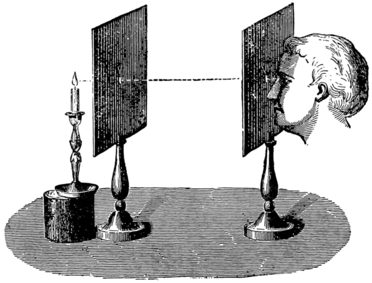
Fig. 306.
That the Visual Rays pass from objects in straight
lines to the eye may be proved by the following
experiment (see fig. 306):—Pierce two screens with a
large pin, and place them so that the holes are in a
straight line with a flame, as the light of a candle or
lamp. On fixing the eye to one of these holes we are
able to see the flame; but if we slightly move the
flame, one of the screens, or the eye, the flame is no
longer visible. To be visible, the flame, the holes in
the screens, and the eye must all be in the same straight
line. See fig. 306.
In fig. 299 the picture plane is represented by
the rectangle W X Y Z. Although the picture plane
is here shown as a rectangle, it may be of any shape
or of any size.
The observer is at S, looking through the picture
plane at the cross R C O H. The observer is standing
upon a horizontal surface, which is called the ground
plane. If we are in a room, the window may be called
a picture plane and the floor a ground plane.
The picture plane rests, as it were, upon the
ground plane, in a line which passes from Y to Z. The
two planes meet or intersect in this line, which is called
the ground line. The ground line is sometimes called
the picture line, or the measuring line.
The visual rays, by means of which the observer
sees the cross, will, in their course from it to the eye,
pass through the picture plane. These visual rays will
intersect the picture plane in a number of points, and
if we mark the true positions of these points the result
will be a perspective image of the cross.
The rays are shown passing from the cross to the
eye of the observer, and meeting the picture plane in
points r, c, o, h; r being joined to o, and c to h, we
have the perspective image of the cross as it would
appear to the observer at S. Of course an infinite
number of rays proceed from the cross to the eye
of the observer; but it is quite evident that we need
only consider those proceeding from the extremities of
the object.
Scale or Approximate Perspective.
Real, or true perspective, represents the object exactly as it is seen in nature, where the parts that are
far away from the eye of the observer appear smaller than those nearby. Occasions arise, however, in practical
life, with its numerous phases of industrial requirements, where the convenience of showing the complete form
of the object in a single view might preferably be coupled with the convenience of scale dimensions.
This has led to a modified perspective, that sacrifices
some of the accuracy in the appearance of the
object to gain the advantage of scale dimensions; this
form of perspective may be distinguished by the
name—approximate or scale perspective—which does not
represent the object exactly as seen in nature, but
where those parts that are afar off are shown of the
same size as those that are near by, and where the
lines that run out into space are parallel to each other
and do not converge into a vanishing point.
To represent an object in perspective, the horizon
and the point of vision will have to appear in the
drawing as the fundamental starting points.
Three dimensions are distinguished for the fixing
of an object in space from a certain reference point.
They are height, breadth and thickness, and are in
their direction square to each other. The height is the
fundamental direction, being derived from the direction
of gravity, that invariably extends to the center of
the earth.
All directions in the perspective determination of
an object are parallel to these.
Vertical lines and planes point toward the center
of the earth, while horizontal planes, including the
directions of breadth and thickness, are square to the
vertical direction. In this, the principal visual ray
extends in the direction of thickness.
For a clear understanding of perspective, it must be firmly fixed in mind, that for each prominent point of
the object behind the picture plane, a corresponding point lies in the picture plane, in that position where a
straight line or ray of sight that is going
from the eye to the point of the object,
cuts through the picture plane.
Suppose we could replace these rays
of sight by thin, visible threads of wire
that would go through little holes in
the picture plane, we could then walk
around this bundle of rays, and by looking
at it from three different directions,
we would get three different views of
it. We may look upon it from the top,
from the side or from the end, where the
bundle of rays all concentrate in the eye
of the observer.
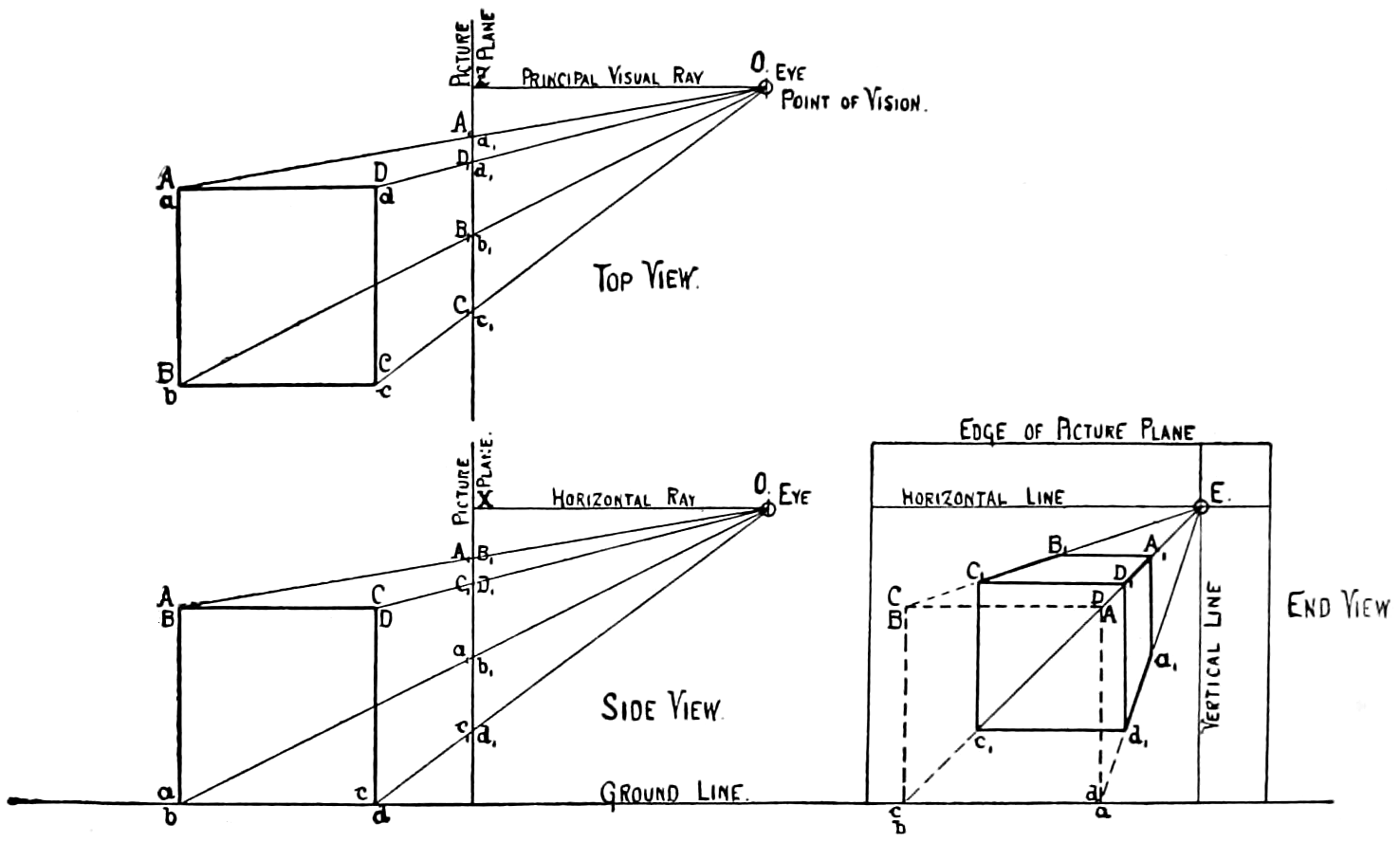
Fig. 307.
Figs. 307 and 308 show, in two cases, how these three
views would appear. The end views are those where
the perspective picture appears on the plane, while the top and side views only show where the rays intersect
the picture plane. The top view shows how far, for example, point A is distant from
a vertical line O Z, while
the side view shows how far point A is below horizontal line O X, which is at the same height above the
ground as the eye of the observer, O. Thus, all points of the cube can be located on the picture plane, and the
outlines of the cube reproduced in perspective.
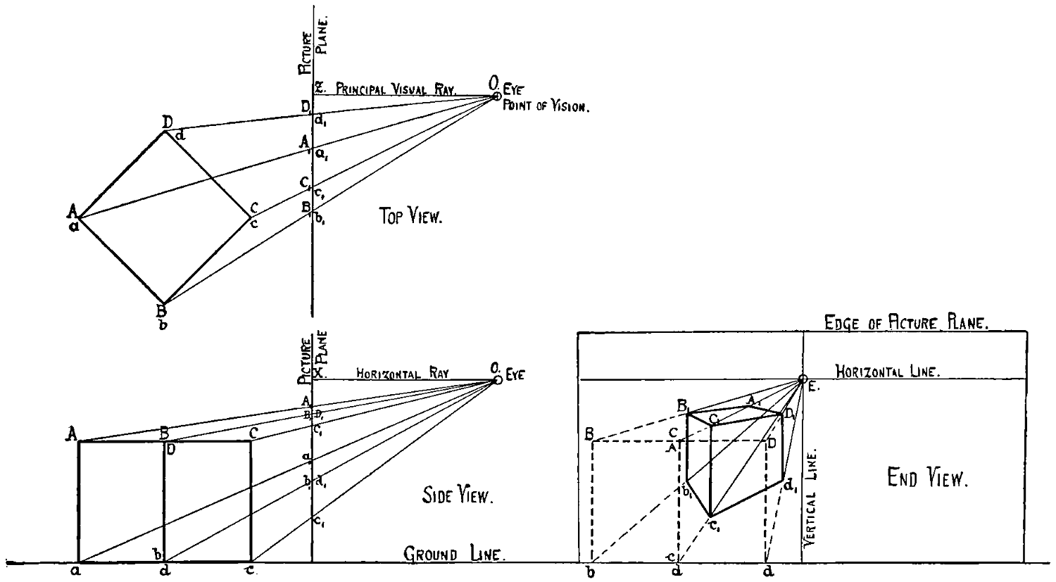
Fig. 308.
Modified arrangements are shown in figs. 309 and
310 for parallel and angular perspective.
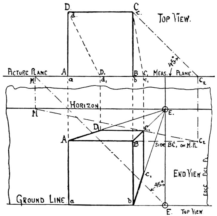
Fig. 309.
The views are so arranged in relation to each other
that the picture plane in the top view is parallel to the
horizon and the ground-line, which latter is the intersection
of the picture plane with the level ground of
the end or perspective view. At the same time the
eye of the observer is in one and the same vertical line
for both views, two vanishing points may be found in
the horizon outside of the principal visual ray. To
find the position of these two vanishing points in
the picture plane, the modified top view, fig. 310, is
used.
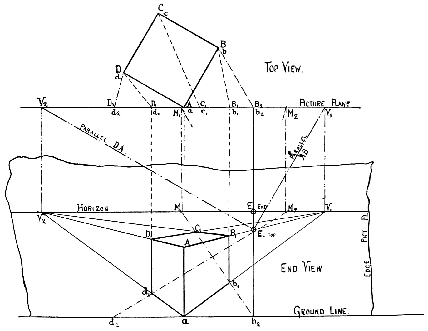
Fig. 310.
As all lines that end in a vanishing point must be
parallel in reality, this parallelism may be seen in the
top view and lines through the eye of the observer,
parallel to the directions of the main lines of the object,
will cut the picture plane at the vanishing points.
Through these two vanishing points the directions
of two sets of lines are found, the starting points of
which are determined from the plane of measurement.
The third set of lines, being vertical, also appears vertical
and parallel in the picture.
The position of each vertical line is found in the
top view, where the light rays from the observing eye
to the ends of the vertical lines intersect with the
picture plane. Projecting these points down upon the
rays to the vanishing points produces the vertical lines
in the picture.
For example, in fig. 311, the purpose of perspective
is entirely defeated by placing the eye of the observer
directly in front of the object and arriving at the view
taken in mechanical drawing which needs supplementary
views for complete comprehension of the form of
the object.
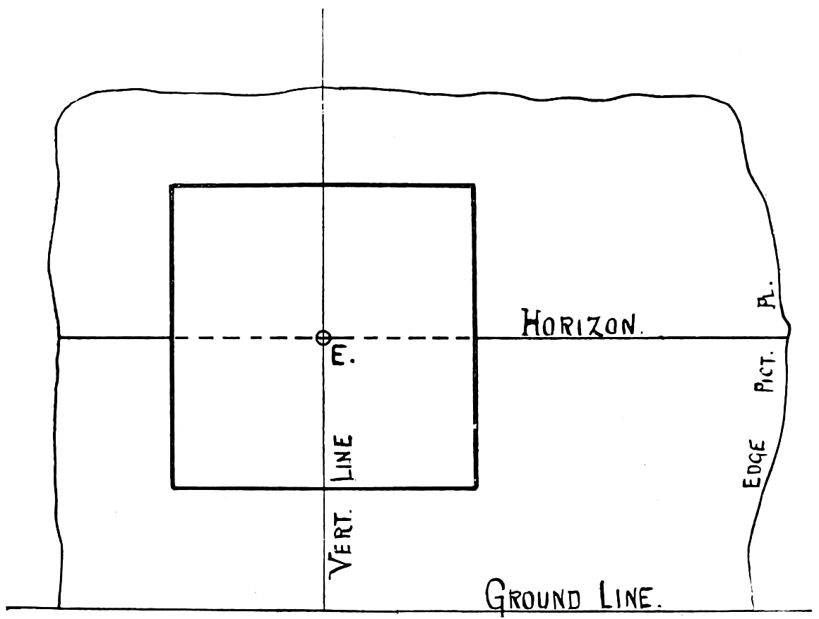
Fig. 311.
In fig. 312 the eye of the observer is first placed directly
opposite the object, then it sees the object to the
left but a short distance away, while in the third figure
the observer is farther away from
the object. In each case the
picture plane and plane of measurement
is at the front face of
the cube.
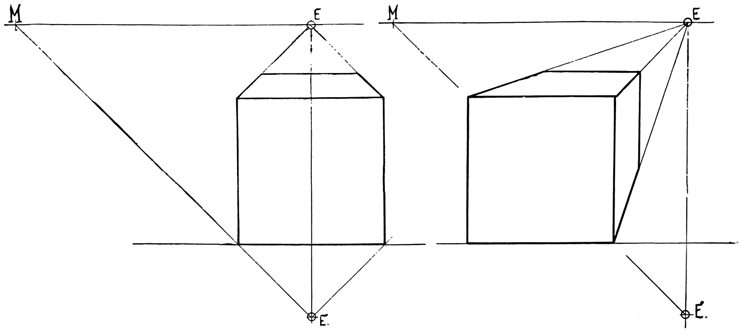
Fig. 312.
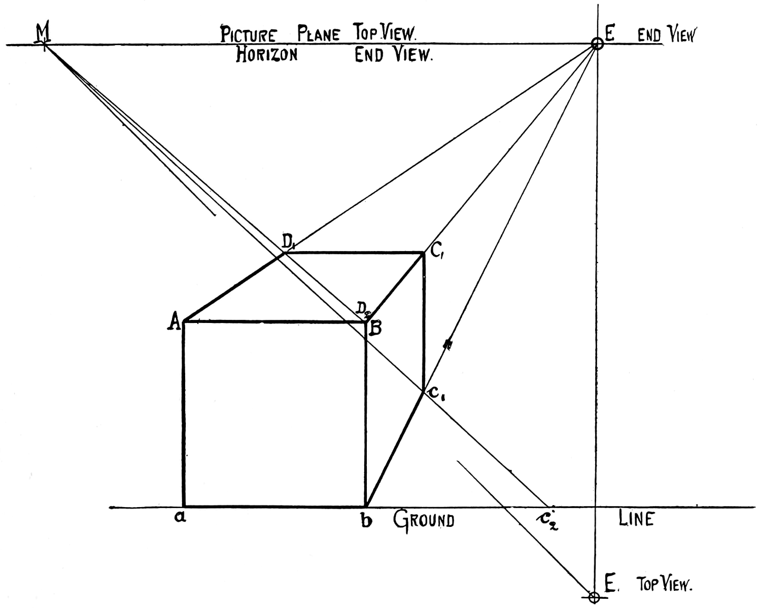
Fig. 312 (second part).
For such simple objects, it is
not necessary to draw the top view
at all. The only reminder of the
top view is the eye or point of
vision, the picture plane that falls
together for the sake of convenience
with the horizon of the end
view and the ray that determines
the measurement point M, which
is, in this suppressed reproduction,
absolutely necessary, in order to
find the apparent position of the
real corners behind the picture
plane.
So far, only square or sharp-cornered objects have
been represented in perspective.
It is evident, however, that round objects can also
be shown in linear perspective, placing reference lines
on the object and representing these as if they were real
lines. A cylinder is thus shown in fig. 313 of which the
end planes will appear very distinctly in sharp outlines.
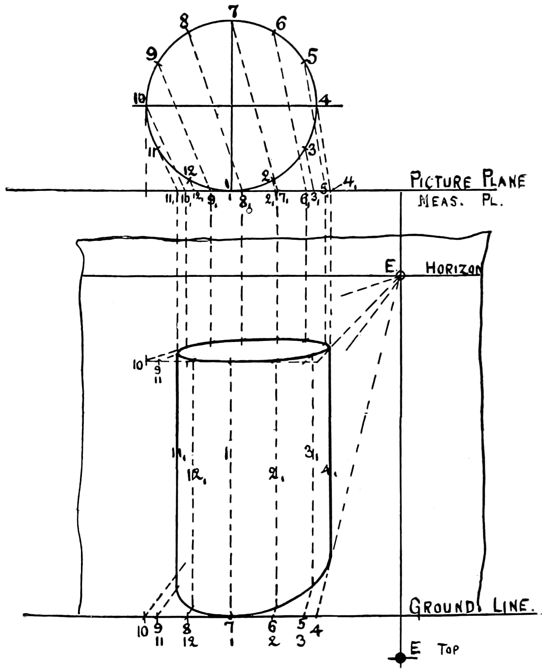
Fig. 313.
Vertically, only the outlines of the cylinder, as contrasted
against space, will appear as distinct outlines,
while the reference lines will not appear and are therefore
shown only as dotted lines.
Fig. 314 shows the approximate or scale perspective
with all the axes drawn and the corresponding angles
and scales marked. The outlines of the object running
in these directions appear all parallel to the axes.
The approximate or scale perspective completely
avoids all the difficulties of choosing a point of sight,
of having several views, vanishing points and measurement
points, and thus offers a representative view, with
a great saving of time and labor. Particularly for
mechanical purposes, where an artistic impression is
not called for, it presents a distinct advantage over the
true or real perspective.
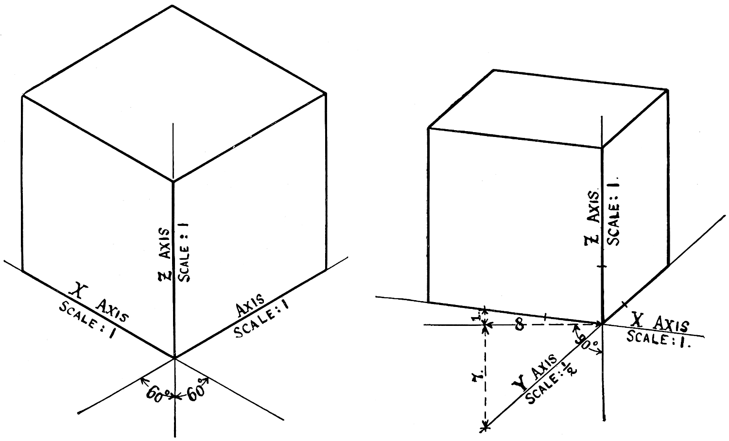
Fig. 314.
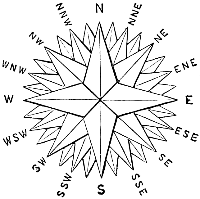
MARINERS’ COMPASS.
Useful Tables for Draughtsmen. — TABLE OF DECIMAL EQUIVALENTS. 8ths, 16ths, 32ds and 64ths of an Inch. — TABLE OF DECIMAL EQUIVALENTS Of Millimeters and Fractions of Millimeters. — RULES RELATIVE TO THE CIRCLE. — ROMAN TABLE. — SOLID MEASURE, OR CUBIC MEASURE. — CIRCULAR MEASURE. — LONG MEASURE—MEASURES OF LENGTH. — Tables of Diameters, Circumferences and Areas of Circles. — UNITED STATES STANDARD SIZES OF WROUGHT IRON WELDED PIPE. — STANDARDS FOR WIRE GAUGES IN USE IN THE UNITED STATES. Dimensions of Sizes in Decimal Parts of an Inch. — UNITED STATES STANDARD SIZES OF BOLTS. — UNITED STATES STANDARD SCREW THREAD GAUGE.
| 8ths. |
| 1⁄8 |
= |
.125 |
| 1⁄4 |
= |
.250 |
| 3⁄8 |
= |
.375 |
| 1⁄2 |
= |
.500 |
| 5⁄8 |
= |
.625 |
| 3⁄4 |
= |
.750 |
| 7⁄8 |
= |
.875 |
| 16ths. |
| 1⁄16 |
= |
.0625 |
| 3⁄16 |
= |
.1875 |
| 5⁄16 |
= |
.3125 |
| 7⁄16 |
= |
.4375 |
| 9⁄16 |
= |
.5625 |
| 11⁄16 |
= |
.6875 |
| 13⁄16 |
= |
.8125 |
| 15⁄16 |
= |
.9375 |
| 32nds. |
| 1⁄32 |
= |
.03125 |
| 3⁄32 |
= |
.09375 |
| 5⁄32 |
= |
.15625 |
| 7⁄32 |
= |
.21875 |
| 9⁄32 |
= |
.28125 |
| 11⁄32 |
= |
.34375 |
| 13⁄32 |
= |
.40625 |
| 15⁄32 |
= |
.46875 |
| 17⁄32 |
= |
.53125 |
| 19⁄32 |
= |
.59375 |
| 21⁄32 |
= |
.65625 |
| 23⁄32 |
= |
.71875 |
| 25⁄32 |
= |
.78125 |
| 27⁄32 |
= |
.84375 |
| 29⁄32 |
= |
.90625 |
| 31⁄32 |
= |
.96875 |
| 64ths. |
| 1⁄64 |
= |
.015625 |
| 3⁄64 |
= |
.046875 |
| 5⁄64 |
= |
.078125 |
| 7⁄64 |
= |
.109375 |
| 9⁄64 |
= |
.140625 |
| 11⁄64 |
= |
.171875 |
| 13⁄64 |
= |
.203125 |
| 15⁄64 |
= |
.234375 |
| 17⁄64 |
= |
.265625 |
| 19⁄64 |
= |
.296875 |
| 21⁄64 |
= |
.328125 |
| 23⁄64 |
= |
.359375 |
| 25⁄64 |
= |
.390625 |
| 27⁄64 |
= |
.421875 |
| 29⁄64 |
= |
.453125 |
| 31⁄64 |
= |
.484375 |
| 33⁄64 |
= |
.515625 |
| 35⁄64 |
= |
.546875 |
| 37⁄64 |
= |
.578125 |
| 39⁄64 |
= |
.609375 |
| 41⁄64 |
= |
.640625 |
| 43⁄64 |
= |
.671875 |
| 45⁄64 |
= |
.703125 |
| 47⁄64 |
= |
.734375 |
| 49⁄64 |
= |
.765625 |
| 51⁄64 |
= |
.796875 |
| 53⁄64 |
= |
.828125 |
| 55⁄64 |
= |
.859375 |
| 57⁄64 |
= |
.890625 |
| 59⁄64 |
= |
.921875 |
| 61⁄64 |
= |
.953125 |
| 63⁄64 |
= |
.984375 |
| mm. |
|
Inches. |
| 1⁄50 |
= |
.00079 |
| 2⁄50 |
= |
.00157 |
| 3⁄50 |
= |
.00236 |
| 4⁄50 |
= |
.00315 |
| 5⁄50 |
= |
.00394 |
| 6⁄50 |
= |
.00472 |
| 7⁄50 |
= |
.00551 |
| 8⁄50 |
= |
.00630 |
| 9⁄50 |
= |
.00709 |
| 10⁄50 |
= |
.00787 |
| 11⁄50 |
= |
.00866 |
| 12⁄50 |
= |
.00945 |
| 13⁄50 |
= |
.01024 |
| 14⁄50 |
= |
.01102 |
| 15⁄50 |
= |
.01181 |
| 16⁄50 |
= |
.01260 |
| 17⁄50 |
= |
.01339 |
| 18⁄50 |
= |
.01417 |
| 19⁄50 |
= |
.01496 |
| 20⁄50 |
= |
.01575 |
| 21⁄50 |
= |
.01654 |
| 22⁄50 |
= |
.01732 |
| 23⁄50 |
= |
.01811 |
| 24⁄50 |
= |
.01890 |
| 25⁄50 |
= |
.01969 |
| 26⁄50 |
= |
.02047 |
| 27⁄50 |
= |
.02126 |
| 28⁄50 |
= |
.02205 |
| 29⁄50 |
= |
.02283 |
| 30⁄50 |
= |
.02362 |
| 31⁄50 |
= |
.02441 |
| 32⁄50 |
= |
.02520 |
| 33⁄50 |
= |
.02598 |
| 34⁄50 |
= |
.02677 |
| 35⁄50 |
= |
.02756 |
| 36⁄50 |
= |
.02835 |
| 37⁄50 |
= |
.02913 |
| 38⁄50 |
= |
.02992 |
| 39⁄50 |
= |
.03071 |
| 40⁄50 |
= |
.03150 |
| 41⁄50 |
= |
.03228 |
| 42⁄50 |
= |
.03307 |
| 43⁄50 |
= |
.03386 |
| 44⁄50 |
= |
.03465 |
| 45⁄50 |
= |
.03543 |
| 46⁄50 |
= |
.03622 |
| 47⁄50 |
= |
.03701 |
| 48⁄50 |
= |
.03780 |
| 49⁄50 |
= |
.03858 |
| 1 |
= |
.03937 |
| 2 |
= |
.07874 |
| 3 |
= |
.11811 |
| 4 |
= |
.15748 |
| 5 |
= |
.19685 |
| 6 |
= |
.23622 |
| 7 |
= |
.27559 |
| 8 |
= |
.31496 |
| 9 |
= |
.35433 |
| 10 |
= |
.39370 |
| 11 |
= |
.43307 |
| 12 |
= |
.47244 |
| 13 |
= |
.51181 |
| 14 |
= |
.55118 |
| 15 |
= |
.59055 |
| 16 |
= |
.62992 |
| 17 |
= |
.66929 |
| 18 |
= |
.70866 |
| 19 |
= |
.74803 |
| 20 |
= |
.78740 |
| 21 |
= |
.82677 |
| 22 |
= |
.86614 |
| 23 |
= |
.90551 |
| 24 |
= |
.94488 |
| 25 |
= |
.98425 |
| 26 |
= |
1.02362 |
| 10 mm. |
= |
1 |
Centimeter |
= |
0.3937 |
inches. |
| 10 cm. |
= |
1 |
Decimeter |
= |
3.937 |
„ |
| 10 dm. |
= |
1 |
Meter |
= |
39.37 |
„ |
| 25.4 mm. |
= |
1 English Inch. |
The circle contains a greater area than any other plane figure bounded by
an equal perimeter or outline.
TO FIND CIRCUMFERENCE—
| Multiply diameter by |
3.1416. |
| Or divide diameter by |
0.3183. |
TO FIND DIAMETER—
| Multiply circumference by |
0.3183. |
| Or divide circumference by |
3.1416. |
TO FIND RADIUS—
| Multiply circumference by |
0.15915. |
| Or divide circumference by |
6.28318. |
TO FIND SIDE OF AN INSCRIBED SQUARE—
| Multiply diameter by |
0.7071. |
| Or multiply circumference by |
0.2251. |
| Or divide circumference by |
4.4428. |
TO FIND SIDE OF AN EQUAL SQUARE—
| Multiply diameter by |
0.8862. |
| Or divide diameter by |
1.1284. |
| Or multiply circumference by |
0.2821. |
| Or divide circumference by |
3.545. |
SQUARE—
| A side multiplied by |
1.4142 equals diameter of its circumscribing circle. |
| A side multiplied by |
4.443 equals circumference of its circumscribing circle. |
| A side multiplied by |
1.128 equals diameter |
} |
of an
equal
circle. |
| A side multiplied by |
3.545 equals circumference |
| A side multiplied by |
1.273 equals circle inches |
TO FIND THE AREA OF A CIRCLE—
| Multiply circumference by one-quarter of the diameter. |
| Or multiply the square of diameter by |
0.7854. |
| Or multiply the square of circumference by |
.07958. |
| Or multiply the square of 1⁄2 diameter by |
3.1416. |
Contents of cylinder = area of end × length. Contents of wedge = area of base ×
1⁄2 altitude. Surface of cylinder = area of
both ends × length × circumference. Surface of sphere = diameter squared × 3.1416,
or = diameter × circumference. Contents of
sphere = diameter cubed × .5236. Contents of pyramid or cone, right or oblique,
regular or irregular = area of base × 1⁄3 altitude. Area
of triangle = base × 1⁄2 altitude. Area of parallelogram
= base × altitude. Area of trapezoid = altitude × 1⁄2 the sum of parallel sides.
| I. |
denotes |
One. |
| II. |
„ |
Two. |
| III. |
„ |
Three. |
| IV. |
„ |
Four. |
| V. |
„ |
Five. |
| VI. |
„ |
Six. |
| VII. |
„ |
Seven. |
| VIII. |
„ |
Eight. |
| IX. |
„ |
Nine. |
| X. |
„ |
Ten. |
| XI. |
„ |
Eleven. |
| XII. |
„ |
Twelve. |
| XIII. |
„ |
Thirteen. |
| XIV. |
„ |
Fourteen. |
| XV. |
„ |
Fifteen. |
| XVI. |
„ |
Sixteen. |
| XVII. |
„ |
Seventeen. |
| XVIII. |
„ |
Eighteen. |
| XIX. |
„ |
Nineteen. |
| XX. |
„ |
Twenty. |
| XXX. |
„ |
Thirty. |
| XL. |
„ |
Forty. |
| L. |
„ |
Fifty. |
| LX. |
„ |
Sixty. |
| LXX. |
„ |
Seventy. |
| LXXX. |
„ |
Eighty. |
| XC. |
„ |
Ninety. |
| C. |
„ |
One hundred. |
| D. |
„ |
Five hundred. |
| M. |
„ |
One thousand. |
| X̅. |
„ |
Ten thousand. |
| M̅. |
„ |
One million. |
This is used in measuring bodies, or things having
length, breadth and height or depth.
TABLE.
| 1728 |
cubic inches (cu. in.) |
make |
1 cubic foot (cu. ft.). |
| 27 |
cubic feet, |
„ |
1 cubic yard (cu. yd.). |
| 128 |
cubic feet, |
„ |
1 cord (C.). |
| 60 |
seconds (″) |
make |
1 minute (′). |
| 60 |
minutes |
„ |
1 degree (°). |
| 360 |
degrees |
„ |
1 circum. (C.). |
The circumference of every circle whatever, is
supposed to be divided into 360 equal parts, called
degrees.
A degree is 1⁄360 of the circumference of any circle,
small or large.
A quadrant is a fourth of a circumference, or an
arc of 90 degrees.
A degree is divided into 60 parts called minutes,
expressed by the sign (′), and each minute is divided
into 60 seconds, expressed by (″); so that the circumference
of any circle contains 21,600 minutes, or
1,296,000 seconds.
| 12 |
|
inches |
= |
1 foot. |
| 3 |
feet |
= |
1 yard. |
| 5 |
1⁄2 |
yards |
= |
1 rod. |
| 40 |
|
rods |
= |
1 furlong. |
| 8 |
furlongs |
= |
1 common mile. |
| 3 |
miles |
= |
1 league. |
The mile (5,280 feet) of the above table is the
legal mile of the United States and England, and is
called the statute mile.
| Diam. |
Area. |
Circum. |
| 0.0 |
|
|
| .1 |
|
.007854 |
|
.31416 |
| .2 |
|
.031416 |
|
.62832 |
| .3 |
|
.070686 |
|
.94248 |
| .4 |
|
.12566 |
1 |
.2566 |
| .5 |
|
.19735 |
1 |
.5708 |
| .6 |
|
.28274 |
1 |
.8850 |
| .7 |
|
.38485 |
2 |
.1991 |
| .8 |
|
.50266 |
2 |
.5133 |
| .9 |
|
.63617 |
2 |
.8274 |
| 1.0 |
|
.7854 |
3 |
.1416 |
| .1 |
|
.9503 |
3 |
.4558 |
| .2 |
1 |
.1310 |
3 |
.7699 |
| .3 |
1 |
.3273 |
4 |
.0841 |
| .4 |
1 |
.5394 |
4 |
.3982 |
| .5 |
1 |
.7671 |
4 |
.7124 |
| .6 |
2 |
.0106 |
5 |
.0265 |
| .7 |
2 |
.2698 |
5 |
.3407 |
| .8 |
2 |
.5447 |
5 |
.6549 |
| .9 |
2 |
.8353 |
5 |
.9690 |
| 2.0 |
3 |
.1416 |
6 |
.2832 |
| .1 |
3 |
.4636 |
6 |
.5973 |
| .2 |
3 |
.8013 |
6 |
.9115 |
| .3 |
4 |
.1548 |
7 |
.2257 |
| .4 |
4 |
.5239 |
7 |
.5398 |
| .5 |
4 |
.9087 |
7 |
.8540 |
| .6 |
5 |
.3093 |
8 |
.1681 |
| .7 |
5 |
.7256 |
8 |
.4823 |
| .8 |
6 |
.1575 |
8 |
.7965 |
| .9 |
6 |
.6052 |
9 |
.1106 |
| 3.0 |
7 |
.0686 |
9 |
.4248 |
| .1 |
7 |
.5477 |
9 |
.7389 |
| .2 |
8 |
.0425 |
10 |
.0531 |
| .3 |
8 |
.5530 |
10 |
.3673 |
| .4 |
9 |
.0792 |
10 |
.6814 |
| .5 |
9 |
.6211 |
10 |
.9956 |
| .6 |
10 |
.1788 |
11 |
.3097 |
| .7 |
10 |
.7521 |
11 |
.6239 |
| .8 |
11 |
.3411 |
11 |
.9381 |
| .9 |
11 |
.9456 |
12 |
.2522 |
| 4.0 |
12 |
.5664 |
12 |
.5664 |
| .1 |
13 |
.2025 |
12 |
.8805 |
| .2 |
13 |
.8544 |
13 |
.1947 |
| .3 |
14 |
.5220 |
13 |
.5088 |
| .4 |
15 |
.2053 |
13 |
.8230 |
| .5 |
15 |
.9043 |
14 |
.1372 |
| .6 |
16 |
.6190 |
14 |
.4513 |
| .7 |
17 |
.3494 |
14 |
.7655 |
| .8 |
18 |
.0956 |
15 |
.0796 |
| .9 |
18 |
.8574 |
15 |
.3938 |
| 5.0 |
19 |
.6350 |
15 |
.7080 |
| .1 |
20 |
.4282 |
16 |
.0221 |
| .2 |
21 |
.2372 |
16 |
.3363 |
| .3 |
22 |
.0618 |
16 |
.6504 |
| .4 |
22 |
.9022 |
16 |
.9646 |
| .5 |
23 |
.7583 |
17 |
.2788 |
| .6 |
24 |
.6301 |
17 |
.5929 |
| .7 |
25 |
.5176 |
17 |
.9071 |
| .8 |
26 |
.4208 |
18 |
.2212 |
| .9 |
27 |
.3397 |
18 |
.5354 |
| 6.0 |
28 |
.2743 |
18 |
.8496 |
| .1 |
29 |
.2247 |
19 |
.1637 |
| .2 |
30 |
.1907 |
19 |
.4779 |
| .3 |
31 |
.1725 |
19 |
.7920 |
| .4 |
32 |
.1699 |
20 |
.1062 |
| .5 |
33 |
.1831 |
20 |
.4204 |
| .6 |
34 |
.2119 |
20 |
.7345 |
| .7 |
35 |
.2565 |
21 |
.0487 |
| .8 |
36 |
.3168 |
21 |
.3628 |
| .9 |
37 |
.3928 |
21 |
.6770 |
| 7.0 |
38 |
.4845 |
21 |
.9911 |
| .1 |
39 |
.5919 |
22 |
.3053 |
| .2 |
40 |
.7150 |
22 |
.6195 |
| .3 |
41 |
.8539 |
22 |
.9336 |
| .4 |
43 |
.0084 |
23 |
.2478 |
| .5 |
44 |
.1786 |
23 |
.5619 |
| .6 |
45 |
.3646 |
23 |
.8761 |
| .7 |
46 |
.5663 |
24 |
.1903 |
| .8 |
47 |
.7836 |
24 |
.5044 |
| .9 |
49 |
.0167 |
24 |
.8186 |
| 8.0 |
50 |
.2655 |
25 |
.1327 |
| .1 |
51 |
.5300 |
25 |
.4469 |
| .2 |
52 |
.8102 |
25 |
.7611 |
| .3 |
54 |
.1061 |
26 |
.0752 |
| .4 |
55 |
.4177 |
26 |
.3894 |
| .5 |
56 |
.7450 |
26 |
.7035 |
| .6 |
58 |
.0880 |
27 |
.0177 |
| .7 |
59 |
.4468 |
27 |
.3319 |
| .8 |
60 |
.8212 |
27 |
.6460 |
| .9 |
62 |
.2114 |
27 |
.9602 |
| 9.0 |
63 |
.6173 |
28 |
.2743 |
| .1 |
65 |
.0388 |
28 |
.5885 |
| .2 |
66 |
.4761 |
28 |
.9027 |
| .3 |
67 |
.9291 |
29 |
.2168 |
| .4 |
69 |
.3978 |
29 |
.5310 |
| .5 |
70 |
.8822 |
29 |
.8451 |
| .6 |
72 |
.3823 |
30 |
.1593 |
| .7 |
73 |
.8981 |
30 |
.4734 |
| .8 |
75 |
.4296 |
30 |
.7876 |
| .9 |
76 |
.9769 |
31 |
.1018 |
| 10.0 |
78 |
.5398 |
31 |
.4159 |
| .1 |
80 |
.1185 |
31 |
.7301 |
| .2 |
81 |
.7128 |
32 |
.0442 |
| .3 |
83 |
.3229 |
32 |
.3584 |
| .4 |
84 |
.9487 |
32 |
.6726 |
| .5 |
86 |
.5901 |
32 |
.9887 |
| .6 |
88 |
.2473 |
33 |
.3009 |
| .7 |
89 |
.9202 |
33 |
.6150 |
| .8 |
91 |
.6088 |
33 |
.9292 |
| .9 |
93 |
.3132 |
34 |
.2434 |
| 11.0 |
95 |
.0332 |
34 |
.5575 |
| .1 |
96 |
.7689 |
34 |
.8717 |
| .2 |
98 |
.5203 |
35 |
.1858 |
| .3 |
100 |
.2875 |
35 |
.5000 |
| .4 |
102 |
.0703 |
35 |
.8142 |
| .5 |
103 |
.8689 |
36 |
.1283 |
| .6 |
105 |
.6832 |
36 |
.4425 |
| .7 |
107 |
.5132 |
36 |
.7566 |
| .8 |
109 |
.3588 |
37 |
.0708 |
| .9 |
111 |
.2202 |
37 |
.3850 |
| 12.0 |
113 |
.0973 |
37 |
.6991 |
| .1 |
114 |
.9901 |
38 |
.0133 |
| .2 |
116 |
.8987 |
38 |
.3274 |
| .3 |
118 |
.8229 |
38 |
.6416 |
| .4 |
120 |
.7628 |
38 |
.9557 |
| .5 |
122 |
.7185 |
39 |
.2099 |
| .6 |
124 |
.6898 |
39 |
.6841 |
| .7 |
126 |
.6769 |
39 |
.8982 |
| .8 |
128 |
.6796 |
40 |
.2121 |
| .9 |
130 |
.6981 |
40 |
.5265 |
| 13.0 |
132 |
.7323 |
40 |
.8407 |
| .1 |
134 |
.7822 |
41 |
.1549 |
| .2 |
136 |
.8478 |
41 |
.4690 |
| .3 |
138 |
.9291 |
41 |
.7832 |
| .4 |
141 |
.0261 |
42 |
.0973 |
| .5 |
143 |
.1388 |
42 |
.4116 |
| .6 |
145 |
.2672 |
42 |
.7257 |
| .7 |
147 |
.4114 |
43 |
.0398 |
| .8 |
149 |
.5712 |
43 |
.3540 |
| .9 |
151 |
.7468 |
43 |
.6681 |
| 14.0 |
153 |
.9380 |
43 |
.9823 |
| .1 |
156 |
.1450 |
44 |
.2965 |
| .2 |
158 |
.3677 |
44 |
.6106 |
| .3 |
160 |
.6061 |
44 |
.9248 |
| .4 |
162 |
.8602 |
45 |
.2389 |
| .5 |
165 |
.1300 |
45 |
.5531 |
| .6 |
167 |
.4155 |
45 |
.8673 |
| .7 |
169 |
.7167 |
46 |
.1814 |
| .8 |
172 |
.0336 |
46 |
.4956 |
| .9 |
174 |
.3662 |
46 |
.8097 |
| 15.0 |
176 |
.7146 |
47 |
.1239 |
| .1 |
179 |
.0786 |
47 |
.4380 |
| .2 |
181 |
.4584 |
47 |
.7522 |
| .3 |
183 |
.8539 |
48 |
.0664 |
| .4 |
186 |
.2650 |
48 |
.3805 |
| .5 |
188 |
.6919 |
48 |
.6947 |
| .6 |
191 |
.1345 |
49 |
.0088 |
| .7 |
193 |
.5928 |
49 |
.3230 |
| .8 |
196 |
.0668 |
49 |
.6372 |
| .9 |
198 |
.5565 |
49 |
.9513 |
| 16.0 |
201 |
.0619 |
50 |
.2655 |
| .1 |
203 |
.5831 |
50 |
.5796 |
| .2 |
206 |
.1199 |
50 |
.8938 |
| .3 |
208 |
.6724 |
51 |
.2080 |
| .4 |
211 |
.2407 |
51 |
.5221 |
| .5 |
213 |
.8246 |
51 |
.8363 |
| .6 |
216 |
.4243 |
52 |
.1504 |
| .7 |
219 |
.0397 |
52 |
.4646 |
| .8 |
221 |
.6708 |
52 |
.7788 |
| .9 |
224 |
.3176 |
53 |
.0929 |
| 17.0 |
226 |
.9801 |
53 |
.4071 |
| .1 |
229 |
.6583 |
53 |
.7212 |
| .2 |
232 |
.3522 |
54 |
.0354 |
| .3 |
235 |
.0618 |
54 |
.3496 |
| .4 |
237 |
.7871 |
54 |
.6637 |
| .5 |
240 |
.5282 |
54 |
.9779 |
| .6 |
243 |
.2849 |
55 |
.2920 |
| .7 |
246 |
.0574 |
55 |
.6062 |
| .8 |
248 |
.8456 |
55 |
.9203 |
| .9 |
251 |
.6494 |
56 |
.2345 |
| 18.0 |
254 |
.4690 |
56 |
.5486 |
| .1 |
257 |
.3043 |
56 |
.8628 |
| .2 |
260 |
.1553 |
57 |
.1770 |
| .3 |
263 |
.0220 |
57 |
.4911 |
| .4 |
265 |
.9044 |
57 |
.8053 |
| .5 |
268 |
.8025 |
58 |
.1195 |
| .6 |
271 |
.7164 |
58 |
.4336 |
| .7 |
274 |
.6459 |
58 |
.7478 |
| .8 |
277 |
.5911 |
59 |
.0619 |
| .9 |
280 |
.5521 |
59 |
.3761 |
| 19.0 |
283 |
.5287 |
59 |
.6903 |
| .1 |
286 |
.5211 |
60 |
.0044 |
| .2 |
289 |
.5292 |
60 |
.3186 |
| .3 |
292 |
.5530 |
60 |
.6327 |
| .4 |
295 |
.5925 |
60 |
.9469 |
| .5 |
298 |
.6477 |
61 |
.2611 |
| .6 |
301 |
.7186 |
61 |
.5752 |
| .7 |
304 |
.8052 |
61 |
.8894 |
| .8 |
307 |
.9075 |
62 |
.2035 |
| .9 |
311 |
.0255 |
62 |
.5177 |
| 20.0 |
314 |
.1593 |
62 |
.8319 |
| .1 |
317 |
.3087 |
63 |
.1460 |
| .2 |
320 |
.4739 |
63 |
.4602 |
| .3 |
323 |
.6547 |
63 |
.7743 |
| .4 |
326 |
.8513 |
64 |
.0885 |
| .5 |
330 |
.0636 |
64 |
.4026 |
| .6 |
333 |
.2916 |
64 |
.7168 |
| .7 |
336 |
.5353 |
65 |
.0310 |
| .8 |
339 |
.7947 |
65 |
.3451 |
| .9 |
343 |
.0698 |
65 |
.6593 |
| 21.0 |
346 |
.3606 |
65 |
.9734 |
| .1 |
349 |
.6671 |
66 |
.2876 |
| .2 |
352 |
.9894 |
66 |
.6018 |
| .3 |
356 |
.3273 |
66 |
.9159 |
| .4 |
359 |
.6809 |
67 |
.2301 |
| .5 |
363 |
.0503 |
67 |
.5442 |
| .6 |
266 |
.4354 |
67 |
.8584 |
| .7 |
369 |
.8361 |
68 |
.1726 |
| .8 |
373 |
.2526 |
68 |
.4867 |
| .9 |
376 |
.6848 |
68 |
.8009 |
| 22.0 |
380 |
.1327 |
69 |
.1150 |
| .1 |
383 |
.5963 |
69 |
.4292 |
| .2 |
387 |
.0756 |
69 |
.7434 |
| .3 |
390 |
.5707 |
70 |
.0575 |
| .4 |
394 |
.0814 |
70 |
.3717 |
| .5 |
397 |
.6078 |
70 |
.6858 |
| .6 |
401 |
.1500 |
71 |
.0000 |
| .7 |
404 |
.7078 |
71 |
.3142 |
| .8 |
408 |
.2814 |
71 |
.6283 |
| .9 |
411 |
.8707 |
71 |
.9425 |
| 23.0 |
415 |
.4756 |
72 |
.2566 |
| .1 |
419 |
.0993 |
72 |
.5708 |
| .2 |
422 |
.7327 |
72 |
.8849 |
| .3 |
426 |
.3848 |
73 |
.1991 |
| .4 |
430 |
.0526 |
73 |
.5133 |
| .5 |
433 |
.7361 |
73 |
.8274 |
| .6 |
437 |
.4354 |
74 |
.1416 |
| .7 |
441 |
.1503 |
74 |
.4557 |
| .8 |
444 |
.8809 |
74 |
.7699 |
| .9 |
448 |
.6273 |
75 |
.0841 |
| 24.0 |
452 |
.3893 |
75 |
.3982 |
| .1 |
456 |
.1671 |
75 |
.7424 |
| .2 |
459 |
.9606 |
76 |
.0265 |
| .3 |
463 |
.7693 |
76 |
.3407 |
| .4 |
467 |
.5947 |
76 |
.6549 |
| .5 |
471 |
.4352 |
76 |
.9690 |
| .6 |
475 |
.2916 |
77 |
.2832 |
| .7 |
479 |
.1636 |
77 |
.5973 |
| .8 |
483 |
.0513 |
77 |
.9115 |
| .9 |
486 |
.9547 |
78 |
.2257 |
| 25.0 |
490 |
.8739 |
78 |
.5398 |
| .1 |
494 |
.8087 |
78 |
.8540 |
| .2 |
498 |
.7592 |
79 |
.1681 |
| .3 |
502 |
.7255 |
79 |
.4823 |
| .4 |
506 |
.7075 |
79 |
.7965 |
| .5 |
510 |
.7052 |
80 |
.1106 |
| .6 |
514 |
.7185 |
80 |
.4248 |
| .7 |
518 |
.7476 |
80 |
.7389 |
| .8 |
522 |
.7924 |
81 |
.0531 |
| .9 |
526 |
.8529 |
81 |
.3672 |
| 26.0 |
530 |
.9292 |
81 |
.6814 |
| .1 |
535 |
.0211 |
81 |
.9956 |
| .2 |
539 |
.1287 |
82 |
.3097 |
| .3 |
543 |
.2521 |
82 |
.6239 |
| .4 |
547 |
.3911 |
82 |
.9380 |
| .5 |
551 |
.5459 |
83 |
.2522 |
| .6 |
555 |
.7163 |
83 |
.5664 |
| .7 |
559 |
.9025 |
83 |
.8805 |
| .8 |
564 |
.1044 |
84 |
.1947 |
| .9 |
568 |
.3220 |
84 |
.5088 |
| 27.0 |
572 |
.5553 |
84 |
.8230 |
| .1 |
576 |
.8043 |
85 |
.1372 |
| .2 |
581 |
.0690 |
85 |
.4513 |
| .3 |
585 |
.3494 |
85 |
.7655 |
| .4 |
589 |
.6455 |
86 |
.0796 |
| .5 |
593 |
.9574 |
86 |
.3938 |
| .6 |
598 |
.2849 |
86 |
.7080 |
| .7 |
602 |
.6282 |
87 |
.0221 |
| .8 |
606 |
.9871 |
87 |
.3363 |
| .9 |
611 |
.3618 |
87 |
.6504 |
| 28.0 |
615 |
.7522 |
87 |
.9646 |
| .1 |
620 |
.1582 |
88 |
.2788 |
| .2 |
624 |
.5800 |
88 |
.5929 |
| .3 |
629 |
.0175 |
88 |
.9071 |
| .4 |
633 |
.4707 |
89 |
.2212 |
| .5 |
637 |
.9397 |
89 |
.5354 |
| .6 |
642 |
.4243 |
89 |
.8495 |
| .7 |
646 |
.9246 |
90 |
.1637 |
| .8 |
651 |
.4407 |
90 |
.4779 |
| .9 |
655 |
.9724 |
90 |
.7920 |
| 29.0 |
660 |
.5199 |
91 |
.1063 |
| .1 |
665 |
.0830 |
91 |
.4203 |
| .2 |
669 |
.6619 |
91 |
.7345 |
| .3 |
674 |
.2565 |
92 |
.0487 |
| .4 |
678 |
.8668 |
92 |
.3628 |
| .5 |
683 |
.4928 |
92 |
.6770 |
| .6 |
688 |
.1345 |
92 |
.9911 |
| .7 |
692 |
.7919 |
93 |
.3053 |
| .8 |
697 |
.4650 |
93 |
.6195 |
| .9 |
702 |
.1538 |
93 |
.9336 |
| 30.0 |
706 |
.8583 |
94 |
.2478 |
| .1 |
711 |
.5786 |
94 |
.5610 |
| .2 |
716 |
.3145 |
94 |
.8761 |
| .3 |
721 |
.0662 |
95 |
.1903 |
| .4 |
725 |
.8336 |
95 |
.5044 |
| .5 |
730 |
.6167 |
95 |
.8186 |
| .6 |
735 |
.4154 |
96 |
.1327 |
| .7 |
740 |
.2299 |
96 |
.4469 |
| .8 |
745 |
.0601 |
96 |
.7611 |
| .9 |
749 |
.9060 |
97 |
.0752 |
| 31.0 |
754 |
.7676 |
97 |
.3894 |
| .1 |
759 |
.6450 |
97 |
.7035 |
| .2 |
761 |
.5380 |
98 |
.0177 |
| .3 |
769 |
.4467 |
98 |
.3319 |
| .4 |
774 |
.3712 |
98 |
.6460 |
| .5 |
779 |
.3113 |
98 |
.9602 |
| .6 |
784 |
.2672 |
99 |
.2743 |
| .7 |
789 |
.2388 |
99 |
.5885 |
| .8 |
794 |
.2260 |
99 |
.9026 |
| .9 |
799 |
.2290 |
100 |
.2168 |
| 32.0 |
804 |
.2477 |
100 |
.5310 |
| .1 |
809 |
.2821 |
100 |
.8451 |
| .2 |
814 |
.3322 |
101 |
.1593 |
| .3 |
819 |
.3980 |
101 |
.4734 |
| .4 |
824 |
.4796 |
101 |
.7876 |
| .5 |
829 |
.5768 |
102 |
.1018 |
| .6 |
834 |
.6898 |
102 |
.4159 |
| .7 |
839 |
.8185 |
102 |
.7301 |
| .8 |
844 |
.9628 |
103 |
.0442 |
| .9 |
850 |
.1229 |
103 |
.3584 |
| 33.0 |
855 |
.2986 |
103 |
.6726 |
| .1 |
860 |
.4902 |
103 |
.9867 |
| .2 |
865 |
.6973 |
104 |
.3009 |
| .3 |
870 |
.9202 |
104 |
.6150 |
| .4 |
876 |
.1588 |
104 |
.9292 |
| .5 |
881 |
.4131 |
105 |
.2434 |
| .6 |
886 |
.6831 |
105 |
.5575 |
| .7 |
891 |
.9688 |
105 |
.8717 |
| .8 |
897 |
.2703 |
106 |
.1858 |
| .9 |
902 |
.5874 |
106 |
.5000 |
| 34.0 |
907 |
.9203 |
106 |
.8142 |
| .1 |
913 |
.2688 |
107 |
.1283 |
| .2 |
918 |
.6331 |
107 |
.4425 |
| .3 |
924 |
.0131 |
107 |
.7566 |
| .4 |
929 |
.4088 |
108 |
.0708 |
| .5 |
934 |
.8202 |
108 |
.3849 |
| .6 |
940 |
.2473 |
108 |
.6991 |
| .7 |
945 |
.6901 |
109 |
.0133 |
| .8 |
951 |
.1486 |
109 |
.3274 |
| .9 |
956 |
.6228 |
109 |
.6416 |
| 35.0 |
962 |
.1128 |
109 |
.9557 |
| .1 |
967 |
.6184 |
110 |
.2699 |
| .2 |
973 |
.1397 |
110 |
.5841 |
| .3 |
978 |
.6768 |
110 |
.8982 |
| .4 |
984 |
.2296 |
111 |
.2124 |
| .5 |
989 |
.7980 |
111 |
.5265 |
| .6 |
995 |
.3822 |
111 |
.8407 |
| .7 |
1000 |
.9821 |
112 |
.1549 |
| .8 |
1006 |
.5977 |
112 |
.4690 |
| .9 |
1012 |
.2290 |
112 |
.7832 |
| 36.0 |
1017 |
.8760 |
113 |
.0973 |
| .1 |
1023 |
.5387 |
113 |
.4115 |
| .2 |
1029 |
.2172 |
113 |
.7257 |
| .3 |
1034 |
.9113 |
114 |
.0398 |
| .4 |
1040 |
.6212 |
114 |
.3540 |
| .5 |
1046 |
.3467 |
114 |
.6681 |
| .6 |
1052 |
.0880 |
114 |
.9823 |
| .7 |
1057 |
.8449 |
115 |
.2965 |
| .8 |
1063 |
.6176 |
115 |
.6106 |
| .9 |
1069 |
.4060 |
115 |
.9248 |
| 37.0 |
1075 |
.2101 |
116 |
.2389 |
| .1 |
1081 |
.0299 |
116 |
.5531 |
| .2 |
1086 |
.8654 |
116 |
.8672 |
| .3 |
1093 |
.7166 |
117 |
.1814 |
| .4 |
1098 |
.5835 |
117 |
.4956 |
| .5 |
1104 |
.4662 |
117 |
.8097 |
| .6 |
1110 |
.3645 |
118 |
.1239 |
| .7 |
1116 |
.2786 |
118 |
.4380 |
| .8 |
1122 |
.2083 |
118 |
.7522 |
| .9 |
1128 |
.1538 |
119 |
.0664 |
| 38.0 |
1134 |
.1149 |
119 |
.3805 |
| .1 |
1140 |
.0918 |
119 |
.6947 |
| .2 |
1146 |
.0844 |
120 |
.0088 |
| .3 |
1152 |
.0927 |
120 |
.3230 |
| .4 |
1158 |
.1167 |
120 |
.6372 |
| .5 |
1164 |
.1564 |
120 |
.9513 |
| .6 |
1170 |
.2118 |
121 |
.2655 |
| .7 |
1176 |
.2830 |
121 |
.5796 |
| .8 |
1182 |
.3698 |
121 |
.8938 |
| .9 |
1188 |
.4724 |
122 |
.2080 |
| 39.0 |
1194 |
.5906 |
122 |
.5221 |
| .1 |
1200 |
.7246 |
122 |
.8363 |
| .2 |
1206 |
.8742 |
123 |
.1504 |
| .3 |
1213 |
.0396 |
123 |
.4646 |
| .4 |
1219 |
.2207 |
123 |
.7788 |
| .5 |
1225 |
.4175 |
124 |
.0929 |
| .6 |
1231 |
.6300 |
124 |
.4071 |
| .7 |
1237 |
.8582 |
124 |
.7212 |
| .8 |
1244 |
.1021 |
125 |
.0354 |
| .9 |
1250 |
.3617 |
125 |
.3495 |
| 40.0 |
1256 |
.6371 |
125 |
.6637 |
| .1 |
1262 |
.9281 |
125 |
.9779 |
| .2 |
1269 |
.2348 |
126 |
.2920 |
| .3 |
1275 |
.5573 |
126 |
.6062 |
| .4 |
1281 |
.8955 |
126 |
.9203 |
| .5 |
1288 |
.2493 |
127 |
.2345 |
| .6 |
1294 |
.3189 |
127 |
.5487 |
| .7 |
1301 |
.0042 |
127 |
.8628 |
| .8 |
1307 |
.4052 |
128 |
.1770 |
| .9 |
1313 |
.8219 |
128 |
.4911 |
| 41.0 |
1320 |
.2543 |
128 |
.8053 |
| .1 |
1326 |
.7024 |
129 |
.1195 |
| .2 |
1333 |
.1663 |
129 |
.4336 |
| .3 |
1339 |
.6458 |
129 |
.7478 |
| .4 |
1346 |
.1410 |
130 |
.0619 |
| .5 |
1352 |
.6520 |
130 |
.3761 |
| .6 |
1359 |
.1786 |
130 |
.6903 |
| .7 |
1365 |
.7210 |
131 |
.0044 |
| .8 |
1372 |
.2791 |
131 |
.3186 |
| .9 |
1378 |
.8529 |
131 |
.6227 |
| 42.0 |
1385 |
.4424 |
131 |
.9469 |
| .1 |
1392 |
.0476 |
132 |
.2611 |
| .2 |
1398 |
.6685 |
132 |
.5752 |
| .3 |
1405 |
.3051 |
132 |
.8894 |
| .4 |
1411 |
.9574 |
133 |
.2035 |
| .5 |
1418 |
.6254 |
133 |
.5177 |
| .6 |
1425 |
.3092 |
133 |
.8318 |
| .7 |
1432 |
.0086 |
134 |
.1460 |
| .8 |
1438 |
.7238 |
134 |
.4602 |
| .9 |
1445 |
.4546 |
134 |
.7743 |
| 43.0 |
1452 |
.2012 |
135 |
.0885 |
| .1 |
1458 |
.9635 |
135 |
.4026 |
| .2 |
1465 |
.7415 |
135 |
.7168 |
| .3 |
1472 |
.5352 |
136 |
.0310 |
| .4 |
1479 |
.3446 |
136 |
.3451 |
| .5 |
1486 |
.1697 |
136 |
.6593 |
| .6 |
1493 |
.0105 |
136 |
.9734 |
| .7 |
1499 |
.8670 |
137 |
.2876 |
| .8 |
1506 |
.7393 |
137 |
.6018 |
| .9 |
1513 |
.6272 |
137 |
.9159 |
| 44.0 |
1520 |
.5308 |
138 |
.2301 |
| .1 |
1527 |
.4502 |
138 |
.5442 |
| .2 |
1534 |
.3853 |
138 |
.8584 |
| .3 |
1541 |
.3360 |
139 |
.1726 |
| .4 |
1548 |
.3025 |
139 |
.4867 |
| .5 |
1555 |
.2847 |
139 |
.8009 |
| .6 |
1562 |
.2826 |
140 |
.1153 |
| .7 |
1569 |
.2063 |
140 |
.4292 |
| .8 |
1576 |
.3255 |
140 |
.7434 |
| .9 |
1583 |
.3706 |
141 |
.0575 |
| 45.0 |
1590 |
.4313 |
141 |
.3717 |
| .1 |
1597 |
.5077 |
141 |
.6858 |
| .2 |
1604 |
.5999 |
142 |
.0000 |
| .3 |
1611 |
.7077 |
142 |
.3142 |
| .4 |
1618 |
.8313 |
142 |
.6283 |
| .5 |
1625 |
.9705 |
142 |
.9425 |
| .6 |
1633 |
.1255 |
143 |
.2566 |
| .7 |
1640 |
.2962 |
143 |
.5708 |
| .8 |
1647 |
.4826 |
143 |
.8849 |
| .9 |
1654 |
.6847 |
144 |
.1991 |
| 46.0 |
1661 |
.9025 |
144 |
.5133 |
| .1 |
1669 |
.1360 |
144 |
.8274 |
| .2 |
1676 |
.3853 |
145 |
.1416 |
| .3 |
1683 |
.6502 |
145 |
.4557 |
| .4 |
1690 |
.9308 |
145 |
.7699 |
| .5 |
1698 |
.2272 |
146 |
.0841 |
| .6 |
1705 |
.5392 |
146 |
.3982 |
| .7 |
1712 |
.8670 |
146 |
.7124 |
| .8 |
1720 |
.2105 |
147 |
.0265 |
| .9 |
1727 |
.5697 |
147 |
.3407 |
| 47.0 |
1734 |
.9445 |
147 |
.6550 |
| .1 |
1742 |
.3351 |
147 |
.9690 |
| .2 |
1749 |
.7414 |
148 |
.2832 |
| .3 |
1757 |
.1635 |
148 |
.5973 |
| .4 |
1764 |
.6012 |
148 |
.9115 |
| .5 |
1772 |
.0546 |
149 |
.2257 |
| .6 |
1779 |
.5237 |
149 |
.5398 |
| .7 |
1787 |
.0086 |
149 |
.8540 |
| .8 |
1794 |
.5091 |
150 |
.1681 |
| .9 |
1802 |
.0254 |
150 |
.4823 |
| 48.0 |
1809 |
.5574 |
150 |
.7964 |
| .1 |
1817 |
.1050 |
151 |
.1105 |
| .2 |
1824 |
.6684 |
151 |
.4248 |
| .3 |
1832 |
.2475 |
151 |
.7389 |
| .4 |
1839 |
.8423 |
152 |
.0531 |
| .5 |
1847 |
.4528 |
152 |
.3672 |
| .6 |
1855 |
.0790 |
152 |
.6814 |
| .7 |
1862 |
.7210 |
152 |
.9956 |
| .8 |
1870 |
.3786 |
153 |
.3097 |
| .9 |
1878 |
.0519 |
153 |
.6239 |
| 49.0 |
1885 |
.7409 |
153 |
.9380 |
| .1 |
1893 |
.4457 |
154 |
.2522 |
| .2 |
1901 |
.1662 |
154 |
.5664 |
| .3 |
1908 |
.9024 |
154 |
.8805 |
| .4 |
1916 |
.6543 |
155 |
.1947 |
| .5 |
1924 |
.4218 |
155 |
.5088 |
| .6 |
1932 |
.2051 |
155 |
.8230 |
| .7 |
1940 |
.0042 |
156 |
.1372 |
| .8 |
1947 |
.8189 |
156 |
.4513 |
| .9 |
1955 |
.6493 |
156 |
.7655 |
| 50.0 |
1963 |
.4954 |
157 |
.0796 |
| .1 |
1971 |
.3572 |
157 |
.3938 |
| .2 |
1979 |
.2348 |
157 |
.7080 |
| .3 |
1987 |
.1280 |
158 |
.0221 |
| .4 |
1995 |
.0370 |
158 |
.3363 |
| .5 |
2002 |
.9617 |
158 |
.6504 |
| .6 |
2010 |
.9020 |
158 |
.9646 |
| .7 |
2018 |
.8581 |
159 |
.2787 |
| .8 |
2026 |
.8299 |
159 |
.5929 |
| .9 |
2034 |
.8174 |
159 |
.9071 |
| 51.0 |
2042 |
.6206 |
160 |
.2212 |
| .1 |
2050 |
.8895 |
160 |
.5354 |
| .2 |
2058 |
.8742 |
160 |
.8495 |
| .3 |
2066 |
.9245 |
161 |
.1637 |
| .4 |
2074 |
.9905 |
161 |
.4779 |
| .5 |
2083 |
.0723 |
161 |
.7920 |
| .6 |
2091 |
.1697 |
162 |
.1062 |
| .7 |
2099 |
.2829 |
162 |
.4203 |
| .8 |
2107 |
.4118 |
162 |
.7345 |
| .9 |
2115 |
.5563 |
163 |
.0487 |
| 52.0 |
2123 |
.7166 |
163 |
.3628 |
| .1 |
2131 |
.8926 |
163 |
.6770 |
| .2 |
2140 |
.0843 |
163 |
.9911 |
| .3 |
2148 |
.2917 |
164 |
.3053 |
| .4 |
2156 |
.5149 |
164 |
.6195 |
| .5 |
2164 |
.7537 |
164 |
.9336 |
| .6 |
2173 |
.0082 |
165 |
.2479 |
| .7 |
2181 |
.2785 |
165 |
.5619 |
| .8 |
2189 |
.5644 |
165 |
.8761 |
| .9 |
2197 |
.8661 |
166 |
.1903 |
| 53.0 |
2206 |
.1834 |
166 |
.5044 |
| .1 |
2214 |
.5165 |
166 |
.8186 |
| .2 |
2222 |
.8653 |
167 |
.1327 |
| .3 |
2231 |
.2298 |
167 |
.4469 |
| .4 |
2239 |
.6100 |
167 |
.7610 |
| .5 |
2248 |
.0059 |
168 |
.0752 |
| .6 |
2256 |
.4175 |
168 |
.3894 |
| .7 |
2264 |
.8448 |
168 |
.7035 |
| .8 |
2273 |
.2879 |
169 |
.0177 |
| .9 |
2281 |
.7466 |
169 |
.3318 |
| 54.0 |
2290 |
.2210 |
169 |
.6460 |
| .1 |
2298 |
.7112 |
169 |
.9602 |
| .2 |
2307 |
.2171 |
170 |
.2743 |
| .3 |
2315 |
.7386 |
170 |
.5885 |
| .4 |
2324 |
.2759 |
170 |
.9026 |
| .5 |
2332 |
.8289 |
171 |
.2168 |
| .6 |
2341 |
.3976 |
171 |
.5310 |
| .7 |
2349 |
.9820 |
171 |
.8451 |
| .8 |
2358 |
.5821 |
172 |
.1593 |
| .9 |
2367 |
.1979 |
172 |
.4735 |
| 55.0 |
2375 |
.8294 |
172 |
.7876 |
| .1 |
2384 |
.4767 |
173 |
.1017 |
| .2 |
2393 |
.1396 |
173 |
.4159 |
| .3 |
2401 |
.8183 |
173 |
.7301 |
| .4 |
2410 |
.5126 |
174 |
.0442 |
| .5 |
2419 |
.2227 |
174 |
.3584 |
| .6 |
2427 |
.9485 |
174 |
.6726 |
| .7 |
2436 |
.6899 |
174 |
.9867 |
| .8 |
2145 |
.4471 |
175 |
.3009 |
| .9 |
2454 |
.2200 |
175 |
.6150 |
Inside
diam-
eter
nom. |
Actual
outside
Diam-
eter. |
Thick-
ness. |
Actual
Inside
Diam-
eter. |
External
circum-
ference. |
Internal
circum-
ference. |
Length
of pipe
per
square
foot of
outside
surface. |
Length
of pipe
per
square
foot of
inside
surface. |
External
area. |
Actual
internal
area. |
Length
of pipe
con-
taining
one
cubic
foot. |
Weight
per
foot of
length. |
No. of
threads
per
Inch
of
screw. |
Length
perfect
screw. |
| |
1⁄8 |
|
.405 |
.068 |
0 |
.269 |
1 |
.272 |
0 |
.848 |
9 |
.440 |
14 |
.15 |
|
.129 |
|
.0572 |
2500 |
. |
|
.243 |
27 |
|
0.19 |
| |
1⁄4 |
|
.54 |
.088 |
0 |
.364 |
1 |
.696 |
1 |
.144 |
7 |
.075 |
10 |
.50 |
|
.229 |
|
.1041 |
1385 |
. |
|
.422 |
18 |
|
0.29 |
| |
3⁄8 |
|
.675 |
.091 |
0 |
.493 |
2 |
.121 |
1 |
.552 |
5 |
.657 |
7 |
.67 |
|
.358 |
|
.1916 |
751 |
.5 |
|
.561 |
18 |
|
0.30 |
| |
1⁄2 |
|
.840 |
.109 |
0 |
.622 |
2 |
.652 |
1 |
.957 |
4 |
.502 |
6 |
.13 |
|
.554 |
|
.3048 |
472 |
.4 |
|
.845 |
14 |
|
0.39 |
| |
3⁄4 |
1 |
.050 |
.113 |
0 |
.824 |
3 |
.299 |
2 |
.589 |
3 |
.637 |
4 |
.635 |
|
.866 |
|
.5333 |
270 |
.0 |
1 |
.126 |
14 |
|
0.40 |
| 1 |
|
1 |
.315 |
.134 |
1 |
.047 |
4 |
.134 |
3 |
.292 |
2 |
.903 |
3 |
.679 |
1 |
.357 |
|
.8627 |
166 |
.9 |
1 |
.670 |
11 |
1⁄2 |
0.51 |
| 1 |
1⁄4 |
1 |
.660 |
.140 |
1 |
.38 |
5 |
.215 |
4 |
.335 |
2 |
.301 |
2 |
.768 |
2 |
.164 |
1 |
.496 |
96 |
.25 |
2 |
.258 |
11 |
1⁄2 |
0.54 |
| 1 |
1⁄2 |
1 |
.90 |
.145 |
1 |
.61 |
5 |
.969 |
5 |
.061 |
2 |
.010 |
2 |
.371 |
2 |
.835 |
2 |
.038 |
70 |
.65 |
2 |
.694 |
11 |
1⁄2 |
0.55 |
| 2 |
|
2 |
.375 |
.154 |
2 |
.067 |
7 |
.461 |
6 |
.494 |
1 |
.611 |
1 |
.848 |
4 |
.430 |
3 |
.355 |
42 |
.36 |
3 |
.667 |
11 |
1⁄2 |
0.58 |
| 2 |
1⁄2 |
2 |
.875 |
.204 |
2 |
.467 |
9 |
.032 |
7 |
.754 |
1 |
.328 |
1 |
.547 |
6 |
.491 |
4 |
.783 |
30 |
.11 |
5 |
.773 |
8 |
|
0.89 |
| 3 |
|
3 |
.50 |
.217 |
3 |
.066 |
10 |
.996 |
9 |
.636 |
1 |
.091 |
1 |
.245 |
9 |
.621 |
7 |
.388 |
19 |
.40 |
7 |
.547 |
8 |
|
0.95 |
| 3 |
1⁄2 |
4 |
.0 |
.226 |
3 |
.548 |
12 |
.566 |
11 |
.146 |
|
.955 |
1 |
.077 |
12 |
.566 |
9 |
.837 |
14 |
.56 |
9 |
.055 |
8 |
|
1.00 |
| 4 |
|
4 |
.50 |
.237 |
4 |
.026 |
14 |
.137 |
12 |
.648 |
|
.849 |
0 |
.949 |
15 |
.901 |
12 |
.730 |
11 |
.31 |
10 |
.728 |
8 |
|
1.05 |
| 4 |
1⁄2 |
5 |
.0 |
.247 |
4 |
.506 |
15 |
.708 |
14 |
.153 |
|
.765 |
0 |
.848 |
19 |
.635 |
15 |
.939 |
9 |
.03 |
12 |
.492 |
8 |
|
1.10 |
| 5 |
|
5 |
.563 |
.259 |
5 |
.045 |
17 |
.475 |
15 |
.849 |
|
.629 |
0 |
.757 |
24 |
.299 |
19 |
.990 |
7 |
.20 |
14 |
.564 |
8 |
|
1.16 |
| 6 |
|
6 |
.625 |
.280 |
5 |
.065 |
20 |
.813 |
19 |
.054 |
|
.577 |
0 |
.630 |
34 |
.471 |
28 |
.889 |
4 |
.98 |
18 |
.767 |
8 |
|
1.26 |
| 7 |
|
7 |
.625 |
.301 |
7 |
.023 |
23 |
.954 |
22 |
.063 |
|
.505 |
0 |
.544 |
45 |
.663 |
38 |
.737 |
3 |
.72 |
23 |
.410 |
8 |
|
1.36 |
| 8 |
|
8 |
.625 |
.322 |
7 |
.981 |
27 |
.096 |
25 |
.076 |
|
.444 |
0 |
.478 |
58 |
.426 |
50 |
.039 |
2 |
.88 |
28 |
.348 |
8 |
|
1.46 |
| 9 |
|
9 |
.688 |
.344 |
9 |
.00 |
30 |
.433 |
28 |
.277 |
|
.394 |
0 |
.425 |
73 |
.715 |
63 |
.633 |
2 |
.26 |
34 |
.677 |
8 |
|
1.57 |
| 10 |
|
10 |
.750 |
.366 |
10 |
.018 |
33 |
.772 |
31 |
.475 |
|
.355 |
0 |
.381 |
90 |
.762 |
78 |
.838 |
1 |
.80 |
40 |
.641 |
8 |
|
1.68 |
Thread taper three-fourths inch to one foot.
All pipe below 11⁄2 inches is butt-welded, and
proved to 300 pounds per square inch; 11⁄2 inch and above is lap-welded and proved
to 500 pounds per square inch.
Number
of Wire
Gauge. |
American
or
Brown
&
Sharpe. |
Birming-
ham,
or
Stubs’
Wire. |
Washburn
& Moen
Mfg. Co.,
Worces-
ter, Ms. |
Impe-
rial
Wire
Gauge. |
Stubs’
Steel
Wire. |
U. S.
Stand.
for
Plate. |
Number
of Wire
Gauge. |
| 000000 |
.... |
.... |
.... |
.464 |
.... |
.46875 |
000000 |
| 00000 |
.... |
.... |
.... |
.432 |
.... |
.4375 |
00000 |
| 0000 |
.46 |
.454 |
.3938 |
.400 |
.... |
.40625 |
0000 |
| 000 |
.40964 |
.425 |
.3625 |
.372 |
.... |
.375 |
000 |
| 00 |
.3648 |
.38 |
.3310 |
.348 |
.... |
.34375 |
00 |
| 0 |
.32486 |
.34 |
.3065 |
.324 |
.... |
.3125 |
0 |
| 1 |
.2893 |
.3 |
.2830 |
.300 |
.227 |
.28125 |
1 |
| 2 |
.25763 |
.284 |
.2625 |
.276 |
.219 |
.265625 |
2 |
| 3 |
.22942 |
.259 |
.2437 |
.252 |
.212 |
.25 |
3 |
| 4 |
.20431 |
.238 |
.2253 |
.232 |
.207 |
.234375 |
4 |
| 5 |
.18194 |
.22 |
.2070 |
.212 |
.204 |
.21875 |
5 |
| 6 |
.16202 |
.203 |
.1920 |
.192 |
.201 |
.203125 |
6 |
| 7 |
.14428 |
.18 |
.1770 |
.176 |
.199 |
.1875 |
7 |
| 8 |
.12849 |
.165 |
.1620 |
.160 |
.197 |
.171875 |
8 |
| 9 |
.11443 |
.148 |
.1483 |
.144 |
.194 |
.15625 |
9 |
| 10 |
.10189 |
.134 |
.1350 |
.128 |
.191 |
.140625 |
10 |
| 11 |
.090742 |
.12 |
.1205 |
.116 |
.188 |
.125 |
11 |
| 12 |
.080808 |
.109 |
.1055 |
.104 |
.185 |
.109375 |
12 |
| 13 |
.071961 |
.095 |
.0915 |
.092 |
.182 |
.09375 |
13 |
| 14 |
.064084 |
.083 |
.0800 |
.080 |
.180 |
.078125 |
14 |
| 15 |
.057068 |
.072 |
.0720 |
.072 |
.178 |
.0703125 |
15 |
| 16 |
.05082 |
.065 |
.0625 |
.064 |
.175 |
.0625 |
16 |
| 17 |
.045257 |
.058 |
.0540 |
.056 |
.172 |
.05625 |
17 |
| 18 |
.040303 |
.049 |
.0475 |
.048 |
.168 |
.05 |
18 |
| 19 |
.03589 |
.042 |
.0410 |
.040 |
.164 |
.04375 |
19 |
| 20 |
.031961 |
.035 |
.0348 |
.036 |
.161 |
.0375 |
20 |
| 21 |
.028462 |
.032 |
.03175 |
.032 |
.157 |
.034375 |
21 |
| 22 |
.025347 |
.028 |
.0286 |
.028 |
.155 |
.03125 |
22 |
| 23 |
.022571 |
.025 |
.0258 |
.024 |
.153 |
.028125 |
23 |
| 24 |
.0201 |
.022 |
.0230 |
.022 |
.151 |
.025 |
24 |
| 25 |
.0179 |
.02 |
.0204 |
.020 |
.148 |
.021875 |
25 |
| 26 |
.01594 |
.018 |
.0181 |
.018 |
.146 |
.01875 |
26 |
| 27 |
.014195 |
.016 |
.0173 |
.0164 |
.143 |
.0171875 |
27 |
| 28 |
.012641 |
.014 |
.0162 |
.0149 |
.139 |
.015625 |
28 |
| 29 |
.011257 |
.013 |
.0150 |
.0136 |
.134 |
.0140625 |
29 |
| 30 |
.010025 |
.012 |
.0140 |
.0124 |
.127 |
.0125 |
30 |
| 31 |
.008928 |
.01 |
.0132 |
.0116 |
.120 |
.0109375 |
31 |
| 32 |
.00795 |
.009 |
.0128 |
.0108 |
.115 |
.01015625 |
32 |
| 33 |
.00708 |
.008 |
.0118 |
.0100 |
.112 |
.009375 |
33 |
| 34 |
.006304 |
.007 |
.0104 |
.0092 |
.110 |
.00859375 |
34 |
| 35 |
.005614 |
.005 |
.0095 |
.0084 |
.108 |
.0078125 |
35 |
| 36 |
.005 |
.004 |
.0090 |
.0076 |
.106 |
.00703125 |
36 |
| 37 |
.004453 |
.... |
.... |
.0068 |
.103 |
.006640625 |
37 |
| 38 |
.003965 |
.... |
.... |
.0060 |
.101 |
.00625 |
38 |
| 39 |
.003531 |
.... |
.... |
.0052 |
.099 |
.... |
39 |
| 40 |
.003144 |
.... |
.... |
.0048 |
.097 |
.... |
40 |
DIAM-
ETER. |
Distance
Across
Flats,
Square
and
Hex. |
Distance
Across
Corners,
Hex. |
Thickness
of Head. |
| |
1⁄4″ |
|
1⁄2″ |
|
9⁄16″ |
|
1⁄4″ |
| |
3⁄8 |
|
11⁄16 |
|
25⁄32 |
|
11⁄32 |
| |
1⁄2 |
|
7⁄8 |
1 |
|
|
7⁄16 |
| |
5⁄8 |
1 |
1⁄16 |
1 |
7⁄32 |
|
17⁄32 |
| |
3⁄4 |
1 |
1⁄4 |
1 |
7⁄16 |
|
5⁄8 |
| |
7⁄8 |
1 |
7⁄16 |
1 |
21⁄32 |
|
21⁄32 |
| 1 |
|
1 |
5⁄8 |
1 |
7⁄8 |
|
13⁄16 |
| 1 |
1⁄8 |
1 |
13⁄16 |
2 |
3⁄32 |
|
29⁄32 |
| 1 |
1⁄4 |
2 |
|
2 |
5⁄16 |
1 |
|
| 1 |
3⁄8 |
2 |
3⁄16 |
2 |
1⁄2 |
1 |
3⁄32 |
| 1 |
1⁄2 |
2 |
3⁄8 |
2 |
3⁄4 |
1 |
3⁄16 |
| 1 |
5⁄8 |
2 |
9⁄16 |
2 |
15⁄16 |
1 |
9⁄32 |
| 1 |
3⁄4 |
2 |
3⁄4 |
3 |
3⁄16 |
1 |
3⁄8 |
| 1 |
7⁄8 |
2 |
15⁄16 |
3 |
13⁄32 |
1 |
15⁄32 |
| 2 |
|
3 |
1⁄8 |
3 |
5⁄8 |
1 |
9⁄16 |
| 2 |
1⁄4 |
3 |
1⁄2 |
4 |
1⁄16 |
1 |
3⁄4 |
| 2 |
1⁄2 |
3 |
7⁄8 |
4 |
1⁄2 |
1 |
15⁄16 |
| 2 |
3⁄4 |
4 |
1⁄4 |
4 |
7⁄8 |
2 |
1⁄8 |
| 3 |
|
4 |
5⁄8 |
5 |
11⁄32 |
2 |
5⁄16 |
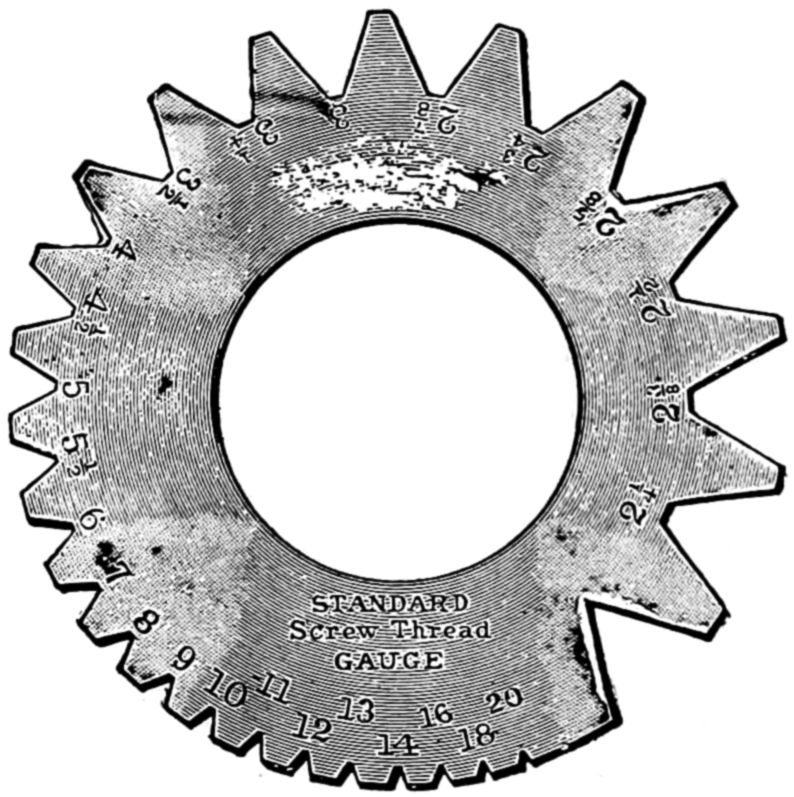
Fig. 316.