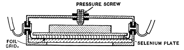
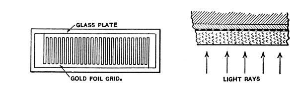
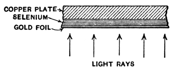
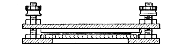
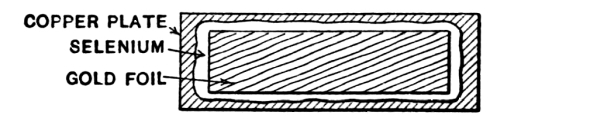
The Fritts Cell, as mentioned by the inventor, when first made
has one of two states or conditions. In one the resistance is very
high, in the other very low, being but a few ohms or a fraction of an
ohm. In the latter state it is insensitive and possesses no definite
characteristic until matured. This maturing will come about gradually
if the cell is used in experimenting but can be greatly hastened by the
proper treatment. By subjecting them to an alternating or pulsating
current the resistance can be increased rapidly.
To facilitate the maturing and enable the resistance of the cell to be
determined at various stages of the treatment the maturing and testing
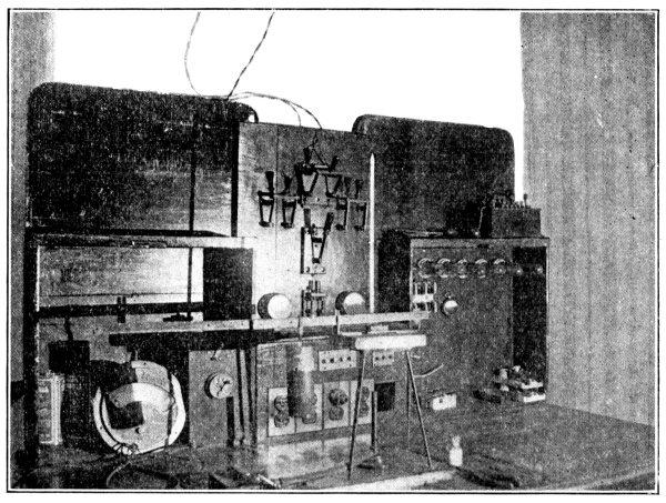
set shown in Fig. 12 can be made use of. The apparatus allows
of the measurement of the cell by the Wheatstone bridge and substitution
methods both with the cell lighted and dark and permits the application
of alternating current as desired. It consists of a base on which
is conveniently mounted a closed lamp box to light the cell when
necessary and the various switches and binding posts arranged for quick
manipulation of the circuit.
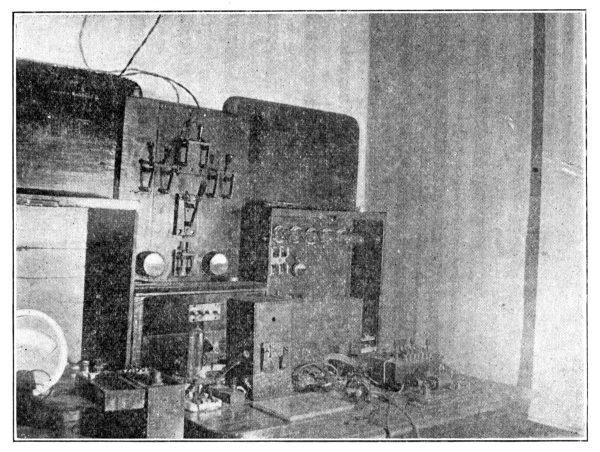
Fig. 12. Testing and Maturing Set
The details of the device are given in Fig. 13. The base
measuring 20 by 12 inches has mounted at the rear center a wooden box containing
a 75 Watt, type C, Mazda lamp. Where lighting current cannot be obtained
a 12 volt automobile headlight bulb may be used to illuminate the cell.
The lamp in either case is connected to the switch mounted just to the
left of the box.
The front of the lamp housing has a hole measuring 1 by ¾ inches cut in
it on a level with the lamp filament. Two clips cut from spring brass
of the shape shown in the detail drawing are mounted on the front of
the box in such a position that when the posts on the back of the cell
are slipped into the holes in the ends of the strips the window of the
cell will be opposite the opening in the lamp housing. Connection is
made to the cell by means of these clips.
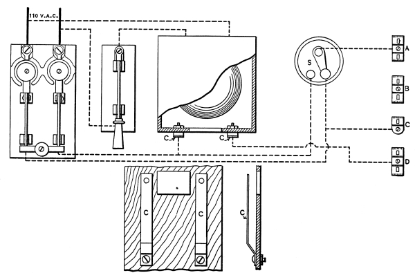
Fig. 13. Layout and Wiring Diagram of Testing
and Maturing Set
At the extreme left of the base a double pole fuse switch is mounted
to control the alternating current to treat the cell. Instead of fuses
two tubular incandescent lamps are screwed into the receptacles on the
switch to limit the A. C. to a value that will not endanger the cell
by overheating it. Should lighting current not be available use can be
made of a buzzer and telephone induction coil connected to a dry cell
as shown in Fig. 14 to furnish current for
treating the cell.
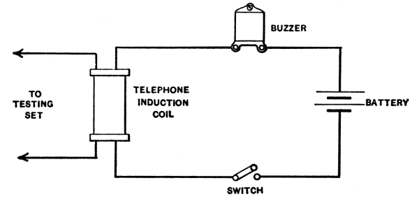
Fig. 14. Connections for Buzzer and Induction Coil
to Produce Alternating Current
A small two point battery switch and four double spring binding posts
are also mounted on the base and wired as shown by the dotted lines. A
fairly sensitive galvonometer is employed to indicate when the bridge
is balance. A telephone receiver might be used for the purpose, opening
and closing the circuit to cause clicking in the receiver, the bridge
being balance when the noise is reduced to a minimum. The small center
zero ammeters with the shunt removed make excellent galvonometers.
Ratio arms and a rheostat box having a maximum resistance of 100,000
ohms complete the apparatus necessary to make the tests on the cells.
A laboratory set with this range is rather expensive and since our
measurements need not be extremely accurate a good resistance box may
be made from resistance units as used for motor starting and signal
work. These units consist of an iron tube covered with asbestos on
which is wrapped the resistance wire, the wire in turn being covered
with a vitreous insulating material baked in place. These units can
be purchased quite reasonable from any large electrical supply house
in any resistance up to 150,000 ohms. For our purpose 15 units will
be required, five, 200 ohm; five, 2000 ohm and five, 20,000 ohm; all
tapped at the center, for the rheostat arm. For the ratio arms a
single 1000 ohm unit tapped at the center is used. The rheostat arm
units should be mounted in a box and heavy leads run to 12 single
pole switches mounted on the top of the box. The method of wiring
the resistances is shown in Fig. 15, the switches being
marked so the resistance in the circuit can be quickly determined. With this
arrangement any resistance from 100 to 111,000 ohms can be obtained in
steps of 100 ohms by opening the proper switches.
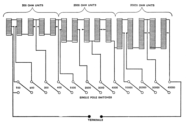
Fig. 15. Connections for
Interior of Rheostat Box
The ratio arms are made by bringing leads from the ends and center
of the 1000 ohm unit. Ratios other than one to one are not advised,
for the cells are so sensitive to external influences that one system
of measurement must be adopted and adhered to if the cells are to be
compared. With the one to one ratio half the current flows thru the
cells when the bridge is balanced.
The current for testing the cells can be obtained from a dozen three
cell flashlight batteries. The battery should be connected to a
multipoint switch so that any number of cells can be switched into the
current as desired.
To prepare the various instruments for testing the cells with the
bridge circuit connect as shown in Fig. 16. The diagrammatic
wiring is shown in the insert in the illustration. The positive or carbon of
the battery is connected to post A. The source of alternating current
whether from the lightning mains or an induction coil is connected to
the double pole switch, current for the lamp in the enclosed box being
supplied to it thru the single pole switch.
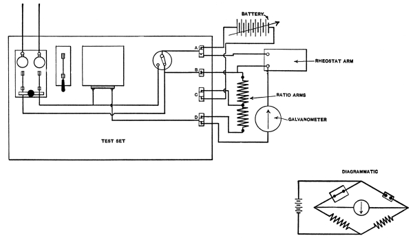
Fig. 16. Circuit for
Wheatstone Bridge Measurement
To test the cell, open both knife switches and place switch S on
the left hand point. Place the cell in the clips with the terminal
connected to the gold leaf in the clip connected to binding post
A. This makes the gold leaf the anode of the cell. Now close the
battery switch applying about 6 volts to the bridge. Balance the
bridge by adding or removing resistance in the rheostat arm until the
galvonometer gives no deflection. The resistance of the cell in the
dark is read direct from the markings on the open switches on the
rheostat box.
Now close the single pole knife switch lighting the cell and again
balance the bridge. The latter reading will be the light resistance of
the cell, gold anode.
For convenience in recording the data a sheet of paper should be ruled
into columns headed, date, voltage applied, resistance dark, resistance
lighted (gold anode), resistance dark, resistance lighted (copper
anode) and remarks. The cells should be numbered and the corresponding
data sheet headed with the same number so that changes in the cell can
readily be detected and improvements noted. A separate sheet should be
provided for each cell.
Now increase the voltage to 9 volts and take another set of readings
with the cell both dark and lighted. The values obtained are recorded
and the voltage increased further. The cell is tested with gradually
increasing voltages till the maximum voltage possible without heating
the cell has been applied. Heating of the cell can usually be noted by
a faint crackling noise being given but it is advisable to feel the
surface of the mica occasionally to detect any heating.
It may be found on examining the data obtained that the resistance of
the cell has varied with different voltages. We can classify the cells
by calling a cell in which the resistance increases with an increasing
voltage the A type, those in which the resistance falls off with an
increase of voltage the B type and those in which changes of voltage
cause little or no change of resistance the C type.
Now reverse the cell in the clips making the copper plate the anode and
repeat the above series of tests and record the values in the proper
columns on the ruled sheet. It will be found in many cases that the
reversal of the current thru the cell has increased the resistance. A
cell showing this characteristic is polarized while one in which the
reversal of the current does not alter the resistance to any great
extent is non-polarized.
The cell is now to be treated with alternating current for a period of
five minutes by opening the battery switch, cutting the galvanometer
out of the circuit and closing the double pole switch. Current will
flow thru the ratio arms and the cell. Care should be taken that the
current is not heavy enough to heat the cell excessively. If this
occurs reduce the current by adding resistance till heating is not
detected.
The cell is again tested according to the directions already given
both for its light and dark resistances with the current flowing in
both directions thru the cell. If the difference between the dark and
light resistance has increased it is safe to say that the cell will be
sensitive to light and the treatment should be continued to develop
this property. The quickest method of doing this is to select from the
various readings the voltage that gives the greatest difference in the
dark and light resistance. Use this voltage to make one test after each
treatment with A. C. till the sensitiveness of the cell to light has
reached a fair value. When the resistance in the dark is ten times as
great as in the light the cell is suitable for experimental working and
treatment can be discontinued.
Should the cell have practically no resistance when first put in the
testing set it is useless to go thru the entire series of tests till
the resistance has been raised. Treat the cell with A. C. repeatedly
till the resistance is brought up to a fair amount, at least 500 ohms,
then make the tests outlined previously.
Sometimes even prolonged treatment will fail to raise the resistance,
in this case test the cell for polarization by reversing in the clips.
If strongly polarized the cell may be a good generator, i.e., will
give a current under the influence of light. To test this, connect the
galvonometer to posts A and D of the set, put battery switch on left
hand point and light the cell by closing the single pole knife switch.
If the galvonometer gives a deflection it indicates that current is
being generated in the cell. This cell should be reserved for use as a
generator, this property being increased by short circuiting the
terminals and exposing the cell to light periodically until it will
generate a fair amount of current. The current generated by these cells
is a true photo-electric current, no chemical action taking place, the
light rays being converted directly into electricity by some unknown
action of the cell. The current flows from the copper plate thru the
external circuit back to the gold foil terminal.
Should the cell after prolonged treatment with A.C., fail to increase
in resistance or having increased in resistance and remain insensitive
to light and not prove to be a current generator the cell must be
classed as useless. It is seldom indeed that this occurs for a cell
that shows even a slight change in resistance when lighted should be
treated with A.C. from time to time and used in experiments and will
eventually increase in sensitiveness sufficiently to be of value. When
a cell proves intractable, the gold foil may be carefully removed by
means of a stiff brush and the cell put back in the hot press to be
reconstructed. Retreating with heat and pressure will often give a very
sensitive cell.
Even when the cells are being used for experimental work the
maturing process will be going on. The point of maturity and maximum
sensitiveness of any cell has been reached when the dark resistance of
the cell remains constant over a period of time. The maturing seems to
affect the cell by increasing the dark resistance, the light resistance
remaining practically the same thruout. From this it will be seen that
a cell with a very low resistance when first made may under proper
treatment become extremely sensitive to light.
As previously mentioned the testing set may be used for measuring the
resistance of the cells by the substitution method. The apparatus is
connected as shown in Fig. 17 when so used, a diagrammatic
circuit being given in the insert. When the battery switch is on the left hand
point the cell is in series with the battery and galvonometer. When
the switch is moved to the right hand point the rheostat is in series
with the battery and galvonometer. The method of measuring is to first
determine the galvonometer deflection with the cell in the circuit and
then by switching the rheostat into the circuit and adjusting it so
the galvonometer gives the same deflection enabling the resistance of
the cell to be read directly. The same series of tests should be gone
through with this method as with the bridge circuit.
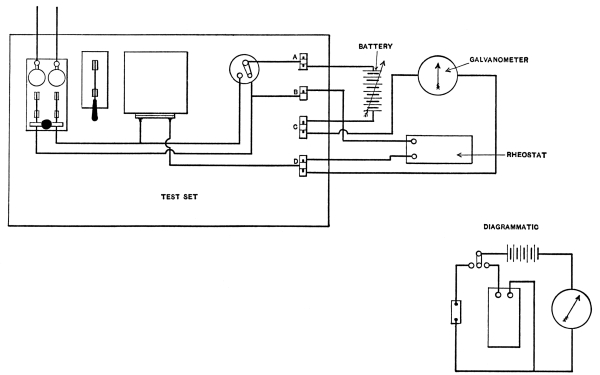
Fig. 17. Circuit for
Substitution Method of Measurement
The substitution method has the advantage of indicating roughly
the sensitiveness of the cell to light. With the cell darkened and
the current flowing thru it the galvonometer will give a certain
deflection, on lighting the cell the deflection will increase
indicating a lowering of the resistance. The determination of cell
sensitiveness is more rapid and this circuit can be employed when the
cell has a low resistance at first and it is necessary to increase it
before tests can be made. With the substitution method of measurement
it is advisable to use a rather insensitive galvonometer or meter since
the current at times may reach a value that would damage a delicate
instrument. A tangent galvonometer with heavy windings will be found
most suitable.
To determine if a cell is sensitive enough to close a relay the
substitution circuit may be used with a relay connected in place of the
galvonometer. If the cell is suitable for the purpose the relay will
close when the cell is lighted.
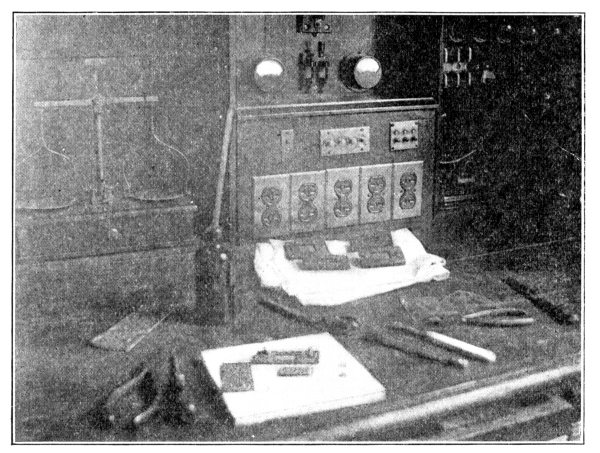
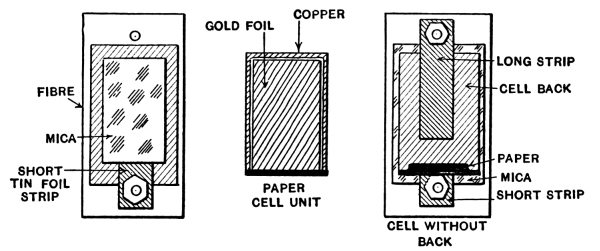
Fig. 18. Showing Cell ready for Assembly with Four
Completed Cells in Background
For practical purposes the sensitiveness of a cell to light and its
current generating properties are the only ones of value but other
properties of these cells will be mentioned later. These may be
developed by proper treatment and the results of experiments along
these lines can hardly be foreseen with any degree of accuracy at the
present stage of the development of the cells.
When satisfied that a cell is properly made and fairly sensitive it can
be permanently sealed by pouring melted sealing wax around the edges
and smoothing with a hot knife. A small sheet of paper should be pasted
on the back of the cell with the more important characteristics marked
thereon as well as the most suitable voltage. The terminal connected to
the gold foil can be indicated by a positive (+) sign for convenience
in properly connecting the cell into the circuit.