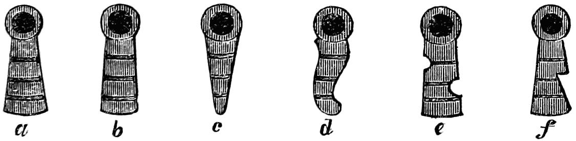
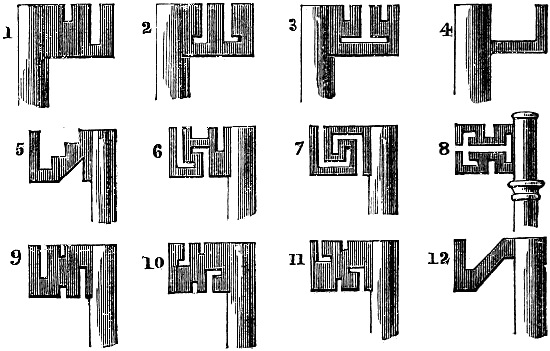
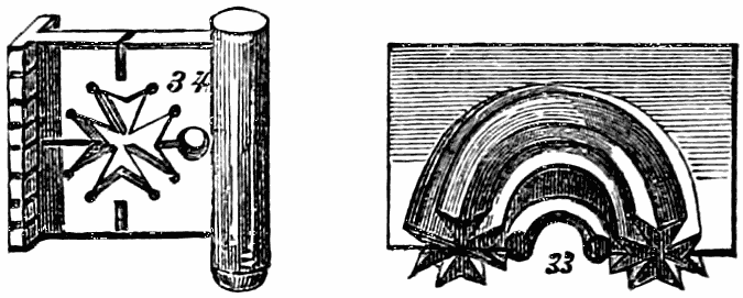
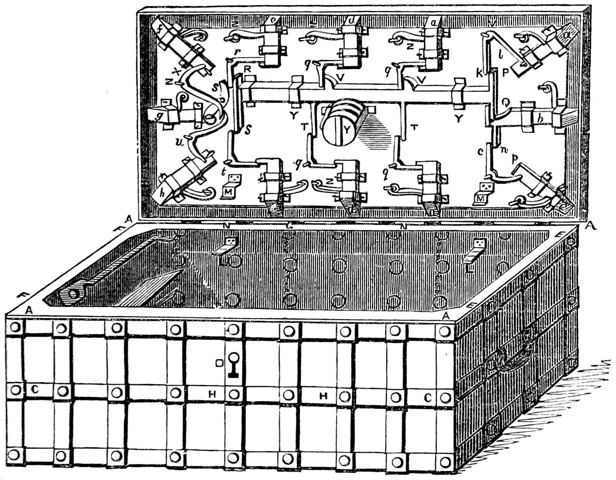
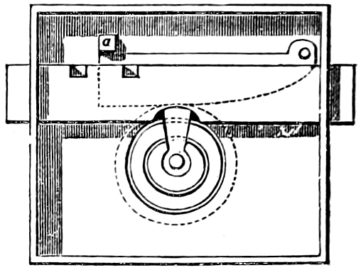
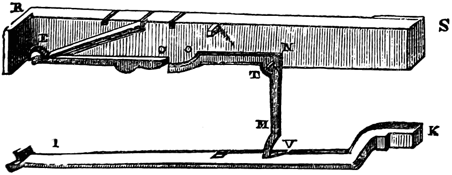
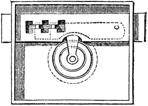
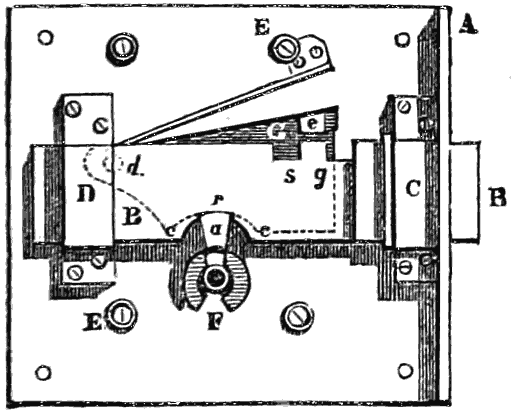
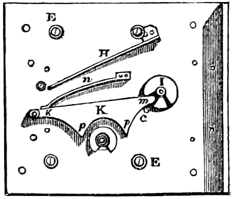
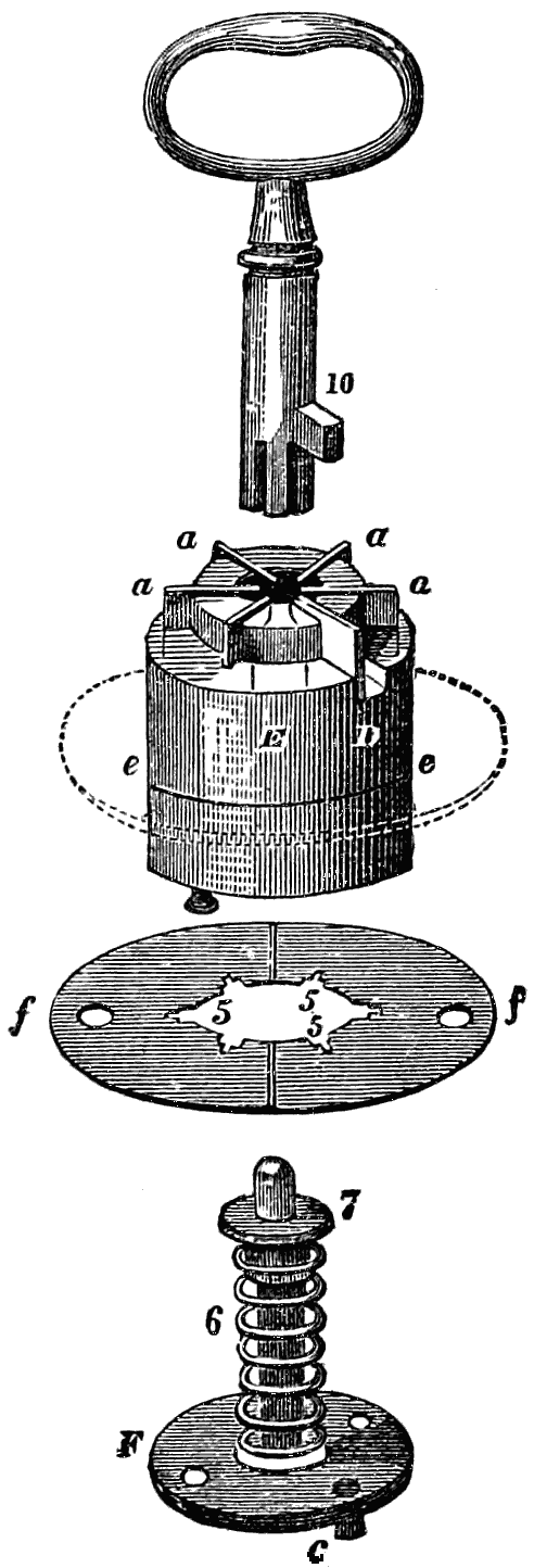
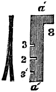
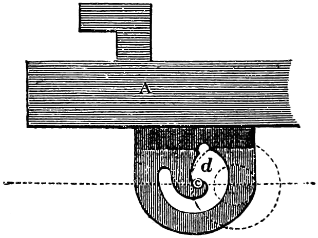
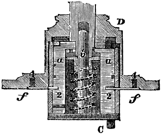
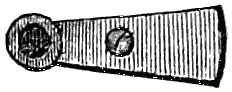
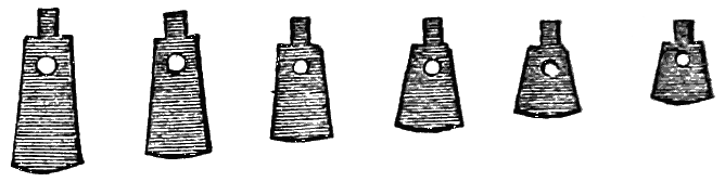
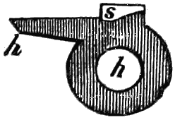
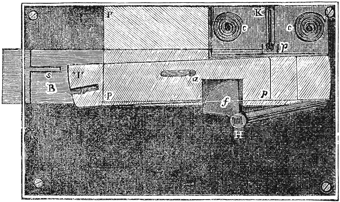
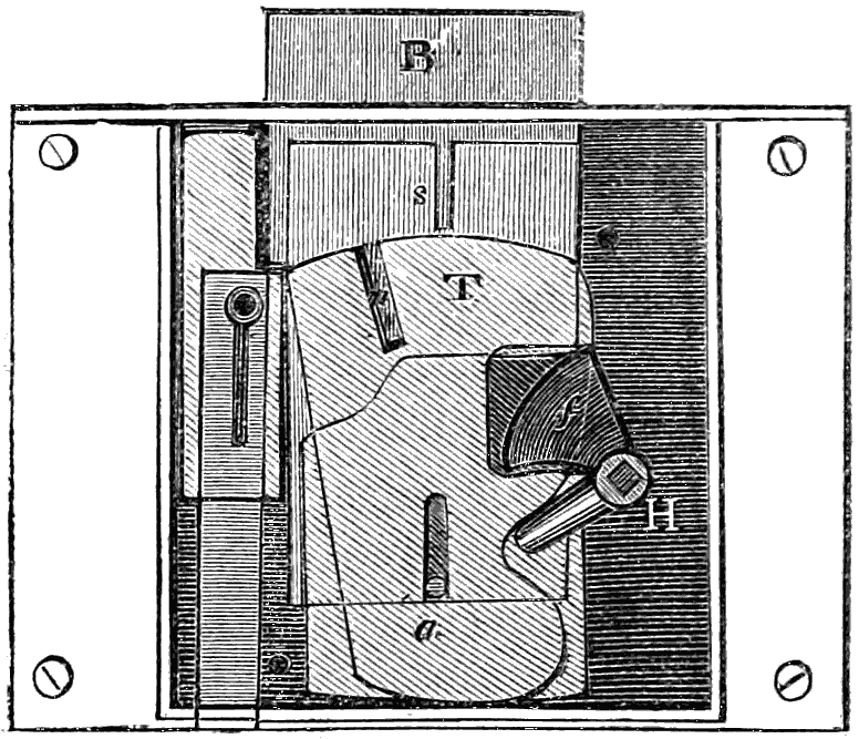
The simple fixed-guard or warded lock is so utterly worthless
for security, no matter what amount of good workmanship be
bestowed upon it, that it demands but short notice. It was
contrived with the intention of making the passage to the
bolt intricate; but it will be seen at once that this intricacy
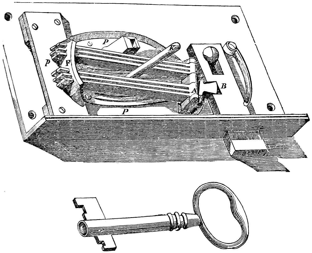
does not really offer any security. The wards of a lock are
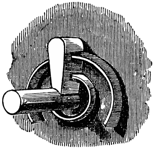
circular arcs of thin metal, so arranged as to require a key of
peculiar pattern to pass amongst them, the shape of the cuts
in the key being a section of the wards. To make a really
complicated box of wards, and to cut keys which shall accurately
fit their sweep, is a matter requiring considerable
manual dexterity; and some warded locks are therefore expensive.
But even with the best of them, all that it is necessary
to do for opening the lock is to take a blank key which
will properly fit the keyhole, coat it with wax, and then inserting
it in the lock, press it round against the wards, which
will cause them to leave an accurate impression of their
section on the key. The parts impressed are then cut out
with small files, drills, and saws, and the occasional use of
fine cross-cut chisels. The key will then pass those wards
which impressed themselves upon it; and if these are the
only wards, it will go completely round and open the lock.
If there are also other wards in addition, not brought up
flush with the first wards, the key is waxed again and pressed
against them, and then further cut out, as before. This
process is evidently one of absolute certainty, and the key so
made is in all respects as capable of mastering the lock as
the original key.
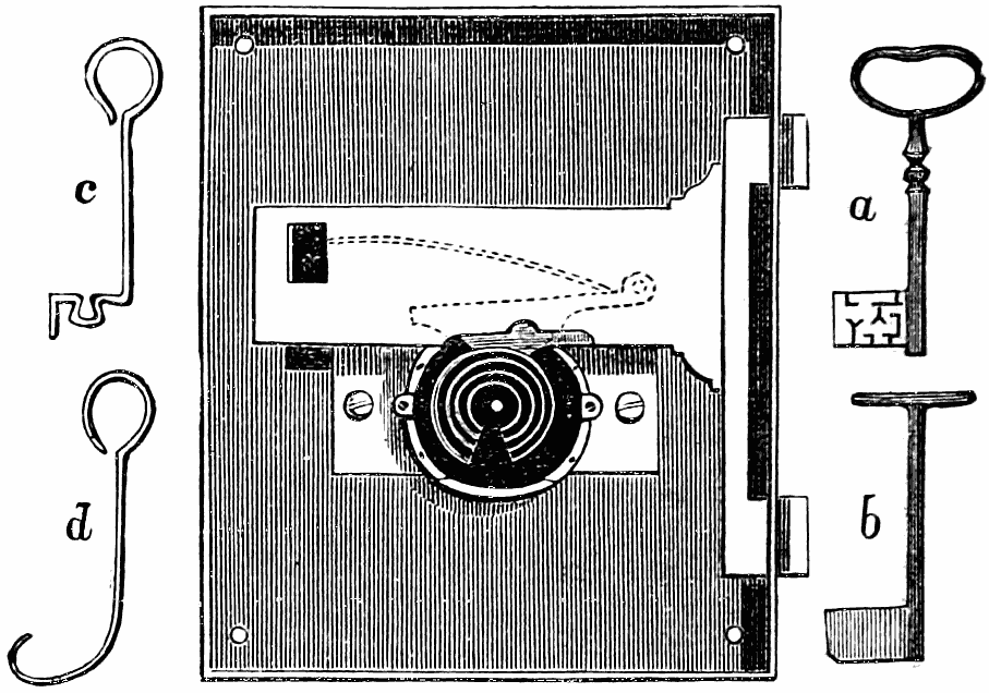
These warded locks are however easily opened with merely
a piece of bent steel wire,—bent into such a sweep as will
reach right round the wards instead of passing amongst
them, thus escaping all chance of being obstructed by them.
Such an instrument is called by burglars a “twirl.”
The fixed-guard or warded lock was the one in general use
in the middle ages.
The next kind of lock is the tumbler lock, in which the
bolt is moved backwards and forwards by the key as usual,
but these movements cannot take place till a small lever with
a stump on one side be lifted. This lever and stump form
the tumbler, which is held down by a spring; and in the
tail of the bolt are two notches, into one of which the stump
fits when the bolt is shot, and into the other when it is withdrawn.
All that is necessary to effect the picking of this
lock is to lift the tumbler high enough for clearing the
stump out of the notch, and then draw back the bolt. The
tumbler may be lifted with one pick, and the bolt drawn
back with another; but generally one pick will suffice for
both purposes.
In the Barron tumbler lock the principle of double-action
was introduced.
The next improvement was the lever lock properly so called,
under which designation the majority of the modern locks
may be classed.
The Bramah lock was an admirable contrivance with remarkably
beautiful mechanism contained in a small compass;
and since its invention there have been several ingenious
modifications of the same principle in different radial locks,
such as the Yale lock, in which the slides move radially
instead of axially. One advantage in these radial locks is
the greater difficulty in copying the keys, in comparison with
the flat keys of ordinary lever locks: this difficulty however
is not an insurmountable one.
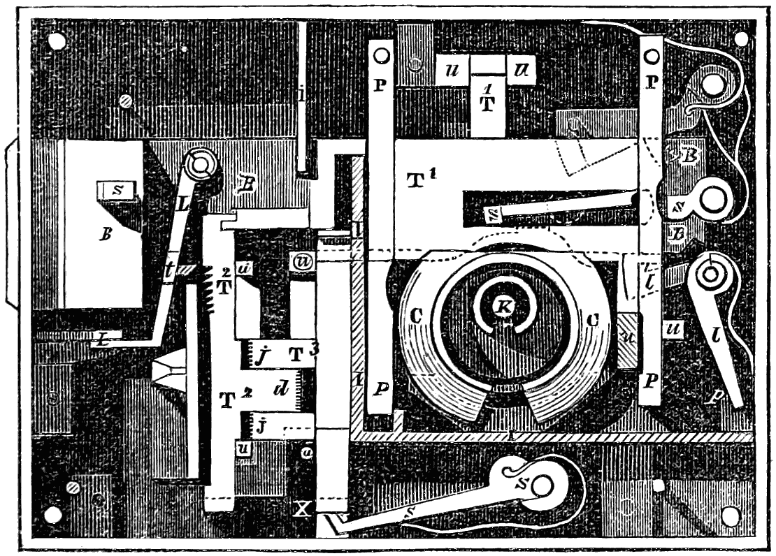
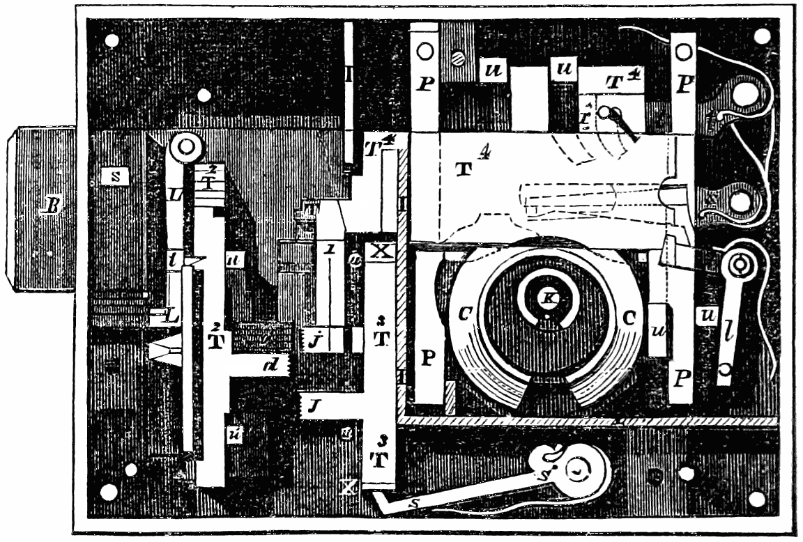
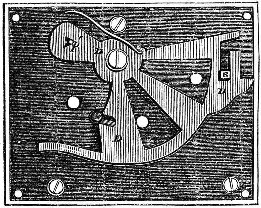
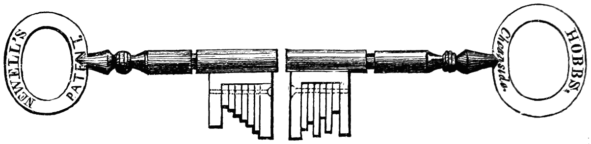
A very ingenious addition was made to the action of the
lever lock in Newell’s American lock, which was shown in
the 1851 Exhibition, and described at page 89 of the present
volume.
Though locks such as those already referred to exhibit
great dissimilarity of construction, yet there is one point in
which they all agree, and that is in the possession of a direct
passage from the outside to the works. Although various
locks have been devised with the object of having no direct
passage to the works from the outside, one consideration
shows the inevitable existence of such a passage; namely,
that without it the key could not possibly at one and the
same time touch the hand of the operator and the works of
the lock. It therefore follows that any instrument which
can pass in the same space as the key may be brought to
bear on the works, whatever may be their construction.
It can now be shown that, if picking instruments are thus
brought to bear on the works through the keyhole, there is a
regular tentative system whereby the picking of any lock
with an open keyhole can sooner or later be effected.
From the foregoing observations it is evident that there
are two important defects in the principle of the previous
lever locks, which being defects in principle are fatal to their
security; namely, the means of access to the works of the
lock through the keyhole, allowing of a series of attempts
being made to open the lock by picking instruments; and
also the facility afforded for repeating the trial of a false key
made from a wax impression of the true key, and thus perfecting
it by successive alterations after trial. In consequence
of the possibility thus allowed of making these successive
attempts either by picking instruments or by a false
key, it has been shown by the cases that have occurred of
locks of the best makes which have been falsely opened, that,
however numerous and complicated may be the secondary
impediments introduced into these locks, there can be no real
security against the ultimate success of sufficiently numerous
and persevering attempts, except by the adoption of some new
principle of construction specially meeting the above two
defects.
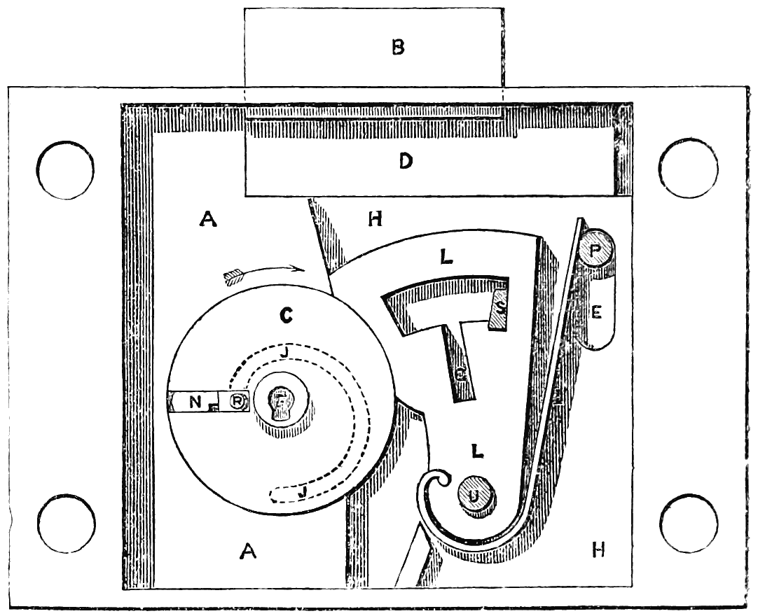
fig. 53.
In the invention of the Improved Lock and Key now to be
described, and which has been termed the adytic
lock,[13] the
writer’s object has been to meet this requirement. In fig. 53
is shown an elevation of this lock, such as is made for an iron
safe; two of the front cover plates being removed to show the
construction.
The head B of the main bolt is of such a thickness as to be
flush with the face of the levers L and guard
A; and the
strap or tail D of the bolt is thin, and passes behind the levers
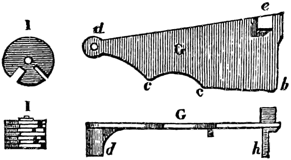
and guard, and also behind the plate H H. The part of the
tail D which would lie under the levers
L and cylinder C is
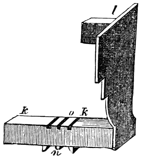
removed, as seen in fig. 54, and replaced by a separate flat
plate or stump-bolt, carrying the stump S. This stump-bolt
has a projection K upon it, let into a recess in the tail D
of the main bolt, but with 1⁄10th inch vertical play in the recess.
A spring in the tail of the main bolt presses the stump-bolt
downwards, keeping the stump S in the notches of the
levers L, as shown in fig. 53. The stump-bolt can thus descend
1⁄10th inch at first without moving the main bolt, and this
amount of vertical movement is sufficient to carry the stump
in and out of the notches in the levers; but the stump-bolt
cannot descend further without taking the main bolt with it.
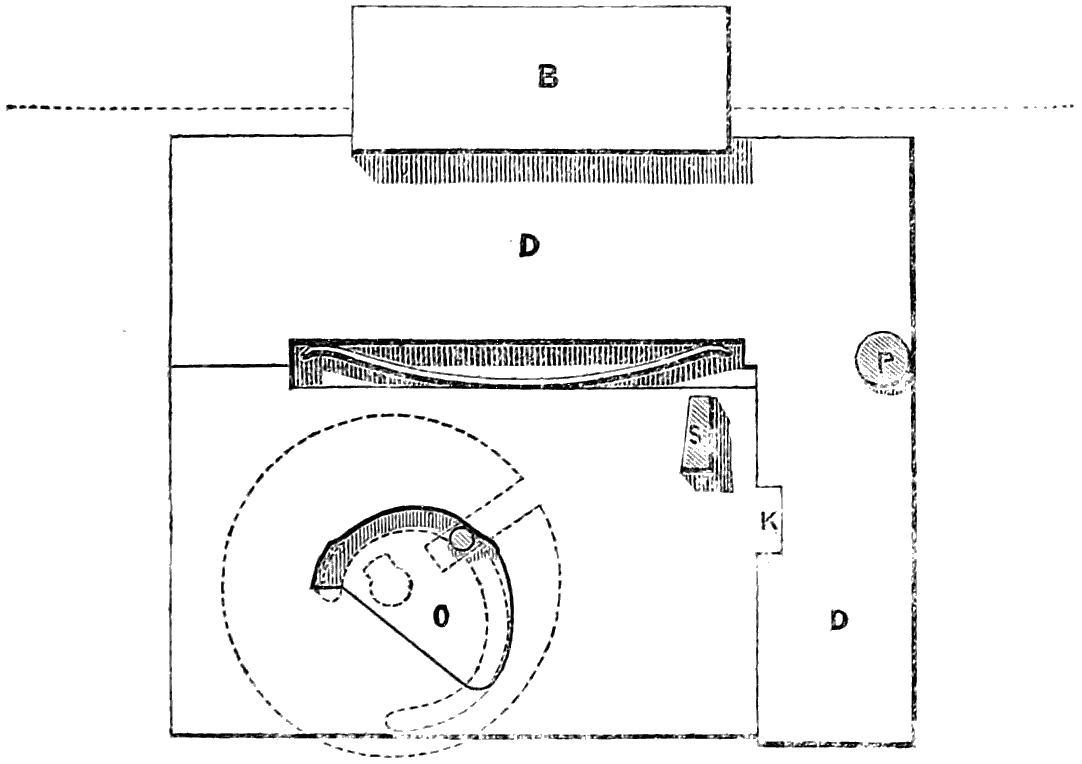
fig. 54.
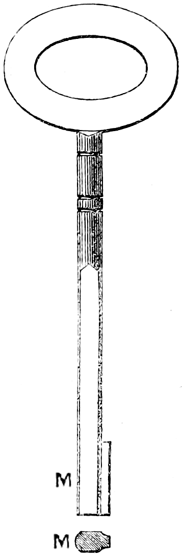
fig. 55.
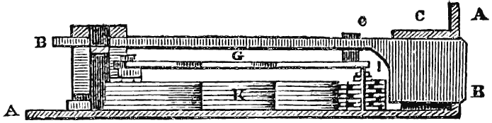
Immediately in front of the bolts comes the fixed plate H H,
in which is cut the cam groove shown by the dotted line J J;
and also the vertical slot E for the pin P to work through,
together with another vertical slot in which the stump S fits
and works. This plate carries the centre pin U on which the
levers L turn. The levers are six in number, though any
other number may be used; and they occupy collectively
3⁄8ths inch thickness. In front of the plate H is fixed the
guard A, which is made of iron or steel,
and has the brass cylinder C ground into it.
The guard is made a shade thicker than
the levers L, in order to prevent the back
plate H and the corresponding front plate
from being so tightened on the levers as
to impede their freedom of movement. The
cylinder C is the same thickness as the
levers, excepting the centre boss F, which
projects from the back of the cylinder and
works in a bearing in the back plate H, and
also projects in front through the thickness
of the two front cover plates. The small
keyhole in the centre of the boss goes only
a short distance into the cylinder C, being
merely for the purpose of enabling the
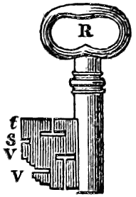
stem of the key M, fig. 55, to turn the
cylinder; the bit of the key is a separate
piece, N, fig. 57, which is inserted through
a separate keyhole into the radial slot of
the revolving cylinder C, as shown at N in
fig. 53.
This radial slot is cut in the side of the cylinder C that is
furthest from the levers when the cylinder is in the position
shown in fig. 53; and in the slot fits the slide block R, which
is a steel block having a pin projecting on each side. The
back pin enters the guide groove J J in the back plate H, as
shown by the dotted line, and the front pin enters the corresponding
guide groove in the front cover plate, which is
shown removed. The back pin of the slide block projects
through the back plate H, as shown in fig. 56, and works in
the cam groove O in the tail of the stump-bolt
S, fig. 54, which
is so shaped that as the slide block travels round the guide
groove J J, shown by the dotted lines, it moves
the stump-bolt
vertically as may be required according to the position of the
bolts and levers.
In the position of the lock shown in fig. 53, the bit N has
been inserted into the vacant space of the radial slot in the
cylinder C, in front of the slide block R. The size of this
vacant space is 3⁄8ths inch long by
1⁄8th inch wide and 3⁄8ths
inch deep; and in the two front cover plates of the lock,
and also in the door to which the lock is attached, a hole
is made of the same shape. In the door there is no bearing
for the centre boss F, but only a small keyhole corresponding
in size with that in the boss F for inserting the stem of
the key.
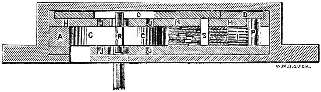
fig. 56.
In the position of the parts shown in fig. 53, it will be seen
that the levers L are held pressing down against the circumference
of the cylinder C by their springs I bearing against the
pin P. In this position also the bolt spring between the main
bolt and the stump-bolt, fig. 54, presses the stump S down into
the notches of the levers, so that the levers are completely
locked by the stump, as seen in fig. 53.
In order to unlock the lock, which in fig. 53 is shown with
the bolt shot, it is necessary that all the gatings G in the
levers should be brought precisely under the stump S.
Through the centre keyhole F there is no communication
possible at any time with the levers L; nor will any instrument,
however slender, if passed into the radial slot through
the aperture at N be able to reach them, whether the cylinder
C be in the position shown in
fig. 53 or turned round into any
other position. For the only difference made by turning the
solid cylinder C is that the radial slot in it is carried away
from the aperture in the external plates, and the solid part of
the cylinder is brought opposite to the aperture, which is
thereby completely closed against the insertion of a picking
instrument. This construction accordingly not only precludes
the possibility of opening this lock with an ordinary key, in
which the part that acts on the levers is attached to the stem
of the key, but it also renders it an absolute impossibility to
introduce a pick of any form, as nothing can reach the levers
L except a detached piece of such a size and shape as to be
capable of travelling round in the vacant space left in front of
the slide block R in the radial slot of the cylinder C.
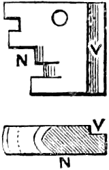
fig. 57.
For the purpose of unlocking the lock the bit N, fig. 57, is
used. This bit is of such a size as to fit into the
vacant space of 3⁄8 × 3⁄8
× 1⁄8 inch in the radial slot of
the cylinder C; and the indent at V is merely for
the purpose of ensuring the insertion of the bit in
the right direction, the external aperture for the
bit being made with a corresponding projection
to fit the indent in the bit. This bit being inserted
through the aperture in the door, is pushed in by means
of the key stem M, which is flattened on two sides for that
purpose, as shown in fig. 55; and the bit is thus pushed
home into its place in the radial slot of the cylinder, as
shown at N, fig. 53.
The key stem M is now inserted into the centre keyhole F,
and the cylinder is turned round by it in the direction shown
by the arrow, carrying round the slide block R and the bit N.
The slide block R, while moving through the concentric portion
at the commencement of the guide grooves J J, does not affect
the bit; but by means of the cam groove O in the tail of the
stump-bolt, fig. 54, it moves that bolt so far as to lift the stump
S completely out of the notches in the levers L, which are
thereby left free to be raised. On continuing to turn the
cylinder C, the eccentric part of the guide grooves
J J causes
the slide block R to move outwards along the radial slot,
pushing the bit N before it; and the bit is thus made to project
beyond the circumference of the cylinder, which it can
then do, being no longer confined by the guard A. The further
projection of the bit as the cylinder revolves causes the steps
in the bit to lift their respective levers; and the steps in the
bit are so arranged that, when the cylinder arrives at the
position shown in fig. 58, all the gatings G are brought simultaneously
opposite the stump S, which is instantly shot down
through the distance of the 1⁄10th inch play by the bolt spring.
The bit N remains in contact with the extreme part T of the
levers while the stump S is entering the gatings, the action of
the bolt spring being so rapid that the bit cannot move
through any appreciable distance during the time.
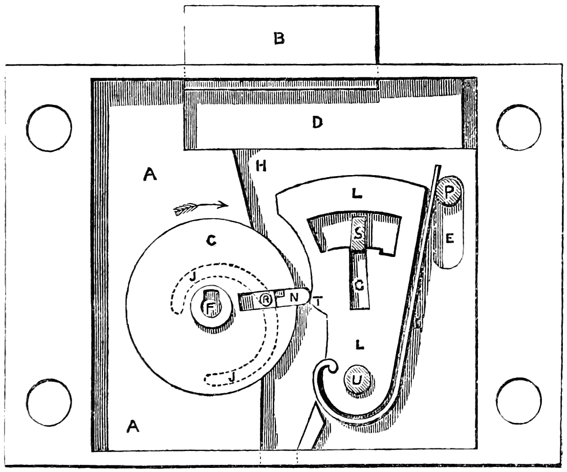
fig. 58.
In other locks a spring action of this kind would greatly
facilitate the picking, inasmuch as it would afford the gentle
uniform pressure desired upon the levers. In other locks,
therefore, the bolt is caused to move, and the stump to
enter the gatings, by the direct contact of the key with
the bolt, instead of by a spring; but as the key, while
moving the stump into the gatings, is also altering its
position under the levers, a slight tremulous motion of the
levers is thereby occasioned, which no care in manufacture
can obviate. This tremulous motion is aggravated by the
circumstance that, as the keyhole is open to inspection, it is
necessary to make all the levers fit flush with one another when
down, in order to avoid affording any clue to the shape of the
key from the positions of the levers; but as the various steps
of the key, being of different lengths, describe different arcs,
the curves of the levers when raised are of necessity in error
to them all. The result of these combined faults is that the
gatings have to be made wider than the stump, to allow a
sufficient amount of play, thus introducing a fatal element of
insecurity in the construction of the lock, since the security
is of course enhanced in proportion as the gatings fit the
stump accurately. In the new lock, on the contrary, the arc
T, fig. 58, in each lever, can be shaped truly to its own proper
radius, independent of all the rest of the levers; and as the
action of the stump is instantaneous in catching the gatings
as soon as they are all brought simultaneously under it, the
stump and gatings can be made to fit one another with the
most perfect accuracy, and without the slightest play.
On turning the cylinder C further round, the bit N passes
from under the levers, which remain held back by the insertion
of the stump in the gatings; and just before reaching
the position shown in fig. 59, the slide block R has pushed
the bit completely out of the radial slot, and the bit falls
down as shown in fig. 59, and drops through a hole into the
inside of the safe that is locked. At this point the back pin
of the slide block comes in contact with the lower side of the
cam groove O in the stump-bolt, fig. 54; and by turning the
cylinder C onwards to the position shown in fig. 60, the withdrawal
of the bolt B is completed, bringing the parts into the
position shown in fig. 60. In these drawings only one lever
L is shown; but there are altogether six levers, as shown in
the sectional plan, fig. 56. The pin P is fixed in the tail D of
the main bolt, so as to travel with the bolt; and by this
means the springs I are released from strain, as shown in
fig. 60, as soon as the bolt is withdrawn.
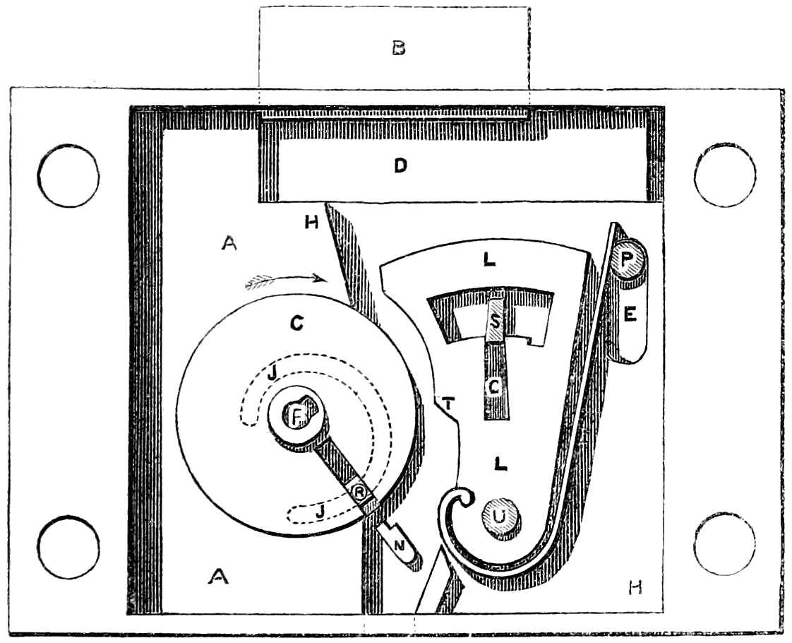
fig. 59.
From the nicety with which the various parts of this lock
are constructed, it is evident that the levers must be very
accurately lifted by the bit of the key in order to withdraw
the bolt; and therefore any error in the bit, such as would
occur with a false bit, will effectually prevent the lock from
being opened. This may be illustrated by supposing the
false bit to be so close an imitation as to have five of its steps
absolutely correct, and the sixth only slightly wrong: though
it is almost impossible that such a near approach to correctness
could be attained in practice. The counterfeit bit being
inserted in the lock, and the cylinder turned round, all will
go on the same as with the true bit, up to the time when the
false bit reaches the point T of the levers, as previously shown
with the true bit in fig. 58. Here a change of action takes
place; but what is the nature of the change the operator has
no means as yet of ascertaining. In the case supposed, where
five of the steps in the bit are right, but the sixth is wrong, the
gating of the sixth lever does not precisely coincide with the
others, nor with the stump S; and the consequence is that, at
the critical moment when the stump ought to spring into the
gatings and hold back the levers from falling forwards, it will
be prevented from entering the gatings, owing to the entrance
being partly blocked up by the one lever, which stands more
or less across it.
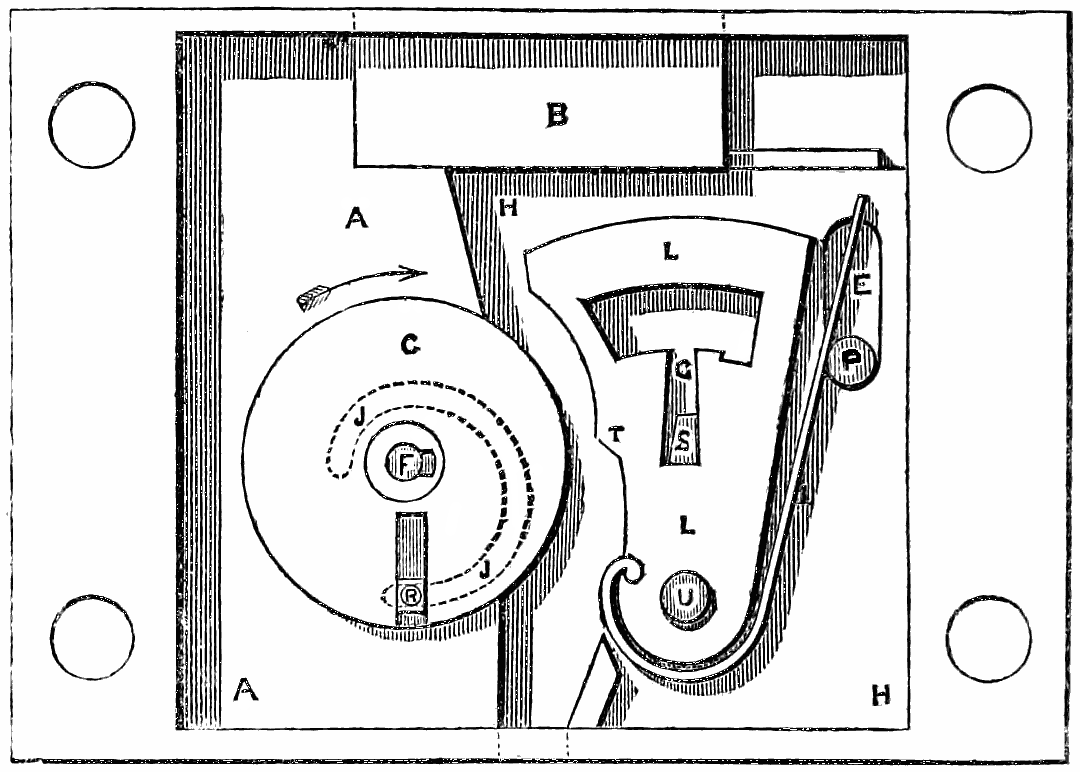
fig. 60.
The fact, however, that the stump cannot enter the gatings,
does not become known to the operator until the cylinder C
has been turned further round, so as to bring the slide-block
pin in contact with the lower side of the cam groove O in the
stump-bolt; and before this point has been reached the false
bit has already passed clear of the levers, which, not being
retained by the stump, are instantly thrown forwards again
by their springs, and locked in their original position by the
stump entering the notches. At the same time the false bit
has dropped into the inside of the safe in the same manner as
the true bit, as shown in fig. 61.
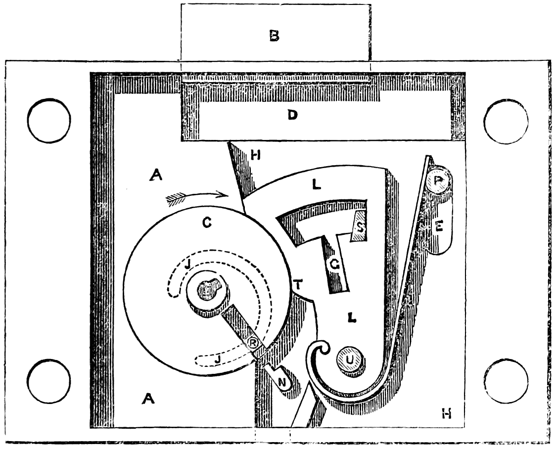
fig. 61.
Hence a person putting a false bit into one of these locks
will not only infallibly lose it at the very first trial, but will
do so without gaining any information as to the nature of its
inaccuracy; for as the gatings of the levers cannot be seen or
felt, all that can be told about the action of a false bit is,
that it has failed to open the lock. In fact, a counterfeit bit
passes under the levers, and through the lock, just like the
true bit; and it is only the stoppage afterwards met with of
the bolt that indicates the failure of the false bit, which is
by that time gone beyond recovery. Whatever amount of
labour, therefore, may have been spent on the fabrication of a
counterfeit bit, this bit can only be tried once, so that no
alteration can afterwards be made in it.
Nothing that can be inserted into the radial slot of the
cylinder C through the aperture in the front plates can do
any injury to the lock; and a charge of gunpowder inserted in
that way would only blow out again at the orifice without
damaging the lock, both the apertures for the key being
merely blind holes with parallel sides.
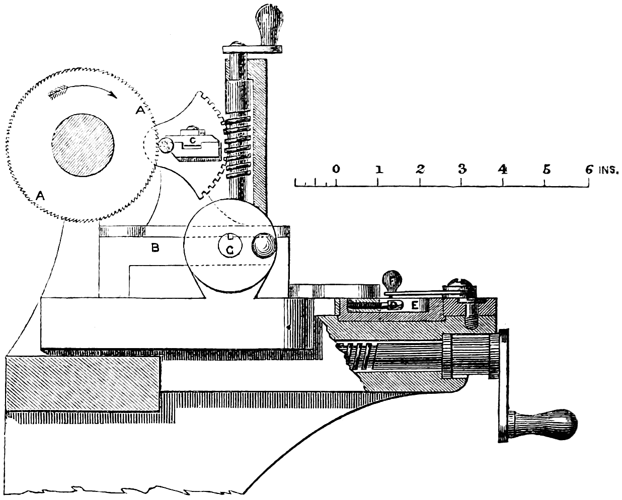
fig. 62.
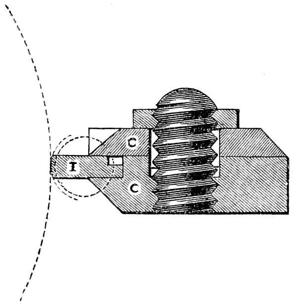
fig. 63.
For the manufacture of the
bits for the keys of this lock
a self-acting machine is employed,
in which the height
and width of the several steps
in the bit are regulated by
adjustments of very great accuracy,
and admitting of an
almost endless variety of figure
for the bits. This key-cutting
machine is shown in
figs. 62 to 64, and consists
of a small circular saw A running vertically, of the same
thickness as each step in the bit I, which is brought up
to the saw by the slide-rest B. The bit I is fixed in the
holder C, which rocks upon a centre, so as to give the required
curvature to the edge of each step in the bit when cut by
the saw, as shown in the full-size section of the bit-holder,
fig. 63. The adjustment of the depth of cut is effected by the
set screw D upon the slide-rest coming up against the eccentric
ring E upon the bed of the slide-rest; this ring is turned
round by hand, and set to sixteen different positions by means
of the catch-pin F and the sixteen holes on the circumference
of the ring, allowing of sixteen different depths of cut. The
lateral adjustment for the pitch between the successive steps
of the bit is effected by the two bed-screws G G acting on the
slide-rest B, having a dividing plate on the head, and such a
pitch of thread that one turn of the screws traverses the slide-rest
through the exact distance of one step in the bit. The
occurrence of any play or backlash is entirely prevented by
having the screws placed one at each end of the slide-rest; so
that by slacking back one screw through one or more turns,
and then advancing the other through the same number of
turns, the slide-rest is always held with perfect steadiness
between them, filling exactly the space between the ends of
the two screws.
The number of changes admissible in this key-cutting
machine, if used for making keys for locks having six levers,
is the number of permutations that sixteen terms are capable
of when taken six together, which is upwards of sixteen
millions. Some of these changes are so slight that too great
accuracy of workmanship would be required to make the
locks accordingly; but of those changes that differ from one
another so far that no lock could be opened by any other than
its own key, more remain than could be used up by all the
locks in the world.
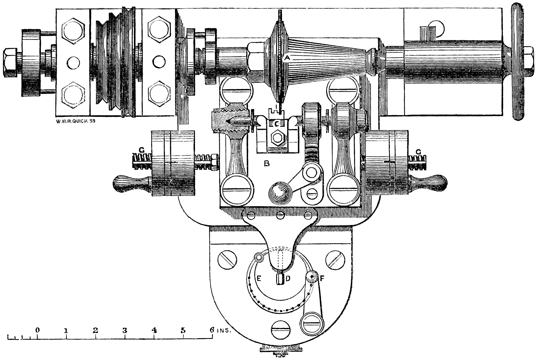
fig. 64.
The writer may observe that it was the study of the circumstances
of the great gold robbery on the 15th of May,
1855, by Agar and his confederates (when two of the best
lever locks were picked, and gold stolen weighing upwards
of 200 lbs., while in transit on the South-Eastern Railway
from London to Paris, packed in three sealed iron-bound
boxes, inclosed in a bullion safe, secured by those locks),
and of the various modes of picking locks, which led him to
turn his attention to the achievement of what had been so
long and perseveringly sought after, namely, an unpickable
lock. The principle of a detached bit has been previously
tried, in so far as that locks have been made in which the bit of
the key was deposited in the lock by unscrewing the key stem,
and then withdrawn by screwing in the stem again. But
inasmuch as the detached bit, even though it failed to open
the lock in the case of a counterfeit key, could always be
brought back again to the keyhole and removed, this admitted
of a repetition of attempts with successive alterations of the
one counterfeit key, without the certainty that any warning
would be given by the lock of such attempts having been
made.
In another still more complicated lock with a detached bit
there were two keyholes, into one of which the bit of the key
was put, and the stem being then unscrewed from the bit,
was put into the second keyhole and turned round so as to close
the first keyhole over the bit; a separate handle was then
turned to work the lock, six separate operations being required
for either opening or closing the lock. Further, a
kind of retainer has been attempted by so arranging the lock
that, if any key was put in but the right one, it was held in
the keyhole in such a manner that it could never be got out.
In this case, however, if the false key would not open the
lock, neither would it let even the right one do so, and it
would be necessary to break open the door secured by the
lock.
In the new lock here described, the special points that have
been aimed at are the following:—
Firstly, in no position of the lock is there any access to the
works from the outside through the keyhole. This access
through the keyhole is more or less a defect in all other principles
of lock, as it admits of feeling and manipulating the
works for the purpose of getting information for picking the
lock in the absence of the right key; whereas in the new
lock there is no opening whatever at any time, except the
two plain parallel recesses into which the key and the bit are
fitted. From the moment the turning of the lock commences
both these recesses are effectually blocked up: the one for the
bit being conveyed bodily away from the keyhole, and its
place taken by the solid metal of the cylinder; while the
other is completely filled by the key, which cannot be withdrawn
except by turning it back to the original position. In
consequence of this construction no injury can be done to the
lock by explosion of gunpowder in the keyhole, the only
openings from the outside being parallel at their sides, and
not communicating with any portion of the interior of the
lock; and the simplicity and solidity of construction are such
that the revolving cylinder is made practically air-tight within
its bearing. This effectually prevents all attempts to open
the lock by picklocks, and leaves no alternative but the
attempt to make a sufficiently accurate copy of the true key.
Secondly, as no clue whatever can be obtained from the
outside of the lock respecting the key required, the attempts
upon the lock are thus limited to the chance of obtaining a
wax impression of the true key. The difficulty of making a
counterfeit key sufficiently correct by this means for opening
one of the best of the previous constructions of lock is very
great; but in the new lock this difficulty is greatly increased
by the fact of the levers remaining absolutely stationary while
the stump enters the gatings, in consequence of which the
gatings are made so close a fit to the stump that an exceedingly
minute error in the lifting of any of the levers is sufficient
to prevent the lock being opened. This extreme
delicacy of construction can be carried out practically without
objection in the new lock, because there is no possibility of
putting a strain from the key upon the stump, so as to cause
injury by forcing it at the moment of entering the gatings;
for the only force acting upon the stump at that time is
the uniform pressure of its own spring. In addition to this
source of increased safety, there is the still more important
circumstance that only a single trial can be made of each
counterfeit bit; because, if carried forwards far enough to
try its effect in opening the lock by passing the levers, the
bit is inevitably lost by falling through the lock and inside
the door. Thus not only is all chance prevented of a second
trial with the same key, but the bit retained inside the door
gives warning of the attempt having been made, and shows
how near the counterfeit key has approached to the original.
The numerous cases that have occurred of attempts to open
locks by counterfeit keys, such as the remarkable instance
previously referred to, show that even with the most practised
hands it is next to impossible to make from a wax impression
a key that will serve for opening a good lock the very first
time it is tried; and the striking importance is therefore seen
of this arrangement in the new lock, which prevents more
than a single attempt being made with a counterfeit.
Thirdly, another advantage to be named in this lock is that
the stem alone of the key is required to lock it, but it can
only be unlocked by the complete key. The stem, therefore,
can be left by the principal of an establishment for locking up
by a subordinate; but the bit, which is the essential part of the
key required for opening the lock, need never be used or seen
by any one but the principal himself. As the hole in the
external door-plate for the stem of the key has a notch on
one side only to admit the key stem, and the cylinder is prevented
from making a complete revolution, the stem of the
key cannot be withdrawn from the lock except when the bolt
is shot; so that its absence from the keyhole serves as a proof
that the bolt is shot.
Fourthly, one other advantage in this lock is its simplicity
and solidity of construction. It contains no more parts than
the simpler forms of lever lock having the same number of
levers, and the total number of separate pieces in the complete
lock is only sixteen. The principle of security, therefore,
upon which the new lock is constructed, avoids entirely the
complications and the delicate and minute class of work rendered
necessary in other locks by the use of detectors and the
other auxiliary contrivances employed for increasing the difficulty
of picking.
Mr. Fenby exhibited, at a conversazione of the Institute of
Civil Engineers, and at the meeting of Mechanical Engineers,
specimens of his adytic lock, and showed its action both with
the true key and with counterfeit keys; and he showed by
trial that the counterfeit failed to open the lock, notwithstanding
that by means of the permutating cutting machine
it had been made a much nearer approach to a perfect copy
than was practicable in the best handwork from a wax impression.
He also exhibited the key-cutting machine employed for
cutting the bits; and also a set of burglar’s tools employed
for drilling into the door of an iron safe sufficiently for
breaking open or removing the lock, showing that the hold
required for giving the cutting pressure upon the powerful
drill employed for the purpose was obtained by a steel cross
piece inserted into the keyhole and turned at right angles, so
as to hold across inside the lock; but in the new lock, as the
keyhole had no opening into the lock, and only a slight
shoulder on one side, no means were afforded for obtaining
the required hold for the drill.
The following are the salient points of the discussion that
followed the reading of his paper:—
The Chairman remarked that the paper just read gave a
very excellent and clear description of the detailed working
of the new lock, and he thought this construction of lock was
a most valuable one, as affording real security against all
fraudulent attempts. He inquired whether there would be
any possibility of tampering with the lock by examining it
upon the inside of a safe door, whenever the door might
happen to be left unlocked.
Mr. Fenby replied that there was no means of tampering
with the lock from the inside of the door, as the two keyholes
for working the lock were only in the front face of the door,
and the lock was all closed up on the inside of the door,
excepting the hole through which the bit was allowed to drop
out; but this would be useless for the purpose of tampering
with the lock, as the bit dropped down a tube leading to the
bottom of the door, through which no examination of the lock
could be successfully made.
The Chairman inquired whether there was any provision
against the bit being accidentally locked up inside the safe,
in which case it appeared the lock could not be opened again.
Mr. Fenby replied that the owner of the safe must of course
be careful after unlocking the safe to take the bit out before
locking it again, otherwise there would be no means of opening
the lock afterwards with that key. As a precaution,
however, against any such accident, each lock was provided
with three bits, all duplicates, one of which would be kept
in the pocket for use, while the two others would be preserved
in a place of safety for the chance of any such contingency.
Moreover, in most of the safes fitted with these
locks, the tube through which the bit dropped had been made
of such a length as to carry out the bit on opening the door,
dropping it into a small tin tray outside the safe; and by this
means the accidental locking in of the right bit was rendered
impossible. One of the advantages of the new lock was that
the stem of the key was not required to be kept constantly in
the possession of the owner, but it might be left in the
lock, as the bit alone was the valuable part of the key; and
as the bits were of such small size and convenient shape, a
number of them might readily be kept in the pocket by a person
having charge of a number of safes, without the inconvenience
attending a large bunch of ordinary keys. In the
case of an attempt being made to open the lock with a counterfeit
bit, the advantages of retaining the counterfeit inside the
safe were not merely that the person attempting the lock was
deprived of his instrument, while the proprietor immediately
discovered the attempt upon the next occasion of
opening the safe; but the retention of the counterfeit itself
afforded the means of judging, by a comparison with the true
bit, whether the attempt had been made altogether in the
dark as to the actual construction of the lock, or whether it
was likely that some clue regarding the true bit had been
obtained by means of a wax impression or otherwise. In the
latter case the owner of the safe might think it desirable to
have the lock taken off, and the arrangement of the levers altered,
and a new bit made so as to baffle any further attempts.
Mr. W. S. Longridge observed that the inconvenience that
had been alluded to with the new lock, of accidentally locking
up the bit inside the safe, was no greater than occurred with
an ordinary safe lock if ever the key was accidentally lost;
in either case, unless the precaution was taken of keeping a
duplicate in reserve, it would of course be necessary to have
the safe broken open.
The Chairman inquired how the ideas had been arrived at
of separating the bit from the key, and of preventing all access
to the works through the keyhole, and also of retaining the
bit inside the door after any attempt at unlocking.
Mr. Fenby replied that his attention had in the first
instance been attracted to the subject of the picking of locks as
a mechanical problem, and he had found that there had hitherto
been no principle in lockmaking which could effectually
baffle persevering attempts at picking. For although there
were certain complicated constructions of locks, having many
points of excellence, they had all yielded in time to the picking
instrument in clever hands; and it must be remembered
that any individual lock when once constructed remained
stationary as regarded subsequent improvement, whereas the
art of picking that lock was continually progressing towards
success, with all previous constructions of locks, and it was
clear therefore that the lock must ultimately be defeated.
He had been further stimulated in the investigation of this
subject by the occurrence of the great gold robbery referred
to at page 188; and the circumstance which had struck him
most forcibly in connection with that robbery had been that
locks of the best make hitherto known had admitted of seven
successive trials being made upon them without detection,
each trial furnishing the information for further perfecting
the counterfeit key, until the locks were at length opened.
These considerations had led him to the conclusion that two
points were established and were required to be kept in view
for the construction of any lock that should be really secure
against fraudulent attempts. The first point was that wherever
a man could get instruments into the lock he could ultimately
solve any problem laid before him by the maker of the lock, as
the lock when once made could be tried any number of times
if an instrument could be got into it at all. Hence he had
concluded that it was requisite for all access to the interior to
be cut off, so as to preclude all possibility of getting a pick-lock
in; and this was accordingly accomplished by adopting
the plan of separating the bit from the stem of the key. The
second point established was that it was necessary to prevent
the possibility of making a succession of trials with the same
counterfeit key; and it had then struck him that, if the bit of
the key were arranged to drop inside the safe in unlocking,
there would be no means of going on gradually improving
and touching up the counterfeit from the results of previous
trials, as the false bit would be irrecoverably lost in the very
first attempt, without furnishing any clue whatever as a guide
for alteration in a subsequent trial. The first lock that he
had invented for meeting the requirements thus pointed out
had been made with a solid block having a tunnel through it,
but involving the same principle of retaining the bit of the
key and keeping the levers inaccessible from the outside.
Subsequently, however, he had abandoned that construction
and produced the new lock shown in the drawings, having
the revolving barrel with radial slot.
The Chairman proposed a vote of thanks to Mr. Fenby for
his paper, which was passed.
This lock has been designed with a view to doing away
with several weak points in the construction of lever locks.
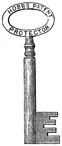
The introduction of the movable stump by Mr. Hobbs, in
order to defeat picking by the tentative method of applying
pressure to the bolt, so as to cause binding between the stump
and the levers, was a great advance in the art of lock-making.
The movable stump, as so constructed, was, however, open
to this objection, that while sufficiently delicate and certain
in its action to render picking very difficult, it was at the
same time, through the smallness of its parts—resulting from
the confined space available for its action—unsuited to withstand
any amount of force applied to push back the bolt.
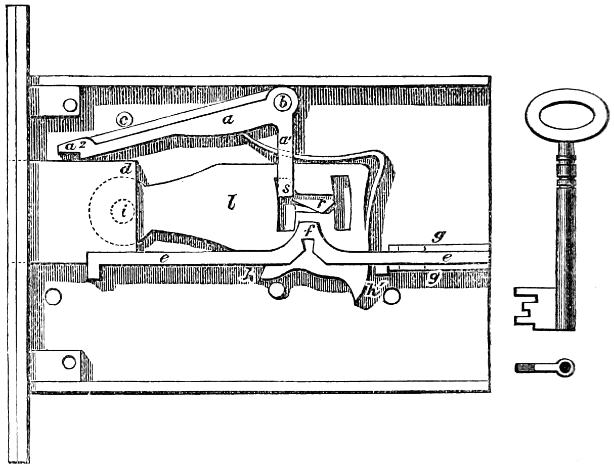
fig. 65.
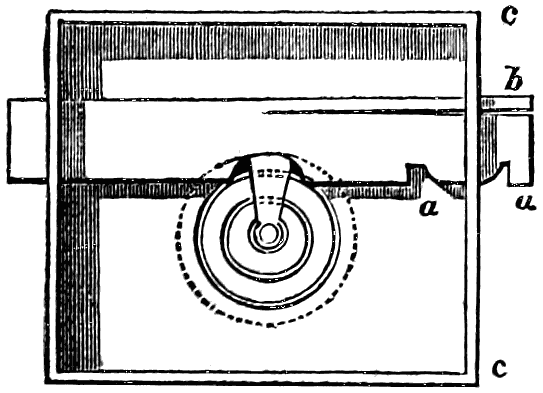
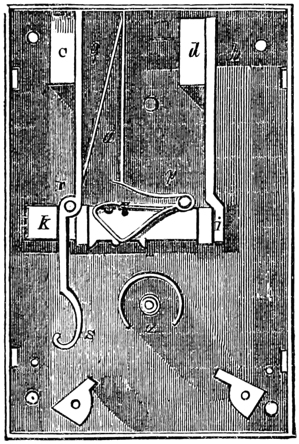
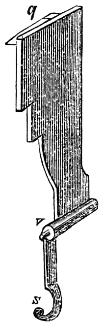
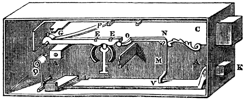
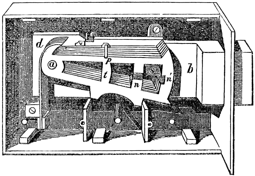
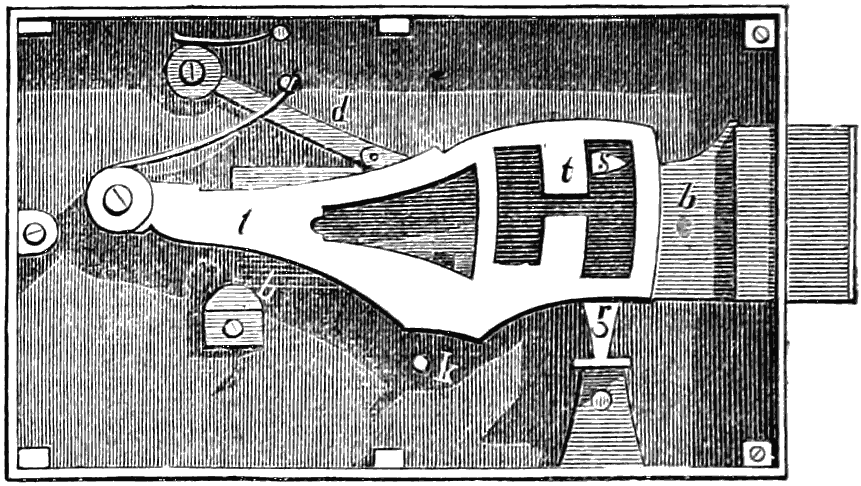
In the lock under notice the stump s is formed in the solid
on the shorter arm a1 of a cranked lever or oscillating stop
a. This stop a works on the steel pin or centre b, which
latter has a bearing in both plates of the lock. At the end a
of the stop a is a recess formed to fit the corner d of the bolt-head.
c is a stud limiting the range of a in an upward
direction, so that when in its normal position the stop a may
just clear the bolt-head, as shown in figs. 65, 66, and 67. The
tail of the bolt, instead of being in the form usually adopted,
is formed of the bar e set on edge so as to reach from the back
to the front plate of the lock, completely dividing the lower
part, in which the keyhole lies, from the upper, in which the
main parts of the works are placed.
This bar e works between the guide pieces g g, so that in
whatever position the bolt may be, the division of the lock
into two chambers is complete. At f is the recess in which
the key acts to move the bolt. The levers l turn upon the
pin i formed in the solid of the bolt-head. The part of each
lever on which the key is to act passes through a slot or
recess in e, the parts h and h1 of the levers being struck to
the arcs of circles, having their centres coincident with that
upon which the levers turn at i.
As it is not possible to lift the levers out of this slot in the
bar e, and further, as the levers and bolt move together in a
longitudinal direction, the movements necessary to locking
and unlocking open no communication between the upper and
lower chambers of the lock.
The springs of the levers are formed out of the solid metal
of the levers themselves, and are thus not liable to that displacement
which so often occurs with separate springs, nor
to the corrosion by oxidation incidental to steel springs.
They are cut round the corner, and down the front of the
lever, to gain greater elasticity.
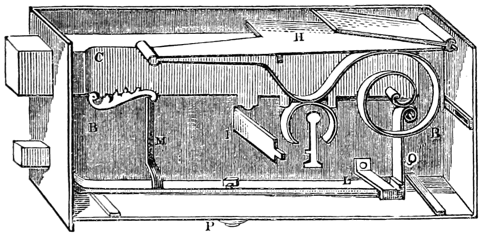
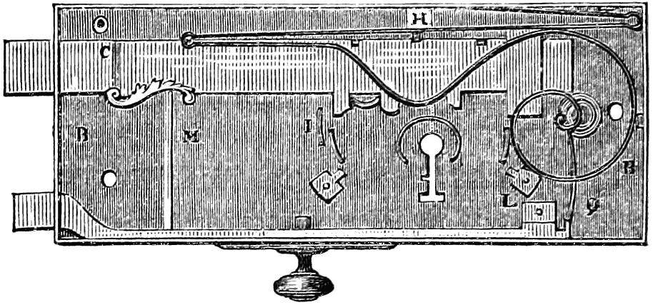
In fig. 65 the lock is shown with the front plate removed,
and the works as they stand when unlocked. Fig. 66 is the
same, except that the works are shown locked, and the back
plate removed instead of the front. Fig. 67 shows the front
view of fig. 66. Fig. 68 shows the result of any attempt to
pick the lock by pressure.
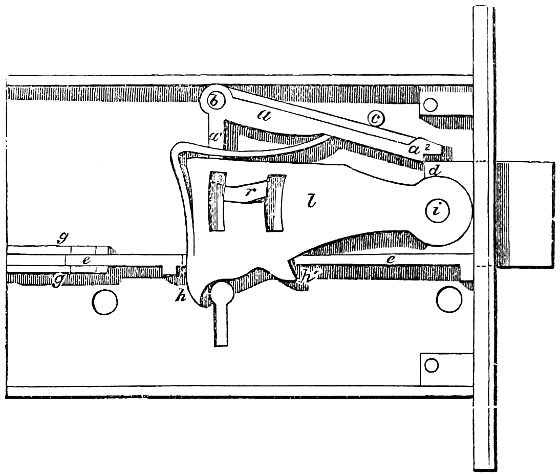
fig. 66.
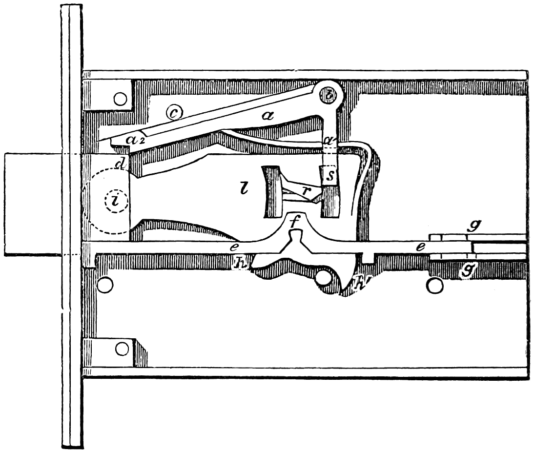
fig. 67.
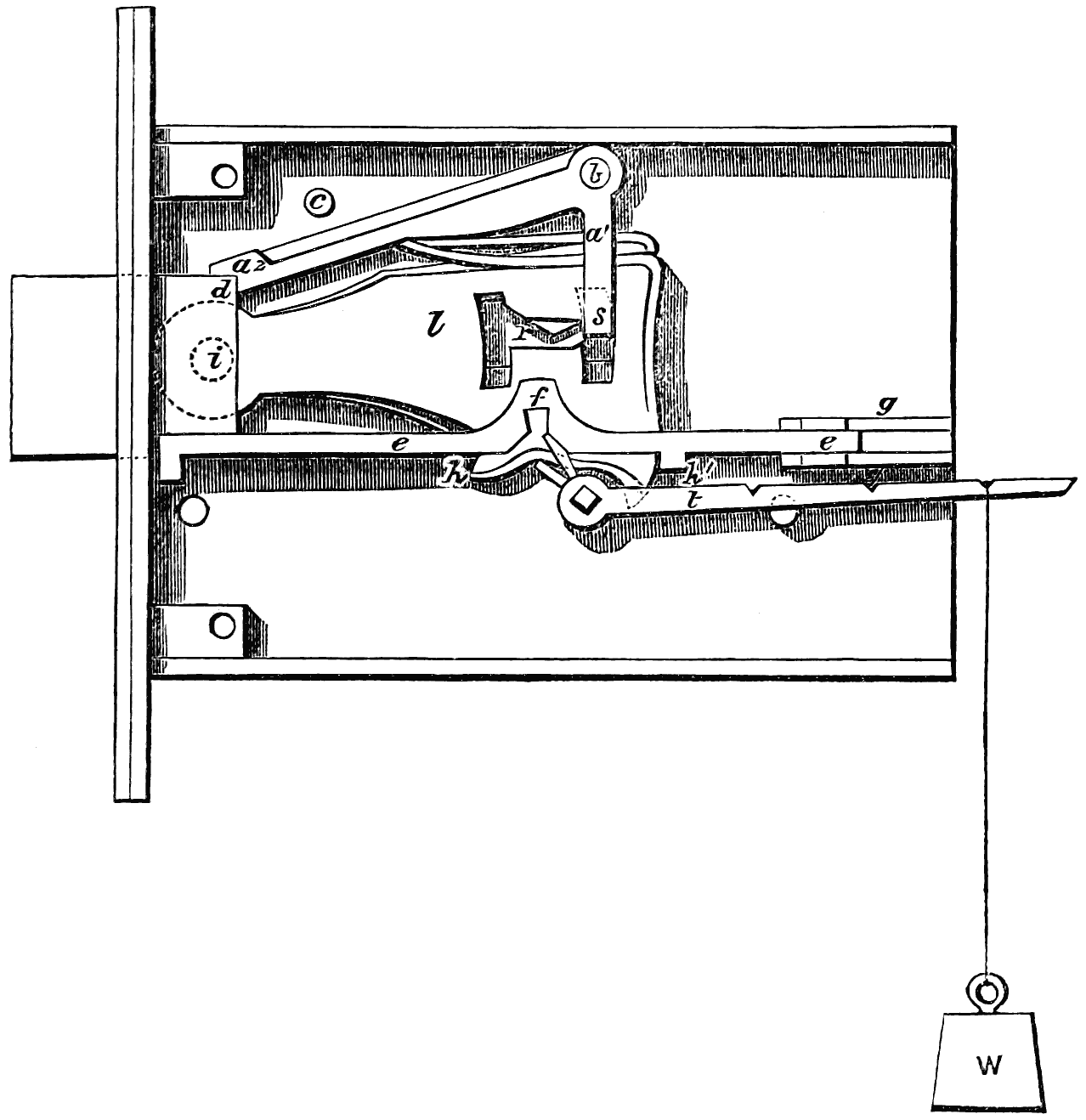
fig. 68.
The lock being locked, as shown in figs. 66 and 67, it will
be seen that the stop a just clears the angle d of the bolt-head.
Further, that the gatings r of the levers l cannot pass the
stump s, unless the levers be so lifted as to coincide with each
other and the stump. The stop a being held up by a very
light pressure from the lever springs, a small force applied to
the stump s is sufficient to upset its equilibrium, and bring
down its end a2 upon the bolt-head at d, as shown in fig. 68.
This occurs whenever an attempt is made to “feel” the stump
with the levers; and not only does the stop a free the levers
from all pressure, and so preserve them and the stump from
injury, and the lock from being picked, but it also forms a
strut for securing the bolt: in fact, no violence short of that
necessary to shear the pin b can make the bolt yield.
The drawings show a mortise lock, but the improvements
shown are universally applicable in the construction of locks
of all kinds.
For the manufacture of these and other locks, and kindred
articles, Messrs. J. B. Fenby and Co., engineers of the Liverpool
Works, Birmingham, have put up, from the designs of
their managing partner, Mr. J. Beverley Fenby, an experimental
set of machinery, almost entirely self-acting, and
calculated to turn out large quantities of the component parts
of locks and other articles with extreme accuracy and
rapidity.
The whole set works on the interchangeable system—as
already in use for military small arms. It is not,
however, to be supposed that, because the parts of the
locks are interchangeable, one key will open several locks—such
a source of insecurity being guarded against by the
permutating key-cutting machines invented by Mr. Fenby.
These machines give complete command over the making
of keys, whether it be required to make a comparatively
unlimited number, all differing from each other, to make
a number alike, or to make sets with master keys.
Atmospheric and hydraulic pressure also plays an important
part in shaping many of the parts of the locks.
At the conclusion of this work upon locks it will not be out
of place to make a few remarks upon the degree of real safety
that attaches to what are commonly called “safes,” and to
point out in a common-sense way what are the chief dangers
that these may incur from depredators (whether burglars or
in times of public anarchy and violence), and what are the
main conditions to be relied upon for safety—assuming that, by
one or other of the constructions pointed out in the preceding
pages, the lock of the safe be such as to be practically unpickable,
and that carelessness shall not have placed the true key
in the possession of the thief.
There can be no doubt upon the mind of any mechanic or
engineer, thoroughly acquainted with practical working in
metals, that a good deal of what has been brought forward
and affirmed, both by safe-makers and by burglars themselves
(turned approvers), as to the wonderfully-ingenious devices
resorted to by the latter, by which, if we were to believe
it all, nothing in the shape of steel or iron can possibly withstand
ultimately the redoubtable powers of these people, is
simply fiction—imaginary ingenuity utterly impracticable if
tried. Such, for example, is the notion of its being possible,
by an ounce or two of gunpowder exploded in the interior, to
so blow asunder and dislocate the parts of a well-made safe-lock
that the bolts shall then be easily got loose, or that a
steel-plated safe which resists the drill can be softened “by
the blowpipe.” And just as absurd are some of the wonderful
pieces of ingenuity by which some of the burglars’ actual
devices are supposed to be met and frustrated; as, for example,
one for which we believe a patent has been obtained, consisting
in filling-in the hollow space between the inside and outside
plates of the safe with cast-iron bullets left loose. These
might, no doubt, break a flat-stemmed drill, after that had
pierced the outer plate, but could have no effect whatever
upon a round-shanked drill, such as one of the ordinary American
spiral, or teredo-pointed drills.
That there are some methods of violence still untried, and
yet at the command of the burglar who dares to risk a tolerably
loud noise of explosive agents, is well known to skilful
mechanical engineers, and for obvious reasons it would be
unwise that we should give any information as to such; but the
real practical and too-often effectual methods of the burglar
limit themselves almost entirely to the use of the succession
of steel wedges, followed by the powerful steel-pointed pinching
bar, or bars, to the forcing or prizing-screw, and to making
more or less way for this by cutting out beforehand by the
pin-drill.
A safe, to be safe, must be so circumstanced or so constructed,
or both, that it should be able to resist the best efforts
that can be made by these methods for several hours; perhaps
we might say as much as thirty to thirty-six hours—viz.,
from Saturday night to Monday morning.
Now we hesitate not to say that the unsafeness of “safes”
arises not from any structural difficulty whatever, but almost
always from the parsimony and ignorance of those who purchase
and employ them. Safes, like razors, are made to sell,
and if the public demand is for cheap safes, such as we see
every day advertised in the newspapers, it was sure to have
been, and is, met by a supply of things called safes which are
utterly unsafe. The great mass of the showy green and gold
gewgaws that one sees in the safe-shop windows, with flaming
testimonials as to their fire and burglar-proof powers, are
simple shams: a genuine safe could not be made at their
prices.
The very first condition to constitute a genuine safe is that
it shall have an ample mass of metal—i.e., not of cast-iron,
but of wrought-iron, or best of steel, all round it; and especially
that the margins of metal all round the door shall be
of such huge and surplus scantling that no amount of wedging,
by construction possible, should be able to bend any one
side sensibly. The next is that the workmanship of every part
of the safe be first-class: not that there be merely a moulded
door with a showy lock and a trumpery brass-plate upon it,
but that every corner and joint of plate with plate in sides
and back be effectually united and jointed in the best manner,
and that the fitting of the hardened edges of the door shall be
like those of a valve, and not even let a watch-spring be got
in between. If these obvious conditions be observed, and that
the safe itself be properly posited in the premises, it will be
found, even with ordinary forms of construction as to doors
and bolts, but with a really unpickable lock, a very hard nut
for the best burglar to crack.
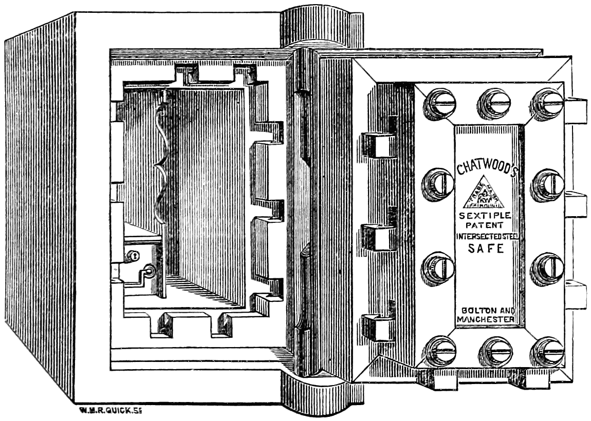
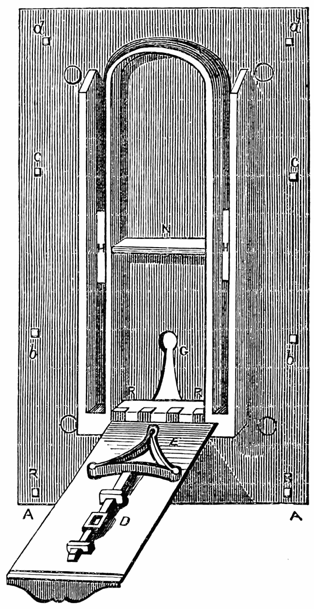
Chatwood’s Safes.
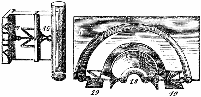
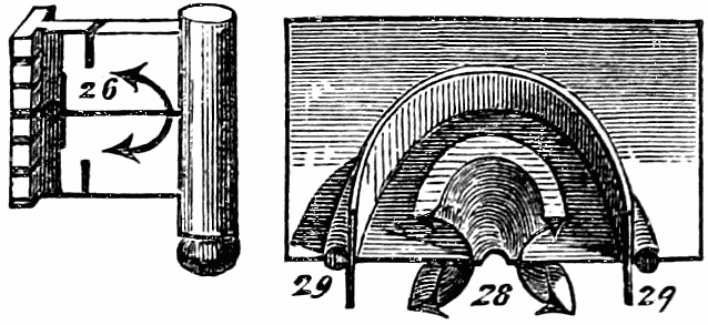
But much more may be effected without any serious increase
of cost. Several forms of safes are now made, the
rabbets of the doors of which are so formed that it is almost
a physical impossibility to get any wedge, however thin, to
drive in between the door and the frame. This is effected in
Chatwood’s patent safes (of Bolton and Manchester), as figured
above, by making the door rabbets in cross section curvilinear,
so that even if the fit be not so perfect but that the edges of
a very thin wedge can still be inserted, it yet cannot be
driven—for, as it goes forward, it must become curved, and
if soft, so as thus to bend, the thin steel will not bear the
severe strain of driving, but if hard, it breaks off into short
bits close to the entrance. In addition to this Chatwood’s
(and we believe other makers’) safes have bolts so constructed,
as seen in the figure, that they hook or lock into the bolt
recesses in the frame in such a manner as to hold the opposite
sides of the frame together, so that, independent of its own
proper stiffness, it cannot be bent anywhere, unless by tearing
asunder the end on the iron bar constituting each cross-bolt.
The bolts, in fact, not only secure the door (as in ordinary)
from opening, but secure the door and frame together. With
such a safe, if the owner will only provide a proper position
for it in his premises, he may rest pretty easy in mind.
Safes are very commonly stood upon a wooden floor, or made
to form part of a wood-framed bookcase, or press, or stand in
a recess. Often they are comeatable all round, and even
underneath, with nought but an inch board below them, and
almost always they are left with the front door freely and fully
exposed, and with ample and convenient room left all round.
This for two or three workmen to manipulate the safe as they
may.
Now the only real conditions of safety are that the iron safe
should be bedded into brickwork set in Portland cement and
sand; or, what is much better, in hard granite or gritstone
masonry, bedded in like manner. Without this be done, a
fire-proof safe is simply a delusion; constructed how it may be,
it is only a crucible of more or less badly-conducting power,
in which, after a time longer or shorter, deeds, bank-notes,
documents, &c., will be calcined, and coin or jewellery
melted, and gems flawed and destroyed. We say this in the
full face of the delusive so-called “fiery ordeals” to which
many of the so-called double-cased fire-proof safes are alleged
to have been for hours exposed. The safe should always be
embedded in masonry, and rest upon that in such a way that
it cannot get undermined by either fire or burglars.
Whenever the premises admit of it, the door of the
safe itself should be set back 10 or 12 inches from the face of
the wall in which it is embedded, and an outer door, flush
with the face of the wall, should be provided of iron, with a
good lock and multiple bolts. The door of the safe should
open to the right; and if so, the outer door should open to
the left; and neither should open more than square to their
position when shut. No one but a practical workman or
engineer can have an adequate notion of the extent to
which any mechanical operation upon the door of a safe thus
circumstanced is hampered by its being set back into the
wall, and with an outer door that even when open, cuts off
all ready manual access to the inner door from one side.
When premises are constructed, as they should be for all
banks and bullion merchants, jewellers, &c., having special
regard to a safe as an indisputably secure depository, then
the safe should be completely iron or steel cased, and embedded
in hard stone masonry (we shall not here go into
additional special precautions against the remoter effects of
fire), covered in with a strong fire-brick arch, and with
nothing but the solid ground below. The door of the safe
should only be approachable through an iron or stone-lined
passage, just the size of the safe-door, and no more. This
should be some feet in length, and have an outer double-cased
steel door, or perhaps that and an intermediate iron
falling-door or portcullis, between the outer door and the
safe-door. With a safe-door so circumstanced, even supposing
both these outer doors forced and open, it is almost
impracticable for even a single workman, however agile or
adroit, to perform any mechanical operation whatever upon
the door, least of all upon its surrounding rabbates. These
are so close to the solid granite walls, starting out at right
angles from the rabbate all round, that he has no room to do
anything; and to get a prizing-bar at the door-rabbate, or
even to get a second man to assist the first in any way, is
impossible, simply for want of room.
The whole of the doors and all the surfaces of such
passage should be painted a dull, lustreless black. No one
who has not tried it, has any idea of the difficulty of
illuminating such a black passage, by even several candles,
sufficiently to perform any delicate mechanical operation;
and good light is essential to the safe-breaker.
In banks there is no better plan than has been ere now
adopted of making the iron safe a great cube, with the door
at one side, placing the whole safe with its bottom resting
upon the stem or plunger of an hydraulic press, the cylinder
of which is fixed in the bottom of the pit in the solid earth,
of a size capable of enabling the whole safe to be bodily
lowered down into the cavity at the end of the day’s work,
and pumped up again out of its hiding-place the next morning.
The lever of the hydraulic pump is taken away, and
the socket into which it fits is plugged, and the plug locked
into its place, and then the pump—situated in a recess in
solid masonry—is itself locked up. The top of the safe itself,
when it has been lowered to the bottom of its chamber,
stands 10 or 12 inches below the floor-level of the stone floor,
and a pair of iron doors is then closed over it and locked down.
A safe executed in this way, though requiring a considerable
expenditure at first, if well done, might bid defiance to
anything almost, even unlimited gunpowder, for some days.
The only addition of safety that almost could be conceived
would be that adopted at the bullion vaults of the Bank of
France in Paris, where these, situated in casemates two
stories under ground, are only approachable by one narrow,
winding staircase, which can be itself, in case of emergency,
rapidly rendered useless, and the cylindrical well in which it
is placed filled up with about 30 feet in depth of water,
which cannot be pumped out until a continuous supply be
shut off by distant means only known to one or two trusted
employés.
Since this revision has been in type the great “safes’
contest” or wager of battle between the rival safes of Mr.
Herring of New York, and Mr. Chatwood of Bolton, for
£600 a side, has come off, at the International Exhibition,
Paris, Mr. R. Mallet and Mr. Robert F. Fairlie, C.E.,
being the representatives of the English interests upon
the occasion. The result, which, owing to the conduct of
some of the parties concerned, assumed an unpleasant and
incomplete form, may be found detailed fully in a pamphlet
published by Tinsley Brothers, London. It is referred to
here because, although no decision of the wager made could
be come to, the facts ascertained are of great interest and
importance as respects the proper construction of safes.
They show conclusively that an effectively constructed door
and jambs is really the one thing needful to absolute security,
provided the safe itself be built up, as we have urged, into
masonry.
They also show that there are good grounds for doubting
that the American (Herring’s) “safe within safe” construction,
with a thick mass of so-called fire-proofing powdery composition
between them, is at all as protective against mere
violence and the persevering use of wedges, as Chatwood’s
simpler but far more effective construction, especially of his
door and jambs. If one of the latter safes, wholly of steel
plating, be fairly embedded into masonry, and another outside
flush door of his construction, with curved rabbates
and hooking locking bolts, be supplied to the masonry ope
itself, it is scarcely an exaggeration to call such a safe
“Invincible,” so far as anything that burglars, in any civilised
place in Europe at least, can effect.