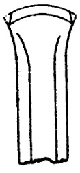
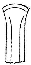
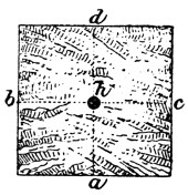
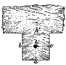
—The operations of blasting consist in
boring suitable holes in the rock to be dislodged, in
inserting a charge of some explosive compound into
the lower portion of these holes, in filling up, sometimes,
the remaining portion of the holes with suitable
material, and in exploding the charge. The subjects
which naturally first present themselves for consideration
are: the nature, form, and construction of the
tools, machines, and other appliances used. Of these
tools, the “drill” or “borer” constitutes the chief.
To understand clearly the action of the rock drill, we
must consider the nature of the substance which has
to be perforated. He who has examined the mineral
constitution of rocks will have recognised the impossibility
of cutting them, using that term in its ordinary
acceptation, inasmuch as the rock constituents are
frequently harder than the material of the tools
employed to penetrate them. As a rock cannot
be cut, the only way of removing portions of it
is to fracture or to disintegrate it by a blow delivered
through the medium of a suitable instrument.
Each blow so delivered may be made to
chip off a small fragment, and by this means the
rock may be gradually worn away. To effect this
chipping, however, the instrument used must present
only a small surface to the rock, in order to
concentrate the force, and that surface must be
bounded by inclined planes or wedge surfaces, to
cause a lateral pressure upon the particles of rock
in contact with them. In other words, the instrument
must be provided with an edge similar to that
possessed by an ordinary cutting tool.
The conditions under which the instrument is
worked are obviously such that this edge will be
rapidly worn down by attrition from the hard rock
material, and by fracture. To withstand these destructive
actions, two qualities are requisite in the
material of which the instrument is composed, namely,
hardness and toughness. Thus there are three important
conditions concurring to determine the nature
and the form of a cutting tool to be used in rock
boring—1, a necessity for a cutting edge; 2, a
necessity for a frequent renewal of that edge; and
3, a necessity for the qualities of hardness and toughness
in the material of the tool.
In very hard rock, a few minutes of work suffice to
destroy the cutting edge, and then the tool has to be
returned to the smithy to be re-sharpened. Hence it
is manifest that the form of the edge should
not be one that is difficult to produce, since,
were it so, much time would be consumed in
the labour of re-sharpening. Experience has
shown that the foregoing conditions are most
fully satisfied in the steel rod terminating in a
simple chisel edge, now universally adopted.
This form of drill is exhibited in Fig. 1,
which represents a common “jumper” borer.
It consists of a rod terminating at each end
in a chisel edge, and having a swell, technically
described as the “bead,” between
the extremities to give it weight. The bead
divides the jumper into two unequal portions,
each of which constitutes a chisel bit, with its
shank or “stock.” The shorter stock is used
while the hole is shallow, and the longer one
to continue it to a greater depth.
With the jumper, the blow is obtained
from the direct impact of the falling tool.
The mode of using the instrument is to lift
it with both hands to a height of about a
foot, and then to let it drop. In lifting the
jumper, care is taken to turn it partially
round, that the edge may not fall twice in
the same place. By this means, the edge is made
to act most favourably in chipping away the rock,
and the hole is kept fairly circular. So long as
the holes are required to be bored vertically downwards,
the jumper is a convenient and very efficient
tool, and hence in open quarrying operations, it
is very commonly employed. But in mining, the
shot-holes are more often required to be bored in
some other direction, or, as it is termed,
“at an angle;” that is, at an angle with
the vertical. Or it may be that a shot-hole
is required to be bored vertically
upward. It is obvious that in any one
of these directions the jumper is useless.
To meet the requirements of such cases,
recourse is had to the hammer wherewith
to deliver the blow, and the drill is constructed
to be used with the hammer. We
have a suitable form of tool for application
in this wise when we cut out the bead of
the jumper and leave the ends flat for a
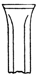
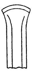
striking face, as shown in Figs. 2 and 3.
The form of the two chisels thus obtained
is that adopted for the ordinary rock drill.
It will be understood from these descriptions
that a rock drill consists of the chisel
edge or bit, the stock, and the striking
face. Formerly drills were made of wrought iron,
and steeled at each end to form the bit and the
striking face. Now they are commonly made of
cast steel, which is supplied for that purpose in
octagonal bars of the requisite diameter. The advantages
offered by steel stocks are numerous. The
superior solidity of texture of that material renders
it capable of transmitting the force of a blow more
effectively than iron. Being stronger than the latter
material, a smaller diameter of stock, and, consequently,
a less weight, are sufficient. This circumstance
also tends to increase the effect of the blow by
diminishing the mass through which it is transmitted.
On the other hand, a steel stock is more easily broken
than one of iron.
The cutting edge of a drill demands careful consideration.
To enable the tool to free itself readily
in the bore-hole, and also to avoid introducing unnecessary
weight into the stock, the bit is made
wider than the latter; the difference in width may
be as much as 1 inch. It is evident that in hard
rock, the liability of the edge to fracture increases as
the difference of width. The edge of the drill may
be straight or slightly curved. The straight edge
cuts its way somewhat more freely than the curved,
but it is weaker at the corners than the latter, a circumstance
that renders it less suitable for very hard
rock. It is also slightly more difficult to forge. The
width of the bit varies, according to the size of the
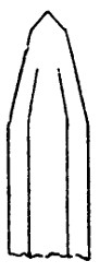
hole required, from 1 inch to 21⁄2 inches. Figs. 4, 5,
and 6 show the straight and the curved bits, and the
angles of the cutting edges for use in rock.
The stock is octagonal in section; it is made in
lengths varying from 20 inches to 42 inches. The
shorter the stock the more effectively does it transmit
the force of the blow, and therefore it is made as
short as possible. For this reason, several lengths
are employed in boring a shot-hole, the shortest
being used at the commencement of the hole, a
longer one to continue the depth, and a still longer
one, sometimes, to complete it. To ensure the longer
drills working freely in the hole, the width of the
bit should be very slightly reduced in each length.
It has already been remarked that the diameter of
the stock is less than the width of the bit; this
difference may be greater in coal drills than in rock
or “stone” drills; a common difference in the latter
is 3⁄8 of an inch for the longer. The following proportions
may be taken as the average adopted:—
| |
Width
of the
Bit. |
Diameter
of the
Stock. |
|
| 1 |
|
inch |
|
5⁄8 |
inch |
| 1 |
1⁄8 |
„ |
|
3⁄4 |
„ |
| 1 |
1⁄4 |
„ |
|
7⁄8 |
„ |
| 1 |
1⁄2 |
„ |
1 |
|
„ |
| 1 |
3⁄4 |
„ |
1 |
1⁄8 |
„ |
| 2 |
|
inches |
1 |
3⁄8 |
„ |
| 2 |
1⁄4 |
„ |
1 |
1⁄2 |
„ |
| 2 |
1⁄2 |
„ |
1 |
5⁄8 |
„ |
The striking face of the drill should be flat. The
diameter of the face is less than that of the stock in
all but the smallest sizes, the difference being made
by drawing in the striking end. The amount of
reduction is greater for the largest diameters; that
of the striking face being rarely more than one-eighth
of an inch.
The making and re-sharpening of rock drills constitute
an extremely important part of the labour of
the mine smith. The frequent use of the drill, and
its rapid wear, necessitate a daily amount of work of
no trifling proportions, and the judgment and skill
required in proper tempering render some degree of
intelligence in the workman indispensable; indeed,
so much depends upon the smith whose duty it is to
repair the miners’ tools, that no pains should be
spared to obtain a man capable of fulfilling that duty
in the most efficient manner possible.
When the borer-steel bars are supplied to the
smith, he cuts them up, as required, into the desired
lengths. To form the bit, the end of the bar is
heated and flattened out by hammering to a width a
little greater than the diameter of the hole to be
bored. The cutting edge is then hammered up with
a light hammer to the requisite angle, and the
corners beaten in to give the exact diameter of the
bore-hole intended. As the drills are made in sets,
the longer stocks will have a bit slightly narrower
than the shorter ones, for reasons already given.
The edge is subsequently touched up with a file. In
performing these operations, heavy hammering should
be avoided, as well as high heats, and care should be
taken in making the heat that the steel should be
well covered with coal, and far enough removed
from the tuyere to be protected from the “raw” air.
Overheated or “burned” steel is liable to fly, and
drills so injured are useless until the burned portion
has been cut away.
Both in making and in re-sharpening drills, great
care is required to form the cutting edge evenly, and
of the full form and dimensions. If the corners get
hammered in, as shown in Fig. 7, they are said to
be “nipped,” and the tool will not free itself in
cutting. When a depression of the straight, or
the curved, line forming the edge occurs, as shown
in Fig. 8, the bit is said to be “backward,” and when
one of the corners is too far back, as in Fig. 9, it is
spoken of as “odd-cornered.” When either of these
defects exist—and they are unfortunately common—not
only does the bit work less effectively on the rock,
but the force of the blow is thrown upon a portion
only of the edge, which, being thereby overstrained,
is liable to fracture.
The hardening and tempering of steel is a matter
requiring careful study and observation. It is a
well-known fact that a sudden and great reduction
of temperature causes a notable increase of hardness
in the metal. The reason of this phenomenon is not
understood, but it is certain that it is in some way
dependent upon the presence of carbon. The degree
of hardness imparted to steel by this means depends
upon the amount of the reduction of the temperature,
and the proportion of carbon present in the metal,
highly carburetted steel being capable of hardening
to a higher degree, under the same conditions, than
steel containing less carbon. Thus, for steel of the
same quality, the wider the range of temperature
the higher is the degree of hardness. But here we
encounter another condition, which limits the degree
of hardness practically attainable.
The change which takes place among the molecules
of the metal in consequence of the change of
temperature causes internal strains, and thereby puts
portions in a state of unequal tension. This state
renders the strained parts liable to yield when an
additional strain is thrown upon them while the tool
is in use; in other words, the brittleness of the steel
increases with its hardness. Here again the proportion
of carbon present comes into play, and it must
be borne in mind that for equal degrees of hardness
the steel which contains the least carbon will be the
most brittle. In hardening borer-steel, which has to
combine as far as possible the qualities of hardness
and toughness, this matter is one deserving careful
attention. It is a remarkable fact, and one of considerable
practical value, that when oil is employed
as the cooling medium instead of water, the toughness
of steel is enormously increased.
The tempering of steel, which is a phenomenon of
a similar character to that of hardening, also claims
careful consideration. When a bright surface of
steel is subjected to heat, a series of colours is produced,
which follow each other in a regular order as
the temperature increases. This order is as follows:
pale yellow, straw yellow, golden yellow, brown,
brown and purple mingled, purple, light blue, full
clear blue, and dark blue. Experience has shown
that some one of these colours is more suitable than
the rest for certain kinds of tools and certain conditions
of working.
The selection of the proper colour constitutes a
subject for the exercise of judgment and skill on the
part of the smith. For rock drills, straw colour is
generally the most suitable when the work is in very
hard rock, and light blue when the rock is only of
moderate hardness.
The processes of hardening and tempering drills
are as follows: When the edge of the bit has been
formed in the manner already described, from 3 to 4
inches of the end is heated to cherry redness, and
dipped in cold water to a depth of about an inch
to harden it. While in the water, the bit should
be moved slightly up and down, for, were this
neglected, the hardness would terminate abruptly,
and the bit would be very liable to fracture along the
line corresponding with the surface of the water. In
cold weather, the water should be slightly warmed,
by immersing a piece of hot iron in it, before dipping
the steel. When a sufficient degree of hardness has
been attained, the remainder of the hot portion is
immersed until the heat is reduced sufficiently for
tempering. At this stage it is withdrawn, and the
colours carefully watched for. The heat which is
left in the stock will pass down to the edge of the
bit, and as the temperature increases in that part the
colours will appear in regular succession upon the
filed surface of the edge. When the proper hue
appears, the whole drill is plunged into the water
and left there till cold, when the tempering is complete.
When the edge is curved or “bowed,” the
colours will reach the corners sooner than the middle
of the bit. This tendency must be checked by dipping
the corners in the water, for otherwise the edge
will not be of equal hardness throughout. As the
colour can be best observed in the dark, it is a good
plan to darken that portion of the smithy in which
tempering is being carried on.
The degree of temper required depends upon the
quality of the steel and the nature of the work to be
performed. The larger the proportion of carbon
present in the metal, the lower must be the temper.
Also the state of the blunted edges, whether battered
or fractured, will show what degree of hardness it
is desirable to produce. From inattention to these
matters, good steel is not unfrequently condemned as
unsuitable.
To form the striking face, the end of the stock is
heated to a dull red, and drawn out by a hammer to
form a conical head. The extremity is then flattened
to form a face from 1⁄2 inch to 1 inch in diameter. This
head is then annealed to a degree that will combine
considerable toughness with hardness. The constant
blows to which the head is subjected tend to wear it
down very rapidly. There is great difference in the
lasting qualities of steel in this respect; some drills
will wear away more quickly at the striking than at
the bit end.
A smith will, with the assistance of a striker,
sharpen and temper about thirty single-hand drills
of medium size in an hour, or twenty double-hand
drills of medium size in the same time. Of course,
much will depend on the degree of bluntness in the
cutting edge; but assuming the drills to be sent up
only moderately blunted, this may be taken as a fair
average of the work of two men.
It will be evident from the foregoing remarks,
that to enable a drill to stand properly it must be
made of good material, be skilfully tempered in the
smithy, and provided with a cutting edge having an
angle and a shape suited to the character of the rock
in which it is used. To these conditions, may be
added another, namely, proper handling; for if the
drill be carelessly turned in the hole so as to bring
all the work upon a portion only of the cutting edge,
or unskilfully struck by the sledge, fracture or
blunting will speedily result. Improper handling
often destroys the edge in the first five minutes of
using.
Drills, as before remarked, are used in sets of
different lengths. The sets may be intended for
use by one man or by two. In the former case,
the sets are described as “single-hand” sets, and they
contain a hammer for striking the drills; in the latter
case, the sets are spoken of as “double-handed,”
and they contain a sledge instead of a hammer for
striking. It may appear at first sight that there is
a waste of power in employing two men, or, as it
is termed, the double set, for that two men cannot
bore twice as fast as one. This rate of speed can,
however, be obtained, and is due less to the greater
effectiveness of the stroke than to the fact that two
men can, by repeatedly changing places with each
other, keep up almost without intermission a succession
of blows for an indefinite length of time;
whereas, with the single set, the man is continually
obliged to cease for rest.
—To deliver the blow upon a rock drill,
hammers and sledges are used. The distinction
between a hammer and a sledge is founded on
dimensions only: the hammer being intended for
use in one hand, is made comparatively light and
is furnished with a short handle, while the sledge,
being intended for use in both hands, is furnished
with a much longer handle and is made heavier.
The striking face of the blasting sledge should be
flat, to enable the striker to deliver a direct blow
with certainty upon the head of the drill; and to
facilitate the directing of the blow, as well as to
increase its effect, the mass of metal composing the
head should be concentrated within a short length.
To cause the sledge to fly off from the head of the
drill in the case of a false blow being struck, and
thereby to prevent it from striking the hand of
the man who holds the drill, the edges of the
striking face should be chamfered or bevelled down
till the diameter is reduced by nearly one-half.
This requirement is, however, but seldom provided
for.
Fig. 10.
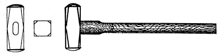
Fig. 11.
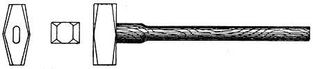
Fig. 12.
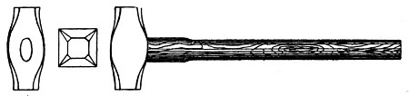
Fig. 13.
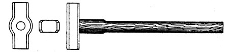
The head of a sledge is of iron; it consists of
a pierced central portion called the “eye,” and two
shanks or “stumps,” the steeled ends of which form
the striking faces or “panes.” The form of the
head varies in different localities, but whatever the
variations may be, the form may be classed under
one of four types or “patterns.” A very common
form is that shown in Fig. 10 and known as the
“bully” pattern. By varying the width, as shown
in Fig. 11, we obtain the “broad bully,” the former
being called for the sake of distinction the “narrow”
bully. Another common form is the “pointing”
pattern, represented in Fig. 12. The form shown
in Fig. 13 is designated as the “bloat” pattern;
and that given in Fig. 14 the “plug” pattern.
Each of these forms possesses peculiar merits which
renders it more suitable for certain uses than the
others. The same forms are used for hammers.
The eye is generally made oval in shape, but sometimes,
especially with the bloat pattern, it is made
circular, as shown in Fig. 13. The weight of a
sledge head may vary from 5 lb. to 10 lb., but a
common and convenient weight is 7 lb. The length
of the helve varies from 20 inches to 30 inches;
a common length for blasting sledges is 24 inches.
The average weight of hammer heads is about 3 lb.,
and the average length of the helve 10 inches.
Fig. 14.
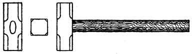
Fig. 15.
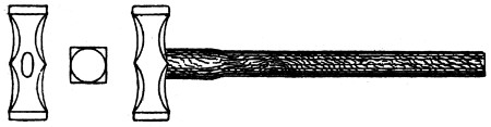
Fig. 15 represents a blasting sledge used in South
Wales. The stumps are octagonal in section, and
spring from a square block in the centre. The
panes or striking faces, however, are circular and
flat. The length of the head is 83⁄4 inches, and that
of the helve 27 inches, and the weight of the tool
complete 7 lb.
Fig. 16.
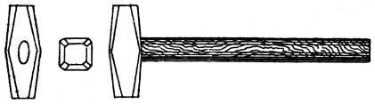
Fig. 16 represents a blasting sledge used in
North Wales. The central block is an irregular
octagon in section, formed by slightly chamfering
the angles of a square section, and the stumps are
chamfered down to form a regular octagon at the
panes, which are flat. The length of the head is
73⁄4 inches, and that of the helve 22 inches, and the
weight of the tool complete 6 lb. 7 oz.
Fig. 17.

The sledges used in the north of England have
shorter heads, and are lighter than the foregoing.
Fig. 17 represents one of these blasting sledges.
The head is nearly square in section at the centre,
and the panes are flat. The length of the head
is 5 inches, and that of the helve 241⁄2 inches, and the
weight of the sledge complete 4 lb. 14 oz.
—Besides the drill and the hammer,
other tools are needed in preparing the hole for the
blasting charge. If the bore-hole is inclined downwards,
the débris or “bore-meal” made by the drill
remains on the bottom of the hole, where it is converted
into mud or “sludge” by the water there
present. This sludge has to be removed as the work
progresses, to keep the rock exposed to the action of
the drill. The removal of the sludge is effected by a
simple tool called a “scraper.” It consists
of a rod of iron from 1⁄4 inch to
1⁄2 inch in diameter, and of sufficient
length to reach the bottom of the bore-hole.
One end of the rod is flattened
out on the anvil and made circular in
form, and then turned up at right angles
to the stem. The disc thus formed must
be less in diameter than the bore-hole,
to allow it to pass readily down. When
inserted in the hole, the scraper is turned
round while it is being pressed to the
bottom; on withdrawing the instrument,
the sludge is brought up upon the disc.
The operation, two or three times repeated,
is sufficient to clear the bore-hole.
The other end of the scraper is sometimes
made to terminate in a ring for
convenience in handling, as shown in
Fig. 18. Instead of the ring, however,
at one end, a disc may be made at
each end, as shown in Fig. 19, the discs in this
case being of different diameter, to render the scraper
suitable for different size bore-holes. Sometimes the
scraper is made to terminate in a spiral hook or
“drag-twist,” as represented in Fig. 20. The use
of the drag is to thoroughly cleanse the hole before
inserting the charge. A wisp of hay is
pushed down the hole, and the drag end of
the scraper introduced after it, and turned
round till it has become firmly entangled.
The withdrawal of the hay by the drag wipes
the bore-hole clean. Instead of the twist
drag, the “loop” drag is frequently employed.
This consists of a loop or eye,
through which a piece of rag or tow is
passed. The rag or tow is used for the same
purpose as the hay, namely, to thoroughly
cleanse and dry the bore-hole previous to
the introduction of the charge. Very frequently
the “swab-stick” is used instead of
the scraper to clear out the bore-hole. This
is simply a deal rod bruised at one end by
blows with a hammer until the fibres separate
to form a kind of stumpy brush or “swab.” When
this is pushed down the hole, the sludge passes up
around and between the fibres, which are then
spread out by being pressed against the bottom of
the hole. On withdrawing the swab, the sludge is
brought out with it.
Fig. 18.

Fig. 19.

Fig. 20.

When the charge has been placed in the bore-hole,
and the fuse laid to it, the hole needs to be tamped,
that is, the portion above the charge has to be filled
up with some suitable substance. For this purpose,
a “rammer,” “stemmer,” or “tamping iron,” as the
instrument is variously called, is required. This
instrument is illustrated in Fig. 21. It consists of a
metal bar, the tamping end of which is
grooved to receive the fuse lying against
the side of the bore-hole. The other end
is flat, to afford a pressing surface for the
hand, or a striking face for the hammer
when the latter is needed. To prevent
the danger of accidental ignition from
sparks caused by the friction of the metal
against silicious substances, the employment
of iron stemmers has been prohibited
by law. They are usually made of
copper or phosphor-bronze, the latter
substance being more resisting than the
former.
Fig. 21.

Fig. 22.

Fig. 23.

Sometimes in wet ground it becomes
necessary to shut back the water from
the bore-hole before introducing the
charge of gunpowder. This happens
very frequently in shaft sinking. The
method employed in such cases is to force clay into
the interstices through which the water enters. The
instrument used for this purpose is the “claying-iron”
or “bull,” represented in Fig. 22. It consists of a
round bar of iron, called the stock or shaft, a little
smaller in diameter than the bore-hole, and a thicker
portion, called the head or poll, terminating in a
striking face. The lower end of the shaft is pointed,
to enable it to penetrate the clay, and the head is
pierced by a hole about an inch in diameter to receive
a lever. Clay in a plastic state having been put into
the bore-hole, the bull is inserted and driven down by
blows with the sledge. As the shaft forces its way
down, the clay is driven into the joints and crevices
of the rock on all sides. To withdraw the bull, a bar
of iron is placed in the eye and used as a lever to
turn it round to loosen it; the rod is then taken by
both hands and the bull lifted out. To allow the
bull to be withdrawn more readily, the shaft
should be made with a slight taper and kept
perfectly smooth. As the bull is subjected to
a good deal of heavy hammering on the head,
the latter part should be made stout. This
tool, which should be considered as an extra
instrument rather than as an essential part
of a blasting set, is a very serviceable one,
and should always be at hand in wet ground
when loose gunpowder is employed.
Another instrument of this auxiliary character
is the beche, Fig. 23, used for extracting a
broken drill. It consists of an iron rod of
nearly the diameter of the bore-hole, and
hollow at the lower end. The form of the
aperture is slightly conical, so that the lower end
may easily pass over the broken stock of the drill,
and, on being pressed down with some force, may
grasp the stock in the higher portion of the aperture
with sufficient firmness to allow of the two being
raised together. When only a portion of the bit
remains in the hole, it may often be extracted by
means of the drag-twist end of the scraper, or the
swab-stick may be driven down upon the broken
portion, and latter withdrawn with the swab.
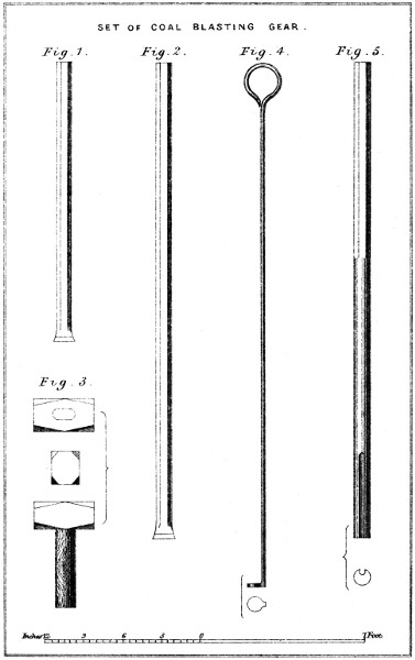
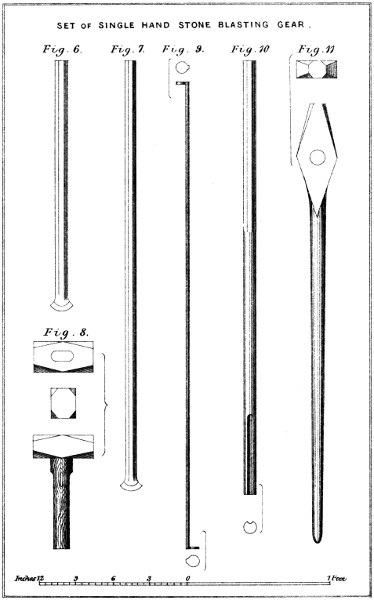
—On Plates I., II., and III.,
will be found three sets of blasting gear; a set
of coal-blasting gear; a set of single-hand stone-blasting
gear; and a set of double-hand stone-blasting
gear. In the first set, the drill, shown in
Fig. 1, is 22 inches in length; the cutting edge is
straight and 11⁄2 inch wide, and the weight is 21⁄2 lb.
The other drill, Fig. 2, is 42 inches in length; it
has a straight cutting edge 17⁄16 inch wide, and
weighs 4 lb. 10 oz. The hammer used in this set
and shown in Fig. 3 weighs 2 lb. 14 oz.; the length
of the head is 41⁄2 inches, and that of the handle
73⁄4 inches. In the second or single-hand stone set,
the shorter drill, Fig. 6, Plate II., is 22 inches in
length; the cutting edge is strongly curved, and is
11⁄2 inch in width, and the weight is 3 lb. 10 oz. The
longer drill, Fig. 7, is 36 inches in length; the width
of the cutting edge, which is curved as in the shorter
drill, is 17⁄16 inch, and the weight is 6 lb. 5 oz. The
hammer used with this set, and represented in
Fig. 8, weighs 3 lb. 6 oz.; the length of the head is
5 inches, and that of the handle 10 inches. In the
third or double-hand stone set, Plate III., the first or
shortest drill, Fig. 12, is 18 inches in length, 13⁄4 inch
wide on the cutting edge, and weighs 41⁄4 lb. The
second drill, Fig. 13, is 27 inches in length, 111⁄16 wide
on the cutting edge, and weighs 6 lb. The third or
longest drill, Fig. 14, is 40 inches in length, 15⁄8 inch
wide on the cutting edge, and weighs 91⁄4 lb. The
cutting edges of all these drills are strongly curved
as in the preceding set. The sledge used with this
set, and represented in Fig. 15, weighs about 5 lb.
—The most remarkable advance,
which in recent, or perhaps in any, times
has been made in the practice of mining consists in
the substitution of machine for hand labour in rock
boring. The importance of this change is obvious,
and very great. Not only is the miner relieved
thereby of the labour of boring, but the speed with
which the shot-holes may be bored is increased a
hundredfold. This gain of speed offers many practical
advantages. The ability to sink a shaft or to
drive a heading rapidly may ensure the success of an
undertaking, and save indirectly the expenditure of
large sums of money; and, in all cases, it allows the
time spent in preparatory work to be materially
shortened. Indeed, it would be difficult to over-estimate
the magnitude of the advantage accruing from
the increased rate of progress due to the substitution
of machine power for hand labour, and in the future
we may expect to see its application greatly extended.
In making this substitution, numerous difficulties have
had to be overcome, and in encountering these many
failures have had to be recorded. But it must now
be conceded by the most prejudiced that rock-boring
machines have successfully passed through what may
be described as the tentative stage of their existence,
and have taken a foremost place among the mechanical
appliances which experience has shown to be
capable of effectually performing the work required
of them. In the author’s work on ‘Mining Engineering,’
the requirements of a rock drill will be
found fully discussed, and the principles and the
construction of the most important machines now in
use carefully explained and described. In the present
work, only one example can be given.
Machine drills penetrate rock in the same way as
the ordinary hand drills already described, namely,
by means of a percussive action. The cutting tool is
in most cases attached directly to the piston rod, with
which it consequently reciprocates. Thus the piston
with its rod is made to constitute a portion of the
cutting tool, and the blow is then given by the direct
action of the steam, or the compressed air, upon the
tool. As no work is done upon the rock by the back
stroke of the piston, the area of the forward side is
reduced to the dimensions necessary only to lift the
piston, and to overcome the resistance due to the friction
of the tool in the bore-hole. The piston is made
to admit steam or air into the cylinder, and to cut off
the supply, and to open the exhaust, as required, by
means of tappet valves, or other suitable devices;
and provision is made to allow, within certain limits,
a variation in the length of the stroke. During a
portion of the stroke, means are brought into action
to cause the piston to rotate to some extent, for the
purposes that have been already explained. To keep
the cutting edge of the tool up to its work, the whole
machine is moved forward as the rock is cut away.
This forward or “feed” motion is usually given by
hand, but in some cases it is communicated automatically.
The machine is supported upon a stand
or framing which varies in form according to the
situation in which it is to be used. This support is
in all cases constructed to allow of the feed motion
taking place, and also of the cutting tool being
directed at any angle. The support for a rock drill
constitutes an indispensable and a very important
adjunct to the machine, for upon the suitability of its
form, material, and construction, the efficiency of the
machine will largely depend.
The foregoing is a general description of the construction
and mode of action of percussive rock-drills.
The numerous varieties now in use differ from each
other rather in the details of their construction than
in the principles of their action, and the importance
of the difference is, of course, dependent upon that
of the details. It is but just to remark here that the
first really practical solution of the rock-drilling problem
is due to M. Sommeiller, whose machine was
employed in excavating the Mont Cenis tunnel.
—The machine which, in
England, has stood the test of experience most satisfactorily,
and which, consequently, is surely working
itself into general favour in this country, and also in
some of the important mining districts of the Continent,
is the invention of John Darlington, and is
known as the “Darlington drill.” This drill is remarkable
as the attainment of the highest degree of
simplicity of parts possible in a machine. The valve
gear of a machine drill is especially liable to derangement.
It must necessarily consist of several parts,
and these parts must as necessarily be of a somewhat
fragile character. Besides this, when actuated by
the piston through the intervention of tappets, the
violence of the blow delivered at each stroke is such
as to rapidly destroy the parts. In some machines,
the force of these blows and their destructive tendency
have been reduced to a minimum; but when
every means of remedying the evil has been employed,
there remains a large amount of inevitable
wear and tear, and a liability to failure from
fracture or displacement exists in a greater or less
degree. Moreover, as these effects are greatly intensified
by increasing the velocity of the piston, it
becomes at least undesirable to use a high piston
speed. To remedy these defects, which are inherent
in the system, Darlington proposed to remove altogether
the necessity for a valve gear by radically
changing the mode of admitting the motor fluid to
the cylinder. This proposal he has realized in the
machine which is illustrated on Plate IV.
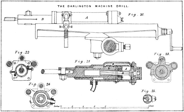
The Darlington rock-drill consists essentially of
only two parts: the cylinder A, Figs. 20 and 21, with
its cover; and the piston B, with its rod. The cover,
when bolted on, forms a part of the cylinder; the
piston rod is cast solid with the piston, and is made
sufficiently large at its outer end to receive the tool.
These two parts constitute an engine, and with less
than one fixed and one moving part it is obviously
impossible to develop power in a machine by the
action of an elastic fluid. The piston itself is made
to do the work of a valve in the following manner:
The annular space affording the area for pressure on
the fore part of the piston gives a much smaller
extent of surface than that afforded by the diameter
of the cylinder, as shown in the drawing; and it is
obvious that by increasing or diminishing the diameter
of the piston rod, the area for pressure on the
one side of the piston may be made to bear any
desired proportion to that on the other side. The
inlet aperture, or port C, being in constant communication
with the interior of the cylinder, the
pressure of the fluid is always acting upon the front
of the piston, consequently when there is no pressure
upon the other side, the piston will be forced backward
in the cylinder. During this backward motion,
the piston first covers the exhaust port D, and then
uncovers the equilibrium port E, by means of which
communication is established between the front and
back ends of the cylinder, and, consequently, the fluid
is made to act upon both sides of the piston. The area
of the back face of the piston being greater than
that of the front face by the extent occupied by the
piston rod, the pressure upon the former first acts to
arrest the backward motion of the piston, which, by
its considerable weight and high velocity, has acquired
a large momentum, and then to produce a
forward motion, the propelling force being dependent
for its amount upon the difference of area on the two
sides of the piston. As the piston passes down, it
cuts off the steam from the back part of the cylinder
and opens the exhaust. The length or thickness of
the piston is such that the exhaust port D is never
open to its front side, but, in the forward stroke, it
is opened almost immediately after the equilibrium
port is closed, and nearly at the time of striking the
blow. It will be observed that the quantity of fluid
expended is only that which passes over to the back
face of the piston, since that which is used to effect
the return stroke is not discharged.
The means employed to give a rotary motion to
the tool are deserving of special attention, as being
simple in design, effective in action, and well situate
within the cylinder. These means consist of a spiral
or rifled bar H, having three grooves, and being
fitted at its head with a ratchet wheel G, recessed
into the cover of the cylinder. Two detents J, J,
Fig. 22, also recessed into the cover, are made to fall
into the teeth of the ratchet wheel by spiral springs.
These springs may, in case of breakage, be immediately
renewed without removing the cover. It
will be observed that this arrangement of the wheel
and the detents allow the spiral bar H to turn freely
in one direction, while it prevents it from turning in
the contrary direction. The spiral bar drops into a
long recess in the piston, which is fitted with a steel
nut made to accurately fit the grooves of the spiral.
Hence the piston, during its instroke, is forced to
turn upon the bar; but, during its outstroke, it turns
the bar, the latter being free to move in the direction
in which the straight outstroke of the piston
tends to rotate it. Thus the piston, and with it the
tool, assumes a new position after each stroke.
The mode of fixing the cutting tool to the piston
rod is a matter deserving some attention. As the
tool has to be changed more than once during the
progress of a bore-hole, it is important that the
change should be accomplished in as short a time as
possible; and as the vibration of the machine and
the strain upon the tool are necessarily great, it is
equally important that the tool be firmly held. It
is also desirable that the mode of fixing the tool
shall not require a shoulder upon the latter, a slot
in it, or any peculiarity of form difficult to be
made in the smithy. The Darlington machine
fulfils the requirements of expedition in fixing, firmness
of retention, and simplicity of form most satisfactorily.
The means and the method are the
following: The outer end of the rod or holder is first
flattened to afford a seat for the nut, as shown in
Figs. 21 and 25. The slot is then cut and fitted
tightly with a piece of steel K forged of the required
shape for the clamp, and the holder is afterwards
bored to receive the tool while the clamp is in place.
This clamp K is then taken out, its fittings eased a
little, and its end screwed and fitted with a nut.
When returned to its place in the holder, the clamp,
in consequence of the easing, can be easily drawn
tight against the tool, by which means it is firmly
held in position. The shank of the tool is turned to
fit the hole easily, and the end of it is made hemispherical
to fit the bottom of the hole, upon which
the force of the reaction of the blow is received.
It would seem impossible to attain a higher degree
of simplicity of form, or to construct a machine with
fewer parts. The absence of a valve or striking
gear of any kind ensures the utmost attainable
degree of durability, and allows a high piston speed
to be adopted without risk or injury. As the piston
controls its own motion, there is no liability to strike
against the cylinder cover. The stroke may be
varied in length from half an inch to four inches, and
as the machine will work effectively with a pressure
of 10 lb. to the inch, holes may be started with the
greatest ease. With a pressure of 40 lb., the
machine makes 1000 blows a minute, a speed that
may be attained without causing undue strains or
vibration. This alone constitutes a very great advantage.
It must indeed be conceded that an unprejudiced
consideration of the merits of this drill
shows it to be admirably adapted to the work required
of it.
—The form and the dimensions of
the cutting tools, variously described as “drills,”
“borers,” and “bits,” used with machine rock-perforators
are matters of great practical importance.
The dimensions are determined mainly by two conditions,
namely, the necessity for sufficient strength
in the shank of the tool, and the necessity for sufficient
space between the shank and the sides of the
hole to allow the débris to escape. Experience has
shown that the latter condition is best fulfilled when
the distance between the sides of the hole and the
shank of the tool is from 3⁄16 inch to 1⁄4 inch, regard
being had to the former condition.
The form of the cutting edge is determined
by several conditions, some of which have been
already discussed in relation to hand drills. The
form first adopted was naturally that possessed by
the hand drill, namely, the chisel edge. To increase
the useful effect of the blow, the cutting
edge was subsequently doubled, the bit being formed
of two chisel edges crossing each other at right
angles. This bit, which from its form was called the
“cross” bit, was found to penetrate the rock more
rapidly than the straight or chisel bit. The gain in
speed was very marked at the commencement of the
hole; but it diminished gradually as the hole progressed
in depth, owing to the difficulty with which
the débris escaped. To remedy this defect, the cutting
edges were next made to cross each other
obliquely, so as to form the letter X. In this way,
the two chisel edges were retained, while the breadth
of the bit was considerably reduced. This form,
described as the X bit, cleared the hole much more
effectively than the cross, but not in a manner that
was altogether satisfactory. Another modification
of the form was, therefore, made, and this time that
of the Z was adopted, the upper and the lower portions
of which were arcs of circles struck from the
centre of the bit in the direction contrary to that
of the rotation.
This form of tool, which is known as the Z bit,
readily cleared itself of the débris. But besides this
advantage, it was found to possess others of an
important character. With the chisel-edge forms,
the corners of the bit were rapidly worn off by
friction against the sides of the hole. With the
Z form, this wearing no longer occurred, by reason
of the large surface exposed to friction. Another
advantage of the Z form of bit lies in its tendency
to bore the hole truly circular. Generally then,
it may be stated that this form satisfies most fully
the determining conditions. The form of bit, however,
that is most suitable in a given case will, in
some degree, be determined by particular circumstances.
Of these, the nature and the character of
the rock will operate most strongly to influence the
choice. Thus the cross bit will generally be found
the most suitable in fissured rock, while the single
chisel edge may be used with advantage in rock of
a very solid and hard character. Indeed, on the
judicious selection of the most suitable form of cutting
edge, the success of machine boring largely
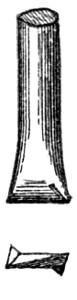
depends. The chisel bit, the cross bit, the X bit,
and the Z bit, are shown in Figs. 24 to 27.
Fig. 24.
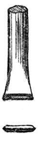
Fig. 25.
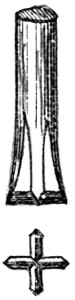
Fig. 26.
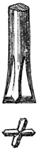
Fig. 27.
The sharpening of bits of a form other than that
of the chisel is done by means of “swages.” The
tempering is effected in the way already described
in reference to hand drills. As in the latter case,
the degree of temper must be suited to the hardness
of the rocks to be penetrated. Generally the straw
colour will be found to be the best degree. It is a
remarkable fact that the wear of the cutting edge
of a machine drill is, for a given length of boring,
five or six times less than that of a hand drill. Steel
of the best quality should always be used.
As in the case of hand boring, each successive
length of drill must diminish slightly in the width
of its cutting edge; a diminution of about 1⁄32 inch
may be considered sufficient. Care should, however,
be taken to ensure the proper dimensions being
given to the edge, and it will be found advantageous
to have at hand an accurate gauge through which
the tool may be passed previously to its being fixed
to the machine. It is important that the tool be
truly “centred,” that is, the centres of the edge of
the bit, of the shank, and of the piston rod, should
be perfectly coincident.
—A machine rock-drill may
satisfy every requirement, and yet, by reason of the
defective character of the support to which it is
attached, it may be unsuitable to the work required
of it. Hence it becomes desirable to carefully study
the design and construction of a drill support, and to
consider the requirements which it is needful to
fulfil. Assuming the necessity for a high degree of
strength and rigidity in the support, a primary condition
is that it shall allow the machine to be readily
adjusted to any angle, so that the holes may be bored
in the direction and with the inclination required.
When this requirement is not fulfilled, the machine
is placed, in this respect, at a great disadvantage with
hand labour. If a machine drill were not capable of
boring in any position and in any direction, hand
labour would have to be employed in conjunction
with it, and such incompleteness in the work of a
machine would constitute a serious objection to its
adoption.
Besides allowing of the desired adjustment of the
machine, the support must be itself adjustable to
uneven ground. The bottom of a shaft which is
being sunk, or the sides, roof, and floor of a heading
which is being driven, present great irregularities
of surface, and, as the support must of necessity in
most cases be fixed to these, it is obvious that its
design and construction must be such as will allow
of its ready adjustment to these irregularities. The
means by which the adjustment is effected should be
few and simple, for simplicity of parts is important
in the support as well as in the machine, and for the
same reasons. A large proportion of the time during
which a machine drill is in use is occupied in shifting
it from one position or one situation to another; this
time reduces, in a proportionate degree, the superiority
of machine over hand labour, in respect of
rapidity of execution, and it is evidently desirable
that it should be shortened as far as possible. Hence
the necessity for the employment of means of adjustment
which shall be few in number, rapid in action,
and of easy management.
For reasons similar to the foregoing, the drill
support must be of small dimensions, and sufficiently
light to allow of its being easily portable. The
limited space in which rock drills are used renders
this condition, as in the case of the machine itself,
a very important one. It must be borne in mind
that, after every blast, the dislodged rock has to be
removed, and rapidity of execution requires that
the operations of removal should be carried on without
hindrance. A drill support that occupies a large
proportion of the free space in a shaft or a heading
is thus a cause of inconvenience and a source of
serious delay. Moreover, as it has to be continually
removed from one situation to another, it should
be of sufficiently light weight to allow of its being
lifted or run along without difficulty. In underground
workings, manual power is generally the
only power available, and therefore it is desirable
that both the machine and its support should be
of such weight that each may be lifted by one man.
Of course, when any endeavour is made to reduce
the weight of the support, the necessity for great
strength and rigidity must be kept in view.
In spacious headings, such as are driven in railway
tunnel work, supports of a special kind may be
used. In these situations, the conditions of work
are different from those which exist in mines. The
space is less limited, the heading is commenced at
surface, and the floor is laid with a tramway and
sidings. In such a case, the support may consist
of a more massive structure mounted upon wheels
to run upon the rails. This support will carry
several machines, and to remove it out of the way
when occasion requires, it will be run back on to a
siding; but for ordinary mining purposes, such a
support is suitable.
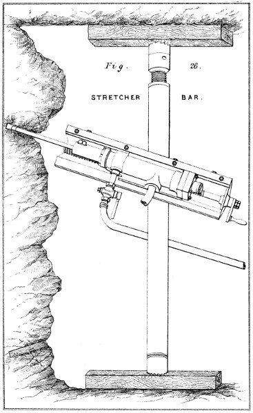
—The simplest kind of support
is the “stretcher bar.” This consists essentially of a
bar so constructed that it may be lengthened or
shortened at pleasure, by means of a screw. It is
fixed in position by screwing the ends into firm
contact with the sides, or with the roof and the floor,
of a heading. The machine is fixed to this bar by
means of a clamp, which, when loosened, slides along
the bar, and allows the drill to be placed in the
required position, and to be directed at the required
angle. The bar illustrated in Fig. 26, Plate V., is
that which is used with the Darlington drill; in it,
lightness and rigidity are combined in the highest
possible degree by the adoption of the hollow section.
The mode of setting the bar in a heading is shown
in the drawing; the end claws are set against pieces
of wood on the floor and the roof, and are tightened
by turning the screw with a common bar.
The simple stretcher bar is frequently used in
narrow drivings and in shafts of small diameter.
But a more satisfactory support in drivings is
afforded by a bar suitably mounted upon a carriage
designed to run upon rails. The carriage consists
simply of a trolly, to the fore part of which the bar
is fixed usually by some kind of hinge-joint. It is
obvious that the details of the construction of this
support may be varied greatly, and numerous designs
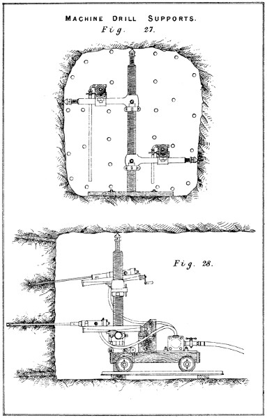
have been introduced and adopted. In Figs. 27
and 28, Plate VI., is shown a support of this character
designed by J. Darlington. A single vertical bar is
carried on the fore part of the trolly, and fixed, by
the usual means, against the centre of the roof.
This vertical bar carries an arm, which is capable
of turning upon it, as upon a centre, and of sliding
up and down it. This arm carries the drill. The
central bar having been fixed in position, the arm
is slid up to the highest position required, and fixed
against the side of the heading. A row of holes
are then bored from this arm. When these are
completed, the arm is lowered the requisite distance,
and another row of holes are bored. This is continued
until all the holes are bored over one-half
the face. The arm is then swung round, and fixed
against the other side of the heading, and the holes
are bored over that half the face in like manner.
In this way, one-half the heading is kept clear to
allow the operations of removing the dislodged rock
to be carried on at the same time. If desired, two
arms may be used. This arrangement gives undoubtedly
great facilities for working the drill, and
leaves the heading comparatively unencumbered.
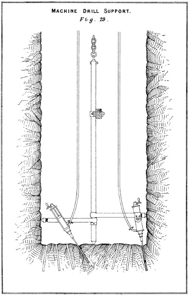
In shaft sinking, the same support, slightly modified,
is used without the trolly. The arrangement
adopted in this case is shown in Fig. 29, Plate VII.
The central bar is held firmly in its position by a
cross stretcher bar set against the sides of the shaft.
The arms are made to revolve upon this bar to
allow the holes to be bored in the positions required.
When all the holes have been bored, the support,
with the machines, is hauled up, by means of a chain
attached to the central bar, out of the way of the
blast. With this support, the time of fixing,
raising, and lowering is reduced to a minimum;
while the facility with which the machines may
be slid along and fixed to the arm, and the positions
of the latter changed, allows the boring to be carried
on rapidly.
For open work, as in quarrying, where the
stretcher bar cannot be used, the tripod stand is
adopted.
—The support commonly
used in France and in Belgium consists of
a kind of carriage carrying bars upon which the
drills are set. This carriage is used in drivings of
all kinds; but it is particularly suitable for tunnelling.
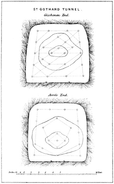
It has been adopted, with but slight modification,
in the St. Gothard tunnel, and in several other
important works of the like character.
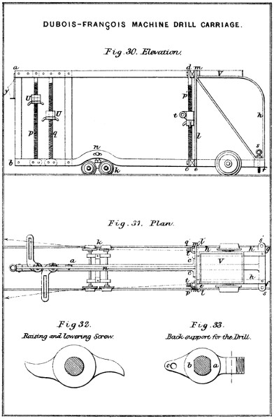
A modification of the carriage is shown in Figs. 30
and 31. Being designed for ordinary mining operations,
it carries but two machines; but it will be readily
perceived that, by increasing the number of vertical
screws, the same support may be made to carry a
larger number. It consists essentially of a vertical
frame of flat bar iron a b c d, 8 feet in length, and
4 feet 9 inches in height above the rails, the hinder
portion of which rests upon a cast-iron plate e f g h,
carried upon two wheels; on this are fixed the two
uprights l, l′, which, being bound to the upper part
by a transverse bar m m′, form a framing to serve
as a support to the two vertical screws p′, q′. The
front framing is formed of two longitudinals b c and
b′ c′ and the uprights a, a′, and the vertical screws
p, q, which are connected to the upper part by the
single piece a d. This framing is supported below
upon a small trolly with four wheels, connected to
the two longitudinals of the framing by a pivot bolt
n of T form, the bar of the T being inserted into
the elongated openings o cut through the middle
of the curved portion of the longitudinals. The
cast-iron plate behind, the use of which is only to
give stability to the carriage, carries above it, by
means of the two curved pieces h, h′, a wrought-iron
plate V, upon which the small tools needed for
repairs are kept. Two screws, s, s′, carried by lugs
cast upon the back of the plate, serve, by turning
them down upon the rails, to fix the carriage, the
latter being slightly lifted by the screws.
Each machine is supported at two points. Behind,
the point of support is given by a cast-iron bracket t,
having a projecting eye which enters between the
two cheeks formed at the back end of the machine
by the continuations of the two longitudinals of the
framing. A pin bolt, carried by the machine, allows
the latter to be fixed to the bracket, while leaving
sufficient freedom of motion to allow of its being
directed at the required angle. This bracket, shown
in plan in Fig. 33, is supported by a kind of
nut, Fig. 32, having two handles whereby it may
be easily turned. By raising or lowering this, the
hinder support of the drill may be brought to the
requisite height. To prevent it turning upon the
screw, a pin is passed through the hole o, which pin
forms a stop for the handles aforementioned. The
rotation of the bracket itself is rendered impossible
by the form of the vertical screw upon which it
is set, as shown in Fig. 33. In front, the support
is a fork, the shank of which slides along in the
piece U, Figs. 30 and 31. This support, which is
not screwed on the inside, rests upon a nut of the
same form as that already described, and the same
means are employed to prevent rotation as in the
case of the hinder supports.
In the foregoing sections, the machines and tools
used in rock boring have been treated of. It now
remains to describe those which are employed in
firing the charges after they have been placed in the
bore-holes. In this direction, too, great progress
has been made in recent times. With the introduction
of new explosive agents, arose the necessity
for improved means of firing them. Attention being
thus directed to the subject, its requirements were
investigated and its conditions observed, the outcome
being some important modifications of the old appliances
and the introduction of others altogether new.
Some of the improvements effected are scarcely less
remarkable than the substitution of machine for
hand boring.
Fig. 28.

Fig. 29.

The means by which the charge of explosive
matter placed in the bore-hole is fired constitute
a very important part of the set of appliances used
in blasting. The conditions which any such means
must fulfil are: (1) that it shall fire the charge with
certainty; (2) that it shall allow the person whose
duty it is to explode the charge to be at a safe
distance away when the explosion takes place; (3)
that it shall be practically suitable, and applicable
to all situations; and (4) that it shall be obtainable
at a low cost. To fulfil the second and most essential
of these conditions, the means must be either
slow in operation, or capable of being acted upon at
a distance. The only known means possessing the
latter quality is electricity. The application of
electricity to this purpose is of recent date, and in
consequence of the great advantages which it offers,
its use is rapidly extending. The other means in
common use are those which are slow in operation, and
which allow thereby sufficient time to elapse between
their ignition and the explosion of the charge for a
person to retire to a safe distance. These means
consist generally of a train of gunpowder so placed
that the ignition of the particles must necessarily be
gradual and slow. The old, and in some parts still
employed, mode of constructing this train was as
follows: An iron rod of small diameter and terminating
in a point, called a “pricker,” was inserted
into the charge and left in the bore-hole while the
tamping was being rammed down. When this
operation was completed, the pricker was withdrawn,
leaving a hole through the tamping down to the
charge. Into this hole, a straw, rush, quill, or
some other like hollow substance filled with gunpowder,
was inserted. A piece of slow-match was
then attached to the upper end of this train, and
lighted.
The combustion of the powder confined in the
straw fired the charge, the time allowed by the
slow burning of the match being sufficient to enable
the man who ignited it to retire to a place
of safety. This method of forming the train
does not, however, satisfy all the conditions
mentioned above. It is not readily applicable
to all situations. Moreover, the use of the
iron pricker may be a source of danger; the
friction of this instrument against silicious
substances in the sides of the bore-hole or in
the tamping has in some instances occasioned
accidental explosions. This danger is, however,
very greatly lessened by the employment
of copper or phosphor-bronze instead
of iron for the prickers. But the method is
defective in some other respects. With many
kinds of tamping, there is a difficulty in keeping
the hole open after the pricker is withdrawn
till the straw can be inserted. When
the holes are inclined upwards, besides this
difficulty, another is occasioned by the liability
of the powder constituting the train to run
out on being ignited. And in wet situations,
special provision has to be made to protect
the trains. Moreover, the manufacture of
these trains by the workmen is always a
source of danger. Many of these defects in
the system may, however, be removed by the
employment of properly constructed trains.
One of these trains or “squibs” is shown full
size in Fig. 28.
—Many of the defects pertaining
to the system were removed by the
introduction of the fuse invented by W. Bickford,
and known as “safety fuse.” The merits
of this fuse, which is shown full size in Fig. 29,
are such as to render it one of the most perfect
of the slow-action means that have yet been
devised. The train of gunpowder is retained
in this fuse, but the details of its arrangement
are changed so as to fairly satisfy the
conditions previously laid down as necessary.
It consists of a flexible cord composed of a
central core of fine gunpowder, surrounded
by hempen yarns twisted up into a tube, and
called the countering. An outer casing is
made of different materials, according to the
circumstances under which it is intended to
be used. A central touch thread, or in some
cases two threads, passes through the core of
gunpowder. This fuse, which in external
appearance resembles a piece of plain cord,
is tolerably certain in its action; it may be
used with equal facility in holes bored in
any direction; it is capable of resisting considerable
pressure without injury; it may
be used without special means of protection
in wet ground; and it may be transported
from place to place without risk of
damage.
In the safety fuse, the conditions of slow burning
are fully satisfied, and certainty is in some measure
provided for by the touch thread through the centre
of the core. As the combustion of the core leaves,
in the small space occupied by it, a carbonaceous
residue, there is little or no passage left through
the tamping by which the gases of the exploding
charge may escape, as in the case of the squibs.
Hence results an economy of force. Another advantage
offered by the safety fuse is, that it may
be made to carry the fire into the centre of the
bursting charge if it be desired to produce rapid
ignition. This fuse can be also very conveniently
used for firing charges of compounds other than
gunpowder, by fixing a detonating charge at the
end of it, and dropping the latter into the charge
of the compound. This means is usually adopted in
firing the nitro-glycerine compounds, the detonating
charge in such cases being generally contained
within a metallic cap. In using this fuse, a sufficient
length is cut off to reach from the charge to a
distance of about an inch, or farther if necessary,
beyond the mouth of the hole. One end is then
untwisted to a height of about a quarter of an inch,
and placed to that depth in the charge. The fuse
being placed against the side of the bore-hole with
the other end projecting beyond it, the tamping is
put in, and the projecting end of the fuse slightly
untwisted. The match may then be applied directly
to this part. The rate of burning is about two and
a half feet a minute.
Safety fuse is sold in coils of 24 feet in length.
The price varies according to the quality, and the
degree of protection afforded to the train.
—The employment of electricity to
fire the charge in blasting rock offers numerous and
great advantages. The most important, perhaps, is
the greatly increased effect of the explosions when
the charges are fired simultaneously. But another
advantage, of no small moment, lies in the security
from accident which this means of firing gives.
When electricity is used, not only may the charge
be fired at the moment desired, after the workmen
have retired to a place of safety, but the danger due
to a misfire is altogether avoided. Further, the
facility afforded by electricity for firing charges
under water is a feature in this agent of very great
practical importance. It would therefore seem,
when all these advantages are taken into account,
that electricity is destined to become of general
application to blasting purposes in this country, as it
is already in Germany and in America.
An electric fuse consists of a charge of an explosive
compound suitably placed in the circuit of an
electric current, which compound is of a character to
be acted upon by the current in a manner and in a
degree sufficient to produce explosion. The mode
in which the current is made to act depends upon the
nature of the source of the electricity. That which
is generated by a machine is of high tension, but
small in quantity; while that which is generated
by a battery is, on the contrary, of low tension, but
is large in quantity. Electricity of high tension is
capable of leaping across a narrow break in the
circuit, and advantage is taken of this property to
place in the break an explosive compound sufficiently
sensitive to be decomposed by the passage of the
current. The electricity generated in a battery,
though incapable of leaping across a break in the
circuit, is in sufficient quantity to develop a high
degree of heat. Advantage is taken of this property
to fire an explosive compound by reducing the
sectional area of the wire composing a portion of the
circuit at a certain point, and surrounding this wire
with the compound. It is obvious that any explosive
compound may be fired in this way; but for the
purpose of increasing the efficiency of the battery,
preference is given to those compounds which ignite
at a low temperature. Hence it will be observed that
there are two kinds of electric fuses, namely, those
which may be fired by means of a machine, and
which are called “tension” fuses, and those which
require a battery, and which are known as “quantity”
fuses.
In the tension, or machine fuses, the circuit is
interrupted within the fuse case, and the priming, as
before remarked, is interposed in the break; the
current, in leaping across the interval, passes
through the priming. In the quantity or battery
fuses, the reduction of the sectional area is effected
by severing the conducting wire within the fuse
case, and again joining the severed ends of the
wire by soldering to them a short piece of very
fine wire. Platinum wire, on account of its high
resistance and low specific heat, is usually employed
for this purpose. The priming composition
is placed around this fine wire, which is heated
to redness by the current as soon as the circuit is
closed.
The advantages of high tension lie chiefly in the
convenient form and ready action of the machines
employed to excite the electricity. Being of small
dimensions and weight, simple in construction, and
not liable to get quickly out of order, these sources
of electricity are particularly suitable for use in
mining operations, especially when these operations
are entrusted, as they usually are, to men of no
scientific knowledge.
Another advantage of high tension is the small
effect of line resistance upon the current, a consequence
of which is that mines may be fired at long
distances from the machine, and through iron wire
of very small section. A disadvantage of high
tension is the necessity for a perfect insulation of
the wires.
When electricity of low tension is employed, the
insulation of the wires needs not to be perfect, so that
leakages arising from injury to the coating
of the wire are not of great importance. In
many cases, bare wires may be used. Other
advantages of low tension are the ability to
test the fuse at any moment by means of a
weak current, and an almost absolute certainty
of action. For this reason, it is
usually preferred for torpedoes and important
submarine work. On the other hand, the
copper wires used must be of comparatively
large section, and the influence of line resistance
is so considerable that only a small
number of shots can be fired simultaneously
when the distance is great.
Fig. 30.

Fig. 31.

Fig. 32.

In Fig. 30 is shown an external view of
an electric tension fuse. It consists of a
metal cap containing a detonating composition,
upon the top of which is placed the
priming to be ignited by the electric spark.
The ends of two insulated wires project
into this priming, which is fired by the
passage of the spark from one of these
wires to the other. The insulated wires are
sufficiently long to reach a few inches beyond
the bore-hole.
Sometimes the fuse is attached to the
end of a stick, and the wires are affixed
to the latter in the manner shown in
Fig. 31. The rigidity of the stick
allows the fuse to be readily pushed
into the bore-hole. When the ground
is not very wet, bare wires are, for
cheapness, used, and the stick is in
that case covered with oiled paper,
or some other substance capable of
resisting moisture. These “blasting
sticks,” as they are called, are extensively
used in Germany. When
heavy tamping is employed, the
stick is not suitable, by reason of
the space which it occupies in the
bore-hole.
A mode of insulating the wires,
less expensive than the guttapercha
shown in Fig. 30, is illustrated in
Fig. 32. In this case, the wires are
cemented between strips of paper,
and the whole is dipped into some
resinous substance to protect it from
water. These “ribbon” wires may
be used in ground that is not very
wet. They occupy little or no space
in the bore-hole, and therefore are
suitable for use with tamping.
To connect the fuses with the
machine or the battery, two sets of
wires are required when a single
shot is fired, and three sets may be needed when
two or more shots are fired simultaneously. Of
these several sets of wires, the first consists of those
which are attached to the fuses, and which, by
reason of their being placed in the shot-hole, are
called the “shot-hole wires.” Two shot-hole wires
must be attached to each fuse, and they must be of
such a length that, when the fuse has been placed in
its proper position in the charge, the ends may
project a few inches from the hole. These wires
must also be “insulated,” that is, covered with a
substance capable of preventing the escape of electricity.
The second set of wires consists of those which
are employed to connect the charges one with
another, and which, for this reason, are called “connecting
wires.” In connecting the charges in single
circuit, the end of one of the shot-hole wires of the
first charge is left free, and the other wire is connected,
by means of a piece of this connecting wire, to
one of the shot-hole wires in the second hole; the
other wire in this second hole is then connected, in the
same manner, to one of the wires in the third hole;
and so on till the last hole is reached, one shot-hole
wire of which is left free, as in the first. Whenever
the connecting wires can be kept from touching the
rock, and also from coming into contact one with
another—and in most cases this may be done—bare
wire may be used, the cost of which is very little.
But when this condition cannot be complied with,
and, of course, when blasting in water, the connecting
wires, like the shot-hole wires, must be insulated.
When guttapercha shot-hole wires are used, it is best
to have them sufficiently long to allow the ends
projecting from one hole to reach those projecting
from the next hole. This renders connecting wire
unnecessary, and moreover saves one joint for each
shot.
Fig. 33.

Fig. 34.

—The third set of wires required consists
of those used to connect the charges with the machine
or the battery. These wires, which are called
the “cables,” consist each of three or more strands
of copper wire well insulated with guttapercha, or
better, indiarubber, the coating of these materials
being protected from injury by a sheathing of tape
or of galvanized iron wire underlaid with hemp.
Two cables are needed to complete the circuit; the
one which is attached to the positive pole of the
machine, that is, the pole through which the electric
current passes out, is distinguished as the “leading
cable,” and the other, which is attached to the
negative pole, that is, the pole through which the
current returns to the machine, is described as the
return cable. Sometimes both the leading and the
return cables are contained within one covering.
When a cable having a metallic sheathing is used,
the sheathing may be made to serve as a return
cable, care being taken to make good metallic contact
with the wires that connect the sheathing to the
fuses and to the terminal of the machine. The best
kind of unprotected cable consists of a three-strand
tinned copper wire, each 0·035 inch in diameter,
insulated with three layers of indiarubber to 0·22
inch diameter, and taped with indiarubber-saturated
cotton to 0·24 inch diameter, as shown in
Fig. 33. The best protected cable consists
of a similar strand of copper wire, covered
with guttapercha and tarred jute, and
sheathed with fifteen galvanized iron wires
of 0·08 inch diameter each, to a total
diameter of 0·48 inch, as shown in Fig. 34.
—The new explosives of the nitro-cotton
and nitro-glycerine class cannot be effectively
fired by means of safety or other fuse alone. To
bring about their instantaneous decomposition, it is
necessary to produce in their midst the explosion of
some other substance. The force of this initial explosion
causes the charge of gun-cotton, or dynamite,
as the case may be, to detonate. It has been found
that the explosion of the fulminate of mercury brings
about this result most effectively and with the
greatest certainty; and this substance is therefore
generally used for the purpose. The charge of fulminate
is contained in a copper capsule about a quarter
of an inch in diameter, and from 1 inch to 11⁄4 inch
in length. These caps, with their charge of fulminate,
which are now well known to users of the
nitro-compounds, are called “detonators.” It is of
the highest importance that these detonators should
contain a sufficiently strong charge to produce detonation,
for if too weak, not only is the whole force of
the explosive not developed, but a large quantity
of noxious gas is generated. Gun-cotton requires a
much stronger charge of fulminate than dynamite.
Fig. 35.
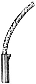
In the electric fuses illustrated, the metal case
shown is the detonator, the fuse being placed inside
above the fulminate. When safety fuse is used, the
end is cut off clean and inserted into the cap, which
is then pressed tightly upon the fuse
by means of a pair of nippers, as shown
in Fig. 35. When water tamping is
used, and when, with ordinary tamping,
the hole is very wet, a little white-lead
or grease must be put round the edge
of the cap as a protection. The electric
fuses are always made waterproof;
consequently, they are ready for use
under all circumstances. When the
safety fuse burns down into the cap,
or when, in the other case, the priming of the
electric fuse is fired, the fulminate explodes and
causes the detonation of the charge in which it is
placed.
—The electrical
machines used for firing tension fuses are of two
kinds. In one kind, the electricity is excited by
friction, and stored in a condenser to be afterwards
discharged by suitable means provided for the purpose.
In the other kind, the electricity is excited
by the motion of an armature before the poles of a
magnet. The former kind are called “frictional
electric” exploders; the latter kind are known as
“magneto-electric” exploders. When a magneto-electric
machine contains an electro-magnet instead
of a permanent magnet, it is described as a “dynamo-electric
exploder.”
Frictional machines act very well as exploders so
long as they are kept in a proper state. But as
they are injuriously affected by a moist atmosphere,
and weaken rapidly with use by reason of the wearing
away of the rubbers, it is necessary to take care
that they be in good electrical condition before using
them for firing. Unless this care be taken, the
quantity of electricity excited by a given number of
revolutions of the plate will be very variable, and
vexatious failures will ensue. If, however, the proper
precautions be observed, very certain and satisfactory
results may be obtained. In Germany and in
America, frictional exploders are generally used.
Magneto-electric machines possess the very valuable
quality of constancy. They are unaffected, in
any appreciable degree, by atmospheric changes, and
they are not subject to wear. These qualities are of
inestimable worth in an exploder used for ordinary
blasting operations. Moreover, as they give electricity
of a lower tension than the frictional machines,
defects of insulation are less important. Of these
machines, only the dynamo variety are suitable for
industrial blasting. It is of primary importance that
an exploder should possess great power. The mistake
of using weak machines has done more than anything
else to hinder the adoption of electrical firing
in this country.
Fig. 36.
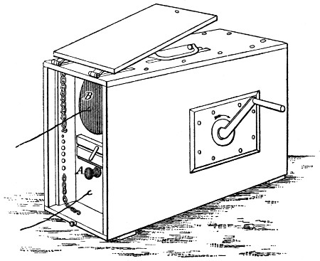
The machine most used in Germany is Bornhardt’s
frictional exploder, shown in Fig. 36. This machine
is contained in a wooden case 20 inches in length,
7 inches in breadth, and 14 inches in depth, outside
measurement. The weight is about 20 lb.
To fire the charges by means of this exploder, the
leading wire is attached to the upper terminal B,
and the return to the lower terminal C, the other
ends of these wires being connected to the fuses.
The handle is then turned briskly from fifteen to
thirty times, according to the number of the fuses
and the state of the machine, to excite the electricity.
The knob A is then pressed suddenly in, and the
discharge takes place. To ascertain the condition of
the machine, a scale of fifteen brass-headed nails is
provided on the outside, which scale may be put in
communication with the poles B and C by means of
brass chains, as shown in the drawing. If after twelve
or fourteen turns, the spark leaps the scale when the
knob is pushed in, the machine is in a sufficiently
good working condition. To give security to the
men engaged, the handle is designed to be taken off
when the machine is not in actual use; and the end
of the machine into which the cable wires are led is
made to close with a lid and lock, the key of which
should be always in the
possession of the man
in charge of the firing
operations.
Fig. 37.
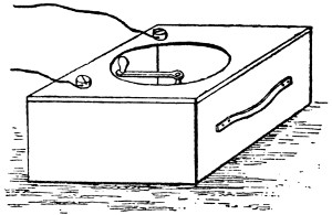
Fig. 38.
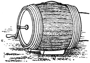
In America, there are
two frictional exploders
in common use. One,
shown in Fig. 37, is the invention of H. Julian
Smith. The apparatus is enclosed in a wooden
case about 1 foot square and 6 inches in depth.
The handle is on the top of the case, and is
turned horizontally. This handle is removable, as
in Bornhardt’s machine. The cable wires having
been attached to the terminals, the handle is turned
forward a certain number of times to excite the
electricity, and then turned a quarter of a revolution
backward to discharge the condenser and to fire the
blast. By this device, the necessity for a second
aperture of communication with the inside is avoided,
an important point in frictional machines, which are
so readily affected by moisture. The aperture through
which the axis of the plate passes, upon which axis
the handle is fixed, is tightly closed by a stuffing-box.
A leathern strap on one end of the case allows
the machine to be easily carried. The weight of this
exploder is under 10 lb.
The other exploder used is that designed by G.
Mowbray. This machine, which is shown in Fig. 38,
is contained in a wooden
barrel-shaped case, and is
known as the “powder-keg”
exploder, the form
and dimensions of the case
being those of a powder-keg.
The action is similar
to that of the machine last
described. The cable wires having been attached
to the terminals at one end of the keg, the handle
at the other end is turned forward to excite the
electricity, and the condenser is discharged by
making a quarter turn backward, as in Smith’s
machine. The handle is in this case also removable.
The weight of the powder-keg exploder is about
26 lb.
Both of these machines are very extensively used,
and good results are obtained from them. They
stand well in a damp atmosphere, and do not quickly
get out of order from the wearing of the rubbers.
They are also, especially the former, very easily
portable.
Fig. 39.
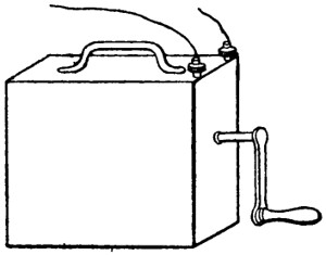
The machine commonly used in England is the
dynamo-electric exploder of the Messrs. Siemens.
This machine, which is the best of its kind yet
introduced for blasting purposes, is not more than
half the size of Bornhardt’s frictional exploder;
but it greatly exceeds the latter in weight, that
of Siemens’ being about 55 lb. The apparatus,
which is contained within the casing shown in
Fig. 39, consists of an ordinary
Siemens’ armature, which is
made, by turning the handle,
to revolve between the poles
of an electro-magnet. The coils
of the electro-magnet are in
circuit with the wire of the
armature; the residual magnetism of the electro-magnet
cores excites, at first, weak currents; these
pass into the coils, thereby increasing the magnetism
of the cores, and inducing still stronger currents in
the armature wire, to the limit of magnetic saturation
of the iron cores of the electro-magnets. By the
automatic action of the machine, this powerful current
is, at every second turn of the handle, sent into
the cables leading to the fuses.
To fire this machine, the handle is turned gently
till a click is heard from the inside, indicating that
the handle is in the right position to start from.
The cable wires are then attached to the terminals,
and the handle is turned quickly, but steadily. At
the completion of the second revolution, the current
is sent off into line, as it is termed, that is, the
current passes out through the cables and the fuses.
As in the case of the frictional machines, the handle
is, for safety, made removable. This exploder is
practically unaffected by moisture, and it is not
liable to get out of order from wear.
Induction coils have been used to fire tension
fuses; but it is surprising that they have not been
more extensively applied to that purpose. A coil
designed for the work required of it is a very
effective instrument. If constructed to give a spark
not exceeding three inches in length, with comparatively
thick wire for quantity, it makes a very
powerful exploder. An objection to its use is the
necessity for a battery. But a few bichromate of
potash cells, provided with spiral springs to hold the
zincs out of the liquid, and designed to be set in
action by simply pressing down the zincs, give but
little trouble, so that the objection is not a serious
one. The writer has used an induction exploder in
ordinary mining operations without experiencing
any difficulty or inconvenience. It is cheap, easily
portable, and constant in its action.
Batteries are used to fire what are known as
“quantity” or “low tension” fuses. Any cells may
be applied to this purpose; but they are not all
equally suitable. A firing battery should require
but little attention, and should remain in working
order for a long time. These conditions are satisfactorily
fulfilled by only two cells, namely, the
Léclanché and the Bichromate of Potash. The
latter is the more powerful, and generally the more
suitable. The Léclanché is much used in this country
for firing purposes, under the form known as the
“Silvertown Firing Battery.” This battery consists
of a rectangular teak box, containing ten cells.
Two, or more, of these may be joined up together
when great power is required. In France, the battery
used generally for firing is the Bichromate.
This battery is much more powerful than the Léclanché,
and as no action goes on when the zincs
are lifted out of the liquid, it is equally durable.
It is moreover much cheaper. At the suggestion
of the writer, Mr. Apps, of the Strand, London,
has constructed a bichromate firing battery of very
great power. It is contained in a box of smaller
dimension than the 10-cell Silvertown. The firing
is effected by simply lowering the zincs, which rise
again automatically out of the liquid, so that there
is no danger of the battery exhausting itself by continuous
action in case of neglect. Externally, this
battery, like the Silvertown, appears a simple rectangular
box, so that no illustration is needed. With
either of these, the usual objections urged against
the employment of batteries, on the ground of the
trouble involved in keeping them in order, and their
liability to be injured by ignorant or careless handling,
do not apply, or at least apply in only a very
unimportant degree.
To guard against misfires, the machine or the
battery used should be constructed to give a very
powerful current. If this precaution be observed,
and the number of fuses in circuit be limited to one-half
that which the machine is capable of firing with
a fair degree of certainty, perfectly satisfactory results
may be obtained. The employment of weak
machines and batteries leads inevitably to failure.
In the minds of those who have hitherto tried electrical
blasting in this country, there seems to be no
notion of any relation existing between the work to
be done and the force employed to do it. The electrical
exploder is regarded as a sort of magic box
that needs only to be set in action to produce any
required result. Whenever failure ensues, the cause
is unhesitatingly attributed to the fuses.