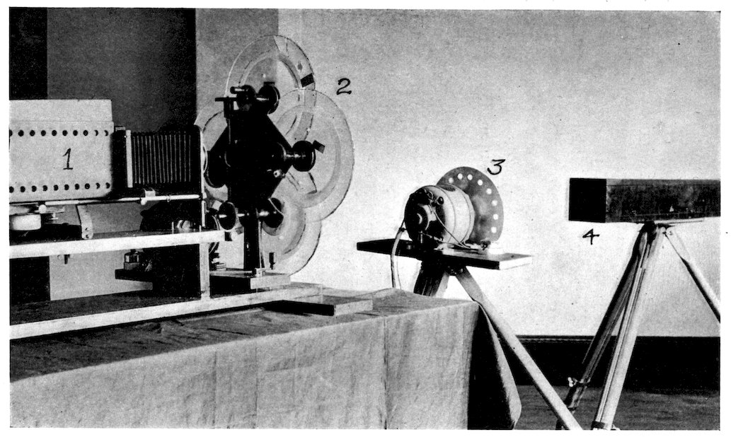
Vision by Radio — INITIAL ACTIVITIES: — PRISMATIC RING: — TRANSMITTING METHODS: — RECEIVING METHODS: — FILAMENT LAMP: — GLOW LAMP: — CONTROL FORK: — RADIO MOTOR: — STROBOSCOPIC LAMP: — SAME WAVE: — MULTIPLE-SIGNAL RADIO: — RADIO VISION: — RADIO SERVICE TO THE EYE: — MECHANISMS EMPLOYED: — SENDING MACHINES—ZINC ETCHING: — SWELLED GELATINE PRINT: — FILLED-IN HALFTONES: — LIGHT SENSITIVE CELLS: — PERFORATED PAPER STRIPS: — RECEIVING MACHINES: — INK PEN RECEIVERS: — CAPILLARY PEN: — ELECTROLYTIC RECEIVERS: — PHOTOGRAPHIC RECEIVERS: — OSCILLOGRAPH RECEIVERS: — LIGHT WEDGE MODULATION: — SILVER WIRE GALVANOMETER: — PNEUMATIC VALVE: — SPARK GAP: — FILAMENT LAMP: — CORONA LAMP:
11
The earliest attempts to send pictures and to see
electrically date back some fifty years, being
practically coincident with efforts to transmit sound
electrically.
At first a metallic circuit was employed to carry
the impulses representing picture values, but when
radio was available several workers immediately
began the adaptation of their apparatus to radio
circuits.
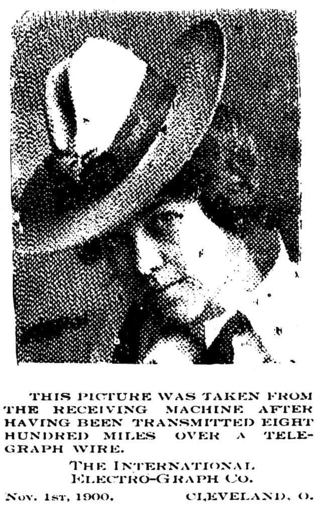
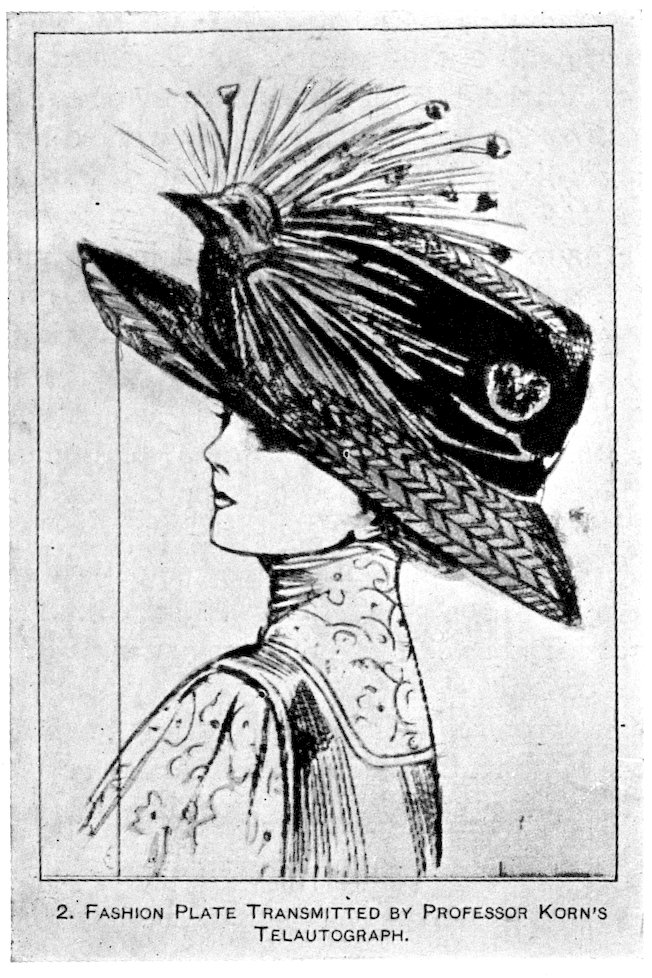
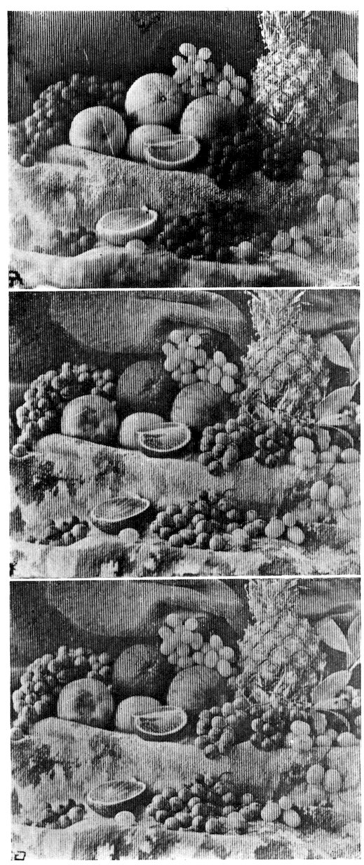
Some remarkably fine examples of pictures transmitted
by both wire and radio have been produced
in recent months; most of them showing the lines,
but some of them without lines at all, i. e., true
photographic results.
And as the transmission of images from living
subjects in action differs from “still” pictures only
in that they are more rapidly formed, it naturally
followed that the solution of this problem should
also be undertaken.
When radio service to the eye shall have a comparable
development with radio service to the ear, a
new era will indeed have been ushered in, when
distance will no longer prevent our seeing our friend
as easily as we hear him.
Our President may then look on the face of the
King of England as he talks with him; or upon the
countenance of the President of France when exchanging
assurances of mutual esteem.
12The general staff of our Navy and Army may see
at headquarters all that a lens looks upon as it is
carried aloft in a scouting airplane over battle front
or fleet maneuvers.
And from our easy chairs by the fireside, we stay-at-homes
can watch the earth below as a great ship,
like the Shenandoah, carries our flag and a broadcasting
lens, over the mountains and plains, the
cities and farms, the lakes and forests, of our wonderful
country.
In due course, then, folks in California and in
Maine, and all the way between, will be able to see
the inaugural ceremonies of their President, in
Washington; the Army and Navy football games at
Franklin Field, Philadelphia; and the struggle for
supremacy in our national sport, baseball.
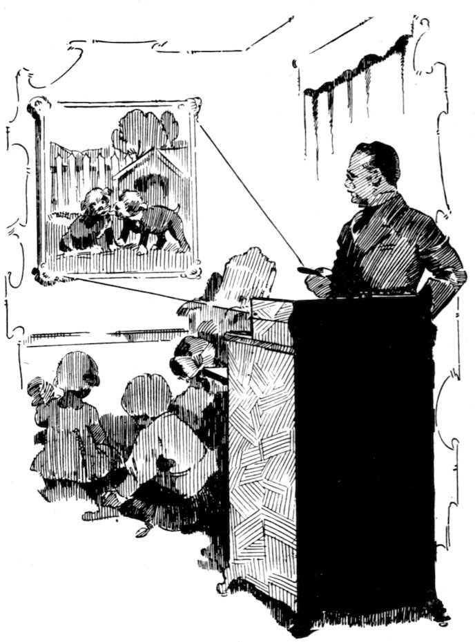
The new machine will come to the fireside as a
fascinating teacher and entertainer, without language,
literacy, or age limitation; a visitor to the old homestead
with photoplays, the opera, and a direct vision
of world activities, without the hindrance of muddy
roads or snow blockades, making farm life still more
attractive to the clever country-bred boys and girls.
Already audible radio is rapidly changing our social
order; those who may now listen to a great man or
woman are numbered in the millions. Our President
recently talked to practically the whole citizenship
of the United States at the same time.
When to this audible radio we add visible radio,
we may both hear and see great events; inaugural
ceremonies, a football, polo, or baseball game; a
regatta, mardi gras, flower festival, or baby parade;
and an entire opera in both action and music.
Educationally, the extension worker in our great
universities may then illustrate his lecture, for the
distant student can see as well as hear him by radio.
13It is not a visionary, or even a very difficult thing
to do; speech and music are carried by radio, and
sight can just as easily be so carried.
To get music by radio, a microphone converts
sound into electrical modulation, which, carried by
radio to distant places, is then changed back into
sound and we hear the music.
To get pictures by radio, a sensitive cell converts
light into electrical current, and at radio distances
changes these currents back into light values, and
one may see the distant scene; for light is the thing
of which pictures are made, as music is made of
sound.
To further show the close relation, it might be
added that in receiving sets these same electrical
values can be put back either into sound with headphones
or into light with a radio camera; although
it may be admitted that such radio signals do not
make much sense when with headphones one listens
to the pictures.
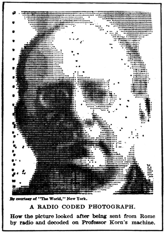
Already radio vision is a laboratory demonstration,
and while it is not yet finished and ready for general
public introduction, it soon will be, for it should be
borne in mind that animated pictures differ from
still pictures only in the speed of presentation, and
the sending of “still” pictures by radio is now an
accomplished fact, radio photographs of no mean
quality, examples of which appear as illustrations in
this volume.
Just as is done in radio photographs the picture
surface is traversed by a small spot of light moving
over the picture surface in successive parallel adjacent
lines, with the value of the lines changed by the
incoming radio signals to conform to a given order,
the order being controlled by the light values of the
scene at the distant sending station.
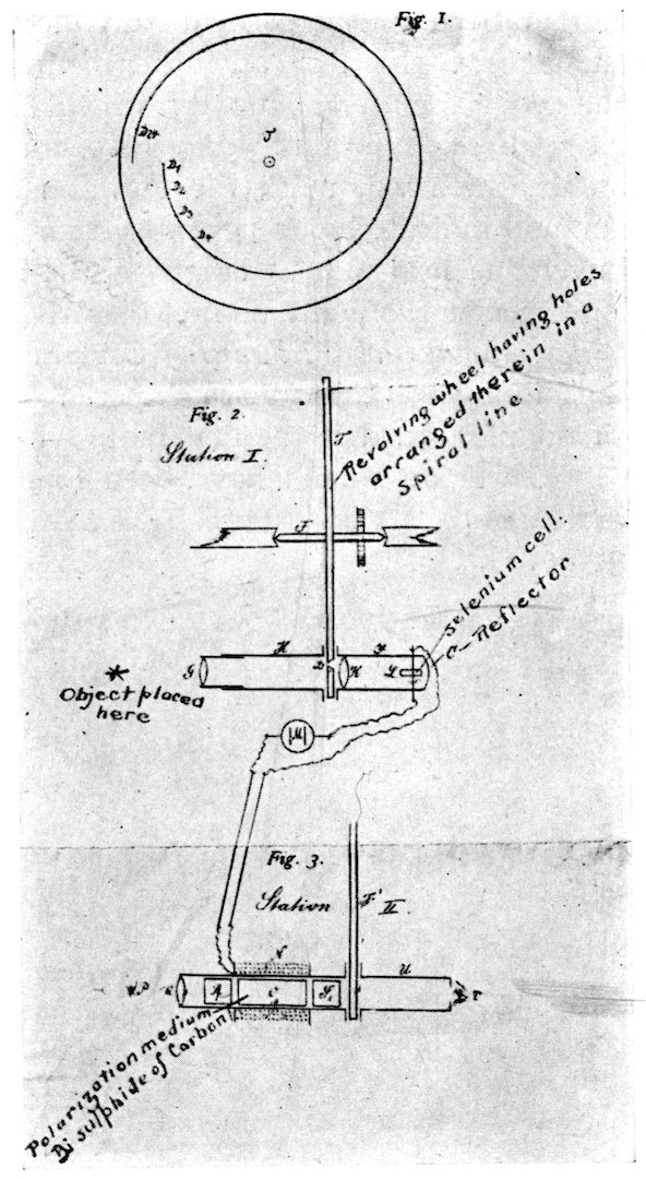
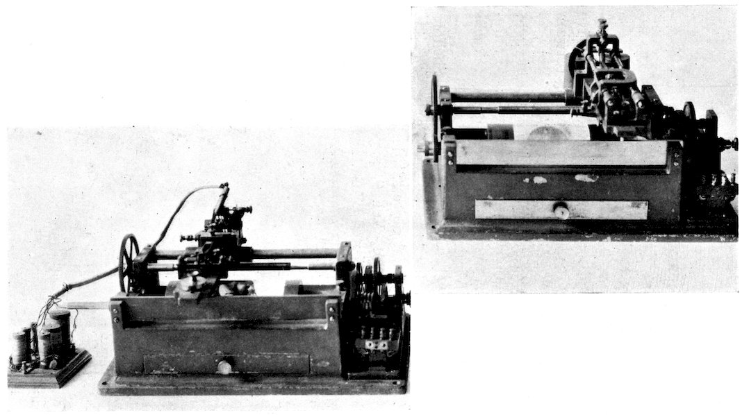
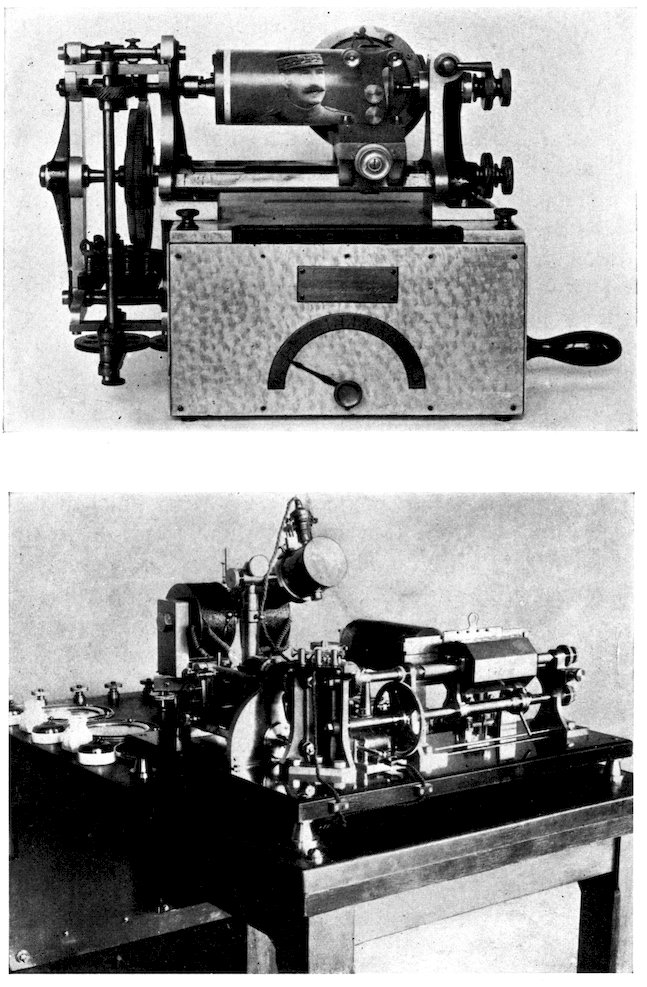
14In sending pictures electrically, there have been
but two methods employed, perhaps the only methods
possible; namely (a) a cylinder mechanism; and (b)
a flat surface.
Without exception, every scheme which had
attained any degree of success, before the author
adopted flat surfaces, has depended upon synchronous
rotation of two cylinders, one at the sending station
with the picture thereon to be sent; and the other
at the receiving station where the picture is to be
put.
Perhaps the very obviousness of the cylinder
scheme, and that there are no patents to prevent,
explains why it has been employed by so many.
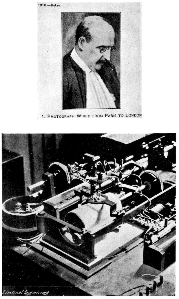
And there have been many workers in this line of
endeavor; for example, in England, Lord Northcliff,
Sir Thompson, Mr. Evans and Mr. Baker; in France,
MM. Armengaud, Ruhmer, Rignoux, Fournier, and
Belin; in Germany, Paul Nipkow, Dr. Anchutz, and
Dr. Korn.
In America, Mr. Ballard, Mr. Brown, and Mr.
Amstutz, the latter deserving particular mention,
for, from a distant picture, a swelled gelatine print,
he engraved a printing plate which could be put
directly on a printing press for reproduction.
All these many workers have adopted the cylinder
method of sending and receiving, and all have arrived
at approximately the final stage of development
permitted by concurrent science.
It may be well to explain that, in these older
schemes, the picture to be sent is wrapped around
the cylinder, usually a cylinder of glass where light
sensitive cells are employed, mounted on a rotating
shaft, which also has longitudinal displacement.
The light values which make up the picture are
converted into electric current of corresponding
15values and put upon a wire or other channel which
delivers them to the distant receiving station.
At the receiving station a suitable film-like sheet
(paper, for example) is wrapped around a cylinder
similar to that at the sending station. As this
cylinder is rotated and longitudinally advanced
under a stationary point in contact with the paper
on the cylinder, a spiral is traced thereon. As the
incoming electrical current represents picture values,
and as the two cylinders are turning in exact synchronism,
a picture duplicate of that at the sending
station appears thereon. After the picture is completed
the paper sheet can then be taken off the
cylinder and flattened out for such use as may be
desired.
It is quite obvious that vision by radio and radio
movies can never be attained by a cylinder method,
for as the picture must appear to the eye complete,
by reason of persistence of vision, it naturally
follows that the eye must make up the whole picture
from a single focal plane.
The attainment of “television” or Radio Vision, as
it is now coming more commonly to be called, requires
that the sending shall be from a flat plane, and
reception on a flat plane, and a modulation which
will give not only the high-lights and shadows but the
halftones as well.
These “flat planes” may, of course, be the focal
planes of the lenses employed at the receiving station,
and from the focal depth of the lens at the sending
station where the picture may perhaps be taken from
living actors in the studio or from an outdoor scene.
At the receiving station the “flat surface” may be
a photographic plate, a white wall, or a miniature of
the usual “silver sheet” of the motion picture theatre.
It may aid in a clearer and quicker understanding
16of the text if the words telephone and television be
limited to metallic circuit service, while radio phone
and radio vision is applied to radio carried signals,
and this designation will be employed in the following
pages.
17
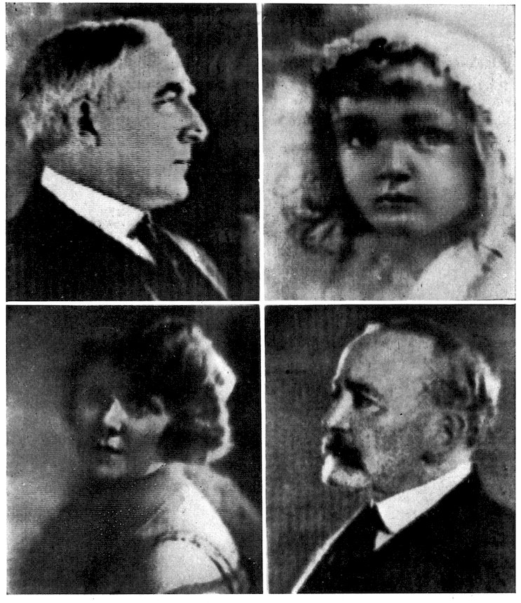
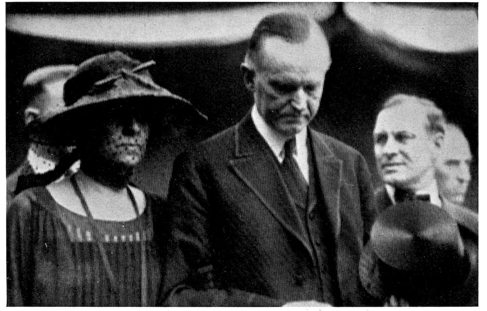
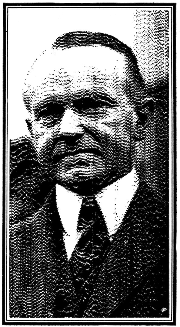
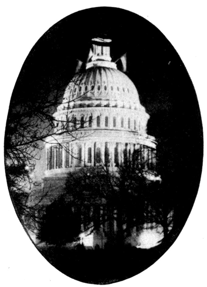
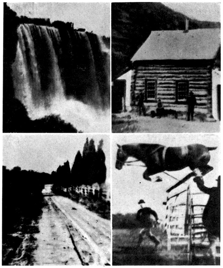
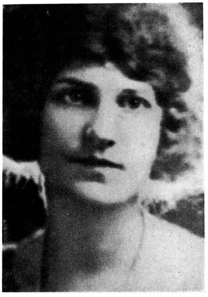
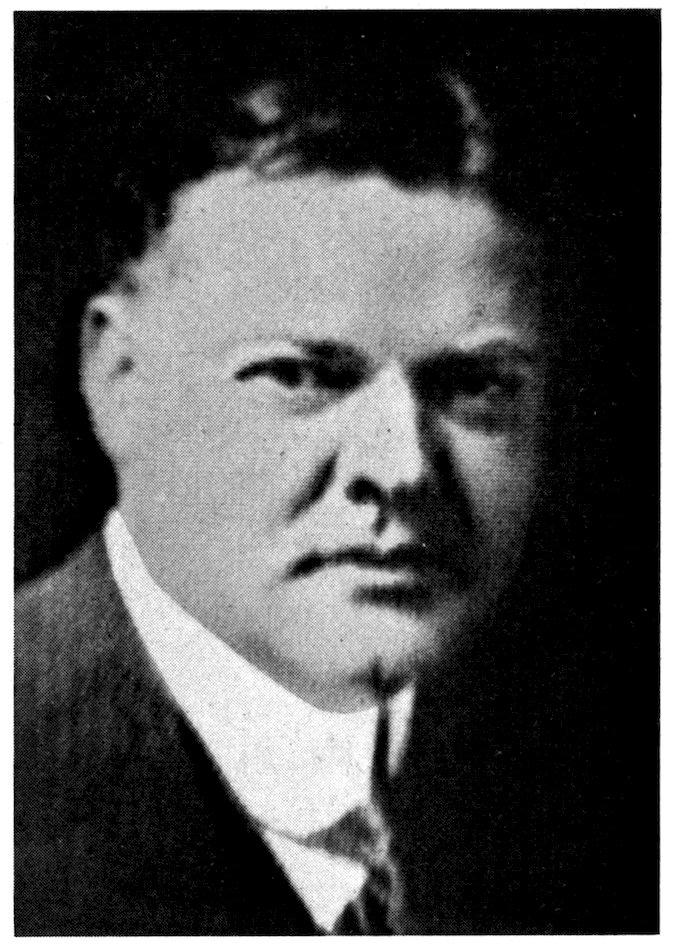
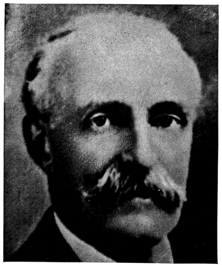
This and succeeding pages are examples of photographs received
by radio from a distance, by the Jenkins system, some
of them from Washington to Philadelphia, and represent the
best work done in 1922, 1923, and 1924.
18
19
20
21
22
23
25
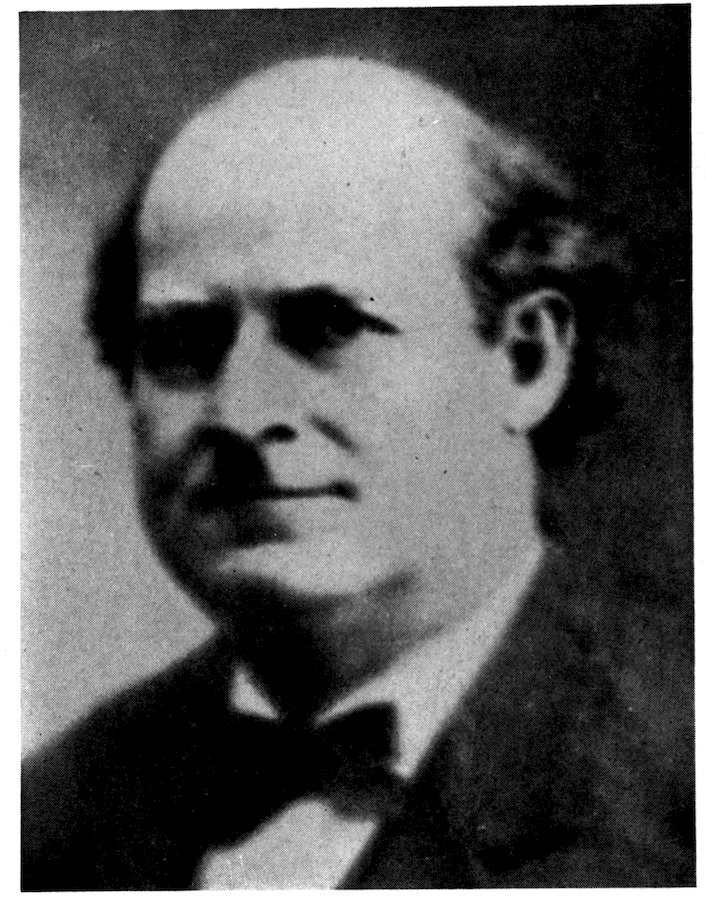
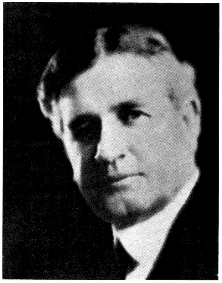
The author’s work began with the publication in
the Motion Picture News, of October 4, 1913, of an
article entitled “Motion Pictures by Wireless.” This
contemplated the employment of a flat receiving
surface, but in the light of subsequent experience
the scheme proposed therein is believed to be impractical.
It did, however, provoke discussion of
the subject and initiated the work which was thereafter
rather continuously prosecuted, except for
interruption to aid in the great World War.
After failure to find a practical, workable mechanism
made up of devices already in use in applied
science, diligent effort was made to discover the
necessary, missing part.
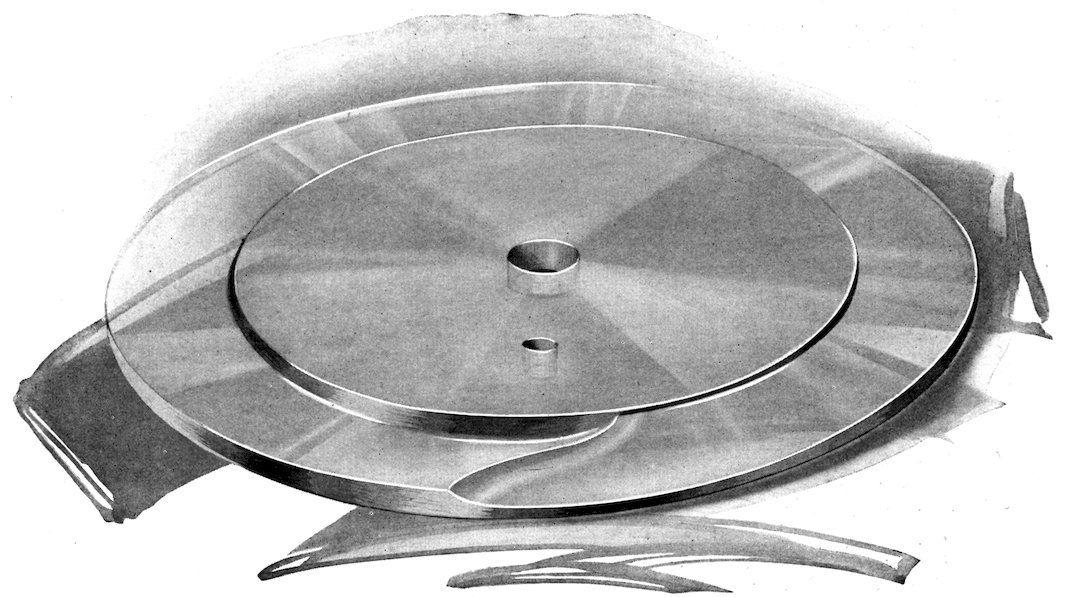
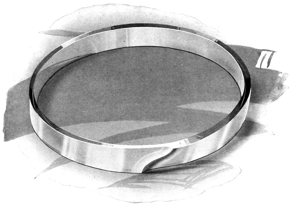
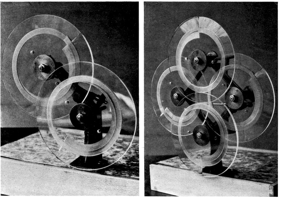
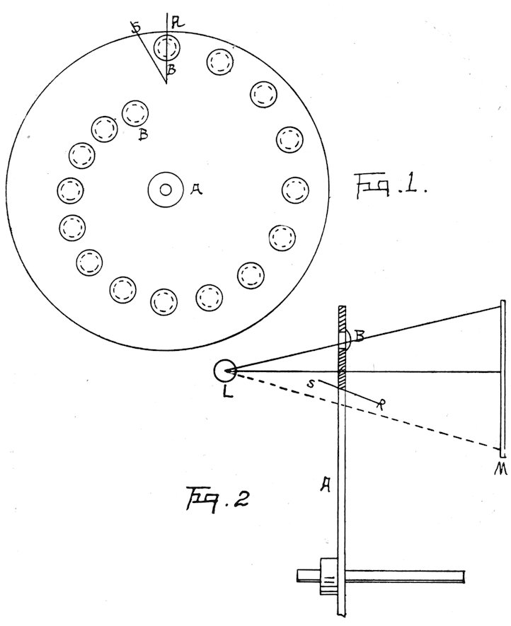
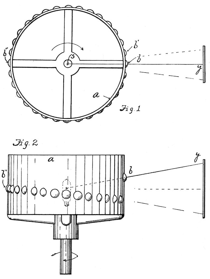
At length a device described as a prismatic ring
was developed, a new contribution to optical science.
In use it is comparable to a solid glass prism which
changes the angle between its sides, giving to a beam
of light passing therethrough a hinged or oscillating
action on one side of the prism while maintaining a
fixed axis of the beam on the other side of the prism.
As a convenience in fabrication this prismatic
ring is ground into the face of a glass disc of suitable
size, of selected mirror plate, which gives the ring
its own support on the rotating shaft upon which it
is mounted.
Success in sending pictures by radio from flat
photographs and receiving them on flat photo negative
26plates (and subsequently of radio vision),
really began with the perfection of automatic
machines for the making of these prismatic rings,
for by means of these prisms and a light sensitive cell
at the sending station the light values which make
up the picture are converted into electrical values,
and broadcast.
So to put this picture on a radio carrier wave we
simply slice up the picture (figuratively) into slices
one-hundredth of an inch in width, in the best pictures,
by sweeping the picture across the light
sensitive cell by means of these rotating prismatic
rings. With each downward sweep the picture is
moved one-hundredth of an inch to the right until
the whole picture has crossed the cell, the cell converting
the light strengths of the different parts of
each such slice into corresponding electrical values.
The process very much resembles a bacon slicer
in the market, each slice showing fat and lean.
Similarly these imaginary slices of our picture show
light and dark parts, and these lights and shadows
moving across the sensitive cell produce corresponding
strength of electric current, modulating the radio
carrier wave of the broadcasting set accordingly.
Further, of course, it is immaterial whether the
current modulation is taken directly from a flat
photograph, from a solid object, or from an outdoor
scene at which the transmitter is pointed.
To put these light values back together again at
the distant receiving station to make up a negative
of the picture being broadcast from the sending
station, it is only necessary to reverse the process;
first, with a point of light to draw lines across a
photographic plate, which the rotating prismatic
27rings do; and, second, to vary the density of the
different parts of the successive lines corresponding
to lights and shadows of the picture at the sending
station, and this the varying strength of the incoming
radio signal does by varying the intensity of the
light.
Dense areas in the negative are built up where the
light is successively very bright at the same place in
adjacent lines; halftones where the light is less
intense; while where the light is very faint, little or
no exposure occurs, and shadows will result.
It is thus the lights and shadows which make the
picture are built up, line by line, for when this
negative is developed, and paper prints made therefrom,
the dense areas produce high-lights in the
picture; the less dense areas the halftones; and the
thin areas the shadows of the picture, person or
scene broadcast at the sending station. It is simply
that a photographic negative has been made of
what the lens at the sending station is looking at.
So, then, to receive pictures by radio, it is only
necessary (1) to cover a photographic plate in
parallel adjacent lines, and (2) to vary the density
of the lines, to build up the shadows, the halftones,
and the high-lights of the picture.
If one puts a nickel under a piece of paper and
draws straight lines across it with a dull pencil, a
picture of the Indian appears. And that is exactly
the way photographs by radio are received, except
that a photographic plate is used instead of a piece
of white paper, and a pencil of light instead of the
pencil of lead, the light pencil changing the exposure
in various parts of the successive adjacent parallel
lines by reason of the variation of the incoming radio
signals.
The scheme is just a long camera with miles instead
28of inches between lens and plate. For example, the
lens in Washington and its photographic plate in
Boston; with this exception, that the one lens in
Washington can put a negative on one, ten or one
hundred photographic plates in as many different
cities at the same time, and at distances limited
only by the power of the broadcasting station, radio
instead of light carrying the image from lens to plate.
The time for transmitting a picture depends upon
the size of the picture and strength of light, say,
from three to six minutes, using a filament lamp as a
source.
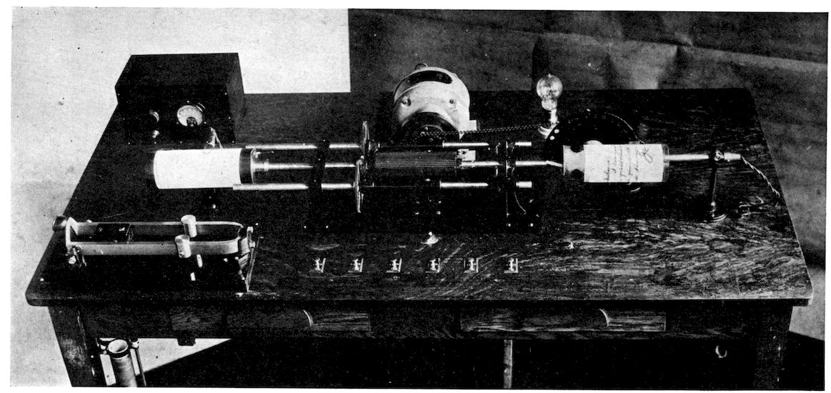
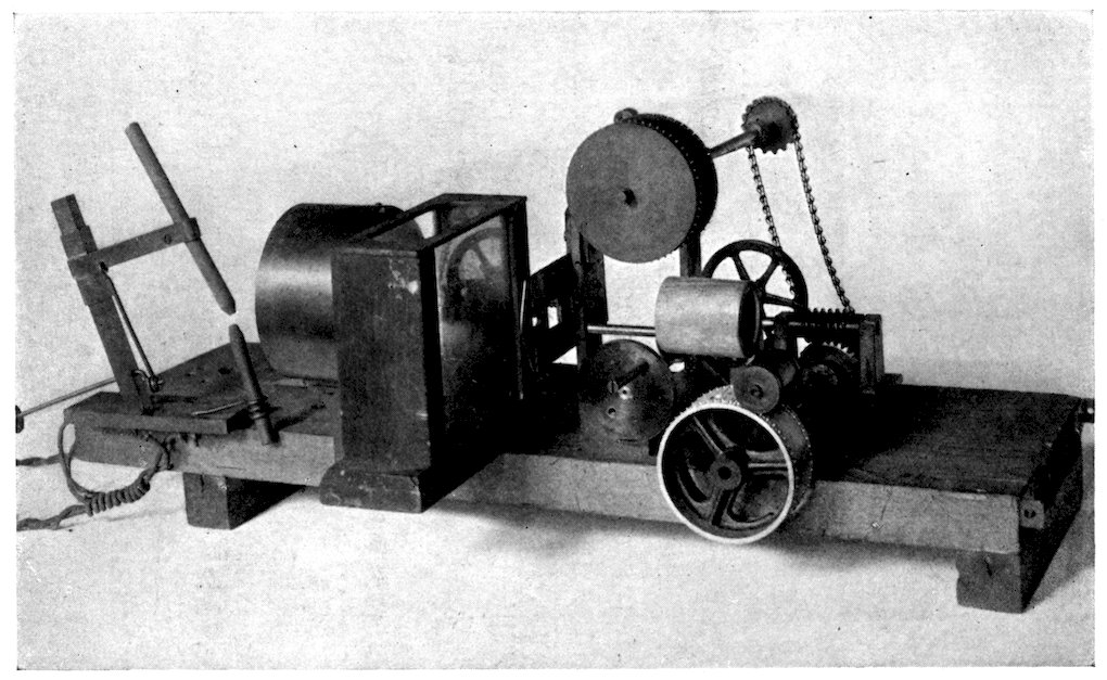
The radio photograph receiving instruments are
rather simple and inexpensive and, like a loudspeaker,
can be attached to any standard amplifying audio-radio
receiving set.
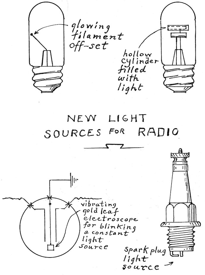
For the light source for radio photographs a filament
lamp is employed, and in a single turn coil
enclosed in a hydrogen atmosphere. This miniature
filament coil is imaged on a photo negative plate,
and the variation in the light is caused by putting
the incoming radio signals through this lamp, perhaps
after the filament has been brought to a red
glow by a battery current. By adjusting the speed
of the motor to the temperature change of this
filament soft gradations of light and shade are
obtained which probably can never be equaled by
any other device, a photograph of true photographic
value, entirely free of lines.
The author wishes to take this occasion to express
his appreciation of the splendid assistance of the
General Electric Company, under the personal
supervision and hearty cooperation of Mr. L. C.
Porter, who from the very first has shown his confidence
29in the ultimate successful conclusion of this
development.
For the high speed radio photograms, where only
blacks and whites are needed, a corona glow lamp of
very high frequency has been developed. This lamp
is lighted by the plate current of the last tube of the
amplifier; and as the lamp can be lighted and extinguished
a million times a second, it is obvious
that the permissible speed is almost limitless, and a
thousand words per minute is believed ultimately
possible.
This lamp has been developed for the author by
Professor D. McFarlan Moore, an expert in lamps
incorporating this phenomena, and who some years
ago, it may be remembered, produced a lamp of this
type more than two hundred feet long. It is probably
safe to predict that no other lamp will ever be
able to compete in speed.
As photography is the quickest means of copying
anything; and radio the swiftest in travel, it seemed
logical that the two hitched together should constitute
the most rapid means of communication
possible.
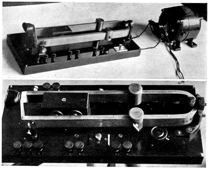
Of course, the sending machine and the receiving
machines must run in exact synchronism. This
synchronous control of the sending and receiving
motors is maintained by the vibration of a rather
heavy fork at each station, and adjusted to beat
together, with such slight automatic correction by
radio as may be required to keep all receiving forks
in step with the fork of the station which at the
moment is sending. It is a very simple and dependable
30mechanism, by which any number of motors, of
any size, separated by any distance, can be made to
run in synchronism.
Another scheme of the rotary type, perhaps even
better adapted to the distant control of large motors,
is a small synchronous radio motor driven by power
carried by radio from the broadcasting station to the
receiving stations. It is, of course, rotated partly by
radio power from the distant station, and partly by
local current, just as a loudspeaker is operated.
These small motors, rotating in synchronism with
the motor at the sending station, control the rotation
of a larger motor in each receiving camera, and so all
stations keep in step.
Of course, it would be fatal if it were necessary to
wait until the picture was developed before it could
be discovered that the receiving camera was getting
out of control. So a special “neon” lamp is located
to shine on a revolving marker on the motor shaft
of the receiving instrument, and flashed by the incoming
radio signals, which latter bear a definite relation
to the rotation of the sending station motor.
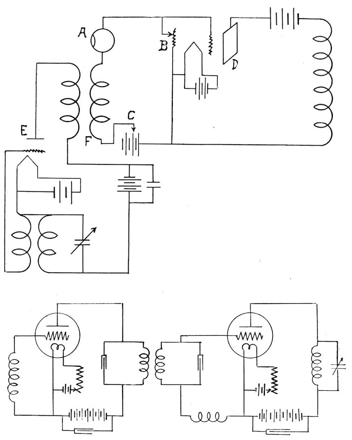
It should be noted that the same radio wave
carries both the picture frequency which builds up
the photograph and the synchronism frequency which
controls the motors, and also that it lights the
stroboscopic lamp.
A further advance step was made when an audible
message was added to the same radio wave which
31carried the picture. This is done by modulating
the carrier wave to give audibility, while interrupting
the same carrier wave at a frequency far above the
audible range, say, two hundred thousand cycles, to
make our picture.
By means of this duplex employment of the same
radio wave, it is possible to get, for example, both
the gesture and the voice of an inaugural address;
the play and the cheers of a national sport; or the
acting and song of grand opera.
Perhaps it might be explained that synchronism
in visual-audible radio reception is accomplished by
the simple expedient of keeping the radio picture
“framed,” exactly as this is done in the motion
picture theatre.
But continuing the description of the still picture
processes a little further, before taking up Radio
Vision and Radio Movies, it might be added that
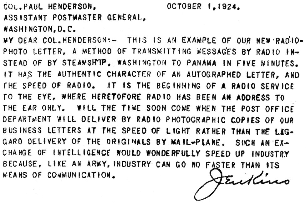
while photographs by radio is the more interesting
and impressive process, there is little doubt but that
radio photo letters will be of much greater immediate
service in business.
Commerce, like an army, can go forward no faster
than its means of communication. The history of
industrial advance in all ages shows that with every
addition to communication facilities the volume of
business has increased. Obviously a third electrical
means of communication will enlarge business, and
speed up commerce and industry.
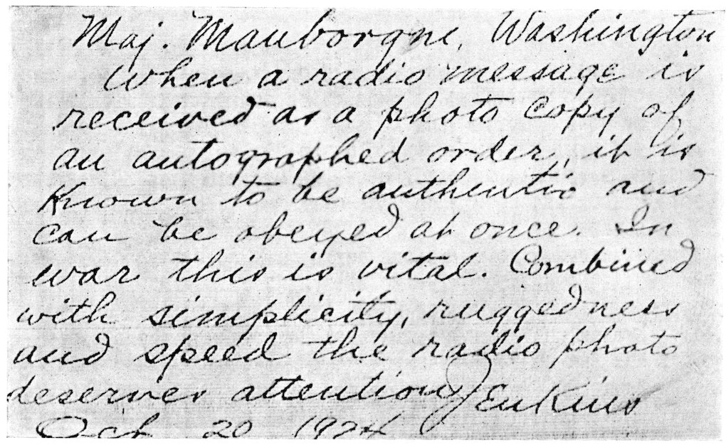
As an aid in national defense the chief of staff of the
Signal Corps of the Army, in a recently published
report to the Secretary of War, said (Washington
Star, November 22, 1924):
“Looking into the future of signal communication
for a moment, it appears that the basic method of
breaking messages up into words, words into letters,
32letters into dots-and-dashes, and then passing these
through the wrist of an operator, as has been the
practice since Morse’s fundamental invention of the
electric telegraph, seems to be nearing the end of a
cycle. Mechanical transmitters with higher speed
qualities are becoming stabilized and American
invention seems to be making further and rapid
progress in associating photography with radio,
which bids fair to revolutionize fundamental methods
of transmission.
“The message of the future, whether it be written,
printed, of mixed with diagrams and photographs,
including the signature of the sender, will, it seems
certain, soon be transmitted photographically by
radio frequency at a rate tens of times faster than
was ever possible by the dot-and-dash methods of
hand transmission.
“Military messages of the future, particularly in
active operations, may contain diagrams and
sketches, or even entire sheets of maps, all transmitted
as part of the same message and by means
of which detection or listening-in will be reduced to
a very low minimum.”
The author suggests that it might be added that
the newcomer, the radio photogram, has merits
distinctly its own, e. g.:
(1) It is autographically authentic; (2) it is photographically
accurate; (3) it is potentially very rapid;
(4) it is little effected by static; (5) it is not effected
by storms; and (6) it is automatic and tireless.
It can also be used to enlarge the individual newspaper’s
influence and prestige by the establishment of
photostat branch printing plants at strategic points,
like summer camps, and winter resorts, and at
ridiculously little cost.
Such copies of the news, financial and market
report pages of the paper could be distributed in
these distant places before they could possibly
appear on the streets of the home city of the paper.
33Of course, produce market reports, stock market
news, and similar matter could be so distributed very
much quicker than could be done by any other
system, certainly so to the farmer and gardener.
Radio Photographs and Radio Vision, when both
are done by the flat-plate method, are identical in
principle, the difference being only in the speed of
the apparatus, with such modification in the apparatus
as will permit of the required speed.
Just as in the Radio Photograph the picture surface
of the Radio Vision is covered with a small spot of
light moving over the picture surface in successive
parallel lines, with the light value of the lines changed
by the incoming radio signals to conform to a given
order, the order being controlled by the distant
scene at the sending station.
And as the whole picture surface is covered in
one-twelfth to one-sixteenth of a second, persistence
of vision of the human eye is sufficient to get the
picture from the white receiving screen—a photographic
plate is not necessary.
When the machine of Radio Vision is turned over
slowly, the little spot of light on the screen which
makes up the picture looks for all the world like a
tiny, twinkling star as it travels across the white
surface of the screen in adjacent parallel lines, changing
in light value to correspond in position and intensity
to the light values of the scene before the lens
at the broadcasting station.
But when the machine is speeded up until the succession
of lines recur with a frequency which deceives
the eye into the belief that it sees all these lines all
the time, then a picture suddenly flashes out on the
white screen in all the glory of its pantomime mystery.
34To accomplish this, the apparatus must be speeded
up until a whole picture can be assembled on the
screen, say, in one-sixteenth of a second, to be seen
by the eye directly.
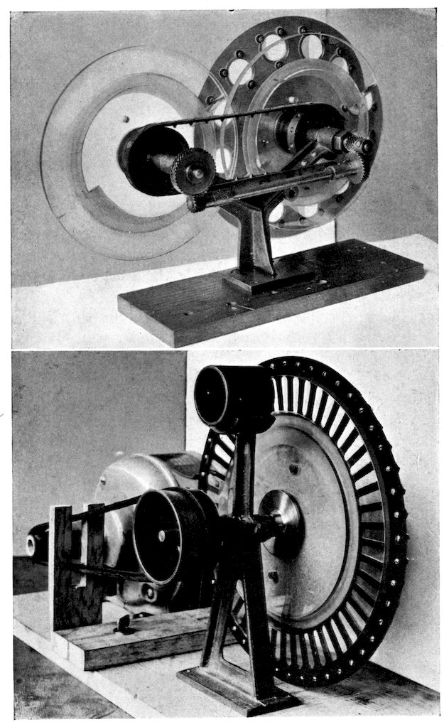
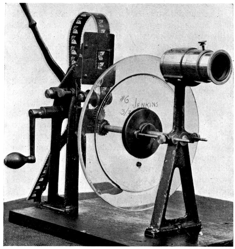
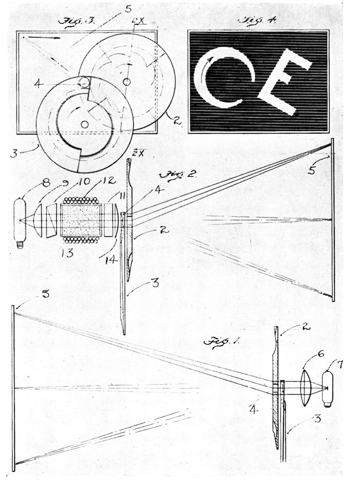
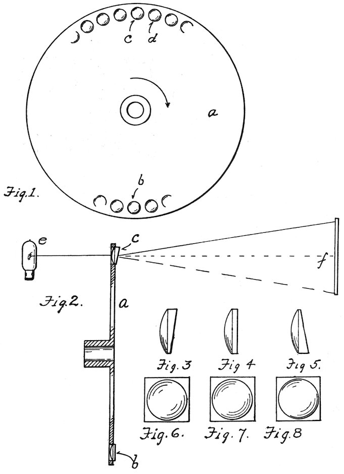
It was necessary to modify the Radio Photo
apparatus to permit this increase in speed. So a
lens disc is substituted for the fast pair of prismatic
plates. Each lens draws a line while the relatively
slow rotation of the prismatic plates distributes the
lines over the whole picture surface, just exactly as
the plates do in the Radio Photo Camera.
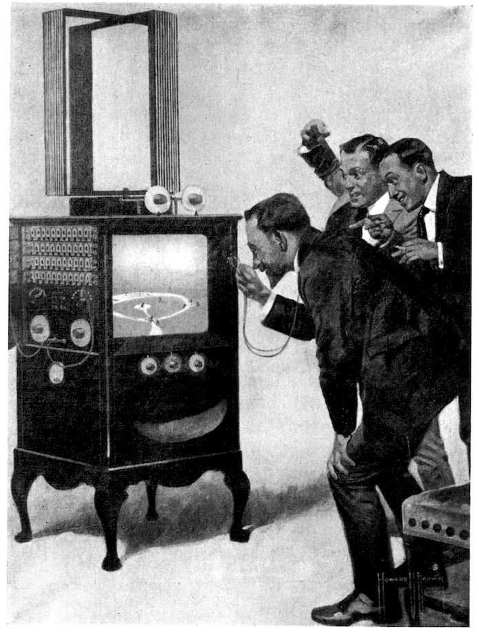
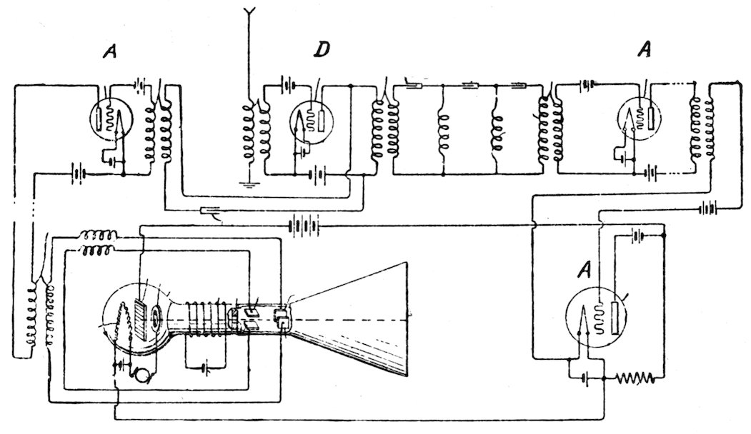
The Radio Vision receiving set and the Radio
Movies set are identical, and one may, therefore,
see in one’s home what is happening in a distant
place, an inaugural parade, football, baseball, or
polo game (and we call it Radio Vision); or one may
see the motion picture taken from the screen of a
distant theatre (and we call it Radio Movies).
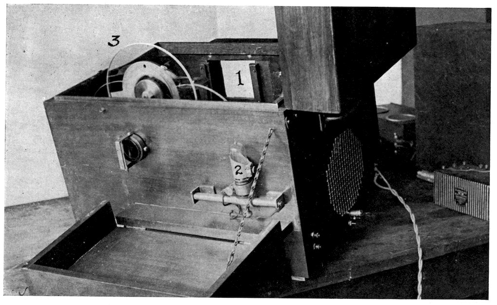
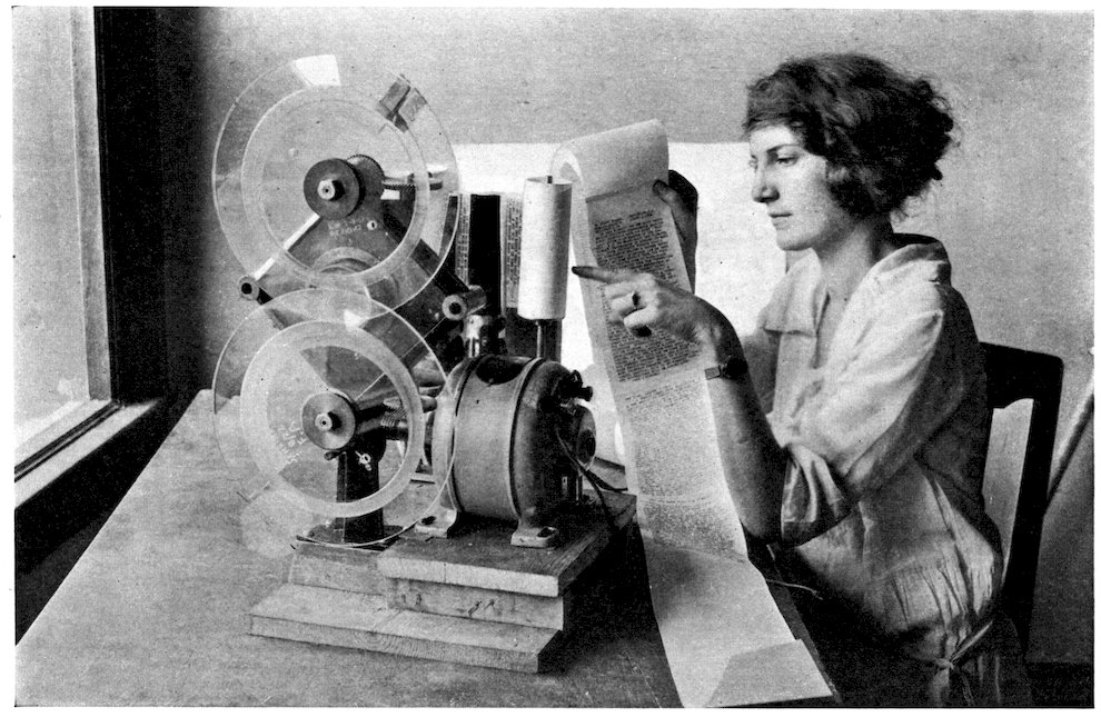
The Radio Vision receiving set, as now designed,
is very simple; namely, a mahogany box, or small
lidded cabinet, containing, beside the radio receiving
set and a loudspeaker, only a small motor rotating a
pair of glass discs, and a miniature, high frequency
lamp for outlining the pantomime picture on a small
motion picture screen in the raised lid of the cabinet,
synchronism being maintained by the simple expedient
of “framing” the picture on the screen exactly
as this is done in a moving picture theatre.
The author wishes to acknowledge his indebtedness
to his friend, Professor D. McFarlan Moore,
for a word name for this new device, i.e., “telorama”
for the radio vision instrument, and “teloramaphone”
for the instrument when it includes simultaneous
reproduction of the music or sound accompanying
the living scene.
35
36
37
38
39
Since the initiation of broadcasting, a veritable
army of engineers have been devoting themselves to
the development of radio as a service to the ear.
The author for several years has been, rather
lonesomely, devoting his efforts to the development
of radio as a service to the eye.
Incidentally it is suggested that there are undreamed
of possibilities in radio in the unlimited
frequencies above audibility, in which speed transmission
is greatly accelerated by the tolerance of
eyesight, not possible in an appeal to the ear. Witness,
the motion picture theatre screen upon which a
picture is taken off and put back again forty-eight
times per second without discovery by the eye; while
the slightest error in a note in the orchestra is
detected at once and grates harshly on the ear.
Just as the motion picture depends for success on
the fact that the eye is easily deceived, so in Radio
Vision the eye is fooled into the belief that it sees the
radio picture as a whole, though in fact the eye sees
at any one moment only the tiny spot of light by
which, with almost lightning like speed, the picture
is made up.
Audio radio engineers have been working in the
very limited audio-frequency band below, say, ten
thousand cycles, whereas the workable range where
light instead of sound is employed goes away up to
millions of cycles. It is confidently predicted that
the next great development in radio is in this area.
When the “teloramaphone” is made generally
available, then pictures at the fireside sent from
distant world points will be the daily source of news;
the daily instructional class; and the evening’s
entertainment; and equally the long day of the sick
and shut-ins will be more endurable, and life in the
40far places less lonely, for the flight of radio is not
hindered by rain, or storm, or snow blockades.
The successful study of the problem of the transmission
of light effects electrically (vision, pictures,
light signals, etc.) might well begin with the division
of the subject into its elements and sub-elements.
The major division is, naturally, into (a) the
sending station apparatus; and (b) the receiving
station apparatus. A great variety of devices have
been invented for analysis of the picture at the
sending station, and the translation of the light values
(which make up the picture) into electrical modulation;
and likewise a variety of methods for receiving
these electrical signals at a distant place (or places)
and there changing the electrical modulations back
into light values with which the picture is built up.
Before the refinement of light sensitive cells, actual
electrical contact was oftenest employed in sending
the impulses which represented light gradations in
the picture.
Usually, therefore, a zinc etching of a pen and ink
picture was made, and curved into a cylinder. This
picture cylinder was then slipped onto a rotating
mandril, which was also moved axially by a screw
thread on the mandril shaft; or the cylinder rotated
and a contact arm moved along by the screw, like
the old wax cylinder phonograph.
A delicately suspended arm, moved along by the
screw as just described and carrying, instead of the
phonograph sound box, a very small and smooth
point which was lifted by the high parts of the zinc
etched picture. When so lifted the arm makes
41electrical contact with an adjustable point and
current is put into the inter-station wire circuit.
By this means the values of the picture are converted
into corresponding duration values of an
electric current, and put onto a wire connecting the
sending machine with a distant receiving machine
(described in detail later in the text).
It will thus be seen that the electric impulses sent
out over a wire attached to the contact point represent
the value of the light and dark portions of the
picture.
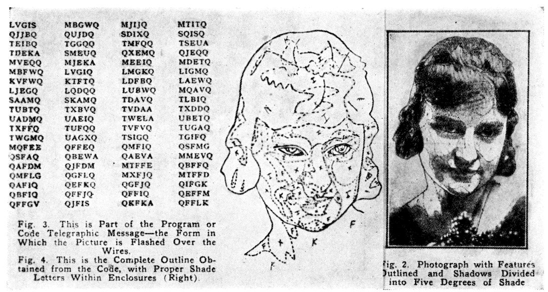
The electric impulses are similar to letter-code
dots-and-dashes, for the picture actually opens and
closes the circuit, like a telegraph key, the dark
portions of the picture sending dashes and the light
portions of the picture sending dots. With the
point set at one end of the cylinder, and the contact
arm advancing longitudinally by reason of the thread
on the shaft, the point traverses a spiral around the
cylinder until the whole picture is covered.
In another process a swelled gelatine picture print
was used to raise and lower the contact-making arm,
and a carbon contact button was employed, but
otherwise the sending machine was much the same.
Somewhat later halftones of photos were available,
and these were similarly bent into cylinders. The
interstices between the metal points of the halftones
were filled with an insulating wax, and the whole
smoothed off until the bright metal points (of different
size and representing the different values of the
picture) were exposed.
When this picture cylinder was rotated under a
42contact point, the cylinder and the point being
parts of an electric circuit, current flowed in the
circuit whenever the point touched the metal parts
of the picture, but no current flowed when the
insulation passed under the point.
Because the point does not jump up and down,
but has a smooth surface to ride on, greater speed
and accuracy is possible with the filled-in etching.
As is quite generally known there are certain
“semi-metals” which have the property of changing
their resistence to an electric current when light falls
thereon.
Of this group selenium is typical, although there
are several others, thallium, strontium, barium, etc.
More recently it was discovered that some of the
rarer alkali metals had the property, under certain
conditions, of actually converting light into electric
current. In this group are potassium, sodium,
caesium, rubidium, etc.
These light sensitive cells vary the electric current
quite accurately in proportion to the intensity of
the light falling thereon, and when available were
quickly seized upon by the workers in “pictures-by-electricity.”
When these light sensitive cells were employed,
a modification of the previous picture-translating
methods and mechanisms was made, for now a
modulation instead of an interruption of the electric
current was possible, the modulation representing
the values of the halftones of a picture transparency
as well as its blacks and whites.
The rotating cylinder now employed was of glass,
around which the picture, on transparent film, was
wrapped. Inside the cylinder a light was put to
43shine through the passing picture film as a minute
point of light falling on the light sensitive cell
located in a dark box.
Just as in the other cylinder schemes the picture
is made to traverse this point of light until the whole
picture is converted into electric current of corresponding
values, which, as before, can be put on
a wire, or can be made to modulate a radio wave.
One of the oddities of picture analytical translation
consists of running a perforated paper strip between
a source of light and a light sensitive cell, the paper
ribbon perforated with a series of groups of holes.
It is intended that the number of holes in successive
groups along the ribbon shall represent successive
values of light in the different parts of the picture
to be transmitted.
While it is possible to perforate such a ribbon it is
quite likely that the experienced engineer would
adopt some of the simpler forms of picture translation,
for there are enough of them which may be
used without hesitation, such basic patents as have
ever existed having long since expired.
An unusual scheme consists in writing the message
in ink made of saltpeter, and then setting fire to the
ink line. The ink line of the message burns itself
out leaving the paper intact. Thereupon the paper
is carefully laid on the metal cylinder of the sending
machine, or on “silver paper” which is put on the
sending cylinder. The contact point drops through
the burnt lines making contact, and the out-going
signals, received on a like cylinder at a distant
station, make a duplicate of the original message.
A more satisfactory scheme is to put a thin coating
of hard wax on a thin sheet of metal, or metal coated
44papers. These sheets as wanted are laid on an
electric hot-plate and the message, picture, or sketch,
is written through the warm wax coating with a lead
pencil or stylus. Then the paper with its message
etched therein, is wrapped around the sending
cylinder and rotated under the contact-making
finger, which sends out the electrical impulses.
One may also take the sketch, line drawing, or
pen picture, to the zinc etcher (halftone engraving
plant), and have him make a print on very thin
metal, and develop and harden it, but not etch it.
This will give a photographically accurate copy.
This copy on the metal sheet can then be bent around
the cylinder of your sending machine, and sent out
by wire or radio, to be received at all stations tuned
in. If etched the etching may be filled in with hard
wax and this put on the cylinder, and run under the
contact finger.
It is possible to write on paper with copper sulphate
(blue vitral) solution, for the acidulated line
carries the current through the paper to the metal
cylinder beneath, and completes the circuit. The
acid may even be strong enough to eat through the
paper exposing the metal cylinder underneath.
Salt water with a little glycerine to keep it from
drying up too fast will also perform.
Another method which has been proposed is to
print or write on paper with sticky material, like
Japan drier, and sprinkle thereon a fine powdered
wax, battery sealing wax, for example. This will
stick to the tacky lines and can be melted over a
hot plate or in an oven. The melted wax leaves
standing lines which will raise a contact-closing pen
passing over it. If the lines are sprinkled with
metallic powder a double contact pen can be used
45and the mechanism is still simpler, less delicate, and
more dependable.
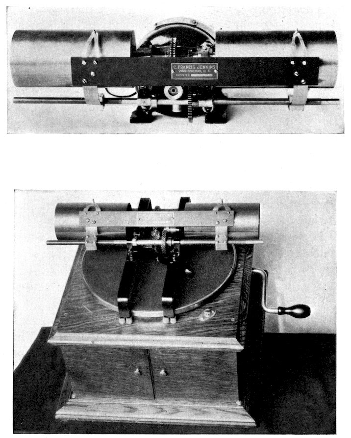
One of the newer methods of photogram transmission
is to use a rotating table, like a talking machine
table, with a rectangular piece of paper thereon
(tucked under at the corners), from which to send a
communication; market bulletins, for example, broadcast
by a progressive newspaper to the farmers and
truck gardener patrons in their vicinity.
The contact point is advanced from the outer edge
to the centre by a spiral cut on the under side of the
table; or by a threaded edge of a detachable tabletop
and a reducing gear to move the contact arm
across the message, or other scheme.
(Of course, the receiving machine should be a
duplicate of the sending machine, with suitable
receiving surface.)
The bulletin sheet can not be advantageously used
to the very centre, any more than a music record
can, but this space can be employed by the broadcaster
for printed announcements (as music disc records
are so used), the receiving paper being furnished
by the broadcaster.
But of all the schemes it is very doubtful if any
will ever equal the writing of the message or sketch
in lead pencil on paper, and rotate it under a two-contact
collector. The graphite of the lines makes
contact across the twin-blade terminals, effecting
the transmitter as would a telegraph key in the
circuit.
Coming now to the design of a suitable receiving
machine, it will be found that an even greater variety
of schemes have been tried.
46
Upon a rotating and longitudinally moving cylinder,
similar to that of the sending machine first
described, a paper is put, and upon this paper, as
the cylinder rotates, an ink pen, mounted on a pivoted
arm, touches intermittently, being drawn down to
ink the paper with every incoming electrical impulse,
and lifted off the paper by a gentle spring.
In another ink and pen scheme the electric current
is passed through a capillary ink tube to make it
flow and black the paper; no lifting of the pen arm
is necessary.
As the order of these dots-and-dashes is controlled
by the impulses put into the line by the picture at
the sending station, a picture is built up on the
paper on the receiving machine cylinder, a copy of
the picture on the cylinder of the sending machine.
In another and similar scheme a chemically
treated paper is put on the cylinder, and upon this,
as it rotates, a metallic point is gently pressed.
When the incoming electric current from the sending
station passes through the paper under the contact
point an electrolysis occurs which appears as a
discoloration of the paper.
And as these discolored dots-and-dashes appear,
as before, in an order controlled by the distant
station, a picture is again built up on the paper, a
copy of the picture at the sending station.
One of the best solutions for the purpose is made
up of Iodide of Potassium one-half pound; Bromide
of Potassium two pounds; Dextrine or Starch one
ounce; and Distilled Water one gallon. (Use an
47iron contact needle). There are other solutions
made of Ferricyanide, but are not so satisfactory.
Still another scheme, the simplest of mechanisms,
consists of a metal disc upon which electrolytic paper
is clipped. This plate is then put on the rotating
table of a talking machine. A rubbing electrical
contact is made with the disc, and the other wire
attached to the tone arm to complete the circuit
through the steel needle of the sound box.
As no groove is available to carry the arm toward
the centre of the disc, a spurred-wheel is attached
thereto, so as to engage the paper on the disc. The
wheel can be adjusted diagonally of the tone arm to
give any separation required in the convolutions of
the spiral line.
One of the schemes employed, and with considerable
success for its time, consisted of an engraving
tool, moved up and down radially of a coated cylinder,
cutting a groove of varying width in the soft
coating of the cylinder.
When this coating was stripped off the cylinder,
laid out flat and hardened, it was mounted on a
printing block, inked, and impressions taken therefrom
on a suitable printing press.
But doubtless photographic paper, wrapped around
the cylinder, has been used oftener than any other
medium. With photo paper or film a point of light
is usually employed to expose the film.
The point sources of light used and methods of
modulation have been almost as varied as the
temperaments of the several workers. One of the
first was the employment of a steady light source
which, reflected in the tiny mirror of an oscillograph,
48is caused to vibrate at a high frequency across a
minute aperture which in turn is imaged on the
film on the cylinder. As the amplitude of vibration
of the mirror determines the amount of light passing
through the aperture and falling on the film, it will
readily be understood that the strength of the
incoming electric signals, representing light values
of the picture at the distant station, reproduce
duplicate values on the exposed film. When this
film is developed a copy of the picture on the cylinder
of the sending machine is obtained.
Another scheme for modulating the light falling
on the film on the cylinder, consists in placing a
light wedge against the face of a lens which images the
vibrating mirror (or light source) on the film.
As the light is constantly imaged on the film by
the lens its slight displacement toward the dark end
of the light wedge by the vibration of the mirror
decreases the strength of the light falling on the
film, while displacement toward the thin edge of the
light wedge gives greater exposure on the film.
It is obvious, therefore, that the vibration of the
mirror determines the exposure at successive positions
on the film; and as these displacements follow
the varying strength of the incoming electric current,
and the latter in turn is determined by the light
values of the picture at the sending station, it naturally
follows that when the film is developed a duplicate
of the distant picture results.
Another method of varying the light falling on
the photo film on the cylinder consists in mounting
two very minute overlapping shutters one on each
49of the two wires of an electric circuit suspended in a
strong magnetic field. On these overlapping shutters
a light source is focused, so that greater or lesser
displacement of the shutters, by reason of varying
strengths of current in the adjacent runs of the wire,
allows more or less light to pass there between.
Another lens images these tiny shutters onto the
film covered cylinder, so that when the shutters are
opened by the incoming currents in the two wires, the
light is concentrated on the film.
As the exposure depends on (a) the shutter openings,
and the shutter opening on (b) the incoming
current strength, and the incoming current strength
on (c) the light values at the sending station, development
of the film again gives a duplicate of the
picture at the sending station.
An interesting scheme of picture reception is
known as the pneumatic light valve, the vibration of
which causes a shadow band to oscillate across a
lens opening into the camera.
In a circular center opening in a magnetized iron
diaphragm is suspended an iron disc somewhat
smaller than the opening. This small disc is magnetically
held by its edge to the inside edge of the
opening in the diaphragm, with its plane in the plane
of the magnetic field of the diaphragm.
Upon the disc is mounted a tiny mirror, and as the
suspension of the disc is in the magnetic field held
there by the strength of the field itself, it is extremely
easily disturbed, so that a small beam of light
reflected from the mirror can be vibrated with a very
little current through great amplitude.
As the beam of light has a transverse shadow
band therein of a width to normally close the lens
50opening into the camera, the varying amplification
of the vibration of the mirror, and therefore, of the
shadow, admits a proportional amount of light.
One of the very simplest light sources for exposing
the film on the receiving cylinder consists of a
minute spark-gap located in contact with the moving
film.
The strength of the incoming current charges a
small condenser until the gap breaks down and the
passing spark exposes the film (or perhaps perforates
it). If the current is strong the sparks pass the gap
at a high frequency, while if the current is weak the
frequency is less. The range may be from 500 to
5,000 per second perhaps, depending on the current
strength, and, of course, the film exposure correspondingly
varies, and the different degrees of density
of the picture results.
This scheme requires about as small current as is
likely to be practical, perhaps, especially when the
spark is in a suitable degree of vacuum, and, of
course, the incoming radio signals require correspondingly
small amplification.
The direct source of light which in the author’s
laboratory has produced the most perfect photographic
effects, i. e., photographs absolutely without
lines, consists of a lamp about an inch in diameter
and two inches long, fitted with a standard screw
base. The tube contains a .6 mil filament with a
small single turn coil in a hydrogen atmosphere.
The coil is offset until it almost touches the glass
wall. Such location of the coiled filament permits
the effective placing of a minute aperture in very
51close relation to the filament; whereas an aperture
on the outside of a bulb with the light source in the
centre of the bulb acts like a pin-hole camera, and
sharpness of image is practically impossible (unless
a lens is used).
The lamp described above will respond to fluctuations
in current well above a thousand times per
second, but requires voltages about four times
normal. It was made for the author by courtesy
of the General Electric Company, under the direction
of Mr. L. C. Porter, of Harrison, N. J.
But the lamp that really elicits the author’s
unqualified admiration is the corona glow lamp made
for the author by Professor D. McFarlan Moore.
It consists of a small glass bulb containing a neat-fitting
metallic cylinder, one terminal of an attached
circuit. Inside and concentric with the cylinder is
a second cylindrical capsule made of a solid rod
drilled to a predetermined depth.
The electron stream from the outside cylinder to
the capsule naturally takes the long path, and as the
longest path is down into the capsule, the result is
that the small central opening of the capsule glows
with great intensity while the other parts of the
lamp remain dark. This lamp, Professor Moore
advises, has a light and dark frequency of a million
per second.
52
53
54
55
56
57
58
59
60
61
62
63
64
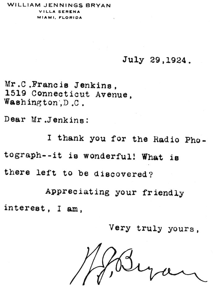
W. J. Bryan'
65
66