Similarity of Heat and Light.—That light and
heat have essentially the same characters is very
soon made evident. Both light and heat travel to
us from the sun across the ninety odd millions of
miles of space unoccupied by any material.
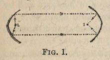
Figure 1
Both are reflected in the same way from reflecting
surfaces. Thus if two parabolic mirrors be placed
facing each other as in the diagram (Fig. 1), with a
source of light L at the focus
of one of them, an inverted
image of the light will be
formed at the focus I of the
other one, and may be
received on a small screen placed there. The paths
of two of the rays are shown by the dotted lines.
If L be now replaced by a heated ball and a[1]
blackened thermometer bulb be placed at I, the
thermometer will indicate a sharp rise of temperature,
showing that the rays of heat are focussed there
as well as the rays of light.
Both heat and light behave in the same way in
passing from one transparent substance to another,
e.g. from air into glass. This can be readily shown
by forming images of sources of heat and of light
by means of a convex lens, as in the diagram
(Fig. 2).
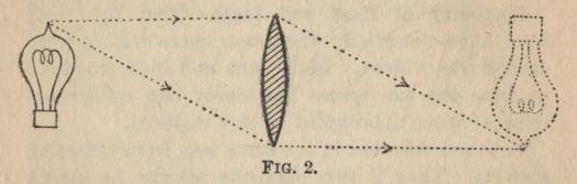
FIG. 2.
The source of light is represented as an electric
light bulb, and two of the rays going to form the
image of the point of the bulb are represented by
the dotted lines. The image is also dotted and
can be received on a screen placed in that position.
If now the electric light bulb be replaced by a
heated ball or some other source of heat, we find by
using a blackened thermometer bulb again that the
rays of heat are brought to a focus at almost the same
position as the rays of light.
The points of similarity between radiant heat and
light might be multiplied indefinitely, but as a number
of them will appear in the course of the book these
few fundamental ones will suffice at this point.
The Corpuscular Theory.—A little over a century
ago everyone believed light to consist of almost
inconceivably small particles or corpuscles shooting
out at enormous speed from every luminous surface
and causing the sensation of sight when impinging
on the retina. This was the corpuscular theory.
It readily explains why light travels in straight lines
in a homogeneous medium, and it can be made to
explain reflection and refraction.
Reflection.—To explain reflection, it is supposed
that the reflector repels the particles as they approach
it, and so the path of one particle would be like that
indicated by the dotted line in the diagram (Fig. 3).
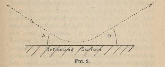
FIG. 3.
Until reaching the point A we suppose that the
particle does not feel appreciably the repulsion of
the surface. After A the repulsion bends the path
of the particle round until B is reached, and after B
the repulsion becomes inappreciable again. The
effect is the same as a perfectly elastic ball bouncing
on a perfectly smooth surface, and consequently the
angle to the surface at which the corpuscle comes up
is equal to the angle at which it departs.
Refraction.—To explain refraction, it is supposed
that when the corpuscle comes very close to the
surface of the transparent substance it is attracted
by the denser substance, e.g. glass, more than by the
lighter substance, e.g. air. Thus a particle moving
along the dotted line in air (Fig. 4) would reach the
point A before the attraction becomes appreciable,
and therefore would be moving in a straight line.
Between A and B the attraction of the glass will be
felt and will therefore pull the particle round in the
path indicated. Beyond B, the attraction again
becomes inappreciable, because the glass will attract
the particle equally in all directions, and therefore
the path will again become a straight line. We
notice that by this
process the direction
of the path has
become more nearly
normal to the surface,
and this is as it
should be. Further,
by treating the angles
between the two
paths and the normal
mathematically we may deduce the laws of refraction
which have been obtained experimentally. One other
important point should be noticed. Since the
surface has been attracting the particle between
A and B the speed of the particle will be greater in
the glass than in the air.
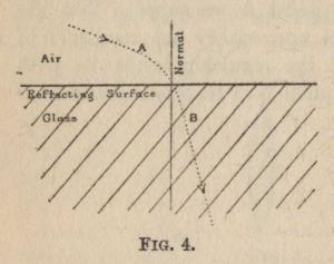
FIG. 4
Ejection and Refraction at the same Surface.—A
difficulty very soon arises from the fact that at
nearly all transparent surfaces some light is reflected
and some refracted. How can the same surface
sometimes repel and sometimes attract a corpuscle?
Newton surmounted this difficulty by attributing a
polarity to each particle, so that one end was repelled
and the other attracted by the reflecting and refracting
surface. Thus, whether a particle was reflected
or refracted depended simply upon which end
happened to be foremost at the time. By attributing
suitable characteristics to the corpuscles, Newton
with his superhuman ingenuity was able to account
for all the known facts, and as the corpuscles were so
small that direct observation was impossible, and as
Newton's authority was so great, there was no one to
say him nay.
Wave Theory. Rectilinear Propagation.—True,
Huyghens in 1678 had propounded the theory that
light consists of waves of some sort starting out from
the luminous body, and he had shown how readily it
expressed a number of the observed facts; but light
travels in straight lines, or appears to do so, and
waves bend round corners and no one at that time
was able to explain the discrepancy. Thus for
nearly a century the theory which was to be universally
accepted remained lifeless and discredited. The
answer of the wave theory to the objection now is,
that light does bend round corners though only
slightly and that the smallness of the bend is quite
simply due to the extreme shortness of the light waves.
The longer waves are, the more they bend round
corners. This can be noticed in any harbour with a
tortuous entrance, for the small choppy waves are
practically all cut off whereas a considerable amount
of the long swell manages to get into the harbour.
Interference of Light. Illustration by Ripples.—The
revival of the wave theory dates from the discovery
by Dr. Young of the phenomenon of interference
of light. In order to understand this we will
consider the same effect in the ripples on the surface
of mercury. A tuning-fork, T (Fig. 5), has two small
styles, S S, placed a little distance apart and dipping
into the mercury contained in a large shallow trough.
When the tuning-fork is set into vibration, the two
styles will move up and down in the mercury at
exactly the same time and each will start a system
of ripples exactly similar to the other. At any
instant each system will be a series of concentric circles
with its centre at the style, and the crests of the
ripples will be at equal distance from each other with
the troughs half-way between the crests.
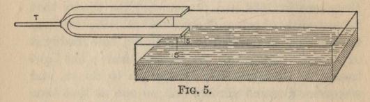
FIG. 5.
The ripples from one style will cross those from
the other, and a curious pattern, something like that
in Fig. 6, will be formed on the mercury. S S
represents the position of the two styles, while the
plain circles denote the positions of the crests and the
dotted circles the positions of the troughs at any
instant. Where two plain circles cross it is evident
that both systems of ripples are producing a crest,
and so the two produce an exaggerated crest.
Similarly where two dotted circles cross an exaggerated
trough is produced. Thus in the shaded portions of
the diagram we get more violent ripples than those
due to a single style. Where a plain circle cuts a
dotted one, however, one system of ripples produces a
crest and the other a trough, and between them the
mercury is neither depressed below nor raised above
its normal level. At these points, therefore, the
effect of one series of ripples is just neutralised by
the effect of the other and no ripples are produced
at all. This occurs in the unshaded regions of the
diagram.
The mutual destruction of the effects of the two
sets of waves is "Interference."
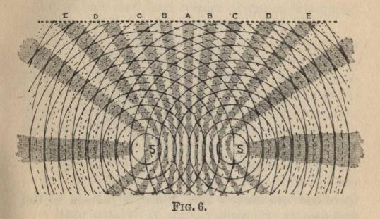
FIG. 6.
Now imagine a row of little floats placed along
the line EDCBABCDE. At the lettered points the
floats will be violently agitated, but at the points
midway between the letters they will be unmoved.
This exactly represents the effect of two interfering
sources of light S, S, sending light which is received
by a screen at the dotted line EDCBABCDE. The
lettered points will be brightly illuminated while the
intermediate points will be dark.
In practice it is found impossible to make two
sources of light whose vibrations start at exactly the
same time and are exactly similar, but this difficulty
is surmounted by using one source of light and
splitting the waves from it into two portions which
interfere.
Young's Experiment.—Dr. Young's arrangement
is diagrammatically represented in Fig. 7.
Light of a certain wave length is admitted at a
narrow slit S, and is intercepted by a screen in which
there are two narrow slits A and B parallel to the
first one.
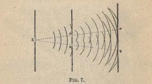
FIG. 7.
A screen receives the light emerging from the two
slits. If the old corpuscular theory were true there
would be two bright bands of light, the one at P and
the other at Q, but instead Dr. Young observed a
whole series of parallel bright bands with dark spaces
in between them. Evidently the two small fractions
of the original waves which pass through A and B
spread out from A and B and interfere just as if they
were independent sources like the two styles in the
mercury ripples experiment.
Speed of Light in Rare and Dense Media.—The
discovery of interference again brought the wave
theory into prominence, and in 1850 the death-blow
was given to the corpuscular theory by Foucault, who
showed that light travels more slowly in a dense
medium such as glass or water than in a light medium
such as air. This is what the wave theory anticipates,
while the reverse is anticipated by the corpuscular
theory.
But if light and heat consist of waves, what kind
of waves are they and how are they produced?
Elastic Solid Theory.—In the earlier days of the
wave theory it was supposed that the whole of space
was filled with something which acted like an elastic
solid material in which the vibrations of the atoms
of a luminous body started waves in all directions,
just as the vibrations of a marble embedded in a
jelly would send out waves through the jelly. These
waves are quite easily imagined in the following way.
If one end of an elastic string be made to oscillate
to and fro a series of waves travels along the string.
If a large number of these strings are attached to
an oscillating point and stretch out in all directions,
the waves will travel along each string, and if the
strings are all exactly alike will travel at the same
speed along all of them. Any particular crest of a
wave will thus at any instant lie on the surface of a
sphere whose centre is the oscillating point. If now
we imagine that the strings are so numerous that
they fill the whole of the space we have a conception
of the transmission of waves by an elastic solid.
Electromagnetic Waves.—Since Maxwell published
his electromagnetic theory in 1873 it has been
universally held that heat and light consist of
electro-magnetic waves.
These are by no means so easy to imagine as the
elastic waves, as there is no actual movement of the
medium; an alternating condition of the medium
is carried onward, not an oscillation of position.
When a stick of sealing-wax or ebonite is rubbed
with flannel it becomes possessed of certain properties
which it did not have before. It will attract light
pieces of paper or pith that are brought near to it,
it will repel a similar rubbed piece of sealing-wax or
ebonite and will attract a rod of quartz which has
been rubbed with silk.
The quartz rod which has been rubbed with silk has
the same property of attracting light bodies which
the ebonite and sealing-wax rod has, but it repels
another rubbed quartz rod and attracts a rubbed
ebonite or sealing-wax rod.
Positive and Negative Electrification.—The ebonite
is said to be negatively electrified and
the quartz positively electrified.
When the two rods, one positively and
the other negatively electrified, are placed
near to one another, we may imagine the
attraction to be due to their being joined
by stretched strings filling up all the space
around them. If a very small positively
electrified body be placed between the
two it will tend to move from the quartz
to the ebonite, i.e. in the direction of the arrows.
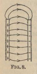
FIG. 8.
The Electric Field. Lines of Force.—The space
surrounding the electrified sticks in which the forces
due to them are appreciable is called the electric field,
and the direction in which a small positively electrified
particle tends to move is called the direction of
the field. The lines along which the small positive
charge would move are called lines of force.
The conception of the electric field as made up of
stretched elastic strings is, of
course, a very crude one, but
there is evidently some change
in the medium in the electric
field which is somewhat analogous to it.
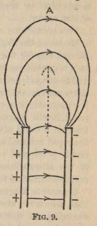
FIG. 9.
Electric Oscillations.—If the
position of the two rods is
reversed, then of course the
direction of the field at a point
between them is reversed, and
if this reversal is repeated
rapidly, we shall have the
direction of the field alternating
rapidly. If these alternations
become sufficiently rapid they
are conveyed outwards in much
the same way as the oscillations
of position are conveyed in an ordinary ripple. Thus
suppose the two rods are suddenly placed in the
position in the diagram. The field is not established
instantaneously, the lines of force taking a short time
to establish themselves in their ultimate positions.
During this time the lines of force will be travelling
outwards to A in the direction of the dotted arrow.
Before they reach A let us suppose that the position
of the rods is reversed. Then the direction of the
lines is reversed and these reversed lines will travel
outwards towards A, following in the track of the
original lines. Thus a continuous procession of
lines of force, first in one direction and then in
the opposite direction, will be moving out
perpendicular to themselves in the direction of the
dotted arrow.
This constitutes an electric wave.
Magnetic Oscillation, Lines of Force, and Field.—Almost
exactly the same kind of description applies
to a magnetic wave. The space near to the North
and South poles of a magnet is modified in somewhat
the same way as that between the electrified rods, and
the magnetic lines of force are the lines along which a
small North magnetic pole would move. We may
imagine a rapid alternation of the magnetic field by
the rapid reversal of the positions of the North and
South poles, and we may imagine the transmission
of the alternations by means of the procession of
magnetic lines of force.
Changes in Magnetic Field.—But experiment shows
that whenever the magnetic field at any place is
changing an electric field is produced during the
alteration, and vice-versa. Electric and magnetic
waves must therefore always accompany one another,
and the two sets of waves together constitute
electro-magnetic waves.
These are the waves which a huge amount of
experimental evidence leads us to believe constitute
heat, light, the electric waves used in wireless
telegraphy,
and the invisible ultraviolet waves which are
so active in inducing chemical action.
Oscillation of Electric Charges within the Atom.—We
have seen how these waves might be produced
by the oscillation of two electrified rods, and it is
supposed that the light coming from luminous bodies
is produced in a similar way. There are many
reasons for believing that there exist in the atoms of
all substances, minute negatively electrified particles
which may rotate in small orbits or oscillate to and
fro within the atom. There also exists an equal
positive charge within the atom. As the negative
particles rotate or oscillate in the atom, it is evident
that the field between them and the positively
electrified part of the atom alternates, and so
electro-magnetic waves are sent out.
A system of ripples on the surface of water appears
in vertical section at any instant somewhat as in
Fig. 10. The dotted line AB represents the
undisturbed surface of the wafer, and the solid line the
actual surface. If the disturbance which is causing
the ripples is an oscillation of perfectly regular period
the individual ripples will be all alike, except
they will get shallower as they become more remote
from the disturbance.
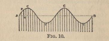
FIG. 10.
Wave-length.—The distance between two
successive crests will be the same everywhere, and this
distance or the distance between any two corresponding
points on two successive ripples is called the
wave-length. Evidently, the wave-length is the
distance in which the whole wave repeats itself.
Phase.—The position of a point in the wave is
called the phase of the point. Thus the difference of
phase between the two points A and C is a quarter
of a wave-length. As the waves move on along the
surface it is evident that each drop of water executes
an up and down oscillation, and at the points C, C the
drop has reached its highest position and at the
points T, T its lowest.
Amplitude.—The largest displacement of the drop,
i.e. the distance from the dotted line to C or to T, is
called the amplitude of the wave. The time taken
for a drop to complete one whole oscillation, i.e. the
time taken for a wave to travel one whole wave-length
forward, is called the period of the wave. The
number of oscillations in one second, i.e. the number
of wave-lengths travelled in one second, is called the
frequency.
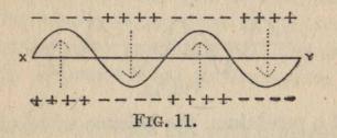
FIG. 11.
Although there is no visible displacement in the
waves of light and heat, yet we may represent them in
much the same way. Thus if AB, Fig. 10, represents
the line along which a ray of light is travelling, the
length NP is drawn to scale to represent the value of
the electric field at the point N, and is drawn upwards
from the line AB when the field is in one direction
and downwards when it is in the opposite direction.
Thus the direction of the field at different points in
the wave XY, Fig. 11, is shown by the dotted arrows
as if due to electrified rods of quartz and ebonite
placed above and below XY.
In the case of the electromagnetic wave, the
amplitude will be the maximum value to which the electric
field attains in either direction, and the other
terms—wave-length, phase, period and frequency—will
have the same meaning as for water ripples.
Wave Form.—Waves not only differ in amplitude,
wave-length, and frequency, but also in wave
form. Waves may have any form, e.g. Fig 12.
Or we may have a solitary irregular disturbance such
as is caused by the splash of a stone in water.
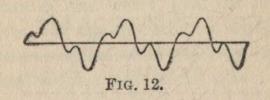
FIG. 12.
But there is one form of motion of a particle in a
wave which is looked upon as the simplest and
fundamental form. It is that form which is executed by
the bob of a pendulum, the balance wheel of a watch,
the prong of a tuning-fork, and most other vibrations
where the controlling force is provided by a spring
or by some other elastic solid.
It is called "Simple Harmonic Motion" or "Simple
Periodic Motion," and the essential feature of it is that
the force restoring the displaced particle to its
undisturbed position is proportional to its displacement
from the undisturbed position. A wave in which all
the particles execute simple harmonic motion has the
form in Fig. 10 or Fig. 11, which is therefore looked
upon as the fundamental wave form or simple wave form.
Simple waves will vary only in amplitude, wave-length,
and frequency, and the energy in the wave
will depend upon these quantities.
Energy in a Simple Wave.—If the velocity is the
same for all wave-lengths, then the frequency will
evidently be inversely proportional to the wave-length
and the energy will depend upon the amplitude
and the wave-length. The kinetic energy of any
moving body, i.e. the energy due to its motion, is
proportional to the square of its velocity, and we may
apply this to the motion of the particles in a wave
and to show how the energy depends upon the
amplitude and wave-length.
Since the distance travelled by a particle in a single
period of the wave will be equal to four times the
amplitude, the velocity at any point in the wave must
be proportional to the amplitude and therefore the
kinetic energy is proportional to the square of the
amplitude.
With the same amplitude but with different wave-lengths,
we see that the time in which the oscillation
is completed is proportional to the wave-length and
that the velocity is therefore inversely proportional
to the wave-length. The kinetic energy is therefore
inversely proportional to the square of the wave-length.
Addition of Waves.—The superposition of two
waves so as to obtain the effect of both waves at the
same place is carried out very simply. The displacements
at any point due to the two waves separately
are algebraically added together, and this sum is
the actual displacement. In Fig. 13 the dotted
lines represent two simple waves, one of which has
double the wave-length of the other. At any point
P on the solid line, the displacement PN is equal to
the algebraic sum of the displacement NQ due to one
of the waves and NR due to the other. The solid
line, therefore, represents the resulting wave. We
may repeat this process for any number of simple
waves, and by suitably choosing the wave-length and
amplitude of the simple waves we may build up any
desired form of wave. The mathematician Fourier
has shown that any form of wave, even the single
irregular disturbance, can thus be expressed as the
sum of a series of simple waves and that the wave-lengths
of these simple waves are equal to the original
wave-length, one-half of it, one-third, one-quarter,
one-fifth, and so on in an infinite series. Fourier
has also shown that only one such series is possible
for any particular form of wave.
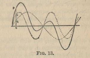
FIG. 13.
The importance of this mathematical expression
lies in the fact that in a number of ways Fourier's
series of simple waves is manufactured from the
original wave and the different members of the series
become separated. Thus the most useful way in
which we can represent any wave is, not to draw the
actual form of a wave, but to represent what simple
waves go to form it and to show how much energy
there is in each particular simple wave.
Energy—Wave-length Curve.—This can be done
quite simply as in Fig. 14. The distance PN from
the line OA being drawn to scale to represent the
energy in the simple wave whose length is
represented by ON.
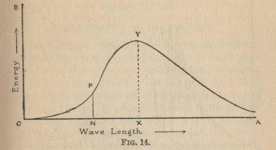
FIG. 14.
Thus the simple wave of length OX has the greatest
amount of energy in it.
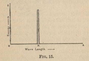
FIG. 15.
Fig. 15 wall represent a simple wave of wave-length
OX, the energy in all the other waves being
zero.
The three curves given in Fig. 16 give a comparison
of the waves from the sun, an arc lamp, and an
ordinary gas-burner.
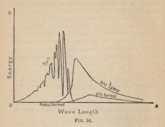
FIG. 16.
The Spectrum. Dispersion.—When a narrow beam
of white light is transmitted through a prism of glass
or of any other transparent substance, it is deflected
from its original direction and is at the same time
spread out into a small fan of rays instead of
remaining a single ray. If a screen is placed in the path of
these rays a coloured band is formed on it, the least
deflected part of the band being red and the colours
ranging from red through orange, yellow, green, blue,
and indigo, to violet at the most deflected end of the
band. This band of colours is called the spectrum
of the white light used, and the spreading out of the
rays is called dispersion.
Newton's Experiment.—Newton first discovered
this fact with an arrangement like that in Fig. 17.
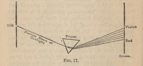
FIG. 17.
If by any means the fan of coloured rays be combined
again into a single beam, white light is reformed,
and Newton therefore came to the conclusion that
white light was a mixture of the various colours in
the spectrum, and that the only function of the
prism was to separate the constituents. Of the nature
of the constituents Newton had little knowledge,
since he had rejected the wave theory, which could
alone give the clue.
We now believe that white light is an irregular
wave, and that the prism manufactures from it the
Fourier's series of waves to which it is equivalent.
It is supposed that the manufacture is effected by
means of the principle of resonance. As an example
of resonance let a small tap be given to a pendulum
just as it commences each swing. Then because the
taps are so timed that each of them increases the
swing of the pendulum by a small amount, they will
very soon cause the pendulum to swing very violently
even though the effect of a single tap can scarcely be
detected at all.
Thus when any body which has a free period of
vibration is subject to periodic impulses of the same
period as its own, it will vibrate very vigorously and
absorb nearly all the energy of the impulses.
Electrons and their Vibrations.—There is conclusive
evidence to show that in the atoms of all substances,
and therefore of the glass of which the prism is composed,
there are a number of minute negatively electrified
particles which are called electrons. These are
held in position by a positive charge on the rest of the
atom, and if they are displaced from their usual
positions by any means they will vibrate about these
positions. The time of vibration of the electron will
depend upon its position in the atom and upon the
position of neighbouring atoms. In solid or liquid
bodies the neighbouring atoms are so near that they
have a considerable influence in modifying the period
of an electron or a system of electrons, and
consequently we may find almost any period of vibration
in one or other of these electrons or systems.
As the wave of light with its alternating electric
fields comes up to the prism, the field will first displace
the electrons in one direction and then in the other, and
so on. If the period of one particular type of electron
happens to coincide with the period of the wave, that
electron will vibrate violently and will in its turn send
out a series of waves in the glass. If the wave is
an irregular one it will start all the electrons vibrating,
but those electrons will vibrate most violently whose
periods are equal to the periods of the Fourier's
constituents which have the greatest energy. Thus we
shall actually have the Fourier's constituent waves
separated into the vibrations of different electrons.
But the speed with which any simple wave travels in
glass or in any transparent medium, other than a
vacuum, is dependent upon its period.
The shorter the period, i.e. the shorter the
wave-length, the slower is the speed in most transparent
substances. But the slower the speed in the prism
the more is the ray deviated, and therefore we
conclude that the violet end of the spectrum consists of
the shortest waves while the red end consists of the
longest waves, and that the different parts of the
spectrum are simple waves of different period.
The Whole Spectrum.—The visible spectrum is by
no means the whole of the series of Fourier's waves,
however. The eye is sensitive only to a very small
range of period, while there exists in sunlight a range
many times as great.
Those waves of shorter period than the violet end
of the visible spectrum will be deviated even more
than the violet, and will therefore be beyond the
violet. They are called the ultra violet rays, and can
easily be detected by means of their chemical activity.
They cause a number of substances to glow, and
therefore by coating the screen on which the spectrum
is received with one of these substances, the violet
end of the spectrum is extended by this glow.
The waves of longer period than the red rays will
be deviated less than the red, and will therefore lie
beyond the red end of the visible spectrum. They
are called the infra-red rays, and are chiefly
remarkable for their heating effect.
All the rays are absorbed when they fall on to a
perfectly dull, black surface, and their energy is
converted into heat. This heating effect provides the
best way of measuring the energy in the different
parts of the spectrum, and of thus constructing
curves similar to those given in Fig. 16. The
instrument moat commonly used is called Langley's
bolometer. It consists of a fine strip of blackened
platinum, which can be placed in any part of the
spectrum at will and thus absorb the waves over a
very small range of wave-length. It is heated by
them, and the rise in temperature is found by measuring
the electrical resistance of the strip. The electrical
resistance of all conductors varies with the
temperature, and since resistance can be measured
with extreme accuracy this forms a very sensitive
and accurate method.
Spectrum of an Incandescent Solid or Liquid.—The
spectra given by different sources of light show
certain marked differences.
An incandescent solid or liquid gives a continuous
spectrum, i.e. all the different wave-lengths are
represented, but the part of the spectrum which has the
greatest energy is different for different substances
and for different temperatures: cf. arc and gas flame
in Fig. 16. This is quite in keeping with the idea
already suggested that in solids and liquids there are
electrons of almost every period of vibration. When
they are agitated by being heated, a mixture of
simple waves of all periods will be sent out giving a
very irregular wave.
Gases may also become incandescent. Thus when
any compound of sodium is put into a colourless
flame the flame becomes coloured an intense yellow.
This is due to the vapour of sodium, and the agitation
of the electrons in it is probably due to the chemical
action in which the compound is split up into sodium
and some other parts.
We may also make the gas incandescent by enclosing
it at low pressure in a vacuum tube and passing
an electrical discharge through it. The glow in the
tube gives the spectrum of the gas. Incandescent
gases give a very characteristic kind of spectrum.
It consists usually of a limited number of narrow
lines, the rest of the spectrum being almost perfectly
dark. The light therefore consists of a few simple
waves of perfectly definite period. This would
suggest that in the atom of a gas there are only a few
electrons which are concerned in the emission of the
light waves.
Thus the spectra of gases and of incandescent
solids are represented in character by the curves in
Fig. 18.
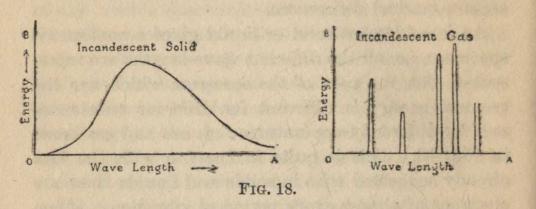
FIG. 18.
Spectrum Analysis.—The lines in a gas spectrum
are so sharply defined and are so definitely
characteristic of the particular gas that they serve as a
delicate method of detecting the presence of some
elements. These spectra which are emitted by
incandescent bodies are called emission spectra. But
not only do different materials emit different kinds of
light when raised to incandescence, but they also
absorb light differently when it passes through them.
When white light is passed through some transparent
solids or liquids and then through a prism, it
is found that whole regions of the spectrum are
absent. Thus a potassium permanganate solution
which is not too concentrated absorbs the whole of
the middle part of the spectrum, allowing the red and
blue rays to pass through. Since with solids and
liquids the absorbed regions are large and somewhat
ill-defined, the absorption spectra are not of any great
use in the detection of substances.
The absorption spectra of gases show the same
sharply defined characteristics as the emission
spectra. Thus if white light from an arc lamp passes
through a flame coloured yellow with sodium vapour,
the spectrum of the issuing light has two sharply
defined narrow dark lines close together in the yellow
part of the spectrum in exactly the same position as
the two bright yellow lines which incandescent
sodium vapour itself gives out. The flame has
therefore absorbed just those waves which it gives
out. This is perfectly general, and applies to solids
and liquids as well as to gases. It is perfectly in
keeping with our view of the refraction of light by
the resonance of electrons to the Fourier's constituents
which have the same period. For if the electrons
have a certain period of vibration they will resound
to waves of that period and therefore absorb their
energy.
Spectrum of the Sun.—One of the most interesting
examples of the absorption by incandescent gases of
their own characteristic lines is provided by the sun.
The spectrum of the sun is crossed by a large number
of fine dark lines which were mapped out by
Fraunhöfer and are therefore called Fraunhöfer lines.
These lines are found to be in the position of the
characteristic lines of a number of known elements,
and therefore we assume that these elements are
present in the sun. The interior of the sun is liquid
or solid owing to the pressure of the mass round it.
It therefore emits a continuous spectrum. But the
light has to pass through the outer layers of
incandescent vapour, and these layers absorb from the
light their characteristic waves and so produce the
dark lines in the spectrum.
The spectra of stars show similar characters to
those of the sun, and therefore we assume them to be
in the same condition as the sun.
The spectra of nebulæ consist only of bright lines,
and we therefore assume that nebulæ consist of
incandescent masses of gas which have not yet cooled
enough to have liquid or solid nuclei.
Absorbing Power.—A perfectly dull black surface
is simply one which absorbs all the light which is
falling on it and reflects or diffuses none of it back.
If the surface absorbs the heat as well as the light
completely, it is called a perfect or full absorber.
Other surfaces merely absorb a fraction of the heat
and light falling on them, and this fraction, expressed
usually as a percentage, is called the absorbing power
of the surface. The absorbing powers of different
kinds of surfaces can be measured in a great many
ways, but the following may be taken as fairly typical.
A perfectly steady beam of heat and light is made
to fall on a small metallic disc, and the amount of
heat which is absorbed per second is calculated from
the mass of the metal and the rate at which its
temperature rises. The disc is first coated with
lamp-black, and the rate at which it then receives heat is
taken as the rate at which a full absorber absorbs
heat under these conditions. The disc is then
coated with the surface whose absorbing power is
to be measured, and the experiment is repeated.
Then the rate at which heat is received in the second
case divided by the rate at which it is received in
the first is the absorbing power of the second surface.
Experiments with a large number of surfaces show
that the lighter in colour and the more polished is the
surface, the smaller is its absorbing power.
Radiating Power.—But the character of the surface
affects not only the rate at which heat and light are
absorbed, but also the rate at which they are emitted.
For example, if we heat a fragment of a willow pattern
china plate in a blowpipe flame until it is bright red hot,
we shall notice that the dark pattern now stands out
brighter than the rest. Thus the dark pattern, which
absorbs more of the light which falls on it when it is
cold, emits more light than the rest of the plate when it
is hot. This is one example of a general rule, for it is
found that the most perfect absorbers are the greatest
radiators, and vice-versa. The perfectly black
surface is therefore taken as a standard in measuring
the heat and light emitted by surfaces, in exactly the
same way as for heat and light absorbed. Thus the
emissive or radiating power of a surface is defined
as the quantity of heat radiated per second by the
surface divided by the amount radiated per second by
a perfectly black surface under the same conditions.
As it is somewhat paradoxical to call a surface a
perfectly black surface when it may even be white hot,
the term "a full radiator" has been suggested as an
alternative and will be used in this book.
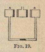
FIG. 19
Relation between Absorbing and Radiating Powers.—The
exact relation between the absorbing and
radiating powers of a surface was first determined by
Ritchie by means of an ingenious experiment. Two
equal air-tight metal chambers A and B were
connected by a glass tube bent twice at right angles as
in Fig. 19. A drop of mercury in the horizontal part
of this tube acted as an indicator. When one of the
vessels became hotter than the other, the air in it
expanded and the mercury index moved towards the
colder side. Between the two metal chambers a
third equal one was mounted which could be heated
up by pouring boiling water into it and could thus
act as a radiator to the other two. One surface of
this radiator was coated with lamp-black and the
opposite one with the surface under
investigation, e.g. cinnabar. The
inner surfaces of the other two vessels
were coated in the same way, the
one with lamp-black, the other with
cinnabar. The middle vessel was
first placed so that the lamp-blacked
surface was opposite to a cinnabar one, and vice-versa.
In this position, when hot water was poured into it
no movement of the mercury drop was detected, and
therefore the amounts of heat received by the two
outer vessels must have been exactly equal. On the
one side the heat given out by the cinnabar surface of
the middle vessel is only a fraction, equal to its
radiating power, of the heat given out by the black surface.
All the heat given out by the cinnabar surface to the
black surface opposite to it is absorbed, however,
while of the heat given out by the black surface to
the cinnabar surface opposite it only a fraction is
absorbed equal to the absorbing power of the cinnabar
surface. Thus on the one side only a fraction is
sent out but all of it is absorbed, and on the other side
all is sent out and only a fraction absorbed. Since
the quantities absorbed are exactly equal, it is obvious
that the two fractions must be exactly equal, or the
absorbing and radiating powers of any surface are
exactly equal. This result is known as Kirchoff's
law, and it applies solely to radiation which is caused
by temperature. Later experiments have shown that
it applies to each individual wave-length, i.e. to
any portion of the spectrum which we isolate, as
well as to the whole radiation. Thus at any particular
temperature let the dotted line in Fig. 20 represent
the wave-length—energy curve for a full radiator, and
let the solid line represent it for the surface under
investigation. Then for any wave-length, ON, the
radiating power of the surface would be equal to QN
divided by PN.
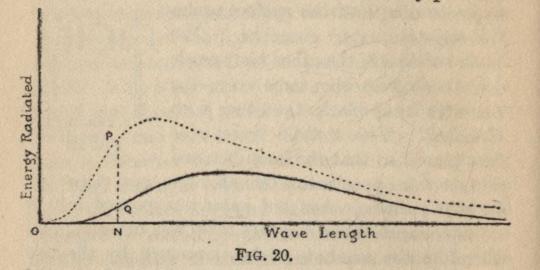
FIG. 20.
Now a wave-length—energy curve may be as easily
constructed for absorbed as for emitted radiation by
means of a Langley's bolometer. The strip of the
bolometer is first coated with lamp-black and the
spectrum of the incident radiation is explored in
exactly the same way as is described in Chapter III.
The strip is then coated with the surface under
investigation and the spectrum is again explored. Since
the incident radiation is exactly the same in the two
experiments, the differences in the quantities of heat
absorbed must be due solely to the difference in the
absorbing powers of the two surfaces. In Fig. 21
the dotted line represents the wave-length—energy
curve for the radiation absorbed by the blackened
bolometer strip, and the solid line the curve for the
strip coated with the surface under investigation.
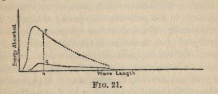
FIG. 21.
The actual form of the curves may and probably
will be quite different from the form in Fig. 20, but
it will be found for the same wave-length ON that
PN/QN is exactly the same in the two figures.
It has already been mentioned that dull, dark-coloured
surfaces radiate the most heat, and that
polished surfaces radiate the least. A radiator for
heating a room should therefore have a dull, dark
surface, while a vessel which is designed to keep its
contents from losing heat should have a highly
polished exterior.
A perfectly transparent substance would radiate
no energy, whatever the temperature to which it is
raised, for its absorbing power is zero and therefore
its radiating power is also zero. No perfectly
transparent substances exist, but some substances are
a very near approach to it. A fused bead of microcosmic
salt heated in a small loop of platinum wire in
a blowpipe flame may be raised to such a temperature
that it is quite painful to look at the platinum wire,
yet the bead itself is scarcely visible at all. Any
speck of metallic dust on the surface of the bead will
at the same time shine out like a bright star.
Gases as Radiators.—Most gases are an even nearer
approach to the perfectly transparent substance, and
consequently, with one or two exceptions, the simple
heating of gases causes no appreciable radiation from
them. Of course, gases do radiate heat and light
under some circumstances, but the radiation seems to
be produced either by chemical action, as in the flames
coloured by metallic vapours, or by electric discharge,
as in vacuum tubes, the arc or the electric spark.
The agitation of the electrons is thus produced in
a different way in gases, and we must not apply
Kirchoff's law to them, although at first sight they
appear to conform to it. We have seen that the
particular waves which an incandescent gas radiates
are also absorbed by it. This we should expect,
because the particular electron which has such a
period of vibration that it sends out a certain
wave-length will naturally be in tune to exactly similar
waves which fall on it, and will so resound to them,
and absorb their energy. The quantitative law,
however, that the absorbing power is exactly equal
to the radiating power, is not true for gases.
Emission of Polarised Light.—One very interesting
result of Kirchoff's law is the emission of polarized
light by glowing tourmaline and by one or two other
crystal when they are heated to incandescence. In
ordinary light the vibrations are in all directions
perpendicular to the line along winch the light travels,
that is, the vibrations at any point are in a plane
perpendicular to this line. Now any vibration in a
plane may be expressed as the sum of two component
vibrations, one component in one direction and the
other in a perpendicular direction. If we divide up
the vibrations all along the wave in this way we shall
have two waves, one of which has its vibrations all
in one direction and the other in a perpendicular
direction. Such waves, in which the vibrations all
lie in one plane, are said to be plane polarised.
Tourmaline is possessed of the curious property
of absorbing vibrations in one direction of the crystal
much more rapidly than it does those vibrations
perpendicular to this direction, and therefore light
which passes through it emerges partially, or in some
cases wholly, plane polarised.
Since the absorbing power of tourmaline is different
for the two components, the emissive power should
also be different, and that component which was most
absorbed should be radiated most strongly. This
was found to be true by Kirchoff himself, who
detected and roughly measured the polarised light
emitted. Subsequently in 1902, Pflüger carried out
exact experiments which gave a beautiful confirmation
of the law.
The Full Radiator.—We have assumed that a
lamp-blacked surface is a perfect absorber, and
consequently a full radiator, but although it is a very near
approach to the ideal it is not absolutely perfect.
No actual surface is a perfectly full radiator, but the
exact equivalent of one has been obtained by an
ingenious device. A hollow vessel which is blackened
on the inside has a small aperture through which
the radiation from the interior of the vessel can
escape. If the vessel is heated up, therefore, the
small aperture may act as a radiator. The radiation
which emerges through the aperture from any small
area on the interior of the vessel is made up of two
parts, one part which it radiates itself, and the other
part which it scatters back from the radiation which
it receives from the other parts of the interior of the
vessel. These two together are equal to the energy
sent out by a full radiator, and therefore the small
aperture acts as a full radiator: e.g. suppose the
inner surface has an absorbing power of 90 per cent.,
then it radiates 90 per cent. of the full radiation and
absorbs 90 per cent. of the radiation coming up to it
therefore scattering back 10 per cent. We have
therefore coming from the inner surface 90 per cent.
radiated and 10 per cent. scattered, and the radiated
and scattered together make 100 per cent.
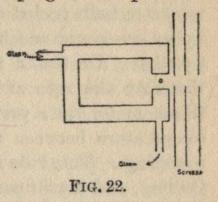
FIG. 22.
One form in which such radiators have been used
is shown in section in Fig. 22. A double walled
cylindrical vessel of brass has a small hole, a, in one
end. Steam can be passed through the space
between the double walls, thus keeping the temperature
of the inner surface at 100° C.
A screen with a hole in it
just opposite to the hole in
the vessel, or rather several
such screens, are placed in
front of the vessel in order
to shield any measuring
instrument from any radiation
except that emerging through the hole.
The Full Absorber.—In an exactly similar way an
aperture in a hollow vessel will act as a full absorber,
for the fraction of the incident radiation which is
scattered on the inner surface again impinges on
another portion of the surface and so all is ultimately
absorbed except a minute fraction which is scattered
out again through the aperture.
The variation in the heat radiated by a full radiator
at different temperatures forms a very important part
of the study of radiation, and a very large number of
experiments and theoretical investigations have been
devoted to it. These investigations may be divided
into two sections: those concerned with the total
quantity of heat radiated at different temperatures
and those concerned with the variation in the
character of the spectrum with varying temperatures.
The experiments in the first section have been
carried out mainly in two ways. In the first, the rate
of cooling of the full radiator has been determined,
and from the rate of cooling at any temperature the
rate at which heat was lost by radiation was immediately
calculated. Newton was the first to investigate
in this way by observing the rate at which a
thermometer bulb cooled down when it was surrounded
by an enclosure which was kept at a uniform
temperature. He found that the rate of cooling, and
therefore the rate at which heat was lost by the
thermometer, was proportional to the difference of
temperature between the thermometer and its
surroundings. This rule is known as Newton's Law of
Cooling, and is still used when it is desired to correct
for the heat lost during an experiment where the
temperature differences are small. It is only true,
however, for very small differences of temperature
between the thermometer and its surroundings, and
as early as 1740 Martine had found that it was only
true for a very limited range of temperature.
Prévost's Theory of Exchanges.—In 1792, Prévost
of Geneva, when endeavouring to explain the supposed
radiation of cold, introduced the line of thought, that
any body is not to be regarded as radiating heat only
when its temperature is falling, or absorbing heat
only when its temperature is rising, but that both
processes are continually and simultaneously going
on. The amount of heat radiated will depend on
the temperature and character of the body itself,
while the amount absorbed will depend upon the
condition of the surroundings as well as upon the nature
of the body. If the amount of heat radiated is greater
than the amount absorbed the body will fall in
temperature, and vice-versa. This view of Prévost's is
called the Theory of Exchanges, and we can see that
it is a necessary consequence of our ideas as to the
production of heat and light waves by the agitation
of electrons in the radiating body.
If the rate of cooling of a body at a certain
temperature is measured when it is placed in an enclosure
at a lower temperature, it must be borne in mind that
the rate of loss of heat is equal to the rate at which
heat is radiated minus the rate at which it is
absorbed from the enclosure.
A second way in which the heat lost by a body has
been measured at different temperatures is by heating
a conductor such as a thin platinum strip by means
of an electric current, and measuring the temperature
to which the conductor has attained. When its
temperature is steady, all the energy given to it by
the current must be lost as heat, and therefore the
electrical energy, which can very easily be calculated,
must be equal to the heat radiated by the body minus
the heat received from the enclosure.
So many attempts have been made to establish,
by one or other of these two methods, the relation
between the quantity of heat radiated and the
temperature, that it is impossible to give even a
passing reference to most of them. Unfortunately, the
results do not show the agreement with one another
which we would like, but probably the most correct
result is that stated by Stefan in 1878, after a close
inspection of the experimental results of Dulong and
Petit. He stated that the quantity of heat radiated
per second by a full radiator is proportional to the
fourth power of its absolute temperature.[1] Thus
the quantity of heat radiated by one square centimetre
of the surface of a full radiator whose absolute
temperature is T, is equal to ET4, where E is some
constant multiplier which must be determined by
experiment and which is called the radiation
constant. If the absolute temperature of the enclosure
in which the surface is placed is T, then the rate
at which the surface is losing heat will be E(T4-T14),
for it will receive heat at the rate ET14 and will
radiate it at the rate ET4.
Stefan's fourth power law has been verified by a
number of good experiments, notably those of
Lummer and Pringsheim (Congrés International de
Physique, Vol. II. p. 78), so that although some
experiments do not agree with it, we are probably justified
in taking it as correct.
In 1884 Boltzmann added still further evidence in
support of this law by deriving it theoretically. He
applied to a space containing the waves of full
radiation the two known laws which govern the
transformation of energy, by imagining the space to be
taken through a cycle of compressions and expansions
in just the same way as a gas is compressed and
expanded in what is known as Carnot's cycle.
Variation of Spectrum with Temperature.—The
variation of the character of the spectrum of a full
radiator has been determined mainly by the use of
Langley's bolometer, but the general nature of the
change may be readily observed by the eye.
As the temperature of a full radiator rises it first
gives out only invisible heat waves; as soon as its
temperature exceeds about 500° C. it begins to emit
some of the longest visible rays; and as the temperature
rises further, more and more of the visible rays in
the spectrum are emitted
until, when the radiator
is white hot, the whole
of the visible spectrum.
is produced. Thus the
higher the temperature
of the radiator the more
of the shorter waves are
produced.
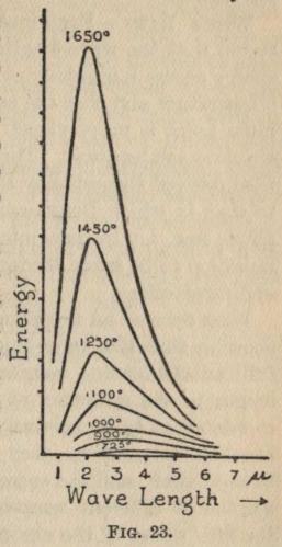
FIG. 23.
By means of Langley's
bolometer the distribution
of energy in the spectrum
has been measured
accurately, with the results
of confirming and amplifying
the general results
just stated. The energy
in the spectrum of even
the hottest of terrestrial
radiators is mostly in the
longer waves of the
infra-red, but the position of the maximum of energy moves
to shorter and shorter wave-lengths as the temperature
rises, and so more of the shorter waves make their
appearance. The sun is not a full radiator, but
is nearly so, and its temperature is so high that the
maximum of energy in its spectrum is in the visible
part near to the red end.
Fig. 23 shows the results obtained by Lummer and
Pringsheim, and brings out clearly the shift of the
maximum with rising temperature and also the
position of the greatest part of the energy in the
infrared region.
Wien's Laws.—Examination of the results also
shows that the wave-length at which the maximum
energy occurs is inversely proportional to the absolute
temperature and that the actual energy at the
maximum point is proportional to the fifth power of the
absolute temperature. These two results have both
been derived theoretically by Wien[2] in a similar way
to that in which Boltzmann derived Stefan's fourth
power law, i.e. by imagining a space filled with the
radiation to be taken through a cycle of compressions
and rarefactions.
Wien derived an amplification of the last result by
showing that if a wave-length in the spectrum of a
full radiator at one temperature and another
wave-length in the spectrum at another temperature are
so related as to be inversely proportional to the two
absolute temperatures, they may be said to correspond
to each other, and the energy in corresponding
wave-lengths at different temperatures is proportional to
the fifth power of the absolute temperature.
We see therefore that if the distribution of energy
in the spectrum of the full radiator be known at any
one temperature it may be calculated for any other
temperature by applying these two laws of
corresponding wave-lengths and the energy in them.
Neither of them give us any information, however,
about the actual distribution of energy at any one
temperature from which we may calculate that at
any other temperature. For that, some relation
must be found between the energy and the
wave-length. Planck, by reasoning founded on the
electromagnetic character of the waves, derived such a
relation, but both his reasoning and his results are a
little too complicated to be introduced here. His
results have been confirmed in the most striking
manner by experiments carried out by Rubens and
Kurlbaum (Ann. der Physik, 4, p. 649, 1901). They
measured the energy in a particular wave-length
(.0051 cms., i.e. nearly 100 times the wave-length
of red light) in the radiation of a full radiator from
a temperature of 85° up to 1773° absolute, and their
results are given in the following table:
  Absolute Temperature.    Observed Energy.    Energy calculated from
                                                 Planck's Formula.

         85                    -20.6                    -21.9
        193                    -11.8                    -12
        293                      0                        0
        523                    +31                      +30.4
        773                     64.6                     63.8
       1023                     98.1                     97.2
       1273                    132                      132
       1523                    164                      160
       1773                    196                      200
We have therefore the means of calculating both the
total quantity and the kind of radiation given out
by any full radiator at any temperature, and a
number of very interesting problems may be solved
by means of the results.
Efficiency in Lighting.—One very simple problem
is concerned with efficiency in lighting. We see by
reference to Fig. 16, that in the radiation from the
electric arc very little of the energy is in the visible
part of the spectrum even though the temperature
in the arc is the highest yet obtained on the earth,
whereas the energy in the visible part of the spectrum
from a gas flame is almost wholly negligible. The
problem of efficient lighting is to get as big a
proportion as possible of the energy into the visible part
of the spectrum, and therefore the higher the temperature
the greater the efficiency. This is the reason
of the greater efficiency of the incandescent gas
mantle over the ordinary gas burner, for the introduction
of the air into the gas allows the combustion
to be much more complete, and therefore the
temperature of the mantle becomes very much higher
than that of the carbon particles in the ordinary
flame. The modern metallic filament electric lamps
have filaments made of metals whose melting point
is extremely high, and they may therefore be raised
to a much higher temperature than the older carbon
filaments. The arc is even more efficient than the
metallic filament lamps, because its temperature is
higher still; and we must assume that the temperature
of the sun is very much higher even than the
arc, since its maximum of energy lies in the visible
spectrum.
Temperature of the Sun.—The actual temperature
of the sun may be calculated approximately by means
of Stefan's fourth power law. We will first assume
that the earth and the sun are both full radiators, and
that the earth is a good conductor, so that its
temperature is the same all over. The first assumption is
very nearly true, and we will make a correction for
the small error it introduces; and the second, although
far from true, makes very little difference to the final
result, for it is found that the values obtained on the
opposite assumption that the earth is an absolute
non-conductor differ by less than 2 per cent. from
those calculated on the first assumption. We will
further assume that the heat radiated out by the
earth is exactly equal to the heat which it receives
from the sun. This is scarcely an assumption, but
rather an experimental fact, for experiment shows
that heat is conducted from the interior of the earth
to the exterior, and so is radiated, but at such a small
rate that it is perfectly negligible compared with the
rate at which the earth is receiving heat from the sun.
The sun occupies just about one 94,000th part of
the hemisphere of the heavens or one 188,000th part
of the whole sphere. If the whole sphere surrounding
the earth were of sun brightness, the earth would
be in an enclosure at the temperature of the sun, and
would therefore be at that temperature itself. The
sphere would be sending heat at 188,000 times the
rate at which the sun is sending it, and the earth would
be radiating it at 188,000 times its present rate. But
the rate at which it radiates is proportional to the
fourth power of its absolute temperature, and therefore
its temperature would be the fourth root of 188,000
times its present temperature, i.e. 20.8 times. If the
radiating or absorbing power of the earth's surface
be taken as 9/10, which is somewhere near the mark,
the calculation gives the number 21.5 instead of 20.8.
The average temperature of the earth's surface is
probably about 17° C. or 290° absolute, and therefore
the temperature of the sun is 290 x 21.5, i.e. about
6200° absolute.
It is easy to see that if we had known the temperature
of the sun and not of the earth, we could have
calculated that of the earth by reversing the process.
By this means we can estimate the temperatures
of the other planets, at any rate of those for which we
may make the same assumptions as for the earth.
Probably those planets which are very much larger
than the earth are still radiating a considerable
amount of heat of their own, and therefore to them
the calculation will not apply; but the smaller planets
Mercury, Venus and Mars have probably already
radiated nearly all their own heat and are now
radiating only such heat as they receive from the sun.
The temperatures calculated in this way are—
                           Average
                    Absolute Temperature

  Mercury . . . . . . . . . 467°
  Venus . . . . . . . . . . 342°
  Earth . . . . . . . . . . 290°
  Mars  . . . . . . . . . . 235°
Since the freezing point of water is 273° absolute,
we see that the average temperature of Mars is 38° C. below
freezing, and it is almost certain that no part
of Mars ever gets above freezing point.
In a very similar way we may find the temperature
to which a non-conducting surface reaches when it
is exposed to full sunlight by equating the heat
absorbed to the heat radiated, and the result comes
to 412° absolute, i.e. 139° C., or considerably above
boiling point. This would be the upper limit to the
temperature of the surface of the moon at a point
where the sun is at its zenith.
On the surface of the earth the sunlight has had to
pass through the atmosphere, and in perfectly bright
sunshine it is estimated that only three-fifths of the
heat is transmitted. Any surface is also radiating
out into surroundings which are at about 300°
absolute. Taking into account these two facts, we
find that the upper limit to a non-conducting surface
in full sunshine on the earth is about 365° absolute,
or only a few degrees less than the boiling point of
water.
Effective Temperature of Space.—The last problem
we will attack by means of the fourth power law is
the estimation of the effective temperature of space,
i.e. the temperature of a full absorber shielded from
the sun and far away from any planet.
It is estimated by experiment that zenith sun
radiation is five million times the radiation from the
stars. This estimate is only very rough, as the
radiation from the stars is so minute. As the sun only
occupies one 94,000th part of the heavens, the
radiation from a sunbright hemisphere would be
five million times 94,000 times starlight, i.e.
470,000,000,000 times. The temperature of the sun
is therefore the fourth root of this quantity times the
effective temperature of space, i.e. about 700 times.
Since the temperature of the sun is about 6200°, the
temperature of space is a little under 10° absolute;
i.e. lower than -263° C.
Note on Absolute Temperature.—It is found that,
if a gas such as air has its temperature raised or
lowered while its pressure is kept uniform, for every
one degree centigrade rise or fall its volume is increased
or decreased by one two hundred and seventy-third
of its volume at freezing point, i.e. at 0° centigrade.
If therefore it continued in the same way right down
to -273° centigrade, its volume would be reduced to
zero at this temperature. This temperature is
therefore called the absolute zero of temperature,
and temperatures reckoned from it are called absolute
temperatures. To get absolute temperatures from
centigrade temperatures we evidently need to add 273°.
No account of radiation would be complete without
mentioning what becomes of the radiation which
bodies absorb, but a good deal of the subject is in so
uncertain a state that very little space will be devoted
to it.
Absorbed Radiation converted into Heat.—The
most common effect of absorbed radiation is to raise
the temperature of the absorbing body, and so cause
it to re-emit long heat-waves. As the usual
arrangement is for the absorbing body to be at a lower
temperature than the radiating one, the waves given out
by the absorber are longer than those given out by
the radiator, and so the net result is the transformation
of shorter waves into longer ones. But we
have seen by Prévost's theory of exchanges that
radiator and absorber are interchangeable, and therefore
we see that those waves which are emitted by the
absorber and absorbed by the radiator are re-emitted
by the latter as shorter waves.
The mechanism by means of which the waves are
converted into heat in the body is still a mystery.
That the waves should cause the electrons to vibrate
is perfectly clear, but how the vibrations of the
electrons are converted into those vibrations of the atoms
and molecules which constitute heat is still unsolved,
and the reverse process is, of course, equally puzzling.
The heating of the body and the consequent re-emission
of heat-waves is not, however, the only process
which goes on. In a large number of substances,
waves are given out under the stimulus of other waves
without any heating of the body at all. In most of
these cases the emission stops as soon as the stimulating
waves are withdrawn, and in these cases the phenomenon
has been called fluorescence. The name has
been derived from fluor spar, the substance which was
first observed to exhibit this peculiar emission of waves.
A familiar example of fluorescence is provided by
paraffin-oil, which glows with a blue light when it is
illuminated with ordinary sunlight or daylight.
Perhaps the easiest way to view it is to project a narrow
beam of light through the paraffin-oil contained in a
glass vessel and view the oil in a direction perpendicular
to the beam. The latter will then show up a
brilliant blue.
A water solution of sulphate of quinine, made acid
by a few drops of sulphuric acid, also exhibits a blue
fluorescence, while a water solution of æsculin (made
by pouring hot water over some scraps of horse-chestnut
bark) shines with a brilliant blue light.
Some lubricating oils fluoresce with a green light, as
does also a solution in water of fluorescene, named
thus because of its marked fluorescence.
A solution of chlorophyll in alcohol, which can be
readily prepared by soaking green leaves in alcohol,
shows a red fluorescence; uranium glass—the canary
glass of which small vases are very frequently
made—exhibits a brilliant green fluorescence, as does also
crystal uranium nitrate.
It is found, on observing the spectrum of the
fluorescent light, that a fairly small range of waves
is emitted showing a well-marked maximum of intensity
at a wave-length which is characteristic of the
particular fluorescing substance.
There also seems to be a limited range of waves
which can induce this fluorescence, and this range also
depends upon the fluorescing substance. As a rule,
the inducing waves are shorter in length than the
induced fluorescence, but this rule has some very
marked exceptions.
The fact that only a limited range of waves produces
fluorescence explains a noticeable characteristic of the
phenomenon. If the fluorescing solutions are at all
strong the fluorescence is confined to the region close
to where the light enters the solution, thus showing
that the rays which are responsible for inducing the
glow become rapidly absorbed, whereas the remainder
of the light goes on practically unabsorbed.
Phosphorescence.—Sometimes the emission of the
induced light continues for some time after the
inducing waves are withdrawn, and then the
phenomenon is termed phosphorescence, since phosphorus
emits a continuous glow without rise of temperature.
Sometimes the glow will continue for several hours
after the exciting rays have been cut off, a good
example of this being provided by Balmain's luminous
paint, which is a sulphide of calcium. With other
substances the glow will only continue for a very
small fraction of a second, so that it is impossible to
say where fluorescence ends and where phosphorescence
begins.
In order to determine the duration of the glow in
the case of these small times, an arrangement
consisting of two rotating discs, each of which have slits
in them, is set up. Through the slits in one of them
the substance is illuminated, and through the slits in
the other the substance is observed while the light is
cut off. By adjusting the position of the discs with
regard to each other the slits may be made to follow
one another after greater or shorter intervals, and so
the time of observation can be made greater or
smaller after the illumination is cut off.
All the bodies which have been observed to exhibit
phosphorescence are solid.
Theory of Fluorescence.—It is fairly simple to
imagine a mechanism by which fluorescence might
be brought about, as we might assume a relation
between the periods of oscillation of certain types of
electron in the substance and the period of the
stimulating waves. Thus resonance might occur, and
the consequent vibrations of the electrons would
start a series of secondary waves.
If, however, we assume resonance, it is difficult to
see why there is a range of wave-lengths produced
and another range of wave-lengths which may
produce them. We should have expected one definite
wave-length or a few definite ones producing one or a
few definite wave-lengths in the glow, while if a whole
range of waves will produce the effect it is difficult
to see why all bodies do not exhibit the phenomenon.
But the phenomenon of phosphorescence finally
disposes of any such description, for the two
phenomena have no sharp distinction between them.
Some substances are known in which the phosphorescence
lasts for such an extremely small fraction of a
second after the stimulating waves are withdrawn
that it is difficult to know whether to call the effect
fluorescence or phosphorescence. It is probable,
therefore, that both are due to the same action.
Now a wave of orange light completes about five
hundred million million vibrations in one second, and
therefore if an orange-coloured phosphoresence were
to last for only one five-hundredth of a second it
would mean that the electrons responsible for it
vibrate one million million times after the stimulus
is removed. This is hardly credible, and becomes
more credible when we remember that in some
phosphorescent substances the effect lasts for many
hours.
Chemical Theory of Phosphoresence.—It is more
probable that the stimulating rays produce an actual
chemical change in the phosphorescent substance.
For instance, it is possible that the vibrations of a
certain type of electron in one kind of atom become
so violent as to detach it from the atom and the
temporarily free electron attaches itself immediately to
another kind of atom.
The new arrangement may be quite stable; it is so
in the action of light on a photographic plate, but it
may only be stable when the electrons are being
driven out of their original atoms, and in this case the
electrons will begin to return to their old allegiance as
soon as the stimulus is withdrawn. In the return
process the electrons will naturally be agitated, and
will therefore emit waves having their characteristic
period. The rate at which the return process takes
place will evidently depend upon the stability of the
new arrangement. If it is extremely unstable, the
whole return may only occupy a fraction of a second,
but if it is nearly as stable as the original
arrangement the return may be extremely slow.
On this view, then, those substances will phosphoresce
which have an electron which is fairly easily
detached from its atom and which will attach itself
to another atom, forming an arrangement which is
less stable than the original.
Temperature and Phosphorescence.—A confirmation
of this chemical view is provided by the effect
of temperature on phosphorescence. The rate of a
chemical change is usually very largely increased by
rise of temperature, and further, at very low
temperatures a large number of chemical changes which take
place quite readily at ordinary temperatures do not
take place at all.
Similarly at very low temperatures the action of
the light may be more or less stable. For example,
Dewar cooled a fragment of ammonium-platino-cyanide
by means of liquid hydrogen, and exposed
it to a strong light. After removing the light no
phosphorescence was observed, though at ordinary
temperatures a brilliant green phosphorescence is
exhibited, but on allowing the fragment to warm up
it presently glows very brightly.
A partial stability is shown by Balmain's luminous
paint, for if it be kept in the dark until it becomes
quite non-luminous it will begin to glow again for a
short time if warmed up in any way. By means of
this property the infra-red region of the spectrum
may be made visible. For this purpose a screen is
coated with the paint, exposed to strong sunlight, and
then placed so as to receive the spectrum. The first
effect of the invisible heat rays is to make the portions
of the screen on which they fall brighter than their
surroundings; but this causes the phosphorescence
to be emitted more rapidly, and soon it is all emitted,
leaving a dark region where the heat has destroyed
the phosphorescence.
On the whole, then, those substances which phosphoresce
at ordinary temperatures do so more rapidly
as the temperature rises.
But Dewar has found a number of substances which
phosphoresce only at low temperatures, e.g. gelatine,
celluloid, paraffin, ivory and horn. This is not a
fatal objection to the idea of chemical change,
as some chemical actions will only take place at
low temperatures, but it is an objection as quite a
large number of substances only phosphoresce at low
temperatures, whereas there are not many chemical
reactions which will only take place there.
As a matter of fact, even if the idea of a chemical
change be the true one, it is not a very satisfactory
one, as chemical changes are undoubtedly very complicated
ones, and it would be too difficult to trace the
change from the vibration of an electron to the
chemical change, and vice-versa.
No satisfactory theory therefore exists to account
for the absorption and the remission of the waves,
whether accompanied or unaccompanied by a rise
in temperature of the absorbing body.
Prediction of Pressure by Maxwell.—Had the fact
that light exerts a pressure been known in Newton's
time there is no doubt that it would have been
hailed as conclusive proof of the superiority of the
corpuscular theory over the wave theory. Yet,
ironically enough, it was reserved for James Clerk
Maxwell to predict its existence and calculate its
value on the assumption of his electromagnetic wave
theory; and further, the measurement of its value
has given decisive evidence in favour of the wave
theory, for the value predicted by the latter is only
one-half that predicted by the corpuscular theory,
and the measurements by Nicholls and Hull agree to
within 1 per cent. with the wave theory value.
Maxwell showed that all waves which come up to
and are absorbed by a surface exert a pressure on
every square centimetre of the surface equal to the
amount of energy contained in one cubic centimetre
of the beam.
If the surface is a perfect reflector, the reflected
waves produce an equal back pressure, and
therefore the pressure is doubled. As the waves are
reflected back along their original direction, the
energy in the beam will also be doubled, and so
the pressure will still be equal to the energy per cubic
centimetre of the beam.
As the energy which is received in one second from
the sun on any area can be measured by measuring
the heat absorbed, and since the speed of light is
known, we can calculate the energy contained in
one cubic centimetre of full sunlight, and hence the
pressure on one square centimetre of surface. For
the energy received on one square centimetre of
surface in one second must have been spread originally
over a length of beam equal to the distance which
the light has travelled in one second, i.e. over a length
equal to the speed of light. If we divide that energy,
therefore, by the speed of light, we shall get the energy
in a one-centimetre length of the beam, and therefore
in one cubic centimetre.
This turns out to be an extremely small pressure
indeed, being only a little more than the weight of
half a milligram, on a square metre of surface.
Maxwell suggested that a much greater energy of
radiation might be obtained by means of the concentrated
rays of an electric lamp. Such rays falling on
a thin, metallic disc delicately suspended in a vacuum
might perhaps produce an observable mechanical
effect.
Nearly thirty years after Maxwell's suggestion
it was successfully carried out by Prof. Lebedew
of Moscow, who used precisely the arrangement
which Maxwell had suggested.
Measurement of the Pressure.—A beam of light
from an arc lamp was concentrated on to a disc
suspended very delicately in an exhausted glass
globe about 8 inches across. Actually four discs
were suspended, as in Fig. 24, and arrangements were
made to concentrate the beam on to either side of any
of the four discs.
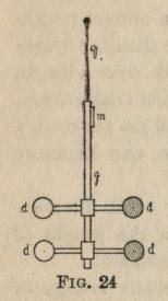
FIG. 24.
The suspension was a very fine quartz fibre q.
The discs d, d, d, d, were half a centimetre in diameter
and were fixed on two light arms, so that their centres
were one centimetre from the glass rod, g, which
carried them. A mirror, m, served to measure the
angle through which the whole system
was twisted owing to the pressure
of the beam on one of the discs.
In order to measure the angle a
telescope viewed the reflection of
a scale in m, and as m turned
different divisions of the scale came
into view.
The two discs on the left were
polished and therefore the pressure
on them should be about twice that
on the blackened discs on the right.
Having measured the angle through which a beam
of light has turned the system, it is a simple matter to
measure the force which would cause this twist in the
fibre q. In order to test whether the pressure agrees
with the calculated value, we must find the energy
in the beam of light. This was done by receiving the
beam on a blackened block of copper and measuring
the rate at which its temperature rose. From this
rate and the weight of copper it is easy to calculate the
amount of heat received per second, and therefore the
amount of energy received per second on one square
centimetre of the area. Knowing the speed of the
light we can, as suggested above, calculate the energy
in one cubic centimetre of the beam.
Lebedew's result was in very fair accord with the
calculated value. The chief difficulty in the experiment
is to eliminate the effects due to the small amount
of gas which remains in the globe. Each disc is heated
by the beam of light, and the gas in contact with it
becomes heated and causes convection currents in the
gas. At very low pressures a slightly different action
of the gas becomes a disturbing factor. This effect is
due to the molecules which come up to the disc
becoming heated and rebounding from the disc with a
greater velocity than that with which they approached
it. The rebound of each molecule causes a backward
kick on to the disc, and the continual stream of
molecules causes a steady pressure.
This would be the same on both sides of the disc if
both sides were at the same temperature, but since the
beam of light comes up to one side, that side becomes
hotter than the other and there will be an excess of
pressure on that side. This action is called
"radiometer" action, because it was first made use of by
Crookes in detecting radiation.
Between the Scylla of convection currents at higher
pressures and the Charybdis of radiometer action at
lower pressures, there seems to be a channel at a
pressure of about two or three centimetres of mercury.
For here the convection currents are small and
the radiometer action has scarcely begun to be
appreciable.
By working at this pressure and using one or two
other devices for eliminating and allowing for the
gas action, Professors Nicholls and Hull also measured
the pressure of light in an exceedingly careful and
masterly way. Their results were extremely
consistent among themselves, and agreed with the
calculated value to within one per cent. Those who know
the difficulty of measuring such minute forces, and
the greatness of the disturbing factors, must recognise
in this result one of the finest experimental
achievements of our time.
Effect of Light Pressure in Astronomy.—Forces due
to light pressure are so small that we should not
expect to be able to detect their effects on astronomical
bodies, and certainly we cannot hope to observe
them in the large bodies of our system.
The pressure of the sunlight on the whole surface
of the earth is about 75,000 tons weight. This does
not sound small until we compare it with the pull of
the sun for the earth, which is two hundred million
million times as great.
When we consider very small bodies, however, we
find that the pressure of the light may even exceed
the gravitational pull, and therefore these small
particles will be driven right away from our system.
In order to show that the light pressure becomes
more and more important, let us imagine two spheres
of the same material, one of which has four times the
radius of the other.
Then the weight of the larger one, that is its gravitational
pull, will be sixty-four times as great as that
of the smaller one, while the area, and therefore the
light pressure, will be sixteen times as great.
The light pressure is therefore four times as
important in the sphere of one-quarter the radius. For
a sphere whose radius is one two hundred million
millionth of the radius of the earth and of the same
density, the pressure of the light would equal the pull
of the sun, and therefore such a sphere would not be
attracted to the sun at all.
This is an extremely small particle, much smaller
than the finest visible dust, but even for much larger
things the light pressure has an appreciable effect.
Thus for a sphere of one centimetre radius and of
the same density as the earth, the pressure due to the
sunlight is one seventy-four thousandth of the pull
due to gravitation. It therefore need not move in
its orbit with quite such a high speed in order that it
may not fall into the sun, and its year is therefore
lengthened by about three minutes. The lengthening
out of comets' tails as they approach the sun, and the
apparent repulsion of the tail by the sun, has sometimes
been attributed to pressure of sunlight, but it is
pretty certain that the forces called into play are very
much greater than can be accounted for by the light.
Doppler Effect.—The Doppler effect also has some
influence on the motion of astronomical bodies.
When a body which is receiving waves moves towards
the source of the waves, it receives the waves more
rapidly than if it were still, and therefore the pressure
is greater. When the body is moving away from the
source it receives the waves less rapidly, and hence
the pressure of light on it is less than for a stationary
body. If a body is moving in an elliptical orbit, it is
moving towards the sun in one part of its orbit and
away in another part; it will therefore be retarded in
both parts, and the ultimate result will be that the
orbit will be circular.
The Doppler effect can act in another way. A
body which is receiving waves from the sun on one
side is thereby heated and emits waves in all directions.
As it is moving in its orbit it will crowd up the waves
which it sends out in front of it and lengthen out
those which it sends out behind it. But the energy
per cubic centimetre will be greater where the waves
are crowded up than where they are drawn out, and
therefore the body will experience a retarding force
in its orbit. As the body tends to move more slowly
it falls in a little towards the sun, and so approaches
the sun in a spiral path.
Three Effects of Light Pressure.—We thus have
three effects of light pressure on bodies describing
an orbit round the sun. The first effect is to lengthen
their period of revolution, the second is to make their
orbits more circular, and the third is to make them
gradually approach the sun in a spiral path. These
effects are quite inappreciable for bodies anything
like the size of the earth, but for small bodies of the
order of one centimetre diameter or less the effects
would be quite large. Our system is full of such
bodies, as is evidenced by the number of them which
penetrate our atmosphere and form shooting stars.
The existence of such bodies is somewhat of a problem,
as whatever estimate of the sun's age we accept as
correct, he is certainly of such an age that if these
bodies had existed at his beginning they would all
have been drawn in to him long ago. We must therefore
suppose that they are continually renewed in
some way, and since we can see no sufficient source
inside the Solar system, we must come to the
conclusion that they are renewed from outside. There
is every reason to believe that some of them originate
in comets which have become disintegrated and
spread out along their orbits. These form the
meteoric showers.
Thus the very finest dust is driven by the sun right
out of our system, and all the rest he is gradually
drawing in to himself.
In this concluding chapter it is proposed to show how
the wave-lengths of radiant heat have been
determined and to state what range of wave-lengths has
been experimentally observed. It is then proposed
to show how electromagnetic waves have been
produced by straightforward electrical means and how
their wave-lengths have been measured. The
similarity in properties of the radiant heat and of the
electric waves will be noted, leading to the conclusion
that the difference between the two sets of waves is
merely one of wave-length.
Diffraction Grating.—The best method of measuring
the wave-lengths of heat and light is by means of the
"Diffraction Grating." This consists essentially of a
large number of fine parallel equidistant slits placed
very close to one another. For the measurement of
the wave-lengths of light and of the shorter heat waves,
it is usually produced by ruling a large number of very
fine close equidistant lines on a piece of glass or on a
polished mirror by means of a diamond point. The
ruled lines are opaque on the glass and do not reflect
on the mirror, and consequently the spaces in between
act as slits.
Rowland's Gratings.—The ruling of these gratings
is a very difficult and tedious business, but the
difficulties have been surmounted in a very remarkable
manner by Rowland, so that the gratings ruled on
his machine have become standard instruments
throughout the world. He succeeded in ruling gratings
6 inches in diameter with 14,000 lines to the inch,
truly a remarkable performance when we remember
that if the diamond point develops the slightest chip
in the process, the whole grating is spoilt.
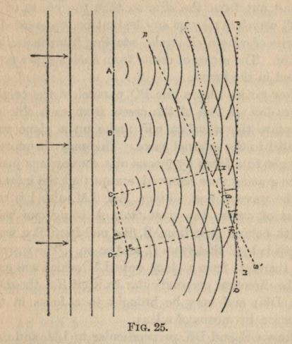
FIG. 25.
The action of the grating can be made clear by
means of Fig. 25. Let A, B, C, D represent the
equidistant slits in a grating, and let the straight
lines to the left of the grating represent at any
instant the crests of some simple plane waves coming
up to the grating. The small fractions of the original
waves emerging from the slits A, B, C, D will
spread out from the slits so that the crests of the
small wavelets may at any instant be represented by
a series of concentric circles, starting from each slit as
centre. The series of crests from each slit are
represented in the figure.
Now notice that a line PQ parallel to the original
waves lies on one of the crests from each slit, and
therefore the wavelets will make up a plane wave
parallel to the original wave. This may therefore be
brought to a focus by means of a convex lens just as
if the grating were removed, except that the intensity
of the wave is less. But a line, LM, also lies on a
series of crests, the crest from A being one
wave-length behind that from B, the one from B a
wave-length behind that from C, and so on. The wavelets
will therefore form a plane wave LM, which will move
in the direction perpendicular to itself (i.e. the
direction DK) and may be brought to a focus in that
direction by means of a lens.
Draw CH and DK perpendicular to LM, and draw
CE perpendicular to DK, i.e. parallel to LM. The
difference between CH and DK is evidently one wave-length,
i.e. DE is one wave-length. If α is the angle
between the direction of PQ and LM, DE is evidently
equal to CD sin α and therefore one
wave-length=CD sin α.
From the ruling of the grating we know the value
of CD, and therefore by measuring α we can calculate
the wave-length.
We find that a third line RS also lies on a series of
crests, and therefore a plane wave sets out in the
direction perpendicular to RS. We notice here that
the crest from A is two wave-lengths behind that
from B, and so on, and therefore if β is the angle
between RS and PQ, CD sin β is equal to two
wave-lengths.
Similarly we get another plane wave for a three
wave-lengths difference, and so on. The intensity
of the wavelets falls off fairly rapidly as they become
more oblique to their original direction, and therefore
the intensity of these plane waves also falls off rather
rapidly as they become more oblique to the direction
in which PQ goes.
We see that the essential condition for the plane
wave to set out in any direction, is that the difference
in the distances of the plane wave from two successive
slits shall be exactly a whole number of wave-lengths.
Should it depart ever so little from this condition we
should see, on drawing the line, that there lie on the
line an equal number of crests and troughs, and
therefore, if a lens focus waves in this direction, the
resulting effect is zero. The directions of the waves
PQ, LM, RS, &c., will therefore be very sharply
defined and will admit of very accurate determination.
Dispersion by Grating.—Evidently the deviations
α, β will be greater
the greater is DE, i.e. the
greater the wave-length, and therefore the light or
heat will be "dispersed" into its different wave-lengths
as in the prism; but in this case the dispersion
is opposite to that in the normal prism, the long
waves being dispersed most and the short waves
least.
Evidently, too, the smaller the distance CD the
greater the angle, and therefore for the extremely
short wave-lengths of light and of ultraviolet rays
we require the distance between successive slits to
be extremely small.
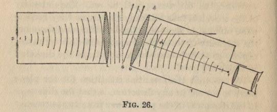
FIG. 26.
The Spectrometer.—The grating is usually used
with a spectrometer, as shown in plan diagrammatically
in Fig. 26. The slit S from which the waves
radiate is placed at the principal focus of the lens L,
and therefore the waves emerge from L as plane waves
which come up to the grating G. The telescope T is
first turned until it views the slit directly, i.e. until
the plane waves like PQ in Fig. 25 are brought to a
focus at the principal focus F of the objective of the
telescope. The eyepiece E views the image of the
slit S which is formed at F. The telescope is then
turned through an angle, α, until it views the second
image of the slit which will be formed by the plane
waves similar to LM in Fig. 25. The angle α is
carefully measured by the graduated circle on the spectrometer,
and hence the wave-length of a particular
kind of light, or of a particular part of the spectrum,
is measured.
This spectrometer method is exactly the method
used for measuring the wave-lengths in the visible
part of the spectrum.
For the ultraviolet rays, instead of viewing the
image of the slit by means of the eyepiece of the
telescope, a photographic plate is placed at the principal
focus F of the objective of the telescope, and serves
to detect the existence and position of these shorter
waves. For the heat rays a Langley's bolometer
strip is placed at F, in fact the bolometer strip might
be used throughout, but it is not quite so sensitive
for the visible and ultraviolet rays as the eye and the
photographic plate.
Absorption by Glass and Quartz.—Two main
difficulties arise in these experiments. The first one
is that although glass, or better still quartz, is
extremely transparent to ultraviolet, visible, and the
shorter infra-red waves, yet it absorbs some of the
longer heat waves almost completely.
For these waves, therefore, some arrangement must
be devised in which they are not transmitted through
a glass diffraction grating or through glass or quartz
lenses. To effect this, the convex lenses are replaced
by concave mirrors and the ruled grating is replaced
by one which is made of very fine wires, which are
stretched on a frame parallel to and equidistant from
each other. The wire grating cannot be constructed
with such fine or close slits as the ruled grating, but
for the longer waves this is unnecessary.
Reflecting Spectrometer.—An arrangement used
by Rubens is represented roughly in plan in Fig. 27.
L represents the source of heat, the rays from which
are reflected at the concave mirror M, and brought to
a focus on the slit S. Emerging from S the rays are
reflected at M2 and are thereby
rendered parallel before passing
through the wire grating
G. After passing through the
grating, the rays are reflected
at M3 and are thereby focussed
on to a bolometer strip placed
at B. Turning the mirror M3
in this arrangement is evidently
equivalent to turning the telescope in the
ordinary spectrometer arrangement.
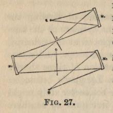
FIG. 27.
Absorption of Waves by Air.—By using a
spectrometer in an exhausted vessel Schumann discovered
that waves existed in the ultraviolet region of much
smaller wave-length than any previously found, and
that these waves were almost completely absorbed
on passing through a few centimetres of air. To all
longer waves, however, air seems to be extremely
transparent.
The second difficulty arises from the fact, already
explained, that a diffraction grating produces not
one, but a number of spectra. If only a small range
of waves exists, this will lead to no confusion, but if
a large range is being investigated, we may get two
or more of these spectra overlapping.
Suppose, for example, we have some waves of wave-length
DE (in Fig. 25), some of wave-length one-half
DE and some of one-third DE. Then in the direction
DK we shall get plane waves of each of these
wave-lengths setting out and being brought to a focus in
the same place. This difficulty can be fairly simply
surmounted where the measurement of wave-length
alone is required, by placing in the path of the rays
from the source of light, suitable absorbing screens,
which will only allow a very small range of wave-lengths
to pass through them. There will then be
no overlapping and no confusion.
Where the actual distribution of energy in the
spectrum of any source of heat is to be determined
the difficulty becomes more serious, and probably
there is some error in the determinations, especially
in the longest waves, which are masked almost
completely by the overlapping shorter waves.
Rest-Strahlen or Residual Rays.—A very beautiful
method of isolating very long heat waves, and so
freeing them from the masking effect of the shorter
waves, was devised by Rubens and Nichols.
It is found that when a substance very strongly
absorbs any waves that pass through it, it also strongly
reflects at its surface the same waves. For example,
a sheet of glass used as a fire-screen will cut off most
of the heat coming from the fire, although it is
perfectly transparent to the light. If, now, it is placed
so as to reflect the light and heat from the fire, it is
found to reflect very little light but a very large
proportion of the heat.
Some substances have a well-defined absorption
band, i.e. they absorb a particular wave-length very
strongly, and these substances will therefore reflect
this same wave-length strongly. If instead of a
single reflection a number of successive reflections be
arranged, at each reflection the proportion of the
strongly reflected wave-length is increased until
ultimately there is practically only this one
wave-length present. It can therefore be very easily
measured. These waves resulting from a number of
successive reflections, rest-strahlen or residual rays
as they have been named, have been very largely
used for investigating long waves. Quartz gives
rest-strahlen of length .00085 centimetres and very
feeble ones of .0020 centimetres long. Sylvite gives
the longest rays yet isolated, the wave-length being
.006 centimetres.
Range of the Waves.—The lengths of the waves
thus far measured are:—
  Schumann waves . . . . . . . .  .00001 to .00002 cms.
  Ultraviolet  . . . . . . . . .  .00002 to .00004  "
  Violet . . . . . . . . . . . .  .00004            "
  Green  . . . . . . . . . . . .  .00005            "
  Red  . . . . . . . . . . . . .  .00006 to .000075 "
  Infra-red  . . . . . . . . . .  .000075 to about .0001  "
  Rest-strahlen from quartz  . .  .00085 and .0020        "
  Rest-strahlen from Sylvite . .  .0060                   "
Thus the longest waves are six hundred times the
length of the shortest.
The corresponding range of wave-lengths of sound
would be a little more than eight octaves, of which
the visible part of the spectrum is less than one.
Electromagnetic Induction.—In the attempt to explain
the nature of an electromagnetic wave (pp. 17-21)
it was stated that an electric wave must always be
accompanied by a magnetic wave. In order to
understand the production of these waves, the relation
between electric and magnetic lines of force must be
stated in more detail. A large number of quite
simple experiments show that whenever the electric
field at any point is changing, i.e. whenever the lines
of force are moving perpendicular to themselves,
a magnetic field is produced at the point, and this
magnetic field lasts while the change is taking place.
An exactly similar result is observed when the
magnetic field at a point is changing—an electric
field is produced which lasts while the magnetic field
is changing. When the electric field changes, therefore,
there is both an action and a reaction—a magnetic
field is produced and this change in magnetic field
produces a corresponding electric field. This
induced electric field is always of such a kind as to
delay the change in the original electric field; if the
original field is becoming weaker the induced field is
in the same direction, thus delaying the weakening,
and if the original field is becoming stronger the
induced field is in the opposite direction, thus delaying
the increase.
Momentum of Moving Electric Field.—Imagine
now a small portion of an electric field moving at a
steady speed; it will produce, owing to its motion,
a steady magnetic field. If now the motion be
stopped, the magnetic field will be destroyed, and
the change in the magnetic field will produce an
electric field so as to delay the change, i.e. so as to
continue the original motion. The moving electric
field thus has momentum in exactly the same way as
a moving mass has. The parallel between the two
is strictly accurate. The mass has energy due to
its motion, and in order to stop the mass this energy
must be converted into some other form of energy
and work must therefore be done. The electric
field has energy due to its motion—the energy of the
magnetic field—and therefore to stop the motion of
the electric field, the energy of the magnetic field
must be converted into some other form, and work
must therefore be done. One consequence of the
momentum of a moving mass is well illustrated by
the pendulum. The bob of the pendulum is in equilibrium
when it is at its lowest point, but when it is
displaced from that point and allowed to swing, it
does not swing to its lowest point and stay there,
but is carried beyond that point by its momentum.
The work done in displacing the bob soon brings it
to rest on the other side, and it swings back again
only to overshoot the mark again. The friction in
the support of the pendulum and the resistance of
the air to the motion makes each swing a little smaller
than the one before it, so that ultimately the swing
will die down to zero and the pendulum will come
to rest at its lowest point. The graph of the
displacement of the bob at different times will therefore
be something like Fig. 28. Should the pendulum
be put to swing, not in air, but in some viscous
medium like oil, its vibrations would
be damped down very much more
rapidly, and if the medium be viscous
enough the vibrations may be
suppressed, altogether, the pendulum
merely sinking to its lowest position.
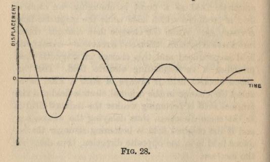
FIG. 28.
Electric Oscillation.—These
conditions have their exact counterpart in
the electric field. To understand
them, three properties of lines of
force must be borne in mind: (i.)
lines of force act as if in tension
and therefore always tend to shorten
as much as possible; (ii.) the ends of
lines of force can move freely on a
conductor; (iii.) lines of force in
motion possess momentum. Now
imagine two conducting plates A and B,
Fig. 29, charged positively and negatively, and
therefore connected by lines of force as indicated. Let
the two plates be suddenly connected by the wire
w, so that the ends of the lines of force may freely
slide from A to B or vice-versa, and therefore all the
lines will slide upwards along A and B, and then
towards each other along w, until they shrink to zero
somewhere in w. The condition of equilibrium will
evidently be reached when all the lines have thus
shrunk to zero, but the lines which are travelling
from A towards B will have momentum and will
therefore overshoot the equilibrium condition and
pass right on to B. That is, the positive ends of the
lines will travel on to B, and similarly the negative
ends will pass on to A. The lines of force between
A and B will therefore be reversed. The tension
in the lines will soon bring them to rest, and they
will slide back again, overshoot the mark again, reach
a limit in the original direction and still again slide
back. The field between A and B will therefore be
continually reversed, but each time its value will be
a little less, until ultimately the vibrations will die
down to zero. Thus if we were to replace the
displacement in Fig. 29 by the value of the field between
A and B we should have an exactly similar graph.
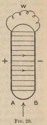
FIG. 29.
The amount by which the oscillations are damped
down will depend upon the character of the wire w.
If it is a very poor conductor it will offer a large
resistance to the sliding of the lines along it, and the
vibrations will be quickly damped down or, if the
resistance is great enough, be suppressed altogether.
This rapid alternation of the electric field will send
out electromagnetic waves which die down as the
oscillations decrease.
The Spark Discharge.—In practice the wire w is
not actually used, but the air itself suddenly becomes
a conductor and makes the connection. When the
electric field at a point in the air exceeds a certain
limiting strength, the air seems to break down and
suddenly become a conductor and remains one for
a short time. This breaking down is accompanied
by light and heat, and is known as the spark discharge
or electric spark.
Experiments of Hertz.—In the brilliant
experiments carried out by Hertz at Karlsruhe between
1886 and 1891, he not only demonstrated the
existence of the waves produced in this way, but he showed
that they are reflected and refracted like ordinary
light, he measured their wave-length and roughly
measured their speed, this latter being equal to the
speed of light within the errors of experiment.
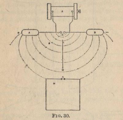
FIG. 30.
One arrangement used by Hertz is shown in plan
in Fig. 30. A Ruhmkorff coil R serves to charge the
two conductors A and B until the air breaks down at
the gap G, and a spark passes. Before the spark is
produced, the lines of force on the lower side of AB
will in form be something like the dotted lines in the
figure, but as soon as the air becomes a conductor, the
positive ends of the lines will surge from A towards
B and on to B, and the negative ends will surge on to
A. These to and fro surgings will continue for a
little while, but will gradually die out. As the
surgings are all up and down AB, the electric
vibrations in the electromagnetic waves sent out
will all be parallel to AB, and therefore they will
be polarised.

FIG. 31.
This is characteristic of all electric waves, as no
single sparking apparatus will produce anything but
waves parallel to the spark gap. The electric vibrations
coming up to a conductor placed in the position
of the wire rectangle, M, will cause surging of the lines
along it, and, if these surgings are powerful enough,
will cause a spark to pass across the small gap S.
Such a rectangle was therefore used by Hertz as
a detector of the waves, but since that time many
detectors of very much greater sensitiveness have
been devised.
Reflection.—In order to show that these waves
are reflected in the same way as light waves, Hertz
placed the sparking knobs, G, at the focus of a large
parabolic metallic reflector, and his detector, D, at
the focus of a similar reflector placed as in Fig. 31,
but much farther away (cf. Fig. 1). In this position
sparking at G produced strong sparking in the
detector, although the distance was such that no
sparking was produced without the reflectors.
Refraction.—The refraction of the waves was
shown by means of a large prism made of pitch.
This had an angle of 30° and was about 1.5 metres
high and 1.2 metres broad.
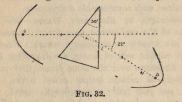
FIG. 32.
Setting it up as shown in plan in Fig. 32, strong
sparking was produced in the detector, thus showing
that the rays of electric waves were deflected by
22° on passing through the prism.
Moving the mirror and detector in either direction
from the line LM, made the sparks decrease rapidly
in intensity, so that the exact position of LM can be
determined with considerable definiteness.
Wave-length, by Stationary Waves.—The wave-lengths
of the oscillations were found by means of
what are known as stationary waves. When two
exactly similar sets of waves are travelling in
opposite directions over the same space, they produce
no effects at certain points called nodes. These
nodes are just half a wave-length apart. Their
production can be understood by reference to Fig. 33.
The dotted lines represent the two waves which are
travelling in the direction indicated by the arrows.
In A the time is chosen when the waves are exactly
superposed, and the resultant displacement will be
represented by the solid line. The points marked
with a cross will be points at which the displacement
is zero.
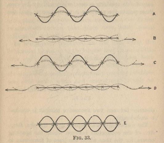
FIG. 33.
In B each wave has travelled a distance equal to
a quarter of a wave-length, and it will be seen that
the two sets of waves cause equal and opposite
displacements. The resulting displacement is therefore
zero, as indicated by the solid line. In C the waves
have travelled another quarter of a wave-length and
are superposed again, but in this case the displacements
will be in the opposite directions from those
in A. In D, still another quarter wave-length has been
traversed by each wave, and another quarter
wave-length would bring back the position A.
In E, we have the successive positions of the wave
drawn in one diagram, and we notice that the points
indicated by a cross are always undisplaced and their
distance apart is one-half a wave-length.
Hertz produced these conditions by setting up his
coil and sparking knobs at some distance from a
reflecting wall, Fig. 34. Then the waves which are
coming up to the wall and those which are reflected
from the wall will be travelling in opposite directions
over the same space. True, the reflected waves will
be rather weaker than the original ones, so that there
will be a little displacement even at the nodes, but
there will be a well-marked minimum. Thus when
the detector is placed at A, B, C or D no sparking or
very feeble sparking occurs, while midway between
these points the sparking is very vigorous, and the
distance between two successive minima is one-half
a wave-length.
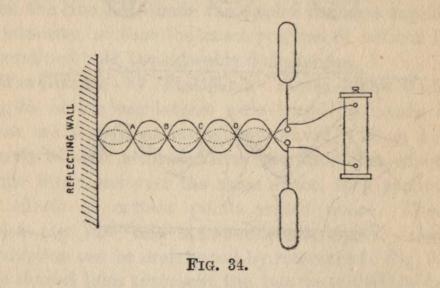
FIG. 34.
The wave-length will depend upon the size, form,
&c., of the conductors between which the sparking
occurs, for the time which the lines of force take to
surge backwards and forwards in the conductors
will depend upon these things. Other things being
equal, the smaller the conductors the smaller the time
and therefore the shorter the wave-length. The
shortest wave which Hertz succeeded in producing
was 24 centimetres long, but since then waves as
little as 6 millimetres long have been produced.
The waves which are produced in a modern wireless
telegraphy apparatus are miles in length.
We thus see that there is rather a large gap between
the longest heat waves which have been isolated,
.006 cms., and the shortest electric waves, .6 cms.
The surprising fact, however, is that this gap is so
small, for the heat waves are produced by vibrations
within a molecule, or at most within a small group of
molecules, whereas the electric surgings, even in the
smallest conductors, take place over many many
millions of molecules.
In conclusion, therefore, we see that from the
Schumann waves up to the longest heat waves a little
over eight octaves of electromagnetic waves have
been detected, then after a gap of between five and
six octaves the ordinary electrically produced
electromagnetic waves begin and extend on through an
almost indefinite number of octaves.
J. H. Poynting, The Pressure of Light.
E. Edser, Heat for Advanced Students: the chapters
on Radiation.
E. Edser, Light for Advanced Students: the chapters
on the Spectrum.
B. W. Wood, Physical Optics: the chapters on
Fluorescence and Phosphorescence, Laws of Radiation,
Nature of White Light, and Absorption of Light.
  ABSORBING power, 37
   — and radiating power, 38
  Absorption, spectra, 34
   — by glass and quartz, 77
   — by air, 78
  Addition of waves, 25
  Amplitude, 23


  BALMAIN, luminous paint, 59
  Boltzmann, laws of radiation, 48


  CONVECTION currents, 67
  Corpuscular theory, 10
   — reflection and refraction by, 11
  Crookes' radiometer, 67


  DEWAR, temperature and phosphorescence, 62
  Diffraction grating, 72
   — dispersion by, 75
   — wire grating, 77
  Dispersion, 29, 75
  Doppler effect, 69


  EFFICIENCY in lighting, 52
  Elastic solid theory, 17
  Electric field, 18
  Electric charges within the atom, 21
  Electric oscillations, 19, 83
  Electrification, positive and negative, 18
  Electromagnetic induction, 80
  Electromagnetic waves, 17, 84
  Electrons, 30
  Energy in simple wave, 25
  Energy—wave-length curve, 27


  FLUORESCENCE, 58
   — theory of, 60
  Foucault, speed of light in different media, 17
  Fourier's series of waves, 26, 30
  Fraunhöfer lines, 35
  Full radiator and absorber, 44, 45


  GASES as radiators, 42


  HUYGHENS' wave theory, 13
  Hertz, experiments on electric waves, 85
   — reflection, 86
   — refraction, 87
   — wave-length by stationary waves, 88


  INFRA-RED rays, 32
  Interference, 13


  KIRCHOFF'S law, 40


  LANGLEY, Bolometer, 32, 48, 49, 77
  Lebedew, pressure of light, 65
  Lummer and Pringsheim, law of radiation, 48, 50


  MAGNETIC oscillations, 20
  Maxwell, electromagnetic theory, 17
   — pressure of light, 64
  Momentum of moving electric field, 81


  NEWTON, dispersion, 29
   — corpuscular theory, 12
   — law of cooling, 46
  Nichols, Rubens and, Rest-strahlen, 79
  Nicholls and Hull, pressure of light, 64, 68


  PFLÜGER, emission from tourmaline, 43
  Phase, 22
  Phosphorescence, 59
   — chemical theory of, 61
   — temperature and phosphorescence, 62
  Planck, energy and wave-length, 51
  Polarised light, emission from tourmaline, 42
  Pressure of light, prediction of by Maxwell, 64
   — measurement by Lebedew, 65
   — measurement by Nicholls and Hull, 64, 68
   — on the earth, 68
   — on fine dust, 69
   — on comets' tails, 69
   — three effects of in astronomy, 70
  Prévost, Theory of Exchanges, 46


  RADIATING power, 38
  Radiometer action, 67
  Reflection, corpuscular theory, 11
   — of electric waves, 87
  Refraction, corpuscular theory, 11
   — of electric waves, 87
  Resonance, 30
  Rest-strahlen or residual rays, 79
  Ripples on mercury, 13
  Ritchie, radiating and absorbing powers, 38
  Rowland, gratings, 73
  Rubens and Kurlbaum, proof of Planck's law, 51
  Rubens and Nichols, Rest-strahlen, 79


  SCHUMANN waves, 78
  Simple harmonic motion, simple periodic motion, 24
  Spark discharge, 84
  Spectrometer, 76
   — reflecting, 78
  Spectrum, 29
   — the whole, 32
   — incandescent solid or liquid, 33
   — incandescent gas, 33
   — analysis, 34
   — emission and absorption, 34
   — sun, 35
   — stars and nebulæ, 36
   — and temperature, 48
  Stationary waves, 88
  Stefan, law of radiation, 47


  TEMPERATURE, absolute, 56
   — of planets, 54
   — of space, 55
   — of sun, 53


  ULTRAVIOLET rays, 32, 77


  WAVE form, 24
  Wave-length, 22
   — range of, 80
   — of electric waves, 90
  Wave theory, rectilinear propagation, 13
  Wien, Law of Radiation, 50


  YOUNG, interference, 16
Printed by BALLANTYNE, HANSON & CO.
Edinburgh & London
********
THE PEOPLE'S BOOKS
"A wonderful enterprise, admirably planned, and
deserving the highest success."—The Nation.
THE FIRST DOZEN VOLUMES
5. BOTANY: THE MODERN STUDY OF PLANTS.
By M. C. STOPES, D.Sc., Ph.D., F.L.S.
"A wonderful 'multum in parvo,' and
cannot fail, by its lucidity and
pleasant method of exposition, to give
the reader not only a clear
conception of the science of botany as a whole,
but also a desire for fuller knowledge
of plant life."—Notes and Queries.
10. HEREDITY. By J. A. S. WATSON, B.Sc.
"Accurate, and written in a simple
manner which will stimulate those
who are interested to wider reading."—Athenæum.
12. ORGANIC CHEMISTRY.
By Professor J. B. COHEN, B.Sc., F.R.S.
"An excellently clear and efficient
treatise on a subject not easily
confined within a short or untechnical
discourse."—The Manchester Guardian.
13. THE PRINCIPLES OF ELECTRICITY. By NORMAN R. CAMPBELL, M.A.
"As for Mr. Norman Campbell's treatise 'in petto'
I cannot but think
it a model of its kind. He takes next to nothing
for granted."—Sunday Times.
15. THE SCIENCE OF THE STARS. By E. W. MAUNDER,
F.R.A.S., of the Royal Observatory, Greenwich.
"Will convey to the attentive reader an enormous amount of
information in a small space,
being clear and abreast of current knowledge."—The Athenæum.
26. HENRI BERGSON: THE PHILOSOPHY OF
CHANGE. By H. WILDON CARR.
"The fact that M. Bergson has read the
proof-sheets of Mr. Carr's
admirable survey will give it a certain
authoritativeness for the general
reader."—Daily News.
32. ROMAN CATHOLICISM. By H. B. COXON. Preface,
Mgr. R. H. BENSON.
"This small book is one which cannot fail
to be of use to those who
desire to know what Catholics do,
and do not, believe."—The Catholic
Chronicle.
39. MARY QUEEN OF SCOTS. By E. O'NEILL, M.A.
"Mrs. O'Neill, on 'Mary Queen of Scots,'
is splendid; it is an attempt
to give the very truth about a subject
on which all feel interest and most
lie freely."—Daily Express.
47. WOMEN'S SUFFRAGE. By M. G. FAWCETT, LL.D.
"Mrs. Fawcett's admirably concise
and fair-minded historical sketch of
the women's suffrage movement.
We could hardly ask for a better
summary of events and prospects."—Daily News.
51. SHAKESPEARE. By Professor C. H. HERFORD, Litt.D.
"Well worth a place alongside Professor
Raleigh's book in the 'English
Men of Letters.' ... Sets a high note
and retains it without effort."—Observer.
53. PURE GOLD—A CHOICE OF LYRICS AND
SONNETS. By H. C. O'NEILL.
"An anthology of good poetry such as
we might expect from a man of
taste."—Daily News.
57. DANTE. By A. G. FERRERS HOWELL.
"It is a fine piece of scholarship,
and should be read by any one who is
beginning the study of Dante, or indeed
any one who is interested generally
in the early process of European literature,
for the process is here admirably
analysed."—The Manchester Guardian.
THE SECOND DOZEN VOLUMES (Ready)
1. THE FOUNDATIONS OF SCIENCE. By W. C. D. WHETHAM, M.A., F.R.S.
11. INORGANIC CHEMISTRY. By Professor K. C. C. BALY, F.R.S.
14. RADIATION. By P. PHILLIPS, D.Sc.
22. LORD KELVIN. By A. RUSSELL, M.A., D.Sc., M.I.E.E.
23. HUXLEY. By Professor G. LEIGHTON, M.D.
36. THE GROWTH OF FREEDOM. By H. W. NEVINSON.
41. JULIUS CAESAR: SOLDIER, STATESMAN, EMPEROR. By HILARY HARDINGE.
43. ENGLAND IN THE MIDDLE AGES. By Mrs. E. O'NEILL, M.A.
54. FRANCIS BACON. By Professor A. R. SKEMP, M.A.
55. THE BRONTËS. By Miss FLORA MASSON.
60. A DICTIONARY OF SYNONYMS. By AUSTIN K. GRAY, B.A.
61. HOME RULE. By L. G. REDMOND HOWARD.
List of other Volumes in Preparation may be had.
LONDON AND EDINBURGH: T. C. & E. C. JACK
NEW YORK: DODGE PUBLISHING CO.