General Principles.—Seebeck, in 1822, made the discovery
that when a junction of two dissimilar metals is heated an electromotive
force is set up at the junction, which gives rise to a current
of electricity when the heated junction forms part of a closed
circuit. Becquerel, in 1826, attempted to apply this discovery to
the measurement of high temperatures, it having been observed that
in general the E.M.F. increased as the temperature of the junction
was raised. No concordant results were obtained, and the same fate
befell the investigations of others who subsequently attempted to
produce pyrometers based on the Seebeck effect. These failures were
due to several causes, but chiefly to the non-existence of reliable
galvanometers, such as we now possess. It was not until 1886 that the
problem was satisfactorily solved by Le Chatelier of Paris.
Although any heated junction of metals will give rise to an
electromotive force, it does not follow that any pair, taken at random,
will be suited to the purposes of a pyrometer. A junction of iron and
copper, for example, gives rise to an E.M.F. which increases with the
temperature up to a certain point, beyond which the E.M.F. falls off
although the temperature rises, and finally reverses in direction—a
phenomenon to which the name of “thermo-electric inversion” has been
applied. Evidently, it would be impossible to measure temperatures
in this case from observations of the electromotive force produced,
and any couple chosen must be free from this deterrent property.
Moreover, the metals used must not undergo deterioration, or alteration
in thermo-electric properties, when subjected for a prolonged
period to the temperature it is desired to measure. These and other
considerations greatly restrict the choice of a suitable pair of
metals, which, to give satisfaction, should conform to the following conditions:—
1. The E.M.F. developed by the junction should increase uniformly as
the temperature rises.
2. The melting point of either component should be well above the
highest temperature to be measured. An exception to this rule occurs
when the E.M.F. of fused materials is employed.
3. The thermo-electric value of the couple should not be altered by
prolonged heating.
4. The metals should be capable of being drawn into homogeneous
wires, so that a junction, wherever formed, may always give rise to the
same E.M.F. under given conditions.
It is a further advantage if the metals which fulfil the above
conditions are cheap and durable.
The exacting character of these requirements delayed the production
of a reliable thermo-electric pyrometer until 1886, when Le Chatelier
discovered that a junction formed of platinum as one metal, and an
alloy of 90 per cent. of platinum and 10 per cent. of rhodium as the
other, gave concordant results. In measuring the E.M.F. produced, Le
Chatelier took advantage of the moving-coil galvanometer introduced by
d’Arsonval, which possessed the advantages of an evenly-divided scale
and a dead-beat action. This happy combination of a suitable junction
with a simple and satisfactory indicator immediately established the
reliability of the thermo-electric method of measuring temperatures.
As platinum melts at 1755° C., and the rhodium alloy at a still higher
temperature, a means was thus provided of controlling most of the
industrial operations carried out in furnaces.
So far, the effect of heating the junction has been considered without
regard to the temperature of the remainder of the circuit, and it is
necessary, before describing the construction of practical instruments,
to consider the laws governing the thermo-electric circuit, the
simplest form of which is represented in fig. 2. One of
the wires is connected at both ends to separate pieces of the other wire, the
free ends of which are taken to the galvanometer Two junctions, A and B, are
thus formed, which evidently act in opposition; for if on heating A the
direction of current be from A to B, then on heating B the direction
will be from B to A. Hence if A and B were equally heated no current
would flow in the circuit, the arrangement being equivalent to two
cells of equal E.M.F. in opposition. Thermal junctions are formed at
each of the galvanometer terminals, but the currents to which they give
rise, when the temperature changes, are opposed and cancel each other.
The law which holds for this circuit may be expressed thus:—
“If in a thermo-electric circuit there be two
junctions, A and B, the electromotive force developed is proportional
to the difference in temperature between A and B.”
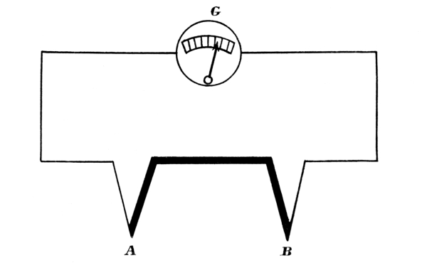
Fig. 2.—Two-junction Thermo-electric Circuit.
It is customary to refer to the two junctions as the “hot” and “cold”
junctions; but it is important to remember that fluctuations in the
temperature of either will alter the reading on the galvanometer or indicator.
A second law, which applies to all thermo-electric circuits, is that
“the E.M.F. developed is independent of the thickness of the wire.”
This does not mean that the deflection of the galvanometer is the
same whether thin or thick wires are used to form the junction. The
deflection depends upon the current flowing through the circuit, and
this, according to Ohm’s law, varies inversely as the total resistance
of the circuit. Consequently, the use of thin wires of a given kind
will tend to give a less deflection than in the case of thick wires, as
the resistance of the former will be greater, and unless the resistance
of the galvanometer be great compared with that of the junction, the
difference in deflection will be conspicuous. The E.M.F., however, is
the same under given conditions, whatever thickness of wire be used.
Reference to fig. 2 will show that in order to realise this
circuit in practice, one of the wires forming the couple must be used in the form
of leads to the galvanometer. This can readily be done if the material
of the wire is cheap; but if platinum or other expensive metal be
used, and the galvanometer be some yards distant, the question of cost
necessitates a compromise, and the circuit is then arranged as in fig. 3.
The wires forming the hot junction are brought to brass terminals T
T, from which copper wires lead to the galvanometer G. This arrangement
results in three effective junctions, viz. the hot junction A to B; the
junction A to brass, and the junction B to brass. It will be seen that
the two junctions of copper to brass are in opposition, and cancel
each other for equal heating; and the same applies to the galvanometer
connections. A circuit thus composed of three separate junctions does
not permit of a simple expression for the net E.M.F. under varying
temperature conditions, and to avoid errors in readings care must be
taken to prevent any notable change of temperature at the terminals T T
in a practical instrument arranged as in the diagram.
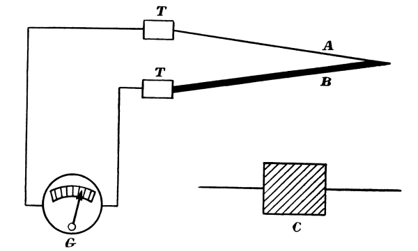
Fig. 3.—Three-junction Thermo-electric Circuit.
A point of practical utility in thermo-electric work is the fact that
if a wire be interrupted by a length of other metal, as indicated at C
in fig. 3, no current will be set up in a circuit if both
joints are equally heated, as the electromotive forces generated at each junction
are in opposition. It is thus possible to interrupt a circuit by a
plug-key or switch, without introducing an error; always provided that
an even temperature prevails over the region containing the joints.
Another useful fact is that if two wires be brought into contact, they
may be fastened over the joint by soldering or using a third metal,
without alteration of thermo-electric value, except in rare cases. Thus
a copper-constantan or iron-constantan junction may suitably be united
by silver solder, using borax as a flux, thus avoiding the uncertainty
of contact which must always occur when the wires are merely twisted
together. Welding, however, is preferable to soldering.
Metals used for Thermal Junctions.—Until recent years
it was customary to employ a platinum-rhodioplatinum or
platinum-iridioplatinum junction for all temperatures beyond the
scope of the mercury thermometer. The almost prohibitive price of
these metals has caused investigations to be made with a view to
discovering cheaper substitutes, with successful results up to 1000°
C. or 1800° F., thus comprehending the range of temperatures employed
in many industrial processes. Above this temperature the platinum
series of metals are still used for accurate working, but it will be
of great advantage if the range measurable by cheap or “base” metals
can be further extended. Promise in this direction is afforded by
the properties of fused metals when used in thermal junctions. An
investigation by the author has shown that in general the E.M.F.
developed by a junction does not undergo any sudden change when one
or both metals melt, but continues as if fusion had not occurred. By
making arrangements to maintain the continuity of the circuit after
fusion, it may be possible to read temperatures approximating to the
boiling points of metals such as copper and tin, both of which are over
2000° C. The base metals are not so durable as platinum and kindred
metals, but as the cost of replacement is negligible, this drawback is
of little importance. Moreover, base-metal junctions usually develop a
much higher E.M.F. than the platinum metals, which enables stronger and
cheaper galvanometers to be used as indicators.
Thermal Junctions used in Pyrometers.
| |
| Couple. |
Upper limit to which |
| Junction may be used. |
| Deg. | Deg. |
| Cent. | Fahr. |
| Platinum and rhodioplatinum (10 per cent. Rh) |
1400 |
2550 |
| 2 Rhodioplatinum alloys of different composition |
1600 |
2900 |
| Platinum and iridioplatinum (10 per cent. Ir) |
1100 |
2000 |
| Nickel and constantan |
900 |
1650 |
| Nickel and copper |
800 |
1475 |
| Nickel and carbon |
1000 |
1850 |
| Nickel and iron |
1000 |
1850 |
| Iron and constantan |
900 |
1650 |
| Copper and constantan |
800 |
1475 |
| Silver and constantan |
800 |
1475 |
| 2 Nickel chrome alloys of different composition |
|
|
| (Hoskin’s alloys) |
1100 |
2010 |
| Nickel-chrome alloy and nickel-aluminium alloy |
1100 |
2010 |
| 2 Iron-nickel alloys of different composition |
1000 |
1850 |
| |
The electromotive force developed by a junction of any given pair of
metals when heated to a given temperature varies according to the
origin of the metals. It is not unusual, for example, for two samples
of 10 per cent. rhodioplatinum, obtained from different sources, to
show a difference in this respect of 40 per cent. when coupled with
the same piece of platinum. Equal or greater divergences may be noted
with other metals; and hence the replacement of a junction can only be
effected, with accuracy, by wires from the same lengths of which the
junction formed a part. As showing how platinum itself is not uniform,
it may be mentioned that almost any two pieces of platinum wire, if
not from the same length, will cause a deflection on a sensitive
galvanometer when made into a junction and heated. It is therefore
customary for makers to obtain considerable quantities of wire of a
given kind, homogeneous as far as possible, in order that a number of
identical instruments may be made, and the junctions replaced, when
necessary, without alteration of the scale of the indicator.
The alloy known as “constantan,” which figures largely in the foregoing
table, is composed of nickel and copper, and is practically identical
with the alloy sold as “Eureka” or “Advance.” It has a high specific
resistance, and a very small temperature coefficient, and is much used
for winding resistances. Couples formed of constantan and other metals
furnish on heating an E.M.F. several times greater than that yielded by
couples of the platinum series, and show an equally steady rise
of E.M.F. with temperature. This alloy has proved of great service in
connection with the thermo-electric method of measuring temperatures.
Couples formed of nickel-chrome alloys, known as “Hoskin’s alloys,”
have been introduced into Britain by the Foster Instrument Company,
which may be used continuously to 1100° C., and for occasional readings
up to 1300° C. Another couple, much used in America, consists of an
alloy of 90 per cent. nickel and 10 per cent. chromium, and an alloy
of 98 per cent. nickel and 2 per cent. aluminium, which may be used up
to 1100° C. Other couples, formed of alloys of nickel, chromium, iron,
aluminium, etc., have been introduced by different makers, but have not
proved so satisfactory as those mentioned above.
Changes in Thermal Junctions when constantly used.—No metal
appears to be able to withstand a high temperature continuously without
undergoing some physical alteration; and for this reason the E.M.F.
developed by a given junction is liable to change after a period of
constant use. At temperatures above 1100° C., platinum, for example,
undergoes a notable change in a comparatively short period, but below
1000° C., the change is very slight, and if this range be not exceeded,
a platinum-rhodioplatinum or iridioplatinum junction may be used for
years without serious error arising from this cause. This liability
to change is one of the factors which restricts the range of thermal
junctions, which should never be used continuously beyond the
temperature at which the alteration commences to become large. A second
cause of discrepancy is the possible alteration in the composition
of an alloy, due to one of the constituents leaving in the form of
vapour, as is noted with iridioplatinum alloys, from which the iridium
volatilises in tangible quantities above 1100° C., causing a fall of
10 per cent. or more in the thermo-electric value of the junction of
these alloys with platinum. Constantan appears to be very stable in
its thermo-electric properties, and the various junctions in which
it plays a part show a high degree of stability if not overheated.
Rhodioplatinum alloys are very stable, and for temperatures exceeding
1100° C. a junction of two of these alloys, of different composition,
is more durable than one in which pure platinum is used. An extended
series of tests on base-metal junctions made in America by Kowalke
showed that continuous heating of couples as received from the makers
altered the E.M.F. considerably, the change in some cases representing
over 100° C. on the indicator. A stable condition, due to the relief of
strains or other change, was finally reached, and the conclusion drawn
that the materials should be thoroughly annealed before calibration. It
is desirable in all cases periodically to test the junctions at some
standard temperature, and if any conspicuous error be noted, to replace
the old junction by a new one.
In addition to the errors due to slow physical changes, a junction
may be altered considerably, if imperfectly protected, owing to the
chemical action of furnace gases, or of solids with which the junction
may come into contact. The vapours of metals such as lead or antimony
are very injurious; and platinum in particular is seriously affected
by vapours containing phosphorus, if in a reducing atmosphere. So
searching is the corrosive action of furnace gases that adequate
protection of the junction is essential if errors and damage are to be
avoided. When a wire has once been corroded, a junction made with it
will not develop the same E.M.F. as before.
Electromotive Force developed by Typical Junctions.—The
following table exhibits the E.M.F. generated by several junctions
for a range of 100° C., taken at the middle part of the working range
in each case. These figures are subject to considerable variation,
according to the origin of the metals.
| |
| Couple. |
E.M.F. in millivolts for |
| a rise of 100° at middle |
| of working range. |
| Platinum-rhodioplatinum (10 per cent. Rh) |
1·1 |
| Platinum-iridioplatinum (10 per cent. Ir) |
1·2 |
| Nickel-constantan |
2·3 |
| Copper-constantan |
5·8 |
| Nickel-copper |
6·1 |
| Iron-constantan |
6·7 |
| Hoskin’s alloys |
7·4 |
|
It will be noted that the base-metal junctions give much higher values
than the platinum series, and hence can be used with a less sensitive,
and therefore cheaper, indicator. Base-metal junctions are also, in
consequence of the greater E.M.F. furnished, capable of yielding more
sensitive readings over a selected range of temperature.
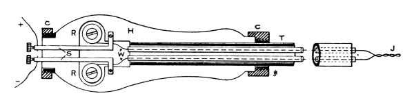
Fig. 4.—Practical Form of Thermo-electric Pyrometer.
Practical Forms of Thermocouples.—When expensive junctions
are employed, wires of the minimum thickness consistent with strength and
convenience of construction are used, a diameter of No. 25 standard
wire gauge being suitable. A common arrangement is shown in fig. 4,
in which J is the hot junction, the wires from which are passed through
thin fireclay tubes which serve as insulators (or through twin-bore
fireclay) to the reels R R, in the head of the pyrometer, upon which
a quantity of spare wire is wound to enable new junctions to be made
when required. Two brass strips, S, are screwed down on to the wires
at one end, and are furnished with screw terminals at the other
end, from which wires are taken to the galvanometer or indicator. A
protecting-tube, T, surrounds the wires and hot junction. The head,
H, may be constructed of wood, fibre, or porcelain, and should be an
insulator for electricity and heat. There are various modifications
in use, but the general method described is adopted by most makers.
In order to guard against errors arising from alterations in the
temperature of the cold junctions in the end of the pyrometer, some
firms construct the head so as to leave a hollow space, through which
cold water is constantly circulated (fig. 5), the arrangement
being known as a “water-cooled head.” In some forms the supply of spare wires
is made to take the form of two spiral springs in a hollow head, the
upper ends of the springs being taken to terminals.

Fig. 5.—Pyrometer with Water-cooled Head.
The choice of a protecting-tube is a matter of considerable importance.
Obviously, such a tube should not soften at the highest temperature
attained, and when expensive metals are used to form the junction the
sheath should not be permeable to gases or vapours. It should also, if
possible, be a good conductor of heat, so that the junction may respond
quickly to a change of temperature in its surroundings, and should be
mechanically strong. It is difficult to secure all these properties
in any single material, and the choice of a sheath is decided by
the conditions under which the couple is to be used. The substances
employed, and their properties and special uses, may be enumerated as
follows:—
1. Iron or Mild Steel.—For temperatures not exceeding 1100° C.
iron or mild steel covers are cheap and efficient from the standpoint
of conductivity, although liable to deteriorate owing to oxidation.
The tendency to oxidise is greatly diminished by “calorising” the
exterior by Ruder’s process, in which the iron is heated in a mixture
of metallic aluminium and oxide of aluminium, a surface alloy being
formed which resists oxidation. A result nearly as good may be obtained
by smearing the surface with fine aluminium powder, and bringing to a
white heat. This treatment greatly prolongs the life of an iron sheath.
Some makers employ an inner steel tube round the wires, and an outer
tube which comes into contact with the furnace gases, corrosion of the
latter being detected before the inner tube has given way and exposed
the junction. Some makers do not consider it safe to expose heated
platinum to an iron surface, with only air intervening, and hence use
an inner cover of silica or porcelain, which the outer iron or steel
tube protects from mechanical damage. For ordinary work seamless steam
or hydraulic steel tubing, with a welded end, is satisfactory; but for
dipping into molten lead or other metals the tube should be bored
from the solid. The great advantage of an iron or steel sheath is its
mechanical strength, which protects the couple from damage in case of
rough usage.
2. Nichrom.—Certain alloys of nickel and chromium, and especially
that known as Nichrom II, may be kept at 1100° C. without oxidising
to any appreciable extent; and hence sheaths of this material may be
used up to the temperature named. In addition to being more durable
than iron, nichrom possesses the same advantages of strength and good
conductivity; on the other hand, it is more costly.
3. Molybdenum.—This metal, which possesses a melting point of
about 2500° C., may be dipped in molten brass, bronze, copper, etc.,
without being attacked, and has been used to form the tip of a
protecting-tube designed to measure the temperature of molten alloys. A
junction covered only by a thin tube of molybdenum quickly attains the
temperature of its surroundings.
4. Graphite and Graphite Compositions.—Carbon has the highest
melting point of all known substances, and in the form of artificial or
Acheson graphite may be easily machined to any desired shape. Graphite
sheaths are sometimes used for immersion in molten metals, but at 1000°
C. and higher Acheson graphite oxidises easily and becomes friable. It
is a good conductor of heat, but is easily broken. Compositions of
natural graphite and refractory earths, such as Morgan’s “Salamander,”
are inferior to pure graphite in conductivity, but are stronger and not
readily oxidised, and may be used to form sheaths for temperatures up
to 1400° C. or possibly higher, when penetration of furnace gases to
the junction is not of moment.
5. Porcelain.—This material, in its best forms, may be used up to
1400° C., but must be efficiently glazed to prevent the ingress of
furnace gases to the junction. It is easily broken by a blow, and when
circumstances permit should be protected by an iron covering-sheath.
The variety known as “Marquardt” has been found very satisfactory for
high-reading thermal couples. Porcelain is not a good conductor of
heat, and a junction encased in it does not respond quickly to external
changes in temperature.
6. Vitrified Silica.—This substance, which may be worked in the
oxy-hydrogen blowpipe, is largely used as a protecting-tube. It is not
advisable, however, to use it for continuous work above 1100° C., as
beyond this temperature devitrification occurs, and the tube becomes
porous. It is a fairly good conductor of heat, and withstands rapid
changes in temperature without cracking. It is very brittle, and for
this reason is generally encased in iron.
7. Alundum.—This material is made from fused bauxite, and
has a melting point of 2050° C. A special form of alundum, used
for protecting-tubes, is non-porous up to 1300° C., and forms a
satisfactory covering. Alundum is a moderately good conductor of heat,
but is easily broken.
8. Carborundum.—This is an electric furnace product, which may
be heated above 2000° C. without damage. For making into pyrometer
tubes, it is bonded with a suitable material, and baked after shaping.
Carborundum, and the amorphous variety known as “silfrax,” have proved
useful for protecting junctions at temperatures as high as 1600° C.
The thermal conductivity is relatively good, but the tubes are easily
broken.
9. Magnesia.—Tubes of this material, which melts at a temperature
considerably above 2000° C., have been used for special work. Magnesia
is a poor conductor of heat, and has little mechanical strength.
10. Zirconia.—This is a very refractory material, its melting point
exceeding 2500° C. It may be made into a vitreous variety, which is
non-porous and proof against sudden temperature changes. At present,
only a moulded form of pyrometer tube, made from zirconia powder, is
available, the material worked in this manner being termed “zirkite.”
Although zirconia is a bad conductor of heat, its other qualities
are such that it forms an excellent material for work at the highest
temperatures possible for thermal junctions; and when the vitreous
variety is available, may come into extended use.

Fig. 6.
Pyrometer
with
Special
Cold
Junction
in Head.
It will be seen from the foregoing that the ideal protecting-tube has
yet to be found, and the user must choose the one which comes nearest
to his requirements. Special consideration must be given in cases when
chemical fumes are present, and a sheath selected which is not attacked
or penetrated by them.
Returning to the junction, it is advisable always to weld the wires,
and not to rely upon the contact resulting from twisting them together.
Platinum and the platinum alloys may be welded readily by placing the
junction in a coal-gas blowpipe fed with oxygen instead of air. For
work at lower temperatures the platinum metals may be soldered by means
of a small quantity of gold, in the flame of a Bunsen burner.
When cheap metals are used for the junction the construction may
be considerably modified, and often with advantage. In fig. 6,
for example, which represents a thermocouple made by A. Gallenkamp & Co.,
the metals used are copper and constantan, and the hot junction,
fastened by silver solder, is supplemented by a cold junction of the
same metals located in the head. The copper wire from the hot junction
passes directly to a copper terminal, from whence a copper wire lead
is carried to the galvanometer; and the same procedure is carried out
with the copper wire from the cold junction, thus realising the circuit
shown in fig. 2. The cold junction is kept in oil, the
temperature of which is registered by a short thermometer, thus enabling (as
will be explained later) the correct temperature of the hot junction
to be deduced under any circumstances. In this instrument twin-bore
fireclay is used to insulate the wires, and the protecting-tube is
of iron—which suffices for the upper limit (800° C.) to which the
junction may be used. Iron and constantan could be used in this manner
by employing iron leads to the galvanometer.
Another type of instrument, rendered practicable by the use of cheap
metals, and which may be termed the “heavy type,” is constructed of
thick pieces of the metals welded together instead of wires, thus
ensuring greater strength and longer life. Messrs Crompton & Co. were
the first to introduce thermocouples of this type, consisting of a
heavy steel tube, to one end of which a nickel rod is welded, the other
end being free, and the length of the rod suitably insulated from the
steel tube; leads for the rod and tube being taken to the galvanometer.
Fig. 7 shows a couple of this kind, made by Paul, consisting
of an iron tube down the middle of which a constantan rod is passed, insulated
from the tube by magnesia. At the tapered end the two metals are welded
together, and at the free end a special cap, fitted over the tube and
rod, the contact parts being insulated from one another, serves to
enable leads to be taken to the galvanometer. Similar thermocouples are
made by the Foster Instrument Company (fig. 8), and are
simple, cheap, and reliable up to 900° C. with an iron-constantan couple,
and to 1100° C. with nichrom couples. When worn out they may be replaced,
at a trifling cost, by others made from the same batch of metal.

Fig. 7.—Heavy Type, Cheap-metal Pyrometer.
The drawback to the use of carbon as one of the materials for a
junction is the difficulty experienced in securing a good contact with
the metal with which it is coupled. In nickel-carbon junctions the
contact is sometimes ensured by the aid of a spring, which presses
the two substances together. Such an arrangement is evidently not so
reliable as one in which the materials are welded, and a defective
contact, arising from any cause, would lead to serious error. A
preferable plan is to screw both the nickel and carbon rods into a
cross-piece of either element.
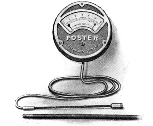
Fig. 8.—Foster’s Cheap-metal Pyrometer.
When applying a thermal junction to the measurement of surface
temperatures, such as steam-pipes or the exterior of furnaces, the
wires may be passed through a thin disc of metal, about ¼ in. in
diameter, and soldered at the back. Suitable materials are copper and
constantan, soldered to a thin copper disc with silver solder, and
brought to a cold junction in the head of the instrument as shown in
fig. 6. The terminal piece of the insulation may be made
of hard wood, with the holes countersunk so as to cover the solder and enable
the wood to touch the disc, which, when pressed on the hot surface, will
then rapidly acquire the temperature. The author has found, by trials
under varying circumstances, that this method of measuring surface
temperatures gives reliable and concordant results. For very
high
surface temperatures a platinum disc, with one of the usual platinum
metal couples soldered to the disc with pure silver, and a piece of
twin-bore fireclay brought to the back of the disc, will be found to
suffice for most cases arising in practice. A small blowpipe flame is
best for soldering the wires to the disc, borax being used as flux in
the first case; but no flux is necessary in soldering the platinum
metals with pure silver.
In deciding upon the length of a thermocouple it must be remembered
that the temperature recorded is that prevailing in the region of
the hot junction. When the temperature of a furnace is uniform it is
sufficient to allow the end of the thermocouple to protrude about 12
inches into the interior, but when following the change of temperature
undergone by objects in a furnace the end must be located near the
objects. If the distance from the exterior of the furnace to the
objects exceed 2 feet, the thermocouple should be inserted through the
roof so as to hang vertically, as if placed through the side it would
droop by its own weight at high temperatures. The distance between
the exterior of the furnace and the cold junctions should be at least
15 inches in all cases in which the heating of the cold junction
is not automatically compensated. After inserting the couple the
opening through the furnace wall should be closed by means of suitable
luting-clay.
In certain instances, such as flues, it is necessary to use a long
instrument in a horizontal position. A rail may then be placed across
the flue, at a suitable place, to serve as a support and so to prevent drooping.
Liquid Element Thermocouples.—An investigation by the author
and A. W. Grace has shown that the continuity of the E.M.F. produced
by a rising temperature is not interrupted by fusion, except in the
cases of bismuth and antimony, which both show an abrupt change in
thermo-electric properties at the melting point. It would therefore
appear feasible to measure temperatures by constructing a thermocouple
so as to retain the circuit after fusion, the advantage gained being
that the range is restricted by the boiling point of the metals instead
of the melting point and higher readings are rendered possible. The
boiling points of some of the common metals are appended:—
| |
| Metal. |
Boiling Point. |
| |
Deg. C. | Deg. F |
| Aluminium |
1800 |
3270 |
| Silver |
1955 |
3550 |
| Tin |
2270 |
4120 |
| Copper |
2310 |
4190 |
| Nickel |
2330 |
4225 |
| Iron |
2450 |
4440 |
| |
From inspection of these figures, it will be seen that if a suitable
couple could be obtained, common metals might be used to measure
temperatures equalling or even exceeding the limit of the range covered
by wire junctions of metals of the platinum series. Instead of using
two metals, graphite might form one member of the couple, provided that
no objection to its use existed on other grounds.
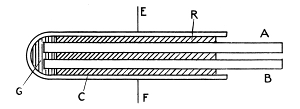
Fig. 9.—Liquid-element Thermocouple.
The form of thermocouple designed by the author to permit of the use of
molten elements is shown in fig. 9. A rod of refractory material,
R, is perforated longitudinally by two holes, down which are passed rods of
the thermo-elements, A and B. The lower ends of A and B are inserted in
a graphite block G, which is jointed on its upper face to R; the whole
being surrounded by the refractory cover C. On either or both of the
elements melting, the circuit is maintained through G, which serves
also to prevent the mixing of A and B when molten, whilst not affecting
the E.M.F. developed. In order to allow for the expansion of the metals
on melting, A and B are made to fit loosely in R. When inserted in a
furnace to a depth represented by EF, only the portion of the metals
adjacent to the closed end will melt, the outer parts remaining solid.
At present it has not been found possible to procure the refractory
parts in a form suited to commercial use, but when this obstacle
is overcome this type of thermocouple should prove of service for
measuring temperatures beyond the scope of ordinary base-metal junctions.
Indicators for Thermo-electric Pyrometers.—As
the electromotive force developed by a single junction when heated is
small, a sensitive galvanometer is required to indicate the minute
current flowing through the circuit. Delicate millivoltmeters, of
the moving-coil type, are universally employed, as they possess the
advantage of an evenly-divided scale combined with the requisite degree
of sensitiveness. The original d’Arsonval galvanometer, consisting of
a coil suspended by a metallic strip between the poles of a horse-shoe
magnet, was used by Le Chatelier, who, by its aid, was enabled to
lay the foundations of this branch of pyrometry. Three forms of this
instrument are now in use, viz. (a) the suspended coil “mirror” type;
(b) the suspended coil “pointer” type; and (c) the pivoted type.
Examples of each will now be described.
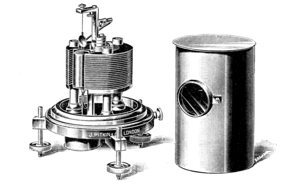
Fig. 10.—Holden-d’Arsonval Mirror Galvanometer.
Fig. 10 represents a mirror galvanometer working on
the d’Arsonval principle, designed by Gen. Holden, F.R.S. The horse-shoe magnet
is laminated, and an iron core, supported by a pillar, is placed
between the poles. The coil, which moves in the space between the
core and the poles of the magnet, is suspended by a thin, flat strip
of phosphor-bronze, which carries a small circular mirror. A similar
phosphor-bronze strip is fastened to the lower part of the coil,
and is continued to an adjusting-screw in the base. The ends of the
suspension strips communicate with the terminals of the galvanometer,
and a current entering at one terminal passes through the metallic
suspensions and the coil to the other. The effect of passing a current
through the coil, which is located in a powerful magnetic field is to
produce an axial movement tending to twist the suspension strips, which
movement is greatly magnified by a spot of light reflected from the
mirror on to a distant scale. When the current ceases, the untwisting
of the strip restores the coil to its former position. Galvanometers of
this type are remarkably “dead-beat” in action, that is, the movement
and restoration of the coil are accomplished without vibration. A
semi-transparent scale, placed at 1 metre distance, and 50 centimetres
long, is suitable for use with this galvanometer. When used in
workshops, it is necessary to protect a mirror galvanometer from the
vibrations produced by machinery, which would cause the spot of light
to become unsteady. The best method of effecting this is shown in fig. 11,
which represents the mode of suspension devised by W. J. Lambert
for use in the Royal Gun Factory, Woolwich Arsenal. The usual supports
of the galvanometer are abolished, and the instrument suspended from
the ring of a brass tripod, so as to keep three springs partly in
compression. When suspended in this manner, a mirror galvanometer
is quite suited to commercial use; in the quiet of the laboratory
the ordinary supports may be employed. The advantage gained by using
the mirror type is that a much longer scale is possible than with
instruments furnished with a pointer, and hence greater accuracy in
determining temperature readings may be secured.
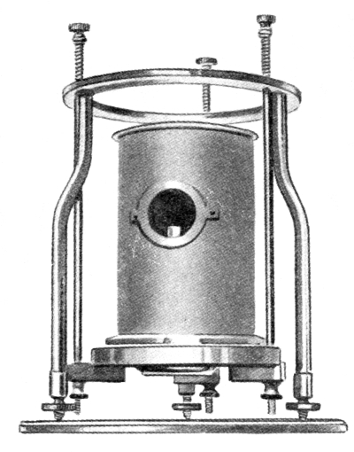
Fig. 11.—Lambert’s Anti-vibration Stand for Galvanometers.
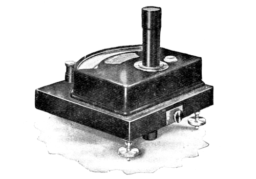
Fig. 12.—Siemens’ Thermo-electric Indicator.
In suspended coil instruments furnished with a pointer, the
construction differs only in detail from the foregoing. In place of
the mirror, a light pointer is attached to the suspension so as to
rest on the coil and a scale is furnished over which the pointer
moves. Fig. 12 is an example of this type, made by Messrs
Siemens, the suspension being contained in the tube which rises from the body
of the instrument. The maximum length of scale moved over by the extremity
of the pointer is about 6 inches, as a longer and therefore heavier
pointer would reduce the sensitiveness below the point requisite for
thermo-electric work.
In the double-pivoted type, the suspension is eliminated, and pivots
are fastened to each end of the moving coil which rest in bearings.
The turning of the coil is made to compress a hair spring, made of
phosphor-bronze; and when the current ceases the unwinding of this
spring restores the coil to its former position. The coil carries
a pointer which moves over a scale. These instruments are not so
sensitive as those in which the coil is suspended, but can be made
sufficiently sensitive to work with any kind of junction in practical
use. The pivoted form is cheaper and stronger than the suspended type,
and is used whenever sufficiently sensitive.
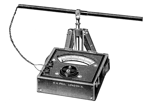
The “Uni-pivot” galvanometer, made by R. W. Paul, is shown in
figs. 13 and 17. The coil,
which carries the pointer, is circular, and moves round a spherical
core of iron placed between the poles of the magnet. A hole is drilled
in the iron core, and the coil rests on a single bearing at the bottom
of this hole. A phosphor-bronze control-spring serves to restore
the coil to the zero position. The lessened friction due to the use
of a single pivot enables this instrument to be made very sensitive
when needed, so that a relatively small rise in the temperature of a
junction may cause the pointer to traverse the whole length of the scale.
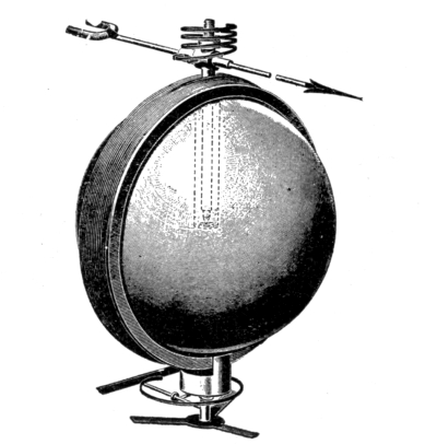
Fig. 13.—Principle of Uni-pivot Galvanometer.
Special Features of Indicators.—All moving-coil instruments,
whether suspended or pivoted, are liable to alteration of the zero
point owing to what is termed “creep.” The suspension strip, when first
fixed in position, generally possesses a certain amount of initial
torsion, which comes into operation gradually and causes a slight
movement of the coil. Similarly, in a pivoted instrument, the strength
or shape of the control-spring undergoes a gradual alteration at first,
causing the pointer to move away from the zero position. For this
reason adjusting arrangements are fitted by means of which the spot of
light or pointer may be brought back to the zero. This creeping ceases
after a time—often requiring twelve months—and if not subjected to
any strain, error from this cause does not recur to any notable extent.
With a mirror galvanometer it is better to move the scale, or turn the
galvanometer round on its axis to restore the correct zero, rather than
to twist the coil back; but with a fixed scale and pointer the only
remedy is to turn the coil bodily round. In a single-pivot indicator
constantly used in the author’s laboratory, the creep amounted to a
movement of the end of the pointer through an angle of 2 degrees in
the first few months, since when, after the lapse of several years, no
further alteration has occurred. It is advisable to test the zero point
of an indicator from time to time by breaking the circuit, and if an
error be discovered the pointer should be re-set, or an allowance made
in taking a reading.
The resistance of an indicator should be so high that the readings
should not be perceptibly altered by any fluctuations in the resistance
of the circuit which may arise in practice. If leads of considerable
length were used to connect the pyrometer with the indicator, and were
subject to fairly large alterations of temperature, the consequent
changes in the resistance of such leads would be noticeable on a
low-resistance indicator; and similarly, if a pyrometer were inserted
at different depths in a furnace at separate times, thus heating up
varying lengths of the junction wires, a discrepancy would arise for
the same reason. The resistance of an indicator, however, cannot be
raised beyond a certain point without reducing the sensitiveness below
the required limit. A mirror galvanometer of the type described may
have a resistance—partly in the coil and partly in an added series
resistance—of 1000 ohms or more, and still be sufficiently sensitive;
and in the latest types of instruments provided with pointers the
resistance may be made as high as 1000 ohms, although it is more
usually 400 to 500 ohms. Many indicators are in use, however, in which
the resistance is 100 ohms or less. As, from Ohm’s law, the current
varies inversely as the total resistance in the circuit, any alteration
in resistance should be small relatively to the total to render the
error negligible. This point is made clear in the following example:—
Example.—A thermocouple and leads have a
resistance of 5 ohms and are subject to alterations amounting to 1 ohm.
To find the errors resulting when indicators of resistances 800, 400,
and 50 ohms respectively are used.
From Ohm’s law, C = E/R, the
variation in C, with E constant, will be 1 in 805, 1 in 405, and 1 in
55 respectively. As the indications are proportional to the current,
the alterations caused will be approximately ⅛ per cent., ¼ per cent.,
and 2 per cent. The first two may be ignored; the last may be quite
serious and lead to the failure of an operation.
It will be seen from the foregoing that low-resistance indicators
should only be used for fixed thermocouples and short leads not subject
to temperature changes, or, in other words, in a circuit of fixed resistance.
The resistance of an indicator, when unknown, may be found by the
following method, suggested by the author:—A resistance box is joined
at one end to one terminal of the indicator. To the other terminal a
fairly stout iron wire, 18 inches long, is connected, and a similar
length of constantan wire is coupled to the other end of the resistance
box. The free ends of the wires are twisted into a junction which is
dipped into boiling water. The deflection obtained with no resistance
in the box (D1) is noted, and resistances (R) are then unplugged
until the deflection (D2) is approximately one-half of D1. The
resistance (G) of the indicator, ignoring that of the wires, is then
given by the formula
as may readily be proved from Ohm’s law, E being constant. This method
is extremely simple and reasonably accurate.
Reliable indicators are now procurable from many instrument-makers at
a comparatively small cost, progress in this direction having been
most marked in recent years, particularly in the case of pivoted
instruments. The most convenient form for workshop use is made with
an edgewise scale (fig. 14) and may be placed in a suitable
position fixed to a bracket. The flat-scale pattern is preferable for use on a
laboratory table, or for a portable pyrometer. The sector pattern is
also good for workshop use, the dial being visible from a distance.
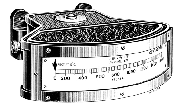
Fig. 14.—Indicator with Edgewise Scale
Standardizing of Indicators to read Temperatures directly.—The
temperature scale of an indicator, for use with a given thermal couple,
is always marked by the maker in the case of instruments furnished
with a pointer, and, generally speaking, is correct within reasonable
limits. It is customary and necessary to send with the instrument a
statement of the cold-junction temperature for which the markings
are correct; say 20° C. or 60° F. The user should then endeavour to
maintain the cold junction at this specified temperature when taking
a reading, or otherwise a considerable error may be introduced. It is
highly desirable, however, that the user should be able to perform the
standardizing himself, if only for checking purposes; and when using a
mirror galvanometer as indicator it is necessary to standardize on the
spot at which the instrument is fixed. Ability to prepare a temperature
scale is further useful, inasmuch as any good millivoltmeter, of range
0 to 20 millivolts, may be used for thermo-electric work of all kinds,
and may be calibrated for different junctions, a suitable series
resistance being added to enable E.M.F.’s higher than 20 millivolts to
be measured. Such an instrument may thus be made extremely useful, both
in the workshop and laboratory.
Standardization may be effected either by subjecting the hot
junction to several known temperatures, and noticing the deflections
corresponding thereto; or by measuring the electromotive force
developed by the junction, and calculating the corresponding
temperature from a formula which is known to hold for the range
comprehended by the instrument. The former method is simpler; and if
carefully conducted is quite accurate. The latter method possesses the
advantage that readings in millivolts may be translated directly into
temperatures when the constants of a given thermal couple are known.
It is now usual to mark indicators with a double scale, one reading
millivolts and the other temperatures.
Standardization by Fixed Points.—Taking any
millivoltmeter which, with a maximum of 20 millivolts at the
terminals, will give a full scale deflection, the first step is
to arrange that the pointer (or spot of light) shall just remain
on the scale at the highest temperature to be attained by the
junction. This may be done by placing the hot junction
in boiling water and noting the deflection obtained, either in
millivolts or equal arbitrary divisions, and also the temperature of
the cold junction. The deflection observed is due to a difference
of temperature (100-t) deg. C, where t is the temperature of
the cold junction. If the highest temperature to be measured is
10 times (100-t), the deflection should be rather less than
1⁄10 of the scale, and
similarly for any other required temperature limit. If the observed
deflection exceed this proportion, a series resistance should be
added until the correct value is obtained. This resistance is then
permanently installed in the circuit for use with the junction under trial.
Before proceeding further it is necessary to consider whether the
pyrometer is to possess a single cold junction of ascertainable
temperature (as in fig. 6), or whether it will be arranged
with two cold junctions in the head, as in fig. 4. In the former
case it is simpler to prepare a “difference” scale; that is, one which reads
differences of temperature between the hot and cold junctions, from
which the temperature of the hot end may be obtained by adding to the
difference that of the cold junction. In the latter case the cold end
should be kept by artificial means at the temperature likely to be
attained in practice—say 25° C.—a water-bath being suitable for this
purpose. It is advisable to remove the shield of the pyrometer when standardizing,
so as to expose the hot junction, as closer readings can then be taken.
A number of materials—preferably cheap—of known boiling points or
melting points are then selected from a table of fixed points (page
16) so as to give about six points, distributed fairly evenly over the
scale. As an example, if it were desired to prepare a temperature scale
from 0° to 1000° C., the following might be chosen:—
| |
| Substance and Condition. |
Temperature. |
| Water at boiling point |
100° C. |
212° F. |
| Tin at melting point |
232 |
449 |
| Zinc at melting point |
419 |
786 |
| Antimony at melting point |
631 |
1167 |
| Common salt at melting point |
800 |
1472 |
| Copper at melting point (covered with graphite) |
1084 |
1983 |
| |
The hot junction is allowed to attain these temperatures successively,
and the corresponding deflection in each case is noted. It is then
possible to divide up the whole of the scale to read temperatures directly.
The first reading is taken by placing the junction in a vessel of
boiling water, and for a locality near sea level it is not necessary
in ordinary work to take account of fluctuations in the boiling point
due to alterations of atmospheric pressure. To ensure that the other
readings are taken when the substances are exactly at the melting
point, the procedure is as follows: about 2-3 lb. of the substance are
melted in a salamander crucible, and a small fireclay tube, closed at
one end, is inserted in the molten mass. The hot junction is placed
in
the fireclay tube, and the intervening space filled with asbestos
fibre. Great care must be taken not to let the junction touch the fused
substance. The crucible is now allowed to cool, and a reading of the
deflection taken every half-minute. When the substance is exactly at
its solidifying point—identical in general with the melting point—the
deflection remains stationary for several consecutive readings, owing
to the liberation of latent heat of fusion in sufficient quantity
to balance the loss by radiation. This stationary reading is noted
for each substance, and represents the deflection given when the hot
junction is at the temperature corresponding to the melting point, and
the cold junction or junctions at the temperature existing when the
observation is made. For melting the materials, a Davies furnace with
a large Teclu or Meker burner is convenient up to 850° C.; but to melt
the copper a blast lamp is requisite. The molten mass may be allowed to
cool in the furnace.
From these observations a calibration curve may be drawn either for
differences between hot and cold junctions, or for a steady temperature of the
cold junctions. Two sets of data are appended to illustrate the procedure.
| |
Temperature
of Hot
Junction. |
Pyrometer 1. Iron-constantan. |
Pyrometer 2. |
| (Series resistance in |
Platinum-iridioplatinum. |
| galvanometer circuit.) |
|
| Deflection. |
Cold Junction. |
Difference. |
Deflection. |
Cold Junction. |
| 100° C. | 8·9 |
15° C. | 85° C. |
5·5 | ┐ |
| 232 | 21·8 |
17 | 215 |
15·6 | │ Constant |
| 419 | 40·6 |
19 | 400 |
29·4 | ├ at |
| 631 | 63·8 |
19 | 612 |
45·5 | │ 25° C. |
| 800 | 83·0 |
20 | 780 |
59·0 | │ |
| 1084 | . . . |
. . . | . . . |
82·0 | ┘ |
| |
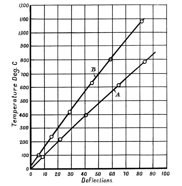
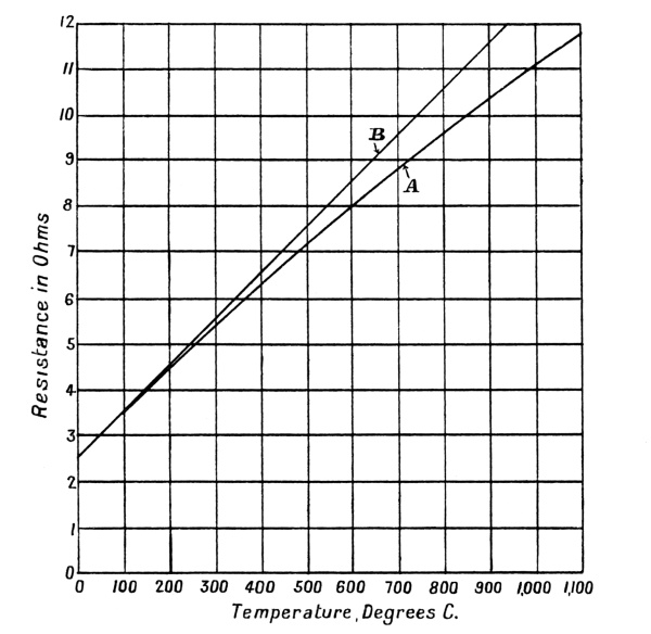
Fig. 15.—Calibration Curves for Two Thermo-electric Pyrometers.
Fig. 15, A, is a calibration curve for thermocouple 1,
connecting deflections with corresponding differences between the temperatures
of the hot and cold junctions. In order to read from this curve the
temperature of the hot end, the reading corresponding to the observed
deflection is added to the existing temperature of the cold junction.
Thus if a deflection of 56 divisions were obtained with the cold
junction at 25°, the temperature of the hot junction would be (540 + 25) = 565° C.
The advantage of this method of calibration is that it is unnecessary
to take precautions to keep the cold junction at a steady temperature;
and when a single cold junction is used, as in fig. 6,
this plan should always be followed. It will be noted that this curve passes
through zero, as no deflection represents no difference of temperature.
Fig. 15, B, represents the calibration curve for pyrometer 2,
and is such that direct readings may be obtained corresponding to any
given deflection, for a cold junction temperature of 25°. This curve,
therefore, cuts the axis of zero deflection at 25°, as no deflection
corresponds to the condition when both hot and cold junctions are at
25°. This method of calibration may be used with advantage for couples
of the type shown in fig. 4, where two cold junctions exist
in the head, and the simple rule of adding the cold junction temperature
does not apply. Many suggestions have been made for correcting for
alterations in the temperature of the cold end of such a couple,
but none are accurate, and it is necessary to keep this part at the
temperature of standardization to secure correct readings. In both of
the above calibrations the galvanometer used possessed a scale divided
into 100 equal arbitrary divisions.
In making permanent temperature scales from these curves to attach
to the existing galvanometer scale, intervals of 100° may be taken
and marked opposite to the corresponding divisions on the existing
scale. Each 100° may then be equally subdivided into as many parts as
the length of scale permits, and numbered at suitable intervals. If
the junction used yield a calibration curve departing greatly from a
straight line, every 50° interval should be taken, or, if necessary,
every 25°. In the examples given both curves are nearly straight lines
in the working region, viz. 400° to 800° for the iron-constantan
junction, and 500° to 1100° for the platinum-iridioplatinum.
One precaution necessary in standardizing an indicator by this method
is to ensure that the metals used are pure, as impurities lower the
melting points. If ordered as “pure” from any dealer of repute, the
metals will generally be found satisfactory. The common salt used
should be the ordinary salt sold in blocks, and not a prepared table
salt. A second precaution, when observing melting points, is to guard
against a possible error due to the substance becoming “surfused” or
“overcooled”; in which case the temperature falls below the ordinary
freezing point before solidification commences. When freezing occurs,
however, the temperature rises to and remains at the true melting
point, and an increase of deflection following a gradual fall always
indicates overcooling. The higher deflection then attained is the true
freezing point. Antimony frequently overcools to 600° before freezing,
but on setting rises to the correct figure—631°. All metals and salts
are liable to overcooling occasionally.
Standardization by Measurement of E.M.F.—It has been found,
as the result of experiments, that the relation between the E.M.F.
developed by a junction and its temperature—under constant conditions
of the cold junction—may be expressed approximately by a formula as under:—
log E = A log t + B (Holman’s formula),
where E = electromotive force in microvolts, t =
temperature in Centigrade degrees, and A and B are constants depending
upon the junction. With certain junctions this formula may be applied
over the working part of the scale with an error not exceeding 2° C.,
but with others the discrepancy is greater. In order to determine the
constants A and B, it is necessary to measure the E.M.F. at two known
temperatures, which should be chosen as far apart as possible in the
working region. When these constants are known, a measurement of E
enables the temperature t to be found by calculation.
Example.—Le Chatelier found that a junction at
the temperature of melted aluminium (657° C.) gave 6200 microvolts; at
the melting point of copper in air (1062° C.) the figure was 10580.
Applying in the above formula
log 6200 = A log 657 + B
and
log 10580 = A log 1062 + B,
the value of A is 1·2196 and of B 0·302, as may
be found by taking logarithms and solving for A and B.
The values of the constants A and B vary for different junctions, and
also for different melts of what are reputed to be the same materials.
When once determined for a quantity of homogeneous wires, to which
the formula applies with sufficient accuracy, it is evident that an
indicator with a millivolt scale may be made to read temperatures
directly without any necessity for further experiment, although it is
always advisable to take one check reading at a fixed point in the
working range.
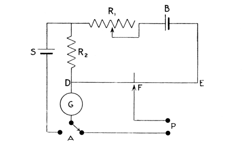
Fig.16.—Potentiometer Method of Measuring E. M. F.
In order to determine the E.M.F. of a junction at different
temperatures, the potentiometer method is used, in which the E.M.F.
of the test-couple is balanced against the known E.M.F. furnished by
a constant cell. The circuit is shown in fig. 16, in which B is an
accumulator which sends a current through the resistances R1, R2,
and the calibrated wire DE. The cold ends of the couple are attached
at P so as to be in opposition to B, and in this branch of the circuit
are included a sensitive galvanometer G and a portion of the wire DE. A
standard cadmium cell, S, is connected between R1 and R2 at one
end, and may be put in circuit with the galvanometer through the switch
A. In commencing, S is connected to the galvanometer and R1 adjusted
until no deflection is obtained on G. The switch A is now moved over
to the circuit of the couple, and the terminal F moved along the wire
until zero deflection is again obtained. The E.M.F. of the couple is
determined from the relation
| E of junction |
|
Resistance of DF |
| ———————— |
= |
———————— |
| E of standard cell |
|
R2 |
By exposing the hot end of the junction to successive standard
temperatures, and maintaining the cold ends at a known constant temperature,
the necessary data for inclusion in a formula may be obtained.
In fixing a permanent temperature scale, calculated from the formula,
to a millivoltmeter, it must be remembered that the values given by
the experiment are absolute, and independent of the resistance of the
circuit composed of the thermo-element and galvanometer. On the other
hand, a millivoltmeter is marked to read difference of potential at
its terminals; and if in series with a junction and leads of notable
resistance, its indications will not be the E.M.F. of the junction. An
example will make this point clear.
Example.—A millivoltmeter has a resistance of
100 ohms, and is marked to read P.D. at its terminals. A thermocouple
and leads connected to the millivoltmeter have a resistance of 5 ohms.
To find the relation between the true E.M.F. of the junction and the
readings of the indicator.
If E = the E.M.F. developed by the junction, and
V, the reading of the millivoltmeter, = P.D. at its terminals, then
the current in the circuit = E⁄105 =
V⁄100; and V = (100⁄105)E.
That is, the readings are lower by 5 per cent. than the true E.M.F. of the
junction. In the same way a low resistance voltmeter, if applied to a
cell of high resistance, shows a lower reading than the E.M.F. of the cell.
This example indicates how a table connecting true E.M.F.’s with
reading in millivolts may be calculated when the resistances concerned
are known. It is presumed, in preparing a scale in this manner, that
the resistance of the couple will not be subject to such alterations as
to affect the reading.
The advantages of this method of calibration are manifest when a number
of junctions are being made from a given batch of wires, as it is only
necessary to divide the scale of the indicator so as to represent
millivolts—a simple operation—and then to attach a temperature scale.
This procedure is much more expeditious than standardizing each
indicator at several fixed points when a number are concerned, but for
a single junction the fixed point method is easier. The potentiometer
method of measuring E.M.F. may also be used to determine temperatures
in place of an indicator, and is of great service in cases where very
accurate readings are specially required, being far more delicate in
detecting small differences of temperature than an indicator. Special
potentiometers for thermo-electric work are made by the Cambridge
and Paul Instrument Company, Siemens, and others, and are useful in
conducting accurate research, but are too elaborate for workshop or
ordinary laboratory practice.
Cold Junction Compensators.—The necessity for paying
attention to the cold junction has led to various attempts to compensate
automatically for changes of temperature at this part of the pyrometer.
A thermometer located near the cold junction, as in fig. 6,
is all that is needed to correct a two-junction circuit; but when a three-junction
circuit is used a correct reading is not secured by adding the excess
temperature of the thermometer over the calibration temperature to
the reading on the indicator. In Bristol’s arrangement a mercury
thermometer, with a large bulb and wide stem, is stationed at the cold
junction, and participates in any temperature change. In the stem is
placed a loop of thin platinum wire, which forms part of the pyrometer
circuit. When the mercury is heated it expands up the stem and
short-circuits a portion of the loop, thereby diminishing the
resistance of the pyrometer circuit, and tending to increase the
deflection on the indicator. Simultaneously the cold junction will
be heated, tending to diminish the current, and so to cause a less
deflection. By adjustment these two tendencies may be counterbalanced,
so that the reading is unaffected, but such adjustment will only
apply to a given E.M.F., and therefore to one temperature of the hot
junction. Hence this method fails in general application.
Peake’s compensated leads are intended to remedy cold-junction errors
by transferring this junction, in effect, to the galvanometer. They
are used for pyrometers in which the platinum metals are employed, and
consist of wires of two different alloys of copper and nickel, which
connect the cold end to the indicator. These alloys are such that
the electromotive forces set up at the junctions in the head—Pt and
Cu-Ni 1, and Pt-Ir with Cu-Ni 2—are equal and opposite at all working
temperatures, and hence changes at the cold junctions do not affect the
reading. At the indicator, however, temperature changes would cause an
alteration in deflection; but as the indicator is generally placed well
away from the furnace, and is not liable to notable heating or cooling,
the possible errors are greatly reduced by the use of these leads. They
are obviously of no value for use with base-metal pyrometers, as the
wires used in such may be prolonged to the indicator, with an identical result.
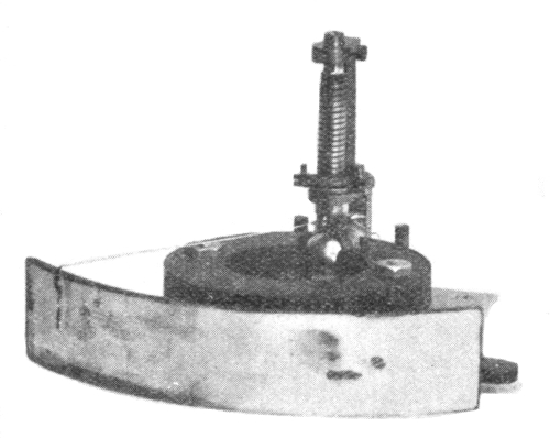
Fig. 17.—Darling’s Compensator, fitted to Galvanometer.
An automatic compensator for use with base-metal pyrometers has been
devised by the author, and is illustrated in figs. 17
and 18. A spiral made of a compound strip of two
metals is attached to the needle of the indicator, and coils or uncoils
when cooled or heated, thereby moving the pointer over the scale. The
length of the spiral is such that an alteration of a given number of
degrees in its temperature moves the pointer by the same number of
degrees on the scale—or, in other words, the temperature scale of the
pyrometer is identical with that of the spiral. The metals forming
the junction are continued, in the form of wires, to the interior of
the galvanometer, where a cold junction is formed, which will always
possess the same temperature as the spiral. The scale is constructed to
represent differences of temperature between the hot and cold
junctions, and before coupling up the pyrometer the pointer indicates
the temperature of the spiral; that is, of the cold junction. On
connecting the thermocouple the pointer is moved by the coil of
the indicator through an amount represented by the difference in
temperature between the two junctions, and therefore finally indicates
the temperature of the hot junction.
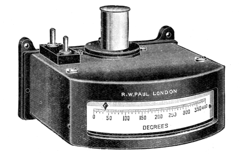
Fig. 18.—Indicator fitted with Darling’s Compensator.
Example.—If the cold junction were at 20°, the
pointer, before connecting the couple, would indicate 20° on the scale.
If the hot junction were 580° hotter than the cold, then on completing
the circuit the pointer would move 580 additional degrees along the
scale, so that the figure indicated would be (20 + 580) = 600°, the
temperature of the hot junction. If now the indicator were heated
by 10°, the spiral would tend to augment the deflection by 10°, but
simultaneously the deflection due to the junctions would fall off by
10°, and the reading would still be 600°.
This method of compensation renders the readings independent of the
cold junction, and, in addition to its use for high temperatures,
enables ordinary and low temperatures to be read simply and correctly,
as will be shown later. The spiral is located in the tower rising from
the top of the indicator in fig. 18.
In Paul’s method of compensation the thermocouple and indicator
are placed across a Wheatstone bridge, two arms of which contain
resistances of copper, whilst the resistances in the other two arms are
of manganin. Any change in temperature at the cold junction is shared
by these four resistances, and, whilst affecting the resistance of the
copper parts, no change is caused in the manganin parts, as this alloy
has a negligible temperature coefficient. If, therefore, the bridge
were initially balanced at 20° C., and the temperature rose to 30°,
the increased resistance of the copper would destroy the balance, and
permit of a small current passing through the indicator. A fall to
10°, by diminishing the resistance of the copper, would cause an equal
current to pass through the indicator in the opposite direction. The
amount of this current is arranged so as to add the rise in temperature
of the cold junction to the reading of the indicator in the one case,
and to subtract the fall in the other, thus retaining true readings for
the cold-junction temperature at which the couple was standardized.
Constant Temperature Cold Junctions.—If the cold junction
can be kept at a steady temperature, compensators are unnecessary,
but no good practical means of achieving this end has yet been
devised. Water-cooled heads have already been referred to; but in many
situations the connecting-pipes entailed would be objectionable, and
hence this arrangement is not greatly used. An alternative method,
suggested by Prof. A. Zeleny, is to bury the cold junction in the
ground. Recent experiments, conducted at Cambridge by R. S. Whipple,
showed that a junction buried 10 feet deep did not vary in temperature
by more than 2° C. over a period of three years. This has led to the
adoption of buried junctions in special cases; but it is probable that
much greater variations would be experienced in the ground beneath
large furnaces, in which case the advantages of this procedure would
be lost. A common workshop method is to locate the cold junction in a
thermos flask filled with oil, when a temperature constant to 2° C. may
be secured, although the changes in the temperature of the surrounding
atmosphere may be as great as 150 C. For special work, ice may be
used in the thermos flask, thus securing absolute constancy; but this
procedure is not feasible in ordinary works practice.
Special-Range Indicators.—When the working range of a
pyrometer is from 600° C. upwards, it is evident that the part of the scale
occupied by the first 600° is useless, and that it would be an
advantage if the whole scale could be utilised for the special working
range, so as to secure more exact readings. This may be accomplished
by a “set-up” against the movement of the pointer caused by the
thermocouple, so as to prevent any motion over the scale until an
assigned temperature is reached. For example, a junction developing
12 millivolts at 1000° C. may be coupled to an indicator in which the
full-scale deflection of the pointer is produced by 6 millivolts. If an
E.M.F. of 6 millivolts be opposed to the junction, no deflection will
occur until the temperature at which the couple develops 6 millivolts
is reached—when the opposing E.M.F. will be overcome. This temperature
may be 500° C., so that the whole scale may be divided up between
500° and 1000°. The length of the indicator scale is thus effectively
doubled; and by using different values for the set-up, it is evident
that any desired range may be obtained within the limits of sensitivity
of the indicator. The method of procuring the opposing E.M.F. varies
with different makers. The Cambridge and Paul Instrument Company employ
a dry cell and a series resistance, connected so as to oppose the
thermocouple; and by adjusting the resistance any desired set-up may be
obtained, the value of which, in degrees, may be read off by connecting
the cell and resistance to the indicator, the couple having been
switched out of the circuit. Thus, to adjust for a range of 500°-1000°
on an indicator giving full-scale deflection for 500°, the resistance
is regulated so that the cell alone causes the pointer to move to the
end of the scale. The method adopted by Paul consists of suitable
resistances inserted in a Wheatstone bridge, which may be thrown off
the balance, and thus cause an opposing E.M.F. of the correct amount at
the terminals of the indicator.
A mechanical set-up has been introduced by the Cambridge and Paul
Instrument Company, the indicator in this case having a suspended
coil. By turning a milled-head a twist may be given to the suspending
strip, and by the turning of a second head the pointer may be brought
back to zero, retaining the initial twist, which is opposed to that
produced by the current due to the couple. Thus, if the imposed twist
were such as to move the pointer to the 400° mark on the scale, the
temperature indicated by the junction would be the observed reading
plus 400. By this method it is possible to obtain any desired range
within the limits of the indicator. The danger of producing errors due
to “creeping” is said to be negligible.
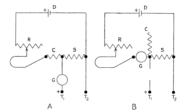
Fig. 19.—Circuit of Northrup’s “Pyrovolter.”
Potentiometer Indicators.—The advantage of measuring E.M.F.
by the potentiometer method is that the result is independent of the
resistance of the circuit under test, whereas an indicator is affected
by changes in the resistance of the circuit in which it is inserted.
When long leads are used to connect a couple to its indicator, notable
errors may be caused by the varying resistance of the leads, due
to changing temperature; and, in addition, the resistance of the
couple-wires varies according to temperature and depth of insertion in
the furnace. Attempts have therefore been made to produce indicators
based on the potentiometer principle, suitable for workshop use, and
one form, known as Northrup’s “Pyrovolter,” is arranged as shown in
fig. 19, A. A cell D sends a current through a rheostat R,
a copper coil C, and a manganin coil S. The copper coil has the same resistance
as the copper winding of the indicator G. The couple is connected,
with G in circuit, across the manganin coil S, the resistance of this
material being unaffected by temperature. By adjusting R until no
deflection is shown on G, the drop of volts across S is made equal
to the E.M.F. of the couple. To measure this drop, a key is pressed,
altering the circuit as shown in B, the indicator being now in series
with S and the couple detached. The value of the current passing
through S is unchanged, as the indicator coil has the same resistance
as the copper coil C, which it now replaces. The deflection on G
indicates the value of this current, and, as the drop of volts across
S is proportional to the current, G may be marked off to read E.M.F.
and the corresponding temperature of the junction. The advantages
claimed are that the indicator may be used with any type of junction,
and is unaffected by temperature changes in the circuit. A similar
instrument is made by the Brown Company of Philadelphia. Up to the
present potentiometer indicators have not been adopted to any extent
in Britain, and the adjustments necessary to obtain a reading must be
accounted a distinct drawback from a workshop standpoint.
Recorders for Thermo-electric Pyrometers.—It is frequently of
importance to know not only the existing temperature of a furnace, but
also the fluctuations to which it is subject. Continuous observation of
a pyrometer would involve too much labour, and it is therefore evident
that an automatic recorder would possess many advantages in such cases.
A continuous record shows whether the attendant has maintained the
temperature between the prescribed limits, and furnishes a permanent
history of a given operation, which often serves as a guide to future procedure.
The first successful recorder, suggested by Sir W. Roberts-Austen and
designed by Gen. Holden, F.R.S., was used in conjunction with a mirror
galvanometer. In its original form, the spot of light from the mirror
was made to fall on a sensitized plate, to which a gradual vertical
motion was conveyed by connecting the dark slide to a water-float by
means of a chain and pulley. The float was placed in a tank of water,
which was gradually emptied through a tap, causing the float to sink
and the plate to rise. If the deflection of the spot of light remained
steady, a vertical straight line was traced on the plate, fluctuations
producing a sinuous line. Trials at known temperatures enabled a
standard plate to be obtained, divided into degrees, which could be
superposed on a trial plate, and the temperatures thus determined. Much
valuable work was accomplished with this recorder by Roberts-Austen
for the Alloys Research Committee of the Institution of Mechanical Engineers.
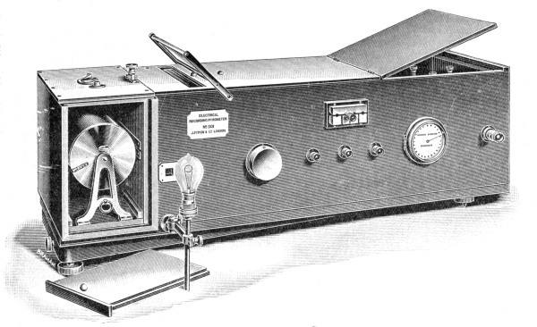
Fig. 20.—Roberts-Austen Recorder.
In its modern form (fig. 20) the photographic plate is
replaced by a sheet of sensitized paper wound round a drum which rotates at a
known rate—say, once in 12 hours—by means of internal clockwork, shown to
the left of the figure. The galvanometer is placed at the opposite
end, and the mirror is illuminated by means of an electric lamp placed
externally, the rays from which are reflected from a prism in the
interior on to the mirror. The ray of light leaving the mirror is
broken into two portions, one of which passes through a narrow slit on
to the sensitized paper, whilst the other portion is reflected on to
a ground-glass scale on the lid, divided so as to read temperatures.
In this manner the arrangement serves not only as a recorder, but
also indicates the existing temperature without necessitating the
examination of the sensitized paper. The whole arrangement is made
impervious to light, so that it may be used in daylight. A dark room is
necessary for fixing the records. When desired, records of two or more
pyrometers may be taken on the same sheet, a clockwork device being
used to switch each instrument in turn on to the galvanometer for a
given period, an external dial indicating which pyrometer is for the
time being in circuit.
Whilst it is a drawback to the use of this recorder that the record is
not visible, the use of a mirror galvanometer confers a high degree of sensitiveness
to the instrument, not possessed by the recorders to be described subsequently.
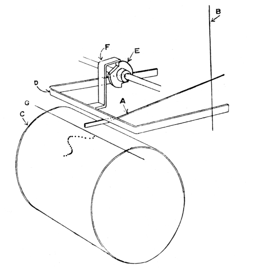
Fig. 21.—Principle of Thread Recorder.
The Thread Recorder.—In this instrument an intermittent
record is secured in ink, possessing the advantages of visibility during
the period over which readings are taken, and of permanence without
subsequent treatment of the chart. The principle is shown in fig. 21,
where A is a boom terminating in a V-shaped piece of ivory, and
attached to the galvanometer suspension B. By means of a cam E, rotated
by clockwork, a bar D is made to descend at stated intervals, pressing
the end of A on to an inked thread G, and causing the thread to touch
a paper wound round the drum C. This drum rotates on its axis once in
25 hours by the action of internal clockwork. The continued rotation
of the cam E alternately raises and depresses the boom A, leaving it
free for a sufficient time to enable it to attain the position it would
occupy if the mechanism were absent. The thread G is passed over
pulleys, and is wound round through an ink-well, so that the portion
opposite A is always moist. With the bar D descending every two
minutes, the successive dots form a nearly continuous line. The paper
on C is divided horizontally into temperatures, and vertically into
time units, so that the temperature existing at any given time may
readily be ascertained. The front of the bar D, or a separate strip
parallel to it, is divided so as to enable temperatures to be read
without reference to the chart. The actual instrument is shown in fig. 22.
When several simultaneous records are required, the drum C is
extended, and other galvanometers introduced, to which the separate
pyrometers are connected. Several records can be taken on one chart by
introducing a clockwork mechanism to couple each pyrometer in turn to
the one galvanometer.
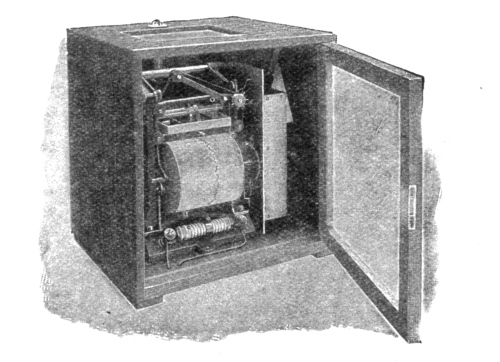
Fig. 22.—Thread Recorder.
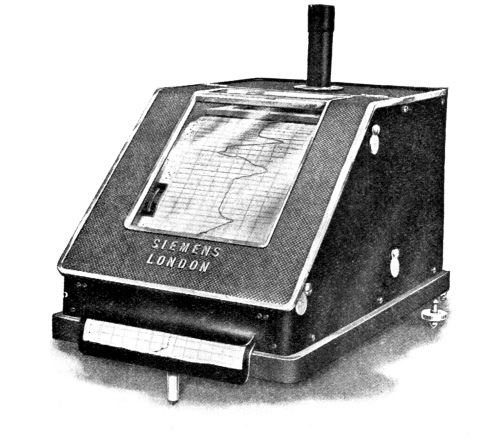
Fig. 23.—Siemens’ Recorder.
The Siemens Recorder.—In this instrument (fig. 23)
the boom from the galvanometer terminates in a knife-edge, and moves over a
thin horizontal rail, the top of which is rounded. Between the rail
and the boom are placed an inking ribbon and a paper chart, which is
moved forward by clockwork. A chopper-bar, also actuated by clockwork,
descends at about half-minute intervals, and depresses the end of the
galvanometer boom, thus producing a small dot on the chart. The paper
is 12 cms. wide and 40 yards long; it is divided into time and
temperature units, and moves forward at the rate of 2 cms. per hour.
Levelling screws are fixed to the base of the recorder.
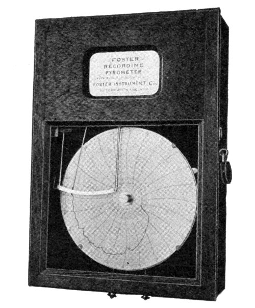
Fig. 24.—Foster’s Recorder.
Foster’s Recorder.—Foster’s recorder (fig. 24)
is designed for use with base-metal couples of the nickel-chromium type, known as
Hoskin’s alloys, which yield an E.M.F. about five times as large as
a platinum-rhodioplatinum couple. The force available in this case
enables the coil of the galvanometer to be pivoted in a horizontal
position, the pointer being vertical, and yet to be sufficiently
sensitive. The chart is mounted on a vertical plate which rotates on
its axis, the time ordinates taking the form of concentric circles,
which are cut at an angle by the temperature ordinates. At the terminus
of the pointer is placed a small capillary tube, fitted with an inked
wick, which, when pressed upon the chart, makes a mark. The presser-bar
is curved to the same radius as the pointer, and carries a pad wetted
with ink, so that at each depression the supply of ink to the wick is
replenished by an amount equal to that imparted to the chart. This
recorder is sometimes fitted with special contacts, so that when the
correct temperature exists an electric lamp with a white bulb remains
lighted; whereas when too low or too high a green or red lamp is lit
up, and an alarm thus given. Such an addition involves the use of a
relay circuit, but is advisable in cases where expensive articles
might suffer if overheated. It can be modified to permit of several
simultaneous records being taken, and possesses the advantage that the
whole chart is visible at any time. On the other hand, the circular
coordinates may be accounted a drawback by some, as not being quite
so familiar to read as charts in which the lines are straight. Robust
construction is a feature of this recorder.
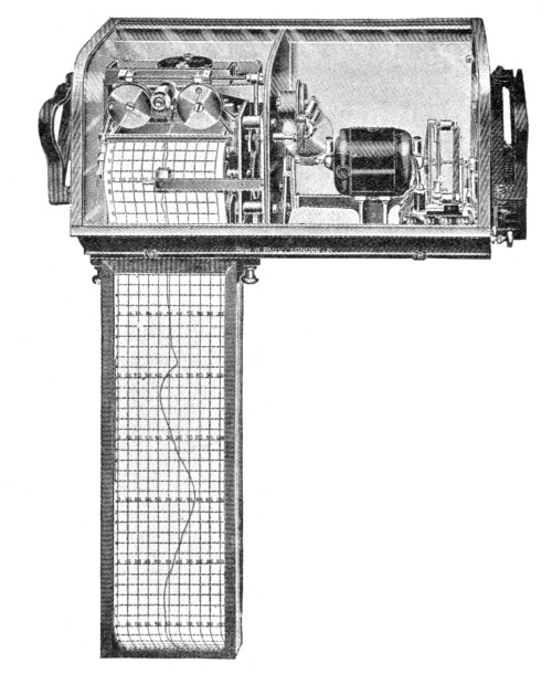
Fig. 25. Paul’s Recorder.
Paul’s Recorder.—In the recorders previously described, the
motive power is furnished by clockwork. R. W. Paul has introduced an
instrument in which all the moving parts are actuated by a motor driven
with power from the mains. This recorder is shown in fig. 25.
The motor is furnished with a special type of governor to ensure constant
speed, and is connected by suitable gearing to the mechanisms moving
the chart, presser-bar, and inking ribbon, provision being made to vary
the speeds of these movements by changing the gear. The galvanometer
is of uni-pivot pattern, and the pointer is pressed at intervals on to
a typewriter ribbon which lies above the chart. Immediately beneath
the ribbon is placed a thin metal rod over which the paper passes, and
the result of the contact is to produce a small dot. As in the thread
recorder, the chart is divided into rectilinear coordinates, the ribbon
in this case serving the same purpose as the thread in the former
instrument. The lower part of the recorder is prolonged so as to
display a considerable length of the chart, which is in the form of
a roll, and is drawn forward by the mechanism. When two records are
taken simultaneously the ribbon consists of two strips, one moistened
with black ink, and the other with red; and it is arranged that each
strip in turn is over the thin rod on to which the pointer is pressed,
so that the records appear in separate colours. This recorder can also
be arranged for multiple records, or fitted with a scale-control.
With a view to workshop use, all the covers are fitted with faced
metal joints, which are much better for keeping out dust than wooden
ones. A further useful feature is that the various units in the
recorder—galvanometer, motor, feed and record mechanism, and reducing
gear—are all separate and interchangeable. By introducing a suitably
divided chart this recorder will also serve for a radiation pyrometer,
or, as will be shown later, for a resistance pyrometer.
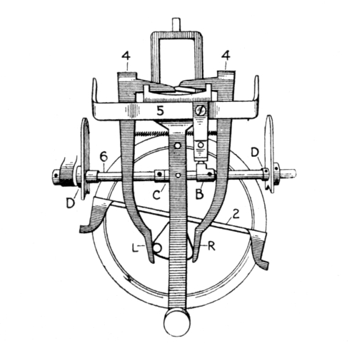
Fig. 26.—Leeds-Northrup Recorder.
The Leeds-Northrup Recorder.—The Leeds and Northrup Company,
of Philadelphia, manufacture a recorder which is largely used in the
United States. As in Paul’s recorder, all the mechanism is motor
driven; but the other arrangements are entirely distinct. Instead of
measuring the deflection of the pointer, a zero deflection method is
used. The pyrometer forms part of a potentiometer circuit, and the
function of the mechanism is to oppose an E.M.F. equal to that of the
pyrometer, from which the temperature is known. This has the advantage
that the measurement is independent of the resistance of the leads, and
is capable of great accuracy. The manner in which the adjustment of the
opposing E.M.F. is controlled may be understood from fig. 26,
in which the galvanometer coil is shown at the top of the figure. The shaft from
the motor carries four cams, B, C, D, D, and at each revolution the cam
B raises the bar (5) so as to press it against an arm attached to the
galvanometer coil. At the same moment the cam C pushes against the bar
(3), and thereby releases a clutch (2) from the disc beneath. As shown,
the boom from the coil is to the right of the central position, and
is gripped between a bar (5) and the lever (4) when the former rises,
causing an angular movement of the clutch-arm (2). As the rotation
continues the cam C leaves the bar (3), which then springs back and
engages the clutch on the disc. The cam D then descends and presses
on the projection of the clutch-arm to the left, causing the disc to
rotate. The movement of the disc is conveyed to an arm which moves over
the slide wire of the potentiometer; and this movement continues until
the galvanometer boom is in the central or zero position, when neither
of the levers 4, 4 is gripped, and consequently the disc is not fed in
either direction. If the boom swing to the left, the movement of the
disc will evidently be in the converse direction to that described.
In this recorder considerable power is available to drive printing or
other mechanisms. The arm moving over the potentiometer wire carries a
pen which marks the moving chart, or, when several records are taken
simultaneously, a stamping machine is used which impresses the number
of the pyrometer on the chart. The same galvanometer mechanism serves
also for use with resistance pyrometers, as will be explained later.
Control of Furnace Temperatures.—Many attempts have been
made to secure the automatic regulation of furnace temperatures by means of
mechanisms controlled by an indicator or recorder. In the arrangement
employed by the Brown Company of Philadelphia, movable stops are
provided, which may be brought to any part of the scale, the mark
between the stops representing the temperature it is desired to
maintain. The indicator (or recorder) is provided with a presser-bar
which descends periodically; and if the temperature be too low the
depressed pointer completes a circuit through the inner stop, whilst
if too high the circuit is through the outer stop. Both circuits
contain a relay which brings a mechanism into operation, the result
being to increase the supply of electricity or gas if the temperature
be too low, or to diminish the supply when too high. When correct,
the depression of the pointer fails to complete either circuit, and
in this manner control between small limits may be ensured. In the
case of large furnaces the relay circuits are employed to light lamps
of different colours, the adjustment then being made by the man in
charge of the furnace. Arrangements of this kind effect a considerable
saving in fuel by preventing unnecessary heating, and are particularly
valuable in cases where overheating would be deleterious to the
articles in the furnace. The future will probably witness considerable
developments along these lines.
Contact-Pen Recorders.—The force with which the pointer
of an indicator is urged over the scale is relatively small, particularly in
the case of pyrometers in which the platinum series of metals are used,
as these furnish only a low E.M.F. If, therefore, the pointer terminate
in a pen which is in continuous contact with the record-paper, the
friction thus occasioned interferes considerably with the free movement
of the pointer. When cheap-metal pyrometers are used, which yield a
much higher E.M.F., the use of the pointer as contact-pen becomes
more feasible, and if uniform friction at all parts of the paper can
be ensured, records may be taken in this manner; and a recorder so
constructed is simpler and cheaper than those of the intermittent
type. Contact-pen recorders are used in America to some extent, being
made by Bristol, Brown, and others; but so far British makers have not
developed the manufacture of these instruments. At present, contact-pen
recorders must be considered less accurate and reliable than those in
which the contact is intermittent.
Installations of Thermo-electric Pyrometers.—When a number
of furnaces in the same establishment are to be controlled, considerable
economy may be effected by making one indicator serve for all the
couples, which in this case must necessarily be made up of wires
identical in thermo-electric value. Such an arrangement is shown in
fig. 27, in which H1 and H2
represent two couples, one wire from
each being connected to one of the terminals of the galvanometer G.
The other terminal of the galvanometer is connected to the arm D of
a switch, and the remaining thermocouple leads are connected to the
points 1 and 2 respectively on the circumference. As shown, H1
is connected to the galvanometer, and by turning the arm D to the point
2 the other couple would then be connected. Any number of junctions
may thus be arranged with a single indicator. When this arrangement
is adopted in a workshop, it is advisable to construct a small wooden
building at a spot convenient for most of the furnaces, in which the
indicator and switchboard are kept, and which could also contain a
recorder if necessary; a spot as free as possible from vibration being
preferable. Separate indicators are only necessary when a furnace is
used for special work.
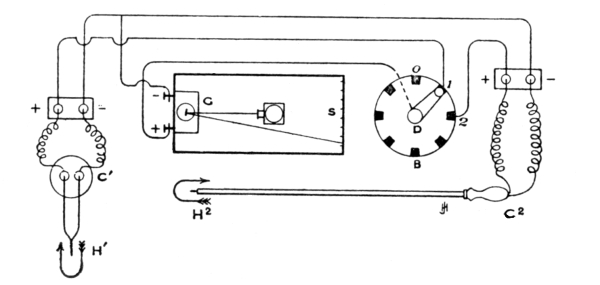
Fig. 27.—Connections for an Installation of Pyrometers.
In some instances a second indicator is kept in the shop office, to
which all the pyrometers are wired, and which serves as a standard.
The scale of the office indicator is checked daily at one point;
and by connecting a given couple first with the shop indicator, and
immediately afterwards with the office standard, any errors can be
detected. It is also possible to ascertain the temperature of any given
furnace in the office at any time, and so to control the whole. In
fixing up such an arrangement it is necessary that each couple and its
leads, up to the indicator, should possess the same resistance, or
should not differ by an amount sufficient to affect the readings. The
general experience of a properly managed installation is that the cost
is saved in a few months in fuel alone; and, in addition, the work is
carried out to much better advantage owing to complete control from the office.
Management of Thermo-electric Pyrometers.—Generally
speaking, thermo-electric pyrometers give little trouble in practice, but
the management should always be placed in skilled hands. It is advisable
to test each instrument periodically at a fixed point near the working
temperature, by the method explained on page 57; and if two or three
pounds of material be used, the protecting shield need not be removed.
A useful material for checking pyrometers near the critical range of
steel is an alloy of 60 per cent. of copper and 40 per cent. of tin,
which gives a well-defined freezing point at 738° C., and which may be
used indefinitely in a reducing atmosphere Any serious error is easily
detected by observing that the indications differ widely from those
generally obtained under the same working conditions. If an error of
20° C. or more is noted, it is advisable to form a new junction, as the
discrepancy will probably become greater, being due to a change at the
hot junction. A small error, of the nature of 5 or 10° C., may be due
to “creep” in the indicator, which may be adjusted accordingly, or
a numerical correction may be made when taking a reading. An iron
protecting sheath may be saved from rapid oxidation by black-leading
once per week, which greatly prolongs its useful life, but should be
replaced immediately it becomes dangerously thin in any part. Coating
with aluminium powder also greatly prolongs the life of an iron sheath.
When used in lead baths, the immersed part, if of iron or steel, should
be bored from the solid, and left thick at the portion opposite the
surface of the lead, where most corrosion occurs. A graphite tube,
or one made of a composition containing graphite, is often useful in cases
where iron is readily corroded, and can be used to much higher temperatures.
When a number of instruments are in use, it is advisable to keep a
standard pyrometer for checking purposes, preferably one which has been
certified by the National Physical Laboratory. In conducting a test,
the couples, with protecting-tubes removed, may be placed in the tube
of an electric furnace of the type shown in fig. 29,
in close proximity with the standard junction. On raising the temperature
gradually, the readings of each working instrument may be compared with the
standard, and the necessary corrections discovered. Care must be taken to prevent
contact with the furnace tube, and this may be accomplished by passing
the wires through an asbestos stopper fitted into the end of the tube.
When recorders are used the attendant should make himself thoroughly
conversant with the details of the mechanism, so as to be able to
remedy any minor ailments, which are, as a rule, easily cured. On no
account should an unskilled workman be trusted with recorders; it is
better and safer to keep these in the office, where they will not be
likely to be damaged or tampered with. All records should be kept
for future reference, properly dated, and labelled according to the
operations represented.
Laboratory Uses of Thermo-electric Pyrometers.—Numerous
operations carried out in muffle furnaces at prescribed temperatures
require no special precautions beyond those previously given.
In determining the melting points of metals or alloys, however,
a porcelain or silica sheath is inadvisable, as they are easily
corroded. An iron sheath is proof against some metals, but not
against others, and it is always safer to fix a thin fireclay sleeve,
closed at the end, over the part immersed. A sheath of graphite or
graphite composition may be used for temperatures above 1100° C.; and
occasionally a sheath bored from a thick arc-lamp carbon, coupled to
an iron tube beyond the heated part, will be found useful at high
temperatures. Alundum is useful up to 1600° C, and for temperatures of
this order the higher refractories such as silfrax and zirkite may also
be used to advantage.
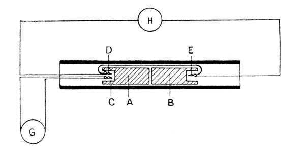
Fig. 28.—Differential Method for Determining Critical Points of Steel.
The determination of the “critical” points of steel call for special
mention. In cooling down a mass of steel the fall of temperature is
arrested at one or more points, observations of which are frequently
of service in deciding the subsequent treatment of the steel. A
method commonly employed is known as the “differential method,” and
is indicated in fig. 28. The sample of steel, A, is placed
side by side with a piece of nickel, B, of equal dimensions, in the tube of
an electric furnace. A naked junction, C, is placed in a hole drilled
in A, and is connected to the galvanometer G, which is calibrated to
read temperatures. A two-junction circuit, formed of a junction D
placed in the hole in A, and another junction E located in the hole in
B, are connected to a delicate galvanometer H. The furnace is heated
until the galvanometer G indicates 900° C., when the arrangement is
allowed to cool. As A and B, under normal circumstances, cool at an
equal rate, the junctions D and E will be at the same temperature, and
no deflection will be observed on H. When, owing to recalescence, the
cooling of A is arrested, B, not being thus affected, will continue to
cool, thus producing a difference between the temperatures of D and E,
and consequently a deflection on H. The temperature of A at the time
this occurs is read off on G.
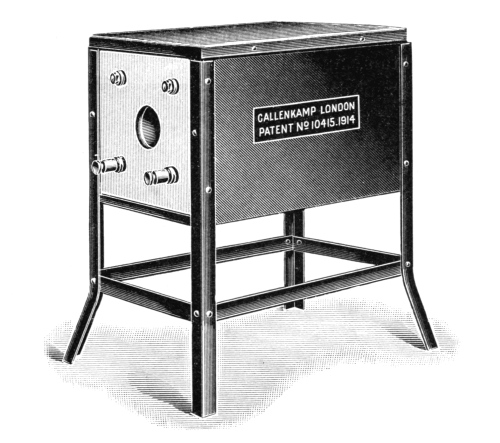
Fig. 29.—Electric Tube-Furnace.
The furnace illustrated in fig. 29 is suited to this
determination. It consists of a silica tube 1 foot long, wound with a special
resistance wire and efficiently lagged, and may be heated in safety to 1000° C.
for long periods, and to 1200° for a short time. It may be placed
across the electric mains directly, and reaches 900° C. in less than
half an hour. It consumes 600 to 700 watts at the highest temperatures,
and the cost of re-winding is small. This furnace is useful as a
general laboratory appliance, and may be kept at a given steady
temperature by the use of an external resistance.
The wires in this experiment should be platinum and iridioplatinum or
rhodioplatinum, or a good pair of base metals, and the junctions in A
should be separated from each other and from the specimen by asbestos;
the same precaution being taken to prevent the junction E from touching
B. A thin layer of mica should be used beneath A and B, to avoid
contact with the furnace tube, which, when hot, allows of leakage of
current from the heating coil. Both A and B may be 1½ in. long, ¾ in.
diameter, with a hole ¼ in. diameter drilled to a depth of ¾ inch.
An alternative method is to insert a junction in a hole in the
specimen, and to take direct readings as the temperature slowly
rises or falls, when an arrest in the movement of the pointer of the
indicator shows that the change-point has been reached. Special sets
are made for this purpose.
Measurement of Lower Temperatures by the Thermo-electric
Method.—Many cases arise in practice in which a thermal junction
and a sensitive galvanometer are preferable to a mercury thermometer;
and below -39° C., at which temperature mercury freezes, a thermal
junction is frequently better to employ than an alcohol or pentane
thermometer. A number of practical examples of the use of thermal
junctions for ordinary and low temperatures will now be considered.
Measurement of Surface Temperatures.—A mercury thermometer,
when laid on a hot surface, only touches along a line, and does not
show the true surface temperature. The construction of a thermal
junction suitable for this purpose is described on page 41, and for
steam-pipe surfaces, hot plates, and the exterior of furnaces, a
specially calibrated millivoltmeter, giving a full-scale deflection
with 20 millivolts, may be used. In making the temperature scale,
boiling water (100°C.), boiling aniline (184° C.), and melting tin
(232° C.) are convenient standards. If the surface temperature be less
than 100° C. a mirror galvanometer should be used, and the junction
standardized in paraffin wax (freezing point usually about 50° C.,
but should previously be determined with an accurate thermometer),
absolute alcohol at boiling point (79° C.) and boiling water. The
author has found that this method yields excellent results in the case
of steam-pipes, the exterior of rotary cement kilns, and hot surfaces generally.
Measurement of Low Temperatures.—Junctions of iron
and constantan, Hoskin’s alloys, copper and German silver, or copper and
constantan, are suited to these measurements. In a laboratory the
cold junction may be kept in ice in a Dewar vessel, the mechanically
protected form known as the “Thermos” flask being very useful for this
purpose. With a good mirror galvanometer precise readings may be
secured, 1/10 of a degree C. being easily detected. Calibration between
-40° and +40°C. may be effected by comparison with a standard mercury
thermometer, a water-bath being used above 0°, and alcohol surrounded
by a freezing mixture of ice and calcium chloride crystals below
zero. For very low temperatures (-200°C. or less) the junction maybe
calibrated in solid carbon dioxide (-78°C.) and liquid air (-184°C.).
Dewar has found that copper and German silver form a reliable junction
for very low temperatures, and the author has successfully used a
couple of Hoskin’s alloys for special work down to -200°C., a pivoted
indicator being employed. No couples tested show a linear relation
between E.M.F. and temperature at these low ranges.
Owing to the magnitude of the error caused by changes in the cold
junction, the thermo-electric method is not suited to the measurement
of atmospheric temperatures, or for explosive magazines or cold stores.
In such cases instruments of the resistance type, to be described
later, are used.
Temperature of Steam, Exhaust Gases, etc.—For measuring the
temperature of ordinary or superheated steam, the exhaust gases from
internal combustion engines, etc., iron-constantan junctions, with
suitable indicators, are satisfactory. When placed in a pipe the
junction should be as nearly as possible in the centre, so as to
avoid the cooling effect of the walls. Several junctions, situated in
different parts of the pipe, may be used with a single indicator and
suitable switchboard. The above remarks also apply to the hot-blast for
blast furnaces, and similar instances where the temperature does not
exceed 900° C.
Measurement of Differences of Temperature.—Cases frequently
arise in practice in which the difference in temperature between two
points is required, and if this difference be subject to rapid changes,
a mercury thermometer, from its large mass, would not respond with
sufficient rapidity to indicate these changes. In such cases a circuit
is made after the manner of fig. 2, one junction being
located at each point; thin wires of iron and constantan being used. For
small differences—1° C. or less—a mirror galvanometer should be used.
Calibration may be performed by placing one junction in hot water and
the other in cold, the water temperatures being read with an accurate
thermometer.
Advantages of the Thermo-electric Method of Measuring
Temperatures.—Compared with other methods, the thermo-electric
possesses the following points of superiority:—(1) Simplicity, no
special experiment being necessary to obtain a reading; (2) cheapness
of outfit; (3) adaptability to a variety of purposes; (4) ease of
repair in case of damage; (5) robustness, not being liable to get
out of order under workshop conditions; and (6) suitability to the
purpose of a centrally controlled installation. The drawbacks are:—(1)
Liability to error owing to fluctuations in the cold junction (which
may be avoided with care); and (2) lack of sensitiveness at very high
temperatures compared with the resistance method—a point seldom of
great practical importance, as the limit of accuracy is usually within
the amount by which an ordinary furnace fluctuates in temperature under
working conditions.