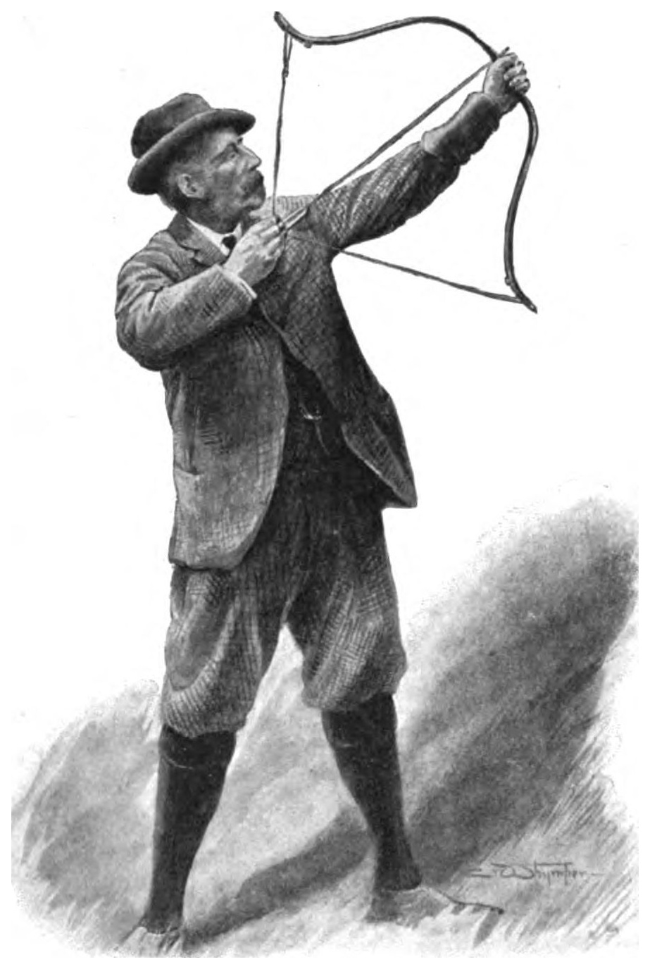
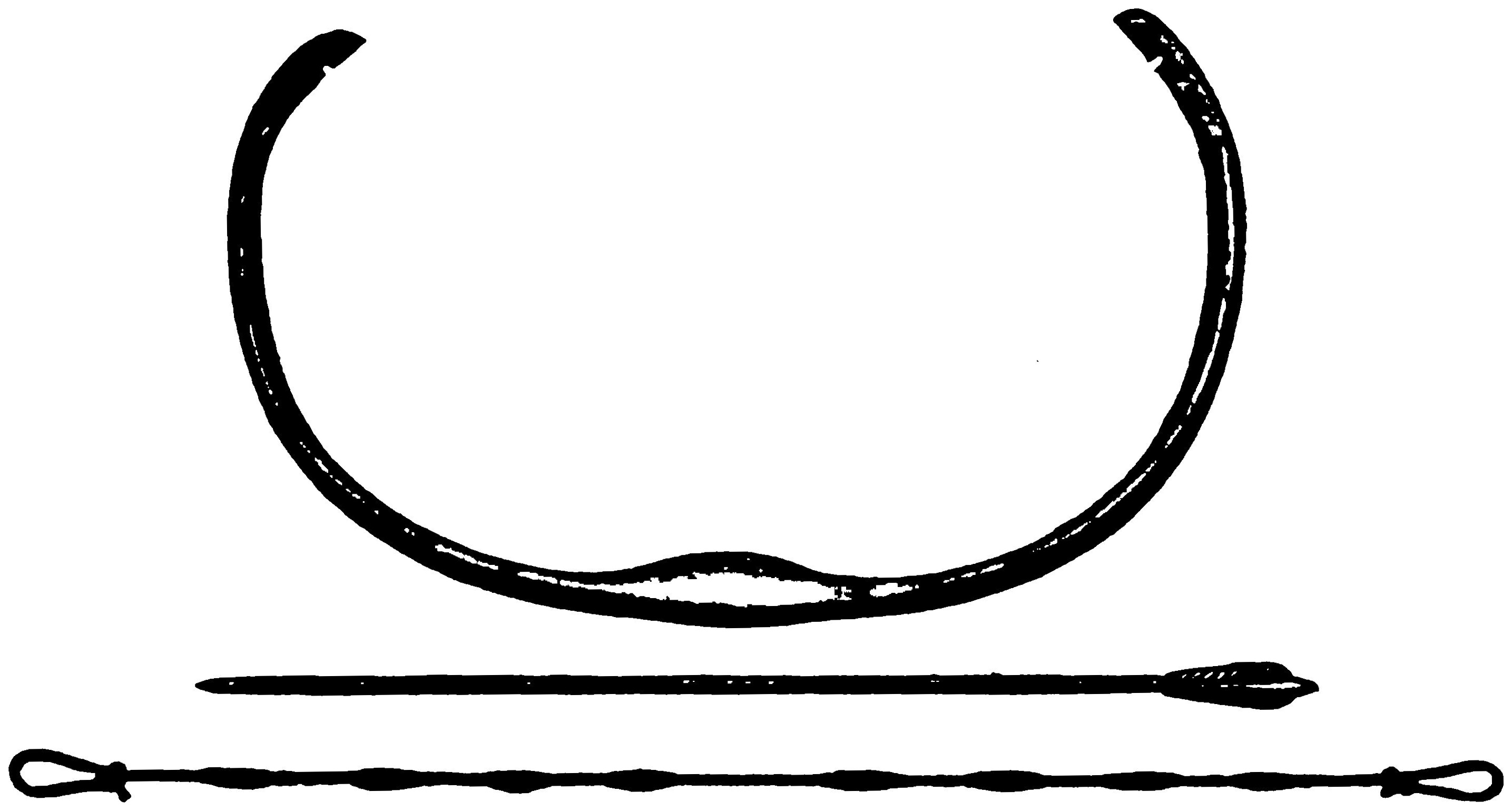
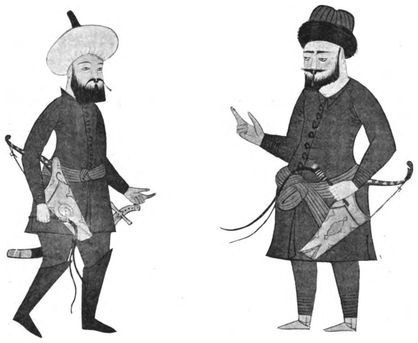
Larger versions of most illustrations may be seen by right-clicking them
and selecting an option to view them separately, or by double-tapping and/or
stretching them.
New original cover art included with this eBook is granted
to the public domain. It uses the original cover with an added illustration taken
from the original book.
The original book contains two separate works (Projectile-Throwing
Engines and Mediæval Bows), each of which begins on
its own page 1 and whose
figures begin with “Fig. 1”. To allow hyperlinks to work properly, the
second one’s page numbers in this eBook begin on page 101.
Figure numbers have not been changed, but in this HTML version, links to
the figures go to the correct ones in each work.
THE PROJECTILE-THROWING ENGINES OF THE ANCIENTS AND TURKISH AND OTHER ORIENTAL BOWS OF MEDIÆVAL AND LATER TIMES — THE PROJECTILE-THROWING ENGINES OF THE ANCIENTS — CONTENTS
By the same Author.
THE CROSSBOW, MEDIÆVAL AND MODERN, MILITARY AND SPORTING:
Its Construction, History, and Management.
WITH A TREATISE ON THE BALISTA AND CATAPULT OF THE ANCIENTS.
With 220 Illustrations. Medium 4to. 63s. net.
LONGMANS, GREEN, & CO., 39 Paternoster Row, London,
New York, Bombay, and Calcutta.
A SUMMARY OF
THE HISTORY, CONSTRUCTION AND
EFFECTS IN WARFARE OF THE
PROJECTILE-THROWING
ENGINES
OF THE ANCIENTS
WITH A TREATISE ON THE
STRUCTURE, POWER AND MANAGEMENT OF
TURKISH AND OTHER ORIENTAL BOWS OF MEDIÆVAL AND LATER TIMES
BY
SIR RALPH PAYNE-GALLWEY, BT.
FORTY ILLUSTRATIONS
LONGMANS, GREEN, AND CO. 39 PATERNOSTER ROW, LONDON
NEW YORK, BOMBAY, AND CALCUTTA
Since my recent book on mediæval archery and ancient weapons
was issued,1 I have obtained a considerable amount of information
concerning the projectile engines of the Greeks and Romans. I now
print a concise account of the history, construction and effects in
warfare of these engines.
In this summary the additional notes I have acquired are
included.
I also append a treatise fully describing that remarkable weapon
the Turkish composite bow, which I only cursorily dealt with in the
work referred to.
R. P. G.
Thirkleby Park, Thirsk: Dec. 1906.
1 The Crossbow, Mediæval and Modern, Military and Sporting: its Construction, History, and
Management. With a Treatise on the Balista and Catapult of the Ancients. 220 illustrations. Messrs.
Longmans & Co., 39 Paternoster Row, London.
PART I INTRODUCTORY NOTES ON ANCIENT PROJECTILE ENGINES
Of ancient Greek authors who have left us accounts of these engines,
Heron (284–221 B.C.) and Philo (about 200 B.C.) are the most trustworthy.
Both these mechanicians give plans and dimensions with an accuracy that
enables us to reconstruct the machines, if not with exactitude at any rate with
sufficient correctness for practical application.
Though in the books of Athenæus, Biton, Apollodorus, Diodorus,
Procopius, Polybius and Josephus we find incomplete descriptions, these
authors, especially Josephus, frequently allude to the effects of the engines
in warfare; and scanty as is the knowledge they impart, it is useful and
explanatory when read in conjunction with the writings of Heron and
Philo.
Among the Roman historians and military engineers, Vitruvius and
Ammianus are the best authorities.
Vitruvius copied his descriptions from the Greek writers, which shows us
that the Romans adopted the engines from the Greeks.
Of all the old authors who have described the engines, we have but copies
of the original writings. It is therefore natural that we should come across
many phrases and drawings which are evidently incorrect, as a result of repeated
transcription, and which we know to be at fault though we cannot actually
prove them to be so.
With few exceptions, all the authors named simply present us with their
own ideas when they are in doubt respecting the mechanical details and performances
of the engines they wish to describe.
All such spurious information is, of course, more detrimental than helpful
to our elucidation of their construction and capabilities.
It frequently happens that in a mediæval picture of one of these machines
some important mechanical detail is omitted, or, from the difficulty of portraying
it correctly, is purposely concealed by figures of soldiers, an omission that may
be supplied by reference to other representations of the same weapon.
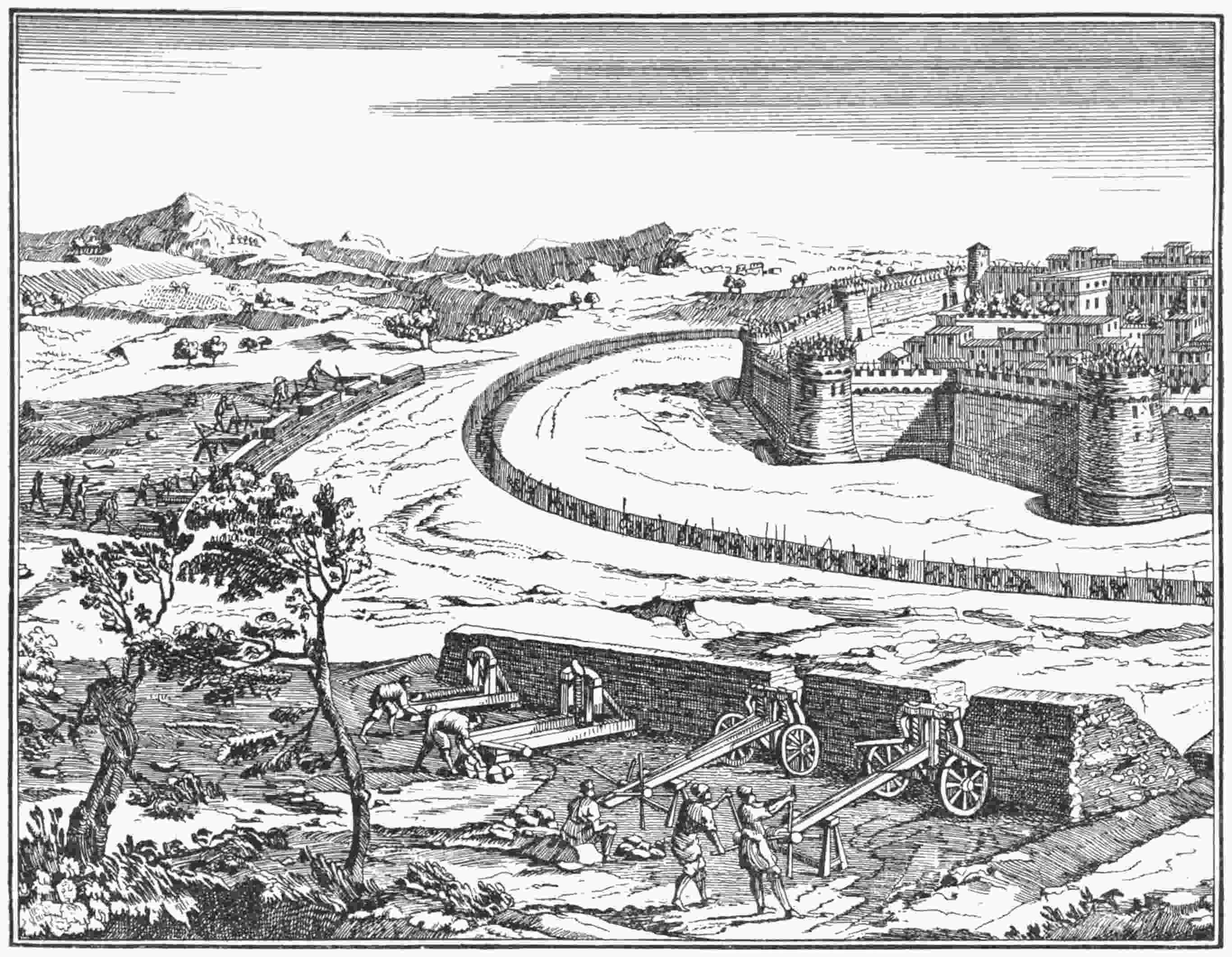
Fig. 1.—Besieging a fortified Town with a Battery of Catapults and Balistas.
Criticism.—In this picture the balistas are fairly correct, but the catapults are too small.
From Polybius. Edition 1727.
It is, indeed, impossible to find a complete working plan of any one of
these old weapons, a perfect design being only obtainable by consulting many
ancient authorities, and, it may be said, piecing together the details of construction
they individually give.
* * * * *
We have no direct evidence as to when the engines for throwing projectiles
were invented.
It does not appear that King Shalmaneser II. of Assyria (859–825 B.C.)
had any, for none are depicted on the bronze doors of the palace of Balâwat,
now in the British Museum, on which his campaigns are represented, though
his other weapons of attack and defence are clearly shown.
The earliest allusion is the one in the Bible, where we read of Uzziah, who
reigned from B.C. 808–9 to B.C. 756–7. ‘Uzziah made in Jerusalem engines
invented by cunning men, to be on the towers and upon the bulwarks, to shoot
arrows and great stones withal.’ (2 Chronicles xxvi. 15.)
Diodorus tells us that the engines were first seen about 400 B.C., and
that when Dionysius of Syracuse organised his great expedition against the
Carthaginians (397 B.C.) there was a genius among the experts collected from
all over the world, and that this man designed the engines that cast stones and
javelins.
From the reign of Dionysius and for many subsequent centuries, or till
near the close of the fourteenth, projectile-throwing engines are constantly mentioned
by military historians.
But it was not till the reign of Philip of Macedon (360–336 B.C.) and that
of his son Alexander the Great (336–323 B.C.) that their improvement was carefully
attended to and their value in warfare fully recognised.
As before stated, the Romans adopted the engines from the Greeks.
Vitruvius and other historians tell us this, and even copy their descriptions
of them from the Greek authors, though too often with palpable inaccuracy.
To ascertain the power and mechanism of these ancient engines a very
close study of all the old authors who wrote about them is essential, with a
view to extracting here and there useful facts amid what are generally verbose
and confused references.
There is no doubt that the engines made and used by the Romans
after their conquest of Greece (B.C. 146), in the course of two or three centuries
became inferior to the original machines previously constructed by the Greek
artificers.
Their efficiency chiefly suffered because the art of manufacturing their
important parts was gradually neglected and allowed to become lost.
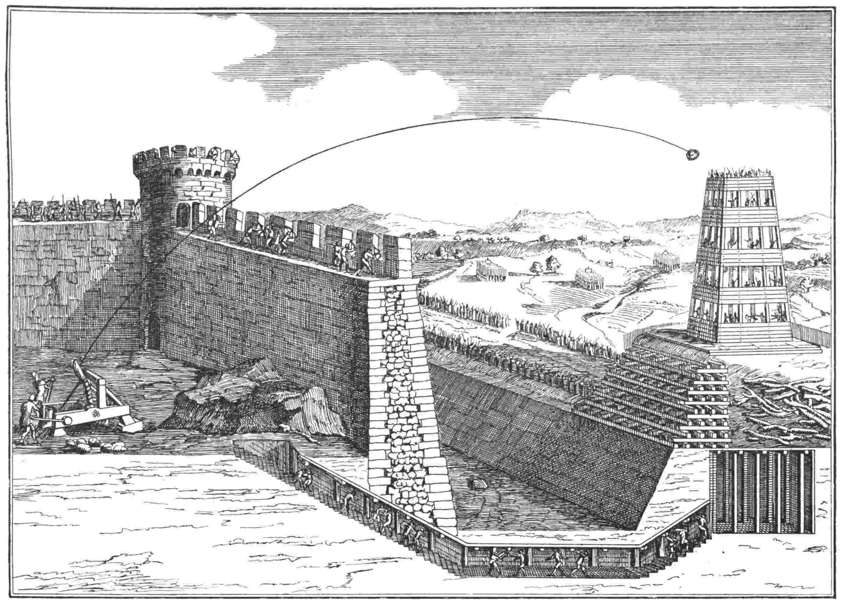
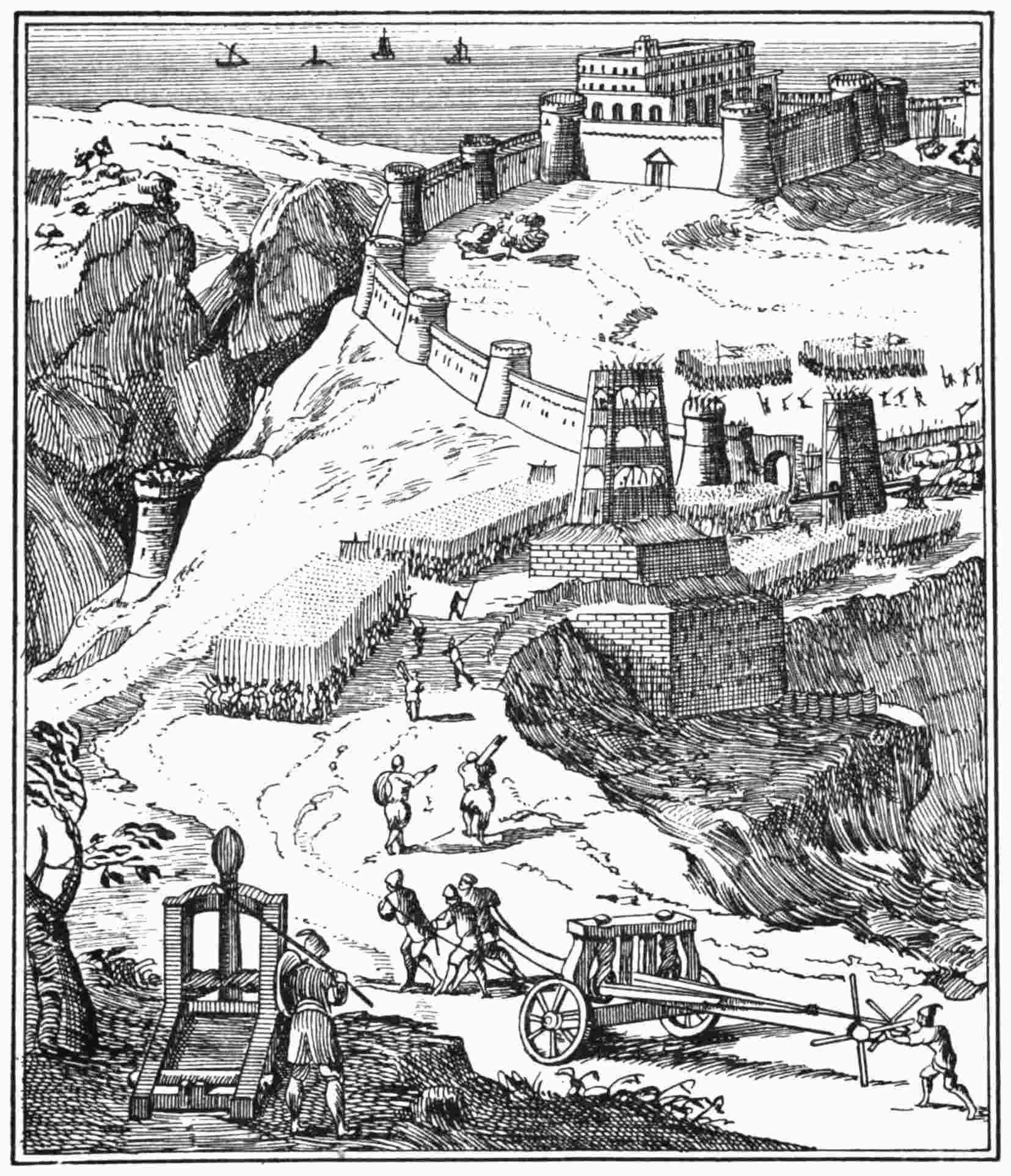
Fig. 2.—A Siege.
Criticism.—The picture is open to the spectator in order that he may see both defenders and besiegers at work.
The besieged have just cast a stone from a catapult. The stone is falling on the movable tower belonging to the attacking side.
From Polybius. Edition 1727.
For instance, how to make the skein of sinew that bestowed the very life
and existence on every projectile-casting engine of the ancients.
The tendons of which the sinew was composed, the animals from which
it was taken, and the manner in which it was prepared, we can never learn
now.
Every kind of sinew, or hair or rope, with which I have experimented,
either breaks or loses its elasticity in a comparatively short time, if great pressure
is applied. It has then to be renewed at no small outlay of expense and
trouble. Rope skeins, with which we are obliged to fit our models, cannot
possibly equal in strength and above all in elasticity, skeins of animal sinew or
even of hair.
The formation of the arm or arms of an engine, whether it is a catapult
with its single upright arm or a balista with its pair of lateral ones, is another
difficulty which cannot now be overcome, for we have no idea how these arms
were made to sustain the great strain they had to endure.
We know that the arm of a large engine was composed of several spars of
wood and lengths of thick sinew fitted longitudinally, and then bound round
with broad strips of raw hide which would afterwards set nearly as hard and
tight as a sheath of metal.
We know this, but we do not know the secret of making a light and
flexible arm of sufficient strength to bear such a strain as was formerly applied
to it in a catapult or a balista.
Certainly, by shaping an arm of great thickness we can produce one
that will not fracture, but substance implies weight, and undue weight prevents
the arm from acting with the speed requisite to cast its projectile with good
effect.
A heavy and ponderous arm of solid wood cannot, of course, rival in
lightness and effectiveness a composite one of wood, sinew and hide.
The former is necessarily inert and slow in its action of slinging a stone,
while the latter would, in comparison, be as quick and lively as a steel
spring.
When the art of producing the perfected machines of the Greeks was lost,
they were replaced by less effective contrivances.
If the knowledge of constructing the great catapult of the ancients in its
original perfection had been retained, such a clumsy engine as the mediæval
trebuchet would never have gained popularity. The trebuchet derived its
power from the gravity of an immense weight at one end of its pivoted
arm tipping up the other end, to which a sling was attached for throwing a
stone.
As regards range, there could be no comparison between the efficiency of a
trebuchet, however large, as worked merely by a counterpoise, and that of an
engine deriving its power from the elasticity of an immense coil of tightly twisted
sinew.
It is certain that if the latter kind of engine had survived in its perfect state
the introduction of cannon would have been considerably delayed, for the effects
in warfare of the early cannon were for a long period decidedly inferior to those
of the best projectile engines of the ancients.
Notwithstanding many difficulties, I have succeeded in reconstructing,
though of course on a considerably smaller scale, the chief projectile throwing
engines of the ancients, and with a success that enables them to compare
favourably, as regards their range, with the Greek and Roman weapons they
represent.
Still, my engines are by no means perfect in their mechanism, and are,
besides, always liable to give way under the strain of working.
One reason of this is that all modern engines of the kind require to be
worked to their utmost capacity, i.e. to the verge of their breaking point, to
obtain from them results that at all equal those of their prototypes.
A marked difference between the ancient engines and their modern
imitations, however excellent the latter may be, is, that the former did
their work easily, and well within their strength, and thus without any
excessive strain which might cause their collapse after a short length of
service.2
2 Again, though my largest catapult will throw a stone to a great distance it cannot throw one of nearly
the weight it should be able to do, considering the size of its frame, skein of cord and mechanism. In this
respect it is decidedly inferior to the ancient engine.
The oft-disputed question as to the distance to which catapults and
balistas shot their projectiles can be solved with approximate accuracy by
comparing their performances—as given by ancient military writers—with the
results obtainable from modern reproductions.
While treating of this matter we should carefully consider the position and
surroundings of the engines when engaged in a siege, and especially the work
for which they were designed.
As an example, archers, with the advantage of being stationed on high
towers and battlements, would be well able to shoot arrows from 270 to
280 yards. For this reason it was necessary for the safe manipulation of the
attacking engines that they should be placed at about 300 yards from the outer
walls of any fortress they were assailing.
As a catapult or a balista was required not only to cast its missile among
the soldiers on the ramparts of a fortified place, but also to send it clear over the
walls amid the houses and people within the defences, it is evident that the
engines must have had a range of from 400 to 500 yards, or more, to be as
serviceable and destructive as they undoubtedly were.
Josephus tells us that at the siege of Jerusalem, A.D. 70 (‘Wars of the Jews,’
Book V. Chapter VI.), stones weighing a talent (57¾ lbs. avoirdupois) were
thrown by the catapults to a distance of two or more ‘stades.’
This statement may be taken as trustworthy, for Josephus relates what he
personally witnessed and his comments are those of a commander of high rank
and intelligence.
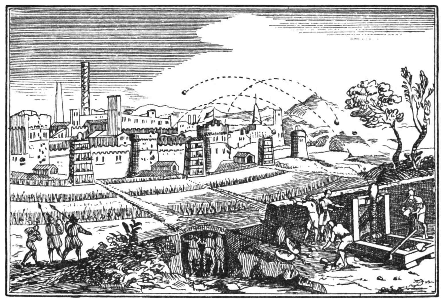
Fig. 3.—A Fortified Town being Bombarded by a Catapult.
Criticism.—The stones thrown by the besieged may be seen falling in the trenches of the
besiegers. The catapult depicted is drawn on much too small a scale.
From Polybius. Edition 1727.
Two or more ‘stades,’ or let us say 2 to 2¼ ‘stades,’ represent 400 to
450 yards. Remarkable and conclusive testimony confirming the truth of what
we read in Josephus is the fact that my largest catapult—though doubtless
much smaller and less powerful than those referred to by the historian—throws
a stone ball of 8 lbs. in weight to a range of from 450 to nearly 500
yards.
It is easy to realise that the ancients, with their great and perfect engines
fitted with skeins of sinew, could cast a far heavier stone than one of 8 lbs., and
to a longer distance than 500 yards.
Agesistratus,3 a Greek writer who flourished B.C. 200, and who wrote a
treatise on making arms for war, estimated that some of the engines shot from
3½ to 4 ‘stades’ (700 to 800 yards).
3 The writings of Agesistratus are non-extant but are quoted by Athenæus.
Though such a very long flight as this appears almost incredible, I can
adduce no sound reason for doubting its possibility. From recent experiments
I am confident I could now build an engine of a size and power to accomplish
such a feat if light missiles were used, and if its cost were not a consideration.
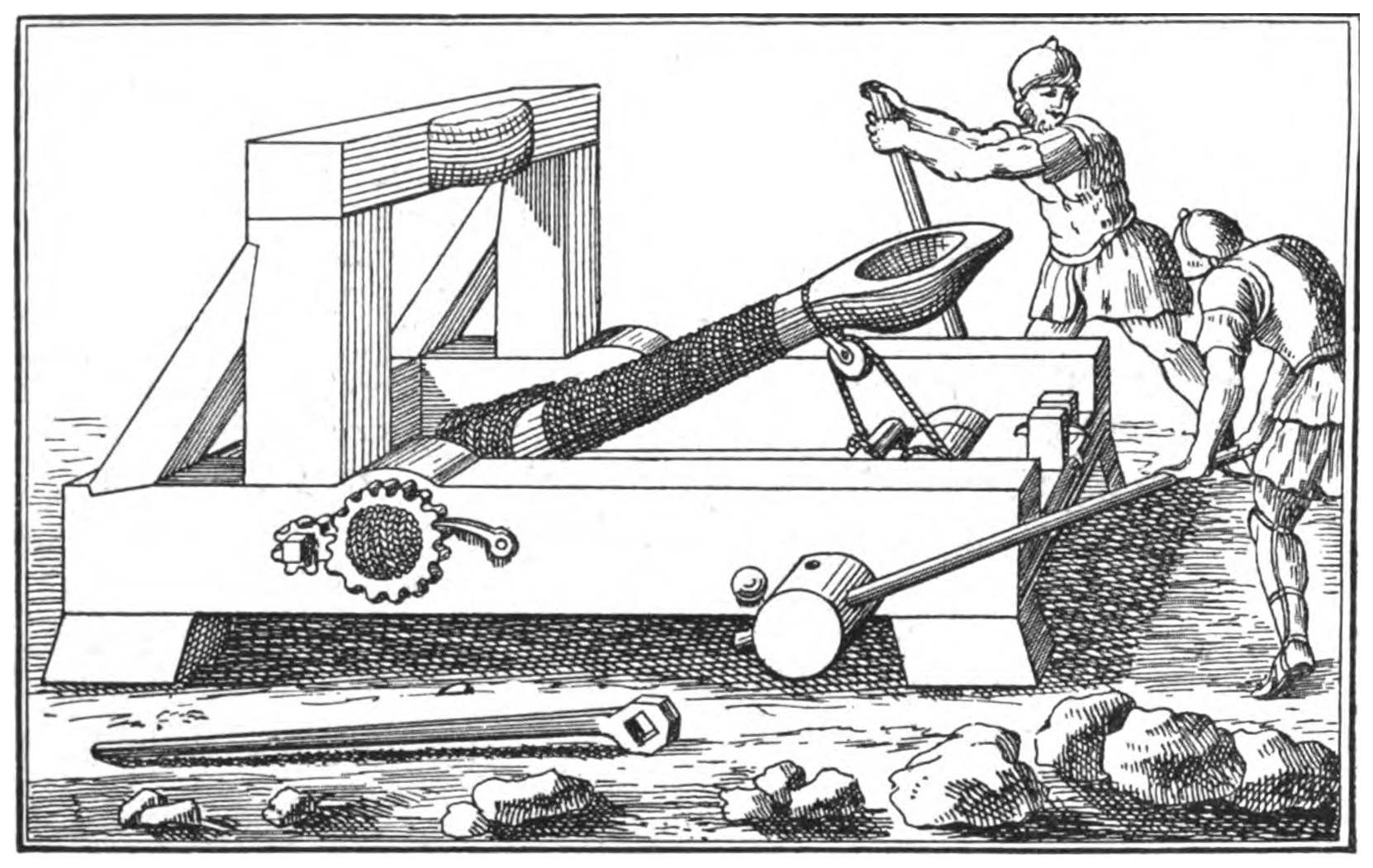
Fig. 4.—A Siege Catapult (without a sling).
From Polybius. Edition 1727.
PART II THE CATAPULT (WITH A SLING) — Fig. 7 .—Catapult (with a sling), see opposite page. — Fig. 10 . The Iron Slip-hook. — HOW TO WORK THE CATAPULT
Fig. 5.—A Siege Catapult (without a sling).
Criticism.—This engine was moved into position on rollers and then props were placed under
its sides to adjust the range of the projectile.
The end of the arm was secured by the notch of the large iron catch and was released by
striking down the handle of the catch with a heavy mallet.
The arm is, however, too long for the height of the cross-bar against which it strikes and
would probably break off at its centre.
The hollow for the stone is much too large, as a stone big enough to fit it could not be cast by
a weapon of the dimensions shown in the picture.
From an Illustrated Manuscript, Fifteenth Century (No. 7239), Bibl. Nat. Paris.
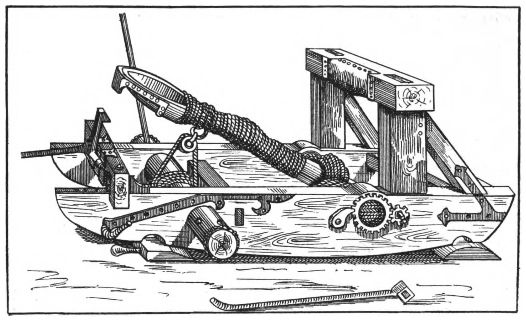
The mediæval catapult was usually fitted with an arm that had a hollow or
cup at its upper end in which was placed the stone it projected, as shown above
in fig. 5.4 I find, however, that the original and more perfect form of this
engine, as employed by the Greeks and ancient Romans, had a sling, made of
rope and leather, attached to its arm.5 (Fig. 6, following page.)
4 See also The Crossbow, etc., Chapters LV., LVI., illustrations 193 to 202.
5 In mediæval times catapults which had not slings cast great stones, but only to a short distance in
comparison with the earlier weapons of the same kind that were equipped with slings. I can find no
allusions or pictures to show that during this period any engine was used with a sling except the trebuchet,
a post-Roman invention. All evidence goes to prove that the secret of making the skein and
other important parts of a catapult was in a great measure lost within a couple of centuries after the
Romans copied the weapon from their conquered enemies the Greeks, with the result that the trebuchet
was introduced for throwing stones.
The catapult was gradually superseded as the art of its construction was neglected, and its efficiency
in sieges was therefrom decreased.
The catapults of the fifth and sixth centuries were very inferior to those described by Josephus as
being used at the sieges of Jerusalem and Jotapata (A.D. 70, A.D. 67), p. 37.
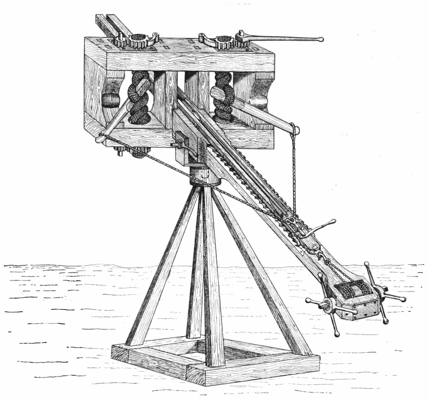
Fig. 6.—Sketch plan of a Catapult for slinging Stones its Arm being partly wound down.
Approximate scale: ¼ in. = 1 ft.
The addition of a sling to the arm of a catapult increases its power by at
least a third. For example, the catapult described in Chapters LV., LVI., of
my book,6 will throw a round stone 8 lbs. in weight, from 350 to 360 yards,
but the same engine with the advantage of a sling to its arm will cast the 8-lb.
stone from 450 to 460 yards, and when its skein is twisted to its limit of tension
to nearly 500 yards.
If the upper end of the arm of a catapult is shaped into a cup to receive
the stone, as shown in fig. 5, p. 11, the arm is, of necessity, large and heavy at
this part.
If, on the other hand, the arm is equipped with a sling, as shown in fig. 6,
opposite page, it can be tapered from its butt-end upwards, and is then much
lighter and recoils with far more speed than an arm that has an enlarged
extremity for holding its missile.
When the arm is fitted with a sling, it is practically lengthened by as much
as the length of the sling attached to it, and this, too, without any appreciable
increase in its weight.
The longer the arm of a catapult, the longer is its sweep through the air,
and thus the farther will it cast its projectile, provided it is not of undue weight.
The difference in this respect is as between the range of a short sling and
that of a long one, when both are used by a school-boy for slinging pebbles.
The increase of power conferred by the addition of a sling to the arm of a
catapult is surprising.
A small model I constructed for throwing a stone ball, one pound in weight,
will attain a distance of 200 yards when used with an arm that has a cup for
holding the ball, though when a sling is fitted to the arm the range of the
engine is at once increased to 300 yards.
The only historian who distinctly tells us that the catapult of the Greeks
and Romans had a sling to its arm, is Ammianus Marcellinus. This author
flourished about 380 A.D., and a closer study of his writings, and of those of
his contemporaries, led me to carry out experiments with catapults and balistas
which I had not contemplated when my work dealing with the projectile engines
of the Ancients was published.
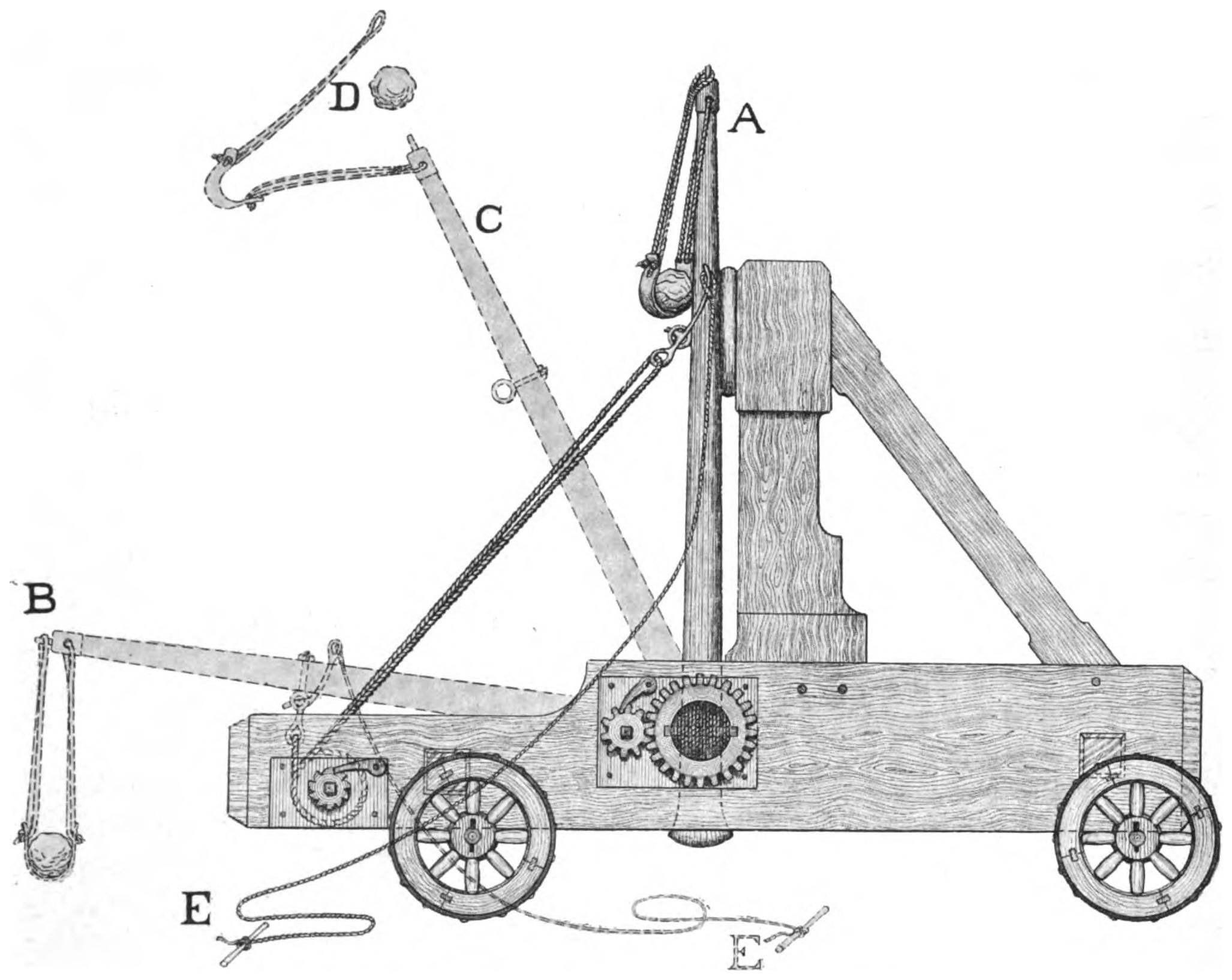
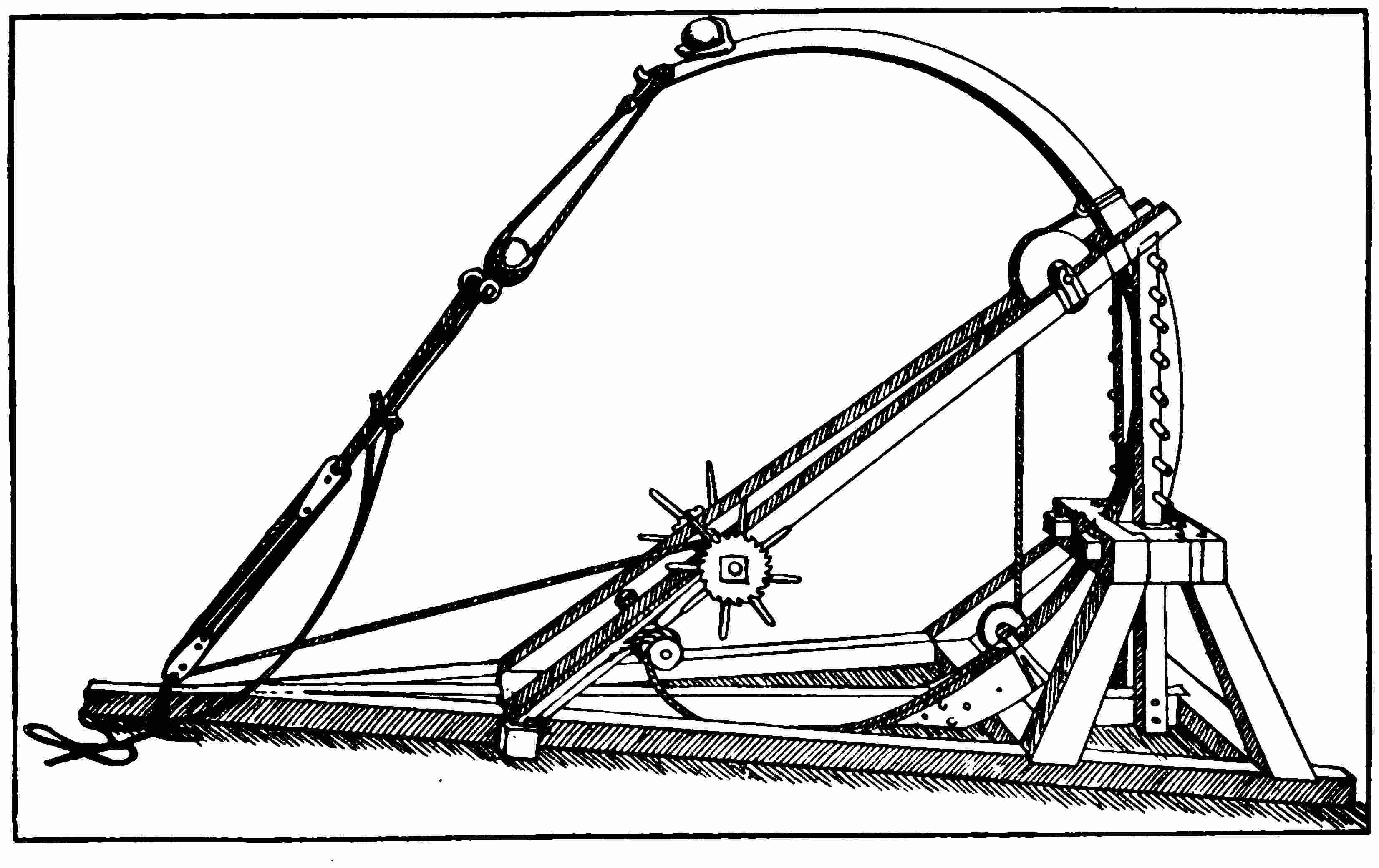
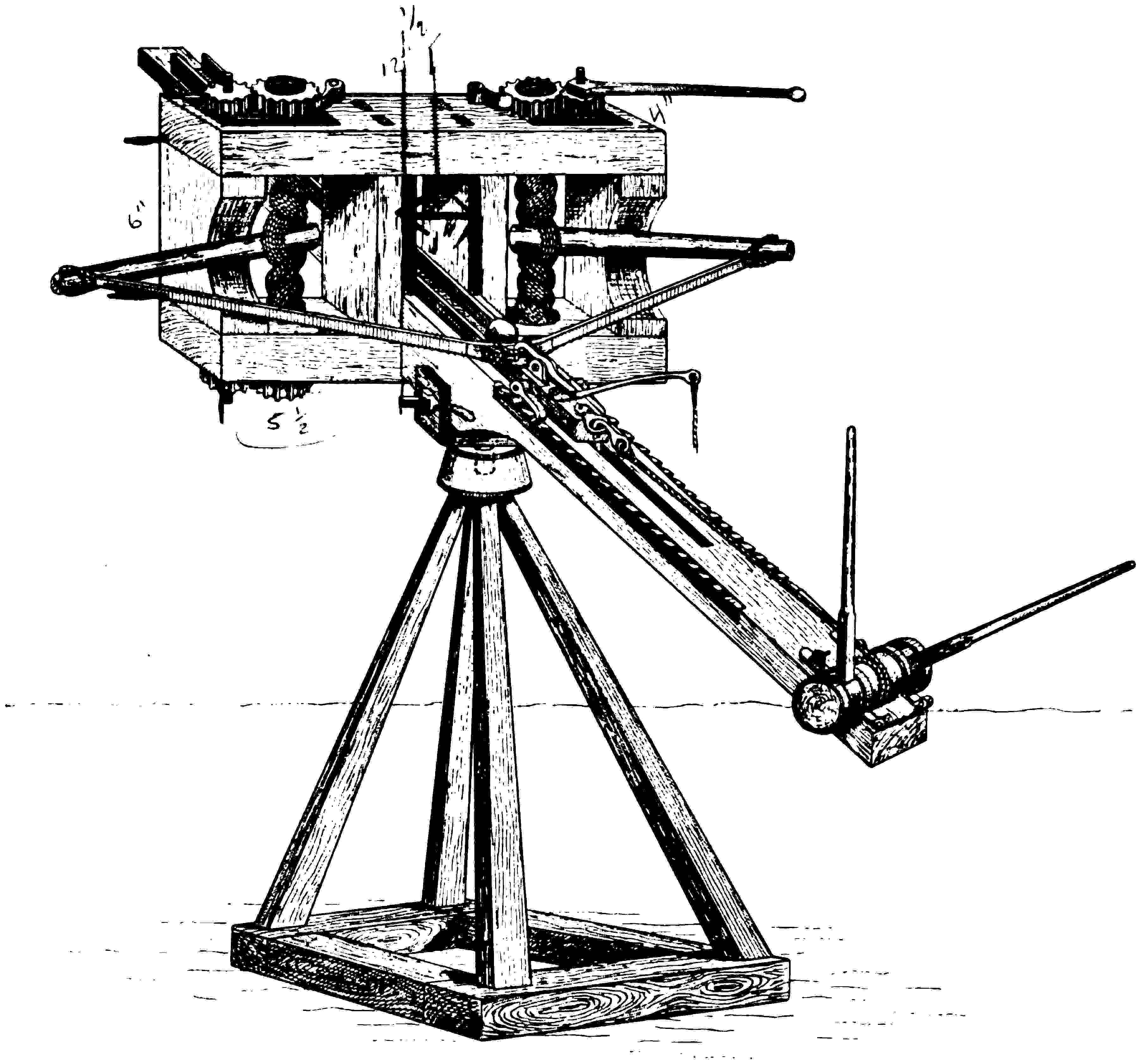
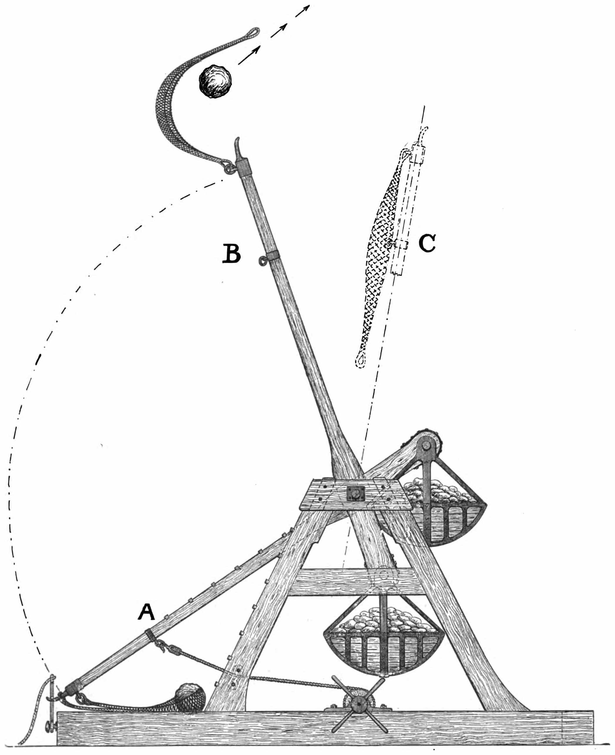
Fig. 7.—Catapult (with a Sling). Side view of frame and mechanism.
‘In the middle of the ropes8 rises a wooden arm like a chariot pole ...
to the top of the arm hangs a sling ... when battle is commenced a round
stone is set in the sling ... four soldiers on each side of the engine wind the
arm down till it is almost level with the ground ... when the arm is set free
it springs up and hurls forth from its sling the stone, which is certain to crush
whatever it strikes. This engine was formerly called the “scorpion,” because
it has its sting erect,9 but later ages have given it the name of Onager, or wild
ass, for when wild asses are chased they kick the stones behind them.’
8i.e. in the middle of the twisted skein formed of ropes of sinew or hair.
9 The upright and tapering arm of a catapult, with the iron pin on its top for the loop of the sling, is
here fancifully likened to the erected tail of an angry scorpion with its sting protruding.
A. The arm at rest, ready to be wound down by the rope attached
to it and also to the wooden roller of the windlass. The stone may be seen in
the sling.
The upper end of the pulley rope is hitched by a metal slip-hook (fig. 6,
p. 12) to a ring-bolt secured to the arm just below the sling.
B. The position of the arm when fully wound down by means of the
windlass and rope. See also EE, fig. 8, page 16.
C. The position of the arm at the moment the stone D leaves the sling,
which it does at an angle of about 45 degrees.
E. By pulling the cord E the arm B is at once released from the slip-hook
and, taking an upward sweep of 90 degrees, returns to its original position
at A.
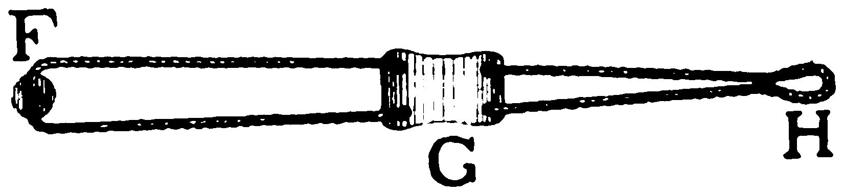
The Sling (open).
[F. Its fixed end which passes through a hole near the top of the arm.
G. The leather pocket for the stone.
H. The loop which is hitched over the iron pin at the top of the arm
when the stone is in position in the sling, as shown at A and B, fig. 7.]
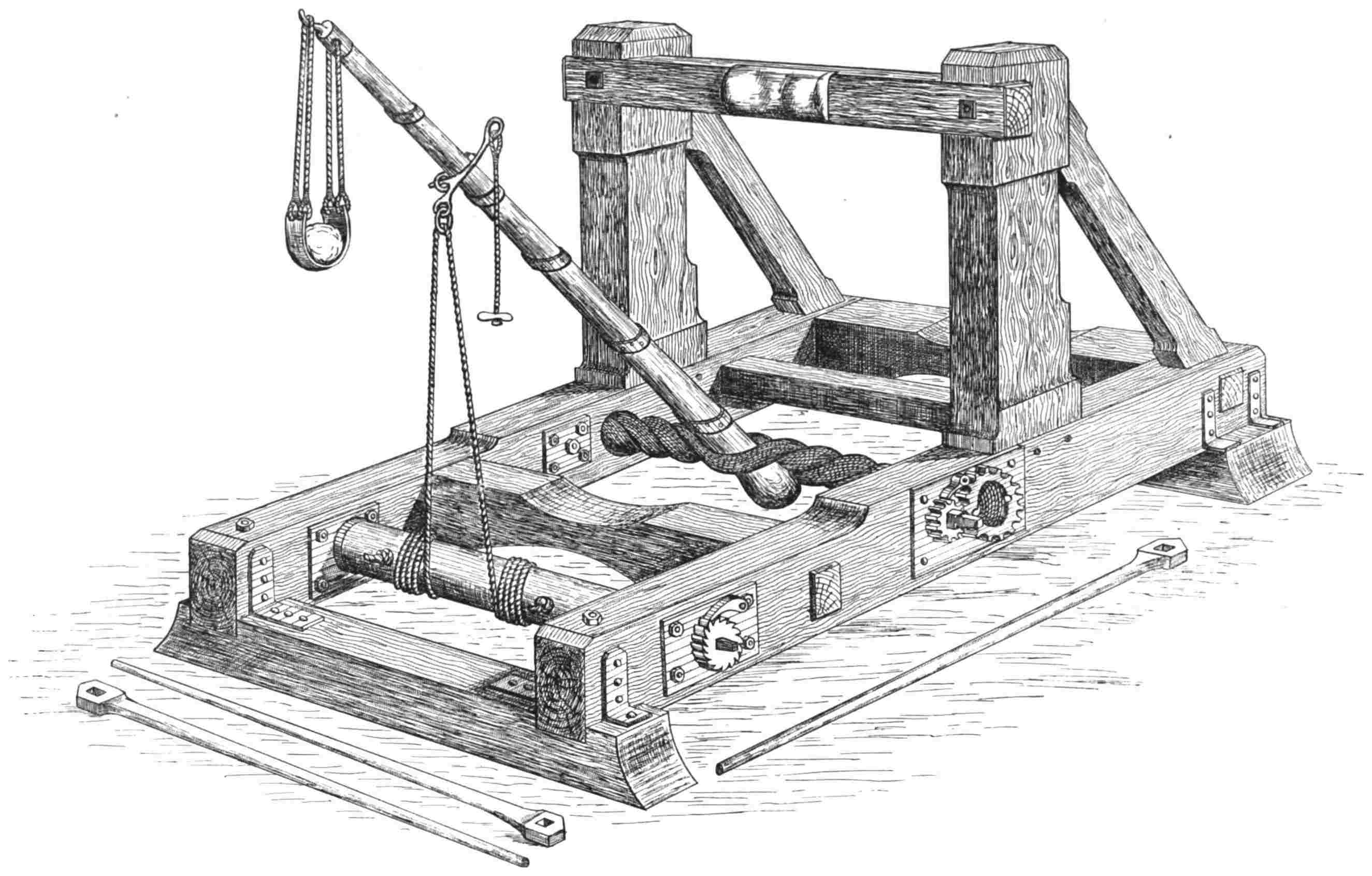
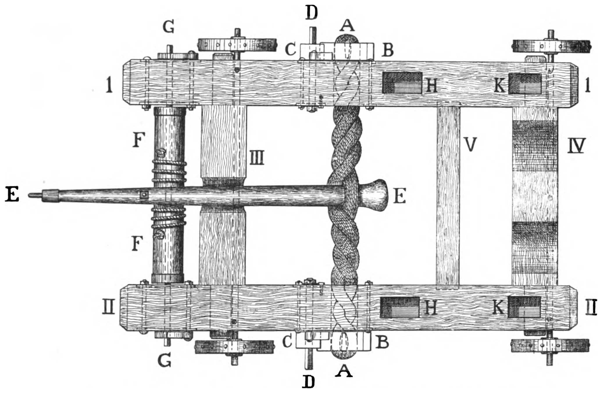
Fig. 8.—Catapult (with a Sling). Surface view of frame and mechanism. Scale: ½ in. = 1 foot.
The arm EE is here shown wound down to its full extent. (Compare with B, fig. 7, page 14.)
I.
I.
}
The side-pieces.
II.
II.
}
III.
IV.
The large cross-pieces.
V.
The small cross-piece.
The ends of the cross-piece beams are stepped into the side-pieces.
AA. The skein of twisted cord.
BB. The large winding wheels. The skein is stretched between these
wheels, its ends passing through the sides of the frame, and then through the
wheels and over their cross-bars. (Fig. 12, p. 19.)
By turning with a long spanner (fig. 6, p. 12) the squared ends of the
spindles DD, the pinion wheels CC rotate the large wheels BB and cause the
latter to twist the skein AA, between the halves of which the arm EE is
placed.
FF. The wooden roller which winds down the arm EE. (Fig. 6, p. 12.)
The roller is revolved by four men (two on each side of the engine) who fit
long spanners on the squared ends of the iron spindle GG.
This spindle passes through the centre of the roller and through the sides
of the frame.
The small cogged wheels, with their checks, which are fitted to the ends of
the spindle GG, prevent the roller from reversing as the arm is being wound
down. (Fig. 6, p. 12.)
HH. The hollows in the sides of the frame which receive the lower
tenons of the two uprights. Between the tops of these uprights the cross-beam
is fixed against which the arm of the catapult strikes when it is released.
(Fig. 6, p. 12.)
KK. The hollows for the lower tenons of the two sloping supports which
prevent the uprights, and the cross-beam between them, from giving way when
the arm recoils. (Fig. 6, p. 12.)
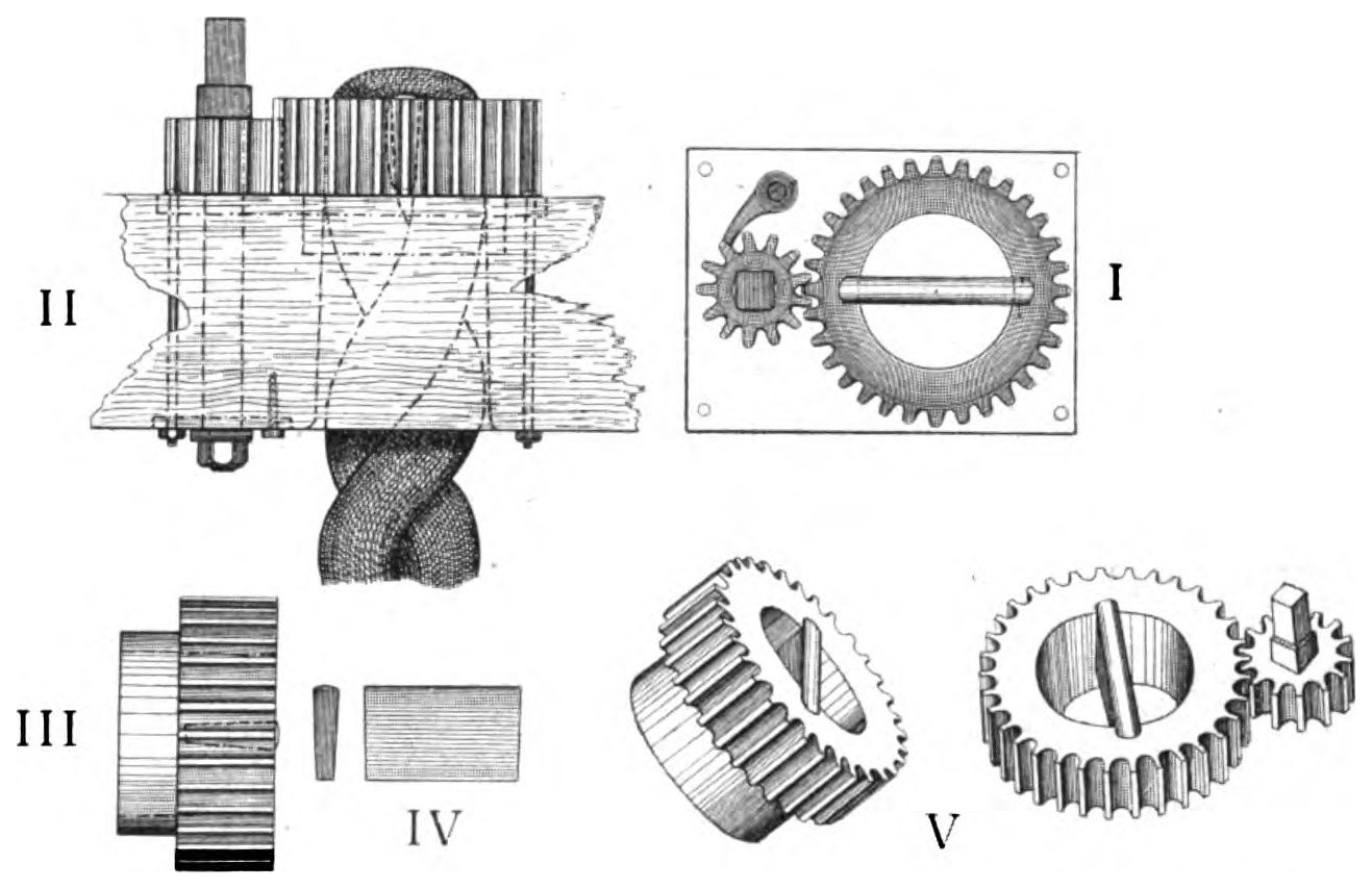
Fig. 9.—One of the Pair of Winches of a Catapult. Scale: 1/16 in. = 1 in.
I. Surface view of one of the winches and of the thick iron plate in which
the socket of the large winding wheel of the winch revolves.
II. View of a winch (from above) as fitted into one of the sides of the
frame of the catapult. One end of the twisted skein may be seen turned round
the cross-bar of the large wheel.
III. Side view of the large wheel of a winch.
IV. The cross-bar of one of the large wheels. These pieces fit like
wedges into tapering slots cut down the barrels, or inside surfaces, of their
respective wheels.
V. Perspective view of the wheels of a winch.
The winches are the vital parts of the catapult as they generate its
projectile power.
They are employed to twist tightly the skein of cord between which the
butt-end of the arm of the engine is placed.
The cord composing the skein is stretched to and fro across and through
the sides of the catapult, and alternately through the insides of the large wheels
and over their cross-bars; as shown in fig. 8, p. 16.
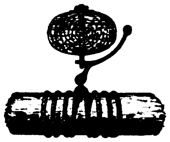
Fig. 10.
This simple contrivance not only pulled down the arm
of a catapult but was also the means of setting it free.
However great the strain on the slip-hook, it will, if properly
shaped, easily effect the release of the arm.
The trajectory of the missile can be regulated by this
form of release, as the longer the distance the arm is pulled
down the higher the angle at which the projectile is thrown.
On the other hand, the shorter the distance the arm is drawn back, the
lower the trajectory of its missile.
The slip-hook will release the arm of the engine at any moment, whether it
is fully or only partially wound down by the windlass.
The slip-hook of the large catapult shown in fig. 6, p. 12, has a handle, i.e.
lever, 10 inches long, the point of the hook, which passes through the eye-bolt
secured to the arm, being one inch in diameter.
Fig. 11.—A Spring Engine with a Sling attached to its Arm, which cast
Two Stones at the Same Time.
From ‘Il Codice Atlantico,’ Leonardo da Vinci. 1445–1520.
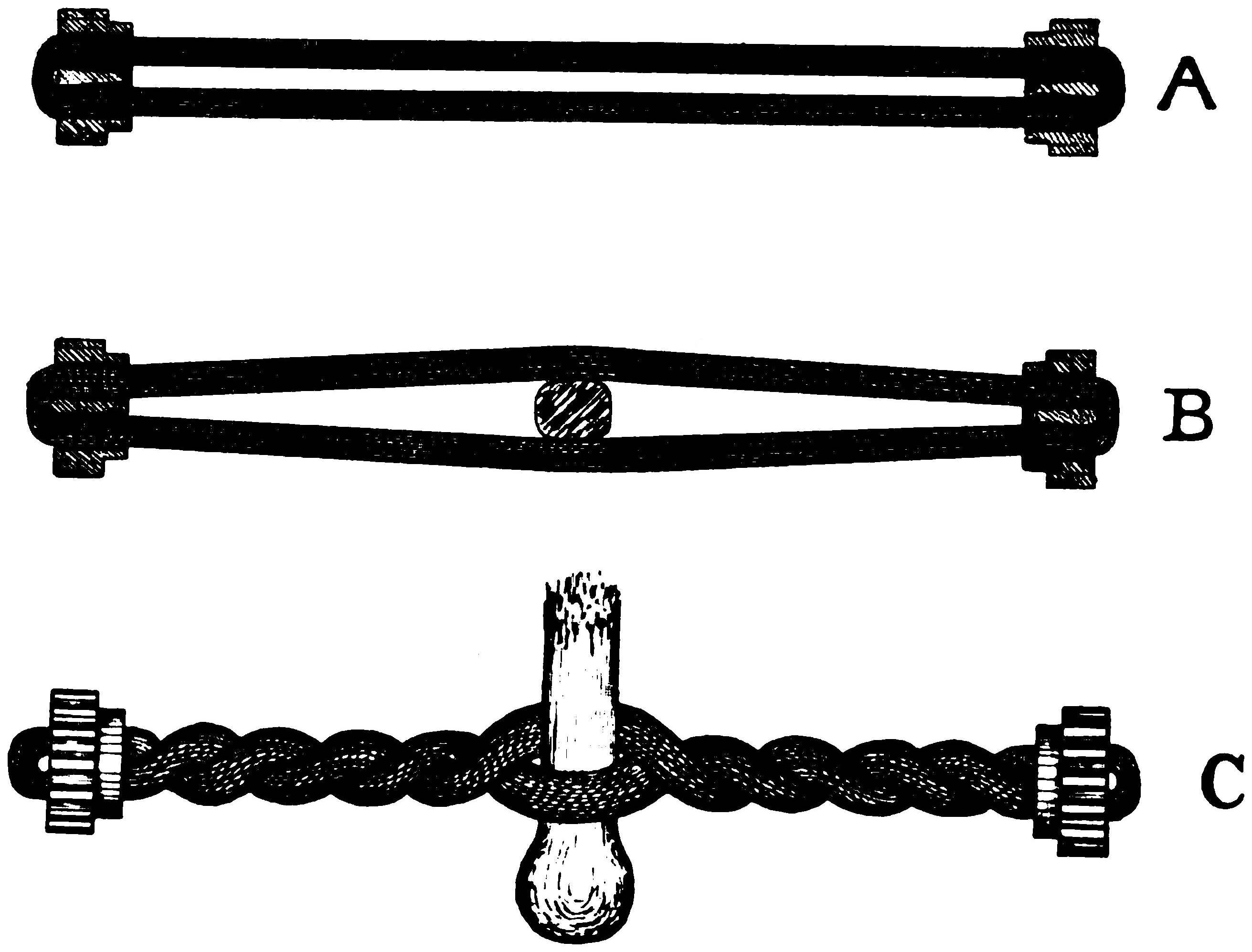
Fig. 12.—The Skein of Cord.
A. The skein as first wound over the cross-bars of the large wheels (shown
in section) of the winches.
B. The skein with the butt-end of the arm (shown in section) placed
between its halves.
C. The skein as it appears when tightly twisted up by the winches.
Compare with AA, fig. 8, p. 16.
Cord of Italian hemp, about ¼ in. thick, is excellent for small catapults.
For large ones, horsehair rope, ½ in. thick, is the best and most elastic. Whatever
is used, the material of the skein must be thoroughly soaked in neats-foot
oil for some days previously, or it is sure to fray and cut under the friction of
being very tightly twisted. Oil will also preserve the skein from damp and
decay for many years.
There is little to write under this heading; as the plans, details of construction
and illustrations will, I trust, elucidate its management.
The skein should never remain in a tightly twisted condition, but should
be untwisted when the engine is not in use.
Previous to using the catapult its winches should be turned with the long
spanner, fig. 6, p. 12, first the winch on one side of the engine and then the
one on the other side of it, and each to exactly the same amount.
Small numerals painted on the surfaces of the large wheels near their
edges, will show how much they have been revolved; in this way their rotation
can be easily arranged to correspond.
As the skein of cord is being twisted by the very powerful winches, the arm
will gradually press with increasing force against the cross-beam between the
uprights. The arm should be so tightly pressed against the fender, or cushion
of straw, attached to the centre of this beam, that, whether large or small, it
cannot be pulled back the least distance by hand.
If the skein of my largest catapult is fully tightened up by the winches,
three strong men are unable to draw the arm back with a rope even an inch
from the cross-beam, though the windlass has to pull it down from six to seven
feet when the engine is made ready for action.
When the skein is as tight as it should be, attach the slip-hook to the ring-bolt
in the arm and place the stone in the sling suspended from the top of the
arm.
The arm can now be drawn down by means of long spanners fitted to the
windlass. Directly the arm is as low as it should be, or as is desired, it should
be instantly released by pulling the cord fastened to the lever of the slip-hook.
The least delay in doing this, and the resulting continuation of the
immense strain on the arm, may cause it to fracture when it would not otherwise
have done so.
The plans I have given are those of my largest engine, which, ponderous as
it seems—(it weighs two tons)—is, however, less than half the size of the
catapult used by the ancients for throwing stones of from forty to fifty pounds
in weight.
As the plans are accurately drawn to scale, the engine can easily be reproduced
in a smaller size.
An interesting model can be constructed that has an arm 3 feet in length,
and a skein of cord about 4 inches in diameter. It can be worked by one man
and will throw a stone, the size of an orange, to a range of 300 yards.
The sling, when suspended with the stone in position, should be one third
the length of the arm, as shown in fig. 7, p. 14.
If the sling is shortened, the ball will be thrown at a high elevation. If the
sling is lengthened, the ball will travel at a lower angle and with much more
velocity.
PART III THE BALISTA — Fig. 14 (Opposite Page).—The Mechanism of the Stock of an Arrow-Throwing Balista.
Fig. 13.—Balista For Discharging Heavy Arrows or Javelins.
Approximate scale: ½ in. = 1 foot.
This engine is here shown ready for discharge with its bow-string drawn to
its full extent by the windlass.
The heavy iron-tipped arrow rests in the shallow wooden trough or groove
which travels along the stock.
The trough has a strip of wood, in the form of a keel, fixed beneath it.
This keel travels to or fro in a dove-tailed slot cut along the upper surface of the
stock for the greater part of its length. (F, fig. 14, p. 23.)
The arrow is laid in the trough before the bow-string is stretched. (A, B,
fig. 14, p. 23.)
The balista is made ready for use by turning the windlass. The windlass
pulls back the sliding trough, and the arrow resting in it, along the stock of the
engine, till the bow-string is at its proper tension for discharging the projectile.
(Fig. 13, p. 21.)
As the trough and the arrow are drawn back together, the arrow can be
safely laid in position before the engine is prepared for action.
The catch for holding the bow-string, and the trigger for releasing it, are
fixed to the solid after-end of the wooden trough. (Fig. 14, p. 23.)
The two ratchets at the sides of the after-end of the trough travel over and
engage, as they pass along, the metal cogs fixed on either side of the stock.
(Fig. 14, p. 23.)10
10 When the bow-string has been released and the arrow discharged, the ratchets are lifted clear of the
cogs on the stock of the engine. This allows the trough to be slid forward to its first position as shown in
A, B, Fig. 14. It is then ready to be drawn back again for the next shot.
By this arrangement the trough can be securely retained, in transit, at any
point between the one it started from and the one it attains when drawn back to
its full extent by the windlass.
As the lock and trigger of the balista are fixed to the after-end of the
sliding trough (fig. 14, p. 23), it will be realised that the arrow could be discharged
at any moment required in warfare, whether the bow-string was fully or
only partially stretched.
In this respect the balista differed from the crossbow, which it somewhat
resembled, as in a crossbow the bow-string cannot be set free by the trigger at
an intermediate point, but only when it is drawn to the lock of the weapon.
It will be seen that the balista derives its power from two arms; each with
its separate skein of cord and pair of winches.
These parts of the balista are the same in their action and mechanism as
those of the catapult.
A. Side view of the stock, with the arrow in the sliding trough before the
bow-string is stretched.
B. Surface view of the stock, with the arrow in the sliding trough before
the bow-string is stretched.
C. Section of the fore-end of the stock, and of the trough which slides in
and along it.
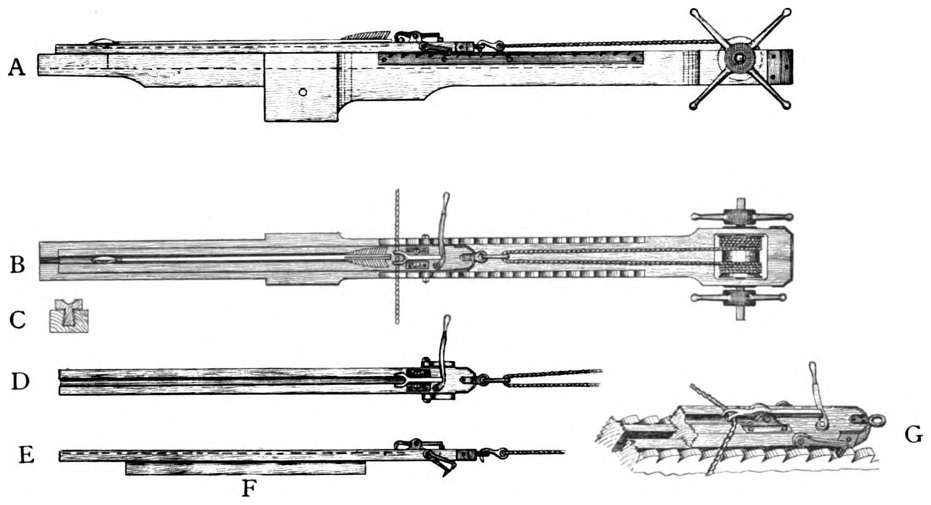
Fig. 14.—The Mechanism of the Stock of an Arrow-throwing Balista.
D. Surface view of the trough, with the trigger and catch for the bow-string.
E. Side view, showing the keel (F) which slides along the slot cut in the
surface of the stock as the trough is drawn back by the windlass.
G. Enlarged view of the solid end of the trough. This sketch shows the
catch for the bow-string, the trigger which sets it free, the ratchets which engage
the cogs on the sides of the stock, and the slot cut in the stock for the dove-tailed
keel of the trough to travel in.
* * * * *
Balistas were constructed of different sizes for the various purposes of siege
and field warfare. The smallest of these engines was not much larger than a
heavy crossbow, though it more than equalled the latter in power and range.
The small balistas were chiefly used for shooting through loopholes and
from battlemented walls at an enemy assaulting with scaling ladders and
movable towers.
The largest had arms of 3 ft. to 4 ft. in length, and skeins of twisted sinew
of 6 in. to 8 in. in diameter.
Judging from models I have made and carefully experimented with; it is
certain that the more powerful balistas of the ancients could cast arrows, or
rather feathered javelins, of from 5 to 6 lbs. weight, to a range of from
450 to 500 yards.
Fig. 15.—Balista for throwing Stone Balls. Approximate scale: ½ in. = 1 foot.
This engine is here shown with its bow-string only slightly drawn along its stock by the windlass.
It will be seen that this engine is almost identical in construction with the
one last described. (Fig. 13, p. 21.)
The difference is that it propelled a stone ball instead of a large arrow.
The ball was driven along a square wooden trough, one-third of the
diameter of the ball being enclosed by the sides of the trough so as to keep
the missile in a true direction after the bow-string was released.
The bow-string was in the form of a broad band, with an enlargement at
its centre against which the ball rested.
The description given of the mechanism and management of the engine
for throwing arrows can be applied to the construction and manipulation of this
form of balista, which was also made of large and small dimensions.
Small engines, with arms about 2 ft. in length and skeins of cord about
4 in. in diameter, such as those I have built for experiment, will send a stone
ball, 1 lb. in weight, from 300 to 350 yards.
There is little doubt that the large stone-throwing balista of the Greeks
and Romans was able to project a circular stone, of 6 to 8 lbs. weight, to a
distance of from 450 to 500 yards.11
11 The balls used by the ancients in their catapults and balistas were often formed of heavy pebbles
inclosed in baked clay, the reason being that balls made in this way shattered on falling and hence could
not be shot back by the engines of the enemy. The balistas for throwing arrows, and those employed for
casting stones, were fitted with axles and wheels when constructed for use in field warfare.
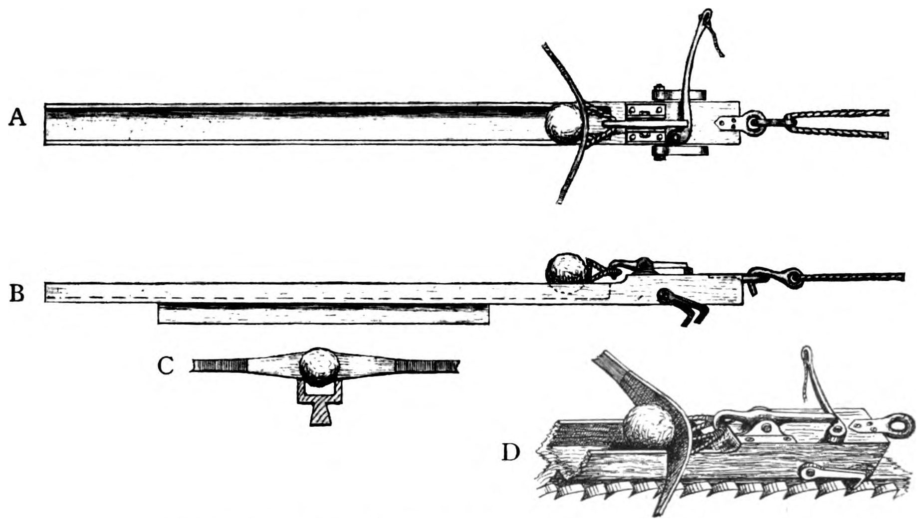
Fig. 16.—The Sliding Trough of the Stone-throwing Balista.
A. Surface view, with the stone in position.
B. Side view, with the stone in position.
C. Front view of the stone as it rests in the trough against the enlarged
centre of the bow-string.
D. Enlarged view of the solid end of the sliding trough. This sketch
shows the ball in position against the bow-string; the catch holding the loop
of the bow-string, and the pivoted trigger which, when pulled, releases the catch.
One of the pair of ratchets which engage the cogs on the sides of the stock,
as the trough is drawn back by the windlass to make ready the engine, is also
shown. The trough has a keel to it, and slides to or fro along the stock in the
same manner as in the arrow-throwing balista. (Fig. 13, p. 21.)
Compare with figs. 13, 14, pp. 21, 23, for further explanation of details.
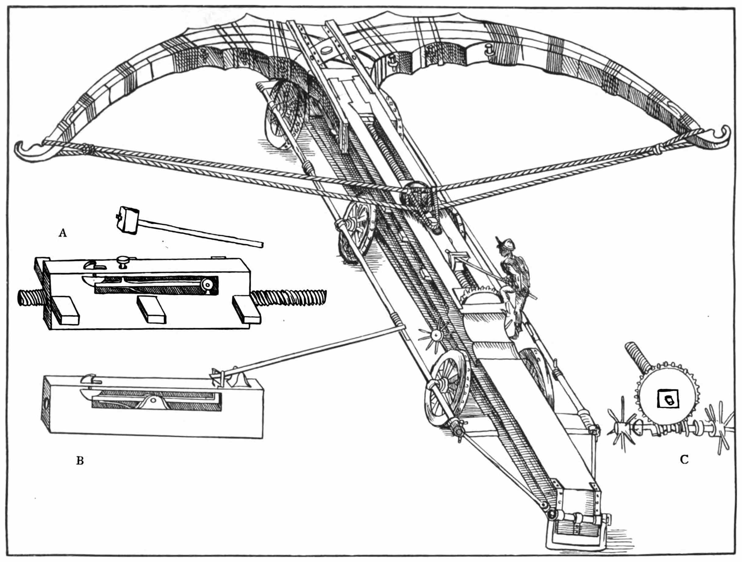
Fig. 17.—A Siege Balista in the form of an immense Stonebow.
From ‘Il Codice Atlantico,’ Leonardo da Vinci, 1445–1520.
Criticism.—A stonebow of vast size. A and B represent two kinds of lock. In A, the catch of the lock over which the loop of the bow-string was
hitched, was released by striking down the knob to be seen below the mallet. In B, the catch was set free by means of a lever. C shows the manner of
pulling back the bow-string. By turning the spoked wheels, the screw-worm revolved the screwed bar on which the lock A, travelled. The lock, as
may be seen, worked to or fro in a slot along the stock of the engine. In the illustration the bow is fully bent and the man indicated is about to discharge
the engine. After this was done, the lock was wound back along the screw-bar and the bow-string was hitched over the catch of the lock preparatory to
bending the bow again. Besides being a famous painter, Leonardo was distinguished as an inventor and exact writer on mechanics and hydraulics.
‘No artist before his time ever had such comprehensive talents, such profound skill or so discerning a judgment to explore the depths of
every art or science to which he applied himself.’—John Gould, Dictionary of Painters, 1839.
From the above eulogy we may conclude that the drawings of ancient siege engines by Leonardo da Vinci are fairly correct.
PART IV THE TREBUCHET
This engine was of much more recent invention than the catapult or the
balista of the Greeks and Romans. It is said to have been introduced into
siege operations by the French in the twelfth century. On the other hand, the
catapult and the balista were in use several centuries before the Christian Era.
Egidio Colonna gives a fairly accurate description of the trebuchet, and writes
of it, about 1280, as though it were the most effective siege weapon of his time.
The projectile force of this weapon was obtained from the gravitation of a
heavy weight, and not from twisted cordage as in the catapult and balista.
From about the middle of the twelfth century, the trebuchet in great
measure superseded the catapult. This preference for the trebuchet was
probably due to the fact that it was able to cast stones of about 300 lbs. in
weight, or five or six times as heavy as those which the largest catapults could
project.12
12 The catapult had, besides, become an inferior engine to what it was some centuries before the
trebuchet was introduced, the art of its construction having been neglected.
The stones thrown by the siege catapults of the time of Josephus would
no doubt destroy towers and battlements, as the result of the constant and
concentrated bombardment of many engines. One huge stone of from 200 to
300 lbs., as slung from a trebuchet, would, however, shake the strongest
defensive masonry.
The trebuchet was essentially an engine for destroying the upper part of
the walls of a fortress, so that it might be entered by means of scaling ladders
or in other ways. The catapult, by reason of its longer range, was of more
service in causing havoc to the people and dwellings inside the defences of a town.
From experiments with models of good size and from other sources, I find
that the largest trebuchets—those with arms of about 50 ft. in length and
counterpoises of about 20,000 lbs.—were capable of slinging a stone from 200 to
300 lbs. in weight to a distance of 300 yards, a range of 350 yards being, in
my opinion, more than these engines were able to attain.13
13 Egidio Colonna tells us that the trebuchet was sometimes made without a counterpoise, and that in
such a case the arm of the engine was worked by a number of men pulling together instead of by a
heavy weight. I cannot believe this, as however many men pulled at the arm of a trebuchet they could not
apply nearly the force that would be conveyed by the gravitation of a heavy weight.
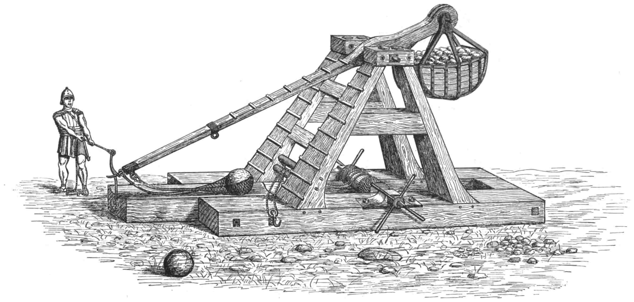
Fig. 18.—The Trebuchet.
The arm is fully wound down and the tackle of the windlass is detached from it. The stone is in the sling and the engine is about to be discharged
by pulling the slip-hook off the end of the arm. The slip-hook is similar to the one shown in fig. 10, p. 18.
N.B.—A Roman soldier is anachronistically shown in this picture. The trebuchet was invented after the time of the Romans.
The trebuchet always had a sling in which to place its missile.
The sling doubled the power of the engine and caused it to throw its
projectile twice as far as it would have been able to do without it.
It was the length of the arm, when suitably weighted with its counterpoise,
which combined with its sling gave power to the trebuchet. Its arm, when
released, swung round with a long easy sweep and with nothing approaching
the velocity of the much shorter arm of the catapult.
The weight of a projectile cast by a trebuchet was governed by the
weight of its counterpoise. Provided the engine was of sufficient strength and
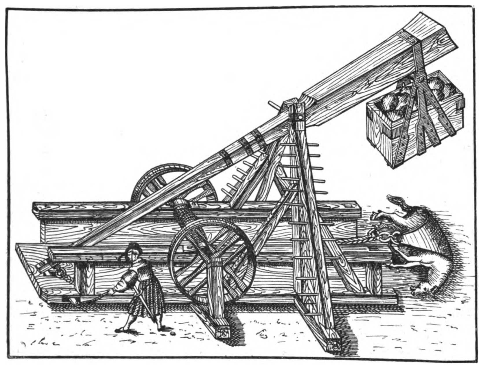
could be manipulated, there was scarcely any limit to its power. Numerous
references are to be found in mediæval authors to the practice of throwing dead
horses into a besieged town with a view to causing a pestilence therein, and
there can be no doubt that trebuchets alone were employed for this purpose.
As a small horse weighs about 10 cwt., we can form some idea of the size
of the rocks and balls of stone that trebuchets were capable of slinging.
When we consider that a trebuchet was able to throw a horse over the
walls of a town, we can credit the statement of Stella,14 who writes ‘that the
Genoese armament sent against Cyprus in 1376 had among other great engines
one which cast stones of 12 cwt.’
14 Stella flourished at the end of the fourteenth century and beginning of fifteenth. He wrote
The Annals of Genoa from 1298–1409. Muratori includes the writings of Stella in his great work, Rerum
Italicarum Scriptores, 25 vols., 1723–38.
Villard de Honnecourt15 describes a trebuchet that had a counterpoise of
sand the frame of which was 12 ft. long, 8 ft. broad, and 12 ft. deep. That
such machines were of vast size will readily be understood. For instance,
twenty-four engines taken by Louis IX. at the evacuation of Damietta in 1249,
afforded timber for stockading his entire camp.16 A trebuchet used at the capture
of Acre by the Infidels in 1291, formed a load for a hundred carts.17 A great
engine that cumbered the tower of St. Paul at Orleans and which was dismantled
previous to the celebrated defence of the town against the English in
1428–9, furnished twenty-six cartloads of timber.18
15 Villard de Honnecourt, an engineer of the thirteenth century. His album translated and edited by
R. Willis, M.A., 1859.
16 Jean, Sire de Joinville. He went with St. Louis to Damietta. His memoirs, written in 1309,
published by F. Michel, 1858.
17 Abulfeda, 1273–1331. Arab soldier and historian, wrote Annals of the Moslems. Published by
Hafnire, 1789–94. Abulfeda was himself in charge of one of the hundred carts.
18 From an old history of the siege (in manuscript) found in the town hall of Orleans and printed by
Saturnin Holot, a bookseller of that city, 1576.
All kinds of articles besides horses, men, stones and bombs were at times
thrown from trebuchets. Vassāf19 records ‘that when the garrison of Delhi
refused to open the gates to Ala’uddin Khilji in 1296, he loaded his engines
with bags of gold and shot them into the fortress, a measure which put an end
to the opposition.’
19 Persian historian, wrote at end of thirteenth and beginning of fourteenth century. The preface to his
history is dated 1288, and the history itself is carried down to 1312.
Figs. 18, 20, pp. 28, 32, explain the construction and working of a trebuchet.
Fig. 19.—Casting a dead Horse into a besieged Town by means of a Trebuchet.
From ‘Il Codice Atlantico,’ Leonardo da Vinci, 1445–1520.
PART V HISTORICAL NOTES ON ANCIENT AND MEDIÆVAL SIEGE ENGINES AND THEIR EFFECTS IN WARFARE
It is evident that a history of ancient siege engines cannot be created de novo.
All that can be done is to quote with running criticism what has already been
written about them.
The first mention of balistas and catapults is to be found in the Old
Testament, two allusions to these weapons being made therein.
The references are:
2 Chronicles xxvi. 15, ‘And he20 made in Jerusalem engines, invented by
cunning men, to be on the towers and upon the bulwarks, to shoot arrows and
great stones withal.’
Ezekiel xxvi. 9, ‘And he shall set engines of war against thy walls.’
Though the latter extract is not so positive in its wording as the one
first given, it undoubtedly refers to engines that cast either stones or arrows
against the walls, especially as the prophet previously alludes to other means of
assault.
One of the most authentic descriptions of the use of great missive engines
is to be found in the account by Plutarch of the siege of Syracuse by the
Romans, 214–212 B.C.
Cæsar in his Commentaries on the Gallic and Civil wars, B.C. 58–50,
frequently mentions the engines which accompanied him in his expeditions.
The balistas on wheels were harnessed to mules and called carro-balistas.
The carro-balista discharged its heavy arrow over the head of the animal
to which the shafts of the engine were attached. Among the ancients these
carro-balistas acted as field artillery and one is plainly shown in use on Trajan’s
Column.
According to Vegetius, every cohort was equipped with one catapult and
every century with one carro-balista; eleven soldiers being required to work the
latter engine.
Fig. 20.—The Action of the Trebuchet.
A. The arm pulled down and secured by the slip-hook previous to unhooking the rope of the windlass. B. The arm released
from the slip-hook and casting the stone out of its sling. C. The arm at the end of its upward sweep.
Sixty carro-balistas accompanied, therefore, besides ten catapults, a legion.
The catapults were drawn along with the army on great carts yoked to oxen.
In the battles and sieges sculptured on Trajan’s Column there are several
figures of balistas and catapults. This splendid monument was erected in
Rome, 105–113, to commemorate the victories of Trajan over the Dacians, and
constitutes a pictorial record in carved stone containing some 2,500 figures of
men and horses.
It is astonishing what a large number of catapults and balistas were
sometimes used in a siege. For instance, at the conquest of Carthage, B.C. 146,
120 great catapults and 200 small ones were taken from the defenders, besides
33 great balistas and 52 small ones (Livy).21
21 Just previous to the famous defence of Carthage, the Carthaginians surrendered to the Romans ‘two
hundred thousand suits of armour and a countless number of arrows and javelins, besides catapults for
shooting swift bolts and for throwing stones to the number of two thousand.’ From Appian of Alexandria,
a Greek writer who flourished 98–161.
Abulfaragio (Arab historian, 1226–1286) records that at the siege of Acre
in 1191, 300 catapults and balistas were employed by Richard I. and Philip II.
Abbo, a monk of Saint Germain des Prés, in his poetic but very detailed
account of the siege of Paris by the Northmen in 885, 886, writes ‘that the
besieged had a hundred catapults on the walls of the town.’22
22 These were probably balistas, as Ammianus Marcellinus writes of the catapult, ‘An engine of this
kind placed on a stone wall shatters whatever is beneath it, not by its weight but by the violence of its
shock when discharged.’
Among our earlier English kings Edward I. was the best versed in
projectile weapons large and small, including crossbows and longbows.
In the Calendar of Documents relating to Scotland, an account is given of
his ‘War-wolf,’ a siege engine in the construction of which he was much
interested and which was no doubt a trebuchet.
This machine was of immense strength and size, and took fifty carpenters
and five foremen a long time to complete. Edward designed it for the siege of
Stirling, whither its parts were sent by land and by sea.
Sir Walter de Bedewyne, writing to a friend on July 20, 1304 (see
Calendar of State Documents relating to Scotland), says: ‘As for news, Stirling
Castle was absolutely surrendered to the King without conditions this Monday,
St. Margaret’s Day, but the King wills it that none of his people enter the
castle till it is struck with his “War-wolf,” and that those within the castle
defend themselves from the said “War-wolf” as best they can.’
From this it is evident that Edward, having constructed his ‘War-wolf’ to
cast heavy stones into the castle of Stirling to induce its garrison to surrender,
was much disappointed by their capitulation before he had an opportunity of
testing the power of his new weapon.
One of the last occasions on which the trebuchet was used with success
is described by Guillet in his ‘Life of Mahomet II.’23 This author writes:
‘At the siege of Rhodes in 1480, the Turks set up a battery of sixteen great
cannon, but the Christians successfully opposed the cannon with a counter-battery
of new invention.24
23 Guillet de Saint George, born about 1625, died 1705. His Life of Mahomet II. was published in
1681. He was the author of several other works, including one on riding, warfare and navigation, termed
the Gentleman’s Dictionary. The best edition of this book is in English and has many very curious
illustrations. It is dated 1705.
24 Called a new invention because the old siege engine of which this one (probably a trebuchet) was a
reproduction had previously been laid aside for many years.
‘An engineer, aided by the most skilful carpenters in the besieged town,
made an engine that cast pieces of stone of a terrible size. The execution
wrought by this engine prevented the enemy from pushing forward the work of
their approaches, destroyed their breastworks, discovered their mines, and filled
with carnage the troops that came within range of it.’
At the siege of Mexico by Cortes in 1521, when the ammunition for the
Spanish cannon ran short, a soldier with a knowledge of engineering undertook
to make a trebuchet that would cause the town to surrender. A huge engine
was constructed, but on its first trial the rock with which it was charged instead
of flying into the town ascended straight upwards, and falling back to its
starting-point destroyed the mechanism of the machine itself.25
Though all the projectile engines worked by cords and weights disappeared
from continental warfare when cannon came to the front in a more or less
improved form, they—if Vincent le Blanc is to be credited—survived in
barbaric nations long after they were discarded in Europe.
This author (in his travels in Abyssinia) writes ‘that in 1576 the Negus
attacked Tamar, a strong town defended by high walls, and that the besieged
had engines composed of great pieces of wood which were wound up by cords
and screwed wheels, and which unwound with a force that would shatter a
vessel, this being the cause why the Negus did not assault the town after he
had dug a trench round it.’26
26 Vincent le Blanc, Voyages aux quatre parties du monde, redigé par Bergeron, Paris, 1649. Though
the accounts given by this author of his travels are imaginative, I consider his allusion to the siege
engine to be trustworthy, as he was not likely to invent so correct a description of one.
Plutarch, in his Life of Marcellus the Roman General, gives a graphic
account of Archimedes and the engines this famous mathematician employed in
the defence of Syracuse.
It appears that Archimedes showed his relative Hiero II., King of
Syracuse, some wonderful examples of the way in which immense weights
could be moved by a combination of levers.
Hiero, being greatly impressed by these experiments, entreated Archimedes
temporarily to employ his genius in designing articles of practical use, with the
result that the scientist constructed for the king all manner of engines suitable
for siege warfare.
Though Hiero did not require the machines, his reign being a peaceful
one, they proved of great value shortly after his death when Syracuse was
besieged by the Romans under Marcellus, 214–212 B.C.
On this occasion Archimedes directed the working of the engines he had
made some years previously for Hiero.
Plutarch writes: ‘And in truth all the rest of the Syracusans were no more
than the body in the batteries of Archimedes, whilst he was the informing
soul. All other weapons lay idle and unemployed, his were the only offensive
and defensive arms of the city.’
When the Romans appeared before Syracuse, its citizens were filled with
terror, for they imagined they could not possibly defend themselves against so
numerous and fierce an enemy.
But, Plutarch tells us, ‘Archimedes soon began to play his engines upon
the Romans and their ships, and shot against them stones of such an enormous
size and with so incredible a noise and velocity that nothing could stand
before them. The stones overturned and crushed whatever came in their way,
and spread terrible disorder through the Roman ranks. As for the machine
which Marcellus brought upon several galleys fastened together, called sambuca27
from its resemblance to the musical instrument of that name; whilst it was
yet at a considerable distance, Archimedes discharged at it a stone of ten
talents’ weight and, after that, a second stone and then a third one, all of which
striking it with an amazing noise and force completely shattered it.28
27Sambuca. A stringed instrument with cords of different lengths like a harp. The machine which
Marcellus brought to Syracuse was designed to lift his soldiers—in small parties at a time and in quick
succession—over the battlements of the town, so that when their numbers inside it were sufficient they
might open its gates to the besiegers. The soldiers were intended to be hoisted on a platform, worked up
and down by ropes and winches. As the machine was likened to a harp, it is probable it had a huge
curved wooden arm fixed in an erect position and of the same shape as the modern crane used for loading
vessels. If the arm of the sambuca had been straight like a mast, it could not have swung its load of men
over a wall. Its further resemblance to a harp would be suggested by the ropes which were employed for
lifting the platform to the summit of the arm, these doubtless being fixed from the top to the foot of the
engine.
28 It is, I consider, impossible that Archimedes, however marvellous the power of his engines, was able
to project a stone of ten Roman talents or nearly 600 lbs. in weight, to a considerable distance! Plutarch
probably refers to the talent of Sicily, which weighed about 10 lbs. A stone of ten Sicilian talents, or say
100 lbs., could have been thrown by a catapult of great strength and size.
Though the trebuchet cast stones of from 200 lbs. to 300 lbs. and more, this weapon was not invented
till long after the time of Archimedes.
‘Marcellus in distress drew off his galleys as fast as possible and sent
orders to his land forces to retire likewise. He then called a council of war, in
which it was resolved to come close up to the walls of the city the next
morning before daybreak, for they argued that the engines of Archimedes, being
very powerful and designed to act at a long distance, would discharge their
projectiles high over their heads. But for this Archimedes had been prepared,
for he had engines at his disposal which were constructed to shoot at
all ranges. When, therefore, the Romans came close to the walls, undiscovered
as they thought, they were assailed with showers of darts, besides huge pieces
of rock which fell as it were perpendicularly upon their heads, for the engines
played upon them from every quarter.
‘This obliged the Romans to retire, and when they were some way from
the town Archimedes used his larger machines upon them as they retreated,
which made terrible havoc among them as well as greatly damaged their
shipping. Marcellus, however, derided his engineers and said, “Why do we not
leave off contending with this geometrical Briareus, who sitting at ease and acting
as if in jest has shamefully baffled our assaults, and in striking us with such a
multitude of bolts at once exceeds even the hundred-handed giant of fable?”
‘At length the Romans were so terrified that, if they saw but a rope or a
beam projecting over the walls of Syracuse, they cried out that Archimedes was
levelling some machine at them and turned their backs and fled.’
As Marcellus was unable to contend with the machines directed by Archimedes
and as his ships and army had suffered severely from the effects of these
stone- and javelin-casting weapons, he changed his tactics and instead of
besieging the town he blockaded it and finally took it by surprise.
Though, at the time of the siege of Syracuse, Archimedes gained a
reputation for divine rather than human knowledge in regard to the methods
he employed in the defence of the city, he left no description of his wonderful
engines, for he regarded them as mere mechanical appliances which were
beneath his serious attention, his life being devoted to solving abstruse questions
of mathematics and geometry.
Archimedes was slain at the capture of Syracuse, B.C. 212, to the great
regret of Marcellus.
The following extracts from Josephus, as translated by Whiston, enable us
to form an excellent idea of the effects of great catapults in warfare:
(1) Wars of the Jews, Book III., Chapter VII.—The siege of Jotapata,
A.D. 67. ‘Vespasian then set the engines for throwing stones and darts round
about the city; the number of the engines was in all a hundred and sixty....
At the same time such engines as were intended for that purpose threw their
spears buzzing forth, and stones of the weight of a talent were thrown by the
engines that were prepared for doing so....
‘But still Josephus and those with him, although they fell down dead one
upon another by the darts and stones which the engines threw upon them,
did not desert the wall.... The engines could not be seen at a great
distance and so what was thrown by them was hard to be avoided; for the force
with which these engines threw stones and darts made them wound several at a
time, and the violence of the stones that were cast by the engines was so great
that they carried away the pinnacles of the wall and broke off the corners of the
towers; for no body of men could be so strong as not to be overthrown to the
last rank by the largeness of the stones.... The noise of the instruments
themselves was very terrible, the sound of the darts and stones that were thrown
by them was so also; of the same sort was that noise that dead bodies made
when they were dashed against the wall.’
(2) Wars of the Jews, Book V., Chapter VI.—The siege of Jerusalem,
A.D. 70. ‘The engines that all the legions had ready prepared for them were
admirably contrived; but still more extraordinary ones belonged to the tenth
legion: those that threw darts and those that threw stones were more forcible
and larger than the rest, by which they not only repelled the excursions of the
Jews but drove those away who were upon the walls also. Now the stones that
were cast were of the weight of a talent29
and were carried two or more stades.30
30 Two stades would be 404 yards; the measure of a stade is 606¾ English feet.
‘The blow they gave was no way to be sustained, not only by those who
stood first in the way but by those who were beyond them for a great space.
‘As for the Jews, they at first watched the coming of the stone, for it was
of a white colour and could therefore not only be perceived by the great noise
it made, but could be seen also before it came by its brightness; accordingly the
watchmen that sat upon the towers gave notice when an engine was let go ...
so those that were in its way stood off and threw themselves down upon the
ground. But the Romans contrived how to prevent this by blacking the stone;
they could then aim with success when the stone was not discerned beforehand,
as it had been previously.’
The accounts given by Josephus are direct and trustworthy evidence, for
the reason that this chronicler relates what he personally witnessed during the
sieges he describes, in one of which (Jotapata) he acted the part of a brave
and resourceful commander.
Tacitus in describing a battle fought near Cremona between the armies
of Vitellius and Vespasian, A.D. 69, writes: ‘The Vitellians at this time
changed the position of their battering-engines, which in the beginning were
placed in different parts of the field and could only play at random against
the woods and hedges that sheltered the enemy. They were now moved to
the Postumian way, and thence having an open space before them could
discharge their missiles with good effect.’31
31 Tacitus continues: ‘The fifteenth legion had an engine of enormous size, which was played off with
dreadful execution and discharged massy stones of a weight to crush whole ranks at once. Inevitable ruin
must have followed if two soldiers had not signalised themselves by a brave exploit. Covering themselves
with shields of the enemy which they found among the slain, they advanced undiscovered to the battering-engine
and cut its ropes and springs. In this bold adventure they both perished and with them two names
that deserved to be immortal.’
Froissart chronicles that at the siege of Thyn-l’Evêque, 1340, in the Low
Countries, ‘John, Duke of Normandy had a great abundance of engines carted
from Cambrai and Douai. Among others he had six very large ones which he
placed before the fortress, and which day and night cast great stones which
battered in the tops and roofs of the towers and of the rooms and halls, so much
so that the men who defended the place took refuge in cellars and vaults.’
Camden records that the strength of the engines employed for throwing
stones was incredibly great and that with the engines called mangonels32 they
used to throw millstones. Camden adds that when King John laid siege
to Bedford Castle, there were on the east side of the castle two catapults battering
the old tower, as also two upon the south side besides another on the north
side which beat two breaches in the walls.
32 Catapults were often called mangons or mangonels, but in course of time the name mangonel was
applied to any siege engine that projected stones or arrows. In this case the trebuchet is intended, as
no catapult could project a millstone.
The same authority asserts that when Henry III. was besieging Kenilworth
Castle, the garrison had engines which cast stones of an extraordinary size, and
that near the castle several balls of stone sixteen inches in diameter have been
found which are supposed to have been thrown by engines with slings33 in
the time of the Barons’ war.
33 The engines here alluded to by Camden were trebuchets.
Holinshed writes that ‘when Edward I. attacked Stirling Castle, he caused
an engine of wood to be set up to batter the castle which shot stones of two
or three hundredweight.’ (See allusion to this, p. 33.)
Père Daniel, in his Histoire de la Milice Françoise, writes: ‘The great
object of the French engineers was to make siege engines of sufficient strength
to project stones large enough to crush in the roofs of houses and break down the
walls.’ This author continues: ‘The French engineers were so successful and
cast stones of such enormous size that their missiles even penetrated the vaults
and floors of the most solidly built houses.’34
The effects of the balista on the defenders of a town were in no degree
inferior to those of the catapult. The missile of the balista consisted of a
huge metal-tipped wooden bolt which, although of far less weight than the great
ball of stone cast by a catapult or the far larger one thrown by a trebuchet, was
able to penetrate roofs and cause great destruction in ranks of soldiers. Cæsar
records that when his lieutenant Caius Trebonius was building a movable tower
at the siege of Marseilles, the only method of protecting the workmen from the
darts of engines35 was by hanging curtains woven from cable-ropes on the three
sides of the tower exposed to the besiegers.36
36 ‘For this was the only sort of defence which they had learned, by experience in other places, could
not be pierced by darts or engines.’ Cæsar’s Commentaries on the Civil War, Book II., Chapter IX.
Procopius relates that during the siege of Rome in 537 by Vitiges King
of Italy, he saw a Gothic chieftain in armour suspended to a tree which he had
climbed, and to which he had been nailed by a balista bolt which had passed
through his body and then penetrated into the tree behind him.
Again, at the siege of Paris by the Northmen in 885–886, Abbo writes that
Ebolus37 discharged from a balista a bolt which transfixed several of the enemy.
37 Abbot of Saint-Germain des Prés and one of the chief defenders of the town.
With grim humour Ebolus bade their comrades carry the slain to the
kitchen, his suggestion being that the men impaled on the shaft of the balista
resembled fowls run through with a spit previous to being roasted.
Not only were ponderous balls of stone and heavy bolts projected into
a town and against its walls and their defenders, but, with a view to causing
a pestilence, it was also the custom to throw in dead horses, and even the bodies
of soldiers who had been killed in sorties or assaults.
For example, Varillas38 writes that ‘at his ineffectual siege of Carolstein
in 1422, Coribut caused the bodies of his soldiers whom the besieged had killed
to be thrown into the town in addition to 2,000 cartloads of manure. A great
number of the defenders fell victims to the fever which resulted from the stench,
and the remainder were only saved from death by the skill of a rich apothecary
who circulated in Carolstein remedies against the poison which infected the town.’
Froissart tells us that at the siege of Auberoche, an emissary who came
to treat for terms was seized and shot back into the town. This author writes:
‘To make it more serious, they took the varlet and hung the letters round
his neck and instantly placed him in the sling of an engine and then shot
him back again into Auberoche. The varlet arrived dead before the knights
who were there and who were much astonished and discomfited when they saw
him arrive.’
Another historian explains that to shoot a man from the sling of an
engine he must first be tied up with ropes, so as to form a round bundle like a
sack of grain.
The engine with which such fiendish deeds were achieved was the
trebuchet.
A catapult was not powerful enough to project the body of a man. This
difficulty was overcome by cutting off the head of any unfortunate emissary
for peace, if the terms he brought were scornfully rejected. His letter of
supplication from the besieged was then nailed to his skull, and his head was
sent flying through space to fall inside the town as a ghastly form of messenger
conveying a refusal to parley.
As it was always an object to the besiegers of a town to start a conflagration
if they could, Greek fire was used for the purpose. The flame of this fearfully
destructive liquid, the composition of which is doubtful, could not be quenched
by water. It was placed in round earthenware vessels that broke on falling,
and which were shot from catapults; as the roofs of ancient and mediæval
dwelling-houses were usually thatched, it of course dealt destruction when it
encountered such combustible material.
The successful attack or defence of a fortified town often depended
on which of the armies engaged had the more powerful balistas, catapults
or trebuchets, as one engine of superior range could work destruction unimpeded
if it happened that a rival of similar power was not available to
check its depredations.
Froissart relates that ‘at the siege of Mortagne in 1340, an engineer
within the town constructed an engine to keep down the discharges of one
powerful machine in the besieging lines. At the third shot he was so lucky as
to break the arm of the attacking engine.’ The account of this incident, as
given by Froissart, is so quaint and graphic that I quote it here: ‘The same
day they of Valencens raysed on their syde a great engyn and dyd cast in
stones so that it troubled sore them within the town. Thus ye firste day passed
and the night in assayling and devysing how they might greve them in the
fortress.
‘Within Mortagne there was a connying maister in making of engyns who
saw well how the engyn of Valencens did greatly greve them: he raysed an
engyn in ye castle, the which was not very great but he trymmed it to a point,39
and he cast therwith but three tymes. The firste stone fell a xii40 fro the
engyn without, the second fell on ye engyn, and the thirde stone hit so
true that it brake clene asonder the shaft of the engyn without; then the
soldyers of Mortagne made a great shout, so that the Hainaulters could get
nothing ther41; then the erle42 sayd how he wolde withdrawe.’
42 Count of Hainault. He was besieging Tournay, but left that place and went to besiege Mortagne
and ordered the people of Valenciennes to go with him.
(From the translation made at the request of Henry VIII. by John Bourchier,
second Lord Berners, published 1523–1525.)
These siege engines when only of moderate size were not always
successful, as in some cases the walls of a town were so massively built that the
projectiles of the enemy made little impression upon them. Froissart tells us
that it was then the habit of the defenders of the walls to pull off their caps,
or produce cloths, and derisively dust the masonry when it was struck by
stones.
Some of the historians, mechanicians and artists from whom information on
balistas, catapults and trebuchets may be derived, are as follows. I name
them alphabetically irrespective of their periods:
Abbo: A monk of Saint-Germain des Prés, born about the middle of the ninth
century, died in 923. He wrote a poem in Latin describing the siege of
Paris by the Northmen in 885–886.
Ammianus Marcellinus: Military historian. Died shortly after 390. His
work first printed at Rome 1474. The latest edition is that of V. Gardthausen,
1874–1875.
Appian: Historian. Lived at Rome during the reigns of Trajan, Hadrian
and Antoninus Pius, 98–161. The best edition of his History is that of
Schweighaeuser, 1785.
Apollodorus of Damascus: Built Trajan’s Column, 105–113. Architect
and engineer. Addressed a series of letters to the Emperor Trajan on siege
engines (vide Thévenot).
Athenæus: Lived in the time of Archimedes, B.C. 287–212. The author of a
treatise on warlike engines (vide Thévenot).
Biton: Flourished about 250 B.C. Wrote a treatise on siege engines for
throwing stones (vide Thévenot).
Blondel, François: French engineer and architect; born 1617; died 1686.
Cæsar, Julius (the Dictator): Born B.C. 100; died B.C. 44. Author of the
‘Commentaries’ on the Gallic and Civil wars.
Camden, William: Born 1551; died 1623. Antiquary. Published his
‘Britannia’ 1586–1607.
Colonna, Egidio: Died 1316. Archbishop of Bourges 1294, after having
been tutor to Philip the Fair of France. His best known works are
‘Quæstiones Metaphysicales’ and ‘De Regimine Principum’; the latter was
written about 1280. Colonna gives a description of the siege engines of his
time.
Daniel, Père Gabriel: Historian. Born 1649; died 1728.
Diodorus (The Sicilian): Historian. Lived under Julius and Augustus
Cæsar (Augustus died A.D. 14). The best modern edition is that edited by
L. Dindorf, 1828.
Fabretti, Raffael: Antiquary. Born 1618; died 1700.
Froissart, Jean: French chronicler. Born about 1337; died 1410. His
Chronicles printed about 1500. Translated into English by Lord Berners,
and published 1523–1525.
Grose, Francis: Military historian and antiquary. Born about 1731; died
1791. Published ‘Military Antiquities’ 1786–1788.
Heron of Alexandria: Mechanician. Lived B.C. 284–221. Bernardino
Baldi edited his work on arrows and siege engines, 1616 (vide Thévenot).
Isidorus, Bishop of Seville: Historian. Died 636.
Josephus, Flavius: Jewish historian. Born A.D. 37; died about the year 100.
Wrote the ‘History of the Jewish Wars’ and also ‘Jewish Antiquities.’
Josephus, acting as commander of the besieged, bravely defended Jotapata,
A.D. 67, against the Roman general Vespasian. He was also present with
the Roman army during the siege of Jerusalem by Titus, A.D. 70.
Leonardo da Vinci: Italian painter. Born 1445; died 1520. In the
immense volume of sketches and MSS. by this famous artist, which is preserved
at Milan and entitled ‘Il Codice Atlantico,’ there are several drawings
of siege engines.
Lipsius, Justus: Historian. Born 1547; died 1606.
Mézeray, François E. de: French historian. Born 1610; died 1683. Published
‘Histoire de France,’ 1643–1651.
Napoleon III.: ‘Etudes sur l’artillerie,’ compiled by order of the Emperor and
containing many drawings of the full-sized models of siege engines made
by his orders, with interesting and scientific criticism of their power and
effect.
Philo of Byzantium: A writer on and inventor of warlike and other
engines. Lived shortly after the time of Archimedes (Archimedes died
212 B.C.): was a contemporary of Ctesibius, who lived in the reign of Ptolemy
Physcon, B.C. 170–117 (vide Thévenot).
Plutarch: Biographer and historian. Time of birth and death unknown. He
was a young man in A.D. 66.
Polybius: Military historian. Born about B.C. 204. His History commences
B.C. 220 and concludes B.C. 146. The most interesting edition is the one
translated into French by Vincent Thuillier with a commentary by
de Folard, 1727–1730.
Procopius: Byzantine historian. Born about 500; died 565. The best
edition is that of L. Dindorf, 1833–1838.
Ramelli, Agostino: Italian engineer. Born about 1531; died 1590.
Published a work on projectile and other engines, 1588.
Tacitus, Cornelius: Roman historian. Born about A.D. 61.
Thévenot, Melchisedech, 1620–1692: Edited a book called ‘Mathematici
Veteres,’ containing several treatises on the siege operations of the ancients,
including the construction and management of their projectile engines.
In this book are to be found the writings on the subject of military engines
that were compiled by Athenæus, Apollodorus, Biton, Heron and Philo.
Thévenot was King’s librarian to Louis XIV. After his death the manuscript
of ‘Mathematici Veteres,’ or ‘The Ancient Mathematicians,’
was revised and published by La Hire in 1693. The book was again
edited by Boivin, an official in the King’s library, who lived 1663–1726.
The treatises contained in Thévenot were finally re-edited and published
by C. Wescher, Paris, 1869.
Valturius, Robertus: Military author. Living at the end of the fifteenth
century. His book ‘De Re Militari’ first printed at Verona, 1472.
Vegetius, Flavius Renatus: Roman military writer. Flourished in the time
of the Emperor Valentinian II., 375–392. The best edition is that of
Schwebel, 1767.
Viollet-le-Duc: French military historian. Published his ‘Dictionnaire
raisonné de l’Architecture,’ 1861.
Vitruvius Pollio: Architect and military engineer and inspector of military
engines under the Emperor Augustus. Born between B.C. 85 and 75. His
tenth book treats of siege engines. Translated into French with commentary
by Perrault, 1673. The most interesting editions of Vitruvius are those
containing the commentary on siege engines by Philander. The best of
these is dated 1649.
Fig. 21.—The Capture of a Fortress.
Criticism.—A fortification being entered by the besiegers, who have made a breach in the
outside wall with a battering ram.
A catapult is in the left corner of the picture, and four men are taking a balista up the
approach to the gateway.
From Polybius. Edition 1727.
A TREATISE ON THE CONSTRUCTION, POWER AND MANAGEMENT OF TURKISH AND OTHER ORIENTAL BOWS OF MEDIÆVAL AND LATER TIMES
Fig. 1.—Turkish Reflex Composite Bow, unstrung and strung, and its Flight Arrow.
PART I THE TURKISH BOW—CONSTRUCTION AND DIMENSIONS
Length of bow, measured, before it is strung, from end to end along its
outer curve with a tape, 3 ft. 9 in. (AAAAA fig. 1, opposite page).
Span of bow, measured between its ends when strung, 3 ft. 2 in.
(BB fig. 1.)
Length of bow-string, 2 ft. 11 in.
Greatest width of each arm of bow, 1⅛ in.
Thickness of each arm, at a distance of 6 in. from the centre of the handle
of the bow, ½ in.43
43 In the very powerful bows, such as the one shown in Fig. 15, p. 121, the thickness at these parts is
from ⅝ to ¾ in.
Circumference of each arm, at a distance of 6 in. from the centre of the
handle of the bow, 3 in.
(The arms of the Persian, Indian, and Chinese composite bows have a width
of from 1½ to 2 in.; and though the span of these bows, when strung, is from
4 to 5 ft. and more, they do not shoot a light arrow nearly so far as the
shorter, narrower, and in proportion far stronger and more elastic Turkish
ones.)
The strength of the bow, or the weight that would be required on the centre
of the bow-string to pull it down from the bow to the full length of the arrow, is
118 lbs. (This is without taking into account the additional two or three inches
the point of the arrow should be drawn within the bow along the horn groove.)
Weight of bow, avoirdupois, 12½ oz.
Though I have carefully examined over fifty of these small Turkish bows,
I have never seen one that exceeded 1¼ in. in width at its widest part, or if
measured with a tape along its outer curve, when unstrung (AAAAA, fig. 1),
was over 3 ft. 10 in. in length. Bows that are 4 or 5 in. longer than the dimensions
here given are invariably of Persian or Indian manufacture, and are very
inferior in the elasticity that is requisite for long-distance shooting, though in
decoration and construction they often closely resemble Turkish bows.
The bow is chiefly constructed of very flexible horn and sinew. These
materials were softened by heat and water and then longitudinally glued to a
slight lath of wood varying from ⅛ to ¼ in. in thickness (except where it formed
the handle of the bow), and from ½ to 1 in. in width.
This strip of wood formed the core or mould of the bow, and extended at
each of its ends for 3 in. beyond the strips of horn and sinew that were fixed
on its opposite sides, and which slightly overlapped it. (Fig. 2, p. 105.) The
projecting ends of the wooden strip were enlarged so as to form the solid
extremities of the bow in which the nocks for the bow-string were cut.
(CC fig. 3, p. 106.)
The two curved horn strips, which in part comprised the arms of the bow
(on its inside face when it was bent), were cut from the horn of a buffalo or an
antelope, and average about ¼ in. in thickness.
The thicker ends of these pieces meet at the middle of the handle of
the bow and their tapered ends extend to within 3 in. of its wooden points.
(EE fig. 3, p. 106.)
The sinew that represents the back of the bow is from the great neck
tendon of an ox or stag. This was probably shredded longitudinally, and, after
being soaked in elastic glue, compressed into a long flat strip about ¼ in.
thick, which was first moulded in a pliable state to the wooden core and
then glued to it. It thus formed the back of the bow when it was bent.
(DDD fig. 3, p. 106.)
The bark of the cherry-tree, or thin leather or skin, was next glued over
the sinew to preserve it from injury and damp. The horn parts, or inner face
of the bow when it was strung, were not covered with bark or skin, a feature of
the Turkish bow that, together with its small size, distinguishes it from the
bows of India and other Oriental countries.44
44 Though the horn strips which form the belly, or inner surface when it is strung, of a Chinese or a
Tartar bow, are neither covered nor decorated, the great size of these weapons easily distinguishes them
from those of Turkish manufacture. (Figs. 13, 14, pp. 116, 117.)
In the best Turkish bows this outer coating of bark, leather or skin was
lacquered a brilliant crimson and elaborately decorated with gold tracery, the
date of the bow being always placed at one of its ends and the name of its
maker at the other.
The horn and sinew (the materials which really form the bow and give it
its power and elasticity) may be likened to a tube, the small centre of which is
filled with wood. (Sections, fig. 2, opposite page.)
Fig. 2.—Sections of a Turkish Bow
Half full size.
I. Section of bow at 6 in. from one of its ends.
II. Section of bow at half-way between the centre of its handle and one
of its ends.
III. Section of bow at the centre of its handle, which is here thickly
covered with sinew.
IV. Longitudinal section of bow at half-way between the centre of its
handle and one of its ends.
Light shading, AAAA. The compressed sinew forming the back of
the bow when it is strung.
Dark shading, BBBB. The horn forming the inner surface of the bow
when it is strung.
Lined centres. The thin lath of wood to which the horn and sinew parts
of the bow are moulded and fixed.
The thin wooden lath, in places only ⅛ in. thick, bestowed no strength on
the bow, as it was merely its heart or core to which the two curved strips of
horn and the long band of sinew were glued. (Fig. 3, p. 106.)
As it would have been very difficult and tedious to shape so fragile a lath
in one length to suit the outline of the finished bow, this lath was always made
in three pieces, which were fitted together at their joints and then secured with
glue. (Fig. 3.)
The middle piece formed the core of the handle of the bow and the other
pieces the core of its limbs. (Fig. 3.)
The extremities of the two outer pieces of the core were enlarged to form
the strong projecting points of the bow in which the nocks for the bow-string
were cut. (CC fig. 3.)
Fig. 3.—Longitudinal Plans of the Parts of a Turkish Bow.
AAA. The three pieces of thin wood that formed the core of the bow.
Surface view. (The two outer lengths of the core were steamed into a curve as
shown in CCC.)
BBB. The pieces glued together. Surface view.
CCC. The pieces glued together. Side view.
DDD. The strip of sinew that was glued to the core, and which formed
the back or outer surface of the bow when it was reversed and strung.
EE. The two strips of naturally curved horn that were glued to the core,
and which formed the belly or inner surface of the bow when it was reversed
and strung.
PART II THE BOW-STRING
The main part of the bow-string was composed of a skein of about sixty
lengths of strong silk and was ingeniously knotted at each of its ends to a
separate loop, formed of hard and closely twisted sinew. A loop and its knot
is shown in fig. 4, opposite page.
These loops could not fray or cut, as would occur if they were made of silk,
and they fit into the nocks of the bow. The loops rest, when the bow is strung,
upon small ivory bridges (fig. 1, p. 102) which are hollowed out to receive them,
and which, in this way, retain the bow-string in its place. Though these little
bridges are not always present on Turkish bows, they are invariably to be
found on those of Persian, Indian or Chinese construction, their greater length
requiring the assistance of bridges to keep their bow-strings in a correct
position.
Fig. 4.—One of the Loops of hard and
closely twisted Sinew which are knotted
to each end of the middle part
or skein of a Turkish bow-string.
Scale: Half full size.
I. A loop and its knot as first
formed on one end of the skein of the
bow-string.
II. The loop drawn up, but not
tightened.
III. The loop drawn up tight and
its loose ends secured.
As shown in III, the projecting
ends of the length of sinew which
forms the loop are cut off to within a
third of an inch of the knot. They are
singed at their extremities, so as to form
small burrs which prevent the short
length of strong silk, which lashes them
together, from slipping off.
The ends of this last small lashing
are placed beneath the wrapping of silk
to be seen on the skein near the knot
in III.
In this way the knot of the loop is rigidly secured against any chance of
drawing when the bow is in use.
(The bow-strings of all Oriental bows, with the exception of the Tartar and
Chinese, were made as above described.)
PART III THE ARROW
Length of arrow, 25½ in. to 25¾ in.
Weight of arrow, avoirdupois, 7 drs., or equal to the weight of two shillings
and a sixpence.
The balance of the arrow is at 12 in. from the end of its nock.
Shape of arrow, ‘barrelled,’ and much tapered from its balancing-point to
its ends: its sharp ivory point being only ⅛ in. in diameter (where it is fitted to
the shaft) and ¼ in. in length. The part of the shaft to which the feathers are
attached is 3/16 in. in diameter, and the centre of the shaft 5/16 in.
Though I have carefully measured and weighed about two hundred
eighteenth-century Turkish flight arrows, I have scarce found a half-dozen that
were ⅛ in. more or less than from 25½ in. to 25¾ in. in length, or that
varied by even as little as ½ dr. from 7 dr. in weight. In regard to their
balancing-point these arrows are equally exact, as this part is invariably from
11½ in. to 12½ in. from the nock.
It is evident that the old Turkish flight arrow was accurately made to a
standard pattern that experience showed was the most successful one for long-distance
shooting.
The light and elegantly shaped wooden nock of an old Turkish arrow
(fig. 5) is quite unlike the clumsy horn nock of the modern European one.
The latter cannot withstand the recoil of the Turkish bow and soon splits
apart, though in the thousands of times I have discharged Turkish arrows
I have never known one to split at the nock.
It will be noticed that the shape of the Turkish nock—with its narrow
entrance that springs apart to admit the bow-string and then closes again—enabled
an archer, even on horseback,
to carry an arrow ready for use on the
string of his bow.
Fig. 5.—The Construction of the Nock of
a Turkish Arrow.
Scale: Half full size.
A. The butt end of the arrow,
with the projecting wooden halves of
the nock shaped and ready to be glued
to the shaft.
B. The halves of the nock glued to the shaft.
C, D. The feathers glued to the shaft.
The feathers (3) of a Turkish flight
arrow, though stiff, are as thin as paper, and are 2½ in. long and ¼ in. high near
the nock. They were often made of parchment.
The dark band of shading to be seen round the nock in C and D is a
wrapping of fine thread-like sinew. This sinew, after being soaked in hot glue,
was wound to a thickness of about 1/32 in. all over the nock and it thus held the
halves of the latter securely to the shaft.
When dry, the wrapping of sinew was cut out where it crossed the opening
for the bow-string. It nevertheless gave a great increase of strength to the
thin projecting halves of the nock, as it covered them on their outer surfaces
with a sheathing that was very tough and elastic, and as smooth as glass to the
touch. This wrapping was, of course, applied before the feathers were glued on.
So careful were the Turks in the construction of these arrows, that even
the halves of their nocks were made from wood with a natural curve to suit
the finished outline. It is possible, of course, they would not otherwise have
withstood the violent shock of the released bow-string. It may be said that
every inch in length of a Turkish bow or arrow was named in a manner that
could be recognised or referred to. In a general way the parts of an arrow were
known as follows:—
The enlarged centre
the stomach.
From the centre to the point
the trowser.
From the centre to the nock
the neck.
PART IV THE METHOD OF STRINGING A TURKISH, PERSIAN OR INDIAN BOW.
In these days no person I have ever heard of can string a strong Turkish
bow—diminutive as this weapon is—without much personal assistance, or else
by mechanical means, yet formerly the Turkish archer unaided could do so
with ease.
This he achieved by a combination of leg and manual power.
(Figs. 6 and 7, p. 110.)
With the longer reflex bows, the Chinese for instance, this operation is
comparatively easy, as the hand can reach one end of the bow and draw it
inwards for the loop of the bow-string to be slipped into the nock.
The Turkish bow, being so short, necessitates a great effort of strength on
the part of the archer to bend it between his legs and, at the same time, stoop
down to fit the bow-string. From constant practice, the Turk of former days
knew exactly how and when to apply the muscular force of leg and arm
necessary to string his bow—a performance that no modern archer could
accomplish with a bow of any strength.
Leg and manual force combined is the only possible method of stringing
a strong reflex bow, unless mechanical power is utilised: it was the hereditary
custom of the Orientals. In the operation, there is always the risk of twisting
the limbs of the bow, from a lack of the great strength of wrist required to
hold them straight during the stringing. If the limbs of the bow are given
the slightest lateral twist as they are being bent, the horn parts are certain to
splinter, and the bow is then useless and damaged beyond repair.45
45 The only safe method for a modern archer to adopt in order to string a powerful reflex bow is
to use strong upright pegs, the size of tent pegs, inserted in smooth ground or in holes in a board, the
bow resting during the process flat along the ground or board. Insert one peg against the inner face of
the handle of the bow and then pull the ends of the bow back by degrees, placing a peg behind each of its
ends as you do so to retain them in their acquired positions. The outer pegs can be shifted towards you as
the bow is gradually bent, first at its one end and then at its other one. Finally, when the bow is fully
bent, the bow-string can be fitted across it from nock to nock and the pegs removed. To unstring the bow,
grasp its extremities and, with the palms of the hands uppermost, bend it slightly across the knee, at the
same time shifting with the thumb one of the loops of the bow-string out of its nock.
The difficulty of reversing and stringing a very stiff bow with such a reflex
curve that its ends nearly meet before it is bent may be imagined.
De Busbecq tells us that some of the Turkish bows were so strong that if
a coin was placed under the bow-string at one end of the bow, as it was being
strung, no one but a trained archer could bend the bow sufficiently to set free
the coin so that it fell to the ground.
Fig. 6.
Fig. 6 shows an Oriental reflex bow being gradually reversed preparatory
to fitting on its bow-string.
Fig. 7.
Fig. 7 shows a similar bow when reversed sufficiently to fit its bow-string.
Though this illustration is from an ancient Greek vase, it will be noticed
that in it the power of the leg and arm is applied in precisely the same way as
in the more modern example given.
PART V THE HORN GROOVE
The thin horn groove which the Turk wore on the thumb of his left hand when
flight-shooting is shown in fig. 8.
Fig. 8.—The Horn Groove.
The bow is shown fully bent and ready for
release, the point of the arrow being drawn
back for a couple of inches inside the bow.
This ingenious contrivance enabled the archer to draw the point of his
arrow from 2 to 3 in. within the inner surface of his bent bow. He was thus
able to shoot a short and light arrow, that would fly much farther than the considerably
longer and heavier one he would have had to use if he had shot in the
ordinary manner without the grooved horn.
The groove in the horn guides the arrow in safety past the side of the bow,
when the bow-string is released by the archer.
The Turk, in fact, shot a short and light arrow from a very powerful bow,
which he bent to the same extent as if he used an arrow 3 in. longer, with
its proportionately increased size, weight,
and frictional surface to retard its flight.
In the former case it will easily be
understood that a much longer range
could be achieved than in the latter.
Of this increase in length of flight
conferred by the use of the grooved horn,
the following experiment is conclusive
evidence.
I lately shot from a Turkish bow
twelve arrows, each arrow being three-quarters
of an ounce in weight and
28½ in. in length.
These twelve arrows were individually
drawn to the head and the distance they
reached averaged 275 yards.
I then reduced the same arrows to a
length of 25½ in. each, and to a weight
of half an ounce each.
They were now shot from the same bow, over the same range and
under the same conditions of weather, but their points were drawn 2½ in.
within the bow along a grooved horn. The distance they then travelled
averaged 360 yards.
The Turk, as was the custom of Orientals, shot his arrow from the right-hand
side of his bow, as shown in fig. 8, p. 111.46
46 To discharge the arrow from the left-hand side of the bow, as is the custom in all European archery,
the leather ring and the grooved horn will have to be fitted to the first joint of the forefinger.
The bow is here represented as fully bent, the point of the arrow being
drawn back along the groove of the horn for a couple of inches within the bow.
The horn is attached to the thumb by a small leathern collar.
A short plaited cord of soft silk is suspended from the fore-end of the
horn and is gripped between the fingers of the archer as he holds the bow.
This cord enables the archer to keep the horn in a level position on his
hand. It is fixed to a small strip of leather which is glued beneath the horn.
The horn is usually of tortoiseshell, very highly polished. It is from
5 to 6 in. long, 1 in. wide, ¼ in. deep inside and 1/16 in. thick.
It is slightly sloped from its centre of length to each of its ends, so that
when the arrow is projected it touches the hard and smooth surface of the horn
very lightly, and with, therefore, the least possible friction to retard its flight.
As the horn groove is only one-sixteenth of an inch thick, the arrow, as it
is drawn back or shot forward, may be said to fit close against the side of the
bow.
PART VI THE THUMB-RING.
The Turk pulled his bow-string with a ring of ivory, or of other hard material,
fitted on his right thumb. (Fig 9, p. 113.) Its manipulation is shown on p. 114.
It might be supposed that the strain of the bow-string on the ivory ring
would cause the edges of the latter to injure the flesh and sinews of the thumb;
this is not, however, the case in the least.
I find I can bend a strong bow much easier and draw it a great deal farther
with the Turkish thumb-ring than I can with the ordinary European finger-grip.
The release to the bow-string which is bestowed by the small and smooth
point [in Turkish “lip”] of the thumb-ring, is as quick and clean as the snap of
a gunlock when a trigger is pulled, and very different in feeling and effect
from the comparatively slow and dragging action that occurs when the release
takes place in the modern way from the leather-covered tips of three fingers.
The range of a flight arrow when shot from a bow by means of a thumb-ring
is always much beyond that of an arrow shot with the three fingers in the
usual manner.
With the thumb-ring the feathers of an arrow can be placed close to its
nock, as the usual space of about 1½ in. need not be left on the shaft at the
butt-end lest the fingers holding the bow-string should crush the feathers of
the arrow—a precaution that is necessary in all European archery.
There is no doubt that the closer to the nock the feathers of an arrow can
be fixed, the farther and steadier it will travel.
The handle of an English bow, or of any other bow that is loosed with the
fingers, is placed below its centre so that the arrow can be fitted to the middle
of the bow-string, a point which is just above the hand of the archer as he
grasps the bow.
A bow held below its centre can never be pulled really true, the limb below
the handle being shorter than the one above it.
Fig. 9.—
The Turkish
Thumb-ring.
(Scale, half full
size.)
In a Turkish bow the handle is in its exact centre of length, and the projecting
point, or lip, of the thumb-ring engages the bow-string close to its centre.
For these reasons the bow is equally strained, each
of its limbs doing its proper share of work in driving the
arrow, an advantage that is very noticeable in flight-shooting,
and would probably also be at the target. In the method of
loosing used in modern times the bow-string lies across the
three middle fingers, its outline, where the arrow is nocked
on the string, taking the form of two angles connected by
a straight line 2½ to 3 in. in length.
With the thumb-ring the bow-string is drawn back to
one sharp angle close to the apex of which the nock of
the arrow is fitted, so that every part of the string is utilised
in driving the arrow. (Fig. 12, p. 114.)
The ease with which a strong bow can be drawn with
the thumb-ring, and the entire absence of any unpleasant
strain on the thumb, is remarkable. This proves how effective
the Oriental style of loosing a bow-string was, compared
with the one now practised by European archers.
The ring was usually of ivory, its edges being round and smooth where
they came in contact with the skin of the thumb.
A covering of soft leather was sometimes glued all over the sloping outer
surface of the projecting lip of the ring.
The leather assisted the archer to hold the ring firmly with his forefinger,
so that it could not slip under the strain of pulling back the bow-string. The
projecting lip of the ring bestowed the leverage which enabled the archer to
draw the bow-string of a powerful bow.
Thumb-rings of silver or of agate were often permanently worn by Turkish
archers of position, both for ornament and for use.
These rings were finely polished and frequently inlaid with gold.
Fig. 10.Fig. 11.
Fig. 12.
The Turkish Thumb-ring and its Manipulation.
Fig. 10. The position of the hand when the arrow is first fitted to the
bow-string, the latter being hitched behind the lip of the thumb-ring. The nock
of the arrow should be close against the lip of the ring, and hence within
about an eighth of an inch of the angle formed in the bow-string when it is
fully drawn, as shown in fig. 12.
Fig. 11. View of the thumb, with the ring, A, in position preparatory
to closing the forefinger and thumb.
[B. Section of the bow-string as hitched behind the projecting lip of the
ring.
C. The base of the forefinger, or the part of it which presses tightly over
the sloping surface of the lip of the ring, in front of the bow-string,
when the bow is being bent.]
Fig. 12. The base of the forefinger pressed against the ring, the hand
closed, and the bow-string and arrow being drawn back by the thumb-ring.
It should be noted that no part of the hand is utilised in holding the ring
and in drawing the bow-string, except the thumb and the base of the forefinger.
When the pressure of the forefinger is taken off the ring (by separating this
finger and the thumb) the bow-string instantly pulls the lip of the ring slightly
forward, and at the same moment slips off it with a sharp ‘click.’
The archers of other Oriental nations besides the Turks employed thumb-rings
of various shapes and dimensions to suit the construction of their bows,
bow-strings and arrows. All thumb-rings were, however, more or less similar,
and were all used in the manner I have described.
It is, indeed, impossible to shoot an arrow by means of a thumb-ring
except as I have shown, and as a very short practical trial will prove.
If the ring is applied in any other way it either flies off the hand when the
bow-string is released; the thumb is injured; or the bow-string escapes from its
hold when only partially drawn.
* * * * *
In one of the Turkish manuals on Archery translated by Baron Purgstall,
many illustrations are given of the construction of the Turkish composite bow,
but, unfortunately, minor details are omitted, though doubtless they were
common knowledge when the Ottoman author wrote.
Without these details the correct formation of the bow cannot be ascertained.
The chief omissions are (1) the composition of the very strong and elastic glue
with which the parts of the bow were so securely joined, (2) the treatment of the
flexible sinew which formed the back of the bow—whether, for instance, it was
glued on in short shredded lengths or was attached in one solid strip.
All we know is that the sinew was taken from the Ligamentum Colli of an
ox or stag, a very powerful and elastic tendon which contracts or expands as the
animal raises or lowers its head to feed or drink.
When the sinew which comprises the back, or outside when it is strung, of
a Turkish bow—however old it be—is dissolved in hot water, it disintegrates
into hundreds of short pieces of from 2 to 3 in. long and about ⅛ in. in diameter,
each as ductile as indiarubber and almost unbreakable by hand.
The component parts of a Turkish bow, consisting of a thin strip of horn,
one of wood and another of sinew (fig. 3, p. 106), are so pliable when separated
that they can almost be coiled round the fingers, though if the same pieces are
glued together they form a bow of unrivalled strength and elasticity.
Figs. 13, 14. The Comparative Dimensions of the Reflex Composite
Bows of various Nations.—The structure of all these bows is similar in that
they are composed of sinew, wood and horn, i.e. sinew on the back of the bow,
naturally curved horn on its inner face, and a thin core of wood between the
horn and sinew.
Though the range of the Turkish bow—whether with a flighting or with a
war arrow—far exceeds that of the other bows depicted, yet the Persian and
Indian weapons are capable of shooting to a long distance, certainly much farther
than any European longbow.
The great Chinese or Tartar bow requires a very long arrow, which from its
length is, of necessity, a heavy one with a thick shaft. It cannot be propelled,
as a result, farther than from 250 to 260 yards. One distinctive feature of
Chinese, Tartar, Persian or Indian bows is the formation of their bow-strings.
These are invariably from ¼ to 5/16 in. in thickness, and are always closely
wrapped round, from end to end, with soft cord or coloured silk of about the
substance of worsted.
The Turkish bow-string is ⅛ in. thick, and is merely served round with fine
silk for 3 in. at its centre of length, with three or four shorter lashings at
intermediate points.
THE LENGTHS OF THE ARROWS FORMERLY USED IN WARFARE WITH THE BOWS
GIVEN IN FIGS. 13 AND 14.
In 1795 Mahmoud Effendi,
Secretary to the Turkish Ambassador
in London, shot a
25½-in. flight arrow 480
yards. The bow he used is
similar to the one shown in
fig. 11, p. 112, and is now preserved
in the Hall of the
Royal Toxophilite Society,
Regent’s Park.
Mahmoud Effendi accomplished
this feat—which
was carefully verified at the
time—in the presence of a
number of well-known members
of the Toxophilite Society
of the day, including Mr. T.
Waring, the author of a work
on Archery.
Joseph Strutt, the historian,
was also a spectator,
and describes the incident in
his book entitled ‘The Sports
and Pastimes of the People of
England.’
48 There are many country residences in England at which the author has made very long shots with
a bow and arrow, and where trees have been planted to mark the distances. Among others: Glynllivon
Park, Carnarvon; Broomhead Hall, Sheffield; Onslow Hall, Shrewsbury; Norton Priory, Runcorn; and
Harpton Court, New Radnor, may be named.
It is beyond question that in the seventeenth and eighteenth centuries, with
bows precisely similar to the one shown in Fig. 1, but of much greater power,
flight arrows were shot from 600 to 800 yards by certain famous Turkish archers.
The achievements of these celebrated bowmen were engraved on marble
columns erected at the ancient archery ground near Constantinople, and these
records are still in existence (p. 125).
The only trustworthy evidence of unusual ranges attained with the English
longbow is as follows:
1798.
Mr. Troward
340
yards.
1856.
Mr. Horace Ford
308
„
1881.
Mr. C. J. Longman
286
„
1891.
Mr. L. W. Maxon
290
„
1897.
Major Joseph Straker
310
„
It is not probable that the English bowmen of mediæval days were able to
shoot the arrows they used in warfare farther than from 230 to 250 yards. Nor
is it likely that they could send flight arrows to longer ranges than those given
above, as heavy yew bows, strong as they may have been, were unsuitable
for the purpose.49 It was from their great elasticity, as much as from their
strength, that composite bows derived their wonderful power.
49 In King Henry IV., Second Part, Act III., Scene 2, Shakespeare makes Shallow exclaim of
Double that the latter could shoot a flight arrow from 280 to 290 yards. In the time of Shakespeare
(1564–1616) it was, therefore, considered a notable feat to send an arrow to this distance.
When, too, the composite bow was strung, its bow-string was much more
taut than was that of any European bow, as the latter was merely bent out of a
straight line, whilst the former was bent from a sharp reflex curve, which it was
always striving to resume when in use.
Though many nations formerly used composite bows of horn and sinew, no
people attained such dexterity in their manipulation, or constructed them of such
marvellous power and efficiency, and at the same time so small, elegant and
light, as did the Turks.
It should not be supposed, however, that because these bows were so diminutive
in size, they were mere playthings for shooting a flight arrow to an
immense range. They were powerful weapons of warfare, and, as I have
proved in practice, those of only moderate power are capable of sending an iron-shod
arrow weighing 5s., or one ounce, to a distance of 280 yards. Bows that
could shoot a flight arrow 600 yards, and more, would certainly be able to drive
an ounce arrow 360 to 400 yards—or much farther than was possible with the
old English longbow and its war shaft.
I have obtained with much difficulty during the last few years about a score
of composite bows of Turkish manufacture from various parts of the Ottoman
Empire. Not more than three or four of these have, however, proved serviceable,
owing to their age, as no bows of the kind have been made for over a
hundred years, the art of their construction being long since neglected and lost.
With the bow depicted in Fig. 1, I shot six arrows in succession to ranges
exceeding 350 yards, the longest flights being 360, 365 and 367 yards. This
public record was established July 7th, 1905, at an archery meeting held at Le
Touquet, near Etaples in France. The ground selected for the trial was perfectly
level; there was no wind, and the distances were accurately measured by
several well-known members of the Royal Toxophilite Society who were present.
With the same bow I have, in private practice, thrice exceeded 415 yards,
and on one occasion reached 421 yards.
Though this bow is a powerful one for a modern archer to draw, it is a
mere plaything compared with other Turkish bows of the same length, but of
far greater strength, which I possess.
Some of the latter are so curved in their unstrung state that their ends
nearly meet, and are so stiff, when strung, that I cannot draw them to more than
half the length of a 25½-in. arrow. Fig. 15 shows a bow of this kind in my
collection.
Fig. 15. Sketch of a very powerful Turkish Bow with its Arrow and Bow-string.
Such bows as these require a pull of 150 to 160 lbs. to bend them to their full
extent, which quite accounts for the marvellous, but well authenticated, distances
attained in flight-shooting by the muscular Turkish bowmen of bygone days.
Though 367 yards is a short range in comparison with that which the best
Turkish archers were formerly capable of obtaining, it is, so far as known, much
in excess of the distance any arrow has been shot from a bow since the oft-quoted
feat of Mahmoud Effendi in 1795, p. 119.
Full corroboration of the wonderful flight-shooting of the Turks may be
found in some treatises on Ottoman archery which have been translated into
German by Baron Hammer-Purgstall (Vienna, 1851).
In his directions concerning the selection of suitable bows and arrows for
the sport, one of the Turkish authors quoted by Purgstall writes: ‘The thinnest
and longest flying arrow has white swan feathers shaped like leaves,50 and this
arrow, with a good shot, carries from 1,000 to 1,200 paces.’
The orthodox length of a pace is thirty inches, and thus even 1,000 paces,
or the lesser range mentioned, would exceed 800 English yards.
Augier Ghislen de Busbecq (1522–1592), a Belgian author and diplomatist,
describes the Turkish archery he witnessed when ambassador to the court of
Solyman, and the well-nigh incredible distances to which he saw arrows propelled.
Full information to the same effect, with excellent diagrams, may be found
in a Latin MS. on Turkish archery by J. Covel, D.D., Chaplain to the Embassy
at Constantinople 1670–1676.51
Another treatise (in Turkish) entitled ‘An Account of some famous Archery
Matches at Bagdad (1638–1740),’ dedicated to the Governor of that city by the
author, M. Rizai,52 may also be consulted, as it gives the exact ranges of the
longest-flying arrows.
It should be remembered that many years ago flight-shooting was a very
popular recreation of the Turks, that every able-bodied man was a practised
archer, and that every male child was trained to use a bow from the earliest
possible age.
The origin of Turkish and other highly finished composite bows, and the
approximate date when they were first used in sport and warfare, it is now
impossible to determine. Bows that are undoubtedly of this kind and which
are of excellent shape and design, are depicted on some of the most ancient
pottery existent, and are also referred to in some of the oldest writings we
possess.
In further connection with long-distance shooting with the Turkish bow,
I append a letter written by one of my ancestors to another. They were both
skilled and enthusiastic archers in their day. This letter, and the notes and
translations which follow it, describe the extraordinary feats said to have been
achieved by the Turks with their bows when shooting to attain a long range
with a flight arrow:—
‘London, 1795.
‘Dear Brother,—I have just been to see the secretary of the Turkish
Ambassador shooting with Waring53 and other famous English bowmen. There
was a great crowd, as you may suppose, to see them. The Turk,54 regardless
of the many persons standing round him, and to the amazement and terror of
the Toxophilites, suddenly began firing his arrows up in all directions, but the
astonishment of the company was increased by finding the arrows were not
made to fly, but fell harmlessly within a few yards. These arrows the Turk called
his “exercising arrows.” This was an idea that was quite new to the bowmen
present and they began to have more respect for the Turk and his bow. The
Turk’s bow is made of antelopes’ horns and is short, and purposely made short
for the convenience of being used in all directions on horseback.
‘The Toxophilites wished to see the powers of the Turkish bow, and the
Turk was asked to shoot one of his flight arrows. He shot four or five, and
the best flight was very carefully measured at the time. It was 482 yards.
The Toxophilites were astonished, I can tell you.
‘Waring said the furthest distance attained with an English flight arrow,
of which he had ever heard, was 335 yards, and that Lord Aylesford had once
shot one, with a slight wind in his favour, 330 yards. Waring told me that
he himself, in all his life, had never been able to send a flight arrow above
283 yards.
‘The Turk was not satisfied with his performance, but declared that he and
his bow were stiff and out of condition, and that with some practice he could
shoot very much further than he had just done.
‘He said, however, that he never was a first-class bowman, even when in
his best practice, but that the present Grand Seigneur was very fond of the
exercise and a very strong man, there being only two men in the whole Turkish
army who could shoot an arrow as far as he could.
‘The Turk said he had seen the Grand Seigneur send a flight arrow
800 yards.
‘I asked Waring to what he attributed the Turk’s great superiority over
our English bowmen; whether to his bow or not. Waring replied he did not
consider it was so much the result of the Turk’s bow, but rather of his strength
and skill, combined with the short light arrows he used, and his method of
shooting them along the grooved horn attached to his hand.
‘Neither Waring nor any of the Toxophilites present (and many tried)
could bend the bow as the Turk did when he used it.
‘So much for the triumph of the Infidels and the humiliation of
Christendom.
‘Yours aff.,
‘W. Frankland.
‘To Sir Thos. Frankland, Bt., M.P. ‘Thirkleby Park.’
53 T. Waring, author of a Treatise on Archery, 1st ed. 1814, last ed. 1832. Waring was an accomplished
archer and a well-known manufacturer of bows and arrows.
I found the following records in a manuscript notebook of 1798, describing
feats and incidents of archery collected by the recipient of the letter I have
given.
‘Records of Turkish archery procured in 1797 from Constantinople by
Sir Robert Ainslie, at the request of Sir Joseph Banks, and translated
by Sir Robert Ainslie’s interpreter.
‘The Turks still have detachments of archers in their armies so as not to
deviate from ancient custom, for in Turkey archery is now merely regarded as
an amusing exercise that is to this day practised by all ranks of the people.
‘The Ottoman emperors, with their court, often enjoy the diversion of
archery in public, and there is an extensive piece of ground allotted to that
purpose.
‘This place is upon an eminence in the suburbs of the city of Constantinople
and commands an extensive view of the town and harbour. It is called
Ok Meydan, or the Place of the Arrow. The ground mentioned is covered
with marble pillars erected in honour of those archers who have succeeded in
shooting arrows to any remarkable distance. Each pillar is inscribed with the
name of the person whose dexterity it records, together with some complimentary
verses to him, and the exact range which he attained with his flight
arrow.
‘The Ottoman emperors, from ancient times, have always been supposed
to live by their manual labour and in consequence of this supposition they have
each learnt some art or profession, most of them having preferred the art of
making bows and arrows.
‘The present emperor was bound apprentice to the trade of archery, and at
the time he was received as a master in this trade he gave very splendid public
entertainments at the Ok Meydan, where the State tents were pitched for him
and his court.’
Translations of the inscriptions on some of the marble columns at the Ok Meydan
(Place of the Arrow) which were erected in honour of those who excelled
in archery.
1.
Ak Siraly Mustapha Aga shot two arrows both of which travelled to a distance of
625
yards.
2.
Omer Aga shot an arrow to a distance of
628
„
3.
Seid Muhammed Effendy, son in-law of Sherbetzy Zade
630
„
4.
Sultan Murad
685
„
5.
Hagy Muhammed Aga shot an arrow
729
„
6.
Muhammed Ashur Effendy shot an arrow which fixed in the ground at
759
„
7.
Ahmed Aga, a gentleman of the Seraglio under Sultan Suleiman the Legislator, shot an arrow
760
„
8.
Pashaw Oglee Medmed shot an arrow
762
„
9.
The present Grand Admiral Husseir Pashaw shot an arrow which drove into the ground at
764
„
10.
Pilad Aga, Treasurer to Hallib Pashaw
805
„
11.
Hallib Aga
810
„
12.
The reigning Emperor, Sultan Selim, shot an arrow which drove into the ground at a distance of
838
„
The Sultan shot a second arrow to near the same distance.
In the translation of the above from the Turkish language the feet
and inches were also given for each shot, but these I have omitted as
unnecessary.
In the manuscript, the interpreter remarks that the measurements of the
distances on the marble columns at Ok Meydan are in pikes, the pike being
a Turkish measure of a little over two feet, easily convertible into English
yards, feet and inches.
It will be observed that the longest flight recorded on the columns selected
for quotation is 838 yards, and the shortest, 625 yards. Though these
distances are almost too extraordinary to be true, they corroborate the statement
made in 1795 by the secretary of the Turkish ambassador, p. 123. If
they are correct, they can only be accounted for by the use of a light short
arrow, a very powerful bow, great strength and skill, and above all else by
the horn appendage which the Turkish archer attached to his left hand, and
without which he could not shoot so short an arrow from his bow.
Even if we accept the shortest range recorded on the columns as correct—i.e.
625 yards—it is an extraordinary distance for any arrow to be propelled,
and is 285 yards beyond what has ever been achieved, as far as we know, by an
English bowman with a longbow, p. 120.
It is, however, beyond question that the secretary to the Turkish
Ambassador did shoot an arrow 482 yards (the arrow and bow being even
now preserved in the Toxophilite Society’s rooms), though he declared at
the time of the occurrence that he was not proficient in the art of sending a
flight arrow to what he considered a great distance. We may from this
safely assume that a range of 143 yards further than the Turkish secretary
attained with his bow, or a total flight of 625 yards, was quite possible in the
case of a more powerful and skilled Turkish archer than he was.
Turkish Cavalry Soldiers with their Bows.
From an illuminated Turkish MS. in the Sloane Collection, B.M., dated 1621, No. 5258.
These reproductions plainly show how small was the size of the bow formerly used in warfare
by Turkish soldiers.
Punctuation, hyphenation, and spelling were made
consistent when a predominant preference was found
in the original book; otherwise they were not changed.
Simple typographical errors were corrected; unbalanced
quotation marks were remedied when the change was
obvious, and otherwise left unbalanced.
Illustrations in this eBook have been positioned
between paragraphs and outside quotations. Captions that mention
scaling refer to the original physical book, and are not meaningful
in an eBook.