It is often desirable to perform boring operations on the milling
machine, particularly in connection with jig work. Large jigs, which
because of their size or shape could not be conveniently handled in
the lathe, and also a variety of smaller work, can often be bored
to advantage on the milling machine. When such a machine is in good
condition, the necessary adjustments of the work in both vertical and
horizontal planes, can be made with considerable accuracy by the direct
use of the graduated feed-screw dials. It is good practice, however,
when making adjustments in this way, to check the accuracy of the
setting by measuring the center distances between the holes directly.
For the purpose of obtaining fine adjustments when boring on the
milling machine, the Brown & Sharpe Mfg. Co. makes special scales and
verniers that are attached to milling machines, so that the table may
be set by direct measurement. By attaching a scale and vernier to the
table and saddle, respectively, and a second scale to the column with
a vernier on the knee, both longitudinal and vertical measurements can
be made quickly and accurately, and the chance of error resulting from
inaccuracy of the screw, or from lost motion between the screw and nut,
is eliminated.
One method of checking the accuracy of the location of holes bored in
the milling machine, is to insert closely fitting ground plugs into the
bored holes and then determine the center-to-center distance by taking
a direct measurement across the plugs with a micrometer or vernier
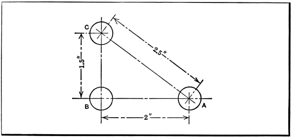
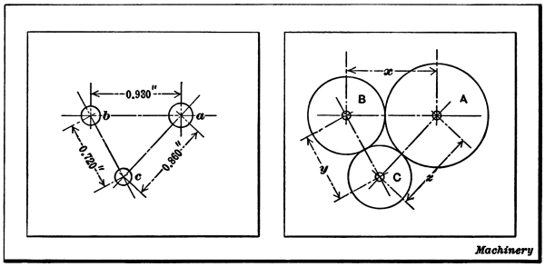
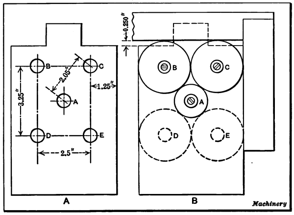
caliper. For example, if holes were to be bored in a jig-plate, as
shown in Fig. 1, assuming that hole A were finished
first, the platen would then be moved two inches, as shown by the feed dial;
hole B would then be bored slightly under size. Plugs should then be
accurately fitted to these holes, having projecting ends, preferably of
the same size. By measuring from one of these plugs to the other with a
vernier or micrometer caliper, the center distance between them can be
accurately determined, allowance being made, of course, for the radii
of each plug. If this distance is incorrect, the work can be adjusted
before finishing B to size, by using the feed-screw dial. After
hole B is finished, the knee could be dropped 1.5 inch, as shown
by the vertical feed dial, and hole C bored slightly under size;
then by the use of plugs, as before, the location of this hole could be
tested by measuring center distances between C-B and C-A.
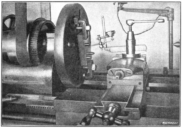
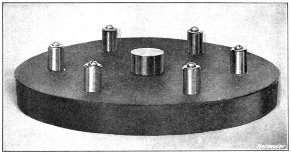
An example of work requiring the micrometer-and-plug test, is shown set
up in the milling machine in Fig. 25. The large circular
plate shown has a central hole and it was necessary to bore the outer holes in
correct relation with the center hole within a limit of 0.0005 inch.
The center hole was first bored and reamed to size; then an accurately
fitting plug was inserted and the distances to all the other holes
were checked by measuring from this plug. This method of testing with
the plugs is intended to prevent errors which might occur because of
wear in the feed-screws or nuts, that would cause the graduated dials
to give an incorrect reading. On some jig work, sufficient accuracy
could be obtained by using the feed-screw dials alone, that is, without
testing with the plugs, in which case the accuracy would naturally
depend largely on the condition of the machine.
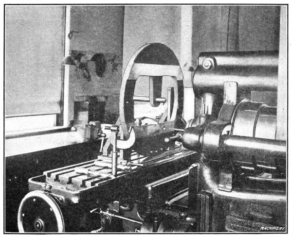
Fig. 25. Example of Precision
Boring on Milling Machine
A method that is a modification of the one in which plugs are used
to test the center distance is as follows: All the holes are first
drilled with suitable allowance for boring, the location being obtained
directly by the feed-screw dials. A special boring-tool, the end of
which is ground true with the shank, is then inserted in the spindle
and the first hole, as at A in Fig. 1 is finished,
after which the platen is adjusted for hole B by using the dial as before.
A close-fitting plug is then inserted in hole A and the accuracy
of the setting is obtained by measuring the distance between this plug
and the end of the boring-tool, which is a combination tool and test
plug. In a similar manner, the tool is moved from one position to
another, and, as all the holes have been previously drilled, all are
bored without removing the tool from the spindle.
Another modification of the micrometer-and-plug method is illustrated
in Figs. 26 and 27.
It is assumed that the plate to be bored is finished on the edges, and
that it is fastened to an angle-plate, which is secured to the table
of the milling machine and set square with the spindle. A piece of
cold-rolled steel or brass is first fastened in the chuck (which is
mounted on the spindle) and turned off to any diameter. This diameter
should preferably be an even number of thousandths, to make the
calculations which are to follow easier. The turning can be done either
by holding the tool in the milling machine vise, or by securing it to
the table with clamps. In either case, the tool should be located near
the end of the table, so as to be out of the way when not in use.
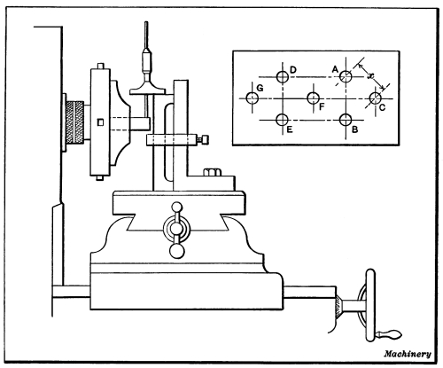
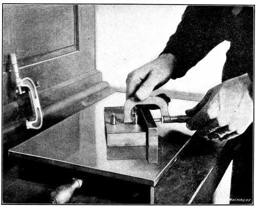
Fig. 26. Obtaining Vertical
Adjustment by Means of
Depth Gage and turned Plug in Chuck
After the piece in the chuck is trued, the table and knee are adjusted
until the center of the spindle is in alignment with the center of the
first hole to be machined. This setting of the jig-plate is effected
by measuring with a micrometer depth gage from the top and sides of
the work, to the turned plug, as illustrated in Fig. 26.
When taking these measurements, the radius of the plug in the chuck is, of course,
deducted. When the plate is set the plug is removed from the chuck and
the first hole drilled and bored or reamed to its proper size. We shall
assume that the holes are to be located as shown by the detail view,
Fig. 26, and that hole A is the first one bored.
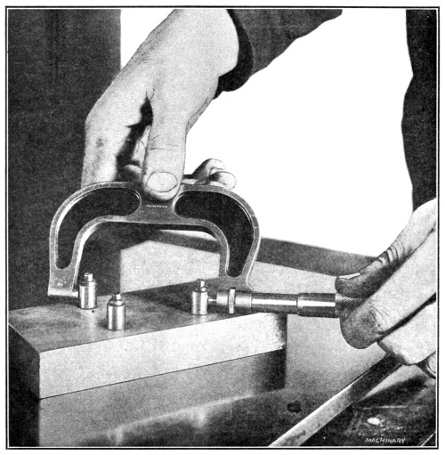
The plug is then again inserted in the chuck and trued with the tool, after which
it is set opposite the place where the second hole B is to be
bored; this is done by inserting an accurately fitting plug in hole
A and measuring from this plug to the turned piece in the chuck,
with an outside micrometer as indicated in Fig. 27.
Allowance is, of course, again made for the radii of the two plugs. The
horizontal measurement can be taken from the side of the work with a
depth gage as before. The plug is then removed and the hole drilled and
bored to the proper size. The plug is again inserted in the chuck and
turned true; the table is then moved vertically to a position midway
between A and B, and then horizontally to the proper
position for hole C, as indicated by the depth gage from the
side of the work. The location can be verified by measuring the center
distances x with the micrometer. In a similar manner holes
D, E, F and G are accurately located.
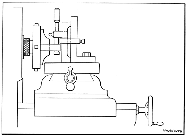
Fig. 27. Adjusting for
Center-to-center Distance
by use of Plugs and Micrometer
If the proper allowances are made for the variation in the size of the
plug, which, of course, is made smaller each time it is trued, and if
no mistakes are made in the calculations, this method is very accurate.
Care should be taken to have the gibs on all sides fairly tight at the
beginning, and these should not be tightened after each consecutive
alignment, as this generally throws the work out a few thousandths. If
the reductions in the size of the plug, each time it is turned, are
confusing, new plugs can be used each time a test is made, or the end
of the original plug can be cut off so that it can be turned to the
same diameter for every test. If the center distances x are not
given, it is, of course, far more convenient to make all the geometric
calculations before starting to work.
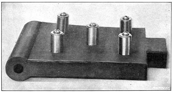
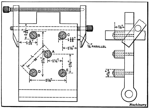
The use of the button method as applied to the milling machine, is
illustrated in Fig. 28, where a plain jig-plate
is shown set up for boring. The jig, with buttons B accurately
located in positions corresponding to the holes to be bored, is clamped
to the angle-plate A that is set at right angles to the spindle.
Inserted in the spindle there is a plug P, the end of which is
ground to the exact size of the indicating buttons. A sliding sleeve
S is accurately fitted to this plug and when the work is to be
set for boring a hole, the table and knee of the machine are adjusted
until the sleeve S will pass over the button representing
the location of the hole, which brings the button and spindle into
alignment. When setting the button in alignment, all lost motion or
backlash should be taken up in the feed-screws. For instance, if the
button on the jig should be a little higher than the plug in the
spindle, do not lower the knee until the bushing slips over the button,
but lower the knee more than is required and then raise it until the
bushing will pass over the button. This same rule should be followed
for longitudinal adjustments.
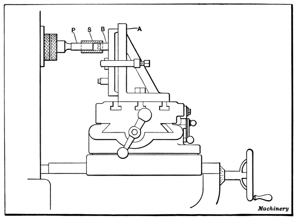
Fig. 28. Accurate Method
of Aligning Spindle with Button on Jig-Plate
After the button is set by this method, it is removed and the plug in
the spindle is replaced by a drill and then by a boring-tool or reamer
for finishing the hole to size. In a similar manner the work is set
for the remaining holes. The plug P for the spindle must be
accurately made so that the outer end is concentric with the shank,
and the latter should always be inserted in the spindle in the same
relative position. With a reasonable degree of care, work can be set
with considerable precision by this method, providing, of course, the
buttons are properly set.
Some toolmakers use, instead of the plug and sleeve referred to, a test
indicator for setting the buttons concentric with the machine spindle.
This indicator is attached to and revolves with the spindle, while the
point is brought into contact with the button to be set. The difficulty
of seeing the pointer as it turns is a disadvantage, but with care
accurate results can be obtained.
Another method which can at times be employed for accurately
locating a jig-plate in different positions on an angle-plate, is shown
in Fig. 29. The angle-plate is, of course, set at
right angles to the spindle and depth gages and size blocks are used
for measuring directly the amount of adjustment. Both the angle-plate
and work should have finished surfaces on two sides at right angles
to each other, from which measurements can be taken. After the first
hole has been bored, the plate is adjusted the required distance both
horizontally and vertically, by using micrometer depth gages, which
should preferably be clamped to the angle-plate. If the capacity of the
gages is exceeded, measurements may be taken by using standard size
blocks in conjunction with the depth gages.
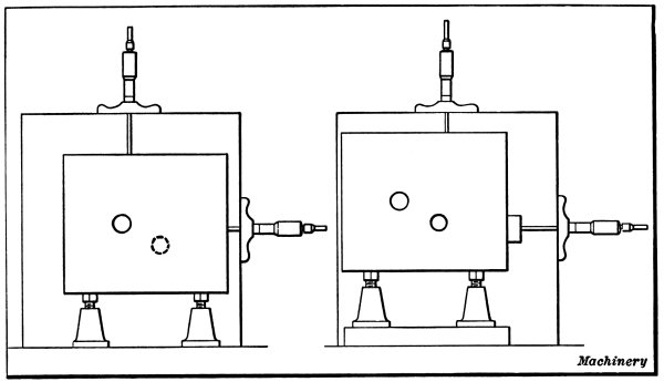
Fig. 29. Locating Work from
Edges of Angle-Plate
by means of Depth Gages and Size Blocks
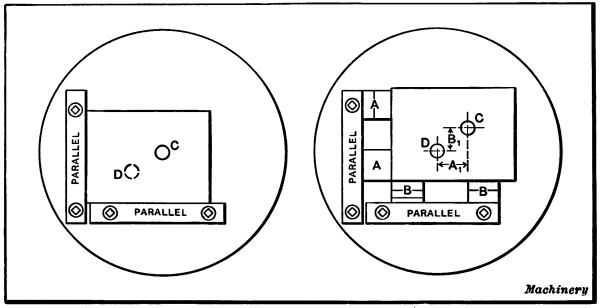
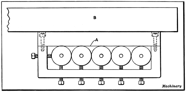
It is frequently necessary to bore holes in cast jig-plates or machine
parts, which either have irregularly shaped or unfinished edges. A good
method of locating such work is illustrated in Fig. 30.
The part to be bored is attached to an auxiliary plate A which should
have parallel sides and at least two edges which are straight and at right
angles to each other. This auxiliary plate with the work, is clamped
against an accurate angle-plate B, which should be set square
with the axis of the machine spindle. A parallel strip is bolted to the
angle-plate and the inner edge is set square with the machine table.
After the first hole is bored, the work is located for boring the other
to the edge of the auxiliary plate, and horizontal measurements
y between the parallel and the plate. These measurements,
if quite large, might be taken with micrometer gages, whereas, for
comparatively small adjustments, size blocks might be more convenient.
When a vernier height gage is available, it can often be used to
advantage for setting work preparatory to boring in a milling machine.
One advantage of this method is that it requires little in the way of
special equipment. The work is mounted on an angle-plate or directly
on the platen, depending on its form, and at one end an angle-plate is
set up with its face parallel to the spindle. An accurately finished
plug is inserted in the spindle and this plug is set vertically from
the platen and horizontally from the end angle-plate, by measuring with
the vernier height gage. After the plug is set for each hole, it is, of
course, removed and the hole drilled and bored or reamed.
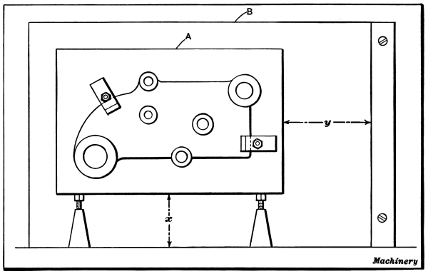
Fig. 30. Method of Holding and
Locating Casting
of Irregular Shape, for Boring Holes
The way the plug and height gage is used is clearly illustrated in
Figs. 31 and 32.
The work, in this particular case, is a small jig. This is clamped
directly to the machine table and at one end an angle-plate is also
bolted to the table. This angle-plate is first set parallel with
the traverse of the saddle or in line with the machine spindle. To
secure this alignment, an arbor is inserted in the spindle and a test
indicator is clamped to it by gripping the indicator between bushings
placed on the arbor. The table is then moved longitudinally until the
contact point of the indicator is against the surface plate; then by
traversing the saddle crosswise, any lack of parallelism between the
surface of the angle-plate and the line of saddle traverse will be
shown by the indicator.
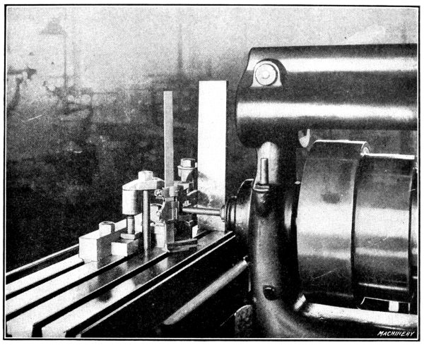
Fig. 31. Making a Vertical Adjustment
by Measuring to Ground Plug in Spindle
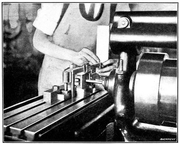
Fig. 32. Making a Horizontal Adjustment
by measuring from Angle-Plate to Ground Plug
When the work is to be adjusted horizontally, the vernier height gage
is used as shown in Fig. 32, the base of the gage resting
on the angle-plate and the measurement being taken to an accurately ground and
lapped plug in the spindle. For vertical adjustments, the measurements
are taken between this ground plug and the machine platen as in Fig. 31.
The problem of accurately locating holes to be bored on the milling
machine has received much attention, and the method generally used when
accuracy has been required is the button method, which was previously
described. So much time is required for doing the work by this method,
however, that numerous efforts have been made to obtain equally good
results in other ways.
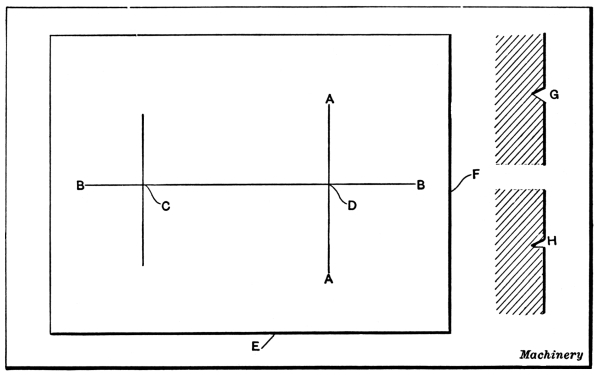
Fig. 33. Diagram Illustrating Rapid
but Accurate Method of
Locating Holes to be bored on Milling Machine
The increasing demand for rapidity combined with accuracy and a minimum
liability of error, led to the development of the system described in
the following: A center-punch mark takes the place of the button, from
which to indicate the work into the proper position for boring. The
fundamental principle involved is to lay out, accurately, two lines
at right angles to each other, and correctly center-punch the point
where they intersect. With proper care, lines may be drawn with a
vernier height gage at right angles, with extreme accuracy, the chief
difficulty being to accurately center the lines where they cross. For
semi-accurate work this may be done with a common center-punch but
where extreme accuracy is required this method is not applicable, as
the average man is incapable of marking the point of intersection
accurately.
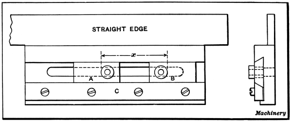
The diagram, Fig. 33, illustrates, in a simple way, the
procedure adopted in laying out work by this system. The base E is in
contact with a surface plate while the line BB is drawn with a
height gage; then with side F on the plate the line AA is
drawn. It will be seen that these lines will be at right angles to each
other, if the bases E and F are square. Work done by this
method must have two working surfaces or base lines, and these must
be at right angles to each other. There is no difficulty in drawing
the locating lines AA and BB correctly, either with a
vernier height gage or with a special micrometer gage reading to 0.0001
inch, the only difficult element being to accurately center-punch the
lines where they intersect as at D. It is assumed that two holes
are to be bored, so that the intersection at C would also be
center-punched.
The scriber point of the height gage should be ground so that it
will make a V-shaped line, as shown by the enlarged sketch G,
rather than one which would resemble a saw-tooth, as at H, if a
cross-section of it were examined with a microscope. This is important
because when the lines are V-shaped, an accurate point of intersection
is obtained.
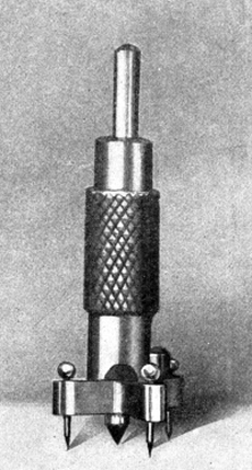
Fig. 34. Center Locating Punch
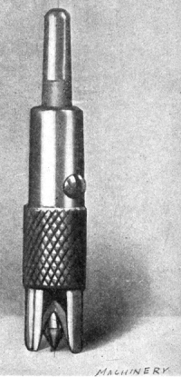
Fig. 35. Center Enlarging Punch
As it is quite or almost impossible to accurately center-punch the
intersection of even two correctly drawn lines, by ordinary means, the
punch shown in Figs. 34 and 36
was designed and an extended experience with it on a very high grade
of work has demonstrated its value for the purpose. It consists
essentially of a small center-punch O (Fig.
36) held in vertical position by a holder P which is knurled
to facilitate handling. Great care should be exercised in making this
tool to have the body of the punch straight, and to have it stand at
right angles to the surface to be operated upon, for the slightest
inclination will cause the finished hole to be incorrect, no matter how
carefully the lines are drawn. The 60-degree point must be ground true
with the axis. The holder for the punch stands on three legs, located
as indicated, and ground accurately to a taper fit in the holder, where
they are secured by watch screws bearing on their tops. The lower ends
are hardened, and terminate in an angular point of 55 degrees (the
point of the vernier scriber being 60 degrees). The edges are sharp,
and slightly rounded at the ends, so that the legs will slide along
a line smoothly. The points V and U (Fig. 36)
have edges that are in line with each other, while the point T has an edge
at right angles to the other two. The center of the punch is located at
equal distances from all the legs, and is held off the work normally by
a leather friction acted upon by a set-screw in the side of holder P.
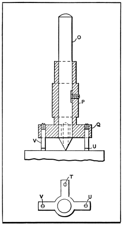
Fig. 36. Section of
Center Locating Punch
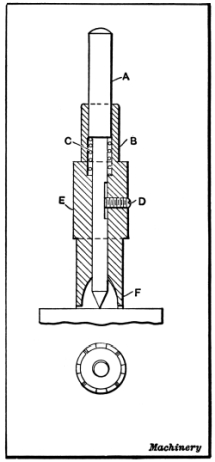
Fig. 37. Section of
Center Enlarging Punch
If this tool is placed upon lines of the form shown at G, Fig. 33,
the legs V and U may be slid along horizontal line
B-B, Fig. 33, until the sharp edge of leg T
drops into line A-A. When this occurs the punch O is lightly tapped
with a hammer, and the resulting mark will be accurately located in the
center of the intersection of the lines. It is good practice to make
the work very smooth before drawing the lines, and after laying them
out, to stone them so as to remove the slight burr raised in drawing
them. A drop of oil is then rubbed into the lines, and the surplus
wiped off. This procedure permits points V and U to run
very smoothly along the line, and the burr having been removed, the
edge of leg T drops into the line very readily with a slight
click. As it is not advisable to strike punch O more than a
very light blow, it marks the work but slightly, and a more distinct
indentation is made with the follower punch shown in Figs.
35 and 37.
This punch is made like the previous one, so that it will stand at
right angles to the work. The sectional view (Fig. 37) shows
the punch A supported by the holder E which has four legs cut away
on the sides so that the point of the punch may be seen. When this
punch is in position, it is struck a sufficiently heavy blow to make a
distinctly visible mark. The work is now ready to be placed upon the
work table of the milling machine, and indicated for boring the holes,
an indicator being used in the milling machine spindle.
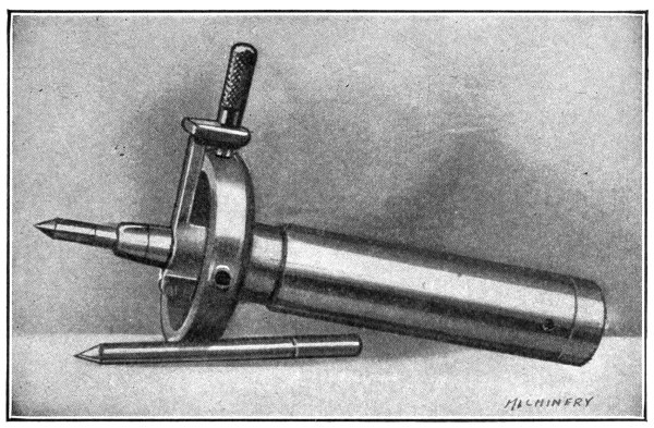
Fig. 38. Indicator used for
Aligning Punch Marks with Machine Spindle
An indicator which has been found especially valuable for this purpose
is shown in Figs. 38 and 39.
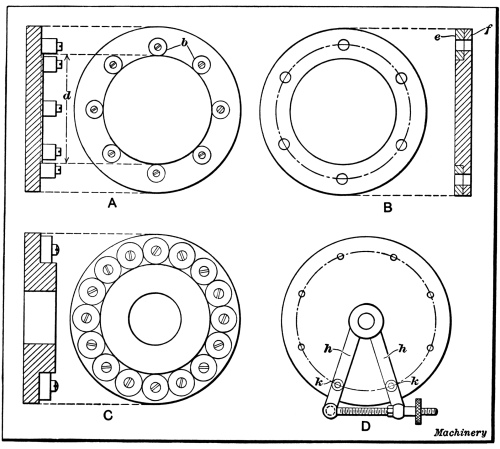
It is of the concentric centering type, and with it the work is
brought concentric with the axis of the spindle. The arbor I
is provided with a threaded nose on which disk D is screwed.
This disk has four holes in its rim, equally-spaced from each other.
Hardened, ground, and lapped bushings b are put into these
holes to receive plug A which is made a gage-fit both in these
holes and in hole B in the outer end of sector C. This
sector is held by a split sleeve to the barrel L which carries
the 60-degree centering-rod K that comes into contact with the
work to be bored. The spherical base of barrel L fits into a
corresponding concave seat in the nose of the arbor at H, and
is held in place by a spring E which connects at one end to the
cylindrical stud in the base of the barrel, and at the other to the
axial rod M by which it and the other connecting parts may be
drawn into place, and held by the headless set-screw J, bearing
on a flat spot on the tang end of the rod.
Now, if plug A is removed from bushing b the point of the
centering-rod K may be made to describe a circle. At some point
within this circle is located the center-punch mark on the work to be
bored. The holes in the rim of the faceplate all being exactly the
same distance from an axial line through both the arbor I and
centering-rod K, it follows that the center mark on the work
must be so located by horizontal and vertical movements of the work
table that pin A may be freely entered in all the four holes in
the rim of disk D. When that occurs, the center coincides with
the axis of the spindle.
The point of the center-punch A (Fig. 37) should
have an angle slightly greater than the angle on the centering-rod K, as it
is impossible to locate the work in the preliminary trials so that the
center of the work will be coincident with the axis of the spindle, and
unless the precaution mentioned is taken, the true center on the work
is liable to be drawn from its proper location when trying to bring the
work into such a position that the plug will enter all the holes in the
disk. As the work being operated on is brought nearer to the proper
location by the movements of the milling machine table, spring G
will be compressed, the center rod sliding back into barrel L.
This spring is made so that it will hold the center against the work
firmly, but without interfering with the free rotation of the sector
C around disk D. When the work is located so that the
plug enters the holes, the gibs of the machine should be tightened up
and the plug tried once more, to make sure that the knee of the machine
has not moved sufficiently to cause the work on the table to be out of
line. The work table is now clamped to prevent accidental horizontal
shifting, and the work is drilled and bored.
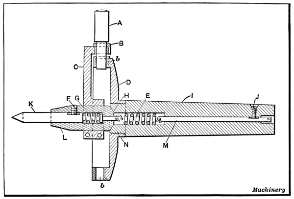
Fig. 39. Sectional View of
Indicator shown in Fig. 38
In using this indicator the milling machine spindle is not rotated
together with arbor I, only the sector being turned around the
disk. The tool is set, however, in the beginning, so that the axes of
two of the bushings b are at right angles to the horizontal
plane of the machine table, while the axes of the other holes in the
disk are parallel with the top of the work table. The centering-rods
are made interchangeable and of various lengths, to reach more or less
accessible centers. Fig. 38 shows the indicator
with one of the long center-rods in the foreground.
The only part of the milling machine on which dependence must be placed
for accuracy is the hole in the spindle, and this is less liable to get
out of truth, from wear such as would impair the accuracy, than are the
knee, table, or micrometer screws. The only moving part is the sector,
and this, being light, is very sensitive.
A series of 24 holes was laid out and bored in one and one-half day by
the method described in the foregoing. Measurements across accurately
lapped plugs in the holes, showed the greatest deviation from truth
to be 0.0002 inch, and running from that to accuracy so great that no
error was measurable. This same work with buttons would have required
considerably more time.
Machinery is the leading journal in the machine-building
field and meets the requirements of the mechanical engineer, superintendent,
designer, toolmaker and machinist, as no other journal does. Machinery deals exclusively with machine design,
tool design, machine construction, shop practice, shop systems and shop
management. The reading matter in Machinery
is written by practical men and edited by mechanical men of long
practical training.
Each number of Machinery contains a
variety of articles on machine shop practice. These articles include
carefully prepared descriptions of manufacturing methods and current
mechanical developments. Shop systems and shop managements are ably
handled by the foremost writers. Every number contains the most
extensive and complete record published by any journal, or in any
form, of new machinery and tools and accessories for the machine shop.
A special department is devoted to “Letters on Practical Subjects,”
to which practical mechanics contribute their experiences. There is
a department of Shop Kinks—brief, concise little contributions which
contain ideas of value to the man in the shop or at the drafting table.
The mechanical engineer, machine designer and draftsman are also
well provided for in Machinery. Every number
contains articles on the theory and practice of machine design, on the
properties of materials, and on labor-saving methods and systems. There
are reviews of research work in the mechanical field, and valuable
results of carefully made experiments are recorded.
The supremacy of Machinery in the
mechanical field is due to the care with which all matter offered for
publication in its pages is scrutinized. Only the best of the
material offered by mechanical writers is published, and, as a result,
its pages contain the most authoritative, practical and up-to-date
mechanical information.
Machinery, 140-148 Lafayette Street,
New York City
51 and 52, CHANCERY LANE, LONDON, W. C.
Heat-Treatment of Steel
is one of a series of high-class authoritative, attractive
and well-bound books published by Machinery.
The strongest claim that can be made for these books is that they have
all the characteristics of Machinery itself.
These books cover comprehensively, and in a thoroughly practical
manner, the most important subjects in the metal-working field.
Each book comprises about 300 pages, printed on high-grade paper, with
engravings of the same superior type that has made Machinery
distinctive in its field.
The price of each book is $2.50. Special combination offers on a
monthly payment plan will be sent upon request.
Machinery 140-148 Lafayette St.
New York City
51 and 52, CHANCERY LANE, LONDON, W. C.
The Five New Books
Brought Out by Machinery
SPUR AND BEVEL GEARING
A treatise on the principles, dimensions, calculation, design and
strength of spur and bevel gearing, together with chapters on special
tooth forms and methods of cutting gear teeth.
SPIRAL AND WORM GEARING
A treatise on the principles, dimensions, calculation and design of
spiral and worm gearing, together with chapters on the methods of
cutting the teeth in these types of gears.
TURNING AND BORING
By Franklin D. Jones Associate Editor
of Machinery
A specialized treatise for machinists, students in industrial and
engineering schools, and apprentices on turning and boring methods,
including modern practice with engine lathes, turret lathes, vertical
and horizontal boring machines.
PLANING AND MILLING
By Franklin D. Jones Associate Editor
of Machinery
A treatise on the use of planers, shapers, slotters and various types
of horizontal and vertical milling machines and their attachments.
HEAT-TREATMENT OF STEEL
A comprehensive treatise on the hardening, tempering, annealing and
case-hardening of various kinds of steel, including high-speed,
high-carbon, alloy and low-carbon steels, together with chapters on
heat-treating furnaces and on hardness testing.
Price of each book $2.50. Special combination
offers on a monthly payment plan will be sent upon request.
Machinery 140-148 Lafayette St.
New York City
51 and 52, CHANCERY LANE, LONDON, W. C.