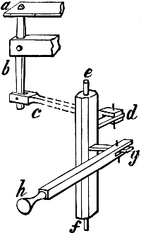
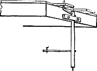
TWO-MANUAL ORGANS.
This treatise must not close without some reference
to organ work of a more advanced kind than that
which we have taken as the groundwork or medium
of our hints on this subject.
Some of our readers may very naturally wish to
understand the construction of an organ with two
or more manuals and a pedal with separate pipes;
and this implies a description of coupling movements
and of the swell-box and its appliances.
In the first place, let us remark that as the swell-organ
is a modern invention, innumerable examples
of organs with more than one manual and with
numerous stops, but entirely without the swell,
were in existence in England up to a recent period,
and are still to be found in every part of the continent
of Europe. A great number of the most
renowned organs of Germany and of Holland,
organs furnished with four manuals and an
immense aggregate of pipes, are without the swell
to this day.
This is not the place to discuss the question
whether the introduction of the swell, as the second
division of an organ with only two manuals, has
been an unmixed advantage, and whether it has or
has not tended to raise the standard of organ music
and organ-playing in England. But some few
musicians may agree with the present writer that
it is quite possible to sacrifice sound principles of
organ-building to the prevailing worship of the
pretty and fanciful effects of the swell, and may
even go so far as to regret, with him, the supersession
of the old "choir organ," with its sweet tranquil
tone and quiet cheerful brightness. We ourselves
make no secret of our wish that in the design
and erection of organs with only two manuals, the
second manual should act upon a choir organ,
while the swell should be reserved for those instruments
in which a third manual is introduced.
But we are quite aware that these views will be
received with derision by a great majority of
persons, who have become accustomed to the constant
use of the swell and of the pedal Bourdons
which characterizes the playing of many English
organists on modern English organs.
Quite apart, however, from these views, which
must be taken for what they are worth, there are
reasons why any reader, resolving from the first
to construct a small organ with two manuals for
chamber use, will do well to resist the temptation
to introduce the swell. These reasons will become
apparent if we sketch out one or two plans for such
chamber organs, and we should only occupy space
needlessly by stating them in advance.
Resolving, then, to indulge ourselves with two
manuals, but compelled to be economical of space
and of pecuniary outlay, we decide at once to plant
all the pipes, belonging to both manuals alike,
upon a single sound-board, and by the system of
borrowing to avoid the reduplication of large pipes
in the bass octave.
To our original design of five stops on a single
manual, let us suppose that we have added three,
played by a second key-board. We must assume
that the five stops belonging to the first manual (the
lower), will be all throughout, and may be something
like this, viz.: an open Diapason with wood
bass octave; a Clarabella, with stopped bass octave;
a Principal, Flute, and 2-feet stop as before. Then
the second or upper manual should have some such
stops as these: Stopped Diapason, the bass octave
borrowed from that of the Clarabella; Dulciana to
Tenor C; Gems-horn, or some other light 4-feet
stop, the bass octave borrowed from that of the
Flute or Principal.
As the sound-board will have two grooves for
each note throughout its whole extent, namely
108 grooves if the manuals are of the usual compass,
its length might be unwieldy and inconvenient,
ill adapted to the size of ordinary rooms.
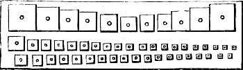
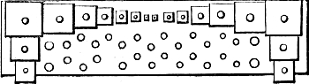
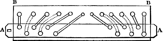
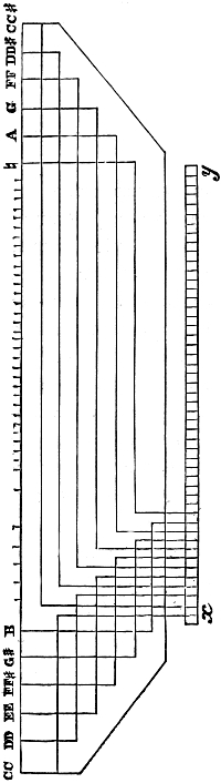
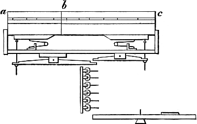
We must strongly recommend, therefore, that the
arrangement shown in Fig. 39 (see p. 112) be
adopted. On the front portion, b c, containing
eighty-four grooves, and carrying eight sliders, all
the stops from Tenor C to top F may be planted.
On the back portion, a b, which will have twenty-four
grooves only, all the bass pipes will be placed,
unless, indeed, we assume that the large open
8-feet pipes are conveyanced off. This back portion
will carry one slider for this open bass, one for
each of the 4-feet and 2-feet stops, and two pairs of
twin sliders, placed close together, for the borrowed
stopped bass and borrowed 4-feet bass.
Our readers may feel confidence in the directions
now given if we say that we are describing
an organ built by ourselves and now in our possession.[3]
The sound-board, admitting of eighty-four
grooves in its front division, is 5 feet 3 inches
long, and its seven sliders (we have no stopped
Flute), with the bearers, occupy a width of
16 inches; but the 4-feet octave of the Open Diapason,
and six pipes of the Dulciana, are brought
into sight as a "speaking front," and therefore fill
no space on the board itself. The back part of the
board, with four sliders (two of them twin), has
also a width of about 16 inches, our large open
wood bass being on a board at a lower level, as
in Fig. 10. Thus the whole board, carrying practically
eight stops (one of our stops is of two ranks,
viz. a Twelfth and Fifteenth) throughout, is 5 feet
3 inches long and 32 inches wide.
We hope we have said quite enough in former
pages of roller boards and backfalls to enable any
intelligent reader to devise for himself the double
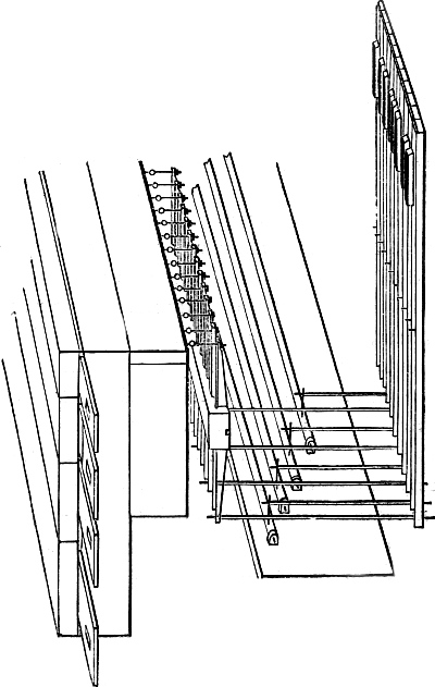
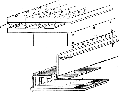
action of such an organ. An inspection of Figs.
37, 38, and 39 may suggest ideas to him. An
essential point is that everything should be within
reach if defects should require attention; and access
to the back as well as to the front of such an organ
is indispensable.
A word about the borrowing. It is plainly not
enough to groove the two channels of each note together
in the bass, as in the case of a single manual.
If this were done the wind would fill the whole of
the two channels upon lowering a key in the bass
octave of either manual, and all the stops of which
the sliders happened to be drawn at the time would
speak together. Thus our purpose of borrowing
one particular stop would be defeated. We must
effect it thus: the twin sliders will be closely contiguous,
and will only be separated by short pins
of brass or iron let into the table, to prevent the
friction of actual contact. Thus the two holes
which are to be brought into connection are near
to each other, and the communicating groove will
be short. If this is cut in the upper board itself it
must be neatly executed, and the bottom of the
groove must be level and smooth. Over each of
the two holes within the groove so cut must
be placed a valve, consisting of a small piece
of pallet leather covering the hole completely,
and rising with complete freedom by a hinge
along its edge, like the clacks of the bellows.
Each pair of holes being furnished with these
valves the grooves are roofed in and the pipes
planted, as described in earlier pages of this book.
On lowering one of the keys the wind will affect the
borrowed pipe only, since the little valve will stop
the twin hole and prevent the flow of air through
it into the channel. If the key corresponding to
the same note be pressed down on both manuals,
then both the little valves will be blown open by the
wind; but if all the channels, grooves, and holes
be of ample size, so that there is no throttling of the
wind, the speech of the pipe will be entirely unaltered,
since it will only receive a given quantity
of wind through the perforation in its foot, and this
wind will be of the same weight or pressure as
before.
The borrowing grooves may be cut in the under
surface of a separate board, which will then form
a roof or cover to the several pairs of valves
arranged over the holes on the upper surface of
the sound-board itself. Or this borrowing-board
may be put together with bars, cheeks, and an
upper table like a light sound-board. The essential
point is that all the openings be of ample size,
and that the valves fly open widely at the slightest
breath of wind, and close the holes as promptly
when the wind is withdrawn. If due attention is
given to all this no failure need be anticipated
with the borrowed basses.
We have proposed the lower key-board as
"Manual I.," in accordance with the German usage,
and because that arrangement will facilitate some
of our mechanism, for instance, the pulling down
by the pedals of the bass notes. But lovers of
old English organs, among whom we must reckon
ourselves, may prefer to make Manual I. the upper
manual of the two. A beautiful instrument of this
class, built by the late J. C. Bishop, stands in the
chapel of Jesus College, Cambridge, and was the
gift of an accomplished amateur, whose performances
on it are still remembered.[4] The same
gentleman was the possessor of a chamber organ
of exquisite tone by Bernhard Schmidt, of such
remarkable composition that it merits description
here. The lower manual, or Choir, had three stops,
an Open Diapason, a Stopped Diapason, and a
Principal, all made of oak, and of extreme delicacy
and beauty. The upper manual, or Great, had
likewise three stops, all metal, namely, Stopped
Flute, Fifteenth, and Mixture of two ranks (19th
and 22nd in the bass, 12th and 17th in the treble).
The Stopped Diapason could also be played upon
this manual by borrowing. A coupler united the
lower to the upper at pleasure, and then the "Full
Organ" was produced upon the upper manual
with an astonishing effect of sprightliness and
brightness. Such an organ as this, with some
changes (its key-boards were very antiquated, and
so high from the ground that the player was
perforce erect), might afford an admirable model
for imitation.
Let us add that if pedal notes of 16-feet tone are
added to an organ of this class, namely of two
manuals, Great and Choir, only twelve large pipes
will be necessary, even though the compass of the
pedal-board be of thirty notes complete. This
great economy of space and outlay will be secured
thus: 1st, by making the pedals pull down on the
chief manual throughout their whole extent as
before; 2nd, by adapting the twelve deep pipes to
the lower octave of the pedals, and by making
their upper octave and a half pull down upon the
lowest keys of the second manual. A moment's
reflection will show that the 16-feet tone is thus
obtained throughout the whole compass, and no
inconvenience whatever will ensue to the player.
The mode of introducing the large bass pipes,
and of pulling down as above, will be described
before we conclude this work.
Still desiring to erect a chamber organ, and,
therefore, to be chary of space and cost, we must
now show how the swell-box may be included in
our design.
We shall suppose that the organ has been
completed so far as the lower manual is concerned,
with all that pertains to it, according to the rules
which have now been given at length and in
detail. In laying it out we must assume that care
has been taken to give increased size to the
bellows, and to arrange the frame for the reception
of a second sound-board.
We feel it due as well to our readers as to ourselves
to explain that we confine ourselves in all
that follows to a description of work done by ourselves
in our own workshop.
We shall place only three stops in our swell,
which will have a compass of forty-two notes, from
Tenor C to top f. The stops will be a Diapason in
wood, partly stopped, and the rest open; a Flute
of 4-feet tone in wood, open throughout; and a
Gamba of reedy quality, in metal, of 8-feet
pitch, but only descending to Fid. G., 3 feet, the
remaining notes being grooved to No. 1. This
curtailment is greatly to be regretted, but such
imperfections are among the objections to the
swell-box, which would assume dimensions inconsistent
with a chamber organ if an attempt were
made to give full compass to its 8-feet stops.
The sound-board for these three stops will be
only 2 feet 9 inches in length, and 1 foot in width;
but the upper boards must have an ample margin
or surplus in both directions to afford support for
the box which will rest upon them.
This box must be made of thick stuff, say 1½ inch
deal; it will therefore be very heavy, and care
must be taken to provide for its weight in planning
the frame. It should be put together with screws,
so that it can easily be taken to pieces for transit,
and it is usual to line the whole of its interior with
sheets of thick brown paper, applied with glue.
It will be very convenient, if access can be had to
the back of the organ, to fit the back of the box
with hinged doors, or to make the back removable
like a shutter; in this case the pipes should be
planted so as to present themselves readily to the
tuner. If access to the back cannot be had, then
a space is inevitable in the middle of the organ
for a passage-board, on which the tuner may
stand, or at least place his foot, while he removes
the front shades in order to reach the pipes
planted accordingly. In the swell-boxes of church
organs the sides of the box are generally fitted as
doors; then, the pipes being planted with the
tallest in the centre, diminishing in height to each
end, half of them can be tuned at one operation.
When the pipes are thus planted, the top of the
box will slope towards each side from a central
ridge, like the roof of a house.
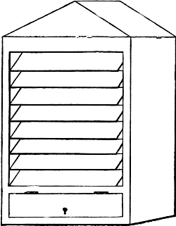
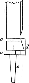
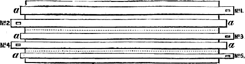
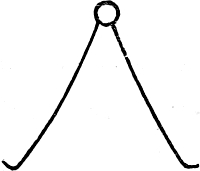
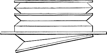
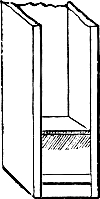
Fig. 50.
We cannot doubt that many of our readers have
had, or may have, opportunities of examining the
construction of the shutters or shades of a swell-box.
We have sketched it, however, in Fig. 50.
The shades are 6 inches in breadth, and of the
same thickness as the rest of the box, and each
shade turns on pins let into the ends of it at a
distance of 2 inches from its upper edge. These
pins work in notches cut in the cheeks of the box,
so formed that any shade may be easily lifted
out and replaced. The edges of the shades are
bevelled to half a right angle so that they
overlap when closed, and the bevelled surfaces
are faced with leather or cloth to
shut in the sound more effectually.

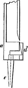
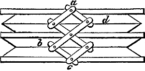
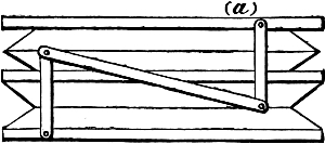
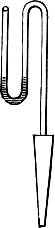
Fig. 51.
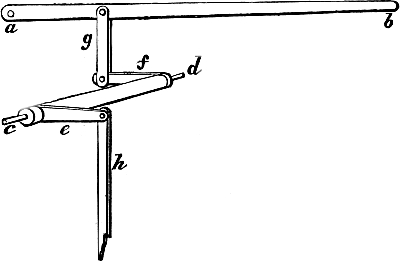
The mode of opening the shades, and
so producing a crescendo, is shown in Fig.
51. a, b, c are arms of oak, morticed into
the shades at the level of the pins, viz.
2 inches from the upper line; d e is a long
rod or tringle of wood, connecting all these
arms by pins passing through them and
itself. It is evident that by drawing up
this rod at its top, or by pushing it up
from below, we shall open all the shades
at once, and as they are hung on axes
placed at one-third of their breadth, they
will close by their own weight when released.
The leverage by which this movement is brought
under the control of the player may be safely left
to the inventive powers of the reader. It is usual
to give promptness to the return of the swell-pedal,
and therefore to the closing of the shades, by attaching
a strong spiral spring to the pedal, and to
some firm point in the frame.
As the swell-box is at the back of the instrument,
its key-action will have to pass or cross that
of the Great organ. The way in which this will be
effected must depend a little upon circumstances—for
instance, upon the length of the key-tails in the
two manuals. If the swell manual acts by squares
and trackers, while the Great has backfalls and
stickers, the small trackers, being thin ribands of
wood, can be easily made to pass between the
Great stickers. Or if the swell-keys act on backfalls,
these backfalls may be thinned down behind
the line of key-tails, so as to allow the stickers of
the lower manual to pass between them. This
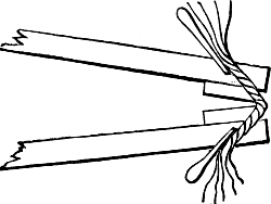
may be understood from Fig. 52, though that figure
refers to another subject. The worst plan of all is
to make the lower stickers pass through holes or
mortices in the upper key-tails, since this prevents
the removal of the upper key-board without a disturbance
of the whole action.
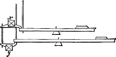
Fig. 52.
We believe that these constructive details contain
in themselves the grounds on which we based
our advice to hesitate before including a swell-box
in the design for a small chamber organ. It has
been made apparent that it brings with it a considerable
increase of bulk, weight, and complication,
and that it cannot possess the full compass.
We must add that if the bellows are worked by the
foot, the use of the swell-pedal at the same time is
of course impossible.
The large swells of church organs owe their
grandeur of effect to their reed-stops; the
trumpet, of which the oboe is a soft echo and our
little gamba a faint and humble imitation, the
horn or cornopean, and the double trumpet or
bassoon, a stop of 16-feet pitch. All reed-stops
are quite beyond the range of amateur construction,
and each of the above will cost about £25 if
purchased from a good maker and made of first-class
material. Beautiful as such stops are when
made and voiced by highly-skilled workmen, they
may easily be unpleasing and even offensive.
Let us add that the twelve notes of the swell
manual, below Tenor C, may be made to act on
the lower manual by a "choir coupler" (see next
section, and Fig. 52); or, if there is a complete
pedal Sub-bass or Bourdon of twenty-five or more
notes, the silent keys of the swell manual may
borrow the pedal notes from CC, 8-feet tone
upwards. An easy mechanical movement of
squares and trackers will effect this.
Two manuals imply couplers, though we greatly
regret the incessant use of these contrivances by
modern organists.
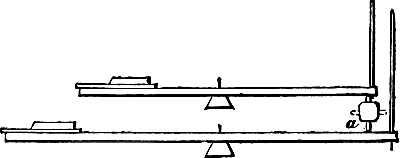
Fig. 53.
We shall treat, very briefly, of couplers under
three heads, viz. the coupling of—
- (a) Upper Manual to Lower Manual.
- (b) Lower Manual to Upper Manual.
- (c) Manuals to Pedals.
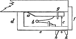
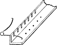
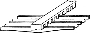
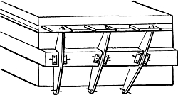
(a) The common Tumbler coupler is represented
in Fig. 53. a is a slender bridge, having as many
notches as keys in the manual, and fitted with
short stickers called tumblers. These tumblers, or
stickers, are generally rectangular in section, and
they must fit the notches neatly but with freedom
of motion; the notches are closed in by a
tringle of wood glued over them, thus forming a
series of mortices; and each sticker has a little pin,
or a pair of pins, to prevent it from falling out of
its notch or mortice. Or, the tumblers may be
made from round rods, and may pass through
round holes in the bridge. They are well blackleaded
in either case. Now if this bridge, with its
tumblers, is placed between the manuals near
their hinder extremities, if the length of the
tumblers is equal to the interval between the upper
and lower key-tails, it is evident that on pressing
down a key of the lower manual the tumbler will
push up the tail of the corresponding key on the
upper manual, and so on throughout the full compass
of both. To reverse this, and to leave the
manuals separate and independent as before, the
bridge is made to take a quarter of a revolution in
sockets fitted to carry its ends, which are rounded
or turned in the lathe; the tumblers, by this
partial revolution, are then no longer perpendicular,
but parallel to the key-tails, as shown by the
dotted lines in the figure, and cease to be touched
by them. On the whole, this is the simplest form
of swell-coupler.
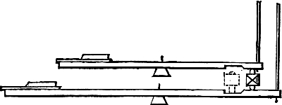
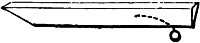
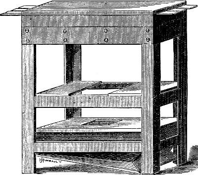
Fig. 54.
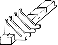
The tumblers may also be placed on or off by
causing the bridge to slide between guides for a
distance of 1 inch or 2 inches. When the bridge
is pushed back by drawing a stop-handle (which
acts upon a horizontal trundle with arms and traces
to give the sliding motion), the tumblers act on the
key-tails; when it is drawn forward by thrusting
in the stop, they fall into a hollow cut in the key-tails,
and are too short to be of use. The hollow
in the key-tails is bevelled, and the inclined plane
so formed is leathered and blackleaded (see
Fig. 54).
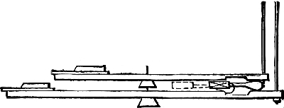
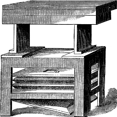
Fig. 55.
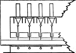
The ram coupler, Fig. 55, acts in a way closely
resembling the last. Instead of tumblers, the
bridge carries a set of short backfalls, turning on a
wire as usual, and cut at the free end into a circular
form. The sliding of the bridge brings these
circular ends into contact with the key-tails of both
manuals, or places them in a hollow cut in the
keys, bevelled, leathered, and blackleaded as
before. The ram-coupler can be used between
manuals arranged too closely to admit of tumblers.
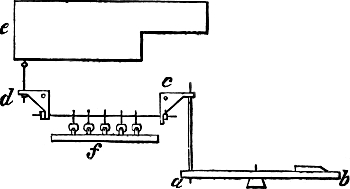
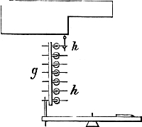
(b) It will facilitate our description of the choir-coupler
and pedal-couplers if we here point out
that if a bridge with backfalls (or squares) be made
to rise or fall ½ inch or more at pleasure, the action
connected with it will be thrown into or out of
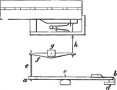
gear at the will of the player. If, in Fig. 32, for
instance, the bridge g be made to rise ½ inch by
drawing a stop-handle, the stickers e will then be
too short by ½ inch, or the pull-downs h will be too
long in an equal degree, and the manual will be
silenced.
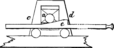
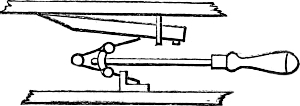
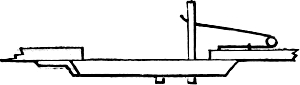
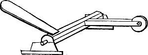
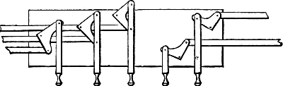
Fig. 56.
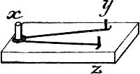
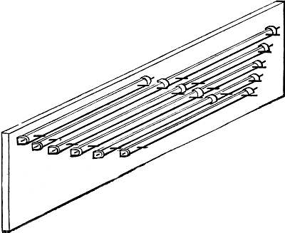
An easy way of making such a bridge rise and
fall is shown in Fig. 56. The bridge a, which
cannot be too solid and heavy, is held between
guides, c d, which are blackleaded and accurately
adjusted. At each end of the bridge is fitted a
little roller or wheel of box-wood, turning freely on
a pin. To the frame below is fitted another such
roller, or two, as in the figure. Between these two
or three rollers, at each end of the bridge, an
inclined plane of wood, e, is made to traverse by
means of a horizontal trundle and arms. It will be
seen at a glance that when the inclined plane is
pushed between the rollers by drawing or thrusting
in a stop-handle, it lifts the bridge between the
guides and dislocates the action; when it is withdrawn,
the bridge resumes its place by its own
weight, and the action is again in order.
It is now easy to understand the construction of
the remaining couplers. The choir-coupler (Fig.
52, p. 152), has two bridges, x, y, with two sets of
short backfalls and communicating stickers. If the
bridges are fixed, then on depressing any key on
the upper manual its tail raises the backfall, which
presses down the lower backfall, which in its turn
pushes up the tail of the lower key and causes the
note to be heard. If the upper bridge be made to
rise or the lower to fall ½ inch, then the keys are
at once disconnected.
(c) The coupling of manuals to pedals is generally
effected by rising and falling bridges, carrying
backfalls which push up the tails of the keys.
These bridges are arranged one above the other
beneath the keyboards in large organs with three
or four manuals, each bridge bringing its own
manual into connection with the pedals by the
movement already described. One roller-board
(the rollers are often of iron for the sake of compactness)
suffices for all the sets of backfalls, and
the stickers (in this case generally flat strips of
wood) pass through mortices cut in the tails of
the lower keys to act upon the tails of the keys to
which they belong.
The reader will easily perceive from these hints
how the pedals may be made to act through their
whole extent upon one of our manuals, and through
only a part of their extent upon the other manual,
as we have hinted at page 148. There will be two
bridges, one over the other, and a very little
ingenuity will be required to plan the roller-board
so that the central C of the pedals shall pull down
the lowest C of the second manual (be it upper
or lower), and thus give the octave below (or 16-feet
pitch) without additional pipes from that note
upwards. But this, perhaps, belongs to the subject
of the pedal organ, which we reserve for the conclusion
of this book.
It is right to add here that in old-fashioned
organs, both in England and on the Continent
(where many such instruments remain unaltered),
the manuals were made to couple by being drawn
out or pushed in about ½ inch. A spur or protuberance
of wood was glued to the upper part
of the tail of each key, and a similar spur to the
under part of the tail of the key in the manual
above. These spurs had rounded ends covered
with leather. On shifting one of the key-boards
backwards or forwards the spurs met each other,
and the coupling was effected. Or the spurs were
glued under the front of each key, immediately
behind the beading of the key-frame, and upon
the upper surface of each key in the manual
beneath it, and a similar shifting brought about
a like result. We see no objection to this very
simple old-fashioned arrangement strong enough
to induce us to discard it from consideration.
The common type of small church organ with
Great and Swell (throughout) would be vastly
improved by the introduction of a manual between
the other two, having no stops of its own, but
coupled to both by such spurs. Instead of two
qualities of sound, namely Swell alone and Great
and Swell combined (the incessant use of the
coupler being the inveterate habit of most players),
we should have three: Great alone, Swell alone,
and combination of Great and Swell. This obvious
improvement could be introduced into new organs
or added to existing instruments at a very small
cost. There should be a coupler to connect this
Combination Manual with the pedals.
It is undeniable that the addition of a pedal
organ with a Sub-bass or Bourdon of 16-feet tone
is a very important and valuable improvement
to any organ, large or small. It gives a dignified
cathedral-like solemnity and grandeur which every
ear can appreciate. We shall bring our treatise
to a close by a few remarks upon it.
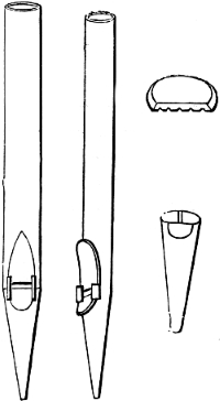
1. The pipes will be made precisely like those of
the Stopped Diapason, of which they may be
regarded as a continuation, and they should be of
stout material, the last four or five of inch stuff,
then three-quarters to the twelfth or thirteenth
note above.
On the question of scale the most diverse
opinions have found favour of late years. A
writer whose dicta are entitled to respect[5] urges
that the lowest pipe (CCC, 16-feet tone) should
have the enormous if not preposterous scale of 11½
by 13 inches inside measurement, and that the
next six pipes above it should be in proportion.
After that, he says, a smaller scale may suffice.
It is clear that if this ruling be correct we may
dismiss the idea of introducing a Sub-bass into our
chamber organ. Mr. Hopkins, on the other hand,
prints two scales for 16-feet toned Bourdons, the
larger of which gives 6⅛ inches by 4⅝ as the inside
measurement of the CCC pipe; while the smaller
gives 5 inches by 3⅜ for the same pipe. We may
safely adopt this larger scale of Mr. Hopkins; and
we will only say further that with our light 2-inch
wind the mouths should be cut up one-third of the
width, or rather less, and the foot-holes should be
of ample size.
2. Their location in the organ must depend very
much on special circumstances. When they can
be placed in a row at the back of the instrument,
their connection with the pedals becomes very
simple, two sets of squares with trackers running
under the bellows being all that will be necessary.
If the room has abundance of height, the back set
of squares may act on a roller-board, and then the
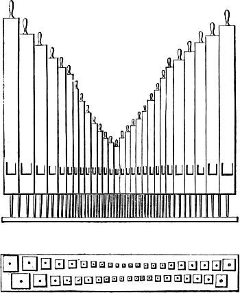
pipes can be disposed symmetrically, the largest
at each end.
3. The board on which they stand will not
require a slider. It will be, in fact, a wind-chest
only, a long box of stout pine or deal, having holes
in its top countersunk to receive the pipe-feet.
Under each hole is placed a pallet or valve, held
up by a strong spring, and having a pull-down
wire passed through a brass plate in the usual way.
The aperture of the wind-trunk is in the lower
board of this chest, and over it, before the board is
in place, is fitted a valve, faced with leather, and
made to slide to and fro between guides. An iron
spindle, turned to fit accurately in a brass collar,
carries an arm jointed to the valve by a connecting
rod or trace; and outside the chest it carries
another arm, at right angles to this, jointed to the
draw-stop handle or its trace. We have, in fact, a
trundle passing air-tight through a collar, and by
this simple contrivance we can shut off the wind
at pleasure from the chest. Other methods of
effecting this are in use, and may easily be
devised. The pipes are very frequently placed on
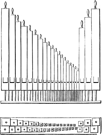
both sides of the organ, to the right and left. In
this case the two chests will be at right angles
to the manual chest or chests, and the action will
be less direct. But it will be readily arranged as
follows:—The pedal roller board will be long
enough to act upon sets of squares, carried on the
organ-frame to the right and left of the player, and
at any convenient height. The other arms of
these squares act by trackers on roller-frames
placed under the chests.
There are cases in which this roller-board will
be better placed at the back of the organ, the connection
between it and the pedals being by squares
and trackers; and there are also cases in which
a large roller-frame lying upon the ground under
the bellows may be made to answer every purpose.
Bell-cranks, or horizontal squares, may also transmit
the pressure of the foot on the pedal by other
squares and trackers to the pedal pallets in a
manner analogous to that of the draw-stop action,
Fig. 49. There is abundant room for ingenuity
and contrivance in all these details; the essential
points are strength, quietness, and accessibility
for repair or adjustment.
Some of our readers may be able to indulge in
the luxury of a second pedal stop. This should be
a Violoncello in metal, of 8-feet tone and length.
In this case the pedal chest or chests will be regular
sound-boards, with sliders; or the Sub-bass may be
on a chest as already described, while the Violoncello
may be on another, with two actions.
We have only to add, that the power and effectiveness
of small organs may be increased by the
contrivance called a "Terzo Mano" (Third Hand),
or octave coupler. Let us suppose that an ordinary
action has been fitted with backfalls in the usual
positions. Then a second bridge, rising and falling
by a draw-stop, is introduced, carrying skew backfalls
which act on the pull-downs an octave higher
than the first set. Thus the key CC will take down
the Tenor C note, and so on throughout the scale.
It is evident that the effect on the ear will be nearly,
though not quite, the same as if each 8-feet stop
had its corresponding 4-feet stop drawn with it.
An Open Diapason will sound like an Open Diapason
and Principal; a Stopped Diapason, like a
Stopped Diapason and Stopped Flute, &c. To
render the illusion complete, the pipes should be
carried up twelve notes higher than the apparent
compass of the key-board, that is to say, if the key-board
has fifty-four notes the sound-board should
have sixty-six grooves.
In a similar way the pedal Sub-bass may be made
to play in octaves, producing the effect of a Sub-bass,
16-feet tone, with a Flute-bass of 8-feet tone
added to it.
Of all such mechanical devices it must be said,
finally, that neatness, accuracy, and noiseless precision
of action are the conditions necessary to
complete success.